US10357650B2 - Electrode transition seal for implantable lead body - Google Patents
Electrode transition seal for implantable lead bodyDownload PDFInfo
- Publication number
- US10357650B2 US10357650B2US15/271,940US201615271940AUS10357650B2US 10357650 B2US10357650 B2US 10357650B2US 201615271940 AUS201615271940 AUS 201615271940AUS 10357650 B2US10357650 B2US 10357650B2
- Authority
- US
- United States
- Prior art keywords
- lead
- recited
- lead body
- implantable stimulation
- stimulation lead
- Prior art date
- Legal status (The legal status is an assumption and is not a legal conclusion. Google has not performed a legal analysis and makes no representation as to the accuracy of the status listed.)
- Active, expires
Links
- 230000007704transitionEffects0.000titleclaimsabstractdescription29
- 230000000638stimulationEffects0.000claimsabstractdescription46
- 239000000463materialSubstances0.000claimsabstractdescription28
- BASFCYQUMIYNBI-UHFFFAOYSA-NplatinumChemical compound[Pt]BASFCYQUMIYNBI-UHFFFAOYSA-N0.000claimsdescription16
- 229920002635polyurethanePolymers0.000claimsdescription8
- 239000004814polyurethaneSubstances0.000claimsdescription8
- 229920001296polysiloxanePolymers0.000claimsdescription5
- 229910000575Ir alloyInorganic materials0.000claimsdescription4
- 229910001260Pt alloyInorganic materials0.000claimsdescription4
- 229910052697platinumInorganic materials0.000claimsdescription4
- 125000006850spacer groupChemical group0.000claimsdescription2
- 239000000560biocompatible materialSubstances0.000claims1
- 239000012530fluidSubstances0.000description6
- 239000004020conductorSubstances0.000description4
- 238000005260corrosionMethods0.000description3
- 230000007797corrosionEffects0.000description3
- 239000000956alloySubstances0.000description2
- 230000008901benefitEffects0.000description2
- 239000008280bloodSubstances0.000description2
- 210000004369bloodAnatomy0.000description2
- GKOZUEZYRPOHIO-UHFFFAOYSA-Niridium atomChemical compound[Ir]GKOZUEZYRPOHIO-UHFFFAOYSA-N0.000description2
- 238000007789sealingMethods0.000description2
- 238000004088simulationMethods0.000description2
- 238000005299abrasionMethods0.000description1
- 238000010276constructionMethods0.000description1
- 230000002439hemostatic effectEffects0.000description1
- 239000007943implantSubstances0.000description1
- 238000000608laser ablationMethods0.000description1
- WABPQHHGFIMREM-NOHWODKXSA-Nlead-200Chemical compound[200Pb]WABPQHHGFIMREM-NOHWODKXSA-N0.000description1
- 230000007774longtermEffects0.000description1
- 230000007257malfunctionEffects0.000description1
- 238000000034methodMethods0.000description1
- 238000012986modificationMethods0.000description1
- 230000004048modificationEffects0.000description1
- 230000005641tunnelingEffects0.000description1
Images


Classifications
- A—HUMAN NECESSITIES
- A61—MEDICAL OR VETERINARY SCIENCE; HYGIENE
- A61N—ELECTROTHERAPY; MAGNETOTHERAPY; RADIATION THERAPY; ULTRASOUND THERAPY
- A61N1/00—Electrotherapy; Circuits therefor
- A61N1/02—Details
- A61N1/04—Electrodes
- A61N1/05—Electrodes for implantation or insertion into the body, e.g. heart electrode
- A61N1/0551—Spinal or peripheral nerve electrodes
Definitions
- the subject inventionis directed to a stimulation lead, and more particularly, to a low profile neuro stimulation lead having an elongated lead body with at least two electrically active electrodes positioned along a distal portion of the lead body.
- Implantable stimulation leadsare typically designed with a lead body formed from a biocompatible polymeric material such as polyurethane, preferably having a durometer of about 55D or 90A on the Shore hardness scale.
- a biocompatible polymeric materialsuch as polyurethane, preferably having a durometer of about 55D or 90A on the Shore hardness scale.
- the use of polyurethane lead bodiesis preferable, in particular with neuro stimulation leads, as compared to implantable grade silicone for several reasons.
- polyurethaneprevents the lead body from stretching during a tunneling implant procedure.
- the lead bodywill have a smoother and more lubricious body surface, and third, they have a higher abrasion resistance when several leads are positioned next to each other and/or the lead has to be tunneled through small spaces such as the epidural.
- Neuro stimulation leadscommonly feature at least two stimulation electrodes, which are typically made from Platinum (Pt) and/or an alloy of Platinum and Iridium (Pt/Ir) or other electrically conductive biocompatible alloy materials, and they are typically connected through conductors to a stimulation source.
- PtPlatinum
- Pt/Iran alloy of Platinum and Iridium
- FIG. 1is a side elevational view of an elongated lead body having a pair of stimulation electrodes operatively associated with a distal end portion thereof and a connector operatively associated with a proximal end portion thereof;
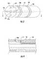
- FIG. 2is a side elevational view of an elongated lead body having a pair of stimulation electrodes operatively associated with a distal end portion thereof and a stimulation source embedded into the proximal end portion thereof;
- FIG. 3is a detailed cross-sectional view of a sealed electrode transition region constructed in accordance with a preferred embodiment of the subject invention shown in FIG. 1 ;
- FIG. 4is a cross-sectional view taken along line 4 - 4 of FIG. 3 , showing the sealed electrode transition region of the subject invention.
- FIG. 5is a detailed cross-sectional view taken along line 5 - 5 of FIG. 2 , showing a distal end portion of the implantable stimulation lead of the subject invention, illustrating the structural components of the sealed transition region associated with the electrode assembly.
- FIG. 1a stimulation lead in accordance with a preferred embodiment of the subject invention and designated generally by reference numeral 100 .
- the stimulation lead 100includes an elongated lead body 102 having opposed proximal and distal end portions 104 , 106 .
- a pair of stimulation electrodes 112 , 114is operatively associated with the distal end portion 104 thereof.
- Each stimulation electrode 112 , 114is operatively associated with a stimulation source through a connector 116 positioned at the proximal end portion 106 of the lead body 102 .
- the stimulation sourcecould be a neuro stimulator in form of a pulse generator (not shown), whereby the lead would be connected through a standardized connector to a header receptacle of the pulse generator and whereby silicone O-rings 118 on either the connector or generator receptacle side would provide a hemostatic seal to prevent fluid ingression.
- a stimulation lead 100 having a connector 116 of this typeis illustrated in FIG. 1 .
- the stimulation sourcecould be an electrically active circuit 216 with a conductive charging coil inside the lead body 202 operatively associated with electrodes 212 , 214 , as shown for example with simulation lead 200 in FIG. 2 . In either configuration, it is desirable for the stimulation lead to be completely sealed from fluid ingression, so as to prevent electrical shortage and the potential for long term corrosion.
- the lead body 102may be a single lumen channel or may include a plurality of circumferentially spaced lumens 124 a - d surrounding an interior lumen 122 , as seen best in FIG. 3 .
- the interior lumen 122may be for placement of a stylet or guidewire while remaining lumens 124 a - d may be used for conductors, including conductor 132 connecting electrode 112 to simulation source.
- each electrode 112 , 114 along the distal portion 104 of the lead body 102is positioned within a transition component 142 defining a seal region for neuro stimulation.
- the electrodes 112 , 114are preferably configured at least as a bipolar stimulation assembly and include at least two spaced apart cylindrical ring electrodes. It is envisioned however, that the electrode assembly could be configured as a multi-polar assembly with between four (4) and sixteen (16) or more spaced apart electrodes.
- the electrodesare formed from Platinum (Pt) and/or an alloy of Platinum and Iridium (Pt/Ir) or other electrically conductive biocompatible alloy materials.
- the electrodescan be positioned either on top of the elongated lead body or the lead body wall can be reduced in diameter (for example by means of centerless grinding or laser ablation) in the area of the electrode location to allow a seamless atraumatic smooth transition between the electrodes and the lead body, as shown in FIGS. 3 and 4 .
- the transition component 142 of the seal regionis made from a material that is relatively softer than the material from which the lead body 102 is formed. Accordingly, when the lead body 102 is bent in this region, the softer transition components 142 will advantageously comply more readily than the harder lead body 102 , so as to maintain a fluid seal in relation to the electrode 112 , so that the interior 102 a of the lead body adjacent to the electrode will not become exposed. This will prevent the ingress of fluid or blood into the interior lumen 122 of the lead body 102 , and thereby eliminate the possibility of an electrical short or corrosion of the internal conductors located within the lead body 102 .
- the lead body 102is formed from a biocompatible polymeric material and the transition components 142 are formed from a biocompatible polymeric material. More preferably, the lead body 102 is formed from a polyurethane material and the transition components are formed from a silicone material. In particular, the lead body 102 is formed from a biocompatible polymeric material having a relatively hard durometer and the transition components are formed from a biocompatible polymeric material having a durometer of relatively medium hardness. More particularly, the lead body is formed from a material having a Shore A hardness of about 90 (55D), and the transition components are formed from a material having a Shore A hardness of about 70 or softer.
- the circumferential seal regionincludes a pair of axially spaced apart transition components 144 that are each defined by a cylindrical sealing plug 148 .
- Each cylindrical electrode 212 , 214surrounds at least portions of the axially spaced apart transition components 144 associated therewith.
- the seal plugs 148each have an enlarged diameter portion 148 a that interacts with the lead body and a reduced diameter portion 148 b that interacts with the cylindrical electrode 212 , 214 .
- a cylindrical body spacer 146is disposed between two adjacent electrodes 212 , 214 .
Landscapes
- Health & Medical Sciences (AREA)
- Neurology (AREA)
- Neurosurgery (AREA)
- Orthopedic Medicine & Surgery (AREA)
- Cardiology (AREA)
- Heart & Thoracic Surgery (AREA)
- Engineering & Computer Science (AREA)
- Biomedical Technology (AREA)
- Nuclear Medicine, Radiotherapy & Molecular Imaging (AREA)
- Radiology & Medical Imaging (AREA)
- Life Sciences & Earth Sciences (AREA)
- Animal Behavior & Ethology (AREA)
- General Health & Medical Sciences (AREA)
- Public Health (AREA)
- Veterinary Medicine (AREA)
- Electrotherapy Devices (AREA)
- Materials For Medical Uses (AREA)
Abstract
Description
Claims (18)
Priority Applications (1)
| Application Number | Priority Date | Filing Date | Title |
|---|---|---|---|
| US15/271,940US10357650B2 (en) | 2015-09-21 | 2016-09-21 | Electrode transition seal for implantable lead body |
Applications Claiming Priority (2)
| Application Number | Priority Date | Filing Date | Title |
|---|---|---|---|
| US201562221212P | 2015-09-21 | 2015-09-21 | |
| US15/271,940US10357650B2 (en) | 2015-09-21 | 2016-09-21 | Electrode transition seal for implantable lead body |
Publications (2)
| Publication Number | Publication Date |
|---|---|
| US20170080215A1 US20170080215A1 (en) | 2017-03-23 |
| US10357650B2true US10357650B2 (en) | 2019-07-23 |
Family
ID=58276221
Family Applications (1)
| Application Number | Title | Priority Date | Filing Date |
|---|---|---|---|
| US15/271,940Active2037-02-26US10357650B2 (en) | 2015-09-21 | 2016-09-21 | Electrode transition seal for implantable lead body |
Country Status (1)
| Country | Link |
|---|---|
| US (1) | US10357650B2 (en) |
Families Citing this family (2)
| Publication number | Priority date | Publication date | Assignee | Title |
|---|---|---|---|---|
| US10603488B2 (en) | 2017-02-10 | 2020-03-31 | Oscor Inc. | Implantable medical devices having diamagnetic conductors and contacts |
| US11147963B2 (en) | 2017-06-09 | 2021-10-19 | Oscor Inc. | Implantable medical devices and methods of manufacture |
Citations (6)
| Publication number | Priority date | Publication date | Assignee | Title |
|---|---|---|---|---|
| US5433742A (en)* | 1993-11-19 | 1995-07-18 | Willis; Allan | Conductive adhesive band for cathether electrode |
| US5580699A (en)* | 1994-08-16 | 1996-12-03 | Ventritex, Inc. | Method for manufacturing implantable cardiac defibrillation electrodes using a laser beam material removal process |
| US20050021119A1 (en)* | 2003-04-25 | 2005-01-27 | Medtronic, Inc. | Implantable medical lead and system, and method of use thereof |
| US20060116739A1 (en)* | 2002-05-23 | 2006-06-01 | Nir Betser | Electrode assembly for nerve control |
| US20090264943A1 (en)* | 2008-04-21 | 2009-10-22 | Boston Scientific Neuromodulation Corporation | High-resolution connector for a neurostimulation lead |
| US20110054580A1 (en)* | 2009-09-02 | 2011-03-03 | Shrojalkumar Desai | Polyisobutylene urethane, urea and urethane/urea copolymers and medical leads containing the same |
- 2016
- 2016-09-21USUS15/271,940patent/US10357650B2/enactiveActive
Patent Citations (6)
| Publication number | Priority date | Publication date | Assignee | Title |
|---|---|---|---|---|
| US5433742A (en)* | 1993-11-19 | 1995-07-18 | Willis; Allan | Conductive adhesive band for cathether electrode |
| US5580699A (en)* | 1994-08-16 | 1996-12-03 | Ventritex, Inc. | Method for manufacturing implantable cardiac defibrillation electrodes using a laser beam material removal process |
| US20060116739A1 (en)* | 2002-05-23 | 2006-06-01 | Nir Betser | Electrode assembly for nerve control |
| US20050021119A1 (en)* | 2003-04-25 | 2005-01-27 | Medtronic, Inc. | Implantable medical lead and system, and method of use thereof |
| US20090264943A1 (en)* | 2008-04-21 | 2009-10-22 | Boston Scientific Neuromodulation Corporation | High-resolution connector for a neurostimulation lead |
| US20110054580A1 (en)* | 2009-09-02 | 2011-03-03 | Shrojalkumar Desai | Polyisobutylene urethane, urea and urethane/urea copolymers and medical leads containing the same |
Also Published As
| Publication number | Publication date |
|---|---|
| US20170080215A1 (en) | 2017-03-23 |
Similar Documents
| Publication | Publication Date | Title |
|---|---|---|
| US11735876B2 (en) | Distal connector assemblies for medical lead extensions | |
| US7174220B1 (en) | Construction of a medical electrical lead | |
| US4469104A (en) | Multipolar connector for pacing lead | |
| CN105214215B (en) | defibrillation catheter | |
| US7711437B1 (en) | Lead fixation device | |
| US8602827B2 (en) | Terminal connector assembly for a medical electrical lead | |
| US9106004B2 (en) | Implantable medical electrical leads and connector assemblies thereof | |
| US6253111B1 (en) | Multi-conductor lead | |
| US9079020B2 (en) | Terminal ring configuration to prevent improper IS4 lead connector electrical contact with DF4 connector port | |
| US11806532B2 (en) | Implantable lead with asymmetric fiducial marker | |
| US20100234931A1 (en) | Active fixation element | |
| US10357650B2 (en) | Electrode transition seal for implantable lead body | |
| US10541500B2 (en) | Connector constructions and components thereof for implantable medical electrical systems | |
| CN104136069B (en) | Implantable medical lead | |
| US20220047874A1 (en) | Implantable lead | |
| US20240390687A1 (en) | Seals for lead passageways of implantable medical devices | |
| US10842992B2 (en) | Active cardiac electrical lead | |
| CN109524863B (en) | Implantable lead assembly | |
| US20220233846A1 (en) | Implantable medical lead devices and systems having balanced clocked conductor positions | |
| US11752351B2 (en) | Seals for lead bores of implantable medical devices | |
| US20220409881A1 (en) | Implantable medical leads having electrode segments of different sizes | |
| WO2022271837A1 (en) | Implantable medical leads having electrode segments of different sizes |
Legal Events
| Date | Code | Title | Description |
|---|---|---|---|
| AS | Assignment | Owner name:OSCOR INC., FLORIDA Free format text:ASSIGNMENT OF ASSIGNORS INTEREST;ASSIGNOR:OSYPKA, THOMAS P.;REEL/FRAME:039933/0741 Effective date:20160930 | |
| STPP | Information on status: patent application and granting procedure in general | Free format text:DOCKETED NEW CASE - READY FOR EXAMINATION | |
| STPP | Information on status: patent application and granting procedure in general | Free format text:NOTICE OF ALLOWANCE MAILED -- APPLICATION RECEIVED IN OFFICE OF PUBLICATIONS | |
| STPP | Information on status: patent application and granting procedure in general | Free format text:PUBLICATIONS -- ISSUE FEE PAYMENT RECEIVED | |
| STPP | Information on status: patent application and granting procedure in general | Free format text:PUBLICATIONS -- ISSUE FEE PAYMENT VERIFIED | |
| STCF | Information on status: patent grant | Free format text:PATENTED CASE | |
| AS | Assignment | Owner name:WELLS FARGO BANK, NATIONAL ASSOCIATION, AS ADMINISTRATIVE AGENT, VIRGINIA Free format text:SECURITY INTEREST;ASSIGNOR:OSCOR INC.;REEL/FRAME:058838/0203 Effective date:20220124 | |
| FEPP | Fee payment procedure | Free format text:ENTITY STATUS SET TO UNDISCOUNTED (ORIGINAL EVENT CODE: BIG.); ENTITY STATUS OF PATENT OWNER: LARGE ENTITY | |
| MAFP | Maintenance fee payment | Free format text:PAYMENT OF MAINTENANCE FEE, 4TH YEAR, LARGE ENTITY (ORIGINAL EVENT CODE: M1551); ENTITY STATUS OF PATENT OWNER: LARGE ENTITY Year of fee payment:4 |