US10357264B2 - Shock wave balloon catheter with insertable electrodes - Google Patents
Shock wave balloon catheter with insertable electrodesDownload PDFInfo
- Publication number
- US10357264B2 US10357264B2US15/370,900US201615370900AUS10357264B2US 10357264 B2US10357264 B2US 10357264B2US 201615370900 AUS201615370900 AUS 201615370900AUS 10357264 B2US10357264 B2US 10357264B2
- Authority
- US
- United States
- Prior art keywords
- balloon
- electrode carrier
- elongate member
- shock wave
- angioplasty balloon
- Prior art date
- Legal status (The legal status is an assumption and is not a legal conclusion. Google has not performed a legal analysis and makes no representation as to the accuracy of the status listed.)
- Active, expires
Links
Images


Classifications
- A—HUMAN NECESSITIES
- A61—MEDICAL OR VETERINARY SCIENCE; HYGIENE
- A61B—DIAGNOSIS; SURGERY; IDENTIFICATION
- A61B17/00—Surgical instruments, devices or methods
- A61B17/22—Implements for squeezing-off ulcers or the like on inner organs of the body; Implements for scraping-out cavities of body organs, e.g. bones; for invasive removal or destruction of calculus using mechanical vibrations; for removing obstructions in blood vessels, not otherwise provided for
- A61B17/22004—Implements for squeezing-off ulcers or the like on inner organs of the body; Implements for scraping-out cavities of body organs, e.g. bones; for invasive removal or destruction of calculus using mechanical vibrations; for removing obstructions in blood vessels, not otherwise provided for using mechanical vibrations, e.g. ultrasonic shock waves
- A61B17/22012—Implements for squeezing-off ulcers or the like on inner organs of the body; Implements for scraping-out cavities of body organs, e.g. bones; for invasive removal or destruction of calculus using mechanical vibrations; for removing obstructions in blood vessels, not otherwise provided for using mechanical vibrations, e.g. ultrasonic shock waves in direct contact with, or very close to, the obstruction or concrement
- A61B17/22022—Implements for squeezing-off ulcers or the like on inner organs of the body; Implements for scraping-out cavities of body organs, e.g. bones; for invasive removal or destruction of calculus using mechanical vibrations; for removing obstructions in blood vessels, not otherwise provided for using mechanical vibrations, e.g. ultrasonic shock waves in direct contact with, or very close to, the obstruction or concrement using electric discharge
- A—HUMAN NECESSITIES
- A61—MEDICAL OR VETERINARY SCIENCE; HYGIENE
- A61B—DIAGNOSIS; SURGERY; IDENTIFICATION
- A61B17/00—Surgical instruments, devices or methods
- A61B17/22—Implements for squeezing-off ulcers or the like on inner organs of the body; Implements for scraping-out cavities of body organs, e.g. bones; for invasive removal or destruction of calculus using mechanical vibrations; for removing obstructions in blood vessels, not otherwise provided for
- A61B17/22004—Implements for squeezing-off ulcers or the like on inner organs of the body; Implements for scraping-out cavities of body organs, e.g. bones; for invasive removal or destruction of calculus using mechanical vibrations; for removing obstructions in blood vessels, not otherwise provided for using mechanical vibrations, e.g. ultrasonic shock waves
- A61B17/22012—Implements for squeezing-off ulcers or the like on inner organs of the body; Implements for scraping-out cavities of body organs, e.g. bones; for invasive removal or destruction of calculus using mechanical vibrations; for removing obstructions in blood vessels, not otherwise provided for using mechanical vibrations, e.g. ultrasonic shock waves in direct contact with, or very close to, the obstruction or concrement
- A—HUMAN NECESSITIES
- A61—MEDICAL OR VETERINARY SCIENCE; HYGIENE
- A61M—DEVICES FOR INTRODUCING MEDIA INTO, OR ONTO, THE BODY; DEVICES FOR TRANSDUCING BODY MEDIA OR FOR TAKING MEDIA FROM THE BODY; DEVICES FOR PRODUCING OR ENDING SLEEP OR STUPOR
- A61M25/00—Catheters; Hollow probes
- A61M25/10—Balloon catheters
- A61M25/104—Balloon catheters used for angioplasty
- A—HUMAN NECESSITIES
- A61—MEDICAL OR VETERINARY SCIENCE; HYGIENE
- A61B—DIAGNOSIS; SURGERY; IDENTIFICATION
- A61B17/00—Surgical instruments, devices or methods
- A61B17/22—Implements for squeezing-off ulcers or the like on inner organs of the body; Implements for scraping-out cavities of body organs, e.g. bones; for invasive removal or destruction of calculus using mechanical vibrations; for removing obstructions in blood vessels, not otherwise provided for
- A61B17/22004—Implements for squeezing-off ulcers or the like on inner organs of the body; Implements for scraping-out cavities of body organs, e.g. bones; for invasive removal or destruction of calculus using mechanical vibrations; for removing obstructions in blood vessels, not otherwise provided for using mechanical vibrations, e.g. ultrasonic shock waves
- A61B17/22012—Implements for squeezing-off ulcers or the like on inner organs of the body; Implements for scraping-out cavities of body organs, e.g. bones; for invasive removal or destruction of calculus using mechanical vibrations; for removing obstructions in blood vessels, not otherwise provided for using mechanical vibrations, e.g. ultrasonic shock waves in direct contact with, or very close to, the obstruction or concrement
- A61B2017/22025—Implements for squeezing-off ulcers or the like on inner organs of the body; Implements for scraping-out cavities of body organs, e.g. bones; for invasive removal or destruction of calculus using mechanical vibrations; for removing obstructions in blood vessels, not otherwise provided for using mechanical vibrations, e.g. ultrasonic shock waves in direct contact with, or very close to, the obstruction or concrement applying a shock wave
- A—HUMAN NECESSITIES
- A61—MEDICAL OR VETERINARY SCIENCE; HYGIENE
- A61B—DIAGNOSIS; SURGERY; IDENTIFICATION
- A61B17/00—Surgical instruments, devices or methods
- A61B17/22—Implements for squeezing-off ulcers or the like on inner organs of the body; Implements for scraping-out cavities of body organs, e.g. bones; for invasive removal or destruction of calculus using mechanical vibrations; for removing obstructions in blood vessels, not otherwise provided for
- A61B2017/22051—Implements for squeezing-off ulcers or the like on inner organs of the body; Implements for scraping-out cavities of body organs, e.g. bones; for invasive removal or destruction of calculus using mechanical vibrations; for removing obstructions in blood vessels, not otherwise provided for with an inflatable part, e.g. balloon, for positioning, blocking, or immobilisation
- A—HUMAN NECESSITIES
- A61—MEDICAL OR VETERINARY SCIENCE; HYGIENE
- A61M—DEVICES FOR INTRODUCING MEDIA INTO, OR ONTO, THE BODY; DEVICES FOR TRANSDUCING BODY MEDIA OR FOR TAKING MEDIA FROM THE BODY; DEVICES FOR PRODUCING OR ENDING SLEEP OR STUPOR
- A61M25/00—Catheters; Hollow probes
- A61M2025/0008—Catheters; Hollow probes having visible markings on its surface, i.e. visible to the naked eye, for any purpose, e.g. insertion depth markers, rotational markers or identification of type
Definitions
- the present disclosurerelates generally to occlusions in human vascular structures and, in particular, to the use of shock wave therapy in the treatment of calcified lesions.
- Balloon angioplastyis a well-known, standard treatment that restores blood flow in blocked arteries. Blockages occur when plaque accumulates in the walls of the blood vessels, forming lesions.
- a catheter carrying an angioplasty balloonis inserted into the blood vessel along a guide wire to position the angioplasty balloon adjacent to a lesion. Progress of the guide wire may be tracked using fluoroscopy or x-rays. Inflating the angioplasty balloon compresses soft lesions on the wall of the vessel, thereby dilating the blood vessel and allowing blood to flow through a larger portion thereof.
- gentle compressionmay not be effective.
- An improved electrohydraulic dilation techniquehas been used to treat calcified plaques using shock waves.
- Lithoplasty® technologyis described in U.S. Pat. Nos. 8,956,371 and 8,888,788, assigned to Shockwave, Inc., of Fremont, Calif., both of which are incorporated by reference herein in their entireties.
- electrodesare disposed inside the angioplasty balloon.
- the angioplasty balloonis inflated with a conductive fluid, for example, a saline solution, which will propagate shock waves, i.e., high energy pressure waves.
- shock waveWhen high voltage pulsed signals are applied to a bipolar emitter, i.e., a pair of emitter electrodes, a resulting plasma arc creates a rapidly expanding and collapsing gas bubble that emits a shock wave through the fluid.
- a unipolar emitterWhen a unipolar emitter is used, the high voltage signal arcs between a single emitter electrode and the fluid itself.
- shock waveshave been shown to effectively break up, dislodge, or pulverize hardened plaques, thereby softening the lesion while preserving the integrity of the vessel walls.
- a conventional low-pressure angioplasty procedurecan be used effectively to gently compress the softened lesions and dilate the blood vessel.
- While existing cardiovascular intervention therapiesare appropriate for treating calcified lesions in larger blood vessels, e.g., leg arteries having diameters of about 5.0-10.0 mm, smaller vascular structures, or those that are severely blocked may not have a sufficient diameter to accommodate a Lithoplasty® apparatus.
- Such smaller vascular structuresinclude, for example, cerebral and coronary arteries having diameters less than about 3.0 mm.
- a translatable shock wave treatment apparatusis suitable for use in treating small diameter blood vessels that contain calcified lesions.
- an elongate member, or catheter, carrying a folded or collapsed angioplasty balloonis first inserted into the narrow blood vessel.
- the collapsed angioplasty balloonhas a small diameter that will fit into the narrow blood vessel.
- the angioplasty balloonis then inflated with a conducting fluid to pre-dilate the narrow blood vessel prior to introducing electrodes and applying shock wave therapy.
- a translatable electrode carrier equipped with one or more shock wave emittersis advanced along the catheter from an initial position outside the balloon to a destination position inside the balloon.
- shock wavesare then propagated through the fluid to impart energy to calcified plaques along the vessel walls, thereby softening the calcified lesions.
- the angioplasty ballooncan be further inflated to gently compress the softened lesion and complete dilation of the blood vessel.
- shock wave therapycan be used multiple times—first, to pre-dilate the blood vessel, and then, alternating with inflation of the angioplasty balloon, to open the blood vessel.
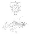
- FIG. 1is a cross-sectional view of an existing shock wave balloon catheter apparatus, according to the prior art.
- FIG. 2Ais a side view of a translatable shock wave treatment apparatus according to some embodiments of the present disclosure, as described herein.
- FIG. 2Bis a side view of a translatable shock wave treatment apparatus according to some embodiments of the present disclosure, as described herein.
- FIGS. 3A, 3B, 3C, and 3Dshow side views, magnified views, and an end view, respectively, of a translatable shock wave treatment apparatus according to some embodiments of the present disclosure, as described herein.
- FIG. 4is a magnified side elevation view of a handle assembly of the translatable shock wave treatment apparatus shown in FIG. 2B .
- FIG. 5is a side elevation view of the translatable shock wave treatment apparatus of FIGS. 3A-3D in an initial position.
- FIG. 6is a cross-sectional view of a distal end of the translatable shock wave treatment apparatus of FIGS. 3A-3D .
- FIG. 7is a side elevation view of the translatable shock wave treatment apparatus of FIGS. 3A-3D in a final position.
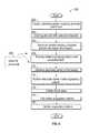
- FIG. 8is a flow diagram of a method of treating calcified lesions using the translatable shock wave treatment apparatus shown in FIGS. 3-7 , according to some embodiments of the present disclosure as described herein.
- FIGS. 9-13are side elevation views of the translatable shock wave treatment apparatus in use at various steps of the method shown in FIG. 8 .
- FIG. 9is a side elevation view of the translatable shock wave treatment apparatus in use, prior to inflating the angioplasty balloon.
- FIG. 10is a side elevation view of the translatable shock wave treatment apparatus in use, after partially inflating the angioplasty balloon with a fluid.
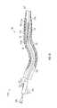
- FIG. 11is a side elevation view of the translatable shock wave treatment apparatus in use, during shock wave emission.
- FIG. 12is a magnified side elevation view of the translatable shock wave treatment apparatus in use, during shock wave emission.
- FIG. 13is a side elevation view of the translatable shock wave treatment apparatus in use, following treatment of calcified lesions.
- firstmeans “first,” “second,” etc. to describe various elements, these elements should not be limited by the terms. These terms are only used to distinguish one element from another, not to imply a priority of one element over the other.
- a first markercould be termed a second marker, and, similarly, a second marker could be termed a first marker, without departing from the scope of the various described embodiments.
- the first marker and the second markerare both markers, but they are not the same marker.
- ifmay be construed to mean “when” or “upon” or “in response to determining” or “in response to detecting,” depending on the context.
- phrase “if it is determined” or “if [a stated condition or event] is detected”may be construed to mean “upon determining” or “in response to determining” or “upon detecting [the stated condition or event]” or “in response to detecting [the stated condition or event],” depending on the context.
- FIG. 1illustrates an exemplary vascular structure, e.g., a blood vessel 50 representing an artery, having a central axis 51 and a vessel wall 52 .
- the representative blood vessel 50is occluded by a region of plaque, or lesion 54 that has formed in the vessel wall 52 .
- the lesion 54may include hardened plaque deposits e.g., calcifications 56 .
- Such lesions 54may be located in other types of vascular structures such as, for example, a valve in a blood vessel, or a heart valve.
- lesions 54extend from opposite vessel walls 52 far enough into the center of the blood vessel 50 that blood flow is almost fully obstructed. Only a narrow opening 58 remains along the central axis 51 .
- FIG. 1further illustrates an attempt to insert an existing shock wave treatment apparatus 80 into the occluded blood vessel 50 , according to an existing method of treatment.
- the existing shock wave treatment apparatus 80having an angioplasty balloon 82 , a shock wave guide wire lumen 83 , a guide wire 84 , an electrode carrier 86 , and electrodes 88 .
- the angioplasty balloon 82 and the electrode carrier 86are coaxial with the guide wire lumen 83 and the guide wire 84 .
- the angioplasty balloon 82is initially folded over the guide wire lumen 83 .
- the electrodes 88are shown as cylinders, co-axial with the electrode carrier 86 .
- Each electrode 88may represent a uni-polar electrode or a pair of bi-polar electrodes, both of which are known in the art.
- a leading end of the guide wire 84is inserted through the narrow opening 58 , followed by the shock wave treatment apparatus 80 bearing the folded angioplasty balloon 82 .
- the shock wave treatment apparatus 80bearing the folded angioplasty balloon 82 .
- the opening 58is very narrow. Consequently, the shock wave treatment apparatus 80 is too large, relative to the opening 58 , to be safely advanced into the occluded region, even when the balloon is deflated.
- the shock wave treatment apparatus 80may have a diameter of about 0.044 inches, or approximately 1.0 mm.
- This problemarises, for example, when the blood vessel 50 has a narrow diameter, e.g., a few millimeters, or whenever the lesions 54 are localized so that the diameter of the blood vessel opening 58 is abruptly reduced to about 1.0 mm or less.
- FIGS. 2-7illustrate a translatable shock wave treatment apparatus 90 , according to some embodiments of the present disclosure.
- Two exemplary embodiments of the translatable shock wave treatment apparatus 90are shown in FIGS. 2A, 2B , having respective catheter systems 100 A,B respective handle assemblies 101 A,B, an emitter assembly 102 , a guide wire 103 , a guide wire lumen 104 , an angioplasty balloon 105 , and an electrode carrier 106 .
- the handle assembly 101 A/Bdefines a proximal end of the translatable shock wave treatment apparatus 90 .
- the angioplasty balloon 105is attached to a distal end of the translatable shock wave treatment apparatus 90 , opposite the handle assembly 101 A/B at the proximal end.
- the guide wire lumen 104is a hollow tube containing the guide wire 103 .
- the guide wire lumen 104or elongate member of the translatable shock wave treatment apparatus 90 , extends between the distal end and the handle assembly along a central axis 107 .
- the emitter assembly 102is mounted to a distal end of the electrode carrier 106 for translation along the elongate member, relative to the angioplasty balloon 105 .
- the elongate memberis semi-rigid but also flexible, permitting insertion into a blood vessel.
- the angioplasty balloon 105has a known structure and is made of a known material, e.g., a bio-compatible flexible material that is used in conventional angioplasty procedures.
- the guide wire lumen 104 and the guide wire 103also have conventional structures and are made of biocompatible materials that may safely be introduced into a human bloodstream.
- FIG. 2Aillustrates a first embodiment of the translatable shock wave treatment apparatus 90 , in which the guide wire 103 joins the catheter system 100 A at a sealed entry port 108 .
- the catheter system 100 Ais known in the art as a rapid exchange (Rx) system.
- the handle assembly 101 Aincludes an electrical connector 129 that transmits electrical power to the emitter assembly 102 via wires 132 .
- the handle assembly 101 Ais configured to translate the emitter assembly 102 with respect to the angioplasty balloon 105 .
- FIG. 2Billustrates a second embodiment of the translatable shock wave treatment apparatus 90 , in which the guide wire 103 extends all the way through the catheter system 100 B, including the handle assembly 101 B.
- the catheter system 100 Bis known in the art as an over-the-wire system.
- the handle assembly 101 Bincludes a guide wire handle 128 that can be used to extend and retract the guide wire 103 .
- the handle assembly 101 Balso includes an electrical connector 129 that transmits electrical power to the emitter assembly 102 via the wires 132 .
- Either one of the rapid exchange system 100 A or the over-the-wire system 100 Bcan be equipped with the emitter assembly 102 , the electrode carrier 106 , and either handle assembly 101 A, or 101 B to permit translation of the emitter assembly 102 into and out of the angioplasty balloon 105 .
- FIGS. 3A and 3Bshow magnified views of the distal end of the translatable shock wave treatment apparatus 90 , in which the guide wire lumen 104 supports the emitter assembly 102 and the angioplasty balloon 105 , according to some embodiments of the present disclosure.
- the electrode carrier 106is outside the angioplasty balloon 105 .
- the angioplasty balloon 105is folded over the guide wire lumen 104 so that the guide wire lumen 104 bearing the collapsed balloon has a narrow profile and a diameter d b .
- the diameter d bmay be compressible.
- the electrode carrier 106is outside the angioplasty balloon 105 and the angioplasty balloon 105 is inflated.
- FIG. 3Cshows a magnified view of a portion 115 of the emitter assembly 102 .
- the emitter assembly 102includes an electrode carrier 106 and electrodes 110 .
- the electrode carrier 106is a moveable overtube, coaxial with the guide wire lumen 104 and the guide wire 103 , aligned with the central axis 107 .
- the electrode carrier 106is flexible, having an inner diameter d c of about 0.025 inches.
- bipolar electrodes 110are in the form of pairs of co-axial cylinders separated by an internal insulating layer. The electrodes 110 are wrapped around, or otherwise mounted to, the electrode carrier 106 .
- the exemplary cylindrical electrodes 110have outer diameters d e of about 0.030 inches.
- unipolar electrodes, low profile electrodes, or emitter electrodes of any other suitable designmay be used.
- the electrodes 110are powered via the electrical wires 132 that extend along the electrode carrier 106 , e.g., in a groove formed on an outside surface of the electrode carrier 106 , as is known in the art (see, for example, U.S. Pat. No. 8,888,788, which shows similar wiring grooves on an outside surface of a catheter).
- the electrical wires 132are coupled by the connector 129 to an external generator, e.g., an external high voltage pulse generator. There may be slack in the electrical wires at the connector 129 to allow advancement of the electrode carrier 106 .
- Two markerse.g., marker bands 114 a,b , are provided on a surface of the guide wire lumen 104 , marking destination locations inside the angioplasty balloon 105 .
- the marker bands 114 a,bare crimped onto the guide wire lumen 104 .
- the marker bands 114 a,bare glued onto the guide wire lumen 104 .
- FIG. 3Dillustrates an end view from the distal end of the translatable shock wave treatment apparatus 100 , showing the guide wire 103 , the guide wire lumen 104 , and the folded angioplasty balloon 105 .
- the angioplasty balloon 105may be wrapped in a clockwise or counterclockwise arrangement to facilitate unobstructed inflation, as is known in the art.
- the guide wire lumen 104has an outer diameter equal to about 0.023 inches and the guide wire 103 , the guide wire lumen 104 , and the folded angioplasty balloon 105 , together have an outer diameter d b that is as small as 0.032 inches, i.e., less than 1.0 mm.
- FIG. 4shows a magnified view of an exemplary handle assembly 101 B, according to some embodiments of the present disclosure.
- the handle assembly 101 Blike the handle assembly 101 A, is operable to move the emitter assembly 102 relative to the angioplasty balloon 105 .
- the handle assembly 101 Bis further operable to move the guide wire 103 relative to a receiving vascular structure.
- the handle assemblies 101 A,Binclude a housing 116 , an inflation lumen 120 , an electrode carrier handle 124 , a stop 125 , a post 126 , a slot 127 of length L, and the connector 129 .
- the handle assembly 101 Bfurther includes the guide wire handle 128 .
- the housing 116is generally cylindrical, but may have a cross-section of arbitrary shape e.g., a round cylinder, a square cylinder, a triangular cylinder, or the like.
- the inflation lumen 120is operable to inflate the angioplasty balloon 105 , via a channel, with a fluid, e.g., a conducting fluid 140 .
- the conducting fluid 140may be, for example, saline solution or another electrolytic solution. Inflation of the angioplasty balloon 105 occurs when an inflation port 130 pressurizes the conducting fluid, causing the conducting fluid to flow through the inflation lumen 120 .
- the inflation lumen 120may be, for example, a tube or channel that extends through the housing 116 and along the central axis 107 , into the angioplasty balloon 105 .
- the inflation lumen 120has a volume that is in fluid communication with an interior volume of the angioplasty balloon 105 , as shown in FIGS. 3A and 3D .
- the inflation lumen 120may be coaxial with the guide wire lumen 104 and the guide wire 103 as shown in FIG. 4 , or the inflation lumen 120 may be within the guide wire lumen 104 , alongside the guide wire 103 , as is known in the art.
- the guide wire handle 128is attached to the proximal end of the guide wire 103 .
- the guide wire 103is inserted into a vascular structure by manually pushing the guide wire handle 128 toward the housing 116 , as is known in the art.
- the connector 129is attached to wires 132 .
- the connector 129couples the external generator that supplies electrical power, e.g., in the form of high voltage pulses, to the emitter assembly 102 via the wires 132 .
- the electrode carrier handle 124is used to align the emitter assembly 102 with respect to the angioplasty balloon 105 .
- the emitter assembly 102is initially positioned outside the angioplasty balloon 105 .
- the emitter assembly 102translates along the guide wire lumen 104 to a position inside the angioplasty balloon 105 , as will be described in greater detail below.
- the electrode carrier 106extends between the marker bands 114 a,b , which are also separated by a distance approximately equal to L.
- the distance Lmay be about 15 mm.
- a position of the electrode carrier handle 124 opposite the stop 125corresponds to a position of the emitter assembly 102 that is outside the inflated angioplasty balloon 105 .
- the electrode carrier handle 124is coupled to the electrode carrier 106 by a pusher 138 , made of a semi-rigid material.
- the pusher 138is a nitinol rod having a diameter of about 0.010 inches.
- the pusher 138is internal to the housing 116 . As the post 126 slides through the slot 127 toward the stop 125 , the pusher 138 causes the emitter assembly 102 to translate forward along the central axis 107 , relative to the angioplasty balloon 105 .
- FIG. 5shows the translatable shock wave treatment apparatus 100 after advancing the guide wire lumen 104 and at least partially inflating the angioplasty balloon 105 , according to some embodiments of the present disclosure.
- the inflated angioplasty balloon 105may be elongated as shown, or it may have a more spherical shape.
- the emitter assembly 102is shown in an initial position outside the inflated angioplasty balloon 105 .
- the angioplasty balloon 105may be inflated just enough to allow the emitter assembly 102 to be inserted into the balloon.
- the emitter assembly 102includes one or more wires 132 e.g., copper leads, of a flexible circuit that wraps around the electrode carrier 106 , e.g., in a spiral configuration. Emitters may be stationed at locations along the wires 132 instead of being in the form of cylindrical electrodes 110 .
- FIG. 6shows a magnified cut view of the distal end of the guide wire lumen 104 , according to some embodiments of the present disclosure.
- the emitter assembly 102may reside within or adjacent to the inflation lumen 120 , and is positioned outside the inflated angioplasty balloon 105 .
- the emitter assembly 102has a distal end 134 that will align with a first marker band 114 a after the electrode carrier 106 is moved inside the angioplasty balloon 105 .
- the emitter assembly 102also has a proximal end 136 that will align with a second marker band 114 b when the electrode carrier 106 is moved inside the angioplasty balloon 105 .
- FIG. 7shows the translatable shock wave treatment apparatus 100 , in which the electrode carrier 106 has been moved inside the angioplasty balloon 105 , so that the ends of the electrode carrier 106 coincide with the marker bands 114 a,b . Accordingly, the electrode carrier handle 124 has been moved along the slot 127 to a position that coincides with the stop 125 .
- the electrodes 110may be of the design shown in FIG. 6 or of the design shown in FIG. 3B .
- FIG. 8shows a sequence of steps illustrating a shock wave therapy technique, according to some embodiments of the present disclosure.
- the shock wave therapy techniqueentails executing a method 200 using the translatable shock wave treatment apparatus 100 , as described below and illustrated in FIGS. 9-13 .
- the translatable shock wave treatment apparatus 100is prepared for insertion into the blood vessel 50 .
- the guide wire handle 128is pulled behind the housing 116 to a retracted position, and the electrode carrier handle 124 slides to its initial position at the proximal end of the slot 127 , opposite the stop 125 .
- the guide wire 103is inserted into the target vascular structure, e.g., the blood vessel 50 , as shown in FIG. 9 .
- the guide wire 103is advanced ahead of the guide wire lumen 104 , through the blood vessel 50 using the guide wire handle 128 .
- the tip of the guide wire lumen 104 bearing the folded angioplasty balloon 105is positioned in an occluded region of the blood vessel 50 that has lesions 54 and, in particular, calcifications 56 , as shown in FIG. 9 .
- the guide wire lumen 104is then advanced until the marker bands 114 a,b are aligned with the occluded region to be treated.
- the smallest diameter, D 1 of the blood vessel 50may accommodate the guide wire lumen 104 and the folded balloon 105 , while being too small to accommodate insertion of the electrode carrier 106 .
- the electrode carrier handle 124remains at an initial position opposite the stop 125 so that the electrode carrier 106 temporarily remains outside the angioplasty balloon 105 .
- the angioplasty balloon 105is inflated, at least partially, expanding outward from its folded position around the guide wire lumen 104 , as shown in FIG. 10 .
- Inflationoccurs as the angioplasty balloon 105 is filled with the conducting fluid 140 by pumping the conducting fluid 140 through the inflation lumen 120 using the inflation port 130 .
- the inflated angioplasty balloon 105pre-dilates the occluded region of the blood vessel 50 by compressing soft portions of the lesion 54 , while the calcifications 56 resist inflation of the angioplasty balloon 105 .
- Inflation of the angioplasty balloon 105opens the interior diameter of the blood vessel 50 to a diameter D 2 that exceeds the diameter d c of the electrode carrier 106 bearing the electrodes 110 .
- the guide wire lumen 104is advanced further into the pre-dilated blood vessel 50 so as to align the distal end 134 of the emitter assembly 102 with the second marker band 114 b .
- the angioplasty balloon 105may be further inflated one or more times after advancing the guide wire lumen 104 . Steps 208 - 210 may be repeated to ensure that the diameter D 2 will accommodate the electrode carrier 106 and the electrodes 110 .
- the electrode carrier handle 124is advanced by sliding the post 126 along the slot 127 through the full distance L, to the stop 125 .
- the distal end 134 of the emitter assembly 102is then aligned with the first marker band 114 a and the proximal end 136 of the emitter assembly 102 is aligned with the second marker band 114 b , as shown in FIG. 11 .
- the electrode carrier 106thus is positioned inside the angioplasty balloon 105 between the first and second marker bands 114 a , 114 b , which are stationed at destination locations along the guide wire lumen 104 .
- the electrode carrier 106may be rotated to align one or more of the emitters closer to the calcifications 56 in a target area of the vessel wall 52 .
- the angioplasty balloon 105may be deflated for about 30 seconds to allow blood to flow, followed by re-inflating the angioplasty balloon 105 to a pressure of about four atmospheres.
- a shock waveis initiated by applying an electrical signal, e.g., a high voltage pulsed signal, to the electrodes 110 .
- the high voltage pulsed signalcauses the emitters to arc, either to one another or to the conducting fluid 140 , depending on a relative polarity and spacing between the emitters.
- the electrodes 110are unipolar and the conducting fluid acts as a second pole.
- pairs of emitters, or bipolar electrodesare positioned close to one another, e.g., spaced apart about 4-15 millimeters along the wires 132 .
- a pulsing gap between negative and positive poles within each pairmay be in the range of about 0.0005-0.02 inches so that an arc occurs across the pulsing gap.
- Heat from the arcing eventvaporizes and then ionizes a small volume of the conducting fluid 140 , creating a rapidly expanding region of plasma around the energized electrodes 110 .
- Such rapid expansioninitiates a shock wave 142 that propagates out from each electrode 110 through the conducting fluid 140 , as shown in FIGS. 11 and 12 .
- shock wave energyis transmitted to the lesions 54 .
- the shock wave energybreaks apart the calcifications 56 , thereby softening the lesions 54 .
- the high voltage pulsed signalmay include, for example, between five and twenty pulses.
- the angioplasty balloon 105is fully inflated to compress the softened lesions 54 against the vessel wall 52 , thus restoring blood flow within the blood vessel 50 , as shown in FIG. 13 .
- the angioplasty balloon 105may be deflated for about 30 seconds, and then re-inflated to a pressure of about six atmospheres for about 30 seconds.
- Steps 214 and 216may be repeated one or more times until the calcifications 56 are broken into small pieces and blood flow within the blood vessel 50 is restored to about 90%. In some embodiments of the method 200 , 8-10 such cycles are performed so as not to interrupt blood flow for an extended period of time.
- performing the angioplasty procedure in short cyclesmay prevent syncope.
- peripheral arteriesperforming the angioplasty procedure in short cycles may prevent swelling.
- the angioplasty balloon 105is deflated by de-pressurizing the conducting fluid 140 using the inflation port 130 .
- the guide wire lumen 104is removed from the blood vessel 50 and the guide wire handle 128 is then pulled away from the housing 116 to retract the guide wire 103 .
- the blood vessel 50is so occluded that shock waves 142 are needed to create an opening that permits full inflation of the angioplasty balloon 105 and, subsequently, full insertion of the electrode carrier 106 into the angioplasty balloon 105 .
- an additional step 209may be inserted before or after step 208 in the method 200 .
- an optional pre-shock treatmentmay be applied from a position slightly outside the balloon 105 , or outside the severely obstructed region, as shown in FIG. 12 .
- the pre-shock treatmentis carried out in a similar fashion as the shock treatment described above in step 214 .
- the optional pre-shock treatmentdilates the blood vessel 50 so that the electrode carrier 106 can be slidably advanced further into the occluded region in an incremental fashion, to allow repeated application of the shock waves 142 .
- shock wave therapywith inflation of the angioplasty balloon 105 , it is possible to treat an extended calcified lesion 54 along the length of the blood vessel 50 .
Landscapes
- Health & Medical Sciences (AREA)
- Life Sciences & Earth Sciences (AREA)
- Engineering & Computer Science (AREA)
- Heart & Thoracic Surgery (AREA)
- Surgery (AREA)
- Animal Behavior & Ethology (AREA)
- Veterinary Medicine (AREA)
- Public Health (AREA)
- Vascular Medicine (AREA)
- Biomedical Technology (AREA)
- General Health & Medical Sciences (AREA)
- Nuclear Medicine, Radiotherapy & Molecular Imaging (AREA)
- Molecular Biology (AREA)
- Medical Informatics (AREA)
- Orthopedic Medicine & Surgery (AREA)
- Mechanical Engineering (AREA)
- Child & Adolescent Psychology (AREA)
- Biophysics (AREA)
- Pulmonology (AREA)
- Anesthesiology (AREA)
- Hematology (AREA)
- Media Introduction/Drainage Providing Device (AREA)
- Surgical Instruments (AREA)
Abstract
Description
Claims (23)
Priority Applications (2)
| Application Number | Priority Date | Filing Date | Title |
|---|---|---|---|
| US15/370,900US10357264B2 (en) | 2016-12-06 | 2016-12-06 | Shock wave balloon catheter with insertable electrodes |
| PCT/US2017/055480WO2018106334A1 (en) | 2016-12-06 | 2017-10-06 | Shock wave balloon catheter with insertable electrodes |
Applications Claiming Priority (1)
| Application Number | Priority Date | Filing Date | Title |
|---|---|---|---|
| US15/370,900US10357264B2 (en) | 2016-12-06 | 2016-12-06 | Shock wave balloon catheter with insertable electrodes |
Publications (2)
| Publication Number | Publication Date |
|---|---|
| US20180153568A1 US20180153568A1 (en) | 2018-06-07 |
| US10357264B2true US10357264B2 (en) | 2019-07-23 |
Family
ID=60153512
Family Applications (1)
| Application Number | Title | Priority Date | Filing Date |
|---|---|---|---|
| US15/370,900Active2037-07-27US10357264B2 (en) | 2016-12-06 | 2016-12-06 | Shock wave balloon catheter with insertable electrodes |
Country Status (2)
| Country | Link |
|---|---|
| US (1) | US10357264B2 (en) |
| WO (1) | WO2018106334A1 (en) |
Cited By (28)
| Publication number | Priority date | Publication date | Assignee | Title |
|---|---|---|---|---|
| CN111388086A (en)* | 2020-06-08 | 2020-07-10 | 上海微创医疗器械(集团)有限公司 | Electrode balloon catheter |
| US11484327B2 (en) | 2021-02-26 | 2022-11-01 | Fastwave Medical Inc. | Intravascular lithotripsy |
| US11517713B2 (en) | 2019-06-26 | 2022-12-06 | Boston Scientific Scimed, Inc. | Light guide protection structures for plasma system to disrupt vascular lesions |
| US11583339B2 (en) | 2019-10-31 | 2023-02-21 | Bolt Medical, Inc. | Asymmetrical balloon for intravascular lithotripsy device and method |
| US11648057B2 (en) | 2021-05-10 | 2023-05-16 | Bolt Medical, Inc. | Optical analyzer assembly with safety shutdown system for intravascular lithotripsy device |
| US11660427B2 (en) | 2019-06-24 | 2023-05-30 | Boston Scientific Scimed, Inc. | Superheating system for inertial impulse generation to disrupt vascular lesions |
| US11672585B2 (en) | 2021-01-12 | 2023-06-13 | Bolt Medical, Inc. | Balloon assembly for valvuloplasty catheter system |
| US11672599B2 (en) | 2020-03-09 | 2023-06-13 | Bolt Medical, Inc. | Acoustic performance monitoring system and method within intravascular lithotripsy device |
| US11707323B2 (en) | 2020-04-03 | 2023-07-25 | Bolt Medical, Inc. | Electrical analyzer assembly for intravascular lithotripsy device |
| US11717139B2 (en) | 2019-06-19 | 2023-08-08 | Bolt Medical, Inc. | Plasma creation via nonaqueous optical breakdown of laser pulse energy for breakup of vascular calcium |
| US11806075B2 (en) | 2021-06-07 | 2023-11-07 | Bolt Medical, Inc. | Active alignment system and method for laser optical coupling |
| US11819229B2 (en) | 2019-06-19 | 2023-11-21 | Boston Scientific Scimed, Inc. | Balloon surface photoacoustic pressure wave generation to disrupt vascular lesions |
| US11839391B2 (en) | 2021-12-14 | 2023-12-12 | Bolt Medical, Inc. | Optical emitter housing assembly for intravascular lithotripsy device |
| US11903642B2 (en) | 2020-03-18 | 2024-02-20 | Bolt Medical, Inc. | Optical analyzer assembly and method for intravascular lithotripsy device |
| US11911056B2 (en) | 2021-02-26 | 2024-02-27 | Fastwave Medical Inc. | Intravascular lithotripsy |
| US11918285B2 (en) | 2022-06-01 | 2024-03-05 | Fast Wave Medical Inc. | Intravascular lithotripsy |
| WO2024049941A1 (en)* | 2022-08-31 | 2024-03-07 | Medtronic, Inc. | Lithotripsy balloon catheter |
| US11944331B2 (en) | 2021-02-26 | 2024-04-02 | Fastwave Medical Inc. | Intravascular lithotripsy |
| US12016610B2 (en) | 2020-12-11 | 2024-06-25 | Bolt Medical, Inc. | Catheter system for valvuloplasty procedure |
| US12102384B2 (en) | 2019-11-13 | 2024-10-01 | Bolt Medical, Inc. | Dynamic intravascular lithotripsy device with movable energy guide |
| US12193738B2 (en) | 2022-06-01 | 2025-01-14 | Fastwave Medical Inc. | Intravascular lithotripsy |
| US12207870B2 (en) | 2020-06-15 | 2025-01-28 | Boston Scientific Scimed, Inc. | Spectroscopic tissue identification for balloon intravascular lithotripsy guidance |
| WO2025049248A1 (en)* | 2023-08-25 | 2025-03-06 | Shockwave Medical, Inc. | Intravascular lithotripsy catheters with laterally movable and positionable emitters |
| US12274497B2 (en) | 2019-12-18 | 2025-04-15 | Bolt Medical, Inc. | Multiplexer for laser-driven intravascular lithotripsy device |
| US12274485B2 (en) | 2021-01-12 | 2025-04-15 | Bolt Medical, Inc. | Balloon assembly for valvuloplasty catheter system |
| US12295654B2 (en) | 2020-06-03 | 2025-05-13 | Boston Scientific Scimed, Inc. | System and method for maintaining balloon integrity within intravascular lithotripsy device with plasma generator |
| US12396742B1 (en) | 2024-02-08 | 2025-08-26 | IV-X Medical, LLC | Intravascular lithotripsy system |
| US12402946B2 (en) | 2019-06-19 | 2025-09-02 | Boston Scientific Scimed, Inc. | Breakdown of laser pulse energy for breakup of vascular calcium |
Families Citing this family (31)
| Publication number | Priority date | Publication date | Assignee | Title |
|---|---|---|---|---|
| US8574247B2 (en) | 2011-11-08 | 2013-11-05 | Shockwave Medical, Inc. | Shock wave valvuloplasty device with moveable shock wave generator |
| US11071557B2 (en) | 2017-10-19 | 2021-07-27 | Medtronic Vascular, Inc. | Catheter for creating pulse wave within vasculature |
| US11103262B2 (en) | 2018-03-14 | 2021-08-31 | Boston Scientific Scimed, Inc. | Balloon-based intravascular ultrasound system for treatment of vascular lesions |
| US11541204B2 (en) | 2018-09-26 | 2023-01-03 | W. L. Gore & Associates, Inc. | Cyclic expansion tissue treatment programs and associated systems |
| WO2020086361A1 (en) | 2018-10-24 | 2020-04-30 | Boston Scientific Scimed, Inc. | Photoacoustic pressure wave generation for intravascular calcification disruption |
| US11266425B2 (en)* | 2018-10-25 | 2022-03-08 | Medtronic Vascular, Inc. | Cavitation catheter |
| US11266817B2 (en) | 2018-10-25 | 2022-03-08 | Medtronic Vascular, Inc. | Cavitation catheter |
| US11826092B2 (en) | 2018-10-25 | 2023-11-28 | Medtronic Vascular, Inc. | Cavitation guidewire |
| CN111790046B (en)* | 2020-07-31 | 2024-09-27 | 深圳市赛禾医疗技术有限公司 | A pressure wave balloon catheter |
| MX2023006886A (en)* | 2020-12-11 | 2023-07-18 | Shockwave Medical Inc | Lesion crossing shock wave catheter. |
| CN112914719A (en)* | 2021-03-24 | 2021-06-08 | 上海微创旋律医疗科技有限公司 | Electrode balloon catheter and high-voltage generation treatment device |
| CN113332570B (en)* | 2021-07-02 | 2025-04-22 | 苏州中荟医疗科技有限公司 | A balloon catheter and shock wave generating system |
| CN114931691A (en)* | 2021-07-31 | 2022-08-23 | 上海百心安生物技术股份有限公司 | Quick-exchange type pulse balloon catheter |
| US20230040190A1 (en)* | 2021-08-05 | 2023-02-09 | Nextern Innovation, Llc | Systems, devices and methods for generating subsonic pressure waves in intravascular lithotripsy |
| DE112022003823T5 (en)* | 2021-08-05 | 2024-05-23 | Nextern Innovation, Llc | Lithoplasty balloon systems, devices and procedures with multiple spark gap electrode pairs |
| US12089861B2 (en) | 2021-08-05 | 2024-09-17 | Nextern Innovation, Llc | Intravascular lithotripsy system and device |
| US11877761B2 (en) | 2021-08-05 | 2024-01-23 | Nextern Innovation, Llc | Systems, devices and methods for monitoring voltage and current and controlling voltage of voltage pulse generators |
| US11957369B2 (en) | 2021-08-05 | 2024-04-16 | Nextern Innovation, Llc | Intravascular lithotripsy systems and methods |
| US11896248B2 (en) | 2021-08-05 | 2024-02-13 | Nextern Innovation, Llc | Systems, devices and methods for generating subsonic pressure waves in intravascular lithotripsy |
| US11801066B2 (en)* | 2021-08-05 | 2023-10-31 | Nextern Innovation, Llc | Systems, devices and methods for selection of arc location within a lithoplasty balloon spark gap |
| CN113558715A (en)* | 2021-08-13 | 2021-10-29 | 苏州中荟医疗科技有限公司 | Device for treating occlusive lesions |
| CN113900971A (en)* | 2021-09-27 | 2022-01-07 | 江苏朴芃医疗科技有限公司 | Consumable model identification circuit, identification method and calcified plaque treatment equipment |
| CN113855163B (en)* | 2021-11-09 | 2024-03-22 | 上海蓝帆博元医疗科技有限公司 | Shock wave electrode assembly, balloon catheter device and medical equipment |
| CN115154858A (en)* | 2022-07-26 | 2022-10-11 | 深圳高性能医疗器械国家研究院有限公司 | burst wave balloon catheter |
| CN115245373B (en)* | 2022-09-26 | 2023-06-23 | 上海百心安生物技术股份有限公司 | Pulse saccule dilating catheter capable of being crushed uniformly |
| US20240260981A1 (en)* | 2023-02-02 | 2024-08-08 | Shockwave Medical, Inc. | Intravascular lithotripsy catheter with movable emitters |
| AU2023443541A1 (en)* | 2023-04-13 | 2025-09-11 | Fastwave Medical Inc. | Intravascular lithotripsy |
| WO2025064605A1 (en)* | 2023-09-20 | 2025-03-27 | J.D. Franco & Co., Llc | Ophthalmic artery angioplasty balloon and guidewire based intra vascular lithotripsy (ivl) for treatment of ophthalmic diseases |
| WO2025111596A1 (en)* | 2023-11-24 | 2025-05-30 | Fastwave Medical Inc. | Improved user interface and user experience for an intravascular lithotripsy system |
| CN117899338B (en)* | 2023-12-08 | 2025-03-04 | 江苏瑞诺兹医疗科技有限公司 | A balloon catheter for treating mitral valve calcification |
| US20250281191A1 (en)* | 2024-03-05 | 2025-09-11 | Shockwave Medical, Inc. | Shock wave catheter with retractable enclosure |
Citations (169)
| Publication number | Priority date | Publication date | Assignee | Title |
|---|---|---|---|---|
| US3413976A (en) | 1963-07-29 | 1968-12-03 | G Elektrotekhnichesky Zd Vef | Arrangement for removal of concretions from urinary tract |
| US3785382A (en) | 1971-05-14 | 1974-01-15 | Wolf Gmbh Richard | Device for destroying stones in the bladder, in the ureter, in the kidneys and the like |
| US3902499A (en) | 1974-01-02 | 1975-09-02 | Hoffman Saul | Stone disintegrator |
| US4027674A (en) | 1975-06-06 | 1977-06-07 | Tessler Arthur N | Method and device for removing concretions within human ducts |
| US4030505A (en) | 1975-11-28 | 1977-06-21 | Calculus Instruments Ltd. | Method and device for disintegrating stones in human ducts |
| DE3038445A1 (en) | 1980-10-11 | 1982-05-27 | Dornier Gmbh, 7990 Friedrichshafen | Pressure wave generator for diagnosis and therapy - has spark gap in inflatable balloon at end of catheter |
| JPS60191353U (en) | 1984-05-25 | 1985-12-18 | 日立工機株式会社 | Ink ribbon feeding control device |
| US4662126A (en) | 1986-05-23 | 1987-05-05 | Fike Corporation | Vibration resistant explosion control vent |
| US4671254A (en) | 1985-03-01 | 1987-06-09 | Memorial Hospital For Cancer And Allied Diseases | Non-surgical method for suppression of tumor growth |
| JPS6299210U (en) | 1985-12-12 | 1987-06-24 | ||
| US4685458A (en) | 1984-03-01 | 1987-08-11 | Vaser, Inc. | Angioplasty catheter and method for use thereof |
| JPS62275446A (en) | 1986-05-21 | 1987-11-30 | オリンパス光学工業株式会社 | Discharge stone crushing apparatus |
| US4809682A (en) | 1985-12-12 | 1989-03-07 | Dornier Medizintechnik Gmbh | Underwater electrodes for contactless lithotripsy |
| US4878495A (en) | 1987-05-15 | 1989-11-07 | Joseph Grayzel | Valvuloplasty device with satellite expansion means |
| WO1989011307A1 (en) | 1988-05-26 | 1989-11-30 | The Regents Of The University Of California | Perfusion balloon catheter |
| US4900303A (en) | 1978-03-10 | 1990-02-13 | Lemelson Jerome H | Dispensing catheter and method |
| JPH0363059A (en) | 1989-04-26 | 1991-03-19 | Advanced Cardiovascular Syst Inc | Blood flow measurement using self-irrigation catheter for blood vessel formation and its device |
| US5009232A (en) | 1988-08-17 | 1991-04-23 | Siemens Aktiengesellschaft | Extracorporeal lithotripsy apparatus using high intensity shock waves for calculus disintegration and low intensity shock waves for imaging |
| EP0442199A2 (en) | 1990-02-12 | 1991-08-21 | BS & B SAFETY SYSTEMS, INC. | Low pressure non-fragmenting rupture disks |
| US5057106A (en) | 1986-02-27 | 1991-10-15 | Kasevich Associates, Inc. | Microwave balloon angioplasty |
| US5057103A (en) | 1990-05-01 | 1991-10-15 | Davis Emsley A | Compressive intramedullary nail |
| US5061240A (en) | 1990-04-02 | 1991-10-29 | George Cherian | Balloon tip catheter for venous valve ablation |
| US5078717A (en) | 1989-04-13 | 1992-01-07 | Everest Medical Corporation | Ablation catheter with selectively deployable electrodes |
| US5103804A (en) | 1990-07-03 | 1992-04-14 | Boston Scientific Corporation | Expandable tip hemostatic probes and the like |
| US5152768A (en) | 1991-02-26 | 1992-10-06 | Bhatta Krishna M | Electrohydraulic lithotripsy |
| US5152767A (en) | 1990-11-23 | 1992-10-06 | Northgate Technologies, Inc. | Invasive lithotripter with focused shockwave |
| US5154722A (en) | 1988-05-05 | 1992-10-13 | Circon Corporation | Electrohydraulic probe having a controlled discharge path |
| US5176675A (en) | 1985-04-24 | 1993-01-05 | The General Hospital Corporation | Use of lasers to break down objects for removal from within the body |
| US5195508A (en) | 1990-05-18 | 1993-03-23 | Dornier Medizintechnik Gmbh | Spark gap unit for lithotripsy |
| US5245988A (en) | 1989-11-15 | 1993-09-21 | Dormer Gmbh | Preparing a circuit for the production of shockwaves |
| US5246447A (en) | 1989-02-22 | 1993-09-21 | Physical Sciences, Inc. | Impact lithotripsy |
| EP0571306A1 (en) | 1992-05-22 | 1993-11-24 | LASER MEDICAL TECHNOLOGY, Inc. | Apparatus and method for removal of deposits from the walls of body passages |
| US5281231A (en) | 1989-02-22 | 1994-01-25 | Physical Sciences, Inc. | Impact lithotrypsy |
| US5295958A (en) | 1991-04-04 | 1994-03-22 | Shturman Cardiology Systems, Inc. | Method and apparatus for in vivo heart valve decalcification |
| JPH06125915A (en) | 1992-10-21 | 1994-05-10 | Inter Noba Kk | Catheter type medical instrument |
| US5321715A (en) | 1993-05-04 | 1994-06-14 | Coherent, Inc. | Laser pulse format for penetrating an absorbing fluid |
| US5324255A (en) | 1991-01-11 | 1994-06-28 | Baxter International Inc. | Angioplasty and ablative devices having onboard ultrasound components and devices and methods for utilizing ultrasound to treat or prevent vasopasm |
| US5336234A (en) | 1992-04-17 | 1994-08-09 | Interventional Technologies, Inc. | Method and apparatus for dilatation of a stenotic vessel |
| US5362309A (en) | 1992-09-14 | 1994-11-08 | Coraje, Inc. | Apparatus and method for enhanced intravascular phonophoresis including dissolution of intravascular blockage and concomitant inhibition of restenosis |
| US5364393A (en) | 1990-07-02 | 1994-11-15 | Heart Technology, Inc. | Tissue dissipative recanalization catheter |
| US5368591A (en) | 1988-10-28 | 1994-11-29 | Prutech Research And Development Partnership Ii | Heated balloon catheters |
| JPH0747135A (en) | 1993-02-05 | 1995-02-21 | Joe W & Dorothy Dorsett Brown Found:The | Ultrasonic angioplasty balloon catheter |
| US5395335A (en) | 1991-05-24 | 1995-03-07 | Jang; G. David | Universal mode vascular catheter system |
| US5417208A (en) | 1993-10-12 | 1995-05-23 | Arrow International Investment Corp. | Electrode-carrying catheter and method of making same |
| US5425735A (en) | 1989-02-22 | 1995-06-20 | Psi Medical Products, Inc. | Shielded tip catheter for lithotripsy |
| US5472406A (en) | 1991-10-03 | 1995-12-05 | The General Hospital Corporation | Apparatus and method for vasodilation |
| US5505702A (en) | 1992-04-09 | 1996-04-09 | Scimed Life Systems, Inc. | Balloon catheter for dilatation and perfusion |
| WO1996024297A1 (en) | 1995-02-09 | 1996-08-15 | C.R. Bard, Inc. | Angioplasty catheter used to expand and/or open up blood vessels |
| US5582578A (en) | 1995-08-01 | 1996-12-10 | Duke University | Method for the comminution of concretions |
| US5603731A (en) | 1994-11-21 | 1997-02-18 | Whitney; Douglass G. | Method and apparatus for thwarting thrombosis |
| JPH1099444A (en) | 1996-09-27 | 1998-04-21 | Advanced Cardeovascular Syst Inc | Vibratory stent to open calcified lesion part |
| JPH10314177A (en) | 1997-04-26 | 1998-12-02 | Convergenza Ag | Device with treating catheter |
| US5846218A (en) | 1996-09-05 | 1998-12-08 | Pharmasonics, Inc. | Balloon catheters having ultrasonically driven interface surfaces and methods for their use |
| WO1999002096A1 (en) | 1997-07-08 | 1999-01-21 | The Regents Of The University Of California | Circumferential ablation device assembly and method |
| US5931805A (en) | 1997-06-02 | 1999-08-03 | Pharmasonics, Inc. | Catheters comprising bending transducers and methods for their use |
| US6080119A (en) | 1997-05-02 | 2000-06-27 | Hmt Holding Ag | Process and device for generating shock waves for medical uses |
| US6113560A (en) | 1994-09-21 | 2000-09-05 | Hmt High Medical Techologies | Method and device for generating shock waves for medical therapy, particularly for electro-hydraulic lithotripsy |
| US6186963B1 (en) | 1997-05-02 | 2001-02-13 | Hmt Holding Ag | Device for generating acoustic shock waves, especially for medical applications |
| US6210408B1 (en) | 1999-02-24 | 2001-04-03 | Scimed Life Systems, Inc. | Guide wire system for RF recanalization of vascular blockages |
| US6217531B1 (en) | 1997-10-24 | 2001-04-17 | Its Medical Technologies & Services Gmbh | Adjustable electrode and related method |
| US6267747B1 (en) | 1998-05-11 | 2001-07-31 | Cardeon Corporation | Aortic catheter with porous aortic root balloon and methods for inducing cardioplegic arrest |
| US6277138B1 (en) | 1999-08-17 | 2001-08-21 | Scion Cardio-Vascular, Inc. | Filter for embolic material mounted on expandable frame |
| US20010044596A1 (en) | 2000-05-10 | 2001-11-22 | Ali Jaafar | Apparatus and method for treatment of vascular restenosis by electroporation |
| US6352535B1 (en) | 1997-09-25 | 2002-03-05 | Nanoptics, Inc. | Method and a device for electro microsurgery in a physiological liquid environment |
| US6367203B1 (en) | 2000-09-11 | 2002-04-09 | Oklahoma Safety Equipment Co., Inc. | Rupture panel |
| US6371971B1 (en) | 1999-11-15 | 2002-04-16 | Scimed Life Systems, Inc. | Guidewire filter and methods of use |
| US20020045890A1 (en) | 1996-04-24 | 2002-04-18 | The Regents Of The University O F California | Opto-acoustic thrombolysis |
| US6398792B1 (en) | 1999-06-21 | 2002-06-04 | O'connor Lawrence | Angioplasty catheter with transducer using balloon for focusing of ultrasonic energy and method for use |
| US6406486B1 (en) | 1991-10-03 | 2002-06-18 | The General Hospital Corporation | Apparatus and method for vasodilation |
| US6440061B1 (en) | 2000-03-24 | 2002-08-27 | Donald E. Wenner | Laparoscopic instrument system for real-time biliary exploration and stone removal |
| JP2002538932A (en) | 1999-03-19 | 2002-11-19 | アトリオニクス・インコーポレーテツド | Perimeter linear reformer assembly for providing a modifying perimeter linear band along an inflatable member and method of use and manufacture thereof |
| US20030004434A1 (en) | 2001-06-29 | 2003-01-02 | Francesco Greco | Catheter system having disposable balloon |
| US6514203B2 (en) | 2001-02-12 | 2003-02-04 | Sonata Technologies Ltd. | Method for ultrasonic coronary thrombolysis |
| US6524251B2 (en) | 1999-10-05 | 2003-02-25 | Omnisonics Medical Technologies, Inc. | Ultrasonic device for tissue ablation and sheath for use therewith |
| US6589253B1 (en) | 1999-12-30 | 2003-07-08 | Advanced Cardiovascular Systems, Inc. | Ultrasonic angioplasty transmission wire |
| US6607003B1 (en) | 2001-04-23 | 2003-08-19 | Oklahoma Safety Equipment Co, | Gasket-lined rupture panel |
| US20030163081A1 (en) | 2002-02-28 | 2003-08-28 | Constantz Brent R. | Localized fluid delivery devices having a porous applicator and methods for using the same |
| US20030176873A1 (en) | 2002-03-12 | 2003-09-18 | Lithotech Medical Ltd. | Method for intracorporeal lithotripsy fragmentation and apparatus for its implementation |
| US6638246B1 (en) | 2000-11-28 | 2003-10-28 | Scimed Life Systems, Inc. | Medical device for delivery of a biologically active material to a lumen |
| US6652547B2 (en) | 1999-10-05 | 2003-11-25 | Omnisonics Medical Technologies, Inc. | Apparatus and method of removing occlusions using ultrasonic medical device operating in a transverse mode |
| US20030229370A1 (en) | 2002-06-11 | 2003-12-11 | Miller Paul James | Catheter balloon with ultrasonic microscalpel blades |
| JP2004081374A (en) | 2002-08-26 | 2004-03-18 | Dairin Kk | Instrument for removing sediment in tubular organ |
| US20040082859A1 (en) | 2002-07-01 | 2004-04-29 | Alan Schaer | Method and apparatus employing ultrasound energy to treat body sphincters |
| US6736784B1 (en) | 1999-06-24 | 2004-05-18 | Ferton Holding S.A. | Medical instrument for treating biological tissue and method for transmitting pressure waves |
| US20040097996A1 (en) | 1999-10-05 | 2004-05-20 | Omnisonics Medical Technologies, Inc. | Apparatus and method of removing occlusions using an ultrasonic medical device operating in a transverse mode |
| US20040097963A1 (en) | 2002-11-19 | 2004-05-20 | Seddon J. Michael | Method and apparatus for disintegrating urinary tract stones |
| US6740081B2 (en) | 2002-01-25 | 2004-05-25 | Applied Medical Resources Corporation | Electrosurgery with improved control apparatus and method |
| US6755821B1 (en) | 1998-12-08 | 2004-06-29 | Cardiocavitational Systems, Inc. | System and method for stimulation and/or enhancement of myocardial angiogenesis |
| WO2004069072A2 (en) | 2003-02-03 | 2004-08-19 | Cardiofocus, Inc. | Coaxial catheter instruments for ablation with radiant energy |
| US20040162508A1 (en) | 2003-02-19 | 2004-08-19 | Walter Uebelacker | Shock wave therapy method and device |
| US20040249401A1 (en) | 1999-10-05 | 2004-12-09 | Omnisonics Medical Technologies, Inc. | Apparatus and method for an ultrasonic medical device with a non-compliant balloon |
| US20040254570A1 (en) | 2003-06-13 | 2004-12-16 | Andreas Hadjicostis | Endoscopic medical treatment involving acoustic ablation |
| JP2004357792A (en) | 2003-06-02 | 2004-12-24 | Keio Gijuku | Apparatus for preventing and treating vascular restenosis by sound pressure wave induced by high intensity pulsed light irradiation |
| US20050021013A1 (en) | 1997-10-21 | 2005-01-27 | Endo Vasix, Inc. | Photoacoustic removal of occlusions from blood vessels |
| US20050015953A1 (en) | 2003-07-21 | 2005-01-27 | Yaron Keidar | Method for making a spiral array ultrasound transducer |
| US20050059965A1 (en) | 2003-09-15 | 2005-03-17 | Scimed Life Systems, Inc. | Catheter balloons |
| JP2005095410A (en) | 2003-09-25 | 2005-04-14 | Keisei Ika Kogyo Kk | Catheter for thrombus removal |
| US20050090846A1 (en) | 2003-07-18 | 2005-04-28 | Wesley Pedersen | Valvuloplasty devices and methods |
| US20050113722A1 (en) | 2003-03-14 | 2005-05-26 | Sws Shock Wave Systems Ag | Apparatus and process for optimized electro-hydraulic pressure pulse generation |
| US20050113822A1 (en) | 2002-07-23 | 2005-05-26 | Fuimaono Kristine B. | Ablation catheter having stabilizing array |
| US20050171527A1 (en) | 2003-12-31 | 2005-08-04 | Sumita Bhola | Circumferential ablation device assembly with an expandable member |
| US20050228372A1 (en) | 2000-08-01 | 2005-10-13 | Sciogen, Inc. | Voltage threshold ablation apparatus |
| WO2005099594A1 (en) | 2004-04-08 | 2005-10-27 | Boston Scientific Limited | Cutting balloon catheter and method for blade mounting |
| US20050245866A1 (en) | 1996-05-20 | 2005-11-03 | Medtronic Vascular, Inc. | Exchange method for emboli containment |
| US20050251131A1 (en) | 1997-05-09 | 2005-11-10 | Lesh Michael D | Circumferential ablation device assembly |
| US20060004286A1 (en) | 2004-04-21 | 2006-01-05 | Acclarent, Inc. | Methods and devices for performing procedures within the ear, nose, throat and paranasal sinuses |
| WO2006006169A2 (en) | 2004-07-14 | 2006-01-19 | By-Pass, Inc. | Material delivery system |
| US6989009B2 (en) | 2002-04-19 | 2006-01-24 | Scimed Life Systems, Inc. | Cryo balloon |
| US20060074484A1 (en) | 2004-10-02 | 2006-04-06 | Huber Christoph H | Methods and devices for repair or replacement of heart valves or adjacent tissue without the need for full cardiopulmonary support |
| US20060184076A1 (en) | 2004-12-01 | 2006-08-17 | Gill Robert P | Ultrasonic device and method for treating stones within the body |
| WO2006127158A2 (en) | 2005-05-23 | 2006-11-30 | Qi Yu | An intravascular ultrasound catheter device and method for ablating atheroma |
| US20070016112A1 (en) | 2005-06-09 | 2007-01-18 | Reiner Schultheiss | Shock Wave Treatment Device and Method of Use |
| US20070088380A1 (en) | 2005-10-14 | 2007-04-19 | Endocross Ltd. | Balloon catheter system for treating vascular occlusions |
| WO2007088546A2 (en) | 2006-02-02 | 2007-08-09 | Releaf Medical Ltd. | Shock-wave generating device, such as for the treatment of calcific aortic stenosis |
| CN101043914A (en) | 2004-07-14 | 2007-09-26 | 旁路公司 | Material delivery system |
| US20070239082A1 (en) | 2006-01-27 | 2007-10-11 | General Patent, Llc | Shock Wave Treatment Device |
| US20070239253A1 (en) | 2006-04-06 | 2007-10-11 | Jagger Karl A | Oscillation assisted drug elution apparatus and method |
| US20070244423A1 (en) | 2002-05-29 | 2007-10-18 | Jona Zumeris | Acoustic add-on device for biofilm prevention in urinary catheter |
| US20070255270A1 (en) | 2006-04-27 | 2007-11-01 | Medtronic Vascular, Inc. | Intraluminal guidance system using bioelectric impedance |
| US20070282301A1 (en) | 2004-02-26 | 2007-12-06 | Segalescu Victor A | Dilatation Balloon Catheter Including External Means For Endoluminal Therapy And For Drug Activation |
| WO2007149905A2 (en) | 2006-06-20 | 2007-12-27 | Aortx, Inc. | Prosthetic valve implant site preparation techniques |
| US20070299481A1 (en) | 2006-06-21 | 2007-12-27 | Intrapace, Inc. | Endoscopic device delivery system |
| US20080077165A1 (en) | 2006-02-24 | 2008-03-27 | National University Of Ireland, Galway | Minimally Invasive Intravascular Treatment Device |
| US20080086073A1 (en) | 2006-10-10 | 2008-04-10 | Mcdaniel Benjamin | Multi-region staged inflation balloon |
| US20080097251A1 (en) | 2006-06-15 | 2008-04-24 | Eilaz Babaev | Method and apparatus for treating vascular obstructions |
| US20080188913A1 (en) | 2006-10-18 | 2008-08-07 | Minnow Medical, Inc. | Inducing desirable temperature effects on body tissue |
| US20090030503A1 (en) | 2007-07-23 | 2009-01-29 | Ho Paul C | Method and apparatus for percutaneous aortic valve replacement |
| US20090041833A1 (en) | 2005-04-18 | 2009-02-12 | Bracco Research S.A. | Composition comprising gas-filled microcapsules for ultrasound mediated delivery |
| US7505812B1 (en) | 1993-05-10 | 2009-03-17 | Arthrocare Corporation | Electrosurgical system for treating restenosis of body lumens |
| US20090247945A1 (en) | 2006-10-13 | 2009-10-01 | Endocross | Balloons and balloon catheter systems for treating vascular occlusions |
| WO2009121017A1 (en) | 2008-03-27 | 2009-10-01 | The Regents Of The University Of California | Balloon catheter for reducing restenosis via irreversible electroporation |
| WO2009126544A1 (en) | 2008-04-08 | 2009-10-15 | Arizona Board Of Regents, A Body Corporate Of The State Of Arizona Acting For And On Behalf Of Arizona State University | Assemblies and methods for reducing warp and bow of a flexible substrate during semiconductor processing |
| WO2009152352A2 (en) | 2008-06-13 | 2009-12-17 | Aspen Medtech, Inc. | Shockwave balloon catheter system |
| US20100016862A1 (en) | 2008-07-16 | 2010-01-21 | Daniel Hawkins | Method of providing embolic protection and shockwave angioplasty therapy to a vessel |
| WO2010014515A2 (en) | 2008-07-27 | 2010-02-04 | Klein, David | Fracturing calcifications in heart valves |
| US20100036294A1 (en) | 2008-05-07 | 2010-02-11 | Robert Mantell | Radially-Firing Electrohydraulic Lithotripsy Probe |
| US20100094209A1 (en) | 2008-10-10 | 2010-04-15 | Intervalve, Inc. | Valvuloplasty Catheter And Methods |
| US20100114020A1 (en) | 2008-11-05 | 2010-05-06 | Daniel Hawkins | Shockwave valvuloplasty catheter system |
| US20100114065A1 (en) | 2008-11-04 | 2010-05-06 | Daniel Hawkins | Drug delivery shockwave balloon catheter system |
| US20100121322A1 (en) | 2002-09-24 | 2010-05-13 | Endoscopic Technologies, Inc. (Estech) | Electrophysiology electrode having multiple power connections and electrophysiology devices including the same |
| US20100179424A1 (en) | 2009-01-09 | 2010-07-15 | Reinhard Warnking | Methods and apparatus for treatment of mitral valve insufficiency |
| US20100204712A1 (en)* | 2009-02-11 | 2010-08-12 | Mark Mallaby | Neurovascular microcatheter device, system and methods for use thereof |
| US20100324554A1 (en) | 2004-12-09 | 2010-12-23 | The Foundry, Llc | Aortic Valve Repair |
| US7873404B1 (en) | 2008-05-29 | 2011-01-18 | Seth Caplan | Method for performing angioplasty and angiography with a single catheter |
| US20110034832A1 (en) | 2009-07-08 | 2011-02-10 | Iulian Cioanta | Usage of Extracorporeal and Intracorporeal Pressure Shock Waves in Medicine |
| CN102057422A (en) | 2008-04-14 | 2011-05-11 | 阿夫纳·斯佩科特 | Automatic adjustable voltage for pressure stabilization of shock wave medical therapy equipment |
| WO2011069025A1 (en) | 2009-12-05 | 2011-06-09 | Pi-R-Squared Ltd. | Fracturing calcifications in heart valves |
| US20110208185A1 (en) | 2010-02-24 | 2011-08-25 | Valery Diamant | Method and system for assisting a wire guide to cross occluded ducts |
| WO2011143468A2 (en) | 2010-05-12 | 2011-11-17 | Shifamed, Llc | Low profile electrode assembly |
| WO2012025833A2 (en) | 2010-08-27 | 2012-03-01 | Socpra- Sciences Et Génie, S.E.C. | Mechanical wave generator and method thereof |
| US20120095461A1 (en) | 2010-04-09 | 2012-04-19 | Minnow Medical, Inc. | Power generating and control apparatus for the treatment of tissue |
| US20120116289A1 (en) | 2010-11-09 | 2012-05-10 | Daniel Hawkins | Shockwave valvuloplasty device with guidewire and debris basket |
| US20120143177A1 (en) | 2010-12-07 | 2012-06-07 | Boaz Avitall | Catheter Systems for Cardiac Arrhythmia Ablation |
| US20120203255A1 (en) | 2011-02-04 | 2012-08-09 | Daniel Hawkins | High pressure balloon shockwave catheter and method |
| US20120221013A1 (en) | 2008-06-13 | 2012-08-30 | Daniel Hawkins | Non-cavitation shockwave balloon catheter system |
| CN102765785A (en) | 2012-07-16 | 2012-11-07 | 广州埔玛电气有限公司 | Device and method for sterilizing and disinfecting wastewater by pulsed liquid-phase discharge plasma |
| US20130030431A1 (en) | 2008-06-13 | 2013-01-31 | Adams John M | Shock wave balloon catheter system with off center shock wave generator |
| US20130116714A1 (en) | 2011-11-08 | 2013-05-09 | John M. Adams | Shock wave valvuloplasty device with moveable shock wave generator |
| US20140005576A1 (en) | 2012-06-27 | 2014-01-02 | Shockwave Medical, Inc. | Shock wave balloon catheter with multiple shock wave sources |
| US20140039513A1 (en) | 2012-08-06 | 2014-02-06 | Shockwave Medical, Inc. | Low profile electrodes for an angioplasty shock wave catheter |
| WO2014025620A1 (en) | 2012-08-06 | 2014-02-13 | Shockwave Medical, Inc. | Shockwave catheter |
| US20140046353A1 (en) | 2012-08-08 | 2014-02-13 | Shockwave Medical, Inc. | Shockwave valvuloplasty with multiple balloons |
| US20140046229A1 (en)* | 2012-08-10 | 2014-02-13 | Shockwave Medical, Inc. | Shockwave nerve therapy system and method |
| US20140052145A1 (en) | 2012-08-17 | 2014-02-20 | Shockwave Medical, Inc. | Shock wave catheter system with arc preconditioning |
| US20140074111A1 (en) | 2012-09-13 | 2014-03-13 | Shockwave Medical, Inc. | Shockwave catheter system with energy control |
| US20140288570A1 (en) | 2012-09-13 | 2014-09-25 | Shockwave Medical, Inc. | Shockwave catheter system with energy control |
| US8976371B2 (en) | 2012-04-09 | 2015-03-10 | Kyocera Document Solutions Inc. | Sheet loading unit having face connecting portion with upper edge and inclined edge |
| US20150320432A1 (en) | 2014-05-08 | 2015-11-12 | Shockwave Medical, Inc. | Shock wave guide wire |
| US20160135828A1 (en) | 2014-11-14 | 2016-05-19 | Shockwave Medical, Inc. | Shock wave valvuloplasty device and methods |
Family Cites Families (3)
| Publication number | Priority date | Publication date | Assignee | Title |
|---|---|---|---|---|
| US7342210B2 (en)* | 2003-07-23 | 2008-03-11 | Lightswitch Safety Systems, Inc. | Remote control for auto-darkening lens systems and method |
| US20100001686A1 (en)* | 2006-01-24 | 2010-01-07 | Michael Steven Hargett | Electric vehicle battery alternating recharging process |
| US20130011671A1 (en)* | 2010-03-30 | 2013-01-10 | Chiho Fujita | Article and an adhesive for a roll-shaped paper |
- 2016
- 2016-12-06USUS15/370,900patent/US10357264B2/enactiveActive
- 2017
- 2017-10-06WOPCT/US2017/055480patent/WO2018106334A1/ennot_activeCeased
Patent Citations (240)
| Publication number | Priority date | Publication date | Assignee | Title |
|---|---|---|---|---|
| US3413976A (en) | 1963-07-29 | 1968-12-03 | G Elektrotekhnichesky Zd Vef | Arrangement for removal of concretions from urinary tract |
| US3785382A (en) | 1971-05-14 | 1974-01-15 | Wolf Gmbh Richard | Device for destroying stones in the bladder, in the ureter, in the kidneys and the like |
| US3902499A (en) | 1974-01-02 | 1975-09-02 | Hoffman Saul | Stone disintegrator |
| US4027674A (en) | 1975-06-06 | 1977-06-07 | Tessler Arthur N | Method and device for removing concretions within human ducts |
| US4030505A (en) | 1975-11-28 | 1977-06-21 | Calculus Instruments Ltd. | Method and device for disintegrating stones in human ducts |
| US4900303A (en) | 1978-03-10 | 1990-02-13 | Lemelson Jerome H | Dispensing catheter and method |
| DE3038445A1 (en) | 1980-10-11 | 1982-05-27 | Dornier Gmbh, 7990 Friedrichshafen | Pressure wave generator for diagnosis and therapy - has spark gap in inflatable balloon at end of catheter |
| US4685458A (en) | 1984-03-01 | 1987-08-11 | Vaser, Inc. | Angioplasty catheter and method for use thereof |
| JPS60191353U (en) | 1984-05-25 | 1985-12-18 | 日立工機株式会社 | Ink ribbon feeding control device |
| US4671254A (en) | 1985-03-01 | 1987-06-09 | Memorial Hospital For Cancer And Allied Diseases | Non-surgical method for suppression of tumor growth |
| US5176675A (en) | 1985-04-24 | 1993-01-05 | The General Hospital Corporation | Use of lasers to break down objects for removal from within the body |
| JPS6299210U (en) | 1985-12-12 | 1987-06-24 | ||
| US4809682A (en) | 1985-12-12 | 1989-03-07 | Dornier Medizintechnik Gmbh | Underwater electrodes for contactless lithotripsy |
| US5057106A (en) | 1986-02-27 | 1991-10-15 | Kasevich Associates, Inc. | Microwave balloon angioplasty |
| JPS62275446A (en) | 1986-05-21 | 1987-11-30 | オリンパス光学工業株式会社 | Discharge stone crushing apparatus |
| US4662126A (en) | 1986-05-23 | 1987-05-05 | Fike Corporation | Vibration resistant explosion control vent |
| US4878495A (en) | 1987-05-15 | 1989-11-07 | Joseph Grayzel | Valvuloplasty device with satellite expansion means |
| US5154722A (en) | 1988-05-05 | 1992-10-13 | Circon Corporation | Electrohydraulic probe having a controlled discharge path |
| WO1989011307A1 (en) | 1988-05-26 | 1989-11-30 | The Regents Of The University Of California | Perfusion balloon catheter |
| US5009232A (en) | 1988-08-17 | 1991-04-23 | Siemens Aktiengesellschaft | Extracorporeal lithotripsy apparatus using high intensity shock waves for calculus disintegration and low intensity shock waves for imaging |
| US5368591A (en) | 1988-10-28 | 1994-11-29 | Prutech Research And Development Partnership Ii | Heated balloon catheters |
| US5425735A (en) | 1989-02-22 | 1995-06-20 | Psi Medical Products, Inc. | Shielded tip catheter for lithotripsy |
| US5281231A (en) | 1989-02-22 | 1994-01-25 | Physical Sciences, Inc. | Impact lithotrypsy |
| US5246447A (en) | 1989-02-22 | 1993-09-21 | Physical Sciences, Inc. | Impact lithotripsy |
| US5078717A (en) | 1989-04-13 | 1992-01-07 | Everest Medical Corporation | Ablation catheter with selectively deployable electrodes |
| US5046503A (en) | 1989-04-26 | 1991-09-10 | Advanced Cardiovascular Systems, Inc. | Angioplasty autoperfusion catheter flow measurement method and apparatus |
| JPH0363059A (en) | 1989-04-26 | 1991-03-19 | Advanced Cardiovascular Syst Inc | Blood flow measurement using self-irrigation catheter for blood vessel formation and its device |
| US5245988A (en) | 1989-11-15 | 1993-09-21 | Dormer Gmbh | Preparing a circuit for the production of shockwaves |
| EP0442199A2 (en) | 1990-02-12 | 1991-08-21 | BS & B SAFETY SYSTEMS, INC. | Low pressure non-fragmenting rupture disks |
| US5061240A (en) | 1990-04-02 | 1991-10-29 | George Cherian | Balloon tip catheter for venous valve ablation |
| US5057103A (en) | 1990-05-01 | 1991-10-15 | Davis Emsley A | Compressive intramedullary nail |
| US5195508A (en) | 1990-05-18 | 1993-03-23 | Dornier Medizintechnik Gmbh | Spark gap unit for lithotripsy |
| US5364393A (en) | 1990-07-02 | 1994-11-15 | Heart Technology, Inc. | Tissue dissipative recanalization catheter |
| US5103804A (en) | 1990-07-03 | 1992-04-14 | Boston Scientific Corporation | Expandable tip hemostatic probes and the like |
| US5152767A (en) | 1990-11-23 | 1992-10-06 | Northgate Technologies, Inc. | Invasive lithotripter with focused shockwave |
| US5324255A (en) | 1991-01-11 | 1994-06-28 | Baxter International Inc. | Angioplasty and ablative devices having onboard ultrasound components and devices and methods for utilizing ultrasound to treat or prevent vasopasm |
| US5152768A (en) | 1991-02-26 | 1992-10-06 | Bhatta Krishna M | Electrohydraulic lithotripsy |
| US5295958A (en) | 1991-04-04 | 1994-03-22 | Shturman Cardiology Systems, Inc. | Method and apparatus for in vivo heart valve decalcification |
| US5395335A (en) | 1991-05-24 | 1995-03-07 | Jang; G. David | Universal mode vascular catheter system |
| US6033371A (en) | 1991-10-03 | 2000-03-07 | The General Hospital Corporation | Apparatus and method for vasodilation |
| US5662590A (en) | 1991-10-03 | 1997-09-02 | The General Hospital Corporation | Apparatus and method for vasodilation |
| US6406486B1 (en) | 1991-10-03 | 2002-06-18 | The General Hospital Corporation | Apparatus and method for vasodilation |
| US5472406A (en) | 1991-10-03 | 1995-12-05 | The General Hospital Corporation | Apparatus and method for vasodilation |
| US5505702A (en) | 1992-04-09 | 1996-04-09 | Scimed Life Systems, Inc. | Balloon catheter for dilatation and perfusion |
| US5336234A (en) | 1992-04-17 | 1994-08-09 | Interventional Technologies, Inc. | Method and apparatus for dilatation of a stenotic vessel |
| EP0571306A1 (en) | 1992-05-22 | 1993-11-24 | LASER MEDICAL TECHNOLOGY, Inc. | Apparatus and method for removal of deposits from the walls of body passages |
| US5362309A (en) | 1992-09-14 | 1994-11-08 | Coraje, Inc. | Apparatus and method for enhanced intravascular phonophoresis including dissolution of intravascular blockage and concomitant inhibition of restenosis |
| JPH06125915A (en) | 1992-10-21 | 1994-05-10 | Inter Noba Kk | Catheter type medical instrument |
| JPH0747135A (en) | 1993-02-05 | 1995-02-21 | Joe W & Dorothy Dorsett Brown Found:The | Ultrasonic angioplasty balloon catheter |
| US5609606A (en) | 1993-02-05 | 1997-03-11 | Joe W. & Dorothy Dorsett Brown Foundation | Ultrasonic angioplasty balloon catheter |
| US5321715A (en) | 1993-05-04 | 1994-06-14 | Coherent, Inc. | Laser pulse format for penetrating an absorbing fluid |
| US7505812B1 (en) | 1993-05-10 | 2009-03-17 | Arthrocare Corporation | Electrosurgical system for treating restenosis of body lumens |
| US5417208A (en) | 1993-10-12 | 1995-05-23 | Arrow International Investment Corp. | Electrode-carrying catheter and method of making same |
| US6113560A (en) | 1994-09-21 | 2000-09-05 | Hmt High Medical Techologies | Method and device for generating shock waves for medical therapy, particularly for electro-hydraulic lithotripsy |
| US5603731A (en) | 1994-11-21 | 1997-02-18 | Whitney; Douglass G. | Method and apparatus for thwarting thrombosis |
| US6007530A (en) | 1995-02-09 | 1999-12-28 | C.R. Bard, Inc. | Angioplasty catheter for expanding and/or opening up blood vessels |
| JPH10513379A (en) | 1995-02-09 | 1998-12-22 | シー.アール.バード インコーポレイテッド | Angioplasty catheter for dilating and / or opening blood vessels |
| WO1996024297A1 (en) | 1995-02-09 | 1996-08-15 | C.R. Bard, Inc. | Angioplasty catheter used to expand and/or open up blood vessels |
| US5582578A (en) | 1995-08-01 | 1996-12-10 | Duke University | Method for the comminution of concretions |
| US20020045890A1 (en) | 1996-04-24 | 2002-04-18 | The Regents Of The University O F California | Opto-acoustic thrombolysis |
| US20050245866A1 (en) | 1996-05-20 | 2005-11-03 | Medtronic Vascular, Inc. | Exchange method for emboli containment |
| US20020177889A1 (en) | 1996-09-05 | 2002-11-28 | Pharmasonics, Inc. | Ballon catheters having ultraonically driven interface surfaces and methods for their use |
| US5846218A (en) | 1996-09-05 | 1998-12-08 | Pharmasonics, Inc. | Balloon catheters having ultrasonically driven interface surfaces and methods for their use |
| US6287272B1 (en) | 1996-09-05 | 2001-09-11 | Pharmasonics, Inc. | Balloon catheters having ultrasonically driven interface surfaces and methods for their use |
| JPH1099444A (en) | 1996-09-27 | 1998-04-21 | Advanced Cardeovascular Syst Inc | Vibratory stent to open calcified lesion part |
| US6083232A (en) | 1996-09-27 | 2000-07-04 | Advanced Cardivascular Systems, Inc. | Vibrating stent for opening calcified lesions |
| JPH10314177A (en) | 1997-04-26 | 1998-12-02 | Convergenza Ag | Device with treating catheter |
| US6689089B1 (en) | 1997-04-26 | 2004-02-10 | Convergenza Ag | Therapeutic catheter having sensor for monitoring distal environment |
| US20070129667A1 (en) | 1997-04-26 | 2007-06-07 | Convergenza Ag | Device with a therapeutic catheter |
| US6186963B1 (en) | 1997-05-02 | 2001-02-13 | Hmt Holding Ag | Device for generating acoustic shock waves, especially for medical applications |
| US6080119A (en) | 1997-05-02 | 2000-06-27 | Hmt Holding Ag | Process and device for generating shock waves for medical uses |
| US20050251131A1 (en) | 1997-05-09 | 2005-11-10 | Lesh Michael D | Circumferential ablation device assembly |
| US5931805A (en) | 1997-06-02 | 1999-08-03 | Pharmasonics, Inc. | Catheters comprising bending transducers and methods for their use |
| CN1269708A (en) | 1997-07-08 | 2000-10-11 | 加利福尼亚大学董事会 | Circumferential ablation device assembly and method |
| WO1999002096A1 (en) | 1997-07-08 | 1999-01-21 | The Regents Of The University Of California | Circumferential ablation device assembly and method |
| US6352535B1 (en) | 1997-09-25 | 2002-03-05 | Nanoptics, Inc. | Method and a device for electro microsurgery in a physiological liquid environment |
| US20050021013A1 (en) | 1997-10-21 | 2005-01-27 | Endo Vasix, Inc. | Photoacoustic removal of occlusions from blood vessels |
| US6217531B1 (en) | 1997-10-24 | 2001-04-17 | Its Medical Technologies & Services Gmbh | Adjustable electrode and related method |
| US6267747B1 (en) | 1998-05-11 | 2001-07-31 | Cardeon Corporation | Aortic catheter with porous aortic root balloon and methods for inducing cardioplegic arrest |
| US6755821B1 (en) | 1998-12-08 | 2004-06-29 | Cardiocavitational Systems, Inc. | System and method for stimulation and/or enhancement of myocardial angiogenesis |
| US6210408B1 (en) | 1999-02-24 | 2001-04-03 | Scimed Life Systems, Inc. | Guide wire system for RF recanalization of vascular blockages |
| US7241295B2 (en) | 1999-03-19 | 2007-07-10 | Astrionix | Circumferential ablation device assembly and methods of use and manufacture providing an ablative circumferential band along an expandable member |
| JP2002538932A (en) | 1999-03-19 | 2002-11-19 | アトリオニクス・インコーポレーテツド | Perimeter linear reformer assembly for providing a modifying perimeter linear band along an inflatable member and method of use and manufacture thereof |
| US6398792B1 (en) | 1999-06-21 | 2002-06-04 | O'connor Lawrence | Angioplasty catheter with transducer using balloon for focusing of ultrasonic energy and method for use |
| US6736784B1 (en) | 1999-06-24 | 2004-05-18 | Ferton Holding S.A. | Medical instrument for treating biological tissue and method for transmitting pressure waves |
| US6277138B1 (en) | 1999-08-17 | 2001-08-21 | Scion Cardio-Vascular, Inc. | Filter for embolic material mounted on expandable frame |
| US20040097996A1 (en) | 1999-10-05 | 2004-05-20 | Omnisonics Medical Technologies, Inc. | Apparatus and method of removing occlusions using an ultrasonic medical device operating in a transverse mode |
| US6524251B2 (en) | 1999-10-05 | 2003-02-25 | Omnisonics Medical Technologies, Inc. | Ultrasonic device for tissue ablation and sheath for use therewith |
| US20040249401A1 (en) | 1999-10-05 | 2004-12-09 | Omnisonics Medical Technologies, Inc. | Apparatus and method for an ultrasonic medical device with a non-compliant balloon |
| US6652547B2 (en) | 1999-10-05 | 2003-11-25 | Omnisonics Medical Technologies, Inc. | Apparatus and method of removing occlusions using ultrasonic medical device operating in a transverse mode |
| US6371971B1 (en) | 1999-11-15 | 2002-04-16 | Scimed Life Systems, Inc. | Guidewire filter and methods of use |
| US6589253B1 (en) | 1999-12-30 | 2003-07-08 | Advanced Cardiovascular Systems, Inc. | Ultrasonic angioplasty transmission wire |
| US6440061B1 (en) | 2000-03-24 | 2002-08-27 | Donald E. Wenner | Laparoscopic instrument system for real-time biliary exploration and stone removal |
| US20010044596A1 (en) | 2000-05-10 | 2001-11-22 | Ali Jaafar | Apparatus and method for treatment of vascular restenosis by electroporation |
| US20100305565A1 (en) | 2000-08-01 | 2010-12-02 | Arqos Surgical, Inc. | Voltage threshold ablation apparatus |
| US20050228372A1 (en) | 2000-08-01 | 2005-10-13 | Sciogen, Inc. | Voltage threshold ablation apparatus |
| US6367203B1 (en) | 2000-09-11 | 2002-04-09 | Oklahoma Safety Equipment Co., Inc. | Rupture panel |
| US20040044308A1 (en) | 2000-11-28 | 2004-03-04 | Scimed Life Systems, Inc. | Medical device for delivery of a biologically active material to a lumen |
| US7569032B2 (en) | 2000-11-28 | 2009-08-04 | Boston Scientific Scimed, Inc. | Medical device for delivery of a biologically active material to a lumen |
| US6638246B1 (en) | 2000-11-28 | 2003-10-28 | Scimed Life Systems, Inc. | Medical device for delivery of a biologically active material to a lumen |
| US6514203B2 (en) | 2001-02-12 | 2003-02-04 | Sonata Technologies Ltd. | Method for ultrasonic coronary thrombolysis |
| US6607003B1 (en) | 2001-04-23 | 2003-08-19 | Oklahoma Safety Equipment Co, | Gasket-lined rupture panel |
| US20030004434A1 (en) | 2001-06-29 | 2003-01-02 | Francesco Greco | Catheter system having disposable balloon |
| US6740081B2 (en) | 2002-01-25 | 2004-05-25 | Applied Medical Resources Corporation | Electrosurgery with improved control apparatus and method |
| JP2005515825A (en) | 2002-01-25 | 2005-06-02 | アプライド メディカル リソーシーズ コーポレイション | Electrosurgical instrument using improved control device and method of handling the same |
| US20030163081A1 (en) | 2002-02-28 | 2003-08-28 | Constantz Brent R. | Localized fluid delivery devices having a porous applicator and methods for using the same |
| US20030176873A1 (en) | 2002-03-12 | 2003-09-18 | Lithotech Medical Ltd. | Method for intracorporeal lithotripsy fragmentation and apparatus for its implementation |
| US6989009B2 (en) | 2002-04-19 | 2006-01-24 | Scimed Life Systems, Inc. | Cryo balloon |
| US20070244423A1 (en) | 2002-05-29 | 2007-10-18 | Jona Zumeris | Acoustic add-on device for biofilm prevention in urinary catheter |
| US20030229370A1 (en) | 2002-06-11 | 2003-12-11 | Miller Paul James | Catheter balloon with ultrasonic microscalpel blades |
| US20040082859A1 (en) | 2002-07-01 | 2004-04-29 | Alan Schaer | Method and apparatus employing ultrasound energy to treat body sphincters |
| US20050113822A1 (en) | 2002-07-23 | 2005-05-26 | Fuimaono Kristine B. | Ablation catheter having stabilizing array |
| JP2004081374A (en) | 2002-08-26 | 2004-03-18 | Dairin Kk | Instrument for removing sediment in tubular organ |
| US20100121322A1 (en) | 2002-09-24 | 2010-05-13 | Endoscopic Technologies, Inc. (Estech) | Electrophysiology electrode having multiple power connections and electrophysiology devices including the same |
| US20040097963A1 (en) | 2002-11-19 | 2004-05-20 | Seddon J. Michael | Method and apparatus for disintegrating urinary tract stones |
| WO2004069072A2 (en) | 2003-02-03 | 2004-08-19 | Cardiofocus, Inc. | Coaxial catheter instruments for ablation with radiant energy |
| JP2006516465A (en) | 2003-02-03 | 2006-07-06 | カーディオフォーカス・インコーポレイテッド | Coaxial catheter device for ablation with radiant energy |
| US20040162508A1 (en) | 2003-02-19 | 2004-08-19 | Walter Uebelacker | Shock wave therapy method and device |
| US20050113722A1 (en) | 2003-03-14 | 2005-05-26 | Sws Shock Wave Systems Ag | Apparatus and process for optimized electro-hydraulic pressure pulse generation |
| JP2004357792A (en) | 2003-06-02 | 2004-12-24 | Keio Gijuku | Apparatus for preventing and treating vascular restenosis by sound pressure wave induced by high intensity pulsed light irradiation |
| US20040254570A1 (en) | 2003-06-13 | 2004-12-16 | Andreas Hadjicostis | Endoscopic medical treatment involving acoustic ablation |
| US7618432B2 (en) | 2003-07-18 | 2009-11-17 | Intervalve, Inc. | Valvuloplasty devices and methods |
| US20050090846A1 (en) | 2003-07-18 | 2005-04-28 | Wesley Pedersen | Valvuloplasty devices and methods |
| US20050015953A1 (en) | 2003-07-21 | 2005-01-27 | Yaron Keidar | Method for making a spiral array ultrasound transducer |
| US20050059965A1 (en) | 2003-09-15 | 2005-03-17 | Scimed Life Systems, Inc. | Catheter balloons |
| JP2005095410A (en) | 2003-09-25 | 2005-04-14 | Keisei Ika Kogyo Kk | Catheter for thrombus removal |
| US20050171527A1 (en) | 2003-12-31 | 2005-08-04 | Sumita Bhola | Circumferential ablation device assembly with an expandable member |
| US20070282301A1 (en) | 2004-02-26 | 2007-12-06 | Segalescu Victor A | Dilatation Balloon Catheter Including External Means For Endoluminal Therapy And For Drug Activation |
| WO2005099594A1 (en) | 2004-04-08 | 2005-10-27 | Boston Scientific Limited | Cutting balloon catheter and method for blade mounting |
| JP2007532182A (en) | 2004-04-08 | 2007-11-15 | ボストン サイエンティフィック リミテッド | Cutting balloon catheter and blade mounting method |
| US20060004286A1 (en) | 2004-04-21 | 2006-01-05 | Acclarent, Inc. | Methods and devices for performing procedures within the ear, nose, throat and paranasal sinuses |
| WO2006006169A2 (en) | 2004-07-14 | 2006-01-19 | By-Pass, Inc. | Material delivery system |
| JP2008506447A (en) | 2004-07-14 | 2008-03-06 | バイ−パス, インコーポレイテッド | Material delivery system |
| CN101043914A (en) | 2004-07-14 | 2007-09-26 | 旁路公司 | Material delivery system |
| US20060190022A1 (en) | 2004-07-14 | 2006-08-24 | By-Pass, Inc. | Material delivery system |
| US20060074484A1 (en) | 2004-10-02 | 2006-04-06 | Huber Christoph H | Methods and devices for repair or replacement of heart valves or adjacent tissue without the need for full cardiopulmonary support |
| US20060184076A1 (en) | 2004-12-01 | 2006-08-17 | Gill Robert P | Ultrasonic device and method for treating stones within the body |
| US20100324554A1 (en) | 2004-12-09 | 2010-12-23 | The Foundry, Llc | Aortic Valve Repair |
| US20090041833A1 (en) | 2005-04-18 | 2009-02-12 | Bracco Research S.A. | Composition comprising gas-filled microcapsules for ultrasound mediated delivery |
| WO2006127158A2 (en) | 2005-05-23 | 2006-11-30 | Qi Yu | An intravascular ultrasound catheter device and method for ablating atheroma |
| US8162859B2 (en) | 2005-06-09 | 2012-04-24 | General Patent , LLC | Shock wave treatment device and method of use |
| US20070016112A1 (en) | 2005-06-09 | 2007-01-18 | Reiner Schultheiss | Shock Wave Treatment Device and Method of Use |
| US20070088380A1 (en) | 2005-10-14 | 2007-04-19 | Endocross Ltd. | Balloon catheter system for treating vascular occlusions |
| US20090254114A1 (en) | 2005-10-14 | 2009-10-08 | Eran Hirszowicz | Balloon catheter system for treating vascular occlusions |
| US20070239082A1 (en) | 2006-01-27 | 2007-10-11 | General Patent, Llc | Shock Wave Treatment Device |
| WO2007088546A2 (en) | 2006-02-02 | 2007-08-09 | Releaf Medical Ltd. | Shock-wave generating device, such as for the treatment of calcific aortic stenosis |
| US20080077165A1 (en) | 2006-02-24 | 2008-03-27 | National University Of Ireland, Galway | Minimally Invasive Intravascular Treatment Device |
| US20070239253A1 (en) | 2006-04-06 | 2007-10-11 | Jagger Karl A | Oscillation assisted drug elution apparatus and method |
| US20070255270A1 (en) | 2006-04-27 | 2007-11-01 | Medtronic Vascular, Inc. | Intraluminal guidance system using bioelectric impedance |
| US20080097251A1 (en) | 2006-06-15 | 2008-04-24 | Eilaz Babaev | Method and apparatus for treating vascular obstructions |
| WO2007149905A2 (en) | 2006-06-20 | 2007-12-27 | Aortx, Inc. | Prosthetic valve implant site preparation techniques |
| US20070299481A1 (en) | 2006-06-21 | 2007-12-27 | Intrapace, Inc. | Endoscopic device delivery system |
| US20080086073A1 (en) | 2006-10-10 | 2008-04-10 | Mcdaniel Benjamin | Multi-region staged inflation balloon |
| US20090247945A1 (en) | 2006-10-13 | 2009-10-01 | Endocross | Balloons and balloon catheter systems for treating vascular occlusions |
| US20080188913A1 (en) | 2006-10-18 | 2008-08-07 | Minnow Medical, Inc. | Inducing desirable temperature effects on body tissue |
| US20090030503A1 (en) | 2007-07-23 | 2009-01-29 | Ho Paul C | Method and apparatus for percutaneous aortic valve replacement |
| WO2009121017A1 (en) | 2008-03-27 | 2009-10-01 | The Regents Of The University Of California | Balloon catheter for reducing restenosis via irreversible electroporation |
| WO2009126544A1 (en) | 2008-04-08 | 2009-10-15 | Arizona Board Of Regents, A Body Corporate Of The State Of Arizona Acting For And On Behalf Of Arizona State University | Assemblies and methods for reducing warp and bow of a flexible substrate during semiconductor processing |
| JP2011520248A (en) | 2008-04-08 | 2011-07-14 | アリゾナ ボード オブ リージェンツ ア ボディー コーポレート アクティング オン ビハーフ オブ アリゾナ ステイト ユニバーシティ | Assembly and method for reducing warp and bow of a flexible substrate during semiconductor processing |
| CN102057422A (en) | 2008-04-14 | 2011-05-11 | 阿夫纳·斯佩科特 | Automatic adjustable voltage for pressure stabilization of shock wave medical therapy equipment |
| US20120071889A1 (en) | 2008-05-07 | 2012-03-22 | Northgate Technologies Inc. | Radially-firing electrohydraulic lithotripsy probe |
| US20100036294A1 (en) | 2008-05-07 | 2010-02-11 | Robert Mantell | Radially-Firing Electrohydraulic Lithotripsy Probe |
| US7873404B1 (en) | 2008-05-29 | 2011-01-18 | Seth Caplan | Method for performing angioplasty and angiography with a single catheter |
| WO2009152352A2 (en) | 2008-06-13 | 2009-12-17 | Aspen Medtech, Inc. | Shockwave balloon catheter system |
| JP2011524203A (en) | 2008-06-13 | 2011-09-01 | ダニエル ホーキンス、 | Shock wave balloon catheter device |
| US20120221013A1 (en) | 2008-06-13 | 2012-08-30 | Daniel Hawkins | Non-cavitation shockwave balloon catheter system |
| US20130030447A1 (en) | 2008-06-13 | 2013-01-31 | Adams John M | Shockwave balloon catheter system |
| US20110166570A1 (en) | 2008-06-13 | 2011-07-07 | Daniel Hawkins | Shockwave balloon catheter system |
| US20150238208A1 (en) | 2008-06-13 | 2015-08-27 | Shockwave Medical, Inc. | Shockwave balloon catheter system |
| US20090312768A1 (en) | 2008-06-13 | 2009-12-17 | Aspen Medtech, Inc. | Shockwave balloon catheter system |
| US20130030431A1 (en) | 2008-06-13 | 2013-01-31 | Adams John M | Shock wave balloon catheter system with off center shock wave generator |
| US20100016862A1 (en) | 2008-07-16 | 2010-01-21 | Daniel Hawkins | Method of providing embolic protection and shockwave angioplasty therapy to a vessel |
| US20110118634A1 (en) | 2008-07-27 | 2011-05-19 | Erez Golan | Fracturing calcifications in heart valves |
| WO2010014515A2 (en) | 2008-07-27 | 2010-02-04 | Klein, David | Fracturing calcifications in heart valves |
| WO2010014515A3 (en) | 2008-07-27 | 2010-08-12 | Klein, David | Fracturing calcifications in heart valves |
| JP2011528963A (en) | 2008-07-27 | 2011-12-01 | ゴラン、エレズ | Fracture of calcified part in heart valve |
| US7951111B2 (en) | 2008-10-10 | 2011-05-31 | Intervalve, Inc. | Valvuloplasty catheter and methods |
| US20100094209A1 (en) | 2008-10-10 | 2010-04-15 | Intervalve, Inc. | Valvuloplasty Catheter And Methods |
| US20100114065A1 (en) | 2008-11-04 | 2010-05-06 | Daniel Hawkins | Drug delivery shockwave balloon catheter system |
| JP2012508042A (en) | 2008-11-05 | 2012-04-05 | ダニエル ホーキンス、 | Shock wave valve forming catheter system |
| US9044619B2 (en) | 2008-11-05 | 2015-06-02 | Shockwave Medical, Inc. | Shockwave valvuloplasty catheter system |
| US20150238209A1 (en) | 2008-11-05 | 2015-08-27 | Shockwave Medical, Inc. | Shockwave valvuloplasty catheter system |
| US20100114020A1 (en) | 2008-11-05 | 2010-05-06 | Daniel Hawkins | Shockwave valvuloplasty catheter system |
| US20110295227A1 (en) | 2008-11-05 | 2011-12-01 | Daniel Hawkins | Shockwave valvuloplasty catheter system |
| CN102271748A (en) | 2008-11-05 | 2011-12-07 | 丹尼尔·霍金斯 | Shockwave Valvuloplasty Catheter System |
| US9044618B2 (en) | 2008-11-05 | 2015-06-02 | Shockwave Medical, Inc. | Shockwave valvuloplasty catheter system |
| US20160324534A1 (en) | 2008-11-05 | 2016-11-10 | Shockwave Medical, Inc. | Shockwave valvuloplasty catheter system |
| AU2009313507B2 (en) | 2008-11-05 | 2014-11-27 | Djt, Llc | Shockwave valvuloplasty catheter system |
| WO2010054048A2 (en) | 2008-11-05 | 2010-05-14 | Daniel Hawkins | Shockwave valvuloplasty catheter system |
| WO2010054048A3 (en) | 2008-11-05 | 2010-09-02 | Daniel Hawkins | Shockwave valvuloplasty catheter system |
| EP2362798A2 (en) | 2008-11-05 | 2011-09-07 | Daniel Hawkins | Shockwave valvuloplasty catheter system |
| EP2362798B1 (en) | 2008-11-05 | 2014-04-09 | Djt, Llc. | Shockwave valvuloplasty catheter system |
| US20100179424A1 (en) | 2009-01-09 | 2010-07-15 | Reinhard Warnking | Methods and apparatus for treatment of mitral valve insufficiency |
| US20100204712A1 (en)* | 2009-02-11 | 2010-08-12 | Mark Mallaby | Neurovascular microcatheter device, system and methods for use thereof |
| US8556813B2 (en) | 2009-07-08 | 2013-10-15 | Sanuwave, Inc. | Extracorporeal pressure shock wave device |
| US20110034832A1 (en) | 2009-07-08 | 2011-02-10 | Iulian Cioanta | Usage of Extracorporeal and Intracorporeal Pressure Shock Waves in Medicine |
| WO2011069025A1 (en) | 2009-12-05 | 2011-06-09 | Pi-R-Squared Ltd. | Fracturing calcifications in heart valves |
| US20120253358A1 (en) | 2009-12-05 | 2012-10-04 | Erez Golan | Fracturing calcifications in heart valves |
| US20110208185A1 (en) | 2010-02-24 | 2011-08-25 | Valery Diamant | Method and system for assisting a wire guide to cross occluded ducts |
| US20120095461A1 (en) | 2010-04-09 | 2012-04-19 | Minnow Medical, Inc. | Power generating and control apparatus for the treatment of tissue |
| WO2011143468A2 (en) | 2010-05-12 | 2011-11-17 | Shifamed, Llc | Low profile electrode assembly |
| WO2012025833A2 (en) | 2010-08-27 | 2012-03-01 | Socpra- Sciences Et Génie, S.E.C. | Mechanical wave generator and method thereof |
| US20120116289A1 (en) | 2010-11-09 | 2012-05-10 | Daniel Hawkins | Shockwave valvuloplasty device with guidewire and debris basket |
| US20120143177A1 (en) | 2010-12-07 | 2012-06-07 | Boaz Avitall | Catheter Systems for Cardiac Arrhythmia Ablation |
| US20120203255A1 (en) | 2011-02-04 | 2012-08-09 | Daniel Hawkins | High pressure balloon shockwave catheter and method |
| US20130116714A1 (en) | 2011-11-08 | 2013-05-09 | John M. Adams | Shock wave valvuloplasty device with moveable shock wave generator |
| WO2013070750A1 (en) | 2011-11-08 | 2013-05-16 | Shockwave Medical, Inc. | Shock wave valvuloplasty device with moveable shock wave generator |
| US9289224B2 (en) | 2011-11-08 | 2016-03-22 | Shockwave Medical, Inc. | Shock wave valvuloplasty device with moveable shock wave generator |
| US20180028208A1 (en) | 2011-11-08 | 2018-02-01 | Shockwave Medical, Inc. | Shock wave valvuloplasty device with moveable shock wave generator |
| US20140039514A1 (en) | 2011-11-08 | 2014-02-06 | Shockwave Medical, Inc. | Shock wave valvuloplasty device with moveable shock wave generator |
| US20140214061A1 (en) | 2011-11-08 | 2014-07-31 | Shockwave Medical, Inc. | Shock wave valvuloplasty device with moveable shock wave generator |
| US8574247B2 (en) | 2011-11-08 | 2013-11-05 | Shockwave Medical, Inc. | Shock wave valvuloplasty device with moveable shock wave generator |
| US20160151081A1 (en) | 2011-11-08 | 2016-06-02 | Shockwave Medical, Inc. | Shock wave valvuloplasty device with moveable shock wave generator |
| US8709075B2 (en) | 2011-11-08 | 2014-04-29 | Shockwave Medical, Inc. | Shock wave valvuloplasty device with moveable shock wave generator |
| US8976371B2 (en) | 2012-04-09 | 2015-03-10 | Kyocera Document Solutions Inc. | Sheet loading unit having face connecting portion with upper edge and inclined edge |
| US9011463B2 (en) | 2012-06-27 | 2015-04-21 | Shockwave Medical, Inc. | Shock wave balloon catheter with multiple shock wave sources |
| US20140243820A1 (en) | 2012-06-27 | 2014-08-28 | Shockwave Medical, Inc. | Shock wave balloon catheter with multiple shock wave sources |
| US20140005576A1 (en) | 2012-06-27 | 2014-01-02 | Shockwave Medical, Inc. | Shock wave balloon catheter with multiple shock wave sources |
| CN102765785A (en) | 2012-07-16 | 2012-11-07 | 广州埔玛电气有限公司 | Device and method for sterilizing and disinfecting wastewater by pulsed liquid-phase discharge plasma |
| US20150073430A1 (en) | 2012-08-06 | 2015-03-12 | Shockwave Medical, Inc. | Low profile electrodes for an angioplasty shock wave catheter |
| US20140052147A1 (en) | 2012-08-06 | 2014-02-20 | Shockwave Medical, Inc. | Low profile electrodes for an angioplasty shock wave catheter |
| US8888788B2 (en) | 2012-08-06 | 2014-11-18 | Shockwave Medical, Inc. | Low profile electrodes for an angioplasty shock wave catheter |
| US20140039513A1 (en) | 2012-08-06 | 2014-02-06 | Shockwave Medical, Inc. | Low profile electrodes for an angioplasty shock wave catheter |
| US20140163592A1 (en) | 2012-08-06 | 2014-06-12 | Shockwave Medical, Inc. | Shockwave catheter |
| US8747416B2 (en) | 2012-08-06 | 2014-06-10 | Shockwave Medical, Inc. | Low profile electrodes for an angioplasty shock wave catheter |
| WO2014025620A1 (en) | 2012-08-06 | 2014-02-13 | Shockwave Medical, Inc. | Shockwave catheter |
| US20140046353A1 (en) | 2012-08-08 | 2014-02-13 | Shockwave Medical, Inc. | Shockwave valvuloplasty with multiple balloons |
| US20140046229A1 (en)* | 2012-08-10 | 2014-02-13 | Shockwave Medical, Inc. | Shockwave nerve therapy system and method |
| US20140052145A1 (en) | 2012-08-17 | 2014-02-20 | Shockwave Medical, Inc. | Shock wave catheter system with arc preconditioning |
| US9005216B2 (en) | 2012-09-13 | 2015-04-14 | Shockwave Medical, Inc. | Shockwave catheter system with energy control |
| US20140074111A1 (en) | 2012-09-13 | 2014-03-13 | Shockwave Medical, Inc. | Shockwave catheter system with energy control |
| US20140074113A1 (en) | 2012-09-13 | 2014-03-13 | Shockwave Medical, Inc. | Shockwave catheter system with energy control |
| US9333000B2 (en) | 2012-09-13 | 2016-05-10 | Shockwave Medical, Inc. | Shockwave catheter system with energy control |
| US8728091B2 (en) | 2012-09-13 | 2014-05-20 | Shockwave Medical, Inc. | Shockwave catheter system with energy control |
| US20160183957A1 (en) | 2012-09-13 | 2016-06-30 | Shockwave Medical, Inc. | Shockwave catheter system with energy control |
| US20140288570A1 (en) | 2012-09-13 | 2014-09-25 | Shockwave Medical, Inc. | Shockwave catheter system with energy control |
| US20140243847A1 (en) | 2012-09-13 | 2014-08-28 | Shockwave Medical, Inc. | Shockwave catheter system with energy control |
| US20150320432A1 (en) | 2014-05-08 | 2015-11-12 | Shockwave Medical, Inc. | Shock wave guide wire |
| US20160135828A1 (en) | 2014-11-14 | 2016-05-19 | Shockwave Medical, Inc. | Shock wave valvuloplasty device and methods |
| WO2016077627A1 (en) | 2014-11-14 | 2016-05-19 | Shockwave Medical, Inc. | Shock wave valvuloplasty device and methods |
Non-Patent Citations (154)
| Title |
|---|
| Advisory Action Received for U.S. Appl. No. 12/482,995, dated Jun. 2, 2014, 3 pages. |
| Advisory Action Received for U.S. Appl. No. 12/482,995, dated Sep. 29, 2011, 2 pages. |
| Advisory Action Received for U.S. Appl. No. 12/581,295, dated Jul. 3, 2014, 3 pages. |
| Advisory Action Received for U.S. Appl. No. 13/049,199, dated Jun. 7, 2012, 3 pages. |
| Advisory Action received for U.S. Appl. No. 13/267,383, dated Jan. 6, 2014, 4 pages. |
| Advisory Action received for U.S. Appl. No. 13/615,107, dated Nov. 6, 2015, 3 pages. |
| Advisory Action received for U.S. Appl. No. 14/229,735, dated Nov. 3, 2015, 3 pages. |
| Decision of Appeals Notice received for Japanese Patent Application No. 2011534914, dated Oct. 17, 2016, 2 pages (Official Copy Only) (See Communication under 37 CFR § 1.98(a) (3)). |
| Decision to Grant received for European Patent Application No. 09825393.3, dated Mar. 13, 2014, 2 pages. |
| Decision to Grant received for European Patent Application No. 13748228.7, dated Aug. 25, 2016, 2 pages. |
| Decision to Grant received for European Patent Application No. 13756766.5, dated May 27, 2016, 2 pages. |
| Decision to Grant received for Japanese Patent Application No. 2011-513694, dated Oct. 7, 2014, 3 pages (Official Copy Only) (See Communication under 37 CFR § 1.98(a) (3)). |
| Extended Eumpeen Search Report and Search Opinion received for EP Patent Appiieaiion No. 098253933, dated Feb. 28, 2013, 6 pages. |
| Extended European Search Report (includes Supplementary European Search Report and Search Opinion) received for European Patent Application No. 09763640.1, dated Oct. 10, 2013, 5 pages. |
| Extended European Search Report received for European Patent Application No. 13827971.6, dated Apr. 12, 2016, 8 pages. |
| Final Office Action received for U.S. Appl. No. 12/482,995, dated Feb. 20, 2014, 11 pages. |
| Final Office Action received for U.S. Appl. No. 12/482,995, dated Jul. 22, 2011, 14 pages. |
| Final Office Action received for U.S. Appl. No. 12/581,295, dated Jun. 5, 2014, 14 pages. |
| Final Office Action received for U.S. Appl. No. 12/601,619, dated Feb. 21, 2012, 12 pages. |
| Final Office Action received for U.S. Appl. No. 12/611,997, dated Dec. 11, 2012, 9 pages. |
| Final Office Action received for U.S. Appl. No. 12/611,997, dated Nov. 10, 2011, 15 pages. |
| Final Office Action received for U.S. Appl. No. 12/611,997, dated Oct. 24, 2013, 10 pages. |
| Final Office Action received for U.S. Appl. No. 13/049,199, dated Apr. 4, 2012, 10 pages. |
| Final Office Action received for U.S. Appl. No. 13/049,199, dated Aug. 11, 2014, 8 pages. |
| Final Office Action received for U.S. Appl. No. 13/207,381, dated Nov. 2, 2012, 7 pages. |
| Final Office Action received for U.S. Appl. No. 13/207,381, dated Nov. 7, 2013, 7 pages. |
| Final Office Action received for U.S. Appl. No. 13/267,383, dated May 28, 2015, 12 pages. |
| Final Office Action received for U.S. Appl. No. 13/267,383, dated Oct. 25, 2013, 8 pages. |
| Final Office Action received for U.S. Appl. No. 13/534,658, dated Aug. 23, 2016, 11 pages. |
| Final Office Action received for U.S. Appl. No. 13/615,107, dated Sep. 1, 2015, 9 pages. |
| Final Office Action received for U.S. Appl. No. 13/646,570, dated Dec. 23, 2014, 10 pages. |
| Final Office Action received for U.S. Appl. No. 14/229,735, dated Aug. 27, 2015, 7 pages. |
| Final Office Action received for U.S. Appl. No. 14/271,342, dated Feb. 27, 2015, 7 pages. |
| Intention to Grant received for European Patent Application No. 13748228.7, dated Mar. 23, 2016, 5 pages. |
| Intention to Grant received for European Patent Application No. 13756766.5, dated Jan. 8, 2016, 5 pages. |
| International Preliminary Report on Patentability received for PCT Patent Application No. PCT/US2009/047070, dated Dec. 23, 2010, 7 pages. |
| International Preliminary Report on Patentability received for PCT Patent Application No. PCT/US2009/063354, dated May 19, 2011, 6 pages. |
| International Preliminary Report on Patentability received for PCT Patent Application No. PCT/US2011/047070, dated Feb. 21, 2013, 7 pages. |
| International Preliminary Report on Patentability received for PCT Patent Application No. PCT/US2011/051606, dated May 14, 2013, 6 pages. |
| International Preliminary Report on Patentability received for PCT Patent Application No. PCT/US2012/023172, dated Aug. 15, 2013, 6 pages. |
| International Preliminary Report on Patentability received for PCT Patent Application No. PCT/US2012/063925, dated May 22, 2014, 12 pages. |
| International Preliminary Report on Patentability received for PCT Patent Application No. PCT/US2013/031805, dated Feb. 19, 2015, 11 pages. |
| International Preliminary Report on Patentability received for PCT Patent Application No. PCT/US2013/039987, dated Nov. 20, 2014, 11 pages. |
| International Preliminary Report on Patentability received for PCT Patent Application No. PCT/US2013/048277, dated Jan. 8, 2015, 9 pages. |
| International Preliminary Report on Patentability received for PCT Patent Application No. PCT/US2013/053292, dated Feb. 19, 2015, 9 pages. |
| International Preliminary Report on Patentability received for PCT Patent Application No. PCT/US2013/054104, dated Feb. 19, 2015, 8 pages. |
| International Preliminary Report on Patentability received for PCT Patent Application No. PCT/US2013/055431, dated Feb. 26, 2015, 7 pages. |
| International Preliminary Report on Patentability received for PCT Patent Application No. PCT/US2013/059533, dated Mar. 26, 2015, 10 pages. |
| International Search Report and Written Opinion received for PCT Patent Application No. PCT/US2011/051606, dated Apr. 24, 2012, 9 pages. |
| International Search Report and Written Opinion received for PCT Patent Application No. PCT/US2013/031805, dated May 20, 2013, 13 pages. |
| International Search Report and Written Opinion received for PCT Patent Application No. PCT/US2013/039987, dated Sep. 23, 2013, 15 pages. |
| International Search Report and Written Opinion received for PCT Patent Application No. PCT/US2013/048277, dated Oct. 2, 2013, 14 pages. |
| International Search Report and Written Opinion received for PCT Patent Application No. PCT/US2013/053292, dated Nov. 4, 2013, 14 pages. |
| International Search Report and Written Opinion received for PCT Patent Application No. PCT/US2013/054104, dated Oct. 22, 2013, 12 pages. |
| International Search Report and Written Opinion received for PCT Patent Application No. PCT/US2013/055431, dated Nov. 12, 2013, 9 pages. |
| International Search Report and Written Opinion received for PCT Patent Application No. PCT/US2013/059533, dated Nov. 7, 2013, 14 pages. |
| International Search Report and Written Opinion received for PCT Patent Application No. PCT/US2015/029088, dated Jul. 16, 2015, 13 pages. |
| International Search Report and Written Opinion received for PCT Patent Application No. PCT/US2015/060453, dated Jan. 21, 2016, 15 pages. |
| International Search Report and Written Opinion received for PCT Patent Application No. PCT/US2017/055480, dated Jan. 29, 2018, 14 pages. |
| International Search Report received for PCT Patent Application No. PCT/US2009/047070, dated Jan. 19, 2010, 4 pages. |
| International Search Report received for PCT Patent Application No. PCT/US2009/063354, dated Jun. 11, 2010, 3 pages. |
| International Search Report received for PCT Patent Application No. PCT/US2012/023172, dated Sep. 28, 2012, 3 pages. |
| International Search Report received for PCT Patent Application No. PCT/US2012/063925, dated Mar. 25, 2013, 3 pages. |
| International Written Opinion received for PCT Patent Application No. PCT/US2009/047070, dated Jan. 19, 2010, 5 pages. |
| International Written Opinion received for PCT Patent Application No. PCT/US2009/063354, dated Jun. 11, 2010, 4 pages. |
| International Written Opinion received for PCT Patent Application No. PCT/US2011/047070, dated May 1, 2012, 5 pages. |
| International Written Opinion received for PCT Patent Application No. PCT/US2012/023172, dated Sep. 28, 2012, 4 pages. |
| International Written Opinion received for PCT Patent Application No. PCT/US2012/063925, dated Mar. 25, 2013, 9 pages. |
| Non Final Office Action received for U.S. Appl. No. 12/482,995, dated Aug. 13, 2014, 10 pages. |
| Non Final Office Action received for U.S. Appl. No. 12/482,995, dated Feb. 11, 2011, 27 pages. |
| Non Final Office Action received for U.S. Appl. No. 12/482,995, dated Jul. 12, 2013, 11 pages. |
| Non Final Office Action received for U.S. Appl. No. 12/501,619, dated Nov. 3, 2011, 10 pages. |
| Non Final Office Action received for U.S. Appl. No. 12/611,997, dated Apr. 8, 2013, 9 pages. |
| Non Final Office Action received for U.S. Appl. No. 12/611,997, dated Aug. 24, 2012, 11 pages. |
| Non Final Office Action received for U.S. Appl. No. 12/611,997, dated Jun. 21, 2011, 13 pages. |
| Non Final Office Action received for U.S. Appl. No. 12/611,997, dated Nov. 26, 2014, 8 pages. |
| Non Final Office Action received for U.S. Appl. No. 13/049,199, dated Dec. 12, 2011, 10 pages. |
| Non Final Office Action received for U.S. Appl. No. 13/207,381, dated Feb. 22, 2013, 7 pages. |
| Non Final Office Action received for U.S. Appl. No. 13/207,381, dated Jun. 12, 2012, 6 pages. |
| Non Final Office Action received for U.S. Appl. No. 13/207,381, dated Nov. 25, 2014, 5 pages. |
| Non Final Office Action received for U.S. Appl. No. 13/232,730, dated Apr. 23, 2013, 10 pages. |
| Non Final Office Action received for U.S. Appl. No. 13/291,875, dated Feb. 28, 2013, 8 pages. |
| Non Final Office Action received for U.S. Appl. No. 13/465,264, dated Oct. 29, 2014, 13 pages. |
| Non Final Office Action received for U.S. Appl. No. 13/534,658, dated Mar. 11, 2016, 12 pages. |
| Non Final Office Action received for U.S. Appl. No. 13/646,570, dated Oct. 29, 2014, 10 pages. |
| Non Final Office Action received for U.S. Appl. No. 14/079,463, dated Mar. 4, 2014, 9 pages. |
| Non Final Office Action received for U.S. Appl. No. 14/218,858, dated Mar. 30, 2016, 13 pages. |
| Non Final Office Action received for U.S. Appl. No. 14/229,735, dated May 7, 2015, 8 pages. |
| Non Final Office Action received for U.S. Appl. No. 14/515,130, dated Jan. 14, 2016, 16 pages. |
| Non-Final Office Action received for U.S. Appl. No. 12/501,619, dated Jan. 28, 2014, 10 pages. |
| Non-Final Office Action received for U.S. Appl. No. 12/581,295, dated Jan. 15, 2015, 14 pages. |
| Non-Final Office Action received for U.S. Appl. No. 12/581,295, dated Mar. 10, 2014, 11 pages. |
| Non-Final Office Action received for U.S. Appl. No. 12/611,997, dated Feb. 13, 2014, 9 pages. |
| Non-Final Office Action received for U.S. Appl. No. 13/049,199, dated Feb. 4, 2014, 8 pages. |
| Non-Final Office Action received for U.S. Appl. No. 13/207,381, dated Feb. 25, 2014, 8 pages. |
| Non-Final Office Action received for U.S. Appl. No. 13/267,383, dated Feb. 25, 2015, 9 pages. |
| Non-Final Office Action received for U.S. Appl. No. 13/465,264, dated Dec. 23, 2014, 13 pages. |
| Non-Final Office Action received for U.S. Appl. No. 13/615,107, dated Apr. 24, 2015, 9 pages. |
| Non-Final Office Action received for U.S. Appl. No. 13/646,583, dated Oct. 31, 2014, 8 pages. |
| Non-Final Office Action received for U.S. Appl. No. 13/962,315, dated Aug. 26, 2015, 20 pages. |
| Non-Final Office Action received for U.S. Appl. No. 14/061,554, dated Mar. 12, 2014, 14 pages. |
| Non-Final Office Action received for U.S. Appl. No. 14/271,276, dated Aug. 4, 2014, 7 pages. |
| Non-Final Office Action received for U.S. Appl. No. 14/271,342, dated Sep. 2, 2014, 6 pages. |
| Non-Final Office Action received for U.S. Appl. No. 14/273,063, dated Jun. 3, 2016, 9 pages. |
| Non-Final Office Action received for U.S. Appl. No. 14/693,155, dated Jan. 15, 2016, 6 pages. |
| Non-Final Office Action received for U.S. Appl. No. 15/018,160, dated Apr. 7, 2017, 10 pages. |
| Notice of Acceptance Received for Australian Patent Application No. 2009257368, dated Aug. 28, 2014, 2 pages. |
| Notice of Acceptance Received for Australian Patent Application No. 2009313507, dated Nov. 17, 2014, 2 pages. |
| Notice of Allowance received for Canadian Patent Application No. 2,727,429, dated May 26, 2015, 1 page. |
| Notice of Allowance received for U.S. Appl. No. 12/482,995, dated Dec. 24, 2014, 6 pages. |
| Notice of Allowance received for U.S. Appl. No. 12/581,295, dated Jul. 10, 2015, 15 pages. |
| Notice of Allowance received for U.S. Appl. No. 12/581,295, dated Jul. 29, 2015, 7 pages. |
| Notice of Allowance received for U.S. Appl. No. 12/611,997, dated Apr. 15, 2015, 7 pages. |
| Notice of Allowance received for U.S. Appl. No. 13/049,199, dated Dec. 15, 2014, 7 pages. |
| Notice of Allowance received for U.S. Appl. No. 13/049,199, dated Jan. 13, 2015, 4 pages. |
| Notice of Allowance received for U.S. Appl. No. 13/207,381, dated Apr. 14, 2015, 7 pages. |
| Notice of Allowance received for U.S. Appl. No. 13/291,875, dated Sep. 17, 2013, 11 pages. |
| Notice of Allowance received for U.S. Appl. No. 13/465,264, dated May 8, 2015, 7 pages. |
| Notice of Allowance received for U.S. Appl. No. 13/615,107, dated Dec. 31, 2015, 10 pages. |
| Notice of Allowance received for U.S. Appl. No. 13/646,570, dated Mar. 11, 2015, 7 pages. |
| Notice of Allowance received for U.S. Appl. No. 13/777,807, dated May 19, 2015, 13 pages. |
| Notice of Allowance received for U.S. Appl. No. 13/831,543, dated Oct. 8, 2014, 14 pages. |
| Notice of Allowance received for U.S. Appl. No. 13/957,276, dated Aug. 28, 2015, 9 pages. |
| Notice of Allowance received for U.S. Appl. No. 14/046,635, dated Dec. 17, 2013, 7 pages. |
| Notice of Allowance received for U.S. Appl. No. 14/061,554, dated Apr. 25, 2014, 8 pages. |
| Notice of Allowance received for U.S. Appl. No. 14/079,463, dated Apr. 1, 2014, 5 pages. |
| Notice of Allowance received for U.S. Appl. No. 14/218,858, dated Aug. 26, 2016, 8 pages. |
| Notice of Allowance received for U.S. Appl. No. 14/229,735, dated Nov. 17, 2015, 5 pages. |
| Notice of Allowance received for U.S. Appl. No. 14/271,276, dated Feb. 25, 2015, 8 pages. |
| Notice of Allowance received for U.S. Appl. No. 14/271,342, dated Mar. 13, 2015, 5 pages. |
| Notice of Allowance received for U.S. Appl. No. 14/515,130, dated May 2, 2016, 8 pages. |
| Notice of Allowance received for U.S. Appl. No. 14/515,130, dated May 25, 2016, 3 pages. |
| Notice of Allowance received for U.S. Appl. No. 14/693,155, dated Apr. 26, 2016, 9 pages. |
| Notice of Allowance received for U.S. Appl. No. 15/018,160, dated Jul. 14, 2017, 7 pages. |
| Office Action received for Australian Patent Application No. 2009257368, dated Apr. 28, 2014, 4 pages. |
| Office Action received for Australian Patent Application No. 2009257368, dated Jul. 31, 2013, 4 pages. |
| Office Action received for Australian Patent Application No. 2009313507, dated Nov. 13, 2013, 3 pages. |
| Office Action received for Canadian Patent Application No. 2,727,429, dated Apr. 14, 2015, 4 pages. |
| Office Action received for Canadian Patent Application No. 2,779,600, dated Jan. 4, 2016, 6 pages. |
| Office Action received for Chinese Patent Application No. 200980153687.X, dated Dec. 26, 2012, 11 pages (Official Copy Only) (See Communication under 37 CFR § 1.98(a) (3)). |
| Office Action received for Chinese Patent Application No. 200980153687.X, dated Jul. 11, 2013, 11 pages (Official Copy Only) (See Communication under 37 CFR § 1.98(a) (3)). |
| Office Action received for Chinese Patent Application No. 201380033808.3, dated Jul. 5, 2016, 9 pages (3 pages of English translation and 6 pages of Official Copy). |
| Office Action received for Chinese Patent Application No. 201380041288.0, dated Jun. 20, 2016, 7 pages (4 pages of English Translation and 3 pages of Official Copy). |
| Office Action received for Chinese Patent Application No. 201380041656.1, dated Jul. 5, 2016, 9 pages (4 pages of English Translation and 5 pages of Official Copy). |
| Office Action received for Japanese Patent Application No. 2011-513694, dated Aug. 27, 2013, 6 pages (3 pages of English Translation and 3 pages of Official Copy). |
| Office Action Received for Japanese Patent Application No. 2011-534914, dated Jan. 13, 2015, 9 pages (7 pages of English Translation and 2 pages of Official Copy). |
| Office Action Received for Japanese Patent Application No. 2011-534914, dated Jul. 15, 2014, 3 pages (1 page of English Translation and 2 pages of Official Copy). |
| Office Action received for Japanese Patent Application No. 2011-534914, dated May 10, 2016, 10 pages (6 pages of English Translation and 4 pages of Official Copy). |
| Office Action received for Japanese Patent Application No. 2011-534914, dated Oct. 1, 2013, 5 pages (2 pages of English Translation and 3 pages of Official Copy). |
| Office Action Received for Japanese Patent Application No. 2014-158517, dated May 19, 2015, 5 pages (2 pages of English Translation and 3 pages of Official Copy). |
| Office Action received for Japanese Patent Application No. 2015-036444, dated Feb. 23, 2016, 3 pages (English Translation Only). |
| Office Action received for Japanese Patent Application No. 2015-036444, dated Sep. 14, 2016, 5 pages (3 Pages of English Translation and 2 Pages of Official Copy). |
| Rosenschein et al., "Shock-Wave Thrombus Ablation, a New Method for Noninvasive Mechanical Thrombolysis", The American Journal of Cardiology, vol. 70, No. 15, 1992, pp. 1358-1361. |
| Zhong et al., "Transient Oscillation of Cavitation Bubbles Near Stone Surface During Electohydraulic Lithotripsy", Journal of Endourology, vol. 11, No. 1, Feb. 1997, pp. 55-61. |
Cited By (38)
| Publication number | Priority date | Publication date | Assignee | Title |
|---|---|---|---|---|
| US11717139B2 (en) | 2019-06-19 | 2023-08-08 | Bolt Medical, Inc. | Plasma creation via nonaqueous optical breakdown of laser pulse energy for breakup of vascular calcium |
| US12402946B2 (en) | 2019-06-19 | 2025-09-02 | Boston Scientific Scimed, Inc. | Breakdown of laser pulse energy for breakup of vascular calcium |
| US11819229B2 (en) | 2019-06-19 | 2023-11-21 | Boston Scientific Scimed, Inc. | Balloon surface photoacoustic pressure wave generation to disrupt vascular lesions |
| US11660427B2 (en) | 2019-06-24 | 2023-05-30 | Boston Scientific Scimed, Inc. | Superheating system for inertial impulse generation to disrupt vascular lesions |
| US11517713B2 (en) | 2019-06-26 | 2022-12-06 | Boston Scientific Scimed, Inc. | Light guide protection structures for plasma system to disrupt vascular lesions |
| US12280223B2 (en) | 2019-06-26 | 2025-04-22 | Boston Scientific Scimed, Inc. | Focusing element for plasma system to disrupt vascular lesions |
| US12186499B2 (en) | 2019-06-26 | 2025-01-07 | Boston Scientific Scimed, Inc. | Light guide protection structures for plasma system to disrupt vascular lesions |
| US12311124B2 (en) | 2019-06-26 | 2025-05-27 | Boston Scientific Scimed, Inc. | Fortified balloon inflation fluid for plasma system to disrupt vascular lesions |
| US11911574B2 (en) | 2019-06-26 | 2024-02-27 | Boston Scientific Scimed, Inc. | Fortified balloon inflation fluid for plasma system to disrupt vascular lesions |
| US11583339B2 (en) | 2019-10-31 | 2023-02-21 | Bolt Medical, Inc. | Asymmetrical balloon for intravascular lithotripsy device and method |
| US12102384B2 (en) | 2019-11-13 | 2024-10-01 | Bolt Medical, Inc. | Dynamic intravascular lithotripsy device with movable energy guide |
| US12274497B2 (en) | 2019-12-18 | 2025-04-15 | Bolt Medical, Inc. | Multiplexer for laser-driven intravascular lithotripsy device |
| US11672599B2 (en) | 2020-03-09 | 2023-06-13 | Bolt Medical, Inc. | Acoustic performance monitoring system and method within intravascular lithotripsy device |
| US11903642B2 (en) | 2020-03-18 | 2024-02-20 | Bolt Medical, Inc. | Optical analyzer assembly and method for intravascular lithotripsy device |
| US11707323B2 (en) | 2020-04-03 | 2023-07-25 | Bolt Medical, Inc. | Electrical analyzer assembly for intravascular lithotripsy device |
| US12295654B2 (en) | 2020-06-03 | 2025-05-13 | Boston Scientific Scimed, Inc. | System and method for maintaining balloon integrity within intravascular lithotripsy device with plasma generator |
| CN111388086A (en)* | 2020-06-08 | 2020-07-10 | 上海微创医疗器械(集团)有限公司 | Electrode balloon catheter |
| CN111388086B (en)* | 2020-06-08 | 2020-08-25 | 上海微创医疗器械(集团)有限公司 | Electrode balloon catheter |
| US12207870B2 (en) | 2020-06-15 | 2025-01-28 | Boston Scientific Scimed, Inc. | Spectroscopic tissue identification for balloon intravascular lithotripsy guidance |
| US12016610B2 (en) | 2020-12-11 | 2024-06-25 | Bolt Medical, Inc. | Catheter system for valvuloplasty procedure |
| US11672585B2 (en) | 2021-01-12 | 2023-06-13 | Bolt Medical, Inc. | Balloon assembly for valvuloplasty catheter system |
| US12274485B2 (en) | 2021-01-12 | 2025-04-15 | Bolt Medical, Inc. | Balloon assembly for valvuloplasty catheter system |
| US11944331B2 (en) | 2021-02-26 | 2024-04-02 | Fastwave Medical Inc. | Intravascular lithotripsy |
| US12156668B2 (en) | 2021-02-26 | 2024-12-03 | Fastwave Medical Inc. | Intravascular lithotripsy |
| US12376869B2 (en) | 2021-02-26 | 2025-08-05 | Fastwave Medical Inc. | Intravascular lithotripsy |
| US11911056B2 (en) | 2021-02-26 | 2024-02-27 | Fastwave Medical Inc. | Intravascular lithotripsy |
| US11484327B2 (en) | 2021-02-26 | 2022-11-01 | Fastwave Medical Inc. | Intravascular lithotripsy |
| US11633200B2 (en) | 2021-02-26 | 2023-04-25 | Fastwave Medical Inc. | Intravascular lithotripsy |
| US11648057B2 (en) | 2021-05-10 | 2023-05-16 | Bolt Medical, Inc. | Optical analyzer assembly with safety shutdown system for intravascular lithotripsy device |
| US11806075B2 (en) | 2021-06-07 | 2023-11-07 | Bolt Medical, Inc. | Active alignment system and method for laser optical coupling |
| US12232753B2 (en) | 2021-12-14 | 2025-02-25 | Bolt Medical, Inc. | Optical emitter housing assembly for intravascular lithotripsy device |
| US11839391B2 (en) | 2021-12-14 | 2023-12-12 | Bolt Medical, Inc. | Optical emitter housing assembly for intravascular lithotripsy device |
| US12193738B2 (en) | 2022-06-01 | 2025-01-14 | Fastwave Medical Inc. | Intravascular lithotripsy |
| US11918285B2 (en) | 2022-06-01 | 2024-03-05 | Fast Wave Medical Inc. | Intravascular lithotripsy |
| WO2024049941A1 (en)* | 2022-08-31 | 2024-03-07 | Medtronic, Inc. | Lithotripsy balloon catheter |
| WO2025049248A1 (en)* | 2023-08-25 | 2025-03-06 | Shockwave Medical, Inc. | Intravascular lithotripsy catheters with laterally movable and positionable emitters |
| US12396742B1 (en) | 2024-02-08 | 2025-08-26 | IV-X Medical, LLC | Intravascular lithotripsy system |
| US12402901B2 (en) | 2024-02-08 | 2025-09-02 | IV-X Medical, LLC | Intravascular lithotripsy catheter |
Also Published As
| Publication number | Publication date |
|---|---|
| US20180153568A1 (en) | 2018-06-07 |
| WO2018106334A1 (en) | 2018-06-14 |
Similar Documents
| Publication | Publication Date | Title |
|---|---|---|
| US10357264B2 (en) | Shock wave balloon catheter with insertable electrodes | |
| US11950793B2 (en) | Device and method for generating forward directed shock waves | |
| US12426938B2 (en) | Low profile electrodes for a shock wave catheter | |
| US11771449B2 (en) | Shockwave balloon catheter system | |
| US20200297366A1 (en) | Low profile electrodes for a shock wave catheter | |
| US20100016862A1 (en) | Method of providing embolic protection and shockwave angioplasty therapy to a vessel | |
| US20120203255A1 (en) | High pressure balloon shockwave catheter and method | |
| US20130030431A1 (en) | Shock wave balloon catheter system with off center shock wave generator |
Legal Events
| Date | Code | Title | Description |
|---|---|---|---|
| AS | Assignment | Owner name:SHOCKWAVE MEDICAL, INC., CALIFORNIA Free format text:ASSIGNMENT OF ASSIGNORS INTEREST;ASSIGNOR:KAT-KUOY, DENNY;REEL/FRAME:040803/0506 Effective date:20161207 | |
| STPP | Information on status: patent application and granting procedure in general | Free format text:NOTICE OF ALLOWANCE MAILED -- APPLICATION RECEIVED IN OFFICE OF PUBLICATIONS | |
| STPP | Information on status: patent application and granting procedure in general | Free format text:PUBLICATIONS -- ISSUE FEE PAYMENT VERIFIED | |
| STCF | Information on status: patent grant | Free format text:PATENTED CASE | |
| FEPP | Fee payment procedure | Free format text:ENTITY STATUS SET TO UNDISCOUNTED (ORIGINAL EVENT CODE: BIG.); ENTITY STATUS OF PATENT OWNER: LARGE ENTITY | |
| AS | Assignment | Owner name:WELLS FARGO BANK, NATIONAL ASSOCIATION, NORTH CAROLINA Free format text:SECURITY AGREEMENT;ASSIGNOR:SHOCKWAVE MEDICAL, INC.;REEL/FRAME:061728/0132 Effective date:20221019 | |
| MAFP | Maintenance fee payment | Free format text:PAYMENT OF MAINTENANCE FEE, 4TH YEAR, LARGE ENTITY (ORIGINAL EVENT CODE: M1551); ENTITY STATUS OF PATENT OWNER: LARGE ENTITY Year of fee payment:4 | |
| AS | Assignment | Owner name:SHOCKWAVE MEDICAL, INC., CALIFORNIA Free format text:TERMINATION OF PATENT SECURITY AGREEMENT;ASSIGNOR:WELLS FARGO BANK, NATIONAL ASSOCIATION, AS ADMINISTRATIVE AGENT;REEL/FRAME:067605/0799 Effective date:20240531 |