US10357078B2 - Footwear having sensor system - Google Patents
Footwear having sensor systemDownload PDFInfo
- Publication number
- US10357078B2 US10357078B2US15/677,709US201715677709AUS10357078B2US 10357078 B2US10357078 B2US 10357078B2US 201715677709 AUS201715677709 AUS 201715677709AUS 10357078 B2US10357078 B2US 10357078B2
- Authority
- US
- United States
- Prior art keywords
- insert
- port
- sole
- footwear
- module
- Prior art date
- Legal status (The legal status is an assumption and is not a legal conclusion. Google has not performed a legal analysis and makes no representation as to the accuracy of the status listed.)
- Active
Links
Images


Classifications
- A43B3/0005—
- A—HUMAN NECESSITIES
- A43—FOOTWEAR
- A43B—CHARACTERISTIC FEATURES OF FOOTWEAR; PARTS OF FOOTWEAR
- A43B13/00—Soles; Sole-and-heel integral units
- A43B13/02—Soles; Sole-and-heel integral units characterised by the material
- A43B13/12—Soles with several layers of different materials
- A—HUMAN NECESSITIES
- A43—FOOTWEAR
- A43B—CHARACTERISTIC FEATURES OF FOOTWEAR; PARTS OF FOOTWEAR
- A43B13/00—Soles; Sole-and-heel integral units
- A43B13/14—Soles; Sole-and-heel integral units characterised by the constructive form
- A—HUMAN NECESSITIES
- A43—FOOTWEAR
- A43B—CHARACTERISTIC FEATURES OF FOOTWEAR; PARTS OF FOOTWEAR
- A43B13/00—Soles; Sole-and-heel integral units
- A43B13/14—Soles; Sole-and-heel integral units characterised by the constructive form
- A43B13/18—Resilient soles
- A43B13/20—Pneumatic soles filled with a compressible fluid, e.g. air, gas
- A43B13/203—Pneumatic soles filled with a compressible fluid, e.g. air, gas provided with a pump or valve
- A—HUMAN NECESSITIES
- A43—FOOTWEAR
- A43B—CHARACTERISTIC FEATURES OF FOOTWEAR; PARTS OF FOOTWEAR
- A43B13/00—Soles; Sole-and-heel integral units
- A43B13/38—Built-in insoles joined to uppers during the manufacturing process, e.g. structural insoles; Insoles glued to shoes during the manufacturing process
- A43B13/386—Built-in insoles joined to uppers during the manufacturing process, e.g. structural insoles; Insoles glued to shoes during the manufacturing process multilayered
- A—HUMAN NECESSITIES
- A43—FOOTWEAR
- A43B—CHARACTERISTIC FEATURES OF FOOTWEAR; PARTS OF FOOTWEAR
- A43B3/00—Footwear characterised by the shape or the use
- A43B3/34—Footwear characterised by the shape or the use with electrical or electronic arrangements
- A—HUMAN NECESSITIES
- A43—FOOTWEAR
- A43B—CHARACTERISTIC FEATURES OF FOOTWEAR; PARTS OF FOOTWEAR
- A43B3/00—Footwear characterised by the shape or the use
- A43B3/34—Footwear characterised by the shape or the use with electrical or electronic arrangements
- A43B3/44—Footwear characterised by the shape or the use with electrical or electronic arrangements with sensors, e.g. for detecting contact or position
- A—HUMAN NECESSITIES
- A43—FOOTWEAR
- A43B—CHARACTERISTIC FEATURES OF FOOTWEAR; PARTS OF FOOTWEAR
- A43B7/00—Footwear with health or hygienic arrangements
- A43B7/06—Footwear with health or hygienic arrangements ventilated
- A43B7/08—Footwear with health or hygienic arrangements ventilated with air-holes, with or without closures
- A43B7/084—Footwear with health or hygienic arrangements ventilated with air-holes, with or without closures characterised by the location of the holes
- A43B7/088—Footwear with health or hygienic arrangements ventilated with air-holes, with or without closures characterised by the location of the holes in the side of the sole
- A—HUMAN NECESSITIES
- A61—MEDICAL OR VETERINARY SCIENCE; HYGIENE
- A61B—DIAGNOSIS; SURGERY; IDENTIFICATION
- A61B5/00—Measuring for diagnostic purposes; Identification of persons
- A61B5/68—Arrangements of detecting, measuring or recording means, e.g. sensors, in relation to patient
- A61B5/6801—Arrangements of detecting, measuring or recording means, e.g. sensors, in relation to patient specially adapted to be attached to or worn on the body surface
- A61B5/6802—Sensor mounted on worn items
- A61B5/6804—Garments; Clothes
- A61B5/6807—Footwear
- G—PHYSICS
- G01—MEASURING; TESTING
- G01L—MEASURING FORCE, STRESS, TORQUE, WORK, MECHANICAL POWER, MECHANICAL EFFICIENCY, OR FLUID PRESSURE
- G01L1/00—Measuring force or stress, in general
- G01L1/20—Measuring force or stress, in general by measuring variations in ohmic resistance of solid materials or of electrically-conductive fluids; by making use of electrokinetic cells, i.e. liquid-containing cells wherein an electrical potential is produced or varied upon the application of stress
- G01L1/205—Measuring force or stress, in general by measuring variations in ohmic resistance of solid materials or of electrically-conductive fluids; by making use of electrokinetic cells, i.e. liquid-containing cells wherein an electrical potential is produced or varied upon the application of stress using distributed sensing elements
- A—HUMAN NECESSITIES
- A61—MEDICAL OR VETERINARY SCIENCE; HYGIENE
- A61B—DIAGNOSIS; SURGERY; IDENTIFICATION
- A61B2503/00—Evaluating a particular growth phase or type of persons or animals
- A61B2503/10—Athletes
- A—HUMAN NECESSITIES
- A61—MEDICAL OR VETERINARY SCIENCE; HYGIENE
- A61B—DIAGNOSIS; SURGERY; IDENTIFICATION
- A61B2560/00—Constructional details of operational features of apparatus; Accessories for medical measuring apparatus
- A61B2560/04—Constructional details of apparatus
- A61B2560/0443—Modular apparatus
- A61B2560/045—Modular apparatus with a separable interface unit, e.g. for communication
- A—HUMAN NECESSITIES
- A61—MEDICAL OR VETERINARY SCIENCE; HYGIENE
- A61B—DIAGNOSIS; SURGERY; IDENTIFICATION
- A61B2562/00—Details of sensors; Constructional details of sensor housings or probes; Accessories for sensors
- A61B2562/02—Details of sensors specially adapted for in-vivo measurements
- A61B2562/0247—Pressure sensors
- A—HUMAN NECESSITIES
- A61—MEDICAL OR VETERINARY SCIENCE; HYGIENE
- A61B—DIAGNOSIS; SURGERY; IDENTIFICATION
- A61B2562/00—Details of sensors; Constructional details of sensor housings or probes; Accessories for sensors
- A61B2562/02—Details of sensors specially adapted for in-vivo measurements
- A61B2562/0252—Load cells
- A—HUMAN NECESSITIES
- A61—MEDICAL OR VETERINARY SCIENCE; HYGIENE
- A61B—DIAGNOSIS; SURGERY; IDENTIFICATION
- A61B2562/00—Details of sensors; Constructional details of sensor housings or probes; Accessories for sensors
- A61B2562/04—Arrangements of multiple sensors of the same type
- A61B2562/046—Arrangements of multiple sensors of the same type in a matrix array
- A—HUMAN NECESSITIES
- A61—MEDICAL OR VETERINARY SCIENCE; HYGIENE
- A61B—DIAGNOSIS; SURGERY; IDENTIFICATION
- A61B2562/00—Details of sensors; Constructional details of sensor housings or probes; Accessories for sensors
- A61B2562/16—Details of sensor housings or probes; Details of structural supports for sensors
- A61B2562/164—Details of sensor housings or probes; Details of structural supports for sensors the sensor is mounted in or on a conformable substrate or carrier
- A—HUMAN NECESSITIES
- A61—MEDICAL OR VETERINARY SCIENCE; HYGIENE
- A61B—DIAGNOSIS; SURGERY; IDENTIFICATION
- A61B2562/00—Details of sensors; Constructional details of sensor housings or probes; Accessories for sensors
- A61B2562/16—Details of sensor housings or probes; Details of structural supports for sensors
- A61B2562/166—Details of sensor housings or probes; Details of structural supports for sensors the sensor is mounted on a specially adapted printed circuit board
- A—HUMAN NECESSITIES
- A61—MEDICAL OR VETERINARY SCIENCE; HYGIENE
- A61B—DIAGNOSIS; SURGERY; IDENTIFICATION
- A61B2562/00—Details of sensors; Constructional details of sensor housings or probes; Accessories for sensors
- A61B2562/16—Details of sensor housings or probes; Details of structural supports for sensors
- A61B2562/168—Fluid filled sensor housings
- A—HUMAN NECESSITIES
- A61—MEDICAL OR VETERINARY SCIENCE; HYGIENE
- A61B—DIAGNOSIS; SURGERY; IDENTIFICATION
- A61B2562/00—Details of sensors; Constructional details of sensor housings or probes; Accessories for sensors
- A61B2562/22—Arrangements of medical sensors with cables or leads; Connectors or couplings specifically adapted for medical sensors
- A61B2562/221—Arrangements of sensors with cables or leads, e.g. cable harnesses
- A61B2562/222—Electrical cables or leads therefor, e.g. coaxial cables or ribbon cables
- A—HUMAN NECESSITIES
- A61—MEDICAL OR VETERINARY SCIENCE; HYGIENE
- A61B—DIAGNOSIS; SURGERY; IDENTIFICATION
- A61B2562/00—Details of sensors; Constructional details of sensor housings or probes; Accessories for sensors
- A61B2562/22—Arrangements of medical sensors with cables or leads; Connectors or couplings specifically adapted for medical sensors
- A61B2562/225—Connectors or couplings
- A61B2562/227—Sensors with electrical connectors
- A—HUMAN NECESSITIES
- A61—MEDICAL OR VETERINARY SCIENCE; HYGIENE
- A61B—DIAGNOSIS; SURGERY; IDENTIFICATION
- A61B5/00—Measuring for diagnostic purposes; Identification of persons
- A61B5/0002—Remote monitoring of patients using telemetry, e.g. transmission of vital signals via a communication network
- A61B5/0015—Remote monitoring of patients using telemetry, e.g. transmission of vital signals via a communication network characterised by features of the telemetry system
- A61B5/0022—Monitoring a patient using a global network, e.g. telephone networks, internet
- A—HUMAN NECESSITIES
- A61—MEDICAL OR VETERINARY SCIENCE; HYGIENE
- A61B—DIAGNOSIS; SURGERY; IDENTIFICATION
- A61B5/00—Measuring for diagnostic purposes; Identification of persons
- A61B5/103—Measuring devices for testing the shape, pattern, colour, size or movement of the body or parts thereof, for diagnostic purposes
- A61B5/11—Measuring movement of the entire body or parts thereof, e.g. head or hand tremor or mobility of a limb
- A61B5/1113—Local tracking of patients, e.g. in a hospital or private home
- A61B5/1114—Tracking parts of the body
- A—HUMAN NECESSITIES
- A61—MEDICAL OR VETERINARY SCIENCE; HYGIENE
- A61B—DIAGNOSIS; SURGERY; IDENTIFICATION
- A61B5/00—Measuring for diagnostic purposes; Identification of persons
- A61B5/103—Measuring devices for testing the shape, pattern, colour, size or movement of the body or parts thereof, for diagnostic purposes
- A61B5/11—Measuring movement of the entire body or parts thereof, e.g. head or hand tremor or mobility of a limb
- A61B5/112—Gait analysis
- A—HUMAN NECESSITIES
- A61—MEDICAL OR VETERINARY SCIENCE; HYGIENE
- A61B—DIAGNOSIS; SURGERY; IDENTIFICATION
- A61B5/00—Measuring for diagnostic purposes; Identification of persons
- A61B5/103—Measuring devices for testing the shape, pattern, colour, size or movement of the body or parts thereof, for diagnostic purposes
- A61B5/11—Measuring movement of the entire body or parts thereof, e.g. head or hand tremor or mobility of a limb
- A61B5/1121—Determining geometric values, e.g. centre of rotation or angular range of movement
- A—HUMAN NECESSITIES
- A61—MEDICAL OR VETERINARY SCIENCE; HYGIENE
- A61B—DIAGNOSIS; SURGERY; IDENTIFICATION
- A61B5/00—Measuring for diagnostic purposes; Identification of persons
- A61B5/103—Measuring devices for testing the shape, pattern, colour, size or movement of the body or parts thereof, for diagnostic purposes
- A61B5/11—Measuring movement of the entire body or parts thereof, e.g. head or hand tremor or mobility of a limb
- A61B5/1124—Determining motor skills
Definitions
- the present inventiongenerally relates to footwear having a sensor system and, more particularly, to a shoe having a force and/or pressure sensor assembly operably connected to a communication port located in the shoe.
- Shoes having sensor systems incorporated thereinare known. Sensor systems collect performance data wherein the data can be accessed for later use such as for analysis purposes. In certain systems, the sensor systems are complex or data can only be accessed or used with certain operating systems. Thus, uses for the collected data can be unnecessarily limited. Accordingly, while certain shoes having sensor systems provide a number of advantageous features, they nevertheless have certain limitations. The present invention seeks to overcome certain of these limitations and other drawbacks of the prior art, and to provide new features not heretofore available.
- the present inventionrelates generally to footwear having a sensor system. Aspects of the invention relate to an article of footwear that includes an upper member and a sole structure, with a sensor system connected to the sole structure.
- the sensor systemincludes a plurality of sensors that are configured for detecting forces and/or pressure exerted by a user's foot on the sensor.
- the sensor systemincludes an insert member configured to be inserted into a foot-receiving chamber of an article of footwear, the insert member including a first layer and a second layer, a port connected to the insert and configured for communication with an electronic module, a plurality of force and/or pressure sensors on the insert member, and a plurality of leads connecting the sensors to the port.
- the systemmay also include a pathway providing electrical communication between the first and second layers.
- the systemmay further include a housing connected to the insert and configured to support the electronic module in communication with the port.
- the insertmay further include at least one additional layer, such as a spacer layer having holes aligned with the sensors and/or the pathway to permit engagement of such components through the spacer layer.
- the sensor systemincludes a first resistor located on the first layer and a second resistor located on the second layer, each connected to one or more of the leads.
- the port, the pathway, the sensors, the leads, and the first and second resistorsform a circuit on the insert member, and the circuit is configured to have a voltage applied between a first terminal and a ground located at the port.
- the first and second resistorsare arranged in parallel between the first terminal and the ground.
- Each of the resistorsmay include an inner section connected to a first lead, an outer section connected to a second lead, and a bridge extending between the inner section and the outer section and partially overlapping both the inner section and the outer section, wherein the resistor is configured such that an electronic signal can pass between the first lead and the second lead through the inner section, the bridge, and the outer section.
- the pathwaymay further include a substantially annular stiffener positioned around the pathway on at least one of the first and second layers, wherein the stiffener has decreased flexibility compared to the pathway.
- the pathwaymay additionally or alternately include a first conductive portion on the first layer and a second conductive portion on the second layer, wherein the first and second conductive portions are in continuous engagement with each other through the hole to provide electrical communication between the first and second layers, with the first and second conductive portions each having a gap extending therethrough and dividing the first and second conductive portions into separate first and second sections.
- the gapmay be elongated and aligned substantially perpendicular to a virtual line extending between a front edge of the first metatarsophalangeal sensor and a rear edge of the fourth metatarsophalangeal sensor.
- the pathway in this configurationmay constitute two separate pathways, on opposite sides of the gap.
- the spacer layermay include a first hole aligned with one of the sensors to permit at least partial engagement between the first and second contacts of the sensor through the spacer layer, and may further include a channel extending from the hole to a vent in the insert member, wherein the channel permits air to flow between the first and second layers from the sensor to an exterior of the insert member, through the first vent.
- the ventmay have a selectively permeable closure member positioned to cover the vent.
- the ventmay be connected to more than one sensor through additional channels, and/or the insert may contain a second vent connected to one or more sensors in a similar arrangement.
- An article of footwear incorporating the insertmay include a cavity within a sole member of the footwear that is located at least partially below the vent.
- the cavityextends laterally from the vent to a distal end located outside a peripheral boundary of the insert, such that the cavity is configured to permit the air exiting the first vent to pass away from the insert member.
- a patch of dielectric materialmay be connected to one of the first and second layers and may extend across the channel to be positioned between the first and second layers, resisting shorting of one or more conductive members between the first and second layers through the channel.
- the insertmay include an extension extending into the well and consolidating the ends of the leads to form the interface, the extension having a strip of reinforcing material extending across the ends of the leads.
- the extensionhas a bend area where the extension bends downwardly at or near a peripheral edge of the housing and a depending portion that extends downwardly from the bend area into the well.
- the interfaceis located on the depending portion within the well, and the strip extends transversely across the bend area to provide reinforcement and wear resistance to the bend area.
- the systemmay also contain an interface assembly that includes a base member and a plurality of electrical connectors supported by the base member, where at least a portion of the depending portion is received in the base member and the ends of the leads engage the electrical connectors to form the interface.
- the insertincludes a first cut-out on a medial edge of the insert member and a second cut-out on a lateral edge of the insert member, proximate a juncture between the forefoot portion and the midfoot portion.
- a width of the insert defined between the medial and lateral edgesis larger in the midfoot portion than the width measured between the first and second cut-outs and the width measured at the heel portion.
- the insertmay also include a hole in the midfoot portion configured to receive the housing, and the hole may make up less than half the width of the midfoot portion.
- the insertmay also include other cut-out portions.
- FIG. 1Further aspects of the invention relate to a system that includes an article of footwear with a sensor system as described above, with an electronic module connected to the sensor system, and an external device configured for communication with the electronic module.
- the moduleis configured to receive data from the sensors and to transmit the data to the external device, and the external device is configured for further processing the data.
- the systemalso includes an accessory device connected to the external device, configured to enable communication between the electronic module and the external device.
- the accessory devicemay also be configured for connection to a second external device to enable communication between the electronic module and the second external device.
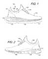
- FIG. 1is a side view of a shoe
- FIG. 2is an opposed side view of the shoe of FIG. 1 ;
- FIG. 3is a top perspective view of a sole of a shoe (having a shoe upper removed and a foot contacting member folded aside) incorporating one embodiment of a sensor system according to aspects of the present invention
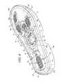
- FIG. 4is a top perspective view of the sole and the sensor system of FIG. 3 , with a foot contacting member of the shoe removed and an electronic module removed;
- FIG. 5is a top perspective view of the sole of FIG. 3 , with the foot contacting member of the shoe removed and without the sensor system;
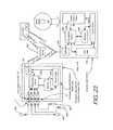
- FIG. 6is a schematic diagram of one embodiment of an electronic module capable of use with a sensor system, in communication with an external electronic device;
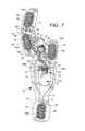
- FIG. 7is a top view of an insert of the sensor system of FIG. 3 , adapted to be positioned within the sole structure of an article of footwear for a user's right foot;
- FIG. 8is a top perspective view of the insert of FIG. 7 ;
- FIG. 9is a top view of the sensor system of FIG. 3 , including the insert of FIG. 7 ;
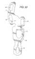
- FIG. 10is a top perspective view of the sensor system of FIG. 9 ;
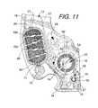
- FIG. 11is a magnified top view of a portion of the sensor system of FIG. 9 ;
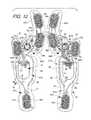
- FIG. 12is a top view of the sensor system of FIG. 9 and a similar sensor system adapted for use in the sole structure of an article of footwear for a user's left foot;
- FIG. 13is an exploded perspective view of the insert of FIG. 7 , showing four different layers;
- FIG. 14is a top view of a first layer of the insert of FIG. 13 ;
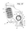
- FIG. 15is a magnified top view of a portion of the first layer of FIG. 14 ;
- FIG. 16is a top view of a second layer of the insert of FIG. 13 ;
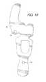
- FIG. 17is a magnified top view of a portion of the second layer of FIG. 16 ;
- FIG. 18is a top view of a spacer layer of the insert of FIG. 13 ;
- FIG. 19is a top view of a bottom layer of the insert of FIG. 13 ;
- FIG. 20is a schematic circuit diagram illustrating one embodiment of a circuit formed by the components of the sensor system of FIG. 9 ;
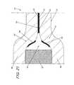
- FIG. 21is magnified cross-sectional view schematically illustrating the area indicated by lines 21 - 21 in FIG. 11 ;
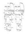
- FIG. 22Ais a bottom view of the sensor system of FIG. 9 ;
- FIG. 22Bis a bottom view of the sensor system as illustrated in FIG. 22A , having filters connected over vents in the sensor system;
- FIG. 22Cis a top view of a spacer layer of another embodiment of an insert for a sensor system according to aspects of the present invention, with broken lines showing positions of sensors;
- FIG. 22Dis a bottom view of an insert for a sensor system incorporating the spacer layer of FIG. 22C , with broken lines showing positions of filters connected to insert;
- FIG. 23is a schematic diagram of the electronic module of FIG. 6 , in communication with an external gaming device;
- FIG. 24is a schematic diagram of a pair of shoes, each containing a sensor system, in a mesh communication mode with an external device;
- FIG. 25is a schematic diagram of a pair of shoes, each containing a sensor system, in a “daisy chain” communication mode with an external device;
- FIG. 26is a schematic diagram of a pair of shoes, each containing a sensor system, in an independent communication mode with an external device;
- FIG. 27is a plot showing pressure vs. resistance for one embodiment of a sensor according to aspects of the present invention.
- FIG. 28is a schematic cross-sectional view of a portion of the sole and sensor system of FIG. 4 ;
- FIG. 29is a schematic cross-sectional view of a portion of another embodiment of a sole and sensor system according to aspects of the present invention.
- FIG. 30is a top view of the sole of FIG. 3 with the foot contacting member in operational position;
- FIG. 31is a cross-sectional view schematically depicting the view taken along lines 31 - 31 of FIG. 10 ;
- FIG. 32is a cross-sectional view schematically depicting the view taken along lines 32 - 32 of FIG. 10 ;
- FIG. 33is an exploded perspective view of another embodiment of a sensor system according to aspects of the present invention.
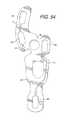
- FIG. 34is an exploded perspective view of another embodiment of a sensor system according to aspects of the present invention.
- FIGS. 35A and 35Bare schematic cross-sectional views of a sensor of the sensor system of FIG. 7 ;
- FIG. 36is a top perspective view of a sole of a shoe (having a shoe upper removed and a foot contacting member folded aside) incorporating another embodiment of a sensor system according to aspects of the present invention
- FIG. 37is a top perspective view of the sole of FIG. 36 , with the foot contacting member of the shoe removed and without the sensor system;
- FIG. 38is a top perspective view of the sole and the sensor system of FIG. 36 , with a foot contacting member of the shoe removed and an electronic module removed;
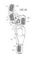
- FIG. 39is a top view of an insert of the sensor system of FIG. 36 , adapted to be positioned within the sole structure of an article of footwear for a user's right foot;
- FIG. 40is a top view of a first layer of the insert of FIG. 39 ;
- FIG. 41is a top view of a second layer of the insert of FIG. 39 ;
- FIG. 42is a top view of a spacer layer of the insert of FIG. 39 ;
- FIG. 43is a top view of a bottom layer of the insert of FIG. 39 ;
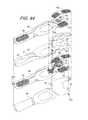
- FIG. 44is an exploded perspective view of the insert of FIG. 39 , showing four different layers;
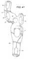
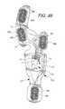
- FIG. 45is a top perspective view of a sole of a shoe (having a shoe upper removed and a foot contacting member folded aside) incorporating another embodiment of a sensor system according to aspects of the present invention
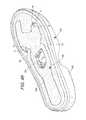
- FIG. 46is a top perspective view of the sole of FIG. 45 , with the foot contacting member of the shoe removed and without the sensor system;
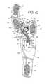
- FIG. 47is a top perspective view of the sole and the sensor system of FIG. 45 , with a foot contacting member of the shoe removed and an electronic module removed;
- FIG. 48is a top view of another embodiment of an insert of the sensor system adapted to be positioned within the sole structure of an article of footwear for a user's right foot, according to aspects of the present invention
- FIG. 49is a top view of a first layer of the insert of FIG. 48 ;
- FIG. 50is a top view of a spacer layer of the insert of FIG. 48 ;
- FIG. 51is a top view of a second layer of the insert of FIG. 48 ;
- FIG. 52is a top view of another embodiment of an insert of a sensor system according to aspects of the present invention.
- FIG. 53is a top view of a first layer of the insert of FIG. 52 ;
- FIG. 54is a top view of a spacer layer of the insert of FIG. 52 ;
- FIG. 55is a top view of a second layer of the insert of FIG. 52 ;
- FIG. 56is a cross-sectional view taken along lines 56 - 56 in FIG. 52 ;
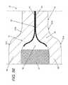
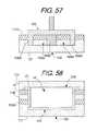
- FIG. 57is a schematic cross-sectional view illustrating one embodiment of a method and equipment for forming a well in a sole structure of an article of footwear, according to aspects of the present invention
- FIG. 58is a schematic cross-sectional view illustrating the sole structure of the article of footwear of FIG. 57 with an insert member of a sensor system and a foot contacting member connected thereto;
- FIG. 59is a schematic cross-sectional view illustrating another embodiment of a sensor system positioned within a sole structure of an article of footwear, according to aspects of the present invention.
- FIG. 59Ais a schematic cross-sectional view illustrating another embodiment of a sensor system positioned within a sole structure of an article of footwear, according to aspects of the present invention.
- FIG. 60is a perspective view of one embodiment of a foot contacting member configured for use with a sensor system according to aspects of the present invention.
- FIG. 61is a perspective view of another embodiment of a sensor system according to aspects of the present invention.
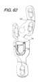
- FIGS. 62-64illustrate a plan view and perspective views of the port in the insert member according to aspects of the invention.
- FIGS. 65-67illustrate components of a housing of the port
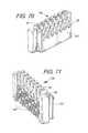
- FIGS. 68-71illustrate views of an interface assembly used in the port
- FIGS. 72-73illustrate views of the interface assembly operably connected to the insert member
- FIG. 74is a partial enlarged plan view of the port connected to the insert member and having a cover member removed;
- FIGS. 75-76are side elevation views of the port attached to the insert member
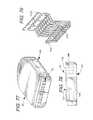
- FIGS. 77-78are additional views of the module according to aspects of the invention.
- FIGS. 79-80are perspective views of contacts and a module carrier according to aspects of the invention.
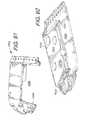
- FIGS. 81-83are perspective view of components of the module
- FIG. 84is a partial cross-sectional view showing over-molding of contacts of an interface of the module
- FIGS. 85-86are plan views of the module showing a light assembly according to aspects of the invention.
- FIGS. 87-90are internal views of the module showing components of the light assembly.
- FIGS. 91-94are views of a PCB and a ground plane extender associated with the module according to aspects of the invention.
- Footwearsuch as a shoe
- the footwear 100can take many different forms, including, for example, various types of athletic footwear.
- the shoe 100generally includes a force and/or pressure sensor system 12 operably connected to a universal communication port 14 .
- the sensor system 12collects performance data relating to a wearer of the shoe 100 .
- the universal communication port 14Through connection to the universal communication port 14 , multiple different users can access the performance data for a variety of different uses as described in greater detail below.
- FIGS. 1-2An article of footwear 100 is depicted in FIGS. 1-2 as including an upper 120 and a sole structure 130 .
- footwear 100may be divided into three general regions: a forefoot region 111 , a midfoot region 112 , and a heel region 113 , as illustrated in FIG. 1 .
- Regions 111 - 113are not intended to demarcate precise areas of footwear 100 . Rather, regions 111 - 113 are intended to represent general areas of footwear 100 that provide a frame of reference during the following discussion. Although regions 111 - 113 apply generally to footwear 100 , references to regions 111 - 113 also may apply specifically to upper 120 , sole structure 130 , or individual components included within and/or formed as part of either upper 120 or sole structure 130 .
- the upper 120is secured to sole structure 130 and defines a void or chamber for receiving a foot.
- upper 120includes a lateral side 121 , an opposite medial side 122 , and a vamp or instep area 123 .
- Lateral side 121is positioned to extend along a lateral side of the foot (i.e., the outside) and generally passes through each of regions 111 - 113 .
- medial side 122is positioned to extend along an opposite medial side of the foot (i.e., the inside) and generally passes through each of regions 111 - 113 .
- Vamp area 123is positioned between lateral side 121 and medial side 122 to correspond with an upper surface or instep area of the foot.
- Vamp area 123in this illustrated example, includes a throat 124 having a lace 125 or other desired closure mechanism that is utilized in a conventional manner to modify the dimensions of upper 120 relative the foot, thereby adjusting the fit of footwear 100 .
- Upper 120also includes an ankle opening 126 that provides the foot with access to the void within upper 120 .
- a variety of materialsmay be used for constructing upper 120 , including materials that are conventionally utilized in footwear uppers.
- upper 120may be formed from one or more portions of leather, synthetic leather, natural or synthetic textiles, polymer sheets, polymer foams, mesh textiles, felts, non-woven polymers, or rubber materials, for example.
- the upper 120may be formed from one or more of these materials wherein the materials or portions thereof are stitched or adhesively bonded together, e.g., in manners that are conventionally known and used in the art.
- Upper 120may also include a heel element (not shown) and a toe element (not shown).
- the heel elementwhen present, may extend upward and along the interior surface of upper 120 in the heel region 113 to enhance the comfort of footwear 100 .
- the toe elementwhen present, may be located in forefoot region 111 and on an exterior surface of upper 120 to provide wear-resistance, protect the wearer's toes, and assist with positioning of the foot.
- one or both of the heel element and the toe elementmay be absent, or the heel element may be positioned on an exterior surface of the upper 120 , for example.
- upper 120may exhibit the configuration of any desired conventional or non-conventional upper structure without departing from this invention.
- the sole structure 130is secured to a lower surface of upper 120 and may have a generally conventional shape.
- the sole structure 130may have a multipiece structure, e.g., one that includes a midsole 131 , an outsole 132 , and a foot contacting member 133 .
- the foot contacting member 133is typically a thin, compressible member that may be located within the void in upper 120 and adjacent to a lower surface of the foot (or between the upper 120 and midsole 131 ) to enhance the comfort of footwear 100 .
- the foot contacting member 133may be a sockliner, a strobel, an insole member, a bootie element, a sock, etc.
- the foot contacting member 133is an insole member or a sockliner.
- the term “foot contacting member,” as used hereindoes not necessarily imply direct contact with the user's foot, as another element may interfere with direct contact. Rather, the foot contacting member forms a portion of the inner surface of the foot-receiving chamber of an article of footwear. For example, the user may be wearing a sock that interferes with direct contact.
- the sensor system 12may be incorporated into an article of footwear that is designed to slip over a shoe or other article of footwear, such as an external bootie element or shoe cover.
- the upper portion of the sole structuremay be considered a foot contacting member, even though it does not directly contact the foot of the user.
- an insole or socklinermay be absent, and in other embodiments, the footwear 100 may have a foot contacting member positioned on top of an insole or sockliner.
- Midsole member 131may be or include an impact attenuating member, and may include multiple members or elements in some embodiments.
- the midsole member 131may be formed of polymer foam material, such as polyurethane, ethylvinylacetate, or other materials (such as phylon, phylite, etc.) that compress to attenuate ground or other contact surface reaction forces during walking, running, jumping, or other activities.
- the polymer foam materialmay encapsulate or include various elements, such as a fluid-filled bladder or moderator, that enhance the comfort, motion-control, stability, and/or ground or other contact surface reaction force attenuation properties of footwear 100 .
- the midsole 131may include additional elements that compress to attenuate ground or other contact surface reaction forces.
- the midsole 131may include column type elements to aid in cushioning and absorption of forces.
- Outsole 132is secured to a lower surface of midsole 131 in this illustrated example footwear structure 100 and is formed of a wear-resistant material, such as rubber or a flexible synthetic material, such as polyurethane, that contacts the ground or other surface during ambulatory or other activities.
- the material forming outsole 132may be manufactured of suitable materials and/or textured to impart enhanced traction and slip resistance.
- the outsole 132 shown in FIGS. 1 and 2is shown to include a plurality of incisions or sipes 136 in either or both sides of the outsole 132 , although many other types of outsoles 132 with various types of treads, contours, and other structures may be used in connection with the present invention. It is understood that embodiments of the present invention may be used in connection with other types and configurations of shoes, as well as other types of footwear and sole structures.
- FIGS. 1-5illustrate exemplary embodiments of the footwear 100 incorporating a sensor system 12 in accordance with the present invention
- FIGS. 3-22Billustrate exemplary embodiments of the sensor system 12
- the sensor system 12includes an insert member 37 having a force and/or pressure sensor assembly 13 connected thereto.
- the insert member 37is configured to be positioned in contact with the sole structure 130 of the footwear 100 , and in one embodiment, the insert member 37 is configured to be positioned underneath the foot contacting member 133 and over the top of the midsole member 131 and in general confronting relation.
- the sensor assembly 13includes a plurality of sensors 16 , and a communication or output port 14 in communication with the sensor assembly 13 (e.g., electrically connected via conductors).
- the port 14is configured for communicating data received from the sensors 16 , such as to an electronic module (also referred to as an electronic control unit) 22 as described below.
- the port 14 and/or the module 22may be configured to communicate with an external device, as also described below.
- the system 12has four sensors 16 : a first sensor 16 a at the big toe (first phalange or hallux) area of the shoe, two sensors 16 b - c at the forefoot area of the shoe, including a second sensor 16 b at the first metatarsal head region and a third sensor 16 c at the fifth metatarsal head region, and a fourth sensor 16 d at the heel. These areas of the foot typically experience the greatest degree of pressure during movement.
- Each sensor 16is configured for detecting a pressure exerted by a user's foot on the sensor 16 .
- the sensorscommunicate with the port 14 through sensor leads 18 , which may be wire leads and/or another electrical conductor or suitable communication medium.
- the sensor leads 18may be an electrically conductive medium that is printed on the insert member 37 , such as a silver-based ink or other metallic ink, such as an ink based on copper and/or tin.
- the leads 18may alternately be provided as thin wires in one embodiment. In other embodiments, the leads 18 may be connected to the foot contacting member 133 , the midsole member 131 , or another member of the sole structure 130 .
- the sensor system 12may contain a different number or configuration of sensors 16 , and generally include at least one sensor 16 .
- the system 12includes a much larger number of sensors, and in another embodiment, the system 12 includes two sensors, one in the heel and one in the forefoot of the shoe 100 .
- the sensors 16may communicate with the port 14 in a different manner, including any known type of wired or wireless communication, including Bluetooth and near-field communication.
- a pair of shoesmay be provided with sensor systems 12 in each shoe of the pair, and it is understood that the paired sensor systems may operate synergistically or may operate independently of each other, and that the sensor systems in each shoe may or may not communicate with each other. The communication of the sensor systems 12 is described in greater detail below.
- the sensor system 12may be provided with computer programs/algorithms to control collection and storage of data (e.g., pressure data from interaction of a user's foot with the ground or other contact surface), and that these programs/algorithms may be stored in and/or executed by the sensors 16 , the module 22 , and/or the external device 110 .
- datae.g., pressure data from interaction of a user's foot with the ground or other contact surface
- these programs/algorithmsmay be stored in and/or executed by the sensors 16 , the module 22 , and/or the external device 110 .
- the sensor system 12can be positioned in several configurations in the sole 130 of the shoe 100 .
- the port 14 , the sensors 16 , and the leads 18can be positioned between the midsole 131 and the foot contacting member 133 , such as by positioning the insert member 37 between the midsole 131 and the foot contacting member 133 .
- the insert member 37may be connected to one or both of the midsole and the foot contacting member 133 in one embodiment.
- a cavity or well 135can be located in the midsole 131 ( FIG. 5 ) and/or in the foot contacting member 133 for receiving the electronic module 22 , as described below, and the port 14 may be accessible from within the well 135 in one embodiment.
- the well 135may further contain a housing 24 for the module 22 , and the housing 24 may be configured for connection to the port 14 , such as by providing physical space for the port 14 and/or by providing hardware for interconnection between the port 14 and the module 22 .
- the well 135is formed by a cavity in the upper major surface of the midsole 131 .
- the sole structure 130may include a compressible sole member 138 that has a hole formed therein to receive the housing 24 , which provides access to the well 135 and/or may be considered a portion of the well 135 .
- the insert 37can be placed on top of the compressible sole member 138 to place the housing 24 in the well 135 .
- the compressible sole member 138may confront the midsole 131 in one embodiment, and may be in direct contact with the midsole 131 . It is understood that the compressible sole member 138 may confront the midsole 131 with one or more additional structures positioned between the compressible sole member 138 and the midsole 131 , such as a strobel member.
- the compressible sole member 138is in the form of a foam member 138 (e.g. an EVA member) located between the foot contacting member 133 and the midsole 131 , which may be considered a lower insole/sockliner in this embodiment.
- the foam member 138may be bonded to a strobel 133 A ( FIG.
- the housing 24has a plurality of walls, including side walls 25 and a base wall 26 , and also includes a flange or lip 28 that extends outward from the tops of the side walls 25 and is configured for connection to the insert 37 .
- the flange 28is a separate member that connects to a tub 29 to form the housing 24 , via pegs 28 A that connect through holes 28 B in the insert 37 located at the front end of the hole 27 .
- the pegs 28 Amay be connected via ultrasonic welding or other technique, and may be received in receivers in one embodiment.
- an article of footwear 100may be manufactured with the tub 29 formed in the sole structure 130 , and the flange 28 may be later connected, such as by a snap connection, optionally after other portions of the port have also been assembled.
- the housing 24may include retaining structure to retain the module 22 within the housing 24 , and such retaining structure may be complementary with retaining structure on the module 22 , such as a tab/flange and slot arrangement, complementary tabs, locking members, friction-fit members, etc.
- the housing 24also includes a finger recess 29 A located in the flange 28 and/or the tub 29 , which provides room for the user's finger to engage the module 22 to remove the module 22 from the housing 24 .
- the flange 28provides a wide base engaging the top of the insert 37 , which spreads out the forces exerted on the insert 37 and/or on the foot contacting member 133 by the flange 28 , which creates less likelihood of severe deflection and/or damage of such components.
- the rounded corners on the flange 28also assists in avoiding damage to the insert 37 and/or the foot contacting member 133 . It is understood that the flange 28 may have a different shape and/or contour in other embodiments, and may provide similar functionality with different shapes and/or contours.
- the foot contacting member 133is configured to be placed on top of the foam member 138 to cover the insert 37 , and may contain an indent 134 in its lower major surface to provide space for the housing 24 , as shown in FIG. 3 .
- the foot contacting member 133may be adhered to the foam member 138 , and in one embodiment, may be adhered only in the forefoot region to permit the foot contacting member 133 to be pulled up to access the module 22 , as shown in FIG. 3 .
- the foot contacting member 133may include a tacky or high-friction material (not shown) located on at least a portion of the underside to resist slippage against the insert 37 and/or the foam member 138 , such as a silicone material.
- the foot contacting member 133may have the tacky material located on the heel region.
- the tacky materialmay also provide enhanced sealing to resist penetration of dirt into the sensor system.
- the foot contacting member 133may include a door or hatch 137 configured to be located over the port 14 and sized to permit insertion and/or removal of the module 22 through the foot contacting member 133 .
- the embodiment of the foot contacting member 133 shown in FIG. 60may be usable in place of the foot contacting member 133 in FIG. 3, 36 , or 45 , to provide access to the port 14 and the module 22 .
- the door 137has a hinge 137 A formed by material attachment along one edge of the door 137 , allowing the door 137 to be opened and closed by swinging. Additionally, the door 137 is formed of the same material as the foot contacting member 133 in this embodiment, so that no significant loss of cushioning is lost by inclusion of the door 137 . Further, the door 137 may have a tab 137 B or other structure to aid in gripping and manipulation of the door 137 by the user. In one embodiment, the sensor system 12 may be positioned on the underside of the foot contacting member 133 , and the door 137 may provide access to the port 14 in such an embodiment (not shown). In another embodiment, the door 137 may have a hinge on another edge, or may open in a different manner, such as by removal, sliding, etc. In one embodiment, the foot contacting member 133 may also have graphic indicia 92 thereon, as described below.
- the foam member 138may also include a recess 139 having the same peripheral shape as the insert 37 to receive the insert 37 therein, and the bottom layer 69 ( FIG. 13 ) of the insert member 37 may include adhesive backing to retain the insert 37 within the recess 139 .
- a relatively strong adhesivesuch as a quick bonding acrylic adhesive, may be utilized for this purpose.
- the insert 37has a hole or space 27 for receiving and providing room for the housing 24 , and the foam member 138 in this embodiment may also allow the housing 24 to pass completely through into and/or through at least a portion of the strobel and/or the midsole 131 . In the embodiment shown in FIGS.
- the foot contacting member 133may have a thickness that is reduced relative to a typical foot contacting member 133 (e.g. sockliner), with the thickness of the foam member 138 being substantially equal to the reduction in thickness of the foot contacting member 133 , to provide equivalent cushioning.
- the foot contacting member 133may be a sockliner with a thickness of about 2-3 mm
- the foam member 138may have a thickness of about 2 mm, with the recess 139 having a depth of about 1 mm.
- the foam member 138may be adhesively connected to the insert member 37 prior to connecting the foam member 138 to the article of footwear 100 in one embodiment.
- This configurationpermits the adhesive between the foam member 138 and the insert 37 to set in a flat condition before attaching the foam member to the strobel or other portion of the footwear 100 , which is typically bends or curves the foam member 138 and may otherwise cause delamination.
- the foam member 138 with the insert 37 adhesively attachedmay be provided in this configuration as a single product for insertion into an article of footwear 100 in one embodiment.
- the positioning of the port 14 in FIGS. 3-5not only presents minimal contact, irritation, or other interference with the user's foot, but also provides easy accessibility by simply lifting the foot contacting member 133 .
- the housing 24extends completely through the insert 37 and the foam member 138
- the well 135also extends completely through the strobel 133 A and partially into the midsole 131 of the footwear 100 to receive the housing 24 , as illustrated schematically in FIG. 58 .
- the well 135may be differently configured, and may be positioned completely underneath the strobel 133 A in one embodiment, with a window through the strobel 133 A to permit access to the module 22 in the well 135 .
- the well 135may be formed using a variety of techniques, including cutting or removing material from the strobel 133 A and/or the midsole 131 , forming the strobel 133 A and/or the midsole 131 with the well contained therein, or other techniques or combinations of such techniques.
- a hot knife 109is used to cut through the strobel 133 A and into the midsole 131 to remove a piece 135 A of material to form the well 135 , as illustrated schematically in FIG. 57 .
- the hot knife 109includes a wall 109 A extending around the periphery of the hot knife 109 to define a cavity 109 B that receives the piece 135 A to be removed, as well as prongs 109 C that extend down through the middle of the piece 135 A.
- the wall 109 Acuts down into the strobel 133 A and the midsole 131 to cut the outer boundaries of the piece 135 A to be removed.
- the prongs 109 Cboth weaken the bottom side of the piece 135 A to facilitate removal and also assist in retaining the piece 135 A within the cavity 109 B during removal, so the piece 135 A can be removed by simply lifting the hot knife 109 away from the sole structure 130 .
- the hot knife 109may be heated to a temperature of between 250-260° C.
- a hot knife 109(which may be differently configured) may be utilized to form a differently shaped and/or configured well 135 in the sole structure 130 .
- FIG. 58schematically illustrates the insert 37 connected to the sole structure 130 and the housing 24 received in the well 135 after formation. As shown in FIG. 58 , the housing 24 fits closely with the walls of the well 135 , which can be advantageous, as gaps between the housing 24 and the well 135 may be sources of material failure. The process of removing the piece 135 may be automated using appropriate computer control equipment.
- the well 135may be located elsewhere in the sole structure 130 in further embodiments.
- the well 135may be located in the upper major surface of the foot contacting member 133 and the insert 37 can be placed on top of the foot contacting member 133 .
- the well 135may be located in the lower major surface of the foot contacting member 133 , with the insert 37 located between the foot contacting member 133 and the midsole 131 .
- the well 135may be located in the outsole 132 and may be accessible from outside the shoe 100 , such as through an opening in the side, bottom, or heel of the sole 130 . In the configurations illustrated in FIGS. 3-5 , the port 14 is easily accessible for connection or disconnection of an electronic module 22 , as described below.
- the foot contacting member 133has the insert 37 connected to the bottom surface, and the port 14 and the well 135 are formed in the sole structure 130 , such as in the same configuration described above and shown in FIG. 58 .
- the interface 20is positioned on the side of the housing 24 as similarly shown with respect to other embodiments, although it is understood that the interface 20 could be positioned elsewhere, such as for engagement through the top of the module 22 .
- the module 22may be altered to accommodate such a change.
- the foot contacting member 133may be provided with an opening for accessing the module 22 (such as in FIG. 60 ) or may be able to be pulled upward to access the module 22 , as shown in FIG. 3 .
- FIG. 60the opening for accessing the module 22
- the insert 37is positioned below both the foot contacting member 133 and the strobel 133 A, and in contact with the midsole member 131 .
- the strobel 133 A and/or the foot contacting member 133may be provided with openings for accessing the module 22 and/or may be able to be pulled upward to access the module 22 , as shown in FIG. 3 .
- the sensor system 12can be positioned differently.
- the insert 37can be positioned within the outsole 132 , midsole 131 , or foot contacting member 133 .
- insert 37may be positioned within a foot contacting member 133 positioned above an insole member, such as a sock, sockliner, interior footwear bootie, or other similar article, or may be positioned between the foot contacting member 133 and the insole member. Still other configurations are possible, and some examples of other configurations are described below.
- the sensor system 12may be included in each shoe in a pair.
- the insert member 37 in the embodiment illustrated in FIGS. 3-22Bis formed of multiple layers, including at least a first layer 66 and a second layer 68 .
- the first and second layers 66 , 68may be formed of a flexible film material, such as a Mylar® or other PET (polyethylene terephthalate) film, or another polymer film, such as polyamide.
- the first and second layers 66 , 68may each be PET films having thicknesses of 0.05-0.2 mm, such as a thickness of 125 ⁇ m.
- each of the first and second layers 66 , 68has a minimum bend radius of equal to or less than 2 mm.
- the insert 37may further include a spacer layer 67 positioned between the first and second layers 66 , 68 and/or a bottom layer 69 positioned on the bottom of the insert 37 below the second layer 68 , which are included in the embodiment illustrated in FIGS. 3-22B .
- the layers 66 , 67 , 68 , 69 of the insert 37are stacked on top of each other and in confronting relation to each other, and in one embodiment, the layers 66 , 67 , 68 , 69 all have similar or identical peripheral shapes and are superimposed on one another ( FIG. 13 ).
- the spacer layer 67 and the bottom layer 69may each have a thickness of 89-111 ⁇ m, such as a thickness of 100 ⁇ m.
- the entire thickness of the insert member 37may be about 450 ⁇ m in one embodiment, or about 428-472 ⁇ m in another embodiment, and about 278-622 ⁇ m in a further embodiment.
- the insert 37may also include additional adhesive that is 100-225 ⁇ m thick, and may further include one or more selective reinforcement layers, such as additional PET layers, in other embodiments. Additionally, in one embodiment, the entire four-layer insert as described above has a minimum bend radius of equal to or less than 5 mm. It is understood that the orientations of the first and second layers 66 , 68 may be reversed in another embodiment, such as by placing the second layer 68 as the top layer and the first layer 66 below the second layer 68 . In the embodiment of FIGS.
- the first and second layers 66 , 68have various circuitry and other components printed thereon, including the sensors 16 , the leads 18 , resistors 53 , 54 , a pathway 50 , dielectric patches 80 , and other components, which are described in greater detail below.
- the componentsare printed on the underside of the first layer 66 and on the upper side of the second layer 68 in the embodiment of FIGS. 3-22B , however in other embodiments, at least some components may be printed on the opposite sides of the first and second layers 66 , 68 . It is understood that components located on the first layer 66 and/or the second layer 68 may be moved/transposed to the other layer 66 , 68 .
- the componentsmay be printed on the layers 66 , 68 in a manner so as to limit the total number of printer passes required, and in one embodiment, all the components on an individual layer 66 , 68 may be printed in a single pass.
- the layers 66 , 67 , 68 , 69can be connected together by an adhesive or other bonding material in one embodiment.
- the spacer layer 67may contain adhesive on one or both surfaces in one embodiment to connect to the first and second layers 66 , 68 .
- the bottom layer 69may likewise have adhesive on one or both surfaces, to connect to the second layer 68 as well as to the article of footwear 100 .
- the first or second layers 66 , 68may additionally or alternately have adhesive surfaces for this purpose.
- a variety of other techniquescan be used for connecting the layers 66 , 67 , 68 , 69 in other embodiments, such as heat sealing, spot welding, or other known techniques.
- the insert 37 , the foot contacting member 133 , and/or other components of the sensor system 12 and the footwear 100may also include a graphic design or other indicia (not shown) thereon.
- the graphic designmay be provided on one or more graphic layers (not shown) that may be connected to the insert 37 , such as by overlaying the graphic layer on top of the first layer 66 .
- the graphic designmay correspond to the sensor assembly 13 , leads 18 and the various other components supported by the layer.
- the foot contacting member 133has graphical indicia 92 that forms a graphical depiction of the insert 37 of the sensor system 12 that is positioned below the foot contacting member 133 .
- Other graphical designsmay be used in other embodiments, including informative, stylistic, and other such designs.
- the insert 37 illustrated in FIGS. 3-22Bhas a configuration that may utilize less material than other insert configurations and may provide greater resistance to tearing at common stress points.
- the insert 37has several portions of material cut out of areas of the insert 37 that may be superfluous, such as in the lateral forefoot area or the lateral and medial heel areas.
- the insert 37 in this configurationhas a midfoot portion 37 A configured to be engaged by the midfoot region of the user's foot and a forefoot portion 37 B configured to be engaged by the forefoot (i.e.
- FIGS. 4, 8, 10, and 22Aillustrate these features in greater detail. It is understood that, depending on the shape of the user's foot, the first phalange portion 37 D may engage only the first phalange region of the user's foot.
- the width of the forefoot portion 37 Bis greater than the width of the midfoot portion 37 A, and both the midfoot and forefoot portions 37 A-B have greater width than the first phalange portion 37 D and the heel portion 37 C, such that the first phalange portion 37 D and the heel portion 37 C are configured as peninsulas that extend forward or rearward, respectively, from a base at the wider midfoot and forefoot portions 37 A-B to a free end in elongated manners.
- the width of a portion of the insert 37is measured in the medial-to-lateral direction, and the length is measured in the front-to-rear (toe-to-heel) direction.
- the first phalange portion 37 Dhas one of the sensors 16 a located thereon, to be engaged by the first phalange of the user
- the heel portion 37 Chas another one of the sensors 16 d thereon, to be engaged by the heel of the user.
- the remaining two sensors 16 b , 16 care located on the forefoot portion 37 B of the insert 37 , specifically at the first metatarsal head region and at the fifth metatarsal head region, to be engaged by the first and fifth metatarsal head regions of the user's foot, respectively.
- the midfoot portion 37 Acontains the hole 27 for receiving the housing 24 and module 22 , and the hole 27 defines two strips 88 that extend between and connect the forefoot portion 37 B and the heel portion 37 C.
- the strips 88have minimum widths of 8 mm or widths within a range of 3-5% of the overall length of the insert 37 .
- the length of the insert 37is measured from the forefoot-most end of the first phalange portion 37 D to the heel-most end of the heel portion 37 C.
- These strips 88undergo high stresses during use, and this width assists in avoiding failure during use.
- the strips 88may be reinforced by additional structure.
- the strips 88 and/or other portions of the insert 37may be reinforced by fibers or similar structures.
- the insert 37may include an additional structural layer over at least a portion of the insert 37 in one embodiment, such as an additional structural layer that completely surrounds the housing 24 and occupies the entireties of both strips 88 and the junctures between the strips 88 and the remainder of the insert 37 .
- the insert 37has a peripheral edge defining a periphery of the insert 37 , and including a medial edge 85 extending along the medial side of the insert 37 from the back of the heel portion 37 C to the front end of the first phalange portion 37 D, a lateral edge 86 extending from the back of the heel portion 37 C to the front of the forefoot portion 37 B, and a front edge 87 extending from the lateral edge 86 to the first phalange portion 37 D along second, third, fourth, and fifth metatarsal areas of the insert 37 .
- the medial edge 85 , the lateral edge 86 , and the front edge 87each have a cut-out portion in this embodiment, as shown, for example, in FIGS. 8, 10, and 22A .
- the cut-out portion 87 A along the front edge 87is located between the lateral edge 86 and the first phalange portion (i.e. peninsula) 37 D.
- the cut-out portions 85 A, 86 A along the medial and lateral edges 85 , 86are located proximate the juncture between the forefoot portion 37 B and the midfoot portion 37 A, and the width W 1 of the insert 37 (defined between the medial and lateral edges 85 , 86 ) in the midfoot portion 37 A and the width W 2 in the forefoot portion 37 B are greater than the width W 3 of the insert measured between the first and second cut-outs 85 A, 86 A.
- This configurationcreates a narrowed neck 89 between the midfoot portion 37 A and the forefoot portion 37 B that is narrower than either the midfoot portion 37 A or the forefoot portion 37 B.
- the widths W 1 , W 2 of the midfoot portion 37 A and forefoot portion 37 Bare also greater than the width W 4 measured at the heel portion 37 C, and the forefoot portion 37 B has the greatest relative width W 2 .
- the heel portion 37 C in this embodimentincludes a widened tail portion 37 E that is wider than the more forward portions of the heel portion 37 C, such that the heel portion 37 C increases in width from the midfoot portion 37 A toward the heel end of the insert member 37 .
- each of the cut out portions 85 A, 86 A, 87 Aeach extend inwardly into the body of the insert 37 and generally have a concave and/or indented shape.
- each of the cut out portions 85 A, 86 A, 87 Ahas a smooth and concave inwardly curved (curvilinear) shape, which resists ripping, tearing, or propagation of cracks in the insert 37 .
- each of the cut out portions 85 A, 86 A, 87 Ais at least partially defined by a concave curvilinear edge defining an arc of at least 120°.
- At least one of the cut out portions 85 A, 86 A, 87 Ais at least partially defined by a concave curvilinear edge defining an arc of at least 180°.
- at least the medial and lateral cut out portions 85 A, 86 Aare each at least partially defined by a concave curvilinear edge defining an arc of at least 180°.
- each of the cut out portions 85 A, 86 A, 87 A in this embodimentis bounded on both sides by smoothly curved edges located on the outer periphery of the insert, at the medial, lateral, and front edges 85 , 86 , 87 .
- One or both of the smoothly curved edges bounding each of the cut out portions 85 A, 86 A, 87 A in this embodimentdefines an arc of at least 90°.
- the use of the cut out portions 85 A, 86 A, 87 A in these locations and with these configurationscan increase the durability and longevity of the insert 37 , for example, by resisting ripping, tearing, or propagation of cracks in the insert 37 as described above.
- the cut out portions 85 A, 86 A, 87 Aare positioned in high stress areas, where this damage resistance is most beneficial.
- the insert 37 configured as shown in FIGS. 3-22Bmay have sufficient fatigue resistance to withstand stresses of up to 20 MPa over at least 500,000 cycles.
- the insert 37may have different cut out portions and/or may have cut out portions in the same locations but with different shapes.
- the insert 37 ′ shown in FIGS. 22C-Dhas cut out portions 85 A, 86 A, 87 A in similar locations as compared to the insert 37 of FIGS. 3-22B , with the cut out portions 85 A, 86 A, 87 A having slightly different peripheral shapes.
- the medial cut out portion 85 Adefines a smaller arc as compared to the medial cut out portion 85 A of the insert 37 of FIGS. 3-22B .
- the front cut out portion 87 A of this embodimentdefines a shape that is less symmetrical and evenly curved as compared to the front cut out portion 87 A of the insert 37 of FIGS. 3-22B .
- FIGS. 36-47illustrate additional embodiments of sensor systems 412 , 512 with inserts 437 , 537 that have different shapes and configurations than the sensor system 12 and the insert 37 described above and shown in FIGS. 3-22B .
- the sensor systems 412 , 512 of FIGS. 36-47include many structural and functional features in common with the sensor system 12 of FIGS. 3-22B .
- the sensor systems 412 , 512include sensors 16 that are configured and positioned substantially the same and function in a similar manner as the sensor system 12 of FIGS. 3-22B .
- the sensor systems 412 , 512include two fixed resistors 53 , 54 in parallel and a pathway 50 between the layers 66 , 68 , similar to the sensor system 12 of FIGS. 3-22B .
- the insert 437has cut out portions 85 A, 86 A, 87 A in similar locations as compared to the insert 37 of FIGS. 3-22B , with the cut out portions 85 A, 86 A, 87 A having slightly different peripheral shapes.
- the medial cut out portion 85 Adefines a smaller arc as compared to the medial cut out portion 85 A of the insert 37 of FIGS. 3-22B .
- the front cut out portion 87 A of this embodimentis deeper and defines a larger arc as compared to the front cut out portion 87 A of the insert 37 of FIGS. 3-22B .
- the lateral cut out portion 86 A of this embodimentis shallower and defines a smaller arc as compared to the lateral cut out portion 86 A of the insert 37 of FIGS. 3-22B .
- the insert 437 of FIGS. 36-44has a heel portion 37 C with a substantially constant width, and has no widened tail portion 37 E.
- the insert 537has cut out portions 85 A, 86 A, 87 A in similar locations as compared to the insert 37 of FIGS. 3-22B , with the cut out portions 85 A, 86 A, 87 A having slightly different peripheral shapes.
- the medial cut out portion 85 Adefines a smaller arc as compared to the medial cut out portion 85 A of the insert 37 of FIGS. 3-22B .
- the lateral cut out portion 86 A of this embodimentis shallower and defines a smaller arc as compared to the lateral cut out portion 86 A of the insert 37 of FIGS. 3-22B .
- the insert 45-48is angled steadily from the first phalange portion 37 D toward the fifth metatarsal sensor 16 c , and defines a substantially straight edge that extends directly into the front cut out portion 87 A.
- the resultant front cut out portion 87 Adefines a smaller arc as compared to the front cut out portion 87 A of the insert 37 of FIGS. 3-22B .
- the insert 537 of FIGS. 45-48has a heel portion 37 C with a substantially constant width, and has no widened tail portion 37 E.
- the leads 18 and many other components of the sensor system 512 of FIGS. 45-48are not illustrated and/or referenced herein, and it is understood that such components may be configured similarly or identically to the corresponding components in the sensor system 12 of FIGS. 3-22B and/or the sensor system 412 in FIGS. 36-44 (structurally and/or functionally).
- inserts 37 , 37 ′, 437 , 537may have any number of different configurations, shapes, and structures, and including a different number and/or configuration of sensors 16 , and a different insert structure or peripheral shape.
- any of the inserts 37 , 37 ′, 437 , 537 described hereinmay include some or all of the structural features and the functions associated with such structural features as described above, such as the cut-out portions 85 A, 86 A, 87 A and other features of the peripheral shape, while being contoured, dimensioned, and configured differently.
- any of the inserts 37 , 37 ′, 437 , 537 described hereinmay include additional or different structural features that may provide different shapes and/or functionalities.
- the sensors 16are force and/or pressure sensors for measuring pressure and/or force on the sole 130 .
- the sensors 16have a resistance that decreases as pressure on the sensor 16 increases, such that measurement of the resistance through the port 14 can be performed to detect the pressure on the sensor 16 .
- the sensors 16 in the embodiment illustrated in FIGS. 3-22Bare elliptical or obround in shape, which enables a single sensor size to be utilized in several different shoe sizes.
- the sensors 16 in this embodimenteach include two contacts 40 , 42 , including a first contact 40 positioned on the first layer 66 and a second contact 42 positioned on the second layer 68 .
- the figures illustrating the first layer 66 hereinare top views, and that the electronic structures (including the contacts 40 , the leads 18 , etc.) are positioned on the bottom side of the first layer 66 and viewed through a transparent or translucent first layer 66 unless specifically noted otherwise.
- the contacts 40 , 42are positioned opposite each other and are in superimposed relation to each other, so that pressure on the insert member 37 , such as by the user's foot, causes increased engagement between the contacts 40 , 42 .
- the resistance of the sensor 16decreases as the engagement between the contacts 40 , 42 increases, and the module 22 is configured to detect pressure based on changes in resistance of the sensors 16 .
- the contacts 40 , 42may be formed by conductive patches that are printed on the first and second layers 66 , 68 , such as in the embodiment of FIGS. 3-22B , and the two contacts 40 , 42 may be formed of the same or different materials.
- the leads 18are formed of a material that has a higher conductivity and lower resistivity than the material(s) of the sensor contacts 40 , 42 .
- the patchesmay be formed of carbon black or another conductive carbon material.
- the two contacts 40 , 42may be formed of the same material or two materials with similar hardnesses, which can reduce abrasion and wear due to differences in hardness of the materials in contact with each other.
- the first contacts 40are printed on the underside of the first layer 66
- the second contacts 42are printed on the top side of the second layer 68 , to permit engagement between the contacts 40 , 42 .
- the embodiment illustrated in FIGS. 3-22Bincludes the spacer layer 67 , which has holes 43 positioned at each sensor 16 to permit engagement of the contacts 40 , 42 through the spacer layer 67 , while insulating other portions of the first and second layers 66 , 68 from each other.
- each hole 43is aligned with one of the sensors 16 and permits at least partial engagement between the contacts 40 , 42 of the respective sensor 16 .
- the holes 43are smaller in area than the sensor contacts 40 , 42 , allowing the central portions of the contacts 40 , 42 to engage each other, while insulating outer portions of the contacts 40 , 42 and the distribution leads 18 A from each other (See, e.g., FIGS. 13 and 35A -B).
- the holes 43may be sized to permit engagement between the contacts 40 , 42 over their entire surfaces. It is understood that the size, dimensions, contours, and structure of the sensors 16 and the contacts 40 , 42 may be altered in other embodiments while retaining similar functionality. It is also understood that sensors 16 having the same sizes may be utilized in different sizes of inserts 37 for different shoe sizes, in which case the dimensions of the sensors 16 relative to the overall dimensions of the insert 37 may be different for different insert 37 sizes.
- the sensor system 12may have sensors 16 that are differently configured than the sensors 16 of the embodiment of FIGS. 3-22B .
- FIGS. 33-34illustrate additional embodiments of sensor systems 212 , 312 that have sensors 16 that are configured differently from the sensors 16 in the sensor system 12 of FIGS. 3-22B .
- the contacts 40 , 42 of the sensors 16 in FIGS. 33-34are configured differently from the contacts 40 , 42 of the sensors 16 in the embodiment of FIGS. 3-22B .
- Other components and features of the sensor systems 212 , 312are similar or identical to those of the sensor system 12 of FIGS. 3-22B , including any variations or alternate embodiments described herein.
- FIGS. 33-34illustrate additional embodiments of sensor systems 212 , 312 that have sensors 16 that are configured differently from the sensors 16 in the sensor system 12 of FIGS. 3-22B .
- the contacts 40 , 42 of the sensors 16 in FIGS. 33-34are configured differently from the contacts 40 , 42 of the sensors 16 in the embodiment of FIGS.
- 48-51illustrate an embodiment of a sensor system 712 that includes sensors 16 that have contacts 740 , 742 , 744 that are configured differently from the sensors 16 and contacts 40 , 42 of the embodiment of FIGS. 3-22B .
- the sensors 16may utilize a different configuration that does not include carbon-based or similar contacts 40 , 42 and/or may not function as a resistive sensor 16 . Examples of such sensors include a capacitive pressure sensor or a strain gauge pressure sensor, among other examples.
- the insert 37may include an internal airflow system 70 configured to allow airflow through the insert 37 during compression and/or flexing of the insert 37 .
- FIGS. 9, 11, 13, 18, 22A -B, and 28 - 30illustrate the components of the airflow system 70 in greater detail.
- the airflow system 70may include one or more air passages or channels 71 that lead from the sensors 16 to one or more vents 72 , to allow air to flow from the sensor 16 during compression, between the first and second layers 66 , 68 and outward through the vent(s) 72 to the exterior of the insert 37 .
- the airflow system 70resists excessive pressure buildup during compression of the sensors 16 , and also permits consistent separation of the contacts 40 , 42 of the sensors 16 at various air pressures and altitudes, leading to more consistent performance.
- the channels 71may be formed between the first and second layers 66 , 68 . As shown in FIG. 18 , the spacer layer 67 has the channels 71 formed therein, and the air can flow through these channels 71 between the first and second layers 66 , 68 , to the appropriate vent(s) 72 .
- the vents 72may have filters 73 covering them in one embodiment, as shown in FIG. 22B . These filters 73 may be configured to permit air, moisture, and debris to pass out of the vents 72 and resist moisture and debris passage into the vents 72 .
- the insert 37may not contain a spacer layer, and the channels 71 may be formed by not sealing the layers 66 , 68 together in a specific pattern, such as by application of a non-sealable material.
- the airflow system 70may be considered to be integral with or directly defined by the layers 66 , 68 in such an embodiment.
- the airflow system 70may contain a different number or configuration of air channels 71 , vents 72 , and/or other passages.
- the airflow system 70includes two vents 72 and a plurality of air channels 71 connecting each of the four sensors 16 to one of the vents 72 .
- the spacer layer 67includes holes 43 at each sensor in this embodiment, and the channels 71 are connected to the holes 43 to permit air to flow away from the sensor 16 through the channel 71 .
- two of the sensors 16are connected to each of the vents 72 through channels 71 .
- FIGS. 3-22B, 28, and 30the airflow system 70 includes two vents 72 and a plurality of air channels 71 connecting each of the four sensors 16 to one of the vents 72 .
- the spacer layer 67includes holes 43 at each sensor in this embodiment, and the channels 71 are connected to the holes 43 to permit air to flow away from the sensor 16 through the channel 71 .
- two of the sensors 16are connected to each of the vents 72 through channels 71 .
- the first metatarsal sensor 16 bhas a channel 71 that extends to a vent 72 slightly behind the first metatarsal area of the insert 37
- the first phalangeal sensor 16 ahas a channel 71 that also extends to the same vent 72 , via a passageway that includes traveling through the first metatarsal sensor 16 b
- the first phalangeal sensor 16 ahas a channel 71 that extends from the hole 43 at the first phalangeal sensor 16 a to the hole 43 at the first metatarsal sensor 16 b
- another channel 71extends from the first metatarsal sensor 16 b to the vent 72 .
- the fifth metatarsal sensor 16 c and the heel sensor 16 dalso share a common vent 72 , located in the heel portion of the insert 37 .
- One channel 71extends rearward from the hole 43 at the fifth metatarsal sensor 16 c to the vent 72 , and another channel 71 extends forward from the hole 43 at the heel sensor 16 d to the vent 72 . Sharing the vents 72 among multiple sensors can decrease expense, particularly by avoiding the need for additional filters 73 .
- the airflow system 70may have a different configuration, such as the configuration shown in FIGS. 22C-D and discussed below.
- each sensor 16may have its own individual vent 72 , or more than two sensors 16 may share the same vent 72 .
- Each vent 72is formed as an opening in a bottom side of the second layer 68 (i.e. opposite the first layer 66 ), such that the opening permits outward flow of air, moisture, and/or debris from the airflow system 70 , as seen in FIGS. 16-18 and 22A -B.
- the vent 72may include multiple openings.
- the vent 72may additionally or alternately be formed by an opening in the first layer 66 , causing the air to vent upwards out of the insert 37 .
- the vent 72may be on the side (thin edge) of the insert 37 , such as by extending the channel 71 to the edge, such that the channel 71 opens through the edge to the exterior of the insert 37 .
- the venting of the air downwardmakes it more difficult for debris to enter the vent 72 .
- the bottom layer 69also includes apertures 74 located below the vents 72 , to permit the air flowing out of the vents 72 to pass through the bottom layer 69 .
- the apertures 74are significantly larger than the vents 72 , in order to allow the filters 73 to be adhesively attached to the second layer 68 through the bottom layer 69 around the periphery of each vent 72 , as described below.
- each vent 72has a reinforcement material 75 positioned around the vent 72 , to add stability and strength to the material and prevent breaking/tearing.
- the reinforcement material 75is formed of the same material as the leads 18 (e.g. silver or other metallic ink) to facilitate printing, but may also be formed of the same material as the sensor contacts 40 , 42 (e.g. carbon) or the dielectric material discussed herein.
- each cavity 76is formed as a slot that extends completely through the foam member 138 , which may be formed by punching, cutting, or another technique.
- the cavity 76may be a recess that extends through only a portion of the foam member 138 , or may extend deeper than the foam member 138 , such as through at least a portion of a structure below the foam member 138 (e.g. a strobel, midsole, etc.).
- the sole structuremay not contain the foam member 138 , and the cavity 76 may be formed at least in part by a slot, recess, or other cavity-like structure in another sole member, such as a strobel, midsole, etc.
- at least a portion of the cavity 76may be circular in one embodiment, and may extend wider than the vent 72 to provide space for air venting.
- the insert 37may be positioned above another sole member (such as a portion of the midsole 131 ), which may contain one or more cavities 76 as described above. In a further embodiment, no cavity may be present, and the air may vent 72 directly downward into the foam member 138 or other sole member.
- One or both of the cavities 76may have extending portions that form passages 77 that further allow air to pass out of the cavity 76 .
- each of the cavities 76has a channel portion 77 extending laterally away from the cavity 76 and beyond the peripheral boundary of the insert 37 .
- the channel portion 77 of the cavity 76extends laterally from the vent 72 to a distal end 78 located outside the peripheral boundary of the insert 37 . It is understood that if the foam member 138 has a recess 139 to receive the insert member 37 , the distal end 78 of the channel portion 77 of the cavity 76 may also be located outside the peripheral boundary of the recess 139 . In the embodiment shown in FIGS. 3-5 , the distal end 78 extends to the edge of the foam member 138 . This configuration permits air passing into the cavity 76 to exit the sole structure 130 by passing laterally through the channel portion 77 and then upward and/or outward away from the foam member 138 . FIG.
- FIGS. 3-5, 28, and 30show a schematic cross-section of this configuration, with arrows illustrating the flow of air.
- the configuration illustrated in FIGS. 3-5, 28, and 30permits air flow out of the vent 72 , and possibly back into the vent 72 , while resisting migration of debris (e.g. dirt, fibers, etc.) and moisture from migrating to and through the vent 72 .
- debrise.g. dirt, fibers, etc.
- the combined downward, lateral, and upward paths that the air must pass through to travel to and from the vent 72acts to resist this migration, and debris will often become trapped near the distal end 78 of the cavity 76 , much like a drain trap in a plumbing application.
- the distal end 78may stop at a point within the foam member 138 and still outside the peripheral boundary of the insert 37 , which allows the air to vent upward out of the cavity 76 at the distal end 78 and provides the same or similar functionality.
- FIGS. 36-38 and 47illustrate an example embodiment of this configuration. It is understood that the foot contacting member 133 in the embodiments of FIGS. 36-38 and 47 may include passages positioned around the distal ends 78 of the cavities 76 to allow air passage through the foot contacting member 133 , such as the passages 79 shown in FIGS. 28 and 30 . In a further embodiment, at least a portion of the channel portion 77 may be a tunnel within the foam member 138 , rather than a slit.
- the channel portion 77may have a tunnel portion and an open portion that permits air passing through the tunnel to vent upward, or the tunnel portion may extend all the way to the edge of the foam member 138 to permit sideways venting.
- FIG. 29shows a cross-section of an alternate embodiment, where the foam member 138 contains a cavity 76 but no channel portion 77 .
- the foot contacting member 133includes one or more passages 79 extending through the foot contacting member 133 located at the distal end 78 of the cavity 76 , in the embodiment of FIGS. 3-5, 28, and 30 .
- the passages 79may be pinhole-type passages 79 that extend vertically through the foot contacting member 133 .
- a different type of passage 79may be used, including slits or grooves, and at least one passage 79 may extend laterally to a side of the foot contacting member 133 , rather than upward through the thickness of the foot contacting member 133 .
- the passages 79allow the air exiting through the vent 72 and outward through the cavity 76 to pass through the foot contacting member 133 and out of the sole structure 130 .
- the foot contacting member 133may not include any passage(s) 79 .
- the foot contacting member 133may still provide ventilation in a configuration without any passage(s) 79 , such as by using a breathable foam or other breathable material for constructing the foot contacting member 133 .
- the insert 37may have one or more filters 73 that at least partially cover the vent(s) 72 , as seen in FIGS. 22B and 28-29 .
- the filter 73may be considered to be a selectively permeable closure that covers the vent 72 , which at least allows passage of air out of the vent 72 and resists passage of certain undesirable substances into the vent.
- the filter 73is a selectively permeable closure that permits inward and outward flow of air, and also permits outward flow of moisture, while resisting the inward flow of moisture and/or particles.
- filter 73that may achieve this function is a fluoroplastic porous membrane, for example, a porous membrane comprising PTFE (i.e. Teflon) fibers.
- a porous membranemay be a 10 ⁇ m to 100 ⁇ m thick porous membrane in one embodiment.
- the high surface energy of the PTFEcauses water to ball up on the surface of the filter 73 , rather than penetrating.
- the filter 73may also have an adhesive on one side to permit the filter 73 to be connected to the insert 37 , and may further have another material connected to either the inward or outward facing side, such as a polyester material to provide shear strength for the porous membrane.
- a polyester materialto provide shear strength for the porous membrane.
- the filter 73is adhesively attached to the bottom side of the second layer 68 around the periphery of the vent 72 to cover the vent 72 .
- the bottom layer 69includes apertures 74 that are significantly larger than the vents 72 , in order to allow the filters 73 to be adhesively attached to the second layer 68 , in the embodiment of FIGS. 3-22B, 28, and 30 .
- a different type of filter 73may be used, and/or the filter 73 may be connected to the insert 37 in another manner.
- no filter 73may be used.
- FIGS. 36-44illustrate a sensor system 412 with an insert 437 that includes an airflow system 70 with a different arrangement of channels 71 and vents 72 than the insert 37 described above and shown in FIGS. 3-22B .
- FIGS. 22C-D and FIGS. 45-47illustrate additional embodiments of insert members 37 ′, 537 that include an airflow system 70 with a channels 71 and vents 72 arranged similarly to the insert 437 of FIGS. 36-44 .
- the positions of the sensors 16 a - d in the embodiment of FIGS. 22C-Dare generally the same as in the embodiment of FIGS. 3-22B, 28, and 30 , and are illustrated in broken lines on the spacer layer 67 in FIG. 22C .
- the first phalangeal sensor 16 a and the first metatarsal sensor 16 bare connected to the same vent 72 by channels 71 in substantially the same configuration described above.
- the fifth metatarsal sensor 16 c and the heel sensor 16 dalso share a common vent 72 , which is located in the fifth metatarsal area of the insert 437 , rather than in the heel portion as in the embodiment of FIGS. 3-22B, 28, and 30 .
- the heel sensor 16 dhas a channel 71 that extends from the hole 43 at the heel sensor 16 d to the hole 43 at the fifth metatarsal sensor 16 c , and another channel 71 extends from the fifth metatarsal sensor 16 c to the vent 72 .
- the locations of the vents 72are different from the embodiment described above, and accordingly, the insert 437 may be used with a sole structure 130 that contains features specifically adapted for vents 72 in these locations.
- FIGS. 36-38illustrate a sole structure 130 and a foam member 138 that includes cavities 76 positioned for cooperation with the vents 72 of the insert 437 . These cavities 76 function similarly to the cavities 76 of the embodiment shown in FIGS.
- the foam member 138has a cavity 76 in the fifth metatarsal area of the sole structure 130 extending forward beyond the peripheral edge of the insert 437 in order to provide venting of air from the vent 72 in the fifth metatarsal area of the insert 437 .
- the foam member 138also has a cavity 76 in the first metatarsal area of the sole structure 130 extending rearward beyond the peripheral edge of the insert 437 in order to provide venting of air from the vent 72 in the first metatarsal area of the insert 437 .
- the inserts 37 ′, 537 of FIGS. 22C-D and 45 - 47may utilize foam members 138 with cavities 76 positioned in similar locations in various embodiments.
- cavities 76may be utilized in other embodiments.
- a single sole structure 130may contain multiple cavities 76 arranged for use with several different types of inserts 37 , 37 ′, 437 , 537 having different vent 72 locations.
- at least some of the cavities 76may be unused, depending on the configuration of the insert 37 , et seq.
- any of the features, characteristics, etc., of the embodiments of airflow systems 70 described hereinmay be combined with other embodiments of airflow systems 70 , as well as other embodiments of sensor systems 12 , inserts 37 , and/or footwear 100 .
- the spacer layer 67generally insulates conductive members/components on the first and second layers 66 , 68 from each other, except in areas where electrical contact is desired, such as at the pathway 50 and between the contacts 40 , 42 of the sensors 16 .
- the spacer layer 67has holes 38 , 43 to define areas of desired electrical contact between the layers 66 , 68 .
- the components of the airflow system 70in particular the channels 71 may provide a route for shorting or other undesired electrical contact by one or more conductive members between the first and second layers 66 , 68 .
- the sensor system 12may include one or more patches of dielectric material 80 to resist or prevent undesired shorting by one or more conductive members across open areas of the spacer layer 67 , such as the channels 71 .
- This dielectric material 80may be in the form of an acrylic ink or other UV-curable ink, or another insulating material suitable for the application.
- the insert 37has several patches of dielectric material 80 extending across the channel 71 , to insulate the distribution leads 18 A located around the sensor contacts 40 , 42 from each other. As shown in FIGS.
- the dielectric material 80is connected to the top side of the second layer 68 and covers the distribution lead 18 A, although in another embodiment, the dielectric material 80 may be connected to the first layer 66 , 68 , or both layers may have the dielectric material 80 .
- the spacer layer 67may have a dielectric “bridge” over the channel 71 in a further embodiment. Additionally, the dielectric material completely covers a portion of the distribution lead 18 A and is wider than the width of the channel 71 , which compensates for movement or displacement of the spacer layer 67 or differences in manufacturing tolerances.
- the insert 37has patches of the dielectric material 80 located at each intersection of one of the channels 71 with the distribution leads 18 A, including one patch 80 on the rear side of the first phalangeal sensor 16 a , two patches 80 on the front and rear ends of the first metatarsal sensor 16 b , one patch 80 on the rear side of the fifth metatarsal sensor 16 c , and one patch 80 on the front side of the heel sensor 16 d .
- the insert 37may have patches of the dielectric material located elsewhere on the insert 37 , to insulate other portions of the distribution leads 18 A or other conductive members from shorting between the layers 66 , 68 .
- a spacer layer 67 having a different configuration with holes, apertures, openings, etc. that are differently shaped and/or locatedmay give rise to the use of the dielectric material 80 in other locations for insulation purposes.
- the dielectric material 80may be used in other places as a reinforcement or stiffening material.
- the port 14 , the sensors 16 , and the leads 18form a circuit 10 on the insert member 37 .
- the port 14has a plurality of terminals 11 , with four terminals 11 each dedicated to one of the four sensors 16 individually, one terminal 11 for applying a voltage to the circuit 10 , and one terminal 1 for voltage measurement.
- the sensor system 12also includes a pair of resistors 53 , 54 , each located on one of the layers 66 , 68 , and a pathway 50 connecting the circuitry on the first layer 66 with the circuitry on the second layer 68 .
- the resistors 53 , 54provide a reference point for the module 22 to measure the resistance of each sensor 16 , and permit the module 22 to convert the variable current from the active sensor 16 into a measurable voltage. Additionally, the resistors 53 , 54 are arranged in parallel within the circuit 10 , which compensates for variations in the circuit 10 and/or variations in the manufacturing processes used to create the resistors 53 , 54 , such as variations in conductivity of the inks used to print the leads 18 and/or the sensor contacts 40 , 42 . In one embodiment, the equivalent resistance of the two resistors 53 , 54 is 1500+/ ⁇ 500 k ⁇ . In another embodiment, a single resistor 53 , 54 or two resistors 53 , 54 in series could be used. In a further embodiment, the resistors 53 , 54 may be positioned elsewhere on the insert 37 , or may be located within the circuitry of the module 22 . A more technical depiction of the circuit 10 of this embodiment is described below and shown in FIG. 20 .
- FIG. 20illustrates a circuit 10 that may be used to detect and measure pressure in accordance with an embodiment of the invention.
- the circuit 10includes six terminals 104 a - 104 f , including a power terminal 104 a for applying a voltage to the circuit 10 , a measurement terminal 104 b for measuring a voltage as described below, and four sensor terminals 104 c - 104 f , each of which is dedicated to one of the sensors 16 a - 16 d individually, and each of which represents ground in this embodiment.
- the terminals 104 a - 104 frepresent the terminals 11 of the port 14 .
- fixed resistors 102 a and 102 bwhich represent resistors 53 and 54 , are connected in parallel.
- fixed resistors 102 a and 102 bElectrically connecting fixed resistors 102 a and 102 b in parallel compensates for variations in the manufacturing processes used to create fixed resistors 102 a and 102 b .
- the deviation of the equivalent resistance determined by equation 1is minimized by the averaging effect of fixed resistor 102 b .
- two fixed resistorsare shown for illustration purposes only. Additional fixed resistors may be connected in parallel and each fixed resistor may be formed on a different layer.
- each of sensors 16 a - 16 dmay be implemented with variable resistors that change resistance in response to changes in pressure, as described above.
- Each of sensors 16 a - 16 dmay be implemented with multiple variable resistors.
- each of sensors 16 a - 16 dis implemented with two variable resistors which are physically located on different layers and electrically connected in parallel.
- each sensor 16 a - 16 dmay contain two contacts 40 , 42 that engage each other to a greater degree as applied pressure increases, and the resistance of the sensor 16 a - 16 d may decrease as the engagement increases.
- the contacts 40 , 42may be arranged in series.
- Sensors 16 a - 16 dmay be connected to ground via switches 108 a - 108 d .
- Switches 108 a - 108 dmay be closed one at a time to connect a sensor.
- switches 108 a - 108 dare implemented with transistors or integrated circuits.
- a voltage levelsuch as 3 volts
- Switches 108 a - 108 dare closed one at a time to connect one of sensors 16 a - 16 d to ground.
- each of sensors 16 a - 16 dforms a voltage divider with the combination of fixed resistors 102 a and 102 b .
- switch 108 awhen switch 108 a is closed, the voltage between terminal 104 a and ground is divided between the combination of fixed resistors 102 a and 102 b and sensor 16 a .
- the voltage measured at terminal 104 bchanges as the resistance of sensor 16 a changes.
- pressure applied to sensor 16 amay be measured as a voltage level at terminal 104 b .
- the resistance of the sensor 16 ais measured utilizing the voltage applied to the sensor 16 a in series with the combined fixed resistors 104 a and 104 b of known value.
- selectively closing switches 108 b - 108 dwill generate voltage levels at terminal 104 b that are related to the pressure applied at sensors 16 b - 16 d . It is understood that the connections between the sensors 16 a - d and the terminals 104 c - f may be different in other embodiments.
- the sensors 16 a - dare connected to different pins of the interface 20 in the left shoe insert 37 as compared to the right shoe insert 37 , as shown in FIG. 12 .
- the voltage levelmay be applied in the opposite manner, with the ground located at terminal 104 a and the voltage applied at terminals 104 c - f .
- another circuit configurationmay be used to achieve a similar result and functionality.
- the two resistors 53 , 54have similar or identical structures in the embodiment illustrated, however it is understood that the resistors may have different structures in other embodiments.
- Each resistor 53 , 54has two sections 55 , 56 spaced from each other and a bridge 57 positioned between and connecting the sections 55 , 56 .
- FIGS. 15 and 17illustrate more detailed views of the resistors 53 , 54 , with one resistor 53 shown from the top and the other resistor 54 shown from the underside.
- the sections 55 , 56may be connected to different leads 18 , such that an electronic signal or current that enters the resistor 53 , 54 through one lead 18 would travel between the sections 55 , 56 across the bridge 57 , and then exit through the other lead 18 .
- the sections 55 , 56may be formed as an inner section 55 and an outer section 56 that substantially surrounds the inner section 55 , to provide a large length for transmission between the sections 55 , 56 within a small area.
- the bridge 57also substantially surrounds the inner section 55 and is substantially surrounded by the outer section 56 .
- the bridge 57overlaps partially with both the inner section 55 and the outer section 56 , in order to permit transmission through the bridge 57 .
- the inner section 55is formed in a circular or substantially circular shape.
- the outer section 56is at least partially formed by a semi-annular ring shape that at least partially surrounds the inner section 55 and is spaced from the inner section around the inner edge of the ring, in this embodiment.
- the bridge 57 in this embodimentis also at least partially formed by a semi-annular ring shape with inner and outer semi-circular edges, and the bridge 57 at least partially surrounds the inner section 55 and at least partially fills the spaces between the sections 55 , 56 .
- the inner edge of the bridge 57overlaps the inner section 55 and the outer edge of the bridge 57 overlaps the outer section 56 , as illustrated in FIG. 17 .
- a gap 58is defined through the outer section 56 and the bridge 57 to permit the lead 18 to connect to the inner section 55 and pass away from the inner section 55 without contacting the outer section 56 or the bridge 57 .
- the semi-annular ring-shaped outer section 56 and bridge 57have ends that define the gap 58 therebetween. It is understood that the relative shapes, sizes, and arrangements of the sections 55 , 56 and the bridge 57 may be different in other embodiments.
- the bridge 57may be formed of a more resistive material than the sections 55 , 56 , and may thus provide the majority of the resistance of each resistor 53 , 54 .
- the sections 55 , 56may be at least partially formed of a high-conductivity material, such as a silver material.
- the inner and outer sections 55 , 56are formed of the same material as the leads 18 , such as a printed silver-based or other metallic-based ink.
- the bridge 57is formed of the same material as the sensor contacts 40 , 42 , such as carbon black or another conductive carbon material. It is understood that the inner and outer sections 55 , 56 and/or the bridge 57 may be formed of different materials in other embodiments.
- the pathway 50generally permits continuous and/or uninterrupted electrical communication and passes electronic signals between the first and second layers 66 , 68 .
- the port 14is directly connected to the second layer 68 , and the pathway 50 may serve as a vertical path between the port 14 and the sensor contacts 40 on the first layer 66 , 68 .
- the pathway 50includes conductive portions 51 on the first layer 66 and the second layer 68 , such that conductive portions 51 are in continuous engagement with each other to provide continuous electrical communication between the first and second layers 66 , 68 (See, e.g., FIG. 21 ).
- the spacer layer 67 in this embodimentincludes a hole 38 that is aligned with the pathway 50 and allows for continuous engagement between the conductive portions 51 through the spacer layer 67 .
- each of the conductive portions 51is divided into two sections 52 that are separated by an elongated gap 59 ( FIG. 15 ).
- These conductive sections 52have substantially half-circular shapes in the embodiment shown in FIGS. 3-22B , and the conductive portions 51 have a generally circular shape.
- the sections 52 on the first layer 66are shaped, sized, and located substantially the same as the sections 52 on the second layer 68 , such that the sections on each layer 66 , 68 engage the corresponding sections 52 on the other layer 66 , 68 .
- the gaps 59 on the two layers 66 , 68are also substantially aligned in this embodiment.
- the conductive portions 51may be arranged so that the left sections 52 of the conductive portions 51 engage each other and the right sections 52 of the conductive portions 51 engage each other, with no direct engagement between either of the left sections 52 and either of the right sections 52 .
- This configurationmay alternately be described as creating two separate, side-by-side pathways between the first and second layers 66 , 68 , and each section 52 may be considered to be separate conductive portions forming each pathway.
- the conductive portions 51 of the pathway 50are formed of a conductive material, and in one embodiment, the conductive portions 51 may be formed of the same material as the leads 18 , such as a silver-based ink or other metallic ink. In other embodiments, the pathway 50 , and the components thereof described herein, may have a different size, shape, form, or location, and may be formed of a different material.
- the pathway 50may be at least partially surrounded by or bounded by a stiffening structure 60 in one embodiment to provide structural support and/or effects.
- the conductive portions 51are surrounded by a substantially annular stiffener 60 .
- the stiffener 60 in this embodimentis not completely annular, as the gap 59 extends through the stiffener 60 , and the stiffener 60 may also include additional gaps for leads 18 to pass through and connect to the conductive portions 51 , in another embodiment.
- the stiffener 60 in this embodimentserves to assist with engagement between the conductive portions 51 , to achieve maximum engagement between the conductive portions 51 .
- FIG. 21illustrates this configuration in greater detail. It is understood that FIG.
- FIG. 21is at least partially schematic in nature, and the relative sizes of the components shown in FIG. 21 may be exaggerated for effect and understanding. Additionally, FIG. 21 does not show the bottom layer 69 , for clarity in illustrating the other layers 66 , 67 , 68 . In general, the spacer layer 67 provides separation between the conductive portions 51 , such that the layers 66 , 68 must be deflected toward each other at the pathway 50 in order for the conductive portions 51 to engage each other.
- the hole 38 in the spacer layer 67permits the conductive portions 51 to deflect toward each other and engage each other.
- the first and second layers 66 , 68may be vacuumed or otherwise pressed together to achieve this contact, such as by passing a roller over the assembled insert 37 at the location of the pathway 50 to remove excess air.
- the deflection of the layers 66 , 68 toward each othercreates an annular transition region 61 on one or both of the layers 66 , 68 around the rim of the hole 38 , where the layer or layers 66 , 68 deflect toward each other.
- the transition region 61 in this embodimentis defined by an outer annular break line 61 a and an inner annular break line 61 b , with the transition region 61 between the break lines 61 a , 61 b , and with the conductive portions 51 within the inner break line 61 b .
- the first and second layers 66 , 68are generally horizontal outside the outer break line 61 a and within the inner break line 61 a , and the first and second layers 66 , 68 slope toward each other at the transition region 61 to create engagement between the conductive portions 51 .
- the hole 38is larger in dimension than the stiffener 60 , such that the stiffener 60 is positioned adjacent the edge of the hole 38 .
- the increased stiffness of the stiffener 60tends to cause the layers 66 , 68 to make a sharp transition from horizontal to at least partially vertical at the location of the stiffener 60 , and thus the stiffener 60 tends to define the transition region 61 .
- the location of the transition region 61 at the stiffener 60permits maximum contact between the conductive portions 51 inside the area 62 bounded by the transition region 61 .
- majorities of the conductive portions 51are in continuous engagement with each other through the hole 38 inside an area 62 bounded by the transition region 61 .
- the conductive portions 51are in continuous engagement with each other through the hole 38 over the entirety or substantially the entirety of the area 62 bounded by the transition region 61 . This continuous contact assists in ensuring that the pathway 50 and the circuit 10 will be uninterrupted and will function properly.
- Adhesivesmay be utilized at or around the pathway 50 to enhance the engagement between the layers 66 , 68 at the pathway 50 .
- the stiffener 60may be formed of any material that has suitable stiffness, and in one embodiment, may be formed of a material with greater stiffness than the material of the conductive portions 51 .
- a material with greater stiffnessis carbon black or other carbon-based material, although other materials may be used in other embodiments, including other types of printable substances.
- the stiffener 60may also assist in achieving continuous engagement between the conductive portions 51 in a different way.
- the stiffener 60is formed by a carbon-based ink that is more absorptive of many wavelengths of light as compared to the metallic-based ink of the conductive portions 51 , which may tend to be reflective.
- the ink on the layers 66 , 68may be cured using IR radiation, and in this embodiment, the stiffener 60 may absorb a greater amount of the IR radiation than the conductive portions 51 .
- This absorptionmay tend to heat the area of the layer 66 , 68 immediately below the stiffener 60 to cause a temperature gradient across the thickness of the layer 66 , 68 , such that the layer 66 , 68 is warmer on the surface on which the stiffener 60 is printed and cooler on the opposite surface.
- This temperature gradientmay cause differential expansion/contraction at the opposed surfaces of the layer 66 , 68 around the stiffener 60 , such that the warmer surface at the stiffener 60 may contract relative to the surface opposite the stiffener 60 , causing the region of each layer 66 , 68 inside the stiffener 60 (i.e. at the conductive portions 51 ) to protrude or dimple slightly upward.
- This protrusion of the layers 66 , 68extends the conductive portions 51 on the layers 66 , 68 closer to each other, which may result in increased engagement between the conductive portions 51 , assisting in achieving continuous or substantially continuous engagement of the conductive portions 51 within the stiffener 60 .
- the protrusion of the layers 66 , 68may additionally or alternately be enhanced by mechanical stamping or other pre-straining action to create a protruding or dimpling effect. Bonding techniques, such as ultrasonic spot welding or other spot welding, may additionally or alternately be used increase engagement between the conductive portions 51 . In one embodiment, ultrasonic spot welding may be used in a waffle pattern between the conductive portions 51 to retain the conductive portions 51 in engagement with each other.
- the gap 59 in the pathway 50may serve multiple functions.
- One function that may be served by the gap 59is to create electrical separation between the sections 52 of the pathway 50 , in order to create separate connections between the layers 66 , 68 .
- Another function that may be served by the gap 59is to increase the durability of the pathway 50 during flexing of the insert 37 .
- the foot of the userwill tend to “roll” from the fifth metatarsal area (also referred to as the fifth metatarsal head area or the fifth metatarsophalangeal area) to the first metatarsal area (also referred to as the first metatarsal head area or the first metatarsophalangeal area).
- the fifth metatarsal areaalso referred to as the fifth metatarsal head area or the fifth metatarsophalangeal area
- the first metatarsal areaalso referred to as the first metatarsal head area or the first metatarsophalangeal area.
- the pathway 50is located around the second and/or third metatarsal areas of the insert 37 , so that the roll of the user's foot passes directly over the pathway 50 . Repeated rolling of this nature can cause bending of the conductive portions 51 , which can in turn, cause abrasion, fracture, separation, etc.
- the gap 59can serve as a flexing point to minimize bending of the conductive portions 51 if aligned properly. In the embodiment of FIGS. 3-22B , the gap 59 is generally aligned perpendicular to the direction of the typical roll of the user's foot, or in other words, perpendicular to a line extending between the fifth metatarsal area and the first metatarsal area of the insert 37 .
- a virtual line Lmay be drawn between the sensor 16 b in the first metatarsal area and the sensor 16 c in the fifth metatarsal area, and the gap 59 may be aligned perpendicular to this line L or within +/ ⁇ 45° of being perpendicular to the line L.
- the line L as shown in FIG. 10is drawn between the front edge (e.g. front center) of the first metatarsal sensor 16 b and the rear edge (e.g. rear center) of the fifth metatarsal sensor 16 c .
- the gap 59(if present) may be positioned differently, particularly if the pathway 50 is located in a different area of the insert 37 .
- FIGS. 52-56illustrate another embodiment of a sensor system 612 that includes an insert member 37 , which are similar to the sensor system 12 and the insert 37 of FIGS. 3-22B .
- the pathway 50does not include a stiffener 60 as in the embodiment of FIGS. 3-22B .
- the conductive portions 51 of the pathway 50 in this embodimentare enlarged to cover the area that is covered by the stiffener 60 in the embodiment of FIGS. 3-22B .
- the conductive portions 51extend almost to the edge of the hole 38 that is aligned with the pathway 50 , and portions of the conductive portions 51 are positioned within the transition region 61 , as illustrated schematically in FIG. 56 .
- the increased sizes of the conductive portions 51 in the embodiment of FIGS. 52-56may provide a greater surface area for potential engagement between the conductive portions 51 , and thereby provide more consistent and uninterrupted function of the pathway 50 .
- the pathway 50shares structural and functional features with the embodiments of the pathway 50 shown in FIGS. 3-22B and described elsewhere herein. Such similar structures and functions are not described again for the sake of brevity.
- mechanical stamping or other pre-straining actioncan be used to create a protruding or dimpling effect of the layers 66 , 68 , enhancing engagement between the conductive portions 51 , as described above.
- Bonding techniquessuch as ultrasonic spot welding or other spot welding, may additionally or alternately be used increase engagement between the conductive portions 51 , as also described above.
- the pathway 50may be positioned in another location or have another configuration.
- the pathway 50may be formed at or near the terminals 11 , such as by utilizing a two-pin connection (not shown) on the first layer 66 and connecting the two-pin connection to the fifth and sixth terminals 11 of the interface 20 , such as by a crimping connection.
- Other structures for forming a pathway 50may be utilized in further embodiments.
- FIGS. 48-51illustrate another embodiment of a sensor system 712 that is configured differently than the sensor systems 12 , 412 , 512 , 612 described herein and has a different mode of operation compared to the sensor systems 12 , 412 , 512 , 612 described herein.
- the sensor system 712 of FIGS. 48-51includes many structural and functional features in common with the sensor system 12 described above and shown in FIGS. 3-22B .
- the external shape of the insert 37 , the general positions of the sensors 16 , and the configuration of the airflow system 70 in the embodiment of FIGS. 48-51are similar or identical to the shape of the insert 37 , the general positions of the sensors 16 , and the configuration of the airflow system 70 in FIGS. 3-22B .
- These and other such common featuresmay not be described again herein for the sake of brevity.
- the sensor system 712has sensors 16 that include two contacts or electrodes 740 , 742 positioned on the second layer 68 and a third contact 744 positioned on the first layer 66 .
- all the contacts 40 , 742 , 744are formed of a carbon-based ink as described above, having one or more distribution leads 18 A at the edges of each of the contacts 740 , 742 , 744 .
- the contacts 740 , 742 on the second layer 68may have a different conductivity than the contacts 744 on the first layer 66 , and may be formed of a carbon-based ink that is doped to achieve higher conductivity.
- the contacts 740 , 742 on the second layer 68are electrically separate from each other and are each connected to the port 14 by leads 18 .
- a single power or ground lead 18 Bconnects to a first contact 740 of all of the sensors 16 , and the second contact 742 of each individual sensor 16 is connected by an individual lead 18 to the port 14 .
- the structures of the sensors 16 in the sensor system 712 of FIGS. 48-51are otherwise similar to the sensors 16 in the embodiment of FIGS. 3-22B .
- the combined first and second contacts 740 , 742are structured similarly to the contact 42 on the second layer 68 of the embodiment of FIGS. 3-22B , except that the first and second contacts 740 , 742 are electrically separate from each other and the third contact 744 is structured similarly to the contact 40 on the first layer 66 in the embodiment of FIGS. 3-22B .
- the sensors 16 and/or the contacts 740 , 742 , 744may have different configurations.
- the contact 744 on the first layer 66may be a single patch of the carbon-based ink.
- the first and second contacts 740 , 742are electrically separate from each other, and the third contact 744 is in confronting relation to the first and second contacts 740 , 742 , such that the third contact 744 engages the first and second contacts 740 , 742 upon application of vertical pressure to the sensor 16 .
- the signals from the port 14travel between the two electrodes 740 , 742 of each sensor 16 on the second layer 68 by passing through the electrode 744 of that sensor 16 on the first layer 66 .
- the resistivity of the sensor 16is determined by the engagement between the contacts 740 , 742 on the second layer 68 and the electrode 744 on the first layer 66 , and the relationship between the pressure applied to the sensor 16 and the resistance of the sensor 16 is similar to that of the sensors 16 of the embodiment in FIGS. 3-22B described herein and shown in FIG. 27 .
- the sensitivity range, activation pressure, and other functional properties of the sensors 16 of FIGS. 48-51may also be similar to those of the sensors 16 of the sensor system 12 in FIGS. 3-22B .
- the connections at the port 14 in the sensor system 712 of FIGS. 49-51are similar to those in the embodiment of FIGS. 3-22B and illustrated schematically in FIG. 20 , including a power terminal 104 a , a measurement terminal 104 b , and four sensor terminals 104 c - f . Resistivity/resistance measurements may be completed in the same or a similar manner as described above.
- the circuit in the embodiment of FIGS. 48-51is similar to that shown in FIG. 20 , however this embodiment includes only a single fixed resistor 53 , rather than two fixed resistors 53 , 54 in parallel as in the embodiment of FIGS. 3-22B . Additionally, each sensor 16 in the embodiment of FIGS.
- each sensor 16 in the sensor system 712 of FIGS. 49-51may be considered to be two resistors in parallel (contact 742 ) arranged in series with three additional resistors in parallel (contact 740 ).
- the sensor system 712 of FIGS. 48-51may be wired to have two fixed resistors in parallel or any other resistor configuration described herein. It is understood that because the leads 18 connected to the port 14 exist on only the second layer 68 , no pathway 50 between the layers 66 , 68 is necessary in this embodiment. Accordingly, the spacer layer 67 in the sensor system 712 of FIGS. 48-51 may not contain the hole 38 as in the spacer layer 67 of FIGS. 3-22B .
- the insert 37may be constructed by depositing the various components on a polymer (e.g. PET) film.
- the insert 37is constructed by first depositing the conductive metallic material on each layer 66 , 68 , such as by printing in the traced pattern of the leads 18 (including the distribution lead 18 A, the conductive portions 51 of the pathway 50 , the inner and outer sections 55 , 56 of the resistors 53 , 54 , etc.
- the additional carbon materialcan then be deposited on each layer 66 , 68 , such as by printing, to form the contacts 40 , 42 , the stiffener 60 of the pathway 50 , the bridge 57 of the resistors 53 , 54 , etc. Any additional components can then be deposited, such as any dielectric portions.
- the layers 66 , 68may be printed on PET sheets and then cut out to form the outer peripheral shape after printing in one embodiment.
- the port 14is configured for communication of data collected by the sensors 16 to an outside source, in one or more known manners.
- the port 14is a universal communication port, configured for communication of data in a universally readable format.
- the port 14includes an interface 20 for connection to an electronic module 22 , shown in connection with the port 14 in FIG. 3 .
- the port 14is associated with the housing 24 for insertion of the electronic module 22 , located in the well 135 in the middle arch or midfoot region of the midsole 131 .
- the sensor leads 18converge together to form a consolidated interface 20 at their terminals 11 , in order to connect to the port 14 .
- the consolidated interfacemay include individual connection of the sensor leads 18 to the port interface 20 , such as through a plurality of electrical contacts.
- the sensor leads 18could be consolidated to form an external interface, such as a plug-type interface or another configuration, and in a further embodiment, the sensor leads 18 may form a non-consolidated interface, with each lead 18 having its own separate terminal 11 .
- the module 22may have an interface 23 for connection to the port interface 20 and/or the sensor leads 18 .
- the interface 20takes the form of electrical contacts or terminals 11 .
- the terminals 11are formed on a tongue or extension 21 that extends from one of the layers 66 , 68 into the hole 27 provided for the housing 24 .
- the extensionconsolidates the ends of the leads 18 to a single area to form the interface 20 .
- the extension 21extends from the second layer 68 into the hole 27 , and is bent downward within the housing 24 to place the terminals 11 within the housing 24 and make the interface 20 accessible within the housing 24 .
- the second layer 68further has slits 83 on both sides of the extension 21 in this embodiment, to increase the length of the extension 21 and permit the extension 21 to be bent downwardly and extend down into the housing 24 .
- the rounded ends of the slits 83can resist formation and/or propagation of cracks and tears in the material of the second layer 68 around the extension 21 .
- the extension 21may pass underneath the flange 28 of the housing 24 and through a slot or other space underneath the lip 28 in order to extend into the housing 24 .
- the flange 28is a separate piece, such as in the embodiment shown in FIGS. 31-32 , the extension 21 may be inserted between the flange 28 and the tub 29 before the flange 28 is connected to the tub 29 .
- the extension 21is formed of the same polymeric film material as the second layer 68 and is integral (e.g. formed as a single piece) with the second layer 68 .
- the extension 21may extend from the first layer 66 , may include portions connected to both layers 66 , 68 , and/or may be formed of a separate piece that is connected to one or both layers.
- the extension 21 as illustrated in FIGS. 3-22B and 32has a reinforcing material 81 that is connected to the extension to reinforce a portion of the extension 21 .
- This reinforcing material 81may be selected from a number of different materials that provide strength, stiffness, wear resistance, and other reinforcement.
- the reinforcing material 81may be formed of the same material as the dielectric material 80 used to insulate between the layers 66 , 68 at the channels 71 , such as an acrylic ink or other UV-curable ink.
- the reinforcing material 81is in the form of an elongated strip that extends across the entire width of the extension 21 midway along the length of the extension 21 .
- the extension 21 in this embodimentextends from the second layer 68 into the hole 27 , and the reinforcing material 81 is deposited on the top side of the extension 21 , extending over and across the ends of the leads 18 .
- the reinforcing material 81may have a stiffness that is greater than the stiffness of the material of the leads 18 in one embodiment, and may also have a greater stiffness than the film material forming the layers 66 , 68 in another embodiment.
- the extension 21bends downwardly into the well 135 and into the housing 24 , as discussed above, to place the terminals 11 within the housing 24 and forming the interface 20 within the housing 24 .
- the extension 21has a bend area 84 where the extension 21 bends downwardly at the peripheral edge of the housing 24 , to extend downwardly along the side wall 25 of the housing 24 .
- the bend area 84is generally linear and extends transversely across the extension 21 .
- the reinforcing material 81is located on the extension 21 such that the strip of reinforcing material 81 extends transversely across the extension 21 at the bend area 84 and generally parallel to the bend area 84 .
- the reinforcing material 81is formed as an elongated rectangular strip and has a width that is sufficient so that the reinforcing material 81 covers the entire bend area 84 .
- the reinforcing material 81serves several functions.
- One such functionis protecting the leads 18 and/or the film of the extension 21 from damage due to the bending of the extension 21 .
- Another such functionis protecting the leads 18 and/or the film of the extension 21 from wear and abrasion at the bend area 84 , such as from rubbing against the housing 24 at that location.
- a further such functionis to add stiffness and/or strength to the extension 21 .
- Other benefits of the reinforcing material 81may be apparent to those skilled in the art.
- the reinforcing material 81may be positioned, shaped, or configured differently, or the reinforcing material 81 may additionally or alternately be used in a different location to impart strength, stiffness, wear resistance, etc. to another component of the sensor assembly 12 .
- no reinforcing material 81may be used, or the majority of the extension 21 may be covered by the reinforcing material 81 .
- the housing 24may contain connection structure, such as connector pins or springs (not shown) for establishing connection between the interface 20 and the module 22 .
- the port 14includes an electrical connector 82 forming the interface 20 , which may include contacts that individually attach to the terminals 11 , as mentioned above and shown in FIG. 32 .
- the connector 82may connect to the extension 21 and the terminals 11 via a crimping connection.
- the interface 20 in this embodimentincludes seven terminals: four terminals 11 each individually connected to one of the sensors 16 , one terminal 11 serving as the measurement terminal ( 104 b in FIG. 20 ), and one terminal serving as a power terminal ( 104 a in FIG. 20 ) to apply a voltage to the circuit 10 .
- the power terminalmay instead be configured as a ground terminal in another embodiment, with the sensor terminals ( 104 c - f in FIG. 20 ) being configured as power terminals.
- the arrangement of the sensors 16 , the leads 18 , and other components of the sensor system 12may be different between the left and right foot inserts 37 , and the sensors 16 may be connected to different terminals 11 in the left insert 37 as compared to the right insert 37 .
- the first four terminals 11are still reserved for connection to the sensors 16 (albeit in potentially a different order), with the fifth, sixth, and seventh terminals 11 retaining the same function in both the left and right inserts 37 .
- This configurationmay be different in other embodiments.
- the module 22may be specifically configured for use with a left or right shoe 100 and insert 37 .
- the seventh terminalmay be utilized for powering of accessories, such as a unique identification chip.
- the sixth and seventh terminals 11are extended on a tail 21 A that extends from the end of the extension 21 .
- An accessorymay be connected across the two terminals 11 on the tail 21 A to power the accessory.
- the accessorymay include a small printed circuit board (PCB) with a memory chip that are attached via anisotropic contact formation to the tail 21 A.
- PCBprinted circuit board
- an accessory chipmay include information uniquely identifying the article of footwear 100 , such as a serial number, as well as substantive information such as whether the footwear 100 is a left or right shoe, a men's or women's shoe, a specific type of shoe (e.g. running, tennis, basketball, etc.), and other types of information. This information may be read by the module 22 and subsequently used in analysis, presentation, and/or organization of data from the sensors.
- the accessorymay be sealed into the housing 24 , such as via epoxy or other material.
- the port 14is adapted for connection to a variety of different electronic modules 22 , which may be as simple as a memory component (e.g., a flash drive) or which may contain more complex features. It is understood that the module 22 could be as complex a component as a personal computer, mobile device, server, etc.
- the port 14is configured for transmitting data gathered by the sensors 16 to the module 22 for storage, transmission, and/or processing. In some embodiments, the port 14 , the sensors 16 , and/or other components of the sensor system 12 may be configured for processing the data.
- the port 14 , sensors 16 , and/or other components of the sensor system 12may additionally or alternately be configured for transmission of data directly to an external device 110 or a plurality of modules 22 and/or external devices 110 .
- the port 14 , the sensors 16 , and/or other components of the sensor system 12may include appropriate hardware, software, etc., for these purposes. Examples of a housing and electronic modules in a footwear article are illustrated in U.S. patent application Ser. No. 11/416,458, published as U.S. Patent Application Publication No. 2007/0260421, which is incorporated by reference herein and made part hereof. Although the port 14 is illustrated with electronic terminals 11 forming an interface 20 for connection to a module 22 , in other embodiments, the port 14 may contain one or more additional or alternate communication interfaces.
- the port 14may contain or comprise a USB port, a Firewire port, 16-pin port, or other type of physical contact-based connection, or may include a wireless or contactless communication interface, such as an interface for Wi-Fi, Bluetooth, near-field communication, RFID, Bluetooth Low Energy, Zigbee, or other wireless communication technique, or an interface for infrared or other optical communication technique.
- the sensor system 12may include more than one port 14 configured for communication with one or more modules 22 or external devices 110 . This configuration may alternately be considered to be a single distributed port 14 .
- each of the sensors 16may have a separate port 14 for communication with one or more electronic modules 22 , as in the embodiment of the sensor system 812 illustrated in FIG. 61 .
- each port 14may include an RFID chip with an antenna, and in another embodiment, the port(s) 14 may utilize the user's body as a transmission system, transmitting information from the user's feet to a module 22 located elsewhere on the user's body.
- the ports 14 in this embodimentare connected to the sensors 16 by leads 18 , and it is understood that the leads 18 in broken lines in FIG. 61 represent leads 18 on a lower layer of the insert 37 .
- the ports 14may be located between the layers of the insert 37 , within a hole in the insert 37 , or above or below the insert 37 in various embodiments.
- multiple or distributed port(s) 14may be used, with combinations of two or more sensors connected to a single port 14 .
- the sensor system 12may include one or more ports 14 having different configurations, which may include a combination of two or more configurations described herein.
- the module 22may additionally have one or multiple communication interfaces for connecting to an external device 110 to transmit the data for processing, as described below and shown in FIGS. 6 and 23 .
- Such interfacescan include any of the contacted or contactless interfaces described above.
- the module 22includes at least a retractable USB connection for connection to a computer and/or for charging a battery of the module 22 .
- the module 22may be configured for contacted or contactless connection to a mobile device, such as a watch, cell phone, portable music player, etc.
- the module 22may be configured for wireless communication with the external device 110 , which allows the device 22 to remain in the footwear 100 .
- the module 22may be configured to be removed from the footwear 100 to be directly connected to the external device 110 for data transfer, such as by the retractable USB connection described above.
- the module 22may be connected to an antenna for wireless communication.
- the antennamay be shaped, sized, and positioned for use with the appropriate transmission frequency for the selected wireless communication method. Additionally, the antenna may be located internally within the module 22 or external to the module.
- the sensor system 12 itself(such as the leads 18 and conductive portions of the sensors 16 ) could be used to form an antenna.
- the module 22may further be placed, positioned, and/or configured in order to improve antenna reception, and in one embodiment, may use a portion of the user's body as an antenna.
- the module 22may be permanently mounted within the footwear 100 , or alternately may be removable at the option of the user and capable of remaining in the footwear 100 if desired. Additionally, as further explained below, the module 22 may be removed and replaced with another module 22 programmed and/or configured for gathering and/or utilizing data from the sensors 16 in another manner. If the module 22 is permanently mounted within the footwear 100 , the sensor system 12 may further contain an external port (not shown) to allow for data transfer and/or battery charging, such as a USB or Firewire port. It is understood that the module 22 may be configured for both contacted and contactless communication.
- the port 14may be located in a variety of positions without departing from the invention, in one embodiment, the port 14 is provided at a position and orientation and/or is otherwise structured so as to avoid or minimize contact with and/or irritation of the wearer's foot, e.g., as the wearer steps down in and/or otherwise uses the article of footwear 100 , such as during an athletic activity.
- the positioning of the port 14 in FIGS. 3-4illustrates one such example.
- the port 14is located proximate the heel or instep regions of the shoe 100 .
- Other features of the footwear structure 100may help reduce or avoid contact between the wearer's foot and the port 14 (or an element connected to the port 14 ) and improve the overall comfort of the footwear structure 100 .
- the foot contacting member 133may fit over and at least partially cover the port 14 , thereby providing a layer of padding between the wearer's foot and the port 14 . Additional features for reducing contact between and modulating any undesired feel of the port 14 at the wearer's foot may be used. If desired, the opening to the port 14 may be provided through the top surface of the foot contacting member 133 without departing from the invention. Such a construction may be used, for example, when the housing 24 , electronic module 22 , and other features of the port 14 include structures and/or are made from materials so as to modulate the feel at the user's foot, when additional comfort and feel modulating elements are provided, etc.
- FIGS. 62-76disclose further views of one embodiment of the port 14 configured to be utilized with the insert member 37 . Similar structures described above will be designated with identical or similar reference numerals. This embodiment and variations of the embodiment are described in detail below.
- the port 14defines or supports an interface 20 for an operable connection with the module 22 .
- the module 22will also be described in greater detail below. Through the operable connection between the port 14 and the module 22 , data sensed by the sensor assembly 12 can be acquired, stored and/or processed for further use and analysis.
- the port 14is generally supported at a mid-portion of the insert assembly 37 .
- the port 14generally includes the housing 24 that supports an interface assembly 156 .
- the interface assembly 156is operably connected to the extension 21 having the leads 11 thereon of the insert member 37 . With such connection, the interface 20 is established for further operable connection with the interface 23 of the module 22 .
- the housing 24 in this embodimentincludes a base member 140 and a cover member 142 .
- the base member 140may correspond to the tub 29 as described above that defines the side walls 25 and the base wall 26 .
- a first end of the base member 140has a generally squared configuration that receives the extension 21 of the insert member 37 .
- a second end of the base member 140has a rounded configuration.
- the base member 140defines a first section 144 and a second section 146 .
- the first section 144is generally dimensioned to correspond in shape and receive the module 22
- the second section 146is dimensioned to receive and support the interface assembly 156 .
- the second section 146further has a first lateral slot 148 and a second lateral slot 150 that are in communication with one another.
- the first lateral slot 148may extend wider and be larger than the second lateral slot 150 .
- the housing 24further defines a projection 151 at the second end for retaining the module 22 in the housing 24 .
- the finger recess 29 Ais generally positioned proximate the projection 151 .
- the base member 140further has a pair of receivers 152 for cooperation with the cover member 142 .
- the cover member 142has a central aperture 153 dimensioned to receive the module 22 therethrough.
- the cover member 142further has a beam member 154 at a first end and a second end of the cover member 142 has a rounded configuration.
- the beam member 154overhangs above a portion of the first section 144 when connected to the base member 140 as will be described.
- An underside of the cover member 142has a pair of depending posts 155 that cooperate with the receivers 152 on the base member 140 as will be described.
- An outer periphery of the cover member 142defines the lip or flange 28 .
- the cover member 142may have depending walls that cooperatively define the side walls 25 of the housing 24 . In such configuration, the base member 140 may define a ledge on the side wall to receive the depending walls on the cover member 142 .
- FIGS. 68-71further show components of the interface assembly 156 .
- the interface assembly 156has a carrier 157 that supports the electrical connectors 82 such as described schematically in reference to FIG. 32 .
- the electrical connectors 82each have a distal end defining a contact that is resiliently supported by the carrier 157 that will cooperate with a corresponding contact on the module 22 .
- the electrical connectors 82have bends around the carrier 157 and have proximate ends having a plurality of fingers 158 thereon. In one embodiment, four fingers 158 are associated with each connector 82 , and the fingers 158 may be arranged in a flower-petal arrangement.
- the interface assembly 156may further include a filler material 159 or potting compound 159 . It is also understood that ends 82 A of the connectors are snapped off at a predetermined location prior to connection with the extension 21 of the insert member 37 , as shown in FIG. 69 .
- the interface assembly 156is operably connected to the extension 21 having the leads 11 thereon of the insert member 37 .
- the fingers 158are connected to the extension 21 where there is engagement between the leads 11 and the connectors 82 .
- This engagementcan be seen and appreciated from FIG. 72 and also understood from FIG. 32 .
- the fingers 158protrude through the extension 21 , wherein each plurality of fingers 158 extend through and engage the extension 21 in a circumferential manner.
- the tail 21 Acan be further folded over to be positioned adjacent a back side of the extension 21 .
- the tail 21 A having the sixth and seventh connectorsmay have a PCB member 90 , which may be an unique identification chip, connected thereto to function as previously described. It is understood that the extension 21 and carrier 157 are positioned to depend from an upper planar surface of the insert member 37 . As further shown in FIG. 74 , the carrier 157 is positioned in the first lateral slot 148 of the base member 140 of the housing 24 . The carrier 157 is dimensioned to fit snugly and be retained in the first lateral slot 148 . The connectors 82 face into the first section 144 defined by the housing 24 . As can be appreciated from FIGS.
- the filler material 159 or potting compound 159may be injected into the second lateral slot 150 through an opening 150 A ( FIG. 65 ) in the base member 140 proximate the second lateral slot 150 .
- the potting compound 159may be a thermosetting plastic in an exemplary embodiment and could also be one or more other materials.
- the potting compound 159fills the second lateral slot 150 and extends around the area wherein the extension 21 is connected to the connectors 82 held by the carrier 157 , thus providing a protective connection.
- the potting compound 159maintains a desired amount of flexibility to enhance the connection between the extension 21 and the port 14 .
- the potting compound 159can resist shock and vibration while also resisting moisture ingress and corrosive agents. It is further understood that the base member 140 is positioned at the insert member 37 wherein the receivers 152 align with corresponding openings 28 B through the insert member 37 .
- the cover member 142is positioned on the top surface of the insert member 37 wherein the depending posts 155 fit into the receivers 152 ( FIGS. 62-67 ).
- An ultrasonic welding operationis performed to connect the cover member 142 to the base member 140 . This connection is similar to the connection of the pegs 28 A as shown in FIG. 31 .
- Other connection techniques for connecting the cover member 142 to the base member 140may be utilized in other embodiments, including snapping connections or other mechanical connections.
- the beam member 154extends over the interface 20 wherein the connectors 82 are protected in the housing 24 . This configuration provides a robust connection of the port 14 to the insert member 37 and for further operable connection with the module 22 as described herein.
- FIGS. 77-90disclose additional views and features of one embodiment of the module 22 , which is described in greater detail below.
- the module 22is received by and is operably connected to the port 14 to collect, store and/or process data received from the sensor assembly 12 .
- the module 22houses various components for such purposes including but not limited to, printed circuit boards, power supplies, light members, interfaces, and different types of sensors, including multi-axis accelerometer, gyroscopes and/or magnetometers.
- the module 22generally includes a housing 170 that supports an interface 23 having electrical connectors that form contacts for cooperation with the interface 20 of the port 14 . As explained in greater detail below, the contacts associated with the interface 23 of the module 22 are formed such that they are in a sealed configuration to protect against moisture ingress. The module 22 further has a dead-fronted LED light indicator that is only visually perceptible upon illumination. Finally, the module 22 utilizes a unique ground plane extender that enhances operation of the module 22 .
- the housing 170 of the module 22supports an interface assembly 171 .
- the interface assembly 171has a plurality of connectors 172 and a module carrier 173 .
- the connectors 172each have distal ends that form contacts that collectively define the interface 23 of the module 22 . It is understood that the connectors 172 are insert molded such that material is formed around the connectors 172 to define the module carrier 173 . It is also understood that portions 172 A ( FIG. 79 ) of the connectors 172 are snapped off at a predetermined location to place the connectors 172 at a proper length for further operable connection.
- the housing 170generally has a module base member 174 having an outer base member 175 and an inner base member 176 .
- the housing 170further has a module top member 177 having an outer top member 178 and an inner top member 179 .
- the module base members 175 , 176 , the module top members 178 , 179 and interface assembly 171cooperate to provide a sealed configuration around the connectors 172 .
- the connectors 172may be considered to have an over-molded configuration. These components also form an inner cavity wherein the housing 170 supports internal components including a printed circuit board 180 that is operably connected to the connectors 172 .
- the connectors 172are insert molded wherein the module carrier 173 is formed around the connectors 172 .
- the outer base member 175is formed such as in an injection-molding process and defines an end opening. In such process, the connectors 172 can be sufficiently supported in the mold to withstand the pressures associated with the injection-molding process.
- the interface assembly 171 and outer base member 175are placed in a mold wherein the interface assembly 171 is positioned at the end opening and supported by the outer base member 175 . In a further injection-molding process, additional material is injected into the mold to form inner base member 176 .
- the inner base member 176is formed around the module carrier 173 and distal ends of the connectors 172 and further against surfaces of the outer base member 175 .
- An internal cavityis defined by the inner base member 176 wherein the printed circuit board 180 is supported therein as is known. It is understood that the connectors 172 are operably connected to the printed circuit board 180 . It is further understood that other components of the module 22 are supported in the internal cavity. As explained in greater detail below, the connectors 172 are configured in a sealed fashion from the over-molding process.
- the module top member 177 as shown in FIGS. 85-86 and 89-90may also be formed using an injection technique in one embodiment.
- the inner top member 179has an aperture 181 therethrough.
- the outer top member 178is generally a planar member.
- the inner top member 179is positioned over the base member 174 and the outer top member 178 is positioned over the inner top member 179 .
- the top member 177is connected to the base member 175 to encase the internal components of the module 22 .
- the connectors 172are sealed to prevent potential moisture ingress.
- the carrier 173is in surface-to-surface engagement with the connectors 172 generally at inner surfaces of the connectors 172 .
- the inner base member 176is positioned around the connectors 172 generally at outer surfaces of the connectors 172 .
- the inner base member 176further has an engagement surface 182 that abuts and engages an engagement surface 183 defined by the outer base member 175 .
- a tortuous path represented by the phantom line Lis defined. Such tortuous path L minimizes the chances for moisture ingress.
- a bonding materiale.g. adhesive
- the module carrier 173may be utilized between the module carrier 173 and the inner base member 176 proximate the tortuous path L, such as at one or both points P in FIG. 84 .
- the module 22is received in the port 14 .
- a front end of the module 22is inserted through the central aperture 153 and into the first section 144 .
- the module 22is dimensioned to generally correspond in size to the first section 144 and in an interference fit.
- the interface 23 on the module 22is operably engaged with the interface 20 on the port 14 wherein the respective contacts of the interfaces 20 , 23 are in surface-to-surface contact.
- the constructionis such that the interface 23 of the module 22 is forced against the interface 20 of the port 14 .
- the module 22may have a recess 184 on a rear surface that receives the projection 151 of the housing 24 to assist in retaining the module 22 in the port 14 through a snap connection.
- a usercan easily remove the module 22 from the port by accessing the module 22 with the assistance of the finger recess 29 A.
- the modules 22can easily be inserted into the port 14 and removed from the port 14 when necessary such as for charging or transferring data, or when replacing one type of module 22 for one application with a different type of module for a different application, or replacing a power drained module 22 with a freshly charged module 22 .
- the module 22is provided with a light assembly 185 to provide lighted indicia to a user.
- the light assembly 185is operably connected to the printed circuit board 180 .
- the light assembly 185generally includes a light member 186 and a light guide 187 .
- the light member 186is an LED light member in an exemplary embodiment although other light members can be used.
- the light member 186has an arcuate section 188 and is configured to project light in a first direction such as shown by the arrow A 1 , which may be a horizontal direction in an exemplary embodiment.
- the light member 186may be considered to be a side-firing LED.
- the light guide 187has a first section 189 defining a first passageway 190 configured in a first direction.
- the first section 189has a recessed area that generally corresponds to and receives the arcuate section 188 of the light member 186 to capture as much light from the light member 186 as possible.
- the first section 189is in confronting relation to the arcuate section 188 of the light member 186 and partially encircles the light member 186 .
- the light guide 187has a geometry that assists in spreading the light to a larger area, thus spreading the light out along an arc.
- the light guide 187further has a second section 191 defining a second passageway 192 configured in a second direction.
- the second passageway 192extends upwards and at an angle and is thus different from the first direction.
- the second section 191is inclined at approximately a 45 degree angle which was determined to enhance reflection of the light.
- the second passageway 192has a distal end that is positioned proximate the aperture 181 in the inner top member 179 .
- the light guide 187may be treated with a dispersant agent such as by adding the agent to the resin prior to injection molding the light guide. Because the light member 186 and light guide 187 are configured in confronting relation, the components achieve a minimized footprint, which is helpful due to the limited area defined in the module 22 . In operation, the light member 186 is activated as desired via the printed circuit board 180 . Light is projected in the direction shown by the arrow A 1 .
- Lightis also projected in an arcuate configuration based on the shape of the light guide 187 .
- the lightis projected in these directions into the first passageway 190 .
- the light guide 187directs the light into the second passageway 192 in the direction of arrow A 2 upwards.
- the lighttransitions from the direction A 1 to an inclined direction towards the second passageway 192 .
- Lightthen passes through the aperture 181 in the direction A 2 and shines through outer top member 178 .
- the geometry of the light guide 187is tailored to evenly disperse light in a very short path-length as shown.
- the dispersant agent used with the light guide 187assists in diffusing light more evenly, thus minimizing concentrations of light from the light member 186 .
- the LED light member 186could project light that had more focused brightness in certain areas. With the present design, light is more evenly spread and reflected where there is a limited gradient of light across the aperture 181 .
- the outer top member 178 positioned over the aperture 181is structured in thickness and colorant loading of the material to provide a desired translucency.
- FIGS. 90 and 91when the light member 186 is not illuminated, a user cannot detect that an LED exists in the module 22 , thus providing a blank or “dead-front” appearance.
- the light member 186is activated, light is directed along the arrow A 1 and upwards along the arrow A 2 , and through the aperture 181 and outer top member 178 as shown by the designation LT in FIG. 91 .
- the light guide 187 and top membersWith the geometry and treatment of the light guide 187 and top members, light is reflected in a more enhanced manner providing an evenly dispersed light across the entire area of the light shining through the top member. Additional structures could also be added to reflect the light in a more enhanced manner.
- the light guide 187could be provided with a surface texture to enhance light reflection.
- the inclined wall of the light guide 187 or other surfacescould be painted or have a sticker applied thereon to achieve desired changes in light reflection. It is understood that the light member 186 may project light in multiple colors.
- the light member 186provides indicia for indicating various parameters including battery life of the module 22 .
- the constructions of the port 14 and module 22 described hereinprovide a snug fit.
- the constructionsprovide a water tight configuration and resist moisture ingress. These properties are achieved while maintaining an operable connection between the port 14 and module 22 .
- the fingers 158 on the interface assemblyalso provide a robust connection with the extension 21 of the insert member 37 as engagement locations between the fingers and extension are maximized.
- the filler material 159is selected to have a desired hardness to provide sufficient flexibility and anti-corrosion properties. In one exemplary embodiment, the filler material 159 may have a shore durometer on the type A scale of 30 or lower.
- the filler material 159provides protection around the connection between the extension 21 and the interface assembly 156 .
- the receiver/post connections of the housing and insert member 37further provides stress relief to the insert member 37 to minimize chances that the insert member 37 could tear during use.
- FIGS. 91-94disclose additional features relating to a ground plan extender associated with the module 22 .
- further aspectsrelate to maximizing the surface area of a layer of a PCB of one or more electronic devices, such as the module 22 .
- Certain aspectsrelate to increasing the surface area of a ground plane layer of a PCB.
- FIG. 91shows a perspective top view of example PCB 1002 , which may comprise on or more components in electric communication, including but not limited to processors, capacitors, diodes, resistors, and/or combinations thereof.
- PCB 1002is shown to be planar across a horizontal axis (“x” axis), however, those skilled in the art will appreciate that PCB 1002 (or a plurality of individual PCBs in operative communication) may be configured to form a non-planar structure.
- PCB 1002further comprises a ground plane layer (see 1004 ) formed of conductive material, such as for example, copper. As shown in FIG. 91 , the visible portion of ground plane layer 1004 is positioned around a periphery of PCB 1002 , however, portions of layer 1004 may be disposed and/or connected to other portions of PCB 1002 .
- At least one component of PCB 1002may be configurable to be in operatively communication with a portable power supply, such as for example, a battery (not shown in FIGS. 91-93 but shown in FIG. 94 ).
- PCB 1002may be configured for placement within a portable device having limited dimensions for batteries or other forms of portable power supplies. Due to the aforementioned dimensional restrictions of portable devices, batteries are often small, and such may have limited service time between charges and/or limited rates of discharge.
- PCB 1002may comprise a space, such as battery space 1006 . As shown in FIG. 91 , battery space 1006 comprises area along the x and z plane of PCB 1002 to permit placement of a power source adjacent to PCB 1002 .
- PCB 1002may be manufactured to dimensions creating battery space 1002 or may be configured to be altered (such as through snap regions and/or areas of alternating thickness) to form one or more battery spaces.
- the illustrative spaceis a battery space, those skilled in the art will appreciate that this disclosure is not limited to only those areas and/or spaces configured for housing or positioning a battery.
- battery space 1006 of PCB 1002is shown as a slot configuration flanked on three sides by portions of PCB 1002 , those skilled in the art will readily appreciate that the shape, size and/or configuration of PCB 1002 is merely illustrative and other shapes are within the scope of this disclosure. The exact shape and size of battery space 1006 may be dictated by its intended use and is not limited by this disclosure. The only requirement, therefore, of battery space 1006 is the inclusion of area along the horizontal plane (e.g., along the x-axis) of PCB 1002 to permit placement of a power source along the same plane and adjacent to PCB 1002 . As shown in FIG.
- a batterysuch as battery 1008
- a batterymay be positioned along the horizontal plane (x-axis) of the PCB 1002 . Because battery 1008 occupies area within battery space 1006 , the surface area of the PCB 1002 is minimized as compared with a PCB not having a space, such as battery space 1008 , but instead includes a greater area of the ground plane layer 1004 located in the same spot.
- a ground plane extender(see, e.g., 1010 ) may be electronically connected to the ground plane layer 1004 of the PCB 1002 .
- FIG. 92shows an example ground plane extender 1010 in accordance with one embodiment.
- Ground plane extender 1010may be formed of any material that effectively increases the surface area of the ground plane layer 1004 .
- the ground plane extendermay comprise copper and/or aluminum, however, in further embodiments any conductive material may be utilized for at least a portion of ground plane extender 1010 .
- One or more connectors 1012may be utilized to allow contact (and/or alignment) between extender 1010 and ground plane layer 1004 , either by conductive adhesives, soldering, pass through soldering, welding, snapping in, and combinations thereof.
- extender 1010may be placed adjacent to one side of the battery 1008 (e.g., the top), and comprise a portion such as a top region (e.g., 1014 ) that is substantially parallel to, and thus planar with, PCB 1002 along the horizontal (x) axis.
- extender 1010may comprise a vertical ridge 1016 that operatively connects to and extends from PCB 1002 to top region 1016 .
- Top region 1016may comprise one or more apertures 1018 that may permit heat exchange from the surrounding components, including battery 1008 .
- extender 1010is shown adjacent to a first side (e.g., top side) of battery 1008 and electronically connected with PCB 1002 and an antenna 1020 is positioned adjacent to an opposing side (e.g. the bottom) of battery 1008 .
- the ground plane extender 1010 and antenna 1020are also in parallel configuration with PCB 1002 and each other.
- a portable devicemay comprise three layers—a first layer comprising a ground plane extender, such as extender 1010 , a second layer comprising a battery positioned such that at least a portion of the battery is along the same plane as a PCB operatively connected to the ground plane extender, and a third layer comprising an antenna, such as antenna, such as antenna 1020 .
- the layersare vertically arranged; however, other arrangements are within the scope of this disclosure.
- each layerbe in direct physical contact with the adjacent surface of an adjacent layer, unless otherwise stated.
- antenna 1020be in direct physical contact with the adjacent surface of battery 1008 .
- FIG. 6shows a schematic diagram of an example electronic module 22 including data transmission/reception capabilities through a data transmission/reception system 107 , which may be used in accordance with at least some examples of this invention. While the example structures of FIG. 6 illustrate the data transmission/reception system (TX-RX) 107 as integrated into the electronic module structure 22 , those skilled in the art will appreciate that a separate component may be included as part of a footwear structure 100 or other structure for data transmission/reception purposes and/or that the data transmission/reception system 107 need not be entirely contained in a single housing or a single package in all examples of the invention.
- TX-RXdata transmission/reception system
- various components or elements of the data transmission/reception system 107may be separate from one another, in different housings, on different boards, and/or separately engaged with the article of footwear 100 or other device in a variety of different manners without departing from this invention.
- Various examples of different potential mounting structuresare described in more detail below.
- the electronic component 22may include a data transmission/reception element 107 for transmitting data to and/or receiving data from one or more remote systems.
- the transmission/reception element 107is configured for communication through the port 14 , such as by the contacted or contactless interfaces described above.
- the module 22includes an interface 23 configured for connection to the port 14 and/or sensors 16 .
- the interface 23has contacts that are complementary with the terminals 11 of the interface 20 of the port 14 , to connect with the port 14 .
- the port 14 and the module 22may contain different types of interfaces 20 , 23 , which may be contacted or wireless.
- the module 22may interface with the port 14 and/or sensors 16 through the TX-RX element 107 . Accordingly, in one embodiment, the module 22 may be external to the footwear 100 , and the port 14 may comprise a wireless transmitter interface for communication with the module 22 .
- the electronic component 22 of this examplefurther includes a processing system 202 (e.g., one or more microprocessors), a memory system 204 , and a power supply 206 (e.g., a battery or other power source).
- the power supply 206may be configured for inductive charging, such as by including a coil or other inductive member.
- the module 22may be charged by placing the article of footwear 100 on an inductive pad or other inductive charger, allowing charging without removal of the module 22 from the port 14 .
- the power supply 206may additionally or alternately be configured for charging using energy-harvesting technology, and may include a device for energy harvesting, such as a charger that charges the power supply 206 through absorption of kinetic energy due to movement of the user.
- connection to the one or more sensorscan be accomplished as shown in FIG. 6 , but additional sensors (not shown) may be provided to sense or provide data or information relating to a wide variety of different types of parameters, such as physical or physiological data associated with use of the article of footwear 100 or the user, including pedometer type speed and/or distance information, other speed and/or distance data sensor information, temperature, altitude, barometric pressure, humidity, GPS data, accelerometer output or data, heart rate, pulse rate, blood pressure, body temperature, EKG data, EEG data, data regarding angular orientation and changes in angular orientation (such as a gyroscope-based sensor), etc., and this data may be stored in memory 204 and/or made available, for example, for transmission by the transmission/reception system 107 to some remote location or system.
- the additional sensor(s), if present,may also include an accelerometer (e.g., for sensing direction changes during steps, such as for pedometer type speed and/or distance information, for sensing jump height, etc.).
- the module 22may include an additional sensor 208 , such as an accelerometer, and the data from the sensors 16 may be integrated with the data from the accelerometer 208 , such as by the module 22 or the external device 110 .
- electronic modules, systems, and methods of the various types described abovemay be used for providing automatic impact attenuation control for articles of footwear.
- Such systems and methodsmay operate, for example, like those described in U.S. Pat. No. 6,430,843, U.S. Patent Application Publication No. 2003/0009913, and U.S. Patent Application Publication No. 2004/0177531, which describe systems and methods for actively and/or dynamically controlling the impact attenuation characteristics of articles of footwear (U.S. Pat. No. 6,430,843, U.S. Patent Application Publication No. 2003/0009913, and U.S. patent application Publication No. 2004/0177531 are each entirely incorporated herein by reference and made part hereof).
- sensing units, algorithms, and/or systems of the types described in U.S. Pat. Nos. 5,724,265, 5,955,667, 6,018,705, 6,052,654, 6,876,947 and 6,882,955may be used. These patents each are entirely incorporated herein by reference. Additional embodiments of sensors and sensor systems, as well as articles of footwear and sole structures and members utilizing the same, are described in U.S. Patent Application Publications Nos. 2010/0063778 and 2010/0063779, which applications are incorporated by reference herein in their entireties and made part hereof.
- the electronic module 22can also include an activation system (not shown).
- the activation system or portions thereofmay be engaged with the module 22 or with the article of footwear 100 (or other device) together with or separate from other portions of the electronic module 22 .
- the activation systemmay be used for selectively activating the electronic module 22 and/or at least some functions of the electronic module 22 (e.g., data transmission/reception functions, etc.).
- a wide variety of different activation systemsmay be used without departing from this invention, and a variety of such systems will be described in more detail below with respect to various included figures.
- the sensor system 12may be activated and/or deactivated by activating the sensors 16 in a specific pattern, such as consecutive or alternating toe/heel taps.
- the sensor system 12may be activated by a button or switch, which may be located on the module 22 , on the shoe 100 , or on an external device in communication with the sensor system 12 , as well as other locations.
- the sensor system 12may contain a “sleep” mode, which can deactivate the system 12 after a set period of inactivity.
- the sensor system 12may operate as a low-power device that does not activate or deactivate.
- the module 22may further be configured for communication with an external device 110 , which may be an external computer or computer system, mobile device, gaming system, or other type of electronic device, as shown in FIG. 23 .
- the exemplary external device 110 shown in FIG. 23includes a processor 302 , a memory 304 , a power supply 306 , a display 308 , a user input 310 , and a data transmission/reception system 108 .
- the transmission/reception system 108is configured for communication with the module 22 via the transmission/reception system 107 of the module 22 , through any type of known electronic communication, including the contacted and contactless communication methods described above and elsewhere herein.
- the module 22 and/or the port 14can be configured for communication with a plurality of external devices, including a wide variety of different types and configurations of electronic devices, and also including intermediate devices that function to pass information on to another external device and may or may not further process such data. Additionally, the transmission/reception system 107 of the module 22 may be configured for a plurality of different types of electronic communication. It is further understood that the shoe 100 may include a separate power source to operate the sensors 16 if necessary, such as a battery, piezoelectric, solar power supplies, or others. In the embodiment of FIGS. 3-22B , the sensors 16 receive power through connection to the module 22 .
- such sensor assembliescan be customized for use with specific software for the electronic module 22 and/or the external device 110 .
- a third partymay provide such software along with a sole insert having a customized sensor assembly, as a package.
- the module 22 and/or the overall sensor system 12may cooperate with one or more algorithms for analysis of the data obtained from the sensors 16 , including algorithms stored on and/or executed by the module, the external device 110 , or another component.
- the sensors 16gather data according to their function and design, and transmit the data to the port 14 .
- the port 14then allows the electronic module 22 to interface with the sensors 16 and collect the data for later use and/or processing.
- the datais collected, stored, and transmitted in a universally readable format, so the data is able to be accessed and/or downloaded by a plurality of users, with a variety of different applications, for use in a variety of different purposes.
- the datais collected, stored, and transmitted in XML format.
- the module 22detects pressure changes in the sensors 16 utilizing the circuit 10 as shown in FIG.
- FIG. 27illustrates one example of a pressure—resistance curve for a sensor 16 , with broken lines illustrating potential shifts of the curve due to factors such as bending of the insert 37 .
- the module 22may have an activation resistance RA, which is the detected resistance necessary for the module 22 to register the pressure on the sensor. The corresponding pressure to produce such resistance is known as the activation pressure PA.
- the activation resistance RAmay be selected to correspond to a specific activation pressure PA at which it is desired for the module 22 to register data.
- the activation pressure PAmay be about 0.15 bar, about 0.2 bar, or about 0.25 bar, and the corresponding activation resistance RA may be about 100 k ⁇ . Additionally, in one embodiment, the highest sensitivity range may be from 150-1500 mbar. In one embodiment, the sensor system 12 constructed as shown in FIGS. 3-22B can detect pressures in the range of 0.1-7.0 bar (or about 0.1-7.0 atm), and in another embodiment, the sensor system 12 may detect pressures over this range with high sensitivity.
- the sensor system 12may be configured to collect different types of data.
- the sensor(s) 16can collect data regarding the number, sequence, and/or frequency of compressions.
- the system 12can record the number or frequency of steps, jumps, cuts, kicks, or other compressive forces incurred while wearing the footwear 100 , as well as other parameters, such as contact time and flight time. Both quantitative sensors and binary on/off type sensors can gather this data.
- the systemcan record the sequence of compressive forces incurred by the footwear, which can be used for purposes such as determining foot pronation or supination, weight transfer, foot strike patterns, or other such applications.
- the sensor(s) 16are able to quantitatively measure the compressive forces on the adjacent portions of the shoe 100 , and the data consequently can include quantitative compressive force and/or impact measurement. Relative differences in the forces on different portions of the shoe 100 can be utilized in determining weight distribution and “center of pressure” of the shoe 100 .
- the weight distribution and/or center of pressurecan be calculated independently for one or both shoes 100 , or can be calculated over both shoes together, such as to find a center of pressure or center of weight distribution for a person's entire body.
- the sensor(s) 16may be able to measure rates of changes in compressive force, contact time, flight time or time between impacts (such as for jumping or running), and/or other temporally-dependent parameters. It is understood that, in any embodiment, the sensors 16 may require a certain threshold force or impact before registering the force/impact, as described above.
- the datais provided through the universal port 14 to the module 22 in a universally readable format, so that the number of applications, users, and programs that can use the data is nearly unlimited.
- the port 14 and module 22are configured and/or programmed as desired by a user, and the port 14 and module 22 receive input data from the sensor system 12 , which data can be used in any manner desired for different applications.
- the module 22may be able to recognize whether the data received is related to a left or right shoe, such as through the use of the unique identification chip 92 as described herein.
- the module 22may process the data differently according to the recognition of L/R shoe, and may also transmit the data to the external device 110 with an identification of whether the data is from a L/R shoe.
- the external device 110may likewise process or otherwise handle the data differently based on the identification of L/R shoe as well.
- the connections of the sensors 16 to the terminals 11 and the interface 20may be different between the left and right inserts 37 , as shown in FIG. 12 and discussed above.
- the data from the left insert 37may be interpreted differently from the data from the right insert 37 in accordance with this arrangement.
- the module 22 and/or the electronic device 110may perform similar actions with respect to other identifying information contained on the unique identification chip 92 .
- the datais further processed by the module 22 and/or the external device 110 prior to use.
- the module 22may transmit the data to the external device 110 .
- This transmitted datamay be transmitted in the same universally-readable format, or may be transmitted in another format, and the module 22 may be configured to change the format of the data. Additionally, the module 22 can be configured and/or programmed to gather, utilize, and/or process data from the sensors 16 for one or more specific applications. In one embodiment, the module 22 is configured for gathering, utilizing, and/or processing data for use in a plurality of applications. Examples of such uses and applications are given below.
- the term “application”refers generally to a particular use, and does not necessarily refer to use in a computer program application, as that term is used in the computer arts. Nevertheless, a particular application may be embodied wholly or partially in a computer program application.
- the module 22can be removed from the footwear 100 and replaced with a second module 22 configured for operating differently than the first module 22 .
- the replacementis accomplished by lifting the foot contacting member 133 , disconnecting the first module 22 from the port 14 and removing the first module 22 from the housing 24 , then inserting the second module 22 into the housing 24 and connecting the second module 22 to the port 14 , and finally placing the foot contacting member 133 back into position.
- the second module 22may be programmed and/or configured differently than the first module 22 .
- the first module 22may be configured for use in one or more specific applications, and the second module 22 may be configured for use in one or more different applications.
- the first module 22may be configured for use in one or more gaming applications and the second module 22 may be configured for use in one or more athletic performance monitoring applications. Additionally, the modules 22 may be configured for use in different applications of the same type. For example, the first module 22 may be configured for use in one game or athletic performance monitoring application, and the second module 22 may be configured for use in a different game or athletic performance monitoring application. As another example, the modules 22 may be configured for different uses within the same game or performance monitoring application. In another embodiment, the first module 22 may be configured to gather one type of data, and the second module 22 may be configured to gather a different type of data. Examples of such types of data are described herein, including quantitative force and/or pressure measurement, relative force and/or pressure measurement (i.e.
- the first module 22may be configured to utilize or process data from the sensors 16 in a different manner than the second module 22 .
- the modules 22may be configured to only gather, store, and/or communicate data, or the modules 22 may be configured to further process the data in some manner, such as organizing the data, changing the form of the data, performing calculations using the data, etc.
- the modules 22may be configured to communicate differently, such as having different communication interfaces or being configured to communicate with different external devices 110 .
- the modules 22may function differently in other aspects as well, including both structural and functional aspects, such as using different power sources or including additional or different hardware components, such as additional sensors as described above (e.g. GPS, accelerometer, etc.).
- One use contemplated for the data collected by the system 12is in measuring weight transfer, which is important for many athletic activities, such as a golf swing, a baseball/softball swing, a hockey swing (ice hockey or field hockey), a tennis swing, throwing/pitching a ball, etc.
- the pressure data collected by the system 12can give valuable feedback regarding balance and stability for use in improving technique in any applicable athletic field. It is understood that more or less expensive and complex sensor systems 12 may be designed, based on the intended use of the data collected thereby.
- the data collected by the system 12can be used in measurement of a variety of other athletic performance characteristics.
- the datacan be used to measure the degree and/or speed of foot pronation/supination, foot strike patterns, balance, and other such parameters, which can be used to improve technique in running/jogging or other athletic activities.
- analysis of the datacan also be used as a predictor of pronation/supination.
- Speed and distance monitoringcan be performed, which may include pedometer-based measurements, such as contact measurement or loft time measurement.
- Jump heightcan also be measured, such as by using contact or loft time measurement.
- Lateral cutting forcecan be measured, including differential forces applied to different parts of the shoe 100 during cutting.
- the sensors 16can also be positioned to measure shearing forces, such as a foot slipping laterally within the shoe 100 .
- additional sensorsmay be incorporated into the sides of the upper 120 of the shoe 100 to sense forces against the sides.
- the data, or the measurements derived therefrom,may be useful for athletic training purposes, including improving speed, power, quickness, consistency, technique, etc.
- the port 14 , module 22 , and/or external device 110can be configured to give the user active, real-time feedback.
- the port 14 and/or module 22can be placed in communication with a computer, mobile device, etc., in order to convey results in real time.
- one or more vibration elementsmay be included in the shoe 100 , which can give a user feedback by vibrating a portion of the shoe to help control motion, such as the features disclosed in U.S. Pat. No. 6,978,684, which is incorporated herein by reference and made part hereof.
- the datacan be used to compare athletic movements, such as comparing a movement with a user's past movements to show consistency, improvement, or the lack thereof, or comparing a user's movement with the same movement of another, such as a professional golfer's swing.
- the system 12may be used to record biomechanical data for a “signature” athletic movement of an athlete. This data could be provided to others for use in duplicating or simulating the movement, such as for use in gaming applications or in a shadow application that overlays a movement over a user's similar movement.
- the system 12can also be configured for “all day activity” tracking, to record the various activities a user engages in over the course of a day.
- the system 12may include a special algorithm for this purpose, such as in the module 22 , the external device 110 , and/or the sensors 16 .
- the system 12may also be used for control applications, rather than data collection and processing applications.
- the system 12could be incorporated into footwear, or another article that encounters bodily contact, for use in controlling an external device 110 , such as a computer, television, video game, etc., based on movements by the user detected by the sensors 16 .
- an external device 110such as a computer, television, video game, etc.
- the footwear with the incorporated sensors 16 and leads 18 extending to a universal port 14allows the footwear to act as an input system
- the electronic module 22can be configured, programmed, and adapted to accept the input from the sensors 16 and use this input data in any desired manner, e.g., as a control input for a remote system.
- a shoe with sensor controlscould be used as a control or input device for a computer, or for a program being executed by the computer, similarly to a mouse, where certain foot movements, gestures, etc. (e.g., a foot tap, double foot tap, heel tap, double heel tap, side-to-side foot movement, foot-point, foot-flex, etc.) can control a pre-designated operation on a computer (e.g., page down, page up, undo, copy, cut, paste, save, close, etc.).
- Softwarecan be provided to assign foot gestures to different computer function controls for this purpose. It is contemplated that an operating system could be configured to receive and recognize control input from the sensor system 12 . Televisions or other external electronic devices can be controlled in this manner.
- Footwear 100 incorporating the system 12can also be used in gaming applications and game programs, similarly to the Nintendo Wii controller, where specific movements can be assigned certain functions and/or can be used to produce a virtual representation of the user's motion on a display screen.
- center of pressure data and other weight distribution datacan be used in gaming applications, which may involve virtual representations of balancing, weight shifting, and other performance activities.
- the system 12can be used as an exclusive controller for a game or other computer system, or as a complementary controller. Examples of configurations and methods of using sensor systems for articles of footwear as controls for external devices and foot gestures for such controls are shown and described in U.S. Provisional Application No. 61/138,048, which is incorporated by reference herein in its entirety.
- the system 12may be configured to communicate directly with the external device 110 and/or with a controller for the external device.
- FIG. 6illustrates one embodiment for communication between the electronic module 22 and the external device.
- the system 12can be configured for communication with an external gaming device 110 A.
- the external gaming device 110 Acontains similar components to the exemplary external device 110 shown in FIG. 6 .
- the external gaming device 110 Aalso includes at least one game media 307 containing a game program (e.g. a cartridge, CD, DVD, Blu-Ray, or other storage device), and at least one remote controller 305 configured to communicate by wired and/or wireless connection through the transmitting/receiving element 108 .
- a game programe.g. a cartridge, CD, DVD, Blu-Ray, or other storage device
- the controller 305complements the user input 310 , however in one embodiment, the controller 305 may function as the sole user input.
- the system 12is provided with an accessory device 303 , such as a wireless transmitter/receiver with a USB plug-in, that is configured to be connected to the external device 110 and/or the controller 305 to enable communication with the module 22 .
- the accessory device 303may be configured to be connected to one or more additional controllers and/or external devices, of the same and/or different type than the controller 305 and the external device 110 . It is understood that if the system 12 includes other types of sensors described above (e.g., an accelerometer), such additional sensors can also be incorporated into controlling a game or other program on an external device 110 .
- An external device 110such as a computer/gaming system, can be provided with other types of software to interact with the system 12 .
- a gaming programmay be configured to alter the attributes of an in-game character based on a user's real-life activities, which can encourage exercise or greater activity by the user.
- a programmay be configured to display an avatar of the user that acts in relation or proportion to the user activity collected by the sensing system of the shoe. In such a configuration, the avatar may appear excited, energetic, etc., if the user has been active, and the avatar may appear sleepy, lazy, etc., if the user has been inactive.
- the sensor system 12could also be configured for more elaborate sensing to record data describing a “signature move” of an athlete, which could then be utilized for various purposes, such as in a gaming system or modeling system.
- a single article of footwear 100 containing the sensor system 12 as described hereincan be used alone or in combination with a second article of footwear 100 ′ having its own sensor system 12 ′, such as a pair of shoes 100 , 100 ′ as illustrated in FIGS. 24-26 .
- the sensor system 12 ′ of the second shoe 100 ′generally contains one or more sensors 16 ′ connected by sensor leads 18 ′ to a port 14 ′ in communication with an electronic module 22 ′.
- the second sensor system 12 ′ of the second shoe 100 ′ shown in FIGS. 24-26has the same configuration as the sensor system 12 of the first shoe 100 .
- the shoes 100 , 100 ′may have sensor systems 12 , 12 ′ having different configurations.
- the two shoes 100 , 100 ′are both configured for communication with the external device 110 , and in the embodiment illustrated, each of the shoes 100 , 100 ′ has an electronic module 22 , 22 ′ configured for communication with the external device 110 . In another embodiment, both shoes 100 , 100 ′ may have ports 14 , 14 ′ configured for communication with the same electronic module 22 . In this embodiment, at least one shoe 100 , 100 ′ may be configured for wireless communication with the module 22 .
- FIGS. 24-26illustrate various modes for communication between the modules 22 , 22 ′.
- FIG. 24illustrates a “mesh” communication mode, where the modules 22 , 22 ′ are configured for communicating with each other, and are also configured for independent communication with the external device 110 .
- FIG. 25illustrates a “daisy chain” communication mode, where one module 22 ′ communicates with the external device 110 through the other module 22 .
- the second module 22 ′is configured to communicate signals (which may include data) to the first module 22
- the first module 22is configured to communicate signals from both modules 22 , 22 ′ to the external device 110 .
- the external devicecommunicates with the second module 22 ′ through the first module 22 , by sending signals to the first module 22 , which communicates the signals to the second module 22 ′.
- the modules 22 , 22 ′can also communicate with each other for purposes other than transmitting signals to and from the external device 110 .
- FIG. 26illustrates an “independent” communication mode, where each module 22 , 22 ′ is configured for independent communication with the external device 110 , and the modules 22 , 22 ′ are not configured for communication with each other.
- the sensor systems 12 , 12 ′may be configured for communication with each other and/or with the external device 110 in another manner.
- aspects described hereinmay be embodied as a method, a data processing system, or a computer program product. Accordingly, those aspects may take the form of an entirely hardware embodiment, an entirely software embodiment or an embodiment combining software and hardware aspects. Furthermore, such aspects may take the form of a computer program product stored by one or more tangible computer-readable storage media or storage devices having computer-readable program code, or instructions, embodied in or on the storage media. Any suitable tangible computer readable storage media may be utilized, including hard disks, CD-ROMs, optical storage devices, magnetic storage devices, and/or any combination thereof.
- various intangible signals representing data or events as described hereinmay be transferred between a source and a destination in the form of electromagnetic waves traveling through signal-conducting media such as metal wires, optical fibers, and/or wireless transmission media (e.g., air and/or space).
- signal-conducting mediasuch as metal wires, optical fibers, and/or wireless transmission media (e.g., air and/or space).
- aspects of the present inventionmay be described in the general context of computer-executable instructions, such as program modules, being executed by a computer and/or a processor thereof.
- program modulesinclude routines, programs, objects, components, data structures, etc. that perform particular tasks or implement particular abstract data types.
- Such a program modulemay be contained in a tangible, non-transitory computer-readable medium, as described above.
- aspects of the present inventionmay also be practiced in distributed computing environments where tasks are performed by remote processing devices that are linked through a communications network.
- Program modulesmay be located in a memory, such as the memory 204 of the module 22 or memory 304 of the external device 110 , or an external medium, such as game media 307 , which may include both local and remote computer storage media including memory storage devices. It is understood that the module 22 , the external device 110 , and/or external media may include complementary program modules for use together, such as in a particular application. It is also understood that a single processor 202 , 302 and single memory 204 , 304 are shown and described in the module 22 and the external device 110 for sake of simplicity, and that the processor 202 , 302 and memory 204 , 304 may include a plurality of processors and/or memories respectively, and may comprise a system of processors and/or memories.
- the sensor system described hereincan be utilized in a variety of different applications and configurations including general athletic performance monitoring such as in fitness training or sport specific activity such as basketball. It is understood that additional sensors can be positioned at other locations on the footwear.
- the sensors in the sensor systemcan also be configured to sense specific lateral movements and athletic cutting movements.
- data collected by the sensor systemcan be processed by the associated algorithms either in the electronic module, the mobile device or a remote site. It is contemplated that such data processing can be used to advise users regarding wear such that the user is advised when a new pair of shoes is needed. Such data could also be processed and used to advise a user of a particular type of shoe design that may be beneficial for the particular user. Finally, the data can be processed to aid in the custom design of footwear. While the sensor system is shown in footwear, the system can be used in other types of apparel.
- the various embodiments of the sensor system described herein, as well as the articles of footwear, foot contacting members, inserts, and other structures incorporating the sensor system,provide benefits and advantages over existing technology.
- many of the sensor embodiments described hereinprovide relatively low cost and durable options for sensor systems, so that a sensor system can be incorporated into articles of footwear with little added cost and good reliability.
- footwearcan be manufactured with integral sensor systems regardless of whether the sensor systems are ultimately desired to be used by the consumer, without appreciably affecting price.
- sole inserts with customized sensor systemscan be inexpensively manufactured and distributed along with software designed to utilize the sensor systems, without appreciably affecting the cost of the software.
- the sensor systemprovides a wide range of functionality for a wide variety of applications, including gaming, fitness, athletic training and improvement, practical controls for computers and other devices, and many others described herein and recognizable to those skilled in the art.
- third-party software developerscan develop software configured to run using input from the sensor systems, including games and other programs.
- the ability of the sensor system to provide data in a universally readable formatgreatly expands the range of third party software and other applications for which the sensor system can be used.
- the sensor systemcan produce signals and data that permit accurate detection of applied forces, which provides greater utility and versatility.
- the various sole inserts containing sensor systems, including liners, insoles, and other elementspermit interchangeability and customization of the sensor system for different applications. Other advantages are recognizable to those skilled in the art.
- the term “plurality,” as used herein,indicates any number greater than one, either disjunctively or conjunctively, as necessary, up to an infinite number.
- “Providing” an article or apparatus, as used herein,refers broadly to making the article available or accessible for future actions to be performed on the article, and does not connote that the party providing the article has manufactured, produced, or supplied the article or that the party providing the article has ownership or control of the article. Accordingly, while specific embodiments have been illustrated and described, numerous modifications come to mind without significantly departing from the spirit of the invention and the scope of protection is only limited by the scope of the accompanying claims.
Landscapes
- Health & Medical Sciences (AREA)
- Engineering & Computer Science (AREA)
- Physics & Mathematics (AREA)
- Life Sciences & Earth Sciences (AREA)
- General Health & Medical Sciences (AREA)
- Public Health (AREA)
- General Physics & Mathematics (AREA)
- Epidemiology (AREA)
- Microelectronics & Electronic Packaging (AREA)
- Biophysics (AREA)
- Materials Engineering (AREA)
- Pathology (AREA)
- Biomedical Technology (AREA)
- Heart & Thoracic Surgery (AREA)
- Medical Informatics (AREA)
- Molecular Biology (AREA)
- Surgery (AREA)
- Animal Behavior & Ethology (AREA)
- Veterinary Medicine (AREA)
- Chemical & Material Sciences (AREA)
- Footwear And Its Accessory, Manufacturing Method And Apparatuses (AREA)
Abstract
Description
Req=R102a·R102b/(R102a+R102b) (Equation 1)
- R102a=Resistance of fixed resistors102a
- R102b=Resistance of fixed
resistors 102b - Req=Equivalent resistance
Claims (20)
Priority Applications (4)
| Application Number | Priority Date | Filing Date | Title |
|---|---|---|---|
| US15/677,709US10357078B2 (en) | 2012-02-22 | 2017-08-15 | Footwear having sensor system |
| US16/513,057US11071345B2 (en) | 2012-02-22 | 2019-07-16 | Footwear having sensor system |
| US17/300,505US11793264B2 (en) | 2012-02-22 | 2021-07-26 | Footwear having sensor system |
| US18/370,011US20240074529A1 (en) | 2012-02-22 | 2023-09-19 | Footwear Having Sensor System |
Applications Claiming Priority (3)
| Application Number | Priority Date | Filing Date | Title |
|---|---|---|---|
| US13/401,918US20130213147A1 (en) | 2012-02-22 | 2012-02-22 | Footwear Having Sensor System |
| US14/559,680US9756895B2 (en) | 2012-02-22 | 2014-12-03 | Footwear having sensor system |
| US15/677,709US10357078B2 (en) | 2012-02-22 | 2017-08-15 | Footwear having sensor system |
Related Parent Applications (1)
| Application Number | Title | Priority Date | Filing Date |
|---|---|---|---|
| US14/559,680ContinuationUS9756895B2 (en) | 2012-02-22 | 2014-12-03 | Footwear having sensor system |
Related Child Applications (1)
| Application Number | Title | Priority Date | Filing Date |
|---|---|---|---|
| US16/513,057ContinuationUS11071345B2 (en) | 2012-02-22 | 2019-07-16 | Footwear having sensor system |
Publications (2)
| Publication Number | Publication Date |
|---|---|
| US20170340049A1 US20170340049A1 (en) | 2017-11-30 |
| US10357078B2true US10357078B2 (en) | 2019-07-23 |
Family
ID=48981242
Family Applications (6)
| Application Number | Title | Priority Date | Filing Date |
|---|---|---|---|
| US13/401,918AbandonedUS20130213147A1 (en) | 2012-02-22 | 2012-02-22 | Footwear Having Sensor System |
| US14/559,680ActiveUS9756895B2 (en) | 2012-02-22 | 2014-12-03 | Footwear having sensor system |
| US15/677,709ActiveUS10357078B2 (en) | 2012-02-22 | 2017-08-15 | Footwear having sensor system |
| US16/513,057ActiveUS11071345B2 (en) | 2012-02-22 | 2019-07-16 | Footwear having sensor system |
| US17/300,505Active2032-04-18US11793264B2 (en) | 2012-02-22 | 2021-07-26 | Footwear having sensor system |
| US18/370,011PendingUS20240074529A1 (en) | 2012-02-22 | 2023-09-19 | Footwear Having Sensor System |
Family Applications Before (2)
| Application Number | Title | Priority Date | Filing Date |
|---|---|---|---|
| US13/401,918AbandonedUS20130213147A1 (en) | 2012-02-22 | 2012-02-22 | Footwear Having Sensor System |
| US14/559,680ActiveUS9756895B2 (en) | 2012-02-22 | 2014-12-03 | Footwear having sensor system |
Family Applications After (3)
| Application Number | Title | Priority Date | Filing Date |
|---|---|---|---|
| US16/513,057ActiveUS11071345B2 (en) | 2012-02-22 | 2019-07-16 | Footwear having sensor system |
| US17/300,505Active2032-04-18US11793264B2 (en) | 2012-02-22 | 2021-07-26 | Footwear having sensor system |
| US18/370,011PendingUS20240074529A1 (en) | 2012-02-22 | 2023-09-19 | Footwear Having Sensor System |
Country Status (1)
| Country | Link |
|---|---|
| US (6) | US20130213147A1 (en) |
Cited By (4)
| Publication number | Priority date | Publication date | Assignee | Title |
|---|---|---|---|---|
| US20240230434A1 (en)* | 2021-07-07 | 2024-07-11 | Cornell University | Stretchable fiber optic pressure sensors and uses thereof |
| US12115000B2 (en) | 2020-09-24 | 2024-10-15 | SportScientia Pte. Ltd. | Sock for monitoring human lower limb and foot performance |
| US12123654B2 (en) | 2010-05-04 | 2024-10-22 | Fractal Heatsink Technologies LLC | System and method for maintaining efficiency of a fractal heat sink |
| US12440157B2 (en) | 2021-12-28 | 2025-10-14 | SportScientia Pte. Ltd. | Systems and methods of monitoring foot performance using a therapy boot |
Families Citing this family (139)
| Publication number | Priority date | Publication date | Assignee | Title |
|---|---|---|---|---|
| US8784336B2 (en) | 2005-08-24 | 2014-07-22 | C. R. Bard, Inc. | Stylet apparatuses and methods of manufacture |
| ES2465915T3 (en) | 2007-11-26 | 2014-06-09 | C.R. Bard, Inc. | Integrated system for intravascular catheter placement |
| US9521961B2 (en) | 2007-11-26 | 2016-12-20 | C. R. Bard, Inc. | Systems and methods for guiding a medical instrument |
| US8781555B2 (en) | 2007-11-26 | 2014-07-15 | C. R. Bard, Inc. | System for placement of a catheter including a signal-generating stylet |
| US9901714B2 (en) | 2008-08-22 | 2018-02-27 | C. R. Bard, Inc. | Catheter assembly including ECG sensor and magnetic assemblies |
| US9532724B2 (en) | 2009-06-12 | 2017-01-03 | Bard Access Systems, Inc. | Apparatus and method for catheter navigation using endovascular energy mapping |
| JP5621090B2 (en) | 2009-10-16 | 2014-11-05 | ビーボップ センサーズ、インコーポレイテッド | Foot-operated controller and computer-implemented method |
| EP2912999B1 (en) | 2010-05-28 | 2022-06-29 | C. R. Bard, Inc. | Apparatus for use with needle insertion guidance system |
| US9301569B2 (en) | 2010-06-22 | 2016-04-05 | Nike, Inc. | Article of footwear with color change portion and method of changing color |
| US8474146B2 (en) | 2010-06-22 | 2013-07-02 | Nike, Inc. | Article of footwear with color change portion and method of changing color |
| US8850716B2 (en) | 2010-12-28 | 2014-10-07 | Schawbel Technologies Llc | Heated insole remote control systems |
| US9305120B2 (en) | 2011-04-29 | 2016-04-05 | Bryan Marc Failing | Sports board configuration |
| UA112278C2 (en) | 2011-12-30 | 2016-08-10 | Шавбель Текнолоджис Ллс | CHARGED SYSTEM FOR HEATED SHOES |
| US9339691B2 (en) | 2012-01-05 | 2016-05-17 | Icon Health & Fitness, Inc. | System and method for controlling an exercise device |
| US20130213144A1 (en)* | 2012-02-22 | 2013-08-22 | Nike, Inc. | Footwear Having Sensor System |
| US11071344B2 (en) | 2012-02-22 | 2021-07-27 | Nike, Inc. | Motorized shoe with gesture control |
| US11684111B2 (en) | 2012-02-22 | 2023-06-27 | Nike, Inc. | Motorized shoe with gesture control |
| USD688856S1 (en)* | 2012-02-29 | 2013-09-03 | Nike, Inc. | Shoe outsole |
| US9076419B2 (en) | 2012-03-14 | 2015-07-07 | Bebop Sensors, Inc. | Multi-touch pad controller |
| JP5958689B2 (en)* | 2012-03-22 | 2016-08-02 | セイコーエプソン株式会社 | Head-mounted display device |
| JP5885249B2 (en)* | 2012-05-16 | 2016-03-15 | 株式会社エー・アンド・デイ | Axial force sensor |
| US9277864B2 (en)* | 2012-05-24 | 2016-03-08 | Vital Connect, Inc. | Modular wearable sensor device |
| US10598555B2 (en)* | 2012-06-06 | 2020-03-24 | Iee International Electronics & Engineering S.A. | Pressure sensor, e.g. in sole for an article of footwear |
| US10926133B2 (en) | 2013-02-01 | 2021-02-23 | Nike, Inc. | System and method for analyzing athletic activity |
| US9595932B2 (en) | 2013-03-05 | 2017-03-14 | Nike, Inc. | Adaptive music playback system |
| US10772522B2 (en)* | 2013-03-12 | 2020-09-15 | Vital Connect, Inc. | Disposable biometric patch device |
| WO2014153158A1 (en) | 2013-03-14 | 2014-09-25 | Icon Health & Fitness, Inc. | Strength training apparatus with flywheel and related methods |
| US10318708B2 (en)* | 2013-03-14 | 2019-06-11 | Nike, Inc. | System and method for monitoring athletic activity from multiple body locations |
| US9504407B2 (en)* | 2013-05-21 | 2016-11-29 | Chin Keong Lam | Method and system for processing runner data |
| US9144267B2 (en)* | 2013-08-08 | 2015-09-29 | Chih-Fang Lo | Sole device with air cushion function |
| US9491983B2 (en) | 2013-08-19 | 2016-11-15 | Nike, Inc. | Article of footwear with adjustable sole |
| US10645990B2 (en) | 2013-08-19 | 2020-05-12 | Nike, Inc. | Article of footwear with adjustable sole |
| USD730035S1 (en)* | 2013-10-14 | 2015-05-26 | Cole Haan Llc | Shoe sole |
| US9314064B2 (en) | 2013-12-04 | 2016-04-19 | Schawbel Technologies Llc | Heated insole with removable heating assembly |
| US9572397B2 (en) | 2013-12-04 | 2017-02-21 | Schawbel Technologies Llc | Heated insole with removable assembly |
| US9538806B2 (en) | 2013-12-04 | 2017-01-10 | Schawbel Technologies Llc | Shoe with a heated insole |
| CN105848733B (en) | 2013-12-26 | 2018-02-13 | 爱康保健健身有限公司 | Magnetic resistance mechanism in hawser apparatus |
| US10433612B2 (en) | 2014-03-10 | 2019-10-08 | Icon Health & Fitness, Inc. | Pressure sensor to quantify work |
| USD737769S1 (en) | 2014-04-09 | 2015-09-01 | Schawbel Technologies Llc | Battery pack for an insole |
| USD734012S1 (en) | 2014-04-09 | 2015-07-14 | Schawbel Technologies Llc | Insole |
| US9380834B2 (en) | 2014-04-22 | 2016-07-05 | Nike, Inc. | Article of footwear with dynamic support |
| USD748386S1 (en) | 2014-05-13 | 2016-02-02 | Cole Haan Llc | Shoe sole |
| US9568381B2 (en) | 2014-05-15 | 2017-02-14 | Henry J. Daniecki | Lower limb force sensing system |
| US9753568B2 (en)* | 2014-05-15 | 2017-09-05 | Bebop Sensors, Inc. | Flexible sensors and applications |
| US20140259756A1 (en)* | 2014-05-30 | 2014-09-18 | Wan-Fu Pan | Multi-function ventilated insole |
| WO2015191445A1 (en) | 2014-06-09 | 2015-12-17 | Icon Health & Fitness, Inc. | Cable system incorporated into a treadmill |
| US10362989B2 (en) | 2014-06-09 | 2019-07-30 | Bebop Sensors, Inc. | Sensor system integrated with a glove |
| WO2015195965A1 (en) | 2014-06-20 | 2015-12-23 | Icon Health & Fitness, Inc. | Post workout massage device |
| US20170231316A1 (en)* | 2014-08-11 | 2017-08-17 | Chandni SETHI | Adaptable shoe |
| US10070816B2 (en)* | 2014-09-09 | 2018-09-11 | Intel Corporation | Orthotic sensor device |
| US10383394B2 (en)* | 2015-01-12 | 2019-08-20 | Under Armour, Inc. | Sole structure with bottom-loaded compression |
| US10182608B2 (en) | 2015-01-29 | 2019-01-22 | Nike, Inc. | Article with illuminating surface |
| US9863823B2 (en) | 2015-02-27 | 2018-01-09 | Bebop Sensors, Inc. | Sensor systems integrated with footwear |
| US10391361B2 (en) | 2015-02-27 | 2019-08-27 | Icon Health & Fitness, Inc. | Simulating real-world terrain on an exercise device |
| US10292451B2 (en)* | 2015-05-28 | 2019-05-21 | Nike, Inc. | Sole plate for an article of footwear |
| US10010129B2 (en) | 2015-05-28 | 2018-07-03 | Nike, Inc. | Lockout feature for a control device |
| US9820531B2 (en)* | 2015-05-29 | 2017-11-21 | Nike, Inc. | Footwear including an incline adjuster |
| US10306726B2 (en)* | 2015-06-19 | 2019-05-28 | Nike, Inc. | Method of illuminating an article |
| US20160366972A1 (en)* | 2015-06-19 | 2016-12-22 | Nike, Inc. | Article Incorporating an Illumination Device |
| US9827996B2 (en) | 2015-06-25 | 2017-11-28 | Bebop Sensors, Inc. | Sensor systems integrated with steering wheels |
| WO2016210325A1 (en)* | 2015-06-26 | 2016-12-29 | C.R. Bard, Inc. | Connector interface for ecg-based catheter positioning system |
| USD794813S1 (en) | 2015-07-15 | 2017-08-15 | Schawbel Technologies Llc | Heat pack |
| US11103030B2 (en) | 2015-10-07 | 2021-08-31 | Puma SE | Article of footwear having an automatic lacing system |
| US11185130B2 (en) | 2015-10-07 | 2021-11-30 | Puma SE | Article of footwear having an automatic lacing system |
| US11033079B2 (en) | 2015-10-07 | 2021-06-15 | Puma SE | Article of footwear having an automatic lacing system |
| US10056850B2 (en)* | 2015-10-12 | 2018-08-21 | Joseph L. Meloche | Wearable power generating device |
| EP3364808B1 (en)* | 2015-10-20 | 2019-11-20 | Nike Innovate C.V. | Footwear with interchangeable sole structure elements |
| US9968159B2 (en) | 2015-10-20 | 2018-05-15 | Nike, Inc. | Footwear with interchangeable sole structure elements |
| US9635901B1 (en) | 2015-10-20 | 2017-05-02 | Nike, Inc. | Footwear with interchangeable sole structure elements |
| USD790818S1 (en)* | 2015-11-14 | 2017-07-04 | Converse Inc. | Shoe midsole |
| DE102015119996A1 (en)* | 2015-11-18 | 2017-05-18 | Moticon Gmbh | PCB, sensor component and sole |
| US10813407B2 (en) | 2015-11-30 | 2020-10-27 | Nike, Inc. | Electrorheological fluid structure having strain relief element and method of fabrication |
| MX378226B (en) | 2015-12-02 | 2025-03-10 | Puma SE | PROCEDURE FOR TYING A SHOE, PARTICULARLY A SPORTS SHOE |
| US10602932B2 (en) | 2015-12-16 | 2020-03-31 | Siren Care, Inc. | System and method for detecting inflammation in a foot |
| USD790171S1 (en)* | 2015-12-18 | 2017-06-27 | Nike, Inc. | Shoe midsole |
| US11047706B2 (en)* | 2016-02-01 | 2021-06-29 | One Two Free Inc. | Pedometer with accelerometer and foot motion distinguishing method |
| KR101949811B1 (en)* | 2016-11-28 | 2019-02-19 | 솔티드벤처 주식회사 | Shoes |
| US10798986B2 (en)* | 2016-02-22 | 2020-10-13 | Salted Venture Co., Ltd. | Shoe |
| EP3429397A4 (en)* | 2016-03-15 | 2019-12-04 | Nike Innovate C.V. | ASSEMBLY METHOD FOR AUTOMATED FOOTWEAR ARTICLE PLATFORM |
| US10625137B2 (en) | 2016-03-18 | 2020-04-21 | Icon Health & Fitness, Inc. | Coordinated displays in an exercise device |
| US10493349B2 (en) | 2016-03-18 | 2019-12-03 | Icon Health & Fitness, Inc. | Display on exercise device |
| US10272317B2 (en) | 2016-03-18 | 2019-04-30 | Icon Health & Fitness, Inc. | Lighted pace feature in a treadmill |
| US10314528B2 (en)* | 2016-05-20 | 2019-06-11 | American Sterilizer Company | Patient support pad |
| US10918156B2 (en)* | 2016-05-23 | 2021-02-16 | Lg Innotek Co., Ltd. | Pressure detection sensor and pressure detection insole including same |
| KR102417498B1 (en)* | 2016-05-23 | 2022-07-06 | 엘지이노텍 주식회사 | Sensor for detecting pressure and insol of sensing pressure including the same |
| WO2017219013A1 (en)* | 2016-06-17 | 2017-12-21 | The Johns Hopkins University | A lower limb alternative control interface for computer |
| US20180008005A1 (en)* | 2016-07-06 | 2018-01-11 | Patricia Vandervoort | Footwear with deployable and retractable tractive features |
| US10327511B2 (en) | 2016-07-08 | 2019-06-25 | Cole Haan Llc | Shoe having knit wingtip upper |
| US12121773B2 (en) | 2016-08-18 | 2024-10-22 | Sigmasense, Llc. | Personal athlete monitoring system |
| US12181352B2 (en) | 2021-06-03 | 2024-12-31 | Sigmasense, Llc. | Insole XYZ force detection system |
| US12225979B2 (en)* | 2016-08-18 | 2025-02-18 | Sigmasense, Llc. | Variable sampling rate within a foot force detection system |
| US20180049671A1 (en)* | 2016-08-18 | 2018-02-22 | Timothy W. Markison | Wireless in-shoe physical activity monitoring dongle |
| US12207703B2 (en) | 2016-08-18 | 2025-01-28 | Sigmasense, Llc. | Shoe to shoe communication within a foot force detection system |
| US12226674B2 (en) | 2016-08-18 | 2025-02-18 | Sigmasense, Llc. | Power harvesting in a foot force detection system |
| US12194344B2 (en) | 2016-08-18 | 2025-01-14 | Sigmasense, Llc. | Plurality of layers of pressure sensors within a foot force detection system |
| US10480104B2 (en) | 2016-09-27 | 2019-11-19 | Siren Care, Inc. | Smart yarn and method for manufacturing a yarn containing an electronic device |
| US10671705B2 (en) | 2016-09-28 | 2020-06-02 | Icon Health & Fitness, Inc. | Customizing recipe recommendations |
| US11439192B2 (en) | 2016-11-22 | 2022-09-13 | Puma SE | Method for putting on or taking off a piece of clothing or for closing, putting on, opening, or taking off a piece of luggage |
| MX2019005959A (en) | 2016-11-22 | 2019-07-10 | Puma SE | Method for fastening a shoe, in particular a sports shoe, and shoe, in particular sports shoe. |
| US20180153254A1 (en)* | 2016-12-07 | 2018-06-07 | Nike, Inc. | Rigid Sole Structures For Articles Of Footwear |
| US10357066B2 (en) | 2017-08-07 | 2019-07-23 | Under Armour, Inc. | System and method for apparel identification |
| KR101991466B1 (en)* | 2017-08-07 | 2019-06-20 | 한국과학기술연구원 | Measuring Device for Ambulation Data |
| CN111263597B (en) | 2017-08-31 | 2022-04-01 | 耐克创新有限合伙公司 | Recliner with multiple discrete chambers |
| CN114766774A (en) | 2017-08-31 | 2022-07-22 | 耐克创新有限合伙公司 | Footwear including a tilt adjuster |
| JP6965443B2 (en) | 2017-10-13 | 2021-11-10 | ナイキ イノベイト シーブイ | Footwear midsole with electrorheological fluid housing |
| US20190151712A1 (en)* | 2017-11-22 | 2019-05-23 | Altra Llc | Sensor incorporated into the sole of a shoe |
| WO2019164901A1 (en)* | 2018-02-20 | 2019-08-29 | Siren Care, Inc. | Garment for monitoring a user and method for making the same |
| US10716492B2 (en) | 2018-03-30 | 2020-07-21 | Bay West Veterinary Surgery, Inc. | Quadruped lameness detection |
| US11229390B2 (en)* | 2018-04-30 | 2022-01-25 | Bittium Biosignals Ltd | Electrode device |
| CN108742637B (en)* | 2018-05-31 | 2021-02-12 | 北京辰安科技股份有限公司 | Body state detection method and detection system based on gait recognition device |
| US10884496B2 (en) | 2018-07-05 | 2021-01-05 | Bebop Sensors, Inc. | One-size-fits-all data glove |
| KR102514691B1 (en)* | 2018-08-27 | 2023-03-28 | 삼성전자주식회사 | Shoes |
| KR102588072B1 (en) | 2018-08-27 | 2023-10-12 | 삼성전자주식회사 | Method for manufacturing an insole |
| KR102514651B1 (en)* | 2018-08-27 | 2023-03-28 | 삼성전자주식회사 | Insole and shoes comprising the same |
| US10992079B2 (en) | 2018-10-16 | 2021-04-27 | Bard Access Systems, Inc. | Safety-equipped connection systems and methods thereof for establishing electrical connections |
| EP4302626A3 (en)* | 2018-11-30 | 2024-03-20 | Nike Innovate C.V. | Autolacing footwear motor having force-directing supports |
| KR102604085B1 (en) | 2018-12-12 | 2023-11-21 | 삼성전자주식회사 | Shoe type apparatus and control method thereof |
| WO2020118694A1 (en) | 2018-12-14 | 2020-06-18 | Siren Care, Inc. | Temperature-sensing garment and method for making same |
| US11571157B2 (en)* | 2019-01-16 | 2023-02-07 | Stmicroelectronics S.R.L. | Wearable sensing device |
| USD899053S1 (en) | 2019-01-30 | 2020-10-20 | Puma SE | Shoe |
| USD889805S1 (en) | 2019-01-30 | 2020-07-14 | Puma SE | Shoe |
| USD906657S1 (en) | 2019-01-30 | 2021-01-05 | Puma SE | Shoe tensioning device |
| US11480481B2 (en) | 2019-03-13 | 2022-10-25 | Bebop Sensors, Inc. | Alignment mechanisms sensor systems employing piezoresistive materials |
| EP3714785B1 (en)* | 2019-03-26 | 2022-02-09 | Tata Consultancy Services Limited | Wearable apparatus and a method for calculating drift-free plantar pressure parameters for gait monitoring |
| US20200383600A1 (en)* | 2019-06-08 | 2020-12-10 | PercuSense, Inc. | Analyte sensor |
| EP4013297A4 (en) | 2019-08-16 | 2023-12-13 | Poltorak Technologies, LLC | DEVICE AND METHOD FOR MEDICAL DIAGNOSTICS |
| US11484089B2 (en) | 2019-10-21 | 2022-11-01 | Puma SE | Article of footwear having an automatic lacing system with integrated sound damping |
| US12096819B2 (en) | 2020-05-28 | 2024-09-24 | Nike, Inc. | Foot support systems including fluid movement controllers and adjustable foot support pressure |
| EP4211653A4 (en) | 2020-09-14 | 2024-08-07 | Ekto VR, Inc. | SYSTEM AND METHOD FOR ROBOTIC VIRTUAL REALITY FOOTWEAR |
| GB2618269A (en)* | 2021-02-26 | 2023-11-01 | Laaf Inc | Data-analyzing smart insole apparatus and method |
| WO2023044296A1 (en)* | 2021-09-20 | 2023-03-23 | The Trustees Of Columbia University In The City Of New York | Devices, methods, and systems for gait modification |
| US12171306B2 (en) | 2021-11-16 | 2024-12-24 | Puma SE | Article of footwear having an automatic lacing system |
| US20250152065A1 (en)* | 2022-02-01 | 2025-05-15 | Georgia Tech Research Corporation | Active biosensing electrode and method |
| JP2025532485A (en) | 2022-08-31 | 2025-10-01 | ナイキ イノベイト シーブイ | Electromechanical walking assist device |
| CN120152635A (en) | 2022-09-19 | 2025-06-13 | 耐克创新有限合伙公司 | Wearable article with integrated display for displaying encrypted digital images |
| CN120035394A (en) | 2022-11-28 | 2025-05-23 | 耐克创新有限合伙公司 | Footwear with an articulated sole structure for easy entry |
| WO2024238323A1 (en)* | 2023-05-12 | 2024-11-21 | Nike Innovate C.V. | Article of footwear with liner having external ground plane |
| US20250107595A1 (en) | 2023-09-29 | 2025-04-03 | Nike, Inc. | Adjustable Foot Support Systems Including Fluid-Filled Bladder Chambers |
| TW202521021A (en) | 2023-10-18 | 2025-06-01 | 荷蘭商耐克創新有限合夥公司 | Article of footwear with removable shield |
Citations (403)
| Publication number | Priority date | Publication date | Assignee | Title |
|---|---|---|---|---|
| GB251054A (en) | 1925-02-25 | 1926-04-29 | Shoe Inv S Ltd | Improvements in the manufacture of boots and shoes |
| US3270564A (en) | 1964-05-18 | 1966-09-06 | James W Evans | Athletic swing measurement system |
| JPS5664301A (en) | 1979-10-29 | 1981-06-01 | Toyobo Co Ltd | Dichromatic dye containing polarizing film |
| US4372558A (en) | 1978-11-21 | 1983-02-08 | Matsushita Electric Industrial Co., Ltd. | Remote game apparatus |
| US4373651A (en) | 1980-09-02 | 1983-02-15 | Fanslow Charles E | Method and apparatus assembling and nailing boards together |
| US4518267A (en) | 1980-03-11 | 1985-05-21 | Volker Hepp | Mobile event-module |
| EP0160880A1 (en) | 1984-04-27 | 1985-11-13 | Energaire Corporation | Sole-and-heel structure having premolded bulges |
| US4578969A (en) | 1984-11-26 | 1986-04-01 | Supra Products, Inc. | Tumbler lock having peripheral key |
| JPS61176429U (en) | 1985-04-24 | 1986-11-04 | ||
| US4647918A (en) | 1985-01-16 | 1987-03-03 | Goforth William P | Multi-event notification system for monitoring critical pressure points on persons with diminished sensation of the feet |
| US4703445A (en) | 1984-02-13 | 1987-10-27 | Puma Ag Rudolf Dassler Sport (Formerly Puma-Sportschuhfabriken Rudolf Dassler Kg) | Athletic shoe for running disciplines and a process for providing information and/or for exchanging information concerning moving sequences in running disciplines |
| DE3704870C1 (en) | 1987-02-16 | 1988-04-28 | Peter Seitz | Device for measuring the flat distribution of pressure forces |
| US4745930A (en) | 1986-10-16 | 1988-05-24 | Chattanooga Corporation | Force sensing insole for electro-goniometer |
| US4814661A (en) | 1986-05-23 | 1989-03-21 | Washington State University Research Foundation, Inc. | Systems for measurement and analysis of forces exerted during human locomotion |
| US4866412A (en) | 1986-08-14 | 1989-09-12 | The Microelectronics Applications Research Institute Limited | Tactile sensor device |
| JPH023020A (en) | 1988-06-20 | 1990-01-08 | Nec Corp | Liquid crystal display and its manufacture |
| US4991317A (en) | 1987-05-26 | 1991-02-12 | Nikola Lakic | Inflatable sole lining for shoes and boots |
| US5010774A (en) | 1987-11-05 | 1991-04-30 | The Yokohama Rubber Co., Ltd. | Distribution type tactile sensor |
| US5033291A (en) | 1989-12-11 | 1991-07-23 | Tekscan, Inc. | Flexible tactile sensor for measuring foot pressure distributions and for gaskets |
| US5047952A (en) | 1988-10-14 | 1991-09-10 | The Board Of Trustee Of The Leland Stanford Junior University | Communication system for deaf, deaf-blind, or non-vocal individuals using instrumented glove |
| US5050962A (en) | 1989-06-14 | 1991-09-24 | Thomson-Csf | Display device for ergonomic sights with a large field of observation |
| US5150536A (en) | 1990-01-09 | 1992-09-29 | Molly Strong | Winter weather footwear article |
| US5154960A (en) | 1990-06-21 | 1992-10-13 | Eileen Mucci | Drapeable soft odor absorbing sheet material |
| JPH0561724A (en) | 1991-09-05 | 1993-03-12 | Toshiba Corp | Initializing information resetting system |
| JPH05161724A (en) | 1991-12-16 | 1993-06-29 | Hidekazu Takahashi | Insole collecting kinesiologic information |
| US5249967A (en) | 1991-07-12 | 1993-10-05 | George P. O'Leary | Sports technique video training device |
| US5253656A (en) | 1991-05-23 | 1993-10-19 | Rincoe Richard G | Apparatus and method for monitoring contact pressure between body parts and contact surfaces |
| JPH0614803A (en) | 1991-12-16 | 1994-01-25 | Hidekazu Takahashi | Canvas shoes for collecting kinematic information |
| US5303131A (en) | 1993-08-23 | 1994-04-12 | Andy Wu | Shoe warning light device |
| JPH0641505U (en) | 1992-11-13 | 1994-06-03 | 行雄 平田 | Insole and insole |
| US5323650A (en) | 1993-01-14 | 1994-06-28 | Fullen Systems, Inc. | System for continuously measuring forces applied to the foot |
| JPH06336967A (en) | 1993-05-31 | 1994-12-06 | Mitsubishi Electric Corp | Distributor for internal combustion engine ignition |
| US5374821A (en) | 1993-06-30 | 1994-12-20 | Martin Marietta Energy Systems, Inc. | Elastomeric optical fiber sensors and method for detecting and measuring events occurring in elastic materials |
| US5373651A (en) | 1993-05-03 | 1994-12-20 | Wood; Thomas L. | Smart shoes |
| US5393651A (en) | 1993-07-12 | 1995-02-28 | Fuji Photo Film Co., Ltd. | Silver halide light-sensitive material comprising polymerizable layer provided on aluminum support |
| CN1101757A (en) | 1993-08-10 | 1995-04-19 | 惠特克公司 | Extended height connector for a battery |
| US5408873A (en) | 1994-07-25 | 1995-04-25 | Cleveland Medical Devices, Inc. | Foot force sensor |
| US5419562A (en) | 1993-08-10 | 1995-05-30 | Cromarty; John I. | Method and apparatus for analyzing movements of an individual |
| US5422521A (en) | 1993-11-18 | 1995-06-06 | Liebel-Flarsheim Co. | Foot operated control system for a multi-function device |
| EP0662600A1 (en) | 1993-06-10 | 1995-07-12 | Kabushiki Kaisha Oh-Yoh Keisoku Kenkyusho | Apparatus for measuring position of moving object |
| US5444462A (en) | 1991-12-16 | 1995-08-22 | Wambach; Mark L. | Computer mouse glove with remote communication |
| US5471405A (en) | 1992-11-13 | 1995-11-28 | Marsh; Stephen A. | Apparatus for measurement of forces and pressures applied to a garment |
| US5500635A (en) | 1990-02-20 | 1996-03-19 | Mott; Jonathan C. | Products incorporating piezoelectric material |
| JPH0889482A (en) | 1994-09-28 | 1996-04-09 | Hitachi Ltd | Insole of shoe and physical condition monitoring device using it |
| US5588227A (en) | 1992-04-30 | 1996-12-31 | L.A. Gear, Inc. | Athletic shoe having air bladder pressure indicating means |
| US5636146A (en) | 1994-11-21 | 1997-06-03 | Phatrat Technology, Inc. | Apparatus and methods for determining loft time and speed |
| US5636378A (en) | 1995-06-08 | 1997-06-10 | Griffith; Quentin L. | Impact sensing vest |
| US5638300A (en) | 1994-12-05 | 1997-06-10 | Johnson; Lee E. | Golf swing analysis system |
| US5644858A (en) | 1993-12-02 | 1997-07-08 | L.A. Gear, Inc. | Inertially responsive footwear lights |
| US5655316A (en) | 1995-12-11 | 1997-08-12 | Raymond Hwang | Shoe with weighing and step counting means |
| US5697791A (en) | 1994-11-29 | 1997-12-16 | Nashner; Lewis M. | Apparatus and method for assessment and biofeedback training of body coordination skills critical and ball-strike power and accuracy during athletic activitites |
| US5702323A (en) | 1995-07-26 | 1997-12-30 | Poulton; Craig K. | Electronic exercise enhancer |
| US5714706A (en) | 1995-08-31 | 1998-02-03 | Yamaha Corporation | Method and apparatus for controlling musical sounds by player's foot movements |
| US5720200A (en) | 1995-01-06 | 1998-02-24 | Anderson; Kenneth J. | Performance measuring footwear |
| WO1998007341A2 (en) | 1996-08-20 | 1998-02-26 | Adidas Ag | Shoe having an internal chassis |
| US5724265A (en) | 1995-12-12 | 1998-03-03 | Hutchings; Lawrence J. | System and method for measuring movement of objects |
| US5785666A (en) | 1995-10-31 | 1998-07-28 | Ergonomic Technologies Corporation | Portable electronic data collection apparatus for monitoring musculoskeletal stresses |
| JPH10241648A (en) | 1997-02-26 | 1998-09-11 | Nec Shizuoka Ltd | Portable terminal |
| US5812142A (en) | 1994-09-30 | 1998-09-22 | Apple Computer, Inc. | Motion movement cueing through synchronized display port and image |
| US5813142A (en) | 1996-02-09 | 1998-09-29 | Demon; Ronald S. | Shoe sole with an adjustable support pattern |
| US5844861A (en) | 1997-07-18 | 1998-12-01 | Maurer; Gregory C. | Athletic jump duration timing apparatus |
| US5889464A (en) | 1998-03-13 | 1999-03-30 | Huang; Tien-Tsai | Tire pressure indicator including pressure gauges that have a self-generating power capability |
| US5903454A (en) | 1991-12-23 | 1999-05-11 | Hoffberg; Linda Irene | Human-factored interface corporating adaptive pattern recognition based controller apparatus |
| US5913727A (en) | 1995-06-02 | 1999-06-22 | Ahdoot; Ned | Interactive movement and contact simulation game |
| US5929332A (en) | 1997-08-15 | 1999-07-27 | Brown; Norma | Sensor shoe for monitoring the condition of a foot |
| US5963891A (en) | 1997-04-24 | 1999-10-05 | Modern Cartoons, Ltd. | System for tracking body movements in a virtual reality system |
| US6017128A (en) | 1993-02-05 | 2000-01-25 | L.A. Gear, Inc. | Footwear with flashing lights |
| US6018705A (en) | 1997-10-02 | 2000-01-25 | Personal Electronic Devices, Inc. | Measuring foot contact time and foot loft time of a person in locomotion |
| US6050962A (en) | 1997-04-21 | 2000-04-18 | Virtual Technologies, Inc. | Goniometer-based body-tracking device and method |
| JP3036281B2 (en) | 1993-02-05 | 2000-04-24 | 栗田工業株式会社 | Treatment method of human wastewater |
| WO2000033031A1 (en) | 1998-11-27 | 2000-06-08 | Carnap Analytic Corporation | System for use in footwear for measuring, analyzing, and reporting the performance of an athlete |
| US6081750A (en) | 1991-12-23 | 2000-06-27 | Hoffberg; Steven Mark | Ergonomic man-machine interface incorporating adaptive pattern recognition based control system |
| US6122340A (en) | 1998-10-01 | 2000-09-19 | Personal Electronic Devices, Inc. | Detachable foot mount for electronic device |
| US6122846A (en) | 1999-08-30 | 2000-09-26 | Frank B. Gray | Force monitoring shoe |
| US6148280A (en) | 1995-02-28 | 2000-11-14 | Virtual Technologies, Inc. | Accurate, rapid, reliable position sensing using multiple sensing technologies |
| US6155120A (en) | 1995-11-14 | 2000-12-05 | Taylor; Geoffrey L. | Piezoresistive foot pressure measurement method and apparatus |
| US6174294B1 (en) | 1996-08-02 | 2001-01-16 | Orbital Technologies, Inc. | Limb load monitor |
| US6198394B1 (en) | 1996-12-05 | 2001-03-06 | Stephen C. Jacobsen | System for remote monitoring of personnel |
| US6195921B1 (en) | 1999-09-28 | 2001-03-06 | Vinncente Hoa Gia Truong | Virtual intelligence shoe with a podiatric analysis system |
| US6226577B1 (en) | 1999-07-08 | 2001-05-01 | Hyundai Motor Company | Method for searching trip log of vehicle |
| KR20010035162A (en) | 2001-01-09 | 2001-05-07 | 손태원 | Fibrous polymer particle covered with Metal layer |
| US20010003665A1 (en) | 1999-12-08 | 2001-06-14 | Kim Jae Kap | Method for fabricating semiconductor device |
| US6266623B1 (en) | 1994-11-21 | 2001-07-24 | Phatrat Technology, Inc. | Sport monitoring apparatus for determining loft time, speed, power absorbed and other factors such as height |
| KR20010079094A (en) | 2001-06-13 | 2001-08-22 | 남현정 | Load Data Transmitter for Use in System for Measuring Distribution of Dynamic Load in Athletic Sports |
| US6287200B1 (en) | 1999-12-15 | 2001-09-11 | Nokia Corporation | Relative positioning and virtual objects for mobile devices |
| US6298314B1 (en) | 1997-10-02 | 2001-10-02 | Personal Electronic Devices, Inc. | Detecting the starting and stopping of movement of a person on foot |
| US6330757B1 (en) | 1998-08-18 | 2001-12-18 | Britek Footwear Development, Llc | Footwear with energy storing sole construction |
| US20010054043A1 (en) | 2000-01-12 | 2001-12-20 | Duane Harlan | Method for selection of events based on proximity |
| JP2001351591A (en) | 2000-06-06 | 2001-12-21 | Kenwood Corp | Casing for electronic apparatus, battery terminal, and battery terminal mounting structure |
| US6336365B1 (en) | 1999-08-24 | 2002-01-08 | Personal Electronic Devices, Inc. | Low-cost accelerometer |
| US6356856B1 (en) | 1998-02-25 | 2002-03-12 | U.S. Philips Corporation | Method of and system for measuring performance during an exercise activity, and an athletic shoe for use in system |
| US20020035184A1 (en) | 2000-05-26 | 2002-03-21 | Plaver Deborah E. | Method of reducing degradation in polymers |
| US6360597B1 (en) | 1997-01-08 | 2002-03-26 | The Trustees Of Boston University | In-shoe remote telemetry gait analysis system |
| WO2002035184A2 (en) | 2000-10-20 | 2002-05-02 | Fibersense Technology Corporation | Methods and systems for analyzing the motion of sporting equipment |
| JP2002131155A (en) | 2000-10-30 | 2002-05-09 | Denso Corp | Pressure sensitive resistance sensor |
| JP2002163404A (en) | 2000-11-29 | 2002-06-07 | Sanyo Electric Co Ltd | Net guide office system |
| US6426490B1 (en) | 1998-11-16 | 2002-07-30 | Leica Microsystems Heidelberg Gmbh | Method for operating a preferably confocal laser scanning microscope |
| US6430843B1 (en) | 2000-04-18 | 2002-08-13 | Nike, Inc. | Dynamically-controlled cushioning system for an article of footwear |
| US20020133069A1 (en) | 2000-12-18 | 2002-09-19 | Roberts Lauri E. | Electrode placement device for taking electrocardiograms and method of use |
| US20020134153A1 (en) | 2001-03-26 | 2002-09-26 | Grenlund Aaron E. | Instrumented athletic device for coaching and like purposes |
| US6496952B1 (en) | 1998-09-25 | 2002-12-17 | Hitachi, Ltd. | Semiconductor integrated circuit device, method of manufacturing the device, and computer readable medium |
| US20030009308A1 (en) | 2000-06-24 | 2003-01-09 | Chris Kirtley | Instrumented insole |
| US6516284B2 (en) | 1994-11-21 | 2003-02-04 | Phatrat Technology, Inc. | Speedometer for a moving sportsman |
| US6515284B1 (en) | 1997-11-12 | 2003-02-04 | Fraunhofer-Gesellschaft Zur Forderung Der Angewandten Forschvng E.V. | Processes and devices for the photothermal inspection of a test body |
| JP2003061779A (en) | 2001-08-28 | 2003-03-04 | Fujikura Ltd | Spectator detection system |
| US20030054327A1 (en) | 2001-09-20 | 2003-03-20 | Evensen Mark H. | Repetitive motion feedback system and method of practicing a repetitive motion |
| US6539336B1 (en) | 1996-12-12 | 2003-03-25 | Phatrat Technologies, Inc. | Sport monitoring system for determining airtime, speed, power absorbed and other factors such as drop distance |
| US6544858B1 (en) | 1998-01-28 | 2003-04-08 | Trikon Equipments Limited | Method for treating silicon-containing polymer layers with plasma or electromagnetic radiation |
| US6560903B1 (en) | 2000-03-07 | 2003-05-13 | Personal Electronic Devices, Inc. | Ambulatory foot pod |
| US20030097878A1 (en) | 2001-11-29 | 2003-05-29 | Koninklijke Philips Electronics | Shoe based force sensor and equipment for use with the same |
| US6578291B2 (en) | 2000-06-06 | 2003-06-17 | John Hirsch | Shoe wear indicator |
| JP2003236002A (en) | 2002-02-20 | 2003-08-26 | Honda Motor Co Ltd | Body protection method and body protection device |
| US6611789B1 (en) | 1997-10-02 | 2003-08-26 | Personal Electric Devices, Inc. | Monitoring activity of a user in locomotion on foot |
| US20030163287A1 (en) | 2000-12-15 | 2003-08-28 | Vock Curtis A. | Movement and event systems and associated methods related applications |
| US6640144B1 (en) | 2000-11-20 | 2003-10-28 | Universal Electronics Inc. | System and method for creating a controlling device |
| US6656042B2 (en) | 2000-03-24 | 2003-12-02 | Espn-Starwave Partners | Interactive fantasy lottery |
| US6718200B2 (en) | 2001-04-10 | 2004-04-06 | Koninklijke Philips Electronics N.V. | Wearable body-fat sensor |
| US6739200B1 (en) | 2002-09-18 | 2004-05-25 | Craig Norton | Method of stress testing footwear |
| JP2004158242A (en) | 2002-11-05 | 2004-06-03 | Alps Electric Co Ltd | Power supply for electronic equipment |
| US6748462B2 (en) | 2001-12-20 | 2004-06-08 | Koninklijke Philips Electronics N.V. | Activity-based remote control device |
| US20040148799A1 (en)* | 2002-05-13 | 2004-08-05 | Adidas International Marketing B. V. | Shoe with tunable cushioning system |
| US20040154190A1 (en) | 2002-09-03 | 2004-08-12 | Udo Munster | Shoe or athletic shoe |
| US20040162702A1 (en) | 2003-02-19 | 2004-08-19 | Pandipati Radha K. C. | Diet/exercise monitor |
| US6785805B1 (en) | 2000-08-08 | 2004-08-31 | Vi Technology, Inc. | Network-based configuration method for systems integration in test, measurement, and automation environments |
| US20040177531A1 (en) | 2003-03-10 | 2004-09-16 | Adidas International Marketing B.V. | Intelligent footwear systems |
| US6808462B2 (en) | 2001-06-25 | 2004-10-26 | Gregory P. Snyder | Training shoe for soccer |
| US20040215413A1 (en) | 2001-02-22 | 2004-10-28 | Everest Vit | Method and system for storing calibration data within image files |
| US20040218317A1 (en) | 2003-02-12 | 2004-11-04 | Japan Control Engineering Co., Ltd. | Safety controller |
| US20040225467A1 (en) | 1994-11-21 | 2004-11-11 | Vock Curtis A. | Systems for assessing athletic performance |
| US20040226192A1 (en) | 1998-05-06 | 2004-11-18 | Geer Kenton D. | Footwear structure and method of forming the same |
| US6836744B1 (en) | 2000-08-18 | 2004-12-28 | Fareid A. Asphahani | Portable system for analyzing human gait |
| JP2005019305A (en) | 2003-06-27 | 2005-01-20 | Advanex Inc | connector |
| US20050011085A1 (en) | 2003-07-16 | 2005-01-20 | Nike, Inc. | Footwear with a sole structure incorporating a lobed fluid-filled chamber |
| US20050032582A1 (en) | 2002-12-19 | 2005-02-10 | Satayan Mahajan | Method and apparatus for determining orientation and position of a moveable object |
| US20050046576A1 (en) | 2003-08-21 | 2005-03-03 | Ultimate Balance, Inc. | Adjustable training system for athletics and physical rehabilitation including student unit and remote unit communicable therewith |
| JP2005079019A (en) | 2003-09-02 | 2005-03-24 | Sony Corp | Electronic apparatus |
| US6876947B1 (en) | 1997-10-02 | 2005-04-05 | Fitsense Technology, Inc. | Monitoring activity of a user in locomotion on foot |
| KR20050032119A (en) | 2002-08-22 | 2005-04-06 | 보디미디어 인코퍼레이티드 | Apparatus for detecting human physiological and contextual information |
| US6882897B1 (en) | 2004-01-05 | 2005-04-19 | Dennis S. Fernandez | Reconfigurable garment definition and production method |
| US6889282B2 (en) | 2000-06-23 | 2005-05-03 | Abb Patent Gmbh | Fieldbus connecting system for actuators or sensors |
| US6892216B2 (en) | 2001-02-13 | 2005-05-10 | Snap-On Incorporated | Common platform for use in automotive services |
| US20050106977A1 (en) | 2003-09-12 | 2005-05-19 | Invista North America S.A.R.L. | Extended optical range reflective system for monitoring motion of a member |
| JP2005156531A (en) | 2003-11-05 | 2005-06-16 | Sony Corp | Pressure sensor and biological information processor |
| US6909420B1 (en) | 1998-12-03 | 2005-06-21 | Nicolas Frederic | Device indicating movements for software |
| US6922664B1 (en) | 1998-12-23 | 2005-07-26 | Dennis Sunga Fernandez | Method and apparatus for multi-sensor processing |
| US6932698B2 (en) | 2002-01-31 | 2005-08-23 | Peter Sprogis | Treasure hunt game utilizing wireless communications devices and location positioning technology |
| US20050184848A1 (en) | 2004-02-25 | 2005-08-25 | Tdk Corporation | Coil component and method of manufacturing the same |
| US20050183292A1 (en) | 2003-03-10 | 2005-08-25 | Christian Dibenedetto | Intelligent footwear systems |
| US20050188566A1 (en) | 2004-03-01 | 2005-09-01 | Whittlesey Saunders N. | Shoe with sensors, controller and active-response elements and method for use thereof |
| JP2005270640A (en) | 2004-02-26 | 2005-10-06 | Semiconductor Energy Lab Co Ltd | Sports implement, amusement tool, and training tool |
| US20050221403A1 (en) | 2002-05-09 | 2005-10-06 | Sergey Gazenko | Device for rapid detection and identification of single microorganisms without preliminary growth |
| US20050261609A1 (en) | 2004-05-24 | 2005-11-24 | 6121438 Canada Inc. | Foot sensor apparatus, method & system |
| US6978320B2 (en) | 2001-07-17 | 2005-12-20 | Alps Electric Co., Ltd. | Multifunctional input device for centralized control of plurality of actuator drive characteristics have function feel library |
| US20050282633A1 (en) | 2001-11-13 | 2005-12-22 | Frederic Nicolas | Movement-sensing apparatus for software |
| US20060000420A1 (en) | 2004-05-24 | 2006-01-05 | Martin Davies Michael A | Animal instrumentation |
| US20060010174A1 (en) | 2004-07-09 | 2006-01-12 | Lu Nguyen | Method and system for backing up and restoring data |
| US20060017692A1 (en) | 2000-10-02 | 2006-01-26 | Wehrenberg Paul J | Methods and apparatuses for operating a portable device based on an accelerometer |
| US20060025229A1 (en) | 2003-12-19 | 2006-02-02 | Satayan Mahajan | Motion tracking and analysis apparatus and method and system implementations thereof |
| US20060026120A1 (en) | 2004-03-24 | 2006-02-02 | Update Publications Lp | Method and system for collecting, processing, and distributing residential property data |
| KR20060021632A (en) | 2004-09-03 | 2006-03-08 | 안병준 | Online game service system and method to apply momentum data |
| US20060053656A1 (en)* | 2004-09-13 | 2006-03-16 | David Kumle | Footwear with removable insert |
| JP2006086072A (en) | 2004-09-17 | 2006-03-30 | Denso Wave Inc | Electronic equipment |
| WO2006035469A2 (en) | 2004-09-27 | 2006-04-06 | Riccardo Diomedi | Decomposable insole |
| US7030861B1 (en) | 2001-02-10 | 2006-04-18 | Wayne Carl Westerman | System and method for packing multi-touch gestures onto a hand |
| US20060082977A1 (en) | 2004-10-18 | 2006-04-20 | Samsung Electronics Co., Ltd. | Battery, battery mounting apparatus and electronic device |
| US20060091715A1 (en) | 2002-02-13 | 2006-05-04 | Herman Miller, Inc. | Support member for a seating structure |
| US7045151B2 (en) | 2000-12-22 | 2006-05-16 | The Daily Wellness Company | Method and composition for improving fertility health in female and male animals and humans |
| US7046151B2 (en) | 2003-07-14 | 2006-05-16 | Michael J. Dundon | Interactive body suit and interactive limb covers |
| US7057551B1 (en) | 2004-04-27 | 2006-06-06 | Garmin Ltd. | Electronic exercise monitor and method using a location determining component and a pedometer |
| WO2006065679A2 (en) | 2004-12-17 | 2006-06-22 | Nike Inc. | Multi-sensor montoring of athletic performance |
| GB2421416A (en) | 2004-12-21 | 2006-06-28 | Powered Triangle Ltd | Footwear transmitter assembly |
| US20060143645A1 (en) | 2001-12-17 | 2006-06-29 | Vock Curtis A | Shoes employing monitoring devices, and associated methods |
| US20060144152A1 (en) | 2004-12-30 | 2006-07-06 | Cabuz Eugen I | Piezoresistive pressure sensor |
| WO2006091715A1 (en) | 2005-02-23 | 2006-08-31 | Chiodo Christopher P | Foot pressure detection device |
| US20060217231A1 (en) | 2005-03-24 | 2006-09-28 | Walkstyles, Inc. | Interactive exercise device and system |
| EP1707065A1 (en) | 2005-03-31 | 2006-10-04 | adidas International Marketing B.V. | POD for mounting electronic device to footwear |
| US20060226843A1 (en) | 2003-06-06 | 2006-10-12 | Al-Anbuky Adnan H | Methods and apparatus for battery monitoring, characterisation and reserve time estimation |
| US20060248749A1 (en) | 2004-11-22 | 2006-11-09 | Ellis Frampton E | Devices with internal flexibility sipes, including siped chambers for footwear |
| US20060262120A1 (en) | 2005-05-19 | 2006-11-23 | Outland Research, Llc | Ambulatory based human-computer interface |
| US20060270951A1 (en) | 2005-05-27 | 2006-11-30 | Honda Motor Co., Ltd. | Control device and control program for walking assist apparatus |
| US20060282017A1 (en) | 2002-07-11 | 2006-12-14 | Arik Avni | Force sensor system for use in monitoring weight bearing |
| US7152343B2 (en) | 2004-06-25 | 2006-12-26 | Cronus, Inc. | Footwear system |
| US7162392B2 (en) | 1994-11-21 | 2007-01-09 | Phatrat Technology, Inc. | Sport performance systems for measuring athletic performance, and associated methods |
| US20070006489A1 (en) | 2005-07-11 | 2007-01-11 | Nike, Inc. | Control systems and foot-receiving device products containing such systems |
| US20070016091A1 (en) | 2005-07-15 | 2007-01-18 | Suunto Oy | Training device and method |
| JP2007015117A (en) | 2005-07-05 | 2007-01-25 | Canon Chemicals Inc | Mold for molding roller, roller manufacturing method and roller manufactured by them |
| US20070026421A1 (en) | 2000-11-16 | 2007-02-01 | Caliper Life Sciences, Inc. | Method and apparatus for generating thermal melting curves in a microfluidic device |
| US20070032748A1 (en) | 2005-07-28 | 2007-02-08 | 608442 Bc Ltd. | System for detecting and analyzing body motion |
| US20070033838A1 (en) | 2005-08-15 | 2007-02-15 | Luce Nicola J | Intelligent sneaker insole |
| US20070039289A1 (en)* | 2005-08-16 | 2007-02-22 | Lecompte Catheleen B | Equine hoof boot assembly |
| US20070060408A1 (en) | 2005-08-31 | 2007-03-15 | Motorola, Inc. | Method and system for location based game services for wireless devices |
| US20070063850A1 (en) | 2005-09-13 | 2007-03-22 | Devaul Richard W | Method and system for proactive telemonitor with real-time activity and physiology classification and diary feature |
| US20070063849A1 (en) | 2005-09-02 | 2007-03-22 | Francesca Rosella | Wearable haptic telecommunication device and system |
| US20070068244A1 (en) | 2003-10-17 | 2007-03-29 | M.B.T.L. Limited | Measuring forces in athletics |
| US20070073178A1 (en) | 2005-09-29 | 2007-03-29 | Berkeley Heartlab, Inc. | Monitoring device for measuring calorie expenditure |
| US20070078324A1 (en) | 2005-09-30 | 2007-04-05 | Textronics, Inc. | Physiological Monitoring Wearable Having Three Electrodes |
| US20070082389A1 (en) | 2003-11-14 | 2007-04-12 | Enfer Technology | Sample homogeniser |
| US20070094890A1 (en) | 2005-11-02 | 2007-05-03 | Cho Jong S | Shoe with cushion and ventilation device |
| US7219449B1 (en) | 1999-05-03 | 2007-05-22 | Promdx Technology, Inc. | Adaptively controlled footwear |
| JP2007134473A (en) | 2005-11-10 | 2007-05-31 | Matsushita Electric Ind Co Ltd | Flexible wiring board and manufacturing method thereof |
| WO2007064735A2 (en) | 2005-11-29 | 2007-06-07 | Ll International Shoe Company, Inc. | Data system for an article of footwear |
| US20070143452A1 (en) | 2005-12-21 | 2007-06-21 | Asuman Suenbuel | Dynamically-generated operating system for sensor networks |
| US20070152812A1 (en) | 2005-09-21 | 2007-07-05 | Wong Chon M | System and method for active monitoring and diagnostics of life signs using heartbeat waveform and body temperature remotely giving the user freedom to move within its vicinity without wires attachment, gel, or adhesives |
| US7245898B2 (en) | 2004-04-05 | 2007-07-17 | Motorola, Inc. | Programmable foot switch useable in a communications user interface in a vehicle |
| US20070173705A1 (en) | 2000-06-16 | 2007-07-26 | Eric Teller | Apparatus for monitoring health, wellness and fitness |
| WO2007082389A1 (en) | 2006-01-20 | 2007-07-26 | 6Th Dimension Devices Inc. | Method and system for assessing athletic performance |
| US20070208544A1 (en) | 2006-03-03 | 2007-09-06 | Garmin Ltd. | Method and apparatus for estimating a motion parameter |
| US7277021B2 (en) | 2005-01-11 | 2007-10-02 | Wisconsin Alumni Research Foundation | Device and method for alerting a runner when a new pair of running shoes is needed |
| US20070232455A1 (en) | 2004-10-22 | 2007-10-04 | Mytrak Health System Inc. | Computerized Physical Activity System to Provide Feedback |
| US7283647B2 (en) | 2003-07-16 | 2007-10-16 | Mcnitt Michael J | Method and system for physical motion analysis and training of a golf club swing motion using image analysis techniques |
| US20070250286A1 (en) | 2003-07-01 | 2007-10-25 | Queensland University Of Technology | Motion Monitoring and Analysis System |
| US20070260421A1 (en) | 2006-05-03 | 2007-11-08 | Nike, Inc. | Athletic or other performance sensing systems |
| WO2007128049A1 (en) | 2006-05-03 | 2007-11-15 | Ashton Walter Bishop | Footwear with colour indicating means to indicate a variety of conditions |
| US20070261271A1 (en) | 2006-05-10 | 2007-11-15 | Krouse Wayne F | Active shoe cleat system |
| CN200977748Y (en) | 2006-10-07 | 2007-11-21 | 珠海天威技术开发有限公司 | Splitting ink box |
| US7304580B2 (en) | 2003-12-04 | 2007-12-04 | Hoana Medical, Inc. | Intelligent medical vigilance system |
| US20070283599A1 (en) | 2000-10-23 | 2007-12-13 | Sydney Design Technolo | Energy translating footwear mechanism for enhancing forward |
| CN200994779Y (en) | 2006-12-06 | 2007-12-26 | 国家体育总局体育科学研究所 | Human-body gait motor measuring shoes and its energy consumption realtime monitor |
| JP2008003752A (en) | 2006-06-21 | 2008-01-10 | Seiko Epson Corp | Information display system |
| US20080027679A1 (en) | 2004-07-21 | 2008-01-31 | Dror Shklarski | Wearable Device, System and Method for Measuring Physiological and/or Environmental Parameters |
| US20080028783A1 (en) | 2006-04-22 | 2008-02-07 | Manfred Immel | Cooling device |
| US20080039203A1 (en) | 2006-08-11 | 2008-02-14 | Jonathan Ackley | Location Based Gaming System |
| US20080048616A1 (en) | 2006-08-24 | 2008-02-28 | Paul Christopher R | System and method for calculating battery state of charge |
| US20080056508A1 (en) | 2006-08-29 | 2008-03-06 | Motorola, Inc. | Garment for controling an electronic device |
| US20080061023A1 (en) | 2004-05-11 | 2008-03-13 | Moor Timothy N | Collapsible Fluid Containers |
| US20080066560A1 (en) | 2006-09-19 | 2008-03-20 | Mattel, Inc. | Electronic Device With Speed Measurement and Output Generation |
| US20080066343A1 (en) | 2006-09-15 | 2008-03-20 | Sanabria-Hernandez Lillian | Stimulus training system and apparatus to effectuate therapeutic treatment |
| WO2008061023A2 (en) | 2006-11-10 | 2008-05-22 | Mtv Networks | Electronic game that detects and incorporates a user's foot movement |
| US20080127527A1 (en) | 2006-12-05 | 2008-06-05 | Chen Ting-Chun | Multilayered insole for footwear |
| US7383728B2 (en) | 2005-07-13 | 2008-06-10 | Ultimate Balance, Inc. | Orientation and motion sensing in athletic training systems, physical rehabilitation and evaluation systems, and hand-held devices |
| US20080134583A1 (en) | 2006-12-06 | 2008-06-12 | Doron Polus | Non-hanging sliding door system |
| US20080165140A1 (en) | 2007-01-05 | 2008-07-10 | Apple Inc. | Detecting gestures on multi-event sensitive devices |
| US20080172498A1 (en) | 2007-01-12 | 2008-07-17 | John Christian Boucard | System and Apparatus for Managing Interactive Content, Advertising, and Devices |
| US20080177507A1 (en) | 2006-10-10 | 2008-07-24 | Mian Zahid F | Sensor data processing using dsp and fpga |
| US20080188353A1 (en) | 2007-02-05 | 2008-08-07 | Smartsport, Llc | System and method for predicting athletic ability |
| US20080186143A1 (en) | 2007-02-06 | 2008-08-07 | Jacob George | Transponder systems and methods for radio-over-fiber (ROF) wireless picocellular systems |
| CN101240461A (en) | 2007-02-08 | 2008-08-13 | 中国纺织科学研究院 | A kind of preparation method of cellulose spinning solution |
| CN101242880A (en) | 2005-07-25 | 2008-08-13 | 耐克国际有限公司 | Interface and system for displaying athletic performance information on electronic device |
| US20080200312A1 (en) | 2007-02-14 | 2008-08-21 | Nike, Inc. | Collection and display of athletic information |
| US20080203144A1 (en) | 2006-05-30 | 2008-08-28 | Aison Co., Ltd. | Artificial Intelligence Shoe Mounting a Controller and Method for Measuring Quantity of Motion |
| USRE40474E1 (en) | 1991-12-24 | 2008-09-02 | Salomon S.A. | Multilayer sole for sport shoes |
| US20080218310A1 (en) | 2007-03-07 | 2008-09-11 | Apple Inc. | Smart garment |
| US7426873B1 (en) | 2006-05-04 | 2008-09-23 | Sandia Corporation | Micro electro-mechanical system (MEMS) pressure sensor for footwear |
| US7433805B2 (en) | 1994-11-21 | 2008-10-07 | Nike, Inc. | Pressure sensing systems for sports, and associated methods |
| US20080246629A1 (en) | 2007-04-04 | 2008-10-09 | The Hong Kong University Of Science And Technology | Mobile devices as centers for health information, monitoring and services |
| US20080255794A1 (en) | 2006-10-11 | 2008-10-16 | Levine James A | Physical activity monitoring and prompting system |
| US20080258921A1 (en) | 2007-04-19 | 2008-10-23 | Nike, Inc. | Footwork Training System and Method |
| US20080259028A1 (en) | 2007-04-19 | 2008-10-23 | Brenda Teepell | Hand glove mouse |
| US20080269644A1 (en) | 2007-04-26 | 2008-10-30 | Ray Gregory C | Precision Athletic Aptitude and Performance Data Analysis System |
| US20080287832A1 (en) | 2006-11-02 | 2008-11-20 | Eric Collins | Foot pressure alert and sensing system |
| US20080293023A1 (en) | 2007-05-26 | 2008-11-27 | Diehl Glen M | Sports instruction system and method |
| US20080289217A1 (en) | 2007-05-24 | 2008-11-27 | Rasmussen Footwear, Llc | Footwear |
| US20080297832A1 (en) | 2002-05-21 | 2008-12-04 | Brother Kogyo Kabushiki Kaisha | Image-forming system and image-forming apparatus used in the image-forming system |
| US20080306410A1 (en) | 2007-06-05 | 2008-12-11 | 24/8 Llc | Methods and apparatuses for measuring pressure points |
| US20080307899A1 (en) | 2005-11-23 | 2008-12-18 | Alpha-Fit=Gmbh | Pressure Sensor |
| US20080318679A1 (en) | 2007-06-21 | 2008-12-25 | Alexander Bach Tran | Foot game controller with motion detection and/or position detection |
| US20090027917A1 (en) | 2007-07-23 | 2009-01-29 | Inventec Corporation | Optical fiber indicator light |
| CN101367011A (en) | 2007-08-17 | 2009-02-18 | 阿迪达斯国际经营管理有限公司 | Sports electronic training system with electronic game characteristics and use thereof |
| CN101367012A (en) | 2007-08-17 | 2009-02-18 | 阿迪达斯国际经营管理有限公司 | Sports electronic training system and application thereof |
| US20090048538A1 (en) | 2005-05-05 | 2009-02-19 | Levine James A | Systems, methods and devices for promoting thermogenesis |
| US7498956B2 (en) | 2006-01-04 | 2009-03-03 | Iron Will Creations, Inc. | Apparatus and method for inputting information |
| US7498856B2 (en) | 2005-12-05 | 2009-03-03 | Realtek Semiconductor Corporation | Fractional-N frequency synthesizer |
| US7497037B2 (en) | 2005-04-15 | 2009-03-03 | Boston Ideas, Llc | Lighted footwear |
| US20090061837A1 (en) | 2007-09-04 | 2009-03-05 | Chaudhri Imran A | Audio file interface |
| WO2009027917A1 (en) | 2007-08-24 | 2009-03-05 | Koninklijke Philips Electronics N.V. | System and method for displaying anonymously annotated physical exercise data |
| US20090075347A1 (en) | 2002-10-04 | 2009-03-19 | Cervin Marguerite A | Production of Bacterial Strains Cross Reference To Related Applications |
| US20090075781A1 (en) | 2007-09-18 | 2009-03-19 | Sensei, Inc. | System for incorporating data from biometric devices into a feedback message to a mobile device |
| US20090076341A1 (en) | 2007-09-14 | 2009-03-19 | Corventis, Inc. | Adherent Athletic Monitor |
| US20090105047A1 (en) | 2007-10-19 | 2009-04-23 | Technogym S.P.A. | Device for analyzing and monitoring exercise done by a user |
| US20090137933A1 (en) | 2007-11-28 | 2009-05-28 | Ishoe | Methods and systems for sensing equilibrium |
| US20090135001A1 (en) | 2007-11-02 | 2009-05-28 | Lo Tong Yuk | Pressure sensing system |
| US20090149299A1 (en) | 2007-12-07 | 2009-06-11 | Nike, Inc. | Cardiovascular Miles |
| US20090150178A1 (en) | 2007-12-05 | 2009-06-11 | Rick Douglas Sutton | Method And System For Tracking Physical Metrics In A Social Commerce System |
| US20090152456A1 (en) | 2007-12-13 | 2009-06-18 | Precision Energy Services, Inc. | Borehole tester apparatus and methods for using nuclear electromagnetic radiation to determine fluid properties |
| US20090153477A1 (en) | 2007-12-12 | 2009-06-18 | Saenz Valentin L | Computer mouse glove |
| US20090163287A1 (en) | 2007-12-21 | 2009-06-25 | Vald Via Gil G | Shaft cap associated with golf clubs and methods to manufacture golf clubs |
| US20090171614A1 (en) | 2007-12-27 | 2009-07-02 | Move2Health Holding Bv | System and Method for Processing Raw Activity Energy Expenditure Data |
| US20090167677A1 (en) | 2007-12-28 | 2009-07-02 | Immersion Corp. | Method and Apparatus for Providing Communicatons with Haptic Cues |
| JP2009148338A (en) | 2007-12-19 | 2009-07-09 | Panasonic Corp | Mobile device and program thereof |
| US7579946B2 (en) | 2006-04-20 | 2009-08-25 | Nike, Inc. | Footwear products including data transmission capabilities |
| US20090235739A1 (en) | 2008-03-20 | 2009-09-24 | Morris Bamberg Stacy J | Method and system for measuring energy expenditure and foot incline in individuals |
| KR20090102550A (en) | 2008-03-26 | 2009-09-30 | (주) 플레이볼 | A simulation system and a simulation method for analyzing sporting events and improving competition skills |
| US7602301B1 (en) | 2006-01-09 | 2009-10-13 | Applied Technology Holdings, Inc. | Apparatus, systems, and methods for gathering and processing biometric and biomechanical data |
| US20090259566A1 (en) | 2006-12-06 | 2009-10-15 | Action Airgun Llc | System, Method, and Apparatus For Organizing and Implementing A Real-Life, Physical Activity |
| WO2009126818A2 (en) | 2008-04-09 | 2009-10-15 | Nike International, Ltd. | System and method for athletic performance race |
| FR2929827A1 (en) | 2008-04-14 | 2009-10-16 | Commissariat Energie Atomique | SOLE WITH FORCE SENSORS. |
| US20090262088A1 (en) | 2008-04-16 | 2009-10-22 | Nike, Inc. | Athletic performance user interface for mobile device |
| US7617068B2 (en) | 2006-10-20 | 2009-11-10 | Amfit, Inc. | Method for determining relative mobility or regions of an object |
| US7625314B2 (en) | 2007-04-30 | 2009-12-01 | Nike, Inc. | Adaptive training system with aerial mobility system |
| US20090293319A1 (en) | 2004-08-11 | 2009-12-03 | Andante Medical Devices Ltd. | Sports shoe with sensing and control |
| US20090297832A1 (en) | 2004-06-01 | 2009-12-03 | Sekisui Chemical Co., Ltd. | Interlayer film for glass laminate and glass laminate |
| WO2009152456A2 (en) | 2008-06-13 | 2009-12-17 | Nike, Inc. | Footwear having sensor system |
| US20100004566A1 (en) | 2008-01-11 | 2010-01-07 | Esoles, L,L.C. | Intelligent orthotic insoles |
| US20100000121A1 (en) | 2008-07-01 | 2010-01-07 | Andrew Neil Brodie | Insole for an Item of Footwear and an Item of Footwear Comprising the Same |
| US20100009810A1 (en) | 2008-07-08 | 2010-01-14 | Michael Trzecieski | Method and Apparatus for Interfacing Between a Wearable Electronic Device and a Server and An Article of Fitness Equipment |
| US7651442B2 (en) | 2002-08-15 | 2010-01-26 | Alan Carlson | Universal system for monitoring and controlling exercise parameters |
| US20100023531A1 (en) | 2007-01-12 | 2010-01-28 | Truecontext Corporation | Method and system for real time records from aggregated mobile data |
| US20100023231A1 (en) | 2008-07-24 | 2010-01-28 | Zf Friedrichshafen Ag | Transmission control device |
| US7670263B2 (en) | 2001-02-20 | 2010-03-02 | Michael Ellis | Modular personal network systems and methods |
| US20100054746A1 (en) | 2007-07-24 | 2010-03-04 | Eric Raymond Logan | Multi-port accumulator for radio-over-fiber (RoF) wireless picocellular systems |
| US20100065836A1 (en) | 2008-09-18 | 2010-03-18 | Hynix Semiconductor Inc. | Resistive memory device and method of fabricating the same |
| US20100072948A1 (en) | 2008-09-23 | 2010-03-25 | Industrial Technology Research Institute | Characteristic tracking method and circuit for a battery module |
| US20100082735A1 (en) | 2008-09-30 | 2010-04-01 | Nokia Corporation | Methods, apparatuses, and computer program products for providing activity coordination services |
| US20100088023A1 (en) | 2008-10-03 | 2010-04-08 | Adidas Ag | Program Products, Methods, and Systems for Providing Location-Aware Fitness Monitoring Services |
| US20100094147A1 (en) | 2008-10-15 | 2010-04-15 | Inan Omer T | Systems and methods for monitoring heart function |
| JP2010088886A (en) | 2008-10-03 | 2010-04-22 | Adidas Ag | Program products, methods, and systems for providing location-aware fitness monitoring services |
| US20100113160A1 (en) | 2008-11-06 | 2010-05-06 | At&T Intellectual Property I, L.P. | Massively multiplayer online gaming through a mobile device |
| US20100111705A1 (en) | 2007-07-23 | 2010-05-06 | Mitsubishi Heavy Industries, Ltd. | Refrigerant compressor |
| EP2189191A2 (en) | 2008-11-25 | 2010-05-26 | Fox Factory, Inc. | Methods and Apparatus for Virtual Competition |
| US20100129780A1 (en) | 2008-09-12 | 2010-05-27 | Nike, Inc. | Athletic performance rating system |
| US20100134701A1 (en) | 2008-12-03 | 2010-06-03 | Mark Kenneth Eyer | Non-real time services |
| WO2010065836A2 (en) | 2008-12-05 | 2010-06-10 | Nike, Inc. | Athletic performance monitoring systems and methods in a team sports environment |
| US7739076B1 (en) | 1999-06-30 | 2010-06-15 | Nike, Inc. | Event and sport performance methods and systems |
| US20100152630A1 (en) | 2008-12-17 | 2010-06-17 | Honda Motor Co., Ltd. | Walking assistance device and controller for the same |
| US20100152619A1 (en) | 2008-12-16 | 2010-06-17 | 24/8 Llc | System, method, and computer-program product for measuring pressure points |
| US20100191490A1 (en) | 2007-07-09 | 2010-07-29 | Koninklijke Philips Electronics N.V. | Method and device for determining the state of charge of a battery |
| US7771320B2 (en) | 2006-09-07 | 2010-08-10 | Nike, Inc. | Athletic performance sensing and/or tracking systems and methods |
| US20100231580A1 (en) | 2005-03-18 | 2010-09-16 | Seiko Epson Corporation | Electrophoretic display device and driving method thereof |
| US7805150B2 (en) | 2004-01-16 | 2010-09-28 | Adidas Ag | Wireless device, program products and methods of using a wireless device to deliver services |
| WO2010111705A2 (en) | 2009-03-27 | 2010-09-30 | Infomotion Sports Technologies, Inc. | Monitoring of physical training events |
| US7816632B2 (en) | 2007-02-16 | 2010-10-19 | Tsi Technologies Llc | Inductively heated clothing |
| US20100286601A1 (en) | 2007-12-26 | 2010-11-11 | Ofer Yodfat | Maintaining glycemic control during exercise |
| US20100292599A1 (en) | 2009-05-18 | 2010-11-18 | Adidas Ag | Portable Fitness Monitoring Systems With Displays and Applications Thereof |
| US7840378B2 (en) | 1999-06-30 | 2010-11-23 | Nike, Inc. | Mobile image capture system |
| CN101894206A (en) | 2009-05-18 | 2010-11-24 | 阿迪达斯股份公司 | Method and system for providing fitness monitoring service |
| CN101890215A (en) | 2009-05-18 | 2010-11-24 | 阿迪达斯股份公司 | Portable fitness monitoring systems and application thereof |
| US20100298659A1 (en) | 2009-05-20 | 2010-11-25 | Triage Wireless, Inc. | Body-worn system for continuously monitoring a patient's bp, hr, spo2, rr, temperature, and motion; also describes specific monitors for apnea, asy, vtac, vfib, and 'bed sore' index |
| KR20100127148A (en) | 2009-05-25 | 2010-12-03 | 조준형 | Correct gait correction shoe using Bluetooth and pressure sensor |
| US20100312083A1 (en) | 2009-04-20 | 2010-12-09 | Phil Southerland | System for Monitoring Glucose and Measuring Wattage |
| KR20100130860A (en) | 2009-06-04 | 2010-12-14 | 한양대학교 산학협력단 | Gait correction system |
| KR20100012845U (en) | 2009-06-18 | 2010-12-28 | 송의진 | Wrist exercise device |
| US20110003665A1 (en) | 2009-04-26 | 2011-01-06 | Nike, Inc. | Athletic watch |
| US20110021280A1 (en) | 2009-07-27 | 2011-01-27 | Vladimir Boroda | Hitting technique by identifying ball impact points |
| US7901325B2 (en) | 2008-09-12 | 2011-03-08 | Joe Henderson | Athletic training device |
| US20110087445A1 (en) | 2009-10-08 | 2011-04-14 | Alluvial Joules, Inc. | Intelligent Sport Shoe System |
| US7934983B1 (en) | 2009-11-24 | 2011-05-03 | Seth Eisner | Location-aware distributed sporting events |
| US20110107369A1 (en) | 2006-03-28 | 2011-05-05 | O'brien Christopher J | System and method for enabling social browsing of networked time-based media |
| US20110119027A1 (en) | 2009-11-18 | 2011-05-19 | Silicon Valley Micro E Corporation | Pedometer with shoe mounted sensor and transmitter |
| US20110119058A1 (en) | 2007-12-10 | 2011-05-19 | 4419341 Canada, Inc. | Method and system for the creation of a personalized video |
| JP2011105138A (en) | 2009-11-17 | 2011-06-02 | Fujikura Ltd | Seating sensor |
| JP2011112938A (en) | 2009-11-27 | 2011-06-09 | Kyocera Mita Corp | Image forming apparatus |
| US20110136627A1 (en) | 2009-12-03 | 2011-06-09 | Williams Michael C | Exercise derived currency for exchange or grading |
| US20110152695A1 (en) | 2009-12-18 | 2011-06-23 | Polar Electro Oy | System for Processing Exercise-Related Data |
| KR20110071728A (en) | 2009-12-21 | 2011-06-29 | 한국전자통신연구원 | Insol type navigation device and its operation method |
| US20110167678A1 (en) | 2008-06-20 | 2011-07-14 | Marc Peikert | Sole Unit For Footwear |
| US20110208444A1 (en) | 2006-07-21 | 2011-08-25 | Solinsky James C | System and method for measuring balance and track motion in mammals |
| US20110203390A1 (en) | 2010-02-24 | 2011-08-25 | The Hong Kong Research Institute Of Textiles And Apparel Limited | Soft pressure sensing device |
| CN201948063U (en) | 2010-12-22 | 2011-08-31 | 福建物联天下信息科技有限公司 | Multifunctional intelligent shoe |
| US20110214501A1 (en) | 2008-05-28 | 2011-09-08 | Janice Marie Ross | Sensor device and method for monitoring physical stresses placed on a user |
| JP2011196931A (en) | 2010-03-23 | 2011-10-06 | Clarion Co Ltd | Navigation system, route search method thereof, server system and route search method thereof |
| US8056268B2 (en) | 2003-03-10 | 2011-11-15 | Adidas International Marketing B.V. | Intelligent footwear systems |
| US8061061B1 (en) | 2009-02-25 | 2011-11-22 | Rogue Rivas | Combined footwear and associated fastening accessory |
| WO2011157607A1 (en) | 2010-06-16 | 2011-12-22 | Myotest Sa | Integrated portable device and method implementing an accelerometer for analysing biomechanical parameters of a stride |
| US20120035509A1 (en) | 2010-08-06 | 2012-02-09 | Wilson Richard R | Gait analysis system and methods |
| WO2012021507A2 (en) | 2010-08-09 | 2012-02-16 | Nike International Ltd. | Monitoring fitness using a mobile device |
| US20120041767A1 (en) | 2010-08-11 | 2012-02-16 | Nike Inc. | Athletic Activity User Experience and Environment |
| US20120050351A1 (en) | 2009-05-15 | 2012-03-01 | Osram Ag | Method for operating a projector having a high-pressure discharge lamp |
| US20120050529A1 (en) | 2010-08-26 | 2012-03-01 | Michael Bentley | Portable wireless mobile device motion capture and analysis system and method |
| US8131498B1 (en) | 2009-03-11 | 2012-03-06 | Mccauley Jack J | Systems and methods for an improved weight distribution sensory device with integrated controls |
| US20120059432A1 (en) | 2010-09-07 | 2012-03-08 | Aalborg Universitet | Method and device for reflex-based functional gait training |
| US8142267B2 (en) | 2008-08-18 | 2012-03-27 | Derek Adams | Method and system for training a baseball player |
| JP2012065942A (en) | 2010-09-27 | 2012-04-05 | Brother Industries Ltd | Exercise support system, exercise support method, and program |
| US8155525B2 (en) | 2009-05-15 | 2012-04-10 | Corning Cable Systems Llc | Power distribution devices, systems, and methods for radio-over-fiber (RoF) distributed communication |
| WO2012061804A1 (en) | 2010-11-05 | 2012-05-10 | Nike International Ltd. | Method and system for automated personal training |
| JP2012115709A (en) | 2005-06-27 | 2012-06-21 | Nike Internatl Ltd | System for activating and/or authenticating electronic device for operation with footwear and other use |
| US20120166091A1 (en) | 2010-12-22 | 2012-06-28 | Electronics And Telecommunications Research Institute | Method and apparatus for analyzing gait pattern |
| US8212158B2 (en) | 2009-04-13 | 2012-07-03 | Wiest Pieter C | Weight measuring shoe having a retractable scale |
| US8216081B2 (en) | 2008-05-19 | 2012-07-10 | Nike, Inc. | Putter heads and putters including polymeric material as part of the ball striking face |
| US8230619B2 (en)* | 2004-05-06 | 2012-07-31 | Salvatelli Srl | Footwear orthosis |
| WO2012109244A1 (en) | 2011-02-07 | 2012-08-16 | New Balance Athletic Shoe, Inc. | Systems and methods for monitoring athletic performance |
| WO2012112931A2 (en) | 2011-02-17 | 2012-08-23 | Nike International Ltd. | Footwear having sensor system |
| WO2012112934A2 (en) | 2011-02-17 | 2012-08-23 | Nike International Ltd. | Footwear having sensor system |
| WO2012112930A1 (en) | 2011-02-17 | 2012-08-23 | Nike International Ltd. | Footwear having sensor system |
| WO2012112938A2 (en) | 2011-02-17 | 2012-08-23 | Nike International Ltd. | Footwear having sensor system |
| US8251930B2 (en) | 2005-07-13 | 2012-08-28 | Honda Motor Co., Ltd. | Walking assistance device |
| US8253586B1 (en) | 2009-04-24 | 2012-08-28 | Mayfonk Art, Inc. | Athletic-wear having integral measuring sensors |
| US20120234111A1 (en) | 2008-06-13 | 2012-09-20 | Nike, Inc. | Footwear Having Sensor System |
| US8291618B2 (en) | 2004-11-22 | 2012-10-23 | Frampton E. Ellis | Devices with internal flexibility sipes, including siped chambers for footwear |
| WO2012143274A2 (en) | 2011-04-22 | 2012-10-26 | Iee International Electronics & Engineering S.A. | Footwear article with pressure sensor |
| US20120291564A1 (en) | 2008-06-13 | 2012-11-22 | Nike, Inc. | Footwear Having Sensor System |
| KR20120130306A (en) | 2011-05-22 | 2012-11-30 | 주식회사 머글 | Smart shoes system for improving healthcare |
| US20130002533A1 (en) | 2011-02-17 | 2013-01-03 | Nike, Inc. | User experience |
| US20130061494A1 (en)* | 2011-09-13 | 2013-03-14 | Danner, Inc. | Footwear with sole assembly having midsole plate and heel insert and associated methods |
| US20130079907A1 (en) | 2008-09-12 | 2013-03-28 | Kristopher L Homsi | Golf athleticism rating system |
| JP2013106773A (en) | 2011-11-21 | 2013-06-06 | Kddi Corp | Bodily movement diagnostic system, bodily movement diagnostic method, and bodily movement diagnostic program |
| US8474153B2 (en) | 2005-09-15 | 2013-07-02 | Alfred Cloutier Ltée | Adaptable shoe cover |
| US20130171599A1 (en) | 2011-08-19 | 2013-07-04 | Pulson, Inc. | System and Method for Reliably Coordinating Musculoskeletal and Cardiovascular Hemodynamics |
| US8479416B2 (en) | 2010-02-09 | 2013-07-09 | Nike, Inc. | Footwear component for an article of footwear |
| US8484654B2 (en) | 2010-11-23 | 2013-07-09 | International Business Machines Corporation | Determining suitable network interface for partition deployment/re-deployment in a cloud environment |
| US20130190903A1 (en) | 2012-01-19 | 2013-07-25 | Nike, Inc. | Action Detection and Activity Classification |
| US20130213146A1 (en) | 2012-02-22 | 2013-08-22 | Nike, Inc. | Footwear Having Sensor System |
| US20130213145A1 (en) | 2012-02-22 | 2013-08-22 | Nike, Inc. | Footwear Having Sensor System |
| US20140174205A1 (en) | 2012-12-20 | 2014-06-26 | SmartMove, Inc. | System And Insole For Measuring Information From The Foot Of A User And Related Method Of Providing Same |
| US20140222173A1 (en) | 2013-02-01 | 2014-08-07 | Nike, Inc. | System and method for analyzing athletic activity |
| US20140259779A1 (en) | 2013-03-15 | 2014-09-18 | Javanscience Llc | Modular Shoe Systems and Methods of Using Same |
| US20140350435A1 (en) | 2013-05-21 | 2014-11-27 | Chin Keong Lam | Method and system for processing runner data |
| JP5664301B2 (en) | 2011-02-08 | 2015-02-04 | 大日本印刷株式会社 | Computer device, electronic pen input system, and program |
| US9002680B2 (en) | 2008-06-13 | 2015-04-07 | Nike, Inc. | Foot gestures for computer input and interface control |
| US20150257475A1 (en) | 2014-03-13 | 2015-09-17 | Nike, Inc. | Article of Footwear For Athletic And Recreational Activities |
| US20160242500A1 (en) | 2015-02-20 | 2016-08-25 | Nike, Inc. | Wrestling shoe with textile on toe cap |
| US9445646B2 (en)* | 2007-10-19 | 2016-09-20 | Nike, Inc. | Article of footwear with a sole structure having fluid-filled support elements |
| US20160345663A1 (en) | 2015-05-29 | 2016-12-01 | Nike, Inc. | Footwear Including an Incline Adjuster |
| US20170306539A1 (en) | 2014-11-10 | 2017-10-26 | The North Face Apparel Corp. | Footwear and other articles formed by jet extrusion processes |
Family Cites Families (17)
| Publication number | Priority date | Publication date | Assignee | Title |
|---|---|---|---|---|
| DE370480C (en) | 1921-01-23 | 1923-03-03 | Walter Rohmann | Motorized drive for calculating machines |
| JPS5664301U (en) | 1979-10-22 | 1981-05-29 | ||
| JPS6373901A (en) | 1986-09-16 | 1988-04-04 | 株式会社 パテイネ商会 | Shoes |
| US5357696A (en) | 1992-05-01 | 1994-10-25 | Gray Frank B | Device for measuring force applied to a wearer's foot |
| US5678448A (en) | 1994-01-14 | 1997-10-21 | Fullen Systems, Inc. | System for continuously measuring forces applied by the foot |
| CA2199458C (en) | 1997-03-07 | 2000-06-27 | Tien-Tsai Huang | Electronic step counting shoe |
| US5983433A (en)* | 1998-03-17 | 1999-11-16 | Chapman; Mark | Foot cleaning device |
| DE10201134A1 (en) | 2002-01-08 | 2003-07-10 | Mohammad Nasseri | Capture and processing of human movement data using piezoelectric sensors incorporated in the sole of a shoe or in an innersole together with integral processing and storage electronics |
| US7186270B2 (en) | 2002-10-15 | 2007-03-06 | Jeffrey Elkins 2002 Corporate Trust | Foot-operated controller |
| US7474206B2 (en)* | 2006-02-06 | 2009-01-06 | Global Trek Xploration Corp. | Footwear with embedded tracking device and method of manufacture |
| CN100534346C (en) | 2007-07-25 | 2009-09-02 | 中国科学院合肥物质科学研究院 | Digital running shoes based on flexible array pressure sensors |
| US8112907B2 (en)* | 2009-01-03 | 2012-02-14 | Eric Byeung Kim | Disposable cushion shoe insert |
| CN101524196A (en) | 2009-04-16 | 2009-09-09 | 吴江市东塔鞋业有限公司 | Digital shoes based on pressure sensor |
| KR101191800B1 (en) | 2010-05-12 | 2012-10-16 | 이진욱 | Shoe insole for walk diagnosis |
| CN102266140A (en) | 2010-06-07 | 2011-12-07 | 鸿富锦精密工业(深圳)有限公司 | Shoe |
| US20130213144A1 (en)* | 2012-02-22 | 2013-08-22 | Nike, Inc. | Footwear Having Sensor System |
| CN106336967A (en) | 2016-08-30 | 2017-01-18 | 柳州职业技术学院 | Environmentally-friendly enzyme prepared from kitchen garbage and preparation method of enzyme |
- 2012
- 2012-02-22USUS13/401,918patent/US20130213147A1/ennot_activeAbandoned
- 2014
- 2014-12-03USUS14/559,680patent/US9756895B2/enactiveActive
- 2017
- 2017-08-15USUS15/677,709patent/US10357078B2/enactiveActive
- 2019
- 2019-07-16USUS16/513,057patent/US11071345B2/enactiveActive
- 2021
- 2021-07-26USUS17/300,505patent/US11793264B2/enactiveActive
- 2023
- 2023-09-19USUS18/370,011patent/US20240074529A1/enactivePending
Patent Citations (499)
| Publication number | Priority date | Publication date | Assignee | Title |
|---|---|---|---|---|
| GB251054A (en) | 1925-02-25 | 1926-04-29 | Shoe Inv S Ltd | Improvements in the manufacture of boots and shoes |
| US3270564A (en) | 1964-05-18 | 1966-09-06 | James W Evans | Athletic swing measurement system |
| US4372558A (en) | 1978-11-21 | 1983-02-08 | Matsushita Electric Industrial Co., Ltd. | Remote game apparatus |
| JPS5664301A (en) | 1979-10-29 | 1981-06-01 | Toyobo Co Ltd | Dichromatic dye containing polarizing film |
| US4518267A (en) | 1980-03-11 | 1985-05-21 | Volker Hepp | Mobile event-module |
| US4373651A (en) | 1980-09-02 | 1983-02-15 | Fanslow Charles E | Method and apparatus assembling and nailing boards together |
| US4703445A (en) | 1984-02-13 | 1987-10-27 | Puma Ag Rudolf Dassler Sport (Formerly Puma-Sportschuhfabriken Rudolf Dassler Kg) | Athletic shoe for running disciplines and a process for providing information and/or for exchanging information concerning moving sequences in running disciplines |
| EP0160880A1 (en) | 1984-04-27 | 1985-11-13 | Energaire Corporation | Sole-and-heel structure having premolded bulges |
| JPS60234603A (en) | 1984-04-27 | 1985-11-21 | エナゲイア・コーポレーシヨン | Shoe sole |
| US4578969A (en) | 1984-11-26 | 1986-04-01 | Supra Products, Inc. | Tumbler lock having peripheral key |
| US4647918A (en) | 1985-01-16 | 1987-03-03 | Goforth William P | Multi-event notification system for monitoring critical pressure points on persons with diminished sensation of the feet |
| JPS61176429U (en) | 1985-04-24 | 1986-11-04 | ||
| US4814661A (en) | 1986-05-23 | 1989-03-21 | Washington State University Research Foundation, Inc. | Systems for measurement and analysis of forces exerted during human locomotion |
| US4866412A (en) | 1986-08-14 | 1989-09-12 | The Microelectronics Applications Research Institute Limited | Tactile sensor device |
| US4745930A (en) | 1986-10-16 | 1988-05-24 | Chattanooga Corporation | Force sensing insole for electro-goniometer |
| DE3704870C1 (en) | 1987-02-16 | 1988-04-28 | Peter Seitz | Device for measuring the flat distribution of pressure forces |
| US4862743A (en) | 1987-02-16 | 1989-09-05 | Peter Seitz | Device for measuring the areal distribution of compressive forces |
| US4991317A (en) | 1987-05-26 | 1991-02-12 | Nikola Lakic | Inflatable sole lining for shoes and boots |
| US5010774A (en) | 1987-11-05 | 1991-04-30 | The Yokohama Rubber Co., Ltd. | Distribution type tactile sensor |
| JPH023020A (en) | 1988-06-20 | 1990-01-08 | Nec Corp | Liquid crystal display and its manufacture |
| US5047952A (en) | 1988-10-14 | 1991-09-10 | The Board Of Trustee Of The Leland Stanford Junior University | Communication system for deaf, deaf-blind, or non-vocal individuals using instrumented glove |
| US5813406A (en) | 1988-10-14 | 1998-09-29 | The Board Of Trustees Of The Leland Stanford Junior University | Strain-sensing goniometers, systems and recognition algorithms |
| US5050962A (en) | 1989-06-14 | 1991-09-24 | Thomson-Csf | Display device for ergonomic sights with a large field of observation |
| US5033291A (en) | 1989-12-11 | 1991-07-23 | Tekscan, Inc. | Flexible tactile sensor for measuring foot pressure distributions and for gaskets |
| US5150536A (en) | 1990-01-09 | 1992-09-29 | Molly Strong | Winter weather footwear article |
| US5500635A (en) | 1990-02-20 | 1996-03-19 | Mott; Jonathan C. | Products incorporating piezoelectric material |
| US5154960A (en) | 1990-06-21 | 1992-10-13 | Eileen Mucci | Drapeable soft odor absorbing sheet material |
| US5253656A (en) | 1991-05-23 | 1993-10-19 | Rincoe Richard G | Apparatus and method for monitoring contact pressure between body parts and contact surfaces |
| US5249967A (en) | 1991-07-12 | 1993-10-05 | George P. O'Leary | Sports technique video training device |
| JPH0561724A (en) | 1991-09-05 | 1993-03-12 | Toshiba Corp | Initializing information resetting system |
| JPH0614803A (en) | 1991-12-16 | 1994-01-25 | Hidekazu Takahashi | Canvas shoes for collecting kinematic information |
| US5444462A (en) | 1991-12-16 | 1995-08-22 | Wambach; Mark L. | Computer mouse glove with remote communication |
| JPH05161724A (en) | 1991-12-16 | 1993-06-29 | Hidekazu Takahashi | Insole collecting kinesiologic information |
| US6081750A (en) | 1991-12-23 | 2000-06-27 | Hoffberg; Steven Mark | Ergonomic man-machine interface incorporating adaptive pattern recognition based control system |
| US5903454A (en) | 1991-12-23 | 1999-05-11 | Hoffberg; Linda Irene | Human-factored interface corporating adaptive pattern recognition based controller apparatus |
| USRE40474E1 (en) | 1991-12-24 | 2008-09-02 | Salomon S.A. | Multilayer sole for sport shoes |
| US5588227A (en) | 1992-04-30 | 1996-12-31 | L.A. Gear, Inc. | Athletic shoe having air bladder pressure indicating means |
| JPH0641505U (en) | 1992-11-13 | 1994-06-03 | 行雄 平田 | Insole and insole |
| US5471405A (en) | 1992-11-13 | 1995-11-28 | Marsh; Stephen A. | Apparatus for measurement of forces and pressures applied to a garment |
| US5323650A (en) | 1993-01-14 | 1994-06-28 | Fullen Systems, Inc. | System for continuously measuring forces applied to the foot |
| US6017128A (en) | 1993-02-05 | 2000-01-25 | L.A. Gear, Inc. | Footwear with flashing lights |
| JP3036281B2 (en) | 1993-02-05 | 2000-04-24 | 栗田工業株式会社 | Treatment method of human wastewater |
| US5373651A (en) | 1993-05-03 | 1994-12-20 | Wood; Thomas L. | Smart shoes |
| JPH06336967A (en) | 1993-05-31 | 1994-12-06 | Mitsubishi Electric Corp | Distributor for internal combustion engine ignition |
| EP0662600A1 (en) | 1993-06-10 | 1995-07-12 | Kabushiki Kaisha Oh-Yoh Keisoku Kenkyusho | Apparatus for measuring position of moving object |
| US5764786A (en) | 1993-06-10 | 1998-06-09 | Kuwashima; Shigesumi | Moving object measurement device employing a three-dimensional analysis to obtain characteristics of the moving object |
| US5374821A (en) | 1993-06-30 | 1994-12-20 | Martin Marietta Energy Systems, Inc. | Elastomeric optical fiber sensors and method for detecting and measuring events occurring in elastic materials |
| US5393651A (en) | 1993-07-12 | 1995-02-28 | Fuji Photo Film Co., Ltd. | Silver halide light-sensitive material comprising polymerizable layer provided on aluminum support |
| US5419562A (en) | 1993-08-10 | 1995-05-30 | Cromarty; John I. | Method and apparatus for analyzing movements of an individual |
| CN1101757A (en) | 1993-08-10 | 1995-04-19 | 惠特克公司 | Extended height connector for a battery |
| US5303131A (en) | 1993-08-23 | 1994-04-12 | Andy Wu | Shoe warning light device |
| US5422521A (en) | 1993-11-18 | 1995-06-06 | Liebel-Flarsheim Co. | Foot operated control system for a multi-function device |
| US5644858A (en) | 1993-12-02 | 1997-07-08 | L.A. Gear, Inc. | Inertially responsive footwear lights |
| US5408873A (en) | 1994-07-25 | 1995-04-25 | Cleveland Medical Devices, Inc. | Foot force sensor |
| JPH0889482A (en) | 1994-09-28 | 1996-04-09 | Hitachi Ltd | Insole of shoe and physical condition monitoring device using it |
| US5812142A (en) | 1994-09-30 | 1998-09-22 | Apple Computer, Inc. | Motion movement cueing through synchronized display port and image |
| US6516284B2 (en) | 1994-11-21 | 2003-02-04 | Phatrat Technology, Inc. | Speedometer for a moving sportsman |
| US7457724B2 (en) | 1994-11-21 | 2008-11-25 | Nike, Inc. | Shoes and garments employing one or more of accelerometers, wireless transmitters, processors, altimeters, to determine information such as speed to persons wearing the shoes or garments |
| US6885971B2 (en) | 1994-11-21 | 2005-04-26 | Phatrat Technology, Inc. | Methods and systems for assessing athletic performance |
| US5636146A (en) | 1994-11-21 | 1997-06-03 | Phatrat Technology, Inc. | Apparatus and methods for determining loft time and speed |
| US7072789B2 (en) | 1994-11-21 | 2006-07-04 | Phatrat Technology, Inc. | Systems for assessing athletic performance |
| US6963818B2 (en) | 1994-11-21 | 2005-11-08 | Phatrat Technology, Inc. | Mobile speedometer system and associated methods |
| US7054784B2 (en) | 1994-11-21 | 2006-05-30 | Phatrat Technology, Inc. | Sport monitoring systems |
| US7623987B2 (en) | 1994-11-21 | 2009-11-24 | Nike, Inc. | Shoes and garments employing one or more of accelerometers, wireless transmitters, processors, altimeters, to determine information such as speed to persons wearing the shoes or garments |
| US6498994B2 (en) | 1994-11-21 | 2002-12-24 | Phatrat Technologies, Inc. | Systems and methods for determining energy experienced by a user and associated with activity |
| US6496787B1 (en) | 1994-11-21 | 2002-12-17 | Phatrat Technologies, Inc. | Apparatus and method for determining loft time and speed |
| US20040225467A1 (en) | 1994-11-21 | 2004-11-11 | Vock Curtis A. | Systems for assessing athletic performance |
| US6266623B1 (en) | 1994-11-21 | 2001-07-24 | Phatrat Technology, Inc. | Sport monitoring apparatus for determining loft time, speed, power absorbed and other factors such as height |
| US7162392B2 (en) | 1994-11-21 | 2007-01-09 | Phatrat Technology, Inc. | Sport performance systems for measuring athletic performance, and associated methods |
| US7433805B2 (en) | 1994-11-21 | 2008-10-07 | Nike, Inc. | Pressure sensing systems for sports, and associated methods |
| US5960380A (en) | 1994-11-21 | 1999-09-28 | Phatrat Technology, Inc. | Apparatus and methods for determining loft time and speed |
| US5697791A (en) | 1994-11-29 | 1997-12-16 | Nashner; Lewis M. | Apparatus and method for assessment and biofeedback training of body coordination skills critical and ball-strike power and accuracy during athletic activitites |
| US5907819A (en) | 1994-12-05 | 1999-05-25 | Johnson; Lee Edward | Golf swing analysis system |
| US5638300A (en) | 1994-12-05 | 1997-06-10 | Johnson; Lee E. | Golf swing analysis system |
| US5720200A (en) | 1995-01-06 | 1998-02-24 | Anderson; Kenneth J. | Performance measuring footwear |
| US6148280A (en) | 1995-02-28 | 2000-11-14 | Virtual Technologies, Inc. | Accurate, rapid, reliable position sensing using multiple sensing technologies |
| US5913727A (en) | 1995-06-02 | 1999-06-22 | Ahdoot; Ned | Interactive movement and contact simulation game |
| US5636378A (en) | 1995-06-08 | 1997-06-10 | Griffith; Quentin L. | Impact sensing vest |
| US6066075A (en) | 1995-07-26 | 2000-05-23 | Poulton; Craig K. | Direct feedback controller for user interaction |
| US5702323A (en) | 1995-07-26 | 1997-12-30 | Poulton; Craig K. | Electronic exercise enhancer |
| US5714706A (en) | 1995-08-31 | 1998-02-03 | Yamaha Corporation | Method and apparatus for controlling musical sounds by player's foot movements |
| US5785666A (en) | 1995-10-31 | 1998-07-28 | Ergonomic Technologies Corporation | Portable electronic data collection apparatus for monitoring musculoskeletal stresses |
| US6155120A (en) | 1995-11-14 | 2000-12-05 | Taylor; Geoffrey L. | Piezoresistive foot pressure measurement method and apparatus |
| US5655316A (en) | 1995-12-11 | 1997-08-12 | Raymond Hwang | Shoe with weighing and step counting means |
| US5724265A (en) | 1995-12-12 | 1998-03-03 | Hutchings; Lawrence J. | System and method for measuring movement of objects |
| US5813142A (en) | 1996-02-09 | 1998-09-29 | Demon; Ronald S. | Shoe sole with an adjustable support pattern |
| US6174294B1 (en) | 1996-08-02 | 2001-01-16 | Orbital Technologies, Inc. | Limb load monitor |
| JP2000516509A (en) | 1996-08-20 | 2000-12-12 | アディダス アーゲー | Shoes with internal chassis |
| WO1998007341A2 (en) | 1996-08-20 | 1998-02-26 | Adidas Ag | Shoe having an internal chassis |
| US6198394B1 (en) | 1996-12-05 | 2001-03-06 | Stephen C. Jacobsen | System for remote monitoring of personnel |
| US6539336B1 (en) | 1996-12-12 | 2003-03-25 | Phatrat Technologies, Inc. | Sport monitoring system for determining airtime, speed, power absorbed and other factors such as drop distance |
| US6959259B2 (en) | 1996-12-12 | 2005-10-25 | Phatrat Technology, Inc. | System and methods for determining performance data |
| US7092846B2 (en) | 1996-12-12 | 2006-08-15 | Phatrat Technology, Inc. | Systems and methods for determining performance data |
| US6360597B1 (en) | 1997-01-08 | 2002-03-26 | The Trustees Of Boston University | In-shoe remote telemetry gait analysis system |
| JPH10241648A (en) | 1997-02-26 | 1998-09-11 | Nec Shizuoka Ltd | Portable terminal |
| US7070571B2 (en) | 1997-04-21 | 2006-07-04 | Immersion Corporation | Goniometer-based body-tracking device |
| US6428490B1 (en) | 1997-04-21 | 2002-08-06 | Virtual Technologies, Inc. | Goniometer-based body-tracking device and method |
| US6050962A (en) | 1997-04-21 | 2000-04-18 | Virtual Technologies, Inc. | Goniometer-based body-tracking device and method |
| US5963891A (en) | 1997-04-24 | 1999-10-05 | Modern Cartoons, Ltd. | System for tracking body movements in a virtual reality system |
| US5844861A (en) | 1997-07-18 | 1998-12-01 | Maurer; Gregory C. | Athletic jump duration timing apparatus |
| US5929332A (en) | 1997-08-15 | 1999-07-27 | Brown; Norma | Sensor shoe for monitoring the condition of a foot |
| US6611789B1 (en) | 1997-10-02 | 2003-08-26 | Personal Electric Devices, Inc. | Monitoring activity of a user in locomotion on foot |
| US7200517B2 (en) | 1997-10-02 | 2007-04-03 | Nike, Inc. | Monitoring activity of a user in locomotion on foot |
| US6298314B1 (en) | 1997-10-02 | 2001-10-02 | Personal Electronic Devices, Inc. | Detecting the starting and stopping of movement of a person on foot |
| US6018705A (en) | 1997-10-02 | 2000-01-25 | Personal Electronic Devices, Inc. | Measuring foot contact time and foot loft time of a person in locomotion |
| US7428471B2 (en) | 1997-10-02 | 2008-09-23 | Nike, Inc. | Monitoring activity of a user in locomotion on foot |
| US6876947B1 (en) | 1997-10-02 | 2005-04-05 | Fitsense Technology, Inc. | Monitoring activity of a user in locomotion on foot |
| US6515284B1 (en) | 1997-11-12 | 2003-02-04 | Fraunhofer-Gesellschaft Zur Forderung Der Angewandten Forschvng E.V. | Processes and devices for the photothermal inspection of a test body |
| US6544858B1 (en) | 1998-01-28 | 2003-04-08 | Trikon Equipments Limited | Method for treating silicon-containing polymer layers with plasma or electromagnetic radiation |
| US6356856B1 (en) | 1998-02-25 | 2002-03-12 | U.S. Philips Corporation | Method of and system for measuring performance during an exercise activity, and an athletic shoe for use in system |
| US5889464A (en) | 1998-03-13 | 1999-03-30 | Huang; Tien-Tsai | Tire pressure indicator including pressure gauges that have a self-generating power capability |
| US20040226192A1 (en) | 1998-05-06 | 2004-11-18 | Geer Kenton D. | Footwear structure and method of forming the same |
| US6330757B1 (en) | 1998-08-18 | 2001-12-18 | Britek Footwear Development, Llc | Footwear with energy storing sole construction |
| US6496952B1 (en) | 1998-09-25 | 2002-12-17 | Hitachi, Ltd. | Semiconductor integrated circuit device, method of manufacturing the device, and computer readable medium |
| US6536139B2 (en) | 1998-10-01 | 2003-03-25 | Personal Electronic Devices, Inc. | Detachable foot mount for electronic device |
| US6357147B1 (en) | 1998-10-01 | 2002-03-19 | Personal Electronics, Inc. | Detachable foot mount for electronic device |
| US6122340A (en) | 1998-10-01 | 2000-09-19 | Personal Electronic Devices, Inc. | Detachable foot mount for electronic device |
| US6426490B1 (en) | 1998-11-16 | 2002-07-30 | Leica Microsystems Heidelberg Gmbh | Method for operating a preferably confocal laser scanning microscope |
| WO2000033031A1 (en) | 1998-11-27 | 2000-06-08 | Carnap Analytic Corporation | System for use in footwear for measuring, analyzing, and reporting the performance of an athlete |
| US6909420B1 (en) | 1998-12-03 | 2005-06-21 | Nicolas Frederic | Device indicating movements for software |
| US6922664B1 (en) | 1998-12-23 | 2005-07-26 | Dennis Sunga Fernandez | Method and apparatus for multi-sensor processing |
| US7219449B1 (en) | 1999-05-03 | 2007-05-22 | Promdx Technology, Inc. | Adaptively controlled footwear |
| US20100225763A1 (en) | 1999-06-30 | 2010-09-09 | Nike, Inc. | Event and sport performance methods and systems |
| US7840378B2 (en) | 1999-06-30 | 2010-11-23 | Nike, Inc. | Mobile image capture system |
| US20100332188A1 (en) | 1999-06-30 | 2010-12-30 | Nike, Inc. | Mobile image capture system |
| US7739076B1 (en) | 1999-06-30 | 2010-06-15 | Nike, Inc. | Event and sport performance methods and systems |
| US6226577B1 (en) | 1999-07-08 | 2001-05-01 | Hyundai Motor Company | Method for searching trip log of vehicle |
| US6336365B1 (en) | 1999-08-24 | 2002-01-08 | Personal Electronic Devices, Inc. | Low-cost accelerometer |
| US6122846A (en) | 1999-08-30 | 2000-09-26 | Frank B. Gray | Force monitoring shoe |
| US6195921B1 (en) | 1999-09-28 | 2001-03-06 | Vinncente Hoa Gia Truong | Virtual intelligence shoe with a podiatric analysis system |
| US20010003665A1 (en) | 1999-12-08 | 2001-06-14 | Kim Jae Kap | Method for fabricating semiconductor device |
| US6287200B1 (en) | 1999-12-15 | 2001-09-11 | Nokia Corporation | Relative positioning and virtual objects for mobile devices |
| US6778973B2 (en) | 2000-01-12 | 2004-08-17 | Duane Harlan | Method for selection of events based on proximity |
| US20010054043A1 (en) | 2000-01-12 | 2001-12-20 | Duane Harlan | Method for selection of events based on proximity |
| US6560903B1 (en) | 2000-03-07 | 2003-05-13 | Personal Electronic Devices, Inc. | Ambulatory foot pod |
| US6656042B2 (en) | 2000-03-24 | 2003-12-02 | Espn-Starwave Partners | Interactive fantasy lottery |
| US6430843B1 (en) | 2000-04-18 | 2002-08-13 | Nike, Inc. | Dynamically-controlled cushioning system for an article of footwear |
| US20020035184A1 (en) | 2000-05-26 | 2002-03-21 | Plaver Deborah E. | Method of reducing degradation in polymers |
| US6578291B2 (en) | 2000-06-06 | 2003-06-17 | John Hirsch | Shoe wear indicator |
| JP2001351591A (en) | 2000-06-06 | 2001-12-21 | Kenwood Corp | Casing for electronic apparatus, battery terminal, and battery terminal mounting structure |
| US20070173705A1 (en) | 2000-06-16 | 2007-07-26 | Eric Teller | Apparatus for monitoring health, wellness and fitness |
| US6889282B2 (en) | 2000-06-23 | 2005-05-03 | Abb Patent Gmbh | Fieldbus connecting system for actuators or sensors |
| US20030009308A1 (en) | 2000-06-24 | 2003-01-09 | Chris Kirtley | Instrumented insole |
| US6785805B1 (en) | 2000-08-08 | 2004-08-31 | Vi Technology, Inc. | Network-based configuration method for systems integration in test, measurement, and automation environments |
| US6836744B1 (en) | 2000-08-18 | 2004-12-28 | Fareid A. Asphahani | Portable system for analyzing human gait |
| US20060017692A1 (en) | 2000-10-02 | 2006-01-26 | Wehrenberg Paul J | Methods and apparatuses for operating a portable device based on an accelerometer |
| WO2002035184A2 (en) | 2000-10-20 | 2002-05-02 | Fibersense Technology Corporation | Methods and systems for analyzing the motion of sporting equipment |
| US20030207718A1 (en) | 2000-10-20 | 2003-11-06 | Perlmutter Michael S. | Methods and systems for analyzing the motion of sporting equipment |
| US20070283599A1 (en) | 2000-10-23 | 2007-12-13 | Sydney Design Technolo | Energy translating footwear mechanism for enhancing forward |
| JP2002131155A (en) | 2000-10-30 | 2002-05-09 | Denso Corp | Pressure sensitive resistance sensor |
| US20070026421A1 (en) | 2000-11-16 | 2007-02-01 | Caliper Life Sciences, Inc. | Method and apparatus for generating thermal melting curves in a microfluidic device |
| US6829512B2 (en) | 2000-11-20 | 2004-12-07 | Universal Electronics Inc. | System and method for creating a controlling device |
| US6785579B2 (en) | 2000-11-20 | 2004-08-31 | Universal Electronics Inc. | System and method for creating a controlling device |
| US6640144B1 (en) | 2000-11-20 | 2003-10-28 | Universal Electronics Inc. | System and method for creating a controlling device |
| JP2002163404A (en) | 2000-11-29 | 2002-06-07 | Sanyo Electric Co Ltd | Net guide office system |
| US20070118328A1 (en) | 2000-12-15 | 2007-05-24 | Vock Curtis A | Shoe-based weight measuring system |
| US20030163287A1 (en) | 2000-12-15 | 2003-08-28 | Vock Curtis A. | Movement and event systems and associated methods related applications |
| US20020133069A1 (en) | 2000-12-18 | 2002-09-19 | Roberts Lauri E. | Electrode placement device for taking electrocardiograms and method of use |
| US7045151B2 (en) | 2000-12-22 | 2006-05-16 | The Daily Wellness Company | Method and composition for improving fertility health in female and male animals and humans |
| KR20010035162A (en) | 2001-01-09 | 2001-05-07 | 손태원 | Fibrous polymer particle covered with Metal layer |
| US7030861B1 (en) | 2001-02-10 | 2006-04-18 | Wayne Carl Westerman | System and method for packing multi-touch gestures onto a hand |
| US6892216B2 (en) | 2001-02-13 | 2005-05-10 | Snap-On Incorporated | Common platform for use in automotive services |
| US20100062740A1 (en) | 2001-02-20 | 2010-03-11 | Michael Ellis | Mobile wireless audio device |
| US7909737B2 (en) | 2001-02-20 | 2011-03-22 | Michael Ellis | Workout definition and tracking methods |
| US7905815B2 (en) | 2001-02-20 | 2011-03-15 | Michael Ellis | Personal data collection systems and methods |
| US20100057951A1 (en) | 2001-02-20 | 2010-03-04 | Michael Ellis | Mobile data logging systems and methods |
| US20100059561A1 (en) | 2001-02-20 | 2010-03-11 | Michael Ellis | Reconfigurable personal display system and method |
| US20100056340A1 (en) | 2001-02-20 | 2010-03-04 | Michael Ellis | Position tracking and guidance methods |
| US20100053867A1 (en) | 2001-02-20 | 2010-03-04 | Michael Ellis | Conveniently viewable display device and method |
| US7670263B2 (en) | 2001-02-20 | 2010-03-02 | Michael Ellis | Modular personal network systems and methods |
| US20040215413A1 (en) | 2001-02-22 | 2004-10-28 | Everest Vit | Method and system for storing calibration data within image files |
| US20020134153A1 (en) | 2001-03-26 | 2002-09-26 | Grenlund Aaron E. | Instrumented athletic device for coaching and like purposes |
| US6718200B2 (en) | 2001-04-10 | 2004-04-06 | Koninklijke Philips Electronics N.V. | Wearable body-fat sensor |
| KR20010079094A (en) | 2001-06-13 | 2001-08-22 | 남현정 | Load Data Transmitter for Use in System for Measuring Distribution of Dynamic Load in Athletic Sports |
| US6808462B2 (en) | 2001-06-25 | 2004-10-26 | Gregory P. Snyder | Training shoe for soccer |
| JP2005507678A (en) | 2001-06-25 | 2005-03-24 | グレゴリー・ピー・スナイダー | Soccer training shoes |
| US6978320B2 (en) | 2001-07-17 | 2005-12-20 | Alps Electric Co., Ltd. | Multifunctional input device for centralized control of plurality of actuator drive characteristics have function feel library |
| JP2003061779A (en) | 2001-08-28 | 2003-03-04 | Fujikura Ltd | Spectator detection system |
| US20030054327A1 (en) | 2001-09-20 | 2003-03-20 | Evensen Mark H. | Repetitive motion feedback system and method of practicing a repetitive motion |
| US20050282633A1 (en) | 2001-11-13 | 2005-12-22 | Frederic Nicolas | Movement-sensing apparatus for software |
| US20030097878A1 (en) | 2001-11-29 | 2003-05-29 | Koninklijke Philips Electronics | Shoe based force sensor and equipment for use with the same |
| US20060143645A1 (en) | 2001-12-17 | 2006-06-29 | Vock Curtis A | Shoes employing monitoring devices, and associated methods |
| US7171331B2 (en) | 2001-12-17 | 2007-01-30 | Phatrat Technology, Llc | Shoes employing monitoring devices, and associated methods |
| US6748462B2 (en) | 2001-12-20 | 2004-06-08 | Koninklijke Philips Electronics N.V. | Activity-based remote control device |
| US6932698B2 (en) | 2002-01-31 | 2005-08-23 | Peter Sprogis | Treasure hunt game utilizing wireless communications devices and location positioning technology |
| US20060091715A1 (en) | 2002-02-13 | 2006-05-04 | Herman Miller, Inc. | Support member for a seating structure |
| JP2003236002A (en) | 2002-02-20 | 2003-08-26 | Honda Motor Co Ltd | Body protection method and body protection device |
| US20050221403A1 (en) | 2002-05-09 | 2005-10-06 | Sergey Gazenko | Device for rapid detection and identification of single microorganisms without preliminary growth |
| US20040148799A1 (en)* | 2002-05-13 | 2004-08-05 | Adidas International Marketing B. V. | Shoe with tunable cushioning system |
| US20080297832A1 (en) | 2002-05-21 | 2008-12-04 | Brother Kogyo Kabushiki Kaisha | Image-forming system and image-forming apparatus used in the image-forming system |
| US20060282017A1 (en) | 2002-07-11 | 2006-12-14 | Arik Avni | Force sensor system for use in monitoring weight bearing |
| US7651442B2 (en) | 2002-08-15 | 2010-01-26 | Alan Carlson | Universal system for monitoring and controlling exercise parameters |
| KR20050032119A (en) | 2002-08-22 | 2005-04-06 | 보디미디어 인코퍼레이티드 | Apparatus for detecting human physiological and contextual information |
| US20040154190A1 (en) | 2002-09-03 | 2004-08-12 | Udo Munster | Shoe or athletic shoe |
| US6739200B1 (en) | 2002-09-18 | 2004-05-25 | Craig Norton | Method of stress testing footwear |
| US20090075347A1 (en) | 2002-10-04 | 2009-03-19 | Cervin Marguerite A | Production of Bacterial Strains Cross Reference To Related Applications |
| JP2004158242A (en) | 2002-11-05 | 2004-06-03 | Alps Electric Co Ltd | Power supply for electronic equipment |
| US20050032582A1 (en) | 2002-12-19 | 2005-02-10 | Satayan Mahajan | Method and apparatus for determining orientation and position of a moveable object |
| US20040218317A1 (en) | 2003-02-12 | 2004-11-04 | Japan Control Engineering Co., Ltd. | Safety controller |
| US20040162702A1 (en) | 2003-02-19 | 2004-08-19 | Pandipati Radha K. C. | Diet/exercise monitor |
| US8056268B2 (en) | 2003-03-10 | 2011-11-15 | Adidas International Marketing B.V. | Intelligent footwear systems |
| US20050183292A1 (en) | 2003-03-10 | 2005-08-25 | Christian Dibenedetto | Intelligent footwear systems |
| US20040177531A1 (en) | 2003-03-10 | 2004-09-16 | Adidas International Marketing B.V. | Intelligent footwear systems |
| US20060226843A1 (en) | 2003-06-06 | 2006-10-12 | Al-Anbuky Adnan H | Methods and apparatus for battery monitoring, characterisation and reserve time estimation |
| JP2005019305A (en) | 2003-06-27 | 2005-01-20 | Advanex Inc | connector |
| US20070250286A1 (en) | 2003-07-01 | 2007-10-25 | Queensland University Of Technology | Motion Monitoring and Analysis System |
| US7046151B2 (en) | 2003-07-14 | 2006-05-16 | Michael J. Dundon | Interactive body suit and interactive limb covers |
| US20050011085A1 (en) | 2003-07-16 | 2005-01-20 | Nike, Inc. | Footwear with a sole structure incorporating a lobed fluid-filled chamber |
| US7283647B2 (en) | 2003-07-16 | 2007-10-16 | Mcnitt Michael J | Method and system for physical motion analysis and training of a golf club swing motion using image analysis techniques |
| US20050046576A1 (en) | 2003-08-21 | 2005-03-03 | Ultimate Balance, Inc. | Adjustable training system for athletics and physical rehabilitation including student unit and remote unit communicable therewith |
| JP2005079019A (en) | 2003-09-02 | 2005-03-24 | Sony Corp | Electronic apparatus |
| US20050106977A1 (en) | 2003-09-12 | 2005-05-19 | Invista North America S.A.R.L. | Extended optical range reflective system for monitoring motion of a member |
| US20070068244A1 (en) | 2003-10-17 | 2007-03-29 | M.B.T.L. Limited | Measuring forces in athletics |
| JP2005156531A (en) | 2003-11-05 | 2005-06-16 | Sony Corp | Pressure sensor and biological information processor |
| US20070082389A1 (en) | 2003-11-14 | 2007-04-12 | Enfer Technology | Sample homogeniser |
| US7304580B2 (en) | 2003-12-04 | 2007-12-04 | Hoana Medical, Inc. | Intelligent medical vigilance system |
| US20060025229A1 (en) | 2003-12-19 | 2006-02-02 | Satayan Mahajan | Motion tracking and analysis apparatus and method and system implementations thereof |
| US20080221403A1 (en) | 2004-01-05 | 2008-09-11 | Fernandez Dennis S | Reconfigurable Garment Definition and Production Method |
| US20090018691A1 (en) | 2004-01-05 | 2009-01-15 | Fernandez Dennis S | Reconfigurable Garment Definition and Production Method |
| US20070067885A1 (en) | 2004-01-05 | 2007-03-29 | Fernandez Dennis S | Reconfigurable garment definition and production method |
| US7522970B2 (en) | 2004-01-05 | 2009-04-21 | Fernandez Dennis S | Reconfigurable garment definition and production method |
| US6882897B1 (en) | 2004-01-05 | 2005-04-19 | Dennis S. Fernandez | Reconfigurable garment definition and production method |
| US7805150B2 (en) | 2004-01-16 | 2010-09-28 | Adidas Ag | Wireless device, program products and methods of using a wireless device to deliver services |
| US20050184848A1 (en) | 2004-02-25 | 2005-08-25 | Tdk Corporation | Coil component and method of manufacturing the same |
| JP2005270640A (en) | 2004-02-26 | 2005-10-06 | Semiconductor Energy Lab Co Ltd | Sports implement, amusement tool, and training tool |
| US7552549B2 (en) | 2004-03-01 | 2009-06-30 | Acushnet Company | Shoe with sensors, controller and active-response elements and method for use thereof |
| US20050188566A1 (en) | 2004-03-01 | 2005-09-01 | Whittlesey Saunders N. | Shoe with sensors, controller and active-response elements and method for use thereof |
| US7310895B2 (en) | 2004-03-01 | 2007-12-25 | Acushnet Company | Shoe with sensors, controller and active-response elements and method for use thereof |
| US20080060224A1 (en) | 2004-03-01 | 2008-03-13 | Whittlesey Saunders N | Shoe with sensors, controller and active-response elements and method for use thereof |
| US20060026120A1 (en) | 2004-03-24 | 2006-02-02 | Update Publications Lp | Method and system for collecting, processing, and distributing residential property data |
| US7245898B2 (en) | 2004-04-05 | 2007-07-17 | Motorola, Inc. | Programmable foot switch useable in a communications user interface in a vehicle |
| US7057551B1 (en) | 2004-04-27 | 2006-06-06 | Garmin Ltd. | Electronic exercise monitor and method using a location determining component and a pedometer |
| US8230619B2 (en)* | 2004-05-06 | 2012-07-31 | Salvatelli Srl | Footwear orthosis |
| US20080061023A1 (en) | 2004-05-11 | 2008-03-13 | Moor Timothy N | Collapsible Fluid Containers |
| US7758523B2 (en) | 2004-05-24 | 2010-07-20 | Kineteks Corporation | Remote sensing shoe insert apparatus, method and system |
| US20060000420A1 (en) | 2004-05-24 | 2006-01-05 | Martin Davies Michael A | Animal instrumentation |
| US20050261609A1 (en) | 2004-05-24 | 2005-11-24 | 6121438 Canada Inc. | Foot sensor apparatus, method & system |
| US20090297832A1 (en) | 2004-06-01 | 2009-12-03 | Sekisui Chemical Co., Ltd. | Interlayer film for glass laminate and glass laminate |
| US7152343B2 (en) | 2004-06-25 | 2006-12-26 | Cronus, Inc. | Footwear system |
| US20060010174A1 (en) | 2004-07-09 | 2006-01-12 | Lu Nguyen | Method and system for backing up and restoring data |
| US20080027679A1 (en) | 2004-07-21 | 2008-01-31 | Dror Shklarski | Wearable Device, System and Method for Measuring Physiological and/or Environmental Parameters |
| US20090293319A1 (en) | 2004-08-11 | 2009-12-03 | Andante Medical Devices Ltd. | Sports shoe with sensing and control |
| KR20060021632A (en) | 2004-09-03 | 2006-03-08 | 안병준 | Online game service system and method to apply momentum data |
| US20060053656A1 (en)* | 2004-09-13 | 2006-03-16 | David Kumle | Footwear with removable insert |
| JP2006086072A (en) | 2004-09-17 | 2006-03-30 | Denso Wave Inc | Electronic equipment |
| WO2006035469A2 (en) | 2004-09-27 | 2006-04-06 | Riccardo Diomedi | Decomposable insole |
| US20060082977A1 (en) | 2004-10-18 | 2006-04-20 | Samsung Electronics Co., Ltd. | Battery, battery mounting apparatus and electronic device |
| KR20060034353A (en) | 2004-10-18 | 2006-04-24 | 삼성전자주식회사 | Battery Packs, Battery Removal Devices, and Electronic Devices |
| US20070232455A1 (en) | 2004-10-22 | 2007-10-04 | Mytrak Health System Inc. | Computerized Physical Activity System to Provide Feedback |
| US8291618B2 (en) | 2004-11-22 | 2012-10-23 | Frampton E. Ellis | Devices with internal flexibility sipes, including siped chambers for footwear |
| US20060248749A1 (en) | 2004-11-22 | 2006-11-09 | Ellis Frampton E | Devices with internal flexibility sipes, including siped chambers for footwear |
| WO2006065679A2 (en) | 2004-12-17 | 2006-06-22 | Nike Inc. | Multi-sensor montoring of athletic performance |
| GB2421416A (en) | 2004-12-21 | 2006-06-28 | Powered Triangle Ltd | Footwear transmitter assembly |
| WO2006067434A1 (en) | 2004-12-21 | 2006-06-29 | Powered Triangle Limited | Footwear and accessories therefor |
| US20060144152A1 (en) | 2004-12-30 | 2006-07-06 | Cabuz Eugen I | Piezoresistive pressure sensor |
| US7277021B2 (en) | 2005-01-11 | 2007-10-02 | Wisconsin Alumni Research Foundation | Device and method for alerting a runner when a new pair of running shoes is needed |
| WO2006091715A1 (en) | 2005-02-23 | 2006-08-31 | Chiodo Christopher P | Foot pressure detection device |
| US20100231580A1 (en) | 2005-03-18 | 2010-09-16 | Seiko Epson Corporation | Electrophoretic display device and driving method thereof |
| US20060217231A1 (en) | 2005-03-24 | 2006-09-28 | Walkstyles, Inc. | Interactive exercise device and system |
| US7596891B2 (en) | 2005-03-31 | 2009-10-06 | Adidas International Marketing B.V. | Shoe housing |
| JP2006280955A (en) | 2005-03-31 | 2006-10-19 | Adidas Internatl Marketing Bv | Shoe and housing |
| US20060283050A1 (en) | 2005-03-31 | 2006-12-21 | Adidas International Marketing B.V. | Shoe housing |
| EP1707065A1 (en) | 2005-03-31 | 2006-10-04 | adidas International Marketing B.V. | POD for mounting electronic device to footwear |
| CN1839724A (en) | 2005-03-31 | 2006-10-04 | 阿迪达斯国际经营管理有限公司 | Shoes and casing |
| US7497037B2 (en) | 2005-04-15 | 2009-03-03 | Boston Ideas, Llc | Lighted footwear |
| US20090048538A1 (en) | 2005-05-05 | 2009-02-19 | Levine James A | Systems, methods and devices for promoting thermogenesis |
| US20060262120A1 (en) | 2005-05-19 | 2006-11-23 | Outland Research, Llc | Ambulatory based human-computer interface |
| US20060270951A1 (en) | 2005-05-27 | 2006-11-30 | Honda Motor Co., Ltd. | Control device and control program for walking assist apparatus |
| JP2012115709A (en) | 2005-06-27 | 2012-06-21 | Nike Internatl Ltd | System for activating and/or authenticating electronic device for operation with footwear and other use |
| JP2007015117A (en) | 2005-07-05 | 2007-01-25 | Canon Chemicals Inc | Mold for molding roller, roller manufacturing method and roller manufactured by them |
| US20070006489A1 (en) | 2005-07-11 | 2007-01-11 | Nike, Inc. | Control systems and foot-receiving device products containing such systems |
| US7383728B2 (en) | 2005-07-13 | 2008-06-10 | Ultimate Balance, Inc. | Orientation and motion sensing in athletic training systems, physical rehabilitation and evaluation systems, and hand-held devices |
| US8251930B2 (en) | 2005-07-13 | 2012-08-28 | Honda Motor Co., Ltd. | Walking assistance device |
| US20070016091A1 (en) | 2005-07-15 | 2007-01-18 | Suunto Oy | Training device and method |
| CN101242880A (en) | 2005-07-25 | 2008-08-13 | 耐克国际有限公司 | Interface and system for displaying athletic performance information on electronic device |
| US20070032748A1 (en) | 2005-07-28 | 2007-02-08 | 608442 Bc Ltd. | System for detecting and analyzing body motion |
| US20070033838A1 (en) | 2005-08-15 | 2007-02-15 | Luce Nicola J | Intelligent sneaker insole |
| US20070039289A1 (en)* | 2005-08-16 | 2007-02-22 | Lecompte Catheleen B | Equine hoof boot assembly |
| US20070060408A1 (en) | 2005-08-31 | 2007-03-15 | Motorola, Inc. | Method and system for location based game services for wireless devices |
| US20070063849A1 (en) | 2005-09-02 | 2007-03-22 | Francesca Rosella | Wearable haptic telecommunication device and system |
| US20070063850A1 (en) | 2005-09-13 | 2007-03-22 | Devaul Richard W | Method and system for proactive telemonitor with real-time activity and physiology classification and diary feature |
| US8474153B2 (en) | 2005-09-15 | 2013-07-02 | Alfred Cloutier Ltée | Adaptable shoe cover |
| US20070152812A1 (en) | 2005-09-21 | 2007-07-05 | Wong Chon M | System and method for active monitoring and diagnostics of life signs using heartbeat waveform and body temperature remotely giving the user freedom to move within its vicinity without wires attachment, gel, or adhesives |
| US20070073178A1 (en) | 2005-09-29 | 2007-03-29 | Berkeley Heartlab, Inc. | Monitoring device for measuring calorie expenditure |
| US20070078324A1 (en) | 2005-09-30 | 2007-04-05 | Textronics, Inc. | Physiological Monitoring Wearable Having Three Electrodes |
| US20070094890A1 (en) | 2005-11-02 | 2007-05-03 | Cho Jong S | Shoe with cushion and ventilation device |
| JP2007134473A (en) | 2005-11-10 | 2007-05-31 | Matsushita Electric Ind Co Ltd | Flexible wiring board and manufacturing method thereof |
| US20080307899A1 (en) | 2005-11-23 | 2008-12-18 | Alpha-Fit=Gmbh | Pressure Sensor |
| WO2007064735A2 (en) | 2005-11-29 | 2007-06-07 | Ll International Shoe Company, Inc. | Data system for an article of footwear |
| US7498856B2 (en) | 2005-12-05 | 2009-03-03 | Realtek Semiconductor Corporation | Fractional-N frequency synthesizer |
| US20070143452A1 (en) | 2005-12-21 | 2007-06-21 | Asuman Suenbuel | Dynamically-generated operating system for sensor networks |
| US7498956B2 (en) | 2006-01-04 | 2009-03-03 | Iron Will Creations, Inc. | Apparatus and method for inputting information |
| US20090153369A1 (en) | 2006-01-04 | 2009-06-18 | Iron Will Creations. Inc. | Apparatus and method for inputting information |
| US20100201500A1 (en) | 2006-01-09 | 2010-08-12 | Harold Dan Stirling | Apparatus, systems, and methods for communicating biometric and biomechanical information |
| US20100201512A1 (en) | 2006-01-09 | 2010-08-12 | Harold Dan Stirling | Apparatus, systems, and methods for evaluating body movements |
| US20100204616A1 (en) | 2006-01-09 | 2010-08-12 | Applied Technology Holdings, Inc. | Apparatus, systems, and methods for gathering and processing biometric and biomechanical data |
| US7602301B1 (en) | 2006-01-09 | 2009-10-13 | Applied Technology Holdings, Inc. | Apparatus, systems, and methods for gathering and processing biometric and biomechanical data |
| WO2007082389A1 (en) | 2006-01-20 | 2007-07-26 | 6Th Dimension Devices Inc. | Method and system for assessing athletic performance |
| US20070208544A1 (en) | 2006-03-03 | 2007-09-06 | Garmin Ltd. | Method and apparatus for estimating a motion parameter |
| US20110107369A1 (en) | 2006-03-28 | 2011-05-05 | O'brien Christopher J | System and method for enabling social browsing of networked time-based media |
| US7579946B2 (en) | 2006-04-20 | 2009-08-25 | Nike, Inc. | Footwear products including data transmission capabilities |
| US20080028783A1 (en) | 2006-04-22 | 2008-02-07 | Manfred Immel | Cooling device |
| US7607243B2 (en) | 2006-05-03 | 2009-10-27 | Nike, Inc. | Athletic or other performance sensing systems |
| WO2007130287A2 (en) | 2006-05-03 | 2007-11-15 | Nike, Inc. | Athletic or other performance sensing systems |
| US20070260421A1 (en) | 2006-05-03 | 2007-11-08 | Nike, Inc. | Athletic or other performance sensing systems |
| JP2009535157A (en) | 2006-05-03 | 2009-10-01 | ナイキ インコーポレーティッド | Competition or other athletic ability sensing system |
| US20090107009A1 (en) | 2006-05-03 | 2009-04-30 | Ashton Walter Bishop | Footwear |
| WO2007128049A1 (en) | 2006-05-03 | 2007-11-15 | Ashton Walter Bishop | Footwear with colour indicating means to indicate a variety of conditions |
| US7426873B1 (en) | 2006-05-04 | 2008-09-23 | Sandia Corporation | Micro electro-mechanical system (MEMS) pressure sensor for footwear |
| US20070261271A1 (en) | 2006-05-10 | 2007-11-15 | Krouse Wayne F | Active shoe cleat system |
| US20080203144A1 (en) | 2006-05-30 | 2008-08-28 | Aison Co., Ltd. | Artificial Intelligence Shoe Mounting a Controller and Method for Measuring Quantity of Motion |
| JP2008003752A (en) | 2006-06-21 | 2008-01-10 | Seiko Epson Corp | Information display system |
| US20110208444A1 (en) | 2006-07-21 | 2011-08-25 | Solinsky James C | System and method for measuring balance and track motion in mammals |
| US20080039203A1 (en) | 2006-08-11 | 2008-02-14 | Jonathan Ackley | Location Based Gaming System |
| US20080048616A1 (en) | 2006-08-24 | 2008-02-28 | Paul Christopher R | System and method for calculating battery state of charge |
| US20080056508A1 (en) | 2006-08-29 | 2008-03-06 | Motorola, Inc. | Garment for controling an electronic device |
| US7771320B2 (en) | 2006-09-07 | 2010-08-10 | Nike, Inc. | Athletic performance sensing and/or tracking systems and methods |
| US20080066343A1 (en) | 2006-09-15 | 2008-03-20 | Sanabria-Hernandez Lillian | Stimulus training system and apparatus to effectuate therapeutic treatment |
| US7997007B2 (en) | 2006-09-15 | 2011-08-16 | Early Success, Inc. | Stimulus training system and apparatus to effectuate therapeutic treatment |
| US20080066560A1 (en) | 2006-09-19 | 2008-03-20 | Mattel, Inc. | Electronic Device With Speed Measurement and Output Generation |
| CN200977748Y (en) | 2006-10-07 | 2007-11-21 | 珠海天威技术开发有限公司 | Splitting ink box |
| US20080177507A1 (en) | 2006-10-10 | 2008-07-24 | Mian Zahid F | Sensor data processing using dsp and fpga |
| US20080255794A1 (en) | 2006-10-11 | 2008-10-16 | Levine James A | Physical activity monitoring and prompting system |
| US7617068B2 (en) | 2006-10-20 | 2009-11-10 | Amfit, Inc. | Method for determining relative mobility or regions of an object |
| US7726206B2 (en) | 2006-11-02 | 2010-06-01 | The Regents Of The University Of California | Foot pressure alert and sensing system |
| US20080287832A1 (en) | 2006-11-02 | 2008-11-20 | Eric Collins | Foot pressure alert and sensing system |
| CA2668946A1 (en) | 2006-11-10 | 2008-05-22 | Mtv Networks | Electronic game that detects and incorporates a user's foot movement |
| WO2008061023A2 (en) | 2006-11-10 | 2008-05-22 | Mtv Networks | Electronic game that detects and incorporates a user's foot movement |
| US20100035688A1 (en) | 2006-11-10 | 2010-02-11 | Mtv Networks | Electronic Game That Detects and Incorporates a User's Foot Movement |
| US20080127527A1 (en) | 2006-12-05 | 2008-06-05 | Chen Ting-Chun | Multilayered insole for footwear |
| CN200994779Y (en) | 2006-12-06 | 2007-12-26 | 国家体育总局体育科学研究所 | Human-body gait motor measuring shoes and its energy consumption realtime monitor |
| US20090259566A1 (en) | 2006-12-06 | 2009-10-15 | Action Airgun Llc | System, Method, and Apparatus For Organizing and Implementing A Real-Life, Physical Activity |
| US20080134583A1 (en) | 2006-12-06 | 2008-06-12 | Doron Polus | Non-hanging sliding door system |
| US20080165140A1 (en) | 2007-01-05 | 2008-07-10 | Apple Inc. | Detecting gestures on multi-event sensitive devices |
| US20100023531A1 (en) | 2007-01-12 | 2010-01-28 | Truecontext Corporation | Method and system for real time records from aggregated mobile data |
| US20080172498A1 (en) | 2007-01-12 | 2008-07-17 | John Christian Boucard | System and Apparatus for Managing Interactive Content, Advertising, and Devices |
| US20080188353A1 (en) | 2007-02-05 | 2008-08-07 | Smartsport, Llc | System and method for predicting athletic ability |
| US20080186143A1 (en) | 2007-02-06 | 2008-08-07 | Jacob George | Transponder systems and methods for radio-over-fiber (ROF) wireless picocellular systems |
| CN101240461A (en) | 2007-02-08 | 2008-08-13 | 中国纺织科学研究院 | A kind of preparation method of cellulose spinning solution |
| JP2010517725A (en) | 2007-02-14 | 2010-05-27 | ナイキ インコーポレーティッド | How to collect and display exercise information |
| US20080200312A1 (en) | 2007-02-14 | 2008-08-21 | Nike, Inc. | Collection and display of athletic information |
| WO2008101085A2 (en) | 2007-02-14 | 2008-08-21 | Nike, Inc. | Collection and display of athletic information |
| US7816632B2 (en) | 2007-02-16 | 2010-10-19 | Tsi Technologies Llc | Inductively heated clothing |
| US8099258B2 (en) | 2007-03-07 | 2012-01-17 | Apple Inc. | Smart garment |
| US20080218310A1 (en) | 2007-03-07 | 2008-09-11 | Apple Inc. | Smart garment |
| US20080246629A1 (en) | 2007-04-04 | 2008-10-09 | The Hong Kong University Of Science And Technology | Mobile devices as centers for health information, monitoring and services |
| US20080258921A1 (en) | 2007-04-19 | 2008-10-23 | Nike, Inc. | Footwork Training System and Method |
| US20080259028A1 (en) | 2007-04-19 | 2008-10-23 | Brenda Teepell | Hand glove mouse |
| WO2008134583A1 (en) | 2007-04-26 | 2008-11-06 | Ray Gregory C | Precision athletic aptitude and performance data analysis system |
| US20080269644A1 (en) | 2007-04-26 | 2008-10-30 | Ray Gregory C | Precision Athletic Aptitude and Performance Data Analysis System |
| US7658694B2 (en) | 2007-04-30 | 2010-02-09 | Nike, Inc. | Adaptive training system |
| US7625314B2 (en) | 2007-04-30 | 2009-12-01 | Nike, Inc. | Adaptive training system with aerial mobility system |
| US20080289217A1 (en) | 2007-05-24 | 2008-11-27 | Rasmussen Footwear, Llc | Footwear |
| US20080293023A1 (en) | 2007-05-26 | 2008-11-27 | Diehl Glen M | Sports instruction system and method |
| US20080306410A1 (en) | 2007-06-05 | 2008-12-11 | 24/8 Llc | Methods and apparatuses for measuring pressure points |
| US20080318679A1 (en) | 2007-06-21 | 2008-12-25 | Alexander Bach Tran | Foot game controller with motion detection and/or position detection |
| US20100191490A1 (en) | 2007-07-09 | 2010-07-29 | Koninklijke Philips Electronics N.V. | Method and device for determining the state of charge of a battery |
| US20090027917A1 (en) | 2007-07-23 | 2009-01-29 | Inventec Corporation | Optical fiber indicator light |
| US20100111705A1 (en) | 2007-07-23 | 2010-05-06 | Mitsubishi Heavy Industries, Ltd. | Refrigerant compressor |
| US20100054746A1 (en) | 2007-07-24 | 2010-03-04 | Eric Raymond Logan | Multi-port accumulator for radio-over-fiber (RoF) wireless picocellular systems |
| CN101367012A (en) | 2007-08-17 | 2009-02-18 | 阿迪达斯国际经营管理有限公司 | Sports electronic training system and application thereof |
| CN101367011A (en) | 2007-08-17 | 2009-02-18 | 阿迪达斯国际经营管理有限公司 | Sports electronic training system with electronic game characteristics and use thereof |
| CN101784230A (en) | 2007-08-24 | 2010-07-21 | 皇家飞利浦电子股份有限公司 | System and method for displaying anonymously annotated physical exercise data |
| WO2009027917A1 (en) | 2007-08-24 | 2009-03-05 | Koninklijke Philips Electronics N.V. | System and method for displaying anonymously annotated physical exercise data |
| US20090061837A1 (en) | 2007-09-04 | 2009-03-05 | Chaudhri Imran A | Audio file interface |
| US20090076341A1 (en) | 2007-09-14 | 2009-03-19 | Corventis, Inc. | Adherent Athletic Monitor |
| US20090075781A1 (en) | 2007-09-18 | 2009-03-19 | Sensei, Inc. | System for incorporating data from biometric devices into a feedback message to a mobile device |
| US20090105047A1 (en) | 2007-10-19 | 2009-04-23 | Technogym S.P.A. | Device for analyzing and monitoring exercise done by a user |
| US9445646B2 (en)* | 2007-10-19 | 2016-09-20 | Nike, Inc. | Article of footwear with a sole structure having fluid-filled support elements |
| US20090135001A1 (en) | 2007-11-02 | 2009-05-28 | Lo Tong Yuk | Pressure sensing system |
| US20090137933A1 (en) | 2007-11-28 | 2009-05-28 | Ishoe | Methods and systems for sensing equilibrium |
| US20090150178A1 (en) | 2007-12-05 | 2009-06-11 | Rick Douglas Sutton | Method And System For Tracking Physical Metrics In A Social Commerce System |
| US20090149299A1 (en) | 2007-12-07 | 2009-06-11 | Nike, Inc. | Cardiovascular Miles |
| US20110119058A1 (en) | 2007-12-10 | 2011-05-19 | 4419341 Canada, Inc. | Method and system for the creation of a personalized video |
| US20090153477A1 (en) | 2007-12-12 | 2009-06-18 | Saenz Valentin L | Computer mouse glove |
| US20090152456A1 (en) | 2007-12-13 | 2009-06-18 | Precision Energy Services, Inc. | Borehole tester apparatus and methods for using nuclear electromagnetic radiation to determine fluid properties |
| JP2009148338A (en) | 2007-12-19 | 2009-07-09 | Panasonic Corp | Mobile device and program thereof |
| US20090163287A1 (en) | 2007-12-21 | 2009-06-25 | Vald Via Gil G | Shaft cap associated with golf clubs and methods to manufacture golf clubs |
| US20100286601A1 (en) | 2007-12-26 | 2010-11-11 | Ofer Yodfat | Maintaining glycemic control during exercise |
| US20090171614A1 (en) | 2007-12-27 | 2009-07-02 | Move2Health Holding Bv | System and Method for Processing Raw Activity Energy Expenditure Data |
| US20090167677A1 (en) | 2007-12-28 | 2009-07-02 | Immersion Corp. | Method and Apparatus for Providing Communicatons with Haptic Cues |
| US20100004566A1 (en) | 2008-01-11 | 2010-01-07 | Esoles, L,L.C. | Intelligent orthotic insoles |
| US7921716B2 (en) | 2008-03-20 | 2011-04-12 | University Of Utah Research Foundation | Method and system for measuring energy expenditure and foot incline in individuals |
| US20090235739A1 (en) | 2008-03-20 | 2009-09-24 | Morris Bamberg Stacy J | Method and system for measuring energy expenditure and foot incline in individuals |
| KR20090102550A (en) | 2008-03-26 | 2009-09-30 | (주) 플레이볼 | A simulation system and a simulation method for analyzing sporting events and improving competition skills |
| WO2009126818A2 (en) | 2008-04-09 | 2009-10-15 | Nike International, Ltd. | System and method for athletic performance race |
| FR2929827A1 (en) | 2008-04-14 | 2009-10-16 | Commissariat Energie Atomique | SOLE WITH FORCE SENSORS. |
| US20090262088A1 (en) | 2008-04-16 | 2009-10-22 | Nike, Inc. | Athletic performance user interface for mobile device |
| US8216081B2 (en) | 2008-05-19 | 2012-07-10 | Nike, Inc. | Putter heads and putters including polymeric material as part of the ball striking face |
| US20110214501A1 (en) | 2008-05-28 | 2011-09-08 | Janice Marie Ross | Sensor device and method for monitoring physical stresses placed on a user |
| US8676541B2 (en) | 2008-06-13 | 2014-03-18 | Nike, Inc. | Footwear having sensor system |
| CN102143695A (en) | 2008-06-13 | 2011-08-03 | 耐克国际有限公司 | Shoes with sensor system |
| WO2009152456A2 (en) | 2008-06-13 | 2009-12-17 | Nike, Inc. | Footwear having sensor system |
| US20120234111A1 (en) | 2008-06-13 | 2012-09-20 | Nike, Inc. | Footwear Having Sensor System |
| US9462844B2 (en) | 2008-06-13 | 2016-10-11 | Nike, Inc. | Footwear having sensor system |
| US20120291563A1 (en) | 2008-06-13 | 2012-11-22 | Nike, Inc. | Footwear Having Sensor System |
| JP2011524207A (en) | 2008-06-13 | 2011-09-01 | ナイキ インコーポレーティッド | Footwear with sensor system |
| US9089182B2 (en) | 2008-06-13 | 2015-07-28 | Nike, Inc. | Footwear having sensor system |
| US9002680B2 (en) | 2008-06-13 | 2015-04-07 | Nike, Inc. | Foot gestures for computer input and interface control |
| US20100063779A1 (en) | 2008-06-13 | 2010-03-11 | Nike, Inc. | Footwear Having Sensor System |
| US20120291564A1 (en) | 2008-06-13 | 2012-11-22 | Nike, Inc. | Footwear Having Sensor System |
| US20100063778A1 (en) | 2008-06-13 | 2010-03-11 | Nike, Inc. | Footwear Having Sensor System |
| US20110167678A1 (en) | 2008-06-20 | 2011-07-14 | Marc Peikert | Sole Unit For Footwear |
| US20100000121A1 (en) | 2008-07-01 | 2010-01-07 | Andrew Neil Brodie | Insole for an Item of Footwear and an Item of Footwear Comprising the Same |
| US20100009810A1 (en) | 2008-07-08 | 2010-01-14 | Michael Trzecieski | Method and Apparatus for Interfacing Between a Wearable Electronic Device and a Server and An Article of Fitness Equipment |
| US20100023231A1 (en) | 2008-07-24 | 2010-01-28 | Zf Friedrichshafen Ag | Transmission control device |
| US8142267B2 (en) | 2008-08-18 | 2012-03-27 | Derek Adams | Method and system for training a baseball player |
| US7901325B2 (en) | 2008-09-12 | 2011-03-08 | Joe Henderson | Athletic training device |
| US20130079907A1 (en) | 2008-09-12 | 2013-03-28 | Kristopher L Homsi | Golf athleticism rating system |
| US20100129780A1 (en) | 2008-09-12 | 2010-05-27 | Nike, Inc. | Athletic performance rating system |
| US20100065836A1 (en) | 2008-09-18 | 2010-03-18 | Hynix Semiconductor Inc. | Resistive memory device and method of fabricating the same |
| US20100072948A1 (en) | 2008-09-23 | 2010-03-25 | Industrial Technology Research Institute | Characteristic tracking method and circuit for a battery module |
| US20100082735A1 (en) | 2008-09-30 | 2010-04-01 | Nokia Corporation | Methods, apparatuses, and computer program products for providing activity coordination services |
| JP2010088886A (en) | 2008-10-03 | 2010-04-22 | Adidas Ag | Program products, methods, and systems for providing location-aware fitness monitoring services |
| US20100088023A1 (en) | 2008-10-03 | 2010-04-08 | Adidas Ag | Program Products, Methods, and Systems for Providing Location-Aware Fitness Monitoring Services |
| US20100094147A1 (en) | 2008-10-15 | 2010-04-15 | Inan Omer T | Systems and methods for monitoring heart function |
| US20100113160A1 (en) | 2008-11-06 | 2010-05-06 | At&T Intellectual Property I, L.P. | Massively multiplayer online gaming through a mobile device |
| EP2189191A2 (en) | 2008-11-25 | 2010-05-26 | Fox Factory, Inc. | Methods and Apparatus for Virtual Competition |
| US20100134701A1 (en) | 2008-12-03 | 2010-06-03 | Mark Kenneth Eyer | Non-real time services |
| WO2010065886A1 (en) | 2008-12-05 | 2010-06-10 | Nike International, Ltd. | Athletic performance monitoring systems and methods in a team sports environment |
| WO2010065836A2 (en) | 2008-12-05 | 2010-06-10 | Nike, Inc. | Athletic performance monitoring systems and methods in a team sports environment |
| US8172722B2 (en) | 2008-12-05 | 2012-05-08 | Nike, Inc. | Athletic performance monitoring systems and methods in a team sports environment |
| US20100184563A1 (en) | 2008-12-05 | 2010-07-22 | Nike, Inc. | Athletic Performance Monitoring Systems and Methods in a Team Sports Environment |
| US20100184564A1 (en) | 2008-12-05 | 2010-07-22 | Nike, Inc. | Athletic Performance Monitoring Systems and Methods in a Team Sports Environment |
| US20100152619A1 (en) | 2008-12-16 | 2010-06-17 | 24/8 Llc | System, method, and computer-program product for measuring pressure points |
| US20100152630A1 (en) | 2008-12-17 | 2010-06-17 | Honda Motor Co., Ltd. | Walking assistance device and controller for the same |
| US8061061B1 (en) | 2009-02-25 | 2011-11-22 | Rogue Rivas | Combined footwear and associated fastening accessory |
| US8131498B1 (en) | 2009-03-11 | 2012-03-06 | Mccauley Jack J | Systems and methods for an improved weight distribution sensory device with integrated controls |
| WO2010111705A2 (en) | 2009-03-27 | 2010-09-30 | Infomotion Sports Technologies, Inc. | Monitoring of physical training events |
| US8212158B2 (en) | 2009-04-13 | 2012-07-03 | Wiest Pieter C | Weight measuring shoe having a retractable scale |
| US20100312083A1 (en) | 2009-04-20 | 2010-12-09 | Phil Southerland | System for Monitoring Glucose and Measuring Wattage |
| US8253586B1 (en) | 2009-04-24 | 2012-08-28 | Mayfonk Art, Inc. | Athletic-wear having integral measuring sensors |
| US20110003665A1 (en) | 2009-04-26 | 2011-01-06 | Nike, Inc. | Athletic watch |
| JP2012524638A (en) | 2009-04-26 | 2012-10-18 | ナイキ インターナショナル リミテッド | GPS features and functionality of an athletic watch system |
| US8155525B2 (en) | 2009-05-15 | 2012-04-10 | Corning Cable Systems Llc | Power distribution devices, systems, and methods for radio-over-fiber (RoF) distributed communication |
| US20120050351A1 (en) | 2009-05-15 | 2012-03-01 | Osram Ag | Method for operating a projector having a high-pressure discharge lamp |
| CN101890215A (en) | 2009-05-18 | 2010-11-24 | 阿迪达斯股份公司 | Portable fitness monitoring systems and application thereof |
| CN101894206A (en) | 2009-05-18 | 2010-11-24 | 阿迪达斯股份公司 | Method and system for providing fitness monitoring service |
| US20100292599A1 (en) | 2009-05-18 | 2010-11-18 | Adidas Ag | Portable Fitness Monitoring Systems With Displays and Applications Thereof |
| US20100298659A1 (en) | 2009-05-20 | 2010-11-25 | Triage Wireless, Inc. | Body-worn system for continuously monitoring a patient's bp, hr, spo2, rr, temperature, and motion; also describes specific monitors for apnea, asy, vtac, vfib, and 'bed sore' index |
| KR20100127148A (en) | 2009-05-25 | 2010-12-03 | 조준형 | Correct gait correction shoe using Bluetooth and pressure sensor |
| KR20100130860A (en) | 2009-06-04 | 2010-12-14 | 한양대학교 산학협력단 | Gait correction system |
| KR20100012845U (en) | 2009-06-18 | 2010-12-28 | 송의진 | Wrist exercise device |
| US20110021280A1 (en) | 2009-07-27 | 2011-01-27 | Vladimir Boroda | Hitting technique by identifying ball impact points |
| US8467979B2 (en) | 2009-10-08 | 2013-06-18 | Alluvial Joules, Inc. | Intelligent sport shoe system |
| US20110087445A1 (en) | 2009-10-08 | 2011-04-14 | Alluvial Joules, Inc. | Intelligent Sport Shoe System |
| JP2011105138A (en) | 2009-11-17 | 2011-06-02 | Fujikura Ltd | Seating sensor |
| US20110119027A1 (en) | 2009-11-18 | 2011-05-19 | Silicon Valley Micro E Corporation | Pedometer with shoe mounted sensor and transmitter |
| US8333643B2 (en) | 2009-11-24 | 2012-12-18 | Seth Eisner | Location-aware distributed sporting events |
| US7934983B1 (en) | 2009-11-24 | 2011-05-03 | Seth Eisner | Location-aware distributed sporting events |
| JP2011112938A (en) | 2009-11-27 | 2011-06-09 | Kyocera Mita Corp | Image forming apparatus |
| US20110136627A1 (en) | 2009-12-03 | 2011-06-09 | Williams Michael C | Exercise derived currency for exchange or grading |
| US20110152695A1 (en) | 2009-12-18 | 2011-06-23 | Polar Electro Oy | System for Processing Exercise-Related Data |
| KR20110071728A (en) | 2009-12-21 | 2011-06-29 | 한국전자통신연구원 | Insol type navigation device and its operation method |
| US8479416B2 (en) | 2010-02-09 | 2013-07-09 | Nike, Inc. | Footwear component for an article of footwear |
| US20110203390A1 (en) | 2010-02-24 | 2011-08-25 | The Hong Kong Research Institute Of Textiles And Apparel Limited | Soft pressure sensing device |
| JP2011196931A (en) | 2010-03-23 | 2011-10-06 | Clarion Co Ltd | Navigation system, route search method thereof, server system and route search method thereof |
| WO2011157607A1 (en) | 2010-06-16 | 2011-12-22 | Myotest Sa | Integrated portable device and method implementing an accelerometer for analysing biomechanical parameters of a stride |
| JP2013537436A (en) | 2010-06-16 | 2013-10-03 | ミオテスト・ソシエテ・アノニム | Integrated portable device and method implementing accelerometer for analyzing stride biomechanical parameters |
| US20120035509A1 (en) | 2010-08-06 | 2012-02-09 | Wilson Richard R | Gait analysis system and methods |
| WO2012021507A2 (en) | 2010-08-09 | 2012-02-16 | Nike International Ltd. | Monitoring fitness using a mobile device |
| US20120041767A1 (en) | 2010-08-11 | 2012-02-16 | Nike Inc. | Athletic Activity User Experience and Environment |
| US20120050529A1 (en) | 2010-08-26 | 2012-03-01 | Michael Bentley | Portable wireless mobile device motion capture and analysis system and method |
| US20120059432A1 (en) | 2010-09-07 | 2012-03-08 | Aalborg Universitet | Method and device for reflex-based functional gait training |
| JP2012065942A (en) | 2010-09-27 | 2012-04-05 | Brother Industries Ltd | Exercise support system, exercise support method, and program |
| WO2012061804A1 (en) | 2010-11-05 | 2012-05-10 | Nike International Ltd. | Method and system for automated personal training |
| US8484654B2 (en) | 2010-11-23 | 2013-07-09 | International Business Machines Corporation | Determining suitable network interface for partition deployment/re-deployment in a cloud environment |
| CN201948063U (en) | 2010-12-22 | 2011-08-31 | 福建物联天下信息科技有限公司 | Multifunctional intelligent shoe |
| US20120166091A1 (en) | 2010-12-22 | 2012-06-28 | Electronics And Telecommunications Research Institute | Method and apparatus for analyzing gait pattern |
| WO2012109244A1 (en) | 2011-02-07 | 2012-08-16 | New Balance Athletic Shoe, Inc. | Systems and methods for monitoring athletic performance |
| US9642415B2 (en) | 2011-02-07 | 2017-05-09 | New Balance Athletics, Inc. | Systems and methods for monitoring athletic performance |
| JP5664301B2 (en) | 2011-02-08 | 2015-02-04 | 大日本印刷株式会社 | Computer device, electronic pen input system, and program |
| US20130002533A1 (en) | 2011-02-17 | 2013-01-03 | Nike, Inc. | User experience |
| WO2012112938A2 (en) | 2011-02-17 | 2012-08-23 | Nike International Ltd. | Footwear having sensor system |
| WO2012112931A2 (en) | 2011-02-17 | 2012-08-23 | Nike International Ltd. | Footwear having sensor system |
| WO2012112934A2 (en) | 2011-02-17 | 2012-08-23 | Nike International Ltd. | Footwear having sensor system |
| WO2012112930A1 (en) | 2011-02-17 | 2012-08-23 | Nike International Ltd. | Footwear having sensor system |
| US20130019694A1 (en) | 2011-02-17 | 2013-01-24 | Nike, Inc. | Footwear Having Sensor System |
| JP2014505577A (en) | 2011-02-17 | 2014-03-06 | ナイキ インターナショナル リミテッド | Footwear with sensor system |
| KR20130130051A (en) | 2011-02-17 | 2013-11-29 | 나이키 인터내셔널 엘티디. | Footwear having sensor system |
| KR20140004206A (en) | 2011-02-17 | 2014-01-10 | 나이키 인터내셔널 엘티디. | Footwear having sensor system |
| US20140033572A1 (en) | 2011-04-22 | 2014-02-06 | Iee International Electronics & Engineering S.A. | Footwear article with pressure sensor |
| WO2012143274A2 (en) | 2011-04-22 | 2012-10-26 | Iee International Electronics & Engineering S.A. | Footwear article with pressure sensor |
| KR20120130306A (en) | 2011-05-22 | 2012-11-30 | 주식회사 머글 | Smart shoes system for improving healthcare |
| US20130171599A1 (en) | 2011-08-19 | 2013-07-04 | Pulson, Inc. | System and Method for Reliably Coordinating Musculoskeletal and Cardiovascular Hemodynamics |
| US20130061494A1 (en)* | 2011-09-13 | 2013-03-14 | Danner, Inc. | Footwear with sole assembly having midsole plate and heel insert and associated methods |
| JP2013106773A (en) | 2011-11-21 | 2013-06-06 | Kddi Corp | Bodily movement diagnostic system, bodily movement diagnostic method, and bodily movement diagnostic program |
| US20130190903A1 (en) | 2012-01-19 | 2013-07-25 | Nike, Inc. | Action Detection and Activity Classification |
| US20130213145A1 (en) | 2012-02-22 | 2013-08-22 | Nike, Inc. | Footwear Having Sensor System |
| US8739639B2 (en) | 2012-02-22 | 2014-06-03 | Nike, Inc. | Footwear having sensor system |
| US20130213146A1 (en) | 2012-02-22 | 2013-08-22 | Nike, Inc. | Footwear Having Sensor System |
| US20140174205A1 (en) | 2012-12-20 | 2014-06-26 | SmartMove, Inc. | System And Insole For Measuring Information From The Foot Of A User And Related Method Of Providing Same |
| US20140222173A1 (en) | 2013-02-01 | 2014-08-07 | Nike, Inc. | System and method for analyzing athletic activity |
| US20140259779A1 (en) | 2013-03-15 | 2014-09-18 | Javanscience Llc | Modular Shoe Systems and Methods of Using Same |
| US20140350435A1 (en) | 2013-05-21 | 2014-11-27 | Chin Keong Lam | Method and system for processing runner data |
| US20150257475A1 (en) | 2014-03-13 | 2015-09-17 | Nike, Inc. | Article of Footwear For Athletic And Recreational Activities |
| US20170306539A1 (en) | 2014-11-10 | 2017-10-26 | The North Face Apparel Corp. | Footwear and other articles formed by jet extrusion processes |
| US20160242500A1 (en) | 2015-02-20 | 2016-08-25 | Nike, Inc. | Wrestling shoe with textile on toe cap |
| US20160345663A1 (en) | 2015-05-29 | 2016-12-01 | Nike, Inc. | Footwear Including an Incline Adjuster |
Non-Patent Citations (31)
| Title |
|---|
| Aug. 21, 2012—(WO) ISR & WO—App. No. PCT/US2012/025717. |
| Aug. 21, 2013—(WO) International Preliminary Report on Patentability App No. PCT/US2012/025713. |
| Aug. 7, 2013—(WO) ISR and WO—App. No. PCT/US2013/027397. |
| Aug. 9, 2016—(EP) Extended Search Report—App. No. 16170589.2. |
| Aylward, "Sensemble : a wireless inertial sensor system for the interactive dance and collective motion analysis," Massachusetts Institute of Technology, School of Architecture and Planning, Program in Media Arts and Sciences, 2006, http://dspace.mitedu/handle/1721.1/37391 (3 pages). |
| Chee et al, "A low cost wearable wireless sensing system for upper limb home rehabilitation," Robotics Automation and Mechatronics (RAM) 2010 IEEE Conference on Jun. 28-30, 2010; Abstract printout (1 page). |
| Choquette et al., "Accelerometer-based wireless body area network to estimate intensity of therapy in post-acute rehabilitation," Journal of NeuroEngineering and Rehabilitation 2008, http://www.jneuroengrehab.com/content/5/1/20/abstract (1 page). |
| Coyne; Stout's Shoes on Mass Ave Oldest Shoe Store in the USA; Jun. 18, 2013; FunCityFinder website; 5 pages. |
| Danko; How to Work a Nike Sensor; Dec. 26, 2010; eHow website; 4 pages. |
| Davis, The Re-emergence of the Minimal Running Shoe, Clinical Commentary, Journal of Orthopaedic & Sports Physical Therapy, vol. 44, No. 10, pp. 775-784, Oct. 2014. |
| Dec. 11, 2009—(WO) ISR and WO App No. PCT/2009/047246. |
| Fleming et al, Athlete and Coach Perceptions of Technology Needs for Evaluating Running Performance, article, Aug. 14, 2010, 18 pages, 13:1-18, UK. |
| Frazier, Karen, "How Many Calories to 1 Carb?" published Nov. 12, 2010, Livestrong.com, 3 pages. |
| Guraliuc et al., "Channel model for on the body communication along and around the human torso at 2.4Ghz and 5.8Ghz," Antenna Technology (IWAT), 2010 International Workshop on Mar. 1-3, 2010; Abstract printout (1 page). |
| Jul. 11, 2012—(WO) ISR & WO App No. PCT/US2012/025709. |
| Jul. 15, 2013—(WO) Search Report and Written Opinion—App. No. PCT/US2013/022219. |
| Jun. 21, 2012—(WO) ISR—App No. PCT/US2012/025701. |
| Lapinski, "A wearable, wireless sensor system for sports medicine," Massachusetts Institute of Technology, School of Architecture and Planning, Program in Media Arts and Sciences, 2008, http://dspace.mit.edulhandle/1721.1/46581(3 pages). |
| Lim, Joo-Tack, STO Ltd., Final Report on IT development cooperative project, "Development of IT running shoes that an transmit athletic information of the shoes when running and development of receiver technology," Ministry of Knowledge Economy (Institute for Information Technology Advancement (ITA)) (Jun. 30, 2009). |
| Llosa et al., "Design of a Motion Detector to Monitor Rowing Performance Based on Wireless Sensor Networks," Intelligent Networking and Collaborativge Systems, 2009, http://ieeexplore.ieee.org/xpl/freeabs_all.jsp?arnumber=5369324 (1 page). |
| Lovell, "A system for real-time gesture recognition and classification of coordinated motion," Massachusetts Institute of Technology, Dept. of Electrical Engineering and Computer Science, 2005, <http://dspace.mitedu/handle/1721.1/33290> (2 pages). |
| Mar. 15, 2017—(EP) ESR—App. No. 16199665.7. |
| Mar. 7, 2012—(WO) ISR and WO—App. PCT/US2011/060187. |
| May 28, 2013—(WO) ISR & WO App No. PCT/US2013/027421. |
| May 28, 2013—(WO) Partial ISR—App. No. PCT/US13/027397. |
| Morris, "A shoe-integrated sensor system for wireless gait analysis and real-time therapeutic feedback," Harvard-MIT Division of Health Sciences and Technology, 2004,http://dspace.mitedu/handle/1721.1/28601 (3 pages). |
| Morris, Stacy J., A Shoe-Integrated Sensor System for Wireless Gait Analysis and Real-Time Therapeutic Feedback, dissertation, 2004, pp. 1-314, Massachusetts Institute of Technology, MA. |
| Oct. 1, 2013—(WO) ISR and WO—App No. PCT/US2013/048157. |
| Salpavaara, et al. Wireless Insole Sensor System for Plantar Force Measurements during Sports Events, article, Sep. 6-11, 2009, XIX IMEKO World Congress, Fundamental and Applied Metrology, 6 pages, Lisbon, Portugal. |
| Sep. 1, 2016—(EP) Extended Search Report—App. No. 16167470.0. |
| Sep. 25, 2012—(WO) ISR & WO, App. No. PCT/US12/025713. |
Cited By (6)
| Publication number | Priority date | Publication date | Assignee | Title |
|---|---|---|---|---|
| US12123654B2 (en) | 2010-05-04 | 2024-10-22 | Fractal Heatsink Technologies LLC | System and method for maintaining efficiency of a fractal heat sink |
| US12115000B2 (en) | 2020-09-24 | 2024-10-15 | SportScientia Pte. Ltd. | Sock for monitoring human lower limb and foot performance |
| US12414738B2 (en) | 2020-09-24 | 2025-09-16 | SportScientia Pte. Ltd. | Insole layer for monitoring human lower limb and foot performance |
| US20240230434A1 (en)* | 2021-07-07 | 2024-07-11 | Cornell University | Stretchable fiber optic pressure sensors and uses thereof |
| US12436047B2 (en)* | 2021-07-07 | 2025-10-07 | Cornell University | Stretchable fiber optic pressure sensors and uses thereof |
| US12440157B2 (en) | 2021-12-28 | 2025-10-14 | SportScientia Pte. Ltd. | Systems and methods of monitoring foot performance using a therapy boot |
Also Published As
| Publication number | Publication date |
|---|---|
| US20190335844A1 (en) | 2019-11-07 |
| US11071345B2 (en) | 2021-07-27 |
| US11793264B2 (en) | 2023-10-24 |
| US20240074529A1 (en) | 2024-03-07 |
| US20150313308A1 (en) | 2015-11-05 |
| US20170340049A1 (en) | 2017-11-30 |
| US20220015495A1 (en) | 2022-01-20 |
| US20130213147A1 (en) | 2013-08-22 |
| US9756895B2 (en) | 2017-09-12 |
Similar Documents
| Publication | Publication Date | Title |
|---|---|---|
| US11793264B2 (en) | Footwear having sensor system | |
| US10151648B2 (en) | Footwear having sensor system | |
| US9763489B2 (en) | Footwear having sensor system | |
| US8739639B2 (en) | Footwear having sensor system | |
| CA2865257C (en) | Footwear having sensor system | |
| US10568381B2 (en) | Motorized shoe with gesture control | |
| EP3429387B1 (en) | Footwear with motorized lacing and gesture control | |
| US12185793B2 (en) | Motorized shoe with gesture control |
Legal Events
| Date | Code | Title | Description |
|---|---|---|---|
| STPP | Information on status: patent application and granting procedure in general | Free format text:NOTICE OF ALLOWANCE MAILED -- APPLICATION RECEIVED IN OFFICE OF PUBLICATIONS | |
| STPP | Information on status: patent application and granting procedure in general | Free format text:PUBLICATIONS -- ISSUE FEE PAYMENT VERIFIED | |
| STCF | Information on status: patent grant | Free format text:PATENTED CASE | |
| AS | Assignment | Owner name:IEE SENSING, INC., MICHIGAN Free format text:ASSIGNMENT OF ASSIGNORS INTEREST;ASSIGNORS:ATANG, NDIKUM PROTUS;STEIER, ANDREAS HENRICH;SIGNING DATES FROM 20120925 TO 20120926;REEL/FRAME:055868/0324 Owner name:NIKE, INC., OREGON Free format text:ASSIGNMENT OF ASSIGNORS INTEREST;ASSIGNOR:SYNAPSE PRODUCT DEVELOPMENT INC.;REEL/FRAME:055868/0284 Effective date:20190815 Owner name:SYNAPSE PRODUCT DEVELOPMENT LLC, WASHINGTON Free format text:ASSIGNMENT OF ASSIGNORS INTEREST;ASSIGNORS:HEBERT, JEFFREY J.;STILLMAN, MARTINE W.;TEMPEL, MARK A.;AND OTHERS;SIGNING DATES FROM 20190814 TO 20190829;REEL/FRAME:055868/0238 Owner name:NIKE, INC., OREGON Free format text:ASSIGNMENT OF ASSIGNORS INTEREST;ASSIGNORS:AMOS, MICHAEL S.;OWINGS, ANDREW A.;REEL/FRAME:055868/0402 Effective date:20190923 Owner name:NIKE, INC., OREGON Free format text:ASSIGNMENT OF ASSIGNORS INTEREST;ASSIGNOR:IEE SENSING INC.;REEL/FRAME:055875/0324 Effective date:20101001 | |
| AS | Assignment | Owner name:NIKE, INC., OREGON Free format text:ASSIGNMENT OF ASSIGNORS INTEREST;ASSIGNORS:RICE, JORDAN M.;SCHROCK, ALLAN M.;WALKER, STEVEN H.;REEL/FRAME:056619/0729 Effective date:20120925 | |
| MAFP | Maintenance fee payment | Free format text:PAYMENT OF MAINTENANCE FEE, 4TH YEAR, LARGE ENTITY (ORIGINAL EVENT CODE: M1551); ENTITY STATUS OF PATENT OWNER: LARGE ENTITY Year of fee payment:4 |