US10354359B2 - Video display with pan function controlled by viewing direction - Google Patents
Video display with pan function controlled by viewing directionDownload PDFInfo
- Publication number
- US10354359B2 US10354359B2US14/913,363US201314913363AUS10354359B2US 10354359 B2US10354359 B2US 10354359B2US 201314913363 AUS201314913363 AUS 201314913363AUS 10354359 B2US10354359 B2US 10354359B2
- Authority
- US
- United States
- Prior art keywords
- picture
- angular direction
- viewing
- display screen
- video
- Prior art date
- Legal status (The legal status is an assumption and is not a legal conclusion. Google has not performed a legal analysis and makes no representation as to the accuracy of the status listed.)
- Active
Links
Images


Classifications
- G—PHYSICS
- G06—COMPUTING OR CALCULATING; COUNTING
- G06T—IMAGE DATA PROCESSING OR GENERATION, IN GENERAL
- G06T3/00—Geometric image transformations in the plane of the image
- G06T3/20—Linear translation of whole images or parts thereof, e.g. panning
- G—PHYSICS
- G06—COMPUTING OR CALCULATING; COUNTING
- G06F—ELECTRIC DIGITAL DATA PROCESSING
- G06F3/00—Input arrangements for transferring data to be processed into a form capable of being handled by the computer; Output arrangements for transferring data from processing unit to output unit, e.g. interface arrangements
- G06F3/01—Input arrangements or combined input and output arrangements for interaction between user and computer
- G06F3/011—Arrangements for interaction with the human body, e.g. for user immersion in virtual reality
- G06F3/013—Eye tracking input arrangements
- G—PHYSICS
- G06—COMPUTING OR CALCULATING; COUNTING
- G06F—ELECTRIC DIGITAL DATA PROCESSING
- G06F3/00—Input arrangements for transferring data to be processed into a form capable of being handled by the computer; Output arrangements for transferring data from processing unit to output unit, e.g. interface arrangements
- G06F3/01—Input arrangements or combined input and output arrangements for interaction between user and computer
- G06F3/048—Interaction techniques based on graphical user interfaces [GUI]
- G06F3/0484—Interaction techniques based on graphical user interfaces [GUI] for the control of specific functions or operations, e.g. selecting or manipulating an object, an image or a displayed text element, setting a parameter value or selecting a range
- G06F3/0485—Scrolling or panning
Definitions
- the inventionrelates to a video display apparatus controlled by a viewer viewing direction.
- Panis a term typically referred to cropping off horizontal sides of an original widescreen image having, for example, an aspect ratio of 2.35:1. Typically, pan may be used for fitting the most significant portion of the picture for display on, for example, a 16:9 aspect ratio display screen.
- the analogous cropping off in the vertical directionis typically referred to as “tilt & scan” (tilt).
- Zoom functionmay be used for better recognizing details. The zoom function may also be chosen for adapting pictures with different display ratio on the given screen from letterbox to different zoom modes. Different combinations of zoom, scan and tilt functions may be selected and controllable by a viewer using, for example, a conventional hand held remote-control unit.
- FIG. 1 aillustrates a picture 100 displayed on a display screen 106 without cropping and in a non-zoomed mode.
- a zoom functionis applied to picture 100 such that only a picture portion 105 a of picture 100 is displayed on display screen 106 .
- portion 105 a or picture 100is zoomed center by having a center point 110 of display screen 106 at the same point as a center point 110 ′ of picture 100 .
- the zoom functionresults in a portion 105 b of picture 100 being invisible for being outside the viewing area of screen 106 .
- FIG. 1 aillustrates a picture 100 displayed on a display screen 106 without cropping and in a non-zoomed mode.
- a zoom functionis applied to picture 100 such that only a picture portion 105 a of picture 100 is displayed on display screen 106 .
- portion 105 a or picture 100is zoomed center by having a center point 110 of display screen 106 at the same point as a center point 110 ′ of picture
- FIGS. 1 a , 1 b and 1 cillustrates picture portion 105 a , displayed on display screen 106 that results from applying a combination of both a zoom function and a pan function. As a result, center points 110 and 110 ′ do not coincide. Similar symbols and numerals in FIGS. 1 a , 1 b and 1 c indicate similar items or functions.
- a particular objectmay catch the viewer's attention.
- Such objectmay move in relation to screen 106 in a particular direction, for example, to the right of FIG. 1 b . Consequently, the viewer might tend to follow the moving object by changing the viewer's head direction and/or the direction to which the viewer's eyes are directed to the right of FIG. 1 b.
- dynamically tracking pan functiona dynamically tracking tilt function or a combination thereof (each being referred herein as dynamically tracking pan/tilt function) responsive to the viewer head/eye movement.
- Such functionmay be used in order to maintain the moving object within visible portion 105 a instead of being invisible.
- dynamically tracking pan/tilt functionis not performed or is disabled. Once the viewer's viewing angle crosses a first threshold angular direction, away from the screen center and towards, for example, a right side border of the screen, dynamically tracking pan function is enabled so as to shift the displayed picture in the opposite direction.
- the resultis that the aforementioned moving object is shifted closer to the center of the screen.
- that portion of the zoomed picture that has been heretofore invisiblewill, consequently, shift into the viewing area of the display screen. Therefore, the moving object will, advantageously, tend to remain closer to the screen center.
- the viewer's viewing angular directionbegins changing in the opposite direction. This may result, for example, because the moving object has shifted by the aforementioned picture shift operation of the pan function. It may be desirable to avoid a picture bounce in the vicinity of the first threshold angular direction.
- the viewer's viewing angular directionis required to cross a threshold angular direction that is smaller than the first threshold angular direction in order to suspend or stop further pan function operation.
- a hysteresis featureis incorporated into the pan/tilt function.
- the picturewhen the viewer's viewing angular direction crosses an even larger, second threshold angular direction away from screen center and towards the same side border of the screen, the picture will pan at a faster rate than when the viewer's viewing angular direction is between the first and second threshold angular directions.
- the faster rateis applied, advantageously, to prevent the moving object from disappearing from the visible portion of the screen.
- the hysteresis featurecan also be incorporated with respect to crossing the second threshold angular direction. Similarly, incorporating multiple thresholds and corresponding hysteresis features are also possible.
- pan function in the opposite directionis initiated.
- the third threshold angular directionis adaptably determined by the extent of the accumulation of the picture shifting present at the time the picture shifting stopped.
- a hysteresis featuremay also be incorporated with respect to crossing the third threshold angular direction.
- a sudden fast rate of change of the eye movement, head-tracking or face orientation of the viewermight indicate a disturbance unrelated to the displayed picture. Therefore, in carrying out a further inventive feature, detection of such fast rate of change will have no effect on the pan/tilt function.
- thisis accomplished by adaptively mixing, for example, two stereo channels in response to control signals that control the pan/tilt function.
- the locations from which the sound is perceived to originatealso track the display image to which the zoom or tracking pan/tilt function is applied.
- the stereophonic widthdynamically varies in accordance with the stereoscopic width.
- U.S. Pat. No. 5,742,687shows an embodiment for an audio-visual reproduction system in the form of, for example, a television set.
- a stereo audio signalis supplied, the position of the sound source that reproduces the left channel will present a virtual shift to the left. Similarly, the source representing the right channel signal will undergo a virtual shift to the right.
- U.S. Pat. No. 5,987,141Hoover, teaches a stereo expander in which stereophonic audio processing system having left and right stereophonic sound channels with respective loudspeakers therefor is presented. The system is provided with spatial expansion of the stereophonic sound so that a first pair of spaced-apart loudspeakers will acoustically appear to be spaced further apart than they actually are.
- a video display apparatusincludes a source of a video signal containing picture information of a picture to be displayed on a display screen and a sensor for sensing a viewing direction of a viewer with respect to the display screen.
- a processoris responsive to an output signal of the sensor and coupled to the display screen for applying a pan/tilt function to the displayed picture to shift the displayed picture with respect to the display screen.
- the displayed pictureis shifted when the viewing direction crosses, in a first direction, a first threshold direction.
- a changeis produced in the picture shifting when the viewing direction crosses, in a direction opposite to the first direction, a second threshold direction in a manner to provide hysteresis.
- the displayed pictureis shifted at a first rate and in a first direction after the viewing direction crosses a first threshold direction.
- the displayed pictureis further shifted in the same direction at a different, second rate, after the viewing direction crosses, in the first direction, a second threshold direction.
- the pictureis shifted with respect to the display screen in a first direction when the viewing direction is within a first range of values. Additional picture shifting ceases when the viewing direction is within a second range of values. The picture is shifted in the opposite direction when the viewing direction crosses a first threshold direction.
- the first threshold directionis adaptively adjusted in accordance with a magnitude of the picture shift accumulated prior to a time when the additional picture shifting has ceased.
- the processoris further responsive to content of the picture for varying the picture shift previously obtained in response to a change in the displayed picture content.
- FIG. 1 aillustrates in a front view a picture displayed on a display screen without cropping and in non-zoomed mode, in accordance with the prior art
- FIG. 1 billustrates in a front view a picture displayed on a display screen when a zoom function is applied to the picture, in accordance with the prior art
- FIG. 1 cillustrates in a front view a picture portion displayed on the display screen when both a zoom function and a pan function are applied, in accordance with the prior art
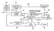
- FIG. 2illustrates a block diagram of a system, embodying an inventive feature
- FIGS. 3 a and 3 billustrate, each, a pair of cameras for sensing viewer viewing direction and for controlling the arrangement of FIG. 2 ;
- FIGS. 4 a , 4 b , 4 c and 4 dillustrate, each, a top view of a display screen viewed by a viewer, for explaining the operation of the system of FIG. 2 ;
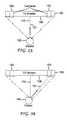
- FIGS. 5 a and 5 billustrate, each, a front view of display screen for explaining the operation of the system of FIG. 2 ;
- FIG. 6illustrates a block diagram of a portion of an audio processor of FIG. 2 that performs a virtual audio shift of a pair of stereo audio channels in response to an output of the cameras of FIGS. 3 a and 3 b.
- FIG. 2illustrates a block diagram of a system 150 , embodying an inventive feature. Similar symbols and numerals in FIGS. 1 a , 1 b , 1 c and 2 indicate similar items or functions.
- System 150 of FIG. 2includes an input video/audio source 156 that applies a video containing portion of an input video/audio signal 156 a to a video processor 155 and an audio containing portion of input video/audio signal 156 a to an enhanced audio processor 157 .
- Video processor 155derives picture information and enhanced audio processor 157 derives audio information from the corresponding portions of video/audio signal 156 a in a conventional manner.
- a zoom, pan/tilt function controller 154is responsive to a signal 180 a produced in a conventional way in a viewer interface and remote control 180 . Controller 154 generates a signal 154 a that is applied to video processor 155 . Video processor 155 applies in a conventional manner a conventional zoom or pan/tilt function in a conventional video display 159 in accordance with viewer's initiated commands via interface and remote control 180 . Video processor 155 generates an output video signal 155 a for driving video display 159 .
- FIGS. 3 a and 3 billustrates schematically a top view of a pair of cameras 152 of system 150 of FIG. 2 mounted in the vicinity of the left and right sides, respectively, of display screen 106 of FIGS. 3 a and 3 b .
- Similar symbols and numerals in FIGS. 1 a -1 c , 2 , 3 a and 3 bindicate similar items or functions.
- Cameras 152 of FIGS. 3 a and 3 bprovide together, stereoscopic picture information that enables a conventional processor for sensing viewing direction 151 to sense viewing direction 161 of a viewer 160 .
- viewing angular direction 161is perpendicular to display screen 106 of video display 159 .
- viewing angular direction 161 in the example of FIG. 3 bis directed to the extreme right side of display screen 106 .
- Cameras 152 of FIG. 2generate a pair of output signals 152 a are applied to processor for sensing viewing direction 151 for sensing at least one of face, head or eyes position of viewer 160 of FIGS. 3 a and 3 b with respect to display screen 106 .
- a single stereoscopic cameracan be used instead of the pair of cameras 152 .
- a non-stereoscopic single camera with enhanced processing of face or eye movement detectioncan be used instead of pair cameras 152 .
- Processor for sensing viewing direction 151 of FIG. 2generates in a conventional manner an output signal 151 a that is indicative of a present viewing direction of viewer 160 of FIGS. 3 a and 3 b.
- zoom, pan/tilt function controller 154 of FIG. 2is responsive to output signal 151 a for generating control signal 154 a .
- Control signal 154 a produced in controller 154is applied to video processor 155 in a manner to produce dynamically tracking pan/tilt function.
- FIGS. 5 a and 5 bare similar to FIGS. 1 b and 1 c , respectively, except as explained later on.
- Each of FIGS. 5 a and 5 bshows a horizontal line 110 a extending through screen center 110 for explanation purposes.
- FIGS. 4 a , 4 b , 4 c and 4 dcollectively depict a direction 161 a 1 , a direction 161 a , a direction 161 b 1 , a direction 161 b , a direction 161 a ′ and a direction 161 b ′.
- Each of directions 161 a 1 , 161 a , 161 b 1 , 161 b , 161 a ′ and 161 b ′intersects, for example, in a spot 161 a 1 , a spot 161 a , a spot 161 b 1 , a spot 161 b , a spot 161 a ′ and a spot 161 b ′, respectively, disposed in a horizontal direction along, for example, horizontal line 110 a of FIGS. 5 a and 5 b .
- intersection spots 161 a 1 and 161 b 1have been omitted.
- Similar symbols and numerals in FIGS. 1 a -1 c , 2 , 3 a , 3 b , 4 a - 4 d , 5 a and 5 bindicate similar items or functions.
- FIG. 4 apicture 100 is initially zoomed center in a way similar to that explained with respect to FIG. 1 b or 5 a .
- an object, not shown, that is displayed in display screen 106 in visible portion 105 a of FIG. 5 amoves in a horizontal direction parallel to horizontal line 110 a towards a side edge 111 of screen 106 that is at the right of each of FIGS. 4 a , 4 b , 4 c and 4 d .
- viewer 160turns the head or eyes to the right side of FIG. 4 a that is the left side with respect to viewer 160 , for the purpose of, for example, following the moving object.
- dynamically tracking pan functionis not applied or is disabled.
- dynamic tracking pan functionis applied so as to shift picture 100 gradually to the left of FIG. 4 b at a slow first rate.
- dynamically tracking pan functionis further applied so that picture 100 additionally shifts to the right with respect to viewer 160 that is to the left of FIG. 4 b , as indicated by the direction of an arrow 173 .
- Threshold angular direction 161 a 1is slightly smaller than angle 161 a for providing hysteresis that, advantageously, prevents picture back and forth bouncing.
- Threshold angular direction 161 b 1is slightly smaller than threshold angular direction 161 b in a manner to provide hysteresis. Should viewer 160 viewing angle become smaller than hysteresis providing threshold angular direction 161 b 1 but larger than threshold angular 161 a 1 of FIG. 4 b , additional shifting of picture 100 would revert to the slower rate that existed immediately prior to crossing threshold angular direction 161 b of FIG. 4 c . When the viewing angular direction of viewer 160 becomes smaller than threshold angular direction 161 a 1 of FIG. 4 b , additional shifting of picture 100 ceases and shifting picture 100 is held in suspense in the same shifted or pan state accumulated immediately prior to crossing threshold angular direction 161 a 1 .
- Threshold angular direction 161 a ′extends from perpendicular direction line 172 towards the left side of line 172 .
- the viewing angular direction of as viewer 160is within an angular range that is smaller than threshold angular direction 161 a ′, any change in shifting of picture 100 remains suspended, as explained before.
- dynamically tracking pan functionwould apply in the opposite direction for shifting picture 100 to the right of FIG.
- angular directions 161 a , and 161 bare similarly applicable to angular directions 161 a ′ and 161 b ′, respectively, that are located at the left side of perpendicular direction line 172 .
- the magnitude of, for example, each of threshold angular directions 161 a ′ and 161 b ′ of FIG. 4 dvaries adaptably in accordance with the amount of pre-existing shifting of picture 100 that has accumulated until the additional shifting of picture 100 to the left side of FIG. 4 c has been accumulated and held in suspense.
- FIGS. 4 a -4 dare symmetrically applicable to a symmetrical situation in which the object, not shown, displayed in display screen 106 in portion 105 a of FIG. 5 a , moves along horizontal line 110 a , instead, towards a side edge 112 of screen 106 that is at the left of each of FIGS. 4 a , 4 b , 4 c and 4 d when picture 100 is zoomed center.
- angular directions 161 a ′ and 161 b ′are equal to angular directions 161 a and 161 b , respectively.
- the magnitude of each of threshold angular directions 161 a ′ and 161 b ′ of FIG. 4 dthat is applicable to the situation, described before with respect to FIG. 4 d , in which pre-existing shifting of picture 100 is present, the magnitude of each of angular directions 161 a ′ and 161 b ′ is smaller than in FIG. 4 a , respectively.
- This featureadvantageously, facilitates a quick return to the non-shifted, zoomed center of picture 100 of FIG. 4 a.
- Dynamically tracking tilt functionis performed in an analogous way to dynamically tracking pan function.
- picture shiftoccurs in the horizontal direction, as explained before; whereas in implementing the dynamically tracking tilt function, picture shift occurs in the vertical direction.
- pan/tilt functioninstead of having pan/tilt function that changes at discrete threshold angular directions, changes in the pan/tilt function can occur in a non-discrete continuous manner angular directions.
- FIGS. 5 a and 5 bdepicts a perimeter 261 a and a perimeter 261 b .
- Perimeter 261 aincludes threshold angular directions 161 a and 161 a ′ in the horizontal direction of horizontal line 110 a .
- perimeter 261 bincludes threshold angular directions 161 b and 161 b ′.
- a corresponding portion of each of perimeter 261 a and 261 balso includes threshold angular directions that are associated with initiating shifting of picture 100 in the vertical direction to provide dynamically tracking tilt function.
- FIG. 5 apicture 100 is zoomed centered. Therefore, perimeters 261 a and 261 b are symmetrical in the horizontal direction with respect to center 110 .
- FIG. 5 bpicture 100 is already pre-shifted. Therefore, perimeters 261 a and 261 b are asymmetrical in the horizontal direction with respect to center 110 in a manner to provide adaptable dynamically tracking pan function, as explained before.
- video processor 155 of FIG. 2includes a detector, not shown, responsive to video/audio signal 156 a for detecting the occurrence of the scene change to generate a reset signal 155 b that is coupled to zoom, pan/tilt function controller 154 for overriding the accumulated shifting of picture 100 of FIG. 5 b in a manner to center picture 100 as in FIG. 5 a .
- This featureadvantageously, facilitates a quick return to the non-shifted centered picture 100 of FIG. 4 a upon the occurrence of a scene change.
- FIG. 6depicts a console 300 that is included in audio processor 157 of FIG. 2 . Similar symbols and numerals in FIGS. 1 a -1 c , 2 , 3 a , 3 b , 4 a - 4 d , 5 a , 5 b and 6 indicate similar items or functions.
- Console 300 of FIG. 6receives a pair of stereo audio channels, 138 and 139 . Channels 138 and 139 are derived in a conventional manner, not shown, in audio processor 157 from video/audio signal 156 a of FIG. 2 .
- Channel 138 of FIG. 6is applied through three parallel signal paths to an audio mixer 304 . It is delayed in a delay 301 to produce a delayed signal 301 a ; it is filtered in a filter 302 to produce a filtered signal 302 a and it is reverbed in a reverb stage 303 to produce a reverbed signal 303 a . Similarly, channel 139 is applied through three parallel signal paths to an audio mixer 304 ′.
- Mixer 304combines signals 301 a , 302 a , 303 a , 301 a ′, 302 a ′ and 303 a ′ to generate output signal 157 a for driving speaker 158 a .
- Mixer 304 ′also combines signals 301 a , 302 a , 303 a , 301 a ′, 302 a ′ and 303 a ′ to generate output signal 157 b for driving speaker 158 b .
- a pair of stereo signalssuch as channels 138 and 139 in such a way that the sound produced by speakers such as 158 a and 158 b appears to a viewer/listener as being originated in locations, shifted relative to where the actual speakers are physically located.
- output signal 154 a that controls zoom, pan/tilt functionis also applied to a programmable logic array (PLA) 305 for producing a set of coefficients 305 a that are collectively applied to delay 301 , filter 302 , reverb stage 303 and mixer 304 .
- PLA 305also produces, a second set of coefficients 305 b that are collectively applied to delay 301 ′, filter 302 ′, reverb stage 303 ′ and mixer 304 ′.
- coefficients 305 a and 305 bchange dynamically in accordance with signal 154 a to produce dynamic virtual shift of the sound sources. For obtaining a corresponding virtual sound source shift, coefficients 305 a and 305 b dynamically vary in accordance with the present shift of picture 100 of FIGS. 4 a - 4 d.
- signals 157 a and 157 b of FIGS. 2 and 6 generated by enhanced audio processor 157drive loudspeakers 158 a and 158 b , respectively, in a manner to make viewer 160 of FIGS. 4 a -4 d perceive the sound produced in loudspeakers 158 a and 158 b of FIG. 2 as dynamically changing in accordance with the dynamically tracking pan/tilt function.
- this arrangementis not limited to a pair of speakers but may include systems like the surround sound speakers or the like.
- Coefficients 305 a and 305 b of FIG. 6 that are required for each selected virtual shift of loudspeakers 157 and 158can be programmed prior to installation or use by computation according to the teaching of the prior art and/or by experimentation that might consider the size of a room containing loudspeakers 157 and 158 .
- the selection of coefficients 305 a and 305 b of FIG. 5change in a dynamic manner.
Landscapes
- Engineering & Computer Science (AREA)
- Theoretical Computer Science (AREA)
- General Engineering & Computer Science (AREA)
- Physics & Mathematics (AREA)
- General Physics & Mathematics (AREA)
- Human Computer Interaction (AREA)
- Controls And Circuits For Display Device (AREA)
- Stereophonic System (AREA)
- Two-Way Televisions, Distribution Of Moving Picture Or The Like (AREA)
Abstract
Description
Claims (9)
Applications Claiming Priority (1)
| Application Number | Priority Date | Filing Date | Title |
|---|---|---|---|
| PCT/IB2013/001811WO2015025185A1 (en) | 2013-08-21 | 2013-08-21 | Video display with pan function controlled by viewing direction |
Publications (2)
| Publication Number | Publication Date |
|---|---|
| US20160203581A1 US20160203581A1 (en) | 2016-07-14 |
| US10354359B2true US10354359B2 (en) | 2019-07-16 |
Family
ID=49226195
Family Applications (1)
| Application Number | Title | Priority Date | Filing Date |
|---|---|---|---|
| US14/913,363ActiveUS10354359B2 (en) | 2013-08-21 | 2013-08-21 | Video display with pan function controlled by viewing direction |
Country Status (6)
| Country | Link |
|---|---|
| US (1) | US10354359B2 (en) |
| EP (1) | EP3036601B1 (en) |
| JP (1) | JP2016533114A (en) |
| KR (1) | KR20160045084A (en) |
| CN (1) | CN105518569A (en) |
| WO (1) | WO2015025185A1 (en) |
Families Citing this family (11)
| Publication number | Priority date | Publication date | Assignee | Title |
|---|---|---|---|---|
| US10198865B2 (en) | 2014-07-10 | 2019-02-05 | Seiko Epson Corporation | HMD calibration with direct geometric modeling |
| US10585485B1 (en) | 2014-11-10 | 2020-03-10 | Amazon Technologies, Inc. | Controlling content zoom level based on user head movement |
| US10192133B2 (en) | 2015-06-22 | 2019-01-29 | Seiko Epson Corporation | Marker, method of detecting position and pose of marker, and computer program |
| US10192361B2 (en) | 2015-07-06 | 2019-01-29 | Seiko Epson Corporation | Head-mounted display device and computer program |
| US10424117B2 (en) | 2015-12-02 | 2019-09-24 | Seiko Epson Corporation | Controlling a display of a head-mounted display device |
| CN106375691A (en)* | 2016-08-31 | 2017-02-01 | 深圳Tcl数字技术有限公司 | Curved television video play method and apparatus |
| CN106851405A (en)* | 2016-12-13 | 2017-06-13 | 合网络技术(北京)有限公司 | Video broadcasting method and device based on oblique viewing angle detection |
| US10740446B2 (en) | 2017-08-24 | 2020-08-11 | International Business Machines Corporation | Methods and systems for remote sensing device control based on facial information |
| JP2019185114A (en)* | 2018-04-02 | 2019-10-24 | レノボ・シンガポール・プライベート・リミテッド | Information processing apparatus, display control method and program |
| CN114449319B (en)* | 2020-11-04 | 2024-06-04 | 深圳Tcl新技术有限公司 | Video picture dynamic adjustment method and device, intelligent terminal and storage medium |
| CN118761401B (en)* | 2024-09-05 | 2025-01-07 | 深圳市迪博企业风险管理技术有限公司 | A method and system for generating financial analysis report |
Citations (27)
| Publication number | Priority date | Publication date | Assignee | Title |
|---|---|---|---|---|
| US4219696A (en) | 1977-02-18 | 1980-08-26 | Matsushita Electric Industrial Co., Ltd. | Sound image localization control system |
| US4524451A (en) | 1980-03-19 | 1985-06-18 | Matsushita Electric Industrial Co., Ltd. | Sound reproduction system having sonic image localization networks |
| US5046097A (en) | 1988-09-02 | 1991-09-03 | Qsound Ltd. | Sound imaging process |
| EP0816980A2 (en) | 1996-06-26 | 1998-01-07 | Sun Microsystems, Inc. | Eyetrack-driven scrolling |
| US5742687A (en) | 1994-01-17 | 1998-04-21 | U.S. Philips Corporation | Signal processing circuit including a signal combining circuit stereophonic audio reproduction system including the signal processing circuit and an audio-visual reproduction system including the stereophonic audio reproduction system |
| US5742264A (en) | 1995-01-24 | 1998-04-21 | Matsushita Electric Industrial Co., Ltd. | Head-mounted display |
| US5987141A (en) | 1992-08-28 | 1999-11-16 | Thomson Consumer Electronics, Inc. | Stereo expander |
| US6084556A (en) | 1995-11-28 | 2000-07-04 | Vega Vista, Inc. | Virtual computer monitor |
| US6211912B1 (en)* | 1994-02-04 | 2001-04-03 | Lucent Technologies Inc. | Method for detecting camera-motion induced scene changes |
| US20020105482A1 (en) | 2000-05-26 | 2002-08-08 | Lemelson Jerome H. | System and methods for controlling automatic scrolling of information on a display or screen |
| US20050270367A1 (en) | 1996-11-13 | 2005-12-08 | Fakespace Labs, Inc. | Multi-person stereo display system |
| WO2006055907A1 (en) | 2004-11-19 | 2006-05-26 | Hillcrest Laboratories, Inc. | User interface for impaired users |
| WO2007107949A1 (en) | 2006-03-23 | 2007-09-27 | Koninklijke Philips Electronics N.V. | Hotspots for eye track control of image manipulation |
| US20090051699A1 (en)* | 2007-08-24 | 2009-02-26 | Videa, Llc | Perspective altering display system |
| US20100007582A1 (en) | 2007-04-03 | 2010-01-14 | Sony Computer Entertainment America Inc. | Display viewing system and methods for optimizing display view based on active tracking |
| US20100103516A1 (en) | 2008-10-27 | 2010-04-29 | Real D | Head-tracking enhanced stereo glasses |
| US7747040B2 (en) | 2005-04-16 | 2010-06-29 | Microsoft Corporation | Machine vision system and method for estimating and tracking facial pose |
| KR20110035162A (en) | 2009-09-30 | 2011-04-06 | 에스케이텔레콤 주식회사 | Screen processing method and mobile terminal using gaze recognition |
| US20110115883A1 (en)* | 2009-11-16 | 2011-05-19 | Marcus Kellerman | Method And System For Adaptive Viewport For A Mobile Device Based On Viewing Angle |
| US20120060177A1 (en)* | 2010-09-02 | 2012-03-08 | Verizon Patent And Licensing, Inc. | Perspective display systems and methods |
| WO2012061148A1 (en) | 2010-10-25 | 2012-05-10 | Qualcomm Incorporated | Systems, methods, apparatus, and computer-readable media for head tracking based on recorded sound signals |
| US20120162221A1 (en) | 2009-08-06 | 2012-06-28 | Sony Corporation | Method and apparatus for stereoscopic multi-users display |
| US20120257035A1 (en) | 2011-04-08 | 2012-10-11 | Sony Computer Entertainment Inc. | Systems and methods for providing feedback by tracking user gaze and gestures |
| WO2013006338A2 (en) | 2011-07-01 | 2013-01-10 | Dolby Laboratories Licensing Corporation | System and method for adaptive audio signal generation, coding and rendering |
| US20130113999A1 (en)* | 2011-11-03 | 2013-05-09 | Infosys Technologies, Ltd. | Methods, systems, and computer-readable media for detecting scene changes in a video |
| US20150015487A1 (en)* | 2012-07-02 | 2015-01-15 | Sony Computer Entertainment Inc. | Interaction with an expanded information space on a cellular phone |
| US9274597B1 (en)* | 2011-12-20 | 2016-03-01 | Amazon Technologies, Inc. | Tracking head position for rendering content |
- 2013
- 2013-08-21USUS14/913,363patent/US10354359B2/enactiveActive
- 2013-08-21EPEP13765759.9Apatent/EP3036601B1/enactiveActive
- 2013-08-21KRKR1020167006539Apatent/KR20160045084A/ennot_activeWithdrawn
- 2013-08-21WOPCT/IB2013/001811patent/WO2015025185A1/enactiveApplication Filing
- 2013-08-21JPJP2016535534Apatent/JP2016533114A/ennot_activeWithdrawn
- 2013-08-21CNCN201380078908.8Apatent/CN105518569A/enactivePending
Patent Citations (27)
| Publication number | Priority date | Publication date | Assignee | Title |
|---|---|---|---|---|
| US4219696A (en) | 1977-02-18 | 1980-08-26 | Matsushita Electric Industrial Co., Ltd. | Sound image localization control system |
| US4524451A (en) | 1980-03-19 | 1985-06-18 | Matsushita Electric Industrial Co., Ltd. | Sound reproduction system having sonic image localization networks |
| US5046097A (en) | 1988-09-02 | 1991-09-03 | Qsound Ltd. | Sound imaging process |
| US5987141A (en) | 1992-08-28 | 1999-11-16 | Thomson Consumer Electronics, Inc. | Stereo expander |
| US5742687A (en) | 1994-01-17 | 1998-04-21 | U.S. Philips Corporation | Signal processing circuit including a signal combining circuit stereophonic audio reproduction system including the signal processing circuit and an audio-visual reproduction system including the stereophonic audio reproduction system |
| US6211912B1 (en)* | 1994-02-04 | 2001-04-03 | Lucent Technologies Inc. | Method for detecting camera-motion induced scene changes |
| US5742264A (en) | 1995-01-24 | 1998-04-21 | Matsushita Electric Industrial Co., Ltd. | Head-mounted display |
| US6084556A (en) | 1995-11-28 | 2000-07-04 | Vega Vista, Inc. | Virtual computer monitor |
| EP0816980A2 (en) | 1996-06-26 | 1998-01-07 | Sun Microsystems, Inc. | Eyetrack-driven scrolling |
| US20050270367A1 (en) | 1996-11-13 | 2005-12-08 | Fakespace Labs, Inc. | Multi-person stereo display system |
| US20020105482A1 (en) | 2000-05-26 | 2002-08-08 | Lemelson Jerome H. | System and methods for controlling automatic scrolling of information on a display or screen |
| WO2006055907A1 (en) | 2004-11-19 | 2006-05-26 | Hillcrest Laboratories, Inc. | User interface for impaired users |
| US7747040B2 (en) | 2005-04-16 | 2010-06-29 | Microsoft Corporation | Machine vision system and method for estimating and tracking facial pose |
| WO2007107949A1 (en) | 2006-03-23 | 2007-09-27 | Koninklijke Philips Electronics N.V. | Hotspots for eye track control of image manipulation |
| US20100007582A1 (en) | 2007-04-03 | 2010-01-14 | Sony Computer Entertainment America Inc. | Display viewing system and methods for optimizing display view based on active tracking |
| US20090051699A1 (en)* | 2007-08-24 | 2009-02-26 | Videa, Llc | Perspective altering display system |
| US20100103516A1 (en) | 2008-10-27 | 2010-04-29 | Real D | Head-tracking enhanced stereo glasses |
| US20120162221A1 (en) | 2009-08-06 | 2012-06-28 | Sony Corporation | Method and apparatus for stereoscopic multi-users display |
| KR20110035162A (en) | 2009-09-30 | 2011-04-06 | 에스케이텔레콤 주식회사 | Screen processing method and mobile terminal using gaze recognition |
| US20110115883A1 (en)* | 2009-11-16 | 2011-05-19 | Marcus Kellerman | Method And System For Adaptive Viewport For A Mobile Device Based On Viewing Angle |
| US20120060177A1 (en)* | 2010-09-02 | 2012-03-08 | Verizon Patent And Licensing, Inc. | Perspective display systems and methods |
| WO2012061148A1 (en) | 2010-10-25 | 2012-05-10 | Qualcomm Incorporated | Systems, methods, apparatus, and computer-readable media for head tracking based on recorded sound signals |
| US20120257035A1 (en) | 2011-04-08 | 2012-10-11 | Sony Computer Entertainment Inc. | Systems and methods for providing feedback by tracking user gaze and gestures |
| WO2013006338A2 (en) | 2011-07-01 | 2013-01-10 | Dolby Laboratories Licensing Corporation | System and method for adaptive audio signal generation, coding and rendering |
| US20130113999A1 (en)* | 2011-11-03 | 2013-05-09 | Infosys Technologies, Ltd. | Methods, systems, and computer-readable media for detecting scene changes in a video |
| US9274597B1 (en)* | 2011-12-20 | 2016-03-01 | Amazon Technologies, Inc. | Tracking head position for rendering content |
| US20150015487A1 (en)* | 2012-07-02 | 2015-01-15 | Sony Computer Entertainment Inc. | Interaction with an expanded information space on a cellular phone |
Non-Patent Citations (14)
| Title |
|---|
| Adams et al., "The Inspection of Very Large Images by Eye-gaze Control", AVI '08 Proceedings of the Working Conference on Advanced Visual Interfaces, May 28, 2008, pp. 111-118. |
| Andrew Kiruluta et al., "Predictive Head Movement Tracking Using a Kalman Filter", IEEE Transactions on Systems, Man, and Cybernetics-Part B: Cybernetics, vol. 27, No. 2, Apr. 1997. |
| Andrew Kiruluta et al., "Predictive Head Movement Tracking Using a Kalman Filter", IEEE Transactions on Systems, Man, and Cybernetics—Part B: Cybernetics, vol. 27, No. 2, Apr. 1997. |
| Anuraag Agrawal et al., "Poster: Evaluation of an Approach for Remote Object Manipulation Utilizing Dynamic Magnifying Lenses", 2008 IEEE Symposium on 3D User Interfaces, Reno, NE, Mar. 2008. |
| Hansen et al., "Noise Tolerant Selection by Gaze-Controlled Pan and Zoom in 3D", ETRA '08 Proceedings of the 2008 Symposium on Eye Tracking Research & Applications, Mar. 26, 2008, pp. 205-212, Retrieved from Internet on Feb. 6, 2014. |
| John M. Chowning, "The Simulation of Moving Sound Sources", Department of Music and Artificial Intelligence Project, Stanford University, Stanford, CA, Jan. 1971. |
| Lankford, "Effective Eye-Gaze Input Into Windows", Proceedings from the Eye Tracking Research & Applications Symposium 2000 (ETRA), Palm Beach Gardens, FL, Nov. 6-8, 2000, ACM, NY, NY, pp. 23-27. |
| Myung-Suk Song et al., "Personal 3D Audio System With Loudspeakers", 2010 IEEE International Conference on Multimedia and Expo, Suntec City, Jul. 2010. |
| Paul M. Sharkey, Proceedings of the 1st European conference on disability, virtual reality and associated technologies (ECDVRAT Jul. 1996). |
| Search Report dated Feb. 6, 2014. |
| Toet, "Gaze directed displays as an enabling technology for attention aware systems", Computers in Human Behavior, Pergamon, NY, US, vol. 22, No. 4, Jul. 1, 2006, pp. 615-647. |
| William L. Chapin et al., "Virtual Environment Display for a 3D Audio Room Simulation", Proceedings vol. 1669, Stereoscopic Displays and Applications III; Jun. 1992. |
| Zhu et al. "Eye and gaze tracking for interactive graphic display", Machine Vision and Applications, vol. 15, No. 3, Jun. 8, 2004, pp. 139-148. |
| Zhu et al., "Moving to the centre: a gaze-driven remote camera for teleoperation", Interacting with Computers, Elsevier vol. 23, No. 1, Butterworth-Geinemann, GB, Jan. 1, 2011, pp. 85-95. |
Also Published As
| Publication number | Publication date |
|---|---|
| EP3036601B1 (en) | 2020-01-08 |
| WO2015025185A1 (en) | 2015-02-26 |
| JP2016533114A (en) | 2016-10-20 |
| US20160203581A1 (en) | 2016-07-14 |
| CN105518569A (en) | 2016-04-20 |
| EP3036601A1 (en) | 2016-06-29 |
| KR20160045084A (en) | 2016-04-26 |
Similar Documents
| Publication | Publication Date | Title |
|---|---|---|
| US10354359B2 (en) | Video display with pan function controlled by viewing direction | |
| US9367218B2 (en) | Method for adjusting playback of multimedia content according to detection result of user status and related apparatus thereof | |
| CN113490132B (en) | Audio reproducing method and sound reproducing system | |
| US20100328419A1 (en) | Method and apparatus for improved matching of auditory space to visual space in video viewing applications | |
| EP3127329A1 (en) | Multi-view display control | |
| JP2021533593A (en) | Audio equipment and its operation method | |
| CN105657396A (en) | Video play processing method and device | |
| JP2983844B2 (en) | 3D image conversion method | |
| EP3036918B1 (en) | Video display having audio controlled by viewing direction | |
| US20230336934A1 (en) | Information processing apparatus, information processing method, and information processing program | |
| JP2013236354A (en) | Acoustic system and speaker device | |
| JP2012080294A (en) | Electronic device, video processing method, and program | |
| JP5447220B2 (en) | Sound reproduction apparatus and sound reproduction method | |
| US11546715B2 (en) | Systems and methods for generating video-adapted surround-sound | |
| JP2011259298A (en) | Three-dimensional sound output device | |
| JPH08140200A (en) | Three-dimensional sound image controller | |
| KR20140011614A (en) | Audio steering video/audio system and providing method thereof | |
| JP2012253707A (en) | Stereoscopic video display device and sound reproduction device | |
| JP4454959B2 (en) | 3D image display method | |
| US12231861B2 (en) | Signal processing device, signal processing method, and image display device | |
| JP5506241B2 (en) | Communication apparatus, system, and control method | |
| JP5501150B2 (en) | Display device and control method thereof | |
| CN119729333A (en) | Sound source adjusting method, device, equipment and medium based on audience position | |
| KR20130014536A (en) | Method and system for reproduction of 3d image contents | |
| JPH1198534A (en) | Method for generating three-dimensional image |
Legal Events
| Date | Code | Title | Description |
|---|---|---|---|
| STPP | Information on status: patent application and granting procedure in general | Free format text:NOTICE OF ALLOWANCE MAILED -- APPLICATION RECEIVED IN OFFICE OF PUBLICATIONS | |
| AS | Assignment | Owner name:THOMSON LICENSING, FRANCE Free format text:ASSIGNMENT OF ASSIGNORS INTEREST;ASSIGNORS:KELLER, ANTON WERNER;BERNOLD, ROLAND RENE;REEL/FRAME:049181/0417 Effective date:20130827 | |
| AS | Assignment | Owner name:INTERDIGITAL CE PATENT HOLDINGS, FRANCE Free format text:ASSIGNMENT OF ASSIGNORS INTEREST;ASSIGNOR:THOMSON LICENSING;REEL/FRAME:049196/0458 Effective date:20180730 | |
| STPP | Information on status: patent application and granting procedure in general | Free format text:PUBLICATIONS -- ISSUE FEE PAYMENT VERIFIED | |
| STCF | Information on status: patent grant | Free format text:PATENTED CASE | |
| AS | Assignment | Owner name:INTERDIGITAL MADISON PATENT HOLDINGS, SAS, FRANCE Free format text:ASSIGNMENT OF ASSIGNORS INTEREST;ASSIGNOR:INTERDIGITAL CE PATENT HOLDINGS,SAS;REEL/FRAME:053061/0025 Effective date:20190911 | |
| MAFP | Maintenance fee payment | Free format text:PAYMENT OF MAINTENANCE FEE, 4TH YEAR, LARGE ENTITY (ORIGINAL EVENT CODE: M1551); ENTITY STATUS OF PATENT OWNER: LARGE ENTITY Year of fee payment:4 |