US10351274B2 - Combination wire and plastic strapping device - Google Patents
Combination wire and plastic strapping deviceDownload PDFInfo
- Publication number
- US10351274B2 US10351274B2US15/018,638US201615018638AUS10351274B2US 10351274 B2US10351274 B2US 10351274B2US 201615018638 AUS201615018638 AUS 201615018638AUS 10351274 B2US10351274 B2US 10351274B2
- Authority
- US
- United States
- Prior art keywords
- tying
- wire
- plastic
- strapping machine
- strap
- Prior art date
- Legal status (The legal status is an assumption and is not a legal conclusion. Google has not performed a legal analysis and makes no representation as to the accuracy of the status listed.)
- Active, expires
Links
- 239000000463materialSubstances0.000claimsabstractdescription98
- 238000000034methodMethods0.000abstractdescription21
- 238000010586diagramMethods0.000description7
- 239000013590bulk materialSubstances0.000description3
- 238000005304joiningMethods0.000description2
- 239000002699waste materialSubstances0.000description2
- 238000003466weldingMethods0.000description2
- 230000000712assemblyEffects0.000description1
- 238000000429assemblyMethods0.000description1
- 238000002788crimpingMethods0.000description1
- 238000005516engineering processMethods0.000description1
- 230000001939inductive effectEffects0.000description1
- 229920000728polyesterPolymers0.000description1
- 238000007789sealingMethods0.000description1
- 238000003860storageMethods0.000description1
Images


Classifications
- B—PERFORMING OPERATIONS; TRANSPORTING
- B65—CONVEYING; PACKING; STORING; HANDLING THIN OR FILAMENTARY MATERIAL
- B65B—MACHINES, APPARATUS OR DEVICES FOR, OR METHODS OF, PACKAGING ARTICLES OR MATERIALS; UNPACKING
- B65B13/00—Bundling articles
- B65B13/02—Applying and securing binding material around articles or groups of articles, e.g. using strings, wires, strips, bands or tapes
- B65B13/04—Applying and securing binding material around articles or groups of articles, e.g. using strings, wires, strips, bands or tapes with means for guiding the binding material around the articles prior to severing from supply
- B65B13/08—Single guide or carrier for the free end of material movable part-away around articles from one side only
- B—PERFORMING OPERATIONS; TRANSPORTING
- B65—CONVEYING; PACKING; STORING; HANDLING THIN OR FILAMENTARY MATERIAL
- B65B—MACHINES, APPARATUS OR DEVICES FOR, OR METHODS OF, PACKAGING ARTICLES OR MATERIALS; UNPACKING
- B65B13/00—Bundling articles
- B65B13/18—Details of, or auxiliary devices used in, bundling machines or bundling tools
- B65B13/24—Securing ends of binding material
- B65B13/26—Securing ends of binding material by knotting
- B—PERFORMING OPERATIONS; TRANSPORTING
- B65—CONVEYING; PACKING; STORING; HANDLING THIN OR FILAMENTARY MATERIAL
- B65B—MACHINES, APPARATUS OR DEVICES FOR, OR METHODS OF, PACKAGING ARTICLES OR MATERIALS; UNPACKING
- B65B13/00—Bundling articles
- B65B13/02—Applying and securing binding material around articles or groups of articles, e.g. using strings, wires, strips, bands or tapes
- B65B13/04—Applying and securing binding material around articles or groups of articles, e.g. using strings, wires, strips, bands or tapes with means for guiding the binding material around the articles prior to severing from supply
- B65B13/06—Stationary ducts or channels
- B—PERFORMING OPERATIONS; TRANSPORTING
- B65—CONVEYING; PACKING; STORING; HANDLING THIN OR FILAMENTARY MATERIAL
- B65B—MACHINES, APPARATUS OR DEVICES FOR, OR METHODS OF, PACKAGING ARTICLES OR MATERIALS; UNPACKING
- B65B13/00—Bundling articles
- B65B13/18—Details of, or auxiliary devices used in, bundling machines or bundling tools
- B65B13/24—Securing ends of binding material
- B65B13/32—Securing ends of binding material by welding, soldering, or heat-sealing; by applying adhesive
- B—PERFORMING OPERATIONS; TRANSPORTING
- B65—CONVEYING; PACKING; STORING; HANDLING THIN OR FILAMENTARY MATERIAL
- B65B—MACHINES, APPARATUS OR DEVICES FOR, OR METHODS OF, PACKAGING ARTICLES OR MATERIALS; UNPACKING
- B65B57/00—Automatic control, checking, warning, or safety devices
- B65B57/02—Automatic control, checking, warning, or safety devices responsive to absence, presence, abnormal feed, or misplacement of binding or wrapping material, containers, or packages
- B65B57/04—Automatic control, checking, warning, or safety devices responsive to absence, presence, abnormal feed, or misplacement of binding or wrapping material, containers, or packages and operating to control, or to stop, the feed of such material, containers, or packages
- B—PERFORMING OPERATIONS; TRANSPORTING
- B65—CONVEYING; PACKING; STORING; HANDLING THIN OR FILAMENTARY MATERIAL
- B65B—MACHINES, APPARATUS OR DEVICES FOR, OR METHODS OF, PACKAGING ARTICLES OR MATERIALS; UNPACKING
- B65B59/00—Arrangements to enable machines to handle articles of different sizes, to produce packages of different sizes, to vary the contents of packages, to handle different types of packaging material, or to give access for cleaning or maintenance purposes
- B65B59/003—Arrangements to enable adjustments related to the packaging material
Definitions
- Embodiments of the present inventionrelate to a combination strapping machine including a wire tying system and a plastic tying system. More particularly, embodiments of the present invention relate to a combination strapping machine for baling recycled materials, having a common frame coupled to both a wire strapping system for applying a wire tying medium, and a plastic strapping system for applying a plastic tying medium.
- baling machinesincorporate a tying system for wrapping and/or securing the baled material, such as a wire tying system.
- a tying mediumhaving sufficient strength to maintain the form of the compressed bale for shipping and/or storage.
- the tying medium used to secure a balemust be adequately tensioned by the tying system, as well as securely knotted and/or tied around the bale.
- a single baling machinetypically uses a single tying medium with a single tying system coupled to the machine. As such, a baling machine is not able to vary the types of tying media applied to different portions of a single bale.
- embodiments of the present inventionintroduce technology for resolving the above-mentioned issues conventionally experienced when varying the tying medium used for bulk-material baling systems.
- a combination strapping machinefor use on a baler.
- the strapping machinemay include a strapping machine frame having a common track perimeter and a top side, a right side, a left side, and a bottom side; a plastic tying system coupled to one of the top side, the right side, the left side, or the bottom side of the strapping machine frame, the plastic tying system having a plastic track, wherein the plastic tying system is configured to apply a plastic strap to a baled material, the plastic tying system may include a plastic closing mechanism (such as a welder); and a wire tying system coupled to one of the top side, the right side, the left side, or the bottom side of the strapping machine frame, the wire tying system having a wire track, wherein the wire tying system is configured to apply a wire strap to the baled material, the wire tying system may include a wire closing mechanism (such as a knotter from a knotter assembly), wherein the wire track
- a combination strapping machine for dynamic strapping of a first tying medium and a second tying medium on a balermay include: a strapping machine frame having a common track perimeter; a first tying system for the first tying medium, the first tying system coupled to a first portion of the strapping machine; and a second tying system for the second tying medium, the second tying system coupled to a second portion of the strapping machine, wherein the first tying system and the second tying system are configured to alternate applying straps to a baled material secured by the combination strapping machine and alternate utilizing a common track when applying the strap to the baled material.
- embodiments of the inventionare directed to a method for strapping a baled material according to a predetermined order of strap application, the method comprising: receiving, by a strapping machine, a material for baling, wherein the strapping machine comprises a first tying assembly, a second tying assembly, and a common control system configured to automatically alternate control indications between the first tying assembly and the second tying assembly; applying at least one strap of a first tying medium according to the predetermined order of strap application and in response to one or more control indications from the common control system, wherein the at least one strap of the first tying medium is applied using the first tying assembly coupled to the strapping machine; and applying at least one strap of a second tying medium according to the predetermined order of strap application and in response to one or more control indications from the common control system, wherein the at least one strap of the second tying medium is applied using the second tying assembly coupled to the strapping machine.
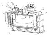
- FIG. 1is a front perspective view of an exemplary strapping machine for bulk-material baling, in accordance with an embodiment of the invention
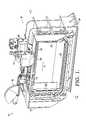
- FIG. 2Ais an enlarged, front perspective view of the strapping machine of FIG. 1 , in accordance with an embodiment of the invention
- FIG. 2Bis a top, schematic diagram of the components of an exemplary strapping machine, in accordance with an embodiment of the invention.
- FIG. 3Ais a front view of an exemplary strapping machine applying a plastic strap using a plastic tying system, in accordance with an embodiment of the invention
- FIG. 3Bis a front view of an exemplary strapping machine applying a wire strap using a wire tying system, in accordance with an embodiment of the invention
- FIG. 3Cis a front view of an exemplary strapping machine having a wire tying system located on a side surface of the strapping machine and a plastic tying system located on a top surface of the strapping machine.
- FIG. 4Ais an enlarged, perspective view of the plastic tying system of FIG. 1 , in accordance with an embodiment of the invention
- FIG. 4Bis an enlarged, perspective view of the wire tying system of FIG. 1 , in accordance with an embodiment of the invention
- FIG. 5is a flow diagram of a method of tying a plastic strap and a wire strap using a common strapping machine, in accordance with an embodiment of the invention
- FIG. 6is a flow diagram of a method of applying a strap of a first material and a strap of a second material using a common strapping machine, in accordance with an embodiment of the invention.
- FIG. 7is a flow diagram of a method for strapping a baled material according to a predetermined order of strap application, in accordance with an embodiment of the invention.
- the present inventiongenerally relates to a combination strapping machine for applying two different types of tying materials to a single bale, such as a bale of recycled material.
- the strapping machineis coupled to two separate tying systems and/or strapper heads for dynamically applying and/or attaching plastic straps or wire ties to a baled material.
- the two separate tying systemsinclude a plastic tying system having a plastic closing mechanism (such as a welder) and a wire tying system having a wire closing mechanism (such as a knotter).
- both the plastic tying system and the wire tying systemare adjacent, and coupled to a common strapping machine frame on one of a top, right, left, or bottom side and/or surface.
- the tying systemsmay be oriented along an x-axis of the width of a strapping machine or along a z-axis of the height of the strapping machine, offset with respect to the front side and the rear side of the strapping machine along a y-axis corresponding to the front-to-rear depth of the machine.
- a common controllermay be configured to coordinate the alternating straps applied by the strapping machine to one or more bales of material.
- the common controllermay be utilized to alternately apply a plastic strap from the plastic tying system, and a wire tie from a wire tying system.
- both the plastic tying medium and the wire tying mediumare strapped around the bale using a common track perimeter of the strapping machine frame.
- a plastic closing mechanism (such as a welder) of the plastic tying system offset from a wire closing mechanism (such as a knotter) of the wire tying systemare used to apply both straps utilizing a common track perimeter of the strapping machine having a limited amount of space along the top side/surface.
- both strapsare applied utilizing a common track of the strapping machine.
- a combination strapping machinefor use on a baler.
- the strapping machinemay include a strapping machine frame having a common track perimeter and a top side, a right side, a left side, or a bottom side; a plastic tying system coupled to one of the top side, the right side, the left side, or the bottom side of the strapping machine frame, the plastic tying system having a plastic track, wherein the plastic tying system is configured to apply a plastic strap to a baled material, the plastic tying system may include the plastic closing mechanism (such as a welder); and a wire tying system coupled to one of the top side, the right side, the left side, or the bottom side of the strapping machine frame, the wire tying system having a wire track, wherein the wire tying system is configured to apply a wire strap to the baled material, the wire tying system may include the wire closing mechanism (such as a knotter), wherein the wire track is adjacent the plastic track
- the plastic tying systemmay include a plurality of bloom plates that surround the common track perimeter.
- the bloom platesmay be coupled to the common track perimeter of the strapping machine frame, and are thereby configured to contact a baled material secured within an opening of the strapping machine.
- the plastic tying systemmay be configured to apply the plastic strap to the baled material from a first direction relative to the common track perimeter. In one embodiment, the first direction may be clockwise.
- embodiments of the wire tying systemmay be configured to apply the wire strap to the baled material from a second direction relative to the common track perimeter, which in some embodiments the second direction may be counterclockwise.
- a combination strapping machine for dynamic strapping of a first tying medium and a second tying medium on a balermay include: a strapping machine frame having a common track perimeter; a first tying system for the first tying medium, the first tying system coupled to a first portion of the strapping machine; and a second tying system for the second tying medium, the second tying system coupled to a second portion of the strapping machine, wherein the first tying system and the second tying system are configured to alternate applying straps to a baled material secured by the combination strapping machine and alternate utilizing a common track when applying the strap to the baled material.
- the first tying systemmay apply one or more straps before alternating to the second tying system applying one or more straps.
- the first portion of the strapping machineis adjacent the second portion of the strapping machine on a first side of the strapping machine frame.
- the common track perimetercomprises a first track for the first tying medium and a second track for the second tying medium.
- the first tying systemmay be a plastic tying system positioned at a rear side of the combination strapping machine, while in further embodiments, the plastic tying system may be configured to apply a plastic strap to the baled material from a first direction relative to the common track perimeter.
- the second tying systemmay be a wire tying system positioned at a front side of the combination strapping machine.
- the wire tying systemmay be configured to apply a wire strap to the baled material from a second direction relative to the common track perimeter.
- Embodiments of the combination strapping machinemay be configured to apply alternating straps to a baled material secured by the combination strapping machine by applying at least one strap of the first tying medium and at least one strap of the second tying medium to the bale.
- Embodiments of the combination strapping machinemay further include an integrated controller for controlling the first tying system and the second tying system.
- the integrated controllermay be configured to alternate tying the baled material with multiple straps of the first tying medium and multiple straps of the second tying medium according to a particular order for applying each strap of the first tying material and each strap of the second tying material.
- embodiments of the inventionare directed to a method for strapping a baled material according to a predetermined order of strap application, the method comprising: receiving, by a strapping machine, a material for baling, wherein the strapping machine comprises a first tying assembly, a second tying assembly, and a common control system configured to automatically alternate control indications between the first tying assembly and the second tying assembly; applying at least one strap of a first tying medium according to the predetermined order of strap application and in response to one or more control indications from the common control system, wherein the at least one strap of the first tying medium is applied using the first tying assembly coupled to the strapping machine; and applying at least one strap of a second tying medium according to the predetermined order of strap application and in response to one or more control indications from the common control system, wherein the at least one strap of the second tying medium is applied using the second tying assembly coupled to the strapping machine.
- the first tying mediumcomprises a plastic tying medium.
- the second tying mediumcomprises a wire tying medium.
- the methodfurther comprises: advancing the material to be baled to a first position; upon advancing the material to be baled to the first position, providing a first control indication to the first tying assembly to apply a first strap comprised of the first tying medium to the material to be baled; advancing the material to be baled to a second position; upon advancing the material to be baled to the second position, providing a second control indication to the second tying assembly to apply a second strap comprised of the second tying medium to the material to be baled; advancing the material to be baled to third position; and upon advancing the material to be baled to the third position, providing a third control indication to the first tying assembly to apply a third strap comprised of the first tying medium to the material to be baled.
- the methodfurther comprises: advancing the material to be baled to a plurality of intermediate positions between the first position and the third position and upon each advancement to an intermediate position, providing a control indication to one of the first tying assembly and the second tying assembly to apply an additional strap comprised of the first or second tying medium, respectively, to the material to be baled.
- an embodiment of a strapping machine 10may include a strapping machine frame 12 coupled to a wire tying system 14 and a plastic tying system 16 . Both the wire tying system 14 and the plastic tying system 16 may be configured to apply a tying medium to a baled material via the common track perimeter 18 . As shown in the embodiment of FIG. 1 , based on the application of plastic tying medium to a baled material, the common strapping machine includes bloom plates 22 coupled to the strapping machine frame 12 . In some embodiments, the common base 24 supports the strapping machine frame 12 having a wire tying system 14 and a plastic tying system 16 on a top surface.
- the exemplary strapping machine 10also includes a knotter assembly 26 of the wire tying system 14 .
- Embodiments of the inventioninclude a knotter assembly 26 for tying a wire strap around a baled material, such as the knotter assembly described in one or more of the following U.S. patent applications: U.S. application Ser. No. 12/717,616, filed Mar. 4, 2010, entitled “Knotter Assembly,” now U.S. Pat. No. 8,397,632, issued Mar. 19, 2013; U.S. application Ser. No. 13/220,798, filed Aug. 30, 2011, entitled “Knotter Assembly”; and U.S. application Ser. No. 13/753,188, filed Jan. 29, 2013, entitled “Method For Removing A Twist-Module Sub-Assembly In A Knotter Assembly,” the disclosure of each of which is hereby incorporated by reference in its entirety.
- the strapping machine 10may include a control system 66 coupled directly or indirectly to the strapping machine 10 .
- the strapping machine 10having both a wire tying system 14 and a plastic tying system 16 , may include a common control system 66 configured to control both tying media, such as the control system described in U.S. Application No. 61/873,662, filed Sep. 4, 2013, entitled “Control User Interface For Tying System,” the disclosure of which is hereby incorporated by reference in its entirety.
- the strapping machine 10includes a front side A and a rear side B, oriented with respect to a y-axis.
- the wire tying system 14is configured towards the front side A of the strapping machine frame 12
- the plastic tying systemis configured towards the rear side B of the strapping machine frame 12 .
- wire tying system 14 and plastic tying system 16may be oriented along a common x-axis, on a top surface of the strapping machine 10 .
- the wire tying system 14 , the plastic tying system 16 , or both the wire tying system 14 and the plastic tying system 16may be positioned on a side surface, a bottom surface, a top surface of the strapping machine 10 , or a combination of multiple different surfaces and/or sides of the strapping machine 10 .
- the wire tying system 14 and knotter assembly 26is positioned on a side surface of the strapping machine 10 and the wire tying system 16 is positioned on a top surface of the strapping machine 10 .
- the tying portion 30may be located on the top of the strapping machine 10 and may include at least a portion of the wire tying system 14 and at least a portion of the plastic tying system 16 . In other embodiments, there may be more than one tying portion 30 . For example, as depicted in FIG. 3C , there is a tying portion 30 associated with the top of the strapping machine 10 that includes a portion of the plastic tying system 16 and a second tying portion 31 associated with the side of the strapping machine 10 that includes a portion of the wire tying system 14 .
- a portion of each of the wire tying system 14 and the plastic tying system 16may be offset with respect to the common track perimeter 18 , enabling a wire track to be positioned adjacent a plastic track along a common track perimeter 18 .
- the common track perimeter 18may be configured to secure both a wire strap 34 (from a wire tying system 14 ) and a plastic strap 36 (from a plastic tying system 16 ).
- a common track perimeter 18may refer to a single-channel surrounding a baled material that receives both a first and a second tying material.
- a common track perimeter 18may refer to a multi-channel feature surrounding a baled material that receives a first tying material via a first channel, and receives a second tying material via a second channel adjacent and/or parallel to the first channel.
- a front view of an exemplary strapping machine 38depicts the application of a plastic strap 40 around a material based through opening 20 , according to one embodiment of the invention.
- the plastic strap 40may be applied using the plastic tying system 16 by travelling along the common track perimeter 18 in a clockwise direction.
- a front view of an exemplary strapping machine 42depicts the application of a wire strap 44 around a material baled through opening 20 , according to one embodiment of the invention.
- the wire strap 44may be applied using the wire tying system 14 by travelling along the common track perimeter 18 in a counterclockwise direction.
- the plastic tying system 16utilizes a plastic closing mechanism to join a plastic strap around a baled material.
- the plastic closing mechanismcomprises a thermal welding head for sealing of two portions of the plastic strap together.
- the plastic closing mechanismcomprises a hot knife system.
- the plastic closing mechanismcomprises a friction inducing means, such as a vibrating platen and/or anvil, is used to join two portions of the plastic strap together.
- the plastic closing mechanismcomprises crimping or buckling two portions of the plastic strap together. It is understood that the plastic closing mechanism may comprise any suitable means for joining two portions of the plastic strap together to seal the plastic strap around the baled material.
- Embodiments of the wire tying system 14may include a wire closing mechanism to join a wire strap around a baled material, the wire closing mechanism may be controlled by the control system 66 .
- the wire closing mechanismcomprises a knotter assembly 26 for knotting two portions of the wire together.
- the wire closing mechanismcomprises a welder for welding two portions of the wire together.
- the wire closing mechanismcomprises a joint sealer for creating a seal and notch joint, a seal and crimp, or a seal-less joint in two portions of the wire. It is understood that the wire closing mechanism may comprise any suitable means for joining two portions of the wire together to seal the wire strap around the baled material.
- an exemplary method 50 of tying a plastic strap and a wire strap using a common strapping machine in accordance with one embodimentis provided.
- a materialis received for baling, such as a recycled and/or waste material.
- wireis strapped from a top right side of the strapping machine. In embodiments, based on strapping the wire from a top right side of the strapping machine, the wire continues through the common track perimeter of the strapping machine in a counterclockwise direction.
- a plastic strapis applied from a top left side of the strapping machine. Accordingly, the plastic strap continues through the common track perimeter of the strapping machine in a clockwise direction, according to embodiments of the invention. It is understood that the wire may be strapped from any side along the strapping machine perimeter and not only from the top right side of the strapping machine. Likewise, it is understood that plastic strap may be applied from any side along the strapping machine perimeter and not only from the top left side.
- a material for balingis received, such as a recycled and/or waste material.
- at least one strap of a first materialis applied to the bale using a first tying assembly. In embodiments, the first material is applied to the bale in a first direction around the common track perimeter.
- at least one strap of a second materialis applied to the bale using a second tying assembly. In embodiments, the second material is applied to the bale in a second direction around the common track perimeter. In embodiments, the second direction is opposite the first direction, and the second material and/or tying medium is different than the first material and/or tying medium.
- a particular order of strap application of multiple types of tying mediamay be executed.
- a “recipe” for order of strap application of different types of straps, such as wire straps and plastic strapsmay be provided and utilized by a single, common strapping machine.
- a recipe for strappingmay include a series of commands for applying 1) a wire strap to a first end of a bale, 2) a plastic strap to the middle of the bale, and 3) an additional wire strap at the second end of the bale.
- the baled materialmay be secured by a wire strap at either end of the baled material, with any combination of wire and/or plastic straps on a middle portion of the bale.
- beginning, middle, and end portions of a bale for tying using the strapping machinemay be identified by the strapping machine control system, and tied accordingly.
- different characteristics of different portions of a baled materiali.e., along the y-axis of the strapping machine
- the common strapping machinedynamically adjusts to apply different tying straps to different portions of a bale, such as applying multiple different plastic straps and wire straps to a single bale.
- the offset positioning of the plastic tying system and wire tying systemprovides a tying portion of the strapping machine that is configured to alternate between one type of tying medium and another, without adjusting and/or removing a portion of the strapping mechanism.
- the wire tying systemis positioned in front of and higher than the plastic tying system. As such, in some embodiments, the wire tying system is closer to the front side A of the strapping machine, while the plastic tying system is closer to the rear side B of the strapping machine. Additionally, in some embodiments, a portion of the wire tying system is positioned a particular distance apart from the plastic tying system, when oriented along the same x-axis.
- the wire tying assembly and the plastic tying assemblymay utilize the same path for travel of the various tying media.
- the two tying assembliesmay share the same path for travel while not needing to change a part of the wire tying assembly or the plastic tying assembly and while maintaining tension around the bale.
- a common track pathmay be utilized for applying both a first tying medium and a second tying medium to a baled material, with each material being strapped/applied/terminated on the same or different sides of the of the dual-component tying system.
- a common trackmay be utilized by the wire tying assembly and the plastic tying assembly to tie a plurality of straps from beginning to end of a single bale.
- the common trackmay be utilized by advancing the single bale through the baling machine, applying at least one strap of a first tying medium from a first closing mechanism location on the common track, and applying at least one strap of a second tying medium from a second closing mechanism location on the common track, where the first closing mechanism location is different from the second closing mechanism location.
- a method 68 of strapping a baled material according to a predetermined order of strap applicationincludes receiving, by a strapping machine, a material for baling, as depicted at block 70 .
- the strapping machinemay comprise a first tying assembly, a second tying assembly, and a common control system configured to automatically alternate control indications between the first tying assembly and the second tying assembly.
- the method 68includes applying at least one strap of a first tying medium according to the predetermined order of strap application and in response to one or more control indications from the common control system, as depicted in block 72 .
- the at least one strap of the first tying mediummay be applied using the first tying assembly coupled to the strapping machine.
- the method 68includes applying at least one strap of a second tying medium according to the predetermined order of strap application and in response to one or more control indications from the common control system, as depicted in block 74 .
- the at least one strap of the second tying mediummay be applied using the second tying assembly coupled to the strapping machine.
- the first tying mediumcomprises a plastic tying medium.
- the second tying mediumcomprises a wire tying medium. It is understood that the first and second tying mediums may comprise other suitable material tying mediums (such as polyester) so long as the first tying medium is different from the second tying medium.
- the method 68may further include advancing the material to be baled to a first position; and upon advancing the material to be baled to the first position, providing a first control indication to the first tying assembly to apply a first strap comprised of the first tying medium to the material to be baled.
- the method 68may further include advancing the material to be baled to a second position; and upon advancing the material to be baled to the second position, providing a second control indication to the second tying assembly to apply a second strap comprised of the second tying medium to the material to be baled.
- the method 68may further include advancing the material to be baled to a third position; and upon advancing the material to be baled to the third position, providing a third control indication to the first tying assembly to apply a third strap comprised of the first tying medium to the material to be baled.
- the method 68may further comprise advancing the material to be baled to a plurality of intermediate positions between the first position and the third position, and upon each advancement to an intermediate position, providing a control indication to one of the first tying assembly and the second tying assembly to apply an additional strap comprised of the first tying medium or the second tying medium, respectively, to the material to be baled.
Landscapes
- Engineering & Computer Science (AREA)
- Mechanical Engineering (AREA)
- Basic Packing Technique (AREA)
Abstract
Description
Claims (6)
Priority Applications (3)
| Application Number | Priority Date | Filing Date | Title |
|---|---|---|---|
| US15/018,638US10351274B2 (en) | 2014-02-20 | 2016-02-08 | Combination wire and plastic strapping device |
| GB1702076.9AGB2547114A (en) | 2016-02-08 | 2017-02-08 | Combination wire and plastic strapping device |
| US16/433,118US11040789B2 (en) | 2014-02-20 | 2019-06-06 | Combination wire and plastic strapping device |
Applications Claiming Priority (2)
| Application Number | Priority Date | Filing Date | Title |
|---|---|---|---|
| US14/185,524US9278772B2 (en) | 2014-02-20 | 2014-02-20 | Combination wire and plastic strapping device |
| US15/018,638US10351274B2 (en) | 2014-02-20 | 2016-02-08 | Combination wire and plastic strapping device |
Related Parent Applications (1)
| Application Number | Title | Priority Date | Filing Date |
|---|---|---|---|
| US14/185,524Continuation-In-PartUS9278772B2 (en) | 2014-02-20 | 2014-02-20 | Combination wire and plastic strapping device |
Related Child Applications (1)
| Application Number | Title | Priority Date | Filing Date |
|---|---|---|---|
| US16/433,118Continuation-In-PartUS11040789B2 (en) | 2014-02-20 | 2019-06-06 | Combination wire and plastic strapping device |
Publications (2)
| Publication Number | Publication Date |
|---|---|
| US20160152362A1 US20160152362A1 (en) | 2016-06-02 |
| US10351274B2true US10351274B2 (en) | 2019-07-16 |
Family
ID=56078706
Family Applications (1)
| Application Number | Title | Priority Date | Filing Date |
|---|---|---|---|
| US15/018,638Active2035-12-20US10351274B2 (en) | 2014-02-20 | 2016-02-08 | Combination wire and plastic strapping device |
Country Status (1)
| Country | Link |
|---|---|
| US (1) | US10351274B2 (en) |
Families Citing this family (3)
| Publication number | Priority date | Publication date | Assignee | Title |
|---|---|---|---|---|
| GB2547114A (en)* | 2016-02-08 | 2017-08-09 | Accent Packaging Inc | Combination wire and plastic strapping device |
| CN110356652B (en)* | 2019-07-04 | 2024-04-19 | 苏州大喆智能科技有限公司 | Detection, stacking, bundling and conveying all-in-one machine for objects |
| CN116605468B (en)* | 2023-07-21 | 2023-10-03 | 新乡职业技术学院 | Metal sheet carries binding apparatus |
Citations (87)
| Publication number | Priority date | Publication date | Assignee | Title |
|---|---|---|---|---|
| US25783A (en) | 1859-10-11 | Improved burnishing-machine | ||
| US1460649A (en) | 1920-05-13 | 1923-07-03 | Alec J Gerrard | Wire stretching and tying machine |
| GB325783A (en) | 1928-08-17 | 1930-02-17 | Cons Steel Strapping Company | An improved package tying machine |
| US1868141A (en) | 1930-06-25 | 1932-07-19 | Harvey Herbert | Wire tying machine |
| US1939746A (en) | 1931-08-03 | 1933-12-19 | Smith Corp A O | Wire tightener |
| GB417803A (en) | 1932-06-02 | 1934-10-12 | Gerrard Co Inc | Improvements in or relating to wire tying machines |
| GB420098A (en) | 1933-05-26 | 1934-11-26 | Henry Wilfred Cox | Improvements in wire tying machines |
| GB474813A (en) | 1936-05-08 | 1937-11-08 | Herbert Harvey | Wire tying machine |
| GB704931A (en) | 1951-04-26 | 1954-03-03 | Universal Winding Co | Improvements in or relating to winding machines |
| US2756783A (en) | 1954-04-08 | 1956-07-31 | United States Steel Corp | Wire-tying machine |
| US2853885A (en) | 1952-04-15 | 1958-09-30 | American Baler Co | Shaft driving arrangement |
| US2859687A (en) | 1954-04-15 | 1958-11-11 | Sperry Rand Corp | Automatic wire tying mechanism |
| US2907356A (en) | 1954-12-06 | 1959-10-06 | Ernest Roe | Portable wire tying tool |
| US2922359A (en) | 1958-01-16 | 1960-01-26 | United States Steel Corp | Knotter for automatic wire-tying machine |
| US2963958A (en) | 1955-04-26 | 1960-12-13 | Massey Ferguson Inc | Bale tying mechanism and drive |
| US3037535A (en) | 1960-02-10 | 1962-06-05 | United States Steel Corp | Knotter mechanism for automatic wire-tying machine |
| US3037534A (en) | 1959-08-11 | 1962-06-05 | United States Steel Corp | Wire-tying machine |
| US3086450A (en) | 1959-02-02 | 1963-04-23 | Sperry Rand Corp | Wire tier |
| US3099204A (en) | 1956-08-22 | 1963-07-30 | Stromberg Nils Erik | Bundle binding machine |
| GB984251A (en) | 1961-10-02 | 1965-02-24 | Acme Steel Co | Strapping machine |
| US3232216A (en) | 1963-04-29 | 1966-02-01 | Devco Inc | Wire binding machine |
| US3251296A (en) | 1963-05-06 | 1966-05-17 | Mid States Steel & Wire Compan | Tying machine |
| US3295436A (en) | 1965-02-10 | 1967-01-03 | United States Steel Corp | Knotter mechanism for wire-tying apparatus |
| US3327618A (en) | 1965-05-17 | 1967-06-27 | Package Sealing Company Export | Package binding machines |
| US3338273A (en) | 1965-01-18 | 1967-08-29 | United Mattress Machinery Comp | Knotting head |
| US3447448A (en) | 1967-03-13 | 1969-06-03 | Ovalstrapping Inc | Wire tying machines |
| US3880204A (en) | 1974-02-19 | 1975-04-29 | Forest M Sarff | Wire tying mechanism |
| US3888134A (en) | 1974-06-03 | 1975-06-10 | Lawrence Thomas Miranda | Eccentric shaft mounting apparatus |
| US3889584A (en) | 1972-10-17 | 1975-06-17 | Sunds Ab | Binding machine |
| US4079667A (en) | 1976-12-20 | 1978-03-21 | Signode Corporation | Method of forming and tensioning a strap loop about a package |
| US4114527A (en) | 1977-09-09 | 1978-09-19 | Neill Robert S O | Bale tying device and knot produced thereby |
| US4164176A (en) | 1978-02-21 | 1979-08-14 | United States Steel Corporation | Strapping machine with strap stop barrier, pivotable clamp and adjustable shear anvil |
| US4177842A (en) | 1978-01-25 | 1979-12-11 | Peters Equipment Corporation | Tying machine |
| US4252157A (en) | 1979-01-09 | 1981-02-24 | Takigawa Kogyo Co., Ltd. | Automatic bundling apparatus |
| US4302991A (en) | 1980-02-28 | 1981-12-01 | Brouse S Bernard | Fastener plunging apparatus |
| US4403542A (en) | 1981-09-01 | 1983-09-13 | Cranston Machinery Company, Inc. | Bale strapping system |
| US4566378A (en) | 1982-05-06 | 1986-01-28 | Vepa Aktiengesellschaft | Apparatus for hooping a fiber bale in a fiber bale press |
| US4577554A (en) | 1985-03-22 | 1986-03-25 | United States Steel Corporation | Knotting apparatus for wire strapping machine |
| US4587791A (en) | 1984-12-24 | 1986-05-13 | United States Steel Corporation | Edge protector positioning apparatus |
| US4611534A (en) | 1985-04-08 | 1986-09-16 | Cranston Machinery Co., Inc. | Bale strapping apparatus |
| US4655264A (en) | 1983-10-27 | 1987-04-07 | Ben Clements & Sons, Inc. | Twist tying machine |
| US4730434A (en) | 1986-07-03 | 1988-03-15 | Knudsen David S | Machine for applying twist-type ties |
| US4739700A (en) | 1985-09-23 | 1988-04-26 | U.S. Steel Supply Inc. | Seal-less strapping head |
| US4817519A (en) | 1986-10-10 | 1989-04-04 | Stanwich Holdings, Inc. | Wire feed and tensioning apparatus |
| US4827991A (en) | 1986-10-28 | 1989-05-09 | Ben Clements & Sons, Inc. | Twist tie feed device |
| CN2050497U (en) | 1988-03-26 | 1990-01-03 | 浙江省玉环县坎门电器元件一厂 | Check clip |
| US5078057A (en)* | 1990-01-05 | 1992-01-07 | Illinois Tool Works Inc. | Binding machine, such as strapping machine |
| US5392821A (en) | 1993-10-08 | 1995-02-28 | Signode Corporation | Strapping tool with mechanism for admitting, retaining, and releasing steel strap |
| US5433255A (en) | 1993-12-13 | 1995-07-18 | L&P Property Management Company | Wire knotter head yoke cover with replacement inserts |
| US5467804A (en) | 1994-01-26 | 1995-11-21 | L&P Property Management Company | Wire twister-cutter assembly |
| US5494081A (en) | 1994-01-26 | 1996-02-27 | L&P Property Management Company | Wire twister pinion and assembly |
| US5577760A (en) | 1995-08-28 | 1996-11-26 | Pressler; Hallis R. | Farm wagon stabilizing bar system |
| US5704283A (en) | 1995-10-24 | 1998-01-06 | L & P Property Management Company | Automatic tie system for baler |
| US5921289A (en) | 1997-06-10 | 1999-07-13 | L&P Property Management Company | Method and apparatus for tying and binding bales of compressed materials |
| US6009646A (en) | 1998-06-05 | 2000-01-04 | L&P Property Management Company | Apparatus for tying and binding bales of compressed materials |
| US6032575A (en) | 1998-07-16 | 2000-03-07 | L&P Property Management Company | Automatic baler with tying system having simultaneously engaged twister pinions |
| US6283017B1 (en) | 1995-10-24 | 2001-09-04 | L & P Property Management Company | Apparatus for tying and binding bales of compressed materials |
| CN2451448Y (en) | 2000-11-25 | 2001-10-03 | 陈万兴 | Motorcycle stand |
| US6341470B1 (en)* | 1997-07-25 | 2002-01-29 | Comtor Limited | Wrapping machine |
| US6363843B1 (en) | 1999-09-02 | 2002-04-02 | L&P Property Management Company | Wire tie guide with tying device and method |
| CN2527767Y (en) | 2001-12-18 | 2002-12-25 | 王礼标 | Dog |
| US20030024404A1 (en)* | 2001-07-31 | 2003-02-06 | Bart Daniel | Baling machine with narrow head wire feeder |
| US6571691B1 (en) | 2000-04-28 | 2003-06-03 | L&P Property Management Company | Apparatus for tieing and binding bales of material |
| US6640700B2 (en) | 1999-12-02 | 2003-11-04 | Enterprises International, Inc. | Apparatus for applying flexible straps around bundles of objects |
| US20040006402A1 (en)* | 2001-07-31 | 2004-01-08 | L & P Property Management Company | Operator input interface for baling machine |
| US6745677B2 (en) | 2001-07-12 | 2004-06-08 | Illinois Tool Works, Inc. | Strapping machine with easy access and feed guides |
| US6755123B2 (en) | 2001-07-12 | 2004-06-29 | Illinois Tool Works | Strapping machine with modular heads |
| US20040144264A1 (en) | 2000-03-31 | 2004-07-29 | L & P Property Management Company | Wire-tie pull pins |
| US6857252B2 (en) | 2003-06-20 | 2005-02-22 | Illinois Tool Works, Inc. | Strapping machine with strap path access guide |
| US6920741B2 (en) | 2002-11-27 | 2005-07-26 | Illinois Tool Works, Inc. | Strapping machine with quick-release enclosure door latches |
| US6923113B2 (en) | 2002-11-27 | 2005-08-02 | Illinois Tool Works, Inc. | Strapping machine with paddle formed strap path |
| US6957835B2 (en) | 2003-11-21 | 2005-10-25 | Deere & Company | Device for adjusting the space between adjacent knotter assemblies on a knotter drive shaft |
| US6962109B2 (en) | 2003-06-17 | 2005-11-08 | Illinois Tool Works, Inc. | Strapping machine with automatic chute opening system |
| US6968779B2 (en) | 2000-03-15 | 2005-11-29 | Enterprises International, Inc. | Apparatus and methods for wire-tying bundles of objects |
| US20060042478A1 (en) | 2004-08-25 | 2006-03-02 | L & P Property Management Company | Laterally displaceable guide track for a bulk material baler apparatus and method |
| US20060042477A1 (en) | 2004-08-25 | 2006-03-02 | L & P Property Management Company | Short platen compatible guide track insertion and removal apparatus and method |
| US7085625B2 (en) | 2001-07-31 | 2006-08-01 | L&P Property Management Company | Control system for baling machine |
| US7124679B2 (en) | 2004-08-25 | 2006-10-24 | L&P Property Management Company | Lower guide track for down packing press apparatus and method |
| US7146294B1 (en) | 2003-02-06 | 2006-12-05 | Mgm Services, Inc. | Weighing baled material |
| US7373877B2 (en) | 2004-04-14 | 2008-05-20 | Accent Packaging, Inc. | Wire strapper for waste material baler |
| US20090250930A1 (en) | 2008-04-08 | 2009-10-08 | Cnh America Llc | Knotter for a Baler |
| US20130019764A1 (en) | 2011-07-20 | 2013-01-24 | Pantech International Inc. | Rocker assembly of a strapping machine |
| US8397632B2 (en) | 2010-03-04 | 2013-03-19 | L & P Property Management Company | Knotter assembly |
| US20130180416A1 (en) | 2012-01-18 | 2013-07-18 | Del Bradley Stein | System and method for applying strapping to bales of material |
| US20130247515A1 (en) | 2012-03-22 | 2013-09-26 | H.W.J. Designs For Agribusiness, Inc. | Strap welding system and method |
| US9045245B2 (en) | 2010-03-04 | 2015-06-02 | L&P Property Management Company | Knotter assembly |
| US9278772B2 (en) | 2014-02-20 | 2016-03-08 | L&P Property Management Company | Combination wire and plastic strapping device |
- 2016
- 2016-02-08USUS15/018,638patent/US10351274B2/enactiveActive
Patent Citations (92)
| Publication number | Priority date | Publication date | Assignee | Title |
|---|---|---|---|---|
| US25783A (en) | 1859-10-11 | Improved burnishing-machine | ||
| US1460649A (en) | 1920-05-13 | 1923-07-03 | Alec J Gerrard | Wire stretching and tying machine |
| GB325783A (en) | 1928-08-17 | 1930-02-17 | Cons Steel Strapping Company | An improved package tying machine |
| US1868141A (en) | 1930-06-25 | 1932-07-19 | Harvey Herbert | Wire tying machine |
| US1939746A (en) | 1931-08-03 | 1933-12-19 | Smith Corp A O | Wire tightener |
| GB417803A (en) | 1932-06-02 | 1934-10-12 | Gerrard Co Inc | Improvements in or relating to wire tying machines |
| GB420098A (en) | 1933-05-26 | 1934-11-26 | Henry Wilfred Cox | Improvements in wire tying machines |
| GB474813A (en) | 1936-05-08 | 1937-11-08 | Herbert Harvey | Wire tying machine |
| GB704931A (en) | 1951-04-26 | 1954-03-03 | Universal Winding Co | Improvements in or relating to winding machines |
| US2853885A (en) | 1952-04-15 | 1958-09-30 | American Baler Co | Shaft driving arrangement |
| US2756783A (en) | 1954-04-08 | 1956-07-31 | United States Steel Corp | Wire-tying machine |
| US2859687A (en) | 1954-04-15 | 1958-11-11 | Sperry Rand Corp | Automatic wire tying mechanism |
| US2907356A (en) | 1954-12-06 | 1959-10-06 | Ernest Roe | Portable wire tying tool |
| US2963958A (en) | 1955-04-26 | 1960-12-13 | Massey Ferguson Inc | Bale tying mechanism and drive |
| US3099204A (en) | 1956-08-22 | 1963-07-30 | Stromberg Nils Erik | Bundle binding machine |
| US2922359A (en) | 1958-01-16 | 1960-01-26 | United States Steel Corp | Knotter for automatic wire-tying machine |
| US3086450A (en) | 1959-02-02 | 1963-04-23 | Sperry Rand Corp | Wire tier |
| US3037534A (en) | 1959-08-11 | 1962-06-05 | United States Steel Corp | Wire-tying machine |
| US3037535A (en) | 1960-02-10 | 1962-06-05 | United States Steel Corp | Knotter mechanism for automatic wire-tying machine |
| GB984251A (en) | 1961-10-02 | 1965-02-24 | Acme Steel Co | Strapping machine |
| US3232216A (en) | 1963-04-29 | 1966-02-01 | Devco Inc | Wire binding machine |
| US3251296A (en) | 1963-05-06 | 1966-05-17 | Mid States Steel & Wire Compan | Tying machine |
| US3338273A (en) | 1965-01-18 | 1967-08-29 | United Mattress Machinery Comp | Knotting head |
| US3295436A (en) | 1965-02-10 | 1967-01-03 | United States Steel Corp | Knotter mechanism for wire-tying apparatus |
| US3327618A (en) | 1965-05-17 | 1967-06-27 | Package Sealing Company Export | Package binding machines |
| US3447448A (en) | 1967-03-13 | 1969-06-03 | Ovalstrapping Inc | Wire tying machines |
| US3889584A (en) | 1972-10-17 | 1975-06-17 | Sunds Ab | Binding machine |
| US3880204A (en) | 1974-02-19 | 1975-04-29 | Forest M Sarff | Wire tying mechanism |
| US3888134A (en) | 1974-06-03 | 1975-06-10 | Lawrence Thomas Miranda | Eccentric shaft mounting apparatus |
| US4079667A (en) | 1976-12-20 | 1978-03-21 | Signode Corporation | Method of forming and tensioning a strap loop about a package |
| US4114527A (en) | 1977-09-09 | 1978-09-19 | Neill Robert S O | Bale tying device and knot produced thereby |
| US4177842A (en) | 1978-01-25 | 1979-12-11 | Peters Equipment Corporation | Tying machine |
| US4164176A (en) | 1978-02-21 | 1979-08-14 | United States Steel Corporation | Strapping machine with strap stop barrier, pivotable clamp and adjustable shear anvil |
| US4252157A (en) | 1979-01-09 | 1981-02-24 | Takigawa Kogyo Co., Ltd. | Automatic bundling apparatus |
| US4302991A (en) | 1980-02-28 | 1981-12-01 | Brouse S Bernard | Fastener plunging apparatus |
| US4403542A (en) | 1981-09-01 | 1983-09-13 | Cranston Machinery Company, Inc. | Bale strapping system |
| US4566378A (en) | 1982-05-06 | 1986-01-28 | Vepa Aktiengesellschaft | Apparatus for hooping a fiber bale in a fiber bale press |
| US4655264A (en) | 1983-10-27 | 1987-04-07 | Ben Clements & Sons, Inc. | Twist tying machine |
| US4587791A (en) | 1984-12-24 | 1986-05-13 | United States Steel Corporation | Edge protector positioning apparatus |
| US4577554A (en) | 1985-03-22 | 1986-03-25 | United States Steel Corporation | Knotting apparatus for wire strapping machine |
| US4611534A (en) | 1985-04-08 | 1986-09-16 | Cranston Machinery Co., Inc. | Bale strapping apparatus |
| US4739700A (en) | 1985-09-23 | 1988-04-26 | U.S. Steel Supply Inc. | Seal-less strapping head |
| US4730434A (en) | 1986-07-03 | 1988-03-15 | Knudsen David S | Machine for applying twist-type ties |
| US4817519A (en) | 1986-10-10 | 1989-04-04 | Stanwich Holdings, Inc. | Wire feed and tensioning apparatus |
| US4827991A (en) | 1986-10-28 | 1989-05-09 | Ben Clements & Sons, Inc. | Twist tie feed device |
| CN2050497U (en) | 1988-03-26 | 1990-01-03 | 浙江省玉环县坎门电器元件一厂 | Check clip |
| US5078057A (en)* | 1990-01-05 | 1992-01-07 | Illinois Tool Works Inc. | Binding machine, such as strapping machine |
| US5392821A (en) | 1993-10-08 | 1995-02-28 | Signode Corporation | Strapping tool with mechanism for admitting, retaining, and releasing steel strap |
| US5433255A (en) | 1993-12-13 | 1995-07-18 | L&P Property Management Company | Wire knotter head yoke cover with replacement inserts |
| US5467804A (en) | 1994-01-26 | 1995-11-21 | L&P Property Management Company | Wire twister-cutter assembly |
| US5494081A (en) | 1994-01-26 | 1996-02-27 | L&P Property Management Company | Wire twister pinion and assembly |
| US5577760A (en) | 1995-08-28 | 1996-11-26 | Pressler; Hallis R. | Farm wagon stabilizing bar system |
| US6283017B1 (en) | 1995-10-24 | 2001-09-04 | L & P Property Management Company | Apparatus for tying and binding bales of compressed materials |
| US5704283A (en) | 1995-10-24 | 1998-01-06 | L & P Property Management Company | Automatic tie system for baler |
| US5870950A (en) | 1995-10-24 | 1999-02-16 | L & P Property Management Company | Automatic tie system for baler |
| US5921289A (en) | 1997-06-10 | 1999-07-13 | L&P Property Management Company | Method and apparatus for tying and binding bales of compressed materials |
| US6341470B1 (en)* | 1997-07-25 | 2002-01-29 | Comtor Limited | Wrapping machine |
| US6009646A (en) | 1998-06-05 | 2000-01-04 | L&P Property Management Company | Apparatus for tying and binding bales of compressed materials |
| US6032575A (en) | 1998-07-16 | 2000-03-07 | L&P Property Management Company | Automatic baler with tying system having simultaneously engaged twister pinions |
| US6363843B1 (en) | 1999-09-02 | 2002-04-02 | L&P Property Management Company | Wire tie guide with tying device and method |
| US6640700B2 (en) | 1999-12-02 | 2003-11-04 | Enterprises International, Inc. | Apparatus for applying flexible straps around bundles of objects |
| US6968779B2 (en) | 2000-03-15 | 2005-11-29 | Enterprises International, Inc. | Apparatus and methods for wire-tying bundles of objects |
| US20040144264A1 (en) | 2000-03-31 | 2004-07-29 | L & P Property Management Company | Wire-tie pull pins |
| US6571691B1 (en) | 2000-04-28 | 2003-06-03 | L&P Property Management Company | Apparatus for tieing and binding bales of material |
| CN2451448Y (en) | 2000-11-25 | 2001-10-03 | 陈万兴 | Motorcycle stand |
| US6755123B2 (en) | 2001-07-12 | 2004-06-29 | Illinois Tool Works | Strapping machine with modular heads |
| US6745677B2 (en) | 2001-07-12 | 2004-06-08 | Illinois Tool Works, Inc. | Strapping machine with easy access and feed guides |
| US20040006402A1 (en)* | 2001-07-31 | 2004-01-08 | L & P Property Management Company | Operator input interface for baling machine |
| US20030024404A1 (en)* | 2001-07-31 | 2003-02-06 | Bart Daniel | Baling machine with narrow head wire feeder |
| US7085625B2 (en) | 2001-07-31 | 2006-08-01 | L&P Property Management Company | Control system for baling machine |
| US6975911B2 (en) | 2001-07-31 | 2005-12-13 | L&P Property Management Company | Operator input interface for baling machine |
| CN2527767Y (en) | 2001-12-18 | 2002-12-25 | 王礼标 | Dog |
| US6920741B2 (en) | 2002-11-27 | 2005-07-26 | Illinois Tool Works, Inc. | Strapping machine with quick-release enclosure door latches |
| US6923113B2 (en) | 2002-11-27 | 2005-08-02 | Illinois Tool Works, Inc. | Strapping machine with paddle formed strap path |
| US7146294B1 (en) | 2003-02-06 | 2006-12-05 | Mgm Services, Inc. | Weighing baled material |
| US6962109B2 (en) | 2003-06-17 | 2005-11-08 | Illinois Tool Works, Inc. | Strapping machine with automatic chute opening system |
| US6857252B2 (en) | 2003-06-20 | 2005-02-22 | Illinois Tool Works, Inc. | Strapping machine with strap path access guide |
| US6957835B2 (en) | 2003-11-21 | 2005-10-25 | Deere & Company | Device for adjusting the space between adjacent knotter assemblies on a knotter drive shaft |
| US7373877B2 (en) | 2004-04-14 | 2008-05-20 | Accent Packaging, Inc. | Wire strapper for waste material baler |
| US7380574B2 (en) | 2004-04-14 | 2008-06-03 | Accent Packaging, Inc. | Wire strapper for waste material baler |
| US20060042478A1 (en) | 2004-08-25 | 2006-03-02 | L & P Property Management Company | Laterally displaceable guide track for a bulk material baler apparatus and method |
| US20060042477A1 (en) | 2004-08-25 | 2006-03-02 | L & P Property Management Company | Short platen compatible guide track insertion and removal apparatus and method |
| US7124679B2 (en) | 2004-08-25 | 2006-10-24 | L&P Property Management Company | Lower guide track for down packing press apparatus and method |
| US20090250930A1 (en) | 2008-04-08 | 2009-10-08 | Cnh America Llc | Knotter for a Baler |
| US8397632B2 (en) | 2010-03-04 | 2013-03-19 | L & P Property Management Company | Knotter assembly |
| US8757055B2 (en) | 2010-03-04 | 2014-06-24 | L & P Property Management Company | Method for removing a twist-module sub-assembly in a knotter assembly |
| US9045245B2 (en) | 2010-03-04 | 2015-06-02 | L&P Property Management Company | Knotter assembly |
| US9090367B2 (en) | 2010-03-04 | 2015-07-28 | L&P Property Management Company | Method for removing a twist-module sub-assembly in a knotter assembly |
| US20130019764A1 (en) | 2011-07-20 | 2013-01-24 | Pantech International Inc. | Rocker assembly of a strapping machine |
| US20130180416A1 (en) | 2012-01-18 | 2013-07-18 | Del Bradley Stein | System and method for applying strapping to bales of material |
| US20130247515A1 (en) | 2012-03-22 | 2013-09-26 | H.W.J. Designs For Agribusiness, Inc. | Strap welding system and method |
| US9278772B2 (en) | 2014-02-20 | 2016-03-08 | L&P Property Management Company | Combination wire and plastic strapping device |
Non-Patent Citations (8)
| Title |
|---|
| "Bundling Demand Met by ISB," Converter The International Technical Publication for the Paper, Board, Film and Foil Converter, Jul. 2003, vol. 40, Issue 7, p. 20. (2 pages). |
| "Samuel Strapping Systems. The Science of Strap Selection. Handbook [online]. Oct. 2, 2012 (Oct. 2, 2012) [retrieved on May 20, 2015]. Retrieved from the Internet: http://www.thomasnet.com/white-papers/abstract/101792/the-science-of-strap-selection. html". |
| Australian Office Action dated Apr. 1, 2016 in Application No. 2012302002, 3 pages. |
| Brian Taylor, "Fit to be tied: the right wire-tying system conserves costs while keeping bales in ship-shape," Baler Focus, Recycling Today, Feb. 2003. (5 pages). |
| Cranston Machinery Co., Inc., Oak Grove, Oregon, 1000 Series Wire Strapper, 25 pages (Excerpts from Manual). Sep. 1996. |
| European Office Action dated Feb. 2, 2016 in Application No. 12827753, 4 pages. |
| International Preliminary Report on Patentability dated Mar. 17, 2016 in Application No. PCT/US15/19446, 15 pages. |
| International Preliminary Report on Patentability dated Mar. 17, 2016 in Application No. PCT/US2014/053986, 7 pages. |
Also Published As
| Publication number | Publication date |
|---|---|
| US20160152362A1 (en) | 2016-06-02 |
Similar Documents
| Publication | Publication Date | Title |
|---|---|---|
| US9278772B2 (en) | Combination wire and plastic strapping device | |
| US10351274B2 (en) | Combination wire and plastic strapping device | |
| US11040789B2 (en) | Combination wire and plastic strapping device | |
| CN104507813B (en) | For tying up the modularity baling press of steel band | |
| US10336491B2 (en) | Packaging method and apparatus | |
| JP2010537908A5 (en) | ||
| JP2009522175A5 (en) | ||
| CN108473217A (en) | Coil is packed for tying up head module | |
| CN102951307A (en) | Method for strapping containers, bulk goods and/or items and packaging machine with application head for applying a strap | |
| US11623775B1 (en) | Multiple strapping device | |
| CN109383866A (en) | A kind of baling equipment and intelligent packaging logistics system | |
| KR100991459B1 (en) | Bookbinding Spring Packaging Device | |
| CN105916368A (en) | Packaging device and method of packaging packages using such a device | |
| CN209366538U (en) | Baling equipment and intelligent packaging logistics system | |
| CN104163256A (en) | Method and device for the preparation of strapping bindings and measuring assembly for detecting a tape tension of such strapping bindings | |
| GB2547114A (en) | Combination wire and plastic strapping device | |
| US10889396B2 (en) | Vegetable binding packing material having air columns, vegetable binding packing device using same, and method therefor | |
| RU2018130853A (en) | Banding machine and method of fastening part of the tying element in a loop around one or more objects | |
| KR101707004B1 (en) | Process For Packing Vegetables Using Packing Member Having Air-Column | |
| KR101707006B1 (en) | Apparatus For Packing Vegetables Using Packing Member Having Air-Column | |
| CN206719602U (en) | Baling equipment for the manufacture of strapping | |
| US11945613B2 (en) | Compressed bale, packaging device and production device for compressed bales | |
| CA2751905C (en) | Strapping machine and method of operating same | |
| US6230473B1 (en) | Method and apparatus for packing stacks of flat articles | |
| CN210437442U (en) | An improved device for packaging and bundling of bobbin woven bags |
Legal Events
| Date | Code | Title | Description |
|---|---|---|---|
| AS | Assignment | Owner name:L&P PROPERTY MANAGEMENT COMPANY, CALIFORNIA Free format text:ASSIGNMENT OF ASSIGNORS INTEREST;ASSIGNORS:VAUGHN, MARK A.;STAMPS, TIMOTHY CHARLES;YORK, JAMES R.;SIGNING DATES FROM 20140319 TO 20140324;REEL/FRAME:037723/0922 | |
| AS | Assignment | Owner name:ACCENT PACKAGING. INC., TEXAS Free format text:ASSIGNMENT OF ASSIGNORS INTEREST;ASSIGNOR:L&P PROPERTY MANAGEMENT COMPANY;REEL/FRAME:039698/0140 Effective date:20160909 | |
| STPP | Information on status: patent application and granting procedure in general | Free format text:NOTICE OF ALLOWANCE MAILED -- APPLICATION RECEIVED IN OFFICE OF PUBLICATIONS | |
| FEPP | Fee payment procedure | Free format text:ENTITY STATUS SET TO SMALL (ORIGINAL EVENT CODE: SMAL); ENTITY STATUS OF PATENT OWNER: SMALL ENTITY | |
| STPP | Information on status: patent application and granting procedure in general | Free format text:PUBLICATIONS -- ISSUE FEE PAYMENT VERIFIED | |
| STCF | Information on status: patent grant | Free format text:PATENTED CASE | |
| AS | Assignment | Owner name:PNC BANK, NATIONAL ASSOCIATION, PENNSYLVANIA Free format text:SECURITY INTEREST;ASSIGNOR:ACCENT PACKAGING, INC.;REEL/FRAME:050411/0047 Effective date:20190918 | |
| AS | Assignment | Owner name:ACCENT WIRE HOLDINGS LLC, TEXAS Free format text:ASSIGNMENT OF ASSIGNORS INTEREST;ASSIGNOR:ACCENT PACKAGING, INC.;REEL/FRAME:051007/0755 Effective date:20191114 | |
| MAFP | Maintenance fee payment | Free format text:PAYMENT OF MAINTENANCE FEE, 4TH YR, SMALL ENTITY (ORIGINAL EVENT CODE: M2551); ENTITY STATUS OF PATENT OWNER: SMALL ENTITY Year of fee payment:4 | |
| AS | Assignment | Owner name:BPA DISTRIBUTION GROUP, LLC, FLORIDA Free format text:RELEASE BY SECURED PARTY;ASSIGNOR:PNC BANK, NATIONAL ASSOCIATION;REEL/FRAME:064524/0851 Effective date:20230804 Owner name:ACCENT PACKAGING, INC., TEXAS Free format text:RELEASE BY SECURED PARTY;ASSIGNOR:PNC BANK, NATIONAL ASSOCIATION;REEL/FRAME:064524/0851 Effective date:20230804 | |
| AS | Assignment | Owner name:ALTER DOMUS (US) LLC, AS COLLATERAL AGENT, ILLINOIS Free format text:NOTICE OF GRANT OF SECURITY INTEREST IN PATENTS (FIRST LIEN);ASSIGNOR:ACCENT WIRE HOLDINGS LLC;REEL/FRAME:064544/0001 Effective date:20230804 |