US10350336B2 - Disposable cartridge for vacuum actuated fluid delivery - Google Patents
Disposable cartridge for vacuum actuated fluid deliveryDownload PDFInfo
- Publication number
- US10350336B2 US10350336B2US14/794,269US201514794269AUS10350336B2US 10350336 B2US10350336 B2US 10350336B2US 201514794269 AUS201514794269 AUS 201514794269AUS 10350336 B2US10350336 B2US 10350336B2
- Authority
- US
- United States
- Prior art keywords
- negative
- pressure
- fluid
- chamber
- dosing chamber
- Prior art date
- Legal status (The legal status is an assumption and is not a legal conclusion. Google has not performed a legal analysis and makes no representation as to the accuracy of the status listed.)
- Active, expires
Links
Images


Classifications
- A61M1/0035—
- A61M1/0058—
- A61M1/0088—
- A—HUMAN NECESSITIES
- A61—MEDICAL OR VETERINARY SCIENCE; HYGIENE
- A61M—DEVICES FOR INTRODUCING MEDIA INTO, OR ONTO, THE BODY; DEVICES FOR TRANSDUCING BODY MEDIA OR FOR TAKING MEDIA FROM THE BODY; DEVICES FOR PRODUCING OR ENDING SLEEP OR STUPOR
- A61M1/00—Suction or pumping devices for medical purposes; Devices for carrying-off, for treatment of, or for carrying-over, body-liquids; Drainage systems
- A61M1/71—Suction drainage systems
- A61M1/72—Cassettes forming partially or totally the fluid circuit
- A—HUMAN NECESSITIES
- A61—MEDICAL OR VETERINARY SCIENCE; HYGIENE
- A61M—DEVICES FOR INTRODUCING MEDIA INTO, OR ONTO, THE BODY; DEVICES FOR TRANSDUCING BODY MEDIA OR FOR TAKING MEDIA FROM THE BODY; DEVICES FOR PRODUCING OR ENDING SLEEP OR STUPOR
- A61M1/00—Suction or pumping devices for medical purposes; Devices for carrying-off, for treatment of, or for carrying-over, body-liquids; Drainage systems
- A61M1/71—Suction drainage systems
- A61M1/74—Suction control
- A61M1/743—Suction control by changing the cross-section of the line, e.g. flow regulating valves
- A—HUMAN NECESSITIES
- A61—MEDICAL OR VETERINARY SCIENCE; HYGIENE
- A61M—DEVICES FOR INTRODUCING MEDIA INTO, OR ONTO, THE BODY; DEVICES FOR TRANSDUCING BODY MEDIA OR FOR TAKING MEDIA FROM THE BODY; DEVICES FOR PRODUCING OR ENDING SLEEP OR STUPOR
- A61M1/00—Suction or pumping devices for medical purposes; Devices for carrying-off, for treatment of, or for carrying-over, body-liquids; Drainage systems
- A61M1/90—Negative pressure wound therapy devices, i.e. devices for applying suction to a wound to promote healing, e.g. including a vacuum dressing
- A61M1/92—Negative pressure wound therapy devices, i.e. devices for applying suction to a wound to promote healing, e.g. including a vacuum dressing with liquid supply means
- A—HUMAN NECESSITIES
- A61—MEDICAL OR VETERINARY SCIENCE; HYGIENE
- A61M—DEVICES FOR INTRODUCING MEDIA INTO, OR ONTO, THE BODY; DEVICES FOR TRANSDUCING BODY MEDIA OR FOR TAKING MEDIA FROM THE BODY; DEVICES FOR PRODUCING OR ENDING SLEEP OR STUPOR
- A61M1/00—Suction or pumping devices for medical purposes; Devices for carrying-off, for treatment of, or for carrying-over, body-liquids; Drainage systems
- A61M1/90—Negative pressure wound therapy devices, i.e. devices for applying suction to a wound to promote healing, e.g. including a vacuum dressing
- A61M1/94—Negative pressure wound therapy devices, i.e. devices for applying suction to a wound to promote healing, e.g. including a vacuum dressing with gas supply means
- A—HUMAN NECESSITIES
- A61—MEDICAL OR VETERINARY SCIENCE; HYGIENE
- A61M—DEVICES FOR INTRODUCING MEDIA INTO, OR ONTO, THE BODY; DEVICES FOR TRANSDUCING BODY MEDIA OR FOR TAKING MEDIA FROM THE BODY; DEVICES FOR PRODUCING OR ENDING SLEEP OR STUPOR
- A61M1/00—Suction or pumping devices for medical purposes; Devices for carrying-off, for treatment of, or for carrying-over, body-liquids; Drainage systems
- A61M1/90—Negative pressure wound therapy devices, i.e. devices for applying suction to a wound to promote healing, e.g. including a vacuum dressing
- A61M1/96—Suction control thereof
- A—HUMAN NECESSITIES
- A61—MEDICAL OR VETERINARY SCIENCE; HYGIENE
- A61M—DEVICES FOR INTRODUCING MEDIA INTO, OR ONTO, THE BODY; DEVICES FOR TRANSDUCING BODY MEDIA OR FOR TAKING MEDIA FROM THE BODY; DEVICES FOR PRODUCING OR ENDING SLEEP OR STUPOR
- A61M3/00—Medical syringes, e.g. enemata; Irrigators
- A61M3/02—Enemata; Irrigators
- A61M3/0204—Physical characteristics of the irrigation fluid, e.g. conductivity or turbidity
- A61M3/0208—Physical characteristics of the irrigation fluid, e.g. conductivity or turbidity before use
- A—HUMAN NECESSITIES
- A61—MEDICAL OR VETERINARY SCIENCE; HYGIENE
- A61M—DEVICES FOR INTRODUCING MEDIA INTO, OR ONTO, THE BODY; DEVICES FOR TRANSDUCING BODY MEDIA OR FOR TAKING MEDIA FROM THE BODY; DEVICES FOR PRODUCING OR ENDING SLEEP OR STUPOR
- A61M3/00—Medical syringes, e.g. enemata; Irrigators
- A61M3/02—Enemata; Irrigators
- A61M3/0204—Physical characteristics of the irrigation fluid, e.g. conductivity or turbidity
- A61M3/022—Volume; Flow rate
- A—HUMAN NECESSITIES
- A61—MEDICAL OR VETERINARY SCIENCE; HYGIENE
- A61M—DEVICES FOR INTRODUCING MEDIA INTO, OR ONTO, THE BODY; DEVICES FOR TRANSDUCING BODY MEDIA OR FOR TAKING MEDIA FROM THE BODY; DEVICES FOR PRODUCING OR ENDING SLEEP OR STUPOR
- A61M3/00—Medical syringes, e.g. enemata; Irrigators
- A61M3/02—Enemata; Irrigators
- A61M3/0233—Enemata; Irrigators characterised by liquid supply means, e.g. from pressurised reservoirs
- A61M3/0254—Enemata; Irrigators characterised by liquid supply means, e.g. from pressurised reservoirs the liquid being pumped
- A—HUMAN NECESSITIES
- A61—MEDICAL OR VETERINARY SCIENCE; HYGIENE
- A61M—DEVICES FOR INTRODUCING MEDIA INTO, OR ONTO, THE BODY; DEVICES FOR TRANSDUCING BODY MEDIA OR FOR TAKING MEDIA FROM THE BODY; DEVICES FOR PRODUCING OR ENDING SLEEP OR STUPOR
- A61M39/00—Tubes, tube connectors, tube couplings, valves, access sites or the like, specially adapted for medical use
- A61M39/22—Valves or arrangement of valves
- A61M39/227—Valves actuated by a secondary fluid, e.g. hydraulically or pneumatically actuated valves
- A—HUMAN NECESSITIES
- A61—MEDICAL OR VETERINARY SCIENCE; HYGIENE
- A61M—DEVICES FOR INTRODUCING MEDIA INTO, OR ONTO, THE BODY; DEVICES FOR TRANSDUCING BODY MEDIA OR FOR TAKING MEDIA FROM THE BODY; DEVICES FOR PRODUCING OR ENDING SLEEP OR STUPOR
- A61M39/00—Tubes, tube connectors, tube couplings, valves, access sites or the like, specially adapted for medical use
- A61M39/22—Valves or arrangement of valves
- A61M39/28—Clamping means for squeezing flexible tubes, e.g. roller clamps
- A61M39/281—Automatic tube cut-off devices, e.g. squeezing tube on detection of air
- A—HUMAN NECESSITIES
- A61—MEDICAL OR VETERINARY SCIENCE; HYGIENE
- A61M—DEVICES FOR INTRODUCING MEDIA INTO, OR ONTO, THE BODY; DEVICES FOR TRANSDUCING BODY MEDIA OR FOR TAKING MEDIA FROM THE BODY; DEVICES FOR PRODUCING OR ENDING SLEEP OR STUPOR
- A61M5/00—Devices for bringing media into the body in a subcutaneous, intra-vascular or intramuscular way; Accessories therefor, e.g. filling or cleaning devices, arm-rests
- A61M5/14—Infusion devices, e.g. infusing by gravity; Blood infusion; Accessories therefor
- A61M5/142—Pressure infusion, e.g. using pumps
- A61M5/14212—Pumping with an aspiration and an expulsion action
- A61M5/14224—Diaphragm type
- A—HUMAN NECESSITIES
- A61—MEDICAL OR VETERINARY SCIENCE; HYGIENE
- A61M—DEVICES FOR INTRODUCING MEDIA INTO, OR ONTO, THE BODY; DEVICES FOR TRANSDUCING BODY MEDIA OR FOR TAKING MEDIA FROM THE BODY; DEVICES FOR PRODUCING OR ENDING SLEEP OR STUPOR
- A61M5/00—Devices for bringing media into the body in a subcutaneous, intra-vascular or intramuscular way; Accessories therefor, e.g. filling or cleaning devices, arm-rests
- A61M5/14—Infusion devices, e.g. infusing by gravity; Blood infusion; Accessories therefor
- A61M5/168—Means for controlling media flow to the body or for metering media to the body, e.g. drip meters, counters ; Monitoring media flow to the body
- A61M5/16877—Adjusting flow; Devices for setting a flow rate
- A61M5/16881—Regulating valves
- F—MECHANICAL ENGINEERING; LIGHTING; HEATING; WEAPONS; BLASTING
- F16—ENGINEERING ELEMENTS AND UNITS; GENERAL MEASURES FOR PRODUCING AND MAINTAINING EFFECTIVE FUNCTIONING OF MACHINES OR INSTALLATIONS; THERMAL INSULATION IN GENERAL
- F16K—VALVES; TAPS; COCKS; ACTUATING-FLOATS; DEVICES FOR VENTING OR AERATING
- F16K7/00—Diaphragm valves or cut-off apparatus, e.g. with a member deformed, but not moved bodily, to close the passage ; Pinch valves
- F16K7/02—Diaphragm valves or cut-off apparatus, e.g. with a member deformed, but not moved bodily, to close the passage ; Pinch valves with tubular diaphragm
- F16K7/04—Diaphragm valves or cut-off apparatus, e.g. with a member deformed, but not moved bodily, to close the passage ; Pinch valves with tubular diaphragm constrictable by external radial force
- F16K7/07—Diaphragm valves or cut-off apparatus, e.g. with a member deformed, but not moved bodily, to close the passage ; Pinch valves with tubular diaphragm constrictable by external radial force by means of fluid pressure
- A61F13/00068—
- A—HUMAN NECESSITIES
- A61—MEDICAL OR VETERINARY SCIENCE; HYGIENE
- A61F—FILTERS IMPLANTABLE INTO BLOOD VESSELS; PROSTHESES; DEVICES PROVIDING PATENCY TO, OR PREVENTING COLLAPSING OF, TUBULAR STRUCTURES OF THE BODY, e.g. STENTS; ORTHOPAEDIC, NURSING OR CONTRACEPTIVE DEVICES; FOMENTATION; TREATMENT OR PROTECTION OF EYES OR EARS; BANDAGES, DRESSINGS OR ABSORBENT PADS; FIRST-AID KITS
- A61F13/00—Bandages or dressings; Absorbent pads
- A61F13/05—Bandages or dressings; Absorbent pads specially adapted for use with sub-pressure or over-pressure therapy, wound drainage or wound irrigation, e.g. for use with negative-pressure wound therapy [NPWT]
- A—HUMAN NECESSITIES
- A61—MEDICAL OR VETERINARY SCIENCE; HYGIENE
- A61M—DEVICES FOR INTRODUCING MEDIA INTO, OR ONTO, THE BODY; DEVICES FOR TRANSDUCING BODY MEDIA OR FOR TAKING MEDIA FROM THE BODY; DEVICES FOR PRODUCING OR ENDING SLEEP OR STUPOR
- A61M5/00—Devices for bringing media into the body in a subcutaneous, intra-vascular or intramuscular way; Accessories therefor, e.g. filling or cleaning devices, arm-rests
- A61M5/14—Infusion devices, e.g. infusing by gravity; Blood infusion; Accessories therefor
- A61M5/142—Pressure infusion, e.g. using pumps
- A61M5/145—Pressure infusion, e.g. using pumps using pressurised reservoirs, e.g. pressurised by means of pistons
- A61M2005/14506—Pressure infusion, e.g. using pumps using pressurised reservoirs, e.g. pressurised by means of pistons mechanically driven, e.g. spring or clockwork
- A—HUMAN NECESSITIES
- A61—MEDICAL OR VETERINARY SCIENCE; HYGIENE
- A61M—DEVICES FOR INTRODUCING MEDIA INTO, OR ONTO, THE BODY; DEVICES FOR TRANSDUCING BODY MEDIA OR FOR TAKING MEDIA FROM THE BODY; DEVICES FOR PRODUCING OR ENDING SLEEP OR STUPOR
- A61M2205/00—General characteristics of the apparatus
- A61M2205/12—General characteristics of the apparatus with interchangeable cassettes forming partially or totally the fluid circuit
- A61M2205/128—General characteristics of the apparatus with interchangeable cassettes forming partially or totally the fluid circuit with incorporated valves
- A—HUMAN NECESSITIES
- A61—MEDICAL OR VETERINARY SCIENCE; HYGIENE
- A61M—DEVICES FOR INTRODUCING MEDIA INTO, OR ONTO, THE BODY; DEVICES FOR TRANSDUCING BODY MEDIA OR FOR TAKING MEDIA FROM THE BODY; DEVICES FOR PRODUCING OR ENDING SLEEP OR STUPOR
- A61M2205/00—General characteristics of the apparatus
- A61M2205/14—Detection of the presence or absence of a tube, a connector or a container in an apparatus
- A—HUMAN NECESSITIES
- A61—MEDICAL OR VETERINARY SCIENCE; HYGIENE
- A61M—DEVICES FOR INTRODUCING MEDIA INTO, OR ONTO, THE BODY; DEVICES FOR TRANSDUCING BODY MEDIA OR FOR TAKING MEDIA FROM THE BODY; DEVICES FOR PRODUCING OR ENDING SLEEP OR STUPOR
- A61M2205/00—General characteristics of the apparatus
- A61M2205/33—Controlling, regulating or measuring
- A61M2205/3331—Pressure; Flow
- A61M2205/3334—Measuring or controlling the flow rate
- A—HUMAN NECESSITIES
- A61—MEDICAL OR VETERINARY SCIENCE; HYGIENE
- A61M—DEVICES FOR INTRODUCING MEDIA INTO, OR ONTO, THE BODY; DEVICES FOR TRANSDUCING BODY MEDIA OR FOR TAKING MEDIA FROM THE BODY; DEVICES FOR PRODUCING OR ENDING SLEEP OR STUPOR
- A61M2205/00—General characteristics of the apparatus
- A61M2205/33—Controlling, regulating or measuring
- A61M2205/3331—Pressure; Flow
- A61M2205/3337—Controlling, regulating pressure or flow by means of a valve by-passing a pump
- A—HUMAN NECESSITIES
- A61—MEDICAL OR VETERINARY SCIENCE; HYGIENE
- A61M—DEVICES FOR INTRODUCING MEDIA INTO, OR ONTO, THE BODY; DEVICES FOR TRANSDUCING BODY MEDIA OR FOR TAKING MEDIA FROM THE BODY; DEVICES FOR PRODUCING OR ENDING SLEEP OR STUPOR
- A61M2205/00—General characteristics of the apparatus
- A61M2205/50—General characteristics of the apparatus with microprocessors or computers
- A—HUMAN NECESSITIES
- A61—MEDICAL OR VETERINARY SCIENCE; HYGIENE
- A61M—DEVICES FOR INTRODUCING MEDIA INTO, OR ONTO, THE BODY; DEVICES FOR TRANSDUCING BODY MEDIA OR FOR TAKING MEDIA FROM THE BODY; DEVICES FOR PRODUCING OR ENDING SLEEP OR STUPOR
- A61M3/00—Medical syringes, e.g. enemata; Irrigators
- A61M3/02—Enemata; Irrigators
- A61M3/0201—Cassettes therefor
- A—HUMAN NECESSITIES
- A61—MEDICAL OR VETERINARY SCIENCE; HYGIENE
- A61M—DEVICES FOR INTRODUCING MEDIA INTO, OR ONTO, THE BODY; DEVICES FOR TRANSDUCING BODY MEDIA OR FOR TAKING MEDIA FROM THE BODY; DEVICES FOR PRODUCING OR ENDING SLEEP OR STUPOR
- A61M3/00—Medical syringes, e.g. enemata; Irrigators
- A61M3/02—Enemata; Irrigators
- A61M3/0233—Enemata; Irrigators characterised by liquid supply means, e.g. from pressurised reservoirs
- A61M3/0241—Enemata; Irrigators characterised by liquid supply means, e.g. from pressurised reservoirs the liquid being supplied by gravity
- A—HUMAN NECESSITIES
- A61—MEDICAL OR VETERINARY SCIENCE; HYGIENE
- A61M—DEVICES FOR INTRODUCING MEDIA INTO, OR ONTO, THE BODY; DEVICES FOR TRANSDUCING BODY MEDIA OR FOR TAKING MEDIA FROM THE BODY; DEVICES FOR PRODUCING OR ENDING SLEEP OR STUPOR
- A61M5/00—Devices for bringing media into the body in a subcutaneous, intra-vascular or intramuscular way; Accessories therefor, e.g. filling or cleaning devices, arm-rests
- A61M5/14—Infusion devices, e.g. infusing by gravity; Blood infusion; Accessories therefor
- A61M5/168—Means for controlling media flow to the body or for metering media to the body, e.g. drip meters, counters ; Monitoring media flow to the body
- A61M5/16804—Flow controllers
- A61M5/16813—Flow controllers by controlling the degree of opening of the flow line
Definitions
- therapeutic fluidse.g. saline or antibiotic fluids
- the delivery of therapeutic fluidscan also provide benefits to healing of a tissue site.
- Treatment of tissue sites with the delivery of therapeutic fluidsmay also be referred to as “instillation therapy.” Instillation therapy may assist in cleaning the tissue site by aiding in the removal of infectious agents or necrotic tissue.
- the therapeutic fluids used in instillation therapymay also provide medicinal fluids, such as antibiotics, anti-fungals, antiseptics, analgesics, or other similar substances, to aid in the treatment of a tissue site.
- a therapy systemfor providing instillation therapy and negative-pressure therapy.
- the systemcan include a negative-pressure source, a fluid source, and a cartridge.
- the cartridgemay include a housing having a dosing chamber and a negative-pressure chamber fluidly isolated from each other.
- the cartridgemay also have a moveable barrier disposed in the housing between the dosing chamber and the negative-pressure chamber.
- a fluid inletmay be in fluid communication with the dosing chamber, and a fluid outlet may be in fluid communication with the dosing chamber.
- a negative-pressure inletmay also be in fluid communication with the negative-pressure chamber.
- the cartridgecan also include a biasing element coupled to the moveable barrier and operable to move the moveable barrier between a charge position and a discharge position.
- a method for providing instillation therapy with a negative-pressure sourceis described.
- a negative-pressure source, a fluid source, and a cartridgemay be provided.
- the cartridgemay include a housing having a dosing chamber and a negative-pressure chamber fluidly isolated from each other.
- the cartridgemay also have a moveable barrier disposed in the housing between the dosing chamber and the negative-pressure chamber.
- a fluid inletmay be in fluid communication with the dosing chamber, and a fluid outlet may be in fluid communication with the dosing chamber.
- a negative-pressure inletmay also be in fluid communication with the negative-pressure chamber.
- the cartridgecan also include a biasing element coupled to the moveable barrier and operable to move the moveable barrier between a charge position and a discharge position.
- the negative-pressure sourcemay be fluidly coupled to the negative-pressure inlet, and the fluid source may be fluidly coupled to the fluid inlet. Negative-pressure may be supplied to the negative-pressure chamber to move the moveable barrier to the charge position. In response to the supply of negative pressure, fluid may be drawn from the fluid source into the dosing chamber. The supply of negative pressure to the negative-pressure chamber may be stopped, and the biasing element may be actuated to move the moveable barrier to the discharge position to move fluid from the dosing chamber through the fluid outlet.
- an apparatus for providing instillation therapy with a negative-pressure sourcecan include a housing having a dosing chamber and a negative-pressure chamber fluidly isolated from each other.
- the apparatuscan also include a diaphragm disposed in the housing between the dosing chamber and the negative-pressure chamber and configured to move between a charge position and a discharge position in response to the application of negative-pressure to the negative-pressure chamber.
- a fluid inletcan be in fluid communication with the dosing chamber, and a fluid outlet can be in fluid communication with the dosing chamber.
- a negative-pressure inletmay be in fluid communication with the negative-pressure chamber.
- the apparatuscan also include a fluid inlet valve fluidly coupled to the fluid inlet and a fluid outlet valve fluidly coupled to the fluid outlet.
- a method for determining a mode of a therapy systemis described.
- a negative pressurecan be provided, and a rate of change of the negative pressure can be calculated. If the rate of change of the negative pressure is less than a threshold rate of change of negative pressure, negative-pressure therapy can be provided.
- an apparatus for providing negative-pressure therapy and instillation therapycan include a negative-pressure source and a controller.
- the controllercan be configured to calculate a rate of change of negative pressure generated by the negative-pressure source.
- the controllercan also be configured to provide negative-pressure therapy if the rate of change of negative pressure is less than a threshold rate of change.
- the controllercan be further configured to provide instillation therapy if the rate of change is greater than a threshold rate of change.
- an apparatus for providing instillation therapy with a negative-pressure sourcemay include a housing having an ambient chamber and a negative-pressure chamber fluidly isolated from each other.
- the apparatusmay also include a moveable barrier disposed in the housing between the ambient chamber and the negative-pressure chamber.
- a tubemay be configured to be fluidly coupled to a fluid source and a dressing. The tube may pass through the ambient chamber.
- the apparatusmay further include a negative-pressure inlet in fluid communication with the negative-pressure chamber; and a biasing element coupled to the moveable barrier. The biasing element may be operable to selectively permit fluid flow through the tube in response to operation of a negative-pressure source.
- FIG. 1is a functional block diagram of an example embodiment of a therapy system that can provide instillation fluid in accordance with this specification;
- FIG. 2is a schematic sectional diagram illustrating additional details that may be associated with an example embodiment of a cartridge of the therapy system of FIG. 1 ;
- FIG. 3is a schematic sectional diagram illustrating additional details that may be associated with an operative embodiment of the cartridge of FIG. 2 ;
- FIG. 4is a schematic sectional diagram illustrating additional details that may be associated with an operative embodiment of the cartridge of FIG. 2 ;
- FIG. 6is a flow chart depicting logical operational steps of another method for providing instillation therapy in accordance with some embodiments.
- FIG. 7is a schematic sectional diagram illustrating details that may be associated with another embodiment of a cartridge.
- FIG. 8is a schematic sectional diagram illustrating additional details that may be associated with an operative embodiment of the cartridge of FIG. 7 .
- FIG. 1is a simplified functional block diagram of an example embodiment of a therapy system 100 that can provide instillation therapy in accordance with this specification.
- the therapy system 100may include a dressing and a negative-pressure source.
- a dressing 102may be fluidly coupled to a negative-pressure source 104 , as illustrated in FIG. 1 .
- a dressinggenerally includes a cover and a tissue interface.
- the dressing 102for example, includes a cover 108 , and a tissue interface 110 .
- the therapy system 100may also include a fluid management device, such as a cartridge 112 , fluidly coupled to the dressing 102 and to the negative-pressure source 104 .
- components of the therapy system 100may be coupled directly or indirectly.
- the negative-pressure source 104may be directly coupled to the cartridge 112 and indirectly coupled to the dressing 102 through the cartridge 112 .
- Componentsmay be fluidly coupled to each other to provide a path for transferring fluids (i.e., liquid and/or gas) between the components.
- componentsmay be fluidly coupled through a tube.
- a tubeis an elongated, cylindrical structure with some flexibility, but the geometry and rigidity may vary.
- componentsmay additionally or alternatively be coupled by virtue of physical proximity, being integral to a single structure, or being formed from the same piece of material. Coupling may also include mechanical, thermal, electrical, or chemical coupling (such as a chemical bond) in some contexts.
- the tissue interface 110may be placed within, over, on, or otherwise proximate to a tissue site.
- the cover 108may be placed over the tissue interface 110 and sealed to tissue near the tissue site.
- the cover 108may be sealed to undamaged epidermis peripheral to a tissue site.
- the dressing 102can provide a sealed therapeutic environment proximate to a tissue site, substantially isolated from the external environment, and the negative-pressure source 104 can reduce the pressure in the sealed therapeutic environment. Negative pressure applied across the tissue site through the tissue interface 110 in the sealed therapeutic environment can induce macrostrain and macrostrain in the tissue site, as well as remove exudates and other fluids from the tissue site, which can be collected and disposed of properly.
- the fluid mechanics of using a negative-pressure source to reduce pressure in another component or location, such as within a sealed therapeutic environment,can be mathematically complex.
- the basic principles of fluid mechanics applicable to negative-pressure therapyare generally well-known to those skilled in the art, and the process of reducing pressure may be described illustratively herein as “delivering,” “distributing,” or “generating” negative pressure, for example.
- downstreamtypically refers to a position in a fluid path relatively closer to a negative-pressure source
- upstreamrefers to a position relatively further away from a negative-pressure source.
- tissue sitein this context broadly refers to a wound or defect located on or within tissue, including but not limited to, bone tissue, adipose tissue, muscle tissue, neural tissue, dermal tissue, vascular tissue, connective tissue, cartilage, tendons, or ligaments.
- a woundmay include chronic, acute, traumatic, subacute, and dehisced wounds, partial-thickness burns, ulcers (such as diabetic, pressure, or venous insufficiency ulcers), flaps, and grafts, for example.
- tissue sitemay also refer to areas of any tissue that are not necessarily wounded or defective, but are instead areas in which it may be desirable to add or promote the growth of additional tissue. For example, negative pressure may be used in certain tissue areas to grow additional tissue that may be harvested and transplanted to another tissue location.
- Negative pressuregenerally refers to a pressure less than a local ambient pressure, such as the ambient pressure in a local environment external to a sealed therapeutic environment provided by the dressing 102 .
- the local ambient pressuremay also be the atmospheric pressure at which a tissue site is located.
- the pressuremay be less than a hydrostatic pressure associated with tissue at the tissue site. Unless otherwise indicated, values of pressure stated herein are gauge pressures.
- references to increases in negative pressuretypically refer to a decrease in absolute pressure, while decreases in negative pressure typically refer to an increase in absolute pressure.
- a negative-pressure sourcesuch as the negative-pressure source 104
- a negative-pressure sourcemay be housed within or used in conjunction with other components, such as sensors, processing units, alarm indicators, memory, databases, software, display devices, or user interfaces that further facilitate negative-pressure therapy.
- the pressureis generally a low vacuum, also commonly referred to as a rough vacuum, between ⁇ 5 mm Hg ( ⁇ 667 Pa) and ⁇ 500 mm Hg ( ⁇ 66.7 kPa).
- a rough vacuumbetween ⁇ 5 mm Hg ( ⁇ 667 Pa) and ⁇ 500 mm Hg ( ⁇ 66.7 kPa).
- Common therapeutic rangesare between ⁇ 75 mm Hg ( ⁇ 9.9 kPa) and ⁇ 300 mm Hg ( ⁇ 39.9 kPa).
- a negative-pressure sourcemay include a user interface.
- a user interfacemay be a device configured to allow communication between a controller and an environment external to a negative-pressure source.
- an external environmentmay include an operator or a computer system configured to interface with a negative-pressure source, for example.
- a user interfacemay receive a signal from a controller and present the signal in a manner that may be understood by an external environment.
- a user interfacemay receive signals from an external environment and, in response, send signals to a controller.
- a user interfacemay be a graphical user interface, a touchscreen, or one or more motion tracking devices.
- a user interfacemay also include one or more display screens, such as a liquid crystal display (“LCD”), lighting devices, such as light emitting diodes (“LED”) of various colors, and audible indicators, such as a whistle, configured to emit a sound that may be heard by an operator.
- LCDliquid crystal display
- LEDlight emitting diodes
- a user interfacemay further include one or more devices, such as knobs, buttons, keyboards, remotes, touchscreens, ports that may be configured to receive a discrete or continuous signal from another device, or other similar devices; these devices may be configured to permit the external environment to interact with the user interface.
- a user interfacemay permit an external environment to select a therapy to be performed with a negative-pressure source.
- a user interfacemay display information for an external environment such as a duration of therapy, a type of therapy, an amount of negative pressure being supplied, an amount of instillation solution being provided, a fluid level of a container, or a fluid level of a cartridge, for example.
- a negative-pressure sourcemay also include one or more pressure sensors.
- a pressure sensormay be a piezoresistive strain gauge, a capacitive sensor, an electromagnetic sensor, a piezoelectric sensor, an optical sensor, or a potentiometric sensor, for example.
- a pressure sensorcan measure a strain caused by an applied pressure.
- a pressure sensormay be calibrated by relating a known amount of strain to a known pressure applied. The known relationship may be used to determine an unknown applied pressure based on a measured amount of strain.
- a pressure sensormay include a receptacle configured to receive an applied pressure.
- a negative-pressure sourcemay include one or more controllers communicatively coupled to components of the negative-pressure source, such as a valve, a flow meter, a sensor, a user interface, or a pump, for example, to control operation of the same.
- communicative couplingmay refer to a coupling between components that permits the transmission of signals between the components.
- the signalsmay be discrete or continuous signals.
- a discrete signalmay be a signal representing a value at a particular instance in a time period.
- a plurality of discrete signalsmay be used to represent a changing value over a time period.
- a continuous signalmay be a signal that provides a value for each instance in a time period.
- the signalsmay also be analog signals or digital signals.
- An analog signalmay be a continuous signal that includes a time varying feature that represents another time varying quantity.
- a digital signalmay be a signal composed of a sequence of discrete values.
- communicative coupling between a controller and other devicesmay be one-way communication. In one-way communication, signals may only be sent in one direction. For example, a sensor may generate a signal that may be communicated to a controller, but the controller may not be capable of sending a signal to the sensor.
- communicative coupling between a controller and another devicemay be two-way communication. In two-way communication, signals may be sent in both directions.
- a controller and a user interfacemay be communicatively coupled so that the controller may send and receive signals from the user interface.
- a user interfacemay send and receive signals from a controller.
- signal transmission between a controller and another devicemay be referred to as the controller operating the device.
- interaction between a controller and a valvemay be referred to as the controller: operating the valve; placing the valve in an open position, a closed position, or a metering position; and opening the valve, closing the valve, or metering the valve.
- a controllermay be a computing device or system, such as a programmable logic controller, or a data processing system, for example.
- a controllermay be configured to receive input from one or more devices, such as a user interface, a sensor, or a flow meter, for example.
- a controllermay receive input, such as an electrical signal, from an alternative source, such as through an electrical port, for example.
- a controllermay be a data processing system.
- a data processing system suitable for storing and/or executing program codemay include at least one processor coupled directly or indirectly to memory elements through a system bus.
- the memory elementscan include local memory employed during actual execution of the program code, bulk storage, and cache memories which provide temporary storage of at least some program code in order to reduce the number of times code is retrieved from bulk storage during execution.
- a controllermay be a programmable logic controller (PLC).
- PLCmay be a digital computer configured to receive one or more inputs and send one or more outputs in response to the one or more inputs.
- a PLCmay include a non-volatile memory configured to store programs or operational instructions.
- the non-volatile memorymay be operationally coupled to a battery back-up so that the non-volatile memory retains the programs or operational instructions if the PLC otherwise loses power.
- a PLCmay be configured to receive discrete signals and continuous signals and produce discrete and continuous signals in response.
- a negative-pressure sourcemay also include a power source.
- a power sourcemay be a device that supplies electric power to an electric load.
- a power sourcemay include a battery, a direct current (DC) power supply, an alternating current (AC) power supply, a linear regulated power supply, or a switched-mode power supply, for example.
- a power supplymay supply electric power to a controller, a sensor, a flow meter, a valve, a user interface, or a pump, for example.
- the tissue interface 110can be generally adapted to contact a tissue site.
- the tissue interface 110may be partially or fully in contact with the tissue site. If the tissue site is a wound, for example, the tissue interface 110 may partially or completely fill the wound, or may be placed over the wound.
- the tissue interface 110may take many forms, and may have many sizes, shapes, or thicknesses depending on a variety of factors, such as the type of treatment being implemented or the nature and size of a tissue site. For example, the size and shape of the tissue interface 110 may be adapted to the contours of deep and irregular shaped tissue sites.
- the tissue interface 110may be a manifold.
- a “manifold” in this contextgenerally includes any substance or structure providing a plurality of pathways adapted to collect or distribute fluid across a tissue site under negative pressure.
- a manifoldmay be adapted to receive negative pressure from a source and distribute the negative pressure through multiple apertures across a tissue site, which may have the effect of collecting fluid from across a tissue site and drawing the fluid toward the source.
- the fluid pathmay be reversed or a secondary fluid path may be provided to facilitate delivering fluid across a tissue site.
- the pathways of a manifoldmay be channels interconnected to improve distribution or collection of fluids across a tissue site.
- cellular foam, open-cell foam, reticulated foam, porous tissue collections, and other porous materialsuch as gauze or felted mat generally include pores, edges, and/or walls adapted to form interconnected fluid pathways.
- Liquids, gels, and other foamsmay also include or be cured to include apertures and flow channels.
- a manifoldmay be a porous foam material having interconnected cells or pores adapted to uniformly (or quasi-uniformly) distribute negative pressure to a tissue site.
- the foam materialmay be either hydrophobic or hydrophilic.
- a manifoldmay be an open-cell, reticulated polyurethane foam such as Granufoam® dressing available from Kinetic Concepts, Inc. of San Antonio, Tex.
- the tissue interface 110may be made from a hydrophilic material
- the tissue interface 110may also wick fluid away from a tissue site, while continuing to distribute negative pressure to the tissue site.
- the wicking properties of the tissue interface 110may draw fluid away from a tissue site by capillary flow or other wicking mechanisms.
- An example of a hydrophilic foamis a polyvinyl alcohol, open-cell foam such as V.A.C. WhiteFoam® dressing available from Kinetic Concepts, Inc. of San Antonio, Tex.
- Other hydrophilic foamsmay include those made from polyether.
- Other foams that may exhibit hydrophilic characteristicsinclude hydrophobic foams that have been treated or coated to provide hydrophilicity.
- the tissue interface 110may further promote granulation at a tissue site when pressure within the sealed therapeutic environment is reduced.
- any or all of the surfaces of the tissue interface 110may have an uneven, coarse, or jagged profile that can induce microstrains and stresses at a tissue site if negative pressure is applied through the tissue interface 110 .
- the tissue interface 110may be constructed from bioresorbable materials. Suitable bioresorbable materials may include, without limitation, a polymeric blend of polylactic acid (PLA) and polyglycolic acid (PGA). The polymeric blend may also include without limitation polycarbonates, polyfumarates, and capralactones.
- the tissue interface 110may further serve as a scaffold for new cell-growth, or a scaffold material may be used in conjunction with the tissue interface 110 to promote cell-growth.
- a scaffoldis generally a substance or structure used to enhance or promote the growth of cells or formation of tissue, such as a three-dimensional porous structure that provides a template for cell growth.
- Illustrative examples of scaffold materialsinclude calcium phosphate, collagen, PLA/PGA, coral hydroxy apatites, carbonates, or processed allograft materials.
- the cover 108may provide a bacterial barrier and protection from physical trauma.
- the cover 108may also be constructed from a material that can reduce evaporative losses and provide a fluid seal between two components or two environments, such as between a therapeutic environment and a local external environment.
- the cover 108may be, for example, an elastomeric film or membrane that can provide a seal adequate to maintain a negative pressure at a tissue site for a given negative-pressure source.
- the cover 108may be a polymer drape, such as a polyurethane film, that is permeable to water vapor but impermeable to liquid. Such drapes typically have a thickness in the range of 25-50 microns. For permeable materials, the permeability generally should be low enough that a desired negative pressure may be maintained.
- An attachment devicemay be used to attach the cover 108 to an attachment surface, such as undamaged epidermis, a gasket, or another cover.
- the attachment devicemay take many forms.
- an attachment devicemay be a medically-acceptable, pressure-sensitive adhesive that extends about a periphery, a portion, or an entire sealing member.
- some or all of the cover 108may be coated with an acrylic adhesive having a coating weight between 25-65 grams per square meter (gsm). Thicker adhesives, or combinations of adhesives, may be applied in some embodiments to improve the seal and reduce leaks.
- Other example embodiments of an attachment devicemay include a double-sided tape, paste, hydrocolloid, hydrogel, silicone gel, or organogel.
- the dressing 102may also be used to provide a sealed therapeutic environment for instillation therapy.
- Instillation therapymay include the slow introduction of a solution to a tissue site.
- the solutionmay be used to provide moisture to the tissue site, to provide warmth or cold to the tissue site, to provide a drug to the tissue site, or to provide another substance to the tissue site.
- different types of instillation therapymay require a different type of instillation fluid to achieve a desired effect.
- a first type of fluidmay provide moisture to the tissue site.
- a different type of fluidmay supply a drug to the tissue site.
- the need for different types of fluid to treat the tissue sitemay make instillation therapy time consuming to administer.
- Some patientsmay experience improved outcomes with a combined treatment that includes using both negative-pressure therapy and instillation therapy.
- Existing therapy systems that provide instillation or irrigation of a tissue site as well as negative-pressure therapycan be complicated to use and setup. Multiple tubes, clamps, and interfaces may often be needed to properly apply both negative pressure and fluid to the tissue site.
- components for both systemsmay be placed proximate to a patient.
- the cost of a combined treatment systemcan be prohibitive in many clinical environments, reducing the likelihood that a patient may receive the benefits of both systems.
- negative-pressure therapyrelies on a dedicated negative-pressure therapy system to provide negative-pressure therapy to a tissue site.
- the dedicated negative-pressure therapy systemmay be positioned proximate to a patient receiving negative-pressure therapy, and the dedicated negative-pressure therapy system may be fluidly coupled to a tissue site to provide negative-pressure therapy.
- instillation therapyoften relies on a dedicated instillation therapy system to provide instillation therapy to a tissue site.
- the dedicated instillation therapy systemmay also be positioned proximate to a patient receiving instillation therapy, and the dedicated instillation therapy device may be fluidly coupled to a tissue site to provide instillation therapy. Having both negative-pressure therapy system components and instillation therapy system components proximate to a patient may make the area around the patient cluttered, which can lead to negative outcomes for the patient.
- Both dedicated negative-pressure therapy systems and dedicated instillation therapy systemsmay be expensive. Generally, given the costs associated with negative-pressure therapy and instillation therapy, medical facilities may not be willing to use capital to purchase both a dedicated negative-pressure therapy system and a dedicated instillation therapy system. As a result, some clinical facilities may choose to forgo some types of clinical treatment. For example, some clinical facilities may maintain a dedicated negative-pressure therapy system to provide negative-pressure therapy. If a patient requires instillation therapy, a clinician may be required to physically administer instillation therapy, such as with a syringe. Application of instillation therapy in this manner may also require the clinician to remove the dressing, which can cause pain to the patient and potentially increase infection risks. Physical administration of instillation therapy can require a significant investment of clinician time, increase the likelihood of misapplication of therapy, and potentially increase the risk of infection of a tissue site.
- a multi-channel negative-pressure therapy systemmay be capable of providing negative-pressure therapy to more than one tissue site at a time.
- a multi-channel negative-pressure therapy systemmay be large and inhibit placement of other devices near a patient. If instillation therapy is also needed, it may be difficult to place a dedicated instillation therapy system proximate to a patient. Consequently, a clinician may be required to physically administer instillation therapy, which can cause some or all of the complications previously described.
- the therapy system 100 described hereincan solve these problems and others by managing negative-pressure to deliver instillation fluids.
- the therapy system 100can provide negative-pressure therapy to the tissue site.
- the therapy system 100can be fluidly coupled to the dressing 102 to provide negative-pressure therapy to a tissue site.
- the therapy system 100can provide instillation therapy to the tissue site.
- the cartridge 112can be fluidly coupled to the dressing 102 and the negative-pressure source 104 to use the therapy system 100 to provide instillation therapy.
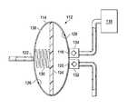
- FIG. 2is a schematic sectional diagram, illustrating additional details that may be associated with some example embodiments of the cartridge 112 .
- the cartridge 112may have many different shapes and sizes.
- the cartridge 112may be manufactured to physically couple to existing negative-pressure therapy products.
- the cartridge 112 and the components described belowmay be manufactured to resemble a canister, such as a Bemis canister that can be coupled to the negative-pressure source 104 .
- the cartridge 112may be manufactured to resemble a canister for a V.A.C. ULTATM negative-pressure wound therapy system manufactured by Kinetic Concepts, Inc.
- the embodiments described and illustrated beloware schematic representations, and the shape of the cartridge 112 may vary.
- the cartridge 112may have a housing 114 .
- the housing 114may form an outer portion of the cartridge 112 .
- the housing 114may be disposed inside another container so that the housing 114 may be enclosed in the cartridge 112 .
- the housing 114may generally define a chamber and have a structural arrangement to fluidly isolate the chamber from the ambient environment.
- the housing 114may be ovoid in shape and form an ovoid chamber having an oval cross-section.
- the housing 114may have other suitable shapes, such as spherical, cuboid, or amorphous shapes that form similarly shaped chambers having similarly shaped cross-sections.
- the shape of the chambermay not correspond with the shape of the housing 114 .
- the housing 114may be formed of EASTARTM DN004 produced by Eastman Chemical Company.
- the housing 114may be formed of Terlux® 2802HD or Terlux® 2822HD produced by Styrolution Group GmbH.
- a barriermay be disposed within the chamber of the housing 114 .
- a barriermay be a solid object positioned within the chamber of the housing 114 to divide the chamber of the housing 114 into two separate fluid chambers.
- a portion or an entirety of a barriermay be movable, such as a piston or a diaphragm 124 , to adjust respective volumes of the chambers created by the barrier.
- the diaphragm 124may be a membrane or a sheet of semi-flexible material having a periphery. The periphery of the diaphragm 124 may be coupled to the housing 114 to form a negative-pressure chamber 126 and a dosing chamber 128 .
- the periphery of the diaphragm 124may be coupled to the housing 114 so that the negative-pressure chamber 126 is fluidly isolated from the dosing chamber 128 .
- the diaphragm 124may be sealed to the housing 114 , may be welded to the housing 114 , or may be otherwise coupled to the housing 114 to prevent fluid movement across the diaphragm 124 .
- the diaphragm 124may be formed of an elastic or a semi-elastic material.
- the diaphragm 124may be formed of rubber, thermoplastic, or polytetrafluoroethlyene.
- the periphery of the diaphragm 124may be coupled to the housing 114 so that the diaphragm 124 may flex between a discharge position and a charge position.
- the discharge position of the diaphragm 124may be the position of the diaphragm 124 that maximizes the volume of the negative-pressure chamber 126 and minimizes the volume of the dosing chamber 128 .
- the charge position of the diaphragm 124may be the position of the diaphragm 124 that maximizes the volume of the dosing chamber 128 and minimizes the volume of the negative-pressure chamber 126 .
- the periphery of the diaphragm 124may be coupled proximate to a center of a cross-section of the housing 114 .
- the housing 114may form an ovoid or elliptical-shaped chamber having a transverse diameter and a conjugate diameter.
- the periphery of the diaphragm 124may be coupled to the housing 114 so that the diaphragm 124 coincides with the transverse diameter if the volumes of the negative-pressure chamber 126 and the dosing chamber 128 are equal, as shown in FIG. 2 .
- the diaphragm 124may be coupled to the housing 114 in other locations of the housing 114 .
- the dimensions of the diaphragm 124 , the negative-pressure chamber 126 , and the dosing chamber 128may be determined by the amount of fluid needed to provide instillation. For example, a tissue site may need approximately 5 milliliters of fluid to be dispensed with each operation of the cartridge 112 . Consequently, the dosing chamber 128 may have a volume of about 5 milliliters if the diaphragm 124 is in the charged position, and the negative-pressure chamber 126 may have a volume of about 5 milliliters if the diaphragm 124 is in the discharge position. If the housing 114 is spherical, then the dosing chamber 128 may have a radius given by:
- the radius of the dosing chamber 128 if the diaphragm 124 is in the charge positionis about 10.6 millimeters.
- the diaphragm 124may have a radius approximately equal to the radius of the dosing chamber 128 if the diaphragm 124 is in the charge position.
- the negative-pressure chamber 126may have a radius of about 10.6 millimeters if the diaphragm 124 is in the discharge position.
- the volume of the dosing chamber 128 if the diaphragm 124 is in the charge positionis between about 5 milliliters and about 10 milliliters. In other embodiments, the volume of the dosing chamber 128 may be varied as need to administer a therapeutic amount of fluid to a tissue site.
- the housing 114may be formed of two sheets of a polymer film having peripheral portions.
- the peripheral portions of each sheetmay be coupled together, such as by welding, adhering, or otherwise securing the peripheral portions of each sheet to each other.
- a third sheet of polymer materialmay be disposed between the first sheet and the second sheet of polymer material.
- the third sheetmay have peripheral portions coupled to the peripheral portions of the first and second sheet of polymer material to form the diaphragm 124 , the negative-pressure chamber 126 , and the dosing chamber 128 .
- the housing 114may have a negative-pressure inlet 122 .
- the negative-pressure inlet 122may be a fluid passage formed in the housing 114 to provide fluid communication with the negative-pressure chamber 126 .
- the negative-pressure inlet 122may be a tube having at least one lumen. The tube may be coupled to the housing 114 so that the lumen of the tube is in fluid communication with the negative-pressure chamber 126 .
- the negative-pressure inlet 122may be further fluidly coupled to the negative-pressure source 104 .
- the diaphragm 124may be biased to the discharge position.
- a biasing elementmay be disposed in the negative-pressure chamber 126 to bias the diaphragm 124 to the discharge position.
- a biasing elementmay be a spring 130 , for example.
- the spring 130may have a first end coupled to the housing 114 and a second end coupled to the diaphragm 124 .
- the spring 130may have an unloaded position and a loaded position. Generally, if no external force is acting on the spring 130 , the spring 130 is in the unloaded position. If the spring 130 is compressed or extended, the spring 130 may be in the loaded position.
- a springmay exert a reactive force in response to displacement from the unloaded position. The reactive force is generally proportional to the distance a spring is either compressed or extended if an external force loads the spring. As shown in FIG. 2 , the spring 130 may be partially compressed or partially loaded.
- the biasing elementmay be a foam disposed in the negative-pressure chamber 126 .
- the foammay be an open-cell reticulated foam having a spring rate similar to the spring 130 .
- the foammay be configured to compress along a length of the cylinder in response to the application of negative pressure.
- the cartridge 112may also have a fluid outlet 120 .
- the fluid outlet 120may be a fluid passage coupled to the housing 114 to provide fluid communication with the dosing chamber 128 .
- the fluid outlet 120may be a tube having at least one lumen. The tube may be coupled to the housing 114 so a lumen is in fluid communication with the dosing chamber 128 .
- the fluid outlet 120may be further fluidly coupled to a dressing, such as the dressing 102 . If the fluid outlet 120 is fluidly coupled to the dressing 102 , the dressing 102 may be in fluid communication with the dosing chamber 128 through the fluid outlet 120 .
- a valve 132may be fluidly coupled to the fluid outlet 120 to control fluid flow through the fluid outlet 120 .
- the valve 132may be coupled to the housing 114 , and the fluid outlet 120 may be coupled to the valve 132 so that the valve 132 is fluidly coupled between the fluid outlet 120 and the dosing chamber 128 .
- the valve 132may be coupled in other locations.
- the valve 132is a check valve.
- the valve 132may be fluidly coupled to the fluid outlet 120 to prevent fluid flow through the fluid outlet 120 into the dosing chamber 128 and permit fluid flow from the dosing chamber 128 into the fluid outlet 120 .
- FIG. 3is a schematic sectional diagram illustrating additional details that may be associated with some example embodiments of the cartridge 112 .
- the spring 130may be in the loaded position, and the diaphragm 124 may be in the charge position.
- the negative-pressure source 104may generate a negative-pressure in the negative-pressure chamber 126 by drawing fluid from the negative-pressure chamber 126 through the negative-pressure inlet 122 . Consequently, a negative-pressure may be generated in the negative-pressure chamber 126 .
- the increasing pressure differential between the negative-pressure chamber 126 and the dosing chamber 128may cause the diaphragm 124 to move toward the negative-pressure inlet 122 .
- Fluid at ambient pressure surrounding the housing 114may flow into the negative-pressure chamber 126 through the vent 136 if a negative pressure is generated in the negative-pressure chamber 126 .
- the negative-pressure source 104may draw fluid from the negative-pressure chamber 126 faster than the fluid at ambient pressure may flow into the negative-pressure chamber 126 through the vent 136 .
- the volume of the dosing chamber 128may increase.
- An increase in the volume of the dosing chamber 128may generate a negative pressure in the dosing chamber 128 that can draw fluid into the dosing chamber 128 through the fluid inlet 116 and the fluid outlet 120 .
- the valve 132may be closed to prevent the flow of fluid into the dosing chamber 128 through the fluid outlet 120
- the valve 134may be opened to allow the flow of fluid into the dosing chamber 128 through the fluid inlet 116 .
- fluidmay flow from the fluid source 118 , through the fluid inlet 116 , and into the dosing chamber 128 .
- the dosing chamber 128may be sized to hold a predetermined dose of instillation fluid for instillation of a tissue site.
- the dosing chamber 128may have a volume substantially equal to the amount of fluid necessary to provide a therapeutic dose of instillation fluid to a tissue site.
- a therapeutic dose of instillation fluidmay be a volume of fluid prescribed to be delivered to a tissue site to provide suitable therapeutic benefits to the tissue site.
- the volume of the dosing chamber 128may be larger or smaller than the therapeutic dose of instillation fluid.
- the reactive force generated by the compression of the spring 130may overcome the force exerted by the pressure differential between the negative-pressure chamber 126 and the dosing chamber 128 , causing the diaphragm 124 to move toward the fluid outlet 120 and the discharge position.
- the reactive force of the spring 130moves the diaphragm 124 toward the fluid outlet 120 , the diaphragm 124 may compress the fluid in the dosing chamber 128 . If the valve 134 is closed and the valve 132 is open, fluid may flow from the dosing chamber 128 , through the fluid outlet 120 , and to the dressing 102 to provide instillation therapy.
- the spring 130may be disposed in the dosing chamber 128 . If the spring 130 is disposed in the dosing chamber 128 , the spring 130 may be in an unloaded position if the diaphragm 124 is in the discharge position, and the spring 130 may be in a loaded position if the diaphragm 124 is in the charge position. Operation of the negative-pressure source 104 may cause the diaphragm 124 to extend the spring 130 , and the cessation of operation of the negative-pressure source 104 may allow the spring 130 to draw the diaphragm 124 to the discharge position.
- FIG. 5is a flow chart 500 illustrating exemplary logical operations that can be implemented in some embodiments of the therapy system 100 of FIG. 1 .
- the operationsmay be implemented by a controller operably associated with a negative-pressure source, such as the negative-pressure source 104 , configured to execute the operations.
- the negative-pressure source 104may have a mechanical apparatus adapted to be operated by a clinician for the selection of instillation or negative-pressure therapy.
- the negative-pressure source 104may include software or other control devices to determine if a canister for the collection of fluid from the tissue site is fluidly coupled to the negative-pressure source 104 .
- the negative-pressure source 104may also include software or other control devices to determine if a fluid instillation cartridge is fluidly coupled to the negative-pressure source 104 . In these embodiments, the negative-pressure source 104 may then provide negative-pressure therapy or instillation therapy based on the determination of the type of apparatus fluidly coupled to the negative-pressure source 104 .
- a negative-pressure sourcemay be operated to provide negative pressure to the cartridge.
- a controller of the negative-pressure source 104may operate the negative-pressure source 104 .
- a rate of change of negative-pressuremay be calculated.
- a controller of the negative-pressure source 104may calculate the rate of change of negative pressure based on one more pressure readings from a pressure sensor located in the negative-pressure source 104 .
- the rate of change of negative pressuremay indicate how quickly or slowly the negative pressure in the negative-pressure chamber 126 is increasing within a time period.
- the time periodmay be predetermined.
- the time periodmay correspond to a known amount of time that may be required to evacuate a canister.
- the rate of change of the negative pressureis greater than a threshold rate of change of the negative pressure.
- the rate of change of negative pressuremay be within a predetermined range.
- the cartridge 112is fluidly coupled to the negative-pressure source 104 , the rate of change of negative pressure may fall within a different predetermined range.
- a canister for negative-pressure therapymay have a larger volume than the negative-pressure chamber 126 of the cartridge 112 . Because the canister has a larger volume, the predetermined rate of change of negative pressure may be lower than the predetermined rate of change of negative pressure for the cartridge 112 .
- a controller of the negative-pressure source 104may determine if the rate of change of negative pressure is within the predetermined rate of change for the cartridge 112 , that is, high. In other embodiments, a controller of the negative-pressure source 104 may be programmed to compare the rate of change of negative pressure to a threshold rate of change of negative pressure for the cartridge 112 . If a controller is programmed to compare the rate of change of negative-pressure to the threshold rate of change of negative pressure for the cartridge 112 , a controller may determine if the rate of change of negative pressure is less than the threshold rate of change of negative pressure, that is, low.
- a cartridge for providing instillation therapyis fluidly coupled to the negative-pressure source.
- a controller of the negative-pressure source 104may determine that the cartridge 112 is fluidly coupled to the negative-pressure source 104 .
- a negative-pressure sourcemay be operated in an instill mode or an instill sequence to provide instillation therapy to a tissue site.
- a controller of the negative-pressure source 104may operate the negative-pressure source 104 and the cartridge 112 as described above with respect to FIGS. 2-4 to provide instillation therapy to a tissue site.
- a canister for negative-pressure therapyis fluidly coupled to the negative-pressure source.
- a controller of the negative-pressure source 104may determine that a canister for negative-pressure therapy is fluidly coupled to the negative-pressure source 104 .
- the empty volume of the canister or “dead space”can be calculated.
- a controller of the negative-pressure source 104may perform dead space calculations for the canister.
- the amount of dead space in a canistermay be calculated by supplying a negative-pressure to the canister and then venting the canister for about 1 second.
- the corresponding rise in pressure during the 1 second intervalis monitored to determine the empty volume of the canister.
- the calculations of the dead spacecan be used to determine if a fluidly coupled canister is full.
- a controller of the negative-pressure source 104can determine if a fluidly coupled canister is full.
- a negative-pressure sourcecan provide negative-pressure therapy at block 520 .
- a controller of the negative-pressure source 104can operate the negative-pressure source 104 to provide negative-pressure therapy to a tissue site.
- a full canister indicationmay be provided at block 522 .
- a controllermay provide a full canister indication on a user interface of the negative-pressure source 104 .
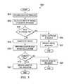
- FIG. 6is a flow chart 600 illustrating exemplary logical operations that can be implemented in some embodiments of the therapy system 100 of FIG. 1 .
- the operationsmay be implemented by a controller in a negative-pressure source, such as the negative-pressure source 104 , configured to execute the operations.
- a negative-pressure sourcemay be turned on.
- a controller of the negative-pressure source 104may turn on a pump in the negative-pressure source 104 to generate a negative pressure in the cartridge 112 .
- the pressure at the negative-pressure sourcemay be monitored.
- a controller of the negative-pressure source 104may monitor the pressure at the pump in the negative-pressure source 104 for a time interval, which may be predetermined.
- the time intervalmay correspond to a known amount of time that may be required to fill the dosing chamber 128 of the cartridge 112 with a dose of instillation fluid.
- the rate of change of the negative pressure at the negative-pressure sourcecan be determined.
- a controller of the negative-pressure source 104may monitor the rate of change of negative pressure at the negative-pressure source 104 for the time interval.
- a controller of the negative-pressure source 104may determine the rate of change of the negative pressure during the predetermined time.
- the rate of change of the pressure during the predetermined timemay indicate if a fluid source, such as the fluid source 118 is empty. For example, if the rate of change of the negative pressure is greater than a threshold rate of change of the negative pressure during the time interval, it can be inferred that the fluid source 118 may be empty.
- an empty bag errormay be provided at block 620 .
- a controllermay provide an empty bag error on a user interface of the negative-pressure source 104 .
- the fluid sourceis not empty, it can be determined at block 612 if a dose of fluid has filled the cartridge.
- the pressure in the negative-pressure source 104is stable, that is, maintaining a predetermined pressure within predetermined tolerances, the diaphragm 124 in the cartridge 112 may be positioned in the charge position adjacent to the negative-pressure inlet 122 .
- the predetermined pressure and predetermined tolerancesmay be based on known pressures that can be provided by the negative-pressure source 104 .
- the predetermined pressuremay be about ⁇ 100 mm Hg having a tolerance of about +/ ⁇ 10 mm Hg.
- a controller of the negative-pressure source 104may determine that the pressure is stable to determine if dose of fluid has filled the dosing chamber 128 of the cartridge 112 . If a dose of fluid has not filled the cartridge, a pressure at the negative-pressure source can be monitored at block 606 .
- the negative-pressure source 104may be turned off and a timer may be started.
- a controller of the negative-pressure source 104can turn off the negative-pressure source 104 and start a timer in the negative-pressure source 104 .
- a biasing elementsuch as the spring 130 may exert a reactive force on the diaphragm 124 , causing fluid to flow from the cartridge 112 to the tissue site as described above with respect to FIG. 4 .
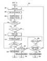
- the rate of change of negative pressure in the negative-pressure sourcecan be determined.
- a controller of the negative-pressure source 104can monitor the rate of change of negative pressure at the negative-pressure inlet 122 via a pressure sensor fluidly coupled to the negative-pressure inlet 122 . If fluid is flowing from the dosing chamber 128 through the fluid outlet 120 , the negative pressure in the negative-pressure chamber 126 may change at an expected rate. The expected rate may be based on the spring constant of the spring 130 , the size of the vent 136 , and the size of the dosing chamber 128 . If the rate of change of pressure is greater than or less than the expected rate of change of negative pressure associated with normal dosage of instillation fluid by the spring 130 and the diaphragm 124 , an error may have occurred. For example, if the rate of change of negative pressure is greater than the expected rate of change of negative pressure, the fluid source 118 may be empty. If the rate of change of pressure is less than the expected rate of change of pressure or does not change, the fluid outlet 120 may be blocked.
- an empty bag errormay be provided at block 620 .
- a controller of the negative-pressures sourcemay provide an empty bag error with a user interface of the negative-pressure source 104 .
- a negative-pressure sourcemay determine if the fluid outlet is blocked at block 622 .
- a controller of the negative-pressure source 104may determine if the fluid outlet 120 is blocked. If the fluid outlet is blocked an instill blockage error may be provided at block 624 .
- a controllermay provide an instill blockage error on the user interface of the negative-pressure source 104 .
- the negative-pressure sourcedetermines if the timer has expired at block 626 . If the timer has not expired, the rate of change of negative pressure may be determined at block 616 . For example, a controller of the negative-pressure source 104 can determine if the timer, started when the pump was stopped, has reached a predetermined time. The predetermined time may be based on an expected time interval for the fluid in the dosage chamber 128 to flow through the fluid outlet 120 . At block 626 , if the timer has expired, the negative-pressure source can determine if the total volume has been provided.
- a controller of the negative-pressure source 104can include a counter that increments upwards each time the pump of the negative-pressure source 104 is operated during the instillation therapy cycle. If the volume of the dosing chamber 128 when the diaphragm 124 is in the charge position is known, a controller can determine the total volume of fluid provided through the fluid outlet 120 . A controller can then compare the total volume of fluid provided to a predetermined volume of instillation fluid to be provided to determine if the predetermined volume of instillation fluid required has been provided. The predetermined volume of instillation fluid required may be based on a total volume prescribed by a clinician.
- the negative-pressure sourcemay be turned on at block 604 .
- a total volume dispensed indicationcan be provided.
- a controllermay provide a total volume dispensed indication on the user interface of the negative-pressure source 104 .
- FIG. 7is a schematic diagram of another cartridge 212 , illustrating details that may be associated with some example embodiments.
- the cartridge 212may be similar to and include elements of the cartridge 112 . Similar elements may have similar reference numbers that are indexed to 200 .
- the cartridge 212may include a housing 214 having a negative-pressure chamber 226 and an ambient chamber 238 formed by a diaphragm 224 .
- a biasing membersuch as a spring 230 , may be disposed in the negative-pressure chamber 226 and may be operatively coupled to the diaphragm 224 .
- the diaphragm 224may have a pinch valve, such as a boss 242 coupled to the diaphragm 224 .
- the boss 242may be coupled to the diaphragm 224 so that the boss 242 is disposed in the ambient chamber 238 .
- a tube 240may pass through the ambient chamber 238 and may be fluidly coupled to the fluid source 118 and the dressing 102 .
- the fluid source 118may be fluidly coupled so that gravity may urge fluid to flow from the fluid source 118 to the cartridge 212 .
- the negative-pressure source 104may be fluidly coupled to the negative-pressure chamber 226 .
- the housing 214may be similar to and operate as described with respect to the housing 114 .
- the diaphragm 224 , the spring 230 , and the negative-pressure chamber 226may be similar to and operate as described with respect to the diaphragm 124 , the spring 130 , and the negative-pressure chamber 126 .
- the ambient chamber 238may be configured to receive the tube 240 .
- the ambient chamber 238may be open to the ambient environment so that a pressure in the ambient chamber 238 may be substantially the same as a pressure in the ambient environment.
- the ambient chamber 238may have a wall 244 .
- the wall 244may be positioned opposite of the diaphragm 224 .
- the tube 240may pass through the ambient chamber 238 , and the wall 244 may be substantially parallel to an axis of the tube 240 .
- the boss 242may be a solid body having a triangularly shaped cross section, an apex 246 , and a base 248 .
- the base 248may be coupled to the diaphragm 224 so that the apex 246 is proximate to the wall 244 of the ambient chamber 238 .
- the apex 246 of the boss 242may be rounded.
- the boss 242may be coupled to the diaphragm 224 so that the boss 242 may move with the diaphragm 224 .
- the spring 230may be biased so that if the tube 240 passes through the ambient chamber 238 , the boss 242 may engage the tube 240 . If the boss 242 engages the tube 240 , the boss 242 may compress the tube 240 against the wall 244 . Compression of the tube 240 may restrict fluid flow through the tube 240 .
- FIG. 8is a schematic diagram illustrating additional details that may be associated with some example embodiments of the cartridge 212 .
- the negative-pressure source 104may be operated to draw fluid from the negative-pressure chamber 226 .
- a negative pressuremay be generated in the negative-pressure chamber 226 .
- Generation of a negative-pressure in the negative-pressure chamber 226may cause a pressure differential to arise across the diaphragm 224 . If the pressure in the negative-pressure chamber 226 is lower than the pressure in the ambient chamber 238 , the pressure differential may urge the diaphragm 224 away from the wall 244 .
- the boss 242may disengage from the tube 240 , uncompressing the tube 240 so that fluid may flow through the tube 240 from the fluid source 118 to the dressing 102 .
- Venting of the negative-pressure chamber 226such as through the negative-pressure source 104 , may decrease the pressure differential across the diaphragm 224 , allowing the spring 230 to move the diaphragm 224 back to the position of FIG. 7 so that the boss 242 engages the tube 240 to stop flow from the fluid source 118 to the dressing 102 .
- Example embodiments of the cartridgehave been described herein that can be combined with an existing negative-pressure wound treatment therapy system to provide controlled instillation therapy.
- the cartridgecan also be calibrated to provide a dosage of fluid at a pressure suitable for use with a tissue site, for example, approximately 100 mmHg.
- the cartridgecan also be calibrated to provide an accurate dosing of a prescribed amount of fluids.
- the cartridgecan be used with a multi-channel negative-pressure system so that the multi-channel negative-pressure system can provide both instillation and negative-pressure therapy.
- multiple cartridgescan be used with a multi-channel negative-pressure system to provide instillation of multiple different types of fluids.
- the cartridgemay also be combined with a tissue site drain to allow for continuous washing of the tissue site with instillation fluids.
- Example embodimentmay also include a negative-pressure therapy system having the capability to determine if a canister or an instillation cartridge is fluidly coupled to the negative-pressure source and provide an appropriate therapy in response to the determination.
Landscapes
- Health & Medical Sciences (AREA)
- Heart & Thoracic Surgery (AREA)
- Engineering & Computer Science (AREA)
- General Health & Medical Sciences (AREA)
- Veterinary Medicine (AREA)
- Biomedical Technology (AREA)
- Anesthesiology (AREA)
- Hematology (AREA)
- Life Sciences & Earth Sciences (AREA)
- Animal Behavior & Ethology (AREA)
- Public Health (AREA)
- Vascular Medicine (AREA)
- Physics & Mathematics (AREA)
- Fluid Mechanics (AREA)
- General Engineering & Computer Science (AREA)
- Pulmonology (AREA)
- Mechanical Engineering (AREA)
- Infusion, Injection, And Reservoir Apparatuses (AREA)
- Dermatology (AREA)
- Medical Informatics (AREA)
Abstract
Description
where r is the radius of a sphere in millimeters and V is the volume of the sphere in milliliters. For an exemplary 5 milliliter volume, the radius of the
Claims (36)
Priority Applications (3)
| Application Number | Priority Date | Filing Date | Title |
|---|---|---|---|
| US14/794,269US10350336B2 (en) | 2014-07-18 | 2015-07-08 | Disposable cartridge for vacuum actuated fluid delivery |
| US16/432,206US11890437B2 (en) | 2014-07-18 | 2019-06-05 | Disposable cartridge for vacuum actuated fluid delivery |
| US18/538,759US12403239B2 (en) | 2014-07-18 | 2023-12-13 | Disposable cartridge for vacuum actuated fluid delivery |
Applications Claiming Priority (2)
| Application Number | Priority Date | Filing Date | Title |
|---|---|---|---|
| US201462026500P | 2014-07-18 | 2014-07-18 | |
| US14/794,269US10350336B2 (en) | 2014-07-18 | 2015-07-08 | Disposable cartridge for vacuum actuated fluid delivery |
Related Child Applications (1)
| Application Number | Title | Priority Date | Filing Date |
|---|---|---|---|
| US16/432,206DivisionUS11890437B2 (en) | 2014-07-18 | 2019-06-05 | Disposable cartridge for vacuum actuated fluid delivery |
Publications (2)
| Publication Number | Publication Date |
|---|---|
| US20160015872A1 US20160015872A1 (en) | 2016-01-21 |
| US10350336B2true US10350336B2 (en) | 2019-07-16 |
Family
ID=53758525
Family Applications (3)
| Application Number | Title | Priority Date | Filing Date |
|---|---|---|---|
| US14/794,269Active2037-08-29US10350336B2 (en) | 2014-07-18 | 2015-07-08 | Disposable cartridge for vacuum actuated fluid delivery |
| US16/432,206Active2038-04-26US11890437B2 (en) | 2014-07-18 | 2019-06-05 | Disposable cartridge for vacuum actuated fluid delivery |
| US18/538,759Active2035-08-09US12403239B2 (en) | 2014-07-18 | 2023-12-13 | Disposable cartridge for vacuum actuated fluid delivery |
Family Applications After (2)
| Application Number | Title | Priority Date | Filing Date |
|---|---|---|---|
| US16/432,206Active2038-04-26US11890437B2 (en) | 2014-07-18 | 2019-06-05 | Disposable cartridge for vacuum actuated fluid delivery |
| US18/538,759Active2035-08-09US12403239B2 (en) | 2014-07-18 | 2023-12-13 | Disposable cartridge for vacuum actuated fluid delivery |
Country Status (3)
| Country | Link |
|---|---|
| US (3) | US10350336B2 (en) |
| EP (2) | EP3851134B1 (en) |
| WO (1) | WO2016010790A2 (en) |
Cited By (1)
| Publication number | Priority date | Publication date | Assignee | Title |
|---|---|---|---|---|
| US11896756B2 (en) | 2020-03-03 | 2024-02-13 | Deroyal Industries, Inc. | Negative pressure wound therapy instillation system |
Families Citing this family (22)
| Publication number | Priority date | Publication date | Assignee | Title |
|---|---|---|---|---|
| EP3297697B1 (en) | 2015-05-18 | 2022-05-11 | Smith & Nephew plc | Negative pressure wound therapy apparatus |
| AU2016305091B2 (en) | 2015-08-13 | 2021-06-10 | Smith & Nephew, Inc. | Systems and methods for applying reduced pressure therapy |
| US11185624B2 (en) | 2016-06-03 | 2021-11-30 | Kci Licensing, Inc. | Negative-pressure therapy with disposable instillation pump chamber |
| US11395870B2 (en) | 2017-02-15 | 2022-07-26 | Smith & Nephew Asia Pacific Pte. Limited | Negative pressure wound therapy apparatuses and methods for using the same |
| US20210145648A1 (en)* | 2017-06-09 | 2021-05-20 | Kci Licensing, Inc. | Granulating Chronic Wound Dressing |
| EP4275711A3 (en)* | 2017-07-18 | 2024-02-28 | 3M Innovative Properties Company | Negative-pressure therapy with adjustable instillation pump chamber |
| EP3687592B1 (en) | 2017-09-29 | 2025-09-03 | T.J. Smith & Nephew, Limited | Negative pressure wound therapy apparatus with removable panels |
| CN111836655A (en) | 2017-11-16 | 2020-10-27 | 康沃特克有限公司 | fluid collection equipment |
| GB201813282D0 (en) | 2018-08-15 | 2018-09-26 | Smith & Nephew | System for medical device activation and opertion |
| GB201804347D0 (en) | 2018-03-19 | 2018-05-02 | Smith & Nephew Inc | Securing control of settings of negative pressure wound therapy apparatuses and methods for using the same |
| USD888225S1 (en) | 2018-04-30 | 2020-06-23 | Smith & Nephew Asia Pacific Pte. Limited | Pump and canister assembly for negative pressure wound therapy |
| GB201806988D0 (en) | 2018-04-30 | 2018-06-13 | Quintanar Felix Clarence | Power source charging for negative pressure wound therapy apparatus |
| WO2019211731A1 (en) | 2018-04-30 | 2019-11-07 | Smith & Nephew Pte. Limited | Systems and methods for controlling dual mode negative pressure wound therapy apparatus |
| GB201808438D0 (en) | 2018-05-23 | 2018-07-11 | Smith & Nephew | Systems and methods for determining blockages in a negative pressure wound therapy system |
| US11701264B2 (en)* | 2018-06-27 | 2023-07-18 | Kci Licensing, Inc. | Wound therapy system with wound volume estimation using geometric approximation |
| WO2020051273A1 (en)* | 2018-09-05 | 2020-03-12 | Kci Licensing, Inc. | Systems and methods for scheduling and controlling wound therapy |
| EP3873551B1 (en)* | 2018-11-02 | 2025-10-15 | Solventum Intellectual Properties Company | Wound therapy tubeset system for wound volume estimation |
| EP3924016A1 (en)* | 2019-02-12 | 2021-12-22 | Amgen Inc. | Continuous dosing systems and approaches |
| US11266770B2 (en) | 2019-03-11 | 2022-03-08 | Kci Licensing, Inc. | Wound therapy system with fluid canister volume detection |
| GB201914283D0 (en) | 2019-10-03 | 2019-11-20 | Smith & Nephew | Apparatuses and methods for negative pressure wound therapy |
| US11504457B2 (en) | 2020-01-29 | 2022-11-22 | Travis L. Perry | Wound irrigation system |
| EP4138945A4 (en)* | 2020-04-22 | 2024-05-22 | NxStage Medical, Inc. | FLOW BALANCING DEVICES, METHODS AND SYSTEMS |
Citations (130)
| Publication number | Priority date | Publication date | Assignee | Title |
|---|---|---|---|---|
| US1355846A (en) | 1920-02-06 | 1920-10-19 | David A Rannells | Medical appliance |
| US2547758A (en) | 1949-01-05 | 1951-04-03 | Wilmer B Keeling | Instrument for treating the male urethra |
| US2632443A (en) | 1949-04-18 | 1953-03-24 | Eleanor P Lesher | Surgical dressing |
| GB692578A (en) | 1949-09-13 | 1953-06-10 | Minnesota Mining & Mfg | Improvements in or relating to drape sheets for surgical use |
| US2682873A (en) | 1952-07-30 | 1954-07-06 | Johnson & Johnson | General purpose protective dressing |
| US2910763A (en) | 1955-08-17 | 1959-11-03 | Du Pont | Felt-like products |
| US2969057A (en) | 1957-11-04 | 1961-01-24 | Brady Co W H | Nematodic swab |
| US3066672A (en) | 1960-09-27 | 1962-12-04 | Jr William H Crosby | Method and apparatus for serial sampling of intestinal juice |
| US3367332A (en) | 1965-08-27 | 1968-02-06 | Gen Electric | Product and process for establishing a sterile area of skin |
| US3520300A (en) | 1967-03-15 | 1970-07-14 | Amp Inc | Surgical sponge and suction device |
| US3568675A (en) | 1968-08-30 | 1971-03-09 | Clyde B Harvey | Fistula and penetrating wound dressing |
| US3648692A (en) | 1970-12-07 | 1972-03-14 | Parke Davis & Co | Medical-surgical dressing for burns and the like |
| US3682180A (en) | 1970-06-08 | 1972-08-08 | Coilform Co Inc | Drain clip for surgical drain |
| US3826254A (en) | 1973-02-26 | 1974-07-30 | Verco Ind | Needle or catheter retaining appliance |
| DE2640413A1 (en) | 1976-09-08 | 1978-03-09 | Wolf Gmbh Richard | CATHETER MONITORING DEVICE |
| US4080970A (en) | 1976-11-17 | 1978-03-28 | Miller Thomas J | Post-operative combination dressing and internal drain tube with external shield and tube connector |
| US4096853A (en) | 1975-06-21 | 1978-06-27 | Hoechst Aktiengesellschaft | Device for the introduction of contrast medium into an anus praeter |
| US4139004A (en) | 1977-02-17 | 1979-02-13 | Gonzalez Jr Harry | Bandage apparatus for treating burns |
| US4165748A (en) | 1977-11-07 | 1979-08-28 | Johnson Melissa C | Catheter tube holder |
| US4184510A (en) | 1977-03-15 | 1980-01-22 | Fibra-Sonics, Inc. | Valued device for controlling vacuum in surgery |
| WO1980002182A1 (en) | 1979-04-06 | 1980-10-16 | J Moss | Portable suction device for collecting fluids from a closed wound |
| US4233969A (en) | 1976-11-11 | 1980-11-18 | Lock Peter M | Wound dressing materials |
| US4245630A (en) | 1976-10-08 | 1981-01-20 | T. J. Smith & Nephew, Ltd. | Tearable composite strip of materials |
| US4256109A (en) | 1978-07-10 | 1981-03-17 | Nichols Robert L | Shut off valve for medical suction apparatus |
| US4261363A (en) | 1979-11-09 | 1981-04-14 | C. R. Bard, Inc. | Retention clips for body fluid drains |
| US4275721A (en) | 1978-11-28 | 1981-06-30 | Landstingens Inkopscentral Lic, Ekonomisk Forening | Vein catheter bandage |
| US4284079A (en) | 1979-06-28 | 1981-08-18 | Adair Edwin Lloyd | Method for applying a male incontinence device |
| US4297995A (en) | 1980-06-03 | 1981-11-03 | Key Pharmaceuticals, Inc. | Bandage containing attachment post |
| US4333468A (en) | 1980-08-18 | 1982-06-08 | Geist Robert W | Mesentery tube holder apparatus |
| US4373519A (en) | 1981-06-26 | 1983-02-15 | Minnesota Mining And Manufacturing Company | Composite wound dressing |
| US4382441A (en) | 1978-12-06 | 1983-05-10 | Svedman Paul | Device for treating tissues, for example skin |
| US4392853A (en) | 1981-03-16 | 1983-07-12 | Rudolph Muto | Sterile assembly for protecting and fastening an indwelling device |
| US4392858A (en) | 1981-07-16 | 1983-07-12 | Sherwood Medical Company | Wound drainage device |
| US4419097A (en) | 1981-07-31 | 1983-12-06 | Rexar Industries, Inc. | Attachment for catheter tube |
| EP0100148A1 (en) | 1982-07-06 | 1984-02-08 | Dow Corning Limited | Medical-surgical dressing and a process for the production thereof |
| US4465485A (en) | 1981-03-06 | 1984-08-14 | Becton, Dickinson And Company | Suction canister with unitary shut-off valve and filter features |
| EP0117632A2 (en) | 1983-01-27 | 1984-09-05 | Johnson & Johnson Products Inc. | Adhesive film dressing |
| US4475909A (en) | 1982-05-06 | 1984-10-09 | Eisenberg Melvin I | Male urinary device and method for applying the device |
| US4480638A (en) | 1980-03-11 | 1984-11-06 | Eduard Schmid | Cushion for holding an element of grafted skin |
| US4525166A (en) | 1981-11-21 | 1985-06-25 | Intermedicat Gmbh | Rolled flexible medical suction drainage device |
| US4525374A (en) | 1984-02-27 | 1985-06-25 | Manresa, Inc. | Treating hydrophobic filters to render them hydrophilic |
| US4540412A (en) | 1983-07-14 | 1985-09-10 | The Kendall Company | Device for moist heat therapy |
| US4543100A (en) | 1983-11-01 | 1985-09-24 | Brodsky Stuart A | Catheter and drain tube retainer |
| US4548202A (en) | 1983-06-20 | 1985-10-22 | Ethicon, Inc. | Mesh tissue fasteners |
| US4551139A (en) | 1982-02-08 | 1985-11-05 | Marion Laboratories, Inc. | Method and apparatus for burn wound treatment |
| EP0161865A2 (en) | 1984-05-03 | 1985-11-21 | Smith and Nephew Associated Companies p.l.c. | Adhesive wound dressing |
| US4569348A (en) | 1980-02-22 | 1986-02-11 | Velcro Usa Inc. | Catheter tube holder strap |
| AU550575B2 (en) | 1981-08-07 | 1986-03-27 | Richard Christian Wright | Wound drainage device |
| US4605399A (en) | 1984-12-04 | 1986-08-12 | Complex, Inc. | Transdermal infusion device |
| US4608041A (en) | 1981-10-14 | 1986-08-26 | Frese Nielsen | Device for treatment of wounds in body tissue of patients by exposure to jets of gas |
| US4640688A (en) | 1985-08-23 | 1987-02-03 | Mentor Corporation | Urine collection catheter |
| US4655754A (en) | 1984-11-09 | 1987-04-07 | Stryker Corporation | Vacuum wound drainage system and lipids baffle therefor |
| US4664662A (en) | 1984-08-02 | 1987-05-12 | Smith And Nephew Associated Companies Plc | Wound dressing |
| WO1987004626A1 (en) | 1986-01-31 | 1987-08-13 | Osmond, Roger, L., W. | Suction system for wound and gastro-intestinal drainage |
| US4710165A (en) | 1985-09-16 | 1987-12-01 | Mcneil Charles B | Wearable, variable rate suction/collection device |
| US4733659A (en) | 1986-01-17 | 1988-03-29 | Seton Company | Foam bandage |
| GB2195255A (en) | 1986-09-30 | 1988-04-07 | Vacutec Uk Limited | Method and apparatus for vacuum treatment of an epidermal surface |
| US4743232A (en) | 1986-10-06 | 1988-05-10 | The Clinipad Corporation | Package assembly for plastic film bandage |
| GB2197789A (en) | 1986-11-28 | 1988-06-02 | Smiths Industries Plc | Anti-foaming disinfectants used in surgical suction apparatus |
| US4758220A (en) | 1985-09-26 | 1988-07-19 | Alcon Laboratories, Inc. | Surgical cassette proximity sensing and latching apparatus |
| US4787888A (en) | 1987-06-01 | 1988-11-29 | University Of Connecticut | Disposable piezoelectric polymer bandage for percutaneous delivery of drugs and method for such percutaneous delivery (a) |
| US4826494A (en) | 1984-11-09 | 1989-05-02 | Stryker Corporation | Vacuum wound drainage system |
| US4838883A (en) | 1986-03-07 | 1989-06-13 | Nissho Corporation | Urine-collecting device |
| US4840187A (en) | 1986-09-11 | 1989-06-20 | Bard Limited | Sheath applicator |
| US4863449A (en) | 1987-07-06 | 1989-09-05 | Hollister Incorporated | Adhesive-lined elastic condom cathether |
| US4872450A (en) | 1984-08-17 | 1989-10-10 | Austad Eric D | Wound dressing and method of forming same |
| US4878901A (en) | 1986-10-10 | 1989-11-07 | Sachse Hans Ernst | Condom catheter, a urethral catheter for the prevention of ascending infections |
| GB2220357A (en) | 1988-05-28 | 1990-01-10 | Smiths Industries Plc | Medico-surgical containers |
| US4897081A (en) | 1984-05-25 | 1990-01-30 | Thermedics Inc. | Percutaneous access device |
| US4906240A (en) | 1988-02-01 | 1990-03-06 | Matrix Medica, Inc. | Adhesive-faced porous absorbent sheet and method of making same |
| US4906233A (en) | 1986-05-29 | 1990-03-06 | Terumo Kabushiki Kaisha | Method of securing a catheter body to a human skin surface |
| US4919654A (en) | 1988-08-03 | 1990-04-24 | Kalt Medical Corporation | IV clamp with membrane |
| CA2005436A1 (en) | 1988-12-13 | 1990-06-13 | Glenda G. Kalt | Transparent tracheostomy tube dressing |
| US4941882A (en) | 1987-03-14 | 1990-07-17 | Smith And Nephew Associated Companies, P.L.C. | Adhesive dressing for retaining a cannula on the skin |
| US4953565A (en) | 1986-11-26 | 1990-09-04 | Shunro Tachibana | Endermic application kits for external medicines |
| WO1990010424A1 (en) | 1989-03-16 | 1990-09-20 | Smith & Nephew Plc | Absorbent devices and precursors therefor |
| US4969880A (en) | 1989-04-03 | 1990-11-13 | Zamierowski David S | Wound dressing and treatment method |
| US4985019A (en) | 1988-03-11 | 1991-01-15 | Michelson Gary K | X-ray marker |
| GB2235877A (en) | 1989-09-18 | 1991-03-20 | Antonio Talluri | Closed wound suction apparatus |
| US5037397A (en) | 1985-05-03 | 1991-08-06 | Medical Distributors, Inc. | Universal clamp |
| US5086170A (en) | 1989-01-16 | 1992-02-04 | Roussel Uclaf | Process for the preparation of azabicyclo compounds |
| US5092858A (en) | 1990-03-20 | 1992-03-03 | Becton, Dickinson And Company | Liquid gelling agent distributor device |
| US5100396A (en) | 1989-04-03 | 1992-03-31 | Zamierowski David S | Fluidic connection system and method |
| US5134994A (en) | 1990-02-12 | 1992-08-04 | Say Sam L | Field aspirator in a soft pack with externally mounted container |
| US5149331A (en) | 1991-05-03 | 1992-09-22 | Ariel Ferdman | Method and device for wound closure |
| US5167613A (en) | 1992-03-23 | 1992-12-01 | The Kendall Company | Composite vented wound dressing |
| US5176663A (en) | 1987-12-02 | 1993-01-05 | Pal Svedman | Dressing having pad with compressibility limiting elements |
| WO1993009727A1 (en) | 1991-11-14 | 1993-05-27 | Wake Forest University | Method and apparatus for treating tissue damage |
| US5215522A (en) | 1984-07-23 | 1993-06-01 | Ballard Medical Products | Single use medical aspirating device and method |
| US5232453A (en) | 1989-07-14 | 1993-08-03 | E. R. Squibb & Sons, Inc. | Catheter holder |
| US5261883A (en) | 1990-10-26 | 1993-11-16 | Alcon Surgical, Inc. | Portable apparatus for controlling fluid flow to a surgical site |
| US5261893A (en) | 1989-04-03 | 1993-11-16 | Zamierowski David S | Fastening system and method |
| US5278100A (en) | 1991-11-08 | 1994-01-11 | Micron Technology, Inc. | Chemical vapor deposition technique for depositing titanium silicide on semiconductor wafers |
| US5279550A (en) | 1991-12-19 | 1994-01-18 | Gish Biomedical, Inc. | Orthopedic autotransfusion system |
| US5298015A (en) | 1989-07-11 | 1994-03-29 | Nippon Zeon Co., Ltd. | Wound dressing having a porous structure |
| US5342376A (en) | 1993-05-03 | 1994-08-30 | Dermagraphics, Inc. | Inserting device for a barbed tissue connector |
| US5344415A (en) | 1993-06-15 | 1994-09-06 | Deroyal Industries, Inc. | Sterile system for dressing vascular access site |
| DE4306478A1 (en) | 1993-03-02 | 1994-09-08 | Wolfgang Dr Wagner | Drainage device, in particular pleural drainage device, and drainage method |
| WO1994020041A1 (en) | 1993-03-09 | 1994-09-15 | Wake Forest University | Wound treatment employing reduced pressure |
| US5358494A (en) | 1989-07-11 | 1994-10-25 | Svedman Paul | Irrigation dressing |
| US5437622A (en) | 1992-04-29 | 1995-08-01 | Laboratoire Hydrex (Sa) | Transparent adhesive dressing with reinforced starter cuts |
| US5437651A (en) | 1993-09-01 | 1995-08-01 | Research Medical, Inc. | Medical suction apparatus |
| DE29504378U1 (en) | 1995-03-15 | 1995-09-14 | MTG Medizinisch, technische Gerätebau GmbH, 66299 Friedrichsthal | Electronically controlled low-vacuum pump for chest and wound drainage |
| WO1996005873A1 (en) | 1994-08-22 | 1996-02-29 | Kinetic Concepts Inc. | Wound drainage equipment |
| US5527293A (en) | 1989-04-03 | 1996-06-18 | Kinetic Concepts, Inc. | Fastening system and method |
| US5542918A (en)* | 1995-01-06 | 1996-08-06 | Zimmer, Inc. | Vacuum driven fluid pump for an aspiration/irrigation instrument |
| US5549584A (en) | 1994-02-14 | 1996-08-27 | The Kendall Company | Apparatus for removing fluid from a wound |
| US5554011A (en)* | 1994-10-27 | 1996-09-10 | Symbiosis Corporation | Medical fluid pump powered by a constant source of vacuum |
| US5556375A (en) | 1994-06-16 | 1996-09-17 | Hercules Incorporated | Wound dressing having a fenestrated base layer |
| US5607388A (en) | 1994-06-16 | 1997-03-04 | Hercules Incorporated | Multi-purpose wound dressing |
| WO1997018007A1 (en) | 1995-11-14 | 1997-05-22 | Kci Medical Limited | Portable wound treatment apparatus |
| GB2329127A (en) | 1997-09-12 | 1999-03-17 | Kci Medical Ltd | Suction head and drape wound treatment assembly |
| US6071267A (en) | 1998-02-06 | 2000-06-06 | Kinetic Concepts, Inc. | Medical patient fluid management interface system and method |
| US6135116A (en) | 1997-07-28 | 2000-10-24 | Kci Licensing, Inc. | Therapeutic method for treating ulcers |
| US6241747B1 (en) | 1993-05-03 | 2001-06-05 | Quill Medical, Inc. | Barbed Bodily tissue connector |
| US6250505B1 (en)* | 2000-03-29 | 2001-06-26 | The Gillette Company | Fluid dispensers |
| US6287316B1 (en) | 1999-03-26 | 2001-09-11 | Ethicon, Inc. | Knitted surgical mesh |
| US20020077661A1 (en) | 2000-12-20 | 2002-06-20 | Vahid Saadat | Multi-barbed device for retaining tissue in apposition and methods of use |
| US20020115951A1 (en) | 2001-02-22 | 2002-08-22 | Core Products International, Inc. | Ankle brace providing upper and lower ankle adjustment |
| US20020120185A1 (en) | 2000-05-26 | 2002-08-29 | Kci Licensing, Inc. | System for combined transcutaneous blood gas monitoring and vacuum assisted wound closure |
| US20020143286A1 (en) | 2001-03-05 | 2002-10-03 | Kci Licensing, Inc. | Vacuum assisted wound treatment apparatus and infection identification system and method |
| US6488643B1 (en) | 1998-10-08 | 2002-12-03 | Kci Licensing, Inc. | Wound healing foot wrap |
| US6493568B1 (en) | 1994-07-19 | 2002-12-10 | Kci Licensing, Inc. | Patient interface system |
| AU755496B2 (en) | 1997-09-12 | 2002-12-12 | Kci Licensing, Inc. | Surgical drape and suction head for wound treatment |
| JP4129536B2 (en) | 2000-02-24 | 2008-08-06 | ヴェネテック インターナショナル,インコーポレイテッド | Highly compatible catheter anchoring system |
| WO2012162287A1 (en) | 2011-05-26 | 2012-11-29 | Kci Licensing, Inc. | Systems and methods of stimulation and activation of fluids for use with instillation therapy |
| WO2015066622A1 (en) | 2013-11-01 | 2015-05-07 | Allegiance Corporation | Pneumatic pump system and related methods |
| US20160015871A1 (en)* | 2014-07-18 | 2016-01-21 | Kci Licensing, Inc. | Instillation cartridge for vacuum actuated fluid delivery |
| US20160015873A1 (en)* | 2014-07-18 | 2016-01-21 | Kci Licensing, Inc. | Instillation cartridge and therapy system for negative-pressure therapy and instillation therapy |
| US20180059690A1 (en)* | 2011-11-16 | 2018-03-01 | Zane Coleman | Device with dynamic optical states using fluids with different optical properties |
Family Cites Families (20)
| Publication number | Priority date | Publication date | Assignee | Title |
|---|---|---|---|---|
| US3932065A (en)* | 1973-07-26 | 1976-01-13 | Coulter Electronics, Inc. | Pneumatically controlled liquid transfer system |
| US4077263A (en)* | 1975-07-30 | 1978-03-07 | Brailsford Harrison D | Vacuum operated sampler |
| US5836909A (en)* | 1996-09-13 | 1998-11-17 | Cosmescu; Ioan | Automatic fluid control system for use in open and laparoscopic laser surgery and electrosurgery and method therefor |
| US7846141B2 (en) | 2002-09-03 | 2010-12-07 | Bluesky Medical Group Incorporated | Reduced pressure treatment system |
| GB0224986D0 (en) | 2002-10-28 | 2002-12-04 | Smith & Nephew | Apparatus |
| GB0325120D0 (en) | 2003-10-28 | 2003-12-03 | Smith & Nephew | Apparatus with actives |
| GB0325126D0 (en) | 2003-10-28 | 2003-12-03 | Smith & Nephew | Apparatus with heat |
| US7909805B2 (en) | 2004-04-05 | 2011-03-22 | Bluesky Medical Group Incorporated | Flexible reduced pressure treatment appliance |
| US8529548B2 (en) | 2004-04-27 | 2013-09-10 | Smith & Nephew Plc | Wound treatment apparatus and method |
| US8057411B2 (en)* | 2007-04-25 | 2011-11-15 | General Patent, Llc | Wound care vacuum bandaging in combination with acoustic shock wave applications |
| US7746620B2 (en)* | 2008-02-22 | 2010-06-29 | Baxter International Inc. | Medical fluid machine having solenoid control system with temperature compensation |
| US8021347B2 (en) | 2008-07-21 | 2011-09-20 | Tyco Healthcare Group Lp | Thin film wound dressing |
| US8007481B2 (en) | 2008-07-17 | 2011-08-30 | Tyco Healthcare Group Lp | Subatmospheric pressure mechanism for wound therapy system |
| US8216198B2 (en) | 2009-01-09 | 2012-07-10 | Tyco Healthcare Group Lp | Canister for receiving wound exudate in a negative pressure therapy system |
| US8251979B2 (en) | 2009-05-11 | 2012-08-28 | Tyco Healthcare Group Lp | Orientation independent canister for a negative pressure wound therapy device |
| US9677555B2 (en)* | 2011-12-21 | 2017-06-13 | Deka Products Limited Partnership | System, method, and apparatus for infusing fluid |
| WO2012143693A1 (en)* | 2011-04-18 | 2012-10-26 | Martin John Hofmann | Apparatus and methods for fluid processing and flow control |
| CA2851495A1 (en)* | 2011-09-30 | 2013-04-04 | Eksigent Technologies, Llc | Electrokinetic pump based wound treatment system and methods |
| EP2626049B1 (en)* | 2012-02-11 | 2018-07-25 | Paul Hartmann AG | Wound treatment device |
| US9545508B2 (en)* | 2012-06-12 | 2017-01-17 | Carefusion 303, Inc. | Drip chamber |
- 2015
- 2015-07-08EPEP21161086.0Apatent/EP3851134B1/enactiveActive
- 2015-07-08WOPCT/US2015/039605patent/WO2016010790A2/enactiveApplication Filing
- 2015-07-08EPEP15742442.5Apatent/EP3169380B1/enactiveActive
- 2015-07-08USUS14/794,269patent/US10350336B2/enactiveActive
- 2019
- 2019-06-05USUS16/432,206patent/US11890437B2/enactiveActive
- 2023
- 2023-12-13USUS18/538,759patent/US12403239B2/enactiveActive
Patent Citations (140)
| Publication number | Priority date | Publication date | Assignee | Title |
|---|---|---|---|---|
| US1355846A (en) | 1920-02-06 | 1920-10-19 | David A Rannells | Medical appliance |
| US2547758A (en) | 1949-01-05 | 1951-04-03 | Wilmer B Keeling | Instrument for treating the male urethra |
| US2632443A (en) | 1949-04-18 | 1953-03-24 | Eleanor P Lesher | Surgical dressing |
| GB692578A (en) | 1949-09-13 | 1953-06-10 | Minnesota Mining & Mfg | Improvements in or relating to drape sheets for surgical use |
| US2682873A (en) | 1952-07-30 | 1954-07-06 | Johnson & Johnson | General purpose protective dressing |
| US2910763A (en) | 1955-08-17 | 1959-11-03 | Du Pont | Felt-like products |
| US2969057A (en) | 1957-11-04 | 1961-01-24 | Brady Co W H | Nematodic swab |
| US3066672A (en) | 1960-09-27 | 1962-12-04 | Jr William H Crosby | Method and apparatus for serial sampling of intestinal juice |
| US3367332A (en) | 1965-08-27 | 1968-02-06 | Gen Electric | Product and process for establishing a sterile area of skin |
| US3520300A (en) | 1967-03-15 | 1970-07-14 | Amp Inc | Surgical sponge and suction device |
| US3568675A (en) | 1968-08-30 | 1971-03-09 | Clyde B Harvey | Fistula and penetrating wound dressing |
| US3682180A (en) | 1970-06-08 | 1972-08-08 | Coilform Co Inc | Drain clip for surgical drain |
| US3648692A (en) | 1970-12-07 | 1972-03-14 | Parke Davis & Co | Medical-surgical dressing for burns and the like |
| US3826254A (en) | 1973-02-26 | 1974-07-30 | Verco Ind | Needle or catheter retaining appliance |
| US4096853A (en) | 1975-06-21 | 1978-06-27 | Hoechst Aktiengesellschaft | Device for the introduction of contrast medium into an anus praeter |
| DE2640413A1 (en) | 1976-09-08 | 1978-03-09 | Wolf Gmbh Richard | CATHETER MONITORING DEVICE |
| US4245630A (en) | 1976-10-08 | 1981-01-20 | T. J. Smith & Nephew, Ltd. | Tearable composite strip of materials |
| US4233969A (en) | 1976-11-11 | 1980-11-18 | Lock Peter M | Wound dressing materials |
| US4080970A (en) | 1976-11-17 | 1978-03-28 | Miller Thomas J | Post-operative combination dressing and internal drain tube with external shield and tube connector |
| US4139004A (en) | 1977-02-17 | 1979-02-13 | Gonzalez Jr Harry | Bandage apparatus for treating burns |
| US4184510A (en) | 1977-03-15 | 1980-01-22 | Fibra-Sonics, Inc. | Valued device for controlling vacuum in surgery |
| US4165748A (en) | 1977-11-07 | 1979-08-28 | Johnson Melissa C | Catheter tube holder |
| US4256109A (en) | 1978-07-10 | 1981-03-17 | Nichols Robert L | Shut off valve for medical suction apparatus |
| US4275721A (en) | 1978-11-28 | 1981-06-30 | Landstingens Inkopscentral Lic, Ekonomisk Forening | Vein catheter bandage |
| US4382441A (en) | 1978-12-06 | 1983-05-10 | Svedman Paul | Device for treating tissues, for example skin |
| WO1980002182A1 (en) | 1979-04-06 | 1980-10-16 | J Moss | Portable suction device for collecting fluids from a closed wound |
| US4284079A (en) | 1979-06-28 | 1981-08-18 | Adair Edwin Lloyd | Method for applying a male incontinence device |
| US4261363A (en) | 1979-11-09 | 1981-04-14 | C. R. Bard, Inc. | Retention clips for body fluid drains |
| US4569348A (en) | 1980-02-22 | 1986-02-11 | Velcro Usa Inc. | Catheter tube holder strap |
| US4480638A (en) | 1980-03-11 | 1984-11-06 | Eduard Schmid | Cushion for holding an element of grafted skin |
| US4297995A (en) | 1980-06-03 | 1981-11-03 | Key Pharmaceuticals, Inc. | Bandage containing attachment post |
| US4333468A (en) | 1980-08-18 | 1982-06-08 | Geist Robert W | Mesentery tube holder apparatus |
| US4465485A (en) | 1981-03-06 | 1984-08-14 | Becton, Dickinson And Company | Suction canister with unitary shut-off valve and filter features |
| US4392853A (en) | 1981-03-16 | 1983-07-12 | Rudolph Muto | Sterile assembly for protecting and fastening an indwelling device |
| US4373519A (en) | 1981-06-26 | 1983-02-15 | Minnesota Mining And Manufacturing Company | Composite wound dressing |
| US4392858A (en) | 1981-07-16 | 1983-07-12 | Sherwood Medical Company | Wound drainage device |
| US4419097A (en) | 1981-07-31 | 1983-12-06 | Rexar Industries, Inc. | Attachment for catheter tube |
| AU550575B2 (en) | 1981-08-07 | 1986-03-27 | Richard Christian Wright | Wound drainage device |
| US4608041A (en) | 1981-10-14 | 1986-08-26 | Frese Nielsen | Device for treatment of wounds in body tissue of patients by exposure to jets of gas |
| US4525166A (en) | 1981-11-21 | 1985-06-25 | Intermedicat Gmbh | Rolled flexible medical suction drainage device |
| US4551139A (en) | 1982-02-08 | 1985-11-05 | Marion Laboratories, Inc. | Method and apparatus for burn wound treatment |
| US4475909A (en) | 1982-05-06 | 1984-10-09 | Eisenberg Melvin I | Male urinary device and method for applying the device |
| EP0100148A1 (en) | 1982-07-06 | 1984-02-08 | Dow Corning Limited | Medical-surgical dressing and a process for the production thereof |
| EP0117632A2 (en) | 1983-01-27 | 1984-09-05 | Johnson & Johnson Products Inc. | Adhesive film dressing |
| US4548202A (en) | 1983-06-20 | 1985-10-22 | Ethicon, Inc. | Mesh tissue fasteners |
| US4540412A (en) | 1983-07-14 | 1985-09-10 | The Kendall Company | Device for moist heat therapy |
| US4543100A (en) | 1983-11-01 | 1985-09-24 | Brodsky Stuart A | Catheter and drain tube retainer |
| US4525374A (en) | 1984-02-27 | 1985-06-25 | Manresa, Inc. | Treating hydrophobic filters to render them hydrophilic |
| EP0161865A2 (en) | 1984-05-03 | 1985-11-21 | Smith and Nephew Associated Companies p.l.c. | Adhesive wound dressing |
| US4897081A (en) | 1984-05-25 | 1990-01-30 | Thermedics Inc. | Percutaneous access device |
| US5215522A (en) | 1984-07-23 | 1993-06-01 | Ballard Medical Products | Single use medical aspirating device and method |
| US4664662A (en) | 1984-08-02 | 1987-05-12 | Smith And Nephew Associated Companies Plc | Wound dressing |
| US4872450A (en) | 1984-08-17 | 1989-10-10 | Austad Eric D | Wound dressing and method of forming same |
| US4655754A (en) | 1984-11-09 | 1987-04-07 | Stryker Corporation | Vacuum wound drainage system and lipids baffle therefor |
| US4826494A (en) | 1984-11-09 | 1989-05-02 | Stryker Corporation | Vacuum wound drainage system |
| US4605399A (en) | 1984-12-04 | 1986-08-12 | Complex, Inc. | Transdermal infusion device |
| US5037397A (en) | 1985-05-03 | 1991-08-06 | Medical Distributors, Inc. | Universal clamp |
| US4640688A (en) | 1985-08-23 | 1987-02-03 | Mentor Corporation | Urine collection catheter |
| US4710165A (en) | 1985-09-16 | 1987-12-01 | Mcneil Charles B | Wearable, variable rate suction/collection device |
| US4758220A (en) | 1985-09-26 | 1988-07-19 | Alcon Laboratories, Inc. | Surgical cassette proximity sensing and latching apparatus |
| US4733659A (en) | 1986-01-17 | 1988-03-29 | Seton Company | Foam bandage |
| WO1987004626A1 (en) | 1986-01-31 | 1987-08-13 | Osmond, Roger, L., W. | Suction system for wound and gastro-intestinal drainage |
| US4838883A (en) | 1986-03-07 | 1989-06-13 | Nissho Corporation | Urine-collecting device |
| US4906233A (en) | 1986-05-29 | 1990-03-06 | Terumo Kabushiki Kaisha | Method of securing a catheter body to a human skin surface |
| US4840187A (en) | 1986-09-11 | 1989-06-20 | Bard Limited | Sheath applicator |
| GB2195255A (en) | 1986-09-30 | 1988-04-07 | Vacutec Uk Limited | Method and apparatus for vacuum treatment of an epidermal surface |
| US4743232A (en) | 1986-10-06 | 1988-05-10 | The Clinipad Corporation | Package assembly for plastic film bandage |
| US4878901A (en) | 1986-10-10 | 1989-11-07 | Sachse Hans Ernst | Condom catheter, a urethral catheter for the prevention of ascending infections |
| US4953565A (en) | 1986-11-26 | 1990-09-04 | Shunro Tachibana | Endermic application kits for external medicines |
| GB2197789A (en) | 1986-11-28 | 1988-06-02 | Smiths Industries Plc | Anti-foaming disinfectants used in surgical suction apparatus |
| US4941882A (en) | 1987-03-14 | 1990-07-17 | Smith And Nephew Associated Companies, P.L.C. | Adhesive dressing for retaining a cannula on the skin |
| US4787888A (en) | 1987-06-01 | 1988-11-29 | University Of Connecticut | Disposable piezoelectric polymer bandage for percutaneous delivery of drugs and method for such percutaneous delivery (a) |
| US4863449A (en) | 1987-07-06 | 1989-09-05 | Hollister Incorporated | Adhesive-lined elastic condom cathether |
| US5176663A (en) | 1987-12-02 | 1993-01-05 | Pal Svedman | Dressing having pad with compressibility limiting elements |
| US4906240A (en) | 1988-02-01 | 1990-03-06 | Matrix Medica, Inc. | Adhesive-faced porous absorbent sheet and method of making same |
| US4985019A (en) | 1988-03-11 | 1991-01-15 | Michelson Gary K | X-ray marker |
| GB2220357A (en) | 1988-05-28 | 1990-01-10 | Smiths Industries Plc | Medico-surgical containers |
| EP0358302A2 (en) | 1988-05-28 | 1990-03-14 | Smiths Industries Public Limited Company | Medico-surgical suction container |
| US4919654A (en) | 1988-08-03 | 1990-04-24 | Kalt Medical Corporation | IV clamp with membrane |
| CA2005436A1 (en) | 1988-12-13 | 1990-06-13 | Glenda G. Kalt | Transparent tracheostomy tube dressing |
| US5086170A (en) | 1989-01-16 | 1992-02-04 | Roussel Uclaf | Process for the preparation of azabicyclo compounds |
| WO1990010424A1 (en) | 1989-03-16 | 1990-09-20 | Smith & Nephew Plc | Absorbent devices and precursors therefor |
| US5100396A (en) | 1989-04-03 | 1992-03-31 | Zamierowski David S | Fluidic connection system and method |
| US5527293A (en) | 1989-04-03 | 1996-06-18 | Kinetic Concepts, Inc. | Fastening system and method |
| US4969880A (en) | 1989-04-03 | 1990-11-13 | Zamierowski David S | Wound dressing and treatment method |
| US5261893A (en) | 1989-04-03 | 1993-11-16 | Zamierowski David S | Fastening system and method |
| US5298015A (en) | 1989-07-11 | 1994-03-29 | Nippon Zeon Co., Ltd. | Wound dressing having a porous structure |
| US5358494A (en) | 1989-07-11 | 1994-10-25 | Svedman Paul | Irrigation dressing |
| US5232453A (en) | 1989-07-14 | 1993-08-03 | E. R. Squibb & Sons, Inc. | Catheter holder |
| GB2235877A (en) | 1989-09-18 | 1991-03-20 | Antonio Talluri | Closed wound suction apparatus |
| US5134994A (en) | 1990-02-12 | 1992-08-04 | Say Sam L | Field aspirator in a soft pack with externally mounted container |
| US5092858A (en) | 1990-03-20 | 1992-03-03 | Becton, Dickinson And Company | Liquid gelling agent distributor device |
| US5261883A (en) | 1990-10-26 | 1993-11-16 | Alcon Surgical, Inc. | Portable apparatus for controlling fluid flow to a surgical site |
| US5149331A (en) | 1991-05-03 | 1992-09-22 | Ariel Ferdman | Method and device for wound closure |
| US5278100A (en) | 1991-11-08 | 1994-01-11 | Micron Technology, Inc. | Chemical vapor deposition technique for depositing titanium silicide on semiconductor wafers |
| US5636643A (en) | 1991-11-14 | 1997-06-10 | Wake Forest University | Wound treatment employing reduced pressure |
| US5645081A (en) | 1991-11-14 | 1997-07-08 | Wake Forest University | Method of treating tissue damage and apparatus for same |
| WO1993009727A1 (en) | 1991-11-14 | 1993-05-27 | Wake Forest University | Method and apparatus for treating tissue damage |
| US5279550A (en) | 1991-12-19 | 1994-01-18 | Gish Biomedical, Inc. | Orthopedic autotransfusion system |
| US5167613A (en) | 1992-03-23 | 1992-12-01 | The Kendall Company | Composite vented wound dressing |
| US5437622A (en) | 1992-04-29 | 1995-08-01 | Laboratoire Hydrex (Sa) | Transparent adhesive dressing with reinforced starter cuts |
| DE4306478A1 (en) | 1993-03-02 | 1994-09-08 | Wolfgang Dr Wagner | Drainage device, in particular pleural drainage device, and drainage method |
| WO1994020041A1 (en) | 1993-03-09 | 1994-09-15 | Wake Forest University | Wound treatment employing reduced pressure |
| US5342376A (en) | 1993-05-03 | 1994-08-30 | Dermagraphics, Inc. | Inserting device for a barbed tissue connector |
| US6241747B1 (en) | 1993-05-03 | 2001-06-05 | Quill Medical, Inc. | Barbed Bodily tissue connector |
| US5344415A (en) | 1993-06-15 | 1994-09-06 | Deroyal Industries, Inc. | Sterile system for dressing vascular access site |
| US5437651A (en) | 1993-09-01 | 1995-08-01 | Research Medical, Inc. | Medical suction apparatus |
| US5549584A (en) | 1994-02-14 | 1996-08-27 | The Kendall Company | Apparatus for removing fluid from a wound |
| US5556375A (en) | 1994-06-16 | 1996-09-17 | Hercules Incorporated | Wound dressing having a fenestrated base layer |
| US5607388A (en) | 1994-06-16 | 1997-03-04 | Hercules Incorporated | Multi-purpose wound dressing |
| US6493568B1 (en) | 1994-07-19 | 2002-12-10 | Kci Licensing, Inc. | Patient interface system |
| WO1996005873A1 (en) | 1994-08-22 | 1996-02-29 | Kinetic Concepts Inc. | Wound drainage equipment |
| US5554011A (en)* | 1994-10-27 | 1996-09-10 | Symbiosis Corporation | Medical fluid pump powered by a constant source of vacuum |
| US5542918A (en)* | 1995-01-06 | 1996-08-06 | Zimmer, Inc. | Vacuum driven fluid pump for an aspiration/irrigation instrument |
| DE29504378U1 (en) | 1995-03-15 | 1995-09-14 | MTG Medizinisch, technische Gerätebau GmbH, 66299 Friedrichsthal | Electronically controlled low-vacuum pump for chest and wound drainage |
| WO1997018007A1 (en) | 1995-11-14 | 1997-05-22 | Kci Medical Limited | Portable wound treatment apparatus |
| US6135116A (en) | 1997-07-28 | 2000-10-24 | Kci Licensing, Inc. | Therapeutic method for treating ulcers |
| AU755496B2 (en) | 1997-09-12 | 2002-12-12 | Kci Licensing, Inc. | Surgical drape and suction head for wound treatment |
| US6814079B2 (en) | 1997-09-12 | 2004-11-09 | Kci Licensing, Inc. | Surgical drape and suction head for wound treatment |
| EP1018967A1 (en) | 1997-09-12 | 2000-07-19 | KCI Medical Ltd. | Surgical drape and suction head for wound treatment |
| GB2333965A (en) | 1997-09-12 | 1999-08-11 | Kci Medical Ltd | Surgical drape |
| US6553998B2 (en) | 1997-09-12 | 2003-04-29 | Kci Licensing, Inc. | Surgical drape and suction head for wound treatment |
| GB2329127A (en) | 1997-09-12 | 1999-03-17 | Kci Medical Ltd | Suction head and drape wound treatment assembly |
| US6345623B1 (en) | 1997-09-12 | 2002-02-12 | Keith Patrick Heaton | Surgical drape and suction head for wound treatment |
| AU745271B2 (en) | 1997-09-12 | 2002-03-14 | Kci Licensing, Inc. | Surgical drape and suction head for wound treatment |
| WO1999013793A1 (en) | 1997-09-12 | 1999-03-25 | Kci Medical Limited | Surgical drape and suction head for wound treatment |
| US6071267A (en) | 1998-02-06 | 2000-06-06 | Kinetic Concepts, Inc. | Medical patient fluid management interface system and method |
| US6488643B1 (en) | 1998-10-08 | 2002-12-03 | Kci Licensing, Inc. | Wound healing foot wrap |
| US6287316B1 (en) | 1999-03-26 | 2001-09-11 | Ethicon, Inc. | Knitted surgical mesh |
| JP4129536B2 (en) | 2000-02-24 | 2008-08-06 | ヴェネテック インターナショナル,インコーポレイテッド | Highly compatible catheter anchoring system |
| US6250505B1 (en)* | 2000-03-29 | 2001-06-26 | The Gillette Company | Fluid dispensers |
| US20020120185A1 (en) | 2000-05-26 | 2002-08-29 | Kci Licensing, Inc. | System for combined transcutaneous blood gas monitoring and vacuum assisted wound closure |
| US20020077661A1 (en) | 2000-12-20 | 2002-06-20 | Vahid Saadat | Multi-barbed device for retaining tissue in apposition and methods of use |
| US20020115951A1 (en) | 2001-02-22 | 2002-08-22 | Core Products International, Inc. | Ankle brace providing upper and lower ankle adjustment |
| US20020143286A1 (en) | 2001-03-05 | 2002-10-03 | Kci Licensing, Inc. | Vacuum assisted wound treatment apparatus and infection identification system and method |
| WO2012162287A1 (en) | 2011-05-26 | 2012-11-29 | Kci Licensing, Inc. | Systems and methods of stimulation and activation of fluids for use with instillation therapy |
| US20180059690A1 (en)* | 2011-11-16 | 2018-03-01 | Zane Coleman | Device with dynamic optical states using fluids with different optical properties |
| WO2015066622A1 (en) | 2013-11-01 | 2015-05-07 | Allegiance Corporation | Pneumatic pump system and related methods |
| US20160015871A1 (en)* | 2014-07-18 | 2016-01-21 | Kci Licensing, Inc. | Instillation cartridge for vacuum actuated fluid delivery |
| US20160015873A1 (en)* | 2014-07-18 | 2016-01-21 | Kci Licensing, Inc. | Instillation cartridge and therapy system for negative-pressure therapy and instillation therapy |
Non-Patent Citations (43)
| Title |
|---|
| A.A. Safronov, Dissertation Abstract, Vacuum Therapy of Trophic Ulcers of the Lower Leg with Simultaneous Autoplasty of the Skin (Central Scientific Research Institute of Traumatology and Orthopedics, Moscow, U.S.S.R. 1967) (copy and certified translation). |
| Arnljots, Bjorn et al.: "Irrigation Treatment in Split-Thickness Skin Grafting of Intractable Leg Ulcers", Scand J. Plast Reconstr. Surg., No. 19, 1985, pp. 211-213. |
| C.E. Tennants, "The Use of Hypermia in the Postoperative Treatment of Lesions of the Extremities and Thorax,"Journal of the American Medical Association 64 (1915), pp. 1548-1549. |
| Chariker, Mark E., M.D., et al; "Effective Management of incisional and cutaneous fistulae with closed suction wound drainage"; Contemporary Surgery, vol. 34, Jun. 1989, pp. 59-63. |
| Chinn, Steven D. et al.: "Closed Wound Suction Drainage", The Journal of Foot Surgery, vol. 24, No. 1, 1985, pp. 76-81. |
| D.E. Tribble, An Improved Sump Drain-Irrigation Device of Simple Construction, Archives of Surgery 105 (1972) pp. 511-513. |
| Dattilo, Philip P., Jr., et al; "Medical Textiles: Application of an Absorbable Barbed Bi-directional Surgical Suture"; Journal of Textile and Apparel, Technology and Management, vol. 2, Issue 2, Spring 2002, pp. 1-5. |
| Davydov, Yu. A., et al; "Vacuum Therapy in the Treatment of Purulent Lactation Mastitis"; Vestnik Khirurgi, May 14, 1986, pp. 66-70, and 9 page English translation thereof. |
| Davydov, Yu.A., et al; "Bacteriological and Cytological Assessment of Vacuum Therapy for Purulent Wounds"; Vestnik Khirugi, Oct 1988, pp. 48-52, and 8 page English translation thereof. |
| Davydov, Yu.A., et al; "Concepts for the Clinical-Biological Management of the Wound Process in the Treatment of Purulent Wounds by Means of Vacuum Therapy"; Vestnik Khirurgi, Jul. 7, 1980, pp. 132-136, and 8 page English translation thereof. |
| Egnell Minor, Instruction Book, First Edition, 300 7502, Feb. 1975, pp. 24. |
| Egnell Minor: Addition to the Users Manual Concerning Overflow Protection-Concerns all Egnell Pumps, Feb. 3, 1983, pp. 2. |
| Egnell Minor: Addition to the Users Manual Concerning Overflow Protection—Concerns all Egnell Pumps, Feb. 3, 1983, pp. 2. |
| F.E. Johnson, "An Improved Technique for Skin Graft Placement Using a Suction Drain," Surgery, Gynecology, and Obstetrics 159 (1984), pp. 584-585. |
| G. {hacek over (Z)}ivadinovi?, V. ?uki?, Ź. Maksimovi?, ?. Radak, and P. Peśka, "Vacuum Therapy in the Treatment of Peripheral Blood Vessels," Timok Medical Journal 11 (1986), pp. 161-164 (copy and certified translation). |
| George V. Letsou, MD., et al; "Stimulation of Adenylate Cyclase Activity in Cultured Endothelial Cells Subjected to Cyclic Stretch"; Journal of Cardiovascular Surgery, 31, 1990, pp. 634-639. |
| International Search Report and Written Opinion for corresponding PCT/US2015/039605 dated Jan. 22, 2016. |
| International Search Report for PCT International Application PCT/GB95/01983; dated Nov. 23, 1995. |
| James H. Blackburn II, MD et al.: Negative-Pressure Dressings as a Bolster for Skin Grafts; Annals of Plastic Surgery, vol. 40, No. 5, May 1998, pp. 453-457; Lippincott Williams & Wilkins, Inc., Philidelphia, PA, USA. |
| John Masters; "Reliable, Inexpensive and Simple Suction Dressings"; Letter to the Editor, British Journal of Plastic Surgery, 198, vol. 51 (3), p. 267; Elsevier Science/the British Association of Plastic Surgeons, UK. |
| K.F. Jeter, T.E. Tintle, and M. Chariker, "Managing Draining Wounds and Fistulae: New and Established Methods," Chronic Wound Care, edited by D. Krasner (Health Management Publications, Inc., King of Prussia, PA 1990), pp. 240-246. |
| Kostyuchenok, B.M., et al; "Vacuum Treatment in the Surgical Management of Purulent Wounds"; Vestnik Khirurgi, Sep. 1986, pp. 18-21 and 6 page English translation thereof. |
| Louis C. Argenta, MD and Michael J. Morykwas, PhD; Vacuum-Assisted Closure: A New Method for Wound Control and Treatment: Clinical Experience; Annals of Plastic Surgery. |
| M. Schein, R. Saadia, J.R. Jamieson, and G.A.G. Decker, "The 'Sandwich Technique' in the Management of the Open Abdomen," British Journal of Surgery 73 (1986), pp. 369-370. |
| M. Schein, R. Saadia, J.R. Jamieson, and G.A.G. Decker, "The ‘Sandwich Technique’ in the Management of the Open Abdomen," British Journal of Surgery 73 (1986), pp. 369-370. |
| M.J. Morykwas, L.C. Argenta, E.I. Shelton-Brown, and W. McGuirt, "Vacuum-Assisted Closure: A New Method for Wound Control and Treatment: Animal Studies and Basic Foundation," Annals of Plastic Surgery 38 (1997), pp. 553-562 (Morykwas I). |
| N.A. Bagautdinov, "Variant of External Vacuum Aspiration in the Treatment of Purulent Diseases of Soft Tissues," Current Problems in Modern Clinical Surgery: Interdepartmental Collection, edited by V. Ye Volkov et al. (Chuvashia State University, Cheboksary, U.S.S.R. 1986); pp. 94-96 (copy and certified translation). |
| Orringer, Jay, et al; "Management of Wounds in Patients with Complex Enterocutaneous Fistulas"; Surgery, Gynecology & Obstetrics, Jul. 1987, vol. 165, pp. 79-80. |
| PCT International Examination and Search Report, PCT International Application PCT/GB96/02802; dated Jan. 15, 1998 & dated Apr. 29, 1997. |
| PCT International Search Report for PCT International Application PCT/GB98/02713; dated Jan. 8, 1999. |
| PCT Written Opinion, PCT International Application PCT/GB96/02802; dated Sep. 3, 1997. |
| PCT Written Opinion; PCT International Application PCT/GB98/02713; dated Jun. 8, 1999. |
| S.E. Greer, et al. "The Use of Subatmospheric Pressure Dressing Therapy to Close Lymphocutaneous Fistulas of the Groin" British Journal of Plastic Surgery (2000), 53, pp. 484-487. |
| Selections from W. Meyer and V. Schmieden, Bier's Hyperemic Treatment in Surgery, Medicine, and the Specialties: A Manual of Its Practical Application, (W.B. Saunders Co., Philadelphia, PA 1909), pp. 17-25, 44-64, 90-96, 167-170, and 210-211. |
| Susan Mendez-Eatmen, RN; "When wounds Won't Heal" RN Jan. 1998, vol. 61 (1); Medical Economics Company, Inc., Montvale, NJ, USA; pp. 20-24. |
| Svedman, P. et al: "A Dressing System Providing Fluid Supply and Suction Drainage Used for Continuous of Intermittent Irrigation", Annals of Plastic Surgery, vol. 17, No. 2, Aug. 1986, pp. 125-133. |
| Svedman, P.: "A Dressing Allowing Continuous Treatment of a Biosurface", IRCS Medical Science: Biomedical Technology, Clinical Medicine, Surgery and Transplantation, vol. 7, 1979, p. 221. |
| Svedman, P.: "Irrigation Treatment of Leg Ulcers", The Lancet, Sep. 3, 1983, pp. 532-534. |
| V.A. Kuznetsov & N.a. Bagautdinov, "Vacuum and Vacuum-Sorption Treatment of Open Septic Wounds," in II All-Union Conference on Wounds and Wound Infections: Presentation Abstracts, edited by B.M. Kostyuchenok et al. (Moscow, U.S.S.R. Oct. 28-29, 1986) pp. 91-92 ("Bagautdinov II"). |
| V.A. Solovev et al., Guidelines, The Method of Treatment of Immature External Fistulas in the Upper Gastrointestinal Tract, editor-in-chief Prov. V.I. Parahonyak (S.M. Kirov Gorky State Medical Institute, Gorky, U.S.S.R. 1987) ("Solovev Guidelines"). |
| V.A. Solovev, Dissertation Abstract, Treatment and Prevention of Suture Failures after Gastric Resection (S.M. Kirov Gorky State Medical Institute, Gorky, U.S.S.R. 1988) ("Solovev Abstract"). |
| V.A.C. ® Therapy Clinical Guidelines: A Reference Source for Clinicians; Jul. 2007. |
| Yusupov. Yu.N., et al; "Active Wound Drainage", Vestnki Khirurgi, vol. 138, Issue 4, 1987, and 7 page English translation thereof. |
Cited By (1)
| Publication number | Priority date | Publication date | Assignee | Title |
|---|---|---|---|---|
| US11896756B2 (en) | 2020-03-03 | 2024-02-13 | Deroyal Industries, Inc. | Negative pressure wound therapy instillation system |
Also Published As
| Publication number | Publication date |
|---|---|
| EP3851134B1 (en) | 2024-12-25 |
| US11890437B2 (en) | 2024-02-06 |
| EP3169380A2 (en) | 2017-05-24 |
| US20190282740A1 (en) | 2019-09-19 |
| EP3169380B1 (en) | 2021-03-10 |
| WO2016010790A3 (en) | 2016-03-17 |
| US20240115797A1 (en) | 2024-04-11 |
| US20160015872A1 (en) | 2016-01-21 |
| WO2016010790A2 (en) | 2016-01-21 |
| US12403239B2 (en) | 2025-09-02 |
| EP3851134A1 (en) | 2021-07-21 |
Similar Documents
| Publication | Publication Date | Title |
|---|---|---|
| US12403239B2 (en) | Disposable cartridge for vacuum actuated fluid delivery | |
| US20230398281A1 (en) | Instillation cartridge for vacuum actuated fluid delivery | |
| US20190328941A1 (en) | Instillation cartridge and therapy system for negative-pressure therapy and instillation therapy | |
| US20220152370A1 (en) | Autonomous fluid instillation system and method with tissue site pressure monitoring | |
| US20210370043A1 (en) | Apparatus for irrigation with negative pressure | |
| US10188581B2 (en) | Method and system to evacuate one or more dressings using two or more vacuum pumps |
Legal Events
| Date | Code | Title | Description |
|---|---|---|---|
| AS | Assignment | Owner name:KCI LICENSING, INC., TEXAS Free format text:ASSIGNMENT OF ASSIGNORS INTEREST;ASSIGNORS:LUCKEMEYER, JAMES A.;LOCKE, CHRISTOPHER BRIAN;SIGNING DATES FROM 20150611 TO 20150622;REEL/FRAME:036042/0937 | |
| AS | Assignment | Owner name:WILMINGTON TRUST, NATIONAL ASSOCIATION, AS COLLATERAL AGENT, MINNESOTA Free format text:SECOND LIEN SECURITY AGREEMENT;ASSIGNORS:KCI USA, INC.;LIFECELL CORPORATION;KCI LICENSING, INC.;REEL/FRAME:040098/0268 Effective date:20160920 Owner name:WILMINGTON TRUST, NATIONAL ASSOCIATION, AS COLLATE Free format text:SECOND LIEN SECURITY AGREEMENT;ASSIGNORS:KCI USA, INC.;LIFECELL CORPORATION;KCI LICENSING, INC.;REEL/FRAME:040098/0268 Effective date:20160920 | |
| AS | Assignment | Owner name:WILMINGTON TRUST, NATIONAL ASSOCIATION, AS COLLATERAL AGENT, MINNESOTA Free format text:LIMITED THIRD LIEN INTELLECTUAL PROPERTY SECURITY AGREEMENT;ASSIGNORS:KCI USA, INC.;LIFECELL CORPORATION;KCI LICENSING, INC.;REEL/FRAME:040291/0237 Effective date:20161006 Owner name:WILMINGTON TRUST, NATIONAL ASSOCIATION, AS COLLATE Free format text:LIMITED THIRD LIEN INTELLECTUAL PROPERTY SECURITY AGREEMENT;ASSIGNORS:KCI USA, INC.;LIFECELL CORPORATION;KCI LICENSING, INC.;REEL/FRAME:040291/0237 Effective date:20161006 | |
| AS | Assignment | Owner name:KCI USA, INC., TEXAS Free format text:RELEASE OF SECURITY INTEREST REEL/FRAME 040098/0268;ASSIGNOR:WILMINGTON TRUST;REEL/FRAME:041666/0320 Effective date:20170203 | |
| STPP | Information on status: patent application and granting procedure in general | Free format text:NOTICE OF ALLOWANCE MAILED -- APPLICATION RECEIVED IN OFFICE OF PUBLICATIONS | |
| STPP | Information on status: patent application and granting procedure in general | Free format text:PUBLICATIONS -- ISSUE FEE PAYMENT VERIFIED | |
| STCF | Information on status: patent grant | Free format text:PATENTED CASE | |
| AS | Assignment | Owner name:KCI USA, INC., TEXAS Free format text:RELEASE OF SECURITY INTEREST IN PATENTS;ASSIGNOR:WILMINGTON TRUST, NATIONAL ASSOCIATION;REEL/FRAME:050966/0547 Effective date:20191011 Owner name:KCI LICENSING, INC., TEXAS Free format text:RELEASE OF SECURITY INTEREST IN PATENTS;ASSIGNOR:WILMINGTON TRUST, NATIONAL ASSOCIATION;REEL/FRAME:050966/0547 Effective date:20191011 | |
| MAFP | Maintenance fee payment | Free format text:PAYMENT OF MAINTENANCE FEE, 4TH YEAR, LARGE ENTITY (ORIGINAL EVENT CODE: M1551); ENTITY STATUS OF PATENT OWNER: LARGE ENTITY Year of fee payment:4 | |
| AS | Assignment | Owner name:3M INNOVATIVE PROPERTIES COMPANY, MINNESOTA Free format text:ASSIGNMENT OF ASSIGNORS INTEREST;ASSIGNOR:KCI LICENSING, INC.;REEL/FRAME:064730/0636 Effective date:20230824 | |
| AS | Assignment | Owner name:SOLVENTUM INTELLECTUAL PROPERTIES COMPANY, MINNESOTA Free format text:ASSIGNMENT OF ASSIGNORS INTEREST;ASSIGNOR:3M INNOVATIVE PROPERTIES COMPANY;REEL/FRAME:066432/0376 Effective date:20240201 |