US10350088B2 - Instrumentation and methods for inserting an intervertebral disc prosthesis - Google Patents
Instrumentation and methods for inserting an intervertebral disc prosthesisDownload PDFInfo
- Publication number
- US10350088B2 US10350088B2US15/012,815US201615012815AUS10350088B2US 10350088 B2US10350088 B2US 10350088B2US 201615012815 AUS201615012815 AUS 201615012815AUS 10350088 B2US10350088 B2US 10350088B2
- Authority
- US
- United States
- Prior art keywords
- guide
- prosthesis
- antero
- implanting
- intervertebral space
- Prior art date
- Legal status (The legal status is an assumption and is not a legal conclusion. Google has not performed a legal analysis and makes no representation as to the accuracy of the status listed.)
- Expired - Lifetime
Links
Images


Classifications
- A—HUMAN NECESSITIES
- A61—MEDICAL OR VETERINARY SCIENCE; HYGIENE
- A61F—FILTERS IMPLANTABLE INTO BLOOD VESSELS; PROSTHESES; DEVICES PROVIDING PATENCY TO, OR PREVENTING COLLAPSING OF, TUBULAR STRUCTURES OF THE BODY, e.g. STENTS; ORTHOPAEDIC, NURSING OR CONTRACEPTIVE DEVICES; FOMENTATION; TREATMENT OR PROTECTION OF EYES OR EARS; BANDAGES, DRESSINGS OR ABSORBENT PADS; FIRST-AID KITS
- A61F2/00—Filters implantable into blood vessels; Prostheses, i.e. artificial substitutes or replacements for parts of the body; Appliances for connecting them with the body; Devices providing patency to, or preventing collapsing of, tubular structures of the body, e.g. stents
- A61F2/02—Prostheses implantable into the body
- A61F2/30—Joints
- A61F2/46—Special tools for implanting artificial joints
- A61F2/4603—Special tools for implanting artificial joints for insertion or extraction of endoprosthetic joints or of accessories thereof
- A61F2/4611—Special tools for implanting artificial joints for insertion or extraction of endoprosthetic joints or of accessories thereof of spinal prostheses
- A—HUMAN NECESSITIES
- A61—MEDICAL OR VETERINARY SCIENCE; HYGIENE
- A61B—DIAGNOSIS; SURGERY; IDENTIFICATION
- A61B17/00—Surgical instruments, devices or methods
- A61B17/16—Instruments for performing osteoclasis; Drills or chisels for bones; Trepans
- A61B17/1662—Instruments for performing osteoclasis; Drills or chisels for bones; Trepans for particular parts of the body
- A61B17/1671—Instruments for performing osteoclasis; Drills or chisels for bones; Trepans for particular parts of the body for the spine
- A—HUMAN NECESSITIES
- A61—MEDICAL OR VETERINARY SCIENCE; HYGIENE
- A61B—DIAGNOSIS; SURGERY; IDENTIFICATION
- A61B17/00—Surgical instruments, devices or methods
- A61B17/16—Instruments for performing osteoclasis; Drills or chisels for bones; Trepans
- A61B17/17—Guides or aligning means for drills, mills, pins or wires
- A61B17/1739—Guides or aligning means for drills, mills, pins or wires specially adapted for particular parts of the body
- A61B17/1757—Guides or aligning means for drills, mills, pins or wires specially adapted for particular parts of the body for the spine
- A—HUMAN NECESSITIES
- A61—MEDICAL OR VETERINARY SCIENCE; HYGIENE
- A61F—FILTERS IMPLANTABLE INTO BLOOD VESSELS; PROSTHESES; DEVICES PROVIDING PATENCY TO, OR PREVENTING COLLAPSING OF, TUBULAR STRUCTURES OF THE BODY, e.g. STENTS; ORTHOPAEDIC, NURSING OR CONTRACEPTIVE DEVICES; FOMENTATION; TREATMENT OR PROTECTION OF EYES OR EARS; BANDAGES, DRESSINGS OR ABSORBENT PADS; FIRST-AID KITS
- A61F2/00—Filters implantable into blood vessels; Prostheses, i.e. artificial substitutes or replacements for parts of the body; Appliances for connecting them with the body; Devices providing patency to, or preventing collapsing of, tubular structures of the body, e.g. stents
- A61F2/02—Prostheses implantable into the body
- A61F2/30—Joints
- A61F2/44—Joints for the spine, e.g. vertebrae, spinal discs
- A61F2/442—Intervertebral or spinal discs, e.g. resilient
- A—HUMAN NECESSITIES
- A61—MEDICAL OR VETERINARY SCIENCE; HYGIENE
- A61B—DIAGNOSIS; SURGERY; IDENTIFICATION
- A61B17/00—Surgical instruments, devices or methods
- A61B17/16—Instruments for performing osteoclasis; Drills or chisels for bones; Trepans
- A61B17/1604—Chisels; Rongeurs; Punches; Stamps
- A—HUMAN NECESSITIES
- A61—MEDICAL OR VETERINARY SCIENCE; HYGIENE
- A61B—DIAGNOSIS; SURGERY; IDENTIFICATION
- A61B17/00—Surgical instruments, devices or methods
- A61B17/16—Instruments for performing osteoclasis; Drills or chisels for bones; Trepans
- A61B17/17—Guides or aligning means for drills, mills, pins or wires
- A61B17/1735—Guides or aligning means for drills, mills, pins or wires for rasps or chisels
- A—HUMAN NECESSITIES
- A61—MEDICAL OR VETERINARY SCIENCE; HYGIENE
- A61F—FILTERS IMPLANTABLE INTO BLOOD VESSELS; PROSTHESES; DEVICES PROVIDING PATENCY TO, OR PREVENTING COLLAPSING OF, TUBULAR STRUCTURES OF THE BODY, e.g. STENTS; ORTHOPAEDIC, NURSING OR CONTRACEPTIVE DEVICES; FOMENTATION; TREATMENT OR PROTECTION OF EYES OR EARS; BANDAGES, DRESSINGS OR ABSORBENT PADS; FIRST-AID KITS
- A61F2/00—Filters implantable into blood vessels; Prostheses, i.e. artificial substitutes or replacements for parts of the body; Appliances for connecting them with the body; Devices providing patency to, or preventing collapsing of, tubular structures of the body, e.g. stents
- A61F2/02—Prostheses implantable into the body
- A61F2/30—Joints
- A61F2002/30001—Additional features of subject-matter classified in A61F2/28, A61F2/30 and subgroups thereof
- A61F2002/30316—The prosthesis having different structural features at different locations within the same prosthesis; Connections between prosthetic parts; Special structural features of bone or joint prostheses not otherwise provided for
- A61F2002/30535—Special structural features of bone or joint prostheses not otherwise provided for
- A61F2002/30537—Special structural features of bone or joint prostheses not otherwise provided for adjustable
- A61F2002/30538—Special structural features of bone or joint prostheses not otherwise provided for adjustable for adjusting angular orientation
- A—HUMAN NECESSITIES
- A61—MEDICAL OR VETERINARY SCIENCE; HYGIENE
- A61F—FILTERS IMPLANTABLE INTO BLOOD VESSELS; PROSTHESES; DEVICES PROVIDING PATENCY TO, OR PREVENTING COLLAPSING OF, TUBULAR STRUCTURES OF THE BODY, e.g. STENTS; ORTHOPAEDIC, NURSING OR CONTRACEPTIVE DEVICES; FOMENTATION; TREATMENT OR PROTECTION OF EYES OR EARS; BANDAGES, DRESSINGS OR ABSORBENT PADS; FIRST-AID KITS
- A61F2/00—Filters implantable into blood vessels; Prostheses, i.e. artificial substitutes or replacements for parts of the body; Appliances for connecting them with the body; Devices providing patency to, or preventing collapsing of, tubular structures of the body, e.g. stents
- A61F2/02—Prostheses implantable into the body
- A61F2/30—Joints
- A61F2/30767—Special external or bone-contacting surface, e.g. coating for improving bone ingrowth
- A61F2/30771—Special external or bone-contacting surface, e.g. coating for improving bone ingrowth applied in original prostheses, e.g. holes or grooves
- A61F2002/30878—Special external or bone-contacting surface, e.g. coating for improving bone ingrowth applied in original prostheses, e.g. holes or grooves with non-sharp protrusions, for instance contacting the bone for anchoring, e.g. keels, pegs, pins, posts, shanks, stems, struts
- A61F2002/30884—Fins or wings, e.g. longitudinal wings for preventing rotation within the bone cavity
- A—HUMAN NECESSITIES
- A61—MEDICAL OR VETERINARY SCIENCE; HYGIENE
- A61F—FILTERS IMPLANTABLE INTO BLOOD VESSELS; PROSTHESES; DEVICES PROVIDING PATENCY TO, OR PREVENTING COLLAPSING OF, TUBULAR STRUCTURES OF THE BODY, e.g. STENTS; ORTHOPAEDIC, NURSING OR CONTRACEPTIVE DEVICES; FOMENTATION; TREATMENT OR PROTECTION OF EYES OR EARS; BANDAGES, DRESSINGS OR ABSORBENT PADS; FIRST-AID KITS
- A61F2/00—Filters implantable into blood vessels; Prostheses, i.e. artificial substitutes or replacements for parts of the body; Appliances for connecting them with the body; Devices providing patency to, or preventing collapsing of, tubular structures of the body, e.g. stents
- A61F2/02—Prostheses implantable into the body
- A61F2/30—Joints
- A61F2/46—Special tools for implanting artificial joints
- A61F2/4603—Special tools for implanting artificial joints for insertion or extraction of endoprosthetic joints or of accessories thereof
- A61F2002/4625—Special tools for implanting artificial joints for insertion or extraction of endoprosthetic joints or of accessories thereof with relative movement between parts of the instrument during use
- A61F2002/4627—Special tools for implanting artificial joints for insertion or extraction of endoprosthetic joints or of accessories thereof with relative movement between parts of the instrument during use with linear motion along or rotating motion about the instrument axis or the implantation direction, e.g. telescopic, along a guiding rod, screwing inside the instrument
- A—HUMAN NECESSITIES
- A61—MEDICAL OR VETERINARY SCIENCE; HYGIENE
- A61F—FILTERS IMPLANTABLE INTO BLOOD VESSELS; PROSTHESES; DEVICES PROVIDING PATENCY TO, OR PREVENTING COLLAPSING OF, TUBULAR STRUCTURES OF THE BODY, e.g. STENTS; ORTHOPAEDIC, NURSING OR CONTRACEPTIVE DEVICES; FOMENTATION; TREATMENT OR PROTECTION OF EYES OR EARS; BANDAGES, DRESSINGS OR ABSORBENT PADS; FIRST-AID KITS
- A61F2/00—Filters implantable into blood vessels; Prostheses, i.e. artificial substitutes or replacements for parts of the body; Appliances for connecting them with the body; Devices providing patency to, or preventing collapsing of, tubular structures of the body, e.g. stents
- A61F2/02—Prostheses implantable into the body
- A61F2/30—Joints
- A61F2/46—Special tools for implanting artificial joints
- A61F2/4657—Measuring instruments used for implanting artificial joints
- A61F2002/4658—Measuring instruments used for implanting artificial joints for measuring dimensions, e.g. length
- A—HUMAN NECESSITIES
- A61—MEDICAL OR VETERINARY SCIENCE; HYGIENE
- A61F—FILTERS IMPLANTABLE INTO BLOOD VESSELS; PROSTHESES; DEVICES PROVIDING PATENCY TO, OR PREVENTING COLLAPSING OF, TUBULAR STRUCTURES OF THE BODY, e.g. STENTS; ORTHOPAEDIC, NURSING OR CONTRACEPTIVE DEVICES; FOMENTATION; TREATMENT OR PROTECTION OF EYES OR EARS; BANDAGES, DRESSINGS OR ABSORBENT PADS; FIRST-AID KITS
- A61F2/00—Filters implantable into blood vessels; Prostheses, i.e. artificial substitutes or replacements for parts of the body; Appliances for connecting them with the body; Devices providing patency to, or preventing collapsing of, tubular structures of the body, e.g. stents
- A61F2/02—Prostheses implantable into the body
- A61F2/30—Joints
- A61F2/46—Special tools for implanting artificial joints
- A61F2/4657—Measuring instruments used for implanting artificial joints
- A61F2002/4668—Measuring instruments used for implanting artificial joints for measuring angles
- A—HUMAN NECESSITIES
- A61—MEDICAL OR VETERINARY SCIENCE; HYGIENE
- A61F—FILTERS IMPLANTABLE INTO BLOOD VESSELS; PROSTHESES; DEVICES PROVIDING PATENCY TO, OR PREVENTING COLLAPSING OF, TUBULAR STRUCTURES OF THE BODY, e.g. STENTS; ORTHOPAEDIC, NURSING OR CONTRACEPTIVE DEVICES; FOMENTATION; TREATMENT OR PROTECTION OF EYES OR EARS; BANDAGES, DRESSINGS OR ABSORBENT PADS; FIRST-AID KITS
- A61F2/00—Filters implantable into blood vessels; Prostheses, i.e. artificial substitutes or replacements for parts of the body; Appliances for connecting them with the body; Devices providing patency to, or preventing collapsing of, tubular structures of the body, e.g. stents
- A61F2/02—Prostheses implantable into the body
- A61F2/30—Joints
- A61F2/46—Special tools for implanting artificial joints
- A61F2002/4687—Mechanical guides for implantation instruments
- A—HUMAN NECESSITIES
- A61—MEDICAL OR VETERINARY SCIENCE; HYGIENE
- A61F—FILTERS IMPLANTABLE INTO BLOOD VESSELS; PROSTHESES; DEVICES PROVIDING PATENCY TO, OR PREVENTING COLLAPSING OF, TUBULAR STRUCTURES OF THE BODY, e.g. STENTS; ORTHOPAEDIC, NURSING OR CONTRACEPTIVE DEVICES; FOMENTATION; TREATMENT OR PROTECTION OF EYES OR EARS; BANDAGES, DRESSINGS OR ABSORBENT PADS; FIRST-AID KITS
- A61F2250/00—Special features of prostheses classified in groups A61F2/00 - A61F2/26 or A61F2/82 or A61F9/00 or A61F11/00 or subgroups thereof
- A61F2250/0004—Special features of prostheses classified in groups A61F2/00 - A61F2/26 or A61F2/82 or A61F9/00 or A61F11/00 or subgroups thereof adjustable
- A61F2250/0006—Special features of prostheses classified in groups A61F2/00 - A61F2/26 or A61F2/82 or A61F9/00 or A61F11/00 or subgroups thereof adjustable for adjusting angular orientation
Definitions
- the present inventionrelates to instrumentation for inserting intervertebral disc prostheses.
- the embodiments disclosed hereinprovide instrumentation and methods that allow insertion of a prosthesis between the vertebrae, laterally or obliquely, while appropriately positioning the prosthesis in relation to the sagittal plane and the coronal plane.
- Embodiments of instrumentation for the insertion of intervertebral disc prosthesis between vertebrae in accordance with the present inventioncomprise a guide and at least one separator.
- the guidehas at least two lateral faces, at least one upper plate, at least one lower plate, at least one retainer, a cage defining an insertion axis for the intervertebral disc prosthesis and having open posterior and anterior faces, and an angle adjuster adapted to adjust the angle formed by the insertion axis and an antero-posterior median sagittal axis of the vertebrae.
- the separatorsare sized to maintain a gap between the upper vertebra and the lower vertebra that is sufficient for insertion of the intervertebral disc prosthesis through the guide into the intervertebral space.
- the upper plateis disposed proximal to a plane substantially coincident with the lower surface of the upper vertebra, and the lower plate is disposed proximal to a plane substantially coincident with the upper surface of the lower vertebra.
- the upper plate and the lower plateare separated by a distance approximately equal to the height of the intervertebral disc prosthesis.
- the angle adjusteris adapted to position the guide opposite the intervertebral space between the upper vertebra and the lower vertebra and to adjust an angle formed by the insertion axis and an antero-posterior median sagittal axis defined by the intersection of a midline, substantially vertical, sagittal plane and a transverse, substantially horizontal, plane of the spinal column.
- the angle adjustercomprises at least one sighting device configured for visual adjustment of the angle between the insertion axis and the antero-posterior median sagittal axis.
- the angle adjustercomprises a sighting device configured for operation with at least one pin implanted into at least one of the upper vertebra and the lower vertebra and approximately oriented with the antero-posterior median sagittal axis of said vertebra to align said sighting device with the antero-posterior median sagittal axis.
- the instrumentationfurther comprises:
- At least one pinfor implantation into at least one of the upper vertebra and the lower vertebra in approximate orientation with the antero-posterior median sagittal axis of said vertebra;
- At least one offset adjusteradjustably linking the angle adjuster to the at least one pin.
- the instrumentationfurther comprises:
- At least one contact adjusterdisposed approximately parallel to the insertion axis
- a connectorconfigured to move along the longitudinal axis of the pin and to connect the at least one offset adjuster to the at least one pin.
- the at least one pincomprises a sharp point.
- the angle adjustercomprises at least one adjustment gauge indicating at least one parameter concerning the position of the guide relative to the vertebrae.
- the adjustment gaugecomprises a lateral offset gauge comprising a pointer pointing to graduations indicating the lateral offset of the guide from the antero-posterior median sagittal axis of the vertebrae.
- the adjustment gaugecomprises an angle gauge comprising a pointer pointing to radial graduations indicating the angle between the insertion axis of the intervertebral disc prosthesis and the antero-posterior median sagittal axis of the vertebrae.
- the instrumentationfurther comprises a tightener that selectively allows or prevents rotation of the angle adjuster with respect to the guide, thereby permitting adjustment and fixation of the angle between the insertion axis of the intervertebral disc prosthesis and the antero-posterior median sagittal axis.
- the at least one retainercomprises at least one groove permitting the at least one separator to slide within the groove.
- the at least one retainercomprises at least one shaft providing at least one axis of rotation for the at least one separator.
- the guidefurther comprises a stop limiting the rotation of the at least one separator about the at least one axis of rotation.
- the rotation of an at least one separatoris limited by an adjustable stop enabling to set the extent to which the rotation is limited.
- the guidecomprises at least one channel oriented substantially parallel to the insertion axis of the intervertebral disc prosthesis and configured to guide at least one part protruding from at least one surface of the intervertebral disc prosthesis.
- the insertion axis of the intervertebral disc prosthesis through the guideis oriented approximately parallel to a longitudinal centerline of the guide passing through the open anterior and posterior faces of the cage.
- the insertion axis of the intervertebral disc prosthesis through the guideis not oriented approximately parallel to a longitudinal centerline of the guide passing through the open anterior and posterior faces of the cage.
- the instrumentationfurther comprises at least one chisel having at least one blade and suitable shape and dimension for engagement with the guide and for cutting at least one notch in a vertebra.
- the chiselcomprises a shaft, a handle at the end of the shaft opposite the at least one blade, and an adjustable stop limiting the travel of the chisel inside the guide.
- the chiselcomprises two blades and a spacer of suitable dimension to separate the blades by a distance approximately equal to the height of the intervertebral space.
- the instrumentationfurther comprises an impactor having a shaft, a handle at one end of the shaft for manipulating the impactor, and at the other end of the shaft a pusher having shape and dimensions substantially conforming to at least one edge of the intervertebral disc prosthesis contacted by the pusher during use.
- the impactorhas an adjustable stop limiting the travel of the impactor inside the guide.
- the instrumentationfurther comprises a holder for the intervertebral disc prosthesis and wherein the guide comprises a recess providing clearance for holder for the intervertebral disc prosthesis sufficient to position the intervertebral disc prosthesis into the guide.
- the instrumentationfurther comprises a holder for the guide engaging at least two notches of the guide.
- the holder for the guideis configured to engage the at least two notches of the guide without interfering with engagement of a recess of the guide by tools for accessing the intervertebral space or by the holder for the intervertebral disc prosthesis.
- Methods for inserting an intervertebral disc prosthesis in accordance with the present inventioncan be performed using instrumentation comprising at least one pin and a guide having at least one upper plate, at least one lower plate, a cage defining an insertion axis for the intervertebral disc prosthesis and having open posterior and anterior faces, and an angle adjuster.
- a method according the present inventioncomprises:
- the methodfurther comprises a step of adjusting an offset adjuster for setting a lateral offset of the guide relative to the antero-posterior median sagittal axis.
- the step of inserting the intervertebral disc prosthesis into the intervertebral spaceis performed using an impactor comprising a shaft and an adjustable stop, said step further comprising adjustment of the stop and the application of a thrust to the impactor.
- the step of adjusting the angle adjusteris performed using a sighting device for aligning the guide with the antero-posterior median sagittal axis, said step further comprising placement of the sighting device in contact with the at least one pin.
- the methodfurther comprises a step of adjusting an offset adjuster of adjustable length connecting the angle adjuster of the guide to a connector connected to the pin, this adjusting step being implemented thanks to the measurements of the intervertebral space.
- the step of positioning the guide adjacent to the intervertebral spacefurther comprises translation of the guide along an axis substantially parallel to the antero-posterior median sagittal axis until the guide is proximal to the vertebrae.
- the methodfurther comprises the insertion of one or more separators into the intervertebral space.
- the methodfurther comprises the engagement of at least one of the one or more separators with at least one retainer of the guide.
- the step of positioning the guideis performed with a holder for the guide.
- the step of inserting the intervertebral disc prosthesis into the guideis performed with a holder for the intervertebral disc prosthesis, the guide comprising a recess providing clearance sufficient for the holder for the intervertebral disc prosthesis to position the intervertebral disc prosthesis into the guide.
- the step of positioning the guideis performed with a holder for the guide configured to engage at least two notches of the guide to provide clearance for tools for accessing the intervertebral space.
- the methodfurther comprises, before inserting the intervertebral disc prosthesis into the intervertebral space, the step of preparing the intervertebral space using a chisel having at least one blade, an adjustable stop and suitable shape and dimension for engagement with the guide and for cutting at least one notch in at least one vertebra.
- the methodfurther comprises the step of clearing the intervertebral space of the bone debris generated by cutting the notch.
- the methodfurther comprises a step of removing the guide, the one or more separators, and the at least one pin after the step of inserting the intervertebral disc intervertebral disc prosthesis into the intervertebral space.
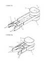
- FIG. 1represents a perspective view of the instrumentation according to an embodiment of the invention, with a pin implanted in a vertebra and the guide facing the intervertebral space located above this vertebra.
- FIG. 2represents a top view of the instrumentation represented in FIG. 1 .
- FIG. 3represents a side view of the instrumentation in FIG. 1 , seen from the posterior face of the guide.
- FIGS. 4A and 4Brepresent, respectively, a perspective view and a top view of the guide according to an embodiment of the invention.
- FIGS. 5A and 5Brepresent perspective views of another embodiment of the guide of the instrumentation, respectively, before and after the introduction of the separating elements in the guide.
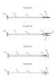
- FIGS. 6A and 6Brepresent, respectively, a top view and a side view of the chisel according to an embodiment of the invention.
- FIGS. 6C and 6Drepresent, respectively, a top view and a side view of the impactor on an embodiment of the invention.
- FIGS. 7A and 7Brepresent a perspective view of an embodiment of the invention, when using a chisel.
- FIG. 7Bpresents further details of FIG. 7A .
- FIGS. 8A and 8Brepresent a top view of the instrumentation according to an embodiment of the invention, when using the chisel and, respectively, before and after the penetration of the chisel into the vertebra.
- FIG. 9Arepresents a perspective view of the instrumentation according to an embodiment of the invention, when using the impactor.
- FIG. 9Bpresents further details of FIG. 9A .
- FIG. 10Arepresents a top view of the instrumentation according to an embodiment of the invention, during the insertion of the prosthesis in the guide.
- FIG. 10Brepresents a top view of the instrumentation according to an embodiment of the invention, when using the impactor pushing the prosthesis inside the guide.
- FIG. 11Arepresents a transparent view of the instrumentation according to an embodiment of the invention, when the prosthesis is being pushed into the intervertebral space by the impactor according to an embodiment of the invention.
- FIG. 11 brepresents a prosthesis in place in the intervertebral space after the impactor has been removed.
- the inventionrelates to an instrumentation and methods for inserting intervertebral disc prostheses (P) between vertebrae (Vi, Vs).
- Pintervertebral disc prostheses
- Vivertebrae
- Vsvertebrae
- the inventioncomplements general surgical instruments and methods.
- the following descriptionpresents different, non-restrictive, embodiments of devices and methods according to various features of the invention. The different structures and steps in the various embodiments can be incorporated in the other embodiments in various combinations.
- the instrumentationcomprises a guide ( 1 ) in the shape of an open cage that can slide, by use of a movable connector ( 22 ), on at least one pin ( 2 ) implanted into a vertebra.
- a guide ( 1 )in the shape of an open cage that can slide, by use of a movable connector ( 22 ), on at least one pin ( 2 ) implanted into a vertebra.
- Two pins ( 2 ), one implanted in upper vertebra (Vs) and the other implanted in the lower vertebra (Vs), and two movable connectors ( 22 ),can also be used.
- antero-posterior reference axisS
- the determination of this antero-posterior reference axiswill be apparent to the surgeon using the embodiments of the instrumentation and methods described.
- the antero-posterior reference axiswill lie along the intersection of a plane substantially coincident with a median sagittal (a substantially vertical plane along the midline of the spine) and a plane substantially coincident with a horizontal plane (a transverse plane, along the antero-posterior axis of the vertebrae and substantially horizontal), although other orientations may be appropriate depending on the particular characteristics of the spine and vertebrae and/or on the choice of the surgeon.
- the antero-posterior reference axis (S)may not lie along the midline sagittal plane of the spine and may thus be Para-Sagittal and it can be inclined leftward or rightward in the antero-posterior direction of the vertebrae.
- the antero-posterior reference axis (S)may also not be aligned along the horizontal plane of the vertebrae and may thus be inclined upward or downward in the antero-posterior direction of the vertebrae.
- a holder (not represented) for the guidecan be used to place the guide ( 1 ) over the pin ( 2 ) and to make it slide until it is proximal with the vertebrae.
- the guide ( 1 )comprises two lateral faces, at least one upper plate ( 17 ) and at least one lower plate ( 18 ) which together form a cage intended to receive the prosthesis (P) through its open posterior face and allow the insertion through its open anterior face of the prosthesis (P) between the lower (Vi) and upper (Vs) vertebrae.
- separators ( 10 )comprising, for example, substantially rectangular plates having dimensions adapted to the height of the prosthesis (P) (generally without regard to any osteal anchors), are placed approximately parallel to the lateral faces of the guide ( 1 ) and in proximity to the lateral faces. Separators ( 10 ) maintain a sufficient gap between the vertebrae and, co-operating with the guide ( 1 ), allow the insertion of the prosthesis (P) between the vertebrae.
- a holder (not represented) of the prosthesis (P)allows placement of the prosthesis (P) inside the guide ( 1 ).
- An impactor ( 4 )is provided for pushing the prosthesis (P) through the open cage of the guide into the intervertebral space.
- the guide ( 1 )has a cage through which the prosthesis will be inserted until it reaches the intervertebral space.
- the cageis open on its anterior and posterior faces.
- the guide ( 1 )comprises lateral faces, at least one upper plate ( 17 ) and at least one lower plate ( 18 ).
- the guide ( 1 )has a shape substantially of a parallelepiped, with its upper plate ( 17 ) and lower plate ( 18 ) approximately parallel to each other.
- the upper plate ( 17 ) and lower plate ( 18 )are not approximately parallel to each other and the guide ( 1 ) has, in coronal (frontal) section, a substantially trapezoidal shape.
- the separators ( 10 )could, according to the insertion angle (A 1 ) of the prosthesis (P), comprise non-rectangular plates such as trapezoidal plates, and/or could have different dimensions from one lateral face of the guide ( 1 ) to the other.
- a trapezoidal embodimentis especially suitable for implanting a prosthesis having upper and lower surfaces form an angle, thus imposing an inclination on the vertebrae between which they are intended to be implanted.
- the guide ( 1 )has solid lateral faces comprising substantially rectangular plates, whereas in the embodiments represented in the other figures, the lateral faces of the guide are open and comprise rods linking the upper plate ( 17 ) and lower plate ( 18 ).
- the guide ( 1 )could have open lateral faces in the embodiment represented in FIGS. 5A and 5B or even have solid lateral faces in the embodiments represented in the other figures.
- the guide ( 1 )comprises, proximate to its lateral faces, retainer ( 100 ) allowing it to co-operate with separators ( 10 ) used to maintain a gap between the vertebrae before and during the insertion of the prosthesis.
- the separators ( 10 )have a shape and dimensions adapted to the height of the prosthesis (P) (generally without regard to any osteal anchors), allowing for maintenance of a sufficient gap between the vertebrae (Vi, Vs) for the introduction of the prosthesis (P) into the intervertebral space.
- the height of the cage of the guide ( 1 )is adapted to the height of the prosthesis (generally without regard to any osteal anchors).
- the width of the cage of the guide ( 1 )can be configured to allow the same guide to be used for the implanting of prostheses of substantially different widths, as for the two prostheses represented in FIGS. 11A and 11B .
- a guide ( 1 )is used for prostheses of substantially different widths
- preferred embodimentsuse guiding channels ( 11 ) engaging osteal anchors on the prostheses to guide the prostheses during insertion.
- a surgeonwill preferably use a guide ( 1 ) having a size most suitable to the dimensions of and the encumbrances of access to the intervertebral space, and will implant a prosthesis having a size most suitable to the dimensions of the guide ( 1 ) and the intervertebral space.
- the retainer ( 100 ) of the guide ( 1 )comprises grooves on each of the lateral edges of each of the lower ( 18 ) and upper ( 17 ) plates of the guide ( 1 ).
- the groovesreceive the separators ( 10 ), and permit the separators ( 10 ) to co-operate with the guide ( 1 ) by sliding in the grooves ( 100 ).
- the sliding of the separators ( 10 ) in relation to these retainers ( 100 )allows a translation of the guide ( 1 ) in relation to the separators ( 10 ).
- the separators ( 10 )could be inserted between the vertebrae (Vs, Vi) before or after the positioning of the guide ( 1 ).
- this embodimentalso allows to remove the guide ( 1 ) once the prosthesis has been implanted, while leaving the separators ( 10 ) in place between the vertebrae (Vs, Vi) to allow proper positioning of the prosthesis.
- the retainer ( 100 ) of the guidecomprises shafts located proximally to the lateral faces of the guide ( 1 ). These shafts provide axes of rotation about which the separators ( 10 ) may rotate.
- retainer ( 100 )as seen in FIGS. 1 and 2 stops limiting the rotation can be disposed proximal to the lateral faces, towards the exterior of the guide, limiting rotation of the separators ( 10 ) about their respective axis of rotation ( 100 ).
- these stopscomprise a rod ( 13 a ) having a distance to the anterior face of the guide ( 1 ) that is less than the distance of the axis of rotation ( 100 ) of the separators ( 10 ) to the anterior face of the guide ( 1 ).
- the stopsare adjustable and comprise, for example, at least one conical part ( 13 b ) screwed into at least the upper ( 17 ) or lower ( 18 ) plates of the guide. The depth of the adjustable stop can be set using the screw threads, and will adjust the limit on the rotation of the separators ( 10 ) about their axis of rotation ( 100 ).
- the stops limiting the rotation of the separators ( 10 ) about their axis of rotationcan also comprise, as in the embodiment represented in FIGS. 4A and 4B , studs ( 13 a ) attached to the separators ( 10 ) and projecting into an opening or recess made in at least one of the lower plate ( 18 ) and upper plate ( 17 ).
- the relative sizes of these studs and the opening or recesscan be used to establish the limit on the rotational freedom of the separators ( 10 ).
- instrumentationcomprises at least a pin ( 2 ) having a sharp point ( 21 ) intended to be implanted into an antero-posterior reference axis (S) of one of the vertebrae (Vi, Vs) between which the prosthesis (P) is to be implanted.
- Implanting the pin ( 2 ) into a vertebraprovides a reference that, in conjunction with other structure of the guide ( 1 ), permits targeting the point (C) onto which the prosthesis (P) is to be centred in the intervertebral space.
- the guide ( 1 )comprises at least one angle adjuster ( 12 ) allowing adjustment of the insertion axis (X) of the prosthesis (P) in relation to the antero-posterior reference axis (S) of the vertebrae, and thus the angle (A 1 ) between the insertion axis (X) and the antero-posterior reference axis (S).
- the intersection between the insertion axis (X) and the antero-posterior reference axis (S)defines a point which can be set to coincide with the point (C) onto which the prosthesis (P) is to be centred in the intervertebral space.
- the antero-posterior reference axis (S)may lie along the intersection of a plane substantially coincident with a median sagittal plane and a plane substantially coincident with a horizontal plane, although other orientations may be appropriate depending on the particular characteristics of the spine and vertebrae and/or depending on the choice of the surgeon.
- the angle adjuster ( 12 )comprises a sighting device having, for instance, a back sight intended to cooperate with at least one pin ( 2 ) implanted in the median sagittal axis of at least one vertebra.
- the back sightpreferably has a suitable shape and dimension to cooperate with the pin ( 2 ) to allow the back sight to be placed against the pin and to slide the guide ( 1 ) along the pin, thereby permitting a suitable positioning of the guide ( 1 ) along the antero-posterior reference axis (S).
- the sighting device ( 12 )By providing stable placement of the guide ( 1 ) with reference to the antero-posterior reference axis (S), the sighting device ( 12 ) also facilitates adjustment (either visually or by use of a gauge or other device) of the angle (A 1 ) between the insertion axis (X) of the prosthesis (P) and the antero-posterior reference axis (S) of the vertebrae (Vi, Vs).
- an offset adjuster ( 120 ) of adjustable lengthlinks the angle adjuster ( 12 ) to a connector ( 22 ) that can slide on pin ( 2 ).
- the offset adjuster ( 120 )comprises a rod with one end fixed to the connector ( 22 ) and the opposite end threaded to mate with a treaded hole in the angle adjuster ( 12 ).
- the offset adjuster ( 120 )comprises a rod attached to connector ( 22 ) but freely rotatable with respect to connector ( 22 ).
- offset adjuster ( 120 )can be screwed in the threaded hole in angle adjuster ( 12 ) even when connector ( 22 ) is in place on pin ( 2 ).
- a six-sided holecan be formed in the threaded end of offset adjuster ( 120 ) and used to rotate offset adjuster ( 120 ) with known tools.
- the guide ( 1 )can also comprise at least one contact adjuster ( 110 ).
- the contact adjuster ( 110 )is disposed approximately parallel to the insertion axis (X) of the prosthesis (P).
- the angle adjuster ( 12 )is configured to slide along the contact adjuster ( 110 ), although other adjustable couplings between the angle adjuster ( 12 ) and the contact adjuster ( 110 ) are readily apparent.
- angle adjuster ( 12 )can be set to the desired angle (A 1 ) between the insertion axis (X) of the prosthesis (P) and the antero-posterior reference axis (S), and by adjusting the distance between angle adjuster ( 12 ) and connector ( 22 ) using offset adjuster ( 120 ), the intersection point between the insertion axis (X) of the prosthesis (P) and the antero-posterior reference axis (S) of the vertebrae can be made to coincide with the point (C) on which the prosthesis (P) is to be centered.
- the guide ( 1 )can be brought proximal to the vertebrae (Vi, Vs) while maintaining the connector ( 22 ) in the desired proximity to the adjacent vertebra.
- the angle adjuster ( 12 ) of the guide ( 1 )comprises an adjustment gauge.
- the adjustment gaugecan be configured to indicate one or more adjustment of the guide ( 1 ), including, for example, the angle (A 1 ) between the insertion axis (X) of the prosthesis (P) and the antero-posterior reference axis (S) and/or the length of the offset distance between angle adjuster ( 12 ) and connector ( 22 ).
- the adjustment gauge embodiment illustrated in FIG. 2comprises a lateral offset gauge.
- the lateral offset gaugeindicates the length of the offset distance between angle adjuster ( 12 ) and connector ( 22 ), indirectly measuring the offset of the guide ( 1 ) laterally from the antero-posterior reference axis (S).
- the lateral offset gaugecomprises a pointer ( 121 1 ) attached to the angle adjuster ( 12 ) and located proximal to graduations ( 121 2 ) made in a surface of the offset adjuster ( 120 ).
- the position of the pointer ( 121 1 ) in relation to the graduations ( 121 2 )indicates the length of the offset distance between angle adjuster ( 12 ) and connector ( 22 ) and therefore the lateral offset of the guide ( 1 ) in relation to the pin ( 2 ).
- the adjustment gauge embodiment illustrated in FIG. 2further comprises an angle gauge indicating the angle (A 1 ) between the insertion axis (X) of the prosthesis (P) and the antero-posterior reference axis (S).
- the angle gaugecomprises a pointer ( 122 1 ) attached to the angle adjuster ( 12 ) and located proximal to radial graduations ( 122 2 ) made in the surface of the guide ( 1 ).
- the position of the pointer ( 122 1 ) in relation to the graduations ( 122 2 )indicates the angle (A 1 ) along which the prosthesis (P) will be implanted in relation to the antero-posterior reference axis (S) of the vertebrae (Vs, Vi).
- a tighteneris provided that selectively allows or prevents rotation of the angle adjuster ( 12 ) with respect to the cage of the guide ( 1 ).
- the tightenerpermits adjustment of the angle (A 1 ) between the insertion axis (X) of the prosthesis (P) and the antero-posterior reference axis (S) by allowing rotation of the angle adjuster ( 12 ), and permits fixation of that angle (A 1 ) in proper adjustment by preventing rotation of the angle adjuster ( 12 ).
- the pin ( 2 )is intended to be implanted in a horizontal transverse plane of the vertebrae.
- Two pins ( 2 )can also be used, along with two angle adjuster ( 12 ), for example, placed one on one of the upper plate ( 17 ) and one on the lower plate ( 18 ) as shown in FIG. 3 .
- the instrumentationalso may use a pin ( 2 ) to be implanted other than in a horizontal transverse plane of the vertebrae.
- the pin ( 2 )may be implanted in an inclined manner in the sagittal plane with its point ( 21 ) oriented towards the bottom of the spinal column.
- the guide ( 1 )could be provided with a single angle adjuster ( 12 ) on one of the upper plate ( 17 ) or lower plate ( 18 ), but still be held in the suitable horizontal position by using to the adjustable offset adjuster ( 120 ) and the angle adjuster ( 12 ).
- the instrumentationcomprises a chisel ( 3 ) used to prepare intervertebral space.
- the chisel ( 3 )has suitable shape and dimension to penetrate into the open cage of the guide ( 1 ) and pass through the guide ( 1 ) to make cuttings on the vertebrae that will be engaged by an osteal anchor ( 51 ).
- At least one plate among the upper ( 17 ) and lower ( 18 ) plates of the guide ( 1 )comprises a guiding channel ( 11 ) oriented along the insertion axis (X) of the prosthesis (P).
- This guiding channel ( 11 )has a shape and dimensions adapted to the shape and dimensions of an osteal anchor ( 51 ) of the prosthesis (P).
- the notch made in the vertebra using the chisel ( 3 )assists centering of the prosthesis in relation to the point (C).
- the guiding channel ( 11 ) defining the insertion axis (X) of the prosthesisis not approximately parallel to the longitudinal centerline (L) passing through the anterior and posterior open faces of the guide ( 1 ), but the guiding channel ( 11 ) can obviously be made so as to define an insertion axis (X) of the prosthesis approximately parallel to the longitudinal centerline passing through the anterior and posterior faces of the guide ( 1 ).
- the chisel ( 3 )comprises a shaft ( 30 ) having, at one of its ends, at least one blade ( 32 ) of suitable shape and dimension for engagement with the guiding channel ( 11 ) of the guide ( 1 ) and for cutting a notch in a vertebra complementary with the shape and dimension of an osteal anchor ( 51 ).
- the shafthas, at its other end, a handle ( 35 ) allowing positioning of the blade ( 32 ) into the guiding channel ( 11 ) manipulating of the chisel to make a notch in the vertebra for the osteal anchor ( 51 ) of the prosthesis (P).
- An adjustable stop ( 31 ) on the shaft ( 30 )can limit the travel of the chisel ( 3 ) in the axis (X) of the guide ( 1 ) and therefore limit the length of the notch, which can correspond to length of the osteal anchor ( 51 ).
- the chisel ( 3 )comprises two blades ( 32 ) held apart from each other by a spacer ( 33 ) of suitable dimension to separate the blades ( 32 ) by a distance approximately equal to the height of the intervertebral disc prosthesis (P) (generally without regard to any osteal anchors).
- the chisel ( 3 )can be used to simultaneously form two notches of suitable dimensions and positions to receive the osteal anchors ( 51 ) assembled on the upper and lower surfaces of the prosthesis (P).
- the instrumentationcomprises an impactor ( 4 ) as shown in FIGS. 6C and 6D used to move the prosthesis (P) through the cage of the guide ( 1 ) into the intervertebral space.
- the impactor ( 4 )comprises a shaft ( 40 ), a handle ( 45 ) at one end of the shaft for manipulating the impactor, and at the other end of the shaft a pusher ( 42 ) having shape and dimensions substantially conforming to the edges of the intervertebral disc prosthesis (P) contacted by the pusher ( 42 ) during use.
- the height and width of the pusher ( 42 )can be substantially equal, respectively, to the height (generally without regard to any osteal anchors) and the width of the prosthesis (P).
- An adjustable stop ( 41 ) on the shaft ( 40 ) of the impactor ( 4 )can limit the travel of the impactor ( 4 ) in the insertion axis (X) of the prosthesis (P) and therefore control the depth to which the prosthesis (P) will be inserted into the intervertebral space.
- the stop ( 41 )therefore can assist centering the prosthesis (P) in relation to the point (C).
- the instrumentationcan comprise a holder (not shown) for the prosthesis (P).
- a holder(not shown) for the prosthesis (P).
- at least one of the upper plate ( 17 ) and the lower plate ( 18 )comprises a recess ( 111 ) providing clearance of the holder for the prosthesis (P) and allowing the prosthesis (P) to be placed in the guide ( 1 ) with the holder.
- Such holder for the prosthesis (P)may consist, for example, of forceps or pliers or tweezers of a known type, with shape and dimensions adapted to insert the prosthesis (P) in the guide ( 1 ) by engaging the recess ( 111 ).
- the instrumentationcan comprise a holder (not shown) for the guide ( 1 ).
- the holdercan assist positioning the guide ( 1 ) in suitable position in contact with the vertebrae (Vi, Vs).
- the holderco-operates with at least two notches ( 112 ) made on at least one of the upper plate ( 17 ) and the lower plate ( 18 ). As represented in drawings, the notches ( 112 ) are located in the recess ( 111 ) of the guide ( 1 ).
- Such holder for the guide ( 1 )may consist, for example, of dilating forceps or opening pliers, or opening tweezers of a known type, with shape and dimensions adapted to co-operate with the notches ( 112 ) while leaving the recess ( 111 ) accessible to forceps or pliers or suitable tools for accessing the intervertebral space.
- the holder for the guide ( 1 )may consist of opening pliers having opening ends curved in a direction approximately orthogonal to the direction of the opening of the pliers.
- These curved endsthus co-operate with the notches ( 112 ) in the recess ( 111 ) and may have dimensions adapted so that, when they co-operate with the notches ( 112 ), they do not substantially protrude from the notches ( 112 ) inside the recess ( 111 ).
- Such holderwill thus hold the guide ( 1 ) while leaving a recess ( 111 ) accessible for the clearance of pliers or small tweezers or any suitable tools for accessing the intervertebral space through the guide ( 1 ).
- the recess ( 111 )may also be accessible for the clearance of the holder for the prosthesis (P) and for the positioning of the prosthesis (P) into the guide ( 1 ), if the holder has still not been removed at this step.
- the inventioncompliments general surgical instruments and methods, which are not an aspect of the inventive method disclosed herein and will not be described.
- the prerequisite steps for preparing the patient and access to the vertebrae, for example from the anterior facewill not be described in detail.
- the surgeonPrior to the implanting itself of the prosthesis (P), the surgeon creates an access to the vertebrae and removes the fibro-cartilaginous tissue of the natural biological intervertebral disc.
- separatorstweezers, according to a commonly used designation
- a known typemaintain a gap between the vertebrae during the removal of the natural biological disc by the surgeon.
- the natural gap of the vertebraewill have been measured beforehand to determine the height (generally without regard to any osteal anchors) of the prosthesis (P) to be implanted in the intervertebral space and, consequently, the height of the guide ( 1 ) that is to be chosen for implantation. Measuring the height of the intervertebral space also allows determination of the height of the separators ( 10 ), which is chosen to maintain the gap required for inserting the prosthesis (P) between the vertebrae.
- the guide ( 1 )will thus be chosen according to the height of these separators ( 10 ) and the dimensions of the prosthesis (P) in the horizontal plane, which will depend on the dimensions of the vertebrae and the encumbrances to accessing the intervertebral space.
- separatorstweezers
- spaceror “bougie”, according to a commonly used designation in English or French, respectively
- Pthe height of the prosthesis
- the removal of the natural biological intervertebral disccan be preceded or followed by a step of implanting at least one pin ( 2 ) of the instrumentation in at least one of the vertebrae (Vi, Vs) between which the prosthesis is to be implanted. So that the pin ( 2 ) provides a symmetrical reference in relation to the vertebrae, the implanting of the pin ( 2 ) is performed by placing it, preferably horizontally, along the antero-posterior reference axis (S) of the vertebra.
- the dimensions of the guide ( 1 ) chosen for implanting the prosthesiswill affect the height in the vertebra for implantation of pin ( 2 ), which should enable the angle adjuster ( 12 ) to place the guide ( 1 ) opposite the intervertebral space with its upper plate ( 17 ) and lower plate ( 18 ) in contact with the respectively upper and lower surfaces of the respectively upper and lower vertebrae.
- the surgeonmeasures the exact dimensions of the vertebrae, using a known measuring device.
- the measuring of the vertebraeinforms the surgeon of the depth of the intervertebral space and allows the surgeon to determine the ideal dimensions of the prosthesis (P) in the horizontal plane and to calculate, as a function of the dimensions of the measured vertebrae and of the chosen prosthesis, the position of the point (C) on which the prosthesis (P) is to be centered.
- the surgeoncan also control the proper positioning of the point ( 21 ) of the pin in the vertebra, for example its alignment on the median sagittal axis.
- the pins ( 2 )are short and comprise, for example, small diameter rods.
- the small dimensions of the pinsallow the surgeon to possibly recommence the step of implanting the pin ( 2 ) into the vertebra if he considers that the position of the point ( 21 ) is unsatisfactory.
- the surgeonhas all the information necessary to choose the most appropriate guide ( 1 ) and prosthesis (P).
- the surgeonadjusts, according to the gathered measurements, the angle adjuster ( 12 ) to accurately target the point (C) on which the prosthesis (P) is to be centered in the intervertebral space.
- the positioning of the guide ( 1 ) opposite the intervertebral spacecan be performed using a holder for the guide or without the use of such a holder.
- the surgeoncan choose between separators ( 10 ) that slide in the grooves of the retainer ( 100 ) or separators ( 10 ) that rotate about their axes of rotation on shafts ( 100 ).
- separators ( 10 ) that slide in the grooves of the retainer ( 100 )the surgeon inserts separators ( 10 ) in the intervertebral space, removes the known wedge (bougie or spacer), and slides the guide ( 1 ) on the separators ( 10 ) to bring the guide ( 1 ) proximal to the vertebrae.
- separators ( 10 )that rotate about their axes of rotation on shafts ( 100 )
- the surgeoninserts the separators ( 10 ) assembled on shafts ( 100 ), removes the known wedge (bougie or spacer), and drives the separators ( 10 ) into the intervertebral space until the guide is proximal with the vertebrae.
- the surgeonmay choose different embodiments of the angle adjuster ( 12 ) to more readily facilitate placement of the prosthesis (P) centered at point (C). According to the encumbrance of the surgeon's access to the vertebrae, the surgeon will choose one of the embodiments described below so as to insert the prosthesis along the antero-posterior sagittal axis or along an inclined axis.
- the surgeontargets the point (C) by placing the sighting device in the median sagittal axis of the vertebrae marked by at least one pin ( 2 ) implanted in at least one vertebra.
- the back sightpreferably has a suitable shape and dimension to co-operate with the pin ( 2 ), so as to allow the back sight to be placed against the pin and to slide the guide ( 1 ) along the pin, thereby ensuring suitable positioning of the guide in relation to the vertebrae.
- the surgeoninserts the prosthesis (P) it into the cage of the guide ( 1 ) though the cage's open posterior face.
- a holder for the prosthesiscan be used that allows, as mentioned above, insertion of the prosthesis (P) into the cage of the guide while the holder for the guide is still in its place and holding the guide in contact with the vertebrae.
- the impactor ( 4 )allows the surgeon to implant the prosthesis between the vertebrae by pushing on the handle ( 45 ) of the impactor ( 4 ) or by hitting, for example with a hammer, on this handle ( 45 ).
- the adjustable position of the stop ( 41 ) on the shaft ( 40 ) of the impactor ( 4 )will have already been set according to the distance of point (C) on which the prosthesis is to be centred between the vertebrae, in relation to the anterior face of the vertebrae.
- the adjusting of the position of the stopnaturally takes into account the size of the pusher ( 42 ) of the impactor ( 4 ) and the diameter of the prosthesis (P).
- implanting of the prosthesis (P) along the antero-posterior sagittal axismay not necessarily be the easiest or least risky solution.
- the vena cava and the aortawhich are major life-supporting blood vessels, pass in front of the lumbar vertebrae and considerably encumber the access to the anterior face of such vertebrae.
- the surgeonmay therefore prefer to implant the intervertebral disc prosthesis (P) along an oblique axis of insertion, such as an antero-lateral axis in the case of access to the vertebrae from the anterior face.
- Some of the embodiments of the inventionfacilitate insertion of the prosthesis (P) obliquely, for example, by use of an angle adjuster ( 12 ) to set an angle (A 1 ) between the insertion axis (X) of the prosthesis and the antero-posterior reference axis (S).
- the small diameter pins ( 2 )can be implanted in the median sagittal plane of the vertebrae without having to shift to any great extent the tissue and/or the organs passing over the anterior face of the vertebrae.
- the angle (A 1 ) created between the insertion axis (X) of the prosthesis and the antero-posterior reference axis (S), as well as the magnitude of the offset of the guide ( 1 ) on one side of the vertebrae,will already have been determined according to the encumbrances to access to the vertebrae (Vi, Vs), the size of the vertebrae (Vi, Vs), and the size of the prosthesis (P).
- adjusting the angle (A 1 ) and the offset of guide ( 1 ) from the antero-posterior reference axis (S)permits the intersection the axis of insertion (X) and of the antero-posterior reference axis (S) to coincide with the point (C) on which the prosthesis is to be centred.
- Offset adjuster ( 120 )can be used to establish the offset of guide ( 1 ) from the antero-posterior reference axis (S), for example, by screwing to a greater or lesser degree a threaded end of offset adjuster ( 120 ) into a threaded hole made in the angle adjuster ( 12 ).
- adjustment of the length of the offset adjuster ( 120 )can be performed before or after the connector ( 22 ) is placed on the pin ( 2 ), depending on the chosen embodiment. The sliding of the connector ( 22 ) over the pin ( 2 ) allows the guide ( 1 ) to be brought proximal to the vertebrae, with its anterior face opposite the intervertebral space.
- the chisel ( 3 )is used to make notches in the vertebrae of shape and dimension complementary with the shape and dimension of the osteal anchors ( 51 ).
- the handle ( 35 ) of the chisel ( 3 )can be used to push, or perhaps use strikes of a hammer, and pull the chisel ( 3 ) to make such notches.
- the shape and dimension of the different embodiments of the chisel ( 3 )are adapted to the type of prosthesis (P) to be implanted and to the type of osteal anchors ( 51 ).
- the surgeonAfter preparing the intervertebral space with the chisel ( 3 ), the surgeon removes the chisel ( 3 ) from the inside of the guide ( 1 ) and removes the fragments of bone generated by making the notches.
- the prosthesisis implanted between the vertebrae using the impactor ( 4 ).
- the surgeonremoves the guide ( 1 ), the separators ( 10 ) and the pin(s) ( 2 ).
Landscapes
- Health & Medical Sciences (AREA)
- Orthopedic Medicine & Surgery (AREA)
- Life Sciences & Earth Sciences (AREA)
- Biomedical Technology (AREA)
- Engineering & Computer Science (AREA)
- Surgery (AREA)
- Veterinary Medicine (AREA)
- General Health & Medical Sciences (AREA)
- Oral & Maxillofacial Surgery (AREA)
- Heart & Thoracic Surgery (AREA)
- Public Health (AREA)
- Animal Behavior & Ethology (AREA)
- Transplantation (AREA)
- Medical Informatics (AREA)
- Molecular Biology (AREA)
- Dentistry (AREA)
- Nuclear Medicine, Radiotherapy & Molecular Imaging (AREA)
- Neurology (AREA)
- Cardiology (AREA)
- Vascular Medicine (AREA)
- Physical Education & Sports Medicine (AREA)
- Prostheses (AREA)
Abstract
Description
This application is a continuation of U.S. patent application Ser. No. 13/892,933, filed May 13, 2013, and issuing as U.S. Pat. No. 9,248,025 on Feb. 2, 2016, which is a continuation of U.S. patent application Ser. No. 12/435,955, filed May 5, 2009, and issuing as U.S. Pat. No. 8,439,931 on May 14, 2013, which is a continuation of U.S. patent application Ser. No. 11/180,868, filed Jul. 13, 2005, and issuing as U.S. Pat. No. 7,632,282 on Dec. 15, 2009, which claims priority under 35 U.S.C. 119 to French Patent Application No. 05 06652, filed in FRANCE on Jun. 29, 2005.
The present invention relates to instrumentation for inserting intervertebral disc prostheses.
Various types of instruments for inserting intervertebral disc prostheses are known, such as those disclosed in the French patent application FR0405899000 filed by the applicant. These instruments only allow insertion by anterior access, along the antero-posterior axis of the prosthesis. Preparation of the vertebrae between which the prosthesis is to be implanted by this type of instrumentation therefore requires opening the tissue covering these vertebrae and pushing aside the blood vessels on the anterior face of the spinal column, which generates a risk for the patient.
The embodiments disclosed herein provide instrumentation and methods that allow insertion of a prosthesis between the vertebrae, laterally or obliquely, while appropriately positioning the prosthesis in relation to the sagittal plane and the coronal plane.
Embodiments of instrumentation for the insertion of intervertebral disc prosthesis between vertebrae in accordance with the present invention comprise a guide and at least one separator. In preferred embodiments, the guide has at least two lateral faces, at least one upper plate, at least one lower plate, at least one retainer, a cage defining an insertion axis for the intervertebral disc prosthesis and having open posterior and anterior faces, and an angle adjuster adapted to adjust the angle formed by the insertion axis and an antero-posterior median sagittal axis of the vertebrae. The separators are sized to maintain a gap between the upper vertebra and the lower vertebra that is sufficient for insertion of the intervertebral disc prosthesis through the guide into the intervertebral space. For the disclosed embodiments, during the insertion of the intervertebral disc prosthesis the upper plate is disposed proximal to a plane substantially coincident with the lower surface of the upper vertebra, and the lower plate is disposed proximal to a plane substantially coincident with the upper surface of the lower vertebra. The upper plate and the lower plate are separated by a distance approximately equal to the height of the intervertebral disc prosthesis. The angle adjuster is adapted to position the guide opposite the intervertebral space between the upper vertebra and the lower vertebra and to adjust an angle formed by the insertion axis and an antero-posterior median sagittal axis defined by the intersection of a midline, substantially vertical, sagittal plane and a transverse, substantially horizontal, plane of the spinal column.
According to another feature in an embodiment, the angle adjuster comprises at least one sighting device configured for visual adjustment of the angle between the insertion axis and the antero-posterior median sagittal axis.
According to another feature in an embodiment, the angle adjuster comprises a sighting device configured for operation with at least one pin implanted into at least one of the upper vertebra and the lower vertebra and approximately oriented with the antero-posterior median sagittal axis of said vertebra to align said sighting device with the antero-posterior median sagittal axis.
According to another feature in an embodiment, the instrumentation further comprises:
at least one pin for implantation into at least one of the upper vertebra and the lower vertebra in approximate orientation with the antero-posterior median sagittal axis of said vertebra;
at least one offset adjuster adjustably linking the angle adjuster to the at least one pin.
According to another feature in an embodiment, the instrumentation further comprises:
at least one contact adjuster disposed approximately parallel to the insertion axis;
a coupling between the at least one contact adjuster and the angle adjuster allowing movement of the angle adjuster with respect to the at least one contact adjuster;
a connector configured to move along the longitudinal axis of the pin and to connect the at least one offset adjuster to the at least one pin.
According to another feature in an embodiment, the at least one pin comprises a sharp point.
According to another feature in an embodiment, the angle adjuster comprises at least one adjustment gauge indicating at least one parameter concerning the position of the guide relative to the vertebrae.
According to another feature in an embodiment, the adjustment gauge comprises a lateral offset gauge comprising a pointer pointing to graduations indicating the lateral offset of the guide from the antero-posterior median sagittal axis of the vertebrae.
According to another feature in an embodiment, the adjustment gauge comprises an angle gauge comprising a pointer pointing to radial graduations indicating the angle between the insertion axis of the intervertebral disc prosthesis and the antero-posterior median sagittal axis of the vertebrae.
According to another feature in an embodiment, the instrumentation further comprises a tightener that selectively allows or prevents rotation of the angle adjuster with respect to the guide, thereby permitting adjustment and fixation of the angle between the insertion axis of the intervertebral disc prosthesis and the antero-posterior median sagittal axis.
According to another feature in an embodiment, the at least one retainer comprises at least one groove permitting the at least one separator to slide within the groove.
According to another feature in an embodiment, the at least one retainer comprises at least one shaft providing at least one axis of rotation for the at least one separator.
According to another feature in an embodiment, the guide further comprises a stop limiting the rotation of the at least one separator about the at least one axis of rotation.
According to another feature in an embodiment, the rotation of an at least one separator is limited by an adjustable stop enabling to set the extent to which the rotation is limited.
According to another feature in an embodiment, the guide comprises at least one channel oriented substantially parallel to the insertion axis of the intervertebral disc prosthesis and configured to guide at least one part protruding from at least one surface of the intervertebral disc prosthesis.
According to another feature in an embodiment, the insertion axis of the intervertebral disc prosthesis through the guide is oriented approximately parallel to a longitudinal centerline of the guide passing through the open anterior and posterior faces of the cage.
According to another feature in an embodiment, the insertion axis of the intervertebral disc prosthesis through the guide is not oriented approximately parallel to a longitudinal centerline of the guide passing through the open anterior and posterior faces of the cage.
According to another feature in an embodiment, the instrumentation further comprises at least one chisel having at least one blade and suitable shape and dimension for engagement with the guide and for cutting at least one notch in a vertebra.
According to another feature in an embodiment, the chisel comprises a shaft, a handle at the end of the shaft opposite the at least one blade, and an adjustable stop limiting the travel of the chisel inside the guide.
According to another feature in an embodiment, the chisel comprises two blades and a spacer of suitable dimension to separate the blades by a distance approximately equal to the height of the intervertebral space.
According to another feature in an embodiment, the instrumentation further comprises an impactor having a shaft, a handle at one end of the shaft for manipulating the impactor, and at the other end of the shaft a pusher having shape and dimensions substantially conforming to at least one edge of the intervertebral disc prosthesis contacted by the pusher during use.
According to another feature in an embodiment, the impactor has an adjustable stop limiting the travel of the impactor inside the guide.
According to another feature in an embodiment, the instrumentation further comprises a holder for the intervertebral disc prosthesis and wherein the guide comprises a recess providing clearance for holder for the intervertebral disc prosthesis sufficient to position the intervertebral disc prosthesis into the guide.
According to another feature in an embodiment, the instrumentation further comprises a holder for the guide engaging at least two notches of the guide.
According to another feature in an embodiment, the holder for the guide is configured to engage the at least two notches of the guide without interfering with engagement of a recess of the guide by tools for accessing the intervertebral space or by the holder for the intervertebral disc prosthesis.
Methods for inserting intervertebral disc prostheses between two vertebrae are also provided.
General steps for preparing the vertebral site for insertion of an intervertebral disc prosthesis between two vertebrae are known, and are not an aspect of the inventive method disclosed herein. In general, such preparatory steps comprise removal of the natural biological intervertebral disc, clearing the intervertebral space, and maintaining a gap between the upper vertebra and lower vertebra with a known instrument.
Methods for inserting an intervertebral disc prosthesis in accordance with the present invention can be performed using instrumentation comprising at least one pin and a guide having at least one upper plate, at least one lower plate, a cage defining an insertion axis for the intervertebral disc prosthesis and having open posterior and anterior faces, and an angle adjuster. In a preferred embodiment, a method according the present invention comprises:
- implanting at least one pin in the median sagittal axis of one of the two vertebrae;
- measuring the dimensions of the intervertebral space;
- choosing the intervertebral disc prosthesis to be implanted;
- choosing the guide to be used;
- adjusting the angle adjuster based on an antero-posterior median sagittal axis of the spinal column, defined by the intersection of a midline, substantially vertical, sagittal plane and a transverse, substantially horizontal, plane of the spinal column, on the dimensions of the intervertebral space and on the obstacles to access to the intervertebral space, in order to set a desired angle between the insertion axis for the intervertebral disc prosthesis and the antero-posterior median sagittal axis;
- positioning the guide adjacent to the intervertebral space at the desired angle;
- inserting the intervertebral disc prosthesis into the guide through the open posterior face of the cage; and
- inserting the intervertebral disc prosthesis into the intervertebral space through the open anterior face of the cage.
According to another feature in an embodiment, the method further comprises a step of adjusting an offset adjuster for setting a lateral offset of the guide relative to the antero-posterior median sagittal axis.
According to another feature in an embodiment, the step of inserting the intervertebral disc prosthesis into the intervertebral space is performed using an impactor comprising a shaft and an adjustable stop, said step further comprising adjustment of the stop and the application of a thrust to the impactor.
According to another feature in an embodiment, the step of adjusting the angle adjuster is performed using a sighting device for aligning the guide with the antero-posterior median sagittal axis, said step further comprising placement of the sighting device in contact with the at least one pin.
According to another feature in an embodiment, the method further comprises a step of adjusting an offset adjuster of adjustable length connecting the angle adjuster of the guide to a connector connected to the pin, this adjusting step being implemented thanks to the measurements of the intervertebral space.
According to another feature in an embodiment, the step of positioning the guide adjacent to the intervertebral space further comprises translation of the guide along an axis substantially parallel to the antero-posterior median sagittal axis until the guide is proximal to the vertebrae.
According to another feature in an embodiment, the method further comprises the insertion of one or more separators into the intervertebral space.
According to another feature in an embodiment, the method further comprises the engagement of at least one of the one or more separators with at least one retainer of the guide.
According to another feature in an embodiment, the step of positioning the guide is performed with a holder for the guide.
According to another feature in an embodiment, the step of inserting the intervertebral disc prosthesis into the guide is performed with a holder for the intervertebral disc prosthesis, the guide comprising a recess providing clearance sufficient for the holder for the intervertebral disc prosthesis to position the intervertebral disc prosthesis into the guide.
According to another feature in an embodiment, the step of positioning the guide is performed with a holder for the guide configured to engage at least two notches of the guide to provide clearance for tools for accessing the intervertebral space.
According to another feature in an embodiment, the method further comprises, before inserting the intervertebral disc prosthesis into the intervertebral space, the step of preparing the intervertebral space using a chisel having at least one blade, an adjustable stop and suitable shape and dimension for engagement with the guide and for cutting at least one notch in at least one vertebra.
According to another feature in an embodiment, the method further comprises the step of clearing the intervertebral space of the bone debris generated by cutting the notch.
According to another feature in an embodiment, the method further comprises a step of removing the guide, the one or more separators, and the at least one pin after the step of inserting the intervertebral disc intervertebral disc prosthesis into the intervertebral space.
Other features and advantages of the invention will become clearer upon reading the following description of various embodiments with reference to the attached drawings.
The invention relates to an instrumentation and methods for inserting intervertebral disc prostheses (P) between vertebrae (Vi, Vs). The invention complements general surgical instruments and methods. The following description presents different, non-restrictive, embodiments of devices and methods according to various features of the invention. The different structures and steps in the various embodiments can be incorporated in the other embodiments in various combinations.
In a preferred embodiment, the instrumentation comprises a guide (1) in the shape of an open cage that can slide, by use of a movable connector (22), on at least one pin (2) implanted into a vertebra. Two pins (2), one implanted in upper vertebra (Vs) and the other implanted in the lower vertebra (Vs), and two movable connectors (22), can also be used.
Various elements of the embodiments described herein involve an antero-posterior reference axis (S). The determination of this antero-posterior reference axis will be apparent to the surgeon using the embodiments of the instrumentation and methods described. In general, the antero-posterior reference axis will lie along the intersection of a plane substantially coincident with a median sagittal (a substantially vertical plane along the midline of the spine) and a plane substantially coincident with a horizontal plane (a transverse plane, along the antero-posterior axis of the vertebrae and substantially horizontal), although other orientations may be appropriate depending on the particular characteristics of the spine and vertebrae and/or on the choice of the surgeon. For example, the antero-posterior reference axis (S) may not lie along the midline sagittal plane of the spine and may thus be Para-Sagittal and it can be inclined leftward or rightward in the antero-posterior direction of the vertebrae. The antero-posterior reference axis (S) may also not be aligned along the horizontal plane of the vertebrae and may thus be inclined upward or downward in the antero-posterior direction of the vertebrae.
A holder (not represented) for the guide can be used to place the guide (1) over the pin (2) and to make it slide until it is proximal with the vertebrae. In a preferred embodiment, the guide (1) comprises two lateral faces, at least one upper plate (17) and at least one lower plate (18) which together form a cage intended to receive the prosthesis (P) through its open posterior face and allow the insertion through its open anterior face of the prosthesis (P) between the lower (Vi) and upper (Vs) vertebrae. In use of the instrumentation, separators (10), comprising, for example, substantially rectangular plates having dimensions adapted to the height of the prosthesis (P) (generally without regard to any osteal anchors), are placed approximately parallel to the lateral faces of the guide (1) and in proximity to the lateral faces. Separators (10) maintain a sufficient gap between the vertebrae and, co-operating with the guide (1), allow the insertion of the prosthesis (P) between the vertebrae. A holder (not represented) of the prosthesis (P) allows placement of the prosthesis (P) inside the guide (1). An impactor (4) is provided for pushing the prosthesis (P) through the open cage of the guide into the intervertebral space.
Various embodiments of the invention will now further be described in detail in reference to the drawings. As shown inFIGS. 1 and 3 , the guide (1) has a cage through which the prosthesis will be inserted until it reaches the intervertebral space. The cage is open on its anterior and posterior faces. The guide (1) comprises lateral faces, at least one upper plate (17) and at least one lower plate (18). In the embodiments represented in the drawings, the guide (1) has a shape substantially of a parallelepiped, with its upper plate (17) and lower plate (18) approximately parallel to each other. In an alternative embodiment (not represented), the upper plate (17) and lower plate (18) are not approximately parallel to each other and the guide (1) has, in coronal (frontal) section, a substantially trapezoidal shape. In this alternative embodiment, the separators (10) could, according to the insertion angle (A1) of the prosthesis (P), comprise non-rectangular plates such as trapezoidal plates, and/or could have different dimensions from one lateral face of the guide (1) to the other. A trapezoidal embodiment is especially suitable for implanting a prosthesis having upper and lower surfaces form an angle, thus imposing an inclination on the vertebrae between which they are intended to be implanted.
In the embodiment represented inFIGS. 5A and 5B , the guide (1) has solid lateral faces comprising substantially rectangular plates, whereas in the embodiments represented in the other figures, the lateral faces of the guide are open and comprise rods linking the upper plate (17) and lower plate (18). However, as mentioned above, the different structures described for the various embodiments of the instruments of the invention can be adapted to other instruments and/or other embodiments. Thus, the guide (1) could have open lateral faces in the embodiment represented inFIGS. 5A and 5B or even have solid lateral faces in the embodiments represented in the other figures.
The guide (1) comprises, proximate to its lateral faces, retainer (100) allowing it to co-operate with separators (10) used to maintain a gap between the vertebrae before and during the insertion of the prosthesis. The separators (10) have a shape and dimensions adapted to the height of the prosthesis (P) (generally without regard to any osteal anchors), allowing for maintenance of a sufficient gap between the vertebrae (Vi, Vs) for the introduction of the prosthesis (P) into the intervertebral space. The height of the cage of the guide (1) is adapted to the height of the prosthesis (generally without regard to any osteal anchors). Guides of different heights generally will be used for prostheses of different heights. The width of the cage of the guide (1), however, can be configured to allow the same guide to be used for the implanting of prostheses of substantially different widths, as for the two prostheses represented inFIGS. 11A and 11B . When a guide (1) is used for prostheses of substantially different widths, preferred embodiments use guiding channels (11) engaging osteal anchors on the prostheses to guide the prostheses during insertion. A surgeon, however, will preferably use a guide (1) having a size most suitable to the dimensions of and the encumbrances of access to the intervertebral space, and will implant a prosthesis having a size most suitable to the dimensions of the guide (1) and the intervertebral space.
In the embodiments represented inFIGS. 5A and 5B , the retainer (100) of the guide (1) comprises grooves on each of the lateral edges of each of the lower (18) and upper (17) plates of the guide (1). The grooves receive the separators (10), and permit the separators (10) to co-operate with the guide (1) by sliding in the grooves (100). The sliding of the separators (10) in relation to these retainers (100) allows a translation of the guide (1) in relation to the separators (10). Thus, the separators (10) could be inserted between the vertebrae (Vs, Vi) before or after the positioning of the guide (1). For example, this embodiment also allows to remove the guide (1) once the prosthesis has been implanted, while leaving the separators (10) in place between the vertebrae (Vs, Vi) to allow proper positioning of the prosthesis.
In the embodiments represented inFIGS. 1 to 4 and 7 to 11 , the retainer (100) of the guide comprises shafts located proximally to the lateral faces of the guide (1). These shafts provide axes of rotation about which the separators (10) may rotate. In these embodiments of retainer (100), as seen inFIGS. 1 and 2 stops limiting the rotation can be disposed proximal to the lateral faces, towards the exterior of the guide, limiting rotation of the separators (10) about their respective axis of rotation (100). In a preferred embodiment, these stops comprise a rod (13a) having a distance to the anterior face of the guide (1) that is less than the distance of the axis of rotation (100) of the separators (10) to the anterior face of the guide (1). In another embodiment, the stops are adjustable and comprise, for example, at least one conical part (13b) screwed into at least the upper (17) or lower (18) plates of the guide. The depth of the adjustable stop can be set using the screw threads, and will adjust the limit on the rotation of the separators (10) about their axis of rotation (100). The stops limiting the rotation of the separators (10) about their axis of rotation can also comprise, as in the embodiment represented inFIGS. 4A and 4B , studs (13a) attached to the separators (10) and projecting into an opening or recess made in at least one of the lower plate (18) and upper plate (17). In this embodiment of stops (13a), the relative sizes of these studs and the opening or recess can be used to establish the limit on the rotational freedom of the separators (10).
In a preferred embodiment, instrumentation according to the invention comprises at least a pin (2) having a sharp point (21) intended to be implanted into an antero-posterior reference axis (S) of one of the vertebrae (Vi, Vs) between which the prosthesis (P) is to be implanted. Implanting the pin (2) into a vertebra provides a reference that, in conjunction with other structure of the guide (1), permits targeting the point (C) onto which the prosthesis (P) is to be centred in the intervertebral space. The guide (1) comprises at least one angle adjuster (12) allowing adjustment of the insertion axis (X) of the prosthesis (P) in relation to the antero-posterior reference axis (S) of the vertebrae, and thus the angle (A1) between the insertion axis (X) and the antero-posterior reference axis (S). The intersection between the insertion axis (X) and the antero-posterior reference axis (S) defines a point which can be set to coincide with the point (C) onto which the prosthesis (P) is to be centred in the intervertebral space. The antero-posterior reference axis (S) may lie along the intersection of a plane substantially coincident with a median sagittal plane and a plane substantially coincident with a horizontal plane, although other orientations may be appropriate depending on the particular characteristics of the spine and vertebrae and/or depending on the choice of the surgeon.
In the embodiments represented inFIGS. 4A, 4B, 5A and 5B , the angle adjuster (12) comprises a sighting device having, for instance, a back sight intended to cooperate with at least one pin (2) implanted in the median sagittal axis of at least one vertebra. The back sight preferably has a suitable shape and dimension to cooperate with the pin (2) to allow the back sight to be placed against the pin and to slide the guide (1) along the pin, thereby permitting a suitable positioning of the guide (1) along the antero-posterior reference axis (S). By providing stable placement of the guide (1) with reference to the antero-posterior reference axis (S), the sighting device (12) also facilitates adjustment (either visually or by use of a gauge or other device) of the angle (A1) between the insertion axis (X) of the prosthesis (P) and the antero-posterior reference axis (S) of the vertebrae (Vi, Vs).
In the embodiments represented inFIGS. 1 to 3 and 7 to 11 , an offset adjuster (120) of adjustable length links the angle adjuster (12) to a connector (22) that can slide on pin (2). For one embodiment, the offset adjuster (120) comprises a rod with one end fixed to the connector (22) and the opposite end threaded to mate with a treaded hole in the angle adjuster (12). In another of the various alternative embodiments, the offset adjuster (120) comprises a rod attached to connector (22) but freely rotatable with respect to connector (22). In such alternative embodiment, offset adjuster (120) can be screwed in the threaded hole in angle adjuster (12) even when connector (22) is in place on pin (2). For example, a six-sided hole can be formed in the threaded end of offset adjuster (120) and used to rotate offset adjuster (120) with known tools.
The guide (1) can also comprise at least one contact adjuster (110). In various embodiments of contact adjusters (110), the contact adjuster (110) is disposed approximately parallel to the insertion axis (X) of the prosthesis (P). The angle adjuster (12) is configured to slide along the contact adjuster (110), although other adjustable couplings between the angle adjuster (12) and the contact adjuster (110) are readily apparent. In this arrangement, angle adjuster (12) can be set to the desired angle (A1) between the insertion axis (X) of the prosthesis (P) and the antero-posterior reference axis (S), and by adjusting the distance between angle adjuster (12) and connector (22) using offset adjuster (120), the intersection point between the insertion axis (X) of the prosthesis (P) and the antero-posterior reference axis (S) of the vertebrae can be made to coincide with the point (C) on which the prosthesis (P) is to be centered. By moving the angle adjuster (12) along the contact adjuster (110), the guide (1) can be brought proximal to the vertebrae (Vi, Vs) while maintaining the connector (22) in the desired proximity to the adjacent vertebra.
In various embodiments, the angle adjuster (12) of the guide (1) comprises an adjustment gauge. The adjustment gauge can be configured to indicate one or more adjustment of the guide (1), including, for example, the angle (A1) between the insertion axis (X) of the prosthesis (P) and the antero-posterior reference axis (S) and/or the length of the offset distance between angle adjuster (12) and connector (22).
The adjustment gauge embodiment illustrated inFIG. 2 comprises a lateral offset gauge. In this embodiment, the lateral offset gauge indicates the length of the offset distance between angle adjuster (12) and connector (22), indirectly measuring the offset of the guide (1) laterally from the antero-posterior reference axis (S). The lateral offset gauge comprises a pointer (1211) attached to the angle adjuster (12) and located proximal to graduations (1212) made in a surface of the offset adjuster (120). The position of the pointer (1211) in relation to the graduations (1212) indicates the length of the offset distance between angle adjuster (12) and connector (22) and therefore the lateral offset of the guide (1) in relation to the pin (2).
The adjustment gauge embodiment illustrated inFIG. 2 further comprises an angle gauge indicating the angle (A1) between the insertion axis (X) of the prosthesis (P) and the antero-posterior reference axis (S). In this embodiment, the angle gauge comprises a pointer (1221) attached to the angle adjuster (12) and located proximal to radial graduations (1222) made in the surface of the guide (1). The position of the pointer (1221) in relation to the graduations (1222) indicates the angle (A1) along which the prosthesis (P) will be implanted in relation to the antero-posterior reference axis (S) of the vertebrae (Vs, Vi).
In an alternative embodiment, a tightener is provided that selectively allows or prevents rotation of the angle adjuster (12) with respect to the cage of the guide (1). The tightener permits adjustment of the angle (A1) between the insertion axis (X) of the prosthesis (P) and the antero-posterior reference axis (S) by allowing rotation of the angle adjuster (12), and permits fixation of that angle (A1) in proper adjustment by preventing rotation of the angle adjuster (12).
In the disclosed embodiments, the pin (2) is intended to be implanted in a horizontal transverse plane of the vertebrae. Two pins (2) can also be used, along with two angle adjuster (12), for example, placed one on one of the upper plate (17) and one on the lower plate (18) as shown inFIG. 3 . However, the instrumentation also may use a pin (2) to be implanted other than in a horizontal transverse plane of the vertebrae. For example, the pin (2) may be implanted in an inclined manner in the sagittal plane with its point (21) oriented towards the bottom of the spinal column. In that configuration, the guide (1) could be provided with a single angle adjuster (12) on one of the upper plate (17) or lower plate (18), but still be held in the suitable horizontal position by using to the adjustable offset adjuster (120) and the angle adjuster (12).
Some prostheses have osteal anchors (51) on the surfaces that contact adjacent vertebrae. For example, winglets on the prosthesis can be provided to engage notches made in the surfaces of the vertebrae. The surfaces of the vertebrae engaged by the osteal anchors (51) of this type of prosthesis therefore must be prepared before insertion of the prosthesis. Accordingly, in a preferred embodiment the instrumentation comprises a chisel (3) used to prepare intervertebral space. The chisel (3) has suitable shape and dimension to penetrate into the open cage of the guide (1) and pass through the guide (1) to make cuttings on the vertebrae that will be engaged by an osteal anchor (51). In a preferred embodiment, at least one plate among the upper (17) and lower (18) plates of the guide (1) comprises a guiding channel (11) oriented along the insertion axis (X) of the prosthesis (P). This guiding channel (11) has a shape and dimensions adapted to the shape and dimensions of an osteal anchor (51) of the prosthesis (P). The notch made in the vertebra using the chisel (3) assists centering of the prosthesis in relation to the point (C). In the embodiments represented in the drawings, the guiding channel (11) defining the insertion axis (X) of the prosthesis is not approximately parallel to the longitudinal centerline (L) passing through the anterior and posterior open faces of the guide (1), but the guiding channel (11) can obviously be made so as to define an insertion axis (X) of the prosthesis approximately parallel to the longitudinal centerline passing through the anterior and posterior faces of the guide (1).
In a preferred embodiment, the chisel (3) comprises a shaft (30) having, at one of its ends, at least one blade (32) of suitable shape and dimension for engagement with the guiding channel (11) of the guide (1) and for cutting a notch in a vertebra complementary with the shape and dimension of an osteal anchor (51). The shaft has, at its other end, a handle (35) allowing positioning of the blade (32) into the guiding channel (11) manipulating of the chisel to make a notch in the vertebra for the osteal anchor (51) of the prosthesis (P). An adjustable stop (31) on the shaft (30) can limit the travel of the chisel (3) in the axis (X) of the guide (1) and therefore limit the length of the notch, which can correspond to length of the osteal anchor (51). In the embodiment inFIGS. 6A and 6B , the chisel (3) comprises two blades (32) held apart from each other by a spacer (33) of suitable dimension to separate the blades (32) by a distance approximately equal to the height of the intervertebral disc prosthesis (P) (generally without regard to any osteal anchors). Using two guiding channels (11), the chisel (3) can be used to simultaneously form two notches of suitable dimensions and positions to receive the osteal anchors (51) assembled on the upper and lower surfaces of the prosthesis (P).
In an embodiment of the invention, the instrumentation comprises an impactor (4) as shown inFIGS. 6C and 6D used to move the prosthesis (P) through the cage of the guide (1) into the intervertebral space. The impactor (4) comprises a shaft (40), a handle (45) at one end of the shaft for manipulating the impactor, and at the other end of the shaft a pusher (42) having shape and dimensions substantially conforming to the edges of the intervertebral disc prosthesis (P) contacted by the pusher (42) during use. The height and width of the pusher (42) can be substantially equal, respectively, to the height (generally without regard to any osteal anchors) and the width of the prosthesis (P). An adjustable stop (41) on the shaft (40) of the impactor (4) can limit the travel of the impactor (4) in the insertion axis (X) of the prosthesis (P) and therefore control the depth to which the prosthesis (P) will be inserted into the intervertebral space. The stop (41) therefore can assist centering the prosthesis (P) in relation to the point (C).
In an embodiment of the invention, the instrumentation can comprise a holder (not shown) for the prosthesis (P). As shown in the drawings, at least one of the upper plate (17) and the lower plate (18) comprises a recess (111) providing clearance of the holder for the prosthesis (P) and allowing the prosthesis (P) to be placed in the guide (1) with the holder. Such holder for the prosthesis (P) may consist, for example, of forceps or pliers or tweezers of a known type, with shape and dimensions adapted to insert the prosthesis (P) in the guide (1) by engaging the recess (111).
In an embodiment of the invention, the instrumentation can comprise a holder (not shown) for the guide (1). The holder can assist positioning the guide (1) in suitable position in contact with the vertebrae (Vi, Vs). The holder co-operates with at least two notches (112) made on at least one of the upper plate (17) and the lower plate (18). As represented in drawings, the notches (112) are located in the recess (111) of the guide (1). Such holder for the guide (1) may consist, for example, of dilating forceps or opening pliers, or opening tweezers of a known type, with shape and dimensions adapted to co-operate with the notches (112) while leaving the recess (111) accessible to forceps or pliers or suitable tools for accessing the intervertebral space. For example, the holder for the guide (1) may consist of opening pliers having opening ends curved in a direction approximately orthogonal to the direction of the opening of the pliers. These curved ends thus co-operate with the notches (112) in the recess (111) and may have dimensions adapted so that, when they co-operate with the notches (112), they do not substantially protrude from the notches (112) inside the recess (111). Such holder will thus hold the guide (1) while leaving a recess (111) accessible for the clearance of pliers or small tweezers or any suitable tools for accessing the intervertebral space through the guide (1). The recess (111) may also be accessible for the clearance of the holder for the prosthesis (P) and for the positioning of the prosthesis (P) into the guide (1), if the holder has still not been removed at this step.
The various embodiments of the invention described above provide instrumentation for implanting an intervertebral disc prosthesis (P) between the vertebrae (Vs, Vi). The use of the instrumentation will now be described, providing detail of the steps taken to implant the prosthesis.
As aforementioned, the invention compliments general surgical instruments and methods, which are not an aspect of the inventive method disclosed herein and will not be described. In addition, the prerequisite steps for preparing the patient and access to the vertebrae, for example from the anterior face, will not be described in detail. Prior to the implanting itself of the prosthesis (P), the surgeon creates an access to the vertebrae and removes the fibro-cartilaginous tissue of the natural biological intervertebral disc. Generally, separators (tweezers, according to a commonly used designation) of a known type maintain a gap between the vertebrae during the removal of the natural biological disc by the surgeon. The natural gap of the vertebrae will have been measured beforehand to determine the height (generally without regard to any osteal anchors) of the prosthesis (P) to be implanted in the intervertebral space and, consequently, the height of the guide (1) that is to be chosen for implantation. Measuring the height of the intervertebral space also allows determination of the height of the separators (10), which is chosen to maintain the gap required for inserting the prosthesis (P) between the vertebrae. The guide (1) will thus be chosen according to the height of these separators (10) and the dimensions of the prosthesis (P) in the horizontal plane, which will depend on the dimensions of the vertebrae and the encumbrances to accessing the intervertebral space.
During the removal of the natural biological disc by the surgeon, separators (tweezers) commonly used are too cumbersome for the rest of the operation and are thus replaced by a wedge (called “spacer” or “bougie”, according to a commonly used designation in English or French, respectively) whose height will have been chosen so as to preserve the natural gap of the vertebrae and to correspond to the height of the prosthesis (P) (generally without regard to any osteal anchors).
The removal of the natural biological intervertebral disc can be preceded or followed by a step of implanting at least one pin (2) of the instrumentation in at least one of the vertebrae (Vi, Vs) between which the prosthesis is to be implanted. So that the pin (2) provides a symmetrical reference in relation to the vertebrae, the implanting of the pin (2) is performed by placing it, preferably horizontally, along the antero-posterior reference axis (S) of the vertebra. The dimensions of the guide (1) chosen for implanting the prosthesis will affect the height in the vertebra for implantation of pin (2), which should enable the angle adjuster (12) to place the guide (1) opposite the intervertebral space with its upper plate (17) and lower plate (18) in contact with the respectively upper and lower surfaces of the respectively upper and lower vertebrae. In a known manner, the surgeon measures the exact dimensions of the vertebrae, using a known measuring device. The measuring of the vertebrae, notably along the antero-posterior axis, informs the surgeon of the depth of the intervertebral space and allows the surgeon to determine the ideal dimensions of the prosthesis (P) in the horizontal plane and to calculate, as a function of the dimensions of the measured vertebrae and of the chosen prosthesis, the position of the point (C) on which the prosthesis (P) is to be centered. By taking a radiograph of the vertebra in which the pin (2) was implanted, for example using a known image intensifier, the surgeon can also control the proper positioning of the point (21) of the pin in the vertebra, for example its alignment on the median sagittal axis. The pins (2) are short and comprise, for example, small diameter rods. The small dimensions of the pins allow the surgeon to possibly recommence the step of implanting the pin (2) into the vertebra if he considers that the position of the point (21) is unsatisfactory.
Once these measurements have been made, the surgeon has all the information necessary to choose the most appropriate guide (1) and prosthesis (P). According to the embodiment of the guide (1) chosen by the surgeon, the surgeon adjusts, according to the gathered measurements, the angle adjuster (12) to accurately target the point (C) on which the prosthesis (P) is to be centered in the intervertebral space.
The positioning of the guide (1) opposite the intervertebral space can be performed using a holder for the guide or without the use of such a holder. Among other embodiments of the invention, the surgeon can choose between separators (10) that slide in the grooves of the retainer (100) or separators (10) that rotate about their axes of rotation on shafts (100). For separators (10) that slide in the grooves of the retainer (100), the surgeon inserts separators (10) in the intervertebral space, removes the known wedge (bougie or spacer), and slides the guide (1) on the separators (10) to bring the guide (1) proximal to the vertebrae. For separators (10) that rotate about their axes of rotation on shafts (100), the surgeon inserts the separators (10) assembled on shafts (100), removes the known wedge (bougie or spacer), and drives the separators (10) into the intervertebral space until the guide is proximal with the vertebrae.
The surgeon may choose different embodiments of the angle adjuster (12) to more readily facilitate placement of the prosthesis (P) centered at point (C). According to the encumbrance of the surgeon's access to the vertebrae, the surgeon will choose one of the embodiments described below so as to insert the prosthesis along the antero-posterior sagittal axis or along an inclined axis.
In the embodiment of the instrument described above in which the angle adjuster (12) comprise a sighting device created by a back sight, and preferably in the case where the prosthesis can be implanted straight on and does not require an oblique insertion, the surgeon targets the point (C) by placing the sighting device in the median sagittal axis of the vertebrae marked by at least one pin (2) implanted in at least one vertebra. The back sight preferably has a suitable shape and dimension to co-operate with the pin (2), so as to allow the back sight to be placed against the pin and to slide the guide (1) along the pin, thereby ensuring suitable positioning of the guide in relation to the vertebrae. The surgeon inserts the prosthesis (P) it into the cage of the guide (1) though the cage's open posterior face. A holder for the prosthesis can be used that allows, as mentioned above, insertion of the prosthesis (P) into the cage of the guide while the holder for the guide is still in its place and holding the guide in contact with the vertebrae. The impactor (4) allows the surgeon to implant the prosthesis between the vertebrae by pushing on the handle (45) of the impactor (4) or by hitting, for example with a hammer, on this handle (45). The adjustable position of the stop (41) on the shaft (40) of the impactor (4) will have already been set according to the distance of point (C) on which the prosthesis is to be centred between the vertebrae, in relation to the anterior face of the vertebrae. The adjusting of the position of the stop naturally takes into account the size of the pusher (42) of the impactor (4) and the diameter of the prosthesis (P).
According to the vertebrae (Vi, Vs) between which the prosthesis (P) is to be implanted, implanting of the prosthesis (P) along the antero-posterior sagittal axis may not necessarily be the easiest or least risky solution. For example, the vena cava and the aorta, which are major life-supporting blood vessels, pass in front of the lumbar vertebrae and considerably encumber the access to the anterior face of such vertebrae. The surgeon may therefore prefer to implant the intervertebral disc prosthesis (P) along an oblique axis of insertion, such as an antero-lateral axis in the case of access to the vertebrae from the anterior face. Some of the embodiments of the invention facilitate insertion of the prosthesis (P) obliquely, for example, by use of an angle adjuster (12) to set an angle (A1) between the insertion axis (X) of the prosthesis and the antero-posterior reference axis (S).
The small diameter pins (2) can be implanted in the median sagittal plane of the vertebrae without having to shift to any great extent the tissue and/or the organs passing over the anterior face of the vertebrae. The angle (A1) created between the insertion axis (X) of the prosthesis and the antero-posterior reference axis (S), as well as the magnitude of the offset of the guide (1) on one side of the vertebrae, will already have been determined according to the encumbrances to access to the vertebrae (Vi, Vs), the size of the vertebrae (Vi, Vs), and the size of the prosthesis (P). Thus, adjusting the angle (A1) and the offset of guide (1) from the antero-posterior reference axis (S) permits the intersection the axis of insertion (X) and of the antero-posterior reference axis (S) to coincide with the point (C) on which the prosthesis is to be centred.
Offset adjuster (120) can be used to establish the offset of guide (1) from the antero-posterior reference axis (S), for example, by screwing to a greater or lesser degree a threaded end of offset adjuster (120) into a threaded hole made in the angle adjuster (12). As mentioned above, adjustment of the length of the offset adjuster (120) can be performed before or after the connector (22) is placed on the pin (2), depending on the chosen embodiment. The sliding of the connector (22) over the pin (2) allows the guide (1) to be brought proximal to the vertebrae, with its anterior face opposite the intervertebral space. Other steps for implanting can be identical to those previously described, for example by using the impactor (4) of which the position of the stop (41) on the shaft (40) of the impactor (4) will already have been set according to the distance of the point (C) in relation to the anterior face of the vertebrae and according to the size of the prosthesis (P).
If the prosthesis comprises osteal anchors (51) fixed to the surfaces of the prosthesis (P), the chisel (3) is used to make notches in the vertebrae of shape and dimension complementary with the shape and dimension of the osteal anchors (51). The handle (35) of the chisel (3) can be used to push, or perhaps use strikes of a hammer, and pull the chisel (3) to make such notches. As mentioned above, the shape and dimension of the different embodiments of the chisel (3) are adapted to the type of prosthesis (P) to be implanted and to the type of osteal anchors (51). After preparing the intervertebral space with the chisel (3), the surgeon removes the chisel (3) from the inside of the guide (1) and removes the fragments of bone generated by making the notches. The prosthesis is implanted between the vertebrae using the impactor (4).
Once the prosthesis has been properly placed in the intervertebral space, the surgeon removes the guide (1), the separators (10) and the pin(s) (2).
Although the present invention has been described in detail, it will be apparent to those skilled in the art that many embodiments taking a variety of specific forms and reflecting changes, substitutions and alterations can be made without departing from the spirit and scope of the invention. Therefore, the described embodiments illustrate but do not restrict the scope of the claims.
Claims (20)
1. Instrumentation for inserting an intervertebral disc prosthesis into an intervertebral space between an upper vertebra and a lower vertebra, the instrumentation comprising:
a guide comprising at least one retainer,
a cage defining an insertion axis for the intervertebral disc prosthesis and having open posterior and anterior faces, and
an angle adjuster adapted to position the guide opposite the intervertebral space and to adjust an angle formed by the insertion axis and an antero-posterior reference axis, the angle adjuster including an adjustment gauge to visually indicate at least the angle formed by the insertion axis and an antero-posterior reference axis.
2. Instrumentation ofclaim 1 in which the angle adjuster comprises at least one sighting device configured for visual adjustment of the angle between the insertion axis and the antero-posterior reference axis.
3. Instrumentation ofclaim 1 in which the angle adjuster comprises a sighting device configured for operation with at least one pin implanted into at least one of the upper vertebra and the lower vertebra and approximately oriented with the antero-posterior reference axis of said vertebra to align said sighting device with the antero-posterior reference axis.
4. Instrumentation ofclaim 1 further comprising:
at least one pin for implantation into at least one of the upper vertebra and the lower vertebra in approximate orientation with the antero-posterior reference axis of said vertebra; and
at least one offset adjuster adjustably linking the angle adjuster to the at least one pin.
5. Instrumentation ofclaim 4 further comprising:
at least one contact adjuster disposed approximately parallel to the insertion axis;
a coupling between the at least one contact adjuster and the angle adjuster allowing movement of the angle adjuster with respect to the at least one contact adjuster; and
a connector configured to move along the longitudinal axis of the pin and to connect the at least one offset adjuster to the at least one pin.
6. Instrumentation ofclaim 5 in which the at least one pin comprises a sharp point.
7. Method for implanting an intervertebral disc prosthesis into an intervertebral space between two vertebrae comprising the steps of:
acquiring instrumentation comprising at least one pin, a guide, a cage defining an insertion axis for the intervertebral disc prosthesis and having open posterior and anterior faces, and an angle adjuster;
implanting at least one pin in at least one of the two vertebrae, along an antero-posterior reference axis;
measuring the dimensions of the intervertebral space;
choosing the intervertebral disc prosthesis to be implanted;
choosing the guide to be used;
adjusting the angle adjuster based on the antero-posterior reference axis, on the dimensions of the intervertebral space and on the obstacles to access to the intervertebral space, in order to set a desired angle between the insertion axis for the intervertebral disc prosthesis and the antero-posterior reference axis;
positioning the guide adjacent to the intervertebral space at the desired angle;
inserting the intervertebral disc prosthesis into the guide through the open posterior face of the cage; and
inserting the intervertebral disc prosthesis into the intervertebral space through the open anterior face of the cage.
8. Method for implanting ofclaim 7 further comprising a step of adjusting an offset adjuster for setting a lateral offset of the guide relative to the antero-posterior reference axis.
9. Method for implanting ofclaim 7 in which the step of inserting the intervertebral disc prosthesis into the intervertebral space is performed using an impactor comprising a shaft and an adjustable stop, said step further comprising adjustment of the stop and the application of a thrust to the impactor.
10. Method for implanting ofclaim 7 in which the step of adjusting the angle adjuster is performed using a sighting device for aligning the guide with the antero-posterior reference axis, said step further comprising placement of the sighting device in contact with the at least one pin.
11. Method for implanting ofclaim 7 further comprising a step of adjusting an offset adjuster of adjustable length connecting the angle adjuster of the guide to a connector connected to the pin, this adjusting step being implemented thanks to the measurements of the intervertebral space.
12. Method for implanting ofclaim 11 further comprising a step of removing the guide, the one or more separators, and the at least one pin after the step of inserting the intervertebral disc intervertebral disc prosthesis into the intervertebral space.
13. Method for implanting set forth inclaim 7 in which the step of positioning the guide adjacent to the intervertebral space further comprises translation of the guide along an axis substantially parallel to the antero-posterior reference axis until the guide is proximal to the vertebrae.
14. Method for implanting ofclaim 7 further comprising the insertion of one or more separators into the intervertebral space.
15. Method for implanting ofclaim 14 further comprising the engagement of at least one of the one or more separators with at least one retainer of the guide.
16. Method for implanting ofclaim 7 in which the step of positioning the guide is performed with a holder for the guide.
17. Method for implanting ofclaim 7 in which the step of inserting the intervertebral disc prosthesis into the guide is performed with a holder for the intervertebral disc prosthesis, the guide comprising a recess providing clearance sufficient for the holder for the intervertebral disc prosthesis to position the intervertebral disc prosthesis into the guide.
18. Method for implanting ofclaim 7 in which the step of positioning the guide is performed with a holder for the guide configured to engage at least two notches of the guide to provide clearance for tools for accessing the intervertebral space.
19. Method for implanting ofclaim 7 further comprising, before inserting the intervertebral disc prosthesis into the intervertebral space, the step of preparing the intervertebral space using a chisel having at least one blade, an adjustable stop and suitable shape and dimension for engagement with the guide and for cutting at least one notch in at least one vertebra.
20. Method for implanting ofclaim 19 further comprising the step of clearing the intervertebral space of the bone debris generated by cutting the notch.
Priority Applications (1)
| Application Number | Priority Date | Filing Date | Title |
|---|---|---|---|
| US15/012,815US10350088B2 (en) | 2005-06-29 | 2016-02-01 | Instrumentation and methods for inserting an intervertebral disc prosthesis |
Applications Claiming Priority (6)
| Application Number | Priority Date | Filing Date | Title |
|---|---|---|---|
| FR0506652 | 2005-06-29 | ||
| FR0506652AFR2887762B1 (en) | 2005-06-29 | 2005-06-29 | INTERVERTEBRAL DISC PROSTHESIS INSERTION INSTRUMENTATION BETWEEN VERTEBRATES |
| US11/180,868US7632282B2 (en) | 2005-06-29 | 2005-07-13 | Instrumentation and methods for inserting an intervertebral disc prosthesis |
| US12/435,955US8439931B2 (en) | 2005-06-29 | 2009-05-05 | Instrumentation and methods for inserting an intervertebral disc prosthesis |
| US13/892,933US9248025B2 (en) | 2005-06-29 | 2013-05-13 | Instrumentation and methods for inserting an intervertebral disc prosthesis |
| US15/012,815US10350088B2 (en) | 2005-06-29 | 2016-02-01 | Instrumentation and methods for inserting an intervertebral disc prosthesis |
Related Parent Applications (1)
| Application Number | Title | Priority Date | Filing Date |
|---|---|---|---|
| US13/892,933ContinuationUS9248025B2 (en) | 2005-06-29 | 2013-05-13 | Instrumentation and methods for inserting an intervertebral disc prosthesis |
Publications (2)
| Publication Number | Publication Date |
|---|---|
| US20160220389A1 US20160220389A1 (en) | 2016-08-04 |
| US10350088B2true US10350088B2 (en) | 2019-07-16 |
Family
ID=35462326
Family Applications (4)
| Application Number | Title | Priority Date | Filing Date |
|---|---|---|---|
| US11/180,868Active2026-06-06US7632282B2 (en) | 2005-06-29 | 2005-07-13 | Instrumentation and methods for inserting an intervertebral disc prosthesis |
| US12/435,955Active2027-01-06US8439931B2 (en) | 2005-06-29 | 2009-05-05 | Instrumentation and methods for inserting an intervertebral disc prosthesis |
| US13/892,933Expired - LifetimeUS9248025B2 (en) | 2005-06-29 | 2013-05-13 | Instrumentation and methods for inserting an intervertebral disc prosthesis |
| US15/012,815Expired - LifetimeUS10350088B2 (en) | 2005-06-29 | 2016-02-01 | Instrumentation and methods for inserting an intervertebral disc prosthesis |
Family Applications Before (3)
| Application Number | Title | Priority Date | Filing Date |
|---|---|---|---|
| US11/180,868Active2026-06-06US7632282B2 (en) | 2005-06-29 | 2005-07-13 | Instrumentation and methods for inserting an intervertebral disc prosthesis |
| US12/435,955Active2027-01-06US8439931B2 (en) | 2005-06-29 | 2009-05-05 | Instrumentation and methods for inserting an intervertebral disc prosthesis |
| US13/892,933Expired - LifetimeUS9248025B2 (en) | 2005-06-29 | 2013-05-13 | Instrumentation and methods for inserting an intervertebral disc prosthesis |
Country Status (8)
| Country | Link |
|---|---|
| US (4) | US7632282B2 (en) |
| EP (1) | EP1915111A2 (en) |
| JP (1) | JP4939535B2 (en) |
| KR (1) | KR101263782B1 (en) |
| CN (1) | CN101252897B (en) |
| BR (1) | BRPI0613068A2 (en) |
| FR (1) | FR2887762B1 (en) |
| WO (1) | WO2007000654A2 (en) |
Families Citing this family (52)
| Publication number | Priority date | Publication date | Assignee | Title |
|---|---|---|---|---|
| FR2897259B1 (en) | 2006-02-15 | 2008-05-09 | Ldr Medical Soc Par Actions Si | INTERSOMATIC TRANSFORAMINAL CAGE WITH INTERBREBAL FUSION GRAFT AND CAGE IMPLANTATION INSTRUMENT |
| FR2824261B1 (en) | 2001-05-04 | 2004-05-28 | Ldr Medical | INTERVERTEBRAL DISC PROSTHESIS AND IMPLEMENTATION METHOD AND TOOLS |
| FR2846550B1 (en) | 2002-11-05 | 2006-01-13 | Ldr Medical | INTERVERTEBRAL DISC PROSTHESIS |
| FR2865629B1 (en) | 2004-02-04 | 2007-01-26 | Ldr Medical | INTERVERTEBRAL DISC PROSTHESIS |
| EP2113227B1 (en) | 2004-02-04 | 2015-07-29 | LDR Medical | Intervertebral disc prosthesis |
| FR2869528B1 (en) | 2004-04-28 | 2007-02-02 | Ldr Medical | INTERVERTEBRAL DISC PROSTHESIS |
| WO2006058221A2 (en) | 2004-11-24 | 2006-06-01 | Abdou Samy M | Devices and methods for inter-vertebral orthopedic device placement |
| FR2879436B1 (en)* | 2004-12-22 | 2007-03-09 | Ldr Medical | INTERVERTEBRAL DISC PROSTHESIS |
| FR2887762B1 (en)* | 2005-06-29 | 2007-10-12 | Ldr Medical Soc Par Actions Si | INTERVERTEBRAL DISC PROSTHESIS INSERTION INSTRUMENTATION BETWEEN VERTEBRATES |
| FR2891135B1 (en) | 2005-09-23 | 2008-09-12 | Ldr Medical Sarl | INTERVERTEBRAL DISC PROSTHESIS |
| FR2893838B1 (en)* | 2005-11-30 | 2008-08-08 | Ldr Medical Soc Par Actions Si | PROSTHESIS OF INTERVERTEBRAL DISC AND INSTRUMENTATION OF INSERTION OF THE PROSTHESIS BETWEEN VERTEBRATES |
| WO2007130699A2 (en)* | 2006-01-13 | 2007-11-15 | Clifford Tribus | Spine reduction and stabilization device |
| US9011441B2 (en) | 2006-02-17 | 2015-04-21 | Paradigm Spine, L.L.C. | Method and system for performing interspinous space preparation for receiving an implant |
| AR064013A1 (en) | 2006-11-30 | 2009-03-04 | Paradigm Spine Llc | VERTEBRAL, INTERLAMINAR, INTERESPINOUS STABILIZATION SYSTEM |
| FR2910267B1 (en) | 2006-12-21 | 2009-01-23 | Ldr Medical Soc Par Actions Si | VERTEBRAL SUPPORT DEVICE |
| US8465546B2 (en) | 2007-02-16 | 2013-06-18 | Ldr Medical | Intervertebral disc prosthesis insertion assemblies |
| FR2916956B1 (en) | 2007-06-08 | 2012-12-14 | Ldr Medical | INTERSOMATIC CAGE, INTERVERTEBRAL PROSTHESIS, ANCHORING DEVICE AND IMPLANTATION INSTRUMENTATION |
| FR2917287B1 (en) | 2007-06-15 | 2010-09-03 | Ldr Medical | INTERVERTEBRAL PROSTHESIS |
| FR2918555B1 (en) | 2007-07-12 | 2010-04-02 | Ldr Medical | DEVICE AND SYSTEM FOR TRANSVERSE SPINACH CONNECTION |
| AU2009205679B2 (en)* | 2008-01-18 | 2013-12-05 | Spinecore, Inc. | Instruments and methods for inserting artificial intervertebral implants |
| FR2928083A1 (en)* | 2008-02-28 | 2009-09-04 | Warsaw Orthopedic Inc | Surgical targeting instrument for use during replacement of intervertebral disk in vertebral column of human being, has body for connecting arms and comprising markers, where one of arms defines insertion direction along angle |
| US20090222011A1 (en)* | 2008-02-28 | 2009-09-03 | Warsaw Orthopedic, Inc. | Targeting surgical instrument for use in spinal disc replacement and methods for use in spinal disc replacement |
| FR2932374B1 (en)* | 2008-06-13 | 2010-06-04 | Spinevision | DEVICE FOR ESTABLISHING AN ANATOMICAL MARK OF AN INTERVERTEBRAL DISC. |
| US8142440B2 (en)* | 2008-11-14 | 2012-03-27 | Warsaw Orthopedic, Inc. | Transverse centering tool with pin placement guides |
| EP2400931B1 (en)* | 2009-02-25 | 2015-10-28 | Spinewelding AG | Spine stabilization device and kit for its implantation |
| US8641766B2 (en) | 2009-04-15 | 2014-02-04 | DePuy Synthes Products, LLC | Arcuate fixation member |
| US9408715B2 (en) | 2009-04-15 | 2016-08-09 | DePuy Synthes Products, Inc. | Arcuate fixation member |
| ES2563172T3 (en) | 2009-07-09 | 2016-03-11 | R Tree Innovations, Llc | Flexible intersomatic implant |
| US8764806B2 (en) | 2009-12-07 | 2014-07-01 | Samy Abdou | Devices and methods for minimally invasive spinal stabilization and instrumentation |
| WO2011080535A1 (en) | 2009-12-31 | 2011-07-07 | Lrd Medical | Anchoring device, intervertebral implant and implantation instrument |
| WO2011097315A1 (en) | 2010-02-02 | 2011-08-11 | Azadeh Farin | Spine surgery device |
| US9579214B1 (en)* | 2011-03-01 | 2017-02-28 | John W. McClellan | Peripheral vertebral body spacer implant and insertion tool |
| US8845728B1 (en) | 2011-09-23 | 2014-09-30 | Samy Abdou | Spinal fixation devices and methods of use |
| US20130226240A1 (en) | 2012-02-22 | 2013-08-29 | Samy Abdou | Spinous process fixation devices and methods of use |
| US9198767B2 (en) | 2012-08-28 | 2015-12-01 | Samy Abdou | Devices and methods for spinal stabilization and instrumentation |
| US9320617B2 (en) | 2012-10-22 | 2016-04-26 | Cogent Spine, LLC | Devices and methods for spinal stabilization and instrumentation |
| US9301849B2 (en)* | 2013-03-14 | 2016-04-05 | Warsaw Orthopedic, Inc. | Endplate punch template and method of use |
| KR101555317B1 (en) | 2013-09-11 | 2015-10-06 | 주식회사 솔고 바이오메디칼 | Cage having the spike |
| CN105148540B (en)* | 2015-08-24 | 2017-07-18 | 浙江省仙居县华润贸易有限公司 | Woodcarving sea-gull dries instrument and woodcarving sea-gull preparation method |
| US10857003B1 (en) | 2015-10-14 | 2020-12-08 | Samy Abdou | Devices and methods for vertebral stabilization |
| CN105520773A (en)* | 2016-01-13 | 2016-04-27 | 温州医科大学附属第二医院 | Solid guide rod for lumbar vertebrae percutaneous transforaminal endoscopic operation |
| US10004609B2 (en)* | 2016-09-23 | 2018-06-26 | Warsaw Orthopedic, Inc. | Surgical instrument and method |
| US10744000B1 (en) | 2016-10-25 | 2020-08-18 | Samy Abdou | Devices and methods for vertebral bone realignment |
| US10973648B1 (en) | 2016-10-25 | 2021-04-13 | Samy Abdou | Devices and methods for vertebral bone realignment |
| RU174198U1 (en)* | 2017-01-09 | 2017-10-06 | Государственное бюджетное учреждение здравоохранения Свердловской области "Центр специализированных видов медицинской помощи "Уральский институт травматологии и ортопедии имени В.Д. Чаклина" (ГБУЗ СО "ЦСВМП "УИТО им. В.Д. Чаклина") | Implant for reconstruction of the ventral spine of patients with osteoporosis |
| US11116583B2 (en) | 2017-10-30 | 2021-09-14 | Warsaw Orthopedic, Inc. | Surgical tracking device and instrument |
| US10736753B2 (en) | 2017-12-06 | 2020-08-11 | Zygofix Ltd. | Implant delivery system |
| US10905566B2 (en)* | 2018-02-05 | 2021-02-02 | Spineology Inc. | Percutaneous posterior implant slide |
| EP3806756B1 (en) | 2018-06-13 | 2024-01-03 | Stryker European Operations Limited | Bone fragment collector and processor |
| US11179248B2 (en) | 2018-10-02 | 2021-11-23 | Samy Abdou | Devices and methods for spinal implantation |
| EP4076290B1 (en) | 2019-12-18 | 2024-07-31 | Stryker European Operations Limited | Bone fragment collector and processor |
| CN112587197A (en)* | 2020-12-07 | 2021-04-02 | 李成 | High-efficiency puncher for fixing intervertebral disc end face prosthesis |
Citations (346)
| Publication number | Priority date | Publication date | Assignee | Title |
|---|---|---|---|---|
| US566360A (en) | 1896-08-25 | Adjustable support | ||
| US1436573A (en) | 1921-07-28 | 1922-11-21 | Choppinet Joseph | Joint |
| US2836442A (en) | 1955-07-19 | 1958-05-27 | Milton A Moskovitz | Dust seals for ball joints |
| US3325197A (en) | 1964-06-12 | 1967-06-13 | Moog Industries Inc | Ball joint |
| US3486505A (en) | 1967-05-22 | 1969-12-30 | Gordon M Morrison | Orthopedic surgical instrument |
| FR2124815A5 (en) | 1971-01-25 | 1972-09-22 | Gutter Lab Inc | |
| DE2263842A1 (en) | 1972-12-28 | 1974-07-04 | Hoffmann Daimler Siegfried Dr | DISC PROTHESIS |
| US3857642A (en) | 1973-02-26 | 1974-12-31 | Ingersoll Rand Co | Flexible or universal coupling means |
| US3958278A (en) | 1974-04-22 | 1976-05-25 | National Research Development Corporation | Endoprosthetic knee joint |
| US4074542A (en) | 1976-11-03 | 1978-02-21 | Rockwell International Corporation | Coupling |
| US4085466A (en) | 1974-11-18 | 1978-04-25 | National Research Development Corporation | Prosthetic joint device |
| FR2372622A1 (en) | 1976-12-03 | 1978-06-30 | Fassio Bernard | Intervertebral prosthesis for surgical use - has flat semicircular disc with hemispherical boss each side to support between vertebrae |
| DE2804936A1 (en) | 1978-02-01 | 1979-08-02 | Sulzer Ag | INTER-SPINE PROSTHESIS |
| DE3023353A1 (en) | 1979-10-03 | 1981-04-09 | Gebrüder Sulzer AG, 8401 Winterthur | INTERMEDIATE TURBINE TOTAL PROSTHESIS |
| EP0042271A1 (en) | 1980-06-13 | 1981-12-23 | David J. Kuntz | Intervertebral disc prosthesis |
| US4309777A (en) | 1980-11-13 | 1982-01-12 | Patil Arun A | Artificial intervertebral disc |
| EP0176728A1 (en) | 1984-09-04 | 1986-04-09 | Humboldt-Universität zu Berlin | Intervertebral-disc prosthesis |
| US4655778A (en) | 1985-08-12 | 1987-04-07 | Harrington Arthritis Research Center | Joint prosthesis |
| US4714469A (en) | 1987-02-26 | 1987-12-22 | Pfizer Hospital Products Group, Inc. | Spinal implant |
| US4756711A (en) | 1985-12-24 | 1988-07-12 | Christian Mai | Self-locking prosthesis, and methods for producing and for fitting in same |
| US4759769A (en) | 1987-02-12 | 1988-07-26 | Health & Research Services Inc. | Artificial spinal disc |
| US4787908A (en) | 1987-04-30 | 1988-11-29 | Queen's University At Kingston | Metatarsal-phalangeal replacement joint |
| EP0298235A1 (en) | 1987-07-09 | 1989-01-11 | GebràDer Sulzer Aktiengesellschaft | Spinal disc prosthesis |
| EP0317972A1 (en) | 1987-11-24 | 1989-05-31 | Asahi Kogaku Kogyo Kabushiki Kaisha | Artificial intervertebral disc |
| US4863476A (en) | 1986-08-29 | 1989-09-05 | Shepperd John A N | Spinal implant |
| EP0333990A2 (en) | 1988-03-23 | 1989-09-27 | Waldemar Link (GmbH & Co.) | Surgical instrument set |
| US4874389A (en) | 1987-12-07 | 1989-10-17 | Downey Ernest L | Replacement disc |
| FR2632516A1 (en) | 1988-06-10 | 1989-12-15 | Guy Esteve | Single-compartment knee prosthesis comprising a tibial plate with metal seat |
| US4892545A (en) | 1988-07-14 | 1990-01-09 | Ohio Medical Instrument Company, Inc. | Vertebral lock |
| EP0356112A1 (en) | 1988-08-18 | 1990-02-28 | University Of Medicine And Dentistry Of New Jersey | Biocompatible elastomeric intervertebral disc |
| US4911718A (en) | 1988-06-10 | 1990-03-27 | University Of Medicine & Dentistry Of N.J. | Functional and biocompatible intervertebral disc spacer |
| US4932975A (en) | 1989-10-16 | 1990-06-12 | Vanderbilt University | Vertebral prosthesis |
| US4955916A (en) | 1989-05-01 | 1990-09-11 | Techmedica, Inc. | Thumb joint prosthesis |
| US4955908A (en) | 1987-07-09 | 1990-09-11 | Sulzer Brothers Limited | Metallic intervertebral prosthesis |
| WO1990011740A1 (en) | 1989-04-08 | 1990-10-18 | Robert Bosch Gmbh | Artificial spinal disc |
| JPH02261446A (en) | 1989-04-03 | 1990-10-24 | Kawasaki Steel Corp | Artificial vertebra |
| DE8912648U1 (en) | 1989-10-23 | 1990-11-22 | Mecron Medizinische Produkte Gmbh, 1000 Berlin | Vertebral body implant |
| US5002576A (en) | 1988-06-06 | 1991-03-26 | Mecron Medizinische Produkte Gmbh | Intervertebral disk endoprosthesis |
| WO1991007931A1 (en) | 1989-11-29 | 1991-06-13 | Ab Volvo | Artificial joint, especially for ankle joints |
| US5041139A (en) | 1989-04-25 | 1991-08-20 | Branemark Per Ingvar | Anchoring element for supporting a joint mechanism of an ankle, hip or other reconstructed joint |
| FR2659226A1 (en) | 1990-03-07 | 1991-09-13 | Jbs Sa | PROSTHESIS FOR INTERVERTEBRAL DISCS AND ITS IMPLANTATION INSTRUMENTS. |
| US5071437A (en) | 1989-02-15 | 1991-12-10 | Acromed Corporation | Artificial disc |
| US5123926A (en) | 1991-02-22 | 1992-06-23 | Madhavan Pisharodi | Artificial spinal prosthesis |
| EP0512529A1 (en) | 1991-05-09 | 1992-11-11 | DePuy Inc. | Prosthetic implant locking assembly |
| WO1993001771A1 (en) | 1991-07-22 | 1993-02-04 | Calcitek, Inc. | Spinal disk implant |
| US5192327A (en) | 1991-03-22 | 1993-03-09 | Brantigan John W | Surgical prosthetic implant for vertebrae |
| US5197986A (en) | 1990-04-11 | 1993-03-30 | Mikhail Michael W E | Recessed patellar prosthesis |
| EP0560141A1 (en) | 1992-03-13 | 1993-09-15 | Waldemar Link (GmbH & Co.) | Intervertebral disc endoprosthesis |
| US5246458A (en) | 1992-10-07 | 1993-09-21 | Graham Donald V | Artificial disk |
| EP0566810A1 (en) | 1992-04-21 | 1993-10-27 | SULZER Medizinaltechnik AG | Artificial spinal disc |
| US5258031A (en) | 1992-01-06 | 1993-11-02 | Danek Medical | Intervertebral disk arthroplasty |
| US5290312A (en) | 1991-09-03 | 1994-03-01 | Alphatec | Artificial vertebral body |
| WO1994004100A1 (en) | 1992-08-24 | 1994-03-03 | Societe De Fabrication De Materiel Orthopedique - Sofamor | Intervertebral disk prosthesis |
| US5306309A (en) | 1992-05-04 | 1994-04-26 | Calcitek, Inc. | Spinal disk implant and implantation kit |
| US5358526A (en) | 1991-12-27 | 1994-10-25 | Etablissements Tornier | Modular shoulder prosthesis |
| US5397364A (en) | 1993-10-12 | 1995-03-14 | Danek Medical, Inc. | Anterior interbody fusion device |
| US5425773A (en) | 1992-01-06 | 1995-06-20 | Danek Medical, Inc. | Intervertebral disk arthroplasty device |
| FR2716619A1 (en) | 1994-02-25 | 1995-09-01 | Lepine Groupe | Tibial component for knee joint replacement prosthesis |
| FR2718635A1 (en) | 1994-04-15 | 1995-10-20 | Axcyl Medical | Vertebral cervical prosthesis |
| FR2723841A1 (en) | 1994-08-23 | 1996-03-01 | Fabien Gauchet | Lumbar vertebral disc prosthesis |
| FR2724108A1 (en) | 1994-09-02 | 1996-03-08 | Jbs Sa | JOINT PROSTHESIS |
| US5507816A (en) | 1991-12-04 | 1996-04-16 | Customflex Limited | Spinal vertebrae implants |
| US5534030A (en) | 1993-02-09 | 1996-07-09 | Acromed Corporation | Spine disc |
| US5534029A (en) | 1992-12-14 | 1996-07-09 | Yumiko Shima | Articulated vertebral body spacer |
| FR2730159A1 (en) | 1995-02-06 | 1996-08-09 | Teule Jean Germain | Intervertebral disc prosthesis for reduced stress and natural movement |
| US5545229A (en) | 1988-08-18 | 1996-08-13 | University Of Medicine And Dentistry Of Nj | Functional and biocompatible intervertebral disc spacer containing elastomeric material of varying hardness |
| US5556431A (en) | 1992-03-13 | 1996-09-17 | B+E,Uml U+Ee Ttner-Janz; Karin | Intervertebral disc endoprosthesis |
| EP0738504A1 (en) | 1995-04-20 | 1996-10-23 | SULZER Medizinaltechnik AG | Tibial tray for a knee joint prosthesis |
| US5571109A (en) | 1993-08-26 | 1996-11-05 | Man Ceramics Gmbh | System for the immobilization of vertebrae |
| EP0747025A1 (en) | 1995-06-07 | 1996-12-11 | SMITH & NEPHEW RICHARDS, INC. | Low wear artificial spinal disc |
| FR2737656A1 (en) | 1995-08-09 | 1997-02-14 | Jbs Sa | IMPACTOR DEVICE FOR PLACING A PROSTHESIS FOR INTERVERTEBRAL DISCS |
| US5609636A (en) | 1994-05-23 | 1997-03-11 | Spine-Tech, Inc. | Spinal implant |
| US5645596A (en) | 1993-07-07 | 1997-07-08 | Asahi Kogaku Kogyo Kabushiki Kaisha | Ceramic vertebrae prosthesis |
| US5674294A (en) | 1993-09-14 | 1997-10-07 | Commissariat A L'energie Atomique | Intervertebral disk prosthesis |
| US5676702A (en) | 1994-12-16 | 1997-10-14 | Tornier S.A. | Elastic disc prosthesis |
| US5683465A (en) | 1996-03-18 | 1997-11-04 | Shinn; Gary Lee | Artificial intervertebral disk prosthesis |
| US5702450A (en) | 1993-06-28 | 1997-12-30 | Bisserie; Michel | Intervertebral disk prosthesis |
| US5702472A (en) | 1996-12-26 | 1997-12-30 | Huebner; Randall J. | Phalangeal finger joint prosthesis and method |
| US5722977A (en) | 1996-01-24 | 1998-03-03 | Danek Medical, Inc. | Method and means for anterior lumbar exact cut with quadrilateral osteotome and precision guide/spacer |
| US5741253A (en) | 1988-06-13 | 1998-04-21 | Michelson; Gary Karlin | Method for inserting spinal implants |
| US5766252A (en) | 1995-01-24 | 1998-06-16 | Osteonics Corp. | Interbody spinal prosthetic implant and method |
| US5772661A (en) | 1988-06-13 | 1998-06-30 | Michelson; Gary Karlin | Methods and instrumentation for the surgical correction of human thoracic and lumbar spinal disease from the antero-lateral aspect of the spine |
| US5776199A (en) | 1988-06-28 | 1998-07-07 | Sofamor Danek Properties | Artificial spinal fusion implants |
| EP0852934A1 (en) | 1997-01-10 | 1998-07-15 | Sulzer Orthopädie AG | Tibial tray for an artificial knee joint |
| US5782919A (en) | 1995-03-27 | 1998-07-21 | Sdgi Holdings, Inc. | Interbody fusion device and method for restoration of normal spinal anatomy |
| US5782832A (en) | 1996-10-01 | 1998-07-21 | Surgical Dynamics, Inc. | Spinal fusion implant and method of insertion thereof |
| US5797909A (en) | 1988-06-13 | 1998-08-25 | Michelson; Gary Karlin | Apparatus for inserting spinal implants |
| US5824094A (en) | 1997-10-17 | 1998-10-20 | Acromed Corporation | Spinal disc |
| US5827328A (en) | 1996-11-22 | 1998-10-27 | Buttermann; Glenn R. | Intervertebral prosthetic device |
| US5865848A (en) | 1997-09-12 | 1999-02-02 | Artifex, Ltd. | Dynamic intervertebral spacer and method of use |
| WO1999009914A1 (en) | 1997-08-27 | 1999-03-04 | University Of Florida Tissue Bank, Inc. | Cortical bone cervical smith-robinson fusion implant |
| EP0903126A1 (en) | 1997-09-23 | 1999-03-24 | Tornier SA | Knee prosthesis with rotating bearing |
| US5888226A (en) | 1997-11-12 | 1999-03-30 | Rogozinski; Chaim | Intervertebral prosthetic disc |
| US5888224A (en) | 1993-09-21 | 1999-03-30 | Synthesis (U.S.A.) | Implant for intervertebral space |
| US5893889A (en) | 1997-06-20 | 1999-04-13 | Harrington; Michael | Artificial disc |
| US5895428A (en) | 1996-11-01 | 1999-04-20 | Berry; Don | Load bearing spinal joint implant |
| US5899941A (en) | 1997-12-09 | 1999-05-04 | Chubu Bearing Kabushiki Kaisha | Artificial intervertebral disk |
| WO1999053871A1 (en) | 1998-04-23 | 1999-10-28 | Cauthen Research Group, Inc. | Articulating spinal implant |
| EP0955021A1 (en) | 1998-03-13 | 1999-11-10 | Waldemar Link (GmbH & Co.) | Set of intervertebral disc endoprostheses |
| WO1999056675A1 (en) | 1994-12-09 | 1999-11-11 | Sdgi Holdings, Inc. | Adjustable vertebral body replacement |
| US6001130A (en) | 1994-11-14 | 1999-12-14 | Bryan; Vincent | Human spinal disc prosthesis with hinges |
| WO1999065412A1 (en) | 1998-06-18 | 1999-12-23 | Pioneer Laboratories, Inc. | Spinal fixation system |
| WO1999066864A1 (en) | 1998-06-25 | 1999-12-29 | New York Society For The Relief Of The Ruptured And Crippled Maintaining The Hospital For Special Surgery | Retaining mechanism for a modular tibial component of a knee prosthesis |
| US6010502A (en) | 1995-12-19 | 2000-01-04 | Spine-Tech, Inc. | Method and apparatus for conjoining bone bodies |
| EP0978258A1 (en) | 1998-08-07 | 2000-02-09 | Howmedica GmbH | Instrument for the positioning of an implant in the human spine |
| US6033438A (en) | 1997-06-03 | 2000-03-07 | Sdgi Holdings, Inc. | Open intervertebral spacer |
| US6039763A (en) | 1998-10-27 | 2000-03-21 | Disc Replacement Technologies, Inc. | Articulating spinal disc prosthesis |
| US6045552A (en) | 1998-03-18 | 2000-04-04 | St. Francis Medical Technologies, Inc. | Spine fixation plate system |
| US6063121A (en) | 1998-07-29 | 2000-05-16 | Xavier; Ravi | Vertebral body prosthesis |
| US6063088A (en) | 1997-03-24 | 2000-05-16 | United States Surgical Corporation | Method and instrumentation for implant insertion |
| FR2787021A1 (en) | 1998-12-11 | 2000-06-16 | Dimso Sa | PROSTHESIS OF PLOTTED INTERVERTEBRAL DISC |
| US6080158A (en) | 1999-08-23 | 2000-06-27 | Lin; Chih-I | Intervertebral fusion device |
| US6093205A (en) | 1997-06-25 | 2000-07-25 | Bridport-Gundry Plc C/O Pearsalls Implants | Surgical implant |
| US6096080A (en) | 1998-05-06 | 2000-08-01 | Cortek, Inc. | Apparatus for spinal fusion using implanted devices |
| US6096038A (en) | 1988-06-13 | 2000-08-01 | Michelson; Gary Karlin | Apparatus for inserting spinal implants |
| US6113637A (en) | 1998-10-22 | 2000-09-05 | Sofamor Danek Holdings, Inc. | Artificial intervertebral joint permitting translational and rotational motion |
| US6113638A (en) | 1999-02-26 | 2000-09-05 | Williams; Lytton A. | Method and apparatus for intervertebral implant anchorage |
| WO2000053127A1 (en) | 1999-03-11 | 2000-09-14 | Sulzer Spine-Tech Inc. | Intervertebral disc prosthesis and method |
| US6136031A (en) | 1998-06-17 | 2000-10-24 | Surgical Dynamics, Inc. | Artificial intervertebral disc |
| US6146421A (en) | 1997-08-04 | 2000-11-14 | Gordon, Maya, Roberts And Thomas, Number 1, Llc | Multiple axis intervertebral prosthesis |
| US6146422A (en) | 1999-01-25 | 2000-11-14 | Lawson; Kevin Jon | Prosthetic nucleus replacement for surgical reconstruction of intervertebral discs and treatment method |
| US6149650A (en) | 1988-06-13 | 2000-11-21 | Michelson; Gary Karlin | Threaded spinal implant |
| WO2000074606A1 (en) | 1999-06-04 | 2000-12-14 | Sdgi Holdings, Inc. | Artificial disc implant |
| WO2001001893A1 (en) | 1999-07-02 | 2001-01-11 | Spine Solutions Inc. | Intervertebral implant |
| US6179873B1 (en) | 1995-08-11 | 2001-01-30 | Bernhard Zientek | Intervertebral implant, process for widening and instruments for implanting an intervertebral implant |
| US6193757B1 (en) | 1998-10-29 | 2001-02-27 | Sdgi Holdings, Inc. | Expandable intervertebral spacers |
| WO2001019295A1 (en) | 1999-09-14 | 2001-03-22 | Spine Solutions Inc. | Instrument for inserting intervertebral implants |
| US6206922B1 (en) | 1995-03-27 | 2001-03-27 | Sdgi Holdings, Inc. | Methods and instruments for interbody fusion |
| US6210412B1 (en) | 1988-06-13 | 2001-04-03 | Gary Karlin Michelson | Method for inserting frusto-conical interbody spinal fusion implants |
| US6221077B1 (en) | 2000-02-28 | 2001-04-24 | Beere Precision Medical Instruments, Inc. | Human spine fixation template and method of making same |
| US6224595B1 (en) | 1995-02-17 | 2001-05-01 | Sofamor Danek Holdings, Inc. | Method for inserting a spinal implant |
| US6224607B1 (en) | 1999-01-25 | 2001-05-01 | Gary K. Michelson | Instrumentation and method for creating an intervertebral space for receiving an implant |
| US6228118B1 (en) | 1997-08-04 | 2001-05-08 | Gordon, Maya, Roberts And Thomas, Number 1, Llc | Multiple axis intervertebral prosthesis |
| US6231609B1 (en) | 1998-07-09 | 2001-05-15 | Hamid M. Mehdizadeh | Disc replacement prosthesis |
| US6245072B1 (en) | 1995-03-27 | 2001-06-12 | Sdgi Holdings, Inc. | Methods and instruments for interbody fusion |
| WO2001041680A1 (en) | 1999-12-08 | 2001-06-14 | Ortho Development Corp. | Tibial prosthesis locking system |
| US6267763B1 (en) | 1999-03-31 | 2001-07-31 | Surgical Dynamics, Inc. | Method and apparatus for spinal implant insertion |
| US6277149B1 (en) | 1999-06-08 | 2001-08-21 | Osteotech, Inc. | Ramp-shaped intervertebral implant |
| WO2001062191A2 (en) | 2000-02-22 | 2001-08-30 | Sdgi Holdings, Inc. | Anterior impacted bone graft and driver instruments |
| US6283998B1 (en) | 1999-05-13 | 2001-09-04 | Board Of Trustees Of The University Of Arkansas | Alloplastic vertebral disk replacement |
| US20010020185A1 (en) | 1997-04-25 | 2001-09-06 | Tegementa L.L.C. | Threaded fusion cage anchoring device and method |
| US6296664B1 (en) | 1998-06-17 | 2001-10-02 | Surgical Dynamics, Inc. | Artificial intervertebral disc |
| US6319257B1 (en) | 1999-12-20 | 2001-11-20 | Kinamed, Inc. | Inserter assembly |
| US6344057B1 (en) | 1994-11-22 | 2002-02-05 | Sdgi Holdings, Inc. | Adjustable vertebral body replacement |
| US6364880B1 (en) | 1994-03-28 | 2002-04-02 | Gary Karlin Michelson | Spinal implant with bone screws |
| US6371988B1 (en) | 1996-10-23 | 2002-04-16 | Sdgi Holdings, Inc. | Bone grafts |
| US6387130B1 (en) | 1999-04-16 | 2002-05-14 | Nuvasive, Inc. | Segmented linked intervertebral implant systems |
| US6395035B2 (en) | 1998-10-20 | 2002-05-28 | Synthes (U.S.A.) | Strain regulating fusion cage for spinal fusion surgery |
| US6402750B1 (en) | 2000-04-04 | 2002-06-11 | Spinlabs, Llc | Devices and methods for the treatment of spinal disorders |
| US6413278B1 (en) | 1998-03-30 | 2002-07-02 | J. Alexander Marchosky | Prosthetic system |
| US20020087212A1 (en) | 2000-12-29 | 2002-07-04 | James Stephen B. | Spinal implant |
| US6416551B1 (en) | 1999-05-21 | 2002-07-09 | Waldemar Link (Gmbh & Co.) | Intervertebral endoprosthesis with a toothed connection plate |
| US6419704B1 (en) | 1999-10-08 | 2002-07-16 | Bret Ferree | Artificial intervertebral disc replacement methods and apparatus |
| US6419706B1 (en) | 1997-12-19 | 2002-07-16 | Sofamor S.N.C. | Partial disc prosthesis |
| EP1222903A1 (en) | 2001-01-12 | 2002-07-17 | Waldemar Link (GmbH & Co.) | Surgical instrument for implanting an intervertebral prosthesis |
| US6423095B1 (en) | 1995-10-16 | 2002-07-23 | Sdgi Holdings, Inc. | Intervertebral spacers |
| US6440168B1 (en) | 1998-04-23 | 2002-08-27 | Sdgi Holdings, Inc. | Articulating spinal implant |
| US6447512B1 (en) | 2000-01-06 | 2002-09-10 | Spinal Concepts, Inc. | Instrument and method for implanting an interbody fusion device |
| US6447546B1 (en) | 2000-08-11 | 2002-09-10 | Dale G. Bramlet | Apparatus and method for fusing opposing spinal vertebrae |
| WO2002071960A1 (en) | 2001-03-13 | 2002-09-19 | Spine Next | Self locking fixable intervertebral implant |
| US20020143343A1 (en) | 2001-03-27 | 2002-10-03 | Surgical Dynamics, Inc. | Method and apparatus for spinal implant insertion |
| US6468310B1 (en) | 2001-07-16 | 2002-10-22 | Third Millennium Engineering, Llc | Intervertebral spacer device having a wave washer force restoring element |
| EP1250898A1 (en) | 2001-04-05 | 2002-10-23 | Waldemar Link (GmbH & Co.) | Intervertebral disc prosthesis system |
| FR2824261A1 (en) | 2001-05-04 | 2002-11-08 | Ldr Medical | INTERVERTEBRAL DISK PROSTHESIS AND IMPLEMENTATION METHOD AND TOOLS |
| US6478800B1 (en) | 2000-05-08 | 2002-11-12 | Depuy Acromed, Inc. | Medical installation tool |
| US6482234B1 (en) | 2000-04-26 | 2002-11-19 | Pearl Technology Holdings, Llc | Prosthetic spinal disc |
| US6506216B1 (en) | 1998-05-13 | 2003-01-14 | Depuy Products, Inc. | Tibial tray with adjustable keel |
| US6514260B1 (en) | 2000-03-15 | 2003-02-04 | Sdgi Holdings, Inc. | Methods and instruments for laparoscopic spinal surgery |
| US20030028249A1 (en) | 1999-10-18 | 2003-02-06 | Stryker Spine | Intervertebral implant with toothed faces |
| US6517580B1 (en) | 2000-03-03 | 2003-02-11 | Scient'x Societe A Responsabilite Limited | Disk prosthesis for cervical vertebrae |
| US6520967B1 (en) | 1999-10-20 | 2003-02-18 | Cauthen Research Group, Inc. | Spinal implant insertion instrument for spinal interbody prostheses |
| US6520996B1 (en) | 1999-06-04 | 2003-02-18 | Depuy Acromed, Incorporated | Orthopedic implant |
| WO2003015646A2 (en) | 2001-08-08 | 2003-02-27 | Jean Taylor | Vertebra stabilizing assembly |
| US6527806B2 (en) | 2001-07-16 | 2003-03-04 | Third Millennium Engineering, Llc | Intervertebral spacer device having a spiral wave washer force restoring element |
| US6527804B1 (en) | 1998-12-11 | 2003-03-04 | Dimso (Distribution Medicale Du Sud-Quest) | Intervertebral disk prosthesis |
| US20030055503A1 (en) | 2001-09-19 | 2003-03-20 | O'neil Michael J. | Alignment verification device and method of use |
| US20030069586A1 (en) | 2001-07-16 | 2003-04-10 | Errico Joseph P. | Instrumentation and methods for use in implanting an artificial intervertebral disc |
| FR2831796A1 (en) | 2001-11-06 | 2003-05-09 | Ldr Medical | BONE ANCHORING DEVICE FOR PROSTHESIS |
| US6572653B1 (en) | 2001-12-07 | 2003-06-03 | Rush E. Simonson | Vertebral implant adapted for posterior insertion |
| WO2003045262A2 (en) | 2001-11-30 | 2003-06-05 | Spine Next | Intervertebral implant with elastically deformable wedge |
| US20030109928A1 (en) | 2000-07-12 | 2003-06-12 | Denis Pasquet | Intersomatic implant |
| US6579291B1 (en) | 2000-10-10 | 2003-06-17 | Spinalabs, Llc | Devices and methods for the treatment of spinal disorders |
| US6582468B1 (en) | 1998-12-11 | 2003-06-24 | Spryker Spine | Intervertebral disc prosthesis with compressible body |
| US6592624B1 (en) | 1999-11-24 | 2003-07-15 | Depuy Acromed, Inc. | Prosthetic implant element |
| WO2003059212A1 (en) | 2002-01-09 | 2003-07-24 | Sdgi Holdings, Inc. | Intervertebral prosthetic joint |
| US6599320B1 (en) | 1993-02-10 | 2003-07-29 | Sulzer Spine-Tech Inc. | Alignment guide assembly for spinal stabilization |
| US6599294B2 (en) | 1999-01-30 | 2003-07-29 | Aesculap Ag & Co. Kg | Surgical instrument for introducing intervertebral implants |
| US20030149438A1 (en) | 2001-04-30 | 2003-08-07 | Howmedica Osteonics Corp. | Insertion instrument |
| US6607558B2 (en) | 2001-07-03 | 2003-08-19 | Axiomed Spine Corporation | Artificial disc |
| US6610089B1 (en) | 1997-08-26 | 2003-08-26 | Sdgi Holdings, Inc. | Spinal implant and cutting tool preparation accessory for mounting the implant |
| US6610093B1 (en) | 2000-07-28 | 2003-08-26 | Perumala Corporation | Method and apparatus for stabilizing adjacent vertebrae |
| US6610092B2 (en) | 2001-10-18 | 2003-08-26 | Spinefore, Inc. | Intervertebral spacer device having a slotted partial circular domed arch strip spring |
| US6613091B1 (en) | 1995-03-27 | 2003-09-02 | Sdgi Holdings, Inc. | Spinal fusion implants and tools for insertion and revision |
| DE20310433U1 (en) | 2003-07-08 | 2003-09-04 | Aesculap AG & Co. KG, 78532 Tuttlingen | Surgical device for inserting dual component implant into appropriate space at spine, comprising particularly shaped holding area |
| US20030171814A1 (en) | 2000-09-08 | 2003-09-11 | Muhanna Nabil L. | System and methods for inserting a vertebral spacer |
| EP1344506A1 (en) | 2002-03-12 | 2003-09-17 | Waldemar Link (GmbH & Co.) | Intervertebral prosthesis for the cervical spine |
| EP1344508A1 (en) | 2002-03-12 | 2003-09-17 | Waldemar Link (GmbH & Co.) | Intervertebral prosthesis especially for the cervical spine |
| WO2003075803A1 (en) | 2002-03-12 | 2003-09-18 | Cervitech Inc. | Intravertebral prosthesis |
| DE20310432U1 (en) | 2003-07-08 | 2003-09-18 | Aesculap AG & Co. KG, 78532 Tuttlingen | Artificial intervertebral disc, comprising particularly shaped complementary joint surfaces |
| WO2003075804A1 (en) | 2002-03-12 | 2003-09-18 | Cervitech Inc. | Cervical intervertebral prosthesis |
| US20030187506A1 (en) | 2002-03-27 | 2003-10-02 | Raymond Ross | Modular disc prosthesis |
| US20030195626A1 (en) | 2000-05-18 | 2003-10-16 | Jean Huppert | Intersomatic cage with unified grafts |
| US6641614B1 (en) | 1997-05-01 | 2003-11-04 | Spinal Concepts, Inc. | Multi-variable-height fusion device |
| US6652533B2 (en) | 2001-09-20 | 2003-11-25 | Depuy Acromed, Inc. | Medical inserter tool with slaphammer |
| US6652586B2 (en) | 2001-07-18 | 2003-11-25 | Smith & Nephew, Inc. | Prosthetic devices employing oxidized zirconium and other abrasion resistant surfaces contacting surfaces of cross-linked polyethylene |
| US20030220691A1 (en) | 2002-05-23 | 2003-11-27 | Pioneer Laboratories, Inc. | Artificial intervertebral disc device |
| US6669730B2 (en) | 2001-02-15 | 2003-12-30 | Spinecore, Inc. | Intervertebral spacer device utilizing a spirally slotted belleville washer having radially extending grooves |
| US20040002758A1 (en) | 2002-03-11 | 2004-01-01 | Landry Michael E. | Spinal implant including a compressible connector |
| US20040002761A1 (en) | 2002-06-27 | 2004-01-01 | Christopher Rogers | Intervertebral disc having translation |
| US20040010316A1 (en) | 2002-03-30 | 2004-01-15 | Lytton William | Intervertebral device and method of use |
| US6679915B1 (en) | 1998-04-23 | 2004-01-20 | Sdgi Holdings, Inc. | Articulating spinal implant |
| US6682562B2 (en) | 2000-03-10 | 2004-01-27 | Eurosurgical Sa | Intervertebral disc prosthesis |
| FR2843293A1 (en) | 2002-08-08 | 2004-02-13 | Didier Capon | Prosthetic implant for anatomical limb articulation comprises metallic base with fixings into limb and receives polyethylene insert by means of complementary fittings |
| US20040034423A1 (en) | 2002-04-25 | 2004-02-19 | Matthew Lyons | Artificial intervertebral disc |
| US6706068B2 (en) | 2002-04-23 | 2004-03-16 | Bret A. Ferree | Artificial disc replacements with natural kinematics |
| US6709439B2 (en) | 2001-10-30 | 2004-03-23 | Depuy Spine, Inc. | Slaphammer tool |
| US6719794B2 (en) | 2001-05-03 | 2004-04-13 | Synthes (U.S.A.) | Intervertebral implant for transforaminal posterior lumbar interbody fusion procedure |
| US20040073311A1 (en) | 2002-04-23 | 2004-04-15 | Ferree Bret A. | Two-component artificial disc replacements |
| US6723127B2 (en) | 2001-07-16 | 2004-04-20 | Spine Core, Inc. | Artificial intervertebral disc having a wave washer force restoring element |
| US6730088B2 (en) | 2001-08-29 | 2004-05-04 | Chung-Chun Yeh | Device for fixing spinal column under treatment |
| FR2846550A1 (en) | 2002-11-05 | 2004-05-07 | Ldr Medical | Intervertebral disc prosthesis has core and lower plate connected to prevent relative movements between them |
| US6733504B2 (en) | 1999-10-07 | 2004-05-11 | Osteotech, Inc. | Cervical dowel and insertion tool |
| US6733532B1 (en) | 1998-12-11 | 2004-05-11 | Stryker Spine | Intervertebral disc prosthesis with improved mechanical behavior |
| US20040093082A1 (en) | 2002-04-19 | 2004-05-13 | Ferree Bret A. | Mobile-bearing artificial disc replacement |
| WO2004039291A1 (en) | 2002-10-29 | 2004-05-13 | Spinecore, Inc. | Instrumentation, methods, and features for use in implanting an artificial intervertebral disc |
| US20040093083A1 (en) | 1998-10-28 | 2004-05-13 | Branch Charles L. | Interbody fusion grafts and instrumentation |
| US6736850B2 (en) | 2001-12-28 | 2004-05-18 | Spinal Concepts, Inc. | Vertebral pseudo arthrosis device and method |
| WO2004041131A2 (en) | 2002-10-31 | 2004-05-21 | Spinal Concepts, Inc. | Movable disc implant |
| US6740117B2 (en) | 2001-02-15 | 2004-05-25 | Spinecore, Inc. | Intervertebral spacer device having a radially thinning slotted belleville spring |
| US20040111160A1 (en) | 2001-07-18 | 2004-06-10 | Evans David L. | Prosthetic devices employing oxidized zirconium and other abrasion resistant surfaces contacting surfaces of cross-linked polyethylene |
| US6749635B1 (en) | 1998-09-04 | 2004-06-15 | Sdgi Holdings, Inc. | Peanut spectacle multi discoid thoraco-lumbar disc prosthesis |
| US20040117022A1 (en) | 2002-12-13 | 2004-06-17 | Theirry Marnay | Intervertebral implant, insertion tool and method of inserting same |
| US6752832B2 (en) | 2000-12-27 | 2004-06-22 | Ulrich Gmbh & Co., Kg | Vertebral implant and setting tool therefor |
| US20040133281A1 (en) | 2002-12-17 | 2004-07-08 | Khandkar Ashok C. | Total disc implant |
| US20040133278A1 (en) | 2002-10-31 | 2004-07-08 | Marino James F. | Spinal disc implant |
| US6764512B2 (en) | 2000-04-04 | 2004-07-20 | Link Spine Group, Inc. | Plastic implant with channel for radiographic contrast wire |
| US6764515B2 (en) | 2001-02-15 | 2004-07-20 | Spinecore, Inc. | Intervertebral spacer device utilizing a spirally slotted belleville washer and a rotational mounting |
| US6767367B1 (en) | 2002-02-02 | 2004-07-27 | Gary K. Michelson | Spinal fusion implant having deployable bone engaging projections |
| US6770074B2 (en) | 1988-06-13 | 2004-08-03 | Gary Karlin Michelson | Apparatus for use in inserting spinal implants |
| US6770095B2 (en) | 2002-06-18 | 2004-08-03 | Depuy Acroned, Inc. | Intervertebral disc |
| US20040162617A1 (en) | 1998-10-20 | 2004-08-19 | St. Francis Medical Technologies, Inc. | Mating insertion instruments for spinal implants and methods of use |
| WO2004071360A2 (en) | 2003-02-12 | 2004-08-26 | Sdgi Holdings Inc. | Instruments and methods for aligning implants for insertion |
| US20040172020A1 (en) | 2001-04-06 | 2004-09-02 | Jacques Beaurain | Spinal osteosynthesis device and preparation method |
| US20040193273A1 (en) | 2003-03-31 | 2004-09-30 | Shih-Shing Huang | Vividly simulated prosthetic intervertebral disc |
| US6800093B2 (en) | 1998-05-06 | 2004-10-05 | Cortek, Inc. | Device for spinal fusion |
| US20040199254A1 (en) | 2001-07-13 | 2004-10-07 | Christian Louis | Vertebral cage device with modular fixation |
| US20040225364A1 (en) | 2003-05-06 | 2004-11-11 | Marc Richelsoph | Artificial intervertebral disc |
| US20040225295A1 (en) | 2001-07-16 | 2004-11-11 | Rafail Zubok | Wedge ramp distractor and related methods for use in implanting artificial intervertebral discs |
| US20040225363A1 (en) | 2003-05-06 | 2004-11-11 | Marc Richelsoph | Artificial intervertebral disc |
| US20040243238A1 (en) | 2003-06-02 | 2004-12-02 | Uri Arnin | Spinal disc prosthesis |
| US20040254577A1 (en) | 2001-10-18 | 2004-12-16 | Joel Delecrin | Progressive approach osteosynthesis device and preassembly method |
| US20050010215A1 (en) | 2001-10-18 | 2005-01-13 | Joel Delecrin | Plate for osteosynthesis device and preassembling method |
| US20050015094A1 (en) | 2003-07-15 | 2005-01-20 | Cervitech, Inc. | Arrangement of a cervical prosthesis and insertion instrument |
| US20050021042A1 (en) | 2003-07-21 | 2005-01-27 | Theirry Marnay | Instruments and method for inserting an intervertebral implant |
| US20050027359A1 (en) | 2003-07-31 | 2005-02-03 | Mashburn M. Laine | Spinal interbody fusion device and method |
| US20050027363A1 (en) | 1999-05-17 | 2005-02-03 | Gordon Jeffrey D. | Intervertebral disc replacement prosthesis |
| US20050033438A1 (en) | 2003-07-08 | 2005-02-10 | Robert Schultz | Intervertebral implant |
| US20050033437A1 (en) | 2002-05-23 | 2005-02-10 | Pioneer Laboratories, Inc. | Artificial disc device |
| US20050043800A1 (en) | 2003-07-31 | 2005-02-24 | Paul David C. | Prosthetic spinal disc replacement |
| US20050043798A1 (en) | 2002-01-17 | 2005-02-24 | Concept Matrix, Llc | Intervertebral disk prosthesis methods of use |
| US20050043804A1 (en) | 1999-05-17 | 2005-02-24 | Vanderbilt University | Intervertebral disc replacement prosthesis |
| US20050060034A1 (en) | 2003-09-15 | 2005-03-17 | Sdgi Holdings, Inc. | Revisable prosthetic device |
| US20050085911A1 (en) | 2003-10-20 | 2005-04-21 | Cervitech, Inc. | Cervical intervertebral prosthesis system |
| US20050107788A1 (en) | 2001-12-12 | 2005-05-19 | Jacques Beaurain | Implant for osseous anchoring with polyaxial head |
| WO2005046534A1 (en) | 2003-10-29 | 2005-05-26 | Laurent Salle | Total intervertebral-disc prothesis |
| US20050113842A1 (en) | 2002-05-06 | 2005-05-26 | Rudolf Bertagnoli | Instrumentation and methods for preparation of an intervertebral space |
| US20050113926A1 (en) | 2003-11-21 | 2005-05-26 | St. Francis Medical Technologies, Inc. | Method of laterally inserting an artificial vertebral disk replacement implant with curved spacer |
| US6899735B2 (en) | 2002-10-02 | 2005-05-31 | Sdgi Holdings, Inc. | Modular intervertebral prosthesis system |
| US20050119665A1 (en) | 2001-10-29 | 2005-06-02 | Arnold Keller | Instrumentation for insertion of an inter-vertebral prosthesis |
| US20050131542A1 (en) | 2003-12-10 | 2005-06-16 | Axiomed Spine Corporation | Method and apparatus for replacing a damaged spinal disc |
| US20050143824A1 (en) | 2003-05-06 | 2005-06-30 | Marc Richelsoph | Artificial intervertebral disc |
| US20050149189A1 (en) | 2004-01-07 | 2005-07-07 | Mokhtar Mourad B. | Intervertebral disk prosthesis |
| DE102004027986A1 (en) | 2003-12-22 | 2005-07-21 | Meisel, Hans Jörg, Dr. med. | Component for a prosthesis, especially a cervica vertebra, comprises two base parts coupled together by a hinge |
| US20050159818A1 (en) | 2002-06-26 | 2005-07-21 | Jason Blain | Total disc replacement system and related methods |
| US20050165485A1 (en) | 2004-01-27 | 2005-07-28 | Sdgi Holdings, Inc. | Hybrid intervertebral disc system |
| US20050165408A1 (en) | 2004-01-26 | 2005-07-28 | Puno Rolando M. | Methods and instrumentation for inserting intervertebral grafts and devices |
| US20050171610A1 (en) | 2004-01-09 | 2005-08-04 | Sdgi Holdings, Inc. | Mobile bearing spinal device and method |
| FR2865629A1 (en) | 2004-02-04 | 2005-08-05 | Ldr Medical | INTERVERTEBRAL DISC PROSTHESIS |
| US20050197705A1 (en) | 2004-03-08 | 2005-09-08 | Uri Arnin | Spinal prosthesis |
| US20050216086A1 (en) | 2004-03-23 | 2005-09-29 | Sdgi Holdings, Inc. | Constrained artificial spinal disc |
| US20050216092A1 (en) | 2004-03-23 | 2005-09-29 | Sdgi Holdings, Inc. | Constrained artificial implant for orthopaedic applications |
| US20050228500A1 (en) | 2003-08-01 | 2005-10-13 | Spinal Kinetics, Inc. | Prosthetic intervertebral disc and methods for using same |
| US20050234553A1 (en) | 1999-05-17 | 2005-10-20 | Vanderbilt University | Intervertebral disc replacement prothesis |
| US20050246024A1 (en) | 2004-04-28 | 2005-11-03 | Ldr Medical, Inc. | Intervertebral disc prosthesis |
| US20050251260A1 (en) | 2002-08-15 | 2005-11-10 | David Gerber | Controlled artificial intervertebral disc implant |
| US20050256579A1 (en) | 2002-03-12 | 2005-11-17 | Cervitech, Inc. | Intervertebral prosthesis |
| US6966929B2 (en) | 2002-10-29 | 2005-11-22 | St. Francis Medical Technologies, Inc. | Artificial vertebral disk replacement implant with a spacer |
| WO2005117728A1 (en) | 2004-05-27 | 2005-12-15 | Abbott Spine | Spinal arthoplasty system |
| US6986789B2 (en) | 2003-08-22 | 2006-01-17 | Aesculap Ag & Co. Kg | Intervertebral implant |
| US20060015183A1 (en) | 2004-07-09 | 2006-01-19 | Pioneer Laboratories, Inc. | Skeletal reconstruction device |
| US20060020341A1 (en) | 2004-06-16 | 2006-01-26 | Susanne Schneid | Intervertebral implant |
| US20060030860A1 (en) | 2004-07-23 | 2006-02-09 | Sdgi Holdings, Inc. | Artificial disc inserter |
| US20060036326A1 (en) | 2002-09-02 | 2006-02-16 | Mathys Medizinaltechnik Ag | Intervertebral implant comprising a three-part articulation |
| US20060041314A1 (en) | 2004-08-20 | 2006-02-23 | Thierry Millard | Artificial disc prosthesis |
| US20060041313A1 (en) | 2004-08-19 | 2006-02-23 | Sdgi Holdings, Inc. | Intervertebral disc system |
| US20060069437A1 (en) | 2004-09-30 | 2006-03-30 | Helmut Weber | Intervertebral prosthesis |
| US20060069441A1 (en) | 2004-09-29 | 2006-03-30 | Zucherman James F | Posterior approach implant method for assembly of multi-piece artificial spinal disk replacement device in situ |
| US7025787B2 (en) | 2001-11-26 | 2006-04-11 | Sdgi Holdings, Inc. | Implantable joint prosthesis and associated instrumentation |
| US7037340B2 (en) | 1999-08-03 | 2006-05-02 | Ldr Medical | Intervertebral nucleus prosthesis and surgical procedure for implanting the same |
| US20060111783A1 (en) | 2004-11-24 | 2006-05-25 | Kamran Aflatoon | Articulating spinal disc prosthetic |
| US20060116769A1 (en) | 2004-11-26 | 2006-06-01 | Theirry Marnay | Intervertebral implant |
| US20060122703A1 (en) | 2002-12-17 | 2006-06-08 | Max Aebi | Intervertebral implant |
| US7060097B2 (en) | 2003-03-31 | 2006-06-13 | Depuy Spine, Inc. | Method and apparatus for implant stability |
| US7060099B2 (en) | 2003-06-26 | 2006-06-13 | Scient' X | Disk prosthesis for cervical vertebrae with controlled clearance |
| US20060136063A1 (en) | 2004-12-22 | 2006-06-22 | Ldr Medical | Intervertebral disc prosthesis |
| US20060149273A1 (en) | 2004-12-06 | 2006-07-06 | Axiomed Spine Corporation | Method and apparatus for replacing a spinal disc |
| US20060149378A1 (en) | 2004-11-24 | 2006-07-06 | Brad Chase | Articulating spinal disc prosthetic |
| US20060149371A1 (en) | 2004-12-10 | 2006-07-06 | Sdgi Holdings, Inc. | Intervertebral prosthetic device and method with locking mechanism |
| US20060178746A1 (en) | 2005-02-10 | 2006-08-10 | Depuy Spine, Inc. | Intervertebral prosthetic disc and method for installing using a guidewire |
| US20060200241A1 (en) | 2005-03-03 | 2006-09-07 | Accin Corporation | Intervertebral stabilizer, methods of use, and instrumentation therefor |
| US7105023B2 (en) | 2002-01-17 | 2006-09-12 | Concept Matrix, L.L.C. | Vertebral defect device |
| US20060212123A1 (en) | 2003-07-22 | 2006-09-21 | Beat Lechmann | Articulated endoprosthesis |
| US20060235520A1 (en) | 2005-04-19 | 2006-10-19 | Pannu Yashdip S | Spinal implant apparatus, method and system |
| US20060235526A1 (en) | 2005-04-15 | 2006-10-19 | Jean-Philippe Lemaire | Intervertebral disk prosthesis |
| US20060259143A1 (en) | 2003-04-04 | 2006-11-16 | Theken Disc, Llc | Artificial disc prosthesis |
| US20060282074A1 (en) | 2003-09-01 | 2006-12-14 | Christian Renaud | Osseous anchorig implant with a polyazial head and method for installing the implant |
| US20060287728A1 (en) | 2005-06-21 | 2006-12-21 | Mokhtar Mourad B | System and method for implanting intervertebral disk prostheses |
| WO2006136760A2 (en) | 2005-06-24 | 2006-12-28 | Abbott Spine | Intervertebral disc prosthesis |
| WO2007000654A2 (en) | 2005-06-29 | 2007-01-04 | Ldr Medical | Instrumentation and methods for inserting an intervertebral disc prosthesis |
| US7169153B2 (en) | 2002-06-10 | 2007-01-30 | Depuy Spine | Surgical instrument for inserting intervertebral prosthesis |
| US7175662B2 (en) | 2004-04-01 | 2007-02-13 | Cervitech, Inc. | Cervical intervertebral prosthesis |
| US20070055378A1 (en) | 2003-07-31 | 2007-03-08 | Ankney David W | Transforaminal prosthetic spinal disc replacement and methods thereof |
| US20070073404A1 (en) | 2005-09-23 | 2007-03-29 | Ralph Rashbaum | Intervertebral disc prosthesis |
| US20070073403A1 (en) | 2005-09-22 | 2007-03-29 | Alan Lombardo | Artificial intervertebral disc |
| US7204851B2 (en) | 2000-08-30 | 2007-04-17 | Sdgi Holdings, Inc. | Method and apparatus for delivering an intervertebral disc implant |
| US20070088362A1 (en) | 2004-10-26 | 2007-04-19 | Bonutti,Ip, Llc | Apparatus and methods for surgery |
| US20070100454A1 (en) | 2005-10-31 | 2007-05-03 | Depuy Spine, Inc. | Intervertebral disc prosthesis |
| US20070100455A1 (en) | 2005-10-31 | 2007-05-03 | Depuy Spine, Inc. | Method and apparatus for fixation of intervertebral disc prosthesis |
| US20070149974A1 (en) | 2003-10-09 | 2007-06-28 | Paolo Mangione | Device and method for sectioning a vertebral lamina |
| US20070162130A1 (en) | 2005-11-30 | 2007-07-12 | Ralph Rashbaum | Intervertebral disc prosthesis and instrumentation for insertion of the prosthesis between the vertebrae |
| US20070270951A1 (en) | 2006-02-15 | 2007-11-22 | Reginald James Davis | Transforaminal intersomatic cage for an intervertebral fusion graft and an instrument for implanting the cage |
| US7419505B2 (en) | 2003-04-22 | 2008-09-02 | Fleischmann Lewis W | Collapsible, rotatable, and tiltable hydraulic spinal disc prosthesis system with selectable modular components |
| US20120116466A1 (en) | 2009-12-31 | 2012-05-10 | Dinville Herve | Instruments and Methods for Removing Fixation Devices from Intervertebral Implants |
| US8262700B2 (en) | 2007-07-12 | 2012-09-11 | Ldr Medical | Transverse spinal linking device and system |
| US8343219B2 (en) | 2007-06-08 | 2013-01-01 | Ldr Medical | Intersomatic cage, intervertebral prosthesis, anchoring device and implantation instruments |
| US20130041408A1 (en) | 2011-06-30 | 2013-02-14 | Hervé Dinville | Interspinous Implant and Implantation Instrument |
| US8465546B2 (en) | 2007-02-16 | 2013-06-18 | Ldr Medical | Intervertebral disc prosthesis insertion assemblies |
| US8617245B2 (en) | 2009-09-17 | 2013-12-31 | DePuy Synthes Products, LLC | Intervertebral implant having extendable bone fixation members |
| US8632591B2 (en) | 2007-06-15 | 2014-01-21 | Ldr Medical | Nucleus prostheses |
| US20150051702A1 (en) | 2012-02-24 | 2015-02-19 | Ldr Medical | Anchoring device and system for an intervertebral implant, intervertebral implant and implantation instrument |
| US8974497B2 (en) | 2006-12-21 | 2015-03-10 | Ldr Medical | Vertebral support device |
| US20150320568A1 (en) | 2014-05-06 | 2015-11-12 | Ldr Medical | Vertebral implant, device for vertebral attachment of the implant and instrumentation for implantation thereof |
| US9314232B2 (en)* | 2008-02-27 | 2016-04-19 | Ilion Medical, Inc | Tools for performing less invasive orthopedic joint procedures |
| US9655739B2 (en) | 2004-02-04 | 2017-05-23 | Ldr Medical | Intervertebral disc prosthesis |
| US9877842B2 (en) | 2014-01-30 | 2018-01-30 | Ldr Medical | Anchoring device for a spinal implant, spinal implant and implantation instrumentation |
| US9974661B2 (en) | 2013-05-16 | 2018-05-22 | Ldr Medical | Vertebral implant, vertebral fastening device of the implant and implant instrumentation |
Family Cites Families (5)
| Publication number | Priority date | Publication date | Assignee | Title |
|---|---|---|---|---|
| US699427A (en)* | 1901-06-01 | 1902-05-06 | John Edward Thornycroft | Motor-vehicle. |
| US5305309A (en)* | 1989-12-06 | 1994-04-19 | Fujitsu Limited | Echo canceller |
| US6546249B1 (en)* | 1999-02-26 | 2003-04-08 | Sumitomo Electric Industries, Ltd | Seamless two-way roadway communication system |
| CN1934617B (en)* | 2004-02-18 | 2010-05-26 | 特克诺普拉斯特有限责任公司 | Support element for stringed musical instrument |
| US7176662B2 (en)* | 2005-02-23 | 2007-02-13 | Coldwatt, Inc. | Power converter employing a tapped inductor and integrated magnetics and method of operating the same |
- 2005
- 2005-06-29FRFR0506652Apatent/FR2887762B1/ennot_activeExpired - Lifetime
- 2005-07-13USUS11/180,868patent/US7632282B2/enactiveActive
- 2006
- 2006-06-28CNCN2006800304829Apatent/CN101252897B/ennot_activeExpired - Fee Related
- 2006-06-28BRBRPI0613068-2Apatent/BRPI0613068A2/ennot_activeIP Right Cessation
- 2006-06-28JPJP2008519004Apatent/JP4939535B2/ennot_activeExpired - Fee Related
- 2006-06-28EPEP06779794Apatent/EP1915111A2/ennot_activeWithdrawn
- 2006-06-28WOPCT/IB2006/001781patent/WO2007000654A2/enactiveApplication Filing
- 2008
- 2008-01-29KRKR1020087002463Apatent/KR101263782B1/ennot_activeExpired - Fee Related
- 2009
- 2009-05-05USUS12/435,955patent/US8439931B2/enactiveActive
- 2013
- 2013-05-13USUS13/892,933patent/US9248025B2/ennot_activeExpired - Lifetime
- 2016
- 2016-02-01USUS15/012,815patent/US10350088B2/ennot_activeExpired - Lifetime
Patent Citations (507)
| Publication number | Priority date | Publication date | Assignee | Title |
|---|---|---|---|---|
| US566360A (en) | 1896-08-25 | Adjustable support | ||
| US1436573A (en) | 1921-07-28 | 1922-11-21 | Choppinet Joseph | Joint |
| US2836442A (en) | 1955-07-19 | 1958-05-27 | Milton A Moskovitz | Dust seals for ball joints |
| US3325197A (en) | 1964-06-12 | 1967-06-13 | Moog Industries Inc | Ball joint |
| US3486505A (en) | 1967-05-22 | 1969-12-30 | Gordon M Morrison | Orthopedic surgical instrument |
| FR2124815A5 (en) | 1971-01-25 | 1972-09-22 | Gutter Lab Inc | |
| DE2263842A1 (en) | 1972-12-28 | 1974-07-04 | Hoffmann Daimler Siegfried Dr | DISC PROTHESIS |
| US3857642A (en) | 1973-02-26 | 1974-12-31 | Ingersoll Rand Co | Flexible or universal coupling means |
| US3958278A (en) | 1974-04-22 | 1976-05-25 | National Research Development Corporation | Endoprosthetic knee joint |
| US4085466A (en) | 1974-11-18 | 1978-04-25 | National Research Development Corporation | Prosthetic joint device |
| US4074542A (en) | 1976-11-03 | 1978-02-21 | Rockwell International Corporation | Coupling |
| FR2372622A1 (en) | 1976-12-03 | 1978-06-30 | Fassio Bernard | Intervertebral prosthesis for surgical use - has flat semicircular disc with hemispherical boss each side to support between vertebrae |
| DE2804936A1 (en) | 1978-02-01 | 1979-08-02 | Sulzer Ag | INTER-SPINE PROSTHESIS |
| DE3023353A1 (en) | 1979-10-03 | 1981-04-09 | Gebrüder Sulzer AG, 8401 Winterthur | INTERMEDIATE TURBINE TOTAL PROSTHESIS |
| US4349921A (en) | 1980-06-13 | 1982-09-21 | Kuntz J David | Intervertebral disc prosthesis |
| EP0042271A1 (en) | 1980-06-13 | 1981-12-23 | David J. Kuntz | Intervertebral disc prosthesis |
| US4309777A (en) | 1980-11-13 | 1982-01-12 | Patil Arun A | Artificial intervertebral disc |
| EP0176728A1 (en) | 1984-09-04 | 1986-04-09 | Humboldt-Universität zu Berlin | Intervertebral-disc prosthesis |
| US4759766A (en) | 1984-09-04 | 1988-07-26 | Humboldt-Universitaet Zu Berlin | Intervertebral disc endoprosthesis |
| US4655778A (en) | 1985-08-12 | 1987-04-07 | Harrington Arthritis Research Center | Joint prosthesis |
| US4756711A (en) | 1985-12-24 | 1988-07-12 | Christian Mai | Self-locking prosthesis, and methods for producing and for fitting in same |
| US4863476A (en) | 1986-08-29 | 1989-09-05 | Shepperd John A N | Spinal implant |
| US4759769A (en) | 1987-02-12 | 1988-07-26 | Health & Research Services Inc. | Artificial spinal disc |
| US4714469A (en) | 1987-02-26 | 1987-12-22 | Pfizer Hospital Products Group, Inc. | Spinal implant |
| US4787908A (en) | 1987-04-30 | 1988-11-29 | Queen's University At Kingston | Metatarsal-phalangeal replacement joint |
| EP0298235A1 (en) | 1987-07-09 | 1989-01-11 | GebràDer Sulzer Aktiengesellschaft | Spinal disc prosthesis |
| US4955908A (en) | 1987-07-09 | 1990-09-11 | Sulzer Brothers Limited | Metallic intervertebral prosthesis |
| EP0317972A1 (en) | 1987-11-24 | 1989-05-31 | Asahi Kogaku Kogyo Kabushiki Kaisha | Artificial intervertebral disc |
| US4946378A (en) | 1987-11-24 | 1990-08-07 | Asahi Kogaku Kogyo Kabushiki Kaisha | Artificial intervertebral disc |
| US4874389A (en) | 1987-12-07 | 1989-10-17 | Downey Ernest L | Replacement disc |
| EP0333990A2 (en) | 1988-03-23 | 1989-09-27 | Waldemar Link (GmbH & Co.) | Surgical instrument set |
| US5122130A (en) | 1988-03-23 | 1992-06-16 | Waldemar Link Gmbh & Co. | Forceps for inserting intervertebral device |
| US4997432A (en) | 1988-03-23 | 1991-03-05 | Waldemar Link Gmbh & Co. | Surgical instrument set |
| US5002576A (en) | 1988-06-06 | 1991-03-26 | Mecron Medizinische Produkte Gmbh | Intervertebral disk endoprosthesis |
| US4911718A (en) | 1988-06-10 | 1990-03-27 | University Of Medicine & Dentistry Of N.J. | Functional and biocompatible intervertebral disc spacer |
| FR2632516A1 (en) | 1988-06-10 | 1989-12-15 | Guy Esteve | Single-compartment knee prosthesis comprising a tibial plate with metal seat |
| US6264656B1 (en) | 1988-06-13 | 2001-07-24 | Gary Karlin Michelson | Threaded spinal implant |
| US5797909A (en) | 1988-06-13 | 1998-08-25 | Michelson; Gary Karlin | Apparatus for inserting spinal implants |
| US6210412B1 (en) | 1988-06-13 | 2001-04-03 | Gary Karlin Michelson | Method for inserting frusto-conical interbody spinal fusion implants |
| US6770074B2 (en) | 1988-06-13 | 2004-08-03 | Gary Karlin Michelson | Apparatus for use in inserting spinal implants |
| US5772661A (en) | 1988-06-13 | 1998-06-30 | Michelson; Gary Karlin | Methods and instrumentation for the surgical correction of human thoracic and lumbar spinal disease from the antero-lateral aspect of the spine |
| US6149650A (en) | 1988-06-13 | 2000-11-21 | Michelson; Gary Karlin | Threaded spinal implant |
| US6270498B1 (en) | 1988-06-13 | 2001-08-07 | Gary Karlin Michelson | Apparatus for inserting spinal implants |
| US6096038A (en) | 1988-06-13 | 2000-08-01 | Michelson; Gary Karlin | Apparatus for inserting spinal implants |
| US5741253A (en) | 1988-06-13 | 1998-04-21 | Michelson; Gary Karlin | Method for inserting spinal implants |
| US5776199A (en) | 1988-06-28 | 1998-07-07 | Sofamor Danek Properties | Artificial spinal fusion implants |
| US6447547B1 (en) | 1988-06-28 | 2002-09-10 | Sofamor Danek Group, Inc. | Artificial spinal fusion implants |
| US6733535B2 (en) | 1988-06-28 | 2004-05-11 | Sdgi Holdings, Inc. | Spinal fusion implant having a trailing end adapted to engage an insertion device |
| US6478823B1 (en) | 1988-06-28 | 2002-11-12 | Sofamor Danek Holdings, Inc. | Artificial spinal fusion implants |
| US4892545A (en) | 1988-07-14 | 1990-01-09 | Ohio Medical Instrument Company, Inc. | Vertebral lock |
| EP0356112A1 (en) | 1988-08-18 | 1990-02-28 | University Of Medicine And Dentistry Of New Jersey | Biocompatible elastomeric intervertebral disc |
| US5171281A (en) | 1988-08-18 | 1992-12-15 | University Of Medicine & Dentistry Of New Jersey | Functional and biocompatible intervertebral disc spacer containing elastomeric material of varying hardness |
| US5545229A (en) | 1988-08-18 | 1996-08-13 | University Of Medicine And Dentistry Of Nj | Functional and biocompatible intervertebral disc spacer containing elastomeric material of varying hardness |
| US5071437A (en) | 1989-02-15 | 1991-12-10 | Acromed Corporation | Artificial disc |
| JPH02261446A (en) | 1989-04-03 | 1990-10-24 | Kawasaki Steel Corp | Artificial vertebra |
| WO1990011740A1 (en) | 1989-04-08 | 1990-10-18 | Robert Bosch Gmbh | Artificial spinal disc |
| US5041139A (en) | 1989-04-25 | 1991-08-20 | Branemark Per Ingvar | Anchoring element for supporting a joint mechanism of an ankle, hip or other reconstructed joint |
| US4955916A (en) | 1989-05-01 | 1990-09-11 | Techmedica, Inc. | Thumb joint prosthesis |
| US4932975A (en) | 1989-10-16 | 1990-06-12 | Vanderbilt University | Vertebral prosthesis |
| DE8912648U1 (en) | 1989-10-23 | 1990-11-22 | Mecron Medizinische Produkte Gmbh, 1000 Berlin | Vertebral body implant |
| WO1991007931A1 (en) | 1989-11-29 | 1991-06-13 | Ab Volvo | Artificial joint, especially for ankle joints |
| WO1991013598A1 (en) | 1990-03-07 | 1991-09-19 | J.B.S. S.A. | Prosthesis for intervertebral discs and instruments for its implantation |
| FR2659226A1 (en) | 1990-03-07 | 1991-09-13 | Jbs Sa | PROSTHESIS FOR INTERVERTEBRAL DISCS AND ITS IMPLANTATION INSTRUMENTS. |
| US5314477A (en) | 1990-03-07 | 1994-05-24 | J.B.S. Limited Company | Prosthesis for intervertebral discs and instruments for implanting it |
| US5197986A (en) | 1990-04-11 | 1993-03-30 | Mikhail Michael W E | Recessed patellar prosthesis |
| US5123926A (en) | 1991-02-22 | 1992-06-23 | Madhavan Pisharodi | Artificial spinal prosthesis |
| US5192327A (en) | 1991-03-22 | 1993-03-09 | Brantigan John W | Surgical prosthetic implant for vertebrae |
| EP0512529A1 (en) | 1991-05-09 | 1992-11-11 | DePuy Inc. | Prosthetic implant locking assembly |
| WO1993001771A1 (en) | 1991-07-22 | 1993-02-04 | Calcitek, Inc. | Spinal disk implant |
| US5290312A (en) | 1991-09-03 | 1994-03-01 | Alphatec | Artificial vertebral body |
| US5507816A (en) | 1991-12-04 | 1996-04-16 | Customflex Limited | Spinal vertebrae implants |
| US5358526A (en) | 1991-12-27 | 1994-10-25 | Etablissements Tornier | Modular shoulder prosthesis |
| US5425773A (en) | 1992-01-06 | 1995-06-20 | Danek Medical, Inc. | Intervertebral disk arthroplasty device |
| US5258031A (en) | 1992-01-06 | 1993-11-02 | Danek Medical | Intervertebral disk arthroplasty |
| US5562738A (en) | 1992-01-06 | 1996-10-08 | Danek Medical, Inc. | Intervertebral disk arthroplasty device |
| EP0560141A1 (en) | 1992-03-13 | 1993-09-15 | Waldemar Link (GmbH & Co.) | Intervertebral disc endoprosthesis |
| US5556431A (en) | 1992-03-13 | 1996-09-17 | B+E,Uml U+Ee Ttner-Janz; Karin | Intervertebral disc endoprosthesis |
| US5401269A (en) | 1992-03-13 | 1995-03-28 | Waldemar Link Gmbh & Co. | Intervertebral disc endoprosthesis |
| EP0566810A1 (en) | 1992-04-21 | 1993-10-27 | SULZER Medizinaltechnik AG | Artificial spinal disc |
| EP0566810B1 (en) | 1992-04-21 | 1996-08-14 | SULZER Medizinaltechnik AG | Artificial spinal disc |
| US5370697A (en) | 1992-04-21 | 1994-12-06 | Sulzer Medizinaltechnik Ag | Artificial intervertebral disk member |
| US5306309A (en) | 1992-05-04 | 1994-04-26 | Calcitek, Inc. | Spinal disk implant and implantation kit |
| WO1994004100A1 (en) | 1992-08-24 | 1994-03-03 | Societe De Fabrication De Materiel Orthopedique - Sofamor | Intervertebral disk prosthesis |
| US5246458A (en) | 1992-10-07 | 1993-09-21 | Graham Donald V | Artificial disk |
| US5534029A (en) | 1992-12-14 | 1996-07-09 | Yumiko Shima | Articulated vertebral body spacer |
| US5676701A (en) | 1993-01-14 | 1997-10-14 | Smith & Nephew, Inc. | Low wear artificial spinal disc |
| US5534030A (en) | 1993-02-09 | 1996-07-09 | Acromed Corporation | Spine disc |
| US6599320B1 (en) | 1993-02-10 | 2003-07-29 | Sulzer Spine-Tech Inc. | Alignment guide assembly for spinal stabilization |
| US5702450A (en) | 1993-06-28 | 1997-12-30 | Bisserie; Michel | Intervertebral disk prosthesis |
| US5645596A (en) | 1993-07-07 | 1997-07-08 | Asahi Kogaku Kogyo Kabushiki Kaisha | Ceramic vertebrae prosthesis |
| US5571109A (en) | 1993-08-26 | 1996-11-05 | Man Ceramics Gmbh | System for the immobilization of vertebrae |
| US5674294A (en) | 1993-09-14 | 1997-10-07 | Commissariat A L'energie Atomique | Intervertebral disk prosthesis |
| US5888224A (en) | 1993-09-21 | 1999-03-30 | Synthesis (U.S.A.) | Implant for intervertebral space |
| US5397364A (en) | 1993-10-12 | 1995-03-14 | Danek Medical, Inc. | Anterior interbody fusion device |
| FR2716619A1 (en) | 1994-02-25 | 1995-09-01 | Lepine Groupe | Tibial component for knee joint replacement prosthesis |
| US6364880B1 (en) | 1994-03-28 | 2002-04-02 | Gary Karlin Michelson | Spinal implant with bone screws |
| FR2718635A1 (en) | 1994-04-15 | 1995-10-20 | Axcyl Medical | Vertebral cervical prosthesis |
| US5609636A (en) | 1994-05-23 | 1997-03-11 | Spine-Tech, Inc. | Spinal implant |
| FR2723841A1 (en) | 1994-08-23 | 1996-03-01 | Fabien Gauchet | Lumbar vertebral disc prosthesis |
| FR2724108A1 (en) | 1994-09-02 | 1996-03-08 | Jbs Sa | JOINT PROSTHESIS |
| US6001130A (en) | 1994-11-14 | 1999-12-14 | Bryan; Vincent | Human spinal disc prosthesis with hinges |
| US6156067A (en) | 1994-11-14 | 2000-12-05 | Spinal Dynamics Corporation | Human spinal disc prosthesis |
| US6344057B1 (en) | 1994-11-22 | 2002-02-05 | Sdgi Holdings, Inc. | Adjustable vertebral body replacement |
| WO1999056675A1 (en) | 1994-12-09 | 1999-11-11 | Sdgi Holdings, Inc. | Adjustable vertebral body replacement |
| US5676702A (en) | 1994-12-16 | 1997-10-14 | Tornier S.A. | Elastic disc prosthesis |
| US5766252A (en) | 1995-01-24 | 1998-06-16 | Osteonics Corp. | Interbody spinal prosthetic implant and method |
| FR2730159A1 (en) | 1995-02-06 | 1996-08-09 | Teule Jean Germain | Intervertebral disc prosthesis for reduced stress and natural movement |
| US6224595B1 (en) | 1995-02-17 | 2001-05-01 | Sofamor Danek Holdings, Inc. | Method for inserting a spinal implant |
| US5984967A (en) | 1995-03-27 | 1999-11-16 | Sdgi Holdings, Inc. | Osteogenic fusion devices |
| US6206922B1 (en) | 1995-03-27 | 2001-03-27 | Sdgi Holdings, Inc. | Methods and instruments for interbody fusion |
| US5782919A (en) | 1995-03-27 | 1998-07-21 | Sdgi Holdings, Inc. | Interbody fusion device and method for restoration of normal spinal anatomy |
| US6645206B1 (en) | 1995-03-27 | 2003-11-11 | Sdgi Holdings, Inc. | Interbody fusion device and method for restoration of normal spinal anatomy |
| US6375655B1 (en) | 1995-03-27 | 2002-04-23 | Sdgi Holdings, Inc. | Interbody fusion device and method for restoration of normal spinal anatomy |
| US6613091B1 (en) | 1995-03-27 | 2003-09-02 | Sdgi Holdings, Inc. | Spinal fusion implants and tools for insertion and revision |
| US6471724B2 (en) | 1995-03-27 | 2002-10-29 | Sdgi Holdings, Inc. | Methods and instruments for interbody fusion |
| US6245072B1 (en) | 1995-03-27 | 2001-06-12 | Sdgi Holdings, Inc. | Methods and instruments for interbody fusion |
| US6695851B2 (en) | 1995-03-27 | 2004-02-24 | Sdgi Holdings, Inc. | Methods and instruments for interbody fusion |
| EP0738504A1 (en) | 1995-04-20 | 1996-10-23 | SULZER Medizinaltechnik AG | Tibial tray for a knee joint prosthesis |
| EP0747025A1 (en) | 1995-06-07 | 1996-12-11 | SMITH & NEPHEW RICHARDS, INC. | Low wear artificial spinal disc |
| FR2737656A1 (en) | 1995-08-09 | 1997-02-14 | Jbs Sa | IMPACTOR DEVICE FOR PLACING A PROSTHESIS FOR INTERVERTEBRAL DISCS |
| US6179873B1 (en) | 1995-08-11 | 2001-01-30 | Bernhard Zientek | Intervertebral implant, process for widening and instruments for implanting an intervertebral implant |
| US6423095B1 (en) | 1995-10-16 | 2002-07-23 | Sdgi Holdings, Inc. | Intervertebral spacers |
| US6010502A (en) | 1995-12-19 | 2000-01-04 | Spine-Tech, Inc. | Method and apparatus for conjoining bone bodies |
| US5722977A (en) | 1996-01-24 | 1998-03-03 | Danek Medical, Inc. | Method and means for anterior lumbar exact cut with quadrilateral osteotome and precision guide/spacer |
| US5683465A (en) | 1996-03-18 | 1997-11-04 | Shinn; Gary Lee | Artificial intervertebral disk prosthesis |
| US5782832A (en) | 1996-10-01 | 1998-07-21 | Surgical Dynamics, Inc. | Spinal fusion implant and method of insertion thereof |
| US6371988B1 (en) | 1996-10-23 | 2002-04-16 | Sdgi Holdings, Inc. | Bone grafts |
| US5895428A (en) | 1996-11-01 | 1999-04-20 | Berry; Don | Load bearing spinal joint implant |
| US5827328A (en) | 1996-11-22 | 1998-10-27 | Buttermann; Glenn R. | Intervertebral prosthetic device |
| US5702472A (en) | 1996-12-26 | 1997-12-30 | Huebner; Randall J. | Phalangeal finger joint prosthesis and method |
| EP0852934A1 (en) | 1997-01-10 | 1998-07-15 | Sulzer Orthopädie AG | Tibial tray for an artificial knee joint |
| US6063088A (en) | 1997-03-24 | 2000-05-16 | United States Surgical Corporation | Method and instrumentation for implant insertion |
| US20010020185A1 (en) | 1997-04-25 | 2001-09-06 | Tegementa L.L.C. | Threaded fusion cage anchoring device and method |
| US6306170B2 (en) | 1997-04-25 | 2001-10-23 | Tegementa, L.L.C. | Threaded fusion cage anchoring device and method |
| US6641614B1 (en) | 1997-05-01 | 2003-11-04 | Spinal Concepts, Inc. | Multi-variable-height fusion device |
| US20040073309A1 (en) | 1997-06-03 | 2004-04-15 | Bianchi John R. | Open intervertebral spacer |
| US6409765B1 (en) | 1997-06-03 | 2002-06-25 | Sdgi Holdings, Inc. | Open intervertebral spacer |
| US6033438A (en) | 1997-06-03 | 2000-03-07 | Sdgi Holdings, Inc. | Open intervertebral spacer |
| US6695882B2 (en) | 1997-06-03 | 2004-02-24 | Sdgi Holdings, Inc. | Open intervertebral spacer |
| US20040148029A1 (en) | 1997-06-03 | 2004-07-29 | Bianchi John R. | Open intervertebral spacer |
| US5893889A (en) | 1997-06-20 | 1999-04-13 | Harrington; Michael | Artificial disc |
| US6093205A (en) | 1997-06-25 | 2000-07-25 | Bridport-Gundry Plc C/O Pearsalls Implants | Surgical implant |
| US6146421A (en) | 1997-08-04 | 2000-11-14 | Gordon, Maya, Roberts And Thomas, Number 1, Llc | Multiple axis intervertebral prosthesis |
| US6228118B1 (en) | 1997-08-04 | 2001-05-08 | Gordon, Maya, Roberts And Thomas, Number 1, Llc | Multiple axis intervertebral prosthesis |
| US6610089B1 (en) | 1997-08-26 | 2003-08-26 | Sdgi Holdings, Inc. | Spinal implant and cutting tool preparation accessory for mounting the implant |
| WO1999009914A1 (en) | 1997-08-27 | 1999-03-04 | University Of Florida Tissue Bank, Inc. | Cortical bone cervical smith-robinson fusion implant |
| US5865848A (en) | 1997-09-12 | 1999-02-02 | Artifex, Ltd. | Dynamic intervertebral spacer and method of use |
| EP0903126A1 (en) | 1997-09-23 | 1999-03-24 | Tornier SA | Knee prosthesis with rotating bearing |
| US5824094A (en) | 1997-10-17 | 1998-10-20 | Acromed Corporation | Spinal disc |
| US6669732B2 (en) | 1997-10-17 | 2003-12-30 | Depuy Acromed, Inc. | Spinal disc |
| US5888226A (en) | 1997-11-12 | 1999-03-30 | Rogozinski; Chaim | Intervertebral prosthetic disc |
| US5899941A (en) | 1997-12-09 | 1999-05-04 | Chubu Bearing Kabushiki Kaisha | Artificial intervertebral disk |
| US6419706B1 (en) | 1997-12-19 | 2002-07-16 | Sofamor S.N.C. | Partial disc prosthesis |
| EP0955021A1 (en) | 1998-03-13 | 1999-11-10 | Waldemar Link (GmbH & Co.) | Set of intervertebral disc endoprostheses |
| US6045552A (en) | 1998-03-18 | 2000-04-04 | St. Francis Medical Technologies, Inc. | Spine fixation plate system |
| US6413278B1 (en) | 1998-03-30 | 2002-07-02 | J. Alexander Marchosky | Prosthetic system |
| US6179874B1 (en) | 1998-04-23 | 2001-01-30 | Cauthen Research Group, Inc. | Articulating spinal implant |
| US6440168B1 (en) | 1998-04-23 | 2002-08-27 | Sdgi Holdings, Inc. | Articulating spinal implant |
| WO1999053871A1 (en) | 1998-04-23 | 1999-10-28 | Cauthen Research Group, Inc. | Articulating spinal implant |
| US6679915B1 (en) | 1998-04-23 | 2004-01-20 | Sdgi Holdings, Inc. | Articulating spinal implant |
| US6261293B1 (en) | 1998-05-06 | 2001-07-17 | Cortek, Inc. | End cut apparatus for implanting spinal fusion device |
| US6800093B2 (en) | 1998-05-06 | 2004-10-05 | Cortek, Inc. | Device for spinal fusion |
| US6096080A (en) | 1998-05-06 | 2000-08-01 | Cortek, Inc. | Apparatus for spinal fusion using implanted devices |
| US6258094B1 (en) | 1998-05-06 | 2001-07-10 | Cortek, Inc. | Surgical apparatus driver device |
| US6506216B1 (en) | 1998-05-13 | 2003-01-14 | Depuy Products, Inc. | Tibial tray with adjustable keel |
| US6296664B1 (en) | 1998-06-17 | 2001-10-02 | Surgical Dynamics, Inc. | Artificial intervertebral disc |
| US6315797B1 (en) | 1998-06-17 | 2001-11-13 | Surgical Dynamics, Inc. | Artificial intervertebral disc |
| US6656224B2 (en) | 1998-06-17 | 2003-12-02 | Howmedica Osteonics Corp. | Artificial intervertebral disc |
| US6136031A (en) | 1998-06-17 | 2000-10-24 | Surgical Dynamics, Inc. | Artificial intervertebral disc |
| WO1999065412A1 (en) | 1998-06-18 | 1999-12-23 | Pioneer Laboratories, Inc. | Spinal fixation system |
| WO1999066864A1 (en) | 1998-06-25 | 1999-12-29 | New York Society For The Relief Of The Ruptured And Crippled Maintaining The Hospital For Special Surgery | Retaining mechanism for a modular tibial component of a knee prosthesis |
| US6231609B1 (en) | 1998-07-09 | 2001-05-15 | Hamid M. Mehdizadeh | Disc replacement prosthesis |
| US6063121A (en) | 1998-07-29 | 2000-05-16 | Xavier; Ravi | Vertebral body prosthesis |
| EP0978258A1 (en) | 1998-08-07 | 2000-02-09 | Howmedica GmbH | Instrument for the positioning of an implant in the human spine |
| US6749635B1 (en) | 1998-09-04 | 2004-06-15 | Sdgi Holdings, Inc. | Peanut spectacle multi discoid thoraco-lumbar disc prosthesis |
| US6395035B2 (en) | 1998-10-20 | 2002-05-28 | Synthes (U.S.A.) | Strain regulating fusion cage for spinal fusion surgery |
| US20040162617A1 (en) | 1998-10-20 | 2004-08-19 | St. Francis Medical Technologies, Inc. | Mating insertion instruments for spinal implants and methods of use |
| US6540785B1 (en) | 1998-10-22 | 2003-04-01 | Sdgi Holdings, Inc. | Artificial intervertebral joint permitting translational and rotational motion |
| US6113637A (en) | 1998-10-22 | 2000-09-05 | Sofamor Danek Holdings, Inc. | Artificial intervertebral joint permitting translational and rotational motion |
| US6039763A (en) | 1998-10-27 | 2000-03-21 | Disc Replacement Technologies, Inc. | Articulating spinal disc prosthesis |
| US20040093083A1 (en) | 1998-10-28 | 2004-05-13 | Branch Charles L. | Interbody fusion grafts and instrumentation |
| US6193757B1 (en) | 1998-10-29 | 2001-02-27 | Sdgi Holdings, Inc. | Expandable intervertebral spacers |
| US6582468B1 (en) | 1998-12-11 | 2003-06-24 | Spryker Spine | Intervertebral disc prosthesis with compressible body |
| US6733532B1 (en) | 1998-12-11 | 2004-05-11 | Stryker Spine | Intervertebral disc prosthesis with improved mechanical behavior |
| US6527804B1 (en) | 1998-12-11 | 2003-03-04 | Dimso (Distribution Medicale Du Sud-Quest) | Intervertebral disk prosthesis |
| FR2787019A1 (en) | 1998-12-11 | 2000-06-16 | Dimso Sa | Intervertebral disc prosthesis has two plates with lugs interacting with slots in flexible body to allow transverse movement |
| FR2787021A1 (en) | 1998-12-11 | 2000-06-16 | Dimso Sa | PROSTHESIS OF PLOTTED INTERVERTEBRAL DISC |
| US6579320B1 (en) | 1998-12-11 | 2003-06-17 | Stryker Spine | Intervertebral disc prosthesis with contact blocks |
| US6146422A (en) | 1999-01-25 | 2000-11-14 | Lawson; Kevin Jon | Prosthetic nucleus replacement for surgical reconstruction of intervertebral discs and treatment method |
| US6224607B1 (en) | 1999-01-25 | 2001-05-01 | Gary K. Michelson | Instrumentation and method for creating an intervertebral space for receiving an implant |
| US6599294B2 (en) | 1999-01-30 | 2003-07-29 | Aesculap Ag & Co. Kg | Surgical instrument for introducing intervertebral implants |
| US6113638A (en) | 1999-02-26 | 2000-09-05 | Williams; Lytton A. | Method and apparatus for intervertebral implant anchorage |
| US6368350B1 (en) | 1999-03-11 | 2002-04-09 | Sulzer Spine-Tech Inc. | Intervertebral disc prosthesis and method |
| WO2000053127A1 (en) | 1999-03-11 | 2000-09-14 | Sulzer Spine-Tech Inc. | Intervertebral disc prosthesis and method |
| US6267763B1 (en) | 1999-03-31 | 2001-07-31 | Surgical Dynamics, Inc. | Method and apparatus for spinal implant insertion |
| US6387130B1 (en) | 1999-04-16 | 2002-05-14 | Nuvasive, Inc. | Segmented linked intervertebral implant systems |
| US6283998B1 (en) | 1999-05-13 | 2001-09-04 | Board Of Trustees Of The University Of Arkansas | Alloplastic vertebral disk replacement |
| US20050043804A1 (en) | 1999-05-17 | 2005-02-24 | Vanderbilt University | Intervertebral disc replacement prosthesis |
| US20050027363A1 (en) | 1999-05-17 | 2005-02-03 | Gordon Jeffrey D. | Intervertebral disc replacement prosthesis |
| US6964686B2 (en) | 1999-05-17 | 2005-11-15 | Vanderbilt University | Intervertebral disc replacement prosthesis |
| US20050234553A1 (en) | 1999-05-17 | 2005-10-20 | Vanderbilt University | Intervertebral disc replacement prothesis |
| US6416551B1 (en) | 1999-05-21 | 2002-07-09 | Waldemar Link (Gmbh & Co.) | Intervertebral endoprosthesis with a toothed connection plate |
| US6402785B1 (en) | 1999-06-04 | 2002-06-11 | Sdgi Holdings, Inc. | Artificial disc implant |
| WO2000074606A1 (en) | 1999-06-04 | 2000-12-14 | Sdgi Holdings, Inc. | Artificial disc implant |
| US6520996B1 (en) | 1999-06-04 | 2003-02-18 | Depuy Acromed, Incorporated | Orthopedic implant |
| US6277149B1 (en) | 1999-06-08 | 2001-08-21 | Osteotech, Inc. | Ramp-shaped intervertebral implant |
| WO2001001893A1 (en) | 1999-07-02 | 2001-01-11 | Spine Solutions Inc. | Intervertebral implant |
| US20050267581A1 (en) | 1999-07-02 | 2005-12-01 | Thierry Marnay | Intervertebral Implant |
| US6936071B1 (en) | 1999-07-02 | 2005-08-30 | Spine Solutions, Inc. | Intervertebral implant |
| US20050085917A1 (en) | 1999-07-02 | 2005-04-21 | Thierry Marnay | Intervertebral implant |
| US7037340B2 (en) | 1999-08-03 | 2006-05-02 | Ldr Medical | Intervertebral nucleus prosthesis and surgical procedure for implanting the same |
| US7695518B2 (en) | 1999-08-03 | 2010-04-13 | Ldr Medical | Intervertebral nucleus prosthesis and surgical procedure for implanting the same |
| US20060173544A1 (en) | 1999-08-03 | 2006-08-03 | Michel Gau | Intervertebral nucleus prosthesis and surgical procedure for implanting the same |
| US6080158A (en) | 1999-08-23 | 2000-06-27 | Lin; Chih-I | Intervertebral fusion device |
| US7118580B1 (en) | 1999-09-14 | 2006-10-10 | Spine Solutions Inc. | Instrument for inserting intervertebral implants |
| WO2001019295A1 (en) | 1999-09-14 | 2001-03-22 | Spine Solutions Inc. | Instrument for inserting intervertebral implants |
| US6733504B2 (en) | 1999-10-07 | 2004-05-11 | Osteotech, Inc. | Cervical dowel and insertion tool |
| US6419704B1 (en) | 1999-10-08 | 2002-07-16 | Bret Ferree | Artificial intervertebral disc replacement methods and apparatus |
| US20030028249A1 (en) | 1999-10-18 | 2003-02-06 | Stryker Spine | Intervertebral implant with toothed faces |
| US6520967B1 (en) | 1999-10-20 | 2003-02-18 | Cauthen Research Group, Inc. | Spinal implant insertion instrument for spinal interbody prostheses |
| US6814737B2 (en) | 1999-10-20 | 2004-11-09 | Cauthen Research Group, Inc. | Spinal implant insertion instrument for spinal interbody prostheses |
| US6592624B1 (en) | 1999-11-24 | 2003-07-15 | Depuy Acromed, Inc. | Prosthetic implant element |
| WO2001041680A1 (en) | 1999-12-08 | 2001-06-14 | Ortho Development Corp. | Tibial prosthesis locking system |
| US6319257B1 (en) | 1999-12-20 | 2001-11-20 | Kinamed, Inc. | Inserter assembly |
| US6524312B2 (en) | 2000-01-06 | 2003-02-25 | Spinal Concepts, Inc. | Instrument and method for implanting an interbody fusion device |
| US6447512B1 (en) | 2000-01-06 | 2002-09-10 | Spinal Concepts, Inc. | Instrument and method for implanting an interbody fusion device |
| US6616671B2 (en) | 2000-01-06 | 2003-09-09 | Spinal Concepts, Inc. | Instrument and method for implanting an interbody fusion device |
| US6984245B2 (en) | 2000-02-22 | 2006-01-10 | Sdgi Holdings, Inc. | Anterior impacted bone graft and driver instruments |
| WO2001062191A2 (en) | 2000-02-22 | 2001-08-30 | Sdgi Holdings, Inc. | Anterior impacted bone graft and driver instruments |
| US6221077B1 (en) | 2000-02-28 | 2001-04-24 | Beere Precision Medical Instruments, Inc. | Human spine fixation template and method of making same |
| US6517580B1 (en) | 2000-03-03 | 2003-02-11 | Scient'x Societe A Responsabilite Limited | Disk prosthesis for cervical vertebrae |
| US6682562B2 (en) | 2000-03-10 | 2004-01-27 | Eurosurgical Sa | Intervertebral disc prosthesis |
| US6514260B1 (en) | 2000-03-15 | 2003-02-04 | Sdgi Holdings, Inc. | Methods and instruments for laparoscopic spinal surgery |
| US6764512B2 (en) | 2000-04-04 | 2004-07-20 | Link Spine Group, Inc. | Plastic implant with channel for radiographic contrast wire |
| US6402750B1 (en) | 2000-04-04 | 2002-06-11 | Spinlabs, Llc | Devices and methods for the treatment of spinal disorders |
| US6482234B1 (en) | 2000-04-26 | 2002-11-19 | Pearl Technology Holdings, Llc | Prosthetic spinal disc |
| US6478800B1 (en) | 2000-05-08 | 2002-11-12 | Depuy Acromed, Inc. | Medical installation tool |
| US6755841B2 (en) | 2000-05-08 | 2004-06-29 | Depuy Acromed, Inc. | Medical installation tool |
| US7291170B2 (en) | 2000-05-18 | 2007-11-06 | Ldr Medical | Intersomatic cage with unified grafts |
| US20030195626A1 (en) | 2000-05-18 | 2003-10-16 | Jean Huppert | Intersomatic cage with unified grafts |
| US9532882B2 (en) | 2000-05-18 | 2017-01-03 | Ldr Medical | Intersomatic cage with unified grafts |
| US8623087B2 (en) | 2000-05-18 | 2014-01-07 | Ldr Medical | Intersomatic cage with unified grafts |
| US20030109928A1 (en) | 2000-07-12 | 2003-06-12 | Denis Pasquet | Intersomatic implant |
| US6610093B1 (en) | 2000-07-28 | 2003-08-26 | Perumala Corporation | Method and apparatus for stabilizing adjacent vertebrae |
| US6447546B1 (en) | 2000-08-11 | 2002-09-10 | Dale G. Bramlet | Apparatus and method for fusing opposing spinal vertebrae |
| US7204851B2 (en) | 2000-08-30 | 2007-04-17 | Sdgi Holdings, Inc. | Method and apparatus for delivering an intervertebral disc implant |
| US6824565B2 (en) | 2000-09-08 | 2004-11-30 | Nabil L. Muhanna | System and methods for inserting a vertebral spacer |
| US20050071009A1 (en) | 2000-09-08 | 2005-03-31 | Nabil L. Muhanna, M.D. | System and methods for inserting a vertebral spacer |
| US20030171814A1 (en) | 2000-09-08 | 2003-09-11 | Muhanna Nabil L. | System and methods for inserting a vertebral spacer |
| US6579291B1 (en) | 2000-10-10 | 2003-06-17 | Spinalabs, Llc | Devices and methods for the treatment of spinal disorders |
| US6752832B2 (en) | 2000-12-27 | 2004-06-22 | Ulrich Gmbh & Co., Kg | Vertebral implant and setting tool therefor |
| US20020087212A1 (en) | 2000-12-29 | 2002-07-04 | James Stephen B. | Spinal implant |
| US20040220582A1 (en) | 2001-01-12 | 2004-11-04 | Arnold Keller | Surgical instrument for inserting an intervertebral endoprosthesis |
| EP1222903A1 (en) | 2001-01-12 | 2002-07-17 | Waldemar Link (GmbH & Co.) | Surgical instrument for implanting an intervertebral prosthesis |
| US6740117B2 (en) | 2001-02-15 | 2004-05-25 | Spinecore, Inc. | Intervertebral spacer device having a radially thinning slotted belleville spring |
| US6669730B2 (en) | 2001-02-15 | 2003-12-30 | Spinecore, Inc. | Intervertebral spacer device utilizing a spirally slotted belleville washer having radially extending grooves |
| US6764515B2 (en) | 2001-02-15 | 2004-07-20 | Spinecore, Inc. | Intervertebral spacer device utilizing a spirally slotted belleville washer and a rotational mounting |
| WO2002071960A1 (en) | 2001-03-13 | 2002-09-19 | Spine Next | Self locking fixable intervertebral implant |
| US20020143343A1 (en) | 2001-03-27 | 2002-10-03 | Surgical Dynamics, Inc. | Method and apparatus for spinal implant insertion |
| EP1250898A1 (en) | 2001-04-05 | 2002-10-23 | Waldemar Link (GmbH & Co.) | Intervertebral disc prosthesis system |
| US7507248B2 (en) | 2001-04-06 | 2009-03-24 | Ldr Medical | Spinal osteosynthesis device and preparation method |
| US9763699B2 (en) | 2001-04-06 | 2017-09-19 | Ldr Medical | Spinal osteosynthesis device and preparation method |
| US8430915B2 (en) | 2001-04-06 | 2013-04-30 | Ldr Medical | Spinal osteosynthesis device and preparation method |
| US20040172020A1 (en) | 2001-04-06 | 2004-09-02 | Jacques Beaurain | Spinal osteosynthesis device and preparation method |
| US20030149438A1 (en) | 2001-04-30 | 2003-08-07 | Howmedica Osteonics Corp. | Insertion instrument |
| US6719794B2 (en) | 2001-05-03 | 2004-04-13 | Synthes (U.S.A.) | Intervertebral implant for transforaminal posterior lumbar interbody fusion procedure |
| FR2824261A1 (en) | 2001-05-04 | 2002-11-08 | Ldr Medical | INTERVERTEBRAL DISK PROSTHESIS AND IMPLEMENTATION METHOD AND TOOLS |
| US7326250B2 (en) | 2001-05-04 | 2008-02-05 | Ldr Medical | Intervertebral disc prosthesis and fitting tools |
| WO2002089701A2 (en) | 2001-05-04 | 2002-11-14 | Ldr Medical | Intervertebral disc prosthesis and fitting tools |
| US9333095B2 (en) | 2001-05-04 | 2016-05-10 | Ldr Medical | Intervertebral disc prosthesis, surgical methods, and fitting tools |
| US20040243240A1 (en) | 2001-05-04 | 2004-12-02 | Jacques Beaurain | Intervertebral disc prosthesis and fitting tools |
| US6607558B2 (en) | 2001-07-03 | 2003-08-19 | Axiomed Spine Corporation | Artificial disc |
| US7594931B2 (en) | 2001-07-13 | 2009-09-29 | Ldr Medical | Vertebral cage device with modular fixation |
| US8147556B2 (en) | 2001-07-13 | 2012-04-03 | Ldr Medical | Vertebral cage device with modular fixation |
| US20040199254A1 (en) | 2001-07-13 | 2004-10-07 | Christian Louis | Vertebral cage device with modular fixation |
| US9078765B2 (en) | 2001-07-13 | 2015-07-14 | Ldr Medical | Vertebral cage device with modular fixation |
| US20040225295A1 (en) | 2001-07-16 | 2004-11-11 | Rafail Zubok | Wedge ramp distractor and related methods for use in implanting artificial intervertebral discs |
| US20030069586A1 (en) | 2001-07-16 | 2003-04-10 | Errico Joseph P. | Instrumentation and methods for use in implanting an artificial intervertebral disc |
| US6527806B2 (en) | 2001-07-16 | 2003-03-04 | Third Millennium Engineering, Llc | Intervertebral spacer device having a spiral wave washer force restoring element |
| US6723127B2 (en) | 2001-07-16 | 2004-04-20 | Spine Core, Inc. | Artificial intervertebral disc having a wave washer force restoring element |
| US6468310B1 (en) | 2001-07-16 | 2002-10-22 | Third Millennium Engineering, Llc | Intervertebral spacer device having a wave washer force restoring element |
| US6652586B2 (en) | 2001-07-18 | 2003-11-25 | Smith & Nephew, Inc. | Prosthetic devices employing oxidized zirconium and other abrasion resistant surfaces contacting surfaces of cross-linked polyethylene |
| US20040111160A1 (en) | 2001-07-18 | 2004-06-10 | Evans David L. | Prosthetic devices employing oxidized zirconium and other abrasion resistant surfaces contacting surfaces of cross-linked polyethylene |
| WO2003015646A2 (en) | 2001-08-08 | 2003-02-27 | Jean Taylor | Vertebra stabilizing assembly |
| US6730088B2 (en) | 2001-08-29 | 2004-05-04 | Chung-Chun Yeh | Device for fixing spinal column under treatment |
| US20030055503A1 (en) | 2001-09-19 | 2003-03-20 | O'neil Michael J. | Alignment verification device and method of use |
| US6652533B2 (en) | 2001-09-20 | 2003-11-25 | Depuy Acromed, Inc. | Medical inserter tool with slaphammer |
| US6673113B2 (en) | 2001-10-18 | 2004-01-06 | Spinecore, Inc. | Intervertebral spacer device having arch shaped spring elements |
| US9549766B2 (en) | 2001-10-18 | 2017-01-24 | Ldr Medical | Plate for osteosynthesis device and preassembly method |
| US8920474B2 (en) | 2001-10-18 | 2014-12-30 | Ldr Medical | Plate for osteosynthesis device and method of preassembling such device |
| US20050010215A1 (en) | 2001-10-18 | 2005-01-13 | Joel Delecrin | Plate for osteosynthesis device and preassembling method |
| US20040254577A1 (en) | 2001-10-18 | 2004-12-16 | Joel Delecrin | Progressive approach osteosynthesis device and preassembly method |
| US8162988B2 (en) | 2001-10-18 | 2012-04-24 | Ldr Medical | Plate for osteosynthesis device and method of preassembling such device |
| US8221457B2 (en) | 2001-10-18 | 2012-07-17 | Ldr Medical | Progressive approach osteosynthesis device and preassembly method |
| US6669731B2 (en) | 2001-10-18 | 2003-12-30 | Spinecore, Inc. | Intervertebral spacer device having a slotted domed arch strip spring |
| US6645249B2 (en) | 2001-10-18 | 2003-11-11 | Spinecore, Inc. | Intervertebral spacer device having a multi-pronged domed spring |
| US6610092B2 (en) | 2001-10-18 | 2003-08-26 | Spinefore, Inc. | Intervertebral spacer device having a slotted partial circular domed arch strip spring |
| US20050119665A1 (en) | 2001-10-29 | 2005-06-02 | Arnold Keller | Instrumentation for insertion of an inter-vertebral prosthesis |
| US6709439B2 (en) | 2001-10-30 | 2004-03-23 | Depuy Spine, Inc. | Slaphammer tool |
| WO2003039400A2 (en) | 2001-11-06 | 2003-05-15 | Ldr Medical | Osseous anchoring device for a prosthesis |
| FR2831796A1 (en) | 2001-11-06 | 2003-05-09 | Ldr Medical | BONE ANCHORING DEVICE FOR PROSTHESIS |
| US7056344B2 (en) | 2001-11-06 | 2006-06-06 | Ldr Medical | Osseous anchoring device for a prosthesis |
| US20050065611A1 (en) | 2001-11-06 | 2005-03-24 | Jean Huppert | Osseous achoring device for a prosthesis |
| US7025787B2 (en) | 2001-11-26 | 2006-04-11 | Sdgi Holdings, Inc. | Implantable joint prosthesis and associated instrumentation |
| WO2003045262A2 (en) | 2001-11-30 | 2003-06-05 | Spine Next | Intervertebral implant with elastically deformable wedge |
| US6572653B1 (en) | 2001-12-07 | 2003-06-03 | Rush E. Simonson | Vertebral implant adapted for posterior insertion |
| US20050107788A1 (en) | 2001-12-12 | 2005-05-19 | Jacques Beaurain | Implant for osseous anchoring with polyaxial head |
| US6736850B2 (en) | 2001-12-28 | 2004-05-18 | Spinal Concepts, Inc. | Vertebral pseudo arthrosis device and method |
| US6740118B2 (en) | 2002-01-09 | 2004-05-25 | Sdgi Holdings, Inc. | Intervertebral prosthetic joint |
| WO2003059212A1 (en) | 2002-01-09 | 2003-07-24 | Sdgi Holdings, Inc. | Intervertebral prosthetic joint |
| US7011684B2 (en) | 2002-01-17 | 2006-03-14 | Concept Matrix, Llc | Intervertebral disk prosthesis |
| US20060155378A1 (en) | 2002-01-17 | 2006-07-13 | Concept Matrix, Llc | Intervertebral disk prosthesis |
| US7105023B2 (en) | 2002-01-17 | 2006-09-12 | Concept Matrix, L.L.C. | Vertebral defect device |
| US20070016299A1 (en) | 2002-01-17 | 2007-01-18 | Concept Matrix, Llc | Vertebral Defect Device |
| US20050043798A1 (en) | 2002-01-17 | 2005-02-24 | Concept Matrix, Llc | Intervertebral disk prosthesis methods of use |
| US6767367B1 (en) | 2002-02-02 | 2004-07-27 | Gary K. Michelson | Spinal fusion implant having deployable bone engaging projections |
| US20040030387A1 (en) | 2002-03-11 | 2004-02-12 | Landry Michael E. | Instrumentation and procedure for implanting spinal implant devices |
| US20040002758A1 (en) | 2002-03-11 | 2004-01-01 | Landry Michael E. | Spinal implant including a compressible connector |
| WO2003075804A1 (en) | 2002-03-12 | 2003-09-18 | Cervitech Inc. | Cervical intervertebral prosthesis |
| US20040083000A1 (en) | 2002-03-12 | 2004-04-29 | Waldemar Link Gmbh & Co. | Cervical intervertebral prosthesis |
| EP1344506A1 (en) | 2002-03-12 | 2003-09-17 | Waldemar Link (GmbH & Co.) | Intervertebral prosthesis for the cervical spine |
| US20050256579A1 (en) | 2002-03-12 | 2005-11-17 | Cervitech, Inc. | Intervertebral prosthesis |
| EP1344508A1 (en) | 2002-03-12 | 2003-09-17 | Waldemar Link (GmbH & Co.) | Intervertebral prosthesis especially for the cervical spine |
| WO2003075803A1 (en) | 2002-03-12 | 2003-09-18 | Cervitech Inc. | Intravertebral prosthesis |
| US20040102846A1 (en) | 2002-03-12 | 2004-05-27 | Waldemar Link Gmbh & Co. | Intervertebral prosthesis especially for a neck vertebral support |
| US20060190082A1 (en) | 2002-03-12 | 2006-08-24 | Cervitech, Inc. | Intervertebral prosthesis system, in particular for the cervical spine |
| US7001432B2 (en) | 2002-03-12 | 2006-02-21 | Cervitech, Inc. | Intervertebral prosthesis |
| US20030187506A1 (en) | 2002-03-27 | 2003-10-02 | Raymond Ross | Modular disc prosthesis |
| US6726720B2 (en) | 2002-03-27 | 2004-04-27 | Depuy Spine, Inc. | Modular disc prosthesis |
| US20040010316A1 (en) | 2002-03-30 | 2004-01-15 | Lytton William | Intervertebral device and method of use |
| US20070010887A1 (en) | 2002-03-30 | 2007-01-11 | Williams Lytton A | Intervertebral Device and Method of Use |
| US20040093082A1 (en) | 2002-04-19 | 2004-05-13 | Ferree Bret A. | Mobile-bearing artificial disc replacement |
| US20040073311A1 (en) | 2002-04-23 | 2004-04-15 | Ferree Bret A. | Two-component artificial disc replacements |
| US6706068B2 (en) | 2002-04-23 | 2004-03-16 | Bret A. Ferree | Artificial disc replacements with natural kinematics |
| US20040034423A1 (en) | 2002-04-25 | 2004-02-19 | Matthew Lyons | Artificial intervertebral disc |
| US20050113842A1 (en) | 2002-05-06 | 2005-05-26 | Rudolf Bertagnoli | Instrumentation and methods for preparation of an intervertebral space |
| US20030220691A1 (en) | 2002-05-23 | 2003-11-27 | Pioneer Laboratories, Inc. | Artificial intervertebral disc device |
| US20050033437A1 (en) | 2002-05-23 | 2005-02-10 | Pioneer Laboratories, Inc. | Artificial disc device |
| US20050192671A1 (en) | 2002-05-23 | 2005-09-01 | Pioneer Laboratories, Inc. | Artificial disc device |
| US7169153B2 (en) | 2002-06-10 | 2007-01-30 | Depuy Spine | Surgical instrument for inserting intervertebral prosthesis |
| US6770095B2 (en) | 2002-06-18 | 2004-08-03 | Depuy Acroned, Inc. | Intervertebral disc |
| US20050159818A1 (en) | 2002-06-26 | 2005-07-21 | Jason Blain | Total disc replacement system and related methods |
| US6793678B2 (en) | 2002-06-27 | 2004-09-21 | Depuy Acromed, Inc. | Prosthetic intervertebral motion disc having dampening |
| EP1374808A1 (en) | 2002-06-27 | 2004-01-02 | DePuy AcroMed, Inc. | Intervertebral disc allowing translational motion |
| US20040002761A1 (en) | 2002-06-27 | 2004-01-01 | Christopher Rogers | Intervertebral disc having translation |
| EP1374808B1 (en) | 2002-06-27 | 2005-12-14 | DePuy Spine, Inc. | Intervertebral disc allowing translational motion |
| FR2843293A1 (en) | 2002-08-08 | 2004-02-13 | Didier Capon | Prosthetic implant for anatomical limb articulation comprises metallic base with fixings into limb and receives polyethylene insert by means of complementary fittings |
| US20050251260A1 (en) | 2002-08-15 | 2005-11-10 | David Gerber | Controlled artificial intervertebral disc implant |
| US20060036326A1 (en) | 2002-09-02 | 2006-02-16 | Mathys Medizinaltechnik Ag | Intervertebral implant comprising a three-part articulation |
| US6899735B2 (en) | 2002-10-02 | 2005-05-31 | Sdgi Holdings, Inc. | Modular intervertebral prosthesis system |
| WO2004039291A1 (en) | 2002-10-29 | 2004-05-13 | Spinecore, Inc. | Instrumentation, methods, and features for use in implanting an artificial intervertebral disc |
| US6966929B2 (en) | 2002-10-29 | 2005-11-22 | St. Francis Medical Technologies, Inc. | Artificial vertebral disk replacement implant with a spacer |
| US20040143332A1 (en) | 2002-10-31 | 2004-07-22 | Krueger David J. | Movable disc implant |
| US20040133278A1 (en) | 2002-10-31 | 2004-07-08 | Marino James F. | Spinal disc implant |
| US20060116768A1 (en) | 2002-10-31 | 2006-06-01 | Krueger David J | Movable disc implant |
| WO2004041131A2 (en) | 2002-10-31 | 2004-05-21 | Spinal Concepts, Inc. | Movable disc implant |
| US9265619B2 (en) | 2002-11-05 | 2016-02-23 | Ldr Medical | Intervertebral disc prosthesis |
| US8267999B2 (en) | 2002-11-05 | 2012-09-18 | Ldr Medical | Intervertebral disc prosthesis |
| WO2004041129A1 (en) | 2002-11-05 | 2004-05-21 | Ldr Medical | Intervertebral disk prosthesis |
| FR2846550A1 (en) | 2002-11-05 | 2004-05-07 | Ldr Medical | Intervertebral disc prosthesis has core and lower plate connected to prevent relative movements between them |
| US20060155377A1 (en) | 2002-11-05 | 2006-07-13 | Jacques Beaurain | Intervertebral disk prosthesis |
| US8753397B2 (en) | 2002-11-05 | 2014-06-17 | Ldr Medical | Intervertebral disc prosthesis |
| US7682396B2 (en) | 2002-11-05 | 2010-03-23 | Ldr Medical | Intervertebral disc prosthesis |
| US20040117022A1 (en) | 2002-12-13 | 2004-06-17 | Theirry Marnay | Intervertebral implant, insertion tool and method of inserting same |
| US7204852B2 (en) | 2002-12-13 | 2007-04-17 | Spine Solutions, Inc. | Intervertebral implant, insertion tool and method of inserting same |
| US20060122703A1 (en) | 2002-12-17 | 2006-06-08 | Max Aebi | Intervertebral implant |
| US20050240273A1 (en) | 2002-12-17 | 2005-10-27 | Khandkar Ashock C | Total disc implant |
| US20040133281A1 (en) | 2002-12-17 | 2004-07-08 | Khandkar Ashok C. | Total disc implant |
| US6994727B2 (en) | 2002-12-17 | 2006-02-07 | Amedica Corporation | Total disc implant |
| WO2004071360A2 (en) | 2003-02-12 | 2004-08-26 | Sdgi Holdings Inc. | Instruments and methods for aligning implants for insertion |
| US20060142863A1 (en) | 2003-03-31 | 2006-06-29 | Robert Fraser | Method and apparatus for implant stability |
| US7060097B2 (en) | 2003-03-31 | 2006-06-13 | Depuy Spine, Inc. | Method and apparatus for implant stability |
| US20040193273A1 (en) | 2003-03-31 | 2004-09-30 | Shih-Shing Huang | Vividly simulated prosthetic intervertebral disc |
| US20060259143A1 (en) | 2003-04-04 | 2006-11-16 | Theken Disc, Llc | Artificial disc prosthesis |
| US7419505B2 (en) | 2003-04-22 | 2008-09-02 | Fleischmann Lewis W | Collapsible, rotatable, and tiltable hydraulic spinal disc prosthesis system with selectable modular components |
| US7105024B2 (en) | 2003-05-06 | 2006-09-12 | Aesculap Ii, Inc. | Artificial intervertebral disc |
| US20050143824A1 (en) | 2003-05-06 | 2005-06-30 | Marc Richelsoph | Artificial intervertebral disc |
| US20040225364A1 (en) | 2003-05-06 | 2004-11-11 | Marc Richelsoph | Artificial intervertebral disc |
| US20040225363A1 (en) | 2003-05-06 | 2004-11-11 | Marc Richelsoph | Artificial intervertebral disc |
| US20060265072A1 (en) | 2003-05-06 | 2006-11-23 | Marc Richelsoph | Artificial intervertebral disc |
| US20040243238A1 (en) | 2003-06-02 | 2004-12-02 | Uri Arnin | Spinal disc prosthesis |
| US7060099B2 (en) | 2003-06-26 | 2006-06-13 | Scient' X | Disk prosthesis for cervical vertebrae with controlled clearance |
| DE20310433U1 (en) | 2003-07-08 | 2003-09-04 | Aesculap AG & Co. KG, 78532 Tuttlingen | Surgical device for inserting dual component implant into appropriate space at spine, comprising particularly shaped holding area |
| DE20310432U1 (en) | 2003-07-08 | 2003-09-18 | Aesculap AG & Co. KG, 78532 Tuttlingen | Artificial intervertebral disc, comprising particularly shaped complementary joint surfaces |
| US7198644B2 (en) | 2003-07-08 | 2007-04-03 | Aesculap Ag & Co. Kg | Intervertebral implant |
| US20050033438A1 (en) | 2003-07-08 | 2005-02-10 | Robert Schultz | Intervertebral implant |
| US20050033305A1 (en) | 2003-07-08 | 2005-02-10 | Robert Schultz | Surgical instrument for handling an implant |
| US20050015094A1 (en) | 2003-07-15 | 2005-01-20 | Cervitech, Inc. | Arrangement of a cervical prosthesis and insertion instrument |
| US20050021042A1 (en) | 2003-07-21 | 2005-01-27 | Theirry Marnay | Instruments and method for inserting an intervertebral implant |
| US20060212123A1 (en) | 2003-07-22 | 2006-09-21 | Beat Lechmann | Articulated endoprosthesis |
| US20050043800A1 (en) | 2003-07-31 | 2005-02-24 | Paul David C. | Prosthetic spinal disc replacement |
| US20050027359A1 (en) | 2003-07-31 | 2005-02-03 | Mashburn M. Laine | Spinal interbody fusion device and method |
| US20070055378A1 (en) | 2003-07-31 | 2007-03-08 | Ankney David W | Transforaminal prosthetic spinal disc replacement and methods thereof |
| US7153325B2 (en) | 2003-08-01 | 2006-12-26 | Ultra-Kinetics, Inc. | Prosthetic intervertebral disc and methods for using the same |
| US20050228500A1 (en) | 2003-08-01 | 2005-10-13 | Spinal Kinetics, Inc. | Prosthetic intervertebral disc and methods for using same |
| US6986789B2 (en) | 2003-08-22 | 2006-01-17 | Aesculap Ag & Co. Kg | Intervertebral implant |
| US8845691B2 (en) | 2003-09-01 | 2014-09-30 | Ldr Medical | Osseous anchoring implant with a polyaxial head and method for installing the implant |
| US20060282074A1 (en) | 2003-09-01 | 2006-12-14 | Christian Renaud | Osseous anchorig implant with a polyazial head and method for installing the implant |
| US20150080959A1 (en) | 2003-09-01 | 2015-03-19 | LDR Medical (JURISTIC ENTITY) | Osseous anchoring implant with a polyaxial head and method for installing the implant |
| US20050060034A1 (en) | 2003-09-15 | 2005-03-17 | Sdgi Holdings, Inc. | Revisable prosthetic device |
| US20070149974A1 (en) | 2003-10-09 | 2007-06-28 | Paolo Mangione | Device and method for sectioning a vertebral lamina |
| US8221422B2 (en) | 2003-10-09 | 2012-07-17 | Ldr Medical | Device and method for sectioning a vertebral lamina |
| US20050085911A1 (en) | 2003-10-20 | 2005-04-21 | Cervitech, Inc. | Cervical intervertebral prosthesis system |
| WO2005046534A1 (en) | 2003-10-29 | 2005-05-26 | Laurent Salle | Total intervertebral-disc prothesis |
| US20050283242A1 (en) | 2003-11-21 | 2005-12-22 | St. Francis Medical Technologies, Inc. | Laterally insertable artificial vertebral disk replacement implant with curved spacer |
| US20050113926A1 (en) | 2003-11-21 | 2005-05-26 | St. Francis Medical Technologies, Inc. | Method of laterally inserting an artificial vertebral disk replacement implant with curved spacer |
| US20050131542A1 (en) | 2003-12-10 | 2005-06-16 | Axiomed Spine Corporation | Method and apparatus for replacing a damaged spinal disc |
| DE102004027986A1 (en) | 2003-12-22 | 2005-07-21 | Meisel, Hans Jörg, Dr. med. | Component for a prosthesis, especially a cervica vertebra, comprises two base parts coupled together by a hinge |
| US20050149189A1 (en) | 2004-01-07 | 2005-07-07 | Mokhtar Mourad B. | Intervertebral disk prosthesis |
| US20050171610A1 (en) | 2004-01-09 | 2005-08-04 | Sdgi Holdings, Inc. | Mobile bearing spinal device and method |
| US20050165408A1 (en) | 2004-01-26 | 2005-07-28 | Puno Rolando M. | Methods and instrumentation for inserting intervertebral grafts and devices |
| US20050165485A1 (en) | 2004-01-27 | 2005-07-28 | Sdgi Holdings, Inc. | Hybrid intervertebral disc system |
| FR2865629A1 (en) | 2004-02-04 | 2005-08-05 | Ldr Medical | INTERVERTEBRAL DISC PROSTHESIS |
| US20050197706A1 (en) | 2004-02-04 | 2005-09-08 | Ldr Medical, Inc. | Intervertebral disc prosthesis |
| US8858635B2 (en) | 2004-02-04 | 2014-10-14 | Ldr Medical | Intervertebral disc prosthesis |
| FR2865630A1 (en) | 2004-02-04 | 2005-08-05 | Ldr Medical | Intervertebral disk prosthesis insertion device, has clamp comprising rear surface with form for engaging with form of rear edge of prosthesis that is held by flexible blades mounted on lateral edges of clamp |
| WO2005074839A1 (en) | 2004-02-04 | 2005-08-18 | Ldr Medical | Intervertebral disc prosthesis |
| US9655739B2 (en) | 2004-02-04 | 2017-05-23 | Ldr Medical | Intervertebral disc prosthesis |
| US20050197705A1 (en) | 2004-03-08 | 2005-09-08 | Uri Arnin | Spinal prosthesis |
| US20050216092A1 (en) | 2004-03-23 | 2005-09-29 | Sdgi Holdings, Inc. | Constrained artificial implant for orthopaedic applications |
| US20050216086A1 (en) | 2004-03-23 | 2005-09-29 | Sdgi Holdings, Inc. | Constrained artificial spinal disc |
| US7175662B2 (en) | 2004-04-01 | 2007-02-13 | Cervitech, Inc. | Cervical intervertebral prosthesis |
| US7494508B2 (en) | 2004-04-28 | 2009-02-24 | Ldr Medical | Intervertebral disc prosthesis |
| US8002835B2 (en) | 2004-04-28 | 2011-08-23 | Ldr Medical | Intervertebral disc prosthesis |
| FR2869528A1 (en) | 2004-04-28 | 2005-11-04 | Ldr Medical | INTERVERTEBRAL DISC PROSTHESIS |
| US20050246024A1 (en) | 2004-04-28 | 2005-11-03 | Ldr Medical, Inc. | Intervertebral disc prosthesis |
| US9445915B2 (en) | 2004-04-28 | 2016-09-20 | Ldr Medical | Intervertebral disc prosthesis |
| WO2005104996A1 (en) | 2004-04-28 | 2005-11-10 | Ldr Medical | Intervertebral disc prothesis |
| US8974532B2 (en) | 2004-04-28 | 2015-03-10 | Ldr Medical | Intervertebral disc prosthesis |
| WO2005117728A1 (en) | 2004-05-27 | 2005-12-15 | Abbott Spine | Spinal arthoplasty system |
| US20060020341A1 (en) | 2004-06-16 | 2006-01-26 | Susanne Schneid | Intervertebral implant |
| US20060015183A1 (en) | 2004-07-09 | 2006-01-19 | Pioneer Laboratories, Inc. | Skeletal reconstruction device |
| US20060030860A1 (en) | 2004-07-23 | 2006-02-09 | Sdgi Holdings, Inc. | Artificial disc inserter |
| US20060041313A1 (en) | 2004-08-19 | 2006-02-23 | Sdgi Holdings, Inc. | Intervertebral disc system |
| US20060041314A1 (en) | 2004-08-20 | 2006-02-23 | Thierry Millard | Artificial disc prosthesis |
| US20060069441A1 (en) | 2004-09-29 | 2006-03-30 | Zucherman James F | Posterior approach implant method for assembly of multi-piece artificial spinal disk replacement device in situ |
| US20060069437A1 (en) | 2004-09-30 | 2006-03-30 | Helmut Weber | Intervertebral prosthesis |
| US20070088362A1 (en) | 2004-10-26 | 2007-04-19 | Bonutti,Ip, Llc | Apparatus and methods for surgery |
| US20060111783A1 (en) | 2004-11-24 | 2006-05-25 | Kamran Aflatoon | Articulating spinal disc prosthetic |
| US20060149378A1 (en) | 2004-11-24 | 2006-07-06 | Brad Chase | Articulating spinal disc prosthetic |
| US20060116769A1 (en) | 2004-11-26 | 2006-06-01 | Theirry Marnay | Intervertebral implant |
| US20060149273A1 (en) | 2004-12-06 | 2006-07-06 | Axiomed Spine Corporation | Method and apparatus for replacing a spinal disc |
| US20060149371A1 (en) | 2004-12-10 | 2006-07-06 | Sdgi Holdings, Inc. | Intervertebral prosthetic device and method with locking mechanism |
| US7695516B2 (en) | 2004-12-22 | 2010-04-13 | Ldr Medical | Intervertebral disc prosthesis |
| US20060136063A1 (en) | 2004-12-22 | 2006-06-22 | Ldr Medical | Intervertebral disc prosthesis |
| US9044339B2 (en) | 2004-12-22 | 2015-06-02 | Ldr Medical | Intervertebral disc prosthesis |
| US8257439B2 (en) | 2004-12-22 | 2012-09-04 | Ldr Medical | Intervertebral disc prosthesis |
| US20060178746A1 (en) | 2005-02-10 | 2006-08-10 | Depuy Spine, Inc. | Intervertebral prosthetic disc and method for installing using a guidewire |
| US20060200241A1 (en) | 2005-03-03 | 2006-09-07 | Accin Corporation | Intervertebral stabilizer, methods of use, and instrumentation therefor |
| US20060200243A1 (en) | 2005-03-03 | 2006-09-07 | Accin Corporation | Cervical intervertebral stabilizer |
| US20060200242A1 (en) | 2005-03-03 | 2006-09-07 | Accin Corporation | Intervertebral stabilizer |
| US20060235526A1 (en) | 2005-04-15 | 2006-10-19 | Jean-Philippe Lemaire | Intervertebral disk prosthesis |
| US20060235520A1 (en) | 2005-04-19 | 2006-10-19 | Pannu Yashdip S | Spinal implant apparatus, method and system |
| US20060287728A1 (en) | 2005-06-21 | 2006-12-21 | Mokhtar Mourad B | System and method for implanting intervertebral disk prostheses |
| WO2006136760A2 (en) | 2005-06-24 | 2006-12-28 | Abbott Spine | Intervertebral disc prosthesis |
| US8439931B2 (en)* | 2005-06-29 | 2013-05-14 | Ldr Medical | Instrumentation and methods for inserting an intervertebral disc prosthesis |
| US20090216241A1 (en) | 2005-06-29 | 2009-08-27 | Ldr Medical | Instrumentation and Methods for Inserting an Intervertebral Disc Prosthesis |
| US9248025B2 (en)* | 2005-06-29 | 2016-02-02 | Ldr Medical | Instrumentation and methods for inserting an intervertebral disc prosthesis |
| US20070016217A1 (en) | 2005-06-29 | 2007-01-18 | Ldr Medical | Instrumentation and methods for inserting an intervertebral disc prosthesis |
| WO2007000654A2 (en) | 2005-06-29 | 2007-01-04 | Ldr Medical | Instrumentation and methods for inserting an intervertebral disc prosthesis |
| WO2007000654A3 (en) | 2005-06-29 | 2007-05-18 | Ldr Medical | Instrumentation and methods for inserting an intervertebral disc prosthesis |
| US20130253651A1 (en) | 2005-06-29 | 2013-09-26 | Ldr Medical | Instrumentation and Methods for Inserting an Intervertebral Disc Prosthesis |
| EP1915111A2 (en) | 2005-06-29 | 2008-04-30 | LDR Medical | Instrumentation and methods for inserting an intervertebral disc prosthesis |
| US7632282B2 (en)* | 2005-06-29 | 2009-12-15 | Ldr Medical | Instrumentation and methods for inserting an intervertebral disc prosthesis |
| US20070073403A1 (en) | 2005-09-22 | 2007-03-29 | Alan Lombardo | Artificial intervertebral disc |
| US9597194B2 (en) | 2005-09-23 | 2017-03-21 | Ldr Medical | Intervertebral disc prosthesis |
| US8979932B2 (en) | 2005-09-23 | 2015-03-17 | Ldr Medical | Intervertebral disc prosthesis |
| US20070073404A1 (en) | 2005-09-23 | 2007-03-29 | Ralph Rashbaum | Intervertebral disc prosthesis |
| US7842088B2 (en) | 2005-09-23 | 2010-11-30 | Ldr Medical | Intervertebral disc prosthesis |
| US20070100456A1 (en) | 2005-10-31 | 2007-05-03 | Depuy Spine, Inc. | Intervertebral disc prosthesis with shear-limiting core |
| US20070100454A1 (en) | 2005-10-31 | 2007-05-03 | Depuy Spine, Inc. | Intervertebral disc prosthesis |
| US20070100455A1 (en) | 2005-10-31 | 2007-05-03 | Depuy Spine, Inc. | Method and apparatus for fixation of intervertebral disc prosthesis |
| US9265618B2 (en) | 2005-11-30 | 2016-02-23 | Ldr Medical | Intervertebral disc prosthesis and instrumentation for insertion of the prosthesis between the vertebrae |
| US8771284B2 (en) | 2005-11-30 | 2014-07-08 | Ldr Medical | Intervertebral disc prosthesis and instrumentation for insertion of the prosthesis between the vertebrae |
| US9144505B2 (en) | 2005-11-30 | 2015-09-29 | Ldr Medical | Intervertebral disc prosthesis and instrumentation for insertion of the prosthesis between the vertebrae |
| US20070162130A1 (en) | 2005-11-30 | 2007-07-12 | Ralph Rashbaum | Intervertebral disc prosthesis and instrumentation for insertion of the prosthesis between the vertebrae |
| US8241359B2 (en) | 2006-02-15 | 2012-08-14 | Ldr Medical | Transforaminal intersomatic cage for an intervertebral fusion graft and an instrument for implanting the cage |
| US9597198B2 (en) | 2006-02-15 | 2017-03-21 | Ldr Medical | Transforaminal intersomatic cage for an intervertebral fusion graft and an instrument for implanting the cage |
| US9713535B2 (en) | 2006-02-15 | 2017-07-25 | Ldr Medical | Transforaminal intersomatic cage for an intervertebral fusion graft and an instrument for implanting the cage |
| US20070270951A1 (en) | 2006-02-15 | 2007-11-22 | Reginald James Davis | Transforaminal intersomatic cage for an intervertebral fusion graft and an instrument for implanting the cage |
| US8409288B2 (en) | 2006-02-15 | 2013-04-02 | Ldr Medical | Transforaminal intersomatic cage for an intervertebral fusion graft and an instrument for implanting the cage |
| US8974497B2 (en) | 2006-12-21 | 2015-03-10 | Ldr Medical | Vertebral support device |
| US9730733B2 (en) | 2006-12-21 | 2017-08-15 | Ldr Medical | Vertebral support device |
| US9480572B2 (en) | 2007-02-16 | 2016-11-01 | Ldr Medical | Intervertebral disc prosthesis insertion assemblies |
| US8465546B2 (en) | 2007-02-16 | 2013-06-18 | Ldr Medical | Intervertebral disc prosthesis insertion assemblies |
| US8685100B2 (en) | 2007-02-16 | 2014-04-01 | Ldr Medical | Interveterbral disc prosthesis insertion assemblies |
| US20140214168A1 (en) | 2007-02-16 | 2014-07-31 | Ldr Medical | Interveterbral disc prosthesis insertion assemblies |
| US9795485B2 (en) | 2007-06-08 | 2017-10-24 | Ldr Medical | Intersomatic cage, intervertebral prosthesis, anchoring device and implantation instruments |
| US8343219B2 (en) | 2007-06-08 | 2013-01-01 | Ldr Medical | Intersomatic cage, intervertebral prosthesis, anchoring device and implantation instruments |
| US9526622B2 (en) | 2007-06-15 | 2016-12-27 | Ldr Medical | Nucleus prosthesis |
| US8632591B2 (en) | 2007-06-15 | 2014-01-21 | Ldr Medical | Nucleus prostheses |
| US8262700B2 (en) | 2007-07-12 | 2012-09-11 | Ldr Medical | Transverse spinal linking device and system |
| US9314232B2 (en)* | 2008-02-27 | 2016-04-19 | Ilion Medical, Inc | Tools for performing less invasive orthopedic joint procedures |
| US8617245B2 (en) | 2009-09-17 | 2013-12-31 | DePuy Synthes Products, LLC | Intervertebral implant having extendable bone fixation members |
| US9463091B2 (en) | 2009-09-17 | 2016-10-11 | Ldr Medical | Intervertebral implant having extendable bone fixation members |
| US8932359B2 (en) | 2009-09-17 | 2015-01-13 | Expanding Concepts, Llc | Intervertebral implant having extendable bone fixation members |
| US9833331B2 (en) | 2009-12-31 | 2017-12-05 | Ldr Medical | Anchoring device and system for an intervertebral implant, intervertebral implant and implantation instrument |
| US20120116466A1 (en) | 2009-12-31 | 2012-05-10 | Dinville Herve | Instruments and Methods for Removing Fixation Devices from Intervertebral Implants |
| US9044337B2 (en) | 2009-12-31 | 2015-06-02 | Ldr Medical | Anchoring device and system for an intervertebral implant, intervertebral implant and implantation instrument |
| US20140228885A1 (en) | 2011-06-30 | 2014-08-14 | Ldr Medical | Interspinous implant and instrument for implanting an interspinous implant |
| US9402658B2 (en) | 2011-06-30 | 2016-08-02 | Ldr Medical | Interspinous implant and instrument for implanting an interspinous implant |
| US20130041408A1 (en) | 2011-06-30 | 2013-02-14 | Hervé Dinville | Interspinous Implant and Implantation Instrument |
| US20150051702A1 (en) | 2012-02-24 | 2015-02-19 | Ldr Medical | Anchoring device and system for an intervertebral implant, intervertebral implant and implantation instrument |
| US9039774B2 (en) | 2012-02-24 | 2015-05-26 | Ldr Medical | Anchoring device and system for an intervertebral implant, intervertebral implant and implantation instrument |
| US9974661B2 (en) | 2013-05-16 | 2018-05-22 | Ldr Medical | Vertebral implant, vertebral fastening device of the implant and implant instrumentation |
| US9877842B2 (en) | 2014-01-30 | 2018-01-30 | Ldr Medical | Anchoring device for a spinal implant, spinal implant and implantation instrumentation |
| US20150320568A1 (en) | 2014-05-06 | 2015-11-12 | Ldr Medical | Vertebral implant, device for vertebral attachment of the implant and instrumentation for implantation thereof |
Non-Patent Citations (108)
Also Published As
| Publication number | Publication date |
|---|---|
| JP2009511089A (en) | 2009-03-19 |
| US20070016217A1 (en) | 2007-01-18 |
| EP1915111A2 (en) | 2008-04-30 |
| WO2007000654A2 (en) | 2007-01-04 |
| CN101252897B (en) | 2012-03-28 |
| US20090216241A1 (en) | 2009-08-27 |
| WO2007000654A9 (en) | 2007-03-08 |
| KR20080032130A (en) | 2008-04-14 |
| US20160220389A1 (en) | 2016-08-04 |
| FR2887762B1 (en) | 2007-10-12 |
| US7632282B2 (en) | 2009-12-15 |
| WO2007000654A3 (en) | 2007-05-18 |
| US8439931B2 (en) | 2013-05-14 |
| CN101252897A (en) | 2008-08-27 |
| FR2887762A1 (en) | 2007-01-05 |
| US9248025B2 (en) | 2016-02-02 |
| BRPI0613068A2 (en) | 2010-12-21 |
| US20130253651A1 (en) | 2013-09-26 |
| KR101263782B1 (en) | 2013-05-13 |
| JP4939535B2 (en) | 2012-05-30 |
Similar Documents
| Publication | Publication Date | Title |
|---|---|---|
| US10350088B2 (en) | Instrumentation and methods for inserting an intervertebral disc prosthesis | |
| JP4388468B2 (en) | Instrument for separating adjacent vertebrae | |
| US7875034B2 (en) | Spinal disc space preparation instruments and methods for interbody spinal implants | |
| US10357374B2 (en) | Transcorporeal spinal decompression and repair systems and related methods | |
| US8062299B2 (en) | Instruments and techniques for disc space preparation | |
| US6635060B2 (en) | Bone preparation instruments and methods | |
| US7527629B2 (en) | Instrument set for fitting an intervertebral joint prosthesis | |
| US20070270862A1 (en) | Instruments and methods for preparing an intervertebral space | |
| US20040176853A1 (en) | Apparatus and method for spinal fusion using posteriorly implanted devices | |
| US20040059337A1 (en) | Bone preparation instruments and methods | |
| EP2564793A1 (en) | Transcorporeal spinal decompression and repair system | |
| US20060247654A1 (en) | Instruments and techniques for spinal disc space preparation | |
| US20090182341A1 (en) | Instrument set for fitting an intervertebral jont prosthesis | |
| US20220054275A1 (en) | Transcorporeal spinal decompression and repair systems and related methods | |
| KR101096381B1 (en) | Mechanisms for insertion of intervertebral prostheses | |
| US20090088847A1 (en) | Surgical instrument system | |
| MXPA06006559A (en) | Instrument for the insertion of an intervertebral articular prosthesis |
Legal Events
| Date | Code | Title | Description |
|---|---|---|---|
| AS | Assignment | Owner name:LDR MEDICAL, FRANCE Free format text:ASSIGNMENT OF ASSIGNORS INTEREST;ASSIGNOR:DINVILLE, HERVE;REEL/FRAME:037906/0943 Effective date:20051103 | |
| STPP | Information on status: patent application and granting procedure in general | Free format text:NOTICE OF ALLOWANCE MAILED -- APPLICATION RECEIVED IN OFFICE OF PUBLICATIONS | |
| STPP | Information on status: patent application and granting procedure in general | Free format text:PUBLICATIONS -- ISSUE FEE PAYMENT VERIFIED | |
| STCF | Information on status: patent grant | Free format text:PATENTED CASE | |
| MAFP | Maintenance fee payment | Free format text:PAYMENT OF MAINTENANCE FEE, 4TH YEAR, LARGE ENTITY (ORIGINAL EVENT CODE: M1551); ENTITY STATUS OF PATENT OWNER: LARGE ENTITY Year of fee payment:4 |