US10345620B2 - Methods and apparatus to form biocompatible energization elements incorporating fuel cells for biomedical devices - Google Patents
Methods and apparatus to form biocompatible energization elements incorporating fuel cells for biomedical devicesDownload PDFInfo
- Publication number
- US10345620B2 US10345620B2US15/047,009US201615047009AUS10345620B2US 10345620 B2US10345620 B2US 10345620B2US 201615047009 AUS201615047009 AUS 201615047009AUS 10345620 B2US10345620 B2US 10345620B2
- Authority
- US
- United States
- Prior art keywords
- cavity
- biocompatible energization
- energization element
- anode
- hole
- Prior art date
- Legal status (The legal status is an assumption and is not a legal conclusion. Google has not performed a legal analysis and makes no representation as to the accuracy of the status listed.)
- Active, expires
Links
Images


Classifications
- H—ELECTRICITY
- H01—ELECTRIC ELEMENTS
- H01M—PROCESSES OR MEANS, e.g. BATTERIES, FOR THE DIRECT CONVERSION OF CHEMICAL ENERGY INTO ELECTRICAL ENERGY
- H01M50/00—Constructional details or processes of manufacture of the non-active parts of electrochemical cells other than fuel cells, e.g. hybrid cells
- H01M50/40—Separators; Membranes; Diaphragms; Spacing elements inside cells
- H01M50/463—Separators, membranes or diaphragms characterised by their shape
- G—PHYSICS
- G02—OPTICS
- G02C—SPECTACLES; SUNGLASSES OR GOGGLES INSOFAR AS THEY HAVE THE SAME FEATURES AS SPECTACLES; CONTACT LENSES
- G02C7/00—Optical parts
- G02C7/02—Lenses; Lens systems ; Methods of designing lenses
- G02C7/08—Auxiliary lenses; Arrangements for varying focal length
- G02C7/081—Ophthalmic lenses with variable focal length
- G02C7/083—Electrooptic lenses
- A—HUMAN NECESSITIES
- A61—MEDICAL OR VETERINARY SCIENCE; HYGIENE
- A61N—ELECTROTHERAPY; MAGNETOTHERAPY; RADIATION THERAPY; ULTRASOUND THERAPY
- A61N1/00—Electrotherapy; Circuits therefor
- A61N1/02—Details
- A61N1/04—Electrodes
- A61N1/05—Electrodes for implantation or insertion into the body, e.g. heart electrode
- B—PERFORMING OPERATIONS; TRANSPORTING
- B29—WORKING OF PLASTICS; WORKING OF SUBSTANCES IN A PLASTIC STATE IN GENERAL
- B29D—PRODUCING PARTICULAR ARTICLES FROM PLASTICS OR FROM SUBSTANCES IN A PLASTIC STATE
- B29D11/00—Producing optical elements, e.g. lenses or prisms
- G—PHYSICS
- G02—OPTICS
- G02C—SPECTACLES; SUNGLASSES OR GOGGLES INSOFAR AS THEY HAVE THE SAME FEATURES AS SPECTACLES; CONTACT LENSES
- G02C7/00—Optical parts
- G02C7/02—Lenses; Lens systems ; Methods of designing lenses
- G02C7/04—Contact lenses for the eyes
- H—ELECTRICITY
- H01—ELECTRIC ELEMENTS
- H01M—PROCESSES OR MEANS, e.g. BATTERIES, FOR THE DIRECT CONVERSION OF CHEMICAL ENERGY INTO ELECTRICAL ENERGY
- H01M16/00—Structural combinations of different types of electrochemical generators
- H01M16/003—Structural combinations of different types of electrochemical generators of fuel cells with other electrochemical devices, e.g. capacitors, electrolysers
- H01M16/006—Structural combinations of different types of electrochemical generators of fuel cells with other electrochemical devices, e.g. capacitors, electrolysers of fuel cells with rechargeable batteries
- H—ELECTRICITY
- H01—ELECTRIC ELEMENTS
- H01M—PROCESSES OR MEANS, e.g. BATTERIES, FOR THE DIRECT CONVERSION OF CHEMICAL ENERGY INTO ELECTRICAL ENERGY
- H01M4/00—Electrodes
- H01M4/86—Inert electrodes with catalytic activity, e.g. for fuel cells
- H01M4/90—Selection of catalytic material
- H01M4/9008—Organic or organo-metallic compounds
- H—ELECTRICITY
- H01—ELECTRIC ELEMENTS
- H01M—PROCESSES OR MEANS, e.g. BATTERIES, FOR THE DIRECT CONVERSION OF CHEMICAL ENERGY INTO ELECTRICAL ENERGY
- H01M8/00—Fuel cells; Manufacture thereof
- H01M8/02—Details
- H01M8/0202—Collectors; Separators, e.g. bipolar separators; Interconnectors
- H01M8/0247—Collectors; Separators, e.g. bipolar separators; Interconnectors characterised by the form
- H01M8/0256—Vias, i.e. connectors passing through the separator material
- H—ELECTRICITY
- H01—ELECTRIC ELEMENTS
- H01M—PROCESSES OR MEANS, e.g. BATTERIES, FOR THE DIRECT CONVERSION OF CHEMICAL ENERGY INTO ELECTRICAL ENERGY
- H01M8/00—Fuel cells; Manufacture thereof
- H01M8/02—Details
- H01M8/0271—Sealing or supporting means around electrodes, matrices or membranes
- H—ELECTRICITY
- H01—ELECTRIC ELEMENTS
- H01M—PROCESSES OR MEANS, e.g. BATTERIES, FOR THE DIRECT CONVERSION OF CHEMICAL ENERGY INTO ELECTRICAL ENERGY
- H01M8/00—Fuel cells; Manufacture thereof
- H01M8/02—Details
- H01M8/0271—Sealing or supporting means around electrodes, matrices or membranes
- H01M8/0276—Sealing means characterised by their form
- H—ELECTRICITY
- H01—ELECTRIC ELEMENTS
- H01M—PROCESSES OR MEANS, e.g. BATTERIES, FOR THE DIRECT CONVERSION OF CHEMICAL ENERGY INTO ELECTRICAL ENERGY
- H01M8/00—Fuel cells; Manufacture thereof
- H01M8/02—Details
- H01M8/0271—Sealing or supporting means around electrodes, matrices or membranes
- H01M8/028—Sealing means characterised by their material
- H01M8/0284—Organic resins; Organic polymers
- H—ELECTRICITY
- H01—ELECTRIC ELEMENTS
- H01M—PROCESSES OR MEANS, e.g. BATTERIES, FOR THE DIRECT CONVERSION OF CHEMICAL ENERGY INTO ELECTRICAL ENERGY
- H01M8/00—Fuel cells; Manufacture thereof
- H01M8/02—Details
- H01M8/0271—Sealing or supporting means around electrodes, matrices or membranes
- H01M8/0286—Processes for forming seals
- H—ELECTRICITY
- H01—ELECTRIC ELEMENTS
- H01M—PROCESSES OR MEANS, e.g. BATTERIES, FOR THE DIRECT CONVERSION OF CHEMICAL ENERGY INTO ELECTRICAL ENERGY
- H01M8/00—Fuel cells; Manufacture thereof
- H01M8/16—Biochemical fuel cells, i.e. cells in which microorganisms function as catalysts
- H—ELECTRICITY
- H01—ELECTRIC ELEMENTS
- H01M—PROCESSES OR MEANS, e.g. BATTERIES, FOR THE DIRECT CONVERSION OF CHEMICAL ENERGY INTO ELECTRICAL ENERGY
- H01M4/00—Electrodes
- H01M4/86—Inert electrodes with catalytic activity, e.g. for fuel cells
- H01M2004/8678—Inert electrodes with catalytic activity, e.g. for fuel cells characterised by the polarity
- H01M2004/8684—Negative electrodes
- H—ELECTRICITY
- H01—ELECTRIC ELEMENTS
- H01M—PROCESSES OR MEANS, e.g. BATTERIES, FOR THE DIRECT CONVERSION OF CHEMICAL ENERGY INTO ELECTRICAL ENERGY
- H01M2250/00—Fuel cells for particular applications; Specific features of fuel cell system
- H01M2250/30—Fuel cells in portable systems, e.g. mobile phone, laptop
- H—ELECTRICITY
- H01—ELECTRIC ELEMENTS
- H01M—PROCESSES OR MEANS, e.g. BATTERIES, FOR THE DIRECT CONVERSION OF CHEMICAL ENERGY INTO ELECTRICAL ENERGY
- H01M4/00—Electrodes
- H01M4/86—Inert electrodes with catalytic activity, e.g. for fuel cells
- Y—GENERAL TAGGING OF NEW TECHNOLOGICAL DEVELOPMENTS; GENERAL TAGGING OF CROSS-SECTIONAL TECHNOLOGIES SPANNING OVER SEVERAL SECTIONS OF THE IPC; TECHNICAL SUBJECTS COVERED BY FORMER USPC CROSS-REFERENCE ART COLLECTIONS [XRACs] AND DIGESTS
- Y02—TECHNOLOGIES OR APPLICATIONS FOR MITIGATION OR ADAPTATION AGAINST CLIMATE CHANGE
- Y02B—CLIMATE CHANGE MITIGATION TECHNOLOGIES RELATED TO BUILDINGS, e.g. HOUSING, HOUSE APPLIANCES OR RELATED END-USER APPLICATIONS
- Y02B90/00—Enabling technologies or technologies with a potential or indirect contribution to GHG emissions mitigation
- Y02B90/10—Applications of fuel cells in buildings
- Y02B90/18—
- Y—GENERAL TAGGING OF NEW TECHNOLOGICAL DEVELOPMENTS; GENERAL TAGGING OF CROSS-SECTIONAL TECHNOLOGIES SPANNING OVER SEVERAL SECTIONS OF THE IPC; TECHNICAL SUBJECTS COVERED BY FORMER USPC CROSS-REFERENCE ART COLLECTIONS [XRACs] AND DIGESTS
- Y02—TECHNOLOGIES OR APPLICATIONS FOR MITIGATION OR ADAPTATION AGAINST CLIMATE CHANGE
- Y02E—REDUCTION OF GREENHOUSE GAS [GHG] EMISSIONS, RELATED TO ENERGY GENERATION, TRANSMISSION OR DISTRIBUTION
- Y02E60/00—Enabling technologies; Technologies with a potential or indirect contribution to GHG emissions mitigation
- Y02E60/10—Energy storage using batteries
- Y—GENERAL TAGGING OF NEW TECHNOLOGICAL DEVELOPMENTS; GENERAL TAGGING OF CROSS-SECTIONAL TECHNOLOGIES SPANNING OVER SEVERAL SECTIONS OF THE IPC; TECHNICAL SUBJECTS COVERED BY FORMER USPC CROSS-REFERENCE ART COLLECTIONS [XRACs] AND DIGESTS
- Y02—TECHNOLOGIES OR APPLICATIONS FOR MITIGATION OR ADAPTATION AGAINST CLIMATE CHANGE
- Y02E—REDUCTION OF GREENHOUSE GAS [GHG] EMISSIONS, RELATED TO ENERGY GENERATION, TRANSMISSION OR DISTRIBUTION
- Y02E60/00—Enabling technologies; Technologies with a potential or indirect contribution to GHG emissions mitigation
- Y02E60/30—Hydrogen technology
- Y02E60/50—Fuel cells
- Y02E60/527—
- Y—GENERAL TAGGING OF NEW TECHNOLOGICAL DEVELOPMENTS; GENERAL TAGGING OF CROSS-SECTIONAL TECHNOLOGIES SPANNING OVER SEVERAL SECTIONS OF THE IPC; TECHNICAL SUBJECTS COVERED BY FORMER USPC CROSS-REFERENCE ART COLLECTIONS [XRACs] AND DIGESTS
- Y02—TECHNOLOGIES OR APPLICATIONS FOR MITIGATION OR ADAPTATION AGAINST CLIMATE CHANGE
- Y02P—CLIMATE CHANGE MITIGATION TECHNOLOGIES IN THE PRODUCTION OR PROCESSING OF GOODS
- Y02P70/00—Climate change mitigation technologies in the production process for final industrial or consumer products
- Y02P70/50—Manufacturing or production processes characterised by the final manufactured product
- Y02P70/56—
Definitions
- the methods and apparatus to form the biocompatible energization elementsinvolve forming a membrane element of the energization element.
- the active elementsincluding anodes, cathodes and fuel cell solutions may be electrochemically connected and may interact with the formed membrane elements.
- a field of use for the methods and apparatusmay include any biocompatible device or product that requires energization elements.
- These medical devicescan include, for example, implantable pacemakers, electronic pills for monitoring and/or testing a biological function, surgical devices with active components, contact lenses, infusion pumps, and neurostimulators.
- Added functionality and an increase in performance to the many of the aforementioned medical deviceshas been theorized and developed.
- many of these devicesnow require self-contained energization means that are compatible with the size and shape requirements of these devices, as well as the energy requirements of the new energized components.
- Some medical devicesmay include components such as semiconductor devices that perform a variety of functions and can be incorporated into many biocompatible and/or implantable devices. However, such semiconductor components require energy and, thus, energization elements may typically also be included in such biocompatible devices.
- the topology and relatively small size of the biocompatible devicescreates novel and challenging environments for the definition of various functionalities. In many embodiments, it may be important to provide safe, reliable, compact and cost effective means to energize the semiconductor components within the biocompatible devices. Therefore, a need exists for novel embodiments of forming biocompatible energization elements for implantation within or upon biocompatible devices where the structure of the elements provides enhanced containment for chemical components of the energization elements as well as improved control over the quantity of chemical components contained in the energization element.
- Fuel cellsparticularly those that utilize bioavailable fuel sources, may be good solutions as energization elements. In some cases, combinations of fuel cells and batteries may provide energy to biomedical devices.
- biocompatible energization elementsare disclosed which afford manufacturing advantages while creating structures which may significantly contain the fuel cell chemistry.
- the structural designmay also provide for inherent control of the quantities of the energization elements found within the fuel cell elements.
- an energization elementmay be formed by placing layers of structure together in a stack.
- An anode spacer layermay have a first hole cut out from the anode layer.
- the spacer layer sidewalls of the holemay be portions of a cavity that is formed when multiple layers are stacked.
- a cathode spacer layermay have a second hole cut into it.
- the second holemay be aligned to the first hole.
- the second holemay be larger than the first hole, and when the holes are aligned to each other, a ridge of anode spacer layer material may be exposed in the first hole.
- a membrane layermay be cut to a size and shape that it may fit into the second hole and be larger than the first hole.
- the membrane layermay be placed within the second hole and adhered to the ridge of anode spacer layer material.
- the structuremay form a first cavity between the sides of the first hole and a first surface of the membrane layer.
- the first cavitymay be filled with an anode solution.
- a second cavitymay result from the placement of the membrane layer and may comprise surfaces of the membrane layer and exposed side wall regions of the second hole in the cathode spacer layer.
- the second cavitymay be filled with a cathode solution.
- the anode solutionmay comprise a first enzyme.
- the anode solutioncomprises glucose-6-phosphate dehydrogenase.
- the anode solutioncomprises ⁇ -glucan phosphorylase.
- the anode solutionmay also comprise phosphoglucomutase in some examples.
- the anode solutionmay comprise 6-phosphogluconate dehydrogenase.
- At least one of the various types of energization elements comprising one or more of the exemplary optionsmay be electrically connected to an electroactive element within a biomedical device.
- the biomedical devicemay be an ophthalmic device.
- the ophthalmic devicemay be a contact lens.
- the fuel solution and other solutions within the energization elementmay comprise one or more of maltodextrin and glucose.
- the sealsmay be formed between the anode spacer layer and the cathode spacer layer. In some examples, there may be intermediate layers between the anode spacer layer and the cathode spacer layer that are comprised after treatment into the seal.
- the sealmay be formed by one or more of laser welding, ultrasonic welding, and direct thermal welding.
- the sealmay also be formed by photo-patterning of polymer seals.
- a biocompatible energization elementmay be formed from multiple layers.
- An anode spacer layermay be formed, and a first hole may be cut into the anode spacer layer by various means including laser cutting and die punching.
- a cathode layermay also be formed.
- a second holemay be located into the cathode spacer layer. The second hole may be aligned to the first hole.
- a membrane layermay be placed between the anode layer and the cathode layer.
- the second holemay be cut to be larger than the first hole.
- the second hole and the first holemay be aligned into the device. The aligned first hole and second hole may form a ridge of anode spacer material that may be exposed in the second hole.
- a membrane layermay be formed into a shape that may fit within the second hole.
- the membranemay be placed within the second hole and adhered to the ridge of anode spacer layer material.
- the structuremay form a first cavity between the sides of the first hole and a first surface of the membrane layer.
- the first cavitymay be filled with an anode solution.
- a second cavitymay result from the placement of the membrane layer and may comprise surfaces of the membrane layer and exposed side wall regions of the second hole in the cathode spacer layer. There may be regions on the ridge of anode spacer layer material that may be within the second cavity in some examples.
- the second cavitymay be filled with a cathode solution.
- a channelmay be formed that provide fluid movement between the third cavity and the first cavity.
- the channelmay include an electrically actuated channel blocking mechanism, wherein the channel blocking mechanism blocks the channel connecting the third cavity to the first cavity, and wherein the electrical actuation allows fuel to flow from the third cavity into the first cavity.
- the anode solutionmay comprise a first enzyme.
- the anode solutioncomprises glucose-6-phosphate dehydrogenase.
- the anode solutioncomprises ⁇ -glucan phosphorylase.
- the anode solutionmay also comprise phosphoglucomutase in some examples.
- the anode solutionmay comprise 6-phosphogluconate dehydrogenase.
- At least one of the various types of energization elements comprising one or more of the exemplary optionsmay be electrically connected to an electroactive element within a biomedical device.
- the biomedical devicemay be an ophthalmic device.
- the ophthalmic devicemay be a contact lens.
- the fuel solution and other solutions within the energization elementmay comprise one or more of maltodextrin and glucose.
- the sealmay be formed by one or more of laser welding, ultrasonic welding, and direct thermal welding.
- the sealmay also be formed by photo-patterning of polymer seals.
- energization elementsas described in the summary that also comprise one or more battery cells.
- the battery cellmay have numerous functional aspects.
- the battery cellmay be used with an activation element to begin active operations of the energization element.
- the activationmay include electrically altering a seal between a cavity containing a fuel source and one or more solutions of the energization element which may include an anode solution of the fuel cell.
- the batterymay also operate for a period while the fuel cell begins to reach an operating condition.
- FIGS. 1A-1Dillustrate exemplary aspects of biocompatible energization elements in concert with the exemplary application of contact lenses.
- FIG. 2illustrates exemplary size and shape of individual cells of an exemplary fuel cell design.
- FIG. 3Aillustrates a stand-alone, packaged biocompatible energization element with exemplary anode and cathode connections.
- FIG. 3Billustrates a stand-alone, packaged biocompatible energization element with exemplary anode and cathode connections.
- FIGS. 4A-4Nillustrate exemplary method steps for the formation of biocompatible energization elements for biomedical devices.
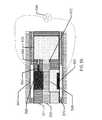
- FIGS. 5A-Billustrate exemplary features of cavity based fuel cells.
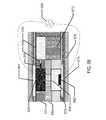
- FIGS. 6A-Billustrate alternative exemplary features of cavity based fuel cells.
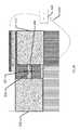
- FIG. 7illustrates a close-up view of the anode region and fuel store region of exemplary cavity based fuel cells.
- FIG. 8illustrates a close-up view of the cathode region of exemplary cavity based fuel cells.
- FIGS. 9 A-Cillustrate exemplary interconnection schemes for exemplary fuel cells.
- the membrane element within the energization elementsmay be formed with novel methods and may comprise novel materials.
- detailed descriptions of various embodimentsare described. The description of both preferred and alternative embodiments are exemplary embodiments only, and various modifications and alterations may be apparent to those skilled in the art. Therefore, the exemplary embodiments do not limit the scope of this application.
- the three-dimensional biocompatible energization elementsare designed for use in or proximate to the body of a living organism.
- Anoderefers to an electrode through which electric current flows into a polarized electrical device.
- the direction of electric currentis typically opposite to the direction of electron flow. In other words, the electrons flow from the anode into, for example, an electrical circuit.
- Biocompatiblerefers to a material or device that performs with an appropriate host response in a specific application.
- a biocompatible devicedoes not have toxic or injurious effects on biological systems.
- Cathoderefers to an electrode through which electric current flows out of a polarized electrical device.
- the direction of electric currentis typically opposite to the direction of electron flow. Therefore, the electrons flow into the cathode of the polarized electrical device and out of, for example, the connected electrical circuit.
- Coatingrefers to a deposit of material in thin forms. In some uses, the term will refer to a thin deposit that substantially covers the surface of a substrate it is formed upon. In other more specialized uses, the term may be used to describe small thin deposits in smaller regions of the surface.
- Electrodeas used herein can refer to an active mass in the energy source.
- itmay include one or both of the anode and cathode.
- Energizedrefers to the state of being able to supply electrical current or to have electrical energy stored within.
- Energyrefers to the capacity of a physical system to do work. Many uses of the energization elements may relate to the capacity of being able to perform electrical actions.
- Energy Sourceor “Energization Element” or “Energization Device” as used herein refers to any device or layer which is capable of supplying energy or placing a logical or electrical device in an energized state.
- the energization elementsmay include fuel cells.
- the fuel cellscan be formed from alkaline type cell chemistry and may be solid-state fuel cells or wet cell fuel cells.
- “Film” as used hereinrefers to a thin layer of a material that may act as a covering or a coating; in laminate structures the film typically approximates a planar layer with a top surface and a bottom surface and a body; wherein the body is typically much thinner than the extent of the layer.
- “Functionalized” as used hereinrefers to making a layer or device able to perform a function including for example, energization, activation, and/or control.
- Moldrefers to a rigid or semi-rigid object that may be used to form three-dimensional objects from uncured formulations. Some preferred molds include two mold parts that, when opposed to one another, define the structure of a three-dimensional object.
- Powerrefers to work done or energy transferred per unit of time.
- Rechargeableor “Re-energizable” as used herein refer to a capability of being restored to a state with higher capacity to do work. Many uses may relate to the capability of being restored with the ability to flow electrical current at a certain rate for certain, reestablished time periods.
- Reenergizeor “Recharge” as used herein refer to restoring to a state with higher capacity to do work. Many uses may relate to restoring a device to the capability to flow electrical current at a certain rate for a certain, reestablished time period.
- Releasedas used herein and sometimes referred to as “released from a mold” means that a three-dimensional object is either completely separated from the mold, or is only loosely attached to the mold, so that it may be removed with mild agitation.
- “Stacked” as used hereinmeans to place at least two component layers in proximity to each other such that at least a portion of one surface of one of the layers contacts a first surface of a second layer.
- a coatingmay reside between the two layers that are in contact with each other through said coating.
- Tracesrefer to energization element components capable of connecting together the circuit components.
- circuit tracescan include copper or gold when the substrate is a printed circuit board and can typically be copper, gold or printed film in a flexible circuit.
- a special type of “Trace”is the current collector.
- Current collectorsare traces with electrochemical compatibility that makes the current collector suitable for use in conducting electrons to and from an anode or cathode.
- the methods and apparatus presented hereinrelate to forming biocompatible energization elements for inclusion within or on flat or three-dimensional biocompatible devices.
- An example of a biomedical device that may incorporate the energization elements, fuel cells, of the present disclosuremay be an electroactive focal-adjusting contact lens.
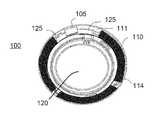
- an example of such a contact lens insertmay be depicted as contact lens insert 100 .
- a circuit 105 to provide those controlling voltage signals as well as to provide other function such as controlling sensing of the environment for external control signalsmay be powered by a biocompatible fuel cell element 110 .
- the fuel cell element 110may be found as multiple major pieces, in this case three pieces, and may comprise various configurations of fuel cell chemistry elements.
- the fuel cell elementsmay have various interconnect features to join together pieces as may be depicted underlying the region of interconnect 114 .
- the fuel cell elementsmay be connected to a circuit element that may have its own substrate 111 upon which interconnect features 125 may be located.
- the circuit 105which may be in the form of an integrated circuit, may be electrically and physically connected to the substrate 111 and its interconnect features 125 .
- a cross sectional relief of a contact lens 150may contain contact lens insert 100 and its discussed constituents.
- the contact lens insert 100may be encapsulated into a skirt of contact lens hydrogel 155 which may encapsulate the insert and provide a comfortable interface of the contact lens 150 to a user's eye.
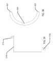
- the fuel cell elementsmay be formed in a two-dimensional form as depicted in another example of FIG. 1C .
- the flat elementmay connect to a circuit element 163 , which in the example of FIG. 1C may contain two major circuit areas 167 .
- the circuit elementmay connect to the fuel cell element at an electrical contact 161 and a physical contact 162 .
- the flat structuremay be bent into a three-dimensional conical structure as has been described in the present disclosure.
- a second electrical contact 166 and a second physical contact 164may be used to connect and physically stabilize the three-dimensional structure.
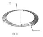
- a representation of this three-dimensional conical structure 180may be found.
- the physical and electrical contact points 181may also be found and the illustration may be viewed as a three-dimensional view of the resulting structure.
- This structuremay comprise the modular electrical and fuel cell component that will be incorporated with a lens insert into a biocompatible device.
- segmented fuel cell schemesis depicted for an exemplary fuel cell element for a contact lens type example.
- the segmented componentsmay be relatively circular-shaped 271 , square-shaped 272 or rectangular-shaped. In rectangular-shaped examples, the rectangles can be small rectangular shapes 273 , larger rectangular shapes 274 , or large rectangular shapes 275 .
- These different types of segmentingprovide design tradeoffs for parameters of the fuel cell such as capacity, internal resistance, manufacturability, voltage capability, defect resistance and packaging.
- the fuel cellsmay be formed as flat elements.
- FIG. 3Aan example of a rectangular outline 310 of the fuel cell element may be depicted with an anode connection 311 and a cathode connection 312 .
- FIG. 3Ban example of a circular outline 330 of a fuel cell element may be depicted with an anode connection 331 and a cathode connection 332 .
- the outlines of the fuel cell formmay be dimensionally and geometrically configured to fit in custom products.
- custom “free-form” or “free shape” outlinesmay be formed which may allow the fuel cell configuration to be optimized to fit within a given product.
- a “free-form” example of a flat outlinemay be arcuate in form; the free form may be of such geometry that when formed to a three-dimensional (3D) shape, it may take the form of a conical, annular skirt that fits within the constraining confines of a contact lens. It may be clear that similar beneficial geometries may be formed where medical devices have restrictive two-dimensional (2D) or 3D shape requirements.
- the fuel cells according to the present disclosuremay have important aspects relating to safety and biocompatibility.
- fuel cells for biomedical devicesmay need to meet requirements above and beyond those for typical fuel cell usage scenarios.
- design aspectsmay be considered related to stressing events.
- the safety of an electronic contact lensmay need to be considered in the event a user breaks the lens during insertion or removal.
- design aspectsmay consider the potential for a user to be struck in the eye by a foreign object.
- stressful conditionsthat may be considered in developing design parameters and constraints may relate to the potential for a user to wear the lens in challenging environments like the environment under water or the environment at high altitude in non-limiting examples.
- pacemakersmay be a typical type of biomedical device which may include a fuel cell and which may be implanted in a user for an extended period of time. Accordingly, in some examples, such pacemakers may typically be packaged with welded, hermetic titanium enclosures, or in other examples, multiple layers of encapsulation. Emerging powered biomedical devices may present new challenges for packaging, especially fuel cell packaging. These new devices may be much smaller than existing biomedical devices, for example, an electronic contact lens or pill camera may be significantly smaller than a pacemaker. In such examples, the volume and area available for packaging may be greatly reduced.
- Another area for design considerationsmay relate to electrical requirements of the device upon the fuel cell device.
- an appropriate fuel cellmay need to meet the full electrical requirements of the system when operating in a non-connected or non-externally powered mode.
- An emerging field of non-connected or non-externally powered biomedical devicesmay include, for example, vision-correcting contact lenses, health monitoring devices, pill cameras, and novelty devices.
- Recent developments in integrated circuit (IC) technologymay permit meaningful electrical operation at very low current levels, for example, picoamps of standby current and microamps of operating current. IC's may also permit very small devices.
- Micro-fuel cells for biomedical applicationsmay be required to meet many simultaneous, challenging requirements.
- the micro-fuel cellmay be required to have the capability to deliver a suitable operating voltage to an incorporated electrical circuit.
- This operating voltagemay be influenced by several factors including the IC process “node,” the output voltage from the circuit to another device, and a particular current consumption target which may also relate to a desired device lifetime.
- nodesmay typically be differentiated by the minimum feature size of a transistor, such as its “so-called” transistor channel.
- This physical featurealong with other parameters of the IC fabrication, such as gate oxide thickness, can be associated with a resulting rating standard for turn-on, or threshold, voltages of field-effect transistors (FET's) fabricated in the given process node.
- FET'sfield-effect transistors
- a node with a minimum feature size of 0.5 micronsit may be common to find FET's with turn-on voltages of 5.0 V.
- the FET'smay turn-on at 1.2, 1.8, or 2.5 V.
- the IC foundrymay supply standard cells of digital blocks, for example, inverters and flip-flops that have been characterized and are rated for use over certain voltage ranges.
- Designerschose an IC process node based on several factors including density of digital devices, analog/digital mixed signal devices, leakage current, wiring layers, and availability of specialty devices such as high-voltage FET's. Given these parametric aspects of the electrical components which may draw power from a micro-fuel cell, it may be important for the micro-fuel cell power source to be matched to the requirements of the chosen process node and IC design especially in terms of available voltage and current.
- an electrical circuit powered by a micro-fuel cellmay connect to another device.
- the micro-fuel cell powered electrical circuitmay connect to an actuator or a transducer.
- thesemay include a light-emitting diode (LED), a sensor, a microelectromechanical system (MEMS) pump, or numerous other such devices.
- LEDlight-emitting diode
- MEMSmicroelectromechanical system
- such connected devicesmay require higher operating voltage conditions than common IC process nodes, for example, a variable-focus lens may require 35 V to activate. The operating voltage provided by the fuel cell may therefore be a critical consideration when designing such a system.
- the efficiency of a lens driver to produce 35 V from a 1 V fuel cellmay be significantly less than it might be when operating from a 2 V fuel cell. Further requirements such as die size may be dramatically different considering the operating parameters of the micro-fuel cell as well.
- Individual fuel cell cellsmay typically be rated with open-circuit, loaded, and cutoff voltages.
- the open-circuit voltageis the potential produced by the fuel cell with infinite load resistance.
- the loaded voltageis the potential produced by the cell with an appropriate, and typically also specified, load impedance placed across the cell terminals.
- capacitors or batteriesmay supplement the fuel cell and may be used to buffer temporary and dynamic load conditions where the power density of a fuel cell may be insufficient.
- Shelf lifetypically refers to the period of time which a fuel cell may survive in storage and still maintain useful operating parameters. Shelf life may be particularly important for biomedical devices for several reasons. Electronic devices may displace non-powered devices, as for example may be the case for the introduction of an electronic contact lens. Products in these existing market spaces may have established shelf life requirements, for example, three years, due to customer, supply chain, and other requirements. It may typically be desired that such specifications not be altered for new products. Shelf life requirements may also be set by the distribution, inventory, and use methods of a device comprising a micro-fuel cell. Accordingly, micro-fuel cells for biomedical devices may have specific shelf life requirements, which may be measured in the number of years for example.
- a fuel cellmay function to provide the electrical energy for an electrical system.
- the fuel cellmay be electrically connected to the circuit of the electrical system.
- the connections between a circuit and a fuel cellmay be classified as interconnects. These interconnects may become increasingly challenging for biomedical micro-fuel cells due to several factors.
- powered biomedical devicesmay be very small thus allowing little area and volume for the interconnects. The restrictions of size and area may impact the electrical resistance and reliability of the interconnections.
- a fuel cellmay contain liquids which could boil at high temperature. This restriction may directly compete with the desire to use a solder interconnect which may, for example, require relatively high temperatures such as 250 degrees C. to melt.
- the fuel cell chemistry and the heat source used to form solder based interconnectsmay be isolated spatially from each other, in the cases of emerging biomedical devices, the small size may preclude the separation of aqueous solutions and solder joints by sufficient distance to reduce heat conduction.
- Interconnectsmay allow current to flow from the fuel cell in connection with an external circuit. Such interconnects may interface with the environments inside and outside the fuel cell, and may cross the boundary or seal between those environments. These interconnects may be considered as traces, making connections to an external circuit, passing through the fuel cell seal, and then connecting to the current collectors inside the fuel cell. As such, these interconnects may have several requirements. Outside the fuel cell, the interconnects may resemble typical printed circuit traces. They may be soldered to or otherwise connect to other traces. In an example where the fuel cell is a separate physical element from a circuit board containing an integrated circuit, the fuel cell interconnect may allow for connection to the external circuit. This connection may be formed with solder, conductive tape, conductive ink or epoxy, or other means. The interconnect traces may need to survive in the environment outside the fuel cell, for example not corroding in the presence of oxygen.
- Adhesionmay be required between the seal and interconnect in addition to the adhesion which may be required between the seal and fuel cell package.
- Seal integritymay need to be maintained in the presence of aqueous solutions and other materials inside the fuel cell.
- Interconnectswhich may typically be metallic, may be known as points of failure in fuel cell packaging. The electrical potential and/or flow of current may increase the tendency for solutions within the fuel cell to “creep” along the interconnect. Accordingly, an interconnect may need to be engineered to maintain seal integrity.
- the interconnectsmay interface with the current collectors or may actually form the current collectors.
- the interconnectmay need to meet the requirements of the current collectors as described herein, or may need to form an electrical connection to such current collectors.
- metal foilsare available in thickness of 25 microns or less, which make them suitable for very thin fuel cells. Such foil may also be sourced with low surface roughness and contamination, two factors which may be critical for fuel cell performance.
- the foilsmay include zinc, nickel, brass, copper, titanium, other metals, and various alloys.
- Metal foilsmay also have coatings of various types that may be applied to their surfaces. In an example, a carbon or graphite coating may be applied to a copper foil, wherein the coating may be a conductive film with a rough surface topology which may increase surface area of the electrode to adjacent solutions. Furthermore, the coating may provide a barrier of various kinds between adjacent solutions and the metal films, which may have different aspect of chemical reactivity. There may be numerous films and coating applied to the electrode foils.
- a modular fuel cell componentmay be formed according to some aspects and examples of the present disclosure.
- the modular fuel cell assemblymay be a separate component from other parts of the biomedical device.
- such a designmay comprise a modular fuel cell that is separate from the rest of a media insert.
- a modular fuel cell componentmay be formed in a separate, non-integrated process which may alleviate the need to handle rigid, 3D-formed optical plastic components.
- the sources of manufacturingmay be more flexible and may operate in a more parallel mode to the manufacturing of the other components in the biomedical device.
- modular fuel cell componentsmay be decoupled from the characteristics of 3D-shaped devices.
- a modular fuel cell systemmay be fabricated in a flat or roughly two-dimensional perspective and then shaped to the appropriate three-dimensional shape.
- a modular fuel cell componentmay be tested independently of the rest of the biomedical device, and yield loss due to fuel cell components may be sorted before assembly.
- the resulting modular fuel cell componentmay be utilized in various media insert constructs that do not have an appropriate rigid region upon which the fuel cell components may be formed, and, in a still further example, the use of modular fuel cell components may facilitate the use of different options for fabrication technologies than would otherwise be utilized, for example, web-based technology (roll to roll), sheet-based technology (sheet-to-sheet), printing, and lithography processing.
- the discrete containment aspect of such a devicemay result in additional material being added to the overall biomedical device construct. Such effects may set a constraint for the use of modular fuel cell solutions when the available space parameters require minimized thickness or volume of solutions.
- the form factormay require a three-dimensional curvature of the fuel cell component where a radius of that curvature may be on the order of approximately 8.4 mm.
- the nature of such a curvaturemay be considered to be relatively steep and for reference may approximate the type of curvature found on a human fingertip.
- the nature of a relative steep curvaturecreates challenging aspects for manufacture.
- a modular fuel cell componentmay be designed such that it may be fabricated in a flat, two-dimensional manner and then formed into a three-dimensional form of relative high curvature.
- the thickness of the fuel cell componentmay be an important and limiting parameter.
- fuel cell thicknessmay be determined by the combined thicknesses of top and bottom sheets, spacer sheets, and adhesive layer thicknesses. Practical manufacturing aspects may drive certain parameters of film thickness to standard values in available sheet stock.
- the filmsmay have minimum thickness values to which they may be specified base upon technical considerations relating to chemical compatibility, moisture/gas impermeability, surface finish, and compatibility with coatings that may be deposited upon the film layers.
- a desired or goal thickness of a finished fuel cell componentmay be a component thickness that is less than 220 ⁇ m.
- this desired thicknessmay be driven by the three-dimensional geometry of an exemplary ophthalmic lens device where the fuel cell component may need to be fit inside the available volume defined by a hydrogel lens shape given end user comfort, biocompatibility, and acceptance constraints.
- This volume and its effect on the needs of fuel cell component thicknessmay be a function of total device thickness specification as well as device specification relating to its width, cone angle, and inner diameter.
- Another important design consideration for the resulting fuel cell component designmay relate to the volume available for active fuel cell chemicals and materials in a given fuel cell component design with respect to the resulting chemical energy that may result from that design. This resulting chemical energy may then be balanced for the electrical requirements of a functional biomedical device for its targeted life and operating conditions.
- a flexible fuel cell modulemay facilitate the previously mentioned ability to fabricate the fuel cell form in a two-dimensional flat form.
- the flexibility of the formmay allow the two-dimensional fuel cell to then be formed into an appropriate three-dimensional shape to fit into a biomedical device such as a contact lens.
- a contact lens form of a biomedical devicemay have advantages for insertion/removal of the media insert based contact lens that may be closer to the insertion/removal of a standard, non-filled hydrogel contact lens.
- flexibility of the fuel cell module and associated biomedical devicesmay allow for important advantages to the use of these devices.
- an intraocular lensmay provide an example of a biomedical device using a flexible fuel cell module since a typical insertion of such a lens during a surgical procedure may place a folded lens body through a small incision before unfolding it into place. For this type of surgery and others, a smaller incisions site may result in improved results, quicker healing and other such benefits.
- the number of flexuresmay be important to the engineering of the fuel cell.
- a fuel cell which may only flex one time from a planar form into a shape suitable for a contact lensmay have significantly different design from a fuel cell capable of multiple flexures.
- the flexure of the fuel cellmay also extend beyond the ability to mechanically survive the flexure event.
- an electrodemay be physically capable of flexing without breaking, but the mechanical and electrochemical properties of the electrode may be altered by flexure. Flex-induced changes may appear instantly, for example as changes to impedance, or flexure may introduce changes which are only apparent in long-term shelf life testing.
- the fuel cell width requirementmay be largely a function of the application in which it is applied.
- a contact lens fuel cell systemmay have constrained needs for the specification on the width of a modular fuel cell component.
- the variable optic portion of the devicemay occupy a central spherical region of about 7.0 mm in diameter.
- the exemplary fuel cell elementsmay be considered as a 3-dimensional object, which fits as an annular, conical skirt around the central optic and formed into a truncated conical ring.
- the required maximum diameter of the rigid insertis a diameter of 8.50 mm, and tangency to a certain diameter sphere may be targeted (as for example in a roughly 8.40 mm diameter), then geometry may dictate what the allowable fuel cell width may be.
- geometric modelsthat may be useful for calculating desirable specifications for the resulting geometry which in some examples may be termed a conical frustum flattened into a sector of an annulus.
- Flattened fuel cell widthmay be driven by two features of the fuel cell element, the active fuel cell components and seal width.
- a target thicknessmay be between 0.100 mm and 0.500 mm per side, and the active fuel cell components may be targeted at roughly 0.800 mm wide.
- Other biomedical devicesmay have differing design constraints but the principles for flexible flat fuel cell elements may apply in similar fashion.
- fuel cell elementsmay be designed in manners that segment the regions of active fuel cell chemistry. There may be numerous advantages from the division of the active fuel cell components into discrete segments. In a non-limiting example, the fabrication of discrete and smaller elements may facilitate production of the elements. The function of fuel cell elements including numerous smaller elements may be improved. Defects of various kinds may be segmented and non-functional elements may be isolated in some cases to result in decreased loss of function. This may be relevant in examples where the loss of fuel cell solution may occur.
- the isolation of individualized componentsmay allow for a defect that results in leakage of fluids out of the critical regions of the fuel cell to limit the loss of function to that small segment of the total fuel cell element whereas the fluid loss through the defect could empty a significantly larger region for fuel cells configured as a single cell.
- Smaller cellsmay result in lowered volume of active fuel cell chemicals on an overall perspective, but the mesh of material surrounding each of the smaller cells may result in a strengthening of the overall structure.
- the plurality of components comprising the laminar micro-fuel cells of the present disclosuremay be held together with a pressure-sensitive adhesive (PSA) that also serves as a sealant.
- PSApressure-sensitive adhesive
- alternatives to pressure sensitive adhesivesmay be utilized. While a myriad of commercially available pressure sensitive adhesive formulations may exist, such formulations may include components that may make them unsuitable for use within a biocompatible laminar micro-fuel cell. Examples of undesirable components in pressure sensitive adhesives may include low molecular mass leachable components, antioxidants e.g.
- BHT and/or MEHQplasticizing oils, impurities, oxidatively unstable moieties containing, for example, unsaturated chemical bonds, residual solvents and/or monomers, polymerization initiator fragments, polar tackifiers, and the like.
- Suitable PSAsmay on the other hand exhibit the following properties. They may be able to be applied to laminar components to achieve thin layers on the order of 2 to 20 microns. As well, they may contain a minimum of, preferably zero, undesirable or non-biocompatible components. Additionally, they may have sufficient adhesive and cohesive properties so as to bind the components of the laminar fuel cell together. And, they may be able to flow into the micron-scale features inherent in devices of the present construction while providing for a robust sealing of fluids within the fuel cell. In some examples of suitable PSAs, the PSAs may have a low permeability to water vapor in order to maintain a desirable aqueous solution composition within the fuel cell even when the fuel cell may be subjected to extremes in humidity for extended periods of time.
- polyisobutylenemay be a commercially-available material that may be formulated into PSA compositions meeting many if not all desirable requirements. Furthermore, PIB may be an excellent barrier sealant with very low water absorbance and low oxygen permeability.
- An example of PIB useful in the examples of the present disclosuremay be Oppanol B15 by BASF Corporation. Oppanol B15 may be dissolved in hydrocarbon solvents such as toluene, dodecane, mineral spirits, and the like.
- a preferred PSA compositionmay comprise 30% Oppanol B15 (w/w) in a solvent mixture comprising 70% (w/w) toluene and 30% dodecane.
- the adhesive and rheological properties of PIB based PSA'smay be determined in some examples by the blending of different molecular mass grades of PIB.
- a common approachmay be to use a majority of low molar mass PIB, e.g. Oppanol B10 to effect wetting, tack, and adhesion, and to use a minority of high molar mass PIB to effect toughness and resistance to flow. Consequently, blends of any number of PIB molar mass grades may be envisioned and may be practiced within the scope of the present disclosure.
- tackifiersmay be added to the PSA formulation so long as the aforementioned requirements may be met.
- tackifiersimpart polar properties to PSA formulations, so they may need to be used with caution so as to not adversely affect the barrier properties of the PSA.
- tackifiersmay in some cases be oxidatively unstable and may include an antioxidant, which could leach out of the PSA.
- preferred tackifiers for use in PSA's for biocompatible laminar micro fuel cellsmay include fully- or mostly hydrogenated hydrocarbon resin tackifiers such as the Regalrez series of tackifiers from Eastman Chemical Corporation.
- examples of processingmay include the use of a pressure sensitive adhesive. In many cases other types of adhesion or sealing may be employed in similar manners with similar results.
- additional processing to that used to adhere parts togethermay be employed to increase the ability of the adhered surfaces to be sealed. For example, laser welding may join or further support sealing. In other examples, ultrasonic welding or thermal welding may be used to support sealing aspects. Still further examples may include photo-patterned polymer seals.
- a work piecemay be assembled into a general structure with the use of pressure sensitive adhesives and then after a number of structural elements have been joined, additional processing may ensure to enhance or define appropriate sealing surfaces.
- the packagingmay desirably be predominantly foil and/or film based where these packaging layers may be as thin as possible, for example, 10 to 50 microns.
- the packagingmay provide a sufficient diffusion barrier to moisture gain or loss during the shelf life. In many desirable examples, the packaging may provide a sufficient diffusion barrier to oxygen ingress.
- the packagingmay provide a finite permeation pathway to any gasses that may evolve.
- top and bottom packaging layersmay comprise metallic foils or polymer films.
- such polymer filmsmay themselves be coated in numerous manners including in a non-limiting sense to be evaporated, sputtered or coated in other manners by layers of metallic compounds or elements or other non-metallic compounds such as silicon dioxide for example.
- Top and bottom packaging layersmay be comprised of multi-layer film constructs containing a plurality of polymer and/or barrier layers. Such film constructs may be referred to as coextruded barrier laminate films.
- An example of a commercial coextruded barrier laminate film of particular utility in the present disclosuremay be 3M Scotchpak 1109 backing which consists of a PET carrier web, a vapor-deposited aluminum barrier layer, and a polyethylene layer comprising a total average film thickness of 33 microns. Numerous other similar multilayer barrier films may be available and may be used in alternate examples of the present disclosure.
- packaging layer surface roughnessmay be of particular importance, because the PSA may also need to seal opposing packaging layer faces.
- Surface roughnessmay result from manufacturing processes used in foil and film production, for example processes employing rolling, extruding, embossing and/or calendaring, among others. If the surface is too rough, PSA may be not able to be applied in a uniform thickness when the desired PSA thickness may be on the order of the surface roughness Ra. Furthermore, PSA's may not adequately seal against an opposing face if the opposing face has roughness that may be on the order of the PSA layer thickness. In the present disclosure, packaging materials having a surface roughness, Ra, less than 10 microns may be acceptable examples.
- surface roughness valuesmay be 5 microns or less. And, in still further examples, the surface roughness may be 1 micron or less.
- Surface roughness valuesmay be measured by a variety of methods including but not limited to measurement techniques such as white light interferometry, stylus profilometry, and the like. There may be many examples in the art of surface metrology that surface roughness may be described by a number of alternative parameters and that the average surface roughness, Ra, values discussed herein may be meant to be representative of the types of features inherent in the aforementioned manufacturing processes.
- a fuel cellhas the following elements: a cathode region with an inert electrode, an anode typically with enzymes for catalysis of the fuel cell reaction, a fuel source, and a membrane which may be called an electrolyte, a cathode current collector, an anode current collector, and packaging.
- the designmay have dual-use components, for example, the process of using a metal package to double as a current collector. From a relative volume and thickness standpoint, these elements may be nearly all the same volume, except for the cathode and fuel source.
- the packaging needed to provide sufficient protection to maintain fuel cell chemistry in use environmentsmay have a planned maximal thickness of approximately 50 ⁇ m.
- such examplesmay assume a “pouch”-like construct, using webs or sheets fabricated into various configurations, with fuel cell elements arranged inside.
- the containmentmay have two films or one film bended over onto the other side either configuration of which may form two roughly planar surfaces, which may be then sealed on the perimeter to form a container.
- This thin-but-wide form factormay make fuel cell elements themselves thin and wide.
- these examplesmay be suitable for application through coating, gravure printing, screen printing, sputtering, or other similar fabrication technology.
- the processing of the fuel cell structuremay be classified as laminate assembly, which may involve using films, either in a web or sheet form, to build up a fuel cell layer by layer.
- Sheetscan be bonded to each other using adhesives, such as pressure-sensitive adhesives, thermally activated adhesives, or chemical reaction-based adhesives.
- the sheetscan be bonded by welding techniques such as thermal welding, ultrasonic welding and the like. Sheets may lend themselves to standard industry practices as roll-to-roll (R2R), or sheet-to-sheet assembly.
- R2Rroll-to-roll
- an interior volume for the fuelmay need to be substantially larger than the other active elements in the fuel cell.
- Much of a fuel cell constructmay have to create the space for the fuel, and support it from migration during flexing of the fuel cell.
- a sheet form of membranemay create an advantageous solution for laminate processing.
- the membranemay be formed by dispensing polymer material into a layer to act as the membrane.
- another laminate layermay be introduced to contain this element.
- the thickness of the formed devicemay increase in order to accommodate and contain the necessary spacer material volume to contain the membrane.
- the productmay have an anode sheet, which may be a combination of a package layer and an anode current collector, as well as substrate for the anode layer.
- the forming productmay also have an optional membrane spacer sheet, a cathode spacer sheet, and a cathode sheet.
- the cathode sheetmay be a combination of a package layer and a cathode current collector layer.
- Intimate contact between electrodes and current collectorsis of critical importance for reducing impedance and increasing discharge capacity. If portions of the electrode are not in contact with the current collector, resistance may increase since conductivity is then through the electrode (typically less conductive than the current collector) or a portion of the electrode may become totally disconnected.
- An embossing stepmay be performed after assembly of the laminar stack, introducing compression into the stack.
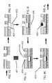
- FIGS. 4A-4NAn example of the steps that may be involved in processing fuel cell elements may be found referring to FIGS. 4A-4N .
- the processing at some of the exemplary stepsmay be found in the individual figures.
- FIG. 4Aa combination of a PET Anode Spacer 401 and a PET Cathode Spacer 404 is illustrated.
- the PET Anode Spacer 401may be formed by applying films of PET 403 which, for example, may be roughly 3 mils thick.
- two PET layersmay surround a metal sealed cavity 407 between the two layers.
- the metal sealmay include electrical connecting layers within the space between the PET layers to allow for electrically driven removal of the metal seal.
- PSA layersOn either side of the PET layer may be found PSA layers or these may be capped with a polyvinylidene fluoride (PVDF) release layer 402 which may be roughly 1 mil in thickness.
- PVDFpolyvinylidene fluoride
- the PET Cathode Spacer 404may be formed of a PVDF layer 409 which may be roughly 3 mils of thickness.
- a hole 406 in the Cathode Spacer layer 404may be cut by laser cutting treatment.
- the cut PET Cathode Spacer layermay be laminated 408 to the PET Anode Spacer layer 401 .
- a cathode spacer hole 410 and a fuel cavity hole 411may be cut by laser cutting treatment. The alignment of this cutting step may be registered to the previously cut features in the PET Cathode Spacer layer 404 .
- a layer of membrane 412may be bonded to a carrier 413 . Proceeding to FIG.
- the membrane materialmay be cut to figures that are between the size of the previous two laser-cut holes surrounding the cathode and anode cavities, and approximately the size of the PET Cathode Spacer hole, forming a precut membrane 420 .
- a pick and place tool 421may be used to pick and place discrete pieces of membrane into their desired locations on the growing device.
- the placed membrane pieces 422are fastened into place.
- a cavity solution 423which may be a slurry of ice in some examples, may be filled into the cathode cavity. If the cavity solution 423 is in liquid form, the filling may occur with the layers inverted from the depicted direction.
- the growing device structuremay be bonded to a cathode contact 425 .
- a mixture of the fuel for the fuel cellmay be added to the anode cavity 430 and the fuel cavity 432 .
- a squeegee 431may be used in some examples to spread the cathode mix across a work piece and in the process fill the gaps of the fuel cell devices being formed.
- the remaining PVDF release layer 433may be removed which may result in the structure transformation illustrated from FIG. 4K to 4L .
- additional materials 440such as enzymes and buffers may be added to the anode cavity to also be at the height of the PET layer top.
- the enzymes included in the anode cavitymay include glucose-6-phosphate dehydrogenase, ⁇ -glucan phosphorylase, phosphoglucomutase, and 6-phosphogluconate dehydrogenase as well as other examples of enzymes.
- an anode contact layer 450which may include a bound layer of enzymes on an anode 451 , may be bonded to the growing structure.
- a laser cutting processmay be performed to remove side regions 460 and yield a fuel cell element.
- the laminate layer based cavity approachesmay be useful in forming a fuel cell.
- An energization element with fuel cellsmay utilize the cavity approach described in the present disclosure and may include multiple cavities, with a number of cavities being a cathode, anode, or fuel source.
- a cathode cavitymay contain a cathode fluid composition.
- An anode cavitymay contain an anode fluid composition which may contain a number of enzymes to facilitate catabolic oxidation of a fuel source.
- a fuel source cavitymay contain a fuel source for the fuel cell. This fuel source may include a hydrocarbon biofuel such as glucose or maltodextrin, as non-limiting examples.
- the membrane layers of these cavitieswhich may also be called the electrolyte, keep the reaction intermediaries from each other while allowing small ionic species such as hydrogen ions to diffuse across the electrolyte region.
- the electrolytemay include different materials, including semi-permeable materials, as a non-limiting example.
- the energization elementmay include both fuel cells as well as battery elements. The battery elements may be useful to activate the fuel cell for use conditions and may allow fuel to flow into the fuel cell from a storage location.
- a cavity-based fuel cellmay have three main cavities for operation: a fuel source cavity 510 , an anode cavity 520 , and a cathode cavity 530 .
- a single cavitymay have a stacked implementation with the one or more of the anode, cathode and fuel source cavity occupying a single cavity with intervening layers separating the different functions. The interaction and interconnection of these cavities or elements in a cavity may allow for the functioning as a fuel cell.
- the fuel source cavity 510 and anode cavity 520may be connected by means of a bridge 540 between the two cavities that contains a gate 545 to separate the two cavities until it may be opened upon desired operation of the cavity fuel cell.
- the anode cavity 520 and cathode cavity 530may be separated by a semi-permeable membrane or electrolyte 550 that separates the general contents of each cavity, but may allow the transfer of protons from the anode cavity 520 to the cathode cavity 530 , as may be necessary for the functioning of the cavity fuel cell.
- the anode cavity 520 and cathode cavity 530may be connected by an external circuit 560 that may utilize the energy released in reactions within the fuel cell. Interconnections may facilitate the transfer of electrons from an electrode 561 in the anode cavity 520 to an electrode 562 in the cathode cavity 530 , as may be necessary for the functioning of the cavity fuel cell.
- anode cavitymay contain the fuel source without an additional fuel source cavity being employed.
- the effective surface areas of the electrodes in the anode and cathodemay be important factors in the performance of the fuel cells.
- High surface area platinum based electrodesmay be utilized in some examples.
- Other examples of forming high surface area filmssuch as texturing of a surface physically, growing dendritic features of high surface area, electroplating, sputter coating, laser milling, chemical etching, and other such examples may provide desirable electrodes.
- the electrolytemay play a key function in preventing reactants from crossing between the anode and cathode while also allowing hydrogen ions to diffuse through the cell to complete the electrochemical circuit.
- Other parts of the construction reaction processhave similar important functions.
- the adhesives, 570may be an example where diffusion control and material choice may be important, and the seals formed at the adhesive layers may have supplemental sealing such as laser based melt flow sealing as examples.
- the laminate material such as layer 571may be another example, where materials that are non-permeable are desirable.
- a supplemental laminate piece 572may be found which may add a non-permeable characteristic between the electrolyte 550 and the fuel source cavity 510 .
- the volume of the fuel cavitymay be altered with an impervious layer 573 which may be used to isolate the fuel from the membrane/electrolyte region.
- the various layersmay be formed to be impermeable to oxygen to support this function.
- the anode electrodeitself may have perforations or gaps that allow for gasses to diffuse into the cathode cell.
- Other structuressuch as electrical interconnects 575 and support layers 576 may also be designed to have permeability to oxygen.
- oxygenis consumed in the cathode cell while carbon dioxide may be evolved in the anode cell.
- the carbon dioxidemay be evolved and diffuse out of the cell, or in other examples, the carbon dioxide may be dissolved in the reactant solution with buffers present to limit the change in pH that occurs as carbon dioxide is solvated.
- an oxidant sourcemay be incorporated within the cathode solution even when the various regions are kept from allowing diffusion of molecules such as oxygen across boundaries.
- General zeolites formed to absorb oxygen or nanotubesmay be configured to adsorb oxygen molecules and surrender them during an oxidation reaction.
- adsorbant surfaces of zeolytesmay be used to segregate carbon dioxide formed in the anode during the course of the generation of electricity in a fuel cell.
- the fuel source cavity 510may contain the fuel source for the fuel cell's operation, which may include maltodextrin, glucose or other biofuels, as non-limiting examples.
- the fuel sourcemay be an aqueous solution of maltodextrin, glucose or other biofuels.
- a solid or highly concentrated solution of the fuelmay be stored in the fuel cavity.
- a closed gate 610may prevent the fuel source from transferring from the fuel source cavity 510 into the anode cavity 520 .
- this gate 610 which is closedmay consist of an electrically conductive metal sheet.
- the gatemay be an electrically controlled expansive element that may be programmed to open and close multiple times, to allow fuel to move from the fuel cavity to the anode cavity.
- a separate power source 620which may include a cavity-formed battery as described in the referenced related applications of the present disclosure, may be connected to the closed gate 610 at connection points 621 , 622 to create a circuit that may be connected or broken by means of an electrical switch 630 .
- the operating voltage of the separate power source 620may be high enough that when the electrical switch 630 is connected to complete the circuit, the voltage across the closed gate 610 may very quickly increase power enough to melt the thin film like an electric fuse.
- the current flowmay cause the closed gate 610 to rupture, resulting in an open gate 640 as depicted in FIG. 6B . When this occurs, the fuel source in the fuel source cavity 510 may now transfer to the anode cavity 520 .
- an activation signalmay be received by electronic circuitry powered by a small battery cell.
- the battery cell's capacitymay be based on that needed to support a receiver of the activation signal and the energy required to rupture the seal in the fuel cell fuel source cavity at the closed gate 610 .
- the batterymay have a small additional energy capacity to operate the biomedical device for a period of time while the fuel cell initiates.
- the materials that comprise a fuel cellmay be more biologically compatible than battery chemistry and in those cases, the use of a fuel cell based energization element of this composite design may maximize the usage of biocompatible materials in the fuel cell.
- an exemplary active anode cavitymay be seen.
- the fuel sourcemay be able to travel in the direction indicated by arrow 710 into the anode cavity 520 .
- the active anode cavitymay contain a combination of ingredients including a buffer solution to maintain a stable pH of the solution, a single or possible combination of reaction catalysts, and specific concentrations of other ingredients that may react with the fuel source when it is exposed to these ingredients.
- the reaction catalystsmay consist of a single or combination of specific enzymes, to function as reaction catalysts in a desired catabolic reaction with a biofuel, such as, but not limited to, maltodextrin or other glucose molecules.
- This catabolic reactionmay generate a number of free protons, which may travel in the direction indicated by arrow 730 across the membrane (also called an electrolyte in previous discussions) into the cathode cavity 530 , which is depicted in following FIG. 8 , as well as an equal number of free electrons, which may travel in the direction indicated by arrow 735 through an external circuit 560 to the cathode as well.
- the active anode cavitymay be oxygen-impermeable.
- the outer anode boundary 740which may be an electrical interconnect, may be composed of an oxygen-impermeable material, such as a metal, as a non-limiting example. In some examples, films of brass, titanium, aluminum and metals like this may be used.
- the catabolic oxidation reactionsmay produce carbon dioxide as a byproduct 750 . Since the anode cavity may be designed to not allow oxygen to diffuse into the cavity, this same impervious active anode cavity may not be able to dispel generated carbon dioxide.
- the carbon dioxide as generatedmay be dissolved in the aqueous solution of the anode.
- the carbon dioxidemay alter the pH of the ingredient solution present in the active anode cavity.
- a buffering solutionmay be useful in the solution to increase the amount of carbon dioxide that may be evolved before the pH of the anode lowers enough to effect the reactions.
- buffersmay be introduced to keep the pH within operational levels.
- an active cathode cavitymay be seen.
- This active cathode cavitymay contain an electrically conductive electrode 810 that may serve as the site for the reduction reaction 820 present in the cathode.
- This reduction reaction 820may be caused by an influx of protons and electrons from the anode cavity.
- oxygenmay be introduced into the active cathode cavity from the environment 830 ; as such, the cathode cavity 530 may be constructed with oxygen-permeable materials including, but not limited to, a hydrogel.
- watermay be generated 840 .
- a contact lensmay have an “outer curve” surface and an “inner curve” surface.
- the inner curve surfacemay rest upon or in closest proximity to the surface of the eye.
- the “outer curve”may therefore sit facing the atmosphere surrounding the ocular environment. Even though the lens surface may still be bathed in tear fluid during use, there may be an expectation that the oxygen concentration in proximity to atmosphere is relatively higher.
- the opening of a packagemay allow oxygen from the atmosphere to flood into the biomedical device and diffuse into the fuel cell. As the oxygen diffuses into the fuel cell it may begin to generate electrical current as its fuel source is consumed. Thus, another type of activation may result from such an example.
- electronsflow into the cathode cell and are illustrated by the arrow pointing towards the electrical load 560 . After flowing through the electrical load 560 , electrons enter into the cathode through conductive electrode 810 and then participate in the reduction reaction 820 .
- FIG. 9an exemplary combination of cavity-based fuel cells may be seen.
- the devicethat may be powered by the combination of cavity fuel cells, it may be desirable to supply the device with a greater voltage or current than may be supplied by just a single cavity fuel cell.
- multiple cavity-based fuel cellsmay be connected in parallel 910 as shown in FIG. 9A to increase the supplied current.
- a combinationmay be formed to increase the supplied voltage, such as in series 920 as shown in FIG. 9B .
- Many different series and parallel combinations 930 , in FIG. 9Cof cavity based fuel cells may be possible to achieve a resulting supply voltage and current.
- the laminate cavity based approachmay result in a straight forward manner to define multiple fuel cell examples in a small volume that may be combined in an equally straight forward manner.
- this exemplary combination of cavity fuel cellsmay contain, as a non-limiting example, cavity fuel cells that are activated immediately upon powering on the device, as well as cavity fuel cells that are activated at a later moment. Because cavity based fuel cells may have a finite lifespan, limited by a finite fuel source or degradation of active components, as non-limiting examples, the lifespan of a device powered by these cavity fuel cells, may be limited to the lifespan of the cavity fuel cells.
- the life span of the devicemay be doubled, tripled, or increased by a larger amount, depending on how many of these such groups are utilized.
- the activation of subsequent cavity fuel cell groupsmay be triggered, for example, by control circuitry that measures the loaded voltage dropping below a certain value, as a non-limiting example.
- Fuel cellsmay be designed and incorporated into numerous types of biomedical devices. In some examples, fuel cells based on cavity based architectures may result in desirable solutions.
- the biomedical devicesmay be, for example, implantable electronic devices, such as pacemakers and micro-energy harvesters, electronic pills for monitoring and/or testing a biological function, surgical devices with active components, ophthalmic devices, microsized pumps, defibrillators, stents, and the like.
Landscapes
- Chemical & Material Sciences (AREA)
- Life Sciences & Earth Sciences (AREA)
- Engineering & Computer Science (AREA)
- Chemical Kinetics & Catalysis (AREA)
- Electrochemistry (AREA)
- General Chemical & Material Sciences (AREA)
- Health & Medical Sciences (AREA)
- Sustainable Development (AREA)
- Sustainable Energy (AREA)
- Manufacturing & Machinery (AREA)
- Ophthalmology & Optometry (AREA)
- Physics & Mathematics (AREA)
- General Health & Medical Sciences (AREA)
- General Physics & Mathematics (AREA)
- Optics & Photonics (AREA)
- Microbiology (AREA)
- Biochemistry (AREA)
- Materials Engineering (AREA)
- Heart & Thoracic Surgery (AREA)
- Cardiology (AREA)
- Mechanical Engineering (AREA)
- Biomedical Technology (AREA)
- Nuclear Medicine, Radiotherapy & Molecular Imaging (AREA)
- Radiology & Medical Imaging (AREA)
- Animal Behavior & Ethology (AREA)
- Public Health (AREA)
- Veterinary Medicine (AREA)
- Fuel Cell (AREA)
- Inert Electrodes (AREA)
- Eyeglasses (AREA)
- Electrotherapy Devices (AREA)
Abstract
Description
Claims (34)
Priority Applications (12)
| Application Number | Priority Date | Filing Date | Title |
|---|---|---|---|
| US15/047,009US10345620B2 (en) | 2016-02-18 | 2016-02-18 | Methods and apparatus to form biocompatible energization elements incorporating fuel cells for biomedical devices |
| IL250417AIL250417A0 (en) | 2016-02-18 | 2017-02-02 | Methods and apparatus to form biocompatible energization elements incorporating fuel cells for biomedical devices |
| AU2017200727AAU2017200727A1 (en) | 2016-02-18 | 2017-02-03 | Methods and apparatus to form biocompatible energization elements incorporating fuel cells for biomedical devices |
| SG10201700966WASG10201700966WA (en) | 2016-02-18 | 2017-02-07 | Methods and apparatus to form biocompatible energization elements incorporating fuel cells for biomedical devices |
| RU2017104257ARU2638949C1 (en) | 2016-02-18 | 2017-02-09 | Methods and device for manufacturing bio-compatible batteries with inbuilt fuel cells for biomedical devices |
| CA2957662ACA2957662A1 (en) | 2016-02-18 | 2017-02-10 | Methods and apparatus to form biocompatible energization elements incorporating fuel cells for biomedical devices |
| KR1020170020410AKR20170097567A (en) | 2016-02-18 | 2017-02-15 | Methods and apparatus to form biocompatible energization elements incorporating fuel cells for biomedical devices |
| BR102017003173-0ABR102017003173A2 (en) | 2016-02-18 | 2017-02-16 | METHODS AND APPARATUS FOR FORMING BIOCOMPATIBLE ENERGIZATION ELEMENTS INCORPORATING FUEL CELLS FOR BIOMEDICAL DEVICES |
| TW106105004ATW201806224A (en) | 2016-02-18 | 2017-02-16 | Methods and apparatus to form biocompatible energization elements incorporating fuel cells for biomedical devices |
| CN201710085908.0ACN107093751A (en) | 2016-02-18 | 2017-02-17 | The method and apparatus for forming the biocompatibility energization element comprising fuel cell for biologic medical equipment |
| EP17156729.0AEP3208881B1 (en) | 2016-02-18 | 2017-02-17 | Methods and apparatus to form biocompatible energization elements incorporating fuel cells for biomedical devices |
| JP2017027782AJP2017157554A (en) | 2016-02-18 | 2017-02-17 | Method and apparatus for forming bio-compatible energizing element with integrated fuel cell for biomedical apparatus |
Applications Claiming Priority (1)
| Application Number | Priority Date | Filing Date | Title |
|---|---|---|---|
| US15/047,009US10345620B2 (en) | 2016-02-18 | 2016-02-18 | Methods and apparatus to form biocompatible energization elements incorporating fuel cells for biomedical devices |
Publications (2)
| Publication Number | Publication Date |
|---|---|
| US20170242271A1 US20170242271A1 (en) | 2017-08-24 |
| US10345620B2true US10345620B2 (en) | 2019-07-09 |
Family
ID=58057047
Family Applications (1)
| Application Number | Title | Priority Date | Filing Date |
|---|---|---|---|
| US15/047,009Active2036-03-20US10345620B2 (en) | 2016-02-18 | 2016-02-18 | Methods and apparatus to form biocompatible energization elements incorporating fuel cells for biomedical devices |
Country Status (12)
| Country | Link |
|---|---|
| US (1) | US10345620B2 (en) |
| EP (1) | EP3208881B1 (en) |
| JP (1) | JP2017157554A (en) |
| KR (1) | KR20170097567A (en) |
| CN (1) | CN107093751A (en) |
| AU (1) | AU2017200727A1 (en) |
| BR (1) | BR102017003173A2 (en) |
| CA (1) | CA2957662A1 (en) |
| IL (1) | IL250417A0 (en) |
| RU (1) | RU2638949C1 (en) |
| SG (1) | SG10201700966WA (en) |
| TW (1) | TW201806224A (en) |
Families Citing this family (8)
| Publication number | Priority date | Publication date | Assignee | Title |
|---|---|---|---|---|
| US9668916B2 (en) | 2013-11-04 | 2017-06-06 | Vance M. Thompson | Conjunctival cover and methods therefor |
| US9869883B2 (en) | 2015-03-11 | 2018-01-16 | Vance M. Thompson | Tear shaping for refractive correction |
| US10353220B2 (en) | 2016-10-17 | 2019-07-16 | Vance M. Thompson | Tear shaping for refractive correction |
| US10678067B2 (en) | 2018-04-06 | 2020-06-09 | Vance M. Thompson | Tear shaping for refractive correction |
| US20200085564A1 (en) | 2018-09-18 | 2020-03-19 | Vance M. Thompson | Structures and methods for tear shaping for refractive correction |
| US12161874B2 (en) | 2018-11-14 | 2024-12-10 | The Regents Of The University Of California | Implantable, biofuel cells for self-charging medical devices |
| CN111714133A (en)* | 2020-04-30 | 2020-09-29 | 苏州无双医疗设备有限公司 | Implantable medical device with glucose biofuel cell |
| CN113013439A (en)* | 2021-02-08 | 2021-06-22 | 上海矗鑫实业有限公司 | MEA edge sealing process for core component of PEM fuel cell |
Citations (410)
| Publication number | Priority date | Publication date | Assignee | Title |
|---|---|---|---|---|
| US754804A (en) | 1903-12-07 | 1904-03-15 | Charles A Pratt | Speed-regulating magnetic clutch. |
| US787657A (en) | 1904-12-13 | 1905-04-18 | Quimby S Backus | Gas fireplace-heater. |
| US1390765A (en) | 1919-04-12 | 1921-09-13 | New Jersey Patent Co | Galvanic battery |
| US1559562A (en) | 1923-05-25 | 1925-11-03 | Thomas A Edison | Storage battery |
| GB743731A (en) | 1953-05-19 | 1956-01-25 | Dunlop Rubber Co | Adhesive butyl rubber compositions |
| US2871281A (en) | 1956-11-16 | 1959-01-27 | Mc Graw Edison Co | Alkaline storage battery with negative iron electrode |
| US2991324A (en) | 1953-03-21 | 1961-07-04 | Vogt Hans | Alkaline storage battery |
| US3291296A (en) | 1964-10-26 | 1966-12-13 | Lemkelde Russell | Pipe nipple holder |
| US3306776A (en) | 1964-02-27 | 1967-02-28 | Pentti J Tamminen | Galvanic primary cell |
| US3353998A (en) | 1965-02-02 | 1967-11-21 | Sonotone Corp | Alkaline battery cells with silver-oxide or silver electrodes |
| US3375136A (en) | 1965-05-24 | 1968-03-26 | Army Usa | Laminated thin film flexible alkaline battery |
| US3431327A (en) | 1964-08-31 | 1969-03-04 | George F Tsuetaki | Method of making a bifocal contact lens with an embedded metal weight |
| US3642539A (en) | 1969-05-16 | 1972-02-15 | Hitachi Maxell | Secondary battery with indate ion in the electrolyte |
| GB1307393A (en) | 1969-02-20 | 1973-02-21 | Union Carbide Corp | Primary cell electrolyte |
| JPS52146650A (en) | 1976-05-28 | 1977-12-06 | Poler Stanley | Lens system that is substituted for crystalline lens |
| US4118860A (en) | 1977-01-27 | 1978-10-10 | Polaroid Corporation | Method of making a flat battery |
| US4125686A (en) | 1977-06-30 | 1978-11-14 | Polaroid Corporation | Laminar cells and methods for making the same |
| US4254191A (en) | 1977-01-24 | 1981-03-03 | Polaroid Corporation | Method for manufacturing battery vents and vented batteries |
| US4268132A (en) | 1979-09-24 | 1981-05-19 | Neefe Charles W | Oxygen generating contact lens |
| US4294891A (en) | 1980-03-12 | 1981-10-13 | The Montefiore Hospital Association Of Western Pennsylvania | Intermittently refuelable implantable bio-oxidant fuel cell |
| JPS57136774A (en) | 1981-02-17 | 1982-08-23 | Toshiba Battery Co Ltd | Alkaly cell |
| JPS58116764A (en) | 1981-12-30 | 1983-07-12 | Fujitsu Ltd | Manufacturing method of semiconductor device |
| US4408023A (en) | 1980-11-12 | 1983-10-04 | Tyndale Plains-Hunter, Ltd. | Polyurethane diacrylate compositions useful for contact lenses and the like |
| US4522897A (en) | 1983-10-14 | 1985-06-11 | Cape Cod Research, Inc. | Rope batteries |
| US4592944A (en) | 1982-05-24 | 1986-06-03 | International Business Machines Corporation | Method for providing a top seal coating on a substrate containing an electrically conductive pattern and coated article |
| US4601545A (en) | 1984-05-16 | 1986-07-22 | Kern Seymour P | Variable power lens system |
| JPS63105319U (en) | 1986-12-26 | 1988-07-08 | ||
| US4772517A (en) | 1985-02-26 | 1988-09-20 | Basf Aktiengesellschaft | Composite electrode |
| US4783237A (en) | 1983-12-01 | 1988-11-08 | Harry E. Aine | Solid state transducer and method of making same |
| US4787903A (en) | 1985-07-24 | 1988-11-29 | Grendahl Dennis T | Intraocular lens |
| US4816031A (en) | 1988-01-29 | 1989-03-28 | Pfoff David S | Intraocular lens system |
| US4846031A (en) | 1987-11-04 | 1989-07-11 | Jl Tool And Machine Co. | Method and apparatus for blanking molded parts |
| JPH01286809A (en) | 1987-10-30 | 1989-11-17 | Ronald D Blum | Method and device for manufacturing lens |
| US4921728A (en) | 1986-08-22 | 1990-05-01 | Ricoh Company, Ltd. | Process of making a liquid crystal element |
| US4939000A (en) | 1989-08-22 | 1990-07-03 | Sony Corporation | Carbon slurry regeneration method |
| US4977046A (en) | 1982-04-26 | 1990-12-11 | Polaroid Corporation | Lithium batteries |
| US5112703A (en) | 1990-07-03 | 1992-05-12 | Beta Power, Inc. | Electrochemical battery cell having a monolithic bipolar flat plate beta" al |
| US5168018A (en) | 1990-05-17 | 1992-12-01 | Matsushita Electric Industrial Co., Ltd. | Method of manufacturing zinc-alkaline batteries |
| US5219497A (en) | 1987-10-30 | 1993-06-15 | Innotech, Inc. | Method for manufacturing lenses using thin coatings |
| US5227805A (en) | 1989-10-26 | 1993-07-13 | Motorola, Inc. | Antenna loop/battery spring |
| EP0581964A1 (en) | 1992-02-14 | 1994-02-09 | Yuasa Corporation | Method of producing thin cell |
| WO1994023334A1 (en) | 1993-04-07 | 1994-10-13 | The Technology Partnership Plc | Switchable lens |
| US5358539A (en) | 1992-10-29 | 1994-10-25 | Valence Technology, Inc. | Method for making a battery assembly |
| JPH0765817A (en) | 1993-08-23 | 1995-03-10 | Matsushita Electric Ind Co Ltd | Alkaline battery |
| US5430693A (en) | 1993-10-14 | 1995-07-04 | Junghans Uhren Gmbh | Radio-controlled timepiece |
| US5435874A (en) | 1993-11-01 | 1995-07-25 | Wilson Greatbatch Ltd. | Process for making cathode components for use in electrochemical cells |
| US5478420A (en) | 1994-07-28 | 1995-12-26 | International Business Machines Corporation | Process for forming open-centered multilayer ceramic substrates |
| US5492782A (en) | 1994-12-06 | 1996-02-20 | Hughes Aircraft Company | Battery having fiber electrodes |
| JPH08162823A (en) | 1994-12-08 | 1996-06-21 | Citizen Watch Co Ltd | Pager receiver |
| US5540741A (en) | 1993-03-05 | 1996-07-30 | Bell Communications Research, Inc. | Lithium secondary battery extraction method |
| US5549988A (en) | 1995-03-10 | 1996-08-27 | Motorola, Inc. | Polymer electrolytes and electrochemical cells using same |
| US5568353A (en) | 1995-04-03 | 1996-10-22 | Motorola, Inc. | Electrochemical capacitor and method of making same |
| US5596567A (en) | 1995-03-31 | 1997-01-21 | Motorola, Inc. | Wireless battery charging system |
| US5600180A (en) | 1994-07-22 | 1997-02-04 | Nec Corporation | Sealing structure for bumps on a semiconductor integrated circuit chip |
| US5607485A (en) | 1993-03-05 | 1997-03-04 | Bell Communications Research, Inc. | Method of making polymeric electrolytic cell separator membrane |
| WO1997017737A1 (en) | 1995-11-06 | 1997-05-15 | Battery Technologies Inc. | Rechargeable alkaline cells containing zinc anodes without added mercury |
| JPH09266636A (en) | 1996-03-28 | 1997-10-07 | Nippon Zeon Co Ltd | Battery device for medical device drive |
| US5682210A (en) | 1995-12-08 | 1997-10-28 | Weirich; John | Eye contact lens video display system |
| JPH10209185A (en) | 1997-01-24 | 1998-08-07 | Matsushita Electric Works Ltd | Method for carrying semiconductor package |
| US5792574A (en) | 1996-03-04 | 1998-08-11 | Sharp Kabushiki Kaisha | Nonaqueous secondary battery |
| JPH10219185A (en) | 1997-02-05 | 1998-08-18 | Nippon Steel Chem Co Ltd | Paint base agent and anticorrosion paint composition |
| JPH10229095A (en) | 1997-02-11 | 1998-08-25 | Lg Semicon Co Ltd | Semiconductor package manufacturing method |
| JPH11135712A (en) | 1997-10-27 | 1999-05-21 | Nec Kyushu Ltd | Semiconductor device and its manufacture |
| US5928808A (en) | 1995-10-30 | 1999-07-27 | Eshraghi; Ray R. | Fibrous electrochemical feed cells |
| WO2000004601A1 (en) | 1998-07-16 | 2000-01-27 | Koninklijke Philips Electronics N.V. | Lithium secondary battery |
| DE19858172A1 (en) | 1998-12-16 | 2000-06-21 | Campus Micro Technologies Gmbh | Artificial lens implant for measuring eye internal pressure has telemetric endosystem for continuous pressure monitoring incorporated in peripheral rim of artificial lens |
| JP2000228213A (en) | 1999-02-04 | 2000-08-15 | Fuji Electric Co Ltd | Energy storage element and method of manufacturing the same |
| WO2000057504A1 (en) | 1999-03-19 | 2000-09-28 | Ntk Powerdex, Inc. | Thin lithium battery with slurry cathode |
| US6134188A (en) | 1997-08-08 | 2000-10-17 | Junghans Uhren Gmbh | Antenna for a radio-controlled wristwatch |
| JP2000299542A (en) | 1999-04-13 | 2000-10-24 | Mitsui High Tec Inc | Laminated circuit substrate and its manufacture |
| US6168884B1 (en) | 1999-04-02 | 2001-01-02 | Lockheed Martin Energy Research Corporation | Battery with an in-situ activation plated lithium anode |
| JP2001028036A (en) | 1999-07-14 | 2001-01-30 | Shinko Electric Ind Co Ltd | Semiconductor device and its manufacture |
| US6217171B1 (en) | 1998-05-26 | 2001-04-17 | Novartis Ag | Composite ophthamic lens |
| JP2001110445A (en) | 1999-10-12 | 2001-04-20 | Sony Corp | Cord type battery |
| US6242132B1 (en) | 1997-04-16 | 2001-06-05 | Ut-Battelle, Llc | Silicon-tin oxynitride glassy composition and use as anode for lithium-ion battery |
| US6273904B1 (en) | 1999-03-02 | 2001-08-14 | Light Sciences Corporation | Polymer battery for internal light device |
| US6282668B1 (en) | 1997-04-10 | 2001-08-28 | Bayerische Motoren Werke Aktiengesellschaft | Data bus system for motor vehicles |
| US6316142B1 (en) | 1999-03-31 | 2001-11-13 | Imra America, Inc. | Electrode containing a polymeric binder material, method of formation thereof and electrochemical cell |
| US6322589B1 (en) | 1995-10-06 | 2001-11-27 | J. Stuart Cumming | Intraocular lenses with fixated haptics |
| US20020009649A1 (en) | 2000-06-16 | 2002-01-24 | Takaya Sato | Polymer battery and method of manufacture |
| US6355501B1 (en) | 2000-09-21 | 2002-03-12 | International Business Machines Corporation | Three-dimensional chip stacking assembly |
| JP2002093385A (en) | 2000-09-19 | 2002-03-29 | Dainippon Printing Co Ltd | Battery laminated film and battery container using the same |
| US6364482B1 (en) | 1999-11-03 | 2002-04-02 | Johnson & Johnson Vision Care, Inc. | Contact lens useful for avoiding dry eye |
| CN1344022A (en) | 2000-09-21 | 2002-04-10 | Tdk株式会社 | Surface electrode structure on ceramic multilayer substrate and its mfg. method |
| US20020041027A1 (en) | 2000-10-10 | 2002-04-11 | Kabushiki Kaisha Toshiba | Semiconductor device |
| WO2002029836A1 (en) | 2000-10-02 | 2002-04-11 | Andelman Marc D | Fringe-field capacitor electrode for electrochemical device |
| US6379835B1 (en) | 1999-01-12 | 2002-04-30 | Morgan Adhesives Company | Method of making a thin film battery |
| US6434429B1 (en) | 1999-06-25 | 2002-08-13 | Biotronik Mess- Und Therapiegeraete Gmbh & Co. Ingenieurbuero Berlin | Implant with close and long-range telemetry |
| US20020110728A1 (en) | 2000-03-29 | 2002-08-15 | Gozdz Antoni S. | Method and making bonded-electrode rechargeable electrochemical cells |
| US6447669B1 (en) | 1997-12-03 | 2002-09-10 | Accentus Plc | Recycling of galvanic cells |
| US6470215B1 (en) | 1999-06-25 | 2002-10-22 | Biotronik Mess-Und Therapiegeraete Gmbh & Co Ingenieurbuero Berlin | Method of data transmission in implant monitoring |
| US6477410B1 (en) | 2000-05-31 | 2002-11-05 | Biophoretic Therapeutic Systems, Llc | Electrokinetic delivery of medicaments |
| JP2002537580A (en) | 1999-02-17 | 2002-11-05 | ケント ステイト ユニバーシティ | Liquid crystal microstructure that can be controlled electrically |
| US20020162631A1 (en) | 2001-04-11 | 2002-11-07 | Thomas Wien | Label applicator, method and label therefor |
| US6490487B1 (en) | 1999-06-25 | 2002-12-03 | Biotronki Mess - Und Therapiegeraete Gmbh & Co. Ingenieurbuero Berlin | Transmitter of the telemetry device of an implant |
| EP1262307A2 (en) | 2001-05-30 | 2002-12-04 | Novartis AG | Method and apparatus for applying a coating to an ophthalmic lens |
| US20030002160A1 (en) | 2000-12-29 | 2003-01-02 | Web Communications Group, Inc. | Lenticular lens array and tool for making a lenticular lens array |
| US20030021601A1 (en) | 2001-07-30 | 2003-01-30 | Tim Goldstein | System and method for controlling electronic devices |
| US6517974B1 (en) | 1998-01-30 | 2003-02-11 | Canon Kabushiki Kaisha | Lithium secondary battery and method of manufacturing the lithium secondary battery |
| US20030059526A1 (en) | 2001-09-12 | 2003-03-27 | Benson Martin H. | Apparatus and method for the design and manufacture of patterned multilayer thin films and devices on fibrous or ribbon-like substrates |
| US20030064292A1 (en) | 2001-09-12 | 2003-04-03 | Neudecker Bernd J. | Thin-film electrochemical devices on fibrous or ribbon-like substrates and method for their manufacture and design |
| US6544171B2 (en) | 2000-02-25 | 2003-04-08 | Biotronik Mess- Und Therapiegerate Gmbh & Co. Ingenieurburo Berlin | System for patient monitoring |
| US20030068559A1 (en) | 2001-09-12 | 2003-04-10 | Armstrong Joseph H. | Apparatus and method for the design and manufacture of multifunctional composite materials with power integration |
| US20030069666A1 (en) | 2001-10-10 | 2003-04-10 | Imt Robot Ag | Method for automated placement of articles onto a support |
| US6553262B1 (en) | 1998-09-18 | 2003-04-22 | Biotronik Mess-Und Therapiegerate Gmbh & Co. Ingenieurburo Berlin | Arrangement for patient monitoring |
| WO2003035166A2 (en) | 2001-10-24 | 2003-05-01 | Power Paper Ltd. | Dermal patch |
| EP1313159A2 (en) | 2001-11-19 | 2003-05-21 | Wilson Greatbatch Ltd. | Powder process for double current collector screen cathode preparation |
| US6574509B1 (en) | 1999-06-25 | 2003-06-03 | Biotronik Mass- Und Therapiegerate Gmbh & Co. Ingenieurbuero Berlin | Apparatus for the transmission of data in particular from an electromedical implant |
| JP2003202525A (en) | 2002-01-09 | 2003-07-18 | Sun-Lux Optical Co Ltd | Lenses, lenses, and glasses |
| US20030137922A1 (en) | 2002-01-19 | 2003-07-24 | Samsung Electronics Co., Ltd | Method of manufacturing optical disk |
| US6599778B2 (en) | 2001-12-19 | 2003-07-29 | International Business Machines Corporation | Chip and wafer integration process using vertical connections |
| WO2003065481A1 (en) | 2002-01-29 | 2003-08-07 | Newturn Energy Co., Ltd. | Electrochemical cell and method of manufacturing thereof |
| US20030146414A1 (en) | 2002-02-04 | 2003-08-07 | Ernest Ndzebet | Manganese oxide based electrode for alkaline electrochemical system and method of its production |
| WO2003069700A2 (en) | 2002-02-12 | 2003-08-21 | Eveready Battery Company, Inc. | Flexible thin printed battery with gelled electrolyte and method of manufacturing same |
| EP1342560A2 (en) | 2002-03-04 | 2003-09-10 | Johnson & Johnson Vision Care, Inc. | Use of microwave energy to disassemble, release, and hydrate contact lenses |
| US6622043B1 (en) | 1999-06-25 | 2003-09-16 | Biotronik Mess- Und Therapiegeraete Gmbh & Co. Ingenieurbuero Berlin | Method of data interrogation in implant after-care |
| WO2003078300A1 (en) | 2002-03-18 | 2003-09-25 | Ki Bang Lee | Microbattery and systems using microbattery |
| US6638304B2 (en) | 2001-07-20 | 2003-10-28 | Massachusetts Eye & Ear Infirmary | Vision prosthesis |
| WO2003090611A1 (en) | 2002-04-25 | 2003-11-06 | E-Vision, Llc | Electro-active multi-focal spectacle lens |
| US20030207978A1 (en) | 1996-09-03 | 2003-11-06 | Tapesh Yadav | Non-spherical nanopowder derived nanocomposites |
| CA2389907A1 (en) | 2002-06-07 | 2003-12-07 | Battery Technologies Inc. | Small format, high current density flat plate rechargeable electrochemical cell |
| US20040000732A1 (en) | 2002-06-26 | 2004-01-01 | Spaulding Terry L. | Methods for the production of tinted contact lenses |
| US20040027536A1 (en) | 1999-07-02 | 2004-02-12 | Blum Ronald D. | Electro-active contact lens system |
| WO2004015460A2 (en) | 2002-08-09 | 2004-02-19 | E-Vision, Llc | Electro-active contact lens system |
| JP2004505667A (en) | 2000-08-04 | 2004-02-26 | テキア、 インコーポレイテッド | Two-piece "L" -shaped fake IOL |
| US20040062985A1 (en) | 2002-09-30 | 2004-04-01 | Aamodt Paul B. | Contoured battery for implantable medical devices and method of manufacture |
| US20040084790A1 (en) | 1999-07-02 | 2004-05-06 | Blum Ronald D. | Method of manufacturing an electro-active lens |
| US20040091779A1 (en) | 2002-11-01 | 2004-05-13 | The University Of Chicago | Layered cathode materials for lithium ion rechargeable batteries |
| US20040131925A1 (en) | 2003-01-02 | 2004-07-08 | Jenson Mark L. | Solid state activity-activated battery device and method |
| US6770176B2 (en) | 2002-08-02 | 2004-08-03 | Itn Energy Systems. Inc. | Apparatus and method for fracture absorption layer |
| WO2004093786A2 (en) | 2003-04-16 | 2004-11-04 | Corium International | Covalent and non-covalent crosslinking of hydrophilic polymers and adhesive compositions prepared therewith |
| JP2004305313A (en) | 2003-04-03 | 2004-11-04 | Seed Co Ltd | Medicine sustained release ocular lens |
| US20040241528A1 (en) | 2003-05-27 | 2004-12-02 | The Regents Of The University Of California | Implantable, miniaturized microbial fuel cell |
| US20040239874A1 (en) | 2001-04-30 | 2004-12-02 | Q.R. Spex, Inc. | Eyewear with exchangeable temples housing a radio frequency transceiver |
| US20040242794A1 (en) | 2001-06-28 | 2004-12-02 | Hitoshi Kanazawa | Method of modifying polymeric material and use thereof |
| US20040239784A1 (en) | 2003-03-25 | 2004-12-02 | Fuji Photo Film Co., Ltd. | Color-image pickup device in which an R picture signal is relatively enhanced with distance from center of light-reception area |
| US20040258982A1 (en) | 2003-04-23 | 2004-12-23 | Rechargeable Battery Corporation | Battery employing an electrode pellet having an inner electrode embedded therein |
| US20050009959A1 (en) | 2003-06-23 | 2005-01-13 | Geo Specialty Chemicals, Inc. | Cement dispersant and methods of making and using the same |
| US20050031959A1 (en) | 2003-08-05 | 2005-02-10 | Matsushita Electric Industrial Co., Ltd. | Positive electrode material mixture and alkaline battery using the same |
| US20050036109A1 (en) | 2003-08-15 | 2005-02-17 | Blum Ronald D. | Enhanced electro-active lens system |
| US20050069760A1 (en) | 2003-09-30 | 2005-03-31 | Yoshiki Somatomo | Sealed rectangular battery |
| US6893395B1 (en) | 1999-06-25 | 2005-05-17 | Biotronik Mess- Und Therapiegeraete Gmbh & Co. Ingenieurbuero Berlin | Method and apparatus for data transmission between an electromedical implant and an external apparatus |
| JP2005142050A (en) | 2003-11-07 | 2005-06-02 | Yuasa Corp | Battery current collector and non-aqueous electrolyte battery using the same |
| US20050147877A1 (en) | 2004-01-06 | 2005-07-07 | Tarnowski Dave J. | Layered barrier structure having one or more definable layers and method |
| WO2005064712A1 (en) | 2003-12-30 | 2005-07-14 | Lg Chem, Ltd. | Ionic liquid-modified cathode and electrochemical device using the same |
| US6924036B2 (en) | 2002-02-28 | 2005-08-02 | Solvay Solexis S.P.A. | PTFE-based aqueous dispersions |
| US20050185135A1 (en) | 1999-07-02 | 2005-08-25 | Blum Ronald D. | Electro-active spectacle employing modal liquid crystal lenses |
| US20050208381A1 (en) | 2004-03-18 | 2005-09-22 | Boulton Jonathan M | Wafer alkaline cell |
| WO2005088388A1 (en) | 2004-03-05 | 2005-09-22 | Koninklijke Philips Electronics N.V. | Variable focus lens |
| US20050231377A1 (en) | 2001-12-31 | 2005-10-20 | Sunderman Carl B | Instrumented rock bolt, data logger and user interface system |
| US20050231677A1 (en) | 2004-04-13 | 2005-10-20 | Gerald Meredith | Patterned electrodes for electroactive liquid-crystal ophthalmic devices |
| WO2005098994A1 (en) | 2004-04-12 | 2005-10-20 | Gyeongsang National University | Thread-type flexible battery |
| US20050255079A1 (en) | 2004-05-14 | 2005-11-17 | Santerre Paul J | Polymeric coupling agents and pharmaceutically-active polymers made therefrom |
| US20060001137A1 (en) | 2004-06-30 | 2006-01-05 | Stmicroelectronics, Inc. | Integrated circuit package including embedded thin-film battery |
| US20060024567A1 (en) | 2004-07-30 | 2006-02-02 | Heller Bernard F Jr | Anode cup and methods of fabrication for medical grade electrochemical cells |
| US20060026505A1 (en) | 2002-09-19 | 2006-02-02 | Ravi Mani | Tree construction for XML to XML document transformation |
| US20060026201A1 (en) | 2004-07-27 | 2006-02-02 | Texas Instruments Incorporated | Method and system for multiple object representation |
| US20060038536A1 (en) | 1998-03-10 | 2006-02-23 | Lafollette Rodney M | Microscopic batteries for MEMS systems |
| JP2006507541A (en) | 2002-11-13 | 2006-03-02 | ジョンソン・アンド・ジョンソン・ビジョン・ケア・インコーポレイテッド | Contact lens extraction method |
| US20060066808A1 (en) | 2004-09-27 | 2006-03-30 | Blum Ronald D | Ophthalmic lenses incorporating a diffractive element |
| US20060065989A1 (en) | 2004-09-29 | 2006-03-30 | Thad Druffel | Lens forming systems and methods |
| JP2006093659A (en) | 2004-08-24 | 2006-04-06 | Sony Corp | Semiconductor apparatus, substrate, equipment board and manufacturing method of semiconductor apparatus, and semiconductor chip for communication |
| US20060095128A1 (en) | 2004-11-02 | 2006-05-04 | Blum Ronald D | Electro-active intraocular lenses |
| US20060099496A1 (en) | 2004-10-29 | 2006-05-11 | Aamodt Paul B | Separator container |
| WO2006050171A2 (en) | 2004-11-02 | 2006-05-11 | E-Vision, Llc | Electro-active intraocular lenses |
| US20060127761A1 (en) | 2001-03-15 | 2006-06-15 | Powergenix, Inc. | Electrolyte composition for nickel-zinc batteries |
| US20060152912A1 (en) | 2005-01-10 | 2006-07-13 | Siemens Ag | Electronic unit with EMC shielding |
| WO2006078472A2 (en) | 2005-01-06 | 2006-07-27 | Rutgers, The State University | Electrochemically self assembled batteries |
| US20060166088A1 (en) | 2005-01-26 | 2006-07-27 | Hokanson Karl E | Electrode connector tabs |
| WO2006077192A1 (en) | 2005-01-20 | 2006-07-27 | Oticon A/S | Hearing aid with rechargeable battery and rechargeable battery |
| TW200629549A (en) | 2004-10-22 | 2006-08-16 | Semiconductor Energy Lab Co Ltd | Semiconductor device |
| US20060181676A1 (en) | 2004-12-17 | 2006-08-17 | Tucker Robert C | Colored contact lenses for enhancing a wearer's natural eye color |
| US20060202359A1 (en) | 2005-02-11 | 2006-09-14 | Wintec Industries, Inc. | Apparatus and method for predetermined component placement to a target platform |
| US20060204839A1 (en) | 2004-03-18 | 2006-09-14 | Richards Thomas C | Wafer alkaline cell |
| US20060210877A1 (en) | 2005-03-15 | 2006-09-21 | Rechargable Battery Corporation | Flexible pasted anode, primary cell with pasted anode, and method for making same |
| US20060226556A1 (en) | 2005-04-06 | 2006-10-12 | Nec Electronics Corporation | Semiconductor device and method of manufacturing the same |
| US20060234121A1 (en) | 2005-04-15 | 2006-10-19 | Rocket Electric Co., Ltd. | Electrode of ultra thin manganese battery and manufacturing method therefor |
| WO2006115649A2 (en) | 2005-04-27 | 2006-11-02 | Spansion Llc | Multi-chip module and method of manufacture |
| US20060255441A1 (en) | 2005-05-13 | 2006-11-16 | Denso Corporation | Physical quantity sensor device |
| US20060265058A1 (en) | 2005-04-14 | 2006-11-23 | Silvestrini Thomas A | Corneal mask formed of degradation resistant polymer and providing reduced corneal deposits |
| US20060267167A1 (en) | 2004-10-25 | 2006-11-30 | Mccain Joseph H | Microelectronic device with integrated energy source |
| US20060267768A1 (en) | 2005-05-24 | 2006-11-30 | Anton Sabeta | Method & system for tracking the wearable life of an ophthalmic product |
| EP1736291A2 (en) | 2002-03-04 | 2006-12-27 | Johnson and Johnson Vision Care, Inc. | Use of a microwave energy to disassemble, release and hydrate contact lenses |
| KR20070009231A (en) | 2005-07-15 | 2007-01-18 | 경상대학교산학협력단 | Thread type variable battery for easy weaving |
| EP1760515A2 (en) | 2003-10-03 | 2007-03-07 | Invisia Ltd. | Multifocal ophthalmic lens |
| US20070052876A1 (en) | 2003-10-03 | 2007-03-08 | Invisia Ltd. | Multifocal lens |
| US20070090869A1 (en) | 2005-10-26 | 2007-04-26 | Motorola, Inc. | Combined power source and printed transistor circuit apparatus and method |
| US20070128420A1 (en) | 2005-12-07 | 2007-06-07 | Mariam Maghribi | Hybrid composite for biological tissue interface devices |
| US20070125644A1 (en) | 2005-09-15 | 2007-06-07 | Board Of Regents, The University Of Texas System | Reduction of the loss of zinc by its reaction with oxygen in galvanized steel and batteries |
| US20070141463A1 (en) | 2005-12-21 | 2007-06-21 | Maya Stevanovic | Cathode for battery |
| WO2007072781A1 (en) | 2005-12-20 | 2007-06-28 | Nec Corporation | Electrical storage device |
| US20070156184A1 (en) | 2005-12-15 | 2007-07-05 | Root Michael J | Method and apparatus for flexible battery for implantable device |
| US20070159562A1 (en) | 2006-01-10 | 2007-07-12 | Haddock Joshua N | Device and method for manufacturing an electro-active spectacle lens involving a mechanically flexible integration insert |
| WO2007102692A1 (en) | 2006-03-08 | 2007-09-13 | Lg Chem, Ltd. | Lithium secondary battery of improved performance |
| CN101041258A (en) | 2006-03-24 | 2007-09-26 | 株式会社理光 | Apparatus and method for molding object with enhanced transferability of transfer face and object made by the same |
| RU2307429C1 (en) | 2006-04-20 | 2007-09-27 | Институт химии твердого тела и механохимии Сибирского отделения Российской академии наук (ИХТТМ СО РАН) | Method for producing laminated-structure surface-modified cathode material for lithium and lithium-ion batteries |
| US20070242171A1 (en) | 2006-04-12 | 2007-10-18 | Funai Electric Co., Ltd. | Muting device, liquid crystal display television, and muting method |
| US20070242173A1 (en) | 2004-11-02 | 2007-10-18 | Blum Ronald D | Electro-active spectacles and method of fabricating same |
| CN101062581A (en) | 2006-04-28 | 2007-10-31 | 索尼株式会社 | Apparatus and method for forming optical element |
| RU2310952C2 (en) | 2005-12-16 | 2007-11-20 | Общество с ограниченной ответственностью "Национальная инновационная компания "Новые энергетические проекты" | Tubular cell (alternatives), tubular-cell battery with current passage over generating line, and method for its manufacture |
| JP2007313594A (en) | 2006-05-24 | 2007-12-06 | Omron Corp | Multilayer device and manufacturing method thereof |
| US20070285385A1 (en) | 1998-11-02 | 2007-12-13 | E Ink Corporation | Broadcast system for electronic ink signs |
| CN101094626A (en) | 2004-11-02 | 2007-12-26 | E-视觉有限公司 | electro-active intraocular lens |
| US20080002149A1 (en) | 2006-06-29 | 2008-01-03 | Fritsch Michael H | Contact lens materials, designs, substances, and methods |
| US20080020127A1 (en) | 2005-12-12 | 2008-01-24 | Allaccem, Inc. | Methods and systems for coating a medical device |
| JP2008502016A (en) | 2004-06-11 | 2008-01-24 | エシロール アンテルナシオナル (コンパニー ジェネラレ ドプテイク) | Ophthalmic lens with electro-optic function |
| WO2008010390A1 (en) | 2006-07-19 | 2008-01-24 | Calsonic Kansei Corporation | Collecting portion structure of exhaust manifold |
| US20080020874A1 (en) | 2006-01-09 | 2008-01-24 | Yao-Jen Huang | Structure of softball |
| US7324287B1 (en) | 2006-11-07 | 2008-01-29 | Corning Incorporated | Multi-fluid lenses and optical devices incorporating the same |
| US20080024848A1 (en) | 2006-07-28 | 2008-01-31 | Fuji Xerox Co., Ltd. | Hologram recording method and hologram recording device |
| US20080042227A1 (en) | 2005-01-04 | 2008-02-21 | I Square Reserch Co., Ltd. | Solid-Stated Image Pickup Device And Method For Manufacturing Same |
| EP1892788A1 (en) | 2006-08-25 | 2008-02-27 | Ngk Insulator, Ltd. | All-solid battery element |
| JP2008506031A (en) | 2004-07-16 | 2008-02-28 | トランジションズ オプティカル, インコーポレイテッド | Method for making photosensitive microparticles, its aqueous composition and articles prepared using it |
| JP2008053134A (en) | 2006-08-28 | 2008-03-06 | Kyoto Univ | Two-dimensional photonic crystal thermal radiation source |
| US20080058652A1 (en) | 2004-11-04 | 2008-03-06 | Payne Peter A | Medical Devices |
| WO2008039806A2 (en) | 2006-09-25 | 2008-04-03 | Board Of Regents, The University Of Texas System | Surface and bulk modified high capacity layered oxide cathodes with low irreversible capacity loss |
| US20080079396A1 (en) | 2006-09-29 | 2008-04-03 | Semiconductor Energy Laboratory Co., Ltd. | Wireless power storage device, semiconductor device including the wireless power storage device, and method for operating the same |
| US20080086206A1 (en) | 2006-05-05 | 2008-04-10 | University Of Southern California | Intraocular Camera for Retinal Prostheses |
| JP2008088019A (en) | 2006-10-02 | 2008-04-17 | Ohara Inc | Glass composition |
| JP2008512348A (en) | 2004-06-25 | 2008-04-24 | ジヤンセン・フアーマシユーチカ・ナームローゼ・フエンノートシヤツプ | CCR2 antagonist which is a quaternary salt |
| US20080101267A1 (en) | 2006-10-31 | 2008-05-01 | Semiconductor Energy Laboratory Co., Ltd. | Semiconductor device |
| CN100403477C (en) | 2003-01-02 | 2008-07-16 | Cymbet公司 | Solid-state battery-powered devices and manufacturing methods |
| JP2008178226A (en) | 2007-01-18 | 2008-07-31 | Fujitsu Ltd | Power supply device and method for supplying power supply voltage to load device |
| WO2008091859A1 (en) | 2007-01-22 | 2008-07-31 | E-Vision, Llc | Flexible electro-active lens |
| US7407728B2 (en) | 2001-09-07 | 2008-08-05 | Carl Freudenberg Kg | Alkaline cell or battery |
| US20080187824A1 (en) | 2007-02-07 | 2008-08-07 | Rosecreek Technologies Inc. | Composite current collector |
| US7410700B2 (en) | 2001-11-30 | 2008-08-12 | Sabic Innovative Plastic Ip B.V. | Weatherable multilayer articles and method for their preparation |
| WO2008103906A2 (en) | 2007-02-23 | 2008-08-28 | Pixeloptics, Inc. | Ophthalmic dynamic aperture |
| US20080212007A1 (en) | 2006-09-01 | 2008-09-04 | Gerald Meredith | Electro-Optic Lenses Employing Resistive Electrodes |
| WO2008109867A2 (en) | 2007-03-07 | 2008-09-12 | University Of Washington | Active contact lens |
| JP2008227068A (en) | 2007-03-12 | 2008-09-25 | Toshiba Corp | Semiconductor device and manufacturing method thereof |
| US20080241683A1 (en) | 2007-04-02 | 2008-10-02 | Fensore Alex T | Alkaline electrochemical cell |
| US20080261390A1 (en) | 2007-04-17 | 2008-10-23 | Advanced Semiconductor Engineering Inc. | Method for forming bumps on under bump metallurgy |
| US20080280184A1 (en) | 2007-05-08 | 2008-11-13 | Sony Corporation | Fuel cell, method for manufacturing fuel cell, and electronic apparatus |
| JP2008281095A (en) | 2007-05-10 | 2008-11-20 | Nsk Ltd | Synchronizer ring manufacturing method |
| US20090003383A1 (en) | 2004-09-21 | 2009-01-01 | Koji Watanabe | Node Device, Packet Control Device, Radio Communication Device, and Transmission Control Method |
| US20090002012A1 (en) | 2007-06-29 | 2009-01-01 | Yih-Yuh Doong | Accurate Capacitance Measurement for Ultra Large Scale Integrated Circuits |
| JP2009007629A (en) | 2007-06-28 | 2009-01-15 | Kobe Steel Ltd | Method for predicting ferrite structure |
| WO2009012463A2 (en) | 2007-07-18 | 2009-01-22 | Blue Spark Technologies, Inc. | Integrated electronic device and methods of making the same |
| WO2009018315A2 (en) | 2007-08-01 | 2009-02-05 | Blue Spark Technologies, Inc. | Integrated electronic device and methods of making the same |
| US20090042066A1 (en) | 2007-08-10 | 2009-02-12 | Mphase Technologies, Inc. | Adjustable Barrier For Regulating Flow Of A Fluid |
| US20090042065A1 (en) | 2007-08-10 | 2009-02-12 | Mphase Technologies, Inc. | Event Activated Micro Control Devices |
| US20090046349A1 (en) | 2007-07-03 | 2009-02-19 | Haddock Joshua N | Multifocal lens with a diffractive optical power region |
| US20090050267A1 (en) | 2007-08-11 | 2009-02-26 | Maverick Enterprises, Inc. | Customizable item labeling system for use in manufacturing, packaging, product shipment-fulfillment, distribution, and on-site operations, adaptable for validation of variable-shaped items |
| WO2009025763A2 (en) | 2007-08-16 | 2009-02-26 | Schepens Eye Research Institute | Therapeutic compositions for treatment of inflammation of ocular and adnexal tissues |
| US20090057289A1 (en) | 2007-09-05 | 2009-03-05 | Cole Williams | Electrically heated articles of apparel having variable heating characteristics and methods of making same |
| CN101395520A (en) | 2006-01-10 | 2009-03-25 | E-视觉有限公司 | Improved apparatus and method for manufacturing electro-active spectacle lenses including mechanically bendable integrated inserts |
| US20090079641A1 (en) | 2006-03-28 | 2009-03-26 | Saint-Gobain Glass France | Substrate provided with an electroconductive element having an antenna function |
| WO2009038897A2 (en) | 2007-08-10 | 2009-03-26 | The Board Of Trustees Of The Leland Stanford Junior University | Nanowire battery methods and arrangements |
| US20090092903A1 (en) | 2007-08-29 | 2009-04-09 | Johnson Lonnie G | Low Cost Solid State Rechargeable Battery and Method of Manufacturing Same |
| US20090091818A1 (en) | 2007-10-05 | 2009-04-09 | Haddock Joshua N | Electro-active insert |
| DE102007048859A1 (en) | 2007-10-11 | 2009-04-16 | Robert Bosch Gmbh | Intraocular lens for being implanted in eyes of e.g. human, has lens body formed as form-changeable hollow body fillable with fluid, and micro pump provided for variation of fluid volume in lens body |
| TW200916832A (en) | 2007-10-11 | 2009-04-16 | Pixeloptics Inc | Alignment of liquid crystalline materials to surface relief diffractive structures |
| US20090098281A1 (en) | 2005-10-11 | 2009-04-16 | Ji-Guang Zhang | Method of manufacturing lithium battery |
| JP2009087895A (en) | 2007-10-03 | 2009-04-23 | Panasonic Corp | Alkaline battery |
| US20090105817A1 (en) | 2005-08-16 | 2009-04-23 | Georg Bretthauer | Artificial Accommodation System |
| US20090142656A1 (en) | 2004-04-27 | 2009-06-04 | Tel Aviv University Future Technology Development L.P. | 3-d microbatteries based on interlaced micro-container structures |
| US7548040B2 (en) | 2005-07-28 | 2009-06-16 | Zerog Wireless, Inc. | Wireless battery charging of electronic devices such as wireless headsets/headphones |
| US20090175016A1 (en) | 2008-01-04 | 2009-07-09 | Qimonda Ag | Clip for attaching panels |
| US20090182426A1 (en) | 2008-01-15 | 2009-07-16 | Jeffrey Allen Von Arx | Implantable medical device with antenna |
| US20090204454A1 (en) | 2006-08-28 | 2009-08-13 | Frankie James Lagudi | Online hosted customisable merchant directory with search function |
| US20090204207A1 (en) | 2007-02-23 | 2009-08-13 | Pixeloptics, Inc. | Advanced Electro-Active Optic Device |
| US20090202899A1 (en) | 2008-02-11 | 2009-08-13 | Pyszczek Michael F | Electrical apparatus with integral thin film solid state battery and methods of manufacture |
| US20090206498A1 (en) | 2008-02-20 | 2009-08-20 | Tepedino Jr Michael A | Energized biomedical device |
| US7581124B1 (en) | 2003-09-19 | 2009-08-25 | Xilinx, Inc. | Method and mechanism for controlling power consumption of an integrated circuit |
| WO2009109867A2 (en) | 2008-03-04 | 2009-09-11 | Natco Pharma Limited | Crystal form of phenylamino pyrimidine derivatives |
| WO2009113296A1 (en) | 2008-03-14 | 2009-09-17 | 住友ベークライト株式会社 | Resin varnish for semiconductor element bonding film formation, semiconductor element bonding film, and semiconductor device |
| US20090244477A1 (en) | 2008-03-31 | 2009-10-01 | Pugh Randall B | Ophthalmic lens media insert |
| US20090243125A1 (en) | 2008-03-26 | 2009-10-01 | Pugh Randall B | Methods and apparatus for ink jet provided energy receptor |
| US20090256977A1 (en) | 2008-04-11 | 2009-10-15 | Pixeloptics Inc. | Electro-active diffractive lens and method for making the same |
| US20090269392A1 (en) | 2008-04-29 | 2009-10-29 | Ocugenics, LLC | Drug Delivery System And Methods Of Use |
| US20090278503A1 (en) | 2002-10-29 | 2009-11-12 | Stmicroelectronics, Inc. | Thin-film battery equipment |
| US20100001926A1 (en) | 2007-03-07 | 2010-01-07 | Washington, University Of | Contact lens with integrated light-emitting component |
| US20100002190A1 (en) | 2007-03-12 | 2010-01-07 | Roger Clarke | Electrical insulating layers, uv protection, and voltage spiking for electro-active diffractive optics |
| RU2380794C1 (en) | 2008-10-10 | 2010-01-27 | Эрика Александровна Алисова | Electro-chemical element with solid electrolyte |
| JP2010034254A (en) | 2008-07-29 | 2010-02-12 | Mitsubishi Chemicals Corp | Three-dimensional large-scale integrated circuit (lsi) |
| US20100062342A1 (en) | 2008-09-09 | 2010-03-11 | Lin-Feng Li | Polymer membrane utilized as a separator in rechargeable zinc cells |
| US20100076553A1 (en) | 2008-09-22 | 2010-03-25 | Pugh Randall B | Energized ophthalmic lens |
| US20100073534A1 (en) | 2008-09-25 | 2010-03-25 | Sharp Kabushiki Kaisha | Optical element, optical element wafer, optical element wafer module, optical element module, method for manufacturing optical element module, electronic element wafer module, method for manufacturing electronic element module, electronic element module and electronic information device |
| CA2737865A1 (en) | 2008-09-22 | 2010-03-25 | Johnson & Johnson Vision Care, Inc. | Binder of energized components in an ophthalmic lens |
| US20100079724A1 (en) | 2008-09-30 | 2010-04-01 | Pugh Randall B | Variable focus ophthalmic device |
| US20100078837A1 (en) | 2008-09-29 | 2010-04-01 | Pugh Randall B | Apparatus and method for formation of an energized ophthalmic device |
| US20100078838A1 (en) | 2008-09-30 | 2010-04-01 | Pugh Randall B | Energized media for an ophthalmic device |
| JP2010073533A (en) | 2008-09-19 | 2010-04-02 | National Institute Of Advanced Industrial Science & Technology | Chargeable and dischargeable battery |
| US20100103369A1 (en) | 2008-10-28 | 2010-04-29 | Pugh Randall B | Apparatus and method for activation of components of an energized ophthalmic lens |
| US20100109175A1 (en) | 2008-10-31 | 2010-05-06 | Pugh Randall B | Processor controlled ophthalmic device |
| US20100110372A1 (en) | 2008-10-31 | 2010-05-06 | Pugh Randall B | Ophthalmic device with embedded microcontroller |
| WO2010058574A1 (en) | 2008-11-19 | 2010-05-27 | 独立行政法人産業技術総合研究所 | Nickel positive electrode for fiber battery |
| US20100149777A1 (en) | 2005-09-28 | 2010-06-17 | Kenichi Yamamoto | Electronic circuit connection structure and its manufacturing method |
| US7755583B2 (en) | 2006-06-12 | 2010-07-13 | Johnson & Johnson Vision Care Inc | Method to reduce power consumption with electro-optic lenses |
| US20100178543A1 (en) | 2007-04-10 | 2010-07-15 | The Regents Of The University Of California | Charge storage devices containing carbon nanotube films as electrodes and charge collectors |
| WO2010082993A2 (en) | 2008-12-11 | 2010-07-22 | Mc10, Inc. | Systems, methods, and devices using stretchable or flexible electronics for medical applications |
| US20100211186A1 (en) | 2007-08-09 | 2010-08-19 | The Regents Of The University Of California | Electroactive polymer actuation of implants |
| US7798301B2 (en) | 2006-02-21 | 2010-09-21 | Borgwarner Inc. | Segmented core plate and friction disc |
| JP2010209855A (en) | 2009-03-11 | 2010-09-24 | Fujitsu General Ltd | Rotary compressor |
| KR20100102969A (en) | 2009-03-12 | 2010-09-27 | 한전케이피에스 주식회사 | Turbine oil flushing device |
| US20100261071A1 (en) | 2009-04-13 | 2010-10-14 | Applied Materials, Inc. | Metallized fibers for electrochemical energy storage |
| US20100266895A1 (en) | 2007-12-19 | 2010-10-21 | Blue Spark Technologies, Inc. | High current thin electrochemical cell and methods of making the same |
| WO2010119754A1 (en) | 2009-04-15 | 2010-10-21 | ソニー株式会社 | Method for manufacturing solid electrolytic cell, and solid electrolytic cell |
| WO2010133317A1 (en) | 2009-05-17 | 2010-11-25 | Helmut Binder | Lens with variable refraction power for the human eye |
| US20100295135A1 (en) | 2009-05-22 | 2010-11-25 | Unisantis Electronics (Japan) Ltd. | Semiconductor memory device and production method therefor |
| US20110007656A1 (en) | 2008-03-03 | 2011-01-13 | Thomson Licensing | Deterministic back-off method and apparatus for peer-to-peer communications |
| WO2011005216A1 (en) | 2009-07-06 | 2011-01-13 | Housing And Development Board | A plant tray |
| WO2011007548A1 (en) | 2009-07-14 | 2011-01-20 | 川崎重工業株式会社 | Electrical storage device provided with fiber electrodes, and method for producing same |
| US7876573B2 (en) | 2006-04-28 | 2011-01-25 | Olympus Corporation | Stacked mounting structure |
| WO2011015866A1 (en) | 2009-08-06 | 2011-02-10 | Bac2 Limited | Electrical device |
| US20110039150A1 (en) | 2009-08-14 | 2011-02-17 | Yichun Wang | Alkaline primary cells |
| US7901811B2 (en) | 2002-01-19 | 2011-03-08 | G. Hambitzer | Rechargeable electrochemical battery cell |
| US20110076567A1 (en) | 2009-09-28 | 2011-03-31 | Stmicroelectronics (Tours) Sas | Method for forming a thin-film lithium-ion battery |
| US20110074281A1 (en) | 2009-09-30 | 2011-03-31 | General Electric Company | Monolithic parallel interconnect structure |
| US20110076568A1 (en) | 2009-09-28 | 2011-03-31 | Stmicroelectronics (Tours) Sas | Method for forming a vertical thin-film lithium-ion battery |
| CN102005612A (en) | 2009-08-28 | 2011-04-06 | 意法半导体(图尔)公司 | Method for encapsulating a lithium-ion battery in thin layers directly on the substrate |
| US20110086077A1 (en) | 2007-11-28 | 2011-04-14 | The Polymer Technology Group, Inc. | Silicone hydrogels for tissue adhesives and tissue dressing applications |
| US20110091778A1 (en) | 2008-05-13 | 2011-04-21 | Hironori Kambara | Fuel cell and fuel cell stack |
| US20110134683A1 (en) | 2009-11-06 | 2011-06-09 | Semiconductor Energy Laboratory Co., Ltd. | Semiconductor device |
| US7959769B2 (en) | 2004-12-08 | 2011-06-14 | Infinite Power Solutions, Inc. | Deposition of LiCoO2 |
| US20110143225A1 (en) | 2007-12-07 | 2011-06-16 | Sony Corporation | Fuel cell and method for manufacturing the same, electronic apparatus, enzyme-immobilized electrode and method for manufacturing the same, water-repellent agent, and enzyme-immobilizing material |
| JP2011517659A (en) | 2008-01-09 | 2011-06-16 | ザ スキーペンズ アイ リサーチ インスティチュート インコーポレイテッド | Therapeutic composition for treating inflammatory disorders of the eye |
| US7968991B2 (en) | 2007-04-04 | 2011-06-28 | Unimicron Technology Corp. | Stacked package module and board having exposed ends |
| WO2011083105A1 (en) | 2010-01-05 | 2011-07-14 | Sensimed Sa | Intraocular pressure monitoring device |
| US20110174431A1 (en) | 2008-07-21 | 2011-07-21 | Essilor International (compagnie Genarale D'optique) | Method of transferring a portion of a functional film |
| US7991934B2 (en) | 2006-03-29 | 2011-08-02 | Shenzhen Mindray Bio-Medical Electronics Co., Ltd. | Multiprocessor method and system using stacked processor modules and board-to-board connectors |
| US7993773B2 (en) | 2002-08-09 | 2011-08-09 | Infinite Power Solutions, Inc. | Electrochemical apparatus with barrier layer protected substrate |
| US8014166B2 (en) | 2008-09-06 | 2011-09-06 | Broadpak Corporation | Stacking integrated circuits containing serializer and deserializer blocks using through silicon via |
| US8014164B2 (en) | 2006-12-06 | 2011-09-06 | Princo Corp. | Hybrid structure of multi-layer substrates and manufacture method thereof |
| US20110230963A1 (en) | 2008-11-20 | 2011-09-22 | Insight Innovations, Llc | Biocompatible biodegradable intraocular implant system |
| WO2011137239A1 (en) | 2010-04-28 | 2011-11-03 | Flexel, Llc | A thin flexible electrochemical energy cell |
| US20110287318A1 (en) | 2010-05-24 | 2011-11-24 | Amprius, Inc. | Multidimensional electrochemically active structures for battery electrodes |
| US20110284912A1 (en) | 2010-05-21 | 2011-11-24 | Napra Co., Ltd. | Electronic device and manufacturing method therefor |
| WO2011153158A1 (en) | 2010-06-01 | 2011-12-08 | Elenza, Inc. | Implantable ophthalmic device with an aspheric lens |
| US20110311877A1 (en) | 2010-06-17 | 2011-12-22 | Finecs Co., Ltd. | Metal foil for secondary battery and secondary battery |
| WO2011163080A1 (en) | 2010-06-20 | 2011-12-29 | Elenza, Inc. | Ophthalmic devices and methods with application specific integrated circuits |
| US20120024295A1 (en) | 2010-07-30 | 2012-02-02 | Mihin Chiropractic Clinic, LLC | Orthopedic device |
| US20120026598A1 (en) | 2010-07-29 | 2012-02-02 | Pugh Randall B | Liquid meniscus lens with concave torus-segment meniscus wall |
| WO2012013774A1 (en) | 2010-07-29 | 2012-02-02 | Robert Bosch Gmbh | Operating device |
| WO2012018583A1 (en) | 2010-07-26 | 2012-02-09 | Elenza, Inc. | Hermetically sealed implantable ophthalmic devices and methods of making same |
| WO2012023774A2 (en) | 2010-08-14 | 2012-02-23 | 주식회사 샤인 | Electrode assembly having fiber-shaped structures, and battery including same |
| JP2012044074A (en) | 2010-08-23 | 2012-03-01 | Seiko Instruments Inc | Electronic component, electronic device, and method for manufacturing electronic component |
| US20120057244A1 (en) | 2010-09-08 | 2012-03-08 | Pugh Randall B | Lens with multi-convex meniscus wall |
| JP2012056758A (en) | 2010-09-13 | 2012-03-22 | Seiko Epson Corp | Stacking member and sorting device |
| US20120088129A1 (en) | 2010-04-28 | 2012-04-12 | Mayumi Kaneda | Secondary battery |
| WO2012046854A1 (en) | 2010-10-08 | 2012-04-12 | 住友化学株式会社 | Positive electrode material precursor for lithium secondary cell and method for producing positive electrode material |
| US20120100412A1 (en) | 2010-08-25 | 2012-04-26 | Yo-Han Kwon | Cable-type secondary battery |
| US20120115041A1 (en) | 2003-09-10 | 2012-05-10 | West Robert C | Electrochemical device having electrolyte including disiloxane |
| US20120156259A1 (en) | 2009-07-31 | 2012-06-21 | Ascendis Pharma A/S | Biodegradable Polyethylene Glycol Based Water-Insoluble Hydrogels |
| US20120162600A1 (en) | 2009-09-10 | 2012-06-28 | Pugh Randall B | Energized ophthalmic lens including stacked integrated components |
| US20120171599A1 (en) | 2009-10-16 | 2012-07-05 | Olympus Corporation | Fuel cell, battery and electrode for fuel cell |
| US20120188467A1 (en) | 2009-07-31 | 2012-07-26 | Boulder Nonlinear Systems, Inc. | Beam steering devices including stacked liquid crystal polarization gratings and related methods of operation |
| US20120196187A1 (en) | 2009-09-28 | 2012-08-02 | National University Corporation Shizuoka University | Solvent for Electrolyte Solution, Electrolyte Solution, and Gel-like Electrolyte |
| EP2485294A1 (en) | 2009-09-29 | 2012-08-08 | Faculdade De Ciências E Tecnologia Da Universidade Nova de Lisboa | Energy generation and/or storage device based on fibres and thin films |
| US20120218508A1 (en) | 2011-02-28 | 2012-08-30 | Pugh Randall B | Methods and apparatus for an ophthalmic lens with functional insert layers |
| US20120236254A1 (en) | 2011-03-18 | 2012-09-20 | Pugh Randall B | Method for using a stacked integrated component media insert in an ophthalmic device |
| US20120235277A1 (en) | 2011-03-18 | 2012-09-20 | Pugh Randall B | Multiple energization elements in stacked integrated component devices |
| US20120236524A1 (en) | 2011-03-18 | 2012-09-20 | Pugh Randall B | Stacked integrated component devices with energization |
| WO2012129210A2 (en) | 2011-03-21 | 2012-09-27 | Johnson & Johnson Vision Care, Inc. | Methods and apparatus for functional insert with power layer |
| US20120245444A1 (en) | 2007-11-07 | 2012-09-27 | University Of Washington | Wireless powered contact lens with glucose sensor |
| EP2508935A1 (en) | 2011-04-08 | 2012-10-10 | Nxp B.V. | Flexible eye insert and glucose measuring system |
| US20120282519A1 (en) | 2011-05-06 | 2012-11-08 | Greatbatch Ltd. | Dissimilar Material Battery Enclosure for Improved Weld Structure |
| US8309397B2 (en) | 2005-03-31 | 2012-11-13 | Stats Chippac Ltd. | Integrated circuit packaging system with a component in an encapsulant cavity and method of fabrication thereof |
| US8343216B2 (en) | 2002-01-14 | 2013-01-01 | Abbott Medical Optics Inc. | Accommodating intraocular lens with outer support structure |
| US20130024575A1 (en) | 2011-07-20 | 2013-01-24 | Taylor Richard C | Methods, systems, and computer readable media for providing legacy devices access to a session initiation protocol (sip) based network |
| US20130023005A1 (en) | 2011-07-21 | 2013-01-24 | Hao Chen | Coupling of Liquid Chromatography with Mass Spectrometry by Liquid Sample Desorption Electrospray Ionization (DESI) |
| US20130019540A1 (en) | 2011-07-22 | 2013-01-24 | Irwin Seating Company | Nosemount seating system |
| TWI384672B (en) | 2009-08-20 | 2013-02-01 | ||
| WO2013019525A1 (en) | 2011-08-02 | 2013-02-07 | Johnson & Johnson Vision Care, Inc. | Biocompatible wire battery |
| US20130065122A1 (en) | 2011-09-07 | 2013-03-14 | 24M Technologies, Inc. | Semi-solid electrode cell having a porous current collector and methods of manufacture |
| US20130155371A1 (en) | 2011-12-14 | 2013-06-20 | Semprus Biosciences Corp. | Redox processes for contact lens modification |
| EP2620802A1 (en) | 2012-01-26 | 2013-07-31 | Johnson & Johnson Vision Care, Inc. | Ophthalmic lens assembly having an integrated antenna structure |
| US20130196214A1 (en) | 2012-01-27 | 2013-08-01 | Medtronic, Inc. | Medical device battery enclosure |
| WO2013112748A1 (en) | 2012-01-26 | 2013-08-01 | Johnson & Johnson Vision Care, Inc. | Energized ophthalmic lens including stacked integrated components |
| US20130215380A1 (en) | 2012-02-22 | 2013-08-22 | Randall B. Pugh | Method of using full rings for a functionalized layer insert of an ophthalmic device |
| JP2013533046A (en) | 2010-07-30 | 2013-08-22 | オフティマリア | Integrated flexible passive sensor in soft contact lens for intraocular pressure monitoring |
| EP2631962A1 (en) | 2011-08-29 | 2013-08-28 | Panasonic Corporation | Thin battery |
| KR20130096676A (en) | 2012-02-22 | 2013-08-30 | 존슨 앤드 존슨 비젼 케어, 인코포레이티드 | An ophthalmic lens with segmented ring layers in a functionalized insert |
| WO2013128206A1 (en) | 2012-03-02 | 2013-09-06 | Energy Diagnostics Limited | Separatorless storage battery |
| US20130245755A1 (en) | 2010-09-07 | 2013-09-19 | Elenza, Inc. | Installation and sealing of a battery on a thin glass wafer to supply power to an intraocular implant |
| US20130245754A1 (en) | 2010-11-15 | 2013-09-19 | Elenza Inc. | Adaptive intraocular lens |
| US20130266873A1 (en) | 2010-10-28 | 2013-10-10 | Zeon Corporation | Secondary battery porous membrane, slurry for secondary battery porous membrane, and secondary battery |
| US20130266855A1 (en) | 2012-04-06 | 2013-10-10 | Korea Institute Of Science And Technology | Method of fabricating cathode for lithium ion secondary battery by recycling cathode active material and lithium ion secondary battery fabricated thereby |
| US8579435B2 (en) | 1999-07-02 | 2013-11-12 | E-Vision Smart Optics, Inc. | Electro-active opthalmic lens having an optical power blending region |
| CN203300756U (en) | 2013-06-07 | 2013-11-20 | 广东国光电子有限公司 | Device for manually packaging soft package polymer lithium ion battery |
| US20130309547A1 (en) | 2012-05-18 | 2013-11-21 | 24M Technologies, Inc. | Electrochemical cells and methods of manufacturing the same |
| JP2013239263A (en) | 2012-05-11 | 2013-11-28 | Lasertec Corp | Method of observing lithium ion battery, lithium ion battery for test, and method of manufacturing the same |
| US20140000101A1 (en) | 2012-06-29 | 2014-01-02 | Johnson & Johnson Vision Care, Inc. | Methods and apparatus to form printed batteries on ophthalmic devices |
| US20140017557A1 (en) | 2012-07-16 | 2014-01-16 | Nthdegree Technologies Worldwide Inc. | Printable Composition for an Ionic Gel Separation Layer for Energy Storage Devices |
| US20140047742A1 (en) | 2012-08-14 | 2014-02-20 | Ben Schloss | Edge Lit Magnetic Sign |
| WO2014049089A1 (en) | 2012-09-28 | 2014-04-03 | Csem Centre Suisse D'electronique Et De Microtechnique Sa - Recherche Et Developpement | Implantable devices |
| US20140121557A1 (en) | 2012-11-01 | 2014-05-01 | Blue Spark Technologies, Inc. | Body temperature logging patch |
| WO2014071571A1 (en) | 2012-11-07 | 2014-05-15 | Empire Technology Development Llc | Liquid-activated hydrogel battery |
| US20140147742A1 (en) | 2012-11-27 | 2014-05-29 | Apple Inc. | Battery with Increased Energy Density and Method of Manufacturing the Same |
| US20140227574A1 (en) | 2011-06-01 | 2014-08-14 | Robert F. Savinell | Iron flow batterty |
| EP2779272A1 (en) | 2013-03-15 | 2014-09-17 | Johnson & Johnson Vision Care Inc. | Methods and apparatus to form three-dimensional biocompatible energization elements |
| JP5591567B2 (en) | 2010-03-17 | 2014-09-17 | 富士フイルム株式会社 | Ink set and image forming method using the same |
| AU2014201529A1 (en) | 2013-03-15 | 2014-10-02 | Johnson & Johnson Vision Care, Inc. | Methods and apparatus to form three-dimensional biocompatible energization elements |
| US20140323968A1 (en) | 2013-04-12 | 2014-10-30 | The Board Of Trustees Of The University Of Illinois | Materials, electronic systems and modes for active and passive transience |
| US20140342247A1 (en) | 2013-05-17 | 2014-11-20 | Rahul Sarpeshkar | Flexible and Implantable Glucose Fuel Cell |
| US20150214567A1 (en) | 2014-01-24 | 2015-07-30 | Google Inc. | Battery |
| US9102111B2 (en) | 2011-03-21 | 2015-08-11 | Johnson & Johnson Vision Care, Inc. | Method of forming a functionalized insert with segmented ring layers for an ophthalmic lens |
| US9134546B2 (en) | 2012-02-22 | 2015-09-15 | Johnson & Johnson Vision Care, Inc. | Ophthalmic lens with segmented ring layers in a functionalized insert |
| RU2563842C2 (en) | 2011-05-23 | 2015-09-20 | Канека Корпорейшн | Multilayer conductive film, current tap using above film, battery and bipolar battery |
| JP5788668B2 (en) | 2010-12-03 | 2015-10-07 | 三栄源エフ・エフ・アイ株式会社 | Coffee-containing beverage or tea beverage with enhanced richness |
| US20150288024A1 (en) | 2014-04-08 | 2015-10-08 | International Business Machines Corporation | Homogeneous solid metallic anode for thin film microbattery |
| US20150323811A1 (en)* | 2011-03-18 | 2015-11-12 | Johnson & Johnson Vision Care, Inc. | Components with multiple energization elements for biomedical devices |
| US9195075B2 (en) | 2011-03-21 | 2015-11-24 | Johnson & Johnson Vision Care, Inc. | Full rings for a functionalized layer insert of an ophthalmic lens |
| US20160028101A1 (en)* | 2013-06-05 | 2016-01-28 | Yi Heng Percival ZHANG | Complete Oxidation of Sugars to Electricity by Using Cell-Free Synthetic Enzymatic Pathways |
| US20160056440A1 (en)* | 2014-08-21 | 2016-02-25 | Johnson & Johnson Vision Care, Inc. | Biocompatible rechargable energization elements for biomedical devices |
| US20160056498A1 (en)* | 2014-08-21 | 2016-02-25 | Johnson & Johnson Vision Care, Inc. | Methods of forming biocompatible rechargable energization elements for biomedical devices |
| US20160054589A1 (en)* | 2014-08-21 | 2016-02-25 | Johnson & Johnson Vision Care, Inc. | Methods and apparatus to form separators for biocompatible energization elements for biomedical devices |
| US20160056459A1 (en) | 2014-08-21 | 2016-02-25 | Johnson & Johnson Vision Care, Inc. | Cathode mixture for use in a biocompatible battery |
| US20170229730A1 (en) | 2011-08-02 | 2017-08-10 | Johnson & Johnson Vision Care, Inc. | Method for manufacturing a biocompatible cathode slurry for use in biocompatible batteries for a contact lens |
- 2016
- 2016-02-18USUS15/047,009patent/US10345620B2/enactiveActive
- 2017
- 2017-02-02ILIL250417Apatent/IL250417A0/enunknown
- 2017-02-03AUAU2017200727Apatent/AU2017200727A1/ennot_activeAbandoned
- 2017-02-07SGSG10201700966WApatent/SG10201700966WA/enunknown
- 2017-02-09RURU2017104257Apatent/RU2638949C1/ennot_activeIP Right Cessation
- 2017-02-10CACA2957662Apatent/CA2957662A1/ennot_activeAbandoned
- 2017-02-15KRKR1020170020410Apatent/KR20170097567A/ennot_activeWithdrawn
- 2017-02-16TWTW106105004Apatent/TW201806224A/enunknown
- 2017-02-16BRBR102017003173-0Apatent/BR102017003173A2/ennot_activeApplication Discontinuation
- 2017-02-17JPJP2017027782Apatent/JP2017157554A/enactivePending
- 2017-02-17CNCN201710085908.0Apatent/CN107093751A/ennot_activeWithdrawn
- 2017-02-17EPEP17156729.0Apatent/EP3208881B1/enactiveActive
Patent Citations (566)
| Publication number | Priority date | Publication date | Assignee | Title |
|---|---|---|---|---|
| US754804A (en) | 1903-12-07 | 1904-03-15 | Charles A Pratt | Speed-regulating magnetic clutch. |
| US787657A (en) | 1904-12-13 | 1905-04-18 | Quimby S Backus | Gas fireplace-heater. |
| US1390765A (en) | 1919-04-12 | 1921-09-13 | New Jersey Patent Co | Galvanic battery |
| US1559562A (en) | 1923-05-25 | 1925-11-03 | Thomas A Edison | Storage battery |
| US2991324A (en) | 1953-03-21 | 1961-07-04 | Vogt Hans | Alkaline storage battery |
| GB743731A (en) | 1953-05-19 | 1956-01-25 | Dunlop Rubber Co | Adhesive butyl rubber compositions |
| US2871281A (en) | 1956-11-16 | 1959-01-27 | Mc Graw Edison Co | Alkaline storage battery with negative iron electrode |
| US3306776A (en) | 1964-02-27 | 1967-02-28 | Pentti J Tamminen | Galvanic primary cell |
| US3431327A (en) | 1964-08-31 | 1969-03-04 | George F Tsuetaki | Method of making a bifocal contact lens with an embedded metal weight |
| US3291296A (en) | 1964-10-26 | 1966-12-13 | Lemkelde Russell | Pipe nipple holder |
| US3353998A (en) | 1965-02-02 | 1967-11-21 | Sonotone Corp | Alkaline battery cells with silver-oxide or silver electrodes |
| US3375136A (en) | 1965-05-24 | 1968-03-26 | Army Usa | Laminated thin film flexible alkaline battery |
| GB1307393A (en) | 1969-02-20 | 1973-02-21 | Union Carbide Corp | Primary cell electrolyte |
| US3642539A (en) | 1969-05-16 | 1972-02-15 | Hitachi Maxell | Secondary battery with indate ion in the electrolyte |
| JPS52146650A (en) | 1976-05-28 | 1977-12-06 | Poler Stanley | Lens system that is substituted for crystalline lens |
| US4254191A (en) | 1977-01-24 | 1981-03-03 | Polaroid Corporation | Method for manufacturing battery vents and vented batteries |
| US4118860A (en) | 1977-01-27 | 1978-10-10 | Polaroid Corporation | Method of making a flat battery |
| US4125686A (en) | 1977-06-30 | 1978-11-14 | Polaroid Corporation | Laminar cells and methods for making the same |
| US4268132A (en) | 1979-09-24 | 1981-05-19 | Neefe Charles W | Oxygen generating contact lens |
| US4294891A (en) | 1980-03-12 | 1981-10-13 | The Montefiore Hospital Association Of Western Pennsylvania | Intermittently refuelable implantable bio-oxidant fuel cell |
| US4408023A (en) | 1980-11-12 | 1983-10-04 | Tyndale Plains-Hunter, Ltd. | Polyurethane diacrylate compositions useful for contact lenses and the like |
| JPS57136774A (en) | 1981-02-17 | 1982-08-23 | Toshiba Battery Co Ltd | Alkaly cell |
| JPS58116764A (en) | 1981-12-30 | 1983-07-12 | Fujitsu Ltd | Manufacturing method of semiconductor device |
| US4977046A (en) | 1982-04-26 | 1990-12-11 | Polaroid Corporation | Lithium batteries |
| US4592944A (en) | 1982-05-24 | 1986-06-03 | International Business Machines Corporation | Method for providing a top seal coating on a substrate containing an electrically conductive pattern and coated article |
| US4522897A (en) | 1983-10-14 | 1985-06-11 | Cape Cod Research, Inc. | Rope batteries |
| US4783237A (en) | 1983-12-01 | 1988-11-08 | Harry E. Aine | Solid state transducer and method of making same |
| US4601545A (en) | 1984-05-16 | 1986-07-22 | Kern Seymour P | Variable power lens system |
| US4772517A (en) | 1985-02-26 | 1988-09-20 | Basf Aktiengesellschaft | Composite electrode |
| US4787903A (en) | 1985-07-24 | 1988-11-29 | Grendahl Dennis T | Intraocular lens |
| US4921728A (en) | 1986-08-22 | 1990-05-01 | Ricoh Company, Ltd. | Process of making a liquid crystal element |
| JPS63105319U (en) | 1986-12-26 | 1988-07-08 | ||
| US5219497A (en) | 1987-10-30 | 1993-06-15 | Innotech, Inc. | Method for manufacturing lenses using thin coatings |
| JPH01286809A (en) | 1987-10-30 | 1989-11-17 | Ronald D Blum | Method and device for manufacturing lens |
| US4846031A (en) | 1987-11-04 | 1989-07-11 | Jl Tool And Machine Co. | Method and apparatus for blanking molded parts |
| US4816031A (en) | 1988-01-29 | 1989-03-28 | Pfoff David S | Intraocular lens system |
| US4939000A (en) | 1989-08-22 | 1990-07-03 | Sony Corporation | Carbon slurry regeneration method |
| US5227805A (en) | 1989-10-26 | 1993-07-13 | Motorola, Inc. | Antenna loop/battery spring |
| US5168018A (en) | 1990-05-17 | 1992-12-01 | Matsushita Electric Industrial Co., Ltd. | Method of manufacturing zinc-alkaline batteries |
| US5112703A (en) | 1990-07-03 | 1992-05-12 | Beta Power, Inc. | Electrochemical battery cell having a monolithic bipolar flat plate beta" al |
| RU2116891C1 (en) | 1991-10-18 | 1998-08-10 | Иннотек, Инк. | Method of lens production, method of production of completely machined lens and its blanks |
| EP0581964A1 (en) | 1992-02-14 | 1994-02-09 | Yuasa Corporation | Method of producing thin cell |
| US5358539A (en) | 1992-10-29 | 1994-10-25 | Valence Technology, Inc. | Method for making a battery assembly |
| US5540741A (en) | 1993-03-05 | 1996-07-30 | Bell Communications Research, Inc. | Lithium secondary battery extraction method |
| US5607485A (en) | 1993-03-05 | 1997-03-04 | Bell Communications Research, Inc. | Method of making polymeric electrolytic cell separator membrane |
| EP0918248A2 (en) | 1993-04-07 | 1999-05-26 | Ttp Group Plc | Switchable lens |
| WO1994023334A1 (en) | 1993-04-07 | 1994-10-13 | The Technology Partnership Plc | Switchable lens |
| US5712721A (en) | 1993-04-07 | 1998-01-27 | Technology Partnership, Plc | Switchable lens |
| JPH08508826A (en) | 1993-04-07 | 1996-09-17 | ザ テクノロジィー パートナーシップ ピーエルシー | Switchable lens |
| JPH0765817A (en) | 1993-08-23 | 1995-03-10 | Matsushita Electric Ind Co Ltd | Alkaline battery |
| US5430693A (en) | 1993-10-14 | 1995-07-04 | Junghans Uhren Gmbh | Radio-controlled timepiece |
| US5435874A (en) | 1993-11-01 | 1995-07-25 | Wilson Greatbatch Ltd. | Process for making cathode components for use in electrochemical cells |
| US5600180A (en) | 1994-07-22 | 1997-02-04 | Nec Corporation | Sealing structure for bumps on a semiconductor integrated circuit chip |
| US5478420A (en) | 1994-07-28 | 1995-12-26 | International Business Machines Corporation | Process for forming open-centered multilayer ceramic substrates |
| US5492782A (en) | 1994-12-06 | 1996-02-20 | Hughes Aircraft Company | Battery having fiber electrodes |
| JPH08264203A (en) | 1994-12-06 | 1996-10-11 | He Holdings Inc Dba Hughes Electron | Battery with fiber electrode |
| JPH08162823A (en) | 1994-12-08 | 1996-06-21 | Citizen Watch Co Ltd | Pager receiver |
| US5549988A (en) | 1995-03-10 | 1996-08-27 | Motorola, Inc. | Polymer electrolytes and electrochemical cells using same |
| US5596567A (en) | 1995-03-31 | 1997-01-21 | Motorola, Inc. | Wireless battery charging system |
| US5568353A (en) | 1995-04-03 | 1996-10-22 | Motorola, Inc. | Electrochemical capacitor and method of making same |
| US6322589B1 (en) | 1995-10-06 | 2001-11-27 | J. Stuart Cumming | Intraocular lenses with fixated haptics |
| US6004691A (en) | 1995-10-30 | 1999-12-21 | Eshraghi; Ray R. | Fibrous battery cells |
| US5928808A (en) | 1995-10-30 | 1999-07-27 | Eshraghi; Ray R. | Fibrous electrochemical feed cells |
| WO1997017737A1 (en) | 1995-11-06 | 1997-05-15 | Battery Technologies Inc. | Rechargeable alkaline cells containing zinc anodes without added mercury |
| US5682210A (en) | 1995-12-08 | 1997-10-28 | Weirich; John | Eye contact lens video display system |
| US5792574A (en) | 1996-03-04 | 1998-08-11 | Sharp Kabushiki Kaisha | Nonaqueous secondary battery |
| JPH09266636A (en) | 1996-03-28 | 1997-10-07 | Nippon Zeon Co Ltd | Battery device for medical device drive |
| US20030207978A1 (en) | 1996-09-03 | 2003-11-06 | Tapesh Yadav | Non-spherical nanopowder derived nanocomposites |
| JPH10209185A (en) | 1997-01-24 | 1998-08-07 | Matsushita Electric Works Ltd | Method for carrying semiconductor package |
| JPH10219185A (en) | 1997-02-05 | 1998-08-18 | Nippon Steel Chem Co Ltd | Paint base agent and anticorrosion paint composition |
| JPH10229095A (en) | 1997-02-11 | 1998-08-25 | Lg Semicon Co Ltd | Semiconductor package manufacturing method |
| US6282668B1 (en) | 1997-04-10 | 2001-08-28 | Bayerische Motoren Werke Aktiengesellschaft | Data bus system for motor vehicles |
| US6242132B1 (en) | 1997-04-16 | 2001-06-05 | Ut-Battelle, Llc | Silicon-tin oxynitride glassy composition and use as anode for lithium-ion battery |
| US6134188A (en) | 1997-08-08 | 2000-10-17 | Junghans Uhren Gmbh | Antenna for a radio-controlled wristwatch |
| JPH11135712A (en) | 1997-10-27 | 1999-05-21 | Nec Kyushu Ltd | Semiconductor device and its manufacture |
| US6447669B1 (en) | 1997-12-03 | 2002-09-10 | Accentus Plc | Recycling of galvanic cells |
| US6517974B1 (en) | 1998-01-30 | 2003-02-11 | Canon Kabushiki Kaisha | Lithium secondary battery and method of manufacturing the lithium secondary battery |
| US20060038536A1 (en) | 1998-03-10 | 2006-02-23 | Lafollette Rodney M | Microscopic batteries for MEMS systems |
| US6217171B1 (en) | 1998-05-26 | 2001-04-17 | Novartis Ag | Composite ophthamic lens |
| WO2000004601A1 (en) | 1998-07-16 | 2000-01-27 | Koninklijke Philips Electronics N.V. | Lithium secondary battery |
| US6553262B1 (en) | 1998-09-18 | 2003-04-22 | Biotronik Mess-Und Therapiegerate Gmbh & Co. Ingenieurburo Berlin | Arrangement for patient monitoring |
| US20070285385A1 (en) | 1998-11-02 | 2007-12-13 | E Ink Corporation | Broadcast system for electronic ink signs |
| DE19858172A1 (en) | 1998-12-16 | 2000-06-21 | Campus Micro Technologies Gmbh | Artificial lens implant for measuring eye internal pressure has telemetric endosystem for continuous pressure monitoring incorporated in peripheral rim of artificial lens |
| US6379835B1 (en) | 1999-01-12 | 2002-04-30 | Morgan Adhesives Company | Method of making a thin film battery |
| JP2000228213A (en) | 1999-02-04 | 2000-08-15 | Fuji Electric Co Ltd | Energy storage element and method of manufacturing the same |
| JP2002537580A (en) | 1999-02-17 | 2002-11-05 | ケント ステイト ユニバーシティ | Liquid crystal microstructure that can be controlled electrically |
| US6273904B1 (en) | 1999-03-02 | 2001-08-14 | Light Sciences Corporation | Polymer battery for internal light device |
| US6277520B1 (en) | 1999-03-19 | 2001-08-21 | Ntk Powerdex, Inc. | Thin lithium battery with slurry cathode |
| EP1183745A1 (en) | 1999-03-19 | 2002-03-06 | NTK Powerdex, Inc. | Thin lithium battery with slurry cathode |
| WO2000057504A1 (en) | 1999-03-19 | 2000-09-28 | Ntk Powerdex, Inc. | Thin lithium battery with slurry cathode |
| US20020041999A1 (en) | 1999-03-19 | 2002-04-11 | Ntk Powerdex, Inc. | Thin lithium battery with slurry cathode |
| US6316142B1 (en) | 1999-03-31 | 2001-11-13 | Imra America, Inc. | Electrode containing a polymeric binder material, method of formation thereof and electrochemical cell |
| US6168884B1 (en) | 1999-04-02 | 2001-01-02 | Lockheed Martin Energy Research Corporation | Battery with an in-situ activation plated lithium anode |
| JP2000299542A (en) | 1999-04-13 | 2000-10-24 | Mitsui High Tec Inc | Laminated circuit substrate and its manufacture |
| US6470215B1 (en) | 1999-06-25 | 2002-10-22 | Biotronik Mess-Und Therapiegeraete Gmbh & Co Ingenieurbuero Berlin | Method of data transmission in implant monitoring |
| US6574509B1 (en) | 1999-06-25 | 2003-06-03 | Biotronik Mass- Und Therapiegerate Gmbh & Co. Ingenieurbuero Berlin | Apparatus for the transmission of data in particular from an electromedical implant |
| US6622043B1 (en) | 1999-06-25 | 2003-09-16 | Biotronik Mess- Und Therapiegeraete Gmbh & Co. Ingenieurbuero Berlin | Method of data interrogation in implant after-care |
| US6893395B1 (en) | 1999-06-25 | 2005-05-17 | Biotronik Mess- Und Therapiegeraete Gmbh & Co. Ingenieurbuero Berlin | Method and apparatus for data transmission between an electromedical implant and an external apparatus |
| US6434429B1 (en) | 1999-06-25 | 2002-08-13 | Biotronik Mess- Und Therapiegeraete Gmbh & Co. Ingenieurbuero Berlin | Implant with close and long-range telemetry |
| US6490487B1 (en) | 1999-06-25 | 2002-12-03 | Biotronki Mess - Und Therapiegeraete Gmbh & Co. Ingenieurbuero Berlin | Transmitter of the telemetry device of an implant |
| US20050185135A1 (en) | 1999-07-02 | 2005-08-25 | Blum Ronald D. | Electro-active spectacle employing modal liquid crystal lenses |
| US7404636B2 (en) | 1999-07-02 | 2008-07-29 | E-Vision, Llc | Electro-active spectacle employing modal liquid crystal lenses |
| US20140036226A1 (en) | 1999-07-02 | 2014-02-06 | E-Vision Smart Optics, Inc. | Electro-Active Opthalmic Lens Having an Optical Power Blending Region |
| US8579435B2 (en) | 1999-07-02 | 2013-11-12 | E-Vision Smart Optics, Inc. | Electro-active opthalmic lens having an optical power blending region |
| US20050099594A1 (en) | 1999-07-02 | 2005-05-12 | E-Vision, Llc | Stabilized electro-active contact lens |
| US20040027536A1 (en) | 1999-07-02 | 2004-02-12 | Blum Ronald D. | Electro-active contact lens system |
| US20040084790A1 (en) | 1999-07-02 | 2004-05-06 | Blum Ronald D. | Method of manufacturing an electro-active lens |
| JP2001028036A (en) | 1999-07-14 | 2001-01-30 | Shinko Electric Ind Co Ltd | Semiconductor device and its manufacture |
| JP2001110445A (en) | 1999-10-12 | 2001-04-20 | Sony Corp | Cord type battery |
| US6364482B1 (en) | 1999-11-03 | 2002-04-02 | Johnson & Johnson Vision Care, Inc. | Contact lens useful for avoiding dry eye |
| US6544171B2 (en) | 2000-02-25 | 2003-04-08 | Biotronik Mess- Und Therapiegerate Gmbh & Co. Ingenieurburo Berlin | System for patient monitoring |
| US20020110728A1 (en) | 2000-03-29 | 2002-08-15 | Gozdz Antoni S. | Method and making bonded-electrode rechargeable electrochemical cells |
| US6477410B1 (en) | 2000-05-31 | 2002-11-05 | Biophoretic Therapeutic Systems, Llc | Electrokinetic delivery of medicaments |
| US20020009649A1 (en) | 2000-06-16 | 2002-01-24 | Takaya Sato | Polymer battery and method of manufacture |
| JP2004505667A (en) | 2000-08-04 | 2004-02-26 | テキア、 インコーポレイテッド | Two-piece "L" -shaped fake IOL |
| JP2002093385A (en) | 2000-09-19 | 2002-03-29 | Dainippon Printing Co Ltd | Battery laminated film and battery container using the same |
| US6355501B1 (en) | 2000-09-21 | 2002-03-12 | International Business Machines Corporation | Three-dimensional chip stacking assembly |
| CN1344022A (en) | 2000-09-21 | 2002-04-10 | Tdk株式会社 | Surface electrode structure on ceramic multilayer substrate and its mfg. method |
| US20020058151A1 (en) | 2000-09-21 | 2002-05-16 | Tdk Corporation | Surface electrode structure on ceramic multi-layer substrate and process for producing the same |
| WO2002029836A1 (en) | 2000-10-02 | 2002-04-11 | Andelman Marc D | Fringe-field capacitor electrode for electrochemical device |
| JP2002118198A (en) | 2000-10-10 | 2002-04-19 | Toshiba Corp | Semiconductor device |
| US20020041027A1 (en) | 2000-10-10 | 2002-04-11 | Kabushiki Kaisha Toshiba | Semiconductor device |
| US20030002160A1 (en) | 2000-12-29 | 2003-01-02 | Web Communications Group, Inc. | Lenticular lens array and tool for making a lenticular lens array |
| US20060127761A1 (en) | 2001-03-15 | 2006-06-15 | Powergenix, Inc. | Electrolyte composition for nickel-zinc batteries |
| US20020162631A1 (en) | 2001-04-11 | 2002-11-07 | Thomas Wien | Label applicator, method and label therefor |
| US20040239874A1 (en) | 2001-04-30 | 2004-12-02 | Q.R. Spex, Inc. | Eyewear with exchangeable temples housing a radio frequency transceiver |
| EP1262307B1 (en) | 2001-05-30 | 2010-02-24 | Novartis AG | Method for applying a coating to an ophtalmic lens or a medical device |
| EP1262307A2 (en) | 2001-05-30 | 2002-12-04 | Novartis AG | Method and apparatus for applying a coating to an ophthalmic lens |
| EP1262307A3 (en) | 2001-05-30 | 2003-11-12 | Novartis AG | Method and apparatus for applying a coating to an ophthalmic lens |
| US20040242794A1 (en) | 2001-06-28 | 2004-12-02 | Hitoshi Kanazawa | Method of modifying polymeric material and use thereof |
| US6638304B2 (en) | 2001-07-20 | 2003-10-28 | Massachusetts Eye & Ear Infirmary | Vision prosthesis |
| US20030021601A1 (en) | 2001-07-30 | 2003-01-30 | Tim Goldstein | System and method for controlling electronic devices |
| US7407728B2 (en) | 2001-09-07 | 2008-08-05 | Carl Freudenberg Kg | Alkaline cell or battery |
| US20030068559A1 (en) | 2001-09-12 | 2003-04-10 | Armstrong Joseph H. | Apparatus and method for the design and manufacture of multifunctional composite materials with power integration |
| US20030064292A1 (en) | 2001-09-12 | 2003-04-03 | Neudecker Bernd J. | Thin-film electrochemical devices on fibrous or ribbon-like substrates and method for their manufacture and design |
| US20050271796A1 (en) | 2001-09-12 | 2005-12-08 | Neudecker Bernd J | Thin-film electrochemical devices on fibrous or ribbon-like substrates and method for their manufacture and design |
| US20030059526A1 (en) | 2001-09-12 | 2003-03-27 | Benson Martin H. | Apparatus and method for the design and manufacture of patterned multilayer thin films and devices on fibrous or ribbon-like substrates |
| US20030069666A1 (en) | 2001-10-10 | 2003-04-10 | Imt Robot Ag | Method for automated placement of articles onto a support |
| RU2320378C2 (en) | 2001-10-24 | 2008-03-27 | Пауэр Пэйпер Лтд. | Cutaneous applicator |
| WO2003035166A2 (en) | 2001-10-24 | 2003-05-01 | Power Paper Ltd. | Dermal patch |
| EP1313159A2 (en) | 2001-11-19 | 2003-05-21 | Wilson Greatbatch Ltd. | Powder process for double current collector screen cathode preparation |
| US7410700B2 (en) | 2001-11-30 | 2008-08-12 | Sabic Innovative Plastic Ip B.V. | Weatherable multilayer articles and method for their preparation |
| US6599778B2 (en) | 2001-12-19 | 2003-07-29 | International Business Machines Corporation | Chip and wafer integration process using vertical connections |
| US20050231377A1 (en) | 2001-12-31 | 2005-10-20 | Sunderman Carl B | Instrumented rock bolt, data logger and user interface system |
| JP2003202525A (en) | 2002-01-09 | 2003-07-18 | Sun-Lux Optical Co Ltd | Lenses, lenses, and glasses |
| US8343216B2 (en) | 2002-01-14 | 2013-01-01 | Abbott Medical Optics Inc. | Accommodating intraocular lens with outer support structure |
| US7901811B2 (en) | 2002-01-19 | 2011-03-08 | G. Hambitzer | Rechargeable electrochemical battery cell |
| US20030137922A1 (en) | 2002-01-19 | 2003-07-24 | Samsung Electronics Co., Ltd | Method of manufacturing optical disk |
| WO2003065481A1 (en) | 2002-01-29 | 2003-08-07 | Newturn Energy Co., Ltd. | Electrochemical cell and method of manufacturing thereof |
| US20030146414A1 (en) | 2002-02-04 | 2003-08-07 | Ernest Ndzebet | Manganese oxide based electrode for alkaline electrochemical system and method of its production |
| WO2003069700A3 (en) | 2002-02-12 | 2004-08-26 | Eveready Battery Inc | Flexible thin printed battery with gelled electrolyte and method of manufacturing same |
| WO2003069700A2 (en) | 2002-02-12 | 2003-08-21 | Eveready Battery Company, Inc. | Flexible thin printed battery with gelled electrolyte and method of manufacturing same |
| US20120107666A1 (en) | 2002-02-12 | 2012-05-03 | Eveready Battery Company, Inc. | Flexible Thin Printed Battery and Device and Method of Manufacturing Same |
| US20030165744A1 (en) | 2002-02-12 | 2003-09-04 | Schubert Mark A. | Flexible thin printed battery and device and method of manufacturing same |
| US6924036B2 (en) | 2002-02-28 | 2005-08-02 | Solvay Solexis S.P.A. | PTFE-based aqueous dispersions |
| EP1342560A3 (en) | 2002-03-04 | 2004-09-08 | Johnson & Johnson Vision Care, Inc. | Use of microwave energy to disassemble, release, and hydrate contact lenses |
| EP1342560B1 (en) | 2002-03-04 | 2008-07-09 | Johnson & Johnson Vision Care, Inc. | Use of microwave energy to demold contact lenses |
| CN1520983A (en) | 2002-03-04 | 2004-08-18 | Use of microwave energy to disassemble, release, and hydrate contact lenses | |
| EP1849589A3 (en) | 2002-03-04 | 2009-03-25 | Johnson and Johnson Vision Care, Inc. | Use of microwave energy to dissassemble, release, and hydrate contact lenses |
| EP1342560A2 (en) | 2002-03-04 | 2003-09-10 | Johnson & Johnson Vision Care, Inc. | Use of microwave energy to disassemble, release, and hydrate contact lenses |
| EP1849589A2 (en) | 2002-03-04 | 2007-10-31 | Johnson and Johnson Vision Care, Inc. | Use of microwave energy to dissassemble, release, and hydrate contact lenses |
| EP1747879A3 (en) | 2002-03-04 | 2007-03-07 | Johnson & Johnson Vision Care, Inc. | Use of a microwave energy to disassemble, release and hydrate contact lenses |
| EP1747879A2 (en) | 2002-03-04 | 2007-01-31 | Johnson & Johnson Vision Care, Inc. | Use of a microwave energy to disassemble, release and hydrate contact lenses |
| EP1736291A3 (en) | 2002-03-04 | 2007-03-07 | Johnson and Johnson Vision Care, Inc. | Use of a microwave energy to disassemble, release and hydrate contact lenses |
| EP1736291A2 (en) | 2002-03-04 | 2006-12-27 | Johnson and Johnson Vision Care, Inc. | Use of a microwave energy to disassemble, release and hydrate contact lenses |
| WO2003078300A1 (en) | 2002-03-18 | 2003-09-25 | Ki Bang Lee | Microbattery and systems using microbattery |
| JP2005523483A (en) | 2002-04-25 | 2005-08-04 | イー・ビジョン・エルエルシー | Electroactive multifocal spectacle lens |
| WO2003090611A1 (en) | 2002-04-25 | 2003-11-06 | E-Vision, Llc | Electro-active multi-focal spectacle lens |
| CA2389907A1 (en) | 2002-06-07 | 2003-12-07 | Battery Technologies Inc. | Small format, high current density flat plate rechargeable electrochemical cell |
| US6852254B2 (en) | 2002-06-26 | 2005-02-08 | Johnson & Johnson Vision Care, Inc. | Methods for the production of tinted contact lenses |
| US20040000732A1 (en) | 2002-06-26 | 2004-01-01 | Spaulding Terry L. | Methods for the production of tinted contact lenses |
| US6770176B2 (en) | 2002-08-02 | 2004-08-03 | Itn Energy Systems. Inc. | Apparatus and method for fracture absorption layer |
| JP2005535942A (en) | 2002-08-09 | 2005-11-24 | イー・ビジョン・エルエルシー | Electrically driven contact lens system |
| US7993773B2 (en) | 2002-08-09 | 2011-08-09 | Infinite Power Solutions, Inc. | Electrochemical apparatus with barrier layer protected substrate |
| WO2004015460A2 (en) | 2002-08-09 | 2004-02-19 | E-Vision, Llc | Electro-active contact lens system |
| WO2004015460A3 (en) | 2002-08-09 | 2004-06-24 | E Vision Llc | Electro-active contact lens system |
| US20060026505A1 (en) | 2002-09-19 | 2006-02-02 | Ravi Mani | Tree construction for XML to XML document transformation |
| US20040062985A1 (en) | 2002-09-30 | 2004-04-01 | Aamodt Paul B. | Contoured battery for implantable medical devices and method of manufacture |
| US20090278503A1 (en) | 2002-10-29 | 2009-11-12 | Stmicroelectronics, Inc. | Thin-film battery equipment |
| US20040091779A1 (en) | 2002-11-01 | 2004-05-13 | The University Of Chicago | Layered cathode materials for lithium ion rechargeable batteries |
| JP2006507541A (en) | 2002-11-13 | 2006-03-02 | ジョンソン・アンド・ジョンソン・ビジョン・ケア・インコーポレイテッド | Contact lens extraction method |
| US20040131925A1 (en) | 2003-01-02 | 2004-07-08 | Jenson Mark L. | Solid state activity-activated battery device and method |
| CN100403477C (en) | 2003-01-02 | 2008-07-16 | Cymbet公司 | Solid-state battery-powered devices and manufacturing methods |
| US20040239784A1 (en) | 2003-03-25 | 2004-12-02 | Fuji Photo Film Co., Ltd. | Color-image pickup device in which an R picture signal is relatively enhanced with distance from center of light-reception area |
| JP2004305313A (en) | 2003-04-03 | 2004-11-04 | Seed Co Ltd | Medicine sustained release ocular lens |
| WO2004093786A2 (en) | 2003-04-16 | 2004-11-04 | Corium International | Covalent and non-covalent crosslinking of hydrophilic polymers and adhesive compositions prepared therewith |
| US20040258982A1 (en) | 2003-04-23 | 2004-12-23 | Rechargeable Battery Corporation | Battery employing an electrode pellet having an inner electrode embedded therein |
| US20040241528A1 (en) | 2003-05-27 | 2004-12-02 | The Regents Of The University Of California | Implantable, miniaturized microbial fuel cell |
| US20050009959A1 (en) | 2003-06-23 | 2005-01-13 | Geo Specialty Chemicals, Inc. | Cement dispersant and methods of making and using the same |
| US20050031959A1 (en) | 2003-08-05 | 2005-02-10 | Matsushita Electric Industrial Co., Ltd. | Positive electrode material mixture and alkaline battery using the same |
| TW200532278A (en) | 2003-08-15 | 2005-10-01 | E Vision Llc | Enhanced electro-active lens system |
| US20050036109A1 (en) | 2003-08-15 | 2005-02-17 | Blum Ronald D. | Enhanced electro-active lens system |
| US20120115041A1 (en) | 2003-09-10 | 2012-05-10 | West Robert C | Electrochemical device having electrolyte including disiloxane |
| US7581124B1 (en) | 2003-09-19 | 2009-08-25 | Xilinx, Inc. | Method and mechanism for controlling power consumption of an integrated circuit |
| US20050069760A1 (en) | 2003-09-30 | 2005-03-31 | Yoshiki Somatomo | Sealed rectangular battery |
| US20080024858A1 (en) | 2003-10-03 | 2008-01-31 | Invisia Ltd. | Lens with slm |
| US20070052876A1 (en) | 2003-10-03 | 2007-03-08 | Invisia Ltd. | Multifocal lens |
| EP1760515A3 (en) | 2003-10-03 | 2011-08-31 | Invisia Ltd. | Multifocal ophthalmic lens |
| EP1760515A2 (en) | 2003-10-03 | 2007-03-07 | Invisia Ltd. | Multifocal ophthalmic lens |
| US7423801B2 (en) | 2003-10-03 | 2008-09-09 | Invisia Ltd | Lens with SLM |
| JP2005142050A (en) | 2003-11-07 | 2005-06-02 | Yuasa Corp | Battery current collector and non-aqueous electrolyte battery using the same |
| WO2005064712A1 (en) | 2003-12-30 | 2005-07-14 | Lg Chem, Ltd. | Ionic liquid-modified cathode and electrochemical device using the same |
| US20050147877A1 (en) | 2004-01-06 | 2005-07-07 | Tarnowski Dave J. | Layered barrier structure having one or more definable layers and method |
| WO2005088388A1 (en) | 2004-03-05 | 2005-09-22 | Koninklijke Philips Electronics N.V. | Variable focus lens |
| US20050208381A1 (en) | 2004-03-18 | 2005-09-22 | Boulton Jonathan M | Wafer alkaline cell |
| US20060204839A1 (en) | 2004-03-18 | 2006-09-14 | Richards Thomas C | Wafer alkaline cell |
| WO2005098994A9 (en) | 2004-04-12 | 2006-11-23 | Nat University Gyeongsang | Thread-type flexible battery |
| KR100625892B1 (en) | 2004-04-12 | 2006-09-20 | 경상대학교산학협력단 | True Variable Battery |
| JP2007533098A (en) | 2004-04-12 | 2007-11-15 | キョンサン ナショナル ユニバーシティ | Yarn-type flexible battery |
| WO2005098994A1 (en) | 2004-04-12 | 2005-10-20 | Gyeongsang National University | Thread-type flexible battery |
| US20050231677A1 (en) | 2004-04-13 | 2005-10-20 | Gerald Meredith | Patterned electrodes for electroactive liquid-crystal ophthalmic devices |
| US20090142656A1 (en) | 2004-04-27 | 2009-06-04 | Tel Aviv University Future Technology Development L.P. | 3-d microbatteries based on interlaced micro-container structures |
| US20050255079A1 (en) | 2004-05-14 | 2005-11-17 | Santerre Paul J | Polymeric coupling agents and pharmaceutically-active polymers made therefrom |
| JP2008502016A (en) | 2004-06-11 | 2008-01-24 | エシロール アンテルナシオナル (コンパニー ジェネラレ ドプテイク) | Ophthalmic lens with electro-optic function |
| JP2008512348A (en) | 2004-06-25 | 2008-04-24 | ジヤンセン・フアーマシユーチカ・ナームローゼ・フエンノートシヤツプ | CCR2 antagonist which is a quaternary salt |
| US20060001137A1 (en) | 2004-06-30 | 2006-01-05 | Stmicroelectronics, Inc. | Integrated circuit package including embedded thin-film battery |
| JP2008506031A (en) | 2004-07-16 | 2008-02-28 | トランジションズ オプティカル, インコーポレイテッド | Method for making photosensitive microparticles, its aqueous composition and articles prepared using it |
| US20060026201A1 (en) | 2004-07-27 | 2006-02-02 | Texas Instruments Incorporated | Method and system for multiple object representation |
| US20060024567A1 (en) | 2004-07-30 | 2006-02-02 | Heller Bernard F Jr | Anode cup and methods of fabrication for medical grade electrochemical cells |
| JP2006093659A (en) | 2004-08-24 | 2006-04-06 | Sony Corp | Semiconductor apparatus, substrate, equipment board and manufacturing method of semiconductor apparatus, and semiconductor chip for communication |
| US20090003383A1 (en) | 2004-09-21 | 2009-01-01 | Koji Watanabe | Node Device, Packet Control Device, Radio Communication Device, and Transmission Control Method |
| US20060066808A1 (en) | 2004-09-27 | 2006-03-30 | Blum Ronald D | Ophthalmic lenses incorporating a diffractive element |
| US20060065989A1 (en) | 2004-09-29 | 2006-03-30 | Thad Druffel | Lens forming systems and methods |
| TW200629549A (en) | 2004-10-22 | 2006-08-16 | Semiconductor Energy Lab Co Ltd | Semiconductor device |
| US20080048180A1 (en) | 2004-10-22 | 2008-02-28 | Hiroko Abe | Semiconductor Device |
| US20060267167A1 (en) | 2004-10-25 | 2006-11-30 | Mccain Joseph H | Microelectronic device with integrated energy source |
| US20060099496A1 (en) | 2004-10-29 | 2006-05-11 | Aamodt Paul B | Separator container |
| US20070242173A1 (en) | 2004-11-02 | 2007-10-18 | Blum Ronald D | Electro-active spectacles and method of fabricating same |
| WO2006050171A2 (en) | 2004-11-02 | 2006-05-11 | E-Vision, Llc | Electro-active intraocular lenses |
| WO2006050171A3 (en) | 2004-11-02 | 2006-09-28 | E Vision Llc | Electro-active intraocular lenses |
| US20060095128A1 (en) | 2004-11-02 | 2006-05-04 | Blum Ronald D | Electro-active intraocular lenses |
| CN101094626A (en) | 2004-11-02 | 2007-12-26 | E-视觉有限公司 | electro-active intraocular lens |
| US20080058652A1 (en) | 2004-11-04 | 2008-03-06 | Payne Peter A | Medical Devices |
| US7959769B2 (en) | 2004-12-08 | 2011-06-14 | Infinite Power Solutions, Inc. | Deposition of LiCoO2 |
| US20060181676A1 (en) | 2004-12-17 | 2006-08-17 | Tucker Robert C | Colored contact lenses for enhancing a wearer's natural eye color |
| US20080042227A1 (en) | 2005-01-04 | 2008-02-21 | I Square Reserch Co., Ltd. | Solid-Stated Image Pickup Device And Method For Manufacturing Same |
| JP2008072111A (en) | 2005-01-04 | 2008-03-27 | I Square Research Co Ltd | Solid-state imaging device package |
| WO2006078472A2 (en) | 2005-01-06 | 2006-07-27 | Rutgers, The State University | Electrochemically self assembled batteries |
| US20060152912A1 (en) | 2005-01-10 | 2006-07-13 | Siemens Ag | Electronic unit with EMC shielding |
| WO2006077192A1 (en) | 2005-01-20 | 2006-07-27 | Oticon A/S | Hearing aid with rechargeable battery and rechargeable battery |
| JP2008529208A (en) | 2005-01-20 | 2008-07-31 | オティコン アクティーセルスカプ | Hearing aid with rechargeable battery and rechargeable battery |
| US20060166088A1 (en) | 2005-01-26 | 2006-07-27 | Hokanson Karl E | Electrode connector tabs |
| US20060202359A1 (en) | 2005-02-11 | 2006-09-14 | Wintec Industries, Inc. | Apparatus and method for predetermined component placement to a target platform |
| US20060210877A1 (en) | 2005-03-15 | 2006-09-21 | Rechargable Battery Corporation | Flexible pasted anode, primary cell with pasted anode, and method for making same |
| US8309397B2 (en) | 2005-03-31 | 2012-11-13 | Stats Chippac Ltd. | Integrated circuit packaging system with a component in an encapsulant cavity and method of fabrication thereof |
| US20060226556A1 (en) | 2005-04-06 | 2006-10-12 | Nec Electronics Corporation | Semiconductor device and method of manufacturing the same |
| US20060265058A1 (en) | 2005-04-14 | 2006-11-23 | Silvestrini Thomas A | Corneal mask formed of degradation resistant polymer and providing reduced corneal deposits |
| US20060234121A1 (en) | 2005-04-15 | 2006-10-19 | Rocket Electric Co., Ltd. | Electrode of ultra thin manganese battery and manufacturing method therefor |
| JP2011082586A (en) | 2005-04-27 | 2011-04-21 | Spansion Llc | Method of manufacturing multi-chip module |
| WO2006115649A3 (en) | 2005-04-27 | 2007-06-28 | Spansion Llc | Multi-chip module and method of manufacture |
| WO2006115649A2 (en) | 2005-04-27 | 2006-11-02 | Spansion Llc | Multi-chip module and method of manufacture |
| JP2006317321A (en) | 2005-05-13 | 2006-11-24 | Denso Corp | Physical quantity sensor device |
| US20060255441A1 (en) | 2005-05-13 | 2006-11-16 | Denso Corporation | Physical quantity sensor device |
| US20060267768A1 (en) | 2005-05-24 | 2006-11-30 | Anton Sabeta | Method & system for tracking the wearable life of an ophthalmic product |
| KR20070009231A (en) | 2005-07-15 | 2007-01-18 | 경상대학교산학협력단 | Thread type variable battery for easy weaving |
| US7548040B2 (en) | 2005-07-28 | 2009-06-16 | Zerog Wireless, Inc. | Wireless battery charging of electronic devices such as wireless headsets/headphones |
| US20090105817A1 (en) | 2005-08-16 | 2009-04-23 | Georg Bretthauer | Artificial Accommodation System |
| US20070125644A1 (en) | 2005-09-15 | 2007-06-07 | Board Of Regents, The University Of Texas System | Reduction of the loss of zinc by its reaction with oxygen in galvanized steel and batteries |
| US20100149777A1 (en) | 2005-09-28 | 2010-06-17 | Kenichi Yamamoto | Electronic circuit connection structure and its manufacturing method |
| US20090098281A1 (en) | 2005-10-11 | 2009-04-16 | Ji-Guang Zhang | Method of manufacturing lithium battery |
| WO2007050402A2 (en) | 2005-10-26 | 2007-05-03 | Motorola Inc. | Combined power source and printed transistor circuit apparatus and method |
| WO2007050402A3 (en) | 2005-10-26 | 2009-03-26 | Motorola Inc | Combined power source and printed transistor circuit apparatus and method |
| US20070090869A1 (en) | 2005-10-26 | 2007-04-26 | Motorola, Inc. | Combined power source and printed transistor circuit apparatus and method |
| US20070128420A1 (en) | 2005-12-07 | 2007-06-07 | Mariam Maghribi | Hybrid composite for biological tissue interface devices |
| US20080020127A1 (en) | 2005-12-12 | 2008-01-24 | Allaccem, Inc. | Methods and systems for coating a medical device |
| US7985500B2 (en) | 2005-12-15 | 2011-07-26 | Cardiac Pacemakers, Inc. | Method and apparatus for flexible battery for implantable device |
| US20070156184A1 (en) | 2005-12-15 | 2007-07-05 | Root Michael J | Method and apparatus for flexible battery for implantable device |
| RU2310952C2 (en) | 2005-12-16 | 2007-11-20 | Общество с ограниченной ответственностью "Национальная инновационная компания "Новые энергетические проекты" | Tubular cell (alternatives), tubular-cell battery with current passage over generating line, and method for its manufacture |
| WO2007072781A1 (en) | 2005-12-20 | 2007-06-28 | Nec Corporation | Electrical storage device |
| US20070141463A1 (en) | 2005-12-21 | 2007-06-21 | Maya Stevanovic | Cathode for battery |
| US20080020874A1 (en) | 2006-01-09 | 2008-01-24 | Yao-Jen Huang | Structure of softball |
| WO2007081959A3 (en) | 2006-01-10 | 2008-05-08 | E Vision Llc | An improved device and method for manufacturing an electro-active spectacle lens involving a mechanically flexible integration insert |
| CN101395520A (en) | 2006-01-10 | 2009-03-25 | E-视觉有限公司 | Improved apparatus and method for manufacturing electro-active spectacle lenses including mechanically bendable integrated inserts |
| US20070159562A1 (en) | 2006-01-10 | 2007-07-12 | Haddock Joshua N | Device and method for manufacturing an electro-active spectacle lens involving a mechanically flexible integration insert |
| WO2007081959A2 (en) | 2006-01-10 | 2007-07-19 | E-Vision, Llc | An improved device and method for manufacturing an electro-active spectacle lens involving a mechanically flexible integration insert |
| US7798301B2 (en) | 2006-02-21 | 2010-09-21 | Borgwarner Inc. | Segmented core plate and friction disc |
| WO2007102692A1 (en) | 2006-03-08 | 2007-09-13 | Lg Chem, Ltd. | Lithium secondary battery of improved performance |
| CN101041258A (en) | 2006-03-24 | 2007-09-26 | 株式会社理光 | Apparatus and method for molding object with enhanced transferability of transfer face and object made by the same |
| US20070231575A1 (en) | 2006-03-24 | 2007-10-04 | Jun Watanabe | Apparatus and method for molding object with enhanced transferability of transfer face and object made by the same |
| US7794643B2 (en) | 2006-03-24 | 2010-09-14 | Ricoh Company, Ltd. | Apparatus and method for molding object with enhanced transferability of transfer face and object made by the same |
| US20090079641A1 (en) | 2006-03-28 | 2009-03-26 | Saint-Gobain Glass France | Substrate provided with an electroconductive element having an antenna function |
| US7991934B2 (en) | 2006-03-29 | 2011-08-02 | Shenzhen Mindray Bio-Medical Electronics Co., Ltd. | Multiprocessor method and system using stacked processor modules and board-to-board connectors |
| US20070242171A1 (en) | 2006-04-12 | 2007-10-18 | Funai Electric Co., Ltd. | Muting device, liquid crystal display television, and muting method |
| RU2307429C1 (en) | 2006-04-20 | 2007-09-27 | Институт химии твердого тела и механохимии Сибирского отделения Российской академии наук (ИХТТМ СО РАН) | Method for producing laminated-structure surface-modified cathode material for lithium and lithium-ion batteries |
| CN101062581A (en) | 2006-04-28 | 2007-10-31 | 索尼株式会社 | Apparatus and method for forming optical element |
| US7876573B2 (en) | 2006-04-28 | 2011-01-25 | Olympus Corporation | Stacked mounting structure |
| EP1849574A2 (en) | 2006-04-28 | 2007-10-31 | Sony Corporation | Apparatus and method for forming optical element |
| US20080086206A1 (en) | 2006-05-05 | 2008-04-10 | University Of Southern California | Intraocular Camera for Retinal Prostheses |
| JP2007313594A (en) | 2006-05-24 | 2007-12-06 | Omron Corp | Multilayer device and manufacturing method thereof |
| US7755583B2 (en) | 2006-06-12 | 2010-07-13 | Johnson & Johnson Vision Care Inc | Method to reduce power consumption with electro-optic lenses |
| US20080002149A1 (en) | 2006-06-29 | 2008-01-03 | Fritsch Michael H | Contact lens materials, designs, substances, and methods |
| US8061130B2 (en) | 2006-07-19 | 2011-11-22 | Calsonic Kansei Corporation | Collecting part structure of exhaust manifold |
| US20090288405A1 (en) | 2006-07-19 | 2009-11-26 | Calsonic Kansei Corporation | Collecting part structure of exhaust manifold |
| WO2008010390A1 (en) | 2006-07-19 | 2008-01-24 | Calsonic Kansei Corporation | Collecting portion structure of exhaust manifold |
| US20080024848A1 (en) | 2006-07-28 | 2008-01-31 | Fuji Xerox Co., Ltd. | Hologram recording method and hologram recording device |
| EP1892788A1 (en) | 2006-08-25 | 2008-02-27 | Ngk Insulator, Ltd. | All-solid battery element |
| US20090204454A1 (en) | 2006-08-28 | 2009-08-13 | Frankie James Lagudi | Online hosted customisable merchant directory with search function |
| JP2008053134A (en) | 2006-08-28 | 2008-03-06 | Kyoto Univ | Two-dimensional photonic crystal thermal radiation source |
| US20080212007A1 (en) | 2006-09-01 | 2008-09-04 | Gerald Meredith | Electro-Optic Lenses Employing Resistive Electrodes |
| WO2008039806A2 (en) | 2006-09-25 | 2008-04-03 | Board Of Regents, The University Of Texas System | Surface and bulk modified high capacity layered oxide cathodes with low irreversible capacity loss |
| WO2008039806A3 (en) | 2006-09-25 | 2008-07-17 | Univ Texas | Surface and bulk modified high capacity layered oxide cathodes with low irreversible capacity loss |
| US20080079396A1 (en) | 2006-09-29 | 2008-04-03 | Semiconductor Energy Laboratory Co., Ltd. | Wireless power storage device, semiconductor device including the wireless power storage device, and method for operating the same |
| JP2008088019A (en) | 2006-10-02 | 2008-04-17 | Ohara Inc | Glass composition |
| US20080101267A1 (en) | 2006-10-31 | 2008-05-01 | Semiconductor Energy Laboratory Co., Ltd. | Semiconductor device |
| US7324287B1 (en) | 2006-11-07 | 2008-01-29 | Corning Incorporated | Multi-fluid lenses and optical devices incorporating the same |
| US8014164B2 (en) | 2006-12-06 | 2011-09-06 | Princo Corp. | Hybrid structure of multi-layer substrates and manufacture method thereof |
| JP2008178226A (en) | 2007-01-18 | 2008-07-31 | Fujitsu Ltd | Power supply device and method for supplying power supply voltage to load device |
| JP2010517081A (en) | 2007-01-22 | 2010-05-20 | イー・ビジョン・エルエルシー | Flexible electroactive lens |
| WO2008091859A1 (en) | 2007-01-22 | 2008-07-31 | E-Vision, Llc | Flexible electro-active lens |
| US20080208335A1 (en) | 2007-01-22 | 2008-08-28 | Blum Ronald D | Flexible electro-active lens |
| US20080187824A1 (en) | 2007-02-07 | 2008-08-07 | Rosecreek Technologies Inc. | Composite current collector |
| WO2008103906A2 (en) | 2007-02-23 | 2008-08-28 | Pixeloptics, Inc. | Ophthalmic dynamic aperture |
| CN101669059A (en) | 2007-02-23 | 2010-03-10 | 像素光学公司 | Ophthalmic dynamic aperture |
| WO2008103906A3 (en) | 2007-02-23 | 2008-11-06 | E A Opthalmic Llc | Ophthalmic dynamic aperture |
| US20090204207A1 (en) | 2007-02-23 | 2009-08-13 | Pixeloptics, Inc. | Advanced Electro-Active Optic Device |
| US20090033863A1 (en) | 2007-02-23 | 2009-02-05 | Blum Ronald D | Ophthalmic dynamic aperture |
| WO2008109867A3 (en) | 2007-03-07 | 2008-10-23 | Univ Washington | Active contact lens |
| WO2008109867A2 (en) | 2007-03-07 | 2008-09-12 | University Of Washington | Active contact lens |
| US20100001926A1 (en) | 2007-03-07 | 2010-01-07 | Washington, University Of | Contact lens with integrated light-emitting component |
| US20100103368A1 (en) | 2007-03-07 | 2010-04-29 | Washington, University Of | Active contact lens |
| JP2008227068A (en) | 2007-03-12 | 2008-09-25 | Toshiba Corp | Semiconductor device and manufacturing method thereof |
| US20100002190A1 (en) | 2007-03-12 | 2010-01-07 | Roger Clarke | Electrical insulating layers, uv protection, and voltage spiking for electro-active diffractive optics |
| US20080241683A1 (en) | 2007-04-02 | 2008-10-02 | Fensore Alex T | Alkaline electrochemical cell |
| US7968991B2 (en) | 2007-04-04 | 2011-06-28 | Unimicron Technology Corp. | Stacked package module and board having exposed ends |
| US20100178543A1 (en) | 2007-04-10 | 2010-07-15 | The Regents Of The University Of California | Charge storage devices containing carbon nanotube films as electrodes and charge collectors |
| US20080261390A1 (en) | 2007-04-17 | 2008-10-23 | Advanced Semiconductor Engineering Inc. | Method for forming bumps on under bump metallurgy |
| US20080280184A1 (en) | 2007-05-08 | 2008-11-13 | Sony Corporation | Fuel cell, method for manufacturing fuel cell, and electronic apparatus |
| JP2008281095A (en) | 2007-05-10 | 2008-11-20 | Nsk Ltd | Synchronizer ring manufacturing method |
| JP2009007629A (en) | 2007-06-28 | 2009-01-15 | Kobe Steel Ltd | Method for predicting ferrite structure |
| US20090002012A1 (en) | 2007-06-29 | 2009-01-01 | Yih-Yuh Doong | Accurate Capacitance Measurement for Ultra Large Scale Integrated Circuits |
| US20090046349A1 (en) | 2007-07-03 | 2009-02-19 | Haddock Joshua N | Multifocal lens with a diffractive optical power region |
| WO2009012463A2 (en) | 2007-07-18 | 2009-01-22 | Blue Spark Technologies, Inc. | Integrated electronic device and methods of making the same |
| WO2009018315A2 (en) | 2007-08-01 | 2009-02-05 | Blue Spark Technologies, Inc. | Integrated electronic device and methods of making the same |
| US20100211186A1 (en) | 2007-08-09 | 2010-08-19 | The Regents Of The University Of California | Electroactive polymer actuation of implants |
| US20090042066A1 (en) | 2007-08-10 | 2009-02-12 | Mphase Technologies, Inc. | Adjustable Barrier For Regulating Flow Of A Fluid |
| JP2010536158A (en) | 2007-08-10 | 2010-11-25 | ザ ボード オブ トラスティーズ オブ ザ リランド スタンフォード ジュニア ユニヴァーシティ | Method and configuration of nanowire battery |
| WO2009038897A2 (en) | 2007-08-10 | 2009-03-26 | The Board Of Trustees Of The Leland Stanford Junior University | Nanowire battery methods and arrangements |
| WO2009038897A3 (en) | 2007-08-10 | 2009-06-18 | Univ Leland Stanford Junior | Nanowire battery methods and arrangements |
| US20090042065A1 (en) | 2007-08-10 | 2009-02-12 | Mphase Technologies, Inc. | Event Activated Micro Control Devices |
| US20090050267A1 (en) | 2007-08-11 | 2009-02-26 | Maverick Enterprises, Inc. | Customizable item labeling system for use in manufacturing, packaging, product shipment-fulfillment, distribution, and on-site operations, adaptable for validation of variable-shaped items |
| WO2009025763A2 (en) | 2007-08-16 | 2009-02-26 | Schepens Eye Research Institute | Therapeutic compositions for treatment of inflammation of ocular and adnexal tissues |
| US20090092903A1 (en) | 2007-08-29 | 2009-04-09 | Johnson Lonnie G | Low Cost Solid State Rechargeable Battery and Method of Manufacturing Same |
| US20090057289A1 (en) | 2007-09-05 | 2009-03-05 | Cole Williams | Electrically heated articles of apparel having variable heating characteristics and methods of making same |
| JP2009087895A (en) | 2007-10-03 | 2009-04-23 | Panasonic Corp | Alkaline battery |
| US20090091818A1 (en) | 2007-10-05 | 2009-04-09 | Haddock Joshua N | Electro-active insert |
| DE102007048859A1 (en) | 2007-10-11 | 2009-04-16 | Robert Bosch Gmbh | Intraocular lens for being implanted in eyes of e.g. human, has lens body formed as form-changeable hollow body fillable with fluid, and micro pump provided for variation of fluid volume in lens body |
| TW200916832A (en) | 2007-10-11 | 2009-04-16 | Pixeloptics Inc | Alignment of liquid crystalline materials to surface relief diffractive structures |
| US20120245444A1 (en) | 2007-11-07 | 2012-09-27 | University Of Washington | Wireless powered contact lens with glucose sensor |
| US20110086077A1 (en) | 2007-11-28 | 2011-04-14 | The Polymer Technology Group, Inc. | Silicone hydrogels for tissue adhesives and tissue dressing applications |
| US20110143225A1 (en) | 2007-12-07 | 2011-06-16 | Sony Corporation | Fuel cell and method for manufacturing the same, electronic apparatus, enzyme-immobilized electrode and method for manufacturing the same, water-repellent agent, and enzyme-immobilizing material |
| US20100266895A1 (en) | 2007-12-19 | 2010-10-21 | Blue Spark Technologies, Inc. | High current thin electrochemical cell and methods of making the same |
| US20090175016A1 (en) | 2008-01-04 | 2009-07-09 | Qimonda Ag | Clip for attaching panels |
| JP2011517659A (en) | 2008-01-09 | 2011-06-16 | ザ スキーペンズ アイ リサーチ インスティチュート インコーポレイテッド | Therapeutic composition for treating inflammatory disorders of the eye |
| US20090182426A1 (en) | 2008-01-15 | 2009-07-16 | Jeffrey Allen Von Arx | Implantable medical device with antenna |
| US20090202899A1 (en) | 2008-02-11 | 2009-08-13 | Pyszczek Michael F | Electrical apparatus with integral thin film solid state battery and methods of manufacture |
| JP2011512565A (en) | 2008-02-20 | 2011-04-21 | ジョンソン・アンド・ジョンソン・ビジョン・ケア・インコーポレイテッド | Method for producing an ophthalmic lens capable of applying energy |
| TW200950960A (en) | 2008-02-20 | 2009-12-16 | Johnson & Johnson Vision Care | Energized biomedical device |
| WO2009105261A1 (en) | 2008-02-20 | 2009-08-27 | Johnson & Johnson Vision Care, Inc. | Method of making aw energizable ophthalmic lens |
| US20090206498A1 (en) | 2008-02-20 | 2009-08-20 | Tepedino Jr Michael A | Energized biomedical device |
| KR20100132003A (en) | 2008-02-20 | 2010-12-16 | 존슨 앤드 존슨 비젼 케어, 인코포레이티드 | Manufacturing method of powered ophthalmic lens |
| US20110007656A1 (en) | 2008-03-03 | 2011-01-13 | Thomson Licensing | Deterministic back-off method and apparatus for peer-to-peer communications |
| WO2009109867A2 (en) | 2008-03-04 | 2009-09-11 | Natco Pharma Limited | Crystal form of phenylamino pyrimidine derivatives |
| WO2009113296A1 (en) | 2008-03-14 | 2009-09-17 | 住友ベークライト株式会社 | Resin varnish for semiconductor element bonding film formation, semiconductor element bonding film, and semiconductor device |
| WO2009117506A3 (en) | 2008-03-18 | 2010-01-07 | Pixeloptics, Inc. | Advanced electro-active optic device |
| JP2011515157A (en) | 2008-03-18 | 2011-05-19 | ピクセルオプティクス, インコーポレイテッド | Advanced electroactive optical component devices |
| WO2009117506A2 (en) | 2008-03-18 | 2009-09-24 | Pixeloptics, Inc. | Advanced electro-active optic device |
| US20090243125A1 (en) | 2008-03-26 | 2009-10-01 | Pugh Randall B | Methods and apparatus for ink jet provided energy receptor |
| JP2011516922A (en) | 2008-03-31 | 2011-05-26 | ジョンソン・アンド・ジョンソン・ビジョン・ケア・インコーポレイテッド | Method for forming an ophthalmic lens containing a conductive material |
| TW201003172A (en) | 2008-03-31 | 2010-01-16 | Johnson & Johnson Vision Care | Ophthalmic lens media insert |
| US20090244477A1 (en) | 2008-03-31 | 2009-10-01 | Pugh Randall B | Ophthalmic lens media insert |
| CN101983122A (en) | 2008-03-31 | 2011-03-02 | 庄臣及庄臣视力保护公司 | Method of forming an ophthalmic lens comprising a conductive material |
| JP2011516927A (en) | 2008-04-11 | 2011-05-26 | ピクセルオプティクス, インコーポレイテッド | Electroactive diffractive lens and method for making the same |
| US20090256977A1 (en) | 2008-04-11 | 2009-10-15 | Pixeloptics Inc. | Electro-active diffractive lens and method for making the same |
| US20090269392A1 (en) | 2008-04-29 | 2009-10-29 | Ocugenics, LLC | Drug Delivery System And Methods Of Use |
| US20110091778A1 (en) | 2008-05-13 | 2011-04-21 | Hironori Kambara | Fuel cell and fuel cell stack |
| US20110174431A1 (en) | 2008-07-21 | 2011-07-21 | Essilor International (compagnie Genarale D'optique) | Method of transferring a portion of a functional film |
| JP2010034254A (en) | 2008-07-29 | 2010-02-12 | Mitsubishi Chemicals Corp | Three-dimensional large-scale integrated circuit (lsi) |
| US8014166B2 (en) | 2008-09-06 | 2011-09-06 | Broadpak Corporation | Stacking integrated circuits containing serializer and deserializer blocks using through silicon via |
| US20100062342A1 (en) | 2008-09-09 | 2010-03-11 | Lin-Feng Li | Polymer membrane utilized as a separator in rechargeable zinc cells |
| JP2010073533A (en) | 2008-09-19 | 2010-04-02 | National Institute Of Advanced Industrial Science & Technology | Chargeable and dischargeable battery |
| WO2010033679A3 (en) | 2008-09-22 | 2010-06-17 | Johnson & Johnson Vision Care, Inc. | Energized ophthalmic lens |
| AU2009293182A1 (en) | 2008-09-22 | 2010-03-25 | Johnson & Johnson Vision Care, Inc. | Binder of energized components in an ophthalmic lens |
| EP2349697A2 (en) | 2008-09-22 | 2011-08-03 | Johnson & Johnson Vision Care Inc. | Energized ophthalmic lens |
| US20100076553A1 (en) | 2008-09-22 | 2010-03-25 | Pugh Randall B | Energized ophthalmic lens |
| WO2010033679A2 (en) | 2008-09-22 | 2010-03-25 | Johnson & Johnson Vision Care, Inc. | Energized ophthalmic lens |
| AR073742A1 (en) | 2008-09-22 | 2010-12-01 | Johnson & Johnson Vision Care | ENERGIZED OPHTHALMIC LENS |
| CA2737861A1 (en) | 2008-09-22 | 2010-03-25 | Johnson & Johnson Vision Care, Inc. | Energized ophthalmic lens |
| CA2737865A1 (en) | 2008-09-22 | 2010-03-25 | Johnson & Johnson Vision Care, Inc. | Binder of energized components in an ophthalmic lens |
| US20100072643A1 (en) | 2008-09-22 | 2010-03-25 | Pugh Randall B | Binder of energized components in an ophthalmic lens |
| BRPI0919346A2 (en) | 2008-09-22 | 2015-12-29 | Johnson & Johnson Vision Care | ophthalmic lens energized. |
| EP2349698A1 (en) | 2008-09-22 | 2011-08-03 | Johnson & Johnson Vision Care Inc. | Binder of energized components in an ophthalmic lens |
| KR20110073530A (en) | 2008-09-22 | 2011-06-29 | 존슨 앤드 존슨 비젼 케어, 인코포레이티드 | Powered Ophthalmic Lens |
| AU2009293178A1 (en) | 2008-09-22 | 2010-03-25 | Johnson & Johnson Vision Care, Inc. | Energized ophthalmic lens |
| WO2010033683A1 (en) | 2008-09-22 | 2010-03-25 | Johnson & Johnson Vision Care, Inc. | Binder of energized components in an ophthalmic lens |
| US20150378176A1 (en) | 2008-09-22 | 2015-12-31 | Johnson & Johnson Vision Care, Inc. | Energized ophthalmic lens |
| JP2012503222A (en) | 2008-09-22 | 2012-02-02 | ジョンソン・アンド・ジョンソン・ビジョン・ケア・インコーポレイテッド | Energized ophthalmic lens |
| JP2012502823A (en) | 2008-09-22 | 2012-02-02 | ジョンソン・アンド・ジョンソン・ビジョン・ケア・インコーポレイテッド | Energized component binder in ophthalmic lenses |
| US9296158B2 (en) | 2008-09-22 | 2016-03-29 | Johnson & Johnson Vision Care, Inc. | Binder of energized components in an ophthalmic lens |
| IL211309A (en) | 2008-09-22 | 2016-11-30 | Johnson & Johnson Vision Care | Binder of energized components in an ophthalmic lens |
| CN102159382A (en) | 2008-09-22 | 2011-08-17 | 庄臣及庄臣视力保护公司 | Adhesives for energized components in ophthalmic lenses |
| KR20110069113A (en) | 2008-09-22 | 2011-06-22 | 존슨 앤드 존슨 비젼 케어, 인코포레이티드 | Binders for Powered Components in Ophthalmic Lenses |
| TW201026489A (en) | 2008-09-22 | 2010-07-16 | Johnson & Johnson Vision Care | Energized ophthalmic lens |
| CN102159381A (en) | 2008-09-22 | 2011-08-17 | 庄臣及庄臣视力保护公司 | Energized ophthalmic lens |
| TW201024827A (en) | 2008-09-22 | 2010-07-01 | Johnson & Johnson Vision Care | Binder of energized components in an ophthalmic lens |
| AR073391A1 (en) | 2008-09-22 | 2010-11-03 | Johnson & Johnson Vision Care | BINDER OF ENERGIZED COMPONENTS IN AN OPHTHALMIC LENS |
| US20100073534A1 (en) | 2008-09-25 | 2010-03-25 | Sharp Kabushiki Kaisha | Optical element, optical element wafer, optical element wafer module, optical element module, method for manufacturing optical element module, electronic element wafer module, method for manufacturing electronic element module, electronic element module and electronic information device |
| US20100078837A1 (en) | 2008-09-29 | 2010-04-01 | Pugh Randall B | Apparatus and method for formation of an energized ophthalmic device |
| JP2012504065A (en) | 2008-09-30 | 2012-02-16 | ジョンソン・アンド・ジョンソン・ビジョン・ケア・インコーポレイテッド | Variable focus ophthalmic device |
| US20100079724A1 (en) | 2008-09-30 | 2010-04-01 | Pugh Randall B | Variable focus ophthalmic device |
| CN102171028A (en) | 2008-09-30 | 2011-08-31 | 庄臣及庄臣视力保护公司 | Method and apparatus for forming a variable focus opthalmic device |
| WO2010039610A3 (en) | 2008-09-30 | 2010-07-15 | Johnson & Johnson Vision Care, Inc. | Method of forming an ophtalmic lens with an energy source and a current drawing component |
| CN102202874A (en) | 2008-09-30 | 2011-09-28 | 庄臣及庄臣视力保护公司 | Energized media for an ophthalmic device |
| US20110045112A1 (en) | 2008-09-30 | 2011-02-24 | Pugh Randall B | Variable focus ophthalmic device |
| JP2012504257A (en) | 2008-09-30 | 2012-02-16 | ジョンソン・アンド・ジョンソン・ビジョン・ケア・インコーポレイテッド | Energized media for ophthalmic devices |
| US20100078838A1 (en) | 2008-09-30 | 2010-04-01 | Pugh Randall B | Energized media for an ophthalmic device |
| WO2010039610A2 (en) | 2008-09-30 | 2010-04-08 | Johnson & Johnson Vision Care, Inc. | Energized media for an ophthalmic device |
| RU2380794C1 (en) | 2008-10-10 | 2010-01-27 | Эрика Александровна Алисова | Electro-chemical element with solid electrolyte |
| CN102196789A (en) | 2008-10-28 | 2011-09-21 | 庄臣及庄臣视力保护公司 | Apparatus and method for activation of components of an energized ophthalmic lens |
| WO2010062504A2 (en) | 2008-10-28 | 2010-06-03 | Johnson & Johnson Vision Care, Inc. | Apparatus and method for activation of components of an energized ophthalmic lens |
| CN102196789B (en) | 2008-10-28 | 2014-11-05 | 庄臣及庄臣视力保护公司 | Apparatus and methods for activating energized ophthalmic lens elements |
| US20100103369A1 (en) | 2008-10-28 | 2010-04-29 | Pugh Randall B | Apparatus and method for activation of components of an energized ophthalmic lens |
| WO2010051225A1 (en) | 2008-10-31 | 2010-05-06 | Johnson & Johnson Vision Care, Inc. | Method and apparatus for forming an ophthalmic lens with embedded microcontroller |
| TW201029830A (en) | 2008-10-31 | 2010-08-16 | Johnson & Johnson Vision Care | Ophthalmic device with embedded microcontroller |
| WO2010051203A1 (en) | 2008-10-31 | 2010-05-06 | Johnson & Johnson Vision Care, Inc. | Method and apparatus for forming an ophthalmic lens with embedded data processor |
| CN102271899A (en) | 2008-10-31 | 2011-12-07 | 庄臣及庄臣视力保护公司 | Method and apparatus for forming an ophthalmic lens with embedded microcontroller |
| JP2012507747A (en) | 2008-10-31 | 2012-03-29 | ジョンソン・アンド・ジョンソン・ビジョン・ケア・インコーポレイテッド | Method and apparatus for forming an ophthalmic lens with an embedded data processor |
| US20100110372A1 (en) | 2008-10-31 | 2010-05-06 | Pugh Randall B | Ophthalmic device with embedded microcontroller |
| WO2010051225A9 (en) | 2008-10-31 | 2010-06-24 | Johnson & Johnson Vision Care, Inc. | Method and apparatus for forming an ophthalmic lens with embedded microcontroller |
| US20100109175A1 (en) | 2008-10-31 | 2010-05-06 | Pugh Randall B | Processor controlled ophthalmic device |
| WO2010058574A1 (en) | 2008-11-19 | 2010-05-27 | 独立行政法人産業技術総合研究所 | Nickel positive electrode for fiber battery |
| US20110230963A1 (en) | 2008-11-20 | 2011-09-22 | Insight Innovations, Llc | Biocompatible biodegradable intraocular implant system |
| WO2010082993A2 (en) | 2008-12-11 | 2010-07-22 | Mc10, Inc. | Systems, methods, and devices using stretchable or flexible electronics for medical applications |
| WO2010082993A3 (en) | 2008-12-11 | 2010-09-23 | Mc10, Inc. | Systems, methods, and devices using stretchable or flexible electronics for medical applications |
| JP2010209855A (en) | 2009-03-11 | 2010-09-24 | Fujitsu General Ltd | Rotary compressor |
| KR20100102969A (en) | 2009-03-12 | 2010-09-27 | 한전케이피에스 주식회사 | Turbine oil flushing device |
| US20100261071A1 (en) | 2009-04-13 | 2010-10-14 | Applied Materials, Inc. | Metallized fibers for electrochemical energy storage |
| WO2010119754A1 (en) | 2009-04-15 | 2010-10-21 | ソニー株式会社 | Method for manufacturing solid electrolytic cell, and solid electrolytic cell |
| WO2010133317A1 (en) | 2009-05-17 | 2010-11-25 | Helmut Binder | Lens with variable refraction power for the human eye |
| US20120092612A1 (en) | 2009-05-17 | 2012-04-19 | Helmut Binder | Lens with variable refraction power for the human eye |
| WO2010133317A9 (en) | 2009-05-17 | 2011-10-06 | Helmut Binder | Lens with variable refraction power for the human eye |
| US20100295135A1 (en) | 2009-05-22 | 2010-11-25 | Unisantis Electronics (Japan) Ltd. | Semiconductor memory device and production method therefor |
| WO2011005216A1 (en) | 2009-07-06 | 2011-01-13 | Housing And Development Board | A plant tray |
| WO2011007548A1 (en) | 2009-07-14 | 2011-01-20 | 川崎重工業株式会社 | Electrical storage device provided with fiber electrodes, and method for producing same |
| US20120156259A1 (en) | 2009-07-31 | 2012-06-21 | Ascendis Pharma A/S | Biodegradable Polyethylene Glycol Based Water-Insoluble Hydrogels |
| US20120188467A1 (en) | 2009-07-31 | 2012-07-26 | Boulder Nonlinear Systems, Inc. | Beam steering devices including stacked liquid crystal polarization gratings and related methods of operation |
| WO2011015866A1 (en) | 2009-08-06 | 2011-02-10 | Bac2 Limited | Electrical device |
| US20110039150A1 (en) | 2009-08-14 | 2011-02-17 | Yichun Wang | Alkaline primary cells |
| TWI384672B (en) | 2009-08-20 | 2013-02-01 | ||
| CN102005612A (en) | 2009-08-28 | 2011-04-06 | 意法半导体(图尔)公司 | Method for encapsulating a lithium-ion battery in thin layers directly on the substrate |
| US20120162600A1 (en) | 2009-09-10 | 2012-06-28 | Pugh Randall B | Energized ophthalmic lens including stacked integrated components |
| US20110076567A1 (en) | 2009-09-28 | 2011-03-31 | Stmicroelectronics (Tours) Sas | Method for forming a thin-film lithium-ion battery |
| US20110076568A1 (en) | 2009-09-28 | 2011-03-31 | Stmicroelectronics (Tours) Sas | Method for forming a vertical thin-film lithium-ion battery |
| US20120196187A1 (en) | 2009-09-28 | 2012-08-02 | National University Corporation Shizuoka University | Solvent for Electrolyte Solution, Electrolyte Solution, and Gel-like Electrolyte |
| EP2485294A1 (en) | 2009-09-29 | 2012-08-08 | Faculdade De Ciências E Tecnologia Da Universidade Nova de Lisboa | Energy generation and/or storage device based on fibres and thin films |
| US20110074281A1 (en) | 2009-09-30 | 2011-03-31 | General Electric Company | Monolithic parallel interconnect structure |
| US20120171599A1 (en) | 2009-10-16 | 2012-07-05 | Olympus Corporation | Fuel cell, battery and electrode for fuel cell |
| US20110134683A1 (en) | 2009-11-06 | 2011-06-09 | Semiconductor Energy Laboratory Co., Ltd. | Semiconductor device |
| TW201140756A (en) | 2009-11-06 | 2011-11-16 | Semiconductor Energy Lab | Semiconductor device |
| JP2013516255A (en) | 2010-01-05 | 2013-05-13 | センシメッド エスアー | Intraocular pressure monitoring device |
| WO2011083105A1 (en) | 2010-01-05 | 2011-07-14 | Sensimed Sa | Intraocular pressure monitoring device |
| JP5591567B2 (en) | 2010-03-17 | 2014-09-17 | 富士フイルム株式会社 | Ink set and image forming method using the same |
| WO2011137239A1 (en) | 2010-04-28 | 2011-11-03 | Flexel, Llc | A thin flexible electrochemical energy cell |
| US20120088129A1 (en) | 2010-04-28 | 2012-04-12 | Mayumi Kaneda | Secondary battery |
| US20130089769A1 (en) | 2010-04-28 | 2013-04-11 | Flexel, Llc | Thin flexible electrochemical energy cell |
| CN102959769A (en) | 2010-04-28 | 2013-03-06 | 弗莱克赛尔有限责任公司 | Thin flexible electrochemical energy cell |
| EP2564454A1 (en) | 2010-04-28 | 2013-03-06 | Flexel, LLC | A thin flexible electrochemical energy cell |
| US20110284912A1 (en) | 2010-05-21 | 2011-11-24 | Napra Co., Ltd. | Electronic device and manufacturing method therefor |
| JP2012009820A (en) | 2010-05-21 | 2012-01-12 | Napura:Kk | Electronic device and method for manufacturing the same |
| US20110287318A1 (en) | 2010-05-24 | 2011-11-24 | Amprius, Inc. | Multidimensional electrochemically active structures for battery electrodes |
| WO2011153158A1 (en) | 2010-06-01 | 2011-12-08 | Elenza, Inc. | Implantable ophthalmic device with an aspheric lens |
| JP2013532010A (en) | 2010-06-01 | 2013-08-15 | エレンザ, インコーポレイテッド | Implantable ophthalmic device with an aspheric lens |
| US20110311877A1 (en) | 2010-06-17 | 2011-12-22 | Finecs Co., Ltd. | Metal foil for secondary battery and secondary battery |
| US20140148899A1 (en) | 2010-06-20 | 2014-05-29 | Jean-Noel Fehr | Ophthalmic devices and methods with application specific integrated circuits |
| WO2011163080A1 (en) | 2010-06-20 | 2011-12-29 | Elenza, Inc. | Ophthalmic devices and methods with application specific integrated circuits |
| WO2012018583A1 (en) | 2010-07-26 | 2012-02-09 | Elenza, Inc. | Hermetically sealed implantable ophthalmic devices and methods of making same |
| US20120026598A1 (en) | 2010-07-29 | 2012-02-02 | Pugh Randall B | Liquid meniscus lens with concave torus-segment meniscus wall |
| WO2012013774A1 (en) | 2010-07-29 | 2012-02-02 | Robert Bosch Gmbh | Operating device |
| JP2013533046A (en) | 2010-07-30 | 2013-08-22 | オフティマリア | Integrated flexible passive sensor in soft contact lens for intraocular pressure monitoring |
| US20120024295A1 (en) | 2010-07-30 | 2012-02-02 | Mihin Chiropractic Clinic, LLC | Orthopedic device |
| EP2605314A2 (en) | 2010-08-14 | 2013-06-19 | Shine Co., Ltd | Electrode assembly having fiber-shaped structures, and battery including same |
| WO2012023774A2 (en) | 2010-08-14 | 2012-02-23 | 주식회사 샤인 | Electrode assembly having fiber-shaped structures, and battery including same |
| JP2012044074A (en) | 2010-08-23 | 2012-03-01 | Seiko Instruments Inc | Electronic component, electronic device, and method for manufacturing electronic component |
| US20120100412A1 (en) | 2010-08-25 | 2012-04-26 | Yo-Han Kwon | Cable-type secondary battery |
| US20130245755A1 (en) | 2010-09-07 | 2013-09-19 | Elenza, Inc. | Installation and sealing of a battery on a thin glass wafer to supply power to an intraocular implant |
| US20120057244A1 (en) | 2010-09-08 | 2012-03-08 | Pugh Randall B | Lens with multi-convex meniscus wall |
| JP2012056758A (en) | 2010-09-13 | 2012-03-22 | Seiko Epson Corp | Stacking member and sorting device |
| WO2012046854A1 (en) | 2010-10-08 | 2012-04-12 | 住友化学株式会社 | Positive electrode material precursor for lithium secondary cell and method for producing positive electrode material |
| US20130266873A1 (en) | 2010-10-28 | 2013-10-10 | Zeon Corporation | Secondary battery porous membrane, slurry for secondary battery porous membrane, and secondary battery |
| US20130245754A1 (en) | 2010-11-15 | 2013-09-19 | Elenza Inc. | Adaptive intraocular lens |
| JP5788668B2 (en) | 2010-12-03 | 2015-10-07 | 三栄源エフ・エフ・アイ株式会社 | Coffee-containing beverage or tea beverage with enhanced richness |
| US20150212339A1 (en) | 2011-02-28 | 2015-07-30 | Johnson & Johnson Vision Care, Inc. | Methods and apparatus for an ophthalmic lens with functional insert layers |
| US8950862B2 (en) | 2011-02-28 | 2015-02-10 | Johnson & Johnson Vision Care, Inc. | Methods and apparatus for an ophthalmic lens with functional insert layers |
| US20120218508A1 (en) | 2011-02-28 | 2012-08-30 | Pugh Randall B | Methods and apparatus for an ophthalmic lens with functional insert layers |
| US20120236524A1 (en) | 2011-03-18 | 2012-09-20 | Pugh Randall B | Stacked integrated component devices with energization |
| US20120235277A1 (en) | 2011-03-18 | 2012-09-20 | Pugh Randall B | Multiple energization elements in stacked integrated component devices |
| US9110310B2 (en) | 2011-03-18 | 2015-08-18 | Johnson & Johnson Vision Care, Inc. | Multiple energization elements in stacked integrated component devices |
| US20150309337A1 (en) | 2011-03-18 | 2015-10-29 | Johnson & Johnson Vision Care, Inc. | Multiple energization elements in stacked integrated component devices |
| US20150323811A1 (en)* | 2011-03-18 | 2015-11-12 | Johnson & Johnson Vision Care, Inc. | Components with multiple energization elements for biomedical devices |
| US20120234453A1 (en) | 2011-03-18 | 2012-09-20 | Pugh Randall B | Stacked integrated component media insert for an ophthalmic device |
| US20120236254A1 (en) | 2011-03-18 | 2012-09-20 | Pugh Randall B | Method for using a stacked integrated component media insert in an ophthalmic device |
| US9233513B2 (en) | 2011-03-18 | 2016-01-12 | Johnson & Johnson Vision Care, Inc. | Apparatus for manufacturing stacked integrated component media inserts for ophthalmic devices |
| WO2012129210A2 (en) | 2011-03-21 | 2012-09-27 | Johnson & Johnson Vision Care, Inc. | Methods and apparatus for functional insert with power layer |
| US20120242953A1 (en) | 2011-03-21 | 2012-09-27 | Pugh Randall B | Methods and apparatus for functional insert with power layer |
| US9195075B2 (en) | 2011-03-21 | 2015-11-24 | Johnson & Johnson Vision Care, Inc. | Full rings for a functionalized layer insert of an ophthalmic lens |
| US9102111B2 (en) | 2011-03-21 | 2015-08-11 | Johnson & Johnson Vision Care, Inc. | Method of forming a functionalized insert with segmented ring layers for an ophthalmic lens |
| CN102727218A (en) | 2011-04-08 | 2012-10-17 | Nxp股份有限公司 | Flexible eye insert and glucose measuring system |
| EP2508935A1 (en) | 2011-04-08 | 2012-10-10 | Nxp B.V. | Flexible eye insert and glucose measuring system |
| US20120259188A1 (en) | 2011-04-08 | 2012-10-11 | Nxp B.V. | Flexible Eye Insert and Glucose Measuring System |
| US20120282519A1 (en) | 2011-05-06 | 2012-11-08 | Greatbatch Ltd. | Dissimilar Material Battery Enclosure for Improved Weld Structure |
| US9601780B2 (en) | 2011-05-23 | 2017-03-21 | Kaneka Corporation | Multilayer conductive film, current collector using same, battery and bipolar battery |
| RU2563842C2 (en) | 2011-05-23 | 2015-09-20 | Канека Корпорейшн | Multilayer conductive film, current tap using above film, battery and bipolar battery |
| US20140227574A1 (en) | 2011-06-01 | 2014-08-14 | Robert F. Savinell | Iron flow batterty |
| US20130024575A1 (en) | 2011-07-20 | 2013-01-24 | Taylor Richard C | Methods, systems, and computer readable media for providing legacy devices access to a session initiation protocol (sip) based network |
| US20130023005A1 (en) | 2011-07-21 | 2013-01-24 | Hao Chen | Coupling of Liquid Chromatography with Mass Spectrometry by Liquid Sample Desorption Electrospray Ionization (DESI) |
| US20130019540A1 (en) | 2011-07-22 | 2013-01-24 | Irwin Seating Company | Nosemount seating system |
| US20170229730A1 (en) | 2011-08-02 | 2017-08-10 | Johnson & Johnson Vision Care, Inc. | Method for manufacturing a biocompatible cathode slurry for use in biocompatible batteries for a contact lens |
| WO2013019525A1 (en) | 2011-08-02 | 2013-02-07 | Johnson & Johnson Vision Care, Inc. | Biocompatible wire battery |
| US20130034760A1 (en) | 2011-08-02 | 2013-02-07 | Otts Daniel B | Biocompatible wire battery |
| EP2740170B1 (en) | 2011-08-02 | 2016-04-27 | Johnson & Johnson Vision Care Inc. | Biocompatible wire battery |
| EP2740170A1 (en) | 2011-08-02 | 2014-06-11 | Johnson & Johnson Vision Care Inc. | Biocompatible wire battery |
| EP2631962A1 (en) | 2011-08-29 | 2013-08-28 | Panasonic Corporation | Thin battery |
| US20130065122A1 (en) | 2011-09-07 | 2013-03-14 | 24M Technologies, Inc. | Semi-solid electrode cell having a porous current collector and methods of manufacture |
| US20130155371A1 (en) | 2011-12-14 | 2013-06-20 | Semprus Biosciences Corp. | Redox processes for contact lens modification |
| WO2013112748A1 (en) | 2012-01-26 | 2013-08-01 | Johnson & Johnson Vision Care, Inc. | Energized ophthalmic lens including stacked integrated components |
| EP2620802A1 (en) | 2012-01-26 | 2013-07-31 | Johnson & Johnson Vision Care, Inc. | Ophthalmic lens assembly having an integrated antenna structure |
| EP2812750A1 (en) | 2012-01-26 | 2014-12-17 | Johnson & Johnson Vision Care Inc. | Energized ophthalmic lens including stacked integrated components |
| US20130194540A1 (en) | 2012-01-26 | 2013-08-01 | Randall Braxton Pugh | Ophthalmic lens assembly having an integrated antenna structure |
| US20140306361A1 (en) | 2012-01-26 | 2014-10-16 | Johnson & Johnson Vision Care, Inc. | Ophthalmic lens assembly having an integrated antenna structure |
| US8857983B2 (en) | 2012-01-26 | 2014-10-14 | Johnson & Johnson Vision Care, Inc. | Ophthalmic lens assembly having an integrated antenna structure |
| US20130196214A1 (en) | 2012-01-27 | 2013-08-01 | Medtronic, Inc. | Medical device battery enclosure |
| JP2013176558A (en) | 2012-02-22 | 2013-09-09 | Johnson & Johnson Vision Care Inc | Ophthalmic lens having segmented ring layers in functionalized insertion member |
| US20130215380A1 (en) | 2012-02-22 | 2013-08-22 | Randall B. Pugh | Method of using full rings for a functionalized layer insert of an ophthalmic device |
| KR20130096676A (en) | 2012-02-22 | 2013-08-30 | 존슨 앤드 존슨 비젼 케어, 인코포레이티드 | An ophthalmic lens with segmented ring layers in a functionalized insert |
| US9134546B2 (en) | 2012-02-22 | 2015-09-15 | Johnson & Johnson Vision Care, Inc. | Ophthalmic lens with segmented ring layers in a functionalized insert |
| WO2013128206A1 (en) | 2012-03-02 | 2013-09-06 | Energy Diagnostics Limited | Separatorless storage battery |
| US20130266855A1 (en) | 2012-04-06 | 2013-10-10 | Korea Institute Of Science And Technology | Method of fabricating cathode for lithium ion secondary battery by recycling cathode active material and lithium ion secondary battery fabricated thereby |
| JP2013239263A (en) | 2012-05-11 | 2013-11-28 | Lasertec Corp | Method of observing lithium ion battery, lithium ion battery for test, and method of manufacturing the same |
| US20130309547A1 (en) | 2012-05-18 | 2013-11-21 | 24M Technologies, Inc. | Electrochemical cells and methods of manufacturing the same |
| US20140002788A1 (en) | 2012-06-29 | 2014-01-02 | Johnson & Johnson Vision Care, Inc. | Methods and apparatus to form printed batteries on ophthalmic devices |
| US20140000101A1 (en) | 2012-06-29 | 2014-01-02 | Johnson & Johnson Vision Care, Inc. | Methods and apparatus to form printed batteries on ophthalmic devices |
| US20140017557A1 (en) | 2012-07-16 | 2014-01-16 | Nthdegree Technologies Worldwide Inc. | Printable Composition for an Ionic Gel Separation Layer for Energy Storage Devices |
| US20140047742A1 (en) | 2012-08-14 | 2014-02-20 | Ben Schloss | Edge Lit Magnetic Sign |
| WO2014049089A1 (en) | 2012-09-28 | 2014-04-03 | Csem Centre Suisse D'electronique Et De Microtechnique Sa - Recherche Et Developpement | Implantable devices |
| US20140121557A1 (en) | 2012-11-01 | 2014-05-01 | Blue Spark Technologies, Inc. | Body temperature logging patch |
| WO2014071571A1 (en) | 2012-11-07 | 2014-05-15 | Empire Technology Development Llc | Liquid-activated hydrogel battery |
| US20140147742A1 (en) | 2012-11-27 | 2014-05-29 | Apple Inc. | Battery with Increased Energy Density and Method of Manufacturing the Same |
| AU2014201529A1 (en) | 2013-03-15 | 2014-10-02 | Johnson & Johnson Vision Care, Inc. | Methods and apparatus to form three-dimensional biocompatible energization elements |
| SG10201400548XA (en) | 2013-03-15 | 2014-10-30 | Johnson & Johnson Vision Care | Methods and apparatus to form three-dimensional biocompatible energization elements |
| EP2779272A1 (en) | 2013-03-15 | 2014-09-17 | Johnson & Johnson Vision Care Inc. | Methods and apparatus to form three-dimensional biocompatible energization elements |
| US20140272522A1 (en) | 2013-03-15 | 2014-09-18 | Johnson & Johnson Vision Care, Inc. | Methods and apparatus to form three-dimensional biocompatible energization elements |
| US20140323968A1 (en) | 2013-04-12 | 2014-10-30 | The Board Of Trustees Of The University Of Illinois | Materials, electronic systems and modes for active and passive transience |
| US20140342247A1 (en) | 2013-05-17 | 2014-11-20 | Rahul Sarpeshkar | Flexible and Implantable Glucose Fuel Cell |
| US20160028101A1 (en)* | 2013-06-05 | 2016-01-28 | Yi Heng Percival ZHANG | Complete Oxidation of Sugars to Electricity by Using Cell-Free Synthetic Enzymatic Pathways |
| CN203300756U (en) | 2013-06-07 | 2013-11-20 | 广东国光电子有限公司 | Device for manually packaging soft package polymer lithium ion battery |
| US20150214567A1 (en) | 2014-01-24 | 2015-07-30 | Google Inc. | Battery |
| US20150288023A1 (en) | 2014-04-08 | 2015-10-08 | International Business Machines Corporation | Cathode for thin film microbattery |
| US20150287960A1 (en) | 2014-04-08 | 2015-10-08 | International Business Machines Corporation | Thin, flexible microsystem with integrated energy source |
| US20150288024A1 (en) | 2014-04-08 | 2015-10-08 | International Business Machines Corporation | Homogeneous solid metallic anode for thin film microbattery |
| US20160054589A1 (en)* | 2014-08-21 | 2016-02-25 | Johnson & Johnson Vision Care, Inc. | Methods and apparatus to form separators for biocompatible energization elements for biomedical devices |
| US20160056459A1 (en) | 2014-08-21 | 2016-02-25 | Johnson & Johnson Vision Care, Inc. | Cathode mixture for use in a biocompatible battery |
| EP2996187A2 (en) | 2014-08-21 | 2016-03-16 | Johnson & Johnson Vision Care Inc. | Cathode mixture for use in a biocompatible battery |
| US20160054590A1 (en)* | 2014-08-21 | 2016-02-25 | Johnson & Johnson Vision Care, Inc. | Methods and apparatus to form biocompatible energization primary elements for biomedical devices |
| US20160056498A1 (en)* | 2014-08-21 | 2016-02-25 | Johnson & Johnson Vision Care, Inc. | Methods of forming biocompatible rechargable energization elements for biomedical devices |
| EP3016194A1 (en) | 2014-08-21 | 2016-05-04 | Johnson & Johnson Vision Care Inc. | Methods for manufacturing biocompatible cathode slurry for use in biocompatible batteries |
| US20160056440A1 (en)* | 2014-08-21 | 2016-02-25 | Johnson & Johnson Vision Care, Inc. | Biocompatible rechargable energization elements for biomedical devices |
| US9746695B2 (en)* | 2014-08-21 | 2017-08-29 | Johnson & Johnson Vision Care, Inc. | Methods and apparatus to form biocompatible energization primary elements for biomedical devices |
Non-Patent Citations (32)
| Title |
|---|
| A. E. Ostfeid. I. Deckrnan, A. M. Gaikwad, C, M. Lochner, and A. C. Arias, "Screen printed passive components for flexible power electronics," Scientific reports, vol. 5, 2015. |
| A. M. Gaik,Apad, B. V. Khat, G. Davies, B. Hertzberg, D. A. Steingart, and A. C. Arias, "A High Areal Capacity Flexible Lithium-Ion Battery with a Strain-Compliant Design," Advanced Energy Materials, vol. 5, iss. 3, 2015. |
| A. M. Gaikwad, A. C. Arias, and D. A. Steingart, "Recent Progress on Printed Flexible Batteries: Mechanical Challenges, Printing Technologies, and Future Prospects," Energy Technology, 2015. |
| Albano et al., "Design of an Implantable power supply for an intraocular sensor, using Power (power optimization for wireless energy requirements)" Journal of Power Soureces, Elsevier SA, CH, vol. 170, No. 1, Apr. 11, 2007, pp. 216-224. |
| Benefits of PVC (Year: 2018), 1 page. |
| Beynw E., "3D System Integration Technologies", 2006, IEEE, International Symposium on VLSI Technology, System and Applications, 2006, 9 pages. |
| Breakthrough Technologies Driving Successful Energy Harvesting-Powered Products, PSMA Energy Harvesting Forum, Mar. 2014. [retrieved on Jan. 22, 2018] Retrieved from the Internet:[URL:http://www.psma.com/sites/default/files/uploads/tech-forums-energy-harvesting/ presentations/is 1-1-1-energy-harvesting-market -requirements-economicsv]. |
| Bruno L.J.S., et al., "Correlation Between Morphological Properties and Ionic Conductivity in an Electrolyte Based on Poly(Vinylidene Fluoride) and Poly(2-hydroxyethyl Methacrylate)," Materials Research, Feb. 2014, vol. 17 (1), pp. 115-120, XP055227556. |
| Cohenladdad J.P., et al., "NMR Study of the Demixing Process in Concentrated polyisobutylene Solutions," Journal of Polymer Science: Polymer Physics Edition, Sep. 1981, vol. 19 (9), pp. 1395-1403. |
| Davies C., "Opto-Electronic Contact Lenses Promise Wireless Displays," Nov. 2009. Retrieved from the Internet: [URL:http://www.slashgear.com/opto-electronic-contact-lenses-promise-wireless-- -displays-2564454/]. |
| Elena A. Belyaeva et al., "Mechanism(s) of Toxic Action of Zn2+ and Selenite: A Study on As-30D Hepatoma Cells and Isolated Mitochondria", Biochemistry Research International, vol. 42, No. 6, Jan. 1, 2011, pp. 361-13. |
| Fernando Yanez et al., "Macromolecule release and smoothness of semi-interpenetrating Pvp-pHEMA networks for comfortable soft contact lenses", European Journal of Pharmaceutics, Elsevier Science Publishers B.V., Amsterdam, NL, vol. 69, No. 3, Aug. 1, 2008, pp. 1094-1103, XP023519572, ISSN: 0939-6411. |
| Geduld, Herb, "Zinc Plating", XP055290076, Columbia Chemical Corp., Macedonia, OH Jan. 1, 1988. |
| Gosalia K.C., "Novel Compact Antennas for Biomedical Implants and Wireless Applications," PhD Dissertation, North Carolina State University, 2004, [retrieved on Dec. 22, 2014] Retrieved from the Internet[URL:http://respitory.lib.ncsu.edu/ir/bitstream/1840.16/4508/1/etd.pdf?-origin=publication.sub.--detail]. |
| Herb G., Zinc Plating [Online], Jan. 1, 1988 [retrieved on Jul. 20, 2016]. Retrieved from the Internet: (URL:http://infohouse.p2ric.orgyef/29/28085.pdf), XP055290076. |
| Hill J., "How to Uniformly Disperse Nanoparticles in Battery Cathode Coatings," Advanced Materials and Processes, May 2010, vol. 168 (5), pp. 34-36. |
| Jani Miettinen et al., "System Design Issue for 3D System-in-Package (SiP)", 2004, vol. 1, p. 610-615. |
| Loy M., et al., "ISM-Band and Short Range Device Antennas," Texas Instruments Application Report, Aug. 2005. Retrieved from the Internet:[URL:http://www.ti.com/lit/an/swra046a/swra046a.pdf]. |
| L�VIO BRUNO J. S., PATR�CIA S. DE O. PATRICIO, TULIO MATENCIO, RODRIGO L. OR�FICE: "Correlation between morphological properties and ionic conductivity in an electrolyte based on poly(vinylidene fluoride) and poly (2-hydroxyethyl methacrylate)", MATERIALS RESEARCH, DOT EDITORAÇÃO ELETRÔNICA, SAO CARLOS, BR, vol. 17, no. 1, BR, pages 115 - 120, XP055227556, ISSN: 1516-1439, DOI: 10.1590/S1516-14392013005000160 |
| Neudecker B.J., et al., "Power Fibers: Thin-Film Batteries on Fiber Substrates," Report Documented by ITN Energy Systems, Inc., Littleton, CO, 2003, pp. 1-9. |
| Orca S., "Micro Machines and Opto-Electronics on a Contact Lens", Nov. 2009. Retrieved from the Internet: [URL:http://hplusmagazine.com/2009/11/20/micro-machines-and- opto-electronics-contact-lense/]. |
| Pandey J., et al., "A Fully Integrated RF-Powered Contact Lens With a Single Element Display," IEEE Transactions on Biomedical Circuits and Systems, Dec. 2010, vol. 4 (6), pp. 454-461. |
| Pandey J., et al., "Toward an Active Contact Lens: Integration of a Wireless Power Harvesting IC," Biomedical Circuits and Systems Conference, 2009, BioCAS 2009, pp. 125-128. Retrieved from the Internet [URL: https://wireless.ee.washington.edu/wp-content/uploads/sites/17/2013/03/biocas2009_jnpyudobpo.pdf. |
| Parviz B.A., "Augmented Reality in a Contact Lens, A New Generation of Contact Lenses Built With Very Small Circuits and LEDs Promises Bionic Eyesight," IEEE Spectrum.org/biomedical/bionics, [retrieved Jul. 10, 20012]. |
| Parviz B.A., "Augmented Reality in a Contact Lens," IEEE Spectrum, Sep. 2009. Retrieved from the Internet:[URL:https://spectrunieee.org/biomedical/bionics/augmented- reality-in-a-contact-lens]. |
| Ratta V., "Crystallization, Morphology, Thermal Stability and Adhesive Properties of Novel High Performance Semicrystalline Polyimides," Virginia Tech University, Chapter 4, PhD Dissertation defended Apr. 26, 1999. |
| Shi S., et al., "Flexible Asymmetric Supercapacitors Based on Ultrathin Two-dimensional Nanosheets With Outstanding Electrochemical Performance and Aesthetic Property Supplementary Information (SI)," Scientific Reports, Feb. 11, 2014, vol. 3, Article No. 2598, pp. 1-10, XP055485252, Retrieved from the Internet: URL: https://media.nature.com/original/nature-assets/srep/2013/130906/srep02598/extref/srep02598-s1.pdf. |
| Stani A. et al., "Development of flat plate rechargeable alkaline manganese dioxide-zinc cells", Journal of Power Sources, Elsevier SA, vol. 153, No. 2, Jun. 28, 2005, pp. 405-12. |
| Tafur, J.P., et al., "Influence of the Ionic Liquid Type on the Gel Polymer Electrolytes Properties," Membranes (Basel), Dec. 2015, vol. 5(4), pp. 752-771. |
| Williams A., "Swiss Startup Puts Mems Sensor in Contact Lens," Electronics Weekly.com, Mar. 25, 2010. Retrieved from the Internet[URL:https://www.electronicsweekly.com/technology-startups/general-technology-startups/swiss-startup-puts-mems-sensor-2010-03/swiss-startup-puts-mems-sensor.html]. |
| Y. Oka et al., "Preparation of cathode film with use of aqueous solvent system", 224th ECS Meeting (Abstract #851), Oct. 27, 2013, Nov. 1, 2013, XP055442472, San Francisco, CA, USA *part "Experimental procedures"*. |
| YANEZ, F. ; CONCHEIRO, A. ; ALVAREZ-LORENZO, C.: "Macromolecule release and smoothness of semi-interpenetrating PVP-pHEMA networks for comfortable soft contact lenses", EUROPEAN JOURNAL OF PHARMACEUTICS AND BIOPHARMACEUTICS., ELSEVIER SCIENCE PUBLISHERS B.V., AMSTERDAM., NL, vol. 69, no. 3, 1 August 2008 (2008-08-01), NL, pages 1094 - 1103, XP023519572, ISSN: 0939-6411, DOI: 10.1016/j.ejpb.2008.01.023 |
Also Published As
| Publication number | Publication date |
|---|---|
| AU2017200727A1 (en) | 2017-09-07 |
| RU2638949C1 (en) | 2017-12-19 |
| EP3208881A1 (en) | 2017-08-23 |
| TW201806224A (en) | 2018-02-16 |
| KR20170097567A (en) | 2017-08-28 |
| EP3208881B1 (en) | 2019-03-27 |
| IL250417A0 (en) | 2017-03-30 |
| CA2957662A1 (en) | 2017-08-18 |
| BR102017003173A2 (en) | 2018-03-13 |
| JP2017157554A (en) | 2017-09-07 |
| SG10201700966WA (en) | 2017-09-28 |
| US20170242271A1 (en) | 2017-08-24 |
| CN107093751A (en) | 2017-08-25 |
Similar Documents
| Publication | Publication Date | Title |
|---|---|---|
| EP3208881B1 (en) | Methods and apparatus to form biocompatible energization elements incorporating fuel cells for biomedical devices | |
| AU2015213356B2 (en) | Methods to form biocompatible energization elements for biomedical devices comprising laminates and placed separators | |
| US10386656B2 (en) | Methods and apparatus to form separators for biocompatible energization elements for biomedical devices | |
| US10451897B2 (en) | Components with multiple energization elements for biomedical devices | |
| US9899700B2 (en) | Methods to form biocompatible energization elements for biomedical devices comprising laminates and deposited separators | |
| CA2900480A1 (en) | Methods of forming biocompatible rechargeable energization elements for biomedical devices | |
| EP2988363B1 (en) | Components with multiple energization elements for biomedical devices | |
| HK1244106A1 (en) | Methods and apparatus to form biocompatible energization elements incorporating fuel cells for biomedical devices | |
| HK1219807B (en) | Methods to form biocompatible energization elements for biomedical devices comprising laminates and deposited separators | |
| HK1224824A1 (en) | Methods to form biocompatible energization elements for biomedical devices comprising laminates and placed separators | |
| HK1224824B (en) | Methods to form biocompatible energization elements for biomedical devices comprising laminates and placed separators | |
| HK1219811B (en) | Components with multiple energization elements for biomedical devices |
Legal Events
| Date | Code | Title | Description |
|---|---|---|---|
| AS | Assignment | Owner name:JOHNSON & JOHNSON VISION CARE, INC., FLORIDA Free format text:ASSIGNMENT OF ASSIGNORS INTEREST;ASSIGNORS:PUGH, RANDALL B.;SNOOK, SHARIKA;FLITSCH, FREDERICK A.;SIGNING DATES FROM 20160218 TO 20160222;REEL/FRAME:038617/0414 | |
| AS | Assignment | Owner name:JOHNSON & JOHNSON VISION CARE, INC., FLORIDA Free format text:CORRECTIVE ASSIGNMENT TO CORRECT THE INVENTOR (ADAM TONER) MISSING FROM RECORDATION COVER SHEET PREVIOUSLY RECORDED ON REEL 038617 FRAME 0414. ASSIGNOR(S) HEREBY CONFIRMS THE PUGH, RANDALL B. SNOOK, SHARIKA FLITSCH, FREDERICK A.;ASSIGNORS:PUGH, RANDALL B.;SNOOK, SHARIKA;TONER, ADAM;AND OTHERS;SIGNING DATES FROM 20160208 TO 20160222;REEL/FRAME:041591/0698 | |
| AS | Assignment | Owner name:JOHNSON & JOHNSON VISION CARE, INC., FLORIDA Free format text:CORRECTIVE ASSIGNMENT TO ADD OMITTED THIRD ASSIGNOR'S DATA PREVIOUSLY RECORDED ON REEL 038617 FRAME 0414. ASSIGNOR(S) HEREBY CONFIRMS THE ASSIGNMENT;ASSIGNORS:PUGH, RANDALL B.;SNOOK, SHARIKA;TONER, ADAM;AND OTHERS;SIGNING DATES FROM 20160218 TO 20160222;REEL/FRAME:041935/0736 | |
| STPP | Information on status: patent application and granting procedure in general | Free format text:NOTICE OF ALLOWANCE MAILED -- APPLICATION RECEIVED IN OFFICE OF PUBLICATIONS | |
| STPP | Information on status: patent application and granting procedure in general | Free format text:PUBLICATIONS -- ISSUE FEE PAYMENT RECEIVED | |
| STPP | Information on status: patent application and granting procedure in general | Free format text:PUBLICATIONS -- ISSUE FEE PAYMENT VERIFIED | |
| STCF | Information on status: patent grant | Free format text:PATENTED CASE | |
| MAFP | Maintenance fee payment | Free format text:PAYMENT OF MAINTENANCE FEE, 4TH YEAR, LARGE ENTITY (ORIGINAL EVENT CODE: M1551); ENTITY STATUS OF PATENT OWNER: LARGE ENTITY Year of fee payment:4 |