US10342983B2 - Systems and methods for making and using connector contact arrays for electrical stimulation systems - Google Patents
Systems and methods for making and using connector contact arrays for electrical stimulation systemsDownload PDFInfo
- Publication number
- US10342983B2 US10342983B2US15/403,029US201715403029AUS10342983B2US 10342983 B2US10342983 B2US 10342983B2US 201715403029 AUS201715403029 AUS 201715403029AUS 10342983 B2US10342983 B2US 10342983B2
- Authority
- US
- United States
- Prior art keywords
- connector
- lead
- disposed
- terminals
- housing
- Prior art date
- Legal status (The legal status is an assumption and is not a legal conclusion. Google has not performed a legal analysis and makes no representation as to the accuracy of the status listed.)
- Active, expires
Links
Images


Classifications
- A—HUMAN NECESSITIES
- A61—MEDICAL OR VETERINARY SCIENCE; HYGIENE
- A61N—ELECTROTHERAPY; MAGNETOTHERAPY; RADIATION THERAPY; ULTRASOUND THERAPY
- A61N1/00—Electrotherapy; Circuits therefor
- A61N1/18—Applying electric currents by contact electrodes
- A61N1/32—Applying electric currents by contact electrodes alternating or intermittent currents
- A61N1/36—Applying electric currents by contact electrodes alternating or intermittent currents for stimulation
- A61N1/372—Arrangements in connection with the implantation of stimulators
- A61N1/375—Constructional arrangements, e.g. casings
- A61N1/3752—Details of casing-lead connections
- A61B5/0478—
- A—HUMAN NECESSITIES
- A61—MEDICAL OR VETERINARY SCIENCE; HYGIENE
- A61B—DIAGNOSIS; SURGERY; IDENTIFICATION
- A61B5/00—Measuring for diagnostic purposes; Identification of persons
- A61B5/24—Detecting, measuring or recording bioelectric or biomagnetic signals of the body or parts thereof
- A61B5/25—Bioelectric electrodes therefor
- A61B5/279—Bioelectric electrodes therefor specially adapted for particular uses
- A61B5/291—Bioelectric electrodes therefor specially adapted for particular uses for electroencephalography [EEG]
- A—HUMAN NECESSITIES
- A61—MEDICAL OR VETERINARY SCIENCE; HYGIENE
- A61B—DIAGNOSIS; SURGERY; IDENTIFICATION
- A61B5/00—Measuring for diagnostic purposes; Identification of persons
- A61B5/68—Arrangements of detecting, measuring or recording means, e.g. sensors, in relation to patient
- A61B5/6846—Arrangements of detecting, measuring or recording means, e.g. sensors, in relation to patient specially adapted to be brought in contact with an internal body part, i.e. invasive
- A61B5/6867—Arrangements of detecting, measuring or recording means, e.g. sensors, in relation to patient specially adapted to be brought in contact with an internal body part, i.e. invasive specially adapted to be attached or implanted in a specific body part
- A61B5/6868—Brain
- A—HUMAN NECESSITIES
- A61—MEDICAL OR VETERINARY SCIENCE; HYGIENE
- A61N—ELECTROTHERAPY; MAGNETOTHERAPY; RADIATION THERAPY; ULTRASOUND THERAPY
- A61N1/00—Electrotherapy; Circuits therefor
- A61N1/02—Details
- A61N1/04—Electrodes
- A61N1/05—Electrodes for implantation or insertion into the body, e.g. heart electrode
- A61N1/0551—Spinal or peripheral nerve electrodes
- A—HUMAN NECESSITIES
- A61—MEDICAL OR VETERINARY SCIENCE; HYGIENE
- A61B—DIAGNOSIS; SURGERY; IDENTIFICATION
- A61B2505/00—Evaluating, monitoring or diagnosing in the context of a particular type of medical care
- A61B2505/05—Surgical care
- A—HUMAN NECESSITIES
- A61—MEDICAL OR VETERINARY SCIENCE; HYGIENE
- A61B—DIAGNOSIS; SURGERY; IDENTIFICATION
- A61B2505/00—Evaluating, monitoring or diagnosing in the context of a particular type of medical care
- A61B2505/09—Rehabilitation or training
- A—HUMAN NECESSITIES
- A61—MEDICAL OR VETERINARY SCIENCE; HYGIENE
- A61B—DIAGNOSIS; SURGERY; IDENTIFICATION
- A61B2562/00—Details of sensors; Constructional details of sensor housings or probes; Accessories for sensors
- A61B2562/04—Arrangements of multiple sensors of the same type
- A61B2562/043—Arrangements of multiple sensors of the same type in a linear array
- A—HUMAN NECESSITIES
- A61—MEDICAL OR VETERINARY SCIENCE; HYGIENE
- A61B—DIAGNOSIS; SURGERY; IDENTIFICATION
- A61B2562/00—Details of sensors; Constructional details of sensor housings or probes; Accessories for sensors
- A61B2562/04—Arrangements of multiple sensors of the same type
- A61B2562/046—Arrangements of multiple sensors of the same type in a matrix array
- A—HUMAN NECESSITIES
- A61—MEDICAL OR VETERINARY SCIENCE; HYGIENE
- A61B—DIAGNOSIS; SURGERY; IDENTIFICATION
- A61B2562/00—Details of sensors; Constructional details of sensor housings or probes; Accessories for sensors
- A61B2562/22—Arrangements of medical sensors with cables or leads; Connectors or couplings specifically adapted for medical sensors
- A61B2562/225—Connectors or couplings
- A61B2562/227—Sensors with electrical connectors
Definitions
- the present inventionis directed to the area of implantable electrical stimulation systems and methods of making and using the systems.
- the present inventionis also directed to implantable electrical stimulation systems having connector contact arrays for receiving split proximal contact arrays, as well as methods of making and using the elongated devices, contact arrays, and electrical stimulation systems.
- Implantable electrical stimulation systemshave proven therapeutic in a variety of diseases and disorders.
- spinal cord stimulation systemshave been used as a therapeutic modality for the treatment of chronic pain syndromes.
- Peripheral nerve stimulationhas been used to treat incontinence, as well as a number of other applications under investigation.
- Functional electrical stimulation systemshave been applied to restore some functionality to paralyzed extremities in spinal cord injury patients.
- Stimulation of the brainsuch as deep brain stimulation, can be used to treat a variety of diseases or disorders.
- a stimulatorcan include a control module (with a pulse generator), one or more leads, and an array of stimulator electrodes on each lead.
- the stimulator electrodesare in contact with or near the nerves, muscles, or other tissue to be stimulated.
- the pulse generator in the control modulegenerates electrical pulses that are delivered by the electrodes to body tissue.
- the connectorincludes an elongated connector housing having a first end and an opposing second end, the connector housing including a first portion, a second portion, at least one coupling element attaching the first portion to the second portion, and a connector lumen defined by the first and second portions, where the first and second portions are configured and arranged to partially separate to receive a lead or lead extension into the connector lumen of the connector housing.
- the connectoralso includes connector contacts disposed on the connector housing adjacent the connector lumen, where a first set of the connector contacts is disposed on the first portion of the connector housing and a second set of the connector contacts is disposed on the second portion of the connector housing; and at least one connector magnetic element coupled to each of the first and second portions of the connector housing to couple to at least one corresponding magnetic element in the lead or lead extension to align the lead or lead extension within the connector lumen of the connector housing.
- At least one of the connector contactsis the at least one connector magnetic element. In at least some embodiments, the at least one connector magnetic element is part of the connector housing. In at least some embodiments, at least one of the at least one connector magnetic element is disposed between two of the connector contacts.
- the first portion and the second portion of the connector housinghave a tongue and groove arrangement along edges of the first and second portions to fasten the first and second portions in a closed position.
- the first portion and the second portion of the connector housingeach have at least one magnet disposed edges of the first and second portions to fasten the first and second portions in a closed position.
- the at least one coupling element of the connector housingis at least one hinge.
- Another embodimentis a lead extension that includes any of the connectors described above; a lead extension body extending from the connector; terminal disposed along a portion of the lead extension body opposite the connector; and conductors extending along the lead extension body and the connector and electrically coupling the connector contacts to the terminals.
- Yet another embodimentis a control module that includes a header having one of the connector described above; a housing coupled to a header; and an electronic subassembly disposed within the housing, where the electronic subassembly is electrically coupled to the connector contacts of the connector.
- a further embodimentis an electrical stimulation lead including an elongate lead body having a proximal end and a distal end opposite the proximal end; electrodes disposed along the distal end of the lead body; terminals disposed along the proximal end of the lead body; conductors extending within the lead body and electrically coupling the electrodes to the terminals; and at least one lead magnetic element disposed along the proximal end of the lead body to couple to at least one corresponding magnetic element in a connector to align the lead within a connector lumen of the connector.
- At least one of the terminalsis the at least one lead magnetic element. In at least some embodiments, the at least one lead magnetic element is part of the lead body. In at least some embodiments, at least one of the at least one lead magnetic element is disposed between two of the terminals.
- Another embodimentis a system for electrical stimulation that includes any one of the connectors described above and any one of the electrical stimulation leads described above.
- at least one of the connector contactsis the at least one connector magnetic element and at least one of the terminals is the at least one lead magnetic element.
- the at least one connector magnetic elementis part of the connector housing and the at least one lead magnetic element is part of the lead body.
- at least one of the at least one connector magnetic elementis disposed between two of the connector contacts and at least one of the at least one lead magnetic element is disposed between two of the terminals.
- the at least one coupling element of the connector housingis at least one hinge.
- the systemfurther includes a lead extension having the connector; a lead extension body extending from the connector; terminals disposed along a portion of the lead extension body opposite the connector; and conductors extending along the lead extension body and the connector and electrically coupling the connector contacts to the terminals.
- the systemfurther includes a control module having a header including the connector; a housing coupled to a header; and an electronic subassembly disposed within the housing, where the electronic subassembly is electrically coupled to the connector contacts of the connector.
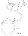
- FIG. 1is a schematic view of one embodiment of an implantable medical device that includes a paddle body coupled to a control module via lead bodies, according to the invention
- FIG. 2is a schematic view of another embodiment of an implantable medical device that includes a percutaneous lead body coupled to a control module via a lead body, according to the invention
- FIG. 3Ais a schematic view of one embodiment of a plurality of connectors disposed in the control module of FIG. 1 , the connectors configured and arranged to receive the proximal portions of the lead bodies of FIG. 1 , according to the invention;
- FIG. 3Bis a schematic view of one embodiment of a connector disposed in the control module of FIG. 2 , the connector configured and arranged to receive the proximal portion of one of the lead body of FIG. 2 , according to the invention;
- FIG. 3Cis a schematic view of one embodiment of a proximal portion of the lead body of FIG. 2 , a lead extension, and the control module of FIG. 2 , the lead extension configured and arranged to couple the lead body to the control module, according to the invention;
- FIG. 4is a schematic side view of yet another embodiment of an implantable medical device for brain stimulation, according to the invention.
- FIG. 5Ais a schematic perspective view of one embodiment of a distal end of a lead containing segmented electrodes, according to the invention.
- FIG. 5Bis a schematic perspective view of a second embodiment of a distal end of a lead containing segmented electrodes, according to the invention.
- FIG. 5Cis a schematic perspective view of a third embodiment of a distal end of a lead containing segmented electrodes, according to the invention.
- FIG. 5Dis a schematic perspective view of a fourth embodiment of a distal end of a lead containing segmented electrodes, according to the invention.
- FIG. 5Eis a schematic perspective view of a fifth embodiment of a distal end of a lead containing segmented electrodes, according to the invention.
- FIG. 5Fis a schematic perspective view of a sixth embodiment of a distal end of a lead containing segmented electrodes, according to the invention.
- FIG. 5Gis a schematic perspective view of a seventh embodiment of a distal end of a lead containing segmented electrodes, according to the invention.
- FIG. 6Ais a schematic side view of one embodiment of a proximal end of a lead containing segmented terminals, according to the invention.
- FIG. 6Bis a schematic side view of a second embodiment of a proximal end of a lead containing segmented terminals, according to the invention.
- FIG. 6Cis a schematic cross-sectional view of the lead of FIG. 6B , according to the invention.
- FIG. 6Dis a schematic side view of a third embodiment of a proximal end of a lead containing segmented terminals, according to the invention.
- FIG. 6Eis a schematic cross-sectional view of the lead of FIG. 6D , according to the invention.
- FIG. 7Ais schematic perspective view of one embodiment of a connector for receiving a lead containing segmented terminals, according to the invention.
- FIG. 7Bis schematic perspective view of the connector of FIG. 7A receiving the lead of FIG. 6A , according to the invention.
- FIG. 8Ais a schematic side view of a fourth embodiment of a proximal end of a lead containing segmented terminals, according to the invention.
- FIG. 8Bis schematic perspective view of one embodiment of a connector for receiving the lead of FIG. 8A , according to the invention.
- FIG. 9is a schematic overview of one embodiment of components of an electrical stimulation system, according to the invention.
- the present inventionis directed to the area of implantable electrical stimulation systems and methods of making and using the systems.
- the present inventionis also directed to implantable electrical stimulation systems having connector contact arrays for receiving split proximal contact arrays, as well as methods of making and using the elongated devices, contact arrays, and electrical stimulation systems.
- Suitable implantable electrical stimulation systemsinclude, but are not limited to, an electrode lead (“lead”) with one or more electrodes disposed on a distal end of the lead and one or more terminals disposed on one or more proximal ends of the lead.
- Leadsinclude, for example, deep brain stimulation leads, percutaneous leads, paddle leads, and cuff leads. Examples of electrical stimulation systems with leads are found in, for example, U.S. Pat. Nos.
- 2007/01500362009/0187222; 2009/0276021; 2010/0076535; 2010/0268298; 2011/0004267; 2011/0078900; 2011/0130817; 2011/0130818; 2011/0238129; 2011/0313500; 2012/0016378; 2012/0046710; 2012/0071949; 2012/0165911; 2012/0197375; 2012/0203316; 2012/0203320; 2012/0203321; 2012/0316615; and 2013/0105071; and U.S. patent application Ser. Nos. 12/177,823 and 13/750,725, all of which are incorporated by reference in their entirety.
- FIG. 1illustrates schematically one embodiment of an electrical stimulation system 100 .
- the electrical stimulation systemincludes a control module (e.g., a stimulator or pulse generator) 102 and a lead 103 .
- the lead 103including a paddle body 104 and one or more lead bodies 106 coupling the control module 102 to the paddle body 104 .
- the paddle body 104 and the one or more lead bodies 106form the lead 103 .
- the paddle body 104typically includes a plurality of electrodes 134 that form an array of electrodes 133 .
- the control module 102typically includes an electronic subassembly 110 and an optional power source 120 disposed in a sealed housing 114 . In FIG. 1 , two lead bodies 106 are shown coupled to the control module 102 .
- the control module 102typically includes one or more connectors 144 into which the proximal end of the one or more lead bodies 106 can be plugged to make an electrical connection via connector contacts (e.g., 316 in FIG. 3A ) disposed in the connector 144 and terminals (e.g., 310 in FIG. 3A ) on each of the one or more lead bodies 106 .
- the connector contactsare coupled to the electronic subassembly 110 and the terminals are coupled to the electrodes 134 .
- FIG. 1two connectors 144 are shown.
- the one or more connectors 144may be disposed in a header 150 .
- the header 150provides a protective covering over the one or more connectors 144 .
- the header 150may be formed using any suitable process including, for example, casting, molding (including injection molding), and the like.
- one or more lead extensions 324can be disposed between the one or more lead bodies 106 and the control module 102 to extend the distance between the one or more lead bodies 106 and the control module 102 .
- the connectors 144are electrically coupled to the electronic subassembly 110 through a feedthrough arrangement between the header 150 and the sealed housing 114 .
- the electrical stimulation systemcan include more, fewer, or different components and can have a variety of different configurations including those configurations disclosed in the electrical stimulation system references cited herein.
- the electrodes 134can be disposed in an array at or near the distal end of a lead body 106 ′ forming a percutaneous lead 103 , as illustrated in FIG. 2 .
- the percutaneous leadmay be isodiametric along the length of the lead body 106 ′′.
- the lead body 106 ′can be coupled with a control module 102 ′ with a single connector 144 .
- the electrical stimulation system or components of the electrical stimulation systemincluding one or more of the lead bodies 106 , the control module 102 , and, in the case of a paddle lead, the paddle body 104 , are typically implanted into the body of a patient.
- the electrical stimulation systemcan be used for a variety of applications including, but not limited to, spinal cord stimulation, brain stimulation, neural stimulation, muscle activation via stimulation of nerves innervating muscle, and the like.
- the electrodes 134can be formed using any conductive, biocompatible material. Examples of suitable materials include metals, alloys, conductive polymers, conductive carbon, and the like, as well as combinations thereof. In at least some embodiments, one or more of the electrodes 134 are formed from one or more of: platinum, platinum iridium, palladium, titanium, or rhenium.
- the number of electrodes 134 in the array of electrodes 133may vary. For example, there can be two, three, four, five, six, seven, eight, nine, ten, eleven, twelve, thirteen, fourteen, fifteen, sixteen, or more electrodes 134 . As will be recognized, other numbers of electrodes 134 may also be used. In FIG. 1 , sixteen electrodes 134 are shown.
- the electrodes 134can be formed in any suitable shape including, for example, round, oval, triangular, rectangular, pentagonal, hexagonal, heptagonal, octagonal, or the like.
- the electrodes of the paddle body 104 or one or more lead bodies 106are typically disposed in, or separated by, a non-conductive, biocompatible material including, for example, silicone, polyurethane, and the like or combinations thereof.
- the paddle body 104 and one or more lead bodies 106may be formed in the desired shape by any process including, for example, molding (including injection molding), casting, and the like. Electrodes and connecting wires can be disposed onto or within a paddle body either prior to or subsequent to a molding or casting process.
- the non-conductive materialtypically extends from the distal end of the lead 103 to the proximal end of each of the one or more lead bodies 106 .
- the non-conductive, biocompatible material of the paddle body 104 and the one or more lead bodies 106may be the same or different.
- the paddle body 104 and the one or more lead bodies 106may be a unitary structure or can be formed as two separate structures that are permanently or detachably coupled together.
- Terminalsare typically disposed at the proximal end of the one or more lead bodies 106 for connection to corresponding conductive contacts (e.g., 316 in FIG. 3A ) in connectors (e.g., 144 in FIG. 1 ) disposed on, for example, the control module 102 (or to other devices, such as conductive contacts on a lead extension, an operating room cable, a splitter, an adaptor, or the like).
- Conductive wiresextend from the terminals (e.g., 310 in FIG. 3A ) to the electrodes 134 .
- one or more electrodes 134are electrically coupled to a terminal (e.g., 310 in FIG. 3A ).
- each terminale.g., 310 in FIG. 3A
- the conductive wiresmay be embedded in the non-conductive material of the lead or can be disposed in one or more lumens (not shown) extending along the lead. In some embodiments, there is an individual lumen for each conductive wire. In other embodiments, two or more conductive wires may extend through a lumen. There may also be one or more lumens (not shown) that open at, or near, the proximal end of the lead, for example, for inserting a stylet rod to facilitate placement of the lead within a body of a patient. Additionally, there may also be one or more lumens (not shown) that open at, or near, the distal end of the lead, for example, for infusion of drugs or medication into the site of implantation of the paddle body 104 . The one or more lumens may, optionally, be flushed continually, or on a regular basis, with saline, epidural fluid, or the like. The one or more lumens can be permanently or removably sealable at the distal end.
- the one or more lead bodies 106may be coupled to the one or more connectors 144 disposed on the control module 102 .
- the control module 102can include any suitable number of connectors 144 including, for example, two three, four, five, six, seven, eight, or more connectors 144 . It will be understood that other numbers of connectors 144 may be used instead.
- each of the two lead bodies 106includes eight terminals that are shown coupled with eight conductive contacts disposed in a different one of two different connectors 144 .
- FIG. 3Ais a schematic side view of one embodiment of a plurality of connectors 144 disposed on the control module 102 .
- the control module 102includes two connectors 144 .
- the control module 102includes four connectors 144 .
- proximal ends 306 of the plurality of lead bodies 106are shown configured and arranged for insertion to the control module 102 .
- FIG. 3Bis a schematic side view of one embodiment of a single connector 144 disposed on the control module 102 ′. In FIG. 3B , the proximal end 306 of the single lead body 106 ′ is shown configured and arranged for insertion to the control module 102 ′.
- the one or more connectors 144are disposed in the header 150 .
- the header 150defines one or more lumens 304 into which the proximal end(s) 306 of the one or more lead bodies 106 / 106 ′ with terminals 310 can be inserted, as shown by directional arrows 312 , in order to gain access to the connector contacts disposed in the one or more connectors 144 .
- the one or more connectors 144each include a connector housing 314 and a plurality of connector contacts 316 disposed therein. Typically, the connector housing 314 provides access to the plurality of connector contacts 316 via the lumen 304 .
- one or more of the connectors 144further includes a retaining element 318 configured and arranged to fasten the corresponding lead body 106 / 106 ′ to the connector 144 when the lead body 106 / 106 ′ is inserted into the connector 144 to prevent undesired detachment of the lead body 106 / 106 ′ from the connector 144 .
- the retaining element 318may include an aperture 320 through which a fastener (e.g., a set screw, pin, or the like) may be inserted and secured against an inserted lead body 106 / 106 ′.
- the connector contacts 316can be aligned with the terminals 310 disposed on the one or more lead bodies 106 / 106 ′ to electrically couple the control module 102 to the electrodes ( 134 of FIG. 1 ) disposed at a distal end of the one or more lead bodies 106 .
- Examples of connectors in control modulesare found in, for example, U.S. Pat. Nos. 7,244,150 and 6,224,450, which are incorporated by reference in their entirety.
- the electrical stimulation systemincludes one or more lead extensions.
- the one or more lead bodies 106 / 106 ′can be coupled to one or more lead extensions which, in turn, are coupled to the control module 102 / 102 ′.
- a lead extension connector 322is disposed on a lead extension 324 and is coupled to a lead extension body 325 .
- the lead extension connector 322is shown disposed at a distal end 326 of the lead extension 324 .
- the lead extension connector 322includes a connector housing 344 .
- the connector housing 344defines at least one lumen 330 into which a proximal end 306 of the lead body 106 ′ with terminals 310 can be inserted, as shown by directional arrow 338 .
- the lead extension connector 322also includes a plurality of connector contacts 340 .
- the connector contacts 340 disposed in the connector housing 344can be aligned with the terminals 310 on the lead body 106 to electrically couple the lead extension 324 to the electrodes ( 134 of FIG. 1 ) disposed at a distal end (not shown) of the lead body 106 ′.
- the proximal end of a lead extensioncan be similarly configured and arranged as a proximal end of a lead body.
- the lead extension 324may include a plurality of conductive wires (not shown) that electrically couple the connector contacts 340 to terminal on a proximal end 348 of the lead extension 324 .
- the conductive wires disposed in the lead extension 324can be electrically coupled to a plurality of terminals (not shown) disposed on the proximal end 348 of the lead extension 324 .
- the proximal end 348 of the lead extension 324is configured and arranged for insertion into a lead extension connector disposed in another lead extension.
- the proximal end 348 of the lead extension 324is configured and arranged for insertion into the connector 144 disposed on the control module 102 ′.
- control modules 102 / 102 ′can receive either lead bodies 106 / 106 ′ or lead extensions 324 .
- electrical stimulation system 100can include a plurality of lead extensions 324 .
- each of the lead bodies 106 shown in FIGS. 1 and 3Acan, alternatively, be coupled to a different lead extension 324 which, in turn, are each coupled to different ports of a two-port control module, such as the control module 102 of FIGS. 1 and 3A .
- the leadmay include stimulation electrodes, recording electrodes, or a combination of both. At least some of the stimulation electrodes, recording electrodes, or both are provided in the form of segmented electrodes that extend only partially around the perimeter (for example, the circumference) of the lead. These segmented electrodes can be provided in sets of electrodes, with each set having electrodes circumferentially distributed about the lead at a particular longitudinal position.
- a practitionermay determine the position of the target neurons using recording electrode(s) and then position the stimulation electrode(s) accordingly.
- the same electrodescan be used for both recording and stimulation.
- separate leadscan be used; one with recording electrodes which identify target neurons, and a second lead with stimulation electrodes that replaces the first after target neuron identification.
- the same leadmay include both recording electrodes and stimulation electrodes or electrodes may be used for both recording and stimulation.
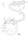
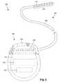
- FIG. 4illustrates one embodiment of a device 400 for brain stimulation.
- the deviceincludes a lead 410 , a plurality of electrodes 425 disposed at least partially about a perimeter of the lead 410 , a plurality of terminals 435 , a connector 444 for connection of the electrodes to a control unit, and a stylet 440 for assisting in insertion and positioning of the lead in the patient's brain.
- the stylet 440can be made of a rigid material. Examples of suitable materials for the stylet include, but are not limited to, tungsten, stainless steel, and plastic.
- the stylet 440may have a handle 450 to assist insertion into the lead 410 , as well as rotation of the stylet 440 and lead 410 .
- the connector 444fits over a proximal end of the lead 410 , preferably after removal of the stylet 440 .
- the electrodes 425are shown as including both ring electrodes, such as ring electrode 420 , and segmented electrodes, such as segmented electrodes 430 .
- the electrodes 425are all segmented. In other embodiments, the electrodes 425 are all ring-shaped.
- each of the terminals 435is shown as being ring-shaped.
- the segmented electrodes of FIG. 4are shown in sets of two, where the two segmented electrodes of a particular set are electrically isolated from one another and are circumferentially offset along the lead 410 . Any suitable number of segmented electrodes can be formed into a set including, for example, two, three, four, or more segmented electrodes.
- Segmented electrodescan be used to direct stimulus current to one side, or even a portion of one side, of the lead.
- current steeringcan be achieved to more precisely deliver the stimulus to a position around an axis of the lead (i.e., radial positioning around the axis of the lead).
- Segmented electrodesmay provide for superior current steering than ring electrodes because target structures in deep brain stimulation are not typically symmetric about the axis of the distal electrode array. Instead, a target may be located on one side of a plane running through the axis of the lead.
- current steeringcan be performed not only along a length of the lead but also around a perimeter of the lead.
- leads with segmented electrodesinclude U.S. Pat. Nos. 6,295,944; and 6,391,985; and U.S. Patent Applications Publication Nos. 2011/0005069; 2010/0268298; 2011/0130817; 2011/0130818; 2011/0078900; 2011/0238129; 2011/0313500; 2012/0016378; 2012/0046710; 2012/0165911; 2012/0197375; 2012/0203316; 2012/0203320; and 2012/0203321, all of which are incorporated herein by reference in their entirety.
- FIGS. 5A-5Hillustrate leads 500 with segmented electrodes 550 , optional ring electrodes 520 or tip electrodes 520 a , and a lead body 510 .
- the sets of segmented electrodes 550each include either two ( FIG. 5B ), three ( FIGS. 5E-5H ), or four ( FIGS. 5A, 5C, and 5D ) or any other number of segmented electrodes including, for example, three, five, six, or more.
- the sets of segmented electrodes 550can be aligned with each other ( FIGS. 5A-5G ) or staggered ( FIG. 5H ).
- the ring electrodes 520 and the segmented electrodes 550may be arranged in any suitable configuration.
- the ring electrodes 520can flank the two sets of segmented electrodes 550 (see e.g., FIGS. 1, 5A, and 5E-5H ).
- the two sets of ring electrodes 520can be disposed proximal to the two sets of segmented electrodes 550 (see e.g., FIG.
- the two sets of ring electrodes 520can be disposed distal to the two sets of segmented electrodes 550 (see e.g., FIG. 5D ).
- One of the ring electrodescan be a tip electrode (see, tip electrode 520 a of FIGS. 5E and 5G ). It will be understood that other configurations are possible as well (e.g., alternating ring and segmented electrodes, or the like).
- the electrode arrangement of FIG. 5Cmay be useful if the physician anticipates that the neural target will be closer to a distal tip of the lead body 510
- the electrode arrangement of FIG. 5Dmay be useful if the physician anticipates that the neural target will be closer to a proximal end of the lead body 510 .
- any combination of ring electrodes 520 and segmented electrodes 550may be disposed on the lead 500 .
- the leadmay include a first ring electrode 520 , two sets of segmented electrodes; each set formed of four segmented electrodes 550 , and a final ring electrode 520 at the end of the lead.
- This configurationmay simply be referred to as a 1-4-4-1 configuration ( FIGS. 5A and 5E —ring electrodes 520 and segmented electrode 550 ). It may be useful to refer to the electrodes with this shorthand notation.
- FIG. 5Cmay be referred to as a 1-1-4-4 configuration
- the embodiment of FIG. 5Dmay be referred to as a 4-4-1-1 configuration.
- 5F, 5G, and 5Hcan be referred to as a 1-3-3-1 configuration.
- Other electrode configurationsinclude, for example, a 2-2-2-2 configuration, where four sets of segmented electrodes are disposed on the lead, and a 4-4 configuration, where two sets of segmented electrodes, each having four segmented electrodes 550 are disposed on the lead.
- the 1-3-3-1 electrode configuration of FIGS. 5F, 5G, and 5Hhas two sets of segmented electrodes, each set containing three electrodes disposed around the perimeter of the lead, flanked by two ring electrodes ( FIGS. 5F and 5H ) or a ring electrode and a tip electrode ( FIG. 5G ).
- the leadincludes 16 electrodes.
- Possible configurations for a 16-electrode leadinclude, but are not limited to 4-4-4-4; 6-8; 5-3-3-3-3-1 (and all rearrangements of this configuration); and 2-2-2-2-2-2-2-2.
- Any other suitable segmented electrode arrangementscan be used including, but not limited to, those disclosed in U.S. Provisional Patent Application Ser. No. 62/113,291 and U.S. Patent Applications Publication Nos. 2012/0197375 and 2015/0045864, all of which are incorporated herein by reference in their entirety.
- a lead with 16 electrodesalso includes 16 terminals.
- Many conventional control modules and connectorsare designed to accept a proximal end of a lead or lead extension with an array of eight terminals. To instead have 16 terminals could extend the length of the proximal end of the lead or lead extension and a consequent increase in the size of connector or control module.
- an elongate membere.g., a lead, lead extension, splitter, adaptor, or the like
- segmented terminalsforming a split proximal contact array.
- the elongate memberalso includes segmented electrodes. Utilizing a split proximal contact array may reduce the physical size of the terminal array when compared to conventional terminal arrays with ring-shaped terminals. Consequently, the portion of the elongate member that is inserted into a connector to make electrical contact with the pulse generator can be reduced, as compared to conventional electrical stimulation systems.
- the number of terminals that can be disposed along a proximal portion of an elongate member and that can be inserted into a conventionally sized connectormay be increased from conventional electrical stimulation systems.
- any elongate membercan have first contacts (for example, electrode for a lead or conductive contacts for a lead extension) disposed along a distal portion of the elongate member and second segmented contacts (for example, segmented terminals) disposed along a proximal portion of the elongate member.
- first contactsfor example, electrode for a lead or conductive contacts for a lead extension
- second segmented contactsfor example, segmented terminals
- FIG. 6Aillustrates one embodiment of a proximal portion of a lead 603 (or other elongate member) with a split proximal contact array of segmented terminals 610 .
- Each of the segmented terminalsextends around less than (for example, no more than 45%, 40%, 33%, 30%, or 25% of) the entire perimeter of the elongate member.
- the terminal arrayis formed exclusively from segmented terminals.
- the terminal arrayincludes a combination of one or more ring-shaped terminals and one or more segmented terminals. The segmented terminals are not in electrical contact with one another.
- the terminal arrayincludes at least one segmented terminal set disposed at a particular longitudinal position along the lead, such as segmented terminal set 611 which, in turn, includes multiple segmented terminals 610 , such as segmented terminals 610 a and 610 b .
- a set of segmented terminalscan have two, three, four, or more segmented terminals disposed at the same position along the longitudinal axis of the elongate member, but circumferentially offset from each other.
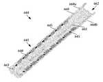
- the terminal arraycan include any suitable number of segmented terminal sets 611 including, for example, one, two, three, four, five, six, seven, eight, nine, ten eleven, twelve, thirteen, fourteen, fifteen, sixteen, or more segmented-terminal sets. In FIG. 6A , eight segmented terminal sets 611 are shown disposed along the lead 603 .
- segmented terminalscan also be used including, but not limited to, helical arrangements, double helical arrangements, staggered arrangements, and the like. Any of the arrangements of segmented electrodes disclosed in the references cited above can be used with the segmented terminals.
- the elongate memberincludes a single proximal portion and multiple distal portions.
- segmented terminalsmay increase the number of terminals disposed along a lead from conventional leads.
- the increased number of terminalsmay enable the lead to be designed with multiple distal portions, where a different electrode array is disposed along each of the distal portions, and where electrodes of each of the multiple electrode arrays are coupled to terminals disposed along a single proximal portion.
- Such a designmay be useful, for example, in deep brain stimulation where bilateral or multilateral stimulation may be desirable.
- the lead 603can have a slit 682 through the proximal portion of the lead, as illustrated in FIGS. 6B and 6D , or partially through the proximal end of the lead, as illustrated in FIGS. 6C and 6E , to separate the proximal portion of the lead into two parts 603 a , 603 b .
- the slit 682separates (or partially separates) the terminals 610 a , 610 b in each set 611 .
- the slit 682only extends partway into the lead 603 to the central lumen 686 , as illustrated in FIG. 6E .
- a proximal portion of an elongate membersuch as the lead 603 is typically inserted into a connector 644 disposed on or along a lead extension, adaptor, splitter, or the like.
- the connector 644includes segmented connector contacts 640 suitable for coupling with the segmented terminals.
- a lead extension bodysee, for example, lead extension body 325 of FIG. 3C ) or other elongate member extends from the connector with conductors (not shown) the couple the segmented connector contacts 640 of the connector 640 to terminals on the proximal end of the lead extension.
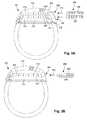
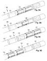
- the connector 644includes an elongated connector housing 660 that defines a connector lumen 662 suitable for receiving a portion of an elongate member, such as the lead 603 ( FIGS. 6A, 6B, and 6D ); a lead extension (e.g., 324 in FIG. 3C ); or the like.
- an elongate membersuch as the lead 603 ( FIGS. 6A, 6B, and 6D ); a lead extension (e.g., 324 in FIG. 3C ); or the like.
- the illustrated connector lumenhas a circular cross-section, it will be understood that lumens with other cross-sections (and leads with non-circular cross-sections) can also be used including, but not limited to, oval, square, rectangular, triangular, pentagonal, hexagonal, octagonal, cruciform, or any other suitable regular or irregular cross-sectional shape.
- the connector 644can have one or more end stops 663 that provide a physical barrier against insertion of the lead further
- the connector housing 660has two portions 660 a , 660 b that are coupled together by one or more hinges 661 or other coupling elements to allow the connector housing 660 to be partially separated (as illustrated in FIGS. 7A and 7B ) or otherwise opened for insertion of the lead 603 or other elongate member into the connector lumen 662 .
- the connectorcan also be part of a header of a control module (see, for example, header 150 of control module 102 FIG. 1 ) where one portion of the connector housing 660 rotates or opens away from the header to allow insertion of the lead into the connector.
- the two portions 660 a , 660 b of the connector housing 660can have a coupling arrangement along the edges 665 a , 665 b to facilitate coupling of the connector housing 660 in a closed position.
- Such coupling arrangementscan be, for example, a tongue and groove arrangement along the edges 665 a , 665 b or magnets in the edges 665 a , 665 b that can be brought together to coupling the portions 660 a , 660 b of the connector housing 660 in the closed position.
- the connector housing 660may have an alignment protrusion (not shown) that can be received in the slit 682 ( FIGS. 6B-6E ) of the lead 603 to facilitate alignment of the lead within the connector housing.
- Multiple connector contacts 640are disposed in a spaced-apart relationship along the longitudinal length of the connector housing 660 such that the connector contacts are exposed to the connector lumen 662 ( FIGS. 7A and 7B ) and individually attached to an array of conductive members (for example, wires, pins, traces, terminals, or the like) that couple the connector contacts to other components.
- the connector 644is disposed on a lead extension (e.g., 324 in FIG. 3C )
- the conductive membersfor example, wires or other conductors
- the conductive membersmay couple the connector contacts to lead extension terminals.
- the conductive membersmay couple the connector contacts 640 to the electronic subassembly ( 110 in FIG. 1 ).
- the conductive members 664couple the connector contacts 640 to the electronic subassembly ( 110 in FIG. 1 ) via feedthrough pins extending through the sealed housing ( 114 in FIG. 1 ).
- the segmented connector contacts 640can be formed in sets of two or more contacts at a same position along the longitudinal axis of the connector lumen 662 .
- Each of the segmented connector contacts of a particular setextends around less than (for example, no more than 45%, 40%, 33%, 30%, 25%, 20%, 15%, or 10% of) the entire perimeter of the connector lumen.
- the segmented connector contacts of the setare not in electrical contact with one another and are circumferentially offset from one another along the connector lumen.
- the connector contact arrayincludes at least one connector contact set, such as connector contact set 641 which, in turn, includes multiple connector contacts 640 , such as connector contacts 640 a and 640 b .
- a set of connector contactscan have two, three, four, or more connector contacts disposed at the same position along the longitudinal axis of the connector lumen, but circumferentially offset from each other.
- Other arrangements of connector contactscan be used similar to those discussed above with respect to the segmented terminals.
- one or more of the segmented terminals 610 of the lead 603 and one or more of the connector contacts 640 of the connector 644are made of (or contain) magnetic material to attract each other and facilitate alignment of the segmented terminals with the connector contacts when the lead (or other elongate member) is inserted into the connector lumen of the connector.
- the magnetic segmented terminal(s) and magnetic connector contact(s)have opposite magnetic polarities so that the corresponding terminal/contact pairs are attracted to each other.
- all of the segmented terminals 610are magnetic and all of the connector contacts 640 are magnetic.
- only some (for example, one, two, three, four, six, or more) of the segmented terminal 610 and some (for example, one, two, three, four, six, or more) of connector contact 640are magnetic.
- one or both of the most proximal or most distal terminals of the lead and one or both of the most proximal or most distal connector contacts of the connectorare magnetic.
- Other arrangements of magnetic and non-magnetic terminals/contactscan be used including, but not limited to, an alternating arrangement of magnetic/non-magnetic terminals/contacts or an arrangement where one terminal of each set of terminals and one contact of each set of contacts are magnetic.
- each set of terminalscan have a terminal of each polarity and each set of contacts can have a contact of each polarity.
- Any other suitable arrangementcan be used.
- the magnetic terminals and contactscan be made of any suitable magnetic materials including, for example, neodymium or other rare earth magnets or ferromagnetic materials.
- FIG. 8Aillustrates another embodiment of a lead 603 that, instead of magnetic segmented terminals, includes magnetic elements 615 disposed between, or distal to or proximal to (or any combination thereof), the segmented terminals 610 .
- the magnetic elements 615can be magnetic spacers between, proximal to, or distal to the segmented terminals 610 or can be magnets disposed within the spacers.
- the magnetic elements 615are non-conductive and can be, for example, ceramic or composite magnets or magnetic material dispersed (or otherwise disposed) in a non-conductive matrix (for example, a polymeric matrix.) In at least some embodiments, the magnetic elements can be formed as at least one magnetic set which includes multiple magnetic elements, such as magnetic elements 615 a and 615 b.
- FIG. 8Billustrates a corresponding connector 644 with magnetic connector elements 645 disposed between, distal to, or proximal to (or any combination thereof), the connector contacts 640 .
- the magnetic connector elements 645are non-conductive and can be, for example, ceramic or composite magnets or magnetic material dispersed (or otherwise disposed) in a non-conductive matrix (for example, a polymeric matrix.)
- the magnetic connector elements 645can be formed as at least one magnetic set which includes multiple magnetic elements.
- the magnetic element(s) 615 of the lead 603 and magnetic connector element(s) 645 of the connector 640should have opposite magnetic polarities so that they are attracted to each other.
- magnetic elements 615are placed between only some (for example, one, two, three, four, six, or more) of the adjacent pairs of segmented terminals 610 and magnetic connector elements 645 are placed between only some (for example, one, two, three, four, six, or more) of the adjacent pairs of connector contacts 640 .
- magnetic elements 615 and magnetic connector elements 645can be used including, but not limited to, magnetic elements 615 positioned distal to, or proximal to (or both), all of the segmented terminals 610 and magnetic connector elements 645 positioned distal to, or proximal to (or both), all of the connector contacts 640 .
- FIG. 9is a schematic overview of one embodiment of components of an electrical stimulation system 900 including an electronic subassembly 910 disposed within a control module. It will be understood that the electrical stimulation system can include more, fewer, or different components and can have a variety of different configurations including those configurations disclosed in the stimulator references cited herein.
- power source 912can be used including, for example, a battery such as a primary battery or a rechargeable battery.
- a batterysuch as a primary battery or a rechargeable battery.
- other power sourcesinclude super capacitors, nuclear or atomic batteries, mechanical resonators, infrared collectors, thermally-powered energy sources, flexural powered energy sources, bioenergy power sources, fuel cells, bioelectric cells, osmotic pressure pumps, and the like including the power sources described in U.S. Pat. No. 7,437,193, incorporated herein by reference in its entirety.
- powercan be supplied by an external power source through inductive coupling via the optional antenna 918 or a secondary antenna.
- the external power sourcecan be in a device that is mounted on the skin of the user or in a unit that is provided near the user on a permanent or periodic basis.
- the batterymay be recharged using the optional antenna 918 , if desired. Power can be provided to the battery for recharging by inductively coupling the battery through the antenna to a recharging unit 916 external to the user. Examples of such arrangements can be found in the references identified above.
- electrical currentis emitted by the electrodes 134 on the paddle or lead body to stimulate nerve fibers, muscle fibers, or other body tissues near the electrical stimulation system.
- a processor 904is generally included to control the timing and electrical characteristics of the electrical stimulation system. For example, the processor 904 can, if desired, control one or more of the timing, frequency, strength, duration, and waveform of the pulses. In addition, the processor 904 can select which electrodes can be used to provide stimulation, if desired. In some embodiments, the processor 904 may select which electrode(s) are cathodes and which electrode(s) are anodes. In some embodiments, the processor 904 may be used to identify which electrodes provide the most useful stimulation of the desired tissue.
- Any processorcan be used and can be as simple as an electronic device that, for example, produces pulses at a regular interval or the processor can be capable of receiving and interpreting instructions from an external programming unit 908 that, for example, allows modification of pulse characteristics.
- the processor 904is coupled to a receiver 902 which, in turn, is coupled to the optional antenna 918 . This allows the processor 904 to receive instructions from an external source to, for example, direct the pulse characteristics and the selection of electrodes, if desired.
- the antenna 918is capable of receiving signals (e.g., RF signals) from an external telemetry unit 906 which is programmed by a programming unit 908 .
- the programming unit 908can be external to, or part of, the telemetry unit 906 .
- the telemetry unit 906can be a device that is worn on the skin of the user or can be carried by the user and can have a form similar to a pager, cellular phone, or remote control, if desired.
- the telemetry unit 906may not be worn or carried by the user but may only be available at a home station or at a clinician's office.
- the programming unit 908can be any unit that can provide information to the telemetry unit 906 for transmission to the electrical stimulation system 900 .
- the programming unit 908can be part of the telemetry unit 906 or can provide signals or information to the telemetry unit 906 via a wireless or wired connection.
- One example of a suitable programming unitis a computer operated by the user or clinician to send signals to the telemetry unit 906 .
- the signals sent to the processor 904 via the antenna 918 and receiver 902can be used to modify or otherwise direct the operation of the electrical stimulation system.
- the signalsmay be used to modify the pulses of the electrical stimulation system such as modifying one or more of pulse duration, pulse frequency, pulse waveform, and pulse strength.
- the signalsmay also direct the electrical stimulation system 900 to cease operation, to start operation, to start charging the battery, or to stop charging the battery.
- the stimulation systemdoes not include an antenna 918 or receiver 902 and the processor 904 operates as programmed.
- the electrical stimulation system 900may include a transmitter (not shown) coupled to the processor 904 and the antenna 918 for transmitting signals back to the telemetry unit 906 or another unit capable of receiving the signals.
- the electrical stimulation system 900may transmit signals indicating whether the electrical stimulation system 900 is operating properly or not or indicating when the battery needs to be charged or the level of charge remaining in the battery.
- the processor 904may also be capable of transmitting information about the pulse characteristics so that a user or clinician can determine or verify the characteristics.
Landscapes
- Health & Medical Sciences (AREA)
- Life Sciences & Earth Sciences (AREA)
- Engineering & Computer Science (AREA)
- Biomedical Technology (AREA)
- Animal Behavior & Ethology (AREA)
- General Health & Medical Sciences (AREA)
- Public Health (AREA)
- Veterinary Medicine (AREA)
- Heart & Thoracic Surgery (AREA)
- Nuclear Medicine, Radiotherapy & Molecular Imaging (AREA)
- Radiology & Medical Imaging (AREA)
- Neurology (AREA)
- Physics & Mathematics (AREA)
- Biophysics (AREA)
- Pathology (AREA)
- Medical Informatics (AREA)
- Molecular Biology (AREA)
- Surgery (AREA)
- Orthopedic Medicine & Surgery (AREA)
- Cardiology (AREA)
- Neurosurgery (AREA)
- Electrotherapy Devices (AREA)
Abstract
Description
This application claims the benefit under 35 U.S.C. § 119(e) of U.S. Provisional Patent Application Ser. No. 62/278,667, filed Jan. 14, 2016, which is incorporated herein by reference.
The present invention is directed to the area of implantable electrical stimulation systems and methods of making and using the systems. The present invention is also directed to implantable electrical stimulation systems having connector contact arrays for receiving split proximal contact arrays, as well as methods of making and using the elongated devices, contact arrays, and electrical stimulation systems.
Implantable electrical stimulation systems have proven therapeutic in a variety of diseases and disorders. For example, spinal cord stimulation systems have been used as a therapeutic modality for the treatment of chronic pain syndromes. Peripheral nerve stimulation has been used to treat incontinence, as well as a number of other applications under investigation. Functional electrical stimulation systems have been applied to restore some functionality to paralyzed extremities in spinal cord injury patients. Stimulation of the brain, such as deep brain stimulation, can be used to treat a variety of diseases or disorders.
Stimulators have been developed to provide therapy for a variety of treatments. A stimulator can include a control module (with a pulse generator), one or more leads, and an array of stimulator electrodes on each lead. The stimulator electrodes are in contact with or near the nerves, muscles, or other tissue to be stimulated. The pulse generator in the control module generates electrical pulses that are delivered by the electrodes to body tissue.
One embodiment is a connector for an implantable electrical stimulation device. The connector includes an elongated connector housing having a first end and an opposing second end, the connector housing including a first portion, a second portion, at least one coupling element attaching the first portion to the second portion, and a connector lumen defined by the first and second portions, where the first and second portions are configured and arranged to partially separate to receive a lead or lead extension into the connector lumen of the connector housing. The connector also includes connector contacts disposed on the connector housing adjacent the connector lumen, where a first set of the connector contacts is disposed on the first portion of the connector housing and a second set of the connector contacts is disposed on the second portion of the connector housing; and at least one connector magnetic element coupled to each of the first and second portions of the connector housing to couple to at least one corresponding magnetic element in the lead or lead extension to align the lead or lead extension within the connector lumen of the connector housing.
In at least some embodiments, at least one of the connector contacts is the at least one connector magnetic element. In at least some embodiments, the at least one connector magnetic element is part of the connector housing. In at least some embodiments, at least one of the at least one connector magnetic element is disposed between two of the connector contacts.
In at least some embodiments, the first portion and the second portion of the connector housing have a tongue and groove arrangement along edges of the first and second portions to fasten the first and second portions in a closed position. In at least some embodiments, the first portion and the second portion of the connector housing each have at least one magnet disposed edges of the first and second portions to fasten the first and second portions in a closed position. In at least some embodiments, the at least one coupling element of the connector housing is at least one hinge.
Another embodiment is a lead extension that includes any of the connectors described above; a lead extension body extending from the connector; terminal disposed along a portion of the lead extension body opposite the connector; and conductors extending along the lead extension body and the connector and electrically coupling the connector contacts to the terminals.
Yet another embodiment is a control module that includes a header having one of the connector described above; a housing coupled to a header; and an electronic subassembly disposed within the housing, where the electronic subassembly is electrically coupled to the connector contacts of the connector.
A further embodiment is an electrical stimulation lead including an elongate lead body having a proximal end and a distal end opposite the proximal end; electrodes disposed along the distal end of the lead body; terminals disposed along the proximal end of the lead body; conductors extending within the lead body and electrically coupling the electrodes to the terminals; and at least one lead magnetic element disposed along the proximal end of the lead body to couple to at least one corresponding magnetic element in a connector to align the lead within a connector lumen of the connector.
In at least some embodiments, at least one of the terminals is the at least one lead magnetic element. In at least some embodiments, the at least one lead magnetic element is part of the lead body. In at least some embodiments, at least one of the at least one lead magnetic element is disposed between two of the terminals.
Another embodiment is a system for electrical stimulation that includes any one of the connectors described above and any one of the electrical stimulation leads described above. In at least some embodiments, at least one of the connector contacts is the at least one connector magnetic element and at least one of the terminals is the at least one lead magnetic element. In at least some embodiments, the at least one connector magnetic element is part of the connector housing and the at least one lead magnetic element is part of the lead body. In at least some embodiments, at least one of the at least one connector magnetic element is disposed between two of the connector contacts and at least one of the at least one lead magnetic element is disposed between two of the terminals. In at least some embodiments, the at least one coupling element of the connector housing is at least one hinge.
In at least some embodiments, the system further includes a lead extension having the connector; a lead extension body extending from the connector; terminals disposed along a portion of the lead extension body opposite the connector; and conductors extending along the lead extension body and the connector and electrically coupling the connector contacts to the terminals.
In at least some embodiments, the system further includes a control module having a header including the connector; a housing coupled to a header; and an electronic subassembly disposed within the housing, where the electronic subassembly is electrically coupled to the connector contacts of the connector.
Non-limiting and non-exhaustive embodiments of the present invention are described with reference to the following drawings. In the drawings, like reference numerals refer to like parts throughout the various figures unless otherwise specified.
For a better understanding of the present invention, reference will be made to the following Detailed Description, which is to be read in association with the accompanying drawings, wherein:
The present invention is directed to the area of implantable electrical stimulation systems and methods of making and using the systems. The present invention is also directed to implantable electrical stimulation systems having connector contact arrays for receiving split proximal contact arrays, as well as methods of making and using the elongated devices, contact arrays, and electrical stimulation systems.
Suitable implantable electrical stimulation systems include, but are not limited to, an electrode lead (“lead”) with one or more electrodes disposed on a distal end of the lead and one or more terminals disposed on one or more proximal ends of the lead. Leads include, for example, deep brain stimulation leads, percutaneous leads, paddle leads, and cuff leads. Examples of electrical stimulation systems with leads are found in, for example, U.S. Pat. Nos. 6,181,969; 6,516,227; 6,609,029; 6,609,032; 6,741,892; 7,244,150; 7,450,997; 7,672,734; 7,761,165; 7,783,359; 7,792,590; 7,809,446; 7,949,395; 7,974,706; 6,175,710; 6,224,450; 6,271,094; 6,295,944; 6,364,278; and 6,391,985; U.S. Patent Applications Publication Nos. 2007/0150036; 2009/0187222; 2009/0276021; 2010/0076535; 2010/0268298; 2011/0004267; 2011/0078900; 2011/0130817; 2011/0130818; 2011/0238129; 2011/0313500; 2012/0016378; 2012/0046710; 2012/0071949; 2012/0165911; 2012/0197375; 2012/0203316; 2012/0203320; 2012/0203321; 2012/0316615; and 2013/0105071; and U.S. patent application Ser. Nos. 12/177,823 and 13/750,725, all of which are incorporated by reference in their entirety.
Thecontrol module 102 typically includes one ormore connectors 144 into which the proximal end of the one or morelead bodies 106 can be plugged to make an electrical connection via connector contacts (e.g.,316 inFIG. 3A ) disposed in theconnector 144 and terminals (e.g.,310 inFIG. 3A ) on each of the one or morelead bodies 106. The connector contacts are coupled to theelectronic subassembly 110 and the terminals are coupled to theelectrodes 134. InFIG. 1 , twoconnectors 144 are shown.
The one ormore connectors 144 may be disposed in aheader 150. Theheader 150 provides a protective covering over the one ormore connectors 144. Theheader 150 may be formed using any suitable process including, for example, casting, molding (including injection molding), and the like. In addition, one or more lead extensions324 (seeFIG. 3C ) can be disposed between the one or morelead bodies 106 and thecontrol module 102 to extend the distance between the one or morelead bodies 106 and thecontrol module 102. Theconnectors 144 are electrically coupled to theelectronic subassembly 110 through a feedthrough arrangement between theheader 150 and the sealedhousing 114.
It will be understood that the electrical stimulation system can include more, fewer, or different components and can have a variety of different configurations including those configurations disclosed in the electrical stimulation system references cited herein. For example, instead of apaddle body 104, theelectrodes 134 can be disposed in an array at or near the distal end of alead body 106′ forming apercutaneous lead 103, as illustrated inFIG. 2 . The percutaneous lead may be isodiametric along the length of thelead body 106″. Thelead body 106′ can be coupled with acontrol module 102′ with asingle connector 144.
The electrical stimulation system or components of the electrical stimulation system, including one or more of thelead bodies 106, thecontrol module 102, and, in the case of a paddle lead, thepaddle body 104, are typically implanted into the body of a patient. The electrical stimulation system can be used for a variety of applications including, but not limited to, spinal cord stimulation, brain stimulation, neural stimulation, muscle activation via stimulation of nerves innervating muscle, and the like.
Theelectrodes 134 can be formed using any conductive, biocompatible material. Examples of suitable materials include metals, alloys, conductive polymers, conductive carbon, and the like, as well as combinations thereof. In at least some embodiments, one or more of theelectrodes 134 are formed from one or more of: platinum, platinum iridium, palladium, titanium, or rhenium.
The number ofelectrodes 134 in the array ofelectrodes 133 may vary. For example, there can be two, three, four, five, six, seven, eight, nine, ten, eleven, twelve, thirteen, fourteen, fifteen, sixteen, ormore electrodes 134. As will be recognized, other numbers ofelectrodes 134 may also be used. InFIG. 1 , sixteenelectrodes 134 are shown. Theelectrodes 134 can be formed in any suitable shape including, for example, round, oval, triangular, rectangular, pentagonal, hexagonal, heptagonal, octagonal, or the like.
The electrodes of thepaddle body 104 or one or morelead bodies 106 are typically disposed in, or separated by, a non-conductive, biocompatible material including, for example, silicone, polyurethane, and the like or combinations thereof. Thepaddle body 104 and one or morelead bodies 106 may be formed in the desired shape by any process including, for example, molding (including injection molding), casting, and the like. Electrodes and connecting wires can be disposed onto or within a paddle body either prior to or subsequent to a molding or casting process. The non-conductive material typically extends from the distal end of thelead 103 to the proximal end of each of the one or morelead bodies 106. The non-conductive, biocompatible material of thepaddle body 104 and the one or morelead bodies 106 may be the same or different. Thepaddle body 104 and the one or morelead bodies 106 may be a unitary structure or can be formed as two separate structures that are permanently or detachably coupled together.
Terminals (e.g.,310 inFIG. 3A ) are typically disposed at the proximal end of the one or morelead bodies 106 for connection to corresponding conductive contacts (e.g.,316 inFIG. 3A ) in connectors (e.g.,144 inFIG. 1 ) disposed on, for example, the control module102 (or to other devices, such as conductive contacts on a lead extension, an operating room cable, a splitter, an adaptor, or the like).
Conductive wires (not shown) extend from the terminals (e.g.,310 inFIG. 3A ) to theelectrodes 134. Typically, one ormore electrodes 134 are electrically coupled to a terminal (e.g.,310 inFIG. 3A ). In some embodiments, each terminal (e.g.,310 inFIG. 3A ) is only coupled to oneelectrode 134.
The conductive wires may be embedded in the non-conductive material of the lead or can be disposed in one or more lumens (not shown) extending along the lead. In some embodiments, there is an individual lumen for each conductive wire. In other embodiments, two or more conductive wires may extend through a lumen. There may also be one or more lumens (not shown) that open at, or near, the proximal end of the lead, for example, for inserting a stylet rod to facilitate placement of the lead within a body of a patient. Additionally, there may also be one or more lumens (not shown) that open at, or near, the distal end of the lead, for example, for infusion of drugs or medication into the site of implantation of thepaddle body 104. The one or more lumens may, optionally, be flushed continually, or on a regular basis, with saline, epidural fluid, or the like. The one or more lumens can be permanently or removably sealable at the distal end.
As discussed above, the one or morelead bodies 106 may be coupled to the one ormore connectors 144 disposed on thecontrol module 102. Thecontrol module 102 can include any suitable number ofconnectors 144 including, for example, two three, four, five, six, seven, eight, ormore connectors 144. It will be understood that other numbers ofconnectors 144 may be used instead. InFIG. 1 , each of the twolead bodies 106 includes eight terminals that are shown coupled with eight conductive contacts disposed in a different one of twodifferent connectors 144.
InFIGS. 3A and 3B , the one ormore connectors 144 are disposed in theheader 150. In at least some embodiments, theheader 150 defines one ormore lumens 304 into which the proximal end(s)306 of the one or morelead bodies 106/106′ withterminals 310 can be inserted, as shown bydirectional arrows 312, in order to gain access to the connector contacts disposed in the one ormore connectors 144.
The one ormore connectors 144 each include aconnector housing 314 and a plurality ofconnector contacts 316 disposed therein. Typically, theconnector housing 314 provides access to the plurality ofconnector contacts 316 via thelumen 304. In at least some embodiments, one or more of theconnectors 144 further includes a retainingelement 318 configured and arranged to fasten the correspondinglead body 106/106′ to theconnector 144 when thelead body 106/106′ is inserted into theconnector 144 to prevent undesired detachment of thelead body 106/106′ from theconnector 144. For example, the retainingelement 318 may include anaperture 320 through which a fastener (e.g., a set screw, pin, or the like) may be inserted and secured against an insertedlead body 106/106′.
When the one or morelead bodies 106/106′ are inserted into the one ormore lumens 304, theconnector contacts 316 can be aligned with theterminals 310 disposed on the one or morelead bodies 106/106′ to electrically couple thecontrol module 102 to the electrodes (134 ofFIG. 1 ) disposed at a distal end of the one or morelead bodies 106. Examples of connectors in control modules are found in, for example, U.S. Pat. Nos. 7,244,150 and 6,224,450, which are incorporated by reference in their entirety.
In at least some embodiments, the electrical stimulation system includes one or more lead extensions. The one or morelead bodies 106/106′ can be coupled to one or more lead extensions which, in turn, are coupled to thecontrol module 102/102′. InFIG. 3C , a lead extension connector322 is disposed on alead extension 324 and is coupled to alead extension body 325. The lead extension connector322 is shown disposed at adistal end 326 of thelead extension 324. The lead extension connector322 includes aconnector housing 344. Theconnector housing 344 defines at least onelumen 330 into which aproximal end 306 of thelead body 106′ withterminals 310 can be inserted, as shown bydirectional arrow 338. The lead extension connector322 also includes a plurality ofconnector contacts 340. When thelead body 106′ is inserted into thelumen 330, theconnector contacts 340 disposed in theconnector housing 344 can be aligned with theterminals 310 on thelead body 106 to electrically couple thelead extension 324 to the electrodes (134 ofFIG. 1 ) disposed at a distal end (not shown) of thelead body 106′.
The proximal end of a lead extension can be similarly configured and arranged as a proximal end of a lead body. Thelead extension 324 may include a plurality of conductive wires (not shown) that electrically couple theconnector contacts 340 to terminal on aproximal end 348 of thelead extension 324. The conductive wires disposed in thelead extension 324 can be electrically coupled to a plurality of terminals (not shown) disposed on theproximal end 348 of thelead extension 324. In at least some embodiments, theproximal end 348 of thelead extension 324 is configured and arranged for insertion into a lead extension connector disposed in another lead extension. In other embodiments (as shown inFIG. 3C ), theproximal end 348 of thelead extension 324 is configured and arranged for insertion into theconnector 144 disposed on thecontrol module 102′.
It will be understood that thecontrol modules 102/102′ can receive eitherlead bodies 106/106′ or leadextensions 324. It will also be understood that theelectrical stimulation system 100 can include a plurality oflead extensions 324. For example, each of thelead bodies 106 shown inFIGS. 1 and 3A can, alternatively, be coupled to adifferent lead extension 324 which, in turn, are each coupled to different ports of a two-port control module, such as thecontrol module 102 ofFIGS. 1 and 3A .
Turning toFIG. 4 , in the case of deep brain stimulation, the lead may include stimulation electrodes, recording electrodes, or a combination of both. At least some of the stimulation electrodes, recording electrodes, or both are provided in the form of segmented electrodes that extend only partially around the perimeter (for example, the circumference) of the lead. These segmented electrodes can be provided in sets of electrodes, with each set having electrodes circumferentially distributed about the lead at a particular longitudinal position.
In at least some embodiments, a practitioner may determine the position of the target neurons using recording electrode(s) and then position the stimulation electrode(s) accordingly. In some embodiments, the same electrodes can be used for both recording and stimulation. In some embodiments, separate leads can be used; one with recording electrodes which identify target neurons, and a second lead with stimulation electrodes that replaces the first after target neuron identification. In some embodiments, the same lead may include both recording electrodes and stimulation electrodes or electrodes may be used for both recording and stimulation.
InFIG. 4 , theelectrodes 425 are shown as including both ring electrodes, such asring electrode 420, and segmented electrodes, such assegmented electrodes 430. In some embodiments, theelectrodes 425 are all segmented. In other embodiments, theelectrodes 425 are all ring-shaped. InFIG. 4 , each of theterminals 435 is shown as being ring-shaped. The segmented electrodes ofFIG. 4 are shown in sets of two, where the two segmented electrodes of a particular set are electrically isolated from one another and are circumferentially offset along thelead 410. Any suitable number of segmented electrodes can be formed into a set including, for example, two, three, four, or more segmented electrodes.
Segmented electrodes can be used to direct stimulus current to one side, or even a portion of one side, of the lead. When segmented electrodes are used in conjunction with an implantable pulse generator that delivers current stimulus, current steering can be achieved to more precisely deliver the stimulus to a position around an axis of the lead (i.e., radial positioning around the axis of the lead). Segmented electrodes may provide for superior current steering than ring electrodes because target structures in deep brain stimulation are not typically symmetric about the axis of the distal electrode array. Instead, a target may be located on one side of a plane running through the axis of the lead. Through the use of a segmented electrode array, current steering can be performed not only along a length of the lead but also around a perimeter of the lead. This provides precise three-dimensional targeting and delivery of the current stimulus to neural target tissue, while potentially avoiding stimulation of other tissue. Examples of leads with segmented electrodes include U.S. Pat. Nos. 6,295,944; and 6,391,985; and U.S. Patent Applications Publication Nos. 2011/0005069; 2010/0268298; 2011/0130817; 2011/0130818; 2011/0078900; 2011/0238129; 2011/0313500; 2012/0016378; 2012/0046710; 2012/0165911; 2012/0197375; 2012/0203316; 2012/0203320; and 2012/0203321, all of which are incorporated herein by reference in their entirety.
When thelead 500 includes bothring electrodes 520 andsegmented electrodes 550, thering electrodes 520 and thesegmented electrodes 550 may be arranged in any suitable configuration. For example, when thelead 500 includes tworing electrodes 520 and two sets ofsegmented electrodes 550, thering electrodes 520 can flank the two sets of segmented electrodes550 (see e.g.,FIGS. 1, 5A, and 5E-5H ). Alternately, the two sets ofring electrodes 520 can be disposed proximal to the two sets of segmented electrodes550 (see e.g.,FIG. 5C ), or the two sets ofring electrodes 520 can be disposed distal to the two sets of segmented electrodes550 (see e.g.,FIG. 5D ). One of the ring electrodes can be a tip electrode (see,tip electrode 520aofFIGS. 5E and 5G ). It will be understood that other configurations are possible as well (e.g., alternating ring and segmented electrodes, or the like).
By varying the location of thesegmented electrodes 550, different coverage of the target neurons may be selected. For example, the electrode arrangement ofFIG. 5C may be useful if the physician anticipates that the neural target will be closer to a distal tip of thelead body 510, while the electrode arrangement ofFIG. 5D may be useful if the physician anticipates that the neural target will be closer to a proximal end of thelead body 510.
Any combination ofring electrodes 520 andsegmented electrodes 550 may be disposed on thelead 500. For example, the lead may include afirst ring electrode 520, two sets of segmented electrodes; each set formed of foursegmented electrodes 550, and afinal ring electrode 520 at the end of the lead. This configuration may simply be referred to as a 1-4-4-1 configuration (FIGS. 5A and 5E —ring electrodes 520 and segmented electrode550). It may be useful to refer to the electrodes with this shorthand notation. Thus, the embodiment ofFIG. 5C may be referred to as a 1-1-4-4 configuration, while the embodiment ofFIG. 5D may be referred to as a 4-4-1-1 configuration. The embodiments ofFIGS. 5F, 5G, and 5H can be referred to as a 1-3-3-1 configuration. Other electrode configurations include, for example, a 2-2-2-2 configuration, where four sets of segmented electrodes are disposed on the lead, and a 4-4 configuration, where two sets of segmented electrodes, each having foursegmented electrodes 550 are disposed on the lead. The 1-3-3-1 electrode configuration ofFIGS. 5F, 5G, and 5H has two sets of segmented electrodes, each set containing three electrodes disposed around the perimeter of the lead, flanked by two ring electrodes (FIGS. 5F and 5H ) or a ring electrode and a tip electrode (FIG. 5G ). In some embodiments, the lead includes 16 electrodes. Possible configurations for a 16-electrode lead include, but are not limited to 4-4-4-4; 6-8; 5-3-3-3-3-1 (and all rearrangements of this configuration); and 2-2-2-2-2-2-2-2. Any other suitable segmented electrode arrangements (with or without ring electrodes) can be used including, but not limited to, those disclosed in U.S. Provisional Patent Application Ser. No. 62/113,291 and U.S. Patent Applications Publication Nos. 2012/0197375 and 2015/0045864, all of which are incorporated herein by reference in their entirety.
In at least some embodiments, a lead with 16 electrodes also includes 16 terminals. Many conventional control modules and connectors are designed to accept a proximal end of a lead or lead extension with an array of eight terminals. To instead have 16 terminals could extend the length of the proximal end of the lead or lead extension and a consequent increase in the size of connector or control module.
Instead, in at least some embodiments it may be advantageous to design an elongate member (e.g., a lead, lead extension, splitter, adaptor, or the like) with segmented terminals forming a split proximal contact array. In at least some embodiments, the elongate member also includes segmented electrodes. Utilizing a split proximal contact array may reduce the physical size of the terminal array when compared to conventional terminal arrays with ring-shaped terminals. Consequently, the portion of the elongate member that is inserted into a connector to make electrical contact with the pulse generator can be reduced, as compared to conventional electrical stimulation systems. Alternately, the number of terminals that can be disposed along a proximal portion of an elongate member and that can be inserted into a conventionally sized connector may be increased from conventional electrical stimulation systems. Some examples of such arrangements are found in, for example, U.S. Provisional Patent Application Ser. No. 62/113,291, incorporated herein by reference in its entirety.
Although the embodiments described below are presented as leads, it will be understood that the arrangement of segmented terminals described below can also be applied to a lead extension or other elongate member having terminals or other contacts. In general, any elongate member can have first contacts (for example, electrode for a lead or conductive contacts for a lead extension) disposed along a distal portion of the elongate member and second segmented contacts (for example, segmented terminals) disposed along a proximal portion of the elongate member.
In at least some embodiments, the terminal array includes at least one segmented terminal set disposed at a particular longitudinal position along the lead, such as segmented terminal set611 which, in turn, includes multiple segmentedterminals 610, such assegmented terminals FIG. 6A , eight segmented terminal sets611 are shown disposed along thelead 603.
Other arrangements of segmented terminals can also be used including, but not limited to, helical arrangements, double helical arrangements, staggered arrangements, and the like. Any of the arrangements of segmented electrodes disclosed in the references cited above can be used with the segmented terminals.
In at least some embodiments, the elongate member includes a single proximal portion and multiple distal portions. One advantage of using segmented terminals is that this may increase the number of terminals disposed along a lead from conventional leads. The increased number of terminals may enable the lead to be designed with multiple distal portions, where a different electrode array is disposed along each of the distal portions, and where electrodes of each of the multiple electrode arrays are coupled to terminals disposed along a single proximal portion. Such a design may be useful, for example, in deep brain stimulation where bilateral or multilateral stimulation may be desirable.
In some embodiments, thelead 603 can have aslit 682 through the proximal portion of the lead, as illustrated inFIGS. 6B and 6D , or partially through the proximal end of the lead, as illustrated inFIGS. 6C and 6E , to separate the proximal portion of the lead into twoparts slit 682 separates (or partially separates) theterminals set 611. In the embodiment ofFIG. 6D , theslit 682 only extends partway into thelead 603 to thecentral lumen 686, as illustrated inFIG. 6E .
Turning toFIGS. 7A and 7B , a proximal portion of an elongate member, such as thelead 603, is typically inserted into aconnector 644 disposed on or along a lead extension, adaptor, splitter, or the like. Theconnector 644 includessegmented connector contacts 640 suitable for coupling with the segmented terminals. In at least some embodiments, a lead extension body (see, for example,lead extension body 325 ofFIG. 3C ) or other elongate member extends from the connector with conductors (not shown) the couple thesegmented connector contacts 640 of theconnector 640 to terminals on the proximal end of the lead extension.
Theconnector 644 includes anelongated connector housing 660 that defines aconnector lumen 662 suitable for receiving a portion of an elongate member, such as the lead603 (FIGS. 6A, 6B, and 6D ); a lead extension (e.g.,324 inFIG. 3C ); or the like. Although the illustrated connector lumen has a circular cross-section, it will be understood that lumens with other cross-sections (and leads with non-circular cross-sections) can also be used including, but not limited to, oval, square, rectangular, triangular, pentagonal, hexagonal, octagonal, cruciform, or any other suitable regular or irregular cross-sectional shape. In at least some embodiments, theconnector 644 can have one or more end stops663 that provide a physical barrier against insertion of the lead further into the connector.
Theconnector housing 660 has twoportions more hinges 661 or other coupling elements to allow theconnector housing 660 to be partially separated (as illustrated inFIGS. 7A and 7B ) or otherwise opened for insertion of thelead 603 or other elongate member into theconnector lumen 662. The connector can also be part of a header of a control module (see, for example,header 150 ofcontrol module 102FIG. 1 ) where one portion of theconnector housing 660 rotates or opens away from the header to allow insertion of the lead into the connector.
In at least some embodiments, the twoportions connector housing 660 can have a coupling arrangement along theedges connector housing 660 in a closed position. Such coupling arrangements can be, for example, a tongue and groove arrangement along theedges edges portions connector housing 660 in the closed position. In some embodiments, theconnector housing 660 may have an alignment protrusion (not shown) that can be received in the slit682 (FIGS. 6B-6E ) of thelead 603 to facilitate alignment of the lead within the connector housing.
In at least some embodiments, thesegmented connector contacts 640 can be formed in sets of two or more contacts at a same position along the longitudinal axis of theconnector lumen 662. Each of the segmented connector contacts of a particular set extends around less than (for example, no more than 45%, 40%, 33%, 30%, 25%, 20%, 15%, or 10% of) the entire perimeter of the connector lumen. The segmented connector contacts of the set are not in electrical contact with one another and are circumferentially offset from one another along the connector lumen. In at least some embodiments, the connector contact array includes at least one connector contact set, such as connector contact set641 which, in turn, includesmultiple connector contacts 640, such as connector contacts640aand640b. In some embodiments, a set of connector contacts can have two, three, four, or more connector contacts disposed at the same position along the longitudinal axis of the connector lumen, but circumferentially offset from each other. Other arrangements of connector contacts can be used similar to those discussed above with respect to the segmented terminals.
In the embodiments ofFIGS. 6A-6E, 7A, and 7B , one or more of thesegmented terminals 610 of thelead 603 and one or more of theconnector contacts 640 of theconnector 644 are made of (or contain) magnetic material to attract each other and facilitate alignment of the segmented terminals with the connector contacts when the lead (or other elongate member) is inserted into the connector lumen of the connector. The magnetic segmented terminal(s) and magnetic connector contact(s) have opposite magnetic polarities so that the corresponding terminal/contact pairs are attracted to each other. In some embodiments, all of thesegmented terminals 610 are magnetic and all of theconnector contacts 640 are magnetic. In other embodiments, only some (for example, one, two, three, four, six, or more) of thesegmented terminal 610 and some (for example, one, two, three, four, six, or more) ofconnector contact 640 are magnetic. As an example, one or both of the most proximal or most distal terminals of the lead and one or both of the most proximal or most distal connector contacts of the connector are magnetic. Other arrangements of magnetic and non-magnetic terminals/contacts can be used including, but not limited to, an alternating arrangement of magnetic/non-magnetic terminals/contacts or an arrangement where one terminal of each set of terminals and one contact of each set of contacts are magnetic. In yet another arrangement, each set of terminals can have a terminal of each polarity and each set of contacts can have a contact of each polarity. Any other suitable arrangement can be used. The magnetic terminals and contacts can be made of any suitable magnetic materials including, for example, neodymium or other rare earth magnets or ferromagnetic materials.
In some embodiments, there is amagnetic element 615 between each adjacent pair ofsegmented terminals 610 and amagnetic connector element 645 between each adjacent pair of theconnector contacts 640. In other embodiments,magnetic elements 615 are placed between only some (for example, one, two, three, four, six, or more) of the adjacent pairs ofsegmented terminals 610 andmagnetic connector elements 645 are placed between only some (for example, one, two, three, four, six, or more) of the adjacent pairs ofconnector contacts 640. Other arrangements ofmagnetic elements 615 andmagnetic connector elements 645 can be used including, but not limited to,magnetic elements 615 positioned distal to, or proximal to (or both), all of thesegmented terminals 610 andmagnetic connector elements 645 positioned distal to, or proximal to (or both), all of theconnector contacts 640.
Some of the components (for example,power source 912,antenna 918,receiver 902, and processor904) of the electrical stimulation system can be positioned on one or more circuit boards or similar carriers within a sealed housing of an implantable pulse generator, if desired. Anypower source 912 can be used including, for example, a battery such as a primary battery or a rechargeable battery. Examples of other power sources include super capacitors, nuclear or atomic batteries, mechanical resonators, infrared collectors, thermally-powered energy sources, flexural powered energy sources, bioenergy power sources, fuel cells, bioelectric cells, osmotic pressure pumps, and the like including the power sources described in U.S. Pat. No. 7,437,193, incorporated herein by reference in its entirety.
As another alternative, power can be supplied by an external power source through inductive coupling via theoptional antenna 918 or a secondary antenna. The external power source can be in a device that is mounted on the skin of the user or in a unit that is provided near the user on a permanent or periodic basis.
If thepower source 912 is a rechargeable battery, the battery may be recharged using theoptional antenna 918, if desired. Power can be provided to the battery for recharging by inductively coupling the battery through the antenna to arecharging unit 916 external to the user. Examples of such arrangements can be found in the references identified above.
In one embodiment, electrical current is emitted by theelectrodes 134 on the paddle or lead body to stimulate nerve fibers, muscle fibers, or other body tissues near the electrical stimulation system. Aprocessor 904 is generally included to control the timing and electrical characteristics of the electrical stimulation system. For example, theprocessor 904 can, if desired, control one or more of the timing, frequency, strength, duration, and waveform of the pulses. In addition, theprocessor 904 can select which electrodes can be used to provide stimulation, if desired. In some embodiments, theprocessor 904 may select which electrode(s) are cathodes and which electrode(s) are anodes. In some embodiments, theprocessor 904 may be used to identify which electrodes provide the most useful stimulation of the desired tissue.
Any processor can be used and can be as simple as an electronic device that, for example, produces pulses at a regular interval or the processor can be capable of receiving and interpreting instructions from anexternal programming unit 908 that, for example, allows modification of pulse characteristics. In the illustrated embodiment, theprocessor 904 is coupled to areceiver 902 which, in turn, is coupled to theoptional antenna 918. This allows theprocessor 904 to receive instructions from an external source to, for example, direct the pulse characteristics and the selection of electrodes, if desired.
In one embodiment, theantenna 918 is capable of receiving signals (e.g., RF signals) from anexternal telemetry unit 906 which is programmed by aprogramming unit 908. Theprogramming unit 908 can be external to, or part of, thetelemetry unit 906. Thetelemetry unit 906 can be a device that is worn on the skin of the user or can be carried by the user and can have a form similar to a pager, cellular phone, or remote control, if desired. As another alternative, thetelemetry unit 906 may not be worn or carried by the user but may only be available at a home station or at a clinician's office. Theprogramming unit 908 can be any unit that can provide information to thetelemetry unit 906 for transmission to theelectrical stimulation system 900. Theprogramming unit 908 can be part of thetelemetry unit 906 or can provide signals or information to thetelemetry unit 906 via a wireless or wired connection. One example of a suitable programming unit is a computer operated by the user or clinician to send signals to thetelemetry unit 906.
The signals sent to theprocessor 904 via theantenna 918 andreceiver 902 can be used to modify or otherwise direct the operation of the electrical stimulation system. For example, the signals may be used to modify the pulses of the electrical stimulation system such as modifying one or more of pulse duration, pulse frequency, pulse waveform, and pulse strength. The signals may also direct theelectrical stimulation system 900 to cease operation, to start operation, to start charging the battery, or to stop charging the battery. In other embodiments, the stimulation system does not include anantenna 918 orreceiver 902 and theprocessor 904 operates as programmed.
Optionally, theelectrical stimulation system 900 may include a transmitter (not shown) coupled to theprocessor 904 and theantenna 918 for transmitting signals back to thetelemetry unit 906 or another unit capable of receiving the signals. For example, theelectrical stimulation system 900 may transmit signals indicating whether theelectrical stimulation system 900 is operating properly or not or indicating when the battery needs to be charged or the level of charge remaining in the battery. Theprocessor 904 may also be capable of transmitting information about the pulse characteristics so that a user or clinician can determine or verify the characteristics.
The above specification, examples and data provide a description of the manufacture and use of the composition of the invention. Since many embodiments of the invention can be made without departing from the spirit and scope of the invention, the invention also resides in the claims hereinafter appended.
Claims (19)
1. A connector for an implantable electrical stimulation device, the connector comprising:
an elongated connector housing having a first end and an opposing second end, the connector housing comprising a first portion, a second portion, at least one coupling element attaching the first portion to the second portion, and a connector lumen defined by the first and second portions, wherein the first and second portions are configured and arranged to partially separate to receive a lead or lead extension into the connector lumen of the connector housing;
a plurality of connector contacts disposed on the connector housing adjacent the connector lumen, wherein a first set of the connector contacts is disposed on the first portion of the connector housing and a second set of the connector contacts is disposed on the second portion of the connector housing; and
a plurality of connector magnets comprising a plurality of first connector magnets disposed on the first portion of the connector housing and a plurality of second connector magnets disposed on the second portion of the connector housing and configured to align the lead or lead extension.
2. The connector ofclaim 1 , wherein at least one of the connector contacts is a magnet.
3. The connector ofclaim 1 , wherein the connector magnets are disposed within the connector housing.
4. The connector ofclaim 3 , wherein at least one of the connector magnets is disposed between two of the connector contacts.
5. The connector ofclaim 1 , wherein the first portion and the second portion of the connector housing have a tongue and groove arrangement along edges of the first and second portions to fasten the first and second portions in a closed position.
6. The connector ofclaim 1 , further comprising at least one coupling magnet disposed on edges of each of the first and second portions to fasten the first and second portions in a closed position.
7. The connector ofclaim 1 , wherein the at least one coupling element of the connector housing is at least one hinge.
8. A lead extension, comprising:
the connector ofclaim 1 ;
a lead extension body extending from the connector;
a plurality of terminals disposed along a portion of the lead extension body opposite the connector; and
a plurality of conductors extending along the lead extension body and the connector and electrically coupling the plurality of connector contacts to the plurality of terminals.
9. A control module, comprising:
a header comprising the connector ofclaim 1 ;
a housing coupled to a header; and
an electronic subassembly disposed within the housing, wherein the electronic subassembly is electrically coupled to the connector contacts of the connector.
10. A system for electrical stimulation, comprising;
the connector ofclaim 1 ; and
an electrical stimulation lead coupleable to the connector, the electrical stimulation lead comprising
an elongate lead body having a proximal end and a distal end opposite the proximal end,
a plurality of electrodes disposed along the distal end of the lead body,
a plurality of terminals disposed along the proximal end of the lead body, wherein each of the terminals extends around no more than 45% of a perimeter of the lead,
a plurality of conductors extending within the lead body and electrically coupling the electrodes to the terminals, and
a plurality of lead magnets disposed along the proximal end of the lead body and configured and arranged to couple to the connector magnets of the connector to align the proximal end of the lead within the connector lumen of the connector so that each of the terminals makes electrical contact with only one of the connector contacts of the connector.
11. The system ofclaim 10 , wherein at least one of the connector contacts is a magnet and at least one of the terminals is a magnet.
12. The system ofclaim 10 , wherein the connector magnets are disposed within the connector housing and the lead magnets are disposed along the lead body.
13. The system ofclaim 12 , wherein at least one of the connector magnets is disposed between two of the connector contacts and at least one of the lead magnets is disposed between two of the terminals.
14. The system ofclaim 10 , wherein the at least one coupling element of the connector housing is at least one hinge.
15. The system ofclaim 10 , further comprising a lead extension, the lead extension comprising
the connector;
a lead extension body extending from the connector;
a plurality of terminals disposed along a portion of the lead extension body opposite the connector; and
a plurality of conductors extending along the lead extension body and the connector and electrically coupling the plurality of connector contacts to the plurality of terminals.
16. The system ofclaim 10 , further comprising a control module, the control module comprising
a header comprising the connector;
a housing coupled to a header; and
an electronic subassembly disposed within the housing, wherein the electronic subassembly is electrically coupled to the connector contacts of the connector.
17. The system ofclaim 10 , wherein at least one of the lead magnets is disposed between two of the terminals.
18. A system for electrical stimulation, comprising;
the connector ofclaim 1 ; and
an electrical stimulation lead coupleable to the connector, the electrical stimulation lead comprising
an elongate lead body having a proximal end and a distal end opposite the proximal end,
a plurality of electrodes disposed along the distal end of the lead body,
a plurality of terminals disposed along the proximal end of the lead body, wherein each of the terminals extends around no more than 45% of a perimeter of the lead, wherein at least one of the terminals is formed of a ferromagnetic material,
a plurality of conductors extending within the lead body and electrically coupling the electrodes to the terminals.
19. The system ofclaim 18 , wherein each of the connector magnets is a contact.
Priority Applications (1)
| Application Number | Priority Date | Filing Date | Title |
|---|---|---|---|
| US15/403,029US10342983B2 (en) | 2016-01-14 | 2017-01-10 | Systems and methods for making and using connector contact arrays for electrical stimulation systems |
Applications Claiming Priority (2)
| Application Number | Priority Date | Filing Date | Title |
|---|---|---|---|
| US201662278667P | 2016-01-14 | 2016-01-14 | |
| US15/403,029US10342983B2 (en) | 2016-01-14 | 2017-01-10 | Systems and methods for making and using connector contact arrays for electrical stimulation systems |
Publications (2)
| Publication Number | Publication Date |
|---|---|
| US20170203104A1 US20170203104A1 (en) | 2017-07-20 |
| US10342983B2true US10342983B2 (en) | 2019-07-09 |
Family
ID=59314135
Family Applications (1)
| Application Number | Title | Priority Date | Filing Date |
|---|---|---|---|
| US15/403,029Active2037-09-03US10342983B2 (en) | 2016-01-14 | 2017-01-10 | Systems and methods for making and using connector contact arrays for electrical stimulation systems |
Country Status (1)
| Country | Link |
|---|---|
| US (1) | US10342983B2 (en) |
Cited By (7)
| Publication number | Priority date | Publication date | Assignee | Title |
|---|---|---|---|---|
| US11052259B2 (en)* | 2018-05-11 | 2021-07-06 | Boston Scientific Neuromodulation Corporation | Connector assembly for an electrical stimulation system and methods of making and using |
| US11309662B2 (en)* | 2018-09-10 | 2022-04-19 | Vadovations, Inc. | Electrical connector |
| US20220368055A1 (en)* | 2019-10-01 | 2022-11-17 | Verily Life Sciences Llc | Separable High Density Connectors For Implantable Device |
| US11602627B2 (en) | 2018-03-20 | 2023-03-14 | Second Heart Assist, Inc. | Circulatory assist pump |
| US12343547B2 (en) | 2021-08-19 | 2025-07-01 | Boston Scientific Neuromodulation Corporation | Connectors for an electrical stimulation system and methods of making and using |
| US12357792B2 (en) | 2019-01-04 | 2025-07-15 | Shifamed Holdings, Llc | Internal recharging systems and methods of use |
| US12440656B2 (en) | 2021-04-23 | 2025-10-14 | Shifamed Holdings, Llc | Power management for interatrial shunts and associated systems and methods |
Families Citing this family (27)
| Publication number | Priority date | Publication date | Assignee | Title |
|---|---|---|---|---|
| US9956394B2 (en) | 2015-09-10 | 2018-05-01 | Boston Scientific Neuromodulation Corporation | Connectors for electrical stimulation systems and methods of making and using |
| US10342983B2 (en) | 2016-01-14 | 2019-07-09 | Boston Scientific Neuromodulation Corporation | Systems and methods for making and using connector contact arrays for electrical stimulation systems |
| DE102016209871A1 (en) | 2016-06-06 | 2017-12-07 | Robert Bosch Gmbh | Punching device and method for punching a lumen and implanting an implant device |
| US10201713B2 (en) | 2016-06-20 | 2019-02-12 | Boston Scientific Neuromodulation Corporation | Threaded connector assembly and methods of making and using the same |
| US10307602B2 (en) | 2016-07-08 | 2019-06-04 | Boston Scientific Neuromodulation Corporation | Threaded connector assembly and methods of making and using the same |
| US10543374B2 (en) | 2016-09-30 | 2020-01-28 | Boston Scientific Neuromodulation Corporation | Connector assemblies with bending limiters for electrical stimulation systems and methods of making and using same |
| US10905871B2 (en) | 2017-01-27 | 2021-02-02 | Boston Scientific Neuromodulation Corporation | Lead assemblies with arrangements to confirm alignment between terminals and contacts |
| US10814136B2 (en) | 2017-02-28 | 2020-10-27 | Boston Scientific Neuromodulation Corporation | Toolless connector for latching stimulation leads and methods of making and using |
| US10603499B2 (en) | 2017-04-07 | 2020-03-31 | Boston Scientific Neuromodulation Corporation | Tapered implantable lead and connector interface and methods of making and using |
| WO2019023067A1 (en) | 2017-07-25 | 2019-01-31 | Boston Scientific Neuromodulation Corporation | Systems and methods for making and using an enhanced connector of an electrical stimulation system |
| US11045656B2 (en) | 2017-09-15 | 2021-06-29 | Boston Scientific Neuromodulation Corporation | Biased lead connector for operating room cable assembly and methods of making and using |
| US10639485B2 (en) | 2017-09-15 | 2020-05-05 | Boston Scientific Neuromodulation Corporation | Actuatable lead connector for an operating room cable assembly and methods of making and using |
| US11139603B2 (en) | 2017-10-03 | 2021-10-05 | Boston Scientific Neuromodulation Corporation | Connectors with spring contacts for electrical stimulation systems and methods of making and using same |
| US11103712B2 (en) | 2018-01-16 | 2021-08-31 | Boston Scientific Neuromodulation Corporation | Connector assemblies with novel spacers for electrical stimulation systems and methods of making and using same |
| DE102018201030B4 (en) | 2018-01-24 | 2025-10-16 | Kardion Gmbh | Magnetic dome element with magnetic bearing function |
| US11154706B1 (en)* | 2018-01-31 | 2021-10-26 | Newpace Ltd. | Pill pacemaker with Bi-V pacing, DDD pacing and AAI with DDD backup pacing |
| DE102018204610A1 (en)* | 2018-03-27 | 2019-10-02 | Kardion Gmbh | Plug for contacting a cable with an implantable device and cable with plug and manufacturing method |
| DE102018206754A1 (en) | 2018-05-02 | 2019-11-07 | Kardion Gmbh | Method and device for determining the temperature at a surface and use of the method |
| DE102018206731A1 (en) | 2018-05-02 | 2019-11-07 | Kardion Gmbh | Device for inductive energy transmission in a human body and use of the device |
| DE102018206725A1 (en) | 2018-05-02 | 2019-11-07 | Kardion Gmbh | Receiving unit, transmitting unit, energy transmission system and method for wireless energy transmission |
| DE102018206750A1 (en) | 2018-05-02 | 2019-11-07 | Kardion Gmbh | Device for inductive energy transfer into a human body and its use |
| DE102018206724A1 (en) | 2018-05-02 | 2019-11-07 | Kardion Gmbh | Energy transmission system and method for wireless energy transmission |
| DE102018208555A1 (en) | 2018-05-30 | 2019-12-05 | Kardion Gmbh | Apparatus for anchoring a cardiac assist system in a blood vessel, method of operation, and method of making a device and cardiac assist system |
| EP3946569B1 (en) | 2019-04-01 | 2023-11-15 | Boston Scientific Neuromodulation Corporation | Low-profile control module for an electrical stimulation system |
| US11357992B2 (en) | 2019-05-03 | 2022-06-14 | Boston Scientific Neuromodulation Corporation | Connector assembly for an electrical stimulation system and methods of making and using |
| US11699551B2 (en) | 2020-11-05 | 2023-07-11 | Kardion Gmbh | Device for inductive energy transmission in a human body and use of the device |
| US20230092658A1 (en)* | 2021-08-24 | 2023-03-23 | Medtronic, Inc. | Template-based determination of electrophysiological signal sources |
Citations (410)
| Publication number | Priority date | Publication date | Assignee | Title |
|---|---|---|---|---|
| US3222471A (en) | 1963-06-10 | 1965-12-07 | Ripley Company Inc | Multiple electrical connector with longitudinal spaced contacts carried by insulating key |
| US3601747A (en) | 1969-09-18 | 1971-08-24 | Singer General Precision | Brush block retractor and alignment device |
| US3718142A (en) | 1971-04-23 | 1973-02-27 | Medtronic Inc | Electrically shielded, gas-permeable implantable electro-medical apparatus |
| US3757789A (en) | 1971-10-26 | 1973-09-11 | I Shanker | Electromedical stimulator lead connector |
| US3771106A (en) | 1971-04-14 | 1973-11-06 | New Nippon Electric Co | Socket suited for revolving the lamp attached thereto |
| US3908668A (en) | 1974-04-26 | 1975-09-30 | Medtronic Inc | Tissue stimulator with sealed lead connector |
| US3951154A (en) | 1974-04-30 | 1976-04-20 | Medtronic, Inc. | Lead connector for electro-medical device |
| US3990727A (en) | 1976-01-26 | 1976-11-09 | Stephen Franics Gallagher | Quick detachable coupler |
| US4003616A (en) | 1975-12-03 | 1977-01-18 | Clairol Incorporated | Swivelling electrical connector |
| US4112953A (en) | 1977-03-11 | 1978-09-12 | Medcor, Inc. | Pacer stimulator with improved lead connector |
| US4142532A (en) | 1978-04-07 | 1979-03-06 | Medtronic, Inc. | Body implantable stimulator with novel connector and method |
| US4180078A (en) | 1978-04-07 | 1979-12-25 | Medtronic, Inc. | Lead connector for a body implantable stimulator |
| US4245642A (en) | 1979-06-28 | 1981-01-20 | Medtronic, Inc. | Lead connector |
| US4259962A (en) | 1979-08-24 | 1981-04-07 | Cordis Corporation | Sealing system for cardiac pacer lead connector |
| US4310001A (en) | 1980-04-21 | 1982-01-12 | Medtronic, Inc. | Connector assembly for body implantable medical systems |
| US4364625A (en) | 1980-06-12 | 1982-12-21 | Bell Telephone Laboratories, Incorporated | Electrical jack assembly |
| US4367907A (en) | 1980-08-04 | 1983-01-11 | Magnetic Controls Company | Circuit monitoring jack |
| US4411277A (en) | 1981-04-28 | 1983-10-25 | Medtronic, Inc. | Implantable connector |
| US4411276A (en) | 1981-04-28 | 1983-10-25 | Medtronic, Inc. | Implantable multiple connector |
| US4461194A (en) | 1982-04-28 | 1984-07-24 | Cardio-Pace Medical, Inc. | Tool for sealing and attaching a lead to a body implantable device |
| US4466441A (en) | 1982-08-02 | 1984-08-21 | Medtronic, Inc. | In-line and bifurcated cardiac pacing lead connector |
| US4516820A (en) | 1983-01-27 | 1985-05-14 | The Commonwealth Of Australia | Cochlear prosthesis package connector |
| US4540236A (en) | 1983-07-18 | 1985-09-10 | Cordis Corporation | Quick lock/quick release connector |
| USRE31990E (en) | 1978-11-22 | 1985-09-24 | Intermedics, Inc. | Multiple function lead assembly and method for inserting assembly into an implantable tissue stimulator |
| US4602624A (en) | 1984-10-11 | 1986-07-29 | Case Western Reserve University | Implantable cuff, method of manufacture, and method of installation |
| US4603696A (en) | 1985-02-14 | 1986-08-05 | Medtronic, Inc. | Lead connector |
| US4614395A (en) | 1985-04-04 | 1986-09-30 | Cordis Corporation | Quick connector to medical electrical lead |
| US4630611A (en) | 1981-02-02 | 1986-12-23 | Medtronic, Inc. | Orthogonally-sensing lead |
| US4695117A (en) | 1985-06-03 | 1987-09-22 | Switchcraft, Inc. | Jack module and jackfield |
| US4695116A (en) | 1984-02-27 | 1987-09-22 | Switchcraft, Inc. | Stacked electrical jacks |
| US4712557A (en) | 1986-04-28 | 1987-12-15 | Cordis Leads, Inc. | A pacer including a multiple connector assembly with removable wedge and method of use |
| US4715380A (en) | 1986-04-03 | 1987-12-29 | Telectronics N.V. | Capped pacer neck containing a connector assembly |
| US4744370A (en) | 1987-04-27 | 1988-05-17 | Cordis Leads, Inc. | Lead assembly with selectable electrode connection |
| US4784141A (en) | 1987-08-04 | 1988-11-15 | Cordis Leads, Inc. | Lead locking mechanism for cardiac pacers |
| US4832032A (en) | 1985-08-16 | 1989-05-23 | La Jolla Technology, Inc. | Electrical apparatus protective interconnect |
| US4840580A (en) | 1987-06-05 | 1989-06-20 | Siemens Ag | Connector arrangement for a lead for an implantable stimulation device |
| US4850359A (en) | 1987-10-16 | 1989-07-25 | Ad-Tech Medical Instrument Corporation | Electrical brain-contact devices |
| US4860750A (en) | 1986-04-17 | 1989-08-29 | Intermedics Inc. | Sidelock pacer lead connector |
| US4867708A (en) | 1986-12-27 | 1989-09-19 | Iizuka Electric Industry Company Limited | Electric jack |
| US4869255A (en) | 1987-12-04 | 1989-09-26 | Ad-Tech Medical Instrument Corp. | Electrical connection device |
| US4898173A (en) | 1988-04-22 | 1990-02-06 | Medtronic, Inc. | In-line pacemaker connector system |
| US4899753A (en) | 1985-10-02 | 1990-02-13 | Fukuda Denshi Co., Ltd. | Electrocardiographic electrode |
| US4951687A (en) | 1989-01-31 | 1990-08-28 | Medtronic, Inc. | Medical electrical lead connector |
| US4995389A (en) | 1985-12-16 | 1991-02-26 | Telectronics Pacing Systems, Inc. | Multielectrode quick connect cardiac pacing lead connector assembly |
| US5000177A (en) | 1990-01-29 | 1991-03-19 | Cardiac Pacemakers, Inc. | Bipolar lead adapter with resilient housing and rigid retainers for plug seals |
| US5000194A (en) | 1988-08-25 | 1991-03-19 | Cochlear Corporation | Array of bipolar electrodes |
| US5007864A (en) | 1989-11-27 | 1991-04-16 | Siemens-Pacesetter, Inc. | Device for adapting a pacemaker lead to a pacemaker |
| US5007435A (en) | 1988-05-25 | 1991-04-16 | Medtronic, Inc. | Connector for multiconductor pacing leads |
| US5070605A (en) | 1988-04-22 | 1991-12-10 | Medtronic, Inc. | Method for making an in-line pacemaker connector system |
| US5082453A (en) | 1991-05-16 | 1992-01-21 | Siemens-Pacesetter, Inc. | Multi-contact connector system for an implantable medical device |
| US5086773A (en) | 1990-09-10 | 1992-02-11 | Cardiac Pacemakers, Inc. | Tool-less pacemaker lead assembly |
| US5135001A (en) | 1990-12-05 | 1992-08-04 | C. R. Bard, Inc. | Ultrasound sheath for medical diagnostic instruments |
| US5193539A (en) | 1991-12-18 | 1993-03-16 | Alfred E. Mann Foundation For Scientific Research | Implantable microstimulator |
| US5193540A (en) | 1991-12-18 | 1993-03-16 | Alfred E. Mann Foundation For Scientific Research | Structure and method of manufacture of an implantable microstimulator |
| US5201865A (en) | 1991-10-28 | 1993-04-13 | Medtronic, Inc. | Medical lead impedance measurement system |
| US5241957A (en) | 1991-11-18 | 1993-09-07 | Medtronic, Inc. | Bipolar temporary pacing lead and connector and permanent bipolar nerve wire |
| US5252090A (en) | 1992-09-30 | 1993-10-12 | Telectronics Pacing Systems, Inc. | Self-locking implantable stimulating lead connector |
| US5261395A (en) | 1992-03-02 | 1993-11-16 | Cardiac Pacemaker, Inc. | Tooless pulse generator to lead connection |
| EP0580928A1 (en) | 1992-07-31 | 1994-02-02 | ARIES S.r.l. | A spinal electrode catheter |
| US5312439A (en) | 1991-12-12 | 1994-05-17 | Loeb Gerald E | Implantable device having an electrolytic storage electrode |
| US5324312A (en) | 1992-05-06 | 1994-06-28 | Medtronic, Inc. | Tool-less threaded connector assembly |
| US5330521A (en) | 1992-06-29 | 1994-07-19 | Cohen Donald M | Low resistance implantable electrical leads |
| US5336246A (en) | 1993-06-23 | 1994-08-09 | Telectronics Pacing Systems, Inc. | Lead connector assembly for medical device and method of assembly |
| US5348481A (en) | 1993-09-29 | 1994-09-20 | Cardiometrics, Inc. | Rotary connector for use with small diameter flexible elongate member having electrical capabilities |
| US5354326A (en) | 1993-01-27 | 1994-10-11 | Medtronic, Inc. | Screening cable connector for interface to implanted lead |
| US5358514A (en) | 1991-12-18 | 1994-10-25 | Alfred E. Mann Foundation For Scientific Research | Implantable microdevice with self-attaching electrodes |
| US5368496A (en) | 1993-12-10 | 1994-11-29 | Tetrad Corporation | Connector assembly having control lever actuation |
| US5374279A (en) | 1992-10-30 | 1994-12-20 | Medtronic, Inc. | Switchable connector block for implantable defibrillator |
| US5383913A (en) | 1993-04-21 | 1995-01-24 | Schiff; Steven M. | Bidirectional lead connector for left or right sided implantation of pacemakers and/or other implantable electrophysiologic devices and a method for using the same |
| EP0650694A1 (en) | 1993-11-01 | 1995-05-03 | Polartechnics Ltd | Method and apparatus for diseased tissue type recognition |
| US5413595A (en) | 1993-10-15 | 1995-05-09 | Pacesetter, Inc. | Lead retention and seal for implantable medical device |
| US5435731A (en) | 1994-05-12 | 1995-07-25 | Kang; Steve | Rotatable hidden connector for telephone transmitter |
| US5458629A (en) | 1994-02-18 | 1995-10-17 | Medtronic, Inc. | Implantable lead ring electrode and method of making |
| US5486202A (en) | 1993-12-17 | 1996-01-23 | Intermedics, Inc. | Cardiac stimulator lead connector |
| US5489225A (en) | 1993-12-16 | 1996-02-06 | Ventritex, Inc. | Electrical terminal with a collet grip for a defibrillator |
| US5509928A (en) | 1995-03-02 | 1996-04-23 | Pacesetter, Inc. | Internally supported self-sealing septum |
| US5522874A (en) | 1994-07-28 | 1996-06-04 | Gates; James T. | Medical lead having segmented electrode |
| US5534019A (en) | 1994-12-09 | 1996-07-09 | Ventritex, Inc. | Cardiac defibrillator with case that can be electrically active or inactive |
| US5545188A (en) | 1995-06-05 | 1996-08-13 | Intermedics, Inc. | Cardiac pacemaker with collet-type lead connector |
| US5545189A (en) | 1995-11-02 | 1996-08-13 | Ventritex, Inc. | Case-activating switch assembly for an implantable cardiac stimulation device |
| US5560358A (en) | 1994-09-08 | 1996-10-01 | Radionics, Inc. | Connector design for multi-contact medical electrode |
| US5582180A (en) | 1994-11-04 | 1996-12-10 | Physio-Control Corporation | Combination three-twelve lead electrocardiogram cable |
| WO1997032628A1 (en) | 1996-03-07 | 1997-09-12 | Axon Engineering, Inc. | Polymer-metal foil structure for neural stimulating electrodes |
| US5679026A (en) | 1995-12-21 | 1997-10-21 | Ventritex, Inc. | Header adapter for an implantable cardiac stimulation device |
| US5683433A (en) | 1995-05-17 | 1997-11-04 | Ventritex, Inc. | Implantable medical apparatus with magnifying header |
| US5711316A (en) | 1996-04-30 | 1998-01-27 | Medtronic, Inc. | Method of treating movement disorders by brain infusion |
| US5713922A (en) | 1996-04-25 | 1998-02-03 | Medtronic, Inc. | Techniques for adjusting the locus of excitation of neural tissue in the spinal cord or brain |
| US5720631A (en) | 1995-12-07 | 1998-02-24 | Pacesetter, Inc. | Lead lumen sealing device |
| US5730628A (en) | 1996-09-25 | 1998-03-24 | Pacesetter, Inc. | Multi-contact connector for an implantable medical device |
| EP0832667A2 (en) | 1996-09-27 | 1998-04-01 | Medtronic, Inc. | High resolution brain stimulation lead |
| US5755743A (en) | 1996-06-05 | 1998-05-26 | Implex Gmbh Spezialhorgerate | Implantable unit |
| US5766042A (en) | 1995-12-28 | 1998-06-16 | Medtronic, Inc. | Tool-less locking and sealing assembly for implantable medical device |
| US5782892A (en) | 1997-04-25 | 1998-07-21 | Medtronic, Inc. | Medical lead adaptor for external medical device |
| US5796044A (en) | 1997-02-10 | 1998-08-18 | Medtronic, Inc. | Coiled wire conductor insulation for biomedical lead |
| US5800495A (en) | 1997-03-27 | 1998-09-01 | Sulzer Intermedics Inc. | Endocardial lead assembly |
| US5807144A (en) | 1996-01-29 | 1998-09-15 | Pacesetter Ab | Device for affixing a lead connector to an implantable stimulator |
| US5837006A (en) | 1996-09-10 | 1998-11-17 | Medtronic, Inc. | Retraction stop for helical medical lead electrode |
| US5843141A (en) | 1997-04-25 | 1998-12-01 | Medronic, Inc. | Medical lead connector system |
| US5906634A (en) | 1997-08-08 | 1999-05-25 | Cardiac Pacemakers, Inc. | Implantable device having a quick connect mechanism for leads |
| US5931861A (en) | 1997-04-25 | 1999-08-03 | Medtronic, Inc. | Medical lead adaptor having rotatable locking clip mechanism |
| US5938688A (en) | 1997-10-22 | 1999-08-17 | Cornell Research Foundation, Inc. | Deep brain stimulation method |
| US5951595A (en) | 1996-05-13 | 1999-09-14 | Pacesetteer, Inc. | Setscrewless connector assembly for implantable medical devices |
| US5968082A (en) | 1996-03-04 | 1999-10-19 | Biotronik Mess- Und Therapiegeraete Gmbh & Co. Ingenieurbuero Berlin | Pacemaker lead locking mechanism |
| WO1999055411A2 (en) | 1998-04-30 | 1999-11-04 | Medtronic, Inc. | Apparatus and method for expanding a stimulation lead body in situ |
| US5989077A (en) | 1998-03-13 | 1999-11-23 | Intermedics Inc | Connector for implantable medical device |
| US6006135A (en) | 1997-09-26 | 1999-12-21 | Medtronic, Inc. | Apparatus for interconnecting implantable electrical leads and medical device |
| US6018684A (en) | 1998-07-30 | 2000-01-25 | Cardiac Pacemakers, Inc. | Slotted pacing/shocking electrode |
| US6042432A (en) | 1997-08-11 | 2000-03-28 | Yazaki Corporation | Terminal for charging with large current |
| US6051017A (en) | 1996-02-20 | 2000-04-18 | Advanced Bionics Corporation | Implantable microstimulator and systems employing the same |
| US6080188A (en) | 1997-06-16 | 2000-06-27 | Medtronic, Inc. | Setscrew less lead connector system for medical devices |
| WO2000038574A1 (en) | 1998-12-23 | 2000-07-06 | Nuvasive, Inc. | Nerve surveillance cannulae systems |
| US6112121A (en) | 1998-09-09 | 2000-08-29 | Intermedics Inc. | Implantable medical device with positive indication of lead connection and connector therefor |
| US6112120A (en) | 1997-07-03 | 2000-08-29 | Ela Medical S.A. | Apparatus for connecting a probe connector and an active implantable medical device |
| US6125302A (en) | 1997-09-02 | 2000-09-26 | Advanced Bionics Corporation | Precurved modiolar-hugging cochlear electrode |
| US6134478A (en) | 1998-06-05 | 2000-10-17 | Intermedics Inc. | Method for making cardiac leads with zone insulated electrodes |
| US6154678A (en) | 1999-03-19 | 2000-11-28 | Advanced Neuromodulation Systems, Inc. | Stimulation lead connector |
| US6162101A (en) | 1998-09-03 | 2000-12-19 | Pmt Corporation | Connector assembly for electrodes |
| US6167314A (en) | 1998-04-14 | 2000-12-26 | Intermedics Inc. | Cardiac pacemaker lead with pacemaker connector |
| US6167311A (en) | 1999-06-14 | 2000-12-26 | Electro Core Techniques, Llc | Method of treating psychological disorders by brain stimulation within the thalamus |
| US6164284A (en) | 1997-02-26 | 2000-12-26 | Schulman; Joseph H. | System of implantable devices for monitoring and/or affecting body parameters |
| US6175710B1 (en) | 1991-07-06 | 2001-01-16 | Fujitsu Limited | Electrophotographic recording apparatus using developing device with one-component type developer and having combination of charge injection effect and conductive contact type charger |
| US6181989B1 (en) | 1999-10-22 | 2001-01-30 | Joseph Andrew Gwozdecki | Aircraft attitude sensor and feedback control system |
| US6185452B1 (en) | 1997-02-26 | 2001-02-06 | Joseph H. Schulman | Battery-powered patient implantable device |
| US6198969B1 (en) | 1998-02-12 | 2001-03-06 | Advanced Bionics Corporation | Implantable connector for multi-output neurostimulators |
| US6208894B1 (en) | 1997-02-26 | 2001-03-27 | Alfred E. Mann Foundation For Scientific Research And Advanced Bionics | System of implantable devices for monitoring and/or affecting body parameters |
| US6224450B1 (en) | 1998-08-28 | 2001-05-01 | Laurie J. Norton | Cycling activity belt |
| US6271094B1 (en) | 2000-02-14 | 2001-08-07 | International Business Machines Corporation | Method of making MOSFET with high dielectric constant gate insulator and minimum overlap capacitance |
| WO2001058520A1 (en) | 2000-02-09 | 2001-08-16 | Transneuronix, Inc. | Medical implant device for electrostimulation using discrete micro-electrodes |
| US20010023368A1 (en) | 1999-04-26 | 2001-09-20 | Advanced Neuromodulation Systems, Inc. | Implantable lead and method of manufacture |
| US6295944B1 (en) | 2000-06-20 | 2001-10-02 | J Timothy Lovett | Automatic tethering system for a floating dock |
| US6321126B1 (en) | 1998-12-07 | 2001-11-20 | Advanced Bionics Corporation | Implantable connector |
| US6319021B1 (en) | 2000-12-19 | 2001-11-20 | Hon Hai Precision Ind. Co., Ltd. | Power connector providing improved performance |
| US6322559B1 (en) | 1998-07-06 | 2001-11-27 | Vnus Medical Technologies, Inc. | Electrode catheter having coil structure |
| EP1181947A2 (en) | 2000-08-17 | 2002-02-27 | William N. Borkan | Spinal cord stimulation leads |
| US6364278B1 (en) | 1999-11-05 | 2002-04-02 | Hon Hai Precision Ind. Co., Ltd. | Stand for supporting a computer |
| US6370434B1 (en) | 2000-02-28 | 2002-04-09 | Cardiac Pacemakers, Inc. | Cardiac lead and method for lead implantation |
| US6391985B1 (en) | 1999-10-21 | 2002-05-21 | Union Carbide Chemicals & Plastics Technology Corporation | High condensing mode polyolefin production under turbulent conditions in a fluidized bed |
| US6397108B1 (en) | 2000-04-03 | 2002-05-28 | Medtronic Inc. | Safety adaptor for temporary medical leads |
| US6415168B1 (en) | 2000-04-19 | 2002-07-02 | Ad-Tech Medical Instrument Corporation | Electrical connector for multi-contact medical electrodes |
| US6428336B1 (en) | 1997-03-25 | 2002-08-06 | Radi Medical Systems Ab | Female connector |
| US6428368B1 (en) | 2001-03-26 | 2002-08-06 | Pacesetter, Inc. | Side actuated lead connector assembly for implantable tissue stimulation device |
| US6430442B1 (en) | 2000-02-29 | 2002-08-06 | Medtronic, Inc. | Split contact with super elastic retaining ring for implantable medical device |
| WO2002068042A1 (en) | 2001-02-28 | 2002-09-06 | Gill Steven Streatfield | Brain electrode |
| US20020143376A1 (en) | 2000-05-05 | 2002-10-03 | Chinn Kenny K. | Multiple in-line contact connector |
| US6466824B1 (en) | 2001-04-23 | 2002-10-15 | Medtronic, Inc. | Bi-atrial and/or bi-ventricular patient safety cable and methods regarding same |
| US6473654B1 (en) | 2000-03-08 | 2002-10-29 | Advanced Bionics Corporation | Lead anchor |
| US20020183817A1 (en) | 2000-12-07 | 2002-12-05 | Paul Van Venrooij | Directional brain stimulation and recording leads |
| US6498952B2 (en) | 2001-03-08 | 2002-12-24 | Pacesetter, Inc. | Hermetically sealed feedthrough connector using shape memory alloy for implantable medical device |
| US6516227B1 (en) | 1999-07-27 | 2003-02-04 | Advanced Bionics Corporation | Rechargeable spinal cord stimulator system |
| US6556873B1 (en) | 1999-11-29 | 2003-04-29 | Medtronic, Inc. | Medical electrical lead having variable bending stiffness |
| US6564078B1 (en) | 1998-12-23 | 2003-05-13 | Nuvasive, Inc. | Nerve surveillance cannula systems |
| US6605094B1 (en) | 1999-11-19 | 2003-08-12 | Advanced Bionics Corporation | Integrated subcutaneous tunneling and carrying tool |
| US6609029B1 (en) | 2000-02-04 | 2003-08-19 | Advanced Bionics Corporation | Clip lock mechanism for retaining lead |
| US6609032B1 (en) | 1999-01-07 | 2003-08-19 | Advanced Bionics Corporation | Fitting process for a neural stimulation system |
| US20030163171A1 (en) | 2002-02-28 | 2003-08-28 | Kast John E. | In-line lead header for an implantable medical device |
| US6654641B1 (en) | 1998-10-27 | 2003-11-25 | St. Jude Medical Ab | Heart stimulator housing having a tubular connector |
| US6662035B2 (en) | 2001-09-13 | 2003-12-09 | Neuropace, Inc. | Implantable lead connector assembly for implantable devices and methods of using it |
| US6663570B2 (en) | 2002-02-27 | 2003-12-16 | Volcano Therapeutics, Inc. | Connector for interfacing intravascular sensors to a physiology monitor |
| US6671553B1 (en) | 2001-05-23 | 2003-12-30 | Pacesetter, Inc. | Implantable cardiac lead having terminating connector strain relief and method of manufacture |
| US6671534B2 (en) | 2000-04-19 | 2003-12-30 | Ad-Tech Medical Instrument Corporation | Electrical connector for multi-contact medical electrodes |
| US6678564B2 (en) | 2001-12-06 | 2004-01-13 | Advanced Cochlear Systems, Inc. | Bio-implant and method of making the same |
| US20040064164A1 (en) | 2002-09-30 | 2004-04-01 | Ries Andrew J. | Connector module jumper for quadrapolar leads |
| US6741892B1 (en) | 2000-03-10 | 2004-05-25 | Advanced Bionics Corporation | Movable contact locking mechanism for spinal cord stimulator lead connector |
| WO2004045707A1 (en) | 2002-11-20 | 2004-06-03 | Advanced Neuromodulation Systems, Inc. | Apparatus for directionally stimulating nerve tissue |
| US6757039B2 (en) | 2002-06-17 | 2004-06-29 | Yao-Dong Ma | Paper white cholesteric displays employing reflective elliptical polarizer |
| US6757970B1 (en) | 2000-11-07 | 2004-07-06 | Advanced Bionics Corporation | Method of making multi-contact electrode array |
| US6799991B2 (en) | 2001-09-05 | 2004-10-05 | Medtronic, Inc. | Medical lead connector |
| US6805675B1 (en) | 2000-09-12 | 2004-10-19 | Medtronic, Inc. | Method and apparatus for deflecting a screw-in lead |
| US20040230268A1 (en) | 2003-05-13 | 2004-11-18 | Medtronic, Inc. | Medical lead adaptor assembly |
| US20040260373A1 (en) | 2003-06-19 | 2004-12-23 | Medtronic, Inc. | Medical lead adaptor |
| US20050027327A1 (en) | 2003-07-31 | 2005-02-03 | Medtronic, Inc. | Small format connector clip of an implantable medical device |
| US20050027326A1 (en) | 2003-07-31 | 2005-02-03 | Ries Andrew J. | Connector assembly for connecting a lead and an implantable medical device |
| US6854994B2 (en) | 2001-04-19 | 2005-02-15 | Medtronic, Inc. | Medical electrical lead connector arrangement including anti-rotation means |
| US20050038489A1 (en) | 2003-08-14 | 2005-02-17 | Grill Warren M. | Electrode array for use in medical stimulation and methods thereof |
| US20050043771A1 (en) | 2003-08-21 | 2005-02-24 | Medtronic, Inc. | Multi-polar electrical medical lead connector system |
| US20050043770A1 (en) | 2003-08-21 | 2005-02-24 | Medtronic, Inc. | Multi-polar electrical medical lead connector system |
| US6878013B1 (en) | 2003-12-02 | 2005-04-12 | Edgar G. Behan | Connector apparatus for a medical device |
| US20050137665A1 (en) | 2003-10-03 | 2005-06-23 | Medtronic Inc. | Implantabel electrical connector system |
| US6913478B2 (en) | 2002-07-01 | 2005-07-05 | Dixi Microtechniques, S.A. | Multi-contact connector for electrode for example for medical use |
| US6921295B2 (en) | 2001-04-19 | 2005-07-26 | Medtronic, Inc. | Medical lead extension and connection system |
| US20050171587A1 (en) | 2003-11-25 | 2005-08-04 | Advanced Neuromodulation Systems, Inc. | Directional stimulation lead and orientation system |
| US20050186829A1 (en) | 2004-02-23 | 2005-08-25 | Balsells Peter J. | Stackable assembly for direct connection between a pulse generator and a human body |
| US6968235B2 (en) | 2001-07-17 | 2005-11-22 | Medtronic, Inc. | Enhanced method and apparatus to identify and connect a small diameter lead with a low profile lead connector |
| US20050272280A1 (en) | 2001-10-22 | 2005-12-08 | Osypka Thomas P | Lead adaptor having low resistance conductors and/or encapsulated housing |
| US6980863B2 (en) | 2003-03-20 | 2005-12-27 | Medtronic, Inc. | Neurological stimulation lead extension |
| US20060015163A1 (en) | 2004-07-19 | 2006-01-19 | Team Brown Enterprises, Llc | Lead extender for implantable device |
| US20060025841A1 (en) | 2004-07-27 | 2006-02-02 | Mcintyre Cameron | Thalamic stimulation device |
| US20060030918A1 (en) | 2004-08-04 | 2006-02-09 | Chinn Kenny K | Operating room lead connector |
| EP1625875A1 (en) | 2004-08-09 | 2006-02-15 | Advanced Neuromodulation Systems, Inc. | System and method for providing strain relief for medical device leads |
| US7027852B2 (en) | 2002-05-21 | 2006-04-11 | Pacesetter, Inc. | Lead with distal tip surface electrodes connected in parallel |
| US7058452B2 (en) | 2000-03-08 | 2006-06-06 | St. Jude Medical Ab | Pacemaker connector part and manufacturing process for making same |
| US7069081B2 (en) | 2001-02-08 | 2006-06-27 | Wilson Greatbatch Ltd. | One piece header assembly for an implantable medical device |
| US20060167522A1 (en) | 2005-01-25 | 2006-07-27 | Malinowski Zdzislaw B | Connector for use in an implantable stimulator device |
| US7083474B1 (en) | 2004-12-08 | 2006-08-01 | Pacesetter, Inc. | System for lead retention and sealing of an implantable medical device |
| US7110827B2 (en) | 2003-04-25 | 2006-09-19 | Medtronic, Inc. | Electrical connectors for medical lead having weld-less wiring connection |
| US7108549B2 (en) | 2004-03-30 | 2006-09-19 | Medtronic, Inc. | Medical electrical connector |
| US20060224208A1 (en) | 2005-04-05 | 2006-10-05 | Bal Seal Engineering Co., Inc. | Medical electronics electrical implantable medical devices |
| US7128600B2 (en) | 2001-10-22 | 2006-10-31 | Oscor Inc. | Adapter for electrical stimulation leads |
| US20060247697A1 (en) | 2005-04-28 | 2006-11-02 | Vinod Sharma | Rate control during AF using cellular intervention to modulate AV node |
| US20060247749A1 (en) | 2005-05-02 | 2006-11-02 | Advanced Bionics Corporation | Compliant stimulating electrodes and leads and methods of manufacture and use |
| US20060259106A1 (en) | 2005-05-12 | 2006-11-16 | Arnholt Devon N | Interconnected electrode assembly for a lead connector and method therefor |
| US7155283B2 (en) | 2003-12-11 | 2006-12-26 | Medtronic, Inc. | Connector header grommet for an implantable medical device |
| US7164951B2 (en) | 2003-07-31 | 2007-01-16 | Medtronic, Inc. | Electrical connector assembly having integrated conductive element and elastomeric seal for coupling medical leads to implantable medical devices |
| US7168165B2 (en) | 2005-03-07 | 2007-01-30 | Medtronic, Inc. | Fabrication of electrical medical leads employing multi-filar wire conductors |
| US20070042648A1 (en) | 2005-05-19 | 2007-02-22 | Bal Seal Engineering Co., Inc. | Electrical connector with embedded canted coil spring |
| US7191009B2 (en) | 2004-08-09 | 2007-03-13 | Medtronic, Inc. | Means for increasing implantable medical device electrode surface area |
| US7195523B2 (en) | 2004-08-26 | 2007-03-27 | Bal Seal Engineering Co., Inc. | Electrical conductive path for a medical electronics device |
| US7203548B2 (en) | 2002-06-20 | 2007-04-10 | Advanced Bionics Corporation | Cavernous nerve stimulation via unidirectional propagation of action potentials |
| US7231253B2 (en) | 1997-08-01 | 2007-06-12 | Medtronic, Inc. | IMD connector header with grommet retainer |
| US20070142889A1 (en) | 2005-12-19 | 2007-06-21 | Advanced Bionics Corporation | Electrode arrangement for nerve stimulation and methods of treating disorders |
| US20070150036A1 (en) | 2005-12-27 | 2007-06-28 | Advanced Bionics Corporation | Stimulator leads and methods for lead fabrication |
| US7241180B1 (en) | 2006-01-31 | 2007-07-10 | Medtronic, Inc. | Medical electrical lead connector assembly |
| US20070161294A1 (en) | 2006-01-09 | 2007-07-12 | Advanced Bionics Corporation | Connector and methods of fabrication |
| US20070168007A1 (en) | 2005-01-11 | 2007-07-19 | Advanced Bionics Corporation | Lead Assembly and Method of Making Same |
| US20070203546A1 (en) | 2006-02-24 | 2007-08-30 | Medtronic, Inc. | Electrical and activation field models for configuring stimulation therapy |
| US7270568B2 (en) | 2001-10-22 | 2007-09-18 | Oscor Inc. | Adapter for electrical stimulation leads |
| US20070219551A1 (en) | 2003-09-22 | 2007-09-20 | Honour Kirk S | Medical device with flexible printed circuit |
| US7283878B2 (en) | 2004-10-12 | 2007-10-16 | Medtronic, Inc. | Lead stabilizer and extension wire |
| US7292890B2 (en) | 2002-06-20 | 2007-11-06 | Advanced Bionics Corporation | Vagus nerve stimulation via unidirectional propagation of action potentials |
| US20080009192A1 (en)* | 2006-03-23 | 2008-01-10 | Medtronic, Inc. | Medical electrical lead connection systems and methods |
| WO2008018067A2 (en) | 2006-08-07 | 2008-02-14 | Alpha Omega Engineering Ltd. | Cerebral electrodes and methods of operating same |
| US20080077186A1 (en) | 2006-04-18 | 2008-03-27 | Proteus Biomedical, Inc. | High phrenic, low capture threshold pacing devices and methods |
| US20080103580A1 (en) | 2006-10-31 | 2008-05-01 | Medtronic, Inc. | Implantable medical elongated member with dual purpose conduit |
| WO2008053789A1 (en) | 2006-10-31 | 2008-05-08 | Semiconductor Energy Laboratory Co., Ltd. | Semiconductor device |
| US20080114230A1 (en) | 2006-11-14 | 2008-05-15 | Bruce Addis | Electrode support |
| US20080139031A1 (en) | 2006-12-07 | 2008-06-12 | Ries Andrew J | Connector assembly with internal seals and manufacturing method |
| US20080177167A1 (en) | 2007-01-18 | 2008-07-24 | Medtronic, Inc. | Hermetic lead connector assembly |
| WO2008100841A1 (en) | 2007-02-14 | 2008-08-21 | Medtronic, Inc. | Implantable medical lead including a directional electrode and fixation elements along an interior surface |
| US20080208277A1 (en) | 2007-01-18 | 2008-08-28 | Medtronic, Inc. | Internal hermetic lead connector for implantable device |
| US20080208279A1 (en) | 2007-01-18 | 2008-08-28 | Medtronic, Inc. | Internal hermetic lead connector for implantable device |
| US20080208278A1 (en) | 2007-01-18 | 2008-08-28 | Medtronic, Inc. | Methods of manufacturing a hermetic lead connector |
| US7422487B2 (en) | 2005-01-27 | 2008-09-09 | Oscos Inc. | Electrical connector and devices using the same |
| US7430958B2 (en) | 2004-09-30 | 2008-10-07 | Yan Kwong Wong | Double blade peeling device for vegetables and fruits |
| US7437193B2 (en) | 2002-06-28 | 2008-10-14 | Boston Scientific Neuromodulation Corporation | Microstimulator employing improved recharging reporting and telemetry techniques |
| US20080255647A1 (en) | 2004-12-22 | 2008-10-16 | Marc Jensen | Implantable Addressable Segmented Electrodes |
| US20080274651A1 (en) | 2007-05-03 | 2008-11-06 | Boyd Garth W | Electrical connection apparatus |
| US7450997B1 (en) | 2000-12-29 | 2008-11-11 | Boston Scientific Neuromodulation Corporation | Method of implanting a lead for brain stimulation |
| US7489971B1 (en) | 2004-06-05 | 2009-02-10 | Advanced Neuromodulation Systems, Inc. | Notched electrode for electrostimulation lead |
| WO2009025816A1 (en) | 2007-08-20 | 2009-02-26 | Medtronic, Inc. | Electrode configurations for directional leads |
| US20090054941A1 (en) | 2007-08-20 | 2009-02-26 | Medtronic, Inc. | Stimulation field management |
| US7512446B2 (en) | 2003-10-24 | 2009-03-31 | Medtronic, Inc. | Lead fixation tool |
| US7516447B2 (en) | 2002-02-22 | 2009-04-07 | Bea Systems, Inc. | Methods and apparatus for building, customizing and using software abstractions of external entities |
| US7526339B2 (en) | 2006-03-27 | 2009-04-28 | Medtronic, Inc. | IPG connector headers for implantable medical devices |
| US7539542B1 (en) | 2003-01-09 | 2009-05-26 | Boston Scientific Neuromodulation Corporation | Lead connector, lead adapter, and lead insertion apparatus |
| US7554493B1 (en) | 2002-07-08 | 2009-06-30 | Boston Scientific Neuromodulation Corporation | Folded monopole antenna for implanted medical device |
| US20090187222A1 (en) | 2008-01-23 | 2009-07-23 | Boston Scientific Neuromodulation Corporation | Steerable stylet handle assembly |
| US20090204192A1 (en) | 2008-02-11 | 2009-08-13 | Intelect Medical, Inc. | Directional electrode devices with locating features |
| WO2009102536A1 (en) | 2008-02-12 | 2009-08-20 | Intelect Medical, Inc. | Directional lead assembly |
| EP2092952A1 (en) | 2008-02-19 | 2009-08-26 | Bradley D. Vilims | Electrical stimulation device |
| US7583999B2 (en) | 2006-07-31 | 2009-09-01 | Cranial Medical Systems, Inc. | Multi-channel connector for brain stimulation system |
| US7590451B2 (en) | 2005-10-31 | 2009-09-15 | Medtronic, Inc. | Axial lead connector for implantable medical devices |
| US20090264943A1 (en) | 2008-04-21 | 2009-10-22 | Boston Scientific Neuromodulation Corporation | High-resolution connector for a neurostimulation lead |
| US20090276021A1 (en) | 2008-04-30 | 2009-11-05 | Boston Scientific Neuromodulation Corporation | Electrodes for stimulation leads and methods of manufacture and use |
| US20090287191A1 (en) | 2007-12-18 | 2009-11-19 | Searete Llc, A Limited Liability Corporation Of The State Of Delaware | Circulatory monitoring systems and methods |
| WO2009148939A1 (en) | 2008-06-03 | 2009-12-10 | Medtronic, Inc. | Lead having radially spaced apart contacts to allow for adjustability |
| US7650184B2 (en) | 2005-12-01 | 2010-01-19 | Boston Scientific Neuromodulation Corporation | Cylindrical multi-contact electrode lead for neural stimulation and method of making same |
| US20100029127A1 (en) | 2008-07-31 | 2010-02-04 | Rob Sjostedt | Device for securing leads into in-line connector devices |
| US20100030298A1 (en) | 2006-09-26 | 2010-02-04 | Koninklijke Philips Electronics N.V. | Tissue stimulation method and apparatus |
| US20100036468A1 (en) | 2006-12-13 | 2010-02-11 | Koninklijke Philips Electronics N.V. | First time right placement of a dbs lead |
| US20100042169A1 (en)* | 2008-08-12 | 2010-02-18 | Boston Scientific Neuromodulation Corporation | Retention assemblies for implantable electric stimulation systems and methods of making and using |
| US7668601B2 (en) | 2007-04-26 | 2010-02-23 | Medtronic, Inc. | Implantable medical lead with multiple electrode configurations |
| US7672734B2 (en) | 2005-12-27 | 2010-03-02 | Boston Scientific Neuromodulation Corporation | Non-linear electrode array |
| US20100057176A1 (en) | 2008-09-03 | 2010-03-04 | Boston Scientific Neuromodulation Corporation | Implantable electric stimulation system and methods of making and using |
| US20100070012A1 (en) | 2008-09-15 | 2010-03-18 | Boston Scientific Neuromodulation Corporation | Lead connection system for an implantable electrical stimulation system and methods for making and using the systems |
| US20100076535A1 (en) | 2008-09-25 | 2010-03-25 | Boston Scientific Neuromodulation Corporation | Leads with non-circular-shaped distal ends for brain stimulation systems and methods of making and using |
| US20100082076A1 (en) | 2008-09-29 | 2010-04-01 | Chong Il Lee | Method and means for connecting and controlling a large number of contacts for electrical cell stimulation in living organisms |
| US20100094387A1 (en) | 2008-10-09 | 2010-04-15 | Boston Scientific Neuromodulation Corporation | Electrode design for leads of implantable electric stimulation systems and methods of making and using |
| US20100100152A1 (en) | 2007-03-02 | 2010-04-22 | Koninklijke Philips Electronics N.V. | Electrode system for deep brain stimulation |
| US20100114210A1 (en)* | 2008-10-31 | 2010-05-06 | Medtronic, Inc. | Implantable medical device lead connection assembly |
| US7736191B1 (en) | 2008-05-27 | 2010-06-15 | Jerzy Roman Sochor | Implantable connector with protected contacts |
| US7758384B2 (en) | 2007-02-26 | 2010-07-20 | Medtronic, Inc. | Implantable bifurcated neurostimulator adapters |
| US7761165B1 (en) | 2005-09-29 | 2010-07-20 | Boston Scientific Neuromodulation Corporation | Implantable stimulator with integrated plastic housing/metal contacts and manufacture and use |
| US7761985B2 (en) | 2005-01-31 | 2010-07-27 | Medtronic, Inc. | Method of manufacturing a medical lead |
| US7783359B2 (en) | 2005-01-05 | 2010-08-24 | Boston Scientific Neuromodulation Corporation | Devices and methods using an implantable pulse generator for brain stimulation |
| US7798864B2 (en) | 2008-03-12 | 2010-09-21 | Boston Scientific Neuromodulation Corporation | Low-profile connector for a neurostimulation lead |
| US7803021B1 (en) | 2008-07-21 | 2010-09-28 | Boston Scientific Neuromodulation Corporation | Implantable electrical stimulation systems with leaf spring connective contacts and methods of making and using |
| US7809446B2 (en) | 2005-01-05 | 2010-10-05 | Boston Scientific Neuromodulation Corporation | Devices and methods for brain stimulation |
| US20100268296A1 (en) | 1999-08-20 | 2010-10-21 | Conley Vickie L | Cardiac rhythm management system with user interface for threshold test |
| US7822482B2 (en) | 2005-07-29 | 2010-10-26 | Medtronic, Inc. | Electrical stimulation lead with rounded array of electrodes |
| US7822477B2 (en) | 2007-08-15 | 2010-10-26 | Bal Seal Engineering, Inc. | Connector assembly for use with medical devices |
| US20100269338A1 (en) | 2009-04-24 | 2010-10-28 | Advanced Neuromodulation Systems, Inc. | Medical leads with segmented electrodes and methods of fabrication thereof |
| US20100269339A1 (en) | 2009-04-24 | 2010-10-28 | Advanced Neuromodulation Systems, Inc. | Method of fabricating stimulation lead by fusing connector segment between lead body and electrode portion of the lead |
| US20100287770A1 (en) | 2009-05-14 | 2010-11-18 | Cochlear Limited | Manufacturing an electrode carrier for an implantable medical device |
| US7848802B2 (en) | 2006-02-24 | 2010-12-07 | Medtronic, Inc. | Programming interface with a concentric axial view of a stimulation lead with complex electrode array geometry |
| US7856707B2 (en) | 2002-04-22 | 2010-12-28 | Medtronic, Inc. | Method for performing a coplanar connection between a conductor and a contact on an implantable lead |
| US7860570B2 (en) | 2002-06-20 | 2010-12-28 | Boston Scientific Neuromodulation Corporation | Implantable microstimulators and methods for unidirectional propagation of action potentials |
| US20110005069A1 (en) | 2009-07-07 | 2011-01-13 | Boston Scientific Neuromodulation Corporation | Systems and leads with a radially segmented electrode array and methods of manufacture |
| US20110022100A1 (en) | 2009-07-21 | 2011-01-27 | Boston Scientific Neuromodulation Corporation | Multi-port modular connector for implantable electrical stimulation systems and methods of making and using |
| US20110047795A1 (en) | 2009-09-01 | 2011-03-03 | Kevin Turner | Medical leads with segmented electrodes and methods of fabrication thereof |
| US20110077699A1 (en) | 2009-09-30 | 2011-03-31 | John Swanson | Medical leads with segmented electrodes and methods of fabrication thereof |
| US20110078900A1 (en) | 2009-07-07 | 2011-04-07 | Boston Scientific Neuromodulation Corporation | Methods for making leads with radially-aligned segmented electrodes for electrical stimulation systems |
| US7949395B2 (en) | 1999-10-01 | 2011-05-24 | Boston Scientific Neuromodulation Corporation | Implantable microdevice with extended lead and remote electrode |
| US20110130803A1 (en) | 2009-11-30 | 2011-06-02 | Boston Scientific Neuromodulation Corporation | Electrode array having concentric windowed cylinder electrodes and methods of making the same |
| US20110130816A1 (en) | 2009-11-30 | 2011-06-02 | Boston Scientific Neuromodulation Corporation | Electrode array with electrodes having cutout portions and methods of making the same |
| US20110130818A1 (en) | 2009-11-30 | 2011-06-02 | Boston Scientific Neuromodulation Corporation | Electrode array having concentric split ring electrodes and methods of making the same |
| US20110130817A1 (en) | 2009-11-30 | 2011-06-02 | Boston Scientific Neuromodulation Corporation | Electrode array having a rail system and methods of manufacturing the same |
| US7974705B2 (en) | 2008-11-13 | 2011-07-05 | Proteus Biomedical, Inc. | Multiplexed multi-electrode neurostimulation devices |
| US7974706B2 (en) | 2006-03-30 | 2011-07-05 | Boston Scientific Neuromodulation Corporation | Electrode contact configurations for cuff leads |
| US7979140B2 (en) | 2006-12-12 | 2011-07-12 | Alfred E. Mann Foundation For Scientific Research | Segmented electrode |
| US20110184480A1 (en) | 2010-01-28 | 2011-07-28 | Medtronic, Inc. | Lead connector with glass braze |
| US20110238129A1 (en) | 2010-03-23 | 2011-09-29 | Boston Scientific Neuromodulation Corporation | Helical radial spacing of contacts on a cylindrical lead |
| US20110245903A1 (en) | 2010-04-02 | 2011-10-06 | Boston Scientific Neuromodulation Corporation | Directional lead assembly |
| US8046073B1 (en) | 2008-04-16 | 2011-10-25 | Boston Scientifique Neuromodulation Corporation | Lead connector for an implantable electric stimulation system and methods of making and using |
| US20110270330A1 (en) | 2010-04-29 | 2011-11-03 | Medtronic, Inc. | Diffusion bonded lead connector |
| US20110301665A1 (en) | 2008-11-12 | 2011-12-08 | Ecole Polytechnique Federale De Lausanne | Microfabricated neurostimulation device |
| US8078280B2 (en) | 2003-04-25 | 2011-12-13 | Medtronic, Inc. | Implantable biomedical electrical connectors having integral side and inner walls |
| US20110313500A1 (en) | 2010-06-18 | 2011-12-22 | Boston Scientific Neuromodulation Corporation | Electrode array having embedded electrodes and methods of making the same |
| US8099177B2 (en) | 2006-03-02 | 2012-01-17 | St. Jude Medical Ab | Implantable medical lead and method for the manufacture thereof |
| US20120016378A1 (en) | 2010-07-16 | 2012-01-19 | Boston Scientific Neuromodulation Corporation | Systems and methods for radial steering of electrode arrays |
| US8100726B2 (en) | 2010-03-26 | 2012-01-24 | Hon Hai Precision Ind. Co., Ltd. | Waterproof audio jack and method of making the same |
| US20120046710A1 (en) | 2010-08-18 | 2012-02-23 | Boston Scientific Neuromodulation Corporation | Methods, systems, and devices for deep brain stimulation using helical movement of the centroid of stimulation |
| US20120053646A1 (en) | 2010-08-31 | 2012-03-01 | Boston Scientific Neuromodulation Corporation | Systems and methods for making and using connector assembly retainers for electrical stimulation systems |
| US8140163B1 (en) | 2008-05-23 | 2012-03-20 | Advanced Neuromodulation Systems, Inc. | Implantable pulse generator and method of use |
| US20120071949A1 (en) | 2010-09-21 | 2012-03-22 | Boston Scientific Neuromodulation Corporation | Systems and methods for making and using radially-aligned segmented electrodes for leads of electrical stimulation systems |
| US20120071937A1 (en) | 2010-09-22 | 2012-03-22 | Boston Scientific Neuromodulation Corporation | Systems and methods for making and using connectors for electrical stimulation systems |
| US20120100729A1 (en)* | 2010-10-21 | 2012-04-26 | Avram Allan Edidin | Imaging system having a quick connect coupling interface |
| US8167660B2 (en) | 2009-09-04 | 2012-05-01 | Bal Seal Engineering, Inc. | Connector assemblies for use with implantable medical devices |
| US8175710B2 (en) | 2006-03-14 | 2012-05-08 | Boston Scientific Neuromodulation Corporation | Stimulator system with electrode array and the method of making the same |
| US8190259B1 (en) | 2007-04-10 | 2012-05-29 | Advanced Neuromodulation Systems, Inc. | Header design for implantable pulse generator |
| US8206180B1 (en) | 2007-10-02 | 2012-06-26 | Medtronic Inc. | Connector assemblies and contacts for implantable medical electrical systems |
| US20120165911A1 (en) | 2010-12-23 | 2012-06-28 | Boston Scientific Neuromodulation Corporation | Methods for making leads with segmented electrodes for electrical stimulation systems |
| US8224450B2 (en) | 2006-09-18 | 2012-07-17 | Boston Scientific Neuromodulation Corporation | Feed through interconnect assembly for an implantable stimulation system and methods of making and using |
| US20120185019A1 (en) | 2010-04-29 | 2012-07-19 | Donatelle Plastics, Inc. | Header for implantable pulse generator and method of making same |
| US8225504B2 (en) | 2009-04-24 | 2012-07-24 | Advanced Neuromodulation Systems, Inc. | Medical leads with segmented electrodes and methods of fabrication thereof |
| US20120197375A1 (en) | 2011-02-02 | 2012-08-02 | Boston Scientific Neuromodulation Corporation | Leads with spiral of helical segmented electrode arrays and methods of making and using the leads |
| US20120203302A1 (en) | 2011-02-08 | 2012-08-09 | Boston Scientific Neuromodulation Corporation | Systems and methods for making and using improved lead extension connectors for electrical stimulation systems |
| US20120203316A1 (en) | 2011-02-08 | 2012-08-09 | Boston Scientific Neuromodulation Corporation | Leads with segmented electrodes for electrical stimulation of planar regions and methods of making and using |
| US20120203320A1 (en) | 2011-02-08 | 2012-08-09 | Boston Scientific Neuromodulation Corporation | Leads with spirally arranged segmented electrodes and methods of making and using the leads |
| US20120203321A1 (en) | 2011-02-08 | 2012-08-09 | Boston Scientific Neuromodulation Corporation | Methods for making leads with segmented electrodes for electrical stimulation systems |
| US20120232603A1 (en) | 2011-03-11 | 2012-09-13 | Greatbatch Ltd. | Low insertion force electrical connector for implantable medical devices |
| US8271094B1 (en) | 2005-09-30 | 2012-09-18 | Boston Scientific Neuromodulation Corporation | Devices with cannula and electrode lead for brain stimulation and methods of use and manufacture |
| US20120253443A1 (en) | 2008-04-11 | 2012-10-04 | Bal Seal Engineering, Inc. | Connector cartridge stack for electrical transmission |
| US20120259386A1 (en) | 2011-04-08 | 2012-10-11 | Boston Scientific Neuromodulation Corporation | Systems and methods for making and using improved connectors for electrical stimulation systems |
| US8321025B2 (en) | 2006-07-31 | 2012-11-27 | Cranial Medical Systems, Inc. | Lead and methods for brain monitoring and modulation |
| US20120316615A1 (en) | 2011-06-07 | 2012-12-13 | Boston Scientific Neuromodulation Corporation | Systems and methods for making and using improved leads for electrical stimulation systems |
| US8342887B2 (en) | 2009-04-22 | 2013-01-01 | Tyco Electronics Corporation | Image guide wire connection |
| US8364278B2 (en) | 2002-01-29 | 2013-01-29 | Boston Scientific Neuromodulation Corporation | Lead assembly for implantable microstimulator |
| US20130053864A1 (en) | 2011-08-30 | 2013-02-28 | Greatbatch Ltd. | Lead body with inner and outer co-axial coils |
| US8412330B2 (en) | 2007-10-03 | 2013-04-02 | Medtronic, Inc. | Connector assemblies for implantable medical electrical systems |
| US20130098678A1 (en) | 2011-10-19 | 2013-04-25 | Boston Scientific Neuromodulation Corporation | Systems and methods for making and using a side-loading operating room cable of an electrical stimulation system |
| US20130109254A1 (en) | 2011-10-28 | 2013-05-02 | Medtronic, Inc. | Lead End Having Inner Support |
| US20130105071A1 (en) | 2011-11-02 | 2013-05-02 | Boston Scientific Neuromodulation Corporation | Systems and methods for making and using improved leads for electrical stimulation systems |
| US20130116754A1 (en) | 2011-11-08 | 2013-05-09 | Vivek Sharma | Medical device contact assemblies for use with implantable leads, and associated systems and methods |
| US20130149031A1 (en) | 2011-09-21 | 2013-06-13 | Bal Seal Engineering, Inc. | Multi-latching mechanisms and related methods |
| US20130197603A1 (en) | 2012-01-27 | 2013-08-01 | Greatbatch, Ltd. | Contact block using spherical electrical contacts for electrically contacting implantable leads |
| US20130197602A1 (en) | 2012-01-26 | 2013-08-01 | Boston Scientific Neuromodulation Corporation | Systems and methods for identifying the circumferential positioning of electrodes of leads for electrical stimulation systems |
| US20130218154A1 (en) | 2012-02-16 | 2013-08-22 | Boston Scientific Neuromodulation Corporation | Systems and methods for making and using implantable electrical systems with leads that couple to multiple connector ports |
| US8527054B2 (en) | 2009-06-30 | 2013-09-03 | Richard B. North | Implantable medical device connector |
| US20130261684A1 (en) | 2012-03-30 | 2013-10-03 | Boston Scientific Neuromodulation Corporation | Leads with x-ray fluorescent capsules for electrode identification and methods of manufacture and use |
| US20130288501A1 (en) | 2012-03-21 | 2013-10-31 | Bal Seal Engineering, Inc. | Connectors with electrical or signal carrying capabilities and related methods |
| WO2013162775A2 (en) | 2012-04-27 | 2013-10-31 | Medtronic, Inc. | Structures and techniques for medical lead fabrication |
| US8583237B2 (en) | 2010-09-13 | 2013-11-12 | Cranial Medical Systems, Inc. | Devices and methods for tissue modulation and monitoring |
| US20130304140A1 (en) | 2012-05-08 | 2013-11-14 | Boston Scientific Neuromodulation Corporation | Systems and methods for making and using improved connector contacts for electrical stimulation systems |
| US20130317587A1 (en) | 2012-05-25 | 2013-11-28 | Boston Scientific Neuromodulation Corporation | Methods for stimulating the dorsal root ganglion with a lead having segmented electrodes |
| US20130325091A1 (en) | 2012-06-01 | 2013-12-05 | Boston Scientific Neuromodulation Corporation | Leads with tip electrode for electrical stimulation systems and methods of making and using |
| WO2014018092A1 (en) | 2012-07-26 | 2014-01-30 | Medtronic, Inc. | Implantable medical leads |
| US20140039587A1 (en) | 2012-08-03 | 2014-02-06 | Boston Scientific Neuromodulation Corporation | Leads with electrode carrier for segmented electrodes and methods of making and using |
| US20140088666A1 (en) | 2006-02-24 | 2014-03-27 | Medtronic, Inc. | Unwrapped 2d view of a stimulation lead with complex electrode array geometry |
| US8688235B1 (en) | 2008-07-22 | 2014-04-01 | Boston Scientific Neuromodulation Corporation | Lead with transition and methods of manufacture and use |
| US20140142671A1 (en) | 2009-04-16 | 2014-05-22 | Boston Scientific Neuromodulation Corporation | Deep brain stimulation current steering with split electrodes |
| US8784143B2 (en) | 2011-04-20 | 2014-07-22 | Cardiac Pacemakers, Inc. | Cantilevered spring contact for an implantable medical device |
| US20140358209A1 (en) | 2013-05-31 | 2014-12-04 | Boston Scientific Neuromodulation Corporation | Leads with segmented electrodes and methods of making and using the leads |
| US20140358210A1 (en) | 2013-05-31 | 2014-12-04 | Boston Scientific Neuromodulation Corporation | Methods for manufacturing segmented electrode leads using a removable ring and the leads formed thereby |
| US20140358207A1 (en) | 2013-05-31 | 2014-12-04 | Boston Scientific Neuromodulation Corporation | Segmented electrode leads formed from pre-electrodes with depressions or apertures and methods of making and using |
| US20140353001A1 (en) | 2013-05-31 | 2014-12-04 | Boston Scientific Neuromodulation Corporation | Leads containing segmented electrodes with non-perpendicular legs and methods of making and using |
| US20140358208A1 (en) | 2013-05-31 | 2014-12-04 | Boston Scientific Neuromodulation Corporation | Segmented electrode leads formed from pre-electrodes with alignment features and methods of making and using the leads |
| US20150018915A1 (en) | 2013-07-12 | 2015-01-15 | Boston Scientific Neuromodulation Corporation | Leads with segmented electrodes and methods of making and using the leads |
| US20150021817A1 (en) | 2013-07-22 | 2015-01-22 | Boston Scientific Neuromodulation Corporation | Molded segmented electrode leads and systems and methods of manufacturing and using the leads and systems |
| US20150025609A1 (en) | 2013-07-18 | 2015-01-22 | Boston Scientific Neuromodulation Corporation | Systems and methods for making and using improved operating-room cables for electrical stimulation systems |
| US20150045864A1 (en) | 2013-08-07 | 2015-02-12 | Boston Scientific Neuromodulation Corporation | Systems and methods for making and using segmented tip electrodes for leads of electrical stimulation systems |
| US8968331B1 (en) | 2010-04-24 | 2015-03-03 | Jerzy Roman Sochor | Implantable lead and surgical accessories |
| US20150066120A1 (en) | 2013-08-30 | 2015-03-05 | Boston Scientific Neuromodulation Corporation | Methods of making segmented electrode leads using flanged carrier |
| US20150119965A1 (en) | 2013-10-25 | 2015-04-30 | Boston Scientific Neuromodulation Corporation | Lead anchor with pivotable paddles and systems and methods using the lead anchor |
| US20150151113A1 (en) | 2013-12-02 | 2015-06-04 | Boston Scientific Neuromodulation Corporation | Electrical stimulation leads with helically arranged electrodes and methods of making and using |
| US20150209575A1 (en) | 2014-01-27 | 2015-07-30 | Boston Scientific Neuromodulation Corporation | Systems and methods for making and using connector assemblies for implantable medical device systems |
| US9162048B2 (en) | 2013-05-15 | 2015-10-20 | Boston Scientific Neuromodulation Corporation | Systems and methods for making and using tip electrodes for leads of electrical stimulation systems |
| US20150360023A1 (en) | 2014-06-13 | 2015-12-17 | Boston Scientific Neuromodulation Corporation | Leads with electrode carriers for segmented electrodes and methods of making and using |
| US20150374978A1 (en) | 2014-06-27 | 2015-12-31 | Boston Scientific Neuromodulation Corporation | Methods and systems for electrical stimulation including a shielded lead |
| US9234591B2 (en) | 2013-03-15 | 2016-01-12 | Bal Seal Engineering, Inc. | High pressure lip seals with anti-extrusion and anti-galling properties and related methods |
| US20160059019A1 (en) | 2014-08-29 | 2016-03-03 | Boston Scientific Neuromodulation Corporation | Systems and methods for making and using improved connector contacts for electrical stimulation systems |
| US20160129242A1 (en) | 2014-11-10 | 2016-05-12 | Boston Scientific Neuromodulation Corporation | Systems and methods for making and using improved contact arrays for electrical stimulation systems |
| US20160129265A1 (en) | 2014-11-10 | 2016-05-12 | Boston Scientific Neuromodulation Corporation | Systems and methods for making and using improved connector contacts for electrical stimulation systems |
| US9352147B2 (en) | 2009-04-27 | 2016-05-31 | Boston Scientific Neuromodulation Corporation | Torque lock anchor and methods and devices using the anchor |
| US20160158558A1 (en) | 2014-12-09 | 2016-06-09 | Boston Scientific Neuromodulation Corportion | Electrical stimulation system with tool-less lead extension and methods of making and using |
| US20160206891A1 (en) | 2015-01-16 | 2016-07-21 | Boston Scientific Neuromodulation Corporation | Electrical stimulation system with intraoperative cable and methods of making and using |
| US9403022B2 (en) | 2010-01-29 | 2016-08-02 | Medtronic, Inc. | Header assembly for implantable medical device |
| US20160228692A1 (en) | 2015-02-06 | 2016-08-11 | Boston Scientific Neuromodulation Corporation | Systems and methods for making and using improved contact arrays for electrical stimulation systems |
| US20160250466A1 (en)* | 2014-11-26 | 2016-09-01 | Ndi Medical, Llc | Electrical stimulator for peripheral stimulation |
| US20160296745A1 (en) | 2015-04-10 | 2016-10-13 | Boston Scientific Neuromodulation Corporation | Systems and methods for making and using improved contact arrays for electrical stimulation systems |
| US9498618B2 (en) | 2010-03-31 | 2016-11-22 | Medtronic, Inc. | Medical cable connector for a medical lead providing an electrical receptacle that is movable relative to an outer body |
| US9504839B2 (en) | 2013-07-15 | 2016-11-29 | Boston Scientific Neuromodulation Corporation | Tension clamp side loading lead anchor and methods and systems using the lead anchor |
| US20160375238A1 (en) | 2015-06-26 | 2016-12-29 | Boston Scientific Neuromodulation Corporation | Systems and methods for making and using a temporary lead |
| US20170056652A1 (en)* | 2015-09-02 | 2017-03-02 | Cook Medical Technologies Llc | Electrotherapeutic systems, devices, and methods |
| US20170072187A1 (en) | 2015-09-10 | 2017-03-16 | Boston Scientific Neuromodulation Corporation | Connectors for electrical stimulation systems and methods of making and using |
| US9656093B2 (en) | 2015-07-16 | 2017-05-23 | Boston Scientific Neuromodulation Corporation | Systems and methods for making and using connector contact arrays for electrical stimulation systems |
| US20170143978A1 (en) | 2015-11-24 | 2017-05-25 | Boston Scientific Neuromodulation Corporation | Connector for electrical stimulation and methods of making and using |
| US20170203104A1 (en) | 2016-01-14 | 2017-07-20 | Boston Scientific Neuromodulation Corporation | Systems and methods for making and using connector contact arrays for electrical stimulation systems |
| US20170361108A1 (en) | 2016-06-20 | 2017-12-21 | Boston Scientific Neuromodulation Corporation | Threaded connector assembly and methods of making and using the same |
| US9855413B2 (en) | 2010-04-29 | 2018-01-02 | Donatelle Plastics, Inc. | Header for implantable pulse generator and method of making same |
| US20180008832A1 (en) | 2016-07-08 | 2018-01-11 | Boston Scientific Neuromodulation Corporation | Threaded connector assembly and methods of making and using the same |
| US20180028820A1 (en) | 2016-07-29 | 2018-02-01 | Boston Scientific Neuromodulation Corporation | Biased ball-spring contacts for electrical stimulation systems and methods of making and using same |
| US20180093098A1 (en) | 2016-09-30 | 2018-04-05 | Boston Scientific Neuromodulation Corporation | Connector assemblies with bending limiters for electrical stimulation systems and methods of making and using same |
| US20180214687A1 (en) | 2017-01-27 | 2018-08-02 | Boston Scientific Neuromodulation Corporation | Lead assemblies with arrangements to confirm alignment between terminals and contacts |
| US20180243570A1 (en) | 2017-02-28 | 2018-08-30 | Boston Scientific Neuromodulation Corporation | Toolless connector for latching stimulation leads and methods of making and using |
| US20180289968A1 (en) | 2017-04-07 | 2018-10-11 | Boston Scientific Neuromodulation Corporation | Tapered implantable lead and connector interface and methods of making and using |
| US20180369596A1 (en) | 2017-06-26 | 2018-12-27 | Boston Scientific Neuromodulation Corporation | Systems and methods for providing an auxiliary electrical connection along an electrical stimulation system |
| US20190030345A1 (en) | 2017-07-25 | 2019-01-31 | Boston Scientific Neuromodulation Corporation | Systems and methods for making and using an enhanced connector of an electrical stimulation system |
| US20190083793A1 (en) | 2017-09-15 | 2019-03-21 | Boston Scientific Neuromodulation Corporation | Actuatable lead connector for an operating room cable assembly and methods of making and using |
| US20190083794A1 (en) | 2017-09-15 | 2019-03-21 | Boston Scientific Neuromodulation Corporation | Biased lead connector for operating room cable assembly and methods of making and using |
| US20190103696A1 (en) | 2017-10-03 | 2019-04-04 | Boston Scientific Neuromodulation Corporation | Connectors with spring contacts for electrical stimulation systems and methods of making and using same |
Family Cites Families (3)
| Publication number | Priority date | Publication date | Assignee | Title |
|---|---|---|---|---|
| US20050143347A1 (en)* | 2003-12-22 | 2005-06-30 | Aventis Pharma Deutschland Gmbh | Medicinal lipolysis of accumulations of fat |
| TWM304496U (en)* | 2006-06-02 | 2007-01-11 | Lo-Pin Wang | Structure of water supplying head for water bag |
| US8250635B2 (en)* | 2008-07-13 | 2012-08-21 | International Business Machines Corporation | Enabling authentication of openID user when requested identity provider is unavailable |
- 2017
- 2017-01-10USUS15/403,029patent/US10342983B2/enactiveActive
Patent Citations (477)
| Publication number | Priority date | Publication date | Assignee | Title |
|---|---|---|---|---|
| US3222471A (en) | 1963-06-10 | 1965-12-07 | Ripley Company Inc | Multiple electrical connector with longitudinal spaced contacts carried by insulating key |
| US3601747A (en) | 1969-09-18 | 1971-08-24 | Singer General Precision | Brush block retractor and alignment device |
| US3771106A (en) | 1971-04-14 | 1973-11-06 | New Nippon Electric Co | Socket suited for revolving the lamp attached thereto |
| US3718142A (en) | 1971-04-23 | 1973-02-27 | Medtronic Inc | Electrically shielded, gas-permeable implantable electro-medical apparatus |
| US3757789A (en) | 1971-10-26 | 1973-09-11 | I Shanker | Electromedical stimulator lead connector |
| US3908668A (en) | 1974-04-26 | 1975-09-30 | Medtronic Inc | Tissue stimulator with sealed lead connector |
| US3951154A (en) | 1974-04-30 | 1976-04-20 | Medtronic, Inc. | Lead connector for electro-medical device |
| US4003616A (en) | 1975-12-03 | 1977-01-18 | Clairol Incorporated | Swivelling electrical connector |
| US3990727A (en) | 1976-01-26 | 1976-11-09 | Stephen Franics Gallagher | Quick detachable coupler |
| US4112953A (en) | 1977-03-11 | 1978-09-12 | Medcor, Inc. | Pacer stimulator with improved lead connector |
| US4142532A (en) | 1978-04-07 | 1979-03-06 | Medtronic, Inc. | Body implantable stimulator with novel connector and method |
| US4180078A (en) | 1978-04-07 | 1979-12-25 | Medtronic, Inc. | Lead connector for a body implantable stimulator |
| USRE31990E (en) | 1978-11-22 | 1985-09-24 | Intermedics, Inc. | Multiple function lead assembly and method for inserting assembly into an implantable tissue stimulator |
| US4245642A (en) | 1979-06-28 | 1981-01-20 | Medtronic, Inc. | Lead connector |
| US4259962A (en) | 1979-08-24 | 1981-04-07 | Cordis Corporation | Sealing system for cardiac pacer lead connector |
| US4310001A (en) | 1980-04-21 | 1982-01-12 | Medtronic, Inc. | Connector assembly for body implantable medical systems |
| US4364625A (en) | 1980-06-12 | 1982-12-21 | Bell Telephone Laboratories, Incorporated | Electrical jack assembly |
| US4367907A (en) | 1980-08-04 | 1983-01-11 | Magnetic Controls Company | Circuit monitoring jack |
| US4630611A (en) | 1981-02-02 | 1986-12-23 | Medtronic, Inc. | Orthogonally-sensing lead |
| US4411276A (en) | 1981-04-28 | 1983-10-25 | Medtronic, Inc. | Implantable multiple connector |
| US4411277A (en) | 1981-04-28 | 1983-10-25 | Medtronic, Inc. | Implantable connector |
| US4461194A (en) | 1982-04-28 | 1984-07-24 | Cardio-Pace Medical, Inc. | Tool for sealing and attaching a lead to a body implantable device |
| US4466441A (en) | 1982-08-02 | 1984-08-21 | Medtronic, Inc. | In-line and bifurcated cardiac pacing lead connector |
| US4516820A (en) | 1983-01-27 | 1985-05-14 | The Commonwealth Of Australia | Cochlear prosthesis package connector |
| US4540236A (en) | 1983-07-18 | 1985-09-10 | Cordis Corporation | Quick lock/quick release connector |
| US4695116A (en) | 1984-02-27 | 1987-09-22 | Switchcraft, Inc. | Stacked electrical jacks |
| US4602624A (en) | 1984-10-11 | 1986-07-29 | Case Western Reserve University | Implantable cuff, method of manufacture, and method of installation |
| US4603696A (en) | 1985-02-14 | 1986-08-05 | Medtronic, Inc. | Lead connector |
| US4614395A (en) | 1985-04-04 | 1986-09-30 | Cordis Corporation | Quick connector to medical electrical lead |
| US4695117A (en) | 1985-06-03 | 1987-09-22 | Switchcraft, Inc. | Jack module and jackfield |
| US4832032A (en) | 1985-08-16 | 1989-05-23 | La Jolla Technology, Inc. | Electrical apparatus protective interconnect |
| US4899753A (en) | 1985-10-02 | 1990-02-13 | Fukuda Denshi Co., Ltd. | Electrocardiographic electrode |
| US4995389A (en) | 1985-12-16 | 1991-02-26 | Telectronics Pacing Systems, Inc. | Multielectrode quick connect cardiac pacing lead connector assembly |
| US4715380A (en) | 1986-04-03 | 1987-12-29 | Telectronics N.V. | Capped pacer neck containing a connector assembly |
| US4860750A (en) | 1986-04-17 | 1989-08-29 | Intermedics Inc. | Sidelock pacer lead connector |
| US4712557A (en) | 1986-04-28 | 1987-12-15 | Cordis Leads, Inc. | A pacer including a multiple connector assembly with removable wedge and method of use |
| US4867708A (en) | 1986-12-27 | 1989-09-19 | Iizuka Electric Industry Company Limited | Electric jack |
| US4744370A (en) | 1987-04-27 | 1988-05-17 | Cordis Leads, Inc. | Lead assembly with selectable electrode connection |
| US4840580A (en) | 1987-06-05 | 1989-06-20 | Siemens Ag | Connector arrangement for a lead for an implantable stimulation device |
| US4784141A (en) | 1987-08-04 | 1988-11-15 | Cordis Leads, Inc. | Lead locking mechanism for cardiac pacers |
| US4850359A (en) | 1987-10-16 | 1989-07-25 | Ad-Tech Medical Instrument Corporation | Electrical brain-contact devices |
| US4869255A (en) | 1987-12-04 | 1989-09-26 | Ad-Tech Medical Instrument Corp. | Electrical connection device |
| US4898173A (en) | 1988-04-22 | 1990-02-06 | Medtronic, Inc. | In-line pacemaker connector system |
| US5070605A (en) | 1988-04-22 | 1991-12-10 | Medtronic, Inc. | Method for making an in-line pacemaker connector system |
| US5007435A (en) | 1988-05-25 | 1991-04-16 | Medtronic, Inc. | Connector for multiconductor pacing leads |
| US5000194A (en) | 1988-08-25 | 1991-03-19 | Cochlear Corporation | Array of bipolar electrodes |
| US4951687A (en) | 1989-01-31 | 1990-08-28 | Medtronic, Inc. | Medical electrical lead connector |
| US5007864A (en) | 1989-11-27 | 1991-04-16 | Siemens-Pacesetter, Inc. | Device for adapting a pacemaker lead to a pacemaker |
| US5000177A (en) | 1990-01-29 | 1991-03-19 | Cardiac Pacemakers, Inc. | Bipolar lead adapter with resilient housing and rigid retainers for plug seals |
| US5086773A (en) | 1990-09-10 | 1992-02-11 | Cardiac Pacemakers, Inc. | Tool-less pacemaker lead assembly |
| US5135001A (en) | 1990-12-05 | 1992-08-04 | C. R. Bard, Inc. | Ultrasound sheath for medical diagnostic instruments |
| US5082453A (en) | 1991-05-16 | 1992-01-21 | Siemens-Pacesetter, Inc. | Multi-contact connector system for an implantable medical device |
| US6175710B1 (en) | 1991-07-06 | 2001-01-16 | Fujitsu Limited | Electrophotographic recording apparatus using developing device with one-component type developer and having combination of charge injection effect and conductive contact type charger |
| US5201865A (en) | 1991-10-28 | 1993-04-13 | Medtronic, Inc. | Medical lead impedance measurement system |
| US5241957A (en) | 1991-11-18 | 1993-09-07 | Medtronic, Inc. | Bipolar temporary pacing lead and connector and permanent bipolar nerve wire |
| US5312439A (en) | 1991-12-12 | 1994-05-17 | Loeb Gerald E | Implantable device having an electrolytic storage electrode |
| US5193540A (en) | 1991-12-18 | 1993-03-16 | Alfred E. Mann Foundation For Scientific Research | Structure and method of manufacture of an implantable microstimulator |
| US5193539A (en) | 1991-12-18 | 1993-03-16 | Alfred E. Mann Foundation For Scientific Research | Implantable microstimulator |
| US5358514A (en) | 1991-12-18 | 1994-10-25 | Alfred E. Mann Foundation For Scientific Research | Implantable microdevice with self-attaching electrodes |
| US5261395A (en) | 1992-03-02 | 1993-11-16 | Cardiac Pacemaker, Inc. | Tooless pulse generator to lead connection |
| US5324312A (en) | 1992-05-06 | 1994-06-28 | Medtronic, Inc. | Tool-less threaded connector assembly |
| US5433734A (en) | 1992-05-06 | 1995-07-18 | Medtronic, Inc. | Tool-less threaded connector assembly |
| US5330521A (en) | 1992-06-29 | 1994-07-19 | Cohen Donald M | Low resistance implantable electrical leads |
| EP0580928A1 (en) | 1992-07-31 | 1994-02-02 | ARIES S.r.l. | A spinal electrode catheter |
| US5374285A (en) | 1992-07-31 | 1994-12-20 | Aries S.R.L. | Spinal electrode catheter |
| US5252090A (en) | 1992-09-30 | 1993-10-12 | Telectronics Pacing Systems, Inc. | Self-locking implantable stimulating lead connector |
| US5374279A (en) | 1992-10-30 | 1994-12-20 | Medtronic, Inc. | Switchable connector block for implantable defibrillator |
| US5354326A (en) | 1993-01-27 | 1994-10-11 | Medtronic, Inc. | Screening cable connector for interface to implanted lead |
| US5383913A (en) | 1993-04-21 | 1995-01-24 | Schiff; Steven M. | Bidirectional lead connector for left or right sided implantation of pacemakers and/or other implantable electrophysiologic devices and a method for using the same |
| US5336246A (en) | 1993-06-23 | 1994-08-09 | Telectronics Pacing Systems, Inc. | Lead connector assembly for medical device and method of assembly |
| US5348481A (en) | 1993-09-29 | 1994-09-20 | Cardiometrics, Inc. | Rotary connector for use with small diameter flexible elongate member having electrical capabilities |
| US5413595A (en) | 1993-10-15 | 1995-05-09 | Pacesetter, Inc. | Lead retention and seal for implantable medical device |
| EP0650694A1 (en) | 1993-11-01 | 1995-05-03 | Polartechnics Ltd | Method and apparatus for diseased tissue type recognition |
| EP0650694B1 (en) | 1993-11-01 | 1998-07-29 | Polartechnics Ltd | Apparatus for diseased tissue type recognition |
| US5800350A (en) | 1993-11-01 | 1998-09-01 | Polartechnics, Limited | Apparatus for tissue type recognition |
| US5368496A (en) | 1993-12-10 | 1994-11-29 | Tetrad Corporation | Connector assembly having control lever actuation |
| US5489225A (en) | 1993-12-16 | 1996-02-06 | Ventritex, Inc. | Electrical terminal with a collet grip for a defibrillator |
| US5486202A (en) | 1993-12-17 | 1996-01-23 | Intermedics, Inc. | Cardiac stimulator lead connector |
| US5458629A (en) | 1994-02-18 | 1995-10-17 | Medtronic, Inc. | Implantable lead ring electrode and method of making |
| US5435731A (en) | 1994-05-12 | 1995-07-25 | Kang; Steve | Rotatable hidden connector for telephone transmitter |
| US5522874A (en) | 1994-07-28 | 1996-06-04 | Gates; James T. | Medical lead having segmented electrode |
| US5560358A (en) | 1994-09-08 | 1996-10-01 | Radionics, Inc. | Connector design for multi-contact medical electrode |
| US5582180A (en) | 1994-11-04 | 1996-12-10 | Physio-Control Corporation | Combination three-twelve lead electrocardiogram cable |
| US5534019A (en) | 1994-12-09 | 1996-07-09 | Ventritex, Inc. | Cardiac defibrillator with case that can be electrically active or inactive |
| US5509928A (en) | 1995-03-02 | 1996-04-23 | Pacesetter, Inc. | Internally supported self-sealing septum |
| US5683433A (en) | 1995-05-17 | 1997-11-04 | Ventritex, Inc. | Implantable medical apparatus with magnifying header |
| US5545188A (en) | 1995-06-05 | 1996-08-13 | Intermedics, Inc. | Cardiac pacemaker with collet-type lead connector |
| US5545189A (en) | 1995-11-02 | 1996-08-13 | Ventritex, Inc. | Case-activating switch assembly for an implantable cardiac stimulation device |
| US5720631A (en) | 1995-12-07 | 1998-02-24 | Pacesetter, Inc. | Lead lumen sealing device |
| US5679026A (en) | 1995-12-21 | 1997-10-21 | Ventritex, Inc. | Header adapter for an implantable cardiac stimulation device |
| US5766042A (en) | 1995-12-28 | 1998-06-16 | Medtronic, Inc. | Tool-less locking and sealing assembly for implantable medical device |
| US5807144A (en) | 1996-01-29 | 1998-09-15 | Pacesetter Ab | Device for affixing a lead connector to an implantable stimulator |
| US6051017A (en) | 1996-02-20 | 2000-04-18 | Advanced Bionics Corporation | Implantable microstimulator and systems employing the same |
| US5968082A (en) | 1996-03-04 | 1999-10-19 | Biotronik Mess- Und Therapiegeraete Gmbh & Co. Ingenieurbuero Berlin | Pacemaker lead locking mechanism |
| US5987361A (en) | 1996-03-07 | 1999-11-16 | Axon Engineering, Inc. | Polymer-metal foil structure for neural stimulating electrodes |
| WO1997032628A1 (en) | 1996-03-07 | 1997-09-12 | Axon Engineering, Inc. | Polymer-metal foil structure for neural stimulating electrodes |
| US5713922A (en) | 1996-04-25 | 1998-02-03 | Medtronic, Inc. | Techniques for adjusting the locus of excitation of neural tissue in the spinal cord or brain |
| US5711316A (en) | 1996-04-30 | 1998-01-27 | Medtronic, Inc. | Method of treating movement disorders by brain infusion |
| US5951595A (en) | 1996-05-13 | 1999-09-14 | Pacesetteer, Inc. | Setscrewless connector assembly for implantable medical devices |
| US5755743A (en) | 1996-06-05 | 1998-05-26 | Implex Gmbh Spezialhorgerate | Implantable unit |
| US5837006A (en) | 1996-09-10 | 1998-11-17 | Medtronic, Inc. | Retraction stop for helical medical lead electrode |
| US5730628A (en) | 1996-09-25 | 1998-03-24 | Pacesetter, Inc. | Multi-contact connector for an implantable medical device |
| US5843148A (en) | 1996-09-27 | 1998-12-01 | Medtronic, Inc. | High resolution brain stimulation lead and method of use |
| EP0832667A2 (en) | 1996-09-27 | 1998-04-01 | Medtronic, Inc. | High resolution brain stimulation lead |
| EP0832667B1 (en) | 1996-09-27 | 2004-02-25 | Medtronic, Inc. | High resolution brain stimulation lead |
| US5796044A (en) | 1997-02-10 | 1998-08-18 | Medtronic, Inc. | Coiled wire conductor insulation for biomedical lead |
| US6164284A (en) | 1997-02-26 | 2000-12-26 | Schulman; Joseph H. | System of implantable devices for monitoring and/or affecting body parameters |
| US6208894B1 (en) | 1997-02-26 | 2001-03-27 | Alfred E. Mann Foundation For Scientific Research And Advanced Bionics | System of implantable devices for monitoring and/or affecting body parameters |
| US6185452B1 (en) | 1997-02-26 | 2001-02-06 | Joseph H. Schulman | Battery-powered patient implantable device |
| US6428336B1 (en) | 1997-03-25 | 2002-08-06 | Radi Medical Systems Ab | Female connector |
| US5800495A (en) | 1997-03-27 | 1998-09-01 | Sulzer Intermedics Inc. | Endocardial lead assembly |
| US6038481A (en) | 1997-04-25 | 2000-03-14 | Medtronic, Inc. | Medical lead adaptor |
| US5931861A (en) | 1997-04-25 | 1999-08-03 | Medtronic, Inc. | Medical lead adaptor having rotatable locking clip mechanism |
| US6038479A (en) | 1997-04-25 | 2000-03-14 | Medtronic, Inc. | Medical lead adaptor |
| US6343233B1 (en) | 1997-04-25 | 2002-01-29 | Medtronic, Inc. | Medical lead adaptor |
| US5843141A (en) | 1997-04-25 | 1998-12-01 | Medronic, Inc. | Medical lead connector system |
| US6192278B1 (en) | 1997-04-25 | 2001-02-20 | Medtronic, Inc. | Medical lead adaptor |
| US5782892A (en) | 1997-04-25 | 1998-07-21 | Medtronic, Inc. | Medical lead adaptor for external medical device |
| US6080188A (en) | 1997-06-16 | 2000-06-27 | Medtronic, Inc. | Setscrew less lead connector system for medical devices |
| US6112120A (en) | 1997-07-03 | 2000-08-29 | Ela Medical S.A. | Apparatus for connecting a probe connector and an active implantable medical device |
| US7231253B2 (en) | 1997-08-01 | 2007-06-12 | Medtronic, Inc. | IMD connector header with grommet retainer |
| US5906634A (en) | 1997-08-08 | 1999-05-25 | Cardiac Pacemakers, Inc. | Implantable device having a quick connect mechanism for leads |
| US6042432A (en) | 1997-08-11 | 2000-03-28 | Yazaki Corporation | Terminal for charging with large current |
| US6604283B1 (en) | 1997-09-02 | 2003-08-12 | Advanced Bionics Corporation | Method of making precurved, modiolar-hugging cochlear electrode |
| US6125302A (en) | 1997-09-02 | 2000-09-26 | Advanced Bionics Corporation | Precurved modiolar-hugging cochlear electrode |
| US6006135A (en) | 1997-09-26 | 1999-12-21 | Medtronic, Inc. | Apparatus for interconnecting implantable electrical leads and medical device |
| US5938688A (en) | 1997-10-22 | 1999-08-17 | Cornell Research Foundation, Inc. | Deep brain stimulation method |
| US6198969B1 (en) | 1998-02-12 | 2001-03-06 | Advanced Bionics Corporation | Implantable connector for multi-output neurostimulators |
| US5989077A (en) | 1998-03-13 | 1999-11-23 | Intermedics Inc | Connector for implantable medical device |
| US6167314A (en) | 1998-04-14 | 2000-12-26 | Intermedics Inc. | Cardiac pacemaker lead with pacemaker connector |
| WO1999055411A3 (en) | 1998-04-30 | 2000-02-17 | Medtronic Inc | Apparatus and method for expanding a stimulation lead body in situ |
| US6161047A (en) | 1998-04-30 | 2000-12-12 | Medtronic Inc. | Apparatus and method for expanding a stimulation lead body in situ |
| WO1999055411A2 (en) | 1998-04-30 | 1999-11-04 | Medtronic, Inc. | Apparatus and method for expanding a stimulation lead body in situ |
| US6134478A (en) | 1998-06-05 | 2000-10-17 | Intermedics Inc. | Method for making cardiac leads with zone insulated electrodes |
| US6322559B1 (en) | 1998-07-06 | 2001-11-27 | Vnus Medical Technologies, Inc. | Electrode catheter having coil structure |
| US6018684A (en) | 1998-07-30 | 2000-01-25 | Cardiac Pacemakers, Inc. | Slotted pacing/shocking electrode |
| US6224450B1 (en) | 1998-08-28 | 2001-05-01 | Laurie J. Norton | Cycling activity belt |
| US6162101A (en) | 1998-09-03 | 2000-12-19 | Pmt Corporation | Connector assembly for electrodes |
| US6112121A (en) | 1998-09-09 | 2000-08-29 | Intermedics Inc. | Implantable medical device with positive indication of lead connection and connector therefor |
| US6654641B1 (en) | 1998-10-27 | 2003-11-25 | St. Jude Medical Ab | Heart stimulator housing having a tubular connector |
| US6321126B1 (en) | 1998-12-07 | 2001-11-20 | Advanced Bionics Corporation | Implantable connector |
| US6564078B1 (en) | 1998-12-23 | 2003-05-13 | Nuvasive, Inc. | Nerve surveillance cannula systems |
| WO2000038574A1 (en) | 1998-12-23 | 2000-07-06 | Nuvasive, Inc. | Nerve surveillance cannulae systems |
| US6609032B1 (en) | 1999-01-07 | 2003-08-19 | Advanced Bionics Corporation | Fitting process for a neural stimulation system |
| US6154678A (en) | 1999-03-19 | 2000-11-28 | Advanced Neuromodulation Systems, Inc. | Stimulation lead connector |
| US20100077606A1 (en) | 1999-04-26 | 2010-04-01 | Damon Ray Black | Method of forming a lead |
| US20010023368A1 (en) | 1999-04-26 | 2001-09-20 | Advanced Neuromodulation Systems, Inc. | Implantable lead and method of manufacture |
| US6167311A (en) | 1999-06-14 | 2000-12-26 | Electro Core Techniques, Llc | Method of treating psychological disorders by brain stimulation within the thalamus |
| US6516227B1 (en) | 1999-07-27 | 2003-02-04 | Advanced Bionics Corporation | Rechargeable spinal cord stimulator system |
| US20100268296A1 (en) | 1999-08-20 | 2010-10-21 | Conley Vickie L | Cardiac rhythm management system with user interface for threshold test |
| US7949395B2 (en) | 1999-10-01 | 2011-05-24 | Boston Scientific Neuromodulation Corporation | Implantable microdevice with extended lead and remote electrode |
| US6391985B1 (en) | 1999-10-21 | 2002-05-21 | Union Carbide Chemicals & Plastics Technology Corporation | High condensing mode polyolefin production under turbulent conditions in a fluidized bed |
| US6181989B1 (en) | 1999-10-22 | 2001-01-30 | Joseph Andrew Gwozdecki | Aircraft attitude sensor and feedback control system |
| US6364278B1 (en) | 1999-11-05 | 2002-04-02 | Hon Hai Precision Ind. Co., Ltd. | Stand for supporting a computer |
| US6605094B1 (en) | 1999-11-19 | 2003-08-12 | Advanced Bionics Corporation | Integrated subcutaneous tunneling and carrying tool |
| US6556873B1 (en) | 1999-11-29 | 2003-04-29 | Medtronic, Inc. | Medical electrical lead having variable bending stiffness |
| US6609029B1 (en) | 2000-02-04 | 2003-08-19 | Advanced Bionics Corporation | Clip lock mechanism for retaining lead |
| WO2001058520A1 (en) | 2000-02-09 | 2001-08-16 | Transneuronix, Inc. | Medical implant device for electrostimulation using discrete micro-electrodes |
| US6271094B1 (en) | 2000-02-14 | 2001-08-07 | International Business Machines Corporation | Method of making MOSFET with high dielectric constant gate insulator and minimum overlap capacitance |
| US6370434B1 (en) | 2000-02-28 | 2002-04-09 | Cardiac Pacemakers, Inc. | Cardiac lead and method for lead implantation |
| US6430442B1 (en) | 2000-02-29 | 2002-08-06 | Medtronic, Inc. | Split contact with super elastic retaining ring for implantable medical device |
| US7058452B2 (en) | 2000-03-08 | 2006-06-06 | St. Jude Medical Ab | Pacemaker connector part and manufacturing process for making same |
| US6473654B1 (en) | 2000-03-08 | 2002-10-29 | Advanced Bionics Corporation | Lead anchor |
| US6741892B1 (en) | 2000-03-10 | 2004-05-25 | Advanced Bionics Corporation | Movable contact locking mechanism for spinal cord stimulator lead connector |
| US6397108B1 (en) | 2000-04-03 | 2002-05-28 | Medtronic Inc. | Safety adaptor for temporary medical leads |
| US6415168B1 (en) | 2000-04-19 | 2002-07-02 | Ad-Tech Medical Instrument Corporation | Electrical connector for multi-contact medical electrodes |
| US6671534B2 (en) | 2000-04-19 | 2003-12-30 | Ad-Tech Medical Instrument Corporation | Electrical connector for multi-contact medical electrodes |
| US20020143376A1 (en) | 2000-05-05 | 2002-10-03 | Chinn Kenny K. | Multiple in-line contact connector |
| US6725096B2 (en) | 2000-05-05 | 2004-04-20 | Advanced Bionics Corporation | Multiple in-line contact connector |
| US6295944B1 (en) | 2000-06-20 | 2001-10-02 | J Timothy Lovett | Automatic tethering system for a floating dock |
| US6510347B2 (en) | 2000-08-17 | 2003-01-21 | William N. Borkan | Spinal cord stimulation leads |
| US20020156513A1 (en) | 2000-08-17 | 2002-10-24 | Borkan William N. | Spinal cord stimulation leads |
| EP1181947B1 (en) | 2000-08-17 | 2006-01-11 | William N. Borkan | Spinal cord stimulation leads |
| EP1181947A2 (en) | 2000-08-17 | 2002-02-27 | William N. Borkan | Spinal cord stimulation leads |
| US7396335B2 (en) | 2000-09-12 | 2008-07-08 | Medtronic, Inc. | Method and apparatus for deflecting a screw-in lead |
| US6805675B1 (en) | 2000-09-12 | 2004-10-19 | Medtronic, Inc. | Method and apparatus for deflecting a screw-in lead |
| US6757970B1 (en) | 2000-11-07 | 2004-07-06 | Advanced Bionics Corporation | Method of making multi-contact electrode array |
| US20020183817A1 (en) | 2000-12-07 | 2002-12-05 | Paul Van Venrooij | Directional brain stimulation and recording leads |
| US6319021B1 (en) | 2000-12-19 | 2001-11-20 | Hon Hai Precision Ind. Co., Ltd. | Power connector providing improved performance |
| US7792590B1 (en) | 2000-12-29 | 2010-09-07 | Boston Scientific Neuromodulation Corporation | Implantable lead systems for brain stimulation |
| US7450997B1 (en) | 2000-12-29 | 2008-11-11 | Boston Scientific Neuromodulation Corporation | Method of implanting a lead for brain stimulation |
| US7069081B2 (en) | 2001-02-08 | 2006-06-27 | Wilson Greatbatch Ltd. | One piece header assembly for an implantable medical device |
| US7287995B2 (en) | 2001-02-21 | 2007-10-30 | Stein Paul M | Medical lead and lead connector system |
| US20110131808A1 (en) | 2001-02-28 | 2011-06-09 | Medtronic, Inc. | Brain electrode |
| WO2002068042A1 (en) | 2001-02-28 | 2002-09-06 | Gill Steven Streatfield | Brain electrode |
| US20050015130A1 (en) | 2001-02-28 | 2005-01-20 | Gill Steven Streatfield | Brain electrode |
| US6498952B2 (en) | 2001-03-08 | 2002-12-24 | Pacesetter, Inc. | Hermetically sealed feedthrough connector using shape memory alloy for implantable medical device |
| US6428368B1 (en) | 2001-03-26 | 2002-08-06 | Pacesetter, Inc. | Side actuated lead connector assembly for implantable tissue stimulation device |
| US6921295B2 (en) | 2001-04-19 | 2005-07-26 | Medtronic, Inc. | Medical lead extension and connection system |
| US6854994B2 (en) | 2001-04-19 | 2005-02-15 | Medtronic, Inc. | Medical electrical lead connector arrangement including anti-rotation means |
| US6466824B1 (en) | 2001-04-23 | 2002-10-15 | Medtronic, Inc. | Bi-atrial and/or bi-ventricular patient safety cable and methods regarding same |
| US6671553B1 (en) | 2001-05-23 | 2003-12-30 | Pacesetter, Inc. | Implantable cardiac lead having terminating connector strain relief and method of manufacture |
| US6968235B2 (en) | 2001-07-17 | 2005-11-22 | Medtronic, Inc. | Enhanced method and apparatus to identify and connect a small diameter lead with a low profile lead connector |
| US6799991B2 (en) | 2001-09-05 | 2004-10-05 | Medtronic, Inc. | Medical lead connector |
| US6662035B2 (en) | 2001-09-13 | 2003-12-09 | Neuropace, Inc. | Implantable lead connector assembly for implantable devices and methods of using it |
| US7128600B2 (en) | 2001-10-22 | 2006-10-31 | Oscor Inc. | Adapter for electrical stimulation leads |
| US7270568B2 (en) | 2001-10-22 | 2007-09-18 | Oscor Inc. | Adapter for electrical stimulation leads |
| US20050272280A1 (en) | 2001-10-22 | 2005-12-08 | Osypka Thomas P | Lead adaptor having low resistance conductors and/or encapsulated housing |
| US6678564B2 (en) | 2001-12-06 | 2004-01-13 | Advanced Cochlear Systems, Inc. | Bio-implant and method of making the same |
| US8364278B2 (en) | 2002-01-29 | 2013-01-29 | Boston Scientific Neuromodulation Corporation | Lead assembly for implantable microstimulator |
| US7516447B2 (en) | 2002-02-22 | 2009-04-07 | Bea Systems, Inc. | Methods and apparatus for building, customizing and using software abstractions of external entities |
| US6663570B2 (en) | 2002-02-27 | 2003-12-16 | Volcano Therapeutics, Inc. | Connector for interfacing intravascular sensors to a physiology monitor |
| US6895276B2 (en) | 2002-02-28 | 2005-05-17 | Medtronic, Inc. | In-line lead header for an implantable medical device |
| US20030163171A1 (en) | 2002-02-28 | 2003-08-28 | Kast John E. | In-line lead header for an implantable medical device |
| US7856707B2 (en) | 2002-04-22 | 2010-12-28 | Medtronic, Inc. | Method for performing a coplanar connection between a conductor and a contact on an implantable lead |
| US7027852B2 (en) | 2002-05-21 | 2006-04-11 | Pacesetter, Inc. | Lead with distal tip surface electrodes connected in parallel |
| US6757039B2 (en) | 2002-06-17 | 2004-06-29 | Yao-Dong Ma | Paper white cholesteric displays employing reflective elliptical polarizer |
| US7860570B2 (en) | 2002-06-20 | 2010-12-28 | Boston Scientific Neuromodulation Corporation | Implantable microstimulators and methods for unidirectional propagation of action potentials |
| US7292890B2 (en) | 2002-06-20 | 2007-11-06 | Advanced Bionics Corporation | Vagus nerve stimulation via unidirectional propagation of action potentials |
| US7203548B2 (en) | 2002-06-20 | 2007-04-10 | Advanced Bionics Corporation | Cavernous nerve stimulation via unidirectional propagation of action potentials |
| US7437193B2 (en) | 2002-06-28 | 2008-10-14 | Boston Scientific Neuromodulation Corporation | Microstimulator employing improved recharging reporting and telemetry techniques |
| US6913478B2 (en) | 2002-07-01 | 2005-07-05 | Dixi Microtechniques, S.A. | Multi-contact connector for electrode for example for medical use |
| US7554493B1 (en) | 2002-07-08 | 2009-06-30 | Boston Scientific Neuromodulation Corporation | Folded monopole antenna for implanted medical device |
| US20040064164A1 (en) | 2002-09-30 | 2004-04-01 | Ries Andrew J. | Connector module jumper for quadrapolar leads |
| US7047084B2 (en) | 2002-11-20 | 2006-05-16 | Advanced Neuromodulation Systems, Inc. | Apparatus for directionally stimulating nerve tissue |
| WO2004045707A1 (en) | 2002-11-20 | 2004-06-03 | Advanced Neuromodulation Systems, Inc. | Apparatus for directionally stimulating nerve tissue |
| US7539542B1 (en) | 2003-01-09 | 2009-05-26 | Boston Scientific Neuromodulation Corporation | Lead connector, lead adapter, and lead insertion apparatus |
| US6980863B2 (en) | 2003-03-20 | 2005-12-27 | Medtronic, Inc. | Neurological stimulation lead extension |
| US7110827B2 (en) | 2003-04-25 | 2006-09-19 | Medtronic, Inc. | Electrical connectors for medical lead having weld-less wiring connection |
| US8078280B2 (en) | 2003-04-25 | 2011-12-13 | Medtronic, Inc. | Implantable biomedical electrical connectors having integral side and inner walls |
| US20040230268A1 (en) | 2003-05-13 | 2004-11-18 | Medtronic, Inc. | Medical lead adaptor assembly |
| US7242987B2 (en) | 2003-06-19 | 2007-07-10 | Medtronic, Inc. | Medical lead adaptor |
| US20040260373A1 (en) | 2003-06-19 | 2004-12-23 | Medtronic, Inc. | Medical lead adaptor |
| US7225034B2 (en) | 2003-06-19 | 2007-05-29 | Medtronic, Inc. | Medical lead adaptor |
| US7164951B2 (en) | 2003-07-31 | 2007-01-16 | Medtronic, Inc. | Electrical connector assembly having integrated conductive element and elastomeric seal for coupling medical leads to implantable medical devices |
| US20050027327A1 (en) | 2003-07-31 | 2005-02-03 | Medtronic, Inc. | Small format connector clip of an implantable medical device |
| US20050027326A1 (en) | 2003-07-31 | 2005-02-03 | Ries Andrew J. | Connector assembly for connecting a lead and an implantable medical device |
| US20050038489A1 (en) | 2003-08-14 | 2005-02-17 | Grill Warren M. | Electrode array for use in medical stimulation and methods thereof |
| US20050043771A1 (en) | 2003-08-21 | 2005-02-24 | Medtronic, Inc. | Multi-polar electrical medical lead connector system |
| US20050043770A1 (en) | 2003-08-21 | 2005-02-24 | Medtronic, Inc. | Multi-polar electrical medical lead connector system |
| US20070219551A1 (en) | 2003-09-22 | 2007-09-20 | Honour Kirk S | Medical device with flexible printed circuit |
| US20050137665A1 (en) | 2003-10-03 | 2005-06-23 | Medtronic Inc. | Implantabel electrical connector system |
| US7286882B2 (en) | 2003-10-03 | 2007-10-23 | Medtronic, Inc. | Implantable electrical connector system |
| US7512446B2 (en) | 2003-10-24 | 2009-03-31 | Medtronic, Inc. | Lead fixation tool |
| US20050171587A1 (en) | 2003-11-25 | 2005-08-04 | Advanced Neuromodulation Systems, Inc. | Directional stimulation lead and orientation system |
| US6878013B1 (en) | 2003-12-02 | 2005-04-12 | Edgar G. Behan | Connector apparatus for a medical device |
| US7155283B2 (en) | 2003-12-11 | 2006-12-26 | Medtronic, Inc. | Connector header grommet for an implantable medical device |
| US20050186829A1 (en) | 2004-02-23 | 2005-08-25 | Balsells Peter J. | Stackable assembly for direct connection between a pulse generator and a human body |
| US7108549B2 (en) | 2004-03-30 | 2006-09-19 | Medtronic, Inc. | Medical electrical connector |
| US7489971B1 (en) | 2004-06-05 | 2009-02-10 | Advanced Neuromodulation Systems, Inc. | Notched electrode for electrostimulation lead |
| US8036755B2 (en) | 2004-06-05 | 2011-10-11 | Advanced Neuromodulation Systems, Inc. | Notched electrode for electrostimulation lead |
| US20060015163A1 (en) | 2004-07-19 | 2006-01-19 | Team Brown Enterprises, Llc | Lead extender for implantable device |
| US20060025841A1 (en) | 2004-07-27 | 2006-02-02 | Mcintyre Cameron | Thalamic stimulation device |
| US8239042B2 (en) | 2004-08-04 | 2012-08-07 | Boston Scientific Neuromodulation Corporation | Operating room lead connector |
| US20060030918A1 (en) | 2004-08-04 | 2006-02-09 | Chinn Kenny K | Operating room lead connector |
| US7548788B2 (en) | 2004-08-04 | 2009-06-16 | Boston Scientific Neuromodulation Corporation | Operating room lead connector |
| EP1625875A1 (en) | 2004-08-09 | 2006-02-15 | Advanced Neuromodulation Systems, Inc. | System and method for providing strain relief for medical device leads |
| US7191009B2 (en) | 2004-08-09 | 2007-03-13 | Medtronic, Inc. | Means for increasing implantable medical device electrode surface area |
| US7195523B2 (en) | 2004-08-26 | 2007-03-27 | Bal Seal Engineering Co., Inc. | Electrical conductive path for a medical electronics device |
| US7430958B2 (en) | 2004-09-30 | 2008-10-07 | Yan Kwong Wong | Double blade peeling device for vegetables and fruits |
| US7283878B2 (en) | 2004-10-12 | 2007-10-16 | Medtronic, Inc. | Lead stabilizer and extension wire |
| US7083474B1 (en) | 2004-12-08 | 2006-08-01 | Pacesetter, Inc. | System for lead retention and sealing of an implantable medical device |
| US20080255647A1 (en) | 2004-12-22 | 2008-10-16 | Marc Jensen | Implantable Addressable Segmented Electrodes |
| US7783359B2 (en) | 2005-01-05 | 2010-08-24 | Boston Scientific Neuromodulation Corporation | Devices and methods using an implantable pulse generator for brain stimulation |
| US20110004267A1 (en) | 2005-01-05 | 2011-01-06 | Boston Scientific Neuromodulation Corporation | Devices and methods for brain stimulation |
| US7809446B2 (en) | 2005-01-05 | 2010-10-05 | Boston Scientific Neuromodulation Corporation | Devices and methods for brain stimulation |
| US20070168007A1 (en) | 2005-01-11 | 2007-07-19 | Advanced Bionics Corporation | Lead Assembly and Method of Making Same |
| US20060167522A1 (en) | 2005-01-25 | 2006-07-27 | Malinowski Zdzislaw B | Connector for use in an implantable stimulator device |
| US7422487B2 (en) | 2005-01-27 | 2008-09-09 | Oscos Inc. | Electrical connector and devices using the same |
| US7585190B2 (en) | 2005-01-27 | 2009-09-08 | Oscor Inc. | Electrical connector and devices using the same |
| US7761985B2 (en) | 2005-01-31 | 2010-07-27 | Medtronic, Inc. | Method of manufacturing a medical lead |
| US20110056076A1 (en) | 2005-01-31 | 2011-03-10 | Medtronic, Inc. | Medical lead with segmented electrode |
| US8000808B2 (en) | 2005-01-31 | 2011-08-16 | Medtronic, Inc. | Medical lead with segmented electrode |
| US7168165B2 (en) | 2005-03-07 | 2007-01-30 | Medtronic, Inc. | Fabrication of electrical medical leads employing multi-filar wire conductors |
| US20060224208A1 (en) | 2005-04-05 | 2006-10-05 | Bal Seal Engineering Co., Inc. | Medical electronics electrical implantable medical devices |
| US20060247697A1 (en) | 2005-04-28 | 2006-11-02 | Vinod Sharma | Rate control during AF using cellular intervention to modulate AV node |
| US20060247749A1 (en) | 2005-05-02 | 2006-11-02 | Advanced Bionics Corporation | Compliant stimulating electrodes and leads and methods of manufacture and use |
| US20060259106A1 (en) | 2005-05-12 | 2006-11-16 | Arnholt Devon N | Interconnected electrode assembly for a lead connector and method therefor |
| US20070042648A1 (en) | 2005-05-19 | 2007-02-22 | Bal Seal Engineering Co., Inc. | Electrical connector with embedded canted coil spring |
| US7822482B2 (en) | 2005-07-29 | 2010-10-26 | Medtronic, Inc. | Electrical stimulation lead with rounded array of electrodes |
| US7761165B1 (en) | 2005-09-29 | 2010-07-20 | Boston Scientific Neuromodulation Corporation | Implantable stimulator with integrated plastic housing/metal contacts and manufacture and use |
| US8271094B1 (en) | 2005-09-30 | 2012-09-18 | Boston Scientific Neuromodulation Corporation | Devices with cannula and electrode lead for brain stimulation and methods of use and manufacture |
| US7590451B2 (en) | 2005-10-31 | 2009-09-15 | Medtronic, Inc. | Axial lead connector for implantable medical devices |
| US7650184B2 (en) | 2005-12-01 | 2010-01-19 | Boston Scientific Neuromodulation Corporation | Cylindrical multi-contact electrode lead for neural stimulation and method of making same |
| US20070142889A1 (en) | 2005-12-19 | 2007-06-21 | Advanced Bionics Corporation | Electrode arrangement for nerve stimulation and methods of treating disorders |
| US7672734B2 (en) | 2005-12-27 | 2010-03-02 | Boston Scientific Neuromodulation Corporation | Non-linear electrode array |
| US20070150036A1 (en) | 2005-12-27 | 2007-06-28 | Advanced Bionics Corporation | Stimulator leads and methods for lead fabrication |
| US7244150B1 (en) | 2006-01-09 | 2007-07-17 | Advanced Bionics Corporation | Connector and methods of fabrication |
| US20070161294A1 (en) | 2006-01-09 | 2007-07-12 | Advanced Bionics Corporation | Connector and methods of fabrication |
| US7241180B1 (en) | 2006-01-31 | 2007-07-10 | Medtronic, Inc. | Medical electrical lead connector assembly |
| US20140088666A1 (en) | 2006-02-24 | 2014-03-27 | Medtronic, Inc. | Unwrapped 2d view of a stimulation lead with complex electrode array geometry |
| US7848802B2 (en) | 2006-02-24 | 2010-12-07 | Medtronic, Inc. | Programming interface with a concentric axial view of a stimulation lead with complex electrode array geometry |
| US20070203546A1 (en) | 2006-02-24 | 2007-08-30 | Medtronic, Inc. | Electrical and activation field models for configuring stimulation therapy |
| US8099177B2 (en) | 2006-03-02 | 2012-01-17 | St. Jude Medical Ab | Implantable medical lead and method for the manufacture thereof |
| US8175710B2 (en) | 2006-03-14 | 2012-05-08 | Boston Scientific Neuromodulation Corporation | Stimulator system with electrode array and the method of making the same |
| US7402083B2 (en) | 2006-03-23 | 2008-07-22 | Medtronic, Inc. | Medical electrical lead connection systems and methods |
| US20080009192A1 (en)* | 2006-03-23 | 2008-01-10 | Medtronic, Inc. | Medical electrical lead connection systems and methods |
| US7526339B2 (en) | 2006-03-27 | 2009-04-28 | Medtronic, Inc. | IPG connector headers for implantable medical devices |
| US7974706B2 (en) | 2006-03-30 | 2011-07-05 | Boston Scientific Neuromodulation Corporation | Electrode contact configurations for cuff leads |
| US20080077186A1 (en) | 2006-04-18 | 2008-03-27 | Proteus Biomedical, Inc. | High phrenic, low capture threshold pacing devices and methods |
| US20130197424A1 (en) | 2006-07-31 | 2013-08-01 | Cranial Medical Systems, Inc. | Lead and methods for brain monitoring and modulation |
| US7583999B2 (en) | 2006-07-31 | 2009-09-01 | Cranial Medical Systems, Inc. | Multi-channel connector for brain stimulation system |
| US8321025B2 (en) | 2006-07-31 | 2012-11-27 | Cranial Medical Systems, Inc. | Lead and methods for brain monitoring and modulation |
| US8849415B2 (en) | 2006-07-31 | 2014-09-30 | Boston Scientific Neuromodulation Corporation | Multi-channel connector for brain stimulation system |
| WO2008018067A2 (en) | 2006-08-07 | 2008-02-14 | Alpha Omega Engineering Ltd. | Cerebral electrodes and methods of operating same |
| US20080215125A1 (en) | 2006-08-07 | 2008-09-04 | Alpha Omega Engineering Ltd. | Directional stimulation of neural tissue |
| US8224450B2 (en) | 2006-09-18 | 2012-07-17 | Boston Scientific Neuromodulation Corporation | Feed through interconnect assembly for an implantable stimulation system and methods of making and using |
| US20100030298A1 (en) | 2006-09-26 | 2010-02-04 | Koninklijke Philips Electronics N.V. | Tissue stimulation method and apparatus |
| US8041309B2 (en) | 2006-10-31 | 2011-10-18 | Semiconductor Energy Laboratory Co., Ltd. | Semiconductor device |
| US7840188B2 (en) | 2006-10-31 | 2010-11-23 | Semiconductor Energy Laboratory Co., Ltd. | Semiconductor device |
| WO2008053789A1 (en) | 2006-10-31 | 2008-05-08 | Semiconductor Energy Laboratory Co., Ltd. | Semiconductor device |
| US20080103580A1 (en) | 2006-10-31 | 2008-05-01 | Medtronic, Inc. | Implantable medical elongated member with dual purpose conduit |
| US20080114230A1 (en) | 2006-11-14 | 2008-05-15 | Bruce Addis | Electrode support |
| US20080139031A1 (en) | 2006-12-07 | 2008-06-12 | Ries Andrew J | Connector assembly with internal seals and manufacturing method |
| US7979140B2 (en) | 2006-12-12 | 2011-07-12 | Alfred E. Mann Foundation For Scientific Research | Segmented electrode |
| US20100036468A1 (en) | 2006-12-13 | 2010-02-11 | Koninklijke Philips Electronics N.V. | First time right placement of a dbs lead |
| US20080208279A1 (en) | 2007-01-18 | 2008-08-28 | Medtronic, Inc. | Internal hermetic lead connector for implantable device |
| US20080177167A1 (en) | 2007-01-18 | 2008-07-24 | Medtronic, Inc. | Hermetic lead connector assembly |
| US20080208277A1 (en) | 2007-01-18 | 2008-08-28 | Medtronic, Inc. | Internal hermetic lead connector for implantable device |
| US20080208278A1 (en) | 2007-01-18 | 2008-08-28 | Medtronic, Inc. | Methods of manufacturing a hermetic lead connector |
| WO2008100841A1 (en) | 2007-02-14 | 2008-08-21 | Medtronic, Inc. | Implantable medical lead including a directional electrode and fixation elements along an interior surface |
| US7758384B2 (en) | 2007-02-26 | 2010-07-20 | Medtronic, Inc. | Implantable bifurcated neurostimulator adapters |
| US20100100152A1 (en) | 2007-03-02 | 2010-04-22 | Koninklijke Philips Electronics N.V. | Electrode system for deep brain stimulation |
| US8190259B1 (en) | 2007-04-10 | 2012-05-29 | Advanced Neuromodulation Systems, Inc. | Header design for implantable pulse generator |
| US7668601B2 (en) | 2007-04-26 | 2010-02-23 | Medtronic, Inc. | Implantable medical lead with multiple electrode configurations |
| US20080274651A1 (en) | 2007-05-03 | 2008-11-06 | Boyd Garth W | Electrical connection apparatus |
| US7822477B2 (en) | 2007-08-15 | 2010-10-26 | Bal Seal Engineering, Inc. | Connector assembly for use with medical devices |
| WO2009025816A1 (en) | 2007-08-20 | 2009-02-26 | Medtronic, Inc. | Electrode configurations for directional leads |
| US20090054941A1 (en) | 2007-08-20 | 2009-02-26 | Medtronic, Inc. | Stimulation field management |
| US8206180B1 (en) | 2007-10-02 | 2012-06-26 | Medtronic Inc. | Connector assemblies and contacts for implantable medical electrical systems |
| US8412330B2 (en) | 2007-10-03 | 2013-04-02 | Medtronic, Inc. | Connector assemblies for implantable medical electrical systems |
| US20090287191A1 (en) | 2007-12-18 | 2009-11-19 | Searete Llc, A Limited Liability Corporation Of The State Of Delaware | Circulatory monitoring systems and methods |
| US20090187222A1 (en) | 2008-01-23 | 2009-07-23 | Boston Scientific Neuromodulation Corporation | Steerable stylet handle assembly |
| US20090204192A1 (en) | 2008-02-11 | 2009-08-13 | Intelect Medical, Inc. | Directional electrode devices with locating features |
| WO2009102536A1 (en) | 2008-02-12 | 2009-08-20 | Intelect Medical, Inc. | Directional lead assembly |
| US8019440B2 (en) | 2008-02-12 | 2011-09-13 | Intelect Medical, Inc. | Directional lead assembly |
| EP2092952A1 (en) | 2008-02-19 | 2009-08-26 | Bradley D. Vilims | Electrical stimulation device |
| US7798864B2 (en) | 2008-03-12 | 2010-09-21 | Boston Scientific Neuromodulation Corporation | Low-profile connector for a neurostimulation lead |
| US20120253443A1 (en) | 2008-04-11 | 2012-10-04 | Bal Seal Engineering, Inc. | Connector cartridge stack for electrical transmission |
| US8046073B1 (en) | 2008-04-16 | 2011-10-25 | Boston Scientifique Neuromodulation Corporation | Lead connector for an implantable electric stimulation system and methods of making and using |
| US8046074B2 (en) | 2008-04-21 | 2011-10-25 | Boston Scientific Neuromodulation Corporation | High-resolution connector for a neurostimulation lead |
| US20090264943A1 (en) | 2008-04-21 | 2009-10-22 | Boston Scientific Neuromodulation Corporation | High-resolution connector for a neurostimulation lead |
| US20090276021A1 (en) | 2008-04-30 | 2009-11-05 | Boston Scientific Neuromodulation Corporation | Electrodes for stimulation leads and methods of manufacture and use |
| US8140163B1 (en) | 2008-05-23 | 2012-03-20 | Advanced Neuromodulation Systems, Inc. | Implantable pulse generator and method of use |
| US7736191B1 (en) | 2008-05-27 | 2010-06-15 | Jerzy Roman Sochor | Implantable connector with protected contacts |
| WO2009148939A1 (en) | 2008-06-03 | 2009-12-10 | Medtronic, Inc. | Lead having radially spaced apart contacts to allow for adjustability |
| US7803021B1 (en) | 2008-07-21 | 2010-09-28 | Boston Scientific Neuromodulation Corporation | Implantable electrical stimulation systems with leaf spring connective contacts and methods of making and using |
| US8688235B1 (en) | 2008-07-22 | 2014-04-01 | Boston Scientific Neuromodulation Corporation | Lead with transition and methods of manufacture and use |
| US20100029127A1 (en) | 2008-07-31 | 2010-02-04 | Rob Sjostedt | Device for securing leads into in-line connector devices |
| US8301255B2 (en) | 2008-08-12 | 2012-10-30 | Boston Scientific Neuromodulation Corporation | Retention assemblies for implantable electric stimulation systems and methods of making and using |
| US20100042169A1 (en)* | 2008-08-12 | 2010-02-18 | Boston Scientific Neuromodulation Corporation | Retention assemblies for implantable electric stimulation systems and methods of making and using |
| US20100057176A1 (en) | 2008-09-03 | 2010-03-04 | Boston Scientific Neuromodulation Corporation | Implantable electric stimulation system and methods of making and using |
| US20100070012A1 (en) | 2008-09-15 | 2010-03-18 | Boston Scientific Neuromodulation Corporation | Lead connection system for an implantable electrical stimulation system and methods for making and using the systems |
| US20100076535A1 (en) | 2008-09-25 | 2010-03-25 | Boston Scientific Neuromodulation Corporation | Leads with non-circular-shaped distal ends for brain stimulation systems and methods of making and using |
| US20100082076A1 (en) | 2008-09-29 | 2010-04-01 | Chong Il Lee | Method and means for connecting and controlling a large number of contacts for electrical cell stimulation in living organisms |
| US20100094387A1 (en) | 2008-10-09 | 2010-04-15 | Boston Scientific Neuromodulation Corporation | Electrode design for leads of implantable electric stimulation systems and methods of making and using |
| US8359107B2 (en) | 2008-10-09 | 2013-01-22 | Boston Scientific Neuromodulation Corporation | Electrode design for leads of implantable electric stimulation systems and methods of making and using |
| US20100114210A1 (en)* | 2008-10-31 | 2010-05-06 | Medtronic, Inc. | Implantable medical device lead connection assembly |
| US20110301665A1 (en) | 2008-11-12 | 2011-12-08 | Ecole Polytechnique Federale De Lausanne | Microfabricated neurostimulation device |
| US7974705B2 (en) | 2008-11-13 | 2011-07-05 | Proteus Biomedical, Inc. | Multiplexed multi-electrode neurostimulation devices |
| US20140142671A1 (en) | 2009-04-16 | 2014-05-22 | Boston Scientific Neuromodulation Corporation | Deep brain stimulation current steering with split electrodes |
| US8342887B2 (en) | 2009-04-22 | 2013-01-01 | Tyco Electronics Corporation | Image guide wire connection |
| US8225504B2 (en) | 2009-04-24 | 2012-07-24 | Advanced Neuromodulation Systems, Inc. | Medical leads with segmented electrodes and methods of fabrication thereof |
| US20100269338A1 (en) | 2009-04-24 | 2010-10-28 | Advanced Neuromodulation Systems, Inc. | Medical leads with segmented electrodes and methods of fabrication thereof |
| US20100269339A1 (en) | 2009-04-24 | 2010-10-28 | Advanced Neuromodulation Systems, Inc. | Method of fabricating stimulation lead by fusing connector segment between lead body and electrode portion of the lead |
| US9352147B2 (en) | 2009-04-27 | 2016-05-31 | Boston Scientific Neuromodulation Corporation | Torque lock anchor and methods and devices using the anchor |
| US20100287770A1 (en) | 2009-05-14 | 2010-11-18 | Cochlear Limited | Manufacturing an electrode carrier for an implantable medical device |
| US8527054B2 (en) | 2009-06-30 | 2013-09-03 | Richard B. North | Implantable medical device connector |
| US20110005069A1 (en) | 2009-07-07 | 2011-01-13 | Boston Scientific Neuromodulation Corporation | Systems and leads with a radially segmented electrode array and methods of manufacture |
| US9270070B2 (en) | 2009-07-07 | 2016-02-23 | Boston Scientific Neuromodulation Corporation | Methods of manufacturing leads with a radially segmented electrode array |
| US20110078900A1 (en) | 2009-07-07 | 2011-04-07 | Boston Scientific Neuromodulation Corporation | Methods for making leads with radially-aligned segmented electrodes for electrical stimulation systems |
| US8600507B2 (en) | 2009-07-21 | 2013-12-03 | Boston Scientific Neuromodulation Corporation | Multi-port modular connector for implantable electrical stimulation systems and methods of making and using |
| US20110022100A1 (en) | 2009-07-21 | 2011-01-27 | Boston Scientific Neuromodulation Corporation | Multi-port modular connector for implantable electrical stimulation systems and methods of making and using |
| US20110047795A1 (en) | 2009-09-01 | 2011-03-03 | Kevin Turner | Medical leads with segmented electrodes and methods of fabrication thereof |
| US8167660B2 (en) | 2009-09-04 | 2012-05-01 | Bal Seal Engineering, Inc. | Connector assemblies for use with implantable medical devices |
| US20110077699A1 (en) | 2009-09-30 | 2011-03-31 | John Swanson | Medical leads with segmented electrodes and methods of fabrication thereof |
| US20110130818A1 (en) | 2009-11-30 | 2011-06-02 | Boston Scientific Neuromodulation Corporation | Electrode array having concentric split ring electrodes and methods of making the same |
| US20110130817A1 (en) | 2009-11-30 | 2011-06-02 | Boston Scientific Neuromodulation Corporation | Electrode array having a rail system and methods of manufacturing the same |
| US20110130803A1 (en) | 2009-11-30 | 2011-06-02 | Boston Scientific Neuromodulation Corporation | Electrode array having concentric windowed cylinder electrodes and methods of making the same |
| US20110130816A1 (en) | 2009-11-30 | 2011-06-02 | Boston Scientific Neuromodulation Corporation | Electrode array with electrodes having cutout portions and methods of making the same |
| US8391985B2 (en) | 2009-11-30 | 2013-03-05 | Boston Scientific Neuromodulation Corporation | Electrode array having concentric windowed cylinder electrodes and methods of making the same |
| US8295944B2 (en) | 2009-11-30 | 2012-10-23 | Boston Scientific Neuromodulation Corporation | Electrode array with electrodes having cutout portions and methods of making the same |
| US20110184480A1 (en) | 2010-01-28 | 2011-07-28 | Medtronic, Inc. | Lead connector with glass braze |
| US9403022B2 (en) | 2010-01-29 | 2016-08-02 | Medtronic, Inc. | Header assembly for implantable medical device |
| US20110238129A1 (en) | 2010-03-23 | 2011-09-29 | Boston Scientific Neuromodulation Corporation | Helical radial spacing of contacts on a cylindrical lead |
| US8100726B2 (en) | 2010-03-26 | 2012-01-24 | Hon Hai Precision Ind. Co., Ltd. | Waterproof audio jack and method of making the same |
| US9498618B2 (en) | 2010-03-31 | 2016-11-22 | Medtronic, Inc. | Medical cable connector for a medical lead providing an electrical receptacle that is movable relative to an outer body |
| US20110245903A1 (en) | 2010-04-02 | 2011-10-06 | Boston Scientific Neuromodulation Corporation | Directional lead assembly |
| US8968331B1 (en) | 2010-04-24 | 2015-03-03 | Jerzy Roman Sochor | Implantable lead and surgical accessories |
| US9855413B2 (en) | 2010-04-29 | 2018-01-02 | Donatelle Plastics, Inc. | Header for implantable pulse generator and method of making same |
| US20110270330A1 (en) | 2010-04-29 | 2011-11-03 | Medtronic, Inc. | Diffusion bonded lead connector |
| US20120185019A1 (en) | 2010-04-29 | 2012-07-19 | Donatelle Plastics, Inc. | Header for implantable pulse generator and method of making same |
| US20110313500A1 (en) | 2010-06-18 | 2011-12-22 | Boston Scientific Neuromodulation Corporation | Electrode array having embedded electrodes and methods of making the same |
| US20120016378A1 (en) | 2010-07-16 | 2012-01-19 | Boston Scientific Neuromodulation Corporation | Systems and methods for radial steering of electrode arrays |
| US20120046710A1 (en) | 2010-08-18 | 2012-02-23 | Boston Scientific Neuromodulation Corporation | Methods, systems, and devices for deep brain stimulation using helical movement of the centroid of stimulation |
| US9409032B2 (en) | 2010-08-31 | 2016-08-09 | Boston Scientific Neuromodulation Corporation | Systems and methods for making and using connector assembly retainers for electrical stimulation systems |
| US20120053646A1 (en) | 2010-08-31 | 2012-03-01 | Boston Scientific Neuromodulation Corporation | Systems and methods for making and using connector assembly retainers for electrical stimulation systems |
| US8583237B2 (en) | 2010-09-13 | 2013-11-12 | Cranial Medical Systems, Inc. | Devices and methods for tissue modulation and monitoring |
| US20120071949A1 (en) | 2010-09-21 | 2012-03-22 | Boston Scientific Neuromodulation Corporation | Systems and methods for making and using radially-aligned segmented electrodes for leads of electrical stimulation systems |
| US8897876B2 (en) | 2010-09-22 | 2014-11-25 | Boston Scientific Neuromodulation Corporation | Systems and methods for making and using connectors for electrical stimulation systems |
| US20120071937A1 (en) | 2010-09-22 | 2012-03-22 | Boston Scientific Neuromodulation Corporation | Systems and methods for making and using connectors for electrical stimulation systems |
| US20120100729A1 (en)* | 2010-10-21 | 2012-04-26 | Avram Allan Edidin | Imaging system having a quick connect coupling interface |
| US20120165911A1 (en) | 2010-12-23 | 2012-06-28 | Boston Scientific Neuromodulation Corporation | Methods for making leads with segmented electrodes for electrical stimulation systems |
| US20120197375A1 (en) | 2011-02-02 | 2012-08-02 | Boston Scientific Neuromodulation Corporation | Leads with spiral of helical segmented electrode arrays and methods of making and using the leads |
| US20140180375A1 (en) | 2011-02-02 | 2014-06-26 | Boston Scientific Neruomodulation Corporation | Leads with spiral of helical segmented electrode arrays and methods of making and using the leads |
| US20120203321A1 (en) | 2011-02-08 | 2012-08-09 | Boston Scientific Neuromodulation Corporation | Methods for making leads with segmented electrodes for electrical stimulation systems |
| US20120203320A1 (en) | 2011-02-08 | 2012-08-09 | Boston Scientific Neuromodulation Corporation | Leads with spirally arranged segmented electrodes and methods of making and using the leads |
| US20120203316A1 (en) | 2011-02-08 | 2012-08-09 | Boston Scientific Neuromodulation Corporation | Leads with segmented electrodes for electrical stimulation of planar regions and methods of making and using |
| US20120203302A1 (en) | 2011-02-08 | 2012-08-09 | Boston Scientific Neuromodulation Corporation | Systems and methods for making and using improved lead extension connectors for electrical stimulation systems |
| US20120232603A1 (en) | 2011-03-11 | 2012-09-13 | Greatbatch Ltd. | Low insertion force electrical connector for implantable medical devices |
| US20140148885A1 (en) | 2011-04-08 | 2014-05-29 | Boston Scientific Neuromodulation Corporation | Systems and methods for making and using improved connectors for electrical stimulation systems |
| US20120259386A1 (en) | 2011-04-08 | 2012-10-11 | Boston Scientific Neuromodulation Corporation | Systems and methods for making and using improved connectors for electrical stimulation systems |
| US8682439B2 (en) | 2011-04-08 | 2014-03-25 | Boston Scientific Neuromodulation Corporation | Systems and methods for making and using improved connectors for electrical stimulation systems |
| US8784143B2 (en) | 2011-04-20 | 2014-07-22 | Cardiac Pacemakers, Inc. | Cantilevered spring contact for an implantable medical device |
| US20120316615A1 (en) | 2011-06-07 | 2012-12-13 | Boston Scientific Neuromodulation Corporation | Systems and methods for making and using improved leads for electrical stimulation systems |
| US20130053864A1 (en) | 2011-08-30 | 2013-02-28 | Greatbatch Ltd. | Lead body with inner and outer co-axial coils |
| US20130149031A1 (en) | 2011-09-21 | 2013-06-13 | Bal Seal Engineering, Inc. | Multi-latching mechanisms and related methods |
| US9101775B2 (en) | 2011-10-19 | 2015-08-11 | Boston Scientific Neuromodulation Corportion | Systems and methods for making and using a side-loading operating room cable of an electrical stimulation system |
| US20130098678A1 (en) | 2011-10-19 | 2013-04-25 | Boston Scientific Neuromodulation Corporation | Systems and methods for making and using a side-loading operating room cable of an electrical stimulation system |
| US20130109254A1 (en) | 2011-10-28 | 2013-05-02 | Medtronic, Inc. | Lead End Having Inner Support |
| US20130105071A1 (en) | 2011-11-02 | 2013-05-02 | Boston Scientific Neuromodulation Corporation | Systems and methods for making and using improved leads for electrical stimulation systems |
| US20130116754A1 (en) | 2011-11-08 | 2013-05-09 | Vivek Sharma | Medical device contact assemblies for use with implantable leads, and associated systems and methods |
| US8831742B2 (en) | 2012-01-26 | 2014-09-09 | Boston Scientific Neuromodulation Corporation | Systems and methods for identifying the circumferential positioning of electrodes of leads for electrical stimulation systems |
| US20130197602A1 (en) | 2012-01-26 | 2013-08-01 | Boston Scientific Neuromodulation Corporation | Systems and methods for identifying the circumferential positioning of electrodes of leads for electrical stimulation systems |
| US20130197603A1 (en) | 2012-01-27 | 2013-08-01 | Greatbatch, Ltd. | Contact block using spherical electrical contacts for electrically contacting implantable leads |
| US20130218154A1 (en) | 2012-02-16 | 2013-08-22 | Boston Scientific Neuromodulation Corporation | Systems and methods for making and using implantable electrical systems with leads that couple to multiple connector ports |
| US20130288501A1 (en) | 2012-03-21 | 2013-10-31 | Bal Seal Engineering, Inc. | Connectors with electrical or signal carrying capabilities and related methods |
| US20130261684A1 (en) | 2012-03-30 | 2013-10-03 | Boston Scientific Neuromodulation Corporation | Leads with x-ray fluorescent capsules for electrode identification and methods of manufacture and use |
| WO2013162775A2 (en) | 2012-04-27 | 2013-10-31 | Medtronic, Inc. | Structures and techniques for medical lead fabrication |
| US20130304140A1 (en) | 2012-05-08 | 2013-11-14 | Boston Scientific Neuromodulation Corporation | Systems and methods for making and using improved connector contacts for electrical stimulation systems |
| US8849396B2 (en) | 2012-05-08 | 2014-09-30 | Boston Scientific Neuromodulation Corporation | Systems and methods for making and using improved connector contacts for electrical stimulation systems |
| US20130317587A1 (en) | 2012-05-25 | 2013-11-28 | Boston Scientific Neuromodulation Corporation | Methods for stimulating the dorsal root ganglion with a lead having segmented electrodes |
| US20130325091A1 (en) | 2012-06-01 | 2013-12-05 | Boston Scientific Neuromodulation Corporation | Leads with tip electrode for electrical stimulation systems and methods of making and using |
| WO2014018092A1 (en) | 2012-07-26 | 2014-01-30 | Medtronic, Inc. | Implantable medical leads |
| US8897891B2 (en) | 2012-08-03 | 2014-11-25 | Boston Scientific Neuromodulation Corporation | Leads with electrode carrier for segmented electrodes and methods of making and using |
| US20140039587A1 (en) | 2012-08-03 | 2014-02-06 | Boston Scientific Neuromodulation Corporation | Leads with electrode carrier for segmented electrodes and methods of making and using |
| US9234591B2 (en) | 2013-03-15 | 2016-01-12 | Bal Seal Engineering, Inc. | High pressure lip seals with anti-extrusion and anti-galling properties and related methods |
| US9162048B2 (en) | 2013-05-15 | 2015-10-20 | Boston Scientific Neuromodulation Corporation | Systems and methods for making and using tip electrodes for leads of electrical stimulation systems |
| US9149630B2 (en) | 2013-05-31 | 2015-10-06 | Boston Scientific Neuromodulation Corporation | Segmented electrode leads formed from pre-electrodes with alignment features and methods of making and using the leads |
| US20140358209A1 (en) | 2013-05-31 | 2014-12-04 | Boston Scientific Neuromodulation Corporation | Leads with segmented electrodes and methods of making and using the leads |
| US9498620B2 (en) | 2013-05-31 | 2016-11-22 | Boston Scientific Neuromodulation Corporation | Leads containing segmented electrodes with non-perpendicular legs and methods of making and using |
| US20140358210A1 (en) | 2013-05-31 | 2014-12-04 | Boston Scientific Neuromodulation Corporation | Methods for manufacturing segmented electrode leads using a removable ring and the leads formed thereby |
| US20140358207A1 (en) | 2013-05-31 | 2014-12-04 | Boston Scientific Neuromodulation Corporation | Segmented electrode leads formed from pre-electrodes with depressions or apertures and methods of making and using |
| US20140353001A1 (en) | 2013-05-31 | 2014-12-04 | Boston Scientific Neuromodulation Corporation | Leads containing segmented electrodes with non-perpendicular legs and methods of making and using |
| US9381348B2 (en) | 2013-05-31 | 2016-07-05 | Boston Scientific Neuromodulation Corporation | Leads with segmented electrodes and methods of making and using the leads |
| US20140358208A1 (en) | 2013-05-31 | 2014-12-04 | Boston Scientific Neuromodulation Corporation | Segmented electrode leads formed from pre-electrodes with alignment features and methods of making and using the leads |
| US20150018915A1 (en) | 2013-07-12 | 2015-01-15 | Boston Scientific Neuromodulation Corporation | Leads with segmented electrodes and methods of making and using the leads |
| US9289596B2 (en) | 2013-07-12 | 2016-03-22 | Boston Scientific Neuromodulation Corporation | Leads with segmented electrodes and methods of making and using the leads |
| US9504839B2 (en) | 2013-07-15 | 2016-11-29 | Boston Scientific Neuromodulation Corporation | Tension clamp side loading lead anchor and methods and systems using the lead anchor |
| US20150025609A1 (en) | 2013-07-18 | 2015-01-22 | Boston Scientific Neuromodulation Corporation | Systems and methods for making and using improved operating-room cables for electrical stimulation systems |
| US20150021817A1 (en) | 2013-07-22 | 2015-01-22 | Boston Scientific Neuromodulation Corporation | Molded segmented electrode leads and systems and methods of manufacturing and using the leads and systems |
| US20150045864A1 (en) | 2013-08-07 | 2015-02-12 | Boston Scientific Neuromodulation Corporation | Systems and methods for making and using segmented tip electrodes for leads of electrical stimulation systems |
| US20150066120A1 (en) | 2013-08-30 | 2015-03-05 | Boston Scientific Neuromodulation Corporation | Methods of making segmented electrode leads using flanged carrier |
| US20150119965A1 (en) | 2013-10-25 | 2015-04-30 | Boston Scientific Neuromodulation Corporation | Lead anchor with pivotable paddles and systems and methods using the lead anchor |
| US20150151113A1 (en) | 2013-12-02 | 2015-06-04 | Boston Scientific Neuromodulation Corporation | Electrical stimulation leads with helically arranged electrodes and methods of making and using |
| US9440066B2 (en) | 2014-01-27 | 2016-09-13 | Boston Scientific Neuromodulation Corporation | Systems and methods for making and using connector assemblies for implantable medical device systems |
| US20150209575A1 (en) | 2014-01-27 | 2015-07-30 | Boston Scientific Neuromodulation Corporation | Systems and methods for making and using connector assemblies for implantable medical device systems |
| US20150360023A1 (en) | 2014-06-13 | 2015-12-17 | Boston Scientific Neuromodulation Corporation | Leads with electrode carriers for segmented electrodes and methods of making and using |
| US20150374978A1 (en) | 2014-06-27 | 2015-12-31 | Boston Scientific Neuromodulation Corporation | Methods and systems for electrical stimulation including a shielded lead |
| US9770598B2 (en) | 2014-08-29 | 2017-09-26 | Boston Scientific Neuromodulation Corporation | Systems and methods for making and using improved connector contacts for electrical stimulation systems |
| US20160059019A1 (en) | 2014-08-29 | 2016-03-03 | Boston Scientific Neuromodulation Corporation | Systems and methods for making and using improved connector contacts for electrical stimulation systems |
| US20160129242A1 (en) | 2014-11-10 | 2016-05-12 | Boston Scientific Neuromodulation Corporation | Systems and methods for making and using improved contact arrays for electrical stimulation systems |
| US20160129265A1 (en) | 2014-11-10 | 2016-05-12 | Boston Scientific Neuromodulation Corporation | Systems and methods for making and using improved connector contacts for electrical stimulation systems |
| US9604068B2 (en) | 2014-11-10 | 2017-03-28 | Boston Scientific Neuromodulation Corporation | Systems and methods for making and using improved connector contacts for electrical stimulation systems |
| US20160250466A1 (en)* | 2014-11-26 | 2016-09-01 | Ndi Medical, Llc | Electrical stimulator for peripheral stimulation |
| US20160158558A1 (en) | 2014-12-09 | 2016-06-09 | Boston Scientific Neuromodulation Corportion | Electrical stimulation system with tool-less lead extension and methods of making and using |
| US20160206891A1 (en) | 2015-01-16 | 2016-07-21 | Boston Scientific Neuromodulation Corporation | Electrical stimulation system with intraoperative cable and methods of making and using |
| US20160228692A1 (en) | 2015-02-06 | 2016-08-11 | Boston Scientific Neuromodulation Corporation | Systems and methods for making and using improved contact arrays for electrical stimulation systems |
| US20160296745A1 (en) | 2015-04-10 | 2016-10-13 | Boston Scientific Neuromodulation Corporation | Systems and methods for making and using improved contact arrays for electrical stimulation systems |
| US20160375238A1 (en) | 2015-06-26 | 2016-12-29 | Boston Scientific Neuromodulation Corporation | Systems and methods for making and using a temporary lead |
| US9656093B2 (en) | 2015-07-16 | 2017-05-23 | Boston Scientific Neuromodulation Corporation | Systems and methods for making and using connector contact arrays for electrical stimulation systems |
| US20170056652A1 (en)* | 2015-09-02 | 2017-03-02 | Cook Medical Technologies Llc | Electrotherapeutic systems, devices, and methods |
| US20170072187A1 (en) | 2015-09-10 | 2017-03-16 | Boston Scientific Neuromodulation Corporation | Connectors for electrical stimulation systems and methods of making and using |
| US20170143978A1 (en) | 2015-11-24 | 2017-05-25 | Boston Scientific Neuromodulation Corporation | Connector for electrical stimulation and methods of making and using |
| US20170203104A1 (en) | 2016-01-14 | 2017-07-20 | Boston Scientific Neuromodulation Corporation | Systems and methods for making and using connector contact arrays for electrical stimulation systems |
| US20170361108A1 (en) | 2016-06-20 | 2017-12-21 | Boston Scientific Neuromodulation Corporation | Threaded connector assembly and methods of making and using the same |
| US20180008832A1 (en) | 2016-07-08 | 2018-01-11 | Boston Scientific Neuromodulation Corporation | Threaded connector assembly and methods of making and using the same |
| US20180028820A1 (en) | 2016-07-29 | 2018-02-01 | Boston Scientific Neuromodulation Corporation | Biased ball-spring contacts for electrical stimulation systems and methods of making and using same |
| US20180093098A1 (en) | 2016-09-30 | 2018-04-05 | Boston Scientific Neuromodulation Corporation | Connector assemblies with bending limiters for electrical stimulation systems and methods of making and using same |
| US20180214687A1 (en) | 2017-01-27 | 2018-08-02 | Boston Scientific Neuromodulation Corporation | Lead assemblies with arrangements to confirm alignment between terminals and contacts |
| US20180243570A1 (en) | 2017-02-28 | 2018-08-30 | Boston Scientific Neuromodulation Corporation | Toolless connector for latching stimulation leads and methods of making and using |
| US20180289968A1 (en) | 2017-04-07 | 2018-10-11 | Boston Scientific Neuromodulation Corporation | Tapered implantable lead and connector interface and methods of making and using |
| US20180369596A1 (en) | 2017-06-26 | 2018-12-27 | Boston Scientific Neuromodulation Corporation | Systems and methods for providing an auxiliary electrical connection along an electrical stimulation system |
| US20190030345A1 (en) | 2017-07-25 | 2019-01-31 | Boston Scientific Neuromodulation Corporation | Systems and methods for making and using an enhanced connector of an electrical stimulation system |
| US20190083793A1 (en) | 2017-09-15 | 2019-03-21 | Boston Scientific Neuromodulation Corporation | Actuatable lead connector for an operating room cable assembly and methods of making and using |
| US20190083794A1 (en) | 2017-09-15 | 2019-03-21 | Boston Scientific Neuromodulation Corporation | Biased lead connector for operating room cable assembly and methods of making and using |
| US20190103696A1 (en) | 2017-10-03 | 2019-04-04 | Boston Scientific Neuromodulation Corporation | Connectors with spring contacts for electrical stimulation systems and methods of making and using same |
Cited By (8)
| Publication number | Priority date | Publication date | Assignee | Title |
|---|---|---|---|---|
| US11602627B2 (en) | 2018-03-20 | 2023-03-14 | Second Heart Assist, Inc. | Circulatory assist pump |
| US11052259B2 (en)* | 2018-05-11 | 2021-07-06 | Boston Scientific Neuromodulation Corporation | Connector assembly for an electrical stimulation system and methods of making and using |
| US11309662B2 (en)* | 2018-09-10 | 2022-04-19 | Vadovations, Inc. | Electrical connector |
| US12357792B2 (en) | 2019-01-04 | 2025-07-15 | Shifamed Holdings, Llc | Internal recharging systems and methods of use |
| US20220368055A1 (en)* | 2019-10-01 | 2022-11-17 | Verily Life Sciences Llc | Separable High Density Connectors For Implantable Device |
| US11996645B2 (en)* | 2019-10-01 | 2024-05-28 | Verily Life Sciences Llc | Separable high density connectors for implantable device |
| US12440656B2 (en) | 2021-04-23 | 2025-10-14 | Shifamed Holdings, Llc | Power management for interatrial shunts and associated systems and methods |
| US12343547B2 (en) | 2021-08-19 | 2025-07-01 | Boston Scientific Neuromodulation Corporation | Connectors for an electrical stimulation system and methods of making and using |
Also Published As
| Publication number | Publication date |
|---|---|
| US20170203104A1 (en) | 2017-07-20 |
Similar Documents
| Publication | Publication Date | Title |
|---|---|---|
| US10342983B2 (en) | Systems and methods for making and using connector contact arrays for electrical stimulation systems | |
| US9839787B2 (en) | Systems and methods for making and using connector contact arrays for electrical stimulation systems | |
| US10286205B2 (en) | Systems and methods for making and using improved contact arrays for electrical stimulation systems | |
| US9833611B2 (en) | Systems and methods for making and using improved contact arrays for electrical stimulation systems | |
| US9764149B2 (en) | Systems and methods for making and using improved connector contacts for electrical stimulation systems | |
| US10905871B2 (en) | Lead assemblies with arrangements to confirm alignment between terminals and contacts | |
| US9561362B2 (en) | Systems and methods for making and using improved contact arrays for electrical stimulation systems | |
| US8600507B2 (en) | Multi-port modular connector for implantable electrical stimulation systems and methods of making and using | |
| US9402993B2 (en) | Systems and methods for enhancing paddle lead placement | |
| US9409032B2 (en) | Systems and methods for making and using connector assembly retainers for electrical stimulation systems | |
| US8046073B1 (en) | Lead connector for an implantable electric stimulation system and methods of making and using | |
| US10814127B2 (en) | Slotted sleeve neurostimulation device | |
| US20160008592A1 (en) | Systems and methods for making and using tip electrodes for leads of electrical stimulation systems | |
| US20140148885A1 (en) | Systems and methods for making and using improved connectors for electrical stimulation systems | |
| US10485969B2 (en) | Electrical stimulation cuff devices and systems | |
| US10232169B2 (en) | Burr hole plugs for electrical stimulation systems and methods of making and using | |
| WO2018022460A1 (en) | Systems and methods for making and using an electrical stimulation system for peripheral nerve stimulation | |
| CA2910173A1 (en) | Electrical stimulation leads and systems with anchoring units and methods of making and using | |
| US20180021569A1 (en) | Systems and methods for making and using an electrical stimulation system for stimulation of dorsal root ganglia | |
| US20130282091A1 (en) | Systems and methods for making and using improved electrodes for implantable paddle leads | |
| US20150051677A1 (en) | Control module with port for receiving one or two leads and systems and methods using the control module |
Legal Events
| Date | Code | Title | Description |
|---|---|---|---|
| AS | Assignment | Owner name:BOSTON SCIENTIFIC NEUROMODULATION CORPORATION, CAL Free format text:ASSIGNMENT OF ASSIGNORS INTEREST;ASSIGNORS:NAGERI, RANJAN KRISHNA MUKHARI;VILLARTA, GEOFFREY ABELLANA;PIANCA, ANNE M.;SIGNING DATES FROM 20161129 TO 20170103;REEL/FRAME:040938/0739 | |
| STPP | Information on status: patent application and granting procedure in general | Free format text:NON FINAL ACTION MAILED | |
| STPP | Information on status: patent application and granting procedure in general | Free format text:RESPONSE TO NON-FINAL OFFICE ACTION ENTERED AND FORWARDED TO EXAMINER | |
| STPP | Information on status: patent application and granting procedure in general | Free format text:PUBLICATIONS -- ISSUE FEE PAYMENT RECEIVED | |
| STPP | Information on status: patent application and granting procedure in general | Free format text:PUBLICATIONS -- ISSUE FEE PAYMENT VERIFIED | |
| STCF | Information on status: patent grant | Free format text:PATENTED CASE | |
| MAFP | Maintenance fee payment | Free format text:PAYMENT OF MAINTENANCE FEE, 4TH YEAR, LARGE ENTITY (ORIGINAL EVENT CODE: M1551); ENTITY STATUS OF PATENT OWNER: LARGE ENTITY Year of fee payment:4 |