US10342582B2 - Bone anchor assemblies and methods with improved locking - Google Patents
Bone anchor assemblies and methods with improved lockingDownload PDFInfo
- Publication number
- US10342582B2 US10342582B2US14/070,943US201314070943AUS10342582B2US 10342582 B2US10342582 B2US 10342582B2US 201314070943 AUS201314070943 AUS 201314070943AUS 10342582 B2US10342582 B2US 10342582B2
- Authority
- US
- United States
- Prior art keywords
- bone anchor
- compression member
- distal
- proximal
- receiver member
- Prior art date
- Legal status (The legal status is an assumption and is not a legal conclusion. Google has not performed a legal analysis and makes no representation as to the accuracy of the status listed.)
- Active
Links
Images


Classifications
- A—HUMAN NECESSITIES
- A61—MEDICAL OR VETERINARY SCIENCE; HYGIENE
- A61B—DIAGNOSIS; SURGERY; IDENTIFICATION
- A61B17/00—Surgical instruments, devices or methods
- A61B17/56—Surgical instruments or methods for treatment of bones or joints; Devices specially adapted therefor
- A61B17/58—Surgical instruments or methods for treatment of bones or joints; Devices specially adapted therefor for osteosynthesis, e.g. bone plates, screws or setting implements
- A61B17/68—Internal fixation devices, including fasteners and spinal fixators, even if a part thereof projects from the skin
- A61B17/70—Spinal positioners or stabilisers, e.g. stabilisers comprising fluid filler in an implant
- A61B17/7001—Screws or hooks combined with longitudinal elements which do not contact vertebrae
- A61B17/7035—Screws or hooks, wherein a rod-clamping part and a bone-anchoring part can pivot relative to each other
- A61B17/7037—Screws or hooks, wherein a rod-clamping part and a bone-anchoring part can pivot relative to each other wherein pivoting is blocked when the rod is clamped
- A—HUMAN NECESSITIES
- A61—MEDICAL OR VETERINARY SCIENCE; HYGIENE
- A61B—DIAGNOSIS; SURGERY; IDENTIFICATION
- A61B17/00—Surgical instruments, devices or methods
- A61B17/56—Surgical instruments or methods for treatment of bones or joints; Devices specially adapted therefor
- A61B17/58—Surgical instruments or methods for treatment of bones or joints; Devices specially adapted therefor for osteosynthesis, e.g. bone plates, screws or setting implements
- A61B17/68—Internal fixation devices, including fasteners and spinal fixators, even if a part thereof projects from the skin
- A61B17/84—Fasteners therefor or fasteners being internal fixation devices
- A61B17/86—Pins or screws or threaded wires; nuts therefor
- A61B17/8685—Pins or screws or threaded wires; nuts therefor comprising multiple separate parts
- A—HUMAN NECESSITIES
- A61—MEDICAL OR VETERINARY SCIENCE; HYGIENE
- A61B—DIAGNOSIS; SURGERY; IDENTIFICATION
- A61B90/00—Instruments, implements or accessories specially adapted for surgery or diagnosis and not covered by any of the groups A61B1/00 - A61B50/00, e.g. for luxation treatment or for protecting wound edges
- A61B90/03—Automatic limiting or abutting means, e.g. for safety
- A61B2090/037—Automatic limiting or abutting means, e.g. for safety with a frangible part, e.g. by reduced diameter
Definitions
- the present inventionrelates to methods and devices for correcting a spine, and in particular to bone anchor assemblies and methods of using the same.
- Bone anchorsmay be used in orthopedic surgery to fix bone during healing or during a fusion process.
- spinal surgerybone anchors may be used with spinal fixation elements, such as spinal rods, to stabilize multiple vertebrae either rigidly, in which no relative motion between the vertebrae is desired, or dynamically, in which limited, controlled motion between the vertebrae is desired.
- Fixation elementscan help to support the spine in a desired alignment, for example by defining a shape towards which a deformed spine is to be corrected. Attaching the vertebrae to the fixation element causes vertebrae which are out of position to be drawn towards the fixation element, so that they can then be retained in a correct alignment against forces imposed by soft tissue tending to revert the configuration of the spine towards the deformed shape. Correction of the spinal deformation can involve application to the vertebrae of translational forces, torsional forces, or combinations thereof to cause vertebrae to translate and/or rotate.
- Traditional bone anchor assembliesinclude a bone anchor having a rod-receiving member formed thereon or coupled thereto for seating a spinal fixation rod.
- a compression member disposed distally of the spinal fixation rod and proximally of the bone anchorcan be provided for locking the bone anchor at a fixed angular orientation relative to the rod-receiving member.
- a bone anchor assemblycan include a bone anchor having a proximal head portion and a distal shank portion, a receiver member having a polyaxial seat formed therein for polyaxially seating the head portion of the bone anchor, a closure mechanism matable with the receiver member to lock the bone anchor within the receiver member, and a compression member.
- the compression membercan be configured to be disposed within the receiver member between the bone anchor and the closure mechanism and can have a proximal end configured to seat a distal end of the closure mechanism.
- the proximal end of the compression membercan have a shape that causes the compression member to move radially inward when a distally-directed force is applied thereto by the closure mechanism that exceeds a threshold force.
- the compression membercan have a variety of configurations and can be configured to interact with the closure mechanism in a variety of ways.
- the distal end of the closure mechanismcan be seated in the proximal end of the compression member such that the compression member is freely rotatable but does not move radially inward or outward unless a force greater than the threshold force is applied thereto.
- the proximal end of the compression membercan have a convex shape that corresponds to a concave shape of the distal end of the closure mechanism.
- the closure mechanismcan include at least one threaded member.
- the proximal end of the compression membercan have a height that decreases radially outward.
- the compression membercan additionally or alternatively have a distal end that abuts against the proximal head of the bone anchor, and the distal end can include a distally-extending skirt formed around at least a portion of an outer perimeter thereof such that the skirt extends distally beyond a proximal-most end of the head portion of the bone anchor when the compression member and the bone anchor are disposed within the receiver member.
- the skirtcan extend all the way around a circumference of the head portion of the bone anchor.
- an outer portion of a distal facing end surface of the compression membercan extend at an angle relative to an inner portion of the distal facing end surface that is planar and extends substantially perpendicularly to a central longitudinal axis of the compression member.
- a bone anchor assemblycan include a bone anchor having a proximal head portion and a distal shank portion, a receiver member having a polyaxial seat formed in a distal portion thereof for polyaxially seating the head portion of the bone anchor, and a closure mechanism.
- the closure mechanismcan have an outer member and an inner member.
- the outer membercan have outer threads configured to threadably mate with threads formed in the receiver member to thereby lock the proximal head of the bone anchor with respect to the receiver member.
- the outer membercan also have a central opening with inner threads formed therein.
- the inner membercan have outer threads formed therearound for threadably mating with the inner threads formed in the outer member and can be configured to lock a spinal fixation element within the receiver member. At least one of the outer threads on the inner member and the inner threads on the outer member can be configured to provide an interference fit when the inner member is threadably mated to the outer member.
- the threads of the inner and outer memberscan be configured in a variety of ways.
- at least a portion of the outer threads on the inner membercan have a pitch that is different from a pitch of the inner threads on the outer member.
- at least one of the outer threads on the inner member and the inner threads on the outer membercan include a mechanical deformation formed thereon and configured to create the interference fit when the inner and outer members are threadably mated.
- the mechanical deformationcan comprise a surface protrusion formed on at least one of the outer threads on the inner member and the inner threads on the outer member and configured to extend into a surface of an adjacent thread.
- the bone anchor assemblycan further include a compression member that can be configured to be disposed within the receiver member between the bone anchor and the closure mechanism. Additionally or alternatively, each of the bone anchor assembles described herein can include an expandable clip that can be seated around a head of the bone anchor and/or within a groove formed in the receiver member. The expandable clip can be configured to apply a frictional drag force to the head portion of the bone anchor.
- the present inventionfurther provides devices, systems, and methods as claimed.
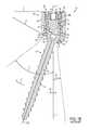
- FIG. 1Ais a perspective view of a prior art bone anchor assembly
- FIG. 1Bis an exploded view of the bone anchor assembly of FIG. 1A ;
- FIG. 1Cis a cross-sectional view of a portion of the bone anchor assembly of FIG. 1A ;
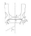
- FIG. 1Eis a cross-sectional view of the bone anchor assembly of FIG. 1A ;
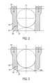
- FIG. 2is a cross-sectional view of one embodiment of a compression member for use with a bone anchor assembly
- FIG. 3is a cross-sectional view of another embodiment of a compression member for use with a bone anchor assembly
- FIG. 4is a cross-sectional view of another embodiment of a compression member for use with a bone anchor assembly
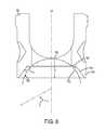
- FIG. 5is a cross-sectional view of another embodiment of a compression member for use with a bone anchor assembly
- FIG. 6is a cross-sectional view of another embodiment of a compression member for use with a bone anchor assembly
- FIG. 7is a cross-sectional view of another embodiment of a compression member for use with a bone anchor assembly
- FIG. 8is a cross-sectional view of another embodiment of a compression member for use with a bone anchor assembly
- FIG. 9is a cross-sectional view of a receiver member for use with a bone anchor assembly
- FIG. 10is a partial cross-sectional view of the receiver member of FIG. 9 ;
- FIG. 11is a partial cross-sectional view of the receiver member of FIG. 9 having a bone anchor seated therein;
- FIG. 12is a cross-sectional view of an exemplary embodiment of a closure mechanism for use with a bone anchor assembly
- FIG. 13is a cross-sectional view of a portion of the closure mechanism of FIG. 12 ;
- FIG. 14is a cross-sectional view of another exemplary embodiment of a closure mechanism for use with a bone anchor assembly
- FIG. 15is a cross-sectional view of a portion of the closure mechanism of FIG. 14 ;
- FIG. 16is a perspective view of an inner set screw of the closure mechanism of FIG. 14 ;
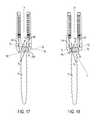
- FIG. 17is a cross-sectional view of a bone anchor assembly showing the compression member of FIG. 5 oriented in a first orientation relative to the receiver member of FIG. 9 ;
- FIG. 18is a cross-sectional view of another a bone anchor assembly showing the compression member of FIG. 5 oriented in a second orientation relative to the receiver member of FIG. 9 ;
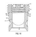
- FIG. 19is a cross-sectional view of the compression member of FIG. 8 that is mated to an outer screw of the closure mechanism of FIG. 14 .
- a bone anchor assemblyincludes a bone anchor configured to engage bone, a receiver member that polyaxially seats a spherical head of the bone anchor, and a compression member for securing the receiver member at a fixed angle with respect to the bone anchor.
- the compression membercan be seated within the receiver member, proximally of the head of the bone anchor, and can have a distal end with one or more gripping features thereon configured to grip the head of the bone anchor, even where the bone anchor is oriented at an angle to a longitudinal axis of the compression member.
- the one or more gripping featurescan be configured to create at least one of a line contact and/or a band contact with the head of the bone anchor, thus providing a firm grip on the head of the bone anchor and reducing a risk of slippage of the bone anchor with respect to the receiver member.
- FIGS. 1A-1Eillustrate a prior art bone anchor assembly 10 including a bone anchor 12 , a receiver member 14 for receiving a spinal fixation element, such as a spinal rod 22 , to be coupled to the bone anchor 12 , and a closure mechanism 16 to capture a spinal fixation element within the receiver member 14 and fix the spinal fixation element with respect to the receiver member 14 .
- the bone anchor 12includes a proximal head 18 and a distal shaft 20 configured to engage bone.
- the receiver member 14has a proximal end 26 having a pair of spaced apart arms 28 A, 28 B defining a recess 30 therebetween and a distal end 32 having an inner surface 35 for polyaxially seating the proximal head 18 of the bone anchor 12 and distal end surface 34 defining an opening through which at least a portion of the bone anchor 12 extends.
- the closure mechanism 16can be positionable between and can engage the arms 28 A, 28 B to capture a spinal fixation element, e.g., a spinal rod 22 , within the receiver member 14 and fix the spinal fixation element with respect to the receiver member 14 .
- the proximal head 18 of the bone anchor 12is generally in the shape of a truncated sphere having a planar proximal surface 36 and an approximately spherically-shaped distal surface 38 .
- the illustrated bone anchor assemblyis a polyaxial bone anchor designed for posterior implantation in the pedicle or lateral mass of a vertebra.
- the proximal head 18 of the bone anchor 12engages the distal end 32 of the receiver member 14 in a ball and socket like arrangement in which the proximal head 18 the distal shaft 20 can pivot relative to the receiver member 14 .
- the distal surface 38 of the proximal head 18 of the bone anchor 12 and a mating surface within the distal end 32 of the receiver member 14can have any shape that facilitates this arrangement, including, for example, spherical (as illustrated), toroidal, conical, frustoconical, and any combinations of these shapes.
- the distal shaft 20 of the bone anchor 12can be configured to engage bone and, in the illustrated embodiment, includes an external bone engaging thread 40 .
- the thread form for the distal shaft 20including the number of threads, the pitch, the major and minor diameters, and the thread shape, can be selected to facilitate connection with bone. Exemplary thread forms are disclosed in U.S. Patent Application Publication No. 2011/0288599, filed on May 18, 2011, and in U.S. Provisional Patent Application Ser. No. 61/527,389, filed Aug. 25, 2011, both of which are incorporated herein by reference.
- the distal shaft 20can also include other structures for engaging bone, including a hook.
- the distal shaft 20 of the bone anchor 12can be cannulated, having a central passage or cannula extending the length of the bone anchor to facilitate delivery of the bone anchor over a guide wire in, for example, minimally-invasive procedures.
- Other components of the bone anchor assemblyincluding, for example, the closure member 16 , the receiver member 14 , and the compression member 60 (discussed below) can be cannulated or otherwise have an opening to permit delivery over a guide wire or to permit the insertion of a driver instrument to manipulate the bone anchor.
- the distal shaft 20can also include one or more sidewall openings or fenestrations that communicate with the cannula to permit bone in-growth or to permit the dispensing of bone cement or other materials through the bone anchor 12 .
- the sidewall openingscan extend radially from the cannula through the sidewall of the distal shaft 20 .
- Exemplary systems for delivering bone cement to the bone anchor assembly 10 and alternative bone anchor configurations for facilitating cement deliveryare described in U.S. Patent Application Publication No. 2010/0114174, filed on Oct. 29, 2009, which is hereby incorporated herein by reference.
- the distal shaft 20 of the bone anchor 12can also be coated with materials to permit bone growth, such as, for example, hydroxyl apatite, and the bone anchor assembly 10 can be coated partially or entirely with anti-infective materials, such as, for example, tryclosan.
- the proximal end 26 of the receiver member 14includes a pair of spaced apart arms 28 A, 28 B defining a U-shaped recess 30 therebetween for receiving a spinal fixation element, e.g., a spinal rod 22 .
- Each of the arms 28 A, 28 Bcan extend from the distal end 32 of the receiver member 14 to a free end.
- the outer surfaces of each of the arms 28 A, 28 Bcan include a feature, such as a recess, dimple, notch, projection, or the like, to facilitate connection of the receiver member 14 to instruments.
- the outer surface of each arm 28 A, 28 Bcan include an arcuate groove at the respective free end of the arms. Such grooves are described in more detail in U.S. Pat. No. 7,179,261, issued on Feb. 20, 2007, which is hereby incorporated herein by reference.
- At least a portion of the proximal end surface 48 of the receiver member 12defines a plane Y.
- the receiver member 14has a central longitudinal axis L
- the distal end 32 of the receiver member 14includes a distal end surface 34 which is generally annular in shape defining a circular opening through which at least a portion of the bone anchor 12 extends.
- a distal end surface 34which is generally annular in shape defining a circular opening through which at least a portion of the bone anchor 12 extends.
- the distal shaft 20 of the bone anchor 12can extend through the opening.
- At least a portion of the distal end surface 34defines a plane X.
- the bone anchor 12can be selectively fixed relative to the receiver member 14 . Prior to fixation, the bone anchor 12 is movable relative to the receiver member 14 within a cone of angulation generally defined by the geometry of the distal end 32 of the receiver member and the proximal head 18 of the bone anchor 12 .
- the illustrated bone anchoris a favored-angle polyaxial screw in which the cone of angulation is biased in one direction. In this manner, the bone anchor 12 is movable relative to the receiver member 14 in at least a first direction, indicated by arrow A in FIG. 1E , at a first angle C relative to the central longitudinal axis L of the receiver member 14 .
- the bone anchor 12is also movable in at least a second direction, indicated by arrow B in FIG.
- the distal shaft 20 of the bone anchor 12defines a neutral axis 48 with respect to the receiver member 14 .
- the neutral axis 48can be perpendicular to the plane X defined by the distal end surface 34 and intersects the center point of the opening in the distal end surface 34 through which the distal shaft 20 of the bone anchor 12 extends.
- the neutral axis 48can be oriented at an angle to the central longitudinal axis L of the receiver member 14 .
- the proximal end 26 of the receiver member 14can include a proximal first bore 50 coaxial with a first central longitudinal axis N (which is coincident with longitudinal axis L) and a distal second bore 52 coaxial with a second central longitudinal axis M (which is coincident with the neutral axis 48 ) and the first central longitudinal axis N and second central longitudinal axis M can intersect one another.
- the angle between the plane X and the plane Y and the angle between the axis L and the axis Mcan be selected to provide the desired degree of biased angulation.
- Examples of favored angled polyaxial screwsare described in more detail in U.S. Pat. No. 6,974,460, issued on Dec. 13, 2005, and in U.S. Pat. No. 6,736,820, issued on May 18, 2004, both of which are hereby incorporated herein by reference.
- the bone anchor assemblycan be a conventional (non-biased) polyaxial screw in which the bone anchor pivots in the same amount in every direction and has a neutral axis that is coincident with the central longitudinal axis L of the receiver member.
- the spinal fixation elemente.g., the spinal rod 22
- the spinal fixation elementcan either directly contact the proximal head 18 of the bone anchor 12 or can contact an intermediate element, e.g., a compression member 60 .
- the compression member 60can be positioned within the receiver member 14 and interposed between the spinal rod 22 and the proximal head 18 of the bone anchor 12 to compress the distal outer surface 38 of the proximal head 18 into direct, fixed engagement with the distal inner surface of the receiver member 14 .
- a proximal portion of the compression member 60can include a pair of spaced apart arms 62 A and 62 B defining a U-shaped seat 64 for receiving the spinal rod 22 .
- a distal portion of the compression member 60can include a sidewall having an inner cylindrical surface 67 that is connected to an outer cylindrical surface 68 by a distal-facing surface 66 .
- At least a portion of the distal surface 66 of the compression member 60can be shaped as a negative of the proximal portion 18 of the bone anchor 20 , against which the distal surface 66 abuts when the compression member 60 is fully inserted into the receiver member 14 .
- the contact area between the distal surface 66 of the compression member 60 and the proximal head 18is maximized.
- the angle of the shaft 20 with respect to the longitudinal axis Lis not zero, however, the contact area between the distal surface 66 of the compression member 60 and the head 18 can be reduced, thus increasing a risk of slippage of the bone anchor 12 with respect to the receiver member 14 .
- the compression member 60is configured to slide freely along the longitudinal axis L within the recess 30 of the receiver member 14 .
- the compression member 60can be configured to mate with the receiver member, for example by mechanically deforming a portion of the compression member 60 against the receiver member 14 .
- opposing bores formed in the arms 62 A, 62 B of the compression member 60are aligned with bores formed in the arms 62 A, 62 B of the receiver member 14 , such that opposing pins can be inserted through the passageways defined by the bores to compress or “swage” the compression member 60 against the receiver member 14 .
- the swaging processcan prevent subsequent removal of the compression member 60 from the receiver member 14 .
- FIG. 1Cillustrates a ring member, e.g., a snap ring 120 , for frictionally engaging the head of the bone anchor.
- the snap ring 120can have a variety of configurations, shapes, and sizes, but it should be adapted to expand to fit around at least a portion of the head 18 of the bone anchor 12 and to thereby exert a frictional drag force on the head 18 .
- the snap ring 120is in the shape of a loop with an opening formed therein that allows the diameter d of the snap ring 120 to expand to fit around a portion of the spherical head 18 of the bone anchor 12 .
- a groove 122 formed within the recess 30 of the receiver member 14maintains the snap ring 120 at a particular location with respect to the spherical head 18 such that the snap ring 120 is expanded around the head 18 .
- the groove 122can be configured to maintain the snap ring 120 at a position just proximal to a center line of the head 18 .
- the proximal end 26 of the receiver member 14can be configured to receive a closure mechanism 16 positionable between and engaging the arms 28 A, 28 B of the receiver member 14 .
- the closure mechanism 16can be configured to capture a spinal fixation element, e.g., a spinal rod 22 , within the receiver member 14 , to fix the spinal rod 22 relative to the receiver member 14 , and to fix the bone anchor 12 relative to the receiver member 14 .
- the closure mechanism 16can be a single set screw having an outer thread for engaging an inner thread 42 provided on the arms 28 A, 28 B of the receiver member 14 .
- the closure mechanism 16comprises an outer set screw 70 positionable between and engaging the arms 28 A, 28 B of the receiver member 14 and an inner set screw 72 positionable within the outer set screw 70 .
- the outer set screw 70is operable to act on the compression member 60 to fix the bone anchor 12 relative to the receiver member 14 .
- the inner set screw 72is operable to act on the spinal rod 22 to fix the spinal rod 22 relative to the receiver member 14 .
- the closure mechanism 16permits the bone anchor 12 to be fixed relative to the receiver member 14 independently of the spinal rod 22 being fixed to the receiver member 14 .
- the outer set screw 70can engage the proximal end surfaces of the arms 62 A, 62 B of the compression member 60 to force the distal-facing surface 66 of the compression member 60 into contact with the proximal head 18 of bone anchor 12 , which in turn forces the distal surface 38 of the proximal head 18 into fixed engagement with the distal inner surface of the receiver member 14 .
- the inner set screw 72can engage the spinal rod 22 to force the spinal rod 22 into fixed engagement with the rod seat 64 of the compression member 60 .
- the outer set screw 70includes a first outer thread 74 for engaging a complementary inner thread 42 on the arms 28 A, 28 B of the receiver member 14 .
- the outer set screw 74includes a central passage 96 from a top surface 98 of the outer set screw 74 to a bottom surface 100 of the outer set screw 74 for receiving the inner set screw 72 .
- the central passage 96can includes an inner thread 102 for engaging a complementary outer thread 104 on the inner set screw 72 .
- the thread form for the inner thread 102 and the outer thread 104including the number of threads, the pitch, major and minor diameter, and thread shape, can be selected to facilitate connection between the components and transfer of the desired axial tightening force.
- the top surface 98 of the outer set screw 74can have one or more drive features to facilitate rotation and advancement of the outer set screw 74 relative to the receiver member 14 .
- the illustrated outer set screw 74includes drive features in the form of a plurality of cut-outs 106 spaced-apart about the perimeter of the top surface 98 .
- the inner set screw 104can include drive features for receiving an instrument to rotate and advance the inner set screw 72 relative to the outer set screw 74 .
- the illustrated inner set screw 104includes drive features in the form of a central passage 108 having a plurality of spaced apart, longitudinally oriented cut-outs for engaging complementary features on an instrument.
- the bone anchor assembly 10can be used with a spinal fixation element such as rigid spinal rod 22 .
- a spinal fixation elementsuch as rigid spinal rod 22 .
- the various components of the bone anchor assemblies disclosed herein, as well as the spinal rod 22can be constructed from various materials, including titanium, titanium alloys, stainless steel, cobalt chrome, PEEK, or other materials suitable for rigid fixation.
- the spinal fixation elementcan be a dynamic stabilization member that allows controlled mobility between the instrumented vertebrae.
- bonecan be prepared to receive the bone anchor assembly 10 , generally by drilling a hole in the bone which is sized appropriately to receive the bone anchor 12 .
- the bone anchor assembly 10can be assembled, which can include assembling the bone anchor 12 and the receiver member 14 , so that the distal shaft 20 extends through the opening in the distal end 32 of the receiver member 14 and the proximal head 18 of the bone anchor 12 is received in the distal end 32 of the receiver member 14 .
- a driver toolcan be fitted with the bone anchor 12 to drive the bone anchor 12 into the prepared hole in the bone.
- the compression member 60can be positioned within the receiver member 14 such that the arms 62 A, 62 B of the compression member are aligned with the arms 28 A, 28 B of the receiver member 14 and the lower surface of the compression member 14 is in contact with the proximal head 18 of the bone anchor 12 .
- a spinal fixation elemente.g., the spinal rod 22
- the closure mechanism 16can be engaged with the inner thread 42 provided on the arms 28 A, 28 B of the receiver member 14 .
- a torsional forcecan be applied to the outer set screw 70 to move it within the recess 30 using a tool which can engage the plurality of cut-outs 106 in the upper facing surface of the outer set screw 70 , so as to force the compression member 60 onto the proximal head 18 of the bone anchor 12 .
- Torsional forcescan then be applied to the inner set screw 72 to move it relative to the outer set screw 70 so that it contacts the spinal rod 22 and can, for example, fix the spinal rod 22 relative to the receiver member 14 and the bone anchor 12 .
- FIGS. 2-8show various embodiments of compression members similar to the compression member 60 shown in FIG. 1B and having gripping features on a distal end thereof for gripping a head of a bone anchor with greater friction as compared with a distal end formed as a negative of the head portion of the bone anchor.
- the compression members shown in FIGS. 2-8can be used with the bone anchor assembly 10 shown in FIGS. 1A-1E , or with various other bone anchor assemblies known in the art.
- FIGS. 9-11show various embodiments of receiver member similar to the receiver member 14 shown in FIG. 1B and having gripping features formed within a distal recess therein for gripping the underside of a head of a bone anchor with greater friction as compared with a recess in a receiver formed as a negative of the head portion of the bone anchor.
- the receiver members shown in FIGS. 9-11can be used with the bone anchor assembly shown in FIGS. 1A-1E , or with various other bone anchor assemblies known in the art.
- FIGS. 12-16show various embodiments of a closure mechanism similar to the closure mechanism 16 shown in FIG. 1B and comprising inner and outer members.
- the closure mechanisms of FIGS. 12-16can be used with the bone anchor assembly 10 shown in FIGS. 1A-1E , or with various other bone anchor assemblies known in the art.
- FIG. 2illustrates an exemplary embodiment of a compression member for use with a bone anchor assembly of the type described above.
- the illustrated compression member 160has a distal end that is configured to grip a proximal head of a bone anchor to secure the head at a desired angle with respect to a receiver member (not shown) when the compression member is locked within the receiver member, e.g., when a closure mechanism is applied to the receiver member to lock the bone anchor in a fixed position relative to the receiver member.
- the distal end of the compression member 160can be configured to grip the head of a bone anchor in a variety of ways, in the illustrated embodiment, the compression member 160 includes a planar distal-facing surface 166 that extends between an inner cylindrical surface 167 and an outer cylindrical surface 168 .
- the distal-facing surface 166can extend in a plane perpendicular to the longitudinal axis L 1 of the compression member 160 , and the surface can have a generally circular shape with an inner circular corner or edge 161 .
- the edge 161can create a ring-shaped line contact with the head of the bone anchor to substantially prevent movement of the head and to ensure that the bone anchor remains at a fixed angle with respect to the receiver member.
- Such line contactcan be particularly advantageous with favored-angle bone anchors in which the bone anchor is at an extreme angle relative to the receiver member.
- the compression member 160can be locked within the receiver member by applying a closure mechanism, e.g., inner and/or outer set screws, to the receiver member.
- the closure mechanismcan apply a distally directed force to a spinal fixation element, e.g., a spinal rod, seated within the receiver member, and the spinal rod in turn can apply a distally directed force to the compression member 160 to cause the compression member 160 to press down on and engage the head of the bone anchor.
- the closure mechanismcan be configured to provide a force directly to the compression member 160 to lock the head of the bone anchor in a fixed position relative to the receiver member without locking the spinal fixation rod within the receiver member.
- the closure mechanismcan include inner and outer set screws, with the inner set screw locking the rod and the outer set screw locking the compression member and thus the bone anchor. A person skilled in the art will appreciate that a variety of locking techniques can be utilized.
- the configuration of the edge 161can vary, and in one embodiment the edge 161 can have a radius of curvature corresponding to a radius of curvature of the head of a bone anchor to be used therewith. In some embodiments, a largest diameter of the edge 161 can be smaller than a diameter of the head where the edge 161 grips the head to create an interference fit between the compression member 160 and the head.
- the edge 161and thus the ring-shaped line contact, extends in a plane that is substantially perpendicular to a longitudinal axis L 1 of the compression member 160 , but it will be appreciated by a person skilled in the art that the line contact can be formed in a plane that is oriented at any angle to the longitudinal axis L 1 of the compression member 160 .
- FIGS. 3-8illustrate additional embodiments of compression members with distal-facing surfaces having various shapes and various gripping features thereon configured to grip a head of a bone anchor when the compression member is in a locked configuration.
- the compression members of FIGS. 3-8can generally be configured and used similar to the compression member 160 of FIG. 2 . Additionally, like-named elements and like-illustrated elements of the compression member 160 and of the other compression members discussed herein can be configured and used similar to one another.
- the compression member 260has a sloped distal-facing surface 266 that extends between an inner cylindrical surface 267 and an outer cylindrical surface 268 , the inner and outer surfaces 267 , 268 defining the inner and outer sidewalls of the compression member 260 .
- the inner surface 267can extend distally beyond the outer surface 268 , such that the distal-facing surface 266 can be oriented at an angle to a longitudinal axis L 2 of the compression member 260 and such that the distal-facing surface 266 forms a cone.
- a distal-most tip of the coneterminates in a sharp edge 261 . Similar to the edge 161 of compression member 160 of FIG. 2 , the edge 261 in FIG.
- the sloped orientation of the distal-facing surface 266can increase a sharpness of the edge 261 such that the edge 261 is configured to dig into the head and further reduce a risk of slippage of the head of a bone anchor with respect to the receiver member.
- a compression member 360can have a first spherically shaped distal-facing surface 366 and second spherically shaped distal-facing surface 366 ′ extending distally from the first distal-facing surface 366 .
- the first distal facing surface 366can have a radius of curvature that is different, e.g., less, than a radius of curvature of the second distal-facing surface 366 ′, such that a ring-shaped crest 361 is formed at the intersection of the first distal-facing surface 366 and the second distal-facing surface 366 ′ for gripping the head of a bone anchor.
- a largest diameter of the crest 361can be smaller than a diameter of the head of the bone anchor where the crest 361 grips the head, thus creating an interference fit between the compression member 360 and the head.
- the dimensions of the crest 361 as shown in FIG. 4are exaggerated for the sake of illustration. While the position of the crest 361 can vary, in the illustrated embodiment the crest is shown at a general mid-portion of the distal-facing surface such that a height of the first distal-facing surface 366 is substantially the same as a height of the second distal-facing surface 366 ′. This configuration can allow the edge 361 to engage the head of the bone anchor at a desirable location.
- edge 361can vary as may be desired based on the size of the head of the bone anchor. Moreover, as with the embodiment of FIG. 2 , the edge 361 can extend at any angle relative to the longitudinal axis L 3 , including perpendicular or at some other angle.
- FIG. 5illustrates another embodiment of a compression member 460 having an angled distal-facing surface that extends in a plane P 1 that is transverse and non-perpendicular to the longitudinal axis L 4 of the compression member 460 .
- the compression member 460can have a first hemicylindrical portion 468 A that extends distally beyond a distal-most end of a second hemicylindrical portion 468 B such that a first distal-facing surface 466 A can be distal and offset along a longitudinal axis L 1 of the compression member 460 from a second distal-facing surface 466 B.
- the angled distal-facing surfacecan also cause the first distal-facing surface 466 A to have a shape that differs a shape of the second distal-facing surface 466 B.
- the compression member 460can have a generally spherical recess formed in the distal end thereof, and the spherical recess can have a center point (not shown) that is positioned along the longitudinal axis L 4 of the compression member 460 .
- the plane P 1can intersect the perimeter of the sphere at a location (shown as edge 461 B) that causes the second distal-facing surface 466 B to be co-planar with plane P 1 .
- the second distal-facing surface 466 Bwill thus define an edge 461 B for creating a semicircular line contact with the head of a bone anchor, whereas the spherical shape of the first distal-facing surface 466 A will form a negative of a portion of the head against which the first distal-facing surface 466 A abuts.
- the first distal-facing surface 466 Awill thus support the head on one end of the head while the edge 461 B on the second distal-facing surface 466 B can cut into the head at an opposed end of the head.
- the compression member 460can thus exert a compressive force on the head that acts at an angle to the longitudinal axis L 4 of the compression member 460 and that can balance an opposing resistive force of the bone anchor against the compression member 460 when the bone anchor is oriented at an angle to the longitudinal axis L 4 .
- the first distal-facing surface 466 Acan have a radius of curvature corresponding to a radius of curvature of a head of a bone anchor where the first distal-facing surface 466 A grips the head, although the radius of curvature of the first distal-facing surface 466 A can be smaller than the radius of curvature of the head to create an interference fit with the head.
- a largest diameter of an inner cylindrical surface 467 of the compression member 460can be smaller than a diameter of the head where the compression member 460 grips the head.
- a distal end of a compression membercan have multiple gripping features thereon to facilitate gripping a head of a bone anchor.
- FIG. 6illustrates a compression member 560 having a plurality of teeth 563 formed on a distal-facing surface 566 .
- the distal-facing surface 566can extend between an inner cylindrical surface 567 and an outer cylindrical surface 568 , with the inner and outer cylindrical surfaces 567 , 568 defining inner and outer sidewalls of the compression member. Similar to the edge 261 described above and illustrated in FIG. 3 , sharp crests 561 of the teeth 563 can grip the head of a bone anchor along ring-shaped line contacts to reduce a risk of slippage.
- the teeth 563can impart the additional advantage of providing multiple line contacts with the head to provide a stronger grip on the head.
- Each of the crests 561can have a radius of curvature, either the same or different from one another, corresponding to the radius of curvature of the head.
- a largest diameter of at least one of the crests 561can be slightly smaller than a diameter of the head where the at least one of the crests 561 grips the head to create an interference fit between the compression member 560 and the head.
- the teeth 563can be of any size, shape, and number.
- the teeth 563include two planar, substantially perpendicular side walls that meet at the sharp crests 561 , although the side walls of the teeth can be oriented at various angles with respect to one another to form sharper or duller crests 561 .
- the teeth 563can extend along any distance around a circumference of the distal-facing surface 566 , although in the illustrated embodiment the teeth 563 extend along the entire circumference of the distal-facing surface 566 .
- Each of the teeth 563extend in a plane that is substantially perpendicular to a longitudinal axis L 5 of the compression member 560 , but the teeth 563 can be oriented in any plane, either the same or different from one another. Moreover, the teeth 563 can be disposed along the distal-facing surface 566 at any distance from one another, although the teeth 563 of the illustrated embodiment are disposed at regular intervals along the longitudinal axis L 5 of the compression member 560 . In one aspect, the teeth can be composed of one or more flexible materials, such that the teeth 563 are configured to deform upon contact with the head of a bone anchor. In this embodiment, the teeth 563 can form ring-shaped band contacts with the head, the band contacts having a width measured along the longitudinal axis L 5 of the compression member 560 that corresponds to an amount of deformation of the teeth 563 .
- FIG. 7illustrates another embodiment of a compression member 660 having teeth 663 for gripping the head, in which the teeth 663 can each have spherical surfaces 661 such that the teeth 663 can form a plurality of ring-shaped band contacts with the head of a bone anchor.
- the teeth 663can be configured similarly to the teeth 553 of the compression member 560 of FIG. 6 , however the spherical shape of the spherical surfaces 661 of the teeth 663 can simplify the manufacturing process and can reduce a risk of deformation of the head by the teeth 663 .
- the teeth 663can be comprised of one or more flexible materials, such that the teeth 663 are configured to deform into contact with the head along the ring-shaped band contacts.
- FIG. 8illustrates another embodiment of a compression member 760 having a skirt 769 that extends around the head of the bone anchor and that can improve the structural integrity of the compression member 760 .
- compression member 760can include an edge 761 that is configured to grip the head of the bone anchor.
- a distal end wall 766 of the compression member 760can include a first inner portion 762 and a second outer portion 764 that extends at an angle ⁇ to the first portion 762 .
- the first inner portion 762is a planar surface that is oriented substantially perpendicularly to the longitudinal axis L 7 .
- the second outer portion 764is also a planar surface, but it extends at an angle ⁇ to the first portion 762 , and therefore the longitudinal axis L 7 , thereby defining a skirt 769 that can extend around the head of the bone anchor.
- the second portion 764can extend distally by any desired distance D 7 from a distal-most end of a U-shaped seat 765 of the compression member 760 .
- the distance D 7can be large enough to cause the skirt 769 to help resist a distally-directed force applied to the compression member 760 by, e.g., a closure mechanism, which can thereby improve the structural integrity of the compression member 760 and reduce a risk of breakage of the compression member 760 .
- the distance D 7can be in the range of about 0.7 mm to 4.5 mm.
- compression members 360 , 460 , 560 , 660also include similar “skirt” portions that extend distally beyond a distal-most portion of U-shaped seats of compression members 360 , 460 , 560 , 660 .
- skirt 769the distally-extending portions of compression members 360 , 460 , 560 , 660 can improve the structural integrity of compression members 360 , 460 , 560 , 660 .
- the skirt 769 of compression member 760can be configured not to contact the head of the bone anchor unless the shaft of the bone anchor is moved beyond a certain angle ⁇ with respect to a longitudinal axis L 7 of the compression member 760 .
- the skirt 769can thus function as a stop to prevent movement of the bone anchor beyond the angle ⁇ .
- the second portion 764 of the distal-facing surface 766can be configured such that it does not contact the head of the bone anchor until the shaft of the bone anchor is moved beyond an angle ⁇ with respect to the longitudinal axis L 7 .
- the head of the bone anchorcan come into contact with the second portion 764 , which can prevent the bone anchor from moving beyond the angle ⁇ .
- the second portion 764can help to prevent accidental and/or excessive movement of the bone anchor.
- the skirt 769can extend around any circumferential length of the head of the bone anchor, for example around an entire circumference of the head, such that the skirt 769 can prevent movement of the bone anchor beyond the angle ⁇ in any direction.
- the skirt 769can extend around only a portion of the circumference of the head, such that the skirt 769 only inhibits movement of the bone anchor beyond the angle ⁇ in certain directions.
- the angles ⁇ , ⁇can vary to provide for any desired amount of movement of the bone anchor within the receiver member, although the angle ⁇ is generally in the range of about 120 to 170 degrees and the angle ⁇ is generally in the range of about 30 to 60 degrees.
- FIG. 9illustrates one example of a receiver member 214 having a distal end 232 with a plurality of teeth 215 configured to grip the head of a bone anchor.
- the teeth 215shown in more detail in FIG.
- the teeth 215can extend around any portion of the circumference of the distal inner surface 235 and can be positioned at various locations along a length measured along a longitudinal axis L R of the receiver member 214 . As shown in FIG. 11 , the teeth 215 can cut into the head to substantially prevent movement of the head when the receiver member 214 is locked to the bone anchor.
- the receiver member 214is a favored-angle receiver having teeth 215 formed only on a first portion 235 A of the distal inner surface 235 , i.e., on a distal-most end that extends distally beyond a distal-most end of an opposed second portion 235 A of the distal inner surface 235 .
- the distal-most end of the second portion 235 Acan be in the form of an edge that is opposed from the teeth 215 and can thus provide for opposed clamping of the head 18 similar to that described above with respect to the compression member 460 of FIG. 5 .
- FIGS. 12-16illustrate exemplary embodiments of a closure mechanism for use with a bone anchor assembly of the type described above. Similar to the closure mechanism 16 explained above, the illustrated closure mechanisms can include inner and outer members—the inner member being configured to secure the spinal rod within the receiver member and the outer member being configured to secure the compression member and the bone anchor within the receiver member. The inner member can be configured to removably mate with the outer member by, e.g., threaded engagement.
- Each of the closure mechanisms of FIGS. 12-16can have at least one feature thereon configured to prevent relative movement of the inner and outer members once mated, absent application of a force applied thereto that equals or exceeds a threshold force.
- the inner memberwill not migrate relative to the outer member unless a force equal to or exceeding the threshold force is applied thereto. This can help to reduce a risk of accidental removal of the inner member from the outer member, thus stabilizing the closure mechanism during transport and sterilization.
- the bone anchor assemblyWhen the bone anchor assembly is implanted in a patient's body, it can help to secure both the bone anchor and the spinal rod within the receiver member at a desired orientation.
- a closure mechanism 216includes an inner set screw 272 configured to engage an outer set screw 270 by interference fit.
- inner threads 271 of the outer set screware configured to engage outer threads 273 of the inner set screw 272 such that the inner set screw 272 will not move relative to the outer set screw 270 unless a force equal to or exceeding a threshold force is applied thereto.
- the interference fit between threads 271 and threads 273can be created in a variety of ways, although in the exemplary embodiment the interference fit is created by a difference in pitch between at least a portion of threads 271 and threads 273 .
- a pitch P I of threads 271 on the outer screw 270can be smaller than a pitch P O of threads 273 on the inner screw 272 along at least a portion thereof.
- the difference in pitchcan create regions of overlap 275 between edges of the threads 271 , 273 that provide resistance to movement of the inner set screw 272 relative to the outer set screw 270 .
- the pitch differencecan be adjusted to customize the threshold force required to overcome the resistance and move the screws 270 , 272 relative to one another. For example, a larger pitch difference can increase the threshold force.
- the pitch P Ican be in the range of about 0.9 mm to 0.914 mm
- the pitch P Ocan be in the range of about 0.890 mm to 0.899 mm or 0.915 mm to 0.924 mm
- the pitch differencecan be in the range of about 0.001 mm to 0.024 mm.
- Pitch P I and pitch P Ocan vary along a length of the screws 270 , 272 , for example such that only a portion of the threads 271 , 273 are engaged via interference fit.
- a number of parameters of the screws 270 , 272can be adjusted to customize the threshold force necessary to move the screws 270 , 272 relative to one another.
- a height H I of threads 273 of the inner screw 272can be above standard clearance levels for use with threads 271 of the outer screw 270 that have a height H O .
- the threads 271 , 273can provide greater interference to avoid de-threading as compared with traditional screw assemblies.
- the height H Ican be in the range of about 0.466 mm to 0.476 mm
- the height H Ocan be in the range of about 0.477 mm to 0.487 mm
- the height differencecan be in the range of about 0.001 mm to 0.021 mm
- FIGS. 14-16illustrate another embodiment of a closure mechanism including inner and outer set screws secured together by interference fit.
- an inner set screw 372 of a closure mechanism 316is mechanically deformed to dig into a portion of an outer set screw 370 .
- a blunt instrumentcan be used to deform at least a portion of the threads 373 .
- the instrumentis inserted between two threads and the deformation caused a portion of an upper thread 373 a to be deformed proximally, and a portion of a lower thread 373 b to be deformed distally.
- FIG. 15the instrument is inserted between two threads and the deformation caused a portion of an upper thread 373 a to be deformed proximally, and a portion of a lower thread 373 b to be deformed distally.
- protrusion 377 acan dig into an upper thread 371 a of the outer set screw 370 and protrusion 377 b can dig into a lower thread 371 b of the outer set screw 370 to create overlapping regions 375 a , 375 b .
- An extent and location of the deformationcan be adjusted to customize a threshold force that must be applied to the closure mechanism 316 to move the inner set screw 372 relative to the outer set screw 370 to overcome a frictional force created by the interference fit.
- creation of the protrusions 377 a , 377 b over a larger portion of the threads 373 a , 373 bcan create more friction between the inner and outer screws 372 , 370 to increase the threshold force.
- a person of skill in the artwill appreciate that nearly any deformation of the inner set screw 372 and/or the outer set screw 370 can create an interference fit that resists relative movement of the screws 370 , 372 . Also, deformation of any number and portion of the threads 371 , 373 can be performed during manufacturing.
- interference fits between the inner and outer memberscan be accomplished in a variety of ways.
- at least one of the outer threads of the inner membercan have a height that is greater than a height of at least one of the inner threads of the outer member, such that outer tips of the outer threads of the inner member dig into the outer member when the inner and outer members are threadably mated to each other.
- at least one of the inner threads of the outer membercan have a height that is greater than a height of at least one of the outer threads of the inner member. It will further be appreciated by a person of skill in the art that any of the aforementioned means of increasing the threshold force required to move the inner and outer members relative to each other can be used in conjunction with one another.
- a bone anchor assemblycan be assembled, either during manufacturing, prior to use, or intraoperatively, by passing an elongate shank of a bone anchor in a proximal-to-distal direction through an aperture formed in a distal end of a receiver member.
- bottom-loading bone anchorscan be utilized.
- a proximal head portion of the bone anchorcan be polyaxially seated within the polyaxial recess in the receiver member.
- a compression membercan be inserted between the opposed arms of the receiver member, proximal to the proximal head of the bone anchor. An angle of the bone anchor with respect to the receiver member can be adjusted to a desired angle.
- the compression memberis configured to apply a frictional force to the bone anchor to maintain the bone anchor in a desired angular orientation prior to lock, while still allowing a force to be applied to the bone anchor to move the bone anchor relative to the receiver member.
- the bonecan be prepared to receive the bone anchor, e.g., by drilling an appropriately sized hole.
- a driver toolcan be fitted with the bone anchor to drive the bone anchor into the prepared hole in the bone.
- a spinal fixation elemente.g., a rod
- a closure mechanismcan be applied to the receiver member, proximally of the rod, to urge the spinal rod and the compression member distally such that a distal-facing surface of the compression member comes into contact with the head of the bone anchor.
- Gripping features of the compression membercan grip the head of the bone anchor to grip the head portion of the bone anchor with greater friction as compared with a distal end formed as a negative of the head portion of the bone anchor on the head of the bone anchor.
- the compression membercan make at least one of line contact and band contact with the head portion of the bone anchor.
- the bone anchoris locked at the desired angle with respect to the receiver member.
- gripping features on the receiver membercan have the same effect to lock the receiver member in a fixed position relative to the bone anchor.
- Such gripping features on the compression member and/or the receiver membercan provide increased contact and further prevent the risk of slippage as compared to compression members and receivers lacking such features.
- a bone anchor assemblyincludes both a favored-angle receiver member, such as receiver 214 shown in FIG. 9 , and a favored-angle compression member, such as compression member 460 shown in FIG. 5
- the angled distal-surfacescan be oriented relative to one another so as to direct the compressive forces in a desired direction.
- the distal-facing surface of compression member 460extends in a plane P C that is transverse and non-perpendicular to a plane P R of the distal-facing surface of the receiver member 214 .
- a compressive force F C exerted by the compression member 460can act on one side of the head 18 of the bone anchor in a direction that is opposite to a compressive force F R exerted by the receiver member 214 on the opposite side of the head 18 .
- Both compressive forces F C , F Rcan act at an angle to the longitudinal axis L 4 of the compression member 460 and can counterbalance one another to stabilize the bone anchor 12 .
- the plane P C of the distal-facing surface of the compression member 460is oriented substantially parallel to the plane P R of the distal-facing surface of the receiver member 214 .
- the compressive forces F C , F R exerted by the compression member 460 and the receiver member 214can act on a same side of the head 18 but in opposite proximal-distal directions.
- This alignment of compressive forces F C , F Rcan similarly help to stabilize the head 18 , particularly where the bone anchor 12 is oriented at an angle to the longitudinal axis L 4 of the compression member 460 in a direction X as shown in FIG. 18 .
- the planes P C , P R of the distal-facing surfaces of the compression member 460 and receiver member 214can be oriented in a desired configuration during manufacturing, e.g., via a swaging process described above, or before or during surgery.
- the compression membercan be configured to directly transmit a distally-directed force applied thereto by the closure mechanism to thereby lock the bone anchor in a fixed position.
- the compression membercan alternatively be configured to absorb at least a portion of the force applied thereto by the closure mechanism, particularly where the force exceeds a threshold force, such that some of the force applied to a proximal end of the compression member is not transferred to the bone anchor. This can help to ensure that neither the compression member nor the bone anchor is damaged by the application of excessive force thereto.
- at least a proximal portion of the compression membercan be configured to compress inwardly or expand outwardly upon the application of a distally-directed force exceeding the threshold force.
- opposed arms of the compression membercan each have proximal end surfaces that are configured to seat a distal end surface of the closure mechanism such that a distally-directed force applied by the closure mechanism to the compression member can cause the opposed arms to move inwardly toward one another when the force exceeds the threshold force.
- a proximal portion of the compression member and a distal portion of the closure mechanismcan be configured in a variety of ways to cause the opposed arms of the compression member to compress inwardly.
- the proximal portion of the compression member 760can have a convex shape that corresponds to a concave shape of the distal portion of the screw 370 .
- proximal end surfaces 764 A, 764 B of the compression member 760can each have a convex shape, and the compression member 760 can have a height that decreases radially outward from an inner wall 767 to an outer wall 768 .
- the screw 370can have a convex shape and, to correspond to the shape of the compression member 760 , the outer wall of the screw 370 can extend distally beyond the inner wall of the screw 370 .
- the corresponding shapescan allow for both the compression member 760 and the screw 370 to rotate freely relative to one another when mated together, while at the same time preventing inward and outward movement of the components relative to one another.
- the outer portion of the screw 370can exert a lateral force on the arms 762 A, 762 B to thereby push the arms 762 A, 762 B of compression member 760 toward one another.
- the opposed arms 762 A, 762 Bcan be formed from a material that is sufficiently flexible to allow the opposed arms 762 A, 762 B to move toward one another when acted upon by a force exceeding the threshold force, but sufficiently rigid to maintain a fixed distance from one another when a force applied thereto is below the threshold force.
- the arms 762 A, 762 Bcan be formed from either the same or different materials than the remainder of the compression member 760 .
- any number of force-absorbing mechanismse.g., a spring
- the compression member 760can have a skirt 769 that can resist some of the force applied to the compression member 760 by a closure mechanism, thus helping to preserve the structural integrity of the compression member 760 under large forces.
Landscapes
- Health & Medical Sciences (AREA)
- Orthopedic Medicine & Surgery (AREA)
- Life Sciences & Earth Sciences (AREA)
- Surgery (AREA)
- Neurology (AREA)
- Heart & Thoracic Surgery (AREA)
- Engineering & Computer Science (AREA)
- Biomedical Technology (AREA)
- Nuclear Medicine, Radiotherapy & Molecular Imaging (AREA)
- Medical Informatics (AREA)
- Molecular Biology (AREA)
- Animal Behavior & Ethology (AREA)
- General Health & Medical Sciences (AREA)
- Public Health (AREA)
- Veterinary Medicine (AREA)
- Surgical Instruments (AREA)
Abstract
Description
Claims (12)
Priority Applications (2)
| Application Number | Priority Date | Filing Date | Title |
|---|---|---|---|
| US14/070,943US10342582B2 (en) | 2013-03-14 | 2013-11-04 | Bone anchor assemblies and methods with improved locking |
| US16/452,497US11311318B2 (en) | 2013-03-14 | 2019-06-25 | Bone anchor assemblies and methods with improved locking |
Applications Claiming Priority (2)
| Application Number | Priority Date | Filing Date | Title |
|---|---|---|---|
| US13/826,161US20140277153A1 (en) | 2013-03-14 | 2013-03-14 | Bone Anchor Assemblies and Methods With Improved Locking |
| US14/070,943US10342582B2 (en) | 2013-03-14 | 2013-11-04 | Bone anchor assemblies and methods with improved locking |
Related Parent Applications (1)
| Application Number | Title | Priority Date | Filing Date |
|---|---|---|---|
| US13/826,161Continuation-In-PartUS20140277153A1 (en) | 2013-03-14 | 2013-03-14 | Bone Anchor Assemblies and Methods With Improved Locking |
Related Child Applications (1)
| Application Number | Title | Priority Date | Filing Date |
|---|---|---|---|
| US16/452,497ContinuationUS11311318B2 (en) | 2013-03-14 | 2019-06-25 | Bone anchor assemblies and methods with improved locking |
Publications (2)
| Publication Number | Publication Date |
|---|---|
| US20140277161A1 US20140277161A1 (en) | 2014-09-18 |
| US10342582B2true US10342582B2 (en) | 2019-07-09 |
Family
ID=51531135
Family Applications (2)
| Application Number | Title | Priority Date | Filing Date |
|---|---|---|---|
| US14/070,943ActiveUS10342582B2 (en) | 2013-03-14 | 2013-11-04 | Bone anchor assemblies and methods with improved locking |
| US16/452,497Active2034-01-30US11311318B2 (en) | 2013-03-14 | 2019-06-25 | Bone anchor assemblies and methods with improved locking |
Family Applications After (1)
| Application Number | Title | Priority Date | Filing Date |
|---|---|---|---|
| US16/452,497Active2034-01-30US11311318B2 (en) | 2013-03-14 | 2019-06-25 | Bone anchor assemblies and methods with improved locking |
Country Status (1)
| Country | Link |
|---|---|
| US (2) | US10342582B2 (en) |
Cited By (6)
| Publication number | Priority date | Publication date | Assignee | Title |
|---|---|---|---|---|
| US20200179016A1 (en)* | 2015-12-03 | 2020-06-11 | Nuvasive, Inc. | Bone Anchor |
| US10786284B2 (en) | 2012-09-28 | 2020-09-29 | Medos International Sarl | Bone anchor assemblies |
| US10987138B2 (en) | 2013-03-14 | 2021-04-27 | Medos International Sari | Locking compression members for use with bone anchor assemblies and methods |
| US10987145B2 (en) | 2008-02-04 | 2021-04-27 | Medos International Sarl | Methods for correction of spinal deformities |
| US11311318B2 (en) | 2013-03-14 | 2022-04-26 | DePuy Synthes Products, Inc. | Bone anchor assemblies and methods with improved locking |
| US12127766B2 (en) | 2021-03-05 | 2024-10-29 | Medos International Sàrl | Selectively locking polyaxial screw |
Families Citing this family (14)
| Publication number | Priority date | Publication date | Assignee | Title |
|---|---|---|---|---|
| US20190247094A1 (en)* | 2011-07-15 | 2019-08-15 | Globus Medical, Inc. | Orthopedic fixation devices and methods of installation thereof |
| EP2606841B1 (en)* | 2011-12-23 | 2016-03-09 | Biedermann Technologies GmbH & Co. KG | Polyaxial bone anchoring device |
| EP2764840B1 (en)* | 2013-02-11 | 2017-05-03 | Biedermann Technologies GmbH & Co. KG | Coupling assembly for coupling a rod to a bone anchoring element and bone anchoring device with such a coupling assembly |
| US9775660B2 (en) | 2013-03-14 | 2017-10-03 | DePuy Synthes Products, Inc. | Bottom-loading bone anchor assemblies and methods |
| US9724145B2 (en) | 2013-03-14 | 2017-08-08 | Medos International Sarl | Bone anchor assemblies with multiple component bottom loading bone anchors |
| US20140277153A1 (en) | 2013-03-14 | 2014-09-18 | DePuy Synthes Products, LLC | Bone Anchor Assemblies and Methods With Improved Locking |
| US9833263B2 (en)* | 2015-04-13 | 2017-12-05 | Medos International Sarl | Bone anchor assemblies with orientation indicator |
| DE102015109481A1 (en)* | 2015-06-15 | 2016-12-15 | Aesculap Ag | Pedicle screw with radially offset guide |
| US10905476B2 (en)* | 2016-09-08 | 2021-02-02 | DePuy Synthes Products, Inc. | Variable angle bone plate |
| US11026730B2 (en)* | 2017-05-10 | 2021-06-08 | Medos International Sarl | Bone anchors with drag features and related methods |
| US10610265B1 (en) | 2017-07-31 | 2020-04-07 | K2M, Inc. | Polyaxial bone screw with increased angulation |
| USD902405S1 (en) | 2018-02-22 | 2020-11-17 | Stryker Corporation | Self-punching bone anchor inserter |
| EP3695796B1 (en)* | 2019-02-13 | 2022-08-03 | Biedermann Technologies GmbH & Co. KG | Anchoring assembly for anchoring a rod to a bone or a vertebra |
| US12364515B2 (en) | 2021-03-05 | 2025-07-22 | Medos International Sàrl | Multi-feature polyaxial screw |
Citations (285)
| Publication number | Priority date | Publication date | Assignee | Title |
|---|---|---|---|---|
| US2788045A (en)* | 1952-10-06 | 1957-04-09 | Rosan Joseph | Conventional truncated screw threads with small locking thread bonded therebetween |
| US2842180A (en)* | 1950-02-23 | 1958-07-08 | Set Screw & Mfg Company | Self-locking threads with locking interference fit |
| US4124318A (en) | 1978-03-23 | 1978-11-07 | General Motors Corporation | Splined assembly with retaining rings |
| US4762024A (en) | 1985-07-30 | 1988-08-09 | Dana Corporation | Shaft retaining means for a differential gear assembly |
| US5009017A (en) | 1987-01-20 | 1991-04-23 | Caterpillar Inc. | Retaining pin having a positive keeper means |
| WO1991016020A1 (en) | 1990-04-26 | 1991-10-31 | Danninger Medical Technology, Inc. | Transpedicular screw system and method of use |
| EP0470660A1 (en) | 1990-08-07 | 1992-02-12 | Acromed B.V. | Apparatus for the correction of scoliosis |
| US5129388A (en) | 1989-02-09 | 1992-07-14 | Vignaud Jean Louis | Device for supporting the spinal column |
| US5154719A (en) | 1990-02-19 | 1992-10-13 | Societe De Fabrication De Materiel Orthopedique - Sofamor | Implant for a device for osteosynthesis, in particular of the spine |
| US5306275A (en) | 1992-12-31 | 1994-04-26 | Bryan Donald W | Lumbar spine fixation apparatus and method |
| US5385565A (en) | 1992-09-21 | 1995-01-31 | Danek Medical, Inc. | Tool and method for derotating scoliotic spine |
| US5443467A (en) | 1993-03-10 | 1995-08-22 | Biedermann Motech Gmbh | Bone screw |
| US5486174A (en) | 1993-02-24 | 1996-01-23 | Soprane S.A. | Fastener for the osteosynthesis of the spinal column |
| US5487744A (en) | 1993-04-08 | 1996-01-30 | Advanced Spine Fixation Systems, Inc. | Closed connector for spinal fixation systems |
| US5501684A (en) | 1992-06-25 | 1996-03-26 | Synthes (U.S.A.) | Osteosynthetic fixation device |
| US5520689A (en) | 1992-06-04 | 1996-05-28 | Synthes (U.S.A.) | Osteosynthetic fastening device |
| US5562661A (en) | 1995-03-16 | 1996-10-08 | Alphatec Manufacturing Incorporated | Top tightening bone fixation apparatus |
| US5580246A (en) | 1995-01-30 | 1996-12-03 | Fried; Paula S. | Dental implants and methods for extending service life |
| US5643260A (en) | 1995-02-14 | 1997-07-01 | Smith & Nephew, Inc. | Orthopedic fixation system |
| US5672176A (en) | 1995-03-15 | 1997-09-30 | Biedermann; Lutz | Anchoring member |
| US5782833A (en) | 1996-12-20 | 1998-07-21 | Haider; Thomas T. | Pedicle screw system for osteosynthesis |
| EP0857465A1 (en) | 1997-02-10 | 1998-08-12 | Patrice Francois Diebold | Separable screw for an osteosynthesis plate or for setting two bone fragments |
| US5797911A (en) | 1996-09-24 | 1998-08-25 | Sdgi Holdings, Inc. | Multi-axial bone screw assembly |
| US5879350A (en) | 1996-09-24 | 1999-03-09 | Sdgi Holdings, Inc. | Multi-axial bone screw assembly |
| US5885286A (en) | 1996-09-24 | 1999-03-23 | Sdgi Holdings, Inc. | Multi-axial bone screw assembly |
| DE29903342U1 (en) | 1999-02-24 | 1999-06-02 | Grzibek, Egbert, 97534 Waigolshausen | Fixing element for holding elements of spinal implants |
| US5941882A (en) | 1996-07-02 | 1999-08-24 | Societe Etudes Et Developpements S.E.D. | Medical screw particularly for surgery and emplacement tool |
| US5964591A (en) | 1997-04-09 | 1999-10-12 | Implant Innovations, Inc. | Implant delivery system |
| US5989250A (en) | 1996-10-24 | 1999-11-23 | Spinal Concepts, Inc. | Method and apparatus for spinal fixation |
| US6050997A (en) | 1999-01-25 | 2000-04-18 | Mullane; Thomas S. | Spinal fixation system |
| US6056753A (en) | 1998-07-13 | 2000-05-02 | Jackson; Roger P. | Set screw for use with osteosynthesis apparatus |
| US6068632A (en) | 1998-05-12 | 2000-05-30 | Carchidi; Joseph Edward | Bone tap apparatus |
| US6074391A (en) | 1997-06-16 | 2000-06-13 | Howmedica Gmbh | Receiving part for a retaining component of a vertebral column implant |
| US6077262A (en) | 1993-06-04 | 2000-06-20 | Synthes (U.S.A.) | Posterior spinal implant |
| US6090111A (en) | 1998-06-17 | 2000-07-18 | Surgical Dynamics, Inc. | Device for securing spinal rods |
| US6113601A (en)* | 1998-06-12 | 2000-09-05 | Bones Consulting, Llc | Polyaxial pedicle screw having a loosely coupled locking cap |
| US6146383A (en) | 1998-02-02 | 2000-11-14 | Sulzer Orthopadie Ag | Pivotal securing system at a bone screw |
| US6224598B1 (en) | 2000-02-16 | 2001-05-01 | Roger P. Jackson | Bone screw threaded plug closure with central set screw |
| US6224596B1 (en) | 1997-01-06 | 2001-05-01 | Roger P. Jackson | Set screw for use with osteosynthesis apparatus |
| US6251112B1 (en) | 2000-04-18 | 2001-06-26 | Roger P. Jackson | Thin profile closure cap for open ended medical implant |
| US6258090B1 (en) | 2000-04-28 | 2001-07-10 | Roger P. Jackson | Closure for open ended medical implant and removal tool |
| US6261287B1 (en) | 1992-03-02 | 2001-07-17 | Stryker Trauma Gmbh | Apparatus for bracing vertebrae |
| US6280442B1 (en) | 1999-09-01 | 2001-08-28 | Sdgi Holdings, Inc. | Multi-axial bone screw assembly |
| US6296642B1 (en) | 1998-11-09 | 2001-10-02 | Sdgi Holdings, Inc. | Reverse angle thread for preventing splaying in medical devices |
| US6302888B1 (en) | 1999-03-19 | 2001-10-16 | Interpore Cross International | Locking dovetail and self-limiting set screw assembly for a spinal stabilization member |
| US6355038B1 (en) | 1998-09-25 | 2002-03-12 | Perumala Corporation | Multi-axis internal spinal fixation |
| US6379356B1 (en) | 2000-04-26 | 2002-04-30 | Roger P. Jackson | Closure for open ended medical implant |
| US20020058942A1 (en) | 2000-11-10 | 2002-05-16 | Biedermann Motech Gmbh | Bone screw |
| US6402757B1 (en) | 1999-03-12 | 2002-06-11 | Biomet, Inc. | Cannulated fastener system for repair of bone fracture |
| US6440132B1 (en) | 2000-05-24 | 2002-08-27 | Roger P. Jackson | Open head bone screw closure with threaded boss |
| US20020133159A1 (en) | 2000-12-08 | 2002-09-19 | Jackson Roger P. | Closure for open-headed medical implant |
| US6454772B1 (en) | 2000-12-08 | 2002-09-24 | Roger P. Jackson | Set screw for medical implant with gripping side slots |
| US6454768B1 (en) | 2000-12-05 | 2002-09-24 | Roger P. Jackson | Removable gripping set screw |
| US6458132B2 (en) | 2000-03-15 | 2002-10-01 | Gil-Woon Choi | Spine supporting system |
| US6475218B2 (en) | 2000-06-30 | 2002-11-05 | Sofamor, S.N.C. | Spinal implant for an osteosynthesis device |
| US6485491B1 (en) | 2000-09-15 | 2002-11-26 | Sdgi Holdings, Inc. | Posterior fixation system |
| US6488681B2 (en) | 2001-01-05 | 2002-12-03 | Stryker Spine S.A. | Pedicle screw assembly |
| US20030023243A1 (en) | 2001-07-27 | 2003-01-30 | Biedermann Motech Gmbh | Bone screw and fastening tool for same |
| US20030055426A1 (en) | 2001-09-14 | 2003-03-20 | John Carbone | Biased angulation bone fixation assembly |
| EP1295566A1 (en) | 1999-06-30 | 2003-03-26 | Surgival Co., S.A. | Polyaxial vertebral fixing system |
| US6540748B2 (en) | 1999-09-27 | 2003-04-01 | Blackstone Medical, Inc. | Surgical screw system and method of use |
| US20030073996A1 (en) | 2001-10-17 | 2003-04-17 | Doubler Robert L. | Split ring bone screw for a spinal fixation system |
| US20030100896A1 (en) | 2001-11-27 | 2003-05-29 | Lutz Biedermann | Element with a shank and a holding element connected to it for connecting to a rod |
| US20030125741A1 (en) | 2001-12-28 | 2003-07-03 | Biedermann Motech Gmbh | Locking device for securing a rod-shaped element in a holding element connected to a shank |
| US20030153911A1 (en) | 2002-02-13 | 2003-08-14 | Endius Incorporated | Apparatus for connecting a longitudinal member to a bone portion |
| US6629977B1 (en) | 1999-11-15 | 2003-10-07 | Arthrex, Inc. | Tapered bioabsorbable interference screw and method for endosteal fixation of ligaments |
| US6663656B2 (en) | 2001-02-26 | 2003-12-16 | Arthrex, Inc. | Torque driver for interference screw |
| US20040049190A1 (en) | 2002-08-09 | 2004-03-11 | Biedermann Motech Gmbh | Dynamic stabilization device for bones, in particular for vertebrae |
| US6726687B2 (en) | 2000-12-08 | 2004-04-27 | Jackson Roger P | Closure plug for open-headed medical implant |
| US6726480B1 (en) | 1997-05-24 | 2004-04-27 | Straumann Holding Ag | Support for sustaining and/or forming a dental prosthesis |
| US6730089B2 (en) | 2002-08-26 | 2004-05-04 | Roger P. Jackson | Nested closure plug and set screw with break-off heads |
| US6740086B2 (en) | 2002-04-18 | 2004-05-25 | Spinal Innovations, Llc | Screw and rod fixation assembly and device |
| US6755836B1 (en) | 2002-12-20 | 2004-06-29 | High Plains Technology Group, Llc | Bone screw fastener and apparatus for inserting and removing same |
| WO2004058081A1 (en) | 2002-12-20 | 2004-07-15 | High Plains Technology Group, Llc | Bone screw fastener and apparatus for inserting and removing same |
| US20040162560A1 (en) | 2003-02-19 | 2004-08-19 | Raynor Donald E. | Implant device including threaded locking mechanism |
| US20040186473A1 (en) | 2003-03-21 | 2004-09-23 | Cournoyer John R. | Spinal fixation devices of improved strength and rigidity |
| US6835196B2 (en) | 2001-03-27 | 2004-12-28 | Biedermann Motech Gmbh | Anchoring element |
| US6843790B2 (en) | 2001-03-27 | 2005-01-18 | Bret A. Ferree | Anatomic posterior lumbar plate |
| US20050055026A1 (en) | 2002-10-02 | 2005-03-10 | Biedermann Motech Gmbh | Bone anchoring element |
| US6869433B2 (en) | 2001-01-12 | 2005-03-22 | Depuy Acromed, Inc. | Polyaxial screw with improved locking |
| US20050080415A1 (en) | 2003-10-14 | 2005-04-14 | Keyer Thomas R. | Polyaxial bone anchor and method of spinal fixation |
| US6884244B1 (en) | 2000-06-06 | 2005-04-26 | Roger P. Jackson | Removable medical implant closure for open headed implants |
| US20050154391A1 (en) | 2003-12-30 | 2005-07-14 | Thomas Doherty | Bone anchor assemblies |
| US20050154393A1 (en) | 2003-12-30 | 2005-07-14 | Thomas Doherty | Bone anchor assemblies and methods of manufacturing bone anchor assemblies |
| US20050153077A1 (en) | 2003-12-03 | 2005-07-14 | Anthony Gedeon | Method of resisting contaminant build up and oxidation of vehicle surfaces and other surfaces |
| US20050182401A1 (en) | 2003-05-02 | 2005-08-18 | Timm Jens P. | Systems and methods for spine stabilization including a dynamic junction |
| US20050187548A1 (en) | 2004-01-13 | 2005-08-25 | Butler Michael S. | Pedicle screw constructs for spine fixation systems |
| EP1570794A1 (en) | 2004-03-04 | 2005-09-07 | U & I Corporation | Bone fixation apparatus, method and tool for assembling the same |
| US20050216003A1 (en) | 2004-03-03 | 2005-09-29 | Biedermann Motech Gmbh | Bone anchoring element for anchoring in a bone or vertebra, and stabilization device with such a bone anchoring element |
| US20050228326A1 (en) | 2004-03-31 | 2005-10-13 | Depuy Spine, Inc. | Head-to-head connector spinal fixation system |
| US20050273101A1 (en) | 2004-05-28 | 2005-12-08 | Aesculap Ag & Co. Kg | Bone screw and osteosynthesis device |
| US20050277928A1 (en)* | 2004-06-14 | 2005-12-15 | Boschert Paul F | Spinal implant fixation assembly |
| US6981973B2 (en) | 2003-08-11 | 2006-01-03 | Mckinley Laurence M | Low profile vertebral alignment and fixation assembly |
| US20060025771A1 (en) | 2000-08-23 | 2006-02-02 | Jackson Roger P | Helical reverse angle guide and advancement structure with break-off extensions |
| US6997927B2 (en) | 2000-12-08 | 2006-02-14 | Jackson Roger P | closure for rod receiving orthopedic implant having a pair of spaced apertures for removal |
| US7018378B2 (en) | 2000-12-27 | 2006-03-28 | Biedermann Motech Gmbh | Screw |
| US7022122B2 (en) | 1997-01-22 | 2006-04-04 | Synthes (U.S.A.) | Device for connecting a longitudinal bar to a pedicle screw |
| US20060083603A1 (en) | 2000-08-23 | 2006-04-20 | Jackson Roger P | Reverse angled threadform with anti-splay clearance |
| US20060100621A1 (en) | 2004-11-10 | 2006-05-11 | Jackson Roger P | Polyaxial bone screw with discontinuous helically wound capture connection |
| US20060100622A1 (en) | 2004-11-10 | 2006-05-11 | Jackson Roger P | Polyaxial bone screw with helically wound capture connection |
| US20060149241A1 (en)* | 2002-04-18 | 2006-07-06 | Marc Richelsoph | Screw and rod fixation assembly and device |
| US20060161153A1 (en) | 2004-10-25 | 2006-07-20 | Alphaspine, Inc. | Pedicle screw systems and methods of assembling/installing the same |
| US7083621B2 (en) | 2003-04-25 | 2006-08-01 | Sdgi Holdings, Inc. | Articulating spinal fixation rod and system |
| US7087057B2 (en) | 2003-06-27 | 2006-08-08 | Depuy Acromed, Inc. | Polyaxial bone screw |
| EP1694229A1 (en) | 2003-12-17 | 2006-08-30 | SDGI Holdings, Inc. | Device for osteosynthesis of the spine |
| US20060200128A1 (en) | 2003-04-04 | 2006-09-07 | Richard Mueller | Bone anchor |
| US20060264933A1 (en) | 2005-05-04 | 2006-11-23 | Baker Daniel R | Multistage spinal fixation locking mechanism |
| US7179261B2 (en) | 2003-12-16 | 2007-02-20 | Depuy Spine, Inc. | Percutaneous access devices and bone anchor assemblies |
| US7186255B2 (en) | 2004-08-12 | 2007-03-06 | Atlas Spine, Inc. | Polyaxial screw |
| US20070055244A1 (en)* | 2004-02-27 | 2007-03-08 | Jackson Roger P | Dynamic fixation assemblies with inner core and outer coil-like member |
| US7198625B1 (en) | 2003-10-01 | 2007-04-03 | Stryker Corporation | Surgical instrument with retractable sheath |
| EP1774919A1 (en) | 2005-10-12 | 2007-04-18 | BIEDERMANN MOTECH GmbH | Poly-axial screw pivotable in a single plane |
| US20070118117A1 (en) | 2005-10-20 | 2007-05-24 | Ebi, L.P. | Bone fixation assembly |
| US20070118123A1 (en) | 2005-11-21 | 2007-05-24 | Strausbaugh William L | Polyaxial bone anchors with increased angulation |
| US7223268B2 (en) | 2001-11-27 | 2007-05-29 | Biedermann Mötech GmbH | Locking device for securing a rod-shaped element in a holding element connected to a shank |
| US20070123870A1 (en) | 2005-07-18 | 2007-05-31 | Jeon Dong M | Bi-polar screw assembly |
| US20070123862A1 (en) | 2004-10-25 | 2007-05-31 | Warnick David R | Bone fixation system and method for using the same |
| EP1795134A1 (en) | 2005-11-17 | 2007-06-13 | BIEDERMANN MOTECH GmbH | Polyaxial screw for flexible rod |
| US7235075B1 (en) | 2002-05-21 | 2007-06-26 | Peter Metz-Stavenhagen | Anchoring element for securing a rod on a vertebra |
| US7261716B2 (en) | 1999-12-23 | 2007-08-28 | Karl Storz Gmbh & Co. Kg | Biodegradable interference screw and tool for attaching a transplant to a bone |
| US7264621B2 (en) | 2004-06-17 | 2007-09-04 | Sdgi Holdings, Inc. | Multi-axial bone attachment assembly |
| US20070233078A1 (en) | 2006-01-27 | 2007-10-04 | Justis Jeff R | Pivoting joints for spinal implants including designed resistance to motion and methods of use |
| US20070265621A1 (en) | 2006-04-06 | 2007-11-15 | Wilfried Matthis | Bone anchoring device |
| US20070270813A1 (en) | 2006-04-12 | 2007-11-22 | Laszlo Garamszegi | Pedicle screw assembly |
| US20070293862A1 (en)* | 2005-09-30 | 2007-12-20 | Jackson Roger P | Dynamic stabilization connecting member with elastic core and outer sleeve |
| US7322981B2 (en) | 2003-08-28 | 2008-01-29 | Jackson Roger P | Polyaxial bone screw with split retainer ring |
| US7325470B2 (en) | 2005-06-16 | 2008-02-05 | Orthohelix Surgical Designs, Inc. | Self-centering screw and retaining screw driver for use in surgery |
| US20080045953A1 (en) | 2006-07-14 | 2008-02-21 | Laszlo Garamszegi | Pedicle screw assembly with inclined surface seat |
| WO2008024937A2 (en) | 2006-08-23 | 2008-02-28 | Pioneer Surgical Technology, Inc. | Minimally invasive surgical system |
| US20080119852A1 (en) | 2006-11-20 | 2008-05-22 | Dalton Brian E | Bone repair device and method |
| US20080132957A1 (en) | 2006-11-22 | 2008-06-05 | Wilfried Matthis | Bone anchoring device |
| US20080147129A1 (en) | 2006-11-17 | 2008-06-19 | Lutz Biedermann | Bone anchoring device |
| US20080161859A1 (en)* | 2006-10-16 | 2008-07-03 | Innovative Delta Technology Llc | Bone Screw and Associated Assembly and Methods of Use Thereof |
| US20080200956A1 (en) | 2007-02-19 | 2008-08-21 | Tutela Medicus, Llc | Low Profile Orthopedic Fastener Assembly Having Enhanced Flexibility |
| US20080215100A1 (en) | 2006-12-22 | 2008-09-04 | Wilfried Matthis | Bone anchoring device |
| WO2008119006A1 (en) | 2007-03-27 | 2008-10-02 | Alpinespine Llc | Pedicle screw system configured to receive a straight or a curved rod |
| US20080269809A1 (en) | 2007-03-26 | 2008-10-30 | Laszlo Garamszegi | Bottom-loading pedicle screw assembly |
| US20080269805A1 (en) | 2007-04-25 | 2008-10-30 | Warsaw Orthopedic, Inc. | Methods for correcting spinal deformities |
| US7445627B2 (en) | 2005-01-31 | 2008-11-04 | Alpinespine, Llc | Polyaxial pedicle screw assembly |
| US20080288001A1 (en) | 2007-05-18 | 2008-11-20 | Trace Cawley | Cervical plate locking mechanism and associated surgical method |
| US20080294202A1 (en)* | 2005-04-25 | 2008-11-27 | Joseph Peterson | Bone Anchor With Locking Cap and Method of Spinal Fixation |
| US20080312692A1 (en) | 2007-06-15 | 2008-12-18 | Terrence Brennan | Multi-level spinal stabilization system |
| US20090005813A1 (en) | 2007-06-28 | 2009-01-01 | Angela Crall | Apparatus and methods for spinal implants |
| US20090012567A1 (en)* | 2006-03-31 | 2009-01-08 | Lutz Biedermann | Locking assembly for securing a rod member in a receiver part for use in spinal or trauma surgery, bone anchoring device with such a locking assembly and tool therefor |
| US20090062861A1 (en) | 2007-08-31 | 2009-03-05 | Frasier William J | Spanning connector for connecting a spinal fixation element and an offset bone anchor |
| US20090118772A1 (en) | 2007-06-01 | 2009-05-07 | Jennifer Diederich | Polyaxial bone anchor with increased angulation |
| WO2009073655A1 (en) | 2007-12-04 | 2009-06-11 | Cormed Nv/Sa | Spinal fixation assembly |
| EP2070485A1 (en) | 2007-12-13 | 2009-06-17 | Biedermann Motech GmbH | Anchoring device for anchoring a rod in bones or vertebrae |
| US20090163962A1 (en) | 2007-12-20 | 2009-06-25 | Aesculap Implant Systems, Inc. | Locking device introducer instrument |
| US7559943B2 (en) | 2004-06-09 | 2009-07-14 | Zimmer Spine, Inc. | Spinal fixation device with internal drive structure |
| US20090182384A1 (en) | 2008-01-14 | 2009-07-16 | Warsaw Orthopedic, Inc. | Material combinations for medical device implants |
| US20090198280A1 (en) | 2007-10-24 | 2009-08-06 | Frank Spratt | Assembly for Orthopaedic Surgery |
| US20090216280A1 (en) | 2008-02-04 | 2009-08-27 | John Hutchinson | Methods for Correction of Spinal Deformities |
| US20090228053A1 (en) | 2008-03-10 | 2009-09-10 | Eric Kolb | Derotation instrument with reduction functionality |
| US20090228051A1 (en) | 2008-03-10 | 2009-09-10 | Eric Kolb | Bilateral vertebral body derotation system |
| US20090254125A1 (en) | 2008-04-03 | 2009-10-08 | Daniel Predick | Top Loading Polyaxial Spine Screw Assembly With One Step Lockup |
| US20090264896A1 (en) | 2008-04-22 | 2009-10-22 | Lutz Biedermann | Instrument for assembling a bone anchoring device |
| US20090264933A1 (en) | 2008-04-22 | 2009-10-22 | Warsaw Orthopedic, Inc. | Anchors for securing a rod to a vertebral member |
| US7615068B2 (en) | 2003-05-02 | 2009-11-10 | Applied Spine Technologies, Inc. | Mounting mechanisms for pedicle screws and related assemblies |
| US7625394B2 (en) | 2005-08-05 | 2009-12-01 | Warsaw Orthopedic, Inc. | Coupling assemblies for spinal implants |
| EP2129310A1 (en) | 2007-03-07 | 2009-12-09 | Roger P. Jackson | Poly axial bone screw with spherical capture, compression insert and alignment and retention structures |
| US20090326587A1 (en) | 2005-07-08 | 2009-12-31 | Biedermann Motech Gmbh | Bone anchoring device |
| US20100004693A1 (en) | 2008-07-01 | 2010-01-07 | Peter Thomas Miller | Cam locking spine stabilization system and method |
| US20100010547A1 (en) | 2001-12-12 | 2010-01-14 | Ldr Medical | Implant for Osseous Anchoring with Polyaxial Head |
| US20100023061A1 (en) | 2008-07-24 | 2010-01-28 | Randol David S | Locking mechanism with two-piece washer |
| US20100020272A1 (en) | 2006-09-08 | 2010-01-28 | Tae-Su Kim | Mirror effect liquid crystal display device using reflection polarizer |
| US20100030272A1 (en) | 2007-06-05 | 2010-02-04 | Spartek Medical Inc. | Spinal prosthesis having a three bar linkage for motion preservation and dynamic stabilization of the spine |
| US7670362B2 (en) | 2003-06-13 | 2010-03-02 | Tyco Healthcare Group Lp | Multiple member interconnect for surgical instrument and absorbable screw fastener |
| US7674277B2 (en) | 2004-12-01 | 2010-03-09 | Warsaw Orthopedic, Inc. | Side-loading bone anchor |
| US7678139B2 (en) | 2004-04-20 | 2010-03-16 | Allez Spine, Llc | Pedicle screw assembly |
| US7686833B1 (en) | 2004-04-02 | 2010-03-30 | Muhanna Nabil L | Ball jointed pedicle screw and rod system |
| US7699876B2 (en) | 2006-11-08 | 2010-04-20 | Ebi, Llc | Multi-axial bone fixation apparatus |
| US20100114174A1 (en) | 2008-10-30 | 2010-05-06 | Bryan Jones | Systems and Methods for Delivering Bone Cement to a Bone Anchor |
| WO2010056846A2 (en) | 2008-11-14 | 2010-05-20 | Ortho Innovations, Llc | Locking polyaxial ball and socket fastener |
| US7731736B2 (en) | 2004-06-14 | 2010-06-08 | Zimmer Spine, Inc. | Fastening system for spinal stabilization system |
| US7736380B2 (en) | 2004-12-21 | 2010-06-15 | Rhausler, Inc. | Cervical plate system |
| US20100152785A1 (en) | 2008-12-16 | 2010-06-17 | Abbott Spine Inc. | Coaxially lockable poly-axial bone fastener assemblies |
| US20100160977A1 (en) | 2008-10-14 | 2010-06-24 | Gephart Matthew P | Low Profile Dual Locking Fixation System and Offset Anchor Member |
| US20100168747A1 (en) | 2008-12-30 | 2010-07-01 | Howmedica Osteonics Corp. | Method and apparatus for removal of tissue |
| US7766946B2 (en) | 2005-07-27 | 2010-08-03 | Frank Emile Bailly | Device for securing spinal rods |
| US20100198272A1 (en) | 2007-07-20 | 2010-08-05 | Thomas Keyer | Polyaxial bone fixation element |
| US20100204735A1 (en) | 2009-02-11 | 2010-08-12 | Gephart Matthew P | Wide Angulation Coupling Members For Bone Fixation System |
| US20100222827A1 (en) | 2009-02-10 | 2010-09-02 | Bryan Griffiths | Screw with variable diameter cannulation and driver |
| US7789900B2 (en) | 2007-12-04 | 2010-09-07 | Expanding Orthopedics, Inc. | Double collet connector assembly for bone anchoring element |
| US20100234891A1 (en) | 2007-08-31 | 2010-09-16 | University Of South Florida | Translational manipulation polyaxial screw head |
| US20100305621A1 (en) | 2009-06-02 | 2010-12-02 | Alphatec Spine, Inc. | Bone screw assembly for limited angulation |
| US7846190B2 (en) | 2003-12-12 | 2010-12-07 | Integra Lifesciences Corporation | Apparatuses, systems and methods for bone fixation |
| US7850718B2 (en) | 2003-05-28 | 2010-12-14 | Spinevision | Connecting device for spinal osteosynthesis |
| US7867257B2 (en) | 2006-03-20 | 2011-01-11 | Synthes Usa, Llc | Poly-axial bone screw mating seat |
| EP2286748A1 (en) | 2009-08-20 | 2011-02-23 | BIEDERMANN MOTECH GmbH | Bone anchoring device, tool and method for assembling the same and tool for use with the same |
| US7901413B1 (en) | 2006-07-21 | 2011-03-08 | High Plains Technology Group, Llc | Surgical locking screw and driver arrangement |
| US7922748B2 (en) | 2006-06-16 | 2011-04-12 | Zimmer Spine, Inc. | Removable polyaxial housing for a pedicle screw |
| US20110106179A1 (en)* | 2009-10-30 | 2011-05-05 | Warsaw Orthopedic, Inc. | Set Screw Having Variable Pitch Thread for Use With Spinal Implant Systems |
| WO2011059732A1 (en) | 2009-10-28 | 2011-05-19 | Bonovo Orthopedics, Inc. | Pedicle screws and methods of use |
| US7951175B2 (en) | 2005-03-04 | 2011-05-31 | Depuy Spine, Inc. | Instruments and methods for manipulating a vertebra |
| US7951173B2 (en) | 2007-05-16 | 2011-05-31 | Ortho Innovations, Llc | Pedicle screw implant system |
| US20110160779A1 (en) | 2008-09-05 | 2011-06-30 | Synthes Usa, Llc | Bone fixation assembly |
| US20110160778A1 (en) | 2009-11-16 | 2011-06-30 | Nexxt Spine, LLC | Poly-Axial Implant Fixation System |
| US20110190822A1 (en) | 2004-11-16 | 2011-08-04 | James Spitler | Internal Structure Stabilization System for Spanning Three or More Structures |
| US20110213424A1 (en) | 2009-08-12 | 2011-09-01 | Lutz Biedermann | receiving part for receiving a rod for coupling the rod to a bone anchoring element |
| WO2011109009A1 (en) | 2010-03-01 | 2011-09-09 | K2M, Inc. | Bone screw assembly with non-uniform material |
| US8016862B2 (en) | 2006-09-27 | 2011-09-13 | Innovasis, Inc. | Spinal stabilizing system |
| US20110245876A1 (en) | 2010-04-05 | 2011-10-06 | Brumfield David L | Fully-Adjustable bone fixation device |
| US20110245877A1 (en) | 2008-04-15 | 2011-10-06 | Madhavan Pisharodi | Rod and plate system for incremental reduction of the spine |
| US20110251650A1 (en) | 2010-03-29 | 2011-10-13 | Lutz Biedermann | Bone anchoring device |
| WO2011127065A1 (en) | 2010-04-06 | 2011-10-13 | Seaspine, Inc. | System and methods for correcting spinal deformities |
| US20110270322A1 (en) | 2010-05-03 | 2011-11-03 | Olsen Russell G | Surgical fastener and associated systems and methods |
| US8052724B2 (en) | 2003-06-18 | 2011-11-08 | Jackson Roger P | Upload shank swivel head bone screw spinal implant |
| US20110276098A1 (en) | 2010-05-05 | 2011-11-10 | Lutz Biedermann | Receiving part for receiving a rod for coupling the rod to a bone anchoring element, bone anchoring device, method and tool for assembling the same |
| US20110282399A1 (en) | 2007-01-22 | 2011-11-17 | Jackson Roger P | Polyaxial bone screw with cam connection and lock and release insert |
| US20110288592A1 (en) | 2010-03-30 | 2011-11-24 | Aeolin Llc | Side Opening Bone Fastener System |
| US20110288599A1 (en) | 2010-05-19 | 2011-11-24 | Michael Michielli | Bone Anchors |
| US8066744B2 (en) | 2006-11-10 | 2011-11-29 | Warsaw Orthopedic, Inc. | Keyed crown orientation for multi-axial screws |
| US8066745B2 (en) | 2005-07-29 | 2011-11-29 | X-Spine Systems, Inc. | Capless multiaxial screw and spinal fixation assembly and method |
| US8075599B2 (en) | 2005-10-18 | 2011-12-13 | Warsaw Orthopedic, Inc. | Adjustable bone anchor assembly |
| US8083774B2 (en) | 2000-06-23 | 2011-12-27 | Warsaw Orthopedic, Inc. | Percutaneous vertebral fusion system |
| US20120010661A1 (en) | 2003-08-20 | 2012-01-12 | Warsaw Orthopedic, Inc. | Multi-axial orthopedic device and system |
| US8097023B2 (en) | 2003-11-24 | 2012-01-17 | Warsaw Orthopedic, Inc. | Grommet assembly |
| US20120022593A1 (en) | 2010-07-22 | 2012-01-26 | Aesculap Implant Systems, Llc | Semi-dynamic fixation plate system |
| US20120035670A1 (en) | 2009-06-15 | 2012-02-09 | Jackson Roger P | Polyaxial bone anchors with pop-on shank, fully constrained friction fit retainer and lock and release insert |
| WO2012024665A2 (en) | 2010-08-20 | 2012-02-23 | K2M, Inc. | Spinal fixation system |
| US20120046701A1 (en) | 2009-03-12 | 2012-02-23 | Euros | Spinal implant with a lockable ball joint |
| WO2012030712A1 (en) | 2010-08-30 | 2012-03-08 | Zimmer Spine, Inc. | Polyaxial pedicle screw |
| US20120059425A1 (en) | 2010-03-08 | 2012-03-08 | Markku Biedermann | Locking Element for a Polyaxial Bone Anchor, Bone Plate Assembly and Tool |
| US20120059426A1 (en)* | 2008-08-01 | 2012-03-08 | Jackson Roger P | Polyaxial bone anchors with pop-on shank, friction fit fully restrained retainer, insert and tool receiving features |
| WO2012035479A2 (en) | 2010-09-13 | 2012-03-22 | Facetmed Ltd. | Spinal fixation system and pedicle screw therefor |
| US20120078307A1 (en) | 2010-09-28 | 2012-03-29 | Raj Nihalani | Pedicle screws and dynamic adaptors |
| US20120083845A1 (en) | 2010-10-05 | 2012-04-05 | Spartek Medical, Inc. | Compound spinal rod and method for dynamic stabilization of the spine |
| US8162989B2 (en) | 2002-11-04 | 2012-04-24 | Altus Partners, Llc | Orthopedic rod system |
| US8167912B2 (en) | 2007-02-27 | 2012-05-01 | The Center for Orthopedic Research and Education, Inc | Modular pedicle screw system |
| WO2012060868A1 (en) | 2010-11-02 | 2012-05-10 | Jackson Roger P | Polyaxial bone anchor with pop-on shank and pivotable retainer |
| EP2455028A1 (en) | 2010-11-22 | 2012-05-23 | Biedermann Technologies GmbH & Co. KG | Polyaxial bone anchoring device |
| US20120136395A1 (en) | 2010-11-24 | 2012-05-31 | Lutz Biedermann | Polyaxial bone anchoring device with enlarged pivot angle |
| US20120143266A1 (en) | 2009-06-15 | 2012-06-07 | Jackson Roger P | Polyaxial bone anchor with open planar retainer, pop-on shank and friction fit insert |
| US8197518B2 (en) | 2007-05-16 | 2012-06-12 | Ortho Innovations, Llc | Thread-thru polyaxial pedicle screw system |
| US8197517B1 (en) | 2007-05-08 | 2012-06-12 | Theken Spine, Llc | Frictional polyaxial screw assembly |
| US20120150239A1 (en) | 2010-10-15 | 2012-06-14 | Laszlo Garamszegi | Fixation screw assembly |
| US20120165882A1 (en) | 2010-12-27 | 2012-06-28 | Lutz Biedermann | Polyaxial bone anchoring device |
| US20120165881A1 (en) | 2010-12-23 | 2012-06-28 | Lutz Biedermann | Bone anchoring device |
| US20120179209A1 (en) | 2010-12-10 | 2012-07-12 | Lutz Biedermann | Receiving part for receiving a rod for coupling the rod to a bone anchoring element and a bone anchoring device |
| US8221471B2 (en) | 2007-05-24 | 2012-07-17 | Aesculap Implant Systems, Llc | Pedicle screw fixation system |
| US20120185003A1 (en) | 2010-12-13 | 2012-07-19 | Lutz Biedermann | Bone anchoring device |
| US20120197313A1 (en) | 2011-01-28 | 2012-08-02 | Warsaw Orthopedic, Inc. | Angled Receiver Wall for Provisionally Fixing a Crown in a Multi-Axial Screw Assembly |
| US8236035B1 (en) | 2009-06-16 | 2012-08-07 | Bedor Bernard M | Spinal fixation system and method |
| US8241341B2 (en) | 2009-03-20 | 2012-08-14 | Spinal Usa, Inc. | Pedicle screws and methods of using the same |
| US20120209336A1 (en)* | 2009-06-15 | 2012-08-16 | Jackson Roger P | Polyaxial bone anchor with pop-on shank, friction fit retainer and winged insert |
| US8257396B2 (en) | 2003-06-18 | 2012-09-04 | Jackson Roger P | Polyaxial bone screw with shank-retainer inset capture |
| US8267968B2 (en) | 2009-06-24 | 2012-09-18 | Neuropro Technologies, Inc. | Percutaneous system for dynamic spinal stabilization |
| US20120253404A1 (en) | 2003-05-02 | 2012-10-04 | Rachiotek, Llc | Method for stabilizing a spinal segment |
| US8287576B2 (en) | 2007-10-23 | 2012-10-16 | K2M, Inc. | Mono-axial, taper lock bone screw |
| US8298270B2 (en) | 2006-01-27 | 2012-10-30 | Warsaw Orthopedic, Inc. | Pivoting joints for spinal implants including designed resistance to motion and methods of use |
| US20120277805A1 (en) | 2011-04-29 | 2012-11-01 | Warsaw Orthopedic, Inc. | Rotatable Base Multi-Axial Screw Assembly |
| US8308782B2 (en) | 2004-11-23 | 2012-11-13 | Jackson Roger P | Bone anchors with longitudinal connecting member engaging inserts and closures for fixation and optional angulation |
| US20120303070A1 (en) | 2005-09-30 | 2012-11-29 | Jackson Roger P | Polyaxial bone anchor assembly with one-piece closure, pressure insert and plastic elongate member |
| US20120316605A1 (en) | 2011-06-13 | 2012-12-13 | Greg Palagi | Taper Lock For A Polyaxial Spinal Rod Screw Assembly |
| US8337530B2 (en) | 2011-03-09 | 2012-12-25 | Zimmer Spine, Inc. | Polyaxial pedicle screw with increased angulation |
| US20130013003A1 (en) | 2010-02-23 | 2013-01-10 | K2M, Inc. | Polyaxial bonescrew assembly |
| US20130046350A1 (en) | 2009-06-15 | 2013-02-21 | Roger P. Jackson | Polyaxial bone anchor with pop-on shank, shank, friction fit retainer, winged insert and low profile edge lock |
| WO2013028851A1 (en) | 2011-08-25 | 2013-02-28 | Medos International Sarl | Bone anchors |
| US20130096623A1 (en)* | 2011-09-15 | 2013-04-18 | Lutz Biedermann | Polyaxial bone anchoring device with enlarged pivot angle |
| US20130096618A1 (en) | 2011-10-14 | 2013-04-18 | Thibault Chandanson | Bone anchor assemblies |
| US20130103093A1 (en) | 2011-08-05 | 2013-04-25 | Lutz Biedermann | Locking device for locking a rod-shaped element in a receiving part of a bone anchor and bone anchor with such a locking device |
| US20130110180A1 (en) | 2011-10-28 | 2013-05-02 | Robert L. Doubler | Top loading polyaxial ball and socket fastener with saddle |
| US20130110172A1 (en) | 2011-10-28 | 2013-05-02 | Biedermann Technologies Gmbh & Co. Kg | Locking assembly for a polyaxial bone anchoring device |
| US20130144346A1 (en) | 2004-11-23 | 2013-06-06 | Roger P. Jackson | Modular polyaxial bone anchor with retainer having interconnected pieces |
| US8465528B2 (en) | 2007-08-30 | 2013-06-18 | Aesculap Ag | Surgical retaining screw |
| US8491640B1 (en) | 2012-07-02 | 2013-07-23 | James C. Robinson | Bone screw coupling assembly |
| US20130211467A1 (en) | 2012-02-10 | 2013-08-15 | Warsaw Orthopedic, Inc. | Connector and fastener system |
| US8556938B2 (en) | 2009-06-15 | 2013-10-15 | Roger P. Jackson | Polyaxial bone anchor with non-pivotable retainer and pop-on shank, some with friction fit |
| US20140025119A1 (en) | 2012-07-18 | 2014-01-23 | Biedermann Technologies GmbH & Co., KG | Polyaxial bone anchoring device |
| US20140094849A1 (en) | 2012-09-28 | 2014-04-03 | Frank Spratt | Bone Anchor Assemblies |
| US20140142633A1 (en)* | 2012-11-21 | 2014-05-22 | Roger P. Jackson | Splay control closure for open bone anchor |
| US20140142634A1 (en) | 2012-11-16 | 2014-05-22 | DePuy Synthes Products, LLC | Bone fixation assembly |
| US20140277189A1 (en) | 2013-03-14 | 2014-09-18 | DePuy Synthes Products, LLC | Bone anchor assemblies with multiple component bottom loading bone anchors |
| US20140277159A1 (en) | 2013-03-14 | 2014-09-18 | DePuy Synthes Products, LLC | Bottom-loading bone anchor assemblies |
| US20140277157A1 (en) | 2013-03-14 | 2014-09-18 | DePuy Synthes Products, LLC | Locking Compression Members for Use With Bone Anchor Assemblies and Methods |
| US20140277162A1 (en) | 2013-03-13 | 2014-09-18 | K2M, Inc. | Fixation implant and method of insertion |
| US20140277158A1 (en) | 2013-03-14 | 2014-09-18 | DePuy Synthes Products, LLC | Bottom-loading bone anchor assemblies and methods |
| US20140277153A1 (en) | 2013-03-14 | 2014-09-18 | DePuy Synthes Products, LLC | Bone Anchor Assemblies and Methods With Improved Locking |
| US20150173816A1 (en) | 2013-12-19 | 2015-06-25 | Lutz Biedermann | Polyaxial bone anchoring device with enlarged pivot angle |
| US9402673B2 (en) | 2012-09-28 | 2016-08-02 | DePuy Synthes Products, Inc. | Devices and methods for breaking and retaining surgical reduction tabs |
| US9433445B2 (en) | 2013-03-14 | 2016-09-06 | DePuy Synthes Products, Inc. | Bone anchors and surgical instruments with integrated guide tips |
| USRE46431E1 (en) | 2003-06-18 | 2017-06-13 | Roger P Jackson | Polyaxial bone anchor with helical capture connection, insert and dual locking assembly |
| US9700354B2 (en) | 2004-11-23 | 2017-07-11 | Roger P. Jackson | Polyaxial bone screw with multi-part shank retainer and pressure insert |
| US9788866B2 (en) | 2005-05-27 | 2017-10-17 | Roger P. Jackson | Polyaxial bone screw with shank articulation pressure insert and method |
Family Cites Families (16)
| Publication number | Priority date | Publication date | Assignee | Title |
|---|---|---|---|---|
| BE469107A (en) | 1945-01-25 | |||
| US5102412A (en) | 1990-06-19 | 1992-04-07 | Chaim Rogozinski | System for instrumentation of the spine in the treatment of spinal deformities |
| US7806914B2 (en) | 2003-12-31 | 2010-10-05 | Spine Wave, Inc. | Dynamic spinal stabilization system |
| US7288161B2 (en)* | 2004-07-15 | 2007-10-30 | International Business Machines Corporation | Reworkable adhesives containing thermally labile groups |
| US9216041B2 (en) | 2009-06-15 | 2015-12-22 | Roger P. Jackson | Spinal connecting members with tensioned cords and rigid sleeves for engaging compression inserts |
| US7776072B2 (en) | 2004-12-30 | 2010-08-17 | Barry Mark A | System and method for aligning vertebrae in the amelioration of aberrant spinal column deviation conditions |
| US7951172B2 (en) | 2005-03-04 | 2011-05-31 | Depuy Spine Sarl | Constrained motion bone screw assembly |
| EP1769761B1 (en) | 2005-07-12 | 2008-09-10 | BIEDERMANN MOTECH GmbH | Bone anchoring device |
| US20080172062A1 (en) | 2007-01-12 | 2008-07-17 | Depuy Spine, Inc. | Bone anchor manipulation device |
| US8979904B2 (en) | 2007-05-01 | 2015-03-17 | Roger P Jackson | Connecting member with tensioned cord, low profile rigid sleeve and spacer with torsion control |
| KR100936816B1 (en) | 2007-05-26 | 2010-01-14 | 이문기 | Pointing device by camera and mark output |
| US7775498B2 (en)* | 2007-06-26 | 2010-08-17 | Electrolux Home Products, Inc. | Anti-tip device for an appliance with an interlock switch |
| US20090088803A1 (en) | 2007-10-01 | 2009-04-02 | Warsaw Orthopedic, Inc. | Flexible members for correcting spinal deformities |
| EP2604204B1 (en) | 2011-12-13 | 2014-10-01 | Biedermann Technologies GmbH & Co. KG | Monoplanar bone anchoring device with selectable pivot plane |
| US10058354B2 (en) | 2013-01-28 | 2018-08-28 | Roger P. Jackson | Pivotal bone anchor assembly with frictional shank head seating surfaces |
| US10342582B2 (en) | 2013-03-14 | 2019-07-09 | DePuy Synthes Products, Inc. | Bone anchor assemblies and methods with improved locking |
- 2013
- 2013-11-04USUS14/070,943patent/US10342582B2/enactiveActive
- 2019
- 2019-06-25USUS16/452,497patent/US11311318B2/enactiveActive
Patent Citations (378)
| Publication number | Priority date | Publication date | Assignee | Title |
|---|---|---|---|---|
| US2842180A (en)* | 1950-02-23 | 1958-07-08 | Set Screw & Mfg Company | Self-locking threads with locking interference fit |
| US2788045A (en)* | 1952-10-06 | 1957-04-09 | Rosan Joseph | Conventional truncated screw threads with small locking thread bonded therebetween |
| US4124318A (en) | 1978-03-23 | 1978-11-07 | General Motors Corporation | Splined assembly with retaining rings |
| US4762024A (en) | 1985-07-30 | 1988-08-09 | Dana Corporation | Shaft retaining means for a differential gear assembly |
| US5009017A (en) | 1987-01-20 | 1991-04-23 | Caterpillar Inc. | Retaining pin having a positive keeper means |
| US5129388A (en) | 1989-02-09 | 1992-07-14 | Vignaud Jean Louis | Device for supporting the spinal column |
| US5154719A (en) | 1990-02-19 | 1992-10-13 | Societe De Fabrication De Materiel Orthopedique - Sofamor | Implant for a device for osteosynthesis, in particular of the spine |
| WO1991016020A1 (en) | 1990-04-26 | 1991-10-31 | Danninger Medical Technology, Inc. | Transpedicular screw system and method of use |
| US5360431A (en) | 1990-04-26 | 1994-11-01 | Cross Medical Products | Transpedicular screw system and method of use |
| US5474555A (en) | 1990-04-26 | 1995-12-12 | Cross Medical Products | Spinal implant system |
| EP0470660A1 (en) | 1990-08-07 | 1992-02-12 | Acromed B.V. | Apparatus for the correction of scoliosis |
| US6261287B1 (en) | 1992-03-02 | 2001-07-17 | Stryker Trauma Gmbh | Apparatus for bracing vertebrae |
| US6537276B2 (en) | 1992-03-02 | 2003-03-25 | Stryker Trauma Gmbh | Apparatus for bracing vertebrae |
| US5520689A (en) | 1992-06-04 | 1996-05-28 | Synthes (U.S.A.) | Osteosynthetic fastening device |
| US5501684A (en) | 1992-06-25 | 1996-03-26 | Synthes (U.S.A.) | Osteosynthetic fixation device |
| US5385565A (en) | 1992-09-21 | 1995-01-31 | Danek Medical, Inc. | Tool and method for derotating scoliotic spine |
| US5306275A (en) | 1992-12-31 | 1994-04-26 | Bryan Donald W | Lumbar spine fixation apparatus and method |
| US5486174A (en) | 1993-02-24 | 1996-01-23 | Soprane S.A. | Fastener for the osteosynthesis of the spinal column |
| US5443467A (en) | 1993-03-10 | 1995-08-22 | Biedermann Motech Gmbh | Bone screw |
| US5487744A (en) | 1993-04-08 | 1996-01-30 | Advanced Spine Fixation Systems, Inc. | Closed connector for spinal fixation systems |
| US6077262A (en) | 1993-06-04 | 2000-06-20 | Synthes (U.S.A.) | Posterior spinal implant |
| US5580246A (en) | 1995-01-30 | 1996-12-03 | Fried; Paula S. | Dental implants and methods for extending service life |
| US5643260A (en) | 1995-02-14 | 1997-07-01 | Smith & Nephew, Inc. | Orthopedic fixation system |
| US5672176A (en) | 1995-03-15 | 1997-09-30 | Biedermann; Lutz | Anchoring member |
| US5562661A (en) | 1995-03-16 | 1996-10-08 | Alphatec Manufacturing Incorporated | Top tightening bone fixation apparatus |
| US5941882A (en) | 1996-07-02 | 1999-08-24 | Societe Etudes Et Developpements S.E.D. | Medical screw particularly for surgery and emplacement tool |
| US5885286A (en) | 1996-09-24 | 1999-03-23 | Sdgi Holdings, Inc. | Multi-axial bone screw assembly |
| US5879350A (en) | 1996-09-24 | 1999-03-09 | Sdgi Holdings, Inc. | Multi-axial bone screw assembly |
| US5797911A (en) | 1996-09-24 | 1998-08-25 | Sdgi Holdings, Inc. | Multi-axial bone screw assembly |
| US6053917A (en) | 1996-09-24 | 2000-04-25 | Sdgi Holdings, Inc. | Multi-axial bone screw assembly |
| US5989250A (en) | 1996-10-24 | 1999-11-23 | Spinal Concepts, Inc. | Method and apparatus for spinal fixation |
| US6565567B1 (en) | 1996-12-20 | 2003-05-20 | Thomas T. Haider | Pedicle screw for osteosynthesis |
| US5782833A (en) | 1996-12-20 | 1998-07-21 | Haider; Thomas T. | Pedicle screw system for osteosynthesis |
| US6485494B1 (en) | 1996-12-20 | 2002-11-26 | Thomas T. Haider | Pedicle screw system for osteosynthesis |
| US6224596B1 (en) | 1997-01-06 | 2001-05-01 | Roger P. Jackson | Set screw for use with osteosynthesis apparatus |
| US7022122B2 (en) | 1997-01-22 | 2006-04-04 | Synthes (U.S.A.) | Device for connecting a longitudinal bar to a pedicle screw |
| EP0857465A1 (en) | 1997-02-10 | 1998-08-12 | Patrice Francois Diebold | Separable screw for an osteosynthesis plate or for setting two bone fragments |
| US5964591A (en) | 1997-04-09 | 1999-10-12 | Implant Innovations, Inc. | Implant delivery system |
| US6726480B1 (en) | 1997-05-24 | 2004-04-27 | Straumann Holding Ag | Support for sustaining and/or forming a dental prosthesis |
| US6074391A (en) | 1997-06-16 | 2000-06-13 | Howmedica Gmbh | Receiving part for a retaining component of a vertebral column implant |
| US6146383A (en) | 1998-02-02 | 2000-11-14 | Sulzer Orthopadie Ag | Pivotal securing system at a bone screw |
| US6068632A (en) | 1998-05-12 | 2000-05-30 | Carchidi; Joseph Edward | Bone tap apparatus |
| US6113601A (en)* | 1998-06-12 | 2000-09-05 | Bones Consulting, Llc | Polyaxial pedicle screw having a loosely coupled locking cap |
| US6090111A (en) | 1998-06-17 | 2000-07-18 | Surgical Dynamics, Inc. | Device for securing spinal rods |
| US6056753A (en) | 1998-07-13 | 2000-05-02 | Jackson; Roger P. | Set screw for use with osteosynthesis apparatus |
| US6355038B1 (en) | 1998-09-25 | 2002-03-12 | Perumala Corporation | Multi-axis internal spinal fixation |
| US6296642B1 (en) | 1998-11-09 | 2001-10-02 | Sdgi Holdings, Inc. | Reverse angle thread for preventing splaying in medical devices |
| US6050997A (en) | 1999-01-25 | 2000-04-18 | Mullane; Thomas S. | Spinal fixation system |
| DE29903342U1 (en) | 1999-02-24 | 1999-06-02 | Grzibek, Egbert, 97534 Waigolshausen | Fixing element for holding elements of spinal implants |
| US6402757B1 (en) | 1999-03-12 | 2002-06-11 | Biomet, Inc. | Cannulated fastener system for repair of bone fracture |
| US6302888B1 (en) | 1999-03-19 | 2001-10-16 | Interpore Cross International | Locking dovetail and self-limiting set screw assembly for a spinal stabilization member |
| EP1295566A1 (en) | 1999-06-30 | 2003-03-26 | Surgival Co., S.A. | Polyaxial vertebral fixing system |
| US6280442B1 (en) | 1999-09-01 | 2001-08-28 | Sdgi Holdings, Inc. | Multi-axial bone screw assembly |
| US8298274B2 (en) | 1999-09-01 | 2012-10-30 | Warsaw Orthopedic, Inc. | Multi-axial bone screw assembly |
| US20040116929A1 (en) | 1999-09-01 | 2004-06-17 | Barker B. Thomas | Multi-axial bone screw assembly |
| US20100198270A1 (en) | 1999-09-01 | 2010-08-05 | Warsaw Orthopedic, Inc. | Multi-Axial Bone Screw Assembly |
| US20020026193A1 (en)* | 1999-09-01 | 2002-02-28 | B. Thomas Barker | Multi-axial bone screw assembly |
| US7727261B2 (en) | 1999-09-01 | 2010-06-01 | Warsaw Orthopedic, Inc. | Multi-axial bone screw assembly |
| US6660004B2 (en) | 1999-09-01 | 2003-12-09 | Sdgi Holdings, Inc. | Multi-axial bone screw assembly |
| US6540748B2 (en) | 1999-09-27 | 2003-04-01 | Blackstone Medical, Inc. | Surgical screw system and method of use |
| US6629977B1 (en) | 1999-11-15 | 2003-10-07 | Arthrex, Inc. | Tapered bioabsorbable interference screw and method for endosteal fixation of ligaments |
| US7261716B2 (en) | 1999-12-23 | 2007-08-28 | Karl Storz Gmbh & Co. Kg | Biodegradable interference screw and tool for attaching a transplant to a bone |
| US6361535B2 (en) | 2000-02-16 | 2002-03-26 | Roger P. Jackson | Bone screw threaded plug closure with central set screw |
| US6224598B1 (en) | 2000-02-16 | 2001-05-01 | Roger P. Jackson | Bone screw threaded plug closure with central set screw |
| US6458132B2 (en) | 2000-03-15 | 2002-10-01 | Gil-Woon Choi | Spine supporting system |
| US6251112B1 (en) | 2000-04-18 | 2001-06-26 | Roger P. Jackson | Thin profile closure cap for open ended medical implant |
| US6379356B1 (en) | 2000-04-26 | 2002-04-30 | Roger P. Jackson | Closure for open ended medical implant |
| US6258090B1 (en) | 2000-04-28 | 2001-07-10 | Roger P. Jackson | Closure for open ended medical implant and removal tool |
| US6440132B1 (en) | 2000-05-24 | 2002-08-27 | Roger P. Jackson | Open head bone screw closure with threaded boss |
| US6884244B1 (en) | 2000-06-06 | 2005-04-26 | Roger P. Jackson | Removable medical implant closure for open headed implants |
| US8083774B2 (en) | 2000-06-23 | 2011-12-27 | Warsaw Orthopedic, Inc. | Percutaneous vertebral fusion system |
| US6475218B2 (en) | 2000-06-30 | 2002-11-05 | Sofamor, S.N.C. | Spinal implant for an osteosynthesis device |
| US20060083603A1 (en) | 2000-08-23 | 2006-04-20 | Jackson Roger P | Reverse angled threadform with anti-splay clearance |
| US20060025771A1 (en) | 2000-08-23 | 2006-02-02 | Jackson Roger P | Helical reverse angle guide and advancement structure with break-off extensions |
| US6485491B1 (en) | 2000-09-15 | 2002-11-26 | Sdgi Holdings, Inc. | Posterior fixation system |
| US20060106383A1 (en) | 2000-11-10 | 2006-05-18 | Biedermann Motech Gmbh | Bone screw |
| US20040153077A1 (en) | 2000-11-10 | 2004-08-05 | Lutz Biedermann | Bone screw |
| US20060084995A1 (en) | 2000-11-10 | 2006-04-20 | Biedermann Motech Gmbh | Bone screw |
| US20020058942A1 (en) | 2000-11-10 | 2002-05-16 | Biedermann Motech Gmbh | Bone screw |
| US8409260B2 (en) | 2000-11-10 | 2013-04-02 | Biedermann Technologies Gmbh & Co. Kg | Bone screw |
| US6736820B2 (en) | 2000-11-10 | 2004-05-18 | Biedermann Motech Gmbh | Bone screw |
| US7785354B2 (en) | 2000-11-10 | 2010-08-31 | Biedermann Motech Gmbh | Bone screw |
| US6454768B1 (en) | 2000-12-05 | 2002-09-24 | Roger P. Jackson | Removable gripping set screw |
| US6454772B1 (en) | 2000-12-08 | 2002-09-24 | Roger P. Jackson | Set screw for medical implant with gripping side slots |
| US6997927B2 (en) | 2000-12-08 | 2006-02-14 | Jackson Roger P | closure for rod receiving orthopedic implant having a pair of spaced apertures for removal |
| US20020133159A1 (en) | 2000-12-08 | 2002-09-19 | Jackson Roger P. | Closure for open-headed medical implant |
| US6726687B2 (en) | 2000-12-08 | 2004-04-27 | Jackson Roger P | Closure plug for open-headed medical implant |
| US20040186478A1 (en) | 2000-12-08 | 2004-09-23 | Jackson Roger P. | Closure plug for open headed medical implant |
| US8377100B2 (en) | 2000-12-08 | 2013-02-19 | Roger P. Jackson | Closure for open-headed medical implant |
| US7018378B2 (en) | 2000-12-27 | 2006-03-28 | Biedermann Motech Gmbh | Screw |
| US6488681B2 (en) | 2001-01-05 | 2002-12-03 | Stryker Spine S.A. | Pedicle screw assembly |
| US7291153B2 (en) | 2001-01-12 | 2007-11-06 | Debuy Acromed, Inc. | Polyaxial screw with improved locking |
| US6869433B2 (en) | 2001-01-12 | 2005-03-22 | Depuy Acromed, Inc. | Polyaxial screw with improved locking |
| US6663656B2 (en) | 2001-02-26 | 2003-12-16 | Arthrex, Inc. | Torque driver for interference screw |
| US6835196B2 (en) | 2001-03-27 | 2004-12-28 | Biedermann Motech Gmbh | Anchoring element |
| US6843790B2 (en) | 2001-03-27 | 2005-01-18 | Bret A. Ferree | Anatomic posterior lumbar plate |
| US6723100B2 (en) | 2001-07-27 | 2004-04-20 | Biedermann Motech Gmbh | Bone screw and fastening tool for same |
| US20030023243A1 (en) | 2001-07-27 | 2003-01-30 | Biedermann Motech Gmbh | Bone screw and fastening tool for same |
| US20040243126A1 (en) | 2001-09-14 | 2004-12-02 | Stryker Spine | Methods for stabilizing bone using spinal fixation devices |
| US6974460B2 (en) | 2001-09-14 | 2005-12-13 | Stryker Spine | Biased angulation bone fixation assembly |
| US20030055426A1 (en) | 2001-09-14 | 2003-03-20 | John Carbone | Biased angulation bone fixation assembly |
| US20030073996A1 (en) | 2001-10-17 | 2003-04-17 | Doubler Robert L. | Split ring bone screw for a spinal fixation system |
| US20070260246A1 (en) | 2001-11-27 | 2007-11-08 | Biedermann Motech Gmbh | Locking device for securing a rod-shaped element in a holding element connected to a shank |
| US20120328394A1 (en) | 2001-11-27 | 2012-12-27 | Biedermann Technologies Gmbh & Co. Kg | Element with a shank and a holding element connected to it for connecting to a rod |
| US7223268B2 (en) | 2001-11-27 | 2007-05-29 | Biedermann Mötech GmbH | Locking device for securing a rod-shaped element in a holding element connected to a shank |
| US20030100896A1 (en) | 2001-11-27 | 2003-05-29 | Lutz Biedermann | Element with a shank and a holding element connected to it for connecting to a rod |
| US20100010547A1 (en) | 2001-12-12 | 2010-01-14 | Ldr Medical | Implant for Osseous Anchoring with Polyaxial Head |
| US7211086B2 (en) | 2001-12-28 | 2007-05-01 | Biedermann Motech Gmbh | Locking device for securing a rod-shaped element in a holding element connected to a shank |
| US20030125741A1 (en) | 2001-12-28 | 2003-07-03 | Biedermann Motech Gmbh | Locking device for securing a rod-shaped element in a holding element connected to a shank |
| US20030153911A1 (en) | 2002-02-13 | 2003-08-14 | Endius Incorporated | Apparatus for connecting a longitudinal member to a bone portion |
| US6740086B2 (en) | 2002-04-18 | 2004-05-25 | Spinal Innovations, Llc | Screw and rod fixation assembly and device |
| US20040193160A1 (en) | 2002-04-18 | 2004-09-30 | Marc Richelsoph | Screw and rod fixation asembly and device |
| US20060149241A1 (en)* | 2002-04-18 | 2006-07-06 | Marc Richelsoph | Screw and rod fixation assembly and device |
| US7955363B2 (en) | 2002-04-18 | 2011-06-07 | Aesculap Implant Systems, Llc | Screw and rod fixation assembly and device |
| US7235075B1 (en) | 2002-05-21 | 2007-06-26 | Peter Metz-Stavenhagen | Anchoring element for securing a rod on a vertebra |
| US7722649B2 (en) | 2002-08-09 | 2010-05-25 | Biedermann Motech Gmbh | Dynamic stabilization device for bones, in particular for vertebrae |
| US20040049190A1 (en) | 2002-08-09 | 2004-03-11 | Biedermann Motech Gmbh | Dynamic stabilization device for bones, in particular for vertebrae |
| US6730089B2 (en) | 2002-08-26 | 2004-05-04 | Roger P. Jackson | Nested closure plug and set screw with break-off heads |
| US20050055026A1 (en) | 2002-10-02 | 2005-03-10 | Biedermann Motech Gmbh | Bone anchoring element |
| US8162989B2 (en) | 2002-11-04 | 2012-04-24 | Altus Partners, Llc | Orthopedic rod system |
| US6755836B1 (en) | 2002-12-20 | 2004-06-29 | High Plains Technology Group, Llc | Bone screw fastener and apparatus for inserting and removing same |
| WO2004058081A1 (en) | 2002-12-20 | 2004-07-15 | High Plains Technology Group, Llc | Bone screw fastener and apparatus for inserting and removing same |
| US20040162560A1 (en) | 2003-02-19 | 2004-08-19 | Raynor Donald E. | Implant device including threaded locking mechanism |
| US20040186473A1 (en) | 2003-03-21 | 2004-09-23 | Cournoyer John R. | Spinal fixation devices of improved strength and rigidity |
| US20060200128A1 (en) | 2003-04-04 | 2006-09-07 | Richard Mueller | Bone anchor |
| US7083621B2 (en) | 2003-04-25 | 2006-08-01 | Sdgi Holdings, Inc. | Articulating spinal fixation rod and system |
| US7473267B2 (en) | 2003-04-25 | 2009-01-06 | Warsaw Orthopedic, Inc. | System and method for minimally invasive posterior fixation |
| US20120253404A1 (en) | 2003-05-02 | 2012-10-04 | Rachiotek, Llc | Method for stabilizing a spinal segment |
| US20050182401A1 (en) | 2003-05-02 | 2005-08-18 | Timm Jens P. | Systems and methods for spine stabilization including a dynamic junction |
| US7615068B2 (en) | 2003-05-02 | 2009-11-10 | Applied Spine Technologies, Inc. | Mounting mechanisms for pedicle screws and related assemblies |
| US7850718B2 (en) | 2003-05-28 | 2010-12-14 | Spinevision | Connecting device for spinal osteosynthesis |
| US7670362B2 (en) | 2003-06-13 | 2010-03-02 | Tyco Healthcare Group Lp | Multiple member interconnect for surgical instrument and absorbable screw fastener |
| USRE46431E1 (en) | 2003-06-18 | 2017-06-13 | Roger P Jackson | Polyaxial bone anchor with helical capture connection, insert and dual locking assembly |
| US8052724B2 (en) | 2003-06-18 | 2011-11-08 | Jackson Roger P | Upload shank swivel head bone screw spinal implant |
| US8257396B2 (en) | 2003-06-18 | 2012-09-04 | Jackson Roger P | Polyaxial bone screw with shank-retainer inset capture |
| US20130103099A1 (en) | 2003-06-27 | 2013-04-25 | Depuy Spine, Inc. | Polyaxial bone screw |
| US7682377B2 (en) | 2003-06-27 | 2010-03-23 | Depuy Spine, Inc. | Polyaxial bone screw |
| US7087057B2 (en) | 2003-06-27 | 2006-08-08 | Depuy Acromed, Inc. | Polyaxial bone screw |
| US8313516B2 (en)* | 2003-06-27 | 2012-11-20 | Depuy Spine, Inc. | Polyaxial bone screw |
| US20060241599A1 (en) | 2003-06-27 | 2006-10-26 | Konieczynski David D | Polyaxial Bone Screw |
| US6981973B2 (en) | 2003-08-11 | 2006-01-03 | Mckinley Laurence M | Low profile vertebral alignment and fixation assembly |
| US20120010661A1 (en) | 2003-08-20 | 2012-01-12 | Warsaw Orthopedic, Inc. | Multi-axial orthopedic device and system |
| US7322981B2 (en) | 2003-08-28 | 2008-01-29 | Jackson Roger P | Polyaxial bone screw with split retainer ring |
| US7198625B1 (en) | 2003-10-01 | 2007-04-03 | Stryker Corporation | Surgical instrument with retractable sheath |
| US20050080415A1 (en) | 2003-10-14 | 2005-04-14 | Keyer Thomas R. | Polyaxial bone anchor and method of spinal fixation |
| US8097023B2 (en) | 2003-11-24 | 2012-01-17 | Warsaw Orthopedic, Inc. | Grommet assembly |
| US20050153077A1 (en) | 2003-12-03 | 2005-07-14 | Anthony Gedeon | Method of resisting contaminant build up and oxidation of vehicle surfaces and other surfaces |
| US7846190B2 (en) | 2003-12-12 | 2010-12-07 | Integra Lifesciences Corporation | Apparatuses, systems and methods for bone fixation |
| US7179261B2 (en) | 2003-12-16 | 2007-02-20 | Depuy Spine, Inc. | Percutaneous access devices and bone anchor assemblies |
| EP1694229A1 (en) | 2003-12-17 | 2006-08-30 | SDGI Holdings, Inc. | Device for osteosynthesis of the spine |
| US20050159750A1 (en) | 2003-12-30 | 2005-07-21 | Thomas Doherty | Bone anchor assemblies and methods of manufacturing bone anchor assemblies |
| US20050154393A1 (en) | 2003-12-30 | 2005-07-14 | Thomas Doherty | Bone anchor assemblies and methods of manufacturing bone anchor assemblies |
| US20050154391A1 (en) | 2003-12-30 | 2005-07-14 | Thomas Doherty | Bone anchor assemblies |
| US20080021473A1 (en) | 2004-01-13 | 2008-01-24 | Life Spine Llc | Pedicle screw constructs for spine fixation systetms |
| US8092494B2 (en) | 2004-01-13 | 2012-01-10 | Life Spine, Inc. | Pedicle screw constructs for spine fixation systems |
| US20050187548A1 (en) | 2004-01-13 | 2005-08-25 | Butler Michael S. | Pedicle screw constructs for spine fixation systems |
| US7678137B2 (en) | 2004-01-13 | 2010-03-16 | Life Spine, Inc. | Pedicle screw constructs for spine fixation systems |
| US9662143B2 (en) | 2004-02-27 | 2017-05-30 | Roger P Jackson | Dynamic fixation assemblies with inner core and outer coil-like member |
| US20070055244A1 (en)* | 2004-02-27 | 2007-03-08 | Jackson Roger P | Dynamic fixation assemblies with inner core and outer coil-like member |
| US7591839B2 (en) | 2004-03-03 | 2009-09-22 | Biedermann Motech Gmbh | Bone anchoring element for anchoring in a bone or vertebra, and stabilization device with such a bone anchoring element |
| US20050216003A1 (en) | 2004-03-03 | 2005-09-29 | Biedermann Motech Gmbh | Bone anchoring element for anchoring in a bone or vertebra, and stabilization device with such a bone anchoring element |
| EP1570794A1 (en) | 2004-03-04 | 2005-09-07 | U & I Corporation | Bone fixation apparatus, method and tool for assembling the same |
| US20050228326A1 (en) | 2004-03-31 | 2005-10-13 | Depuy Spine, Inc. | Head-to-head connector spinal fixation system |
| US7686833B1 (en) | 2004-04-02 | 2010-03-30 | Muhanna Nabil L | Ball jointed pedicle screw and rod system |
| US7678139B2 (en) | 2004-04-20 | 2010-03-16 | Allez Spine, Llc | Pedicle screw assembly |
| US8273112B2 (en) | 2004-04-20 | 2012-09-25 | Phygen, Llc | Pedicle screw assembly |
| US7717942B2 (en) | 2004-05-28 | 2010-05-18 | Aesculap Ag | Bone screw and osteosynthesis device |
| US20050273101A1 (en) | 2004-05-28 | 2005-12-08 | Aesculap Ag & Co. Kg | Bone screw and osteosynthesis device |
| US7559943B2 (en) | 2004-06-09 | 2009-07-14 | Zimmer Spine, Inc. | Spinal fixation device with internal drive structure |
| US7731736B2 (en) | 2004-06-14 | 2010-06-08 | Zimmer Spine, Inc. | Fastening system for spinal stabilization system |
| US7857834B2 (en) | 2004-06-14 | 2010-12-28 | Zimmer Spine, Inc. | Spinal implant fixation assembly |
| US20050277928A1 (en)* | 2004-06-14 | 2005-12-15 | Boschert Paul F | Spinal implant fixation assembly |
| US7264621B2 (en) | 2004-06-17 | 2007-09-04 | Sdgi Holdings, Inc. | Multi-axial bone attachment assembly |
| US7186255B2 (en) | 2004-08-12 | 2007-03-06 | Atlas Spine, Inc. | Polyaxial screw |
| US20060161153A1 (en) | 2004-10-25 | 2006-07-20 | Alphaspine, Inc. | Pedicle screw systems and methods of assembling/installing the same |
| US20070123862A1 (en) | 2004-10-25 | 2007-05-31 | Warnick David R | Bone fixation system and method for using the same |
| US7604655B2 (en) | 2004-10-25 | 2009-10-20 | X-Spine Systems, Inc. | Bone fixation system and method for using the same |
| US20090287261A1 (en) | 2004-11-10 | 2009-11-19 | Jackson Roger P | Polyaxial bone screw with discontinuous helically wound capture connection |
| US20060100622A1 (en) | 2004-11-10 | 2006-05-11 | Jackson Roger P | Polyaxial bone screw with helically wound capture connection |
| US7572279B2 (en) | 2004-11-10 | 2009-08-11 | Jackson Roger P | Polyaxial bone screw with discontinuous helically wound capture connection |
| US20060100621A1 (en) | 2004-11-10 | 2006-05-11 | Jackson Roger P | Polyaxial bone screw with discontinuous helically wound capture connection |
| US20110190822A1 (en) | 2004-11-16 | 2011-08-04 | James Spitler | Internal Structure Stabilization System for Spanning Three or More Structures |
| US20130144346A1 (en) | 2004-11-23 | 2013-06-06 | Roger P. Jackson | Modular polyaxial bone anchor with retainer having interconnected pieces |
| US9700354B2 (en) | 2004-11-23 | 2017-07-11 | Roger P. Jackson | Polyaxial bone screw with multi-part shank retainer and pressure insert |
| US8308782B2 (en) | 2004-11-23 | 2012-11-13 | Jackson Roger P | Bone anchors with longitudinal connecting member engaging inserts and closures for fixation and optional angulation |
| US7674277B2 (en) | 2004-12-01 | 2010-03-09 | Warsaw Orthopedic, Inc. | Side-loading bone anchor |
| US7736380B2 (en) | 2004-12-21 | 2010-06-15 | Rhausler, Inc. | Cervical plate system |
| US7445627B2 (en) | 2005-01-31 | 2008-11-04 | Alpinespine, Llc | Polyaxial pedicle screw assembly |
| US20090018591A1 (en) | 2005-01-31 | 2009-01-15 | Hawkes David T | Polyaxial Pedicle Screw Assembly |
| US20120310290A1 (en) | 2005-02-22 | 2012-12-06 | Jackson Roger P | Polyaxial bone screw with spherical capture, compression insert and alignment and retention structures |
| US7951175B2 (en) | 2005-03-04 | 2011-05-31 | Depuy Spine, Inc. | Instruments and methods for manipulating a vertebra |
| US20080294202A1 (en)* | 2005-04-25 | 2008-11-27 | Joseph Peterson | Bone Anchor With Locking Cap and Method of Spinal Fixation |
| US8221472B2 (en) | 2005-04-25 | 2012-07-17 | Synthes Usa, Llc | Bone anchor with locking cap and method of spinal fixation |
| US20060264933A1 (en) | 2005-05-04 | 2006-11-23 | Baker Daniel R | Multistage spinal fixation locking mechanism |
| US9788866B2 (en) | 2005-05-27 | 2017-10-17 | Roger P. Jackson | Polyaxial bone screw with shank articulation pressure insert and method |
| US9801665B2 (en) | 2005-05-27 | 2017-10-31 | Roger P. Jackson | Polyaxial bone screw with shank articulation pressure insert and method |
| US7325470B2 (en) | 2005-06-16 | 2008-02-05 | Orthohelix Surgical Designs, Inc. | Self-centering screw and retaining screw driver for use in surgery |
| US20090326587A1 (en) | 2005-07-08 | 2009-12-31 | Biedermann Motech Gmbh | Bone anchoring device |
| US20070123870A1 (en) | 2005-07-18 | 2007-05-31 | Jeon Dong M | Bi-polar screw assembly |
| US7766946B2 (en) | 2005-07-27 | 2010-08-03 | Frank Emile Bailly | Device for securing spinal rods |
| US8066745B2 (en) | 2005-07-29 | 2011-11-29 | X-Spine Systems, Inc. | Capless multiaxial screw and spinal fixation assembly and method |
| US7625394B2 (en) | 2005-08-05 | 2009-12-01 | Warsaw Orthopedic, Inc. | Coupling assemblies for spinal implants |
| US20070293862A1 (en)* | 2005-09-30 | 2007-12-20 | Jackson Roger P | Dynamic stabilization connecting member with elastic core and outer sleeve |
| US20120303070A1 (en) | 2005-09-30 | 2012-11-29 | Jackson Roger P | Polyaxial bone anchor assembly with one-piece closure, pressure insert and plastic elongate member |
| EP1774919A1 (en) | 2005-10-12 | 2007-04-18 | BIEDERMANN MOTECH GmbH | Poly-axial screw pivotable in a single plane |
| US8075599B2 (en) | 2005-10-18 | 2011-12-13 | Warsaw Orthopedic, Inc. | Adjustable bone anchor assembly |
| US20070118117A1 (en) | 2005-10-20 | 2007-05-24 | Ebi, L.P. | Bone fixation assembly |
| US8097025B2 (en) | 2005-10-25 | 2012-01-17 | X-Spine Systems, Inc. | Pedicle screw system configured to receive a straight or curved rod |
| EP1795134A1 (en) | 2005-11-17 | 2007-06-13 | BIEDERMANN MOTECH GmbH | Polyaxial screw for flexible rod |
| US20070118123A1 (en) | 2005-11-21 | 2007-05-24 | Strausbaugh William L | Polyaxial bone anchors with increased angulation |
| US20120089194A1 (en) | 2005-11-21 | 2012-04-12 | Strausbaugh William L | Polyaxial bone anchors with increased angulation |
| US8100946B2 (en) | 2005-11-21 | 2012-01-24 | Synthes Usa, Llc | Polyaxial bone anchors with increased angulation |
| US20070233078A1 (en) | 2006-01-27 | 2007-10-04 | Justis Jeff R | Pivoting joints for spinal implants including designed resistance to motion and methods of use |
| US8298270B2 (en) | 2006-01-27 | 2012-10-30 | Warsaw Orthopedic, Inc. | Pivoting joints for spinal implants including designed resistance to motion and methods of use |
| US7867257B2 (en) | 2006-03-20 | 2011-01-11 | Synthes Usa, Llc | Poly-axial bone screw mating seat |
| US20090012567A1 (en)* | 2006-03-31 | 2009-01-08 | Lutz Biedermann | Locking assembly for securing a rod member in a receiver part for use in spinal or trauma surgery, bone anchoring device with such a locking assembly and tool therefor |
| US20070265621A1 (en) | 2006-04-06 | 2007-11-15 | Wilfried Matthis | Bone anchoring device |
| US20070270813A1 (en) | 2006-04-12 | 2007-11-22 | Laszlo Garamszegi | Pedicle screw assembly |
| US7922748B2 (en) | 2006-06-16 | 2011-04-12 | Zimmer Spine, Inc. | Removable polyaxial housing for a pedicle screw |
| US20080045953A1 (en) | 2006-07-14 | 2008-02-21 | Laszlo Garamszegi | Pedicle screw assembly with inclined surface seat |
| US7901413B1 (en) | 2006-07-21 | 2011-03-08 | High Plains Technology Group, Llc | Surgical locking screw and driver arrangement |
| WO2008024937A2 (en) | 2006-08-23 | 2008-02-28 | Pioneer Surgical Technology, Inc. | Minimally invasive surgical system |
| US20100312279A1 (en) | 2006-08-23 | 2010-12-09 | Gephart Matthew P | Minimally Invasive Surgical System |
| US20100020272A1 (en) | 2006-09-08 | 2010-01-28 | Tae-Su Kim | Mirror effect liquid crystal display device using reflection polarizer |
| US8016862B2 (en) | 2006-09-27 | 2011-09-13 | Innovasis, Inc. | Spinal stabilizing system |
| US20080161859A1 (en)* | 2006-10-16 | 2008-07-03 | Innovative Delta Technology Llc | Bone Screw and Associated Assembly and Methods of Use Thereof |
| US8167910B2 (en) | 2006-10-16 | 2012-05-01 | Innovative Delta Technology Llc | Bone screw and associated assembly and methods of use thereof |
| US7699876B2 (en) | 2006-11-08 | 2010-04-20 | Ebi, Llc | Multi-axial bone fixation apparatus |
| US8066744B2 (en) | 2006-11-10 | 2011-11-29 | Warsaw Orthopedic, Inc. | Keyed crown orientation for multi-axial screws |
| US7892259B2 (en) | 2006-11-17 | 2011-02-22 | Biedermann Motech Gmbh | Bone anchoring device |
| US20080147129A1 (en) | 2006-11-17 | 2008-06-19 | Lutz Biedermann | Bone anchoring device |
| US20080119852A1 (en) | 2006-11-20 | 2008-05-22 | Dalton Brian E | Bone repair device and method |
| EP2272451A1 (en) | 2006-11-22 | 2011-01-12 | BIEDERMANN MOTECH GmbH | Bone anchoring device |
| US20080132957A1 (en) | 2006-11-22 | 2008-06-05 | Wilfried Matthis | Bone anchoring device |
| US20080215100A1 (en) | 2006-12-22 | 2008-09-04 | Wilfried Matthis | Bone anchoring device |
| US8343191B2 (en) | 2006-12-22 | 2013-01-01 | Biedermann Technologies Gmbh & Co. Kg | Bone anchoring device |
| US20110282399A1 (en) | 2007-01-22 | 2011-11-17 | Jackson Roger P | Polyaxial bone screw with cam connection and lock and release insert |
| US20080200956A1 (en) | 2007-02-19 | 2008-08-21 | Tutela Medicus, Llc | Low Profile Orthopedic Fastener Assembly Having Enhanced Flexibility |
| US8167912B2 (en) | 2007-02-27 | 2012-05-01 | The Center for Orthopedic Research and Education, Inc | Modular pedicle screw system |
| US20120330364A1 (en) | 2007-02-27 | 2012-12-27 | The Center For Orthopedic Research And Education, Inc. | Modular pedicle screw system |
| EP2129310A1 (en) | 2007-03-07 | 2009-12-09 | Roger P. Jackson | Poly axial bone screw with spherical capture, compression insert and alignment and retention structures |
| US20080269809A1 (en) | 2007-03-26 | 2008-10-30 | Laszlo Garamszegi | Bottom-loading pedicle screw assembly |
| WO2008119006A1 (en) | 2007-03-27 | 2008-10-02 | Alpinespine Llc | Pedicle screw system configured to receive a straight or a curved rod |
| US20080269805A1 (en) | 2007-04-25 | 2008-10-30 | Warsaw Orthopedic, Inc. | Methods for correcting spinal deformities |
| US8197517B1 (en) | 2007-05-08 | 2012-06-12 | Theken Spine, Llc | Frictional polyaxial screw assembly |
| US8197518B2 (en) | 2007-05-16 | 2012-06-12 | Ortho Innovations, Llc | Thread-thru polyaxial pedicle screw system |
| US7951173B2 (en) | 2007-05-16 | 2011-05-31 | Ortho Innovations, Llc | Pedicle screw implant system |
| US20080288001A1 (en) | 2007-05-18 | 2008-11-20 | Trace Cawley | Cervical plate locking mechanism and associated surgical method |
| US8221471B2 (en) | 2007-05-24 | 2012-07-17 | Aesculap Implant Systems, Llc | Pedicle screw fixation system |
| US20090118772A1 (en) | 2007-06-01 | 2009-05-07 | Jennifer Diederich | Polyaxial bone anchor with increased angulation |
| US8114134B2 (en) | 2007-06-05 | 2012-02-14 | Spartek Medical, Inc. | Spinal prosthesis having a three bar linkage for motion preservation and dynamic stabilization of the spine |
| US20100030272A1 (en) | 2007-06-05 | 2010-02-04 | Spartek Medical Inc. | Spinal prosthesis having a three bar linkage for motion preservation and dynamic stabilization of the spine |
| US20080312692A1 (en) | 2007-06-15 | 2008-12-18 | Terrence Brennan | Multi-level spinal stabilization system |
| US8313515B2 (en) | 2007-06-15 | 2012-11-20 | Rachiotek, Llc | Multi-level spinal stabilization system |
| US20090005813A1 (en) | 2007-06-28 | 2009-01-01 | Angela Crall | Apparatus and methods for spinal implants |
| US20100198272A1 (en) | 2007-07-20 | 2010-08-05 | Thomas Keyer | Polyaxial bone fixation element |
| US8465528B2 (en) | 2007-08-30 | 2013-06-18 | Aesculap Ag | Surgical retaining screw |
| US8277490B2 (en) | 2007-08-31 | 2012-10-02 | University Of South Florida | Translational manipulation polyaxial screw head |
| US8057518B2 (en) | 2007-08-31 | 2011-11-15 | Depuy Spine, Inc. | Spanning connector for connecting a spinal fixation element and an offset bone anchor |
| US20090062861A1 (en) | 2007-08-31 | 2009-03-05 | Frasier William J | Spanning connector for connecting a spinal fixation element and an offset bone anchor |
| US20100234891A1 (en) | 2007-08-31 | 2010-09-16 | University Of South Florida | Translational manipulation polyaxial screw head |
| US8287576B2 (en) | 2007-10-23 | 2012-10-16 | K2M, Inc. | Mono-axial, taper lock bone screw |
| US8430914B2 (en) | 2007-10-24 | 2013-04-30 | Depuy Spine, Inc. | Assembly for orthopaedic surgery |
| US20090198280A1 (en) | 2007-10-24 | 2009-08-06 | Frank Spratt | Assembly for Orthopaedic Surgery |
| US7789900B2 (en) | 2007-12-04 | 2010-09-07 | Expanding Orthopedics, Inc. | Double collet connector assembly for bone anchoring element |
| WO2009073655A1 (en) | 2007-12-04 | 2009-06-11 | Cormed Nv/Sa | Spinal fixation assembly |
| EP2070485A1 (en) | 2007-12-13 | 2009-06-17 | Biedermann Motech GmbH | Anchoring device for anchoring a rod in bones or vertebrae |
| US8257399B2 (en) | 2007-12-13 | 2012-09-04 | Biedermann Technologies Gmbh & Co. Kg | Anchoring device for anchoring a rod in bones or vertebrae |
| US20090163962A1 (en) | 2007-12-20 | 2009-06-25 | Aesculap Implant Systems, Inc. | Locking device introducer instrument |
| US20090182384A1 (en) | 2008-01-14 | 2009-07-16 | Warsaw Orthopedic, Inc. | Material combinations for medical device implants |
| US8007522B2 (en) | 2008-02-04 | 2011-08-30 | Depuy Spine, Inc. | Methods for correction of spinal deformities |
| US9713488B2 (en) | 2008-02-04 | 2017-07-25 | Medos International Sarl | Methods for correction of spinal deformities |
| US20140018861A1 (en) | 2008-02-04 | 2014-01-16 | DePuy Synthes Products, LLC. | Methods for Correction of Spinal Deformities |
| US20110295321A1 (en) | 2008-02-04 | 2011-12-01 | John Hutchinson | Methods for Correction of Spinal Deformities |
| US8556941B2 (en) | 2008-02-04 | 2013-10-15 | DePuy Synthes Products, LLC | Methods for correction of spinal deformities |
| US20090216280A1 (en) | 2008-02-04 | 2009-08-27 | John Hutchinson | Methods for Correction of Spinal Deformities |
| US20170354448A1 (en) | 2008-02-04 | 2017-12-14 | Medos International Sarl | Methods for correction of spinal deformities |
| US20090228051A1 (en) | 2008-03-10 | 2009-09-10 | Eric Kolb | Bilateral vertebral body derotation system |
| US8608746B2 (en) | 2008-03-10 | 2013-12-17 | DePuy Synthes Products, LLC | Derotation instrument with reduction functionality |
| US20090228053A1 (en) | 2008-03-10 | 2009-09-10 | Eric Kolb | Derotation instrument with reduction functionality |
| US20090254125A1 (en) | 2008-04-03 | 2009-10-08 | Daniel Predick | Top Loading Polyaxial Spine Screw Assembly With One Step Lockup |
| US20110245877A1 (en) | 2008-04-15 | 2011-10-06 | Madhavan Pisharodi | Rod and plate system for incremental reduction of the spine |
| US20090264896A1 (en) | 2008-04-22 | 2009-10-22 | Lutz Biedermann | Instrument for assembling a bone anchoring device |
| US20090264933A1 (en) | 2008-04-22 | 2009-10-22 | Warsaw Orthopedic, Inc. | Anchors for securing a rod to a vertebral member |
| US20100004693A1 (en) | 2008-07-01 | 2010-01-07 | Peter Thomas Miller | Cam locking spine stabilization system and method |
| US20100023061A1 (en) | 2008-07-24 | 2010-01-28 | Randol David S | Locking mechanism with two-piece washer |
| US20120059426A1 (en)* | 2008-08-01 | 2012-03-08 | Jackson Roger P | Polyaxial bone anchors with pop-on shank, friction fit fully restrained retainer, insert and tool receiving features |
| US20110160779A1 (en) | 2008-09-05 | 2011-06-30 | Synthes Usa, Llc | Bone fixation assembly |
| US20100160977A1 (en) | 2008-10-14 | 2010-06-24 | Gephart Matthew P | Low Profile Dual Locking Fixation System and Offset Anchor Member |
| US20100114174A1 (en) | 2008-10-30 | 2010-05-06 | Bryan Jones | Systems and Methods for Delivering Bone Cement to a Bone Anchor |
| US8465530B2 (en) | 2008-11-14 | 2013-06-18 | Ortho Innovations, Llc | Locking polyaxial ball and socket fastener |
| WO2010056846A2 (en) | 2008-11-14 | 2010-05-20 | Ortho Innovations, Llc | Locking polyaxial ball and socket fastener |
| US20100152785A1 (en) | 2008-12-16 | 2010-06-17 | Abbott Spine Inc. | Coaxially lockable poly-axial bone fastener assemblies |
| US8303594B2 (en) | 2008-12-30 | 2012-11-06 | Howmedica Osteonics Corp. | Method and apparatus for removal of tissue |
| US20100168747A1 (en) | 2008-12-30 | 2010-07-01 | Howmedica Osteonics Corp. | Method and apparatus for removal of tissue |
| US20100222827A1 (en) | 2009-02-10 | 2010-09-02 | Bryan Griffiths | Screw with variable diameter cannulation and driver |
| US20100204735A1 (en) | 2009-02-11 | 2010-08-12 | Gephart Matthew P | Wide Angulation Coupling Members For Bone Fixation System |
| US8951294B2 (en) | 2009-03-12 | 2015-02-10 | Euros | Spinal implant with a lockable ball joint |
| US20120046701A1 (en) | 2009-03-12 | 2012-02-23 | Euros | Spinal implant with a lockable ball joint |
| US8241341B2 (en) | 2009-03-20 | 2012-08-14 | Spinal Usa, Inc. | Pedicle screws and methods of using the same |
| US20100305621A1 (en) | 2009-06-02 | 2010-12-02 | Alphatec Spine, Inc. | Bone screw assembly for limited angulation |
| US20120209336A1 (en)* | 2009-06-15 | 2012-08-16 | Jackson Roger P | Polyaxial bone anchor with pop-on shank, friction fit retainer and winged insert |
| US20120035670A1 (en) | 2009-06-15 | 2012-02-09 | Jackson Roger P | Polyaxial bone anchors with pop-on shank, fully constrained friction fit retainer and lock and release insert |
| US8556938B2 (en) | 2009-06-15 | 2013-10-15 | Roger P. Jackson | Polyaxial bone anchor with non-pivotable retainer and pop-on shank, some with friction fit |
| US20130046350A1 (en) | 2009-06-15 | 2013-02-21 | Roger P. Jackson | Polyaxial bone anchor with pop-on shank, shank, friction fit retainer, winged insert and low profile edge lock |
| US20120143266A1 (en) | 2009-06-15 | 2012-06-07 | Jackson Roger P | Polyaxial bone anchor with open planar retainer, pop-on shank and friction fit insert |
| US8236035B1 (en) | 2009-06-16 | 2012-08-07 | Bedor Bernard M | Spinal fixation system and method |
| US8267968B2 (en) | 2009-06-24 | 2012-09-18 | Neuropro Technologies, Inc. | Percutaneous system for dynamic spinal stabilization |
| US20110213424A1 (en) | 2009-08-12 | 2011-09-01 | Lutz Biedermann | receiving part for receiving a rod for coupling the rod to a bone anchoring element |
| EP2286748A1 (en) | 2009-08-20 | 2011-02-23 | BIEDERMANN MOTECH GmbH | Bone anchoring device, tool and method for assembling the same and tool for use with the same |
| US20110046683A1 (en) | 2009-08-20 | 2011-02-24 | Lutz Biedermann | Bone anchoring device, tool and method for assembling the same and tool for use with the same |
| WO2011059732A1 (en) | 2009-10-28 | 2011-05-19 | Bonovo Orthopedics, Inc. | Pedicle screws and methods of use |
| US20110106179A1 (en)* | 2009-10-30 | 2011-05-05 | Warsaw Orthopedic, Inc. | Set Screw Having Variable Pitch Thread for Use With Spinal Implant Systems |
| US20110160778A1 (en) | 2009-11-16 | 2011-06-30 | Nexxt Spine, LLC | Poly-Axial Implant Fixation System |
| US20130013003A1 (en) | 2010-02-23 | 2013-01-10 | K2M, Inc. | Polyaxial bonescrew assembly |
| WO2011109009A1 (en) | 2010-03-01 | 2011-09-09 | K2M, Inc. | Bone screw assembly with non-uniform material |
| US20120059425A1 (en) | 2010-03-08 | 2012-03-08 | Markku Biedermann | Locking Element for a Polyaxial Bone Anchor, Bone Plate Assembly and Tool |
| US20110251650A1 (en) | 2010-03-29 | 2011-10-13 | Lutz Biedermann | Bone anchoring device |
| US20110288592A1 (en) | 2010-03-30 | 2011-11-24 | Aeolin Llc | Side Opening Bone Fastener System |
| US20110245876A1 (en) | 2010-04-05 | 2011-10-06 | Brumfield David L | Fully-Adjustable bone fixation device |
| WO2011127065A1 (en) | 2010-04-06 | 2011-10-13 | Seaspine, Inc. | System and methods for correcting spinal deformities |
| US20110270322A1 (en) | 2010-05-03 | 2011-11-03 | Olsen Russell G | Surgical fastener and associated systems and methods |
| US20110276098A1 (en) | 2010-05-05 | 2011-11-10 | Lutz Biedermann | Receiving part for receiving a rod for coupling the rod to a bone anchoring element, bone anchoring device, method and tool for assembling the same |
| US20110288599A1 (en) | 2010-05-19 | 2011-11-24 | Michael Michielli | Bone Anchors |
| US20120022593A1 (en) | 2010-07-22 | 2012-01-26 | Aesculap Implant Systems, Llc | Semi-dynamic fixation plate system |
| WO2012024665A2 (en) | 2010-08-20 | 2012-02-23 | K2M, Inc. | Spinal fixation system |
| WO2012030712A1 (en) | 2010-08-30 | 2012-03-08 | Zimmer Spine, Inc. | Polyaxial pedicle screw |
| WO2012035479A2 (en) | 2010-09-13 | 2012-03-22 | Facetmed Ltd. | Spinal fixation system and pedicle screw therefor |
| US20120078307A1 (en) | 2010-09-28 | 2012-03-29 | Raj Nihalani | Pedicle screws and dynamic adaptors |
| US8491641B2 (en) | 2010-09-28 | 2013-07-23 | Spinofix, Inc. | Pedicle screws and dynamic adaptors |
| US20120083845A1 (en) | 2010-10-05 | 2012-04-05 | Spartek Medical, Inc. | Compound spinal rod and method for dynamic stabilization of the spine |
| US20120150239A1 (en) | 2010-10-15 | 2012-06-14 | Laszlo Garamszegi | Fixation screw assembly |
| WO2012060868A1 (en) | 2010-11-02 | 2012-05-10 | Jackson Roger P | Polyaxial bone anchor with pop-on shank and pivotable retainer |
| EP2455028A1 (en) | 2010-11-22 | 2012-05-23 | Biedermann Technologies GmbH & Co. KG | Polyaxial bone anchoring device |
| US20120136395A1 (en) | 2010-11-24 | 2012-05-31 | Lutz Biedermann | Polyaxial bone anchoring device with enlarged pivot angle |
| US20120179209A1 (en) | 2010-12-10 | 2012-07-12 | Lutz Biedermann | Receiving part for receiving a rod for coupling the rod to a bone anchoring element and a bone anchoring device |
| US20120185003A1 (en) | 2010-12-13 | 2012-07-19 | Lutz Biedermann | Bone anchoring device |
| US20120165881A1 (en) | 2010-12-23 | 2012-06-28 | Lutz Biedermann | Bone anchoring device |
| US20120165882A1 (en) | 2010-12-27 | 2012-06-28 | Lutz Biedermann | Polyaxial bone anchoring device |
| US20120197313A1 (en) | 2011-01-28 | 2012-08-02 | Warsaw Orthopedic, Inc. | Angled Receiver Wall for Provisionally Fixing a Crown in a Multi-Axial Screw Assembly |
| US8337530B2 (en) | 2011-03-09 | 2012-12-25 | Zimmer Spine, Inc. | Polyaxial pedicle screw with increased angulation |
| US20120277805A1 (en) | 2011-04-29 | 2012-11-01 | Warsaw Orthopedic, Inc. | Rotatable Base Multi-Axial Screw Assembly |
| US20120316605A1 (en) | 2011-06-13 | 2012-12-13 | Greg Palagi | Taper Lock For A Polyaxial Spinal Rod Screw Assembly |
| US20130103093A1 (en) | 2011-08-05 | 2013-04-25 | Lutz Biedermann | Locking device for locking a rod-shaped element in a receiving part of a bone anchor and bone anchor with such a locking device |
| US20130053901A1 (en) | 2011-08-25 | 2013-02-28 | Philip Cormier | Bone anchors |
| WO2013028851A1 (en) | 2011-08-25 | 2013-02-28 | Medos International Sarl | Bone anchors |
| US9155580B2 (en) | 2011-08-25 | 2015-10-13 | Medos International Sarl | Multi-threaded cannulated bone anchors |
| US20130096623A1 (en)* | 2011-09-15 | 2013-04-18 | Lutz Biedermann | Polyaxial bone anchoring device with enlarged pivot angle |
| US20130096618A1 (en) | 2011-10-14 | 2013-04-18 | Thibault Chandanson | Bone anchor assemblies |
| US20130110180A1 (en) | 2011-10-28 | 2013-05-02 | Robert L. Doubler | Top loading polyaxial ball and socket fastener with saddle |
| US20130110172A1 (en) | 2011-10-28 | 2013-05-02 | Biedermann Technologies Gmbh & Co. Kg | Locking assembly for a polyaxial bone anchoring device |
| US20130211467A1 (en) | 2012-02-10 | 2013-08-15 | Warsaw Orthopedic, Inc. | Connector and fastener system |
| US8491640B1 (en) | 2012-07-02 | 2013-07-23 | James C. Robinson | Bone screw coupling assembly |
| US20140025119A1 (en) | 2012-07-18 | 2014-01-23 | Biedermann Technologies GmbH & Co., KG | Polyaxial bone anchoring device |
| US9782204B2 (en) | 2012-09-28 | 2017-10-10 | Medos International Sarl | Bone anchor assemblies |
| US9402673B2 (en) | 2012-09-28 | 2016-08-02 | DePuy Synthes Products, Inc. | Devices and methods for breaking and retaining surgical reduction tabs |
| US20170360482A1 (en) | 2012-09-28 | 2017-12-21 | Medos International Sarl | Bone Anchor Assemblies |
| US20140094849A1 (en) | 2012-09-28 | 2014-04-03 | Frank Spratt | Bone Anchor Assemblies |
| US20140142634A1 (en) | 2012-11-16 | 2014-05-22 | DePuy Synthes Products, LLC | Bone fixation assembly |
| US20140142633A1 (en)* | 2012-11-21 | 2014-05-22 | Roger P. Jackson | Splay control closure for open bone anchor |
| US20140277162A1 (en) | 2013-03-13 | 2014-09-18 | K2M, Inc. | Fixation implant and method of insertion |
| US9724145B2 (en) | 2013-03-14 | 2017-08-08 | Medos International Sarl | Bone anchor assemblies with multiple component bottom loading bone anchors |
| US9259247B2 (en) | 2013-03-14 | 2016-02-16 | Medos International Sarl | Locking compression members for use with bone anchor assemblies and methods |
| US9433445B2 (en) | 2013-03-14 | 2016-09-06 | DePuy Synthes Products, Inc. | Bone anchors and surgical instruments with integrated guide tips |
| US20140277157A1 (en) | 2013-03-14 | 2014-09-18 | DePuy Synthes Products, LLC | Locking Compression Members for Use With Bone Anchor Assemblies and Methods |
| US20140277159A1 (en) | 2013-03-14 | 2014-09-18 | DePuy Synthes Products, LLC | Bottom-loading bone anchor assemblies |
| US9724130B2 (en) | 2013-03-14 | 2017-08-08 | Medos International Sarl | Locking compression members for use with bone anchor assemblies and methods |
| US20160135848A1 (en) | 2013-03-14 | 2016-05-19 | Medos International Sarl | Locking Compression Members for Use With Bone Anchor Assemblies and Methods |
| US9775660B2 (en) | 2013-03-14 | 2017-10-03 | DePuy Synthes Products, Inc. | Bottom-loading bone anchor assemblies and methods |
| US20140277189A1 (en) | 2013-03-14 | 2014-09-18 | DePuy Synthes Products, LLC | Bone anchor assemblies with multiple component bottom loading bone anchors |
| US9918747B2 (en) | 2013-03-14 | 2018-03-20 | DePuy Synthes Products, Inc. | Bone anchor assemblies and methods with improved locking |
| US20170296235A1 (en) | 2013-03-14 | 2017-10-19 | Medos International Sarl | Locking Compression Members for Use With Bone Anchor Assemblies and Methods |
| US20160128733A1 (en) | 2013-03-14 | 2016-05-12 | DePuy Synthes Products, Inc. | Bone anchor assemblies and methods with improved locking |
| US20170354446A1 (en) | 2013-03-14 | 2017-12-14 | Medos International Sarl | Bone anchor assemblies with multiple component bottom loading bone anchors |
| US20140277158A1 (en) | 2013-03-14 | 2014-09-18 | DePuy Synthes Products, LLC | Bottom-loading bone anchor assemblies and methods |
| US20140277153A1 (en) | 2013-03-14 | 2014-09-18 | DePuy Synthes Products, LLC | Bone Anchor Assemblies and Methods With Improved Locking |
| US20170360491A1 (en) | 2013-03-14 | 2017-12-21 | Medos International Sarl | Bottom-loading bone anchor assemblies and methods |
| US20150173816A1 (en) | 2013-12-19 | 2015-06-25 | Lutz Biedermann | Polyaxial bone anchoring device with enlarged pivot angle |
Non-Patent Citations (25)
| Title |
|---|
| **[No Author Listed] A New Angle on Correction. Expedium. DePuy. 2009. 2 pages. |
| **[No Author Listed] Straight Talk with Expedium. Expedium. 10 pages. Jul. 2007. |
| **[No Author Listed] Surgical Technique Guide and Ordering Information. Expedium. DePuy Spine Inc. Sep. 2011. 24 Pages. |
| **[No Author Listed] Value Analysis Brief—Expedium Favored Angle Screw. DePuy Synthes Spine. Aug. 2012. 4 pages. |
| **[No Author Listed] Viper 2 MIS Spine System. System Guide. DePuy Spine Inc. Sep. 2011. 60 pages. |
| [No Author Listed] Definition of "clip," www.thefreedictionary.com/clip; accessed May 16, 2015. |
| [No Author Listed] Expedium Dual Innie Brochure, DePuy Spine, Aug. 1, 2004. |
| [No Author Listed] Moss Miami Polyaxial Reduction Screw Surgical Technique, DePuy AcroMed, Inc. 1998. |
| [No Author Listed] Viper 2 MIS Extended Tab , DePuy Spine, Inc., Feb. 1, 2009. |
| Duerig, "Engineering Aspects of Shape Memory Alloys", T W Duerig et al, on p. 370, Butterworth-Heinemann (1990). |
| International Preliminary Report on Patentability for Application No. PCT/US2014/021198, dated Sep. 24, 2015 (7 pages). |
| International Search Report and Written Opinion for Application No. PCT/US2013/060350, dated Jan. 3, 2014 (9 pages). |
| International Search Report for PCT/US14/201198 dated Jun. 5, 2014 (3 Pages). |
| U.S. Appl. No. 12/365,225, filed Feb. 4, 2009, Methods for Correction of Spinal Deformities. |
| U.S. Appl. No. 13/205,248, filed Aug. 8, 2011, Methods for Correction of Spinal Deformities. |
| U.S. Appl. No. 14/029,005, filed Sep. 17, 2013, Bone Anchor Assemblies. |
| U.S. Appl. No. 14/029,037, filed Sep. 17, 2013, Methods for Correction of Spinal Deformities. |
| U.S. Appl. No. 14/966,531, filed Dec. 11, 2015, Bone Anchor Assemblies and Methods With Improved Locking. |
| U.S. Appl. No. 14/987,812, filed Jan. 6, 2016, Locking Compression Members for Use With Bone Anchor Assemblies and Methods. |
| U.S. Appl. No. 15/629,825, filed Jun. 22, 2017, Methods for Correction of Spinal Deformities. |
| U.S. Appl. No. 15/634,630, filed Jun. 27, 2017, Bone Anchor Assemblies With Multiple Component Bottom Loading Bone Anchors. |
| U.S. Appl. No. 15/643,075, filed Jul. 6, 2017, Locking Compression Members for Use With Bone Anchor Assemblies and Methods. |
| U.S. Appl. No. 15/692,166, filed Aug. 31, 2017, Bone Anchor Assemblies. |
| U.S. Appl. No. 15/692,822, filed Aug. 31, 2017, Bottom-Loading Bone Anchor Assemblies and Methods. |
| U.S. Appl. No. 61/706,860, filed Sep. 28, 2012 (66 pages). |
Cited By (9)
| Publication number | Priority date | Publication date | Assignee | Title |
|---|---|---|---|---|
| US10987145B2 (en) | 2008-02-04 | 2021-04-27 | Medos International Sarl | Methods for correction of spinal deformities |
| US10786284B2 (en) | 2012-09-28 | 2020-09-29 | Medos International Sarl | Bone anchor assemblies |
| US10987138B2 (en) | 2013-03-14 | 2021-04-27 | Medos International Sari | Locking compression members for use with bone anchor assemblies and methods |
| US11311318B2 (en) | 2013-03-14 | 2022-04-26 | DePuy Synthes Products, Inc. | Bone anchor assemblies and methods with improved locking |
| US12082852B2 (en) | 2013-03-14 | 2024-09-10 | Medos International Sàrl | Locking compression members for use with bone anchor assemblies and methods |
| US20200179016A1 (en)* | 2015-12-03 | 2020-06-11 | Nuvasive, Inc. | Bone Anchor |
| US11653954B2 (en)* | 2015-12-03 | 2023-05-23 | Nuvasive, Inc. | Bone anchor |
| US12364517B2 (en) | 2015-12-03 | 2025-07-22 | Nuvasive, Inc. | Bone anchor |
| US12127766B2 (en) | 2021-03-05 | 2024-10-29 | Medos International Sàrl | Selectively locking polyaxial screw |
Also Published As
| Publication number | Publication date |
|---|---|
| US20190365426A1 (en) | 2019-12-05 |
| US11311318B2 (en) | 2022-04-26 |
| US20140277161A1 (en) | 2014-09-18 |
Similar Documents
| Publication | Publication Date | Title |
|---|---|---|
| US11311318B2 (en) | Bone anchor assemblies and methods with improved locking | |
| US9918747B2 (en) | Bone anchor assemblies and methods with improved locking | |
| US12082852B2 (en) | Locking compression members for use with bone anchor assemblies and methods | |
| US10238441B2 (en) | Bottom-loading bone anchor assemblies and methods | |
| US10786284B2 (en) | Bone anchor assemblies | |
| US10413342B2 (en) | Bone anchor assemblies with multiple component bottom loading bone anchors | |
| US20150272626A1 (en) | Bottom-loading bone anchor assemblies | |
| EP3282979B1 (en) | Bone anchor assemblies with orientation indicator | |
| US12201327B2 (en) | Bottom loading bone anchor assemblies with drag retaining ring and related methods | |
| US12329420B2 (en) | Implant receivers and connectors with grip grooves for rod fixation |
Legal Events
| Date | Code | Title | Description |
|---|---|---|---|
| AS | Assignment | Owner name:DEPUY SYNTHES PRODUCTS, LLC, MASSACHUSETTS Free format text:ASSIGNMENT OF ASSIGNORS INTEREST;ASSIGNORS:SPRATT, FRANK;CORMIER, PHILIP A.;QUINTANILHA, ERNEST;AND OTHERS;SIGNING DATES FROM 20141113 TO 20141215;REEL/FRAME:036794/0240 Owner name:MEDOS INTERNATIONAL SARL, SWITZERLAND Free format text:ASSIGNMENT OF ASSIGNORS INTEREST;ASSIGNOR:CHANDANSON, THIBAULT;REEL/FRAME:036794/0249 Effective date:20150820 Owner name:DEPUY SYNTHES PRODUCTS, INC., MASSACHUSETTS Free format text:CHANGE OF NAME;ASSIGNOR:DEPUY SYNTHES PRODUCTS, LLC;REEL/FRAME:036867/0259 Effective date:20141219 | |
| AS | Assignment | Owner name:DEPUY SYNTHES PRODUCTS, INC., MASSACHUSETTS Free format text:ASSIGNMENT OF ASSIGNORS INTEREST;ASSIGNOR:MEDOS INTERNATIONAL SARL;REEL/FRAME:037179/0876 Effective date:20151030 | |
| STPP | Information on status: patent application and granting procedure in general | Free format text:NOTICE OF ALLOWANCE MAILED -- APPLICATION RECEIVED IN OFFICE OF PUBLICATIONS | |
| STPP | Information on status: patent application and granting procedure in general | Free format text:AWAITING TC RESP., ISSUE FEE NOT PAID | |
| STPP | Information on status: patent application and granting procedure in general | Free format text:NOTICE OF ALLOWANCE MAILED -- APPLICATION RECEIVED IN OFFICE OF PUBLICATIONS | |
| STPP | Information on status: patent application and granting procedure in general | Free format text:PUBLICATIONS -- ISSUE FEE PAYMENT VERIFIED | |
| STCF | Information on status: patent grant | Free format text:PATENTED CASE | |
| MAFP | Maintenance fee payment | Free format text:PAYMENT OF MAINTENANCE FEE, 4TH YEAR, LARGE ENTITY (ORIGINAL EVENT CODE: M1551); ENTITY STATUS OF PATENT OWNER: LARGE ENTITY Year of fee payment:4 |