US10342561B2 - Quick-release end effectors and related systems and methods - Google Patents
Quick-release end effectors and related systems and methodsDownload PDFInfo
- Publication number
- US10342561B2 US10342561B2US14/853,477US201514853477AUS10342561B2US 10342561 B2US10342561 B2US 10342561B2US 201514853477 AUS201514853477 AUS 201514853477AUS 10342561 B2US10342561 B2US 10342561B2
- Authority
- US
- United States
- Prior art keywords
- end effector
- lumen
- component
- arm
- contact
- Prior art date
- Legal status (The legal status is an assumption and is not a legal conclusion. Google has not performed a legal analysis and makes no representation as to the accuracy of the status listed.)
- Active, expires
Links
Images


Classifications
- A—HUMAN NECESSITIES
- A61—MEDICAL OR VETERINARY SCIENCE; HYGIENE
- A61B—DIAGNOSIS; SURGERY; IDENTIFICATION
- A61B17/00—Surgical instruments, devices or methods
- A61B17/28—Surgical forceps
- A61B17/29—Forceps for use in minimally invasive surgery
- A61B17/2909—Handles
- A—HUMAN NECESSITIES
- A61—MEDICAL OR VETERINARY SCIENCE; HYGIENE
- A61B—DIAGNOSIS; SURGERY; IDENTIFICATION
- A61B17/00—Surgical instruments, devices or methods
- A61B17/28—Surgical forceps
- A61B17/2812—Surgical forceps with a single pivotal connection
- A—HUMAN NECESSITIES
- A61—MEDICAL OR VETERINARY SCIENCE; HYGIENE
- A61B—DIAGNOSIS; SURGERY; IDENTIFICATION
- A61B17/00—Surgical instruments, devices or methods
- A61B17/28—Surgical forceps
- A61B17/29—Forceps for use in minimally invasive surgery
- A—HUMAN NECESSITIES
- A61—MEDICAL OR VETERINARY SCIENCE; HYGIENE
- A61B—DIAGNOSIS; SURGERY; IDENTIFICATION
- A61B18/00—Surgical instruments, devices or methods for transferring non-mechanical forms of energy to or from the body
- A61B18/04—Surgical instruments, devices or methods for transferring non-mechanical forms of energy to or from the body by heating
- A61B18/12—Surgical instruments, devices or methods for transferring non-mechanical forms of energy to or from the body by heating by passing a current through the tissue to be heated, e.g. high-frequency current
- A61B18/14—Probes or electrodes therefor
- A61B18/1442—Probes having pivoting end effectors, e.g. forceps
- A61B18/1445—Probes having pivoting end effectors, e.g. forceps at the distal end of a shaft, e.g. forceps or scissors at the end of a rigid rod
- A—HUMAN NECESSITIES
- A61—MEDICAL OR VETERINARY SCIENCE; HYGIENE
- A61B—DIAGNOSIS; SURGERY; IDENTIFICATION
- A61B34/00—Computer-aided surgery; Manipulators or robots specially adapted for use in surgery
- A61B34/30—Surgical robots
- A—HUMAN NECESSITIES
- A61—MEDICAL OR VETERINARY SCIENCE; HYGIENE
- A61B—DIAGNOSIS; SURGERY; IDENTIFICATION
- A61B17/00—Surgical instruments, devices or methods
- A61B2017/00367—Details of actuation of instruments, e.g. relations between pushing buttons, or the like, and activation of the tool, working tip, or the like
- A61B2017/00398—Details of actuation of instruments, e.g. relations between pushing buttons, or the like, and activation of the tool, working tip, or the like using powered actuators, e.g. stepper motors, solenoids
- A—HUMAN NECESSITIES
- A61—MEDICAL OR VETERINARY SCIENCE; HYGIENE
- A61B—DIAGNOSIS; SURGERY; IDENTIFICATION
- A61B17/00—Surgical instruments, devices or methods
- A61B2017/0046—Surgical instruments, devices or methods with a releasable handle; with handle and operating part separable
- A61B2017/00473—Distal part, e.g. tip or head
- A—HUMAN NECESSITIES
- A61—MEDICAL OR VETERINARY SCIENCE; HYGIENE
- A61B—DIAGNOSIS; SURGERY; IDENTIFICATION
- A61B17/00—Surgical instruments, devices or methods
- A61B2017/00477—Coupling
- A—HUMAN NECESSITIES
- A61—MEDICAL OR VETERINARY SCIENCE; HYGIENE
- A61B—DIAGNOSIS; SURGERY; IDENTIFICATION
- A61B17/00—Surgical instruments, devices or methods
- A61B2017/00831—Material properties
- A61B2017/00876—Material properties magnetic
- A—HUMAN NECESSITIES
- A61—MEDICAL OR VETERINARY SCIENCE; HYGIENE
- A61B—DIAGNOSIS; SURGERY; IDENTIFICATION
- A61B18/00—Surgical instruments, devices or methods for transferring non-mechanical forms of energy to or from the body
- A61B2018/00053—Mechanical features of the instrument of device
- A61B2018/00172—Connectors and adapters therefor
- A61B2018/00178—Electrical connectors
- A—HUMAN NECESSITIES
- A61—MEDICAL OR VETERINARY SCIENCE; HYGIENE
- A61B—DIAGNOSIS; SURGERY; IDENTIFICATION
- A61B18/00—Surgical instruments, devices or methods for transferring non-mechanical forms of energy to or from the body
- A61B2018/00053—Mechanical features of the instrument of device
- A61B2018/00184—Moving parts
- A61B2018/00202—Moving parts rotating
- A61B2018/00208—Moving parts rotating actively driven, e.g. by a motor
- A—HUMAN NECESSITIES
- A61—MEDICAL OR VETERINARY SCIENCE; HYGIENE
- A61B—DIAGNOSIS; SURGERY; IDENTIFICATION
- A61B18/00—Surgical instruments, devices or methods for transferring non-mechanical forms of energy to or from the body
- A61B2018/00571—Surgical instruments, devices or methods for transferring non-mechanical forms of energy to or from the body for achieving a particular surgical effect
- A61B2018/00595—Cauterization
- A—HUMAN NECESSITIES
- A61—MEDICAL OR VETERINARY SCIENCE; HYGIENE
- A61B—DIAGNOSIS; SURGERY; IDENTIFICATION
- A61B90/00—Instruments, implements or accessories specially adapted for surgery or diagnosis and not covered by any of the groups A61B1/00 - A61B50/00, e.g. for luxation treatment or for protecting wound edges
- A61B90/50—Supports for surgical instruments, e.g. articulated arms
Definitions
- the various embodiments disclosed hereinrelate to various medical device systems and related components, including robotic and/or in vivo medical devices and related components. More specifically, certain embodiments include various medical device operational components, often referred to as “end effectors.” Certain end effector embodiments disclosed herein relate to quick-release end effectors that can be easily coupled to and removed from a medical device—including the forearm of a robotic medical device—with ease and efficiency. Further embodiments relate to systems and methods for operating the above components.
- Invasive surgical proceduresare essential for addressing various medical conditions.
- minimally invasive proceduressuch as laparoscopy
- known minimally invasive technologiessuch as laparoscopy are limited in scope and complexity due in part to the need to remove and insert new surgical tools into the body cavity when changing surgical instruments due to the size of the access ports.
- Known robotic systemssuch as the da Vinci® Surgical System (available from Intuitive Surgical, Inc., located in Sunnyvale, Calif.) are also restricted by the access ports and trocars, the necessity for medical professionals to remove and insert new surgical tools into the abdominal cavity, as well as having the additional disadvantages of being very large, very expensive, unavailable in most hospitals, and having limited sensory and mobility capabilities.
- robotic surgical toolshave been developed to perform certain procedures inside a target cavity of a patient.
- These robotic systemsare intended to replace the standard laparoscopic tools and procedures—such as, for example, the da Vinci® system—that involve the insertion of long surgical tools through trocars positioned through incisions in the patient such that the surgical tools extend into the target cavity and allow the surgeon to perform a procedure using the long tools.
- the da Vinci® systemthat involve the insertion of long surgical tools through trocars positioned through incisions in the patient such that the surgical tools extend into the target cavity and allow the surgeon to perform a procedure using the long tools.
- various new componentsare developed to further improve the operation and effectiveness of these systems.
- an arm component for a medical devicecomprises an arm body, a rotatable cylinder disposed within the arm body, and a rotatable linear drive component operably coupled to the rotatable cylinder.
- the rotatable cylindercomprises a fluidically sealed end effector lumen defined within the rotatable cylinder and at least one torque transfer channel defined in a wall of the end effector lumen.
- the rotatable linear drive componentcomprises a rotatable body, and a drive component lumen defined in a distal portion of the rotatable body, wherein the drive component lumen comprises mating features defined within the drive component lumen.
- Example 2relates to the arm component according to Example 1, further comprising a ring seal disposed between the arm body and the rotatable cylinder.
- Example 3relates to the arm component according to Example 1, further comprising a first motor operably coupled to a first drive gear, wherein the first drive gear is operably coupled to an external gear disposed on an outer wall of the rotatable cylinder, wherein actuation of the first motor causes rotation of the rotatable cylinder.
- Example 4relates to the arm component according to Example 1, further comprising a second motor operably coupled to a second drive gear, wherein the second drive gear is operably coupled to a driven gear operably coupled to the linear drive component, wherein actuation of the second motor causes rotation of the linear drive component.
- Example 5relates to the arm component according to Example 1, further comprising a first outer contact ring disposed around the rotatable cylinder, a second outer contact ring disposed around the rotatable cylinder, a first contact component disposed on an outer wall of the rotatable cylinder such that the first contact component is in continuous contact with the first inner contact ring regardless of a rotational position of the rotatable cylinder, a second contact component disposed on the outer wall of the rotatable cylinder such that the second contact component is in continuous contact with the second inner contact ring regardless of the rotational position of the rotatable cylinder, a first inner contact ring disposed on the inner wall of the end effector lumen, and a second inner contact ring disposed on the inner wall of the end effector lumen.
- Example 6relates to the arm component according to Example 5, further comprising a quick-release end effector configured to be positionable within the end effector lumen, the quick-release end effector comprising first and second end effector contact components, wherein the first end effector contact component is in contact with the first inner contact ring and the second end effector contact component is in contact with the second inner contact ring when the quick-release end effector is operably coupled to the arm.
- a quick-release end effectorconfigured to be positionable within the end effector lumen
- the quick-release end effectorcomprising first and second end effector contact components, wherein the first end effector contact component is in contact with the first inner contact ring and the second end effector contact component is in contact with the second inner contact ring when the quick-release end effector is operably coupled to the arm.
- Example 7relates to the arm component according to Example 1, further comprising a quick-release end effector configured to be positionable within the end effector lumen.
- the quick-release end effectorcomprises an end effector body, at least one torque transfer protrusion defined in an exterior portion of the end effector body, a rod disposed within the end effector body, and a rod coupling component disposed at a proximal portion of the rod.
- the at least one torque transfer protrusionis configured to be mateable with the at least one torque transfer channel in the end effector lumen.
- the rod coupling componentis configured to be coupleable with the mating features defined in the lumen of the rotatable linear drive component.
- a quick-release end effector for a medical devicecomprises an end effector body, an end effector coupling component disposed around the end effector body, at least one torque transfer protrusion defined in an exterior portion of the end effector body, a rod disposed within the end effector body, a rod coupling component disposed at a proximal portion of the rod, and first and second contact rings disposed around the rod.
- the end effector coupling componentcomprises at least one male protrusion extending from the coupling component.
- the rod coupling componentcomprising first mating features disposed on an external portion of the rod coupling component.
- Example 9relates to the quick-release end effector according to Example 8, further comprising an end effector disposed at a distal end of the end effector body, wherein the end effector is operably coupled to the rod such that actuation of the rod causes actuation of the end effector.
- Example 10relates to the quick-release end effector according to Example 8, further comprising a grasper end effector comprising first and second grasper arms, wherein the first contact ring is electrically coupled to the first grasper arm and the second contact ring is electrically coupled to the second grasper arm.
- Example 11relates to the quick-release end effector according to Example 8, wherein the end effector is configured to be positionable in a lumen of an arm of a medical device.
- Example 12relates to the quick-release end effector according to Example 8, wherein the end effector is configured to be positionable in a lumen of an arm of a medical device, the lumen comprising at least one torque transfer channel defined in the lumen, wherein the at least one torque transfer protrusion is configured to be mateable with the at least one torque transfer channel in the end effector lumen.
- Example 13relates to the quick-release end effector according to Example 8, wherein the end effector is configured to be positionable in a lumen of an arm of a medical device, wherein the arm comprises at least one female channel defined in a distal portion of the arm, wherein the end effector coupling component is configured to be coupleable to the arm such that the at least one male protrusion is mateable with the at least one female channel.
- Example 14relates to the quick-release end effector according to Example 8, wherein the end effector is configured to be positionable in an arm of a medical device.
- the armcomprises an arm body, a rotatable cylinder disposed within the arm body, and a rotatable linear drive component operably coupled to the rotatable cylinder.
- the rotatable cylindercomprises an end effector lumen defined within the rotatable cylinder, and at least one torque transfer channel defined in a wall of the end effector lumen.
- the linear drive componentcomprises a rotatable body, and a lumen defined in a distal portion of the rotatable body, wherein the lumen comprises second mating features defined within the lumen.
- the first mating features of the rod coupling componentare configured to be coupleable with the second mating features defined within the lumen of the rotatable linear drive component.
- an arm component for a medical devicecomprises a forearm and a quick-release end effector.
- the forearmcomprises a forearm body, a fluidically sealed tube defining an end effector lumen within the forearm body, a magnetic ring disposed around the end effector lumen, and a linear drive component disposed at a proximal end of the end effector lumen.
- the linear drive componentcomprises a proximal section comprising external threads and a slot defined in a distal portion of the linear drive component.
- the quick-release end effectoris configured to be positionable within the end effector lumen and comprises an end effector body, a magnetic collar disposed around the end effector body, a rod disposed within the end effector body, and at least one finger component operably coupled to the rod, wherein the at least one finger component extends proximally from the rod and is configured to be coupleable with the slot in the linear drive component.
- Example 16relates to the arm component for a medical device according to Example 15, further comprising a first motor operably coupled to a first drive gear, wherein the first drive gear is operably coupled to a first driven gear, wherein the driven gear is operably coupled to the magnetic ring, wherein actuation of the first motor causes rotation of the magnetic ring.
- Example 17relates to the arm component for a medical device according to Example 16, wherein the magnetic collar is magnetically coupleable with the magnetic ring such that rotation of the magnetic ring causes rotation of the magnetic collar.
- Example 18relates to the arm component for a medical device according to Example 15, further comprising a second motor operably coupled to a second drive gear, wherein the second drive gear is operably coupled to a drive cylinder, wherein the drive cylinder is operably coupled to the proximal section of the linear drive component, wherein the actuation of the second motor causes axial movement of the linear drive component.
- Example 19relates to the arm component for a medical device according to Example 15, wherein the fluidically sealed tube is fixedly coupled to the linear drive component, wherein the fluidically sealed tube is configured to flex when the linear drive component moves axially.
- Example 20relates to the arm component for a medical device according to Example 15, further comprising a compression spring disposed within the forearm body, wherein the compression spring is operably coupled to the forearm body and the at least one finger.
- an arm component for a medical devicecomprises a forearm comprising a forearm body, a fluidically sealed tube defining an end effector lumen within the forearm body, a first magnetic ring disposed around the end effector lumen at or near the distal end of the forearm body, a first motor operably coupled to a first drive gear, a second magnetic ring disposed around the end effector lumen at or near a proximal end of the forearm body, and a second motor operably coupled to a second drive gear.
- the lumencomprises an opening defined at a distal end of the forearm body.
- the first drive gearis operably coupled to a first driven gear, wherein the first driven gear is operably coupled to the first magnetic ring.
- the second drive gearis operably coupled to a second driven gear, wherein the second driven gear is operably coupled to the second magnetic ring.
- an arm component for a medical devicecomprises a forearm and a quick-release end effector.
- the forearmcomprises a forearm body, a rotatable cylinder disposed within the forearm body, a linear drive component operably coupled to the rotatable cylinder, and a rotatable drive component defining a drive component lumen comprising internal threads.
- the rotatable cylindercomprises an end effector lumen defined within the rotatable cylinder.
- the linear drive componentcomprises a proximal section comprising external threads, a lumen defined in a distal portion of the linear drive component, and a cylinder coupling pin coupled to the linear drive component.
- the lumencomprises a hook coupling pin disposed within the lumen.
- Each end of the cylinder coupling pinis slideably disposed in a longitudinal slot defined in the rotatable cylinder.
- the drive component lumenis configured to be threadably coupled to the proximal section of the linear drive component.
- the quick-release end effectoris configured to be positionable within the end effector lumen and comprises an end effector body, a rod disposed within the end effector body, and a coupling hook operably coupled to a proximal portion of the rod, wherein the coupling hook extends proximally from the rod and is configured to be coupleable with the hook coupling pin.
- FIG. 1Ais a perspective view of a robotic surgical device having arms.
- FIG. 1Bis a perspective view of another robotic surgical device having arms.
- FIG. 1Cis a perspective view of a further robotic surgical device having arms.
- FIG. 1Dis a perspective view of a forearm of a robotic surgical device having a quick-release end effector, according to one embodiment.
- FIG. 2is a perspective view of a quick-release end effector, according to one embodiment.
- FIG. 3Ais an expanded cross-sectional side view of a portion of the quick-release end effector of FIG. 2 positioned in a portion of a forearm, according to one embodiment.
- FIG. 3Bis a further expanded cross-sectional side view of the portion of the quick release end effector positioned in the portion of the forearm of FIG. 3A .
- FIG. 4Ais a perspective view of a quick-release forearm configured to receive a quick-release end effector, according to another embodiment.
- FIG. 4Bis a cross-sectional side view of the quick-release forearm of FIG. 4A .
- FIG. 4Cis a side view of the quick-release forearm of FIG. 4A .
- FIG. 4Dis an end view of the quick-release forearm of FIG. 4A .
- FIG. 5Ais a perspective view of another quick-release end effector, according to a further embodiment.
- FIG. 5Bis an expanded cross-sectional perspective view of a portion of the quick-release end effector of FIG. 5A positioned in a portion of a forearm, according to one embodiment.
- FIG. 6is a perspective view of another quick-release end effector, according to yet another embodiment.
- FIG. 7is a perspective view of another quick-release end effector, according to another embodiment.
- FIG. 8is a cross-sectional side view of another quick-release forearm configured to receive a quick-release end effector, according to another embodiment.
- FIG. 9Ais a perspective view of a rotatable cylinder that can define the end effector lumen in the quick-release forearm of FIG. 8 , according to one embodiment.
- FIG. 9Bis a cross-sectional perspective view of the rotatable cylinder of FIG. 9A .
- FIG. 10is a perspective view of a linear drive component that can be positioned in the quick-release forearm of FIG. 8 , according to one embodiment.
- FIG. 11is a perspective view of a support cylinder that can be positioned around the rotatable cylinder in the quick-release forearm of FIG. 8 , according to one embodiment.
- FIG. 12is a cross-sectional side view of the quick-release forearm of FIG. 8 with a quick-release end effector positioned therein, according to one embodiment.
- FIG. 13is an expended perspective view of the quick-release forearm of FIG. 8 with certain components removed for easier viewing of certain portions of the forearm.
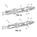
- FIG. 14is an expanded perspective view of the quick-release end effector of FIG. 6 with certain components removed for easier viewing of certain portions of the end effector.
- FIG. 15is an expanded perspective view of the quick-release end effector of FIG. 7 with certain components removed for easier viewing of certain portions of the end effector.
- the various systems and devices disclosed hereinrelate to devices for use in medical procedures and systems. More specifically, various embodiments relate to end effector components or devices that can be used in various procedural devices and systems. For example, certain embodiments relate to quick-release end effector components incorporated into or used with various medical devices, including robotic and/or in vivo medical devices. It is understood that the term “quick-release” as used herein are intended to describe any end effector, forearm, or combination thereof that can be easily and/or quickly coupled and/or uncoupled by anyone in the surgical theater, including any nurse or assistant (in contrast to a component that cannot be coupled or uncoupled quickly or easily or requires someone with technical expertise).
- FIGS. 1A-1Ddepict certain exemplary medical devices and systems that could incorporate a quick-release end effector as disclosed or contemplated herein. More specifically, FIGS. 1A-1C show robotic surgical devices 10 , 12 , 14 having arms 16 A, 16 B, 18 A, 18 B, 20 A, 20 B to which certain end effectors 22 A, 22 B, 24 A, 24 B, 26 A, 26 B have been coupled.
- the end effectors 22 A, 22 B, 24 A, 24 B, 26 A, 26 Bare quick-release end effectors as disclosed herein. Further, FIG. 1D depicts a forearm 28 that has a quick-release end effector 30 .
- any of the various embodiments disclosed hereincan be incorporated into or used with a natural orifice translumenal endoscopic surgical device, such as a NOTES device.
- a NOTES devicesuch as a NOTES device.
- an “in vivo device” as used hereinmeans any device that can be positioned, operated, or controlled at least in part by a user while being positioned into or within a body cavity of a patient, including any device that is positioned substantially against or adjacent to a wall of a body cavity of a patient, further including any such device that is internally actuated (having no external source of motive force), and additionally including any device that may be used laparoscopically or endoscopically during a surgical procedure.
- the terms “robot,” and “robotic device”shall refer to any device that can perform a task either automatically or in response to a command.
- the various end effector embodimentscould be incorporated into various robotic medical device systems that are actuated externally, such as those available from Apollo Endosurgery, Inc., Hansen Medical, Inc., Intuitive Surgical, Inc., and other similar systems, such as any of the devices disclosed in the applications that are incorporated herein elsewhere in this application.
- the various end effector embodimentscan be incorporated into any medical devices that use end effectors.
- FIGS. 2-3Bdepict a quick-release, magnetically-coupled end effector 50 that is releaseably coupleable to forearm 52 , according to one embodiment.
- the end effector 50 in this implementationhas a grasper 54 .
- FIGS. 2-3Bdepict a quick-release, magnetically-coupled end effector 50 that is releaseably coupleable to forearm 52 , according to one embodiment.
- the end effector 50 in this implementationhas a grasper 54 .
- FIGS. 2-3Bdepict a quick-release, magnetically-coupled end effector 50 that is releaseably coupleable to forearm 52 , according to one embodiment.
- the end effector 50 in this implementationhas a grasper 54 .
- the end effector 50also has a mateable coupler 56 , a magnetic collar 58 , a disk 60 , a central rod 68 , a body (also referred to herein as a “forearm body”) 62 that is a slidable cylinder 62 slidably disposed over the rod 68 , a compression spring 70 disposed within the cylinder 62 and over the rod 68 , two leaf springs (one leaf spring 64 is visible in FIG. 2 , while the second leaf spring is positioned on the other side of the cylinder 62 and thus not shown in the figure), and coupling fingers (also referred to as “finger components” or “coupling components”) 66 . As best shown in FIGS.
- the mateable coupler 56has an opening 72 on its proximal side that is configured to receive and be mateable with the coupling projection 84 on the distal end of the forearm 52 (discussed further below).
- the opening 72can contain an o-ring 74 as best shown in FIGS. 3A and 3B that can maintain a sealed connection between the coupler 56 and the projection 84 of the forearm 52 .
- the magnetic collar 58is made up of multiple magnets 58 A, 58 B, 58 C as shown that are positioned on the collar around the full circumference of the end effector 50 .
- the disk 60is fixedly coupled to the central rod 68 via a connection tab 76 that is positioned in a slot 78 (as best shown in FIG. 2 ) in the slidable cylinder 62 such that the cylinder 62 is slidable in relation to the disk 60 as well as the central rod 68 .
- the disk 60can serve as an axial constraint during insertion of the end effector 50 into the forearm 52 and as a bearing during rotation of the end effector 50 in relation to the forearm 52 .
- the first leaf spring 64is electrically connected to one of the blades of the grasper 54 via a wire or other electrical connection (not shown), while the second leaf spring (not shown) is electrically connected to the other of the two blades of the grasper 54 in the same or a similar fashion.
- the blades of the grasper 54are electically isolated from each other.
- the graspers 54can be a cautery tool with electrical energy being transferred to the grasper 54 blades via the leaf springs 64 , not shown, as explained in further detail below.
- the two finger components 66are positioned on opposite sides of the central rod 68 and are attached to the rod 68 at the distal end of the fingers 66 (or along a distal portion of the FIGS. 66 ) such that the fingers 66 do not move axially in relation to the rod 68 .
- the proximal ends of the fingers 66extend proximally farther than the rod 68 and are not coupled to the rod at their proximal ends, thereby allowing the proximal ends of the fingers 66 to be capable of extending radially away from the rod 68 .
- the cylinder 62is slidable laterally along the length of the end effector 50 , and more specifically along the length of the central rod 68 , such that the cylinder 62 can operate in combination with the coupler 56 and the coupling fingers 66 as will be discussed in further detail below to couple the end effector 50 to the forearm 52 .
- the forearm 52has an end effector lumen 80 defined by a fluidically impervious tube 82 such that the lumen 80 is fluidically sealed.
- the lumen 80is capable of receiving an end effector (such as end effector 50 ) while maintaining a complete fluidic or hermetic seal between the lumen 80 (and any fluids in the lumen 80 ) and the interior portions of the forearm 52 .
- the fluidic seal created by the tube 82makes it possible to quickly remove and replace any end effector (such as end effector 50 ) without risking contamination of the interior components of the forearm 52 .
- the lumen 80in one embodiment, has a shoulder 80 B that separates a larger diameter portion 80 A from a smaller diameter portion 80 C.
- the tube 82is positioned in the lumen 80 such that the tube 82 defines the lumen 80 .
- the tube 82is fixedly coupled or affixed to the linear drive component 92 at a proximal end of the tube 82 as best shown in FIG. 3A .
- the tube 82is made of a flexible material such that when the linear drive component 92 is moved laterally as described below, the tube 82 remains attached to the drive component 92 and simply flexes or deforms to accommodate the movement of the drive component 92 .
- the forearm 52has a coupling projection 84 (discussed above), a magnetic ring 86 , and two contact rings 88 , 90 .
- the forearm 52has a linear drive component 92 that has a threaded proximal shaft 94 and a slot 108 defined in a distal portion of the component 92 .
- the threaded shaft 94is a separate component operably coupled to the linear drive component 92 .
- the forearm 52also has a drive cylinder 95 having a threaded lumen (not shown) through which the threaded shaft 94 is positioned such that the threaded shaft 94 is threadably coupled to the drive cylinder 95 .
- two bearings 104 , 106are disposed around the drive cylinder 95 such that the drive cylinder 95 is rotatably positioned within the bearings 104 , 106 .
- Each of the contact rings 88 , 90is positioned around the wall of the tube 82 of the lumen 80 such that each ring 88 , 90 encircles the lumen 80 .
- One of the contact rings 88 , 90is positioned along the length of the lumen 80 such that it is in contact with the leaf spring 64 when the end effector 50 is coupled to the forearm 52 as shown in FIG. 3B , while the other of the two contact rings 88 , 90 is positioned such that it is in contact with the other leaf spring (not shown).
- the leaf springs64 , not shown
- the leaf springsare continuously in contact with the contact rings 88 , 90 , even when the forearm body 62 is rotating.
- each of the contact rings 88 , 90is operably coupled to a separate wire (not shown) that extends to an electrical energy source (such as a cautery generator, for example) such that electrical energy can be transmitted from the power sources to the rings 88 , 90 and—via the contact between the rings 88 , 90 and the leaf springs ( 64 , not shown)—to the leaf springs ( 64 , not shown), and thereby to the grasper 54 blades.
- the grasper 54can be a bipolar cautery tool.
- the end effector 50can also be a monopolar cautery tool if the same electrical energy is supplied to both contact rings 88 , 90 .
- every forearm implementation disclosed or contemplated hereinis configured to be coupleable with a cautery end effector that can operate as either a bipolar or monopolar cautery tool.
- the magnetic ring 86is made up of at least one magnet, and the ring is configured to rotate around the lumen 80 .
- the end effector 50is rotated via the magnetic interaction of the magnetic collar 58 on the end effector 50 and the magnetic ring 86 on the forearm 52 . That is, the motor 102 in the forearm 52 can be actuated to drive the drive gear 98 , which drives the driven gear 96 , which is operably coupled to the magnetic ring 86 such that the magnetic ring 86 is rotated.
- the magnetic ring 86is magnetically coupled to the magnetic collar 58 such that rotation of the magnetic ring 86 causes the magnetic collar 58 to rotate, thereby rotating the end effector 50 . That is, the magnetic coupling of the magnetic ring 86 in the forearm 52 and the magnetic collar 58 on the end effector 50 can cause the rotation of the end effector 50 without a physical connection between the end effector 50 and the forearm 52 .
- the end effector 50is actuated such that the grasper 54 moves between an open position and a closed position via the linear drive component 92 .
- the end effector 50is coupled to the linear drive component 92 via the coupling fingers 66 , which are positioned around the drive component 92 and into a slot 108 defined in the drive component 92 as shown in FIGS. 3A and 3B . That is, the fingers 66 extend proximally beyond the proximal end of the central rod 68 and thus the proximal ends of the fingers 66 can be positioned into the slot 108 as shown.
- the coupling fingers 66do allow the end effector 50 to rotate in relation to the drive component 92 . That is, the fingers 66 are configured to allow for rotation of the fingers 66 in relation to the linear drive component 92 while not allowing for linear movement of the fingers 66 in relation to the linear drive component 92 when the fingers 66 are positioned in the slot 108 as shown in FIG. 3B .
- the coupling component 66instead of coupling fingers 66 , the coupling component 66 consists of any one or more mechanisms or components that are configured to be positioned within the slot 108 as described herein to couple the drive component 92 to the end effector 50 .
- the actuation of the linear drive component 92causes the end effector 50 to be actuated to move linearly. That is, as discussed above, the threaded shaft 94 is threadably coupled at its proximal end to a drive cylinder 95 that can be actuated to cause the threaded shaft 94 to move axially. More specifically, the drive cylinder 95 is operably coupled to a drive gear (not shown) that is operably coupled to a motor (not shown) that can be actuated to rotate the drive gear and thereby rotate the drive cylinder 95 . The rotation of the drive cylinder 95 causes the threaded shaft 94 to move axially via the threaded connection between the drive cylinder 95 and the threaded shaft 94 .
- the threaded shaft 94is configured such that it cannot be rotated. That is, the threaded shaft 94 has a slot 97 defined longitudinally in the shaft 94 such that a projection (also referred to as a “tongue” or “key”) (not shown) coupled to the forearm 52 can be positioned in the slot 97 , thereby preventing the threaded shaft 94 from rotating while allowing the threaded shaft 94 to move axially.
- the linear drive component 92is coupled to the threaded shaft 94 such that rotation of the drive cylinder 95 causes the threaded shaft 94 to move axially, thereby causing the linear drive component 92 to move axially.
- actuation of the drive cylinder 95 by the motorcauses linear movement of the threaded shaft 94 and the linear drive component 92 , thereby causing linear movement of the central rod 68 , which results in the moving of the grasper 54 between an open configuration and a closed configuration via known grasper components for accomplishing the movement between those two configurations.
- the end effector 50is configured to be easily coupled to and uncoupled from the forearm 52 such that a user (such as a surgeon) can easily remove and replace one end effector with another during a medical procedure.
- the end effector 50has been inserted into the lumen 80 but is not yet fully coupled to the forearm 52 . That is, in FIG. 3A , the end effector 50 has been inserted into the lumen 80 such that the central rod 68 is in contact with the linear drive component 92 and the coupling fingers 66 have been positioned in the slot 108 of the drive component 92 , but the coupler 56 has not yet been coupled to the projection 84 . Note that, in this position (in FIG. 3A ), the slidable cylinder 62 is in its retracted position.
- FIG. 3Bthe coupler 56 has been coupled to the projection 84 , thereby coupling the end effector 50 to the forearm 52 for use. That is, the urging of the coupler 56 proximally toward the forearm 52 urges the entire end effector 50 proximally toward the forearm.
- the disk 60 on the end effector 50was already in contact with the shoulder 80 B in the lumen 80 in FIG. 3A , so the disk 60 is restrained by the shoulder 80 B from moving any further into the lumen 80 when the coupler 56 is urged proximally toward the forearm.
- the central rod 68which is directly coupled to the disk 60 such that the rod 68 cannot move linearly in relation to the disk 60 , also is restrained from moving any further into the lumen 80 .
- the cylinder 62which can move linearly in relation to the disk 60 (because the disk 60 , as explained above, is seated in a tab 76 that is slidably positioned in the slot 78 in the cylinder 62 ), moves proximally toward the forearm due to the urging of the coupler 56 proximally. This causes the proximal end of the cylinder 62 to move proximally over the coupling fingers 66 , which are positioned in the slot 108 , as best shown in FIG. 3B .
- the cylinder 62is positioned at least partially over the slot 108 , thereby securing the fingers 66 in the slot 108 , which thereby secures the end effector 50 to the forearm 52 .
- Thisalso causes the tension spring 70 disposed in the cylinder 62 to be compressed, because it is positioned between a shoulder 110 in the cylinder and tabs 112 at the distal end of the fingers 66 . That is, the proximal advancement of the cylinder 62 as described above causes the shoulder 110 to move proximally toward the tabs 112 on the fingers 66 , thereby causing the spring 70 to be compressed as shown.
- the end effector 50can also be removed just as easily.
- the coupler 56is pulled distally away from the forearm 52 , thereby uncoupling the coupler 56 from the projection 84 as best shown in FIG. 3A .
- Thisremoves the restraint placed on the end effector 50 , thereby allowing the compressed spring 70 as shown in FIG. 3B to urge the cylinder 62 distally toward the grasper 54 .
- Thiscauses the proximal end of the cylinder 62 to move distally away from the linear drive component 92 and specifically from the slot 108 , thereby freeing the proximal end of the fingers 66 from their position in the slot 108 , as best shown in FIG. 3A .
- the end effector 50can be removed from the lumen 80 of the forearm 52 .
- end effector 50can be either bipolar or monopolar.
- any of the other end effector embodiments disclosed or contemplated hereincan also be either bipolar or monopolar, except as discussed in detail below with respect to the end effectors 260 , 262 depicted in FIGS. 6-15 .
- FIGS. 4A-4Ddepict another embodiment of a magnetic coupling forearm 150 , to which a quick-release, magnetically-coupled end effector (not shown) can be attached, according to one embodiment.
- the forearm body 150has two sets of magnets (in contrast to one set of magnets in the previous embodiment shown in FIGS. 2-3B ).
- the first magnetic ring 152is positioned at the distal end of the forearm 150 and drives rotation of the end effector (not shown), while the second magnetic ring 154 is positioned at the proximal end of the forearm 150 and drives linear actuation of the end effector (not shown), thereby actuating operation of the end effector.
- both magnetic rings 152 , 154are each made up of at least one magnet. More specifically, in this exemplary embodiment, the first ring 152 is made up of six magnets 156 , while the second ring 154 is also made up of six magnets 158 . Alternatively, each of the rings 152 , 154 is made up of at least one magnet. In a further alternative, the number of magnets in each ring 152 , 154 can range from 1 to as many magnets that can fit in the ring to accomplish the purposes described herein.
- the forearm body 150has an end effector lumen 160 defined by a fluidically impervious tube 162 such that the lumen 160 is fluidically or hermetically sealed, thereby fluidically sealing the internal components of the forearm 150 from any fluids present in the lumen 160 .
- the tube 162is positioned in the lumen 160 such that the tube 162 defines the lumen 160 .
- the lumen 162contains two contact rings 164 , 166 .
- Each ring 152 , 154is configured to rotate around the lumen 160 and thereby actuate the end effector (not shown) as described above. More specifically, the first magnetic ring 152 is caused to rotate and thereby cause a magnetic collar (not shown) or other magnetic component on the end effector (not shown) to rotate via the magnetic coupling between the ring 152 and the collar (not shown), thereby causing the end effector (not shown) to rotate. Further, the second magnetic ring 154 is caused to rotate and cause a second magnetic collar (not shown) or other magnetic component on the end effector (not shown) to rotate via the magnetic coupling between the two components, thereby actuating the end effector to operate.
- Each of the contact rings 164 , 166is positioned around the wall of the tube 162 of the lumen 160 such that each ring 164 , 166 encircles the lumen 160 .
- each of the contact rings 164 , 166is positioned along the length of the lumen 160 such that each is in contact with one contact component on the end effector (not shown).
- the rings 164 , 166would be positioned to contact the leaf springs ( 64 , not shown) of that end effector 50 .
- the rings 164 , 166can be configured to contact any contact component on the end effector that is coupled to the forearm 150 .
- any end effector used with the forearm 150can be a bipolar cautery tool or, alternatively, can be a monopolar cautery tool if the same electrical energy is supplied to both contact rings 164 , 166 .
- the first magnetic ring 152is actuated by a first motor 180 , which is operably coupled to a drive gear 182 , which is operably coupled to a driven gear 184 , which is operably coupled to the first magnetic ring 152 .
- actuation of the first motor 180actuates the first magnetic ring 152 to rotate.
- the second magnetic ring 154is actuated by a second motor 190 , which is operably coupled to a drive gear 192 , which is operably coupled to a driven gear 194 , which is operably coupled to the second magnetic ring 154 .
- actuation of the second motor 180actuates the second magnetic ring 154 to rotate.
- the forearm 150actuates an end effector (not shown) entirely by magnetic couplings, rather than mechanical couplings.
- the first magnetic ring 152rotates the end effector (not shown) via the magnetic interaction between the ring 152 and the corresponding magnetic collar (not shown) or other magnetic component on the end effector (not shown), while the second magnetic ring 154 actuates the end effector (not shown) via the magnetic interaction between the ring 154 and the corresponding magnetic collar (not shown) or other magnetic component on the end effector (not shown).
- the forearm 150is configured to allow for easy coupling and removal of an end effector (not shown), such that a user (such as a surgeon) can easily remove and replace one end effector with another during a medical procedure.
- FIGS. 5A and 5Bdepict another implementation of a quick-release end effector 200 that is releaseably coupleable to a forearm 202 , according to one embodiment. More specifically, this exemplary implementation is configured to allow for coupling the end effector 200 to the forearm 202 with a single ninety degree turn of the end effector 200 once the end effector 200 is positioned within the lumen 220 of the forearm 202 . This embodiment does not utilize magnetic coupling.
- the end effector 200 in this implementationhas a grasper 204 .
- the end effector 200also has a tubular body 206 , a rod (also referred to as a “central rod”) 208 that is disposed within, is slidable in relation to, and extends proximally from the tubular body 206 , two protrusions (the first protrusion 210 is depicted in FIG. 5A and a second protrusion is not shown), a release button 212 , a coupling hook 214 at a proximal end of the central rod 208 , and an o-ring 216 disposed around the tubular body 206 .
- the rod 208has two contact elements (also referred to as “contact strips”) 209 , 211 that are electrically coupled to the blades of the grasper 204 via separate wires or other connection components such that one strip 209 is coupled to one blade and the other strip 211 is coupled to the other blade.
- the central rod 208is operably coupled to the grasper 204 such that linear actuation of the central rod 208 in relation to the tubular body 206 causes the grasper 204 to move between its open and closed configurations.
- the first 210 and second (not shown) protrusionsare positioned on opposite sides of the tubular body 206 and are configured to be positioned within corresponding channels in the forearm 202 as described below.
- the forearm body 202has an end effector lumen 220 defined by a rotatable cylinder 222 such that the cylinder 222 defines the lumen 220 .
- the cylinder 222has a button channel 224 defined in the cylinder 222 to accommodate the release button 212 when the end effector 200 is positioned within the lumen 220 , and two contact rings 226 , 228 .
- the cylinder 222has two longitudinal channels (not shown) defined on opposite sides of the inner wall of the lumen 220 that are configured to receive the first protrusion 210 (as shown in FIG.
- the channels (not shown)both include a substantially ninety degree turn at the proximal end of the channels that results in two axial slots in communication with the longitudinal channels.
- the axial slotsare configured to accommodate the rotation of the end effector 200 as it is coupled to the forearm 202 as described below.
- Each of the contact rings 226 , 228is positioned on the cylinder 222 such that a portion of each ring 226 , 228 is positioned around the inner wall of the cylinder 222 such that each ring encircles the lumen 220 .
- each of the contact rings 226 , 228is positioned along the length of the lumen 220 such that each is in contact with one of the two contact strips 209 , 211 on the rod 208 when the end effector 200 is coupled to the forearm 202 as shown in FIG. 5B . More specifically, the contact ring 226 contacts contact strip 209 while contact ring 228 contacts contact strip 211 .
- the contact strips 209 , 211are continuously in contact with the contact rings 226 , 228 , even when the rod 208 is rotating or moving axially. That is, the strips 209 , 211 are configured to have some longitudinal length as shown in FIG. 5A such that when the rod 208 is actuated to move axially while coupled to the forearm 202 , the strips 209 , 211 remain in contact with the contact rings 226 , 228 despite the fact that the rings 226 , 228 do not move axially.
- each of the contact rings 226 , 228is in contact with a stationary contact ring 227 , 229 disposed in the forearm 202 such that they encircle the cylinder 222 .
- each of the rings 226 , 228also has a portion that is disposed around the external wall of the cylinder 222 such that each ring 226 , 228 contacts one of the two stationary contact rings 227 , 229 as well.
- the grasper 204can be a bipolar cautery tool.
- the end effector 200can also be a monopolar cautery tool if the same electrical energy is supplied to both stationary contact rings 227 , 229 .
- the forearm 202has a linear drive component 230 disposed in a proximal end of the rotatable cylinder 222 .
- the drive component 230has a lumen 232 defined in its distal end, and the lumen 232 has a coupling pin (also referred to as a “hook coupling pin”) 234 extending from one side of the lumen 232 to the other.
- the pin 234is configured to be coupleable with the coupling hook 214 of the end effector 200 as will be described in further detail below.
- the drive component 230also has a coupling pin (also referred to as a “cylinder coupling pin”) 235 that extends beyond the outer circumference of the drive component 230 such that the ends of the pin 235 are positioned in slots 237 A, 237 B defined in the inner wall of the rotatable cylinder 222 .
- the pin 235is fixedly coupled to the drive component 230 .
- Each of these slots 237 A, 237 Bhas a length that extends longitudinally along the length of the rotatable cylinder 222 .
- this pin 235is slidably positioned in the slots 237 A, 237 B such that the drive component 230 can be moved linearly but cannot rotate in relation to the rotatable cylinder 222 .
- any rotation of the drive component 230causes rotation of the rotatable cylinder 222 .
- This configurationprevents the hook 214 from becoming decoupled from the pin 234 . That is, the pin 235 prevents the drive component 230 from rotating in relation to the rotatable cylinder 222 , thereby ensuring the hook 214 remains coupled to the pin 234 .
- the proximal end of the drive component 230has an externally threaded proximal shaft (also referred to as a linear translation component) 236 .
- the shaft 236is a separate component operably coupled to the drive component 230 , via a retaining ring 241 .
- the retaining ring 241results in the drive component 230 being capable of rotating in relation to the linear translation component 236 .
- the shaft 236is prevented from rotating by a groove (not shown) defined in the shaft 236 that mates with a tongue 243 .
- the shaft 236is positioned within a lumen 238 in a rotatable linear drive component 239 and is threadably coupled to the internal threads defined in the lumen 238 .
- the forearm 202also has a motor 240 coupled to a drive gear 244 via a drive shaft 242 .
- the drive gear 244is coupled to a driven gear 246 that encircles and is coupled to the rotatable cylinder 222 such that rotation of the driven gear 246 causes the rotatable cylinder 222 to rotate.
- the end effector 200is rotated via the motor 240 that is operably coupled to the driven gear 246 . That is, the motor 240 in the forearm 202 can be actuated to drive the drive gear 244 , which drives the driven gear 246 , which is operably coupled to the rotatable cylinder 222 as described above such that the rotatable cylinder 222 is rotated.
- the rotatable cylinder 222is coupled to the end effector 200 when the end effector 200 is fully seated in the lumen 220 of the forearm 202 such that rotation of the rotatable cylinder 222 causes the end effector 200 to rotate. That is, as best shown in FIG.
- the first protrusion 210 and second protrusionare positioned in the channels (not shown) in the lumen 220 such that the tubular body 206 is coupled to the cylinder 222 such that the tubular body 206 rotates when the cylinder 222 rotates.
- the end effector 200is actuated such that the grasper 204 moves between an open position and a closed position via the linear drive component 230 .
- the end effector 200is coupled to the linear drive component 230 via the coupling hook 214 , which is positioned into the lumen 232 of the drive component 230 and around the pin 234 positioned in the lumen 232 . That is, during insertion of the end effector 200 into the forearm 202 , the hook 214 is positioned into the lumen 232 prior to the substantially ninety degree rotation of the end effector 200 such that the hook 214 extends proximally past the pin 234 .
- the hook 214couples to the pin 234 and thereby couples the end effector 200 to the drive component 230 .
- the coupling of the drive component 230 to the end effector 200 via the hook 214 and pin 234results in the end effector 200 being linearly coupled to the linear drive component 230 such that the end effector 200 cannot move linearly in relation to the drive component 230 .
- the actuation of the linear drive component 230causes the end effector 200 to be actuated to move linearly. That is, the rotatable linear drive component 239 is coupled at its proximal end to a driven gear 250 that is coupled to a drive gear (not shown), which is coupled to a motor (not shown) that can be actuated to rotate the driven gear 250 and thus the rotatable drive component 239 .
- the threaded section 236 of the linear drive component 230is positioned in and threadably connected with the lumen 238 in the rotatable drive component 239 . As a result, rotation of the drive component 239 causes the linear drive component 230 to move axially.
- actuation of the drive component 239 by the motorcauses linear movement of the linear drive component 230 , thereby causing linear movement of the central rod 208 , which results in the moving of the grasper 204 between an open configuration and a closed configuration via known grasper components for accomplishing the movement between those two configurations.
- the end effector 200is configured to be easily coupled to and uncoupled from the forearm 202 such that a user (such as a surgeon) can easily remove and replace one end effector with another during a medical procedure.
- a usersuch as a surgeon
- the end effector 200is inserted into the lumen 220 such that the first protrusion 210 and second protrusion (not shown) are positioned in the channels (not shown) in the lumen 220 .
- the hook 214will advance proximally until it moves into the lumen 232 and past the pin 234 .
- the protrusions 212are also advanced as far proximally as possible along the channels (not shown).
- the userrotates the end effector 200 , thereby coupling the hook 214 to the pin 234 and advancing the protrusions 212 (and not shown) along the axial slots described above.
- a usercan couple the end effector 200 to the forearm 202 via two mechanisms with a single twist or rotation of the end effector 200 .
- the end effector 200can also be easily removed.
- the release button 212 on the end effector 200is operably coupled to the coupling hook 214 such that actuation of the button 212 causes the hook 214 to uncouple from the pin 234 .
- a usercan depress the button 212 and then rotate or twist the end effector 200 (in the opposite direction of that required to couple the end effector 200 ).
- the rotation of the end effector 200moves the protrusions 212 (and not shown) along the axial slots (not shown) so that the protrusions 212 (and not shown) are positioned in the channels (not shown) such that they can move distally along the channels (not shown).
- the end effector 200can be removed from the lumen 220 of the forearm 202 .
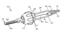
- FIGS. 6-14depict certain additional embodiments of quick-release end effectors 260 , 262 that are releaseably coupleable to a forearm 264 , according to one embodiment. More specifically, these exemplary implementations are configured to allow for coupling of the end effector 260 , 262 to the forearm 264 with a single turn of the end effector 260 , 262 once the end effector 260 , 262 is positioned within the lumen 300 of the forearm 264 .
- the end effector 260in one implementation has a grasper 266 .
- the end effector 260also has a tubular body 270 , a rod (also referred to herein as a “central rod”) 272 that is disposed within and is rotatable in relation to the tubular body 270 and has a rod coupling component 274 that extends proximally from the tubular body 270 , a handle 276 , an end effector coupling component 278 , torque transfer protrusions 280 , two contact rings 282 , 284 , an o-ring 286 adjacent to the handle 276 , and a pin hole 290 defined in the tubular body 270 . Further, as best shown in FIG.
- the first contact ring 282is coupled to a first contact wire 400 that extends from the contact ring 282 to the distal end of the end effector 260 , where the wire 400 is operably coupled to a proximal portion of one arm 266 A of the grasper 266 .
- the second contact ring 284is coupled to a second contact wire 402 that extends from the ring 284 to the distal end of the end effector 260 , where the wire 402 is operably coupled to a proximal portion of the other arm 266 B of the grasper 266 .
- each of the two contact rings 282 , 284is electrically coupled to one of the grasper arms 266 A, 266 B such that electrical energy can be separately transferred from each of the rings 282 , 284 to one of the arms 266 A, 266 B, thereby resulting in a bipolar grasper 266 .
- the central rod 272is operably coupled to the grasper 266 such that rotational actuation of the central rod 272 (via the rod coupling component 274 ) in relation to the tubular body 270 causes the grasper 266 to move between its open and closed configurations.
- the end effector coupling component 278has male protrusions 288 that mate with female channels 380 on the forearm such that protrusions 288 can be positioned into the channels 380 and the end effector 260 can be coupled to the forearm 264 with a single twist or rotation of the end effector 260 .
- the torque transfer protrusions 280are formed or positioned around the tubular body 270 and are configured to be positioned within corresponding torque transfer channels 304 in the forearm 264 as described below such that the end effector 260 is not rotatable in relation to the forearm 264 when the protrusions 280 are seated in the channels 304 .
- the ends of the torque transfer protrusions 280are tapered to make it easier to align the protrusions 280 with the channels 304 .
- there are four protrusions 280(with three visible in the figure).
- the end effector 262can have a pair of scissors 268 as shown in FIG. 7 .
- the other components of this end effector 262are substantially the same as those of the end effector 260 depicted in FIG. 6 and discussed above. As such, those components are identified with the same reference numbers such that the discussion above applies equally to these components as well.
- One differencein certain embodiments, relates to the electrical coupling of the contact rings 282 , 284 to the scissor arms 268 A, 268 B. That is, according to some embodiments, both arms 268 A, 268 B are electrically coupled to both rings 282 , 284 , thereby resulting in a monopolar pair of scissors 268 as will be described in further detail below.
- the first contact ring 282is coupled to a first contact wire 400 that extends from the contact ring 282 to the distal end of the end effector 262 , where the wire 400 is operably coupled to a proximal portion of the pair of scissors 268 such that the contact ring 282 is electrically coupled to both arms 268 A, 268 B of the pair 268 .
- the second contact ring 284is coupled to a second contact wire 402 that extends from the ring 284 to the distal end of the end effector 262 , where the wire 402 is operably coupled to a proximal portion of the pair of scissors 268 such that the contact ring 284 is electrically coupled to both arms 268 A, 268 B of the pair 268 .
- each of the two contact rings 282 , 284is electrically coupled to both scissor arms 268 A, 268 B such that electrical energy is transferred from both rings 282 , 284 to both arms 266 A, 266 B, thereby resulting in a monopolar grasper 268 .
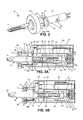
- the forearm body 264has an end effector lumen 300 defined by a rotatable cylinder 302 (as best shown in FIGS. 8, 9A, and 9B ) such that the cylinder 302 defines the lumen 300 .
- the cylinder 302has torque transfer channels 304 , two electrical contact components 306 , 308 , a rotational gear 310 defined or positioned around an external wall of the cylinder 302 , an o-ring 316 disposed around the cylinder, and a seal (a “ring seal” or “lip seal” in this embodiment) 318 disposed around the distal opening of the lumen 300 .
- the torque transfer channels 304are defined in the cylinder 302 to accommodate the torque transfer protrusions 280 of either end effector 260 / 262 when that end effector 260 / 262 is positioned within the lumen 300 .
- the channels 304are tapered to make it easier to align the protrusions 280 with the channels 304 .
- the two electrical contact components 306 , 308are contact leaflets 306 , 308 that are electrically coupled to contact rings 312 , 314 (as best shown in FIG. 9B ) (such that the electrical contact component 306 is coupled to the contact ring 312 and contact component 308 is coupled to the contact ring 314 ).
- the contact rings 312 , 314are disposed along the inner wall of the lumen 300 and are positioned along the length of the lumen 300 such that they are configured to be in contact with the contact rings 282 , 284 on the end effector 260 / 262 when the end effector 260 / 262 is coupled to the forearm 264 .
- the contact leaflet pair 306 , 308extend away from the cylinder 302 in the proximal direction.
- the contact leaflets 306 , 308can extend away from the cylinder 302 in the distal direction.
- the contact components 306 , 308can each have any known configuration for a contact component.
- the lip seal 318operates to serve as the primary seal to retain the fluidic seal of the forearm 264 , thereby preventing fluid from accessing the forearm 264 .
- the o-ring 316(as also best shown in FIGS. 9A and 9B ), according to one embodiment, can operate to serve as a structural support with respect to the cylinder 302 , retaining the cylinder 302 in position in relation to the forearm 264 while allowing the cylinder 302 to rotate.
- the o-ring 316can also operate as a backup to the lip seal 318 , thereby providing a fluidic seal that prevents any fluid that gets past the lip seal 318 from accessing the internal components of the forearm 264 . Further, according to another implemention, the o-ring 316 can also serve to retain lubricant disposed between the lip seal 318 and the o-ring 316 .
- the seal (not shown) for retaining the fluidic seal of the forearm 264can instead extend from an inner lumen of the forearm 264 —such as a portion of the forearm 264 proximal to the female channels 380 —and contact the rotatable cylinder 302 , thereby providing the desired fluidic seal for the forearm 264 as described above.
- the forearm 264has a rotatable linear drive component 330 disposed in the forearm 264 proximally to the rotatable cylinder 302 , as best shown in FIGS. 8 and 10 .
- the drive component 330has a lumen 332 defined in its distal end (as best shown in FIG. 10 ), and the lumen 332 has teeth 334 extending from the inner wall of the lumen 332 that are configured to mate with the rod coupling component 274 on the proximal end of the end effector 260 / 262 .
- the lumen 332can have any type of structure or mechanism—such as ribs, threads, channels, or the like—for mating with or coupling to the rod coupling component 274 .
- the drive component 330has an external structural feature 336 , a seal 338 (such as a “ring seal”), and an o-ring 340 .
- the ring seal 338 and o-ring 40can function in substantially the same fashion as the seal 318 and o-ring 316 discussed above.
- the external structural feature 336is an external hexagon 336 as best shown in FIG. 10 that is configured to mate with a driven gear 342 operably coupled with a drive gear 344 that is operably coupled with a motor 346 (as best shown in FIG. 8 ) such that actuation of the motor 346 causes the rotation of the rotatable drive component 330 .
- the seal (not shown) for retaining the fluidic sealcan instead extend from the lumen 300 of the rotatable cylinder 302 and contact the rotatable linear drive component 330 , thereby providing the desired fluidic seal.
- the rod coupling component 274 of the end effector 260 / 262is positioned within the lumen 332 of the drive component 330 and thereby coupled to the rotatable drive component 330 .
- the rod coupling component 274is caused to rotate, thereby rotating the central rod 272 of the end effector 260 / 262 .
- the central rod 272is disposed within housing 273 and has a slot 294 defined around the outer circumference of the rod 272 that is configured to receive the pin 292 , which is best shown in FIGS. 12, 14, and 16 .
- the pin 292is positioned through the pin hole 290 in the tubular body 270 as best shown in FIGS. 6 and 7 .
- the pin 292is positioned in the slot 294 such that the rod 272 can rotate but cannot move axially when the pin 292 is in the slot 294 .
- the housing 273has a protrusion similar to the pin 292 that extends from an inner lumen of the housing 273 such that the protrusion can be positioned in the slot 294 in a fashion similar to the pin 292 , thereby allowing the rod 272 to rotate but not move axially.
- the central rod 272has an externally threaded section 390 on its distal end which threadably couples with a linear drive component 392 such that rotation of the central rod 272 causes the linear drive component 392 to move linearly.
- the linear drive component 392is operably coupled to the grasper 266 or pair of scissors 268 such that linear movement of the drive component 392 causes the grasper 266 or pair of scissors 268 to move between open and closed configurations.
- the rotation of the central rod 272causes the grasper 266 or pair of scissors 268 to move between open and closed positions.
- the forearm 264also has a motor 350 coupled to a drive gear 352 .
- the drive gear 352is coupled to the rotational gear 310 on the rotatable cylinder 302 (as best shown in FIG. 9A ) such that rotation of the drive gear 352 causes the rotatable cylinder 302 to rotate.
- the rotatable cylinder 302is coupled to the end effector 260 / 262 when the end effector 260 / 262 is fully seated in the lumen 300 of the forearm 264 such that rotation of the rotatable cylinder 302 causes the end effector 260 / 262 to rotate. That is, the protrusions 280 are positioned in the channels 304 in the lumen 300 such that the tubular body 270 is coupled to the cylinder 302 such that the tubular body 270 rotates when the cylinder 302 rotates.
- the forearm 264also has a support cylinder 360 positioned around the rotatable cylinder 302 and having a lumen 362 such that the rotatable cylinder 302 can be positioned in the lumen 362 and rotate in relation to the support cylinder 360 .
- the support cylinder 360(shown in dotted lines) has two inner contact rings 364 , 366 disposed on the inner wall of the support cylinder lumen 362 . The two rings 364 , 366 are configured to be in contact with the two contact leaflet pairs 306 , 308 on the rotatable cylinder 302 .
- both of the end effectors 260 , 262are configured to be easily coupled to and uncoupled from the forearm 264 such that a user (such as a surgeon) can easily remove and replace one end effector with another during a medical procedure.
- a usersuch as a surgeon
- the end effector 260 / 262is inserted into the lumen 300 such that the torque transfer protrusions 280 are positioned in the channels 304 in the lumen 300 .
- the rod coupling component 274will advance proximally until it is positioned in the lumen 332 of the rotatable drive component 330 and mates with the teeth 334 therein.
- the proximal advancement of the end effector 260 / 262causes the male protrusions 288 on the end effector coupling component 278 to advance proximally into the female channels 380 defined in the distal end of the forearm 264 , as best shown in FIG. 8 .
- the female channels 380are configured such that once the protrusions 288 have been advanced proximally into the channels 380 , the end effector 260 / 262 can be rotated via the handle 276 by a user to cause the protrusions 288 to rotate in the channels 288 , thereby securing the end effector 260 / 262 to the forearm 264 .
- a usercan couple the end effector 260 / 262 to the forearm 264 with a single twist or rotation of the end effector 260 / 262 .
- the usercan also remove the end effector 260 / 262 in the same fashion by simply twisting or rotating the handle 276 in the opposite direction.
- any lumen in any forearm device described or contemplated hereinis configured to be easy to sterilize. That is, each lumen is configured to have no crevices or other features that are inaccessible or difficult to access during sterilization. Further, certain embodiments have lumens that have dimensions that make for easy sterilization. That is, such lumens have a length that is sufficiently short and a diameter that is sufficiently large to be accessible by appropriate sterilization tools and techniques. In one specific example, any one or more of the lumens disclosed or contemplated herein can have an inside diameter of at least 3 mm and a length of 400 mm or shorter. Alternatively, the lumen(s) can have an inside diameter of at least 2 mm and a length of 250 mm or shorter. In a further alternative, the lumen(s) can have an inside diameter of at least 1 mm and a length of 125 mm or shorter. In yet another alternative, the lumen(s) can have any dimensions that simplify sterilization.
- the various forearm and end effector embodiments disclosed or contemplated hereinprovide for easy, quick coupling and uncoupling of the end effector to the forearm while providing for one or even two mechanical couplings or interfaces and one or two electrical couplings or interfaces. That is, the various embodiments disclosed herein allow for simple attachment of an end effector to a forearm while also providing up to two electrical couplings and up to two mechanical couplings between the forearm and the end effector.
Landscapes
- Health & Medical Sciences (AREA)
- Surgery (AREA)
- Life Sciences & Earth Sciences (AREA)
- Engineering & Computer Science (AREA)
- Veterinary Medicine (AREA)
- Molecular Biology (AREA)
- Nuclear Medicine, Radiotherapy & Molecular Imaging (AREA)
- Public Health (AREA)
- Biomedical Technology (AREA)
- Heart & Thoracic Surgery (AREA)
- Medical Informatics (AREA)
- General Health & Medical Sciences (AREA)
- Animal Behavior & Ethology (AREA)
- Ophthalmology & Optometry (AREA)
- Robotics (AREA)
- Otolaryngology (AREA)
- Plasma & Fusion (AREA)
- Physics & Mathematics (AREA)
- Surgical Instruments (AREA)
- Manipulator (AREA)
Abstract
Description
Claims (14)
Priority Applications (3)
| Application Number | Priority Date | Filing Date | Title |
|---|---|---|---|
| US14/853,477US10342561B2 (en) | 2014-09-12 | 2015-09-14 | Quick-release end effectors and related systems and methods |
| US16/504,793US11576695B2 (en) | 2014-09-12 | 2019-07-08 | Quick-release end effectors and related systems and methods |
| US18/167,953US12390240B2 (en) | 2014-09-12 | 2023-02-13 | Quick-release end effectors and related systems and methods |
Applications Claiming Priority (2)
| Application Number | Priority Date | Filing Date | Title |
|---|---|---|---|
| US201462049419P | 2014-09-12 | 2014-09-12 | |
| US14/853,477US10342561B2 (en) | 2014-09-12 | 2015-09-14 | Quick-release end effectors and related systems and methods |
Related Child Applications (1)
| Application Number | Title | Priority Date | Filing Date |
|---|---|---|---|
| US16/504,793ContinuationUS11576695B2 (en) | 2014-09-12 | 2019-07-08 | Quick-release end effectors and related systems and methods |
Publications (2)
| Publication Number | Publication Date |
|---|---|
| US20160074120A1 US20160074120A1 (en) | 2016-03-17 |
| US10342561B2true US10342561B2 (en) | 2019-07-09 |
Family
ID=55453639
Family Applications (3)
| Application Number | Title | Priority Date | Filing Date |
|---|---|---|---|
| US14/853,477Active2038-04-22US10342561B2 (en) | 2014-09-12 | 2015-09-14 | Quick-release end effectors and related systems and methods |
| US16/504,793Active2037-11-06US11576695B2 (en) | 2014-09-12 | 2019-07-08 | Quick-release end effectors and related systems and methods |
| US18/167,953Active2036-06-04US12390240B2 (en) | 2014-09-12 | 2023-02-13 | Quick-release end effectors and related systems and methods |
Family Applications After (2)
| Application Number | Title | Priority Date | Filing Date |
|---|---|---|---|
| US16/504,793Active2037-11-06US11576695B2 (en) | 2014-09-12 | 2019-07-08 | Quick-release end effectors and related systems and methods |
| US18/167,953Active2036-06-04US12390240B2 (en) | 2014-09-12 | 2023-02-13 | Quick-release end effectors and related systems and methods |
Country Status (5)
| Country | Link |
|---|---|
| US (3) | US10342561B2 (en) |
| EP (3) | EP4487795A3 (en) |
| JP (4) | JP6710199B2 (en) |
| CA (1) | CA2961213A1 (en) |
| WO (1) | WO2016040946A1 (en) |
Cited By (17)
| Publication number | Priority date | Publication date | Assignee | Title |
|---|---|---|---|---|
| US20180055584A1 (en)* | 2016-08-30 | 2018-03-01 | Board Of Regents Of The University Of Nebraska | Robotic Device with Compact Joint Design and an Additional Degree of Freedom and Related Systems and Methods |
| US11284958B2 (en) | 2016-11-29 | 2022-03-29 | Virtual Incision Corporation | User controller with user presence detection and related systems and methods |
| US11576695B2 (en)* | 2014-09-12 | 2023-02-14 | Virtual Incision Corporation | Quick-release end effectors and related systems and methods |
| US11819299B2 (en) | 2012-05-01 | 2023-11-21 | Board Of Regents Of The University Of Nebraska | Single site robotic device and related systems and methods |
| US11826014B2 (en) | 2016-05-18 | 2023-11-28 | Virtual Incision Corporation | Robotic surgical devices, systems and related methods |
| US11826032B2 (en) | 2013-07-17 | 2023-11-28 | Virtual Incision Corporation | Robotic surgical devices, systems and related methods |
| US11832871B2 (en) | 2011-06-10 | 2023-12-05 | Board Of Regents Of The University Of Nebraska | Methods, systems, and devices relating to surgical end effectors |
| US11832902B2 (en) | 2012-08-08 | 2023-12-05 | Virtual Incision Corporation | Robotic surgical devices, systems, and related methods |
| US11872090B2 (en) | 2015-08-03 | 2024-01-16 | Virtual Incision Corporation | Robotic surgical devices, systems, and related methods |
| US11903658B2 (en) | 2019-01-07 | 2024-02-20 | Virtual Incision Corporation | Robotically assisted surgical system and related devices and methods |
| US11909576B2 (en) | 2011-07-11 | 2024-02-20 | Board Of Regents Of The University Of Nebraska | Robotic surgical devices, systems, and related methods |
| US11950867B2 (en) | 2018-01-05 | 2024-04-09 | Board Of Regents Of The University Of Nebraska | Single-arm robotic device with compact joint design and related systems and methods |
| US11974824B2 (en) | 2017-09-27 | 2024-05-07 | Virtual Incision Corporation | Robotic surgical devices with tracking camera technology and related systems and methods |
| US12070282B2 (en) | 2013-03-14 | 2024-08-27 | Board Of Regents Of The University Of Nebraska | Methods, systems, and devices relating to force control surgical systems |
| US12096999B2 (en) | 2014-11-11 | 2024-09-24 | Board Of Regents Of The University Of Nebraska | Robotic device with compact joint design and related systems and methods |
| US12156710B2 (en) | 2011-10-03 | 2024-12-03 | Virtual Incision Corporation | Robotic surgical devices, systems and related methods |
| US12295680B2 (en) | 2012-08-08 | 2025-05-13 | Board Of Regents Of The University Of Nebraska | Robotic surgical devices, systems and related methods |
Families Citing this family (8)
| Publication number | Priority date | Publication date | Assignee | Title |
|---|---|---|---|---|
| CN109310478B (en)* | 2016-05-26 | 2021-08-03 | 西门子保健有限责任公司 | 3D-printed robot for holding medical instruments during surgery and its controls |
| EP3541219B1 (en) | 2016-11-16 | 2024-01-24 | Wink Robotics | Eyelid covering and stabilization for automatic eyelash extension |
| IL269091B2 (en) | 2017-03-08 | 2024-04-01 | Momentis Surgical Ltd | Electrosurgery device |
| US11350977B2 (en)* | 2017-03-08 | 2022-06-07 | Memic Innovative Surgery Ltd. | Modular electrosurgical device |
| EP3870412B1 (en)* | 2018-10-25 | 2023-12-13 | Wink Robotics | Detachable end effectors for cosmetics robotics |
| US11628023B2 (en)* | 2019-07-10 | 2023-04-18 | Globus Medical, Inc. | Robotic navigational system for interbody implants |
| EP4110221A1 (en)* | 2020-02-26 | 2023-01-04 | Covidien LP | Robotic surgical instrument including linear encoders for measuring cable displacement |
| EP4588627A1 (en)* | 2024-01-18 | 2025-07-23 | Fundació Institut Hospital del Mar d'Investigacions Mèdiques | Electrosurgical device for coagulating biological tissue |
Citations (398)
| Publication number | Priority date | Publication date | Assignee | Title |
|---|---|---|---|---|
| US3870264A (en) | 1973-03-26 | 1975-03-11 | William I Robinson | Stand |
| JPS5115425A (en) | 1974-07-29 | 1976-02-06 | Yashica Co Ltd | DENJIRERIIZUSHIKISUCHIIRUKAMERANIOKERU MOOTADORAIBUSOCHI |
| US3989952A (en) | 1973-08-06 | 1976-11-02 | Siemens Aktiengesellschaft | Dental apparatus |
| US4246661A (en) | 1979-03-15 | 1981-01-27 | The Boeing Company | Digitally-controlled artificial hand |
| US4258716A (en) | 1978-02-06 | 1981-03-31 | The University Of Melbourne | Microsurgical instruments |
| US4278077A (en) | 1978-07-27 | 1981-07-14 | Olympus Optical Co., Ltd. | Medical camera system |
| US4538594A (en) | 1982-11-26 | 1985-09-03 | Richard Wolf Gmbh | Rectoscope |
| US4568311A (en) | 1982-01-29 | 1986-02-04 | Hitachi, Ltd. | Flexible wrist mechanism |
| US4579476A (en)* | 1983-10-18 | 1986-04-01 | Jean Walterscheid Gmbh | Drive shaft coupling mechanism with safety latch |
| US4623183A (en) | 1983-09-30 | 1986-11-18 | Kabushiki Kaisha Toshiba | Robot hand |
| US4736645A (en) | 1985-07-19 | 1988-04-12 | Kuka-Schweissanlagen+Roboter Gmbh | Gear unit for a manipulator |
| US4771652A (en) | 1985-12-19 | 1988-09-20 | Kuka Schweissanlagen+Roboter Gmbh | Manipulator-head drive assembly |
| US4852391A (en) | 1986-04-14 | 1989-08-01 | Den Norske Stats Oljeselskap A.S. | Pipeline vehicle |
| US4896015A (en) | 1988-07-29 | 1990-01-23 | Refractive Laser Research & Development Program, Ltd. | Laser delivery system |
| US4897014A (en) | 1988-09-06 | 1990-01-30 | Harbor Branch Oceanographic Institution, Inc. | Device for interchange of tools |
| US4922755A (en) | 1987-12-28 | 1990-05-08 | Hitachi, Ltd. | Wrist mechanism of industrial robot |
| US4922782A (en) | 1985-09-20 | 1990-05-08 | Doryokuro Kakunenryo Kaihatsu Jigyodan | Manipulator shoulder mechanism |
| US4990050A (en) | 1984-10-15 | 1991-02-05 | Tokico Ltd. | Wrist mechanism |
| US5019968A (en) | 1988-03-29 | 1991-05-28 | Yulan Wang | Three-dimensional vector processor |
| US5108140A (en) | 1988-04-18 | 1992-04-28 | Odetics, Inc. | Reconfigurable end effector |
| WO1992021291A2 (en) | 1991-05-29 | 1992-12-10 | Origin Medsystems, Inc. | Apparatus and method for peritoneal retraction |
| US5172639A (en) | 1991-03-26 | 1992-12-22 | Gas Research Institute | Cornering pipe traveler |
| US5176649A (en) | 1991-01-28 | 1993-01-05 | Akio Wakabayashi | Insertion device for use with curved, rigid endoscopic instruments and the like |
| US5178032A (en) | 1990-10-04 | 1993-01-12 | Comau Spa | Robot wrist |
| US5187032A (en) | 1990-04-17 | 1993-02-16 | Yuasa Battery Co., Ltd. | Solid polymer electrolytes |
| US5187796A (en) | 1988-03-29 | 1993-02-16 | Computer Motion, Inc. | Three-dimensional vector co-processor having I, J, and K register files and I, J, and K execution units |
| US5195388A (en) | 1990-10-04 | 1993-03-23 | Comau Spa | Articulated robot |
| US5201325A (en) | 1989-09-01 | 1993-04-13 | Andronic Devices Ltd. | Advanced surgical retractor |
| US5217003A (en) | 1991-03-18 | 1993-06-08 | Wilk Peter J | Automated surgical system and apparatus |
| US5263382A (en) | 1992-04-13 | 1993-11-23 | Hughes Aircraft Company | Six Degrees of freedom motion device |
| US5271384A (en) | 1989-09-01 | 1993-12-21 | Mcewen James A | Powered surgical retractor |
| US5284096A (en) | 1991-08-06 | 1994-02-08 | Osaka Gas Company, Limited | Vehicle for use in pipes |
| US5297443A (en) | 1992-07-07 | 1994-03-29 | Wentz John D | Flexible positioning appendage |
| US5297536A (en) | 1992-08-25 | 1994-03-29 | Wilk Peter J | Method for use in intra-abdominal surgery |
| US5304899A (en) | 1991-08-30 | 1994-04-19 | Nippondenso Co., Ltd. | Energy supply system to robot within pipe |
| US5307447A (en) | 1982-10-29 | 1994-04-26 | Kabushiki Kaisha Toshiba | Control system of multi-joint arm robot apparatus |
| US5353807A (en) | 1992-12-07 | 1994-10-11 | Demarco Thomas J | Magnetically guidable intubation device |
| US5363935A (en) | 1993-05-14 | 1994-11-15 | Carnegie Mellon University | Reconfigurable mobile vehicle with magnetic tracks |
| US5382885A (en) | 1993-08-09 | 1995-01-17 | The University Of British Columbia | Motion scaling tele-operating system with force feedback suitable for microsurgery |
| JPH07136173A (en) | 1993-11-15 | 1995-05-30 | Olympus Optical Co Ltd | Manipulator for operation |
| US5436542A (en) | 1994-01-28 | 1995-07-25 | Surgix, Inc. | Telescopic camera mount with remotely controlled positioning |
| US5441494A (en) | 1993-07-29 | 1995-08-15 | Ethicon, Inc. | Manipulable hand for laparoscopy |
| US5458583A (en) | 1993-01-07 | 1995-10-17 | Medical Innovations Corporation | Gastrostomy catheter system |
| US5458598A (en) | 1993-12-02 | 1995-10-17 | Cabot Technology Corporation | Cutting and coagulating forceps |
| US5458131A (en) | 1992-08-25 | 1995-10-17 | Wilk; Peter J. | Method for use in intra-abdominal surgery |
| US5471515A (en) | 1994-01-28 | 1995-11-28 | California Institute Of Technology | Active pixel sensor with intra-pixel charge transfer |
| WO1996010957A1 (en) | 1994-10-11 | 1996-04-18 | Klieman Charles H M D | Endoscopic instrument with detachable end effector |
| US5515478A (en) | 1992-08-10 | 1996-05-07 | Computer Motion, Inc. | Automated endoscope system for optimal positioning |
| US5524180A (en) | 1992-08-10 | 1996-06-04 | Computer Motion, Inc. | Automated endoscope system for optimal positioning |
| US5522669A (en)* | 1993-12-13 | 1996-06-04 | Recker; Florian B. | Torque transmitting coupling device |
| US5553198A (en) | 1993-12-15 | 1996-09-03 | Computer Motion, Inc. | Automated endoscope system for optimal positioning |
| JPH08224248A (en) | 1995-02-23 | 1996-09-03 | Olympus Optical Co Ltd | Mdical manipulator |
| US5562448A (en) | 1990-04-10 | 1996-10-08 | Mushabac; David R. | Method for facilitating dental diagnosis and treatment |
| WO1996039944A1 (en) | 1995-06-07 | 1996-12-19 | Sri International | Surgical manipulator for a telerobotic system |
| US5588442A (en) | 1992-08-12 | 1996-12-31 | Scimed Life Systems, Inc. | Shaft movement control apparatus and method |
| US5620417A (en) | 1994-07-07 | 1997-04-15 | Cardiovascular Imaging Systems Incorporated | Rapid exchange delivery catheter |
| US5623582A (en) | 1994-07-14 | 1997-04-22 | Immersion Human Interface Corporation | Computer interface or control input device for laparoscopic surgical instrument and other elongated mechanical objects |
| US5624380A (en) | 1992-03-12 | 1997-04-29 | Olympus Optical Co., Ltd. | Multi-degree of freedom manipulator |
| US5624398A (en) | 1996-02-08 | 1997-04-29 | Symbiosis Corporation | Endoscopic robotic surgical tools and methods |
| US5632761A (en) | 1991-05-29 | 1997-05-27 | Origin Medsystems, Inc. | Inflatable devices for separating layers of tissue, and methods of using |
| US5645520A (en) | 1994-10-12 | 1997-07-08 | Computer Motion, Inc. | Shape memory alloy actuated rod for endoscopic instruments |
| US5657429A (en) | 1992-08-10 | 1997-08-12 | Computer Motion, Inc. | Automated endoscope system optimal positioning |
| US5657584A (en) | 1995-07-24 | 1997-08-19 | Rensselaer Polytechnic Institute | Concentric joint mechanism |
| US5672168A (en) | 1994-10-07 | 1997-09-30 | De La Torre; Roger A. | Laparoscopic access port for surgical instruments or the hand |
| US5674030A (en) | 1991-08-27 | 1997-10-07 | Sika Equipment Ag. | Device and method for repairing building branch lines in inacessible sewer mains |
| JPH106155A (en) | 1996-06-21 | 1998-01-13 | Honda Motor Co Ltd | Assembly work support table |
| US5728599A (en) | 1993-10-28 | 1998-03-17 | Lsi Logic Corporation | Printable superconductive leadframes for semiconductor device assembly |
| US5736821A (en) | 1992-12-28 | 1998-04-07 | Tokyo Gas Co., Ltd. | Intrapipe work robot apparatus and method of measuring position of intrapipe work robot |
| US5754741A (en) | 1992-08-10 | 1998-05-19 | Computer Motion, Inc. | Automated endoscope for optimal positioning |
| US5762458A (en) | 1996-02-20 | 1998-06-09 | Computer Motion, Inc. | Method and apparatus for performing minimally invasive cardiac procedures |
| US5769640A (en) | 1992-12-02 | 1998-06-23 | Cybernet Systems Corporation | Method and system for simulating medical procedures including virtual reality and control method and system for use therein |
| US5792135A (en) | 1996-05-20 | 1998-08-11 | Intuitive Surgical, Inc. | Articulated surgical instrument for performing minimally invasive surgery with enhanced dexterity and sensitivity |
| US5791231A (en) | 1993-05-17 | 1998-08-11 | Endorobotics Corporation | Surgical robotic system and hydraulic actuator therefor |
| US5797900A (en) | 1996-05-20 | 1998-08-25 | Intuitive Surgical, Inc. | Wrist mechanism for surgical instrument for performing minimally invasive surgery with enhanced dexterity and sensitivity |
| US5797538A (en) | 1994-10-05 | 1998-08-25 | United States Surgical Corporation | Articulating apparatus for applying surgical fasteners to body tissue |
| US5807377A (en) | 1996-05-20 | 1998-09-15 | Intuitive Surgical, Inc. | Force-reflecting surgical instrument and positioning mechanism for performing minimally invasive surgery with enhanced dexterity and sensitivity |
| US5808665A (en) | 1992-01-21 | 1998-09-15 | Sri International | Endoscopic surgical instrument and method for use |
| US5825982A (en) | 1995-09-15 | 1998-10-20 | Wright; James | Head cursor control interface for an automated endoscope system for optimal positioning |
| US5845646A (en) | 1996-11-05 | 1998-12-08 | Lemelson; Jerome | System and method for treating select tissue in a living being |
| US5855583A (en) | 1996-02-20 | 1999-01-05 | Computer Motion, Inc. | Method and apparatus for performing minimally invasive cardiac procedures |
| US5876325A (en) | 1993-11-02 | 1999-03-02 | Olympus Optical Co., Ltd. | Surgical manipulation system |
| US5878783A (en) | 1995-05-22 | 1999-03-09 | British Gas Plc | Pipeline vehicle |
| US5895417A (en) | 1996-03-06 | 1999-04-20 | Cardiac Pathways Corporation | Deflectable loop design for a linear lesion ablation apparatus |
| US5906591A (en) | 1996-10-22 | 1999-05-25 | Scuola Superiore Di Studi Universitari E Di Perfezionamento S. Anna | Endoscopic robot |
| US5910129A (en) | 1996-12-19 | 1999-06-08 | Ep Technologies, Inc. | Catheter distal assembly with pull wires |
| US5913874A (en)* | 1997-09-25 | 1999-06-22 | Cabot Technology Corporation | Cartridge for a surgical instrument |
| US5971976A (en) | 1996-02-20 | 1999-10-26 | Computer Motion, Inc. | Motion minimization and compensation system for use in surgical procedures |
| US5993467A (en) | 1996-11-27 | 1999-11-30 | Yoon; Inbae | Suturing instrument with rotatably mounted spreadable needle holder |
| US6030365A (en) | 1998-06-10 | 2000-02-29 | Laufer; Michael D. | Minimally invasive sterile surgical access device and method |
| US6058323A (en) | 1996-11-05 | 2000-05-02 | Lemelson; Jerome | System and method for treating select tissue in a living being |
| US6063095A (en) | 1996-02-20 | 2000-05-16 | Computer Motion, Inc. | Method and apparatus for performing minimally invasive surgical procedures |
| US6066090A (en) | 1997-06-19 | 2000-05-23 | Yoon; Inbae | Branched endoscope system |
| US6132441A (en) | 1996-11-22 | 2000-10-17 | Computer Motion, Inc. | Rigidly-linked articulating wrist with decoupled motion transmission |
| US6132368A (en) | 1996-12-12 | 2000-10-17 | Intuitive Surgical, Inc. | Multi-component telepresence system and method |
| US6139563A (en) | 1997-09-25 | 2000-10-31 | Allegiance Corporation | Surgical device with malleable shaft |
| US6156006A (en) | 1997-10-17 | 2000-12-05 | Circon Corporation | Medical instrument system for piercing through tissue |
| US6159146A (en) | 1999-03-12 | 2000-12-12 | El Gazayerli; Mohamed Mounir | Method and apparatus for minimally-invasive fundoplication |
| US6162171A (en) | 1998-12-07 | 2000-12-19 | Wan Sing Ng | Robotic endoscope and an autonomous pipe robot for performing endoscopic procedures |
| JP2001500510A (en) | 1996-09-13 | 2001-01-16 | シェーリング コーポレイション | Tricyclic inhibitors of farnesyl protein transferase |
| USD438617S1 (en) | 1998-12-08 | 2001-03-06 | Intuitive Surgical, Inc. | Portion of an adaptor for a medical instrument |
| US6206903B1 (en) | 1999-10-08 | 2001-03-27 | Intuitive Surgical, Inc. | Surgical tool with mechanical advantage |
| USD441076S1 (en) | 1998-12-08 | 2001-04-24 | Intuitive Surgical, Inc. | Adaptor for a medical instrument |
| USD441862S1 (en) | 1998-12-08 | 2001-05-08 | Intuitive Surgical, Inc. | Portion of an interface for a medical instrument |
| US6238415B1 (en) | 1994-12-22 | 2001-05-29 | Target Therapeutics, Inc | Implant delivery assembly with expandable coupling/decoupling mechanism |
| US6240312B1 (en) | 1997-10-23 | 2001-05-29 | Robert R. Alfano | Remote-controllable, micro-scale device for use in in vivo medical diagnosis and/or treatment |
| US6241730B1 (en) | 1997-11-26 | 2001-06-05 | Scient'x (Societe A Responsabilite Limitee) | Intervertebral link device capable of axial and angular displacement |
| US6246200B1 (en) | 1998-08-04 | 2001-06-12 | Intuitive Surgical, Inc. | Manipulator positioning linkage for robotic surgery |
| USD444555S1 (en) | 1998-12-08 | 2001-07-03 | Intuitive Surgical, Inc. | Interface for a medical instrument |
| US20010018591A1 (en) | 1998-02-24 | 2001-08-30 | Brock David L. | Articulated apparatus for telemanipulator system |
| US6286514B1 (en) | 1996-11-05 | 2001-09-11 | Jerome Lemelson | System and method for treating select tissue in a living being |
| US6292678B1 (en) | 1999-05-13 | 2001-09-18 | Stereotaxis, Inc. | Method of magnetically navigating medical devices with magnetic fields and gradients, and medical devices adapted therefor |
| US6293282B1 (en) | 1996-11-05 | 2001-09-25 | Jerome Lemelson | System and method for treating select tissue in living being |
| US6309397B1 (en) | 1999-12-02 | 2001-10-30 | Sri International | Accessories for minimally invasive robotic surgery and methods |
| US6309403B1 (en) | 1998-06-01 | 2001-10-30 | Board Of Trustees Operating Michigan State University | Dexterous articulated linkage for surgical applications |
| US6312435B1 (en) | 1999-10-08 | 2001-11-06 | Intuitive Surgical, Inc. | Surgical instrument with extended reach for use in minimally invasive surgery |
| WO2001089405A1 (en) | 2000-05-22 | 2001-11-29 | Siemens Aktiengesellschaft | Fully-automatic, robot-assisted camera guidance using position sensors for laparoscopic interventions |
| US20010049497A1 (en) | 2000-03-24 | 2001-12-06 | Kalloo Anthony Nicolas | Methods and devices for diagnostic and therapeutic interventions in the peritoneal cavity |
| US6331181B1 (en) | 1998-12-08 | 2001-12-18 | Intuitive Surgical, Inc. | Surgical robotic tools, data architecture, and use |
| US20020003173A1 (en) | 2000-04-06 | 2002-01-10 | Siemens Westinghouse Power Corporation | Remote spray coating of nuclear cross-under piping |
| US20020013601A1 (en) | 2000-01-28 | 2002-01-31 | Nobles Anthony A. | Cavity enlarger method and apparatus |
| US20020026186A1 (en) | 1995-06-07 | 2002-02-28 | Arthrocare Corporation | Electrosurgical systems and methods for treating tissue |
| US6352503B1 (en) | 1998-07-17 | 2002-03-05 | Olympus Optical Co., Ltd. | Endoscopic surgery apparatus |
| US20020038077A1 (en) | 1994-10-07 | 2002-03-28 | General Surgical Innovations, Inc., California Corporation | Laparoscopic access port for surgical instruments or the hand |
| US6364888B1 (en) | 1996-09-09 | 2002-04-02 | Intuitive Surgical, Inc. | Alignment of master and slave in a minimally invasive surgical apparatus |
| US6394998B1 (en) | 1999-01-22 | 2002-05-28 | Intuitive Surgical, Inc. | Surgical tools for use in minimally invasive telesurgical applications |
| US20020065507A1 (en) | 1996-05-20 | 2002-05-30 | Gholam-Reza Zadno-Azizi | Exchange method for emboli containment |
| US6398726B1 (en) | 1998-11-20 | 2002-06-04 | Intuitive Surgical, Inc. | Stabilizer for robotic beating-heart surgery |
| US6408224B1 (en) | 1999-11-10 | 2002-06-18 | National Aerospace Laboratory Of Science Technology Agency | Rotary articulated robot and method of control thereof |
| US6424885B1 (en) | 1999-04-07 | 2002-07-23 | Intuitive Surgical, Inc. | Camera referenced control in a minimally invasive surgical apparatus |
| US20020103417A1 (en) | 1999-03-01 | 2002-08-01 | Gazdzinski Robert F. | Endoscopic smart probe and method |
| US20020111535A1 (en) | 2001-02-10 | 2002-08-15 | Byungkyu Kim | Self-propelled endoscopic micro-robot and system for intestinal endoscopy using the same |
| US6436107B1 (en) | 1996-02-20 | 2002-08-20 | Computer Motion, Inc. | Method and apparatus for performing minimally invasive surgical procedures |
| US20020120254A1 (en) | 1998-12-08 | 2002-08-29 | Intuitive Surgical, Inc. | Vivo accessories for minimally invasive robotic surgery |
| US20020128552A1 (en) | 1998-11-20 | 2002-09-12 | Intuitive Surgical, Inc. | Repositioning and reorientation of master/slave relationship in minimally invasive telesurgery |
| US6450104B1 (en) | 2000-04-28 | 2002-09-17 | North Carolina State University | Modular observation crawler and sensing instrument and method for operating same |
| US6451027B1 (en) | 1998-12-16 | 2002-09-17 | Intuitive Surgical, Inc. | Devices and methods for moving an image capture device in telesurgical systems |
| US6454758B1 (en) | 1996-12-19 | 2002-09-24 | Ep Technologies, Inc. | Loop structures for supporting multiple electrode elements |
| US20020140392A1 (en) | 2001-03-30 | 2002-10-03 | Johann Borenstein | Apparatus for obstacle traversion |
| US6463361B1 (en) | 1994-09-22 | 2002-10-08 | Computer Motion, Inc. | Speech interface for an automated endoscopic system |
| US20020147487A1 (en) | 2000-12-29 | 2002-10-10 | Medtronic, Inc. | System and method for placing endocardial leads |
| US20020151906A1 (en) | 1999-12-06 | 2002-10-17 | Bacchus Vascular, Inc. | Systems and methods for clot disruption and retrieval |
| US6468203B2 (en) | 2000-04-03 | 2002-10-22 | Neoguide Systems, Inc. | Steerable endoscope and improved method of insertion |
| US6468265B1 (en) | 1998-11-20 | 2002-10-22 | Intuitive Surgical, Inc. | Performing cardiac surgery without cardioplegia |
| US6470236B2 (en) | 2000-12-19 | 2002-10-22 | Sony Corporation | System and method for controlling master and slave manipulator |
| US20020156347A1 (en) | 2001-04-24 | 2002-10-24 | Byungkyu Kim | Micro-robot for colonoscope with motor locomotion and system for colonoscope using the same |
| WO2002082979A2 (en) | 2001-04-18 | 2002-10-24 | Bbms Ltd. | Navigating and maneuvering of an in vivo vechicle by extracorporeal devices |
| US20020171385A1 (en) | 2001-05-19 | 2002-11-21 | Korea Institute Of Science And Technology | Micro robot |
| US20020173700A1 (en) | 2001-05-19 | 2002-11-21 | Korea Institute Of Science And Technology | Micro robot |
| US6493608B1 (en) | 1999-04-07 | 2002-12-10 | Intuitive Surgical, Inc. | Aspects of a control system of a minimally invasive surgical apparatus |
| US6491691B1 (en) | 1999-10-08 | 2002-12-10 | Intuitive Surgical, Inc. | Minimally invasive surgical hook apparatus and method for using same |
| US6496099B2 (en) | 1996-06-24 | 2002-12-17 | Computer Motion, Inc. | General purpose distributed operating room control system |
| WO2002100256A2 (en) | 2001-01-12 | 2002-12-19 | Tarun Mullick | Miniature ingestible capsule |
| US20020190682A1 (en) | 2001-03-07 | 2002-12-19 | Hagen Schempf | Gas main robotic inspection system |
| US20030020810A1 (en) | 2001-07-30 | 2003-01-30 | Olympus Optical Co., Ltd. | Capsule-type medical apparatus |
| US6522906B1 (en) | 1998-12-08 | 2003-02-18 | Intuitive Surgical, Inc. | Devices and methods for presenting and regulating auxiliary information on an image display of a telesurgical system to assist an operator in performing a surgical procedure |
| US20030065250A1 (en) | 2001-09-17 | 2003-04-03 | Case Western Reserve University | Peristaltically Self-propelled endoscopic device |
| US6548982B1 (en) | 1999-11-19 | 2003-04-15 | Regents Of The University Of Minnesota | Miniature robotic vehicles and methods of controlling same |
| US6554790B1 (en) | 1998-11-20 | 2003-04-29 | Intuitive Surgical, Inc. | Cardiopulmonary bypass device and method |
| US20030092964A1 (en) | 2001-11-12 | 2003-05-15 | Korea Institute Of Science And Technology | Micro capsule type robot |
| US20030089267A1 (en) | 2001-10-17 | 2003-05-15 | William Marsh Rice University | Autonomous robotic crawler for in-pipe inspection |
| US6565554B1 (en) | 1999-04-07 | 2003-05-20 | Intuitive Surgical, Inc. | Friction compensation in a minimally invasive surgical apparatus |
| US20030097129A1 (en) | 1998-01-21 | 2003-05-22 | Arthrocare Corporation | Apparatus and methods for electrosurgical removal and digestion of tissue |
| US6574355B2 (en) | 1992-01-21 | 2003-06-03 | Intuitive Surigical, Inc. | Method and apparatus for transforming coordinate systems in a telemanipulation system |
| US20030114731A1 (en) | 2001-12-14 | 2003-06-19 | Cadeddu Jeffrey A. | Magnetic positioning system for trocarless laparoscopic instruments |
| US6587750B2 (en) | 2001-09-25 | 2003-07-01 | Intuitive Surgical, Inc. | Removable infinite roll master grip handle and touch sensor for robotic surgery |
| US6591239B1 (en) | 1999-12-09 | 2003-07-08 | Steris Inc. | Voice controlled surgical suite |
| US6594552B1 (en) | 1999-04-07 | 2003-07-15 | Intuitive Surgical, Inc. | Grip strength with tactile feedback for robotic surgery |
| US20030135203A1 (en) | 2002-01-16 | 2003-07-17 | Yulun Wang | Minimally invasive surgical training using robotics and tele-collaboration |
| US20030139742A1 (en) | 2002-01-23 | 2003-07-24 | Wampler Scott D. | Feedback light apparatus and method for use with an electrosurgical instrument |
| US20030144656A1 (en) | 2002-01-25 | 2003-07-31 | Medtronic, Inc | Fluid-assisted electrosurgical instrument with shapeable electrode |
| JP2003220065A (en) | 2002-01-30 | 2003-08-05 | Olympus Optical Co Ltd | Anastomotic system to perform anastomosis in vivo |
| US6610007B2 (en) | 2000-04-03 | 2003-08-26 | Neoguide Systems, Inc. | Steerable segmented endoscope and method of insertion |
| US6620173B2 (en) | 1998-12-08 | 2003-09-16 | Intuitive Surgical, Inc. | Method for introducing an end effector to a surgical site in minimally invasive surgery |
| US20030172871A1 (en) | 2002-03-05 | 2003-09-18 | Oswald Scherer | Device and method for internal coating of a pipe |
| US20030181788A1 (en) | 2002-03-25 | 2003-09-25 | Olympus Optical Co., Ltd. | Capsule-type medical device |
| US20030179308A1 (en) | 2002-03-19 | 2003-09-25 | Lucia Zamorano | Augmented tracking using video, computed data and/or sensing technologies |
| EP1354670A1 (en) | 2000-12-06 | 2003-10-22 | Honda Giken Kogyo Kabushiki Kaisha | Multi-finger hand device |
| US6642836B1 (en) | 1996-08-06 | 2003-11-04 | Computer Motion, Inc. | General purpose distributed operating room control system |
| US6646541B1 (en) | 1996-06-24 | 2003-11-11 | Computer Motion, Inc. | General purpose distributed operating room control system |
| US6645196B1 (en) | 2000-06-16 | 2003-11-11 | Intuitive Surgical, Inc. | Guided tool change |
| US6661571B1 (en) | 1999-09-21 | 2003-12-09 | Olympus Optical Co., Ltd. | Surgical microscopic system |
| US6659939B2 (en) | 1998-11-20 | 2003-12-09 | Intuitive Surgical, Inc. | Cooperative minimally invasive telesurgical system |
| US20030229268A1 (en) | 2002-04-08 | 2003-12-11 | Olympus Optical Co., Ltd. | Encapsulated endoscope system in which endoscope moves in lumen by itself and rotation of image of region to be observed is ceased |
| US20030230372A1 (en) | 2002-06-13 | 2003-12-18 | Kurt Schmidt | Method for placing objects on the inner wall of a placed sewer pipe and device for carrying out said method |
| US6676684B1 (en) | 2001-09-04 | 2004-01-13 | Intuitive Surgical, Inc. | Roll-pitch-roll-yaw surgical tool |
| US6684129B2 (en) | 1997-09-19 | 2004-01-27 | Intuitive Surgical, Inc. | Master having redundant degrees of freedom |
| US6687571B1 (en) | 2001-04-24 | 2004-02-03 | Sandia Corporation | Cooperating mobile robots |
| US6685698B2 (en) | 2000-07-27 | 2004-02-03 | Intuitive Surgical, Inc. | Roll-pitch-roll surgical tool |
| US6685648B2 (en) | 1996-10-11 | 2004-02-03 | Transvascular, Inc. | Systems and methods for delivering drugs to selected locations within the body |
| US20040024311A1 (en) | 2002-03-06 | 2004-02-05 | Quaid Arthur E. | System and method for haptic sculpting of physical objects |
| US6699235B2 (en) | 2001-06-29 | 2004-03-02 | Intuitive Surgical, Inc. | Platform link wrist mechanism |
| US6699177B1 (en) | 1996-02-20 | 2004-03-02 | Computer Motion, Inc. | Method and apparatus for performing minimally invasive surgical procedures |
| US6702805B1 (en) | 1999-11-12 | 2004-03-09 | Microdexterity Systems, Inc. | Manipulator |
| US20040050394A1 (en) | 2002-09-12 | 2004-03-18 | Sungho Jin | Magnetic navigation system for diagnosis, biopsy and drug delivery vehicles |
| US6714841B1 (en) | 1995-09-15 | 2004-03-30 | Computer Motion, Inc. | Head cursor control interface for an automated endoscope system for optimal positioning |
| US6720988B1 (en) | 1998-12-08 | 2004-04-13 | Intuitive Surgical, Inc. | Stereo imaging system and method for use in telerobotic systems |
| US6728599B2 (en) | 2001-09-07 | 2004-04-27 | Computer Motion, Inc. | Modularity system for computer assisted surgery |
| US6726699B1 (en) | 2000-08-15 | 2004-04-27 | Computer Motion, Inc. | Instrument guide |
| US6730021B2 (en) | 2001-11-07 | 2004-05-04 | Computer Motion, Inc. | Tissue spreader with force measurement, force indication or force limitation |
| US6731988B1 (en) | 1992-01-21 | 2004-05-04 | Sri International | System and method for remote endoscopic surgery |
| JP2004144533A (en) | 2002-10-23 | 2004-05-20 | Noozeru Engineering Kk | Minute light source locating system |
| US20040102772A1 (en) | 2000-03-09 | 2004-05-27 | Baxter Jeffrey W. | Apparatus and method for minimally invasive surgery using rotational cutting tool |
| US20040099175A1 (en) | 2000-07-18 | 2004-05-27 | Yann Perrot | Robot vehicle adapted to operate in pipelines and other narrow passages |
| US20040106916A1 (en) | 2002-03-06 | 2004-06-03 | Z-Kat, Inc. | Guidance system and method for surgical procedures with improved feedback |
| US20040111113A1 (en) | 2002-12-09 | 2004-06-10 | The University Of Tokyo | High-rigidity forceps tip assembly for active forceps and active forceps equipped with the same |
| US20040117032A1 (en) | 1993-02-22 | 2004-06-17 | Roth Alex T. | Devices for less-invasive intracardiac interventions |
| JP2004180781A (en) | 2002-11-29 | 2004-07-02 | Jikei Univ School Of Medicine | Endoscopic surgery robot |
| US20040138525A1 (en) | 2003-01-15 | 2004-07-15 | Usgi Medical Corp. | Endoluminal tool deployment system |
| US20040140786A1 (en) | 2001-03-30 | 2004-07-22 | Johann Borenstein | Apparatus for obstacle traversion |
| US6770081B1 (en) | 2000-01-07 | 2004-08-03 | Intuitive Surgical, Inc. | In vivo accessories for minimally invasive robotic surgery and methods |
| US6780184B2 (en) | 2000-10-12 | 2004-08-24 | Tanrisever Naim Ertuerk | Quantum energy surgical device and method |
| US6783524B2 (en) | 2001-04-19 | 2004-08-31 | Intuitive Surgical, Inc. | Robotic surgical tool with ultrasound cauterizing and cutting instrument |
| US6788018B1 (en) | 1999-08-03 | 2004-09-07 | Intuitive Surgical, Inc. | Ceiling and floor mounted surgical robot set-up arms |
| US20040176664A1 (en) | 2002-10-29 | 2004-09-09 | Iddan Gavriel J. | In-vivo extendable element device and system, and method of use |
| US20040173116A1 (en) | 2001-10-17 | 2004-09-09 | William Marsh Rice University | Autonomous robotic crawler for in-pipe inspection |
| US6793653B2 (en) | 2001-12-08 | 2004-09-21 | Computer Motion, Inc. | Multifunctional handle for a medical robotic system |
| US6792663B2 (en) | 2001-06-12 | 2004-09-21 | Jacek Krzyzanowski | Method of assembling a non-metallic biopsy forceps jaw |
| US6799065B1 (en) | 1998-12-08 | 2004-09-28 | Intuitive Surgical, Inc. | Image shifting apparatus and method for a telerobotic system |
| US6801325B2 (en) | 2002-06-25 | 2004-10-05 | Intuitive Surgical, Inc. | Method and devices for inspecting and calibrating of stereoscopic endoscopes |
| US6810281B2 (en) | 2000-12-21 | 2004-10-26 | Endovia Medical, Inc. | Medical mapping system |
| US20040215331A1 (en) | 2001-12-03 | 2004-10-28 | Xtent, Inc. | Apparatus and methods for delivery of variable length stents |
| US20040225229A1 (en) | 2000-11-27 | 2004-11-11 | Viola Frank J. | Tissue sampling and removal apparatus and method |
| US6817972B2 (en) | 1999-10-01 | 2004-11-16 | Computer Motion, Inc. | Heart stabilizer |
| US6817975B1 (en) | 2000-01-14 | 2004-11-16 | Intuitive Surgical, Inc. | Endoscope |
| US6817974B2 (en) | 2001-06-29 | 2004-11-16 | Intuitive Surgical, Inc. | Surgical tool having positively positionable tendon-actuated multi-disk wrist joint |
| US6820653B1 (en) | 1999-04-12 | 2004-11-23 | Carnegie Mellon University | Pipe inspection and repair system |
| JP2004329292A (en) | 2003-04-30 | 2004-11-25 | Shimadzu Corp | Small shooting device |
| US20040254680A1 (en) | 2003-03-31 | 2004-12-16 | Kabushiki Kaisha Toshiba | Manipulator and its control apparatus and method |
| US6832988B2 (en) | 2002-07-05 | 2004-12-21 | Yacmur, Ltd. | Ultrasonic cannula system |
| US20040267254A1 (en)* | 2003-06-30 | 2004-12-30 | Intuitive Surgical, Inc., A Delaware Corporation | Electro-surgical instrument with replaceable end-effectors and inhibited surface conduction |
| US6839612B2 (en) | 2001-12-07 | 2005-01-04 | Institute Surgical, Inc. | Microwrist system for surgical procedures |
| US6837846B2 (en) | 2000-04-03 | 2005-01-04 | Neo Guide Systems, Inc. | Endoscope having a guide tube |
| US6840938B1 (en) | 2000-12-29 | 2005-01-11 | Intuitive Surgical, Inc. | Bipolar cauterizing instrument |
| US20050014994A1 (en) | 2003-07-15 | 2005-01-20 | Fowler Dennis L. | Insertable device and system for minimal access procedure |
| US20050021069A1 (en) | 2003-07-24 | 2005-01-27 | Gerald Feuer | Inflatable apparatus for accessing body cavity and methods of making |
| US20050029978A1 (en) | 2003-07-08 | 2005-02-10 | Dmitry Oleynikov | Microrobot for surgical applications |
| US20050043583A1 (en) | 2003-05-22 | 2005-02-24 | Reinmar Killmann | Endoscopy apparatus |
| US6860346B2 (en) | 2002-04-19 | 2005-03-01 | Regents Of The University Of Minnesota | Adjustable diameter wheel assembly, and methods and vehicles using same |
| US6860877B1 (en) | 2000-09-29 | 2005-03-01 | Computer Motion, Inc. | Heart stabilizer support arm |
| US20050049462A1 (en) | 2003-09-01 | 2005-03-03 | Pentax Corporation | Capsule endoscope |
| US20050054902A1 (en) | 2003-09-05 | 2005-03-10 | Mitsujiro Konno | Capsule endoscope |
| US20050054901A1 (en) | 2003-09-05 | 2005-03-10 | Koichiro Yoshino | Capsule endoscope |
| US6870343B2 (en) | 2001-03-30 | 2005-03-22 | The University Of Michigan | Integrated, proportionally controlled, and naturally compliant universal joint actuator with controllable stiffness |
| US20050064378A1 (en) | 2003-09-24 | 2005-03-24 | Toly Christopher C. | Laparoscopic and endoscopic trainer including a digital camera |
| US20050065400A1 (en) | 2001-10-05 | 2005-03-24 | Banik Michael S. | Robotic endoscope with wireless interface |
| US6871563B2 (en) | 2001-02-26 | 2005-03-29 | Howie Choset | Orientation preserving angular swivel joint |
| US20050083460A1 (en) | 2001-07-16 | 2005-04-21 | Nippon Sheet Glass Co., Ltd. | Semi-transmitting mirror-possessing substrate, and semi-transmitting type liquid crystal display apparatus |
| US20050095650A1 (en) | 1997-08-20 | 2005-05-05 | The Regents Of The University Of California | Nucleic acid sequences encoding capsaicin receptor and capsaicin receptor-related polypeptides and uses thereof |
| US20050096502A1 (en) | 2003-10-29 | 2005-05-05 | Khalili Theodore M. | Robotic surgical device |
| US6902560B1 (en) | 2000-07-27 | 2005-06-07 | Intuitive Surgical, Inc. | Roll-pitch-roll surgical tool |
| US6911916B1 (en) | 1996-06-24 | 2005-06-28 | The Cleveland Clinic Foundation | Method and apparatus for accessing medical data over a network |
| US20050143644A1 (en) | 2003-12-31 | 2005-06-30 | Given Imaging Ltd. | In-vivo sensing device with alterable fields of view |
| US20050154376A1 (en) | 2003-11-07 | 2005-07-14 | Riviere Cameron N. | Robot for minimally invasive interventions |
| US20050165449A1 (en) | 2003-12-02 | 2005-07-28 | Board Of Regents, The University Of Texas System | Surgical anchor and system |
| US6936001B1 (en) | 1999-10-01 | 2005-08-30 | Computer Motion, Inc. | Heart stabilizer |
| US6951535B2 (en) | 2002-01-16 | 2005-10-04 | Intuitive Surgical, Inc. | Tele-medicine system that transmits an entire state of a subsystem |
| US6974411B2 (en) | 2000-04-03 | 2005-12-13 | Neoguide Systems, Inc. | Endoscope with single step guiding apparatus |
| US20050283137A1 (en) | 2004-06-16 | 2005-12-22 | Doyle Mark C | Surgical tool kit |
| US20050288665A1 (en) | 2004-06-24 | 2005-12-29 | Arthrocare Corporation | Electrosurgical device having planar vertical electrode and related methods |
| US20050288555A1 (en) | 2004-06-28 | 2005-12-29 | Binmoeller Kenneth E | Methods and devices for illuminating, vievwing and monitoring a body cavity |
| US6984203B2 (en) | 2000-04-03 | 2006-01-10 | Neoguide Systems, Inc. | Endoscope with adjacently positioned guiding apparatus |
| WO2006005075A2 (en) | 2004-06-30 | 2006-01-12 | Amir Belson | Apparatus and methods for capsule endoscopy of the esophagus |
| US20060020272A1 (en) | 2004-06-24 | 2006-01-26 | Gildenberg Philip L | Semi-robotic suturing device |
| US6994708B2 (en) | 2001-04-19 | 2006-02-07 | Intuitive Surgical | Robotic tool with monopolar electro-surgical scissors |
| US6997908B2 (en) | 1996-09-13 | 2006-02-14 | Scimed Life Systems, Inc. | Rapid exchange catheter with detachable hood |
| US20060046226A1 (en) | 2004-08-27 | 2006-03-02 | Bergler Hans J | Dental imaging system and method of use |
| JP2006508049A (en) | 2002-08-13 | 2006-03-09 | ワイエス | Peptides as solubilizing excipients for transforming growth factor beta protein |
| JP2006507809A (en) | 2002-08-19 | 2006-03-09 | ファルマシア・コーポレーション | Antisense modulation of VEGF co-regulated chemokine-1 expression |
| US7033344B2 (en) | 1997-03-06 | 2006-04-25 | Medtronic Vascular, Inc. | Methods for reducing distal embolization |
| WO2006052927A2 (en) | 2004-11-08 | 2006-05-18 | The Johns Hopkins University | Bioptome |
| US7053752B2 (en) | 1996-08-06 | 2006-05-30 | Intuitive Surgical | General purpose distributed operating room control system |
| US20060119304A1 (en) | 2003-07-08 | 2006-06-08 | Shane Farritor | Robot for surgical applications |
| US7063682B1 (en) | 1996-12-19 | 2006-06-20 | Ep Technologies, Inc. | Catheter distal assembly with pull wires |
| US20060149135A1 (en) | 2003-07-02 | 2006-07-06 | Adrian Paz | Virtual ports devices and method |
| US7074179B2 (en) | 1992-08-10 | 2006-07-11 | Intuitive Surgical Inc | Method and apparatus for performing minimally invasive cardiac procedures |
| US20060155263A1 (en) | 2002-12-17 | 2006-07-13 | Lipow Kenneth I | Augmented surgical interface |
| US20060152591A1 (en) | 2005-01-13 | 2006-07-13 | Sheng-Feng Lin | Automatic focus mechanism of an image capturing device |
| US7077446B2 (en) | 2002-10-07 | 2006-07-18 | Harmonic Drive Systems Inc. | Finger unit for robot hand |
| WO2006079108A1 (en) | 2005-01-24 | 2006-07-27 | Intuitive Surgical, Inc | Modular manipulator support for robotic surgery |
| US7083615B2 (en) | 2003-02-24 | 2006-08-01 | Intuitive Surgical Inc | Surgical tool having electrocautery energy supply conductor with inhibited current leakage |
| US7090683B2 (en) | 1998-02-24 | 2006-08-15 | Hansen Medical, Inc. | Flexible instrument |
| US7105000B2 (en) | 2003-03-25 | 2006-09-12 | Ethicon Endo-Surgery, Inc. | Surgical jaw assembly with increased mechanical advantage |
| US7109678B2 (en) | 2003-06-30 | 2006-09-19 | Carl-Zeiss-Stiftung | Holding arrangement having an apparatus for balancing a load torque |
| US7121781B2 (en) | 2003-06-11 | 2006-10-17 | Intuitive Surgical | Surgical instrument with a universal wrist |
| US20060241570A1 (en) | 2005-04-22 | 2006-10-26 | Wilk Patent, Llc | Intra-abdominal medical method |
| US20060241732A1 (en) | 2005-04-22 | 2006-10-26 | Kenergy, Inc. | Catheter system for implanting an intravascular medical device |
| US20060253109A1 (en) | 2006-02-08 | 2006-11-09 | David Chu | Surgical robotic helping hand system |
| US20060258954A1 (en) | 2005-05-13 | 2006-11-16 | Tyler Timberlake | Biopsy forceps assemblies |
| US7147650B2 (en) | 2003-10-30 | 2006-12-12 | Woojin Lee | Surgical instrument |
| WO2007011654A1 (en) | 2005-07-14 | 2007-01-25 | Enhanced Medical System Llc | Robot for minimally invasive interventions |
| JP2007016235A (en) | 2005-07-05 | 2007-01-25 | Jds Uniphase Corp | Place a frame or rim around opaque flakes for invisible security applications |
| US7169141B2 (en) | 1998-02-24 | 2007-01-30 | Hansen Medical, Inc. | Surgical instrument |
| US7182089B2 (en) | 2003-09-19 | 2007-02-27 | Siemens Aktiengesellschaft | Magnetically navigable device with associated magnetic element |
| US20070055342A1 (en) | 2003-09-12 | 2007-03-08 | Wu Patrick P | Delivery system for medical devices |
| US7214230B2 (en) | 1998-02-24 | 2007-05-08 | Hansen Medical, Inc. | Flexible instrument |
| US20070106113A1 (en) | 2005-11-07 | 2007-05-10 | Biagio Ravo | Combination endoscopic operative delivery system |
| US7217240B2 (en) | 1999-10-01 | 2007-05-15 | Intuitive Surgical, Inc. | Heart stabilizer |
| US20070142725A1 (en) | 2005-12-16 | 2007-06-21 | Hardin Terry D | Biopsy site marker deployment device |
| US20070156211A1 (en) | 2004-04-19 | 2007-07-05 | Searete Llc, A Limited Liability Corporation Of The State Of Delaware | Lumen-traveling device |
| US20070156019A1 (en) | 2005-12-30 | 2007-07-05 | Larkin David Q | Robotic surgery system including position sensors using fiber bragg gratings |
| US20070167955A1 (en) | 2005-01-10 | 2007-07-19 | Duke Fiduciary, Llc | Apparatus and method for deploying an implantable device within the body |
| US7250028B2 (en) | 1999-11-09 | 2007-07-31 | Intuitive Surgical Inc | Endoscopic beating-heart stabilizer and vessel occlusion fastener |
| US20070225634A1 (en) | 2004-04-19 | 2007-09-27 | Searete Llc, A Limited Liability Corporation Of The State Of Delaware | Lumen-traveling delivery device |
| WO2007111571A1 (en) | 2006-03-27 | 2007-10-04 | Nanyang Technological University | Surgical robotic system for flexible endoscopy |
| US20070244520A1 (en) | 2004-04-19 | 2007-10-18 | Searete Llc | Lumen-traveling biological interface device and method of use |
| US20070250064A1 (en) | 2006-04-21 | 2007-10-25 | Davol, Inc. | Method and apparatus for surgical fastening |
| US20070255273A1 (en) | 2006-04-29 | 2007-11-01 | Board Of Regents, The University Of Texas System | Devices for use in Transluminal and Endoluminal Surgery |
| WO2007149559A2 (en) | 2006-06-22 | 2007-12-27 | Board Of Regents Of The University Of Nebraska | Magnetically coupleable robotic devices and related methods |
| US20080015566A1 (en) | 2006-07-13 | 2008-01-17 | Steve Livneh | Surgical sealing and cutting apparatus |
| US20080033569A1 (en) | 2004-04-19 | 2008-02-07 | Searete Llc, A Limited Liability Corporation Of The State Of Delaware | Bioelectromagnetic interface system |
| US20080045803A1 (en) | 2006-04-24 | 2008-02-21 | Williams Michael S | Procedural cannula and support system for surgical procedures using natural orifice access |
| US20080058989A1 (en) | 2006-04-13 | 2008-03-06 | Board Of Regents Of The University Of Nebraska | Surgical camera robot |
| US20080109014A1 (en) | 2006-11-06 | 2008-05-08 | De La Pena Alejandro Ramos | Robotic surgical device |
| US20080119870A1 (en) | 2006-11-16 | 2008-05-22 | Williams Matthew R | Two-piece end-effectors for robotic surgical tools |
| US20080132890A1 (en) | 1992-01-07 | 2008-06-05 | Arthrocare Corporation | Electrosurgical apparatus and methods for laparoscopy |
| US20080161804A1 (en) | 2006-12-27 | 2008-07-03 | Boston Scientific Scimed, Inc. | Rf ablation probe array advancing device |
| US20080164079A1 (en) | 2006-11-13 | 2008-07-10 | Jacobsen Stephen C | Serpentine robotic crawler |
| US20080183033A1 (en) | 2005-05-27 | 2008-07-31 | Bern M Jonathan | Endoscope Propulsion System and Method |
| US20080221591A1 (en) | 2007-02-20 | 2008-09-11 | Board Of Regents Of The University Of Nebraska | Methods, systems, and devices for surgical visualization and device manipulation |
| US20080269557A1 (en) | 2007-04-25 | 2008-10-30 | Jacques Francois Bernard Marescaux | Surgical Method Utilizing Transluminal Endoscope and Instruments |
| US20080269562A1 (en) | 2007-04-25 | 2008-10-30 | Karl Storz Endovision, Inc. | Endoscope system with pivotable arms |
| US7447537B1 (en) | 1992-05-27 | 2008-11-04 | International Business Machines Corporation | System and method for augmentation of endoscopic surgery |
| US20090020724A1 (en) | 2007-07-10 | 2009-01-22 | Pierburg Gmbh | Combined check and control valve |
| US20090024142A1 (en) | 2006-02-03 | 2009-01-22 | The European Atomic Energy Community (Euratom) | Robotic surgical system for performing minimally invasive medical procedures |
| WO2009014917A2 (en) | 2007-07-12 | 2009-01-29 | Board Of Regents Of The University Of Nebraska | Methods and systems of actuation in robotic devices |
| US20090048612A1 (en) | 2007-08-15 | 2009-02-19 | Board Of Regents Of The University Of Nebraska | Modular and cooperative medical devices and related systems and methods |
| US20090076536A1 (en) | 2007-08-15 | 2009-03-19 | Board Of Regents Of The University Of Nebraska | Medical inflation, attachment, and delivery devices and related methods |
| JP2009106606A (en) | 2007-10-31 | 2009-05-21 | Terumo Corp | Medical manipulator |
| US20090137952A1 (en) | 2007-08-14 | 2009-05-28 | Ramamurthy Bhaskar S | Robotic instrument systems and methods utilizing optical fiber sensor |
| US20090163929A1 (en) | 2007-06-14 | 2009-06-25 | Benny Hon Bun Yeung | Surgical manipulator |
| US20090171373A1 (en) | 2007-06-21 | 2009-07-02 | Farritor Shane M | Multifunctional operational component for robotic devices |
| US7566300B2 (en) | 2004-04-15 | 2009-07-28 | Wilson-Cook Medical, Inc. | Endoscopic surgical access devices and methods of articulating an external accessory channel |
| US20090234369A1 (en) | 2006-06-19 | 2009-09-17 | Robarts Research Institute | Apparatus for guiding a medical tool |
| US20090240246A1 (en) | 2008-03-19 | 2009-09-24 | Derek Dee Deville | Cordless Medical Cauterization and Cutting Device |
| US20090236400A1 (en) | 2008-03-18 | 2009-09-24 | David Cole | Endoscopic stapling devices and methods |
| US20090248038A1 (en) | 2008-03-31 | 2009-10-01 | Intuitive Surgical Inc., A Delaware Corporation | Force and torque sensing in a surgical robot setup arm |
| US20090247821A1 (en) | 2008-03-31 | 2009-10-01 | Intuitive Surgical, Inc. | Endoscope with rotationally deployed arms |
| US20090281377A1 (en) | 2006-04-19 | 2009-11-12 | Newell Matthew B | Devices, tools and methods for performing minimally invasive abdominal surgical procedures |
| WO2009144729A1 (en) | 2008-05-28 | 2009-12-03 | Technion Research & Development Foundation Ltd. | Laparoscopic camera array |
| US20090305210A1 (en) | 2008-03-11 | 2009-12-10 | Khurshid Guru | System For Robotic Surgery Training |
| US7645230B2 (en) | 2003-02-11 | 2010-01-12 | Olympus Corporation | Over-tube, method of manufacturing over-tube, method of disposing over-tube, and method of treatment in abdominal cavity |
| US20100010294A1 (en) | 2008-07-10 | 2010-01-14 | Ethicon Endo-Surgery, Inc. | Temporarily positionable medical devices |
| US20100016659A1 (en) | 2008-07-18 | 2010-01-21 | Barry Weitzner | Endoscope With Guide |
| US20100016853A1 (en) | 2008-07-16 | 2010-01-21 | Intuitive Surgical, Inc. | Bipolar cautery instrument |
| US7655004B2 (en) | 2007-02-15 | 2010-02-02 | Ethicon Endo-Surgery, Inc. | Electroporation ablation apparatus, system, and method |
| US20100042097A1 (en) | 2008-08-18 | 2010-02-18 | Encision, Inc. | Enhanced control systems including flexible shielding and support systems for electrosurgical applications |
| US20100056863A1 (en) | 2008-09-02 | 2010-03-04 | Takumi Dejima | Medical manipulator, medical treatment system, and method for medical treatment |
| KR20100029087A (en) | 2007-05-08 | 2010-03-15 | 브룩스 오토메이션 인코퍼레이티드 | Substrate transport apparatus with multiple movable arms utilizing a mechanical switch mechanism |
| US20100069710A1 (en) | 2008-09-02 | 2010-03-18 | Ken Yamatani | treatment method |
| US20100069940A1 (en) | 2008-09-12 | 2010-03-18 | Miller Matthew C | Ultrasonic Device for Fingertip Control |
| US20100081875A1 (en) | 2003-07-15 | 2010-04-01 | EndoRobotics Inc. | Surgical Device For Minimal Access Surgery |
| WO2010042611A1 (en) | 2008-10-07 | 2010-04-15 | The Trustees Of Columbia University In The City Of New York | Systems, devices, and method for providing insertable robotic sensory and manipulation platforms for single port surgery |
| WO2010046823A1 (en) | 2008-10-20 | 2010-04-29 | Scuola Superiore Di Studi Universitari E Di Perfezionamento Sant'anna | Endoluminal robotic system |
| WO2010050771A2 (en) | 2008-10-31 | 2010-05-06 | Chang Wook Jeong | Surgical robot system having tool for minimally invasive surgery |
| US7731727B2 (en) | 2006-04-26 | 2010-06-08 | Lsi Solutions, Inc. | Medical instrument to place a pursestring suture, open a hole and pass a guidewire |
| US20100139436A1 (en) | 2007-03-01 | 2010-06-10 | Tokyo Institute Of Technology | Maneuvering system having inner force sense presenting function |
| US7762825B2 (en) | 2005-12-20 | 2010-07-27 | Intuitive Surgical Operations, Inc. | Electro-mechanical interfaces to mount robotic surgical arms |
| US20100204713A1 (en) | 2006-02-03 | 2010-08-12 | The European Atomic Energy Community (Euratom) | Medical robotic system |
| US7785333B2 (en) | 2006-02-21 | 2010-08-31 | Olympus Medical Systems Corp. | Overtube and operative procedure via bodily orifice |
| US7785251B2 (en) | 2005-04-22 | 2010-08-31 | Wilk Patent, Llc | Port extraction method for trans-organ surgery |
| US7789825B2 (en) | 2003-09-29 | 2010-09-07 | Ethicon Endo-Surgery, Inc. | Handle for endoscopic device |
| US7794494B2 (en) | 2002-10-11 | 2010-09-14 | Boston Scientific Scimed, Inc. | Implantable medical devices |
| US20100245549A1 (en) | 2007-11-02 | 2010-09-30 | The Trustees Of Columbia University In The City Of New York | Insertable surgical imaging device |
| US20100262162A1 (en) | 2007-12-28 | 2010-10-14 | Terumo Kabushiki Kaisha | Medical manipulator and medical robot system |
| US20100292691A1 (en) | 2009-03-05 | 2010-11-18 | Intuitive Surgical Operations, Inc. | Cut and seal instrument |
| US20100318059A1 (en) | 2003-07-08 | 2010-12-16 | Board Of Regents Of The University Of Nebraska | Robotic devices with agent delivery components and related methods |
| US20110015569A1 (en) | 2008-03-27 | 2011-01-20 | Kirschenman Mark B | Robotic catheter system input device |
| US20110020779A1 (en) | 2005-04-25 | 2011-01-27 | University Of Washington | Skill evaluation using spherical motion mechanism |
| JP2011504794A (en) | 2007-11-28 | 2011-02-17 | シンセオン,エルエルシー | Cordless power-assisted medical cautery and cutting device |
| EP2286756A1 (en) | 2009-08-21 | 2011-02-23 | Novineon Healthcare Technology Partners Gmbh | Surgical manipulator means |
| JP2011045500A (en) | 2009-08-26 | 2011-03-10 | Terumo Corp | Medical manipulator |
| US20110071347A1 (en) | 2009-09-23 | 2011-03-24 | Intuitive Surgical, Inc. | Cannula mounting fixture |
| US20110071544A1 (en) | 2009-09-23 | 2011-03-24 | Intuitive Surgical, Inc. | Curved cannula instrument |
| US20110077478A1 (en) | 2002-04-19 | 2011-03-31 | Dominique Freeman | Body fluid sampling module with a continuous compression tissue interface surface |
| US20110098529A1 (en) | 2009-10-28 | 2011-04-28 | Boston Scientific Scimed, Inc. | Method and Apparatus Related to a Flexible Assembly at a Distal End Portion of a Medical Device |
| EP2329787A2 (en) | 2009-12-04 | 2011-06-08 | Tyco Healthcare Group LP | Suspension system for minimally invasive surgery |
| WO2011075693A1 (en) | 2009-12-17 | 2011-06-23 | Board Of Regents Of The University Of Nebraska | Modular and cooperative medical devices and related systems and methods |
| US20110238080A1 (en) | 2010-03-25 | 2011-09-29 | Date Ranjit | Robotic Surgical Instrument System |
| WO2011118646A1 (en) | 2010-03-24 | 2011-09-29 | 株式会社安川電機 | Robot hand and robot device |
| US20110264078A1 (en) | 2010-04-23 | 2011-10-27 | Lipow Kenneth I | Ring form surgical effector |
| WO2011135503A1 (en) | 2010-04-26 | 2011-11-03 | Scuola Superiore Di Studi Universitari E Di Perfezionamento Sant'anna | Robotic apparatus for minimally invasive surgery |
| US20110270443A1 (en) | 2010-04-28 | 2011-11-03 | Kabushiki Kaisha Yaskawa Denki | Apparatus and method for detecting contact position of robot |
| US20120035582A1 (en) | 2010-08-06 | 2012-02-09 | Board Of Regents Of The University Of Nebraska | Methods and systems for handling or delivering materials for natural orifice surgery |
| DE102010040405A1 (en) | 2010-09-08 | 2012-03-08 | Siemens Aktiengesellschaft | Instrument system for an endoscopic robot |
| US20120109150A1 (en) | 2002-03-06 | 2012-05-03 | Mako Surgical Corp. | Haptic guidance system and method |
| US20120116362A1 (en) | 2010-06-25 | 2012-05-10 | Kieturakis Maciej J | Single port laparoscopic access with laterally spaced virtual insertion points |
| US20120253515A1 (en) | 2001-06-07 | 2012-10-04 | Inria Roquencourt | Methods and apparatus for surgical planning |
| JP5115425B2 (en) | 2008-09-24 | 2013-01-09 | 豊田合成株式会社 | Group III nitride semiconductor light emitting device |
| US8353897B2 (en) | 2004-06-16 | 2013-01-15 | Carefusion 2200, Inc. | Surgical tool kit |
| WO2013009887A1 (en) | 2011-07-11 | 2013-01-17 | Board Of Regents Of The University Of Nebraska | Robotic surgical devices, systems and related methods |
| US20130041360A1 (en) | 2011-06-10 | 2013-02-14 | Board Of Regents Of The University Of Nebraska | Methods, Systems, and Devices Relating to Surgical End Effectors |
| US20130345717A1 (en) | 2012-06-22 | 2013-12-26 | Board Of Regents Of The University Of Nebraska | Local Control Robotic Surgical Devices and Related Methods |
| US20140001234A1 (en)* | 2012-06-28 | 2014-01-02 | Ethicon Endo-Surgery, Inc. | Coupling arrangements for attaching surgical end effectors to drive systems therefor |
| WO2014011238A2 (en) | 2012-05-01 | 2014-01-16 | Board Of Regents Of The University Of Nebraska | Single site robotic device and related systems and methods |
| US20140046340A1 (en) | 2012-08-08 | 2014-02-13 | Board Of Regents Of The University Of Nebraska | Robotic Surgical Devices, Systems, and Related Methods |
| US20140058205A1 (en) | 2012-01-10 | 2014-02-27 | Board Of Regents Of The University Of Nebraska | Methods, Systems, and Devices for Surgical Access and Insertion |
| US20140303434A1 (en) | 2013-03-15 | 2014-10-09 | Board Of Regents Of The University Of Nebraska | Robotic Surgical Devices, Systems, and Related Methods |
| US20150051446A1 (en) | 2013-07-17 | 2015-02-19 | Board Of Regents Of The University Of Nebraska | Robotic Surgical Devices, Systems and Related Methods |
Family Cites Families (75)
| Publication number | Priority date | Publication date | Assignee | Title |
|---|---|---|---|---|
| JPS5959371A (en) | 1982-09-30 | 1984-04-05 | フアナツク株式会社 | Industrial robot |
| US4787270A (en) | 1987-02-11 | 1988-11-29 | Cincinnati Milacron Inc. | Robotic manipulator |
| JPH04144533A (en) | 1990-10-05 | 1992-05-19 | Olympus Optical Co Ltd | Endoscope |
| JP3307392B2 (en) | 1991-05-29 | 2002-07-24 | オリジン・メドシステムズ・インク | Endoscope retraction device for surgery |
| JPH05184535A (en) | 1991-07-24 | 1993-07-27 | Olympus Optical Co Ltd | Multifunctional treating-implement |
| JPH05115425A (en) | 1991-10-25 | 1993-05-14 | Olympus Optical Co Ltd | Endoscope |
| US5462546A (en)* | 1993-02-05 | 1995-10-31 | Everest Medical Corporation | Bipolar electrosurgical forceps |
| JP3349197B2 (en) | 1993-06-30 | 2002-11-20 | テルモ株式会社 | Trocar tube |
| JP3226710B2 (en) | 1994-05-10 | 2001-11-05 | 株式会社東芝 | Inspection image processing device and method |
| US6113596A (en) | 1996-12-30 | 2000-09-05 | Enable Medical Corporation | Combination monopolar-bipolar electrosurgical instrument system, instrument and cable |
| US6086529A (en) | 1997-05-13 | 2000-07-11 | Wisconsin Medical, Inc. | Bronchoscopic manifold with compressible diaphragmatic valve for simultaneous airway instrumentation |
| US5938633A (en)* | 1997-07-09 | 1999-08-17 | Ethicon Endo-Surgery, Inc. | Ultrasonic surgical devices |
| JP3596340B2 (en) | 1999-03-18 | 2004-12-02 | 株式会社日立製作所 | Surgical insertion device |
| US8517923B2 (en) | 2000-04-03 | 2013-08-27 | Intuitive Surgical Operations, Inc. | Apparatus and methods for facilitating treatment of tissue via improved delivery of energy based and non-energy based modalities |
| JP2002000524A (en) | 2000-06-20 | 2002-01-08 | Hitachi Ltd | Electric vacuum cleaner |
| US6601468B2 (en) | 2000-10-24 | 2003-08-05 | Innovative Robotic Solutions | Drive system for multiple axis robot arm |
| DE10055293A1 (en) | 2000-11-03 | 2002-05-29 | Storz Karl Gmbh & Co Kg | Device for holding and positioning an endoscopic instrument |
| US6478681B1 (en)* | 2000-11-27 | 2002-11-12 | Duke University | Magnetic couplings for imparting simultaneous rotary and longitudinal oscillations |
| US7674270B2 (en) | 2002-05-02 | 2010-03-09 | Laparocision, Inc | Apparatus for positioning a medical instrument |
| FR2839440B1 (en) | 2002-05-13 | 2005-03-25 | Perception Raisonnement Action | POSITIONING SYSTEM ON A PATIENT OF AN OBSERVATION AND / OR INTERVENTION DEVICE |
| JP2004180858A (en) | 2002-12-02 | 2004-07-02 | Olympus Corp | Surgery apparatus |
| JP2005310640A (en) | 2004-04-23 | 2005-11-04 | Omron Corp | Connector |
| US8463439B2 (en) | 2009-03-31 | 2013-06-11 | Intuitive Surgical Operations, Inc. | Optic fiber connection for a force sensing instrument |
| JP2007029274A (en)* | 2005-07-25 | 2007-02-08 | Hitachi Ltd | Surgical device |
| JP2009507617A (en) | 2005-09-14 | 2009-02-26 | ネオガイド システムズ, インコーポレイテッド | Method and apparatus for performing transluminal and other operations |
| KR101477133B1 (en) | 2006-06-13 | 2014-12-29 | 인튜어티브 서지컬 인코포레이티드 | Minimally invasive surgical system |
| US8231610B2 (en) | 2006-09-06 | 2012-07-31 | National Cancer Center | Robotic surgical system for laparoscopic surgery |
| WO2009004616A2 (en) | 2007-07-02 | 2009-01-08 | M.S.T. Medical Surgery Technologies Ltd | System for positioning endoscope and surgical instruments |
| AU2008302043B2 (en) | 2007-09-21 | 2013-06-27 | Covidien Lp | Surgical device |
| GB2454017A (en) | 2007-10-26 | 2009-04-29 | Prosurgics Ltd | A control assembly |
| AU2009215477B2 (en) | 2008-02-20 | 2014-10-23 | Mayo Foundation For Medical Education And Research | Systems, devices and methods for accessing body tissue |
| US8343034B2 (en) | 2008-05-13 | 2013-01-01 | Olympus Medical Systems Corp. | Electric medical instrument fitting which is attached to a medical instrument holding device |
| US8562513B2 (en) | 2008-05-20 | 2013-10-22 | Olympus Medical Systems Corp. | Endoscope device |
| US9265567B2 (en) | 2008-06-30 | 2016-02-23 | Intuitive Surgical Operations, Inc. | Vessel sealing instrument with stepped jaw |
| GB2462828B (en)* | 2008-08-19 | 2012-12-05 | Soutter Medical Ltd De | A medical device |
| US8423182B2 (en) | 2009-03-09 | 2013-04-16 | Intuitive Surgical Operations, Inc. | Adaptable integrated energy control system for electrosurgical tools in robotic surgical systems |
| US8418073B2 (en) | 2009-03-09 | 2013-04-09 | Intuitive Surgical Operations, Inc. | User interfaces for electrosurgical tools in robotic surgical systems |
| WO2010126127A1 (en)* | 2009-04-30 | 2010-11-04 | テルモ株式会社 | Medical manipulator |
| US20100286480A1 (en) | 2009-05-06 | 2010-11-11 | Peine William J | Surgical instrument |
| US20110054462A1 (en) | 2009-08-28 | 2011-03-03 | Ellman Alan G | Electrosurgical instrument with multi-function handpiece |
| EP2467065B1 (en) | 2009-11-13 | 2020-01-08 | Intuitive Surgical Operations, Inc. | End effector with redundant closing mechanisms |
| JP2013524862A (en) | 2010-01-15 | 2013-06-20 | メドトロニック・アドヴァンスド・エナジー・エルエルシー | Electrosurgical apparatus, electrosurgical unit, and method of use thereof |
| US20110245888A1 (en) | 2010-04-05 | 2011-10-06 | Pacesetter, Inc. | Medical device with charge leakage detection |
| US9918787B2 (en) | 2010-05-05 | 2018-03-20 | St. Jude Medical, Atrial Fibrillation Division, Inc. | Monitoring, managing and/or protecting system and method for non-targeted tissue |
| US8437884B2 (en) | 2010-07-28 | 2013-05-07 | GM Global Technology Operations LLC | System and method for detecting vehicle motion |
| EP3964146B1 (en) | 2011-01-31 | 2023-10-18 | Boston Scientific Scimed Inc. | Medical devices having releasable coupling |
| US9839480B2 (en) | 2012-07-09 | 2017-12-12 | Covidien Lp | Surgical adapter assemblies for use between surgical handle assembly and surgical end effectors |
| US9770305B2 (en) | 2012-08-08 | 2017-09-26 | Board Of Regents Of The University Of Nebraska | Robotic surgical devices, systems, and related methods |
| CA2905948C (en) | 2013-03-14 | 2022-01-11 | Board Of Regents Of The University Of Nebraska | Methods, systems, and devices relating to robotic surgical devices, end effectors, and controllers |
| CA2906672C (en) | 2013-03-14 | 2022-03-15 | Board Of Regents Of The University Of Nebraska | Methods, systems, and devices relating to force control surgical systems |
| US9797486B2 (en) | 2013-06-20 | 2017-10-24 | Covidien Lp | Adapter direct drive with manual retraction, lockout and connection mechanisms |
| US9918713B2 (en) | 2013-12-09 | 2018-03-20 | Covidien Lp | Adapter assembly for interconnecting electromechanical surgical devices and surgical loading units, and surgical systems thereof |
| CN110448377A (en) | 2013-12-12 | 2019-11-15 | 柯惠Lp公司 | Gear train for robotic surgical system |
| US10080552B2 (en) | 2014-04-21 | 2018-09-25 | Covidien Lp | Adapter assembly with gimbal for interconnecting electromechanical surgical devices and surgical loading units, and surgical systems thereof |
| US9895200B2 (en) | 2014-04-22 | 2018-02-20 | Bio-Medical Engineering (HK) Limited | Robotic devices and systems for performing single incision procedures and natural orifice translumenal endoscopic surgical procedures, and methods of configuring robotic devices and systems |
| JP2017514608A (en) | 2014-05-05 | 2017-06-08 | バイカリアス サージカル インク. | Virtual reality surgical device |
| CA2961213A1 (en) | 2014-09-12 | 2016-03-17 | Board Of Regents Of The University Of Nebraska | Quick-release end effectors and related systems and methods |
| EP3217890B1 (en) | 2014-11-11 | 2020-04-08 | Board of Regents of the University of Nebraska | Robotic device with compact joint design |
| US20160291915A1 (en) | 2015-03-31 | 2016-10-06 | Airwatch Llc | Display sharing sessions between devices |
| WO2017024081A1 (en) | 2015-08-03 | 2017-02-09 | Board Of Regents Of The University Of Nebraska | Robotic surgical devices systems and related methods |
| US9956073B2 (en) | 2015-11-18 | 2018-05-01 | Verily Life Sciences Llc | Intraocular lens system with folding features |
| CA3024623A1 (en) | 2016-05-18 | 2017-11-23 | Virtual Incision Corporation | Robotic surgical devices, systems and related methods |
| CA3034671A1 (en) | 2016-08-25 | 2018-03-01 | Shane Farritor | Quick-release tool coupler and related systems and methods |
| WO2018045036A1 (en) | 2016-08-30 | 2018-03-08 | Board Of Regents Of The University Of Nebraska | Robotic device with compact joint design and an additional degree of freedom and related systems and methods |
| CN115337111B (en) | 2016-11-22 | 2025-04-25 | 内布拉斯加大学董事会 | Improved coarse positioning device and related system and method |
| CN115553922A (en) | 2016-11-29 | 2023-01-03 | 虚拟切割有限公司 | User controller with user presence detection and related systems and methods |
| WO2018112199A1 (en) | 2016-12-14 | 2018-06-21 | Virtual Incision Corporation | Releasable attachment device for coupling to medical devices and related systems and methods |
| US10799308B2 (en) | 2017-02-09 | 2020-10-13 | Vicarious Surgical Inc. | Virtual reality surgical tools system |
| CN117017492A (en) | 2017-09-27 | 2023-11-10 | 虚拟切割有限公司 | Robotic surgical device with tracking camera technology and related systems and methods |
| US20200281643A1 (en) | 2017-11-17 | 2020-09-10 | Intuitive Surgical Operations, Inc. | Reduced capacitively leakage current in electrosurgical instruments |
| CA3087672A1 (en) | 2018-01-05 | 2019-07-11 | Board Of Regents Of The University Of Nebraska | Single-arm robotic device with compact joint design and related systems and methods |
| WO2019139944A1 (en) | 2018-01-10 | 2019-07-18 | Covidien Lp | Surgical robotic arms and pulley assemblies thereof |
| WO2020146348A1 (en) | 2019-01-07 | 2020-07-16 | Virtual Incision Corporation | Robotically assisted surgical system and related devices and methods |
| CA3144616A1 (en) | 2019-06-24 | 2020-12-30 | Vicarious Surgical Inc. | Methods of inserting a surgical robot through a trocar |
| JP2023532977A (en) | 2020-07-06 | 2023-08-01 | バーチャル インシジョン コーポレイション | Surgical robotic positioning system and related apparatus and methods |
- 2015
- 2015-09-14CACA2961213Apatent/CA2961213A1/enactivePending
- 2015-09-14JPJP2017514416Apatent/JP6710199B2/enactiveActive
- 2015-09-14EPEP24206509.2Apatent/EP4487795A3/enactivePending
- 2015-09-14USUS14/853,477patent/US10342561B2/enactiveActive
- 2015-09-14EPEP15840040.8Apatent/EP3191009B1/enactiveActive
- 2015-09-14WOPCT/US2015/049998patent/WO2016040946A1/enactiveApplication Filing
- 2015-09-14EPEP21165733.3Apatent/EP3868322B1/enactiveActive
- 2019
- 2019-07-08USUS16/504,793patent/US11576695B2/enactiveActive
- 2020
- 2020-05-26JPJP2020091101Apatent/JP7074799B2/enactiveActive
- 2022
- 2022-05-12JPJP2022078829Apatent/JP7664884B2/enactiveActive
- 2023
- 2023-02-13USUS18/167,953patent/US12390240B2/enactiveActive
- 2025
- 2025-02-10JPJP2025019807Apatent/JP2025065414A/enactivePending
Patent Citations (548)
| Publication number | Priority date | Publication date | Assignee | Title |
|---|---|---|---|---|
| US3870264A (en) | 1973-03-26 | 1975-03-11 | William I Robinson | Stand |
| US3989952A (en) | 1973-08-06 | 1976-11-02 | Siemens Aktiengesellschaft | Dental apparatus |
| JPS5115425A (en) | 1974-07-29 | 1976-02-06 | Yashica Co Ltd | DENJIRERIIZUSHIKISUCHIIRUKAMERANIOKERU MOOTADORAIBUSOCHI |
| US4258716A (en) | 1978-02-06 | 1981-03-31 | The University Of Melbourne | Microsurgical instruments |
| US4278077A (en) | 1978-07-27 | 1981-07-14 | Olympus Optical Co., Ltd. | Medical camera system |
| US4246661A (en) | 1979-03-15 | 1981-01-27 | The Boeing Company | Digitally-controlled artificial hand |
| US4568311A (en) | 1982-01-29 | 1986-02-04 | Hitachi, Ltd. | Flexible wrist mechanism |
| US5307447A (en) | 1982-10-29 | 1994-04-26 | Kabushiki Kaisha Toshiba | Control system of multi-joint arm robot apparatus |
| US4538594A (en) | 1982-11-26 | 1985-09-03 | Richard Wolf Gmbh | Rectoscope |
| US4623183A (en) | 1983-09-30 | 1986-11-18 | Kabushiki Kaisha Toshiba | Robot hand |
| US4579476A (en)* | 1983-10-18 | 1986-04-01 | Jean Walterscheid Gmbh | Drive shaft coupling mechanism with safety latch |
| US4990050A (en) | 1984-10-15 | 1991-02-05 | Tokico Ltd. | Wrist mechanism |
| US4736645A (en) | 1985-07-19 | 1988-04-12 | Kuka-Schweissanlagen+Roboter Gmbh | Gear unit for a manipulator |
| US4922782A (en) | 1985-09-20 | 1990-05-08 | Doryokuro Kakunenryo Kaihatsu Jigyodan | Manipulator shoulder mechanism |
| US4771652A (en) | 1985-12-19 | 1988-09-20 | Kuka Schweissanlagen+Roboter Gmbh | Manipulator-head drive assembly |
| US4852391A (en) | 1986-04-14 | 1989-08-01 | Den Norske Stats Oljeselskap A.S. | Pipeline vehicle |
| US4922755A (en) | 1987-12-28 | 1990-05-08 | Hitachi, Ltd. | Wrist mechanism of industrial robot |
| US5019968A (en) | 1988-03-29 | 1991-05-28 | Yulan Wang | Three-dimensional vector processor |
| US5187796A (en) | 1988-03-29 | 1993-02-16 | Computer Motion, Inc. | Three-dimensional vector co-processor having I, J, and K register files and I, J, and K execution units |
| US5108140A (en) | 1988-04-18 | 1992-04-28 | Odetics, Inc. | Reconfigurable end effector |
| US4896015A (en) | 1988-07-29 | 1990-01-23 | Refractive Laser Research & Development Program, Ltd. | Laser delivery system |
| US4897014A (en) | 1988-09-06 | 1990-01-30 | Harbor Branch Oceanographic Institution, Inc. | Device for interchange of tools |
| US5271384A (en) | 1989-09-01 | 1993-12-21 | Mcewen James A | Powered surgical retractor |
| US5201325A (en) | 1989-09-01 | 1993-04-13 | Andronic Devices Ltd. | Advanced surgical retractor |
| US5562448A (en) | 1990-04-10 | 1996-10-08 | Mushabac; David R. | Method for facilitating dental diagnosis and treatment |
| US5187032A (en) | 1990-04-17 | 1993-02-16 | Yuasa Battery Co., Ltd. | Solid polymer electrolytes |
| US5195388A (en) | 1990-10-04 | 1993-03-23 | Comau Spa | Articulated robot |
| US5178032A (en) | 1990-10-04 | 1993-01-12 | Comau Spa | Robot wrist |
| US5176649A (en) | 1991-01-28 | 1993-01-05 | Akio Wakabayashi | Insertion device for use with curved, rigid endoscopic instruments and the like |
| US5217003A (en) | 1991-03-18 | 1993-06-08 | Wilk Peter J | Automated surgical system and apparatus |
| US5172639A (en) | 1991-03-26 | 1992-12-22 | Gas Research Institute | Cornering pipe traveler |
| US5632761A (en) | 1991-05-29 | 1997-05-27 | Origin Medsystems, Inc. | Inflatable devices for separating layers of tissue, and methods of using |
| WO1992021291A2 (en) | 1991-05-29 | 1992-12-10 | Origin Medsystems, Inc. | Apparatus and method for peritoneal retraction |
| US5284096A (en) | 1991-08-06 | 1994-02-08 | Osaka Gas Company, Limited | Vehicle for use in pipes |
| US5388528A (en) | 1991-08-06 | 1995-02-14 | Osaka Gas Company, Limited | Vehicle for use in pipes |
| US5674030A (en) | 1991-08-27 | 1997-10-07 | Sika Equipment Ag. | Device and method for repairing building branch lines in inacessible sewer mains |
| US5304899A (en) | 1991-08-30 | 1994-04-19 | Nippondenso Co., Ltd. | Energy supply system to robot within pipe |
| US20080132890A1 (en) | 1992-01-07 | 2008-06-05 | Arthrocare Corporation | Electrosurgical apparatus and methods for laparoscopy |
| US6574355B2 (en) | 1992-01-21 | 2003-06-03 | Intuitive Surigical, Inc. | Method and apparatus for transforming coordinate systems in a telemanipulation system |
| US6731988B1 (en) | 1992-01-21 | 2004-05-04 | Sri International | System and method for remote endoscopic surgery |
| US5808665A (en) | 1992-01-21 | 1998-09-15 | Sri International | Endoscopic surgical instrument and method for use |
| US6223100B1 (en) | 1992-01-21 | 2001-04-24 | Sri, International | Apparatus and method for performing computer enhanced surgery with articulated instrument |
| JP2004322310A (en) | 1992-01-21 | 2004-11-18 | Sri Internatl | Teleoperator system and telepresence method |
| US5624380A (en) | 1992-03-12 | 1997-04-29 | Olympus Optical Co., Ltd. | Multi-degree of freedom manipulator |
| US5263382A (en) | 1992-04-13 | 1993-11-23 | Hughes Aircraft Company | Six Degrees of freedom motion device |
| US7447537B1 (en) | 1992-05-27 | 2008-11-04 | International Business Machines Corporation | System and method for augmentation of endoscopic surgery |
| US5297443A (en) | 1992-07-07 | 1994-03-29 | Wentz John D | Flexible positioning appendage |
| US5515478A (en) | 1992-08-10 | 1996-05-07 | Computer Motion, Inc. | Automated endoscope system for optimal positioning |
| US5841950A (en) | 1992-08-10 | 1998-11-24 | Computer Motion, Inc. | Automated endoscope system for optimal positioning |
| US5524180A (en) | 1992-08-10 | 1996-06-04 | Computer Motion, Inc. | Automated endoscope system for optimal positioning |
| US6804581B2 (en) | 1992-08-10 | 2004-10-12 | Computer Motion, Inc. | Automated endoscope system for optimal positioning |
| US5907664A (en) | 1992-08-10 | 1999-05-25 | Computer Motion, Inc. | Automated endoscope system for optimal positioning |
| US5878193A (en) | 1992-08-10 | 1999-03-02 | Computer Motion, Inc. | Automated endoscope system for optimal positioning |
| US5657429A (en) | 1992-08-10 | 1997-08-12 | Computer Motion, Inc. | Automated endoscope system optimal positioning |
| US7074179B2 (en) | 1992-08-10 | 2006-07-11 | Intuitive Surgical Inc | Method and apparatus for performing minimally invasive cardiac procedures |
| US5754741A (en) | 1992-08-10 | 1998-05-19 | Computer Motion, Inc. | Automated endoscope for optimal positioning |
| US5815640A (en) | 1992-08-10 | 1998-09-29 | Computer Motion, Inc. | Automated endoscope system for optimal positioning |
| US6994703B2 (en) | 1992-08-10 | 2006-02-07 | Intuitive Surgical | Method and apparatus for performing minimally invasive cardiac procedures |
| US7027892B2 (en) | 1992-08-10 | 2006-04-11 | Intuitive Surgical | Method and apparatus for performing minimally invasive cardiac procedures |
| US5588442A (en) | 1992-08-12 | 1996-12-31 | Scimed Life Systems, Inc. | Shaft movement control apparatus and method |
| US5458131A (en) | 1992-08-25 | 1995-10-17 | Wilk; Peter J. | Method for use in intra-abdominal surgery |
| US5297536A (en) | 1992-08-25 | 1994-03-29 | Wilk Peter J | Method for use in intra-abdominal surgery |
| US5769640A (en) | 1992-12-02 | 1998-06-23 | Cybernet Systems Corporation | Method and system for simulating medical procedures including virtual reality and control method and system for use therein |
| US5353807A (en) | 1992-12-07 | 1994-10-11 | Demarco Thomas J | Magnetically guidable intubation device |
| US5736821A (en) | 1992-12-28 | 1998-04-07 | Tokyo Gas Co., Ltd. | Intrapipe work robot apparatus and method of measuring position of intrapipe work robot |
| US5458583A (en) | 1993-01-07 | 1995-10-17 | Medical Innovations Corporation | Gastrostomy catheter system |
| US20040117032A1 (en) | 1993-02-22 | 2004-06-17 | Roth Alex T. | Devices for less-invasive intracardiac interventions |
| US5363935A (en) | 1993-05-14 | 1994-11-15 | Carnegie Mellon University | Reconfigurable mobile vehicle with magnetic tracks |
| US5791231A (en) | 1993-05-17 | 1998-08-11 | Endorobotics Corporation | Surgical robotic system and hydraulic actuator therefor |
| US5441494A (en) | 1993-07-29 | 1995-08-15 | Ethicon, Inc. | Manipulable hand for laparoscopy |
| US5382885A (en) | 1993-08-09 | 1995-01-17 | The University Of British Columbia | Motion scaling tele-operating system with force feedback suitable for microsurgery |
| US5728599A (en) | 1993-10-28 | 1998-03-17 | Lsi Logic Corporation | Printable superconductive leadframes for semiconductor device assembly |
| US5876325A (en) | 1993-11-02 | 1999-03-02 | Olympus Optical Co., Ltd. | Surgical manipulation system |
| JPH07136173A (en) | 1993-11-15 | 1995-05-30 | Olympus Optical Co Ltd | Manipulator for operation |
| US5458598A (en) | 1993-12-02 | 1995-10-17 | Cabot Technology Corporation | Cutting and coagulating forceps |
| US5522669A (en)* | 1993-12-13 | 1996-06-04 | Recker; Florian B. | Torque transmitting coupling device |
| US5553198A (en) | 1993-12-15 | 1996-09-03 | Computer Motion, Inc. | Automated endoscope system for optimal positioning |
| US5436542A (en) | 1994-01-28 | 1995-07-25 | Surgix, Inc. | Telescopic camera mount with remotely controlled positioning |
| US5471515A (en) | 1994-01-28 | 1995-11-28 | California Institute Of Technology | Active pixel sensor with intra-pixel charge transfer |
| US5620417A (en) | 1994-07-07 | 1997-04-15 | Cardiovascular Imaging Systems Incorporated | Rapid exchange delivery catheter |
| US5623582A (en) | 1994-07-14 | 1997-04-22 | Immersion Human Interface Corporation | Computer interface or control input device for laparoscopic surgical instrument and other elongated mechanical objects |
| US6965812B2 (en) | 1994-09-22 | 2005-11-15 | Computer Motion, Inc. | Speech interface for an automated endoscopic system |
| US6463361B1 (en) | 1994-09-22 | 2002-10-08 | Computer Motion, Inc. | Speech interface for an automated endoscopic system |
| US5797538A (en) | 1994-10-05 | 1998-08-25 | United States Surgical Corporation | Articulating apparatus for applying surgical fasteners to body tissue |
| US20020038077A1 (en) | 1994-10-07 | 2002-03-28 | General Surgical Innovations, Inc., California Corporation | Laparoscopic access port for surgical instruments or the hand |
| US5672168A (en) | 1994-10-07 | 1997-09-30 | De La Torre; Roger A. | Laparoscopic access port for surgical instruments or the hand |
| WO1996010957A1 (en) | 1994-10-11 | 1996-04-18 | Klieman Charles H M D | Endoscopic instrument with detachable end effector |
| US5645520A (en) | 1994-10-12 | 1997-07-08 | Computer Motion, Inc. | Shape memory alloy actuated rod for endoscopic instruments |
| US6238415B1 (en) | 1994-12-22 | 2001-05-29 | Target Therapeutics, Inc | Implant delivery assembly with expandable coupling/decoupling mechanism |
| JPH08224248A (en) | 1995-02-23 | 1996-09-03 | Olympus Optical Co Ltd | Mdical manipulator |
| US6107795A (en) | 1995-05-22 | 2000-08-22 | British Gas Plc | Pipeline vehicle with linked modules and carriages |
| US6031371A (en) | 1995-05-22 | 2000-02-29 | Bg Plc | Self-powered pipeline vehicle for carrying out an operation on a pipeline and method |
| US5878783A (en) | 1995-05-22 | 1999-03-09 | British Gas Plc | Pipeline vehicle |
| WO1996039944A1 (en) | 1995-06-07 | 1996-12-19 | Sri International | Surgical manipulator for a telerobotic system |
| US6832996B2 (en) | 1995-06-07 | 2004-12-21 | Arthrocare Corporation | Electrosurgical systems and methods for treating tissue |
| US20020026186A1 (en) | 1995-06-07 | 2002-02-28 | Arthrocare Corporation | Electrosurgical systems and methods for treating tissue |
| US5657584A (en) | 1995-07-24 | 1997-08-19 | Rensselaer Polytechnic Institute | Concentric joint mechanism |
| US6714841B1 (en) | 1995-09-15 | 2004-03-30 | Computer Motion, Inc. | Head cursor control interface for an automated endoscope system for optimal positioning |
| US5911036A (en) | 1995-09-15 | 1999-06-08 | Computer Motion, Inc. | Head cursor control interface for an automated endoscope system for optimal positioning |
| US5825982A (en) | 1995-09-15 | 1998-10-20 | Wright; James | Head cursor control interface for an automated endoscope system for optimal positioning |
| US7670329B2 (en) | 1995-10-13 | 2010-03-02 | Medtronic Vascular, Inc. | Systems and methods for delivering drugs to selected locations within the body |
| US5624398A (en) | 1996-02-08 | 1997-04-29 | Symbiosis Corporation | Endoscopic robotic surgical tools and methods |
| US6296635B1 (en) | 1996-02-08 | 2001-10-02 | Symbiosis Corporation | Endoscopic robotic surgical tools and methods |
| US6699177B1 (en) | 1996-02-20 | 2004-03-02 | Computer Motion, Inc. | Method and apparatus for performing minimally invasive surgical procedures |
| US6001108A (en) | 1996-02-20 | 1999-12-14 | Computer Motion, Inc. | Method and apparatus for performing minimally invasive cardiac procedures |
| US6905491B1 (en) | 1996-02-20 | 2005-06-14 | Intuitive Surgical, Inc. | Apparatus for performing minimally invasive cardiac procedures with a robotic arm that has a passive joint and system which can decouple the robotic arm from the input device |
| US6905460B2 (en) | 1996-02-20 | 2005-06-14 | Intuitive Surgical, Inc. | Method and apparatus for performing minimally invasive surgical procedures |
| US5971976A (en) | 1996-02-20 | 1999-10-26 | Computer Motion, Inc. | Motion minimization and compensation system for use in surgical procedures |
| US5855583A (en) | 1996-02-20 | 1999-01-05 | Computer Motion, Inc. | Method and apparatus for performing minimally invasive cardiac procedures |
| US7118582B1 (en) | 1996-02-20 | 2006-10-10 | Computer Motion, Inc. | Method and apparatus for performing minimally invasive cardiac procedures |
| US7083571B2 (en) | 1996-02-20 | 2006-08-01 | Intuitive Surgical | Medical robotic arm that is attached to an operating table |
| US6102850A (en) | 1996-02-20 | 2000-08-15 | Computer Motion, Inc. | Medical robotic system |
| US6436107B1 (en) | 1996-02-20 | 2002-08-20 | Computer Motion, Inc. | Method and apparatus for performing minimally invasive surgical procedures |
| US6007550A (en) | 1996-02-20 | 1999-12-28 | Computer Motion, Inc. | Method and apparatus for performing minimally invasive cardiac procedures |
| US20030100817A1 (en) | 1996-02-20 | 2003-05-29 | Yulun Wang | Method and apparatus for performing minimally invasive surgical procedures |
| US5762458A (en) | 1996-02-20 | 1998-06-09 | Computer Motion, Inc. | Method and apparatus for performing minimally invasive cardiac procedures |
| US6244809B1 (en) | 1996-02-20 | 2001-06-12 | Computer Motion, Inc. | Method and apparatus for performing minimally invasive cardiac procedures |
| US6063095A (en) | 1996-02-20 | 2000-05-16 | Computer Motion, Inc. | Method and apparatus for performing minimally invasive surgical procedures |
| US7025064B2 (en) | 1996-02-20 | 2006-04-11 | Intuitive Surgical Inc | Method and apparatus for performing minimally invasive cardiac procedures |
| US5895417A (en) | 1996-03-06 | 1999-04-20 | Cardiac Pathways Corporation | Deflectable loop design for a linear lesion ablation apparatus |
| US6544276B1 (en) | 1996-05-20 | 2003-04-08 | Medtronic Ave. Inc. | Exchange method for emboli containment |
| US6991627B2 (en) | 1996-05-20 | 2006-01-31 | Intuitive Surgical Inc. | Articulated surgical instrument for performing minimally invasive surgery with enhanced dexterity and sensitivity |
| US5807377A (en) | 1996-05-20 | 1998-09-15 | Intuitive Surgical, Inc. | Force-reflecting surgical instrument and positioning mechanism for performing minimally invasive surgery with enhanced dexterity and sensitivity |
| US6371952B1 (en) | 1996-05-20 | 2002-04-16 | Intuitive Surgical, Inc. | Articulated surgical instrument for performing minimally invasive surgery with enhanced dexterity and sensitivity |
| US20020065507A1 (en) | 1996-05-20 | 2002-05-30 | Gholam-Reza Zadno-Azizi | Exchange method for emboli containment |
| US5797900A (en) | 1996-05-20 | 1998-08-25 | Intuitive Surgical, Inc. | Wrist mechanism for surgical instrument for performing minimally invasive surgery with enhanced dexterity and sensitivity |
| US5792135A (en) | 1996-05-20 | 1998-08-11 | Intuitive Surgical, Inc. | Articulated surgical instrument for performing minimally invasive surgery with enhanced dexterity and sensitivity |
| JPH106155A (en) | 1996-06-21 | 1998-01-13 | Honda Motor Co Ltd | Assembly work support table |
| US6911916B1 (en) | 1996-06-24 | 2005-06-28 | The Cleveland Clinic Foundation | Method and apparatus for accessing medical data over a network |
| US6646541B1 (en) | 1996-06-24 | 2003-11-11 | Computer Motion, Inc. | General purpose distributed operating room control system |
| US7097640B2 (en) | 1996-06-24 | 2006-08-29 | Intuitive Surgical, Inc. | Multi-functional surgical control system and switching interface |
| US6496099B2 (en) | 1996-06-24 | 2002-12-17 | Computer Motion, Inc. | General purpose distributed operating room control system |
| US6642836B1 (en) | 1996-08-06 | 2003-11-04 | Computer Motion, Inc. | General purpose distributed operating room control system |
| US7259652B2 (en) | 1996-08-06 | 2007-08-21 | Intuitive Surgical, Inc. | General purpose distributed operating room control system |
| US6943663B2 (en) | 1996-08-06 | 2005-09-13 | Intuitive Surgical, Inc. | General purpose distributed operating room control system |
| US7053752B2 (en) | 1996-08-06 | 2006-05-30 | Intuitive Surgical | General purpose distributed operating room control system |
| US6364888B1 (en) | 1996-09-09 | 2002-04-02 | Intuitive Surgical, Inc. | Alignment of master and slave in a minimally invasive surgical apparatus |
| JP2001500510A (en) | 1996-09-13 | 2001-01-16 | シェーリング コーポレイション | Tricyclic inhibitors of farnesyl protein transferase |
| US6997908B2 (en) | 1996-09-13 | 2006-02-14 | Scimed Life Systems, Inc. | Rapid exchange catheter with detachable hood |
| US6685648B2 (en) | 1996-10-11 | 2004-02-03 | Transvascular, Inc. | Systems and methods for delivering drugs to selected locations within the body |
| US5906591A (en) | 1996-10-22 | 1999-05-25 | Scuola Superiore Di Studi Universitari E Di Perfezionamento S. Anna | Endoscopic robot |
| US6293282B1 (en) | 1996-11-05 | 2001-09-25 | Jerome Lemelson | System and method for treating select tissue in living being |
| US6058323A (en) | 1996-11-05 | 2000-05-02 | Lemelson; Jerome | System and method for treating select tissue in a living being |
| US5845646A (en) | 1996-11-05 | 1998-12-08 | Lemelson; Jerome | System and method for treating select tissue in a living being |
| US6327492B1 (en) | 1996-11-05 | 2001-12-04 | Jerome Lemelson | System and method for treating select tissue in a living being |
| US6286514B1 (en) | 1996-11-05 | 2001-09-11 | Jerome Lemelson | System and method for treating select tissue in a living being |
| US6400980B1 (en) | 1996-11-05 | 2002-06-04 | Jerome Lemelson | System and method for treating select tissue in a living being |
| US6321106B1 (en) | 1996-11-05 | 2001-11-20 | Jerome Lemelson | System and method for treating select tissue in a living being |
| US6132441A (en) | 1996-11-22 | 2000-10-17 | Computer Motion, Inc. | Rigidly-linked articulating wrist with decoupled motion transmission |
| US5993467A (en) | 1996-11-27 | 1999-11-30 | Yoon; Inbae | Suturing instrument with rotatably mounted spreadable needle holder |
| US20020091374A1 (en) | 1996-12-12 | 2002-07-11 | Intuitive Surgical, Inc. | Multi-component telepresence system and method |
| US6866671B2 (en) | 1996-12-12 | 2005-03-15 | Intuitive Surgical, Inc. | Surgical robotic tools, data architecture, and use |
| US6132368A (en) | 1996-12-12 | 2000-10-17 | Intuitive Surgical, Inc. | Multi-component telepresence system and method |
| US6346072B1 (en) | 1996-12-12 | 2002-02-12 | Intuitive Surgical, Inc. | Multi-component telepresence system and method |
| US6454758B1 (en) | 1996-12-19 | 2002-09-24 | Ep Technologies, Inc. | Loop structures for supporting multiple electrode elements |
| US7063682B1 (en) | 1996-12-19 | 2006-06-20 | Ep Technologies, Inc. | Catheter distal assembly with pull wires |
| US5910129A (en) | 1996-12-19 | 1999-06-08 | Ep Technologies, Inc. | Catheter distal assembly with pull wires |
| US7033344B2 (en) | 1997-03-06 | 2006-04-25 | Medtronic Vascular, Inc. | Methods for reducing distal embolization |
| US6066090A (en) | 1997-06-19 | 2000-05-23 | Yoon; Inbae | Branched endoscope system |
| US20050095650A1 (en) | 1997-08-20 | 2005-05-05 | The Regents Of The University Of California | Nucleic acid sequences encoding capsaicin receptor and capsaicin receptor-related polypeptides and uses thereof |
| US6684129B2 (en) | 1997-09-19 | 2004-01-27 | Intuitive Surgical, Inc. | Master having redundant degrees of freedom |
| JP2001505810A (en) | 1997-09-25 | 2001-05-08 | アレジアンス、コーポレイション | Surgical tool with flexible shaft |
| US6139563A (en) | 1997-09-25 | 2000-10-31 | Allegiance Corporation | Surgical device with malleable shaft |
| US5913874A (en)* | 1997-09-25 | 1999-06-22 | Cabot Technology Corporation | Cartridge for a surgical instrument |
| US6156006A (en) | 1997-10-17 | 2000-12-05 | Circon Corporation | Medical instrument system for piercing through tissue |
| US6240312B1 (en) | 1997-10-23 | 2001-05-29 | Robert R. Alfano | Remote-controllable, micro-scale device for use in in vivo medical diagnosis and/or treatment |
| US6241730B1 (en) | 1997-11-26 | 2001-06-05 | Scient'x (Societe A Responsabilite Limitee) | Intervertebral link device capable of axial and angular displacement |
| US6949096B2 (en) | 1998-01-21 | 2005-09-27 | Arthrocare Corporation | Electrosurgical ablation and aspiration apparatus having flow directing feature and methods related thereto |
| US20030097129A1 (en) | 1998-01-21 | 2003-05-22 | Arthrocare Corporation | Apparatus and methods for electrosurgical removal and digestion of tissue |
| US7169141B2 (en) | 1998-02-24 | 2007-01-30 | Hansen Medical, Inc. | Surgical instrument |
| US7214230B2 (en) | 1998-02-24 | 2007-05-08 | Hansen Medical, Inc. | Flexible instrument |
| US20010018591A1 (en) | 1998-02-24 | 2001-08-30 | Brock David L. | Articulated apparatus for telemanipulator system |
| US20030045888A1 (en) | 1998-02-24 | 2003-03-06 | Endo Via Medical, Inc. | Articulated apparatus for telemanipulator system |
| US6692485B1 (en) | 1998-02-24 | 2004-02-17 | Endovia Medical, Inc. | Articulated apparatus for telemanipulator system |
| US6432112B2 (en) | 1998-02-24 | 2002-08-13 | Brock Rogers Surgical, Inc. | Articulated apparatus for telemanipulator system |
| US7090683B2 (en) | 1998-02-24 | 2006-08-15 | Hansen Medical, Inc. | Flexible instrument |
| US6309403B1 (en) | 1998-06-01 | 2001-10-30 | Board Of Trustees Operating Michigan State University | Dexterous articulated linkage for surgical applications |
| US6030365A (en) | 1998-06-10 | 2000-02-29 | Laufer; Michael D. | Minimally invasive sterile surgical access device and method |
| US6352503B1 (en) | 1998-07-17 | 2002-03-05 | Olympus Optical Co., Ltd. | Endoscopic surgery apparatus |
| US6246200B1 (en) | 1998-08-04 | 2001-06-12 | Intuitive Surgical, Inc. | Manipulator positioning linkage for robotic surgery |
| US6441577B2 (en) | 1998-08-04 | 2002-08-27 | Intuitive Surgical, Inc. | Manipulator positioning linkage for robotic surgery |
| US6554790B1 (en) | 1998-11-20 | 2003-04-29 | Intuitive Surgical, Inc. | Cardiopulmonary bypass device and method |
| US6837883B2 (en) | 1998-11-20 | 2005-01-04 | Intuitive Surgical, Inc. | Arm cart for telerobotic surgical system |
| US6764445B2 (en) | 1998-11-20 | 2004-07-20 | Intuitive Surgical, Inc. | Stabilizer for robotic beating-heart surgery |
| US20020128552A1 (en) | 1998-11-20 | 2002-09-12 | Intuitive Surgical, Inc. | Repositioning and reorientation of master/slave relationship in minimally invasive telesurgery |
| US20080015565A1 (en) | 1998-11-20 | 2008-01-17 | Arthrocare Corporation | Electrosurgical apparatus and methods for ablating tissue |
| US6858003B2 (en) | 1998-11-20 | 2005-02-22 | Intuitive Surgical, Inc. | Performing cardiac surgery without cardioplegia |
| US7087049B2 (en) | 1998-11-20 | 2006-08-08 | Intuitive Surgical | Repositioning and reorientation of master/slave relationship in minimally invasive telesurgery |
| US6398726B1 (en) | 1998-11-20 | 2002-06-04 | Intuitive Surgical, Inc. | Stabilizer for robotic beating-heart surgery |
| US6659939B2 (en) | 1998-11-20 | 2003-12-09 | Intuitive Surgical, Inc. | Cooperative minimally invasive telesurgical system |
| US6468265B1 (en) | 1998-11-20 | 2002-10-22 | Intuitive Surgical, Inc. | Performing cardiac surgery without cardioplegia |
| US20040153057A1 (en) | 1998-11-20 | 2004-08-05 | Arthrocare Corporation | Electrosurgical apparatus and methods for ablating tissue |
| US7865266B2 (en) | 1998-11-20 | 2011-01-04 | Intuitive Surgical Operations, Inc. | Cooperative minimally invasive telesurgical system |
| US6459926B1 (en) | 1998-11-20 | 2002-10-01 | Intuitive Surgical, Inc. | Repositioning and reorientation of master/slave relationship in minimally invasive telesurgery |
| US6979423B2 (en) | 1998-11-20 | 2005-12-27 | Intuitive Surgical | Cardiopulmonary bypass device and method |
| US6162171A (en) | 1998-12-07 | 2000-12-19 | Wan Sing Ng | Robotic endoscope and an autonomous pipe robot for performing endoscopic procedures |
| USD438617S1 (en) | 1998-12-08 | 2001-03-06 | Intuitive Surgical, Inc. | Portion of an adaptor for a medical instrument |
| US6714839B2 (en) | 1998-12-08 | 2004-03-30 | Intuitive Surgical, Inc. | Master having redundant degrees of freedom |
| US20020120254A1 (en) | 1998-12-08 | 2002-08-29 | Intuitive Surgical, Inc. | Vivo accessories for minimally invasive robotic surgery |
| US6766204B2 (en) | 1998-12-08 | 2004-07-20 | Intuitive Surgical, Inc. | Alignment of master and slave in a minimally invasive surgical apparatus |
| US6799065B1 (en) | 1998-12-08 | 2004-09-28 | Intuitive Surgical, Inc. | Image shifting apparatus and method for a telerobotic system |
| USD441862S1 (en) | 1998-12-08 | 2001-05-08 | Intuitive Surgical, Inc. | Portion of an interface for a medical instrument |
| US6491701B2 (en) | 1998-12-08 | 2002-12-10 | Intuitive Surgical, Inc. | Mechanical actuator interface system for robotic surgical tools |
| US6620173B2 (en) | 1998-12-08 | 2003-09-16 | Intuitive Surgical, Inc. | Method for introducing an end effector to a surgical site in minimally invasive surgery |
| US6720988B1 (en) | 1998-12-08 | 2004-04-13 | Intuitive Surgical, Inc. | Stereo imaging system and method for use in telerobotic systems |
| US6522906B1 (en) | 1998-12-08 | 2003-02-18 | Intuitive Surgical, Inc. | Devices and methods for presenting and regulating auxiliary information on an image display of a telesurgical system to assist an operator in performing a surgical procedure |
| USD441076S1 (en) | 1998-12-08 | 2001-04-24 | Intuitive Surgical, Inc. | Adaptor for a medical instrument |
| US7048745B2 (en) | 1998-12-08 | 2006-05-23 | Intuitive Surgical | Surgical robotic tools, data architecture, and use |
| US7574250B2 (en) | 1998-12-08 | 2009-08-11 | Intuitive Surgical, Inc. | Image shifting apparatus and method for a telerobotic system |
| US7125403B2 (en) | 1998-12-08 | 2006-10-24 | Intuitive Surgical | In vivo accessories for minimally invasive robotic surgery |
| USD444555S1 (en) | 1998-12-08 | 2001-07-03 | Intuitive Surgical, Inc. | Interface for a medical instrument |
| US7107090B2 (en) | 1998-12-08 | 2006-09-12 | Intuitive Surgical | Devices and methods for presenting and regulating auxiliary information on an image display of a telesurgical system to assist an operator in performing a surgical procedure |
| US6331181B1 (en) | 1998-12-08 | 2001-12-18 | Intuitive Surgical, Inc. | Surgical robotic tools, data architecture, and use |
| US6451027B1 (en) | 1998-12-16 | 2002-09-17 | Intuitive Surgical, Inc. | Devices and methods for moving an image capture device in telesurgical systems |
| US6936042B2 (en) | 1999-01-22 | 2005-08-30 | Intuitive Surgical | Surgical tools for use in minimally invasive telesurgical applications |
| US6394998B1 (en) | 1999-01-22 | 2002-05-28 | Intuitive Surgical, Inc. | Surgical tools for use in minimally invasive telesurgical applications |
| US20020103417A1 (en) | 1999-03-01 | 2002-08-01 | Gazdzinski Robert F. | Endoscopic smart probe and method |
| US6984205B2 (en) | 1999-03-01 | 2006-01-10 | Gazdzinski Robert F | Endoscopic smart probe and method |
| US6159146A (en) | 1999-03-12 | 2000-12-12 | El Gazayerli; Mohamed Mounir | Method and apparatus for minimally-invasive fundoplication |
| US6594552B1 (en) | 1999-04-07 | 2003-07-15 | Intuitive Surgical, Inc. | Grip strength with tactile feedback for robotic surgery |
| US6493608B1 (en) | 1999-04-07 | 2002-12-10 | Intuitive Surgical, Inc. | Aspects of a control system of a minimally invasive surgical apparatus |
| US6974449B2 (en) | 1999-04-07 | 2005-12-13 | Intuitive Surgical, Inc | Friction compensation in a minimally invasive surgical apparatus |
| US6899705B2 (en) | 1999-04-07 | 2005-05-31 | Intuitive Surgical | Friction compensation in a minimally invasive surgical apparatus |
| US6565554B1 (en) | 1999-04-07 | 2003-05-20 | Intuitive Surgical, Inc. | Friction compensation in a minimally invasive surgical apparatus |
| US6671581B2 (en) | 1999-04-07 | 2003-12-30 | Intuitive Surgical, Inc. | Camera referenced control in a minimally invasive surgical apparatus |
| US6879880B2 (en) | 1999-04-07 | 2005-04-12 | Intuitive Surgical, Inc. | Grip strength with tactile feedback for robotic surgery |
| US6424885B1 (en) | 1999-04-07 | 2002-07-23 | Intuitive Surgical, Inc. | Camera referenced control in a minimally invasive surgical apparatus |
| US7155315B2 (en) | 1999-04-07 | 2006-12-26 | Intuitive Surgical, Inc. | Camera referenced control in a minimally invasive surgical apparatus |
| US6820653B1 (en) | 1999-04-12 | 2004-11-23 | Carnegie Mellon University | Pipe inspection and repair system |
| US6292678B1 (en) | 1999-05-13 | 2001-09-18 | Stereotaxis, Inc. | Method of magnetically navigating medical devices with magnetic fields and gradients, and medical devices adapted therefor |
| US6788018B1 (en) | 1999-08-03 | 2004-09-07 | Intuitive Surgical, Inc. | Ceiling and floor mounted surgical robot set-up arms |
| US6933695B2 (en) | 1999-08-03 | 2005-08-23 | Intuitive Surgical | Ceiling and floor mounted surgical robot set-up arms |
| US6661571B1 (en) | 1999-09-21 | 2003-12-09 | Olympus Optical Co., Ltd. | Surgical microscopic system |
| US20040070822A1 (en) | 1999-09-21 | 2004-04-15 | Olympus Optical Co., Ltd. | Surgical microscopic system |
| US6936001B1 (en) | 1999-10-01 | 2005-08-30 | Computer Motion, Inc. | Heart stabilizer |
| US6817972B2 (en) | 1999-10-01 | 2004-11-16 | Computer Motion, Inc. | Heart stabilizer |
| US7217240B2 (en) | 1999-10-01 | 2007-05-15 | Intuitive Surgical, Inc. | Heart stabilizer |
| US6491691B1 (en) | 1999-10-08 | 2002-12-10 | Intuitive Surgical, Inc. | Minimally invasive surgical hook apparatus and method for using same |
| US6312435B1 (en) | 1999-10-08 | 2001-11-06 | Intuitive Surgical, Inc. | Surgical instrument with extended reach for use in minimally invasive surgery |
| US6206903B1 (en) | 1999-10-08 | 2001-03-27 | Intuitive Surgical, Inc. | Surgical tool with mechanical advantage |
| US7250028B2 (en) | 1999-11-09 | 2007-07-31 | Intuitive Surgical Inc | Endoscopic beating-heart stabilizer and vessel occlusion fastener |
| US6408224B1 (en) | 1999-11-10 | 2002-06-18 | National Aerospace Laboratory Of Science Technology Agency | Rotary articulated robot and method of control thereof |
| US6702805B1 (en) | 1999-11-12 | 2004-03-09 | Microdexterity Systems, Inc. | Manipulator |
| US6548982B1 (en) | 1999-11-19 | 2003-04-15 | Regents Of The University Of Minnesota | Miniature robotic vehicles and methods of controlling same |
| US6309397B1 (en) | 1999-12-02 | 2001-10-30 | Sri International | Accessories for minimally invasive robotic surgery and methods |
| US20020151906A1 (en) | 1999-12-06 | 2002-10-17 | Bacchus Vascular, Inc. | Systems and methods for clot disruption and retrieval |
| US6591239B1 (en) | 1999-12-09 | 2003-07-08 | Steris Inc. | Voice controlled surgical suite |
| US6770081B1 (en) | 2000-01-07 | 2004-08-03 | Intuitive Surgical, Inc. | In vivo accessories for minimally invasive robotic surgery and methods |
| US6817975B1 (en) | 2000-01-14 | 2004-11-16 | Intuitive Surgical, Inc. | Endoscope |
| US20020013601A1 (en) | 2000-01-28 | 2002-01-31 | Nobles Anthony A. | Cavity enlarger method and apparatus |
| US20030167000A1 (en) | 2000-02-08 | 2003-09-04 | Tarun Mullick | Miniature ingestible capsule |
| US7039453B2 (en) | 2000-02-08 | 2006-05-02 | Tarun Mullick | Miniature ingestible capsule |
| US20060195015A1 (en) | 2000-02-08 | 2006-08-31 | Tarun Mullick | Miniature ingestible capsule |
| US20040102772A1 (en) | 2000-03-09 | 2004-05-27 | Baxter Jeffrey W. | Apparatus and method for minimally invasive surgery using rotational cutting tool |
| US20010049497A1 (en) | 2000-03-24 | 2001-12-06 | Kalloo Anthony Nicolas | Methods and devices for diagnostic and therapeutic interventions in the peritoneal cavity |
| US6610007B2 (en) | 2000-04-03 | 2003-08-26 | Neoguide Systems, Inc. | Steerable segmented endoscope and method of insertion |
| US6837846B2 (en) | 2000-04-03 | 2005-01-04 | Neo Guide Systems, Inc. | Endoscope having a guide tube |
| US6468203B2 (en) | 2000-04-03 | 2002-10-22 | Neoguide Systems, Inc. | Steerable endoscope and improved method of insertion |
| US6974411B2 (en) | 2000-04-03 | 2005-12-13 | Neoguide Systems, Inc. | Endoscope with single step guiding apparatus |
| US6984203B2 (en) | 2000-04-03 | 2006-01-10 | Neoguide Systems, Inc. | Endoscope with adjacently positioned guiding apparatus |
| US6508413B2 (en) | 2000-04-06 | 2003-01-21 | Siemens Westinghouse Power Corporation | Remote spray coating of nuclear cross-under piping |
| US20020003173A1 (en) | 2000-04-06 | 2002-01-10 | Siemens Westinghouse Power Corporation | Remote spray coating of nuclear cross-under piping |
| US6450104B1 (en) | 2000-04-28 | 2002-09-17 | North Carolina State University | Modular observation crawler and sensing instrument and method for operating same |
| WO2001089405A1 (en) | 2000-05-22 | 2001-11-29 | Siemens Aktiengesellschaft | Fully-automatic, robot-assisted camera guidance using position sensors for laparoscopic interventions |
| US6645196B1 (en) | 2000-06-16 | 2003-11-11 | Intuitive Surgical, Inc. | Guided tool change |
| US20040099175A1 (en) | 2000-07-18 | 2004-05-27 | Yann Perrot | Robot vehicle adapted to operate in pipelines and other narrow passages |
| US6746443B1 (en) | 2000-07-27 | 2004-06-08 | Intuitive Surgical Inc. | Roll-pitch-roll surgical tool |
| US6902560B1 (en) | 2000-07-27 | 2005-06-07 | Intuitive Surgical, Inc. | Roll-pitch-roll surgical tool |
| US6685698B2 (en) | 2000-07-27 | 2004-02-03 | Intuitive Surgical, Inc. | Roll-pitch-roll surgical tool |
| US6726699B1 (en) | 2000-08-15 | 2004-04-27 | Computer Motion, Inc. | Instrument guide |
| US6860877B1 (en) | 2000-09-29 | 2005-03-01 | Computer Motion, Inc. | Heart stabilizer support arm |
| US6780184B2 (en) | 2000-10-12 | 2004-08-24 | Tanrisever Naim Ertuerk | Quantum energy surgical device and method |
| US20040225229A1 (en) | 2000-11-27 | 2004-11-11 | Viola Frank J. | Tissue sampling and removal apparatus and method |
| EP1354670A1 (en) | 2000-12-06 | 2003-10-22 | Honda Giken Kogyo Kabushiki Kaisha | Multi-finger hand device |
| US6470236B2 (en) | 2000-12-19 | 2002-10-22 | Sony Corporation | System and method for controlling master and slave manipulator |
| US6810281B2 (en) | 2000-12-21 | 2004-10-26 | Endovia Medical, Inc. | Medical mapping system |
| US20020147487A1 (en) | 2000-12-29 | 2002-10-10 | Medtronic, Inc. | System and method for placing endocardial leads |
| US6840938B1 (en) | 2000-12-29 | 2005-01-11 | Intuitive Surgical, Inc. | Bipolar cauterizing instrument |
| WO2002100256A2 (en) | 2001-01-12 | 2002-12-19 | Tarun Mullick | Miniature ingestible capsule |
| US6702734B2 (en) | 2001-02-10 | 2004-03-09 | Korea Institute Of Science And Technology | Self-propelled endoscopic micro-robot and system for intestinal endoscopy using the same |
| US20020111535A1 (en) | 2001-02-10 | 2002-08-15 | Byungkyu Kim | Self-propelled endoscopic micro-robot and system for intestinal endoscopy using the same |
| US6871563B2 (en) | 2001-02-26 | 2005-03-29 | Howie Choset | Orientation preserving angular swivel joint |
| US6917176B2 (en) | 2001-03-07 | 2005-07-12 | Carnegie Mellon University | Gas main robotic inspection system |
| US20020190682A1 (en) | 2001-03-07 | 2002-12-19 | Hagen Schempf | Gas main robotic inspection system |
| US6512345B2 (en) | 2001-03-30 | 2003-01-28 | The Regents Of The University Of Michigan | Apparatus for obstacle traversion |
| US6870343B2 (en) | 2001-03-30 | 2005-03-22 | The University Of Michigan | Integrated, proportionally controlled, and naturally compliant universal joint actuator with controllable stiffness |
| US20020140392A1 (en) | 2001-03-30 | 2002-10-03 | Johann Borenstein | Apparatus for obstacle traversion |
| US6774597B1 (en) | 2001-03-30 | 2004-08-10 | The Regents Of The University Of Michigan | Apparatus for obstacle traversion |
| US20040140786A1 (en) | 2001-03-30 | 2004-07-22 | Johann Borenstein | Apparatus for obstacle traversion |
| WO2002082979A2 (en) | 2001-04-18 | 2002-10-24 | Bbms Ltd. | Navigating and maneuvering of an in vivo vechicle by extracorporeal devices |
| US20040138552A1 (en) | 2001-04-18 | 2004-07-15 | Alex Harel | Navigating and maneuvering of an in vivo vehicle by extracorporeal devices |
| US7311107B2 (en) | 2001-04-18 | 2007-12-25 | Bbms Ltd. | Navigating and maneuvering of an in vivo vehicle by extracorporeal devices |
| US6994708B2 (en) | 2001-04-19 | 2006-02-07 | Intuitive Surgical | Robotic tool with monopolar electro-surgical scissors |
| US6783524B2 (en) | 2001-04-19 | 2004-08-31 | Intuitive Surgical, Inc. | Robotic surgical tool with ultrasound cauterizing and cutting instrument |
| US6648814B2 (en) | 2001-04-24 | 2003-11-18 | Korean Institute Of Science And Technology | Micro-robot for colonoscope with motor locomotion and system for colonoscope using the same |
| US20020156347A1 (en) | 2001-04-24 | 2002-10-24 | Byungkyu Kim | Micro-robot for colonoscope with motor locomotion and system for colonoscope using the same |
| US6687571B1 (en) | 2001-04-24 | 2004-02-03 | Sandia Corporation | Cooperating mobile robots |
| US20020173700A1 (en) | 2001-05-19 | 2002-11-21 | Korea Institute Of Science And Technology | Micro robot |
| US20020171385A1 (en) | 2001-05-19 | 2002-11-21 | Korea Institute Of Science And Technology | Micro robot |
| US6824508B2 (en) | 2001-05-19 | 2004-11-30 | Korea Institute Of Science And Technology | Micro robot |
| US6824510B2 (en) | 2001-05-19 | 2004-11-30 | Korea Institute Of Science And Technology | Micro robot |
| US20120253515A1 (en) | 2001-06-07 | 2012-10-04 | Inria Roquencourt | Methods and apparatus for surgical planning |
| US6792663B2 (en) | 2001-06-12 | 2004-09-21 | Jacek Krzyzanowski | Method of assembling a non-metallic biopsy forceps jaw |
| US6817974B2 (en) | 2001-06-29 | 2004-11-16 | Intuitive Surgical, Inc. | Surgical tool having positively positionable tendon-actuated multi-disk wrist joint |
| US7066926B2 (en) | 2001-06-29 | 2006-06-27 | Intuitive Surgical Inc | Platform link wrist mechanism |
| US6699235B2 (en) | 2001-06-29 | 2004-03-02 | Intuitive Surgical, Inc. | Platform link wrist mechanism |
| US20050083460A1 (en) | 2001-07-16 | 2005-04-21 | Nippon Sheet Glass Co., Ltd. | Semi-transmitting mirror-possessing substrate, and semi-transmitting type liquid crystal display apparatus |
| US20030020810A1 (en) | 2001-07-30 | 2003-01-30 | Olympus Optical Co., Ltd. | Capsule-type medical apparatus |
| US6676684B1 (en) | 2001-09-04 | 2004-01-13 | Intuitive Surgical, Inc. | Roll-pitch-roll-yaw surgical tool |
| US6892112B2 (en) | 2001-09-07 | 2005-05-10 | Computer Motion, Inc. | Modularity system for computer assisted surgery |
| US6836703B2 (en) | 2001-09-07 | 2004-12-28 | Computer Motion, Inc. | Modularity system for computer assisted surgery |
| US6785593B2 (en) | 2001-09-07 | 2004-08-31 | Computer Motion, Inc. | Modularity system for computer assisted surgery |
| US6799088B2 (en) | 2001-09-07 | 2004-09-28 | Computer Motion, Inc. | Modularity system for computer assisted surgery |
| US6728599B2 (en) | 2001-09-07 | 2004-04-27 | Computer Motion, Inc. | Modularity system for computer assisted surgery |
| US6871117B2 (en) | 2001-09-07 | 2005-03-22 | Intuitive Surgical, Inc. | Modularity system for computer assisted surgery |
| US7239940B2 (en) | 2001-09-07 | 2007-07-03 | Intuitive Surgical, Inc | Modularity system for computer assisted surgery |
| US6764441B2 (en) | 2001-09-17 | 2004-07-20 | Case Western Reserve University | Peristaltically self-propelled endoscopic device |
| US20030065250A1 (en) | 2001-09-17 | 2003-04-03 | Case Western Reserve University | Peristaltically Self-propelled endoscopic device |
| US6587750B2 (en) | 2001-09-25 | 2003-07-01 | Intuitive Surgical, Inc. | Removable infinite roll master grip handle and touch sensor for robotic surgery |
| US20050065400A1 (en) | 2001-10-05 | 2005-03-24 | Banik Michael S. | Robotic endoscope with wireless interface |
| US20030089267A1 (en) | 2001-10-17 | 2003-05-15 | William Marsh Rice University | Autonomous robotic crawler for in-pipe inspection |
| US20040173116A1 (en) | 2001-10-17 | 2004-09-09 | William Marsh Rice University | Autonomous robotic crawler for in-pipe inspection |
| US7210364B2 (en) | 2001-10-17 | 2007-05-01 | Fathi Hassan Ghorbel | Autonomous robotic crawler for in-pipe inspection |
| US7182025B2 (en) | 2001-10-17 | 2007-02-27 | William Marsh Rice University | Autonomous robotic crawler for in-pipe inspection |
| US6730021B2 (en) | 2001-11-07 | 2004-05-04 | Computer Motion, Inc. | Tissue spreader with force measurement, force indication or force limitation |
| US20030092964A1 (en) | 2001-11-12 | 2003-05-15 | Korea Institute Of Science And Technology | Micro capsule type robot |
| US6719684B2 (en) | 2001-11-12 | 2004-04-13 | Korea Institute Of Science And Technology | Micro capsule type robot |
| US20040215331A1 (en) | 2001-12-03 | 2004-10-28 | Xtent, Inc. | Apparatus and methods for delivery of variable length stents |
| US6839612B2 (en) | 2001-12-07 | 2005-01-04 | Institute Surgical, Inc. | Microwrist system for surgical procedures |
| US6793653B2 (en) | 2001-12-08 | 2004-09-21 | Computer Motion, Inc. | Multifunctional handle for a medical robotic system |
| US20030114731A1 (en) | 2001-12-14 | 2003-06-19 | Cadeddu Jeffrey A. | Magnetic positioning system for trocarless laparoscopic instruments |
| US6852107B2 (en) | 2002-01-16 | 2005-02-08 | Computer Motion, Inc. | Minimally invasive surgical training using robotics and tele-collaboration |
| US6951535B2 (en) | 2002-01-16 | 2005-10-04 | Intuitive Surgical, Inc. | Tele-medicine system that transmits an entire state of a subsystem |
| US20030135203A1 (en) | 2002-01-16 | 2003-07-17 | Yulun Wang | Minimally invasive surgical training using robotics and tele-collaboration |
| US20030139742A1 (en) | 2002-01-23 | 2003-07-24 | Wampler Scott D. | Feedback light apparatus and method for use with an electrosurgical instrument |
| US20040267326A1 (en) | 2002-01-25 | 2004-12-30 | Ocel Jon M | Cardiac mapping instrument with shapeable electrode |
| US20070043397A1 (en) | 2002-01-25 | 2007-02-22 | Ocel Jon M | Cardiac mapping instrument with shapeable electrode |
| US20030144656A1 (en) | 2002-01-25 | 2003-07-31 | Medtronic, Inc | Fluid-assisted electrosurgical instrument with shapeable electrode |
| JP2003220065A (en) | 2002-01-30 | 2003-08-05 | Olympus Optical Co Ltd | Anastomotic system to perform anastomosis in vivo |
| US20030172871A1 (en) | 2002-03-05 | 2003-09-18 | Oswald Scherer | Device and method for internal coating of a pipe |
| US20120109150A1 (en) | 2002-03-06 | 2012-05-03 | Mako Surgical Corp. | Haptic guidance system and method |
| US20040034302A1 (en) | 2002-03-06 | 2004-02-19 | Abovitz Rony A. | System and method for intra-operative haptic planning of a medical procedure |
| US20040034283A1 (en) | 2002-03-06 | 2004-02-19 | Quaid Arthur E. | System and method for interactive haptic positioning of a medical device |
| US7206626B2 (en) | 2002-03-06 | 2007-04-17 | Z-Kat, Inc. | System and method for haptic sculpting of physical objects |
| US20040034282A1 (en) | 2002-03-06 | 2004-02-19 | Quaid Arthur E. | System and method for using a haptic device as an input device |
| US20040024311A1 (en) | 2002-03-06 | 2004-02-05 | Quaid Arthur E. | System and method for haptic sculpting of physical objects |
| US20040106916A1 (en) | 2002-03-06 | 2004-06-03 | Z-Kat, Inc. | Guidance system and method for surgical procedures with improved feedback |
| US7206627B2 (en) | 2002-03-06 | 2007-04-17 | Z-Kat, Inc. | System and method for intra-operative haptic planning of a medical procedure |
| US20030179308A1 (en) | 2002-03-19 | 2003-09-25 | Lucia Zamorano | Augmented tracking using video, computed data and/or sensing technologies |
| US20030181788A1 (en) | 2002-03-25 | 2003-09-25 | Olympus Optical Co., Ltd. | Capsule-type medical device |
| US20030229268A1 (en) | 2002-04-08 | 2003-12-11 | Olympus Optical Co., Ltd. | Encapsulated endoscope system in which endoscope moves in lumen by itself and rotation of image of region to be observed is ceased |
| US20100198231A1 (en) | 2002-04-18 | 2010-08-05 | Intuitive Surgical Operations, Inc. | Methods for replaceable end-effector cartridges |
| US6860346B2 (en) | 2002-04-19 | 2005-03-01 | Regents Of The University Of Minnesota | Adjustable diameter wheel assembly, and methods and vehicles using same |
| US20110077478A1 (en) | 2002-04-19 | 2011-03-31 | Dominique Freeman | Body fluid sampling module with a continuous compression tissue interface surface |
| US20030230372A1 (en) | 2002-06-13 | 2003-12-18 | Kurt Schmidt | Method for placing objects on the inner wall of a placed sewer pipe and device for carrying out said method |
| US6801325B2 (en) | 2002-06-25 | 2004-10-05 | Intuitive Surgical, Inc. | Method and devices for inspecting and calibrating of stereoscopic endoscopes |
| US6832988B2 (en) | 2002-07-05 | 2004-12-21 | Yacmur, Ltd. | Ultrasonic cannula system |
| JP2006508049A (en) | 2002-08-13 | 2006-03-09 | ワイエス | Peptides as solubilizing excipients for transforming growth factor beta protein |
| JP2006507809A (en) | 2002-08-19 | 2006-03-09 | ファルマシア・コーポレーション | Antisense modulation of VEGF co-regulated chemokine-1 expression |
| US20040050394A1 (en) | 2002-09-12 | 2004-03-18 | Sungho Jin | Magnetic navigation system for diagnosis, biopsy and drug delivery vehicles |
| US6776165B2 (en) | 2002-09-12 | 2004-08-17 | The Regents Of The University Of California | Magnetic navigation system for diagnosis, biopsy and drug delivery vehicles |
| US7077446B2 (en) | 2002-10-07 | 2006-07-18 | Harmonic Drive Systems Inc. | Finger unit for robot hand |
| US7794494B2 (en) | 2002-10-11 | 2010-09-14 | Boston Scientific Scimed, Inc. | Implantable medical devices |
| JP2004144533A (en) | 2002-10-23 | 2004-05-20 | Noozeru Engineering Kk | Minute light source locating system |
| US6936003B2 (en) | 2002-10-29 | 2005-08-30 | Given Imaging Ltd | In-vivo extendable element device and system, and method of use |
| US20040176664A1 (en) | 2002-10-29 | 2004-09-09 | Iddan Gavriel J. | In-vivo extendable element device and system, and method of use |
| JP2004180781A (en) | 2002-11-29 | 2004-07-02 | Jikei Univ School Of Medicine | Endoscopic surgery robot |
| US20040111113A1 (en) | 2002-12-09 | 2004-06-10 | The University Of Tokyo | High-rigidity forceps tip assembly for active forceps and active forceps equipped with the same |
| US7273488B2 (en) | 2002-12-09 | 2007-09-25 | The University Of Tokyo | High-rigidity forceps tip assembly for active forceps and active forceps equipped with the same |
| US20060155263A1 (en) | 2002-12-17 | 2006-07-13 | Lipow Kenneth I | Augmented surgical interface |
| US20040138525A1 (en) | 2003-01-15 | 2004-07-15 | Usgi Medical Corp. | Endoluminal tool deployment system |
| US7637905B2 (en) | 2003-01-15 | 2009-12-29 | Usgi Medical, Inc. | Endoluminal tool deployment system |
| US7645230B2 (en) | 2003-02-11 | 2010-01-12 | Olympus Corporation | Over-tube, method of manufacturing over-tube, method of disposing over-tube, and method of treatment in abdominal cavity |
| US7083615B2 (en) | 2003-02-24 | 2006-08-01 | Intuitive Surgical Inc | Surgical tool having electrocautery energy supply conductor with inhibited current leakage |
| US7105000B2 (en) | 2003-03-25 | 2006-09-12 | Ethicon Endo-Surgery, Inc. | Surgical jaw assembly with increased mechanical advantage |
| US6993413B2 (en) | 2003-03-31 | 2006-01-31 | Kabushiki Kaisha Toshiba | Manipulator and its control apparatus and method |
| US20040254680A1 (en) | 2003-03-31 | 2004-12-16 | Kabushiki Kaisha Toshiba | Manipulator and its control apparatus and method |
| JP2004329292A (en) | 2003-04-30 | 2004-11-25 | Shimadzu Corp | Small shooting device |
| US20050043583A1 (en) | 2003-05-22 | 2005-02-24 | Reinmar Killmann | Endoscopy apparatus |
| US7121781B2 (en) | 2003-06-11 | 2006-10-17 | Intuitive Surgical | Surgical instrument with a universal wrist |
| US7109678B2 (en) | 2003-06-30 | 2006-09-19 | Carl-Zeiss-Stiftung | Holding arrangement having an apparatus for balancing a load torque |
| US20040267254A1 (en)* | 2003-06-30 | 2004-12-30 | Intuitive Surgical, Inc., A Delaware Corporation | Electro-surgical instrument with replaceable end-effectors and inhibited surface conduction |
| US20060149135A1 (en) | 2003-07-02 | 2006-07-06 | Adrian Paz | Virtual ports devices and method |
| US7126303B2 (en) | 2003-07-08 | 2006-10-24 | Board Of Regents Of The University Of Nebraska | Robot for surgical applications |
| US20050029978A1 (en) | 2003-07-08 | 2005-02-10 | Dmitry Oleynikov | Microrobot for surgical applications |
| US20100318059A1 (en) | 2003-07-08 | 2010-12-16 | Board Of Regents Of The University Of Nebraska | Robotic devices with agent delivery components and related methods |
| US7960935B2 (en) | 2003-07-08 | 2011-06-14 | The Board Of Regents Of The University Of Nebraska | Robotic devices with agent delivery components and related methods |
| US7339341B2 (en) | 2003-07-08 | 2008-03-04 | Board Of Regents Of The University Of Nebraska | Surgical camera robot |
| US7042184B2 (en) | 2003-07-08 | 2006-05-09 | Board Of Regents Of The University Of Nebraska | Microrobot for surgical applications |
| US20110224605A1 (en) | 2003-07-08 | 2011-09-15 | The Board of Regents of the University of Nebraska (UNeMed) | Robotic devices with agent delivery components and related methods |
| US20060196301A1 (en) | 2003-07-08 | 2006-09-07 | Dmitry Oleynikov | Robot for surgical applications |
| US20060198619A1 (en) | 2003-07-08 | 2006-09-07 | Dmitry Oleynikov | Surgical camera robot |
| US8179073B2 (en) | 2003-07-08 | 2012-05-15 | The Board Of Regents Of The University Of Nebraska | Robotic devices with agent delivery components and related methods |
| US20060119304A1 (en) | 2003-07-08 | 2006-06-08 | Shane Farritor | Robot for surgical applications |
| US7372229B2 (en) | 2003-07-08 | 2008-05-13 | Board Of Regents For The University Of Nebraska | Robot for surgical applications |
| US20080111513A1 (en) | 2003-07-08 | 2008-05-15 | Board Of Regents Of The University Of Nebraska | Robot for surgical applications |
| US20070241714A1 (en) | 2003-07-08 | 2007-10-18 | Board Or Regents Of The University Of Nebraska | Robot for surgical applications |
| US7492116B2 (en) | 2003-07-08 | 2009-02-17 | Board Of Regents Of The University Of Nebraska | Robot for surgical applications |
| US7199545B2 (en) | 2003-07-08 | 2007-04-03 | Board Of Regents Of The University Of Nebraska | Robot for surgical applications |
| US20070080658A1 (en) | 2003-07-08 | 2007-04-12 | Shane Farritor | Robot for Surgical Applications |
| US7772796B2 (en) | 2003-07-08 | 2010-08-10 | Board Of Regents Of The University Of Nebraska | Robotic devices with agent delivery components and related methods |
| US20090069821A1 (en) | 2003-07-08 | 2009-03-12 | Board Of Regents Of The University Of Nebraska | Robotic devices with agent delivery components and related methods |
| US20050014994A1 (en) | 2003-07-15 | 2005-01-20 | Fowler Dennis L. | Insertable device and system for minimal access procedure |
| US7066879B2 (en) | 2003-07-15 | 2006-06-27 | The Trustees Of Columbia University In The City Of New York | Insertable device and system for minimal access procedure |
| US20100081875A1 (en) | 2003-07-15 | 2010-04-01 | EndoRobotics Inc. | Surgical Device For Minimal Access Surgery |
| US20070032701A1 (en) | 2003-07-15 | 2007-02-08 | Fowler Dennis L | Insertable device and system for minimal access procedure |
| WO2005009211A2 (en) | 2003-07-15 | 2005-02-03 | The Trustees Of Columbia University In The City Of New York | Insertable device and system for minimal access procedure |
| US20050021069A1 (en) | 2003-07-24 | 2005-01-27 | Gerald Feuer | Inflatable apparatus for accessing body cavity and methods of making |
| US20050049462A1 (en) | 2003-09-01 | 2005-03-03 | Pentax Corporation | Capsule endoscope |
| US20050054902A1 (en) | 2003-09-05 | 2005-03-10 | Mitsujiro Konno | Capsule endoscope |
| US20050054901A1 (en) | 2003-09-05 | 2005-03-10 | Koichiro Yoshino | Capsule endoscope |
| US20070055342A1 (en) | 2003-09-12 | 2007-03-08 | Wu Patrick P | Delivery system for medical devices |
| US7182089B2 (en) | 2003-09-19 | 2007-02-27 | Siemens Aktiengesellschaft | Magnetically navigable device with associated magnetic element |
| US20050064378A1 (en) | 2003-09-24 | 2005-03-24 | Toly Christopher C. | Laparoscopic and endoscopic trainer including a digital camera |
| US7789825B2 (en) | 2003-09-29 | 2010-09-07 | Ethicon Endo-Surgery, Inc. | Handle for endoscopic device |
| WO2005044095A1 (en) | 2003-10-29 | 2005-05-19 | Cedars-Sinai Medical Center | Robotic surgical device |
| US20050096502A1 (en) | 2003-10-29 | 2005-05-05 | Khalili Theodore M. | Robotic surgical device |
| US7147650B2 (en) | 2003-10-30 | 2006-12-12 | Woojin Lee | Surgical instrument |
| US20050154376A1 (en) | 2003-11-07 | 2005-07-14 | Riviere Cameron N. | Robot for minimally invasive interventions |
| US20050165449A1 (en) | 2003-12-02 | 2005-07-28 | Board Of Regents, The University Of Texas System | Surgical anchor and system |
| US20050143644A1 (en) | 2003-12-31 | 2005-06-30 | Given Imaging Ltd. | In-vivo sensing device with alterable fields of view |
| US7566300B2 (en) | 2004-04-15 | 2009-07-28 | Wilson-Cook Medical, Inc. | Endoscopic surgical access devices and methods of articulating an external accessory channel |
| US20070156211A1 (en) | 2004-04-19 | 2007-07-05 | Searete Llc, A Limited Liability Corporation Of The State Of Delaware | Lumen-traveling device |
| US20070244520A1 (en) | 2004-04-19 | 2007-10-18 | Searete Llc | Lumen-traveling biological interface device and method of use |
| US20070225633A1 (en) | 2004-04-19 | 2007-09-27 | Searete Llc, A Limited Liability Corporation Of The State Of Delaware | Lumen-traveling device |
| US20080033569A1 (en) | 2004-04-19 | 2008-02-07 | Searete Llc, A Limited Liability Corporation Of The State Of Delaware | Bioelectromagnetic interface system |
| US20070225634A1 (en) | 2004-04-19 | 2007-09-27 | Searete Llc, A Limited Liability Corporation Of The State Of Delaware | Lumen-traveling delivery device |
| US20080103440A1 (en) | 2004-04-19 | 2008-05-01 | Searete Llc, A Limited Liability Corporation Of The State Of Delaware | Lumen-traveling biological interface device |
| US8353897B2 (en) | 2004-06-16 | 2013-01-15 | Carefusion 2200, Inc. | Surgical tool kit |
| US8021358B2 (en) | 2004-06-16 | 2011-09-20 | Carefusion 2200, Inc. | Surgical tool kit |
| US20050283137A1 (en) | 2004-06-16 | 2005-12-22 | Doyle Mark C | Surgical tool kit |
| US20050288665A1 (en) | 2004-06-24 | 2005-12-29 | Arthrocare Corporation | Electrosurgical device having planar vertical electrode and related methods |
| US20060020272A1 (en) | 2004-06-24 | 2006-01-26 | Gildenberg Philip L | Semi-robotic suturing device |
| US20050288555A1 (en) | 2004-06-28 | 2005-12-29 | Binmoeller Kenneth E | Methods and devices for illuminating, vievwing and monitoring a body cavity |
| WO2006005075A2 (en) | 2004-06-30 | 2006-01-12 | Amir Belson | Apparatus and methods for capsule endoscopy of the esophagus |
| US20060046226A1 (en) | 2004-08-27 | 2006-03-02 | Bergler Hans J | Dental imaging system and method of use |
| WO2006052927A2 (en) | 2004-11-08 | 2006-05-18 | The Johns Hopkins University | Bioptome |
| US20070167955A1 (en) | 2005-01-10 | 2007-07-19 | Duke Fiduciary, Llc | Apparatus and method for deploying an implantable device within the body |
| US20060152591A1 (en) | 2005-01-13 | 2006-07-13 | Sheng-Feng Lin | Automatic focus mechanism of an image capturing device |
| WO2006079108A1 (en) | 2005-01-24 | 2006-07-27 | Intuitive Surgical, Inc | Modular manipulator support for robotic surgery |
| US20060241732A1 (en) | 2005-04-22 | 2006-10-26 | Kenergy, Inc. | Catheter system for implanting an intravascular medical device |
| US20060241570A1 (en) | 2005-04-22 | 2006-10-26 | Wilk Patent, Llc | Intra-abdominal medical method |
| US7785251B2 (en) | 2005-04-22 | 2010-08-31 | Wilk Patent, Llc | Port extraction method for trans-organ surgery |
| US20110020779A1 (en) | 2005-04-25 | 2011-01-27 | University Of Washington | Skill evaluation using spherical motion mechanism |
| US20060258954A1 (en) | 2005-05-13 | 2006-11-16 | Tyler Timberlake | Biopsy forceps assemblies |
| US20080183033A1 (en) | 2005-05-27 | 2008-07-31 | Bern M Jonathan | Endoscope Propulsion System and Method |
| JP2007016235A (en) | 2005-07-05 | 2007-01-25 | Jds Uniphase Corp | Place a frame or rim around opaque flakes for invisible security applications |
| US20070123748A1 (en) | 2005-07-14 | 2007-05-31 | Dwight Meglan | Robot for minimally invasive interventions |
| WO2007011654A1 (en) | 2005-07-14 | 2007-01-25 | Enhanced Medical System Llc | Robot for minimally invasive interventions |
| US20070106113A1 (en) | 2005-11-07 | 2007-05-10 | Biagio Ravo | Combination endoscopic operative delivery system |
| US20070142725A1 (en) | 2005-12-16 | 2007-06-21 | Hardin Terry D | Biopsy site marker deployment device |
| US7762825B2 (en) | 2005-12-20 | 2010-07-27 | Intuitive Surgical Operations, Inc. | Electro-mechanical interfaces to mount robotic surgical arms |
| US20070156019A1 (en) | 2005-12-30 | 2007-07-05 | Larkin David Q | Robotic surgery system including position sensors using fiber bragg gratings |
| US20100204713A1 (en) | 2006-02-03 | 2010-08-12 | The European Atomic Energy Community (Euratom) | Medical robotic system |
| US20090024142A1 (en) | 2006-02-03 | 2009-01-22 | The European Atomic Energy Community (Euratom) | Robotic surgical system for performing minimally invasive medical procedures |
| US20060253109A1 (en) | 2006-02-08 | 2006-11-09 | David Chu | Surgical robotic helping hand system |
| US7785333B2 (en) | 2006-02-21 | 2010-08-31 | Olympus Medical Systems Corp. | Overtube and operative procedure via bodily orifice |
| WO2007111571A1 (en) | 2006-03-27 | 2007-10-04 | Nanyang Technological University | Surgical robotic system for flexible endoscopy |
| US20080058989A1 (en) | 2006-04-13 | 2008-03-06 | Board Of Regents Of The University Of Nebraska | Surgical camera robot |
| US20090281377A1 (en) | 2006-04-19 | 2009-11-12 | Newell Matthew B | Devices, tools and methods for performing minimally invasive abdominal surgical procedures |
| US20070250064A1 (en) | 2006-04-21 | 2007-10-25 | Davol, Inc. | Method and apparatus for surgical fastening |
| US20080045803A1 (en) | 2006-04-24 | 2008-02-21 | Williams Michael S | Procedural cannula and support system for surgical procedures using natural orifice access |
| US7731727B2 (en) | 2006-04-26 | 2010-06-08 | Lsi Solutions, Inc. | Medical instrument to place a pursestring suture, open a hole and pass a guidewire |
| US20070255273A1 (en) | 2006-04-29 | 2007-11-01 | Board Of Regents, The University Of Texas System | Devices for use in Transluminal and Endoluminal Surgery |
| US20090234369A1 (en) | 2006-06-19 | 2009-09-17 | Robarts Research Institute | Apparatus for guiding a medical tool |
| US20080004634A1 (en) | 2006-06-22 | 2008-01-03 | Board Of Regents Of The University Of Nebraska | Magnetically coupleable robotic surgical devices and related methods |
| WO2007149559A2 (en) | 2006-06-22 | 2007-12-27 | Board Of Regents Of The University Of Nebraska | Magnetically coupleable robotic devices and related methods |
| US20080058835A1 (en) | 2006-06-22 | 2008-03-06 | Board Of Regents Of The University Of Nebraska | Magnetically coupleable robotic surgical devices and related methods |
| US20080015566A1 (en) | 2006-07-13 | 2008-01-17 | Steve Livneh | Surgical sealing and cutting apparatus |
| US20080109014A1 (en) | 2006-11-06 | 2008-05-08 | De La Pena Alejandro Ramos | Robotic surgical device |
| US20090143787A9 (en) | 2006-11-06 | 2009-06-04 | De La Pena Alejandro Ramos | Robotic surgical device |
| US20080164079A1 (en) | 2006-11-13 | 2008-07-10 | Jacobsen Stephen C | Serpentine robotic crawler |
| US20080119870A1 (en) | 2006-11-16 | 2008-05-22 | Williams Matthew R | Two-piece end-effectors for robotic surgical tools |
| US20080161804A1 (en) | 2006-12-27 | 2008-07-03 | Boston Scientific Scimed, Inc. | Rf ablation probe array advancing device |
| US7655004B2 (en) | 2007-02-15 | 2010-02-02 | Ethicon Endo-Surgery, Inc. | Electroporation ablation apparatus, system, and method |
| US20080221591A1 (en) | 2007-02-20 | 2008-09-11 | Board Of Regents Of The University Of Nebraska | Methods, systems, and devices for surgical visualization and device manipulation |
| US20100139436A1 (en) | 2007-03-01 | 2010-06-10 | Tokyo Institute Of Technology | Maneuvering system having inner force sense presenting function |
| US20080269557A1 (en) | 2007-04-25 | 2008-10-30 | Jacques Francois Bernard Marescaux | Surgical Method Utilizing Transluminal Endoscope and Instruments |
| US20080269562A1 (en) | 2007-04-25 | 2008-10-30 | Karl Storz Endovision, Inc. | Endoscope system with pivotable arms |
| KR20100029087A (en) | 2007-05-08 | 2010-03-15 | 브룩스 오토메이션 인코퍼레이티드 | Substrate transport apparatus with multiple movable arms utilizing a mechanical switch mechanism |
| US20090163929A1 (en) | 2007-06-14 | 2009-06-25 | Benny Hon Bun Yeung | Surgical manipulator |
| US20090171373A1 (en) | 2007-06-21 | 2009-07-02 | Farritor Shane M | Multifunctional operational component for robotic devices |
| US20090020724A1 (en) | 2007-07-10 | 2009-01-22 | Pierburg Gmbh | Combined check and control valve |
| WO2009014917A2 (en) | 2007-07-12 | 2009-01-29 | Board Of Regents Of The University Of Nebraska | Methods and systems of actuation in robotic devices |
| JP2010533045A (en) | 2007-07-12 | 2010-10-21 | ボード オブ リージェンツ オブ ザ ユニバーシティ オブ ネブラスカ | Biopsy elements, arm devices, and medical devices |
| US20120179168A1 (en) | 2007-07-12 | 2012-07-12 | The Board of Regents of the University of Nebraska (UNeMed) | Methods, systems, and devices for surgical access and procedures |
| US20090054909A1 (en) | 2007-07-12 | 2009-02-26 | Board Of Regents Of The University Of Nebraska | Methods and systems of actuation in robotic devices |
| US20090137952A1 (en) | 2007-08-14 | 2009-05-28 | Ramamurthy Bhaskar S | Robotic instrument systems and methods utilizing optical fiber sensor |
| WO2009023851A1 (en) | 2007-08-15 | 2009-02-19 | Board Of Regents Of The University Of Nebraska | Modular and cooperative medical devices and related systems and methods |
| US20090076536A1 (en) | 2007-08-15 | 2009-03-19 | Board Of Regents Of The University Of Nebraska | Medical inflation, attachment, and delivery devices and related methods |
| JP2010536436A (en) | 2007-08-15 | 2010-12-02 | ボード オブ リージェンツ オブ ザ ユニバーシティ オブ ネブラスカ | Modular and collaborative medical devices and related systems and methods |
| US20090048612A1 (en) | 2007-08-15 | 2009-02-19 | Board Of Regents Of The University Of Nebraska | Modular and cooperative medical devices and related systems and methods |
| JP2009106606A (en) | 2007-10-31 | 2009-05-21 | Terumo Corp | Medical manipulator |
| US20100245549A1 (en) | 2007-11-02 | 2010-09-30 | The Trustees Of Columbia University In The City Of New York | Insertable surgical imaging device |
| JP2011504794A (en) | 2007-11-28 | 2011-02-17 | シンセオン,エルエルシー | Cordless power-assisted medical cautery and cutting device |
| US20100262162A1 (en) | 2007-12-28 | 2010-10-14 | Terumo Kabushiki Kaisha | Medical manipulator and medical robot system |
| US20090305210A1 (en) | 2008-03-11 | 2009-12-10 | Khurshid Guru | System For Robotic Surgery Training |
| US20090236400A1 (en) | 2008-03-18 | 2009-09-24 | David Cole | Endoscopic stapling devices and methods |
| US20090240246A1 (en) | 2008-03-19 | 2009-09-24 | Derek Dee Deville | Cordless Medical Cauterization and Cutting Device |
| US20110015569A1 (en) | 2008-03-27 | 2011-01-20 | Kirschenman Mark B | Robotic catheter system input device |
| US20090248038A1 (en) | 2008-03-31 | 2009-10-01 | Intuitive Surgical Inc., A Delaware Corporation | Force and torque sensing in a surgical robot setup arm |
| US20090247821A1 (en) | 2008-03-31 | 2009-10-01 | Intuitive Surgical, Inc. | Endoscope with rotationally deployed arms |
| WO2009144729A1 (en) | 2008-05-28 | 2009-12-03 | Technion Research & Development Foundation Ltd. | Laparoscopic camera array |
| US20100010294A1 (en) | 2008-07-10 | 2010-01-14 | Ethicon Endo-Surgery, Inc. | Temporarily positionable medical devices |
| US20100016853A1 (en) | 2008-07-16 | 2010-01-21 | Intuitive Surgical, Inc. | Bipolar cautery instrument |
| US20100016659A1 (en) | 2008-07-18 | 2010-01-21 | Barry Weitzner | Endoscope With Guide |
| US20100042097A1 (en) | 2008-08-18 | 2010-02-18 | Encision, Inc. | Enhanced control systems including flexible shielding and support systems for electrosurgical applications |
| US20100056863A1 (en) | 2008-09-02 | 2010-03-04 | Takumi Dejima | Medical manipulator, medical treatment system, and method for medical treatment |
| US20100069710A1 (en) | 2008-09-02 | 2010-03-18 | Ken Yamatani | treatment method |
| US20100069940A1 (en) | 2008-09-12 | 2010-03-18 | Miller Matthew C | Ultrasonic Device for Fingertip Control |
| JP5115425B2 (en) | 2008-09-24 | 2013-01-09 | 豊田合成株式会社 | Group III nitride semiconductor light emitting device |
| WO2010042611A1 (en) | 2008-10-07 | 2010-04-15 | The Trustees Of Columbia University In The City Of New York | Systems, devices, and method for providing insertable robotic sensory and manipulation platforms for single port surgery |
| US20110230894A1 (en) | 2008-10-07 | 2011-09-22 | The Trustees Of Columbia University In The City Of New York | Systems, devices, and methods for providing insertable robotic sensory and manipulation platforms for single port surgery |
| WO2010046823A1 (en) | 2008-10-20 | 2010-04-29 | Scuola Superiore Di Studi Universitari E Di Perfezionamento Sant'anna | Endoluminal robotic system |
| WO2010050771A2 (en) | 2008-10-31 | 2010-05-06 | Chang Wook Jeong | Surgical robot system having tool for minimally invasive surgery |
| US20100292691A1 (en) | 2009-03-05 | 2010-11-18 | Intuitive Surgical Operations, Inc. | Cut and seal instrument |
| US20110152615A1 (en) | 2009-08-21 | 2011-06-23 | Novineon Healthcare Technology Partners, Gmbh | Surgical manipulator |
| EP2286756A1 (en) | 2009-08-21 | 2011-02-23 | Novineon Healthcare Technology Partners Gmbh | Surgical manipulator means |
| JP2011045500A (en) | 2009-08-26 | 2011-03-10 | Terumo Corp | Medical manipulator |
| US20110071347A1 (en) | 2009-09-23 | 2011-03-24 | Intuitive Surgical, Inc. | Cannula mounting fixture |
| US20110071544A1 (en) | 2009-09-23 | 2011-03-24 | Intuitive Surgical, Inc. | Curved cannula instrument |
| US20110098529A1 (en) | 2009-10-28 | 2011-04-28 | Boston Scientific Scimed, Inc. | Method and Apparatus Related to a Flexible Assembly at a Distal End Portion of a Medical Device |
| EP2329787A2 (en) | 2009-12-04 | 2011-06-08 | Tyco Healthcare Group LP | Suspension system for minimally invasive surgery |
| JP2011115591A (en) | 2009-12-04 | 2011-06-16 | Tyco Healthcare Group Lp | Suspension system for minimally invasive surgery |
| WO2011075693A1 (en) | 2009-12-17 | 2011-06-23 | Board Of Regents Of The University Of Nebraska | Modular and cooperative medical devices and related systems and methods |
| US20110237890A1 (en) | 2009-12-17 | 2011-09-29 | Board Of Regents Of The University Of Nebraska | Modular and cooperative medical devices and related systems and methods |
| WO2011118646A1 (en) | 2010-03-24 | 2011-09-29 | 株式会社安川電機 | Robot hand and robot device |
| CN102821918A (en) | 2010-03-24 | 2012-12-12 | 株式会社安川电机 | Robot hand and robot device |
| US20110238080A1 (en) | 2010-03-25 | 2011-09-29 | Date Ranjit | Robotic Surgical Instrument System |
| US20110264078A1 (en) | 2010-04-23 | 2011-10-27 | Lipow Kenneth I | Ring form surgical effector |
| US20130131695A1 (en) | 2010-04-26 | 2013-05-23 | Scuola Superiore De Studi Universitari E Di Per- Fezionamento Sant'anna | Robotic apparatus for minimally invasive surgery |
| EP2563261A1 (en) | 2010-04-26 | 2013-03-06 | Scuola Superiore di Studi Universitari e di Perfezionamento Sant'Anna | Robotic apparatus for minimally invasive surgery |
| WO2011135503A1 (en) | 2010-04-26 | 2011-11-03 | Scuola Superiore Di Studi Universitari E Di Perfezionamento Sant'anna | Robotic apparatus for minimally invasive surgery |
| US20110270443A1 (en) | 2010-04-28 | 2011-11-03 | Kabushiki Kaisha Yaskawa Denki | Apparatus and method for detecting contact position of robot |
| US20120116362A1 (en) | 2010-06-25 | 2012-05-10 | Kieturakis Maciej J | Single port laparoscopic access with laterally spaced virtual insertion points |
| US20120035582A1 (en) | 2010-08-06 | 2012-02-09 | Board Of Regents Of The University Of Nebraska | Methods and systems for handling or delivering materials for natural orifice surgery |
| DE102010040405A1 (en) | 2010-09-08 | 2012-03-08 | Siemens Aktiengesellschaft | Instrument system for an endoscopic robot |
| US20130041360A1 (en) | 2011-06-10 | 2013-02-14 | Board Of Regents Of The University Of Nebraska | Methods, Systems, and Devices Relating to Surgical End Effectors |
| WO2013009887A1 (en) | 2011-07-11 | 2013-01-17 | Board Of Regents Of The University Of Nebraska | Robotic surgical devices, systems and related methods |
| US9089353B2 (en) | 2011-07-11 | 2015-07-28 | Board Of Regents Of The University Of Nebraska | Robotic surgical devices, systems, and related methods |
| US20140058205A1 (en) | 2012-01-10 | 2014-02-27 | Board Of Regents Of The University Of Nebraska | Methods, Systems, and Devices for Surgical Access and Insertion |
| WO2014011238A2 (en) | 2012-05-01 | 2014-01-16 | Board Of Regents Of The University Of Nebraska | Single site robotic device and related systems and methods |
| US20140039515A1 (en) | 2012-05-01 | 2014-02-06 | Board Of Regents Of The University Of Nebraska | Single Site Robotic Device and Related Systems and Methods |
| US20130345717A1 (en) | 2012-06-22 | 2013-12-26 | Board Of Regents Of The University Of Nebraska | Local Control Robotic Surgical Devices and Related Methods |
| US20140001234A1 (en)* | 2012-06-28 | 2014-01-02 | Ethicon Endo-Surgery, Inc. | Coupling arrangements for attaching surgical end effectors to drive systems therefor |
| US20140046340A1 (en) | 2012-08-08 | 2014-02-13 | Board Of Regents Of The University Of Nebraska | Robotic Surgical Devices, Systems, and Related Methods |
| US20140303434A1 (en) | 2013-03-15 | 2014-10-09 | Board Of Regents Of The University Of Nebraska | Robotic Surgical Devices, Systems, and Related Methods |
| US20150051446A1 (en) | 2013-07-17 | 2015-02-19 | Board Of Regents Of The University Of Nebraska | Robotic Surgical Devices, Systems and Related Methods |
Non-Patent Citations (173)
| Title |
|---|
| "International Search Report and Written Opinion from international application No. PCT/US07/14567, dated Apr. 28, 2008, 19 pp." |
| Abbott et al., "Design of an Endoluminal NOTES Robotic System," from the Proceedings of the 2007 IEEE/RSJ Int'l Conf. on Intelligent Robot Systems, San Diego, CA, Oct. 29-Nov. 2, 2007, pp. 410-416. |
| Abbou et al., "Laparoscopic Radical Prostatectomy with a Remote Controlled Robot," The Journal of Urology, Jun. 2001, 165: 1964-1966. |
| Allendorf et al., "Postoperative Immune Function Varies Inversely with the Degree of Surgical Trauma in a Murine Model," Surgical Endoscopy 1997; 11:427-430. |
| Ang, "Active Tremor Compensation in Handheld Instrument for Microsurgery," Doctoral Dissertation, tech report CMU-RI-TR-04-28, Robotics Institute, Carnegie Mellon Unviersity, May 2004, 167pp. |
| Applicant Amendment after Notice of Allowance under Rule 312, filed Aug. 25, 2008, in related case U.S. Appl. No. 11/695,944, 6pp. |
| Applicant Response to Office Action dated Apr. 17, 2007, in related case U.S. Appl. No. 11/552,379, filed Aug. 8, 2007, 7 pp. |
| Applicant Response to Office Action dated Aug. 18, 2006, in related case U.S. Appl. No. 11/398,174, filed Nov. 7, 2006, 8pp. |
| Applicant Response to Office Action dated Aug. 21, 2006, in related case U.S. Appl. No. 11/403,756, filed Nov. 21, 2006, 52pp. |
| Applicant Response to Office Action dated Oct. 29, 2007, in related case U.S. Appl. No. 11/695,944, filed Jan. 22, 2008, 6pp. |
| Atmel 80C5X2 Core, http://www.atmel.com, 2006, 186pp. |
| Bailey et al., "Complications of Laparoscopic Surgery," Quality Medical Publishers, Inc., 1995, 25pp. |
| Ballantyne, "Robotic Surgery, Telerobotic Surgery, Telepresence, and Telementoring," Surgical Endoscopy, 2002; 16: 1389-1402. |
| Bauer et al., "Case Report: Remote Percutaneous Renal Percutaneous Renal Access Using a New Automated Telesurgical Robotic System," Telemedicine Journal and e-Health 2001; (4): 341-347. |
| Begos et al., "Laparoscopic Cholecystectomy: From Gimmick to Gold Standard," J Clin Gastroenterol, 1994; 19(4): 325-330. |
| Berg et al., "Surgery with Cooperative Robots," Medicine Meets Virtual Reality, Feb. 2007, 1 pg. |
| Breda et al., "Future developments and perspectives in laparoscopy," Eur. Urology 2001; 40(1): 84-91. |
| Breedveld et al., "Design of Steerable Endoscopes to Improve the Visual Perception of Depth During Laparoscopic Surgery," ASME, Jan. 2004; vol. 126, pp. 1-5. |
| Breedveld et al., "Locomotion through the Intestine by means of Rolling Stents," Proceedings of the ASME Design Engineering Technical Conferences, 2004, pp. 1-7. |
| Calafiore et al., Multiple Arterial Conduits Without Cardiopulmonary Bypass: Early Angiographic Results,: Ann Thorac Surg, 1999; 67: 450-456. |
| Camarillo et al., "Robotic Technology in Surgery: Past, Present and Future," The American Journal of Surgery, 2004; 188: 2S-15. |
| Cavusoglu et al., "Robotics for Telesurgery: Second Generation Berkeley/UCSF Laparoscopic Telesurgical Workstation and Looking Towards the Future Applications," Industrial Robot: An International Journal, 2003; 30(1): 22-29. |
| Cavusoglu et al., "Telesurgery and Surgical Simulation: Haptic Interfaces to Real and Virtual Surgical Environments," In McLaughliin, M.L, Hespanha, J.P., and Sukhatme, G., editors. Touch in virtual environments, IMSC Series in Multimedia 2001, 28pp. |
| Chanthasopeephan et al., (2003), "Measuring Forces in Liver Cutting: New Equipment and Experimenal Results," Annals of Biomedical Engineering 31: 1372-1382. |
| Choi et al., "Flexure-based Manipulator for Active Handheld Microsurgical Instrument," Proceedings of the 27th Annual International Conference of the IEEE Engineering in Medicine and Biology Society (EMBS), Sep. 2005, 4pp. |
| Cleary et al., "State of the Art in Surgical Rootics: Clinical Applications and Technology Challenges", "Computer Aided Surgery", Jan. 1, 2002, pp. 312-328, vol. 6. |
| Cuschieri, "Technology for Minimal Access Surgery," BMJ, 1999, 319: 1-6. |
| Dakin et al., "Comparison of laparoscopic skills performance between standard instruments and two surgical robotic systems," Surg Endosc., 2003; 17: 574-579. |
| Dumpert et al., "Improving in Vivo Robot Visioin Quality," from the Proceedings of Medicine Meets Virtual Realtiy, Long Beach, CA, Jan. 26-29, 2005. 1 pg. |
| Dumpert et al., "Stereoscopic In Vivo Surgical Robots," IEEE Sensors Special Issue on In Vivo Sensors for Medicine, Jan. 2007, 10 pp. |
| Examiner Interview Summary dated Aug. 6 and Aug. 12, 2008, in related case U.S. Appl. No. 11/695,944, 1 pg. |
| Examiner Interview Summary dated May 9, 2008, in related case U.S. Appl. No. 11/695,944, 1 pg. |
| Examiner Interview Summary dated Nov. 30, 2006, in related case U.S. Appl. No. 11/398,174, 2pp. |
| Falcone et al., "Robotic Surgery," Clin. Obstet. Gynecol. 2003, 46(1): 37-43. |
| Faraz et al., "Engineering Approaches to Mechanical and Robotic Design for Minimaly Invasive Surgery (MIS)," Kluwer Academic Publishers (Boston), 2000, 13pp. |
| Fearing et al., "Wing Transmission for a Micromechanical Flying Insect," Proceedings of the 2000 IEEE International Conference to Robotics & Automation, Apr. 2000; 1509-1516. |
| Fireman et al., "Diagnosing small bowel Crohn's desease with wireless capsule endoscopy," Gut 2003; 52: 390-392. |
| Flynn et al., "Tomorrow's Surgery: micromotors and microbots for minimally invasive procedures," Minimally Invasive Surgery & Allied Technologies. |
| Franklin et al., "Prospective Comparison of Open vs. Laparoscopic Colon Surgery for Carcinoma: Five-Year Results," Dis Colon Rectum, 1996; 39: S35-S46. |
| Franzino, "The Laprotek Surgical System and the Next Generation of Robotics," Surg Clin North Am, 2003 83(6). |
| Fraulob et al., "Miniature assistance module for robot-assisted heart surgery," Biomed. Tech. 2002, 47 Suppl. 1, Pt. 1: 12-15. |
| Fukuda et al., "Mechanism and Swimming Experiment of Micro Mobile Robot in Water," Proceedings of the 1994 IEEE International Conference on Robotics and Automation, 1994: 814-819. |
| Fukuda et al., "Micro Active Catheter System with Multi Degrees of Freedom," Proceedings of the IEEE International Conference on Robotics and Automation, May, 1994, pp. 2290-2295. |
| Fuller et al., "Laparoscopic Trocar Injuries: A Report from a U.S. Food and Drug Administration (FDA) Center for Devices and Radiological Health (CDRH) Systematic Technology Assessment of Medical Products (STAMP) Committe," U.S. Food and Drug Adminstration, available at http://www.fdaJ:?;ov, Finalized: Nov. 7, 2003; Updated: Jun. 24, 2005, 11 pp. |
| Glukhovsky et al., "The development and application of wireless capsule endoscopy," Int. J. Med. Robot. Comput. Assist. Surgery, 2004; I (1): 114-123. |
| Gong et al., "Wireless endoscopy," Gastrointestinal Endoscopy 2000; 51(6): 725-729. |
| Grady, "Doctors Try New Surgery for Gallbladder Removal," The New York Times, Apr. 20, 2007, 3 pp. |
| Green, "Telepresence Surgery", Jan. 1, 1995, Publisher: IEEE Engineering in Medicine and Biology. |
| Guber et al., "Miniaturized Instrumetn Systems for Minimally Invasive Diagnosis and Therapy," Biomedizinishe Technic. 2002, Band 47, Erganmngsband 1. |
| Hanly et al., "Robotic Abdominal Surgery," The American Journal of Surgery 188 (Suppl.to Oct. 1994): 19S-26S, 2004. |
| Hanly et al., "Value of the SAGES Learning Center in introducing new technology," Surgical Endoscopy, 2004; 19(4): 477-483. |
| Heikkinen et al., "Comparison of laparoscopic and open Nissen fundoplication two years after operation: A prospective randomized trial," Surgical Endoscopy, 2000; 14: 1019-1023. |
| Hissink, "Olympus Medical develops capsule camera technology," Dec. 2004, accessed Aug. 29, 2007, http://www.letsgodigital.org , 3 pp. |
| Horgan et al., "Technical Report: Robots in Laparoscopic Surgery," Journal of Laparoendoscopic & Advanced Surgical Techniques, 2001; 11(6): 415-419. |
| International Preliminary Report on Patentability from related case PCT/US2007/014567, dated Jan. 8, 2009, 11 pp. |
| International Search Report and Written Opinion from international application No. PCT/US12/46274, dated Sep. 25, 2012. |
| International Search Report and Written Opinion from international application No. PCT/US2007/089191, dated Nov. 10, 2008, 20 pp. |
| International Search report and Written Opinion from international application No. PCT/US2012/41911, dated Mar. 13, 2013. |
| International Search Report and Written Opinion issued in PCT/US11/46809, dated Dec. 8, 2011. |
| International Search Report and Written Opinion of international application No. PCT/US2008/069822, dated Aug. 5, 2009, 12 pp. |
| International Search Report and Written Opinion of international application No. PCT/US2008/073334, dated Jan. 12, 2009, 11 pp. |
| International Search Report and Written Opinion of international application No. PCT/US2008/073369, dated Nov. 12, 2008, 12 pp. |
| International Search Report and Written Opinion of international application No. PCT/US2010/061137, dated Feb. 11, 2011, 10 pp. |
| Ishiyama et al., "Spiral-type Micro-machine for Medical Applications," 2000 International Symposium on Micromechatronics and Human Science, 2000: 65-69. |
| Jagannath et al., "Peroral transgastric endoscopic ligation of fallopian tubes with long-term survival in a porcine model," Gastrointestinal Endoscopy, 2005; 61(3): 449-453. |
| Kalloo et al., "Flexible transgastric peritoneoscopy: a novel approach to diagnostic and therapeutic interventions in the peritoneal cavity," Gastrointestinal Endoscopy, 2004; 60(1): 114-117. |
| Kang et al., "Robotic Assistants Aid Surgeons During Minimally Invasive Procedures," IEEE Engineering in Medicine and Biology, Jan.-Feb. 2001; pp. 94-104. |
| Kantsevoy et al., "Endoscopic gastrojejunostomy with survival in a porcine model," Gastrointestinal Endoscopy, 2005; 62(2): 287-292. |
| Kantsevoy et al., "Transgastric endoscopic splenectomy," Surgical Endoscopy, 2006; 20: 522-525. |
| Kazemier et al. (1998), "Vascular Injuries During Laparoscopy," J. Am. Coll. Surg. 186(5): 604-5. |
| Kim, "Early Experience with Telemanipulative Robot-Assisted Laparoscopic Cholecystectomy Using da Vinci," Surgical Laparoscopy, Endoscopy & Percutaneous Techniques, 2002; 12(1):33-40. |
| Ko et al., "Per-Oral transgastric abdominal surgery," Chinese Journal of Digestive Diseases, 2006; 7: 67-70. |
| Lafullarde et al., "Laparoscopic Nissen Fundoplication: Five-year Results and Beyond," Arch/Surg, Feb. 2001; 136:180-184. |
| Leggett et al. (2002), "Aortic injury during laparoscopic fundoplication," Surg. Endoscopy 16(2): 362. |
| Li et al. (2000), "Microvascular Anastomoses Performed in Rats Using a Microsurgical Telemanipulator," Comp. Aid. Surg. 5: 326-332. |
| Liem et al., "Comparison of Conventional Anterior Surgery and Laparoscopic Surgery for Inguinal-hernia Repair," New England Journal of Medicine, 1997; 336 (22): 1541-1547. |
| MacFarlane et al., "Force-Feedback Grasper Helps Restore the Sense of Touch in Minimally Invasive Surgery," Journal of Gastrointestinal Surgery, 1999; 3: 278-285. |
| Mack et al., "Present Role of Thoracoscopy in the Diagnosis and Treatment of Diseases of the Chest," Ann Thorac Surgery, 1992; 54: 403-409. |
| Mack, "Minimally Invasive and Robotic Surgery," JAMA, Feb. 2001; 285(5): 568-572. |
| Mei et al., "Wireless Drive and Control of a Swimming Microrobot," Proceedings of the 2002 IEEE International Conference on Robotics & Automation, May 2002: 1131-1136. |
| Melvin et al., "Computer-Enhanced vs. Standard Laparoscopic Antireflux Surgery," J Gastrointest Surg 2002; 6: 11-16. |
| Menciassi et al., "Locomotion of a Leffed Capsule in the Gastrointestinal Tract: Theoretical Study and Preliminary Technological Results," IEEE Int. Conf. on Engineering in Medicine and Biology, San Francisco, CA, pp. 2767-2770, Sep. 2004. |
| Menciassi et al., "Robotic Solutions and Mechanisms for a Semi-Autonomous Endoscope," Proceedings of the 2002 IEEE/RSJ Intl. Conference on Intelligent Robots and Systems, Oct. 2002; 1379-1384. |
| Menciassi et al., "Shape memory alloy clamping devices of a capsule for monitoring tasks in the gastrointestinal tract," J. Micromech. Microeng, 2005, 15: 2045-2055. |
| Meron, "The development of the swallowable video capsule (M2A)," Gastrointestinal Endoscopy 2000; 52 6: 817-819. |
| Micron, http://www.micron.com, 2006, I/4-inch VGA NTSC/PAL CMOS Digital Image Sensor, 98 pp. |
| Midday Jeff et al., "Material Handling System for Robotic natural Orifice Surgery", Proceedings of the 2011 Design of medical Devices Conference, Apr. 12-14, 2011, Minneapolis, MN, 4 pages. |
| Miller, Ph.D., et al., "In-Vivo Stereoscopic Imaging System with 5 Degrees-of-Freedom for Minimal Access Surgery," Dept. of Computer Science and Dept. of Surgery, Columbia University, New York, NY, 7 pp. |
| Munro (2002), "Laparoscopic access: complications, technologies, and techniques," Curro Opin. Obstet. Gynecol., 14(4): 365-74. |
| Nio et al., "Efficiency of manual vs robotical (Zeus) assisted laparoscopic surgery in the performance of standardized tasks," Surg Endosc, 2002; 16: 412-415. |
| Office Action dated Apr. 17, 2007, received in related case U.S. Appl. No. 11/552,379, 5 pp. |
| Office Action dated Apr. 3, 2009, received in related case U.S. Appl. No. 11/932,516, 43 pp. |
| Office Action dated Aug. 18, 2006, received in related case U.S. Appl. No. 11/398,174, 6 pp. |
| Office Action dated Aug. 21, 2006, received in related case U.S. Appl. No. 11/403,756, 6 pp. |
| Office Action dated Oct. 29, 2007, received in related case U.S. Appl. No. 11/695,944, 6 pp. |
| Office Action dated Oct. 9, 2008, received in related case U.S. Appl. No. 11/932,441, 4 pp. |
| Oleynikov et al., "In Vivo Camera Robots Provide Improved Vision for Laparoscopic Surgery," Computer Assisted Radiology and Surgery (CARS), Chicago, IL, Jun. 23-26, 2004b. |
| Oleynikov et al., "In Vivo Robotic Laparoscopy," Surgical Innovation, Jun. 2005, 12(2): 177-181. |
| Oleynikov et al., "Miniature Robots Can Assist in Laparoscopic Cholecystectomy," Journal of Surgical Endoscopy, 19-4: 473-476, 2005. |
| O'Neill, "Surgeon takes new route to gallbladder," The Oregonian, Jun. 2007, 2 pp. |
| Orlando et al., (2003), "Needle and Trocar Injuries in Diagnostic Laparoscopy under Local Anesthesia: What Is the True Incidence of These Complications?" Journal of Laparoendoscopic & Advanced Surgical Techniques 13(3): 181-184. |
| Palm, William, "Rapid Prototyping Primer" May 1998 (revised Jul. 30, 2002) (http://www.me.psu.edu/lamancusa/rapidpro/primer/chapter2.htm). |
| Park et al., "Experimental studies of transgastric gallbladder surgery: cholecystectomy and cholecystogastric anastomosis (videos)," Gastrointestinal Endoscopy, 2005; 61(4): 601-606. |
| Park et al., "Trocar-less Instrumentation for Laparoscopy: Magnetic Positioning of Intra-abdominal Camera and Retractor," Ann Surg, Mar. 2007; 245(3): 379-384. |
| Patronik et al., "Crawling on the Heart: A Mobile Robotic Device for Minimally Invasive Cardiac Interventions," MICCAI, 2004, pp. 9-16. |
| Patronik et al., "Development of a Tethered Epicardial Crawler for Minimally Invasive Cardiac Therapies," IEEE, pp. 239-240. |
| Patronik et al., "Preliminary evaluation of a mobile robotic device for navigation and intervention on the beating heart," Computer Aided Surgery, 10(4): 225-232, Jul. 2005. |
| Peirs et al., "A miniature manipulator for integration in a self-propelling endoscope," Sensors and Actuators A, 2001, 92: 343-349. |
| Peters, "Minimally Invasive Colectomy: Are the Potential Benefits Realized?" Dis Colon Rectum 1993; 36: 751-756. |
| Phee et al., "Analysis and Development of Locomotion Devices for the Gastrointestinal Tract," IEEE Transaction on Biomedical Engineering, vol. 49, No. 6, Jun. 2002, pp. 613-616. |
| Phee et al., "Development of Microrobotic Devices for Locomotion in the Human Gastrointestinal Tract," International Conference on Computational Intelligence, Robotics and Autonomous Systems (CIRAS 2001), Nov. 28-30, (2001), Singapore. |
| Platt et al., "In Vivo Robotic Cameras can Enhance Imaging Capability During Laparoscopic Surgery," in the Proceedings of the Society of American Gastrointestinal Endoscopic Surgeons (SAGES) Scientific Conference, Ft. Lauderdale, FL, Apr. 13-16, 2005, I pg. |
| Preliminary Amendment filed Apr. 11, 2007, in related case U.S. Appl. No. 11/403,756, 7 pp. |
| Preliminary Amendment filed Jul. 30, 2008, in related case U.S. Appl. No. 12/171,413, 4 pp. |
| RCE and Amendment filed Jun. 13, 2007, in related case U.S. Appl. No. 11/403,756, 8 pp. |
| Rentschler et al., "An In Vivo Mobile Robot for Surgical Vision and Task Assistance," Journal of Medical Devices, Mar. 2007, vol. 1: 23-29. |
| Rentschler et al., "In vivo Mobile Surgical Robotic Task Assistance," 1 pg. |
| Rentschler et al., "In vivo Robotics during the NEEMO 9 Mission," Medicine Meets Virtual Reality, Feb. 2007, I pg. |
| Rentschler et al., "Mechanical Design of Robotic In Vivo Wheeled Mobility," ASME Journal of Mechanical Design, 2006a, pp. I-II. |
| Rentschler et al., "Miniature in vivo Robots for Remote and Harsh Environments," IEEE Transactions on Information Technology in Biomedicine, Jan. 2006; 12(1): 66-75. |
| Rentschler et al., "Mobile In Vivo Biopsy and Camera Robot," Studies in Health and Infonnatics Medicine Meets Virtual Reality, vol. 119., pp. 449-454, IOS Press, Long Beach, CA, 2006e. |
| Rentschler et al., "Mobile In Vivo Camera Robots Provide Sole Visual Feedback for Abdominal Exploration and Cholecystectomy," Journal of Surgical Endoscopy, 20-I: 135-138, 2006b. |
| Rentschler et al., "Mobile In Vivo Robots Can Assist in Abdominal Exploration," from the Proceedings of the Society of American Gastrointestinal Endoscopic Surgeons (SAGES) Scientific Conference, Ft. Lauderdale, FL, Apr. 13-16, 2005b. |
| Rentschler et al., "Modeling, Analysis, and Experimental Study of In Vivo Wheeled Robotic Mobility," IEEE Transactions on Robotics, 22 (2): 308-321, 2005c. |
| Rentschler et al., "Natural Orifice Surgery with an Endoluminal Mobile Robot," The Society of American Gastrointestinal Endoscopic Surgeons, Dallas, TX, Apr. 2006d, 14 pp. |
| Rentschler et al., "Theoretical and Experimental Analysis of In Vivo Wheeled Mobility," ASME Design Engineering Technical Conferences: 28th Biennial Mechanisms and Robotics Conference, Salt Lake City, Utah, Sep. 28-Oct. 2, 2004, pp. 1-9. |
| Rentschler et al., "Toward In Vivo Mobility," Studies in Health Technology and Infornnatics—Medicine Meets Virtual Reality, ISO Press, Long Beach, CA, 2005a, III: 397-403. |
| Rentschler et al., Mobile In Vivo Biopsy Robot, IEEE International Conference on Robotics and Automation, Orlando, Florida, May 2006, pp. 4155-4160. |
| Rentschler et al.., "In Vivo Robots for Laparoscopic Surgery," Studies in Health Technology and Infonnatics—Medicine Meets Virtual Reality, ISO Press, Newport Beach, CA, 2004a, 98: 316-322. |
| Response to Rule 312 Amendment in related case U.S. Appl. No. 11/695,944, dated Jan. 12, 2009, 2 pp. |
| Riviere et al., "Toward Active Tremor Canceling in Handheld Microsurgical Instruments," IEEE Transactions on Robotics and Automation, Oct. 2003, 19(5): 793-800. |
| Rosen et al., "Force Controlled and Teleoperated Endoscopic, Grasper for Minimally Invasive Surgery-Experimental Performance Evaluation," IEEE Transactions of Biomedical Engineering, Oct. 1999; 46(10): 1212-1221. |
| Rosen et al., "Objective Laparoscopic Skills Assessments of Surgical Residents Using Hidden Markov Models Based on Haptic Information and Tool/Tissue Interactions," Studies in Health Technology and Infornnatics—Medicine Meets Virtual Reality, Jan. 2001, 7 pp. |
| Rosen et al., "Spherical Mechanism Analysis of a Surgical Robot for Minimally Invasive Surgery—Analytical and Experimental Approaches," Studies in Health Technology and Infornnatics—Medicine Meets Virtual Reality, pp. 442-448, Jan. 2005. |
| Rosen et al., "Task Decomposition of Laparoscopic Surgery for Objective Evaluation of Surgical Residents' Learning Curve Using Hidden Markov Model," Computer Aided Surgery, vol. 7, pp. 49-61, 2002. |
| Rosen et al., "The Blue DRAGON—A System of Measuring the Kinematics and the Dynamics of Minimally Invasive Surgical Tools In-Vivo," Proc. of the 2002 IEEE International Conference on Robotics and Automation, Washington, DC, pp. 1876-1881, May 2002. |
| Ruurda et al., "Feasibility of Robot-Assisted Laparoscopic Surgery," Surgical Laparoscopy, Endoscopy & Percutaneous Techniques, 2002; 12(1):41-45. |
| Ruurda et al., "Robot-Assisted surgical systems: a new era in laparoscopic surgery," Ann R. Coll Surg Engl., 2002; 84: 223-226. |
| Sackier et al., "Robotically assisted laparoscopic surgery," Surgical Endoscopy, 1994; 8: 63-66. |
| Salky, "What is the Penetration of Endoscopic Techniques into Surgical Practice?" Digestive Surgery, 2000; 17:422-426. |
| Satava, "Surgical Robotics: The Early Chronicles," Surgical Laparoscopy, Endoscopy & Percutaneous Techniques, 2002; 12(1): 6-16. |
| Schippers et al., (1996) "Requirements and Possibilities of Computer-Assisted Endoscopic Surgery," In: Computer Integrated Surgery: Technology and Clinical Applications, pp. 561-565. |
| Schurr et al., "Robotics and Telemanipulation Technologies for Endoscopic Surgery," Surgical Endoscopy, 2000; 14: 375-381. |
| Schwartz, "In the Lab: Robots that Slink and Squirm," The New York Times, Mar. 27, 2007, 4 pp. |
| Sharp LL-151-3D, http://www.sharp3d.com, 2006, 2 pp. |
| Slatkin et al., "The Development of a Robotic Endoscope," Proceedings of the 1995 IEEE International Conference on Robotics and Automation, pp. 162-171, 1995. |
| Smart Pill "Fastastic Voyage: Smart Pill to Expand Testing," http://www.smartpilldiagnostics.com, Apr. 13, 2005, 1 pg. |
| Southern Surgeons Club (1991), "A prospective analysis of 1518 laparoscopic cholecystectomies," N. Eng. 1 Med. 324 (16): 1073-1078. |
| Stefanini et al., "Modeling and Experiments on a Legged Microrobot Locomoting in a Tubular Compliant and Slippery Environment," Int. Journal of Robotics Research, vol. 25, No. 5-6, pp. 551-560, May-Jun. 2006. |
| Stiff et al.., "Long-term Pain: Less Common After Laparoscopic than Open Cholecystectomy," British Journal of Surgery, 1994; 81: 1368-1370. |
| Stoianovici et al., "Robotic Tools for Minimally Invasive Urologic Surgery", Jan. 1, 2002, pp. 1-17. |
| Strong, et al., "Efficacy of Novel Robotic Camera vs. a Standard Laproscopic Camera," Surgical Innovation vol. 12, No. 4, Dec. 2005, Westminster Publications, Inc., pp. 315-318. |
| Suzumori et al., "Development of Flexible Microactuator and its Applications to Robotics Mechanisms," Proceedings of the IEEE International Conference on Robotics and Automation, 1991: 1622-1627. |
| Taylor et al., "A Telerobotic Assistant for Laparoscopic Surgery," IEEE Eng Med Biol, 1995; 279-287. |
| Tendick et al., "Applications of Micromechatronics in Minimally Invasive Surgery," IEEE/ASME Transactions on Mechatronics, 1998; 3(1): 34-42. |
| Tendick et al.. (1993), "Sensing and Manipulation Problems in Endoscopic Surgery: Experiment, Analysis, and Observation," Presence 2( 1): 66-81. |
| Thomann et al., "The Design of a new type of Micro Robot for the Intestinal Inspection," Proceedings of the 2002 IEEE Intl. Conference on Intelligent Robots and Systems, Oct. 2002: 1385-1390. |
| U.S. Appl. No. 60/180,960, filed Feb. 2000. |
| U.S. Appl. No. 60/956,032, filed Aug. 15, 2007. |
| U.S. Appl. No. 60/983,445, filed Oct. 29, 2007. |
| U.S. Appl. No. 60/990,062, filed Nov. 26, 2007. |
| U.S. Appl. No. 60/990,076, filed Nov. 26, 2007. |
| U.S. Appl. No. 60/990,086, filed Nov. 26, 2007. |
| U.S. Appl. No. 60/990,106, filed Nov. 26, 2007. |
| U.S. Appl. No. 60/990,470, filed Nov. 27, 2007. |
| U.S. Appl. No. 61/025,346, filed Feb. 1, 2008. |
| U.S. Appl. No. 61/030,588, filed Feb. 22, 2008. |
| U.S. Appl. No. 61/030,617, filed Feb. 22, 2008. |
| Way et al., (editors), "Fundamentals of Laparoscopic Surgery," Churchill Livingstone Inc., 1995, 14 pp. |
| Wolfe et al., "Endoscopic Cholecystectomy: An analysis of Complications," Arch. Surg. Oct. 1991; 126: 1192-1196. |
| Worn et al., "Espirit Project No. 33915: Miniaturised Robot for Micro Manipulation (MINIMAN)", Nov. 1998; http://www.ipr.ira.ujka.de/-microbot/miniman. |
| Yu et al., "Microrobotic Cell Injection," Proceedings of the 2001 IEEE International Conference on Robotics and Automation, May 2001; 620-625. |
| Yu, BSN, RN, "M2ATM Capsule Endoscopy A Breakthrough Diagnostic Tool for Small Intestine Imagining," vol. 25, No. 1, Gastroenterology Nursing, pp. 24-27. |
Cited By (27)
| Publication number | Priority date | Publication date | Assignee | Title |
|---|---|---|---|---|
| US11832871B2 (en) | 2011-06-10 | 2023-12-05 | Board Of Regents Of The University Of Nebraska | Methods, systems, and devices relating to surgical end effectors |
| US12323289B2 (en) | 2011-07-11 | 2025-06-03 | Board Of Regents Of The University Of Nebraska | Robotic surgical devices, systems, and related methods |
| US11909576B2 (en) | 2011-07-11 | 2024-02-20 | Board Of Regents Of The University Of Nebraska | Robotic surgical devices, systems, and related methods |
| US12156710B2 (en) | 2011-10-03 | 2024-12-03 | Virtual Incision Corporation | Robotic surgical devices, systems and related methods |
| US11819299B2 (en) | 2012-05-01 | 2023-11-21 | Board Of Regents Of The University Of Nebraska | Single site robotic device and related systems and methods |
| US12171512B2 (en) | 2012-05-01 | 2024-12-24 | Board Of Regents Of The University Of Nebraska | Single site robotic device and related systems and methods |
| US11832902B2 (en) | 2012-08-08 | 2023-12-05 | Virtual Incision Corporation | Robotic surgical devices, systems, and related methods |
| US12295680B2 (en) | 2012-08-08 | 2025-05-13 | Board Of Regents Of The University Of Nebraska | Robotic surgical devices, systems and related methods |
| US12070282B2 (en) | 2013-03-14 | 2024-08-27 | Board Of Regents Of The University Of Nebraska | Methods, systems, and devices relating to force control surgical systems |
| US11826032B2 (en) | 2013-07-17 | 2023-11-28 | Virtual Incision Corporation | Robotic surgical devices, systems and related methods |
| US11576695B2 (en)* | 2014-09-12 | 2023-02-14 | Virtual Incision Corporation | Quick-release end effectors and related systems and methods |
| US12096999B2 (en) | 2014-11-11 | 2024-09-24 | Board Of Regents Of The University Of Nebraska | Robotic device with compact joint design and related systems and methods |
| US11872090B2 (en) | 2015-08-03 | 2024-01-16 | Virtual Incision Corporation | Robotic surgical devices, systems, and related methods |
| US11826014B2 (en) | 2016-05-18 | 2023-11-28 | Virtual Incision Corporation | Robotic surgical devices, systems and related methods |
| US12383355B2 (en) | 2016-05-18 | 2025-08-12 | Virtual Incision Corporation | Robotic surgical devices, systems and related methods |
| US20240398494A1 (en)* | 2016-08-30 | 2024-12-05 | Board Of Regents Of The University Of Nebraska | Robotic Device with Compact Joint Design and an Additional Degree of Freedom and Related Systems and Methods |
| US20180055584A1 (en)* | 2016-08-30 | 2018-03-01 | Board Of Regents Of The University Of Nebraska | Robotic Device with Compact Joint Design and an Additional Degree of Freedom and Related Systems and Methods |
| US12274517B2 (en) | 2016-08-30 | 2025-04-15 | Board Of Regents Of The University Of Nebraska | Robotic device with compact joint design and an additional degree of freedom and related systems and methods |
| US10702347B2 (en)* | 2016-08-30 | 2020-07-07 | The Regents Of The University Of California | Robotic device with compact joint design and an additional degree of freedom and related systems and methods |
| US12114953B2 (en) | 2016-11-29 | 2024-10-15 | Virtual Incision Corporation | User controller with user presence detection and related systems and methods |
| US11701193B2 (en) | 2016-11-29 | 2023-07-18 | Virtual Incision Corporation | User controller with user presence detection and related systems and methods |
| US11284958B2 (en) | 2016-11-29 | 2022-03-29 | Virtual Incision Corporation | User controller with user presence detection and related systems and methods |
| US11974824B2 (en) | 2017-09-27 | 2024-05-07 | Virtual Incision Corporation | Robotic surgical devices with tracking camera technology and related systems and methods |
| US12343098B2 (en) | 2017-09-27 | 2025-07-01 | Virtual Incision Corporation | Robotic surgical devices with tracking camera technology and related systems and methods |
| US11950867B2 (en) | 2018-01-05 | 2024-04-09 | Board Of Regents Of The University Of Nebraska | Single-arm robotic device with compact joint design and related systems and methods |
| US12303221B2 (en) | 2018-01-05 | 2025-05-20 | Board Of Regents Of The University Of Nebraska | Single-arm robotic device with compact joint design and related systems and methods |
| US11903658B2 (en) | 2019-01-07 | 2024-02-20 | Virtual Incision Corporation | Robotically assisted surgical system and related devices and methods |
Also Published As
| Publication number | Publication date |
|---|---|
| CA2961213A1 (en) | 2016-03-17 |
| US12390240B2 (en) | 2025-08-19 |
| EP3191009A4 (en) | 2018-04-18 |
| JP7664884B2 (en) | 2025-04-18 |
| JP6710199B2 (en) | 2020-06-17 |
| JP2022097693A (en) | 2022-06-30 |
| EP3868322B1 (en) | 2024-11-20 |
| JP2025065414A (en) | 2025-04-17 |
| US20160074120A1 (en) | 2016-03-17 |
| EP4487795A2 (en) | 2025-01-08 |
| US11576695B2 (en) | 2023-02-14 |
| US20230190320A1 (en) | 2023-06-22 |
| US20190328415A1 (en) | 2019-10-31 |
| EP3868322A1 (en) | 2021-08-25 |
| JP7074799B2 (en) | 2022-05-24 |
| WO2016040946A1 (en) | 2016-03-17 |
| JP2020146481A (en) | 2020-09-17 |
| JP2017527392A (en) | 2017-09-21 |
| EP4487795A3 (en) | 2025-03-19 |
| EP3191009B1 (en) | 2021-03-31 |
| EP3191009A1 (en) | 2017-07-19 |
Similar Documents
| Publication | Publication Date | Title |
|---|---|---|
| US12390240B2 (en) | Quick-release end effectors and related systems and methods | |
| US20230240787A1 (en) | Robotic Surgical Devices, Systems, and Related Methods | |
| US11032125B2 (en) | Robotic surgical devices, systems and related methods | |
| US20220008047A1 (en) | Apparatus and ethods for hybrid endoscopic and laparoscopic surgery | |
| JP6279587B2 (en) | Detachable end effector and loader | |
| US11013564B2 (en) | Single-arm robotic device with compact joint design and related systems and methods | |
| CN108472062B (en) | Surgical end effector loading device and trocar integration | |
| US20140088638A1 (en) | Detachable End Effector with Lateral Lock | |
| EP2618752A1 (en) | Laparoscopic instrument with attachable end effector | |
| US12161309B2 (en) | Articulating mechanism for the laparoscopic ablation device for blunt dissection | |
| Farritor et al. | QUICK-RELEASE END EFFECTOR TOOL INTERFACE | |
| HK40038072A (en) | Single-arm robotic device with compact joint design and related systems and methods |
Legal Events
| Date | Code | Title | Description |
|---|---|---|---|
| AS | Assignment | Owner name:VIRTUAL INCISION CORPORATION, NEBRASKA Free format text:ASSIGNMENT OF ASSIGNORS INTEREST;ASSIGNORS:FARRITOR, SHANE;SHASHO, JEFF;BACHMAN, ALAN;AND OTHERS;SIGNING DATES FROM 20160105 TO 20160119;REEL/FRAME:037932/0533 | |
| STPP | Information on status: patent application and granting procedure in general | Free format text:NOTICE OF ALLOWANCE MAILED -- APPLICATION RECEIVED IN OFFICE OF PUBLICATIONS | |
| STPP | Information on status: patent application and granting procedure in general | Free format text:AWAITING TC RESP., ISSUE FEE NOT PAID Free format text:NOTICE OF ALLOWANCE MAILED -- APPLICATION RECEIVED IN OFFICE OF PUBLICATIONS | |
| STPP | Information on status: patent application and granting procedure in general | Free format text:PUBLICATIONS -- ISSUE FEE PAYMENT VERIFIED | |
| STCF | Information on status: patent grant | Free format text:PATENTED CASE | |
| MAFP | Maintenance fee payment | Free format text:PAYMENT OF MAINTENANCE FEE, 4TH YR, SMALL ENTITY (ORIGINAL EVENT CODE: M2551); ENTITY STATUS OF PATENT OWNER: SMALL ENTITY Year of fee payment:4 | |
| AS | Assignment | Owner name:VIRTUAL INCISION CORPORATION, NEBRASKA Free format text:ASSIGNMENT OF ASSIGNORS INTEREST;ASSIGNOR:BOARD OF REGENTS OF THE UNIVERSITY OF NEBRASKA;REEL/FRAME:068659/0503 Effective date:20170711 |