US10342554B2 - Limb sparing in mammals using patient-specific endoprostheses and cutting guides - Google Patents
Limb sparing in mammals using patient-specific endoprostheses and cutting guidesDownload PDFInfo
- Publication number
- US10342554B2 US10342554B2US15/620,502US201715620502AUS10342554B2US 10342554 B2US10342554 B2US 10342554B2US 201715620502 AUS201715620502 AUS 201715620502AUS 10342554 B2US10342554 B2US 10342554B2
- Authority
- US
- United States
- Prior art keywords
- limb
- cutting guide
- radius
- bone
- sparing
- Prior art date
- Legal status (The legal status is an assumption and is not a legal conclusion. Google has not performed a legal analysis and makes no representation as to the accuracy of the status listed.)
- Expired - Fee Related, expires
Links
Images


Classifications
- A—HUMAN NECESSITIES
- A61—MEDICAL OR VETERINARY SCIENCE; HYGIENE
- A61B—DIAGNOSIS; SURGERY; IDENTIFICATION
- A61B17/00—Surgical instruments, devices or methods
- A61B17/16—Instruments for performing osteoclasis; Drills or chisels for bones; Trepans
- A61B17/17—Guides or aligning means for drills, mills, pins or wires
- A61B17/1739—Guides or aligning means for drills, mills, pins or wires specially adapted for particular parts of the body
- A—HUMAN NECESSITIES
- A61—MEDICAL OR VETERINARY SCIENCE; HYGIENE
- A61B—DIAGNOSIS; SURGERY; IDENTIFICATION
- A61B17/00—Surgical instruments, devices or methods
- A61B17/14—Surgical saws
- A61B17/15—Guides therefor
- A—HUMAN NECESSITIES
- A61—MEDICAL OR VETERINARY SCIENCE; HYGIENE
- A61B—DIAGNOSIS; SURGERY; IDENTIFICATION
- A61B17/00—Surgical instruments, devices or methods
- A61B17/14—Surgical saws
- A61B17/15—Guides therefor
- A61B17/151—Guides therefor for corrective osteotomy
- A—HUMAN NECESSITIES
- A61—MEDICAL OR VETERINARY SCIENCE; HYGIENE
- A61B—DIAGNOSIS; SURGERY; IDENTIFICATION
- A61B17/00—Surgical instruments, devices or methods
- A61B17/16—Instruments for performing osteoclasis; Drills or chisels for bones; Trepans
- A61B17/17—Guides or aligning means for drills, mills, pins or wires
- A61B17/1728—Guides or aligning means for drills, mills, pins or wires for holes for bone plates or plate screws
- A—HUMAN NECESSITIES
- A61—MEDICAL OR VETERINARY SCIENCE; HYGIENE
- A61B—DIAGNOSIS; SURGERY; IDENTIFICATION
- A61B17/00—Surgical instruments, devices or methods
- A61B17/56—Surgical instruments or methods for treatment of bones or joints; Devices specially adapted therefor
- A61B17/58—Surgical instruments or methods for treatment of bones or joints; Devices specially adapted therefor for osteosynthesis, e.g. bone plates, screws or setting implements
- A61B17/68—Internal fixation devices, including fasteners and spinal fixators, even if a part thereof projects from the skin
- A61B17/80—Cortical plates, i.e. bone plates; Instruments for holding or positioning cortical plates, or for compressing bones attached to cortical plates
- A61B17/8061—Cortical plates, i.e. bone plates; Instruments for holding or positioning cortical plates, or for compressing bones attached to cortical plates specially adapted for particular bones
- A—HUMAN NECESSITIES
- A61—MEDICAL OR VETERINARY SCIENCE; HYGIENE
- A61B—DIAGNOSIS; SURGERY; IDENTIFICATION
- A61B34/00—Computer-aided surgery; Manipulators or robots specially adapted for use in surgery
- A61B34/10—Computer-aided planning, simulation or modelling of surgical operations
- A—HUMAN NECESSITIES
- A61—MEDICAL OR VETERINARY SCIENCE; HYGIENE
- A61F—FILTERS IMPLANTABLE INTO BLOOD VESSELS; PROSTHESES; DEVICES PROVIDING PATENCY TO, OR PREVENTING COLLAPSING OF, TUBULAR STRUCTURES OF THE BODY, e.g. STENTS; ORTHOPAEDIC, NURSING OR CONTRACEPTIVE DEVICES; FOMENTATION; TREATMENT OR PROTECTION OF EYES OR EARS; BANDAGES, DRESSINGS OR ABSORBENT PADS; FIRST-AID KITS
- A61F2/00—Filters implantable into blood vessels; Prostheses, i.e. artificial substitutes or replacements for parts of the body; Appliances for connecting them with the body; Devices providing patency to, or preventing collapsing of, tubular structures of the body, e.g. stents
- A61F2/02—Prostheses implantable into the body
- A61F2/28—Bones
- A—HUMAN NECESSITIES
- A61—MEDICAL OR VETERINARY SCIENCE; HYGIENE
- A61B—DIAGNOSIS; SURGERY; IDENTIFICATION
- A61B17/00—Surgical instruments, devices or methods
- A61B17/56—Surgical instruments or methods for treatment of bones or joints; Devices specially adapted therefor
- A61B2017/568—Surgical instruments or methods for treatment of bones or joints; Devices specially adapted therefor produced with shape and dimensions specific for an individual patient
- A—HUMAN NECESSITIES
- A61—MEDICAL OR VETERINARY SCIENCE; HYGIENE
- A61B—DIAGNOSIS; SURGERY; IDENTIFICATION
- A61B34/00—Computer-aided surgery; Manipulators or robots specially adapted for use in surgery
- A61B34/10—Computer-aided planning, simulation or modelling of surgical operations
- A61B2034/101—Computer-aided simulation of surgical operations
- A61B2034/105—Modelling of the patient, e.g. for ligaments or bones
- A—HUMAN NECESSITIES
- A61—MEDICAL OR VETERINARY SCIENCE; HYGIENE
- A61B—DIAGNOSIS; SURGERY; IDENTIFICATION
- A61B34/00—Computer-aided surgery; Manipulators or robots specially adapted for use in surgery
- A61B34/10—Computer-aided planning, simulation or modelling of surgical operations
- A61B2034/108—Computer aided selection or customisation of medical implants or cutting guides
- A—HUMAN NECESSITIES
- A61—MEDICAL OR VETERINARY SCIENCE; HYGIENE
- A61F—FILTERS IMPLANTABLE INTO BLOOD VESSELS; PROSTHESES; DEVICES PROVIDING PATENCY TO, OR PREVENTING COLLAPSING OF, TUBULAR STRUCTURES OF THE BODY, e.g. STENTS; ORTHOPAEDIC, NURSING OR CONTRACEPTIVE DEVICES; FOMENTATION; TREATMENT OR PROTECTION OF EYES OR EARS; BANDAGES, DRESSINGS OR ABSORBENT PADS; FIRST-AID KITS
- A61F2/00—Filters implantable into blood vessels; Prostheses, i.e. artificial substitutes or replacements for parts of the body; Appliances for connecting them with the body; Devices providing patency to, or preventing collapsing of, tubular structures of the body, e.g. stents
- A61F2/02—Prostheses implantable into the body
- A61F2/30—Joints
- A61F2/3094—Designing or manufacturing processes
- A61F2/30942—Designing or manufacturing processes for designing or making customized prostheses, e.g. using templates, CT or NMR scans, finite-element analysis or CAD-CAM techniques
- A—HUMAN NECESSITIES
- A61—MEDICAL OR VETERINARY SCIENCE; HYGIENE
- A61F—FILTERS IMPLANTABLE INTO BLOOD VESSELS; PROSTHESES; DEVICES PROVIDING PATENCY TO, OR PREVENTING COLLAPSING OF, TUBULAR STRUCTURES OF THE BODY, e.g. STENTS; ORTHOPAEDIC, NURSING OR CONTRACEPTIVE DEVICES; FOMENTATION; TREATMENT OR PROTECTION OF EYES OR EARS; BANDAGES, DRESSINGS OR ABSORBENT PADS; FIRST-AID KITS
- A61F2/00—Filters implantable into blood vessels; Prostheses, i.e. artificial substitutes or replacements for parts of the body; Appliances for connecting them with the body; Devices providing patency to, or preventing collapsing of, tubular structures of the body, e.g. stents
- A61F2/02—Prostheses implantable into the body
- A61F2/30—Joints
- A61F2002/30001—Additional features of subject-matter classified in A61F2/28, A61F2/30 and subgroups thereof
- A61F2002/30316—The prosthesis having different structural features at different locations within the same prosthesis; Connections between prosthetic parts; Special structural features of bone or joint prostheses not otherwise provided for
- A61F2002/30535—Special structural features of bone or joint prostheses not otherwise provided for
- A61F2002/30576—Special structural features of bone or joint prostheses not otherwise provided for with extending fixation tabs
- A61F2002/30578—Special structural features of bone or joint prostheses not otherwise provided for with extending fixation tabs having apertures, e.g. for receiving fixation screws
- A—HUMAN NECESSITIES
- A61—MEDICAL OR VETERINARY SCIENCE; HYGIENE
- A61F—FILTERS IMPLANTABLE INTO BLOOD VESSELS; PROSTHESES; DEVICES PROVIDING PATENCY TO, OR PREVENTING COLLAPSING OF, TUBULAR STRUCTURES OF THE BODY, e.g. STENTS; ORTHOPAEDIC, NURSING OR CONTRACEPTIVE DEVICES; FOMENTATION; TREATMENT OR PROTECTION OF EYES OR EARS; BANDAGES, DRESSINGS OR ABSORBENT PADS; FIRST-AID KITS
- A61F2/00—Filters implantable into blood vessels; Prostheses, i.e. artificial substitutes or replacements for parts of the body; Appliances for connecting them with the body; Devices providing patency to, or preventing collapsing of, tubular structures of the body, e.g. stents
- A61F2/02—Prostheses implantable into the body
- A61F2/30—Joints
- A61F2002/30001—Additional features of subject-matter classified in A61F2/28, A61F2/30 and subgroups thereof
- A61F2002/30667—Features concerning an interaction with the environment or a particular use of the prosthesis
- A61F2002/307—Prostheses for animals
- A—HUMAN NECESSITIES
- A61—MEDICAL OR VETERINARY SCIENCE; HYGIENE
- A61F—FILTERS IMPLANTABLE INTO BLOOD VESSELS; PROSTHESES; DEVICES PROVIDING PATENCY TO, OR PREVENTING COLLAPSING OF, TUBULAR STRUCTURES OF THE BODY, e.g. STENTS; ORTHOPAEDIC, NURSING OR CONTRACEPTIVE DEVICES; FOMENTATION; TREATMENT OR PROTECTION OF EYES OR EARS; BANDAGES, DRESSINGS OR ABSORBENT PADS; FIRST-AID KITS
- A61F2/00—Filters implantable into blood vessels; Prostheses, i.e. artificial substitutes or replacements for parts of the body; Appliances for connecting them with the body; Devices providing patency to, or preventing collapsing of, tubular structures of the body, e.g. stents
- A61F2/02—Prostheses implantable into the body
- A61F2/30—Joints
- A61F2/3094—Designing or manufacturing processes
- A61F2/30942—Designing or manufacturing processes for designing or making customized prostheses, e.g. using templates, CT or NMR scans, finite-element analysis or CAD-CAM techniques
- A61F2002/30948—Designing or manufacturing processes for designing or making customized prostheses, e.g. using templates, CT or NMR scans, finite-element analysis or CAD-CAM techniques using computerized tomography, i.e. CT scans
- A—HUMAN NECESSITIES
- A61—MEDICAL OR VETERINARY SCIENCE; HYGIENE
- A61F—FILTERS IMPLANTABLE INTO BLOOD VESSELS; PROSTHESES; DEVICES PROVIDING PATENCY TO, OR PREVENTING COLLAPSING OF, TUBULAR STRUCTURES OF THE BODY, e.g. STENTS; ORTHOPAEDIC, NURSING OR CONTRACEPTIVE DEVICES; FOMENTATION; TREATMENT OR PROTECTION OF EYES OR EARS; BANDAGES, DRESSINGS OR ABSORBENT PADS; FIRST-AID KITS
- A61F2/00—Filters implantable into blood vessels; Prostheses, i.e. artificial substitutes or replacements for parts of the body; Appliances for connecting them with the body; Devices providing patency to, or preventing collapsing of, tubular structures of the body, e.g. stents
- A61F2/02—Prostheses implantable into the body
- A61F2/30—Joints
- A61F2/3094—Designing or manufacturing processes
- A61F2/30942—Designing or manufacturing processes for designing or making customized prostheses, e.g. using templates, CT or NMR scans, finite-element analysis or CAD-CAM techniques
- A61F2002/30952—Designing or manufacturing processes for designing or making customized prostheses, e.g. using templates, CT or NMR scans, finite-element analysis or CAD-CAM techniques using CAD-CAM techniques or NC-techniques
- A—HUMAN NECESSITIES
- A61—MEDICAL OR VETERINARY SCIENCE; HYGIENE
- A61F—FILTERS IMPLANTABLE INTO BLOOD VESSELS; PROSTHESES; DEVICES PROVIDING PATENCY TO, OR PREVENTING COLLAPSING OF, TUBULAR STRUCTURES OF THE BODY, e.g. STENTS; ORTHOPAEDIC, NURSING OR CONTRACEPTIVE DEVICES; FOMENTATION; TREATMENT OR PROTECTION OF EYES OR EARS; BANDAGES, DRESSINGS OR ABSORBENT PADS; FIRST-AID KITS
- A61F2/00—Filters implantable into blood vessels; Prostheses, i.e. artificial substitutes or replacements for parts of the body; Appliances for connecting them with the body; Devices providing patency to, or preventing collapsing of, tubular structures of the body, e.g. stents
- A61F2/02—Prostheses implantable into the body
- A61F2/30—Joints
- A61F2/3094—Designing or manufacturing processes
- A61F2/30942—Designing or manufacturing processes for designing or making customized prostheses, e.g. using templates, CT or NMR scans, finite-element analysis or CAD-CAM techniques
- A61F2002/30962—Designing or manufacturing processes for designing or making customized prostheses, e.g. using templates, CT or NMR scans, finite-element analysis or CAD-CAM techniques using stereolithography
Definitions
- the present inventionrelates to the art of medical treatments. More specifically, the present invention is concerned with limb sparing in mammals using patient-specific endoprostheses and cutting guides.
- Osteosarcoma of the distal radiusis the most common type of bone tumor in dogs and affects over 10 000 dogs each year. To date, several surgical limb sparing techniques exist which result in functionally good outcome. Nevertheless, post-surgery complication rates with these techniques remain significant. Complications most commonly encountered include implant or bone failure, infection and tumor recurrence.
- Limb sparinghas been performed for over 25 years in dogs afflicted by primary bone tumors of the appendicular skeleton. 1,2 Limb sparing consists in removing the segment of bone bearing the primary tumor and using internal or external fixation to the remaining bones with or without segmental bone replacement, resulting in a salvaged functional limb. Although amputation remains the standard of care to address the local tumor, some dogs are not good candidates for amputation because of concurrent orthopedic or neurologic disease or some owners are opposed to having an amputation performed. The prognosis for survival is the same with amputation of the limb or limb sparing.
- the anatomic sites most amendable to limb sparingare the distal aspect of the radius, the ulna distal to the interosseous ligament, and the scapula.
- the distal aspect of the ulna and the scapulaare technically simpler because they do not require reconstruction 3-6 and are not considered true limb sparing procedures by many for this reason.
- the most common anatomic site where limb sparing is performed in dogsis the distal radius.
- the most commonly performed techniquehas been the use of an allograft 7-11 to replace the critical bone defect created by segmental osseous excision.
- limb functionis good to excellent in 75%-90% of dogs with the allograft technique, 1,11 the complication rate is significant.
- the most common complications with this techniqueare infection, implant related problems, and local recurrence. Infection is reported in up to 70% of limbs, 7 implant problems in up to 60%, 7 and local recurrence in up to 60% as well.
- the allograft techniquerequires either the maintenance of a bone bank, which is time consuming and costly, or purchasing an allograft from a commercial site (https://vtsonline.com, for example) on a case by case basis. 3
- endoprosthesiscarries the strong advantage of simplicity compared to the use of an allograft and consequently it is time-saving.
- standard fixation platesbears limitations: they form a lap-type connection with the remaining bones, which is eccentric to the applied load, thus not offering an adequate support for the salvaged limb.
- standard platesneed contouring in the operation room to approach the natural curvature of the limb, thus extending the operation time.
- the use of personalized implantsappears to be an ideal solution to reduce the above-mentioned drawbacks 19 of conventional limb sparing techniques.
- three problems related to limb sparingare: high infection rate, implant/bone failure and local recurrence of the tumor.
- the present inventionuses computer aided reconstruction and design methods as well as two independent 3D printing techniques to design and manufacture personalized endoprostheses and cutting guides.
- the patient specific design approachpromises to provide patients with highly resilient implants and decreased failure risk due to more physiological loading.
- the most natural implant fitwill significantly reduce surgical time which reduces the risk of infection.
- the rapidity of the proposed workflowsenables shorter turnover times which will help in decreasing the risk of local recurrence.
- the main reasons for infectionare surgical trauma to the local environment, duration of the surgery, decreased local immunity from the presence of the tumor, use of adjuvant chemotherapy, or implantation of a large non-viable bone graft.
- the use of personalized implantsallows the surgical time to be significantly decreased because there will be no need to modulate/bend the implant to fit a local geometry, thus reducing the risk of infection.
- personalized implants having a better fitcould be thinner than conventional plates, thus contributing to reducing the risk of infection even further, as a link between insufficient soft tissue coverage at the implant site and infection has been reported. 10
- 3D printingfacilitates controlled surface texturing of endoprostheses and subsequent bioactiviation 20 which could aid in locally delivering chemotherapeutics.
- the proposed method for limb sparinguses the following steps. While the proposed method herein is used in the context of dogs, this method is also applicable in other animals, such as humans for example.
- Anatomically correct geometrical reconstruction of both forelimbsis the first step for the design of the custom-made endoprosthesis. Commonly, in dogs suffering from osteosarcoma, both the affected and normal contralateral limbs are imaged simultaneously. The affected limb serves to determine the length of the excised portion of the radius and to design the cutting guide. The unaffected limb is utilized to design the bone replica portion of the endoprosthesis. Subsequently, a mirrored image of the replica is generated to bridge the bone defect created during surgery.
- the mirrored geometryis then examined and, if necessary, adjusted to obtain the best possible fit between the bone replica and the remaining proximal portion of the affected radius.
- This stepallows detecting and correcting anatomical differences between the normal contralateral and affected limbs.
- This approachoriginates from the circumstance that the tumor often results in severe deformations of the affected radius; hence mirroring is then a designated solution for adequate implant design.
- a patient-specific limb sparing plateis created on the mirrored bone replica and the operated remaining radius to complete the endoprosthesis.
- the design of the implantis accomplished in two steps. First, a personalized cutting guide is designed. Second, the personalized implant is designed. The design of these components is, for example, carried out entirely in the CAD environment. Subsequently, both components are manufactured, for example using 3D printing or a CNC controlled machine, among other possibilities.
- the cutting guideis highly advantageous in ensuring that the limb-sparing prosthesis will precisely fit the bone defect in terms of length and overall size.
- the cutting guide's shapeis primarily influenced by the deformation created by the bone tumor and the cutting guide length depends on the resection margin established by the surgeon to prevent tumor recurrence.
- To create the cutting guidethe location at which osteotomy will occur is marked on the reconstructed affected limb geometry.
- the profile of the cutting guideis drawn with the help of 2D sketches on the affected limb.
- the 3D solid model of the cutting guideis created using a multi-section solid extrusion feature. The 3D cutting guide extends beyond the osteotomy location and intersects with the limb.
- a cutting slot pocket featurewide enough for the bone saw blade to pass, is provided.
- the cutting guidewill be aligned using the distal tip of the ulna. Using this anatomical landmark is beneficial for alignment, because the tumor's pseudocapsule will remain intact.
- a Boolean type logical subtraction between the affected limb and the cutting guidewill be performed to create a seamless geometrical fit between the limb and the cutting guide. This fit helps in (i) centering the guide's cutting slot exactly at the osteotomy location and (ii) to lock the cutting guide in place while the veterinary surgeon performs the osteotomy.
- the endoprosthesis(i) serves to span the bone defect caused by the surgical en bloc resection of the osteosarcoma, (ii) guarantees adequate biomechanical functionality of the spared limb, and (iii) minimizes the risk of implant failure and infection.
- the patient-specific prosthesisplays an important role in improving the patient's quality of life and function.
- the endoprosthesisincorporates two main functional components, which are typically combined in one single part. Hence, no assembly of the implant is required, which greatly reduces the risk of failure, the creation of third body wear particles and surgical time.
- the first functional componentis a mirror image of the normal contralateral radius.
- the second functional componentis a personalized upgraded limb sparing plate. This patient-specific implant allows panarthrodesis (surgical joint stiffening) of the carpal joint.
- the replica of the removed affected bone segmentis created using a mirror image of the reconstructed normal contralateral solid limb model, obtained as described previously.
- a scaled extrusion of a portion of the medullary cavityis created (intramedullary stem) to enable a more solid connection between the implant and the intact bone.
- the limb sparing plate's locally variable profile and curvatureis drawn on top of the reconstructed affected limb geometry using 2D sketches along the segment's longitudinal axis. During sketch creation, it is possible to implement variable degrees of extension in the antebrachial-carpal joint which will further improve limb function.
- the 3D model of the fixation plateis then generated, for example, with the help of a multi-section solid extrusion feature. Subsequently, the replica of the removed segment and the limb sparing plate are combined to form a single solid part with the help of a Boolean type logical addition. Lastly, mounting apertures, for example threaded countersunk hole features, are placed on the proximal and distal portions of the limb sparing plate for locking screw placement during surgery. To enable a solid connection between the implant and the remaining radius, at least one, for example two, screws from the radial side pass through threaded holes in the intramedullary pin, thereby acting similarly to an interlocking nail.
- the cutting guide and endoprosthesisare manufactured using any suitable method. For example they are manufactured using two different additive manufacturing techniques. Prior to manufacturing, the solid 3D models of the cutting guide and endoprosthesis are surface tessellated and exported as separate .STL files.
- the cutting guideis manufactured using fused deposition modeling (FDM), a cost-effective additive manufacturing technology capable of transforming biocompatible plastic materials. 21
- the endoprosthesisis manufactured using selective laser melting (SLM), a versatile manufacturing technology capable of direct manufacturing of parts made of biocompatible metals.
- SLMselective laser melting
- An EOS280 SLM systemcan be utilized which uses a focused Nd-YAG laser to locally melt metal powder (e.g. stainless steel) evenly spread on a moveable building plate.
- a lattice structurecan be implemented inside the replica of the removed bone.
- the endoprosthesisis cut off the building platform.
- all surfaces of the endoprosthesismay be finished using sand blasting followed by polishing. Such treatment results in a smooth and even surface that decreases the risk of bacterial adhesion and minimizes the risk of biofilm formation.
- Designing patient-specific limb-sparing implantsis advantageous over existing techniques, such as a combination “radius spacer-limb salvage plate” (RS-LSP), as it provides the closest to natural fit of the implant, a more physiological distribution of the mechanical load through the spared limb and hence a reduced risk of implant or bone failure.
- RS-LSPRadius spacer-limb salvage plate
- the plate cross-sectioncan also be minimized to create a low profile implant that is sufficiently strong to withstand applied loads.
- using patient-specific limb-sparing implantsavoids the use of the endoprostheses with fixed, predetermined length, which is a limitation of the implants on the market today. Consequently, the length of the bone resection is dictated by the length of the commercially-available implants instead of the optimal length of resection.
- FIG. 1in a flowchart, illustrates a limb sparing method in dogs in accordance with an embodiment of the present invention
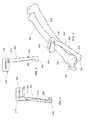
- FIG. 2in a perspective environmental view, illustrates a cutting guide usable in the method of FIG. 1 , the cutting guide being shown mounted to a radius and an ulna of a dog;
- FIG. 3in a top elevation view, illustrates the cutting guide of FIG. 2 ;
- FIG. 4in a bottom elevation view, illustrates the cutting guide of FIG. 2 ;
- FIG. 5in a perspective view, illustrates an endoprosthesis usable in the method of FIG. 1 ;
- FIG. 6in a perspective environmental view, illustrates the endoprosthesis of FIG. 5 ;
- FIG. 7in a perspective environmental view with a partial cutaway, illustrates the endoprosthesis of FIG. 5 ;
- FIG. 8in an alternative perspective environmental view, illustrates the endoprosthesis of FIG. 5 ;
- FIG. 9in an other alternative perspective environmental view, illustrates the endoprosthesis of FIG. 5 ;
- FIG. 10in a series of photographs, illustrates some steps of the method of FIG. 1 performed on a cadaveric dog.
- the present inventionrelates to limb sparing methods and devices.
- the present inventionimplements a method 100 in which part of an affected limb is amputated and replaced by an endoprosthesis.
- the methodstarts at step 105 .
- images of the affected limb and of the contralateral limbare acquired.
- the imagesare acquired using an imaging modality that allows creation of a 3D model of both limbs adjacent the portion of the affected limb to amputate, such as CT imaging, as performed in step 115 . More specifically, in step 115 , an affected limb 3D model is created, and a contralateral limb 3D model is created.
- 3D modelsare used as basis for manufacturing respectively an endoprosthesis (in part from the mirror image of the contralateral limb 3D model and in part from the affected limb 3D model) and a cutting guide (from the affected limb 3D model), at step 120 .
- a surgical procedureis performed in which the cutting guide is positioned on the affected limb, directly on the bone, part of the affected bone is removed using surgical instruments, such as a surgical saw, and the prosthesis is secured to the remaining portion of the bone.
- the methodends at step 130 .
- the cutting guide 200 shown in FIGS. 2 to 4is well suited to guide removal of the distal portion 207 of the radius 202 (both shown in FIG. 2 ) in dogs and other similar animals. Such removal may be required for example because the distal portion 207 of the radius 202 is affected by a tumor.
- the distal part of the dog forelimbsincludes two bones that are parallel to each other, the radius 202 and the ulna 204 .
- the ulna 204is terminated by an ulnar distal tip known as the styloid process 206 .
- the carpal bones 208extend distally to the radius 202 and ulna 204
- the metacarpal bones 210extend distally to the carpal bones 208 .
- the forelimb bonesare terminated distally by the phalanges 212 .
- the cutting guide 200includes a cut guiding portion 214 , an opposed ulnar mounting portion 216 and a linking portion 218 therebetween, which are typically integrally formed together. Indeed, the radius 202 may be deformed by the tumor and as such its distal portion 207 is a poor choice for precise alignment of the cutting guide 200 . Thus, a large portion of the cutting guide 200 is shaped for mounting to the ulna 204 .
- the cut guiding portion 214is configured to abut against the radius adjacent the cut location where the radius 202 is to be cut during surgery.
- the cut guiding portion 214defines a slit 220 through which the blade of a saw (not shown in the drawings) can be inserted to cut through the radius 202 .
- the slit 220is configured, sized and positioned to be substantially adjacent the cut location when the cutting guide 200 is operatively mounted to the radius 202 and ulna 204 .
- the cut guiding portion 214takes the form of a substantially plate-shaped element through which the slit 220 extends, but other configurations are within the scope of the invention.
- the slit 220is typically generally perpendicular to the radius 202 when the cutting guide 200 is mounted to the radius 202 and ulna 204 , but other orientations are within the scope of the invention.
- the ulnar mounting portion 216is substantially elongated and defines a substantially rectilinear main shaft 222 extending from the linking portion 218 and terminated, opposed to the cut guiding portion 214 , by a hook 224 .
- the hook 224defines a hook recess 226 which opens generally towards the cut guiding portion 214 .
- the linking portion 218takes any suitable shape.
- the linking portion 218is substantially elongated and rectilinear and extends at an angle relative to the main shaft 222 .
- the cutting guide 200is delimited by a cutting guide peripheral surface 228 .
- the cutting guide peripheral surface 228defines a bone facing portion 230 , better seen in FIG. 4 , which faces the radius 202 and ulna 204 when the cutting guide 200 is mounted thereto.
- the bone facing portion 230has a shape, configuration and dimensions so that is conforms to the shape of the radius 202 and ulna 204 .
- FIGS. 5 to 9illustrates a prosthesis 300 in accordance with an embodiment of the present invention.
- the prosthesis 300replaces a portion of the radius 202 that has been removed, for example using the cutting guide 200 of FIG. 2 .
- the prosthesis 300includes a fixation plate 302 , a bone replica 304 extending from the fixation plate 302 and a fixation shaft 306 extending from the bone replica, in a generally parallel and spaced apart relationship relative to the fixation plate 302 .
- the prosthesis 300is made of a single integrally extending piece of material, but a prosthesis made of many assembled components is also within the scope of the present invention.
- the fixation plate 302includes a plate proximal portion 308 , a plate distal portion 310 and a plate intermediate portion 312 extending therebetween.
- the plate intermediate portion 312supports the bone replica 304 .
- the plate proximal and distal portions 308 and 310are provided respectively proximally and distally relative to the plate intermediate portion 312 when the prosthesis 300 is operatively secured to the radius 202 and adjacent bones.
- the plate proximal portion 308is substantially elongated and of substantially constant width, as better seen in FIG. 9 .
- the plate proximal portion 308is secured to the radius 202 in use.
- the plate intermediate portion 312widens in a direction leading towards the plate distal portion 310 .
- the plate distal portion 310is substantially V-shaped and defines two arms 320 , although plates having one or more than two arms 320 are within the scope of the invention. Each arm 320 is secured to a respective metacarpal bone 210 in use.
- the bone replica 304has a shape substantially similar to the shape the portion of the radius 202 that it replaces. This is achieved for example by having the bone replica 304 having the shape of a mirror image of the contralateral radius.
- the fixation shaft 306extends coaxially with the bone replica 304 , at its proximal end, and is dimensioned to be inserted in the medulla 209 of the remaining portion of the radius 202 , as seen in FIG. 7 .
- the plate proximal and distal portions 308 and 310defines respectively opposed proximal inner and outer surfaces 322 and 324 and distal inner and outer surfaces 326 and 328 , as seen in FIGS. 5 and 6 .
- the proximal and distal inner surfaces 322 and 326face respectively the radius 202 and the metacarpal bones 210 when the prosthesis 300 is fixed in the patient. To that effect, they are shaped to conform to the outer surface of these bones, using 3D models thereof constructed at step 115 of method 100 .
- the plate proximal and distal portions 308 and 310are mounted to the radius 202 and metacarpal bones 210 in any suitable manner.
- mounting apertures 330extend between the proximal inner and outer surfaces 322 and 324 and between the distal inner and outer surfaces 326 and 328 .
- the prosthesis 300includes 6 mounting apertures 330 in the plate proximal portion 308 and 6 mounting apertures 330 in each arm 320 , any suitable number of mounting apertures 330 is usable.
- Fastenerssuch as screws (seen in FIG. 10 ) are inserted through the mounting apertures 330 and in the radius 202 and metacarpal bones 210 .
- the fixation shaft 306is provided with shaft apertures 332 , seen in FIG. 5 , each in register with one of the mounting apertures 330 so that the screws that are in register therewith can extend therethrough. Since fixation shaft 306 is usually shorter than the plate proximal portion 308 , the number of shaft apertures 332 is typically smaller than the number of mounting apertures 330 in the plate proximal portion 308 .
- the fixation plate 302can be chamfered at one or both ends to facilitate insertion between bones and soft tissues.
- FIG. 10includes photographs taken during performance of the method 100 .
- a custom-made prosthesis 300was created. Standard surgical technique utilized in dogs clinically afflicted with osteosarcoma of the distal radius was performed. Once a predetermined length of distal radius 202 was excised with the use of the cutting guide 200 , the prosthesis 300 was positioned and fixated with 6 screws proximally (radius) and 12 screws distally (Metacarpals III and IV). Surgical technique took less than an hour and application/fixation of the prosthesis 300 was greatly facilitated by the use of a pre-contoured implant.
Landscapes
- Health & Medical Sciences (AREA)
- Life Sciences & Earth Sciences (AREA)
- Surgery (AREA)
- Orthopedic Medicine & Surgery (AREA)
- Engineering & Computer Science (AREA)
- Veterinary Medicine (AREA)
- Animal Behavior & Ethology (AREA)
- Public Health (AREA)
- Biomedical Technology (AREA)
- Heart & Thoracic Surgery (AREA)
- General Health & Medical Sciences (AREA)
- Medical Informatics (AREA)
- Molecular Biology (AREA)
- Nuclear Medicine, Radiotherapy & Molecular Imaging (AREA)
- Oral & Maxillofacial Surgery (AREA)
- Dentistry (AREA)
- Neurology (AREA)
- Robotics (AREA)
- Cardiology (AREA)
- Transplantation (AREA)
- Vascular Medicine (AREA)
- Prostheses (AREA)
Abstract
Description
- 1. Straw R C, Withrow S J: Limb-sparing surgery versus amputation for dogs with bone tumors. Vet Clin North Am Small Anim Pract 26:135-143, 1996.
- 2. Kuntz C A, Asselin T L, Dernell W S, et al: Limb salvage surgery for osteosarcoma of the proximal humerus: outcome in 17 dogs. Vet Surg 27:417-422, 1998.
- 3. Norton C, Drenen C M, Emms S G: Subtotal scapulectomy as the treatment for scapular tumour in the dog: a report of six cases. Aust Vet J 84:364-366, 2006.
- 4. Trout N J, Pavletic M M, Kraus K H: Partial scapulectomy for management of sarcomas in three dogs and two cats. J Am Vet Med Assoc 207:585-587, 1995.
- 5. Montinaro V, Boston S E, Buracco P, et al: Clinical outcome of 42 dogs with scapular tumors treated by scapulectomy: a Veterinary Society of Surgical Oncology (VSSO) retrospective study (1995-2010). Vet Surg 42:943-950, 2013.
- 6. Sivacolundhu R K, Runge J J, Donovan T A, et al: Ulnar osteosarcoma in dogs: 30 cases (1992-2008). J Am Vet Med Assoc 243:96-101, 2013.
- 7. Kirpensteijn J, Steinheimer D, Park R D, et al: Comparison of cemented and non-cemented allografts in dogs with osteosarcoma. Vet Comp Orthop Traumatol 11:178-184, 1998.
- 8. Lascelles B D, Dernell W S, Correa M T, et al: Improved survival associated with postoperative wound infection in dogs treated with limb-salvage surgery for osteosarcoma. Ann Surg Oncol 12:1073-1083, 2005.
- 9. Withrow S J, Liptak J M, Straw R C, et al: Biodegradable cisplatin polymer in limb-sparing surgery for canine osteosarcoma. Ann Surg Oncol 11:705-713, 2004.
- 10. Liptak J M D W, Ehrhart N, Withrow S J, Seguin B, Walsh P J, Kuntz C A: Canine appendicular osteosarcoma: curative-intent treatment. Compendium on Continuing Education 26:186-196, 2004.
- 11. Liptak J M, Dernell W S, Ehrhart N, et al: Cortical allograft and endoprosthesis for limb-sparing surgery in dogs with distal radial osteosarcoma: a prospective clinical comparison of two different limb-sparing techniques. Vet Surg 35:518-533, 2006.
- 12. Ehrhart N: Longitudinal bone transport for treatment of primary bone tumors in dogs: technique description and outcome in 9 dogs. Vet Surg 34:24-34, 2005.
- 13. Tommasini Degna M, Ehrhart N, Feretti A, et al: Bone Transport Osteogenesis for Limb Salvage Following Resection of Primary Bone Tumors: Experience with Six Cases (1991-1996). Vet Comp Orthop Traumatol 13:18-22, 2000.
- 14. Boston S E, Duerr F, Bacon N, et al: Intraoperative radiation for limb sparing of the distal aspect of the radius without transcarpal plating in five dogs. Vet Surg 36:314-323, 2007.
- 15. Buracco P, Morello E, Martano M, et al: Pasteurized tumoral autograft as a novel procedure for limb sparing in the dog: A clinical report. Vet Surg 31:525-532, 2002.
- 16. Hodge S C, Degner D, Walshaw R, et al: Vascularized ulnar bone grafts for limb-sparing surgery for the treatment of distal radial osteosarcoma. J Am Anim Hosp Assoc 47:98-111, 2011.
- 17. Seguin B, Walsh P J, Mason D R, et al: Use of an ipsilateral vascularized ulnar transposition autograft for limb-sparing surgery of the distal radius in dogs: an anatomic and clinical study. Vet Surg 32:69-79, 2003.
- 18. Seguin B, Walsh P J: Novel limb sparing technique for the distal radial site in dogs: lateral manus translation, Proceedings, European College of Veterinary Surgeons Annual Scientific Meeting, Nantes, France, 2009 (available from
- 19. Harrysson O A, Marcellin-Little D, Horn T: Applications of Metal Additive Manufacturing in Veterinary Orthopedic Surgery. JOM 67:647-654, 2015. 14
- 20. Liu X, Chu P K, Ding C: Surface modification of titanium, titanium alloys, and related materials for biomedical applications. Materials Science and Engineering: R: Reports 47:49-121, 2004.
- 21. M. Perez M B, D. Espalin, R. Winker, T. Hoppe, F. Medina, and R. Wicker: Sterilization of FDM-Manufactured Parts, in 23rd Int. Solid Freeform Fabr. Symp., Vol, 2012, pp 285-296.
- 22. Pooya H A, Séguin B, Mason D R, et al: Biomechanical Comparison of Cortical Radial Graft versus Ulnar Transposition Graft Limb-Sparing Techniques for the Distal Radial Site in Dogs. Veterinary Surgery 33:301-308, 2004.
- 23. Ehrhart N P, Ryan S D, Fan T M: Tumors of the skeletal system, in Withrow S J V D, Page R L (ed): Small Animal Clinical Oncology, Vol. St-Louis, Elsevier, 2013, pp 463-503.
- 24. Wilke V L, Robinson D A, Evans R B, et al: Estimate of the annual economic impact of treatment of cranial cruciate ligament injury in dogs in the United States. J Am Vet Med Assoc 227:1604-1607, 2005.
- 25. Rowell J L, McCarthy D O, Alvarez C E: Dog models of naturally occurring cancer. Trends Mol Med 17:380-388, 2011.
Claims (4)
Priority Applications (3)
| Application Number | Priority Date | Filing Date | Title |
|---|---|---|---|
| US15/620,502US10342554B2 (en) | 2016-06-17 | 2017-06-12 | Limb sparing in mammals using patient-specific endoprostheses and cutting guides |
| US16/181,954US10792154B2 (en) | 2016-06-17 | 2018-11-06 | Limb sparing in mammals using patient-specific endoprostheses and cutting guides |
| US17/015,721US20200405322A1 (en) | 2016-06-17 | 2020-09-09 | Limb sparing in mammals using patient-specific endoprostheses and cutting guides. |
Applications Claiming Priority (2)
| Application Number | Priority Date | Filing Date | Title |
|---|---|---|---|
| US201662351533P | 2016-06-17 | 2016-06-17 | |
| US15/620,502US10342554B2 (en) | 2016-06-17 | 2017-06-12 | Limb sparing in mammals using patient-specific endoprostheses and cutting guides |
Related Child Applications (1)
| Application Number | Title | Priority Date | Filing Date |
|---|---|---|---|
| US16/181,954Continuation-In-PartUS10792154B2 (en) | 2016-06-17 | 2018-11-06 | Limb sparing in mammals using patient-specific endoprostheses and cutting guides |
Publications (2)
| Publication Number | Publication Date |
|---|---|
| US20170360453A1 US20170360453A1 (en) | 2017-12-21 |
| US10342554B2true US10342554B2 (en) | 2019-07-09 |
Family
ID=60661471
Family Applications (1)
| Application Number | Title | Priority Date | Filing Date |
|---|---|---|---|
| US15/620,502Expired - Fee RelatedUS10342554B2 (en) | 2016-06-17 | 2017-06-12 | Limb sparing in mammals using patient-specific endoprostheses and cutting guides |
Country Status (2)
| Country | Link |
|---|---|
| US (1) | US10342554B2 (en) |
| CA (1) | CA2969998A1 (en) |
Families Citing this family (11)
| Publication number | Priority date | Publication date | Assignee | Title |
|---|---|---|---|---|
| DE102015122793A1 (en)* | 2015-12-23 | 2017-06-29 | Karl Leibinger Medizintechnik Gmbh & Co. Kg | Implant for bone augmentation with Bohrvektorvorgabeloch and Umgriffsplatte for jaw replacement and Implantatstellverfahren |
| FR3070249B1 (en) | 2017-08-22 | 2023-01-27 | Newclip Int | SURGICAL GUIDING DEVICE, TO ASSIST AN OPENING OSTEOTOMY TECHNIQUE |
| JP2021506559A (en) | 2017-12-20 | 2021-02-22 | グレンハースト ラブス エルエルシー | Multi-faceted fixation plate for fracture repair |
| US11000360B2 (en) | 2018-09-14 | 2021-05-11 | Onkos Surgical, Inc. | Systems and methods for attaching soft tissue to an implant |
| WO2020089840A1 (en)* | 2018-11-01 | 2020-05-07 | Technion Research & Development Foundation Ltd. | Miniature bone-mounted robot for in-situ three-dimensional bioprinting |
| KR20210149825A (en) | 2019-04-12 | 2021-12-09 | 디퍼이 신테스 프로덕츠, 인코포레이티드 | osteotomy guide |
| WO2021123994A1 (en)* | 2019-12-16 | 2021-06-24 | Socovar, L.P. | Limb and joint sparing in mammals using patient-specific surgical guides and implant with textured muscle attachment zones. |
| CO2020003879A1 (en)* | 2020-03-30 | 2021-04-08 | Techfit Digital Surgery Inc | One-piece sternum replacement implant |
| CA3116453A1 (en)* | 2020-05-04 | 2021-11-04 | Laboratoires Bodycad Inc. | Osteotomy plate and method for performing an osteotomy procedure using the same |
| US20220061899A1 (en)* | 2020-09-02 | 2022-03-03 | Abys Medical | Method For Generating Digital Models Of Osteosynthesis Plates Specific To The Patient's Morphology |
| US20250090338A1 (en)* | 2023-09-15 | 2025-03-20 | Zimmer, Inc. | Humeral limb salvage implant system |
Citations (19)
| Publication number | Priority date | Publication date | Assignee | Title |
|---|---|---|---|---|
| US5935128A (en)* | 1997-04-18 | 1999-08-10 | Bristol-Myers Squibb Co. | Orthopaedic template system including a joint locator |
| US20020082604A1 (en) | 2000-12-21 | 2002-06-27 | Mahmoud Abdelgany | Bone graft forming guide and method of forming bone grafts |
| US20020198600A1 (en) | 2001-06-26 | 2002-12-26 | Charles Kuntz | Stainless steel bone-shaped prosthesis for animals |
| USD536453S1 (en) | 2004-03-25 | 2007-02-06 | Precimed S.A. | Bone plate |
| WO2007092481A2 (en) | 2006-02-06 | 2007-08-16 | Bendix Spicer Foundation Brake Llc | Brake assembly, brake actuator and method of making a brake actuator |
| US7282053B2 (en) | 2003-03-27 | 2007-10-16 | Depuy Products, Inc. | Method of using fracture fixation plate for performing osteotomy |
| US20090198244A1 (en)* | 2005-11-18 | 2009-08-06 | Leibel David A | Instrument for Implanting a Wrist Prosthesis |
| WO2009105535A1 (en) | 2008-02-19 | 2009-08-27 | North Carolina State University | Transcutaneous osseointegrated device for prostheses |
| US20110238073A1 (en) | 2003-11-25 | 2011-09-29 | Conformis, Inc. | Patient Selectable Joint Arthroplasty Devices and Surgical Tools |
| US20110269100A1 (en) | 2010-04-29 | 2011-11-03 | Andre Furrer | Orthognathic implant and methods of use |
| US20110304332A1 (en) | 2009-02-25 | 2011-12-15 | Mohamed Rashwan Mahfouz | Intelligent cartilage system |
| US20120158001A1 (en) | 2001-05-25 | 2012-06-21 | Conformis, Inc. | Surgical Tools Facilitating Increased Accuracy, Speed and Simplicity in Performing Joint Arthroplasty |
| US20120277751A1 (en) | 2011-04-29 | 2012-11-01 | Biomet Manufacturing Corp. | Patient-specific convertible guides |
| US20130292870A1 (en) | 2009-08-14 | 2013-11-07 | Howmedica Osteonics Corp. | Methods for manufacturing custom cutting guides in orthopedic applications |
| US20140257309A1 (en) | 2013-03-11 | 2014-09-11 | Luke J. Aram | Customized patient-specific revision surgical instruments and method |
| US9113914B2 (en) | 2009-02-24 | 2015-08-25 | Microport Orthopedics Holdings Inc. | Method for forming a patient specific surgical guide mount |
| WO2015131234A1 (en) | 2014-03-04 | 2015-09-11 | Rmit University | A method for producing a customised orthopaedic implant |
| US9186256B2 (en) | 2011-08-19 | 2015-11-17 | Integra Lifesciences Corporation | Wrist implants and methods |
| US20150342643A1 (en) | 2012-12-19 | 2015-12-03 | Fitzbionics Limited | Clamp |
- 2017
- 2017-06-09CACA2969998Apatent/CA2969998A1/ennot_activeAbandoned
- 2017-06-12USUS15/620,502patent/US10342554B2/ennot_activeExpired - Fee Related
Patent Citations (19)
| Publication number | Priority date | Publication date | Assignee | Title |
|---|---|---|---|---|
| US5935128A (en)* | 1997-04-18 | 1999-08-10 | Bristol-Myers Squibb Co. | Orthopaedic template system including a joint locator |
| US20020082604A1 (en) | 2000-12-21 | 2002-06-27 | Mahmoud Abdelgany | Bone graft forming guide and method of forming bone grafts |
| US20120158001A1 (en) | 2001-05-25 | 2012-06-21 | Conformis, Inc. | Surgical Tools Facilitating Increased Accuracy, Speed and Simplicity in Performing Joint Arthroplasty |
| US20020198600A1 (en) | 2001-06-26 | 2002-12-26 | Charles Kuntz | Stainless steel bone-shaped prosthesis for animals |
| US7282053B2 (en) | 2003-03-27 | 2007-10-16 | Depuy Products, Inc. | Method of using fracture fixation plate for performing osteotomy |
| US20110238073A1 (en) | 2003-11-25 | 2011-09-29 | Conformis, Inc. | Patient Selectable Joint Arthroplasty Devices and Surgical Tools |
| USD536453S1 (en) | 2004-03-25 | 2007-02-06 | Precimed S.A. | Bone plate |
| US20090198244A1 (en)* | 2005-11-18 | 2009-08-06 | Leibel David A | Instrument for Implanting a Wrist Prosthesis |
| WO2007092481A2 (en) | 2006-02-06 | 2007-08-16 | Bendix Spicer Foundation Brake Llc | Brake assembly, brake actuator and method of making a brake actuator |
| WO2009105535A1 (en) | 2008-02-19 | 2009-08-27 | North Carolina State University | Transcutaneous osseointegrated device for prostheses |
| US9113914B2 (en) | 2009-02-24 | 2015-08-25 | Microport Orthopedics Holdings Inc. | Method for forming a patient specific surgical guide mount |
| US20110304332A1 (en) | 2009-02-25 | 2011-12-15 | Mohamed Rashwan Mahfouz | Intelligent cartilage system |
| US20130292870A1 (en) | 2009-08-14 | 2013-11-07 | Howmedica Osteonics Corp. | Methods for manufacturing custom cutting guides in orthopedic applications |
| US20110269100A1 (en) | 2010-04-29 | 2011-11-03 | Andre Furrer | Orthognathic implant and methods of use |
| US20120277751A1 (en) | 2011-04-29 | 2012-11-01 | Biomet Manufacturing Corp. | Patient-specific convertible guides |
| US9186256B2 (en) | 2011-08-19 | 2015-11-17 | Integra Lifesciences Corporation | Wrist implants and methods |
| US20150342643A1 (en) | 2012-12-19 | 2015-12-03 | Fitzbionics Limited | Clamp |
| US20140257309A1 (en) | 2013-03-11 | 2014-09-11 | Luke J. Aram | Customized patient-specific revision surgical instruments and method |
| WO2015131234A1 (en) | 2014-03-04 | 2015-09-11 | Rmit University | A method for producing a customised orthopaedic implant |
Non-Patent Citations (25)
| Title |
|---|
| Boston SE, Duerr F, Bacon N, et al: Intraoperative radiation for limb sparing of the distal aspect of the radius without transcarpal plating in five dogs. Vet Surg; Jun. 2007; 36:314-323. |
| Buracco P, Morello E, Martano M, et al: Pasteurized tumoral autograft as a novel procedure for limb sparing in the dog: A clinical report. Vet Surg;Nov. 2002; 31:525-532. |
| Ehrhart N: Longitudinal bone transport for treatment of primary bone tumors in dogs: technique description and outcome in 9 dogs. Vet Surg Jan. 2005; 34:24-34. |
| Ehrhart NP, Ryan SD, Fan TM: Tumors of the skeletal system, in Withrow SJ VD, p. Rl (ed): Small Animal clinical Oncology, vol. St-Louis, Nov. 2012 Elsevier, pp. 463-503. |
| Harrysson OA, Marcellin-Little D, Horn T: Applications of Metal Additive Manufacturing in Veterinary Orthopedic Surgery. Feb. 2015; JOM 67:647-654. |
| Hodge SC, Degner D, Walshaw R, et al: Vascularized ulnar bone grafts for limb-sparing surgery for the treatment of distal radial osteosarcoma. J Am Anim Hosp Assoc 47Mar. 2011; 98-111. |
| Kirpensteijn J, Steinheimer D, Park Rd, et al: Comparison of cemented and non-cemented allografts in logs with osteosarcoma. Vet Comp Orthop Traumatol Nov. 1998; 11:178-184. |
| Kuntz Ca, Assel in TL, Dernell WS, et al: Limb salvage surgery for osteosarcoma of the proximal humerus: outcome in 17 dogs. Vet Surg Sep. 1998 ;27:417-422, 1998. |
| Lascelles BD, Dernell WS, Correa Mt, et al: Improved survival associated with postoperative wound Infection in dogs treated with limb-salvage surgery for osteosarcoma. Ann Surg Oncol Oct. 2005; 12:1073-1083. |
| Liptak JM DW, Ehrhart N, Withrow SJ, Seguin B, Walsh PJ, Kuntz Ca: Canine appendicular osteosarcoma: curative-intent treatment. Compendium on Continuing Education;Mar. 2004; 26:186-196. |
| Liptak JM, Dernell WS, Ehrhart N, et al: Cortical allograft and endoprosthesis for limb-sparing surgery in dogs with distal radial osteosarcoma: a prospective clinical comparison of two different limb-sparing techniques. Vet Surg Aug. 2006; 35:518-533. |
| Liu X, Chu PK, Ding C: Surface modification of titanium, titanium alloys, and related materials for biomedical applications. Materials Science and Engineering: R: Reports; Dec. 2004; 47:49-121. |
| M. Perez MB, D. Espalin, R. Winker, T. Hoppe, F. Medina, and R. Wicker: Sterilization of FDM-Manufactured Parts, in 23rd Int. Solid Freeform Fabr. Symp., Aug. 2011; vol., 2012, pp. 285-296. |
| Montinaro V, Boston SE, Buracco P, et al: Clinical outcome of 42 dogs with scapular tumors treated by scapulectomy: a Veterinary Society of Surgical Oncology (VSSO) retrospective study (1995-2010). Vet Surg Nov. 2013; 42:943-950. |
| Norton C, Drenen CM, EMMS SG: Subtotal scapulectomy as the treatment for scapular tumour in the dog: a report of six cases. Aust Vet J;Oct. 2006; 84:364-366. |
| Pooya Ha, Séguin B, Mason Dr, et al: Biomechanical Comparison of Cortical Radial Graft versus Ulnar Transposition Graft Limb-Sparing Techniques for the Distal Radial Site in Dogs. Veterinary Surgery Jul. 2004;33:301-308. |
| Rowell JL, Mccarthy Do, Alvarez CE: Dog models of naturally occurring cancer. Trends Mol Med Mar. 2011; 17:380-388. |
| Seguin B, Walsh PJ, Mason Dr, et al: Use of an ipsilateral vascularized ulnar transposition autograft for limb-sparing surgery of the distal radius in dogs: an anatomic and clinical study; Jan. 2003; Vet Surg 32:69-79. |
| Seguin B, Walsh PJ: Novel limb sparing technique for the distal radial site in dogs: lateral manus translation, Proceedings, European College of Veterinary Surgeons Annual Scientific Meeting, Nantes, France, Jun. 2009. |
| Sivacolundhu RK, Runge JJ, Donovan Ta, et al: Ulnar osteosarcoma in dogs: 30 cases (1992-2008). J Am Vet Med Assoc Jul. 2013; 243:96-101. |
| Straw RC, Withrow SJ: Limb-sparing surgery versus amputation for dogs with bone tumors. Vet Clin North Am Small Anim Pract Jan. 1996; 26:135-143. |
| Tommasini Degna M, Ehrhart N, Feretti A, et al: Bone Transport Osteogenesis for Limb Salvage Following Resection of Primary Bone Tumors: Experience with Six Cases (1991-1996). Vet Comp Orthop Traumatol Feb. 2000; 13:18-22. |
| Trout NJ, Pavletic MM, Kraus KH: Partial scapulectomy for management of sarcomas in three dogs and two ;cats. J Am Vet Med Assoc; Sep. 1995; 207:585-587. |
| Wilke VL, Robinson DA, Evans RB, et al: Estimate of the annual economic impact of treatment of cranial cruciate ligament injury in dogs in the United States. J Am Vet Med Assoc Nov. 2005; 227:1604-1607. |
| Withrow SJ, Liptak Jm, Straw RC, et al: Biodegradable cisplatin polymer in limb-sparing surgery for canine osteosarcoma. Ann Surg Oncol ;Jul. 2004; 11:705-713. |
Also Published As
| Publication number | Publication date |
|---|---|
| US20170360453A1 (en) | 2017-12-21 |
| CA2969998A1 (en) | 2017-12-17 |
Similar Documents
| Publication | Publication Date | Title |
|---|---|---|
| US10342554B2 (en) | Limb sparing in mammals using patient-specific endoprostheses and cutting guides | |
| US10792154B2 (en) | Limb sparing in mammals using patient-specific endoprostheses and cutting guides | |
| Fan et al. | Implantation of customized 3-D printed titanium prosthesis in limb salvage surgery: a case series and review of the literature | |
| Angelini et al. | Three-dimension-printed custom-made prosthetic reconstructions: from revision surgery to oncologic reconstructions | |
| BE1019821A3 (en) | TAILOR-MADE SURGERY GUIDES, METHODS FOR MANUFACTURING THEM AND USE THEM. | |
| Woo et al. | Three-dimensional-printing technology in hip and pelvic surgery: current landscape | |
| Popov Jr et al. | Additive manufacturing to veterinary practice: Recovery of bony defects after the osteosarcoma resection in canines | |
| Holzapfel et al. | Customised osteotomy guides and endoprosthetic reconstruction for periacetabular tumours | |
| Harrysson et al. | Applications of metal additive manufacturing in veterinary orthopedic surgery | |
| Friedrich et al. | Management of severe periacetabular bone loss combined with pelvic discontinuity in revision hip arthroplasty | |
| Timercan et al. | Personalized 3D-printed endoprostheses for limb sparing in dogs: Modeling and in vitro testing | |
| US20140188240A1 (en) | Methods and devices related to patient-adapted hip joint implants | |
| US20150250597A1 (en) | Methods and devices related to patient-adapted hip joint implants | |
| JP2011505922A (en) | System and method for determining the mechanical axis of a femur | |
| US20200253740A1 (en) | Wholly patient-specific orthopedic implants and implanting appratuses, system and manufacture thereof | |
| Séguin et al. | Limb‐sparing in dogs using patient‐specific, three‐dimensional‐printed endoprosthesis for distal radial osteosarcoma: A pilot study | |
| KR20200029548A (en) | How to optimize orthopedic component design | |
| AU2012273668A1 (en) | Anatomically matched patient alignment blocks | |
| WO2021123994A1 (en) | Limb and joint sparing in mammals using patient-specific surgical guides and implant with textured muscle attachment zones. | |
| Wang et al. | Is three-dimensional–printed custom-made ultra-short stem with a porous structure an acceptable reconstructive alternative in peri-knee metaphysis for the tumorous bone defect? | |
| US12121272B2 (en) | Two-part surgical guide | |
| Li et al. | Intercalary prosthetic reconstruction with three‐dimensional‐printed custom‐made porous component for defects of long bones with short residual bone segments after tumor resection | |
| Séguin et al. | Updates in Surgical Oncology | |
| RU2702014C1 (en) | Method of primary total shoulder replacement in the post-traumatic deformations of the glenoid surface of the blade with an individual endoprosthesis | |
| Oka et al. | Corrective osteotomy using customized hydroxyapatite implants prepared by preoperative computer simulation |
Legal Events
| Date | Code | Title | Description |
|---|---|---|---|
| AS | Assignment | Owner name:UNIVERSITE DE MONTREAL, CANADA Free format text:NUNC PRO TUNC ASSIGNMENT;ASSIGNOR:LUSSIER, BERTRAND;REEL/FRAME:043907/0731 Effective date:20170804 Owner name:SOCOVAR, L.P., CANADA Free format text:NUNC PRO TUNC ASSIGNMENT;ASSIGNOR:ECOLE DE TECHNOLOGIE SUPERIEURE;REEL/FRAME:043907/0804 Effective date:20170830 Owner name:ECOLE DE TECHNOLOGIE SUPERIEURE, CANADA Free format text:NUNC PRO TUNC ASSIGNMENT;ASSIGNORS:BRAILOVSKI, VLADIMIR;PETIT, YVAN;BRUMMUND, MARTIN;AND OTHERS;SIGNING DATES FROM 20170810 TO 20170814;REEL/FRAME:043907/0759 Owner name:COLORADO STATE UNIVERSITY RESEARCH FOUNDATION, COL Free format text:NUNC PRO TUNC ASSIGNMENT;ASSIGNOR:SEGUIN, BERNARD;REEL/FRAME:043907/0849 Effective date:20170830 | |
| STPP | Information on status: patent application and granting procedure in general | Free format text:NOTICE OF ALLOWANCE MAILED -- APPLICATION RECEIVED IN OFFICE OF PUBLICATIONS | |
| STPP | Information on status: patent application and granting procedure in general | Free format text:PUBLICATIONS -- ISSUE FEE PAYMENT VERIFIED | |
| STCF | Information on status: patent grant | Free format text:PATENTED CASE | |
| FEPP | Fee payment procedure | Free format text:MAINTENANCE FEE REMINDER MAILED (ORIGINAL EVENT CODE: REM.); ENTITY STATUS OF PATENT OWNER: SMALL ENTITY | |
| LAPS | Lapse for failure to pay maintenance fees | Free format text:PATENT EXPIRED FOR FAILURE TO PAY MAINTENANCE FEES (ORIGINAL EVENT CODE: EXP.); ENTITY STATUS OF PATENT OWNER: SMALL ENTITY | |
| STCH | Information on status: patent discontinuation | Free format text:PATENT EXPIRED DUE TO NONPAYMENT OF MAINTENANCE FEES UNDER 37 CFR 1.362 | |
| FP | Lapsed due to failure to pay maintenance fee | Effective date:20230709 |