US10339627B2 - Apparatus and methods for the optimal stitch zone calculation of a generated projection of a spherical image - Google Patents
Apparatus and methods for the optimal stitch zone calculation of a generated projection of a spherical imageDownload PDFInfo
- Publication number
- US10339627B2 US10339627B2US15/289,851US201615289851AUS10339627B2US 10339627 B2US10339627 B2US 10339627B2US 201615289851 AUS201615289851 AUS 201615289851AUS 10339627 B2US10339627 B2US 10339627B2
- Authority
- US
- United States
- Prior art keywords
- images
- projection
- image
- spherical
- stitch line
- Prior art date
- Legal status (The legal status is an assumption and is not a legal conclusion. Google has not performed a legal analysis and makes no representation as to the accuracy of the status listed.)
- Active
Links
Images


Classifications
- G—PHYSICS
- G06—COMPUTING OR CALCULATING; COUNTING
- G06T—IMAGE DATA PROCESSING OR GENERATION, IN GENERAL
- G06T3/00—Geometric image transformations in the plane of the image
- G06T3/08—Projecting images onto non-planar surfaces, e.g. geodetic screens
- G—PHYSICS
- G06—COMPUTING OR CALCULATING; COUNTING
- G06T—IMAGE DATA PROCESSING OR GENERATION, IN GENERAL
- G06T3/00—Geometric image transformations in the plane of the image
- G06T3/12—Panospheric to cylindrical image transformations
- G06T3/005—
- G06T3/0062—
- G06T3/0068—
- G—PHYSICS
- G06—COMPUTING OR CALCULATING; COUNTING
- G06T—IMAGE DATA PROCESSING OR GENERATION, IN GENERAL
- G06T3/00—Geometric image transformations in the plane of the image
- G06T3/14—Transformations for image registration, e.g. adjusting or mapping for alignment of images
- G—PHYSICS
- G06—COMPUTING OR CALCULATING; COUNTING
- G06T—IMAGE DATA PROCESSING OR GENERATION, IN GENERAL
- G06T3/00—Geometric image transformations in the plane of the image
- G06T3/40—Scaling of whole images or parts thereof, e.g. expanding or contracting
- G06T3/4038—Image mosaicing, e.g. composing plane images from plane sub-images
- H—ELECTRICITY
- H04—ELECTRIC COMMUNICATION TECHNIQUE
- H04N—PICTORIAL COMMUNICATION, e.g. TELEVISION
- H04N23/00—Cameras or camera modules comprising electronic image sensors; Control thereof
- H04N23/45—Cameras or camera modules comprising electronic image sensors; Control thereof for generating image signals from two or more image sensors being of different type or operating in different modes, e.g. with a CMOS sensor for moving images in combination with a charge-coupled device [CCD] for still images
- H—ELECTRICITY
- H04—ELECTRIC COMMUNICATION TECHNIQUE
- H04N—PICTORIAL COMMUNICATION, e.g. TELEVISION
- H04N23/00—Cameras or camera modules comprising electronic image sensors; Control thereof
- H04N23/60—Control of cameras or camera modules
- H04N23/698—Control of cameras or camera modules for achieving an enlarged field of view, e.g. panoramic image capture
- H04N5/2258—
- H04N5/23238—
Definitions
- the present disclosurerelates generally to video image post-processing and in one exemplary aspect, to methods and apparatus for the optimal stitch zone calculation of a generated projection of a spherical image.
- Spherical imagesare typically obtained by capturing multiple images with overlapping fields of view from different cameras and combining (“stitching”) these images together in order to provide a two-dimensional projection.
- Conventional stitching algorithmsmay result in undesirable artifacts around the stitch lines due to imperfections in the stitching process.
- prior techniquesinvolved the use of equirectangular projections for handling these spherical images (e.g., for so-called virtual reality (VR) content) and accordingly compression techniques have been developed that may be less than optimal when handling content embodied within these equirectangular projections. Accordingly, techniques are needed to improve upon these conventional stitching algorithms, and improve upon the compression efficiencies associated with the transmission and storage of these projected images in order to allow, for example, modern display devices to perform to their capabilities when displaying, inter alia, spherical image video content.
- VRvirtual reality
- the present disclosuresatisfies the foregoing needs by providing, inter alia, methods and apparatus for the optimal stitch zone calculation of a generated projection of a spherical image.
- an apparatusconfigured to generate an optimal stitch zone calculation of a generated projection of a spherical image.
- the apparatusincludes a processing apparatus; and a storage apparatus in data communication with the processing apparatus, the storage apparatus having a non-transitory computer readable medium comprising instructions which are configured to, when executed by the processing apparatus, cause the computerized apparatus to: obtain a plurality of images, the plurality of images configured to represent a panoramic image; map the plurality of images into a spherical collection of images; re-orient the spherical collection of images in accordance with an optimal stitch zone for a desired projection; the optimal stitch zone characterized as a set of points that defines a single line on the desired projection in which the set of points along the desired projection lie closest to the spherical collection of images in a mean square sense.
- a method of generating an optimal stitch zone calculation of a generated projection of a spherical imageincludes obtaining a plurality of images; mapping the plurality of images onto a spherical image; re-orienting the spherical image in accordance with an optimal stitch zone for a desired projection, the optimal stitch zone characterized as a set of points that defines a single line on the desired projection in which the set of points along the desired projection lie closest to the spherical collection of images in a mean square sense.
- a computing devicein a third aspect of the present disclosure, includes logic configured to: obtain a plurality of images; map the plurality of images onto a spherical image; re-orient the spherical image in accordance with a desired stitch line and a desired projection for the desired stitch line; and map the spherical image to the desired projection having the desired stitch line.
- the plurality of imagesare obtained via the use of a spherical camera system having a image capture devices, each of the image capture devices configured to have an overlapping field of view with at least one other one image capture devices.
- the computing devicefurther includes logic configured to align one or more features present within the overlapping field of view such that a first image of the images is aligned with a second image of the images, the overlapping field of view including at least a portion of the desired stitch line.
- the desired stitch lineincludes a meridian stitch zone and the desired projection is selected from the group consisting of: an equirectangular projection, a cubic projection, and an octahedron projection.
- the computing devicefurther includes logic configured to generate a bandwidth requirement for the desired projection and cause the display of the generated bandwidth requirement on a user's display.
- the computing devicefurther includes logic configured to generate a plurality of respective bandwidth requirements for a plurality of possible projections and cause the display of the plurality of respective bandwidth requirements on a user's display.
- the display of the plurality of respective bandwidth requirements on the user's displayis performed prior to the spherical image being mapped onto the desired projection having the desired stitch line.
- a computer readable storage apparatusincludes a non-transitory computer readable medium having instructions which are configured to, when executed by a processing apparatus, cause a computerized apparatus to: obtain a plurality of images, the plurality of images configured to represent a panoramic image; map the plurality of images into a spherical collection of images; re-orient the spherical collection of images in accordance with a desired stitch line for a desired projection; and map the spherical collection of images into the desired projection comprising the desired stitch line.
- the desired stitch lineincludes an optimal stitch zone, the optimal stitch zone characterized as a set of points that defines a single line on the desired projection in which the set of points along the desired projection lie closest to the spherical collection of images in a mean square sense.
- the desired projectionincludes an octahedron projection and the desired stitch line lies within a meridian zone for the octahedron projection.
- the desired projectioncomprises a cubic projection and the desired stitch line lies either on: (1) an equatorial stitch zone; or (2) a meridian stitch zone.
- the imagesare mapped into the spherical collection of images in accordance with a Cartesian coordinate system.
- the imagesare mapped into the spherical collection of images in accordance with a spherical coordinate system.
- the spherical collection of images mapped in accordance with the spherical coordinate systemare assumed to have a fixed radial dimension.
- the spherical collection of images mapped in accordance with the spherical coordinate systemare assumed to have a variable radial dimension.
- an integrated circuit (IC) apparatusincludes logic configured to: obtain a plurality of images; map the plurality of images onto a spherical image; re-orient the spherical image in accordance with a desired stitch line and a desired projection for the desired stitch line; and map the spherical image to the desired projection having the desired stitch line.
- an apparatusconfigured to generate a selected projection of a spherical image.
- the apparatusincludes a processing apparatus; and a storage apparatus in data communication with the processing apparatus, the storage apparatus having a non-transitory computer readable medium comprising instructions which are configured to, when executed by the processing apparatus, cause the computerized apparatus to: obtain a plurality of images, the plurality of images configured to represent a panoramic image; map the plurality of images into a spherical collection of images; re-orient the spherical collection of images in accordance with a desired stitch line for a desired projection; and map the spherical collection of images into the desired projection comprising the desired stitch line.
- a method of generating a selected projection of a spherical imageincludes obtaining a plurality of images; mapping the plurality of images onto a spherical image; re-orienting the spherical image in accordance with a desired stitch line and a desired projection for the desired stitch line; and mapping the spherical image to the desired projection having the desired stitch line.
- the methodfurther includes mapping the spherical image onto a plurality of differing desired projections.
- the methodfurther includes selecting one of the plurality of differing desired projections and causing the display of a region of interest for the spherical image in accordance with the selected one of the plurality of differing desired projections.
- the selection of the one of the plurality of differing desired projectionsis based upon using a bandwidth consideration for the transmission of at least a portion of the selected one of the plurality of differing desired projections.
- the selection of the one of the plurality of differing desired projectionsis based upon using a storage consideration for at least a portion of the selected one of the plurality of differing desired projections.
- FIG. 1is a block diagram of one exemplary spherical camera system, in accordance with the principles of the present disclosure.
- FIG. 2Ais a logical flow diagram of an exemplary method for generating a rectangular projection of a spherical image, in accordance with the principles of the present disclosure.
- FIG. 2Bis a sequence of images resulting from the exemplary methodology of FIG. 2A , in accordance with the principles of the present disclosure.
- FIG. 3Ais a logical flow diagram of another exemplary method for generating a rectangular projection of a spherical image, in accordance with the principles of the present disclosure.
- FIG. 3Bis a sequence of images resulting from the exemplary methodology of FIG. 3A , in accordance with the principles of the present disclosure.
- FIG. 4Ais a logical flow diagram of an exemplary method for re-orienting a rectangular projection of a spherical image, in accordance with the principles of the present disclosure.
- FIG. 4Bis a sequence of images resulting from the exemplary methodology of FIG. 4A , in accordance with the principles of the present disclosure.
- FIG. 5Ais an isometric view of a cubic projection taken from a spherical image in which the stitch zone is placed on a meridian zone, in accordance with the principles of the present disclosure.
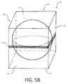
- FIG. 5Bis an isometric view of a cubic projection taken from a spherical image in which the stitch zone is placed on an equatorial zone, in accordance with the principles of the present disclosure.
- FIG. 5Cis a logical plan view illustrating the mapping of the cubic projection of FIG. 5A into a sequence of frames suitable for storage and transmission, in accordance with the principles of the present disclosure.
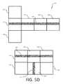
- FIG. 5Dis a logical plan view illustrating the mapping of the cubic projection of FIG. 5B into a sequence of frames suitable for storage and transmission, in accordance with the principles of the present disclosure.
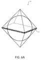
- FIG. 6Ais an isometric view of an octahedron projection taken from a spherical image in which the stitch zone is placed on an equatorial zone, in accordance with the principles of the present disclosure.
- FIG. 6Bis an isometric view of an octahedron projection taken from a spherical image in which the stitch zone is placed on a meridian zone, in accordance with the principles of the present disclosure.
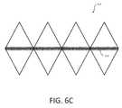
- FIG. 6Cis a logical plan view illustrating the mapping of the octahedron projection of FIG. 6A into a sequence of frames suitable for storage and transmission, in accordance with the principles of the present disclosure.
- FIG. 6Dis a logical plan view illustrating the mapping of the octahedron projection of FIG. 6B into a sequence of frames suitable for storage and transmission, in accordance with the principles of the present disclosure.
- FIG. 7is a logical flow diagram of an exemplary method for mapping a spherical image to a desired polygon-type projection, in accordance with the principles of the present disclosure.
- FIG. 8is a block diagram of an exemplary implementation of a computing device, useful in performing the methodologies described herein.
- each of the centers of view for the respective camerasreside on a given two-dimensional plane
- one or more of these camerascan reside such that their center of view is focused at an azimuthal angle (e.g., at 45°), with respect to the given two-dimensional plane for other one(s) of the cameras.
- FIG. 1illustrates an embodiment of an example spherical camera system 100 that may include a first camera 110 capturing a first field of view 112 and a second camera 120 capturing a second field of view 122 .
- the cameras 110 , 120may be integrated in a back-to-back configuration in which cameras 110 , 120 face opposite directions.
- the first camera 110may be a “front-facing” camera 110 such that a user may point towards an object or scene of interest and the second camera 120 may be a “rear-facing” camera facing in an opposite direction of the front-facing camera 110 .
- the fields of view 112 , 122may each comprise a hyper-hemispherical field of view that captures slightly greater than a 180° range in at least one direction. Because the respective fields of view 112 , 122 are hyper-hemispherical (e.g., greater than 180°), they overlap in overlapping regions 132 , 134 near their respective boundaries.
- the fields of view 112 , 122may overlap by n degrees (e.g., where n equals 1°, 5°, 10° or other various degrees of field of view overlap between, for example, a front-facing and rear-facing camera).
- n degreese.g., where n equals 1°, 5°, 10° or other various degrees of field of view overlap between, for example, a front-facing and rear-facing camera.
- These overlapping regions 132 , 134may be used for the stitching of these separately captured images obtained by the respective cameras 110 , 120 , as will be described in further detail below.
- each of these camerasmay capture an image that has a field of view that is greater than a 120° range in at least one direction, so that the resultant images may be stitched together into a full 360° field of view.
- the processes described hereinmay be performed by a video processing system comprising at least one processor and a non-transitory computer-readable storage apparatus having a storage medium.
- the storage mediumstores a number of computer-executable instructions thereon, that when executed by the at least one processor, cause the at least one processor to perform the processes described herein.
- the video processing systemmay be partially or wholly implemented in the camera 100 or may be implemented partially or wholly in an external device (e.g., in a computing device that is separate from the camera system 100 that obtained the resultant images).
- the various projection methodologies described hereinare useful in, for example, the compression, storage and/or transmission of this captured video data.
- FIG. 2Aillustrates a first embodiment of a process for stitching images captured by a spherical camera system 100 where the stitching zone runs along a meridian zone of the spherical image
- FIG. 2Billustrates example images resulting from the process of FIG. 2A .
- FIGS. 2A and 2Bare described together for clarity and convenience.
- an image sensorreceives a first circular image corresponding to a first hyper-hemispherical field of view and a second circular image corresponding to a second hyper-hemispherical field of view.
- a first circular imagee.g., image “A”
- a second circular imagee.g., image “B”
- the first circular image 250may represent, for example, the field of view captured by a first camera 110 (e.g., a front-facing camera) of a spherical camera system 100 and the second circular image 260 may represent, for example, the field of view captured by the second camera 120 (e.g., a rear-facing camera) of a spherical camera system 100 .
- the images 250 , 260are circular because they represent the entire fields of view as seen by the respective cameras 110 , 120 as opposed to a cropped rectangular field of view captured by a traditional camera.
- the circular images 250 , 260may be captured by using only a circular region of a respective square or rectangular image sensor 252 , 262 .
- the circular images 250 , 260may be captured using respective circular image sensors.
- the circular images 250 , 260may each represent a hyper-hemispherical field of view (e.g., n degrees greater than a hemisphere in at least one direction (referenced supra)).
- n degreesgreater than a hemisphere in at least one direction (referenced supra)
- This overlapmay be used to align features present within both of these images for the later stitching of these images as will be described in further detail below.
- the first circular image 250 and the second circular image 260may be projected to a first equirectangular image 254 and a second equirectangular image 264 respectively, using equirectangular projections at step 204 of FIG. 2A .
- the circular images 250 , 260may each be stretched horizontally to fill a square.
- the equirectangular images 254 , 264may become increasingly more distorted as the top and bottom edges are approached.
- the center row of pixelsmay not undergo any stretching during the equirectangular projection processing, while the top and bottom row in the original circular image (which may each be represented by a respective single pixel) may be stretched to fill the entire top and bottom rows respectively of the equirectangular projections 254 , 264 .
- the resulting equirectangular images 254 , 264each may comprise an image representing a 180 degree (or a 180+2n) field of view along the vertical axis and represent a 180+2n degree field of view along the horizontal axis, where n represents the degree of overlap between the respective fields of view of the original images 250 , 260 .
- the first equirectangular image 254may comprise a field of view in the range of 0-n degrees to 180+n degrees and the second equirectangular image 264 may comprise a field of view in the range of 180 ⁇ n degrees to 360+n degrees along the horizontal axis.
- the distortion introduced at the top and bottom of the respective images 254 , 264is primarily introduced as a result of the projection from a spherical image onto an equirectangular image.
- ultra wide-angle lense.g., a so-called fisheye lens
- this characteristic distortioncan be subsequently removed from the generated spherical image as a result of the fact that this characteristic distortion is generally known (i.e., fixed within a reasonable degree of accuracy) when using an ultra wide-angle lens of appreciable quality.
- the second image 264may then be split at step 206 into a first sub-image 266 (e.g., a left sub-image) and a second sub-image 268 (e.g., a right sub-image).
- a first sub-image 266e.g., a left sub-image
- a second sub-image 268e.g., a right sub-image
- the second image 264may be divided vertically into two equal-sized sub-images 266 , 268 in which the left sub-image 266 may represent the field of view 180 ⁇ n degrees to 270 degrees and the right sub-image 268 may represent the field of view 270 degrees to 360+n degrees.
- the left sub-image 266may then be stitched at step 208 to the right side of the first image 254 (e.g., by aligning one or more features appearing in the n overlapping degrees near the left edge of the left-sub-image 266 with the one or more features in the n overlapping degrees near the right edge of the first image 254 ), and the right sub-image 268 may be stitched 208 to the left side of the first image 254 (e.g., by aligning one or more features appearing in the n overlapping degrees near the right edge of the right-sub-image 268 with the one or more features in the n overlapping degrees near the left edge of the first image 254 ).
- the resulting image 270(referred to herein as an “equatorial view” of the spherical image) provides a useful equirectangular projection of the spherical field of view in which the center portion of the image 270 corresponds to the image 250 captured by the front-facing camera 110 and the left and right edges of the image 270 may correspond to the image 260 captured by the rear-facing camera 120 .
- This orientation of the spherical imagemay be useful because many existing viewing and editing applications for spherical images assume that an image is received in this orientation.
- An advantage of the method of FIGS. 2A-2Bis that by projecting the spherical image to equirectangular images 254 , 264 prior to stitching, a conventional stitching algorithm designed for rectangular images can be used without requiring a specialized stitching algorithm that operates directly in the spherical domain.
- a potential problem with the above-described processis that the top and bottom of the stitch lines in the stitched image 270 correspond to portions of the equirectangular images 254 , 264 that may be subject to the greatest distortion from the equirectangular projection. This can lead to various errors in the stitching algorithm, which can result in undesirable artifacts near these top and bottom edges of the stitch lines.
- FIGS. 3A and 3Billustrate a second embodiment of a process for stitching images in a spherical camera system 100 where the stitching zone now runs along the equatorial zone of the spherical image (as opposed to the meridian zone as shown in FIGS. 2A and 2B ), while FIG. 3B illustrates example images resulting from the process of FIG. 3A .
- the stitching methodology of FIG. 3Aonly utilizes a single stitch line.
- FIGS. 3A and 3Bare described together for clarity and convenience.
- a first circular image 350 and a second circular image 360may be received at step 302 at a video processing system, which may be similar to the first circular image 250 and second circular image 260 respectively discussed above.
- the first circular image 350 and the second circular image 360may be projected at step 304 to a first rectangular image 352 and a second rectangular image 362 respectively.
- a projectionmay instead be used in which the outer edge of the circular image 350 , 360 maps to a first horizontal edge of the rectangular image 352 , 362 and a center point of the circular image 350 , 360 maps to a second horizontal edge of the rectangular image 352 , 362 .
- the center point of the first circular image 350maps to a top edge of the rectangular image 352 and the outer edge of the first circular image 350 maps to the bottom edge of the rectangular image 352 .
- This projectionmay also be understood as taking increasing larger concentric rings of pixels from the circular image 350 and arranging them in rows (e.g., forming a triangle in which the center point represents the vertex of the triangle and the outer most ring represents the base of the triangle), which are then stretched to fill the rectangle.
- the distortion in the rectangular image 352 due to stretching of the pixelsincreases near the top edge of the first rectangular image 352 .
- a single pixel(representing the center point of the original first circular image) may be stretched across the entire top edge, while along the bottom edge, no stretching may be performed.
- Thismay result in a rectangular image 352 representing a field of view from 0-n degrees to 90 degrees along the vertical axis (corresponding to the angles from the outer edge to the center point of the original circular image 350 ) and from 0 degrees to 360 degrees along the horizontal axis (corresponding to the angles around the circumference of the original circular image 350 .
- the center point of the second circular image 360may be mapped to a bottom edge of the second rectangular image 362 and the outer edge of the second circular image 360 may be mapped to the top edge of the second rectangular image 360 .
- a single pixel(representing the center point of the original second circular image 360 ) may be stretched across the entire bottom edge, while along the top edge, no stretching may be performed.
- the first rectangular image 352 and the second rectangular image 362may then be stitched at step 306 together (e.g., by aligning the n overlapping degrees of the bottom edge of the first rectangular image 352 with the top edge of the second rectangular image 362 ).
- the resulting image 370may be referred to as “polar view” of a spherical image.
- the stitch linemay be referred to as an “equatorial stitch” because the stitched edges may correspond to an equator between the two hemispheres captured by the cameras 110 , 120 .
- FIGSthe stitching technique of FIGS.
- only a single stitch linemay be used and the stitch may be performed along edges of the images 352 , 354 that have the least amount of distortion (e.g., no distortion) introduced from the rectangular projection.
- the least amount of distortione.g., no distortion
- stitching artifacts caused by the projection distortionmay be reduced or eliminated.
- the resulting stitched image 370 in the polar viewmay be converted to the equatorial view of FIG. 2B , in which the center line of the front-facing camera 110 represents the center line of the image and the center of the rear-facing camera 120 represents the left and right edges.
- FIG. 4Aillustrates a process for re-projecting the image from the polar view to the equatorial view.
- FIG. 4Billustrates example images resulting from this process.
- FIGS. 4A-4Bare described together herein for clarity and convenience.
- the stitched image 370may be divided at step 402 into left and right equally sized sub-images 452 , 454 .
- the left sub-image 452may be rotated at step 404 clockwise 90 degrees and the right sub-image 454 may be rotated 404 counterclockwise 90 degrees.
- the rotated left sub-image 456 and the rotated right sub-image 458may be re-combined at step 406 (e.g., by aligning the right edge of the rotated left sub-image 406 with the left edge of the rotated right sub-image 408 ) to generate the re-orientated image 410 .
- This re-orientationmay be useful to enable the spherical image to be processed using the same editing or viewing tools designed for use with the projection of FIG. 2B .
- FIGS. 5A-5Bvarious methodologies for selecting the orientation of a stitching line for a generated cubic projection from a spherical image is shown and described in detail.
- FIGS. 5A and 5Billustrate various ways in which these stitch lines may be generated in order to generate a desired cubic projection from a spherical image.
- stitch zone 524as shown in FIG. 5A , illustrates a stitch zone that runs along a meridian zone of the spherical image
- stitch zone 532as shown in FIG. 5B illustrates a stitch zone that runs along the equatorial zone of the spherical image.
- a so-called “optimal stitch zone” for any projectionmay be defined as a set of points that defines a single line (or plane) in which the set of points along that projection lie closest to the spherical image in a mean square sense, while bisecting the spherical image in two equal halves.
- cubic projection 510 of the spherical imageis shown having six (6) faces.
- cubic projection 510includes a top face 512 , a front face 514 , a right face 516 , a bottom face 518 , a back face 520 , and a left face 522 .
- the stitch zone 524may be characterized by its length, and compared with the circumference of the spherical image, in order to generally get a sense of the level of distortion introduced by the cubic projection. In the illustrated embodiment of FIG.
- the circumference for the spherical imagewill be 2 ⁇ r in total length (or approximately 6.28r).
- the total length of the stitching line on the cubic projection 510is 8r (i.e., the total combined length of the stitching line 524 on the front face 514 , top face 512 , back face 520 and bottom face 518 ).
- cubic projection 530also includes a top face 512 , a front face 514 , a right face 516 , a bottom face 518 , a back face 520 , and a left face 522
- the stitch line 532now runs along the equatorial line of the spherical image.
- the stitch line 532now runs along the front face 514 , left face 522 , back face 520 , and right side face 516 .
- the total length of the stitching line on the cubic projection 530is 8r (i.e., the total combined length of the stitching line 524 on the front face 514 , left face 522 , back face 520 , and right face 516 ). Accordingly, when viewed as a whole, the level of distortion contained within the cubic projection 510 shown in FIG. 5A may generally possess an equivalent level of distortion contained within the cubic projection 530 as shown in FIG. 5B .
- FIG. 5Cillustrates one such representation of a frame packing arrangement for the cubic projection generated in FIG. 5A .
- the top portion of FIG. 5Cillustrates the logical unfolding of the cubic projection generated in FIG. 5A .
- the faces corresponding to the cubic projection generated in FIG. 5Ainclude the back face 520 , the top face 512 , and the bottom face 518 with the stitching line 524 running down the middle of each of these faces.
- the right face 516Located adjacent the back face 520 , resides the right face 516 , followed by the front face 514 , and the left face 522 . Note that due to the meridian zone nature of the stitching line 524 of FIG.
- the stitching line 524also runs through the front face 524 of the cubic projection generated in FIG. 5A .
- the bottom portion of FIG. 5Cillustrates one logical frame packing arrangement for the cubic projection generated in FIG. 5A .
- the front face 514has been rotated by 180° and placed underneath the top face 512 such that their respective stitching lines 524 have now been aligned.
- the left face 522has been rotated by 180° and logically placed underneath the right face 516
- the back face 520has been rotated by 180° and logically placed underneath the bottom face 518 so that their respective stitching lines 524 have been aligned.
- FIG. 5Dillustrates one such representation of a frame packing arrangement for the cubic projection generated in FIG. 5B .
- the arrangement of the faces as shown in the top portion of FIG. 5Dis identical to that shown in the top portion of FIG. 5C ; however, the arrangement of the stitching line 532 differs in that the stitching line runs along the equatorial zone of the cubic projection (i.e., through the middle of the back face 520 , the middle of the right face 516 , the middle of the front face 514 , and the middle of the left face 522 ) as shown in FIG. 5B .
- the bottom portion of FIG. 5Dillustrates one logical frame packing arrangement for the cubic projection generated in FIG. 5B .
- the top rowconsists of the front face 514 , the right face 516 , and the back face 520 , each having the stitching line 532 running there through.
- the bottom rowconsists of the top face 512 , the left face 522 , and the bottom face 518 .
- the left face 522also has the stitching line 532 running there through; however, the face 522 has been rotated by 90°. Accordingly, as is illustrated in FIGS. 5C and 5D , the selection of a differing stitch zone for a desired projection does not affect the ability to generate various frame packing arrangements for the imaging data.
- FIGS. 6A-6Bvarious methodologies for selecting the orientation of a stitching line for a generated octahedron projection from a spherical image is shown and described in detail.
- FIGS. 6A and 6Billustrate various ways in which these stitch lines may be generated in order to generate a desired octahedron projection from a spherical image.
- stitch zone 612 for octahedron projection 610results in an equatorial stitch line in the configuration illustrated in FIG. 6A .
- the length of the stitch line illustrated in FIG. 6Amay have a length of 8r, when capturing a spherical image having a radial dimension r (similar to the cubic projections illustrated in FIGS. 5A and 5B ).
- FIG. 6Billustrates a meridian stitch zone 632 for the octahedron projection 630 .
- the length of this meridian stitch zone 632would have a total length of 4r ⁇ 3 (i.e., approximately 6.9r). Accordingly, the length of the meridian stitch zone 632 for the octahedron projection 630 illustrated in FIG. 6B would be shorter than the equatorial stitch zone 612 for the octahedron projection 610 illustrated in FIG. 6A .
- the meridian stitch zone 632may be expected to have a lesser amount of distortion associated with it for the octahedron projection then the equatorial stitch zone 612 illustrated in FIG. 6A .
- the desired projectione.g., equirectangular, cubic, octahedron and other types of projections
- a desired stitching zoneone may be able to optimize the arrangement of the captured spherical imaging content depending upon, for example, particular areas of interest within the captured image(s), reducing the number of operations associated with generating the desired projection (e.g., with equirectangular projections, running the stitch line along the equator involves rotation/remapping operations as discussed supra) and/or other considerations.
- FIGS. 6C and 6Dillustrate logical frame packing arrangements for the octahedron projections illustrated in FIGS. 6A and 6B , respectively.
- FIG. 6Cillustrates the placement of the stitch line 612 on the octahedron projection 610 as is illustrated in FIG. 6A
- FIG. 6Dillustrates the placement of the stitch line 632 on the octahedron projection 630 of FIG. 6B .
- the selection of a differing stitch zone for a desired projectiondoes not affect the ability to generate various frame packing arrangements for the imaging data.
- two or more imagesare obtained using, for example, the aforementioned spherical camera system 100 .
- a pair of fish eye camera lens imagesmay be obtained using the aforementioned spherical camera system 100 .
- Each of the pair of imagesmay capture respective images having an overlapping field of view such that common feature(s) residing within each of these images may be mapped in order to later combine (stitch) these pair of images.
- the imagesmay be obtained using three or more cameras that are offset with one another by, for example, 120° and/or by using one or more cameras with their fields of view arranged outside of the equatorial field of view of two or more other cameras within spherical camera system 100 .
- the obtained images from step 702may be mapped onto a spherical image of the collective field of views associated with the spherical camera system 100 .
- individual pixels associated with the images captured at step 702are mapped to a Cartesian coordinate system so that each of the pixels captured by the spherical camera system has an x-coordinate, y-coordinate, and a z-coordinate associated with it. Accordingly, these Cartesian coordinates may be used to re-orient the spherical image for placement of an optimal stitch zone at step 706 .
- individual pixels associated with the images captured at step 702are mapped in accordance with a spherical coordinate system.
- the individual pixelswill assumed to have a fixed radius r and accordingly, the spherical coordinate system will map the images according to a polar angle ⁇ , and an azimuth angle ⁇ .
- each pixel captured at step 702will be assigned a variable value r, in addition to being assigned a polar angle ⁇ , and an azimuth angle ⁇ .
- the mapped spherical image obtained at step 704is re-oriented in accordance with the desired placement of a stitch line on a desired projection.
- the placement of the stitch linemay be placed in accordance with an optimal stitch zone for the desired projection. For example, where the desired projection is a cubic projection, the mapped spherical image will be re-oriented such that the stitch line is placed either on an equatorial plane of the spherical image, or on a meridian plane of the spherical image.
- the mapped spherical imagemay be re-oriented such that, for example, the stitch line may be placed in an optimal stitch zone (i.e., such that the set of points that make up the stitching zone lies closest to the sphere in a means square sense, while bisecting the spherical image into two equal halves).
- the spherical imagemay be re-oriented such that the placement of the stitch line is optimal for reducing the level of distortion for an object of interest within the spherical image (e.g., a person, a face, a building, and/or other objects of interest), either taking (or not taking) the optimal stitch zone into consideration.
- the re-oriented spherical image of step 706is mapped to a desired projection.
- the desired projectionmay take into consideration bandwidth considerations for the transmission of the image data, For example, in one or more implementations some projections (such as, for example, the aforementioned cubic or octahedron projections) may compress more efficiently than other projections (such as, for example, the aforementioned equirectangular projection). This compression efficiency may be enhanced as a result of, for example, lesser distortion contained at the poles of the projected image.
- other considerationsmay be taken into account, additionally or alternatively to, the aforementioned bandwidth considerations (e.g., storage considerations for the display device, power considerations for the encoding/decoding of the projected images and/or other considerations).
- a relatively complex projectionsuch as e.g., an icosahedron projection
- a relatively complex projectionmay be more desirable as the field of view of interest may not cross any face boundaries (or may cross relatively few facial boundaries) on the relatively complex projection.
- face boundaries on a desired polygon projectionare prone to artifacts as a result of, for example, an encoder encoding different faces in separate instances and as a result having to make differing quantization parameter (QP)/mode decisions.
- QPquantization parameter
- Another reason for selecting a projection that has a fewer number facesmay be to reduce the transmission bit rate for the projected image.
- onemay have to encode a slight overlap region between the faces in order to, inter alia, reduce discontinuities (especially when dealing with relatively large QP values).
- these overlapping regionscan increase the bit rate of the transmitted projection as compared with a projection that has a fewer number of faces.
- a 0.5% increase in overlap areamay introduce a 1.7% increase in the bit rate necessary to transmit this projection.
- FIG. 8is a block diagram illustrating components of an example computing system able to read instructions from a computer-readable medium and execute them in one or more processors (or controllers).
- the computing system in FIG. 8may represent an implementation of, for example, the video processing device for performing the stitching processes described herein.
- the computing system 800can be used to execute instructions 824 (e.g., program code or software) for causing the computing system 800 to perform any one or more of the methodologies (or processes) described herein.
- the computing system 800operates as a standalone device or a connected (e.g., networked) device that connects to other computer systems.
- the computing system 800may comprise, for example, a personal computer (PC), a tablet PC, a notebook computer, or other device capable of executing instructions 824 (sequential or otherwise) that specify actions to be taken.
- the computing system 800may comprise a server.
- the computing system 800may operate in the capacity of a server or client in a server-client network environment, or as a peer device in a peer-to-peer (or distributed) network environment. Further, while only a single computer system 800 is illustrated, a plurality of computing systems 800 may operate to jointly execute instructions 824 to perform any one or more of the methodologies discussed herein.
- the example computing system 800includes one or more processing units (generally processor 802 ).
- the processor 802may include, for example, a central processing unit (CPU), a graphics processing unit (GPU), a digital signal processor (DSP), a controller, a state machine, one or more application specific integrated circuits (ASICs), one or more radio-frequency integrated circuits (RFICs), or any combination of the foregoing.
- the computing system 800also includes a main memory 804 .
- the computing system 800may include a storage unit 816 .
- the processor 802 , memory 804 and the storage unit 816may communicate via a bus 808 .
- the computing system 800may include a static memory 806 , a display driver 810 (e.g., to drive a plasma display panel (PDP), a liquid crystal display (LCD), or a projector).
- the computing system 800may also include input/output devices, e.g., an alphanumeric input device 812 (e.g., touch screen-based keypad or an external input device such as a keyboard), a dimensional (e.g., 2-D or 3-D) control device 814 (e.g., a touch screen or external input device such as a mouse, a trackball, a joystick, a motion sensor, or other pointing instrument), a signal generation device 818 (e.g., a speaker), and a network interface device 820 , which also are configured to communicate via the bus 808 .
- an alphanumeric input device 812e.g., touch screen-based keypad or an external input device such as a keyboard
- Embodiments of the computing system 800 corresponding to a client devicemay include a different configuration than an embodiment of the computing system 800 corresponding to a server.
- an embodiment corresponding to a servermay include a larger storage unit 816 , more memory 804 , and a faster processor 802 but may lack the display driver 810 , input device 812 , and dimensional control device 814 .
- the storage unit 816includes a computer-readable medium 811 on which is stored instructions 824 (e.g., software) embodying any one or more of the methodologies or functions described herein.
- the instructions 824may also reside, completely or at least partially, within the main memory 804 or within the processor 802 (e.g., within a processor's cache memory) during execution thereof by the computing system 800 , the main memory 804 and the processor 802 also constituting computer-readable media.
- the instructions 824may be transmitted or received over a network via the network interface device 820 .
- computer-readable medium 822is shown in an example embodiment to be a single medium, the term “computer-readable medium” should be taken to include a single medium or multiple media (e.g., a centralized or distributed database, or associated caches and servers) able to store the instructions 824 .
- the term “computer-readable medium”shall also be taken to include any medium that is capable of storing instructions 524 for execution by the computing system 500 and that cause the computing system 500 to perform, for example, one or more of the methodologies disclosed herein.
- computing deviceincludes, but is not limited to, personal computers (PCs) and minicomputers, whether desktop, laptop, or otherwise, mainframe computers, workstations, servers, personal digital assistants (PDAs), handheld computers, embedded computers, programmable logic device, personal communicators, tablet computers, portable navigation aids, J2ME equipped devices, cellular telephones, smart phones, personal integrated communication or entertainment devices, or literally any other device capable of executing a set of instructions.
- PCspersonal computers
- PDAspersonal digital assistants
- handheld computershandheld computers
- embedded computersembedded computers
- programmable logic devicepersonal communicators
- tablet computerstablet computers
- portable navigation aidsJ2ME equipped devices
- J2ME equipped devicesJ2ME equipped devices
- cellular telephonescellular telephones
- smart phonespersonal integrated communication or entertainment devices
- personal integrated communication or entertainment devicespersonal integrated communication or entertainment devices
- ⁇As used herein, the term “computer program” or “software” is meant to include any sequence or human or machine cognizable steps which perform a function.
- Such programmay be rendered in virtually any programming language or environment including, for example, C/C++, C#, Fortran, COBOL, MATLABTM, PASCAL, Python, assembly language, markup languages (e.g., HTML, SGML, XML, VoXML), and the like, as well as object-oriented environments such as the Common Object Request Broker Architecture (CORBA), JavaTM (including J2ME, Java Beans), Binary Runtime Environment (e.g., BREW), and the like.
- CORBACommon Object Request Broker Architecture
- JavaTMincluding J2ME, Java Beans
- Binary Runtime Environmente.g., BREW
- integrated circuitis meant to refer to an electronic circuit manufactured by the patterned diffusion of trace elements into the surface of a thin substrate of semiconductor material.
- integrated circuitsmay include field programmable gate arrays (e.g., FPGAs), a programmable logic device (PLD), reconfigurable computer fabrics (RCFs), systems on a chip (SoC), application-specific integrated circuits (ASICs), and/or other types of integrated circuits.
- FPGAsfield programmable gate arrays
- PLDprogrammable logic device
- RCFsreconfigurable computer fabrics
- SoCsystems on a chip
- ASICsapplication-specific integrated circuits
- memoryincludes any type of integrated circuit or other storage device adapted for storing digital data including, without limitation, ROM. PROM, EEPROM, DRAM, Mobile DRAM, SDRAM, DDR/2 SDRAM, EDO/FPMS, RLDRAM, SRAM, “flash” memory (e.g., NAND/NOR), memristor memory, and PSRAM.
- flash memorye.g., NAND/NOR
- memristor memoryand PSRAM.
- processing unitis meant generally to include digital processing devices.
- digital processing devicesmay include one or more of digital signal processors (DSPs), reduced instruction set computers (RISC), general-purpose (CISC) processors, microprocessors, gate arrays (e.g., field programmable gate arrays (FPGAs)), PLDs, reconfigurable computer fabrics (RCFs), array processors, secure microprocessors, application-specific integrated circuits (ASICs), and/or other digital processing devices.
- DSPsdigital signal processors
- RISCreduced instruction set computers
- CISCgeneral-purpose processors
- microprocessorse.g., gate arrays (e.g., field programmable gate arrays (FPGAs)), PLDs, reconfigurable computer fabrics (RCFs), array processors, secure microprocessors, application-specific integrated circuits (ASICs), and/or other digital processing devices.
- FPGAsfield programmable gate arrays
- RCFsreconfigurable computer fabrics
- ASICsapplication-specific
- the term “camera”may be used to refer to any imaging device or sensor configured to capture, record, and/or convey still and/or video imagery, which may be sensitive to visible parts of the electromagnetic spectrum and/or invisible parts of the electromagnetic spectrum (e.g., infrared, ultraviolet), and/or other energy (e.g., pressure waves).
- visible parts of the electromagnetic spectrume.g., infrared, ultraviolet
- other energye.g., pressure waves
Landscapes
- Engineering & Computer Science (AREA)
- Physics & Mathematics (AREA)
- General Physics & Mathematics (AREA)
- Theoretical Computer Science (AREA)
- Multimedia (AREA)
- Signal Processing (AREA)
- Human Computer Interaction (AREA)
- Image Processing (AREA)
- Studio Devices (AREA)
Abstract
Description
Claims (17)
Priority Applications (8)
| Application Number | Priority Date | Filing Date | Title |
|---|---|---|---|
| US15/289,851US10339627B2 (en) | 2016-10-10 | 2016-10-10 | Apparatus and methods for the optimal stitch zone calculation of a generated projection of a spherical image |
| EP17794129.1AEP3523955B1 (en) | 2016-10-10 | 2017-10-10 | Computing device and method for the optimal stitch zone calculation of a generated projection of a spherical image |
| PCT/US2017/055885WO2018071386A1 (en) | 2016-10-10 | 2017-10-10 | Apparatus and methods for the optimal stitch zone calculation of a generated projection of a spherical image |
| US16/459,482US10817978B2 (en) | 2016-10-10 | 2019-07-01 | Apparatus and methods for the optimal stitch zone calculation of a generated projection of a spherical image |
| US17/080,693US11475534B2 (en) | 2016-10-10 | 2020-10-26 | Apparatus and methods for the optimal stitch zone calculation of a generated projection of a spherical image |
| US17/960,040US11756152B2 (en) | 2016-10-10 | 2022-10-04 | Apparatus and methods for the optimal stitch zone calculation of a generated projection of a spherical image |
| US18/225,850US11983839B2 (en) | 2016-10-10 | 2023-07-25 | Apparatus and methods for the optimal stitch zone calculation of a generated projection of a spherical image |
| US18/632,691US12205236B2 (en) | 2016-10-10 | 2024-04-11 | Apparatus and methods for the optimal stitch zone calculation of a generated projection of a spherical image |
Applications Claiming Priority (1)
| Application Number | Priority Date | Filing Date | Title |
|---|---|---|---|
| US15/289,851US10339627B2 (en) | 2016-10-10 | 2016-10-10 | Apparatus and methods for the optimal stitch zone calculation of a generated projection of a spherical image |
Related Child Applications (1)
| Application Number | Title | Priority Date | Filing Date |
|---|---|---|---|
| US16/459,482ContinuationUS10817978B2 (en) | 2016-10-10 | 2019-07-01 | Apparatus and methods for the optimal stitch zone calculation of a generated projection of a spherical image |
Publications (2)
| Publication Number | Publication Date |
|---|---|
| US20180101931A1 US20180101931A1 (en) | 2018-04-12 |
| US10339627B2true US10339627B2 (en) | 2019-07-02 |
Family
ID=60245190
Family Applications (6)
| Application Number | Title | Priority Date | Filing Date |
|---|---|---|---|
| US15/289,851ActiveUS10339627B2 (en) | 2016-10-10 | 2016-10-10 | Apparatus and methods for the optimal stitch zone calculation of a generated projection of a spherical image |
| US16/459,482ActiveUS10817978B2 (en) | 2016-10-10 | 2019-07-01 | Apparatus and methods for the optimal stitch zone calculation of a generated projection of a spherical image |
| US17/080,693Active2037-01-14US11475534B2 (en) | 2016-10-10 | 2020-10-26 | Apparatus and methods for the optimal stitch zone calculation of a generated projection of a spherical image |
| US17/960,040ActiveUS11756152B2 (en) | 2016-10-10 | 2022-10-04 | Apparatus and methods for the optimal stitch zone calculation of a generated projection of a spherical image |
| US18/225,850ActiveUS11983839B2 (en) | 2016-10-10 | 2023-07-25 | Apparatus and methods for the optimal stitch zone calculation of a generated projection of a spherical image |
| US18/632,691ActiveUS12205236B2 (en) | 2016-10-10 | 2024-04-11 | Apparatus and methods for the optimal stitch zone calculation of a generated projection of a spherical image |
Family Applications After (5)
| Application Number | Title | Priority Date | Filing Date |
|---|---|---|---|
| US16/459,482ActiveUS10817978B2 (en) | 2016-10-10 | 2019-07-01 | Apparatus and methods for the optimal stitch zone calculation of a generated projection of a spherical image |
| US17/080,693Active2037-01-14US11475534B2 (en) | 2016-10-10 | 2020-10-26 | Apparatus and methods for the optimal stitch zone calculation of a generated projection of a spherical image |
| US17/960,040ActiveUS11756152B2 (en) | 2016-10-10 | 2022-10-04 | Apparatus and methods for the optimal stitch zone calculation of a generated projection of a spherical image |
| US18/225,850ActiveUS11983839B2 (en) | 2016-10-10 | 2023-07-25 | Apparatus and methods for the optimal stitch zone calculation of a generated projection of a spherical image |
| US18/632,691ActiveUS12205236B2 (en) | 2016-10-10 | 2024-04-11 | Apparatus and methods for the optimal stitch zone calculation of a generated projection of a spherical image |
Country Status (3)
| Country | Link |
|---|---|
| US (6) | US10339627B2 (en) |
| EP (1) | EP3523955B1 (en) |
| WO (1) | WO2018071386A1 (en) |
Cited By (8)
| Publication number | Priority date | Publication date | Assignee | Title |
|---|---|---|---|---|
| US20180114291A1 (en)* | 2016-10-20 | 2018-04-26 | Ricoh Company, Ltd. | Image processing method and device as well as non-transitory computer-readable medium |
| US20190005709A1 (en)* | 2017-06-30 | 2019-01-03 | Apple Inc. | Techniques for Correction of Visual Artifacts in Multi-View Images |
| US10754242B2 (en) | 2017-06-30 | 2020-08-25 | Apple Inc. | Adaptive resolution and projection format in multi-direction video |
| US10924747B2 (en) | 2017-02-27 | 2021-02-16 | Apple Inc. | Video coding techniques for multi-view video |
| US10999602B2 (en) | 2016-12-23 | 2021-05-04 | Apple Inc. | Sphere projected motion estimation/compensation and mode decision |
| US11093752B2 (en) | 2017-06-02 | 2021-08-17 | Apple Inc. | Object tracking in multi-view video |
| US11259046B2 (en) | 2017-02-15 | 2022-02-22 | Apple Inc. | Processing of equirectangular object data to compensate for distortion by spherical projections |
| US11756152B2 (en) | 2016-10-10 | 2023-09-12 | Gopro, Inc. | Apparatus and methods for the optimal stitch zone calculation of a generated projection of a spherical image |
Families Citing this family (17)
| Publication number | Priority date | Publication date | Assignee | Title |
|---|---|---|---|---|
| US10043237B2 (en) | 2015-08-12 | 2018-08-07 | Gopro, Inc. | Equatorial stitching of hemispherical images in a spherical image capture system |
| KR102598082B1 (en)* | 2016-10-28 | 2023-11-03 | 삼성전자주식회사 | Image display apparatus, mobile device and operating method for the same |
| KR102589853B1 (en)* | 2016-10-27 | 2023-10-16 | 삼성전자주식회사 | Image display apparatus and method for displaying image |
| US10467775B1 (en)* | 2017-05-03 | 2019-11-05 | Amazon Technologies, Inc. | Identifying pixel locations using a transformation function |
| US11049219B2 (en)* | 2017-06-06 | 2021-06-29 | Gopro, Inc. | Methods and apparatus for multi-encoder processing of high resolution content |
| TWI690728B (en)* | 2018-03-02 | 2020-04-11 | 聯發科技股份有限公司 | Method for processing projection-based frame that includes projection faces packed in cube-based projection layout with padding |
| US11636708B2 (en)* | 2019-01-04 | 2023-04-25 | Gopro, Inc. | Face detection in spherical images |
| CN113544733A (en)* | 2019-03-10 | 2021-10-22 | 谷歌有限责任公司 | 360-degree wide-angle camera using butt-joint method |
| CN109982047B (en)* | 2019-04-04 | 2021-02-02 | 郑州和光电子科技有限公司 | Flight monitoring panorama fusion display method |
| US12136192B2 (en)* | 2019-05-15 | 2024-11-05 | Ntt Docomo, Inc. | Image processing apparatus |
| CN110276286B (en)* | 2019-06-13 | 2022-03-04 | 中国电子科技集团公司第二十八研究所 | Embedded panoramic video stitching system based on TX2 |
| US11109067B2 (en) | 2019-06-26 | 2021-08-31 | Gopro, Inc. | Methods and apparatus for maximizing codec bandwidth in video applications |
| US11228781B2 (en) | 2019-06-26 | 2022-01-18 | Gopro, Inc. | Methods and apparatus for maximizing codec bandwidth in video applications |
| US11481863B2 (en) | 2019-10-23 | 2022-10-25 | Gopro, Inc. | Methods and apparatus for hardware accelerated image processing for spherical projections |
| WO2022116194A1 (en)* | 2020-12-04 | 2022-06-09 | 中国科学院深圳先进技术研究院 | Panoramic presentation method and device therefor |
| CN113793281B (en)* | 2021-09-15 | 2023-09-08 | 江西格灵如科科技有限公司 | Panoramic image gap real-time stitching method and system based on GPU |
| CN117455766A (en)* | 2023-12-19 | 2024-01-26 | 新乡北方车辆仪表有限公司 | Image fusion method based on improved spelling line optimizing and smooth transition |
Citations (42)
| Publication number | Priority date | Publication date | Assignee | Title |
|---|---|---|---|---|
| US20020018047A1 (en)* | 2000-07-07 | 2002-02-14 | Matsushita Electric Industrial Co., Ltd. | Picture composing apparatus and method |
| US20030007567A1 (en) | 2001-06-26 | 2003-01-09 | Newman David A. | Method and apparatus for real-time editing of plural content streams |
| US20060072176A1 (en)* | 2004-09-29 | 2006-04-06 | Silverstein D A | Creating composite images based on image capture device poses corresponding to captured images |
| US20060256113A1 (en)* | 2005-05-13 | 2006-11-16 | Micoy Corporation | Image processing and display |
| US20080074489A1 (en)* | 2006-09-27 | 2008-03-27 | Samsung Electronics Co., Ltd. | Apparatus, method, and medium for generating panoramic image |
| US20100054628A1 (en)* | 2008-08-28 | 2010-03-04 | Zoran Corporation | Robust fast panorama stitching in mobile phones or cameras |
| US8217956B1 (en)* | 2008-02-29 | 2012-07-10 | Adobe Systems Incorporated | Method and apparatus for rendering spherical panoramas |
| US20130021433A1 (en)* | 2011-07-21 | 2013-01-24 | Robert Bosch Gmbh | Overview configuration and control method for ptz cameras |
| US8395657B2 (en) | 2007-02-14 | 2013-03-12 | Photint Venture Group Inc. | Method and system for stitching two or more images |
| US20130169685A1 (en)* | 2011-12-30 | 2013-07-04 | James D. Lynch | Path side image on map overlay |
| US20130169668A1 (en)* | 2011-12-30 | 2013-07-04 | James D. Lynch | Path side imagery |
| US8606073B2 (en) | 2010-05-12 | 2013-12-10 | Woodman Labs, Inc. | Broadcast management system |
| US20140267593A1 (en)* | 2013-03-14 | 2014-09-18 | Snu R&Db Foundation | Method for processing image and electronic device thereof |
| US20140362176A1 (en)* | 2013-01-05 | 2014-12-11 | Patrick A. St. Clair | Spherical panoramic imaging system |
| US20150002641A1 (en)* | 2013-07-01 | 2015-01-01 | Samsung Electronics Co., Ltd. | Apparatus and method for generating or displaying three-dimensional image |
| US20150220781A1 (en)* | 2014-02-06 | 2015-08-06 | Sony Corporation | Image processing apparatus, image processing method, and program |
| US9171577B1 (en) | 2003-04-25 | 2015-10-27 | Gopro, Inc. | Encoding and decoding selectively retrievable representations of video content |
| US9277122B1 (en)* | 2015-08-13 | 2016-03-01 | Legend3D, Inc. | System and method for removing camera rotation from a panoramic video |
| US20160198088A1 (en)* | 2014-12-23 | 2016-07-07 | SZ DJI Technology Co., Ltd | Uav panoramic imaging |
| US20160239340A1 (en) | 2015-02-13 | 2016-08-18 | International Business Machines Corporation | Determining an ordering to use to open and close programs that call other programs |
| US20160274338A1 (en) | 2015-03-18 | 2016-09-22 | Gopro, Inc. | UniBody Dual-Lens Mount for a Spherical Camera |
| US20160295108A1 (en)* | 2015-04-01 | 2016-10-06 | Cheng Cao | System and method for panoramic imaging |
| US20160360104A1 (en)* | 2015-06-02 | 2016-12-08 | Qualcomm Incorporated | Systems and methods for producing a combined view from fisheye cameras |
| US20170019595A1 (en)* | 2015-07-14 | 2017-01-19 | Prolific Technology Inc. | Image processing method, image processing device and display system |
| US20170046820A1 (en)* | 2015-08-12 | 2017-02-16 | Gopro, Inc. | Equatorial Stitching of Hemispherical Images in a Spherical Image Capture System |
| US9589350B1 (en)* | 2013-05-30 | 2017-03-07 | 360 Lab Llc. | Utilizing three overlapping images for exposure correction during panoramic image stitching |
| US20170230587A1 (en)* | 2016-02-05 | 2017-08-10 | Sintai Optical (Shenzhen) Co., Ltd. | Image stitching method and image processing apparatus |
| US20170287200A1 (en)* | 2016-04-05 | 2017-10-05 | Qualcomm Incorporated | Dual fisheye image stitching for spherical image content |
| US20170366812A1 (en)* | 2016-06-20 | 2017-12-21 | Gopro, Inc. | Systems and methods for spatially selective video coding |
| US20180027181A1 (en)* | 2016-07-22 | 2018-01-25 | 6115187 Canada, d/b/a ImmerVision, Inc. | Method to capture, store, distribute, share, stream and display panoramic image or video |
| US20180027226A1 (en)* | 2016-07-19 | 2018-01-25 | Gopro, Inc. | Systems and methods for providing a cubic transport format for multi-lens spherical imaging |
| US20180033176A1 (en)* | 2016-07-28 | 2018-02-01 | Cyberlink Corp. | Systems and methods for rendering effects in 360 video |
| US20180035047A1 (en)* | 2016-07-29 | 2018-02-01 | Multimedia Image Solution Limited | Method for stitching together images taken through fisheye lens in order to produce 360-degree spherical panorama |
| US20180075635A1 (en)* | 2016-09-12 | 2018-03-15 | Samsung Electronics Co., Ltd. | Method and apparatus for transmitting and receiving virtual reality content |
| US20180084257A1 (en)* | 2016-09-20 | 2018-03-22 | Gopro, Inc. | Apparatus and methods for compressing video content using adaptive projection selection |
| US20180082401A1 (en)* | 2016-09-16 | 2018-03-22 | Adobe Systems Incorporated | Warping panoramic images to fit a boundary |
| US20180122042A1 (en)* | 2016-10-31 | 2018-05-03 | Adobe Systems Incorporated | Utilizing an inertial measurement device to adjust orientation of panorama digital images |
| US9986155B2 (en)* | 2014-09-05 | 2018-05-29 | Htc Corporation | Image capturing method, panorama image generating method and electronic apparatus |
| US20180227558A1 (en)* | 2015-08-18 | 2018-08-09 | Sony Interactive Entertainment Inc. | Image generating apparatus and image display control apparatus |
| US20180286026A1 (en)* | 2017-03-31 | 2018-10-04 | Mstar Semiconductor, Inc. | Image processing method and image processing device |
| US20180374192A1 (en)* | 2015-12-29 | 2018-12-27 | Dolby Laboratories Licensing Corporation | Viewport Independent Image Coding and Rendering |
| US20190012818A1 (en)* | 2017-07-06 | 2019-01-10 | Humaneyes Technologies Ltd. | Systems and methods for adaptive stitching of digital images |
Family Cites Families (58)
| Publication number | Priority date | Publication date | Assignee | Title |
|---|---|---|---|---|
| JP3817119B2 (en) | 2000-06-30 | 2006-08-30 | 株式会社リコー | Image input device |
| US6947059B2 (en)* | 2001-08-10 | 2005-09-20 | Micoy Corporation | Stereoscopic panoramic image capture device |
| US7450137B2 (en) | 2005-02-18 | 2008-11-11 | Hewlett-Packard Development Company, L.P. | System and method for blending images |
| JP5413344B2 (en)* | 2010-09-27 | 2014-02-12 | カシオ計算機株式会社 | Imaging apparatus, image composition method, and program |
| JP5754312B2 (en)* | 2011-09-08 | 2015-07-29 | カシオ計算機株式会社 | Image processing apparatus, image processing method, and program |
| JP5966341B2 (en)* | 2011-12-19 | 2016-08-10 | 大日本印刷株式会社 | Image processing apparatus, image processing method, program for image processing apparatus, and image display apparatus |
| KR101804205B1 (en)* | 2012-03-15 | 2017-12-04 | 삼성전자주식회사 | Apparatus and method for image processing |
| US8902322B2 (en)* | 2012-11-09 | 2014-12-02 | Bubl Technology Inc. | Systems and methods for generating spherical images |
| US10068334B2 (en)* | 2013-05-29 | 2018-09-04 | Capsovision Inc | Reconstruction of images from an in vivo multi-camera capsule |
| WO2014201176A1 (en) | 2013-06-11 | 2014-12-18 | Qualcomm Incorporated | Interactive and automatic 3-d object scanning method for the purpose of database creation |
| KR101657039B1 (en)* | 2013-08-28 | 2016-09-12 | 가부시키가이샤 리코 | Image processing apparatus, image processing method, and imaging system |
| US9854164B1 (en)* | 2013-12-31 | 2017-12-26 | Ic Real Tech, Inc. | Single sensor multiple lens camera arrangement |
| CN103841332B (en)* | 2014-03-21 | 2018-10-12 | 英华达(上海)科技有限公司 | Mobile device, system and method for shooting and browsing panoramic scenes |
| JP2015194587A (en)* | 2014-03-31 | 2015-11-05 | ソニー株式会社 | Image data processing device, image data processing method, image distortion response processing device, and image distortion response processing method |
| JP2015210702A (en)* | 2014-04-28 | 2015-11-24 | キヤノン株式会社 | Image processing apparatus and image processing method |
| US10204658B2 (en)* | 2014-07-14 | 2019-02-12 | Sony Interactive Entertainment Inc. | System and method for use in playing back panorama video content |
| JP5846268B1 (en)* | 2014-08-12 | 2016-01-20 | 株式会社リコー | Image processing system, image processing apparatus, program, and imaging system |
| US9973694B1 (en)* | 2014-08-21 | 2018-05-15 | Jaunt Inc. | Image stitching to form a three dimensional panoramic image |
| US20160112713A1 (en)* | 2014-10-20 | 2016-04-21 | Google Inc. | Mapping spherical image to 2d representations |
| KR102234477B1 (en)* | 2015-01-15 | 2021-04-01 | 한국전자통신연구원 | Apparatus and method for generating panorama image based on image quality |
| WO2016163342A1 (en)* | 2015-04-06 | 2016-10-13 | 株式会社リコー | Information processing device, information processing method, and information processing program |
| US9992412B1 (en)* | 2015-04-15 | 2018-06-05 | Amazon Technologies, Inc. | Camera device with verged cameras |
| US20170006219A1 (en) | 2015-06-30 | 2017-01-05 | Gopro, Inc. | Image stitching in a multi-camera array |
| JP6615545B2 (en)* | 2015-09-15 | 2019-12-04 | 株式会社トプコン | Image processing apparatus, image processing method, and image processing program |
| US10217189B2 (en)* | 2015-09-16 | 2019-02-26 | Google Llc | General spherical capture methods |
| US9681111B1 (en) | 2015-10-22 | 2017-06-13 | Gopro, Inc. | Apparatus and methods for embedding metadata into video stream |
| US10645258B2 (en)* | 2015-11-17 | 2020-05-05 | Sony Corporation | Multi-camera system, method of controlling a multi-camera system, and camera |
| US9792709B1 (en)* | 2015-11-23 | 2017-10-17 | Gopro, Inc. | Apparatus and methods for image alignment |
| US10157448B2 (en)* | 2016-02-12 | 2018-12-18 | Qualcomm Incorporated | Foveated video rendering |
| EP3432567A4 (en)* | 2016-03-15 | 2019-02-27 | Ricoh Company, Ltd. | IMAGE PROCESSING DEVICE, IMAGE PROCESSING METHOD, AND IMAGE PROCESSING SYSTEM |
| US10404915B1 (en)* | 2016-04-07 | 2019-09-03 | Scott Zhihao Chen | Method and system for panoramic video image stabilization |
| US10808879B2 (en)* | 2016-04-20 | 2020-10-20 | Sony Interactive Entertainment Inc. | Actuator apparatus |
| WO2017185309A1 (en)* | 2016-04-28 | 2017-11-02 | SZ DJI Technology Co., Ltd. | System and method for obtaining spherical panorama image |
| JP2017208619A (en)* | 2016-05-16 | 2017-11-24 | 株式会社リコー | Image processing apparatus, image processing method, program, and imaging system |
| US9811946B1 (en)* | 2016-05-30 | 2017-11-07 | Hong Kong Applied Science and Technology Research Institute Company, Limited | High resolution (HR) panorama generation without ghosting artifacts using multiple HR images mapped to a low resolution 360-degree image |
| KR102506480B1 (en)* | 2016-06-14 | 2023-03-07 | 삼성전자주식회사 | Image processing apparatus and method for image processing thereof |
| JP6966184B2 (en)* | 2016-06-15 | 2021-11-10 | 株式会社トプコン | Surveying system |
| CN107561821A (en)* | 2016-07-01 | 2018-01-09 | 严平 | Omnidirectional images gather compound camera lens |
| US10127637B2 (en)* | 2016-08-30 | 2018-11-13 | Adobe Systems Incorporated | Automatic orientation adjustment of spherical panorama digital images |
| CN106548446B (en)* | 2016-09-29 | 2019-08-09 | 北京奇艺世纪科技有限公司 | A kind of method and device of the textures on Spherical Panorama Image |
| US10002406B2 (en)* | 2016-10-03 | 2018-06-19 | Samsung Electronics Co., Ltd. | Consistent spherical photo and video orientation correction |
| US10339627B2 (en) | 2016-10-10 | 2019-07-02 | Gopro, Inc. | Apparatus and methods for the optimal stitch zone calculation of a generated projection of a spherical image |
| CN107967665B (en)* | 2016-10-20 | 2021-07-13 | 株式会社理光 | Image processing method and image processing apparatus |
| KR102598082B1 (en)* | 2016-10-28 | 2023-11-03 | 삼성전자주식회사 | Image display apparatus, mobile device and operating method for the same |
| US10999602B2 (en)* | 2016-12-23 | 2021-05-04 | Apple Inc. | Sphere projected motion estimation/compensation and mode decision |
| US20190340737A1 (en)* | 2016-12-28 | 2019-11-07 | Keiichi Kawaguchi | Image processing apparatus, image processing system, image capturing system, image processing method, and recording medium |
| JP2019057903A (en)* | 2016-12-28 | 2019-04-11 | 株式会社リコー | Image processing apparatus, photographing system, image processing method, and program |
| US9990753B1 (en)* | 2017-01-11 | 2018-06-05 | Macau University Of Science And Technology | Image stitching |
| US10194097B2 (en) | 2017-01-13 | 2019-01-29 | Gopro, Inc. | Apparatus and methods for the storage of overlapping regions of imaging data for the generation of optimized stitched images |
| US11259046B2 (en)* | 2017-02-15 | 2022-02-22 | Apple Inc. | Processing of equirectangular object data to compensate for distortion by spherical projections |
| US10554948B2 (en)* | 2017-05-05 | 2020-02-04 | Torus Media Labs Inc. | Methods and systems for 360-degree video post-production |
| US11093752B2 (en)* | 2017-06-02 | 2021-08-17 | Apple Inc. | Object tracking in multi-view video |
| JP7095697B2 (en)* | 2017-06-26 | 2022-07-05 | ソニーグループ株式会社 | Generation device and generation method, as well as playback device and playback method |
| EP3687178B1 (en)* | 2017-09-26 | 2023-03-15 | LG Electronics Inc. | Overlay processing method in 360 video system, and device thereof |
| JP2019075766A (en)* | 2017-10-19 | 2019-05-16 | 株式会社リコー | Image processing apparatus, photographing system, image processing method, and program |
| US11158025B2 (en)* | 2018-12-31 | 2021-10-26 | Gopro, Inc. | Methods and apparatus for optimized stitching of overcapture content |
| US10614553B1 (en)* | 2019-05-17 | 2020-04-07 | National Chiao Tung University | Method for spherical camera image stitching |
| US20240195966A1 (en)* | 2021-04-15 | 2024-06-13 | Nokia Technologies Oy | A method, an apparatus and a computer program product for high quality regions change in omnidirectional conversational video |
- 2016
- 2016-10-10USUS15/289,851patent/US10339627B2/enactiveActive
- 2017
- 2017-10-10WOPCT/US2017/055885patent/WO2018071386A1/ennot_activeCeased
- 2017-10-10EPEP17794129.1Apatent/EP3523955B1/enactiveActive
- 2019
- 2019-07-01USUS16/459,482patent/US10817978B2/enactiveActive
- 2020
- 2020-10-26USUS17/080,693patent/US11475534B2/enactiveActive
- 2022
- 2022-10-04USUS17/960,040patent/US11756152B2/enactiveActive
- 2023
- 2023-07-25USUS18/225,850patent/US11983839B2/enactiveActive
- 2024
- 2024-04-11USUS18/632,691patent/US12205236B2/enactiveActive
Patent Citations (49)
| Publication number | Priority date | Publication date | Assignee | Title |
|---|---|---|---|---|
| US20020018047A1 (en)* | 2000-07-07 | 2002-02-14 | Matsushita Electric Industrial Co., Ltd. | Picture composing apparatus and method |
| US20030007567A1 (en) | 2001-06-26 | 2003-01-09 | Newman David A. | Method and apparatus for real-time editing of plural content streams |
| US9171577B1 (en) | 2003-04-25 | 2015-10-27 | Gopro, Inc. | Encoding and decoding selectively retrievable representations of video content |
| US20060072176A1 (en)* | 2004-09-29 | 2006-04-06 | Silverstein D A | Creating composite images based on image capture device poses corresponding to captured images |
| US20060256113A1 (en)* | 2005-05-13 | 2006-11-16 | Micoy Corporation | Image processing and display |
| US20080074489A1 (en)* | 2006-09-27 | 2008-03-27 | Samsung Electronics Co., Ltd. | Apparatus, method, and medium for generating panoramic image |
| EP1909226A2 (en) | 2006-09-27 | 2008-04-09 | Samsung Electronics Co., Ltd. | Apparatus, method, and medium for generating panoramic image |
| US8768098B2 (en)* | 2006-09-27 | 2014-07-01 | Samsung Electronics Co., Ltd. | Apparatus, method, and medium for generating panoramic image using a series of images captured in various directions |
| US8395657B2 (en) | 2007-02-14 | 2013-03-12 | Photint Venture Group Inc. | Method and system for stitching two or more images |
| US8217956B1 (en)* | 2008-02-29 | 2012-07-10 | Adobe Systems Incorporated | Method and apparatus for rendering spherical panoramas |
| US20100054628A1 (en)* | 2008-08-28 | 2010-03-04 | Zoran Corporation | Robust fast panorama stitching in mobile phones or cameras |
| WO2010025309A1 (en) | 2008-08-28 | 2010-03-04 | Zoran Corporation | Robust fast panorama stitching in mobile phones or cameras |
| US8554014B2 (en)* | 2008-08-28 | 2013-10-08 | Csr Technology Inc. | Robust fast panorama stitching in mobile phones or cameras |
| US8606073B2 (en) | 2010-05-12 | 2013-12-10 | Woodman Labs, Inc. | Broadcast management system |
| US20130021433A1 (en)* | 2011-07-21 | 2013-01-24 | Robert Bosch Gmbh | Overview configuration and control method for ptz cameras |
| US20130169668A1 (en)* | 2011-12-30 | 2013-07-04 | James D. Lynch | Path side imagery |
| US20130169685A1 (en)* | 2011-12-30 | 2013-07-04 | James D. Lynch | Path side image on map overlay |
| US20140362176A1 (en)* | 2013-01-05 | 2014-12-11 | Patrick A. St. Clair | Spherical panoramic imaging system |
| US20140267593A1 (en)* | 2013-03-14 | 2014-09-18 | Snu R&Db Foundation | Method for processing image and electronic device thereof |
| US9589350B1 (en)* | 2013-05-30 | 2017-03-07 | 360 Lab Llc. | Utilizing three overlapping images for exposure correction during panoramic image stitching |
| US20150002641A1 (en)* | 2013-07-01 | 2015-01-01 | Samsung Electronics Co., Ltd. | Apparatus and method for generating or displaying three-dimensional image |
| US20150220781A1 (en)* | 2014-02-06 | 2015-08-06 | Sony Corporation | Image processing apparatus, image processing method, and program |
| US9986155B2 (en)* | 2014-09-05 | 2018-05-29 | Htc Corporation | Image capturing method, panorama image generating method and electronic apparatus |
| US20160198088A1 (en)* | 2014-12-23 | 2016-07-07 | SZ DJI Technology Co., Ltd | Uav panoramic imaging |
| US20160239340A1 (en) | 2015-02-13 | 2016-08-18 | International Business Machines Corporation | Determining an ordering to use to open and close programs that call other programs |
| US20160274338A1 (en) | 2015-03-18 | 2016-09-22 | Gopro, Inc. | UniBody Dual-Lens Mount for a Spherical Camera |
| US20160295108A1 (en)* | 2015-04-01 | 2016-10-06 | Cheng Cao | System and method for panoramic imaging |
| US20160360104A1 (en)* | 2015-06-02 | 2016-12-08 | Qualcomm Incorporated | Systems and methods for producing a combined view from fisheye cameras |
| US20170019595A1 (en)* | 2015-07-14 | 2017-01-19 | Prolific Technology Inc. | Image processing method, image processing device and display system |
| US20170046820A1 (en)* | 2015-08-12 | 2017-02-16 | Gopro, Inc. | Equatorial Stitching of Hemispherical Images in a Spherical Image Capture System |
| US10043237B2 (en)* | 2015-08-12 | 2018-08-07 | Gopro, Inc. | Equatorial stitching of hemispherical images in a spherical image capture system |
| US9277122B1 (en)* | 2015-08-13 | 2016-03-01 | Legend3D, Inc. | System and method for removing camera rotation from a panoramic video |
| US20180227558A1 (en)* | 2015-08-18 | 2018-08-09 | Sony Interactive Entertainment Inc. | Image generating apparatus and image display control apparatus |
| US20180374192A1 (en)* | 2015-12-29 | 2018-12-27 | Dolby Laboratories Licensing Corporation | Viewport Independent Image Coding and Rendering |
| US20170230587A1 (en)* | 2016-02-05 | 2017-08-10 | Sintai Optical (Shenzhen) Co., Ltd. | Image stitching method and image processing apparatus |
| US20170287200A1 (en)* | 2016-04-05 | 2017-10-05 | Qualcomm Incorporated | Dual fisheye image stitching for spherical image content |
| US20170366812A1 (en)* | 2016-06-20 | 2017-12-21 | Gopro, Inc. | Systems and methods for spatially selective video coding |
| US20180027226A1 (en)* | 2016-07-19 | 2018-01-25 | Gopro, Inc. | Systems and methods for providing a cubic transport format for multi-lens spherical imaging |
| US20180146137A1 (en)* | 2016-07-22 | 2018-05-24 | 6115187 Canada, d/b/a ImmerVision, Inc. | Method to capture, store, distribute, share, stream and display panoramic image or video |
| US20180027181A1 (en)* | 2016-07-22 | 2018-01-25 | 6115187 Canada, d/b/a ImmerVision, Inc. | Method to capture, store, distribute, share, stream and display panoramic image or video |
| US20180033176A1 (en)* | 2016-07-28 | 2018-02-01 | Cyberlink Corp. | Systems and methods for rendering effects in 360 video |
| US20180035047A1 (en)* | 2016-07-29 | 2018-02-01 | Multimedia Image Solution Limited | Method for stitching together images taken through fisheye lens in order to produce 360-degree spherical panorama |
| US10136055B2 (en)* | 2016-07-29 | 2018-11-20 | Multimedia Image Solution Limited | Method for stitching together images taken through fisheye lens in order to produce 360-degree spherical panorama |
| US20180075635A1 (en)* | 2016-09-12 | 2018-03-15 | Samsung Electronics Co., Ltd. | Method and apparatus for transmitting and receiving virtual reality content |
| US20180082401A1 (en)* | 2016-09-16 | 2018-03-22 | Adobe Systems Incorporated | Warping panoramic images to fit a boundary |
| US20180084257A1 (en)* | 2016-09-20 | 2018-03-22 | Gopro, Inc. | Apparatus and methods for compressing video content using adaptive projection selection |
| US20180122042A1 (en)* | 2016-10-31 | 2018-05-03 | Adobe Systems Incorporated | Utilizing an inertial measurement device to adjust orientation of panorama digital images |
| US20180286026A1 (en)* | 2017-03-31 | 2018-10-04 | Mstar Semiconductor, Inc. | Image processing method and image processing device |
| US20190012818A1 (en)* | 2017-07-06 | 2019-01-10 | Humaneyes Technologies Ltd. | Systems and methods for adaptive stitching of digital images |
Non-Patent Citations (33)
| Title |
|---|
| Achanta R., et al., "Slic Superpixels Compared to State-of-The-Art Superpixel Methods," IEEE Transactions on Pattern Analysis and Machine Intelligence, 2012, vol. 34 (11), pp. 2274-2282. |
| Allène C., et al., "Seamless Image-based Texture Atlases Using Multi-band Blending," Pattern Recognition, 2008. ICPR 2008. 19th International Conference on, 2008. |
| Badrinarayanan V., et al., "Segnet: a Deep Convolutional Encoder-Decoder Architecture for Image Segmentation," arXiv preprint arXiv:1511.00561, 2015. |
| Barghout L. and Sheynin J., "Real-world scene perception and perceptual organization: Lessons from Computer Vision". Journal of Vision, 2013, vol. 13 (9). (Abstract). |
| Barghout L., "Visual Taxometric approach Image Segmentation using Fuzzy-Spatial Taxon Cut Yields Contextually Relevant Regions," Communications in Computer and Information Science (CCIS), Springer-Verlag, 2014, pp. 163-173. |
| Bay H., et al., "Surf: Speeded up Robust Features," European Conference on Computer Vision, Springer Berlin Heidelberg, 2006, pp. 404-417. |
| Beier et al., "Feature-Based Image Metamorphosis," in Computer Graphics Journal, Jul. 1992, vol. 26 (2), pp. 35-42. |
| Brainard R.C., et al., "Low-Resolution TV: Subjective Effects of Frame Repetition and Picture Replenishment," Bell Labs Technical Journal, Jan. 1967, vol. 46 (1), pp. 261-271. |
| Burt et al., "A Multiresolution Spline with Application to Image Mosaics," in ACM Transactions on Graphics (TOG), 1983, vol. 2, No. 4, pp. 217-236. |
| Chan T.F. and Vese LA., "Active contours without edges". IEEE Transactions on Image Processing, 2001, 10 (2), pp. 266-277 (hereinafter "Chan"). |
| Chang H., et al., "Super-resolution Through Neighbor Embedding," Computer Vision and Pattern Recognition, 2004. CVPR 2004, Proceedings of the 2004 IEEE Computer Society Conference on, vol. 1, 2004. |
| Chunxiao Bian et al: "Stitching line and deformation propagation for seamless image stitching", Image and Vision Computing New Zealand, ACM, 2 Penn Plaza, Suite 701 New York NY 10121-0701 USA, Nov. 26, 2012 (Nov. 26, 2012), pp. 262-267, XP058030037. |
| Elen R., "Whatever happened to Ambisonics" AudioMedia Magazine, Nov. 1991. |
| Gracias N., et al., "Fast Image Blending Using Watersheds and Graph Cuts," Image and Vision Computing, 2009, vol. 27 (5), pp. 597-607. |
| Herbst E., et al., "Occlusion Reasoning for Temporal Interpolation Using Optical Flow," Department of Computer Science and Engineering, University of Washington, Tech. Rep. UW-CSE-09-08-01, 2009. |
| Jakubowski M., et al., "Block-based motion estimation algorithms—a survey," Opto-Electronics Review 21, No. 1 (2013), pp. 86-102. |
| Kendall A., et al., "Bayesian Segnet: Model Uncertainty in Deep Convolutional Encoder-Decoder Architectures for Scene Understanding," arXiv preprint arXiv:1511.02680, 2015. |
| Lowe D.G., "Object Recognition From Local Scale-invariant Features," Computer vision, The proceedings of the seventh IEEE international conference on 1999, vol. 2, pp. 1150-1157. |
| Mitzel D., et al., "Video Super Resolution Using Duality Based TV-I 1 Optical Flow," Joint Pattern Recognition Symposium, 2009, pp. 432-441. |
| PCT ISR and Written Opinion for PCT/US2017/055885 dated Dec. 6, 2017 (14 pages). |
| Pérez et al., "Poisson Image Editing," in ACM Transactions on Graphics (TOG), 2003, vol. 22, No. 3, pp. 313-318. |
| Schick A., et al., "Improving Foreground Segmentations with Probabilistic Superpixel Markov Random Fields," 2012 IEEE Computer Society Conference on Computer Vision and Pattern Recognition Workshops, 2012, pp. 27-31. |
| Schwartz, E., et al., "Implementation of Compression with Reversible Embedded Wavelets," In Proc. SPIE, 1995, 12 pages. |
| Suzuki et al., "Inter Frame Coding with Template Matching Averaging," in IEEE International Conference on Image Processing Proceedings (2007), vol. (III), pp. 409-412. |
| Szeliski R., "Computer vision: algorithms and applications," Springer Science & Business Media, 2010. |
| Thaipanich T., et al., "Low Complexity Algorithms for Robust Video frame rate up-conversion (FRUC) technique," IEEE Transactions on Consumer Electronics, Feb. 2009, vol. 55 (1),pp. 220-228. |
| Vass, J., et al., "Efficient Three-Dimensional Wavelet Codecs for Networked Video Communication," in Proceedings of IEEE International Conference on Image Processing, Kobe, Japan, Oct. 1999, pp. 565-569. |
| Xiao J., and Quan L., "Multiple View Semantic Segmentation for Street View Images," 2009 IEEE 12th International Conference on Computer Vision, 2009, pp. 686-693. |
| Xiaoyong Sun et al: "A novel algorithm to stitch multiple views in image mosaics", Acoustics, Speech, and Signal Processing, 2004. Proceedings. (ICASSP ' 04). IEEE International Conference on Montreal, Quebec, Canada May 17-21, 2004, Piscataway, NJ, USA,IEEE, Piscataway, NJ, USA, vol. 3, May 17, 2004 (May 17, 2004), pp. 481-484, XP010718231. |
| XIAOYONG SUN, DUBOIS E.: "A novel algorithm to stitch multiple views in image mosaics", ACOUSTICS, SPEECH, AND SIGNAL PROCESSING, 2004. PROCEEDINGS. (ICASSP ' 04). IEEE INTERNATIONAL CONFERENCE ON MONTREAL, QUEBEC, CANADA 17-21 MAY 2004, PISCATAWAY, NJ, USA,IEEE, PISCATAWAY, NJ, USA, vol. 3, 17 May 2004 (2004-05-17) - 21 May 2004 (2004-05-21), Piscataway, NJ, USA, pages 481 - 484, XP010718231, ISBN: 978-0-7803-8484-2 |
| Xiong Y., et al., "Gradient Domain image Blending and Implementation on Mobile Devices," International Conference on Mobile Computing, Applications, and Services, Springer Berlin Heidelberg, 2009, pp. 293-306. |
| Zhai et al., "A Low Complexity Motion Compensated Frame Interpolation Method," in IEEE International Symposium on Circuits and Systems (2005), pp. 4927-4930. |
| Zhang., "A Flexible New Technique for Camera Calibration" IEEE Transactions, dated Nov. 2000, vol. 22, No. 11, pp. 1330-1334. |
Cited By (12)
| Publication number | Priority date | Publication date | Assignee | Title |
|---|---|---|---|---|
| US11756152B2 (en) | 2016-10-10 | 2023-09-12 | Gopro, Inc. | Apparatus and methods for the optimal stitch zone calculation of a generated projection of a spherical image |
| US11983839B2 (en) | 2016-10-10 | 2024-05-14 | Gopro, Inc. | Apparatus and methods for the optimal stitch zone calculation of a generated projection of a spherical image |
| US12205236B2 (en) | 2016-10-10 | 2025-01-21 | Gopro, Inc. | Apparatus and methods for the optimal stitch zone calculation of a generated projection of a spherical image |
| US20180114291A1 (en)* | 2016-10-20 | 2018-04-26 | Ricoh Company, Ltd. | Image processing method and device as well as non-transitory computer-readable medium |
| US10482571B2 (en)* | 2016-10-20 | 2019-11-19 | Ricoh Company, Ltd. | Dual fisheye, hemispherical image projection and stitching method, device and computer-readable medium |
| US10999602B2 (en) | 2016-12-23 | 2021-05-04 | Apple Inc. | Sphere projected motion estimation/compensation and mode decision |
| US11818394B2 (en) | 2016-12-23 | 2023-11-14 | Apple Inc. | Sphere projected motion estimation/compensation and mode decision |
| US11259046B2 (en) | 2017-02-15 | 2022-02-22 | Apple Inc. | Processing of equirectangular object data to compensate for distortion by spherical projections |
| US10924747B2 (en) | 2017-02-27 | 2021-02-16 | Apple Inc. | Video coding techniques for multi-view video |
| US11093752B2 (en) | 2017-06-02 | 2021-08-17 | Apple Inc. | Object tracking in multi-view video |
| US20190005709A1 (en)* | 2017-06-30 | 2019-01-03 | Apple Inc. | Techniques for Correction of Visual Artifacts in Multi-View Images |
| US10754242B2 (en) | 2017-06-30 | 2020-08-25 | Apple Inc. | Adaptive resolution and projection format in multi-direction video |
Also Published As
| Publication number | Publication date |
|---|---|
| US11475534B2 (en) | 2022-10-18 |
| US20230027366A1 (en) | 2023-01-26 |
| US20210042876A1 (en) | 2021-02-11 |
| WO2018071386A1 (en) | 2018-04-19 |
| US20240257297A1 (en) | 2024-08-01 |
| US11756152B2 (en) | 2023-09-12 |
| US20190385273A1 (en) | 2019-12-19 |
| US20230368329A1 (en) | 2023-11-16 |
| US11983839B2 (en) | 2024-05-14 |
| EP3523955B1 (en) | 2023-06-14 |
| US20180101931A1 (en) | 2018-04-12 |
| EP3523955A1 (en) | 2019-08-14 |
| US10817978B2 (en) | 2020-10-27 |
| US12205236B2 (en) | 2025-01-21 |
Similar Documents
| Publication | Publication Date | Title |
|---|---|---|
| US11475534B2 (en) | Apparatus and methods for the optimal stitch zone calculation of a generated projection of a spherical image | |
| US11330245B2 (en) | Apparatus and methods for providing a cubic transport format for multi-lens spherical imaging | |
| US12022227B2 (en) | Apparatus and methods for the storage of overlapping regions of imaging data for the generation of optimized stitched images | |
| US11195253B2 (en) | Equatorial stitching of hemispherical images in a spherical image capture system | |
| US11265527B2 (en) | Methods and apparatus for providing a frame packing arrangement for panoramic con tent | |
| TWI637355B (en) | Methods of compressing a texture image and image data processing system and methods of generating a 360-degree panoramic video thereof | |
| US10650592B2 (en) | Methods and apparatus for providing rotated spherical viewpoints | |
| US11218676B2 (en) | Methods and apparatus for projection conversion decoding for applications eco-systems | |
| US20180376130A1 (en) | Image processing apparatus, image processing method, and image processing system | |
| US20180295293A1 (en) | Method and apparatus for generating a panoramic image having one or more spatially altered portions |
Legal Events
| Date | Code | Title | Description |
|---|---|---|---|
| AS | Assignment | Owner name:JPMORGAN CHASE BANK, N.A., AS ADMINISTRATIVE AGENT, NEW YORK Free format text:SECURITY INTEREST;ASSIGNOR:GOPRO, INC.;REEL/FRAME:041777/0440 Effective date:20170123 Owner name:JPMORGAN CHASE BANK, N.A., AS ADMINISTRATIVE AGENT Free format text:SECURITY INTEREST;ASSIGNOR:GOPRO, INC.;REEL/FRAME:041777/0440 Effective date:20170123 | |
| AS | Assignment | Owner name:GOPRO, INC., CALIFORNIA Free format text:ASSIGNMENT OF ASSIGNORS INTEREST;ASSIGNORS:ABBAS, ADEEL;MACMILLAN, TIMOTHY;DOUADY-PLEVEN, CESAR;SIGNING DATES FROM 20170117 TO 20170715;REEL/FRAME:043025/0102 | |
| STPP | Information on status: patent application and granting procedure in general | Free format text:NOTICE OF ALLOWANCE MAILED -- APPLICATION RECEIVED IN OFFICE OF PUBLICATIONS | |
| STPP | Information on status: patent application and granting procedure in general | Free format text:PUBLICATIONS -- ISSUE FEE PAYMENT VERIFIED | |
| STCF | Information on status: patent grant | Free format text:PATENTED CASE | |
| AS | Assignment | Owner name:JPMORGAN CHASE BANK, N.A., AS ADMINISTRATIVE AGENT, NEW YORK Free format text:SECURITY INTEREST;ASSIGNOR:GOPRO, INC.;REEL/FRAME:054113/0594 Effective date:20201016 | |
| AS | Assignment | Owner name:GOPRO, INC., CALIFORNIA Free format text:RELEASE OF PATENT SECURITY INTEREST;ASSIGNOR:JPMORGAN CHASE BANK, N.A., AS ADMINISTRATIVE AGENT;REEL/FRAME:055106/0434 Effective date:20210122 | |
| MAFP | Maintenance fee payment | Free format text:PAYMENT OF MAINTENANCE FEE, 4TH YEAR, LARGE ENTITY (ORIGINAL EVENT CODE: M1551); ENTITY STATUS OF PATENT OWNER: LARGE ENTITY Year of fee payment:4 | |
| AS | Assignment | Owner name:WELLS FARGO BANK, NATIONAL ASSOCIATION, AS AGENT, CALIFORNIA Free format text:SECURITY INTEREST;ASSIGNOR:GOPRO, INC.;REEL/FRAME:072358/0001 Effective date:20250804 Owner name:FARALLON CAPITAL MANAGEMENT, L.L.C., AS AGENT, CALIFORNIA Free format text:SECURITY INTEREST;ASSIGNOR:GOPRO, INC.;REEL/FRAME:072340/0676 Effective date:20250804 |