US10338225B2 - Dynamic LIDAR sensor controller - Google Patents
Dynamic LIDAR sensor controllerDownload PDFInfo
- Publication number
- US10338225B2 US10338225B2US15/379,854US201615379854AUS10338225B2US 10338225 B2US10338225 B2US 10338225B2US 201615379854 AUS201615379854 AUS 201615379854AUS 10338225 B2US10338225 B2US 10338225B2
- Authority
- US
- United States
- Prior art keywords
- lidar
- sensor
- lidar sensor
- speed
- vertical
- Prior art date
- Legal status (The legal status is an assumption and is not a legal conclusion. Google has not performed a legal analysis and makes no representation as to the accuracy of the status listed.)
- Active
Links
Images


Classifications
- G01S17/936—
- G—PHYSICS
- G01—MEASURING; TESTING
- G01S—RADIO DIRECTION-FINDING; RADIO NAVIGATION; DETERMINING DISTANCE OR VELOCITY BY USE OF RADIO WAVES; LOCATING OR PRESENCE-DETECTING BY USE OF THE REFLECTION OR RERADIATION OF RADIO WAVES; ANALOGOUS ARRANGEMENTS USING OTHER WAVES
- G01S17/00—Systems using the reflection or reradiation of electromagnetic waves other than radio waves, e.g. lidar systems
- G01S17/02—Systems using the reflection of electromagnetic waves other than radio waves
- G01S17/06—Systems determining position data of a target
- G01S17/42—Simultaneous measurement of distance and other co-ordinates
- G—PHYSICS
- G01—MEASURING; TESTING
- G01S—RADIO DIRECTION-FINDING; RADIO NAVIGATION; DETERMINING DISTANCE OR VELOCITY BY USE OF RADIO WAVES; LOCATING OR PRESENCE-DETECTING BY USE OF THE REFLECTION OR RERADIATION OF RADIO WAVES; ANALOGOUS ARRANGEMENTS USING OTHER WAVES
- G01S17/00—Systems using the reflection or reradiation of electromagnetic waves other than radio waves, e.g. lidar systems
- G01S17/88—Lidar systems specially adapted for specific applications
- G01S17/89—Lidar systems specially adapted for specific applications for mapping or imaging
- G—PHYSICS
- G01—MEASURING; TESTING
- G01S—RADIO DIRECTION-FINDING; RADIO NAVIGATION; DETERMINING DISTANCE OR VELOCITY BY USE OF RADIO WAVES; LOCATING OR PRESENCE-DETECTING BY USE OF THE REFLECTION OR RERADIATION OF RADIO WAVES; ANALOGOUS ARRANGEMENTS USING OTHER WAVES
- G01S17/00—Systems using the reflection or reradiation of electromagnetic waves other than radio waves, e.g. lidar systems
- G01S17/88—Lidar systems specially adapted for specific applications
- G01S17/93—Lidar systems specially adapted for specific applications for anti-collision purposes
- G01S17/931—Lidar systems specially adapted for specific applications for anti-collision purposes of land vehicles
- G—PHYSICS
- G01—MEASURING; TESTING
- G01S—RADIO DIRECTION-FINDING; RADIO NAVIGATION; DETERMINING DISTANCE OR VELOCITY BY USE OF RADIO WAVES; LOCATING OR PRESENCE-DETECTING BY USE OF THE REFLECTION OR RERADIATION OF RADIO WAVES; ANALOGOUS ARRANGEMENTS USING OTHER WAVES
- G01S7/00—Details of systems according to groups G01S13/00, G01S15/00, G01S17/00
- G01S7/48—Details of systems according to groups G01S13/00, G01S15/00, G01S17/00 of systems according to group G01S17/00
- G01S7/481—Constructional features, e.g. arrangements of optical elements
- G01S7/4814—Constructional features, e.g. arrangements of optical elements of transmitters alone
- G—PHYSICS
- G02—OPTICS
- G02B—OPTICAL ELEMENTS, SYSTEMS OR APPARATUS
- G02B26/00—Optical devices or arrangements for the control of light using movable or deformable optical elements
- G02B26/08—Optical devices or arrangements for the control of light using movable or deformable optical elements for controlling the direction of light
- G02B26/10—Scanning systems
- G02B26/12—Scanning systems using multifaceted mirrors
- G02B26/123—Multibeam scanners, e.g. using multiple light sources or beam splitters
Definitions
- Automated or autonomous vehiclesmay require continuous processing of sensor data provided by an on-board laser imaging, detection, and ranging (LIDAR) sensor system.
- LIDARlaser imaging, detection, and ranging
- FIG. 1is a block diagram illustrating an example AV including a LIDAR sensor configuration module, as described herein;
- FIG. 2is a block diagram illustrating an example LIDAR sensor configuration system utilized in connection with a LIDAR sensor, as described herein;
- FIG. 3is a high level flow chart describing an example method of dynamically configuring a LIDAR sensor
- FIG. 4is a low level flow chart describing an example method of configuring a LIDAR sensor, as described herein;
- FIG. 5is a block diagram illustrating an example computing system upon which examples described herein may be implemented.
- LIDAR technologyinclude fixed-beam LIDAR systems that include laser sources, scanners, optical systems (e.g., a beam splitter), and photodetectors.
- cutting edge LIDAR systemscan include pulse rates on the order of one million pulses per second producing a detailed point cloud map of an AV's surroundings at ranges upwards of one hundred-plus meters.
- operational speedmay be limited by the nature of the beam pattern produced by the LIDAR system.
- the LIDAR systemmay require at least twelve separate beams to readily detect potential hazards with sufficient granularity and decelerate, maneuver, and/or stop the AV accordingly.
- a very high speede.g. 60 mph, 75 mph, etc.
- a fixed-beam LIDAR systemmay require well over seventy separate beams.
- LIDARLow-power laser desorption spectroscopy
- the LIDARwill require more power, greater processing capability, larger or more sensitive photodetector and receiving equipment, constrained optics, and generally greater weight and more space.
- cost and wastequickly become an issue when increasing the number of fixed-beams, since the fixed-beam pattern or the fixed-beam LIDAR system must be tuned for a maximum operational speed of the AV. If AVs are going to operate safely with LIDAR technology on public highways at high speed, then alternative arrangements may be necessary to avoid spiraling costs, wasted power, additional equipment, and increased processing requirement.
- a LIDAR sensor configuration systemis provided with an adjustable-beam LIDAR sensor to control various adjustable parameters of the LIDAR sensor while an AV travels on a given road.
- the LIDAR configuration systemcan include a sensor controller that executes sensor configuration logic to adjust the configurable parameters in response to AV feedback from, for example, a control system of the AV.
- the configurable parameters of the LIDAR sensorcan include a beam pattern (e.g., provided by a light source of the LIDAR), such as a vertical beam pattern that adjusts a vertical field of view of the LIDAR sensor.
- the configurable parameterscan also include a rotational speed of the LIDAR system, a scan rate, a pulse rate, a beam frequency (e.g., a visible versus an infrared laser frequency), a photodetector sensitivity, and the like.
- the feedback data provided to the LIDAR configuration systemcan include a current speed of the AV, road conditions (e.g., type of road, road wetness, potholes, etc.), weather conditions (e.g., whether precipitation is detected), traffic conditions, pedestrian activity, road geometry (e.g., advance knowledge of road curves, gradients, etc. using a map or sensor data from the LIDAR itself) driving parameters (e.g., a turn rate, acceleration and/or braking of the AV), and the like.
- road conditionse.g., type of road, road wetness, potholes, etc.
- weather conditionse.g., whether precipitation is detected
- traffic conditionse.g., pedestrian activity, road geometry (e.
- the LIDAR configuration systemcan receive the feedback data from a control system of the AV, where the control system operates the steering, acceleration, and braking systems. Additionally or alternatively, the LIDAR configuration system can receive feedback as sensor data directly from a sensor array (e.g., LIDAR data from the LIDAR itself). In variations, the LIDAR configuration system can receive feedback data from an on-board computing system, such as a data processing system, of the AV. The LIDAR configuration system can respond to the feedback data by adjusting any number of the adjustable parameters of the LIDAR sensor.
- the LIDAR configuration systemcan dynamically adjust a vertical angular spacing between each beam based on the speed of the AV.
- the LIDAR configuration systemcan dynamically increase the vertical angular spacing of the beams as the AV decreases speed, and dynamically decrease the vertical angular spacing of the beams as the AV increases speed.
- the LIDAR sensor systemcan include components having adjustable parameters, such as a rotational motor that can be adjusted to control a scan rate or horizontal sweep rate of the beam pattern, and mirror actuators that can be adjusted to control the vertical field of view or vertical sweep of the beam pattern. Each of these components can be dynamically adjusted by the LIDAR configuration system in response to the feedback from the AV.
- the AV control systemmay operate the AV in a high-caution mode, reducing speed, increasing processing power, and maintaining large gaps between the AV and any potential hazard.
- the LIDAR configuration systemcan also operate in a high-caution mode by, for example, increasing a scan rate, and adjusting the horizontal and vertical sweep pattern of the LIDAR sensor to provide more detailed data for the AV's on-board data processing system.
- the optics of the LIDARmay be such that a general vertical angle of the beams may be adjusted, in addition to the vertical spacing between the beams.
- the feedback datacan include a road gradient of the current road traveled by the AV (e.g., a mapping resource can indicate that the road immediately in front of the AV curves upwardly).
- the LIDAR configuration systemcan compensate for the upward gradient of the road by adjusting the general vertical beam angle of the LIDAR sensor. That is, in addition to adjusting the angular spacing between beams, every beam may be also angled to adjust for the forward road gradient indicated in the feedback data.
- the general anglemay be adjusted to align with the detected angle, and may be limited based on the speed of the AV.
- NHTSANational Highway Traffic and Safety Administration
- the LIDAR configurationdynamically set boundaries for the general vertical angle of the beam pattern based on the speed of the AV, and in accordance with the NHTSA regulations, since the LIDAR configuration system can expect, with certainty, that the gradient will not increase or decrease beyond a certain rate.
- a fixed-beam LIDAR systemhaving optimized, uneven beam spacing for a wide variety of travel conditions.
- the fixed-beam LIDAR systemcan be calibrated to provide optimal beam spacing for short, medium, and long distance range, all in one set of lasers.
- the beam anglescan progressively decrease or converge along the length of the laser configuration (e.g., from the bottom to top).
- the beam anglescan be optimally calibrated and configured individually.
- the beam anglescan be individually calibrated based on distance, anticipated speeds, vehicle dynamics, typical road gradients, and the like, and can comprise uneven beam spacing for optimal use in a wide variety of environments (e.g., urban scenarios and well as open, rural roads).
- a combination of fixed-beam and adjustable beam laser configurationcan be implemented in LIDAR sensors described herein.
- the examples described hereinachieve a technical effect of providing adjustability for LIDAR sensors in order to increase data quality, reduce costs, reduce processing requirements, and reduce the number of beams necessary for typical road travel for AVs.
- the AV's LIDAR systemimplements remote sensing using laser beams, which can include diode lasers, fiber lasers, and the like.
- LIDARis used herein as a representation of any light detection and ranging systems utilized on an AV. Such systems may be referred to as “LIDAR” or “LADAR” systems.
- LIDARis used throughout to represent any of such systems should distinctions be made in the common nomenclature for future reference.
- a computing devicerefers to devices corresponding to desktop computers, cellular devices or smartphones, personal digital assistants (PDAs), field programmable gate arrays (FPGAs), laptop computers, tablet devices, television (IP Television), etc., that can provide network connectivity and processing resources for communicating with the system over a network.
- PDAspersonal digital assistants
- FPGAsfield programmable gate arrays
- a computing devicecan also correspond to custom hardware, in-vehicle devices, or on-board computers, etc.
- the computing devicecan also operate a designated application configured to communicate with the network service.
- One or more examples described hereinprovide that methods, techniques, and actions performed by a computing device are performed programmatically, or as a computer-implemented method.
- Programmaticallymeans through the use of code or computer-executable instructions. These instructions can be stored in one or more memory resources of the computing device.
- a programmatically performed stepmay or may not be automatic.
- a programmatic module, engine, or componentcan include a program, a sub-routine, a portion of a program, or a software component or a hardware component capable of performing one or more stated tasks or functions.
- a module or componentcan exist on a hardware component independently of other modules or components. Alternatively, a module or component can be a shared element or process of other modules, programs or machines.
- computing devicesincluding processing and memory resources.
- one or more examples described hereinmay be implemented, in whole or in part, on computing devices such as servers, desktop computers, cellular or smartphones, personal digital assistants (e.g., PDAs), laptop computers, printers, digital picture frames, network equipment (e.g., routers) and tablet devices.
- PDAspersonal digital assistants
- Memory, processing, and network resourcesmay all be used in connection with the establishment, use, or performance of any example described herein (including with the performance of any method or with the implementation of any system).
- one or more examples described hereinmay be implemented through the use of instructions that are executable by one or more processors. These instructions may be carried on a computer-readable medium.
- Machines shown or described with figures belowprovide examples of processing resources and computer-readable mediums on which instructions for implementing examples disclosed herein can be carried and/or executed.
- the numerous machines shown with examples of the inventioninclude processor(s) and various forms of memory for holding data and instructions.
- Examples of computer-readable mediumsinclude permanent memory storage devices, such as hard drives on personal computers or servers.
- Other examples of computer storage mediumsinclude portable storage units, such as CD or DVD units, flash memory (such as carried on smartphones, multifunctional devices or tablets), and magnetic memory.
- Computers, terminals, network enabled devicesare all examples of machines and devices that utilize processors, memory, and instructions stored on computer-readable mediums. Additionally, examples may be implemented in the form of computer-programs, or a computer usable carrier medium capable of carrying such a program.
- FIG. 1is a block diagram illustrating an example AV 100 including a LIDAR sensor configuration module 135 , as described herein.
- the AV 100can include an adjustable-beam LIDAR sensor 105 that can provide LIDAR data 102 to an on-board data processing system 110 of the AV 100 .
- the LIDAR sensor 105can comprise a light source (e.g., a laser), a photodetector, scanner components (e.g., which can include a mirror(s), one or more motor(s), and one or more actuator(s)), and circuitry to couple to various components of the AV 100 .
- a light sourcee.g., a laser
- scanner componentse.g., which can include a mirror(s), one or more motor(s), and one or more actuator(s)
- circuitryto couple to various components of the AV 100 .
- the data processing system 110can utilize the LIDAR data 102 to detect the situational conditions of the AV 100 as the AV 100 travels along a current route. For example, the data processing system 110 can identify potential obstacles or road hazards—such as pedestrians, bicyclists, objects on the road, road cones, road signs, animals, etc.—in order to enable an AV control system 120 to react accordingly.
- potential obstacles or road hazardssuch as pedestrians, bicyclists, objects on the road, road cones, road signs, animals, etc.
- the data processing system 110can utilize localization maps 133 stored in a database 130 of the AV 100 in order to perform localization and pose operations to determine a current location and orientation of the AV 100 in relation to a given region (e.g., a city).
- the localization maps 133can comprise previously recorded sensor data, such as stereo camera data, radar maps, and/or LIDAR maps that enable the data processing system 110 to compare the LIDAR data 102 from the LIDAR sensor 105 with a current localization map 134 to identify such obstacles and potential road hazards in real time.
- the data processing system 110can provide the processed sensor data 113 —identifying such obstacles and road hazards—to AV control system 120 , which can react accordingly by operating the steering, braking, and acceleration systems 125 of the AV 100 .
- the AV control system 120can receive a destination 119 from, for example, an interior interface system 115 of the AV 100 .
- the interior interface system 115can include any number of touch-screens or voice sensors that enable a passenger 139 to provide a passenger input 141 indicating the destination 119 .
- the passenger 139can type the destination 119 into a mapping engine 175 of the AV 100 , or can speak the destination 119 into the interior interface system 115 .
- the destination 119can be received by the AV 100 as a communication from a backend system that manages routes for a fleet of AVs.
- the backend systemcan be operative to facilitate passenger pick-ups and drop-offs to generally service pick-up requests, facilitate delivery such as packages, food, goods, or animals, and the like.
- the AV control system 120can utilize the mapping engine 175 to receive route data 132 indicating a route to the destination 119 .
- the mapping engine 175can also generate map content 126 dynamically indicating the route traveled to the destination 119 .
- the route data 132 and/or map content 126can be utilized by the AV control system 120 to maneuver the AV 100 to the destination 119 along the selected route.
- the AV control system 120can dynamically generate control commands 121 for the AV's steering, braking, and acceleration system 125 to actively drive the AV 100 to the destination 119 along the selected route.
- the map content 126 showing the current route traveledcan be streamed to the interior interface system 115 so that the passenger(s) 139 can view the route and route progress in real time.
- the processed data 113 provided to the AV control system 120can indicate low level occurrences, obstacles, and potential hazards to which the AV control system 120 can react.
- the processed data 113can indicate a pedestrian crossing the road, traffic signals, stop signs, other vehicles, road conditions, traffic conditions, bicycle lanes, crosswalks, pedestrian activity (e.g., a crowded adjacent sidewalk), and the like.
- the AV control system 120can respond to the processed data 113 by generating control commands 121 to reactively operate the steering, braking, and acceleration systems 125 accordingly.
- the AV 100can include a LIDAR configuration module 135 to receive AV feedback data 123 from the AV control system 120 in order to configure various adjustable parameters of the LIDAR sensor 105 .
- the AV feedback data 123can include data indicating the current speed of the AV 100 , any of the described obstacles and/or potential hazards, weather conditions identified by the data processing system 110 (e.g., rain or snow), forward road features (e.g., an imminent gradient of the road), traffic conditions, a turn rate and/or an acceleration rate, and the like.
- the LIDAR configuration module 135can respond to the AV feedback data 123 by adjusting one or more adjustable parameters of the LIDAR sensor 105 .
- the LIDAR configuration module 135can generate configuration commands 138 in response to the AV feedback data 123 to adjust a rotational parameter 109 of the LIDAR sensor 105 (e.g., the rotational speed of the motor), a vertical field of view (VFOV) parameter 101 of the LIDAR sensor 105 , a number of emitted LIDAR beams 107 by the LIDAR sensor 105 , and/or a beam spacing 103 or angular spacing between the LIDAR beams 107 themselves.
- a rotational parameter 109 of the LIDAR sensor 105e.g., the rotational speed of the motor
- VFOVvertical field of view
- One or more components of the LIDAR sensor 105can comprise non-mechanical aspects that cause the LIDAR beams 107 to adjust their beam angles in response to autonomous driving characteristics by the AV control system 120 , such as vehicle velocity, acceleration, braking inputs, steering inputs, and the like.
- the angle of the LIDAR beam 107may be wholly adjusted non-mechanically, or may be adjusted through a combination of mechanical and non-mechanical features.
- the LIDAR configuration module 135can generate configuration commands 138 that are executable on mechanical components of the LIDAR sensor 105 to adjust the beam spacing 103 of the LIDAR beams 107 in response to the AV feedback data 123 .
- the LIDAR configuration module 135can dynamically increase the angular beam spacing 103 between the LIDAR beams 107 since (i) the reaction and stopping distances are much lower at low speeds, and (ii) an increased VFOV may necessary to detect objects close to the AV 100 .
- the LIDAR configuration module 135can dynamically narrow the VFOV parameter 101 , decreasing the angular beam spacing 103 , since (i) the reaction and stopping distances increase, thereby requiring finer granularity in the LIDAR data 102 to detect objects further down the road, (ii) a decreased field of view may be suitable for increased speeds since more proximate objects can be detected earlier, and (iii) at higher speeds, NHTSA guidelines specify road geometries that make decreased field of view suitable. Detailed discussion is provided with regard to the LIDAR configuration module 135 with respect to FIG. 2 below.
- FIG. 2is a block diagram illustrating an example LIDAR sensor configuration system 200 utilized in connection with an adjustable-beam LIDAR sensor 210 , as described herein.
- the LIDAR configuration system 200may be implemented as a component of the AV 100 described in connection with FIG. 1 .
- the LIDAR configuration system 200 shown and described with respect to FIG. 2can include the same or similar functionality as the LIDAR configuration module 135 shown and described with respect to FIG. 1 .
- the LIDAR configuration system 200can include an AV control interface 285 to receive the AV feedback data 230 from the AV control system 220 .
- the AV feedback data 230can include various aspects of the AV's speed 232 , the road conditions 234 (e.g., road gradient, wet versus dry conditions, lane count, etc.), traffic conditions 236 (e.g., light, moderate, or heavy traffic), detected hazards 238 (e.g., identified pedestrians, bicyclists, road objects, etc.), and/or driving parameters 239 (e.g., acceleration rate, braking rate, and/or turning rate).
- the road conditions 234e.g., road gradient, wet versus dry conditions, lane count, etc.
- traffic conditions 236e.g., light, moderate, or heavy traffic
- detected hazards 238e.g., identified pedestrians, bicyclists, road objects, etc.
- driving parameters 239e.g., acceleration rate, braking rate, and/or turning rate.
- the LIDAR configuration system 200is shown as a standalone module for illustrative purposes. However, various functions of the LIDAR configuration system 200 may be performed by separate processing components of the AV 100 itself. For example, one or more of the data processing system 110 , the AV control system 120 , or one or more sensor processor(s) contained within the sensor system itself (e.g. the adjustable beam LIDAR sensor 210 shown in FIG. 2 ) can perform any number of functions or actions described in connection with the LIDAR configuration system 200 . Additionally, any of the various commands transmitted between the blocks shown in FIG. 2 may be transmitted and received via a computer network either wirelessly or via wired communication.
- the AV control interface 285can provide the AV feedback data 230 to a configuration optimizer 270 which can process the AV feedback data 230 to optimize the LIDAR configurations for the LIDAR sensor 210 accordingly.
- the configuration optimizer 270can execute configuration logic 271 to perform a lookup 272 in a number of lookup tables (LUTs 275 ) to select an optimal set of configurations 277 from any number of LIDAR configurations 279 logged or chronicled in the LUTs 275 .
- the configuration optimizer 270can execute the configuration logic 271 to dynamically determine the optimal set of configurations 277 to be executed by a LIDAR controller 250 of the LIDAR configuration system 200 .
- the dynamically determined configuration sets 277can consequently be dynamically executed by the LIDAR controller 250 to generate the configuration commands 252 that actively adjust the configurable parameters of the LIDAR sensor 210 .
- the dynamically executed set of configurations 277can cause the LIDAR controller to generate configuration commands 252 that operate on adjustable parameters of the LIDAR sensor 210 , such as a rotational motor 212 that controls a rotational rate of the LIDAR beams and/or a scan rate of the LIDAR scanner 218 .
- the LIDAR controller 250can further generate configuration commands 252 that adjust a pulse rate and/or frequency of the laser by tuning a laser source 216 of the LIDAR sensor 210 .
- the LIDAR controller 250can increase or decrease power to the laser source 216 , increase or decrease the pulse rate (e.g., to increase or decrease granularity of the point cloud), and/or modulate the frequency of the beams themselves (e.g., modifying the reflectance parameters of the LIDAR sensor 210 ).
- the LIDAR controller 250can generate configuration commands 252 to operate mirror actuators 214 of the LIDAR sensor 210 which, in turn, can adjust the VFOV of the LIDAR sensor 210 .
- the LIDAR controller 250can increase or decrease the VFOV of the LIDAR sensor 210 by operating the mirror actuators 214 in response to the speed of the AV.
- the mirror actuators 214can split the emitted beams between positive VFOV beams, which detect the AV environment above a sensor plane parallel to the road, and negative VFOV beams, which detect the AV environment below the sensor plane.
- the configuration optimizer 270may generate and/or select a configuration set 277 can causes the LIDAR controller 250 to adjust a vertical beam pattern of the LIDAR sensor 210 for the positive VFOV beams differently in comparison to the negative VFOV beams. For example, when the AV is stopped at a stop light in a dense pedestrian environment, the configuration optimizer 270 may select a more spread out negative VFOV beam pattern to identify potential hazards within a much broader VFOV (e.g., a child standing next to the AV).
- VFOV adjustmentscan be made with adjustable beam splitters, directional laser apertures, or adjustable dual oscillating mirrors and/or polygonal mirrors.
- an adjustable laser grating of a LIDAR sensor 210can be configured to dynamically adjust the vertical sweep of the beam pattern by compressing or spreading the angular spacing of the beams.
- the LIDAR sensor 210can further include a scanner and optics system 218 which can be configurable by the LIDAR controller 250 .
- the configuration optimizer 270can select a set of configurations 277 that cause the scanner and optics system 218 to increase a scan rate in response to detecting precipitation.
- the increased scan ratecan be executed in conjunction with, for example, the AV control system operating in a high-caution mode.
- the LIDAR sensor 210can include a photodetector 219 which, in certain aspects, can be voltage-adjustable for increased or decreased sensitivity.
- Examples described hereinimprove upon current LIDAR technology by providing a LIDAR configuration system 200 that can dynamically configure the adjustable parameters of the AV's LIDAR sensor 210 in response to AV feedback 230 received from the AV control system 220 and/or other subsystems of the AV.
- the LIDAR configuration system 200can dynamically adjust a vertical sweep pattern of the LIDAR sensor 210 by adjusting the angle, or the angular spacing between the beams.
- the LIDAR configuration system 200can require less beams than current fixed-beam systems, reducing costs and increasing data quality for the AV's on-board data processing system.
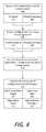
- FIG. 3is a high level flow chart describing an example method of dynamically configuring a LIDAR sensor.
- the high level method described with respect to FIG. 3may be performed by an example LIDAR configuration module 135 shown and described with respect to FIG. 1 , or the LIDAR configuration system 200 shown and described with respect to FIG. 2 .
- the LIDAR configuration system 200can receive AV data 230 from subsystems of the AV 100 , such as the AV control system 120 or the data processing system 110 ( 300 ).
- the AV data 230can include information such as the AV's speed ( 305 ), and road conditions ( 310 ) which can indicate potential hazards as the AV 100 travels along a current route.
- the LIDAR configuration system 200can dynamically configure the adjustable parameters of the LIDAR sensor system 210 of the AV 100 ( 315 ). For example, the LIDAR configuration system 200 can dynamically adjust an angular beam spacing between the beams to control a VFOV ( 320 ) based on the speed of the AV 100 . As another example, the LIDAR configuration system 200 can control a scan rate of the LIDAR sensor system 210 in response to the road conditions ( 325 ).
- FIG. 4is a low level flow chart describing an example method of configuring a LIDAR sensor, as described herein.
- the low level method described with respect to FIG. 4may be performed by an example LIDAR configuration module 135 shown and described with respect to FIG. 1 , or the LIDAR configuration system 200 shown and described with respect to FIG. 2 .
- the LIDAR configuration system 200can receive AV feedback data 230 from the AV control system 120 ( 400 ).
- the AV feedback data 230 from the AV control system 120can include the current AV speed ( 402 ) and/or driving parameters of the AV 100 ( 404 ).
- the AV feedback data 230can also be received from the data processing system 110 of the AV 100 ( 405 ). This data may include potential hazards on the road ( 407 ) and/or precipitation data ( 409 ). Based on the received feedback data 230 from the AV control system 120 and the on-board data processing system 110 , the LIDAR configuration system 200 can dynamically perform a lookup 272 in a set of LUTs 275 or perform an optimization to select a set of configurations 277 for the LIDAR sensor system 210 ( 410 ). The LIDAR configuration system 200 may then dynamically execute the set of configurations 277 on the LIDAR system 210 ( 415 ).
- execution of the configuration set 277causes the LIDAR configuration system 200 to adjust a VFOV or the beams angles of the LIDAR sensor system 210 ( 417 ). Additionally or alternatively, the configuration set 277 can cause the LIDAR configuration system 200 to adjust a scan rate ( 419 ) and/or a beam count ( 416 ) for the LIDAR sensor system 210 . In still other aspects, the LIDAR configuration system 200 can adjust a general vertical angle of the beams in response to detecting a road gradient ( 418 ).
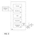
- FIG. 5is a block diagram that illustrates a computer system upon which examples described herein may be implemented.
- a computer system 500can be implemented on, for example, a server or combination of servers.
- the computer system 500may be implemented as part of a LIDAR configuration system 135 , which itself may be implemented as a part of the AV's on-board data processing system 110 .
- the LIDAR configuration system 135may include a sensor controller that executes sensor configuration logic or instructions, and can be implemented using a computer system such as described by FIG. 5 .
- the LIDAR configuration system 135may also be implemented using a combination of multiple computer systems as described in connection with FIG. 5 .
- the computer system 500includes processing resources 510 , a main memory 520 , a read-only memory (ROM) 530 , a storage device 540 , and a communication interface 550 .
- the computer system 500includes at least one processor 510 for processing information stored in the main memory 520 , such as provided by a random access memory (RAM) or other dynamic storage device, for storing information and instructions which are executable by the processor 510 .
- the main memory 520also may be used for storing temporary variables or other intermediate information during execution of instructions to be executed by the processor 510 .
- the computer system 500may also include the ROM 530 or other static storage device for storing static information and instructions for the processor 510 .
- a storage device 540such as a magnetic disk or optical disk, is provided for storing information and instructions.
- the communication interface 550enables the computer system 500 to communicate with one or more AV subsystems 580 over a network link (e.g., a wireless or wired link).
- the computer system 500receives feedback data 582 from the AV subsystems 580 .
- the executable instructions stored in the memory 530can include configuration instructions 522 , which the processor 510 executes to determine a set of configurations to configure the adjustable parameters of the AV's LIDAR sensor system 210 based on the feedback data 582 .
- the processor 510is configured with software and/or other logic to perform one or more processes, steps and other functions described with implementations, such as described by FIGS. 1 through 4 , and elsewhere in the present application.
- Examples described hereinare related to the use of the computer system 500 for implementing the techniques described herein. According to one example, those techniques are performed by the computer system 500 in response to the processor 510 executing one or more sequences of one or more instructions contained in the main memory 520 . Such instructions may be read into the main memory 520 from another machine-readable medium, such as the storage device 540 . Execution of the sequences of instructions contained in the main memory 520 causes the processor 510 to perform the process steps described herein. In alternative implementations, hard-wired circuitry may be used in place of or in combination with software instructions to implement examples described herein. Thus, the examples described are not limited to any specific combination of hardware circuitry and software.
Landscapes
- Physics & Mathematics (AREA)
- Engineering & Computer Science (AREA)
- General Physics & Mathematics (AREA)
- Computer Networks & Wireless Communication (AREA)
- Radar, Positioning & Navigation (AREA)
- Remote Sensing (AREA)
- Electromagnetism (AREA)
- Optics & Photonics (AREA)
- Traffic Control Systems (AREA)
- Optical Radar Systems And Details Thereof (AREA)
Abstract
Description
Claims (16)
Priority Applications (4)
| Application Number | Priority Date | Filing Date | Title |
|---|---|---|---|
| US15/379,854US10338225B2 (en) | 2015-12-15 | 2016-12-15 | Dynamic LIDAR sensor controller |
| US16/035,862US10677925B2 (en) | 2015-12-15 | 2018-07-16 | Adjustable beam pattern for lidar sensor |
| US16/859,650US11740355B2 (en) | 2015-12-15 | 2020-04-27 | Adjustable beam pattern for LIDAR sensor |
| US18/351,075US12282095B2 (en) | 2015-12-15 | 2023-07-12 | Adjustable beam pattern for LIDAR sensor |
Applications Claiming Priority (2)
| Application Number | Priority Date | Filing Date | Title |
|---|---|---|---|
| US201562267785P | 2015-12-15 | 2015-12-15 | |
| US15/379,854US10338225B2 (en) | 2015-12-15 | 2016-12-15 | Dynamic LIDAR sensor controller |
Related Child Applications (1)
| Application Number | Title | Priority Date | Filing Date |
|---|---|---|---|
| US16/035,862ContinuationUS10677925B2 (en) | 2015-12-15 | 2018-07-16 | Adjustable beam pattern for lidar sensor |
Publications (2)
| Publication Number | Publication Date |
|---|---|
| US20170168146A1 US20170168146A1 (en) | 2017-06-15 |
| US10338225B2true US10338225B2 (en) | 2019-07-02 |
Family
ID=59020620
Family Applications (4)
| Application Number | Title | Priority Date | Filing Date |
|---|---|---|---|
| US15/379,854ActiveUS10338225B2 (en) | 2015-12-15 | 2016-12-15 | Dynamic LIDAR sensor controller |
| US16/035,862ActiveUS10677925B2 (en) | 2015-12-15 | 2018-07-16 | Adjustable beam pattern for lidar sensor |
| US16/859,650Active2038-06-30US11740355B2 (en) | 2015-12-15 | 2020-04-27 | Adjustable beam pattern for LIDAR sensor |
| US18/351,075ActiveUS12282095B2 (en) | 2015-12-15 | 2023-07-12 | Adjustable beam pattern for LIDAR sensor |
Family Applications After (3)
| Application Number | Title | Priority Date | Filing Date |
|---|---|---|---|
| US16/035,862ActiveUS10677925B2 (en) | 2015-12-15 | 2018-07-16 | Adjustable beam pattern for lidar sensor |
| US16/859,650Active2038-06-30US11740355B2 (en) | 2015-12-15 | 2020-04-27 | Adjustable beam pattern for LIDAR sensor |
| US18/351,075ActiveUS12282095B2 (en) | 2015-12-15 | 2023-07-12 | Adjustable beam pattern for LIDAR sensor |
Country Status (1)
| Country | Link |
|---|---|
| US (4) | US10338225B2 (en) |
Cited By (10)
| Publication number | Priority date | Publication date | Assignee | Title |
|---|---|---|---|---|
| US20190353762A1 (en)* | 2018-05-15 | 2019-11-21 | Hyundai Mobis Co., Ltd. | Lidar apparatus for vehicle and control method thereof |
| US10677925B2 (en)* | 2015-12-15 | 2020-06-09 | Uatc, Llc | Adjustable beam pattern for lidar sensor |
| US10914820B2 (en) | 2018-01-31 | 2021-02-09 | Uatc, Llc | Sensor assembly for vehicles |
| US10942524B2 (en) | 2016-03-03 | 2021-03-09 | Uatc, Llc | Planar-beam, light detection and ranging system |
| US20220291383A1 (en)* | 2019-08-07 | 2022-09-15 | Nebras Ozzo | A lidar device, system, and control methods of the same |
| US11933967B2 (en) | 2019-08-22 | 2024-03-19 | Red Creamery, LLC | Distally actuated scanning mirror |
| US12123950B2 (en) | 2016-02-15 | 2024-10-22 | Red Creamery, LLC | Hybrid LADAR with co-planar scanning and imaging field-of-view |
| US12259475B2 (en) | 2021-03-30 | 2025-03-25 | Lg Innotek Co., Ltd. | Closed-loop motor control using unidirectional data feedback |
| US12399279B1 (en) | 2016-02-15 | 2025-08-26 | Red Creamery Llc | Enhanced hybrid LIDAR with high-speed scanning |
| US12399278B1 (en) | 2016-02-15 | 2025-08-26 | Red Creamery Llc | Hybrid LIDAR with optically enhanced scanned laser |
Families Citing this family (43)
| Publication number | Priority date | Publication date | Assignee | Title |
|---|---|---|---|---|
| AU2014239979B2 (en) | 2013-03-15 | 2017-06-22 | Aurora Operations, Inc. | Methods, systems, and apparatus for multi-sensory stereo vision for robotics |
| US9952317B2 (en) | 2016-05-27 | 2018-04-24 | Uber Technologies, Inc. | Vehicle sensor calibration system |
| US10479376B2 (en) | 2017-03-23 | 2019-11-19 | Uatc, Llc | Dynamic sensor selection for self-driving vehicles |
| US11300958B2 (en)* | 2017-07-13 | 2022-04-12 | Waymo Llc | Sensor adjustment based on vehicle motion |
| US20210403015A1 (en)* | 2017-08-03 | 2021-12-30 | Koito Manufacturing Co., Ltd | Vehicle lighting system, vehicle system, and vehicle |
| US10746858B2 (en) | 2017-08-17 | 2020-08-18 | Uatc, Llc | Calibration for an autonomous vehicle LIDAR module |
| US10775488B2 (en) | 2017-08-17 | 2020-09-15 | Uatc, Llc | Calibration for an autonomous vehicle LIDAR module |
| US10816666B2 (en)* | 2017-11-21 | 2020-10-27 | Magna Electronics Inc. | Vehicle sensing system with calibration/fusion of point cloud partitions |
| US20190179317A1 (en) | 2017-12-13 | 2019-06-13 | Luminar Technologies, Inc. | Controlling vehicle sensors using an attention model |
| US11385331B2 (en) | 2018-01-29 | 2022-07-12 | The Regents Of The University Of California | Enclosure for light detection and ranging unit and related methods |
| US10884115B2 (en) | 2018-03-09 | 2021-01-05 | Waymo Llc | Tailoring sensor emission power to map, vehicle state, and environment |
| US11467590B2 (en) | 2018-04-09 | 2022-10-11 | SafeAI, Inc. | Techniques for considering uncertainty in use of artificial intelligence models |
| US11625036B2 (en) | 2018-04-09 | 2023-04-11 | SafeAl, Inc. | User interface for presenting decisions |
| US11561541B2 (en)* | 2018-04-09 | 2023-01-24 | SafeAI, Inc. | Dynamically controlling sensor behavior |
| US11169536B2 (en) | 2018-04-09 | 2021-11-09 | SafeAI, Inc. | Analysis of scenarios for controlling vehicle operations |
| US20210253116A1 (en)* | 2018-06-10 | 2021-08-19 | Osr Enterprises Ag | System and method for enhancing sensor operation in a vehicle |
| US10627516B2 (en)* | 2018-07-19 | 2020-04-21 | Luminar Technologies, Inc. | Adjustable pulse characteristics for ground detection in lidar systems |
| US10340651B1 (en)* | 2018-08-21 | 2019-07-02 | Luminar Technologies, Inc. | Lidar system with optical trigger |
| WO2020057517A1 (en)* | 2018-09-18 | 2020-03-26 | Suteng Innovation Technology Co., Ltd. | Multi-beam lidar systems and methods for detection using the same |
| JP6723307B2 (en)* | 2018-09-28 | 2020-07-15 | 三菱電機株式会社 | Laser distance measuring device |
| US11536846B2 (en) | 2018-12-28 | 2022-12-27 | Wipro Limited | Elevation detection system for autonomous vehicles and a method thereof |
| US11016489B2 (en)* | 2019-01-18 | 2021-05-25 | Baidu Usa Llc | Method to dynamically determine vehicle effective sensor coverage for autonomous driving application |
| US11409302B2 (en) | 2019-03-03 | 2022-08-09 | Wipro Limited | Method for autonomous parking of a vehicle, and an autonomous vehicle thereof |
| CN109782015B (en)* | 2019-03-21 | 2024-11-29 | 同方威视技术股份有限公司 | Laser speed measuring method, control device and laser speed measuring instrument |
| US11709227B2 (en) | 2019-04-02 | 2023-07-25 | Ford Global Technologies, Llc | Beam distribution adjustment for a sensor |
| US11275673B1 (en)* | 2019-06-24 | 2022-03-15 | Zoox, Inc. | Simulated LiDAR data |
| US11242098B2 (en) | 2019-07-26 | 2022-02-08 | Waymo Llc | Efficient autonomous trucks |
| CN213252024U (en) | 2019-09-10 | 2021-05-25 | 贝克顿·迪金森公司 | Vascular access system and clamping device |
| US11698446B2 (en)* | 2019-10-07 | 2023-07-11 | Gm Cruise Holdings Llc | Vertically stacked lidar assembly |
| KR102276597B1 (en)* | 2019-11-28 | 2021-07-14 | 한국전자기술연구원 | Device and method to control vehicle for optimizing LIDAR data range by using vector map |
| US12439003B2 (en) | 2019-12-23 | 2025-10-07 | Waymo Llc | Real-time adjustment of vehicle sensor field of view volume |
| US11360191B2 (en)* | 2019-12-27 | 2022-06-14 | Woven Planet North America, Inc. | Adaptive tilting radars for effective vehicle controls |
| DE102020001765A1 (en) | 2020-03-17 | 2021-09-23 | Scania Cv Ab | Method and control arrangement for selecting a subset of sensor data from a vehicle sensor |
| US11447128B2 (en)* | 2020-04-29 | 2022-09-20 | GM Global Technology Operations LLC | Method and system for operating an on-vehicle LiDAR sensor |
| JP7348881B2 (en)* | 2020-06-10 | 2023-09-21 | 株式会社日立製作所 | Obstacle detection system, obstacle detection method, and self-position estimation system |
| US12095367B2 (en) | 2020-06-15 | 2024-09-17 | The Regents Of The University Of Michigan | Cycle-by-cycle digital control of DC-DC converters |
| KR20220058032A (en)* | 2020-10-30 | 2022-05-09 | (주)인사이트테크 | Personal mobility collision recognition system |
| KR102563339B1 (en)* | 2020-12-18 | 2023-08-02 | 국민대학교산학협력단 | Apparatus and method for detecting object of vehicle |
| CN115754993A (en)* | 2021-09-03 | 2023-03-07 | 广州华凌制冷设备有限公司 | Laser radar data correction method and device, air conditioner and storage medium |
| EP4198567B1 (en)* | 2021-12-20 | 2025-01-08 | Toyota Jidosha Kabushiki Kaisha | Method for determining a beam configuration of a lidar system |
| US20230204781A1 (en)* | 2021-12-28 | 2023-06-29 | Nio Technology (Anhui) Co., Ltd. | Time of flight cameras using passive image sensors and existing light sources |
| US20240045064A1 (en)* | 2022-08-03 | 2024-02-08 | Board Of Regents Of The Nevada System Of Higher Education, On Behalf Of The University Of Nevada | METHODS AND SYSTEMS FOR DATA MAPPING USING ROADSIDE LiDAR SENSOR DATA AND GEOGRAPHIC INFORMATION SYSTEM (GIS) BASED SOFTWARE |
| CN119511247B (en)* | 2024-12-04 | 2025-09-16 | 重庆赛力斯凤凰智创科技有限公司 | Laser radar angle adjustment method, device, electronic device and storage medium |
Citations (116)
| Publication number | Priority date | Publication date | Assignee | Title |
|---|---|---|---|---|
| EP0185816A1 (en) | 1984-12-27 | 1986-07-02 | THE GENERAL ELECTRIC COMPANY, p.l.c. | A vehicle guidance and control system |
| US5012745A (en) | 1989-03-08 | 1991-05-07 | Koyo Jidoki Company Limited | Vehicle turn-table |
| US5590604A (en) | 1995-06-07 | 1997-01-07 | Autran Corp. | Transportation system with high speed vehicles and automatic control |
| US5598783A (en) | 1995-06-07 | 1997-02-04 | Autran Corp. | Integrated transportation system including transfer vehicles |
| JPH09163197A (en) | 1995-12-09 | 1997-06-20 | Sony Corp | Video camera equipment |
| JPH09326032A (en) | 1996-06-06 | 1997-12-16 | Fuji Heavy Ind Ltd | Vehicle peripheral three-dimensional object recognizing device |
| US5726647A (en) | 1995-04-05 | 1998-03-10 | Bayersche Motoren Werke Aktiengesellscaft | Method and apparatus for avoiding a collision of a motor vehicle |
| US6122040A (en)* | 1997-11-06 | 2000-09-19 | Omron Corporation | System and method of detecting deviation of an axis and adjusting the axis of a range finder |
| US20020135468A1 (en) | 1997-09-22 | 2002-09-26 | Donnelly Corporation, A Corporation Of The State Of Michigan | Vehicle imaging system with accessory control |
| US6657705B2 (en)* | 2001-06-20 | 2003-12-02 | Denso Corporation | Distance measuring apparatus |
| US20040030474A1 (en) | 2002-08-05 | 2004-02-12 | Samuel Stepen Varghese | Method and system for correcting sensor offsets |
| DE10244638A1 (en) | 2002-09-25 | 2004-04-08 | Ibeo Automobile Sensor Gmbh | Position monitoring system for use on road vehicle uses pulsed lasers, sensor module and mechanical scanner with mirror set at angle on shaft with calibration disk driven by electric motor |
| US20040148093A1 (en) | 2003-01-27 | 2004-07-29 | Denso Corporation | Vehicle behavior detector, in-vehicle processing system, detection information calibrator, and in-vehicle processor |
| US6827265B2 (en) | 1998-03-24 | 2004-12-07 | Metrologic Instruments, Inc. | Automatic vehicle identification and classification (AVIC) system employing a tunnel-arrangement of PLIIM-based subsystems |
| JP2005024463A (en) | 2003-07-04 | 2005-01-27 | Fuji Heavy Ind Ltd | Stereo wide-field image processor |
| US6860350B2 (en)* | 2002-12-20 | 2005-03-01 | Motorola, Inc. | CMOS camera with integral laser ranging and velocity measurement |
| US20050095092A1 (en) | 2000-07-20 | 2005-05-05 | Maurice Segal | Multi-level, automated vehicle parking structure |
| US20050185846A1 (en) | 2004-02-24 | 2005-08-25 | Trw Automotive U.S. Llc | Method and apparatus for controlling classification and classification switching in a vision system |
| US20050196035A1 (en) | 2004-03-03 | 2005-09-08 | Trw Automotive U.S. Llc | Method and apparatus for producing classifier training images |
| US20050196015A1 (en) | 2004-03-02 | 2005-09-08 | Trw Automotive U.S. Llc | Method and apparatus for tracking head candidate locations in an actuatable occupant restraining system |
| US6956227B2 (en)* | 2002-10-07 | 2005-10-18 | Omron Corporation | Object detecting device and method with means for controlling direction of scan by electromagnetic waves |
| US20060089765A1 (en) | 2004-10-22 | 2006-04-27 | Pack Robert T | System and method for behavior based control of an autonomous vehicle |
| US20060158423A1 (en) | 2002-10-12 | 2006-07-20 | Leica Geosystems Ag | Electronic display and control device for a measuring device |
| US7248342B1 (en)* | 2003-02-14 | 2007-07-24 | United States Of America As Represented By The Administrator Of The National Aeronautics And Space Administration | Three-dimension imaging lidar |
| EP1816514A1 (en) | 2004-11-15 | 2007-08-08 | Hitachi, Ltd. | Stereo camera |
| US20070200064A1 (en) | 2003-07-15 | 2007-08-30 | Ford Global Technologies, Llc | Active night vision thermal control system using wavelength-temperature characteristic of light source |
| US20070219720A1 (en)* | 2006-03-16 | 2007-09-20 | The Gray Insurance Company | Navigation and control system for autonomous vehicles |
| JP2007249632A (en) | 2006-03-16 | 2007-09-27 | Fujitsu Ltd | A mobile robot that moves autonomously in an environment with obstacles and a method for controlling the mobile robot |
| US20080002427A1 (en) | 2006-05-15 | 2008-01-03 | Miroslav Kropac | Variable planar light guide module |
| US20080039991A1 (en) | 2006-08-10 | 2008-02-14 | May Reed R | Methods and systems for providing accurate vehicle positioning |
| US20080161986A1 (en) | 1997-10-22 | 2008-07-03 | Intelligent Technologies International, Inc. | Autonomous Vehicle Travel Control Systems and Methods |
| US20090312906A1 (en)* | 2007-01-04 | 2009-12-17 | Continental Automotive Gmbh | Vertical alignment of a lidar sensor |
| US20090319112A1 (en) | 2007-09-28 | 2009-12-24 | Honeywell International Inc. | Automatic planning and regulation of the speed of autonomous vehicles |
| US7650239B2 (en)* | 2004-11-16 | 2010-01-19 | Denso Corporation | Object recognition apparatus for motor vehicle |
| US20100013615A1 (en) | 2004-03-31 | 2010-01-21 | Carnegie Mellon University | Obstacle detection having enhanced classification |
| US20100020306A1 (en)* | 2006-07-13 | 2010-01-28 | Velodyne Acoustics, Inc. | High definition lidar system |
| US20100053715A1 (en)* | 2006-10-30 | 2010-03-04 | O'neill James | Scanning system for lidar |
| US20100110192A1 (en) | 1998-04-09 | 2010-05-06 | Johnston Gregory E | Mobile Surveillance System |
| US20100185353A1 (en) | 2009-01-17 | 2010-07-22 | Boomerang Systems, Inc. | Variable offset positioning antenna array for enhanced guidance of automated guided vehicles (agvs) |
| US20100194890A1 (en) | 2000-03-02 | 2010-08-05 | Donnelly Corporation | Video mirror system suitable for use in a vehicle |
| US20100208034A1 (en) | 2009-02-17 | 2010-08-19 | Autoliv Asp, Inc. | Method and system for the dynamic calibration of stereovision cameras |
| US20100208244A1 (en)* | 2008-05-09 | 2010-08-19 | Ball Aerospace & Technologies Corp. | Flash ladar system |
| US20110050855A1 (en) | 2006-07-26 | 2011-03-03 | Guenter Nobis | Optical measuring device with two camera units |
| JP2011088623A (en) | 2009-09-22 | 2011-05-06 | Nippon Sharyo Seizo Kaisha Ltd | Dampers for vibration control of railway vehicles |
| US20110134249A1 (en) | 2009-12-04 | 2011-06-09 | Lockheed Martin Corporation | Optical Detection and Ranging Sensor System For Sense and Avoid, and Related Methods |
| US20110166757A1 (en)* | 2010-01-04 | 2011-07-07 | Gm Global Technology Operations, Inc. | Closed-loop feedback control and reduction of the torque converter clutch slip for enhanced drivability for heavy tip-in maneuvers |
| US20110184605A1 (en) | 2006-11-29 | 2011-07-28 | Neff Ryan A | Driverless vehicle |
| US20110245964A1 (en) | 2010-04-06 | 2011-10-06 | Sullivan Robert P | Self Aligning Automated Material Handling System |
| US20110241845A1 (en) | 2010-04-06 | 2011-10-06 | Sullivan Robert P | Automated Material Handling System with Identification Features |
| US20110301786A1 (en) | 2010-05-12 | 2011-12-08 | Daniel Allis | Remote Vehicle Control System and Method |
| US20110317993A1 (en) | 2010-06-23 | 2011-12-29 | Outwest Systems, Inc. | Apparatus for Mounting a Webcam to Another Optical Instrument |
| US20120008129A1 (en)* | 2007-11-07 | 2012-01-12 | Magna Electronics, Inc. | Object detection system |
| US20120033196A1 (en)* | 2010-03-12 | 2012-02-09 | Vanek Michael D | Method for Enhancing a Three Dimensional Image from a Plurality of Frames of Flash Lidar Data |
| CN102494609A (en) | 2011-11-18 | 2012-06-13 | 李志扬 | Three-dimensional photographing process based on laser probe array and device utilizing same |
| US20120154785A1 (en) | 2010-11-01 | 2012-06-21 | Patrick Gilliland | Flash Ladar Collision Avoidance System |
| US8208716B2 (en) | 2007-09-03 | 2012-06-26 | Electronics And Telecommunications Research Institute | Stereo vision system and stereo vision processing method |
| US20120239238A1 (en) | 2011-03-18 | 2012-09-20 | Harvey Dean S | Communication technique by which an autonomous guidance system controls an industrial vehicle |
| CN101959022B (en) | 2009-07-17 | 2012-11-28 | 深圳泰山在线科技有限公司 | Synchronous circuit, and image pick-up device and synchronous exposure control method thereof |
| US8344940B2 (en)* | 2009-01-22 | 2013-01-01 | Mando Corporation | Apparatus and sensor for adjusting sensor vertical alignment |
| US20130078063A1 (en) | 2011-09-22 | 2013-03-28 | Unitronics Parking Solutions Ltd. | Vehicle positioning system |
| CN103152518A (en) | 2011-12-01 | 2013-06-12 | 索尼公司 | Image processing system and method |
| CN103179339A (en) | 2011-12-01 | 2013-06-26 | 索尼公司 | Image processing system and method |
| US20130166105A1 (en) | 2011-12-22 | 2013-06-27 | Park Plus, Inc. | Automated parking garage/self-storage apparatus |
| US20130190963A1 (en) | 2011-03-18 | 2013-07-25 | The Raymond Corporation | System and Method for Gathering Video Data Related to Operation of an Autonomous Industrial Vehicle |
| US20130226431A1 (en)* | 2012-02-27 | 2013-08-29 | Jianbo Lu | Smart adaptive cruise control |
| RU2493988C2 (en) | 2009-06-10 | 2013-09-27 | Сканиа Св Аб | Module and system for definition of reference magnitudes for vehicle control system |
| US20130317649A1 (en)* | 2012-05-25 | 2013-11-28 | United States Of America As Represented By The Secretary Of The Navy | Nodding Mechanism For A Single-Scan Sensor |
| CN203353019U (en) | 2013-05-28 | 2013-12-18 | 东莞劲胜精密组件股份有限公司 | Graphene metal cooling fin and electronic product cooling structure |
| US20140041966A1 (en) | 2010-02-12 | 2014-02-13 | Snap-On Incorporated | Apparatus for guiding a vehicle onto a service lift using a machine vision wheel alignment system |
| US20140136414A1 (en) | 2006-03-17 | 2014-05-15 | Raj Abhyanker | Autonomous neighborhood vehicle commerce network and community |
| RU2012154453A (en) | 2012-12-06 | 2014-06-20 | Александр ГУРЕВИЧ | METHOD FOR DETERMINING THE BOUNDARIES OF THE ROAD, FORM AND POSITION OF OBJECTS ON THE ROAD, AND THE DEVICE FOR ITS PERFORMANCE |
| US8797828B1 (en) | 2010-02-15 | 2014-08-05 | Soreq NRC | Remote optical seismic surveying and detection and imaging of underground objects |
| US20140231647A1 (en) | 2010-11-23 | 2014-08-21 | United States Of America, As Represented By The Secretary Of The Army | Compact fiber-based scanning laser detection and ranging system |
| US20140277691A1 (en) | 2013-03-15 | 2014-09-18 | Cybernet Systems Corporation | Automated warehousing using robotic forklifts |
| US20140286744A1 (en) | 2013-03-21 | 2014-09-25 | Unitronics Parking Solutions Ltd. | Vehicle centering system |
| US8899903B1 (en) | 2010-05-18 | 2014-12-02 | The Boeing Company | Vehicle base station |
| US8996224B1 (en) | 2013-03-15 | 2015-03-31 | Google Inc. | Detecting that an autonomous vehicle is in a stuck condition |
| US8994581B1 (en)* | 2012-09-25 | 2015-03-31 | Adam Brown | Direction of arrival (DOA) estimation using multiple offset receive channels |
| CN103001428B (en) | 2012-12-26 | 2015-05-20 | 上海摩软通讯技术有限公司 | Flat motor and mobile terminal |
| US20150202939A1 (en) | 2013-03-08 | 2015-07-23 | Advanced Scientific Concepts, Inc. | Ladar enabled impact mitigation system |
| US9126595B2 (en)* | 2012-07-24 | 2015-09-08 | Hyundai Mobis Co., Ltd. | Apparatus and method for calculating inter-vehicle distance |
| US20150293225A1 (en)* | 2014-04-14 | 2015-10-15 | The Boeing Company | Aerial positioning systems and methods |
| EP2940489A1 (en) | 2014-05-02 | 2015-11-04 | Ricoh Company, Ltd. | Object detection device and sensing apparatus |
| US20150334269A1 (en) | 2014-05-19 | 2015-11-19 | Soichiro Yokota | Processing apparatus, processing system, and processing method |
| US9201424B1 (en) | 2013-08-27 | 2015-12-01 | Google Inc. | Camera calibration using structure from motion techniques |
| CN102857592B (en) | 2011-06-01 | 2015-12-02 | Lg电子株式会社 | Mobile terminal and 3D image display method thereof |
| US9224053B1 (en) | 2013-07-31 | 2015-12-29 | Google Inc. | Combining multiple estimates of an environment into a consolidated estimate for an autonomous vehicle |
| US9231998B2 (en) | 2014-01-22 | 2016-01-05 | Ford Global Technologies, Llc | Vehicle-specific computation management system for cloud computing |
| US20160003946A1 (en) | 2014-07-03 | 2016-01-07 | Advanced Scientific Concepts, Inc. | Ladar sensor for a dense environment |
| CN103146355B (en) | 2011-12-07 | 2016-02-10 | 北京中石伟业科技股份有限公司 | A kind of heat-sink material |
| US20160129917A1 (en) | 2014-11-07 | 2016-05-12 | Clearpath Robotics, Inc. | Self-calibrating sensors and actuators for unmanned vehicles |
| RU2014146890A (en) | 2013-11-22 | 2016-06-10 | Форд Глобал Технолоджис, ЛЛК | VEHICLE SYSTEM FOR CONFIGURING ITS OFFLINE OPERATION MODES |
| US9383753B1 (en)* | 2012-09-26 | 2016-07-05 | Google Inc. | Wide-view LIDAR with areas of special attention |
| US20160223671A1 (en) | 2011-06-30 | 2016-08-04 | The Regents Of The University Of Colorado | Remote measurement of shallow depths in semi-transparent media |
| US20160231746A1 (en) | 2015-02-06 | 2016-08-11 | Delphi Technologies, Inc. | System And Method To Operate An Automated Vehicle |
| US9453914B2 (en) | 2011-09-08 | 2016-09-27 | Continental Advanced Lidar Solutions Us, Inc. | Terrain mapping LADAR system |
| US20160291134A1 (en)* | 2015-04-06 | 2016-10-06 | Google Inc. | Long Range Steerable LIDAR System |
| US20160318415A1 (en) | 2015-04-29 | 2016-11-03 | General Electric Company | Apparatus and method for automated positioning of a vehicle |
| US20160349746A1 (en) | 2015-05-29 | 2016-12-01 | Faro Technologies, Inc. | Unmanned aerial vehicle having a projector and being tracked by a laser tracker |
| US9529079B1 (en) | 2015-03-26 | 2016-12-27 | Google Inc. | Multiplexed multichannel photodetector |
| US20170096138A1 (en) | 2015-10-06 | 2017-04-06 | Ford Global Technologies, Llc | Collision Avoidance Using Auditory Data Augmented With Map Data |
| US9625582B2 (en)* | 2015-03-25 | 2017-04-18 | Google Inc. | Vehicle with multiple light detection and ranging devices (LIDARs) |
| US9669827B1 (en) | 2014-10-02 | 2017-06-06 | Google Inc. | Predicting trajectories of objects based on contextual information |
| US20170168146A1 (en)* | 2015-12-15 | 2017-06-15 | Uber Technologies, Inc. | Dynamic lidar sensor controller |
| US20170184399A1 (en) | 2011-06-30 | 2017-06-29 | The Regents Of The University Of Colorado | Remote measurement of shallow depths in semi-transparent media |
| US9696722B1 (en) | 2013-03-06 | 2017-07-04 | Waymo Llc | Light steering device with an array of oscillating reflective slats |
| US9720415B2 (en) | 2015-11-04 | 2017-08-01 | Zoox, Inc. | Sensor-based object-detection optimization for autonomous vehicles |
| US9719801B1 (en) | 2013-07-23 | 2017-08-01 | Waymo Llc | Methods and systems for calibrating sensors using road map data |
| US20170226765A1 (en) | 2016-02-09 | 2017-08-10 | Park Plus, Inc. | Vehicle parking with automated guided vehicles, vertically reciprocating conveyors and safety barriers |
| US9823353B2 (en)* | 2015-11-30 | 2017-11-21 | Luminar Technologies, Inc. | Lidar system |
| US9841763B1 (en)* | 2015-12-16 | 2017-12-12 | Uber Technologies, Inc. | Predictive sensor array configuration system for an autonomous vehicle |
| US9840256B1 (en)* | 2015-12-16 | 2017-12-12 | Uber Technologies, Inc. | Predictive sensor array configuration system for an autonomous vehicle |
| US9841495B2 (en)* | 2015-11-05 | 2017-12-12 | Luminar Technologies, Inc. | Lidar system with improved scanning speed for high-resolution depth mapping |
| US9869754B1 (en)* | 2017-03-22 | 2018-01-16 | Luminar Technologies, Inc. | Scan patterns for lidar systems |
| US9869753B2 (en)* | 2014-08-15 | 2018-01-16 | Quanergy Systems, Inc. | Three-dimensional-mapping two-dimensional-scanning lidar based on one-dimensional-steering optical phased arrays and method of using same |
| US20180070804A1 (en) | 2012-06-27 | 2018-03-15 | Camplex, Inc. | Interface for viewing video from cameras on a surgical visualization system |
Family Cites Families (54)
| Publication number | Priority date | Publication date | Assignee | Title |
|---|---|---|---|---|
| JP3292729B2 (en) | 1990-11-26 | 2002-06-17 | 三菱電機株式会社 | Optical fiber type optical amplifier |
| US5212738A (en)* | 1991-04-12 | 1993-05-18 | Martin Marietta Magnesia Specialties Inc. | Scanning laser measurement system |
| DE69942446D1 (en) | 1998-03-04 | 2010-07-15 | Jds Uniphase Corp | OPTICAL COUPLERS FOR MULTIMODE FIBERS |
| US20140152823A1 (en)* | 1998-11-30 | 2014-06-05 | American Vehicular Sciences Llc | Techniques to Obtain Information About Objects Around a Vehicle |
| JP2004535580A (en) | 2001-07-16 | 2004-11-25 | ベルス・メステヒニーク・ゲーエムベーハー | Surface characteristic measuring method and coordinate measuring device |
| US8483960B2 (en)* | 2002-09-20 | 2013-07-09 | Visual Intelligence, LP | Self-calibrated, remote imaging and data processing system |
| US7725258B2 (en)* | 2002-09-20 | 2010-05-25 | M7 Visual Intelligence, L.P. | Vehicle based data collection and processing system and imaging sensor system and methods thereof |
| US8994822B2 (en)* | 2002-08-28 | 2015-03-31 | Visual Intelligence Lp | Infrastructure mapping system and method |
| US7901348B2 (en) | 2003-12-12 | 2011-03-08 | University Of Washington | Catheterscope 3D guidance and interface system |
| US7532311B2 (en)* | 2005-04-06 | 2009-05-12 | Lockheed Martin Coherent Technologies, Inc. | Efficient lidar with flexible target interrogation pattern |
| EP1969312B1 (en)* | 2005-12-08 | 2017-03-29 | Advanced Scientific Concepts INC. | Laser ranging, tracking and designation using 3-d focal planes |
| US8744224B2 (en) | 2006-03-07 | 2014-06-03 | Alcatel Lucent | Tapered fiber bundle apparatus with monitoring capability |
| US7406220B1 (en)* | 2006-03-09 | 2008-07-29 | Lockheed Martin Coherent Technologies, Inc. | Beam steering and combination |
| EP1840140A1 (en) | 2006-03-30 | 2007-10-03 | Total Petrochemicals Research Feluy | Method for making a transition between polymer grades |
| US8884763B2 (en)* | 2006-10-02 | 2014-11-11 | iRobert Corporation | Threat detection sensor suite |
| JP5049546B2 (en) | 2006-10-17 | 2012-10-17 | 株式会社ツバキエマソン | Sealed rotation sensor built-in motor |
| KR100834577B1 (en) | 2006-12-07 | 2008-06-02 | 한국전자통신연구원 | Stereo vision processing to find and track targets and intelligent home service robot devices |
| US8164742B1 (en)* | 2007-07-18 | 2012-04-24 | The United States Of America As Represented By The Secretary Of The Army | Photopolarimetric lidar dual-beam switching device and mueller matrix standoff detection system and method |
| US7746449B2 (en)* | 2007-11-14 | 2010-06-29 | Rosemount Aerospace Inc. | Light detection and ranging system |
| US9041915B2 (en)* | 2008-05-09 | 2015-05-26 | Ball Aerospace & Technologies Corp. | Systems and methods of scene and action capture using imaging system incorporating 3D LIDAR |
| US8126642B2 (en) | 2008-10-24 | 2012-02-28 | Gray & Company, Inc. | Control and systems for autonomously driven vehicles |
| DE102008055159A1 (en)* | 2008-12-29 | 2010-07-01 | Robert Bosch Gmbh | Adaptive angle and power adjustment for 3D micromirror lidar |
| US8089617B2 (en)* | 2009-01-21 | 2012-01-03 | Raytheon Company | Energy efficient laser detection and ranging system |
| US8810796B2 (en)* | 2009-04-21 | 2014-08-19 | Michigan Aerospace Corporation | Light processing system and method |
| US8125622B2 (en)* | 2009-07-28 | 2012-02-28 | Applied Concepts, Inc. | Lidar measurement device with target tracking and method for use of same |
| US9303989B2 (en) | 2010-02-23 | 2016-04-05 | Ben-Gurion University Of The Negev | System and method for providing 3D imaging |
| US9086488B2 (en)* | 2010-04-20 | 2015-07-21 | Michigan Aerospace Corporation | Atmospheric measurement system and method |
| US8736818B2 (en)* | 2010-08-16 | 2014-05-27 | Ball Aerospace & Technologies Corp. | Electronically steered flash LIDAR |
| US9530060B2 (en) | 2012-01-17 | 2016-12-27 | Avigilon Fortress Corporation | System and method for building automation using video content analysis with depth sensing |
| EP2822472B1 (en)* | 2012-03-07 | 2022-09-28 | Ziteo, Inc. | Systems for tracking and guiding sensors and instruments |
| US9738223B2 (en)* | 2012-05-31 | 2017-08-22 | GM Global Technology Operations LLC | Dynamic guideline overlay with image cropping |
| US9228833B2 (en) | 2012-06-28 | 2016-01-05 | GM Global Technology Operations LLC | Wide baseline binocular object matching method using minimal cost flow network |
| JP2014053408A (en) | 2012-09-06 | 2014-03-20 | Canon Inc | Charged particle beam lens and manufacturing method thereof |
| US9823351B2 (en) | 2012-12-18 | 2017-11-21 | Uber Technologies, Inc. | Multi-clad fiber based optical apparatus and methods for light detection and ranging sensors |
| US9476981B2 (en)* | 2013-01-08 | 2016-10-25 | Massachusetts Institute Of Technology | Optical phased arrays |
| WO2014129386A1 (en) | 2013-02-19 | 2014-08-28 | ピーエスフォー ルクスコ エスエイアールエル | Command fifo circuit |
| AU2014239979B2 (en) | 2013-03-15 | 2017-06-22 | Aurora Operations, Inc. | Methods, systems, and apparatus for multi-sensory stereo vision for robotics |
| EP2827099A1 (en)* | 2013-07-16 | 2015-01-21 | Leica Geosystems AG | Laser tracker with target searching functionality |
| US9454150B2 (en)* | 2013-07-17 | 2016-09-27 | Toyota Motor Engineering & Manufacturing North America, Inc. | Interactive automated driving system |
| US9425654B2 (en) | 2013-09-30 | 2016-08-23 | Google Inc. | Contactless electrical coupling for a rotatable LIDAR device |
| US9831630B2 (en)* | 2014-02-06 | 2017-11-28 | GM Global Technology Operations LLC | Low cost small size LiDAR for automotive |
| US9360554B2 (en)* | 2014-04-11 | 2016-06-07 | Facet Technology Corp. | Methods and apparatus for object detection and identification in a multiple detector lidar array |
| US9612436B1 (en)* | 2014-08-12 | 2017-04-04 | Ball Aerospace & Technologies Corp. | High-speed scanner-tracker |
| EP3186661B1 (en)* | 2014-08-26 | 2021-04-07 | Massachusetts Institute of Technology | Methods and apparatus for three-dimensional (3d) imaging |
| US10557923B2 (en)* | 2015-02-25 | 2020-02-11 | The Government Of The United States Of America, As Represented By The Secretary Of The Navy | Real-time processing and adaptable illumination lidar camera using a spatial light modulator |
| US10042042B2 (en) | 2015-06-12 | 2018-08-07 | Aero Vironment, Inc. | Rotating lidar |
| CN106291580B (en)* | 2015-06-12 | 2019-08-23 | 上海珏芯光电科技有限公司 | Laser infrared radar imaging system |
| CN204990755U (en) | 2015-09-29 | 2016-01-20 | 成都川睿科技有限公司 | Intelligent transportation car -mounted device based on laser radar |
| US10281923B2 (en) | 2016-03-03 | 2019-05-07 | Uber Technologies, Inc. | Planar-beam, light detection and ranging system |
| US20180067195A1 (en)* | 2016-09-08 | 2018-03-08 | Qualcomm Incorporated | Multi-tier light-based ranging systems and methods |
| CN106313078A (en) | 2016-10-27 | 2017-01-11 | 上海思岚科技有限公司 | Mobile robot platform |
| US10479376B2 (en)* | 2017-03-23 | 2019-11-19 | Uatc, Llc | Dynamic sensor selection for self-driving vehicles |
| CN207908673U (en) | 2018-01-04 | 2018-09-25 | 北京汽车股份有限公司 | Autonomous driving vehicle laser radar component and autonomous driving vehicle |
| US10914820B2 (en) | 2018-01-31 | 2021-02-09 | Uatc, Llc | Sensor assembly for vehicles |
- 2016
- 2016-12-15USUS15/379,854patent/US10338225B2/enactiveActive
- 2018
- 2018-07-16USUS16/035,862patent/US10677925B2/enactiveActive
- 2020
- 2020-04-27USUS16/859,650patent/US11740355B2/enactiveActive
- 2023
- 2023-07-12USUS18/351,075patent/US12282095B2/enactiveActive
Patent Citations (128)
| Publication number | Priority date | Publication date | Assignee | Title |
|---|---|---|---|---|
| EP0185816A1 (en) | 1984-12-27 | 1986-07-02 | THE GENERAL ELECTRIC COMPANY, p.l.c. | A vehicle guidance and control system |
| US5012745A (en) | 1989-03-08 | 1991-05-07 | Koyo Jidoki Company Limited | Vehicle turn-table |
| US5726647A (en) | 1995-04-05 | 1998-03-10 | Bayersche Motoren Werke Aktiengesellscaft | Method and apparatus for avoiding a collision of a motor vehicle |
| US5598783A (en) | 1995-06-07 | 1997-02-04 | Autran Corp. | Integrated transportation system including transfer vehicles |
| US5590604A (en) | 1995-06-07 | 1997-01-07 | Autran Corp. | Transportation system with high speed vehicles and automatic control |
| JPH09163197A (en) | 1995-12-09 | 1997-06-20 | Sony Corp | Video camera equipment |
| JPH09326032A (en) | 1996-06-06 | 1997-12-16 | Fuji Heavy Ind Ltd | Vehicle peripheral three-dimensional object recognizing device |
| US20020135468A1 (en) | 1997-09-22 | 2002-09-26 | Donnelly Corporation, A Corporation Of The State Of Michigan | Vehicle imaging system with accessory control |
| US20080161986A1 (en) | 1997-10-22 | 2008-07-03 | Intelligent Technologies International, Inc. | Autonomous Vehicle Travel Control Systems and Methods |
| US6122040A (en)* | 1997-11-06 | 2000-09-19 | Omron Corporation | System and method of detecting deviation of an axis and adjusting the axis of a range finder |
| US6827265B2 (en) | 1998-03-24 | 2004-12-07 | Metrologic Instruments, Inc. | Automatic vehicle identification and classification (AVIC) system employing a tunnel-arrangement of PLIIM-based subsystems |
| US20100110192A1 (en) | 1998-04-09 | 2010-05-06 | Johnston Gregory E | Mobile Surveillance System |
| US20100194890A1 (en) | 2000-03-02 | 2010-08-05 | Donnelly Corporation | Video mirror system suitable for use in a vehicle |
| US20050095092A1 (en) | 2000-07-20 | 2005-05-05 | Maurice Segal | Multi-level, automated vehicle parking structure |
| US6657705B2 (en)* | 2001-06-20 | 2003-12-02 | Denso Corporation | Distance measuring apparatus |
| US20040030474A1 (en) | 2002-08-05 | 2004-02-12 | Samuel Stepen Varghese | Method and system for correcting sensor offsets |
| DE10244638A1 (en) | 2002-09-25 | 2004-04-08 | Ibeo Automobile Sensor Gmbh | Position monitoring system for use on road vehicle uses pulsed lasers, sensor module and mechanical scanner with mirror set at angle on shaft with calibration disk driven by electric motor |
| US6956227B2 (en)* | 2002-10-07 | 2005-10-18 | Omron Corporation | Object detecting device and method with means for controlling direction of scan by electromagnetic waves |
| US20060158423A1 (en) | 2002-10-12 | 2006-07-20 | Leica Geosystems Ag | Electronic display and control device for a measuring device |
| US6860350B2 (en)* | 2002-12-20 | 2005-03-01 | Motorola, Inc. | CMOS camera with integral laser ranging and velocity measurement |
| US20040148093A1 (en) | 2003-01-27 | 2004-07-29 | Denso Corporation | Vehicle behavior detector, in-vehicle processing system, detection information calibrator, and in-vehicle processor |
| US7248342B1 (en)* | 2003-02-14 | 2007-07-24 | United States Of America As Represented By The Administrator Of The National Aeronautics And Space Administration | Three-dimension imaging lidar |
| JP2005024463A (en) | 2003-07-04 | 2005-01-27 | Fuji Heavy Ind Ltd | Stereo wide-field image processor |
| US20070200064A1 (en) | 2003-07-15 | 2007-08-30 | Ford Global Technologies, Llc | Active night vision thermal control system using wavelength-temperature characteristic of light source |
| US20050185846A1 (en) | 2004-02-24 | 2005-08-25 | Trw Automotive U.S. Llc | Method and apparatus for controlling classification and classification switching in a vision system |
| US20050196015A1 (en) | 2004-03-02 | 2005-09-08 | Trw Automotive U.S. Llc | Method and apparatus for tracking head candidate locations in an actuatable occupant restraining system |
| US20050196035A1 (en) | 2004-03-03 | 2005-09-08 | Trw Automotive U.S. Llc | Method and apparatus for producing classifier training images |
| US20100013615A1 (en) | 2004-03-31 | 2010-01-21 | Carnegie Mellon University | Obstacle detection having enhanced classification |
| US20060089765A1 (en) | 2004-10-22 | 2006-04-27 | Pack Robert T | System and method for behavior based control of an autonomous vehicle |
| JP2011123078A (en) | 2004-11-15 | 2011-06-23 | Hitachi Automotive Systems Ltd | Stereo camera |
| EP1816514A1 (en) | 2004-11-15 | 2007-08-08 | Hitachi, Ltd. | Stereo camera |
| US7650239B2 (en)* | 2004-11-16 | 2010-01-19 | Denso Corporation | Object recognition apparatus for motor vehicle |
| US20070219720A1 (en)* | 2006-03-16 | 2007-09-20 | The Gray Insurance Company | Navigation and control system for autonomous vehicles |
| JP2007249632A (en) | 2006-03-16 | 2007-09-27 | Fujitsu Ltd | A mobile robot that moves autonomously in an environment with obstacles and a method for controlling the mobile robot |
| US20140136414A1 (en) | 2006-03-17 | 2014-05-15 | Raj Abhyanker | Autonomous neighborhood vehicle commerce network and community |
| US20080002427A1 (en) | 2006-05-15 | 2008-01-03 | Miroslav Kropac | Variable planar light guide module |
| US20100020306A1 (en)* | 2006-07-13 | 2010-01-28 | Velodyne Acoustics, Inc. | High definition lidar system |
| US20110050855A1 (en) | 2006-07-26 | 2011-03-03 | Guenter Nobis | Optical measuring device with two camera units |
| US20080039991A1 (en) | 2006-08-10 | 2008-02-14 | May Reed R | Methods and systems for providing accurate vehicle positioning |
| US20100053715A1 (en)* | 2006-10-30 | 2010-03-04 | O'neill James | Scanning system for lidar |
| US20110184605A1 (en) | 2006-11-29 | 2011-07-28 | Neff Ryan A | Driverless vehicle |
| US20090312906A1 (en)* | 2007-01-04 | 2009-12-17 | Continental Automotive Gmbh | Vertical alignment of a lidar sensor |
| US8208716B2 (en) | 2007-09-03 | 2012-06-26 | Electronics And Telecommunications Research Institute | Stereo vision system and stereo vision processing method |
| US20090319112A1 (en) | 2007-09-28 | 2009-12-24 | Honeywell International Inc. | Automatic planning and regulation of the speed of autonomous vehicles |
| US20120008129A1 (en)* | 2007-11-07 | 2012-01-12 | Magna Electronics, Inc. | Object detection system |
| US8767186B2 (en)* | 2007-11-07 | 2014-07-01 | Magna Electronics Inc. | Object detection system |
| US7961301B2 (en)* | 2008-05-09 | 2011-06-14 | Ball Aerospace & Technologies Corp. | Flash LADAR system |
| US20100208244A1 (en)* | 2008-05-09 | 2010-08-19 | Ball Aerospace & Technologies Corp. | Flash ladar system |
| US20100185353A1 (en) | 2009-01-17 | 2010-07-22 | Boomerang Systems, Inc. | Variable offset positioning antenna array for enhanced guidance of automated guided vehicles (agvs) |
| US8344940B2 (en)* | 2009-01-22 | 2013-01-01 | Mando Corporation | Apparatus and sensor for adjusting sensor vertical alignment |
| US20100208034A1 (en) | 2009-02-17 | 2010-08-19 | Autoliv Asp, Inc. | Method and system for the dynamic calibration of stereovision cameras |
| RU2493988C2 (en) | 2009-06-10 | 2013-09-27 | Сканиа Св Аб | Module and system for definition of reference magnitudes for vehicle control system |
| CN101959022B (en) | 2009-07-17 | 2012-11-28 | 深圳泰山在线科技有限公司 | Synchronous circuit, and image pick-up device and synchronous exposure control method thereof |
| JP2011088623A (en) | 2009-09-22 | 2011-05-06 | Nippon Sharyo Seizo Kaisha Ltd | Dampers for vibration control of railway vehicles |
| US20110134249A1 (en) | 2009-12-04 | 2011-06-09 | Lockheed Martin Corporation | Optical Detection and Ranging Sensor System For Sense and Avoid, and Related Methods |
| US20110166757A1 (en)* | 2010-01-04 | 2011-07-07 | Gm Global Technology Operations, Inc. | Closed-loop feedback control and reduction of the torque converter clutch slip for enhanced drivability for heavy tip-in maneuvers |
| US20140041966A1 (en) | 2010-02-12 | 2014-02-13 | Snap-On Incorporated | Apparatus for guiding a vehicle onto a service lift using a machine vision wheel alignment system |
| US8797828B1 (en) | 2010-02-15 | 2014-08-05 | Soreq NRC | Remote optical seismic surveying and detection and imaging of underground objects |
| US20120033196A1 (en)* | 2010-03-12 | 2012-02-09 | Vanek Michael D | Method for Enhancing a Three Dimensional Image from a Plurality of Frames of Flash Lidar Data |
| US20110241845A1 (en) | 2010-04-06 | 2011-10-06 | Sullivan Robert P | Automated Material Handling System with Identification Features |
| US20110245964A1 (en) | 2010-04-06 | 2011-10-06 | Sullivan Robert P | Self Aligning Automated Material Handling System |
| US20110301786A1 (en) | 2010-05-12 | 2011-12-08 | Daniel Allis | Remote Vehicle Control System and Method |
| US8899903B1 (en) | 2010-05-18 | 2014-12-02 | The Boeing Company | Vehicle base station |
| US20110317993A1 (en) | 2010-06-23 | 2011-12-29 | Outwest Systems, Inc. | Apparatus for Mounting a Webcam to Another Optical Instrument |
| US20170357260A1 (en) | 2010-11-01 | 2017-12-14 | Continental Advanced Lidar Solutions Us, Llc. | Flash ladar collision avoidance system |
| US20120154785A1 (en) | 2010-11-01 | 2012-06-21 | Patrick Gilliland | Flash Ladar Collision Avoidance System |
| US20140231647A1 (en) | 2010-11-23 | 2014-08-21 | United States Of America, As Represented By The Secretary Of The Army | Compact fiber-based scanning laser detection and ranging system |
| US20120239238A1 (en) | 2011-03-18 | 2012-09-20 | Harvey Dean S | Communication technique by which an autonomous guidance system controls an industrial vehicle |
| US20130190963A1 (en) | 2011-03-18 | 2013-07-25 | The Raymond Corporation | System and Method for Gathering Video Data Related to Operation of an Autonomous Industrial Vehicle |
| CN102857592B (en) | 2011-06-01 | 2015-12-02 | Lg电子株式会社 | Mobile terminal and 3D image display method thereof |
| US20170184399A1 (en) | 2011-06-30 | 2017-06-29 | The Regents Of The University Of Colorado | Remote measurement of shallow depths in semi-transparent media |
| US20160223671A1 (en) | 2011-06-30 | 2016-08-04 | The Regents Of The University Of Colorado | Remote measurement of shallow depths in semi-transparent media |
| US9453914B2 (en) | 2011-09-08 | 2016-09-27 | Continental Advanced Lidar Solutions Us, Inc. | Terrain mapping LADAR system |
| US9328526B2 (en) | 2011-09-22 | 2016-05-03 | Unitronics Automated Solutions Ltd | Vehicle positioning system |
| US20130078063A1 (en) | 2011-09-22 | 2013-03-28 | Unitronics Parking Solutions Ltd. | Vehicle positioning system |
| CN102494609A (en) | 2011-11-18 | 2012-06-13 | 李志扬 | Three-dimensional photographing process based on laser probe array and device utilizing same |
| CN103179339A (en) | 2011-12-01 | 2013-06-26 | 索尼公司 | Image processing system and method |
| CN103152518A (en) | 2011-12-01 | 2013-06-12 | 索尼公司 | Image processing system and method |
| CN103146355B (en) | 2011-12-07 | 2016-02-10 | 北京中石伟业科技股份有限公司 | A kind of heat-sink material |
| US20130166105A1 (en) | 2011-12-22 | 2013-06-27 | Park Plus, Inc. | Automated parking garage/self-storage apparatus |
| US20130226431A1 (en)* | 2012-02-27 | 2013-08-29 | Jianbo Lu | Smart adaptive cruise control |
| US20130317649A1 (en)* | 2012-05-25 | 2013-11-28 | United States Of America As Represented By The Secretary Of The Navy | Nodding Mechanism For A Single-Scan Sensor |
| US8909375B2 (en)* | 2012-05-25 | 2014-12-09 | The United States Of America, As Represented By The Secretary Of The Navy | Nodding mechanism for a single-scan sensor |
| US20180070804A1 (en) | 2012-06-27 | 2018-03-15 | Camplex, Inc. | Interface for viewing video from cameras on a surgical visualization system |
| US9126595B2 (en)* | 2012-07-24 | 2015-09-08 | Hyundai Mobis Co., Ltd. | Apparatus and method for calculating inter-vehicle distance |
| US8994581B1 (en)* | 2012-09-25 | 2015-03-31 | Adam Brown | Direction of arrival (DOA) estimation using multiple offset receive channels |
| US9383753B1 (en)* | 2012-09-26 | 2016-07-05 | Google Inc. | Wide-view LIDAR with areas of special attention |
| RU2012154453A (en) | 2012-12-06 | 2014-06-20 | Александр ГУРЕВИЧ | METHOD FOR DETERMINING THE BOUNDARIES OF THE ROAD, FORM AND POSITION OF OBJECTS ON THE ROAD, AND THE DEVICE FOR ITS PERFORMANCE |
| CN103001428B (en) | 2012-12-26 | 2015-05-20 | 上海摩软通讯技术有限公司 | Flat motor and mobile terminal |
| US9696722B1 (en) | 2013-03-06 | 2017-07-04 | Waymo Llc | Light steering device with an array of oscillating reflective slats |
| US20150202939A1 (en) | 2013-03-08 | 2015-07-23 | Advanced Scientific Concepts, Inc. | Ladar enabled impact mitigation system |
| US8996224B1 (en) | 2013-03-15 | 2015-03-31 | Google Inc. | Detecting that an autonomous vehicle is in a stuck condition |
| US20140277691A1 (en) | 2013-03-15 | 2014-09-18 | Cybernet Systems Corporation | Automated warehousing using robotic forklifts |
| US20140286744A1 (en) | 2013-03-21 | 2014-09-25 | Unitronics Parking Solutions Ltd. | Vehicle centering system |
| CN203353019U (en) | 2013-05-28 | 2013-12-18 | 东莞劲胜精密组件股份有限公司 | Graphene metal cooling fin and electronic product cooling structure |
| US9719801B1 (en) | 2013-07-23 | 2017-08-01 | Waymo Llc | Methods and systems for calibrating sensors using road map data |
| US9224053B1 (en) | 2013-07-31 | 2015-12-29 | Google Inc. | Combining multiple estimates of an environment into a consolidated estimate for an autonomous vehicle |
| US9201424B1 (en) | 2013-08-27 | 2015-12-01 | Google Inc. | Camera calibration using structure from motion techniques |
| RU2014146890A (en) | 2013-11-22 | 2016-06-10 | Форд Глобал Технолоджис, ЛЛК | VEHICLE SYSTEM FOR CONFIGURING ITS OFFLINE OPERATION MODES |
| US9231998B2 (en) | 2014-01-22 | 2016-01-05 | Ford Global Technologies, Llc | Vehicle-specific computation management system for cloud computing |
| US20150293225A1 (en)* | 2014-04-14 | 2015-10-15 | The Boeing Company | Aerial positioning systems and methods |
| EP2940489A1 (en) | 2014-05-02 | 2015-11-04 | Ricoh Company, Ltd. | Object detection device and sensing apparatus |
| US20150334269A1 (en) | 2014-05-19 | 2015-11-19 | Soichiro Yokota | Processing apparatus, processing system, and processing method |
| US9637118B2 (en) | 2014-05-19 | 2017-05-02 | Ricoh Company, Ltd. | Processing apparatus, processing system, and processing method |
| US20160003946A1 (en) | 2014-07-03 | 2016-01-07 | Advanced Scientific Concepts, Inc. | Ladar sensor for a dense environment |
| US9869753B2 (en)* | 2014-08-15 | 2018-01-16 | Quanergy Systems, Inc. | Three-dimensional-mapping two-dimensional-scanning lidar based on one-dimensional-steering optical phased arrays and method of using same |
| US9669827B1 (en) | 2014-10-02 | 2017-06-06 | Google Inc. | Predicting trajectories of objects based on contextual information |
| US20160129917A1 (en) | 2014-11-07 | 2016-05-12 | Clearpath Robotics, Inc. | Self-calibrating sensors and actuators for unmanned vehicles |
| US20160231746A1 (en) | 2015-02-06 | 2016-08-11 | Delphi Technologies, Inc. | System And Method To Operate An Automated Vehicle |
| US9625582B2 (en)* | 2015-03-25 | 2017-04-18 | Google Inc. | Vehicle with multiple light detection and ranging devices (LIDARs) |
| US9529079B1 (en) | 2015-03-26 | 2016-12-27 | Google Inc. | Multiplexed multichannel photodetector |
| US20160291134A1 (en)* | 2015-04-06 | 2016-10-06 | Google Inc. | Long Range Steerable LIDAR System |
| US20180149732A1 (en)* | 2015-04-06 | 2018-05-31 | Waymo Llc | Long Range Steerable LIDAR System |
| US9880263B2 (en)* | 2015-04-06 | 2018-01-30 | Waymo Llc | Long range steerable LIDAR system |
| US20160318415A1 (en) | 2015-04-29 | 2016-11-03 | General Electric Company | Apparatus and method for automated positioning of a vehicle |
| US20160349746A1 (en) | 2015-05-29 | 2016-12-01 | Faro Technologies, Inc. | Unmanned aerial vehicle having a projector and being tracked by a laser tracker |
| US20170096138A1 (en) | 2015-10-06 | 2017-04-06 | Ford Global Technologies, Llc | Collision Avoidance Using Auditory Data Augmented With Map Data |
| US9720415B2 (en) | 2015-11-04 | 2017-08-01 | Zoox, Inc. | Sensor-based object-detection optimization for autonomous vehicles |
| US9897687B1 (en)* | 2015-11-05 | 2018-02-20 | Luminar Technologies, Inc. | Lidar system with improved scanning speed for high-resolution depth mapping |
| US9841495B2 (en)* | 2015-11-05 | 2017-12-12 | Luminar Technologies, Inc. | Lidar system with improved scanning speed for high-resolution depth mapping |
| US9857468B1 (en)* | 2015-11-30 | 2018-01-02 | Luminar Technologies, Inc. | Lidar system |
| US9874635B1 (en)* | 2015-11-30 | 2018-01-23 | Luminar Technologies, Inc. | Lidar system |
| US9823353B2 (en)* | 2015-11-30 | 2017-11-21 | Luminar Technologies, Inc. | Lidar system |
| US20170168146A1 (en)* | 2015-12-15 | 2017-06-15 | Uber Technologies, Inc. | Dynamic lidar sensor controller |
| US9840256B1 (en)* | 2015-12-16 | 2017-12-12 | Uber Technologies, Inc. | Predictive sensor array configuration system for an autonomous vehicle |
| US9841763B1 (en)* | 2015-12-16 | 2017-12-12 | Uber Technologies, Inc. | Predictive sensor array configuration system for an autonomous vehicle |
| US20170226765A1 (en) | 2016-02-09 | 2017-08-10 | Park Plus, Inc. | Vehicle parking with automated guided vehicles, vertically reciprocating conveyors and safety barriers |
| US9869754B1 (en)* | 2017-03-22 | 2018-01-16 | Luminar Technologies, Inc. | Scan patterns for lidar systems |
Non-Patent Citations (7)
| Title |
|---|
| IPRP in PCT/2017/020483 dated Sep. 13, 2018. |
| ISR and Written Opinion in PCT/US2017/020483 dated Jun. 29, 2017. |
| ISR and Written Opinion in PCT/US2018/023885 dated Aug. 16, 2018. |
| Office Action in CA2,902,430 dated Dec. 15, 2017. |
| Office Action in CN201480022190.5 dated Aug. 22, 2017. |
| Office Action in JP 2016-502343 dated Jan. 18, 2018. |
| PESR in EP 17760835.3 dated Jan. 24, 2019. |
Cited By (18)
| Publication number | Priority date | Publication date | Assignee | Title |
|---|---|---|---|---|
| US20230358886A1 (en)* | 2015-12-15 | 2023-11-09 | Uatc, Llc | Adjustable Beam Pattern for LIDAR Sensor |
| US10677925B2 (en)* | 2015-12-15 | 2020-06-09 | Uatc, Llc | Adjustable beam pattern for lidar sensor |
| US20200257000A1 (en)* | 2015-12-15 | 2020-08-13 | Uatc, Llc | Adjustable beam pattern for lidar sensor |
| US12282095B2 (en)* | 2015-12-15 | 2025-04-22 | Aurora Operations, Inc. | Adjustable beam pattern for LIDAR sensor |
| US11740355B2 (en)* | 2015-12-15 | 2023-08-29 | Uatc, Llc | Adjustable beam pattern for LIDAR sensor |
| US12399278B1 (en) | 2016-02-15 | 2025-08-26 | Red Creamery Llc | Hybrid LIDAR with optically enhanced scanned laser |
| US12399279B1 (en) | 2016-02-15 | 2025-08-26 | Red Creamery Llc | Enhanced hybrid LIDAR with high-speed scanning |
| US12123950B2 (en) | 2016-02-15 | 2024-10-22 | Red Creamery, LLC | Hybrid LADAR with co-planar scanning and imaging field-of-view |
| US12105517B2 (en) | 2016-03-03 | 2024-10-01 | Aurora Operations, Inc. | Planar-beam, light detection and ranging system |
| US11604475B2 (en) | 2016-03-03 | 2023-03-14 | Uatc, Llc | Planar-beam, light detection and ranging system |
| US10942524B2 (en) | 2016-03-03 | 2021-03-09 | Uatc, Llc | Planar-beam, light detection and ranging system |
| US11747448B2 (en) | 2018-01-31 | 2023-09-05 | Uatc, Llc | Sensor assembly for vehicles |
| US10914820B2 (en) | 2018-01-31 | 2021-02-09 | Uatc, Llc | Sensor assembly for vehicles |
| US11867845B2 (en)* | 2018-05-15 | 2024-01-09 | Hyundai Mobis Co., Ltd. | LIDAR apparatus for vehicle and control method thereof |
| US20190353762A1 (en)* | 2018-05-15 | 2019-11-21 | Hyundai Mobis Co., Ltd. | Lidar apparatus for vehicle and control method thereof |
| US20220291383A1 (en)* | 2019-08-07 | 2022-09-15 | Nebras Ozzo | A lidar device, system, and control methods of the same |
| US11933967B2 (en) | 2019-08-22 | 2024-03-19 | Red Creamery, LLC | Distally actuated scanning mirror |
| US12259475B2 (en) | 2021-03-30 | 2025-03-25 | Lg Innotek Co., Ltd. | Closed-loop motor control using unidirectional data feedback |
Also Published As
| Publication number | Publication date |
|---|---|
| US10677925B2 (en) | 2020-06-09 |
| US11740355B2 (en) | 2023-08-29 |
| US20170168146A1 (en) | 2017-06-15 |
| US12282095B2 (en) | 2025-04-22 |
| US20180329067A1 (en) | 2018-11-15 |
| US20230358886A1 (en) | 2023-11-09 |
| US20200257000A1 (en) | 2020-08-13 |
Similar Documents
| Publication | Publication Date | Title |
|---|---|---|
| US12282095B2 (en) | Adjustable beam pattern for LIDAR sensor | |
| US20240411311A1 (en) | Planar-Beam, Light Detection and Ranging System | |
| US11462022B2 (en) | Traffic signal analysis system | |
| US11231286B2 (en) | Dynamic routing for self-driving vehicles | |
| CN108427123B (en) | LIDAR device and method for operating a LIDAR device | |
| US11758111B2 (en) | 3D lidar system using a dichroic mirror for autonomous driving vehicles | |
| US9672446B1 (en) | Object detection for an autonomous vehicle | |
| KR102137933B1 (en) | Method for controlling cornering of vehicle and apparatus thereof | |
| US10928488B2 (en) | LIDAR 3D design using a polygon mirror | |
| US20170359561A1 (en) | Disparity mapping for an autonomous vehicle | |
| US12227179B2 (en) | Vehicle control device and vehicle control method | |
| CN114616158A (en) | Automatic driving method, device and storage medium | |
| US12190607B2 (en) | System and method for simultaneous online LIDAR intensity calibration and road marking change detection | |
| US11372090B2 (en) | Light detection and range (LIDAR) device with SPAD and APD sensors for autonomous driving vehicles | |
| US20210096249A1 (en) | Front and side four-lidar design for autonomous driving vehicles |
Legal Events
| Date | Code | Title | Description |
|---|---|---|---|
| STPP | Information on status: patent application and granting procedure in general | Free format text:AWAITING TC RESP., ISSUE FEE NOT PAID | |
| STPP | Information on status: patent application and granting procedure in general | Free format text:NOTICE OF ALLOWANCE MAILED -- APPLICATION RECEIVED IN OFFICE OF PUBLICATIONS | |
| STPP | Information on status: patent application and granting procedure in general | Free format text:PUBLICATIONS -- ISSUE FEE PAYMENT VERIFIED | |
| STCF | Information on status: patent grant | Free format text:PATENTED CASE | |
| AS | Assignment | Owner name:UTAC, LLC, CALIFORNIA Free format text:ASSIGNMENT OF ASSIGNORS INTEREST;ASSIGNOR:UBER TECHNOLOGIES, INC.;REEL/FRAME:050912/0757 Effective date:20190701 | |
| AS | Assignment | Owner name:UATC, LLC, CALIFORNIA Free format text:CORRECTIVE ASSIGNMENT TO CORRECT THE RECEIVING PARTY DATA PREVIOUSLY RECORDED ON REEL 050912 FRAME 0757. ASSIGNOR(S) HEREBY CONFIRMS THE RECEIVING PARTY DATA/ASSIGNEE SHOULD BE UATC, LLC;ASSIGNOR:UBER TECHNOLOGIES, INC.;REEL/FRAME:052084/0590 Effective date:20190701 | |
| AS | Assignment | Owner name:UATC, LLC, CALIFORNIA Free format text:CORRECTIVE ASSIGNMENT TO CORRECT THE CORRECT ASSIGNEE NAME PREVIOUSLY RECORDED AT REEL: 050912 FRAME: 0757. ASSIGNOR(S) HEREBY CONFIRMS THE ASSIGNMENT;ASSIGNOR:UBER TECHNOLOGIES, INC.;REEL/FRAME:052133/0436 Effective date:20190701 | |
| AS | Assignment | Owner name:UBER TECHNOLOGIES, INC., CALIFORNIA Free format text:ASSIGNMENT OF ASSIGNORS INTEREST;ASSIGNOR:BOEHMKE, SCOTT;REEL/FRAME:058619/0605 Effective date:20160909 | |
| MAFP | Maintenance fee payment | Free format text:PAYMENT OF MAINTENANCE FEE, 4TH YEAR, LARGE ENTITY (ORIGINAL EVENT CODE: M1551); ENTITY STATUS OF PATENT OWNER: LARGE ENTITY Year of fee payment:4 | |
| AS | Assignment | Owner name:AURORA OPERATIONS, INC., PENNSYLVANIA Free format text:ASSIGNMENT OF ASSIGNORS INTEREST;ASSIGNOR:UATC, LLC;REEL/FRAME:067733/0001 Effective date:20240321 |