US10336149B2 - Method and apparatus for an adjustable damper - Google Patents
Method and apparatus for an adjustable damperDownload PDFInfo
- Publication number
- US10336149B2 US10336149B2US16/051,245US201816051245AUS10336149B2US 10336149 B2US10336149 B2US 10336149B2US 201816051245 AUS201816051245 AUS 201816051245AUS 10336149 B2US10336149 B2US 10336149B2
- Authority
- US
- United States
- Prior art keywords
- vehicle
- control
- valve
- acceleration
- vehicle suspension
- Prior art date
- Legal status (The legal status is an assumption and is not a legal conclusion. Google has not performed a legal analysis and makes no representation as to the accuracy of the status listed.)
- Active
Links
Images


Classifications
- B—PERFORMING OPERATIONS; TRANSPORTING
- B60—VEHICLES IN GENERAL
- B60G—VEHICLE SUSPENSION ARRANGEMENTS
- B60G17/00—Resilient suspensions having means for adjusting the spring or vibration-damper characteristics, for regulating the distance between a supporting surface and a sprung part of vehicle or for locking suspension during use to meet varying vehicular or surface conditions, e.g. due to speed or load
- B60G17/015—Resilient suspensions having means for adjusting the spring or vibration-damper characteristics, for regulating the distance between a supporting surface and a sprung part of vehicle or for locking suspension during use to meet varying vehicular or surface conditions, e.g. due to speed or load the regulating means comprising electric or electronic elements
- B60G17/016—Resilient suspensions having means for adjusting the spring or vibration-damper characteristics, for regulating the distance between a supporting surface and a sprung part of vehicle or for locking suspension during use to meet varying vehicular or surface conditions, e.g. due to speed or load the regulating means comprising electric or electronic elements characterised by their responsiveness, when the vehicle is travelling, to specific motion, a specific condition, or driver input
- B—PERFORMING OPERATIONS; TRANSPORTING
- B60—VEHICLES IN GENERAL
- B60G—VEHICLE SUSPENSION ARRANGEMENTS
- B60G17/00—Resilient suspensions having means for adjusting the spring or vibration-damper characteristics, for regulating the distance between a supporting surface and a sprung part of vehicle or for locking suspension during use to meet varying vehicular or surface conditions, e.g. due to speed or load
- B60G17/015—Resilient suspensions having means for adjusting the spring or vibration-damper characteristics, for regulating the distance between a supporting surface and a sprung part of vehicle or for locking suspension during use to meet varying vehicular or surface conditions, e.g. due to speed or load the regulating means comprising electric or electronic elements
- B60G17/0152—Resilient suspensions having means for adjusting the spring or vibration-damper characteristics, for regulating the distance between a supporting surface and a sprung part of vehicle or for locking suspension during use to meet varying vehicular or surface conditions, e.g. due to speed or load the regulating means comprising electric or electronic elements characterised by the action on a particular type of suspension unit
- B60G17/0155—Resilient suspensions having means for adjusting the spring or vibration-damper characteristics, for regulating the distance between a supporting surface and a sprung part of vehicle or for locking suspension during use to meet varying vehicular or surface conditions, e.g. due to speed or load the regulating means comprising electric or electronic elements characterised by the action on a particular type of suspension unit pneumatic unit
- B—PERFORMING OPERATIONS; TRANSPORTING
- B60—VEHICLES IN GENERAL
- B60G—VEHICLE SUSPENSION ARRANGEMENTS
- B60G17/00—Resilient suspensions having means for adjusting the spring or vibration-damper characteristics, for regulating the distance between a supporting surface and a sprung part of vehicle or for locking suspension during use to meet varying vehicular or surface conditions, e.g. due to speed or load
- B60G17/015—Resilient suspensions having means for adjusting the spring or vibration-damper characteristics, for regulating the distance between a supporting surface and a sprung part of vehicle or for locking suspension during use to meet varying vehicular or surface conditions, e.g. due to speed or load the regulating means comprising electric or electronic elements
- B60G17/016—Resilient suspensions having means for adjusting the spring or vibration-damper characteristics, for regulating the distance between a supporting surface and a sprung part of vehicle or for locking suspension during use to meet varying vehicular or surface conditions, e.g. due to speed or load the regulating means comprising electric or electronic elements characterised by their responsiveness, when the vehicle is travelling, to specific motion, a specific condition, or driver input
- B60G17/0162—Resilient suspensions having means for adjusting the spring or vibration-damper characteristics, for regulating the distance between a supporting surface and a sprung part of vehicle or for locking suspension during use to meet varying vehicular or surface conditions, e.g. due to speed or load the regulating means comprising electric or electronic elements characterised by their responsiveness, when the vehicle is travelling, to specific motion, a specific condition, or driver input mainly during a motion involving steering operation, e.g. cornering, overtaking
- B—PERFORMING OPERATIONS; TRANSPORTING
- B60—VEHICLES IN GENERAL
- B60G—VEHICLE SUSPENSION ARRANGEMENTS
- B60G17/00—Resilient suspensions having means for adjusting the spring or vibration-damper characteristics, for regulating the distance between a supporting surface and a sprung part of vehicle or for locking suspension during use to meet varying vehicular or surface conditions, e.g. due to speed or load
- B60G17/015—Resilient suspensions having means for adjusting the spring or vibration-damper characteristics, for regulating the distance between a supporting surface and a sprung part of vehicle or for locking suspension during use to meet varying vehicular or surface conditions, e.g. due to speed or load the regulating means comprising electric or electronic elements
- B60G17/016—Resilient suspensions having means for adjusting the spring or vibration-damper characteristics, for regulating the distance between a supporting surface and a sprung part of vehicle or for locking suspension during use to meet varying vehicular or surface conditions, e.g. due to speed or load the regulating means comprising electric or electronic elements characterised by their responsiveness, when the vehicle is travelling, to specific motion, a specific condition, or driver input
- B60G17/0165—Resilient suspensions having means for adjusting the spring or vibration-damper characteristics, for regulating the distance between a supporting surface and a sprung part of vehicle or for locking suspension during use to meet varying vehicular or surface conditions, e.g. due to speed or load the regulating means comprising electric or electronic elements characterised by their responsiveness, when the vehicle is travelling, to specific motion, a specific condition, or driver input to an external condition, e.g. rough road surface, side wind
- B—PERFORMING OPERATIONS; TRANSPORTING
- B60—VEHICLES IN GENERAL
- B60G—VEHICLE SUSPENSION ARRANGEMENTS
- B60G17/00—Resilient suspensions having means for adjusting the spring or vibration-damper characteristics, for regulating the distance between a supporting surface and a sprung part of vehicle or for locking suspension during use to meet varying vehicular or surface conditions, e.g. due to speed or load
- B60G17/015—Resilient suspensions having means for adjusting the spring or vibration-damper characteristics, for regulating the distance between a supporting surface and a sprung part of vehicle or for locking suspension during use to meet varying vehicular or surface conditions, e.g. due to speed or load the regulating means comprising electric or electronic elements
- B60G17/017—Resilient suspensions having means for adjusting the spring or vibration-damper characteristics, for regulating the distance between a supporting surface and a sprung part of vehicle or for locking suspension during use to meet varying vehicular or surface conditions, e.g. due to speed or load the regulating means comprising electric or electronic elements characterised by their use when the vehicle is stationary, e.g. during loading, engine start-up or switch-off
- B—PERFORMING OPERATIONS; TRANSPORTING
- B60—VEHICLES IN GENERAL
- B60G—VEHICLE SUSPENSION ARRANGEMENTS
- B60G17/00—Resilient suspensions having means for adjusting the spring or vibration-damper characteristics, for regulating the distance between a supporting surface and a sprung part of vehicle or for locking suspension during use to meet varying vehicular or surface conditions, e.g. due to speed or load
- B60G17/015—Resilient suspensions having means for adjusting the spring or vibration-damper characteristics, for regulating the distance between a supporting surface and a sprung part of vehicle or for locking suspension during use to meet varying vehicular or surface conditions, e.g. due to speed or load the regulating means comprising electric or electronic elements
- B60G17/018—Resilient suspensions having means for adjusting the spring or vibration-damper characteristics, for regulating the distance between a supporting surface and a sprung part of vehicle or for locking suspension during use to meet varying vehicular or surface conditions, e.g. due to speed or load the regulating means comprising electric or electronic elements characterised by the use of a specific signal treatment or control method
- B—PERFORMING OPERATIONS; TRANSPORTING
- B60—VEHICLES IN GENERAL
- B60G—VEHICLE SUSPENSION ARRANGEMENTS
- B60G17/00—Resilient suspensions having means for adjusting the spring or vibration-damper characteristics, for regulating the distance between a supporting surface and a sprung part of vehicle or for locking suspension during use to meet varying vehicular or surface conditions, e.g. due to speed or load
- B60G17/015—Resilient suspensions having means for adjusting the spring or vibration-damper characteristics, for regulating the distance between a supporting surface and a sprung part of vehicle or for locking suspension during use to meet varying vehicular or surface conditions, e.g. due to speed or load the regulating means comprising electric or electronic elements
- B60G17/0195—Resilient suspensions having means for adjusting the spring or vibration-damper characteristics, for regulating the distance between a supporting surface and a sprung part of vehicle or for locking suspension during use to meet varying vehicular or surface conditions, e.g. due to speed or load the regulating means comprising electric or electronic elements characterised by the regulation being combined with other vehicle control systems
- B—PERFORMING OPERATIONS; TRANSPORTING
- B60—VEHICLES IN GENERAL
- B60G—VEHICLE SUSPENSION ARRANGEMENTS
- B60G17/00—Resilient suspensions having means for adjusting the spring or vibration-damper characteristics, for regulating the distance between a supporting surface and a sprung part of vehicle or for locking suspension during use to meet varying vehicular or surface conditions, e.g. due to speed or load
- B60G17/06—Characteristics of dampers, e.g. mechanical dampers
- B60G17/08—Characteristics of fluid dampers
- F—MECHANICAL ENGINEERING; LIGHTING; HEATING; WEAPONS; BLASTING
- F16—ENGINEERING ELEMENTS AND UNITS; GENERAL MEASURES FOR PRODUCING AND MAINTAINING EFFECTIVE FUNCTIONING OF MACHINES OR INSTALLATIONS; THERMAL INSULATION IN GENERAL
- F16F—SPRINGS; SHOCK-ABSORBERS; MEANS FOR DAMPING VIBRATION
- F16F15/00—Suppression of vibrations in systems; Means or arrangements for avoiding or reducing out-of-balance forces, e.g. due to motion
- F16F15/002—Suppression of vibrations in systems; Means or arrangements for avoiding or reducing out-of-balance forces, e.g. due to motion characterised by the control method or circuitry
- F—MECHANICAL ENGINEERING; LIGHTING; HEATING; WEAPONS; BLASTING
- F16—ENGINEERING ELEMENTS AND UNITS; GENERAL MEASURES FOR PRODUCING AND MAINTAINING EFFECTIVE FUNCTIONING OF MACHINES OR INSTALLATIONS; THERMAL INSULATION IN GENERAL
- F16F—SPRINGS; SHOCK-ABSORBERS; MEANS FOR DAMPING VIBRATION
- F16F9/00—Springs, vibration-dampers, shock-absorbers, or similarly-constructed movement-dampers using a fluid or the equivalent as damping medium
- F16F9/32—Details
- F16F9/50—Special means providing automatic damping adjustment, i.e. self-adjustment of damping by particular sliding movements of a valve element, other than flexions or displacement of valve discs; Special means providing self-adjustment of spring characteristics
- F16F9/512—Means responsive to load action, i.e. static load on the damper or dynamic fluid pressure changes in the damper, e.g. due to changes in velocity
- F16F9/5126—Piston, or piston-like valve elements
- B—PERFORMING OPERATIONS; TRANSPORTING
- B60—VEHICLES IN GENERAL
- B60G—VEHICLE SUSPENSION ARRANGEMENTS
- B60G2202/00—Indexing codes relating to the type of spring, damper or actuator
- B60G2202/20—Type of damper
- B60G2202/24—Fluid damper
- B—PERFORMING OPERATIONS; TRANSPORTING
- B60—VEHICLES IN GENERAL
- B60G—VEHICLE SUSPENSION ARRANGEMENTS
- B60G2206/00—Indexing codes related to the manufacturing of suspensions: constructional features, the materials used, procedures or tools
- B60G2206/01—Constructional features of suspension elements, e.g. arms, dampers, springs
- B60G2206/40—Constructional features of dampers and/or springs
- B60G2206/41—Dampers
- B—PERFORMING OPERATIONS; TRANSPORTING
- B60—VEHICLES IN GENERAL
- B60G—VEHICLE SUSPENSION ARRANGEMENTS
- B60G2300/00—Indexing codes relating to the type of vehicle
- B60G2300/12—Cycles; Motorcycles
- B—PERFORMING OPERATIONS; TRANSPORTING
- B60—VEHICLES IN GENERAL
- B60G—VEHICLE SUSPENSION ARRANGEMENTS
- B60G2400/00—Indexing codes relating to detected, measured or calculated conditions or factors
- B60G2400/05—Attitude
- B60G2400/051—Angle
- B60G2400/0511—Roll angle
- B—PERFORMING OPERATIONS; TRANSPORTING
- B60—VEHICLES IN GENERAL
- B60G—VEHICLE SUSPENSION ARRANGEMENTS
- B60G2400/00—Indexing codes relating to detected, measured or calculated conditions or factors
- B60G2400/10—Acceleration; Deceleration
- B—PERFORMING OPERATIONS; TRANSPORTING
- B60—VEHICLES IN GENERAL
- B60G—VEHICLE SUSPENSION ARRANGEMENTS
- B60G2400/00—Indexing codes relating to detected, measured or calculated conditions or factors
- B60G2400/10—Acceleration; Deceleration
- B60G2400/102—Acceleration; Deceleration vertical
- B—PERFORMING OPERATIONS; TRANSPORTING
- B60—VEHICLES IN GENERAL
- B60G—VEHICLE SUSPENSION ARRANGEMENTS
- B60G2400/00—Indexing codes relating to detected, measured or calculated conditions or factors
- B60G2400/10—Acceleration; Deceleration
- B60G2400/104—Acceleration; Deceleration lateral or transversal with regard to vehicle
- B—PERFORMING OPERATIONS; TRANSPORTING
- B60—VEHICLES IN GENERAL
- B60G—VEHICLE SUSPENSION ARRANGEMENTS
- B60G2400/00—Indexing codes relating to detected, measured or calculated conditions or factors
- B60G2400/20—Speed
- B60G2400/202—Piston speed; Relative velocity between vehicle body and wheel
- B—PERFORMING OPERATIONS; TRANSPORTING
- B60—VEHICLES IN GENERAL
- B60G—VEHICLE SUSPENSION ARRANGEMENTS
- B60G2400/00—Indexing codes relating to detected, measured or calculated conditions or factors
- B60G2400/20—Speed
- B60G2400/204—Vehicle speed
- B—PERFORMING OPERATIONS; TRANSPORTING
- B60—VEHICLES IN GENERAL
- B60G—VEHICLE SUSPENSION ARRANGEMENTS
- B60G2400/00—Indexing codes relating to detected, measured or calculated conditions or factors
- B60G2400/20—Speed
- B60G2400/208—Speed of wheel rotation
- B—PERFORMING OPERATIONS; TRANSPORTING
- B60—VEHICLES IN GENERAL
- B60G—VEHICLE SUSPENSION ARRANGEMENTS
- B60G2400/00—Indexing codes relating to detected, measured or calculated conditions or factors
- B60G2400/25—Stroke; Height; Displacement
- B60G2400/252—Stroke; Height; Displacement vertical
- B—PERFORMING OPERATIONS; TRANSPORTING
- B60—VEHICLES IN GENERAL
- B60G—VEHICLE SUSPENSION ARRANGEMENTS
- B60G2400/00—Indexing codes relating to detected, measured or calculated conditions or factors
- B60G2400/30—Propulsion unit conditions
- B60G2400/33—Throttle position
- B—PERFORMING OPERATIONS; TRANSPORTING
- B60—VEHICLES IN GENERAL
- B60G—VEHICLE SUSPENSION ARRANGEMENTS
- B60G2400/00—Indexing codes relating to detected, measured or calculated conditions or factors
- B60G2400/30—Propulsion unit conditions
- B60G2400/34—Accelerator pedal position
- B—PERFORMING OPERATIONS; TRANSPORTING
- B60—VEHICLES IN GENERAL
- B60G—VEHICLE SUSPENSION ARRANGEMENTS
- B60G2400/00—Indexing codes relating to detected, measured or calculated conditions or factors
- B60G2400/30—Propulsion unit conditions
- B60G2400/39—Brake pedal position
- B—PERFORMING OPERATIONS; TRANSPORTING
- B60—VEHICLES IN GENERAL
- B60G—VEHICLE SUSPENSION ARRANGEMENTS
- B60G2400/00—Indexing codes relating to detected, measured or calculated conditions or factors
- B60G2400/40—Steering conditions
- B60G2400/41—Steering angle
- B—PERFORMING OPERATIONS; TRANSPORTING
- B60—VEHICLES IN GENERAL
- B60G—VEHICLE SUSPENSION ARRANGEMENTS
- B60G2400/00—Indexing codes relating to detected, measured or calculated conditions or factors
- B60G2400/40—Steering conditions
- B60G2400/44—Steering speed
- B—PERFORMING OPERATIONS; TRANSPORTING
- B60—VEHICLES IN GENERAL
- B60G—VEHICLE SUSPENSION ARRANGEMENTS
- B60G2400/00—Indexing codes relating to detected, measured or calculated conditions or factors
- B60G2400/50—Pressure
- B60G2400/51—Pressure in suspension unit
- B60G2400/518—Pressure in suspension unit in damper
- B60G2400/5182—Fluid damper
- B—PERFORMING OPERATIONS; TRANSPORTING
- B60—VEHICLES IN GENERAL
- B60G—VEHICLE SUSPENSION ARRANGEMENTS
- B60G2400/00—Indexing codes relating to detected, measured or calculated conditions or factors
- B60G2400/60—Load
- B60G2400/62—Seat occupation; Passenger presence
- B—PERFORMING OPERATIONS; TRANSPORTING
- B60—VEHICLES IN GENERAL
- B60G—VEHICLE SUSPENSION ARRANGEMENTS
- B60G2400/00—Indexing codes relating to detected, measured or calculated conditions or factors
- B60G2400/60—Load
- B60G2400/63—Location of the center of gravity
- B—PERFORMING OPERATIONS; TRANSPORTING
- B60—VEHICLES IN GENERAL
- B60G—VEHICLE SUSPENSION ARRANGEMENTS
- B60G2401/00—Indexing codes relating to the type of sensors based on the principle of their operation
- B60G2401/16—GPS track data
- B—PERFORMING OPERATIONS; TRANSPORTING
- B60—VEHICLES IN GENERAL
- B60G—VEHICLE SUSPENSION ARRANGEMENTS
- B60G2500/00—Indexing codes relating to the regulated action or device
- B60G2500/10—Damping action or damper
- B—PERFORMING OPERATIONS; TRANSPORTING
- B60—VEHICLES IN GENERAL
- B60G—VEHICLE SUSPENSION ARRANGEMENTS
- B60G2500/00—Indexing codes relating to the regulated action or device
- B60G2500/10—Damping action or damper
- B60G2500/102—Damping action or damper stepwise
- B—PERFORMING OPERATIONS; TRANSPORTING
- B60—VEHICLES IN GENERAL
- B60G—VEHICLE SUSPENSION ARRANGEMENTS
- B60G2500/00—Indexing codes relating to the regulated action or device
- B60G2500/10—Damping action or damper
- B60G2500/11—Damping valves
- B—PERFORMING OPERATIONS; TRANSPORTING
- B60—VEHICLES IN GENERAL
- B60G—VEHICLE SUSPENSION ARRANGEMENTS
- B60G2500/00—Indexing codes relating to the regulated action or device
- B60G2500/30—Height or ground clearance
- B—PERFORMING OPERATIONS; TRANSPORTING
- B60—VEHICLES IN GENERAL
- B60G—VEHICLE SUSPENSION ARRANGEMENTS
- B60G2600/00—Indexing codes relating to particular elements, systems or processes used on suspension systems or suspension control systems
- B60G2600/02—Retarders, delaying means, dead zones, threshold values, cut-off frequency, timer interruption
- B—PERFORMING OPERATIONS; TRANSPORTING
- B60—VEHICLES IN GENERAL
- B60G—VEHICLE SUSPENSION ARRANGEMENTS
- B60G2600/00—Indexing codes relating to particular elements, systems or processes used on suspension systems or suspension control systems
- B60G2600/18—Automatic control means
- B60G2600/187—Digital Controller Details and Signal Treatment
- B—PERFORMING OPERATIONS; TRANSPORTING
- B60—VEHICLES IN GENERAL
- B60G—VEHICLE SUSPENSION ARRANGEMENTS
- B60G2600/00—Indexing codes relating to particular elements, systems or processes used on suspension systems or suspension control systems
- B60G2600/20—Manual control or setting means
- B—PERFORMING OPERATIONS; TRANSPORTING
- B60—VEHICLES IN GENERAL
- B60G—VEHICLE SUSPENSION ARRANGEMENTS
- B60G2600/00—Indexing codes relating to particular elements, systems or processes used on suspension systems or suspension control systems
- B60G2600/22—Magnetic elements
- B60G2600/26—Electromagnets; Solenoids
- B—PERFORMING OPERATIONS; TRANSPORTING
- B60—VEHICLES IN GENERAL
- B60G—VEHICLE SUSPENSION ARRANGEMENTS
- B60G2600/00—Indexing codes relating to particular elements, systems or processes used on suspension systems or suspension control systems
- B60G2600/70—Computer memory; Data storage, e.g. maps for adaptive control
- B—PERFORMING OPERATIONS; TRANSPORTING
- B60—VEHICLES IN GENERAL
- B60G—VEHICLE SUSPENSION ARRANGEMENTS
- B60G2800/00—Indexing codes relating to the type of movement or to the condition of the vehicle and to the end result to be achieved by the control action
- B60G2800/01—Attitude or posture control
- B60G2800/012—Rolling condition
- B—PERFORMING OPERATIONS; TRANSPORTING
- B60—VEHICLES IN GENERAL
- B60G—VEHICLE SUSPENSION ARRANGEMENTS
- B60G2800/00—Indexing codes relating to the type of movement or to the condition of the vehicle and to the end result to be achieved by the control action
- B60G2800/01—Attitude or posture control
- B60G2800/014—Pitch; Nose dive
- B—PERFORMING OPERATIONS; TRANSPORTING
- B60—VEHICLES IN GENERAL
- B60G—VEHICLE SUSPENSION ARRANGEMENTS
- B60G2800/00—Indexing codes relating to the type of movement or to the condition of the vehicle and to the end result to be achieved by the control action
- B60G2800/90—System Controller type
- B60G2800/91—Suspension Control
- F—MECHANICAL ENGINEERING; LIGHTING; HEATING; WEAPONS; BLASTING
- F16—ENGINEERING ELEMENTS AND UNITS; GENERAL MEASURES FOR PRODUCING AND MAINTAINING EFFECTIVE FUNCTIONING OF MACHINES OR INSTALLATIONS; THERMAL INSULATION IN GENERAL
- F16F—SPRINGS; SHOCK-ABSORBERS; MEANS FOR DAMPING VIBRATION
- F16F2230/00—Purpose; Design features
- F16F2230/08—Sensor arrangement
- F—MECHANICAL ENGINEERING; LIGHTING; HEATING; WEAPONS; BLASTING
- F16—ENGINEERING ELEMENTS AND UNITS; GENERAL MEASURES FOR PRODUCING AND MAINTAINING EFFECTIVE FUNCTIONING OF MACHINES OR INSTALLATIONS; THERMAL INSULATION IN GENERAL
- F16F—SPRINGS; SHOCK-ABSORBERS; MEANS FOR DAMPING VIBRATION
- F16F3/00—Spring units consisting of several springs, e.g. for obtaining a desired spring characteristic
- F16F3/02—Spring units consisting of several springs, e.g. for obtaining a desired spring characteristic with springs made of steel or of other material having low internal friction
- F16F3/04—Spring units consisting of several springs, e.g. for obtaining a desired spring characteristic with springs made of steel or of other material having low internal friction composed only of wound springs
- F—MECHANICAL ENGINEERING; LIGHTING; HEATING; WEAPONS; BLASTING
- F16—ENGINEERING ELEMENTS AND UNITS; GENERAL MEASURES FOR PRODUCING AND MAINTAINING EFFECTIVE FUNCTIONING OF MACHINES OR INSTALLATIONS; THERMAL INSULATION IN GENERAL
- F16F—SPRINGS; SHOCK-ABSORBERS; MEANS FOR DAMPING VIBRATION
- F16F9/00—Springs, vibration-dampers, shock-absorbers, or similarly-constructed movement-dampers using a fluid or the equivalent as damping medium
- F16F9/06—Springs, vibration-dampers, shock-absorbers, or similarly-constructed movement-dampers using a fluid or the equivalent as damping medium using both gas and liquid
- F16F9/061—Mono-tubular units
- F—MECHANICAL ENGINEERING; LIGHTING; HEATING; WEAPONS; BLASTING
- F16—ENGINEERING ELEMENTS AND UNITS; GENERAL MEASURES FOR PRODUCING AND MAINTAINING EFFECTIVE FUNCTIONING OF MACHINES OR INSTALLATIONS; THERMAL INSULATION IN GENERAL
- F16F—SPRINGS; SHOCK-ABSORBERS; MEANS FOR DAMPING VIBRATION
- F16F9/00—Springs, vibration-dampers, shock-absorbers, or similarly-constructed movement-dampers using a fluid or the equivalent as damping medium
- F16F9/06—Springs, vibration-dampers, shock-absorbers, or similarly-constructed movement-dampers using a fluid or the equivalent as damping medium using both gas and liquid
- F16F9/064—Units characterised by the location or shape of the expansion chamber
- F16F9/065—Expansion chamber provided on the upper or lower end of a damper, separately there from or laterally on the damper
- F—MECHANICAL ENGINEERING; LIGHTING; HEATING; WEAPONS; BLASTING
- F16—ENGINEERING ELEMENTS AND UNITS; GENERAL MEASURES FOR PRODUCING AND MAINTAINING EFFECTIVE FUNCTIONING OF MACHINES OR INSTALLATIONS; THERMAL INSULATION IN GENERAL
- F16F—SPRINGS; SHOCK-ABSORBERS; MEANS FOR DAMPING VIBRATION
- F16F9/00—Springs, vibration-dampers, shock-absorbers, or similarly-constructed movement-dampers using a fluid or the equivalent as damping medium
- F16F9/10—Springs, vibration-dampers, shock-absorbers, or similarly-constructed movement-dampers using a fluid or the equivalent as damping medium using liquid only; using a fluid of which the nature is immaterial
- F16F9/14—Devices with one or more members, e.g. pistons, vanes, moving to and fro in chambers and using throttling effect
- F16F9/16—Devices with one or more members, e.g. pistons, vanes, moving to and fro in chambers and using throttling effect involving only straight-line movement of the effective parts
- F16F9/18—Devices with one or more members, e.g. pistons, vanes, moving to and fro in chambers and using throttling effect involving only straight-line movement of the effective parts with a closed cylinder and a piston separating two or more working spaces therein
- F16F9/182—Devices with one or more members, e.g. pistons, vanes, moving to and fro in chambers and using throttling effect involving only straight-line movement of the effective parts with a closed cylinder and a piston separating two or more working spaces therein comprising a hollow piston rod
- F—MECHANICAL ENGINEERING; LIGHTING; HEATING; WEAPONS; BLASTING
- F16—ENGINEERING ELEMENTS AND UNITS; GENERAL MEASURES FOR PRODUCING AND MAINTAINING EFFECTIVE FUNCTIONING OF MACHINES OR INSTALLATIONS; THERMAL INSULATION IN GENERAL
- F16F—SPRINGS; SHOCK-ABSORBERS; MEANS FOR DAMPING VIBRATION
- F16F9/00—Springs, vibration-dampers, shock-absorbers, or similarly-constructed movement-dampers using a fluid or the equivalent as damping medium
- F16F9/10—Springs, vibration-dampers, shock-absorbers, or similarly-constructed movement-dampers using a fluid or the equivalent as damping medium using liquid only; using a fluid of which the nature is immaterial
- F16F9/14—Devices with one or more members, e.g. pistons, vanes, moving to and fro in chambers and using throttling effect
- F16F9/16—Devices with one or more members, e.g. pistons, vanes, moving to and fro in chambers and using throttling effect involving only straight-line movement of the effective parts
- F16F9/18—Devices with one or more members, e.g. pistons, vanes, moving to and fro in chambers and using throttling effect involving only straight-line movement of the effective parts with a closed cylinder and a piston separating two or more working spaces therein
- F16F9/185—Bitubular units
- F—MECHANICAL ENGINEERING; LIGHTING; HEATING; WEAPONS; BLASTING
- F16—ENGINEERING ELEMENTS AND UNITS; GENERAL MEASURES FOR PRODUCING AND MAINTAINING EFFECTIVE FUNCTIONING OF MACHINES OR INSTALLATIONS; THERMAL INSULATION IN GENERAL
- F16F—SPRINGS; SHOCK-ABSORBERS; MEANS FOR DAMPING VIBRATION
- F16F9/00—Springs, vibration-dampers, shock-absorbers, or similarly-constructed movement-dampers using a fluid or the equivalent as damping medium
- F16F9/10—Springs, vibration-dampers, shock-absorbers, or similarly-constructed movement-dampers using a fluid or the equivalent as damping medium using liquid only; using a fluid of which the nature is immaterial
- F16F9/14—Devices with one or more members, e.g. pistons, vanes, moving to and fro in chambers and using throttling effect
- F16F9/16—Devices with one or more members, e.g. pistons, vanes, moving to and fro in chambers and using throttling effect involving only straight-line movement of the effective parts
- F16F9/18—Devices with one or more members, e.g. pistons, vanes, moving to and fro in chambers and using throttling effect involving only straight-line movement of the effective parts with a closed cylinder and a piston separating two or more working spaces therein
- F16F9/19—Devices with one or more members, e.g. pistons, vanes, moving to and fro in chambers and using throttling effect involving only straight-line movement of the effective parts with a closed cylinder and a piston separating two or more working spaces therein with a single cylinder and of single-tube type
- F—MECHANICAL ENGINEERING; LIGHTING; HEATING; WEAPONS; BLASTING
- F16—ENGINEERING ELEMENTS AND UNITS; GENERAL MEASURES FOR PRODUCING AND MAINTAINING EFFECTIVE FUNCTIONING OF MACHINES OR INSTALLATIONS; THERMAL INSULATION IN GENERAL
- F16F—SPRINGS; SHOCK-ABSORBERS; MEANS FOR DAMPING VIBRATION
- F16F9/00—Springs, vibration-dampers, shock-absorbers, or similarly-constructed movement-dampers using a fluid or the equivalent as damping medium
- F16F9/32—Details
- F16F9/44—Means on or in the damper for manual or non-automatic adjustment; such means combined with temperature correction
- F16F9/46—Means on or in the damper for manual or non-automatic adjustment; such means combined with temperature correction allowing control from a distance, i.e. location of means for control input being remote from site of valves, e.g. on damper external wall
- F16F9/464—Control of valve bias or pre-stress, e.g. electromagnetically
- F—MECHANICAL ENGINEERING; LIGHTING; HEATING; WEAPONS; BLASTING
- F16—ENGINEERING ELEMENTS AND UNITS; GENERAL MEASURES FOR PRODUCING AND MAINTAINING EFFECTIVE FUNCTIONING OF MACHINES OR INSTALLATIONS; THERMAL INSULATION IN GENERAL
- F16F—SPRINGS; SHOCK-ABSORBERS; MEANS FOR DAMPING VIBRATION
- F16F9/00—Springs, vibration-dampers, shock-absorbers, or similarly-constructed movement-dampers using a fluid or the equivalent as damping medium
- F16F9/32—Details
- F16F9/44—Means on or in the damper for manual or non-automatic adjustment; such means combined with temperature correction
- F16F9/46—Means on or in the damper for manual or non-automatic adjustment; such means combined with temperature correction allowing control from a distance, i.e. location of means for control input being remote from site of valves, e.g. on damper external wall
- F16F9/466—Throttling control, i.e. regulation of flow passage geometry
Definitions
- Embodimentsgenerally relate to a damper assembly for a vehicle. More specifically, the invention relates to an adjustable damper for use with a vehicle suspension.
- Vehicle suspension systemstypically include a spring component or components and a dampening component or components.
- mechanical springslike helical springs are used with some type of viscous fluid-based dampening mechanism and the two are mounted functionally in parallel.
- a springmay comprise pressurized gas and features of the damper or spring are user-adjustable, such as by adjusting the air pressure in a gas spring.
- a dampermay be constructed by placing a damping piston in a fluid-filled cylinder (e.g., liquid such as oil). As the damping piston is moved in the cylinder, fluid is compressed and passes from one side of the piston to the other side. Often, the piston includes vents there through which may be covered by shim stacks to provide for different operational characteristics in compression or extension.
- damping componentsprovide a constant damping rate during compression or extension through the entire length of the stroke.
- Other conventional damping componentsprovide mechanisms for varying the damping rate.
- damping componentsare most prevalently mechanical. As various types of recreational and sporting vehicles continue to become more technologically advanced, what is needed in the art are improved techniques for varying the damping rate.
- FIG. 1depicts an example electronic valve of a vehicle suspension damper, in accordance with an embodiment.
- FIGS. 2A-2Cdepict an electronic valve, in accordance with an embodiment.
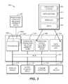
- FIG. 3is a block diagram of an example computer system with which or upon which various embodiments of the present invention may be implemented.
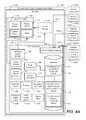
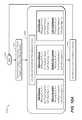
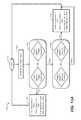
- FIG. 4Ais a block diagram of a system 400 for controlling vehicle motion, in accordance with an embodiment.
- FIG. 4Bis a block diagram of an electronic valve 460 which may be integrated into the system 400 , in accordance with an embodiment.
- FIG. 4Cis a block diagram of the control system 404 of FIG. 4A , in accordance with an embodiment.
- FIG. 4Dis a block diagram of the database 416 of FIG. 4A , in accordance with an embodiment.
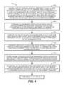
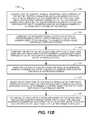
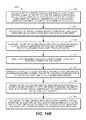
- FIG. 5is a flow diagram of a method 500 for controlling vehicle motion, in accordance with an embodiment.
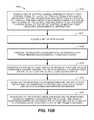
- FIG. 6is a flow diagram of a method 600 for controlling vehicle motion, in accordance with embodiments.
- FIG. 8shows a method for controlling vehicle motion, in accordance with an embodiment.
- FIG. 9depicts a side cross-sectional view of a shock absorber 900 upon which embodiments may be implemented.
- FIGS. 10A-16Bdepict methods for controlling vehicle motion, in accordance with various embodiments.
- FIGS. 17A-17Cshow interactive touch screens, in accordance with various embodiments.
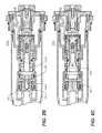
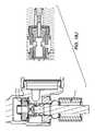
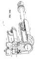
- FIG. 18Ais a side cross-sectional view of a monotube piggyback arrangement with the electronic valve located at the main piston, in accordance with an embodiment.
- FIG. 18Bis an enlarged view of Detail A of FIG. 18A , in accordance with an embodiment.
- FIG. 18Cis an enlarged cross-sectional view of Detail of FIG. 18A , in accordance with an embodiment.
- FIG. 18Dis an enlarged cross-sectional view of Detail of FIG. 18A , in accordance with an embodiment.
- FIG. 18Eis a side cross-sectional view of a solenoid and surrounding components, in accordance with an embodiment.
- FIG. 18Fis an enlarged cross-sectional side view of Detail A of FIG. 18A , in accordance with an embodiment.
- FIG. 18Gis an enlarged cross-sectional side view of Detail A of FIG. 18A , in accordance with an embodiment.
- FIG. 18His an enlarged cross-sectional side view of Detail A of FIG. 18A , in accordance with an embodiment.
- FIG. 18Iis an enlarged cross-sectional side view of Detail A of FIG. 18A , in accordance with an embodiment.
- FIG. 18Jis a side cross-sectional view of the electronic valve acting as the base valve assembly, in accordance with an embodiment.
- FIG. 18Kis an electronic valve 460 integrated into a monotube design of a shock absorber, with a piggy back chamber, in accordance with an embodiment.
- FIG. 18Lis an enlarged cross-sectional view of the base valve electronic valve of Detail A of FIG. 18K , in accordance with an embodiment.
- FIG. 18Mis the monotube design of FIG. 18K in a rebound position, in accordance with an embodiment.
- FIG. 18Nis an enlarged view of the electronic valve 460 shown in Detail A of FIG. 18M , in accordance with an embodiment.
- FIG. 18Ois the electronic valve 460 integrated into an internal bypass monotube design 1863 for a shock absorber, in accordance with an embodiment.
- FIG. 18Pis an enlarged view of the electronic valve 460 of Detail A shown in FIG. 18O , in accordance with an embodiment.
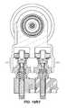
- FIG. 18Qis a side section view of a twin tube 1878 in a compression state, in accordance with an embodiment.
- FIG. 18Ris a block description of the relationship between the components shown in FIGS. 18 R 1 and 18 R 2 , in accordance with an embodiment.
- FIG. 18 R 1is a side section view of the twin tube 1878 in a compression state, in accordance with an embodiment.
- FIG. 18 R 2is a section view of the two electronic valves of FIG. 18 R 1 positioned in parallel with each other, in accordance with an embodiment.
- the electronic computing devicemanipulates and transforms data represented as physical (electronic) quantities within the electronic computing device's processors, registers, and/or memories into other data similarly represented as physical quantities within the electronic computing device's memories, registers and/or other such information storage, processing, transmission, and/or display components of the electronic computing device or other electronic computing device(s). Under the direction of computer-readable instructions, the electronic computing device may carry out operations of one or more of the methods described herein.
- shock absorberssuch as those described in U.S. patent application Ser. No. 114/231,446, “Method and Apparatus for an Adjustable Damper”, may be applied to a multi-wheeled vehicle.
- These shock absorbersmay include an electronic valve that has an orifice block, a primary valve and a pilot valve assembly. Sensors may be attached to the vehicle and provide information, to a control system attached to the electronic valve, on acceleration (with respect to a bicycle) and on acceleration, tilt, velocity and position (with respect to vehicles with more than two wheels). The control system accesses the sensor signals and actuates the electronic valve to provide variable damping.
- Example conventional and novel techniques, systems, and methods for controlling vehicle motionare described herein.
- various conventional systems, methods and techniques that utilize a conventional control system and a conventional electronic valve for controlling vehicle motion in vehicles with three or more wheelsare described.
- FIGS. 4A-4Da novel electronic valve and its functioning is described.
- This novel electronic valveis not only utilized to perform the conventional methods for controlling a vehicle' motion described with respect to FIGS. 1, 2A-2C and 5-8 , but also novel methods for controlling a vehicle's motion by enabling even more selective damping to occur, discussed with reference to FIGS. 10A-16B .
- the conventional features described therein, and as will be described hereinnot only deduce the vertical acceleration values, but also deduce, from a received set of control signals (that include acceleration values associated with various vehicle components), the roll and pitch of a vehicle with more than two wheels.
- These measured acceleration valuesrelate to the tilt (e.g., roll, pitch) of the vehicle and are compared to a database having thereon preprogrammed acceleration threshold values associated with vehicle components as it relates to tilt.
- the conventional control systemreceives measured velocity values associated with user-induced events (e.g., turning a steering wheel, pressing/releasing a brake pedal, pressing/releasing the gas pedal, thereby causing a throttle to open/close).
- the control systemcompares these measured velocity values relating to user-induced events to a database having preprogrammed thereon velocity threshold values associated with vehicle components. Based on the comparison performed with regard to the measured acceleration values with the predetermined acceleration threshold values and the measured velocity values with the predetermined velocity threshold values, as well as the determined state of valves within various vehicle suspension dampers attached to vehicle components, the control system sends an activation signal to power sources of the vehicle suspension dampers.
- the activation signalactivates the power source to deliver a current to valve assemblies within the vehicle suspension dampers. Once delivered, the valve assemblies adjust to a desired state.
- the desired stateis configured to adjust the damping force to reduce or eliminate the tilt of the vehicle's frame. In other words, the orientation of the vehicle frame is placed as close to level as possible.
- these conventional systems and methodsalso provide various system modes within which the vehicle suspension dampers may operate, along with control modes for affecting roll and pitch dynamics of the vehicle. Further, these conventional methods and systems for implementing delays and rebound settle time, for de-conflicting multiple control modes and for cycling between different system modes are described.
- a vehicle suspension damperin quick response to sensed movement of vehicle components (e.g., vehicle wheel base).
- vehicle componentse.g., vehicle wheel base
- These systems and methodsmay be used in various types of multi-wheeled vehicles, such as, but not limited to, side-by-sides (four-wheel drive off-road vehicle), snow mobiles, etc.
- These conventional devicesmay be positioned in both the front fork and the rear shock.
- the conventional systems and methods described herein for controlling vehicle motionprovide a control system that enables the use of sensors and an electronic valve to read the terrain and make changes to the vehicle suspension damper(s) in real time.
- the conventional control system described hereinenables at least the following functions: the execution of algorithms that enable a quicker response and adjustment to the vehicle suspension damper(s) than other conventional vehicle suspension dampers; a quiet operation since there are no audible electronic valve actuation sounds; a power efficient model that is designed for low power consumption; an easily tunable model that may use conventional means in combination with the control system described herein, such as, but not limited to, valve shims; a fail-safe shock absorber, as the electronic valve also functions as a conventional shock if power is lost; a small model that can be packaged in bicycle forks and shocks; and a versatile model that may function in conventional shocks, twin tube shocks and bypass shocks.
- variable pressure valveas part of an electronic valve (instead of a pilot valve assembly), as will be discussed herein with reference to FIGS. 4A-4D and 10A-16B .
- a variable pressure valveis, in comparison to the pilot valve, more robust for use in vehicles with three or more wheels, such as side-by-sides.
- embodiments of the present technologyprovide for methods for controlling vehicle motion that consider a wider range of variables (e.g., temperature, humidity, date, pressure applied against vehicle seats and storage compartments, and vehicle component acceleration, velocity, speed and position, etc.) (as compared with the conventional methods described herein), which enables the vehicle suspension damper to even more selectively tune damping effects (as compared with conventional methods).
- the robust variable pressure valveis capable of implementing such tuned damping within the shock absorber.
- the methods described hereinenable a firm control mode, a medium control mode, a soft control mode, and control modes there between.
- novel systems and methods discussed herein for controlling vehicle motionnot only provide the same aforementioned benefits also provided by conventional electronic valves and conventional control system, but also provide a more robust alternative device/system for effecting changes within the shock absorbers (i.e., more or less damping), while providing methods for customized damping as it specifically applies to the vehicle's environment.
- FIG. 1shows the electronic valve 100 of a vehicle suspension damper.
- the electronic valve 100includes at least a primary valve 112 , a first pressure reducing means which, in FIG. 1 , is an orifice block 122 , and a second pressure reducing means which, in FIG. 1 , is a pilot valve assembly 132 , all of which components cooperatively control the flow of fluid throughout the electronic valve 100 and manipulate the fluid pressure within the pilot pressure chamber 126 .
- the permanent magnet 136 of the solenoid assembly 120conducts through the component 134 to attract the pilot spool 128 . This is the latched position as shown.
- the spool spring 130resists this condition.
- the coilis turned on with positive polarity, it cancels the effect of the permanent magnet 136 and the spool spring 130 moves the pilot spool 128 to the left or closed position.
- the electromagnetis added to the permanent magnet 136 and the pilot spool 128 is drawn to the right or open position.
- the main oil flow pathis through the center of the base valve and radially outwardly into piston port 104 area. Assuming there is enough pressure in the piston ports, it then blows off the valve shims 108 and oil flows into the reservoir 102 . A small amount of oil also flows in parallel through a second fluid flow path in the electronic valve 100 (also called an inertia valve), and in particular through the control orifice 124 and through the solenoid assembly 120 . This generates a pilot pressure inside the area of the primary valve 112 .
- a second fluid flow path in the electronic valve 100also called an inertia valve
- the valve member 114acts to resist the valve shims 108 from opening. This resistive force is dependent on pressure inside the area of the primary valve 112 which is controlled by the pressure drop across the solenoid. Basically, when the solenoid is closed, there is high pressure inside the area of the primary valve 112 (resulting in locked-out fork or firm damping, depending on the damping characteristics determined for the electronic valve 100 , as described in greater detail below). When the solenoid is in an open position, there is low pressure inside the area of the primary valve 112 and the valve member 114 pushes against valve shims 108 with less force, allowing the valve shims 108 to open under lower fluid pressure.
- This open position of the solenoidprovides a normally-operating fork, by which is meant the damping characteristic of the inertia valve is determined predominantly by the tuning of the valve shims 108 (although there is some damping effect provided by the control orifice 124 ).
- a control signalinstructs the vehicle suspension damper to increase or decrease its damping force therein.
- the vehicle suspension damperis configured to respond to the control signal instruction. More particularly, the electronic valve 100 of the vehicle suspension damper, in response to the control signal instruction, quickly manipulates the pressure in the pilot pressure chamber of the electronic valve 100 by moving/adjusting the pilot valve assembly 132 to at least partially close or open the flow ports 118 .
- the pressure in the pilot pressure chamber 126increases or decreases in proportion to the amount of closure or opening that the flow ports 118 experience, respectively.
- fluid in the electronic valve 100flows along a first fluid flow path from the damping cylinder interior 35 and through the shims 108 (unless the shims 108 are held closed under pressure from the valve member 114 , as will be described herein) via the piston port 104 area. Additionally, fluid also flows along a second fluid flow path from the damping cylinder interior 35 and through the control orifice 124 of the orifice block 122 . After having flowed through the control orifice 124 , the fluid moves into the pilot pressure chamber 126 .
- the fluidmoves out of the pilot spool valve 116 (wherein the pilot spool valve 116 is in at least a partially open position) through a set of flow ports 118 and into the reservoir 102 . Additionally, from the pilot pressure chamber 126 , the fluid also moves into the area of the primary valve 112 . When the fluid presents a predetermined pressure against surface 110 of the valve member 114 , a force proportional to the pressure is exerted on the valve member 114 which urges it against the shims 108 .
- valve member 114pushes against the shims 108 , thereby biasing the shims 108 toward a closed position, even though fluid is moving through the shims 108 from the piston port 104 area and into the reservoir 102 . If the force of the valve member 114 against the shims 108 is greater than the force of the fluid moving from the piston port 104 area against the shims 108 , then the shims 108 will become biased toward closing.
- the shims 108will be biased toward an open position, in which the fluid may remain flowing through the shims 108 .
- embodimentsuse a control system to receive control signals from a set of sensors positioned on a vehicle.
- the control systemactivates a power source that is attached to the electronic valve.
- the power sourcedelivers a current to the electronic valve.
- the electronic valveresponds to the delivered current by causing the pilot valve assembly 132 to move and block or open at least a portion of the flow ports 118 through which fluid may flow there through from the pilot pressure chamber 126 and into the reservoir 102 , thereby at least partially closing or opening the flow parts 118 .
- a damper pistonmoves into a damper cylinder interior. More particularly, when the flow ports 118 are at least partially closed, the fluid pressure within the pilot pressure chamber 126 increases such that the fluid pressure in the area of the primary valve 112 also increases. This increase in the fluid pressure in the area of the primary valve 112 causes the valve member 114 to move toward the shims 108 that are open and to push against the shims 108 , thereby causing the shims 108 to at least partially or fully close. When these shims 108 are at least partially or fully closed, the amount of fluid flowing there through decreases or stops.
- the movement of the damper piston into the damper cylinder interiorcauses fluid to flow through the piston port 104 area and hence out through open shims 108 and into the reservoir 102 .
- the fluidalso flows through the control orifice 124 into the pilot pressure chamber 126 . If the shims 108 are closed due to movement of the pilot valve assembly 132 to block the flow ports 118 , then fluid may not flow out through the shims 108 or out through the flow ports 118 into the reservoir 102 . Consequently, the ability of the damper piston to move within the damper cylinder interior to cause fluid to flow through the piston port 104 area as well as through the flow ports 118 is reduced or eliminated.
- the effect of the at least partial closure of the shims 108is to cause a damping function to occur.
- the movement of the pilot valve assembly 132 to at least partially block the flow ports 118causes the damping (or slowing of movement) of the damper piston into the damper cylinder interior.
- the control orifice 124operates cooperatively with the pilot valve assembly 132 to meter the flow of fluid to the primary valve 112 .
- the control orifice 124is a pathway within the orifice block 122 and is positioned between the damper cylinder interior 35 and the pilot pressure chamber 126 .
- the size of the control orifice 124is tunable according to the application; the size may be variously changed.
- the control orifice 124is a key component in enabling the quick and accurate response to sensed changes in a vehicle's motion. As will be explained herein, without the presence of the control orifice 124 , the vehicle would not experience damping during periods of low compression speed, or experience too much damping during periods of high compression speeds.
- the pilot valve assembly 132would act like a bypass.
- control orifice 124without the control orifice, at low compression speed there would almost be no damping and the control orifice 124 and pilot valve assembly 132 would act like a bypass; but at higher compression speeds, pressure drop across the pilot valve assembly 132 would cause a high pressure in the pilot pressure chamber 126 and therefore too much clamping force on the shims 108 .
- the control orifice 124thus, allows damping to occur even during periods of low compression speed, and slows the damping rate during periods of high compression speed.
- the solutionis to cause a pressure drop of damping fluid before it enters the pilot pressure chamber 126 .
- Thisis achieved with the control orifice 124 .
- the control orifice 124provides some damping effect at low compression speeds (by enabling damping fluid to ‘bleed’ through the control orifice), but at high compression speeds provides a significant pressure drop to ensure that the pressure inside the pilot pressure chamber does not get too high, thereby preventing the valve member 114 from locking onto the shims 108 .
- control orifice 124is between 0.5 mm and 2 mm in diameter, but these sizes are dependent on the specific application and the desired damping curve. Pressure drop is directly proportional to the length of the control orifice 124 , but inversely proportional to its diameter. Either one or both of these parameters can be changed at the design stage to affect the performance of the control orifice 124 .
- control orifice 124The essential function of the control orifice 124 is to create a pressure drop. Therefore, anything that will do this could be used in place of the specific arrangement shown. Some possible examples include, but are not limited to: a diffuser; a labyrinth between parallel plates; and leakage past a screw thread.
- a further key featureis the combination of the area of the surface 110 inside the valve member 114 , the control orifice 124 , the pilot valve assembly 132 , and the way this combination enables a variable force to be applied to the shims 108 to control the damping force at any point in time.
- the ratio of the surface area 106 of the shims 108controls the overall damping characteristic of the electronic valve 100 , i.e., what overall range of force can be applied to the shims 108 .
- the valve member 114can be set up to move between full lockout and a completely soft state, or between a firm damping state and a soft state, for example.
- a particular force at any point in timeis set by the position of the pilot valve assembly 132 , which, as explained above, controls the pressure drop across the flow ports 118 .
- the pressure of fluid in the pilot pressure chamber 126is also adjusted. Since the pressure inside the pilot pressure chamber 126 acts against surface 110 of the valve member 114 , the force applied by the valve member 114 to the shims is controllable by adjustment of the position of the pilot valve assembly 132 .
- the overall resistance to fluid flow along the first fluid flow path(i.e. through piston port 104 area and past shims 108 ) is given by the sum of the force provided by the shims 108 and the force applied to the shims 108 by the valve member 114 .
- a significant featureis that a force is generated on the valve member 114 by a control of pressure inside the area of the primary valve 112 (in contrast to other valve bodies where force comes from pressure acting on the outside of the valve member 114 , usually from the damper reservoir).
- the ultimate source of pressure in the pilot pressure chamber 126is the pressure of the damping fluid in the main damping cylinder 35 during compression (but regulated by the control orifice 124 and the pilot valve assembly 132 to give a lower pressure in the pilot pressure chamber 126 ).
- the pilot valve assembly 132enables very large damping forces to be controlled because: (a) the pilot pressure is ‘magnified’ according to the ratio of the area of the primary valve 112 to the area of the piston port 104 ; and (b) because the pilot valve assembly 132 is not required to move any element against the high pressure damping fluid; and 5) the pilot valve assembly 132 allows the damper to utilize conventional shims, but with some level of controllability over the damping force applied by the shims. This allows the shims to be tuned in a conventional manner. Furthermore, if power to the pilot valve assembly 132 fails, the shock absorber will continue to operate (in contrast to other electronically controlled shocks where power loss causes the shock to stop working completely).
- the electronic valve 100including the primary valve 112 , the pilot valve assembly 132 , and the orifice block 122 , not only enables a variable force to be applied to shims 108 , but also enables the control of the damping force within the vehicle at any point in time.
- the pilot valve assembly 132meters a flow of fluid to the primary valve 112 and enables the generation of relatively large damping forces by a relatively small solenoid (or other motive source), while using relatively low amounts of power.
- the solenoidcontinuously powers the inertia valve and does not have a latching mechanism.
- a monitorwill continuously monitor a power source and its operation in order to make sure that the wires leading to the power source do not get cut, thereby providing a dangerous situation for the rider and other vehicles.
- the primary valve 112although it is shown as an internal base valve, it is not limited to this position or application.
- itcan be mounted externally of the vehicle suspension damper (for example in a ‘piggy-back’ reservoir). Further, it could be made part of the main damper piston (either in compression or rebound directions).
- control orifice 124In considering the design of the control orifice 124 , it must have at least the following two functions: a provision of low speed bleed; and a provision of a sufficient pressure drop at high speed to prevent hydraulic lock of the valve member 114 onto the shims 108 .
- the general methodology for determining the diameter and/or length of the control orifice 124 during designis as follows: (1) identify the desired damping curve that the damper should have; (2) determine from step (1) the target low speed damping force; (3) determine from step (1) the target high speed damping force; (4) make informed guess at control orifice diameter and/or length to achieve steps (2) and (3); (5) test the output damping forces produced by shock at different speeds within low to high speed range; (6) compare the measured damping curve against the desired damping curve; (7) if there is too much high speed damping force, then reduce the diameter of the control orifice (to lower the pressure inside the pilot pressure chamber 126 ); (8) if there is too much low speed damping force, then decrease the area ratio (between the area of the primary valve 112 and the piston port 104 area), and increase the diameter of the control orifice 124 ; and (9) repeat steps (5)-(8) until a good approximate to a desired damping curve is obtained. It is to be noted that in steps (7) and (8) the length of the
- FIG. 2Ashows an electronic valve 200 A with a diffuser pin 204 positioned through one set of the cross holes 202 going to the primary valve 112 area. Another set of holes remains (normal to the page) to feed oil to the valve member 114 .
- the diffuser pin 204functions to disrupt the jet flow coming out of the control orifice 124 .
- FIG. 2Bshows an electronic valve 200 B with a diffuser plug 206 pressed into, at least one of and at least partially, the orifice block 122 and the pilot pressure chamber 126 .
- FIG. 2Cshows an electronic valve 200 C with a diffuser pin 204 .
- the spool retainer 208(see FIG. 2C ) is replaced with the diffuser pin 210 .
- the diffuser pin 210 and its position within the vehicle suspension damper 200 Cfunctions to disrupt the jet flow coming out of the control orifice 124 and to minimize the contact of the pilot valve assembly 132 in the firm setting.
- the solenoidincludes a “latching” mechanism to open and close the pressure-balanced pilot spool. Due to the latching configuration of the solenoid, power is only required to open or close the pilot valve assembly 132 . Power is not required to hold the pilot valve assembly 132 open or closed in either setting. Consequently, reduced power consumption is enabled compared to the traditional shock absorber.
- An adjusterturns in or out to vary the effective orifice size of the flow ports 116 when in the open position. This allows the rider to adjust the soft setting of the damper to his preference.
- valve shims 108are optional. Instead, it would be possible for the valve member 114 to act directly on the fluid flow ports 145 . In fact, valve shims are optional in any shock absorber described herein at the point where it would be possible for the valve member 114 (or any other similar valve member described herein) to act directly on the fluid flow ports that control the main flow through the valve assembly.
- the set of sensors 440may be positioned in various locations on various types of vehicles.
- the set of sensors 440is positioned on the seat post of a bicycle.
- a first set of sensorsis positioned near the front wheel, while a second set of sensors is positioned near the rear wheel.
- the set of sensorsmay include at least one accelerometer, but generally includes three accelerometers.
- the three accelerometersdefine a plane of the vehicle's body, such that the acceleration, and in other embodiments, the acceleration and the tilt (i.e., pitch and roll), of the vehicle body may be measured.
- the set of sensorssenses vehicle motion
- the set of sensorssends a control signal to the control system attached to the vehicle suspension damper.
- the control systemdetermines if the sensed vehicle motion meet and/or exceeds a predetermined threshold.
- the predetermined thresholdmay be a constant in one embodiment. However, in another embodiment, the predetermined threshold may be a variable based on other situations sensed at the vehicle.
- the power source that is attached to the vehicle suspension damperbecomes activated.
- the power sourcesends a current to the vehicle suspension damper, thereby causing the pilot valve assembly to move, as is described herein.
- Various methods of sensing via accelerometers and other forms of motion via sensorsare known in the art.
- the vehicle to which a set of sensors and the vehicle suspension damper described thus far herein are attachedmay be attached to a multi-wheeled vehicle, such as, but not limited to, a bicycle, a side-by-side, a snowmobile, a car, a truck, etc.
- more than one set of sensorsmay be used on the non-limiting example of a side-by-side vehicle (e.g., recreational off-highway vehicle [ROV]).
- each wheel basee.g., four
- each wheel basehas attached thereto a different set of sensors, such as a set of accelerometers, each set being attached to a separate vehicle suspension damper.
- One set of sensors(e.g., set of accelerometers) is attached to the ROV, as well as being attached to one or more vehicle suspension dampers.
- the vehicle suspension dampersmay each be programmed to operate in a fully open mode (i.e., soft mode), in which the pilot spool valve 116 of the pilot valve assembly 132 is open to the flow ports 118 , thereby allowing fluid to flow from the damper cylinder interior 35 and into the reservoir 102 either through the first fluid flow path, with resistance provided by the shims 108 (and no additional force provided by the valve member 114 ), and/or through the control orifice 124 that permits low speed bleed of damping fluid via the second fluid flow path.
- a fully open modei.e., soft mode
- the right front tire of an ROVwhen the right front tire of an ROV hits a large rock, the right front tire and a portion of the suspension attached to the tire (or attached wheel base) may rise upwards to move over the rock.
- the set of sensors attached to the ROV's right front sidewill sense the tire's upward movement, and will sense the tire reaching its peak upward movement (the peak of the rock), and will sense the tire beginning to move downwards.
- the set of sensors on the ROV's right front sidewould send control signals to the vehicle suspension damper attached to the ROV's right front side throughout the tire's movement upward and downward.
- the control system attached to the vehicle suspension damperreceives the control signals and causes the power source also attached to the vehicle suspension damper to deliver a current to the vehicle suspension damper in accordance with the control signals.
- the delivered currentfunctions to cause the pilot valve assembly 132 to move to cause the flow ports 118 to be at least partially blocked.
- the pressure within the pilot pressure chamber 126increases due to the at least partially blocked flowports 118 , thereby causing the pressure within the area of the primary valve 112 to increase.
- the valve member 114in response to increased pressure in the area of the primary valve 112 , is urged against the shims 108 , thereby changing the damping characteristics of the shims 108 .
- the fluid flowing along the first fluid flow path from the damper cylinder interior 35 and through the piston port 104 areais reduced, resulting in placing the vehicle suspension damper in a firm damping setting.
- an inertia valvesenses a pressure wave (occurring at the speed of sound) after a vehicle's tire hits a bump.
- the inertia valveopens in response to receiving the pressure wave.
- the vehicle riderstill experiences some form of response to the terrain before the inertia valve has a chance to open into a “soft” mode.
- the shock absorbersthus far described herein, using an electronic valve attached to accelerometers, the electronic valve opens into a “soft” mode before a motion significant enough for a vehicle rider to experience the motion has begun.
- a control signalis sent from a set of accelerometers that communicate the acceleration values of the wheel to a control system that is connected (wire or wirelessly) to the electronic valve.
- the set of accelerometersare positioned to measure the acceleration experienced by the wheel base. These acceleration signals are sent at the beginning of the wheel's ascent over the rock.
- the electronic valveis opened into a soft mode in response to receiving the signals from the set of accelerometers.
- the soft modeis initiated before the wheel experiences such a large acceleration upwards that the vehicle rider feels a reaction to the wheel's motion through the vehicle's frame.
- a quick response to a sensed acceleration of a vehicle wheelis enabled such that an acceleration of a vehicle frame due to the movement of the vehicle wheel may be reduced or prevented.
- one or more set of sensorsmay be attached to each ROV wheel base, and independently control the vehicle suspension damper to account for and respond to various rolls and other types of vehicle motion.
- One or more motion sensorsare provided on a forward or front part of a vehicle, and a signal or signals from the one or more motion sensors is used to control a vehicle suspension damper mounted on a rear part of the vehicle.
- motion information learned from the movement of the front part of the vehiclecan be used to anticipate movement of the rear part of the vehicle, and adjustments may be made to control the damper on the rear part accordingly.
- the set of control signals sent to the control systemmay include, but are not limited to the following values: acceleration values; tilt (e.g., pitch, roll) values; and velocity values.
- acceleration valuese.g., acceleration values
- tilte.g., pitch, roll
- velocity valuese.g., velocity values
- numerous methods for determining orientation in a plane in space using a sensor attached to an objectare well known in the art.
- the adjustment of the vehicle compression dampers to a desired statebased on a comparison of the measured signal values with a database of threshold values, enables the reduction of the tilt of a vehicle's frame.
- embodimentsprovide a novel and robust electronic valve that may be integrated within shock absorbers for use on vehicles having more than two wheels.
- sensorsare attached to the vehicle (with more than two wheels) and provide information on, for example, the following variables: acceleration, tilt, velocity, position, lateral acceleration, speed, temperature, pressure applied to vehicle seats and cargo bay, and humidity.
- a novel control systemaccesses the sensor signals and performs calculations to a control mode setting to be actuated depending on a particular predetermined relationship between the variables.
- the control systemcauses the electronic valve to become actuated, thereby providing variable damping that is more narrowly tailored to the vehicle's environment and to the vehicle rider.
- the novel electronic valveincludes an orifice block, a primary valve and a variable pressure valve is described herein with respect to FIGS. 4A-4D and 18A-18I , wherein the electronic valve is shown installed in a monotube piggyback arrangement (the electronic valve is located at the main piston), a monotube internal bypass arrangement and a twin-tube arrangement.
- FIG. 18Ais a side cross-sectional view of a monotube piggyback arrangement 1800 with the electronic valve 460 located at the main piston 1804 , in accordance with an embodiment.
- the monotube piggyback arrangement 1800is shown in a rebound configuration.
- FIG. 18Bis an enlarged view of Detail A of FIG. 18A , in a compression method position, in accordance with an embodiment.
- the electronic valve 460includes the primary valve 1810 , the variable pressure valve 1814 , the orifice 1818 and reservoir 1920 .
- the valve member 1808is a model TS08-20B-0-V-12ER valve, commercially available from HydraForce, Inc. of Lincolnshire, Ill., USA.
- Also shown in FIG. 18Bis the piston 1804 , the shims 1806 , the valve member 1808 , the flow ports 1812 and the pilot spool 1816 .
- FIG. 18Cis an enlarged cross-sectional view of Detail A of FIG. 18A .
- FIG. 18Ashows the orifice 1818 , the reservoir 1820 , the piston 1804 , the shims 1806 , the valve member 1808 , the primary valve 1810 , and a second valve 1822 .
- the port within FIG. 18C showing the second valve 1822may use any applicable metering device such as a pilot operated and non-pilot operated spool-type valve, poppet type valves and pressure relief valves.
- the second valve 1822may be the variable pressure valve mentioned above, or another type of fluid metering device.
- the robustness of the design of the electronic valve 460is due in part to the placement of the primary valve 1810 below the valve member 1808 , which itself is placed directly against the shims 1806 .
- the second valve 1822will provide an additional form of damping, in one embodiment.
- FIG. 18Dis an enlarged cross-sectional view of Detail A of FIG. 18A .
- FIG. 18Dshows a type of metering device 1824 placed into the area at which the second valve 1822 was shown (see FIG. 18C ).
- a proportionally controlled pilot operated spool valveplaced in the “modular valve port location”, also known as a location for the second valve 1822 .
- These valves that occupy the location for the second valve 1822may be actuated through electronic means such as a solenoid, stepper motor or servo motor, according to an embodiment.
- FIG. 18Eis a side cross-sectional view of a solenoid and surrounding components, in accordance with an embodiment.
- FIG. 18Eshows a novel method of applying a solenoid to increase the ease of vehicle packaging.
- the shaftis used for the solenoid housing and will conduct the magnetic field to the solenoid plunger 1830 so as to produce movement of the metering control device 1824 , in accordance with an embodiment.
- Embodimentsalso allow for the moving parts to be wet or under pressure so as not to have seal friction of a pressure differential requiring a higher output of force for actuation.
- the solenoid plunger 1830is sealed into the shaft using a press fit plug 1828 .
- the coil 1826surrounds the shaft, similar to other known methods regarding solenoids.
- the coilmust have enough stiffness to support the load of the main vehicle spring that surrounds the shock absorber.
- Another methodis to use a snap ring fitting onto the shaft in order to separate the spring forces from the coil 1826 .
- This snap ring designmay be used as a separate nonintegrated device that is 90 degrees oriented out of the eyelet of the shock absorber.
- FIG. 18Fshows an enlarged cross-sectional side view of Detail A of FIG. 18A , during compression, in accordance with an embodiment.
- the electronic valve 460is in soft position, such that the flow ports 1812 are open and fluid may flow there through.
- the fluid flow 1836moves through the orifice 1818 and into the area of the second valve 1822 , and then through the flow ports 1812 .
- the fluid flowmoves into the reservoir 1832 and then provides a force against the valve member 1808 , which itself presses further against the shims 1806 .
- FIG. 18Gshows an enlarged cross-sectional side view of Detail A of FIG. 18A , during compression, in accordance with an embodiment.
- the electronic valve 460is in firm position, in which the flow ports 1812 are blocked.
- the fluid flow 1838moves through the orifice 1818 and into the primary valve 1810 , thereby pushing the valve member 1808 further against the shims 1806 , in one embodiment.
- the shims 1806are reed valves.
- FIG. 18Hshows an enlarged cross-sectional side view of Detail A of FIG. 18A , during rebound, in accordance with an embodiment.
- the valve member 1808is positioned on the compression side of the piston 1804 .
- the fluid flow 1842shows the flow of fluid moving through the flow ports 1812 , into the orifice 1828 , and out into the reservoir 1820 .
- FIG. 18Ishows an enlarged cross-sectional side view of Detail A of FIG. 18A , during rebound, in accordance with an embodiment.
- the valve member 1808is positioned on the compression side of the piston 1804 .
- the fluid flow arrow 1844shows the flow of fluid moving from the reservoir 1832 , into and through the piston 1804 , and into the primary valve 1810 . Once the fluid is in the primary valve 1810 , then the fluid presses against the valve member 1808 , which in turn presses against the shims 1806 .
- FIG. 18Jis a side cross-sectional view of the electronic valve 460 acting as the base valve assembly.
- the design of the electronic valve to be located next to the piston of the monotube by-pass shock absorberis the same design as that electronic valve to be located as the base valve design.
- the electronic valve of FIG. 18Jalso includes check valves 1848 and compression valves 1850 .
- embodiments of the new technologymay be implemented at least in the following design types: 1) a monotube design; 102) a monotube internal bypass design; and 3) a twin-tube design.
- a monotube shock absorber design with Integrated Variable Pressure ValveA brief description of a monotube shock absorber design is as follows.
- a monotube shock absorberhas a single cylinder that is divided by a floating piston and seal into a fluid area section and a high pressure gas chamber section. The piston and the shaft move in the fluid portion. It uses a single fluid valve assembly in the piston. There is no need for an air or gas in the fluid area. This provides an expansion area for the excess fluid movement during the compression stroke. On more aggressive movement, the floating piston is pushed further into the gas chamber with increases gas pressure quickly and provides additional damping.
- FIG. 18Kshows an electronic valve 460 integrated into a monotube design of a shock absorber, with a piggy back chamber, in accordance with an embodiment.
- the electronic valve 460operates as the base valve. (Of note, the monotube design may operate without a base valve.)
- FIG. 18Lshows an enlarged cross-sectional view of the base valve electronic valve 460 of Detail A of FIG. 18K , in accordance with an embodiment.
- a general description of the monotube design in operationis as follows.
- the electronic valve 460is utilized as the base valve, in this embodiment.
- the shaft 1853is displaced into the chamber 1856 for shaft displacement (fluid chamber).
- This monotube designincludes an internal floating piston (IFP) 1859 that moves backwards and forwards depending on the shaft's 1853 displacement and/or thermal expansion of the fluid.
- IFPinternal floating piston
- the IFP 1859moves toward the side opposite that of the shaft 1853 , making room for that fluid that is being displaced as a result of the shaft displacement.
- the fluidis displaced into the external shaft displacement reservoir 1858 , shown to be on one side of the IFP 1859 .
- the main damping piston 1855affixed to the piston rod 1854 ; and the IFP 1859 which separates the gas charge (the spring) and the oil (fluid).
- the shaft 1853 along with the piston rod 1854enters the chamber 1856 , thereby also pushing the damping piston 1855 further into the chamber 1856 .
- the damping piston 1855takes up volume within the chamber 1856 , and creates a fluid flow 1857 toward the electronic valve 460 , acting as the base valve.
- the fluidflows into the passageway leading to the electronic valve 460 .
- the check valve 1861is found to be closed. Also shown in FIG. 18L is the primary valve 1814 that is pressed against the reed shims 1806 .
- the fluidflows through the reed shims 1806 , which open upon receiving the force of the fluid flow (of note, this may be any sort of compression valve appropriate to regulate fluid flow there through), and into the external shaft displacement reservoir 1858 .
- the fluidalso flows, to some small degree, through the orifice 1818 and then through the pressure variable valve 1814 and into the external shaft displacement reservoir 1858 .
- When enough fluid enters the external shaft displacement reservoir 1858that fluid takes up its volume and then pushes against the IFP 1859 .
- the IFP 1859upon being pushed during compression of the shock absorber, further enters the gas chamber 1860 , which acts as a spring, and hence another source of damping, in accordance with embodiments.
- FIG. 18Mshows the monotube design 1852 in a rebound position, in accordance with an embodiment.
- FIG. 18Nshows an enlarged view of the electronic valve 460 shown in Detail A of FIG. 18M , in accordance with an embodiment.
- the shaft 1853 and the piston rod 1854move out of the chamber 1856 , thereby also pulling the damping piston 1855 further toward the end of the chamber 1856 that is opposite the end with the electronic valve 460 coupled therewith.
- a vacuum of fluid flow 1863is created, wherein the fluid flow 1863 is directed toward the damping piston 1855 that is moving in the same directions as the shaft 1853 , in one embodiment.
- the check valve 1861is open.
- the fluid flow 1863 from the external shaft displacement reservoir 1858 , through the channel connecting the chamber 1856 and the external shaft displacement reservoir 1858 , and into the chamber 1856is unimpeded.
- the check valve 1861is open during rebound. Fluid flow generally takes the path of least resistance.
- the fluid, during rebound, and in response to the vacuum of fluid that is created by the shaft 1853 being pulled out of the chamber 1856does not flow back through the electronic valve 460 (such as through the pressure variable valve 1814 and then though the reed shims 1806 ).
- the path of least resistanceis the gap left by the check valve 1861 while it is open during rebound movement.
- the fluidflows from the external shaft displacement reservoir 1858 , through the check valve 1861 , and into the chamber 1856 , according to one embodiment.
- the gas spring and/or the coil spring within the gas chamber 1860facilitates the movement of the fluid flow from the external shaft displacement reservoir 1858 and into the chamber 1856 by pushing the IFP 1859 further into the external shaft displacement reservoir 1858 , in accordance with embodiments.
- FIG. 18Oshows the electronic valve 460 integrated into an internal bypass monotube design 1863 for a shock absorber, in accordance with an embodiment.
- FIG. 18Pshows an enlarged view of the electronic valve 460 of Detail A shown in FIG. 18O .
- the bypass holes 1864function as follows. As the shaft 1853 moves more deeply into the chamber 1856 , the damping piston 1855 creates a fluid flow 1857 toward the electronic valve 460 .
- the fluidflows past the bypass holes 1864 .
- Some of the fluidenters the bypass holes 1864 and travels through an annular chamber 1865 and back to the rebound reservoir chamber 1866 , in accordance with embodiments.
- the damping piston 1855travels past the location of the bypass holes 1864 , no more fluid from the compression side of the damping piston 1855 moves through the bypass holes 1864 .
- the check valve 1861is open.
- the base valve circuitryis the same as the monotube design 1858 and the internal bypass monotube design 1863 .
- a twin tube shock absorberhas an inner and outer cylinder.
- the inner cylinderis a working cylinder, in which a piston and shaft move up and down.
- the outer cylinderserves as a reservoir for a hydraulic fluid.
- FIG. 18Qis a side section view of a twin tube design 1878 in a compression state, in accordance with an embodiment.
- the damping piston 1868does not have any valves there through, such that the movement of the shaft 1869 , which pushes the damping piston 1868 into the reservoir 1875 , causes the fluid flow 1870 toward the left valve 1872 , in accordance with an embodiment.
- the check valve 1871is closed.
- the fluidthen moves through the left electronic valve 1872 , turns a corner, flows around the right electronic valve 1873 , and then flows through the open check valve 1872 , and down into the outer part 1874 of the tube.
- the fluidflows into the backside 1876 of the damping piston 1868 .
- the twin tubeexperiences a rebound positioning, the aforementioned fluid flow process is reversed.
- a cavity that connects to the IFP cavity 1877in one embodiment.
- one of the electronic valvesworks for compression and the other electronic valve works for rebound, while the damping piston is being used as a pump.
- FIG. 18Ris a side section view of the twin tube design 1878 in a compression state, including a section view from the two electronic valves positioned in parallel with each other, in accordance with an embodiment.
- the fluid flow 1870 shown in FIG. 18Ris the same as that described with respect to FIG. 18Q .
- FIG. 3illustrates one example of a type of computer (computer system 300 ) that can be used in accordance with or to implement various embodiments which are discussed herein. It is appreciated that computer system 300 of FIG.
- Computer system 300 of FIG. 3is well adapted to having peripheral non-transitory computer-readable storage media 302 such as, for example, a floppy disk, a compact disc, digital versatile disc, other disc based storage, universal serial bus “thumb” drive, removable memory card, and the like coupled thereto.
- peripheral non-transitory computer-readable storage media 302such as, for example, a floppy disk, a compact disc, digital versatile disc, other disc based storage, universal serial bus “thumb” drive, removable memory card, and the like coupled thereto.
- System 300 of FIG. 3includes an address/data bus 304 for communicating information, and a processor 306 A coupled with bus 304 for processing information and instructions. As depicted in FIG. 3 , system 300 is also well suited to a multi-processor environment in which a plurality of processors 306 A, 306 B, and 306 C are present. Conversely, system 300 is also well suited to having a single processor such as, for example, processor 306 A. Processors 306 A, 306 B, and 306 C may be any of various types of microprocessors. System 300 also includes data storage features such as a computer usable volatile memory 308 , e.g., random access memory (RAM), coupled with bus 304 for storing information and instructions for processors 306 A, 306 B, and 306 C.
- RAMrandom access memory
- System 300also includes computer usable non-volatile memory 310 , e.g., read only memory (ROM), coupled with bus 304 for storing static information and instructions for processors 306 A, 306 B, and 306 C. Also present in system 300 is a data storage unit 312 (e.g., a magnetic or optical disk and disk drive) coupled with bus 304 for storing information and instructions. System 300 also includes an optional alphanumeric input device 314 including alphanumeric and function keys coupled with bus 304 for communicating information and command selections to processor 306 A or processors 306 A, 306 B, and 306 C.
- ROMread only memory
- data storage unit 312e.g., a magnetic or optical disk and disk drive
- System 300also includes an optional alphanumeric input device 314 including alphanumeric and function keys coupled with bus 304 for communicating information and command selections to processor 306 A or processors 306 A, 306 B, and 306 C.
- System 300also includes an optional cursor control device 316 coupled with bus 304 for communicating user input information and command selections to processor 306 A or processors 306 A, 306 B, and 306 C.
- system 300also includes an optional display device 318 coupled with bus 304 for displaying information.
- optional display device 318 of FIG. 3may be a liquid crystal device, cathode ray tube, plasma display device or other display device suitable for creating graphic images and alphanumeric characters recognizable to a user.
- Optional cursor control device 316allows the computer user to dynamically signal the movement of a visible symbol (cursor) on a display screen of display device 318 and indicate user selections of selectable items displayed on display device 318 .
- cursor control device 316are known in the art including a trackball, mouse, touch pad, joystick or special keys on alphanumeric input device 314 capable of signaling movement of a given direction or manner of displacement.
- a cursorcan be directed and/or activated via input from alphanumeric input device 314 using special keys and key sequence commands.
- System 300is also well suited to having a cursor directed by other means such as, for example, voice commands.
- System 300also includes an I/O device 320 for coupling system 300 with external entities.
- I/O device 320is a modem for enabling wired or wireless communications between system 300 and an external network such as, but not limited to, the Internet.
- an operating system 322when present, an operating system 322 , applications 324 , modules 326 , and data 328 are shown as typically residing in one or some combination of computer usable volatile memory 308 (e.g., RAM), computer usable non-volatile memory 310 (e.g., ROM), and data storage unit 312 .
- computer usable volatile memory 308e.g., RAM
- computer usable non-volatile memory 310e.g., ROM
- data storage unit 312all or portions of various embodiments described herein are stored, for example, as an application 324 and/or module 326 in memory locations within RAM 308 , computer-readable storage media within data storage unit 312 , peripheral computer-readable storage media 302 , and/or other tangible computer-readable storage media.
- Example System for Controlling Vehicle Motion of a Vehicle with More than Two Wheelse.g., Truck, Car, Side-by-Side
- the system 400for controlling vehicle motion is described in relation to controlling the operation of a multi-wheeled vehicle that has more than two wheels, such as, but not limited to, trucks, cars, and more specialized vehicles such as, but not limited to side-by-sides and snowmobiles, in accordance with embodiments.
- a multi-wheeled vehiclethat has more than two wheels, such as, but not limited to, trucks, cars, and more specialized vehicles such as, but not limited to side-by-sides and snowmobiles, in accordance with embodiments.
- truckscars
- specialized vehiclessuch as, but not limited to side-by-sides and snowmobiles
- embodimentsare not limited to controlling the operation upon vehicles with four wheels.
- embodimentsmay be used with vehicles with three wheels, five wheels, six wheels, etc.
- Four-wheeled vehiclesmay have four vehicle suspension dampers attached therewith, one vehicle suspension damper attached to each wheel and to the vehicle's frame.
- the system 400includes an electronic valve 460 , as shown in FIG. 4A .
- the electronic valvein one embodiment, includes the orifice block 122 , the primary valve 132 and a valve 490 .
- the valve 490in one embodiment, is the pilot valve assembly 112 . In another embodiment, the valve 490 is a variable pressure valve 462 .
- the system 400 and methoddetects rolls, pitches, and heaves of four-wheeled vehicles. For example and with regard to detecting rolls, if a car turns a corner sharply left and begins to roll to the right, embodiments sense the velocity of the steering wheel as it is being turned, as well as the translational acceleration associated with the roll experienced by the vehicle. The translational acceleration (distance/time 2 ) associated with the roll measures side accelerations. In response to this sensing and in order to control the roll, a control system causes the outer right front and back vehicle suspension dampers to firm up, in some embodiments. Of note, in some embodiments, the vehicle's pitch is measured by sensing the velocity of the throttle pedal as it is being pressed and/or released.
- the vehicle's pitchmay also be measured by sensing the velocity and/or the position of the throttle pedal as it is being pressed and/or released. In yet other embodiments, the vehicle's pitch is measured by sensing the acceleration of the vehicle.
- the control systemdoes not utilize throttle pedal information to measure roll.
- FIG. 4Ais a block diagram of a system 400 for controlling vehicle motion, in accordance with an embodiment.
- the system 400includes the electronic valve 460 (that includes the same component as the electronic valve 100 shown in FIG. 1 or includes the same components as the electronic valve 460 shown in FIGS. 4A & 4B ) and the control system 404 .
- the orifice block 122including the orifice 124
- the primary valve 132 of the electronic valve 460operate in a similar manner as is described herein in regard to the electronic valve 100 of FIG. 1 , in accordance with embodiments.
- control system 404includes the following components: a control signal accessor 456 ; a first comparer 406 ; a second comparer 410 ; a valve monitor 452 ; a control mode determiner 454 ; and an activation signal sender 450 .
- control signal accessor 456the first comparer 406 , and the valve monitor 452 have similar features and functions as the control signal accessor 1730 , the comparer 172 , the valve monitor 1745 , and the activation signal sender 1750 , respectively.
- the second comparer 410compares the accessed user-induced inputs to predetermined user-induced inputs threshold values 448 found at, in one embodiment, the database 416 (in another embodiment, a database residing external to the control system 404 . Further, in various embodiments, the control system 404 optionally includes any of the following: a database 416 , a hold-off timer 426 ; a tracker 430 ; a hold logic delayer 432 ; a rebound settle timer 428 ; a weightings applicator 434 ; and a signal filter 436 .
- the database 416optionally includes predetermined acceleration threshold values 418 and predetermined user-induced inputs threshold values 448 .
- the predetermined user-induced inputs threshold values 448include predetermined velocity threshold values 420 .
- the predetermined user-induced inputs threshold valuesinclude any of the following values: steering velocity threshold value; shock absorber velocity threshold value; brake velocity threshold value; steering position threshold value; throttle position threshold value; shock absorber position threshold value; and brake threshold value.
- control system 404may be part of the vehicle suspension damper 402 (that is, for example, on a side-by-side), or it may be wire/wirelessly connected to the control system 404 .
- control system 404 of system 400is further configured for comparing a set of values associated with at least one user-induced input (such as a user turning a steering wheel and the velocity resulting therefrom) with at least one user-induced input threshold value.
- control system 404that accesses a set of control signals 442 (control signal 442 A, control signal 442 B and control signal 442 C; it should be appreciated that there may be any number of control signals, depending on the number of sensors coupled with vehicle components) that includes both acceleration values and a set of values associated with user-induced inputs (such as velocity values [of a steering wheel being turned and/or a throttle pedal being pressed upon and/or released] measured by a set of gyrometers).
- the set of sensors 440 A, 440 B and 440 C(hereinafter, set of sensors 440 , unless specifically noted otherwise) attached to the vehicle component 438 A, 438 B and 438 C (hereinafter, vehicle component 438 , unless specifically noted otherwise), respectively, may include one or more sensors, such as, but not limited to, accelerometers and gyrometers.
- the acceleration values with respect to the four-wheeled vehiclesare lateral (side-to-side motion) and longitudinal g's (forward and backwards motion). In other embodiments, the acceleration values with respect to four-wheeled vehicles are lateral g's, longitudinal g's and vertical g's (up and down motion).
- User-induced inputsare those inputs by a user that cause a movement to a vehicle component of the vehicle.
- user-induced inputsmay include, but are not limited to any of the following: turning a steering wheel; pressing a brake pedal (the ON/OFF resultant position of the brake pedal being pressed is measured); and pressing a throttle pedal (a velocity and/or position of the throttle pedal is measured).
- a set of values associated with the user-induced inputsmay be, but are not limited to being, any of the following user-induced inputs: a measured velocity value of the turning of a steering wheel; a brake's on/off status; velocities associated with pressing down on the brake and/or the throttle pedal; and the difference in the positions of the throttle pedal before and after being pressed (or the absolute throttle position).
- the user-induced inputs that are measuredare inputs received before acceleration is measured, yet relevant in quickly determining corrective damping forces required to control the roll, pitch and heave once experienced.
- the user-induced inputsare precursors to the sensed accelerations of various vehicle components (e.g., vehicle wheels).
- the first comparer 406 and the second comparer 410compare these values to threshold values, such as those found in the database 416 (a store of information).
- the activation signal sender 450sends an activation signal to the power source 458 to deliver a current to the electronic valve 460 , and more particularly, a valve (e.g., of the variable pressure valve 464 ), based upon the following: 1) the comparison made between the measured acceleration value and the predetermined acceleration threshold value 418 discussed herein; 2) the comparison made between the measured velocity of the steering wheel as it is being turned (the set of values associated with user-induced inputs) and the predetermined velocity threshold value 420 of the predetermined user-induced inputs threshold values 448 ; and 3) the monitoring of the state of the electronic valve 460 .
- a valvee.g., of the variable pressure valve 464
- embodimentsmay include, but are not limited to, other configurations having a control system in wire/wireless communication with the vehicle suspension damper to which it is controlling, such as: 1) a vehicle with only one control system that is wire and/or wirelessly connected to all vehicle suspension dampers attached thereto; 2) a vehicle with one control system attached to one vehicle suspension damper, wherein the one control system controls the other control systems attached to other vehicle suspension dampers (that are attached to different wheels) of the vehicle; and 3) a vehicle with one control system that is not attached to a vehicle suspension damper, wherein the one control system controls other control systems that are attached to vehicle suspension dampers on the vehicle.
- the systemhas at least four user selectable modes: a soft mode; a firm mode; an auto mode; and a remote mode. Further, embodiments enable modes there between the at least four user selectable modes.
- all the vehicle suspension dampersare soft for compression and rebound.
- all rebound and/or compressionare firm.
- the firmness of the rebound and/or compressionis adjustable through system settings.
- the adjustable system settingsare factory set and are finite in number.
- an infinite number of adjustable system settingsare provided.
- the usermay customize and re-configure a finite number of system settings.
- all vehicle suspension dampersare placed in the soft setting with the control system transiently setting various vehicle suspension dampers to be firm.
- a wireless browser interfaceenables the soft, firm and auto mode to be selected.
- the control system 404monitors the position setting of a mechanical switch positioned on the vehicle, wherein the position setting may be set at one of the following modes: soft; firm; auto; and remote (i.e., at least partially wireless). Compression and rebounds are used to reduce the tilt of the vehicle frame. Particular advantages associated with using rebound adjustments are at least the following: a vehicle suspension damper in a hard rebound mode lowers the vehicle's center gravity; and the suspension is allowed to compress and absorb bumps while performing a controlled turn, thereby reducing the feeling of a harsh ride.
- the control system 404When the vehicle suspension damper is in the auto mode, the control system 404 causes the damping force within the vehicle suspension dampers to be adjusted when the trigger logic described below is found to be accurate for the roll and pitch positive and negative modes. The desired state of the vehicle suspension damper that is achieved from this adjustment is considered to be a control mode.
- Trigger Logicis logic implemented by the control system 404 that determines whether or not the vehicle suspension damper is allowed to pass into one of the control modes when the vehicle suspension damper is in an auto mode. Operational examples of trigger logic implemented by the control system 404 are described below.
- “Hold Logic”is logic that is implemented by the control system 404 that holds the system in a given control mode even after the possibly transient trigger logic has become false (becomes inaccurate). Operational examples of hold logic implemented by the control system will be described below.
- Embodimentsalso provide various damper control settings available to be implemented for each control mode.
- a damper control settingis one in which the damping force within the vehicle suspension damper is adjusted for one or more of the vehicle suspension dampers attached to the vehicle.
- the vehicle's roll and pitchare ultimately determined from measuring the vehicle's acceleration and measuring the vehicle component movement caused by user-induced inputs.
- bothhave defined positive and negative directions.
- the vehicle axisis defined as having an x-axis, a z-axis, and a y-axis.
- the x-axisis defined as being out the front of the vehicle.
- the z-axisis defined as being up.
- the y-axisis defined as following the right hand rule, which means the y-axis is out the left side of the vehicle.
- a roll positive modeis defined as a positive rotation about the x-axis of the vehicle associated with a left turn.
- a roll negative modeis defined as a negative rotation about the x-axis of the vehicle associated with a right turn.
- a pitch positive mode, occurring during a dive,is defined as a positive rotation about the y-axis of the vehicle associated with braking.
- a pitch negative mode, occurring during a squat,is defined as a negative rotation about the y-axis of the vehicle associated with throttling.
- control modes1) roll positive and roll negative control modes; 2) pitch positive control mode—dive; and 3) pitch negative control mode—squat.
- trigger and hold logic associated with each control mode and the damper control setting options available for each control modeis also described in accordance with various embodiments:
- control modesinformation associated with the control modes, the trigger and hold logic associated with each control mode and the damper control setting options available for each control mode are stored, in one embodiment, in the database 416 .
- the informationis accessible by the first comparer 406 , the second comparer 410 and the control mode determiner 454 .
- control system 404Upon exceeding a threshold (defined by the trigger logic below) while the vehicle experiences a roll positive or a roll negative, the control system 404 causes the variable pressure valve 464 to adjust to achieve a control state in which the roll positive and the roll negative are reduced or eliminated. Implementation options also available to achieve such a control state are listed below. With regard to the roll positive and roll negative controls that define circumstances when the roll positive and roll negative control modes are triggered or the control modes are held in place, the following definitions apply:
- “ThreshSteerVelTrigger”This is the threshold required for steering wheel velocity to trigger a roll control, subject to the side acceleration being above at least “threshSideAccelRollAllow”.
- the main advantage of triggering a damping force change on steering wheel velocity over side accelerationis that the side acceleration signal lags that of the signal for the velocity value corresponding to the turning of the steering wheel.
- This thresholdis adjustable and may be tuned for trigger and hold logic (tuned by the end user or hard coded).
- ThreshSideAccelRollAllowThis is the threshold required for side acceleration to allow threshSteerVelTrigger to trigger roll control.
- the threshSideAccelRollAllowis nominally set less than zero given that it is used to ensure the steering wheel velocity signal is not inconsistent with the side acceleration signal which, for example, would be the case in a counter steer maneuver. Setting this threshold too high adversely affects the system response time by forcing it to wait for the side acceleration signal to build up.
- This thresholdis adjustable and may be tuned for trigger and hold logic (tuned by the end user or hard coded).
- Option 1Firm inside rebound front and back.
- Option 2Firm outside compression front and back.
- Option 3(1) Firm inside rebound front and back; and (2) Firm outside compression front and back.
- Option 104(1) Firm inside rebound front and back; (2) Firm outside compression front and back; and (3) Firm outside rebound front and back.
- a control signal accessor 456 of the vehicleaccesses a set of control signals 442 that includes the measured side acceleration value and the measured steering wheel velocity value.
- the first comparer 406compares the measured side acceleration value to the predetermined acceleration threshold values 418 (stored at the database 416 ). The first comparer 406 determines if the measured acceleration value is more or less than the predetermined acceleration threshold value. The first comparer 406 accesses the database 416 to find trigger logic that matches the statement in which the comparison between the measured acceleration value and the predetermined acceleration threshold value holds true.
- the trigger logicis linked to a particular control mode that is pre-assigned to that particular trigger logic. If the trigger logic describes the comparison between the measured values and the predetermined threshold values accurately, then the trigger logic is determined to be true. The control system 404 will then actuate the valve within the electronic valve 100 according to the control mode assigned to the trigger logic statement.
- the first comparer 406finds that the measured side acceleration value was greater than the predetermined side acceleration threshold value.
- the second comparer 410finds that the measured steering wheel velocity value is greater than the predetermined user-induced input threshold value.
- one set of trigger logic that is linked to the roll positive controlis as follows:
- the control mode determiner 454determines which control mode is linked to these logic statements. Once the control mode is determined, the control system 404 actuates a valve (e.g., pilot valve assembly 132 ) within the electronic valve 100 to adjust the vehicle suspension damper. In this example, the first comparer 406 found that the following statement is accurate: (side acceleration>threshSideAccelRollTrigger). The control mode determiner 454 determines that the accurate statement is linked to the roll positive control.
- the control system 404actuates the electronic valve 100 , and more particularly, the pilot valve assembly 132 therein.
- the control system 404is enabled to implement the roll positive control mode, according to at least the options discussed herein with regard to the roll positive control mode.
- the second comparer 410finds that the steer velocity value is greater than the predetermined steer velocity threshold value (of the predetermined velocity threshold values 420 ).
- the second comparer 410finds the following first portion of a statement to be accurate: ((steer velocity>threshSteerVelTrigger).
- control mode determiner 454may determine a control mode for a vehicle suspension damper in which trigger logic that includes only acceleration comparisons are used. However, in another embodiment, the control mode determiner 454 may determine a control mode for a vehicle suspension damper in which trigger logic includes both acceleration comparisons and user-induced inputs comparisons.
- the control mode determiner 454operates in a similar manner in interpreting the trigger logic and hold logic linked to other control modes. Thus, in one embodiment, should the trigger logic (a.k.a. control logic) be determined to be accurate, the control mode determiner 454 follows the link from the trigger logic to find the control mode setting.
- the steering velocity threshold (“threshSteerVelTrigger”) valueis 10 rad./sec.
- the acceleration trigger threshold(“threshSideAccelRollTrigger”) value is 0.7 g's
- the acceleration hold threshold (“threshSideAccelRollHold”) valueis 0.2 g's
- the acceleration allow threshold(“threshSideAccelRollAllow”) value is ⁇ 0.1 g's.
- a first example scenarioinvolves the triggering of an adjustment of the vehicle suspension dampers upon receiving a steering wheel velocity measurement, but the holding of the control mode as to the vehicle suspension damper upon receiving a particular side acceleration value.
- a vehicle riderturns a steering wheel while the vehicle is directed into a turn.
- the set of sensors 440(could be set of sensors 440 A, 440 B and/or 440 C; it should be appreciated that there could be more or less sets of sensors, depending on the quantity of vehicle components to which the sets of sensors may be attached) send a velocity signal to the control signal accessor 456 .
- the second comparer 410compares the measured velocity value of 15 rad/sec.
- the set of sensors 440also sends to the control signal accessor 456 a side acceleration value of 0.4 g's.
- the first comparer 406compares the measured side acceleration value of 0.4 g's to the predetermined acceleration trigger threshold value of the predetermined acceleration threshold values 418 and to the trigger logic also stored at the database 416 and determines that the measured side acceleration value of 0.4 g's is lower than the predetermined acceleration trigger threshold value for side acceleration of 0.7 g's.
- the control system 404is triggered to cause the power source 458 to be actuated such that the electronic valve 100 receives a current.
- the currentcauses the electronic valve to close into the firm mode.
- the control system 404would be triggered to cause the vehicle suspension damper to return to the soft mode (by causing the electronic valve 100 to open).
- the logicrequires the side acceleration value to fall below 0.7 g's before the control system 404 is possibly triggered to adjust the damping of the vehicle suspension damper.
- the control system 404does not cause the vehicle suspension damper to be adjusted throughout the turn.
- the side acceleration valuesfall below 0.2 g's and thus below the “threshSideAccelRollHold” value, and the control system 404 is triggered to cause the vehicle suspension damper to adjust to the soft mode.
- a second example scenarioinvolves the triggering of an adjustment of the vehicle suspension dampers upon receiving a first side acceleration value, and the holding of the control mode as to the vehicle suspension damper upon receiving a second side acceleration value. For example, if a vehicle is traveling down a straight path that has various obstacles causing the vehicle to jump and dip, then the vehicle is caused to rattle back and forth (i.e., from side-to-side). If the side acceleration trigger threshold value was set at 0.2 g's and there was no hold logic, then due to the measured side acceleration from the side-to-side movement, the control system would be constantly triggered to cause the vehicle suspension damper to switch in and out of the hard mode, as if the vehicle were in fact repeatedly turning.
- hold logicwas not available to be programmed, then one would either have to program the trigger logic to have low acceleration trigger threshold values of about 0.2 g's and suffer the system constantly falsely triggering on bumps (due to the side-to-side rocking movement) that it perceives as turns, or set the trigger logic to have high acceleration trigger threshold values of about 0.7 g's and suffer the system not staying in the hard mode through an entire turn.
- the side acceleration trigger threshold valueis set at 0.7 g's, it is not until the vehicle actually moves into a turn that the vehicle experiences g's above 0.7 g's. If the vehicle's side acceleration value is measured at 0.8 g's, then the control system causes the vehicle suspension to adjust to be in the hard mode. The hold logic ensures that the vehicle suspension damper will remain in the hard mode until the side acceleration g's are measured below the acceleration hold threshold value of 0.2 g.s.
- a third example scenarioinvolves counter steering. For instance, suppose that a driver turns a steering wheel to the left as he heads into a turn. The steering wheel velocity is measured at 25 rad/sec. and the side acceleration g's are measured at 0.6 g's. Since the steering wheel velocity measured at 25 rad/sec. and the side acceleration g's measured at 0.6 g's are above the steering wheel threshold velocity (“threshSteerVelTrigger”) of 10 rad./sec. and the side allow acceleration threshold (“threshSideAccelRollAllow”) value of ⁇ 0.1 g's, respectively, the control system causes the vehicle suspension damper to adjust to the firm mode.
- threshSteerVelTriggerthe steering wheel threshold velocity
- threshSideAccelRollAllowside allow acceleration threshold
- counter steeringis counter to that which is expected, such as when a driver turns a steering wheel to the right, it is expected that the resulting side acceleration g's will be directed to the right (negative Y-axis). However, in counter steering, such as in the foregoing example, the resulting side acceleration g's are directed to the left (positive).
- the side acceleration allow threshold valueis at ⁇ 0.1 g's; the measured side acceleration for a right turn must be below—( ⁇ 0.1) g's (which is equal to +0.1 g's) (according to the “Roll Negative Control Trigger Logic” described above) for the acceleration allow threshold to be accurate.
- the control systemwill cause the vehicle suspension damper to remain in its current firm mode (will not cause the vehicle suspension dampers to adjust to a soft mode).
- the vehicle suspension damperwill cause the vehicle suspension damper to remain in its current firm mode (will not cause the vehicle suspension dampers to adjust to a soft mode).
- the control system 404Upon exceeding a threshold (defined by the trigger logic below) while the vehicle is experiencing a pitch positive (e.g., dive), the control system 404 causes the variable pressure valve 464 to adjust to achieve a control state in which the pitch positive is reduced or eliminated. Implementation options also available to achieve such a control state are listed below. With regard to the pitch positive controls that define circumstances when the pitch positive control modes are triggered or the control modes are held in place, the following definitions apply:
- This thresholdis nominally set below 1 g, effectively negating it. This threshold is adjustable and may be tuned for trigger and hold logic (tuned by the end user or hard coded).
- Option 1(1) Firm rear rebound left and right.
- Option 2(1) Firm front compression left and right.
- Option 3(1) Firm rear rebound left and right; and (2) Firm front compression left and right.
- Option 4(1) Firm rear rebound left and right; (2) Soft front rebound left and right; and (3) Soft front compression left and right.
- the control system 404Upon exceeding a threshold (defined by the trigger logic below) while the vehicle is experiencing a pitch negative (e.g., squat), the control system 404 causes the variable pressure valve 464 to adjust to achieve a control state in which the pitch negative is reduced or eliminated. Implementation options also available to achieve such a control state are listed below. With regard to the pitch negative controls defining circumstances when the pitch negative control modes are triggered or the control modes are held in place, the following definitions apply:
- the main advantage of triggering on the time derivative of the throttle position as opposed to simply the forward accelerationis that the acceleration signal lags that of the throttle.
- the derivative of the throttleis used because, in general, the steady state position of the throttle is related to velocity and not to the acceleration of the vehicle. This threshold is adjustable and may be tuned for trigger and hold logic (tuned by the end user or hard coded).
- TheshForwardAccelThrottleTriggerThis is the threshold required for forward acceleration to be above in order to trigger negative pitch control, even without the changes in the throttle position. This allows the system to initiate negative pitch control even if the throttle is not being pressed. This threshold value is nominally set above 1 g, effectively negating it. This threshold is adjustable and may be tuned for trigger and hold logic (tuned by the end user or hard coded).
- This thresholdis adjustable and may be tuned for trigger and hold logic (tuned by the end user or hard coded).
- Option 1(1) Firm front rebound left and right.
- Option 2(1) Firm rear compression left and right.
- Option 3(1) Firm front rebound left and right; and (2) Firm rear compression left and right.
- Option 104(1) Firm front rebound left and right; (2) Soft rear rebound left and right; and (3) Soft rear compression left and right.
- a zero gravity control modeis attained, at which vehicle suspension dampers that were operating in a “soft” mode, upon a detection of a zero gravity situation, are made to operate in the “firm” mode.
- vehicle suspension dampersthat were operating in a “soft” mode, upon a detection of a zero gravity situation, are made to operate in the “firm” mode.
- a vehicle that is operating in a “soft” modeis traveling in a straight line along a path that initially contains small bumps, but graduates into large rollers.
- the vehicleinitially is placed in the “soft” mode in order to mitigate and/or nullify the effect (upon the vehicle rider) of the vehicle traveling over small bumps along the pathway.
- the vehicleexperiences a free fall.
- the vehicleis considered to be in freefall when the resultant magnitude of the X, Y, and Z accelerations is less than a predetermined threshold.
- the end of the freefall conditionwill be when the resultant acceleration has exceeded the threshold for a pre-determined amount of time. For example, suppose the pre-determined freefall acceleration threshold is 0.4 g, the calculated resultant acceleration has a magnitude of 0.3 g, and the end-of-freefall timer is 1 second. Since the resultant acceleration is less than the threshold, this is a freefall condition, and the vehicle dampers will be set to the “firm” state. The vehicle will revert to the “soft” state 1 second after the resultant acceleration exceeds 0.4 g.
- the resultant accelerationis taken by squaring the acceleration at each axis, adding them together, and then taking the square root (the equation is: ⁇ (x 2 +y 2 +z 2 )).
- the resultant accelerationis always positive. This equation gives just the magnitude of the resultant acceleration, and does not give information regarding the direction of the resultant acceleration.
- the vehicleis in completely different orientations, but the resultant is the same.
- the componentsare different, but the resultant is the same.
- the magnitudeis calculated (the direction of the resultant acceleration does not matter for the purposes of detecting a freefall condition).
- the accelerometerwill always measure the 1 g acceleration due to gravity. This could be measured all in one axis, or distributed across all three axis. But when the vehicle is not moving, the resultant will always be 1 g as long as the vehicle is on the ground. When the vehicle comes off the ground (like when going off a jump), the 1 g acceleration due to gravity goes away, and the resultant acceleration is 0 g. The only way to have a resultant acceleration of less than 1 g is to go into a freefall.
- the freefall modeisn't triggered either when the resultant equals 0 g, or when the resultant is less than 1.0 g. This is due to at least the following four circumstances that occur when measuring actual motion, rather than doing paper calculations:
- the vehicle's enginecauses high-frequency vibrations of a fairly high magnitude. Measurements may be as high as 2.0 g and as low as 0 g (so noise of +/ ⁇ 1.0 g of the actual value). Since the vibrations of the engine are generally going to be fairly high (at least 30 Hz with the engine at 2000RPM) and the actual motion of the vehicle fairly low (usually 1-2 Hz), a low-pass filter may be used to ignore the vibrations from the engine such that only the acceleration of the vehicle is seen. Since filtering the acceleration takes some time, if the threshold is set at 0 g, a freefall scenario may not be noticed in time for a proper response, or the freefall scenario may be completely missed.
- FIG. 4Ais a block diagram that includes the control system 404 , in accordance with an embodiment.
- Embodiments of the control system 404 of FIG. 4Afurther include: a hold-off timer 426 ; a tracker 430 ; a hold logic delayer 432 ; a rebound settle timer 428 ; a weighting applicator 434 ; and a signal filter 436 .
- the hold-off timer 426may be used when the vehicle suspension damper 402 is in any of the roll and pitch positive and negative control modes.
- the hold-off timer 426enables a time to be set between the time that a first trigger logic is passed and the time that a second trigger logic is allowed to be passed.
- the implementation of the hold-off timer 426limits the amount of cycling the vehicle suspension damper 402 will experience between passive damper settings. (“Cycling” refers to the vehicle suspension damper rapidly cycling between the soft and damper firm settings of the dampers. This may or may not be a significant problem for the rider of vehicle performance. Cycling is more wearing on the solenoids and power circuitry of the vehicle suspension damper.
- control system 404further optionally includes, in one embodiment, a tracker 430 for tracking the times at which a trigger logic is passed.
- the tracker 430tracks the time at which the trigger logic is passed and the hold-off timer 426 is configured to disallow another pass until a minimum hold-off time is reached. If the trigger logic goes false before the hold-off time is reached, the trigger will not pass, and the hold-off timer 426 is not reset. There is only a hold-off timer 426 for going into the damper firm setting, and not coming out of it. This still limits cycling, without increasing the system minimum reaction response time to short stimulus.
- the hold logic delayer 432is programmed to provide a delay that gives time for the hold logic to become true after the trigger logic goes true.
- thishas the disadvantage of increasing the minimum reaction response time of the vehicle suspension damper to even short stimulus (e.g., cycling).
- An example of where this delay may be usefulis if the steering wheel is turned so fast that the side acceleration signals do not build up before the steering velocity signal drops back off again. Theoretically, the side accelerations values should present themselves to the control system as the wheels turn, but this is not necessarily true. For example, there are situations in which the front tires are not getting great traction at an exact moment. Another example in which this delay may be useful is when the gas pedal is slammed down faster than the engine has time to respond.
- the rebound settle timer 428establishes a period of time for the vehicle suspension to settle down before the compression is set firmed. This is a method for controlling the height of the vehicle's center of gravity in firm mode. This method can be reversed through user settings so that the vehicle has increased clearance.
- the weightings applicator 434resolves the situation in which different system control modes make conflicting requests to the same vehicle suspension damper.
- the weightings applicator 434provides weightings associated with each control mode for each of the vehicle suspension dampers that system control mode can affect. Then the weightings applicator 434 implements the request with the highest weighting.
- the signal filter 436filters the control signals that are accessed by the control system 404 .
- the control system 404includes the signal filter 436 .
- the signal filter 436is external to the control system 404 .
- the signal filter 436reduces signal noise levels and helps filter extremely transient signals or glitches.
- the signal filter 436in one embodiment, also adds signal latency, which can have various effects on the control system 404 and hence the vehicle suspension damper 402 , including reducing the need for system delays and dampers.
- the control system 404further optionally includes any of the following (each of which will be described below): a location comparer 466 ; an environmental information comparer 468 ; a vehicle component speed comparer 470 ; a vehicle component position comparer 472 ; a vehicle component velocity comparer 474 ; a vehicle component pressure comparer 476 ; a date tracker 478 ; and a center of gravity (CG) calculator 480 .
- the CG calculator 480includes the following: a pressure value accessor 482 ; a pressure value comparer 484 ; and a CG determiner 486 .
- the database 416further optionally includes any of the following (each of which will be described below): predetermined global location information 493 ; predetermined environmental threshold values 487 which include predetermined environmental temperature threshold values 488 and predetermined humidity threshold values 489 ; predetermined vehicle component speed threshold values 494 which include predetermined vehicle speed threshold values 495 and predetermined wheel speed threshold values 496 ; predetermined shock absorber position threshold values 490 ; predetermined shock absorber velocity threshold values 491 ; and predetermined vehicle component base-level pressure values 492 .
- predetermined global location information 493predetermined environmental threshold values 487 which include predetermined environmental temperature threshold values 488 and predetermined humidity threshold values 489
- predetermined vehicle component speed threshold values 494which include predetermined vehicle speed threshold values 495 and predetermined wheel speed threshold values 496
- predetermined shock absorber position threshold values 490predetermined shock absorber position threshold values 490
- predetermined shock absorber velocity threshold values 491predetermined vehicle component base-level pressure values 492 .
- the location comparer 466in one embodiment, is configured to compare a vehicle global position (that was determined by a GPS sensor attached to a vehicle) with predetermined global location information 493 .
- the environmental information comparer 468is configured to compare environment information (that was determined by temperature sensors and humidity sensors) with predetermined environmental threshold values 487 (and more particularly, in one embodiment, predetermined temperature threshold values 488 and predetermined humidity threshold values 489 ).
- the vehicle component speed comparer 470in one embodiment, is configured to compare the speed of a component of a vehicle (that a vehicle speed sensor measured) with the predetermined vehicle component speed threshold values 494 (and more particularly, in one embodiment, the predetermined vehicle [the entire vehicle being a component onto itself] speed threshold values 495 and the wheel speed threshold values 496 ).
- the vehicle component position comparer 472in one embodiment, is configured to compare the position of a component of a vehicle (that a vehicle position sensor measured) with the predetermined shock absorber position threshold values 490 .
- the vehicle component velocity comparer 474in one embodiment, is configured to compare the velocity of a component of a vehicle (that a vehicle velocity sensor measured) with the predetermined shock absorber velocity threshold values 490 .
- the vehicle component velocity comparer 474in one embodiment, is configured to compare the pressure applied to a component of a vehicle (that a pressure sensor measured) with the predetermined vehicle component base level pressure values 492 .
- the flow diagrams thereofillustrate example methods 500 , 600 , 800 , 1000 , 1050 , 1000 , 1050 , 1200 , 1250 , 1300 , 1350 , 1400 , 1450 , 1500 , 1550 , 1600 and 1650 used by various embodiments.
- the flow diagramsinclude methods 500 , 600 , 800 , 1000 , 1050 , 1000 , 1050 , 1200 , 1250 , 1300 , 1350 , 1400 , 1450 , 1500 , 1550 , 1600 and 1650 and operations thereof that, in various embodiments, are carried out by one or more processors (e.g., processor(s) 306 A- 306 C of FIG. 3 ) under the control of computer-readable and computer-executable instructions. It is appreciated that in some embodiments, the one or more processors may be in physically separate locations or electronic devices/computing systems.
- the computer-readable and computer-executable instructionsreside, for example, in tangible data storage features such as volatile memory, non-volatile memory, and/or a data storage unit (see e.g., 308 , 310 , 312 of FIG. 3 ).
- the computer-readable and computer-executable instructionscan also reside on any tangible computer-readable media such as a hard disk drive, floppy disk, magnetic tape, Compact Disc, Digital versatile Disc, and the like.
- the computer-readable storage mediais non-transitory.
- the computer-readable and computer-executable instructionswhich may reside on computer-readable storage media, are used to control or operate in conjunction with, for example, one or more components of a control system 404 , a user's electronic computing device or user interface thereof, and/or one or more of processors 306 .
- the computer-readable instructionsWhen executed by one or more computer systems or portion(s) thereof, such as a processor, the computer-readable instructions cause the computer system(s) to perform operations described by the methods 500 , 600 , 800 , 1000 , 1050 , 1000 , 1050 , 1200 , 1250 , 1300 , 1350 , 1400 , 1450 , 1500 , 1550 , 1600 and 1650 of the flow diagrams.
- the operations of the methods 500 , 600 , 800 , 1000 , 1050 , 1000 , 1050 , 1200 , 1250 , 1300 , 1350 , 1400 , 1450 , 1500 , 1550 , 1600 and 1650 in the flow diagramsmay be performed in an order different than presented, not all of the operations described in one or more of these flow diagrams may be performed, and/or more additional operations may be added.
- steps described in the 500 , 600 , 800 , 1000 , 1050 , 1000 , 1050 , 1200 , 1250 , 1300 , 1350 , 1400 , 1450 , 1500 , 1550 , 1600 and 1650may be implemented in hardware, or a combination of hardware with firmware and/or software.
- FIGS. 5-8, 10A-16Bflow diagrams for methods 500 , 600 , 800 , 1000 , 1050 , 1000 , 1050 , 1200 , 1250 , 1300 , 1350 , 1400 , 1450 , 1500 , 1550 , 1600 and 1650 for controlling vehicle motion, in accordance with embodiments, and relating to side-by-side roll and/or pitch control.
- FIG. 5describes a method 500 of an operation of control system 404 detecting and responding to a detection of roll and/or pitch of a vehicle component.
- FIGS. 6 and 7follow with a description of a method 600 of controlling vehicle motion, wherein both translational acceleration (roll/pitch) and user-induced inputs are taken into consideration when determining a response to sensed acceleration.
- FIGS. 1A-2C and 4A-4DReference will be made to elements of FIGS. 1A-2C and 4A-4D to facilitate the explanation of the operations of the methods of flow diagrams 500 , 600 , 800 , 1000 , 1050 , 1000 , 1050 , 1200 , 1250 , 1300 , 1350 , 1400 , 1450 , 1500 , 1550 , 1600 and 1650 .
- the methods 500 , 600 , 800 , 1000 , 1050 , 1000 , 1050 , 1200 , 1250 , 1300 , 1350 , 1400 , 1450 , 1500 , 1550 , 1600 and 1650 of the flow diagramsdescribe a use of or instructions for operation of control system 404 .
- FIGS. 5-8it should be appreciated that the method described herein may be performed by the electronic valve 460 that includes the variable pressure valve 462 , instead of the pilot valve assembly 132 shown in FIGS. 1 and 2A-2C .
- the method 500starts at operation 502 .
- the method 500moves to operation 504 .
- the control system 404determines under which system mode the vehicle suspension damper is operating, the soft mode, the firm mode or the auto mode. It should be appreciated that the system mode, in one embodiment, is selected by a user of the vehicle suspension damper. In another embodiment, the system mode is preprogrammed to default to a particular mode, unless overridden by a user.
- control system 404determines if the vehicle suspension damper is operating under the soft mode. If the control system 404 determines that the vehicle suspension damper is operating under the soft mode, then the method 500 moves to operation 506 .
- the control system 404determines if all the vehicle suspension dampers on the vehicle are in the soft mode. If the control system 404 determines that all of the vehicle suspension dampers are in the soft mode, then the method 500 returns to start 502 . If the control system 404 determines that all of the vehicle suspension dampers are not in the soft mode, then the method 500 moves to operation 508 .
- control system 404causes any vehicle suspension damper that is not in the soft mode to adjust to become in the soft mode. After all vehicle suspension dampers are found to be in the soft mode according to the system setting, then the method 500 returns to start 502 .
- control system 404determines that the vehicle suspension damper is operating in the firm mode. If the control system 404 determines that the vehicle suspension damper is operating in the firm mode, then the method 500 moves to operation 510 .
- the control system 404determines if the rebound is firm and the compression is soft. If the control system 404 determines that the rebound of the vehicle suspension damper is firm and the compression of the vehicle suspension dampers is soft, then the method 500 moves to operation 514 .
- the method 500moves to operation 512 .
- the control system 404causes all rebound of the vehicle suspension dampers to become firm and all compression of the vehicle suspension dampers to become soft. The method 500 then moves to operation 514 .
- the control system 404determines if there is a rebound settle time remaining and if the compression of the vehicle suspension dampers is still soft. It the control system 404 determines that there is rebound settle time remaining and the compression of the vehicle dampers is soft, then the method 500 moves to operation 516 . At operation 516 , in one embodiment, the control system 404 causes all of the compression in the vehicle suspension dampers to be firm. The method 500 then returns to the start 502 .
- control system 404determines that there is no rebound settle time remaining and the compression of the vehicle suspension dampers is soft, then the method 500 moves to start 502 .
- the control system 404determines if the control system 404 determines that the vehicle suspension damper 402 is operating in the auto mode. If the control system 404 determines that the control mode state is not active, then the method 500 moves to operation 520 . At operation 520 , in one embodiment, the control system 404 determines whether a trigger logic is passed AND if a time applied by a hold-off timer 426 is in place. If the control system 404 determines both conditions have occurred, then the method 500 moves to operation 522 . At operation 522 , the control system 404 resets the hold-off time and sets the control mode state to active.
- control system 404determines that either a trigger logic has not passed OR a time has not been applied by the hold-off timer 426 , then the method 500 moves to operation 530 .
- control system 404sets the control mode state to inactive. The method 500 then moves to operation 532 .
- control system 404determines that the control mode state is active, then the method 500 moves to operation 528 .
- the control system 404determines if the hold logic has passed OR if the trigger logic is passed OR if the delay for hold has passed.
- control system 404determines that either a hold logic has passed OR a trigger logic has passed OR a delay for hold has passed, then the method 500 moves to operation 524 .
- the control system 404determines under what damping control setting the vehicle suspension damper 402 is operating.
- the method 500returns to the start 502 .
- the control system 404determines that the vehicle suspension damper 402 is operating under a different damper control setting then desired, the control system 404 adjusts the vehicle suspension damper 402 so that it operates under the desired damper control setting. The method 500 then returns to start 502 .
- control system 404determines that either a hold logic has not passed OR a trigger logic has not passed OR a delay for hold has not passed, then the method 500 moves to operation 530 .
- control system 404sets the control mode state to inactive. Then, the method 500 moves to operation 532 .
- control system 404determines if the vehicle suspension dampers are soft.
- the method 500if the control system 404 determines that the vehicle suspension dampers are soft, then the method 500 returns to the start 502 . At operation 532 , in one embodiment, if the control system 404 determines that the vehicle suspension dampers are not soft, then the method 500 moves to operation 534 .
- control system 404functions, as described herein, to cause the vehicle suspension dampers to become soft.
- the method 500then returns to the start 502 .
- the checks for whether or not a vehicle suspension damper is already set according to the method 500need to be done individually for each vehicle suspension damper.
- FIGS. 6 and 7is a flow diagram of a method 600 for controlling vehicle motion, in accordance with embodiments.
- the method 600may be performed using the pilot valve assembly 132 or the novel electronic valve 460 that includes the variable pressure valve 462 .
- a set of control signalsare accessed, wherein at least a first control signal of the set of control signals includes a measured acceleration value associated with a movement of a vehicle component of a vehicle, and at least a second control signal of the set of control signals comprises a set of values associated with user-induced inputs, wherein the vehicle component is coupled with a frame of the vehicle via at least one vehicle suspension damper.
- the measured acceleration valueis compared with a predetermined acceleration threshold value that corresponds to the vehicle component to achieve an acceleration value threshold approach status.
- the predetermined acceleration threshold valuesare located at the database 416 and include the trigger logic, the hold logic, and the damper control setting options described herein.
- the control system 404compares the measured acceleration values with the acceleration threshold values expressed in the trigger logic and hold logic.
- the comparing, at operation 604includes determining if the measured acceleration values do or do not exceed the predetermined acceleration threshold values corresponding to the relevant vehicle component. Further, the control system 404 will pass into the appropriate control mode based on the comparisons made at operation 604 and 606 .
- control system 404is preprogrammed to select a particular control mode implementation option. These implementation decisions may be factory settings or individually customized by the rider/user. Additionally, it should also be appreciated that in one embodiment, the rider may override the control system 404 's selection.
- the set of values associated with the user-induced inputsare compared to predetermined user-induced inputs threshold values to achieve a user-induced input threshold value approach status.
- the predetermined user-induced inputs threshold valuesare located at the database 416 .
- the database 416includes at least one of, optionally the following which is described herein: the trigger logic; the hold logic; and the damper control setting options.
- the comparing, at operation 606includes determining if the measured user-induced inputs (represented as values) does or does not exceed the user-induced inputs threshold values corresponding to the relevant vehicle component. Further, the control system 404 will pass into the appropriate control mode based on the comparisons made at operation 604 and 606 .
- a state of at least one valve within at least one vehicle suspension damper of the vehicleis monitored, wherein the state controls a damping force within the at least one vehicle suspension damper.
- damping forcesare regulated within the at least one vehicle suspension damper by actuating the at least one valve to adjust to a desired state, such that a tilt of the vehicle's frame is reduced.
- a mode switch setting for the at least one vehicle suspension damperis determined.
- a period of time to hold the at least one vehicle suspension damper in the desired stateis set, such that the period of time begins when a first threshold value is determined to have been exceeded and ends when a second threshold value is determined to have been exceeded.
- a period of time for the at least one vehicle suspension damper to settle down before a compression mode of the at least one vehicle suspension damper is set to firmis established.
- a set of times when threshold values are determined to have been exceededis tracked.
- the acceleration values that are measuredmay include lateral acceleration of the vehicle as is described with respect to method 800 of FIG. 8 .
- the user-induced inputs that are measuredmay include the velocity with which a steering wheel is being turned and the absolute value of the difference between the steering wheel's initial position before it was turned and its final position after it was turned, as is described with respect to method 800 of FIG. 8 .
- FIG. 8is a flow diagram of a method 800 for controlling vehicle motion, in accordance with an embodiment.
- the method 800starts at operation 802 .
- the method 800moves from operation 802 to operation 804 .
- the control system 404receives signals from at least one sensor of the set of sensors 440 that gives information regarding a particular vehicle component. For example, a steering wheel sensor and an accelerometer send signals 442 to the control system 404 regarding the velocity and position of the steering wheel having been turned, and the acceleration that the vehicle is experiencing.
- the control signal accessor 456 of the control system 404accessing these signals 442 .
- the first comparer 406compares the measured acceleration of the vehicle with the predetermined acceleration threshold value 418 .
- the second comparer 410compares the measured steering wheel velocity and position to the predetermined user-induced inputs threshold values 448 .
- the control mode determiner 454determines if any of the following scenarios at step 806 are met: 1) at 808 , the measured lateral acceleration of the vehicle is greater than the predetermine acceleration threshold value; 2) at 810 , the measured steering position is greater than the predetermined user-induced input threshold value for that steering wheel position AND the measured lateral acceleration of the vehicle is greater than the predetermined acceleration release threshold value; and 3) at 812 , the measured steering velocity is greater than the predetermined user-induced input threshold value for that steering wheel velocity AND the measured lateral acceleration of the vehicle is greater than the predetermined acceleration release threshold value.
- control system 404allows a control mode to be activated.
- the control mode to be activatedis determined by the control mode determiner 454 .
- the control modeincludes: the inside compression to be “soft”; the outside compression to be “firm”; the inside rebound to be “firm”; and the outside rebound to be “soft”.
- the control mode determiner 454determines if both of the following conditions are met: 1) the measured steering wheel position is less than the predetermined velocity user-induced input threshold value for the steering wheel position; AND 2) the measured lateral acceleration is less than the predetermined acceleration threshold value for release. If both of the foregoing two conditions are found to be met, then the control system 404 allows a control mode to be activated. The control mode to be activated is determined by the control mode determiner 454 .
- control modeincludes, at operation 818 : the inside compression to be “medium” (at some point in between “soft” and “hard”); the outside compression to be “medium”; the inside rebound to be “medium”; and the outside rebound to be “medium”.
- the method 800may be implemented with a single direction semi-active shock (in which the shock is only semi-active in rebound or compression) on any combination of shock absorbers (i.e., the front shock has semi-active rebound and compression, whereas the rear shocks has semi-active only for compression).
- the steering wheel sensormay be an absolute or incremental encoder, a potentiometer, a gyro, a hall effect sensor, etc.
- the following logicis used: (a) Front wheel/ski/track: Treat as inside for purposes of assigning firm/soft control mode; and (b) Rear wheel/ski/track: Treat as outside for purposes of assigning firm/soft control mode.
- method 800may be implemented in shock absorbers using springs.
- method 800may be implemented in a shock absorber having an air spring with a concentric cylinder bypass damper therein, shown in FIG. 9 .
- FIG. 9depicts a side cross-sectional view of a shock absorber 900 upon which embodiments may be implemented. More specifically, the shock absorber 900 includes an air spring integrated with a concentric cylinder bypass damper.
- the shock absorber 900includes the air spring 902 with a concentric cylinder bypass damper 912 slidably engaged therein. As shown, the air spring 902 includes the air spring chamber 906 and the shaft 908 . A fitting 904 is disposed at the top of the air spring 902 . The fitting 904 is enables an entry of air into the air spring chamber 906 .
- the air spring chamber 906has only air within, in one embodiment. As compression of the shock absorber 900 occurs, the concentric cylinder bypass damper 912 moves further into the air spring chamber 906 of the air spring 902 . As the concentric cylinder bypass damper 912 moves further into the air spring chamber 906 , the shaft 908 moves further into the damping fluid chamber 914 of the concentric cylinder bypass damper 912 .
- a damping effectoccurs.
- the strength of the damping effectis determined by the amount of air pressure that is within the air spring chamber 906 .
- the concentric cylinder bypass damper 912enters the air spring chamber 906 the volume of the air spring chamber 906 is increased. The air within the air spring chamber 906 provides resistance to the movement of the concentric cylinder bypass damper 912 therein.
- the electronic valve 460is integrated within the concentric cylinder bypass damper 912 .
- the electronic valve 460is integrated with the main piston attached to the shaft 944 .
- the electronic valve 460may be implemented elsewhere in or on the shock absorber 918 , as described herein with regard to other types of shock absorber structures. See FIGS. 18A-18R for a description of the integration of the electronic valve 460 onto various shock absorber designs.
- FIG. 10Ais a flow diagram of a method 1000 for controlling vehicle motion, in accordance with an embodiment.
- the method 1000starts at operation 1002 .
- the method 1000moves from operation 1002 to operation 1004 .
- the set of sensors 440 of the vehicle components 438sense the vehicle speed, the wheel speed, the shock absorber position and the shock absorber velocity.
- the control system 404calculates the “soft” (some position less than “medium”), “medium” (some position between “soft” and “firm”), and “firm” (some position more than “medium”) damping settings.
- control system 404calculates the soft rebound and the soft compression control mode setting using the following equations:
- control system 404calculates the medium rebound and the medium compression control mode setting using the following equations:
- control system 404calculates the firm rebound and the firm compression control mode setting using the following equations:
- FC ( S V , S w , P S , V S , T )b fc +m fc s v +n fc ( S W ⁇ S V )+ c fc P s +d fc V s +g fc ( T ⁇ T n )
- the control system 404sends an actuation signal to the power source 458 , causing each of the shock absorbers to adjust according to the calculated damping setting at operation 1006 ; the rebound and/or compression damping control modes are actuated.
- the vehicle speed sensormay be a GPS, a wheel speed sensor, an inertial sensor, etc., or any combination thereof.
- the wheel speed sensormay be a rotary/absolute encoder, a gear tooth sensor, etc.
- the shock position sensormay be a LVDT, a string pot, a double integral of an accelerometer or any appropriate sensor.
- the shock velocity sensormay be a derivative of a position sensor, an integral of an accelerometer or any appropriate sensor.
- the shock heat sensormay be a thermocouple, a thermistor or any appropriate technology.
- the shock heat sensormay be internal or external to the chock body.
- the decision between the firm and the soft damping settingmay be manual (e.g., the rider's choice) or automatic based on a desired roll control determination, a desired anti-squat control determination, driving history, etc.
- the different firm and soft damping settingsmay be calculated for each wheel/track/etc. on the vehicle (i.e., this method is performed independently on each wheel/track/etc.).
- FIG. 10Bis a flow diagram of a method 1050 for controlling vehicle motion, in accordance with an embodiment. With reference to FIGS. 4A-4C and 10B , the method 1050 is described.
- the set of control signals 442are accessed, wherein a first control signal of the set of control signals 442 includes a measured vehicle speed value associated with a movement of a vehicle, a second control signal of the set of control signals 442 includes a measured wheel speed value associated with a movement of a wheel of the vehicle, a third control signal of the set of control signals 442 includes a measured vehicle suspension damper position value of a movement of a vehicle suspension damper of the vehicle and a fourth control signal of the set of control signals 442 includes a measured vehicle suspension damper velocity value associated with the movement of the vehicle suspension damper, wherein the vehicle suspension damper is coupled with a frame of the vehicle.
- the measured vehicle speed value, the wheel speed value, the vehicle suspension damper position value and the vehicle suspension damper velocity valuewith corresponding predetermined vehicle speed threshold values 495 , predetermined wheel speed threshold values 496 , vehicle suspension damper position threshold values 490 and predetermined vehicle suspension damper velocity threshold values 491 , respectively, to achieve a threshold approach status.
- a state of at least one valve within the at least one vehicle suspension damperis monitored, wherein the state controls a damping force within the at least one vehicle suspension damper.
- a control mode for the at least one vehicle suspension damperis determined.
- damping forcesare regulated within the at least one vehicle suspension damper by actuating the at least one valve to adjust to a desired state, such that a tilt of the frame is reduced.
- FIG. 11Ais a flow diagram of a method 1100 for controlling vehicle motion, in accordance with an embodiment.
- the method 1100starts at operation 1102 .
- the method 1100in one embodiment, moves from operation 1102 to operation 1104 .
- At operation 1104in one embodiment, at least one set of sensors of the set of sensors 440 senses the vehicle speed.
- control system 404After receiving the vehicle speed measurements having been sensed by the set of sensors 440 , the control system 404 performs at least one of three operations 1106 , 1110 and 1114 .
- the roll control thresholdssuch as the steering position threshold and the steering velocity threshold, are calculated.
- the calculations performed at operation 1106are used to perform the roll control method 800 shown in FIG. 8 .
- the anti-dive thresholdssuch as the brake position trigger threshold and the brake velocity trigger threshold, are calculated.
- the calculations performed at operation 1110are used to perform the anti-dive method that will be explained with respect to method 1200 of FIG. 12A .
- the anti-squat thresholdssuch as the throttle position trigger threshold and the throttle velocity trigger threshold, are calculated.
- the calculations performed at operation 1114are used to perform the anti-squat method that will be explained with respect to method 1300 of FIG. 13 .
- the control system 404sends an actuation signal to the power source 458 to activate the electronic valve 100 or 460 to achieve the control modes determined based on the methods performed at operation 1108 , 1112 and/or 1116 .
- the method 1100moves to the start at operation 1102 .
- the vehicle speed sensormay be a GPS, a wheel speed sensor, an inertial sensor, etc., or any combination thereof.
- the operations performed at 1106 , 1110 and 1115may be enabled/disabled independently of each other.
- FIG. 11Bis a flow diagram of a method 1150 for controlling vehicle motion, in accordance with an embodiment. With reference to FIGS. 4A-4C and FIGS. 11A and 11B , the method 1150 is described.
- a set of control signals 442wherein a first control signal of said set of control signals 442 includes a measured vehicle speed value associated with a movement of a vehicle, and wherein a second control signal of the set of control signals 442 includes a set of values associated with at least one user-induced input, wherein a vehicle suspension damper is coupled with a frame of the vehicle.
- the measured vehicle speed valueis compared with a predetermined vehicle speed threshold value 495 that corresponds to the vehicle, to achieve a speed value threshold approach status.
- the set of values associated with the at least one user-induced inputis compared with a predetermined user-induced input threshold value 448 , to achieve a user-induced input threshold value approach status.
- a state of a valve within the vehicle suspension damperis monitored, wherein the state controls a damping force within the vehicle suspension damper.
- a control mode for the at least one vehicle suspension damperis determined.
- damping forces within the at least one vehicle suspension damperare regulated by actuating the at least one valve to adjust to a desired state, such that a tilt of the frame is reduced.
- FIG. 12Ais a flow diagram of a method 1200 for controlling vehicle motion, in accordance with an embodiment.
- the method 1200provides for “anti-diving” control mode determinations.
- the method 1200starts at operation 1202 .
- the method 1200moves from operation 1202 to operation 1204 .
- the set of sensors 440sense the brake pedal information, such as the position of the brake pedal and the velocity at which the brake pedal moves in response to being pressed.
- the control system 404accesses (retrieves from the set of sensors 440 or receives from the set of sensors 440 ) the sensed information from the set of sensors 440 , such as the brake position and the brake velocity.
- the control system 404compares the measured brake position and the measured brake velocity to the predetermined user-induced inputs threshold values. More specifically, the measured brake position is compared to the predetermined brake position trigger threshold value and the measured brake velocity is compared to the predetermined brake velocity trigger threshold value.
- control mode determiner 454determines whether or not the following conditions are met: the measured brake position is found to be greater than the predetermined brake position trigger threshold; OR the measured brake velocity is found to be greater than the predetermined brake velocity trigger threshold. If the foregoing conditions of operation 1206 are met, then the method 1200 moves to operation 1208 .
- the control mode determiner 454determines the following control modes: the control mode for the front compression is to be “firm”; the control mode for the rear compression is to be “soft”; the control mode for the front rebound is to be “soft”; and the control mode for the rear rebound is to be “firm”.
- the control system 404sends an actuation signal to the power source 458 to cause the electronic valve 100 to adjust to achieve these control modes.
- the control mode determiner 454determines if the following conditions are met: the measured brake position is less than the predetermined brake position release threshold; AND the measured brake velocity is less than the predetermined brake velocity release threshold.
- control mode determiner 454determines, at operation 1212 , the following control modes: the control mode for the front compression is to be “medium”; the control mode for the rear compression is to be “medium”; the control mode for the front rebound is to be “medium”; and the control mode for the rear rebound is to be “medium”.
- the control system 404sends an actuation signal to the power source 458 to cause the electronic valve 100 to adjust to achieve these control modes.
- the method 1200moves from operation 1210 to the start at operation 1202 .
- the method 1200may be implemented with a single direction semi-active shock (only semi-active in rebound or compression) on any combination of shock absorbers (i.e., the front shock absorbers have semi-active rebound and compression, while the rear shock absorbers have semi-active only for compression).
- the thresholds for the soft/medium/firm damping settingsare configured according to the methods 1000 and 1100 .
- the brake sensor of the set of sensors 440may be a hardware sensor (e.g., potentiometer, LVDT, encoder, etc.) or a parameter read from the vehicle's computer.
- FIG. 12Bis a flow diagram of a method 1250 for controlling vehicle motion, in accordance with an embodiment. With reference to FIGS. 4A-4C, 12A and 12B , the method 1250 is described.
- a set of control signals 442are accessed, wherein at least a first control signal of the set of control signals 442 includes a set of values associated with at least one user-induced input, wherein at least one vehicle suspension damper is coupled to a frame of the vehicle.
- a set of release thresholds associated with a brake position and a brake velocity of the at least one user-induced inputis accessed.
- the set of values associated with the at least one user-induced inputis compared with the predetermined user-induced input threshold values 448 , to achieve a user-induced input threshold value approach status.
- a state of at least one valve within the at least one vehicle suspension damperis monitored, wherein the state controls a damping force within the at least one vehicle suspension damper.
- a control mode for the at least one vehicle suspension damperis determined.
- damping forces within the at least one vehicle suspension damperare regulated by actuating the at least one valve to adjust to a desired state, such that a tilt of the frame is reduced.
- FIG. 13Ais a flow diagram of a method 1300 for controlling vehicle motion, in accordance with an embodiment.
- the method 1300provides for “anti-squatting” control mode determinations.
- the method 1300starts at operation 1302 .
- the method 1300moves from operation 1302 to operation 1304 .
- the set of sensors 440sense the throttle information, such as the position of the throttle and the velocity at which the throttle moves in response to being pressed.
- the control system 404accesses (retrieves from the set of sensors 440 or receives from the set of sensors 440 ) the sensed information from the set of sensors 440 , such as the throttle position and the throttle velocity.
- the control system 404compares the measured throttle position and the measured throttle velocity to the predetermined user-induced inputs threshold values. More specifically, the measured throttle position is compared to the predetermined throttle position trigger threshold value and the measured throttle velocity is compared to the predetermined throttle velocity trigger threshold value.
- control mode determiner 454determines whether or not the following conditions are met: the measured throttle position is found to be greater than the predetermined throttle position trigger threshold; OR the measured throttle velocity is found to be greater than the predetermined throttle velocity trigger threshold. If the foregoing conditions of operation 1306 are met, then the method 1300 moves to operation 1308 .
- the control mode determiner 454determines the following control modes: the control mode for the front compression is to be “soft”; the control mode for the rear compression is to be “firm”; the control mode for the front rebound is to be “firm”; and the control mode for the rear rebound is to be “soft”.
- the control system 404sends an actuation signal to the power source 458 to cause the electronic valve 460 to adjust to achieve these control modes.
- the control mode determiner 454determines if the following conditions are met: the measured throttle position is less than the predetermined throttle position release threshold; AND the measured throttle velocity is less than the predetermined throttle velocity release threshold.
- control mode determiner 454determines, at operation 1312 , the following control modes: the control mode for the front compression is to be “soft”; the control mode for the rear compression is to be “soft”; the control mode for the front rebound is to be “soft”; and the control mode for the rear rebound is to be “soft”.
- the control system 404sends an actuation signal to the power source 458 to cause the electronic valve 460 to adjust to achieve these control modes.
- the method 1300moves from operation 1310 to the start at operation 1302 .
- the method 1300may be implemented with a single direction semi-active shock (only semi-active in rebound or compression) on any combination of shock absorbers (i.e., the front shock absorbers have semi-active rebound and compression, while the rear shock absorbers have semi-active only for compression).
- the thresholds for the soft/medium/firm damping settingsare configured according to the methods 1000 and 1100 .
- the throttle sensor of the set of sensors 440may be a hardware sensor (e.g., potentiometer, LVDT, encoder, etc.) or a parameter read from the vehicle's computer.
- FIG. 13Bis a flow diagram of a method 1350 for controlling vehicle motion, in accordance with an embodiment. With reference to FIGS. 4A-4C, 34A and 34B , the method 1350 is described.
- a set of control signals 442are accessed, wherein at least a first control signal of the set of control signals 442 includes a set of values associated with at least one user-induced input, wherein at least one vehicle suspension damper is coupled to a frame of the vehicle.
- a set of release thresholds associated with a throttle position and a throttle velocity of the at least one user-induced inputis accessed.
- the set of values associated with the at least one user-induced inputis compared with the predetermined user-induced input threshold values 448 , to achieve a user-induced input threshold value approach status.
- a state of at least one valve within the at least one vehicle suspension damperis monitored, wherein the state controls a damping force within the at least one vehicle suspension damper.
- a control mode for the at least one vehicle suspension damperis determined.
- damping forces within the at least one vehicle suspension damperare regulated by actuating the at least one valve to adjust to a desired state, such that a tilt of the frame is reduced.
- FIG. 14Ais a flow diagram of a method 1400 for controlling vehicle motion, in accordance with an embodiment.
- the method 1400provides for center of gravity restoration control mode determinations.
- the method 1400starts at operation 1402 .
- the method 1400moves from operation 1402 to operation 1404 .
- the set of sensors 440sense the center of gravity information, such as the pressure applied to the vehicle seats and the pressure applied to the vehicle's cargo bay (due to transporting items [e.g., luggage, fuel, etc.]).
- the control system 404accesses (retrieves from the set of sensors 440 or receives from the set of sensors 440 ) the sensed information from the set of sensors 440 , such as the sensed pressure applied to the vehicle's seats and the sensed pressure applied to the vehicle's cargo bay.
- the control system 404in one embodiment, at operation 1406 , calculates the approximate center of gravity of the vehicle and the passengers/cargo based on the pressures measured at operation 1404 .
- the dampingis adjusted at each corner of the vehicle, via the shock absorbers, to compensate for the shift, if any, in the vehicle's center of gravity.
- the method 1400may be implemented with a single direction semi-active shock (only semi-active in rebound or compression) on any combination of shock absorbers (i.e., the front shock absorbers have semi-active rebound and compression, while the rear shock absorbers have semi-active only for compression).
- FIG. 14Bis a flow diagram of a method 1450 for controlling vehicle motion, in accordance with an embodiment. With reference to FIGS. 4A-4C, 14A and 14B , the method 1450 is described.
- a set of control signals 442are accessed, wherein at least a first control signal of the set of control signals includes a set of values associated a pressure applied to a vehicle component of a vehicle, wherein at least one vehicle suspension damper is coupled to a frame of the vehicle.
- a set of predetermined vehicle component base-level pressure values associated with the vehicle componentis accessed.
- the set of values associated with a pressure applied to the vehicle componentare compared with the set of predetermined vehicle component base-level pressure values.
- an approximate shift in a center of gravity of the vehicleis calculated.
- a state of at least one valve within the at least one vehicle suspension damperis monitored, wherein the state controls a damping force within the at least one vehicle suspension damper.
- a control mode for the at least one vehicle suspension damperis determined, that, if actuated, would compensate the vehicle for the shift in the center of gravity.
- damping forcesare regulated within the at least one vehicle suspension damper by actuating the at least one valve to adjust to a desired state, such that the base-level center of gravity is approximately restored.
- FIG. 15Ais a flow diagram of a method 1500 for controlling vehicle motion, in accordance with an embodiment.
- the method 1500provides for freefall control mode determinations.
- the method 500starts at operation 1502 .
- the method 1500moves from operation 1502 to operation 1504 .
- the set of sensors 440sense acceleration information, such as the acceleration information associated with a vehicle component.
- the control system 404accesses (retrieves from the set of sensors 440 or receives from the set of sensors 440 ) the sensed information from the set of sensors 440 , such as the acceleration information.
- the control system 404compares the measured vehicle component acceleration with a freefall acceleration threshold. If the measured vehicle component acceleration is found to be less than the freefall acceleration threshold, then at operation 1508 , in one embodiment, a freefall timer is set.
- the front compression control modeis set to “firm”
- the rear compression control modeis set to “firm”
- the front rebound control modeis set to “soft”
- the rear rebound control modeis set to “soft”.
- a freefall timeris decremented.
- the front compression control modeis set to “soft”
- the rear compression control modeis set to “soft”
- the front rebound control modeis set to “soft”
- the rear rebound control modeis set to “soft”.
- the method 1500moves to the start at operation 1502 .
- the above method 1500may be implemented with a single direction semi-active shock (only semi-active in rebound or compression) on any combination of shock absorbers (i.e., the front shock absorber has semi-active rebound and compression, whereas the rear shock absorber has semi-active only for compression).
- the thresholds and the soft/firm damping settingsare configured in methods described herein.
- the intent of the freefall timeris to keep the compression firm for a short time after freefall ends (approximately 1s in testing, but configurable in software).
- FIG. 15Bis a flow diagram of a method 1550 for controlling vehicle motion, in accordance with an embodiment. With reference to FIG. 15B and FIGS. 4A-4C , the method 1550 is described.
- a set of control signalsare accessed, wherein at least a first control signal of the set of control signals includes a measured acceleration value associated with a movement of a vehicle component of a vehicle, wherein the vehicle component is coupled with a frame of the vehicle via at least one vehicle suspension damper.
- a set of freefall acceleration threshold valuesis accessed.
- the measured acceleration valueis compared with the set of freefall acceleration threshold values.
- a state of at least one valve within the at least one vehicle suspension damperis monitored, wherein the state controls a damping force within the at least one vehicle suspension damper.
- a control modeis determined for the at least one vehicle suspension damper.
- damping forcesare regulated within the at least one vehicle suspension damper by actuating the at least one valve to adjust to a desired state, such that a tilt of the frame is reduced.
- FIG. 16Ais a flow diagram of a method 1600 for controlling vehicle motion, in accordance with an embodiment.
- the method 1600provides for control mode determinations based on a vehicle's global position, the time of day, the calendar date, the environmental temperature, and the humidity.
- the method 1600starts at operation 1602 .
- the method 1602moves from operation 2602 to operation 1604 .
- the set of sensors 440sense the vehicles global position, the environmental temperature and the humidity.
- a date tracker 478determines the time of day and the calendar date.
- the control system 404accesses (retrieves from the set of sensors 440 or receives from the set of sensors 440 ) the sensed information from the set of sensors 440 (such as the vehicle global position information, the environmental temperature information and the humidity information) and the date information from the date tracker 478 (such as the time of day and the calendar date).
- the control system 404compares the determined vehicle global position with a database of information regarding global positioning, compares the measured environmental temperature values with predetermined environmental temperature threshold values, and compares the measured humidity values with predetermined humidity threshold values 489 .
- the control system 404determines, based on the comparisons made and the date information, control mode settings for each of the vehicle shock absorbers.
- control system 404causes the control modes to be applied to the shock absorbers by setting the rebound and/or compression damping control modes.
- FIG. 16Bis a flow diagram of a method 1650 for controlling vehicle motion, in accordance with an embodiment. With reference to FIG. 16B and FIGS. 4A-4 the method 1650 is described.
- a set of control signals 442is accessed, wherein at least a first control signal of the set of control signals 442 includes a measured location information associated with a location of a vehicle, wherein a vehicle suspension damper is coupled with a frame of the vehicle, wherein at least a second control signal of the set of control signals includes measured environmental information.
- a set of date valuesis accessed.
- the measured environmental informationis compared with predetermined environmental threshold values 487 .
- a state of at least one valve within the at least one vehicle suspension damperis monitored, wherein the state controls a damping force within the at least one vehicle suspension damper.
- a control mode for the at least one vehicle suspension damperis determined.
- damping forcesare regulated within the at least one vehicle suspension damper by actuating the at least one valve to adjust to a desired state, such that a tilt of the frame is reduced.
- user interfaces of the auto mode screen 1700 , the manual mode screen 1720 and the shock setup screen 1740are shown, in accordance with various embodiments. These user interfaces may appear on a touchscreen mounted in a vehicle or on a small phone/tablet that may be accessed remotely, in various embodiments.
- the auto mode screen 1700 at FIG. 17Aappears on an interactive touch screen, which includes any of the following options for automatic performance: a roll control option 1702 ; a load detect option 1704 ; an anti-squat option 1706 ; an anti-dive option 1708 ; and a freefall option 1710 . Any of these options may be enabled or disabled. Additionally, a vehicle 1712 is shown at the auto mode screen 1700 . A visual indicator (e.g., a color, a pattern, etc.) at each wheel shows if the rebound or compression of the shock absorber located at that wheel base is firm or soft.
- a visual indicatore.g., a color, a pattern, etc.
- the manual mode screen 1720 at FIG. 17Bappears on an interactive touch screen, which includes various selectable options that, once selected, support a certain terrain, style, location, driving style, etc. related to the selection.
- selectable optionsmay include any of the following: a woods option 1722 ; a desert option 1724 ; a Barstow option 1726 ; a firm setting option 1728 ; a soft setting option 1730 ; a towing option 1732 ; and a rookie (slow driving) option 1734 .
- parametersmay be chosen based on a location of the vehicle or type of terrain anticipated to be traveling upon, for example. Additionally, parameters may be controlled through a remote phone that is communicatively coupled with a wireless transmitter located at the vehicle.
- the manual mode screen 1720may also include a visual of a vehicle 1736 .
- a visual indicatore.g., a color, a pattern, etc.
- the shock setup screen 1740 at FIG. 17Cappears on an interactive touch screen, in one embodiment, which includes displays a representation of the extent to which each shock absorber is functioning under a particular control mode.
- the front right shock setup 1742is shown to be functioning under all four control mode settings (“Firm Comp” 1744 , “Firm Reb” 1746 , “Soft Comp” 1748 , and “Soft Reb” 1750 ) at varying levels, as is represented by the color indicator extending from each control mode setting label.
Landscapes
- Engineering & Computer Science (AREA)
- Mechanical Engineering (AREA)
- General Engineering & Computer Science (AREA)
- Physics & Mathematics (AREA)
- Fluid Mechanics (AREA)
- Automation & Control Theory (AREA)
- Acoustics & Sound (AREA)
- Aviation & Aerospace Engineering (AREA)
- Vehicle Body Suspensions (AREA)
- Fluid-Damping Devices (AREA)
Abstract
Description
- i. Roll Positive Control Trigger Logic:
- a. ((steer velocity>threshSteerVelTrigger) AND (side acceleration>threshSideAccelRollAllow)); OR
- b. (side acceleration>threshSideAccelRollTrigger).
- ii. Roll Negative Control Trigger Logic:
- a. ((steer velocity<-threshSteerVelTrigger) AND (side acceleration<-threshSideAccelRollAllow)); OR
- b. (side acceleration<-threshSideAccelRollTrigger).
- i. Roll Positive Control Trigger Logic:
- i. Roll Positive Control Hold Logic:
- a. (side acceleration>threshSideAccelRollHold); OR
- b. (steer position>threshSteerPosHold).
- ii. Roll Negative Control Hold Logic:
- a. (side acceleration<-threshSideAccelRollHold); OR
- b. (steer position<-threshSteerPosHold).
- i. Roll Positive Control Hold Logic:
- a. ((steer velocity>threshSteerVelTrigger) AND (side acceleration>threshSideAccelRollAllow)); OR
- b. (side acceleration>threshSideAccelRollTrigger).
- i. ((brake on) AND
- (forward acceleration<threshForwardAccelBrakeAllow)); OR
- ii. (forward acceleration<threshForwardAccelBrakeTrigger)
- i. ((brake on) AND
- i. Forward acceleration<threshForwardAccelBrakeHold.
- i. ((throttle pedal velocity>threshThrottle) AND
- (forward acceleration>threshForwardAccelThrottleAllow)); OR
- ii. (forward acceleration>threshForwardAccelThrottleTrigger)
- i. ((throttle pedal velocity>threshThrottle) AND
- i. Forward acceleration>threshForwardAccelThrottleHold
- 1) Take the following example scenarios to illustrate the above concept: Vehicle sitting flat on level ground: X,Y,Z accelerations are 0 g,0 g,1.0 g. Resultant acceleration is 1.0 g.
- 2) Vehicle sitting upside down on flat level ground: X,Y,Z accelerations are 0 g,0 g,−1.0 g. Resultant acceleration is 1.0 g.
- 3) Vehicle sitting on flat ground, but on a slope of ‘n’ degrees: X,Y,Z accelerations are 0 g sin(n)g, cos(n)g. Resultant acceleration is 1 g due to trig identity: sin2(x)+cos2(x)=1.0
- 4) Vehicle on flat ground, accelerating forward at 0.5 g: X,Y,Z accelerations are 0 g,0.5 g,1.0 g. Resultant acceleration is 1.12 g
- 5) Vehicle on flat ground, driving at constant velocity, but turning so lateral acceleration of 0.5 g: X,Y,Z are seen, and accelerations are 0.5 g,0 g,1 g. Resultant acceleration is 1.12 g.
- SR: soft rebound damping setting;
- SC: soft compression damping setting;
- NR: medium rebound damping setting;
- NC: medium compression damping setting;
- FR: firm rebound damping setting;
- FC: firm compression damping setting;
- SV: speed of the vehicle;
- SW: speed of the individual wheels;
- PS: position shock;
- VS: velocity shock;
- T: temperature of shock;
- Tn: nominal temperature of shock;
- bxx: nominal damping setting;
- mxx: how damping setting changes based on vehicle speed, could be any relationship;
- nxx: how the damping setting changes based on difference in vehicle speed and individual wheel speed, this could be any relationship;
- cxx: how the damping setting changes based on shock position, this could be any relationship;
- dxx: how the damping setting changes based on shock velocity, this could be any relationship; and
- gxx: how damping setting changes based on temperature, could be any relationship.
SR(SV, Sw, PS, VS, T)=bsr+msrsv+nsr(SW−SV)+CsrPS+dsrVs+gsr(T−Tn)
SC(SV, Sw,PS, VS, T)=bsc+mscsv+nsc(SW−SV)+cscPS+dscVs+gsc(T−Tn)
MR(SV, Sw, PS, VS, T)=bmrmmrsv+nmr(SW−SV)+cmrPS+dmrVs+gmr(T−Tn)
MC(SV, Sw, PS, VS, T)=bmc+mmcsv+nmc(SW−SV)+cmcPs+dmcVs+gmc(T−Tn)
FR(SV, Sw, PS, VS, T)=bfr+mfrsv+nfr(SW−SV)+cfrPS+dfrVs+gfr(T−Tn)
FC(SV, Sw, PS, VS, T)=bfc+mfcsv+nfc(SW−SV)+cfcPs+dfcVs+gfc(T−Tn)
SPT(s)=bsp+msps
SVT(s)=bsv+msts
BPT(s)=bbp+mbps
BVT(s)=bbv+mbvs
TPT(s)=btp+mtps
TVT(s)=btv+mtvs
Claims (3)
Priority Applications (3)
| Application Number | Priority Date | Filing Date | Title |
|---|---|---|---|
| US16/051,245US10336149B2 (en) | 2009-01-07 | 2018-07-31 | Method and apparatus for an adjustable damper |
| US16/425,240US11173765B2 (en) | 2009-01-07 | 2019-05-29 | Method and apparatus for an adjustable damper |
| US17/526,425US11890908B2 (en) | 2009-01-07 | 2021-11-15 | Method and apparatus for an adjustable damper |
Applications Claiming Priority (18)
| Application Number | Priority Date | Filing Date | Title |
|---|---|---|---|
| US14315209P | 2009-01-07 | 2009-01-07 | |
| US12/684,072US20100170760A1 (en) | 2009-01-07 | 2010-01-07 | Remotely Operated Bypass for a Suspension Damper |
| US29682610P | 2010-01-20 | 2010-01-20 | |
| US36112710P | 2010-07-02 | 2010-07-02 | |
| US13/010,697US8857580B2 (en) | 2009-01-07 | 2011-01-20 | Remotely operated bypass for a suspension damper |
| US201161491858P | 2011-05-31 | 2011-05-31 | |
| US13/175,244US8627932B2 (en) | 2009-01-07 | 2011-07-01 | Bypass for a suspension damper |
| US13/189,216US9239090B2 (en) | 2009-01-07 | 2011-07-22 | Suspension damper with remotely-operable valve |
| US201261645465P | 2012-05-10 | 2012-05-10 | |
| US13/485,401US20120305350A1 (en) | 2011-05-31 | 2012-05-31 | Methods and apparatus for position sensitive suspension damping |
| US201261667327P | 2012-07-02 | 2012-07-02 | |
| US201261709041P | 2012-10-02 | 2012-10-02 | |
| US13/843,704US9033122B2 (en) | 2009-01-07 | 2013-03-15 | Method and apparatus for an adjustable damper |
| US13/934,067US10060499B2 (en) | 2009-01-07 | 2013-07-02 | Method and apparatus for an adjustable damper |
| US14/251,446US10047817B2 (en) | 2009-01-07 | 2014-04-11 | Method and apparatus for an adjustable damper |
| US14/466,831US9452654B2 (en) | 2009-01-07 | 2014-08-22 | Method and apparatus for an adjustable damper |
| US15/275,078US10040329B2 (en) | 2009-01-07 | 2016-09-23 | Method and apparatus for an adjustable damper |
| US16/051,245US10336149B2 (en) | 2009-01-07 | 2018-07-31 | Method and apparatus for an adjustable damper |
Related Parent Applications (1)
| Application Number | Title | Priority Date | Filing Date |
|---|---|---|---|
| US15/275,078DivisionUS10040329B2 (en) | 2008-05-09 | 2016-09-23 | Method and apparatus for an adjustable damper |
Related Child Applications (1)
| Application Number | Title | Priority Date | Filing Date |
|---|---|---|---|
| US16/425,240ContinuationUS11173765B2 (en) | 2009-01-07 | 2019-05-29 | Method and apparatus for an adjustable damper |
Publications (2)
| Publication Number | Publication Date |
|---|---|
| US20180334008A1 US20180334008A1 (en) | 2018-11-22 |
| US10336149B2true US10336149B2 (en) | 2019-07-02 |
Family
ID=52668703
Family Applications (16)
| Application Number | Title | Priority Date | Filing Date |
|---|---|---|---|
| US14/466,831ActiveUS9452654B2 (en) | 2008-05-09 | 2014-08-22 | Method and apparatus for an adjustable damper |
| US15/275,078ActiveUS10040329B2 (en) | 2008-05-09 | 2016-09-23 | Method and apparatus for an adjustable damper |
| US16/042,563Active2030-03-10US10814689B2 (en) | 2008-05-09 | 2018-07-23 | Method and apparatus for an adjustable damper |
| US16/051,023ActiveUS10336148B2 (en) | 2009-01-07 | 2018-07-31 | Method and apparatus for an adjustable damper |
| US16/051,346Active2030-01-27US10807433B2 (en) | 2009-01-07 | 2018-07-31 | Method and apparatus for an adjustable damper |
| US16/051,156Active2030-01-24US10800220B2 (en) | 2009-01-07 | 2018-07-31 | Method and apparatus for an adjustable damper |
| US16/051,245ActiveUS10336149B2 (en) | 2009-01-07 | 2018-07-31 | Method and apparatus for an adjustable damper |
| US16/424,334Active2030-11-27US11660924B2 (en) | 2009-01-07 | 2019-05-28 | Method and apparatus for an adjustable damper |
| US16/425,240Active2030-01-12US11173765B2 (en) | 2009-01-07 | 2019-05-29 | Method and apparatus for an adjustable damper |
| US17/068,569PendingUS20210023900A1 (en) | 2009-01-07 | 2020-10-12 | Method and apparatus for an adjustable damper |
| US17/073,730ActiveUS11794543B2 (en) | 2009-01-07 | 2020-10-19 | Method and apparatus for an adjustable damper |
| US17/078,858ActiveUS12134293B2 (en) | 2009-01-07 | 2020-10-23 | Method and apparatus for an adjustable damper |
| US17/083,837ActiveUS12257871B2 (en) | 2009-01-07 | 2020-10-29 | Method and apparatus for an adjustable damper |
| US17/526,425ActiveUS11890908B2 (en) | 2009-01-07 | 2021-11-15 | Method and apparatus for an adjustable damper |
| US17/956,632AbandonedUS20230131078A1 (en) | 2009-01-07 | 2022-09-29 | Method and apparatus for an adjustable damper |
| US18/740,129ActiveUS12377699B2 (en) | 2009-01-07 | 2024-06-11 | Method and apparatus for an adjustable damper |
Family Applications Before (6)
| Application Number | Title | Priority Date | Filing Date |
|---|---|---|---|
| US14/466,831ActiveUS9452654B2 (en) | 2008-05-09 | 2014-08-22 | Method and apparatus for an adjustable damper |
| US15/275,078ActiveUS10040329B2 (en) | 2008-05-09 | 2016-09-23 | Method and apparatus for an adjustable damper |
| US16/042,563Active2030-03-10US10814689B2 (en) | 2008-05-09 | 2018-07-23 | Method and apparatus for an adjustable damper |
| US16/051,023ActiveUS10336148B2 (en) | 2009-01-07 | 2018-07-31 | Method and apparatus for an adjustable damper |
| US16/051,346Active2030-01-27US10807433B2 (en) | 2009-01-07 | 2018-07-31 | Method and apparatus for an adjustable damper |
| US16/051,156Active2030-01-24US10800220B2 (en) | 2009-01-07 | 2018-07-31 | Method and apparatus for an adjustable damper |
Family Applications After (9)
| Application Number | Title | Priority Date | Filing Date |
|---|---|---|---|
| US16/424,334Active2030-11-27US11660924B2 (en) | 2009-01-07 | 2019-05-28 | Method and apparatus for an adjustable damper |
| US16/425,240Active2030-01-12US11173765B2 (en) | 2009-01-07 | 2019-05-29 | Method and apparatus for an adjustable damper |
| US17/068,569PendingUS20210023900A1 (en) | 2009-01-07 | 2020-10-12 | Method and apparatus for an adjustable damper |
| US17/073,730ActiveUS11794543B2 (en) | 2009-01-07 | 2020-10-19 | Method and apparatus for an adjustable damper |
| US17/078,858ActiveUS12134293B2 (en) | 2009-01-07 | 2020-10-23 | Method and apparatus for an adjustable damper |
| US17/083,837ActiveUS12257871B2 (en) | 2009-01-07 | 2020-10-29 | Method and apparatus for an adjustable damper |
| US17/526,425ActiveUS11890908B2 (en) | 2009-01-07 | 2021-11-15 | Method and apparatus for an adjustable damper |
| US17/956,632AbandonedUS20230131078A1 (en) | 2009-01-07 | 2022-09-29 | Method and apparatus for an adjustable damper |
| US18/740,129ActiveUS12377699B2 (en) | 2009-01-07 | 2024-06-11 | Method and apparatus for an adjustable damper |
Country Status (1)
| Country | Link |
|---|---|
| US (16) | US9452654B2 (en) |
Cited By (27)
| Publication number | Priority date | Publication date | Assignee | Title |
|---|---|---|---|---|
| US10415662B2 (en) | 2009-01-07 | 2019-09-17 | Fox Factory, Inc. | Remotely operated bypass for a suspension damper |
| US10443671B2 (en) | 2009-01-07 | 2019-10-15 | Fox Factory, Inc. | Remotely operated bypass for a suspension damper |
| US10550909B2 (en) | 2008-08-25 | 2020-02-04 | Fox Factory, Inc. | Methods and apparatus for suspension lock out and signal generation |
| US10670106B2 (en) | 2009-01-07 | 2020-06-02 | Fox Factory, Inc. | Method and apparatus for an adjustable damper |
| US10677309B2 (en) | 2011-05-31 | 2020-06-09 | Fox Factory, Inc. | Methods and apparatus for position sensitive suspension damping |
| US10697514B2 (en) | 2010-01-20 | 2020-06-30 | Fox Factory, Inc. | Remotely operated bypass for a suspension damper |
| US10723409B2 (en) | 2009-01-07 | 2020-07-28 | Fox Factory, Inc. | Method and apparatus for an adjustable damper |
| US10737546B2 (en) | 2016-04-08 | 2020-08-11 | Fox Factory, Inc. | Electronic compression and rebound control |
| US10759247B2 (en) | 2011-09-12 | 2020-09-01 | Fox Factory, Inc. | Methods and apparatus for suspension set up |
| US10781879B2 (en) | 2009-01-07 | 2020-09-22 | Fox Factory, Inc. | Bypass for a suspension damper |
| US10800220B2 (en) | 2009-01-07 | 2020-10-13 | Fox Factory, Inc. | Method and apparatus for an adjustable damper |
| US10821795B2 (en) | 2009-01-07 | 2020-11-03 | Fox Factory, Inc. | Method and apparatus for an adjustable damper |
| US10859133B2 (en) | 2012-05-10 | 2020-12-08 | Fox Factory, Inc. | Method and apparatus for an adjustable damper |
| US11021204B2 (en) | 2008-11-25 | 2021-06-01 | Fox Factory, Inc. | Seat post |
| US11168758B2 (en) | 2009-01-07 | 2021-11-09 | Fox Factory, Inc. | Method and apparatus for an adjustable damper |
| US11279199B2 (en) | 2012-01-25 | 2022-03-22 | Fox Factory, Inc. | Suspension damper with by-pass valves |
| US11279198B2 (en) | 2009-10-13 | 2022-03-22 | Fox Factory, Inc. | Methods and apparatus for controlling a fluid damper |
| US11299233B2 (en) | 2009-01-07 | 2022-04-12 | Fox Factory, Inc. | Method and apparatus for an adjustable damper |
| US11306798B2 (en) | 2008-05-09 | 2022-04-19 | Fox Factory, Inc. | Position sensitive suspension damping with an active valve |
| US11519477B2 (en) | 2009-01-07 | 2022-12-06 | Fox Factory, Inc. | Compression isolator for a suspension damper |
| US11619278B2 (en) | 2009-03-19 | 2023-04-04 | Fox Factory, Inc. | Methods and apparatus for suspension adjustment |
| US11655873B2 (en) | 2009-03-19 | 2023-05-23 | Fox Factory, Inc. | Methods and apparatus for suspension adjustment |
| US20230364958A1 (en)* | 2022-05-13 | 2023-11-16 | Ford Global Technologies, Llc | Suspension system with dynamic weight balancing control |
| US11859690B2 (en) | 2009-10-13 | 2024-01-02 | Fox Factory, Inc. | Suspension system |
| US11866110B2 (en) | 2010-07-02 | 2024-01-09 | Fox Factory, Inc. | Lever assembly for positive lock adjustable seat post |
| US12103349B2 (en) | 2009-03-19 | 2024-10-01 | Fox Factory, Inc. | Methods and apparatus for selective spring pre-load adjustment |
| US12122205B2 (en) | 2009-01-07 | 2024-10-22 | Fox Factory, Inc. | Active valve for an internal bypass |
Families Citing this family (67)
| Publication number | Priority date | Publication date | Assignee | Title |
|---|---|---|---|---|
| US9556925B2 (en) | 2009-01-07 | 2017-01-31 | Fox Factory, Inc. | Suspension damper with by-pass valves |
| US9162573B2 (en) | 2010-06-03 | 2015-10-20 | Polaris Industries Inc. | Electronic throttle control |
| EP2495472B1 (en) | 2011-03-03 | 2024-05-01 | Fox Factory, Inc. | Cooler for a suspension damper |
| US9205717B2 (en) | 2012-11-07 | 2015-12-08 | Polaris Industries Inc. | Vehicle having suspension with continuous damping control |
| US9783086B2 (en)* | 2013-04-23 | 2017-10-10 | Bose Corporation | Seat system for a vehicle |
| US9676441B2 (en)* | 2013-11-12 | 2017-06-13 | Giant Manufacturing Co. Ltd | Automatic shock absorber system for bicycle |
| DE102014207055B4 (en)* | 2014-03-04 | 2016-05-12 | Zf Friedrichshafen Ag | Vibration damper with level control |
| USD746183S1 (en)* | 2014-07-09 | 2015-12-29 | Firestone Industrial Products Company, Llc | Gas spring end member |
| US10648554B2 (en) | 2014-09-02 | 2020-05-12 | Polaris Industries Inc. | Continuously variable transmission |
| US10183539B2 (en)* | 2014-09-17 | 2019-01-22 | Fox Factory, Inc. | Shock absorber |
| CN107406094B (en) | 2014-10-31 | 2020-04-14 | 北极星工业有限公司 | System and method for controlling a vehicle |
| JP6137706B2 (en)* | 2015-03-19 | 2017-05-31 | 本田技研工業株式会社 | Vehicle suspension control device |
| FR3035029B1 (en)* | 2015-04-16 | 2018-09-07 | Performance Suspension | METHOD AND SYSTEM FOR ASSISTING THE ADJUSTMENT OF VEHICLE SHOCK ABSORBERS |
| DE102015107707A1 (en)* | 2015-05-18 | 2016-11-24 | Dt Swiss Ag | Suspension control for a muscle-operated two-wheeler |
| US10262473B2 (en)* | 2015-07-30 | 2019-04-16 | Ford Global Technologies, Llc | Systems and methods for suspension vibration on-board detection |
| US9902300B2 (en) | 2015-11-06 | 2018-02-27 | Clearmotion Acquisition I Llc | Lean-in cornering platform for a moving vehicle |
| US9758073B2 (en) | 2015-11-06 | 2017-09-12 | Bose Corporation | Variable gain control in roll compensating seat |
| US9944206B2 (en) | 2015-11-06 | 2018-04-17 | Clearmotion Acquisition I Llc | Controlling active isolation platform in a moving vehicle |
| US10029586B2 (en)* | 2015-11-06 | 2018-07-24 | Clearmotion Acquisition I Llc | Vehicle seat with angle trajectory planning during large events |
| US10544850B2 (en) | 2015-11-09 | 2020-01-28 | Itt Manufacturing Enterprises Llc | Viscous damper assembly having lockout function |
| CN110121438B (en)* | 2016-11-18 | 2023-01-31 | 北极星工业有限公司 | vehicles with adjustable suspension |
| US20180181676A1 (en)* | 2016-12-22 | 2018-06-28 | Google Inc. | Nodes in directed acyclic graph |
| EP3600956B1 (en)* | 2017-03-31 | 2022-02-16 | ClearMotion Acquisition I LLC | Seat system for a vehicle |
| US10406884B2 (en) | 2017-06-09 | 2019-09-10 | Polaris Industries Inc. | Adjustable vehicle suspension system |
| US20200325509A1 (en) | 2017-09-08 | 2020-10-15 | Intrexon Corporation | Microorganisms and Methods in the Fermentation of Benzylisoquinoline Alkaloids |
| US10981429B2 (en) | 2017-09-29 | 2021-04-20 | Fox Factory, Inc. | Electronically controlled sway bar damping link |
| JP6444472B1 (en) | 2017-10-19 | 2018-12-26 | 株式会社ショーワ | Suspension device and recording medium |
| JP6378413B1 (en)* | 2017-10-19 | 2018-08-22 | 株式会社ショーワ | Suspension device and recording medium |
| EP3489049B1 (en)* | 2017-11-28 | 2024-09-18 | Volvo Car Corporation | Electronic high impact damper (ehid) |
| WO2019183051A1 (en) | 2018-03-19 | 2019-09-26 | Polaris Industries Inc. | Continuously variable transmission |
| DE112018007386B4 (en)* | 2018-03-29 | 2022-06-15 | Hitachi Astemo, Ltd. | suspension control device |
| CN109318675B (en)* | 2018-08-23 | 2022-03-22 | 江苏大学 | Interconnection formula ISD suspension |
| US11117635B2 (en) | 2018-10-03 | 2021-09-14 | Motion Instruments Inc. | System for balancing dampening forces on a suspension system |
| KR102448779B1 (en)* | 2018-10-12 | 2022-09-28 | 히다치 아스테모 가부시키가이샤 | suspension control unit |
| US10774897B2 (en) | 2018-10-29 | 2020-09-15 | Mf Ip Holding, Llc | Electronic damper control |
| US10987987B2 (en)* | 2018-11-21 | 2021-04-27 | Polaris Industries Inc. | Vehicle having adjustable compression and rebound damping |
| US10828986B2 (en)* | 2019-01-07 | 2020-11-10 | Mann+Hummel Gmbh | Cabin air filter element monitoring and analysis system and associated methods |
| US11338639B2 (en)* | 2019-05-31 | 2022-05-24 | Tenneco Automotive Operating Company Inc. | Damper with solenoid in piston rod |
| AU2020348384A1 (en)* | 2019-09-19 | 2022-04-21 | Fox Factory, Inc. | Dual live valve shock having main damper and base valve actively controlled |
| WO2021076813A1 (en)* | 2019-10-15 | 2021-04-22 | Fox Factory, Inc. | An active valve system having more than one stage |
| US11975792B2 (en)* | 2019-11-26 | 2024-05-07 | Fox Factory, Inc. | Selecting different suspension tunes via a manually operated switch |
| US20210214041A1 (en)* | 2020-01-13 | 2021-07-15 | Sram, Llc | Bicycle suspension components |
| US11618296B2 (en)* | 2020-01-22 | 2023-04-04 | Shock Therapy Suspension, Inc. | Shock stiffener system |
| KR102751300B1 (en)* | 2020-05-06 | 2025-01-09 | 현대자동차주식회사 | Apparatus for controlling suspension of vehicle and method thereof |
| US12397878B2 (en) | 2020-05-20 | 2025-08-26 | Polaris Industries Inc. | Systems and methods of adjustable suspensions for off-road recreational vehicles |
| US11927242B2 (en)* | 2020-06-05 | 2024-03-12 | Fox Factory, Inc. | Electronic external bypass |
| MX2022015902A (en) | 2020-07-17 | 2023-01-24 | Polaris Inc | Adjustable suspensions and vehicle operation for off-road recreational vehicles. |
| US11932340B2 (en)* | 2020-12-04 | 2024-03-19 | Robert Bosch Llc | Suspension pre-load management system |
| US11634003B2 (en) | 2020-12-17 | 2023-04-25 | Fox Factory, Inc. | Automated control system for an electronically controlled sway bar link |
| US12065214B2 (en) | 2020-12-28 | 2024-08-20 | Fox Factory, Inc. | Wireless active suspension system |
| US20220210650A1 (en) | 2020-12-28 | 2022-06-30 | Fox Factory, Inc. | Wireless switch for an active component |
| US20220234679A1 (en) | 2021-01-28 | 2022-07-28 | Fox Factory, Inc. | Damper with an annular base valve flow system |
| US12330459B2 (en) | 2021-02-01 | 2025-06-17 | Fox Factory, Inc. | Three-port adjuster |
| US20220266939A1 (en) | 2021-02-23 | 2022-08-25 | Fox Factory, Inc. | Orientationally flexible bump sensor |
| US12305733B2 (en)* | 2021-06-16 | 2025-05-20 | Fox Factory, Inc. | Adjustable shock assembly |
| US12379011B2 (en)* | 2021-06-28 | 2025-08-05 | Fox Factory, Inc. | Electronic modal base valve |
| US12103344B2 (en) | 2021-08-06 | 2024-10-01 | AllTech Motorsports Inc. | Control coil over internal bypass damper for automotive suspensions |
| CN117836537A (en)* | 2021-08-31 | 2024-04-05 | 荣轮科技欧洲有限责任公司 | Compression valve |
| US12083850B2 (en) | 2021-12-20 | 2024-09-10 | Fox Factory, Inc. | Electronically controlled sway bar damping link |
| DE102021134565A1 (en)* | 2021-12-23 | 2023-06-29 | Eto Magnetic Gmbh | Control valve device for controlling damping characteristics and hydraulic flow-through solenoid valve |
| US12311720B2 (en) | 2022-02-23 | 2025-05-27 | Fox Factory, Inc. | Hydraulic cross-linked suspension |
| KR102696060B1 (en)* | 2022-06-30 | 2024-08-19 | 현대모비스 주식회사 | Vehicle height adjusting device |
| US20240092135A1 (en)* | 2022-07-18 | 2024-03-21 | Fox Factory, Inc. | Wireless electronic shock assembly |
| CN115891546B (en)* | 2022-09-26 | 2024-08-02 | 重庆长安汽车股份有限公司 | Shock absorber control method, shock absorber control device, shock absorber control equipment, vehicle and storage medium |
| CN116181833B (en)* | 2023-04-24 | 2023-08-29 | 中国科学技术大学 | Suspension equipment for passenger cars |
| US12311231B2 (en)* | 2023-09-01 | 2025-05-27 | David A. Trevas | Variable resistance apparatus and related equipment and methods |
| US20250276555A1 (en)* | 2024-03-01 | 2025-09-04 | Ford Global Technologies, Llc | Shock service advisory algorithm |
Citations (567)
| Publication number | Priority date | Publication date | Assignee | Title |
|---|---|---|---|---|
| US435995A (en) | 1890-09-09 | John boyd dunlop | ||
| US1492731A (en) | 1922-12-14 | 1924-05-06 | Kerr Benjamin | Shock absorber |
| US1575973A (en) | 1926-03-09 | Shock absorber | ||
| US1655786A (en) | 1924-07-09 | 1928-01-10 | Guerritore Orazio | Vehicle spring suspension |
| US1923011A (en) | 1928-07-05 | 1933-08-15 | Rollin H Moulton | Shock absorber |
| US1948600A (en) | 1931-08-15 | 1934-02-27 | Walter B Templeton | Adjustable dance floor support |
| US2018312A (en) | 1930-08-20 | 1935-10-22 | Rollin H Moulton | Shock absorber |
| US2115072A (en) | 1937-01-25 | 1938-04-26 | Gen Motors Corp | Pneumatic suspension device |
| US2259437A (en) | 1939-03-01 | 1941-10-21 | Peter P Dean | Control apparatus |
| US2492331A (en) | 1947-03-27 | 1949-12-27 | Spring Russell Mason | Shock absorber valve regulator |
| US2540525A (en) | 1947-05-09 | 1951-02-06 | Grinnell Corp | Spring support |
| US2559633A (en) | 1947-12-31 | 1951-07-10 | Katz Maurice | Hydraulic device for damping oscillations for spring suspensions of vehicles and the like |
| US2697600A (en) | 1949-07-20 | 1954-12-21 | Jean A Gregoire | Suspension means for vehicles |
| US2705119A (en) | 1949-12-06 | 1955-03-29 | Ridge Tool Co | Pipe support stand |
| US2725076A (en) | 1953-07-03 | 1955-11-29 | Crane Co | Guided closure unit for check valves and the like |
| US2729308A (en) | 1952-01-05 | 1956-01-03 | Gabriel Co | Multiple stage shock absorber |
| US2784962A (en) | 1954-05-04 | 1957-03-12 | Grinnell Corp | Adjustment scales for spring devices |
| US2809722A (en) | 1953-09-09 | 1957-10-15 | Pullman Standard Car Mfg Co | Pneumatic shock absorber with rebound control |
| US2838140A (en) | 1955-11-03 | 1958-06-10 | Marlin B Rasmusson | Hydraulic dash-pot controller for an actuator |
| US2846028A (en) | 1955-03-30 | 1958-08-05 | Gunther Roland Eric | Magnetic fluid damping device |
| US2879971A (en) | 1954-10-20 | 1959-03-31 | Honeywell Regulator Co | Valve apparatus |
| US2883181A (en) | 1955-11-14 | 1959-04-21 | Cleveland Pneumatic Ind Inc | Landing gear construction |
| US2897613A (en) | 1956-04-25 | 1959-08-04 | Int Harvester Co | Hydraulic carrying-lock for earth-working scrapers |
| US2941629A (en) | 1954-12-06 | 1960-06-21 | Rohacs Etienne | Valves |
| US2967065A (en) | 1957-12-09 | 1961-01-03 | Ford Motor Co | Vehicle air suspension system control valve means |
| US2991804A (en) | 1959-05-27 | 1961-07-11 | Gen Motors Corp | Air suspension and control apparatus therefor |
| US3003595A (en) | 1959-03-06 | 1961-10-10 | Gabriel Co | Shock absorbers |
| US3056598A (en) | 1958-04-18 | 1962-10-02 | Short Brothers & Harland Ltd | Under-carriage shock absorbers for aircraft |
| US3073586A (en) | 1959-09-03 | 1963-01-15 | Cleveland Pneumatic Ind Inc | Aircraft landing gear |
| US3074709A (en) | 1959-08-28 | 1963-01-22 | Clayton Deuandre Company Ltd | Air suspension systems for vehicles |
| US3085530A (en) | 1958-10-22 | 1963-04-16 | Floyd M Williamson | Hydraulic press ram cushion |
| US3087583A (en) | 1959-10-07 | 1963-04-30 | Otis Elevator Co | Extended roller guide for elevators |
| US3202413A (en) | 1962-04-13 | 1965-08-24 | Hoesch Ag | Fluid-pressure devices for vehicle suspensions or the like |
| US3206153A (en) | 1963-02-25 | 1965-09-14 | Bjorgensen Designs Ltd | Tilt swivel mechanism for chairs |
| US3284076A (en) | 1964-07-20 | 1966-11-08 | Thomas & Betts Corp | Adjustable tensioning means for tools |
| US3286797A (en) | 1964-06-29 | 1966-11-22 | Parker Hannifin Corp | Hydraulic control unit |
| US3405625A (en) | 1966-04-28 | 1968-10-15 | Speed O Print Business Machine | Photocopy machine with fluid bath and liquid reservoir package elevator |
| US3419849A (en) | 1962-11-30 | 1968-12-31 | Burroughs Corp | Modular computer system |
| US3420493A (en) | 1965-12-13 | 1969-01-07 | Wilbur P Kraft | Combination metering,check and shut-off valve |
| US3528700A (en) | 1968-03-27 | 1970-09-15 | Albert Kamin | Adjustable clamp and spring arrangement for seat support |
| US3537722A (en) | 1967-06-22 | 1970-11-03 | Moulton Development Ltd | Suspension systems |
| US3556137A (en) | 1969-05-15 | 1971-01-19 | Sloan Valve Co | Control valves |
| US3559027A (en) | 1967-09-27 | 1971-01-26 | Harold B Arsem | Electric shock absorber |
| US3560033A (en) | 1969-02-25 | 1971-02-02 | Homer A Barkus | Telescopic positive lock strut |
| US3575442A (en) | 1969-07-14 | 1971-04-20 | Gen Motors Corp | Semiautomatic door actuated vehicle leveling system |
| US3584331A (en) | 1969-06-13 | 1971-06-15 | Rixson Inc | Hydraulic door checking mechanism |
| US3603575A (en) | 1969-07-07 | 1971-09-07 | Chapman Performance Products I | Adjustable vehicle-stabilizing unit |
| US3605960A (en) | 1969-05-27 | 1971-09-20 | Jerome R Singer | Automatically adjustable shock absorbers |
| US3621950A (en) | 1968-08-08 | 1971-11-23 | Fichtel & Sachs Ag | Shock absorber including valved bypass |
| US3650033A (en) | 1968-10-26 | 1972-03-21 | Siemens Ag | Dental treatment units |
| US3701544A (en) | 1970-10-13 | 1972-10-31 | Frank M Stankovich | Motorcycle front end assembly |
| US3714953A (en) | 1971-10-20 | 1973-02-06 | Nat Water Blast Inc | Pressure relief valve |
| US3750856A (en) | 1971-12-09 | 1973-08-07 | G Kenworthy | Adjustable, pressure compensating shock absorber/buffer |
| US3784228A (en) | 1971-10-22 | 1974-01-08 | Hoesch Ag | Regulating apparatus for a fluid controlled car suspension |
| US3791408A (en) | 1972-05-31 | 1974-02-12 | Yuken Kogyo Co Ltd | Electromagnetic pressure-telecontrolling valve |
| US3830482A (en) | 1972-10-17 | 1974-08-20 | K Norris | Adjustable coil spring lifter |
| US3842753A (en) | 1973-08-03 | 1974-10-22 | Rohr Industries Inc | Suspension dampening for a surface support vehicle by magnetic means |
| US3861487A (en) | 1973-05-16 | 1975-01-21 | Walter L Gill | Electric power means for vehicles |
| US3941402A (en) | 1975-03-03 | 1976-03-02 | Yankowski Anthony P | Electromagnetic shock absorber |
| US3981204A (en) | 1975-01-06 | 1976-09-21 | Starbard Raymond Edward | Shock absorber drive unit |
| US3986118A (en) | 1975-05-02 | 1976-10-12 | Goodyear Aerospace Corporation | Simplified wheel speed transducer |
| US4022113A (en) | 1975-12-10 | 1977-05-10 | Blatt Leland F | Flow control valve |
| US4032829A (en) | 1975-08-22 | 1977-06-28 | Schenavar Harold E | Road shock energy converter for charging vehicle batteries |
| US4036335A (en) | 1971-09-13 | 1977-07-19 | Arnold A. Cowan | Adjustable shock absorber |
| US4072087A (en) | 1975-09-17 | 1978-02-07 | Caterpillar Tractor Co. | Digital positioner for remote actuation of a control valve |
| US4103881A (en) | 1976-09-13 | 1978-08-01 | Simich Irene C | Load regulator |
| US4121610A (en) | 1976-02-02 | 1978-10-24 | Ambac Industries Incorporated | Electrically operated proportional flow control hydraulic valve and manually operable remote control device therefor |
| US4131657A (en) | 1977-03-10 | 1978-12-26 | Gte Sylvania Incorporated | Electric automotive choke |
| US4139186A (en) | 1976-11-26 | 1979-02-13 | Itt Industries, Inc. | Retractable shock absorber |
| US4153237A (en) | 1976-11-01 | 1979-05-08 | Supalla Steven A | Hydrapneumatic suspension unit and valving structure |
| US4159106A (en) | 1977-11-10 | 1979-06-26 | Nyman Bengt E | Vehicular suspension unit |
| US4174098A (en) | 1978-07-03 | 1979-11-13 | Ace Controls, Inc. | Shock absorber and mounting means therefor |
| US4183509A (en) | 1977-03-22 | 1980-01-15 | Honda Giken Kogyo Kabushiki Kaisha | Shock absorber for vehicle use |
| US4291850A (en) | 1979-03-19 | 1981-09-29 | Lockheed Corporation | Contractable shock absorber strut |
| US4305566A (en) | 1979-10-31 | 1981-12-15 | Fluid Controls, Inc. | Fluid control valve |
| US4333668A (en) | 1979-12-17 | 1982-06-08 | The Bendix Corporation | Electronic adaptive ride control system |
| US4334711A (en) | 1980-10-27 | 1982-06-15 | American Standard Inc. | System for automatically delaying application of a snow brake for a railway vehicle |
| US4337850A (en) | 1978-02-06 | 1982-07-06 | Tokico Ltd. | Hydraulic damper |
| US4348016A (en) | 1978-09-06 | 1982-09-07 | Lucien Milly | Process and device for suspension of vehicle wheels |
| US4351515A (en) | 1979-07-02 | 1982-09-28 | Toyota Jidosha Kogyo Kabushiki Kaisha | Feedback control type shock absorbing suspension system |
| JPS57173632A (en) | 1981-04-21 | 1982-10-26 | Kayaba Ind Co Ltd | Hydraulic buffer |
| JPS57173632U (en) | 1981-04-28 | 1982-11-01 | ||
| JPS57182506A (en) | 1981-05-01 | 1982-11-10 | Kayaba Ind Co Ltd | Damping force controller of hydraulic pressure buffer |
| US4366969A (en) | 1981-07-21 | 1983-01-04 | Moog Automotive, Inc. | Adjustable leveling suspension unit for vehicles |
| GB2104183A (en) | 1981-06-18 | 1983-03-02 | Tokico Ltd | Shock absorber with metering rod or tube |
| US4387781A (en) | 1981-02-02 | 1983-06-14 | Ezell Harry E | Electrical generating system for vehicles |
| FR2529002A2 (en) | 1979-10-10 | 1983-12-23 | Laporte Yves | Autonomous multi-facet road sign with remote control - uses photo-voltaic cell array to provide energy for rechargeable battery driving motor which can act directly or pressurise fluid |
| US4437548A (en) | 1980-03-12 | 1984-03-20 | Tokico Ltd. | Shock absorber |
| US4465299A (en) | 1982-11-30 | 1984-08-14 | Paccar Inc. | Vehicle suspension with load-controlled damping and load-controlled damper |
| US4474363A (en) | 1982-03-20 | 1984-10-02 | Toyota Jidosha Kabushiki Kaisha | Suspension for automobile |
| US4491207A (en) | 1983-07-15 | 1985-01-01 | Lord Corporation | Fluid control means for vehicle suspension system |
| US4500827A (en) | 1984-06-11 | 1985-02-19 | Merritt Thomas D | Linear reciprocating electrical generator |
| US4502673A (en) | 1982-02-11 | 1985-03-05 | Applied Power Inc. | Integral shock absorber and spring assembly |
| US4529180A (en) | 1984-01-30 | 1985-07-16 | Menasco Inc. | Thermally efficient shock absorber |
| US4546959A (en) | 1980-07-10 | 1985-10-15 | Showa Manufacturing Co., Ltd. | Shock absorber having adjustable damping means including an auxiliary oil tank |
| US4548233A (en) | 1983-04-27 | 1985-10-22 | Mannesmann Rexroth Gmbh | Electrically controlled pressure relief valve including a hydraulic bias |
| GB2159604A (en) | 1984-05-28 | 1985-12-04 | Boge Gmbh | An adjustable hydraulic damper |
| US4570851A (en) | 1984-05-07 | 1986-02-18 | Cirillo John R | Temperature regulating, pressure relief flow valves employing shaped memory alloys |
| US4572317A (en) | 1982-11-01 | 1986-02-25 | Honda Giken Kogyo K.K. | Position control system for the body of a vehicle |
| US4620619A (en) | 1982-05-20 | 1986-11-04 | Atsugi Motor Parts Co., Ltd. | Variable-damping-force shock absorber |
| US4624346A (en) | 1983-07-20 | 1986-11-25 | Creusot-Loire | Multi-ratio hydraulic energy dissipater |
| US4630818A (en) | 1985-06-27 | 1986-12-23 | Tunturipyora Oy | Torque metering device for a bicycle-type ergometer |
| US4634142A (en) | 1983-08-15 | 1987-01-06 | C & K Venture Income I-Coast | Computer optimized adaptive suspension system |
| EP0207409A2 (en) | 1985-07-02 | 1987-01-07 | Bayerische Motoren Werke Aktiengesellschaft, Patentabteilung AJ-3 | Valve system for an adjustable hydraulic damper |
| US4647068A (en) | 1985-01-16 | 1987-03-03 | Toyota Jidosha Kabushiki Kaisha | Rear suspension controller |
| DE3532292A1 (en) | 1985-09-11 | 1987-03-19 | Fichtel & Sachs Ag | Vibration damper having an adjustable damping force |
| GB2180320A (en) | 1985-09-11 | 1987-03-25 | Fichtel & Sachs Ag | Vibration damper with variable damping force |
| US4655440A (en) | 1984-04-14 | 1987-04-07 | Robert Bosch Gmbh | Apparatus for controlling vehicle spring firmness |
| US4657280A (en) | 1983-10-27 | 1987-04-14 | Honda Giken Kogyo Kabushiki Kaisha | System for controlling the damping rate of a vehicle suspension |
| US4659104A (en) | 1984-12-20 | 1987-04-21 | Nissan Motor Company, Limited | Automatic level control system for automotive vehicle with fail-safe system therefor |
| US4660689A (en) | 1985-03-22 | 1987-04-28 | Toyota Jidosha Kabushiki Kaisha | Hydraulic buffer |
| US4673194A (en) | 1985-06-14 | 1987-06-16 | Nissan Motor Company, Limited | Automotive suspension control system with self-adjustment feature |
| US4709779A (en) | 1985-02-20 | 1987-12-01 | Nissan Motor Co., Ltd. | Vibration damping system for power unit |
| US4729459A (en) | 1984-10-01 | 1988-03-08 | Nippon Soken, Inc. | Adjustable damping force type shock absorber |
| US4732244A (en) | 1986-01-30 | 1988-03-22 | White Power Production B.V. | Hydraulic shock damper assembly for use in vehicles |
| US4744444A (en) | 1978-04-12 | 1988-05-17 | Craig L. Gillingham | Shock absorber |
| US4750735A (en) | 1986-10-09 | 1988-06-14 | M & R Industries, Inc. | Adjustable hydraulic load-resisting mechanisms for exercise machines |
| US4765648A (en) | 1986-05-02 | 1988-08-23 | Gaydon Technology Limited | Suspension system for a motor vehicle |
| US4773671A (en) | 1986-02-21 | 1988-09-27 | Honda Giken Kogyo Kabushiki Kaisha | Method of controlling damping force of damper |
| DE3709447A1 (en) | 1987-03-23 | 1988-10-13 | Bilstein August Gmbh Co Kg | ADJUSTABLE SHOCK ABSORBER, ESPECIALLY FOR MOTOR VEHICLES |
| DE3711442A1 (en) | 1987-04-04 | 1988-10-20 | Boge Ag | Hydraulic, adjustable vibration damper |
| US4786034A (en) | 1986-04-02 | 1988-11-22 | Robert Bosch Gmbh | Apparatus for damping courses of movement |
| FR2617928A1 (en) | 1986-12-09 | 1989-01-13 | Renault | Shock absorber including materials with shape memory |
| EP0304801A2 (en) | 1987-08-25 | 1989-03-01 | Trw Inc. | Strut with controlled variable damping rate |
| US4815575A (en) | 1988-04-04 | 1989-03-28 | General Motors Corporation | Electric, variable damping vehicle suspension |
| JPH0193637A (en) | 1987-10-05 | 1989-04-12 | Nhk Spring Co Ltd | Suspension for vehicle |
| US4821852A (en) | 1986-07-25 | 1989-04-18 | Toyota Jidosha Kabushiki Kaisha | Shock absorber |
| JPH01106721A (en) | 1987-10-20 | 1989-04-24 | Tokico Ltd | Shock absorber |
| US4826207A (en) | 1987-01-16 | 1989-05-02 | Honda Giken Kogyo Kabushiki Kaisha | Compound suspension system |
| US4830395A (en) | 1988-02-22 | 1989-05-16 | Foley Jimmy D | Stabilizer system for racing cars |
| DE3738048A1 (en) | 1987-11-09 | 1989-05-18 | Rexroth Mannesmann Gmbh | Device for damping the self-movements of the masses of a linear two-mass oscillator |
| US4836578A (en) | 1987-12-28 | 1989-06-06 | Ford Motor Company | High resolution digital suspension position sensor for automotive vehicle |
| US4838394A (en) | 1988-09-06 | 1989-06-13 | Lemme Charles D | Adjustable shock absorber and system |
| US4858733A (en) | 1986-12-29 | 1989-08-22 | Bridgestone Corporation | Electroviscous liquid-filled suspension device and control damping device therefor |
| US4919166A (en) | 1988-07-05 | 1990-04-24 | Sims Anthony M | Two-way flow valve |
| US4936424A (en) | 1989-05-09 | 1990-06-26 | Costa Vince F | Hydraulic shock absorber with pressure sensitive external valving |
| JPH02168038A (en) | 1988-09-30 | 1990-06-28 | Tokico Ltd | Hydraulic shock absorber |
| US4938228A (en) | 1989-02-15 | 1990-07-03 | Righter William H | Wrist worn heart rate monitor |
| US4949262A (en) | 1987-09-03 | 1990-08-14 | Kabushiki Kaisha Toyota Chuo Kenkyusho | Electronic controlled fluid suspension system with an advance control and a feedback control of a vehicle attitude |
| US4949989A (en) | 1988-04-19 | 1990-08-21 | Atsugi Motor Parts Co., Ltd. | Automotive suspension system with variable suspension characteristics and variable damping force shock absorber therefor |
| US4958706A (en) | 1988-11-14 | 1990-09-25 | Richardson Donald G | Adjustable shock absorbers |
| US4975849A (en) | 1986-06-20 | 1990-12-04 | Tokico Ltd. | Suspension controller for vehicle |
| US4984819A (en) | 1988-04-14 | 1991-01-15 | Atsugi Motor Parts Company, Limited | Automotive suspension system and shock absorber therefor |
| DE3924166C1 (en) | 1989-07-21 | 1991-02-28 | Boge Ag, 5208 Eitorf, De | Hydraulic vibration damper with valved piston - has changeover control rod with several surface recesses with different widths |
| JPH03113139A (en) | 1989-09-25 | 1991-05-14 | Tokico Ltd | Hydraulic buffer |
| US5027303A (en) | 1989-07-17 | 1991-06-25 | Witte Don C | Measuring apparatus for pedal-crank assembly |
| US5036934A (en) | 1989-03-30 | 1991-08-06 | Nishina Edward T | Electro motor car |
| US5040381A (en) | 1990-04-19 | 1991-08-20 | Prime Computer, Inc. | Apparatus for cooling circuits |
| US5044614A (en) | 1990-02-22 | 1991-09-03 | Rau John A | Shock absorber spring adjuster |
| US5060959A (en) | 1988-10-05 | 1991-10-29 | Ford Motor Company | Electrically powered active suspension for a vehicle |
| US5072812A (en) | 1989-01-10 | 1991-12-17 | Tokico Ltd. | Hydraulic shock absorber |
| US5074624A (en) | 1988-10-05 | 1991-12-24 | Knorr-Bremse Ag | Bogie vehicle with electrohydraulic brakes and hydropneumatic suspension |
| US5076404A (en) | 1989-06-02 | 1991-12-31 | Stromsholmens Mekaniska Verkstad Ab | Time delay device for a gas spring |
| US5080392A (en) | 1990-04-26 | 1992-01-14 | Cb Auto Design Inc. | Suspension unit |
| US5094325A (en) | 1990-06-21 | 1992-03-10 | Smith J Marlow | Vehicle shock absorber assembly |
| DE4029090A1 (en) | 1990-09-13 | 1992-03-19 | Hilti Ag | Sound damping pipe-clip insert - has portion on protrusion towards pipe allowing slide movement |
| US5105918A (en) | 1989-10-23 | 1992-04-21 | Nippondenso Co., Ltd. | Detection of damping force for shock absorber control |
| US5113980A (en) | 1990-09-11 | 1992-05-19 | Hyrad Corporation | Quick response adjustable shock absorber and system |
| US5127634A (en) | 1988-09-14 | 1992-07-07 | Automobiles Peugeot | Hydropneumatic vehicle suspension strut |
| JPH04203540A (en) | 1990-11-29 | 1992-07-24 | Mazda Motor Corp | Damping force adjusting type hydraulic buffer |
| US5152547A (en) | 1990-11-02 | 1992-10-06 | Davis Leo W | Dual piston strut |
| US5161653A (en) | 1989-04-18 | 1992-11-10 | Hare Sr Nicholas S | Electro-rheological shock absorber |
| US5163742A (en) | 1990-03-08 | 1992-11-17 | Mercedes-Benz Ag | Method of distributing brake pressure to the axles of a motor vehicle with an abs pressure-medium brake |
| US5178242A (en) | 1990-11-19 | 1993-01-12 | Atsugi Unisia Corporation | Hydraulic damper |
| US5186481A (en) | 1991-04-03 | 1993-02-16 | Rockshox, Inc. | Bicycle with improved front fork wheel suspension |
| US5203584A (en) | 1990-04-17 | 1993-04-20 | Mazada Motor Corporation | Suspension system for a vehicle |
| US5207774A (en) | 1991-11-27 | 1993-05-04 | Lord Corporation | Valving for a controllable shock absorber |
| JPH05149364A (en) | 1991-11-30 | 1993-06-15 | Tokico Ltd | Damping force adjustable hydraulic shock absorber |
| US5230364A (en) | 1991-04-06 | 1993-07-27 | Vickers, Incorporated | Pressure relief valve |
| EP0552568A1 (en) | 1991-12-27 | 1993-07-28 | Bridgestone Corporation | A process and an apparatus for controlling vibration damping force in a vibration damping device |
| US5236169A (en) | 1991-08-12 | 1993-08-17 | T.J.S.W. Inc. | Adjustable height shock absorbing bicycle seat mounting post assembly |
| US5248014A (en) | 1990-10-19 | 1993-09-28 | Tokico Ltd. | Hydraulic shock absorber |
| US5259487A (en) | 1992-07-14 | 1993-11-09 | The Lubrizol Corporation | Adjustable dampers using electrorheological fluids |
| US5263559A (en) | 1989-09-23 | 1993-11-23 | Robert Bosch Gmbh | Damping system for a shock absorber having a one-way check valve |
| US5265902A (en) | 1992-02-25 | 1993-11-30 | Lewis Roy A | Vehicle suspension member |
| US5277283A (en) | 1988-09-19 | 1994-01-11 | Atsugi Unisia Corporation | Variable damping-characteristics shock absorber with adjustable orifice construction variable of fluid flow restriction depending upon fluid pressure difference |
| US5284330A (en) | 1992-06-18 | 1994-02-08 | Lord Corporation | Magnetorheological fluid devices |
| US5293971A (en) | 1988-08-02 | 1994-03-15 | Atsugi Unisia Corporation | Shock absorber with damping valve structure having wide range variable damping characteristics |
| JPH06101735A (en) | 1992-09-17 | 1994-04-12 | Tokico Ltd | Hydraulic shock absorber |
| US5307907A (en) | 1991-06-11 | 1994-05-03 | Atsugi Unisia Corporation | Hydraulic damper |
| US5318066A (en) | 1990-09-07 | 1994-06-07 | Alfred Teves Gmbh | Solenoid valve for hydraulic brake units with slip control |
| JPH06185562A (en) | 1992-12-18 | 1994-07-05 | Tokico Ltd | Hydraulic shock absorber |
| US5328004A (en) | 1992-08-21 | 1994-07-12 | General Motors Corporation | Bypass valve assembly for a hydraulic damper |
| US5347186A (en) | 1992-05-26 | 1994-09-13 | Mcq Associates, Inc. | Linear motion electric power generator |
| US5348112A (en) | 1993-02-19 | 1994-09-20 | Works Performance Products, Inc. | Motorcycle height adjuster |
| DE4406918A1 (en) | 1993-03-18 | 1994-09-22 | Fichtel & Sachs Ag | Damping valve device |
| US5372224A (en) | 1992-02-07 | 1994-12-13 | Fichtel & Sachs Ag | Oscillation damper |
| US5372223A (en) | 1990-12-27 | 1994-12-13 | Koni B.V. | Twin-pipe shock absorber |
| US5381952A (en) | 1993-10-15 | 1995-01-17 | Standard-Thomson Corporation | Fail-safe thermostat |
| US5390949A (en) | 1993-03-08 | 1995-02-21 | The University Of Toledo | Active suspension systems and components using piezoelectric sensing and actuation devices |
| US5392885A (en) | 1991-02-23 | 1995-02-28 | Fichtel & Sachs Ag | Adjustable hydraulic vibration damper for motor vehicles |
| US5396973A (en) | 1991-11-15 | 1995-03-14 | Lord Corporation | Variable shock absorber with integrated controller, actuator and sensors |
| US5398787A (en) | 1991-02-11 | 1995-03-21 | Fichtel & Sachs Ag | Damping pilot valve having vibration damper-related characteristic curves |
| US5413196A (en) | 1992-03-19 | 1995-05-09 | Fichtel & Sachs Ag | Oscillation damper |
| GB2289111A (en) | 1994-05-02 | 1995-11-08 | Fichtel & Sachs Ag | Vehicle suspension damper control system with a single acceleration sensor |
| US5467280A (en) | 1992-08-04 | 1995-11-14 | Unisia Jecs Corporation | Vehicular suspension system utilizing variable damping force shock absorber |
| US5480011A (en) | 1992-09-29 | 1996-01-02 | Showa Corp. | Hydraulic damper |
| JPH084818A (en) | 1994-06-15 | 1996-01-12 | Tokico Ltd | Damping force adjustable hydraulic shock absorber |
| US5487006A (en) | 1988-11-14 | 1996-01-23 | Atsugi Unisia Corporation | System for detecting road roughness for suspension control and automotive suspension control system utilizing thus detected road roughness as control parameter |
| US5503258A (en) | 1994-08-16 | 1996-04-02 | Ford Motor Co. | Hydraulic shock absorber |
| US5542150A (en) | 1994-08-30 | 1996-08-06 | Tu; A-Shih | Simple push button type link control structure |
| US5551674A (en) | 1994-07-06 | 1996-09-03 | Johnsen; Thore K. | Adjustable resilient support device |
| US5553836A (en) | 1995-05-11 | 1996-09-10 | Patentials Incorporated | Adjustable suspension system |
| US5578877A (en) | 1994-06-13 | 1996-11-26 | General Electric Company | Apparatus for converting vibratory motion to electrical energy |
| US5588510A (en) | 1995-09-25 | 1996-12-31 | Husco International, Inc. | Variable damping force shock absorber |
| US5598337A (en) | 1992-09-30 | 1997-01-28 | Mazda Motor Corporation | Suspension apparatus with driving state feedback for vehicles |
| US5597180A (en) | 1994-08-15 | 1997-01-28 | Ganzel; Blaise J. | Vehicle roll control apparatus |
| US5601164A (en) | 1993-11-11 | 1997-02-11 | Bridgestone Corporation | Device using electrorheological fluid |
| US5651433A (en) | 1992-07-15 | 1997-07-29 | Fichtel & Sachs Ag | Fluid operated oscillation damper |
| US5657840A (en) | 1986-06-05 | 1997-08-19 | Lizell; Magnus B. | Method and apparatus for absorbing mechanical shock |
| US5687575A (en) | 1996-04-29 | 1997-11-18 | Regents Of The University Of California | Miniature thermo-electric cooled cryogenic pump |
| US5697477A (en) | 1994-10-07 | 1997-12-16 | Nifco Inc. | Air damper |
| US5699885A (en) | 1993-03-18 | 1997-12-23 | Fichtel & Sachs Ag | Vibration damper with adjustable damping force |
| US5722645A (en) | 1995-06-16 | 1998-03-03 | Dr. Ing. H. C. F. Porsche Ag | Arrangement for influencing coil spring travel |
| US5803443A (en) | 1997-09-24 | 1998-09-08 | Chang; Wu-Sung | Shock absorber for motor vehicles |
| US5806159A (en) | 1994-07-26 | 1998-09-15 | Nec Corporation | Piezoelectric ceramic transformer |
| WO1998040231A2 (en) | 1997-03-13 | 1998-09-17 | Cannondale Corporation | Electronic suspension system for a wheeled vehicle |
| US5810128A (en) | 1995-05-18 | 1998-09-22 | Yamaha Hatsudoki Kabushiki Kaisha | Shock absorber |
| US5813731A (en) | 1996-06-17 | 1998-09-29 | Hhb Limited, L.L.C. | Hydraulic parking brake system for railway vehicles |
| US5813456A (en) | 1996-11-12 | 1998-09-29 | Milner; John E. | Retrievable bridge plug and retrieving tool |
| US5816281A (en) | 1997-02-21 | 1998-10-06 | Mixon; Charles S. | Brake bleeding tool |
| US5818132A (en) | 1997-01-13 | 1998-10-06 | Konotchick; John A. | Linear motion electric power generator |
| US5826935A (en) | 1997-11-19 | 1998-10-27 | Defreitas; Renato J. | Automatic bicycle seat adjuster |
| US5850352A (en) | 1995-03-31 | 1998-12-15 | The Regents Of The University Of California | Immersive video, including video hypermosaicing to generate from multiple video views of a scene a three-dimensional video mosaic from which diverse virtual video scene images are synthesized, including panoramic, scene interactive and stereoscopic images |
| US5853071A (en) | 1997-07-10 | 1998-12-29 | Mcdonnell Douglas Corporation | Bleed valve for bleeding fluid from a hydraulic circuit |
| WO1999006231A1 (en) | 1997-07-31 | 1999-02-11 | Outback Bicycles, Inc. | Continuosly compensating bicycle suspension system |
| US5872418A (en) | 1994-10-31 | 1999-02-16 | Pi Ceramic Gmbh | Piezoelectric motor |
| US5884921A (en) | 1996-08-29 | 1999-03-23 | Toyota Jidosha Kabushiki Kaisha | Electric control apparatus for damper device in suspension system of automotive vehicle |
| US5937975A (en) | 1996-06-21 | 1999-08-17 | Fichtel & Sachs Ag | Vibration damper for a motor vehicle and a vibration damper having a damping valve with adjustable damping force for a motor vehicle |
| US5947238A (en) | 1997-03-05 | 1999-09-07 | Lord Corporation | Passive magnetorheological fluid device with excursion dependent characteristic |
| US5952823A (en) | 1996-03-22 | 1999-09-14 | Mts Systems Corporation | Magnetostrictive linear displacement transducer for a shock absorber |
| US5954318A (en) | 1997-05-01 | 1999-09-21 | Kluhsman Machine, Inc. | Suspension assembly having detent nut adjustment |
| US5957252A (en) | 1996-08-02 | 1999-09-28 | Berthold; Brian D. | Hydraulic suspension unit |
| US5956951A (en) | 1996-09-20 | 1999-09-28 | Mr Technologies | Adjustable magneto-rheological fluid device |
| US5988655A (en) | 1996-11-08 | 1999-11-23 | Kayaba Kogyo Kabushiki Kaisha | Vehicular height adjusting device |
| US5992450A (en) | 1998-06-30 | 1999-11-30 | Eaton Corporation | Cartridge valve having solenoid bypass and integral relief valve |
| US5999868A (en) | 1996-02-26 | 1999-12-07 | Board Of Regents The University Of Texas System | Constant force suspension, near constant force suspension, and associated control algorithms |
| US5996746A (en) | 1997-07-03 | 1999-12-07 | Rockshox, Inc. | Adjustable twin tube shock absorber |
| US5996745A (en) | 1997-05-15 | 1999-12-07 | K-2 Corporation | Piezoelectric shock absorber valve |
| US6000702A (en) | 1996-04-20 | 1999-12-14 | Daimlerchrysler Ag | Active vehicle suspension system |
| US6013007A (en) | 1998-03-26 | 2000-01-11 | Liquid Spark, Llc | Athlete's GPS-based performance monitor |
| US6017047A (en) | 1997-04-28 | 2000-01-25 | Hoose; Howard | Vehicle suspension |
| US6035979A (en) | 1996-06-21 | 2000-03-14 | Fichtel & Sachs Ag | Vibration damper and a vibration damper with a damping valve having an adjustable damping force |
| US6058340A (en) | 1993-12-28 | 2000-05-02 | Tokico Ltd. | Suspension control apparatus |
| WO2000027658A1 (en) | 1998-11-11 | 2000-05-18 | Kenmar Company Trust | Suspension control unit and control valve |
| US6067490A (en) | 1997-03-18 | 2000-05-23 | Tokico, Ltd. | Suspension control apparatus utilizing a PWM type proportional solenoid valve |
| US6073536A (en) | 1998-03-02 | 2000-06-13 | Campbell; A. Keith | Automotive hydraulic system and method for driving a hydraulic accessory in parallel with a power steering unit |
| US6073700A (en) | 1997-07-25 | 2000-06-13 | Hochiki Kabushiki Kaisha | Sprinkler head |
| US6092011A (en) | 1997-04-08 | 2000-07-18 | Unisia Jecs Corporation | Apparatus and method for controlling damping force characteristic of vehicular shock absorber |
| US6105988A (en) | 1997-07-16 | 2000-08-22 | Rockshox, Inc. | Adjustable suspension system having positive and negative springs |
| US6131709A (en) | 1997-11-25 | 2000-10-17 | Lord Corporation | Adjustable valve and vibration damper utilizing same |
| US6135434A (en) | 1998-02-03 | 2000-10-24 | Fox Factory, Inc. | Shock absorber with positive and negative gas spring chambers |
| US6141969A (en) | 1998-03-10 | 2000-11-07 | Rover Group Limited | Beverage vessel holder |
| EP1050696A2 (en) | 1999-05-04 | 2000-11-08 | PAIOLI S.p.A. | Twin-piston shock absorber particularly for vehicle suspensions |
| US6151930A (en) | 1997-10-29 | 2000-11-28 | Lord Corporation | Washing machine having a controllable field responsive damper |
| US6179098B1 (en) | 1998-04-24 | 2001-01-30 | Honda Giken Kogyo Kabushiki Kaisha | Vehicular damper with vehicle height adjusting function having an internal heat source |
| US6196555B1 (en) | 1998-01-27 | 2001-03-06 | Atlas Copco Wagner, Inc. | Roll-resistant hydraulic suspension system, kit and method for load handling vehicles |
| US6199669B1 (en) | 1999-06-02 | 2001-03-13 | Bill Huang | Brake caliper for a bicycle disk brake |
| US6203026B1 (en) | 1999-09-22 | 2001-03-20 | Marcus Jones | Air suspension override system |
| US6213263B1 (en) | 1996-07-24 | 2001-04-10 | Donerre Amortisseur | Oil damper system |
| US6215217B1 (en) | 1999-01-06 | 2001-04-10 | Kabushiki Kaisha Sankyo Seiki Seisakusho | Dynamic pressure bearing motor |
| US6217049B1 (en) | 1997-07-03 | 2001-04-17 | Rockshox, Inc. | Bicycle suspension system with spring preload adjuster and hydraulic lockout device |
| US6244398B1 (en) | 1997-05-15 | 2001-06-12 | K2 Bike Inc. | Shock absorber with variable bypass damping |
| US6254067B1 (en) | 1999-08-02 | 2001-07-03 | Giant Manufacturing Co., Ltd. | Fluid regulating device for use with a hydraulic cylinder to obtain a variable shock absorbing effect |
| US6279702B1 (en) | 2001-01-05 | 2001-08-28 | Mando Corporation | Shock absorber using a hydraulic fluid and a magnetorheological fluid |
| US20010017334A1 (en) | 2000-02-29 | 2001-08-30 | Vincent Alan Henry | Vibration damping apparatus |
| US6293530B1 (en) | 1995-01-10 | 2001-09-25 | Liquidspring Technologies, Inc. | Compressible liquid vibration control system |
| US6296092B1 (en) | 1998-10-28 | 2001-10-02 | Fox Factory, Inc. | Position-sensitive shock absorber |
| EP1138530A2 (en) | 2000-03-27 | 2001-10-04 | Bose Corporation | Surface vehicle vertical trajectory planning |
| US6311962B1 (en) | 1998-02-03 | 2001-11-06 | Fox Factory, Inc. | Shock absorber with external air cylinder spring |
| US6318525B1 (en) | 1999-05-07 | 2001-11-20 | Marzocchi, S.P.A. | Shock absorber with improved damping |
| US6322468B1 (en) | 1999-11-17 | 2001-11-27 | Borgwarner Inc. | Pressure relief valve and dual path vent disc for hydraulic tensioner |
| US20020000352A1 (en) | 2000-05-31 | 2002-01-03 | Takuya Matsumoto | Damping force control type hydraulic shock absorber |
| US6343807B1 (en) | 2001-01-19 | 2002-02-05 | Answer Products, Inc. | Multi-travel suspension fork for cycles |
| US20020032508A1 (en) | 2000-07-31 | 2002-03-14 | Toru Uchino | Suspension control system |
| US6360857B1 (en) | 1999-03-19 | 2002-03-26 | Fox Factory, Inc. | Damping adjuster for shock absorber |
| US6371262B1 (en) | 1999-04-28 | 2002-04-16 | Tokico Ltd. | Damping force control type hydraulic shock absorber |
| US6371267B1 (en) | 2000-11-06 | 2002-04-16 | General Motors Corporation | Liquid cooled magnetorheological fluid clutch for automotive transmissions |
| US6378816B1 (en) | 1999-06-04 | 2002-04-30 | Joel W. Pfister | Linear motion table leg |
| US6378885B1 (en) | 1998-03-02 | 2002-04-30 | Anthony S. Ellsworth | Bicycle suspension apparatus and related method |
| US20020050112A1 (en) | 2000-11-02 | 2002-05-02 | Okin Gesselschaft Fur Antriebstechnik Mbh & Co. Kg | Telescopic column |
| US20020050518A1 (en) | 1997-12-08 | 2002-05-02 | Roustaei Alexander R. | Sensor array |
| US6382370B1 (en) | 1999-09-01 | 2002-05-07 | K2 Bike, Inc. | Shock absorber with an adjustable lock-out value and two-stage flow restriction |
| US6389341B1 (en) | 2001-01-12 | 2002-05-14 | Davis Family Irrevocable Trust | Control system for a vehicle suspension |
| US6390747B1 (en) | 1999-09-24 | 2002-05-21 | Alfred Commins | Shrinkage compensator for building tiedowns |
| US20020063469A1 (en) | 2000-11-17 | 2002-05-30 | Akitaka Nishio | Vehicle motion control device |
| US6401883B1 (en) | 1999-09-22 | 2002-06-11 | Mts Systems Corporation | Vehicle suspension strut having a continuous position sensor |
| US6412788B1 (en) | 1999-03-31 | 2002-07-02 | Tokico Ltd. | Suspension control system |
| US6418360B1 (en) | 1999-01-08 | 2002-07-09 | Shockware | Sensor structure for measuring vehicle suspension related information |
| US20020089107A1 (en) | 2000-12-29 | 2002-07-11 | You-Seok Koh | Motor controlled suspension system for adjusting the height of a vehicle body and a damping force |
| US6427812B2 (en) | 1997-07-08 | 2002-08-06 | Active Control Experts, Inc. | Damper and valve |
| US20020113347A1 (en) | 2000-05-08 | 2002-08-22 | Lorin Robbins | Adjustable shock absorber |
| US20020121416A1 (en) | 2001-02-19 | 2002-09-05 | Yohei Katayama | Hydraulic cylinder apparatus |
| US6446771B1 (en) | 1998-12-02 | 2002-09-10 | öHLINS RACING AB | Shock absorber |
| EP1241087A1 (en) | 2001-03-13 | 2002-09-18 | Shimano Inc. | Bicycle suspension |
| US20020130000A1 (en) | 2001-03-14 | 2002-09-19 | Delphi Technologies, Inc. | Magneto-rheological damper with ferromagnetic housing insert |
| US20020130003A1 (en) | 2001-03-16 | 2002-09-19 | Delphi Technologies, Inc. | Magnetorheological dampers with improved wear resistance |
| US6467593B1 (en) | 1999-09-30 | 2002-10-22 | Mauro Corradini | Hydraulic shock absorber with progressive braking effect |
| US6474753B1 (en) | 1996-08-21 | 2002-11-05 | Continental Teves Ag & Co., Ohg | Automatically actuated braking system |
| US20020185581A1 (en) | 2001-06-11 | 2002-12-12 | Trask Brian C. | Bicycle seat elevation adjuster |
| US20020187867A1 (en) | 2001-06-07 | 2002-12-12 | Shimano Inc. | Hydraulic gear shift mechanism |
| US6501554B1 (en) | 2000-06-20 | 2002-12-31 | Ppt Vision, Inc. | 3D scanner and method for measuring heights and angles of manufactured parts |
| US20030001358A1 (en) | 2001-07-02 | 2003-01-02 | Becker William M. | Bicycle fork cartridge assembly |
| US6510929B1 (en) | 1999-11-29 | 2003-01-28 | The Board Of Regents Of The University And Community College System Of Nevada | Controllable magneto-rheological fluid damper |
| US6520297B1 (en) | 2000-04-06 | 2003-02-18 | Avid, L.L.C. | Cable feed for a mechanical ball bearing disc brake |
| US20030034697A1 (en) | 2001-05-07 | 2003-02-20 | Goldner Ronald B. | Electromagnetic linear generator and shock absorber |
| US6527093B2 (en) | 2001-02-09 | 2003-03-04 | Delphi Technologies, Inc. | Pressure controlled suspension damper |
| US20030051954A1 (en) | 2001-09-18 | 2003-03-20 | Darryl Sendrea | Temperature compensating shock absorber |
| US20030065430A1 (en) | 2001-10-01 | 2003-04-03 | Jianbo Lu | Attitude sensing system for an automotive vehicle |
| US20030075403A1 (en) | 1999-08-10 | 2003-04-24 | Lars Dernebo | Arrangement for a piston and cylinder device |
| US20030103651A1 (en) | 2001-12-03 | 2003-06-05 | Kurt Novak | Photogrammetric apparatus |
| US6609686B2 (en) | 2002-01-18 | 2003-08-26 | Tam Srl | Adjustable support apparatus |
| US20030160369A1 (en) | 2002-01-11 | 2003-08-28 | Laplante John A. | Semi-active shock absorber control system |
| US6619615B1 (en) | 1999-02-06 | 2003-09-16 | Zf Friedrichshafen Ag | Propotional control pressure valve |
| US6623389B1 (en) | 1999-11-23 | 2003-09-23 | Valentino Campagnolo | Gear shift device for bicycles |
| US20030191567A1 (en) | 2002-04-05 | 2003-10-09 | Gentilcore Michael Leonard | Bicycle data acquisition |
| EP1355209A1 (en) | 2002-04-18 | 2003-10-22 | Ford Global Technologies, LLC | Vehicle control system |
| US6648109B2 (en) | 2001-09-13 | 2003-11-18 | Meritor Heavy Vehicle Technology, Llc | Adjustable shock absorber |
| US6659241B2 (en) | 2001-08-22 | 2003-12-09 | Meritor Heavy Vehicle Technology, Llc | Shock absorber compression damping adjustment |
| US20040004659A1 (en) | 2002-07-02 | 2004-01-08 | Foote Jonathan T. | Intersection detection in panoramic video |
| US20040017455A1 (en) | 2002-07-05 | 2004-01-29 | Kremers Martinus Antonius | Method of printing a receiving material with hot melt ink and an inkjet printer suitable for applying such a method |
| US20040021754A1 (en) | 2002-07-05 | 2004-02-05 | Kremers Martinus Antonius | Meltable ink for an inkjet printer and a method of selecting such an ink |
| EP1394439A1 (en) | 2002-08-29 | 2004-03-03 | Fludicon GmbH | Shock absorbing system for cycles |
| US20040075350A1 (en) | 2002-08-13 | 2004-04-22 | Zf Sachs Ag | Spring support having a height-adjustable spring plate |
| US20040099312A1 (en) | 2002-11-22 | 2004-05-27 | Victor Equipment Company | Gas pressure regulator |
| US20040103146A1 (en) | 2002-11-26 | 2004-05-27 | Seung-Hun Park | Method and system for physically exercising with plurality of participants using network |
| DE202004005229U1 (en) | 2003-04-02 | 2004-07-01 | Gustav Magenwirth Gmbh & Co. Kg | Stroke-dependent damping system |
| EP1449688A2 (en) | 2003-02-18 | 2004-08-25 | Bose Corporation | Surface vehicle vertical trajectory planning |
| US6782980B2 (en) | 2001-11-29 | 2004-08-31 | Tokico Ltd. | Controllable damping force hydraulic shock absorber |
| US20040208687A1 (en) | 2003-04-18 | 2004-10-21 | Wayne Sicz | Adjustable bicycle seat post assembly |
| US20040222056A1 (en) | 2001-08-30 | 2004-11-11 | Fox Robert C. | Inertia valve shock absorber |
| US6817454B2 (en) | 2001-12-12 | 2004-11-16 | Tokico Ltd. | Damping force control type hydraulic shock absorber |
| US20040256778A1 (en) | 2003-06-17 | 2004-12-23 | Frank Verriet | ATV coil spring preload equalizing adjuster |
| DE10326675A1 (en) | 2003-06-13 | 2004-12-30 | Zf Friedrichshafen Ag | Control device for a motor vehicle's chassis has an electronic control device, a vibration generator, an electronic module and a sensor and/or actuator |
| US6837827B1 (en) | 2003-06-17 | 2005-01-04 | Garmin Ltd. | Personal training device using GPS data |
| US6840257B2 (en) | 2001-05-08 | 2005-01-11 | Alberto Arena | Proportional valve with shape memory alloy actuator |
| US6857625B2 (en) | 2001-01-15 | 2005-02-22 | Thyssenkrupp Automotive Ag | Spring carrier |
| US6863291B2 (en) | 2000-01-13 | 2005-03-08 | Shimano, Inc. | Bicycle suspension |
| US20050077131A1 (en) | 2003-10-08 | 2005-04-14 | Peter Russell | Shock absorber apparatus |
| JP2005119549A (en) | 2003-10-17 | 2005-05-12 | Suzuki Motor Corp | Information exchange system, motorcycle, and device, method and computer program for providing information |
| JP2005119548A (en) | 2003-10-17 | 2005-05-12 | Nissan Motor Co Ltd | Electric vehicle suspension system |
| US20050110229A1 (en) | 2003-10-16 | 2005-05-26 | Ryoji Kimura | Vehicle height adjusting apparatus |
| US20050121269A1 (en) | 2003-12-08 | 2005-06-09 | Namuduri Chandra S. | Fluid damper having continuously variable damping response |
| US6920951B2 (en) | 2003-04-17 | 2005-07-26 | Visteon Global Technologies, Inc. | Regenerative damping method and apparatus |
| US20050173849A1 (en) | 2004-02-10 | 2005-08-11 | Bart Vandewal | Electronically controlled frequency dependent damping |
| US6935157B2 (en) | 2002-10-11 | 2005-08-30 | Larry D. Miller | Anti-bob system for cycles |
| US20050195094A1 (en) | 2004-03-05 | 2005-09-08 | White Russell W. | System and method for utilizing a bicycle computer to monitor athletic performance |
| US20050199455A1 (en) | 2004-03-12 | 2005-09-15 | Browne Alan L. | Customizable strut assemblies and articles that employ the same |
| US20050227798A1 (en) | 2004-04-08 | 2005-10-13 | Shimano, Inc. | Apparatus for adjusting a position of a bicycle derailleur |
| US20050239601A1 (en) | 2003-08-14 | 2005-10-27 | Tom Thomas | Virtual exercise system and method |
| US6959906B2 (en) | 2003-02-11 | 2005-11-01 | Thyssenkrupp Bilstein Gmbh | Blow-off valve for a hydraulic dashpot |
| US6959921B2 (en) | 2003-01-13 | 2005-11-01 | Arvinmeritor Technology, Llc | Temperature responsive valve assembly for a pneumatic spring |
| US6966412B2 (en) | 2003-02-24 | 2005-11-22 | Arctic Cat Inc. | Position-sensitive shock absorber |
| US6978871B2 (en) | 2003-09-17 | 2005-12-27 | Tenneco Automotive Operating Company Inc. | Adjustable damper with control valve, mounted in an external collar |
| US6978872B2 (en) | 2002-05-29 | 2005-12-27 | Progressive Suspension Inc. | Hydraulic dampers with pressure regulated control valve |
| US6991076B2 (en) | 1999-04-06 | 2006-01-31 | Specialized Bicycle Components, Inc. | Bicycle damping enhancement system |
| EP1623856A2 (en) | 2004-08-06 | 2006-02-08 | Honda Motor Co., Ltd. | Suspension control system |
| US20060064223A1 (en) | 2004-09-20 | 2006-03-23 | Darrell Voss | Vehicle systems and method |
| US20060065496A1 (en) | 2001-08-30 | 2006-03-30 | Fox Factory, Inc. | Inertia valve shock absorber |
| US20060066074A1 (en) | 2004-09-29 | 2006-03-30 | Maverick American Llc | Adjustable bicycle seat assemblies and methods of use |
| US7025367B2 (en) | 2002-10-08 | 2006-04-11 | Mckinnon Paul G | Adjustable air cushion bicycle seat |
| US20060076757A1 (en) | 2004-10-07 | 2006-04-13 | Arvinmeritor Technology, Llc | Ride height control system for walking beam suspension |
| US20060081431A1 (en) | 2004-10-14 | 2006-04-20 | Tenneco Automotive Operating Company, Inc. | Amplitude controlled orifice valving |
| US20060096817A1 (en) | 2004-11-08 | 2006-05-11 | Norgaard Bret M | Fluid flow regulation of a vehicle shock absorber/damper |
| US20060113834A1 (en) | 2004-11-30 | 2006-06-01 | Nobumichi Hanawa | Damping valve and shock absorber using same |
| US20060124414A1 (en) | 2004-12-09 | 2006-06-15 | Nobumichi Hanawa | Front fork |
| US20060137934A1 (en) | 2004-12-23 | 2006-06-29 | Phonak Ag | Hearing protection earplug and use of the same |
| US20060163551A1 (en) | 2005-01-27 | 2006-07-27 | Duane Coenen | Hydraulic vehicle jack system |
| US20060163787A1 (en) | 2005-01-14 | 2006-07-27 | Zf Friedrichshafen Ag | Spring carrier with adjustable spring collar |
| US20060175792A1 (en) | 2004-04-13 | 2006-08-10 | Kimir Seatpost | Adjustable Bicycle Seat Post Assembly |
| US20060185951A1 (en) | 2003-10-20 | 2006-08-24 | Akira Tanaka | Hydraulic shock absorber system for a vehicle |
| US20060213082A1 (en) | 2005-03-23 | 2006-09-28 | Meschan David F | Athletic shoe with removable resilient element |
| US20060219503A1 (en) | 2005-03-29 | 2006-10-05 | Mando Corporation | Air suspension and electronically controlled suspension system |
| US20060225976A1 (en) | 2005-04-12 | 2006-10-12 | Takao Nakadate | Controllable damping force hydraulic shock absorber |
| US20060237272A1 (en) | 2004-06-04 | 2006-10-26 | Tan-Cheng Huang | Shock absorber |
| US20060253210A1 (en) | 2005-03-26 | 2006-11-09 | Outland Research, Llc | Intelligent Pace-Setting Portable Media Player |
| DE102005025811A1 (en) | 2005-06-02 | 2006-12-07 | Kamm, Thomas, Dipl.-Wirtsch.-Ing. (FH) | Electronically controlled/regulated chassis for e.g. bicycle, has sensors measuring front wheel oscillating systems acceleration and chassis`s body acceleration, and adjusting damping coefficients of wheel damping unit or rear damper |
| US7147207B2 (en) | 2004-11-04 | 2006-12-12 | Sram Corporation | Actuator apparatus for controlling a valve mechanism of a suspension system |
| US20060289258A1 (en) | 2003-07-08 | 2006-12-28 | Fox Robert C | Damper with pressure-sensitive compression damping |
| US20070008096A1 (en) | 2005-05-14 | 2007-01-11 | Tracy Randy L | Reversibly mountable acceleration/de-acceleration warning light |
| US20070006489A1 (en) | 2005-07-11 | 2007-01-11 | Nike, Inc. | Control systems and foot-receiving device products containing such systems |
| US20070021885A1 (en) | 2005-07-25 | 2007-01-25 | Honeywell International Inc. | System and method for personalizing motor vehicle ride or handling characteristics |
| US20070032981A1 (en) | 2005-08-01 | 2007-02-08 | Merkel Carolyn M | Wearable fitness device and fitness device interchangeable with plural wearable articles |
| US20070034464A1 (en) | 2005-08-11 | 2007-02-15 | Barefoot Darek C | Magnetic valve for shock absorbers |
| US20070039790A1 (en) | 2005-08-22 | 2007-02-22 | Technology Investments Limited | Vehicle suspension spring system |
| US20070051573A1 (en) | 2004-11-08 | 2007-03-08 | Norgaard Bret M | Fluid flow regulation of a vehicle shock absorber/damper |
| US20070070069A1 (en) | 2005-09-26 | 2007-03-29 | Supun Samarasekera | System and method for enhanced situation awareness and visualization of environments |
| US20070080515A1 (en) | 2005-08-18 | 2007-04-12 | Mcandrews Michael | Position sensitive shock absorber |
| US7204466B2 (en) | 2005-03-11 | 2007-04-17 | Wu-Hong Hsieh | Quick-acting telescopic tube |
| US20070088475A1 (en) | 2005-10-17 | 2007-04-19 | John Nordgren | Method and apparatus for controlling damping of a vehicle suspension |
| US7208845B2 (en) | 2004-04-15 | 2007-04-24 | Halliburton Energy Services, Inc. | Vibration based power generator |
| US20070090518A1 (en) | 2005-10-20 | 2007-04-26 | Ioan Sauciuc | Microelectronic cooling apparatus and associated method |
| US20070119669A1 (en) | 2003-04-04 | 2007-05-31 | Anderfaas Eric N | Magnetorheological damper system |
| US7234680B2 (en) | 2001-05-31 | 2007-06-26 | Wendell Hull | Combination valve and regulator with vented seat for use with pressurized gas cylinders, particularly oxygen cylinders |
| US7243763B2 (en) | 2000-03-29 | 2007-07-17 | Lord Corporation | System comprising magnetically actuated motion control device |
| KR20070076226A (en) | 2006-01-18 | 2007-07-24 | 주식회사 만도 | Electronically controlled suspension device and anti-squat control method using the same |
| US20070170688A1 (en) | 2006-01-25 | 2007-07-26 | Watson Edward M | Real-Time Bicycle-Mounted Pedal Stroke Power Analysis System |
| US7255210B2 (en) | 2004-03-24 | 2007-08-14 | Ohlins Racing Ab | Telescopic fork leg for a vehicle, preferably a motorcycle |
| EP1825220A2 (en) | 2004-12-17 | 2007-08-29 | NIKE International Ltd. | Multi-sensor montoring of athletic performance |
| US20070213126A1 (en) | 2003-07-14 | 2007-09-13 | Fusion Sport International Pty Ltd | Sports Training And Testing Methods, Appartaus And System |
| US20070239479A1 (en) | 2006-03-29 | 2007-10-11 | Juha Arrasvuori | System and method for gaming |
| US7287760B1 (en) | 2006-08-21 | 2007-10-30 | Bfs Diversified Products, Llc | Vehicle suspension system and method |
| US7292867B2 (en) | 2003-01-16 | 2007-11-06 | Bones In Motion, Inc. | Location-aware fitness training device, methods, and program products that support real-time interactive communication and automated route generation |
| US7293764B2 (en) | 2006-02-03 | 2007-11-13 | Neotek Co., Ltd. | Adjusting mechanism with a helical spring of large diameter |
| US7299112B2 (en) | 2004-11-03 | 2007-11-20 | Activeshock, Inc. | Electrically controlled pressure relief valve and system and method for controlling same |
| JP2007302211A (en) | 2006-05-15 | 2007-11-22 | Toyota Motor Corp | Suspension system |
| US20070272458A1 (en) | 2004-12-09 | 2007-11-29 | Kabushikikaisha Equos Research | Wheel Supporting and Driving Device |
| US20080009992A1 (en) | 2006-06-07 | 2008-01-10 | Honda Motor Co., Ltd. | Control device of variable damping force damper |
| US20080018065A1 (en) | 2004-04-28 | 2008-01-24 | Isuzu Motors Limited | Vehicle Height Adjustment Device And Vehicle Height Adjustment Method |
| US20080029730A1 (en) | 2006-08-07 | 2008-02-07 | Kayaba Industry Co., Ltd. | Rotary valve |
| US20080041677A1 (en) | 2004-12-09 | 2008-02-21 | Namuduri Chandra S | Magnetorheological device and system and method for using the same |
| US20080059025A1 (en) | 2006-08-29 | 2008-03-06 | Honda Motor Co., Ltd. | Vehicle state estimation system |
| US20080067019A1 (en) | 2006-09-19 | 2008-03-20 | Delphi Technologies, Inc. | Magnetorheological damper |
| US7363129B1 (en) | 2007-01-05 | 2008-04-22 | Moon Valley Software | Apparatus, system and method that interfaces with an automobile engine control unit |
| US20080099968A1 (en) | 2006-10-27 | 2008-05-01 | Answer Products, Inc. | Adjustable and progressive coil spring system for two wheeled vehicles |
| US20080116622A1 (en) | 2006-11-16 | 2008-05-22 | Fox Factory, Inc. | Gas spring curve control in an adjustable-volume gas-pressurized device |
| WO2008086605A1 (en) | 2007-01-16 | 2008-07-24 | Denis Boivin | Position sensitive damper |
| US20080185244A1 (en) | 2007-02-07 | 2008-08-07 | Atsushi Maeda | Hydraulic shock absorber |
| US7413063B1 (en) | 2003-02-24 | 2008-08-19 | Davis Family Irrevocable Trust | Compressible fluid magnetorheological suspension strut |
| US7422092B2 (en) | 2003-07-07 | 2008-09-09 | Gregory Hitchcock | Controllable compressible fluid damper |
| JP2008238921A (en) | 2007-03-27 | 2008-10-09 | Honda Motor Co Ltd | Control device for damping force variable damper |
| US20080250844A1 (en) | 2007-04-02 | 2008-10-16 | Gartner Bill J | Methods and Apparatus for Developing a Vehicle Suspension |
| US20080303320A1 (en) | 2007-06-06 | 2008-12-11 | Paul Steven Schranz | Adjustable seat support |
| US20080314706A1 (en) | 2007-06-20 | 2008-12-25 | Saiman Lun | Gas cup assembly and damper having same |
| US20090001684A1 (en) | 2007-06-29 | 2009-01-01 | Specialized Bicycle Components, Inc. | Bicycle suspension assembly |
| US20090020382A1 (en) | 2007-07-19 | 2009-01-22 | Van Weelden Curtis L | Piston With An Integral Electrically Operated Adjustment Valve For A Hydraulic Vibration Damper |
| US20090038897A1 (en) | 2007-06-29 | 2009-02-12 | Hitachi, Ltd. | Shock absorber |
| US20090071773A1 (en) | 2007-09-13 | 2009-03-19 | Saiman Lun | Magnetorheological (MR) piston, MR piston assembly, and MR damper system |
| US7523617B2 (en) | 2004-10-22 | 2009-04-28 | Nextreme Thermal Solutions, Inc. | Thin film thermoelectric devices for hot-spot thermal management in microprocessors and other electronics |
| US20090121398A1 (en) | 2005-10-07 | 2009-05-14 | Toyota Jidosha Kabushiki Kaisha | Electromagnetic shock absorber for vehicle |
| US20090138157A1 (en) | 2007-11-09 | 2009-05-28 | Bae Systems Hagglunds Aktiebolag | Suspension device and method for use with a vehicle |
| US20090171532A1 (en) | 2007-12-31 | 2009-07-02 | Jri Development Group, Llc | Method, system, and device for optimizing a vehicle's suspension |
| US20090192673A1 (en) | 2008-01-24 | 2009-07-30 | Cannondale Bicycle Corporation | Bicycle user interface system and method of operation thereof |
| US7569952B1 (en) | 2003-04-18 | 2009-08-04 | Ferro Solutions, Inc. | High efficiency, inductive vibration energy harvester |
| US20090200126A1 (en) | 2008-02-12 | 2009-08-13 | Honda Motor Co., Ltd. | Variable damping-force damper and manufacturing method of the same |
| US7581743B2 (en) | 2005-11-14 | 2009-09-01 | Santa Cruz Bicycles, Inc. | Bicycle rear wheel suspension system with controlled variable shock rate |
| US20090236807A1 (en) | 2008-03-19 | 2009-09-24 | Wootten Dennis K | Methods and apparatus for suspending vehicles |
| US20090261542A1 (en) | 2008-03-19 | 2009-10-22 | Mcintyre Kevin Joseph | Suspension height adjustment mechanism |
| US20090277736A1 (en) | 2008-05-09 | 2009-11-12 | Specialized Bicycle Components, Inc. | Bicycle damper |
| US20090288924A1 (en) | 2008-05-20 | 2009-11-26 | Todd Michael Murray | Hydraulic vibration damper piston with an integral electrically operated adjustment valve |
| US20090294231A1 (en) | 2008-06-02 | 2009-12-03 | Lord Corporation | Magneto-rheological fluid damper having enhanced on-state yield strength |
| US20090302558A1 (en) | 2008-06-06 | 2009-12-10 | Shimano Inc. | Bicycle suspension system |
| US20090324327A1 (en) | 2008-06-30 | 2009-12-31 | Specialized Bicycle Components, Inc. | Vertically adjustable bicycle assembly |
| US20100010709A1 (en) | 2008-01-24 | 2010-01-14 | Cannondale Bicycle Corporation | Bicycle distributed computing arrangement and method of operation |
| US20100044975A1 (en) | 2008-07-24 | 2010-02-25 | Joshua Benjamin Yablon | Vehicle suspension damper |
| US7673936B2 (en) | 2007-10-25 | 2010-03-09 | Jung Yu Hsu | Adjustable bicycle seat assembly |
| US20100059964A1 (en) | 2008-09-05 | 2010-03-11 | Sram Corporation | Bicycle Suspension System |
| US20100066051A1 (en) | 2008-08-25 | 2010-03-18 | Haugen David M | Methods and apparatus for suspension lock out and signal generation |
| US7684911B2 (en) | 2005-06-20 | 2010-03-23 | Gm Global Technology Operations, Inc. | Suspension control calibration integrity |
| US7699753B2 (en) | 2004-01-30 | 2010-04-20 | Carl Daikeler | Method and apparatus for creating a virtual workout community |
| US7703585B2 (en) | 2002-06-25 | 2010-04-27 | Fox Factory, Inc. | Integrated and self-contained suspension assembly having an on-the-fly adjustable air spring |
| US20100109277A1 (en) | 2008-11-06 | 2010-05-06 | Furrer Fredrick J | Adjustable Monotube Shock Absorber |
| US7722056B2 (en) | 2005-04-15 | 2010-05-25 | Toyota Jidosha Kabushiki Kaisha | Damping force generation system and vehicle suspension system constructed by including the same |
| EP2189191A2 (en) | 2008-11-25 | 2010-05-26 | Fox Factory, Inc. | Methods and Apparatus for Virtual Competition |
| US20100133764A1 (en) | 2008-12-02 | 2010-06-03 | Watson & Chalin Manufacturing, Inc. | Suspension system run height adjustment |
| US7730906B2 (en) | 2005-06-15 | 2010-06-08 | Dipl.-Ing. Wolfgang E. Schultz | Solenoid with path converter |
| US20100147640A1 (en) | 2008-12-15 | 2010-06-17 | Caterpillar Inc. | Machine Configurations Employing Passive And Controllable Cab Mounts |
| US20100170760A1 (en) | 2009-01-07 | 2010-07-08 | John Marking | Remotely Operated Bypass for a Suspension Damper |
| US7764990B2 (en) | 2004-07-01 | 2010-07-27 | Suunto Oy | Method and device for measuring exercise level during exercise and for measuring fatigue |
| US20100186836A1 (en) | 2007-07-26 | 2010-07-29 | Toyo Seikan Kaisha Ltd. | Coupler |
| US7775128B2 (en) | 2008-09-04 | 2010-08-17 | Saris Cycling Group, Inc. | Cassette-based power meter |
| US20100207351A1 (en) | 2009-02-19 | 2010-08-19 | Jochen Klieber | Adjustable-Length Seat Post |
| US20100224454A1 (en) | 2009-03-03 | 2010-09-09 | Chen-Hsieh Chen | Stepless pressure-varying shock absorber |
| US20100244340A1 (en) | 2008-03-19 | 2010-09-30 | Wootten Dennis K | Methods and apparatus for combined variable damping and variable spring rate suspension |
| US20100252972A1 (en) | 2009-03-19 | 2010-10-07 | Christopher Paul Cox | Methods and apparatus for selective spring pre-load adjustment |
| US20100276906A1 (en) | 2009-05-04 | 2010-11-04 | Mario Galasso | Suspension system for a vehicle |
| US20100276238A1 (en) | 2007-10-09 | 2010-11-04 | Dominique Crasset | Device for controlling a hydraulic suspension shock-absorbing device |
| US7837213B2 (en) | 2007-04-16 | 2010-11-23 | Trek Bicycle Corporation | Bicycle rear wheel suspension system |
| US7840346B2 (en) | 2006-11-02 | 2010-11-23 | Nokia Corporation | Real time performance comparison |
| DE202010012738U1 (en) | 2009-09-21 | 2010-11-25 | Shimano Inc., Sakai | Electronic control device for a height-adjustable seat post assembly of a bicycle |
| US7845602B1 (en) | 2006-02-09 | 2010-12-07 | Primos, Inc. | Telescoping support stand apparatus |
| US20100308628A1 (en) | 2009-06-05 | 2010-12-09 | Jung Yu Hsu | Adjustment device for bicycle seat |
| US20100314917A1 (en) | 2009-06-16 | 2010-12-16 | Hsieh Shu-Erh | Saddle Adjusting Device |
| US7857325B2 (en) | 2005-12-16 | 2010-12-28 | Srats, Inc. | Adjustable-height suspension system |
| US20100327542A1 (en) | 2009-06-29 | 2010-12-30 | Shimano, Inc. | Apparatus for controlling a bicycle suspension element |
| JP2011006721A (en) | 2009-06-23 | 2011-01-13 | Nippon Steel Corp | Non-oriented electromagnetic steel sheet and method for manufacturing the same |
| US7872764B2 (en) | 2007-10-16 | 2011-01-18 | Magna Electronics Inc. | Machine vision for predictive suspension |
| US7874567B2 (en) | 2009-03-02 | 2011-01-25 | Shimano Inc. | Bicycle shifting control apparatus |
| US7901292B1 (en) | 2004-04-15 | 2011-03-08 | Navteq North America, Llc | Method for comparing performances on remotely located courses |
| US20110067965A1 (en) | 2009-09-18 | 2011-03-24 | Specialized Bicycle Components, Inc. | Bicycle shock absorber with slidable inertia mass |
| US20110086686A1 (en) | 2009-10-08 | 2011-04-14 | Jason Avent | Interactive computer game |
| US7927253B2 (en) | 2007-08-17 | 2011-04-19 | Adidas International Marketing B.V. | Sports electronic training system with electronic gaming features, and applications thereof |
| US7931132B2 (en) | 2006-04-26 | 2011-04-26 | Robert Bosch Gmbh | Damper |
| US20110097139A1 (en) | 2009-10-22 | 2011-04-28 | Jung-Yu Hsu | Longitudinally adjustable assembly for a bicycle seat |
| US20110095507A1 (en) | 2008-04-02 | 2011-04-28 | Pierre-Geoffroy Plantet | Bicycle suspension system |
| US20110109060A1 (en) | 2009-08-31 | 2011-05-12 | Praxis Works LLC | Active shock-damping system |
| US20110127706A1 (en) | 2008-07-16 | 2011-06-02 | The University Of Sheffield | Dampers for mountain bikes |
| US7975814B2 (en) | 2005-08-19 | 2011-07-12 | Ohlins Racing Ab | Method for arranging a separating piston in a cavity and a device with such a separating piston |
| US20110174582A1 (en) | 2010-01-20 | 2011-07-21 | Wootten Dennis K | Methods and apparatus for variable damping adjuster |
| EP2357098A2 (en) | 2010-02-05 | 2011-08-17 | Fox Factory, Inc. | Method and apparatus for suspension adjustment |
| US20110202236A1 (en) | 2009-03-19 | 2011-08-18 | Mario Galasso | Methods and apparatus for suspension adjustment |
| US20110204201A1 (en) | 2010-02-23 | 2011-08-25 | Shimano Inc. | Height adjustable seatpost assembly |
| US20110214956A1 (en) | 2009-01-07 | 2011-09-08 | John Marking | Remotely operated bypass for a suspension damper |
| US8016349B2 (en) | 2009-08-28 | 2011-09-13 | Shimano Inc. | Motorized bicycle seatpost assembly |
| US20110257848A1 (en) | 2010-04-16 | 2011-10-20 | Shimano Inc. | Bicycle seat height adjustment method |
| US8042427B2 (en) | 2006-02-16 | 2011-10-25 | Shimano Inc. | Bicycle shifter |
| US20110284333A1 (en) | 2010-05-20 | 2011-11-24 | Suspa Gmbh | Damper |
| US8069964B2 (en) | 2007-06-21 | 2011-12-06 | Tenneco Automotive Operating Company Inc. | Junction bleed |
| US20110315494A1 (en) | 2009-01-07 | 2011-12-29 | John Marking | Bypass for a suspension damper |
| US20120006949A1 (en) | 2010-07-02 | 2012-01-12 | Andrew Laird | Positive lock adjustable seat post |
| US20120007327A1 (en) | 2010-07-09 | 2012-01-12 | Specialized Bicycle Components, Inc. | Bicycle with suspension |
| EP2410203A2 (en) | 2010-07-22 | 2012-01-25 | Fox Factory, Inc. | Suspension Damper with Remotely-Operable Valve |
| US20120018263A1 (en) | 2009-01-07 | 2012-01-26 | John Marking | Suspension damper with remotely-operable valve |
| US20120018264A1 (en) | 2010-07-21 | 2012-01-26 | King Shock Technology, Inc. | Adjustable internal bypass shock absorber featuring a fluid flow regulator |
| US8121785B2 (en) | 2007-08-28 | 2012-02-21 | Garmin Switzerland Gmbh | Bicycle computer having position-determining functionality |
| US20120048665A1 (en) | 2009-01-07 | 2012-03-01 | John Marking | Compression isolator for a suspension damper |
| US8136877B2 (en) | 2010-02-03 | 2012-03-20 | Austin A. Walsh | Bicycle seat height adjusting assembly |
| US20120080279A1 (en) | 2009-03-19 | 2012-04-05 | Fox Factory, Inc. | Methods and apparatus for sag adjustment |
| US8151952B2 (en) | 2006-11-02 | 2012-04-10 | Continental Teves Ag & Co. Ohg | Proportional control valve |
| US8210106B2 (en) | 2008-02-26 | 2012-07-03 | Electro-Motive Diesel, Inc. | Adjustable cab isolator bracket |
| US20120181126A1 (en) | 2009-09-29 | 2012-07-19 | Koni B.V. | Adjustable shock absorber |
| EP2479095A2 (en) | 2011-01-25 | 2012-07-25 | DT Swiss AG | Shock absorber for a bicycle |
| US8256587B2 (en) | 2007-07-18 | 2012-09-04 | Eab Engineering As | Shock absorber |
| US8256732B1 (en) | 2006-02-09 | 2012-09-04 | Primos, Inc. | Telescoping support stand apparatus |
| EP2495472A2 (en) | 2011-03-03 | 2012-09-05 | Fox Factory, Inc. | Cooler for a suspension damper |
| US8262100B2 (en) | 2010-09-28 | 2012-09-11 | Georges Thomas | Vehicle height adjustment suspension device |
| US20120228906A1 (en) | 2011-03-11 | 2012-09-13 | Specialized Bicycle Components, Inc. | Adjustable assembly for a bicycle |
| US20120253599A1 (en) | 2011-03-30 | 2012-10-04 | Shimano Inc. | Bicycle suspension control apparatus |
| US20120253600A1 (en) | 2011-03-31 | 2012-10-04 | Shimano Inc. | Bicycle component control apparatus |
| US8285447B2 (en) | 2007-03-20 | 2012-10-09 | Enpulz, L.L.C. | Look ahead vehicle suspension system |
| US8291889B2 (en) | 2009-05-07 | 2012-10-23 | Caterpillar Inc. | Pressure control in low static leak fuel system |
| US8292274B2 (en) | 2003-01-10 | 2012-10-23 | Barnes Group Inc. | Dampened compression spring rod |
| US20120274043A1 (en) | 2009-11-26 | 2012-11-01 | Lee Chang-Yong | Apparatus for adjusting the height of a saddle for a bicycle |
| US8308124B2 (en) | 2010-10-28 | 2012-11-13 | Jung Yu Hsu | Control device for adjustable bicycle seat |
| US8307965B2 (en) | 2005-10-13 | 2012-11-13 | Zf Friedrichshafen Ag | Vibration damper with adjustable damping force |
| US8317261B2 (en) | 2010-11-03 | 2012-11-27 | Austin A. Walsh | Bicycle seat height adjusting assembly |
| US20120305350A1 (en) | 2011-05-31 | 2012-12-06 | Ericksen Everet O | Methods and apparatus for position sensitive suspension damping |
| US20120312648A1 (en) | 2011-06-09 | 2012-12-13 | Mando Corporation | Valve structure of shock absorber having variable flow channel |
| US20130001030A1 (en) | 2009-11-23 | 2013-01-03 | Beijingwest Industries Co., Ltd | Bi-stable shock absorber assembly |
| US8364389B2 (en) | 2009-02-02 | 2013-01-29 | Apple Inc. | Systems and methods for integrating a portable electronic device with a bicycle |
| US20130037361A1 (en) | 2011-08-11 | 2013-02-14 | Mando Corporation | Piston assembly of shock absorber |
| US20130090195A1 (en) | 2011-10-05 | 2013-04-11 | Shimano, Inc. | Apparatus for controlling multiple bicycle operating characteristics |
| US8423244B2 (en) | 2009-05-16 | 2013-04-16 | Bayerische Motoren Werke Aktiengesellschaft | Device and method for controlled damping of a vehicle |
| US20130119634A1 (en) | 2011-08-24 | 2013-05-16 | Trek Bicycle Corp. | Automatic drop seatpost |
| US20130144489A1 (en) | 2011-09-12 | 2013-06-06 | Fox Factory, Inc. | Methods and apparatus for suspension set up |
| US20130168195A1 (en) | 2011-12-30 | 2013-07-04 | Mando Corporation | Piston assembly of shock absorber |
| US20130221713A1 (en) | 2008-11-25 | 2013-08-29 | Fox Factory, Inc. | Seat post |
| US8556049B2 (en) | 2010-11-08 | 2013-10-15 | Mando Corporation | Damping force controlling valve assembly for shock absorber |
| US20130292218A1 (en) | 2009-01-07 | 2013-11-07 | Fox Factory, Inc. | Method and apparatus for an adjustable damper |
| US8596663B2 (en) | 2011-03-29 | 2013-12-03 | Shimano Inc. | Fluid flow control structure |
| US20130333993A1 (en) | 2012-06-13 | 2013-12-19 | Mando Corporation | Piston assembly of shock absorber |
| US20140048365A1 (en) | 2012-08-14 | 2014-02-20 | Mando Corporation | Valve assembly of shock absorber |
| US20140061419A1 (en) | 2012-08-30 | 2014-03-06 | Tien Hsin Industries Co., Ltd. | Multi-position adjustable height seat post |
| US8781690B2 (en) | 2011-11-28 | 2014-07-15 | Shimano Inc. | Bicycle seat position indicator |
| US8781680B2 (en) | 2011-02-28 | 2014-07-15 | Shimano Inc. | Bicycle suspension control setting device |
| US8868253B2 (en) | 2011-07-29 | 2014-10-21 | Shimano Inc. | Bicycle communication adapter |
| US8888115B2 (en) | 2010-04-07 | 2014-11-18 | Specialized Bicycle Components, Inc. | Bicycle seat tube |
| US8936139B2 (en) | 2009-03-19 | 2015-01-20 | Fox Factory, Inc. | Methods and apparatus for suspension adjustment |
| US8950771B2 (en) | 2010-06-05 | 2015-02-10 | B-Labs Ag | Bicycle frame having a height-adjustable saddle pillar |
| US8955653B2 (en) | 2009-10-13 | 2015-02-17 | Fox Factory, Incorporated | Methods and apparatus for controlling a fluid damper |
| EP2848582A1 (en) | 2013-09-12 | 2015-03-18 | Micro Matic A/S | A safety relief valve |
| US20150081171A1 (en) | 2009-01-07 | 2015-03-19 | Fox Factory, Inc. | Method and apparatus for an adjustable damper |
| US8991571B2 (en) | 2011-03-30 | 2015-03-31 | Showa Corporation | Hydraulic shock absorber |
| US9033122B2 (en) | 2009-01-07 | 2015-05-19 | Fox Factory, Inc. | Method and apparatus for an adjustable damper |
| US9073592B2 (en) | 2011-10-12 | 2015-07-07 | Jung Yu Hsu | Height adjustable seat tube with oil storage unit |
| US20150197308A1 (en) | 2012-08-21 | 2015-07-16 | Befra Electronic, S.R.O | Electronically Controlled Suspension System, Method for Controlling a Suspension System and Computer Program |
| US9103400B2 (en) | 2012-05-09 | 2015-08-11 | Fox Factory, Inc. | Method and apparatus for an adjustable damper |
| US9126647B2 (en) | 2013-01-30 | 2015-09-08 | Taiwan Hodaka Industrial Co., Ltd. | Bicycle seat post structure |
| US9157523B2 (en) | 2013-05-27 | 2015-10-13 | Shimano Inc. | Bicycle component actuation apparatus |
| US9194456B2 (en) | 2009-10-13 | 2015-11-24 | Fox Factory, Inc. | Suspension system |
| US9199690B2 (en) | 2013-12-27 | 2015-12-01 | Shimano Inc. | Bicycle suspension system |
| US9229712B2 (en) | 2013-09-10 | 2016-01-05 | Shimano Inc. | Bicycle component control apparatus |
| US9556925B2 (en) | 2009-01-07 | 2017-01-31 | Fox Factory, Inc. | Suspension damper with by-pass valves |
| US20170291466A1 (en) | 2016-04-08 | 2017-10-12 | Fox Factory, Inc. | Electronic compression and rebound control |
| US20180010666A1 (en) | 2010-01-20 | 2018-01-11 | Fox Factory, Inc. | Remotely operated bypass for a suspension damper |
| US20180339566A1 (en) | 2009-01-07 | 2018-11-29 | Fox Factory, Inc. | Method and apparatus for an adjustable damper |
| US20180355946A1 (en) | 2009-01-07 | 2018-12-13 | Fox Factory, Inc. | Method and apparatus for an adjustable damper |
Family Cites Families (345)
| Publication number | Priority date | Publication date | Assignee | Title |
|---|---|---|---|---|
| US1313763A (en) | 1919-08-19 | Shock-ajsojbes | ||
| US1307502A (en) | 1919-06-24 | Spuing control and shock-absorber for automobiles | ||
| US1409849A (en) | 1922-03-14 | Check valve fob dashpots and the like | ||
| US1078060A (en) | 1912-09-14 | 1913-11-11 | Edmund W Newman | Shock-absorber. |
| US1468652A (en) | 1918-10-11 | 1923-09-25 | William J Storey | Shock absorber |
| US1560477A (en) | 1923-06-23 | 1925-11-03 | John W Kessler | Shock absorber |
| US1571788A (en) | 1925-04-23 | 1926-02-02 | J C Craig | Shock absorber |
| US1970239A (en) | 1931-01-21 | 1934-08-14 | Landeweer Klaas | Shock absorber for motor vehicles and the like |
| US2186266A (en) | 1936-08-20 | 1940-01-09 | Onions John Henry | Shock absorber for aircraft |
| US2098119A (en) | 1936-10-19 | 1937-11-02 | Southern Steel Co | Combination fitting for gas dispensing systems |
| US2122407A (en) | 1937-03-15 | 1938-07-05 | Houde Eng Corp | Hydraulic shock absorber |
| US2354340A (en) | 1943-05-07 | 1944-07-25 | Gustaf E Utter | Loom picker check |
| US2379750A (en) | 1943-09-22 | 1945-07-03 | Gen Motors Corp | Shock absorber |
| US2363867A (en) | 1944-02-08 | 1944-11-28 | Malcolm D Isely | Hydraulic snubber |
| US2518553A (en) | 1945-10-18 | 1950-08-15 | Gabriel Co | Closure plate and valve assembly for shock absorbers |
| US2588520A (en) | 1946-10-12 | 1952-03-11 | Minneapolis Moline Co | Hydraulically operated check valve mechanism |
| US2778378A (en) | 1952-07-28 | 1957-01-22 | Bendix Aviat Corp | Combination sequence and locking valve |
| GB806307A (en) | 1955-06-02 | 1958-12-23 | William Kenneth Wasdell | Improvements in or relating to hydraulic shock absorbers |
| US2853974A (en) | 1955-10-31 | 1958-09-30 | Westinghouse Air Brake Co | Piston cushioning arrangement for cylinders |
| US2924304A (en) | 1957-05-23 | 1960-02-09 | Gabriel Co | Shock absorber with recoil cushion |
| US2973744A (en) | 1960-03-09 | 1961-03-07 | W E Hennells Company | Cushioning structure for fluid actuated cylinder |
| US3071394A (en) | 1960-10-21 | 1963-01-01 | Weatherhead Co | Control valve for vehicle suspension |
| US3107753A (en) | 1961-02-24 | 1963-10-22 | Georgette Daniel | Pneumatic motion regulator |
| US3127958A (en) | 1961-06-30 | 1964-04-07 | Ford Motor Co | Shock absorber with improved relief valve structure |
| US3175645A (en) | 1962-09-13 | 1965-03-30 | Stabilus Ind Handels Gmbh | Shock absorber with primary and secondary damping chambers |
| FR1343760A (en) | 1962-10-13 | 1963-11-22 | Cie Parisienne Outil Air Compr | Damping cylinders |
| US3216535A (en) | 1963-08-19 | 1965-11-09 | Gen Motors Corp | Shock absorber of the rod metered type |
| NL132645C (en) | 1964-08-31 | 1900-01-01 | ||
| GB1132038A (en) | 1966-03-17 | 1968-10-30 | Woodhead Mfg Company Ltd | Vibration dampers |
| DE1263407B (en) | 1966-03-30 | 1968-03-14 | Siegfried Haenchen | Hydraulic buffer |
| DE1555311A1 (en) | 1966-04-16 | 1970-08-20 | Fichtel & Sachs Ag | Vibration damper that is automatically adjustable depending on the spring load |
| US3618972A (en) | 1970-03-05 | 1971-11-09 | Walter T Buhl | Valve for a pneumatic leveling system |
| JPS4837572A (en) | 1971-09-17 | 1973-06-02 | ||
| US3792644A (en) | 1973-05-14 | 1974-02-19 | Stanley Works | Hydraulic operator and circuit therefor |
| US3995883A (en) | 1973-11-21 | 1976-12-07 | Lucas Aerospace Limited | Land vehicle wheel suspension arrangements |
| US3903613A (en) | 1974-02-07 | 1975-09-09 | Aaron M Bisberg | Bicycle training device for simulating the movement of a bicycle equipped with gears |
| US3981479A (en) | 1974-06-14 | 1976-09-21 | Snap-Tite, Inc. | Check valve |
| IT1048479B (en) | 1974-08-27 | 1980-11-20 | Wilson Miller & Co | MECHANICAL POWER TRANSMISSION WITH SPEED CHANGE |
| US3974910A (en) | 1975-02-28 | 1976-08-17 | Papai Imre F | Fluid cylinder decelerating means |
| US4007855A (en) | 1975-03-24 | 1977-02-15 | Joseph M. Magrath | Liquid dispenser of the metering type |
| DE2516478C3 (en) | 1975-04-15 | 1978-12-07 | Suspa-Federungstechnik Fritz Bauer & Soehne Ohg, 8503 Altdorf | Gas spring |
| FR2343179A1 (en) | 1976-03-05 | 1977-09-30 | Poclain Sa | TARE DISCHARGE VALVE AND REMOTE TARGET ADJUSTMENT DEVICE |
| US4114735A (en) | 1976-03-15 | 1978-09-19 | Tokico Ltd. | Hydraulic damper and valve structure |
| DE2619176C2 (en) | 1976-04-30 | 1982-10-21 | Stabilus Gmbh, 5400 Koblenz | Gas spring with no extension force when the piston rod is retracted |
| US4192346A (en) | 1976-08-25 | 1980-03-11 | Shoketsu Kinzoku Kogyo Kabushiki Kaisha | Control valve |
| NL185595C (en) | 1977-05-09 | 1990-06-01 | Lely Nv C Van Der | COUPLING ELEMENT IN THE LIFTING ATTACHMENT OF AN IMPLEMENT TO A TRACTOR OR SIMILAR VEHICLE. |
| FR2432424A1 (en) | 1978-08-02 | 1980-02-29 | Micmo | Lock for bicycle saddle post - has eccentric spindle working in transverse bore in pull rod which has locking member at one end |
| DE2855561A1 (en) | 1978-12-22 | 1980-07-10 | Fichtel & Sachs Ag | SHOCK ABSORBER OR SHOCK ABSORBER FOR VEHICLES WITH PRESSURE STOP |
| FR2449236A1 (en) | 1979-02-16 | 1980-09-12 | Brochot Maurice | Hydraulic two=way ram shock absorber for car - has remote controlled pneumatic bellows to vary resistance valves to transfer feed |
| US4550899A (en) | 1980-08-21 | 1985-11-05 | Power Components Inc. | Pneumatic spring |
| JPS58172142A (en) | 1982-03-30 | 1983-10-08 | Fujitsu Ltd | Form aligning device |
| DE3241901C2 (en) | 1982-11-12 | 1987-02-12 | Daimler-Benz Ag, 7000 Stuttgart | Hydro-pneumatic suspension strut for vehicles, especially motor vehicles |
| GB8411319D0 (en) | 1984-05-03 | 1984-06-06 | Armstrong Patents Co Ltd | Shock absorbers |
| DE3418262A1 (en) | 1984-05-17 | 1985-11-21 | Boge Gmbh, 5208 Eitorf | HYDRAULIC, ADJUSTABLE SHOCK ABSORBER |
| JPS611735A (en) | 1984-06-11 | 1986-01-07 | Iseki & Co Ltd | Operator for front loader of tractor |
| US4588053A (en) | 1984-09-19 | 1986-05-13 | The United States Of America As Represented By The Secretary Of The Air Force | Multiple rate shock isolator damping valve |
| JPS6185562A (en) | 1984-10-02 | 1986-05-01 | Suzuki Motor Co Ltd | Exhaust gas recycling device |
| JPS61163011A (en) | 1985-01-14 | 1986-07-23 | Nissan Motor Co Ltd | Electronically controlled shock absorber device |
| US4616810A (en) | 1985-03-28 | 1986-10-14 | Richardson Wayne U | Liquid cooled shock absorber |
| DE3524863A1 (en) | 1985-04-12 | 1986-10-30 | Robert Bosch Gmbh, 7000 Stuttgart | METHOD AND DEVICE FOR CONTROLLING THE SUSPENSION, IN PARTICULAR FOR VEHICLES |
| DE3524862A1 (en) | 1985-04-12 | 1986-10-30 | Robert Bosch Gmbh, 7000 Stuttgart | DEVICE FOR DAMPING MOTION PROCESSES |
| JPS61175641U (en) | 1985-04-20 | 1986-11-01 | ||
| US4662616A (en) | 1985-07-23 | 1987-05-05 | Rantom, Inc. | Combined check and exhaust valve for high pressure gas spring |
| DE8529250U1 (en) | 1985-10-15 | 1990-03-15 | Festo KG, 7300 Esslingen | Pneumatic or hydraulic shock absorber |
| JPS62124378A (en) | 1985-11-19 | 1987-06-05 | Mitsubishi Electric Corp | flow control valve device |
| DE3609862A1 (en) | 1986-03-22 | 1987-10-01 | Boge Gmbh | ADJUSTABLE SHOCK ABSORBER |
| DE3738284A1 (en) | 1986-12-09 | 1988-06-30 | Bosch Gmbh Robert | DEVICE FOR ACTIVE CHASSIS CONTROL IN MOTOR VEHICLES |
| US4838527A (en) | 1987-03-03 | 1989-06-13 | Power Components, Inc. | Convertible gas spring |
| FR2618507B1 (en) | 1987-07-21 | 1993-12-03 | Sirven Jacques | HYDRAULIC SHOCK ABSORBER PROVIDED WITH MEANS FOR VARYING THE OPERATING CHARACTERISTICS |
| US4838306A (en) | 1987-08-10 | 1989-06-13 | Aladdin Engineering & Mfg., Inc. | Pneumatic locking valve with manual override |
| US4806082A (en) | 1987-11-09 | 1989-02-21 | Pennwalt Corporation | Fluid actuated pump with improved flow-limiting fluid refill valve |
| DE3803888A1 (en) | 1988-02-09 | 1989-08-17 | Boge Ag | ADJUSTABLE VIBRATION DAMPER |
| US4892328A (en) | 1988-05-27 | 1990-01-09 | Aura Systems, Inc. | Electromagnetic strut assembly |
| JPH02166038A (en) | 1988-12-12 | 1990-06-26 | Katsu Goto | Automatic labelling apparatus |
| GB8909073D0 (en) | 1989-04-21 | 1989-06-07 | Lotus Group Plc | Vehicle suspension system |
| GB8910392D0 (en) | 1989-05-05 | 1989-06-21 | Lotus Group Plc | A vehicle suspension control system |
| EP0403803B1 (en) | 1989-06-20 | 1992-07-01 | AUGUST BILSTEIN GMBH & CO. KG | Semi-active suspension |
| US5031455A (en) | 1989-09-05 | 1991-07-16 | Cline David J | Bicycle power meter |
| DE59006499D1 (en) | 1989-10-28 | 1994-08-25 | Hemscheidt Fahrwerktech Gmbh | Hydropneumatic suspension system. |
| JP2503930Y2 (en) | 1990-03-15 | 1996-07-03 | 愛三工業株式会社 | Idle speed control device |
| US5231583A (en) | 1990-06-08 | 1993-07-27 | Monroe Auto Equipment Company | Method and apparatus for dynamic leveling of a vehicle using an active suspension system |
| US5207300A (en) | 1990-06-29 | 1993-05-04 | Boge Aktiengesellschaft | Hydraulic, adjustable vibration damper for motor vehicles |
| DE4022099C1 (en) | 1990-07-11 | 1991-12-12 | Boge Ag, 5208 Eitorf, De | Adjustable hydraulic car shock absorber - uses atmos pressure as low one, and has seal between low pressure side and valve plug |
| US5161817A (en) | 1990-10-16 | 1992-11-10 | Imo Industries Inc. | Fluid-operated leveling valve systems |
| JP2644375B2 (en) | 1990-11-30 | 1997-08-25 | ミルトン ドラモンド、ジェームソン | Liquid cooling buffer |
| DE4136224A1 (en)* | 1991-01-31 | 1992-08-06 | Fichtel & Sachs Ag | METHOD AND DEVICE FOR CONTROLLING A VIBRATION DAMPER |
| GB2255056B (en) | 1991-04-23 | 1994-12-14 | Lotus Car | A vehicle suspension system |
| DE4129581C2 (en) | 1991-09-06 | 2000-10-05 | Continental Teves Ag & Co Ohg | Controllable valve arrangement for controllable two-pipe vibration dampers |
| DE4137821A1 (en) | 1991-11-16 | 1993-05-19 | Boge Ag | HYDRAULIC, ADJUSTABLE VIBRATION DAMPER |
| IT1252262B (en) | 1991-11-18 | 1995-06-08 | Catene Calibrate Regina | AUTOMATED TRANSMISSION FOR BICYCLE |
| US5295916A (en) | 1991-12-12 | 1994-03-22 | Chattin Jessie R | Automatic transmission for multispeed bicycle |
| JP2603391B2 (en) | 1991-12-25 | 1997-04-23 | 鹿島建設株式会社 | Variable damping device for damping structures |
| NL9200301A (en) | 1992-02-18 | 1993-09-16 | Koni Bv | VEHICLE DAMPER CONTROL. |
| US5283733A (en) | 1992-03-24 | 1994-02-01 | Colley Russell H | Computer on-line golf scoring device |
| JPH05319054A (en)* | 1992-05-15 | 1993-12-03 | Nissan Motor Co Ltd | Suspension control device |
| US5275086A (en) | 1992-08-27 | 1994-01-04 | Unlimited Solutions, Inc. | Fluid actuator with internal pressure relief valve |
| US5310203A (en) | 1992-12-03 | 1994-05-10 | Chen Tsai L | Bicycle shock-absorbing apparatus |
| US5295563A (en) | 1993-03-01 | 1994-03-22 | General Motors Corporation | Active suspension actuator with control flow through the piston rod |
| US5390121A (en) | 1993-08-19 | 1995-02-14 | Lord Corporation | Banded on-off control method for semi-active dampers |
| DE4424991A1 (en) | 1993-10-15 | 1995-04-20 | Fichtel & Sachs Ag | Vibration damper with load-dependent damping |
| EP0652568A1 (en) | 1993-11-10 | 1995-05-10 | International Business Machines Corporation | Memory card tester |
| EP0659598A1 (en) | 1993-12-21 | 1995-06-28 | Unisia Jecs Corporation | Apparatus and method for controlling damping force characteristic of vehicular shock absorber |
| JPH07208532A (en) | 1994-01-11 | 1995-08-11 | H K S:Kk | Damping force adjusting device for hydraulic shock absorber |
| US5586637A (en) | 1994-02-22 | 1996-12-24 | Aidlin; Samuel S. | Variable angle conveyor assembly with stepped cleat |
| US5445366A (en) | 1994-06-08 | 1995-08-29 | Industrial Technology Research Corporation | Hydraulic shock absorbing device for a bicycle front fork |
| US5529152A (en) | 1994-07-08 | 1996-06-25 | Aimrite Systems International, Inc. | Variable constant force hydraulic components and systems |
| US5566794A (en) | 1994-09-02 | 1996-10-22 | Ace Controls, Inc. | Shock absorber having nonadjustable metering |
| JP3285302B2 (en) | 1994-10-21 | 2002-05-27 | ヤマハ発動機株式会社 | Attenuator |
| US6112868A (en) | 1994-10-31 | 2000-09-05 | Gabriel Ride Control Products, Inc. | Externally adjustable dampening control for a shock absorber |
| US6539336B1 (en) | 1996-12-12 | 2003-03-25 | Phatrat Technologies, Inc. | Sport monitoring system for determining airtime, speed, power absorbed and other factors such as drop distance |
| US5592401A (en) | 1995-02-28 | 1997-01-07 | Virtual Technologies, Inc. | Accurate, rapid, reliable position sensing using multiple sensing technologies |
| KR0166223B1 (en) | 1995-03-29 | 1998-12-01 | 서상기 | Pneumatic cylinder |
| US20020055422A1 (en) | 1995-05-18 | 2002-05-09 | Matthew Airmet | Stationary exercise apparatus adaptable for use with video games and including springed tilting features |
| US5599244A (en) | 1995-08-14 | 1997-02-04 | Ethington; Russell A. | Automatic transmission shifter for velocipedes |
| US5558190A (en) | 1995-10-06 | 1996-09-24 | Chang; John | Damping device adapted for use in exercise apparatus |
| US6219045B1 (en) | 1995-11-13 | 2001-04-17 | Worlds, Inc. | Scalable virtual world chat client-server system |
| US5634563A (en) | 1995-11-28 | 1997-06-03 | Peng; Jung-Ching | CD storage rack |
| JP3733495B2 (en) | 1995-12-20 | 2006-01-11 | 株式会社日立製作所 | Damping force adjustable hydraulic shock absorber |
| JP4288430B2 (en) | 1995-12-26 | 2009-07-01 | 株式会社日立製作所 | Damping force adjustable hydraulic shock absorber |
| US5833036A (en) | 1996-03-20 | 1998-11-10 | Pro-Formance Shocks, Inc. | Rebound adjustable shock absorber |
| AU2343097A (en) | 1996-03-21 | 1997-10-10 | Mpath Interactive, Inc. | Network match maker for selecting clients based on attributes of servers and communication links |
| DE19618055C1 (en) | 1996-05-06 | 1998-01-15 | Mannesmann Sachs Ag | Piston-cylinder unit with path-dependent damping force field |
| EP0958002A4 (en) | 1996-05-08 | 2001-03-28 | Real Vision Corp | Real time simulation using position sensing |
| JP3118414B2 (en) | 1996-05-22 | 2000-12-18 | 株式会社豊田中央研究所 | Vehicle sprung unsprung relative speed calculation device |
| SE9602507L (en) | 1996-06-25 | 1997-12-26 | Oehlins Racing Ab | Shock |
| JPH1084818A (en) | 1996-09-13 | 1998-04-07 | Yutaka Inoue | Fishing gear |
| JP3689829B2 (en) | 1996-10-04 | 2005-08-31 | 株式会社日立製作所 | Suspension control device |
| WO1998022727A1 (en) | 1996-11-21 | 1998-05-28 | Advanced Fluid Systems Limited | Flow-control valve and damper |
| US5829733A (en) | 1996-11-29 | 1998-11-03 | Becker; William R. | Adjustable height shock absorbing bicycle seat mounting assembly |
| JP3321045B2 (en) | 1996-12-20 | 2002-09-03 | 株式会社シマノ | Bicycle electrical operating device |
| KR19980043226U (en) | 1996-12-24 | 1998-09-25 | 추호석 | Hydraulic and Pneumatic Dampers |
| US6050583A (en) | 1997-01-13 | 2000-04-18 | Bohn; David D. | Electronically controlled bicycle suspension apparatus |
| JPH10338017A (en) | 1997-04-11 | 1998-12-22 | Tokico Ltd | Cylinder device and vehicle height adjustment device |
| US5988330A (en) | 1997-07-03 | 1999-11-23 | Morris; Jay | Adjustable shock absorber |
| IT1293261B1 (en) | 1997-07-23 | 1999-02-16 | Marzocchi Spa | HYDRAULIC SHOCK ABSORBER, WITH ADJUSTABLE POSITION EXTERNAL COMPENSATOR |
| US6336648B1 (en) | 1997-12-15 | 2002-01-08 | David D. Bohn | Electronically controlled anti-dive suspension apparatus for two-wheeled vehicles |
| DE19757276B4 (en) | 1997-12-22 | 2009-10-08 | Zf Sachs Ag | Hydraulic, adjustable vibration damper |
| DE19901639B4 (en) | 1998-02-14 | 2009-04-02 | Zf Sachs Ag | Pressure-responsive valve, especially for a vibration damper |
| JP3442643B2 (en) | 1998-02-27 | 2003-09-02 | 三菱電機株式会社 | Step motor |
| JP4147502B2 (en) | 1998-06-26 | 2008-09-10 | 株式会社日立製作所 | Damping force adjustable hydraulic shock absorber |
| US6073708A (en) | 1998-07-29 | 2000-06-13 | Dynamo Drilling Services Inc. | Downhole mud pressure intensifier |
| US7593481B2 (en) | 1998-08-31 | 2009-09-22 | Kamilo Feher | CDMA, W-CDMA, 3rd generation interoperable modem format selectable (MFS) systems with GMSK modulated systems |
| US6120049A (en) | 1998-10-29 | 2000-09-19 | Answer Products, Inc. | Bicycle shock absorber including lockout means |
| DE19853854A1 (en) | 1998-11-23 | 2000-05-25 | Anton Pfeifer | Foot valve has bypass valve with control hole and acting as excess pressure valve, and pressure damping valve |
| JP4086397B2 (en) | 1999-01-22 | 2008-05-14 | 横浜ゴム株式会社 | Wheel dynamic load characteristic measurement device |
| GB2347479B (en) | 1999-03-02 | 2001-01-17 | Atb Sales Ltd | Damper |
| DE19918195C1 (en) | 1999-04-22 | 2000-09-28 | Klaus Leben | Tension/compression buffer for rail vehicle or automobile coupling has piston element displaced from neutral position in opposite directions with hydraulic damping of its return movement |
| US6321888B1 (en) | 1999-05-25 | 2001-11-27 | Tenneco Automotive Inc. | Damper with externally mounted semi-active system |
| US6359837B1 (en) | 1999-06-30 | 2002-03-19 | Casio Computer Co., Ltd. | Camera, camera system, information recording system, timepiece, and link system for camera and timepiece |
| US7166062B1 (en) | 1999-07-08 | 2007-01-23 | Icon Ip, Inc. | System for interaction with exercise device |
| US7166064B2 (en) | 1999-07-08 | 2007-01-23 | Icon Ip, Inc. | Systems and methods for enabling two-way communication between one or more exercise devices and computer devices and for enabling users of the one or more exercise devices to competitively exercise |
| US6458060B1 (en) | 1999-07-08 | 2002-10-01 | Icon Ip, Inc. | Systems and methods for interaction with exercise device |
| US7260369B2 (en) | 2005-08-03 | 2007-08-21 | Kamilo Feher | Location finder, tracker, communication and remote control system |
| US6283462B1 (en) | 1999-11-02 | 2001-09-04 | Raymond L. Emmert | Helical spring tension adjuster |
| US6460567B1 (en) | 1999-11-24 | 2002-10-08 | Hansen Technologies Corpporation | Sealed motor driven valve |
| GB2360658B (en) | 2000-03-20 | 2004-09-08 | Hewlett Packard Co | Camera with user identity data |
| US6746371B1 (en) | 2000-04-28 | 2004-06-08 | International Business Machines Corporation | Managing fitness activity across diverse exercise machines utilizing a portable computer system |
| US6394238B1 (en) | 2000-05-25 | 2002-05-28 | Husco International, Inc. | Regenerative suspension for an off-road vehicle |
| JP3513084B2 (en) | 2000-06-14 | 2004-03-31 | 株式会社東芝 | Information processing system, information equipment and information processing method |
| US8225370B2 (en) | 2000-07-13 | 2012-07-17 | Sony Corporation | Digital broadcast signal processing apparatus and digital broadcast signal processing method |
| US6367833B1 (en) | 2000-09-13 | 2002-04-09 | Shimano, Inc. | Automatic shifting control device for a bicycle |
| DE10062999C5 (en) | 2000-12-16 | 2009-05-28 | Thyssenkrupp Bilstein Suspension Gmbh | Adjustable vibration damper with a damping force control |
| US6431573B1 (en) | 2000-12-29 | 2002-08-13 | Massachusetts Institute Of Technology | Automatic transmission for a cycle, such as a bicycle, and a cycle having such as transmission |
| US7350787B2 (en) | 2001-04-03 | 2008-04-01 | Voss Darrell W | Vehicles and methods using center of gravity and mass shift control system |
| DE10123491A1 (en) | 2001-05-15 | 2002-11-21 | Porsche Ag | Adjustable shock absorber for a motor vehicle |
| US20030040348A1 (en) | 2001-08-21 | 2003-02-27 | Martens Mark Hugo | Graphical workout feedback system |
| US7736272B2 (en) | 2001-08-21 | 2010-06-15 | Pantometrics, Ltd. | Exercise system with graphical feedback and method of gauging fitness progress |
| US6604751B2 (en) | 2001-08-30 | 2003-08-12 | Fox Factory, Inc. | Inertia valve shock absorber |
| US20030054327A1 (en) | 2001-09-20 | 2003-03-20 | Evensen Mark H. | Repetitive motion feedback system and method of practicing a repetitive motion |
| US6701234B1 (en) | 2001-10-18 | 2004-03-02 | Andrew John Vogelsang | Portable motion recording device for motor vehicles |
| US6921351B1 (en) | 2001-10-19 | 2005-07-26 | Cybergym, Inc. | Method and apparatus for remote interactive exercise and health equipment |
| US20030100392A1 (en) | 2001-11-23 | 2003-05-29 | Tadashi Ichida | Method and apparatus for shifting a bicycle transmission |
| AU2002350435A1 (en) | 2001-11-30 | 2003-06-10 | Aws Technology Aps | An apparatus for training on a bicycle connected to the apparatus |
| US6850269B2 (en) | 2001-12-03 | 2005-02-01 | James F. Maguire | Mobile traffic camera system |
| WO2003070546A1 (en) | 2002-02-22 | 2003-08-28 | Noboru Iwayama | Elevating mechanism of saddle and bicycle having that mechanism |
| EP1485635A4 (en) | 2002-03-18 | 2005-09-14 | S Gregory Smith | Variable response bushing |
| US6902513B1 (en) | 2002-04-02 | 2005-06-07 | Mcclure Daniel R. | Interactive fitness equipment |
| US20030216845A1 (en) | 2002-05-15 | 2003-11-20 | Williston Scott Lawton | Automatic tire inflation based on vehicle loading conditions |
| US20040091111A1 (en) | 2002-07-16 | 2004-05-13 | Levy Kenneth L. | Digital watermarking and fingerprinting applications |
| US6755113B2 (en) | 2002-07-30 | 2004-06-29 | Ha Wse Company Limited | Accumulated semi-active hydraulic damper |
| NZ538804A (en) | 2002-08-14 | 2007-10-26 | Heyring Technologies Pty Ltd | A water craft |
| US6931958B2 (en) | 2002-08-23 | 2005-08-23 | Shimaro, Inc. | Apparatus for controlling first and second bicycle transmissions |
| AU2006222730B2 (en) | 2002-11-01 | 2008-05-08 | Catapult Innovations Pty Ltd | Monitoring Sports and Swimming |
| US6883650B2 (en) | 2002-11-15 | 2005-04-26 | Arvinmeritor Technology, Llc. | Adjustable shock absorber |
| US6853955B1 (en) | 2002-12-13 | 2005-02-08 | Garmin Ltd. | Portable apparatus with performance monitoring and audio entertainment features |
| US6868320B1 (en) | 2002-12-23 | 2005-03-15 | Garmin Ltd. | Methods, devices, and systems for automatic flight logs |
| US7143875B2 (en) | 2003-02-05 | 2006-12-05 | Kajima Corporation | Attenuation coefficient switching type hydraulic damper |
| JP3770394B2 (en) | 2003-02-25 | 2006-04-26 | 株式会社シマノ | Bicycle shift control device |
| JP3703810B2 (en) | 2003-02-25 | 2005-10-05 | 株式会社シマノ | Bicycle automatic transmission control device |
| JP2004256047A (en) | 2003-02-27 | 2004-09-16 | Shimano Inc | Distance display system for bicycle and its device |
| US6691991B1 (en) | 2003-03-18 | 2004-02-17 | Tan-Cheng Huang | Shock absorber |
| JP3777360B2 (en) | 2003-03-27 | 2006-05-24 | 株式会社シマノ | Bicycle information processing device |
| US6902045B2 (en) | 2003-04-03 | 2005-06-07 | Delphi Technologies, Inc. | Apparatus, system and method for a vehicle suspension system |
| US8205730B2 (en) | 2003-07-08 | 2012-06-26 | Fox Factory, Inc. | Shock absorber with pressure-controlled damping |
| US6827184B1 (en) | 2003-07-18 | 2004-12-07 | Wei-Li Lin | Shock-absorbing device of an automobile |
| DE60302782T2 (en) | 2003-07-24 | 2006-07-13 | Campagnolo S.R.L. | Method for shifting a bicycle transmission with electric auxiliary drive and switching device |
| WO2005015384A1 (en) | 2003-08-12 | 2005-02-17 | Robertson Graeme K | Shock absorber assembly |
| US7330511B2 (en) | 2003-08-18 | 2008-02-12 | Koplar Interactive Systems International, L.L.C. | Method and system for embedding device positional data in video signals |
| EP1658217B1 (en) | 2003-08-19 | 2017-10-04 | Tramanco Pty Ltd | A method for logging the performance of a vehicle suspension system |
| US20050056507A1 (en) | 2003-09-15 | 2005-03-17 | Molina Simon Anne De | Shock absorber staged valving system |
| US7163223B2 (en) | 2003-11-19 | 2007-01-16 | Sram Corporation | Lockout mechanism for a suspension system |
| US20060120080A1 (en) | 2004-02-03 | 2006-06-08 | Gene Sipinski | Control and an integrated circuit for a multisensory apparatus |
| US7270222B1 (en) | 2004-03-23 | 2007-09-18 | Brandon Aymar | Externally adjustable internal bypass shock absorber |
| US7155336B2 (en) | 2004-03-24 | 2006-12-26 | A9.Com, Inc. | System and method for automatically collecting images of objects at geographic locations and displaying same in online directories |
| US7628414B2 (en) | 2004-08-06 | 2009-12-08 | Illinois Tool Works Inc. | Vehicle roll stabilizing damper system |
| US8321177B2 (en) | 2004-08-19 | 2012-11-27 | Tramanco Pty Ltd. | Method for logging the performance of a vehicle suspension system |
| US7302961B2 (en) | 2004-09-01 | 2007-12-04 | Flow-Safe, Inc. | Surge relief valve |
| US20060176216A1 (en) | 2004-11-17 | 2006-08-10 | Hipskind Jason C | Tracking and timing system |
| EP1662167A1 (en) | 2004-11-30 | 2006-05-31 | Jean-Joseph Willé | Pneumatic spring and damper with pneumatic spring |
| JP2006183691A (en) | 2004-12-24 | 2006-07-13 | Showa Corp | Front forks such as motorcycles |
| WO2006070842A1 (en)* | 2004-12-27 | 2006-07-06 | Equos Research Co., Ltd. | Wheel control device and control device |
| US7416189B2 (en) | 2005-02-17 | 2008-08-26 | Spartan Motors Chassis, Inc. | Vehicle ride control system |
| CN101238003A (en) | 2005-03-01 | 2008-08-06 | 凯耐提克控股有限公司 | Hydraulic system for a vehicle suspension |
| US7320387B2 (en) | 2005-04-06 | 2008-01-22 | Arvinmeritor Technology, Llc | Load adaptive damper with transient air signal restrictor |
| US7963377B2 (en) | 2005-04-06 | 2011-06-21 | GM Global Technology Operations LLC | Dual stage dampers for vehicles suspensions |
| US7395167B2 (en) | 2005-04-29 | 2008-07-01 | The University Of Vermont And State Agricultural College | Method of making a decision on the status of a mechanical system using input and response data acquired in situ |
| US7591187B2 (en) | 2005-05-10 | 2009-09-22 | Microstrain, Inc. | Wireless vibrating strain gauge for smart civil structures |
| JP4852919B2 (en) | 2005-07-25 | 2012-01-11 | アイシン・エィ・ダブリュ株式会社 | Vehicle ride control system and vehicle ride control method |
| EP1919573B1 (en) | 2005-08-08 | 2012-08-01 | Dayton Technologies Limited | Performance monitoring apparatus |
| JP4534944B2 (en)* | 2005-10-07 | 2010-09-01 | トヨタ自動車株式会社 | vehicle |
| DE202006008605U1 (en) | 2005-12-01 | 2006-10-26 | Shimano Inc., Sakai | Bicycle movement controlling unit, has two levers independent of each other, where one lever can be actuated from starting position to control position by exertion of pressure on one of the actuation areas of respective lever |
| US20070213150A1 (en) | 2006-02-03 | 2007-09-13 | Jesse Chattin | Automatic transmission for multi-speed bicycle |
| SE531628C2 (en) | 2006-03-20 | 2009-06-09 | Oehlins Racing Ab | Attenuator device and manufacture of such attenuator device |
| US7717025B2 (en) | 2006-03-27 | 2010-05-18 | Timothy David Webster | Fluid actuator with limit sensors and fluid limit valves |
| JP4768503B2 (en) | 2006-04-26 | 2011-09-07 | カヤバ工業株式会社 | Rear wheel suspension system for motorcycles |
| US8322497B2 (en) | 2006-05-01 | 2012-12-04 | Lord Corporation | Magneto-rheological dampers for semi-active suspension systems |
| US20070260372A1 (en) | 2006-05-08 | 2007-11-08 | Langer William J | Dynamic vehicle suspension system testing and simulation |
| US7822522B2 (en) | 2006-05-31 | 2010-10-26 | Techno-Sciences, Inc. (corporation) | Adaptive energy absorption system for a vehicle seat |
| US7874957B2 (en) | 2006-07-06 | 2011-01-25 | Artis, Llc | Apparatus for measuring exercise performance |
| US7878310B2 (en) | 2006-08-07 | 2011-02-01 | Specialized Bicycle Components, Inc. | Bicycle damper |
| US7771320B2 (en) | 2006-09-07 | 2010-08-10 | Nike, Inc. | Athletic performance sensing and/or tracking systems and methods |
| JP2008062895A (en) | 2006-09-11 | 2008-03-21 | Honda Motor Co Ltd | Electrical device control system |
| JP4519113B2 (en)* | 2006-09-12 | 2010-08-04 | トヨタ自動車株式会社 | Vehicle suspension system |
| JP4844334B2 (en)* | 2006-10-05 | 2011-12-28 | トヨタ自動車株式会社 | Suspension system |
| US8430770B2 (en) | 2006-10-07 | 2013-04-30 | Brian M. Dugan | Systems and methods for measuring and/or analyzing swing information |
| US8079263B2 (en) | 2006-11-10 | 2011-12-20 | Penrith Corporation | Transducer array imaging system |
| US20080119330A1 (en) | 2006-11-22 | 2008-05-22 | Boson Technology Co., Ltd. | Intelligent vehicle meter |
| US20080163718A1 (en) | 2007-01-05 | 2008-07-10 | Chiang Cheng Hsun | Ergonomic Road Bicycle Handlebar |
| US8964014B2 (en) | 2007-01-10 | 2015-02-24 | V.I.O. Inc. | Point-of-view integrated video system having tagging and loop mode features |
| US8311705B2 (en) | 2007-02-02 | 2012-11-13 | Techno-Sciences, Inc. | Constant force control methodology for shock absorption |
| US8162112B2 (en) | 2007-02-09 | 2012-04-24 | Competition Tire East | Methods and apparatus for protecting a shock absorber from bottoming |
| US8727947B2 (en) | 2007-02-16 | 2014-05-20 | Nike, Inc. | Real-time comparison of athletic information |
| US7931563B2 (en) | 2007-03-08 | 2011-04-26 | Health Hero Network, Inc. | Virtual trainer system and method |
| WO2008114445A1 (en) | 2007-03-20 | 2008-09-25 | Pioneer Corporation | Training device, training method, training program, and recording medium |
| US20080254944A1 (en) | 2007-04-14 | 2008-10-16 | Muri John I | Monitoring of a Wearable Athletic Device |
| ITMI20071181A1 (en) | 2007-06-12 | 2008-12-13 | Campagnolo Srl | ELECTRONIC CONTROL METHOD OF A BICYCLE CHANGE AND ELECTRONIC BICYCLE SYSTEM |
| US8393244B2 (en) | 2007-08-06 | 2013-03-12 | Shimano Inc. | Bicycle operating device |
| DE102007040734B4 (en) | 2007-08-29 | 2009-05-07 | Audi Ag | Suspension strut for a suspension of motor vehicles |
| US8010286B2 (en) | 2007-09-07 | 2011-08-30 | Maritz Inc. | Automated narration and recording for drive events |
| US8121784B2 (en) | 2007-09-07 | 2012-02-21 | Maritz, Inc. | GPS triggered narration and recording for drive events |
| EP2036746B1 (en) | 2007-09-17 | 2014-07-23 | S & T Daewoo Co., Ltd. | Sensor module comprising acceleration sensor and relative displacement sensor, damper and electronically controllable suspension system comprising the same, and method of controlling vehicle movement using the same |
| US20090098981A1 (en) | 2007-10-11 | 2009-04-16 | Del Giorno Ralph J | Virtual Trainer |
| US7902967B2 (en) | 2007-10-23 | 2011-03-08 | Shimano Inc. | Bicycle control system |
| US7766794B2 (en) | 2007-11-02 | 2010-08-03 | Microsoft Corporation | Mobile exercise enhancement with virtual competition |
| DE102007056313A1 (en) | 2007-11-22 | 2009-05-28 | Canyon Bicycles Gmbh | Valve device for bicycle suspension strut for removing excess pressure, comprises closing element, which is arranged in valve outlet channel, where closing element seals outlet channel up to threshold pressure |
| DE102007056700B4 (en) | 2007-11-24 | 2012-03-29 | Grammer Aktiengesellschaft | Device with a suspension system and method for adjusting a suspension system |
| JP4930346B2 (en) | 2007-11-29 | 2012-05-16 | トヨタ自動車株式会社 | Suspension system |
| DE102007063365A1 (en) | 2007-12-29 | 2009-07-02 | Marzell Maier | Device for adjusting the height of a seat post |
| US8403115B2 (en) | 2008-01-11 | 2013-03-26 | Penske Racing Shocks | Dual rate gas spring shock absorber |
| ITTO20080168A1 (en) | 2008-03-05 | 2009-09-06 | Sistemi Sospensioni Spa | DYNAMIC CONTROL SYSTEM OF A VEHICLE, WITH ADJUSTMENT CHARACTERISTICS OF THE CONTROL PARAMETERS CALIBRATED BY THE USER. |
| US8157629B2 (en) | 2008-03-14 | 2012-04-17 | Deere & Company | Concave suspension for a threshing section in a harvesting machine |
| JP2011516210A (en) | 2008-04-09 | 2011-05-26 | ナイキ インターナショナル リミテッド | System and method for athletic performance racing |
| US20130081273A1 (en) | 2008-05-09 | 2013-04-04 | Specialized Bicycle Components, Inc. | Bicycle shock absorber |
| EP2116739B1 (en) | 2008-05-09 | 2020-02-26 | Fox Factory, Inc. | Methods and apparatus for position sensitive suspension dampening |
| US11306798B2 (en) | 2008-05-09 | 2022-04-19 | Fox Factory, Inc. | Position sensitive suspension damping with an active valve |
| US8021270B2 (en) | 2008-07-03 | 2011-09-20 | D Eredita Michael | Online sporting system |
| US8262058B2 (en) | 2008-08-28 | 2012-09-11 | Kot Norbert J | Balanced pilot operated check valve |
| US20100271191A1 (en) | 2008-10-07 | 2010-10-28 | De Graff Bassel | Systems, devices, and methods utilizing stretchable electronics to measure tire or road surface conditions |
| CN102037317A (en) | 2008-10-08 | 2011-04-27 | 通腾科技股份有限公司 | Improvements relating to navigation apparatus used in-vehicle |
| DE102008042822A1 (en) | 2008-10-14 | 2010-04-15 | Robert Bosch Gmbh | Damper i.e. shock damper, for commercial motor vehicle, has valve arranged within piston plunger, and rotatably supported folding top disk adjusting effective cross section of fluid channel for parameter of characteristic damper values |
| DE202008015968U1 (en) | 2008-12-03 | 2010-04-29 | Rose Versand Gmbh | Retractable seat post |
| US8201476B2 (en) | 2008-12-09 | 2012-06-19 | Shimano Inc. | Bicycle operating device |
| US8742912B2 (en) | 2008-12-31 | 2014-06-03 | Stmicroelectronics, Inc. | Self-powered sensor system for monitoring tire pressure |
| US12122205B2 (en) | 2009-01-07 | 2024-10-22 | Fox Factory, Inc. | Active valve for an internal bypass |
| US9528565B2 (en) | 2014-09-16 | 2016-12-27 | Fox Factory, Inc. | Adjustable internal bypass |
| US11299233B2 (en) | 2009-01-07 | 2022-04-12 | Fox Factory, Inc. | Method and apparatus for an adjustable damper |
| WO2010117762A2 (en) | 2009-03-30 | 2010-10-14 | Lord Corporation | Land vehicles and systems with controllable suspension systems |
| US8807542B2 (en) | 2009-06-05 | 2014-08-19 | Fox Factory, Inc. | Apparatus and methods for a vehicle shock absorber |
| US8260496B2 (en) | 2009-06-18 | 2012-09-04 | Honda Motor Co., Ltd. | Adaptive active suspension and aware vehicle network system and method |
| JP5246509B2 (en) | 2009-06-30 | 2013-07-24 | 日立オートモティブシステムズ株式会社 | Hydraulic cylinder |
| JP5426431B2 (en) | 2009-06-30 | 2014-02-26 | 株式会社ショーワ | Hydraulic shock absorber |
| WO2011021084A2 (en)* | 2009-08-18 | 2011-02-24 | Toyota Jidosha Kabushiki Kaisha | Vehicle control system |
| US8616351B2 (en) | 2009-10-06 | 2013-12-31 | Tenneco Automotive Operating Company Inc. | Damper with digital valve |
| FR2952031B1 (en) | 2009-10-29 | 2011-11-18 | Michel Georges Isnard | TELESCOPIC SEAT POST FOR BICYCLE |
| JP2011136639A (en) | 2009-12-28 | 2011-07-14 | Shimano Inc | Bicycle gear shift operating device and set thereof |
| US9050874B2 (en) | 2010-01-04 | 2015-06-09 | Magna Steyr Fahrzeugtechnik Ag & Co Kg | Spring damper unit |
| DE102010015951A1 (en) | 2010-03-12 | 2011-09-15 | Muhr Und Bender Kg | Leaf spring for motor vehicles |
| US20110232147A1 (en) | 2010-03-23 | 2011-09-29 | Michael Daniel Zoellner | Pressure measuring device for bullet seating |
| CN102039791B (en) | 2010-06-13 | 2012-07-25 | 中联重科股份有限公司 | Vehicle body inclination angle adjusting unit, oil-gas suspension mechanism and mobile crane |
| US9047778B1 (en)* | 2010-06-25 | 2015-06-02 | Cellco Partnership | Collision avoidance system using telematics unit |
| US8459619B2 (en) | 2010-10-24 | 2013-06-11 | Oshkosh Corporation | Gas spring control system and method |
| DE102010055828A1 (en) | 2010-12-23 | 2012-06-28 | Dt Swiss Ag | Suspension control for a bicycle |
| TW201240872A (en) | 2011-04-13 | 2012-10-16 | J D Components Co Ltd | Gearshift control system of power assisting bicycle |
| RU2469224C1 (en) | 2011-06-10 | 2012-12-10 | Государственное образовательное учреждение высшего профессионального образования "Южно-Уральский государственный университет" | Automotive suspension adaptive damper |
| US8246065B1 (en) | 2011-07-05 | 2012-08-21 | Shimano Inc. | Height adjustable seatpost assembly |
| NL2007728C2 (en) | 2011-11-06 | 2013-05-08 | Tractive Suspension B V | Adjustable telescopic fork for a motorcycle, externally adjustable fork tube assembly, suspension system and motorcycle comprising the same. |
| JP5733426B2 (en) | 2012-01-11 | 2015-06-10 | トヨタ自動車株式会社 | vehicle |
| JP5733431B2 (en) | 2012-01-25 | 2015-06-10 | 日産自動車株式会社 | Vehicle control apparatus and vehicle control method |
| US10330171B2 (en) | 2012-05-10 | 2019-06-25 | Fox Factory, Inc. | Method and apparatus for an adjustable damper |
| US9074651B2 (en) | 2012-07-02 | 2015-07-07 | Tenneco Automotive Operating Company Inc. | Dual range damping system for a shock absorber |
| GB2505945B (en) | 2012-09-17 | 2019-08-28 | Knorr Bremse Systems For Commercial Vehicles Ltd | A trailer automatic level control |
| JP5936271B2 (en) | 2012-10-09 | 2016-06-22 | Kyb株式会社 | Suspension device |
| US8909424B2 (en) | 2012-10-11 | 2014-12-09 | Sram, Llc | Electronic shifting systems and methods |
| ITAN20120145A1 (en) | 2012-11-08 | 2014-05-09 | Tenneco Marzocchi S R L | FORK WITH SOLENOID VALVE. |
| JP6130684B2 (en) | 2013-02-15 | 2017-05-17 | Kyb株式会社 | Solenoid valve |
| JP5952760B2 (en) | 2013-03-13 | 2016-07-13 | Kyb株式会社 | Damping valve |
| US8991840B2 (en) | 2013-03-14 | 2015-03-31 | Oshkosh Defense, Llc | Load dependent damper for a vehicle suspension system |
| US8935036B1 (en)* | 2013-09-06 | 2015-01-13 | State Farm Mutual Automobile Insurance Company | Systems and methods for updating a driving tip model using telematics data |
| DE112014004495T5 (en) | 2013-09-30 | 2016-07-21 | Showa Corporation | Pressure damper and damping force generating mechanism |
| DE102013112739B4 (en) | 2013-11-19 | 2018-10-04 | Thomas Ripa | Traversing stage for a hydraulic shock absorber and shock absorber with the travel stage |
| US9672240B2 (en) | 2013-11-21 | 2017-06-06 | Here Global B.V. | Apparatus and method to update geographic database |
| US9435652B2 (en)* | 2013-12-19 | 2016-09-06 | Novatel Wireless, Inc. | Dynamic routing intelligent vehicle enhancement system |
| DE102013021892A1 (en) | 2013-12-23 | 2015-06-25 | Dt Swiss Ag | Suspension control for a two-wheeler and method |
| DE102014207055B4 (en) | 2014-03-04 | 2016-05-12 | Zf Friedrichshafen Ag | Vibration damper with level control |
| JP6351336B2 (en) | 2014-03-31 | 2018-07-04 | 日立オートモティブシステムズ株式会社 | Shock absorber |
| US9950764B2 (en) | 2014-04-09 | 2018-04-24 | Shimano Inc. | Bicycle operating device |
| US9944145B2 (en) | 2014-04-11 | 2018-04-17 | Oshkosh Defense, Llc | Suspension element |
| GB201512713D0 (en) | 2014-08-01 | 2015-08-26 | Ford Global Tech Llc | Electric bicycle |
| JP6378618B2 (en) | 2014-11-25 | 2018-08-22 | Kyb株式会社 | Damping valve and shock absorber |
| US20160153515A1 (en) | 2014-12-02 | 2016-06-02 | Cycling Sports Group, Inc. | Valve Assembly For Bicycle Suspension System |
| JP6194902B2 (en) | 2015-01-13 | 2017-09-13 | トヨタ自動車株式会社 | Stabilizer device |
| US10354333B1 (en)* | 2015-01-20 | 2019-07-16 | State Farm Mutual Automobile Insurance Company | Providing insurance discounts based upon usage of telematics data-based risk mitigation and prevention functionality |
| US20180174446A1 (en) | 2015-02-09 | 2018-06-21 | Kevin Sunlin Wang | System and method for traffic violation avoidance |
| US10453348B2 (en) | 2015-06-15 | 2019-10-22 | ImageKeeper LLC | Unmanned aerial vehicle management |
| US10589819B2 (en) | 2015-09-30 | 2020-03-17 | Shimano Inc. | Bicycle operating device |
| US9963181B2 (en) | 2015-10-19 | 2018-05-08 | Fox Factory, Inc. | Infinite adjust seat post with pressure relief valve |
| US11194846B2 (en) | 2016-11-28 | 2021-12-07 | Here Global B.V. | Method and apparatus for providing automated generation of parking restriction data using machine learning |
| JP6838372B2 (en) | 2016-12-02 | 2021-03-03 | アイシン精機株式会社 | Damping force adjustment mechanism |
| US10029533B1 (en) | 2017-01-23 | 2018-07-24 | Caterpillar Underground Mining Pty Ltd | Vehicle suspension control system |
| US20190154100A1 (en) | 2017-01-30 | 2019-05-23 | Fox Factory, Inc. | Twin tube shock with adjustable pressure regulation |
| US10578179B2 (en) | 2017-04-26 | 2020-03-03 | Fox Factory, Inc. | Multi-mode air shock |
| EP3687841A1 (en) | 2017-09-28 | 2020-08-05 | Saint-Gobain Performance Plastics Pampus GmbH | Suspension assembly and method of making and using the same |
| US10933709B2 (en) | 2017-12-19 | 2021-03-02 | Ronald D. Shaw | Off-road vehicle suspension monitoring and adjustment system |
| DE102018201091A1 (en) | 2018-01-24 | 2019-07-25 | Thyssenkrupp Ag | Piston damper tube assembly, vibration damper and a method for operating a compression stage of a vibration damper |
| US10604207B2 (en) | 2018-02-12 | 2020-03-31 | Carl Winefordner | System and method for adjusting spring rate of a coil spring in a bike suspension |
| US10941857B2 (en) | 2018-03-28 | 2021-03-09 | Avraham Sonenthal | Self-shifting bicycle that shifts as a function of power output |
| US10472015B1 (en) | 2018-06-28 | 2019-11-12 | Specialized Bicycle Components, Inc. | In-frame mounted bicycle monitoring device |
| US10640171B2 (en) | 2019-03-25 | 2020-05-05 | Hazem Nihad Hamed | Automatic bicycle shifter and user interface |
| US10569836B2 (en) | 2019-03-25 | 2020-02-25 | Hazem Nihad Hamed | Automatic bicycle shifter and chain driver |
| WO2021066819A1 (en) | 2019-10-02 | 2021-04-08 | Motion Instruments Inc. | System for balancing dampening forces on a suspension system |
| EP3809012B1 (en) | 2019-10-18 | 2025-06-11 | Öhlins Racing AB | Front fork position-dependent damping for bicycles and motorcycles |
| US11548586B2 (en) | 2019-11-13 | 2023-01-10 | Shimano Inc. | Operating device for human-powered vehicle |
| US12330459B2 (en) | 2021-02-01 | 2025-06-17 | Fox Factory, Inc. | Three-port adjuster |
| JP7178145B1 (en) | 2022-06-14 | 2022-11-25 | 株式会社カネコ | Portable floodlight |
| US20240403163A1 (en) | 2023-05-31 | 2024-12-05 | Western Digital Technologies, Inc. | Error rate management in non-uniform memory arrays |
- 2014
- 2014-08-22USUS14/466,831patent/US9452654B2/enactiveActive
- 2016
- 2016-09-23USUS15/275,078patent/US10040329B2/enactiveActive
- 2018
- 2018-07-23USUS16/042,563patent/US10814689B2/enactiveActive
- 2018-07-31USUS16/051,023patent/US10336148B2/enactiveActive
- 2018-07-31USUS16/051,346patent/US10807433B2/enactiveActive
- 2018-07-31USUS16/051,156patent/US10800220B2/enactiveActive
- 2018-07-31USUS16/051,245patent/US10336149B2/enactiveActive
- 2019
- 2019-05-28USUS16/424,334patent/US11660924B2/enactiveActive
- 2019-05-29USUS16/425,240patent/US11173765B2/enactiveActive
- 2020
- 2020-10-12USUS17/068,569patent/US20210023900A1/enactivePending
- 2020-10-19USUS17/073,730patent/US11794543B2/enactiveActive
- 2020-10-23USUS17/078,858patent/US12134293B2/enactiveActive
- 2020-10-29USUS17/083,837patent/US12257871B2/enactiveActive
- 2021
- 2021-11-15USUS17/526,425patent/US11890908B2/enactiveActive
- 2022
- 2022-09-29USUS17/956,632patent/US20230131078A1/ennot_activeAbandoned
- 2024
- 2024-06-11USUS18/740,129patent/US12377699B2/enactiveActive
Patent Citations (702)
| Publication number | Priority date | Publication date | Assignee | Title |
|---|---|---|---|---|
| US435995A (en) | 1890-09-09 | John boyd dunlop | ||
| US1575973A (en) | 1926-03-09 | Shock absorber | ||
| US1492731A (en) | 1922-12-14 | 1924-05-06 | Kerr Benjamin | Shock absorber |
| US1655786A (en) | 1924-07-09 | 1928-01-10 | Guerritore Orazio | Vehicle spring suspension |
| US1923011A (en) | 1928-07-05 | 1933-08-15 | Rollin H Moulton | Shock absorber |
| US2018312A (en) | 1930-08-20 | 1935-10-22 | Rollin H Moulton | Shock absorber |
| US1948600A (en) | 1931-08-15 | 1934-02-27 | Walter B Templeton | Adjustable dance floor support |
| US2115072A (en) | 1937-01-25 | 1938-04-26 | Gen Motors Corp | Pneumatic suspension device |
| US2259437A (en) | 1939-03-01 | 1941-10-21 | Peter P Dean | Control apparatus |
| US2492331A (en) | 1947-03-27 | 1949-12-27 | Spring Russell Mason | Shock absorber valve regulator |
| US2540525A (en) | 1947-05-09 | 1951-02-06 | Grinnell Corp | Spring support |
| US2559633A (en) | 1947-12-31 | 1951-07-10 | Katz Maurice | Hydraulic device for damping oscillations for spring suspensions of vehicles and the like |
| US2697600A (en) | 1949-07-20 | 1954-12-21 | Jean A Gregoire | Suspension means for vehicles |
| US2705119A (en) | 1949-12-06 | 1955-03-29 | Ridge Tool Co | Pipe support stand |
| US2729308A (en) | 1952-01-05 | 1956-01-03 | Gabriel Co | Multiple stage shock absorber |
| US2725076A (en) | 1953-07-03 | 1955-11-29 | Crane Co | Guided closure unit for check valves and the like |
| US2809722A (en) | 1953-09-09 | 1957-10-15 | Pullman Standard Car Mfg Co | Pneumatic shock absorber with rebound control |
| US2784962A (en) | 1954-05-04 | 1957-03-12 | Grinnell Corp | Adjustment scales for spring devices |
| US2879971A (en) | 1954-10-20 | 1959-03-31 | Honeywell Regulator Co | Valve apparatus |
| US2941629A (en) | 1954-12-06 | 1960-06-21 | Rohacs Etienne | Valves |
| US2846028A (en) | 1955-03-30 | 1958-08-05 | Gunther Roland Eric | Magnetic fluid damping device |
| US2838140A (en) | 1955-11-03 | 1958-06-10 | Marlin B Rasmusson | Hydraulic dash-pot controller for an actuator |
| US2883181A (en) | 1955-11-14 | 1959-04-21 | Cleveland Pneumatic Ind Inc | Landing gear construction |
| US2897613A (en) | 1956-04-25 | 1959-08-04 | Int Harvester Co | Hydraulic carrying-lock for earth-working scrapers |
| US2967065A (en) | 1957-12-09 | 1961-01-03 | Ford Motor Co | Vehicle air suspension system control valve means |
| US3056598A (en) | 1958-04-18 | 1962-10-02 | Short Brothers & Harland Ltd | Under-carriage shock absorbers for aircraft |
| US3085530A (en) | 1958-10-22 | 1963-04-16 | Floyd M Williamson | Hydraulic press ram cushion |
| US3003595A (en) | 1959-03-06 | 1961-10-10 | Gabriel Co | Shock absorbers |
| US2991804A (en) | 1959-05-27 | 1961-07-11 | Gen Motors Corp | Air suspension and control apparatus therefor |
| US3074709A (en) | 1959-08-28 | 1963-01-22 | Clayton Deuandre Company Ltd | Air suspension systems for vehicles |
| US3073586A (en) | 1959-09-03 | 1963-01-15 | Cleveland Pneumatic Ind Inc | Aircraft landing gear |
| US3087583A (en) | 1959-10-07 | 1963-04-30 | Otis Elevator Co | Extended roller guide for elevators |
| US3202413A (en) | 1962-04-13 | 1965-08-24 | Hoesch Ag | Fluid-pressure devices for vehicle suspensions or the like |
| US3419849A (en) | 1962-11-30 | 1968-12-31 | Burroughs Corp | Modular computer system |
| US3206153A (en) | 1963-02-25 | 1965-09-14 | Bjorgensen Designs Ltd | Tilt swivel mechanism for chairs |
| US3286797A (en) | 1964-06-29 | 1966-11-22 | Parker Hannifin Corp | Hydraulic control unit |
| US3284076A (en) | 1964-07-20 | 1966-11-08 | Thomas & Betts Corp | Adjustable tensioning means for tools |
| US3420493A (en) | 1965-12-13 | 1969-01-07 | Wilbur P Kraft | Combination metering,check and shut-off valve |
| US3405625A (en) | 1966-04-28 | 1968-10-15 | Speed O Print Business Machine | Photocopy machine with fluid bath and liquid reservoir package elevator |
| US3537722A (en) | 1967-06-22 | 1970-11-03 | Moulton Development Ltd | Suspension systems |
| US3559027A (en) | 1967-09-27 | 1971-01-26 | Harold B Arsem | Electric shock absorber |
| US3528700A (en) | 1968-03-27 | 1970-09-15 | Albert Kamin | Adjustable clamp and spring arrangement for seat support |
| US3621950A (en) | 1968-08-08 | 1971-11-23 | Fichtel & Sachs Ag | Shock absorber including valved bypass |
| US3650033A (en) | 1968-10-26 | 1972-03-21 | Siemens Ag | Dental treatment units |
| US3560033A (en) | 1969-02-25 | 1971-02-02 | Homer A Barkus | Telescopic positive lock strut |
| US3556137A (en) | 1969-05-15 | 1971-01-19 | Sloan Valve Co | Control valves |
| US3605960A (en) | 1969-05-27 | 1971-09-20 | Jerome R Singer | Automatically adjustable shock absorbers |
| US3584331A (en) | 1969-06-13 | 1971-06-15 | Rixson Inc | Hydraulic door checking mechanism |
| US3603575A (en) | 1969-07-07 | 1971-09-07 | Chapman Performance Products I | Adjustable vehicle-stabilizing unit |
| US3575442A (en) | 1969-07-14 | 1971-04-20 | Gen Motors Corp | Semiautomatic door actuated vehicle leveling system |
| US3701544A (en) | 1970-10-13 | 1972-10-31 | Frank M Stankovich | Motorcycle front end assembly |
| US4036335A (en) | 1971-09-13 | 1977-07-19 | Arnold A. Cowan | Adjustable shock absorber |
| US3714953A (en) | 1971-10-20 | 1973-02-06 | Nat Water Blast Inc | Pressure relief valve |
| US3784228A (en) | 1971-10-22 | 1974-01-08 | Hoesch Ag | Regulating apparatus for a fluid controlled car suspension |
| US3750856A (en) | 1971-12-09 | 1973-08-07 | G Kenworthy | Adjustable, pressure compensating shock absorber/buffer |
| US3791408A (en) | 1972-05-31 | 1974-02-12 | Yuken Kogyo Co Ltd | Electromagnetic pressure-telecontrolling valve |
| US3830482A (en) | 1972-10-17 | 1974-08-20 | K Norris | Adjustable coil spring lifter |
| US3861487A (en) | 1973-05-16 | 1975-01-21 | Walter L Gill | Electric power means for vehicles |
| US3842753A (en) | 1973-08-03 | 1974-10-22 | Rohr Industries Inc | Suspension dampening for a surface support vehicle by magnetic means |
| US3981204A (en) | 1975-01-06 | 1976-09-21 | Starbard Raymond Edward | Shock absorber drive unit |
| US3941402A (en) | 1975-03-03 | 1976-03-02 | Yankowski Anthony P | Electromagnetic shock absorber |
| US3986118A (en) | 1975-05-02 | 1976-10-12 | Goodyear Aerospace Corporation | Simplified wheel speed transducer |
| US4032829A (en) | 1975-08-22 | 1977-06-28 | Schenavar Harold E | Road shock energy converter for charging vehicle batteries |
| US4072087A (en) | 1975-09-17 | 1978-02-07 | Caterpillar Tractor Co. | Digital positioner for remote actuation of a control valve |
| US4022113A (en) | 1975-12-10 | 1977-05-10 | Blatt Leland F | Flow control valve |
| US4121610A (en) | 1976-02-02 | 1978-10-24 | Ambac Industries Incorporated | Electrically operated proportional flow control hydraulic valve and manually operable remote control device therefor |
| US4103881A (en) | 1976-09-13 | 1978-08-01 | Simich Irene C | Load regulator |
| US4153237A (en) | 1976-11-01 | 1979-05-08 | Supalla Steven A | Hydrapneumatic suspension unit and valving structure |
| US4139186A (en) | 1976-11-26 | 1979-02-13 | Itt Industries, Inc. | Retractable shock absorber |
| US4131657A (en) | 1977-03-10 | 1978-12-26 | Gte Sylvania Incorporated | Electric automotive choke |
| US4183509A (en) | 1977-03-22 | 1980-01-15 | Honda Giken Kogyo Kabushiki Kaisha | Shock absorber for vehicle use |
| US4159106A (en) | 1977-11-10 | 1979-06-26 | Nyman Bengt E | Vehicular suspension unit |
| US4337850A (en) | 1978-02-06 | 1982-07-06 | Tokico Ltd. | Hydraulic damper |
| US4744444A (en) | 1978-04-12 | 1988-05-17 | Craig L. Gillingham | Shock absorber |
| US4174098A (en) | 1978-07-03 | 1979-11-13 | Ace Controls, Inc. | Shock absorber and mounting means therefor |
| US4348016A (en) | 1978-09-06 | 1982-09-07 | Lucien Milly | Process and device for suspension of vehicle wheels |
| US4291850A (en) | 1979-03-19 | 1981-09-29 | Lockheed Corporation | Contractable shock absorber strut |
| US4351515A (en) | 1979-07-02 | 1982-09-28 | Toyota Jidosha Kogyo Kabushiki Kaisha | Feedback control type shock absorbing suspension system |
| FR2529002A2 (en) | 1979-10-10 | 1983-12-23 | Laporte Yves | Autonomous multi-facet road sign with remote control - uses photo-voltaic cell array to provide energy for rechargeable battery driving motor which can act directly or pressurise fluid |
| US4305566A (en) | 1979-10-31 | 1981-12-15 | Fluid Controls, Inc. | Fluid control valve |
| US4333668A (en) | 1979-12-17 | 1982-06-08 | The Bendix Corporation | Electronic adaptive ride control system |
| US4437548A (en) | 1980-03-12 | 1984-03-20 | Tokico Ltd. | Shock absorber |
| US4546959A (en) | 1980-07-10 | 1985-10-15 | Showa Manufacturing Co., Ltd. | Shock absorber having adjustable damping means including an auxiliary oil tank |
| US4334711A (en) | 1980-10-27 | 1982-06-15 | American Standard Inc. | System for automatically delaying application of a snow brake for a railway vehicle |
| US4387781A (en) | 1981-02-02 | 1983-06-14 | Ezell Harry E | Electrical generating system for vehicles |
| JPS57173632A (en) | 1981-04-21 | 1982-10-26 | Kayaba Ind Co Ltd | Hydraulic buffer |
| JPS57173632U (en) | 1981-04-28 | 1982-11-01 | ||
| JPS57182506A (en) | 1981-05-01 | 1982-11-10 | Kayaba Ind Co Ltd | Damping force controller of hydraulic pressure buffer |
| GB2104183A (en) | 1981-06-18 | 1983-03-02 | Tokico Ltd | Shock absorber with metering rod or tube |
| US4366969A (en) | 1981-07-21 | 1983-01-04 | Moog Automotive, Inc. | Adjustable leveling suspension unit for vehicles |
| US4502673A (en) | 1982-02-11 | 1985-03-05 | Applied Power Inc. | Integral shock absorber and spring assembly |
| US4474363A (en) | 1982-03-20 | 1984-10-02 | Toyota Jidosha Kabushiki Kaisha | Suspension for automobile |
| US4620619A (en) | 1982-05-20 | 1986-11-04 | Atsugi Motor Parts Co., Ltd. | Variable-damping-force shock absorber |
| US4572317A (en) | 1982-11-01 | 1986-02-25 | Honda Giken Kogyo K.K. | Position control system for the body of a vehicle |
| US4465299A (en) | 1982-11-30 | 1984-08-14 | Paccar Inc. | Vehicle suspension with load-controlled damping and load-controlled damper |
| US4548233A (en) | 1983-04-27 | 1985-10-22 | Mannesmann Rexroth Gmbh | Electrically controlled pressure relief valve including a hydraulic bias |
| US4491207A (en) | 1983-07-15 | 1985-01-01 | Lord Corporation | Fluid control means for vehicle suspension system |
| US4624346A (en) | 1983-07-20 | 1986-11-25 | Creusot-Loire | Multi-ratio hydraulic energy dissipater |
| US4634142A (en) | 1983-08-15 | 1987-01-06 | C & K Venture Income I-Coast | Computer optimized adaptive suspension system |
| US4657280A (en) | 1983-10-27 | 1987-04-14 | Honda Giken Kogyo Kabushiki Kaisha | System for controlling the damping rate of a vehicle suspension |
| US4529180A (en) | 1984-01-30 | 1985-07-16 | Menasco Inc. | Thermally efficient shock absorber |
| US4655440A (en) | 1984-04-14 | 1987-04-07 | Robert Bosch Gmbh | Apparatus for controlling vehicle spring firmness |
| US4570851A (en) | 1984-05-07 | 1986-02-18 | Cirillo John R | Temperature regulating, pressure relief flow valves employing shaped memory alloys |
| GB2159604A (en) | 1984-05-28 | 1985-12-04 | Boge Gmbh | An adjustable hydraulic damper |
| US4500827A (en) | 1984-06-11 | 1985-02-19 | Merritt Thomas D | Linear reciprocating electrical generator |
| US4729459A (en) | 1984-10-01 | 1988-03-08 | Nippon Soken, Inc. | Adjustable damping force type shock absorber |
| US4659104A (en) | 1984-12-20 | 1987-04-21 | Nissan Motor Company, Limited | Automatic level control system for automotive vehicle with fail-safe system therefor |
| US4647068A (en) | 1985-01-16 | 1987-03-03 | Toyota Jidosha Kabushiki Kaisha | Rear suspension controller |
| US4709779A (en) | 1985-02-20 | 1987-12-01 | Nissan Motor Co., Ltd. | Vibration damping system for power unit |
| US4660689A (en) | 1985-03-22 | 1987-04-28 | Toyota Jidosha Kabushiki Kaisha | Hydraulic buffer |
| US4673194A (en) | 1985-06-14 | 1987-06-16 | Nissan Motor Company, Limited | Automotive suspension control system with self-adjustment feature |
| US4630818A (en) | 1985-06-27 | 1986-12-23 | Tunturipyora Oy | Torque metering device for a bicycle-type ergometer |
| EP0207409A2 (en) | 1985-07-02 | 1987-01-07 | Bayerische Motoren Werke Aktiengesellschaft, Patentabteilung AJ-3 | Valve system for an adjustable hydraulic damper |
| GB2180320A (en) | 1985-09-11 | 1987-03-25 | Fichtel & Sachs Ag | Vibration damper with variable damping force |
| DE3532292A1 (en) | 1985-09-11 | 1987-03-19 | Fichtel & Sachs Ag | Vibration damper having an adjustable damping force |
| US4732244A (en) | 1986-01-30 | 1988-03-22 | White Power Production B.V. | Hydraulic shock damper assembly for use in vehicles |
| US4773671A (en) | 1986-02-21 | 1988-09-27 | Honda Giken Kogyo Kabushiki Kaisha | Method of controlling damping force of damper |
| US4786034A (en) | 1986-04-02 | 1988-11-22 | Robert Bosch Gmbh | Apparatus for damping courses of movement |
| US4765648A (en) | 1986-05-02 | 1988-08-23 | Gaydon Technology Limited | Suspension system for a motor vehicle |
| US5657840A (en) | 1986-06-05 | 1997-08-19 | Lizell; Magnus B. | Method and apparatus for absorbing mechanical shock |
| US4975849A (en) | 1986-06-20 | 1990-12-04 | Tokico Ltd. | Suspension controller for vehicle |
| US4821852A (en) | 1986-07-25 | 1989-04-18 | Toyota Jidosha Kabushiki Kaisha | Shock absorber |
| US4750735A (en) | 1986-10-09 | 1988-06-14 | M & R Industries, Inc. | Adjustable hydraulic load-resisting mechanisms for exercise machines |
| FR2617928A1 (en) | 1986-12-09 | 1989-01-13 | Renault | Shock absorber including materials with shape memory |
| US4858733A (en) | 1986-12-29 | 1989-08-22 | Bridgestone Corporation | Electroviscous liquid-filled suspension device and control damping device therefor |
| US4826207A (en) | 1987-01-16 | 1989-05-02 | Honda Giken Kogyo Kabushiki Kaisha | Compound suspension system |
| DE3709447A1 (en) | 1987-03-23 | 1988-10-13 | Bilstein August Gmbh Co Kg | ADJUSTABLE SHOCK ABSORBER, ESPECIALLY FOR MOTOR VEHICLES |
| DE3711442A1 (en) | 1987-04-04 | 1988-10-20 | Boge Ag | Hydraulic, adjustable vibration damper |
| EP0304801A2 (en) | 1987-08-25 | 1989-03-01 | Trw Inc. | Strut with controlled variable damping rate |
| US4846317A (en) | 1987-08-25 | 1989-07-11 | Trw Inc. | Strut with controlled variable damping rate |
| US4949262A (en) | 1987-09-03 | 1990-08-14 | Kabushiki Kaisha Toyota Chuo Kenkyusho | Electronic controlled fluid suspension system with an advance control and a feedback control of a vehicle attitude |
| JPH0193637A (en) | 1987-10-05 | 1989-04-12 | Nhk Spring Co Ltd | Suspension for vehicle |
| JPH01106721A (en) | 1987-10-20 | 1989-04-24 | Tokico Ltd | Shock absorber |
| DE3738048A1 (en) | 1987-11-09 | 1989-05-18 | Rexroth Mannesmann Gmbh | Device for damping the self-movements of the masses of a linear two-mass oscillator |
| US4836578A (en) | 1987-12-28 | 1989-06-06 | Ford Motor Company | High resolution digital suspension position sensor for automotive vehicle |
| US4830395A (en) | 1988-02-22 | 1989-05-16 | Foley Jimmy D | Stabilizer system for racing cars |
| US4815575A (en) | 1988-04-04 | 1989-03-28 | General Motors Corporation | Electric, variable damping vehicle suspension |
| US4984819A (en) | 1988-04-14 | 1991-01-15 | Atsugi Motor Parts Company, Limited | Automotive suspension system and shock absorber therefor |
| US4949989A (en) | 1988-04-19 | 1990-08-21 | Atsugi Motor Parts Co., Ltd. | Automotive suspension system with variable suspension characteristics and variable damping force shock absorber therefor |
| US4919166A (en) | 1988-07-05 | 1990-04-24 | Sims Anthony M | Two-way flow valve |
| US5293971A (en) | 1988-08-02 | 1994-03-15 | Atsugi Unisia Corporation | Shock absorber with damping valve structure having wide range variable damping characteristics |
| US4838394A (en) | 1988-09-06 | 1989-06-13 | Lemme Charles D | Adjustable shock absorber and system |
| US4838394B1 (en) | 1988-09-06 | 1992-12-01 | D Lemme Charles | |
| US5127634A (en) | 1988-09-14 | 1992-07-07 | Automobiles Peugeot | Hydropneumatic vehicle suspension strut |
| US5277283A (en) | 1988-09-19 | 1994-01-11 | Atsugi Unisia Corporation | Variable damping-characteristics shock absorber with adjustable orifice construction variable of fluid flow restriction depending upon fluid pressure difference |
| JPH02168038A (en) | 1988-09-30 | 1990-06-28 | Tokico Ltd | Hydraulic shock absorber |
| US5074624A (en) | 1988-10-05 | 1991-12-24 | Knorr-Bremse Ag | Bogie vehicle with electrohydraulic brakes and hydropneumatic suspension |
| US5060959A (en) | 1988-10-05 | 1991-10-29 | Ford Motor Company | Electrically powered active suspension for a vehicle |
| US5487006A (en) | 1988-11-14 | 1996-01-23 | Atsugi Unisia Corporation | System for detecting road roughness for suspension control and automotive suspension control system utilizing thus detected road roughness as control parameter |
| US4958706A (en) | 1988-11-14 | 1990-09-25 | Richardson Donald G | Adjustable shock absorbers |
| US5072812A (en) | 1989-01-10 | 1991-12-17 | Tokico Ltd. | Hydraulic shock absorber |
| US4938228A (en) | 1989-02-15 | 1990-07-03 | Righter William H | Wrist worn heart rate monitor |
| US5036934A (en) | 1989-03-30 | 1991-08-06 | Nishina Edward T | Electro motor car |
| US5161653A (en) | 1989-04-18 | 1992-11-10 | Hare Sr Nicholas S | Electro-rheological shock absorber |
| US4936424A (en) | 1989-05-09 | 1990-06-26 | Costa Vince F | Hydraulic shock absorber with pressure sensitive external valving |
| US5076404A (en) | 1989-06-02 | 1991-12-31 | Stromsholmens Mekaniska Verkstad Ab | Time delay device for a gas spring |
| US5027303A (en) | 1989-07-17 | 1991-06-25 | Witte Don C | Measuring apparatus for pedal-crank assembly |
| DE3924166C1 (en) | 1989-07-21 | 1991-02-28 | Boge Ag, 5208 Eitorf, De | Hydraulic vibration damper with valved piston - has changeover control rod with several surface recesses with different widths |
| US5263559A (en) | 1989-09-23 | 1993-11-23 | Robert Bosch Gmbh | Damping system for a shock absorber having a one-way check valve |
| JPH03113139A (en) | 1989-09-25 | 1991-05-14 | Tokico Ltd | Hydraulic buffer |
| US5105918A (en) | 1989-10-23 | 1992-04-21 | Nippondenso Co., Ltd. | Detection of damping force for shock absorber control |
| US5044614A (en) | 1990-02-22 | 1991-09-03 | Rau John A | Shock absorber spring adjuster |
| US5163742A (en) | 1990-03-08 | 1992-11-17 | Mercedes-Benz Ag | Method of distributing brake pressure to the axles of a motor vehicle with an abs pressure-medium brake |
| US5203584A (en) | 1990-04-17 | 1993-04-20 | Mazada Motor Corporation | Suspension system for a vehicle |
| US5040381A (en) | 1990-04-19 | 1991-08-20 | Prime Computer, Inc. | Apparatus for cooling circuits |
| US5080392A (en) | 1990-04-26 | 1992-01-14 | Cb Auto Design Inc. | Suspension unit |
| US5094325A (en) | 1990-06-21 | 1992-03-10 | Smith J Marlow | Vehicle shock absorber assembly |
| US5318066A (en) | 1990-09-07 | 1994-06-07 | Alfred Teves Gmbh | Solenoid valve for hydraulic brake units with slip control |
| US5113980A (en) | 1990-09-11 | 1992-05-19 | Hyrad Corporation | Quick response adjustable shock absorber and system |
| DE4029090A1 (en) | 1990-09-13 | 1992-03-19 | Hilti Ag | Sound damping pipe-clip insert - has portion on protrusion towards pipe allowing slide movement |
| US5248014A (en) | 1990-10-19 | 1993-09-28 | Tokico Ltd. | Hydraulic shock absorber |
| US5152547A (en) | 1990-11-02 | 1992-10-06 | Davis Leo W | Dual piston strut |
| US5178242A (en) | 1990-11-19 | 1993-01-12 | Atsugi Unisia Corporation | Hydraulic damper |
| JPH04203540A (en) | 1990-11-29 | 1992-07-24 | Mazda Motor Corp | Damping force adjusting type hydraulic buffer |
| US5372223A (en) | 1990-12-27 | 1994-12-13 | Koni B.V. | Twin-pipe shock absorber |
| US5398787A (en) | 1991-02-11 | 1995-03-21 | Fichtel & Sachs Ag | Damping pilot valve having vibration damper-related characteristic curves |
| US5392885A (en) | 1991-02-23 | 1995-02-28 | Fichtel & Sachs Ag | Adjustable hydraulic vibration damper for motor vehicles |
| US5186481A (en) | 1991-04-03 | 1993-02-16 | Rockshox, Inc. | Bicycle with improved front fork wheel suspension |
| US5230364A (en) | 1991-04-06 | 1993-07-27 | Vickers, Incorporated | Pressure relief valve |
| US5307907A (en) | 1991-06-11 | 1994-05-03 | Atsugi Unisia Corporation | Hydraulic damper |
| US5236169A (en) | 1991-08-12 | 1993-08-17 | T.J.S.W. Inc. | Adjustable height shock absorbing bicycle seat mounting post assembly |
| US5396973A (en) | 1991-11-15 | 1995-03-14 | Lord Corporation | Variable shock absorber with integrated controller, actuator and sensors |
| US5207774A (en) | 1991-11-27 | 1993-05-04 | Lord Corporation | Valving for a controllable shock absorber |
| JPH05149364A (en) | 1991-11-30 | 1993-06-15 | Tokico Ltd | Damping force adjustable hydraulic shock absorber |
| EP0552568A1 (en) | 1991-12-27 | 1993-07-28 | Bridgestone Corporation | A process and an apparatus for controlling vibration damping force in a vibration damping device |
| US5372224A (en) | 1992-02-07 | 1994-12-13 | Fichtel & Sachs Ag | Oscillation damper |
| US5265902A (en) | 1992-02-25 | 1993-11-30 | Lewis Roy A | Vehicle suspension member |
| US5413196A (en) | 1992-03-19 | 1995-05-09 | Fichtel & Sachs Ag | Oscillation damper |
| US5347186A (en) | 1992-05-26 | 1994-09-13 | Mcq Associates, Inc. | Linear motion electric power generator |
| US5284330A (en) | 1992-06-18 | 1994-02-08 | Lord Corporation | Magnetorheological fluid devices |
| US5259487A (en) | 1992-07-14 | 1993-11-09 | The Lubrizol Corporation | Adjustable dampers using electrorheological fluids |
| US5651433A (en) | 1992-07-15 | 1997-07-29 | Fichtel & Sachs Ag | Fluid operated oscillation damper |
| US5467280A (en) | 1992-08-04 | 1995-11-14 | Unisia Jecs Corporation | Vehicular suspension system utilizing variable damping force shock absorber |
| US5328004A (en) | 1992-08-21 | 1994-07-12 | General Motors Corporation | Bypass valve assembly for a hydraulic damper |
| JPH06101735A (en) | 1992-09-17 | 1994-04-12 | Tokico Ltd | Hydraulic shock absorber |
| US5480011A (en) | 1992-09-29 | 1996-01-02 | Showa Corp. | Hydraulic damper |
| US5598337A (en) | 1992-09-30 | 1997-01-28 | Mazda Motor Corporation | Suspension apparatus with driving state feedback for vehicles |
| JPH06185562A (en) | 1992-12-18 | 1994-07-05 | Tokico Ltd | Hydraulic shock absorber |
| US5348112A (en) | 1993-02-19 | 1994-09-20 | Works Performance Products, Inc. | Motorcycle height adjuster |
| US5390949A (en) | 1993-03-08 | 1995-02-21 | The University Of Toledo | Active suspension systems and components using piezoelectric sensing and actuation devices |
| US5699885A (en) | 1993-03-18 | 1997-12-23 | Fichtel & Sachs Ag | Vibration damper with adjustable damping force |
| DE4406918A1 (en) | 1993-03-18 | 1994-09-22 | Fichtel & Sachs Ag | Damping valve device |
| US5381952A (en) | 1993-10-15 | 1995-01-17 | Standard-Thomson Corporation | Fail-safe thermostat |
| US5601164A (en) | 1993-11-11 | 1997-02-11 | Bridgestone Corporation | Device using electrorheological fluid |
| US6058340A (en) | 1993-12-28 | 2000-05-02 | Tokico Ltd. | Suspension control apparatus |
| GB2289111A (en) | 1994-05-02 | 1995-11-08 | Fichtel & Sachs Ag | Vehicle suspension damper control system with a single acceleration sensor |
| US5578877A (en) | 1994-06-13 | 1996-11-26 | General Electric Company | Apparatus for converting vibratory motion to electrical energy |
| JPH084818A (en) | 1994-06-15 | 1996-01-12 | Tokico Ltd | Damping force adjustable hydraulic shock absorber |
| US5551674A (en) | 1994-07-06 | 1996-09-03 | Johnsen; Thore K. | Adjustable resilient support device |
| US5806159A (en) | 1994-07-26 | 1998-09-15 | Nec Corporation | Piezoelectric ceramic transformer |
| US5597180A (en) | 1994-08-15 | 1997-01-28 | Ganzel; Blaise J. | Vehicle roll control apparatus |
| US5503258A (en) | 1994-08-16 | 1996-04-02 | Ford Motor Co. | Hydraulic shock absorber |
| US5542150A (en) | 1994-08-30 | 1996-08-06 | Tu; A-Shih | Simple push button type link control structure |
| US5697477A (en) | 1994-10-07 | 1997-12-16 | Nifco Inc. | Air damper |
| US5872418A (en) | 1994-10-31 | 1999-02-16 | Pi Ceramic Gmbh | Piezoelectric motor |
| US6293530B1 (en) | 1995-01-10 | 2001-09-25 | Liquidspring Technologies, Inc. | Compressible liquid vibration control system |
| US5850352A (en) | 1995-03-31 | 1998-12-15 | The Regents Of The University Of California | Immersive video, including video hypermosaicing to generate from multiple video views of a scene a three-dimensional video mosaic from which diverse virtual video scene images are synthesized, including panoramic, scene interactive and stereoscopic images |
| US5553836A (en) | 1995-05-11 | 1996-09-10 | Patentials Incorporated | Adjustable suspension system |
| US5810128A (en) | 1995-05-18 | 1998-09-22 | Yamaha Hatsudoki Kabushiki Kaisha | Shock absorber |
| US5722645A (en) | 1995-06-16 | 1998-03-03 | Dr. Ing. H. C. F. Porsche Ag | Arrangement for influencing coil spring travel |
| US5588510A (en) | 1995-09-25 | 1996-12-31 | Husco International, Inc. | Variable damping force shock absorber |
| US5999868A (en) | 1996-02-26 | 1999-12-07 | Board Of Regents The University Of Texas System | Constant force suspension, near constant force suspension, and associated control algorithms |
| US5952823A (en) | 1996-03-22 | 1999-09-14 | Mts Systems Corporation | Magnetostrictive linear displacement transducer for a shock absorber |
| US6000702A (en) | 1996-04-20 | 1999-12-14 | Daimlerchrysler Ag | Active vehicle suspension system |
| US5687575A (en) | 1996-04-29 | 1997-11-18 | Regents Of The University Of California | Miniature thermo-electric cooled cryogenic pump |
| US5813731A (en) | 1996-06-17 | 1998-09-29 | Hhb Limited, L.L.C. | Hydraulic parking brake system for railway vehicles |
| US6035979A (en) | 1996-06-21 | 2000-03-14 | Fichtel & Sachs Ag | Vibration damper and a vibration damper with a damping valve having an adjustable damping force |
| US5937975A (en) | 1996-06-21 | 1999-08-17 | Fichtel & Sachs Ag | Vibration damper for a motor vehicle and a vibration damper having a damping valve with adjustable damping force for a motor vehicle |
| US6213263B1 (en) | 1996-07-24 | 2001-04-10 | Donerre Amortisseur | Oil damper system |
| US5957252A (en) | 1996-08-02 | 1999-09-28 | Berthold; Brian D. | Hydraulic suspension unit |
| US6474753B1 (en) | 1996-08-21 | 2002-11-05 | Continental Teves Ag & Co., Ohg | Automatically actuated braking system |
| US5884921A (en) | 1996-08-29 | 1999-03-23 | Toyota Jidosha Kabushiki Kaisha | Electric control apparatus for damper device in suspension system of automotive vehicle |
| US5956951A (en) | 1996-09-20 | 1999-09-28 | Mr Technologies | Adjustable magneto-rheological fluid device |
| US5988655A (en) | 1996-11-08 | 1999-11-23 | Kayaba Kogyo Kabushiki Kaisha | Vehicular height adjusting device |
| US5813456A (en) | 1996-11-12 | 1998-09-29 | Milner; John E. | Retrievable bridge plug and retrieving tool |
| US5818132A (en) | 1997-01-13 | 1998-10-06 | Konotchick; John A. | Linear motion electric power generator |
| US5816281A (en) | 1997-02-21 | 1998-10-06 | Mixon; Charles S. | Brake bleeding tool |
| US5947238A (en) | 1997-03-05 | 1999-09-07 | Lord Corporation | Passive magnetorheological fluid device with excursion dependent characteristic |
| US5971116A (en) | 1997-03-13 | 1999-10-26 | Cannondale Corporation | Electronic suspension system for a wheeled vehicle |
| US6073736A (en) | 1997-03-13 | 2000-06-13 | Cannondale Corporation | Valve assembly for a suspension system for a wheeled vehicle |
| WO1998040231A2 (en) | 1997-03-13 | 1998-09-17 | Cannondale Corporation | Electronic suspension system for a wheeled vehicle |
| US6067490A (en) | 1997-03-18 | 2000-05-23 | Tokico, Ltd. | Suspension control apparatus utilizing a PWM type proportional solenoid valve |
| US6092011A (en) | 1997-04-08 | 2000-07-18 | Unisia Jecs Corporation | Apparatus and method for controlling damping force characteristic of vehicular shock absorber |
| US6017047A (en) | 1997-04-28 | 2000-01-25 | Hoose; Howard | Vehicle suspension |
| US5954318A (en) | 1997-05-01 | 1999-09-21 | Kluhsman Machine, Inc. | Suspension assembly having detent nut adjustment |
| US6244398B1 (en) | 1997-05-15 | 2001-06-12 | K2 Bike Inc. | Shock absorber with variable bypass damping |
| US5996745A (en) | 1997-05-15 | 1999-12-07 | K-2 Corporation | Piezoelectric shock absorber valve |
| US5996746A (en) | 1997-07-03 | 1999-12-07 | Rockshox, Inc. | Adjustable twin tube shock absorber |
| US6217049B1 (en) | 1997-07-03 | 2001-04-17 | Rockshox, Inc. | Bicycle suspension system with spring preload adjuster and hydraulic lockout device |
| US6427812B2 (en) | 1997-07-08 | 2002-08-06 | Active Control Experts, Inc. | Damper and valve |
| US5853071A (en) | 1997-07-10 | 1998-12-29 | Mcdonnell Douglas Corporation | Bleed valve for bleeding fluid from a hydraulic circuit |
| US6105988A (en) | 1997-07-16 | 2000-08-22 | Rockshox, Inc. | Adjustable suspension system having positive and negative springs |
| US6073700A (en) | 1997-07-25 | 2000-06-13 | Hochiki Kabushiki Kaisha | Sprinkler head |
| WO1999006231A1 (en) | 1997-07-31 | 1999-02-11 | Outback Bicycles, Inc. | Continuosly compensating bicycle suspension system |
| US5803443A (en) | 1997-09-24 | 1998-09-08 | Chang; Wu-Sung | Shock absorber for motor vehicles |
| US6151930A (en) | 1997-10-29 | 2000-11-28 | Lord Corporation | Washing machine having a controllable field responsive damper |
| US5826935A (en) | 1997-11-19 | 1998-10-27 | Defreitas; Renato J. | Automatic bicycle seat adjuster |
| US6131709A (en) | 1997-11-25 | 2000-10-17 | Lord Corporation | Adjustable valve and vibration damper utilizing same |
| US20020050518A1 (en) | 1997-12-08 | 2002-05-02 | Roustaei Alexander R. | Sensor array |
| US6196555B1 (en) | 1998-01-27 | 2001-03-06 | Atlas Copco Wagner, Inc. | Roll-resistant hydraulic suspension system, kit and method for load handling vehicles |
| US6311962B1 (en) | 1998-02-03 | 2001-11-06 | Fox Factory, Inc. | Shock absorber with external air cylinder spring |
| US6135434A (en) | 1998-02-03 | 2000-10-24 | Fox Factory, Inc. | Shock absorber with positive and negative gas spring chambers |
| US6378885B1 (en) | 1998-03-02 | 2002-04-30 | Anthony S. Ellsworth | Bicycle suspension apparatus and related method |
| US6073536A (en) | 1998-03-02 | 2000-06-13 | Campbell; A. Keith | Automotive hydraulic system and method for driving a hydraulic accessory in parallel with a power steering unit |
| US6141969A (en) | 1998-03-10 | 2000-11-07 | Rover Group Limited | Beverage vessel holder |
| US6013007A (en) | 1998-03-26 | 2000-01-11 | Liquid Spark, Llc | Athlete's GPS-based performance monitor |
| US6179098B1 (en) | 1998-04-24 | 2001-01-30 | Honda Giken Kogyo Kabushiki Kaisha | Vehicular damper with vehicle height adjusting function having an internal heat source |
| US5992450A (en) | 1998-06-30 | 1999-11-30 | Eaton Corporation | Cartridge valve having solenoid bypass and integral relief valve |
| US6415895B2 (en) | 1998-10-28 | 2002-07-09 | Fox Factory, Inc. | Position-sensitive shock absorber |
| US6296092B1 (en) | 1998-10-28 | 2001-10-02 | Fox Factory, Inc. | Position-sensitive shock absorber |
| US20010042663A1 (en) | 1998-10-28 | 2001-11-22 | Fox Factory, Inc. | Position-sensitive shock absorber |
| US20050098401A1 (en) | 1998-11-11 | 2005-05-12 | Hamilton James M. | Enhanced computer optimized adaptive suspension system and method |
| US20030001346A1 (en)* | 1998-11-11 | 2003-01-02 | Hamilton James M. | Enhanced computer optimized adaptive suspension system and method |
| US7076351B2 (en) | 1998-11-11 | 2006-07-11 | Great Northern Technologies, Llc | Enhanced computer optimized adaptive suspension system and method |
| US6502837B1 (en) | 1998-11-11 | 2003-01-07 | Kenmar Company Trust | Enhanced computer optimized adaptive suspension system and method |
| WO2000027658A1 (en) | 1998-11-11 | 2000-05-18 | Kenmar Company Trust | Suspension control unit and control valve |
| US6446771B1 (en) | 1998-12-02 | 2002-09-10 | öHLINS RACING AB | Shock absorber |
| US6215217B1 (en) | 1999-01-06 | 2001-04-10 | Kabushiki Kaisha Sankyo Seiki Seisakusho | Dynamic pressure bearing motor |
| US6418360B1 (en) | 1999-01-08 | 2002-07-09 | Shockware | Sensor structure for measuring vehicle suspension related information |
| US6619615B1 (en) | 1999-02-06 | 2003-09-16 | Zf Friedrichshafen Ag | Propotional control pressure valve |
| US6360857B1 (en) | 1999-03-19 | 2002-03-26 | Fox Factory, Inc. | Damping adjuster for shock absorber |
| US6412788B1 (en) | 1999-03-31 | 2002-07-02 | Tokico Ltd. | Suspension control system |
| US7270221B2 (en) | 1999-04-06 | 2007-09-18 | Specialized Bicycle Components, Inc. | Bicycle damping enhancement system |
| US7694987B2 (en) | 1999-04-06 | 2010-04-13 | Specialized Bicycle Components, Inc. | Bicycle damping enhancement system |
| US20080093820A1 (en) | 1999-04-06 | 2008-04-24 | Specialized Bicycle Components, Inc. | Bicycle damping enhancement system |
| US6991076B2 (en) | 1999-04-06 | 2006-01-31 | Specialized Bicycle Components, Inc. | Bicycle damping enhancement system |
| US6371262B1 (en) | 1999-04-28 | 2002-04-16 | Tokico Ltd. | Damping force control type hydraulic shock absorber |
| EP1050696A2 (en) | 1999-05-04 | 2000-11-08 | PAIOLI S.p.A. | Twin-piston shock absorber particularly for vehicle suspensions |
| US6318525B1 (en) | 1999-05-07 | 2001-11-20 | Marzocchi, S.P.A. | Shock absorber with improved damping |
| US6199669B1 (en) | 1999-06-02 | 2001-03-13 | Bill Huang | Brake caliper for a bicycle disk brake |
| US6378816B1 (en) | 1999-06-04 | 2002-04-30 | Joel W. Pfister | Linear motion table leg |
| US6254067B1 (en) | 1999-08-02 | 2001-07-03 | Giant Manufacturing Co., Ltd. | Fluid regulating device for use with a hydraulic cylinder to obtain a variable shock absorbing effect |
| US20030075403A1 (en) | 1999-08-10 | 2003-04-24 | Lars Dernebo | Arrangement for a piston and cylinder device |
| US6659240B2 (en) | 1999-08-10 | 2003-12-09 | Lars Dernebo | Arrangement for a piston and cylinder device |
| US6382370B1 (en) | 1999-09-01 | 2002-05-07 | K2 Bike, Inc. | Shock absorber with an adjustable lock-out value and two-stage flow restriction |
| US6401883B1 (en) | 1999-09-22 | 2002-06-11 | Mts Systems Corporation | Vehicle suspension strut having a continuous position sensor |
| US6203026B1 (en) | 1999-09-22 | 2001-03-20 | Marcus Jones | Air suspension override system |
| US6390747B1 (en) | 1999-09-24 | 2002-05-21 | Alfred Commins | Shrinkage compensator for building tiedowns |
| US6467593B1 (en) | 1999-09-30 | 2002-10-22 | Mauro Corradini | Hydraulic shock absorber with progressive braking effect |
| US6322468B1 (en) | 1999-11-17 | 2001-11-27 | Borgwarner Inc. | Pressure relief valve and dual path vent disc for hydraulic tensioner |
| US6623389B1 (en) | 1999-11-23 | 2003-09-23 | Valentino Campagnolo | Gear shift device for bicycles |
| US6510929B1 (en) | 1999-11-29 | 2003-01-28 | The Board Of Regents Of The University And Community College System Of Nevada | Controllable magneto-rheological fluid damper |
| US6863291B2 (en) | 2000-01-13 | 2005-03-08 | Shimano, Inc. | Bicycle suspension |
| US20010017334A1 (en) | 2000-02-29 | 2001-08-30 | Vincent Alan Henry | Vibration damping apparatus |
| EP1138530A2 (en) | 2000-03-27 | 2001-10-04 | Bose Corporation | Surface vehicle vertical trajectory planning |
| US7243763B2 (en) | 2000-03-29 | 2007-07-17 | Lord Corporation | System comprising magnetically actuated motion control device |
| US6520297B1 (en) | 2000-04-06 | 2003-02-18 | Avid, L.L.C. | Cable feed for a mechanical ball bearing disc brake |
| US20020113347A1 (en) | 2000-05-08 | 2002-08-22 | Lorin Robbins | Adjustable shock absorber |
| US6474454B2 (en) | 2000-05-31 | 2002-11-05 | Tokico Ltd. | Damping force control type hydraulic shock absorber |
| US20020000352A1 (en) | 2000-05-31 | 2002-01-03 | Takuya Matsumoto | Damping force control type hydraulic shock absorber |
| US6501554B1 (en) | 2000-06-20 | 2002-12-31 | Ppt Vision, Inc. | 3D scanner and method for measuring heights and angles of manufactured parts |
| US6434460B1 (en) | 2000-07-31 | 2002-08-13 | Tokico Ltd. | Suspension control system |
| US20020032508A1 (en) | 2000-07-31 | 2002-03-14 | Toru Uchino | Suspension control system |
| US20020050112A1 (en) | 2000-11-02 | 2002-05-02 | Okin Gesselschaft Fur Antriebstechnik Mbh & Co. Kg | Telescopic column |
| US6371267B1 (en) | 2000-11-06 | 2002-04-16 | General Motors Corporation | Liquid cooled magnetorheological fluid clutch for automotive transmissions |
| US6672687B2 (en) | 2000-11-17 | 2004-01-06 | Aisin Seiki Kabushiki Kaisha | Vehicle motion control device |
| US20020063469A1 (en) | 2000-11-17 | 2002-05-30 | Akitaka Nishio | Vehicle motion control device |
| US20020089107A1 (en) | 2000-12-29 | 2002-07-11 | You-Seok Koh | Motor controlled suspension system for adjusting the height of a vehicle body and a damping force |
| US6279702B1 (en) | 2001-01-05 | 2001-08-28 | Mando Corporation | Shock absorber using a hydraulic fluid and a magnetorheological fluid |
| US6389341B1 (en) | 2001-01-12 | 2002-05-14 | Davis Family Irrevocable Trust | Control system for a vehicle suspension |
| US6857625B2 (en) | 2001-01-15 | 2005-02-22 | Thyssenkrupp Automotive Ag | Spring carrier |
| US6343807B1 (en) | 2001-01-19 | 2002-02-05 | Answer Products, Inc. | Multi-travel suspension fork for cycles |
| US6527093B2 (en) | 2001-02-09 | 2003-03-04 | Delphi Technologies, Inc. | Pressure controlled suspension damper |
| US20020121416A1 (en) | 2001-02-19 | 2002-09-05 | Yohei Katayama | Hydraulic cylinder apparatus |
| EP1241087A1 (en) | 2001-03-13 | 2002-09-18 | Shimano Inc. | Bicycle suspension |
| US20020130000A1 (en) | 2001-03-14 | 2002-09-19 | Delphi Technologies, Inc. | Magneto-rheological damper with ferromagnetic housing insert |
| US20020130003A1 (en) | 2001-03-16 | 2002-09-19 | Delphi Technologies, Inc. | Magnetorheological dampers with improved wear resistance |
| US20030034697A1 (en) | 2001-05-07 | 2003-02-20 | Goldner Ronald B. | Electromagnetic linear generator and shock absorber |
| US6952060B2 (en) | 2001-05-07 | 2005-10-04 | Trustees Of Tufts College | Electromagnetic linear generator and shock absorber |
| US6840257B2 (en) | 2001-05-08 | 2005-01-11 | Alberto Arena | Proportional valve with shape memory alloy actuator |
| US7234680B2 (en) | 2001-05-31 | 2007-06-26 | Wendell Hull | Combination valve and regulator with vented seat for use with pressurized gas cylinders, particularly oxygen cylinders |
| US20020187867A1 (en) | 2001-06-07 | 2002-12-12 | Shimano Inc. | Hydraulic gear shift mechanism |
| US20020185581A1 (en) | 2001-06-11 | 2002-12-12 | Trask Brian C. | Bicycle seat elevation adjuster |
| US6592136B2 (en) | 2001-07-02 | 2003-07-15 | Fox Factory, Inc. | Bicycle fork cartridge assembly |
| US20030001358A1 (en) | 2001-07-02 | 2003-01-02 | Becker William M. | Bicycle fork cartridge assembly |
| US7163222B2 (en) | 2001-07-02 | 2007-01-16 | Fox Factory, Inc. | Bicycle fork having lock-out, blow-off, and adjustable blow-off threshold |
| US20070007743A1 (en) | 2001-07-02 | 2007-01-11 | Fox Factory, Inc. | Bicycle Fork Having Lock-out, Blow-off, and Adjustable Blow-off Threshold |
| US6659241B2 (en) | 2001-08-22 | 2003-12-09 | Meritor Heavy Vehicle Technology, Llc | Shock absorber compression damping adjustment |
| US7490705B2 (en) | 2001-08-30 | 2009-02-17 | Fox Factory, Inc. | Bicycle suspension assembly including inertia valve and gas spring |
| US20060065496A1 (en) | 2001-08-30 | 2006-03-30 | Fox Factory, Inc. | Inertia valve shock absorber |
| US7128192B2 (en) | 2001-08-30 | 2006-10-31 | Fox Factory, Inc. | Inertia valve shock absorber |
| US20040222056A1 (en) | 2001-08-30 | 2004-11-11 | Fox Robert C. | Inertia valve shock absorber |
| US7484603B2 (en) | 2001-08-30 | 2009-02-03 | Fox Factory, Inc. | Shock absorber with electronic control |
| US6648109B2 (en) | 2001-09-13 | 2003-11-18 | Meritor Heavy Vehicle Technology, Llc | Adjustable shock absorber |
| US20030051954A1 (en) | 2001-09-18 | 2003-03-20 | Darryl Sendrea | Temperature compensating shock absorber |
| US20030065430A1 (en) | 2001-10-01 | 2003-04-03 | Jianbo Lu | Attitude sensing system for an automotive vehicle |
| US6782980B2 (en) | 2001-11-29 | 2004-08-31 | Tokico Ltd. | Controllable damping force hydraulic shock absorber |
| US20030103651A1 (en) | 2001-12-03 | 2003-06-05 | Kurt Novak | Photogrammetric apparatus |
| US6817454B2 (en) | 2001-12-12 | 2004-11-16 | Tokico Ltd. | Damping force control type hydraulic shock absorber |
| US6732033B2 (en) | 2002-01-11 | 2004-05-04 | Active Shock, Inc. | Semi-active shock absorber control system |
| US20030160369A1 (en) | 2002-01-11 | 2003-08-28 | Laplante John A. | Semi-active shock absorber control system |
| US6609686B2 (en) | 2002-01-18 | 2003-08-26 | Tam Srl | Adjustable support apparatus |
| US20030191567A1 (en) | 2002-04-05 | 2003-10-09 | Gentilcore Michael Leonard | Bicycle data acquisition |
| EP1355209A1 (en) | 2002-04-18 | 2003-10-22 | Ford Global Technologies, LLC | Vehicle control system |
| US6978872B2 (en) | 2002-05-29 | 2005-12-27 | Progressive Suspension Inc. | Hydraulic dampers with pressure regulated control valve |
| US7703585B2 (en) | 2002-06-25 | 2010-04-27 | Fox Factory, Inc. | Integrated and self-contained suspension assembly having an on-the-fly adjustable air spring |
| US20040004659A1 (en) | 2002-07-02 | 2004-01-08 | Foote Jonathan T. | Intersection detection in panoramic video |
| US7289138B2 (en) | 2002-07-02 | 2007-10-30 | Fuji Xerox Co., Ltd. | Intersection detection in panoramic video |
| US6923853B2 (en) | 2002-07-05 | 2005-08-02 | Oce Technologies, B.V. | Meltable ink for an inkjet printer and a method of selecting such an ink |
| US20040017455A1 (en) | 2002-07-05 | 2004-01-29 | Kremers Martinus Antonius | Method of printing a receiving material with hot melt ink and an inkjet printer suitable for applying such a method |
| US6905203B2 (en) | 2002-07-05 | 2005-06-14 | Océ-Technologies B.V. | Method of printing a receiving material with hot melt ink and an inkjet printer suitable for applying such a method |
| US20040021754A1 (en) | 2002-07-05 | 2004-02-05 | Kremers Martinus Antonius | Meltable ink for an inkjet printer and a method of selecting such an ink |
| US20040075350A1 (en) | 2002-08-13 | 2004-04-22 | Zf Sachs Ag | Spring support having a height-adjustable spring plate |
| US7135794B2 (en) | 2002-08-13 | 2006-11-14 | Zf Sachs Ag | Spring support having a height-adjustable spring plate |
| EP1394439A1 (en) | 2002-08-29 | 2004-03-03 | Fludicon GmbH | Shock absorbing system for cycles |
| US7025367B2 (en) | 2002-10-08 | 2006-04-11 | Mckinnon Paul G | Adjustable air cushion bicycle seat |
| US6935157B2 (en) | 2002-10-11 | 2005-08-30 | Larry D. Miller | Anti-bob system for cycles |
| US20040099312A1 (en) | 2002-11-22 | 2004-05-27 | Victor Equipment Company | Gas pressure regulator |
| US20040103146A1 (en) | 2002-11-26 | 2004-05-27 | Seung-Hun Park | Method and system for physically exercising with plurality of participants using network |
| US8292274B2 (en) | 2003-01-10 | 2012-10-23 | Barnes Group Inc. | Dampened compression spring rod |
| US6959921B2 (en) | 2003-01-13 | 2005-11-01 | Arvinmeritor Technology, Llc | Temperature responsive valve assembly for a pneumatic spring |
| US7292867B2 (en) | 2003-01-16 | 2007-11-06 | Bones In Motion, Inc. | Location-aware fitness training device, methods, and program products that support real-time interactive communication and automated route generation |
| US6959906B2 (en) | 2003-02-11 | 2005-11-01 | Thyssenkrupp Bilstein Gmbh | Blow-off valve for a hydraulic dashpot |
| EP1449688A2 (en) | 2003-02-18 | 2004-08-25 | Bose Corporation | Surface vehicle vertical trajectory planning |
| US6966412B2 (en) | 2003-02-24 | 2005-11-22 | Arctic Cat Inc. | Position-sensitive shock absorber |
| US7770701B1 (en) | 2003-02-24 | 2010-08-10 | Horstman, Inc. | Suspension strut for use with a compressible magnetorheological fluid |
| US7413063B1 (en) | 2003-02-24 | 2008-08-19 | Davis Family Irrevocable Trust | Compressible fluid magnetorheological suspension strut |
| DE202004005229U1 (en) | 2003-04-02 | 2004-07-01 | Gustav Magenwirth Gmbh & Co. Kg | Stroke-dependent damping system |
| US8413773B2 (en) | 2003-04-04 | 2013-04-09 | Millenworks | Magnetorheological damper system |
| US20070119669A1 (en) | 2003-04-04 | 2007-05-31 | Anderfaas Eric N | Magnetorheological damper system |
| US20100032254A1 (en) | 2003-04-04 | 2010-02-11 | Anderfaas Eric N | Magnetorheological Damper System |
| US7600616B2 (en) | 2003-04-04 | 2009-10-13 | Millenworks | Magnetorheological damper system |
| US7234575B2 (en) | 2003-04-04 | 2007-06-26 | Millenworks | Magnetorheological damper system |
| US6920951B2 (en) | 2003-04-17 | 2005-07-26 | Visteon Global Technologies, Inc. | Regenerative damping method and apparatus |
| US7569952B1 (en) | 2003-04-18 | 2009-08-04 | Ferro Solutions, Inc. | High efficiency, inductive vibration energy harvester |
| US20040208687A1 (en) | 2003-04-18 | 2004-10-21 | Wayne Sicz | Adjustable bicycle seat post assembly |
| DE10326675A1 (en) | 2003-06-13 | 2004-12-30 | Zf Friedrichshafen Ag | Control device for a motor vehicle's chassis has an electronic control device, a vibration generator, an electronic module and a sensor and/or actuator |
| US20040256778A1 (en) | 2003-06-17 | 2004-12-23 | Frank Verriet | ATV coil spring preload equalizing adjuster |
| US6837827B1 (en) | 2003-06-17 | 2005-01-04 | Garmin Ltd. | Personal training device using GPS data |
| US7422092B2 (en) | 2003-07-07 | 2008-09-09 | Gregory Hitchcock | Controllable compressible fluid damper |
| US7374028B2 (en) | 2003-07-08 | 2008-05-20 | Fox Factory, Inc. | Damper with pressure-sensitive compression damping |
| US20060289258A1 (en) | 2003-07-08 | 2006-12-28 | Fox Robert C | Damper with pressure-sensitive compression damping |
| US20070213126A1 (en) | 2003-07-14 | 2007-09-13 | Fusion Sport International Pty Ltd | Sports Training And Testing Methods, Appartaus And System |
| US20050239601A1 (en) | 2003-08-14 | 2005-10-27 | Tom Thomas | Virtual exercise system and method |
| US7217224B2 (en) | 2003-08-14 | 2007-05-15 | Tom Thomas | Virtual exercise system and method |
| US6978871B2 (en) | 2003-09-17 | 2005-12-27 | Tenneco Automotive Operating Company Inc. | Adjustable damper with control valve, mounted in an external collar |
| US20050077131A1 (en) | 2003-10-08 | 2005-04-14 | Peter Russell | Shock absorber apparatus |
| US20050110229A1 (en) | 2003-10-16 | 2005-05-26 | Ryoji Kimura | Vehicle height adjusting apparatus |
| US7316406B2 (en) | 2003-10-16 | 2008-01-08 | Mitsubishi Fuso Truck And Bus Corporation | Vehicle height adjusting apparatus |
| JP2005119548A (en) | 2003-10-17 | 2005-05-12 | Nissan Motor Co Ltd | Electric vehicle suspension system |
| JP2005119549A (en) | 2003-10-17 | 2005-05-12 | Suzuki Motor Corp | Information exchange system, motorcycle, and device, method and computer program for providing information |
| US20060185951A1 (en) | 2003-10-20 | 2006-08-24 | Akira Tanaka | Hydraulic shock absorber system for a vehicle |
| US20050121269A1 (en) | 2003-12-08 | 2005-06-09 | Namuduri Chandra S. | Fluid damper having continuously variable damping response |
| US7699753B2 (en) | 2004-01-30 | 2010-04-20 | Carl Daikeler | Method and apparatus for creating a virtual workout community |
| US20080006494A1 (en) | 2004-02-10 | 2008-01-10 | Bart Vandewal | Electronically controlled frequency dependent damping |
| US20050173849A1 (en) | 2004-02-10 | 2005-08-11 | Bart Vandewal | Electronically controlled frequency dependent damping |
| US8210330B2 (en) | 2004-02-10 | 2012-07-03 | Tenneco Automotive Operating Company Inc. | Electronically controlled frequency dependent damping |
| US20050195094A1 (en) | 2004-03-05 | 2005-09-08 | White Russell W. | System and method for utilizing a bicycle computer to monitor athletic performance |
| US20050199455A1 (en) | 2004-03-12 | 2005-09-15 | Browne Alan L. | Customizable strut assemblies and articles that employ the same |
| US7255210B2 (en) | 2004-03-24 | 2007-08-14 | Ohlins Racing Ab | Telescopic fork leg for a vehicle, preferably a motorcycle |
| US20050227798A1 (en) | 2004-04-08 | 2005-10-13 | Shimano, Inc. | Apparatus for adjusting a position of a bicycle derailleur |
| US20060175792A1 (en) | 2004-04-13 | 2006-08-10 | Kimir Seatpost | Adjustable Bicycle Seat Post Assembly |
| US7208845B2 (en) | 2004-04-15 | 2007-04-24 | Halliburton Energy Services, Inc. | Vibration based power generator |
| US7901292B1 (en) | 2004-04-15 | 2011-03-08 | Navteq North America, Llc | Method for comparing performances on remotely located courses |
| US7631882B2 (en) | 2004-04-28 | 2009-12-15 | Isuzu Motors Limited | Vehicle height adjustment device and vehicle height adjustment method |
| US20080018065A1 (en) | 2004-04-28 | 2008-01-24 | Isuzu Motors Limited | Vehicle Height Adjustment Device And Vehicle Height Adjustment Method |
| US20060237272A1 (en) | 2004-06-04 | 2006-10-26 | Tan-Cheng Huang | Shock absorber |
| US7764990B2 (en) | 2004-07-01 | 2010-07-27 | Suunto Oy | Method and device for measuring exercise level during exercise and for measuring fatigue |
| EP1623856A2 (en) | 2004-08-06 | 2006-02-08 | Honda Motor Co., Ltd. | Suspension control system |
| US20060064223A1 (en) | 2004-09-20 | 2006-03-23 | Darrell Voss | Vehicle systems and method |
| US20060066074A1 (en) | 2004-09-29 | 2006-03-30 | Maverick American Llc | Adjustable bicycle seat assemblies and methods of use |
| US7306206B2 (en) | 2004-09-29 | 2007-12-11 | Maverick American Llc | Adjustable bicycle seat assemblies and methods of use |
| US20060076757A1 (en) | 2004-10-07 | 2006-04-13 | Arvinmeritor Technology, Llc | Ride height control system for walking beam suspension |
| US20060081431A1 (en) | 2004-10-14 | 2006-04-20 | Tenneco Automotive Operating Company, Inc. | Amplitude controlled orifice valving |
| US7523617B2 (en) | 2004-10-22 | 2009-04-28 | Nextreme Thermal Solutions, Inc. | Thin film thermoelectric devices for hot-spot thermal management in microprocessors and other electronics |
| US7299112B2 (en) | 2004-11-03 | 2007-11-20 | Activeshock, Inc. | Electrically controlled pressure relief valve and system and method for controlling same |
| US7147207B2 (en) | 2004-11-04 | 2006-12-12 | Sram Corporation | Actuator apparatus for controlling a valve mechanism of a suspension system |
| US7325660B2 (en) | 2004-11-08 | 2008-02-05 | Thyssenkrupp Bilstein Of America, Inc. | Fluid flow regulation of a vehicle shock absorber/damper |
| US7628259B2 (en) | 2004-11-08 | 2009-12-08 | Thyssenkrupp Bilstein Of America, Inc. | Fluid flow regulation of a vehicle shock absorber/damper |
| US20060096817A1 (en) | 2004-11-08 | 2006-05-11 | Norgaard Bret M | Fluid flow regulation of a vehicle shock absorber/damper |
| US20070051573A1 (en) | 2004-11-08 | 2007-03-08 | Norgaard Bret M | Fluid flow regulation of a vehicle shock absorber/damper |
| US7591352B2 (en) | 2004-11-30 | 2009-09-22 | Kayaba Industry Co., Ltd. | Damping valve and shock absorber using same |
| US20060113834A1 (en) | 2004-11-30 | 2006-06-01 | Nobumichi Hanawa | Damping valve and shock absorber using same |
| US20060124414A1 (en) | 2004-12-09 | 2006-06-15 | Nobumichi Hanawa | Front fork |
| US7441638B2 (en) | 2004-12-09 | 2008-10-28 | Kayaba Industry Co., Ltd. | Front fork |
| US20080041677A1 (en) | 2004-12-09 | 2008-02-21 | Namuduri Chandra S | Magnetorheological device and system and method for using the same |
| US20070272458A1 (en) | 2004-12-09 | 2007-11-29 | Kabushikikaisha Equos Research | Wheel Supporting and Driving Device |
| EP1825220A2 (en) | 2004-12-17 | 2007-08-29 | NIKE International Ltd. | Multi-sensor montoring of athletic performance |
| US20060137934A1 (en) | 2004-12-23 | 2006-06-29 | Phonak Ag | Hearing protection earplug and use of the same |
| US20060163787A1 (en) | 2005-01-14 | 2006-07-27 | Zf Friedrichshafen Ag | Spring carrier with adjustable spring collar |
| US7469910B2 (en) | 2005-01-14 | 2008-12-30 | Zf Friedrichshafen Ag | Spring carrier with adustable spring collar |
| US20060163551A1 (en) | 2005-01-27 | 2006-07-27 | Duane Coenen | Hydraulic vehicle jack system |
| US7204466B2 (en) | 2005-03-11 | 2007-04-17 | Wu-Hong Hsieh | Quick-acting telescopic tube |
| US7726042B2 (en) | 2005-03-23 | 2010-06-01 | Meschan David F | Athletic shoe with removable resilient element |
| US20060213082A1 (en) | 2005-03-23 | 2006-09-28 | Meschan David F | Athletic shoe with removable resilient element |
| US20060253210A1 (en) | 2005-03-26 | 2006-11-09 | Outland Research, Llc | Intelligent Pace-Setting Portable Media Player |
| US20060219503A1 (en) | 2005-03-29 | 2006-10-05 | Mando Corporation | Air suspension and electronically controlled suspension system |
| US20060225976A1 (en) | 2005-04-12 | 2006-10-12 | Takao Nakadate | Controllable damping force hydraulic shock absorber |
| US7694785B2 (en) | 2005-04-12 | 2010-04-13 | Hitachi, Ltd. | Controllable damping force hydraulic shock absorber |
| US7722056B2 (en) | 2005-04-15 | 2010-05-25 | Toyota Jidosha Kabushiki Kaisha | Damping force generation system and vehicle suspension system constructed by including the same |
| US7397355B2 (en) | 2005-05-14 | 2008-07-08 | Randy Lee Tracy | Reversibly mountable acceleration/de-acceleration warning light |
| US20070008096A1 (en) | 2005-05-14 | 2007-01-11 | Tracy Randy L | Reversibly mountable acceleration/de-acceleration warning light |
| DE102005025811A1 (en) | 2005-06-02 | 2006-12-07 | Kamm, Thomas, Dipl.-Wirtsch.-Ing. (FH) | Electronically controlled/regulated chassis for e.g. bicycle, has sensors measuring front wheel oscillating systems acceleration and chassis`s body acceleration, and adjusting damping coefficients of wheel damping unit or rear damper |
| US7730906B2 (en) | 2005-06-15 | 2010-06-08 | Dipl.-Ing. Wolfgang E. Schultz | Solenoid with path converter |
| US7684911B2 (en) | 2005-06-20 | 2010-03-23 | Gm Global Technology Operations, Inc. | Suspension control calibration integrity |
| US20070006489A1 (en) | 2005-07-11 | 2007-01-11 | Nike, Inc. | Control systems and foot-receiving device products containing such systems |
| US20070021885A1 (en) | 2005-07-25 | 2007-01-25 | Honeywell International Inc. | System and method for personalizing motor vehicle ride or handling characteristics |
| US20070032981A1 (en) | 2005-08-01 | 2007-02-08 | Merkel Carolyn M | Wearable fitness device and fitness device interchangeable with plural wearable articles |
| US8104591B2 (en) | 2005-08-11 | 2012-01-31 | Eko Sport, Inc. | Magnetic valve for shock absorbers |
| US20070034464A1 (en) | 2005-08-11 | 2007-02-15 | Barefoot Darek C | Magnetic valve for shock absorbers |
| US20070080515A1 (en) | 2005-08-18 | 2007-04-12 | Mcandrews Michael | Position sensitive shock absorber |
| US7975814B2 (en) | 2005-08-19 | 2011-07-12 | Ohlins Racing Ab | Method for arranging a separating piston in a cavity and a device with such a separating piston |
| US7779974B2 (en) | 2005-08-22 | 2010-08-24 | Technology Investments Limited | Vehicle suspension spring system |
| EP1757473A2 (en) | 2005-08-22 | 2007-02-28 | Technology Investments Limited | Vehicle suspension spring system |
| US20070039790A1 (en) | 2005-08-22 | 2007-02-22 | Technology Investments Limited | Vehicle suspension spring system |
| US20070070069A1 (en) | 2005-09-26 | 2007-03-29 | Supun Samarasekera | System and method for enhanced situation awareness and visualization of environments |
| US20090121398A1 (en) | 2005-10-07 | 2009-05-14 | Toyota Jidosha Kabushiki Kaisha | Electromagnetic shock absorber for vehicle |
| US8127900B2 (en) | 2005-10-07 | 2012-03-06 | Toyota Jidosha Kabushiki Kaisha | Electromagnetic shock absorber for vehicle |
| US8307965B2 (en) | 2005-10-13 | 2012-11-13 | Zf Friedrichshafen Ag | Vibration damper with adjustable damping force |
| US20070088475A1 (en) | 2005-10-17 | 2007-04-19 | John Nordgren | Method and apparatus for controlling damping of a vehicle suspension |
| US7795711B2 (en) | 2005-10-20 | 2010-09-14 | Intel Corporation | Microelectronic cooling apparatus and associated method |
| US20070090518A1 (en) | 2005-10-20 | 2007-04-26 | Ioan Sauciuc | Microelectronic cooling apparatus and associated method |
| US7581743B2 (en) | 2005-11-14 | 2009-09-01 | Santa Cruz Bicycles, Inc. | Bicycle rear wheel suspension system with controlled variable shock rate |
| US7857325B2 (en) | 2005-12-16 | 2010-12-28 | Srats, Inc. | Adjustable-height suspension system |
| KR20070076226A (en) | 2006-01-18 | 2007-07-24 | 주식회사 만도 | Electronically controlled suspension device and anti-squat control method using the same |
| US20070170688A1 (en) | 2006-01-25 | 2007-07-26 | Watson Edward M | Real-Time Bicycle-Mounted Pedal Stroke Power Analysis System |
| US7293764B2 (en) | 2006-02-03 | 2007-11-13 | Neotek Co., Ltd. | Adjusting mechanism with a helical spring of large diameter |
| US7845602B1 (en) | 2006-02-09 | 2010-12-07 | Primos, Inc. | Telescoping support stand apparatus |
| US8256732B1 (en) | 2006-02-09 | 2012-09-04 | Primos, Inc. | Telescoping support stand apparatus |
| US8042427B2 (en) | 2006-02-16 | 2011-10-25 | Shimano Inc. | Bicycle shifter |
| US20070239479A1 (en) | 2006-03-29 | 2007-10-11 | Juha Arrasvuori | System and method for gaming |
| US8845496B2 (en) | 2006-03-29 | 2014-09-30 | Nokia Corporation | System and method for gaming |
| US7931132B2 (en) | 2006-04-26 | 2011-04-26 | Robert Bosch Gmbh | Damper |
| JP2007302211A (en) | 2006-05-15 | 2007-11-22 | Toyota Motor Corp | Suspension system |
| US20080009992A1 (en) | 2006-06-07 | 2008-01-10 | Honda Motor Co., Ltd. | Control device of variable damping force damper |
| US20080029730A1 (en) | 2006-08-07 | 2008-02-07 | Kayaba Industry Co., Ltd. | Rotary valve |
| US8262062B2 (en) | 2006-08-07 | 2012-09-11 | Kayaba Industry Co., Ltd. | Rotary valve |
| US7287760B1 (en) | 2006-08-21 | 2007-10-30 | Bfs Diversified Products, Llc | Vehicle suspension system and method |
| US20080059025A1 (en) | 2006-08-29 | 2008-03-06 | Honda Motor Co., Ltd. | Vehicle state estimation system |
| US20080067019A1 (en) | 2006-09-19 | 2008-03-20 | Delphi Technologies, Inc. | Magnetorheological damper |
| US20080099968A1 (en) | 2006-10-27 | 2008-05-01 | Answer Products, Inc. | Adjustable and progressive coil spring system for two wheeled vehicles |
| US7840346B2 (en) | 2006-11-02 | 2010-11-23 | Nokia Corporation | Real time performance comparison |
| US8151952B2 (en) | 2006-11-02 | 2012-04-10 | Continental Teves Ag & Co. Ohg | Proportional control valve |
| US20080116622A1 (en) | 2006-11-16 | 2008-05-22 | Fox Factory, Inc. | Gas spring curve control in an adjustable-volume gas-pressurized device |
| US7363129B1 (en) | 2007-01-05 | 2008-04-22 | Moon Valley Software | Apparatus, system and method that interfaces with an automobile engine control unit |
| WO2008086605A1 (en) | 2007-01-16 | 2008-07-24 | Denis Boivin | Position sensitive damper |
| US8556048B2 (en) | 2007-02-07 | 2013-10-15 | Hitachi, Ltd. | Hydraulic shock absorber |
| US20080185244A1 (en) | 2007-02-07 | 2008-08-07 | Atsushi Maeda | Hydraulic shock absorber |
| US8285447B2 (en) | 2007-03-20 | 2012-10-09 | Enpulz, L.L.C. | Look ahead vehicle suspension system |
| JP2008238921A (en) | 2007-03-27 | 2008-10-09 | Honda Motor Co Ltd | Control device for damping force variable damper |
| US7946163B2 (en) | 2007-04-02 | 2011-05-24 | Penske Racing Shocks | Methods and apparatus for developing a vehicle suspension |
| US20080250844A1 (en) | 2007-04-02 | 2008-10-16 | Gartner Bill J | Methods and Apparatus for Developing a Vehicle Suspension |
| US7837213B2 (en) | 2007-04-16 | 2010-11-23 | Trek Bicycle Corporation | Bicycle rear wheel suspension system |
| US20080303320A1 (en) | 2007-06-06 | 2008-12-11 | Paul Steven Schranz | Adjustable seat support |
| US20080314706A1 (en) | 2007-06-20 | 2008-12-25 | Saiman Lun | Gas cup assembly and damper having same |
| US8069964B2 (en) | 2007-06-21 | 2011-12-06 | Tenneco Automotive Operating Company Inc. | Junction bleed |
| US20090038897A1 (en) | 2007-06-29 | 2009-02-12 | Hitachi, Ltd. | Shock absorber |
| US20090001684A1 (en) | 2007-06-29 | 2009-01-01 | Specialized Bicycle Components, Inc. | Bicycle suspension assembly |
| US8256587B2 (en) | 2007-07-18 | 2012-09-04 | Eab Engineering As | Shock absorber |
| US20090020382A1 (en) | 2007-07-19 | 2009-01-22 | Van Weelden Curtis L | Piston With An Integral Electrically Operated Adjustment Valve For A Hydraulic Vibration Damper |
| US20100186836A1 (en) | 2007-07-26 | 2010-07-29 | Toyo Seikan Kaisha Ltd. | Coupler |
| US7927253B2 (en) | 2007-08-17 | 2011-04-19 | Adidas International Marketing B.V. | Sports electronic training system with electronic gaming features, and applications thereof |
| US8121785B2 (en) | 2007-08-28 | 2012-02-21 | Garmin Switzerland Gmbh | Bicycle computer having position-determining functionality |
| US20090071773A1 (en) | 2007-09-13 | 2009-03-19 | Saiman Lun | Magnetorheological (MR) piston, MR piston assembly, and MR damper system |
| US20100276238A1 (en) | 2007-10-09 | 2010-11-04 | Dominique Crasset | Device for controlling a hydraulic suspension shock-absorbing device |
| US7872764B2 (en) | 2007-10-16 | 2011-01-18 | Magna Electronics Inc. | Machine vision for predictive suspension |
| US7673936B2 (en) | 2007-10-25 | 2010-03-09 | Jung Yu Hsu | Adjustable bicycle seat assembly |
| US20090138157A1 (en) | 2007-11-09 | 2009-05-28 | Bae Systems Hagglunds Aktiebolag | Suspension device and method for use with a vehicle |
| US20090171532A1 (en) | 2007-12-31 | 2009-07-02 | Jri Development Group, Llc | Method, system, and device for optimizing a vehicle's suspension |
| US8056392B2 (en) | 2007-12-31 | 2011-11-15 | Jri Development Group, Llc | Method, system, and device for optimizing a vehicle's suspension |
| US20090192673A1 (en) | 2008-01-24 | 2009-07-30 | Cannondale Bicycle Corporation | Bicycle user interface system and method of operation thereof |
| EP2103512A2 (en) | 2008-01-24 | 2009-09-23 | Cannondale Bicycle Corporation | Bicycle user interface system and method of operation thereof |
| US20100010709A1 (en) | 2008-01-24 | 2010-01-14 | Cannondale Bicycle Corporation | Bicycle distributed computing arrangement and method of operation |
| US20090200126A1 (en) | 2008-02-12 | 2009-08-13 | Honda Motor Co., Ltd. | Variable damping-force damper and manufacturing method of the same |
| US8210106B2 (en) | 2008-02-26 | 2012-07-03 | Electro-Motive Diesel, Inc. | Adjustable cab isolator bracket |
| US20090261542A1 (en) | 2008-03-19 | 2009-10-22 | Mcintyre Kevin Joseph | Suspension height adjustment mechanism |
| US20100244340A1 (en) | 2008-03-19 | 2010-09-30 | Wootten Dennis K | Methods and apparatus for combined variable damping and variable spring rate suspension |
| US8087676B2 (en) | 2008-03-19 | 2012-01-03 | Mcintyre Kevin Joseph | Suspension height adjustment mechanism |
| US20090236807A1 (en) | 2008-03-19 | 2009-09-24 | Wootten Dennis K | Methods and apparatus for suspending vehicles |
| US8286982B2 (en) | 2008-04-02 | 2012-10-16 | Cycles Lapierre | Bicycle suspension system |
| US20110095507A1 (en) | 2008-04-02 | 2011-04-28 | Pierre-Geoffroy Plantet | Bicycle suspension system |
| US20090277736A1 (en) | 2008-05-09 | 2009-11-12 | Specialized Bicycle Components, Inc. | Bicycle damper |
| US8336683B2 (en) | 2008-05-09 | 2012-12-25 | Specialized Bicycle Components, Inc. | Bicycle damper |
| US20090288924A1 (en) | 2008-05-20 | 2009-11-26 | Todd Michael Murray | Hydraulic vibration damper piston with an integral electrically operated adjustment valve |
| US7654369B2 (en) | 2008-05-20 | 2010-02-02 | Husco International, Inc. | Hydraulic vibration damper piston with an integral electrically operated adjustment valve |
| US20090294231A1 (en) | 2008-06-02 | 2009-12-03 | Lord Corporation | Magneto-rheological fluid damper having enhanced on-state yield strength |
| US7722069B2 (en) | 2008-06-06 | 2010-05-25 | Shimano Inc. | Bicycle suspension system |
| US20090302558A1 (en) | 2008-06-06 | 2009-12-10 | Shimano Inc. | Bicycle suspension system |
| US8328454B2 (en) | 2008-06-30 | 2012-12-11 | Specialized Bicycle Components, Inc. | Vertically adjustable bicycle assembly |
| US20090324327A1 (en) | 2008-06-30 | 2009-12-31 | Specialized Bicycle Components, Inc. | Vertically adjustable bicycle assembly |
| US20110127706A1 (en) | 2008-07-16 | 2011-06-02 | The University Of Sheffield | Dampers for mountain bikes |
| US8770357B2 (en) | 2008-07-16 | 2014-07-08 | University Of Sheffield | Dampers for mountain bikes |
| US20100044975A1 (en) | 2008-07-24 | 2010-02-25 | Joshua Benjamin Yablon | Vehicle suspension damper |
| US8393446B2 (en) | 2008-08-25 | 2013-03-12 | David M Haugen | Methods and apparatus for suspension lock out and signal generation |
| US10072724B2 (en) | 2008-08-25 | 2018-09-11 | Fox Factory, Inc. | Methods and apparatus for suspension lock out and signal generation |
| US20180335102A1 (en) | 2008-08-25 | 2018-11-22 | Fox Factory, Inc. | Methods and apparatus for suspension lock out and signal generation |
| US20100066051A1 (en) | 2008-08-25 | 2010-03-18 | Haugen David M | Methods and apparatus for suspension lock out and signal generation |
| US8141438B2 (en) | 2008-09-04 | 2012-03-27 | Saris Cycling Group, Inc. | Cassette-based power meter |
| US7775128B2 (en) | 2008-09-04 | 2010-08-17 | Saris Cycling Group, Inc. | Cassette-based power meter |
| US20100059964A1 (en) | 2008-09-05 | 2010-03-11 | Sram Corporation | Bicycle Suspension System |
| US20100109277A1 (en) | 2008-11-06 | 2010-05-06 | Furrer Fredrick J | Adjustable Monotube Shock Absorber |
| US20130221713A1 (en) | 2008-11-25 | 2013-08-29 | Fox Factory, Inc. | Seat post |
| US20100160014A1 (en) | 2008-11-25 | 2010-06-24 | Mario Galasso | Methods and apparatus for virtual competition |
| US20160355226A1 (en) | 2008-11-25 | 2016-12-08 | Fox Factory, Inc. | Seat post |
| US9422018B2 (en) | 2008-11-25 | 2016-08-23 | Fox Factory, Inc. | Seat post |
| EP2189191A2 (en) | 2008-11-25 | 2010-05-26 | Fox Factory, Inc. | Methods and Apparatus for Virtual Competition |
| US20100133764A1 (en) | 2008-12-02 | 2010-06-03 | Watson & Chalin Manufacturing, Inc. | Suspension system run height adjustment |
| US20100147640A1 (en) | 2008-12-15 | 2010-06-17 | Caterpillar Inc. | Machine Configurations Employing Passive And Controllable Cab Mounts |
| US20130292218A1 (en) | 2009-01-07 | 2013-11-07 | Fox Factory, Inc. | Method and apparatus for an adjustable damper |
| US9120362B2 (en) | 2009-01-07 | 2015-09-01 | Fox Factory, Inc. | Bypass for a suspension damper |
| US9366307B2 (en) | 2009-01-07 | 2016-06-14 | Fox Factory, Inc. | Compression isolator for a suspension damper |
| US20160153516A1 (en) | 2009-01-07 | 2016-06-02 | Fox Factory, Inc. | Suspension damper with remotely-operable valve |
| US20120018263A1 (en) | 2009-01-07 | 2012-01-26 | John Marking | Suspension damper with remotely-operable valve |
| US9353818B2 (en) | 2009-01-07 | 2016-05-31 | Fox Factory, Inc. | Remotely operated bypass for a suspension damper |
| US20170259876A1 (en) | 2009-01-07 | 2017-09-14 | Fox Factory, Inc. | Method and apparatus for an adjustable damper |
| US20180339565A1 (en) | 2009-01-07 | 2018-11-29 | Fox Factory, Inc. | Method and apparatus for an adjustable damper |
| US20120048665A1 (en) | 2009-01-07 | 2012-03-01 | John Marking | Compression isolator for a suspension damper |
| US8857580B2 (en) | 2009-01-07 | 2014-10-14 | Fox Factory, Inc. | Remotely operated bypass for a suspension damper |
| US9784333B2 (en) | 2009-01-07 | 2017-10-10 | Fox Factory, Inc. | Compression isolator for a suspension damper |
| US9452654B2 (en) | 2009-01-07 | 2016-09-27 | Fox Factory, Inc. | Method and apparatus for an adjustable damper |
| US20170184174A1 (en) | 2009-01-07 | 2017-06-29 | Fox Factory, Inc. | Bypass for a suspension damper |
| US20150081171A1 (en) | 2009-01-07 | 2015-03-19 | Fox Factory, Inc. | Method and apparatus for an adjustable damper |
| US9033122B2 (en) | 2009-01-07 | 2015-05-19 | Fox Factory, Inc. | Method and apparatus for an adjustable damper |
| US20110315494A1 (en) | 2009-01-07 | 2011-12-29 | John Marking | Bypass for a suspension damper |
| US20180031071A1 (en) | 2009-01-07 | 2018-02-01 | Fox Factory, Inc. | Compression isolator for a suspension damper |
| US10040329B2 (en) | 2009-01-07 | 2018-08-07 | Fox Factory, Inc. | Method and apparatus for an adjustable damper |
| US9239090B2 (en) | 2009-01-07 | 2016-01-19 | Fox Factory, Inc. | Suspension damper with remotely-operable valve |
| US9038791B2 (en) | 2009-01-07 | 2015-05-26 | Fox Factory, Inc. | Compression isolator for a suspension damper |
| US20140027219A1 (en) | 2009-01-07 | 2014-01-30 | Fox Factory, Inc. | Remotely operated bypass for a suspension damper |
| US8627932B2 (en) | 2009-01-07 | 2014-01-14 | Fox Factory, Inc. | Bypass for a suspension damper |
| US20170008363A1 (en) | 2009-01-07 | 2017-01-12 | Fox Factory, Inc. | Method and apparatus for an adjustable damper |
| US20140008160A1 (en) | 2009-01-07 | 2014-01-09 | Fox Factory, Inc. | Remotely operated bypass for a suspension damper |
| US9663181B2 (en) | 2009-01-07 | 2017-05-30 | Fox Factory, Inc. | Method and apparatus for an adjustable damper |
| US10094443B2 (en) | 2009-01-07 | 2018-10-09 | Fox Factory, Inc. | Bypass for a suspension damper |
| US20190032745A1 (en) | 2009-01-07 | 2019-01-31 | Fox Factory, Inc. | Bypass for a suspension damper |
| US20180355946A1 (en) | 2009-01-07 | 2018-12-13 | Fox Factory, Inc. | Method and apparatus for an adjustable damper |
| US20170136843A1 (en) | 2009-01-07 | 2017-05-18 | Fox Factory, Inc. | Suspension damper with by-pass valves |
| US9616728B2 (en) | 2009-01-07 | 2017-04-11 | Fox Factory, Inc. | Bypass for a suspension damper |
| US20180334007A1 (en) | 2009-01-07 | 2018-11-22 | Fox Factory, Inc. | Method and apparatus for an adjustable damper |
| US20110214956A1 (en) | 2009-01-07 | 2011-09-08 | John Marking | Remotely operated bypass for a suspension damper |
| US20160265615A1 (en) | 2009-01-07 | 2016-09-15 | Fox Factory, Inc. | Remotely operated bypass for a suspension damper |
| US20160290431A1 (en) | 2009-01-07 | 2016-10-06 | Fox Factory, Inc. | Compression isolator for a suspension damper |
| US9556925B2 (en) | 2009-01-07 | 2017-01-31 | Fox Factory, Inc. | Suspension damper with by-pass valves |
| US20180328446A1 (en) | 2009-01-07 | 2018-11-15 | Fox Factory, Inc. | Method and apparatus for an adjustable damper |
| US20180339567A1 (en) | 2009-01-07 | 2018-11-29 | Fox Factory, Inc. | Method and apparatus for an adjustable damper |
| US20100170760A1 (en) | 2009-01-07 | 2010-07-08 | John Marking | Remotely Operated Bypass for a Suspension Damper |
| US20180339566A1 (en) | 2009-01-07 | 2018-11-29 | Fox Factory, Inc. | Method and apparatus for an adjustable damper |
| US8364389B2 (en) | 2009-02-02 | 2013-01-29 | Apple Inc. | Systems and methods for integrating a portable electronic device with a bicycle |
| US20100207351A1 (en) | 2009-02-19 | 2010-08-19 | Jochen Klieber | Adjustable-Length Seat Post |
| US7909348B2 (en) | 2009-02-19 | 2011-03-22 | Jochen Klieber | Adjustable-length seat post |
| US7874567B2 (en) | 2009-03-02 | 2011-01-25 | Shimano Inc. | Bicycle shifting control apparatus |
| US20100224454A1 (en) | 2009-03-03 | 2010-09-09 | Chen-Hsieh Chen | Stepless pressure-varying shock absorber |
| US9523406B2 (en) | 2009-03-19 | 2016-12-20 | Fox Factory, Inc. | Methods and apparatus for suspension adjustment |
| US20160185178A1 (en) | 2009-03-19 | 2016-06-30 | Fox Factory, Inc. | Methods and apparatus for suspension set up |
| US20170282669A1 (en) | 2009-03-19 | 2017-10-05 | Fox Factory, Inc. | Methods and apparatus for selective spring pre-load adjustment |
| US20110202236A1 (en) | 2009-03-19 | 2011-08-18 | Mario Galasso | Methods and apparatus for suspension adjustment |
| US9278598B2 (en) | 2009-03-19 | 2016-03-08 | Fox Factory, Inc. | Methods and apparatus for suspension set up |
| US20180328442A1 (en) | 2009-03-19 | 2018-11-15 | Fox Factory, Inc. | Methods and apparatus for suspension adjustment |
| US9140325B2 (en) | 2009-03-19 | 2015-09-22 | Fox Factory, Inc. | Methods and apparatus for selective spring pre-load adjustment |
| US20100252972A1 (en) | 2009-03-19 | 2010-10-07 | Christopher Paul Cox | Methods and apparatus for selective spring pre-load adjustment |
| US20120080279A1 (en) | 2009-03-19 | 2012-04-05 | Fox Factory, Inc. | Methods and apparatus for sag adjustment |
| US9682604B2 (en) | 2009-03-19 | 2017-06-20 | Fox Factory, Inc. | Methods and apparatus for selective spring pre-load adjustment |
| US8936139B2 (en) | 2009-03-19 | 2015-01-20 | Fox Factory, Inc. | Methods and apparatus for suspension adjustment |
| US10036443B2 (en) | 2009-03-19 | 2018-07-31 | Fox Factory, Inc. | Methods and apparatus for suspension adjustment |
| US20160319899A1 (en) | 2009-03-19 | 2016-11-03 | Fox Factory, Inc. | Methods and apparatus for suspension adjustment |
| US10086670B2 (en) | 2009-03-19 | 2018-10-02 | Fox Factory, Inc. | Methods and apparatus for suspension set up |
| US9186949B2 (en) | 2009-03-19 | 2015-11-17 | Fox Factory, Inc. | Methods and apparatus for suspension adjustment |
| US20100276906A1 (en) | 2009-05-04 | 2010-11-04 | Mario Galasso | Suspension system for a vehicle |
| EP2248691A1 (en) | 2009-05-04 | 2010-11-10 | Fox Factory, Inc. | Suspension system for a vehicle |
| US8291889B2 (en) | 2009-05-07 | 2012-10-23 | Caterpillar Inc. | Pressure control in low static leak fuel system |
| US8423244B2 (en) | 2009-05-16 | 2013-04-16 | Bayerische Motoren Werke Aktiengesellschaft | Device and method for controlled damping of a vehicle |
| US20100308628A1 (en) | 2009-06-05 | 2010-12-09 | Jung Yu Hsu | Adjustment device for bicycle seat |
| US8191964B2 (en) | 2009-06-05 | 2012-06-05 | Jung Yu Hsu | Adjustment device for bicycle seat |
| US20100314917A1 (en) | 2009-06-16 | 2010-12-16 | Hsieh Shu-Erh | Saddle Adjusting Device |
| JP2011006721A (en) | 2009-06-23 | 2011-01-13 | Nippon Steel Corp | Non-oriented electromagnetic steel sheet and method for manufacturing the same |
| US8091910B2 (en) | 2009-06-29 | 2012-01-10 | Shimano, Inc. | Apparatus for controlling a bicycle suspension element |
| US20100327542A1 (en) | 2009-06-29 | 2010-12-30 | Shimano, Inc. | Apparatus for controlling a bicycle suspension element |
| US8016349B2 (en) | 2009-08-28 | 2011-09-13 | Shimano Inc. | Motorized bicycle seatpost assembly |
| US20110109060A1 (en) | 2009-08-31 | 2011-05-12 | Praxis Works LLC | Active shock-damping system |
| US20110067965A1 (en) | 2009-09-18 | 2011-03-24 | Specialized Bicycle Components, Inc. | Bicycle shock absorber with slidable inertia mass |
| DE202010012738U1 (en) | 2009-09-21 | 2010-11-25 | Shimano Inc., Sakai | Electronic control device for a height-adjustable seat post assembly of a bicycle |
| US20120181126A1 (en) | 2009-09-29 | 2012-07-19 | Koni B.V. | Adjustable shock absorber |
| US20110086686A1 (en) | 2009-10-08 | 2011-04-14 | Jason Avent | Interactive computer game |
| US9194456B2 (en) | 2009-10-13 | 2015-11-24 | Fox Factory, Inc. | Suspension system |
| US9550405B2 (en) | 2009-10-13 | 2017-01-24 | Fox Factory, Inc. | Methods and apparatus for controlling a fluid damper |
| US8955653B2 (en) | 2009-10-13 | 2015-02-17 | Fox Factory, Incorporated | Methods and apparatus for controlling a fluid damper |
| US20110097139A1 (en) | 2009-10-22 | 2011-04-28 | Jung-Yu Hsu | Longitudinally adjustable assembly for a bicycle seat |
| US20130001030A1 (en) | 2009-11-23 | 2013-01-03 | Beijingwest Industries Co., Ltd | Bi-stable shock absorber assembly |
| US20120274043A1 (en) | 2009-11-26 | 2012-11-01 | Lee Chang-Yong | Apparatus for adjusting the height of a saddle for a bicycle |
| US8641073B2 (en) | 2009-11-26 | 2014-02-04 | Chang-yong Lee | Apparatus for adjusting the height of a saddle for a bicycle |
| US20110174582A1 (en) | 2010-01-20 | 2011-07-21 | Wootten Dennis K | Methods and apparatus for variable damping adjuster |
| US20180010666A1 (en) | 2010-01-20 | 2018-01-11 | Fox Factory, Inc. | Remotely operated bypass for a suspension damper |
| US8622180B2 (en) | 2010-01-20 | 2014-01-07 | Fox Factory, Inc. | Methods and apparatus for variable damping adjuster |
| US8136877B2 (en) | 2010-02-03 | 2012-03-20 | Austin A. Walsh | Bicycle seat height adjusting assembly |
| EP2357098B1 (en) | 2010-02-05 | 2014-10-29 | Fox Factory, Inc. | Method and apparatus for suspension adjustment |
| EP2357098A2 (en) | 2010-02-05 | 2011-08-17 | Fox Factory, Inc. | Method and apparatus for suspension adjustment |
| US20110204201A1 (en) | 2010-02-23 | 2011-08-25 | Shimano Inc. | Height adjustable seatpost assembly |
| US8888115B2 (en) | 2010-04-07 | 2014-11-18 | Specialized Bicycle Components, Inc. | Bicycle seat tube |
| US20110257848A1 (en) | 2010-04-16 | 2011-10-20 | Shimano Inc. | Bicycle seat height adjustment method |
| US8550551B2 (en) | 2010-04-16 | 2013-10-08 | Shimano Inc. | Bicycle seat height adjustment method |
| US20110284333A1 (en) | 2010-05-20 | 2011-11-24 | Suspa Gmbh | Damper |
| US8950771B2 (en) | 2010-06-05 | 2015-02-10 | B-Labs Ag | Bicycle frame having a height-adjustable saddle pillar |
| US8814109B2 (en) | 2010-07-02 | 2014-08-26 | Fox Factory, Inc. | Positive lock adjustable seat post |
| US20120006949A1 (en) | 2010-07-02 | 2012-01-12 | Andrew Laird | Positive lock adjustable seat post |
| US9057416B2 (en) | 2010-07-09 | 2015-06-16 | Specialized Bicycle Components, Inc. | Bicycle with suspension |
| US8480064B2 (en) | 2010-07-09 | 2013-07-09 | Specialized Bicycle Components, Inc. | Bicycle with suspension |
| US20120007327A1 (en) | 2010-07-09 | 2012-01-12 | Specialized Bicycle Components, Inc. | Bicycle with suspension |
| US20120018264A1 (en) | 2010-07-21 | 2012-01-26 | King Shock Technology, Inc. | Adjustable internal bypass shock absorber featuring a fluid flow regulator |
| EP2410203A2 (en) | 2010-07-22 | 2012-01-25 | Fox Factory, Inc. | Suspension Damper with Remotely-Operable Valve |
| US8262100B2 (en) | 2010-09-28 | 2012-09-11 | Georges Thomas | Vehicle height adjustment suspension device |
| US8308124B2 (en) | 2010-10-28 | 2012-11-13 | Jung Yu Hsu | Control device for adjustable bicycle seat |
| US8317261B2 (en) | 2010-11-03 | 2012-11-27 | Austin A. Walsh | Bicycle seat height adjusting assembly |
| US8556049B2 (en) | 2010-11-08 | 2013-10-15 | Mando Corporation | Damping force controlling valve assembly for shock absorber |
| EP2479095A2 (en) | 2011-01-25 | 2012-07-25 | DT Swiss AG | Shock absorber for a bicycle |
| US8967343B2 (en) | 2011-01-25 | 2015-03-03 | Dt Swiss Inc. | Shock absorber for a bicycle |
| US8781680B2 (en) | 2011-02-28 | 2014-07-15 | Shimano Inc. | Bicycle suspension control setting device |
| EP2495472A2 (en) | 2011-03-03 | 2012-09-05 | Fox Factory, Inc. | Cooler for a suspension damper |
| US20120222927A1 (en) | 2011-03-03 | 2012-09-06 | John Marking | Cooler for a suspension damper |
| US8763770B2 (en) | 2011-03-03 | 2014-07-01 | Fox Factory, Inc. | Cooler for a suspension damper |
| US20120228906A1 (en) | 2011-03-11 | 2012-09-13 | Specialized Bicycle Components, Inc. | Adjustable assembly for a bicycle |
| US8596663B2 (en) | 2011-03-29 | 2013-12-03 | Shimano Inc. | Fluid flow control structure |
| US8458080B2 (en) | 2011-03-30 | 2013-06-04 | Shimano Inc. | Bicycle suspension control apparatus |
| US8991571B2 (en) | 2011-03-30 | 2015-03-31 | Showa Corporation | Hydraulic shock absorber |
| US20120253599A1 (en) | 2011-03-30 | 2012-10-04 | Shimano Inc. | Bicycle suspension control apparatus |
| US20120253600A1 (en) | 2011-03-31 | 2012-10-04 | Shimano Inc. | Bicycle component control apparatus |
| US8655548B2 (en) | 2011-03-31 | 2014-02-18 | Shimano Inc. | Bicycle component control apparatus |
| US20120305350A1 (en) | 2011-05-31 | 2012-12-06 | Ericksen Everet O | Methods and apparatus for position sensitive suspension damping |
| US20120312648A1 (en) | 2011-06-09 | 2012-12-13 | Mando Corporation | Valve structure of shock absorber having variable flow channel |
| US8868253B2 (en) | 2011-07-29 | 2014-10-21 | Shimano Inc. | Bicycle communication adapter |
| US8752682B2 (en) | 2011-08-11 | 2014-06-17 | Mando Corporation | Piston assembly of shock absorber |
| US20130037361A1 (en) | 2011-08-11 | 2013-02-14 | Mando Corporation | Piston assembly of shock absorber |
| US8833786B2 (en) | 2011-08-24 | 2014-09-16 | Trek Bicycle Corporation | Automatic drop seatpost |
| US20130119634A1 (en) | 2011-08-24 | 2013-05-16 | Trek Bicycle Corp. | Automatic drop seatpost |
| US20130144489A1 (en) | 2011-09-12 | 2013-06-06 | Fox Factory, Inc. | Methods and apparatus for suspension set up |
| US8838335B2 (en) | 2011-09-12 | 2014-09-16 | Fox Factory, Inc. | Methods and apparatus for suspension set up |
| US20190030975A1 (en) | 2011-09-12 | 2019-01-31 | Fox Factory, Inc. | Methods and apparatus for suspension set up |
| US20130090195A1 (en) | 2011-10-05 | 2013-04-11 | Shimano, Inc. | Apparatus for controlling multiple bicycle operating characteristics |
| US8744699B2 (en) | 2011-10-05 | 2014-06-03 | Shimano, Inc. | Apparatus for controlling multiple bicycle operating characteristics |
| US9073592B2 (en) | 2011-10-12 | 2015-07-07 | Jung Yu Hsu | Height adjustable seat tube with oil storage unit |
| US8781690B2 (en) | 2011-11-28 | 2014-07-15 | Shimano Inc. | Bicycle seat position indicator |
| US20130168195A1 (en) | 2011-12-30 | 2013-07-04 | Mando Corporation | Piston assembly of shock absorber |
| US9103400B2 (en) | 2012-05-09 | 2015-08-11 | Fox Factory, Inc. | Method and apparatus for an adjustable damper |
| US20130333993A1 (en) | 2012-06-13 | 2013-12-19 | Mando Corporation | Piston assembly of shock absorber |
| US20140048365A1 (en) | 2012-08-14 | 2014-02-20 | Mando Corporation | Valve assembly of shock absorber |
| US20150197308A1 (en) | 2012-08-21 | 2015-07-16 | Befra Electronic, S.R.O | Electronically Controlled Suspension System, Method for Controlling a Suspension System and Computer Program |
| US20140061419A1 (en) | 2012-08-30 | 2014-03-06 | Tien Hsin Industries Co., Ltd. | Multi-position adjustable height seat post |
| US9126647B2 (en) | 2013-01-30 | 2015-09-08 | Taiwan Hodaka Industrial Co., Ltd. | Bicycle seat post structure |
| US9157523B2 (en) | 2013-05-27 | 2015-10-13 | Shimano Inc. | Bicycle component actuation apparatus |
| US9229712B2 (en) | 2013-09-10 | 2016-01-05 | Shimano Inc. | Bicycle component control apparatus |
| EP2848582A1 (en) | 2013-09-12 | 2015-03-18 | Micro Matic A/S | A safety relief valve |
| US9199690B2 (en) | 2013-12-27 | 2015-12-01 | Shimano Inc. | Bicycle suspension system |
| US20170291466A1 (en) | 2016-04-08 | 2017-10-12 | Fox Factory, Inc. | Electronic compression and rebound control |
Non-Patent Citations (40)
Cited By (57)
| Publication number | Priority date | Publication date | Assignee | Title |
|---|---|---|---|---|
| US11306798B2 (en) | 2008-05-09 | 2022-04-19 | Fox Factory, Inc. | Position sensitive suspension damping with an active valve |
| US10550909B2 (en) | 2008-08-25 | 2020-02-04 | Fox Factory, Inc. | Methods and apparatus for suspension lock out and signal generation |
| US11162555B2 (en) | 2008-08-25 | 2021-11-02 | Fox Factory, Inc. | Methods and apparatus for suspension lock out and signal generation |
| US11021204B2 (en) | 2008-11-25 | 2021-06-01 | Fox Factory, Inc. | Seat post |
| US11897571B2 (en) | 2008-11-25 | 2024-02-13 | Fox Factory, Inc. | Seat post |
| US12134293B2 (en) | 2009-01-07 | 2024-11-05 | Fox Factory, Inc. | Method and apparatus for an adjustable damper |
| US11173765B2 (en) | 2009-01-07 | 2021-11-16 | Fox Factory, Inc. | Method and apparatus for an adjustable damper |
| US12257871B2 (en) | 2009-01-07 | 2025-03-25 | Fox Factory, Inc. | Method and apparatus for an adjustable damper |
| US11794543B2 (en) | 2009-01-07 | 2023-10-24 | Fox Factory, Inc. | Method and apparatus for an adjustable damper |
| US10781879B2 (en) | 2009-01-07 | 2020-09-22 | Fox Factory, Inc. | Bypass for a suspension damper |
| US10800220B2 (en) | 2009-01-07 | 2020-10-13 | Fox Factory, Inc. | Method and apparatus for an adjustable damper |
| US10807433B2 (en) | 2009-01-07 | 2020-10-20 | Fox Factory, Inc. | Method and apparatus for an adjustable damper |
| US10814689B2 (en) | 2009-01-07 | 2020-10-27 | Fox Factory, Inc. | Method and apparatus for an adjustable damper |
| US10821795B2 (en) | 2009-01-07 | 2020-11-03 | Fox Factory, Inc. | Method and apparatus for an adjustable damper |
| US12122205B2 (en) | 2009-01-07 | 2024-10-22 | Fox Factory, Inc. | Active valve for an internal bypass |
| US12371122B2 (en) | 2009-01-07 | 2025-07-29 | Fox Factory, Inc. | Method and apparatus for an adjustable damper |
| US12377699B2 (en) | 2009-01-07 | 2025-08-05 | Fox Factory, Inc. | Method and apparatus for an adjustable damper |
| US11168758B2 (en) | 2009-01-07 | 2021-11-09 | Fox Factory, Inc. | Method and apparatus for an adjustable damper |
| US10723409B2 (en) | 2009-01-07 | 2020-07-28 | Fox Factory, Inc. | Method and apparatus for an adjustable damper |
| US12091122B2 (en) | 2009-01-07 | 2024-09-17 | Fox Factory, Inc. | Method and apparatus for an adjustable damper |
| US12044286B2 (en) | 2009-01-07 | 2024-07-23 | Fox Factory, Inc. | Compression isolator for a suspension damper |
| US11299233B2 (en) | 2009-01-07 | 2022-04-12 | Fox Factory, Inc. | Method and apparatus for an adjustable damper |
| US10670106B2 (en) | 2009-01-07 | 2020-06-02 | Fox Factory, Inc. | Method and apparatus for an adjustable damper |
| US11408482B2 (en) | 2009-01-07 | 2022-08-09 | Fox Factory, Inc. | Bypass for a suspension damper |
| US11976706B2 (en) | 2009-01-07 | 2024-05-07 | Fox Factory, Inc. | Remotely operated bypass for a suspension damper |
| US11499601B2 (en) | 2009-01-07 | 2022-11-15 | Fox Factory, Inc. | Remotely operated bypass for a suspension damper |
| US11519477B2 (en) | 2009-01-07 | 2022-12-06 | Fox Factory, Inc. | Compression isolator for a suspension damper |
| US11549565B2 (en) | 2009-01-07 | 2023-01-10 | Fox Factory, Inc. | Method and apparatus for an adjustable damper |
| US10415662B2 (en) | 2009-01-07 | 2019-09-17 | Fox Factory, Inc. | Remotely operated bypass for a suspension damper |
| US10443671B2 (en) | 2009-01-07 | 2019-10-15 | Fox Factory, Inc. | Remotely operated bypass for a suspension damper |
| US11890908B2 (en) | 2009-01-07 | 2024-02-06 | Fox Factory, Inc. | Method and apparatus for an adjustable damper |
| US11660924B2 (en) | 2009-01-07 | 2023-05-30 | Fox Factory, Inc. | Method and apparatus for an adjustable damper |
| US11866120B2 (en) | 2009-01-07 | 2024-01-09 | Fox Factory, Inc. | Method and apparatus for an adjustable damper |
| US11619278B2 (en) | 2009-03-19 | 2023-04-04 | Fox Factory, Inc. | Methods and apparatus for suspension adjustment |
| US12103349B2 (en) | 2009-03-19 | 2024-10-01 | Fox Factory, Inc. | Methods and apparatus for selective spring pre-load adjustment |
| US12163569B2 (en) | 2009-03-19 | 2024-12-10 | Fox Factory, Inc. | Methods and apparatus for suspension adjustment |
| US11655873B2 (en) | 2009-03-19 | 2023-05-23 | Fox Factory, Inc. | Methods and apparatus for suspension adjustment |
| US11920655B2 (en) | 2009-03-19 | 2024-03-05 | Fox Factory, Inc. | Methods and apparatus for suspension adjustment |
| US12005755B2 (en) | 2009-10-13 | 2024-06-11 | Fox Factory, Inc. | Methods and apparatus for controlling a fluid damper |
| US11859690B2 (en) | 2009-10-13 | 2024-01-02 | Fox Factory, Inc. | Suspension system |
| US11279198B2 (en) | 2009-10-13 | 2022-03-22 | Fox Factory, Inc. | Methods and apparatus for controlling a fluid damper |
| US10697514B2 (en) | 2010-01-20 | 2020-06-30 | Fox Factory, Inc. | Remotely operated bypass for a suspension damper |
| US11708878B2 (en) | 2010-01-20 | 2023-07-25 | Fox Factory, Inc. | Remotely operated bypass for a suspension damper |
| US11866110B2 (en) | 2010-07-02 | 2024-01-09 | Fox Factory, Inc. | Lever assembly for positive lock adjustable seat post |
| US11796028B2 (en) | 2011-05-31 | 2023-10-24 | Fox Factory, Inc. | Methods and apparatus for position sensitive suspension damping |
| US10677309B2 (en) | 2011-05-31 | 2020-06-09 | Fox Factory, Inc. | Methods and apparatus for position sensitive suspension damping |
| US11958328B2 (en) | 2011-09-12 | 2024-04-16 | Fox Factory, Inc. | Methods and apparatus for suspension set up |
| US10759247B2 (en) | 2011-09-12 | 2020-09-01 | Fox Factory, Inc. | Methods and apparatus for suspension set up |
| US11279199B2 (en) | 2012-01-25 | 2022-03-22 | Fox Factory, Inc. | Suspension damper with by-pass valves |
| US11760150B2 (en) | 2012-01-25 | 2023-09-19 | Fox Factory, Inc. | Suspension damper with by-pass valves |
| US12038062B2 (en) | 2012-05-10 | 2024-07-16 | Fox Factory, Inc. | Method and apparatus for an adjustable damper |
| US11629774B2 (en) | 2012-05-10 | 2023-04-18 | Fox Factory, Inc. | Method and apparatus for an adjustable damper |
| US10859133B2 (en) | 2012-05-10 | 2020-12-08 | Fox Factory, Inc. | Method and apparatus for an adjustable damper |
| US11472252B2 (en) | 2016-04-08 | 2022-10-18 | Fox Factory, Inc. | Electronic compression and rebound control |
| US10737546B2 (en) | 2016-04-08 | 2020-08-11 | Fox Factory, Inc. | Electronic compression and rebound control |
| US12097735B2 (en)* | 2022-05-13 | 2024-09-24 | Ford Global Technologies, Llc | Suspension system with dynamic weight balancing control |
| US20230364958A1 (en)* | 2022-05-13 | 2023-11-16 | Ford Global Technologies, Llc | Suspension system with dynamic weight balancing control |
Also Published As
| Publication number | Publication date |
|---|---|
| US11794543B2 (en) | 2023-10-24 |
| US11660924B2 (en) | 2023-05-30 |
| US20210023900A1 (en) | 2021-01-28 |
| US20180339565A1 (en) | 2018-11-29 |
| US20190275853A1 (en) | 2019-09-12 |
| US20210031582A1 (en) | 2021-02-04 |
| US11890908B2 (en) | 2024-02-06 |
| US20180326808A1 (en) | 2018-11-15 |
| US12257871B2 (en) | 2025-03-25 |
| US10807433B2 (en) | 2020-10-20 |
| US10336148B2 (en) | 2019-07-02 |
| US20240326540A1 (en) | 2024-10-03 |
| US20210039467A1 (en) | 2021-02-11 |
| US10800220B2 (en) | 2020-10-13 |
| US12377699B2 (en) | 2025-08-05 |
| US12134293B2 (en) | 2024-11-05 |
| US20170008363A1 (en) | 2017-01-12 |
| US9452654B2 (en) | 2016-09-27 |
| US20180339567A1 (en) | 2018-11-29 |
| US20180334008A1 (en) | 2018-11-22 |
| US20210039468A1 (en) | 2021-02-11 |
| US11173765B2 (en) | 2021-11-16 |
| US20180334007A1 (en) | 2018-11-22 |
| US10814689B2 (en) | 2020-10-27 |
| US10040329B2 (en) | 2018-08-07 |
| US20150081171A1 (en) | 2015-03-19 |
| US20190283519A1 (en) | 2019-09-19 |
| US20220161625A1 (en) | 2022-05-26 |
| US20230131078A1 (en) | 2023-04-27 |
Similar Documents
| Publication | Publication Date | Title |
|---|---|---|
| US12377699B2 (en) | Method and apparatus for an adjustable damper | |
| US10821795B2 (en) | Method and apparatus for an adjustable damper | |
| US11549565B2 (en) | Method and apparatus for an adjustable damper | |
| EP2939857B1 (en) | Method and apparatus for an adjustable damper | |
| US20230035897A1 (en) | Electronic compression and rebound control | |
| JP5934470B2 (en) | Suspension device | |
| EP3431376A1 (en) | Damper control device, and suspension device | |
| JP6132859B2 (en) | Suspension device |
Legal Events
| Date | Code | Title | Description |
|---|---|---|---|
| FEPP | Fee payment procedure | Free format text:ENTITY STATUS SET TO UNDISCOUNTED (ORIGINAL EVENT CODE: BIG.); ENTITY STATUS OF PATENT OWNER: LARGE ENTITY | |
| STPP | Information on status: patent application and granting procedure in general | Free format text:NOTICE OF ALLOWANCE MAILED -- APPLICATION RECEIVED IN OFFICE OF PUBLICATIONS | |
| STPP | Information on status: patent application and granting procedure in general | Free format text:PUBLICATIONS -- ISSUE FEE PAYMENT VERIFIED | |
| AS | Assignment | Owner name:BANK OF AMERICA, N.A., AS ADMINISTRATIVE AGENT, CA Free format text:PATENT SECURITY AGREEMENT;ASSIGNOR:FOX FACTORY, INC.;REEL/FRAME:049388/0585 Effective date:20190603 Owner name:BANK OF AMERICA, N.A., AS ADMINISTRATIVE AGENT, CALIFORNIA Free format text:PATENT SECURITY AGREEMENT;ASSIGNOR:FOX FACTORY, INC.;REEL/FRAME:049388/0585 Effective date:20190603 | |
| STCF | Information on status: patent grant | Free format text:PATENTED CASE | |
| CC | Certificate of correction | ||
| AS | Assignment | Owner name:FOX FACTORY, INC., GEORGIA Free format text:ASSIGNMENT OF ASSIGNORS INTEREST;ASSIGNORS:ERICKSEN, EVERET OWEN;COX, CHRISTOPHER PAUL;TSIARAS, PHILIP;AND OTHERS;SIGNING DATES FROM 20160606 TO 20160809;REEL/FRAME:054381/0778 | |
| AS | Assignment | Owner name:WELLS FARGO BANK, NATIONAL ASSOCIATION, NORTH CAROLINA Free format text:SECURITY INTEREST;ASSIGNOR:FOX FACTORY, INC.;REEL/FRAME:059616/0435 Effective date:20220405 | |
| AS | Assignment | Owner name:FOX FACTORY, INC., GEORGIA Free format text:RELEASE BY SECURED PARTY;ASSIGNOR:BANK OF AMERICA, N.A.;REEL/FRAME:059704/0224 Effective date:20220405 | |
| MAFP | Maintenance fee payment | Free format text:PAYMENT OF MAINTENANCE FEE, 4TH YEAR, LARGE ENTITY (ORIGINAL EVENT CODE: M1551); ENTITY STATUS OF PATENT OWNER: LARGE ENTITY Year of fee payment:4 |