US10335229B2 - Vessel sealing instrument with suction system - Google Patents
Vessel sealing instrument with suction systemDownload PDFInfo
- Publication number
- US10335229B2 US10335229B2US15/972,168US201815972168AUS10335229B2US 10335229 B2US10335229 B2US 10335229B2US 201815972168 AUS201815972168 AUS 201815972168AUS 10335229 B2US10335229 B2US 10335229B2
- Authority
- US
- United States
- Prior art keywords
- jaw members
- tube
- shaft
- distal
- forceps
- Prior art date
- Legal status (The legal status is an assumption and is not a legal conclusion. Google has not performed a legal analysis and makes no representation as to the accuracy of the status listed.)
- Active
Links
Images


Classifications
- A—HUMAN NECESSITIES
- A61—MEDICAL OR VETERINARY SCIENCE; HYGIENE
- A61B—DIAGNOSIS; SURGERY; IDENTIFICATION
- A61B18/00—Surgical instruments, devices or methods for transferring non-mechanical forms of energy to or from the body
- A61B18/04—Surgical instruments, devices or methods for transferring non-mechanical forms of energy to or from the body by heating
- A61B18/12—Surgical instruments, devices or methods for transferring non-mechanical forms of energy to or from the body by heating by passing a current through the tissue to be heated, e.g. high-frequency current
- A61B18/14—Probes or electrodes therefor
- A61B18/1442—Probes having pivoting end effectors, e.g. forceps
- A61B18/1445—Probes having pivoting end effectors, e.g. forceps at the distal end of a shaft, e.g. forceps or scissors at the end of a rigid rod
- A—HUMAN NECESSITIES
- A61—MEDICAL OR VETERINARY SCIENCE; HYGIENE
- A61B—DIAGNOSIS; SURGERY; IDENTIFICATION
- A61B18/00—Surgical instruments, devices or methods for transferring non-mechanical forms of energy to or from the body
- A61B2018/00315—Surgical instruments, devices or methods for transferring non-mechanical forms of energy to or from the body for treatment of particular body parts
- A61B2018/00345—Vascular system
- A61B2018/00404—Blood vessels other than those in or around the heart
- A—HUMAN NECESSITIES
- A61—MEDICAL OR VETERINARY SCIENCE; HYGIENE
- A61B—DIAGNOSIS; SURGERY; IDENTIFICATION
- A61B18/00—Surgical instruments, devices or methods for transferring non-mechanical forms of energy to or from the body
- A61B2018/00571—Surgical instruments, devices or methods for transferring non-mechanical forms of energy to or from the body for achieving a particular surgical effect
- A61B2018/00601—Cutting
- A—HUMAN NECESSITIES
- A61—MEDICAL OR VETERINARY SCIENCE; HYGIENE
- A61B—DIAGNOSIS; SURGERY; IDENTIFICATION
- A61B18/00—Surgical instruments, devices or methods for transferring non-mechanical forms of energy to or from the body
- A61B2018/00571—Surgical instruments, devices or methods for transferring non-mechanical forms of energy to or from the body for achieving a particular surgical effect
- A61B2018/0063—Sealing
- A—HUMAN NECESSITIES
- A61—MEDICAL OR VETERINARY SCIENCE; HYGIENE
- A61B—DIAGNOSIS; SURGERY; IDENTIFICATION
- A61B18/00—Surgical instruments, devices or methods for transferring non-mechanical forms of energy to or from the body
- A61B18/04—Surgical instruments, devices or methods for transferring non-mechanical forms of energy to or from the body by heating
- A61B18/12—Surgical instruments, devices or methods for transferring non-mechanical forms of energy to or from the body by heating by passing a current through the tissue to be heated, e.g. high-frequency current
- A61B18/14—Probes or electrodes therefor
- A61B18/1442—Probes having pivoting end effectors, e.g. forceps
- A61B2018/146—Scissors
- A—HUMAN NECESSITIES
- A61—MEDICAL OR VETERINARY SCIENCE; HYGIENE
- A61B—DIAGNOSIS; SURGERY; IDENTIFICATION
- A61B2218/00—Details of surgical instruments, devices or methods for transferring non-mechanical forms of energy to or from the body
- A61B2218/001—Details of surgical instruments, devices or methods for transferring non-mechanical forms of energy to or from the body having means for irrigation and/or aspiration of substances to and/or from the surgical site
- A61B2218/007—Aspiration
Definitions
- the present disclosurerelates to the use of medical instruments. More particularly, the present disclosure is directed to vessel sealing devices.
- a surgical forcepsis a plier-like instrument which relies on mechanical action between its jaw members to grasp, clamp, and constrict tissue.
- Energy-based surgical forcepsutilize both mechanical clamping action and energy, e.g., RF energy, ultrasonic energy, microwave energy, thermal energy, light energy, etc., to affect hemostasis by heating tissue and blood vessels to coagulate and/or cauterize tissue.
- Certain surgical proceduresrequire more than simply coagulating/cauterizing tissue and rely on the unique combination of clamping pressure, precise energy control, and gap distance (i.e., the distance between opposing jaw members when closed about tissue) to “seal” tissue.
- tissueis treated, e.g., sealed
- the surgeonhas to accurately sever the tissue along the newly formed tissue seal.
- many surgical forcepshave been designed which incorporate a knife or blade member that effectively severs the tissue after forming a tissue seal.
- Vessel sealing instrumentsare used in many surgical procedures to seal and dissect tissue. Occasionally, during a surgical procedure, bleeding will occur while the surgeon is using the vessel sealing instrument. In such situations, the surgeon may be required to stop use of the vessel sealing instrument, remove it from the surgical site, and insert a separate suction device in order to clear the blood and other bodily fluids that have collected at the surgical site.
- proximalrefers to the end of the apparatus that is closer to the user and the term “distal” refers to the end of the apparatus that is farther away from the user.
- distalrefers to the end of the apparatus that is farther away from the user.
- clinicalrefers to any medical professional (e.g., doctor, surgeon, nurse, or the like) performing a medical procedure involving the use of embodiments described herein.
- a forcepsin at least one aspect of the present disclosure, includes an end effector assembly having first and second jaw members attached at a distal end of a shaft. At least one of the jaw members is movable relative to the other between a spaced-apart position and an approximated position for grasping tissue therebetween. Each jaw member includes an electrically-conductive tissue-contacting surface adapted to connect to a source of energy to treat tissue grasped between the jaw members A suction system is disposed proximate the first and second jaw members and is configured to apply suction to a surgical site upon activation thereof.
- the suction systemincludes a tube attached to the shaft and is configured to connect to a low-pressure source.
- the tubemay be disposed within the shaft and may be selectively slidable within the shaft from a retracted position to a deployed position. In the deployed position, at least a portion of the tube may be extended to a position distal to the jaw members.
- one of the first or second jaw membersis fixed and integral with the shaft.
- the tubemay be offset relative to the fixed jaw member.
- the forcepsincludes a blade disposed within the shaft and configured to cut tissue disposed between the jaw members.
- An actuatoris configured to selectively deploy and retract the tube.
- Another aspect of the present disclosurerelates to a method for performing a surgical procedure including providing a vessel sealing device having two opposable jaw members operably connected to a shaft. At least one of the jaw members is configured to move relative to the other between an open position and a clamped position. A suction system is included proximate one or both of the jaw members.
- the methodalso includes: grasping a vessel between the two jaw members and applying electrosurgical energy to seal tissue; and activating the suction system to remove bodily fluids from the surgical site during the surgical procedure.
- the suction systemmay include a suction tube slidably disposed within the shaft of the vessel sealing device and the method may include the step of deploying the suction tube from a retracted position to a deployed position to remove fluid and debris from the surgical site upon activation of the suction system.
- the methodmay include the steps of providing a vessel sealing device having two opposable jaw members operably connected to a shaft, where at least one of the jaw members is configured to move relative to the other between an open position and a clamped position, disposing a suction system proximate the first and second jaw members that is configured to apply suction to a surgical site upon activation thereof, grasping a vessel between the two jaw members, applying electrosurgical energy to seal tissue, and suctioning bodily fluids from a surgical site during the surgical procedure.
- a vessel sealing devicein another aspect of the present disclosure, includes an end effector assembly having first and second jaw members, at least one of the jaw members being movable relative to the other between a spaced-apart position and an approximated position for grasping tissue therebetween.
- Each jaw memberincludes an electrically-conductive tissue-contacting surface adapted to connect to a source of energy to treat tissue grasped between the jaw members.
- a suction systemis disposed proximate the first and second jaw members and is configured to apply suction to a surgical site upon activation thereof.
- the suction systemincludes a tube slidably disposed on or in the shaft radially outwardly of the second jaw member relative to a longitudinal axis of the shaft.
- the tubeis configured to move between a retracted position wherein the tube is proximal of a distal end of the first and second jaw members to a deployed position wherein at least a portion of the tube extends distally relative to the distal end of the first and second jaw members.
- the tubemay be disposed within the shaft.
- the tubemay also be connected to a suction tube deployment device that is operably connected to the housing.
- the suction tube deployment devicemay include an actuator that deploys the tube from the retracted position via a button, a handle, a mechanical deployment system, an electro-mechanical deployment system, a lever, or a slide.
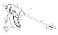
- FIG. 1Ais a perspective view of an embodiment of a medical device in accordance with one embodiment of the present disclosure
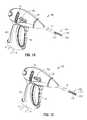
- FIG. 1Bis a partial, perspective view of the embodiment of FIG. 1 , shown with the jaw members in a closed position and a suction tube in a retracted position;
- FIG. 1Cis a partial, perspective view of the embodiment of FIG. 1 , shown with the jaw members in a closed position and a suction tube in a deployed position;
- FIG. 1Dis a partial, cross-sectional, side view of an embodiment of the medical device in accordance with the present disclosure, shown with the jaw members in an open position and the suction tube in a partially retracted position;
- FIG. 1Eis a partial, cross-sectional, side view of an embodiment of the medical device of FIG. 1D , shown with the jaw members in an open position and a suction tube in a fully deployed position;
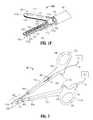
- FIG. 1Fis an enlarged, perspective view of the jaw members shown in an open position with the suction tube in a partially deployed position in accordance with the present disclosure.
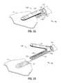
- FIG. 2is a perspective view of an open medical device in accordance with another embodiment the present disclosure.
- FIG. 3Ais an enlarged, perspective view of the jaw members shown engaging tissue with the suction tube in a retracted position
- FIG. 3Bis an enlarged, perspective view of the jaw members shown disengaged from tissue and with the suction tube in a deployed position.
- FIG. 1Adepicts a forceps 10 for use in connection with endoscopic surgical procedures
- FIG. 2depicts an open forceps 10 ′ contemplated for use in connection with traditional open surgical procedures.
- an endoscopic devicee.g., forceps 10
- an open devicee.g., forceps 10 ′
- any other suitable surgical devicemay be utilized in accordance with the present disclosure.
- Different electrical and mechanical connections and considerationsmay apply to each particular type of device, however, the aspects and features of the present disclosure remain generally consistent regardless of the particular device used.
- an endoscopic forceps 10including a housing 20 having a shaft 12 that extends therefrom and defines a longitudinal axis “X-X” therethrough, a handle assembly 30 , and an end effector assembly 100 . Additionally, forceps 10 may be configured to include a rotating assembly 70 and a trigger assembly 80 , as shown in FIG. 1 .
- Forceps 10further includes a shaft 12 having a distal end 14 configured to mechanically engage end effector assembly 100 and a proximal end 16 that mechanically engages housing 20 .
- Forceps 10also includes cable 8 that connects forceps 10 to an energy source, e.g., a generator “G”, or other suitable power source, although forceps 10 may alternatively be configured as a battery-powered device.
- Cable 8includes a wire or wires (not shown) extending therethrough that has sufficient length to extend through shaft 12 in order to provide energy to at least one of tissue-contacting surfaces 112 , 122 ( FIG. 1F ) of jaw members 110 , 120 , respectively.
- An activation switch 200may be provided on housing 20 for selectively supplying energy to jaw members 110 , 120 .
- handle assembly 30includes fixed handle 50 and a moveable handle 40 .
- Fixed handle 50is integrally associated with or rigidly attached to housing 20 and handle 40 is moveable relative to fixed handle 50 .
- Moveable handle 40is ultimately connected to a drive assembly (not shown in FIG. 1A ) that, together, mechanically cooperate to impart movement of jaw members 110 and 120 between a spaced-apart position and an approximated position to grasp tissue disposed between jaw members 110 , 120 .
- moveable handle 40is initially spaced-apart from fixed handle 50 and, correspondingly, jaw members 110 , 120 are disposed in the spaced-apart position.
- Moveable handle 40is compressible from this initial position to a compressed position corresponding to the approximated position of jaw members 110 , 120 .
- Rotating assembly 70is rotatable in either direction about longitudinal axis “X-X” to rotate end effector assembly 100 about longitudinal axis “X-X.”
- Housing 20houses the internal working components of forceps 10 .
- Forceps 10may also include a ratchet assembly 31 for selectively locking the jaw members 110 and 120 relative to one another at various positions during pivoting.
- Ratchet assembly 31may include graduations or other visual markings that enable the user to easily and quickly ascertain and control the amount of closure force desired between the jaw members 110 and 120 .
- Tissue pressures within a working range of about 3 kg/cm2 to about 16 kg/cm2 and, advantageously, within a working range of 7 kg/cm2 to 13 kg/cm2have been shown to be effective for sealing arteries and vascular bundles.
- one of the jaw membersincludes at least one stop member 175 (see FIG. 1F ) disposed on the inner facing surface of the electrically conductive sealing surface 122 (and/or 112 ).
- the stop member(s)is designed to facilitate gripping and manipulation of tissue and to define a gap “g” between opposing jaw members 110 and 120 during sealing (See FIG. 3A ).
- the separation distance during sealing or the gap distance “g”is within the range of about 0.001 inches (about 0.03 millimeters) to about 0.006 inches (about 0.016 millimeters).
- end effector assembly 100 of forceps 10( FIG. 1A ) is shown. End effector assembly 100 may similarly be used in conjunction with forceps 10 ′ ( FIG. 2 ), or any other suitable surgical device. For purposes of simplicity, end effector assembly 100 is described herein as configured for use with forceps 10 ( FIG. 1 ).
- Each jaw member 110 , 120 of end effector assembly 100includes a proximal flange portion 111 a , 121 a , a distal jaw portion 111 b , 121 b , an outer insulative jaw housing 117 , 127 and a tissue-contacting plate 112 , 122 , respectively.
- Proximal flange portions 111 a , 121 a of jaw members 110 , 120are pivotably coupled to one another about a pivot 103 for moving jaw members 110 , 120 between the spaced-apart and approximated positions.
- Distal jaw portions 111 b , 121 b of jaw members 110 , 120are configured to support jaw housings 117 , 127 , and tissue-contacting plates 114 , 124 , respectively, thereon. Further, one of the jaw members, e.g., jaw member 120 , may include an energy-based cutting member (not shown) disposed thereon, or a channel 115 for allowing a mechanical cutting member (not shown), e.g., a knife assembly as described above, to pass therethrough.
- Trigger 82 of trigger assembly 80is operably coupled to the knife assembly (shown in FIGS. 1D-1F ) for selectively translating a knife blade 134 ( FIGS. 1D-1F and 3A-3B ) through a knife channel 115 ( FIG.
- Knife assembly(shown in FIGS. 1D-1F ) may be configured for mechanical cutting, or may be energizable, e.g., via electrical coupling to generator “G” ( FIG. 1A ) via the one or more wires (not shown) of cable 8 ( FIG. 1A ), for electro-mechanically cutting tissue.
- the electrical cutting membercan be similarly coupled to trigger 82 ( FIG. 1A ) and generator “G” ( FIG. 1A ) such that energy, e.g., electrosurgical energy, may be selectively supplied to cutting member and conducted through tissue disposed between jaw members 110 , 120 to either or both of tissue-contacting plates 112 , 122 to cut tissue in a second mode of operation.
- energye.g., electrosurgical energy
- a first insulating membermay surround electrical cutting member to insulate tissue-contacting plate 122 and electrical cutting member from one another.
- a second insulating membermay be disposed within a longitudinal slot defined within tissue-contacting plate 112 of jaw member 110 that opposes electrical cutting member to insulate electrical cutting member from tissue-contacting plate 112 of jaw member 110 when jaw members 110 , 120 are disposed in the approximated position.
- Tissue-contacting plates 112 , 122are formed from an electrically conductive material for conducting electrical energy therebetween for treating tissue, although tissue-contacting plates 112 , 122 may alternatively be configured to conduct any suitable energy through tissue grasped therebetween for energy-based tissue treatment, e.g., tissue sealing.
- the energy-based cutting membermay be formed from an electrically conductive material for conducting electrical energy between energy-based cutting member and one or both of tissue-contacting plates 112 , 122 for electrically cutting tissue.
- Energy-based cutting membermay alternatively be configured to conduct any suitable energy through tissue for electrically cutting tissue.
- Tissue-contacting plates 112 , 122are coupled to an activation switch such as trigger 82 ( FIG. 1A ) and generator “G” ( FIG. 1A ) or other suitable source of energy, e.g., via the wires (not shown) extending from cable 8 ( FIG. 1A ) through forceps 10 , such that energy, e.g., electrosurgical energy, may be selectively supplied to tissue-contacting plate 112 and/or tissue-contacting plate 122 and conducted therebetween and through tissue disposed between jaw members 110 , 120 to treat, e.g., seal, tissue in a first mode of operation.
- tissuemay be simultaneously sealed and cut.
- a suction systemis configured for use with forceps 10 ( FIG. 1A ).
- the suction system as described hereinmay also be configured for use with open forceps 10 ′ as shown in FIG. 2 .
- the suction systemwill be described in detail herein configured for use with forceps 10 ( FIG. 1A ).
- the suction systemincludes one or more tubes 113 connected to a low pressure source “L” via piping 9 .
- Low pressure source “L”may be any device capable of providing a suction flow in tube 113 , such as, but not limited to, a vacuum pump.
- the tube 113may be contained within shaft 12 as shown in FIGS. 1A-1F , or may alternatively be attached externally to shaft 12 .
- Tube 113may also be used for irrigation by connecting tube 113 to a source of fluid such as, but not limited to, saline solution. In this instance the suction system may be designed for positive or negative flow.
- tube 113may be disposed on or within forceps 10 in a fixed manner such that tube 113 may not slide longitudinally and is thus positioned at a fixed extension from shaft 12 .
- tube 113is slidably disposed within the forceps 10 and is selectively extendable via an actuator 199 such that movement of the actuator 199 from an un-actuated position to an actuated position causes tube 113 to translate between a retracted position and a deployed position.
- Actuator 199may include one or more buttons, a handle, a mechanical deployment system, an electro-mechanical deployment system, a lever, or a slide, all configured to move the tube between the retracted and deployed position.
- At least part of the tube 113is offset relative to or disposed proximate the first and second jaw 110 , 120 members and is configured to apply suction to the area proximate the first and second jaw members 110 , 120 .
- Tube 113may be disposed underneath/above (radially offset) relative to one or both of the jaw members 110 , 120 .
- tube 113may be disposed in any other suitable manner, such as, but not limited to, within a jaw member 120 .
- the tube 113is shown in a retracted position such that the tube 113 does not extend past the grasping range of the jaw members but still partially extends from shaft 12 .
- Tube 113may also be fully enclosed by the shaft 12 when in the retracted position.
- FIG. 1Dshows the tube 113 partially extended below jaw member 120 .
- a locking mechanism(not shown) may be included to hold the tube 113 in the retracted position until a user unlocks the tube 113 for selective movement in order to prevent accidental deployment of tube 113 .
- the locking mechanismmay be automatically activated (such as by a spring-loaded latch) or manually activated (such as by a finger switch or knob) upon transitioning the tube 113 to the retracted position.
- FIGS. 1C and 1Eshow tube 113 in a fully deployed position extending at least partially beyond end effector 100 .
- the fully deployed position of the tube 113may not extend beyond the end effector 100 .
- a locking mechanismmay be included to hold the tube 113 in the deployed position until a user unlocks the tube 113 for selective movement in order to prevent accidental retraction of tube 113 during a procedure.
- the locking mechanismmay be automatically activated (such as by a spring-loaded latch) or manually activated (such as by a finger switch or knob) upon the tube 113 reaching the deployed position.
- a suction valve, suction activator, or the likemay be included on or integrated with the housing 20 such that activation of a suction flow through tube 113 may be easily effected by a user by using, e.g., a handswitch.
- the suction activatormay be separate from the housing 20 , such as a footswitch.
- the actuator 199as described above, also acts as a suction valve or the like such that when the actuator 199 is moved from the un-actuated position ( FIG. 1B ) to the actuated position ( FIG. 1C ), the actuator simultaneously activates suction flow through tube 113 .
- the suction flowmay begin when the actuator 199 reaches the fully actuated position ( FIG.
- a button or contactmay be disposed at the end of the path of movement of actuator 199 such that when actuator 199 is moved to the actuated position ( FIG. 1C ), the button or electrical contact initiates suction.
- the actuator 199is shown to operate in a parallel linear fashion along with tube 113 , the actuator 199 may be configured in any desired mechanical format to accommodate a desired ergonomic instrument layout to facilitate activation.
- open forceps 10 ′is shown including two elongated shafts 12 a and 12 b , each having a proximal end 16 a and 16 b , and a distal end 14 a and 14 b , respectively. Similar to forceps 10 ( FIG. 1A ), forceps 10 ′ is configured for use with end effector assembly 100 . More specifically, end effector assembly 100 is attached to distal ends 14 a and 14 b of shafts 12 a and 12 b , respectively. As mentioned above, end effector assembly 100 includes a pair of opposing jaw members 110 and 120 that are pivotably connected about pivot 103 .
- Each shaft 12 a and 12 bincludes a handle 17 a and 17 b disposed at the proximal end 16 a and 16 b thereof.
- Each handle 17 a and 17 bdefines a finger hole 18 a and 18 b therethrough for receiving a finger of the user.
- finger holes 18 a and 18 bfacilitate movement of the shafts 12 a and 12 b relative to one another which, in turn, pivots jaw members 110 and 120 from an open position, wherein the jaw members 110 and 120 are disposed in spaced-apart relation relative to one another, to a closed position, wherein the jaw members 110 and 120 cooperate to grasp tissue therebetween.
- a ratchet assembly 30 ′may be included for selectively locking the jaw members 110 and 120 relative to one another at various positions during pivoting.
- Ratchet assembly 30 ′may include graduations or other visual markings that enable the user to easily and quickly ascertain and control the amount of closure force desired between the jaw members 110 and 120 .
- one of the shaftsincludes a proximal shaft connector 19 which is designed to connect the forceps 10 ′ to a source of energy, e.g., generator “G”.
- Proximal shaft connector 19secures an electrosurgical cable 8 ′ to forceps 10 ′ such that the user may selectively apply energy to jaw members 110 and 120 , as needed.
- One of the shafts, e.g., shaft 12 aincludes an activation switch 90 ′ for selectively supplying energy to jaw members 110 , 120 .
- Forceps 10 ′includes a suction system disposed proximate the first and second jaw members and configured to apply suction to an area proximate the first and second jaw members.
- the suction systemincludes a tube 113 ′, similar to tube 113 as described above, that is connected to a suction source “L” as described herein.
- Tube 113 ′may be slidably disposed within at least one of the shaft members 12 a , 12 b and selectively extendable from an opening defined proximally of the end effector 100 .
- Tube 113 ′may also be connected to an actuator 199 ′, similar to actuator 199 as described above, such that movement of actuator 199 ′ between an un-actuated position and an actuated position causes movement of tube 113 ′ between the retracted position and the deployed position.
- a method for performing a surgical procedureincluding the steps of providing a vessel sealing device such as forceps 10 , open forceps 10 ′, or other medical instrument having two opposable jaw members operably connected to a shaft, at least one of the jaw members configured to move relative to the other between an open position and a clamped position A suction system is included proximate one or both of the jaw members.
- a vessel sealing devicesuch as forceps 10 , open forceps 10 ′, or other medical instrument having two opposable jaw members operably connected to a shaft, at least one of the jaw members configured to move relative to the other between an open position and a clamped position
- a suction systemis included proximate one or both of the jaw members.
- the methodfurther includes the step of grasping a vessel or tissue “T” between the two jaw members and applying electrosurgical energy to seal tissue “T”.
- bodily fluids “B”may form at the surgical site.
- the useractivates the suction system to remove bodily fluids “B” from the surgical site ( FIG. 3B ).
- the tube 113may be slidably disposed in forceps 10 , and the method may also include the step of deploying the tube 113 from the retracted position to the deployed position to remove fluid and debris from the surgical site. The method may also include the step of retracting the tube 113 after use.
- the various embodiments disclosed hereinmay also be configured to work with robotic surgical systems and what is commonly referred to as “Telesurgery”.
- Such systemsemploy various robotic elements to assist the surgeon in the operating room and allow remote operation (or partial remote operation) of surgical instrumentation.
- Various robotic arms, gears, cams, pulleys, electric and mechanical motors, etc.may be employed for this purpose and may be designed with a robotic surgical system to assist the surgeon during the course of an operation or treatment.
- Such robotic systemsmay include remotely steerable systems, automatically flexible surgical systems, remotely flexible surgical systems, remotely articulating surgical systems, wireless surgical systems, modular or selectively configurable remotely operated surgical systems, etc.
- the robotic surgical systemsmay be employed with one or more consoles that are next to the operating theater or located in a remote location.
- one team of surgeons or nursesmay prep the patient for surgery and configure the robotic surgical system with one or more of the instruments disclosed herein while another surgeon (or group of surgeons) remotely controls the instruments via the robotic surgical system.
- a highly skilled surgeonmay perform multiple operations in multiple locations without leaving his/her remote console which can be both economically advantageous and a benefit to the patient or a series of patients.
- the robotic arms of the surgical systemare typically coupled to a pair of master handles by a controller.
- the handlescan be moved by the surgeon to produce a corresponding movement of the working ends of the herein described forceps (e.g., end effectors, suction systems, knifes, etc.) which may complement the use of one or more of the embodiments described herein.
- the movement of the master handlesmay be scaled so that the working ends have a corresponding movement that is different, smaller, or larger, than the movement performed by the operating hands of the surgeon.
- the scale factor or gearing ratiomay be adjustable so that the operator can control the resolution of the working ends of the surgical instrument(s).
- the master handlesmay include various sensors to provide feedback to the surgeon relating to various tissue parameters or conditions, e.g., tissue resistance due to manipulation, cutting or otherwise treating, pressure by the instrument onto the tissue, tissue temperature, tissue impedance, suction strength/pressure drop, etc. As can be appreciated, such sensors provide the surgeon with enhanced tactile feedback simulating actual operating conditions.
- the master handlesmay also include a variety of different actuators for delicate tissue manipulation or treatment further enhancing the surgeon's ability to mimic actual operating conditions.
Landscapes
- Health & Medical Sciences (AREA)
- Surgery (AREA)
- Engineering & Computer Science (AREA)
- Life Sciences & Earth Sciences (AREA)
- Biomedical Technology (AREA)
- Otolaryngology (AREA)
- Nuclear Medicine, Radiotherapy & Molecular Imaging (AREA)
- Plasma & Fusion (AREA)
- Physics & Mathematics (AREA)
- Heart & Thoracic Surgery (AREA)
- Medical Informatics (AREA)
- Molecular Biology (AREA)
- Animal Behavior & Ethology (AREA)
- General Health & Medical Sciences (AREA)
- Public Health (AREA)
- Veterinary Medicine (AREA)
- Surgical Instruments (AREA)
Abstract
Description
Claims (17)
Priority Applications (3)
| Application Number | Priority Date | Filing Date | Title |
|---|---|---|---|
| US15/972,168US10335229B2 (en) | 2013-11-19 | 2018-05-06 | Vessel sealing instrument with suction system |
| US16/445,447US11026742B2 (en) | 2013-11-19 | 2019-06-19 | Vessel sealing instrument with suction system |
| US17/339,229US20210290299A1 (en) | 2013-11-19 | 2021-06-04 | Vessel sealing instrument with suction system |
Applications Claiming Priority (3)
| Application Number | Priority Date | Filing Date | Title |
|---|---|---|---|
| US201361906019P | 2013-11-19 | 2013-11-19 | |
| US14/522,058US9974601B2 (en) | 2013-11-19 | 2014-10-23 | Vessel sealing instrument with suction system |
| US15/972,168US10335229B2 (en) | 2013-11-19 | 2018-05-06 | Vessel sealing instrument with suction system |
Related Parent Applications (1)
| Application Number | Title | Priority Date | Filing Date |
|---|---|---|---|
| US14/522,058ContinuationUS9974601B2 (en) | 2013-11-19 | 2014-10-23 | Vessel sealing instrument with suction system |
Related Child Applications (1)
| Application Number | Title | Priority Date | Filing Date |
|---|---|---|---|
| US16/445,447ContinuationUS11026742B2 (en) | 2013-11-19 | 2019-06-19 | Vessel sealing instrument with suction system |
Publications (2)
| Publication Number | Publication Date |
|---|---|
| US20180250069A1 US20180250069A1 (en) | 2018-09-06 |
| US10335229B2true US10335229B2 (en) | 2019-07-02 |
Family
ID=53174032
Family Applications (4)
| Application Number | Title | Priority Date | Filing Date |
|---|---|---|---|
| US14/522,058Active2036-11-19US9974601B2 (en) | 2013-11-19 | 2014-10-23 | Vessel sealing instrument with suction system |
| US15/972,168ActiveUS10335229B2 (en) | 2013-11-19 | 2018-05-06 | Vessel sealing instrument with suction system |
| US16/445,447Active2034-11-29US11026742B2 (en) | 2013-11-19 | 2019-06-19 | Vessel sealing instrument with suction system |
| US17/339,229AbandonedUS20210290299A1 (en) | 2013-11-19 | 2021-06-04 | Vessel sealing instrument with suction system |
Family Applications Before (1)
| Application Number | Title | Priority Date | Filing Date |
|---|---|---|---|
| US14/522,058Active2036-11-19US9974601B2 (en) | 2013-11-19 | 2014-10-23 | Vessel sealing instrument with suction system |
Family Applications After (2)
| Application Number | Title | Priority Date | Filing Date |
|---|---|---|---|
| US16/445,447Active2034-11-29US11026742B2 (en) | 2013-11-19 | 2019-06-19 | Vessel sealing instrument with suction system |
| US17/339,229AbandonedUS20210290299A1 (en) | 2013-11-19 | 2021-06-04 | Vessel sealing instrument with suction system |
Country Status (1)
| Country | Link |
|---|---|
| US (4) | US9974601B2 (en) |
Families Citing this family (61)
| Publication number | Priority date | Publication date | Assignee | Title |
|---|---|---|---|---|
| US11871901B2 (en) | 2012-05-20 | 2024-01-16 | Cilag Gmbh International | Method for situational awareness for surgical network or surgical network connected device capable of adjusting function based on a sensed situation or usage |
| US9974601B2 (en) | 2013-11-19 | 2018-05-22 | Covidien Lp | Vessel sealing instrument with suction system |
| US10856933B2 (en)* | 2016-08-02 | 2020-12-08 | Covidien Lp | Surgical instrument housing incorporating a channel and methods of manufacturing the same |
| US11534231B2 (en) | 2017-08-22 | 2022-12-27 | CovidienLP | Energy-based surgical instruments and systems configured to minimize thermal spread |
| US11925373B2 (en) | 2017-10-30 | 2024-03-12 | Cilag Gmbh International | Surgical suturing instrument comprising a non-circular needle |
| US11801098B2 (en) | 2017-10-30 | 2023-10-31 | Cilag Gmbh International | Method of hub communication with surgical instrument systems |
| US11911045B2 (en) | 2017-10-30 | 2024-02-27 | Cllag GmbH International | Method for operating a powered articulating multi-clip applier |
| US11291510B2 (en) | 2017-10-30 | 2022-04-05 | Cilag Gmbh International | Method of hub communication with surgical instrument systems |
| US11510741B2 (en) | 2017-10-30 | 2022-11-29 | Cilag Gmbh International | Method for producing a surgical instrument comprising a smart electrical system |
| US11564756B2 (en) | 2017-10-30 | 2023-01-31 | Cilag Gmbh International | Method of hub communication with surgical instrument systems |
| US10722258B2 (en) | 2017-12-21 | 2020-07-28 | Gyrus Acmi, Inc. | Surgical device having atraumatic tissue control |
| US11132462B2 (en) | 2017-12-28 | 2021-09-28 | Cilag Gmbh International | Data stripping method to interrogate patient records and create anonymized record |
| US12096916B2 (en) | 2017-12-28 | 2024-09-24 | Cilag Gmbh International | Method of sensing particulate from smoke evacuated from a patient, adjusting the pump speed based on the sensed information, and communicating the functional parameters of the system to the hub |
| US11026751B2 (en) | 2017-12-28 | 2021-06-08 | Cilag Gmbh International | Display of alignment of staple cartridge to prior linear staple line |
| US11013563B2 (en) | 2017-12-28 | 2021-05-25 | Ethicon Llc | Drive arrangements for robot-assisted surgical platforms |
| US11389164B2 (en) | 2017-12-28 | 2022-07-19 | Cilag Gmbh International | Method of using reinforced flexible circuits with multiple sensors to optimize performance of radio frequency devices |
| US11179175B2 (en) | 2017-12-28 | 2021-11-23 | Cilag Gmbh International | Controlling an ultrasonic surgical instrument according to tissue location |
| US11696760B2 (en) | 2017-12-28 | 2023-07-11 | Cilag Gmbh International | Safety systems for smart powered surgical stapling |
| US11376002B2 (en) | 2017-12-28 | 2022-07-05 | Cilag Gmbh International | Surgical instrument cartridge sensor assemblies |
| US11202570B2 (en) | 2017-12-28 | 2021-12-21 | Cilag Gmbh International | Communication hub and storage device for storing parameters and status of a surgical device to be shared with cloud based analytics systems |
| US11076921B2 (en) | 2017-12-28 | 2021-08-03 | Cilag Gmbh International | Adaptive control program updates for surgical hubs |
| US11166772B2 (en) | 2017-12-28 | 2021-11-09 | Cilag Gmbh International | Surgical hub coordination of control and communication of operating room devices |
| US11786251B2 (en) | 2017-12-28 | 2023-10-17 | Cilag Gmbh International | Method for adaptive control schemes for surgical network control and interaction |
| US11464559B2 (en) | 2017-12-28 | 2022-10-11 | Cilag Gmbh International | Estimating state of ultrasonic end effector and control system therefor |
| US20190206569A1 (en) | 2017-12-28 | 2019-07-04 | Ethicon Llc | Method of cloud based data analytics for use with the hub |
| US11832899B2 (en) | 2017-12-28 | 2023-12-05 | Cilag Gmbh International | Surgical systems with autonomously adjustable control programs |
| US11744604B2 (en) | 2017-12-28 | 2023-09-05 | Cilag Gmbh International | Surgical instrument with a hardware-only control circuit |
| US12396806B2 (en) | 2017-12-28 | 2025-08-26 | Cilag Gmbh International | Adjustment of a surgical device function based on situational awareness |
| US11896322B2 (en) | 2017-12-28 | 2024-02-13 | Cilag Gmbh International | Sensing the patient position and contact utilizing the mono-polar return pad electrode to provide situational awareness to the hub |
| US20190201112A1 (en) | 2017-12-28 | 2019-07-04 | Ethicon Llc | Computer implemented interactive surgical systems |
| US12127729B2 (en) | 2017-12-28 | 2024-10-29 | Cilag Gmbh International | Method for smoke evacuation for surgical hub |
| US12062442B2 (en)* | 2017-12-28 | 2024-08-13 | Cilag Gmbh International | Method for operating surgical instrument systems |
| US20190201039A1 (en) | 2017-12-28 | 2019-07-04 | Ethicon Llc | Situational awareness of electrosurgical systems |
| US11857152B2 (en) | 2017-12-28 | 2024-01-02 | Cilag Gmbh International | Surgical hub spatial awareness to determine devices in operating theater |
| US11998193B2 (en) | 2017-12-28 | 2024-06-04 | Cilag Gmbh International | Method for usage of the shroud as an aspect of sensing or controlling a powered surgical device, and a control algorithm to adjust its default operation |
| US11818052B2 (en) | 2017-12-28 | 2023-11-14 | Cilag Gmbh International | Surgical network determination of prioritization of communication, interaction, or processing based on system or device needs |
| US11559308B2 (en) | 2017-12-28 | 2023-01-24 | Cilag Gmbh International | Method for smart energy device infrastructure |
| US11896443B2 (en) | 2017-12-28 | 2024-02-13 | Cilag Gmbh International | Control of a surgical system through a surgical barrier |
| US11304699B2 (en) | 2017-12-28 | 2022-04-19 | Cilag Gmbh International | Method for adaptive control schemes for surgical network control and interaction |
| US11969216B2 (en) | 2017-12-28 | 2024-04-30 | Cilag Gmbh International | Surgical network recommendations from real time analysis of procedure variables against a baseline highlighting differences from the optimal solution |
| US11633237B2 (en) | 2017-12-28 | 2023-04-25 | Cilag Gmbh International | Usage and technique analysis of surgeon / staff performance against a baseline to optimize device utilization and performance for both current and future procedures |
| US11612444B2 (en) | 2017-12-28 | 2023-03-28 | Cilag Gmbh International | Adjustment of a surgical device function based on situational awareness |
| US20190201090A1 (en) | 2017-12-28 | 2019-07-04 | Ethicon Llc | Capacitive coupled return path pad with separable array elements |
| US11257589B2 (en) | 2017-12-28 | 2022-02-22 | Cilag Gmbh International | Real-time analysis of comprehensive cost of all instrumentation used in surgery utilizing data fluidity to track instruments through stocking and in-house processes |
| US11109866B2 (en) | 2017-12-28 | 2021-09-07 | Cilag Gmbh International | Method for circular stapler control algorithm adjustment based on situational awareness |
| US11969142B2 (en) | 2017-12-28 | 2024-04-30 | Cilag Gmbh International | Method of compressing tissue within a stapling device and simultaneously displaying the location of the tissue within the jaws |
| US11311306B2 (en) | 2017-12-28 | 2022-04-26 | Cilag Gmbh International | Surgical systems for detecting end effector tissue distribution irregularities |
| US10758310B2 (en) | 2017-12-28 | 2020-09-01 | Ethicon Llc | Wireless pairing of a surgical device with another device within a sterile surgical field based on the usage and situational awareness of devices |
| US11324557B2 (en) | 2017-12-28 | 2022-05-10 | Cilag Gmbh International | Surgical instrument with a sensing array |
| US11864728B2 (en) | 2017-12-28 | 2024-01-09 | Cilag Gmbh International | Characterization of tissue irregularities through the use of mono-chromatic light refractivity |
| WO2019133144A1 (en) | 2017-12-28 | 2019-07-04 | Ethicon Llc | Detection and escalation of security responses of surgical instruments to increasing severity threats |
| US11534196B2 (en) | 2018-03-08 | 2022-12-27 | Cilag Gmbh International | Using spectroscopy to determine device use state in combo instrument |
| US11259830B2 (en) | 2018-03-08 | 2022-03-01 | Cilag Gmbh International | Methods for controlling temperature in ultrasonic device |
| US11986233B2 (en) | 2018-03-08 | 2024-05-21 | Cilag Gmbh International | Adjustment of complex impedance to compensate for lost power in an articulating ultrasonic device |
| US11090047B2 (en) | 2018-03-28 | 2021-08-17 | Cilag Gmbh International | Surgical instrument comprising an adaptive control system |
| US11589865B2 (en) | 2018-03-28 | 2023-02-28 | Cilag Gmbh International | Methods for controlling a powered surgical stapler that has separate rotary closure and firing systems |
| CN108992167A (en)* | 2018-09-03 | 2018-12-14 | 安徽赢创医疗科技有限公司 | A kind of microwave bleeding forceps system |
| US11331100B2 (en) | 2019-02-19 | 2022-05-17 | Cilag Gmbh International | Staple cartridge retainer system with authentication keys |
| US20200405380A1 (en)* | 2019-06-27 | 2020-12-31 | Covidien Lp | Multi-function surgical instruments |
| CN111803146B (en)* | 2020-07-22 | 2021-07-16 | 中国医学科学院北京协和医院 | A laparoscopic separating forceps with suction function |
| KR102800205B1 (en)* | 2024-08-14 | 2025-04-28 | 주식회사 노바메디 | Multifunctional laparoscopic surgical medical device |
Citations (178)
| Publication number | Priority date | Publication date | Assignee | Title |
|---|---|---|---|---|
| SU401367A1 (en) | 1971-10-05 | 1973-10-12 | Тернопольский государственный медицинский институт | BIAKTIVNYE ELECTRO SURGICAL INSTRUMENT |
| DE2415263A1 (en) | 1974-03-29 | 1975-10-02 | Aesculap Werke Ag | Surgical H.F. coagulation probe has electrode tongs - with exposed ends of insulated conductors forming tong-jaws |
| DE2514501A1 (en) | 1975-04-03 | 1976-10-21 | Karl Storz | Bipolar coagulation instrument for endoscopes - has two high frequency electrodes looped over central insulating piece |
| DE2627679A1 (en) | 1975-06-26 | 1977-01-13 | Marcel Lamidey | HEMATISTIC HIGH FREQUENCY EXTRACTOR FORCEPS |
| USD249549S (en) | 1976-10-22 | 1978-09-19 | Aspen Laboratories, Inc. | Electrosurgical handle |
| JPS55106A (en) | 1978-05-01 | 1980-01-05 | Bii Uiriamusu Jiyun Kuraarensu | Kit for patient who artificial anus is formed |
| USD263020S (en) | 1980-01-22 | 1982-02-16 | Rau Iii David M | Retractable knife |
| JPS6121797A (en) | 1984-07-09 | 1986-01-30 | Matsushita Electric Ind Co Ltd | How to operate a methane fermentation tank |
| JPS61501068A (en) | 1984-01-30 | 1986-05-29 | ハルコフスキイ ナウチノ−イススレドワテルスキイ インスチチユ−ト オブスチエイ イ ネオトロジノイ ヒルルギイ | bipolar electrosurgical instrument |
| DE3423356C2 (en) | 1984-06-25 | 1986-06-26 | Berchtold Medizin-Elektronik GmbH & Co, 7200 Tuttlingen | Electrosurgical high frequency cutting instrument |
| JPS6285078A (en) | 1985-10-08 | 1987-04-18 | 池泉織物株式会社 | Modification treatment of silk fabric |
| DE3612646A1 (en) | 1985-04-16 | 1987-04-30 | Ellman International | Electrosurgical handle piece for blades, needles and forceps |
| DE3627221A1 (en) | 1986-01-15 | 1988-02-18 | Siemens Ag | HF SURGERY DEVICE WITH POWER CONTROL FROM THE SURGICAL HANDLE |
| DE8712328U1 (en) | 1987-09-11 | 1988-02-18 | Jakoubek, Franz, 7201 Emmingen-Liptingen | Endoscopy forceps |
| USD295894S (en) | 1985-09-26 | 1988-05-24 | Acme United Corporation | Disposable surgical scissors |
| USD295893S (en) | 1985-09-25 | 1988-05-24 | Acme United Corporation | Disposable surgical clamp |
| USD298353S (en) | 1986-05-06 | 1988-11-01 | Vitalmetrics, Inc. | Handle for surgical instrument |
| USD299413S (en) | 1985-07-17 | 1989-01-17 | The Stanley Works | Folding pocket saw handle |
| JPH022328A (en) | 1988-06-09 | 1990-01-08 | Ueno Seiyaku Oyo Kenkyusho:Kk | Preservation of food |
| JPH0211401A (en) | 1988-06-28 | 1990-01-16 | Sky Alum Co Ltd | Manufacture of two-piece wheel rim having excellent gloss |
| JPH0540112A (en) | 1991-02-08 | 1993-02-19 | Tokico Ltd | Sample liquid component analyzer |
| USD343453S (en) | 1993-05-05 | 1994-01-18 | Laparomed Corporation | Handle for laparoscopic surgical instrument |
| JPH0630945A (en) | 1992-05-19 | 1994-02-08 | Olympus Optical Co Ltd | Suturing apparatus |
| USD348930S (en) | 1991-10-11 | 1994-07-19 | Ethicon, Inc. | Endoscopic stapler |
| USD349341S (en) | 1992-10-28 | 1994-08-02 | Microsurge, Inc. | Endoscopic grasper |
| US5336220A (en) | 1992-10-09 | 1994-08-09 | Symbiosis Corporation | Tubing for endoscopic electrosurgical suction-irrigation instrument |
| JPH06343644A (en) | 1993-05-04 | 1994-12-20 | Gyrus Medical Ltd | Surgical peritoneoscope equipment |
| USD354564S (en) | 1993-06-25 | 1995-01-17 | Richard-Allan Medical Industries, Inc. | Surgical clip applier |
| DE4303882C2 (en) | 1993-02-10 | 1995-02-09 | Kernforschungsz Karlsruhe | Combination instrument for separation and coagulation for minimally invasive surgery |
| US5417709A (en) | 1994-04-12 | 1995-05-23 | Symbiosis Corporation | Endoscopic instrument with end effectors forming suction and/or irrigation lumens |
| USD358887S (en) | 1993-12-02 | 1995-05-30 | Cobot Medical Corporation | Combined cutting and coagulating forceps |
| DE4403252A1 (en) | 1994-02-03 | 1995-08-10 | Michael Hauser | Instrument shaft for min. invasive surgery |
| JPH07265328A (en) | 1993-11-01 | 1995-10-17 | Gyrus Medical Ltd | Electrode assembly for electric surgery device and electric surgery device using it |
| JPH0856955A (en) | 1994-06-29 | 1996-03-05 | Gyrus Medical Ltd | Electric surgical apparatus |
| DE19515914C1 (en) | 1995-05-02 | 1996-07-25 | Aesculap Ag | Tong or scissor-shaped surgical instrument |
| DE19506363A1 (en) | 1995-02-24 | 1996-08-29 | Frost Lore Geb Haupt | Non-invasive thermometry in organs under hyperthermia and coagulation conditions |
| US5554172A (en) | 1995-05-09 | 1996-09-10 | The Larren Corporation | Directed energy surgical method and assembly |
| JPH08252263A (en) | 1994-12-21 | 1996-10-01 | Gyrus Medical Ltd | Electronic surgical incision instrument and electronic surgical incision device using the same |
| JPH08289895A (en) | 1995-04-21 | 1996-11-05 | Olympus Optical Co Ltd | Suture device |
| DE29616210U1 (en) | 1996-09-18 | 1996-11-14 | Olympus Winter & Ibe Gmbh, 22045 Hamburg | Handle for surgical instruments |
| JPH08317934A (en) | 1995-04-12 | 1996-12-03 | Ethicon Endo Surgery Inc | Hemostatic device for electric surgery with adaptable electrode |
| JPH08317936A (en) | 1995-01-18 | 1996-12-03 | Ethicon Endo Surgery Inc | Hemostatic device for electric surgery provided with recessed type and/or crossed type electrode |
| JPH09538A (en) | 1995-06-21 | 1997-01-07 | Fuji Photo Optical Co Ltd | High-frequency medical treatment instrument |
| JPH0910223A (en) | 1995-06-23 | 1997-01-14 | Gyrus Medical Ltd | Generator and system for electric operation |
| DE19608716C1 (en) | 1996-03-06 | 1997-04-17 | Aesculap Ag | Bipolar surgical holding instrument |
| JPH09122138A (en) | 1995-10-20 | 1997-05-13 | Ethicon Endo Surgery Inc | Apparatus for operation |
| USD384413S (en) | 1994-10-07 | 1997-09-30 | United States Surgical Corporation | Endoscopic suturing instrument |
| US5690660A (en) | 1993-10-27 | 1997-11-25 | Stryker Corporation | Arthroscopic cutter having curved rotatable drive |
| JPH10195A (en) | 1996-03-05 | 1998-01-06 | Ethicon Endo Surgery Inc | Surgical suturing machine with fixing mechanism |
| JPH1024051A (en) | 1995-09-20 | 1998-01-27 | Olympus Optical Co Ltd | Coagulation forceps with separating function |
| DE19751106A1 (en) | 1996-11-27 | 1998-05-28 | Eastman Kodak Co | Laser printer with array of laser diodes |
| JPH10155798A (en) | 1996-12-04 | 1998-06-16 | Asahi Optical Co Ltd | Hot biopsy forceps for endoscopes |
| USH1745H (en) | 1995-09-29 | 1998-08-04 | Paraschac; Joseph F. | Electrosurgical clamping device with insulation limited bipolar electrode |
| USD402028S (en) | 1997-10-10 | 1998-12-01 | Invasatec, Inc. | Hand controller for medical system |
| JPH1147150A (en) | 1997-08-06 | 1999-02-23 | Olympus Optical Co Ltd | Endoscopic surgery appliance |
| JPH1147149A (en) | 1997-08-04 | 1999-02-23 | Olympus Optical Co Ltd | Endoscopic surgery appliance |
| JPH1170124A (en) | 1997-05-14 | 1999-03-16 | Ethicon Endo Surgery Inc | Improved electrosurgical hemostatic apparatus having anvil |
| USD408018S (en) | 1996-03-12 | 1999-04-13 | Mcnaughton Patrick J | Switch guard |
| DE19751108A1 (en) | 1997-11-18 | 1999-05-20 | Beger Frank Michael Dipl Desig | Electrosurgical operation tool, especially for diathermy |
| JPH11169381A (en) | 1997-12-15 | 1999-06-29 | Olympus Optical Co Ltd | High frequency treating device |
| JPH11192238A (en) | 1997-10-10 | 1999-07-21 | Ethicon Endo Surgery Inc | Ultrasonic forceps coagulation device improved of pivot-attaching of forceps arm |
| US5938589A (en) | 1997-07-15 | 1999-08-17 | Fuji Photo Optical Co., Ltd. | Control switch device for an endoscope duct |
| JPH11244298A (en) | 1997-12-19 | 1999-09-14 | Gyrus Medical Ltd | Electric surgical instrument |
| USD416089S (en) | 1996-04-08 | 1999-11-02 | Richard-Allan Medical Industries, Inc. | Endoscopic linear stapling and dividing surgical instrument |
| JP2000102545A (en) | 1997-06-18 | 2000-04-11 | Eggers & Associates Inc | Electric tweezers for surgery |
| US6056735A (en) | 1996-04-04 | 2000-05-02 | Olympus Optical Co., Ltd. | Ultrasound treatment system |
| USD424694S (en) | 1998-10-23 | 2000-05-09 | Sherwood Services Ag | Forceps |
| JP2000135222A (en) | 1998-08-27 | 2000-05-16 | Olympus Optical Co Ltd | High frequency treatment device |
| USD425201S (en) | 1998-10-23 | 2000-05-16 | Sherwood Services Ag | Disposable electrode assembly |
| WO2000036986A1 (en) | 1998-12-18 | 2000-06-29 | Karl Storz Gmbh & Co. Kg | Bipolar medical instrument |
| USH1904H (en) | 1997-05-14 | 2000-10-03 | Ethicon Endo-Surgery, Inc. | Electrosurgical hemostatic method and device |
| WO2000059392A1 (en) | 1999-04-01 | 2000-10-12 | Erbe Elektromedizin | Surgical instrument |
| JP2000342599A (en) | 1999-05-21 | 2000-12-12 | Gyrus Medical Ltd | Generator for electrosurgical operation, electrosurgical operation system, method for operating this system and method for performing amputation and resection of tissue by electrosurgical operation |
| JP2000350732A (en) | 1999-05-21 | 2000-12-19 | Gyrus Medical Ltd | Electrosurgical system, generator for electrosurgery, and method for cutting or excising tissue by electrosurgery |
| JP2001003400A (en) | 1999-06-21 | 2001-01-09 | Sumitomo Constr Mach Co Ltd | Monitor device for hydraulic shovel |
| JP2001008944A (en) | 1999-05-28 | 2001-01-16 | Gyrus Medical Ltd | Electric surgical signal generator and electric surgical system |
| JP2001029355A (en) | 1999-07-21 | 2001-02-06 | Olympus Optical Co Ltd | Electric cautery device |
| JP2001029356A (en) | 1999-06-11 | 2001-02-06 | Gyrus Medical Ltd | Electric and surgical signal generator |
| WO2001015614A1 (en) | 1999-08-27 | 2001-03-08 | Karl Storz Gmbh & Co. Kg | Bipolar medical instrument |
| JP2001128990A (en) | 1999-05-28 | 2001-05-15 | Gyrus Medical Ltd | Electro surgical instrument and electrosurgical tool converter |
| DE19946527C1 (en) | 1999-09-28 | 2001-07-12 | Storz Karl Gmbh & Co Kg | Bipolar, e.g. laparoscopic surgery instrument, cuts electrically, cauterizes and grips using simple design with high frequency current-concentrating projections |
| JP2001190564A (en) | 2000-01-12 | 2001-07-17 | Olympus Optical Co Ltd | Medical treatment instrument |
| WO2001054604A1 (en) | 2000-01-25 | 2001-08-02 | Aesculap Ag & Co. Kg | Bipolar gripping device |
| USD449886S1 (en) | 1998-10-23 | 2001-10-30 | Sherwood Services Ag | Forceps with disposable electrode |
| EP1159926A2 (en) | 2000-06-03 | 2001-12-05 | Aesculap Ag | Scissor- or forceps-like surgical instrument |
| USD453923S1 (en) | 2000-11-16 | 2002-02-26 | Carling Technologies, Inc. | Electrical rocker switch guard |
| USD454951S1 (en) | 2001-02-27 | 2002-03-26 | Visionary Biomedical, Inc. | Steerable catheter |
| DE20121161U1 (en) | 2001-01-31 | 2002-04-04 | Olympus Winter & Ibe Gmbh, 22045 Hamburg | Endoscopic instrument |
| JP2002136525A (en) | 2000-10-30 | 2002-05-14 | Olympus Optical Co Ltd | Surgical instrument |
| USD457959S1 (en) | 2001-04-06 | 2002-05-28 | Sherwood Services Ag | Vessel sealer |
| USD457958S1 (en) | 2001-04-06 | 2002-05-28 | Sherwood Services Ag | Vessel sealer and divider |
| WO2002045589A2 (en) | 2000-12-08 | 2002-06-13 | Gfd Gesellschaft Für Diamantprodukte Mbh | Instrument, which is provided for surgical applications and which comprises contact areas made of doped diamond, and method for cleaning the instrument |
| JP2002528166A (en) | 1998-10-23 | 2002-09-03 | シャーウッド サーヴィシス アクチェンゲゼルシャフト | Externally-opened vascular sealing forceps with disposable electrodes |
| DE10045375C2 (en) | 2000-09-14 | 2002-10-24 | Aesculap Ag & Co Kg | Medical instrument |
| USD465281S1 (en) | 1999-09-21 | 2002-11-05 | Karl Storz Gmbh & Co. Kg | Endoscopic medical instrument |
| USD466209S1 (en) | 2001-02-27 | 2002-11-26 | Visionary Biomedical, Inc. | Steerable catheter |
| EP1281878A1 (en) | 2001-08-02 | 2003-02-05 | Peugeot Citroen Automobiles | Pivot pin between two elements |
| JP2003116871A (en) | 2001-10-16 | 2003-04-22 | Olympus Optical Co Ltd | Surgical tool |
| JP2003175052A (en) | 2002-11-01 | 2003-06-24 | Olympus Optical Co Ltd | Coagulation treatment tool |
| JP2003245285A (en) | 2002-01-23 | 2003-09-02 | Ethicon Endo Surgery Inc | Feedback light apparatus and method for use with electrosurgical instrument |
| US6740079B1 (en) | 2001-07-12 | 2004-05-25 | Neothermia Corporation | Electrosurgical generator |
| JP2004517668A (en) | 2000-10-20 | 2004-06-17 | オーナックス・メディカル・インコーポレーテッド | Surgical suturing instrument and method of use |
| USD493888S1 (en) | 2003-02-04 | 2004-08-03 | Sherwood Services Ag | Electrosurgical pencil with pistol grip |
| JP2004528869A (en) | 2001-01-26 | 2004-09-24 | エシコン・エンド−サージェリィ・インコーポレイテッド | Electrosurgical instruments for coagulation and cutting |
| USD496997S1 (en) | 2003-05-15 | 2004-10-05 | Sherwood Services Ag | Vessel sealer and divider |
| USD499181S1 (en) | 2003-05-15 | 2004-11-30 | Sherwood Services Ag | Handle for a vessel sealer and divider |
| USD502994S1 (en) | 2003-05-21 | 2005-03-15 | Blake, Iii Joseph W | Repeating multi-clip applier |
| JP2005152663A (en) | 2003-11-20 | 2005-06-16 | Sherwood Services Ag | Electrically conductive/insulative over-shoe for tissue fusion |
| US20050165427A1 (en) | 2004-01-22 | 2005-07-28 | Jahns Scott E. | Vessel sealing devices |
| USD509297S1 (en) | 2003-10-17 | 2005-09-06 | Tyco Healthcare Group, Lp | Surgical instrument |
| JP2005253789A (en) | 2004-03-12 | 2005-09-22 | Olympus Corp | Treatment instrument for operation |
| JP2005312807A (en) | 2004-04-30 | 2005-11-10 | Olympus Corp | Energy therapy device |
| WO2005110264A2 (en) | 2004-05-14 | 2005-11-24 | Erbe Elektromedizin Gmbh | Electrosurgical instrument |
| JP2006015078A (en) | 2004-07-05 | 2006-01-19 | Olympus Corp | Medical apparatus |
| JP2006501939A (en) | 2002-10-04 | 2006-01-19 | シャーウッド・サービシーズ・アクチェンゲゼルシャフト | Electrode assembly for sealing and cutting tissue and method for performing sealing and cutting tissue |
| WO2006021269A1 (en) | 2004-08-24 | 2006-03-02 | Erbe Elektromedizin Gmbh | Surgical instrument |
| JP2006095316A (en) | 2004-09-29 | 2006-04-13 | Sherwood Services Ag | Vessel sealer and divider having elongated knife stroke and safety for cutting mechanism |
| USD525361S1 (en) | 2004-10-06 | 2006-07-18 | Sherwood Services Ag | Hemostat style elongated dissecting and dividing instrument |
| US7112199B2 (en) | 1996-09-20 | 2006-09-26 | Ioan Cosmescu | Multifunctional telescopic monopolar/bipolar surgical device and method therefore |
| USD531311S1 (en) | 2004-10-06 | 2006-10-31 | Sherwood Services Ag | Pistol grip style elongated dissecting and dividing instrument |
| US20060253126A1 (en) | 2005-05-04 | 2006-11-09 | Bernard Medical, Llc | Endoluminal suturing device and method |
| US20060271030A1 (en) | 2005-04-11 | 2006-11-30 | Cierra, Inc. | Methods and apparatus to achieve a closure of a layered tissue defect |
| USD533274S1 (en) | 2004-10-12 | 2006-12-05 | Allegiance Corporation | Handle for surgical suction-irrigation device |
| USD533942S1 (en) | 2004-06-30 | 2006-12-19 | Sherwood Services Ag | Open vessel sealer with mechanical cutter |
| USD535027S1 (en) | 2004-10-06 | 2007-01-09 | Sherwood Services Ag | Low profile vessel sealing and cutting mechanism |
| USD538932S1 (en) | 2005-06-30 | 2007-03-20 | Medical Action Industries Inc. | Surgical needle holder |
| USD541418S1 (en) | 2004-10-06 | 2007-04-24 | Sherwood Services Ag | Lung sealing device |
| USD541938S1 (en) | 2004-04-09 | 2007-05-01 | Sherwood Services Ag | Open vessel sealer with mechanical cutter |
| USD541611S1 (en) | 2006-01-26 | 2007-05-01 | Robert Bosch Gmbh | Cordless screwdriver |
| USD545432S1 (en) | 2003-08-08 | 2007-06-26 | Olympus Corporation | Distal portion of hemostatic forceps for endoscope |
| USD547154S1 (en) | 2006-09-08 | 2007-07-24 | Winsource Industries Limited | Rotary driving tool |
| DE202007009318U1 (en) | 2007-06-26 | 2007-08-30 | Aesculap Ag & Co. Kg | Surgical instrument |
| DE202007009317U1 (en) | 2007-06-26 | 2007-08-30 | Aesculap Ag & Co. Kg | Surgical instrument |
| DE202007009165U1 (en) | 2007-06-29 | 2007-08-30 | Kls Martin Gmbh + Co. Kg | Surgical instrument e.g. tube shaft, for use in e.g. high frequency coagulation instrument, has separator inserted through opening such that largest extension of opening transverse to moving direction corresponds to dimension of separator |
| DE10031773B4 (en) | 2000-05-04 | 2007-11-29 | Erbe Elektromedizin Gmbh | Surgical gripping instrument, in particular tweezers or forceps |
| DE202007016233U1 (en) | 2007-11-20 | 2008-01-31 | Aesculap Ag & Co. Kg | Surgical forceps |
| JP2008054926A (en) | 2006-08-31 | 2008-03-13 | Shiga Univ Of Medical Science | Microwave surgical device |
| USD564662S1 (en) | 2004-10-13 | 2008-03-18 | Sherwood Services Ag | Hourglass-shaped knife for electrosurgical forceps |
| WO2008040483A1 (en) | 2006-10-05 | 2008-04-10 | Erbe Elektromedizin Gmbh | Tubular shaft instrument |
| USD567943S1 (en) | 2004-10-08 | 2008-04-29 | Sherwood Services Ag | Over-ratchet safety for a vessel sealing instrument |
| USD575401S1 (en) | 2007-06-12 | 2008-08-19 | Tyco Healthcare Group Lp | Vessel sealer |
| USD575395S1 (en) | 2007-02-15 | 2008-08-19 | Tyco Healthcare Group Lp | Hemostat style elongated dissecting and dividing instrument |
| USD582038S1 (en) | 2004-10-13 | 2008-12-02 | Medtronic, Inc. | Transurethral needle ablation device |
| DE19738457B4 (en) | 1997-09-03 | 2009-01-02 | Celon Ag Medical Instruments | Method and device for in vivo deep coagulation of biological tissue volumes while sparing the tissue surface with high frequency alternating current |
| US20090177094A1 (en) | 2008-01-08 | 2009-07-09 | Oncoscope, Inc. | Systems and methods for tissue examination, diagnostic, treatment, and/or monitoring |
| DE102008018406B3 (en) | 2008-04-10 | 2009-07-23 | Bowa-Electronic Gmbh & Co. Kg | Electrosurgical device |
| CN201299462Y (en) | 2008-10-28 | 2009-09-02 | 宋洪海 | Multi-layer metal composite pot |
| US20090299364A1 (en) | 2008-04-21 | 2009-12-03 | Medtronic, Inc. | Suction Force Ablation Device |
| USD617903S1 (en) | 2009-05-13 | 2010-06-15 | Tyco Healthcare Group Lp | End effector pointed tip |
| USD617901S1 (en) | 2009-05-13 | 2010-06-15 | Tyco Healthcare Group Lp | End effector chamfered tip |
| USD617900S1 (en) | 2009-05-13 | 2010-06-15 | Tyco Healthcare Group Lp | End effector tip with undercut bottom jaw |
| USD617902S1 (en) | 2009-05-13 | 2010-06-15 | Tyco Healthcare Group Lp | End effector tip with undercut top jaw |
| USD618798S1 (en) | 2009-05-13 | 2010-06-29 | Tyco Healthcare Group Lp | Vessel sealing jaw seal plate |
| USD621503S1 (en) | 2009-04-28 | 2010-08-10 | Tyco Healthcare Group Ip | Pistol grip laparoscopic sealing and dissection device |
| USD627462S1 (en) | 2009-09-09 | 2010-11-16 | Tyco Healthcare Group Lp | Knife channel of a jaw device |
| USD628290S1 (en) | 2009-11-30 | 2010-11-30 | Tyco Healthcare Group Lp | Surgical instrument handle |
| USD628289S1 (en) | 2009-11-30 | 2010-11-30 | Tyco Healthcare Group Lp | Surgical instrument handle |
| USD630324S1 (en) | 2009-08-05 | 2011-01-04 | Tyco Healthcare Group Lp | Dissecting surgical jaw |
| WO2011018154A1 (en) | 2009-08-14 | 2011-02-17 | Erbe Elektromedizin Gmbh | Electrosurgical instrument |
| JP2011125195A (en) | 2009-12-14 | 2011-06-23 | Chugoku Electric Power Co Inc:The | Supporter for indirect hot-line work |
| US7998095B2 (en) | 2005-08-19 | 2011-08-16 | Boston Scientific Scimed, Inc. | Occlusion device |
| USD649249S1 (en) | 2007-02-15 | 2011-11-22 | Tyco Healthcare Group Lp | End effectors of an elongated dissecting and dividing instrument |
| USD649643S1 (en) | 2009-05-13 | 2011-11-29 | Tyco Healthcare Group Lp | End effector with a rounded tip |
| US8075580B2 (en) | 1996-02-02 | 2011-12-13 | Medtronic Vascular, Inc. | Device, system and method for interstitial transvascular intervention |
| US8142425B2 (en) | 2007-10-30 | 2012-03-27 | Hemostatix Medical Techs, LLC | Hemostatic surgical blade, system and method of blade manufacture |
| US20120116379A1 (en)* | 2010-11-05 | 2012-05-10 | Yates David C | Motor Driven Electrosurgical Device With Mechanical And Electrical Feedback |
| USD661394S1 (en) | 2011-02-24 | 2012-06-05 | Tyco Healthcare Group Lp | Device jaw |
| US8207651B2 (en) | 2009-09-16 | 2012-06-26 | Tyco Healthcare Group Lp | Low energy or minimum disturbance method for measuring frequency response functions of ultrasonic surgical devices in determining optimum operating point |
| US20120184990A1 (en)* | 2011-01-14 | 2012-07-19 | Tyco Healthcare Group Lp | Trigger Lockout and Kickback Mechanism for Surgical Instruments |
| US8303581B2 (en) | 2008-09-02 | 2012-11-06 | Covidien Lp | Catheter with remotely extendible instruments |
| USD670808S1 (en) | 2010-10-01 | 2012-11-13 | Tyco Healthcare Group Lp | Open vessel sealing forceps |
| USD680220S1 (en) | 2012-01-12 | 2013-04-16 | Coviden IP | Slider handle for laparoscopic device |
| US8469957B2 (en) | 2008-10-07 | 2013-06-25 | Covidien Lp | Apparatus, system, and method for performing an electrosurgical procedure |
| US8562598B2 (en) | 2008-03-31 | 2013-10-22 | Applied Medical Resources Corporation | Electrosurgical system |
| US8641713B2 (en) | 2005-09-30 | 2014-02-04 | Covidien Ag | Flexible endoscopic catheter with ligasure |
| US9974601B2 (en) | 2013-11-19 | 2018-05-22 | Covidien Lp | Vessel sealing instrument with suction system |
| JP6502328B2 (en) | 2013-09-26 | 2019-04-17 | ヴァレオ ビジョンValeo Vision | Eyeglass lens and eyeglass lens system |
| JP6511401B2 (en) | 2013-02-15 | 2019-05-15 | アラーガン、インコーポレイテッドAllergan,Incorporated | Sustained drug delivery implant |
Family Cites Families (14)
| Publication number | Priority date | Publication date | Assignee | Title |
|---|---|---|---|---|
| JPS55106B1 (en) | 1975-04-03 | 1980-01-05 | ||
| JPS58168310U (en) | 1982-05-07 | 1983-11-10 | オリンパス光学工業株式会社 | Support device with fall prevention mechanism for surgical microscope |
| JPH0211401Y2 (en) | 1984-11-22 | 1990-03-22 | ||
| JPH0826815B2 (en) | 1987-12-03 | 1996-03-21 | 株式会社ウオルブローフアーイースト | Vaporizer starting fuel supply device |
| JPH01147150A (en) | 1987-12-04 | 1989-06-08 | Hitachi Ltd | Variable venturi carburetor |
| US6099550A (en)* | 1989-12-05 | 2000-08-08 | Yoon; Inbae | Surgical instrument having jaws and an operating channel and method for use thereof |
| JP2806511B2 (en) | 1990-07-31 | 1998-09-30 | 松下電工株式会社 | Manufacturing method of sintered alloy |
| US5389102A (en) | 1990-09-13 | 1995-02-14 | United States Surgical Corporation | Apparatus and method for subcuticular stapling of body tissue |
| US5190541A (en) | 1990-10-17 | 1993-03-02 | Boston Scientific Corporation | Surgical instrument and method |
| US5330471A (en) | 1991-06-07 | 1994-07-19 | Hemostatic Surgery Corporation | Bi-polar electrosurgical endoscopic instruments and methods of use |
| JPH0630945B2 (en) | 1991-12-20 | 1994-04-27 | 株式会社サトー | Winding mechanism to prevent meandering of carbon ribbon |
| JP3390041B2 (en) | 1993-04-05 | 2003-03-24 | オリンパス光学工業株式会社 | Forceps |
| JP3654405B2 (en) | 1997-12-09 | 2005-06-02 | 株式会社リコー | Seal lip turning judgment method and seal insertion device |
| JP2006030945A (en) | 2004-06-16 | 2006-02-02 | Ricoh Co Ltd | Fixing device |
- 2014
- 2014-10-23USUS14/522,058patent/US9974601B2/enactiveActive
- 2018
- 2018-05-06USUS15/972,168patent/US10335229B2/enactiveActive
- 2019
- 2019-06-19USUS16/445,447patent/US11026742B2/enactiveActive
- 2021
- 2021-06-04USUS17/339,229patent/US20210290299A1/ennot_activeAbandoned
Patent Citations (182)
| Publication number | Priority date | Publication date | Assignee | Title |
|---|---|---|---|---|
| SU401367A1 (en) | 1971-10-05 | 1973-10-12 | Тернопольский государственный медицинский институт | BIAKTIVNYE ELECTRO SURGICAL INSTRUMENT |
| DE2415263A1 (en) | 1974-03-29 | 1975-10-02 | Aesculap Werke Ag | Surgical H.F. coagulation probe has electrode tongs - with exposed ends of insulated conductors forming tong-jaws |
| DE2514501A1 (en) | 1975-04-03 | 1976-10-21 | Karl Storz | Bipolar coagulation instrument for endoscopes - has two high frequency electrodes looped over central insulating piece |
| DE2627679A1 (en) | 1975-06-26 | 1977-01-13 | Marcel Lamidey | HEMATISTIC HIGH FREQUENCY EXTRACTOR FORCEPS |
| USD249549S (en) | 1976-10-22 | 1978-09-19 | Aspen Laboratories, Inc. | Electrosurgical handle |
| JPS55106A (en) | 1978-05-01 | 1980-01-05 | Bii Uiriamusu Jiyun Kuraarensu | Kit for patient who artificial anus is formed |
| USD263020S (en) | 1980-01-22 | 1982-02-16 | Rau Iii David M | Retractable knife |
| JPS61501068A (en) | 1984-01-30 | 1986-05-29 | ハルコフスキイ ナウチノ−イススレドワテルスキイ インスチチユ−ト オブスチエイ イ ネオトロジノイ ヒルルギイ | bipolar electrosurgical instrument |
| DE3423356C2 (en) | 1984-06-25 | 1986-06-26 | Berchtold Medizin-Elektronik GmbH & Co, 7200 Tuttlingen | Electrosurgical high frequency cutting instrument |
| JPS6121797A (en) | 1984-07-09 | 1986-01-30 | Matsushita Electric Ind Co Ltd | How to operate a methane fermentation tank |
| DE3612646A1 (en) | 1985-04-16 | 1987-04-30 | Ellman International | Electrosurgical handle piece for blades, needles and forceps |
| USD299413S (en) | 1985-07-17 | 1989-01-17 | The Stanley Works | Folding pocket saw handle |
| USD295893S (en) | 1985-09-25 | 1988-05-24 | Acme United Corporation | Disposable surgical clamp |
| USD295894S (en) | 1985-09-26 | 1988-05-24 | Acme United Corporation | Disposable surgical scissors |
| JPS6285078A (en) | 1985-10-08 | 1987-04-18 | 池泉織物株式会社 | Modification treatment of silk fabric |
| DE3627221A1 (en) | 1986-01-15 | 1988-02-18 | Siemens Ag | HF SURGERY DEVICE WITH POWER CONTROL FROM THE SURGICAL HANDLE |
| USD298353S (en) | 1986-05-06 | 1988-11-01 | Vitalmetrics, Inc. | Handle for surgical instrument |
| DE8712328U1 (en) | 1987-09-11 | 1988-02-18 | Jakoubek, Franz, 7201 Emmingen-Liptingen | Endoscopy forceps |
| JPH022328A (en) | 1988-06-09 | 1990-01-08 | Ueno Seiyaku Oyo Kenkyusho:Kk | Preservation of food |
| JPH0211401A (en) | 1988-06-28 | 1990-01-16 | Sky Alum Co Ltd | Manufacture of two-piece wheel rim having excellent gloss |
| JPH0540112A (en) | 1991-02-08 | 1993-02-19 | Tokico Ltd | Sample liquid component analyzer |
| USD348930S (en) | 1991-10-11 | 1994-07-19 | Ethicon, Inc. | Endoscopic stapler |
| JPH0630945A (en) | 1992-05-19 | 1994-02-08 | Olympus Optical Co Ltd | Suturing apparatus |
| US5336220A (en) | 1992-10-09 | 1994-08-09 | Symbiosis Corporation | Tubing for endoscopic electrosurgical suction-irrigation instrument |
| USD349341S (en) | 1992-10-28 | 1994-08-02 | Microsurge, Inc. | Endoscopic grasper |
| DE4303882C2 (en) | 1993-02-10 | 1995-02-09 | Kernforschungsz Karlsruhe | Combination instrument for separation and coagulation for minimally invasive surgery |
| JPH06343644A (en) | 1993-05-04 | 1994-12-20 | Gyrus Medical Ltd | Surgical peritoneoscope equipment |
| USD343453S (en) | 1993-05-05 | 1994-01-18 | Laparomed Corporation | Handle for laparoscopic surgical instrument |
| USD354564S (en) | 1993-06-25 | 1995-01-17 | Richard-Allan Medical Industries, Inc. | Surgical clip applier |
| US5690660A (en) | 1993-10-27 | 1997-11-25 | Stryker Corporation | Arthroscopic cutter having curved rotatable drive |
| JPH07265328A (en) | 1993-11-01 | 1995-10-17 | Gyrus Medical Ltd | Electrode assembly for electric surgery device and electric surgery device using it |
| USD358887S (en) | 1993-12-02 | 1995-05-30 | Cobot Medical Corporation | Combined cutting and coagulating forceps |
| DE4403252A1 (en) | 1994-02-03 | 1995-08-10 | Michael Hauser | Instrument shaft for min. invasive surgery |
| US5417709A (en) | 1994-04-12 | 1995-05-23 | Symbiosis Corporation | Endoscopic instrument with end effectors forming suction and/or irrigation lumens |
| JPH0856955A (en) | 1994-06-29 | 1996-03-05 | Gyrus Medical Ltd | Electric surgical apparatus |
| USD384413S (en) | 1994-10-07 | 1997-09-30 | United States Surgical Corporation | Endoscopic suturing instrument |
| JPH08252263A (en) | 1994-12-21 | 1996-10-01 | Gyrus Medical Ltd | Electronic surgical incision instrument and electronic surgical incision device using the same |
| JPH08317936A (en) | 1995-01-18 | 1996-12-03 | Ethicon Endo Surgery Inc | Hemostatic device for electric surgery provided with recessed type and/or crossed type electrode |
| DE19506363A1 (en) | 1995-02-24 | 1996-08-29 | Frost Lore Geb Haupt | Non-invasive thermometry in organs under hyperthermia and coagulation conditions |
| JPH08317934A (en) | 1995-04-12 | 1996-12-03 | Ethicon Endo Surgery Inc | Hemostatic device for electric surgery with adaptable electrode |
| JPH08289895A (en) | 1995-04-21 | 1996-11-05 | Olympus Optical Co Ltd | Suture device |
| DE19515914C1 (en) | 1995-05-02 | 1996-07-25 | Aesculap Ag | Tong or scissor-shaped surgical instrument |
| US5554172A (en) | 1995-05-09 | 1996-09-10 | The Larren Corporation | Directed energy surgical method and assembly |
| JPH09538A (en) | 1995-06-21 | 1997-01-07 | Fuji Photo Optical Co Ltd | High-frequency medical treatment instrument |
| JPH0910223A (en) | 1995-06-23 | 1997-01-14 | Gyrus Medical Ltd | Generator and system for electric operation |
| JPH1024051A (en) | 1995-09-20 | 1998-01-27 | Olympus Optical Co Ltd | Coagulation forceps with separating function |
| USH1745H (en) | 1995-09-29 | 1998-08-04 | Paraschac; Joseph F. | Electrosurgical clamping device with insulation limited bipolar electrode |
| JPH09122138A (en) | 1995-10-20 | 1997-05-13 | Ethicon Endo Surgery Inc | Apparatus for operation |
| US8075580B2 (en) | 1996-02-02 | 2011-12-13 | Medtronic Vascular, Inc. | Device, system and method for interstitial transvascular intervention |
| JPH10195A (en) | 1996-03-05 | 1998-01-06 | Ethicon Endo Surgery Inc | Surgical suturing machine with fixing mechanism |
| DE19608716C1 (en) | 1996-03-06 | 1997-04-17 | Aesculap Ag | Bipolar surgical holding instrument |
| USD408018S (en) | 1996-03-12 | 1999-04-13 | Mcnaughton Patrick J | Switch guard |
| US6056735A (en) | 1996-04-04 | 2000-05-02 | Olympus Optical Co., Ltd. | Ultrasound treatment system |
| USD416089S (en) | 1996-04-08 | 1999-11-02 | Richard-Allan Medical Industries, Inc. | Endoscopic linear stapling and dividing surgical instrument |
| DE29616210U1 (en) | 1996-09-18 | 1996-11-14 | Olympus Winter & Ibe Gmbh, 22045 Hamburg | Handle for surgical instruments |
| US7112199B2 (en) | 1996-09-20 | 2006-09-26 | Ioan Cosmescu | Multifunctional telescopic monopolar/bipolar surgical device and method therefore |
| DE19751106A1 (en) | 1996-11-27 | 1998-05-28 | Eastman Kodak Co | Laser printer with array of laser diodes |
| JPH10155798A (en) | 1996-12-04 | 1998-06-16 | Asahi Optical Co Ltd | Hot biopsy forceps for endoscopes |
| USH1904H (en) | 1997-05-14 | 2000-10-03 | Ethicon Endo-Surgery, Inc. | Electrosurgical hemostatic method and device |
| USH2037H1 (en) | 1997-05-14 | 2002-07-02 | David C. Yates | Electrosurgical hemostatic device including an anvil |
| JPH1170124A (en) | 1997-05-14 | 1999-03-16 | Ethicon Endo Surgery Inc | Improved electrosurgical hemostatic apparatus having anvil |
| JP2000102545A (en) | 1997-06-18 | 2000-04-11 | Eggers & Associates Inc | Electric tweezers for surgery |
| US5938589A (en) | 1997-07-15 | 1999-08-17 | Fuji Photo Optical Co., Ltd. | Control switch device for an endoscope duct |
| JPH1147149A (en) | 1997-08-04 | 1999-02-23 | Olympus Optical Co Ltd | Endoscopic surgery appliance |
| JPH1147150A (en) | 1997-08-06 | 1999-02-23 | Olympus Optical Co Ltd | Endoscopic surgery appliance |
| DE19738457B4 (en) | 1997-09-03 | 2009-01-02 | Celon Ag Medical Instruments | Method and device for in vivo deep coagulation of biological tissue volumes while sparing the tissue surface with high frequency alternating current |
| USD402028S (en) | 1997-10-10 | 1998-12-01 | Invasatec, Inc. | Hand controller for medical system |
| JPH11192238A (en) | 1997-10-10 | 1999-07-21 | Ethicon Endo Surgery Inc | Ultrasonic forceps coagulation device improved of pivot-attaching of forceps arm |
| DE19751108A1 (en) | 1997-11-18 | 1999-05-20 | Beger Frank Michael Dipl Desig | Electrosurgical operation tool, especially for diathermy |
| JPH11169381A (en) | 1997-12-15 | 1999-06-29 | Olympus Optical Co Ltd | High frequency treating device |
| JPH11244298A (en) | 1997-12-19 | 1999-09-14 | Gyrus Medical Ltd | Electric surgical instrument |
| JP2000135222A (en) | 1998-08-27 | 2000-05-16 | Olympus Optical Co Ltd | High frequency treatment device |
| USD425201S (en) | 1998-10-23 | 2000-05-16 | Sherwood Services Ag | Disposable electrode assembly |
| USD424694S (en) | 1998-10-23 | 2000-05-09 | Sherwood Services Ag | Forceps |
| JP2002528166A (en) | 1998-10-23 | 2002-09-03 | シャーウッド サーヴィシス アクチェンゲゼルシャフト | Externally-opened vascular sealing forceps with disposable electrodes |
| USD449886S1 (en) | 1998-10-23 | 2001-10-30 | Sherwood Services Ag | Forceps with disposable electrode |
| WO2000036986A1 (en) | 1998-12-18 | 2000-06-29 | Karl Storz Gmbh & Co. Kg | Bipolar medical instrument |
| WO2000059392A1 (en) | 1999-04-01 | 2000-10-12 | Erbe Elektromedizin | Surgical instrument |
| JP2000350732A (en) | 1999-05-21 | 2000-12-19 | Gyrus Medical Ltd | Electrosurgical system, generator for electrosurgery, and method for cutting or excising tissue by electrosurgery |
| JP2000342599A (en) | 1999-05-21 | 2000-12-12 | Gyrus Medical Ltd | Generator for electrosurgical operation, electrosurgical operation system, method for operating this system and method for performing amputation and resection of tissue by electrosurgical operation |
| JP2001008944A (en) | 1999-05-28 | 2001-01-16 | Gyrus Medical Ltd | Electric surgical signal generator and electric surgical system |
| JP2001128990A (en) | 1999-05-28 | 2001-05-15 | Gyrus Medical Ltd | Electro surgical instrument and electrosurgical tool converter |
| JP2001029356A (en) | 1999-06-11 | 2001-02-06 | Gyrus Medical Ltd | Electric and surgical signal generator |
| JP2001003400A (en) | 1999-06-21 | 2001-01-09 | Sumitomo Constr Mach Co Ltd | Monitor device for hydraulic shovel |
| JP2001029355A (en) | 1999-07-21 | 2001-02-06 | Olympus Optical Co Ltd | Electric cautery device |
| WO2001015614A1 (en) | 1999-08-27 | 2001-03-08 | Karl Storz Gmbh & Co. Kg | Bipolar medical instrument |
| USD465281S1 (en) | 1999-09-21 | 2002-11-05 | Karl Storz Gmbh & Co. Kg | Endoscopic medical instrument |
| DE19946527C1 (en) | 1999-09-28 | 2001-07-12 | Storz Karl Gmbh & Co Kg | Bipolar, e.g. laparoscopic surgery instrument, cuts electrically, cauterizes and grips using simple design with high frequency current-concentrating projections |
| JP2001190564A (en) | 2000-01-12 | 2001-07-17 | Olympus Optical Co Ltd | Medical treatment instrument |
| WO2001054604A1 (en) | 2000-01-25 | 2001-08-02 | Aesculap Ag & Co. Kg | Bipolar gripping device |
| DE10031773B4 (en) | 2000-05-04 | 2007-11-29 | Erbe Elektromedizin Gmbh | Surgical gripping instrument, in particular tweezers or forceps |
| EP1159926A3 (en) | 2000-06-03 | 2003-03-19 | Aesculap Ag | Scissor- or forceps-like surgical instrument |
| EP1159926A2 (en) | 2000-06-03 | 2001-12-05 | Aesculap Ag | Scissor- or forceps-like surgical instrument |
| DE10045375C2 (en) | 2000-09-14 | 2002-10-24 | Aesculap Ag & Co Kg | Medical instrument |
| JP2004517668A (en) | 2000-10-20 | 2004-06-17 | オーナックス・メディカル・インコーポレーテッド | Surgical suturing instrument and method of use |
| JP2002136525A (en) | 2000-10-30 | 2002-05-14 | Olympus Optical Co Ltd | Surgical instrument |
| USD453923S1 (en) | 2000-11-16 | 2002-02-26 | Carling Technologies, Inc. | Electrical rocker switch guard |
| WO2002045589A2 (en) | 2000-12-08 | 2002-06-13 | Gfd Gesellschaft Für Diamantprodukte Mbh | Instrument, which is provided for surgical applications and which comprises contact areas made of doped diamond, and method for cleaning the instrument |
| JP2004528869A (en) | 2001-01-26 | 2004-09-24 | エシコン・エンド−サージェリィ・インコーポレイテッド | Electrosurgical instruments for coagulation and cutting |
| DE20121161U1 (en) | 2001-01-31 | 2002-04-04 | Olympus Winter & Ibe Gmbh, 22045 Hamburg | Endoscopic instrument |
| USD466209S1 (en) | 2001-02-27 | 2002-11-26 | Visionary Biomedical, Inc. | Steerable catheter |
| USD454951S1 (en) | 2001-02-27 | 2002-03-26 | Visionary Biomedical, Inc. | Steerable catheter |
| USD457959S1 (en) | 2001-04-06 | 2002-05-28 | Sherwood Services Ag | Vessel sealer |
| USD457958S1 (en) | 2001-04-06 | 2002-05-28 | Sherwood Services Ag | Vessel sealer and divider |
| US6740079B1 (en) | 2001-07-12 | 2004-05-25 | Neothermia Corporation | Electrosurgical generator |
| EP1281878A1 (en) | 2001-08-02 | 2003-02-05 | Peugeot Citroen Automobiles | Pivot pin between two elements |
| JP2003116871A (en) | 2001-10-16 | 2003-04-22 | Olympus Optical Co Ltd | Surgical tool |
| JP2003245285A (en) | 2002-01-23 | 2003-09-02 | Ethicon Endo Surgery Inc | Feedback light apparatus and method for use with electrosurgical instrument |
| JP2006501939A (en) | 2002-10-04 | 2006-01-19 | シャーウッド・サービシーズ・アクチェンゲゼルシャフト | Electrode assembly for sealing and cutting tissue and method for performing sealing and cutting tissue |
| JP2003175052A (en) | 2002-11-01 | 2003-06-24 | Olympus Optical Co Ltd | Coagulation treatment tool |
| USD493888S1 (en) | 2003-02-04 | 2004-08-03 | Sherwood Services Ag | Electrosurgical pencil with pistol grip |
| USD496997S1 (en) | 2003-05-15 | 2004-10-05 | Sherwood Services Ag | Vessel sealer and divider |
| USD499181S1 (en) | 2003-05-15 | 2004-11-30 | Sherwood Services Ag | Handle for a vessel sealer and divider |
| USD502994S1 (en) | 2003-05-21 | 2005-03-15 | Blake, Iii Joseph W | Repeating multi-clip applier |
| USD545432S1 (en) | 2003-08-08 | 2007-06-26 | Olympus Corporation | Distal portion of hemostatic forceps for endoscope |
| USD509297S1 (en) | 2003-10-17 | 2005-09-06 | Tyco Healthcare Group, Lp | Surgical instrument |
| JP2005152663A (en) | 2003-11-20 | 2005-06-16 | Sherwood Services Ag | Electrically conductive/insulative over-shoe for tissue fusion |
| US20050165427A1 (en) | 2004-01-22 | 2005-07-28 | Jahns Scott E. | Vessel sealing devices |
| JP2005253789A (en) | 2004-03-12 | 2005-09-22 | Olympus Corp | Treatment instrument for operation |
| USD541938S1 (en) | 2004-04-09 | 2007-05-01 | Sherwood Services Ag | Open vessel sealer with mechanical cutter |
| JP2005312807A (en) | 2004-04-30 | 2005-11-10 | Olympus Corp | Energy therapy device |
| DE102004026179B4 (en) | 2004-05-14 | 2009-01-22 | Erbe Elektromedizin Gmbh | Electrosurgical instrument |
| WO2005110264A3 (en) | 2004-05-14 | 2006-04-13 | Erbe Elektromedizin | Electrosurgical instrument |
| WO2005110264A2 (en) | 2004-05-14 | 2005-11-24 | Erbe Elektromedizin Gmbh | Electrosurgical instrument |
| USD533942S1 (en) | 2004-06-30 | 2006-12-19 | Sherwood Services Ag | Open vessel sealer with mechanical cutter |
| JP2006015078A (en) | 2004-07-05 | 2006-01-19 | Olympus Corp | Medical apparatus |
| WO2006021269A1 (en) | 2004-08-24 | 2006-03-02 | Erbe Elektromedizin Gmbh | Surgical instrument |
| JP2006095316A (en) | 2004-09-29 | 2006-04-13 | Sherwood Services Ag | Vessel sealer and divider having elongated knife stroke and safety for cutting mechanism |
| USD531311S1 (en) | 2004-10-06 | 2006-10-31 | Sherwood Services Ag | Pistol grip style elongated dissecting and dividing instrument |
| USD525361S1 (en) | 2004-10-06 | 2006-07-18 | Sherwood Services Ag | Hemostat style elongated dissecting and dividing instrument |
| USD535027S1 (en) | 2004-10-06 | 2007-01-09 | Sherwood Services Ag | Low profile vessel sealing and cutting mechanism |
| USD541418S1 (en) | 2004-10-06 | 2007-04-24 | Sherwood Services Ag | Lung sealing device |
| USD567943S1 (en) | 2004-10-08 | 2008-04-29 | Sherwood Services Ag | Over-ratchet safety for a vessel sealing instrument |
| USD533274S1 (en) | 2004-10-12 | 2006-12-05 | Allegiance Corporation | Handle for surgical suction-irrigation device |
| USD564662S1 (en) | 2004-10-13 | 2008-03-18 | Sherwood Services Ag | Hourglass-shaped knife for electrosurgical forceps |
| USD582038S1 (en) | 2004-10-13 | 2008-12-02 | Medtronic, Inc. | Transurethral needle ablation device |
| US20060271030A1 (en) | 2005-04-11 | 2006-11-30 | Cierra, Inc. | Methods and apparatus to achieve a closure of a layered tissue defect |
| US20060253126A1 (en) | 2005-05-04 | 2006-11-09 | Bernard Medical, Llc | Endoluminal suturing device and method |
| USD538932S1 (en) | 2005-06-30 | 2007-03-20 | Medical Action Industries Inc. | Surgical needle holder |
| US7998095B2 (en) | 2005-08-19 | 2011-08-16 | Boston Scientific Scimed, Inc. | Occlusion device |
| US8641713B2 (en) | 2005-09-30 | 2014-02-04 | Covidien Ag | Flexible endoscopic catheter with ligasure |
| USD541611S1 (en) | 2006-01-26 | 2007-05-01 | Robert Bosch Gmbh | Cordless screwdriver |
| JP2008054926A (en) | 2006-08-31 | 2008-03-13 | Shiga Univ Of Medical Science | Microwave surgical device |
| USD547154S1 (en) | 2006-09-08 | 2007-07-24 | Winsource Industries Limited | Rotary driving tool |
| WO2008040483A1 (en) | 2006-10-05 | 2008-04-10 | Erbe Elektromedizin Gmbh | Tubular shaft instrument |
| USD575395S1 (en) | 2007-02-15 | 2008-08-19 | Tyco Healthcare Group Lp | Hemostat style elongated dissecting and dividing instrument |
| USD649249S1 (en) | 2007-02-15 | 2011-11-22 | Tyco Healthcare Group Lp | End effectors of an elongated dissecting and dividing instrument |
| USD575401S1 (en) | 2007-06-12 | 2008-08-19 | Tyco Healthcare Group Lp | Vessel sealer |
| DE202007009318U1 (en) | 2007-06-26 | 2007-08-30 | Aesculap Ag & Co. Kg | Surgical instrument |
| DE202007009317U1 (en) | 2007-06-26 | 2007-08-30 | Aesculap Ag & Co. Kg | Surgical instrument |
| DE202007009165U1 (en) | 2007-06-29 | 2007-08-30 | Kls Martin Gmbh + Co. Kg | Surgical instrument e.g. tube shaft, for use in e.g. high frequency coagulation instrument, has separator inserted through opening such that largest extension of opening transverse to moving direction corresponds to dimension of separator |
| US8142425B2 (en) | 2007-10-30 | 2012-03-27 | Hemostatix Medical Techs, LLC | Hemostatic surgical blade, system and method of blade manufacture |
| DE202007016233U1 (en) | 2007-11-20 | 2008-01-31 | Aesculap Ag & Co. Kg | Surgical forceps |
| US20090177094A1 (en) | 2008-01-08 | 2009-07-09 | Oncoscope, Inc. | Systems and methods for tissue examination, diagnostic, treatment, and/or monitoring |
| US8562598B2 (en) | 2008-03-31 | 2013-10-22 | Applied Medical Resources Corporation | Electrosurgical system |
| DE102008018406B3 (en) | 2008-04-10 | 2009-07-23 | Bowa-Electronic Gmbh & Co. Kg | Electrosurgical device |
| US20090299364A1 (en) | 2008-04-21 | 2009-12-03 | Medtronic, Inc. | Suction Force Ablation Device |
| US8303581B2 (en) | 2008-09-02 | 2012-11-06 | Covidien Lp | Catheter with remotely extendible instruments |
| US8469957B2 (en) | 2008-10-07 | 2013-06-25 | Covidien Lp | Apparatus, system, and method for performing an electrosurgical procedure |
| CN201299462Y (en) | 2008-10-28 | 2009-09-02 | 宋洪海 | Multi-layer metal composite pot |
| USD621503S1 (en) | 2009-04-28 | 2010-08-10 | Tyco Healthcare Group Ip | Pistol grip laparoscopic sealing and dissection device |
| USD649643S1 (en) | 2009-05-13 | 2011-11-29 | Tyco Healthcare Group Lp | End effector with a rounded tip |
| USD617901S1 (en) | 2009-05-13 | 2010-06-15 | Tyco Healthcare Group Lp | End effector chamfered tip |
| USD617900S1 (en) | 2009-05-13 | 2010-06-15 | Tyco Healthcare Group Lp | End effector tip with undercut bottom jaw |
| USD617903S1 (en) | 2009-05-13 | 2010-06-15 | Tyco Healthcare Group Lp | End effector pointed tip |
| USD617902S1 (en) | 2009-05-13 | 2010-06-15 | Tyco Healthcare Group Lp | End effector tip with undercut top jaw |
| USD618798S1 (en) | 2009-05-13 | 2010-06-29 | Tyco Healthcare Group Lp | Vessel sealing jaw seal plate |
| USD630324S1 (en) | 2009-08-05 | 2011-01-04 | Tyco Healthcare Group Lp | Dissecting surgical jaw |
| WO2011018154A1 (en) | 2009-08-14 | 2011-02-17 | Erbe Elektromedizin Gmbh | Electrosurgical instrument |
| USD627462S1 (en) | 2009-09-09 | 2010-11-16 | Tyco Healthcare Group Lp | Knife channel of a jaw device |
| US8207651B2 (en) | 2009-09-16 | 2012-06-26 | Tyco Healthcare Group Lp | Low energy or minimum disturbance method for measuring frequency response functions of ultrasonic surgical devices in determining optimum operating point |
| USD628290S1 (en) | 2009-11-30 | 2010-11-30 | Tyco Healthcare Group Lp | Surgical instrument handle |
| USD628289S1 (en) | 2009-11-30 | 2010-11-30 | Tyco Healthcare Group Lp | Surgical instrument handle |
| JP2011125195A (en) | 2009-12-14 | 2011-06-23 | Chugoku Electric Power Co Inc:The | Supporter for indirect hot-line work |
| USD670808S1 (en) | 2010-10-01 | 2012-11-13 | Tyco Healthcare Group Lp | Open vessel sealing forceps |
| US20120116379A1 (en)* | 2010-11-05 | 2012-05-10 | Yates David C | Motor Driven Electrosurgical Device With Mechanical And Electrical Feedback |
| US20120184990A1 (en)* | 2011-01-14 | 2012-07-19 | Tyco Healthcare Group Lp | Trigger Lockout and Kickback Mechanism for Surgical Instruments |
| USD661394S1 (en) | 2011-02-24 | 2012-06-05 | Tyco Healthcare Group Lp | Device jaw |
| USD680220S1 (en) | 2012-01-12 | 2013-04-16 | Coviden IP | Slider handle for laparoscopic device |
| JP6511401B2 (en) | 2013-02-15 | 2019-05-15 | アラーガン、インコーポレイテッドAllergan,Incorporated | Sustained drug delivery implant |
| JP6502328B2 (en) | 2013-09-26 | 2019-04-17 | ヴァレオ ビジョンValeo Vision | Eyeglass lens and eyeglass lens system |
| US9974601B2 (en) | 2013-11-19 | 2018-05-22 | Covidien Lp | Vessel sealing instrument with suction system |
Non-Patent Citations (50)
| Title |
|---|
| "Electrosurgery: A Historical Overview" , Innovations in Electrosurgery; Sales/Product Literature; Dec. 31, 2000. |
| "Electrosurgery: A Historical Overview" Innovations in Electrosurgery; Sales/Product Literature; Dec. 31, 2000. (6 pages). |
| "Reducing Needlestick Injuries in the Operating Room" Sales/Product Literature 2001 (1 page). |
| "Reducing Needlestick Injuries in the Operating Room"; Sales/Product Literature 2001. |
| Barbara Levy, "Use of a New Vessel Ligation Device During Vaginal Hysterectomy" FIGO 2000, Washington, D.C.. (1 page). |
| Barbara Levy, "Use of a New Vessel Ligation Device During Vaginal Hysterectomy"; FIGO 2000, Washington, D.C. |
| Benaron et al., "Optical Time-Of-Flight and Absorbance Imaging of Biologic Media", Science, American Association for the Advancement of Science, Washington, DC, vol. 259, Mar. 5, 1993, pp. 1463-1466. |
| Bergdahl et al. "Studies on Coagulation and the Development of an Automatic Computerized Bipolar Coagulator" J. Neurosurg, vol. 75, Jul. 1991, pp. 148-151. |
| Burdette et al. "In Vivo Probe Measurement Technique for Determining Dielectric Properties at VHF Through Microwave Frequencies", IEEE Transactions on Microwave Theory and Techniques, vol. MTT-28, No. 4, Apr. 1980 pp. 414-427. |
| Carbonell et al., "Comparison of theGyrus PlasmaKinetic Sealer and the Valleylab LigaSure Device in the Hemostasis of Small, Medium, and Large-Sized Arteries" Carolinas Laparoscopic and Advanced Surgery Program, Carolinas Medical Center,Charlotte,NC; Date: Aug. 2003. |
| Carus et al., "Initial Experience With the LigaSure Vessel Sealing System in Abdominal Surgery" Innovations That Work, Jun. 2002. |
| Chung et al., "Clinical Experience of Sutureless Closed Hemorrhoidectomy with LigaSure" Diseases of the Colon & Rectum vol. 46, No. 1 Jan. 2003. |
| Craig Johnson, "Use of the LigaSure Vessel Sealing System in Bloodless Hemorrhoidectomy" Innovations That Work, Mar. 2000. |
| Crawford et al. "Use of the LigaSure Vessel Sealing System in Urologic Cancer Surgery" Grand Rounds in Urology 1999 vol. 1 Issue 4 pp. 10-17. |
| Crouch et al. "A Velocity-Dependent Model for Needle Insertion in Soft Tissue" MICCAI 2005; LNCS 3750 pp. 624-632, Dated: 2005. |
| Dulemba et al. "Use of a Bipolar Electrothermal Vessel Sealer in Laparoscopically Assisted Vaginal Hysterectomy" Sales/Product Literature; Jan. 2004. |
| E. David Crawford "Evaluation of a New Vessel Sealing Device in Urologic Cancer Surgery" Sales/Product Literature 2000. |
| E. David Crawford "Use of a Novel Vessel Sealing Technology in Management of the Dorsal Veinous Complex" Sales/Product Literature 2000. |
| Heniford et al. "Initial Research and Clinical Results with an Electrothermal Bipolar Vessel Sealer" Oct. 1999. |
| Heniford et al. "Initial Results with an Electrothermal Bipolar Vessel Sealer" Surgical Endoscopy (2000) 15:799-801. (4 pages). |
| Heniford et al. "Initial Results with an Electrothermal Bipolar Vessel Sealer"; Surgical Endoscopy (2000) 15:799-801. |
| Herman et al., "Laparoscopic Intestinal Resection With the LigaSure Vessel Sealing System: A Case Report"; Innovations That Work, Feb. 2002. |
| Jarrett et al., "Use of the LigaSure Vessel Sealing System for Peri-Hilar Vessels in Laparoscopic Nephrectomy" Sales/Product Literature 2000. |
| Johnson et al. "Evaluation of a Bipolar Electrothermal Vessel Sealing Device in Hemorrhoidectomy" Sales/Product Literature; Jan. 2004. |
| Johnson et al. "Evaluation of the LigaSure Vessel Sealing System in Hemorrhoidectormy" American College of Surgeons (ACS) Clinicla Congress Poster (2000). |
| Joseph Ortenberg "LigaSure System Used in Laparoscopic 1st and 2nd Stage Orchiopexy" Innovations That Work, Nov. 2002. |
| Kennedy et al. "High-burst-strength, feedback-controlled bipolar vessel sealing" Surgical Endoscopy (1998) 12: 876-878. |
| Koyle et al., "Laparoscopic Palomo Varicocele Ligation in Children and Adolescents" Pediatric Endosurgery & Innovative Techniques, vol. 6, No. 1, 2002. |
| Levy et al. "Randomized Trial of Suture Versus Electrosurgical Bipolar Vessel Sealing in Vaginal Hysterectomy" Obstetrics & Gynecology, vol. 102, No. 1, Jul. 2003. |
| Levy et al. "Use of a New Energy-based Vessel Ligation Device During Vaginal Hysterectomy" Int'l Federation of Gynecology and Obstetrics (FIGO) World Congress 1999. |
| Levy et al., "Update on Hysterectomy—New Technologies and Techniques" OBG Management, Feb. 2003. |
| LigaSure Vessel Sealing System, the Seal of Confidence in General, Gynecologic, Urologic, and Laparaoscopic Surgery; Sales/Product Literature; Apr. 2002. |
| McLellan et al. "Vessel Sealing for Hemostasis During Gynecologic Surgery" Sales/Product Literature 1999. |
| McLellan et al. "Vessel Sealing for Hemostasis During Pelvic Surgery" Int'l Federation of Gynecology and Obstetrics FIGO World Congress 2000, Washington, D.C. |
| Michael Choti, "Abdominoperineal Resection with the LigaSure Vessel Sealing System and LigaSure Atlas 20 cm Open Instrument"; Innovations That Work, Jun. 2003. |
| Muller et al., "Extended Left Hemicolectomy Using the LigaSure Vessel Sealing System" Innovations That Work, Sep. 1999. |
| Olsson et al. "Radical Cystectomy in Females" Current Surgical Techniques in Urology, vol. 14, Issue 3, 2001. |
| Palazzo et al. "Randomized clinical trial of Ligasure versus open haemorrhoidectomy" British Journal of Surgery 2002, 89, 154-157. |
| Paul G. Horgan, "A Novel Technique for Parenchymal Division During Hepatectomy" The American Journal of Surgery, vol. 181, No. 3, Apr. 2001 pp. 236-237. |
| Peterson et al. "Comparison of Healing Process Following Ligation with Sutures and Bipolar Vessel Sealing" Surgical Technology International (2001). |
| Rothenberg et al. "Use of the LigaSure Vessel Sealing System in Minimally Invasive Surgery in Children" Int'l Pediatric Endosurgery Group (IPEG) 2000. |
| Sampayan et al, "Multilayer Ultra-High Gradient Insulator Technology" Discharges and Electrical Insulation in Vacuum, 1998. Netherlands Aug. 17-21, 1998; vol. 2, pp. 740-743. |
| Sayfan et al. "Sutureless Closed Hemorrhoidectomy: A New Technique" Annals of Surgery vol. 234 No. 1 Jul. 2001; pp. 21-24. |
| Sengupta et al., "Use of a Computer-Controlled Bipolar Diathermy System in Radical Prostatectomies and Other Open Urological Surgery" ANZ Journal of Surgery (2001) 71.9 pp. 538-540. |
| Sigel et al. "The Mechanism of Blood Vessel Closure by High Frequency Electrocoagulation" Surgery Gynecology & Obstetrics, Oct. 1965 pp. 823-831. |
| Strasberg et al. "A Phase I Study of the LigaSure Vessel Sealing System in Hepatic Surgery" Section of HPB Surger, Washington University School of Medicine, St. Louis MO, Presented at AHPBA, Feb. 2001. |
| Strasberg et al., "Use of a Bipolar Vessel-Sealing Device for Parenchymal Transection During Liver Surgery" Journal of Gastrointestinal Surgery, vol. 6, No. 4, Jul./Aug. 2002 pp. 569-574. |
| Tinkcler L.F., "Combined Diathermy and Suction Forceps", Feb. 6, 1967 (Feb. 6, 1965), British Medical Journal Feb. 6, 1976, vol. 1, nr. 5431 p. 361, ISSN: 0007-1447. |
| Tinkcler L.F., "Combined Diathermy and Suction Forceps", Feb. 6, 1967 (Feb. 6, 1967), British Medical Journal Feb. 6, 1976, vol. 1, nr. 5431 p. 361, ISSN: 0007-1447. |
| W. Scott Helton, "LigaSure Vessel Sealing System: Revolutionary Hemostasis Product for General Surgery"; Sales/Product Literature 1999. |
Also Published As
| Publication number | Publication date |
|---|---|
| US11026742B2 (en) | 2021-06-08 |
| US20210290299A1 (en) | 2021-09-23 |
| US20150141980A1 (en) | 2015-05-21 |
| US20190298439A1 (en) | 2019-10-03 |
| US20180250069A1 (en) | 2018-09-06 |
| US9974601B2 (en) | 2018-05-22 |
Similar Documents
| Publication | Publication Date | Title |
|---|---|---|
| US11026742B2 (en) | Vessel sealing instrument with suction system | |
| US11730534B2 (en) | Devices, systems, and methods for grasping, treating, and dividing tissue | |
| US10792090B2 (en) | Surgical forceps | |
| US10856933B2 (en) | Surgical instrument housing incorporating a channel and methods of manufacturing the same | |
| EP3072467B1 (en) | Surgical forceps with scalpel functionality | |
| CN105578980A (en) | Electrodes used in bipolar electrosurgical instruments | |
| US20150327913A1 (en) | Surgical instrument with extendible monopolar element | |
| US9987075B2 (en) | Surgical instrument with end-effector assembly including three jaw members | |
| EP2997919B1 (en) | Multi-function surgical instruments | |
| US10779880B2 (en) | Surgical forceps for grasping, treating, and/or cutting tissue | |
| US9987071B2 (en) | Surgical instrument with end-effector assembly including three jaw members | |
| US9987035B2 (en) | Surgical instrument with end-effector assembly including three jaw members and methods of cutting tissue using same | |
| US10426543B2 (en) | Knife trigger for vessel sealer | |
| CN105997232B (en) | pliers | |
| US10918407B2 (en) | Surgical instrument for grasping, treating, and/or dividing tissue | |
| US20160038223A1 (en) | Surgical forceps and methods of manufacturing the same | |
| US20170340381A1 (en) | Surgical instrument incorporating a circuit board and methods of manufacturing the same | |
| US12295641B2 (en) | Electrosurgical forceps with swivel action nerve probe | |
| US11259864B2 (en) | Surgical instrument with enhanced trigger | |
| US11207091B2 (en) | Surgical instrument for grasping, treating, and/or dividing tissue | |
| WO2019028588A1 (en) | Vessel sealing and dissection with controlled gap |
Legal Events
| Date | Code | Title | Description |
|---|---|---|---|
| AS | Assignment | Owner name:COVIDIEN PRIVATE LIMITED, SINGAPORE Free format text:ASSIGNMENT OF ASSIGNORS INTEREST;ASSIGNOR:COVIDIEN ENGINEERING SERVICES PRIVATE LIMITED;REEL/FRAME:045728/0058 Effective date:20141107 Owner name:COVIDIEN ENGINEERING SERVICES PRIVATE LIMITED, IND Free format text:ASSIGNMENT OF ASSIGNORS INTEREST;ASSIGNORS:JADHAV, AMARSINH D.;MANKAR, NIKHIL P.;SIGNING DATES FROM 20140917 TO 20140922;REEL/FRAME:045728/0049 Owner name:COVIDIEN AG, SWITZERLAND Free format text:ASSIGNMENT OF ASSIGNORS INTEREST;ASSIGNOR:COVIDIEN PRIVATE LIMITED;REEL/FRAME:045728/0062 Effective date:20141209 Owner name:COVIDIEN LP, MASSACHUSETTS Free format text:ASSIGNMENT OF ASSIGNORS INTEREST;ASSIGNOR:COVIDIEN AG;REEL/FRAME:045728/0066 Effective date:20141216 | |
| FEPP | Fee payment procedure | Free format text:ENTITY STATUS SET TO UNDISCOUNTED (ORIGINAL EVENT CODE: BIG.); ENTITY STATUS OF PATENT OWNER: LARGE ENTITY | |
| STPP | Information on status: patent application and granting procedure in general | Free format text:NOTICE OF ALLOWANCE MAILED -- APPLICATION RECEIVED IN OFFICE OF PUBLICATIONS | |
| STPP | Information on status: patent application and granting procedure in general | Free format text:PUBLICATIONS -- ISSUE FEE PAYMENT VERIFIED | |
| STCF | Information on status: patent grant | Free format text:PATENTED CASE | |
| MAFP | Maintenance fee payment | Free format text:PAYMENT OF MAINTENANCE FEE, 4TH YEAR, LARGE ENTITY (ORIGINAL EVENT CODE: M1551); ENTITY STATUS OF PATENT OWNER: LARGE ENTITY Year of fee payment:4 |