US10335189B2 - Systems and methods for percutaneous division of fibrous structures - Google Patents
Systems and methods for percutaneous division of fibrous structuresDownload PDFInfo
- Publication number
- US10335189B2 US10335189B2US14/958,003US201514958003AUS10335189B2US 10335189 B2US10335189 B2US 10335189B2US 201514958003 AUS201514958003 AUS 201514958003AUS 10335189 B2US10335189 B2US 10335189B2
- Authority
- US
- United States
- Prior art keywords
- expandable member
- cutting element
- fibrous structure
- set forth
- fibrous
- Prior art date
- Legal status (The legal status is an assumption and is not a legal conclusion. Google has not performed a legal analysis and makes no representation as to the accuracy of the status listed.)
- Active, expires
Links
- 238000000034methodMethods0.000titleabstractdescription32
- 238000005520cutting processMethods0.000claimsabstractdescription141
- 239000012530fluidSubstances0.000claimsabstractdescription21
- 238000004891communicationMethods0.000claimsabstractdescription7
- 210000005036nerveAnatomy0.000claimsdescription30
- 230000004936stimulating effectEffects0.000claimsdescription29
- 210000001519tissueAnatomy0.000claimsdescription17
- 230000000694effectsEffects0.000claimsdescription15
- 239000011810insulating materialSubstances0.000claimsdescription8
- 206010033675panniculitisDiseases0.000claimsdescription5
- 210000004304subcutaneous tissueAnatomy0.000claimsdescription5
- 230000000638stimulationEffects0.000claimsdescription4
- 229920005570flexible polymerPolymers0.000claims1
- 239000002861polymer materialSubstances0.000claims1
- 210000005117flexor retinaculumAnatomy0.000abstractdescription44
- 208000003295carpal tunnel syndromeDiseases0.000abstractdescription17
- 210000003041ligamentAnatomy0.000abstractdescription5
- 230000003213activating effectEffects0.000abstractdescription3
- 230000003313weakening effectEffects0.000abstract1
- 210000001617median nerveAnatomy0.000description30
- 210000003484anatomyAnatomy0.000description17
- 238000002604ultrasonographyMethods0.000description13
- 210000002435tendonAnatomy0.000description10
- 230000006378damageEffects0.000description9
- 239000000463materialSubstances0.000description9
- 210000000707wristAnatomy0.000description7
- 238000003384imaging methodMethods0.000description6
- 238000007689inspectionMethods0.000description6
- 208000024891symptomDiseases0.000description6
- 238000013459approachMethods0.000description5
- 230000006835compressionEffects0.000description5
- 238000007906compressionMethods0.000description5
- 238000012360testing methodMethods0.000description5
- 241000283690Bos taurusSpecies0.000description4
- 208000014674injuryDiseases0.000description4
- 230000008569processEffects0.000description4
- 210000003010carpal boneAnatomy0.000description3
- 239000002872contrast mediaSubstances0.000description3
- 230000002708enhancing effectEffects0.000description3
- 210000000245forearmAnatomy0.000description3
- 230000007246mechanismEffects0.000description3
- 230000007830nerve conductionEffects0.000description3
- 210000003516pericardiumAnatomy0.000description3
- 238000011084recoveryMethods0.000description3
- 238000001356surgical procedureMethods0.000description3
- 230000008733traumaEffects0.000description3
- CURLTUGMZLYLDI-UHFFFAOYSA-NCarbon dioxideChemical compoundO=C=OCURLTUGMZLYLDI-UHFFFAOYSA-N0.000description2
- 206010061218InflammationDiseases0.000description2
- FAPWRFPIFSIZLT-UHFFFAOYSA-MSodium chlorideChemical compound[Na+].[Cl-]FAPWRFPIFSIZLT-UHFFFAOYSA-M0.000description2
- 210000004204blood vesselAnatomy0.000description2
- 230000006837decompressionEffects0.000description2
- 229920002457flexible plasticPolymers0.000description2
- 230000004054inflammatory processEffects0.000description2
- 238000002347injectionMethods0.000description2
- 239000007924injectionSubstances0.000description2
- 238000002690local anesthesiaMethods0.000description2
- 238000012986modificationMethods0.000description2
- 230000004048modificationEffects0.000description2
- 210000003205muscleAnatomy0.000description2
- 238000002559palpationMethods0.000description2
- 239000004033plasticSubstances0.000description2
- 229920003023plasticPolymers0.000description2
- 230000009467reductionEffects0.000description2
- 239000000523sampleSubstances0.000description2
- 230000001953sensory effectEffects0.000description2
- 239000011780sodium chlorideSubstances0.000description2
- 238000012285ultrasound imagingMethods0.000description2
- 206010058808Abdominal compartment syndromeDiseases0.000description1
- 206010002091AnaesthesiaDiseases0.000description1
- 208000012514Cumulative Trauma diseaseDiseases0.000description1
- 208000002623Intra-Abdominal HypertensionDiseases0.000description1
- 206010028347Muscle twitchingDiseases0.000description1
- 208000019462Occupational injuryDiseases0.000description1
- 208000010332Plantar FasciitisDiseases0.000description1
- 239000004696Poly ether ether ketoneSubstances0.000description1
- 239000004698PolyethyleneSubstances0.000description1
- 239000004642PolyimideSubstances0.000description1
- 241000411545PunargentusSpecies0.000description1
- 208000002847Surgical WoundDiseases0.000description1
- 208000027418Wounds and injuryDiseases0.000description1
- 230000004913activationEffects0.000description1
- 239000003570airSubstances0.000description1
- 230000037005anaesthesiaEffects0.000description1
- QVGXLLKOCUKJST-UHFFFAOYSA-Natomic oxygenChemical compound[O]QVGXLLKOCUKJST-UHFFFAOYSA-N0.000description1
- JUPQTSLXMOCDHR-UHFFFAOYSA-Nbenzene-1,4-diol;bis(4-fluorophenyl)methanoneChemical compoundOC1=CC=C(O)C=C1.C1=CC(F)=CC=C1C(=O)C1=CC=C(F)C=C1JUPQTSLXMOCDHR-UHFFFAOYSA-N0.000description1
- 239000000560biocompatible materialSubstances0.000description1
- 230000017531blood circulationEffects0.000description1
- 229910002092carbon dioxideInorganic materials0.000description1
- 239000001569carbon dioxideSubstances0.000description1
- 206010010121compartment syndromeDiseases0.000description1
- 239000012141concentrateSubstances0.000description1
- 238000012790confirmationMethods0.000description1
- 230000001186cumulative effectEffects0.000description1
- 238000013461designMethods0.000description1
- 238000003745diagnosisMethods0.000description1
- 238000002224dissectionMethods0.000description1
- 230000004064dysfunctionEffects0.000description1
- 239000007789gasSubstances0.000description1
- 238000002695general anesthesiaMethods0.000description1
- 238000007429general methodMethods0.000description1
- 238000005286illuminationMethods0.000description1
- 238000009413insulationMethods0.000description1
- 239000007788liquidSubstances0.000description1
- 239000003589local anesthetic agentSubstances0.000description1
- 238000005259measurementMethods0.000description1
- 210000004379membraneAnatomy0.000description1
- 239000012528membraneSubstances0.000description1
- 239000002184metalSubstances0.000description1
- 239000000203mixtureSubstances0.000description1
- 238000012544monitoring processMethods0.000description1
- 230000004118muscle contractionEffects0.000description1
- 210000004126nerve fiberAnatomy0.000description1
- 230000000926neurological effectEffects0.000description1
- 229910052760oxygenInorganic materials0.000description1
- 239000001301oxygenSubstances0.000description1
- 230000001575pathological effectEffects0.000description1
- 230000007170pathologyEffects0.000description1
- 230000000144pharmacologic effectEffects0.000description1
- 229920002530polyetherether ketonePolymers0.000description1
- -1polyethylenePolymers0.000description1
- 229920000573polyethylenePolymers0.000description1
- 229920001721polyimidePolymers0.000description1
- 229920002635polyurethanePolymers0.000description1
- 239000004814polyurethaneSubstances0.000description1
- 230000002980postoperative effectEffects0.000description1
- 210000002321radial arteryAnatomy0.000description1
- 230000000306recurrent effectEffects0.000description1
- 238000002694regional anesthesiaMethods0.000description1
- 230000004044responseEffects0.000description1
- 230000037390scarringEffects0.000description1
- 230000008961swellingEffects0.000description1
- 230000001225therapeutic effectEffects0.000description1
- 230000000451tissue damageEffects0.000description1
- 231100000827tissue damageToxicity0.000description1
- 210000002559ulnar arteryAnatomy0.000description1
- XLYOFNOQVPJJNP-UHFFFAOYSA-NwaterSubstancesOXLYOFNOQVPJJNP-UHFFFAOYSA-N0.000description1
Images


Classifications
- A—HUMAN NECESSITIES
- A61—MEDICAL OR VETERINARY SCIENCE; HYGIENE
- A61B—DIAGNOSIS; SURGERY; IDENTIFICATION
- A61B17/00—Surgical instruments, devices or methods
- A61B17/32—Surgical cutting instruments
- A61B17/3209—Incision instruments
- A—HUMAN NECESSITIES
- A61—MEDICAL OR VETERINARY SCIENCE; HYGIENE
- A61B—DIAGNOSIS; SURGERY; IDENTIFICATION
- A61B17/00—Surgical instruments, devices or methods
- A61B17/32—Surgical cutting instruments
- A61B17/320016—Endoscopic cutting instruments, e.g. arthroscopes, resectoscopes
- A61B17/320036—Endoscopic cutting instruments, e.g. arthroscopes, resectoscopes adapted for use within the carpal tunnel
- A—HUMAN NECESSITIES
- A61—MEDICAL OR VETERINARY SCIENCE; HYGIENE
- A61B—DIAGNOSIS; SURGERY; IDENTIFICATION
- A61B17/00—Surgical instruments, devices or methods
- A61B17/32—Surgical cutting instruments
- A61B17/3205—Excision instruments
- A61B17/3207—Atherectomy devices working by cutting or abrading; Similar devices specially adapted for non-vascular obstructions
- A61B17/320725—Atherectomy devices working by cutting or abrading; Similar devices specially adapted for non-vascular obstructions with radially expandable cutting or abrading elements
- A—HUMAN NECESSITIES
- A61—MEDICAL OR VETERINARY SCIENCE; HYGIENE
- A61B—DIAGNOSIS; SURGERY; IDENTIFICATION
- A61B18/00—Surgical instruments, devices or methods for transferring non-mechanical forms of energy to or from the body
- A61B18/04—Surgical instruments, devices or methods for transferring non-mechanical forms of energy to or from the body by heating
- A61B18/12—Surgical instruments, devices or methods for transferring non-mechanical forms of energy to or from the body by heating by passing a current through the tissue to be heated, e.g. high-frequency current
- A61B18/14—Probes or electrodes therefor
- A61B18/1492—Probes or electrodes therefor having a flexible, catheter-like structure, e.g. for heart ablation
- A—HUMAN NECESSITIES
- A61—MEDICAL OR VETERINARY SCIENCE; HYGIENE
- A61B—DIAGNOSIS; SURGERY; IDENTIFICATION
- A61B90/00—Instruments, implements or accessories specially adapted for surgery or diagnosis and not covered by any of the groups A61B1/00 - A61B50/00, e.g. for luxation treatment or for protecting wound edges
- A61B90/30—Devices for illuminating a surgical field, the devices having an interrelation with other surgical devices or with a surgical procedure
- A—HUMAN NECESSITIES
- A61—MEDICAL OR VETERINARY SCIENCE; HYGIENE
- A61B—DIAGNOSIS; SURGERY; IDENTIFICATION
- A61B17/00—Surgical instruments, devices or methods
- A61B17/32—Surgical cutting instruments
- A61B17/320016—Endoscopic cutting instruments, e.g. arthroscopes, resectoscopes
- A—HUMAN NECESSITIES
- A61—MEDICAL OR VETERINARY SCIENCE; HYGIENE
- A61B—DIAGNOSIS; SURGERY; IDENTIFICATION
- A61B17/00—Surgical instruments, devices or methods
- A61B2017/00017—Electrical control of surgical instruments
- A61B2017/00022—Sensing or detecting at the treatment site
- A61B2017/00039—Electric or electromagnetic phenomena other than conductivity, e.g. capacity, inductivity, Hall effect
- A—HUMAN NECESSITIES
- A61—MEDICAL OR VETERINARY SCIENCE; HYGIENE
- A61B—DIAGNOSIS; SURGERY; IDENTIFICATION
- A61B17/00—Surgical instruments, devices or methods
- A61B2017/00017—Electrical control of surgical instruments
- A61B2017/00022—Sensing or detecting at the treatment site
- A61B2017/00057—Light
- A—HUMAN NECESSITIES
- A61—MEDICAL OR VETERINARY SCIENCE; HYGIENE
- A61B—DIAGNOSIS; SURGERY; IDENTIFICATION
- A61B17/00—Surgical instruments, devices or methods
- A61B17/22—Implements for squeezing-off ulcers or the like on inner organs of the body; Implements for scraping-out cavities of body organs, e.g. bones; for invasive removal or destruction of calculus using mechanical vibrations; for removing obstructions in blood vessels, not otherwise provided for
- A61B2017/22051—Implements for squeezing-off ulcers or the like on inner organs of the body; Implements for scraping-out cavities of body organs, e.g. bones; for invasive removal or destruction of calculus using mechanical vibrations; for removing obstructions in blood vessels, not otherwise provided for with an inflatable part, e.g. balloon, for positioning, blocking, or immobilisation
- A61B2017/22061—Implements for squeezing-off ulcers or the like on inner organs of the body; Implements for scraping-out cavities of body organs, e.g. bones; for invasive removal or destruction of calculus using mechanical vibrations; for removing obstructions in blood vessels, not otherwise provided for with an inflatable part, e.g. balloon, for positioning, blocking, or immobilisation for spreading elements apart
- A—HUMAN NECESSITIES
- A61—MEDICAL OR VETERINARY SCIENCE; HYGIENE
- A61B—DIAGNOSIS; SURGERY; IDENTIFICATION
- A61B17/00—Surgical instruments, devices or methods
- A61B17/32—Surgical cutting instruments
- A61B2017/320056—Tunnelers
- A—HUMAN NECESSITIES
- A61—MEDICAL OR VETERINARY SCIENCE; HYGIENE
- A61B—DIAGNOSIS; SURGERY; IDENTIFICATION
- A61B18/00—Surgical instruments, devices or methods for transferring non-mechanical forms of energy to or from the body
- A61B2018/00053—Mechanical features of the instrument of device
- A61B2018/00214—Expandable means emitting energy, e.g. by elements carried thereon
- A61B2018/0022—Balloons
- A—HUMAN NECESSITIES
- A61—MEDICAL OR VETERINARY SCIENCE; HYGIENE
- A61B—DIAGNOSIS; SURGERY; IDENTIFICATION
- A61B18/00—Surgical instruments, devices or methods for transferring non-mechanical forms of energy to or from the body
- A61B2018/00315—Surgical instruments, devices or methods for transferring non-mechanical forms of energy to or from the body for treatment of particular body parts
- A61B2018/00565—Bone
- A—HUMAN NECESSITIES
- A61—MEDICAL OR VETERINARY SCIENCE; HYGIENE
- A61B—DIAGNOSIS; SURGERY; IDENTIFICATION
- A61B18/00—Surgical instruments, devices or methods for transferring non-mechanical forms of energy to or from the body
- A61B2018/00571—Surgical instruments, devices or methods for transferring non-mechanical forms of energy to or from the body for achieving a particular surgical effect
- A61B2018/00601—Cutting
- A—HUMAN NECESSITIES
- A61—MEDICAL OR VETERINARY SCIENCE; HYGIENE
- A61B—DIAGNOSIS; SURGERY; IDENTIFICATION
- A61B18/00—Surgical instruments, devices or methods for transferring non-mechanical forms of energy to or from the body
- A61B2018/00636—Sensing and controlling the application of energy
- A61B2018/00773—Sensed parameters
- A61B2018/00839—Bioelectrical parameters, e.g. ECG, EEG
- A—HUMAN NECESSITIES
- A61—MEDICAL OR VETERINARY SCIENCE; HYGIENE
- A61B—DIAGNOSIS; SURGERY; IDENTIFICATION
- A61B18/00—Surgical instruments, devices or methods for transferring non-mechanical forms of energy to or from the body
- A61B18/04—Surgical instruments, devices or methods for transferring non-mechanical forms of energy to or from the body by heating
- A61B18/12—Surgical instruments, devices or methods for transferring non-mechanical forms of energy to or from the body by heating by passing a current through the tissue to be heated, e.g. high-frequency current
- A61B18/14—Probes or electrodes therefor
- A61B2018/1405—Electrodes having a specific shape
- A61B2018/1412—Blade
Definitions
- the bodycontains a variety of anatomic compartments with one or more fibrous walls.
- the structures within the compartmentcan be compressed either by swelling or inflammation of the structures or constriction by the compartment walls.
- compression of blood vessels or nerves passing through the compartmentcan lead to poor blood flow or loss of neurologic (sensory or motor) function in the tissues within or beyond the compartment.
- neurologicsensor or motor
- Examples of such conditionsinclude carpal tunnel syndrome, plantar fasciitis, fascial compartment syndrome and abdominal compartment syndrome.
- the treatment of these conditionswill often involve cutting one or more fibrous walls to release pressure on the compartment's anatomic structures. This usually requires open surgery either with direct or endoscopic vision. Few if any percutaneous options exist for these conditions.
- Carpal tunnel syndromeis the most common cumulative trauma disorder (CTD's) which collectively account for over half of all occupational injuries. It exacts a major economic burden on society including billions in lost wages and productivity.
- CTDcumulative trauma disorder
- the carpal tunnelis located in the wrist. It's bounded by the carpal bones posteriorly, laterally and medially and by the transverse carpal ligament anteriorly.
- the flexor tendons and the median nervepass through the carpal tunnel.
- Cumulative traumaleads to inflammation within tunnel and manifests itself clinically through its compressive effect on the median nerve resulting it motor and sensory dysfunction in the hand. The diagnosis is usually confirmed with nerve conduction tests.
- Traditional surgical approachesare effective but invasive and have to be performed in a surgical operating room. An incision is made in the palm or over the wrist.
- the transverse carpal ligamentis surgically exposed and divided with scissors or a scalpel.
- Endoscopic approachesare less invasive but more technically challenging, have been associated with a higher complication rate and are more expensive. They still require a 1 cm surgical incision and some initial surgical dissection before the endoscope is passed into the carpal tunnel.
- One deviceattempts to use a transillumination to guide blind passage of a protected knife.
- Another devicepasses a saw-like cutting device into the carpal tunnel blindly or by ultrasound guidance.
- the present disclosureis directed to a device for dividing a fibrous structure.
- the devicemay comprise a catheter having a proximal end, a distal end, and lumen extending therebetween; an expandable member positioned near the distal end of the catheter and in fluid communication with the lumen of the catheter; and a cutting element situated on an outer surface of the expandable member.
- the expandable membermay be configured to contact the fibrous structure and expand outwards to tension the fibrous structure across the cutting element.
- the expandable memberin various embodiments, may include a balloon.
- the cutting elementin various embodiments, may be configured to apply a mechanical force to weaken or cut the fibrous tissue. Additionally or alternatively, the cutting element, in various embodiments, may be configured to emit electrical or thermal energy to weaken or cut the fibrous tissue.
- the cutting elementmay include a blade and/or an electrocautery lead in some embodiments.
- the devicemay further comprise at least one sensing element and/or stimulating element on the outer surface of the expandable member.
- the sensing and/or stimulating elementsmay be configured to detect or stimulate neuroelectrical in a nearby nerve to facilitate at least one of positioning and orienting the device along the fibrous structure.
- the devicemay still further comprise one or more lighting elements situated along a length of the expandable member proximate the cutting element.
- a brightness and a wavelength of light emitted by the one or more lighting elementsmay be configured such that the light is visible through subcutaneous tissues and skin, and not visible or visible at significantly lower brightness) through the fibrous wall.
- the present disclosureis directed to a method for dividing a fibrous structure.
- the methodmay comprise positioning, proximate the fibrous structure, an expandable member having a cutting element situated thereon; expanding the expandable member outwards to tension the fibrous structure across the cutting element; and activating the cutting element to weaken or cut the fibrous structure.
- the methodmay further comprise determining whether a nerve is present in the vicinity of the cutting element. This may include at least one of monitoring feedback from the at least one element for signals associated with neurological activity; and emitting, via the at least one element, a signal suitable for stimulating neuroelectrical activity. Determining whether a nerve is present can, in various embodiments, be used to adjust a position and/or orientation of the cutting element.
- the present disclosureis directed to a method for treating carpal tunnel syndrome.
- the methodmay comprise inserting a needle into the carpal tunnel; directing a guidewire through the needle to a position proximate the transverse carpal ligament; advancing, along the guidewire, a device having an expandable member and a cutting element; positioning the cutting element along a portion of the transverse carpal ligament to be divided; expanding the expandable member outwards to tension the transverse carpal ligament across the cutting element; and activating the cutting element to weaken or cut the transverse carpal ligament.
- the guidewirein an embodiment, may be further advanced through the skin and out of the body to provide excellent column strength to facilitate advancement of the device.
- Ultrasonic imaging and/or illuminationin various embodiments, may be used to facilitate one or more of the steps the method.
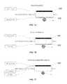
- FIG. 1depicts a schematic view of an anatomical compartment of the human body
- FIG. 2depicts a device for percutaneous division of fibrous structures, in accordance with an embodiment of the present disclosure
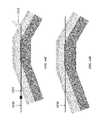
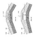
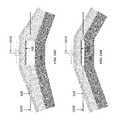
- FIGS. 3A and 3Bdepict side and cross-sectional views of a device for percutaneous division of fibrous structures in deflated and inflated states, in accordance with an embodiment of the present disclosure
- FIG. 4Adepicts a schematic view of the device of FIGS. 3A and 3B in an inflated state for tensioning a fibrous wall of an anatomical compartment;
- FIGS. 4B 1 - 4 B 5depict schematic views of various potential cross-sectional shapes of a balloon, in accordance with an embodiment of the present disclosure
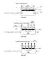
- FIGS. 5A and 5Bdepict a mechanical cutting element of a device for percutaneous division of fibrous structures, in accordance with an embodiment of the present disclosure
- FIGS. 6A-6Cdepict electrical/thermal cutting elements of a device for percutaneous division of fibrous structures, in accordance with an embodiment of the present disclosure
- FIGS. 7A-7Cdepict elements for sensing neuroelectrical activity, stimulating neuroelectrical activity, or both, in a nearby nerve, if present of a device for percutaneous division of fibrous structures, in accordance with an embodiment of the present disclosure
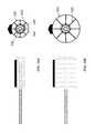
- FIG. 7Ddepicts a perspective view of a device for percutaneous division of fibrous structures, in accordance with an embodiment of the present disclosure
- FIG. 7Edepicts a perspective view of a device for percutaneous division of fibrous structures, in accordance with another embodiment of the present disclosure.
- FIG. 7Fdepicts top and cross-sectional schematic views of a device for percutaneous division of fibrous structures, in accordance with another embodiment of the present disclosure.
- FIGS. 8A-8Cdepict schematic views of a device for percutaneous division of fibrous structures having lighting elements, in accordance with an embodiment of the present disclosure
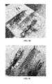
- FIG. 9Adepicts an experimental test in which a device for percutaneous division of fibrous structures is used for cutting synthetic tissue, in accordance with an embodiment of the present disclosure
- FIGS. 9B and 9Cdepict another experimental test in which a device for percutaneous division of fibrous structures is used for cutting bovine pericardium tissue, in accordance with an embodiment of the present disclosure
- FIGS. 10A and 10Bdepict side and cross-sectional views of a device for percutaneous division of fibrous structures in collapsed and expanded states, in accordance with an embodiment of the present disclosure
- FIGS. 11A-11Cdepict steps of a method for percutaneous division of fibrous structures, in accordance with one embodiment of the present disclosure
- FIG. 12Adepicts a carpal tunnel and associated anatomical structures within the human body
- FIGS. 12B-12Fdepict steps of a method for treating carpal tunnel syndrome, in accordance with one embodiment of the present disclosure
- FIG. 13depicts a kit for use in a method for treating carpal tunnel syndrome, in accordance with one embodiment of the present disclosure.
- FIGS. 14A-14Idepict steps of a method for treating carpal tunnel syndrome using the kit of FIG. 13 , in accordance with one embodiment of the present disclosure.
- the present disclosureis directed to a medical device, and in particular, devices for percutaneous division of fibrous structures. While the devices and methods described herein may be used for percutaneous division of any sort of fibrous structure within the body, the present disclosure may, from time to time, refer to the treatment of carpal tunnel syndrome as an exemplary application.
- the carpal tunnelis an anatomic compartment in the wrist bounded by the carpal bones and the transverse carpal ligament.
- the clinical symptoms of carpal tunnel syndromeprimarily arise from compression of the median nerve as it passes through the tunnel.
- Surgical division of the transverse carpal ligamentrelieves the compression of the median nerve and its associated symptoms.
- device 200in various embodiments, may be utilized to divide a fibrous wall 110 of an anatomical compartment 100 within the body to relieve pressure on anatomical structures 120 within compartment 100 .
- percutaneous division device 200 of the present disclosuremay generally include a catheter 300 , an expandable member 400 , one or more cutting elements 500 , and one or more sensing/stimulating elements 600 .
- Percutaneous division device 200may be inserted into the body and advanced towards an anatomic compartment 100 , such as the carpal tunnel, requiring treatment.
- Sensing/stimulating element 600may optionally be utilized to help position device 200 within the compartment, and to avoid damaging any nearby nerves.
- expandable member 400Once properly positioned within the anatomic compartment, expandable member 400 may be expanded to apply a radial force generating lateral tension along a portion of the fibrous wall of the compartment.
- Cutting element 500may be configured to engage the tensioned portion to divide the fibrous wall and thereby decompress the anatomic compartment for therapeutic effect.
- percutaneous division device 200may include a catheter 300 .
- Catheter 300in various embodiments, may be rigid, semi-rigid or flexible.
- Catheter 300may be made of any biocompatible material including plastic or metal.
- catheter 300may be made of a flexible plastic material such as polyurethane, polyethylene or flourothermoplastic, among other suitable plastics.
- Catheter 300may have a proximal end 310 , a distal end 320 , and an outer surface 330 .
- Catheter 300in various embodiments, may include at least one lumen 340 through which fluids may be accommodated and directed between proximal end 310 and distal end 320 .
- Catheter 300may further include one or more openings 332 (shown in FIG. 3A as side holes) through which fluid may be directed between lumen 340 and an environment situated beyond outer surface 330 outside of catheter 300 .
- Openings 332may be situated proximate distal end 320 so as to provide fluid communication between lumen 340 and an interior portion 410 of expandable member 400 positioned about a corresponding portion of outer surface 330 of catheter 300 , as shown.
- fluidmay be introduced into fluid lumen 340 at proximal end 310 , directed towards distal end 320 , and through openings 332 into interior portion 410 to inflate expandable member 400 .
- fluidmay be withdrawn from expandable member 400 along the reverse path to deflate expandable member 400 .
- Catheter 300in various embodiments, may further include at least one lumen 350 for accommodating a guidewire 352 (not shown) for facilitating positioning of catheter 300 within compartment 100 .
- percutaneous division device 200may include expandable member 400 , such as a balloon or similar expandable structure.
- expandable member 400may be referred to herein as balloon 400 in the context of describing percutaneous division device 200 ; however, it should be recognized that expandable member 400 is not intended to be limited as such.
- Balloon 400in an embodiment, may be substantially non-compliant, and can be made of a thin layer or a similar flexible plastic material.
- Balloon 400may be coupled to catheter 300 in a manner suitable for receiving and retaining fluid from lumen 340 of catheter 300 within interior portion 410 of balloon 400 .
- balloon 400may be positioned about a portion of outer surface 330 containing opening(s) 332 such that fluid directed through opening(s) 332 enters interior portion 410 of balloon 400 .
- Balloon 400may be bonded to catheter 300 to retain fluid directed into its interior portion 410 to allow for inflating balloon 400 during the surgical procedure.
- balloon 400may be shaped to apply tension to fibrous wall 110 .
- balloon 400As balloon 400 is inflated, it pushes outward, generating a force in a radial direction on a portion of wall 110 , which stretches that portion of wall 110 in a lateral direction.
- cutting element 500may be longitudinally oriented on balloon 400 , meaning that the lateral tension created in wall 110 by balloon 400 acts in a direction substantially transverse to the longitudinally-oriented cutting element 500 situated on the surface of balloon 400 . As configured, lateral tension causes wall 110 to become taut across cutting element 500 , thereby making it easier to divide.
- tension applied by balloon 400facilitates division by pulling wall 110 apart along the weakened area.
- stretching wall 110 tautprovides for wall 110 to be contacted by a discrete portion of cutting element 500 (e.g., the tip of cutting element 500 , as shown), rather than with a wider portion cutting element 500 as may be the case if wall 110 were slack and allowed to conform around cutting element 500 .
- the tension applied by balloon 400allows cutting element 500 to act with high energy density on a small portion of wall 110 , thereby providing for a cleaner cut with less tissue damage, which in turn may reduce the recovery period for the patient.
- balloon 400may be further shaped and sized to accommodate the specific anatomy of the compartment 100 within which it will be deployed. This may include, for example, being shaped and sized in a manner suitable for manipulating the position of, or minimizing pressure applied to, anatomical structures 120 situated within compartment 100 . This may serve to protect these anatomical structures 120 from damage resulting from contact with cutting element 500 and/or to dissect tissues within the compartment to create more space for the anatomic structures within the compartment. As shown in FIG.
- balloon 400may have an elongated cross-section (e.g., ovular) which, when positioned against fibrous wall 100 , provides contact between an elongated side of balloon 400 and fibrous wall 100 that prevents anatomical structures 120 from sliding around its lateral ends and towards the site of division, where they could be damaged by cutting element 500 .
- balloon 400may be provided with a substantially circular cross-section (not shown) with a large enough diameter sufficient to push nearby tendons, nerves or other anatomical structures 120 outward from device 200 when inflated.
- balloon 400may be provided with a variety of other cross sections.
- balloon 400may have, without limitation, a substantially circular ( FIG. 4B 1 ), ovular ( FIG. 4B 2 ), rectangular ( FIG. 4B 3 ), or triangular ( FIG. 4B 4 ) cross sectional shape, to help achieve the desired effect on wall 110 and/or anatomical structures 120 .
- FIG. 4B 5in an embodiment, multiple balloons or shaped members may be positioned in relation to one another to help form the overall shape of balloon 400 .
- one such embodimentillustrates a “pontoon”-like configuration wherein two smaller balloons are positioned on opposing sides of a larger central balloon to help form an overall ovular shape.
- a “pontoon”-like configurationwherein two smaller balloons are positioned on opposing sides of a larger central balloon to help form an overall ovular shape.
- balloon 400may be adapted to minimize contact with (and applying resulting pressure on) certain surrounding anatomical structures 120 within compartment 100 .
- the small vertical dimension of the elongated cross-sectional design of FIG. 4Amay serve to minimize pressure exerted on median nerve 122 situated below the site of division, whilst its longer horizontal cross-sectional dimension may still serve to apply tension to fibrous wall 100 and push tendons 124 aside.
- Embodiments of balloon 400may be provided with suitable longitudinal profiles adapted for similar purposes.
- percutaneous division device 200may further include one or more cutting elements 500 situated on balloon 400 .
- the specific orientation of cutting element 500 relative to the axis of the catheter 300may depend on the specific anatomy of the compartment.
- Cutting element 500may include a mechanical element 510 such as a sharpened blade, as shown in FIG. 5A .
- the mechanical element 510may be provided with a removable cover 512 to protect surrounding tissue during positioning of device 200 and exposed just prior to balloon inflation, as shown in FIG. 5B .
- the mechanical element 510may be sheathed within catheter 300 and advanced once balloon 400 is inflated (not shown).
- the mechanical element 510makes contact with the fibrous wall 110 .
- the axial and radial forcestension the fibrous wall 110 , and the radial force pushes mechanical element 510 through the fibrous wall 110 , thereby dividing fibrous wall 110 and relieving the pressure in compartment 100 , as described in more detail later in the disclosure.
- cutting element 500may include an electrical element 520 configured to utilize electrical and/or thermal energy to divide fibrous wall 100 .
- cutting element 520may include a unipolar or bipolar leads configured to communicate electrically with an electrocautery generator, as shown in FIGS. 6A and 6B , respectively.
- the electrocautery generatormay be activated to deliver radiofrequency energy to the electrocautery lead(s).
- the radiofrequency energyheats and cuts the contacted, tensioned portion of the fibrous wall 110 and the fibrous wall 110 is divided under the pressure of balloon 400 , thereby relieving the pressure in compartment 100 , as described in more detail later in the disclosure.
- a bipolar configurationmay be preferable in anatomic areas with critical structures (nerves, blood vessels) in the vicinity, as it limits the thermal spread of the radiofrequency energy.
- Leads 520 attached to alternative energy sources, such as microwave and laser light,may also be applicable in certain applications.
- percutaneous division device 200may further comprise a layer of insulating material 522 situated between cutting element 520 and balloon 400 , so as to protect balloon 400 from heat-related damage when cutting element 500 is energized.
- Embodiments of cutting element 520 utilizing electrical and/or thermal energy for divisionmay further have a sharp knife-like edge (not shown) so that fibrous wall 110 is divided using both electrical and mechanical means.
- lead(s) 520may be provided with a substantially triangular cross-section. As configured, the leading edge 522 of the triangularly-shaped lead 520 may serve to concentrate the electrical and mechanical, thereby providing highly-concentrated energy density along a fine line at the site of division. This may result in less tissue trauma, shorter cutting times, faster recovery times, and more precise division of the fibrous wall 100 .
- the sloping surfaces 524 of the triangularly-shaped lead 520may serve to further spread (i.e., tension) the portion of fibrous wall 100 proximate leading edge 522 , thereby further enhancing the ability of device 200 to cut and divide fibrous wall 110 .
- a portion of the surface of the lead 520 extending up sloping surfaces 254may be coated with an insulating material, allowing further concentration of the energy density to leading edge 522 .
- percutaneous division device 200may further include one or more elements 600 configured for sensing neuroelectrical activity, stimulating neuroelectrical activity, or both, in a nearby nerve, if present. Such elements may be utilized to determine whether balloon 400 and cutting element 500 are positioned appropriately relative to structures within compartment 100 .
- element(s) 600may include sensing element(s) 610 configured to detect nerve conduction. As configured, an operator may utilize feedback from sensing element(s) 610 to determine whether cutting element 500 may be in the vicinity of a nerve, such as the median nerve in the carpal tunnel. Sensing element 610 may be connected to an electrical signal detector. Sensing element 610 may be designed to detect an electrical signal emanating from a nearby nerve (e.g., the median nerve) at baseline or from activation of motor nerve fibers during normal muscle contraction (e.g., hand grip) or during electrical stimulation of the nerve (e.g., in the forearm), similar to how nerve conduction studies are performed. A positive signal would confirm that the nerve is located away from cutting element 520 .
- a nearby nervee.g., the median nerve
- element(s) 600may include stimulating element(s) 620 configured to emit a signal for stimulating nearby nerves.
- Simulating element 620may be configured to function in an analogous manner as commonly utilized nerve stimulators used in anesthesia to assess successful pharmacologic muscle relation.
- An electrical stimulusmay be delivered to the nerve by stimulating element 620 . If stimulating element 620 is in the vicinity of a nerve, a corresponding motor reaction is noted in the muscles supplied by the nerve such as twitching of the hand from stimulation of the median nerve. A positive response to stimulation would provide confirmation that the nerve is located away from cutting element 520 .
- element(s) 600may include a sensing element(s) 610 and a separate stimulating element(s) 620 .
- element(s) 600may include a hybrid element configured for both sensing and stimulating functionality (not shown).
- element(s) 600may include an element 630 configured for cutting functionality, and at least one of sensing and/or stimulating functionality.
- element 630may be a hybrid element configured to be a cutting element 500 , and at least one of a sensing element 610 and stimulating element 620 .
- Element 630may initially be utilized as a sensing element 610 and/or stimulating element 620 to facilitate positioning as described above. Once the operator confirms that the nerve is not in the vicinity of cutting element 500 , element 630 can be used as a cutting element 500 to mechanically, electrically, or thermally weaken or cut fibrous wall 110 .
- Element 630can be a single lead, where its functionality as a sensing, stimulating or cutting element is determined by whether it electrically communicates with a signal detector, stimulator or cutting energy source.
- a layer of insulating materialmay be situated between element(s) 600 and balloon 400 , so as to protect balloon 400 from heat-related damage when element(s) 600 are energized.
- percutaneous division device 200may include an expandable member 400 in relation to a catheter 300 with a stimulating element 620 located on the inferior surface of the expandable member 400 and a cutting element 500 located on the superior surface off the expandable member.
- the cutting element 500is separated from the expandable member 400 by a layer of insulating material 522 which protects the expandable member 400 from damage from heat generated by the cutting element 500 .
- the cutting element 500 in this embodimentis a bipolar lead with and triangular active lead 526 and a flat passive return lead 527 ,
- percutaneous division device 200may include an expandable member 400 in relation to a catheter 300 with a hybrid element 630 located on the superior surface of the expandable member 400
- the hybrid element 630is separated from the expandable member 400 by a layer of insulating material 522 which protects the expandable member 400 from damage from heat generated by the hybrid element 630 .
- the hybrid element 630 in this embodimentis a bipolar lead with and triangular active lead 526 and a flat passive return lead 527 .
- stimulating modeeither or both leads can be used to deliver a stimulating signal to confirm that the nerve is not in the vicinity of the hybrid element.
- I cutting modethe bipolar electrical energy is delivered between the active lead 526 and the return lead 527 .
- the operatormay further determine whether device 200 is properly positioned. For example, in a carpal tunnel surgical procedure, it may be desired to position device 200 between the transverse carpal ligament (i.e., fibrous wall 110 ) and the median nerve (i.e., nerve 122 ), with cutting element 500 (or hybrid element 630 ) directed towards the transverse carpal ligament.
- transverse carpal ligamenti.e., fibrous wall 110
- median nervei.e., nerve 122
- element(s) 600are positioned proximate cutting element 500 and provide feedback indicating that the nerve is in that vicinity, an operator may deduce that: 1) balloon 400 is properly oriented, but improperly positioned under the median nerve, rather than between it and the transverse carpal ligament, or 2) balloon 400 is properly positioned, but improperly oriented with cutting edge 500 facing the median nerve rather than the transverse carpal ligament.
- the operatormay make similar, albeit opposite, deductions.
- percutaneous division device 200may include one or more lighting elements 700 along the length of balloon 400 in the vicinity of cutting element 500 , as shown in FIGS. 8A-8C .
- the brightness and wavelength of the row of lighting elements 700may be configured such that they can be visualized through the subcutaneous tissues and skin but not visualized (or visualized at significantly and discernibly lower brightness) when place below fibrous wall 110 .
- the lighting elements 700when the balloon is positioned below fibrous wall 110 and the lighting elements 700 are activated, and the length of fibrous wall 110 relative to the length of cutting element 500 on balloon 400 can be determined by assessing which light elements 700 shine through the tissues.
- the row of lighting elements 700can be longer than the length of fibrous wall 110 so that lighting elements 701 and 705 at the proximal end and distal end of balloon 400 can shine through to help determine the relative length of the tissue.
- cutting element 500is activated, the completeness of the fibrous wall division can be assessed. A complete division would be indicated if all light elements 700 shine through. If the division is incomplete, one or of the light elements 700 will remain dark and the operator can make another attempt to completely divide fibrous wall 110 .
- balloon 400 and hence cutting element 500be relatively shorter than the length of fibrous wall 110 , multiple divisions along the length of fibrous wall 110 can be employed. Although disclosed as having a plurality of lighting elements 700 along the length of balloon 400 , it should be appreciated that one lighting source 700 extending the length of balloon 400 can be used.
- FIGS. 9A-9Csynthetic and bovine tissues were divided during testing with a prototype of an embodiment of percutaneous division device 200 .
- the prototype devicecomprised a 20 mm balloon, inflated with water to 5 atm, with polyimide and PEEK film material situated between electrodes and the balloon surface to provide insulation.
- a bipolar arrangement of electrodes made from coated flat-wirewere spaced 2 mm apart and mounted vertically on the insulating material to simulate a triangular shaped cutting element.
- FIG. 9Aa strip of SynDaver synthetic tissue was placed laterally across the prototype device and tensioned to a level representative of the transverse carpal ligament of the carpal tunnel.
- a full cut through the SynDaver synthetic tissuewas produced by energizing the electrode with 20 W of power.
- FIGS. 9B and 9Ca second test using similar setup, only with bovine pericardium tissue, was performed using the prototype device. As shown in FIG. 9C , a full cut through the bovine pericardium tissue was produced with 20 W of power.
- FIGS. 10A and 10Billustrate percutaneous division device 800 of the present disclosure.
- Device 800may generally include similar components as device 200 , and may additionally or alternatively comprise an expandable member 900 configured for expanding and contracting via mechanical actuation.
- Expandable member 900may comprise a surface 910 on which cutting element 500 and (if equipped) sensing/stimulating elements 600 may be situated as in device 200 .
- surface 910may be made of a flexible material capable of collapsing when device 800 is in a non-actuated state, and expanding when device 800 is in an actuated state.
- surface 910may be a balloon or other membrane formed of a flexible material.
- Expandable member 900may further comprise support members 920 configured to expand surface 910 when device 800 is in an actuated state, and to collapse surface 910 when device 800 is in a non-actuated state, similar to the way fluid may be used to inflate and deflate expandable member 400 of device 200 .
- support members 920may include ribs or similar structure configured to press radially outwards on surface 910 in an expanded state.
- support members 920may be formed of a shaped-material that springs outwards when a retaining force is released so as to expand surface 910 .
- support members 920may be configured to spread outwards and collapse inwards under mechanical actuation.
- expandable member 900may be actuated via a mechanism 362 extending through a lumen 360 in catheter 300 .
- Mechanism 362in an embodiment, may include an elongated shaft 364 coupled to support members 920 .
- elongated shaft 364may be actuated (e.g., pushed or pulled in an axial direction) that causes support members 920 to spread radially or collapse axially to expand and collapse expandable member 900 , respectively.
- device 800may include a sheath (not shown) or similar mechanism configured to be placed over expandable member 900 to retain, in a collapsed state, support members 920 made of shaped-material.
- the sheathmay be retracted to expose expandable member 900 , thereby allowing support members 920 to spring outwards so as to expand surface 910 into a desired shape.
- Support members 920may be configured to provide expandable member 900 with a suitable cross-sectional shape (e.g., circular, elongated, etc.) for accommodating the specific anatomy of the compartment 100 within which device 800 will be deployed, for applying tension to fibrous wall 110 of the compartment 100 , and or for manipulating the position of, or minimizing pressure applied to, anatomical structures 120 situated within compartment 100 , as previously described.
- a suitable cross-sectional shapee.g., circular, elongated, etc.
- FIGS. 11A-11Cillustrate methods for percutaneous division of a fibrous wall 110 of an anatomical compartment 100 using various embodiments of device 200 .
- device 200with balloon 400 in a deflated state, may be inserted into the body and advanced into anatomical compartment 100 .
- Device 200may be navigated into a position proximate fibrous wall 110 , and oriented such that cutting element 500 is pointed towards fibrous wall 110 and away from other critical structures, such as anatomical structures 120 .
- the positioning and orientation of cutting element 500at this stage, may be confirmed by inspection, lighting elements 700 , an imaging modality, a sensing/stimulating functionality 600 , or in other suitable manner, as previously described.
- a fluidsuch as saline or a contrast material may be directed through inflation lumen 340 of catheter 300 and into interior portion 410 of balloon 400 to inflate balloon 400 .
- inflationmay continue until building pressure within balloon 400 causes mechanical cutting element to engage fibrous wall 110 with suitable force to weaken and thereby divide fibrous wall 110 under the simultaneously-building tension provided by balloon 400 .
- balloon 400may first be inflated to a pressure sufficient to tension fibrous wall 110 to a desired level, at which point cutting elements 520 may then be energized to weaken fibrous wall 110 and thereby divide it under the tension provided by balloon 400 .
- the position and orientation of cutting edge 500may be rechecked throughout the inflation process.
- balloon 400may be partially inflated to a first pressure suitable to give it some shape, at which point a recheck of position and orientation is performed before continuing. This may be repeated any number of suitable times during the inflation process to ensure that fibrous wall 110 is divided properly, and without causing damage to anatomical structures 120 .
- Complete division of fibrous wall 110may be confirmed by inspection, lighting elements 700 (as previously described), an imaging modality, or some other suitable technique (e.g. measuring a corresponding reduction in balloon pressure associated with dividing fibrous wall 110 and relieving the pressure within anatomical compartment 100 ).
- expandable member 900 of device 800may be expanded mechanically, as previously described. As with device 200 , expansion of expandable member 900 may be performed in a controlled manner so as to provide intermediate opportunities to recheck the positioning and orientation of cutting element 500 relative to fibrous wall 110 and anatomical structures 120 so as to ensure that fibrous wall 110 is divided properly and without causing collateral damage.
- Embodiments of devices 200 , 800may be particularly well-suited for treating carpal tunnel syndrome by dividing the transverse carpal ligament.
- the carpal tunnelis an anatomic compartment in the wrist bounded by the carpal bones and the transverse carpal ligament.
- the clinical symptoms of carpal tunnel syndromeprimarily arise from compression of the median nerve as it passes through the tunnel.
- Surgical division of the transverse carpal ligamentrelieves the compression of the median nerve and its associated symptoms.
- Embodiments of devices 200 , 800are capable of dividing the transverse carpal ligament percutaneously.
- expandable members 400 , 900may, in operation, dissect and mobilize the median nerve and tendons away from the transverse carpal ligament, thereby enhancing the decompression of the carpal tunnel and potentially preventing late scarring and recurrent symptoms.
- the following methods for treatment of carpal tunnel syndromewill be explained in the context of using device 200 , though it should be recognized that similar methods may be employed using device 800 within the scope of the present disclosure.
- device 200with balloon 400 in a deflated state, may be inserted into the body and advanced into the carpal tunnel.
- Device 200may be navigated into a position proximate the transverse carpal ligament, and oriented such that cutting element 500 (shown here as an electrical and/or thermal cutting element 520 ) is pointed towards the transverse carpal ligament and away from other critical structures, such as the median nerve and surrounding flexor tendons.
- Embodiments of device 200may be of suitable dimensions for positioning within the carpal tunnel in proximity to the transverse carpal ligament. The positioning and orientation of cutting element 500 , at this stage, may be confirmed by inspection, lighting elements 700 , an imaging modality, a sensing/stimulating functionality 600 , or in other suitable manner, as previously described.
- balloon 400may be inflated. Expandable member 400 may be configured to expand to dimensions appropriate for use within the carpal tunnel. Embodiments of balloon 400 having an elongated cross-sectional shape, or other suitable shape, may act to dissect the transverse carpal ligament off the carpal tunnel contents during inflation, creating space and enhancing the decompression of the carpal tunnel.
- balloon 400can be made of a substantially noncompliant material and may be inflated to a specified pressure, designed to achieve this dissecting effect and to provide enough radial force to stretch the transverse carpal ligament across cutting element 500 for subsequent division.
- the inflated balloon 400has dissected and pushed the median nerve and some of the flexor tendons away from one another, and away from cutting element 500 .
- the inflated balloon 400has also applied sufficient tension to the transverse carpal ligament such that it is stretched taut across cutting element 500 .
- cutting element 500may be energized (or further pressure applied, in embodiments comprising mechanical cutting elements 510 ) to weaken the contacted portion of the transverse carpal ligament. Any of the described cutting elements 500 may be used for this application.
- the unipolar or bipolar electrocautery leads 520may be particularly suitable for cutting the transverse carpal ligament, and bipolar embodiments may be preferred to protect the median nerve and its branches from injury.
- cutting elements 520may be energized to weaken a contacted portion of the transverse carpal ligament such that it may be divided in combination with the tension applied by balloon 400 , as shown in FIG. 12F .
- the position and orientation of cutting edge 500may be rechecked throughout the inflation process.
- balloon 400may be partially inflated to a first pressure suitable to give it some shape, at which point a recheck of position and orientation is performed before continuing. This may be repeated any number of suitable times during the inflation process to ensure that the transverse carpal tunnel is divided properly, and without causing damage to the median nerve and flexor tendons within the carpal tunnel.
- Complete division of the transverse carpal ligamentmay be confirmed by inspection, lighting elements 700 (as previously described), an imaging modality, or some other suitable technique (e.g. measuring a corresponding reduction in balloon pressure associated with dividing the transverse carpal ligament and relieving the pressure within the carpal tunnel).
- Kit 1000may be provided along with device 200 to facilitate introduction of the device 200 into the carpal tunnel.
- Kit 1000may include an imaging modality 1010 , such as an ultrasound probe, a needle 1020 , and a guidewire 1030 .
- Kit 1000may also include various dilators, guides or catheters, as well as disposables such as sheath for the ultrasound probe (not shown).
- the method of using the device to divide the transverse carpal ligamentcan be consistent with the general method. Although the procedure may be guided by direct inspection, lighting elements 700 or other technique, ultrasound guidance may be particularly useful. Ultrasound of the wrist is a well-established technique which can clearly delineate the transverse carpal ligament and its association with the median nerve. It is routinely used to direct injections in the vicinity of the median nerve to relieve symptoms of carpal tunnel syndrome.
- FIGS. 14A-14Ithere is provided a method of use of device 200 to treat carpal tunnel syndrome using ultrasound guidance.
- the forearm and hand( FIG. 14A ) are sterilely prepped and draped with the hand in the hyperextended position. Local, regional or general anesthesia may be instituted. A tourniquet may be used but is not necessary.
- Anatomic landmarksare marked on the skin using palpation and ultrasound imaging of the wrist.
- the proximal and distal edges of the transverse carpal ligamentcan be identified as is the path of the palmaris longus tendon.
- the path of the median nerveis followed as it passes into and out of the carpal tunnel deep to the transverse carpal ligament. Any anatomic anomalies (e.g. bifid median nerve) or other pathology is identified.
- Measurementscan be taken using ultrasound or other modalities including determining the width of the transverse carpal ligament. This allows the operator to select the appropriate size kit instruments and cutting balloon catheter.
- a skin entry sitecan be identified in the distal forearm several centimeters proximal to the proximal edge of the transverse carpal ligament.
- the entry siteis generally on the ulnar side of the parlmaris longus tendon and hence the median nerve providing a flat, straight trajectory to the proximal edge of the transverse carpal ligament.
- the skin entry pointmay be in the hand with the device passing through the carpal tunnel from distal to proximal.
- the devicemay also be designed to penetrate the carpal tunnel from a medial or lateral direction with the balloon inflating along the long axis of the tunnel although this approach introduces several additional challenges such as maneuvering around the radial and ulnar arteries.
- Needle 1020is inserted, as shown in FIG. 14B , at the skin entry site and advanced from proximal to distal until it passes into the carpal tunnel just deep to the transverse carpal ligament. Ultrasound imaging can be used to confirm that the tip of needle 1020 enters the carpal tunnel in the correct location, on the ulnar side of median nerve. Needle 1020 can be used to inject fluid or local anesthetic into the carpal tunnel, if desired. This injection can be used to dissect tissues away from each other and create working space.
- Guidewire 1030is then inserted, as shown in FIG. 14C , into needle 1020 and advanced through the carpal tunnel along a trajectory that runs just deep to the transverse carpal tunnel and, again, ulnar to the median nerve.
- Guidewire 1030generally has a straight tip and is stiff enough that it can penetrate through the tissues bluntly.
- the tip of guidewire 1030can be tracked by ultrasound as it passes through the carpal tunnel and exits past the distal edge of the transverse carpal ligament.
- At a minimum guidewire 1030should pass a few centimeters past this edge to provide an adequate rail for the balloon catheter.
- guidewire 1030will be advance further so that it exits through the skin of the palmar surface of the hand between the thenar and hypothenar eminences.
- needle 1020can be advanced over guidewire 1030 so that it penetrates the skin in the hand. Having a guidewire 1030 that exits the skin provides excellent column strength to facilitate positioning of device 200 . Needle 1020 can thereafter be removed, as shown in FIG. 14D .
- An appropriately sized device 200is then selected and advanced over guidewire 1030 into the carpal tunnel, as shown in FIG. 14E .
- Device 200can then be carefully positioned to ensure that its axial orientation is correct, with cutting element 500 positioned superficially, just under the transverse carpal ligament. Its longitudinal position can be adjusted so that cutting element 500 spans the entire width of the ligament. This positioning can be confirmed using ultrasound guidance. If the device contains lighting elements 700 previously described, these can be activated to confirm that cutting element 500 fully straddles the ligament.
- balloon 400may be inflated to a specified pressure with fluid, as shown in FIG. 14F .
- the fluidcan be any liquid including saline or contrast material including echo contrast material or gas including air, carbon dioxide or oxygen.
- Balloon inflationcan be monitored by direct inspection and palpation of the hand or by ultrasound guidance. The operator confirms that balloon 400 inflates uniformly while maintaining its axial orientation and dissecting the transverse carpal ligament from the deeper structures including the median nerve. If device 200 has the lighting element 700 functionality, this can be used to reconfirm balloon position. If the position is not optimal, balloon 400 can be deflated and the device 200 repositioned before reinflating.
- device 200has sensing and/or stimulating functionality (e.g., elements 600 ), these can now be used to confirm that cutting element 500 is not positioned too close to the median nerve, its branches or other nerves.
- the elements 600may be connected to a signal detector and/or stimulator, respectively, as shown back in FIGS. 7A-7C . If these leads 600 are on the same (superficial) surface of balloon 400 as cutting element 500 , they are used to confirm the absence of nearby neuroelectrical activity. If they are located on the opposite (deep) surface of balloon 400 , they are used to confirm that the median nerve is away from cutting element 500 by sensing its signal or stimulating it.
- cutting element 500is activated, as shown in FIG. 14G .
- cutting element 500is an electrocautery lead 520 , it is connected to a radiofrequency generator. The generator is activated delivering radiofrequency energy to the lead 520 as it cuts through the ligament. The cutting process can be monitored by ultrasound and/or the lighting elements 700 , if present.
- balloon 400is deflated and the completeness of the division of the transverse carpal ligament is confirmed by ultrasound or other means, as shown in FIG. 14H .
- Device 200 and guidewire 1030can be removed, as shown in FIG. 14I . Additional local anesthesia can be infiltrated into the wrist. Sterile dressings are applied. Appropriate post-operative care is instituted.
Landscapes
- Health & Medical Sciences (AREA)
- Life Sciences & Earth Sciences (AREA)
- Surgery (AREA)
- Engineering & Computer Science (AREA)
- Animal Behavior & Ethology (AREA)
- Veterinary Medicine (AREA)
- Biomedical Technology (AREA)
- Heart & Thoracic Surgery (AREA)
- Medical Informatics (AREA)
- Molecular Biology (AREA)
- Nuclear Medicine, Radiotherapy & Molecular Imaging (AREA)
- General Health & Medical Sciences (AREA)
- Public Health (AREA)
- Cardiology (AREA)
- Physics & Mathematics (AREA)
- Plasma & Fusion (AREA)
- Otolaryngology (AREA)
- Vascular Medicine (AREA)
- Orthopedic Medicine & Surgery (AREA)
- Oral & Maxillofacial Surgery (AREA)
- Pathology (AREA)
- Surgical Instruments (AREA)
- Media Introduction/Drainage Providing Device (AREA)
Abstract
Description
Claims (27)
Priority Applications (5)
| Application Number | Priority Date | Filing Date | Title |
|---|---|---|---|
| US14/958,003US10335189B2 (en) | 2014-12-03 | 2015-12-03 | Systems and methods for percutaneous division of fibrous structures |
| US15/964,550US11259837B2 (en) | 2014-12-03 | 2018-04-27 | Systems and methods for percutaneous division of fibrous structures |
| US15/964,531US11141186B2 (en) | 2014-12-03 | 2018-04-27 | Systems and methods for percutaneous division of fibrous structures |
| US17/371,851US12114888B2 (en) | 2014-12-03 | 2021-07-09 | Systems and methods for percutaneous division of fibrous structures |
| US17/493,128US20220022910A1 (en) | 2014-12-03 | 2021-10-04 | Systems and Methods for Percutaneous Division of Fibrous Structures |
Applications Claiming Priority (2)
| Application Number | Priority Date | Filing Date | Title |
|---|---|---|---|
| US201462086950P | 2014-12-03 | 2014-12-03 | |
| US14/958,003US10335189B2 (en) | 2014-12-03 | 2015-12-03 | Systems and methods for percutaneous division of fibrous structures |
Related Child Applications (2)
| Application Number | Title | Priority Date | Filing Date |
|---|---|---|---|
| US15/964,531DivisionUS11141186B2 (en) | 2014-12-03 | 2018-04-27 | Systems and methods for percutaneous division of fibrous structures |
| US15/964,550DivisionUS11259837B2 (en) | 2014-12-03 | 2018-04-27 | Systems and methods for percutaneous division of fibrous structures |
Publications (2)
| Publication Number | Publication Date |
|---|---|
| US20160157880A1 US20160157880A1 (en) | 2016-06-09 |
| US10335189B2true US10335189B2 (en) | 2019-07-02 |
Family
ID=56092454
Family Applications (5)
| Application Number | Title | Priority Date | Filing Date |
|---|---|---|---|
| US14/958,003Active2037-04-23US10335189B2 (en) | 2014-12-03 | 2015-12-03 | Systems and methods for percutaneous division of fibrous structures |
| US15/964,550Active2037-07-22US11259837B2 (en) | 2014-12-03 | 2018-04-27 | Systems and methods for percutaneous division of fibrous structures |
| US15/964,531Active2037-09-12US11141186B2 (en) | 2014-12-03 | 2018-04-27 | Systems and methods for percutaneous division of fibrous structures |
| US17/371,851Active2037-04-12US12114888B2 (en) | 2014-12-03 | 2021-07-09 | Systems and methods for percutaneous division of fibrous structures |
| US17/493,128PendingUS20220022910A1 (en) | 2014-12-03 | 2021-10-04 | Systems and Methods for Percutaneous Division of Fibrous Structures |
Family Applications After (4)
| Application Number | Title | Priority Date | Filing Date |
|---|---|---|---|
| US15/964,550Active2037-07-22US11259837B2 (en) | 2014-12-03 | 2018-04-27 | Systems and methods for percutaneous division of fibrous structures |
| US15/964,531Active2037-09-12US11141186B2 (en) | 2014-12-03 | 2018-04-27 | Systems and methods for percutaneous division of fibrous structures |
| US17/371,851Active2037-04-12US12114888B2 (en) | 2014-12-03 | 2021-07-09 | Systems and methods for percutaneous division of fibrous structures |
| US17/493,128PendingUS20220022910A1 (en) | 2014-12-03 | 2021-10-04 | Systems and Methods for Percutaneous Division of Fibrous Structures |
Country Status (7)
| Country | Link |
|---|---|
| US (5) | US10335189B2 (en) |
| EP (1) | EP3226783B1 (en) |
| JP (2) | JP6815998B2 (en) |
| CN (1) | CN107106200B (en) |
| AU (1) | AU2015358424B2 (en) |
| CA (1) | CA2969579A1 (en) |
| WO (1) | WO2016090122A1 (en) |
Cited By (6)
| Publication number | Priority date | Publication date | Assignee | Title |
|---|---|---|---|---|
| US11141186B2 (en) | 2014-12-03 | 2021-10-12 | PAVmed Inc. | Systems and methods for percutaneous division of fibrous structures |
| WO2021242231A1 (en)* | 2020-05-27 | 2021-12-02 | PAVmed Inc. | Systems and methods for minimally-invasive division of fibrous structures |
| US11457937B2 (en) | 2014-09-02 | 2022-10-04 | Tenex Health, Inc. | Subcutaneous wound debridement |
| US11877766B2 (en) | 2014-09-18 | 2024-01-23 | Mayo Foundation For Medical Education And Research | Soft tissue cutting device and methods of use |
| US11890119B2 (en) | 2017-10-13 | 2024-02-06 | Sonex Health, Inc. and Mayo Foundation for Medical Education and Research | Tray for a soft tissue cutting device and methods of use |
| US12156693B2 (en) | 2020-05-27 | 2024-12-03 | PAVmed Inc. | Systems and methods for minimally-invasive division of fibrous structures |
Families Citing this family (7)
| Publication number | Priority date | Publication date | Assignee | Title |
|---|---|---|---|---|
| EP3908215B1 (en) | 2019-01-11 | 2023-08-02 | Mayo Foundation for Medical Education and Research | Micro-invasive surgical device |
| US12426939B2 (en) | 2019-05-29 | 2025-09-30 | Mayo Foundation For Medical Education And Research | Micro-invasive surgical device and methods of use |
| WO2022150837A1 (en) | 2021-01-08 | 2022-07-14 | Sonex Health, Inc. | Surgical cutting device for ultrasonic guided soft tissue surgery |
| US12251122B2 (en) | 2021-04-30 | 2025-03-18 | Sonex Health, Inc. | Cutting device for trigger finger and other soft tissues |
| USD989961S1 (en) | 2021-04-30 | 2023-06-20 | Sonex Health, Inc. | Soft tissue cutting device |
| US12053150B2 (en)* | 2021-08-11 | 2024-08-06 | Terumo Cardiovascular Systems Corporation | Endoscopic vessel harvesting with thermal management and augmented reality display |
| CA3232023A1 (en)* | 2021-09-27 | 2023-03-30 | Lishan Aklog | Systems and methods for percutaneous division of fibrous structures with visual confirmation |
Citations (164)
| Publication number | Priority date | Publication date | Assignee | Title |
|---|---|---|---|---|
| US4976711A (en) | 1989-04-13 | 1990-12-11 | Everest Medical Corporation | Ablation catheter with selectively deployable electrodes |
| US4998933A (en) | 1988-06-10 | 1991-03-12 | Advanced Angioplasty Products, Inc. | Thermal angioplasty catheter and method |
| US5100425A (en) | 1989-09-14 | 1992-03-31 | Medintec R&D Limited Partnership | Expandable transluminal atherectomy catheter system and method for the treatment of arterial stenoses |
| US5196024A (en) | 1990-07-03 | 1993-03-23 | Cedars-Sinai Medical Center | Balloon catheter with cutting edge |
| US5209799A (en) | 1992-04-17 | 1993-05-11 | Inverventional Technologies, Inc. | Method for manufacturing a folding balloon catheter |
| EP0565796A1 (en) | 1992-04-17 | 1993-10-20 | Interventional Technologies Inc | Stenosis dilatation device |
| US5336234A (en) | 1992-04-17 | 1994-08-09 | Interventional Technologies, Inc. | Method and apparatus for dilatation of a stenotic vessel |
| US5344398A (en) | 1992-02-25 | 1994-09-06 | Japan Crescent, Inc. | Heated balloon catheter |
| US5540681A (en) | 1992-04-10 | 1996-07-30 | Medtronic Cardiorhythm | Method and system for radiofrequency ablation of tissue |
| US5547469A (en) | 1994-05-13 | 1996-08-20 | Boston Scientific Corporation | Apparatus for performing diagnostic and therapeutic modalities in the biliary tree |
| US5573533A (en) | 1992-04-10 | 1996-11-12 | Medtronic Cardiorhythm | Method and system for radiofrequency ablation of cardiac tissue |
| US5628746A (en) | 1989-01-18 | 1997-05-13 | Applied Medical Resources Corporation | Dilatation catheter assembly with cutting element and method of using the same |
| USRE35523E (en) | 1991-10-11 | 1997-06-03 | Berger; J. Lee | Percutaneous carpal tunnel plasty method |
| US5697944A (en) | 1995-11-15 | 1997-12-16 | Interventional Technologies Inc. | Universal dilator with expandable incisor |
| US5713913A (en) | 1996-11-12 | 1998-02-03 | Interventional Technologies Inc. | Device and method for transecting a coronary artery |
| WO1998033445A1 (en) | 1997-02-05 | 1998-08-06 | Symbiosis Corporation | Single arm electrocautery probes and probes with upper and lower operating surfaces for use with a resectoscope |
| US5792158A (en) | 1995-11-15 | 1998-08-11 | Lary; Banning Gray | University dilator with expandable incisor |
| US5797935A (en) | 1996-09-26 | 1998-08-25 | Interventional Technologies Inc. | Balloon activated forced concentrators for incising stenotic segments |
| US5904679A (en) | 1989-01-18 | 1999-05-18 | Applied Medical Resources Corporation | Catheter with electrosurgical cutter |
| US5908433A (en)* | 1996-05-10 | 1999-06-01 | Stryker Corporation | Carpal tunnel knife |
| US6024740A (en) | 1997-07-08 | 2000-02-15 | The Regents Of The University Of California | Circumferential ablation device assembly |
| US6033397A (en) | 1996-03-05 | 2000-03-07 | Vnus Medical Technologies, Inc. | Method and apparatus for treating esophageal varices |
| US6036713A (en) | 1996-01-24 | 2000-03-14 | Archimedes Surgical, Inc. | Instruments and methods for minimally invasive vascular procedures |
| US6036689A (en) | 1998-09-24 | 2000-03-14 | Tu; Lily Chen | Ablation device for treating atherosclerotic tissues |
| US6041260A (en) | 1992-05-01 | 2000-03-21 | Vesta Medical, Inc. | Method and apparatus for endometrial ablation |
| US6080102A (en) | 1995-07-07 | 2000-06-27 | Olympus Optical Co., Ltd. | System for evulsing subcutaneous tissue |
| US6117153A (en) | 1996-10-03 | 2000-09-12 | Interventional Technologies, Inc. | Neovascularization catheter |
| US6165187A (en) | 1989-08-18 | 2000-12-26 | Endo Vascular Instruments, Inc. | Method of enlarging a lumen of an artery |
| US6190355B1 (en) | 1992-01-10 | 2001-02-20 | Scimed Life Systems, Inc. | Heated perfusion balloon for reduction of restenosis |
| US6193653B1 (en) | 1998-02-06 | 2001-02-27 | Ethicon Endo-Surgery, Inc. | Methods and devices for visualizing, dissecting and harvesting vessels and the like |
| US6214024B1 (en) | 1995-01-23 | 2001-04-10 | Russell U. Houser | Tissue cutting catheter and RF cutting method |
| US6231572B1 (en) | 1998-05-29 | 2001-05-15 | Applied Medical Resources Corporation | Electrosurgical catheter apparatus and method |
| US6245026B1 (en) | 1996-07-29 | 2001-06-12 | Farallon Medsystems, Inc. | Thermography catheter |
| US6258108B1 (en) | 1996-09-13 | 2001-07-10 | Interventional Technologies, Inc. | Incisor-dilator with tapered balloon |
| US6306151B1 (en) | 1998-03-31 | 2001-10-23 | Interventional Technologies Inc. | Balloon with reciprocating stent incisor |
| US6319242B1 (en) | 1997-02-12 | 2001-11-20 | Prolifix Medical, Inc. | Apparatus and method for controlled removal of stenotic material from stents |
| US6405732B1 (en) | 1994-06-24 | 2002-06-18 | Curon Medical, Inc. | Method to treat gastric reflux via the detection and ablation of gastro-esophageal nerves and receptors |
| US6405733B1 (en)* | 2000-02-18 | 2002-06-18 | Thomas J. Fogarty | Device for accurately marking tissue |
| US20020082592A1 (en) | 1999-03-17 | 2002-06-27 | Banning Lary | Coronary cutting, dilating, tamponading, and perfusing instrument |
| US6423058B1 (en) | 1998-02-19 | 2002-07-23 | Curon Medical, Inc. | Assemblies to visualize and treat sphincters and adjoining tissue regions |
| US6425877B1 (en) | 1999-04-02 | 2002-07-30 | Novasys Medical, Inc. | Treatment of tissue in the digestive circulatory respiratory urinary and reproductive systems |
| US6440128B1 (en) | 1998-01-14 | 2002-08-27 | Curon Medical, Inc. | Actively cooled electrode assemblies for forming lesions to treat dysfunction in sphincters and adjoining tissue regions |
| US6464697B1 (en) | 1998-02-19 | 2002-10-15 | Curon Medical, Inc. | Stomach and adjoining tissue regions in the esophagus |
| US6488679B1 (en) | 1998-09-10 | 2002-12-03 | Scimed Life Systems, Inc. | Systems and methods for controlling power in an electrosurgical probe |
| US6500186B2 (en) | 2001-04-17 | 2002-12-31 | Scimed Life Systems, Inc. | In-stent ablative tool |
| US6562062B2 (en) | 2001-08-10 | 2003-05-13 | Scimed Life Systems, Inc. | Balloon anchoring system |
| US20030144683A1 (en) | 2001-12-13 | 2003-07-31 | Avantec Vascular Corporation | Inflatable members having concentrated force regions |
| US6632231B2 (en) | 2001-08-23 | 2003-10-14 | Scimed Life Systems, Inc. | Segmented balloon catheter blade |
| US6673066B2 (en) | 2000-11-10 | 2004-01-06 | Cardiostream, Inc. | Apparatus and method to diagnose and treat vulnerable plaque |
| US20040098014A1 (en) | 2001-03-30 | 2004-05-20 | Moshe Flugelman | Inflatable medical device with combination cutting elements and drug delivery conduits |
| US6746463B1 (en) | 2003-01-27 | 2004-06-08 | Scimed Life Systems, Inc | Device for percutaneous cutting and dilating a stenosis of the aortic valve |
| US20050070888A1 (en) | 2004-10-29 | 2005-03-31 | Boston Scientific Corporation | Medical device systems and methods |
| US20050177130A1 (en) | 2004-02-10 | 2005-08-11 | Angioscore, Inc. | Balloon catheter with spiral folds |
| US6936047B2 (en) | 2000-05-12 | 2005-08-30 | Agility Capital Llc | Multi-channel RF energy delivery with coagulum reduction |
| US6942680B2 (en) | 2000-07-24 | 2005-09-13 | Jeffrey Grayzel | Stiffened balloon catheter for dilatation and stenting |
| US6951566B2 (en) | 2002-01-25 | 2005-10-04 | Scimed Life Systems, Inc. | Reciprocating cutting and dilating balloon |
| US20050240148A1 (en) | 2004-04-21 | 2005-10-27 | Scimed Life Systems, Inc. | Traction cutting balloon |
| US6971395B2 (en) | 1998-01-14 | 2005-12-06 | Curon Medical, Inc. | Sphincter treatment method |
| US7008438B2 (en) | 2003-07-14 | 2006-03-07 | Scimed Life Systems, Inc. | Anchored PTCA balloon |
| US7018391B2 (en) | 1997-10-06 | 2006-03-28 | Smith & Nephew North America | Methods and apparatus for removing veins |
| US7029450B2 (en) | 2001-12-14 | 2006-04-18 | Boston Scientific Scimed, Inc. | Dilation catheter assembly and related methods |
| US20060116700A1 (en) | 2004-11-29 | 2006-06-01 | Crow Loren M | Aortic stenosis cutting balloon blade |
| US7070576B2 (en) | 2004-04-30 | 2006-07-04 | Boston Scientific Scimed, Inc. | Directional cutting balloon |
| US20060178685A1 (en) | 2004-12-30 | 2006-08-10 | Cook Incorporated | Balloon expandable plaque cutting device |
| US20060184191A1 (en) | 2005-02-11 | 2006-08-17 | Boston Scientific Scimed, Inc. | Cutting balloon catheter having increased flexibility regions |
| US20060276782A1 (en) | 2005-06-06 | 2006-12-07 | Tewodros Gedebou | Nerve stimulator for use as a surgical guide |
| US7153315B2 (en) | 2002-06-11 | 2006-12-26 | Boston Scientific Scimed, Inc. | Catheter balloon with ultrasonic microscalpel blades |
| US7186237B2 (en) | 2002-02-14 | 2007-03-06 | Avantec Vascular Corporation | Ballon catheter for creating a longitudinal channel in a lesion and method |
| US20070198047A1 (en) | 2005-12-20 | 2007-08-23 | Medical Components, Inc. | Cutting balloon catheter assembly |
| US20070213761A1 (en) | 2006-02-24 | 2007-09-13 | National University Of Ireland, Galway | Minimally invasive intravascular treatment device |
| US7270673B2 (en) | 2003-12-31 | 2007-09-18 | Boston Scientific Scimed, Inc. | Microsurgical balloon with protective reinforcement |
| US7279002B2 (en) | 2003-04-25 | 2007-10-09 | Boston Scientific Scimed, Inc. | Cutting stent and balloon |
| US7291158B2 (en) | 2004-11-12 | 2007-11-06 | Boston Scientific Scimed, Inc. | Cutting balloon catheter having a segmented blade |
| US20070265617A1 (en)* | 2006-05-15 | 2007-11-15 | Applied Medical Resources Corporation | Dilation catheter assembly with bipolar cutting element |
| US7303572B2 (en) | 2004-12-30 | 2007-12-04 | Cook Incorporated | Catheter assembly with plaque cutting balloon |
| US7338463B2 (en) | 2003-12-19 | 2008-03-04 | Boston Scientific Scimed, Inc. | Balloon blade sheath |
| US7344535B2 (en) | 2004-01-09 | 2008-03-18 | Barrx Medical, Inc. | Devices and methods for treatment of luminal tissue |
| US20080077165A1 (en) | 2006-02-24 | 2008-03-27 | National University Of Ireland, Galway | Minimally Invasive Intravascular Treatment Device |
| US20080077164A1 (en) | 2006-02-24 | 2008-03-27 | National University Of Ireland, Galway | Minimally Invasive Intravascular Treatment Device |
| US7396358B2 (en) | 2003-03-25 | 2008-07-08 | Angiodynamics, Inc. | Device and method for converting a balloon catheter into a cutting balloon catheter |
| US7413558B2 (en) | 2003-12-19 | 2008-08-19 | Boston Scientific Scimed, Inc. | Elastically distensible folding member |
| US20080300610A1 (en) | 2007-05-31 | 2008-12-04 | Cook Incorporated | Device for treating hardened lesions and method of use thereof |
| US7462179B2 (en) | 1998-01-14 | 2008-12-09 | Respiratory Diagnostic, Inc. | GERD treatment apparatus and method |
| US7494497B2 (en) | 2003-01-02 | 2009-02-24 | Boston Scientific Scimed, Inc. | Medical devices |
| US7517352B2 (en) | 2000-04-07 | 2009-04-14 | Bacchus Vascular, Inc. | Devices for percutaneous remote endarterectomy |
| US7530979B2 (en) | 1999-11-16 | 2009-05-12 | BÂRRX Medical, Inc. | Method of treating abnormal tissue in the human esophagus |
| US20090270892A1 (en) | 2008-04-25 | 2009-10-29 | Greg Arcenio | Steerable medical device for tissue disruption |
| US7611482B2 (en) | 2002-11-21 | 2009-11-03 | Boston Scientific Scimed, Inc. | Minimally-invasive smart devices |
| US7632288B2 (en) | 2003-05-12 | 2009-12-15 | Boston Scientific Scimed, Inc. | Cutting balloon catheter with improved pushability |
| US7641633B2 (en) | 1996-03-05 | 2010-01-05 | Tyco Healthcare Group, Lp | Apparatus for treating venous insufficiency |
| US20100010521A1 (en) | 2008-07-10 | 2010-01-14 | Cook Incorporated | Cutting balloon with movable member |
| US7648500B2 (en) | 1998-02-19 | 2010-01-19 | Mederi Therapeutics, Inc. | Sphincter treatment apparatus |
| US7658744B2 (en) | 2004-12-03 | 2010-02-09 | Boston Scientific Scimed, Inc. | Multiple balloon catheter |
| US7691116B2 (en) | 2006-03-09 | 2010-04-06 | Boston Scientific Scimed, Inc. | Cutting blade for medical devices |
| US20100125266A1 (en) | 2008-11-17 | 2010-05-20 | The Foundry, Llc | Methods and devices to treat compressive neuropathy and other diseases |
| US7736375B2 (en) | 2004-11-29 | 2010-06-15 | Boston Scientific Scimed, Inc. | Balloon catheter with controller depth incising blade |
| US20100168611A1 (en) | 2007-07-16 | 2010-07-01 | Dan Hashimshony | Medical device and method for use in tissue characterization and treatment |
| US7754047B2 (en) | 2004-04-08 | 2010-07-13 | Boston Scientific Scimed, Inc. | Cutting balloon catheter and method for blade mounting |
| US7758604B2 (en) | 2003-05-29 | 2010-07-20 | Boston Scientific Scimed, Inc. | Cutting balloon catheter with improved balloon configuration |
| US7771447B2 (en) | 2003-12-19 | 2010-08-10 | Boston Scientific Scimed, Inc. | Balloon refolding device |
| US7780626B2 (en) | 2003-08-08 | 2010-08-24 | Boston Scientific Scimed, Inc. | Catheter shaft for regulation of inflation and deflation |
| US7799043B2 (en) | 2003-12-01 | 2010-09-21 | Boston Scientific Scimed, Inc. | Cutting balloon having sheathed incising elements |
| US7879053B2 (en) | 2004-12-20 | 2011-02-01 | Boston Scientific Scimed, Inc. | Balloon with stepped sections and implements |
| US7887557B2 (en) | 2003-08-14 | 2011-02-15 | Boston Scientific Scimed, Inc. | Catheter having a cutting balloon including multiple cavities or multiple channels |
| US7901402B2 (en) | 1997-09-11 | 2011-03-08 | Tyco Healthcare Group, Lp | Expandable catheter having two sets of electrodes |
| US7959627B2 (en) | 2005-11-23 | 2011-06-14 | Barrx Medical, Inc. | Precision ablating device |
| US20110160756A1 (en) | 2009-12-29 | 2011-06-30 | William Cook Europe Aps | Cutting or Scoring Balloon, System and Method of Making a Cutting or Scoring Balloon |
| US7976557B2 (en) | 2004-06-23 | 2011-07-12 | Boston Scientific Scimed, Inc. | Cutting balloon and process |
| US7985234B2 (en) | 2002-02-27 | 2011-07-26 | Boston Scientific Scimed, Inc. | Medical device |
| US8034066B2 (en) | 2005-09-15 | 2011-10-11 | Boston Scientific Scimed, Inc. | Multi-layer medical balloons |
| US8038691B2 (en) | 2004-11-12 | 2011-10-18 | Boston Scientific Scimed, Inc. | Cutting balloon catheter having flexible atherotomes |
| US8043311B2 (en) | 2003-12-22 | 2011-10-25 | Boston Scientific Scimed, Inc. | Medical device systems |
| US8043259B2 (en) | 2004-05-24 | 2011-10-25 | Boston Scientific Scimed, Inc. | Medical device systems |
| US8048093B2 (en) | 2003-12-19 | 2011-11-01 | Boston Scientific Scimed, Inc. | Textured balloons |
| US8052703B2 (en) | 2005-06-29 | 2011-11-08 | Boston Scientific Scimed, Inc. | Medical devices with cutting elements |
| US8052701B1 (en) | 2003-06-02 | 2011-11-08 | Abbott Cardiovascular Systems Inc. | Method and apparatus for rupturing a vulnerable plaque |
| US8066726B2 (en) | 2004-11-23 | 2011-11-29 | Boston Scientific Scimed, Inc. | Serpentine cutting blade for cutting balloon |
| US20110301625A1 (en) | 2008-07-25 | 2011-12-08 | Medtronic Vascular, Inc. | Hydrodynamic Thrombectomy Catheter |
| US20110306996A1 (en) | 2009-08-07 | 2011-12-15 | Thayer Intellectual Property, Inc. | Systems and methods for treatment of compressed nerves |
| US20120022532A1 (en)* | 2010-07-26 | 2012-01-26 | Tyco Healthcare Group Lp | Rotary Tissue Sealer and Divider |
| US20120022563A1 (en) | 2007-02-06 | 2012-01-26 | Cook Medical Technologies Llc | Angioplasty balloon with conceal wires |
| US8109951B2 (en) | 2004-03-31 | 2012-02-07 | Siemens Aktiengesellschaft | Device for implementing a cutting balloon intervention with IVUS monitoring |
| US8123770B2 (en) | 2005-11-01 | 2012-02-28 | Cook Medical Technologies Llc | Angioplasty cutting device and method for treating a stenotic lesion in a body vessel |
| US8142422B2 (en) | 2004-04-21 | 2012-03-27 | Acclarent, Inc. | Devices, systems and methods for diagnosing and treating sinusitis and other disorders of the ears, nose and/or throat |
| US20120191112A1 (en) | 2009-08-12 | 2012-07-26 | Zamboni Paolo | Expandable catheter assembly and corresponding kit |
| US20120215251A1 (en) | 2008-03-13 | 2012-08-23 | Cook Medical Technologies | Cutting balloon with connector and dilation element |
| US20120316589A1 (en) | 2011-06-07 | 2012-12-13 | Cook Medical Technologies Llc | Balloon catheter with raised elements and visual marker |
| US20130018396A1 (en) | 2011-07-15 | 2013-01-17 | Boston Scientific Scimed, Inc. | Cutting balloon catheter with flexible cutting blades |
| US20130023912A1 (en) | 2010-12-31 | 2013-01-24 | Volcano Corporation | Multiple Sclerosis Therapeutic Methods Using Therapeutic Cutting Devices and Systems |
| US8364237B2 (en) | 2005-03-28 | 2013-01-29 | Vessix Vascular, Inc. | Tuned RF energy for selective treatment of atheroma and other target tissues and/or structures |
| US8377083B2 (en) | 2010-04-27 | 2013-02-19 | Medtronic Vascular, Inc. | Percutaneous methods and apparatus for creating native tissue venous valves |
| US8377055B2 (en) | 1999-11-16 | 2013-02-19 | Covidien Lp | Methods and systems for determining physiologic characteristics for treatment of the esophagus |
| US20130053851A1 (en) | 2004-10-15 | 2013-02-28 | Gregory P. Schmitz | Access and tissue modification systems and methods |
| US20130060127A1 (en) | 2011-09-02 | 2013-03-07 | Cook Medical Technologies Llc | Ultrasonically visible scoring balloon |
| US20130066346A1 (en) | 2011-09-13 | 2013-03-14 | John P. Pigott | Intravascular Catheter Having An Expandable Incising Portion |
| US20130066257A1 (en) | 2011-09-12 | 2013-03-14 | Boston Scientific Scimed, Inc. | Design of Interventional Cutting Balloon with Enhanced API Delivery Capability |
| US8401667B2 (en) | 2008-11-17 | 2013-03-19 | Vessix Vascular, Inc. | Selective accumulation of energy with or without knowledge of tissue topography |
| US20130072815A1 (en) | 2007-07-16 | 2013-03-21 | Dune Medical Devices Ltd. | Medical device and method for use in tissue characterization and treatment |
| US8412318B2 (en) | 1996-05-06 | 2013-04-02 | Novasys Medical, Inc. | Treatment of tissue in sphincters, sinuses, and orifices |
| US8439908B2 (en) | 2007-07-06 | 2013-05-14 | Covidien Lp | Ablation in the gastrointestinal tract to achieve hemostasis and eradicate lesions with a propensity for bleeding |
| US20130131709A1 (en) | 2004-10-15 | 2013-05-23 | Bard Peripheral Vascular, Inc. | Medical balloon having strengthening rods |
| US20130131770A1 (en) | 2001-10-23 | 2013-05-23 | The Cleveland Clinic Foundation | Electrical stimulation of the sympathetic nerve chain |
| US8454636B2 (en) | 2003-01-21 | 2013-06-04 | Angioscore, Inc. | Apparatus and methods for treating hardened vascular lesions |
| US8454637B2 (en) | 2011-01-20 | 2013-06-04 | Cook Medical Technologies Llc | Scoring balloon with offset scoring elements |
| US20130165962A1 (en) | 2010-05-04 | 2013-06-27 | Brian S. Porshinsky | Surgical device, method of performing surgery using same, and surgical device kit |
| US8491615B2 (en) | 2010-12-29 | 2013-07-23 | Boston Scientific Scimed, Inc. | Cutting balloon catheter |
| US8496653B2 (en) | 2007-04-23 | 2013-07-30 | Boston Scientific Scimed, Inc. | Thrombus removal |
| US8641709B2 (en) | 2001-08-31 | 2014-02-04 | Boston Scientific Scimed, Inc. | Percutaneous pringle occlusion method and device |
| US20140088624A1 (en) | 2012-09-24 | 2014-03-27 | Cook Medical Technologies Llc | Cutting or scoring balloon and apparatus therefor |
| US8685049B2 (en) | 2010-11-18 | 2014-04-01 | Rex Medical L.P. | Cutting wire assembly for use with a catheter |
| US8702736B2 (en) | 2010-11-22 | 2014-04-22 | Rex Medical L.P. | Cutting wire assembly for use with a catheter |
| US8721636B2 (en) | 1996-10-22 | 2014-05-13 | St. Jude Medical, Atrial Fibrillation Division, Inc. | Apparatus and method for diagnosis and therapy of electrophysiological disease |
| US8740846B2 (en) | 1996-09-20 | 2014-06-03 | Verathon, Inc. | Treatment of tissue in sphincters, sinuses, and orifices |
| US8740896B2 (en) | 2002-04-08 | 2014-06-03 | Medtronic Ardian Luxembourg S.A.R.L. | Methods and apparatus for performing renal neuromodulation via catheter apparatuses having inflatable balloons |
| US20140155920A1 (en) | 2010-10-06 | 2014-06-05 | Rex Medical L.P. | Cutting wire assembly for use with a catheter |
| US8774922B2 (en) | 2002-04-08 | 2014-07-08 | Medtronic Ardian Luxembourg S.A.R.L. | Catheter apparatuses having expandable balloons for renal neuromodulation and associated systems and methods |
| US8818514B2 (en) | 2002-04-08 | 2014-08-26 | Medtronic Ardian Luxembourg S.A.R.L. | Methods for intravascularly-induced neuromodulation |
| US20140277002A1 (en) | 2013-03-13 | 2014-09-18 | The Spectranetics Corporation | Assisted cutting balloon |
| US20140277059A1 (en) | 2013-03-12 | 2014-09-18 | Acclarent, Inc. | Apparatus for puncturing balloon in airway dilation shaft |
| US20140296888A1 (en) | 2010-10-06 | 2014-10-02 | Rex Medical, L.P. | Cutting wire assembly with coating for use with a catheter |
| US20140303617A1 (en) | 2013-03-05 | 2014-10-09 | Neuro Ablation, Inc. | Intravascular nerve ablation devices & methods |
| US8920414B2 (en) | 2004-09-10 | 2014-12-30 | Vessix Vascular, Inc. | Tuned RF energy and electrical tissue characterization for selective treatment of target tissues |
| US8951251B2 (en) | 2011-11-08 | 2015-02-10 | Boston Scientific Scimed, Inc. | Ostial renal nerve ablation |
| US8958871B2 (en) | 2002-04-08 | 2015-02-17 | Medtronic Ardian Luxembourg S.A.R.L. | Methods and apparatus for pulsed electric field neuromodulation via an intra-to-extravascular approach |
Family Cites Families (29)
| Publication number | Priority date | Publication date | Assignee | Title |
|---|---|---|---|---|
| US5273024A (en)* | 1992-01-22 | 1993-12-28 | Linvatec Corporation | Method and apparatus for performing endoscopic surgery |
| US5700243A (en)* | 1992-10-30 | 1997-12-23 | Pdt Systems, Inc. | Balloon perfusion catheter |
| US5769865A (en)* | 1997-02-25 | 1998-06-23 | Surgical Insight, Inc. | Instrument and method for transection of a ligament |
| US6338790B1 (en)* | 1998-10-08 | 2002-01-15 | Therasense, Inc. | Small volume in vitro analyte sensor with diffusible or non-leachable redox mediator |
| US6443927B1 (en) | 2001-02-06 | 2002-09-03 | Daniel J. Cook | Needle enclosing safety catheter |
| WO2006102407A2 (en)* | 2005-03-23 | 2006-09-28 | Children's Medical Center Corporation | Orthotic device for preventing and/or correcting deformational posterior plagiocephaly |
| JP2007019084A (en)* | 2005-07-05 | 2007-01-25 | Seiko Epson Corp | Method for manufacturing piezoelectric element and method for manufacturing liquid jet head |
| EP2076198A4 (en) | 2006-10-18 | 2009-12-09 | Minnow Medical Inc | Inducing desirable temperature effects on body tissue |
| US8226664B2 (en) | 2008-03-18 | 2012-07-24 | Restoration Robotics, Inc. | Biological unit removal tools with movable retention member |
| US10828462B2 (en) | 2009-06-01 | 2020-11-10 | Sanovas Intellectual Property, Llc | Systems and methods for impairing smooth muscle tissue function |
| WO2011056684A2 (en) | 2009-10-27 | 2011-05-12 | Innovative Pulmonary Solutions, Inc. | Delivery devices with coolable energy emitting assemblies |
| US20110119601A1 (en) | 2009-11-19 | 2011-05-19 | Nokia Corporation | Method and apparatus for presenting a web application instance to multiple user interfaces |
| US9192790B2 (en) | 2010-04-14 | 2015-11-24 | Boston Scientific Scimed, Inc. | Focused ultrasonic renal denervation |
| AU2011252976A1 (en)* | 2010-05-12 | 2012-11-08 | Shifamed Holdings, Llc | Low profile electrode assembly |
| US9084609B2 (en)* | 2010-07-30 | 2015-07-21 | Boston Scientific Scime, Inc. | Spiral balloon catheter for renal nerve ablation |
| PT105255A (en)* | 2010-08-18 | 2012-02-20 | Jose Dinis Carmo | SURGICAL CUTTING INSTRUMENT FOR PRECISION CUTTING |
| JP6046631B2 (en) | 2010-11-19 | 2016-12-21 | ボストン サイエンティフィック サイムド,インコーポレイテッドBoston Scientific Scimed,Inc. | Renal nerve detection and excision device |
| US9750565B2 (en) | 2011-09-30 | 2017-09-05 | Medtronic Advanced Energy Llc | Electrosurgical balloons |
| US20130090649A1 (en) | 2011-10-11 | 2013-04-11 | Boston Scientific Scimed, Inc. | Device and methods for renal nerve modulation |
| US9028472B2 (en)* | 2011-12-23 | 2015-05-12 | Vessix Vascular, Inc. | Methods and apparatuses for remodeling tissue of or adjacent to a body passage |
| US9168094B2 (en)* | 2012-07-05 | 2015-10-27 | Mc10, Inc. | Catheter device including flow sensing |
| US20150018820A1 (en) | 2013-07-12 | 2015-01-15 | Boston Scientific Scimed, Inc. | Apparatus and methods for renal denervation |
| WO2016044072A1 (en) | 2014-09-18 | 2016-03-24 | Mayo Foundation For Medical Education And Research | Soft tissue cutting device and methods of use |
| EP3226783B1 (en) | 2014-12-03 | 2024-01-10 | PAVmed Inc. | Systems for percutaneous division of fibrous structures |
| WO2016183337A2 (en) | 2015-05-12 | 2016-11-17 | National University Of Ireland Galway | Devices for therapeutic nasal neuromodulation and associated methods and systems |
| US10413346B2 (en) | 2015-08-24 | 2019-09-17 | Mayo Foundation For Medical Education And Research | Surgical cutting device |
| WO2019051039A1 (en) | 2017-09-06 | 2019-03-14 | Mayo Foundation For Medical Education And Research | Endoscopic ultrasound electroporation |
| US10864055B2 (en) | 2017-10-13 | 2020-12-15 | Sonex Health, Inc. | Tray for a soft tissue cutting device and methods of use |
| US12156693B2 (en) | 2020-05-27 | 2024-12-03 | PAVmed Inc. | Systems and methods for minimally-invasive division of fibrous structures |
- 2015
- 2015-12-03EPEP15865054.9Apatent/EP3226783B1/enactiveActive
- 2015-12-03WOPCT/US2015/063703patent/WO2016090122A1/enactiveApplication Filing
- 2015-12-03USUS14/958,003patent/US10335189B2/enactiveActive
- 2015-12-03JPJP2017530119Apatent/JP6815998B2/ennot_activeExpired - Fee Related
- 2015-12-03AUAU2015358424Apatent/AU2015358424B2/enactiveActive
- 2015-12-03CNCN201580072247.7Apatent/CN107106200B/enactiveActive
- 2015-12-03CACA2969579Apatent/CA2969579A1/ennot_activeAbandoned
- 2018
- 2018-04-27USUS15/964,550patent/US11259837B2/enactiveActive
- 2018-04-27USUS15/964,531patent/US11141186B2/enactiveActive
- 2020
- 2020-07-29JPJP2020128393Apatent/JP2020192338A/enactivePending
- 2021
- 2021-07-09USUS17/371,851patent/US12114888B2/enactiveActive
- 2021-10-04USUS17/493,128patent/US20220022910A1/enactivePending
Patent Citations (192)
| Publication number | Priority date | Publication date | Assignee | Title |
|---|---|---|---|---|
| US4998933A (en) | 1988-06-10 | 1991-03-12 | Advanced Angioplasty Products, Inc. | Thermal angioplasty catheter and method |
| US5904679A (en) | 1989-01-18 | 1999-05-18 | Applied Medical Resources Corporation | Catheter with electrosurgical cutter |
| US5628746A (en) | 1989-01-18 | 1997-05-13 | Applied Medical Resources Corporation | Dilatation catheter assembly with cutting element and method of using the same |
| US4976711A (en) | 1989-04-13 | 1990-12-11 | Everest Medical Corporation | Ablation catheter with selectively deployable electrodes |
| US6165187A (en) | 1989-08-18 | 2000-12-26 | Endo Vascular Instruments, Inc. | Method of enlarging a lumen of an artery |
| US5100425A (en) | 1989-09-14 | 1992-03-31 | Medintec R&D Limited Partnership | Expandable transluminal atherectomy catheter system and method for the treatment of arterial stenoses |
| US5616149A (en) | 1990-07-03 | 1997-04-01 | Cedars-Sinai Medical Center | Balloon catheter with cutting edge |
| US5196024A (en) | 1990-07-03 | 1993-03-23 | Cedars-Sinai Medical Center | Balloon catheter with cutting edge |
| US5320634A (en) | 1990-07-03 | 1994-06-14 | Interventional Technologies, Inc. | Balloon catheter with seated cutting edges |
| USRE35523E (en) | 1991-10-11 | 1997-06-03 | Berger; J. Lee | Percutaneous carpal tunnel plasty method |
| US6190355B1 (en) | 1992-01-10 | 2001-02-20 | Scimed Life Systems, Inc. | Heated perfusion balloon for reduction of restenosis |
| US5344398A (en) | 1992-02-25 | 1994-09-06 | Japan Crescent, Inc. | Heated balloon catheter |
| US5573533A (en) | 1992-04-10 | 1996-11-12 | Medtronic Cardiorhythm | Method and system for radiofrequency ablation of cardiac tissue |
| US5540681A (en) | 1992-04-10 | 1996-07-30 | Medtronic Cardiorhythm | Method and system for radiofrequency ablation of tissue |
| US5336234A (en) | 1992-04-17 | 1994-08-09 | Interventional Technologies, Inc. | Method and apparatus for dilatation of a stenotic vessel |
| EP0565796A1 (en) | 1992-04-17 | 1993-10-20 | Interventional Technologies Inc | Stenosis dilatation device |
| US5209799A (en) | 1992-04-17 | 1993-05-11 | Inverventional Technologies, Inc. | Method for manufacturing a folding balloon catheter |
| US6041260A (en) | 1992-05-01 | 2000-03-21 | Vesta Medical, Inc. | Method and apparatus for endometrial ablation |
| US5547469A (en) | 1994-05-13 | 1996-08-20 | Boston Scientific Corporation | Apparatus for performing diagnostic and therapeutic modalities in the biliary tree |
| US6443924B1 (en) | 1994-05-13 | 2002-09-03 | Scimed Life Systems, Inc. | Apparatus for performing diagnostic and therapeutic modalities in the biliary tree |
| US6405732B1 (en) | 1994-06-24 | 2002-06-18 | Curon Medical, Inc. | Method to treat gastric reflux via the detection and ablation of gastro-esophageal nerves and receptors |
| US6214024B1 (en) | 1995-01-23 | 2001-04-10 | Russell U. Houser | Tissue cutting catheter and RF cutting method |
| US6080102A (en) | 1995-07-07 | 2000-06-27 | Olympus Optical Co., Ltd. | System for evulsing subcutaneous tissue |
| US5697944A (en) | 1995-11-15 | 1997-12-16 | Interventional Technologies Inc. | Universal dilator with expandable incisor |
| US5792158A (en) | 1995-11-15 | 1998-08-11 | Lary; Banning Gray | University dilator with expandable incisor |
| US6036713A (en) | 1996-01-24 | 2000-03-14 | Archimedes Surgical, Inc. | Instruments and methods for minimally invasive vascular procedures |
| US6033397A (en) | 1996-03-05 | 2000-03-07 | Vnus Medical Technologies, Inc. | Method and apparatus for treating esophageal varices |
| US7641633B2 (en) | 1996-03-05 | 2010-01-05 | Tyco Healthcare Group, Lp | Apparatus for treating venous insufficiency |
| US8412318B2 (en) | 1996-05-06 | 2013-04-02 | Novasys Medical, Inc. | Treatment of tissue in sphincters, sinuses, and orifices |
| US5908433A (en)* | 1996-05-10 | 1999-06-01 | Stryker Corporation | Carpal tunnel knife |
| US6245026B1 (en) | 1996-07-29 | 2001-06-12 | Farallon Medsystems, Inc. | Thermography catheter |
| US6258108B1 (en) | 1996-09-13 | 2001-07-10 | Interventional Technologies, Inc. | Incisor-dilator with tapered balloon |
| US8740846B2 (en) | 1996-09-20 | 2014-06-03 | Verathon, Inc. | Treatment of tissue in sphincters, sinuses, and orifices |
| US5797935A (en) | 1996-09-26 | 1998-08-25 | Interventional Technologies Inc. | Balloon activated forced concentrators for incising stenotic segments |
| US6117153A (en) | 1996-10-03 | 2000-09-12 | Interventional Technologies, Inc. | Neovascularization catheter |
| US8721636B2 (en) | 1996-10-22 | 2014-05-13 | St. Jude Medical, Atrial Fibrillation Division, Inc. | Apparatus and method for diagnosis and therapy of electrophysiological disease |
| US5713913A (en) | 1996-11-12 | 1998-02-03 | Interventional Technologies Inc. | Device and method for transecting a coronary artery |
| WO1998033445A1 (en) | 1997-02-05 | 1998-08-06 | Symbiosis Corporation | Single arm electrocautery probes and probes with upper and lower operating surfaces for use with a resectoscope |
| US6319242B1 (en) | 1997-02-12 | 2001-11-20 | Prolifix Medical, Inc. | Apparatus and method for controlled removal of stenotic material from stents |
| US6024740A (en) | 1997-07-08 | 2000-02-15 | The Regents Of The University Of California | Circumferential ablation device assembly |
| US7901402B2 (en) | 1997-09-11 | 2011-03-08 | Tyco Healthcare Group, Lp | Expandable catheter having two sets of electrodes |
| US7018391B2 (en) | 1997-10-06 | 2006-03-28 | Smith & Nephew North America | Methods and apparatus for removing veins |
| US6440128B1 (en) | 1998-01-14 | 2002-08-27 | Curon Medical, Inc. | Actively cooled electrode assemblies for forming lesions to treat dysfunction in sphincters and adjoining tissue regions |
| US6971395B2 (en) | 1998-01-14 | 2005-12-06 | Curon Medical, Inc. | Sphincter treatment method |
| US7462179B2 (en) | 1998-01-14 | 2008-12-09 | Respiratory Diagnostic, Inc. | GERD treatment apparatus and method |
| US6193653B1 (en) | 1998-02-06 | 2001-02-27 | Ethicon Endo-Surgery, Inc. | Methods and devices for visualizing, dissecting and harvesting vessels and the like |
| US7648500B2 (en) | 1998-02-19 | 2010-01-19 | Mederi Therapeutics, Inc. | Sphincter treatment apparatus |
| US6423058B1 (en) | 1998-02-19 | 2002-07-23 | Curon Medical, Inc. | Assemblies to visualize and treat sphincters and adjoining tissue regions |
| US6464697B1 (en) | 1998-02-19 | 2002-10-15 | Curon Medical, Inc. | Stomach and adjoining tissue regions in the esophagus |
| US6306151B1 (en) | 1998-03-31 | 2001-10-23 | Interventional Technologies Inc. | Balloon with reciprocating stent incisor |
| US6231572B1 (en) | 1998-05-29 | 2001-05-15 | Applied Medical Resources Corporation | Electrosurgical catheter apparatus and method |
| US6488679B1 (en) | 1998-09-10 | 2002-12-03 | Scimed Life Systems, Inc. | Systems and methods for controlling power in an electrosurgical probe |
| US6036689A (en) | 1998-09-24 | 2000-03-14 | Tu; Lily Chen | Ablation device for treating atherosclerotic tissues |
| US20020082592A1 (en) | 1999-03-17 | 2002-06-27 | Banning Lary | Coronary cutting, dilating, tamponading, and perfusing instrument |
| US6425877B1 (en) | 1999-04-02 | 2002-07-30 | Novasys Medical, Inc. | Treatment of tissue in the digestive circulatory respiratory urinary and reproductive systems |
| US8377055B2 (en) | 1999-11-16 | 2013-02-19 | Covidien Lp | Methods and systems for determining physiologic characteristics for treatment of the esophagus |
| US7530979B2 (en) | 1999-11-16 | 2009-05-12 | BÂRRX Medical, Inc. | Method of treating abnormal tissue in the human esophagus |
| US6405733B1 (en)* | 2000-02-18 | 2002-06-18 | Thomas J. Fogarty | Device for accurately marking tissue |
| US7517352B2 (en) | 2000-04-07 | 2009-04-14 | Bacchus Vascular, Inc. | Devices for percutaneous remote endarterectomy |
| US6936047B2 (en) | 2000-05-12 | 2005-08-30 | Agility Capital Llc | Multi-channel RF energy delivery with coagulum reduction |
| US7662163B2 (en) | 2000-07-24 | 2010-02-16 | Jeffrey Grayzel | Stiffened balloon apparatus with increased flexibility |
| US6942680B2 (en) | 2000-07-24 | 2005-09-13 | Jeffrey Grayzel | Stiffened balloon catheter for dilatation and stenting |
| US8523887B2 (en) | 2000-07-24 | 2013-09-03 | Jeffrey Grayzel | Stiffened balloon apparatus with increased flexibility |
| US6673066B2 (en) | 2000-11-10 | 2004-01-06 | Cardiostream, Inc. | Apparatus and method to diagnose and treat vulnerable plaque |
| US20040098014A1 (en) | 2001-03-30 | 2004-05-20 | Moshe Flugelman | Inflatable medical device with combination cutting elements and drug delivery conduits |
| US6500186B2 (en) | 2001-04-17 | 2002-12-31 | Scimed Life Systems, Inc. | In-stent ablative tool |
| US6562062B2 (en) | 2001-08-10 | 2003-05-13 | Scimed Life Systems, Inc. | Balloon anchoring system |
| US7011670B2 (en) | 2001-08-23 | 2006-03-14 | Scimed Life Systems, Inc. | Segmented balloon catheter blade |
| US6632231B2 (en) | 2001-08-23 | 2003-10-14 | Scimed Life Systems, Inc. | Segmented balloon catheter blade |
| US7172609B2 (en) | 2001-08-23 | 2007-02-06 | Boston Scientific Scimed, Inc. | Apparatus for supporting a segmented blade on a balloon catheter |
| US8641709B2 (en) | 2001-08-31 | 2014-02-04 | Boston Scientific Scimed, Inc. | Percutaneous pringle occlusion method and device |
| US20130131770A1 (en) | 2001-10-23 | 2013-05-23 | The Cleveland Clinic Foundation | Electrical stimulation of the sympathetic nerve chain |
| US8855778B2 (en) | 2001-10-23 | 2014-10-07 | The Cleveland Clinic Foundation | Electrical stimulation of the sympathetic nerve chain |
| US20030144683A1 (en) | 2001-12-13 | 2003-07-31 | Avantec Vascular Corporation | Inflatable members having concentrated force regions |
| US7029450B2 (en) | 2001-12-14 | 2006-04-18 | Boston Scientific Scimed, Inc. | Dilation catheter assembly and related methods |
| US6951566B2 (en) | 2002-01-25 | 2005-10-04 | Scimed Life Systems, Inc. | Reciprocating cutting and dilating balloon |
| US7186237B2 (en) | 2002-02-14 | 2007-03-06 | Avantec Vascular Corporation | Ballon catheter for creating a longitudinal channel in a lesion and method |
| US7985234B2 (en) | 2002-02-27 | 2011-07-26 | Boston Scientific Scimed, Inc. | Medical device |
| US8958871B2 (en) | 2002-04-08 | 2015-02-17 | Medtronic Ardian Luxembourg S.A.R.L. | Methods and apparatus for pulsed electric field neuromodulation via an intra-to-extravascular approach |
| US8818514B2 (en) | 2002-04-08 | 2014-08-26 | Medtronic Ardian Luxembourg S.A.R.L. | Methods for intravascularly-induced neuromodulation |
| US8774922B2 (en) | 2002-04-08 | 2014-07-08 | Medtronic Ardian Luxembourg S.A.R.L. | Catheter apparatuses having expandable balloons for renal neuromodulation and associated systems and methods |
| US8740896B2 (en) | 2002-04-08 | 2014-06-03 | Medtronic Ardian Luxembourg S.A.R.L. | Methods and apparatus for performing renal neuromodulation via catheter apparatuses having inflatable balloons |
| US7153315B2 (en) | 2002-06-11 | 2006-12-26 | Boston Scientific Scimed, Inc. | Catheter balloon with ultrasonic microscalpel blades |
| US7611482B2 (en) | 2002-11-21 | 2009-11-03 | Boston Scientific Scimed, Inc. | Minimally-invasive smart devices |
| US7494497B2 (en) | 2003-01-02 | 2009-02-24 | Boston Scientific Scimed, Inc. | Medical devices |
| US8454636B2 (en) | 2003-01-21 | 2013-06-04 | Angioscore, Inc. | Apparatus and methods for treating hardened vascular lesions |
| US7029483B2 (en) | 2003-01-27 | 2006-04-18 | Scimed Life Systems, Inc. | Device for percutaneous cutting and dilating a stenosis of the aortic valve |
| US6746463B1 (en) | 2003-01-27 | 2004-06-08 | Scimed Life Systems, Inc | Device for percutaneous cutting and dilating a stenosis of the aortic valve |
| US7396358B2 (en) | 2003-03-25 | 2008-07-08 | Angiodynamics, Inc. | Device and method for converting a balloon catheter into a cutting balloon catheter |
| US7279002B2 (en) | 2003-04-25 | 2007-10-09 | Boston Scientific Scimed, Inc. | Cutting stent and balloon |
| US7632288B2 (en) | 2003-05-12 | 2009-12-15 | Boston Scientific Scimed, Inc. | Cutting balloon catheter with improved pushability |
| US7758604B2 (en) | 2003-05-29 | 2010-07-20 | Boston Scientific Scimed, Inc. | Cutting balloon catheter with improved balloon configuration |
| US8052701B1 (en) | 2003-06-02 | 2011-11-08 | Abbott Cardiovascular Systems Inc. | Method and apparatus for rupturing a vulnerable plaque |
| US7008438B2 (en) | 2003-07-14 | 2006-03-07 | Scimed Life Systems, Inc. | Anchored PTCA balloon |
| US7780626B2 (en) | 2003-08-08 | 2010-08-24 | Boston Scientific Scimed, Inc. | Catheter shaft for regulation of inflation and deflation |
| US7887557B2 (en) | 2003-08-14 | 2011-02-15 | Boston Scientific Scimed, Inc. | Catheter having a cutting balloon including multiple cavities or multiple channels |
| US20100312264A1 (en) | 2003-12-01 | 2010-12-09 | Boston Scientific Scimed, Inc. | Cutting balloon having sheathed incising elements |
| US7799043B2 (en) | 2003-12-01 | 2010-09-21 | Boston Scientific Scimed, Inc. | Cutting balloon having sheathed incising elements |
| US7771447B2 (en) | 2003-12-19 | 2010-08-10 | Boston Scientific Scimed, Inc. | Balloon refolding device |
| US7413558B2 (en) | 2003-12-19 | 2008-08-19 | Boston Scientific Scimed, Inc. | Elastically distensible folding member |
| US8048093B2 (en) | 2003-12-19 | 2011-11-01 | Boston Scientific Scimed, Inc. | Textured balloons |
| US7338463B2 (en) | 2003-12-19 | 2008-03-04 | Boston Scientific Scimed, Inc. | Balloon blade sheath |
| US8043311B2 (en) | 2003-12-22 | 2011-10-25 | Boston Scientific Scimed, Inc. | Medical device systems |
| US7270673B2 (en) | 2003-12-31 | 2007-09-18 | Boston Scientific Scimed, Inc. | Microsurgical balloon with protective reinforcement |
| US7344535B2 (en) | 2004-01-09 | 2008-03-18 | Barrx Medical, Inc. | Devices and methods for treatment of luminal tissue |
| US20050177130A1 (en) | 2004-02-10 | 2005-08-11 | Angioscore, Inc. | Balloon catheter with spiral folds |
| US8109951B2 (en) | 2004-03-31 | 2012-02-07 | Siemens Aktiengesellschaft | Device for implementing a cutting balloon intervention with IVUS monitoring |
| US20100274271A1 (en) | 2004-04-08 | 2010-10-28 | Boston Scientific Scimed, Inc | Cutting balloon catheter and method for blade mounting |
| US7754047B2 (en) | 2004-04-08 | 2010-07-13 | Boston Scientific Scimed, Inc. | Cutting balloon catheter and method for blade mounting |
| US8142422B2 (en) | 2004-04-21 | 2012-03-27 | Acclarent, Inc. | Devices, systems and methods for diagnosing and treating sinusitis and other disorders of the ears, nose and/or throat |
| US20050240148A1 (en) | 2004-04-21 | 2005-10-27 | Scimed Life Systems, Inc. | Traction cutting balloon |
| US7070576B2 (en) | 2004-04-30 | 2006-07-04 | Boston Scientific Scimed, Inc. | Directional cutting balloon |
| US8043259B2 (en) | 2004-05-24 | 2011-10-25 | Boston Scientific Scimed, Inc. | Medical device systems |
| US8986248B2 (en) | 2004-06-23 | 2015-03-24 | Boston Scientific Scimed, Inc. | Cutting balloon and process |
| US7976557B2 (en) | 2004-06-23 | 2011-07-12 | Boston Scientific Scimed, Inc. | Cutting balloon and process |
| US8920414B2 (en) | 2004-09-10 | 2014-12-30 | Vessix Vascular, Inc. | Tuned RF energy and electrical tissue characterization for selective treatment of target tissues |
| US8939970B2 (en) | 2004-09-10 | 2015-01-27 | Vessix Vascular, Inc. | Tuned RF energy and electrical tissue characterization for selective treatment of target tissues |
| US8568416B2 (en) | 2004-10-15 | 2013-10-29 | Baxano Surgical, Inc. | Access and tissue modification systems and methods |
| US20130131709A1 (en) | 2004-10-15 | 2013-05-23 | Bard Peripheral Vascular, Inc. | Medical balloon having strengthening rods |
| US20130053851A1 (en) | 2004-10-15 | 2013-02-28 | Gregory P. Schmitz | Access and tissue modification systems and methods |
| US8945168B2 (en) | 2004-10-15 | 2015-02-03 | Bard Peripheral Vascular, Inc. | Medical balloon having strengthening rods |
| US20050070888A1 (en) | 2004-10-29 | 2005-03-31 | Boston Scientific Corporation | Medical device systems and methods |
| US7753907B2 (en) | 2004-10-29 | 2010-07-13 | Boston Scientific Scimed, Inc. | Medical device systems and methods |
| US8690903B2 (en) | 2004-11-12 | 2014-04-08 | Boston Scientific Scimed, Inc. | Cutting balloon catheter having flexible atherotomes |
| US7291158B2 (en) | 2004-11-12 | 2007-11-06 | Boston Scientific Scimed, Inc. | Cutting balloon catheter having a segmented blade |
| US8361096B2 (en) | 2004-11-12 | 2013-01-29 | Boston Scientific Scimed, Inc. | Cutting balloon catheter having flexible atherotomes |
| US8038691B2 (en) | 2004-11-12 | 2011-10-18 | Boston Scientific Scimed, Inc. | Cutting balloon catheter having flexible atherotomes |
| US20140128895A1 (en) | 2004-11-12 | 2014-05-08 | Boston Scientific Scimed, Inc. | Cutting balloon catheter having flexible atherotomes |
| US9017353B2 (en) | 2004-11-12 | 2015-04-28 | Boston Scientific Scimed, Inc. | Cutting balloon catheter having flexible atherotomes |
| US8066726B2 (en) | 2004-11-23 | 2011-11-29 | Boston Scientific Scimed, Inc. | Serpentine cutting blade for cutting balloon |
| US20060116700A1 (en) | 2004-11-29 | 2006-06-01 | Crow Loren M | Aortic stenosis cutting balloon blade |
| US7736375B2 (en) | 2004-11-29 | 2010-06-15 | Boston Scientific Scimed, Inc. | Balloon catheter with controller depth incising blade |
| US7658744B2 (en) | 2004-12-03 | 2010-02-09 | Boston Scientific Scimed, Inc. | Multiple balloon catheter |
| US7879053B2 (en) | 2004-12-20 | 2011-02-01 | Boston Scientific Scimed, Inc. | Balloon with stepped sections and implements |
| US20060178685A1 (en) | 2004-12-30 | 2006-08-10 | Cook Incorporated | Balloon expandable plaque cutting device |
| US7303572B2 (en) | 2004-12-30 | 2007-12-04 | Cook Incorporated | Catheter assembly with plaque cutting balloon |
| US20060184191A1 (en) | 2005-02-11 | 2006-08-17 | Boston Scientific Scimed, Inc. | Cutting balloon catheter having increased flexibility regions |
| US7993358B2 (en) | 2005-02-11 | 2011-08-09 | Boston Scientific Scimed, Inc. | Cutting balloon catheter having increased flexibility regions |
| US8364237B2 (en) | 2005-03-28 | 2013-01-29 | Vessix Vascular, Inc. | Tuned RF energy for selective treatment of atheroma and other target tissues and/or structures |
| US20060276782A1 (en) | 2005-06-06 | 2006-12-07 | Tewodros Gedebou | Nerve stimulator for use as a surgical guide |
| US8052703B2 (en) | 2005-06-29 | 2011-11-08 | Boston Scientific Scimed, Inc. | Medical devices with cutting elements |
| US8034066B2 (en) | 2005-09-15 | 2011-10-11 | Boston Scientific Scimed, Inc. | Multi-layer medical balloons |
| US8123770B2 (en) | 2005-11-01 | 2012-02-28 | Cook Medical Technologies Llc | Angioplasty cutting device and method for treating a stenotic lesion in a body vessel |
| US7959627B2 (en) | 2005-11-23 | 2011-06-14 | Barrx Medical, Inc. | Precision ablating device |
| US20070198047A1 (en) | 2005-12-20 | 2007-08-23 | Medical Components, Inc. | Cutting balloon catheter assembly |
| US20100241148A1 (en) | 2005-12-20 | 2010-09-23 | Medical Components, Inc. | Method for Expanding a Vessel |
| US20080077164A1 (en) | 2006-02-24 | 2008-03-27 | National University Of Ireland, Galway | Minimally Invasive Intravascular Treatment Device |
| US20080077165A1 (en) | 2006-02-24 | 2008-03-27 | National University Of Ireland, Galway | Minimally Invasive Intravascular Treatment Device |
| US20070213761A1 (en) | 2006-02-24 | 2007-09-13 | National University Of Ireland, Galway | Minimally invasive intravascular treatment device |
| US8679141B2 (en) | 2006-03-09 | 2014-03-25 | Boston Scientific Scimed, Inc. | Cutting blade for medical devices |
| US8202285B2 (en) | 2006-03-09 | 2012-06-19 | Boston Scientific Scimed, Inc. | Cutting blade for medical devices |
| US7691116B2 (en) | 2006-03-09 | 2010-04-06 | Boston Scientific Scimed, Inc. | Cutting blade for medical devices |
| US20070265617A1 (en)* | 2006-05-15 | 2007-11-15 | Applied Medical Resources Corporation | Dilation catheter assembly with bipolar cutting element |
| US20120022563A1 (en) | 2007-02-06 | 2012-01-26 | Cook Medical Technologies Llc | Angioplasty balloon with conceal wires |
| US8496653B2 (en) | 2007-04-23 | 2013-07-30 | Boston Scientific Scimed, Inc. | Thrombus removal |
| US8870816B2 (en) | 2007-05-31 | 2014-10-28 | Cook Medical Technologies Llc | Device for treating hardened lesions |
| US8906049B2 (en) | 2007-05-31 | 2014-12-09 | Cook Medical Technologies Llc | Device for treating hardened lesions and method of use thereof |
| US20100286594A1 (en) | 2007-05-31 | 2010-11-11 | Cook Incorporated | Device for Treating Hardened Lesions and Method of Use Thereof |
| US20080300610A1 (en) | 2007-05-31 | 2008-12-04 | Cook Incorporated | Device for treating hardened lesions and method of use thereof |
| US8439908B2 (en) | 2007-07-06 | 2013-05-14 | Covidien Lp | Ablation in the gastrointestinal tract to achieve hemostasis and eradicate lesions with a propensity for bleeding |
| US20100168611A1 (en) | 2007-07-16 | 2010-07-01 | Dan Hashimshony | Medical device and method for use in tissue characterization and treatment |
| US20130072815A1 (en) | 2007-07-16 | 2013-03-21 | Dune Medical Devices Ltd. | Medical device and method for use in tissue characterization and treatment |
| US20120215251A1 (en) | 2008-03-13 | 2012-08-23 | Cook Medical Technologies | Cutting balloon with connector and dilation element |
| US20090270892A1 (en) | 2008-04-25 | 2009-10-29 | Greg Arcenio | Steerable medical device for tissue disruption |
| US20100010521A1 (en) | 2008-07-10 | 2010-01-14 | Cook Incorporated | Cutting balloon with movable member |
| US20110301625A1 (en) | 2008-07-25 | 2011-12-08 | Medtronic Vascular, Inc. | Hydrodynamic Thrombectomy Catheter |
| US20100125266A1 (en) | 2008-11-17 | 2010-05-20 | The Foundry, Llc | Methods and devices to treat compressive neuropathy and other diseases |
| US8401667B2 (en) | 2008-11-17 | 2013-03-19 | Vessix Vascular, Inc. | Selective accumulation of energy with or without knowledge of tissue topography |
| US20110306996A1 (en) | 2009-08-07 | 2011-12-15 | Thayer Intellectual Property, Inc. | Systems and methods for treatment of compressed nerves |
| US20120191112A1 (en) | 2009-08-12 | 2012-07-26 | Zamboni Paolo | Expandable catheter assembly and corresponding kit |
| US20110160756A1 (en) | 2009-12-29 | 2011-06-30 | William Cook Europe Aps | Cutting or Scoring Balloon, System and Method of Making a Cutting or Scoring Balloon |
| US8377083B2 (en) | 2010-04-27 | 2013-02-19 | Medtronic Vascular, Inc. | Percutaneous methods and apparatus for creating native tissue venous valves |
| US20130165962A1 (en) | 2010-05-04 | 2013-06-27 | Brian S. Porshinsky | Surgical device, method of performing surgery using same, and surgical device kit |
| US20120022532A1 (en)* | 2010-07-26 | 2012-01-26 | Tyco Healthcare Group Lp | Rotary Tissue Sealer and Divider |
| US20140296888A1 (en) | 2010-10-06 | 2014-10-02 | Rex Medical, L.P. | Cutting wire assembly with coating for use with a catheter |
| US20140155920A1 (en) | 2010-10-06 | 2014-06-05 | Rex Medical L.P. | Cutting wire assembly for use with a catheter |
| US20140163593A1 (en) | 2010-11-18 | 2014-06-12 | Rex Medical L.P. | Cutting wire assembly for use with a catheter |
| US8685049B2 (en) | 2010-11-18 | 2014-04-01 | Rex Medical L.P. | Cutting wire assembly for use with a catheter |
| US8702736B2 (en) | 2010-11-22 | 2014-04-22 | Rex Medical L.P. | Cutting wire assembly for use with a catheter |
| US8491615B2 (en) | 2010-12-29 | 2013-07-23 | Boston Scientific Scimed, Inc. | Cutting balloon catheter |
| US20130023912A1 (en) | 2010-12-31 | 2013-01-24 | Volcano Corporation | Multiple Sclerosis Therapeutic Methods Using Therapeutic Cutting Devices and Systems |
| US8454637B2 (en) | 2011-01-20 | 2013-06-04 | Cook Medical Technologies Llc | Scoring balloon with offset scoring elements |
| US20120316589A1 (en) | 2011-06-07 | 2012-12-13 | Cook Medical Technologies Llc | Balloon catheter with raised elements and visual marker |
| US20130018396A1 (en) | 2011-07-15 | 2013-01-17 | Boston Scientific Scimed, Inc. | Cutting balloon catheter with flexible cutting blades |
| US20130060127A1 (en) | 2011-09-02 | 2013-03-07 | Cook Medical Technologies Llc | Ultrasonically visible scoring balloon |
| US20130066257A1 (en) | 2011-09-12 | 2013-03-14 | Boston Scientific Scimed, Inc. | Design of Interventional Cutting Balloon with Enhanced API Delivery Capability |
| US20130066346A1 (en) | 2011-09-13 | 2013-03-14 | John P. Pigott | Intravascular Catheter Having An Expandable Incising Portion |
| US8951251B2 (en) | 2011-11-08 | 2015-02-10 | Boston Scientific Scimed, Inc. | Ostial renal nerve ablation |
| US20140088624A1 (en) | 2012-09-24 | 2014-03-27 | Cook Medical Technologies Llc | Cutting or scoring balloon and apparatus therefor |
| US20140303617A1 (en) | 2013-03-05 | 2014-10-09 | Neuro Ablation, Inc. | Intravascular nerve ablation devices & methods |
| US20140277059A1 (en) | 2013-03-12 | 2014-09-18 | Acclarent, Inc. | Apparatus for puncturing balloon in airway dilation shaft |
| US20140277002A1 (en) | 2013-03-13 | 2014-09-18 | The Spectranetics Corporation | Assisted cutting balloon |
Non-Patent Citations (1)
| Title |
|---|
| PCT International Search Report issued in International Application No. PCT/US2015/063703 dated Feb. 5, 2016. |
Cited By (12)
| Publication number | Priority date | Publication date | Assignee | Title |
|---|---|---|---|---|
| US11457937B2 (en) | 2014-09-02 | 2022-10-04 | Tenex Health, Inc. | Subcutaneous wound debridement |
| US11877766B2 (en) | 2014-09-18 | 2024-01-23 | Mayo Foundation For Medical Education And Research | Soft tissue cutting device and methods of use |
| US12053197B2 (en) | 2014-09-18 | 2024-08-06 | Mayo Foundation For Medical Education And Research | Soft tissue cutting device and methods of use |
| US11141186B2 (en) | 2014-12-03 | 2021-10-12 | PAVmed Inc. | Systems and methods for percutaneous division of fibrous structures |
| US11259837B2 (en) | 2014-12-03 | 2022-03-01 | PAVmed Inc. | Systems and methods for percutaneous division of fibrous structures |
| US12114888B2 (en) | 2014-12-03 | 2024-10-15 | PAVmed Inc. | Systems and methods for percutaneous division of fibrous structures |
| US11890119B2 (en) | 2017-10-13 | 2024-02-06 | Sonex Health, Inc. and Mayo Foundation for Medical Education and Research | Tray for a soft tissue cutting device and methods of use |
| US12004884B2 (en) | 2017-10-13 | 2024-06-11 | Sonex Health, Inc. | Tray for a soft tissue cutting device and methods of use |
| US12064136B2 (en) | 2017-10-13 | 2024-08-20 | Sonex Health, Inc. | Tray for a soft tissue cutting device and methods of use |
| US12336732B2 (en) | 2017-10-13 | 2025-06-24 | Sonex Health, Inc. | Tray for a soft tissue cutting device and methods of use |
| WO2021242231A1 (en)* | 2020-05-27 | 2021-12-02 | PAVmed Inc. | Systems and methods for minimally-invasive division of fibrous structures |
| US12156693B2 (en) | 2020-05-27 | 2024-12-03 | PAVmed Inc. | Systems and methods for minimally-invasive division of fibrous structures |
Also Published As
| Publication number | Publication date |
|---|---|
| JP2020192338A (en) | 2020-12-03 |
| US11141186B2 (en) | 2021-10-12 |
| EP3226783B1 (en) | 2024-01-10 |
| JP6815998B2 (en) | 2021-01-20 |
| AU2015358424B2 (en) | 2020-04-30 |
| CN107106200A (en) | 2017-08-29 |
| EP3226783A4 (en) | 2018-12-05 |
| EP3226783A1 (en) | 2017-10-11 |
| US11259837B2 (en) | 2022-03-01 |
| US20220000513A1 (en) | 2022-01-06 |
| AU2015358424A1 (en) | 2017-06-15 |
| CN107106200B (en) | 2020-04-17 |
| US20220022910A1 (en) | 2022-01-27 |
| CA2969579A1 (en) | 2016-06-09 |
| JP2018501847A (en) | 2018-01-25 |
| US20180271552A1 (en) | 2018-09-27 |
| US20180242995A1 (en) | 2018-08-30 |
| WO2016090122A1 (en) | 2016-06-09 |
| US20160157880A1 (en) | 2016-06-09 |
| US12114888B2 (en) | 2024-10-15 |
Similar Documents
| Publication | Publication Date | Title |
|---|---|---|
| US12114888B2 (en) | Systems and methods for percutaneous division of fibrous structures | |
| JP5607100B2 (en) | Tissue removal device | |
| JP2024069255A (en) | Systems, assemblies, and methods for treatment of the bronchial tree - Patents.com | |
| US12156693B2 (en) | Systems and methods for minimally-invasive division of fibrous structures | |
| US8753364B2 (en) | Systems and methods for treatment of compressed nerves | |
| JP6268087B2 (en) | Spinal stenosis treatment device | |
| KR20170067711A (en) | Percutaneous system and methods for enhanced epidural access for spine surgery | |
| WO2021150478A1 (en) | Systems for improving the appearance of tissue | |
| CA3175952A1 (en) | Systems and methods for minimally-invasive division of fibrous structures | |
| US20240374307A1 (en) | Systems and methods for percutaneous division of fibrous structures with visual confirmation |
Legal Events
| Date | Code | Title | Description |
|---|---|---|---|
| AS | Assignment | Owner name:PAVMED INC., NEW YORK Free format text:ASSIGNMENT OF ASSIGNORS INTEREST;ASSIGNORS:AKLOG, LISHAN;DEGUZMAN, BRIAN J.;REEL/FRAME:038631/0066 Effective date:20160504 | |
| AS | Assignment | Owner name:SCOPIA HOLDINGS LLC, NEW YORK Free format text:SECURITY INTEREST;ASSIGNORS:PAVMED INC.;PAVMED SPARCC INC.;PAVMED SUBSIDIARY CORP.;REEL/FRAME:042978/0607 Effective date:20170630 | |
| STPP | Information on status: patent application and granting procedure in general | Free format text:DOCKETED NEW CASE - READY FOR EXAMINATION | |
| AS | Assignment | Owner name:ALTO OPPORTUNITY MASTER FUND, SPC - SEGREGATED MASTER PORTFOLIO B, NEW YORK Free format text:SECURITY INTEREST;ASSIGNOR:PAVMED INC.;REEL/FRAME:047894/0826 Effective date:20181227 Owner name:ALTO OPPORTUNITY MASTER FUND, SPC - SEGREGATED MAS Free format text:SECURITY INTEREST;ASSIGNOR:PAVMED INC.;REEL/FRAME:047894/0826 Effective date:20181227 | |
| STPP | Information on status: patent application and granting procedure in general | Free format text:PUBLICATIONS -- ISSUE FEE PAYMENT VERIFIED | |
| STCF | Information on status: patent grant | Free format text:PATENTED CASE | |
| CC | Certificate of correction | ||
| AS | Assignment | Owner name:ALTO OPPORTUNITY MASTER FUND, SPC - SEGREGATED MASTER PORTFOLIO B, NEW YORK Free format text:SECURITY INTEREST;ASSIGNOR:PAVMED INC.;REEL/FRAME:051130/0512 Effective date:20191104 Owner name:ALTO OPPORTUNITY MASTER FUND, SPC - SEGREGATED MAS Free format text:SECURITY INTEREST;ASSIGNOR:PAVMED INC.;REEL/FRAME:051130/0512 Effective date:20191104 | |
| AS | Assignment | Owner name:ALTO OPPORTUNITY MASTER FUND, SPC - SEGREGATED MASTER PORTFOLIO B, NEW YORK Free format text:SECURITY INTEREST;ASSIGNOR:PAVMED INC.;REEL/FRAME:053497/0946 Effective date:20200805 | |
| AS | Assignment | Owner name:ALTO OPPORTUNITY MASTER FUND, SPC - SEGREGATED MASTER PORTFOLIO B, NEW YORK Free format text:SECURITY INTEREST;ASSIGNORS:PAVMED INC.;VERIS HEALTH INC.;REEL/FRAME:059620/0086 Effective date:20220404 | |
| MAFP | Maintenance fee payment | Free format text:PAYMENT OF MAINTENANCE FEE, 4TH YR, SMALL ENTITY (ORIGINAL EVENT CODE: M2551); ENTITY STATUS OF PATENT OWNER: SMALL ENTITY Year of fee payment:4 |