US10335146B2 - Surgical fastener applying apparatus, kits and methods for endoscopic procedures - Google Patents
Surgical fastener applying apparatus, kits and methods for endoscopic proceduresDownload PDFInfo
- Publication number
- US10335146B2 US10335146B2US15/129,143US201415129143AUS10335146B2US 10335146 B2US10335146 B2US 10335146B2US 201415129143 AUS201415129143 AUS 201415129143AUS 10335146 B2US10335146 B2US 10335146B2
- Authority
- US
- United States
- Prior art keywords
- ferrule
- assembly
- endoscopic
- handle
- connector member
- Prior art date
- Legal status (The legal status is an assumption and is not a legal conclusion. Google has not performed a legal analysis and makes no representation as to the accuracy of the status listed.)
- Active, expires
Links
Images


Classifications
- A—HUMAN NECESSITIES
- A61—MEDICAL OR VETERINARY SCIENCE; HYGIENE
- A61B—DIAGNOSIS; SURGERY; IDENTIFICATION
- A61B17/00—Surgical instruments, devices or methods
- A61B17/068—Surgical staplers, e.g. containing multiple staples or clamps
- A61B17/072—Surgical staplers, e.g. containing multiple staples or clamps for applying a row of staples in a single action, e.g. the staples being applied simultaneously
- A61B17/07207—Surgical staplers, e.g. containing multiple staples or clamps for applying a row of staples in a single action, e.g. the staples being applied simultaneously the staples being applied sequentially
- A—HUMAN NECESSITIES
- A61—MEDICAL OR VETERINARY SCIENCE; HYGIENE
- A61B—DIAGNOSIS; SURGERY; IDENTIFICATION
- A61B17/00—Surgical instruments, devices or methods
- A61B17/00234—Surgical instruments, devices or methods for minimally invasive surgery
- A—HUMAN NECESSITIES
- A61—MEDICAL OR VETERINARY SCIENCE; HYGIENE
- A61B—DIAGNOSIS; SURGERY; IDENTIFICATION
- A61B17/00—Surgical instruments, devices or methods
- A61B17/064—Surgical staples, i.e. penetrating the tissue
- A—HUMAN NECESSITIES
- A61—MEDICAL OR VETERINARY SCIENCE; HYGIENE
- A61B—DIAGNOSIS; SURGERY; IDENTIFICATION
- A61B17/00—Surgical instruments, devices or methods
- A61B17/068—Surgical staplers, e.g. containing multiple staples or clamps
- A—HUMAN NECESSITIES
- A61—MEDICAL OR VETERINARY SCIENCE; HYGIENE
- A61F—FILTERS IMPLANTABLE INTO BLOOD VESSELS; PROSTHESES; DEVICES PROVIDING PATENCY TO, OR PREVENTING COLLAPSING OF, TUBULAR STRUCTURES OF THE BODY, e.g. STENTS; ORTHOPAEDIC, NURSING OR CONTRACEPTIVE DEVICES; FOMENTATION; TREATMENT OR PROTECTION OF EYES OR EARS; BANDAGES, DRESSINGS OR ABSORBENT PADS; FIRST-AID KITS
- A61F2/00—Filters implantable into blood vessels; Prostheses, i.e. artificial substitutes or replacements for parts of the body; Appliances for connecting them with the body; Devices providing patency to, or preventing collapsing of, tubular structures of the body, e.g. stents
- A61F2/0063—Implantable repair or support meshes, e.g. hernia meshes
- A—HUMAN NECESSITIES
- A61—MEDICAL OR VETERINARY SCIENCE; HYGIENE
- A61B—DIAGNOSIS; SURGERY; IDENTIFICATION
- A61B17/00—Surgical instruments, devices or methods
- A61B2017/00367—Details of actuation of instruments, e.g. relations between pushing buttons, or the like, and activation of the tool, working tip, or the like
- A61B2017/00407—Ratchet means
- A—HUMAN NECESSITIES
- A61—MEDICAL OR VETERINARY SCIENCE; HYGIENE
- A61B—DIAGNOSIS; SURGERY; IDENTIFICATION
- A61B17/00—Surgical instruments, devices or methods
- A61B2017/0046—Surgical instruments, devices or methods with a releasable handle; with handle and operating part separable
- A—HUMAN NECESSITIES
- A61—MEDICAL OR VETERINARY SCIENCE; HYGIENE
- A61B—DIAGNOSIS; SURGERY; IDENTIFICATION
- A61B17/00—Surgical instruments, devices or methods
- A61B2017/00477—Coupling
- A—HUMAN NECESSITIES
- A61—MEDICAL OR VETERINARY SCIENCE; HYGIENE
- A61B—DIAGNOSIS; SURGERY; IDENTIFICATION
- A61B17/00—Surgical instruments, devices or methods
- A61B17/064—Surgical staples, i.e. penetrating the tissue
- A61B2017/0647—Surgical staples, i.e. penetrating the tissue having one single leg, e.g. tacks
- A61B2017/0648—Surgical staples, i.e. penetrating the tissue having one single leg, e.g. tacks threaded, e.g. tacks with a screw thread
- A—HUMAN NECESSITIES
- A61—MEDICAL OR VETERINARY SCIENCE; HYGIENE
- A61B—DIAGNOSIS; SURGERY; IDENTIFICATION
- A61B17/00—Surgical instruments, devices or methods
- A61B17/28—Surgical forceps
- A61B17/29—Forceps for use in minimally invasive surgery
- A61B2017/2901—Details of shaft
- A61B2017/2902—Details of shaft characterized by features of the actuating rod
- A61B2017/2903—Details of shaft characterized by features of the actuating rod transferring rotary motion
- A—HUMAN NECESSITIES
- A61—MEDICAL OR VETERINARY SCIENCE; HYGIENE
- A61B—DIAGNOSIS; SURGERY; IDENTIFICATION
- A61B17/00—Surgical instruments, devices or methods
- A61B17/28—Surgical forceps
- A61B17/29—Forceps for use in minimally invasive surgery
- A61B17/2909—Handles
- A61B2017/2912—Handles transmission of forces to actuating rod or piston
- A61B2017/2923—Toothed members, e.g. rack and pinion
- A—HUMAN NECESSITIES
- A61—MEDICAL OR VETERINARY SCIENCE; HYGIENE
- A61B—DIAGNOSIS; SURGERY; IDENTIFICATION
- A61B17/00—Surgical instruments, devices or methods
- A61B17/28—Surgical forceps
- A61B17/29—Forceps for use in minimally invasive surgery
- A61B2017/2946—Locking means
- A—HUMAN NECESSITIES
- A61—MEDICAL OR VETERINARY SCIENCE; HYGIENE
- A61F—FILTERS IMPLANTABLE INTO BLOOD VESSELS; PROSTHESES; DEVICES PROVIDING PATENCY TO, OR PREVENTING COLLAPSING OF, TUBULAR STRUCTURES OF THE BODY, e.g. STENTS; ORTHOPAEDIC, NURSING OR CONTRACEPTIVE DEVICES; FOMENTATION; TREATMENT OR PROTECTION OF EYES OR EARS; BANDAGES, DRESSINGS OR ABSORBENT PADS; FIRST-AID KITS
- A61F2/00—Filters implantable into blood vessels; Prostheses, i.e. artificial substitutes or replacements for parts of the body; Appliances for connecting them with the body; Devices providing patency to, or preventing collapsing of, tubular structures of the body, e.g. stents
- A61F2/0063—Implantable repair or support meshes, e.g. hernia meshes
- A61F2002/0072—Delivery tools therefor
Definitions
- the present disclosurerelates to a surgical apparatus, device and/or system for performing endoscopic surgical procedures and methods of use thereof. More specifically, the present disclosure relates to a surgical fastener applying apparatus, device and/or system for performing endoscopic surgical procedures, which is loadable with disposable endoscopic loading units containing absorbable or permanent surgical fasteners, to kits, and methods of use thereof.
- hernia repairit is often desirable to fasten a mesh to body tissue.
- herniassuch as direct or indirect inguinal hernias
- a part of the intestineprotrudes through a defect in the abdominal wall to form a hernial sac.
- the defectmay be repaired using an open surgery procedure in which a relatively large incision is made and the hernia is closed outside the abdominal wall by suturing.
- the meshis attached with sutures over the opening in the abdominal wall to provide reinforcement.
- Laparoscopic and endoscopic proceduresgenerally utilize long and narrow instruments capable of reaching remote regions within the body and configured to seal with the incision or tube they are inserted through. Additionally, the instruments must be capable of being actuated remotely, that is, from outside the body.
- surgical fastenerse.g., surgical tacks, staples, and clips
- Surgical fastenersare often applied through an elongate instrument for delivery to the mesh, and are manipulated from outside a body cavity.
- the laparoscopic or endoscopic instrumentsare typically loaded with either permanent fasteners or bioabsorbable fasteners. Additionally, following a surgical procedure, these laparoscopic or endoscopic instruments are typically disposed.
- endoscopic or laparoscopic surgical deviceswhich can be loaded with either permanent fasteners or bioabsorbable fasteners as needed or desired, and which may be at least partially sterilized for re-use following a surgical procedure.
- the present disclosurerelates to surgical devices for performing endoscopic surgical procedures which are loadable with disposable endoscopic loading units loaded with absorbable or permanent surgical fasteners, kits, and methods of use thereof.
- an endoscopic surgical deviceincludes a handle assembly including a handle housing and a trigger operatively connected to the handle housing, and a drive mechanism actuatable by the trigger; and an endoscopic assembly selectively connectable to the handle assembly.
- the endoscopic assemblyincludes an outer tube defining a lumen therethrough and having a helical thread disposed within the lumen thereof, the outer tube defining a proximal end and a distal end; an inner tube rotatably supported in the outer tube, the inner tube defining a lumen therethrough and having a proximal end and a splined distal end, wherein the splined distal end of the inner tube is defined by a pair of opposed longitudinally extending tines and a pair of opposed longitudinally extending channels; a plurality of surgical anchors loaded in the lumen of the inner tube of the endoscopic assembly, wherein each anchor includes a threaded body portion, and a head portion defining a pair of opposed radially outer threads and a pair of opposed radial recesses, wherein the pair of radial recesses of each head portion receives respective tines of the inner tube and wherein the pair of opposed radially outer threads of each head portion projects from the pair of opposed longitudinally
- the connectorincludes an outer connector member non-rotatably connected to the proximal end of the outer tube and being non-rotatably connectable to the handle assembly; and an inner connector member non-rotatably connected to the proximal end of the inner tube and being non-rotatably connectable to the drive mechanism, wherein the outer connector member and the inner connector member are rotatable with respect to one another.
- the handle housingmay include a tooth projecting from a surface thereof, and wherein the outer connector member may include a channel formed therein.
- the channel of the outer connector membermay receive the tooth of the handle housing when the endoscopic assembly is connected to the handle assembly.
- the toothmay inhibit rotation of the outer connector member when the trigger is actuated to rotate the inner connector member of the endoscopic assembly.
- the handle assemblymay include a ferrule removably and rotatably connected to the handle housing.
- the ferrulemay define an aperture therein that is in operative alignment with the drive mechanism of the handle assembly.
- the ferrulemay include a tooth projecting radially into the aperture of the ferrule.
- the ferrulemay have a first position wherein the tooth of the ferrule is radially aligned with the tooth of the handle housing; and a second position wherein the tooth of the ferrule is radially out of alignment with the tooth of the handle housing.
- the endoscopic assemblymay be connectable to and disconnectable from the handle assembly.
- the channel of the outer connector membermay be formed in an outer radial surface thereof and may extend axially along an entire length thereof. During connection of the endoscopic assembly to the handle assembly and disconnection of the endoscopic assembly from the handle assembly, the tooth of the ferrule may pass along the channel of the outer connector member.
- the outer channel of the outer connector membermay define a length.
- the tooth of the ferrulemay be disposed distally of the channel of the outer connector member, and wherein the ferrule may be rotatable to the second position such that the tooth of the ferrule may inhibit disconnection of the endoscopic assembly and handle assembly from one another.
- the ferrulemay be rotatable to a third position wherein the ferrule may be disconnectable from the handle housing.
- the handle assemblymay include a safety lock assembly supported on the handle housing.
- the safety lock assemblymay include a proximal end disposed within the handle housing and being in operative association with the drive mechanism, and a distal end projecting from the handle housing and being in operative association with the ferrule.
- the safety lock assemblywhen the ferrule is in the first position, the safety lock assembly may be in a first position such that the proximal end of the safety lock assembly may engage the drive mechanism to block operation of the drive mechanism. Also in use, when the ferrule is in the second position, the safety lock assembly may be in a second position such that the proximal end of the safety lock assembly is disengaged from the drive mechanism to permit operation of the drive mechanism.
- the ferrulemay actuate the safety lock assembly between the first and second positions thereof as the ferrule is moved between respective first and second positions thereof.
- the safety lock assemblymay include a lock plate supported on and extending radially from the proximal end thereof.
- the lock platemay have a generally pie-shaped profile.
- the drive mechanismmay include a gear defining a slot therein. In use, the lock plate of the safety lock assembly may be disposed within the slot of the gear of the drive mechanism when the ferrule is in the first position.
- the drive mechanismmay include a plurality of gears, wherein at least one gear is actuated by the trigger, and wherein at least one gear actuates a drive shaft extending from the handle housing.
- the drive shaftmay be keyed for selective connection to the inner connector member supported at the proximal end of the inner tube.
- an endoscopic surgical deviceincludes a handle assembly including a handle housing and a trigger operatively connected to the handle housing, and a drive mechanism actuatable by the trigger; and an endoscopic assembly selectively connectable to the handle assembly.
- the endoscopic assemblyincludes an outer tube defining a lumen therethrough; an inner tube rotatably supported in the outer tube and defining a lumen therethrough; a plurality of surgical anchors loaded in the lumen of the inner tube of the endoscopic assembly, wherein each anchor includes a threaded body portion and a head portion acted upon by the inner tube to axially advanced the fire the surgical anchors from the endoscopic assembly; and a connector.
- the connectorincludes an outer connector member non-rotatably connected to a proximal end of the outer tube and being non-rotatably connectable to the handle assembly; and an inner connector member non-rotatably connected to a proximal end of the inner tube and being non-rotatably connectable to the drive mechanism, wherein the outer connector member and the inner connector member are rotatable with respect to one another.
- the handle housingmay include a tooth projecting from a surface thereof, and the outer connector member may include a channel formed therein.
- the channel of the outer connector membermay receive the tooth of the handle housing when the endoscopic assembly is connected to the handle assembly.
- the toothmay inhibit rotation of the outer connector member when the trigger is actuated to rotate the inner connector member of the endoscopic assembly.
- the handle assemblymay include a ferrule removably and rotatably connected to the handle housing.
- the ferrulemay define an aperture therein that is in operative alignment with the drive mechanism of the handle assembly.
- the ferrulemay include a tooth projecting radially into the aperture of the ferrule.
- the ferrulemay have a first position wherein the tooth of the ferrule is radially aligned with the tooth of the handle housing; and a second position wherein the tooth of the ferrule is radially out of alignment with the tooth of the handle housing.
- the endoscopic assemblymay be connectable to and disconnectable from the handle assembly.
- the channel of the outer connector membermay be formed in an outer radial surface thereof and may extend axially along an entire length thereof. In use, during connection of the endoscopic assembly to the handle assembly and disconnection of the endoscopic assembly from the handle assembly, the tooth of the ferrule may pass along the channel of the outer connector member.
- the outer channel of the outer connector membermay define a length.
- the tooth of the ferrulemay be disposed distally of the channel of the outer connector member, and wherein the ferrule may be rotatable to the second position such that the tooth of the ferrule inhibits disconnection of the endoscopic assembly and handle assembly from one another.
- the ferrulemay be rotatable to a third position wherein the ferrule is disconnectable from the handle housing.
- the handle assemblymay include a safety lock assembly supported on the handle housing.
- the safety lock assemblymay include a proximal end disposed within the handle housing and being in operative association with the drive mechanism, and a distal end projecting from the handle housing and being in operative association with the ferrule.
- the safety lock assemblywhen the ferrule is in the first position, the safety lock assembly may be in a first position such that the proximal end of the safety lock assembly engages the drive mechanism to block operation of the drive mechanism. Also in use, when the ferrule is in the second position, the safety lock assembly may be in a second position such that the proximal end of the safety lock assembly is disengaged from the drive mechanism to permit operation of the drive mechanism.
- the ferrulemay actuate the safety lock assembly between the first and second positions thereof as the ferrule is moved between respective first and second positions thereof.
- the safety lock assemblymay include a lock plate supported on and extending radially from the proximal end thereof.
- the lock platemay have a generally pie-shaped profile.
- the drive mechanismmay include a gear defining a slot therein. In use, wherein the lock plate of the safety lock assembly may be disposed within the slot of the gear of the drive mechanism when the ferrule is in the first position.
- the drive mechanismmay include a plurality of gears, wherein at least one gear is actuated by the trigger, and wherein at least one gear actuates a drive shaft extending from the handle housing.
- the drive shaftmay be keyed for selective connection to the inner connector member supported at the proximal end of the inner tube.
- the outer tubemay include a helical thread disposed within the lumen thereof.
- the inner tubemay define a splined distal end, wherein the splined distal end of the inner tube is defined by a pair of opposed longitudinally extending tines and a pair of opposed longitudinally extending channels.
- the head portion of each of the plurality of surgical anchorsmay define a pair of opposed radially outer threads and a pair of opposed radial recesses, wherein the pair of radial recesses of each head portion receives respective tines of the inner tube and wherein the pair of opposed radially outer threads of each head portion projects from the pair of opposed longitudinally extending channels of the inner tube and engage the inner helical thread of the outer tube.
- an endoscopic surgical deviceincludes a handle assembly including a handle housing and a trigger operatively connected to the handle housing, wherein the handle housing includes a tooth projecting from a surface thereof; a drive mechanism actuatable by the trigger; and a ferrule removably and rotatably connected to the handle housing, the ferrule defining an aperture therein that is in operative alignment with the drive mechanism of the handle assembly, the ferrule including a tooth projecting radially into the aperture of the ferrule.
- the ferrulehas a first position wherein the tooth of the ferrule is radially aligned with the tooth of the handle housing; and a second position wherein the tooth of the ferrule is radially out of alignment with the tooth of the handle housing.
- the endoscopic surgical devicefurther includes an endoscopic assembly extending from the handle assembly.
- the endoscopic assemblyincludes an outer tube defining a lumen therethrough and a helical inner coil; an inner tube rotatably supported in the outer tube and defining a lumen therethrough; a plurality of surgical anchors loaded in the lumen of the inner tube of the endoscopic assembly, wherein each anchor includes a threaded body portion and a head portion extending radially beyond the inner tube and engaging the helical inner coil; and a connector.
- the connectorhas an outer connector member non-rotatably connected to a proximal end of the outer tube, being insertable through the aperture of the ferrule and being non-rotatably connectable to the handle assembly, wherein the outer connector member defines a channel formed therein that is configured to receive the tooth of the ferrule when the endoscopic assembly is connected to the handle assembly; and an inner connector member non-rotatably connected to a proximal end of the inner tube and being non-rotatably connectable to the drive mechanism, wherein the outer connector member and the inner connector member are rotatable with respect to one another.
- the channel of the outer connector membermay receive the tooth of the handle housing when the endoscopic assembly is connected to the handle assembly. Further in use, the tooth may inhibit rotation of the outer connector member when the trigger is actuated to rotate the inner connector member of the endoscopic assembly.
- the endoscopic assemblymay be connectable to and disconnectable from the handle assembly.
- the channel of the outer connector membermay be formed in an outer radial surface thereof and may extend axially along an entire length thereof. In use, during connection of the endoscopic assembly to the handle assembly and disconnection of the endoscopic assembly from the handle assembly, the tooth of the ferrule may pass along the channel of the outer connector member.
- the outer channel of the outer connector membermay define a length.
- the tooth of the ferrulemay be disposed distally of the channel of the outer connector member, and wherein the ferrule is rotatable to the second position such that the tooth of the ferrule may inhibit disconnection of the endoscopic assembly and handle assembly from one another.
- the ferrulemay be rotatable to a third position wherein the ferrule is disconnectable from the handle housing.
- the handle assemblymay include a safety lock assembly supported on the handle housing.
- the safety lock assemblymay include a proximal end disposed within the handle housing and being in operative association with the drive mechanism, and a distal end projecting from the handle housing and being in operative association with the ferrule.
- the safety lock assemblywhen the ferrule is in the first position, the safety lock assembly may be in a first position such that the proximal end of the safety lock assembly engages the drive mechanism to block operation of the drive mechanism. Also in use, when the ferrule is in the second position, the safety lock assembly may be in a second position such that the proximal end of the safety lock assembly is disengaged from the drive mechanism to permit operation of the drive mechanism.
- the ferrulemay actuate the safety lock assembly between the first and second positions thereof as the ferrule is moved between respective first and second positions thereof.
- the safety lock assemblymay include a lock plate supported on and extending radially from the proximal end thereof.
- the lock platemay have a generally pie-shaped profile.
- the drive mechanismmay include a gear defining a slot therein. In use, the lock plate of the safety lock assembly may be disposed within the slot of the gear of the drive mechanism when the ferrule is in the first position.
- the drive mechanismmay include a plurality of gears, wherein at least one gear may be actuated by the trigger, and wherein at least one gear may actuate a drive shaft extending from the handle housing.
- the drive shaftmay be keyed for selective connection to the inner connector member supported at the proximal end of the inner tube.
- the outer tubemay include a helical thread disposed within the lumen thereof.
- the inner tubemay define a splined distal end, wherein the splined distal end of the inner tube is defined by a pair of opposed longitudinally extending tines and a pair of opposed longitudinally extending channels.
- the head portion of each of the plurality of surgical anchorsmay define a pair of opposed radially outer threads and a pair of opposed radial recesses, wherein the pair of radial recesses of each head portion receives respective tines of the inner tube and wherein the pair of opposed radially outer threads of each head portion projects from the pair of opposed longitudinally extending channels of the inner tube and engage the inner helical thread of the outer tube.
- an endoscopic surgical deviceincludes a handle assembly including a handle housing and a trigger operatively connected to the handle housing, wherein the handle housing includes a tooth projecting from a surface thereof; a drive mechanism actuatable by the trigger; and a ferrule removably and rotatably connected to the handle housing, the ferrule defining an aperture therein that is in operative alignment with the drive mechanism of the handle assembly, the ferrule including a tooth projecting radially into the aperture of the ferrule.
- the ferrulehas a first position wherein the tooth of the ferrule is radially aligned with the tooth of the handle housing; and a second position wherein the tooth of the ferrule is radially out of alignment with the tooth of the handle housing.
- the handle assemblyfurther includes a safety lock assembly supported on the handle housing, the safety lock assembly includes a proximal end disposed within the handle housing and being in operative association with the drive mechanism, and a distal end projecting from the handle housing and being in operative association with the ferrule.
- the safety lock assemblyIn use, when the ferrule is in the first position, the safety lock assembly is in a first position such that the proximal end of the safety lock assembly engages the drive mechanism to block operation of the drive mechanism; and when the ferrule is in the second position, the safety lock assembly is in a second position such that the proximal end of the safety lock assembly is disengaged from the drive mechanism to permit operation of the drive mechanism.
- the ferrulemay actuate the safety lock assembly between the first and second positions thereof as the ferrule is moved between respective first and second positions thereof.
- the endoscopic surgical devicemay further include an endoscopic assembly extending from the handle assembly.
- the endoscopic assemblymay include an outer tube defining a lumen therethrough and a helical inner coil; an inner tube rotatably supported in the outer tube and defining a lumen therethrough; a plurality of surgical anchors loaded in the lumen of the inner tube of the endoscopic assembly, wherein each anchor includes a threaded body portion and a head portion extending radially beyond the inner tube and engaging the helical inner coil; and a connector.
- the connectormay have an outer connector member non-rotatably connected to a proximal end of the outer tube and which is insertable through the aperture of the ferrule and being non-rotatably connectable to the handle assembly, wherein the outer connector member defines a channel formed therein that is configured to receive the tooth of the ferrule and the tooth of the handle housing when the endoscopic assembly is connected to the handle assembly.
- the connectormay also have an inner connector member non-rotatably connected to a proximal end of the inner tube and being non-rotatably connectable to the drive mechanism.
- the outer connector member and the inner connector membermay be rotatable with respect to one another.
- the drive mechanismmay include a plurality of gears, wherein at least one gear is actuated by the trigger, and wherein at least one gear actuates a drive shaft extending from the handle housing, wherein the drive shaft is keyed for selective connection to the inner connector member supported at the proximal end of the inner tube.
- the outer tubemay include a helical thread disposed within the lumen thereof; the inner tube may define a splined distal end, wherein the splined distal end of the inner tube is defined by a pair of opposed longitudinally extending tines and a pair of opposed longitudinally extending channels; and the head portion of each of the plurality of surgical anchors may define a pair of opposed radially outer threads and a pair of opposed radial recesses.
- the pair of radial recesses of each head portionmay receive respective tines of the inner tube and the pair of opposed radially outer threads of each head portion may project from the pair of opposed longitudinally extending channels of the inner tube and engage the inner helical thread of the outer tube.
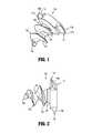
- FIG. 1is a perspective view of a surgical anchor for use in an endoscopic surgical device in accordance with the present disclosure
- FIG. 2is a side, elevational view of the surgical anchor of FIG. 1 ;
- FIG. 3is a distal, end view of the surgical anchor of FIGS. 1 and 2 ;
- FIG. 4is a side, elevational view, partially broken away, of the surgical anchor of FIGS. 1-3 ;
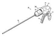
- FIG. 5is a perspective view of an endoscopic surgical device according to an aspect of the present disclosure.
- FIG. 6is a top, plan view of the surgical device of FIG. 5 ;
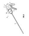
- FIG. 7is a side, elevational view of the surgical device of FIGS. 5 and 6 ;
- FIG. 8is a rear, perspective view of the surgical device of FIGS. 5-7 , illustrating a handle assembly and an endoscopic assembly thereof separated from one another;
- FIG. 9is a right, front, perspective view of the surgical device of FIGS. 5-8 , illustrating a first half-section of the handle assembly removed therefrom;
- FIG. 10is a left, front, perspective view of the surgical device of FIGS. 5-8 , illustrating a second half-section of the handle assembly removed therefrom;
- FIG. 11is a left, front, perspective view, with parts separated, of the surgical device of FIGS. 5-8 , illustrating a second half-section of the handle assembly removed therefrom;
- FIG. 12is a front, perspective view of the surgical device of FIGS. 5-8 , illustrating a ferrule removed therefrom;
- FIG. 13is an enlarged view of the indicated area of detail of FIG. 12 ;
- FIG. 14is an enlarged view of the indicated area of detail of FIG. 5 , illustrating the ferrule in a lock position
- FIG. 15is an enlarged view of the indicated area of detail of FIG. 6 , illustrating the ferrule in the lock position
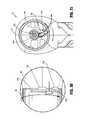
- FIG. 16is a cross-sectional view as taken through section line 16 - 16 of FIG. 6 ;
- FIG. 17is a front, perspective view of a lock out assembly and a first bevel gear of a gear train of the present disclosure
- FIG. 18is a rear, perspective view of the lock out assembly and the first bevel gear of the gear train of the present disclosure
- FIG. 19is a front, plan view of the lock out assembly and the first bevel gear of the gear train of the present disclosure
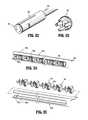
- FIG. 20is a perspective view, with parts separated, of the endoscopic assembly of the surgical device of the present disclosure
- FIG. 21is a rear, perspective view of the endoscopic assembly of the present disclosure.
- FIG. 22is a rear, perspective view of the endoscopic assembly of the present disclosure, illustrating a shipping plug connected thereto;
- FIG. 23is a perspective view of the shipping plug of the present disclosure.
- FIG. 24is a perspective view of a distal end portion of the endoscopic assembly with an outer tube and a coil removed therefrom, shown with surgical anchors loaded therein;
- FIG. 25is a perspective view of the distal end portion of the endoscopic assembly with the outer tube and the coil removed therefrom, shown with surgical anchors separated therefrom;
- FIG. 26is a side elevational view of the handle assembly, with a housing half-section removed therefrom, illustrating the handle assembly during a firing stroke of the endoscopic surgical device;
- FIG. 27is an enlarged view of the indicated area of detail of FIG. 26 ;
- FIG. 28is a cross-sectional view of the distal end portion of the endoscopic assembly, as taken through section line 28 - 28 of FIG. 8 , illustrating the endoscopic assembly during a firing stroke of the endoscopic surgical device;
- FIG. 29is an illustration of surgical anchors of the present disclosure fixing a surgical mesh in place
- FIG. 30is an enlarged view of the indicated area of detail of FIG. 6 , illustrating the ferrule being rotated from the lock position to an exchange position;
- FIG. 31is a cross-sectional view as taken through section line 31 - 31 of FIG. 6 , illustrating the ferrule being rotated from the lock position to the exchange position;
- FIG. 32is an enlarged view of the indicated area of detail of FIG. 6 , illustrating the ferrule rotated to the exchange position;
- FIG. 33is a cross-sectional view as taken through section line 33 - 33 of FIG. 6 , illustrating the ferrule rotated to the exchange position;
- FIG. 34is a rear, perspective view of the lock out assembly and the first bevel gear of the gear train of the present disclosure, illustrating the ferrule rotated to the exchange position;
- FIG. 35is a front, plan view of the lock out assembly and the first bevel gear of the gear train of the present disclosure, illustrating the ferrule rotated to the exchange position;
- FIG. 36is a front, perspective view of the handle assembly, illustrating the ferrule rotated to the exchange position
- FIG. 37is a front, perspective view of the handle assembly and the endoscopic assembly, illustrating a connection of the endoscopic assembly to the handle assembly;
- FIG. 38is a front, perspective view of the handle assembly and the endoscopic assembly, illustrating the endoscopic assembly fully connected to the handle assembly;
- FIG. 39is a front, perspective view of the handle assembly (with the ferrule removed therefrom) and the endoscopic assembly, illustrating the endoscopic assembly fully connected to the handle assembly;
- FIG. 40is a front, perspective view of the handle assembly and the endoscopic assembly, illustrating the endoscopic assembly fully connected to the handle assembly, and illustrating the ferrule being rotated to the lock position;
- FIG. 41is an enlarged view of the indicated area of detail of FIG. 6 , illustrating the ferrule rotated to a release position;
- FIG. 42is a cross-sectional view as taken through section line 42 - 42 of FIG. 6 , illustrating the ferrule rotated to the release position;
- FIG. 43is a rear, perspective view of the lock out assembly and the first bevel gear of the gear train of the present disclosure, illustrating the ferrule rotated to the release position;
- FIG. 44is a front, plan view of the lock out assembly and the first bevel gear of the gear train of the present disclosure, illustrating the ferrule rotated to the release position;
- FIG. 45is a front, perspective view of the surgical device of FIGS. 5-8 , illustrating a ferrule removed therefrom;
- FIG. 46is a rear, perspective view of the ferrule, illustrating internal features thereof.
- FIG. 47is an enlarged, plan view (with portions in phantom) illustrating the ferrule in the release position relative to a handle housing of the handle assembly.
- distalrefers to that portion of the endoscopic surgical device, that is farther from the user
- proximalrefers to that portion of the endoscopic surgical device that is closer to the user.
- anchor 100a surgical anchor for use with the surgical tack applier of the present disclosure is illustrated and generally designated as anchor 100 .
- anchor 100includes a head section 110 , a mesh retention section 120 , and a threaded tissue-snaring section 130 .
- Head section 110includes a pair of opposing threaded sections 112 a , 112 b having respective radially, outer, helical head threads 114 a , 114 b , and a pair of opposing open or slotted sections 116 a , 116 b .
- a distal surface of head section 110is formed onto or integral with a proximal end of mesh retention section 120 .
- Mesh retention section 120 of anchor 100extends from and between a distal end or surface of head section 110 and a proximal end of tissue-snaring section 130 .
- Mesh retention section 120functions to lock, anchor or otherwise retain a surgical mesh (not shown) on to anchor 100 when anchor 100 is screwed into the mesh to a depth past a proximal-most segment 138 of tissue-snaring thread 132 of tissue-snaring section 130 . This is achieved because there is no thread located in mesh retention section 120 that would allow anchor 100 to be unscrewed or backed out from the mesh.
- Mesh retention section 120has a cylindrical or conical transverse cross-sectional profile.
- Mesh retention section 120includes a transverse radial dimension, relative to a central longitudinal axis of anchor 100 , that is smaller than a transverse radial dimension of head section 110 , and smaller than a transverse radial dimension of proximal-most segment 138 of tissue-snaring thread 138 .
- Threaded tissue-snaring section 130 of anchor 100includes helical threads 132 formed onto a tapered truncated body section 134 .
- a distal point or tip 136defines the terminus of the distal most tissue-snaring thread 132 .
- body section 134 of tissue-snaring section 130is tapered, i.e., becoming smaller toward the distal end of threaded tissue-snaring section 130 , and terminates or truncates to a distal truncation point “TP”, prior to reaching an apex or tip of anchor 100 .
- Body section 134includes a concave taper such that, for a given length, a minimum diameter body section 134 is defined upon truncation thereof which is approximately less than 0.01 inches.
- Anchor 100includes a transverse dimension “D”, of a distal-most thread in the threaded tissue-snaring section 130 which is as large as design constraints will allow or approximately greater than 0.040 inches.
- Dtransverse dimension
- the tissue-snaring threads 132terminate at distal tip 136 , which is distal of the truncation point “TP” of body section 134 .
- a penetration of the mesh, by anchor 100is eased; and an indentation of the mesh into relatively soft tissue, by anchor 100 , is minimized, as compared to an anchor having a non-truncated body with tapered threads.
- the larger the dimension “D” of anchor 100the less the distal force that needs to be exerted in order to cause indentation of an underlying tissue and surgical mesh.
- Anchor 100is non-cannulated and is constructed from a suitable bioabsorbable material, such as, for example, polylactide, polyglycolide.
- Anchor 100is formed from a proprietary biocompatible co-polymer (Lactomer USS L1, Boehringer Ingelheim LR 704 S, or Boehringer Ingelheim LG-857).
- Anchormay also be constructed from suitable non-bioabsorbable materials, or permanent material, such as, for example, stainless steel, titanium and the like.
- Tack applier 200includes a handle assembly 210 , and a removable endoscopic assembly 300 (e.g., single use loading unit SULU) extending from handle assembly 210 and configured to store and selectively release or fire a plurality of anchors 100 therefrom and into mesh “M” overlying tissue “T”. ( FIG. 29 ).
- SULUsingle use loading unit
- handle assembly 210includes a handle housing 212 formed from a first half-section 212 a and a second half section 212 b joined to one another.
- First half-section 212 a and second half section 212 b of handle housing 212may be joined to one another using know methods by those of skill in the art, including and not limited to ultrasonic welding, fasteners (i.e., screws) and the like.
- First half-section 212 a and second half section 212 b of handle housing 212are joined to one another such that a fluid-tight seal is provided therebetween.
- Handle housing 212defines a fixed handle portion 216 having a free end 216 a .
- Handle assembly 210includes a trigger 214 pivotably connected to handle housing 212 , at a pivot point disposed within handle housing 212 .
- Trigger 214includes a free end 214 a spaced a distance from fixed handle portion 216 when trigger 214 is in an extended or un-actuated condition.
- Trigger 214includes a pivot end 214 b extending therefrom and extending into handle housing 212 through a side of handle housing 212 .
- a fluid-tight sealmay be provided between pivot end 214 b of trigger 214 and handle housing 212 .
- an X-ring or the like, including an o-ring, etc.,(not shown) may be used between pivot end 214 b of trigger 214 and handle housing 212 .
- handle assembly 210supports a gear train 220 within handle housing 212 .
- Gear train 220includes a trigger or drive gear 222 keyed to or non-rotatably connected to pivot end 214 b of trigger 214 .
- Drive gear 222is a two tiered gear including a first drive gear 222 a , and a second drive gear 222 b .
- First drive gear 222 amay be in the form of a quadrant gear or the like having a plurality of gear teeth 222 a 1 formed along a radial outer edge thereof and extending along an arcuate length of first drive gear 222 a .
- First drive gear 222 aincludes a stem or stopper 223 a extending radially therefrom, at a location proximal of gear teeth 222 a 1 .
- Second drive gear 222 bdefines a plurality of gear teeth 222 b 1 formed along a radial outer edge thereof.
- Gear train 220further includes a transmission gear assembly 224 pivotably supported in handle housing 212 .
- Transmission gear assembly 224is a three tiered gear including a first transmission gear 224 a , a second transmission gear 224 b , and third transmission gear 224 c each rotatably supported on a common pivot axis.
- First transmission gear 224 amay be in the form of a pinion gear or the like having a plurality of gear teeth 224 a 1 formed along a radial outer edge thereof and being in meshing engagement with gear teeth 222 a 1 of first drive gear 222 a .
- Second transmission gear 224 bmay be in the form of a quadrant gear or the like having a plurality of gear teeth 224 b 1 formed along a radial outer edge thereof and extending along an arcuate length of second transmission gear 224 b .
- Third transmission gear 224 cmay be in the form of a pinion gear or the like having a plurality of gear teeth 224 c 1 formed along a radial outer edge thereof and being in meshing engagement with gear teeth 224 b 1 of second transmission gear 224 b.
- Gear train 220also includes a clutch gear 226 pivotably and slidably supported on a pivot axis 227 a in handle housing 212 .
- Clutch gear 226may be in the form of a pinion gear or the like having a plurality of gear teeth 226 a 1 formed along a radial outer edge thereof and being in meshing engagement with gear teeth 224 b 1 of second transmission gear 224 b .
- Clutch gear 226is biased into meshing engagement with second transmission gear 224 b by a biasing member 227 b ( FIGS. 10 and 11 ).
- Clutch gear 226includes an arm 226 b extending radially therefrom, and a cam or ramp 226 c ( FIG. 11 ) extending/projecting from arm 226 b .
- Cam 226 cincludes a front end having a height defining a shoulder, and a tail end tapering into arm 226 b.
- Gear train 220further includes a first bevel gear 228 pivotably and slidably supported on pivot axis 227 a in handle housing 212 .
- First bevel gear 228may be in the form of a crown gear or the like.
- First bevel gear 228is operatively engaged/associated with clutch gear 226 .
- First bevel gear 228defines an arcuate slot 228 a formed in first face 228 d thereof for selectively receiving and engaging cam 226 c of clutch gear 226 .
- Slot 228 aincludes a front end wall configured to engage the front end of cam 226 c of clutch gear 226 , and tapers along a length thereof to be flush with the first face of first bevel gear 228 .
- trigger 214causes drive gear 222 to be rotated, in a first direction.
- drive gear 222causes first transmission gear 224 a and second transmission gear 224 b to be rotated, in a first direction, about the pivot axis thereof.
- second transmission gear 224 bcauses clutch gear 226 to be rotated, in a first direction, about a pivot axis thereof.
- first bevel gear 228As clutch gear 226 is rotated in the first direction, the front end of cam 226 c of clutch gear 226 is rotated in a first direction until the front end of cam 226 c engages or contacts the front end wall of slot 228 a of first bevel gear 228 . After the front end of cam 226 c of clutch gear 226 engages or contacts the front end wall of slot 228 a of first bevel gear 228 , continued rotation of clutch gear 226 , in the first direction, results in concomitant rotation of first bevel gear 228 in a first direction. At this point, first bevel gear 228 continues to rotate in the first direction so long as trigger 214 is being actuated to a closed or fully actuated condition.
- trigger 214When actuation of trigger 214 is stopped, either prior to complete actuation or following complete actuation, rotation of first bevel gear 228 , in the first direction, is also stopped.
- trigger 214Upon the completion of a partial or complete actuation of trigger 214 and a release thereof, trigger 214 causes drive gear 222 to be rotated, in a second direction (opposite the first direction).
- drive gear 222As drive gear 222 is rotated in the second direction, drive gear 222 causes first transmission gear 224 a and second transmission gear 224 b to be rotated, in a second direction, about the pivot axis thereof.
- second transmission gear 224 bcauses clutch gear 226 to be rotated, in a second direction, about pivot axis 227 a .
- clutch gear 226As clutch gear 226 is rotated in the second direction, the tail end of cam 226 c thereof slides along slot 228 a of first bevel gear 228 , and, if the rotation in the second direction is sufficient, slides out of slot 228 a of first bevel gear 228 and along first face 228 d of first bevel gear 228 .
- cam 226 c of clutch gear 226slides along slot 228 a of first bevel gear 228 , clutch gear 226 slides axially along pivot axis 227 a and compresses biasing member 227 b.
- handle assembly 210includes a biasing member 225 configured for maintaining trigger 214 in an extended or un-actuated position.
- Biasing member 225is also configured to have a spring constant sufficient to return trigger 214 to the un-actuated position following a partial or complete actuation of trigger 214 .
- Biasing member 225includes a first end 225 a fixedly connected in handle housing 212 and a second end 225 b connected to stem 223 a extending from first drive gear 222 a.
- handle assembly 210includes an audible/tactile feedback mechanism 250 supported within handle housing 212 and in operative association with drive gear 222 .
- audible/tactile feedback mechanism 250includes a dial 252 rotatably supported in handle housing 212 .
- Dial 252includes a tooth 252 a extending therefrom.
- Dial 252is spring biased to a home position.
- Audible/tactile feedback mechanism 250further includes a tooth or stem 223 b extending from second drive gear 222 b .
- dial 252In operation, as trigger 214 is actuated and second drive gear 222 b rotated, stem 223 b of second drive gear 222 b contacts tooth 252 a of dial 252 causing dial 252 to rotate against the bias of a spring member 254 .
- stem 223 b of second drive gear 222 bclears tooth 252 a of dial 252
- dial 252is returned to or snapped back to the home position thereof due to the bias of spring member 254 .
- dial 252When dial 252 is snapped back to the home position thereof, dial 252 creates an audible and/or tactile response.
- handle assembly 210 of tack applier 200is provided with a ratchet mechanism 260 which is configured to inhibit or prevent inner tube 320 ( FIGS. 20, 24 and 25 ) from backing-out or reversing after anchor 100 has been at least partially driven into tissue.
- Ratchet mechanism 260includes, as seen in FIGS. 9 and 11 , a series of ratchet teeth 228 f formed on a rear or second face of first bevel gear 228 .
- Ratchet mechanism 260further includes a spring clip 262 secured within handle assembly 210 .
- Spring clip 262includes a resilient finger 262 a configured for engagement with ratchet teeth 228 f formed on rear surface of first bevel gear 228 .
- resilient finger 262 a of spring clip 262engages with ratchet teeth 228 f of first bevel gear 228 in such a manner that as first bevel gear 228 is rotated, in a first direction, resilient finger 262 a of spring clip 262 cams over ratchet teeth 228 f and permits rotation of first bevel gear 228 . Also, if first bevel gear 228 starts to rotate in a second direction (opposite to the first direction), resilient finger 262 a of spring clip 262 stops along ratchet teeth 228 f thereby preventing or inhibiting first bevel gear 228 from rotating in the second direction. As such, any reverse rotation or “backing-out” of anchor 100 or inner tube 320 of endoscopic assembly 300 (tending to cause first bevel gear 228 to rotate in the second direction), during a driving or firing stroke, is inhibited or prevented.
- handle assembly 210further includes a second or pinion-bevel gear 230 rotatably supported in a distal end of handle housing 212 .
- Pinion-bevel gear 230includes gear teeth 230 a operatively engaged or meshed with gear teeth 228 c formed on the front face of first bevel gear 228 .
- Pinion-bevel gear 230is non-rotatably secured to a drive shaft 232 extending distally from handle housing 212 .
- Drive shaft 232is configured and dimensioned to engage an inner connector member 344 of endoscopic assembly 300 ( FIGS. 20 and 21 ).
- drive shaft 232defines a plurality of axially extending ribs 232 a at a distal end thereof.
- gear train 220causes pinion-bevel gear 230 to rotate in a first direction.
- pinion-bevel gear 230transmits the rotation to inner tube 320 of endoscopic assembly 300 .
- handle assembly 210includes a ferrule or collar 234 rotatably and removably supported on handle housing 212 .
- Ferrule 234defines a distal opening 234 a that is axially aligned with drive shaft 232 .
- Ferrule 234includes a stopper or tooth 234 b extending radially into distal opening 234 a.
- Ferrule 234is rotatable between a lock position (anchor retaining/advancing assembly 300 is locked to handle assembly 212 , and tacker 200 is ready to fire, FIGS. 14-16 ); an exchange position (anchor retaining/advancing assembly 300 can be connected/disconnected to/from handle assembly 212 , and tacker 200 can not be fired, FIGS. 30-33 ); and a ferrule release position (ferrule 234 can be removed from handle housing 212 , and handle housing 212 may be cleaned or sterilized, FIGS. 41 and 42 ).
- Handle housing 212 and ferrule 234may include complementary inter-engaging features and/or structures which lock or fix a position/orientation of ferrule 234 relative to handle housing 212 .
- Ferrule 234includes opposed radially inwardly extending nubs 234 c and handle housing 212 includes a pair of L-shaped slots 212 d formed in an outer surface of a nose 212 c thereof.
- Housingdefines an annular shoulder 212 e around a proximal end of nose 212 c .
- Shoulder 212 edefines a pair of recesses 212 f , 212 g formed in a distal face of shoulder 212 e.
- nose 212 c of handle housing 212includes a distally extending annular wall 212 h surrounding the distal end of drive shaft 232 .
- Annular wall 212 hincludes a tooth 212 i projecting radially inward therefrom.
- stopper or tooth 234 b of ferrule 234is radially aligned with tooth 212 i of annular wall 212 h .
- stopper or tooth 234 b of ferrule 234is radially out of alignment with tooth 212 i of annular wall 212 h.
- Ferrule 234includes a second tooth 234 d projecting from a proximal surface thereof. Tooth 234 d is configured to engage a selected one of recesses 212 f , 212 g of housing 212 as ferrule 234 is rotated relative to housing 212 . Tooth 234 d is biased to project from proximal end of ferrule 234 .
- handle assembly 210includes a safety lock assembly 240 supported on handle housing 212 and being configured to permit and inhibit actuation of trigger 214 , and for effectuating a loading/retention and a release/removal of endoscopic assembly 300 to handle housing 212 .
- Safety lock assembly 240is in operative association with ferrule 234 and is actuatable upon a rotation of ferrule 234 relative to handle housing 212 .
- Safety lock assembly 240includes a lock pin 242 slidably supported in and projecting distally from handle housing 212 .
- Pin 242includes a transverse head 242 a extending therefrom. Head 242 a of lock pin 242 is operatively disposed within or between internal walls 234 e ( FIGS. 16, 31, 33, 42 and 46 ) provided in ferrule 234 .
- Safety lock assembly 240includes a lock plate 244 supported on a proximal end 242 b of lock pin 242 .
- Lock plate 244has a generally pie-shaped profile. In use, lock plate 244 is caused to be rotated as lock pin 242 is rotated, due to internal walls 234 e of ferrule 234 acting on head 242 a of pin 242 as ferrule 234 is rotated relative to handle housing 212 . In operation, when ferrule 234 is rotated to the exchange position or the ready-to-fire position, with trigger 214 in a fully un-actuated position, lock plate 244 is rotated into a radial slot 228 g formed in first bevel gear 228 , thereby preventing first bevel gear 228 from rotating. Moreover, when ferrule 234 is rotated to the lock position, lock plate 244 is rotated out of radial slot 228 g of first bevel gear 228 , thereby allowing first bevel gear 228 to rotate.
- Safety lock assembly 240further includes a biasing member 246 configured to bias head 242 a of pin 242 and lock plate 244 to the rotated lock position.
- endoscopic assembly 300includes an outer tube 310 , an inner tube 320 rotatably disposed within outer tube 310 , a guide coil or spring 330 disposed between outer tube 310 and inner tube 320 , a plurality of anchors 100 loaded within inner tube 310 , and a connector 340 supported at a proximal end of outer tube 310 and inner tube 320 .
- Outer tube 310 of endoscopic assembly 300includes a proximal end 310 a and a distal end 310 b , and defines a lumen 310 c therethrough. As described briefly above, endoscopic assembly 300 further includes a guide coil or spring 330 fixedly disposed within at least a distal portion of outer tube 310 .
- Endoscopic assembly 300also includes an inner tube 320 rotatably disposed within coil 330 .
- Inner tube 320includes a proximal end portion 320 a and a splined distal end portion 320 b , and defines a lumen 320 c therethrough.
- Distal end portion 320 b of inner tube 320is slotted, defining a pair of opposed tines 320 b 1 and a pair of opposed channels 320 b 2 .
- Distal end portion 320 b of inner tube 320is capable of accepting a plurality of anchors 100 within inner tube 320 .
- anchors 100are loaded into endoscopic assembly 300 such that the pair of opposing threaded sections 112 a , 112 b of anchors 100 extend through respective channels 320 b 2 of distal end portion 320 b of inner tube 320 and are slidably disposed within the groove of coil 330 , and the pair of tines 320 b 1 of distal end portion 320 b of inner tube 320 are disposed within the pair of slotted sections 116 a , 116 b of anchors 100 .
- the pair of tines 320 b 1 of inner tube 320transmit the rotation to anchors 100 and advance anchors 100 distally owing to head threads 114 a , 114 b of anchors 100 engaging with coil 330 .
- endoscopic assembly 300includes a connector 340 having an outer connector member 342 non-rotatably connected to proximal end 310 a of outer tube 310 , and an inner connector member 344 non-rotatably connected to proximal end 320 a of inner tube 320 .
- Inner connector member 344is nested within outer connector member 342 .
- Outer connector member 342is substantially cylindrical and defines at least one longitudinally extending outer radial groove 342 a that extends through a proximal end thereof, and at least one longitudinally extending inner groove 342 b .
- Outer connector member 342is sized and shaped to be inserted into distal opening 234 a of ferrule 234 of handle assembly 210 and into annular wall 212 h of nose 212 c of handle housing 212 .
- Inner connector member 344is substantially cylindrical and defines at least one longitudinally extending inner rib 344 a projecting radially into a lumen thereof.
- outer radial groove 342 a of outer connector member 342is first aligned with stopper or tooth 234 b of ferrule 234 and with tooth 212 i of annular wall 212 h of nose 212 c . Then, outer connector member 342 is fully inserted into ferrule 234 and annular wall 212 h , tooth 212 i of annular wall 212 h of nose 212 c is disposed within outer radial groove 342 a of outer connector member 342 , and stopper or tooth 234 b of ferrule 234 is disposed distally of outer connector member 342 .
- ferrule 234With outer connector member 342 is fully inserted into ferrule 234 and annular wall 212 h , ferrule 234 is rotated from the exchange position to the lock position, whereby stopper or tooth 234 b of ferrule 234 is rotated to a radial position, out of alignment with outer radial groove 342 a of outer connector member 342 , to block withdrawal of outer connector member 342 from within ferrule 234 and from within annular wall 212 h of nose 212 c of handle housing 212 .
- endoscopic assembly 300includes a shipping wedge, plug or cap 350 configured and adapted for selective connection to connector 340 .
- Cap 350includes an end wall 352 , at least one leg 354 extending from end wall 352 and being configured and dimensioned for selective receipt in a respective longitudinally extending outer radial groove 342 a ( FIG. 21 ) of outer connector member 342 , and a stem (not shown) extending from end wall 352 and being configured and dimensioned for selective receipt into inner connector member 344 for engagement with longitudinally extending inner rib(s) 344 a of inner connector member 344 .
- the at least one leg 354 and the stem of cap 350engage outer connector member 342 and inner connector member 344 to prevent their rotation relative to one another.
- Cap 350is used to fix the radial position of inner tube 320 relative to outer tube 310 and thus ensure that the stack of surgical anchors 100 are not prematurely advanced through endoscopic assembly 300 prior to connection of endoscopic assembly 300 to handle assembly 210 . If the stack of surgical anchors 100 are advanced through endoscopic assembly 300 , prior to connection of endoscopic assembly 300 to handle assembly 210 , a timing of the firing of tack applier 200 may be effected, whereby each fully stroke of trigger 214 may either not fully fire a surgical anchor 100 from endoscopic assembly 300 or may begin to fire a second surgical anchor 100 from endoscopic assembly 300 .
- the pair of tines 320 a 1 of inner tube 320transmit the rotation to the entire stack of anchors 100 and advance the entire stack of anchors 100 distally, owing to head threads 114 a , 114 b of anchors 100 engaging with coil 330 .
- the components of surgical tacker 200 , and anchors 100are dimensioned such that a single complete and full actuation of trigger 214 results in a firing of a singe anchor 100 (i.e., the distal-most anchor of the stack of anchors 100 loaded in endoscopic assembly 300 ) from endoscopic assembly 300 .
- Surgical tacker 200may be repeatedly fired to fire anchors from endoscopic assembly 300 until the surgical procedure is complete or until endoscopic assembly 300 is spent of anchors 100 . If endoscopic assembly 300 is spent of anchors 100 , and if additional anchors 100 are required to complete the surgical procedure, spent endoscopic assembly 300 may be replaced with a new (i.e., loaded with anchors 100 ) endoscopic assembly 300 . Alternatively, is it is desired to change the types of anchors 100 that are being used in the surgical procedure, non-spent endoscopic assembly 300 (loaded with a first type of anchors 100 ) may be replaced with another endoscopic assembly 300 (loaded with a second, different type of anchors 100 ).
- the surgeonactuates or rotates ferrule 234 from the locked position ( FIGS. 14-19 ) to the exchange position ( FIGS. 30-33 ) to release the loaded or connected endoscopic assembly 300 , decouples or withdraws endoscopic assembly 300 from handle assembly 210 , loads or connects a new endoscopic assembly 300 to handle assembly 210 , and actuates or rotates ferrule 234 from the exchange position to the locked position to retain the new endoscopic assembly 300 in handle assembly 210 .
- ferrule 234may be removed or disconnected from handle housing 212 such that the ferrule 234 and the remainder of handle assembly 210 may by cleaned by sterilization, washing, wiping, autoclaving, chemical processing and the like.
- ferrule 234is rotated from the exchange position ( FIGS. 30-33 ) to the release position ( FIGS. 41-44 ), wherein ferrule 234 is rotated relative to handle housing 212 until radially inwardly extending nubs 234 c of ferrule 234 are at the end of a long leg of L-shaped slots 212 d of nose 212 c of handle housing 212 .
- ferrule 234may be axially separated from handle housing 212 .
- endoscopic assemblies 300may be provided, wherein endoscopic assemblies may be available which are loaded with surgical anchors fabricated from different materials (e.g., bioabsorbable, permanent, etc.), or endoscopic assemblies may be available having different lengths (e.g., short, medium, long, etc.) wherein the particular length endoscopic assembly is loaded with a respective number of surgical anchors.
- endoscopic assembliesmay be available which are loaded with surgical anchors fabricated from different materials (e.g., bioabsorbable, permanent, etc.), or endoscopic assemblies may be available having different lengths (e.g., short, medium, long, etc.) wherein the particular length endoscopic assembly is loaded with a respective number of surgical anchors.
- the surgeonmay select any one or combination of endoscopic assemblies desired or needed, and the surgeon may interchange or exchange endoscopic assemblies as needed or desired during the surgical procedure.
- all the endoscopic assembliesmay have the same length, but be loaded with varying numbers of surgical anchors therein. In this manner, the surgeon may choose an endoscopic assembly loaded with fewer or more surgical anchors depending on the type of surgical procedure to be performed.
- handle assembly 100may be replaced by an electromechanical control module configured and adapted to drive the inner tube of anchor retaining/advancing assembly to fire or actuate the surgical device.
- the electromechanical control modulemay include at least one microprocessor, at least one drive motor controllable by the at least one microprocessor, and a source of power for energizing the at least one microprocessor and the at least one drive motor.
- An embodimentis an endoscopic surgical device, comprising; a handle assembly including a handle housing and a trigger operatively connected to the handle housing, and a drive mechanism actuatable by the trigger; and an endoscopic assembly selectively connectable to the handle assembly, the endoscopic assembly including: an outer tube defining a lumen therethrough; an inner tube rotatably supported in the outer tube and defining a lumen therethrough; a plurality of surgical anchors loaded in the lumen of the inner tube of the endoscopic assembly, wherein each anchor includes a threaded body portion and a head portion acted upon by the inner tube to axially advanced the fire the surgical anchors from the endoscopic assembly; and a connector having: an outer connector member non-rotatably connected to a proximal end of the outer tube and being non-rotatably connectable to the handle assembly; and an inner connector member non-rotatably connected to a proximal end of the inner tube and being non-rotatably connectable to the drive mechanism, wherein the outer connector member and the inner connector
- the handle housingincludes a tooth projecting from a surface thereof, and wherein the outer connector member includes a channel formed therein, wherein the channel of the outer connector member receives the tooth of the handle housing when the endoscopic assembly is connected to the handle assembly, wherein the tooth inhibits rotation of the outer connector member when the trigger is actuated to rotate the inner connector member of the endoscopic assembly.
- the handle assemblyincludes a ferrule removably and rotatably connected to the handle housing, the ferrule defining an aperture therein that is in operative alignment with the drive mechanism of the handle assembly, the ferrule including a tooth projecting radially into the aperture of the ferrule, the ferrule having: a first position wherein the tooth of the ferrule is radially aligned with the tooth of the handle housing; and a second position wherein the tooth of the ferrule is radially out of alignment with the tooth of the handle housing. Additionally wherein when the ferrule is in the first position the endoscopic assembly is connectable to and disconnectable from the handle assembly.
- the channel of the outer connector memberis formed in an outer radial surface thereof and extends axially along an entire length thereof, and wherein during connection of the endoscopic assembly to the handle assembly and disconnection of the endoscopic assembly from the handle assembly, the tooth of the ferrule passes along the channel of the outer connector member.
- the outer channel of the outer connector memberdefines a length, wherein when the endoscopic assembly is connected to the handle assembly, the tooth of the ferrule is disposed distally of the channel of the outer connector member, and wherein the ferrule is rotatable to the second position such that the tooth of the ferrule inhibits disconnection of the endoscopic assembly and handle assembly from one another.
- the ferruleis rotatable to a third position wherein the ferrule is disconnectable from the handle housing.
- the handle assemblyincludes a safety lock assembly supported on the handle housing, the safety lock assembly includes a proximal end disposed within the handle housing and being in operative association with the drive mechanism, and a distal end projecting from the handle housing and being in operative association with the ferrule.
- the safety lock assemblywhen the ferrule is in the first position, the safety lock assembly is in a first position such that the proximal end of the safety lock assembly engages the drive mechanism to block operation of the drive mechanism; and when the ferrule is in the second position, the safety lock assembly is in a second position such that the proximal end of the safety lock assembly is disengaged from the drive mechanism to permit operation of the drive mechanism. Additionally wherein the ferrule is dimensioned to actuate the safety lock assembly between the first and second positions thereof as the ferrule is moved between respective first and second positions thereof.
- the safety lock assemblyincludes a lock plate supported on and extending radially from the proximal end thereof, wherein the lock plate has a generally pie-shaped profile, wherein the drive mechanism includes a gear defining a slot therein, and wherein the lock plate of the safety lock assembly is disposed within the slot of the gear of the drive mechanism when the ferrule is in the first position. Additionally wherein the drive mechanism includes a plurality of gears, wherein at least one gear is actuated by the trigger, and wherein at least one gear actuates a drive shaft extending from the handle housing, wherein the drive shaft is keyed for selective connection to the inner connector member supported at the proximal end of the inner tube.
- the outer tubeincludes a helical thread disposed within the lumen thereof wherein the inner tube defines a splined distal end, wherein the splined distal end of the inner tube is defined by a pair of opposed longitudinally extending tines and a pair of opposed longitudinally extending channels; and wherein the head portion of each of the plurality of surgical anchors defines a pair of opposed radially outer threads and a pair of opposed radial recesses, wherein the pair of radial recesses of each head portion receives respective tines of the inner tube and wherein the pair of opposed radially outer threads of each head portion projects from the pair of opposed longitudinally extending channels of the inner tube and engage the inner helical thread of the outer tube.
- An embodimentis an endoscopic surgical device, comprising; a handle assembly including: a handle housing and a trigger operatively connected to the handle housing, wherein the handle housing includes a tooth projecting from a surface thereof a drive mechanism actuatable by the trigger; and a ferrule removably and rotatably connected to the handle housing, the ferrule defining an aperture therein that is in operative alignment with the drive mechanism of the handle assembly, the ferrule including a tooth projecting radially into the aperture of the ferrule, the ferrule having: a first position wherein the tooth of the ferrule is radially aligned with the tooth of the handle housing; and a second position wherein the tooth of the ferrule is radially out of alignment with the tooth of the handle housing; and an endoscopic assembly extending from the handle assembly, the endoscopic assembly including: an outer tube defining a lumen therethrough and a helical inner coil; an inner tube rotatably supported in the outer tube and defining a lumen therethrough;
- the channel of the outer connector memberreceives the tooth of the handle housing when the endoscopic assembly is connected to the handle assembly, wherein the tooth inhibits rotation of the outer connector member when the trigger is actuated to rotate the inner connector member of the endoscopic assembly. Additionally wherein when the ferrule is in the first position the endoscopic assembly is connectable to and disconnectable from the handle assembly. Additionally wherein the channel of the outer connector member is formed in an outer radial surface thereof and extends axially along an entire length thereof, and wherein during connection of the endoscopic assembly to the handle assembly and disconnection of the endoscopic assembly from the handle assembly, the tooth of the ferrule passes along the channel of the outer connector member.
- the outer channel of the outer connector memberdefines a length, wherein when the endoscopic assembly is connected to the handle assembly, the tooth of the ferrule is disposed distally of the channel of the outer connector member, and wherein the ferrule is rotatable to the second position such that the tooth of the ferrule inhibits disconnection of the endoscopic assembly and handle assembly from one another. Additionally wherein the ferrule is rotatable to a third position wherein the ferrule is disconnectable from the handle housing.
- the handle assemblyincludes a safety lock assembly supported on the handle housing, the safety lock assembly includes a proximal end disposed within the handle housing and being in operative association with the drive mechanism, and a distal end projecting from the handle housing and being in operative association with the ferrule. Additionally wherein: when the ferrule is in the first position, the safety lock assembly is in a first position such that the proximal end of the safety lock assembly engages the drive mechanism to block operation of the drive mechanism; and when the ferrule is in the second position, the safety lock assembly is in a second position such that the proximal end of the safety lock assembly is disengaged from the drive mechanism to permit operation of the drive mechanism.
- the ferruleis dimensioned to actuate the safety lock assembly between the first and second positions thereof as the ferrule is moved between respective first and second positions thereof.
- the safety lock assemblyincludes a lock plate supported on and extending radially from the proximal end thereof, wherein the lock plate has a generally pie-shaped profile, wherein the drive mechanism includes a gear defining a slot therein, and wherein the lock plate of the safety lock assembly is disposed within the slot of the gear of the drive mechanism when the ferrule is in the first position.
- the drive mechanismincludes a plurality of gears, wherein at least one gear is actuated by the trigger, and wherein at least one gear actuates a drive shaft extending from the handle housing, wherein the drive shaft is keyed for selective connection to the inner connector member supported at the proximal end of the inner tube.
- the outer tubeincludes a helical thread disposed within the lumen thereof; wherein the inner tube defines a splined distal end, wherein the splined distal end of the inner tube is defined by a pair of opposed longitudinally extending tines and a pair of opposed longitudinally extending channels; and wherein the head portion of each of the plurality of surgical anchors defines a pair of opposed radially outer threads and a pair of opposed radial recesses, wherein the pair of radial recesses of each head portion receives respective tines of the inner tube and wherein the pair of opposed radially outer threads of each head portion projects from the pair of opposed longitudinally extending channels of the inner tube and engage the inner helical thread of the outer tube.
- An embodimentis an endoscopic surgical device, comprising; a handle assembly including: a handle housing and a trigger operatively connected to the handle housing, wherein the handle housing includes a tooth projecting from a surface thereof; a drive mechanism actuatable by the trigger; a ferrule removably and rotatably connected to the handle housing, the ferrule defining an aperture therein that is in operative alignment with the drive mechanism of the handle assembly, the ferrule including a tooth projecting radially into the aperture of the ferrule, the ferrule having: a first position wherein the tooth of the ferrule is radially aligned with the tooth of the handle housing; and a second position wherein the tooth of the ferrule is radially out of alignment with the tooth of the handle housing; and a safety lock assembly supported on the handle housing, the safety lock assembly includes a proximal end disposed within the handle housing and being in operative association with the drive mechanism, and a distal end projecting from the handle housing and being in operative association with
- the ferruleis dimensioned to actuate the safety lock assembly between the first and second positions thereof as the ferrule is moved between respective first and second positions thereof.
- the safety lock assemblyincludes a lock plate supported on and extending radially from the proximal end thereof, wherein the lock plate has a generally pie-shaped profile, wherein the drive mechanism includes a gear defining a slot therein, and wherein the lock plate of the safety lock assembly is disposed within the slot of the gear of the drive mechanism when the ferrule is in the first position.
- an endoscopic assemblyextending from the handle assembly, the endoscopic assembly including: an outer tube defining a lumen therethrough and a helical inner coil; an inner tube rotatably supported in the outer tube and defining a lumen therethrough; a plurality of surgical anchors loaded in the lumen of the inner tube of the endoscopic assembly, wherein each anchor includes a threaded body portion and a head portion extending radially beyond the inner tube and engaging the helical inner coil; and a connector having: an outer connector member non-rotatably connected to a proximal end of the outer tube, and being insertable through the aperture of the ferrule and being non-rotatably connectable to the handle assembly, wherein the outer connector member defines a channel formed therein that is configured to receive the tooth of the ferrule and the tooth of the handle housing when the endoscopic assembly is connected to the handle assembly; and an inner connector member non-rotatably connected to a proximal end of the inner tube and being non-rotatably connectable to the
- the drive mechanismincludes a plurality of gears, wherein at least one gear is actuated by the trigger, and wherein at least one gear actuates a drive shaft extending from the handle housing, wherein the drive shaft is keyed for selective connection to the inner connector member supported at the proximal end of the inner tube.
- the outer tubeincludes a helical thread disposed within the lumen thereof; wherein the inner tube defines a splined distal end, wherein the splined distal end of the inner tube is defined by a pair of opposed longitudinally extending tines and a pair of opposed longitudinally extending channels; and wherein the head portion of each of the plurality of surgical anchors defines a pair of opposed radially outer threads and a pair of opposed radial recesses, wherein the pair of radial recesses of each head portion receives respective tines of the inner tube and wherein the pair of opposed radially outer threads of each head portion projects from the pair of opposed longitudinally extending channels of the inner tube and engage the inner helical thread of the outer tube.
Landscapes
- Health & Medical Sciences (AREA)
- Life Sciences & Earth Sciences (AREA)
- Surgery (AREA)
- Veterinary Medicine (AREA)
- General Health & Medical Sciences (AREA)
- Biomedical Technology (AREA)
- Heart & Thoracic Surgery (AREA)
- Engineering & Computer Science (AREA)
- Public Health (AREA)
- Animal Behavior & Ethology (AREA)
- Medical Informatics (AREA)
- Molecular Biology (AREA)
- Nuclear Medicine, Radiotherapy & Molecular Imaging (AREA)
- Cardiology (AREA)
- Oral & Maxillofacial Surgery (AREA)
- Transplantation (AREA)
- Vascular Medicine (AREA)
- Surgical Instruments (AREA)
Abstract
Description
Claims (10)
Applications Claiming Priority (1)
| Application Number | Priority Date | Filing Date | Title |
|---|---|---|---|
| PCT/CN2014/074583WO2015149292A1 (en) | 2014-04-02 | 2014-04-02 | Surgical fastener applying apparatus, kits and methods for endoscopic procedures |
Publications (2)
| Publication Number | Publication Date |
|---|---|
| US20170128068A1 US20170128068A1 (en) | 2017-05-11 |
| US10335146B2true US10335146B2 (en) | 2019-07-02 |
Family
ID=54239276
Family Applications (1)
| Application Number | Title | Priority Date | Filing Date |
|---|---|---|---|
| US15/129,143Active2035-03-14US10335146B2 (en) | 2014-04-02 | 2014-04-02 | Surgical fastener applying apparatus, kits and methods for endoscopic procedures |
Country Status (3)
| Country | Link |
|---|---|
| US (1) | US10335146B2 (en) |
| CN (1) | CN106455936B (en) |
| WO (1) | WO2015149292A1 (en) |
Families Citing this family (40)
| Publication number | Priority date | Publication date | Assignee | Title |
|---|---|---|---|---|
| ES2279156T3 (en) | 2002-06-11 | 2007-08-16 | Tyco Healthcare Group Lp | MALE TIGHTS FOR HERNIAS. |
| US7670362B2 (en) | 2003-06-13 | 2010-03-02 | Tyco Healthcare Group Lp | Multiple member interconnect for surgical instrument and absorbable screw fastener |
| US8926637B2 (en) | 2003-06-13 | 2015-01-06 | Covidien Lp | Multiple member interconnect for surgical instrument and absorbable screw fastener |
| US10478179B2 (en) | 2004-04-27 | 2019-11-19 | Covidien Lp | Absorbable fastener for hernia mesh fixation |
| US9351733B2 (en) | 2013-01-18 | 2016-05-31 | Covidien Lp | Surgical fastener applier |
| US9358010B2 (en) | 2013-03-12 | 2016-06-07 | Covidien Lp | Flex cable and spring-loaded tube for tacking device |
| US9867620B2 (en) | 2013-03-14 | 2018-01-16 | Covidien Lp | Articulation joint for apparatus for endoscopic procedures |
| US9655621B2 (en) | 2013-03-15 | 2017-05-23 | Covidien Lp | Surgical instrument for dispensing tacks and solution |
| US9358004B2 (en) | 2013-06-28 | 2016-06-07 | Covidien Lp | Articulating apparatus for endoscopic procedures |
| US10085746B2 (en) | 2013-06-28 | 2018-10-02 | Covidien Lp | Surgical instrument including rotating end effector and rotation-limiting structure |
| US20150032130A1 (en) | 2013-07-24 | 2015-01-29 | Covidien Lp | Expanding absorbable tack |
| US10335146B2 (en)* | 2014-04-02 | 2019-07-02 | Coviden Lp | Surgical fastener applying apparatus, kits and methods for endoscopic procedures |
| US11090097B2 (en) | 2015-03-17 | 2021-08-17 | Covidien Lp | Connecting end effectors to surgical devices |
| CN105596043B (en)* | 2016-01-25 | 2019-04-09 | 北京天助畅运医疗技术股份有限公司 | Titanium nail and the soft tissue fixation devices containing titanium nail |
| CN105596044B (en)* | 2016-01-25 | 2019-01-25 | 北京天助畅运医疗技术股份有限公司 | Soft tissue fixation devices containing absorbable screw |
| US11452522B2 (en) | 2016-08-15 | 2022-09-27 | Covidien Lp | Circular stapling device with articulating anvil retainer assembly |
| US11045199B2 (en) | 2017-06-09 | 2021-06-29 | Covidien Lp | Handheld electromechanical surgical system |
| US10835341B2 (en)* | 2017-09-12 | 2020-11-17 | Covidien Lp | Endoscopic surgical clip applier and handle assemblies for use therewith |
| US11040174B2 (en)* | 2017-09-19 | 2021-06-22 | Edwards Lifesciences Corporation | Multi-direction steerable handles for steering catheters |
| US11116500B2 (en) | 2018-06-28 | 2021-09-14 | Covidien Lp | Surgical fastener applying device, kits and methods for endoscopic procedures |
| US11141163B2 (en) | 2018-10-04 | 2021-10-12 | Covidien Lp | Circular stapling device with anvil rotation locking structure |
| US11389263B2 (en) | 2018-12-13 | 2022-07-19 | Covidien Lp | Lockout mechanisms for surgical instruments |
| CA3139541A1 (en) | 2019-05-31 | 2020-12-03 | Covidien Lp | Circular stapling device |
| CN110269655B (en)* | 2019-06-26 | 2024-07-12 | 北京博辉瑞进生物科技有限公司 | Repair fixer with nail taking function |
| US11344309B2 (en) | 2019-07-05 | 2022-05-31 | Covidien Lp | Circular stapling instruments |
| US11192227B2 (en) | 2019-07-16 | 2021-12-07 | Covidien Lp | Reload assembly for circular stapling devices |
| US11253255B2 (en) | 2019-07-26 | 2022-02-22 | Covidien Lp | Knife lockout wedge |
| US11464510B2 (en) | 2019-07-26 | 2022-10-11 | Covidien Lp | Reload assembly with knife carrier lockout |
| US11911038B2 (en) | 2020-01-13 | 2024-02-27 | Covidien Lp | Cut optimization for excessive tissue conditions |
| US11653925B2 (en) | 2020-05-21 | 2023-05-23 | Covidien Lp | Tissue relaxation monitoring for optimized tissue stapling |
| US12256899B2 (en)* | 2020-10-27 | 2025-03-25 | Olympus Corporation | Overtube, insertion apparatus having overtube attached and detached thereto, and method for attaching overtube to and detaching overtube from insertion apparatus |
| US11627967B2 (en) | 2020-11-23 | 2023-04-18 | Covidien Lp | Trans-anastomotic insertion device |
| EP4262580B1 (en) | 2020-12-15 | 2025-10-08 | Covidien LP | Surgical stapling device rotatable camming element |
| CN112603250B (en)* | 2020-12-24 | 2025-09-12 | 南微医学科技股份有限公司 | Steering locking device and endoscope |
| US11877750B2 (en) | 2021-01-21 | 2024-01-23 | Covidien Lp | Surgical stapler with powered and manual functions |
| US11986187B2 (en) | 2021-01-29 | 2024-05-21 | Covidien Lp | Circular stapling device with integrated visualization device |
| US11786241B2 (en) | 2021-02-16 | 2023-10-17 | Covidien Lp | Surgical stapling device including a hydraulic staple formation mechanism |
| CN117715596A (en) | 2021-05-24 | 2024-03-15 | 柯惠有限合伙公司 | Anvil and delivery system components with automatic holding suture release |
| US11717299B2 (en) | 2021-10-12 | 2023-08-08 | Covidien Lp | Surgical stapling device with probiotics |
| US12213674B2 (en) | 2021-12-08 | 2025-02-04 | Covidien Lp | Determination of premature staple ejection |
Citations (203)
| Publication number | Priority date | Publication date | Assignee | Title |
|---|---|---|---|---|
| US3596528A (en) | 1968-12-24 | 1971-08-03 | Reimers Getriebe Ag | Infinitely variable cone pulley transmission |
| US3866510A (en) | 1967-06-05 | 1975-02-18 | Carl B H Eibes | Self-tapping threaded bushings |
| US4350491A (en) | 1979-03-17 | 1982-09-21 | P.I.V. Antrieb Werner Reimers Gmbh & Co. Kg | Cone-pulley belt-type transmission |
| US4884572A (en) | 1986-05-20 | 1989-12-05 | Concept, Inc. | Tack and applicator for treating torn bodily material in vivo |
| EP0374088A1 (en) | 1988-12-16 | 1990-06-20 | GebràDer Sulzer Aktiengesellschaft | Bone screw |
| US5085661A (en) | 1990-10-29 | 1992-02-04 | Gerald Moss | Surgical fastener implantation device |
| US5171249A (en) | 1991-04-04 | 1992-12-15 | Ethicon, Inc. | Endoscopic multiple ligating clip applier |
| US5171247A (en) | 1991-04-04 | 1992-12-15 | Ethicon, Inc. | Endoscopic multiple ligating clip applier with rotating shaft |
| US5176306A (en) | 1991-03-19 | 1993-01-05 | Beiersdorf Ag | Instrument for setting wound clamps |
| US5207697A (en)* | 1991-06-27 | 1993-05-04 | Stryker Corporation | Battery powered surgical handpiece |
| US5228256A (en) | 1991-10-02 | 1993-07-20 | Ross Dreveny | Anchor means and apparatus for installing same |
| US5236563A (en) | 1990-06-18 | 1993-08-17 | Advanced Surface Technology Inc. | Surface-modified bioabsorbables |
| US5246441A (en) | 1989-09-08 | 1993-09-21 | Linvatec Corporation | Bioabsorbable tack for joining bodily tissue |
| US5246450A (en) | 1992-03-10 | 1993-09-21 | Edward Weck Incorporated | High capacity medical clip feeding and dispensing mechanism |
| US5312023A (en) | 1991-10-18 | 1994-05-17 | United States Surgical Corporation | Self contained gas powered surgical apparatus |
| US5330487A (en) | 1992-12-17 | 1994-07-19 | Tfi Acquistion Corp. | Drive mechanism for surgical instruments |
| US5344061A (en) | 1993-08-03 | 1994-09-06 | Lawrence Crainich | Ratchet assembly for medical instrument |
| US5356064A (en) | 1991-10-18 | 1994-10-18 | United States Surgical Corporation | Apparatus and method for applying surgical staples to attach an object to body tissue |
| US5382254A (en) | 1989-07-18 | 1995-01-17 | United States Surgical Corporation | Actuating handle for surgical instruments |
| US5398861A (en) | 1993-04-16 | 1995-03-21 | United States Surgical Corporation | Device for driving surgical fasteners |
| US5403327A (en) | 1992-12-31 | 1995-04-04 | Pilling Weck Incorporated | Surgical clip applier |
| US5433721A (en) | 1992-01-17 | 1995-07-18 | Ethicon, Inc. | Endoscopic instrument having a torsionally stiff drive shaft for applying fasteners to tissue |
| US5439468A (en) | 1993-05-07 | 1995-08-08 | Ethicon Endo-Surgery | Surgical clip applier |
| US5466243A (en) | 1994-02-17 | 1995-11-14 | Arthrex, Inc. | Method and apparatus for installing a suture anchor through a hollow cannulated grasper |
| US5467911A (en) | 1993-04-27 | 1995-11-21 | Olympus Optical Co., Ltd. | Surgical device for stapling and fastening body tissues |
| US5474566A (en) | 1994-05-05 | 1995-12-12 | United States Surgical Corporation | Self-contained powered surgical apparatus |
| US5474567A (en) | 1992-09-14 | 1995-12-12 | Ethicon, Inc. | Sterile clips and instrument for their placement |
| US5522844A (en) | 1993-06-22 | 1996-06-04 | Johnson; Lanny L. | Suture anchor, suture anchor installation device and method for attaching a suture to a bone |
| US5527319A (en) | 1992-02-13 | 1996-06-18 | United States Surgical Corporation | Surgical fastener applying instrument for ligating and dividing tissue |
| US5553765A (en) | 1995-04-28 | 1996-09-10 | Ethicon Endo-Surgery, Inc. | Surgical stapler with improved operating lever mounting arrangement |
| US5562685A (en) | 1994-09-16 | 1996-10-08 | General Surgical Innovations, Inc. | Surgical instrument for placing suture or fasteners |
| US5564615A (en) | 1992-10-09 | 1996-10-15 | Ethicon, Inc. | Surgical instrument |
| US5582615A (en) | 1995-10-30 | 1996-12-10 | Pilling Weck, Incorporated | Handle for surgical clip applicator systems |
| US5582616A (en) | 1994-08-05 | 1996-12-10 | Origin Medsystems, Inc. | Surgical helical fastener with applicator |
| US5584425A (en) | 1991-10-18 | 1996-12-17 | United States Surgical Corporation | Lockout mechanism for surgical apparatus |
| US5601573A (en) | 1994-03-02 | 1997-02-11 | Ethicon Endo-Surgery, Inc. | Sterile occlusion fasteners and instruments and method for their placement |
| US5601571A (en) | 1994-05-17 | 1997-02-11 | Moss; Gerald | Surgical fastener implantation device |
| US5626613A (en) | 1995-05-04 | 1997-05-06 | Arthrex, Inc. | Corkscrew suture anchor and driver |
| US5628752A (en) | 1993-08-03 | 1997-05-13 | Howmedica Inc. | Ratcheting compression device |
| JPH09149906A (en) | 1995-11-29 | 1997-06-10 | Nagoya Rashi Seisakusho:Kk | Tool for curing bone disease |
| US5649931A (en) | 1996-01-16 | 1997-07-22 | Zimmer, Inc. | Orthopaedic apparatus for driving and/or removing a bone screw |
| US5662662A (en) | 1992-10-09 | 1997-09-02 | Ethicon Endo-Surgery, Inc. | Surgical instrument and method |
| US5681330A (en) | 1994-03-02 | 1997-10-28 | Ethicon Endo-Surgery, Inc. | Sterile occlusion fasteners and instrument and method for their placement |
| US5685474A (en) | 1994-10-04 | 1997-11-11 | United States Surgical Corporation | Tactile indicator for surgical instrument |
| US5697935A (en) | 1995-09-12 | 1997-12-16 | Medex Marketing, Inc. | Device and method for removing fastening implements from bone |
| US5730744A (en) | 1994-09-27 | 1998-03-24 | Justin; Daniel F. | Soft tissue screw, delivery device, and method |
| US5732806A (en) | 1996-03-29 | 1998-03-31 | Pilling Weck, Incorporated | Compensator to prevent backlash in a surgical instrument |
| US5735854A (en)* | 1996-04-12 | 1998-04-07 | Caron; Philippe | Device for applying a screw |
| EP0834280A1 (en) | 1996-10-04 | 1998-04-08 | United States Surgical Corporation | Tissue fastener implantation apparatus and method |
| US5741268A (en) | 1995-03-18 | 1998-04-21 | Schuetz; Frank-Ullrich | Tacking device and tacking nails for surgery |
| US5762255A (en) | 1996-02-20 | 1998-06-09 | Richard-Allan Medical Industries, Inc. | Surgical instrument with improvement safety lockout mechanisms |
| US5782844A (en) | 1996-03-05 | 1998-07-21 | Inbae Yoon | Suture spring device applicator |
| US5811552A (en) | 1994-05-20 | 1998-09-22 | Fuji Xerox Co., Ltd. | Cyclobutenedione derivative, process for preparing the same, and nonlinear optical element |
| US5830221A (en) | 1996-09-20 | 1998-11-03 | United States Surgical Corporation | Coil fastener applier |
| US5843087A (en) | 1997-01-30 | 1998-12-01 | Ethicon, Inc. | Suture anchor installation tool |
| US5897564A (en) | 1997-04-08 | 1999-04-27 | Ethicon Endo-Surgery, Inc. | Endoscopic instrument assembly for fastening tissue |
| US5904693A (en)* | 1993-04-27 | 1999-05-18 | American Cyanamid Company | Automatic laparoscopic ligation clip applicator |
| US5910105A (en) | 1997-04-14 | 1999-06-08 | C.R. Bard, Inc. | Control handle for an endoscope |
| US5911722A (en) | 1998-07-23 | 1999-06-15 | Millenium Devices Llc | Leban/Gordon surgical hand driver |
| US5928252A (en) | 1997-01-21 | 1999-07-27 | Regen Biologics, Inc. | Device and method for driving a needle and meniscal repair |
| US5931844A (en) | 1998-03-31 | 1999-08-03 | Smith & Nephew, Inc. | Surgical drive tool |
| US5941439A (en) | 1997-05-14 | 1999-08-24 | Mitek Surgical Products, Inc. | Applicator and method for deploying a surgical fastener in tissue |
| US5954259A (en)* | 1994-08-05 | 1999-09-21 | United States Surgical Corporation | Self-contained powered surgical apparatus for applying surgical fasteners |
| US5961524A (en) | 1998-03-11 | 1999-10-05 | Stryker Technologies Corporation | Screw and method of attachment to a substrate |
| US5976160A (en) | 1998-03-31 | 1999-11-02 | Design Standards Corporation | Handle mechanism with two distinct pivot points |
| US5997552A (en) | 1995-10-20 | 1999-12-07 | United States Surgical Corporation | Meniscal fastener applying device |
| US6010513A (en) | 1997-11-26 | 2000-01-04 | Bionx Implants Oy | Device for installing a tissue fastener |
| US6013991A (en) | 1996-03-29 | 2000-01-11 | Stryker Corporation | Motor control circuit |
| US6039753A (en) | 1998-07-16 | 2000-03-21 | Meislin; Robert | Single unit surgical fastener and method |
| WO2000016701A1 (en) | 1998-09-18 | 2000-03-30 | United States Surgical Corporation | Endovascular fastener applicator |
| US6074395A (en) | 1999-02-02 | 2000-06-13 | Linvatec Corporation | Cannulated tissue anchor insertion system |
| US6099537A (en)* | 1996-02-26 | 2000-08-08 | Olympus Optical Co., Ltd. | Medical treatment instrument |
| US6126670A (en) | 1998-12-16 | 2000-10-03 | Medtronic, Inc. | Cordless surgical handpiece with disposable battery; and method |
| US6132435A (en) | 1999-09-14 | 2000-10-17 | Synthes (Usa) | Torque limiting device for surgical use |
| US6146387A (en) | 1998-08-26 | 2000-11-14 | Linvatec Corporation | Cannulated tissue anchor system |
| US6183479B1 (en) | 1997-05-22 | 2001-02-06 | Bionx Implants, Oy | Installation tool for suture anchor |
| US6228098B1 (en) | 1998-07-10 | 2001-05-08 | General Surgical Innovations, Inc. | Apparatus and method for surgical fastening |
| US6235058B1 (en) | 1998-10-19 | 2001-05-22 | Douglas B. Huene | Bone plug anchoring device and methods for anchoring one or more tendons or other grafts using the bone plug anchoring device |
| US6241736B1 (en) | 1998-05-12 | 2001-06-05 | Scimed Life Systems, Inc. | Manual bone anchor placement devices |
| US6261302B1 (en) | 1998-06-26 | 2001-07-17 | Ethicon Endo-Surgery, Inc. | Applier for implantable surgical marker |
| WO2002034140A2 (en) | 2000-10-23 | 2002-05-02 | Tyco Healthcare Group Lp | Absorbable fastener and applying apparatus |
| US6387113B1 (en) | 1999-02-02 | 2002-05-14 | Biomet, Inc. | Method and apparatus for repairing a torn meniscus |
| US6402757B1 (en) | 1999-03-12 | 2002-06-11 | Biomet, Inc. | Cannulated fastener system for repair of bone fracture |
| US20020087170A1 (en)* | 2000-10-19 | 2002-07-04 | Kuhns Jesse J. | Method for attaching hernia mesh |
| US6425900B1 (en) | 2000-10-19 | 2002-07-30 | Ethicon Endo-Surgery | Method for attaching hernia mesh |
| US6439446B1 (en) | 2000-12-01 | 2002-08-27 | Stephen J. Perry | Safety lockout for actuator shaft |
| US6440136B1 (en) | 2000-05-24 | 2002-08-27 | Medtronic Ps Medical, Inc. | Apparatus for attaching to bone |
| US6457625B1 (en) | 1998-02-17 | 2002-10-01 | Bionx Implants, Oy | Device for installing a tissue fastener |
| EP1273272A2 (en) | 2001-07-02 | 2003-01-08 | Depuy France | Fixing device for bone portions |
| US20030009441A1 (en)* | 1996-09-20 | 2003-01-09 | Holsten Henry E. | Coil fastener applier and removal method |
| WO2003034925A2 (en) | 2001-10-23 | 2003-05-01 | Tyco Healthcare Group Lp | Surgical fasteners |
| US6572626B1 (en) | 2000-10-19 | 2003-06-03 | Ethicon Endo-Surgery, Inc. | Surgical instrument having a fastener delivery mechanism |
| US20030114839A1 (en) | 2001-12-19 | 2003-06-19 | Tony Looper | Reconfiguration surgical apparatus |
| US6626916B1 (en) | 1998-12-31 | 2003-09-30 | Teresa T. Yeung | Tissue fastening devices and methods for sustained holding strength |
| US6632228B2 (en) | 2000-08-23 | 2003-10-14 | Scimed Life System, Inc. | System, method, and apparatus for accurately deploying particular medical appliances at a target site |
| US6663656B2 (en) | 2001-02-26 | 2003-12-16 | Arthrex, Inc. | Torque driver for interference screw |
| WO2003103507A2 (en) | 2002-06-11 | 2003-12-18 | Tyco Healthcare Group, Lp | Hernia mesh tacks |
| US6666854B1 (en) | 1999-06-25 | 2003-12-23 | La Precision | Endoscopic surgical instrument |
| US6695867B2 (en) | 2002-02-21 | 2004-02-24 | Integrated Vascular Systems, Inc. | Plunger apparatus and methods for delivering a closure device |
| US6733506B1 (en) | 2000-11-16 | 2004-05-11 | Ethicon, Inc. | Apparatus and method for attaching soft tissue to bone |
| US6743240B2 (en) | 2001-06-25 | 2004-06-01 | Ethicon Endo-Surgery, Inc. | Flexible surgical device having a rotatable end effector assembly |
| US20040111089A1 (en) | 2002-12-04 | 2004-06-10 | Stevens Peter M. | Bone alignment implant and method of use |
| US6755836B1 (en) | 2002-12-20 | 2004-06-29 | High Plains Technology Group, Llc | Bone screw fastener and apparatus for inserting and removing same |
| US20040127916A1 (en) | 1998-09-18 | 2004-07-01 | Aptus Endosystems, Inc. | Catheter-based fastener implantation apparatus and methods with implantation force resolution |
| US6773438B1 (en) | 2000-10-19 | 2004-08-10 | Ethicon Endo-Surgery | Surgical instrument having a rotary lockout mechanism |
| DE10300787A1 (en) | 2003-01-13 | 2004-09-09 | A.M.I (Agency for Medical Innovations GmbH) | Nailing device for attaching a net to animal or human tissue, has magazine manually pressed to release and drive tissue nails towards marked points on surface of tissue, and needle or meter used to determine depth of driven tissue nails |
| US20040181222A1 (en) | 2003-01-16 | 2004-09-16 | Culbert Brad S. | Locking plate for bone anchors |
| US20040193217A1 (en) | 1996-09-13 | 2004-09-30 | Tendon Technology, Ltd. | Apparatus and methods for tendon or ligament repair |
| US20040243139A1 (en)* | 2003-04-28 | 2004-12-02 | Lewis Derek S. | Multiple screw delivery apparatus |
| WO2004112841A2 (en) | 2003-06-13 | 2004-12-29 | Tyco Healthcare Group, Lp | Multiple member interconnect for surgical instrument and absorbable screw fastener |
| US6837893B2 (en) | 2000-09-01 | 2005-01-04 | Onux Medical, Inc. | Multi-fastener surgical apparatus and method |
| US6840943B2 (en) | 2000-09-22 | 2005-01-11 | Codman & Shurtleff, Inc | Instrument and method for applying surgical fasteners |
| WO2005004727A1 (en) | 2003-07-11 | 2005-01-20 | Endogun Medical Systems Ltd. | Surgical fasteners and devices for surgical fastening |
| US6869435B2 (en)* | 2002-01-17 | 2005-03-22 | Blake, Iii John W | Repeating multi-clip applier |
| US6887244B1 (en) | 1998-12-16 | 2005-05-03 | Medtronic, Inc. | Cordless surgical handpiece with disposable battery; and method |
| US6905057B2 (en) | 2003-09-29 | 2005-06-14 | Ethicon Endo-Surgery, Inc. | Surgical stapling instrument incorporating a firing mechanism having a linked rack transmission |
| US6929661B2 (en) | 2001-11-28 | 2005-08-16 | Aptus Endosystems, Inc. | Multi-lumen prosthesis systems and methods |
| US6942674B2 (en) | 2000-01-05 | 2005-09-13 | Integrated Vascular Systems, Inc. | Apparatus and methods for delivering a closure device |
| US6960217B2 (en) | 2001-11-28 | 2005-11-01 | Aptus Endosystems, Inc. | Endovascular aneurysm repair system |
| US6966919B2 (en) | 2002-09-20 | 2005-11-22 | Id, Llc | Instrument for applying a surgical fastener particularly for the transoral treatment of gastroesophageal reflux disease (GERD) |
| US6988650B2 (en) | 2003-12-30 | 2006-01-24 | Ethicon Endo-Surgery, Inc. | Retaining pin lever advancement mechanism for a curved cutter stapler |
| US7000819B2 (en) | 2003-09-29 | 2006-02-21 | Ethicon Endo-Surgery, Inc. | Surgical stapling instrument having multistroke firing incorporating a traction-biased ratcheting mechanism |
| US20060129154A1 (en) | 2004-04-27 | 2006-06-15 | Shipp John I | Absorbable Anchor for Hernia Mesh Fixation |
| US20060129152A1 (en) | 2004-12-10 | 2006-06-15 | Shipp John I | Absorbable Anchor for Hernia Mesh Fixation |
| US7128754B2 (en) | 2001-11-28 | 2006-10-31 | Aptus Endosystems, Inc. | Catheter-based fastener implantation apparatus and methods |
| US7147657B2 (en) | 2003-10-23 | 2006-12-12 | Aptus Endosystems, Inc. | Prosthesis delivery systems and methods |
| US20070038220A1 (en)* | 2004-04-27 | 2007-02-15 | Shipp John I | Absorbable Fastener for Hernia Mesh Fixation |
| US7204847B1 (en) | 2000-07-28 | 2007-04-17 | C. R. Bard, Inc. | Implant anchor systems |
| US20070162030A1 (en) | 2006-01-06 | 2007-07-12 | Ernest Aranyi | Multi-pronged compressive absorbable tack |
| US7261716B2 (en) | 1999-12-23 | 2007-08-28 | Karl Storz Gmbh & Co. Kg | Biodegradable interference screw and tool for attaching a transplant to a bone |
| EP1908409A1 (en)* | 2006-10-06 | 2008-04-09 | Tyco Healthcare Group, LP | Coil fastener applier with flexible shaft |
| US20080147113A1 (en) | 2006-12-14 | 2008-06-19 | Ethicon Endo-Surgery, Inc. | Manually articulating devices |
| US20080188868A1 (en) | 2006-12-01 | 2008-08-07 | Barry Weitzner | Direct drive endoscopy systems and methods |
| US20080243106A1 (en) | 2007-03-30 | 2008-10-02 | Ethicon Endo-Surgery, Inc. | Detachable end effectors |
| WO2008130826A1 (en) | 2007-04-20 | 2008-10-30 | Usgi Medical, Inc. | Endoscopic system with torque transmitting sheath |
| EP1990013A1 (en) | 2007-05-10 | 2008-11-12 | Tyco Healthcare Group, LP | Multiple member interconnect for surgical instrument and absorbable screw fastener |
| US20080281353A1 (en)* | 2007-05-10 | 2008-11-13 | Ernest Aranyi | Powered tacker instrument |
| US20080312687A1 (en) | 2007-06-12 | 2008-12-18 | Blier Kenneth M | Surgical fastener |
| WO2009039506A1 (en) | 2007-09-21 | 2009-03-26 | Power Medical Interventions, Inc. | Surgical device |
| US20090112234A1 (en) | 2007-10-31 | 2009-04-30 | Lawrence Crainich | Reloadable laparoscopic fastener deploying device for use in a gastric volume reduction procedure |
| US20090118776A1 (en) | 2004-09-24 | 2009-05-07 | Biomec, Inc. | Tissue anchors |
| US20090188965A1 (en) | 2008-01-30 | 2009-07-30 | Shalom Levin | Device and method for applying rotary tacks |
| US7591842B2 (en) | 1998-03-13 | 2009-09-22 | Aptus Endosystems, Inc. | Endovascular prosthesis with suture holder |
| US7637932B2 (en) | 2001-11-28 | 2009-12-29 | Aptus Endosystems, Inc. | Devices, systems, and methods for prosthesis delivery and implantation |
| US20100030262A1 (en)* | 2005-05-20 | 2010-02-04 | Neotract, Inc. | Anchor delivery system with replaceable cartridge |
| CN201438958U (en) | 2009-04-02 | 2010-04-21 | 浙江苏嘉医疗器械股份有限公司 | A high temperature and high pressure endoscope |
| US7758612B2 (en) | 2004-04-27 | 2010-07-20 | Tyco Healthcare Group Lp | Surgery delivery device and mesh anchor |
| US20100270354A1 (en) | 2009-04-22 | 2010-10-28 | Ofir Rimer | Ergonomic rotary tacker |
| US20100292713A1 (en)* | 2009-05-12 | 2010-11-18 | Ethicon, Inc. | Surgical fasteners, applicator instruments, and methods for deploying surgical fasteners |
| US20100292710A1 (en) | 2009-05-12 | 2010-11-18 | Ethicon, Inc. | Surgical fasteners, applicator instruments, and methods for deploying surgical fasteners |
| US20100292715A1 (en) | 2009-05-12 | 2010-11-18 | Ethicon, Inc. | Surgical fasteners, applicator instruments, and methods for deploying surgical fasteners |
| WO2010135325A1 (en) | 2009-05-19 | 2010-11-25 | Ethicon Endo-Surgery, Inc. | Manipulatable guide system and methods for natural orifice translumenal endoscopic surgery |
| US7862573B2 (en) | 2006-04-21 | 2011-01-04 | Darois Roger E | Method and apparatus for surgical fastening |
| US20110042441A1 (en) | 2007-06-04 | 2011-02-24 | Ethicon Endo-Surgery, Inc. | Surgical instrument having a directional switching mechanism |
| US20110060349A1 (en) | 2005-05-20 | 2011-03-10 | Neotract, Inc. | Anchor delivery system |
| US7905890B2 (en) | 2004-10-08 | 2011-03-15 | Tyco Healthcare Group Lp | Endoscopic surgical clip applier |
| US20110071578A1 (en) | 2006-07-18 | 2011-03-24 | Davol, Inc. (a C.R. Bard Company) | Method and apparatus for surgical fastening |
| US20110079627A1 (en) | 2009-05-12 | 2011-04-07 | Ethicon, Inc. | Applicator instruments having curved and articulating shafts for deploying surgical fasteners and methods therefor |
| DE102010015009A1 (en) | 2010-04-14 | 2011-10-20 | Olympus Winter & Ibe Gmbh | Bend controllable tubular shaft for laparoscopic instrument, has outer tube formed as screw element that traverses bendable and rigid sections, where screw element is rigidly reinforced in rigid sections |
| US20110295282A1 (en) | 2010-05-26 | 2011-12-01 | Tyco Healthcare Group Lp | Fastener and drive method for soft tissue repair |
| US20110295269A1 (en) | 2008-09-23 | 2011-12-01 | Ethicon Endo-Surgery, Inc. | Robotically-controlled motorized surgical instrument |
| US8075570B2 (en) | 2001-11-28 | 2011-12-13 | Aptus Endosystems, Inc. | Intraluminal prosthesis attachment systems and methods |
| EP2399538A2 (en) | 2010-06-23 | 2011-12-28 | Tyco Healthcare Group, LP | Surgical instrument with a separable coaxial joint |
| US8087142B2 (en) | 2008-07-02 | 2012-01-03 | Easylap Ltd. | Pivoting tacker |
| CN102413863A (en) | 2009-10-14 | 2012-04-11 | 奥林巴斯医疗株式会社 | Flexible medical tube and insertion part of medical instrument |
| US8231639B2 (en) | 2001-11-28 | 2012-07-31 | Aptus Endosystems, Inc. | Systems and methods for attaching a prosthesis within a body lumen or hollow organ |
| CN101933795B (en) | 2010-08-30 | 2012-09-26 | 武汉佑康科技有限公司 | Combined type soft or hard endoscope |
| WO2013046115A1 (en) | 2011-09-26 | 2013-04-04 | Novolap Medical Ltd. | Surgical fastening device and method |
| US20130110088A1 (en) | 2011-10-27 | 2013-05-02 | Covidien Lp | System and method of using simulation reload to optimize staple formation |
| US8474679B2 (en) | 2009-07-13 | 2013-07-02 | C.R. Bard, Inc. | Instrument for applying a surgical fastener |
| US8506475B2 (en)* | 2001-09-19 | 2013-08-13 | James K. Brannon | Flexible scope endoscope |
| US8579920B2 (en) | 2009-05-12 | 2013-11-12 | Ethicon, Inc. | Surgical fasteners, applicator instruments, and methods for deploying surgical fasteners |
| US8690897B2 (en) | 2001-11-28 | 2014-04-08 | Aptus Endosystems, Inc. | Devices, systems, and methods for prosthesis delivery and implantation, including the use of a fastener tool |
| US20140200587A1 (en) | 2011-07-07 | 2014-07-17 | Aspide Medical | Device comprising a plurality of implants for the fixing of prosthetic material |
| US8821514B2 (en) | 2009-06-08 | 2014-09-02 | Covidien Lp | Powered tack applier |
| US20140276972A1 (en) | 2013-03-15 | 2014-09-18 | Covidien Lp | Surgical Instrument For Dispensing Tacks And Solution |
| US20140276969A1 (en) | 2013-03-12 | 2014-09-18 | Covidien Lp | Flex cable and spring-loaded tube for tacking device |
| US20140276967A1 (en) | 2013-03-14 | 2014-09-18 | Covidien Lp | Articulation joint for apparatus for endoscopic procedures |
| US8875971B2 (en)* | 2008-02-14 | 2014-11-04 | Ethicon Endo-Surgery, Inc. | Surgical stapling apparatus with interlockable firing system |
| US20150005748A1 (en) | 2013-06-28 | 2015-01-01 | Covidien Lp | Articulating apparatus with shipping wedge |
| US20150005789A1 (en)* | 2013-06-28 | 2015-01-01 | Covidien Lp | Articulating apparatus for endoscopic procedures |
| US20150001272A1 (en) | 2013-06-28 | 2015-01-01 | Covidien Lp | Articulating apparatus for endoscopic procedures with timing system |
| US20150032130A1 (en) | 2013-07-24 | 2015-01-29 | Covidien Lp | Expanding absorbable tack |
| US20150080911A1 (en)* | 2013-09-17 | 2015-03-19 | Covidien Lp | Surgical device with a trigger lockout mechanism device |
| US9023065B2 (en) | 2001-11-28 | 2015-05-05 | Aptus Endosystems, Inc. | Devices, systems, and methods for supporting tissue and/or structures within a hollow body organ |
| US20150133970A1 (en) | 2013-11-08 | 2015-05-14 | C.R. Bard, Inc. | Surgical fastener |
| US20150133972A1 (en) | 2013-11-08 | 2015-05-14 | C.R. Bard, Inc. | Surgical fastener |
| US20150133971A1 (en) | 2013-11-08 | 2015-05-14 | C.R. Bard, Inc. | Surgical fastener |
| US9138225B2 (en)* | 2007-06-22 | 2015-09-22 | Ethicon Endo-Surgery, Inc. | Surgical stapling instrument with an articulatable end effector |
| WO2015149292A1 (en)* | 2014-04-02 | 2015-10-08 | Covidien Lp | Surgical fastener applying apparatus, kits and methods for endoscopic procedures |
| WO2016000246A1 (en)* | 2014-07-04 | 2016-01-07 | Covidien Lp | Surgical fastener applying apparatus, kits and methods for endoscopic procedures |
| WO2016000255A1 (en)* | 2014-07-04 | 2016-01-07 | Covidien Lp | Surgical fastener applying apparatus and methods for endoscopic procedures |
| WO2016000245A1 (en)* | 2014-07-04 | 2016-01-07 | Covidien Lp | Surgical fastener applying apparatus and methods for endoscopic procedures |
| WO2016011594A1 (en)* | 2014-07-22 | 2016-01-28 | Covidien Lp | Surgical fastener applying apparatus, kits and methods for endoscopic procedures |
| US9351733B2 (en) | 2013-01-18 | 2016-05-31 | Covidien Lp | Surgical fastener applier |
| US20160166255A1 (en)* | 2013-06-28 | 2016-06-16 | Covidien Lp | Surgical instrument including rotating end effector and rotation-limiting structure |
| US20160270835A1 (en) | 2015-03-17 | 2016-09-22 | Covidien Lp | Connecting end effectors to surgical devices |
| CA2999907A1 (en)* | 2015-11-10 | 2017-05-18 | Covidien Lp | Endoscopic reposable surgical clip applier |
| US20170181789A1 (en)* | 2014-07-30 | 2017-06-29 | Covidien Lp | Surgical instruments capable of being selectively disassembled to facilitate replacement of disposable components and/or sterilization of reusable components |
| CA3009420A1 (en)* | 2016-01-11 | 2017-07-20 | Peng YI | Endoscopic reposable surgical clip applier |
| US20170333092A1 (en)* | 2009-09-14 | 2017-11-23 | Warsaw Orthopedic, Inc | Surgical tool |
| US20180042591A1 (en) | 2016-08-15 | 2018-02-15 | Covidien Lp | Surgical instruments including adjustable handle assemblies |
| US20180242977A1 (en)* | 2015-10-10 | 2018-08-30 | Covidien Lp | Endoscopic Surgical Clip Applier |
Family Cites Families (3)
| Publication number | Priority date | Publication date | Assignee | Title |
|---|---|---|---|---|
| KR100546348B1 (en)* | 2003-07-23 | 2006-01-26 | 삼성전자주식회사 | Flash memory system and its data storage method |
| US20070003822A1 (en)* | 2005-06-30 | 2007-01-04 | Shyam Kocha | Voltage cycling durable catalysts |
| US20080028135A1 (en)* | 2006-07-31 | 2008-01-31 | Metaram, Inc. | Multiple-component memory interface system and method |
- 2014
- 2014-04-02USUS15/129,143patent/US10335146B2/enactiveActive
- 2014-04-02WOPCT/CN2014/074583patent/WO2015149292A1/enactiveApplication Filing
- 2014-04-02CNCN201480077682.4Apatent/CN106455936B/enactiveActive
Patent Citations (314)
| Publication number | Priority date | Publication date | Assignee | Title |
|---|---|---|---|---|
| US3866510A (en) | 1967-06-05 | 1975-02-18 | Carl B H Eibes | Self-tapping threaded bushings |
| US3596528A (en) | 1968-12-24 | 1971-08-03 | Reimers Getriebe Ag | Infinitely variable cone pulley transmission |
| US4350491A (en) | 1979-03-17 | 1982-09-21 | P.I.V. Antrieb Werner Reimers Gmbh & Co. Kg | Cone-pulley belt-type transmission |
| US4884572A (en) | 1986-05-20 | 1989-12-05 | Concept, Inc. | Tack and applicator for treating torn bodily material in vivo |
| EP0374088A1 (en) | 1988-12-16 | 1990-06-20 | GebràDer Sulzer Aktiengesellschaft | Bone screw |
| US5382254A (en) | 1989-07-18 | 1995-01-17 | United States Surgical Corporation | Actuating handle for surgical instruments |
| US5246441A (en) | 1989-09-08 | 1993-09-21 | Linvatec Corporation | Bioabsorbable tack for joining bodily tissue |
| US5236563A (en) | 1990-06-18 | 1993-08-17 | Advanced Surface Technology Inc. | Surface-modified bioabsorbables |
| US5085661A (en) | 1990-10-29 | 1992-02-04 | Gerald Moss | Surgical fastener implantation device |
| US5176306A (en) | 1991-03-19 | 1993-01-05 | Beiersdorf Ag | Instrument for setting wound clamps |
| US5171249A (en) | 1991-04-04 | 1992-12-15 | Ethicon, Inc. | Endoscopic multiple ligating clip applier |
| US5171247A (en) | 1991-04-04 | 1992-12-15 | Ethicon, Inc. | Endoscopic multiple ligating clip applier with rotating shaft |
| US5207697A (en)* | 1991-06-27 | 1993-05-04 | Stryker Corporation | Battery powered surgical handpiece |
| US5228256A (en) | 1991-10-02 | 1993-07-20 | Ross Dreveny | Anchor means and apparatus for installing same |
| US5312023A (en) | 1991-10-18 | 1994-05-17 | United States Surgical Corporation | Self contained gas powered surgical apparatus |
| US5356064A (en) | 1991-10-18 | 1994-10-18 | United States Surgical Corporation | Apparatus and method for applying surgical staples to attach an object to body tissue |
| US5584425A (en) | 1991-10-18 | 1996-12-17 | United States Surgical Corporation | Lockout mechanism for surgical apparatus |
| US5433721A (en) | 1992-01-17 | 1995-07-18 | Ethicon, Inc. | Endoscopic instrument having a torsionally stiff drive shaft for applying fasteners to tissue |
| US5527319A (en) | 1992-02-13 | 1996-06-18 | United States Surgical Corporation | Surgical fastener applying instrument for ligating and dividing tissue |
| US5246450A (en) | 1992-03-10 | 1993-09-21 | Edward Weck Incorporated | High capacity medical clip feeding and dispensing mechanism |
| US5474567A (en) | 1992-09-14 | 1995-12-12 | Ethicon, Inc. | Sterile clips and instrument for their placement |
| US5662662A (en) | 1992-10-09 | 1997-09-02 | Ethicon Endo-Surgery, Inc. | Surgical instrument and method |
| US5588581A (en) | 1992-10-09 | 1996-12-31 | Ethicon Endo-Surgery, Inc. | Surgical instrument |
| US5564615A (en) | 1992-10-09 | 1996-10-15 | Ethicon, Inc. | Surgical instrument |
| US5330487A (en) | 1992-12-17 | 1994-07-19 | Tfi Acquistion Corp. | Drive mechanism for surgical instruments |
| US5403327A (en) | 1992-12-31 | 1995-04-04 | Pilling Weck Incorporated | Surgical clip applier |
| US5398861A (en) | 1993-04-16 | 1995-03-21 | United States Surgical Corporation | Device for driving surgical fasteners |
| US5904693A (en)* | 1993-04-27 | 1999-05-18 | American Cyanamid Company | Automatic laparoscopic ligation clip applicator |
| US5467911A (en) | 1993-04-27 | 1995-11-21 | Olympus Optical Co., Ltd. | Surgical device for stapling and fastening body tissues |
| US5439468A (en) | 1993-05-07 | 1995-08-08 | Ethicon Endo-Surgery | Surgical clip applier |
| US5522844A (en) | 1993-06-22 | 1996-06-04 | Johnson; Lanny L. | Suture anchor, suture anchor installation device and method for attaching a suture to a bone |
| US5628752A (en) | 1993-08-03 | 1997-05-13 | Howmedica Inc. | Ratcheting compression device |
| US5344061A (en) | 1993-08-03 | 1994-09-06 | Lawrence Crainich | Ratchet assembly for medical instrument |
| US5683401A (en) | 1994-02-17 | 1997-11-04 | Arthrex, Inc. | Method and apparatus for installing a suture anchor through a hollow cannulated grasper |
| US5466243A (en) | 1994-02-17 | 1995-11-14 | Arthrex, Inc. | Method and apparatus for installing a suture anchor through a hollow cannulated grasper |
| US5681330A (en) | 1994-03-02 | 1997-10-28 | Ethicon Endo-Surgery, Inc. | Sterile occlusion fasteners and instrument and method for their placement |
| US5601573A (en) | 1994-03-02 | 1997-02-11 | Ethicon Endo-Surgery, Inc. | Sterile occlusion fasteners and instruments and method for their placement |
| US5474566A (en) | 1994-05-05 | 1995-12-12 | United States Surgical Corporation | Self-contained powered surgical apparatus |
| US5601571A (en) | 1994-05-17 | 1997-02-11 | Moss; Gerald | Surgical fastener implantation device |
| US5811552A (en) | 1994-05-20 | 1998-09-22 | Fuji Xerox Co., Ltd. | Cyclobutenedione derivative, process for preparing the same, and nonlinear optical element |
| US20080097523A1 (en) | 1994-08-05 | 2008-04-24 | Lee Bolduc | Surgical helical fastener with applicator |
| US6296656B1 (en) | 1994-08-05 | 2001-10-02 | Origin Medsystems, Inc. | Surgical helical fastener with applicator |
| US8579919B2 (en) | 1994-08-05 | 2013-11-12 | Covidien Lp | Surgical helical fastener with applicator |
| US5582616A (en) | 1994-08-05 | 1996-12-10 | Origin Medsystems, Inc. | Surgical helical fastener with applicator |
| US6884248B2 (en) | 1994-08-05 | 2005-04-26 | Sherwood Services Ag | Surgical helical fastener with applicator |
| US5824008A (en) | 1994-08-05 | 1998-10-20 | Origin Medsystems, Inc. | System for applying fasteners to tissue |
| US6562051B1 (en) | 1994-08-05 | 2003-05-13 | Sherwood Services Ag | Surgical helical fastener with applicator |
| US5954259A (en)* | 1994-08-05 | 1999-09-21 | United States Surgical Corporation | Self-contained powered surgical apparatus for applying surgical fasteners |
| US5964772A (en) | 1994-08-05 | 1999-10-12 | Origin Medsystems, Inc. | Applicator for attaching fasteners to tissue |
| US5810882A (en) | 1994-08-05 | 1998-09-22 | Origin Medsystems, Inc. | Surgical helical fastener with applicator and method of use |
| US5562685A (en) | 1994-09-16 | 1996-10-08 | General Surgical Innovations, Inc. | Surgical instrument for placing suture or fasteners |
| US5709692A (en) | 1994-09-16 | 1998-01-20 | General Surgical Innovations | Surgical instrument for placing suture or fasteners |
| US5730744A (en) | 1994-09-27 | 1998-03-24 | Justin; Daniel F. | Soft tissue screw, delivery device, and method |
| US5685474A (en) | 1994-10-04 | 1997-11-11 | United States Surgical Corporation | Tactile indicator for surgical instrument |
| US5741268A (en) | 1995-03-18 | 1998-04-21 | Schuetz; Frank-Ullrich | Tacking device and tacking nails for surgery |
| US5553765A (en) | 1995-04-28 | 1996-09-10 | Ethicon Endo-Surgery, Inc. | Surgical stapler with improved operating lever mounting arrangement |
| US5626613A (en) | 1995-05-04 | 1997-05-06 | Arthrex, Inc. | Corkscrew suture anchor and driver |
| US5697935A (en) | 1995-09-12 | 1997-12-16 | Medex Marketing, Inc. | Device and method for removing fastening implements from bone |
| US5997552A (en) | 1995-10-20 | 1999-12-07 | United States Surgical Corporation | Meniscal fastener applying device |
| US5582615A (en) | 1995-10-30 | 1996-12-10 | Pilling Weck, Incorporated | Handle for surgical clip applicator systems |
| JPH09149906A (en) | 1995-11-29 | 1997-06-10 | Nagoya Rashi Seisakusho:Kk | Tool for curing bone disease |
| US5649931A (en) | 1996-01-16 | 1997-07-22 | Zimmer, Inc. | Orthopaedic apparatus for driving and/or removing a bone screw |
| US5762255A (en) | 1996-02-20 | 1998-06-09 | Richard-Allan Medical Industries, Inc. | Surgical instrument with improvement safety lockout mechanisms |
| US6099537A (en)* | 1996-02-26 | 2000-08-08 | Olympus Optical Co., Ltd. | Medical treatment instrument |
| US5782844A (en) | 1996-03-05 | 1998-07-21 | Inbae Yoon | Suture spring device applicator |
| US5732806A (en) | 1996-03-29 | 1998-03-31 | Pilling Weck, Incorporated | Compensator to prevent backlash in a surgical instrument |
| US6013991A (en) | 1996-03-29 | 2000-01-11 | Stryker Corporation | Motor control circuit |
| US5735854A (en)* | 1996-04-12 | 1998-04-07 | Caron; Philippe | Device for applying a screw |
| US20040193217A1 (en) | 1996-09-13 | 2004-09-30 | Tendon Technology, Ltd. | Apparatus and methods for tendon or ligament repair |
| US5830221A (en) | 1996-09-20 | 1998-11-03 | United States Surgical Corporation | Coil fastener applier |
| US20030009441A1 (en)* | 1996-09-20 | 2003-01-09 | Holsten Henry E. | Coil fastener applier and removal method |
| US5928244A (en)* | 1996-10-04 | 1999-07-27 | United States Surgical Corporation | Tissue fastener implantation apparatus and method |
| EP0834280A1 (en) | 1996-10-04 | 1998-04-08 | United States Surgical Corporation | Tissue fastener implantation apparatus and method |
| US5928252A (en) | 1997-01-21 | 1999-07-27 | Regen Biologics, Inc. | Device and method for driving a needle and meniscal repair |
| US5843087A (en) | 1997-01-30 | 1998-12-01 | Ethicon, Inc. | Suture anchor installation tool |
| US5897564A (en) | 1997-04-08 | 1999-04-27 | Ethicon Endo-Surgery, Inc. | Endoscopic instrument assembly for fastening tissue |
| US5910105A (en) | 1997-04-14 | 1999-06-08 | C.R. Bard, Inc. | Control handle for an endoscope |
| US5941439A (en) | 1997-05-14 | 1999-08-24 | Mitek Surgical Products, Inc. | Applicator and method for deploying a surgical fastener in tissue |
| US6183479B1 (en) | 1997-05-22 | 2001-02-06 | Bionx Implants, Oy | Installation tool for suture anchor |
| US6010513A (en) | 1997-11-26 | 2000-01-04 | Bionx Implants Oy | Device for installing a tissue fastener |
| US6457625B1 (en) | 1998-02-17 | 2002-10-01 | Bionx Implants, Oy | Device for installing a tissue fastener |
| US5961524A (en) | 1998-03-11 | 1999-10-05 | Stryker Technologies Corporation | Screw and method of attachment to a substrate |
| US7544198B2 (en) | 1998-03-13 | 2009-06-09 | Aptus Endosystems, Inc. | Systems and methods for applying a suture within a blood vessel lumen |
| US7591842B2 (en) | 1998-03-13 | 2009-09-22 | Aptus Endosystems, Inc. | Endovascular prosthesis with suture holder |
| US5931844A (en) | 1998-03-31 | 1999-08-03 | Smith & Nephew, Inc. | Surgical drive tool |
| US5976160A (en) | 1998-03-31 | 1999-11-02 | Design Standards Corporation | Handle mechanism with two distinct pivot points |
| US6589249B2 (en) | 1998-05-12 | 2003-07-08 | Scimed Life Systems, Inc. | Manual bone anchor placement devices |
| US6241736B1 (en) | 1998-05-12 | 2001-06-05 | Scimed Life Systems, Inc. | Manual bone anchor placement devices |
| US6893446B2 (en) | 1998-05-12 | 2005-05-17 | Boston Scientific Scimed, Inc. | Manual bone anchor placement devices |
| US6261302B1 (en) | 1998-06-26 | 2001-07-17 | Ethicon Endo-Surgery, Inc. | Applier for implantable surgical marker |
| US6228098B1 (en) | 1998-07-10 | 2001-05-08 | General Surgical Innovations, Inc. | Apparatus and method for surgical fastening |
| US6652538B2 (en) | 1998-07-10 | 2003-11-25 | General Surgical Innovations, Inc. | Apparatus and method for surgical fastening |
| US6330964B1 (en) | 1998-07-10 | 2001-12-18 | General Surgical Innovations, Inc. | Apparatus and method for surgical fastening |
| US6450391B1 (en) | 1998-07-10 | 2002-09-17 | United States Surgical Corporation | Apparatus and method for surgical fastening |
| US6039753A (en) | 1998-07-16 | 2000-03-21 | Meislin; Robert | Single unit surgical fastener and method |
| US5911722A (en) | 1998-07-23 | 1999-06-15 | Millenium Devices Llc | Leban/Gordon surgical hand driver |
| US6146387A (en) | 1998-08-26 | 2000-11-14 | Linvatec Corporation | Cannulated tissue anchor system |
| US20160007996A1 (en) | 1998-09-18 | 2016-01-14 | Medtronic Vascular, Inc. | Method for Attaching a Prosthesis to Soft Tissue |
| US6592593B1 (en) | 1998-09-18 | 2003-07-15 | United States Surgical Corporation | Endovascular fastener applicator |
| US6800081B2 (en) | 1998-09-18 | 2004-10-05 | Aptus Endosystems, Inc. | Systems and methods for applying a suture within a blood vesel lumen |
| WO2000016701A1 (en) | 1998-09-18 | 2000-03-30 | United States Surgical Corporation | Endovascular fastener applicator |
| US20160007991A1 (en) | 1998-09-18 | 2016-01-14 | Medtronic Vascular, Inc. | Fastener Applier |
| US20040127916A1 (en) | 1998-09-18 | 2004-07-01 | Aptus Endosystems, Inc. | Catheter-based fastener implantation apparatus and methods with implantation force resolution |
| US7491232B2 (en) | 1998-09-18 | 2009-02-17 | Aptus Endosystems, Inc. | Catheter-based fastener implantation apparatus and methods with implantation force resolution |
| US20150327859A1 (en) | 1998-09-18 | 2015-11-19 | Medtronic Vascular, Inc. | Surgical Fastener Assembly for Attaching a Prosthesis |
| US6235058B1 (en) | 1998-10-19 | 2001-05-22 | Douglas B. Huene | Bone plug anchoring device and methods for anchoring one or more tendons or other grafts using the bone plug anchoring device |
| US6126670A (en) | 1998-12-16 | 2000-10-03 | Medtronic, Inc. | Cordless surgical handpiece with disposable battery; and method |
| US6887244B1 (en) | 1998-12-16 | 2005-05-03 | Medtronic, Inc. | Cordless surgical handpiece with disposable battery; and method |
| US6626916B1 (en) | 1998-12-31 | 2003-09-30 | Teresa T. Yeung | Tissue fastening devices and methods for sustained holding strength |
| US6387113B1 (en) | 1999-02-02 | 2002-05-14 | Biomet, Inc. | Method and apparatus for repairing a torn meniscus |
| US6074395A (en) | 1999-02-02 | 2000-06-13 | Linvatec Corporation | Cannulated tissue anchor insertion system |
| US6402757B1 (en) | 1999-03-12 | 2002-06-11 | Biomet, Inc. | Cannulated fastener system for repair of bone fracture |
| US6666854B1 (en) | 1999-06-25 | 2003-12-23 | La Precision | Endoscopic surgical instrument |
| US6132435A (en) | 1999-09-14 | 2000-10-17 | Synthes (Usa) | Torque limiting device for surgical use |
| US7261716B2 (en) | 1999-12-23 | 2007-08-28 | Karl Storz Gmbh & Co. Kg | Biodegradable interference screw and tool for attaching a transplant to a bone |
| US6942674B2 (en) | 2000-01-05 | 2005-09-13 | Integrated Vascular Systems, Inc. | Apparatus and methods for delivering a closure device |
| US6440136B1 (en) | 2000-05-24 | 2002-08-27 | Medtronic Ps Medical, Inc. | Apparatus for attaching to bone |
| US7204847B1 (en) | 2000-07-28 | 2007-04-17 | C. R. Bard, Inc. | Implant anchor systems |
| US6632228B2 (en) | 2000-08-23 | 2003-10-14 | Scimed Life System, Inc. | System, method, and apparatus for accurately deploying particular medical appliances at a target site |
| US6837893B2 (en) | 2000-09-01 | 2005-01-04 | Onux Medical, Inc. | Multi-fastener surgical apparatus and method |
| US6840943B2 (en) | 2000-09-22 | 2005-01-11 | Codman & Shurtleff, Inc | Instrument and method for applying surgical fasteners |
| US20020087170A1 (en)* | 2000-10-19 | 2002-07-04 | Kuhns Jesse J. | Method for attaching hernia mesh |
| US6551333B2 (en) | 2000-10-19 | 2003-04-22 | Ethicon Endo-Surgery, Inc. | Method for attaching hernia mesh |
| US6773438B1 (en) | 2000-10-19 | 2004-08-10 | Ethicon Endo-Surgery | Surgical instrument having a rotary lockout mechanism |
| US6425900B1 (en) | 2000-10-19 | 2002-07-30 | Ethicon Endo-Surgery | Method for attaching hernia mesh |
| US6572626B1 (en) | 2000-10-19 | 2003-06-03 | Ethicon Endo-Surgery, Inc. | Surgical instrument having a fastener delivery mechanism |
| US8597311B2 (en) | 2000-10-23 | 2013-12-03 | Covidien Lp | Absorbable fastener and applying apparatus |
| US20040092937A1 (en) | 2000-10-23 | 2004-05-13 | Criscuolo Christopher J. | Absorbable fastener and applying apparatus |
| US8114101B2 (en) | 2000-10-23 | 2012-02-14 | Tyco Healthcare Group Lp | Absorbable fastener and applying apparatus |
| US8728102B2 (en) | 2000-10-23 | 2014-05-20 | Covidien Lp | Absorbable fastener and applying apparatus |
| US8034076B2 (en) | 2000-10-23 | 2011-10-11 | Tyco Healthcare Group Lp | Absorbable fastener and applying apparatus |
| US20120109157A1 (en) | 2000-10-23 | 2012-05-03 | Tyco Healthcare Group Lp | Absorbable fastener and applying apparatus |
| US20120059397A1 (en) | 2000-10-23 | 2012-03-08 | Tyco Healthcare Group Lp | Absorbable fastener and applying apparatus |
| WO2002034140A2 (en) | 2000-10-23 | 2002-05-02 | Tyco Healthcare Group Lp | Absorbable fastener and applying apparatus |
| US6733506B1 (en) | 2000-11-16 | 2004-05-11 | Ethicon, Inc. | Apparatus and method for attaching soft tissue to bone |
| US6439446B1 (en) | 2000-12-01 | 2002-08-27 | Stephen J. Perry | Safety lockout for actuator shaft |
| US6663656B2 (en) | 2001-02-26 | 2003-12-16 | Arthrex, Inc. | Torque driver for interference screw |
| US6824548B2 (en) | 2001-06-25 | 2004-11-30 | Ethicon Endo-Surgery, Inc. | Flexible surgical clip applier |
| US6843794B2 (en) | 2001-06-25 | 2005-01-18 | Ethicon Endo-Surgery, Inc. | Surgical clip applier having jaws adapted to guide and deform a clip |
| US6743240B2 (en) | 2001-06-25 | 2004-06-01 | Ethicon Endo-Surgery, Inc. | Flexible surgical device having a rotatable end effector assembly |
| US6945979B2 (en) | 2001-06-25 | 2005-09-20 | Ethicon Endo-Surgery, Inc. | Surgical device having a handle adapted to impart tensile and compressive forces to elements at a distal end of the device |
| EP1273272A2 (en) | 2001-07-02 | 2003-01-08 | Depuy France | Fixing device for bone portions |
| US8506475B2 (en)* | 2001-09-19 | 2013-08-13 | James K. Brannon | Flexible scope endoscope |
| US20160338694A1 (en) | 2001-10-23 | 2016-11-24 | Covidien Lp | Surgical fasteners |
| US8777969B2 (en) | 2001-10-23 | 2014-07-15 | Covidien Lp | Surgical fasteners |
| WO2003034925A2 (en) | 2001-10-23 | 2003-05-01 | Tyco Healthcare Group Lp | Surgical fasteners |
| US9402623B2 (en) | 2001-10-23 | 2016-08-02 | Covidien Lp | Surgical fasteners |
| US20140316446A1 (en) | 2001-10-23 | 2014-10-23 | Covidien Lp | Surgical fasteners |
| US8231639B2 (en) | 2001-11-28 | 2012-07-31 | Aptus Endosystems, Inc. | Systems and methods for attaching a prosthesis within a body lumen or hollow organ |
| US7823267B2 (en) | 2001-11-28 | 2010-11-02 | Aptus Endosystems, Inc. | Devices, systems, and methods for prosthesis delivery and implantation, including the use of a fastener tool |
| US7128754B2 (en) | 2001-11-28 | 2006-10-31 | Aptus Endosystems, Inc. | Catheter-based fastener implantation apparatus and methods |
| US8685044B2 (en) | 2001-11-28 | 2014-04-01 | Aptus Endosystems, Inc. | Systems and methods for attaching a prosthesis with a body lumen or hollow organ |
| US8083752B2 (en) | 2001-11-28 | 2011-12-27 | Aptus Endosystems, Inc. | Endovascular aneurysm repair systems and methods |
| US7959663B2 (en) | 2001-11-28 | 2011-06-14 | Aptus Endosystems, Inc. | Endovascular aneurysm repair method |
| US7828838B2 (en) | 2001-11-28 | 2010-11-09 | Aptus Endosystems, Inc. | Devices, systems, and methods for prosthesis delivery and implantation, including a prosthesis assembly |
| US6960217B2 (en) | 2001-11-28 | 2005-11-01 | Aptus Endosystems, Inc. | Endovascular aneurysm repair system |
| US7959670B2 (en) | 2001-11-28 | 2011-06-14 | Aptus Endosystems, Inc. | Catheter-based fastener implantation methods |
| US8690897B2 (en) | 2001-11-28 | 2014-04-08 | Aptus Endosystems, Inc. | Devices, systems, and methods for prosthesis delivery and implantation, including the use of a fastener tool |
| US6929661B2 (en) | 2001-11-28 | 2005-08-16 | Aptus Endosystems, Inc. | Multi-lumen prosthesis systems and methods |
| US7637932B2 (en) | 2001-11-28 | 2009-12-29 | Aptus Endosystems, Inc. | Devices, systems, and methods for prosthesis delivery and implantation |
| US8092519B2 (en) | 2001-11-28 | 2012-01-10 | Aptus Endosystems, Inc. | Endovascular aneurysm repair system |
| US8075570B2 (en) | 2001-11-28 | 2011-12-13 | Aptus Endosystems, Inc. | Intraluminal prosthesis attachment systems and methods |
| US9023065B2 (en) | 2001-11-28 | 2015-05-05 | Aptus Endosystems, Inc. | Devices, systems, and methods for supporting tissue and/or structures within a hollow body organ |
| US20030114839A1 (en) | 2001-12-19 | 2003-06-19 | Tony Looper | Reconfiguration surgical apparatus |
| US6869435B2 (en)* | 2002-01-17 | 2005-03-22 | Blake, Iii John W | Repeating multi-clip applier |
| US6695867B2 (en) | 2002-02-21 | 2004-02-24 | Integrated Vascular Systems, Inc. | Plunger apparatus and methods for delivering a closure device |
| US6749621B2 (en) | 2002-02-21 | 2004-06-15 | Integrated Vascular Systems, Inc. | Sheath apparatus and methods for delivering a closure device |
| US8852215B2 (en) | 2002-06-11 | 2014-10-07 | Covidien Lp | Hernia mesh tacks |
| US8343176B2 (en) | 2002-06-11 | 2013-01-01 | Covidien Lp | Hernia mesh tacks |
| US20150018847A1 (en) | 2002-06-11 | 2015-01-15 | Covidien Lp | Hernia mesh tacks |
| WO2003103507A2 (en) | 2002-06-11 | 2003-12-18 | Tyco Healthcare Group, Lp | Hernia mesh tacks |
| US8382778B2 (en) | 2002-06-11 | 2013-02-26 | Covidien Lp | Hernia mesh tacks |
| US7867252B2 (en) | 2002-06-11 | 2011-01-11 | Tyco Healthcare Group Lp | Hernia mesh tacks |
| US9486218B2 (en) | 2002-06-11 | 2016-11-08 | Covidien Lp | Hernia mesh tacks |
| US8821522B2 (en) | 2002-06-11 | 2014-09-02 | Covidien Lp | Hernia mesh tacks |
| US6966919B2 (en) | 2002-09-20 | 2005-11-22 | Id, Llc | Instrument for applying a surgical fastener particularly for the transoral treatment of gastroesophageal reflux disease (GERD) |
| US20040111089A1 (en) | 2002-12-04 | 2004-06-10 | Stevens Peter M. | Bone alignment implant and method of use |
| US6755836B1 (en) | 2002-12-20 | 2004-06-29 | High Plains Technology Group, Llc | Bone screw fastener and apparatus for inserting and removing same |
| DE10300787A1 (en) | 2003-01-13 | 2004-09-09 | A.M.I (Agency for Medical Innovations GmbH) | Nailing device for attaching a net to animal or human tissue, has magazine manually pressed to release and drive tissue nails towards marked points on surface of tissue, and needle or meter used to determine depth of driven tissue nails |
| US20040181222A1 (en) | 2003-01-16 | 2004-09-16 | Culbert Brad S. | Locking plate for bone anchors |
| US20040243139A1 (en)* | 2003-04-28 | 2004-12-02 | Lewis Derek S. | Multiple screw delivery apparatus |
| US20140114329A1 (en) | 2003-06-13 | 2014-04-24 | Covidien Lp | Multiple member interconnect for surgical instrument and absorbable screw fastener |
| US20150150558A1 (en) | 2003-06-13 | 2015-06-04 | Covidien Lp | Multiple member interconnect for surgical instrument and absorbable screw fastener |
| US7670362B2 (en) | 2003-06-13 | 2010-03-02 | Tyco Healthcare Group Lp | Multiple member interconnect for surgical instrument and absorbable screw fastener |
| WO2004112841A2 (en) | 2003-06-13 | 2004-12-29 | Tyco Healthcare Group, Lp | Multiple member interconnect for surgical instrument and absorbable screw fastener |
| US9987010B2 (en) | 2003-06-13 | 2018-06-05 | Covidien Lp | Multiple member interconnect for surgical instrument and absorbable screw fastener |
| US10070860B2 (en) | 2003-06-13 | 2018-09-11 | Covidien Lp | Multiple member interconnect for surgical instrument and absorbable screw fastener |
| US9259221B2 (en) | 2003-06-13 | 2016-02-16 | Covidien Lp | Multiple member interconnect for surgical instrument and absorbable screw fastener |
| US20160135807A1 (en) | 2003-06-13 | 2016-05-19 | Covidien Lp | Multiple member interconnect for surgical instrument and absorbable screw fastener |
| US8821557B2 (en) | 2003-06-13 | 2014-09-02 | Covidien Lp | Surgical fastener with predetermined resorption rate |
| US20130197591A1 (en) | 2003-06-13 | 2013-08-01 | Covidien Lp | Surgical fastener with predetermined resorption rate |
| US8414627B2 (en) | 2003-06-13 | 2013-04-09 | Covidien Lp | Surgical fastener with predetermined resorption rate |
| US8926637B2 (en) | 2003-06-13 | 2015-01-06 | Covidien Lp | Multiple member interconnect for surgical instrument and absorbable screw fastener |
| US20080281336A1 (en)* | 2003-06-13 | 2008-11-13 | Zergiebel Earl M | Multiple member interconnect for surgical instrument and absorbable screw fastener |
| US8292933B2 (en) | 2003-06-13 | 2012-10-23 | Tyco Healthcare Group Lp | Multiple member interconnect for surgical instrument and absorbable screw fastener |
| US20160066971A1 (en) | 2003-06-13 | 2016-03-10 | Covidien Lp | Surgical fastener with predetermined resorption rate |
| US9186138B2 (en) | 2003-06-13 | 2015-11-17 | Covidien Lp | Surgical fastener with predetermined resorption rate |
| US20160270778A1 (en) | 2003-06-13 | 2016-09-22 | Covidien Lp | Multiple member interconnect for surgical instrument and absorbable screw fastener |
| US8002811B2 (en) | 2003-06-13 | 2011-08-23 | Tyco Healthcare Group Lp | Surgical fastener with predetermined resorption rate |
| US9364274B2 (en) | 2003-06-13 | 2016-06-14 | Covidien Lp | Multiple member interconnect for surgical instrument and absorbable screw fastener |
| US20070088390A1 (en) | 2003-07-11 | 2007-04-19 | Endogun Medical Systems Ltd. | Surgical fasteners and devices for surgical fastening |
| WO2005004727A1 (en) | 2003-07-11 | 2005-01-20 | Endogun Medical Systems Ltd. | Surgical fasteners and devices for surgical fastening |
| US6905057B2 (en) | 2003-09-29 | 2005-06-14 | Ethicon Endo-Surgery, Inc. | Surgical stapling instrument incorporating a firing mechanism having a linked rack transmission |
| US7000819B2 (en) | 2003-09-29 | 2006-02-21 | Ethicon Endo-Surgery, Inc. | Surgical stapling instrument having multistroke firing incorporating a traction-biased ratcheting mechanism |
| US7147657B2 (en) | 2003-10-23 | 2006-12-12 | Aptus Endosystems, Inc. | Prosthesis delivery systems and methods |
| US6988650B2 (en) | 2003-12-30 | 2006-01-24 | Ethicon Endo-Surgery, Inc. | Retaining pin lever advancement mechanism for a curved cutter stapler |
| US8282670B2 (en) | 2004-04-27 | 2012-10-09 | Tyco Healthcare Group Lp | Surgery delivery device and mesh anchor |
| US9332983B2 (en)* | 2004-04-27 | 2016-05-10 | Covidien Lp | Absorbable fastener for hernia mesh fixation |
| US8114099B2 (en) | 2004-04-27 | 2012-02-14 | Tyco Healthcare Group Lp | Absorbable anchor for hernia mesh fixation |
| US20070038220A1 (en)* | 2004-04-27 | 2007-02-15 | Shipp John I | Absorbable Fastener for Hernia Mesh Fixation |
| US7758612B2 (en) | 2004-04-27 | 2010-07-20 | Tyco Healthcare Group Lp | Surgery delivery device and mesh anchor |
| US20110022065A1 (en) | 2004-04-27 | 2011-01-27 | Shipp John I | Absorbable anchor for hernia mesh fixation |
| US20060129154A1 (en) | 2004-04-27 | 2006-06-15 | Shipp John I | Absorbable Anchor for Hernia Mesh Fixation |
| US20160074034A1 (en) | 2004-04-27 | 2016-03-17 | Covidien Lp | Absorbable fastener for hernia mesh fixation |
| US8216272B2 (en) | 2004-04-27 | 2012-07-10 | Tyco Healthcare Group Lp | Absorbable anchor for hernia mesh fixation |
| US20110087240A1 (en)* | 2004-04-27 | 2011-04-14 | Tyco Healthcare Group Lp | Absorbable fastener for hernia mesh fixation |
| US20090118776A1 (en) | 2004-09-24 | 2009-05-07 | Biomec, Inc. | Tissue anchors |
| EP2484294A1 (en) | 2004-10-08 | 2012-08-08 | Tyco Healthcare Group LP | An endoscopic surgical clip applier |
| US7905890B2 (en) | 2004-10-08 | 2011-03-15 | Tyco Healthcare Group Lp | Endoscopic surgical clip applier |
| US20060129152A1 (en) | 2004-12-10 | 2006-06-15 | Shipp John I | Absorbable Anchor for Hernia Mesh Fixation |
| US20100030262A1 (en)* | 2005-05-20 | 2010-02-04 | Neotract, Inc. | Anchor delivery system with replaceable cartridge |
| US20110060349A1 (en) | 2005-05-20 | 2011-03-10 | Neotract, Inc. | Anchor delivery system |
| US20070162030A1 (en) | 2006-01-06 | 2007-07-12 | Ernest Aranyi | Multi-pronged compressive absorbable tack |
| US7862573B2 (en) | 2006-04-21 | 2011-01-04 | Darois Roger E | Method and apparatus for surgical fastening |
| US20110071578A1 (en) | 2006-07-18 | 2011-03-24 | Davol, Inc. (a C.R. Bard Company) | Method and apparatus for surgical fastening |
| EP1908409A1 (en)* | 2006-10-06 | 2008-04-09 | Tyco Healthcare Group, LP | Coil fastener applier with flexible shaft |
| US20080086154A1 (en)* | 2006-10-06 | 2008-04-10 | Taylor Eric J | Coil fastener applier with flexible shaft |
| EP1908409B1 (en) | 2006-10-06 | 2010-12-15 | Tyco Healthcare Group, LP | Coil fastener applier with flexible shaft |
| US9017345B2 (en)* | 2006-10-06 | 2015-04-28 | Covidien Lp | Coil fastener applier with flexible shaft |
| US20080188868A1 (en) | 2006-12-01 | 2008-08-07 | Barry Weitzner | Direct drive endoscopy systems and methods |
| US20080147113A1 (en) | 2006-12-14 | 2008-06-19 | Ethicon Endo-Surgery, Inc. | Manually articulating devices |
| US20080243106A1 (en) | 2007-03-30 | 2008-10-02 | Ethicon Endo-Surgery, Inc. | Detachable end effectors |
| WO2008130826A1 (en) | 2007-04-20 | 2008-10-30 | Usgi Medical, Inc. | Endoscopic system with torque transmitting sheath |
| US8328823B2 (en) | 2007-05-10 | 2012-12-11 | Covidien Lp | Powered tacker instrument |
| US7931660B2 (en) | 2007-05-10 | 2011-04-26 | Tyco Healthcare Group Lp | Powered tacker instrument |
| US20080281353A1 (en)* | 2007-05-10 | 2008-11-13 | Ernest Aranyi | Powered tacker instrument |
| EP1990013A1 (en) | 2007-05-10 | 2008-11-12 | Tyco Healthcare Group, LP | Multiple member interconnect for surgical instrument and absorbable screw fastener |
| US20110042441A1 (en) | 2007-06-04 | 2011-02-24 | Ethicon Endo-Surgery, Inc. | Surgical instrument having a directional switching mechanism |
| US20080312687A1 (en) | 2007-06-12 | 2008-12-18 | Blier Kenneth M | Surgical fastener |
| US8728120B2 (en) | 2007-06-12 | 2014-05-20 | Covidien Lp | Biomechanical fastener |
| US8465520B2 (en) | 2007-06-12 | 2013-06-18 | Covidien Lp | Surgical fastener |
| US8343184B2 (en) | 2007-06-12 | 2013-01-01 | Tyco Healthcare Group Lp | Surgical fastener |
| US8323314B2 (en) | 2007-06-12 | 2012-12-04 | Covidien Lp | Surgical fastener |
| US9138225B2 (en)* | 2007-06-22 | 2015-09-22 | Ethicon Endo-Surgery, Inc. | Surgical stapling instrument with an articulatable end effector |
| WO2009039506A1 (en) | 2007-09-21 | 2009-03-26 | Power Medical Interventions, Inc. | Surgical device |
| US9282961B2 (en) | 2007-09-21 | 2016-03-15 | Covidien Lp | Surgical device having multiple drivers |
| EP2055241A2 (en) | 2007-10-31 | 2009-05-06 | Ethicon Endo-Surgery, Inc. | Reloadable laparoscopic fastener deploying device for use in a gastric volume reduction procedure |
| US20090112234A1 (en) | 2007-10-31 | 2009-04-30 | Lawrence Crainich | Reloadable laparoscopic fastener deploying device for use in a gastric volume reduction procedure |
| US20090188965A1 (en) | 2008-01-30 | 2009-07-30 | Shalom Levin | Device and method for applying rotary tacks |
| US8875971B2 (en)* | 2008-02-14 | 2014-11-04 | Ethicon Endo-Surgery, Inc. | Surgical stapling apparatus with interlockable firing system |
| US8087142B2 (en) | 2008-07-02 | 2012-01-03 | Easylap Ltd. | Pivoting tacker |
| US20110295269A1 (en) | 2008-09-23 | 2011-12-01 | Ethicon Endo-Surgery, Inc. | Robotically-controlled motorized surgical instrument |
| CN201438958U (en) | 2009-04-02 | 2010-04-21 | 浙江苏嘉医疗器械股份有限公司 | A high temperature and high pressure endoscope |
| US20100270354A1 (en) | 2009-04-22 | 2010-10-28 | Ofir Rimer | Ergonomic rotary tacker |
| US20100292715A1 (en) | 2009-05-12 | 2010-11-18 | Ethicon, Inc. | Surgical fasteners, applicator instruments, and methods for deploying surgical fasteners |
| US20100292713A1 (en)* | 2009-05-12 | 2010-11-18 | Ethicon, Inc. | Surgical fasteners, applicator instruments, and methods for deploying surgical fasteners |
| US20100292710A1 (en) | 2009-05-12 | 2010-11-18 | Ethicon, Inc. | Surgical fasteners, applicator instruments, and methods for deploying surgical fasteners |
| US8920439B2 (en) | 2009-05-12 | 2014-12-30 | Ethicon, Inc. | Applicator instruments having curved and articulating shafts for deploying surgical fasteners and methods therefor |
| US8579920B2 (en) | 2009-05-12 | 2013-11-12 | Ethicon, Inc. | Surgical fasteners, applicator instruments, and methods for deploying surgical fasteners |
| US20110079627A1 (en) | 2009-05-12 | 2011-04-07 | Ethicon, Inc. | Applicator instruments having curved and articulating shafts for deploying surgical fasteners and methods therefor |
| WO2010135325A1 (en) | 2009-05-19 | 2010-11-25 | Ethicon Endo-Surgery, Inc. | Manipulatable guide system and methods for natural orifice translumenal endoscopic surgery |
| US8821514B2 (en) | 2009-06-08 | 2014-09-02 | Covidien Lp | Powered tack applier |
| US8474679B2 (en) | 2009-07-13 | 2013-07-02 | C.R. Bard, Inc. | Instrument for applying a surgical fastener |
| US20170333092A1 (en)* | 2009-09-14 | 2017-11-23 | Warsaw Orthopedic, Inc | Surgical tool |
| CN102413863A (en) | 2009-10-14 | 2012-04-11 | 奥林巴斯医疗株式会社 | Flexible medical tube and insertion part of medical instrument |
| DE102010015009A1 (en) | 2010-04-14 | 2011-10-20 | Olympus Winter & Ibe Gmbh | Bend controllable tubular shaft for laparoscopic instrument, has outer tube formed as screw element that traverses bendable and rigid sections, where screw element is rigidly reinforced in rigid sections |
| US20110295282A1 (en) | 2010-05-26 | 2011-12-01 | Tyco Healthcare Group Lp | Fastener and drive method for soft tissue repair |
| US9028495B2 (en) | 2010-06-23 | 2015-05-12 | Covidien Lp | Surgical instrument with a separable coaxial joint |
| EP2399538A2 (en) | 2010-06-23 | 2011-12-28 | Tyco Healthcare Group, LP | Surgical instrument with a separable coaxial joint |
| CN101933795B (en) | 2010-08-30 | 2012-09-26 | 武汉佑康科技有限公司 | Combined type soft or hard endoscope |
| WO2012064692A2 (en) | 2010-11-11 | 2012-05-18 | Ethicon, Inc. | Applicator instruments having curved and articulating shafts for deploying surgical fasteners and methods therefor |
| US20140200587A1 (en) | 2011-07-07 | 2014-07-17 | Aspide Medical | Device comprising a plurality of implants for the fixing of prosthetic material |
| WO2013046115A1 (en) | 2011-09-26 | 2013-04-04 | Novolap Medical Ltd. | Surgical fastening device and method |
| US20140243855A1 (en) | 2011-09-26 | 2014-08-28 | Artack Medical (2013) Ltd. | Surgical fastening device and method |
| US9801633B2 (en) | 2011-09-26 | 2017-10-31 | Artack Medical (2013) Ltd. | Surgical fastening device and method |
| US20130110088A1 (en) | 2011-10-27 | 2013-05-02 | Covidien Lp | System and method of using simulation reload to optimize staple formation |
| US9351733B2 (en) | 2013-01-18 | 2016-05-31 | Covidien Lp | Surgical fastener applier |
| US20160249912A1 (en) | 2013-01-18 | 2016-09-01 | Covidien Lp | Surgical fastener applier |
| US9358010B2 (en)* | 2013-03-12 | 2016-06-07 | Covidien Lp | Flex cable and spring-loaded tube for tacking device |
| US20160278766A1 (en) | 2013-03-12 | 2016-09-29 | Covidien Lp | Flex cable and spring-loaded tube for tacking device |
| US20140276969A1 (en) | 2013-03-12 | 2014-09-18 | Covidien Lp | Flex cable and spring-loaded tube for tacking device |
| US20180116670A1 (en) | 2013-03-14 | 2018-05-03 | Covidien Lp | Articulation joint for apparatus for endoscopic procedures |
| US9867620B2 (en) | 2013-03-14 | 2018-01-16 | Covidien Lp | Articulation joint for apparatus for endoscopic procedures |
| US20140276967A1 (en) | 2013-03-14 | 2014-09-18 | Covidien Lp | Articulation joint for apparatus for endoscopic procedures |
| US20140276972A1 (en) | 2013-03-15 | 2014-09-18 | Covidien Lp | Surgical Instrument For Dispensing Tacks And Solution |
| US20170231631A1 (en) | 2013-03-15 | 2017-08-17 | Covidien Lp | Surgical Instrument For Dispensing Tacks And Solution |
| US9655621B2 (en)* | 2013-03-15 | 2017-05-23 | Covidien Lp | Surgical instrument for dispensing tacks and solution |
| US20150001272A1 (en) | 2013-06-28 | 2015-01-01 | Covidien Lp | Articulating apparatus for endoscopic procedures with timing system |
| US20150005748A1 (en) | 2013-06-28 | 2015-01-01 | Covidien Lp | Articulating apparatus with shipping wedge |
| US20160166255A1 (en)* | 2013-06-28 | 2016-06-16 | Covidien Lp | Surgical instrument including rotating end effector and rotation-limiting structure |
| US9351728B2 (en)* | 2013-06-28 | 2016-05-31 | Covidien Lp | Articulating apparatus for endoscopic procedures |
| US20170265859A1 (en)* | 2013-06-28 | 2017-09-21 | Covidien Lp | Articulating apparatus for endoscopic procedures with timing system |
| US20150005788A1 (en)* | 2013-06-28 | 2015-01-01 | Covidien Lp | Articulating apparatus for endoscopic procedures |
| US9668730B2 (en)* | 2013-06-28 | 2017-06-06 | Covidien Lp | Articulating apparatus for endoscopic procedures with timing system |
| US9358004B2 (en)* | 2013-06-28 | 2016-06-07 | Covidien Lp | Articulating apparatus for endoscopic procedures |
| US20160345967A1 (en) | 2013-06-28 | 2016-12-01 | Covidien Lp | Articulating apparatus for endoscopic procedures |
| US20150005789A1 (en)* | 2013-06-28 | 2015-01-01 | Covidien Lp | Articulating apparatus for endoscopic procedures |
| US20150032130A1 (en) | 2013-07-24 | 2015-01-29 | Covidien Lp | Expanding absorbable tack |
| US9526498B2 (en) | 2013-09-17 | 2016-12-27 | Covidien Lp | Surgical device with a trigger lockout mechanism device |
| US20150080911A1 (en)* | 2013-09-17 | 2015-03-19 | Covidien Lp | Surgical device with a trigger lockout mechanism device |
| US20150133972A1 (en) | 2013-11-08 | 2015-05-14 | C.R. Bard, Inc. | Surgical fastener |
| US20150133971A1 (en) | 2013-11-08 | 2015-05-14 | C.R. Bard, Inc. | Surgical fastener |
| US20150133970A1 (en) | 2013-11-08 | 2015-05-14 | C.R. Bard, Inc. | Surgical fastener |
| WO2015149292A1 (en)* | 2014-04-02 | 2015-10-08 | Covidien Lp | Surgical fastener applying apparatus, kits and methods for endoscopic procedures |
| WO2016000246A1 (en)* | 2014-07-04 | 2016-01-07 | Covidien Lp | Surgical fastener applying apparatus, kits and methods for endoscopic procedures |
| WO2016000245A1 (en)* | 2014-07-04 | 2016-01-07 | Covidien Lp | Surgical fastener applying apparatus and methods for endoscopic procedures |
| WO2016000255A1 (en)* | 2014-07-04 | 2016-01-07 | Covidien Lp | Surgical fastener applying apparatus and methods for endoscopic procedures |
| WO2016011594A1 (en)* | 2014-07-22 | 2016-01-28 | Covidien Lp | Surgical fastener applying apparatus, kits and methods for endoscopic procedures |
| US20170181789A1 (en)* | 2014-07-30 | 2017-06-29 | Covidien Lp | Surgical instruments capable of being selectively disassembled to facilitate replacement of disposable components and/or sterilization of reusable components |
| US20160270835A1 (en) | 2015-03-17 | 2016-09-22 | Covidien Lp | Connecting end effectors to surgical devices |
| US20180242977A1 (en)* | 2015-10-10 | 2018-08-30 | Covidien Lp | Endoscopic Surgical Clip Applier |
| CA2999907A1 (en)* | 2015-11-10 | 2017-05-18 | Covidien Lp | Endoscopic reposable surgical clip applier |
| CA3009420A1 (en)* | 2016-01-11 | 2017-07-20 | Peng YI | Endoscopic reposable surgical clip applier |
| US20180042591A1 (en) | 2016-08-15 | 2018-02-15 | Covidien Lp | Surgical instruments including adjustable handle assemblies |
Non-Patent Citations (31)
| Title |
|---|
| Australian Examination Report No. 1 corresponding to Australian Patent Appln. No. 2014200870 dated Oct. 26, 2017. |
| Australian Examination Report No. 1 corresponding to Australian Patent Appln. No. 2014202970 dated Mar. 9, 2018. |
| Australian Examination Report No. 1 corresponding to Australian Patent Appln. No. 2014202972 dated Mar. 27, 2018. |
| Australian Examination Report No. 1 corresponding to Patent Application AU 2014302551 dated Jul. 16, 2018. |
| Chinese First Office Action corresponding to Chinese Patent Appln. No. 201410418879.1 dated Jun. 29, 2017. |
| Chinese First Office Action corresponding to Chinese Patent Appln. No. 201480037169.2 dated Jun. 29, 2017. |
| Chinese Second Office Action corresponding to Chinese Patent Appln. No. 201410090675 dated Nov. 6, 2017. |
| Chinese Second Office Action corresponding to Chinese Patent Appln. No. 2014103063407 dated Feb. 1, 2018. |
| Chinese Second Office Action corresponding to Chinese Patent Appln. No. 2014800776824 dated Mar. 21, 2018. |
| Chinese Second Office Action corresponding to counterpart Chinese Appln. No. 201480077682.4 dated Mar. 21, 2018. |
| Chinese Second Office Action corresponding to Patent Application CN 2014103559671 dated May 25, 2018. |
| European Office Action corresponding to European Patent Appln. No. 14 17 8107.0 dated Oct. 12, 2017. |
| European Office Action corresponding to Patent Application EP 14 15 89465 dated Apr. 26, 2018. |
| Extended European Search Report corresponding to counterpart application EP 10 01 26465, completed Feb. 11, 2011 and dated Feb. 22, 2011; 10 pages. |
| Extended European Search Report corresponding to counterpart application EP 10 01 2659.8, completed Dec. 21, 2010 and dated Jan. 3, 2011; 3 pages. |
| Extended European Search Report corresponding to counterpart application EP 11 25 0549.0, completed Sep. 9, 2013 and dated Sep. 17, 2013; 9 pages. |
| Extended European Search Report corresponding to counterpart application EP 14 15 89465, completed Jun. 20, 2014 and dated Jul. 8, 2014; (9 pp). |
| Extended European Search Report corresponding to counterpart application EP 14 15 9394.7, completed Apr. 16, 2014 and dated Apr. 29, 2014; 8 pages. |
| Extended European Search Report corresponding to counterpart application EP 14 17 4656.0, completed Jan. 16, 2015 and dated Jan. 26, 2015; (7 pp). |
| Extended European Search Report corresponding to counterpart application EP 14 17 8107.0, completed Nov. 24, 2014 and dated Dec. 3, 2014; (5 pp). |
| Extended European Search Report corresponding to counterpart application EP 14 18 49075, completed Jan. 12, 2015 and dated Jan. 27, 2015; (9 pp). |
| Extended European Search Report corresponding to counterpart Int'l Application No. EP 14 18 1900.3 dated Apr. 9, 2015. |
| Extended European Search Report corresponding to counterpart Int'l, Application No. EP 14 19 7885.8 dated Mar. 30, 2015. |
| Extended European Search Report corresponding to Int'l, Application No. EP 14 15 1663.3 dated Jun. 7, 2016. |
| International Search Report for (PCT/CN2014/074583) date of completion is Dec. 4, 2014 (3 pages). |
| Japanese Office Action corresponding to Japanese Patent Appln. No. 2014-047708 dated Nov. 14, 2017. |
| Japanese Office Action corresponding to Japanese Patent Appln. No. 2014-048652 dated Mar. 15, 2018. |
| Japanese Office Action corresponding to Japanese Patent Appln. No. 2014-048652 dated Nov. 14, 2017. |
| Japanese Office Action corresponding to Patent Application JP 2014-047708 dated Aug. 15, 2018. |
| Japanese Office Action corresponding to Patent Application JP 2014-047708 dated May 14, 2018. |
| Japanese Office Action corresponding to Patent Application JP 2014-132105 dated May 1, 2018. |
Also Published As
| Publication number | Publication date |
|---|---|
| WO2015149292A1 (en) | 2015-10-08 |
| CN106455936A (en) | 2017-02-22 |
| US20170128068A1 (en) | 2017-05-11 |
| CN106455936B (en) | 2019-03-08 |
Similar Documents
| Publication | Publication Date | Title |
|---|---|---|
| US10335146B2 (en) | Surgical fastener applying apparatus, kits and methods for endoscopic procedures | |
| US11266401B2 (en) | Articulating apparatus for endoscopic procedures with timing system | |
| AU2014302551B2 (en) | Articulating apparatus for endoscopic procedures | |
| US10188387B2 (en) | Articulating apparatus for endoscopic procedures | |
| WO2016000245A1 (en) | Surgical fastener applying apparatus and methods for endoscopic procedures | |
| US20210378664A1 (en) | Surgical fastener applying device, kits and methods for endoscopic procedures | |
| WO2016011594A1 (en) | Surgical fastener applying apparatus, kits and methods for endoscopic procedures | |
| CN106535797B (en) | Surgical fastener applying apparatus, kit and endoscopic surgical method | |
| WO2016000255A1 (en) | Surgical fastener applying apparatus and methods for endoscopic procedures | |
| WO2015131362A1 (en) | Surgical fastener applying instruments | |
| WO2015135193A1 (en) | Surgical fastener applying instruments and devices for loading surgical fasteners |
Legal Events
| Date | Code | Title | Description |
|---|---|---|---|
| AS | Assignment | Owner name:COVIDIEN (CHINA) MEDICAL DEVICES TECHNOLOGY CO., L Free format text:ASSIGNMENT OF ASSIGNORS INTEREST;ASSIGNORS:ZHANG, JIANGFENG;XU, SHUNHONG;ZHANG, XILIANG;REEL/FRAME:044783/0591 Effective date:20140606 Owner name:COVIDIEN AG, SWITZERLAND Free format text:ASSIGNMENT OF ASSIGNORS INTEREST;ASSIGNOR:COVIDIEN PRIVATE LIMITED;REEL/FRAME:044783/0696 Effective date:20140820 Owner name:COVIDIEN PRIVATE LIMITED, SINGAPORE Free format text:ASSIGNMENT OF ASSIGNORS INTEREST;ASSIGNOR:COVIDIEN (CHINA) MEDICAL DEVICES TECHNOLOGY CO., LTD.;REEL/FRAME:044783/0664 Effective date:20140814 Owner name:COVIDIEN LP, MASSACHUSETTS Free format text:ASSIGNMENT OF ASSIGNORS INTEREST;ASSIGNOR:COVIDIEN AG;REEL/FRAME:044783/0804 Effective date:20140903 | |
| STPP | Information on status: patent application and granting procedure in general | Free format text:NOTICE OF ALLOWANCE MAILED -- APPLICATION RECEIVED IN OFFICE OF PUBLICATIONS | |
| STPP | Information on status: patent application and granting procedure in general | Free format text:PUBLICATIONS -- ISSUE FEE PAYMENT VERIFIED | |
| STCF | Information on status: patent grant | Free format text:PATENTED CASE | |
| MAFP | Maintenance fee payment | Free format text:PAYMENT OF MAINTENANCE FEE, 4TH YEAR, LARGE ENTITY (ORIGINAL EVENT CODE: M1551); ENTITY STATUS OF PATENT OWNER: LARGE ENTITY Year of fee payment:4 |