US10330845B2 - Waveguide for controlled light distribution - Google Patents
Waveguide for controlled light distributionDownload PDFInfo
- Publication number
- US10330845B2 US10330845B2US14/495,867US201414495867AUS10330845B2US 10330845 B2US10330845 B2US 10330845B2US 201414495867 AUS201414495867 AUS 201414495867AUS 10330845 B2US10330845 B2US 10330845B2
- Authority
- US
- United States
- Prior art keywords
- light
- waveguide
- notches
- longitudinal side
- axially extending
- Prior art date
- Legal status (The legal status is an assumption and is not a legal conclusion. Google has not performed a legal analysis and makes no representation as to the accuracy of the status listed.)
- Active
Links
Images


Classifications
- G—PHYSICS
- G02—OPTICS
- G02B—OPTICAL ELEMENTS, SYSTEMS OR APPARATUS
- G02B6/00—Light guides; Structural details of arrangements comprising light guides and other optical elements, e.g. couplings
- G02B6/0001—Light guides; Structural details of arrangements comprising light guides and other optical elements, e.g. couplings specially adapted for lighting devices or systems
- G02B6/0011—Light guides; Structural details of arrangements comprising light guides and other optical elements, e.g. couplings specially adapted for lighting devices or systems the light guides being planar or of plate-like form
- G02B6/0033—Means for improving the coupling-out of light from the light guide
- G02B6/0035—Means for improving the coupling-out of light from the light guide provided on the surface of the light guide or in the bulk of it
- G02B6/0036—2-D arrangement of prisms, protrusions, indentations or roughened surfaces
- B—PERFORMING OPERATIONS; TRANSPORTING
- B60—VEHICLES IN GENERAL
- B60Q—ARRANGEMENT OF SIGNALLING OR LIGHTING DEVICES, THE MOUNTING OR SUPPORTING THEREOF OR CIRCUITS THEREFOR, FOR VEHICLES IN GENERAL
- B60Q1/00—Arrangement of optical signalling or lighting devices, the mounting or supporting thereof or circuits therefor
- B60Q1/0029—Spatial arrangement
- B60Q1/0035—Spatial arrangement relative to the vehicle
- B—PERFORMING OPERATIONS; TRANSPORTING
- B60—VEHICLES IN GENERAL
- B60Q—ARRANGEMENT OF SIGNALLING OR LIGHTING DEVICES, THE MOUNTING OR SUPPORTING THEREOF OR CIRCUITS THEREFOR, FOR VEHICLES IN GENERAL
- B60Q1/00—Arrangement of optical signalling or lighting devices, the mounting or supporting thereof or circuits therefor
- B60Q1/26—Arrangement of optical signalling or lighting devices, the mounting or supporting thereof or circuits therefor the devices being primarily intended to indicate the vehicle, or parts thereof, or to give signals, to other traffic
- B60Q1/2661—Arrangement of optical signalling or lighting devices, the mounting or supporting thereof or circuits therefor the devices being primarily intended to indicate the vehicle, or parts thereof, or to give signals, to other traffic mounted on parts having other functions
- B60Q1/2665—Arrangement of optical signalling or lighting devices, the mounting or supporting thereof or circuits therefor the devices being primarily intended to indicate the vehicle, or parts thereof, or to give signals, to other traffic mounted on parts having other functions on rear-view mirrors
- B—PERFORMING OPERATIONS; TRANSPORTING
- B60—VEHICLES IN GENERAL
- B60Q—ARRANGEMENT OF SIGNALLING OR LIGHTING DEVICES, THE MOUNTING OR SUPPORTING THEREOF OR CIRCUITS THEREFOR, FOR VEHICLES IN GENERAL
- B60Q1/00—Arrangement of optical signalling or lighting devices, the mounting or supporting thereof or circuits therefor
- B60Q1/26—Arrangement of optical signalling or lighting devices, the mounting or supporting thereof or circuits therefor the devices being primarily intended to indicate the vehicle, or parts thereof, or to give signals, to other traffic
- B60Q1/28—Arrangement of optical signalling or lighting devices, the mounting or supporting thereof or circuits therefor the devices being primarily intended to indicate the vehicle, or parts thereof, or to give signals, to other traffic for indicating front of vehicle
- G—PHYSICS
- G02—OPTICS
- G02B—OPTICAL ELEMENTS, SYSTEMS OR APPARATUS
- G02B6/00—Light guides; Structural details of arrangements comprising light guides and other optical elements, e.g. couplings
- G02B6/0001—Light guides; Structural details of arrangements comprising light guides and other optical elements, e.g. couplings specially adapted for lighting devices or systems
- G02B6/0011—Light guides; Structural details of arrangements comprising light guides and other optical elements, e.g. couplings specially adapted for lighting devices or systems the light guides being planar or of plate-like form
- G02B6/0033—Means for improving the coupling-out of light from the light guide
- G02B6/0058—Means for improving the coupling-out of light from the light guide varying in density, size, shape or depth along the light guide
- G02B6/006—Means for improving the coupling-out of light from the light guide varying in density, size, shape or depth along the light guide to produce indicia, symbols, texts or the like
- G—PHYSICS
- G02—OPTICS
- G02B—OPTICAL ELEMENTS, SYSTEMS OR APPARATUS
- G02B6/00—Light guides; Structural details of arrangements comprising light guides and other optical elements, e.g. couplings
- G02B6/0001—Light guides; Structural details of arrangements comprising light guides and other optical elements, e.g. couplings specially adapted for lighting devices or systems
- G02B6/0011—Light guides; Structural details of arrangements comprising light guides and other optical elements, e.g. couplings specially adapted for lighting devices or systems the light guides being planar or of plate-like form
- G02B6/0065—Manufacturing aspects; Material aspects
- G—PHYSICS
- G02—OPTICS
- G02B—OPTICAL ELEMENTS, SYSTEMS OR APPARATUS
- G02B6/00—Light guides; Structural details of arrangements comprising light guides and other optical elements, e.g. couplings
- G02B6/0001—Light guides; Structural details of arrangements comprising light guides and other optical elements, e.g. couplings specially adapted for lighting devices or systems
- G02B6/0011—Light guides; Structural details of arrangements comprising light guides and other optical elements, e.g. couplings specially adapted for lighting devices or systems the light guides being planar or of plate-like form
- G02B6/0066—Light guides; Structural details of arrangements comprising light guides and other optical elements, e.g. couplings specially adapted for lighting devices or systems the light guides being planar or of plate-like form characterised by the light source being coupled to the light guide
- G02B6/0073—Light emitting diode [LED]
Definitions
- This disclosuregenerally relates to a waveguide configured for controlled light distribution.
- Light pipesmay be used in a variety of vehicle applications including illuminating regions inside a vehicle, outside of the vehicle, or both.
- some light pipe applicationsmay be functional or utility-based, and other light pipe applications may be for accent-lighting or have aesthetic qualities.
- the waveguidemay include a body that longitudinally extends from a proximate end to a distal end. And the body may include a plurality of scattering flanges axially extending toward the proximate end on a first longitudinal side and a plurality of notches interposed between each of the plurality of scattering flanges.
- FIG. 1is a front view of an exemplary environment of a waveguide
- FIG. 2illustrates a schematic view of a light engine and a side view of a waveguide
- FIG. 3is an enlarged view of a portion of FIG. 2 illustrating a plurality of scattering flanges of the waveguide;
- FIG. 4is a cross-sectional view of the waveguide of FIG. 2 along section lines 4 - 4 ;
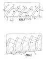
- FIG. 5is a perspective view of the scattering flanges shown in FIG. 2 ;
- FIG. 6is a partial perspective bottom view of the waveguide of FIG. 2 ;
- FIG. 7is a diagram showing light-rays traced through the waveguide
- FIGS. 8 and 9are schematic diagrams illustrating reflectance and scattering from one of the scattering flanges shown in FIG. 2 ;
- FIG. 10is a two-dimensional (2-D) depiction of the performance characteristics of three different types of waveguides
- FIG. 11is a three-dimensional (3-D) depiction of the performance characteristics of one of the waveguides of FIG. 8 ;
- FIG. 12is a three-dimensional (3-D) depiction of the performance characteristics of another one of the waveguides of FIG. 8 .
- a waveguide(or light pipe or light-guide) is described below.
- the waveguidemay be a molded or an extruded body having multiple cuts along one side to reflect and/or scatter light through the body to exit on an opposing side. More particularly, the waveguide may scatter a substantial portion or even a majority of the light backwardly or in a direction opposite its initial propagation (i.e., back toward a source connected to the waveguide).
- waveguides having backward-scatter characteristicsmay be configured to illuminate predetermined, desired patterns or provide more uniform illumination (e.g., along the length of the waveguide).
- FIG. 1illustrates an exemplary environment.
- a front view of a vehicle 10is shown having several waveguides 12 —one waveguide is shown above a front windshield and two more waveguides are shown, one on each side mirror assembly.
- Waveguidesmay have a number automotive applications—e.g., in a vehicle interior and/or on a vehicle's exterior.
- the figuresillustrate an automotive implementation; however, it will be appreciated that embodiments are not limited to an automotive environment or automotive applications.
- waveguides 12may be used in commercial and residential buildings or other architectural implementations, just to name a few other examples. And skilled artisans will appreciate additional implementations as well.
- FIG. 2illustrates a schematic view of a waveguide assembly 20 ; i.e., a light engine 22 coupled to the waveguide 12 .
- the light enginemay comprise a light source 24 and a driver circuit 26 coupled to the source which may be electrically coupled to a power source 28 .
- the driver circuitmay include a processor 30 , memory 32 , or both and may be configured to illuminate the waveguide 12 , as will be explained in greater detail below.
- the waveguide 12is shown having a longitudinally extending body 36 (along a z-axis).
- the body 36may be solid or hollow; however, in at least one implementation, the body of the waveguide is solid.
- the body 36may be comprised of any suitable material including acrylic, polycarbonate (PC), and various transparent plastics, just to name a few examples.
- a longitudinal side 38(oriented as the bottom side in FIGS. 2 and 3 ) may have a reflective coating or layer 40 for directing rays out of an opposing side 42 . And in other implementations, side 38 does not have layer 40 .
- the opposing side 42is flat or smooth; e.g., in one implementation, side 42 is parallel with the z-axis. In other implementations of the opposing side, side 42 is convex, concave, or has another suitable shape.
- the waveguide 12may have multiple scattering or reflecting flanges or fingers 50 on the longitudinal side 38 of the body 36 .
- the fingers 50may reflect and/or scatter light outwardly of the waveguide body 36 .
- a portion 52 of the longitudinal side 38may not have flanges (e.g., nearer a proximate end 54 of the body, nearer a distal end 56 , or at other regions therebetween); however, this is merely an example.
- the scattering flanges 50may be flat or curved, extending both radially and axially toward the proximate end 54 .
- each flange 50may have a similar angle of inclination ( ⁇ ), have a similar linear length (f linear ), a similar axial length (f length ), a similar radial width (f width ), and a similar radial depth (f depth ) (see FIGS. 2-4 ).
- the angle of inclination ( ⁇ )may be measured at a tangent along the curvature—as will be explained more below—in FIG.
- the radial depth (f depth )may be a portion of an overall diameter (d) of the body 36 .
- the radial depth (f depth )is less than or equal to a third of the diameter (d).
- the radial depth (f depth )is less than or equal to one-half of the diameter (d).
- flanges having greater radial depth (f depth )may provide greater flexibility to the waveguide body 36 and that radial depths in excess of one half the diameter (d) may make the body unsuitably brittle.
- the radial depth (f depth ) of the flangesare one parameter that affect light distribution; therefore, depending on other factors (e.g., angle of inclination ( ⁇ ), shape of the waveguide body 36 , etc.), it may be desirable to have deeper or shallower radial depths.
- Scattering flanges 50may have a first surface or side 60 (e.g., shown as a convex side) facing the proximate end 54 and a second surface or side 62 (e.g., shown as a concave side) facing the distal end 56 (see FIGS. 2, 3, 5, and 6 ).
- the sides 60 , 62may be defined by a peripheral edge 64 having a generally curved shape (e.g., having a vertex or apex 66 coincident with the longitudinal side 38 ).
- the curved shapemay be parabolic and may be common to all of the flanges 50 .
- the longitudinal side 38(defined by the peripheral edge 64 ) is illustrated and described with respect to a parabolic embodiment; however, other suitable shapes may be used as well including other curved-, flat-, or angular-shapes.
- first side 60is concave and the second side 62 is convex.
- one of the first or second sides 60 , 62has either a concave or a convex shape, while the other of the sides 60 , 62 has a different shape (e.g., is flat, angled, or has some other feature). These are merely examples; other implementations are also possible.
- Each of the scattering flanges 50may be spaced from one another by a notch or gap 70 (see FIGS. 2, 3, 5, and 6 ).
- the notches 70may define the shape of the adjacent flange(s) 50 ; in addition, in at least one embodiment, the notches 70 extend radially inwardly from the (lower) longitudinal side 38 and axially away from the proximate end 54 of the waveguide body 36 . In the implementation described above, each of the notches 70 have a similar axial length (n length ) ( FIG. 3 ).
- the axial length (n length ) of the notches 70is substantially constant along the linear length of the notch (i.e., the side 62 of one flange is spaced evenly from the side 60 of a neighboring flange—e.g., regardless of whether the flanges 50 are straight or curved).
- the spacing defining the notch 70 between the concave side 60 of the one flangeis not spaced evenly from the convex side 62 of the neighboring flange as well. Regardless, the spacing defining the notches may or may not be uniform for a particular waveguide embodiment.
- the waveguide 12may be manufactured by any suitable process (e.g., molding, extrusion, etc.). However, according in at least one implementation, the body 36 of the waveguide is formed by an extrusion process.
- the reflective layer 40(if applied) may be applied post-extrusion (e.g., by dipping or spraying the body 36 ). Or in some instances, the reflective layer 40 may be formed using a co-extrusion process where both the transparent materials and reflective materials are extruded simultaneously together.
- the shape of an extrusion toolmay define the curved or parabolic shape of the longitudinal side 38 .
- the notches 70may be cut into the longitudinal side 38 forming or defining the shape of the scattering flanges 50 and defining the axial lengths (f length ) and notch lengths (n length ) therebetween.
- the notches 70are cut using a laser and the axial length (n length ) of the notches is defined by the width of the laser.
- the waveguide 12may be formed in a mold—the mold having features to define the shape and size of the flanges 50 .
- the diameter (d) of the body 36may be between 25-100 millimeters (mm); and in at least one embodiment, the diameter (d) may be approximately 3.0-10.0 mm.
- the radial depth (f depth ) of the flanges 50may be between 8.3-33 mm; and in at least one embodiment, the radial depth (f depth ) may be approximately 0.3-5.0 mm.
- the axial length (n length ) of the notches 70may be 0.1-1.0 mm; and in least one embodiment, the axial length (n length ) is approximately 0.2 mm.
- the angle of inclination ( ⁇ )may be between 20 and 70 degrees) (°).
- the waveguidealso exist.
- two or more of the scattering flanges 50may have differing axial lengths (f length ). Described differently, the notches 70 between the flanges 50 may not be uniformly distributed along the length of the waveguide 12 .
- the frequency of the notches(e.g., for a given length of the waveguide body) may provide more or less scattered light according to a predetermined or desired pattern. For example, in at least one embodiment, a more uniform light distribution is provided along the length of the waveguide 12 where the frequency of the notches 70 gradually or progressively increases from the proximate end 54 to the distal end 56 .
- a non-uniform light distribution patternmay be provided by clustering multiple notches 70 closer to one another along the waveguide length (e.g., occurring a higher frequency for at least a portion of the length) and by spacing at least some notches 70 farther from one another along a different portion of the waveguide length.
- Another embodimentmay provide predetermined light distribution patterns or uniformity as well by differing the radial depth (f depth ) of the scattering flanges 50 . Consequently, this also differs the linear length (f linear ) of the flanges.
- a uniform distributionmay be provided by gradually or progressively providing deeper cuts from the proximate end 54 to the distal end 56 (e.g., shallower cuts at the proximate end 54 and deeper cuts at the distal end 56 ) while providing scattering flanges 50 of similar axial lengths (f length ); i.e., a uniform notch arrangement.
- a non-uniform distributionmay be provided having uniform notch distribution by clustering along the length of the waveguide some of the notches 70 having generally deeper cuts and clustering some of the notches having generally shallower cuts.
- the notchesmay be differently spaced from one another to provide a uniform light distribution from the waveguide where a single light source (e.g., 24 ) is located at the proximate end 54 .
- This uniform distributionaccounts for an exponential loss of light intensity by a predetermined amount at each flange 50 (e.g., approximately 5%).
- the spacing of the notches 70may be defined by a relationship between the axial length (f length ) of 1 f each consecutive flange 50 and an ordinal number (n 1 , n 2 , n 3 , . . .
- the axial length (f length ) of the fourth flange 50would equal e ⁇ ( ⁇ n 4 * ⁇ ).
- the a waveguide of any length having any number of flanges 50 and notches 70may be provided that produces a uniform light distribution.
- the axial lengths (f length ) of at least some of the flanges 50 and the radial depths (f depth ) of at least some of the flanges 50both may be varied to produce a multitude of different patterns and light distributions.
- An example of a desirable illumination patternmay include patterns required on some commercial vehicles (such as vehicle 10 ). For example, on vehicles having a width greater than 80 inches, five lamps may be required according to government regulation—e.g., three identification lamps nearer the centerline of the vehicle 10 over the windshield and two clearance lamps spaced from the three lamps nearer the driver and passenger side doors. An example of such an arrangement is shown in FIG. 1 . Between the five lamps, regions of lesser illumination may exist to add decorative or aesthetic qualities. This arrangement may be implemented using a single light engine and a single waveguide (such as engine 22 and waveguide 12 ). The scattering flanges 50 of the waveguide 12 may be configured to adequately scatter more light in the five regions corresponding to the government regulated lamps. In addition, the scattering flanges may be configured so that the aesthetic regions therebetween have a generally uniform appearance. Of course, this is merely an example. Other arrangements are also possible.
- the cross-sectional shape of the waveguidemay differ.
- FIG. 4illustrates a circular cross-sectional shape; however, other shapes including an oval, a mushroom, etc. are possible.
- the powered light engine 22may provide light to the waveguide 12 via the light source 24 .
- the lightmay be received via the proximate end 54 of the waveguide body 36 initially propagating in the direction of the distal end 56 .
- the light rays 78may reflect off of inner surface(s) 80 of the waveguide or off of outer surface(s) 82 of the waveguide (see e.g., FIG. 7 ). Some of these light rays 78 may exit the waveguide (e.g.
- a light ray 78may reflect off of a portion of the inner surface 80 that is coincident with the flange surface 62 and then be directed radially outwardly through the (upper) longitudinal side 42 .
- the reflected light ray 78may scatter at the surface 80 —diverging as it exits waveguide side 42 .
- the flange surface 62Based on the angle of inclination ( ⁇ ) of the flange surface 62 , more of the light rays striking the surface 80 may be reflected in the rearward direction (toward the proximate end 54 ) than in the forward direction (toward the distal end 56 ).
- the scattering (or back scattering) effect of the light rays 78 as they reflect off of the surface 80may further contribute the majority of the light rays 78 being directed towards the proximate end 54 .
- the curvature of the flanges 50may be configured to scatter the light rays 78 to provide a desirable uniformity or pattern.
- FIG. 7illustrates ten light-rays transmitted into the proximate end 54 of the waveguide 12 as modeled using a ray-tracing software (e.g., SPEOSTM).
- the light-rays 78are traced to demonstrate that the configuration of the scattering flanges 50 results in more than 50% of the light rays 78 being reflected and/or scattered in a rearward direction; i.e., in a direction opposite the direction of initial propagation. More specifically, six of the ten rays 78 are directed at least partially toward the proximate end 54 , and the remaining four rays are directed at least partially toward the distal end 56 . Skilled artisans will appreciate that more light rays may pass through the waveguide 12 , and that only ten rays are shown to illustrate the waveguide performance.
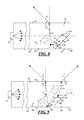
- FIGS. 8 and 9illustrate reflectance and/or scattering from one of the scattering flanges 50 .
- the primary difference between FIGS. 8 and 9is that FIG. 8 illustrates the notch 70 between the flanges 50 as being straight, whereas FIG. 9 illustrates the notch 70 between the flanges 50 as being curved.
- the angle of inclination ( ⁇ ) in FIG. 8may be constant between a distal region 90 of the flange and a proximate region 92 thereof.
- FIG. 9shows a curved flange 50
- the angle of inclination ( ⁇ )changes with the curvature of the flange between the distal and proximate regions 90 , 92 .
- the angle of inclination ( ⁇ )is the angle formed by a tangent to the curvature of side 62 and the z-axis.
- light ray(s)are shown reflecting off the inner surface 80 of the flange 50 and being ultimately directed outwardly of the waveguide body 36 (at the longitudinal side 42 ).
- FIGS. 8 and 9also show a number of angles: an angle A (comprised of angles A 1 and A 2 ), an angle B, and an exit angle psi ( ⁇ ), as well as the afore-mentioned angle of inclination ( ⁇ ).
- Exit angle psi ( ⁇ )is an angle measured relative to a normal of longitudinal side 42 , and according to one embodiment, angle psi ( ⁇ ) or a range of angles psi ( ⁇ ) may be selectable based on the value(s) of inclination ⁇ .
- ⁇sin ⁇ 1 [x*sin(90 ⁇ 2* ⁇ )], where x is the index of refraction associated with the body 36 of the waveguide 12 and air is the second medium (and where ⁇ , ⁇ , and 90 have units of degrees).
- the desired range of values of psi ( ⁇ )can be determined by determining the value(s) of inclination ( ⁇ ), where the desired range will coincide with a desired spread or distribution of light from the longitudinal side 42 .
- light reflecting off of the inner surface 80 exiting the body 36may also diverge or scatter.
- the contribution of this scattering effectmay further contribute to the majority of the light being directed in the rearwardly direction.
- FIGS. 10-12illustrate the performance of one embodiment of the waveguide 12 described herein.
- FIG. 10shows a performance comparison chart made using test devices: waveguide# 1 , waveguide# 2 , and waveguide# 3 .
- the independent axisshows the directivity of reflections and/or scattering of propagated light in the waveguide 12 (e.g., in the rearward and forward directions) (i.e., spanning from ⁇ 50° to +50°, where 0° is a direction normal to the longitudinal side 42 ).
- the dependent axisillustrates the relative intensity or magnitude of illuminance (lux).
- Waveguide# 1was a waveguide having a rough or uneven surface on the (lower) longitudinal side 38 of the body 36 to scatter light; this rough surface did not include flanges.
- Waveguide# 2had flanges 50 as described above that were flat or straight. And waveguide# 3 had flanges 50 that were curved (e.g., having convex and concave sides 60 , 62 as described above). According to the chart data and relatively speaking, waveguide# 1 exhibits no appreciable scattering in the rearward direction; moreover, scattering in the forward and rearward directions is substantially less than that of waveguide# 2 and # 3 . Waveguide# 2 exhibits significant scattering at two peaks: at approximately ⁇ 16° (the rearward direction) and +12° (the forward direction). And waveguide# 3 peaks in the rearward direction at approximately ⁇ 5° having the largest peak of the three test devices.
- FIGS. 11 and 12illustrate some of the same subject matter shown in FIG. 10 ; however, in FIGS. 11 and 12 , the data is presented in a three-dimensional (3-D) format (the relative magnitudes measured in Candela (cd); e.g., 0-1 cd, 1-2 cd, . . . , 5-6 cd).
- FIG. 11illustrates the two peaks at ⁇ 16° and +12° which are described above.
- FIG. 12illustrates the single peak at approximately ⁇ 5°.
- FIGS. 10-12illustrate rearward reflections and/or scattering with waveguides having flanges 50 .
- curved flangessuch as those shown in FIGS. 2, 3, and 6 provide the greatest illuminance in the rearward direction.
- the waveguidehas multiple flanges on one longitudinal side that may be flat or curved.
- the dimensions and orientation of the flangesmay be suitably configured to reflect and/or scatter a substantial amount of light projected into the waveguide by the light engine in a backwards direction; i.e., in a direction opposite of its initial propagation.
- the flangesmay preconfigured to provide regions of uniform light distribution or any suitable light distribution pattern.
- the terms “for example,” “for instance,” “such as,” and “like,” and the verbs “comprising,” “having,” “including,” and their other verb forms, when used in conjunction with a listing of one or more components or other items,are each to be construed as open-ended, meaning that the listing is not to be considered as excluding other, additional components or items.
- Other termsare to be construed using their broadest reasonable meaning unless they are used in a context that requires a different interpretation.
Landscapes
- Physics & Mathematics (AREA)
- Engineering & Computer Science (AREA)
- General Physics & Mathematics (AREA)
- Optics & Photonics (AREA)
- Mechanical Engineering (AREA)
- Manufacturing & Machinery (AREA)
- Planar Illumination Modules (AREA)
- Light Guides In General And Applications Therefor (AREA)
- Non-Portable Lighting Devices Or Systems Thereof (AREA)
Abstract
Description
Claims (10)
Priority Applications (7)
| Application Number | Priority Date | Filing Date | Title |
|---|---|---|---|
| US14/495,867US10330845B2 (en) | 2014-09-24 | 2014-09-24 | Waveguide for controlled light distribution |
| KR1020177009802AKR20170069220A (en) | 2014-09-24 | 2015-09-24 | Waveguide for controlled light distribution |
| PCT/US2015/051925WO2016049305A1 (en) | 2014-09-24 | 2015-09-24 | Waveguide for controlled light distribution |
| CN201580051772.0ACN107003469A (en) | 2014-09-24 | 2015-09-24 | Waveguide for controllable light distribution |
| JP2017516320AJP2017528892A (en) | 2014-09-24 | 2015-09-24 | Controlled light distribution waveguide |
| BR112017006022ABR112017006022A2 (en) | 2014-09-24 | 2015-09-24 | waveguide, and waveguide set. |
| EP15845009.8AEP3198314A4 (en) | 2014-09-24 | 2015-09-24 | Waveguide for controlled light distribution |
Applications Claiming Priority (1)
| Application Number | Priority Date | Filing Date | Title |
|---|---|---|---|
| US14/495,867US10330845B2 (en) | 2014-09-24 | 2014-09-24 | Waveguide for controlled light distribution |
Publications (2)
| Publication Number | Publication Date |
|---|---|
| US20160085017A1 US20160085017A1 (en) | 2016-03-24 |
| US10330845B2true US10330845B2 (en) | 2019-06-25 |
Family
ID=55525600
Family Applications (1)
| Application Number | Title | Priority Date | Filing Date |
|---|---|---|---|
| US14/495,867ActiveUS10330845B2 (en) | 2014-09-24 | 2014-09-24 | Waveguide for controlled light distribution |
Country Status (7)
| Country | Link |
|---|---|
| US (1) | US10330845B2 (en) |
| EP (1) | EP3198314A4 (en) |
| JP (1) | JP2017528892A (en) |
| KR (1) | KR20170069220A (en) |
| CN (1) | CN107003469A (en) |
| BR (1) | BR112017006022A2 (en) |
| WO (1) | WO2016049305A1 (en) |
Families Citing this family (6)
| Publication number | Priority date | Publication date | Assignee | Title |
|---|---|---|---|---|
| NL2013931B1 (en)* | 2014-12-05 | 2016-10-11 | Spgprints B V | Method for manufacturing a printing bar unit for a printing system, and a printing bar unit. |
| WO2019003087A1 (en)* | 2017-06-27 | 2019-01-03 | 3M Innovative Properties Company | Unitary lightguide |
| CZ2017398A3 (en) | 2017-07-10 | 2019-01-23 | Varroc Lighting Systems, s.r.o. | Optical system for lighting equipment, in particular for a signal lamp for motor vehicles |
| CN108328725B (en)* | 2018-01-15 | 2021-06-04 | 同济大学 | A photobiological sewage treatment system with waveguide enhanced light transmission |
| EP3550205A1 (en)* | 2018-04-04 | 2019-10-09 | ZKW Group GmbH | Light conductor for a motor vehicle light module |
| JP7539475B2 (en)* | 2020-01-20 | 2024-08-23 | レイア、インコーポレイテッド | Micro-slit scattering element based backlight, multi-view display and method for providing light exclusion zones - Patents.com |
Citations (28)
| Publication number | Priority date | Publication date | Assignee | Title |
|---|---|---|---|---|
| US5432876A (en)* | 1992-10-19 | 1995-07-11 | Minnesota Mining And Manufacturing Company | Illumination devices and optical fibres for use therein |
| US5664862A (en) | 1994-11-29 | 1997-09-09 | Precision Lamp, Inc. | Edge light for panel display |
| US6021007A (en) | 1997-10-18 | 2000-02-01 | Murtha; R. Michael | Side-collecting lightguide |
| US6095673A (en) | 1998-01-20 | 2000-08-01 | The Whitaker Corporation | Co-extruded light pipe |
| US6152569A (en) | 1998-02-20 | 2000-11-28 | Stanley Electric Co., Ltd. | Flat light source device for illumination use |
| US6259854B1 (en) | 1997-05-29 | 2001-07-10 | Kuraray Co., Ltd. | Lightguide |
| US20010019487A1 (en)* | 1999-12-17 | 2001-09-06 | Kabushiki Kaisha Toshiba | Light guide, line illumination apparatus, and image acquisition system |
| US20010019479A1 (en) | 1997-05-13 | 2001-09-06 | Koki Nakabayashi | Illuminating system |
| US20030137617A1 (en) | 2000-01-14 | 2003-07-24 | Cornelissen Hugo Johan | Display device |
| US6667782B1 (en) | 1999-10-08 | 2003-12-23 | International Business Machines Corporation | Light guide apparatus, a backlight apparatus and a liquid crystal display apparatus |
| US20050210643A1 (en) | 2002-10-04 | 2005-09-29 | Lumitex, Inc. | Transparent light emitting members and method of manufacture |
| US20060245718A1 (en) | 1992-03-23 | 2006-11-02 | 3M Innovative Properties Company | Luminaire device |
| US20070248307A1 (en) | 2002-10-04 | 2007-10-25 | Page David J | Transparent light emitting members and method of manufacture |
| US7437050B2 (en) | 2004-06-11 | 2008-10-14 | Valeo Vision | Lighting and/or signalling device with optical guide for a motor vehicle |
| US20080310187A1 (en)* | 2006-06-28 | 2008-12-18 | Yujing Technology Co., Ltd. | Light guide device for vehicle lamps |
| US20090128735A1 (en)* | 2007-11-19 | 2009-05-21 | Honeywell International, Inc. | Backlight systems for liquid crystal displays |
| US20100157619A1 (en)* | 2008-12-18 | 2010-06-24 | Jeyachandrabose Chinniah | Light pipe with uniformly lit appearance |
| US20100202153A1 (en)* | 2009-02-11 | 2010-08-12 | Gm Global Technology Operations, Inc. | Light guide for vehicle lamp assembly |
| WO2010090992A1 (en) | 2009-02-09 | 2010-08-12 | Johnson Controls Technology Company | Light guide with irregularities on the outer- or side-surface to improve light emission |
| US8029175B2 (en) | 2008-05-22 | 2011-10-04 | Koito Manufacturing Co., Ltd. | Vehicle lighting apparatus |
| US20120019942A1 (en)* | 2007-05-01 | 2012-01-26 | Morgan Solar Inc. | Light-Guide Solar Panel and Method of Fabrication Thereof |
| US20120162281A1 (en)* | 2010-12-27 | 2012-06-28 | Samsung Electronics Co., Ltd. | Light guide plate, backlight unit and display apparatus including the same and manufacturing method thereof |
| US8328403B1 (en) | 2012-03-21 | 2012-12-11 | Morgan Solar Inc. | Light guide illumination devices |
| US8449161B2 (en) | 2010-03-22 | 2013-05-28 | Ford Global Technologies, Llc | Luminous decorative vehicle trim insert |
| US8467013B2 (en) | 2007-11-26 | 2013-06-18 | Iti Scotland Limited | Light guides |
| US20140023319A1 (en)* | 2012-07-20 | 2014-01-23 | Panasonic Corporation | Transparent diffuser for lighting and methods of manufacturing transparent diffuser |
| US20140063839A1 (en)* | 2012-08-31 | 2014-03-06 | Idd Aerospace Corporation | Side emitting optical apparatus and method for possible use in an aircraft |
| US20140140091A1 (en)* | 2012-11-20 | 2014-05-22 | Sergiy Victorovich Vasylyev | Waveguide illumination system |
Family Cites Families (2)
| Publication number | Priority date | Publication date | Assignee | Title |
|---|---|---|---|---|
| EP0961901A1 (en)* | 1996-01-19 | 1999-12-08 | Lumenyte International Corporation | Side lighting optical conduit |
| JP3823289B2 (en)* | 2001-09-21 | 2006-09-20 | ミネベア株式会社 | Surface lighting device |
- 2014
- 2014-09-24USUS14/495,867patent/US10330845B2/enactiveActive
- 2015
- 2015-09-24EPEP15845009.8Apatent/EP3198314A4/ennot_activeWithdrawn
- 2015-09-24CNCN201580051772.0Apatent/CN107003469A/ennot_activeWithdrawn
- 2015-09-24KRKR1020177009802Apatent/KR20170069220A/ennot_activeCeased
- 2015-09-24WOPCT/US2015/051925patent/WO2016049305A1/enactiveApplication Filing
- 2015-09-24BRBR112017006022Apatent/BR112017006022A2/ennot_activeIP Right Cessation
- 2015-09-24JPJP2017516320Apatent/JP2017528892A/enactivePending
Patent Citations (32)
| Publication number | Priority date | Publication date | Assignee | Title |
|---|---|---|---|---|
| US20060245718A1 (en) | 1992-03-23 | 2006-11-02 | 3M Innovative Properties Company | Luminaire device |
| US5432876C1 (en)* | 1992-10-19 | 2002-05-21 | Minnesota Mining & Mfg | Illumination devices and optical fibres for use therein |
| US5432876A (en)* | 1992-10-19 | 1995-07-11 | Minnesota Mining And Manufacturing Company | Illumination devices and optical fibres for use therein |
| US5664862A (en) | 1994-11-29 | 1997-09-09 | Precision Lamp, Inc. | Edge light for panel display |
| US20010019479A1 (en) | 1997-05-13 | 2001-09-06 | Koki Nakabayashi | Illuminating system |
| US6259854B1 (en) | 1997-05-29 | 2001-07-10 | Kuraray Co., Ltd. | Lightguide |
| US6021007A (en) | 1997-10-18 | 2000-02-01 | Murtha; R. Michael | Side-collecting lightguide |
| US6095673A (en) | 1998-01-20 | 2000-08-01 | The Whitaker Corporation | Co-extruded light pipe |
| US6152569A (en) | 1998-02-20 | 2000-11-28 | Stanley Electric Co., Ltd. | Flat light source device for illumination use |
| US6667782B1 (en) | 1999-10-08 | 2003-12-23 | International Business Machines Corporation | Light guide apparatus, a backlight apparatus and a liquid crystal display apparatus |
| US6867828B2 (en) | 1999-10-08 | 2005-03-15 | International Business Machines Corporation | Light guide apparatus, a backlight apparatus and a liquid crystal display apparatus |
| US20010019487A1 (en)* | 1999-12-17 | 2001-09-06 | Kabushiki Kaisha Toshiba | Light guide, line illumination apparatus, and image acquisition system |
| US20030137617A1 (en) | 2000-01-14 | 2003-07-24 | Cornelissen Hugo Johan | Display device |
| US20050210643A1 (en) | 2002-10-04 | 2005-09-29 | Lumitex, Inc. | Transparent light emitting members and method of manufacture |
| US20070248307A1 (en) | 2002-10-04 | 2007-10-25 | Page David J | Transparent light emitting members and method of manufacture |
| US7437050B2 (en) | 2004-06-11 | 2008-10-14 | Valeo Vision | Lighting and/or signalling device with optical guide for a motor vehicle |
| US20080310187A1 (en)* | 2006-06-28 | 2008-12-18 | Yujing Technology Co., Ltd. | Light guide device for vehicle lamps |
| US20120019942A1 (en)* | 2007-05-01 | 2012-01-26 | Morgan Solar Inc. | Light-Guide Solar Panel and Method of Fabrication Thereof |
| CN101715563A (en) | 2007-06-26 | 2010-05-26 | 陆明科技公司 | Transparent light emitting members and manufacture method |
| US20090128735A1 (en)* | 2007-11-19 | 2009-05-21 | Honeywell International, Inc. | Backlight systems for liquid crystal displays |
| US8467013B2 (en) | 2007-11-26 | 2013-06-18 | Iti Scotland Limited | Light guides |
| US8029175B2 (en) | 2008-05-22 | 2011-10-04 | Koito Manufacturing Co., Ltd. | Vehicle lighting apparatus |
| US20100157619A1 (en)* | 2008-12-18 | 2010-06-24 | Jeyachandrabose Chinniah | Light pipe with uniformly lit appearance |
| WO2010090992A1 (en) | 2009-02-09 | 2010-08-12 | Johnson Controls Technology Company | Light guide with irregularities on the outer- or side-surface to improve light emission |
| US20100202153A1 (en)* | 2009-02-11 | 2010-08-12 | Gm Global Technology Operations, Inc. | Light guide for vehicle lamp assembly |
| US8449161B2 (en) | 2010-03-22 | 2013-05-28 | Ford Global Technologies, Llc | Luminous decorative vehicle trim insert |
| US20120162281A1 (en)* | 2010-12-27 | 2012-06-28 | Samsung Electronics Co., Ltd. | Light guide plate, backlight unit and display apparatus including the same and manufacturing method thereof |
| US8328403B1 (en) | 2012-03-21 | 2012-12-11 | Morgan Solar Inc. | Light guide illumination devices |
| US8657479B2 (en) | 2012-03-21 | 2014-02-25 | Morgan Solar Inc. | Light guide illumination devices |
| US20140023319A1 (en)* | 2012-07-20 | 2014-01-23 | Panasonic Corporation | Transparent diffuser for lighting and methods of manufacturing transparent diffuser |
| US20140063839A1 (en)* | 2012-08-31 | 2014-03-06 | Idd Aerospace Corporation | Side emitting optical apparatus and method for possible use in an aircraft |
| US20140140091A1 (en)* | 2012-11-20 | 2014-05-22 | Sergiy Victorovich Vasylyev | Waveguide illumination system |
Non-Patent Citations (5)
| Title |
|---|
| Extended European Search report issued by the European Patent Office for application No. 15845009.8. |
| International Search Report corresponding to International application No. PCT/US2015/051925, dated Jan. 6, 2016, 5 pages. |
| Office action issued by the China National Intellectual Property Administration (CNIPA) for application 201580051772.0 dated Jan. 29, 2019. |
| Translation of the Office action issued by the China National Intellectual Property Administration (CNIPA) for application 201580051772.0. |
| Written Opinion corresponding to International application No. PCT/US2015/051925, dated Jan. 6, 2016, 5 pages. |
Also Published As
| Publication number | Publication date |
|---|---|
| JP2017528892A (en) | 2017-09-28 |
| EP3198314A4 (en) | 2018-04-25 |
| BR112017006022A2 (en) | 2018-01-30 |
| WO2016049305A1 (en) | 2016-03-31 |
| EP3198314A1 (en) | 2017-08-02 |
| CN107003469A (en) | 2017-08-01 |
| KR20170069220A (en) | 2017-06-20 |
| US20160085017A1 (en) | 2016-03-24 |
Similar Documents
| Publication | Publication Date | Title |
|---|---|---|
| US10330845B2 (en) | Waveguide for controlled light distribution | |
| US11644158B2 (en) | Optical light pipe with uniform lit intensity | |
| US9784901B2 (en) | Illumination light guide | |
| EP2002294B1 (en) | Light pipe providing wide illumination angle | |
| US10627078B2 (en) | Method and system for producing a beam of illumination having smooth edges | |
| EP2064574B1 (en) | Lighting device with a light guide and means for redirecting the light extracted from the light guide | |
| CN108006586A (en) | Lamps apparatus for vehicle | |
| WO2021173746A1 (en) | Waveguide lighting fixture providing ambient light | |
| EP3043152A1 (en) | Glow ring for instrument panel | |
| US10480745B1 (en) | Arranged light pipes for automotive lighting systems | |
| JP2017062964A (en) | Vehicular lighting fixture | |
| EP3286494B1 (en) | A device for modifying light distribution | |
| CN111886446A (en) | Optical device for changing light distribution | |
| CN113227646B (en) | Light emitting module with modeling shade | |
| KR101225394B1 (en) | Car headlamp lens | |
| CN210511507U (en) | Device for changing light distribution, illuminator system and mold | |
| TW201741592A (en) | Lens and light structure | |
| KR101612307B1 (en) | Illumination device for motor vehicle including optical fiber | |
| CN210462870U (en) | Light guide structure and lamp | |
| KR101036957B1 (en) | LED lamp | |
| KR20170059362A (en) | Illumination device for motor vehicle including optical fiber | |
| HK1250775B (en) | A device for modifying light distribution | |
| WO2017220983A1 (en) | Optical element |
Legal Events
| Date | Code | Title | Description |
|---|---|---|---|
| AS | Assignment | Owner name:FEDERAL-MOGUL CORPORATION, MICHIGAN Free format text:ASSIGNMENT OF ASSIGNORS INTEREST;ASSIGNORS:IRGANG, TODD;KOWALCHIK, STEPHEN;DOMINICK, JOHN;REEL/FRAME:033935/0322 Effective date:20140926 | |
| AS | Assignment | Owner name:FEDERAL-MOGUL LLC, MICHIGAN Free format text:CHANGE OF NAME;ASSIGNOR:FEDERAL-MOGUL CORPORATION;REEL/FRAME:042107/0565 Effective date:20170213 Owner name:FEDERAL-MOGUL LLC, MICHIGAN Free format text:CONVERSION OF FEDERAL-MOGUL CORPORATION, A DELAWARE CORPORATION, TO FEDERAL-MOGUL LLC, A DELAWARE LIMITED LIABILITY COMPANY;ASSIGNOR:FEDERAL-MOGUL CORPORATION;REEL/FRAME:042107/0929 Effective date:20170213 | |
| AS | Assignment | Owner name:CITIBANK, N.A., AS COLLATERAL TRUSTEE, NEW YORK Free format text:GRANT OF SECURITY INTEREST IN UNITED STATES PATENTS;ASSIGNORS:FEDERAL-MOGUL LLC;FEDERAL-MOGUL PRODUCTS, INC.;FEDERAL-MOGUL MOTORPARTS CORPORATION;AND OTHERS;REEL/FRAME:042963/0662 Effective date:20170330 | |
| AS | Assignment | Owner name:CITIBANK, N.A., AS COLLATERAL TRUSTEE, NEW YORK Free format text:GRANT OF SECURITY INTEREST IN UNITED STATES PATENTS;ASSIGNORS:FEDERAL-MOGUL LLC;FEDERAL-MOGUL PRODUCTS, INC.;FEDERAL-MOGUL MOTORPARTS LLC;AND OTHERS;REEL/FRAME:044013/0419 Effective date:20170629 | |
| AS | Assignment | Owner name:FEDERAL-MOGUL WORLD WIDE LLC (F/K/A/ FEDERAL-MOGUL WORLD WIDE, INC.), MICHIGAN Free format text:RELEASE BY SECURED PARTY;ASSIGNOR:CITIBANK, N.A., AS COLLATERAL TRUSTEE AND AGENT;REEL/FRAME:044721/0032 Effective date:20171204 Owner name:FEDERAL-MOGUL MOTORPARTS LLC (F/K/A/ FEDERAL-MOGUL MOTORPARTS CORPORATION), MICHIGAN Free format text:RELEASE BY SECURED PARTY;ASSIGNOR:CITIBANK, N.A., AS COLLATERAL TRUSTEE AND AGENT;REEL/FRAME:044721/0032 Effective date:20171204 Owner name:FEDERAL-MOGUL CHASSIS LLC, MICHIGAN Free format text:RELEASE BY SECURED PARTY;ASSIGNOR:CITIBANK, N.A., AS COLLATERAL TRUSTEE AND AGENT;REEL/FRAME:044721/0032 Effective date:20171204 Owner name:FEDERAL-MOGUL PRODUCTS, INC., MICHIGAN Free format text:RELEASE BY SECURED PARTY;ASSIGNOR:CITIBANK, N.A., AS COLLATERAL TRUSTEE AND AGENT;REEL/FRAME:044721/0032 Effective date:20171204 Owner name:FEDERAL-MOGUL IGNITION COMPANY, MICHIGAN Free format text:RELEASE BY SECURED PARTY;ASSIGNOR:CITIBANK, N.A., AS COLLATERAL TRUSTEE AND AGENT;REEL/FRAME:044721/0032 Effective date:20171204 Owner name:FEDERAL-MOGUL POWERTRAIN LLC, MICHIGAN Free format text:RELEASE BY SECURED PARTY;ASSIGNOR:CITIBANK, N.A., AS COLLATERAL TRUSTEE AND AGENT;REEL/FRAME:044721/0032 Effective date:20171204 Owner name:FEDERAL-MOGUL MOTORPARTS LLC (F/K/A/ FEDERAL-MOGUL Free format text:RELEASE BY SECURED PARTY;ASSIGNOR:CITIBANK, N.A., AS COLLATERAL TRUSTEE AND AGENT;REEL/FRAME:044721/0032 Effective date:20171204 Owner name:FEDERAL-MOGUL CORPORATION, MICHIGAN Free format text:RELEASE BY SECURED PARTY;ASSIGNOR:CITIBANK, N.A., AS COLLATERAL TRUSTEE AND AGENT;REEL/FRAME:044721/0032 Effective date:20171204 Owner name:FEDERAL-MOGUL, LLC, MICHIGAN Free format text:RELEASE BY SECURED PARTY;ASSIGNOR:CITIBANK, N.A., AS COLLATERAL TRUSTEE AND AGENT;REEL/FRAME:044721/0032 Effective date:20171204 Owner name:FEDERAL-MOGUL WORLD WIDE LLC (F/K/A/ FEDERAL-MOGUL Free format text:RELEASE BY SECURED PARTY;ASSIGNOR:CITIBANK, N.A., AS COLLATERAL TRUSTEE AND AGENT;REEL/FRAME:044721/0032 Effective date:20171204 Owner name:FEDERAL-MOGUL POWERTRAIN, INC., MICHIGAN Free format text:RELEASE BY SECURED PARTY;ASSIGNOR:CITIBANK, N.A., AS COLLATERAL TRUSTEE AND AGENT;REEL/FRAME:044721/0032 Effective date:20171204 | |
| AS | Assignment | Owner name:REBO LIGHTING & ELECTRONICS, LLC, MICHIGAN Free format text:ASSIGNMENT OF ASSIGNORS INTEREST;ASSIGNOR:FEDERAL-MOGUL LLC;REEL/FRAME:045551/0781 Effective date:20171204 | |
| STPP | Information on status: patent application and granting procedure in general | Free format text:PUBLICATIONS -- ISSUE FEE PAYMENT VERIFIED | |
| STCF | Information on status: patent grant | Free format text:PATENTED CASE | |
| CC | Certificate of correction | ||
| AS | Assignment | Owner name:DRIV AUTOMOTIVE INC., ILLINOIS Free format text:RELEASE BY SECURED PARTY;ASSIGNOR:WILMINGTON TRUST, NATIONAL ASSOCIATION;REEL/FRAME:058392/0274 Effective date:20210317 Owner name:FEDERAL-MOGUL POWERTRAIN LLC, MICHIGAN Free format text:RELEASE BY SECURED PARTY;ASSIGNOR:WILMINGTON TRUST, NATIONAL ASSOCIATION;REEL/FRAME:058392/0274 Effective date:20210317 Owner name:FEDERAL-MOGUL CHASSIS LLC, MICHIGAN Free format text:RELEASE BY SECURED PARTY;ASSIGNOR:WILMINGTON TRUST, NATIONAL ASSOCIATION;REEL/FRAME:058392/0274 Effective date:20210317 Owner name:TENNECO INC., AS SUCCESSOR TO FEDERAL-MOGUL LLC, ILLINOIS Free format text:RELEASE BY SECURED PARTY;ASSIGNOR:WILMINGTON TRUST, NATIONAL ASSOCIATION;REEL/FRAME:058392/0274 Effective date:20210317 Owner name:FEDERAL-MOGUL IGNITION, LLC, AS SUCCESSOR TO FEDERAL-MOGUL IGNITION COMPANY, MICHIGAN Free format text:RELEASE BY SECURED PARTY;ASSIGNOR:WILMINGTON TRUST, NATIONAL ASSOCIATION;REEL/FRAME:058392/0274 Effective date:20210317 Owner name:FEDERAL-MOGUL MOTORPARTS LLC, AS SUCCESSOR TO FEDERAL-MOGUL MOTORPARTS CORPORATION, MICHIGAN Free format text:RELEASE BY SECURED PARTY;ASSIGNOR:WILMINGTON TRUST, NATIONAL ASSOCIATION;REEL/FRAME:058392/0274 Effective date:20210317 Owner name:FEDERAL-MOGUL WORLD WIDE, INC., AS SUCCESSOR TO FEDERAL-MOGUL WORLD WIDE LLC, MICHIGAN Free format text:RELEASE BY SECURED PARTY;ASSIGNOR:WILMINGTON TRUST, NATIONAL ASSOCIATION;REEL/FRAME:058392/0274 Effective date:20210317 Owner name:FEDERAL-MOGUL PRODUCTS US, LLC, AS SUCCESSOR TO FEDERAL-MOGUL PRODUCTS, INC., MICHIGAN Free format text:RELEASE BY SECURED PARTY;ASSIGNOR:WILMINGTON TRUST, NATIONAL ASSOCIATION;REEL/FRAME:058392/0274 Effective date:20210317 Owner name:FEDERAL-MOGUL PRODUCTS US, LLC, AS SUCCESSOR TO FEDERAL-MOGUL PRODUCTS, INC., MICHIGAN Free format text:RELEASE BY SECURED PARTY;ASSIGNOR:WILMINGTON TRUST, NATIONAL ASSOCIATION;REEL/FRAME:056886/0455 Effective date:20210317 Owner name:FEDERAL-MOGUL WORLD WIDE, INC., AS SUCCESSOR TO FEDERAL-MOGUL WORLD WIDE LLC, MICHIGAN Free format text:RELEASE BY SECURED PARTY;ASSIGNOR:WILMINGTON TRUST, NATIONAL ASSOCIATION;REEL/FRAME:056886/0455 Effective date:20210317 Owner name:FEDERAL-MOGUL MOTORPARTS LLC, AS SUCCESSOR TO FEDERAL-MOGUL MOTORPARTS CORPORATION, MICHIGAN Free format text:RELEASE BY SECURED PARTY;ASSIGNOR:WILMINGTON TRUST, NATIONAL ASSOCIATION;REEL/FRAME:056886/0455 Effective date:20210317 Owner name:FEDERAL-MOGUL IGNITION, LLC, AS SUCCESSOR TO FEDERAL-MOGUL IGNITION COMPANY, MICHIGAN Free format text:RELEASE BY SECURED PARTY;ASSIGNOR:WILMINGTON TRUST, NATIONAL ASSOCIATION;REEL/FRAME:056886/0455 Effective date:20210317 Owner name:TENNECO INC., AS SUCCESSOR TO FEDERAL-MOGUL LLC, ILLINOIS Free format text:RELEASE BY SECURED PARTY;ASSIGNOR:WILMINGTON TRUST, NATIONAL ASSOCIATION;REEL/FRAME:056886/0455 Effective date:20210317 Owner name:FEDERAL-MOGUL CHASSIS LLC, MICHIGAN Free format text:RELEASE BY SECURED PARTY;ASSIGNOR:WILMINGTON TRUST, NATIONAL ASSOCIATION;REEL/FRAME:056886/0455 Effective date:20210317 Owner name:FEDERAL-MOGUL POWERTRAIN LLC, MICHIGAN Free format text:RELEASE BY SECURED PARTY;ASSIGNOR:WILMINGTON TRUST, NATIONAL ASSOCIATION;REEL/FRAME:056886/0455 Effective date:20210317 Owner name:DRIV AUTOMOTIVE INC., ILLINOIS Free format text:RELEASE BY SECURED PARTY;ASSIGNOR:WILMINGTON TRUST, NATIONAL ASSOCIATION;REEL/FRAME:056886/0455 Effective date:20210317 | |
| MAFP | Maintenance fee payment | Free format text:PAYMENT OF MAINTENANCE FEE, 4TH YEAR, LARGE ENTITY (ORIGINAL EVENT CODE: M1551); ENTITY STATUS OF PATENT OWNER: LARGE ENTITY Year of fee payment:4 |