US10329946B2 - Sliding gear actuation for variable vanes - Google Patents
Sliding gear actuation for variable vanesDownload PDFInfo
- Publication number
- US10329946B2 US10329946B2US15/079,454US201615079454AUS10329946B2US 10329946 B2US10329946 B2US 10329946B2US 201615079454 AUS201615079454 AUS 201615079454AUS 10329946 B2US10329946 B2US 10329946B2
- Authority
- US
- United States
- Prior art keywords
- drive
- gear
- unison ring
- geared
- actuator
- Prior art date
- Legal status (The legal status is an assumption and is not a legal conclusion. Google has not performed a legal analysis and makes no representation as to the accuracy of the status listed.)
- Active, expires
Links
Images


Classifications
- F—MECHANICAL ENGINEERING; LIGHTING; HEATING; WEAPONS; BLASTING
- F01—MACHINES OR ENGINES IN GENERAL; ENGINE PLANTS IN GENERAL; STEAM ENGINES
- F01D—NON-POSITIVE DISPLACEMENT MACHINES OR ENGINES, e.g. STEAM TURBINES
- F01D17/00—Regulating or controlling by varying flow
- F01D17/10—Final actuators
- F01D17/12—Final actuators arranged in stator parts
- F01D17/14—Final actuators arranged in stator parts varying effective cross-sectional area of nozzles or guide conduits
- F01D17/16—Final actuators arranged in stator parts varying effective cross-sectional area of nozzles or guide conduits by means of nozzle vanes
- F01D17/162—Final actuators arranged in stator parts varying effective cross-sectional area of nozzles or guide conduits by means of nozzle vanes for axial flow, i.e. the vanes turning around axes which are essentially perpendicular to the rotor centre line
- F—MECHANICAL ENGINEERING; LIGHTING; HEATING; WEAPONS; BLASTING
- F01—MACHINES OR ENGINES IN GENERAL; ENGINE PLANTS IN GENERAL; STEAM ENGINES
- F01D—NON-POSITIVE DISPLACEMENT MACHINES OR ENGINES, e.g. STEAM TURBINES
- F01D17/00—Regulating or controlling by varying flow
- F01D17/10—Final actuators
- F01D17/12—Final actuators arranged in stator parts
- F—MECHANICAL ENGINEERING; LIGHTING; HEATING; WEAPONS; BLASTING
- F01—MACHINES OR ENGINES IN GENERAL; ENGINE PLANTS IN GENERAL; STEAM ENGINES
- F01D—NON-POSITIVE DISPLACEMENT MACHINES OR ENGINES, e.g. STEAM TURBINES
- F01D25/00—Component parts, details, or accessories, not provided for in, or of interest apart from, other groups
- F01D25/34—Turning or inching gear
- F—MECHANICAL ENGINEERING; LIGHTING; HEATING; WEAPONS; BLASTING
- F01—MACHINES OR ENGINES IN GENERAL; ENGINE PLANTS IN GENERAL; STEAM ENGINES
- F01D—NON-POSITIVE DISPLACEMENT MACHINES OR ENGINES, e.g. STEAM TURBINES
- F01D9/00—Stators
- F01D9/02—Nozzles; Nozzle boxes; Stator blades; Guide conduits, e.g. individual nozzles
- F01D9/04—Nozzles; Nozzle boxes; Stator blades; Guide conduits, e.g. individual nozzles forming ring or sector
- F01D9/042—Nozzles; Nozzle boxes; Stator blades; Guide conduits, e.g. individual nozzles forming ring or sector fixing blades to stators
- F—MECHANICAL ENGINEERING; LIGHTING; HEATING; WEAPONS; BLASTING
- F02—COMBUSTION ENGINES; HOT-GAS OR COMBUSTION-PRODUCT ENGINE PLANTS
- F02K—JET-PROPULSION PLANTS
- F02K3/00—Plants including a gas turbine driving a compressor or a ducted fan
- F02K3/02—Plants including a gas turbine driving a compressor or a ducted fan in which part of the working fluid by-passes the turbine and combustion chamber
- F02K3/04—Plants including a gas turbine driving a compressor or a ducted fan in which part of the working fluid by-passes the turbine and combustion chamber the plant including ducted fans, i.e. fans with high volume, low pressure outputs, for augmenting the jet thrust, e.g. of double-flow type
- F02K3/06—Plants including a gas turbine driving a compressor or a ducted fan in which part of the working fluid by-passes the turbine and combustion chamber the plant including ducted fans, i.e. fans with high volume, low pressure outputs, for augmenting the jet thrust, e.g. of double-flow type with front fan
- F—MECHANICAL ENGINEERING; LIGHTING; HEATING; WEAPONS; BLASTING
- F04—POSITIVE - DISPLACEMENT MACHINES FOR LIQUIDS; PUMPS FOR LIQUIDS OR ELASTIC FLUIDS
- F04D—NON-POSITIVE-DISPLACEMENT PUMPS
- F04D29/00—Details, component parts, or accessories
- F04D29/40—Casings; Connections of working fluid
- F04D29/52—Casings; Connections of working fluid for axial pumps
- F04D29/54—Fluid-guiding means, e.g. diffusers
- F04D29/56—Fluid-guiding means, e.g. diffusers adjustable
- F04D29/563—Fluid-guiding means, e.g. diffusers adjustable specially adapted for elastic fluid pumps
- F—MECHANICAL ENGINEERING; LIGHTING; HEATING; WEAPONS; BLASTING
- F05—INDEXING SCHEMES RELATING TO ENGINES OR PUMPS IN VARIOUS SUBCLASSES OF CLASSES F01-F04
- F05D—INDEXING SCHEME FOR ASPECTS RELATING TO NON-POSITIVE-DISPLACEMENT MACHINES OR ENGINES, GAS-TURBINES OR JET-PROPULSION PLANTS
- F05D2220/00—Application
- F05D2220/30—Application in turbines
- F05D2220/32—Application in turbines in gas turbines
- F05D2220/323—Application in turbines in gas turbines for aircraft propulsion, e.g. jet engines
- F—MECHANICAL ENGINEERING; LIGHTING; HEATING; WEAPONS; BLASTING
- F05—INDEXING SCHEMES RELATING TO ENGINES OR PUMPS IN VARIOUS SUBCLASSES OF CLASSES F01-F04
- F05D—INDEXING SCHEME FOR ASPECTS RELATING TO NON-POSITIVE-DISPLACEMENT MACHINES OR ENGINES, GAS-TURBINES OR JET-PROPULSION PLANTS
- F05D2240/00—Components
- F05D2240/10—Stators
- F05D2240/12—Fluid guiding means, e.g. vanes
- F—MECHANICAL ENGINEERING; LIGHTING; HEATING; WEAPONS; BLASTING
- F05—INDEXING SCHEMES RELATING TO ENGINES OR PUMPS IN VARIOUS SUBCLASSES OF CLASSES F01-F04
- F05D—INDEXING SCHEME FOR ASPECTS RELATING TO NON-POSITIVE-DISPLACEMENT MACHINES OR ENGINES, GAS-TURBINES OR JET-PROPULSION PLANTS
- F05D2260/00—Function
- F05D2260/40—Transmission of power
- Y—GENERAL TAGGING OF NEW TECHNOLOGICAL DEVELOPMENTS; GENERAL TAGGING OF CROSS-SECTIONAL TECHNOLOGIES SPANNING OVER SEVERAL SECTIONS OF THE IPC; TECHNICAL SUBJECTS COVERED BY FORMER USPC CROSS-REFERENCE ART COLLECTIONS [XRACs] AND DIGESTS
- Y02—TECHNOLOGIES OR APPLICATIONS FOR MITIGATION OR ADAPTATION AGAINST CLIMATE CHANGE
- Y02T—CLIMATE CHANGE MITIGATION TECHNOLOGIES RELATED TO TRANSPORTATION
- Y02T50/00—Aeronautics or air transport
- Y02T50/60—Efficient propulsion technologies, e.g. for aircraft
Definitions
- the present disclosurerelates to a gas turbine engine and, more particularly, to a variable vane system therefor.
- Gas turbine enginessuch as those that power modern commercial and military aircraft, generally include a compressor section to pressurize airflow, a combustor section to burn a hydrocarbon fuel in the presence of the pressurized air, and a turbine section to extract energy from the resultant combustion gases.
- variable vanesthat can be pivoted about their individual axes to change an operational performance characteristic.
- the variable vanesare robustly designed to handle the stress loads that are applied to change the position of the vanes.
- a mechanical linkageis typically utilized to rotate the variable vanes. Because forces on the variable vanes can be relatively significant, forces transmitted through the mechanical linkage can also be relatively significant.
- Legacy compressor designstypically utilize fueldraulic actuation to rotate the variable vanes.
- a variable vane systemcan include an actuator; a harmonic drive driven by the actuator; a drive gear driven by the harmonic drive; and a geared unison ring driven by the drive gear, the geared unison ring axially slidable with respect to the drive gear.
- a further embodiment of the present disclosuremay include wherein the geared unison ring includes a gear segment meshed with the drive gear.
- a further embodiment of the present disclosuremay include wherein the drive gear is wider than the gear segment.
- a further embodiment of the present disclosuremay include a support that rotationally supports drive gear.
- a further embodiment of the present disclosuremay include wherein the harmonic drive includes a strain wave gearing mechanism.
- a further embodiment of the present disclosuremay include wherein the strain wave gearing mechanism include a fixed circular spline, a flex spline attached to an output shaft, and a wave generator attached to an input shaft, the flex spline driven by the wave generator with respect to the circular spline.
- a further embodiment of the present disclosuremay include wherein the first actuator gear includes a drive arm.
- a further embodiment of the present disclosuremay include wherein the drive arm is connected to a first unison ring.
- a further embodiment of the present disclosuremay include a link between each of a multiple of variable vanes and the first unison ring.
- a further embodiment of the present disclosuremay include wherein the second actuator gear includes a second drive arm.
- a further embodiment of the present disclosuremay include wherein the second drive arm is connected to a second unison ring.
- a further embodiment of the present disclosuremay include wherein the harmonic drive provides between a 30:1-320:1 gear ratio.
- a further embodiment of the present disclosuremay include wherein the first gear segment and the second gear segment are each less than 180 degrees.
- a further embodiment of the present disclosuremay include wherein the multi-planar drive gear is operable to rotate through about 90 degrees.
- a further embodiment of the present disclosuremay include wherein the actuator is an electric motor.
- a gas turbine enginecan include a harmonic drive operable to drive a variable vane system through a geared connection, the geared connection including a multi-planar drive gear driven by the harmonic drive.
- a further embodiment of the present disclosuremay include wherein the multi-planar drive gear includes a first set of gear teeth in a first plane and a second set of gear teeth in a second plane.
- a further embodiment of the present disclosuremay include, wherein the geared connection includes at least one idler gear.
- a further embodiment of the present disclosuremay include wherein the at least one idler gear is rotationally mounted to a case of the gas turbine engine.
- a further embodiment of the present disclosuremay include wherein the geared connection includes at least one drive gear directly mounted to a variable vane.
- FIG. 1is a schematic cross-section of an example gas turbine engine architecture
- FIG. 2is a perspective view of a variable vane system for a gas turbine engine
- FIG. 3is a partial perspective view of one stage of a variable vane system for a gas turbine engine
- FIG. 4is a schematic view of a variable vane system for a gas turbine engine according to one disclosed non-limiting embodiment
- FIG. 5is a perspective view of a variable vane system for a gas turbine engine
- FIG. 6is a schematic view of harmonic drive system
- FIG. 7is an expanded perspective view of a variable vane system for a gas turbine engine according to one disclosed non-limiting embodiment
- FIG. 8is a side view of the variable vane system of FIG. 7 ;
- FIG. 9is a side view of a variable vane system for a gas turbine engine according to one disclosed non-limiting embodiment
- FIG. 10is an expanded perspective view of the variable vane system of FIG. 9 ;
- FIG. 11Ais a perspective view of a variable vane system for a gas turbine engine according to one disclosed non-limiting embodiment
- FIG. 11Bis an expanded sectional view of the unison ring of FIG. 11A ;
- FIG. 12is a schematic view of a variable vane system for a gas turbine engine according to one disclosed non-limiting embodiment
- FIG. 13is a expanded partial sectional view of a variable vane system for a gas turbine engine according to one disclosed non-limiting embodiment
- FIG. 14is a schematic view of a variable vane system for a gas turbine engine according to one disclosed non-limiting embodiment
- FIG. 15is a schematic view of a variable vane system for a gas turbine engine according to one disclosed non-limiting embodiment
- FIG. 16is a schematic view of a variable vane system for a gas turbine engine according to one disclosed non-limiting embodiment
- FIG. 17is a schematic view of the variable vane system of FIG. 16 in a first position
- FIG. 18is a schematic view of the variable vane system of FIG. 16 in a second position
- FIG. 19is a schematic view of a variable vane system for a gas turbine engine according to one disclosed non-limiting embodiment
- FIG. 20is a schematic view of a variable vane system for a gas turbine engine according to one disclosed non-limiting embodiment
- FIG. 21is a schematic view of a variable vane system for a gas turbine engine according to one disclosed non-limiting embodiment
- FIG. 22is a schematic view of a variable vane system for a gas turbine engine according to one disclosed non-limiting embodiment
- FIG. 23is a schematic view of a variable vane system for a gas turbine engine according to one disclosed non-limiting embodiment
- FIG. 24is a schematic view of a variable vane system for a gas turbine engine according to one disclosed non-limiting embodiment
- FIG. 25is a plan view of a link for use in the system of FIG. 24 ;
- FIG. 26is a schematic view of the variable vane system of FIG. 24 in a first position
- FIG. 27is a schematic view of the variable vane system of FIG. 24 in a second position
- FIG. 28is a sectional view of the link of FIG. 25 ;
- FIG. 29is a sectional view of a unison ring for a variable vane system for a gas turbine engine according to one disclosed non-limiting embodiment
- FIG. 30is a schematic view of a variable vane system for a gas turbine engine according to one disclosed non-limiting embodiment
- FIG. 31is a perspective view of a variable vane system for a gas turbine engine according to one disclosed non-limiting embodiment
- FIG. 32is a sectional view of the variable vane system of FIG. 31 ;
- FIG. 33is a perspective view of a variable vane system for a gas turbine engine according to one disclosed non-limiting embodiment
- FIG. 34is a perspective view of a variable vane system for a gas turbine engine according to one disclosed non-limiting embodiment
- FIG. 35is a perspective view of a variable vane system for a gas turbine engine according to one disclosed non-limiting embodiment
- FIG. 36is a perspective view of a variable vane system for a gas turbine engine according to one disclosed non-limiting embodiment
- FIG. 37is a perspective view of a variable vane system for a gas turbine engine according to one disclosed non-limiting embodiment
- FIG. 38is a sectional view of a variable vane system for a gas turbine engine according to one disclosed non-limiting embodiment.
- FIG. 39is a perspective view of a variable vane system for a gas turbine engine according to one disclosed non-limiting embodiment
- FIG. 1schematically illustrates a gas turbine engine 20 .
- the gas turbine engine 20is disclosed herein as a two-spool GTF (geared turbofan) that generally incorporates a fan section 22 , a compressor section 24 , a combustor section 26 and a turbine section 28 .
- Alternative engine architecturesmight include an augmenter section and exhaust duct section (not shown) among other systems or features.
- the fan section 22drives air along a bypass flowpath while the compressor section 24 drives air along a core flowpath for compression and communication into the combustor section 26 then expansion thru the turbine section 28 .
- an intermediate spoolincludes an intermediate pressure compressor (“IPC”) between a Low Pressure Compressor (“LPC”) and a High Pressure Compressor (“HPC”), and an intermediate pressure turbine (“IPT”) between the high pressure turbine (“HPT”) and the Low pressure Turbine (“LPT”).
- IPCintermediate pressure compressor
- LPCLow Pressure Compressor
- HPCHigh Pressure Compressor
- IPTintermediate pressure turbine
- the engine 20generally includes a low spool 30 and a high spool 32 mounted for rotation about an engine central longitudinal axis A relative to an engine static structure 36 via several bearing compartments 38 .
- the low spool 30generally includes an inner shaft 40 that interconnects a fan 42 , a low pressure compressor 44 (“LPC”) and a low pressure turbine 46 (“LPT”).
- the inner shaft 40drives the fan 42 directly or thru a geared architecture 48 to drive the fan 42 at a lower speed than the low spool 30 .
- An exemplary reduction transmissionis an epicyclic transmission, namely a planetary or star gear system.
- the high spool 32includes an outer shaft 50 that interconnects a high pressure compressor 52 (“HPC”) and high pressure turbine 54 (“HPT”).
- a combustor 56is arranged between the HPC 52 and the HPT 54 .
- the inner shaft 40 and the outer shaft 50are concentric and rotate about the engine central longitudinal axis A which is collinear with their longitudinal axes.
- Core airflowis compressed by the LPC 44 then the HPC 52 , mixed with fuel and burned in the combustor 56 , then expanded over the HPT 54 and the LPT 46 .
- the turbines 54 , 46rotationally drive the respective low spool 30 and high spool 32 in response to the expansion.
- the main engine shafts 40 , 50are supported at a plurality of points by the bearing compartments 38 . It should be understood that various bearing compartments 38 at various locations may alternatively or additionally be provided.
- the gas turbine engine 20is a high-bypass geared aircraft engine with a bypass ratio greater than about six (6:1).
- the geared architecture 48can include an epicyclic gear train, such as a planetary gear system or other gear system.
- the example epicyclic gear trainhas a gear reduction ratio of greater than about 2.3:1, and in another example is greater than about 3.0:1.
- the geared turbofanenables operation of the low spool 30 at higher speeds which can increase the operational efficiency of the LPC 44 and LPT 46 to render increased pressure in a relatively few number of stages.
- a pressure ratio associated with the LPT 46is pressure measured prior to the inlet of the LPT 46 as related to the pressure at the outlet of the LPT 46 prior to an exhaust nozzle of the gas turbine engine 20 .
- the bypass ratio of the gas turbine engine 20is greater than about ten (10:1)
- the fan diameteris significantly larger than that of the LPC 44
- the LPT 46has a pressure ratio that is greater than about five (5:1). It should be understood, however, that the above parameters are only exemplary of one embodiment of a geared architecture engine and that the present disclosure is applicable to other gas turbine engines including direct drive turbofans, where the rotational speed of the fan 42 is the same (1:1) of the LPC 44 .
- a significant amount of thrustis provided by the bypass flow path due to the high bypass ratio.
- the fan section 22 of the gas turbine engine 20is designed for a particular flight condition—typically cruise at about 0.8 Mach and about 35,000 feet (10668 meters). This flight condition, with the gas turbine engine 20 at its best fuel consumption, is also known as bucket cruise Thrust Specific Fuel Consumption (TSFC).
- TSFCThrust Specific Fuel Consumption
- Fan Pressure Ratiois the pressure ratio across a blade of the fan section 22 without the use of a Fan Exit Guide Vane system.
- the relatively low Fan Pressure Ratio according to one example gas turbine engine 20is less than 1.45.
- Low Corrected Fan Tip Speedis the actual fan tip speed divided by an industry standard temperature correction of (“T”/518.7) 0.5 in which “T” represents the ambient temperature in degrees Rankine.
- the Low Corrected Fan Tip Speed according to one example gas turbine engine 20is less than about 1150 fps (351 m/s).
- one or more stages of the LPC 44 and/or the HPC 52include a variable vane system 100 that can be rotated to change an operational performance characteristic of the gas turbine engine 20 for different operating conditions.
- the variable vane system 100may include one or more variable vane stages.
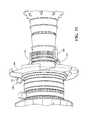
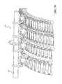
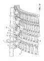
- the variable vane system 100may include a plurality of variable vanes 102 circumferentially arranged around the engine central axis A.
- the variable vanes 102each include a variable vane body that has an airfoil portion that provides a lift force via Bernoulli's principle such that one side of the airfoil portion generally operates as a suction side and the opposing side of the airfoil portion generally operates as a pressure side.
- Each of the variable vanes 102generally spans between an inner diameter and an outer diameter relative to the engine central axis A.
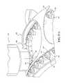
- each of the variable vanes 102includes an inner pivot pin 104 that is receivable into a corresponding socket (not shown) and an outer trunion 106 mounted through an outer case 108 such that each of the variable vanes 102 can pivot about a vane axis V.
- the outer trunion 106is defined along the vane axis V ( FIG. 3 ).
- variable vane system 100further includes a unison ring 110 to which, in one disclosed non-limiting embodiment, each of the outer trunions 106 are attached through a drive arm 112 along a respective axis D. It should be appreciated that although a particular drive arm 112 is disclosed in this embodiment, various linkages of various geometries may be utilized.
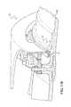
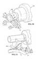
- variable vane system 100is driven by an actuator system 118 with an actuator 120 , a harmonic drive 122 and an actuator arm 124 .
- actuator system 118may be utilized for each stage ( FIG. 5 ), multiple actuator systems 118 may be provided on a single stage ( FIG. 5 ) to facilitate additional stability for each singe unison ring 110 .
- the actuator 120may include an electric motor or other electric powered device.
- the actuator 120is defined along an axis B.
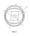
- the harmonic drive 122includes a strain wave gearing mechanism 130 that, in one example, may provide a 30:1-320:1 gear ratio in a compact package that significantly reduces the rotation and increases the torque provided by the actuator 120 .
- the strain wave gearing mechanism 130generally includes a fixed circular spline 132 , a flex spline 134 attached to an output shaft 136 along an axis B, and a wave generator 138 attached to an input shaft 141 which is connected to the actuator 120 along axis B ( FIG. 6 ).
- the harmonic drive 122essentially provides no backlash, compactness and light weight, high gear ratios, reconfigurable ratios within a standard housing, good resolution and excellent repeatability when repositioning inertial loads, high torque capability, and coaxial input and output shafts.
- the harmonic drive 122thereby prevents back driving by the relatively high aerodynamic forces experienced by the variable vanes 102 .
- the harmonic drive 122need only rotate the drive arm 124 through about 90 degrees and, in a more specific embodiment, only about 0-40 degrees to drive rotation of the unison ring 110 , thence the individual variable vanes 102 through the respective drive arms 112 . That is, the actuator arm 124 rotates the unison ring 110 that, in turn, rotates the drive arms 112 along their respective axis B to rotate the trunions 106 , and thus the variable vanes 102 about axis V.
- the actuator system 118 Aincludes a geared connection 140 between the harmonic drive 122 and a drive gear 142 that is meshed with an actuator gear 144 mounted to a trunion 106 of a variable vane 102 .
- the actuator gear 144may be a gear segment of about ninety degrees.
- variable vanes 102are attached to the unison ring 110 though respective links 146 .
- the geared connection 140provides for an offset to accommodate insufficient space for a direct connection attached concentric to the axis of a variable vane, such as the first LPC variable vane stage that is typically adjacent to a structural wall 148 such as a firewall ( FIG. 8 ).
- the actuator system 118 Cincludes an axial geared connection 150 such that the actuator system 118 C is generally axial with the engine axis A for installations with limited vertical packaging space.
- the geared connection 150includes a drive gear 152 that is meshed with an actuator gear 154 mounted to a trunion 106 in a generally perpendicular arrangement ( FIG. 10 ).
- the geared connection 150can be angled relative to the vane actuator via a bevel gear.
- the actuator system 118 Dincludes an extended geared unison ring 160 that spans at least a first variable vane stage 162 with a vane gear 164 for each first stage variable vane trunion 106 and a second variable vane stage 166 with a vane gear 168 for each second stage variable vane trunion 106 .
- the extended geared unison ring 160includes an associated first gear rack 170 and a second gear rack 172 that interface with the respective vane gears 164 , 168 . This minimizes or eliminates axial motion of the extended geared unison ring 160 .
- the geared connection 180includes a drive gear 182 that is meshed with an actuator gear 184 on the extended geared unison ring 160 .
- the actuator gear 184need be only a relatively short gear rack segment.
- the extended geared unison ring 160includes an interface 174 with the outer case 108 .
- the outer case 108may include a flange 176 to restrain axial movement of the extended geared unison ring 160 .
- Low friction devices 178such as bumpers of low friction material, rollers, or other devices may be alternatively, or additionally, provided.
- the actuator system 118 Dmay utilize a geared unison ring 190 to drive a first variable vane stage 192 with a vane gear 194 mounted to each first stage variable vane trunion 106 .
- a flange 176or flange segments, may axially restrain the geared unison ring 160 on the outer case 108 to stabilize the geared unison ring 160 and avoid hysteresis ( FIG. 13 ).
- the actuator system 118 Emay utilize a multi-planar gear 200 .
- the multi-planar gear 200includes a first set of gear teeth 202 in a first plane 204 and a second set of gear teeth 206 in a second plane 208 .
- the first plane 204 and the second plane 208are offset such that the first set of gear teeth 202 are in mesh with a first drive gear 210 for a drive variable vane 102 in a first stage 212 and the second set of gear teeth 206 in mesh with a second drive gear 214 for a drive variable vane 102 in a second stage 216 .
- the first drive gear 210 and the second drive gear 214may be arranged at different heights to interface with the multi-planar gear 200 . Since actuation requires only partial rotation, symmetry of the multi-planar gear 200 is not necessary.
- the gear ratiocan be adjusted to provide different vane rotations per stage.
- the first drive gear 210 and the second drive gear 214also include a drive arm 218 , 220 to rotate a respective unison ring 222 , 224 .
- the driven variable vanes 102are connected their respective unison ring 222 , 224 by a respective linkage 226 , 228 for each variable vane 102 .
- the actuator system 118 Emay include a multiple of idler gears 230 , 231 that interconnect drive gears 232 , 234 , 236 of each of a multiple of stages 238 , 240 , 242 .
- Each of the multiple of idler gears 230may be mounted to static structure (not shown) through a shaft 241 , 243 , 245 such that the multiple of idler gears 230 may be positioned above the variable vane structure.
- the idler gears 230may be mounted directly to a variable vane to direct drive a driving vane.
- a multi-planar gear 232may be driven by a drive shaft 241 driven by a remote actuator.
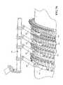
- the actuator system 118 Fmay utilize a geared unison ring 260 .
- the geared unison ring 260locates a gear 262 on an outer diameter of the geared unison ring 260 .
- Rotation of the geared unison ring 260 by the actuator system 118 Fdrives the individual variable vanes 102 through the respective drive arms 205 .
- the actuator system 118 Fis generally axial with the engine axis A for installations with limited vertical packaging space.
- the actuator system 118 Fdrives a drive gear 264 that is wider than the gear 262 as the rotation of the unison ring 260 results in a relatively small amount of axial motion ( FIGS. 17 and 18 ). This will require a small amount of sliding between gear teeth of the gears 262 , 264 , but the rotation required to actuate the variable vanes is relatively small, typically, only a few degrees, and the actuation is slow, so a small amount of sliding may be acceptable.
- the drive gear 264may be an extended shaft with a multiple of gear segments 268 , 270 to drive a respective multiple of unison rings 272 , 274 .
- the actuator system 118 Gmay utilize a cable drive system 280 .
- the cable drive system 280includes a drum 282 , or alternatively, a drum segment 282 A ( FIG. 21 ) with a groove 284 within which a cable 286 is at least partially received.
- the groove 284defines a contoured path to guide the cable 286 ( FIG. 22, 23 ).
- the cable 286defines a path that is contoured to avoid slack in the cable 286 .
- a tension-loading devicemay be used.
- the cable 286is connected to the unison ring 288 such that cable 286 will always remain tangential to the unison ring 288 .
- the actuator system 118 Hmay utilize a multiple of drive arms 300 which actuate the individual variable vanes 102 .
- Each of the multiple of drive arms 300includes a slot 302 that permits single point actuation ( FIG. 25 ).
- Each slot 302 for each drive arm 300receives a respective pin 304 that extends from the unison ring 306 .
- the axial motionis absorbed ( FIGS. 26 and 27 ) in the slots 302 of the individual links, so that the unison ring 306 is effectively stabilized, even with single point actuation.
- Each respective pin 304 that extends from the unison ring 306 and/or slot 302may be tapered to permit rotation of the unison ring 306 with minimal play ( FIG. 28 ).
- the unison ring 306has a “U” shaped cross section that provides significant stiffness while being light in weight.
- the unison ring 306is supported on the engine case by a multiple of supports 308 that are arranged around the engine case.
- the support 308may be generally cross-shaped to support a multiple of rollers 310 .
- each roller 310interacts with an upper surface 312 , a forward surface 314 , and an aft surface 316 of the unison ring 306 .
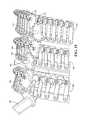
- a single drive shaft 320may include multiple drive gears 322 , 324 , 326 meshed with respective gear racks 328 , 330 , 332 of the associated unison rings 334 , 336 , 338 of each variable vane stage.
- the gear racks 328 , 330 , 332are axially offset on the unison ring 334 , 336 , 338 to provide an extremely low profile.
- the actuator 120 and the harmonic drive 122are remotely located on one side of a firewall 350 with a drive shaft 352 from the harmonic drive 122 that extends therethrough to drive a HPC variable vane system 361 which is in a higher temperate environment.
- the extended drive shaft 352permits the actuator 120 and the harmonic drive 122 to be located in a desirable environment.
- the extended drive shaft 352may mesh with the single drive shaft 320 to drive a multiple of variable vane stages ( FIG. 32 ).
- an actuator system 118 Iincludes a drive shaft 360 operable to control multiple stages of variable vanes (four shown).
- a vane drive bevel gear 370may drive a unison ring 372 , and thus all the variable vanes 102 ( FIG. 3 ) in a direct manner.
- an additional actuation arm 380may extend from the vane drive bevel gear 382 to provide the same linkage motion to the unison ring 384 as the actuation arms on the variable vanes, but is aligned to the bevel gear 382 .
- the unison ring 384may include a bridge 386 which bridges a subset of a multiple of variable vane drive arms 388 . That is, the bridge 386 is mounted to the unison ring 384 to which the multiple of variable vane drive arms 388 are attached.
- the actuation arm 380since not tied directly to a variable vane, is mounted to static structure 390 .
- a drive shaft 400 and gears 402may be enclosed in a gear box 404 that is mounted to an engine case 406 .
- the drive shaft 400has a single input 408 and a multiple of outputs 410 , 412 , 414 , 416 .
- the gearbox 404may house all the necessary supports and bearings and may be mounted directly to the engine case 406 such as a HPC case.
- the gearbox 404also provides a static structure from which to rotationally mount the variable vane actuation arms 420 , 422 that are not tied directly to a variable vane 418 , 424 .
- the variable vane actuation arms 420 , 422may be mounted to a bridge 424 , 426 that is mounted to the respective unison ring 428 , 430 .
- a drive shaft 440drives a multiple of links 442 (four shown) which drive a bridge 450 - 456 to respective unison ring.
- links 442 - 448are shown as linear, the links may alternatively be curved to conform the curvature of the case to provide a more compact package.
- the bridge 450 - 456may be mounted to a side of the respective unison ring to provide a more compact mechanism.
- a drive shaft 460drives a multiple of links 462 (four shown) which drive a bridge 464 to respective unison ring 466 .
- the links 462are driven to provide a linear relationship between the vane rotation angles across all the stages. That is, as the first stage vane angle changes, each of the other stages will change based on a fixed ratio off the first.
- a non-linear relationshipmay be provided for optimal performance.
- the non-linear relationshipmay be optimized as, for each stage, there are 5 variables available: 2 initial angles (D, E) and three lengths (F, G, H). These variables may be specifically tailored to provide a resultant output from the drive shaft 460 that differs for each stage (four shown).
- an actuator system 118 Jmay include a first actuator 480 , a first harmonic drive 482 , a first drive shaft 484 , a second actuator 486 , a second harmonic drive 488 , and a second drive shaft 490 .
- the actuators 480 , 486 and the harmonic drives 482 , 488may be located on a side of firewall 500 , that provides a thermally controlled environment. In one example, the thermally controlled environment is about 160 F.
- the first drive shaft 484 and the second drive shaft 490are coaxial and pass through the firewall 500 into a higher temperature environment of, for example, 200 F-600 F.
- first drive shaft 484 and the second drive shaft 490are independently actuated to respectively control a variable vane stage 502 , 504 .
- the first drive shaft 484 and the second drive shaft 490are operable to drive respective gears 506 , 508 in a siding gear arrangement as described above to drive respective unison rings 510 , 512 ( FIGS. 17, 18 ).
- the respective distal end 520 , 522 of the first drive shaft 484 and the second drive shaft 490may be supported by a support bracket 530 mounted to the engine case.
- the actuator system 118 Jpermits variable vane stages to be actuated independently from a remote distance to provide thermal isolation behind a firewall, or because the motors must be relocated due to limited packaging space.
Landscapes
- Engineering & Computer Science (AREA)
- Mechanical Engineering (AREA)
- General Engineering & Computer Science (AREA)
- Chemical & Material Sciences (AREA)
- Combustion & Propulsion (AREA)
- Control Of Turbines (AREA)
- Supercharger (AREA)
- Retarders (AREA)
Abstract
Description
Claims (12)
Priority Applications (2)
| Application Number | Priority Date | Filing Date | Title |
|---|---|---|---|
| US15/079,454US10329946B2 (en) | 2016-03-24 | 2016-03-24 | Sliding gear actuation for variable vanes |
| EP17162817.5AEP3228823B1 (en) | 2016-03-24 | 2017-03-24 | Sliding gear actuation for variable vanes |
Applications Claiming Priority (1)
| Application Number | Priority Date | Filing Date | Title |
|---|---|---|---|
| US15/079,454US10329946B2 (en) | 2016-03-24 | 2016-03-24 | Sliding gear actuation for variable vanes |
Publications (2)
| Publication Number | Publication Date |
|---|---|
| US20170276015A1 US20170276015A1 (en) | 2017-09-28 |
| US10329946B2true US10329946B2 (en) | 2019-06-25 |
Family
ID=58413001
Family Applications (1)
| Application Number | Title | Priority Date | Filing Date |
|---|---|---|---|
| US15/079,454Active2037-09-09US10329946B2 (en) | 2016-03-24 | 2016-03-24 | Sliding gear actuation for variable vanes |
Country Status (2)
| Country | Link |
|---|---|
| US (1) | US10329946B2 (en) |
| EP (1) | EP3228823B1 (en) |
Families Citing this family (12)
| Publication number | Priority date | Publication date | Assignee | Title |
|---|---|---|---|---|
| US10301962B2 (en) | 2016-03-24 | 2019-05-28 | United Technologies Corporation | Harmonic drive for shaft driving multiple stages of vanes via gears |
| US10458271B2 (en) | 2016-03-24 | 2019-10-29 | United Technologies Corporation | Cable drive system for variable vane operation |
| US10443431B2 (en) | 2016-03-24 | 2019-10-15 | United Technologies Corporation | Idler gear connection for multi-stage variable vane actuation |
| US10107130B2 (en) | 2016-03-24 | 2018-10-23 | United Technologies Corporation | Concentric shafts for remote independent variable vane actuation |
| US10443430B2 (en) | 2016-03-24 | 2019-10-15 | United Technologies Corporation | Variable vane actuation with rotating ring and sliding links |
| US10294813B2 (en) | 2016-03-24 | 2019-05-21 | United Technologies Corporation | Geared unison ring for variable vane actuation |
| US10288087B2 (en) | 2016-03-24 | 2019-05-14 | United Technologies Corporation | Off-axis electric actuation for variable vanes |
| US10415596B2 (en) | 2016-03-24 | 2019-09-17 | United Technologies Corporation | Electric actuation for variable vanes |
| US10329947B2 (en) | 2016-03-24 | 2019-06-25 | United Technologies Corporation | 35Geared unison ring for multi-stage variable vane actuation |
| US10190599B2 (en) | 2016-03-24 | 2019-01-29 | United Technologies Corporation | Drive shaft for remote variable vane actuation |
| GB202005033D0 (en)* | 2020-04-06 | 2020-05-20 | Rolls Royce Plc | Gearboxes for aircraft gas turbine engines |
| GB202005025D0 (en) | 2020-04-06 | 2020-05-20 | Rolls Royce Plc | Gearboxes for aircraft gas turbine engines |
Citations (122)
| Publication number | Priority date | Publication date | Assignee | Title |
|---|---|---|---|---|
| US2435091A (en) | 1944-11-01 | 1948-01-27 | American Blower Corp | Inlet vane control apparatus using levers |
| FR995131A (en) | 1949-07-22 | 1951-11-28 | Rateau Soc | Development of two-flow turbo-reactors |
| GB757577A (en) | 1953-10-09 | 1956-09-19 | Sulzer Ag | Axial flow turbines and compressors |
| CH319364A (en) | 1954-03-06 | 1957-02-15 | Sulzer Ag | Method for operating a gas turbine plant |
| US2923459A (en) | 1956-01-20 | 1960-02-02 | Thompson Ramo Wooldridge Inc | Vane positioning device |
| US3025036A (en)* | 1960-01-06 | 1962-03-13 | Curtiss Wright Corp | Gas turbine speed control |
| US3227176A (en) | 1962-12-31 | 1966-01-04 | Gen Electric | Windmill control system for multiengined aircraft |
| US3458118A (en) | 1967-08-21 | 1969-07-29 | Gen Electric | Low profile stator adjusting mechanism |
| US3632224A (en)* | 1970-03-02 | 1972-01-04 | Gen Electric | Adjustable-blade turbine |
| US3779665A (en) | 1972-09-22 | 1973-12-18 | Gen Electric | Combined variable angle stator and windmill control system |
| US3873230A (en) | 1974-04-10 | 1975-03-25 | United Aircraft Corp | Stator vane actuating mechanism |
| US3876334A (en) | 1974-04-08 | 1975-04-08 | United Aircraft Corp | Variable pitch rate means |
| US3893784A (en) | 1972-11-08 | 1975-07-08 | Bbc Sulzer Turbomaschinen | Apparatus for adjusting stator blades |
| US3914066A (en) | 1974-09-27 | 1975-10-21 | Gen Motors Corp | Vane actuation system |
| DE2448572A1 (en) | 1974-10-11 | 1976-04-22 | Sigma Lutin | Blade rotating mechanism - for blades mounted in a stator rim in a turbine |
| US3964839A (en) | 1974-10-21 | 1976-06-22 | United Technologies Corporation | Pitch change mechanism |
| GB1466613A (en)* | 1973-09-07 | 1977-03-09 | Nissan Motor | Guide vane control for an automobile gas turbine engine |
| US4275560A (en) | 1978-12-27 | 1981-06-30 | General Electric Company | Blocker door actuation system |
| JPS5749759B2 (en) | 1979-04-25 | 1982-10-23 | ||
| US4403912A (en) | 1981-03-23 | 1983-09-13 | Avco Corporation | Integrated multiplane actuator system for compressor variable vanes and air bleed valve |
| US4619580A (en) | 1983-09-08 | 1986-10-28 | The Boeing Company | Variable camber vane and method therefor |
| US4720237A (en) | 1986-02-24 | 1988-01-19 | United Technologies Corporation | Unison ring actuator assembly |
| GB2197912A (en) | 1986-11-28 | 1988-06-02 | United Technologies Corp | Propeller blade pitch actuation system |
| US4968217A (en) | 1989-09-06 | 1990-11-06 | Rolls-Royce Plc | Variable pitch arrangement for a gas turbine engine |
| US5096374A (en) | 1989-02-02 | 1992-03-17 | Hitachi, Ltd. | Vane controller |
| US5190439A (en) | 1991-07-15 | 1993-03-02 | United Technologies Corporation | Variable vane non-linear schedule for a gas turbine engine |
| US5549448A (en) | 1995-02-08 | 1996-08-27 | United Technolgies Corporation | Variable stator vane linkage system and method |
| GB2301868A (en) | 1995-06-05 | 1996-12-18 | Rolls Royce Plc | Actuator mechanism with emergency drive for variable angle vane arrays |
| US5595474A (en)* | 1993-11-10 | 1997-01-21 | Hispano-Suiza | Pitch variation control device for the blades of a turbomachine rotor and method of operating the device |
| US5630701A (en) | 1995-06-05 | 1997-05-20 | Rolls-Royce Plc | Variable angle vane arrays |
| EP0909880A2 (en) | 1997-10-14 | 1999-04-21 | General Electric Company | Turbine vane actuation system |
| US6398483B1 (en) | 1999-06-10 | 2002-06-04 | Snecma Moteurs | Protection device for protecting control mechanism of inlet guide-vanes of turbojet engine |
| US6769868B2 (en) | 2002-07-31 | 2004-08-03 | General Electric Company | Stator vane actuator in gas turbine engine |
| US6821084B2 (en) | 2002-12-11 | 2004-11-23 | General Electric Company | Torque tube bearing assembly |
| US20050153812A1 (en) | 2004-01-12 | 2005-07-14 | Locust, Usa, Inc. | Small-size traction drive transmission system for use in microturbine-powered aircraft |
| US7112041B2 (en) | 2003-07-10 | 2006-09-26 | Snecma Moteurs | Device for pivotally guiding variable-pitch vanes in a turbomachine |
| US7322790B2 (en) | 2005-05-17 | 2008-01-29 | Snecma | System for controlling stages of variable-pitch stator vanes in a turbomachine |
| EP1961919A2 (en) | 2007-02-21 | 2008-08-27 | United Technologies Corporation | Variable rotor blade for gas turbine engine |
| WO2008124758A1 (en) | 2007-04-10 | 2008-10-16 | Elliott Company | Centrifugal compressor having adjustable inlet guide vanes |
| US7506514B2 (en) | 2005-06-30 | 2009-03-24 | United Technologies Corporation | Augmentor fuel conduit bushing |
| US7527130B2 (en) | 2005-04-29 | 2009-05-05 | Delphi Technologies, Inc. | Harmonic drive linear actuator |
| US7578131B2 (en) | 2005-06-30 | 2009-08-25 | United Technologies Corporation | Augmentor spray bar mounting |
| US7588415B2 (en) | 2005-07-20 | 2009-09-15 | United Technologies Corporation | Synch ring variable vane synchronizing mechanism for inner diameter vane shroud |
| EP2107217A1 (en) | 2008-03-31 | 2009-10-07 | Siemens Aktiengesellschaft | Unison ring assembly for an axial compressor casing |
| US7628579B2 (en) | 2005-07-20 | 2009-12-08 | United Technologies Corporation | Gear train variable vane synchronizing mechanism for inner diameter vane shroud |
| US7647775B2 (en) | 2005-06-30 | 2010-01-19 | United Technologies Corporation | Augmentor spray bars |
| US7665959B2 (en) | 2005-07-20 | 2010-02-23 | United Technologies Corporation | Rack and pinion variable vane synchronizing mechanism for inner diameter vane shroud |
| US7690889B2 (en) | 2005-07-20 | 2010-04-06 | United Technologies Corporation | Inner diameter variable vane actuation mechanism |
| US7713022B2 (en) | 2007-03-06 | 2010-05-11 | United Technologies Operations | Small radial profile shroud for variable vane structure in a gas turbine engine |
| US7722318B2 (en) | 2007-02-13 | 2010-05-25 | United Technologies Corporation | Hole liners for repair of vane counterbore holes |
| US7753647B2 (en) | 2005-07-20 | 2010-07-13 | United Technologies Corporation | Lightweight cast inner diameter vane shroud for variable stator vanes |
| EP2211026A2 (en) | 2009-01-26 | 2010-07-28 | Rolls-Royce plc | A variable stator vane assembly in a gas turbine engine |
| US7806652B2 (en) | 2007-04-10 | 2010-10-05 | United Technologies Corporation | Turbine engine variable stator vane |
| US7854112B2 (en) | 2004-12-01 | 2010-12-21 | United Technologies Corporation | Vectoring transition duct for turbine engine |
| US7871242B2 (en) | 2007-05-31 | 2011-01-18 | United Technologies Corporation | Single actuator controlled rotational flow balance system |
| US7927067B2 (en) | 2007-05-01 | 2011-04-19 | United Technologies Corporation | System and method for controlling stator assemblies |
| US8007229B2 (en) | 2007-05-24 | 2011-08-30 | United Technologies Corporation | Variable area turbine vane arrangement |
| US8052388B2 (en) | 2007-11-29 | 2011-11-08 | United Technologies Corporation | Gas turbine engine systems involving mechanically alterable vane throat areas |
| US8061119B2 (en) | 2007-11-29 | 2011-11-22 | United Technologies Corporation | Actuation mechanism for a convertible gas turbine propulsion system |
| US8074498B2 (en) | 2009-05-18 | 2011-12-13 | United Technologies Corporation | System and method of assessing thermal energy levels of a gas turbine engine component |
| US8090456B2 (en) | 2008-11-03 | 2012-01-03 | United Technologies Corporation | System and method for design and control of engineering systems utilizing component-level dynamic mathematical model |
| US8092157B2 (en) | 2007-12-19 | 2012-01-10 | United Technologies Corporation | Variable turbine vane actuation mechanism having a bumper ring |
| US8131384B2 (en) | 2008-11-03 | 2012-03-06 | United Technologies Corporation | Design and control of engineering systems utilizing component-level dynamic mathematical model with multiple-input multiple-output estimator |
| US20120121403A1 (en) | 2009-07-20 | 2012-05-17 | Cameron International Corporation | Removable throat mounted inlet guide vane |
| US20120128481A1 (en) | 2008-11-26 | 2012-05-24 | Snecma | Anti-wear device for the blades of a turbine distributor in an aeronautical turbine engine |
| US8202043B2 (en) | 2007-10-15 | 2012-06-19 | United Technologies Corp. | Gas turbine engines and related systems involving variable vanes |
| US8204671B2 (en) | 2009-05-18 | 2012-06-19 | United Technologies Corporation | System and method of estimating gas turbine engine performance |
| US8210800B2 (en) | 2008-06-12 | 2012-07-03 | United Technologies Corporation | Integrated actuator module for gas turbine engine |
| US8215902B2 (en) | 2008-10-15 | 2012-07-10 | United Technologies Corporation | Scalable high pressure compressor variable vane actuation arm |
| US8240983B2 (en) | 2007-10-22 | 2012-08-14 | United Technologies Corp. | Gas turbine engine systems involving gear-driven variable vanes |
| US8315741B2 (en) | 2009-09-02 | 2012-11-20 | United Technologies Corporation | High fidelity integrated heat transfer and clearance in component-level dynamic turbine system control |
| US8328512B2 (en) | 2009-06-05 | 2012-12-11 | United Technologies Corporation | Inner diameter shroud assembly for variable inlet guide vane structure in a gas turbine engine |
| US8393857B2 (en) | 2009-10-09 | 2013-03-12 | Rolls-Royce Corporation | Variable vane actuation system |
| US8459614B2 (en) | 2004-08-30 | 2013-06-11 | Tt Technologies, Inc. | Dual capstan puller and method |
| US8500394B2 (en) | 2008-02-20 | 2013-08-06 | United Technologies Corporation | Single channel inner diameter shroud with lightweight inner core |
| US8511058B2 (en) | 2007-11-29 | 2013-08-20 | United Technologies Corporation | Convertible gas turbine propulsion system |
| WO2013192055A1 (en) | 2012-06-20 | 2013-12-27 | United Technologies Corporation | Four bar bracket |
| US20140064912A1 (en)* | 2012-08-29 | 2014-03-06 | General Electric Company | Systems and Methods to Control Variable Stator Vanes in Gas Turbine Engines |
| US8668434B2 (en) | 2009-09-02 | 2014-03-11 | United Technologies Corporation | Robust flow parameter model for component-level dynamic turbine system control |
| US8668444B2 (en) | 2010-09-28 | 2014-03-11 | General Electric Company | Attachment stud for a variable vane assembly of a turbine compressor |
| US8686251B1 (en) | 2012-02-15 | 2014-04-01 | Pioneer Hi Bred International Inc | Maize inbred PH1K8C |
| US8720258B2 (en) | 2012-09-28 | 2014-05-13 | United Technologies Corporation | Model based engine inlet condition estimation |
| US20140155219A1 (en) | 2012-01-31 | 2014-06-05 | United Technologies Corporation | Turbine engine gearbox |
| US20140169948A1 (en) | 2012-12-19 | 2014-06-19 | General Electric Company | System for turbomachine vane control |
| US8783119B2 (en) | 2012-09-26 | 2014-07-22 | United Technologies Corporation | Vane arm testing rig |
| US8784043B2 (en) | 2008-04-24 | 2014-07-22 | Snecma | Device for controlling variable-pitch blades in a turbomachine compressor |
| US20140314549A1 (en) | 2013-04-17 | 2014-10-23 | General Electric Company | Flow manipulating arrangement for a turbine exhaust diffuser |
| WO2014189568A2 (en) | 2013-03-13 | 2014-11-27 | United Technologies Corporation | Variable vane drive system |
| US8915703B2 (en) | 2011-07-28 | 2014-12-23 | United Technologies Corporation | Internally actuated inlet guide vane for fan section |
| US8915700B2 (en) | 2012-02-29 | 2014-12-23 | United Technologies Corporation | Gas turbine engine with fan-tied inducer section and multiple low pressure turbine sections |
| US8943796B2 (en) | 2011-06-28 | 2015-02-03 | United Technologies Corporation | Variable cycle turbine engine |
| US8961125B2 (en) | 2011-12-13 | 2015-02-24 | United Technologies Corporation | Gas turbine engine part retention |
| US20150052908A1 (en) | 2013-08-21 | 2015-02-26 | Rolls-Royce Deutschland Ltd & Co Kg | Bleed duct assembly for a gas turbine engine |
| US20150075310A1 (en) | 2013-09-16 | 2015-03-19 | Hamilton Sundstrand Corporation | Compound harmonic drive |
| US9003808B2 (en) | 2011-11-02 | 2015-04-14 | United Technologies Corporation | Turbofan with gear-driven compressor and fan-driven core |
| US20150101331A1 (en) | 2013-10-10 | 2015-04-16 | Rolls-Royce Plc | Gas turbine engine |
| US9038366B2 (en) | 2012-01-31 | 2015-05-26 | United Technologies Corporation | LPC flowpath shape with gas turbine engine shaft bearing configuration |
| US20150167481A1 (en) | 2013-12-17 | 2015-06-18 | Industrial Technology Research Institute | Inlet guide vane assembly |
| US9062560B2 (en) | 2012-03-13 | 2015-06-23 | United Technologies Corporation | Gas turbine engine variable stator vane assembly |
| US9097137B2 (en) | 2008-06-12 | 2015-08-04 | United Technologies Corporation | Integrated actuator module for gas turbine engine |
| US9103227B2 (en) | 2012-02-28 | 2015-08-11 | United Technologies Corporation | Gas turbine engine with fan-tied inducer section |
| WO2015122934A1 (en) | 2014-02-14 | 2015-08-20 | United Technologies Corporation | Integrated environmental control system manifold |
| US20150275770A1 (en) | 2014-03-27 | 2015-10-01 | Hamilton Sundstrand Corporation | Jet engine actuation system |
| US9151178B2 (en) | 2012-11-15 | 2015-10-06 | United Technologies Corporation | Bellcrank for a variable vane assembly |
| US9157366B2 (en) | 2012-05-30 | 2015-10-13 | United Technologies Corporation | Adaptive fan with cold turbine |
| US9194329B2 (en) | 2012-01-31 | 2015-11-24 | United Technologies Corporation | Gas turbine engine shaft bearing configuration |
| US20150362056A1 (en) | 2014-06-16 | 2015-12-17 | Hiwin Technologies Corp. | Harmonic drive achieving a high meshing efficiency |
| US9228438B2 (en) | 2012-12-18 | 2016-01-05 | United Technologies Corporation | Variable vane having body formed of first material and trunnion formed of second material |
| US9470153B2 (en) | 2011-10-05 | 2016-10-18 | United Technologies Corporation | Combined pump system for engine TMS AOC reduction and ECS loss elimination |
| US20170248156A1 (en) | 2014-09-12 | 2017-08-31 | General Electric Company | Axi-centrifugal compressor with variable outlet guide vanes |
| US20170276146A1 (en) | 2016-03-24 | 2017-09-28 | United Technologies Corporation | Electric actuation for variable vanes |
| US20170276017A1 (en) | 2016-03-24 | 2017-09-28 | United Technologies Corporation | 35geared unison ring for multi-stage variable vane actuation |
| US20170276014A1 (en) | 2016-03-24 | 2017-09-28 | United Technologies Corporation | Variable vane actuation with rotating ring and sliding links |
| US20170276011A1 (en) | 2016-03-24 | 2017-09-28 | United Technologies Corporation | Geared drive shaft actuation for variable vanes |
| US20170276018A1 (en) | 2016-03-24 | 2017-09-28 | United Technologies Corporation | Geared unison ring for variable vane actuation |
| US20170276016A1 (en) | 2016-03-24 | 2017-09-28 | United Technologies Corporation | Idler gear connection for multi-stage variable vane actuation |
| US20170276012A1 (en) | 2016-03-24 | 2017-09-28 | United Technologies Corporation | Cable actuation for variable vanes |
| US20170276147A1 (en) | 2016-03-24 | 2017-09-28 | United Technologies Corporation | Drive shaft for remote variable vane actuation |
| US20170276148A1 (en) | 2016-03-24 | 2017-09-28 | United Technologies Corporation | Off-axis electric actuation for variable vanes |
| US20170276013A1 (en) | 2016-03-24 | 2017-09-28 | United Technologies Corporation | Concentric shafts for remote independent variable vane actuation |
| US20180100407A1 (en) | 2015-04-15 | 2018-04-12 | Man Diesel & Turbose | Guide Vane Adjustment Device And Turbomachine |
| US20180119566A1 (en) | 2015-04-15 | 2018-05-03 | Man Diesel & Turbo Se | Guide Vane Adjusting Device And Turbomachine |
- 2016
- 2016-03-24USUS15/079,454patent/US10329946B2/enactiveActive
- 2017
- 2017-03-24EPEP17162817.5Apatent/EP3228823B1/enactiveActive
Patent Citations (142)
| Publication number | Priority date | Publication date | Assignee | Title |
|---|---|---|---|---|
| US2435091A (en) | 1944-11-01 | 1948-01-27 | American Blower Corp | Inlet vane control apparatus using levers |
| FR995131A (en) | 1949-07-22 | 1951-11-28 | Rateau Soc | Development of two-flow turbo-reactors |
| GB757577A (en) | 1953-10-09 | 1956-09-19 | Sulzer Ag | Axial flow turbines and compressors |
| US2862687A (en) | 1953-10-09 | 1958-12-02 | Sulzer Ag | Axial flow turbomachine |
| CH319364A (en) | 1954-03-06 | 1957-02-15 | Sulzer Ag | Method for operating a gas turbine plant |
| US2923459A (en) | 1956-01-20 | 1960-02-02 | Thompson Ramo Wooldridge Inc | Vane positioning device |
| US3025036A (en)* | 1960-01-06 | 1962-03-13 | Curtiss Wright Corp | Gas turbine speed control |
| US3227176A (en) | 1962-12-31 | 1966-01-04 | Gen Electric | Windmill control system for multiengined aircraft |
| US3458118A (en) | 1967-08-21 | 1969-07-29 | Gen Electric | Low profile stator adjusting mechanism |
| US3632224A (en)* | 1970-03-02 | 1972-01-04 | Gen Electric | Adjustable-blade turbine |
| US3779665A (en) | 1972-09-22 | 1973-12-18 | Gen Electric | Combined variable angle stator and windmill control system |
| US3893784A (en) | 1972-11-08 | 1975-07-08 | Bbc Sulzer Turbomaschinen | Apparatus for adjusting stator blades |
| GB1466613A (en)* | 1973-09-07 | 1977-03-09 | Nissan Motor | Guide vane control for an automobile gas turbine engine |
| US3876334A (en) | 1974-04-08 | 1975-04-08 | United Aircraft Corp | Variable pitch rate means |
| US3873230A (en) | 1974-04-10 | 1975-03-25 | United Aircraft Corp | Stator vane actuating mechanism |
| US3914066A (en) | 1974-09-27 | 1975-10-21 | Gen Motors Corp | Vane actuation system |
| DE2448572A1 (en) | 1974-10-11 | 1976-04-22 | Sigma Lutin | Blade rotating mechanism - for blades mounted in a stator rim in a turbine |
| US3964839A (en) | 1974-10-21 | 1976-06-22 | United Technologies Corporation | Pitch change mechanism |
| US4275560A (en) | 1978-12-27 | 1981-06-30 | General Electric Company | Blocker door actuation system |
| JPS5749759B2 (en) | 1979-04-25 | 1982-10-23 | ||
| US4403912A (en) | 1981-03-23 | 1983-09-13 | Avco Corporation | Integrated multiplane actuator system for compressor variable vanes and air bleed valve |
| US4619580A (en) | 1983-09-08 | 1986-10-28 | The Boeing Company | Variable camber vane and method therefor |
| US4720237A (en) | 1986-02-24 | 1988-01-19 | United Technologies Corporation | Unison ring actuator assembly |
| US4750862A (en) | 1986-11-28 | 1988-06-14 | United Technologies Corporation | Modular propeller blade pitch actuation system |
| GB2197912A (en) | 1986-11-28 | 1988-06-02 | United Technologies Corp | Propeller blade pitch actuation system |
| US5096374A (en) | 1989-02-02 | 1992-03-17 | Hitachi, Ltd. | Vane controller |
| US4968217A (en) | 1989-09-06 | 1990-11-06 | Rolls-Royce Plc | Variable pitch arrangement for a gas turbine engine |
| US5190439A (en) | 1991-07-15 | 1993-03-02 | United Technologies Corporation | Variable vane non-linear schedule for a gas turbine engine |
| US5595474A (en)* | 1993-11-10 | 1997-01-21 | Hispano-Suiza | Pitch variation control device for the blades of a turbomachine rotor and method of operating the device |
| US5549448A (en) | 1995-02-08 | 1996-08-27 | United Technolgies Corporation | Variable stator vane linkage system and method |
| GB2301868A (en) | 1995-06-05 | 1996-12-18 | Rolls Royce Plc | Actuator mechanism with emergency drive for variable angle vane arrays |
| US5620301A (en) | 1995-06-05 | 1997-04-15 | Rolls-Royce Plc | Actuator mechanism for variable angle vane arrays |
| US5630701A (en) | 1995-06-05 | 1997-05-20 | Rolls-Royce Plc | Variable angle vane arrays |
| US5993152A (en) | 1997-10-14 | 1999-11-30 | General Electric Company | Nonlinear vane actuation |
| EP0909880A2 (en) | 1997-10-14 | 1999-04-21 | General Electric Company | Turbine vane actuation system |
| US6398483B1 (en) | 1999-06-10 | 2002-06-04 | Snecma Moteurs | Protection device for protecting control mechanism of inlet guide-vanes of turbojet engine |
| US6769868B2 (en) | 2002-07-31 | 2004-08-03 | General Electric Company | Stator vane actuator in gas turbine engine |
| US6821084B2 (en) | 2002-12-11 | 2004-11-23 | General Electric Company | Torque tube bearing assembly |
| US7112041B2 (en) | 2003-07-10 | 2006-09-26 | Snecma Moteurs | Device for pivotally guiding variable-pitch vanes in a turbomachine |
| US20050153812A1 (en) | 2004-01-12 | 2005-07-14 | Locust, Usa, Inc. | Small-size traction drive transmission system for use in microturbine-powered aircraft |
| US8459614B2 (en) | 2004-08-30 | 2013-06-11 | Tt Technologies, Inc. | Dual capstan puller and method |
| US7854112B2 (en) | 2004-12-01 | 2010-12-21 | United Technologies Corporation | Vectoring transition duct for turbine engine |
| US7527130B2 (en) | 2005-04-29 | 2009-05-05 | Delphi Technologies, Inc. | Harmonic drive linear actuator |
| US7322790B2 (en) | 2005-05-17 | 2008-01-29 | Snecma | System for controlling stages of variable-pitch stator vanes in a turbomachine |
| US7506514B2 (en) | 2005-06-30 | 2009-03-24 | United Technologies Corporation | Augmentor fuel conduit bushing |
| US8123228B2 (en) | 2005-06-30 | 2012-02-28 | United Technologies Corporation | Augmentor spray bar mounting |
| US7578131B2 (en) | 2005-06-30 | 2009-08-25 | United Technologies Corporation | Augmentor spray bar mounting |
| US7647775B2 (en) | 2005-06-30 | 2010-01-19 | United Technologies Corporation | Augmentor spray bars |
| US7901178B2 (en) | 2005-07-20 | 2011-03-08 | United Technologies Corporation | Inner diameter vane shroud system having enclosed synchronizing mechanism |
| US7628579B2 (en) | 2005-07-20 | 2009-12-08 | United Technologies Corporation | Gear train variable vane synchronizing mechanism for inner diameter vane shroud |
| US7588415B2 (en) | 2005-07-20 | 2009-09-15 | United Technologies Corporation | Synch ring variable vane synchronizing mechanism for inner diameter vane shroud |
| US7665959B2 (en) | 2005-07-20 | 2010-02-23 | United Technologies Corporation | Rack and pinion variable vane synchronizing mechanism for inner diameter vane shroud |
| US7690889B2 (en) | 2005-07-20 | 2010-04-06 | United Technologies Corporation | Inner diameter variable vane actuation mechanism |
| US7753647B2 (en) | 2005-07-20 | 2010-07-13 | United Technologies Corporation | Lightweight cast inner diameter vane shroud for variable stator vanes |
| US7722318B2 (en) | 2007-02-13 | 2010-05-25 | United Technologies Corporation | Hole liners for repair of vane counterbore holes |
| US7901185B2 (en)* | 2007-02-21 | 2011-03-08 | United Technologies Corporation | Variable rotor blade for gas turbine engine |
| EP1961919A2 (en) | 2007-02-21 | 2008-08-27 | United Technologies Corporation | Variable rotor blade for gas turbine engine |
| US20080273976A1 (en) | 2007-02-21 | 2008-11-06 | United Technologies Corporation | Variable rotor blade for gas turbine engine |
| US7713022B2 (en) | 2007-03-06 | 2010-05-11 | United Technologies Operations | Small radial profile shroud for variable vane structure in a gas turbine engine |
| US7806652B2 (en) | 2007-04-10 | 2010-10-05 | United Technologies Corporation | Turbine engine variable stator vane |
| WO2008124758A1 (en) | 2007-04-10 | 2008-10-16 | Elliott Company | Centrifugal compressor having adjustable inlet guide vanes |
| US20100172745A1 (en) | 2007-04-10 | 2010-07-08 | Elliott Company | Centrifugal compressor having adjustable inlet guide vanes |
| US7927067B2 (en) | 2007-05-01 | 2011-04-19 | United Technologies Corporation | System and method for controlling stator assemblies |
| US8007229B2 (en) | 2007-05-24 | 2011-08-30 | United Technologies Corporation | Variable area turbine vane arrangement |
| US7871242B2 (en) | 2007-05-31 | 2011-01-18 | United Technologies Corporation | Single actuator controlled rotational flow balance system |
| US8202043B2 (en) | 2007-10-15 | 2012-06-19 | United Technologies Corp. | Gas turbine engines and related systems involving variable vanes |
| US8240983B2 (en) | 2007-10-22 | 2012-08-14 | United Technologies Corp. | Gas turbine engine systems involving gear-driven variable vanes |
| US8052388B2 (en) | 2007-11-29 | 2011-11-08 | United Technologies Corporation | Gas turbine engine systems involving mechanically alterable vane throat areas |
| US8061119B2 (en) | 2007-11-29 | 2011-11-22 | United Technologies Corporation | Actuation mechanism for a convertible gas turbine propulsion system |
| US8615980B2 (en) | 2007-11-29 | 2013-12-31 | United Technologies Corporation | Gas turbine engine with noise attenuating variable area fan nozzle |
| US8511058B2 (en) | 2007-11-29 | 2013-08-20 | United Technologies Corporation | Convertible gas turbine propulsion system |
| US8092157B2 (en) | 2007-12-19 | 2012-01-10 | United Technologies Corporation | Variable turbine vane actuation mechanism having a bumper ring |
| US8500394B2 (en) | 2008-02-20 | 2013-08-06 | United Technologies Corporation | Single channel inner diameter shroud with lightweight inner core |
| EP2107217A1 (en) | 2008-03-31 | 2009-10-07 | Siemens Aktiengesellschaft | Unison ring assembly for an axial compressor casing |
| US8123472B2 (en) | 2008-03-31 | 2012-02-28 | Siemens Aktiengesellschaft | Unison ring assembly for an axial compressor casing |
| US8784043B2 (en) | 2008-04-24 | 2014-07-22 | Snecma | Device for controlling variable-pitch blades in a turbomachine compressor |
| US9097137B2 (en) | 2008-06-12 | 2015-08-04 | United Technologies Corporation | Integrated actuator module for gas turbine engine |
| US8210800B2 (en) | 2008-06-12 | 2012-07-03 | United Technologies Corporation | Integrated actuator module for gas turbine engine |
| US8215902B2 (en) | 2008-10-15 | 2012-07-10 | United Technologies Corporation | Scalable high pressure compressor variable vane actuation arm |
| US8195311B2 (en) | 2008-11-03 | 2012-06-05 | United Technologies Corporation | Control of engineering systems utilizing component-level dynamic mathematical model with single-input single-output estimator |
| US8090456B2 (en) | 2008-11-03 | 2012-01-03 | United Technologies Corporation | System and method for design and control of engineering systems utilizing component-level dynamic mathematical model |
| US8131384B2 (en) | 2008-11-03 | 2012-03-06 | United Technologies Corporation | Design and control of engineering systems utilizing component-level dynamic mathematical model with multiple-input multiple-output estimator |
| US20120128481A1 (en) | 2008-11-26 | 2012-05-24 | Snecma | Anti-wear device for the blades of a turbine distributor in an aeronautical turbine engine |
| US8376693B2 (en) | 2009-01-26 | 2013-02-19 | Rolls-Royce Plc | Variable vane assembly |
| EP2211026A2 (en) | 2009-01-26 | 2010-07-28 | Rolls-Royce plc | A variable stator vane assembly in a gas turbine engine |
| US8204671B2 (en) | 2009-05-18 | 2012-06-19 | United Technologies Corporation | System and method of estimating gas turbine engine performance |
| US8074498B2 (en) | 2009-05-18 | 2011-12-13 | United Technologies Corporation | System and method of assessing thermal energy levels of a gas turbine engine component |
| US8951010B2 (en) | 2009-06-05 | 2015-02-10 | United Technologies Corporation | Inner diameter shroud assembly for variable inlet guide vane structure in a gas turbine engine |
| US8328512B2 (en) | 2009-06-05 | 2012-12-11 | United Technologies Corporation | Inner diameter shroud assembly for variable inlet guide vane structure in a gas turbine engine |
| US20120121403A1 (en) | 2009-07-20 | 2012-05-17 | Cameron International Corporation | Removable throat mounted inlet guide vane |
| US9243648B2 (en) | 2009-07-20 | 2016-01-26 | Ingersoll-Rand Company | Removable throat mounted inlet guide vane |
| US8315741B2 (en) | 2009-09-02 | 2012-11-20 | United Technologies Corporation | High fidelity integrated heat transfer and clearance in component-level dynamic turbine system control |
| US8668434B2 (en) | 2009-09-02 | 2014-03-11 | United Technologies Corporation | Robust flow parameter model for component-level dynamic turbine system control |
| US8393857B2 (en) | 2009-10-09 | 2013-03-12 | Rolls-Royce Corporation | Variable vane actuation system |
| US8668444B2 (en) | 2010-09-28 | 2014-03-11 | General Electric Company | Attachment stud for a variable vane assembly of a turbine compressor |
| US8943796B2 (en) | 2011-06-28 | 2015-02-03 | United Technologies Corporation | Variable cycle turbine engine |
| US8915703B2 (en) | 2011-07-28 | 2014-12-23 | United Technologies Corporation | Internally actuated inlet guide vane for fan section |
| US9470153B2 (en) | 2011-10-05 | 2016-10-18 | United Technologies Corporation | Combined pump system for engine TMS AOC reduction and ECS loss elimination |
| US9003808B2 (en) | 2011-11-02 | 2015-04-14 | United Technologies Corporation | Turbofan with gear-driven compressor and fan-driven core |
| US8961125B2 (en) | 2011-12-13 | 2015-02-24 | United Technologies Corporation | Gas turbine engine part retention |
| US9038366B2 (en) | 2012-01-31 | 2015-05-26 | United Technologies Corporation | LPC flowpath shape with gas turbine engine shaft bearing configuration |
| US20140155219A1 (en) | 2012-01-31 | 2014-06-05 | United Technologies Corporation | Turbine engine gearbox |
| US9194329B2 (en) | 2012-01-31 | 2015-11-24 | United Technologies Corporation | Gas turbine engine shaft bearing configuration |
| US8686251B1 (en) | 2012-02-15 | 2014-04-01 | Pioneer Hi Bred International Inc | Maize inbred PH1K8C |
| US9103227B2 (en) | 2012-02-28 | 2015-08-11 | United Technologies Corporation | Gas turbine engine with fan-tied inducer section |
| US8915700B2 (en) | 2012-02-29 | 2014-12-23 | United Technologies Corporation | Gas turbine engine with fan-tied inducer section and multiple low pressure turbine sections |
| US9062560B2 (en) | 2012-03-13 | 2015-06-23 | United Technologies Corporation | Gas turbine engine variable stator vane assembly |
| US9157366B2 (en) | 2012-05-30 | 2015-10-13 | United Technologies Corporation | Adaptive fan with cold turbine |
| WO2013192055A1 (en) | 2012-06-20 | 2013-12-27 | United Technologies Corporation | Four bar bracket |
| US9091209B2 (en) | 2012-06-20 | 2015-07-28 | United Technologies Corporation | Four bar bracket |
| US20140064912A1 (en)* | 2012-08-29 | 2014-03-06 | General Electric Company | Systems and Methods to Control Variable Stator Vanes in Gas Turbine Engines |
| US8783119B2 (en) | 2012-09-26 | 2014-07-22 | United Technologies Corporation | Vane arm testing rig |
| US8720258B2 (en) | 2012-09-28 | 2014-05-13 | United Technologies Corporation | Model based engine inlet condition estimation |
| US9151178B2 (en) | 2012-11-15 | 2015-10-06 | United Technologies Corporation | Bellcrank for a variable vane assembly |
| US9228438B2 (en) | 2012-12-18 | 2016-01-05 | United Technologies Corporation | Variable vane having body formed of first material and trunnion formed of second material |
| US20140169948A1 (en) | 2012-12-19 | 2014-06-19 | General Electric Company | System for turbomachine vane control |
| WO2014189568A2 (en) | 2013-03-13 | 2014-11-27 | United Technologies Corporation | Variable vane drive system |
| US20160024959A1 (en) | 2013-03-13 | 2016-01-28 | United Technologies Corporation | Variable vane drive system |
| US20140314549A1 (en) | 2013-04-17 | 2014-10-23 | General Electric Company | Flow manipulating arrangement for a turbine exhaust diffuser |
| US20150052908A1 (en) | 2013-08-21 | 2015-02-26 | Rolls-Royce Deutschland Ltd & Co Kg | Bleed duct assembly for a gas turbine engine |
| US20150075310A1 (en) | 2013-09-16 | 2015-03-19 | Hamilton Sundstrand Corporation | Compound harmonic drive |
| US20150101331A1 (en) | 2013-10-10 | 2015-04-16 | Rolls-Royce Plc | Gas turbine engine |
| US20150167481A1 (en) | 2013-12-17 | 2015-06-18 | Industrial Technology Research Institute | Inlet guide vane assembly |
| US9534501B2 (en) | 2013-12-17 | 2017-01-03 | Industrial Technology Research Institute | Inlet guide vane assembly |
| WO2015122934A1 (en) | 2014-02-14 | 2015-08-20 | United Technologies Corporation | Integrated environmental control system manifold |
| US20170044991A1 (en) | 2014-02-14 | 2017-02-16 | United Technologies Corporation | Integrated Environmental Control System Manifold |
| US9617922B2 (en) | 2014-03-27 | 2017-04-11 | Hamilton Sundstrand Corporation | Jet engine actuation system |
| US20150275770A1 (en) | 2014-03-27 | 2015-10-01 | Hamilton Sundstrand Corporation | Jet engine actuation system |
| US20150362056A1 (en) | 2014-06-16 | 2015-12-17 | Hiwin Technologies Corp. | Harmonic drive achieving a high meshing efficiency |
| US20170248156A1 (en) | 2014-09-12 | 2017-08-31 | General Electric Company | Axi-centrifugal compressor with variable outlet guide vanes |
| US20180119566A1 (en) | 2015-04-15 | 2018-05-03 | Man Diesel & Turbo Se | Guide Vane Adjusting Device And Turbomachine |
| US20180100407A1 (en) | 2015-04-15 | 2018-04-12 | Man Diesel & Turbose | Guide Vane Adjustment Device And Turbomachine |
| US20170276016A1 (en) | 2016-03-24 | 2017-09-28 | United Technologies Corporation | Idler gear connection for multi-stage variable vane actuation |
| US20170276011A1 (en) | 2016-03-24 | 2017-09-28 | United Technologies Corporation | Geared drive shaft actuation for variable vanes |
| US20170276018A1 (en) | 2016-03-24 | 2017-09-28 | United Technologies Corporation | Geared unison ring for variable vane actuation |
| US20170276014A1 (en) | 2016-03-24 | 2017-09-28 | United Technologies Corporation | Variable vane actuation with rotating ring and sliding links |
| US20170276012A1 (en) | 2016-03-24 | 2017-09-28 | United Technologies Corporation | Cable actuation for variable vanes |
| US20170276147A1 (en) | 2016-03-24 | 2017-09-28 | United Technologies Corporation | Drive shaft for remote variable vane actuation |
| US20170276148A1 (en) | 2016-03-24 | 2017-09-28 | United Technologies Corporation | Off-axis electric actuation for variable vanes |
| US20170276013A1 (en) | 2016-03-24 | 2017-09-28 | United Technologies Corporation | Concentric shafts for remote independent variable vane actuation |
| US20170276017A1 (en) | 2016-03-24 | 2017-09-28 | United Technologies Corporation | 35geared unison ring for multi-stage variable vane actuation |
| US20170276146A1 (en) | 2016-03-24 | 2017-09-28 | United Technologies Corporation | Electric actuation for variable vanes |
Non-Patent Citations (24)
| Title |
|---|
| Anonymous, "Harmonic drive", Feb. 11, 2013, XP055402841. |
| European Search Report dated Aug. 28, 2017 for European Patent Application No. 17162778.9. |
| European Search Report dated Aug. 30, 2017 for European Patent Application No. 17162774.8. |
| European Search Report dated Jul. 25, 2017 for European Patent Application No. 17162762.3. |
| European Search Report dated Oct. 5, 2017 for European Patent Application No. 17162913.2. |
| European Search Report dated Sep. 1, 2017 for European Patent Application No. 17162813.4. |
| European Search Report dated Sep. 25, 2017 for European Patent Application No. 17162867.0. |
| European Search Report dated Sep. 26, 2017 for European Patent Application No. 17162874.6. |
| European Search Report dated Sep. 27, 2017 for European Patent Application No. 17162883.7. |
| European Search Report dated Sep. 4, 2017 for European Patent Application No. 17162820.9. |
| European Search Report dated Sep. 5, 2017 for European Patent Application No. 17162817.5. |
| European Search Report dated Sep. 7, 2017 for European Patent Application No. 17162825.8. |
| Office action dated Aug. 8, 2018 for U.S. Appl. No. 15/079,482. |
| Office action dated Jul. 25, 2018 for U.S. Appl. No. 15/079,469. |
| Office action dated Jun. 13, 2018 for U.S. Appl. No. 15/079,432. |
| Office action dated Jun. 14, 2018 for U.S. Appl. No. 15/079,505. |
| Office action dated May 10, 2018 for U.S. Appl. No. 15/079,409. |
| Office action dated May 14, 2018 for U.S. Appl. No. 15/079,400. |
| Office action dated May 30, 2018 for U.S. Appl. No. 15/079,446. |
| Office action dated Oct. 16, 2018 for U.S. Appl. No. 15/079,392. |
| Office action dated Oct. 22, 2018 for U.S. Appl. No. 15/079,400. |
| Office action dated Sep. 19, 2018 for U.S. Appl. No. 15/079,382. |
| U.S. Office Action dated Nov. 17, 2017, in corresponding U.S. Appl. No. 15/079,417. |
| Ueura, Keiji; Development of the Harmonic Drive for Space Applications; European Space Mechanisms and Tribology Symposium, 1999, from http://esmats.eu/esmatspapers/completelist.pjp?which year=1999. |
Also Published As
| Publication number | Publication date |
|---|---|
| US20170276015A1 (en) | 2017-09-28 |
| EP3228823A1 (en) | 2017-10-11 |
| EP3228823B1 (en) | 2020-11-25 |
Similar Documents
| Publication | Publication Date | Title |
|---|---|---|
| US11131323B2 (en) | Harmonic drive for shaft driving multiple stages of vanes via gears | |
| US10458271B2 (en) | Cable drive system for variable vane operation | |
| US10294813B2 (en) | Geared unison ring for variable vane actuation | |
| US10301962B2 (en) | Harmonic drive for shaft driving multiple stages of vanes via gears | |
| US10443431B2 (en) | Idler gear connection for multi-stage variable vane actuation | |
| US10288087B2 (en) | Off-axis electric actuation for variable vanes | |
| US10107130B2 (en) | Concentric shafts for remote independent variable vane actuation | |
| US10190599B2 (en) | Drive shaft for remote variable vane actuation | |
| US10443430B2 (en) | Variable vane actuation with rotating ring and sliding links | |
| US10329946B2 (en) | Sliding gear actuation for variable vanes | |
| US10329947B2 (en) | 35Geared unison ring for multi-stage variable vane actuation | |
| US9605562B2 (en) | Turbomachine accessory gearbox alignment pin | |
| US11125106B2 (en) | Synchronizing ring surge bumper |
Legal Events
| Date | Code | Title | Description |
|---|---|---|---|
| AS | Assignment | Owner name:UNITED TECHNOLOGIES CORPORATION, CONNECTICUT Free format text:ASSIGNMENT OF ASSIGNORS INTEREST;ASSIGNORS:SUCIU, GABRIEL L;CHANDLER, JESSE M;REEL/FRAME:039004/0576 Effective date:20160329 | |
| STPP | Information on status: patent application and granting procedure in general | Free format text:NOTICE OF ALLOWANCE MAILED -- APPLICATION RECEIVED IN OFFICE OF PUBLICATIONS | |
| STPP | Information on status: patent application and granting procedure in general | Free format text:PUBLICATIONS -- ISSUE FEE PAYMENT VERIFIED | |
| STCF | Information on status: patent grant | Free format text:PATENTED CASE | |
| AS | Assignment | Owner name:RAYTHEON TECHNOLOGIES CORPORATION, MASSACHUSETTS Free format text:CHANGE OF NAME;ASSIGNOR:UNITED TECHNOLOGIES CORPORATION;REEL/FRAME:054062/0001 Effective date:20200403 | |
| AS | Assignment | Owner name:RAYTHEON TECHNOLOGIES CORPORATION, CONNECTICUT Free format text:CORRECTIVE ASSIGNMENT TO CORRECT THE AND REMOVE PATENT APPLICATION NUMBER 11886281 AND ADD PATENT APPLICATION NUMBER 14846874. TO CORRECT THE RECEIVING PARTY ADDRESS PREVIOUSLY RECORDED AT REEL: 054062 FRAME: 0001. ASSIGNOR(S) HEREBY CONFIRMS THE CHANGE OF ADDRESS;ASSIGNOR:UNITED TECHNOLOGIES CORPORATION;REEL/FRAME:055659/0001 Effective date:20200403 | |
| MAFP | Maintenance fee payment | Free format text:PAYMENT OF MAINTENANCE FEE, 4TH YEAR, LARGE ENTITY (ORIGINAL EVENT CODE: M1551); ENTITY STATUS OF PATENT OWNER: LARGE ENTITY Year of fee payment:4 | |
| AS | Assignment | Owner name:RTX CORPORATION, CONNECTICUT Free format text:CHANGE OF NAME;ASSIGNOR:RAYTHEON TECHNOLOGIES CORPORATION;REEL/FRAME:064714/0001 Effective date:20230714 |