US10328398B2 - Multiple function dispenser - Google Patents
Multiple function dispenserDownload PDFInfo
- Publication number
- US10328398B2 US10328398B2US15/483,465US201715483465AUS10328398B2US 10328398 B2US10328398 B2US 10328398B2US 201715483465 AUS201715483465 AUS 201715483465AUS 10328398 B2US10328398 B2US 10328398B2
- Authority
- US
- United States
- Prior art keywords
- dispenser
- eductor
- chemical concentrate
- container
- water
- Prior art date
- Legal status (The legal status is an assumption and is not a legal conclusion. Google has not performed a legal analysis and makes no representation as to the accuracy of the status listed.)
- Expired - Fee Related
Links
Images


Classifications
- B01F5/0413—
- B—PERFORMING OPERATIONS; TRANSPORTING
- B01—PHYSICAL OR CHEMICAL PROCESSES OR APPARATUS IN GENERAL
- B01F—MIXING, e.g. DISSOLVING, EMULSIFYING OR DISPERSING
- B01F25/00—Flow mixers; Mixers for falling materials, e.g. solid particles
- B01F25/30—Injector mixers
- B01F25/31—Injector mixers in conduits or tubes through which the main component flows
- B01F25/312—Injector mixers in conduits or tubes through which the main component flows with Venturi elements; Details thereof
- B—PERFORMING OPERATIONS; TRANSPORTING
- B05—SPRAYING OR ATOMISING IN GENERAL; APPLYING FLUENT MATERIALS TO SURFACES, IN GENERAL
- B05B—SPRAYING APPARATUS; ATOMISING APPARATUS; NOZZLES
- B05B7/00—Spraying apparatus for discharge of liquids or other fluent materials from two or more sources, e.g. of liquid and air, of powder and gas
- B05B7/24—Spraying apparatus for discharge of liquids or other fluent materials from two or more sources, e.g. of liquid and air, of powder and gas with means, e.g. a container, for supplying liquid or other fluent material to a discharge device
- B01F13/002—
- B01F13/0027—
- B—PERFORMING OPERATIONS; TRANSPORTING
- B01—PHYSICAL OR CHEMICAL PROCESSES OR APPARATUS IN GENERAL
- B01F—MIXING, e.g. DISSOLVING, EMULSIFYING OR DISPERSING
- B01F25/00—Flow mixers; Mixers for falling materials, e.g. solid particles
- B01F25/30—Injector mixers
- B01F25/31—Injector mixers in conduits or tubes through which the main component flows
- B01F25/312—Injector mixers in conduits or tubes through which the main component flows with Venturi elements; Details thereof
- B01F25/3121—Injector mixers in conduits or tubes through which the main component flows with Venturi elements; Details thereof with additional mixing means other than injector mixers, e.g. screens, baffles or rotating elements
- B—PERFORMING OPERATIONS; TRANSPORTING
- B01—PHYSICAL OR CHEMICAL PROCESSES OR APPARATUS IN GENERAL
- B01F—MIXING, e.g. DISSOLVING, EMULSIFYING OR DISPERSING
- B01F25/00—Flow mixers; Mixers for falling materials, e.g. solid particles
- B01F25/30—Injector mixers
- B01F25/31—Injector mixers in conduits or tubes through which the main component flows
- B01F25/312—Injector mixers in conduits or tubes through which the main component flows with Venturi elements; Details thereof
- B01F25/3124—Injector mixers in conduits or tubes through which the main component flows with Venturi elements; Details thereof characterised by the place of introduction of the main flow
- B01F25/31242—Injector mixers in conduits or tubes through which the main component flows with Venturi elements; Details thereof characterised by the place of introduction of the main flow the main flow being injected in the central area of the venturi, creating an aspiration in the circumferential part of the conduit
- B—PERFORMING OPERATIONS; TRANSPORTING
- B01—PHYSICAL OR CHEMICAL PROCESSES OR APPARATUS IN GENERAL
- B01F—MIXING, e.g. DISSOLVING, EMULSIFYING OR DISPERSING
- B01F25/00—Flow mixers; Mixers for falling materials, e.g. solid particles
- B01F25/30—Injector mixers
- B01F25/31—Injector mixers in conduits or tubes through which the main component flows
- B01F25/312—Injector mixers in conduits or tubes through which the main component flows with Venturi elements; Details thereof
- B01F25/3124—Injector mixers in conduits or tubes through which the main component flows with Venturi elements; Details thereof characterised by the place of introduction of the main flow
- B01F25/31243—Eductor or eductor-type venturi, i.e. the main flow being injected through the venturi with high speed in the form of a jet
- B—PERFORMING OPERATIONS; TRANSPORTING
- B01—PHYSICAL OR CHEMICAL PROCESSES OR APPARATUS IN GENERAL
- B01F—MIXING, e.g. DISSOLVING, EMULSIFYING OR DISPERSING
- B01F25/00—Flow mixers; Mixers for falling materials, e.g. solid particles
- B01F25/30—Injector mixers
- B01F25/31—Injector mixers in conduits or tubes through which the main component flows
- B01F25/312—Injector mixers in conduits or tubes through which the main component flows with Venturi elements; Details thereof
- B01F25/3125—Injector mixers in conduits or tubes through which the main component flows with Venturi elements; Details thereof characteristics of the Venturi parts
- B01F25/31251—Throats
- B01F25/312511—Adjustable Venturi throat
- B—PERFORMING OPERATIONS; TRANSPORTING
- B01—PHYSICAL OR CHEMICAL PROCESSES OR APPARATUS IN GENERAL
- B01F—MIXING, e.g. DISSOLVING, EMULSIFYING OR DISPERSING
- B01F25/00—Flow mixers; Mixers for falling materials, e.g. solid particles
- B01F25/30—Injector mixers
- B01F25/31—Injector mixers in conduits or tubes through which the main component flows
- B01F25/312—Injector mixers in conduits or tubes through which the main component flows with Venturi elements; Details thereof
- B01F25/3125—Injector mixers in conduits or tubes through which the main component flows with Venturi elements; Details thereof characteristics of the Venturi parts
- B01F25/31252—Nozzles
- B01F25/312521—Adjustable Venturi nozzle
- B—PERFORMING OPERATIONS; TRANSPORTING
- B01—PHYSICAL OR CHEMICAL PROCESSES OR APPARATUS IN GENERAL
- B01F—MIXING, e.g. DISSOLVING, EMULSIFYING OR DISPERSING
- B01F33/00—Other mixers; Mixing plants; Combinations of mixers
- B01F33/50—Movable or transportable mixing devices or plants
- B01F33/501—Movable mixing devices, i.e. readily shifted or displaced from one place to another, e.g. portable during use
- B01F33/5011—Movable mixing devices, i.e. readily shifted or displaced from one place to another, e.g. portable during use portable during use, e.g. hand-held
- B01F33/50114—Movable mixing devices, i.e. readily shifted or displaced from one place to another, e.g. portable during use portable during use, e.g. hand-held of the hand-held gun type
- B01F5/0415—
- B01F5/0428—
- B01F5/043—
- B—PERFORMING OPERATIONS; TRANSPORTING
- B05—SPRAYING OR ATOMISING IN GENERAL; APPLYING FLUENT MATERIALS TO SURFACES, IN GENERAL
- B05B—SPRAYING APPARATUS; ATOMISING APPARATUS; NOZZLES
- B05B1/00—Nozzles, spray heads or other outlets, with or without auxiliary devices such as valves, heating means
- B05B1/30—Nozzles, spray heads or other outlets, with or without auxiliary devices such as valves, heating means designed to control volume of flow, e.g. with adjustable passages
- B05B1/3013—Lift valves
- B—PERFORMING OPERATIONS; TRANSPORTING
- B05—SPRAYING OR ATOMISING IN GENERAL; APPLYING FLUENT MATERIALS TO SURFACES, IN GENERAL
- B05B—SPRAYING APPARATUS; ATOMISING APPARATUS; NOZZLES
- B05B7/00—Spraying apparatus for discharge of liquids or other fluent materials from two or more sources, e.g. of liquid and air, of powder and gas
- B05B7/02—Spray pistols; Apparatus for discharge
- B05B7/12—Spray pistols; Apparatus for discharge designed to control volume of flow, e.g. with adjustable passages
- B—PERFORMING OPERATIONS; TRANSPORTING
- B05—SPRAYING OR ATOMISING IN GENERAL; APPLYING FLUENT MATERIALS TO SURFACES, IN GENERAL
- B05B—SPRAYING APPARATUS; ATOMISING APPARATUS; NOZZLES
- B05B7/00—Spraying apparatus for discharge of liquids or other fluent materials from two or more sources, e.g. of liquid and air, of powder and gas
- B05B7/24—Spraying apparatus for discharge of liquids or other fluent materials from two or more sources, e.g. of liquid and air, of powder and gas with means, e.g. a container, for supplying liquid or other fluent material to a discharge device
- B05B7/2402—Apparatus to be carried on or by a person, e.g. by hand; Apparatus comprising containers fixed to the discharge device
- B05B7/244—Apparatus to be carried on or by a person, e.g. by hand; Apparatus comprising containers fixed to the discharge device using carrying liquid for feeding, e.g. by suction, pressure or dissolution, a carried liquid from the container to the nozzle
- B05B7/2443—Apparatus to be carried on or by a person, e.g. by hand; Apparatus comprising containers fixed to the discharge device using carrying liquid for feeding, e.g. by suction, pressure or dissolution, a carried liquid from the container to the nozzle the carried liquid and the main stream of carrying liquid being brought together downstream of the container before discharge
- B01F2005/0431—
- B01F2005/0435—
- B01F2005/044—
- B—PERFORMING OPERATIONS; TRANSPORTING
- B01—PHYSICAL OR CHEMICAL PROCESSES OR APPARATUS IN GENERAL
- B01F—MIXING, e.g. DISSOLVING, EMULSIFYING OR DISPERSING
- B01F25/00—Flow mixers; Mixers for falling materials, e.g. solid particles
- B01F25/30—Injector mixers
- B01F25/31—Injector mixers in conduits or tubes through which the main component flows
- B01F25/312—Injector mixers in conduits or tubes through which the main component flows with Venturi elements; Details thereof
- B01F25/3125—Injector mixers in conduits or tubes through which the main component flows with Venturi elements; Details thereof characteristics of the Venturi parts
Definitions
- the field of the inventionis dispensers for chemical concentrates, and particularly the dispensing of chemical concentrates at multiple flow rates and different concentrations.
- Dispensers of the type concerned with in this inventionare disclosed in U.S. Pat. Nos. 5,320,288 and 5,372,310. While the spraying apparatus disclosed in these patents can control the flow of carrier fluid and chemical product, it cannot do so in a precise and controlled manner.
- U.S. Pat. No. 2,719,704discloses a valve element 31 with eductor passages 41 and 43. These interconnect with inlet openings 58 and 61.
- U.S. Pat. Nos. 2,991,939 and 4,901,923disclose eductor type dispensers having rotatable discs with various sized apertures for controlling the amount of concentrate being drawn into the water flowing through a nozzle.
- a dispenser which dispenses chemical concentrateshould have the capability of dispensing the concentration at a low rate such as in the instance where a bottle is to be filled and at a high rate where a bucket is to be filled. In the instance of a bucket fill, it is desirable if both a low and high concentration of chemical concentrate can be provided.
- the prior artprovides either a rotatable with concentrate flow passages, eductor type dispensers having rotatable discs with various sized apertures, or a sliding open-venturi. It does not provide a dispensing apparatus with both sliding and rotating eductors as well as valving so as to afford different concentrations of chemical concentrate at different flow rates.
- the present inventionprovides a dispenser for dispensing different concentrations of chemical concentrate into a stream of water from a concentrate container at different flow rates.
- the dispenserincludes a body member having a through bore with an inlet end adapted to be connected to a source of pressurized water at one end and an outlet at the opposite end connected to the inlet housing.
- a valve memberis slideably positioned in the through bore of the body member.
- An eductoris slideably and rotatably received in the body member. The eductor is in contact with the valve member and in fluid communication with a source of chemical concentrate.
- a trigger memberis connected to the body member and eductor to cause slideable movement of the eductor.
- the eductor and valve memberare constructed and arranged to provide control of both different concentrations of chemical concentrate and different flow rates of water and chemical concentrate.
- the eductoris composed of first and second parts with only the first part being rotatable and extending from the body member.
- a second part of the eductoris nonrotatable and includes a fluid passage.
- a dilution adjustment member having a multiplicity of different sized aperturesis connected to the rotatable eductor for sealable engagement with the fluid passage.
- the body memberincludes a product passage and a vent passage.
- a sealis constructed and arranged to seal both the product passage and the vent passage.
- the valve member in the dispenserincludes first and second valve members operatively associated with the nonrotatable eductor, the valve members constructed and arranged so that when the first valve member is moved in a linear slideable manner with respect to the second valve member, a first flow rate is effected and when the second valve member is moved in a linear slideable manner with respect to the body portion with the first valve member moved linearly with respect to the second valve member, a second faster flow rate is established.
- the dispenserincludes an elongated spout connected to the body member and a flexible tube member connected to the eductor and the spout.
- the trigger memberincludes a latching mechanism.
- the body of the dispenserincludes a finger engaging portion extending therefrom at the inlet and a trigger member pivotally connected to the body and extending over a portion of the body opposite the finger engaging portion.
- indexing membersoperatively associated with the body member and the eductor.
- a general object of the inventionis to provide a dispensing apparatus which can effect a mixing of chemical concentrate into a stream of water at different concentrations and dispense the mixed concentrate at controlled flow rates.
- Another objectis a closed dispenser which produces low foam, low air entrapment and a low energy liquid fill independent of the pressure of the attached water supply
- Still another objectis a dispenser which is composed of plastic parts, thus economical to produce and is disposable.
- Yet another objectis a dispenser of the foregoing type which has a good hand feel.
- Still yet another objectis a dispenser of the foregoing type which can accurately dispense chemical concentrate.
- Yet another objectis a dispenser of the foregoing type which can accommodate a back flow prevention device.
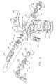
- FIG. 1is a perspective view of the dispenser of this invention in conjunction with a container.
- FIG. 2is a view in side elevation of the dispenser shown in FIG. 1 .
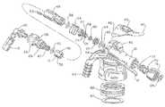
- FIG. 3is an exploded view of the component parts of the dispenser.
- FIG. 4is a cross sectional view of the dispenser in a closed position.
- FIG. 5is a view similar to FIG. 4 showing the dispenser in a low flow condition.
- FIG. 6is a view similar to FIG. 4 showing the dispenser in a high flow condition.
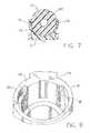
- FIG. 7is a cross sectional view illustrating an indexing of an eductor in the dispenser.
- FIG. 8is a fragmentary view of the dispenser housing illustrating the eductor contact surfaces for limiting the movement thereof.
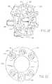
- FIG. 9is a cross sectional view of the dilution adjustment member utilized in the dispenser.
- FIG. 10is a perspective view of an alternative dilution adjustment member in the dispenser.
- FIG. 11is a perspective view of the housing of the dilution adjustment member shown in FIG. 10 .
- FIG. 12is a perspective view of a dilution adjustment device for use in the dilution adjustment member.
- FIG. 13is a back view of the dilution adjustment device shown in FIG. 12 .
- FIG. 14is a front view of the dilution adjustment device shown in FIG. 12 .
- FIG. 15is a cross sectional view of a component of a flow control device employed in the dispenser.
- the dispensergenerally 10 has a body member 12 with a container connector 14 for connection to a container or bottle 16 .
- a preferred connector systemis more fully described in commonly owned U.S. Pat. No. 6,772,914 issued Aug. 10, 2004, which teachings are incorporated herein.
- a hose attachment 18for supplying pressurized water to the dispenser.
- a handle 17is provided below attachment 18 .
- the spout 22 and a nozzle 20for dispensing a mixed chemical solution.
- a flexible tube 15extends between nozzle 20 and spout 22 .
- the dispenser 10includes an eductor generally 11 composed of the first or outer eductor part 24 with a diverging passage 24 a and an inner second eductor part 26 with a converging passage 26 a . They are slideably connected in body member 12 with seals 52 and 56 providing a fluid tight contact.
- a valve assembly 28 for controlling the flow of water through the dispenser 10is also slideably housed in body member 12 and is in contact with eductor part 26 .
- the hose attachment 18is rotatably connected to body member 12 by the snap fitment 34 .
- a back flow preventer 30is positioned in hose attachment 18 and has a seal 32 for contact with body member 12 .
- the nozzle 20is attached to eductor part 24 .
- An annular groove 36is provided in the eductor part 24 and accommodates a head portion 38 of the trigger 40 with flange portions such as shown at 42 on the trigger 40 having shafts (not shown) for extending into bores such as 44 .
- a latch member 46extends upwardly from the member 12 for fitment through the passage 48 of the trigger 40 .
- a dilution adjustment member 50is connected to the eductor part 24 by means of the splines 47 . This is shown in FIG. 9 . It has L-shaped passages 90 - 94 for introducing chemical concentrate into the gap 27 between eductor parts 24 and 26 . These passages 90 - 94 have different diameters or widths for metering different concentrations of chemical concentrate. In some instances there are no passages to provide a rinse function.
- a dip tube 19is connected to body member 12 and extends into container 16 for siphoning chemical concentrate into the bore 13 of body member 12 by way of passage 21 .
- a seal member 23is placed between dilution adjustment member 50 and body member 12 .
- a vent passage 25connects container 16 and bore 13 .
- the adjustment member 50is positioned inside eductor 26 .
- a spring 54biases eductor part 26 as well as eductor part 24 toward the head portion 38 of trigger 40 .
- a quad O-ring 60is attached in groove 57 of valve head portion 58 . It serves as a flow control element as later explained.
- a valve member 28 with passages 33has a head portion 58 with groove 59 .
- a seal 66is seated in groove 59 of head portion 58 and another seal 64 is placed on collar 62 .
- a gasket 67is provided for cap 68 and a hose seal is provided at 69 .
- body member 12has a surface 79 for contact with contact member 29 of eductor 24 as well as a grooves 81 and 82 for the purpose of linearly positioning the eductors 24 and 26 and accordingly valve assembly when trigger 40 is depressed.
- a keyway 70is disposed in body member 12 for accommodating a key member 76 (See FIG. 9 ) in eductor part 26 for allowing sliding but nonrotatable connection in body member 12 .
- a second opposing keyway 80is also disposed in body member 12 in conjunction with key member 84 .
- FIG. 7there is shown the eductor 24 with notches 77 . These accommodate the projections 75 on arms 72 and 73 extending from body member 12 . This provides an indexing function in conjunction with the orientation of dilution adjustment member 50 and passage 21 .
- FIGS. 10-14illustrate an alternative embodiment of the dilution adjustment member 50 which is formed as a separate component from the eductor 24 .
- the dilution adjustment memberincludes a dilution adjustment housing 102 into which is fitted a dilution adjustment device 112 .
- Housing 102includes a central passageway 110 for flow of water and chemical concentrate. It also has five L-shaped passages 103 with an oval portion 105 in a side wall 104 and a cylindrical portion 107 in an end wall 106 .
- the annular adjustment device 112frictionally fits inside annular housing 102 and also has a central passageway 111 for water and chemical concentrate. As best seen in FIG.
- adjustment device or adapter 112has an annular body 113 through which extend the passages 114 from a front side 115 to a back side 117 . These passages also extend through tubular members 116 at the back side 117 . These tubular members 116 fit into the cylindrical portions 107 of passages 103 in dilution adjustment housing 102 . Passages 114 have constrictive bores 122 which are of various dimensions. Alternatively one or more of them could be blocked to provide a rinse function. An orientation projection 118 extends from back side 117 for fitment into orientation compartment 109 of adjustment housing 102 . This facilitates orientation of the tubular members 116 into portions 107 . Projections 120 extend from front side 115 for contact with eductor 26 to provide the gap 27 between the eductors.
- FIG. 4the dispenser is shown in a closed position.
- a source of pressurized watersuch as a hose will have been connected to hose attachment 18 .
- seal 66 on valve head 58is seated against collar 62 and seal 64 against valve seat portion 65 . Accordingly, no water can pass between these two components and into bore 13 .
- This sealing effectis assisted by the flow of water in through the attachment 18 , against the valve components 58 and 62 .
- the spring 54 and force of wateralso positions the head 31 of eductor part 24 away from body contact surface 79 .
- trigger 40has been moved toward body member 12 with the result that eductor head 31 is contacting surface 79 of body member 12 .
- Valve portion 58has moved toward the attachment 18 and seal 66 no longer engages collar 62 .
- watercan flow between the two component parts as there are grooves 63 placed in the collar 62 to allow such flow into bore 13 .
- the quad O-ring 60serves as a flow control element, in that, with increased pressure and flow of water, the ring will expand and partially fill the grooves 63 . This maintains a consistent flow rate despite variations in the pressure of the inlet water supply. Water can then pass through passages 33 and into passage 26 a of eductor part 26 .
- the trigger 40is moved further toward body member 12 . This is shown in FIG. 6 . In this position, not only has seal 66 moved away from collar 62 but collar 62 also has moved away from valve seat portion 65 . In this position, water cannot only flow from between head portion 58 and the grooves 63 in the collar 62 , but also between the collar 62 and the valve seat portion 65 . It should be pointed out that in this high flow position, trigger 40 can now become engaged with latch 46 if desired so that it can be held in the high flow condition. Referring again to FIG. 8 , the contact member 29 of eductor part 24 will now engage the grooves such as 81 or 82 so as to allow the eductor parts 26 and 24 to be moved further inwardly into the body 12 .
- Tube 15in this instance is flexible so as to allow the eductor 24 to move inwardly and outwardly from the body member 12 .
- Thisis the position which is utilized when filling a bucket or a bottle.
- a low flow conditionwould be utilized for filling a bottle while the high flow condition would be utilized to fill a large vessel such as a bucket.
- the spout 22provides for the dispenser to be hung on a bucket 22 a .
- a hose(not shown) can be connected to spout 22 for filling purposes such as a “scrubber washer” or when the dispenser is mounted to a wall.
- Dispenser 10can easily be converted to a spray unit by the replacement of the nozzle 20 and the attachment of a conventional spray head (not shown).
- the concentration of the solutioncan be easily adjusted by the rotation of the eductor 24 in conjunction with the dilution adjustment member 50 .
- the low and high flow condition in combination with the dilution adjustment memberobviates the use of multiple dispenser heads.
- dispenser 10a good hand feel is provided by dispenser 10 . This is accomplished by placement of the handle 17 beneath body member 12 and outwardly from trigger 40 to allow placement of a thumb on trigger 40 .
- Dilution adjustment member 101will function in the same manner as dilution adjustment member 50 .
- the advantage it hasis that the formation of the passages 114 in dilution adjustment device 112 can be more easily controlled as a separate piece during plastic molding. Further, it is less expensive to supply several dilution adjustment devices 112 with varying dimensions of the passages 114 for fitment into housing 102 . To facilitate identification they can be of different colors.
- the dispenser 10has been preferably described in conjunction with a latching feature for the trigger 40 . It is obvious that this is not an essential feature that can be eliminated. Neither is it essential that a back flow preventer be employed in the unit itself. This could be accomplished upstream in a supply line. Further, while the spout 22 offers the advantage of a hose attachment such as with the barbs 100 , this could be eliminated although it does further offer the advantage of a bucket attachment. Neither is it essential that the container connector 14 provides a captive use of the dispenser with the container. The dispenser 10 could be utilized with a refillable container. While dilution adjustment members 50 and 101 have been shown to have five passages, the number can vary from a single passage to as many as can be practically manufactured.
Landscapes
- Chemical & Material Sciences (AREA)
- Chemical Kinetics & Catalysis (AREA)
- Nozzles (AREA)
- Accessories For Mixers (AREA)
- Containers And Packaging Bodies Having A Special Means To Remove Contents (AREA)
- Catching Or Destruction (AREA)
- Feeding, Discharge, Calcimining, Fusing, And Gas-Generation Devices (AREA)
- Sampling And Sample Adjustment (AREA)
- Jet Pumps And Other Pumps (AREA)
Abstract
Description
Claims (18)
Priority Applications (2)
| Application Number | Priority Date | Filing Date | Title |
|---|---|---|---|
| US15/483,465US10328398B2 (en) | 2001-01-12 | 2017-04-10 | Multiple function dispenser |
| US16/237,398US10850241B2 (en) | 2001-01-12 | 2018-12-31 | Multiple function dispenser |
Applications Claiming Priority (8)
| Application Number | Priority Date | Filing Date | Title |
|---|---|---|---|
| US26161301P | 2001-01-12 | 2001-01-12 | |
| US09/956,294US6708901B2 (en) | 2001-01-12 | 2001-09-19 | Multiple function dispenser |
| US10/758,884US7025289B2 (en) | 2001-01-12 | 2004-01-16 | Multiple function dispenser |
| US11/331,254US7341206B2 (en) | 2001-01-12 | 2006-01-12 | Multiple function dispenser |
| US12/024,851US8016212B2 (en) | 2001-01-12 | 2008-02-01 | Multiple function dispenser |
| US13/230,517US8398003B2 (en) | 2001-01-12 | 2011-09-12 | Multiple function dispenser |
| US13/619,800US9616441B2 (en) | 2001-01-12 | 2012-09-14 | Multiple function dispenser |
| US15/483,465US10328398B2 (en) | 2001-01-12 | 2017-04-10 | Multiple function dispenser |
Related Parent Applications (1)
| Application Number | Title | Priority Date | Filing Date |
|---|---|---|---|
| US13/619,800ContinuationUS9616441B2 (en) | 2001-01-12 | 2012-09-14 | Multiple function dispenser |
Related Child Applications (1)
| Application Number | Title | Priority Date | Filing Date |
|---|---|---|---|
| US16/237,398ContinuationUS10850241B2 (en) | 2001-01-12 | 2018-12-31 | Multiple function dispenser |
Publications (2)
| Publication Number | Publication Date |
|---|---|
| US20170304786A1 US20170304786A1 (en) | 2017-10-26 |
| US10328398B2true US10328398B2 (en) | 2019-06-25 |
Family
ID=26948719
Family Applications (12)
| Application Number | Title | Priority Date | Filing Date |
|---|---|---|---|
| US09/956,294Expired - LifetimeUS6708901B2 (en) | 2001-01-12 | 2001-09-19 | Multiple function dispenser |
| US10/758,884Expired - LifetimeUS7025289B2 (en) | 2001-01-12 | 2004-01-16 | Multiple function dispenser |
| US11/206,427Active2026-04-25US7370813B2 (en) | 2001-01-12 | 2005-08-18 | Multiple function dispenser |
| US11/331,254Expired - LifetimeUS7341206B2 (en) | 2001-01-12 | 2006-01-12 | Multiple function dispenser |
| US12/024,851Expired - Fee RelatedUS8016212B2 (en) | 2001-01-12 | 2008-02-01 | Multiple function dispenser |
| US12/111,650Expired - Fee RelatedUS7850095B2 (en) | 2001-01-12 | 2008-04-29 | Multiple function dispenser |
| US12/966,958Expired - Fee RelatedUS9480995B2 (en) | 2001-01-12 | 2010-12-13 | Multiple function dispenser |
| US13/230,517Expired - Fee RelatedUS8398003B2 (en) | 2001-01-12 | 2011-09-12 | Multiple function dispenser |
| US13/619,800Expired - Fee RelatedUS9616441B2 (en) | 2001-01-12 | 2012-09-14 | Multiple function dispenser |
| US13/619,777Expired - Fee RelatedUS8870094B2 (en) | 2001-01-12 | 2012-09-14 | Multiple function dispenser |
| US15/483,465Expired - Fee RelatedUS10328398B2 (en) | 2001-01-12 | 2017-04-10 | Multiple function dispenser |
| US16/237,398Expired - Fee RelatedUS10850241B2 (en) | 2001-01-12 | 2018-12-31 | Multiple function dispenser |
Family Applications Before (10)
| Application Number | Title | Priority Date | Filing Date |
|---|---|---|---|
| US09/956,294Expired - LifetimeUS6708901B2 (en) | 2001-01-12 | 2001-09-19 | Multiple function dispenser |
| US10/758,884Expired - LifetimeUS7025289B2 (en) | 2001-01-12 | 2004-01-16 | Multiple function dispenser |
| US11/206,427Active2026-04-25US7370813B2 (en) | 2001-01-12 | 2005-08-18 | Multiple function dispenser |
| US11/331,254Expired - LifetimeUS7341206B2 (en) | 2001-01-12 | 2006-01-12 | Multiple function dispenser |
| US12/024,851Expired - Fee RelatedUS8016212B2 (en) | 2001-01-12 | 2008-02-01 | Multiple function dispenser |
| US12/111,650Expired - Fee RelatedUS7850095B2 (en) | 2001-01-12 | 2008-04-29 | Multiple function dispenser |
| US12/966,958Expired - Fee RelatedUS9480995B2 (en) | 2001-01-12 | 2010-12-13 | Multiple function dispenser |
| US13/230,517Expired - Fee RelatedUS8398003B2 (en) | 2001-01-12 | 2011-09-12 | Multiple function dispenser |
| US13/619,800Expired - Fee RelatedUS9616441B2 (en) | 2001-01-12 | 2012-09-14 | Multiple function dispenser |
| US13/619,777Expired - Fee RelatedUS8870094B2 (en) | 2001-01-12 | 2012-09-14 | Multiple function dispenser |
Family Applications After (1)
| Application Number | Title | Priority Date | Filing Date |
|---|---|---|---|
| US16/237,398Expired - Fee RelatedUS10850241B2 (en) | 2001-01-12 | 2018-12-31 | Multiple function dispenser |
Country Status (16)
| Country | Link |
|---|---|
| US (12) | US6708901B2 (en) |
| EP (3) | EP1716930B1 (en) |
| JP (1) | JP4035053B2 (en) |
| KR (2) | KR100855775B1 (en) |
| CN (2) | CN1919473B (en) |
| AR (3) | AR032498A1 (en) |
| AT (3) | ATE331569T1 (en) |
| AU (1) | AU2002237795B2 (en) |
| BR (2) | BR122015016896B1 (en) |
| CA (2) | CA2432911C (en) |
| DE (2) | DE60212800T2 (en) |
| ES (2) | ES2363982T3 (en) |
| MX (1) | MXPA03006231A (en) |
| NZ (1) | NZ526309A (en) |
| TW (1) | TW550120B (en) |
| WO (1) | WO2002055213A2 (en) |
Cited By (2)
| Publication number | Priority date | Publication date | Assignee | Title |
|---|---|---|---|---|
| US11491500B2 (en) | 2019-10-11 | 2022-11-08 | Delaware Capital Formation, Inc. | Portable chemical dispenser and method of using same |
| US11779893B2 (en) | 2022-02-19 | 2023-10-10 | Pnu Corp. | Beverage dispensing system and method |
Families Citing this family (56)
| Publication number | Priority date | Publication date | Assignee | Title |
|---|---|---|---|---|
| US6988675B2 (en)* | 2001-01-12 | 2006-01-24 | Johnson Diversey, Inc. | Multiple function dispenser |
| US6708901B2 (en)* | 2001-01-12 | 2004-03-23 | Johnsondiversey, Inc. | Multiple function dispenser |
| USD528917S1 (en)* | 2001-11-08 | 2006-09-26 | Johnsondiversey, Inc. | Bottle |
| US7118049B2 (en)* | 2003-10-30 | 2006-10-10 | Meadwestvaco Corporation | Hose-end sprayer assembly |
| EP1699732B1 (en)* | 2003-12-19 | 2008-02-27 | JohnsonDiversey, Inc. | Support for dispensing device |
| US20050133622A1 (en)* | 2003-12-19 | 2005-06-23 | Johnsondiversey, Inc. | Support for dispensing device |
| US7086610B2 (en)* | 2004-06-24 | 2006-08-08 | Johnsondiversey, Inc. | Vented dispenser |
| US7311823B2 (en)* | 2004-09-23 | 2007-12-25 | Richard Brooke | Pool filter cleaning device |
| US7819340B2 (en)* | 2004-10-08 | 2010-10-26 | Idea Factory, Inc. | Cleaning spray nozzle |
| US7407117B2 (en)* | 2004-10-28 | 2008-08-05 | Meadwestvaco Calmar, Inc. | Liquid sprayer assembly |
| US7188786B2 (en)* | 2004-10-28 | 2007-03-13 | Meadwestvaco Corporation | Hose-end sprayer assembly |
| US7389949B2 (en)* | 2004-12-14 | 2008-06-24 | Briggs & Stratton Corporation | Pressure washer trigger lock |
| US7341207B2 (en)* | 2004-12-20 | 2008-03-11 | Johnsondiversey, Inc. | Variable water flow and dilution chemical dispenser |
| US7237728B1 (en)* | 2005-05-19 | 2007-07-03 | Rodney Laible | Hand-held dispenser |
| US20060289571A1 (en)* | 2005-06-27 | 2006-12-28 | Kevin Saxman | Cleaning solution dispenser |
| US20080083781A1 (en)* | 2005-06-27 | 2008-04-10 | Kevin Saxman | Cleaning solution dispenser |
| US20080302885A1 (en)* | 2006-11-07 | 2008-12-11 | O'brien Paul W | Valve Arrangement for Shower Dispenser |
| CN101652190B (en)* | 2007-03-27 | 2014-06-11 | S.C.约翰逊父子公司 | Refillable devices for dispensing fluids |
| DK2883545T3 (en)* | 2007-06-07 | 2018-11-05 | Bayer Animal Health Gmbh | Control of ectoparasites |
| US8307907B2 (en)* | 2008-02-28 | 2012-11-13 | Hale Products, Inc. | Hybrid foam proportioning system |
| US8453891B2 (en) | 2009-04-07 | 2013-06-04 | 3M Innovative Properties Company | Pump-less toner dispensing cap |
| US8490893B2 (en)* | 2009-04-07 | 2013-07-23 | 3M Innovative Properties Company | Pump-less toner dispenser |
| US8333410B2 (en)* | 2009-05-07 | 2012-12-18 | Fred Knapp Engraving Company, Inc. | Multiple port snap swivel coupling and kit |
| USD696747S1 (en) | 2009-06-17 | 2013-12-31 | S.C. Johnson & Son, Inc. | Container for a fluid dispensing device |
| USD647998S1 (en) | 2009-06-17 | 2011-11-01 | S.C. Johnson & Son, Inc. | Container for a fluid dispensing device |
| CN104875966B (en) | 2009-06-17 | 2017-09-22 | 约翰逊父子公司 | Hand-held device for distributing fluid |
| USD646351S1 (en) | 2009-06-17 | 2011-10-04 | S.C. Johnson & Son, Inc. | Handheld fluid dispensing device |
| US20110139284A1 (en)* | 2009-12-15 | 2011-06-16 | 3M Innovative Properties Company | Diluted-fluid dispensing device with pressure-compensating passive valve |
| US9486824B2 (en)* | 2010-03-09 | 2016-11-08 | Woods Dispensing Systems, Llc | Dispenser device and container |
| KR101038093B1 (en)* | 2010-11-15 | 2011-06-01 | 안미경 | Instrument Lead Processing Equipment |
| US20120223161A1 (en) | 2011-03-01 | 2012-09-06 | Smg Brands, Inc. | Ready-to-use hose end sprayer |
| US8998111B2 (en) | 2011-03-14 | 2015-04-07 | Pops Technologies Llc | Variable flow concentration product dispenser |
| US8596558B2 (en)* | 2011-07-14 | 2013-12-03 | Yuan-Mei Corp. | Finger-operated switch |
| CA2867599A1 (en)* | 2012-03-16 | 2013-09-19 | 3M Innovative Properties Company | Fluid dispensing apparatus, components, and methods |
| US8939322B2 (en)* | 2012-05-07 | 2015-01-27 | Rodney Laible | Wall mounted dispenser |
| US8550302B1 (en)* | 2012-05-07 | 2013-10-08 | Rodney Laible | Wall mounted dispenser |
| FR2993791B1 (en)* | 2012-07-27 | 2014-07-11 | Eveon | FLUID DISPENSER AND DEVICE FOR IN SITU RECONSTRUCTION AND ADMINISTRATION |
| CN103056054B (en)* | 2013-01-29 | 2015-07-22 | 厦门建霖工业有限公司 | Multifunctional distributor |
| BR112015027771A2 (en) | 2013-05-03 | 2017-07-25 | Asoc De Bananeros De Colombia Augura | method of production of biomass and fengicin metabolites of bacillus species and their compositions for biological pest control |
| US10786795B2 (en) | 2013-11-30 | 2020-09-29 | John Boticki | Individualized flow regulation system and method |
| US9468892B2 (en)* | 2014-02-07 | 2016-10-18 | Hydra-Flex, Inc. | Modular chemical dispensing assembly |
| USD751178S1 (en)* | 2014-07-29 | 2016-03-08 | James Gibson | Portable mist generation apparatus |
| US10007275B2 (en) | 2014-12-29 | 2018-06-26 | Diversey, Inc. | Dilution adjustment system and method |
| EP3954468B1 (en)* | 2015-03-04 | 2024-05-15 | Martin Ruda 1. UG (haftungsbeschränkt). | Spray gun |
| EP3352905B1 (en) | 2015-09-21 | 2022-12-07 | S.C. Johnson & Son, Inc. | System for mixing and dispensing |
| US9987641B2 (en)* | 2015-09-25 | 2018-06-05 | Silgan Dispensing Systems Corporation | Dosing dispensers and methods for using the same |
| USD783776S1 (en)* | 2015-11-18 | 2017-04-11 | Yuyao Donghua Electrical Appliance Plastics Factory | Spray gun |
| CN106406605A (en)* | 2016-08-24 | 2017-02-15 | 武汉华星光电技术有限公司 | Touch screen and touch sensing component thereof |
| USD809097S1 (en) | 2016-09-21 | 2018-01-30 | S. C. Johnson & Son, Inc. | Dispenser with container |
| MX2018005056A (en) | 2017-07-19 | 2019-03-28 | Chapin Mfg Inc | Carbon capture. |
| US11376638B2 (en)* | 2019-03-27 | 2022-07-05 | Michael Nugent | Directionally adjustable foam generating attachment for a hose |
| CN110080352A (en)* | 2019-06-03 | 2019-08-02 | 杭州富阳飞尚装饰工程有限公司 | A kind of water economizer that house decoration uses |
| US11213841B2 (en)* | 2019-08-29 | 2022-01-04 | Chapin Manufacturing, Inc. | Wet/dry hose end sprayer |
| TWM603797U (en)* | 2020-09-03 | 2020-11-11 | 頑鎂貿易股份有限公司 | Spray device with spiral groove |
| USD952098S1 (en)* | 2021-06-04 | 2022-05-17 | Taizhou YanKang Trade Co., Ltd. | Foam cannon for pressure washer |
| CN114308434B (en)* | 2022-01-05 | 2023-03-14 | 钱江集团温岭正峰动力有限公司 | High-low pressure foam watering can |
Citations (87)
| Publication number | Priority date | Publication date | Assignee | Title |
|---|---|---|---|---|
| US1202425A (en) | 1915-09-25 | 1916-10-24 | Melvin W Loyd | Valve for mixing fluids. |
| US1721726A (en) | 1926-09-25 | 1929-07-23 | Boe Mfg Company | Grease-pump nozzle |
| US2389134A (en) | 1943-07-05 | 1945-11-20 | Dole Valve Co | Flow control valve |
| US2454929A (en) | 1944-07-17 | 1948-11-30 | Dole Valve Co | Flow control |
| US2719704A (en) | 1954-12-20 | 1955-10-04 | Leslie V Anderson | Chemical mixing nozzle and water shut-off valve |
| US2781061A (en) | 1954-01-08 | 1957-02-12 | Gen Motors Corp | Flow controller |
| US2788244A (en) | 1953-05-15 | 1957-04-09 | Robert A Gilmour | Slide control valves for sprayers |
| US2991939A (en) | 1959-09-28 | 1961-07-11 | Barco Mfg Co Inc | Fluid mixing and spraying device |
| US3049304A (en) | 1960-05-18 | 1962-08-14 | Vernon R Sears | Portable hose spraying apparatus |
| US3090564A (en) | 1961-02-21 | 1963-05-21 | Robert A Gilmour | Spraying device with dilution control |
| US3113725A (en) | 1962-09-07 | 1963-12-10 | Barco Mfg Co Inc | Valve controlled spraying device for a chemical intermixed with water |
| US3145735A (en) | 1960-12-20 | 1964-08-25 | Osrow Products Company Inc | Variable proportioning and variably metering plural-liquid valved dispensing units |
| US3228613A (en) | 1964-07-10 | 1966-01-11 | Munsey S Goldstein | Spraying attachment with base |
| US3282227A (en) | 1964-06-22 | 1966-11-01 | Nielsen Mfg Co | Adjustable venturi injector |
| US3357598A (en)* | 1965-09-21 | 1967-12-12 | Dole Valve Co | Adjustable liquid dispenser |
| US3381899A (en) | 1966-09-19 | 1968-05-07 | Hayes Spray Gun Company | Spray gun |
| US3445067A (en) | 1965-10-24 | 1969-05-20 | Garland L Sheldall | Eductor type proportioner |
| US3454229A (en) | 1967-09-01 | 1969-07-08 | Charles V Armond | Shower spray unit |
| US3473481A (en) | 1966-03-18 | 1969-10-21 | Borgerud Mfg Co Inc | Venturi arrangement |
| US3608829A (en) | 1969-03-28 | 1971-09-28 | Leisure Group Inc | Mixing apparatus |
| US3764074A (en) | 1972-01-20 | 1973-10-09 | D James | Shower head and liquid agent dispensing attachment |
| US3770205A (en) | 1972-08-24 | 1973-11-06 | Jet X Corp | Sprayer with detergent or chemical additive feed |
| US3776468A (en)* | 1972-03-31 | 1973-12-04 | W Davenport | Spray mix applicator |
| US3847178A (en) | 1970-12-10 | 1974-11-12 | Mannesmann & Keppel | Fluid flow regulators |
| US3862640A (en) | 1973-02-16 | 1975-01-28 | Iv Valentine Hechler | Anti-backflow water control and solution proportioner |
| US3863843A (en)* | 1973-02-16 | 1975-02-04 | Iv Valentine Hechler | Anti-back siphoning water supply valve and mixer |
| US3938550A (en)* | 1974-06-24 | 1976-02-17 | Hechler Iv Valentine | Continuous flow ratio monitor |
| US3940069A (en) | 1974-09-30 | 1976-02-24 | Meiko, Incorporated | Spray apparatus |
| US3964689A (en)* | 1975-04-10 | 1976-06-22 | S. C. Johnson & Son, Inc. | Hose-end dispenser device |
| US4010768A (en)* | 1974-11-04 | 1977-03-08 | Hechler Iv Valentine | Two-stage jet pump proportioner |
| US4014363A (en)* | 1974-02-27 | 1977-03-29 | Hechler Iv Valentine | Water and concentrate supply valves for proportioning mixer-dispenser |
| US4171070A (en) | 1977-06-10 | 1979-10-16 | Samuel Colgate, Robert Ramey And Associates | Apparatus for inserting an additive liquid into a flowing fluid and discharging the resultant mixture |
| US4277030A (en)* | 1976-01-22 | 1981-07-07 | Hechler Iv Valentine | Spray and foam dispensing nozzle |
| US4341350A (en) | 1980-09-05 | 1982-07-27 | Otto Wemmer | Chemical injection system for high pressure washers |
| US4382552A (en)* | 1981-09-08 | 1983-05-10 | The O. M. Scott & Sons Company | Liquid applicator |
| US4422833A (en) | 1981-05-11 | 1983-12-27 | Free Flow, Inc. | Pneumatic transfer system and a fluid flow control device therefor |
| US4475689A (en)* | 1982-12-09 | 1984-10-09 | R. M. Smith, Inc. | Variable dilution ratio hose-end sprayer |
| US4508272A (en) | 1982-09-28 | 1985-04-02 | Lincoln Thompson | Hose end spray nozzle |
| US4527740A (en) | 1982-12-16 | 1985-07-09 | Chevron Research Company | Hose-end aspirator sprayer |
| US4901923A (en) | 1988-10-11 | 1990-02-20 | Chevron Research Company | Variable dilution ratio hose-end aspirator sprayer |
| US4934595A (en) | 1988-08-19 | 1990-06-19 | Plastic Flamecoat Systems, Inc. | Method and aparatus for spray coating |
| US4951713A (en) | 1988-09-02 | 1990-08-28 | Jordan Foster A | Overflow check system having automatic start-up |
| US5007588A (en) | 1988-12-08 | 1991-04-16 | Hunter-Melnor, Inc. | Aspiration-type sprayer |
| US5213265A (en) | 1991-03-18 | 1993-05-25 | Hayes Products L.P. | Single valve aspiration type sprayer |
| US5253677A (en) | 1991-07-18 | 1993-10-19 | Hydro Systems Company | Chemical eductor with integral elongated air gap |
| US5297733A (en)* | 1991-09-16 | 1994-03-29 | Plastic Flamecoat Systems, Inc. | Flame spray gun |
| US5320288A (en)* | 1993-05-24 | 1994-06-14 | Green Garden, Inc. | Hose-end spraying apparatus |
| US5335734A (en) | 1993-05-04 | 1994-08-09 | Scott Plastics Ltd. | Reciprocating additive mixing pump apparatus and method |
| US5351875A (en) | 1992-10-29 | 1994-10-04 | Hydro Systems Company | Mixing and dispensing device |
| US5383603A (en) | 1993-06-22 | 1995-01-24 | Hayes Products L.P. | Aspiration-type sprayer |
| US5423228A (en) | 1992-12-18 | 1995-06-13 | Monitor Labs, Inc. | Dilution stack sampling apparatus |
| US5445226A (en) | 1993-05-04 | 1995-08-29 | Scott Plastics Ltd. | Foam generating apparatus for attachment to hose delivering pressurized liquid |
| US5522419A (en) | 1995-06-26 | 1996-06-04 | Hydro Systems Company | Chemical eductor with integral elongated air gap |
| US5529244A (en) | 1994-10-04 | 1996-06-25 | S. C. Johnson & Son, Inc. | Aspirator liquid blending device using multiple restrictors |
| US5544810A (en) | 1990-04-23 | 1996-08-13 | S. C. Johnson & Son, Inc. | Precision-ratioed fluid-mixing device and system |
| US5765605A (en) | 1996-01-19 | 1998-06-16 | Sc Johnson Commerical Markets, Inc. | Distributed concentrated chemical dispensing system |
| US5769322A (en) | 1995-07-07 | 1998-06-23 | Gilmour, Inc. | Rotary sprinkler and base |
| US5810089A (en) | 1996-04-19 | 1998-09-22 | Task Force Tips, Inc. | Portable firefighting apparatus with integral control valve-handle |
| US5902041A (en) | 1996-10-28 | 1999-05-11 | Parsons; William G. | Defoaming mixing eductor |
| US5927338A (en)* | 1996-04-18 | 1999-07-27 | S.C. Johnson Commercial Markets, Inc. | Mixing eductor |
| US5996907A (en) | 1998-03-02 | 1999-12-07 | Ecolab Inc. | Portable wash and rinse system with dilution |
| US6079595A (en) | 1999-04-12 | 2000-06-27 | Ecolab Inc. | Chemical solution dispenser |
| US6113004A (en) | 1996-04-19 | 2000-09-05 | Task Force Tips, Inc. | Portable kit for firefighters |
| US6158673A (en) | 1998-03-02 | 2000-12-12 | Ecolab Inc. | Portable unit wall unit dispensers and method of dispensing |
| US6161779A (en)* | 1999-05-28 | 2000-12-19 | Gilmour, Inc. | Lawn fertilizing apparatus having a detachable body which has two separate water outlets defined therein |
| US6283330B1 (en) | 1999-08-25 | 2001-09-04 | The Butcher Company | Cleaning solution dilution and dispensing system |
| WO2001068455A1 (en) | 2000-03-14 | 2001-09-20 | Emsar, Inc. | Method of using a dispensing head for a squeeze dispenser |
| US6293294B1 (en) | 1999-06-24 | 2001-09-25 | Hydrosurge, Inc. | Method and apparatus for fluid mixing and dispensing |
| US20020008161A1 (en)* | 1998-11-05 | 2002-01-24 | Craig S. Ketcham | Spraying apparatus having a sealing member with apertures |
| US6345773B1 (en) | 1998-02-06 | 2002-02-12 | S. C. Johnson & Son, Inc. | Aspiration-type sprayer |
| US6363977B1 (en)* | 2000-09-12 | 2002-04-02 | Knlght, Inc. | Container filling apparatus |
| US6371385B1 (en) | 2000-07-13 | 2002-04-16 | S. C. Johnson Commercial Markets, Inc. | Portable spraying device |
| US6378789B1 (en) | 2000-06-01 | 2002-04-30 | S. C. Johnson Commercial Markets, Inc. | Combination spray apparatus |
| US6378785B1 (en) | 2000-08-30 | 2002-04-30 | Saint-Gobain Calmar Inc. | Hose-end aspiration-type sprayer |
| WO2002036267A1 (en) | 2000-10-30 | 2002-05-10 | Bruce Alan Whiteley | Fluid mixer with rotatable eductor tube and metering orifices |
| US6398133B1 (en) | 1999-12-22 | 2002-06-04 | Emsar, Inc. | Dispensing head for a squeeze dispenser |
| US20020092925A1 (en)* | 2001-01-12 | 2002-07-18 | Hubmann Curtis H. | Multiple function dispenser |
| US6471141B2 (en) | 2000-06-08 | 2002-10-29 | Dispensing Technologies, L.L.C. | Hose sprayer assembly |
| TW515754B (en) | 2000-05-22 | 2003-01-01 | Zimmer Ag | A method of extruding a continuous moulding |
| US6578776B1 (en) | 2000-04-03 | 2003-06-17 | Hayes Products, Llc. | Single valve ready to use hose end sprayer |
| JP2003200174A (en) | 2002-01-09 | 2003-07-15 | Okazaki Toshio | Sterilized water making apparatus, dental grinding device using sterilized water and sterilized water making method |
| US6655401B2 (en)* | 2001-09-25 | 2003-12-02 | Hydro Systems Company | Multiple chemical product eductive dispenser |
| US6749133B1 (en)* | 2000-08-11 | 2004-06-15 | Green Garden Products Company | Spraying apparatus with insert |
| US6765605B1 (en)* | 1998-12-17 | 2004-07-20 | Fuji Xerox Co., Ltd. | Split scanning optical apparatus |
| US6772914B2 (en)* | 2001-11-09 | 2004-08-10 | Johnsondiversey, Inc. | Non-removable device for attaching a dispenser to a container |
| JP2004227309A (en) | 2003-01-23 | 2004-08-12 | Seiko Epson Corp | Printer control device and printer control program |
| WO2005023432A1 (en) | 2003-09-09 | 2005-03-17 | Johnsondiversey, Inc. | Improved multiple function dispenser |
Family Cites Families (14)
| Publication number | Priority date | Publication date | Assignee | Title |
|---|---|---|---|---|
| US2612403A (en)* | 1949-08-02 | 1952-09-30 | Wilbur A Burch | Device for mixing fluids |
| US3034731A (en)* | 1959-03-04 | 1962-05-15 | R E Chapin Mfg Works Inc | Back flow preventing valve assembly |
| GB8812047D0 (en)* | 1988-05-21 | 1988-06-22 | Garnett R H | Improvements in/relating to chemical concentrate metering |
| JPH03200174A (en) | 1989-12-28 | 1991-09-02 | Toshiba Corp | Image forming device |
| USD445872S1 (en) | 2000-08-11 | 2001-07-31 | Green Garden, Inc. | Spray nozzle |
| JP2003014739A (en) | 2001-07-03 | 2003-01-15 | Shiseido Co Ltd | Screening method of skin swell improvement agent, and skin swell improvement agent |
| US6772966B2 (en)* | 2002-04-10 | 2004-08-10 | Continental Afa Dispensing Company | Adjustable hose end sprayer nozzle |
| US20060038040A1 (en) | 2004-08-16 | 2006-02-23 | Faupel Richard W | Hose-end sprayer improvements |
| US7341207B2 (en)* | 2004-12-20 | 2008-03-11 | Johnsondiversey, Inc. | Variable water flow and dilution chemical dispenser |
| USD555227S1 (en)* | 2005-06-20 | 2007-11-13 | Johnsondiversey, Inc. | Dispensing head |
| US7566013B2 (en)* | 2005-11-08 | 2009-07-28 | Mark Maclean-Blevins | System for failsafe controlled dispensing of liquid material |
| WO2009103078A2 (en) | 2008-02-14 | 2009-08-20 | Green Garden Products Company | Hose-end sprayer bottles with safety features |
| US20100282866A1 (en)* | 2009-05-06 | 2010-11-11 | Briggs & Stratton Corporation | Chemical injector for spray device |
| EP3352905B1 (en)* | 2015-09-21 | 2022-12-07 | S.C. Johnson & Son, Inc. | System for mixing and dispensing |
- 2001
- 2001-09-19USUS09/956,294patent/US6708901B2/ennot_activeExpired - Lifetime
- 2002
- 2002-01-09EPEP06011254Apatent/EP1716930B1/ennot_activeExpired - Lifetime
- 2002-01-09ESES06011254Tpatent/ES2363982T3/ennot_activeExpired - Lifetime
- 2002-01-09CACA002432911Apatent/CA2432911C/ennot_activeExpired - Lifetime
- 2002-01-09DEDE60212800Tpatent/DE60212800T2/ennot_activeExpired - Lifetime
- 2002-01-09ATAT02704095Tpatent/ATE331569T1/ennot_activeIP Right Cessation
- 2002-01-09ATAT05026389Tpatent/ATE552912T1/enactive
- 2002-01-09AUAU2002237795Apatent/AU2002237795B2/ennot_activeExpired
- 2002-01-09ESES02704095Tpatent/ES2265032T3/ennot_activeExpired - Lifetime
- 2002-01-09BRBR122015016896Apatent/BR122015016896B1/enactiveIP Right Grant
- 2002-01-09NZNZ526309Apatent/NZ526309A/ennot_activeIP Right Cessation
- 2002-01-09EPEP05026389Apatent/EP1645335B1/ennot_activeExpired - Lifetime
- 2002-01-09DEDE60239640Tpatent/DE60239640D1/ennot_activeExpired - Lifetime
- 2002-01-09WOPCT/US2002/000580patent/WO2002055213A2/enactiveIP Right Grant
- 2002-01-09ATAT06011254Tpatent/ATE503583T1/ennot_activeIP Right Cessation
- 2002-01-09CNCN2006101399866Apatent/CN1919473B/ennot_activeExpired - Lifetime
- 2002-01-09CNCNB028034864Apatent/CN1287906C/ennot_activeExpired - Lifetime
- 2002-01-09JPJP2002555935Apatent/JP4035053B2/ennot_activeExpired - Lifetime
- 2002-01-09KRKR1020087003184Apatent/KR100855775B1/ennot_activeExpired - Fee Related
- 2002-01-09KRKR1020037009270Apatent/KR100855776B1/ennot_activeExpired - Fee Related
- 2002-01-09EPEP02704095Apatent/EP1353756B1/ennot_activeExpired - Lifetime
- 2002-01-09BRBRPI0206249Apatent/BRPI0206249B1/enactiveIP Right Grant
- 2002-01-09CACA2599800Apatent/CA2599800C/ennot_activeExpired - Lifetime
- 2002-01-09MXMXPA03006231Apatent/MXPA03006231A/enactiveIP Right Grant
- 2002-01-11ARARP020100092Apatent/AR032498A1/enactiveIP Right Grant
- 2002-01-11TWTW091100300Apatent/TW550120B/ennot_activeIP Right Cessation
- 2004
- 2004-01-16USUS10/758,884patent/US7025289B2/ennot_activeExpired - Lifetime
- 2005
- 2005-08-18USUS11/206,427patent/US7370813B2/enactiveActive
- 2006
- 2006-01-12USUS11/331,254patent/US7341206B2/ennot_activeExpired - Lifetime
- 2007
- 2007-08-10ARARP070103554Apatent/AR062329A2/enactiveIP Right Grant
- 2007-08-10ARARP070103553Apatent/AR062328A2/enunknown
- 2008
- 2008-02-01USUS12/024,851patent/US8016212B2/ennot_activeExpired - Fee Related
- 2008-04-29USUS12/111,650patent/US7850095B2/ennot_activeExpired - Fee Related
- 2010
- 2010-12-13USUS12/966,958patent/US9480995B2/ennot_activeExpired - Fee Related
- 2011
- 2011-09-12USUS13/230,517patent/US8398003B2/ennot_activeExpired - Fee Related
- 2012
- 2012-09-14USUS13/619,800patent/US9616441B2/ennot_activeExpired - Fee Related
- 2012-09-14USUS13/619,777patent/US8870094B2/ennot_activeExpired - Fee Related
- 2017
- 2017-04-10USUS15/483,465patent/US10328398B2/ennot_activeExpired - Fee Related
- 2018
- 2018-12-31USUS16/237,398patent/US10850241B2/ennot_activeExpired - Fee Related
Patent Citations (103)
| Publication number | Priority date | Publication date | Assignee | Title |
|---|---|---|---|---|
| US1202425A (en) | 1915-09-25 | 1916-10-24 | Melvin W Loyd | Valve for mixing fluids. |
| US1721726A (en) | 1926-09-25 | 1929-07-23 | Boe Mfg Company | Grease-pump nozzle |
| US2389134A (en) | 1943-07-05 | 1945-11-20 | Dole Valve Co | Flow control valve |
| US2454929A (en) | 1944-07-17 | 1948-11-30 | Dole Valve Co | Flow control |
| US2788244A (en) | 1953-05-15 | 1957-04-09 | Robert A Gilmour | Slide control valves for sprayers |
| US2781061A (en) | 1954-01-08 | 1957-02-12 | Gen Motors Corp | Flow controller |
| US2719704A (en) | 1954-12-20 | 1955-10-04 | Leslie V Anderson | Chemical mixing nozzle and water shut-off valve |
| US2991939A (en) | 1959-09-28 | 1961-07-11 | Barco Mfg Co Inc | Fluid mixing and spraying device |
| US3049304A (en) | 1960-05-18 | 1962-08-14 | Vernon R Sears | Portable hose spraying apparatus |
| US3145735A (en) | 1960-12-20 | 1964-08-25 | Osrow Products Company Inc | Variable proportioning and variably metering plural-liquid valved dispensing units |
| US3090564A (en) | 1961-02-21 | 1963-05-21 | Robert A Gilmour | Spraying device with dilution control |
| US3113725A (en) | 1962-09-07 | 1963-12-10 | Barco Mfg Co Inc | Valve controlled spraying device for a chemical intermixed with water |
| US3282227A (en) | 1964-06-22 | 1966-11-01 | Nielsen Mfg Co | Adjustable venturi injector |
| US3228613A (en) | 1964-07-10 | 1966-01-11 | Munsey S Goldstein | Spraying attachment with base |
| US3357598A (en)* | 1965-09-21 | 1967-12-12 | Dole Valve Co | Adjustable liquid dispenser |
| US3445067A (en) | 1965-10-24 | 1969-05-20 | Garland L Sheldall | Eductor type proportioner |
| US3473481A (en) | 1966-03-18 | 1969-10-21 | Borgerud Mfg Co Inc | Venturi arrangement |
| US3381899A (en) | 1966-09-19 | 1968-05-07 | Hayes Spray Gun Company | Spray gun |
| US3454229A (en) | 1967-09-01 | 1969-07-08 | Charles V Armond | Shower spray unit |
| US3608829A (en) | 1969-03-28 | 1971-09-28 | Leisure Group Inc | Mixing apparatus |
| US3847178A (en) | 1970-12-10 | 1974-11-12 | Mannesmann & Keppel | Fluid flow regulators |
| US3764074A (en) | 1972-01-20 | 1973-10-09 | D James | Shower head and liquid agent dispensing attachment |
| US3776468A (en)* | 1972-03-31 | 1973-12-04 | W Davenport | Spray mix applicator |
| US3770205A (en) | 1972-08-24 | 1973-11-06 | Jet X Corp | Sprayer with detergent or chemical additive feed |
| US3862640A (en) | 1973-02-16 | 1975-01-28 | Iv Valentine Hechler | Anti-backflow water control and solution proportioner |
| US3863843A (en)* | 1973-02-16 | 1975-02-04 | Iv Valentine Hechler | Anti-back siphoning water supply valve and mixer |
| US4014363A (en)* | 1974-02-27 | 1977-03-29 | Hechler Iv Valentine | Water and concentrate supply valves for proportioning mixer-dispenser |
| US3938550A (en)* | 1974-06-24 | 1976-02-17 | Hechler Iv Valentine | Continuous flow ratio monitor |
| US3940069A (en) | 1974-09-30 | 1976-02-24 | Meiko, Incorporated | Spray apparatus |
| US4010768A (en)* | 1974-11-04 | 1977-03-08 | Hechler Iv Valentine | Two-stage jet pump proportioner |
| US3964689A (en)* | 1975-04-10 | 1976-06-22 | S. C. Johnson & Son, Inc. | Hose-end dispenser device |
| US4277030A (en)* | 1976-01-22 | 1981-07-07 | Hechler Iv Valentine | Spray and foam dispensing nozzle |
| US4171070A (en) | 1977-06-10 | 1979-10-16 | Samuel Colgate, Robert Ramey And Associates | Apparatus for inserting an additive liquid into a flowing fluid and discharging the resultant mixture |
| US4341350A (en) | 1980-09-05 | 1982-07-27 | Otto Wemmer | Chemical injection system for high pressure washers |
| US4422833A (en) | 1981-05-11 | 1983-12-27 | Free Flow, Inc. | Pneumatic transfer system and a fluid flow control device therefor |
| US4382552A (en)* | 1981-09-08 | 1983-05-10 | The O. M. Scott & Sons Company | Liquid applicator |
| US4508272A (en) | 1982-09-28 | 1985-04-02 | Lincoln Thompson | Hose end spray nozzle |
| US4475689A (en)* | 1982-12-09 | 1984-10-09 | R. M. Smith, Inc. | Variable dilution ratio hose-end sprayer |
| US4527740A (en) | 1982-12-16 | 1985-07-09 | Chevron Research Company | Hose-end aspirator sprayer |
| US4934595A (en) | 1988-08-19 | 1990-06-19 | Plastic Flamecoat Systems, Inc. | Method and aparatus for spray coating |
| US4951713A (en) | 1988-09-02 | 1990-08-28 | Jordan Foster A | Overflow check system having automatic start-up |
| US4901923A (en) | 1988-10-11 | 1990-02-20 | Chevron Research Company | Variable dilution ratio hose-end aspirator sprayer |
| US5007588A (en) | 1988-12-08 | 1991-04-16 | Hunter-Melnor, Inc. | Aspiration-type sprayer |
| US5544810A (en) | 1990-04-23 | 1996-08-13 | S. C. Johnson & Son, Inc. | Precision-ratioed fluid-mixing device and system |
| US5213265A (en) | 1991-03-18 | 1993-05-25 | Hayes Products L.P. | Single valve aspiration type sprayer |
| US5253677A (en) | 1991-07-18 | 1993-10-19 | Hydro Systems Company | Chemical eductor with integral elongated air gap |
| US5297733A (en)* | 1991-09-16 | 1994-03-29 | Plastic Flamecoat Systems, Inc. | Flame spray gun |
| US5351875A (en) | 1992-10-29 | 1994-10-04 | Hydro Systems Company | Mixing and dispensing device |
| US5423228A (en) | 1992-12-18 | 1995-06-13 | Monitor Labs, Inc. | Dilution stack sampling apparatus |
| US5335734A (en) | 1993-05-04 | 1994-08-09 | Scott Plastics Ltd. | Reciprocating additive mixing pump apparatus and method |
| US5445226A (en) | 1993-05-04 | 1995-08-29 | Scott Plastics Ltd. | Foam generating apparatus for attachment to hose delivering pressurized liquid |
| US5372310A (en) | 1993-05-24 | 1994-12-13 | Green Garden, Inc. | Hose-end spraying apparatus |
| US5320288A (en)* | 1993-05-24 | 1994-06-14 | Green Garden, Inc. | Hose-end spraying apparatus |
| US5383603A (en) | 1993-06-22 | 1995-01-24 | Hayes Products L.P. | Aspiration-type sprayer |
| US5529244A (en) | 1994-10-04 | 1996-06-25 | S. C. Johnson & Son, Inc. | Aspirator liquid blending device using multiple restrictors |
| US5522419A (en) | 1995-06-26 | 1996-06-04 | Hydro Systems Company | Chemical eductor with integral elongated air gap |
| US5769322A (en) | 1995-07-07 | 1998-06-23 | Gilmour, Inc. | Rotary sprinkler and base |
| US5765605A (en) | 1996-01-19 | 1998-06-16 | Sc Johnson Commerical Markets, Inc. | Distributed concentrated chemical dispensing system |
| US5927338A (en)* | 1996-04-18 | 1999-07-27 | S.C. Johnson Commercial Markets, Inc. | Mixing eductor |
| US5810089A (en) | 1996-04-19 | 1998-09-22 | Task Force Tips, Inc. | Portable firefighting apparatus with integral control valve-handle |
| US6113004A (en) | 1996-04-19 | 2000-09-05 | Task Force Tips, Inc. | Portable kit for firefighters |
| US5902041A (en) | 1996-10-28 | 1999-05-11 | Parsons; William G. | Defoaming mixing eductor |
| US6345773B1 (en) | 1998-02-06 | 2002-02-12 | S. C. Johnson & Son, Inc. | Aspiration-type sprayer |
| US5996907A (en) | 1998-03-02 | 1999-12-07 | Ecolab Inc. | Portable wash and rinse system with dilution |
| US6158673A (en) | 1998-03-02 | 2000-12-12 | Ecolab Inc. | Portable unit wall unit dispensers and method of dispensing |
| US6425534B2 (en) | 1998-11-05 | 2002-07-30 | Green Garden Products Company | Spraying apparatus having a sealing member with apertures |
| US20020008161A1 (en)* | 1998-11-05 | 2002-01-24 | Craig S. Ketcham | Spraying apparatus having a sealing member with apertures |
| US6765605B1 (en)* | 1998-12-17 | 2004-07-20 | Fuji Xerox Co., Ltd. | Split scanning optical apparatus |
| US6079595A (en) | 1999-04-12 | 2000-06-27 | Ecolab Inc. | Chemical solution dispenser |
| US6161779A (en)* | 1999-05-28 | 2000-12-19 | Gilmour, Inc. | Lawn fertilizing apparatus having a detachable body which has two separate water outlets defined therein |
| US6293294B1 (en) | 1999-06-24 | 2001-09-25 | Hydrosurge, Inc. | Method and apparatus for fluid mixing and dispensing |
| US6283330B1 (en) | 1999-08-25 | 2001-09-04 | The Butcher Company | Cleaning solution dilution and dispensing system |
| US6398133B1 (en) | 1999-12-22 | 2002-06-04 | Emsar, Inc. | Dispensing head for a squeeze dispenser |
| WO2001068455A1 (en) | 2000-03-14 | 2001-09-20 | Emsar, Inc. | Method of using a dispensing head for a squeeze dispenser |
| US6578776B1 (en) | 2000-04-03 | 2003-06-17 | Hayes Products, Llc. | Single valve ready to use hose end sprayer |
| TW515754B (en) | 2000-05-22 | 2003-01-01 | Zimmer Ag | A method of extruding a continuous moulding |
| US6378789B1 (en) | 2000-06-01 | 2002-04-30 | S. C. Johnson Commercial Markets, Inc. | Combination spray apparatus |
| US6471141B2 (en) | 2000-06-08 | 2002-10-29 | Dispensing Technologies, L.L.C. | Hose sprayer assembly |
| US6371385B1 (en) | 2000-07-13 | 2002-04-16 | S. C. Johnson Commercial Markets, Inc. | Portable spraying device |
| US6749133B1 (en)* | 2000-08-11 | 2004-06-15 | Green Garden Products Company | Spraying apparatus with insert |
| US6378785B1 (en) | 2000-08-30 | 2002-04-30 | Saint-Gobain Calmar Inc. | Hose-end aspiration-type sprayer |
| US6363977B1 (en)* | 2000-09-12 | 2002-04-02 | Knlght, Inc. | Container filling apparatus |
| WO2002036267A1 (en) | 2000-10-30 | 2002-05-10 | Bruce Alan Whiteley | Fluid mixer with rotatable eductor tube and metering orifices |
| US7341206B2 (en)* | 2001-01-12 | 2008-03-11 | Johnsondiversey, Inc. | Multiple function dispenser |
| US7850095B2 (en)* | 2001-01-12 | 2010-12-14 | Diversey, Inc. | Multiple function dispenser |
| US6708901B2 (en)* | 2001-01-12 | 2004-03-23 | Johnsondiversey, Inc. | Multiple function dispenser |
| WO2002055213A2 (en) | 2001-01-12 | 2002-07-18 | Johnsondiversey, Inc. | Multiple function dispenser |
| US20020092925A1 (en)* | 2001-01-12 | 2002-07-18 | Hubmann Curtis H. | Multiple function dispenser |
| US8016212B2 (en)* | 2001-01-12 | 2011-09-13 | Diversey, Inc. | Multiple function dispenser |
| US20040155119A1 (en)* | 2001-01-12 | 2004-08-12 | Hubmann Curtis H. | Multiple function dispenser |
| US7370813B2 (en)* | 2001-01-12 | 2008-05-13 | Johnsondiversey, Inc. | Multiple function dispenser |
| US6988675B2 (en)* | 2001-01-12 | 2006-01-24 | Johnson Diversey, Inc. | Multiple function dispenser |
| US20080179420A1 (en)* | 2001-01-12 | 2008-07-31 | Johnsondiversey, Inc. | Multiple function dispenser |
| EP1353756B1 (en) | 2001-01-12 | 2006-06-28 | Johnson Diversey, Inc. | Multiple function dispenser |
| EP1645335A2 (en) | 2001-01-12 | 2006-04-12 | JohnsonDiversey, Inc. | Multiple function dispenser |
| US7025289B2 (en)* | 2001-01-12 | 2006-04-11 | Johnsondiversey, Inc. | Multiple function dispenser |
| EP1716930A1 (en) | 2001-01-12 | 2006-11-02 | JohnsonDiversey, Inc. | Multiple function dispenser |
| US6655401B2 (en)* | 2001-09-25 | 2003-12-02 | Hydro Systems Company | Multiple chemical product eductive dispenser |
| US6772914B2 (en)* | 2001-11-09 | 2004-08-10 | Johnsondiversey, Inc. | Non-removable device for attaching a dispenser to a container |
| JP2003200174A (en) | 2002-01-09 | 2003-07-15 | Okazaki Toshio | Sterilized water making apparatus, dental grinding device using sterilized water and sterilized water making method |
| JP2004227309A (en) | 2003-01-23 | 2004-08-12 | Seiko Epson Corp | Printer control device and printer control program |
| EP1675689B1 (en) | 2003-09-09 | 2007-01-03 | JohnsonDiversey, Inc. | Improved multiple function dispenser |
| WO2005023432A1 (en) | 2003-09-09 | 2005-03-17 | Johnsondiversey, Inc. | Improved multiple function dispenser |
Non-Patent Citations (8)
| Title |
|---|
| A U.S. patent application entitled Spraying Apparatus Having a Sealing Member with Apertures. This application was filed in the USPTO Feb. 4, 1999, designated as U.S. Appl. No. 09/244,392 naming Ketchum as inventor. |
| A U.S. patent application entitled Spraying Apparatus with Insert. It is believed that this application was filed in the USPTO sometime after Aug. 11, 2000. |
| Gilmour Group, "Spray Doc," catalog (1990) 6 pages, PA, USA. |
| Office Action from the US Patent and Trademark Office for U.S. Appl. No. 13/619,777 dated May 13, 2013 (6 pages). |
| Office Action from the US Patent and Trademark Office for U.S. Appl. No. 13/619,777 dated May 28, 2013 (6 pages). |
| Office Action from the US Patent and Trademark Office for U.S. Appl. No. 13/619,777 dated Sep. 12, 2013 (5 pages). |
| Office Action from the US Patent and Trademark Office for U.S. Appl. No. 13/619,800 dated Jan. 30, 2014 (7 pages). |
| One page from a Johnson Wax Professional Brochure dated 2000 showing the J-Fill Portable Spray Unit. |
Cited By (2)
| Publication number | Priority date | Publication date | Assignee | Title |
|---|---|---|---|---|
| US11491500B2 (en) | 2019-10-11 | 2022-11-08 | Delaware Capital Formation, Inc. | Portable chemical dispenser and method of using same |
| US11779893B2 (en) | 2022-02-19 | 2023-10-10 | Pnu Corp. | Beverage dispensing system and method |
Also Published As
Similar Documents
| Publication | Publication Date | Title |
|---|---|---|
| US10850241B2 (en) | Multiple function dispenser | |
| AU2010206096B2 (en) | Improved multiple function dispenser | |
| AU2002237795A1 (en) | Multiple function dispenser | |
| HK1103283B (en) | Multiple function dispenser |
Legal Events
| Date | Code | Title | Description |
|---|---|---|---|
| AS | Assignment | Owner name:S.C. JOHNSON COMMERCIAL MARKETS, INC., WISCONSIN Free format text:ASSIGNMENT OF ASSIGNORS INTEREST;ASSIGNORS:HUBMANN, CURTIS H.;HALSTEAD, ROBERT C.;YOUNG, MATTHEW E.;AND OTHERS;SIGNING DATES FROM 20011025 TO 20011206;REEL/FRAME:043127/0799 Owner name:DIVERSEY, INC., WISCONSIN Free format text:CHANGE OF NAME;ASSIGNOR:JOHNSONDIVERSEY, INC.;REEL/FRAME:043368/0937 Effective date:20100225 Owner name:JOHNSONDIVERSEY, INC., WISCONSIN Free format text:CHANGE OF NAME;ASSIGNOR:S.C. JOHNSON COMMERCIAL MARKETS, INC.;REEL/FRAME:043445/0074 Effective date:20021112 | |
| AS | Assignment | Owner name:CREDIT SUISSE AG, CAYMAN ISLANDS BRANCH, AS COLLATERAL AGENT, NEW YORK Free format text:SECURITY AGREEMENT;ASSIGNORS:DIVERSEY, INC.;THE BUTCHER COMPANY;REEL/FRAME:045300/0141 Effective date:20170906 Owner name:CREDIT SUISSE AG, CAYMAN ISLANDS BRANCH, AS COLLAT Free format text:SECURITY AGREEMENT;ASSIGNORS:DIVERSEY, INC.;THE BUTCHER COMPANY;REEL/FRAME:045300/0141 Effective date:20170906 | |
| STPP | Information on status: patent application and granting procedure in general | Free format text:WITHDRAW FROM ISSUE AWAITING ACTION | |
| STPP | Information on status: patent application and granting procedure in general | Free format text:DOCKETED NEW CASE - READY FOR EXAMINATION | |
| STPP | Information on status: patent application and granting procedure in general | Free format text:NOTICE OF ALLOWANCE MAILED -- APPLICATION RECEIVED IN OFFICE OF PUBLICATIONS | |
| STPP | Information on status: patent application and granting procedure in general | Free format text:PUBLICATIONS -- ISSUE FEE PAYMENT VERIFIED | |
| STCF | Information on status: patent grant | Free format text:PATENTED CASE | |
| CC | Certificate of correction | ||
| FEPP | Fee payment procedure | Free format text:MAINTENANCE FEE REMINDER MAILED (ORIGINAL EVENT CODE: REM.); ENTITY STATUS OF PATENT OWNER: LARGE ENTITY | |
| AS | Assignment | Owner name:THE BUTCHER COMPANY, NORTH CAROLINA Free format text:RELEASE OF SECURITY AGREEMENT REEL/FRAME 045300/0141;ASSIGNOR:CREDIT SUISSE AG, CAYMAN ISLANDS BRANCH;REEL/FRAME:064236/0722 Effective date:20230705 Owner name:DIVERSEY, INC., NORTH CAROLINA Free format text:RELEASE OF SECURITY AGREEMENT REEL/FRAME 045300/0141;ASSIGNOR:CREDIT SUISSE AG, CAYMAN ISLANDS BRANCH;REEL/FRAME:064236/0722 Effective date:20230705 | |
| LAPS | Lapse for failure to pay maintenance fees | Free format text:PATENT EXPIRED FOR FAILURE TO PAY MAINTENANCE FEES (ORIGINAL EVENT CODE: EXP.); ENTITY STATUS OF PATENT OWNER: LARGE ENTITY | |
| STCH | Information on status: patent discontinuation | Free format text:PATENT EXPIRED DUE TO NONPAYMENT OF MAINTENANCE FEES UNDER 37 CFR 1.362 | |
| FP | Lapsed due to failure to pay maintenance fee | Effective date:20230625 |