US10328207B2 - Antiseptic cap - Google Patents
Antiseptic capDownload PDFInfo
- Publication number
- US10328207B2 US10328207B2US15/637,998US201715637998AUS10328207B2US 10328207 B2US10328207 B2US 10328207B2US 201715637998 AUS201715637998 AUS 201715637998AUS 10328207 B2US10328207 B2US 10328207B2
- Authority
- US
- United States
- Prior art keywords
- cap
- antiseptic
- assembly
- housing
- plunger
- Prior art date
- Legal status (The legal status is an assumption and is not a legal conclusion. Google has not performed a legal analysis and makes no representation as to the accuracy of the status listed.)
- Active, expires
Links
Images


Classifications
- A—HUMAN NECESSITIES
- A61—MEDICAL OR VETERINARY SCIENCE; HYGIENE
- A61M—DEVICES FOR INTRODUCING MEDIA INTO, OR ONTO, THE BODY; DEVICES FOR TRANSDUCING BODY MEDIA OR FOR TAKING MEDIA FROM THE BODY; DEVICES FOR PRODUCING OR ENDING SLEEP OR STUPOR
- A61M5/00—Devices for bringing media into the body in a subcutaneous, intra-vascular or intramuscular way; Accessories therefor, e.g. filling or cleaning devices, arm-rests
- A61M5/178—Syringes
- A61M5/31—Details
- A61M5/315—Pistons; Piston-rods; Guiding, blocking or restricting the movement of the rod or piston; Appliances on the rod for facilitating dosing ; Dosing mechanisms
- A61M5/31511—Piston or piston-rod constructions, e.g. connection of piston with piston-rod
- A—HUMAN NECESSITIES
- A61—MEDICAL OR VETERINARY SCIENCE; HYGIENE
- A61M—DEVICES FOR INTRODUCING MEDIA INTO, OR ONTO, THE BODY; DEVICES FOR TRANSDUCING BODY MEDIA OR FOR TAKING MEDIA FROM THE BODY; DEVICES FOR PRODUCING OR ENDING SLEEP OR STUPOR
- A61M25/00—Catheters; Hollow probes
- A61M25/01—Introducing, guiding, advancing, emplacing or holding catheters
- A61M25/02—Holding devices, e.g. on the body
- A61M25/04—Holding devices, e.g. on the body in the body, e.g. expansible
- A—HUMAN NECESSITIES
- A61—MEDICAL OR VETERINARY SCIENCE; HYGIENE
- A61M—DEVICES FOR INTRODUCING MEDIA INTO, OR ONTO, THE BODY; DEVICES FOR TRANSDUCING BODY MEDIA OR FOR TAKING MEDIA FROM THE BODY; DEVICES FOR PRODUCING OR ENDING SLEEP OR STUPOR
- A61M39/00—Tubes, tube connectors, tube couplings, valves, access sites or the like, specially adapted for medical use
- A61M39/02—Access sites
- A—HUMAN NECESSITIES
- A61—MEDICAL OR VETERINARY SCIENCE; HYGIENE
- A61M—DEVICES FOR INTRODUCING MEDIA INTO, OR ONTO, THE BODY; DEVICES FOR TRANSDUCING BODY MEDIA OR FOR TAKING MEDIA FROM THE BODY; DEVICES FOR PRODUCING OR ENDING SLEEP OR STUPOR
- A61M39/00—Tubes, tube connectors, tube couplings, valves, access sites or the like, specially adapted for medical use
- A61M39/10—Tube connectors; Tube couplings
- A61M39/16—Tube connectors; Tube couplings having provision for disinfection or sterilisation
- A61M39/162—Tube connectors; Tube couplings having provision for disinfection or sterilisation with antiseptic agent incorporated within the connector
- A—HUMAN NECESSITIES
- A61—MEDICAL OR VETERINARY SCIENCE; HYGIENE
- A61M—DEVICES FOR INTRODUCING MEDIA INTO, OR ONTO, THE BODY; DEVICES FOR TRANSDUCING BODY MEDIA OR FOR TAKING MEDIA FROM THE BODY; DEVICES FOR PRODUCING OR ENDING SLEEP OR STUPOR
- A61M39/00—Tubes, tube connectors, tube couplings, valves, access sites or the like, specially adapted for medical use
- A61M39/20—Closure caps or plugs for connectors or open ends of tubes
- A—HUMAN NECESSITIES
- A61—MEDICAL OR VETERINARY SCIENCE; HYGIENE
- A61M—DEVICES FOR INTRODUCING MEDIA INTO, OR ONTO, THE BODY; DEVICES FOR TRANSDUCING BODY MEDIA OR FOR TAKING MEDIA FROM THE BODY; DEVICES FOR PRODUCING OR ENDING SLEEP OR STUPOR
- A61M5/00—Devices for bringing media into the body in a subcutaneous, intra-vascular or intramuscular way; Accessories therefor, e.g. filling or cleaning devices, arm-rests
- A61M5/178—Syringes
- A61M5/31—Details
- A61M2005/3103—Leak prevention means for distal end of syringes, i.e. syringe end for mounting a needle
- A61M2005/3104—Caps for syringes without needle
- A—HUMAN NECESSITIES
- A61—MEDICAL OR VETERINARY SCIENCE; HYGIENE
- A61M—DEVICES FOR INTRODUCING MEDIA INTO, OR ONTO, THE BODY; DEVICES FOR TRANSDUCING BODY MEDIA OR FOR TAKING MEDIA FROM THE BODY; DEVICES FOR PRODUCING OR ENDING SLEEP OR STUPOR
- A61M5/00—Devices for bringing media into the body in a subcutaneous, intra-vascular or intramuscular way; Accessories therefor, e.g. filling or cleaning devices, arm-rests
- A61M5/178—Syringes
- A61M5/31—Details
- A61M5/315—Pistons; Piston-rods; Guiding, blocking or restricting the movement of the rod or piston; Appliances on the rod for facilitating dosing ; Dosing mechanisms
- A61M5/31501—Means for blocking or restricting the movement of the rod or piston
- A61M5/31505—Integral with the syringe barrel, i.e. connected to the barrel so as to make up a single complete piece or unit
- A61M2005/31506—Integral with the syringe barrel, i.e. connected to the barrel so as to make up a single complete piece or unit formed as a single piece, e.g. moulded
- A—HUMAN NECESSITIES
- A61—MEDICAL OR VETERINARY SCIENCE; HYGIENE
- A61M—DEVICES FOR INTRODUCING MEDIA INTO, OR ONTO, THE BODY; DEVICES FOR TRANSDUCING BODY MEDIA OR FOR TAKING MEDIA FROM THE BODY; DEVICES FOR PRODUCING OR ENDING SLEEP OR STUPOR
- A61M25/00—Catheters; Hollow probes
- A61M2025/0019—Cleaning catheters or the like, e.g. for reuse of the device, for avoiding replacement
- A—HUMAN NECESSITIES
- A61—MEDICAL OR VETERINARY SCIENCE; HYGIENE
- A61M—DEVICES FOR INTRODUCING MEDIA INTO, OR ONTO, THE BODY; DEVICES FOR TRANSDUCING BODY MEDIA OR FOR TAKING MEDIA FROM THE BODY; DEVICES FOR PRODUCING OR ENDING SLEEP OR STUPOR
- A61M39/00—Tubes, tube connectors, tube couplings, valves, access sites or the like, specially adapted for medical use
- A61M39/10—Tube connectors; Tube couplings
- A61M2039/1033—Swivel nut connectors, e.g. threaded connectors, bayonet-connectors
- A—HUMAN NECESSITIES
- A61—MEDICAL OR VETERINARY SCIENCE; HYGIENE
- A61M—DEVICES FOR INTRODUCING MEDIA INTO, OR ONTO, THE BODY; DEVICES FOR TRANSDUCING BODY MEDIA OR FOR TAKING MEDIA FROM THE BODY; DEVICES FOR PRODUCING OR ENDING SLEEP OR STUPOR
- A61M5/00—Devices for bringing media into the body in a subcutaneous, intra-vascular or intramuscular way; Accessories therefor, e.g. filling or cleaning devices, arm-rests
- A61M5/001—Apparatus specially adapted for cleaning or sterilising syringes or needles
- A—HUMAN NECESSITIES
- A61—MEDICAL OR VETERINARY SCIENCE; HYGIENE
- A61M—DEVICES FOR INTRODUCING MEDIA INTO, OR ONTO, THE BODY; DEVICES FOR TRANSDUCING BODY MEDIA OR FOR TAKING MEDIA FROM THE BODY; DEVICES FOR PRODUCING OR ENDING SLEEP OR STUPOR
- A61M5/00—Devices for bringing media into the body in a subcutaneous, intra-vascular or intramuscular way; Accessories therefor, e.g. filling or cleaning devices, arm-rests
- A61M5/002—Packages specially adapted therefor, e.g. for syringes or needles, kits for diabetics
- A—HUMAN NECESSITIES
- A61—MEDICAL OR VETERINARY SCIENCE; HYGIENE
- A61M—DEVICES FOR INTRODUCING MEDIA INTO, OR ONTO, THE BODY; DEVICES FOR TRANSDUCING BODY MEDIA OR FOR TAKING MEDIA FROM THE BODY; DEVICES FOR PRODUCING OR ENDING SLEEP OR STUPOR
- A61M5/00—Devices for bringing media into the body in a subcutaneous, intra-vascular or intramuscular way; Accessories therefor, e.g. filling or cleaning devices, arm-rests
- A61M5/178—Syringes
- A61M5/31—Details
- A61M5/3129—Syringe barrels
- A61M5/3135—Syringe barrels characterised by constructional features of the proximal end
- A—HUMAN NECESSITIES
- A61—MEDICAL OR VETERINARY SCIENCE; HYGIENE
- A61M—DEVICES FOR INTRODUCING MEDIA INTO, OR ONTO, THE BODY; DEVICES FOR TRANSDUCING BODY MEDIA OR FOR TAKING MEDIA FROM THE BODY; DEVICES FOR PRODUCING OR ENDING SLEEP OR STUPOR
- A61M5/00—Devices for bringing media into the body in a subcutaneous, intra-vascular or intramuscular way; Accessories therefor, e.g. filling or cleaning devices, arm-rests
- A61M5/178—Syringes
- A61M5/31—Details
- A61M5/3129—Syringe barrels
- A61M5/3137—Specially designed finger grip means, e.g. for easy manipulation of the syringe rod
- A—HUMAN NECESSITIES
- A61—MEDICAL OR VETERINARY SCIENCE; HYGIENE
- A61M—DEVICES FOR INTRODUCING MEDIA INTO, OR ONTO, THE BODY; DEVICES FOR TRANSDUCING BODY MEDIA OR FOR TAKING MEDIA FROM THE BODY; DEVICES FOR PRODUCING OR ENDING SLEEP OR STUPOR
- A61M5/00—Devices for bringing media into the body in a subcutaneous, intra-vascular or intramuscular way; Accessories therefor, e.g. filling or cleaning devices, arm-rests
- A61M5/178—Syringes
- A61M5/31—Details
- A61M5/315—Pistons; Piston-rods; Guiding, blocking or restricting the movement of the rod or piston; Appliances on the rod for facilitating dosing ; Dosing mechanisms
- A61M5/31511—Piston or piston-rod constructions, e.g. connection of piston with piston-rod
- A61M5/31513—Piston constructions to improve sealing or sliding
- A—HUMAN NECESSITIES
- A61—MEDICAL OR VETERINARY SCIENCE; HYGIENE
- A61M—DEVICES FOR INTRODUCING MEDIA INTO, OR ONTO, THE BODY; DEVICES FOR TRANSDUCING BODY MEDIA OR FOR TAKING MEDIA FROM THE BODY; DEVICES FOR PRODUCING OR ENDING SLEEP OR STUPOR
- A61M5/00—Devices for bringing media into the body in a subcutaneous, intra-vascular or intramuscular way; Accessories therefor, e.g. filling or cleaning devices, arm-rests
- A61M5/178—Syringes
- A61M5/31—Details
- A61M5/32—Needles; Details of needles pertaining to their connection with syringe or hub; Accessories for bringing the needle into, or holding the needle on, the body; Devices for protection of needles
- A61M5/34—Constructions for connecting the needle, e.g. to syringe nozzle or needle hub
- A61M5/347—Constructions for connecting the needle, e.g. to syringe nozzle or needle hub rotatable, e.g. bayonet or screw
Definitions
- Catheters used for hemodialysisusually include two relatively large diameter lumens (usually molded as one catheter) for aspiration and rapid return of blood required during the hemodialysis procedure.
- One lumen of such a catheteris used for aspiration, or removal, of blood, while the other lumen is used for returning the blood to the patient's bloodstream.
- Catheter connectionssuch as, for example, connections of catheters to dialysis machine tubing, to IV line tubing, to infusion ports and to catheter caps, which are used to seal the end of a catheter to protect the sterility of the catheter and prevent fluid loss and/or particle contamination, are most often made utilizing the medical industry's standardized Luer taper fittings.
- These fittingswhich may either be male couplings or female couplings, include a tapered end of standardized dimensions. Coupling is made by the press-fit of mating parts. A threaded lock-fit or other type of securing mechanism is commonly utilized to ensure the integrity of the pressure fit of the Luer fittings.
- Cathetersespecially chronic venous catheters, provide challenges in their use.
- One such challengeis that such catheters can become occluded by a thrombus.
- the lumens of the catheterare often filled with a lock solution of a concentrated solution of the commonly used anticoagulant, heparin (up to 10,000 units of heparin per catheter lumen).
- lock solutionor “locking solution” refer to a solution that is injected or otherwise infused into a lumen of a catheter with the intention of allowing a substantial portion of the lock solution to remain in the lumen and not in the systemic blood circulation until it is desired or required to access that particular lumen again, typically for additional treatment, i.e., infusion or withdrawal of fluid.
- alternative lock solutionswith the goal of improving the patency rates of vascular catheters.
- lower-alcohol containing locking solutionsare under development wherein the lower alcohols include ethanol, propanol and butanol.
- Anti-microbial and/or anticoagulant additivescan optionally be added to the lower-alcohol containing locking solution.
- the lock solutioncan remain in the lumen for a desired amount of time lasting from about 1 hour to 3 or 4 days or longer.
- flush proceduressuggest two techniques: 1) at the end of the flush solution delivery, the user maintains pressure on the syringe plunger while clamping the I.V. line; or 2) while delivering the last 0.5 ml of flush solution disconnect the syringe from the I.V. port or clamp the I.V. line. Either technique maintains positive pressure on the fluid in the catheter to prevent reflux of fluid and blood.
- the present inventionrelates to an antiseptic cap and syringe combination.
- the combinationincludes a syringe barrel having an access point connection, and a tip cap having a proximal chamber and a distal chamber.
- the proximal chamberreleasably receives and engages the access point connection of the syringe.
- the distal chamberremovably receives and engages an antiseptic cap.
- the distal chamberhas a plurality of ribs for coacting with a plurality of ribs on the antiseptic cap to prevent relative rotational movement between the distal chamber and the antiseptic cap.
- a combination syringe tip cap and antiseptic capincludes a first chamber having means for releasably engaging an access point connection on a syringe.
- a second chamberis formed integrally with the first chamber.
- An antiseptic capis positioned within the second chamber, and means for releasably engaging the antiseptic cap is provided in the second chamber.
- a method of storing an antiseptic cap of a syringeincludes the steps of providing a syringe having a barrel, a plunger, an access point connection and a tip cap, providing a chamber on the syringe, and releasably engaging an antiseptic cap within the chamber.
- a method of using an antiseptic cap disposed on a tip cap of a syringe having a barrel, a plunger, an access point connection and a tip capis also provided.
- the methodincludes the steps of removing the tip cap from the syringe, and using the syringe.
- the methodfurther includes the step of removing a cover over the antiseptic cap. Steps of using a tip cap to position the antiseptic cap on an access point, and removing the tip cap from engagement with the antiseptic cap, leaving the antiseptic cap on the access point are included.
- an antiseptic cap and syringe combinationin another embodiment, includes a syringe barrel having an access point connection, and a plunger received at one end by the barrel.
- the plungerhas a chamber removeably receiving an antiseptic cap assembly at a second end.
- a tip caphas a proximal chamber for releasably receiving the access point connection of the syringe, and a distal chamber for removeably receiving a second antiseptic cap assembly.
- an antiseptic cap and syringe combinationin another embodiment, includes a syringe barrel having an access point connection, and a plunger received at one end by the barrel.
- a chamberis interconnected with the syringe barrel for removeably receiving an antiseptic cap assembly.
- an antiseptic cap and syringe combinationin another embodiment, includes a syringe barrel having an access point connection and an antiseptic cap.
- a flexible ring for engaging the access point, and a chamber interconnected with the syringe barrel for removeably receiving an antiseptic capare provided.
- an antiseptic cap and syringe combinationin another embodiment, includes a syringe barrel having an access point connection, a tip cap including a proximal chamber for engaging the access point connection and a distal attachment chamber, and a cap assembly.
- the cap assemblyincludes an engagement protrusion for removeably engaging the tip cap.
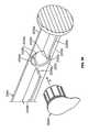
- FIG. 1is a perspective view of an antiseptic cap equipped plunger and syringe barrel assembly prior to connection of a syringe tip to an access point to a central venous catheter;
- FIG. 2is a perspective view of an antiseptic cap equipped plunger and syringe barrel assembly with the syringe tip connected to an access point to a central venous catheter;
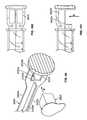
- FIG. 3is a perspective view of an antiseptic cap equipped plunger and syringe barrel assembly prior to connection of the antiseptic cap to an access point to a central venous catheter;
- FIG. 4is a perspective view of an antiseptic cap equipped plunger and syringe barrel assembly after connection of the antiseptic cap to an access point to a central venous catheter;
- FIG. 5is a perspective view assembly drawing of an antiseptic cap equipped plunger
- FIG. 6is a perspective view of an antiseptic cap equipped plunger in a partially assembled state
- FIG. 7is a perspective view of the antiseptic cap equipped plunger of FIG. 6 with a top seal
- FIG. 8is a perspective view of an antiseptic cap equipped plunger of FIG. 7 mounted in a lumen of a syringe barrel;
- FIG. 9is a side view in cutaway of an antiseptic cap equipped plunger and syringe barrel assembly
- FIG. 10shows an exploded view of a detail of FIG. 9 of one embodiment of the antiseptic cap equipped plunger and syringe barrel assembly
- FIG. 11shows an exploded view of a detail of FIG. 9 of another embodiment of the antiseptic cap equipped plunger and syringe barrel assembly
- FIGS. 12-14show various embodiments of grips of the antiseptic cap equipped plunger assembly
- FIGS. 15-17show various views of one embodiment antiseptic cap equipped plunger and syringe barrel assembly with a barrel lock to resist rotation of the plunger assembly with respect to the syringe barrel;
- FIG. 18shows another embodiment of a barrel lock to resist rotation of the plunger assembly with respect to the syringe barrel
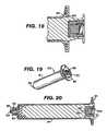
- FIGS. 19-20show various views of another embodiment antiseptic cap equipped plunger and anti-reflux syringe barrel assembly with a barrel lock to resist rotation of the plunger assembly with respect to the syringe barrel;
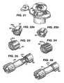
- FIG. 21shows a perspective view of another embodiment antiseptic cap equipped plunger and syringe barrel assembly with a barrel lock to resist rotation of the plunger assembly with respect to the syringe barrel;
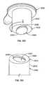
- FIGS. 22 a,bare respectively a perspective view of an antiseptic cap without a sponge and with a sponge;
- FIGS. 23 and 24are different embodiments of the antiseptic cap with varying gripping features
- FIG. 25is a perspective view of the antiseptic cap of FIG. 22 b prior to docking with a valve
- FIG. 27is a side view in cutaway of the antiseptic cap and valve assembly shown in FIG. 26 ;
- FIGS. 28-30are side views in cutaway of two different embodiments of the antiseptic cap
- FIGS. 31 a,bare, respectively, side views in cutaway showing an antiseptic cap with a centrally disposed actuation post mounted on a valve with the valve in the unactivated and activated positions;
- FIGS. 32 and 33are side views in cutaway showing two different embodiments of an antiseptic cap having a molded sponge
- FIG. 34is a side view in cutaway showing another embodiment of an antiseptic cap having a molded sponge docked to a valve;
- FIG. 35is a side view in cutaway showing a step of attaching a molded sponge to an antiseptic cap
- FIG. 36is a side view in cutaway showing a step of delivering an antiseptic compound to a molded sponge positioned within a cap;
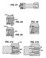
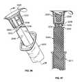
- FIG. 37shows a side view in cutaway of an antiseptic cap docking to a valve with the antiseptic cap having an antiseptic coating
- FIG. 38shows a perspective view of an antiseptic cap in a blister package
- FIG. 39is a side cross-sectional view of an antiseptic cap with a thread cover
- FIG. 41is a side cross-sectional view of an antiseptic cap with a thread cover
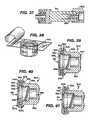
- FIGS. 42 a,bare perspective front and back views of an antiseptic cap with a thread cover connected to a Cardinal SMART SITE access site;
- FIGS. 43 a,bare perspective front and back views of an antiseptic cap without a thread cover connected to a Cardinal SMART SITE access site;
- FIGS. 44 a,bare perspective front and back views of an antiseptic cap with a thread cover connected to a Hospira (ICU) C1000 Clave access device;
- FIGS. 45 a,bare perspective front and back views of an antiseptic cap without a thread cover connected to a Hospira (ICU) C1000 Clave access device;
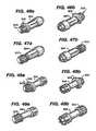
- FIGS. 46 a,bare perspective front and back views of an antiseptic cap with a thread cover connected to a B. Braun ULTRASITE access device;
- FIGS. 47 a,bare perspective front and back views of an antiseptic cap without a thread cover connected to a B. Braun ULTRASITE access device;
- FIGS. 48 a,bare perspective front and back views of an antiseptic cap with a thread cover connected to a Rymed INVISION PLUS access device;
- FIGS. 49 a,bare perspective front and back views of an antiseptic cap without a thread cover connected to a Rymed INVISION PLUS access device;
- FIG. 50is a side cross-sectional view of an antiseptic cap with a thread cover connected to a Cardinal SMARTSITE PLUS access device;
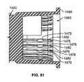
- FIG. 51is a side cross-sectional view of an antiseptic cap with a thread cover connected to a Cardinal SMARTSITE PLUS access device and the thread cover having a reduced diameter when compared to the thread cover shown in FIG. 50 ;
- FIG. 53is an assembly view of an antiseptic cap and cup holder equipped plunger and syringe barrel system
- FIG. 54is an assembly view of a cup-holder-antiseptic cap assembly adjacent a plunger and syringe barrel system
- FIG. 55is a side view in cross-section of an antiseptic cap and cup holder equipped plunger and syringe barrel assembly
- FIG. 56 ais a perspective view of a medical access device adjacent an antiseptic cap equipped plunger and syringe barrel assembly with a lid stock peeled back in preparation for docking;
- FIG. 56 bis a perspective view of a medical access device docked to an antiseptic cap equipped plunger and syringe barrel assembly;
- FIG. 56 cis a perspective view of a medical access device docked to an antiseptic cap adjacent a plunger and syringe barrel assembly;
- FIG. 57is an enlarged view of a cup holder and antiseptic cap assembly adjacent an open and empty chamber of a syringe plunger;
- FIG. 58is an enlarged view of a cup holder and antiseptic cap assembly positioned within a chamber of a syringe plunger;
- FIG. 59is a perspective view of an alternative embodiment of an antiseptic cap assembly adjacent a syringe plunger and barrel assembly;
- FIG. 60is a perspective view of an alternative embodiment of an antiseptic cap assembly docked to a syringe plunger and barrel assembly;
- FIG. 61is a perspective view of an alternative embodiment of an antiseptic cap assembly docked to a syringe plunger and barrel assembly with an outer wall being transparent to reveal interior portions of the assembly;
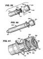
- FIG. 62is a perspective view of a tip cap assembly having an antiseptic cap attached to a syringe
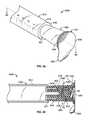
- FIG. 63is a cross-sectional view of a tip cap having an antiseptic cap attached to a syringe
- FIG. 64is an exploded, perspective view showing an antiseptic cap and a tip cap
- FIG. 65is an exploded, perspective view showing an antiseptic cap holder assembly, a tip cap, and a syringe;
- FIG. 66is an exploded, perspective view showing an antiseptic cap holder assembly, a tip cap, and a syringe;
- FIG. 67Ais a cross-sectional view of an antiseptic cap assembly attached to a syringe
- FIG. 67Bis a cross-sectional view of an antiseptic cap assembly and a flexible cap
- FIG. 68is a side view of an antiseptic cap holder assembly attached to a tip cap attached to a syringe;
- FIG. 69is a perspective view of an antiseptic cap holder assembly
- FIG. 70is a perspective view of a tip cap
- FIG. 71is a cross-sectional view of the antiseptic cap holder assembly of FIG. 69 and the tip cap of FIG. 70 disengaged and unlocked;
- FIG. 72is a cross-sectional view of the antiseptic cap holder assembly of FIG. 69 and the tip cap of FIG. 70 engaged and locked;
- FIG. 73is a perspective view of a syringe having a plunger with a cap holder assembly that is manually removable from the plunger;
- FIG. 74is a cross-sectional view of the syringe, plunger, and cap holder assembly of FIG. 73 ;
- FIGS. 75 and 76are sequential views, showing the process of manually removing the cap holder assembly from a chamber of the plunger;
- FIG. 77is a perspective view of another embodiment of a chamber of a plunger with ribs having grooves;
- FIG. 78is a cross-sectional view of the chamber of FIG. 77 ;
- FIG. 79is a cross-sectional view of a cap holder assembly positioned within the chamber shown in FIG. 78 ;
- FIG. 80is a cross-sectional view of a cap holder assembly partially removed from the chamber shown in FIG. 78 ;
- FIG. 81is a cross-sectional view of another embodiment of a chamber of a plunger with ribs having two sets of grooves;
- FIG. 83is a cross-sectional view of a cap holder assembly partially removed from the chamber shown in FIG. 81 ;
- FIG. 84is a perspective view of another embodiment of a plunger having sidewalls with recessed areas
- FIG. 85is a perspective view of another embodiment of a plunger having two or more sidewalls positioned at angles of greater than ninety degrees from each other to provide access to the chamber;
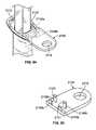
- FIG. 86is a perspective view of another embodiment of a syringe having a flange with receptacles for receiving a cap holder assembly;
- FIG. 87is a perspective view of the syringe shown in FIG. 86 with a cap holder assembly positioned in a receptacle;
- FIG. 88is a perspective view of a flange connector panel having a cap holder assembly receptacle and a flange slot in a sidewall;
- FIG. 89is a top view of the flange connector panel of FIG. 88 connected to a gripping flange of a syringe;
- FIG. 90is a perspective view of another embodiment of a flange connector panel having a flange slot in another sidewall;
- FIG. 91is a top view of the flange connector panel of FIG. 90 connected to a gripping flange of a syringe;
- FIG. 92is a perspective view of another embodiment of a syringe with a gripping flange having engagement teeth
- FIG. 93is a perspective view of a flange connector panel that engages with the gripping flange of FIG. 92 ;
- FIG. 94is a perspective view of another embodiment of a flange connector panel for connection with a gripping flange having a lip;
- FIG. 95is a perspective view of a flange connector panel that attaches to the gripping flange of FIG. 94 ;
- FIG. 96is a perspective view of a plunger and cap holder assembly connected by a frangible attachment
- FIG. 97is a cross-sectional view of the plunger and cap holder assembly of FIG. 96 ;
- FIG. 98is an exploded view of a plunger having a transverse opening to receive a cap holder assembly
- FIG. 99is an exploded view of another embodiment of a plunger having a transverse opening for receiving a cap holder assembly
- FIG. 100is a front view of the plunger of FIG. 99 ;
- FIG. 101is a side view of the plunger of FIG. 99 ;
- FIG. 102is a perspective view of another embodiment of a cap holder assembly having a locking flange
- FIG. 103is a partial perspective view of a plunger having a locking chamber
- FIG. 104is a partial cross-sectional view of the cap holder assembly of FIG. 102 and the plunger of FIG. 103 disengaged and unlocked;
- FIG. 105is a cross-sectional view of the cap holder of the cap holder assembly of FIG. 102 and the plunger of FIG. 103 engaged and locked;
- FIG. 106is a perspective view of another embodiment of a plunger having a locking lever and a cap holder assembly disposed therein;
- FIG. 107is a cross-sectional view of the plunger and cap holder assembly of FIG. 106 ;
- FIG. 108is a side view of the locking lever of FIGS. 106 and 107 ;
- FIG. 109is a cross-sectional view of another embodiment of the plunger and cap holder assembly that includes a locking lever with a toe;
- FIG. 110is a side view of the locking lever of FIG. 109 ;
- FIG. 111is a side view of a cap holder assembly and a plunger each having an adhesive material thereon;
- FIG. 112is a side view of a cap holder assembly and a plunger with compressible material in an uncompressed state
- FIG. 113is a side view of a cap holder assembly and plunger with the compressible material in a compressed state
- FIG. 114is a cross-sectional view of a plunger and a cap holder assembly, wherein the cap holder assembly flange is positioned a distance away from the plunger flange;
- FIG. 115is an exploded view of a plunger having a locking flange attached thereto and a cap holder assembly
- FIG. 116is a perspective view of the plunger and the cap holder assembly of FIG. 115 disposed in the plunger;
- FIG. 117is a top view of the locking flange of FIGS. 115 and 116 ;
- FIG. 118is a top view of another embodiment of the locking flange of FIGS. 115 and 116 .
- FIGS. 1 and 2show an antiseptic cap equipped plunger and syringe barrel assembly 10 having an antiseptic cap equipped plunger (or piston) assembly 12 and a syringe barrel 14 .
- the barrel 14has a side wall 16 defining a chamber 18 and the barrel has a proximal end 20 and a distal end 22 .
- the proximal end 20has an opening 22 to the chamber 18 and a flange 24 extending radially outwardly from the wall 16 .
- the flange 24has upper and lower surfaces 26 , 28 and provides gripping surfaces for a user of the assembly 10 .
- the distal end 22 of the barrel 14has an end wall 30 and an elongate tip 32 extending distally therefrom and having a passageway 34 therethrough and in fluid communication with the chamber 18 .
- the distal end wall 30in one preferred form of the invention, is generally conically shaped and, as is well known in the art, can have a locking luer collar 35 concentrically surrounding the tip 32 and having a set of threads 37 on an inside surface thereof.
- the luer collar 35allows for attaching a needle or a cannula to the syringe assembly and for docking the assembly to mating threads located on other devices such as valves and injection sites.
- FIG. 1shows the syringe assembly proximate an access site 38 having a valve 39 controlling access to a lumen of a tubing 41 .
- the chamber 18 of the syringe assembly 10will be filled with a locking solution or a flush solution for use with an indwelling, central venous catheter.
- a locking or flush solutionfor use with an indwelling, central venous catheter.
- Suitable locking or flushing solutionswill be set forth below.
- the flush or locking solutionis injected into a fluid access site of the catheter to clean and disinfect the catheter and can be withdrawn from the catheter or allowed to remain in an end portion of the catheter to serve as a barrier to the ingress of pathogens and contaminants.
- the antiseptic cap plunger assembly 12has an elongate shaft 40 , a proximal end 42 and a distal end 44 .
- the elongate shaft 40in one preferred form of the invention, is generally cruciform in cross-sectional shape.
- a stopper or piston 50is connected to the distal end 44 of the plunger 12 .
- the piston 50is dimensioned such that when inserted into the syringe barrel chamber 18 an outer circumferential surface of the piston is in fluid-tight engagement with an inner surface 54 of the syringe barrel.
- the piston assembly 12when moved proximally (or when being withdrawn) can draw fluid into the chamber and when moved distally (or when inserted into the syringe chamber) can drive fluid out of the chamber.
- FIG. 1shows the piston assembly 12 partially inserted into the syringe chamber and
- FIG. 2shows the piston assembly fully inserted into the syringe chamber to deliver fluid to the tubing 41 .
- a housing 60is located at the proximal end of the plunger assembly 12 and has a wall 62 defining a chamber 64 having an open end 66 which can be sealed by any suitable structure or material such as a cap or by a foil material 68 .
- An optional annular flange 70extends radially outwardly from the wall 62 and provides a surface upon which the sealing structure can be attached.
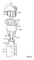
- FIG. 5shows a cap assembly 80 proximate the chamber 64 of the housing 60 and FIG. 6 shows the cap assembly 80 positioned within the chamber 64 .
- the cap assembly 80has a cap 82 having a wall 83 defining a chamber 84 containing an absorbent material 86 such as a sponge.
- the sponge 86in a preferred form of the invention, is wetted or soaked with an agent such as an antiseptic, anticoagulant or antimicrobial (“antiseptic solution”) and can be selected from the locking and flushing solutions set forth below or the antiseptic solutions set forth below.
- the cap 82has an interior surface 87 with a set of threads 88 for mating with a set of threads on the access site 38 .
- FIGS. 7 and 8show the cap assembly 80 sealed with a foil material or lid stock material 68 which can be attached to the flange 70 by any suitable method such as by adhesives or by conductive or inductive heat sealing techniques.
- FIG. 7shows the antiseptic cap piston assembly 12
- FIG. 8shows the antiseptic cap equipped piston assembly 12 inserted into the chamber of the syringe barrel 14 to define the antiseptic cap equipped piston and syringe barrel assembly 10 .
- FIGS. 3 and 4show one possible method for utilizing the cap assembly 80 by docking with the access device 38 .
- FIG. 3shows the lid stock 68 peeled away from the flange 70 and
- FIG. 4shows docking the antiseptic cap assembly 80 to the valve 39 .
- the syringe barrelis rotated clockwise or counterclockwise to engage the threads 88 of the antiseptic cap assembly 80 with the threads of the access site 38 .
- the syringe barrel 14will be moved away from the access site 38 and the antiseptic cap assembly 80 will slide outward from the housing 60 and remain docked to the access site 38 .
- the antiseptic cap assembly 80can remain docked to the valve 39 of the access site 38 for any suitable period of time from a few minutes to numerous hours.
- the tubing or catheter 41is sealed to block the ingress into the catheter of pathogens and contaminants and a portion of the access site 38 is exposed to the antiseptic material in the sponge 86 .
- the present inventionprovides a mechanism associated with the assembly 10 for preventing the rotation of the antiseptic cap assembly 80 with respect to the plunger assembly 12 and more preferably a mechanism on either the plunger assembly or on the antiseptic cap 80 to prevent relative rotational movement between the antiseptic cap 80 and the plunger assembly 12 .
- the mechanism for preventing relative rotation of the antiseptic cap 80 with respect to the plunger assembly 12has mating portions on both parts that when assembled cooperatively engage one another to prevent relative rotation. It is also contemplated that a separate mechanism, device or member could be used to lock the two parts together to achieve this purpose.
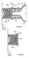
- FIGS. 5, 9-11show exemplary structures for locking the antiseptic cap assembly 80 inside the housing 60 so that these parts rotate together and one part does not rotate in a direction or at a rate different from that of the other part.
- FIGS. 15-18show exemplary structures for interlocking the antiseptic cap plunger assembly 12 with the syringe barrel 14 .
- the housing 60will have a feature or structure that forms an interference fit with an external surface 83 of the antiseptic cap 80 .
- an internal surface 63 of the side wall 62 of the housing 60will have a feature or structure to form an interference fit with a portion of the antiseptic cap assembly 80 .
- the antiseptic cap assembly 80will have a feature to form an interference fit with the housing 60 and even more preferably the outer surface 83 of the antiseptic cap 80 will have a feature to contact the inner surface 63 of the housing side wall 62 .
- FIG. 5shows one preferred form of the invention having a plurality of circumferentially spaced and axially extending ribs 100 on the internal surface 63 of the housing side wall 62 (internal ribs 100 ) for engaging the wall 83 of the antiseptic cap 82 to lock the cap assembly 80 in place to prevent rotation of the cap assembly 80 when positioned inside the housing 60 .
- the internal ribs 100extend from a bottom wall 102 up to an intermediate height of the housing sidewall 62 .
- the internal ribs 100will have a height roughly equal to a height of the cap 82 .
- a plurality of internal slots 108are defined between each set of adjacent internal ribs 100 .
- the internal ribs 100in a preferred form of the invention, will have a width that tapers inwardly from proximate the bottom wall 102 to a top 104 of the internal ribs 100 so that the width of the internal ribs decrease from a bottom 106 of a rib to the top 104 of the rib.
- the top of the internal ribs 100have a generally arcuate profile to act as a lead-in during insertion of the antiseptic cap assembly 80 into the housing 60 .
- the internal ribs 100will terminate short of a top 113 of the housing sidewall 62 to define an annular gap 111 between the top of the rib 104 and the top 113 . Also, extending radially inwardly from the internal surface 63 of the cap 82 is a detent 109 positioned proximate a top portion 113 of the side wall 62 .
- the antiseptic cap 82has a plurality of circumferentially spaced and axially extending ribs 120 extending along an external surface 122 of the cap 82 (external ribs 120 ) from an annular flange 123 .
- the external ribs 120are dimensioned for engaging a portion of the interior wall of the housing 62 to prevent relative rotation of the cap and the plunger assembly 14 and define a plurality of external slots one of each between each adjacent pair of external ribs.
- each of the external ribs 120are positioned within an internal slot 108 and each of the internal ribs are positioned within an external slot to lock together these parts to assure that the cap rotates in the same direction as the plunger rod.
- FIGS. 6 and 11also show that when the cap 82 is positioned within the housing 60 , the detent 109 contacts the annular flange 123 to hold the cap in the housing to prevent or resist inadvertent dropping of the cap from the housing prior to docking of the cap with the access site.
- the external ribs 120are specifically designed in conjunction with internal slots 108 so that the antiseptic cap is guided out of the storage chamber 64 as the cap is screwed onto the threads of the access site.
- FIGS. 12-14show several embodiments of gripping surfaces on the housing 60 (with lid stock 68 removed) to facilitate use of the assembly 10 or the plunger assembly 12 .
- FIG. 12shows axially extending and circumferentially spaced protuberances 130 on an outer surface of the wall 62 .
- the protuberances 130can have numerous different cross-sectional shapes including circular, polygonal, oval and irregular and, in a preferred form of the invention, extend from the flange 70 to a bottom of the housing.
- FIG. 13shows a housing 60 that has no flange 70 and has protuberances 130 on the wall 62 extending substantially the entire height of the housing 60 .
- FIG. 14shows a housing 60 where the outer surface of the wall 62 is relatively smooth but has a series of circumferentially spaced and axially extending protuberances 130 on a circumferential edge of the flange 70 .
- the optional plunger assembly 12 and syringe barrel 14 locking feature or structurecan be positioned alone on the plunger assembly 12 , or alone on the syringe barrel 14 or have cooperating structures on both the plunger assembly 12 and the syringe barrel 14 . It is also contemplated that a separate mechanism, device or member could be used to lock the two parts together to achieve this purpose.
- FIGS. 15-18show various embodiments for the optional feature of locking the plunger assembly 12 from rotational motion with respect to the syringe barrel 14 .
- a wing 150extending axially along an outside surface of the housing side wall 62 engages a tooth 152 positioned on an interior surface of the syringe barrel at is proximal end.
- the plunger assembly 14will have more than one wing 150 with each wing being circumferentially spaced from the other.
- the plunger assemblywill have four wings 150 spaced 90 degrees from one another.
- the syringe barrelwill have a plurality of circumferentially spaced teeth. When the plunger assembly is nearly fully inserted into the syringe barrel each of the wings will extend into a tooth to prevent rotation of the plunger assembly 12 with respect to the syringe barrel 14 .
- FIG. 18shows another embodiment of a locking feature to prevent rotation of the plunger assembly 12 with respect to the syringe barrel 14 and also prevents relative translational motion of the parts.
- an annular protuberance 160positioned on an interior surface of the syringe barrel at its proximal end 20 engages an annular detent 162 on an outside surface of the plunger rod.
- FIGS. 19 and 20show an antiseptic cap equipped plunger assembly 12 and non-refluxing syringe assembly 170 .
- Non-refluxing syringesare well known in the art and there are numerous methodologies for reducing reflux while accessing the access site of a central venous catheter.
- the annular flange 70 of the plunger assembly 12abuts the flange 24 of the syringe barrel prior to the piston 50 contacting an interior surface of the syringe distal end wall 30 .
- FIGS. 22 a, bshow a stand-alone antiseptic cap assembly 200 having three circumferentially spaced ribs 120 for grasping by the hand of a user of the cap assembly.
- FIG. 22 ashows the cap 82 without an absorbent material 86 and
- FIG. 22 bshows the cap with an absorbent material.
- the cap 200can be used for the same purposes of the cap assembly 80 described above but will be used by hand. All other features of the cap 200 are essentially the same as described above with the exception that the cap 200 does not have to be dimensioned to fit within a chamber carried by a syringe plunger.
- FIGS. 23 and 24show varying frequency of ribs 120 and varying shapes and sizes.
- FIG. 25shows the cap 200 proximate the access site 38 and FIGS. 26 and 27 show the cap 200 docked to the access site 38 .
- a suitable absorbent material 86includes medical grade materials capable of storing and releasing an antiseptic liquid, or liquid having other medical purposes, and includes materials such as sponges, rupturable capsules and other materials or devices capable of serving this purpose.
- Suitable spongescan include any sponge suitable for use for medical purposes and can be naturally occurring or synthetic. The sponges can be die cut into suitable shapes or can be molded into the desired shape. It is desirable that the sponge 86 be attached to the antiseptic cap 82 to prevent the sponge 86 from inadvertently falling out of the cap 82 .
- FIG. 28shows the sponge 86 is captured between an annular wall 202 and a disc 204 attached to the cap 82 by any suitable method such as ultrasonic or vibrational welding or other techniques well known in the art.
- FIGS. 29 and 30show a variation on the cap assembly 200 of FIG. 28 .
- the spongeis retained in the cap 82 with a plastic sheet 206 heat welded to the cap.
- the spongeis attached by an adhesive or by other method to form an assembly which is then attached to the cap.
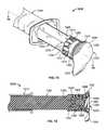
- FIGS. 31 a, bshow the cap 200 having a coaxially disposed and axially extending actuating post 220 circumferentially surrounded by a sponge 86 having a centrally positioned hole to fit over the post 220 .
- FIG. 31 ashows the cap 200 in initial engagement with the access site 38 and
- FIG. 31 bshows the cap threaded onto the access site 38 and the actuating post opens the valve 39 and antiseptic fluid is allowed to flow into the valve.
- FIGS. 32-34show varying shaped sponges that, in one preferred form of the invention, were molded into various desirable shapes.
- the sponge of FIG. 34has a central opening 230 to facilitate attaching the sponge to the cap and to filling the sponge with antiseptic, anticoagulant or other suitable fluids set forth above.
- FIG. 35shows the cap having a centrally disposed energy director 231 , an ultrasonic welder 232 being brought into cooperative engagement with the sponge on a side of the sponge opposite the energy director 231 . By applying ultrasonic energy the energy director 231 melts and attaches the sponge to the cap.
- FIG. 36shows a filling device 240 , having a lumen 242 and a dispensing head 244 in fluid communication with a source of antiseptic, anticoagulant or the like for dispensing a metered amount of such fluid into the interior portion of the sponge.
- FIG. 37shows an alternative embodiment of the antiseptic cap 200 where the sponge is replaced by an antiseptic coating on the actuating post 220 .
- FIG. 38shows the antiseptic cap 200 positioned in a blister pack 233 prior to sealing the blister pack.
- FIG. 39shows an antiseptic cap 300 with a thread cover 302 .
- the thread cover 302can be part of any of the antiseptic caps discussed herein.
- the thread cover 302is made of a deformable material capable of flexing upon application of moderate force applied by hand.
- the thread cover 302is made from a polymeric containing material and more preferably a polymeric material having a modulus of elasticity of less than 20,000 psi.
- the polymeric materialwill be an elastomer or plastomer or like material.
- the thread cover 302enhances the connection between the antiseptic cap 300 and a device such as a valve or other access devices 38 .
- the thread cover 302can provide a universal fit to most commercially available valves, connectors and access devices, or the thread cover 302 can be customized to dock with a particular access device.
- FIG. 39shows, as is described above, the antiseptic cap 300 has an annular wall 305 having a first end 306 and a second end 320 with the first end having a greater diametrical dimension than the second end.
- the annular walldefines a central chamber 322 having an open end 323 .
- the chamber 322will have a sponge 86 positioned therein as shown in FIGS. 5 and 6 above, although it is not shown in FIG. 39 .
- the thread cover 302is shown attached by an optional bonding layer 304 to the first end 306 of the annular wall 305 .
- the thread cover 302has a first leg 308 and a second leg 310 .
- the first leg 308extends parallel to the annular wall 305 and the second leg 310 extends radially inwardly from the annular wall 305 in a direction transverse to the first leg 308 and across a portion of the open end 323 and defines a central opening 312 , having a reduced diameter when compared to the open end 323 , into the chamber 322 .
- the second leg 310terminates at a distal end 330 with a rounded outer surface 332 .
- FIG. 41shows an alternative embodiment of the antiseptic cap 300 that differs from the antiseptic cap shown in FIGS. 39 and 40 by not including a counterbore 336 shown in these figures.
- the counterbore 336provides a chamber of reduced diameter and, therefore, will form a tighter fit with access devices with a narrower outer diameter when compared to the cap shown in FIG. 41 which does not include the counterbore.
- Thisis just one example of the modifications that can be made to the geometry of the antiseptic cap to enhance the connection between the cap and an access site.
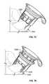
- FIGS. 42 a,bshow front and back views of the antiseptic cap 300 with the thread cover 302 connected to a Cardinal SMART SITE access site 350 .
- FIGS. 43 a,bare perspective front and back views of the antiseptic cap without the thread cover 302 connected to the Cardinal SMART SITE access site.
- FIGS. 46 a,bare perspective front and back views of the antiseptic cap 300 with the thread cover 302 connected to a B. Braun ULTRASITE access device 354 .
- FIGS. 47 a,bare perspective front and back views of the antiseptic cap without the thread cover 302 connected to the B. Braun ULTRASITE access device.
- FIGS. 48 a,bare perspective front and back views of the antiseptic cap with the thread cover 302 connected to a Rymed INVISION PLUS access device; 356 .
- FIGS. 49 a,bare perspective front and back views of the antiseptic cap without the thread cover 302 connected to a Rymed INVISION PLUS access device.
- FIGS. 50-52show various embodiments of the thread cover 302 .
- FIG. 50differs from FIG. 51 in that the second leg 310 extends farther across the opening of the chamber in FIG. 51 than shown in FIG. 50 .
- FIG. 52shows another embodiment of the thread cover 302 having a segmented second leg 310 a,b . This embodiment may be desirable to provide a more effective seal for certain access devices.
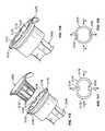
- FIG. 53shows an exploded view of an alternative embodiment 400 of the syringe barrel assemblies 10 , discussed above, incorporating a cap holder 402 into the system of parts.
- the alternative assembly and system 400has an antiseptic cap and cap holder equipped plunger assembly 12 ′, a syringe barrel 14 , an antiseptic cap 82 (shown with an optional thread cover 302 ), an absorbent material 86 , and peelable lid stock 68 .
- FIG. 54shows an exploded view of an antiseptic cap holder assembly 404 including the cap holder 402 with the antiseptic cap assembly 80 positioned within a chamber 406 of the cap holder 402 .
- This embodiment 400allows for the separate manufacture, assembly, and sterilization of the assembly 400 from the plunger assembly and the syringe barrel.
- the cap holder 402 or the antiseptic cap 82will have a structure, element or the like that prevents the relative rotation of the cap holder 402 and the antiseptic cap 82 until the antiseptic cap assembly 80 is securely docked to the access device 38 .
- the cap holder 402 or the plunger assembly 12 ′will have a structure, element or the like for preventing the relative rotation of the cap holder 402 and the plunger assembly 12 ′ until the antiseptic cap assembly 80 is securely docked to the access device 38 .
- Any of the anti-rotation devices discussed above to stop the rotation of the antiseptic cap assembly 80 with the plunger assembly 12would be suitable for, these purposes.
- the devices discussed above in reference to FIGS. 15-21 to prevent the relative rotation of the plunger assembly 12 and the syringe barrel 14could be incorporated into this embodiment 400 .
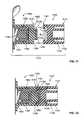
- FIG. 53shows the inner wall surface 412 of the cap holder 402 carries the internal ribs 100 and the internal slots 108 that interact with the external ribs and external slots 120 , 122 of the cap 82 as is described above with respect to FIG. 5 .
- These structuresprevent or resist the relative rotation of the cap holder 402 with respect to the antiseptic cap assembly 80 .
- ribsreferred to herein are structures that are raised or extend outward from a surface.
- slotsrefer to structures that extend below a surface or is defined between two ribs and is at a lower level than the ribs.
- FIG. 53also shows an interlocking structure for preventing the relative rotation of the cap holder 402 , or the cap holder assembly 404 , with respect to the plunger assembly 12 ′.
- the outer wall surface 414has a plurality of circumferentially spaced and axially extending ribs 420 defining slots 424 between each pair of adjacent ribs.
- the ribs 420are generally triangular in shape having a base portion 426 and an apex portion 428 .
- the slots 424are oppositely-oriented triangularly shaped areas having slot base portions 430 extending between two adjacent rib apex portions 428 and slot apex portions 432 separating adjacent rib base portions 426 .
- plunger ribs 434 and plunger slots 436On the internal wall surface 63 of the plunger chamber 64 are similarly shaped plunger ribs 434 and plunger slots 436 .
- the ribs 420are dimensioned to fit within the plunger slots 436 and the slots 424 are dimensioned to fit over and receive the plunger ribs 434 .
- the cap holder ribs 420are interdigitated with the plunger ribs 434 to prevent or resist the relative rotation of the cap holder 402 , or cap holder assembly 404 , with respect to the plunger assembly 12 ′.
- the cap holder 402 , the cap holder assembly 404 or the plunger assembly 12 ′will have a structure, element or the like that resists the relative axial movement of these parts when the cap holder 402 or the cap holder assembly 404 is positioned fully within the plunger assembly 12 ′.
- the cap holder 402has an annular protuberance 440 that is dimensioned to fit within an annular groove 442 on the inner wall surface 414 of the cap holder and preferably extends in line with the base portions of the plunger ribs 434 .
- a second locking structurehaving a plurality of teeth 450 which extend axially outward from the outer wall surface 414 of the cap holder and are positioned in slots 424 .
- the teethextend axially outwardly to a height beyond the height of the ribs 434 .
- the teeth 450can be positioned in one or more of the slots or in each of the slots 424 or in alternating slots or, as is shown, circumferentially spaced 90° from one another.
- the teeth 450preferably are positioned at an intermediate portion, between the base and the apex, of a slot 424 .
- the teeth 450are dimensioned to fit within a segmented annular groove 452 that extends circumferentially about the inner surface 412 crossing through the plunger ribs 434 at an intermediate portion, between the base and the apex, of the plunger ribs 434 .
- FIGS. 56 a,b,crespectively show the assembly 400 in a ready-for-use position, docked position, and used position.
- the assembly 400is used in essentially the same fashion as described above with respect to FIGS. 3 and 4 except that when the assembly 400 is in the used position the cap holder 402 remains in the plunger assembly 12 ′.
- the syringe barrel and plungercan be fabricated from any material suitable for its purpose and includes glass and polymeric material.
- Suitable polymeric materialsinclude, but are not limited to, homopolymers, copolymers and terpolymers formed from monomers such as olefins, cyclic olefins, amides, esters, and ethers.
- the polymeric materialmay be a blend of more than one polymeric material and can be a monolayer structure or a multilayer structure.
- the syringe barrel and the plungerare injection molded from a polypropylene material.
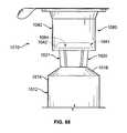
- FIGS. 59-61show a third embodiment 500 of an antiseptic cap equipped syringe plunger and barrel assembly with the antiseptic cap assembly 80 and lid stock 68 removed for clarity.
- the third embodiment 500provides for retrofitting an antiseptic cap assembly 502 to a standard plunger 504 .
- the antiseptic cap 502has a first generally cylindrical outer wall 506 having a proximal end 508 and a distal end 510 .
- the proximal end 508is removably or fixedly attached to a button 512 of the plunger 504 .
- the proximal endhas an opening 514 dimensioned to fit about the button 512 and has a member for attaching to the button.
- the attaching memberincludes a plurality of circumferentially spaced, and axially inwardly directed tabs 516 extending from an inner wall surface 518 and the tabs engage a lower surface of the button 512 to attach the antiseptic cap assembly 502 to the plunger 504 .
- the distal end of the antiseptic cap 502has a top annular flange 520 extending radially inwardly from the first cylindrical wall 506 and defines a generally circular opening 522 .
- a second cylindrical wall 524extends axially downwardly from the top annular flange 520 and is coaxially disposed within the first cylindrical wall 506 .
- the second cylindrical wall 524defines a chamber as is shown in greater detail in FIG. 5 above with the ribs and slots as described for engaging the antiseptic cap assembly 80 to prevent relative rotational movement and to resist relative axial movement of the parts when the antiseptic cap assembly 80 is fully inserted into the chamber. Further, it is contemplated adapting the plunger and syringe as described above to prevent or resist the relative rotational movement of the plunger with respect to the barrel.
- the piston 50can be formed from any suitable material including a polymeric material or a silicone material.
- the stoppercan be selected from a material with a desired durometer so that reflux is reduced when the stopper engages an inner surface of the distal end wall of the syringe barrel.
- Suitable locking and flush solutionsinclude a lower alcohol selected from ethanol, propanol and butanol.
- the locking solutioncan be a single lower alcohol or a blend of lower alcohols.
- Suitable locking solutionscan also include a lower alcohol with an antimicrobial and/or an anticoagulant.
- Suitable locking solutionscan contain at least one lower alcohol in a range from 1% to 99% by volume and at least one other anti-microbial and/or anti-coagulant compound in a range from 1% to 99% by volume.
- the lower alcoholwill usually be in aqueous solution, typically at 1% to 99% by volume, usually from 5% to 95% by volume.
- the at least one other anti-microbialis selected from the group consisting of taurolidine and triclosan
- the at least one anti-coagulantis selected from the group consisting of riboflavin, sodium citrate, ethylene diamine tetraacetic acid, and citric acid.
- the syringe assembly 10will be pre-filled with one of the locking solutions and will be packaged by a manufacture and shipped to a health care provider.
- a cannula or needlewill be attached to the distal end of the barrel and placed into fluid communication with the fluid access site of an indwelling central venous catheter.
- the flush solutionwill be injected into the catheter to clean or lock the catheter.
- the cap assembly 80will be removed from the plunger 17 and the cap will be docked to the fluid access site of the catheter.
- the antisepticis a solution a citrate salt and in another form of the invention the citrate salt solution is a hypertonic solution.
- hypertonicis used herein to refer to a fluid having an osmotic concentration and a density greater than the osmotic concentration and density of the blood of the patient.
- the antiseptic solutionpreferably comprises a citrate salt with a concentration range, in weight percent, of from about 1.5% to about 50% with an osmolality of about 300 to about 6400 mOsm. More preferably, the antiseptic solution comprises citrate salt in a concentration range of from about 10% to about 40%, yet more preferably, in a concentration range of from about 20% to about 30%.
- the antiseptic solutionis prepared to have a pH lower than that of the pH of the patient's blood.
- the citrate salt solutionmay be prepared to have a pH lower than about 6.5, more preferably, from about 4.5 to about 6.5.
- the citrate salt solutioncan include pharmaceutically acceptable agents such as sodium chloride and sodium heparin.
- the citrate salt solutioncan also include a variety of other antibacterial, antimicrobial and anticoagulant agents such as gentamicin, vancomycin, and mixtures of these agents. Additional anticoagulant agents include, for example heparin, urokinase, tissue plasminogen activation (tPA) and mixtures of these agents.
- citrate salt solutionand the included salts and other additives which are, within the scope of sound medical judgment, suitable for use in contact with tissues of humans and lower animals without undue toxicity, irritation, and allergic response. It is also typically necessary that a composition be sterilized to reduce the risk of infection.
- An antimicrobial agent containing antiseptic solution of the present inventionmay contain at least one alcohol, at least one antimicrobial agent and at least one chelator and/or anticoagulant.
- Various antimicrobial substances as disclosed herein and that are well known to one of ordinary skill in the artmay be combined with the locking solution in order to inhibit infection.
- the antimicrobial locking solution of the present inventionmay be use for filling or flushing a medical device such as an indwelling device such as an implanted catheter. Other medical devices that are contemplated for use in the present invention are disclosed herein.
- the antiseptic agentcan contain antibacterial agents such as those classified as aminoglycosides, beta lactams, quinolones or fluoroquinolones, macrolides, sulfonamides, sulfamethoxazoles, tetracyclines, streptogramins, oxazolidinones (such as linezolid), clindamycins, lincomycins, rifamycins, glycopeptides, polymyxins, lipopeptide antibiotics, as well as pharmacologically acceptable sodium salts, pharmacologically acceptable calcium salts, pharmacologically acceptable potassium salts, lipid formulations, derivatives and/or analogs of the above.
- antibacterial agentssuch as those classified as aminoglycosides, beta lactams, quinolones or fluoroquinolones, macrolides, sulfonamides, sulfamethoxazoles, tetracyclines, streptogram
- the aminoglycosidesare bactericidal antibiotics that bind to the 30S ribosome and inhibit bacterial protein synthesis. They are typically active against aerobic gram-negative bacilli and staphylococci . Exemplary aminoglycosides that may be used in some specific aspects of the invention include amikacin, kanamycin, gentamicin, tobramycin, or netilmicin.
- Suitable beta lactamsare selected from a class of antibacterials that inhibit bacterial cell wall synthesis.
- a majority of the clinically useful beta-lactamsbelong to either the penicillin group (penam) or cephalosporin (cephem) groups.
- the beta-lactamsalso include the carbapenems (e.g., imipenem), and monobactams (e.g., aztreonam).
- Inhibitors of beta-lactamasesuch as clavulanic acid and its derivatives are also included in this category.
- Non-limiting examples of the penicillin group of antibioticsthat may be used in the solutions of the present invention include amoxicillin, ampicillin, benzathine penicillin G, carbenicillin, cloxacillin, dicloxacillin, piperacillin, or ticarcillin, etc.
- cephalosporinsexamples include ceftiofur, ceftiofur sodium, cefazolin, cefaclor, ceftibuten, ceftizoxime, cefoperazone, cefuroxime, cefprozil, ceftazidime, cefotaxime, cefadroxil, cephalexin, cefamandole, cefepime, cefdinir, ceftriaxone, cefixime, cefpodoximeproxetil, cephapirin, cefoxitin, cefotetan etc.
- beta lactamsinclude imipenem or meropenem which are extremely active parenteral antibiotics with a spectrum against almost all gram-positive and gram-negative organisms, both aerobic and anaerobic and to which Enterococci, B. fragilis , and P. aeruginosa are particularly susceptible.
- Suitable beta lactamase inhibitorsinclude clavulanate, sulbactam, or tazobactam.
- the antibacterial solutionsmay comprise a combination of at least one beta lactam and at least one beta lactamase inhibitor.
- Macrolide antibioticsare another class of bacteriostatic agents that bind to the 50S subunit of ribosomes and inhibit bacterial protein synthesis. These drugs are active against aerobic and anaerobic gram-positive cocci, with the exception of enterococci, and against gramnegative anaerobes. Exemplary macrolides include erythromycin, azithromycin, clarithromycin.
- Quinolones and fluoroquinolonestypically function by their ability to inhibit the activity of DNA gyrase. Examples include nalidixic acid, cinoxacin, trovafloxacin, ofloxacin, levofloxacin, grepafloxacin, trovafloxacin, sparfloxacin, norfloxacin, ciprofloxacin, moxifloxacin and gatifloxacin.
- Sulphonamidesare synthetic bacteriostatic antibiotics with a wide spectrum against most gram-positive and many gram-negative organisms. These drugs inhibit multiplication of bacteria by acting as competitive inhibitors of p-aminobenzoic acid in the folic acid metabolism cycle. Examples include mafenide, sulfisoxazole, sulfamethoxazole, and sulfadiazine.
- the tetracycline group of antibioticsinclude tetracycline derivatives such as tigecycline which is an investigational new drug (IND), minocycline, doxycycline or demeclocycline and analogs such as anhydrotetracycline, chlortetracycline, or epioxytetracycline.
- tetracycline derivativessuch as tigecycline which is an investigational new drug (IND), minocycline, doxycycline or demeclocycline and analogs such as anhydrotetracycline, chlortetracycline, or epioxytetracycline.
- Suitable streptogramin class of antibacterial agentsinclude quinupristin, dalfopristin or the combination of two streptogramins.
- Drugs of the rifamycin classtypically inhibit DNA-dependent RNA polymerase, leading to suppression of RNA synthesis and have a very broad spectrum of activity against most gram-positive and gram-negative bacteria including Pseudomonas aeruginosa and Mycobacterium species.
- An exemplary rifamycinis rifampicin.
- antibacterial drugsare glycopeptides such as vancomycin, teicoplanin and derivatives thereof.
- antibacterial drugsare the polymyxins which are exemplified by colistin.
- antibacterial agentssuch as prestinomycin, chloramphenicol, trimethoprim, fusidic acid, metronidazole, bacitracin, spectinomycin, nitrofurantoin, daptomycin or other lipopeptides, oritavancin, dalbavancin, ramoplanin, ketolide etc. may be used in preparing the antiseptic solutions described herein.
- metronidazoleis active only against protozoa, such as Giardia lamblia, Entamoeba histolytica and Trichomonas vaginalis , and strictly anaerobic bacteria.
- Spectinomycinis a bacteriostatic antibiotic that binds to the 30S subunit of the ribosome, thus inhibiting bacterial protein synthesis and nitrofurantoin is used orally for the treatment or prophylaxis of UTI as it is active against Escherichia coli, Klebsiella - Enterobacter species, staphylococci , and enterococci .
- the antimicrobial agentis an antifungal agent.
- Some exemplary classes of antifungal agentsinclude imidazoles or triazoles such as clotrimazole, miconazole, ketoconazole, econazole, butoconazole, omoconazole, oxiconazole, terconazole, itraconazole, fluconazole, voriconazole, posaconazole, ravuconazole or flutrimazole; the polyene antifungals such as amphotericin B, liposomal amphotericin B, natamycin, nystatin and nystatin lipid formulations; the cell wall active cyclic lipopeptide antifungals, including the echinocandins such as caspofungin, micafungin, anidulafungin, cilofungin; LY121019; LY303366; the allylamine group of antifungals such as terbinafine.
- antifungal agentsinclude naftifine, tolnaftate, mediocidin, candicidin, trichomycin, hamycin, aureofungin, ascosin, ayfattin, azacolutin, trichomycin, levorin, heptamycin, candimycin, griseofulvin, BF-796, MTCH 24, BTG-137586, pradimicins (MNS 18184), benanomicin; ambisome; nikkomycin Z; flucytosine, or perimycin.
- the antimicrobial agentis an antiviral agent.
- antiviral agentsinclude cidofovir, amantadine, rimantadine, acyclovir, gancyclovir, penciclovir, famciclovir, foscarnet, ribavirin, or valaciclovir.
- the antimicrobial agentis an innate immune peptide or proteins.
- Some exemplary classes of innate peptides or proteinsare transferrins, lactoferrins, defensins, phospholipases, lysozyme, cathelicidins, serprocidins, bactericidal permeability increasing proteins, amphipathic alpha helical peptides, and other synthetic antimicrobial proteins.
- the antimicrobial agentis an antiseptic agent.
- antiseptic agentsinclude a taurinamide derivative, a phenol, a quaternary ammonium surfactant, a chlorine-containing agent, a quinaldinium, a lactone, a dye, a thiosemicarbazone, a quinone, a carbamate, urea, salicylamide, carbanilide, a guanide, an amidine, an imidazoline biocide, acetic acid, benzoic acid, sorbic acid, propionic acid, boric acid, dehydroacetic acid, sulfurous acid, vanillic acid, esters of p-hydroxybenzoic acid, isopropanol, propylene glycol, benzyl alcohol, chlorobutanol, phenylethyl alcohol, 2-bromo-2-nitropropan-1,3-diol, formaldehyde, glutaralde
- the antiseptic solutionincludes a basic reagent and a dye.
- the basic reagentmay be a guanidium compound, a biguanide, a bipyridine, a phenoxide antiseptic, an alkyl oxide, an aryl oxide, a thiol, a halide, an aliphatic amine, or an aromatic amine.
- the basic reagentis a guanidium compound.
- Non-limiting examples of guanidium compoundsinclude chlorhexidine, alexidine, hexamidine.
- the basic reagentis a bipyridine.
- One example of a bipyridineis octenidine.
- the basic reagentis a phenoxide antiseptic.
- the dyemay be a triarylmethane dye, a monoazo dye, a diazo dye, an indigoid dye, a xanthene dye, an anthraquinone dye, a quinoline dye, an FD&C dye.
- triarylmethane dyeinclude gentian violet, crystal violet, ethyl violet, or brilliant green.
- Exemplary monoazo dyesinclude FD&C Yellow No. 5, or FD&C Yellow No. 6.
- Other non-limiting examples of FD&C dyeinclude Blue No. 1 or Green No. 3.
- One non-limiting example of diazo dyesis D&C Red No. 17.
- An example of an indigoid dyeis FD&C Blue No. 2.
- An example of a xanthene dyeis FD&C Red No. 3; of an anthraquinone dye is D&C Green No. 6; and of an quinoline dye is D&C Yellow No. 1.
- antiseptic agentsthat may be used to prepare the antimicrobial solutions of the invention are gendine, genlenol, genlosan, or genfoctol.
- antimicrobial agentsincluding one or more antibacterial agent, and/or one or more antifungal agent, and/or one or more antiviral agent, and/or one or more antiseptic agent, and/or combinations thereof.
- chelator agentsare contemplated as useful in preparing the antiseptic solutions of the invention. This includes chelators such as EDTA free acid, EDTA 2Na, EDTA. 3Na, EDTA 4Na, EDTA 2K, EDTA 2Li, EDTA 2NH 4 , EDTA 3K, Ba(II)-EDTA, Ca(II)-EDTA,
- at least one anticoagulantsuch as heparin, hirudin, EGTA, EDTA, urokinase, streptokinase, hydrogen peroxide etc.
- alcoholsare contemplated as useful in the preparation of the instant antiseptic solution, and include any antimicrobially active alcohol.
- Non-limiting examples of alcoholsinclude ethanol, methanol, isopropanol, propylene glycol, benzyl alcohol, chlorobutanol, phenylethyl alcohol, and the like.
- the solutions of the instant inventioncan comprise various combinations of at least one alcohol, at least one antimicrobial agent, and at least one chelator/anticoagulant.
- the solution of the inventioncomprises at least one alcohol, at least one tetracycline and at least one chelator/anticoagulant.
- such an antimicrobial solutioncomprises ethanol, at least one tetracycline and EDTA or heparin.
- such a solutioncomprises ethanol, minocycline and EDTA or heparin.
- the concentration of minocyclineis 0.001 mg/ml to 100 mg/ml.
- the concentration of minocyclineis about 3 mg/ml.
- the concentration of EDTAis in the range of 10-100 mg/ml. In one embodiment of this aspect, the concentration of EDTA is about 30 mg/ml.
- the antiseptic solutionincludes a pharmacologically acceptable sodium salt, a pharmacologically acceptable calcium salt, a pharmacologically acceptable potassium salt and about one milligram per milliliter polyhexamethylene biguanide hydrochloride in an aqueous admixture.
- the solution of the inventionmay also contain a pharmacologically acceptable salt of lactic acid.
- One preferred antiseptic solutionincludes a pharmacologically acceptable sodium salt such as sodium chloride or the like in a concentration of between about 820 mg to about 900 mg, a pharmacologically acceptable calcium salt, such as calcium chloride dihydrate or the like in a concentration between about 30.0 mg to about 36.0 mg, a pharmacologically acceptable potassium salt, such as potassium chloride or the like in a concentration between about 28.5 to about 31.5 mg and about one milligram per milliliter polyhexamethylene biguanide hydrochloride in an aqueous admixture with one hundred milliliters of water for injection U.S.P.
- the solution of the inventionmay also include sodium lactate in a concentration between about 290 mg and about 330 mg in the one hundred milliliter aqueous admixture.
- the antiseptic solutioncontains an anticoagulant and a photo-oxidant.
- a photo-oxidantis selected that has an antiseptic effect.
- the term “photo-oxidant”is intended to refer to a compound (usually an organic dye) that has photo-oxidation properties, in which the compound exhibits an increased oxidizing potential upon exposure to radiant energy such as light.
- the term “photooxidant”also refers to a composition that releases one or more electrons when struck by light.
- the photo-oxidantis methylene blue, which advantageously provides antibiotic and antifungal activity, and also provides a color to make the antiseptic solution clearly identifiable.
- other photo-oxidantsmay include Rose Bengal, hypericin, methylene violet, proflavine, rivanol, acriflavine, toluide blue, trypan blue, neutral red, a variety of other dyes or mixtures thereof. Therefore, in alternate aspects of the invention, one or more alternative photo-oxidants, preferably a colored photo-oxidant is used in accordance with the invention in place of methylene blue.
- the antiseptic solutionincludes a low viscosity antibacterial agent mixed with a viscosity increasing agent.
- antibacterial agentswhich may be used, in addition to those described above, comprise alcohols, chlorhexidine, Clorpactin, iodine, tauroline, citric acid, and soluble citric acid salts, particularly sodium citrate, optionally mixed with water.
- Suitable viscosity increasing agentsinclude Carbopol, starch, methylcellulose, carboxypolymethylene, carboxymethyl cellulose, hydroxypropylcellulose, or the like.
- Carbopolis a cross-linked polyacrylic acid based polymer sold by Noveon, Inc. It is preferably neutralized to about pH 7 with a base material such as tetrahydroxypropyl ethylene diamine, triethanolamine, or sodium hydroxide.
- Derivatives of starchmay also be used, such as hydroxyethylstarch, hydroxypropylstarch, or starch having bonded organic acid ester groups, to improve compatibility with antibacterial agents such as alcohols, for example, ethanol or isopropanol.
- ester groupsmay be the reaction product of two to twelve carbon organic acids with the starch, for example.
- the elevated viscosity antiseptic solutionmay be created by the use of a fat emulsion, or other dispersions in water/alcohol of glycerol mono or di esters of fatty acids, or fatty acid esters of other polyols such as sugars having one or more bonded fatty acid groups per molecule. Analogous compounds with ether linkages may also be used.
- the fluid of this inventionmay also contain an effective amount of an antithrombogenic agent such as heparin, and a diluent such as water, along with other desired ingredients.
- an antithrombogenic agentsuch as heparin
- a diluentsuch as water
- the antiseptic solutioncontains a mixture of isopropyl alcohol and neutralized Carbopol, with other optional ingredients being present such as water, antithrombogenic agents such as heparin, and the like. Preferably, about 0.4 to 2 weight percent of Carbopol is present.
- Citric acidmay also be present as an antibacterial agent, either with or as a substitute for another anti-bacterial agent such as isopropyl alcohol or ethanol.
- the antiseptic solutionis a gel of an isopropyl alcohol, optionally with up to about 30 weight percent water, and about 2.2 weight percent hydroxypropylcellulose, to form a high viscosity antiseptic solution.
- the antiseptic solutioncontains carbohydrates and/or glucose degradation products.
- Suitable carbohydratesare chosen form the group of glucose and/or fructose.
- Suitable degradation productsinclude 3-deoxyglucosone (3-DG), acetaldehyde, formaldehyde, acetaldehyde, glyoxal, methylglyoxal; 5-hydroxymethyl-2-furaldehyde (5-HMF), 2-furaldehyde, and 3,4-dideoxyglucosone-3-ene (3,4-DGE).
- Suitable agents to be used in this embodiment of the antiseptic solutionincludes substances having anticoagulatory properties i.e., inhibitors of the coagulation cascade such as heparin of standard and low molecular weight, fractionated heparin, synthetic inhibitors in the coagulation cascade, Futhan as a broad protease inhibitor, complexing and chelating substances such as citrate, EDTA, EGTA, substances and mixtures used for preservation of blood products (platelets or plasma), CDPA (citrate, sodium phosphate, dextrose, adenine), synthetic or natural thrombin inhibitor substances.
- Other suitable additivesinclude fucosidan, riboflavin, vitamin E, alphatocopherol, folic acid and amino acids.
- antiinflammatory compounds and drugscould also be used, e.g. cortison, mycophenolic acid (MPA) and derivatives thereof, sirolimus, tacrolimus and cyclosporin, diclofenac, etc.
- Inhibitory peptidescan also be used in the antiseptic solution such as defensins, (dermcidine), and others. Radicals, such as reactive oxygen species, NO-releasing systems or nitric oxide (NO), and peroxynitrite may also be used.
- a buffer compositionmay also be included in the antiseptic solution, and in one preferred form of the invention, the buffer contains lactate, bicarbonate, pyruvate, ethyl pyruvate and citric acid in combination and mixtures including adjustment of pH by acetic acid, hydrochloric acid or sulphuric acid.
- viscosity enhancing additivesmay be added, such as lipids or lipidic substances (also to get water insoluble vitamins or complexes into solution), nutrients in high concentration density gradient e.g. aminoacid containing fluids, polyglucose, icodextrin, pectin, hydroxyethyl starch (HES), alginate, hyaluronic acid, etc.
- the antiseptic solutions of the present inventioncan include Taurolidine and/or Taurultam to prevent clotting and Biofilm formation or the elements can be combined with other antimicrobial agents.
- One embodiment of the present inventionis a gel with thixotropic properties to keep the solution inside the antiseptic cap and not spill out during the time interval between uses. This is accomplished by making a hydrogel matrix as a drug delivery vehicle containing a biocompatible antimicrobial agent alone or with another active agent, which may be useful for particular purposes.
- the hydrogel matrixis biocompatible and, biodegradable in the bloodstream.
- the matrixcan be a hydrogel (e.g., pectin, gelatin, etc), a protein (e.g., collagen, hemoglobin, etc), a colloidal substance (e.g., serum albumin etc.), an emulsion or other adjuvant.
- the matrixshall have structural integrity and be thixotropic.
- Thixotropyis a property, which is exhibited by certain gels. It is a property characterized by a solid or semisolid substance that when shaken, stirred or subject to high shear forces becomes fluid like and can flow and then returns to the semisolid state when the forces and/movement are stopped.
- the gelcould have the properties similar to that of the colloidal dispersion which resists movement, or flow until a high shear force is imparted to the fluid and then it flows easily.
- the preferred antimicrobialis Taurolidine, which can be added to the matrix as a micro particle powder, or encapsulated in liposomes, microspheres, or nanospheres. It should be appreciated that numerous active agents and drugs can be added to the thixotropic gel including sterilants, lysing agents (such as Urokinase), imaging enhancers, catheter surface modifiers, antibiotics and antimicrobial chemicals.
- a hydrogelcomprises a three-dimensional molecular network containing large quantities of water giving them good biocompatibility with material consistency that is soft solid-like with high diffusive properties to gases, chemicals and proteins.
- Suitable hydrogelsinclude natural polymers including serum albumin, collagen, or alginates, polyvinyl alcohol, poly(ethylene oxide) or poly (hydroxyethylene) and polyelectrolytes, such as poly(acrylic acid), poly(styrene sulfonate), and carboxymethylcellulose (CMC).
- One preferred form of the antiseptic solutionincludes Taurolidine with Salicylic acid or Sodium Salicylate in an aqueous solvent.
- Salicylic Acid and Sodium Salicylateare drugs that have been used with antibiotic locks in catheters to enhance the biocidal action of the antibiotic alone and to inhibit the attachment of microbes to surfaces. This last attribute is especially important because the initiation of a Biofilm expression and growth require that the individual bacteria must first attach themselves to the underlying surface. By stopping attachment, Biofilm formation is blocked.
- Sodium salicylatehas been demonstrated to have remarkable antibacterial activity, including the ability to enhance the activities of certain antibiotics. This drug inhibits adherence, growth and Biofilm formation.
- EDTAethylene diamine tetraacetic acid
- antiseptic solutions of the present inventionare safe for human administration and are biocompatible and non-corrosive. They may also have anticoagulant properties and are thus useful for preventing and/or treating a variety of catheter-related infections.
- antiseptic solutions of the present inventionhave at least four, and preferably at least five, of the following properties: anticoagulant properties; inhibitory and/or bactericidal activity against a broad spectrum of bacteria in a planktonic form; inhibitory and/or fungicidal activity against a spectrum of fungal pathogens; inhibitory and/or bactericidal activity against a broad spectrum of bacteria in a sessile form; inhibitory activity against protozoan infections; inhibitory activity against Acanthamoeba infections; safe and biocompatible, at least in modest volumes, in contact with a patient; safe and biocompatible, at least in modest volumes, in a patient's bloodstream; and safe and compatible with industrial objects and surfaces.
- the antiseptic solutioncan have a pH higher than physiological pH such as a pH of >
- the antiseptic solutioncontain a sodium EDTA salt (or combination of sodium salts) in solution at a pH in the range between 8.5 and 12.5 and, in another embodiment, at a pH of between 9.5 and 11.5 and, in yet another embodiment, at a pH of between 10.5 and 11.5.
- a sodium EDTA saltor combination of sodium salts
- the term “EDTA salt”may refer to a single salt, such as a di-sodium or tri- sodium or tetra-sodium salt, or another EDTA salt form, or it may refer to a combination of such salts.
- the composition of EDTA salt(s)depends both on the EDTA salts used to formulate the composition, and on the pH of the composition.
- the sodium EDTA saltsare predominantly present in both the tri-sodium and tetra-sodium salt forms.
- the antiseptic solutioncontains a combination of at least the tri-sodium and tetra-sodium salts of EDTA, and more preferably solutions containing at least 10% of the EDTA in the composition is present in the tetra-sodium salt form. In yet another embodiment, at least 50% and, more preferably at least 60%, of the EDTA in the composition is present in the tri-sodium salt form.
- EDTA solutions of the present inventionare preferably provided in a sterile and non-pyrogenic form and may be packaged in any convenient fashion.
- the compositionsmay be prepared under sterile, aseptic conditions, or they may be sterilized following preparation and/or packaging using any of a variety of suitable sterilization techniques.
- desired antiseptic solutions of the present inventionare formulated by dissolving one or more EDTA salt(s) in an aqueous solvent, such as purified water, to the desired concentration and adjusting the pH of the EDTA salt solution to the desired pH.
- the antiseptic solutionmay then be sterilized using conventional means, such as autoclaving, UV irradiation, filtration and/or ultrafiltration, and other means.
- the preferred osmolarity range for EDTA solutionsis from 240-500 mOsM/Kg, more preferably from 300-420 mOsM/Kg.
- the solutionsare preferably formulated using USP materials.
- Antiseptic solutions containing sodium salts of EDTA other than tri- and tetra-sodium salts, such as di-sodium EDTAis also contemplated.
- di-sodium EDTA solutionscan be used but such solutions have a lower pH in solution than the desired pH range of compositions of the present invention but, upon pH adjustment to the desired range using a pH adjustment material, such as sodium hydroxide, sodium acetate, and other well-known pH adjustment agents, EDTA solutions prepared using di-sodium salts are converted to the preferred combination di- and/or tri- and/or tetra-sodium salt EDTA solutions of the present invention.
- antiseptic compositionsconsisting of a mixture of primarily tri-and tetra-sodium EDTA is provided by dissolving di-sodium EDTA in an aqueous solution, 3%-5% on a weight/volume basis, and adding sodium hydroxide in a volume and/or concentration sufficient to provide the desired pH of>8.5 and ⁇ 12.0.
- Antibacterial enzymerefers to any proteolytic, pore-forming, degradative or inhibitory enzyme that kills or damages a bacterial species or particular strain thereof. The result may be achieved by damaging the cell wall of the bacteria, disrupting cell membranes associated with the cell wall or within the bacteria, inhibiting protein synthesis within the bacteria, disrupting the sugar backbone, or by any other mechanism attributed to a peptide or protein considered by those skilled in the art to be an antibacterial enzyme.
- the enzymemay be a natural, wild-type enzyme, modified by conventional techniques, conjugated to other molecules, recombinantly expressed, or synthetically constructed.
- Lysostaphinis important because it is effective in the treatment of staphylococci and biofilms formed therefrom.
- Lysostaphinand “lysostaphin analogues” are defined as including lysostaphin (wild type), any lysostaphin mutant or variant, any recombinant, or related enzyme (analogue) or any synthetic version or fragment of lysostaphin (whether synthetic or otherwise) that retains the proteolytic ability, in vivo and in vitro, to cleave the cross-linked polyglycine bridges in the cell wall peptidoglycan of staphylococci .
- the enzymesmay be generated by post-translational processing of the protein (either by enzymes present in a producer strain or by means of enzymes or reagents introduced at any stage of the process) or by mutation of the structural gene. Mutations may include site deletion, insertion, domain removal and replacement mutations.
- the lysostaphinmay be synthetically constructed, expressed in mammalian cells, insects, bacteria, yeast, reptiles or fungi, recombinantly expressed from a cell culture or higher recombinant species such as a mouse, or otherwise. This would include the activity-retaining synthetic construction including synthetic peptides and polypeptides or recombinant expression of portions of the lysostaphin enzyme responsible for its activity against staphylococci as part of a larger protein or peptide, include chimeric proteins, containing the active sites of one or more other antibacterial enzymes that are effective either against staphylococci or other biofilmforming bacteria species.
- the antibacterial enzymesmay also be coated on the surface of the devices described herein by immersion of the device in a solution of the enzyme for a length of time sufficient to form a biofilm-formation inhibiting coating of the enzyme on the susceptible surface. Even the most minimal concentration of enzyme will confer some protection. Typically, a concentration of from about 10 ⁇ g/ml to about 100 mg/ml can be used. With device surfaces, the coatings may also be formed by covalent attachment of the enzyme thereto.
- the devices described hereincan be coated with an antiseptic coating by any suitable technique such as immersion of the part into an antiseptic solution, by spray coating the part with the antiseptic solution, by blending the antiseptic solution or material into the polymeric material used to fabricate the device.
- a quantity of physiological, antimicrobial metal compoundis added to the resin for direct molding of an article.
- Physiological, antimicrobial metalsare meant to include the precious metals, such as silver, gold and platinum, and copper and zinc.
- Physiological, antimicrobial metal compounds used hereininclude oxides and salts of preferably silver and also gold, for example: silver acetate, silver benzoate, silver carbonate, silver citrate, silver chloride, silver iodide, silver nitrate, silver oxide, silver sulfadiazine, silver sulfate, gold chloride and gold oxide.
- Platinum compoundssuch as chloroplatinic acid or its salts (e.g., sodium and calcium chloroplatinate) may also be used.
- compounds of copper and zincmay be used, for example: oxides and salts of copper and zinc such as those indicated above for silver.
- Single physiological, antimicrobial metal compounds or combinations of physiological, antimicrobial metal compoundsmay be used.
- Preferred physiological, antimicrobial metal compounds used in this inventionare silver acetate, silver oxide, silver sulfate, gold chloride and a combination of silver oxide and gold chloride.
- the particles of the silver compoundsare sufficiently able to be extracted to form a zone of inhibition to prevent and kill bacteria growth.
- the devices hereinare impregnated with triclosan and silver compounds or triclosan and chlorhexidine.
- a syringe having a tip cap with an antiseptic cap disposed thereonis generally indicated at 610 .
- This arrangementfacilitates use of the antiseptic cap by providing the cap in a convenient location at the proper time it can be used.
- the syringe 612includes a barrel 614 having a forward end 616 .
- the forward end of the syringe 612is configured with an access point connection 618 for attachment to an access point to deliver a fluid or medicament to a patient.
- the syringe access point connection 618Prior to use, the syringe access point connection 618 is covered with a tip cap 620 .
- the tip cap 620has a proximal end 621 that is attached to the access point connection of the syringe 612 .
- the tip cap 620also has a distal end 641 that carries an antiseptic cap 82 .
- the antiseptic cap 82could contain an absorbent material such as a sponge 86 .
- the sponge 86could be made from bonded fiber such as the bonded fiber material which is available from Filtrona Porous Technologies, based in Richmond, Va. The sponge 86 can store an antiseptic liquid.
- a cap assembly 680is sealed by a cover or film 650 which is attached to the surface of the tip cap 620 such as to a flange 648 .
- a pull tab 652may be provided for facilitating removal of the film 650 to provide access to the antiseptic cap 82 .
- the tip cap 620has proximal and distal chambers 622 and 642 respectively, positioned within a cylindrical or tapered side wall 624 .
- the side wall 624is shown to be continuous but it could have discrete areas of different sizes to accommodate chambers of different sizes.
- the side wall 624could include ribs or gripping surfaces to facilitate handling thereof.
- the proximal chamber 622is configured for attachment to the access point connection 618 on the forward end 616 of the barrel 614 of the syringe 612 as is known.
- the proximal chamber 622 of the tip cap 620receives and releasably engages the central male extension of the access point connection 618 , as well as the annular surface that extends thereabout.
- the configuration of the proximal chamber 622can be varied in accordance with what is known in the art.
- the proximal chamber 622could have a base wall 626 .
- the distal chamber 642is sized and configured to receive an antiseptic cap 82 .
- the distal chamber 642could have a base wall 646 .
- the antiseptic cap 82could have one or more ribs 643 as shown in FIG. 64 , and the inner wall of the distal chamber 642 could have corresponding ribs 645 to prevent relative rotational movement between the distal chamber 642 and the antiseptic cap 82 .
- a syringe with an antiseptic cap 82is provided with a fluid or medicament for delivery to a patient through an access point.
- the tip cap 620is removed from the syringe 612 and the syringe 612 is connected to the access point and actuated to deliver the fluid or medicament.
- the syringe 612is then disconnected from the access point, the tip cap 620 is accessed, and the pull tab 652 is used to remove the cover 650 to provide access to the antiseptic cap 82 .
- gripping the tip cap 620one places the antiseptic cap 82 on the access point and pushes and/or twists the antiseptic cap 82 onto the access point.
- the tip cap 620can be removed such that the antiseptic cap 82 is withdrawn from the distal chamber 642 and remains attached to the access point where it disinfects and protects the access point until the next time the access point is accessed.
- FIG. 65shows another aspect of a tip cap 720 wherein a distal chamber 742 is configured to receive a cap holder assembly 780 having an antiseptic cap.
- the tip cap 720has a proximal end 721 and a distal end 741 .
- the distal chamber 742is configured in accordance with the configuration of the chamber of the plunger equipped antiseptic cap previously described and receives the cap holder assembly 780 therein.
- the antiseptic capcan be used as discussed previously, or the cap holder assembly 780 can be removed from the tip cap 720 and used directly.
- FIG. 66shows another aspect of a tip cap 820 wherein a distal chamber 842 is configured to receive a cap holder assembly 880 having an antiseptic cap.
- the tip cap 820has a proximal section 821 and a distal section 841 .
- the proximal section 821 and the distal section 841can be two discrete sections of varying shape and size.
- the proximal section 821could have a cylindrical or tapered side wall, as shown.
- the discrete sections of varying shape or sizecan accommodate chambers of different sizes.
- the discrete sections, e.g., the proximal section 821 and the distal section 841could include ribs 843 or gripping surfaces to facilitate handling thereof.
- the tip cap 820is configured to change geometry from the proximal section 821 to the distal section 841 .
- the proximal section 821is shown to have a truncated conical shape and configured to attach to the access point connection 618 of a syringe 612
- the distal section 841is designed and configured to receive the cap holder assembly 880 .
- the cap holder assembly 880may have ribs 845 that coact with ribs 843 on the distal chamber 842 to prevent rotation of the cap holder assembly 880 with respect to the tip cap 820 .
- the antiseptic capcan be used as discussed previously, or the cap holder assembly 880 can be removed from the tip cap 820 and used directly.
- FIG. 67Ais a cross-sectional view showing a syringe with an antiseptic cap assembly 980 a disposed thereon generally indicated at 910 .
- the syringe 912includes a barrel 914 having a forward end 916 .
- the forward end 916 of the syringe 912is configured with an access point connection 918 and a cylindrical wall 919 for attachment to an access point to deliver a fluid or medicament to a patient.
- the syringe access point connection 918Prior to use, the syringe access point connection 918 is covered with a cap assembly 980 a that engages the cylindrical wall 919 .
- the cap assembly 980 aincludes an antiseptic cap 982 a and a flexible ring 984 a .
- the flexible ring 984 acould be formed by an extension of the outer surface 983 of the cap assembly 980 or, the flexible ring 984 a could be in the form of a flexible cap having a top 985 b and a circular ring 987 b with a cap assembly 980 b attached to the top 985 b , as shown in FIG. 67B .
- the cap assembly 980is attached to the cylindrical wall 919 of the syringe 612 by stretching the flexible ring 984 around the cylindrical wall 919 such that the flexible ring 984 forms around and engages the cylindrical wall 919 .
- the flexible ring 984is biased towards a normal diameter that is smaller than, or equal to, the diameter of the cylindrical wall 919 , such that the cap assembly 980 is secured to the syringe 912 .
- FIG. 68is a side view showing a syringe with an antiseptic cap assembly attached to a tip cap disposed thereon generally indicated at 1010 .
- the syringe 1012includes a barrel 1014 having a forward end 1016 .
- the forward end 1016 of the syringe 1012is configured with an access point connection for attachment to an access point to deliver a fluid or medicament to a patient.
- the syringe access point connectionPrior to use, the syringe access point connection is covered with a tip cap 1020 .
- the tip cap 1020has a proximal end 1021 that is attached to the access point connection of the syringe 1012 .
- the tip cap 1020also has a distal end 1041 comprising a snap-fit flange 1042 .
- a cap holder assembly 1080carries an antiseptic cap 1082 and includes a snap-fit chamber 1084 located at a bottom thereof.
- the snap-fit chamber 1084is configured to mate with the snap-fit flange 1042 .
- the antiseptic cap 1082could be applied while the antiseptic cap holder assembly 1080 is attached to the tip cap 1020 or the antiseptic cap holder assembly 1080 can be removed from the tip cap 1020 and used separately.
- a tip cap and cap holder assembly combinationare generally indicated at 1110 .
- the tip cap 1120has a proximal end 1121 that is attached to the access point connection of a syringe and a distal end 1141 comprising a distal end wall 1149 having a distal locking chamber 1142 disposed therein.
- a cap holder assembly 1180has a proximal end 1181 .
- the proximal end 1181 of the cap holder assembly 1180includes a locking protrusion 1160 comprising a stem 1162 and a locking flange 1164 , discussed in greater detail below.
- the tip cap 1120includes a proximal chamber 1122 and the distal locking chamber 1142 positioned within a cylindrical or tapered side wall 1124 .
- the side wall 1124could include ribs or gripping surfaces to facilitate handling thereof.
- the proximal chamber 1122is configured for attachment to an access point connection on a forward end of a barrel of a syringe as is known.
- the configuration of the proximal chamber 1122can be varied in accordance with what is known in the art.
- the distal locking chamber 1142comprises a circular chamber having an oblong or oval entrance 1154 .
- the locking flange 1164 on the locking protrusion 1160 of the cap holder assembly 1180has an oblong or oval shape configured to match the shape of the entrance 1154 of the distal locking chamber 1142 .
- the stem 1162preferably has a wall thickness that matches the distal end wall 1149 of the tip cap 1120 . This configuration allows the locking flange 1164 to be inserted into the distal locking chamber 1142 .
- the cap holder assembly 1180can be rotated, such as by 90 degrees, such that the locking flange 1164 rotates in the circular distal locking chamber 1142 , to retain the locking flange 1164 in the chamber 1142 such that the locking flange 1164 cannot be pulled therefrom because of the oblong or oval entrance 1154 .
- the cap holder assembly 1180is locked to the tip cap 1120 until it is rotated an additional 90 degrees.
- other locking flange 1164 and entrance or cut out 1154 geometriesare contemplated, and they are not limited to solely oblong or oval geometries.
- the locking flange 1164 and the entrance or cut out 1154may be matching asymmetrical designs, rectangular, triangular, or any other geometric arrangement.
- the antiseptic cap 1182could be applied while the antiseptic cap holder assembly 1180 is attached to the tip cap 1120 or the antiseptic cap holder assembly 1180 can be removed from the tip cap 1120 and used separately.
- the chamber 1260is defined by a bottom wall 1261 , and an annular sidewall 1262 that has a peripheral proximal end 1266 that defines an opening 1268 through which the cap holder assembly 1220 can be inserted into the chamber 1260 .
- the cap holder assembly 1220comprises a cap holder 1222 , an antiseptic cap 1282 , a sponge 1286 in some cases, an antiseptic material, and a cover or film 1250 .
- a pull tab 1252could be provided for facilitating removal of the film 1250 from the cap holder 1222 to provide access to the antiseptic cap 1282 .
- the cap holder 1222could have a distal end 1224 and one or more bulges 1228 on the outer surface 1226 to secure the cap holder assembly 1220 in the chamber 1260 .
- the sidewall 1262 of the plunger 1240includes one or more apertures 1270 defined by edges 1272 .
- the one or more apertures 1270provide access to the chamber 1260 and facilitate removal of the cap holder assembly 1220 from the plunger 1240 as will be described hereinafter.
- the cap holder assembly 1220can be removed from the plunger 1240 and the process thereof is shown in FIGS. 75 and 76 .
- removal of the cap holder assembly 1220 from the plunger 1240involves placing one's thumb or finger through the one or more apertures 1270 against a lower surface of the the cap holder assembly 1220 .
- FIG. 76one thereafter pushes against the cap holder assembly 1220 with a finger or thumb to urge the cap holder assembly 1220 out of the chamber 1260 .
- the cap holder assembly 1220is ejected from the chamber 1260 . In this way, the antiseptic cap 1282 could be conveniently used at a different time than the syringe 1210 .
- FIGS. 77-80show another embodiment of a chamber 1360 of a plunger 1340 wherein an interior surface 1374 of the chamber 1360 of the plunger 1340 could have a plurality of circumferentially spaced ribs 1376 that contact the cap holder assembly 1320 to secure the cap holder assembly 1320 in the chamber 1360 .
- the ribs 1376could each contain a first groove 1378 shaped to accept the bulge 1328 of the cap holder 1322 to further secure the cap holder assembly 1320 within the chamber 1360 .
- applying pressure to the cap holder assembly 1320disengages the bulge 1328 from the groove 1378 , as shown in FIG. 80 .
- the ribs 1376could also be tapered to facilitate the controlled removal of the cap holder assembly 1320 , and prevent the cap holder assembly 1320 from ejecting too rapidly.
- the ribs 1376can provide a decreasing amount of resistance against the bulge 1328 of the cap holder 1322 as the cap holder assembly 1320 is urged out of the chamber 1360 .
- FIGS. 81-83show another embodiment of a chamber 1460 of a plunger 1440 .
- the chamber 1460includes a plurality of ribs 1476 .
- the ribs 1476 of the chamber 1460could each contain a first groove 1478 and a shallower second groove 1480 closer to the proximal end 1466 of the chamber 1460 and shaped to accept the bulge 1428 of the cap holder 1422 of the cap holder assembly 1420 .
- the bulge 1428disengages the first groove 1478 , and then, after continued pressure, engages the second groove 1480 , and then is removed entirely.
- the second groove 1480facilitates the controlled ejectment of the cap holder assembly 1420 from the chamber 1460 because less force is required to disengage the cap holder assembly 1420 from the second groove 1480 than from the first groove 1478 .
- FIG. 84is a perspective view showing a plunger 1540 having four support walls 1530 extending at 90 degree angles with respect to each other from a common point.
- one or more support walls 1530Towards the proximal end 1542 of the plunger 1540 , one or more support walls 1530 has a recessed area 1532 proximal the one or more apertures 1570 to facilitate removal of the cap holder assembly by providing more clearance for a user to place his or her thumb beneath the cap holder assembly as previously shown in FIGS. 75 and 76 .
- the outermost edge of the recessed area 1532is closer to the common point than the outermost edge of the rest of the sidewall 1530 .
- the recessed area 1523could be defined by a flat edge 1532 a , sloped edge 1532 b , or both, as shown in FIG. 84 .
- FIG. 85shows a plunger 1640 having a first set of four support walls 1630 at 90 degrees with respect to each other positioned at a distal portion of the plunger, and a second set of four support walls 1634 at a proximal portion 1642 , some of which are spaced apart at a greater angle with respect to each other to allow a wider aperture 1670 in the sidewall 1662 of the chamber 1660 .
- At least two of the support wallsflank the aperture of the chamber, which facilitates access to, and removal of, the cap holder assembly by providing more clearance for a user's finger or thumb or other removal tool, if any.
- FIGS. 86 and 87Shown in FIGS. 86 and 87 is a syringe having a gripping flange 1715 with one or more storage receptacles.
- the gripping flange 1715 of the syringe 1710includes one or more fully or partially bounded apertures 1717 capable of receiving and holding a cap holder assembly 1720 and/or a pre-cleaner 1721 .
- the pre-cleaner 1721could be used where an access site was not previously disinfected by an antiseptic cap of the present invention, if at all. In such a circumstance, the pre-cleaner 1721 would disinfect the access site, the access site would be used, and then the antiseptic cap would be applied.
- the cap holder assembly 1720can be attached within the aperture by a friction fit and the flange about the cap opening can contact the syringe gripping flange 1715 , or the cap holder assembly could be otherwise engaged within the aperture.
- the sidewall 1854 and sleeve portion 1848are configured to receive a portion of a gripping flange 1815 of a syringe and thereby attach the connector panel 1846 to the syringe.
- the gripping flange 1815is curved
- sleeve portion 1848is similarly curved. This attachment could be maintained by a friction fit, or other means.
- FIGS. 90 and 91show a similar device having an aperture 1917 , where the slot 1956 providing access to the sleeve portion 1948 to receive a portion of the gripping flange 1915 is on another sidewall of the connector panel 1946 .
- a flange connector panel 2046comprises an aperture 2019 completely bounded by the flange connector panel 2046 , and capable of receiving and holding a cap holder assembly.
- the flange connector panel 2046includes a slot 2056 providing access to a sleeve portion 2048 having sockets 2049 .
- the sockets 2049correspond in shape and location to engagement teeth 2023 on a gripping flange 2015 extending from the perimeter of the gripping flange 2015 . In this way, when the flange connector panel 2046 is engaged with the gripping flange 2015 , the engagement teeth 2023 are received by the sockets 2049 to retain the flange connector panel 2046 on the gripping flange 2015 .
- the teeth 2023 of the gripping flangecan have two different sides: a gradually angled side 2029 a , farthest from the plunger 2040 , and a sharply angled side 2029 b .
- the sockets 2049can have corresponding angles.
- the gradually angled sides 2029 a of the teeth 2023 and sockets 2049provide for easy engagement of the connector panel 2046 to the gripping flange 2015 , which the sharply angled sides 2029 b of the teeth 2023 and sockets 2049 prevent disengagement, thereby locking the connector panel 2046 to the gripping flange 2015 .
- a gripping flange 2115includes a lip 2125 along its outer perimeter.
- a flange connector panel 2146that includes an aperture 2119 , a first pair of fingers 2149 a , and a second pair of fingers 2149 b extending from the bottom of the connector 2146 and configured to connect to the lip 2125 of the gripping flange 2115 .
- the distance between the first pair of fingers 2149 a and second pair of fingers 2149 bcould correspond to the width of the lip 2125 of the gripping flange 2115 , such that the first and second pair of fingers 2149 a , 2149 b bear against the lip 2125 of the gripping flange 2115 .
- the first pair of fingers 2149 acould contact the top surface of the gripping flange 2125 .
- the second pair of fingers 2149 bcould be longer than the first pair of fingers 2149 a and comprise flanges 2151 configured to extend down and contact the bottom surface of the gripping flange 2115 .
- the four fingers 2149 a , 2149 bare in a rectangular formation. However, the fingers could be of varying numbers, sizes (e.g., length or width), and/or formations, such as two fingers, six fingers, or a trapezoidal formation.
- FIGS. 96 and 97show a cap holder assembly 2220 connected to the proximal end 2242 of plunger 2240 by a frangible attachment 2236 .
- the frangible attachment 2236can be made of plastic, and a user can remove the cap holder assembly 2220 from the plunger 2240 by breaking the frangible attachment 2236 , such as by bending or twisting. In this way, the cap holder assembly 2220 could be conveniently used at a different time than the syringe 2210 .
- the cap holder 2222could have an annular protrusion 2238 extending from its distal end 2224 and encircling the frangible attachment 2236 to protect a user from contact and potential injury from the frangible attachment 2236 after breaking the frangible attachment 2236 .
- FIG. 98is a perspective view of a plunger 2340 having a receptacle 2333 extending transverse to the plunger 2340 .
- the plunger 2340has four support walls 2330 a , 2330 b , 2330 c , and 2330 d extending at 90 degree angles with respect to each other from a common point.
- One support wall 2330 bhas a discontinuance defined by end walls 2335 a and 2335 b .
- the support wall 2330 d on the opposite sideshas an internal recess defined by distal end wall 2335 c , lateral end wall 2335 d , and proximal end wall (not shown).
- Transverse support walls 2330 a and 2330 chave an inner circular wall 2335 e forming an aperture that extends through walls 2330 a and 2330 c between the discontinuance in wall 2330 b and the recess in wall 2330 d , creating a receptacle in the plunger.
- the receptacleis shaped to receive a cap holder assembly 2320 .
- Arrow Aillustrates the path of insertion of the cap holder assembly 2320 into the receptacle in the plunger.
- the receptacleis circular, but the receptacle could be a variety of shapes.
- the lateral end wall 2335 d of the cutoutprovides structure and rigidity and prevents over insertion of the cap holder assembly 2320 .
- the cap holder assembly 2320can be retained in the plunger 2340 by a friction fit, or other means.
- FIGS. 99-101Shown in FIGS. 99-101 is a plunger 2440 having a receptacle 2433 at a proximal end extending transverse to the plunger 2440 .
- the plunger 2440has four support walls 2430 a , 2430 b , 2430 c , and 2430 d extending at 90 degree angles with respect to each other from a common point.
- Support walls 2430 a and 2430 cdefine the receptacle 2433 and could be square or rectangular to accommodate a square or rectangular cap holder of the cap holder assembly 2420 .
- Arrow Billustrates the path of insertion of the plunger cap holder assembly 2420 .
- Support wall 2430 bhas a break providing clearance for engagement of the cap holder assembly 2420 with the receptacle 2433 .
- the support walls 2430could include a cutout defining sidewalls 2435 a and a bottom wall 2435 b .
- the sidewalls 2435 a of the cutoutprovide clearance for engagement of the cap holder assembly 2420 with the receptacle 2433 .
- the bottom wall 2435 b of the cutoutprovides structure and rigidity to the plunger 2440 and prevents over insertion of the cap holder assembly 2420 .
- the cap holder assembly 2420can be secured in the receptacle by a friction fit, or other means.
- a proximal end 2542 of a plunger 2540comprises a proximal end wall 2543 having a proximal locking chamber 2547 disposed therein.
- the proximal locking chamber 2547comprises a recessed circular chamber having an oblong or oval entrance 2549 .
- the sidewall 2545could include ribs or gripping surfaces (not shown) to facilitate handling thereof.
- the distal end 2524 of the cap holder 2522comprises a locking protrusion 2588 having a circular stem 2590 and an oblong or oval locking flange 2592 that matches the shape of the entrance 2549 of the distal locking chamber 2547 .
- the stem 2590preferably has a wall thickness that matches the proximal end wall 2543 of the plunger 2540 . This configuration allows the locking flange 2592 to be aligned with the entrance and inserted into the proximal locking chamber 2547 .
- the cap holder assembly 2520can be rotated (e.g., 90 degrees), as illustrated by Arrow C, such that the locking flange 2592 rotates in the circular proximal locking chamber 2547 , to retain the locking flange 2592 in the chamber 2547 such that the locking flange 2592 cannot be pulled therefrom because of the oblong or oval entrance 2549 .
- a friction fitcould be provided to prevent accidental rotation/disengagement.
- the cap holder assembly 2520could lock to the plunger 2540 until it is rotated an additional 90 degrees with respect to the plunger.
- locking flanges 2592 , entrances 2549 , and cutout geometriesare contemplated, and they are not limited to solely oblong or oval geometries. Instead, the locking flange 2592 and the entrance 2549 or cutout may be matching asymmetrical designs, rectangular, triangular, or any other geometric arrangement.
- the antiseptic cap 2582could be applied while the cap holder assembly 2520 is attached to the plunger 2540 or the cap holder assembly 2520 can be removed from the plunger 2540 and used separately.
- a sidewall 2662 of a chamber 2660 of a plunger 2640comprises a locking lever 2664 having a proximal end 2668 and a distal end 2672 , and is connected to the sidewall 2662 by a living hinge 2666 , which acts as a fulcrum.
- the proximal end 2668comprises a locking protrusion 2670 that engages a groove in the cap holder 2622 of the cap holder assembly 2620 , thus locking it when the cap holder 2622 is secured within the chamber 2660 of the plunger 2640 .
- the proximal end 2668rotates about the living hinge 2666 , illustrated by lines D, causing the locking protrusion 2670 to disengage from the groove in the cap holder 2622 , thereby allowing removal of the cap holder assembly 2620 from the chamber 2660 .
- the distal end 2772 of the locking lever 2764could have a toe 2773 to facilitate removal of the cap holder assembly 2720 from the chamber 2760 of the plunger 2740 .
- the distal end 2772 of the locking lever 2764is pressed and the proximal protrusion 2770 of the proximal end 2768 rotates about the living hinge 2766 , illustrated by lines E, and disengages from the cap holder 2722 , the toe 2773 pushes against the cap holder assembly 2720 and the shape of the toe 2773 urges the cap holder assembly 2720 out of the chamber 2760 , illustrated by line F.
- a first adhesive material 2894 ais fixed to the distal end 2824 of a cap holder assembly 2820 and a second adhesive material 2894 b is fixed to the proximal end 2842 of the plunger 2840 of the syringe.
- the two adhesive materials 2894 a , 2894 bare removably attachable to one another.
- the adhesive materials 2894 a , 2894 bcould be any suitable adhesive or could be another type of material that can form a connection, such as hook and loop fasteners where material 2894 a could be comprised of hooks, and material 2894 b could be comprised of loops.
- the cap holder assembly 2820could be repeatedly attached to the plunger 2840 . Further, when the cap assembly 2820 is attached to the plunger 2840 , the cap may be removed from the cap assembly 2820 , without first having to remove the cap holder assembly 2820 from the plunger 2840 .
- FIGS. 112 and 113Another embodiment is shown in FIGS. 112 and 113 , where a proximal end of the plunger comprises an axially compressible material 2998 , such as foam or accordion folded plastic, defining a cavity.
- a cap holder assembly 2920could be inserted into the cavity, such as by the path illustrated by Arrow G, and secured therein by the frictional radial force of the compressible material 2998 against the outer surface 2926 of the cap holder 2922 .
- FIG. 113when the compressible material 2998 is compressed, as illustrated by Arrows H, the cap holder assembly 2920 is easily gripped and removed.
- a plunger 3040could have an annular flange 3067 at a peripheral proximal end 3066 of a chamber 3060 and a cap holder 3022 could have an annular flange 3027 .
- the two flanges 3027 , 3067are spaced apart by a distance. The spaced distance allows a user to grip the flange 3027 of the cap holder 3022 , and thus easily remove the cap holder assembly 3020 from the chamber 3060 .
- FIGS. 115-118show another embodiment of the present invention comprising a radially compressible locking ring 3174 attached to a peripheral proximal end 3166 of a plunger 3140 .
- the locking ringcomprises press tabs 3178 and diametrically opposed locking tabs 3176 . As shown in FIG. 116 , the distance between the locking tabs 3176 is less than the diameter of the cap holder 3122 , thus securing the cap holder assembly 3120 in the chamber 3160 of the plunger 3140 .
- FIG. 118shows another embodiment of the locking ring 3274 comprising locking tabs 3276 where the locking ring 3274 is generally circular in shape, and where a force applied, illustrated by lines K, results in the tabs 3276 separating, illustrated by lines L.
Landscapes
- Health & Medical Sciences (AREA)
- Heart & Thoracic Surgery (AREA)
- Life Sciences & Earth Sciences (AREA)
- Engineering & Computer Science (AREA)
- General Health & Medical Sciences (AREA)
- Anesthesiology (AREA)
- Biomedical Technology (AREA)
- Hematology (AREA)
- Veterinary Medicine (AREA)
- Animal Behavior & Ethology (AREA)
- Public Health (AREA)
- Pulmonology (AREA)
- Epidemiology (AREA)
- Vascular Medicine (AREA)
- Biophysics (AREA)
- Infusion, Injection, And Reservoir Apparatuses (AREA)
- Packages (AREA)
Abstract
Description
Claims (16)
Priority Applications (6)
| Application Number | Priority Date | Filing Date | Title |
|---|---|---|---|
| US15/637,998US10328207B2 (en) | 2006-06-22 | 2017-06-29 | Antiseptic cap |
| US16/418,365US11229746B2 (en) | 2006-06-22 | 2019-05-21 | Antiseptic cap |
| US17/120,015US11160932B2 (en) | 2008-06-19 | 2020-12-11 | Antiseptic cap that releases a gas such as nitric oxide |
| US17/576,842US12042640B2 (en) | 2006-06-22 | 2022-01-14 | Antiseptic cap that releases a gas such as nitric oxide |
| US17/822,074US11684720B2 (en) | 2006-06-22 | 2022-08-24 | Antiseptic cap that releases a gas such as nitric oxide |
| US18/778,781US20250099686A1 (en) | 2006-06-22 | 2024-07-19 | Antiseptic cap |
Applications Claiming Priority (7)
| Application Number | Priority Date | Filing Date | Title |
|---|---|---|---|
| US81580606P | 2006-06-22 | 2006-06-22 | |
| US11/821,190US8167847B2 (en) | 2006-06-22 | 2007-06-22 | Antiseptic cap and antiseptic cap equipped plunger and syringe barrel assembly |
| US12/214,526US9707348B2 (en) | 2006-06-22 | 2008-06-19 | Antiseptic cap with thread cover |
| US13/288,529US9700710B2 (en) | 2006-06-22 | 2011-11-03 | Antiseptic cap equipped syringe |
| US13/547,650US9259535B2 (en) | 2006-06-22 | 2012-07-12 | Antiseptic cap equipped syringe |
| US14/799,022US9707350B2 (en) | 2006-06-22 | 2015-07-14 | Antiseptic cap equipped syringe |
| US15/637,998US10328207B2 (en) | 2006-06-22 | 2017-06-29 | Antiseptic cap |
Related Parent Applications (1)
| Application Number | Title | Priority Date | Filing Date |
|---|---|---|---|
| US14/799,022ContinuationUS9707350B2 (en) | 2006-06-22 | 2015-07-14 | Antiseptic cap equipped syringe |
Related Child Applications (1)
| Application Number | Title | Priority Date | Filing Date |
|---|---|---|---|
| US16/418,365ContinuationUS11229746B2 (en) | 2006-06-22 | 2019-05-21 | Antiseptic cap |
Publications (2)
| Publication Number | Publication Date |
|---|---|
| US20170361023A1 US20170361023A1 (en) | 2017-12-21 |
| US10328207B2true US10328207B2 (en) | 2019-06-25 |
Family
ID=48192646
Family Applications (4)
| Application Number | Title | Priority Date | Filing Date |
|---|---|---|---|
| US13/547,650Active2029-04-14US9259535B2 (en) | 2006-06-22 | 2012-07-12 | Antiseptic cap equipped syringe |
| US14/799,022Active2027-10-21US9707350B2 (en) | 2006-06-22 | 2015-07-14 | Antiseptic cap equipped syringe |
| US15/637,998Active2027-09-24US10328207B2 (en) | 2006-06-22 | 2017-06-29 | Antiseptic cap |
| US17/120,015ActiveUS11160932B2 (en) | 2008-06-19 | 2020-12-11 | Antiseptic cap that releases a gas such as nitric oxide |
Family Applications Before (2)
| Application Number | Title | Priority Date | Filing Date |
|---|---|---|---|
| US13/547,650Active2029-04-14US9259535B2 (en) | 2006-06-22 | 2012-07-12 | Antiseptic cap equipped syringe |
| US14/799,022Active2027-10-21US9707350B2 (en) | 2006-06-22 | 2015-07-14 | Antiseptic cap equipped syringe |
Family Applications After (1)
| Application Number | Title | Priority Date | Filing Date |
|---|---|---|---|
| US17/120,015ActiveUS11160932B2 (en) | 2008-06-19 | 2020-12-11 | Antiseptic cap that releases a gas such as nitric oxide |
Country Status (11)
| Country | Link |
|---|---|
| US (4) | US9259535B2 (en) |
| EP (1) | EP2773398B1 (en) |
| JP (1) | JP6087364B2 (en) |
| CN (1) | CN104023768B (en) |
| AU (1) | AU2012332901B2 (en) |
| BR (1) | BR112014010805B1 (en) |
| CA (1) | CA2854296C (en) |
| CO (1) | CO7030941A2 (en) |
| ES (1) | ES2907323T3 (en) |
| MX (1) | MX345307B (en) |
| WO (1) | WO2013066742A1 (en) |
Cited By (17)
| Publication number | Priority date | Publication date | Assignee | Title |
|---|---|---|---|---|
| US10744316B2 (en) | 2016-10-14 | 2020-08-18 | Icu Medical, Inc. | Sanitizing caps for medical connectors |
| US10821278B2 (en) | 2014-05-02 | 2020-11-03 | Excelsior Medical Corporation | Strip package for antiseptic cap |
| US11160932B2 (en) | 2008-06-19 | 2021-11-02 | Excelsior Medical Corporation | Antiseptic cap that releases a gas such as nitric oxide |
| US11229746B2 (en) | 2006-06-22 | 2022-01-25 | Excelsior Medical Corporation | Antiseptic cap |
| US11351353B2 (en) | 2008-10-27 | 2022-06-07 | Icu Medical, Inc. | Packaging container for antimicrobial caps |
| US11389634B2 (en) | 2011-07-12 | 2022-07-19 | Icu Medical, Inc. | Device for delivery of antimicrobial agent into trans-dermal catheter |
| US11400195B2 (en) | 2018-11-07 | 2022-08-02 | Icu Medical, Inc. | Peritoneal dialysis transfer set with antimicrobial properties |
| US11433215B2 (en) | 2018-11-21 | 2022-09-06 | Icu Medical, Inc. | Antimicrobial device comprising a cap with ring and insert |
| US11464962B2 (en) | 2015-08-21 | 2022-10-11 | Medline Industries, Lp | Disinfecting cap |
| US11517733B2 (en) | 2017-05-01 | 2022-12-06 | Icu Medical, Inc. | Medical fluid connectors and methods for providing additives in medical fluid lines |
| US11517732B2 (en) | 2018-11-07 | 2022-12-06 | Icu Medical, Inc. | Syringe with antimicrobial properties |
| US11534595B2 (en) | 2018-11-07 | 2022-12-27 | Icu Medical, Inc. | Device for delivering an antimicrobial composition into an infusion device |
| US11541221B2 (en) | 2018-11-07 | 2023-01-03 | Icu Medical, Inc. | Tubing set with antimicrobial properties |
| US11541220B2 (en) | 2018-11-07 | 2023-01-03 | Icu Medical, Inc. | Needleless connector with antimicrobial properties |
| US11559467B2 (en) | 2015-05-08 | 2023-01-24 | Icu Medical, Inc. | Medical connectors configured to receive emitters of therapeutic agents |
| US11944776B2 (en) | 2020-12-07 | 2024-04-02 | Icu Medical, Inc. | Peritoneal dialysis caps, systems and methods |
| US12076521B2 (en) | 2011-05-23 | 2024-09-03 | Excelsior Medical Corporation | Antiseptic cap |
Families Citing this family (54)
| Publication number | Priority date | Publication date | Assignee | Title |
|---|---|---|---|---|
| US8740864B2 (en) | 2005-11-17 | 2014-06-03 | Becton, Dickinson And Company | Patient fluid line access valve antimicrobial cap/cleaner |
| US9700710B2 (en) | 2006-06-22 | 2017-07-11 | Excelsior Medical Corporation | Antiseptic cap equipped syringe |
| US8167847B2 (en) | 2006-06-22 | 2012-05-01 | Excelsior Medical Corporation | Antiseptic cap and antiseptic cap equipped plunger and syringe barrel assembly |
| US9192449B2 (en) | 2007-04-02 | 2015-11-24 | C. R. Bard, Inc. | Medical component scrubbing device with detachable cap |
| US8336152B2 (en) | 2007-04-02 | 2012-12-25 | C. R. Bard, Inc. | Insert for a microbial scrubbing device |
| WO2012162259A2 (en) | 2011-05-20 | 2012-11-29 | Excelsior Medical Corporation | Caps for cannula access devices |
| US9867975B2 (en) | 2011-05-23 | 2018-01-16 | Excelsior Medical Corporation | Antiseptic line cap |
| US8784388B2 (en) | 2011-09-30 | 2014-07-22 | Becton, Dickinson And Company | Syringe with disinfecting tip feature |
| US10245342B2 (en) | 2012-06-22 | 2019-04-02 | Health Line International Corp. | Antimicrobial devices for use with medical devices and related assemblies and methods |
| US9399125B2 (en) | 2013-02-13 | 2016-07-26 | Becton, Dickinson And Company | Needleless connector and access port disinfection cleaner and antimicrobial protection cap |
| US20170042636A1 (en)* | 2014-02-14 | 2017-02-16 | The Queen Elizabeth Hospital King's Lynn Nhs Foundation Trust | Disinfecting device |
| US11039621B2 (en) | 2014-02-19 | 2021-06-22 | Corning Incorporated | Antimicrobial glass compositions, glasses and polymeric articles incorporating the same |
| US9622483B2 (en) | 2014-02-19 | 2017-04-18 | Corning Incorporated | Antimicrobial glass compositions, glasses and polymeric articles incorporating the same |
| US11039620B2 (en) | 2014-02-19 | 2021-06-22 | Corning Incorporated | Antimicrobial glass compositions, glasses and polymeric articles incorporating the same |
| US9907912B2 (en)* | 2014-09-26 | 2018-03-06 | John B. RANSOME | Gelatin bowel prep with syringe for colonoscopy |
| US9527660B2 (en) | 2014-12-31 | 2016-12-27 | Hyprotek, Inc. | Individually sealed antiseptic applicators |
| WO2016123621A1 (en)* | 2015-01-30 | 2016-08-04 | Smiths Medical Asd, Inc. | Needle assembly with site preparation provisions |
| US10500344B2 (en)* | 2015-03-27 | 2019-12-10 | Hyprotek, Inc. | Injection systems with storage compartments |
| US11446462B2 (en) | 2015-03-31 | 2022-09-20 | Fisher & Paykel Healthcare Limited | Apparatus for use in a respiratory support system |
| JP7061464B2 (en)* | 2015-04-24 | 2022-04-28 | ベクトン・ディキンソン・アンド・カンパニー | Button safety cap for catheter inserter |
| GB201507395D0 (en)* | 2015-04-30 | 2015-06-17 | Steven Gill Anaesthetic Services Ltd | Injectables |
| WO2017037660A1 (en) | 2015-09-04 | 2017-03-09 | Fisher & Paykel Healthcare Limited | Connectors for conduits |
| WO2017089286A1 (en) | 2015-11-27 | 2017-06-01 | Sanofi-Aventis Deutschland Gmbh | A drug delivery device with a cap |
| MX2018008749A (en) | 2016-01-18 | 2018-11-09 | Becton Dickinson Co | Disinfection cap for iv needleless connectors. |
| JP6745600B2 (en)* | 2016-01-29 | 2020-08-26 | 三菱鉛筆株式会社 | Disinfection cap for needleless connectors |
| ITUB20160977A1 (en)* | 2016-02-23 | 2017-08-23 | Brev Angela Srl | Opening and dispensing system for pre-filled containers, relative pre-filled containers and procedures for their realization |
| USD809656S1 (en) | 2016-06-10 | 2018-02-06 | Fisher & Paykel Healthcare Limited | Connector for a breathing circuit |
| EP3266495A1 (en)* | 2016-07-07 | 2018-01-10 | Berlin Heart GmbH | Device for a lead-through for a line through the skin of a patient |
| US10500368B2 (en)* | 2016-07-21 | 2019-12-10 | Germain Jean-Charles | Dental syringe |
| CN107126600B (en)* | 2017-05-23 | 2023-01-03 | 北京大学深圳医院 | Isolation protector and injection device with same |
| EP3634562A1 (en)* | 2017-06-09 | 2020-04-15 | B. Braun Melsungen AG | Adhesive encased protective caps for needle devices and related methods |
| CN107198407B (en)* | 2017-07-21 | 2019-03-15 | 京东方科技集团股份有限公司 | Anti-watering cup and its control method |
| US11083847B2 (en) | 2018-01-26 | 2021-08-10 | Becton, Dickinson And Company | Flush syringe with flip cap |
| AU2019236296B2 (en)* | 2018-03-16 | 2025-01-23 | Icu Medical, Inc. | Sanitizing caps for medical connectors |
| AU2019251203B2 (en)* | 2018-04-10 | 2021-11-11 | Becton, Dickinson And Company | Universal single-use cap for male and female connectors |
| WO2019199786A1 (en)* | 2018-04-10 | 2019-10-17 | Becton, Dickinson And Company | Universal single-use cap for male and female connectors |
| US11541105B2 (en) | 2018-06-01 | 2023-01-03 | The Research Foundation For The State University Of New York | Compositions and methods for disrupting biofilm formation and maintenance |
| US11857320B2 (en) | 2018-06-08 | 2024-01-02 | Smiths Medical Asd, Inc. | Blood sequestration device and method |
| US20220008125A1 (en) | 2018-11-22 | 2022-01-13 | Afreeze Gmbh | Ablation device with adjustable ablation applicator size, ablation system, and method of operating an ablation device |
| US10946224B2 (en) | 2019-07-12 | 2021-03-16 | Frederick Thomas Strobl | Multi-stage nasal filter and method of tuning the filter to a predetermined most penetrating particle size |
| US11786663B2 (en) | 2019-07-12 | 2023-10-17 | Becton, Dickinson And Company | Integrated disinfection device |
| EP4003488A1 (en)* | 2019-07-24 | 2022-06-01 | 3M Innovative Properties Company | Cleaning cap for medical implement |
| CA3145028A1 (en)* | 2019-08-08 | 2021-02-11 | Chang JIANG | Universal cap with pressure seal |
| USD948027S1 (en) | 2019-09-10 | 2022-04-05 | Fisher & Paykel Healthcare Limited | Connector for a breathing conduit |
| US11872367B2 (en)* | 2020-01-02 | 2024-01-16 | Becton, Dickinson And Company | Antimicrobial and antithrombogenic gaseous release device and related systems and methods |
| US11285345B2 (en) | 2020-03-02 | 2022-03-29 | Frederick Thomas Strobl | Multi-stage nasal filter |
| CN111570433A (en)* | 2020-05-24 | 2020-08-25 | 江山市发发科技有限公司 | Membrane isolation disinfection storage flusher |
| USD974551S1 (en) | 2020-12-09 | 2023-01-03 | Fisher & Paykel Healthcare Limited | Connector assembly and connector |
| US11147959B1 (en) | 2021-03-31 | 2021-10-19 | Jason Lakis | Syringe apparatus for disinfection of central line port needleless connector and method of disinfecting a central line port needleless connector |
| USD1073919S1 (en) | 2021-05-17 | 2025-05-06 | Fisher & Paykel Healthcare Limited | Respiratory system conduit with connector |
| USD995758S1 (en) | 2021-06-11 | 2023-08-15 | Fisher & Paykel Healthcare Limited | Tube assembly and connector |
| DE102021131267A1 (en)* | 2021-11-29 | 2023-06-01 | Fresenius Medical Care Deutschland Gmbh | Sealing cap for liquid connections of a dialyzer |
| WO2024039526A1 (en)* | 2022-08-17 | 2024-02-22 | Becton, Dickinson And Company | Pre-filled lock syringe with integrated cap |
| WO2025029752A2 (en)* | 2023-07-28 | 2025-02-06 | Gate Science, Inc. | Methods and systems for pain management and testing thereof |
Citations (292)
| Publication number | Priority date | Publication date | Assignee | Title |
|---|---|---|---|---|
| US877946A (en) | 1907-02-04 | 1908-02-04 | Henry Solomon Wellcome | Apparatus for containing and injecting serums and other substances. |
| GB123221A (en) | 1918-04-09 | 1919-02-20 | Frank Keil | Improvements relating to the Nipples of Soothing-teats, Feeding-bottles and the like. |
| US1793068A (en) | 1930-01-06 | 1931-02-17 | Fairleigh S Dickinson | Hypodermic syringe and needle therefor |
| US2098340A (en) | 1936-12-07 | 1937-11-09 | Joseph P Henahan | Oral airway dam |
| US2436297A (en) | 1944-07-25 | 1948-02-17 | Guarnaschelli Vincent | Bottle cap |
| US2457052A (en) | 1946-01-30 | 1948-12-21 | Tecalemit Ltd | Coupling for use in fluid supply systems |
| US2771644A (en) | 1950-08-07 | 1956-11-27 | Dole Eng Co James | Apparatus for sterilizing container covers |
| US3270743A (en) | 1963-05-29 | 1966-09-06 | Leeming Miles Pharmaccuticals | Hypodermic injection syringe |
| US3301392A (en) | 1965-11-24 | 1967-01-31 | Ethicon Inc | Nested package |
| US3411665A (en) | 1966-05-06 | 1968-11-19 | Ultra Custom Pak Inc | Disposable container, container package and dispensing structure |
| US3538950A (en) | 1969-04-16 | 1970-11-10 | Locking Devices Inc | Quick connect lugged coupling |
| US3882858A (en) | 1973-04-21 | 1975-05-13 | Merck Patent Gmbh | Surgical synthetic-resin material and method of treating osteomyelitis |
| US3977401A (en) | 1975-03-25 | 1976-08-31 | William Floyd Pike | Injection apparatus |
| US3987930A (en) | 1974-09-26 | 1976-10-26 | Ethicon, Inc. | Dual-ended tubing cap |
| US4041934A (en) | 1976-02-02 | 1977-08-16 | Abbott Laboratories | Arterial blood sampling unit |
| US4095810A (en) | 1977-01-17 | 1978-06-20 | Baxter Travenol Laboratories, Inc. | Gill-type tip protector for sealing open tubes and the like |
| US4133441A (en) | 1978-03-23 | 1979-01-09 | Baxter Travenol Laboratories, Inc. | Injection site |
| US4192443A (en) | 1978-07-10 | 1980-03-11 | Champion International Corporation | Divided paperboard tray |
| US4243035A (en) | 1979-06-18 | 1981-01-06 | Barrett Howard G | Syringe with integral swab |
| US4280632A (en) | 1979-09-17 | 1981-07-28 | Yukitomo Yuhara | Bottle cap |
| US4294370A (en) | 1980-03-24 | 1981-10-13 | Toeppen Thurston H | Threaded closure and container |
| US4317446A (en) | 1980-09-04 | 1982-03-02 | Schering Corporation | Prefilled disposable syringe |
| FR2493149A1 (en) | 1980-11-05 | 1982-05-07 | Materiels Annexes Dialyse | DEVICE FOR PROTECTING A CONNECTION TIP BY A DISINFECTANT |
| US4335756A (en) | 1981-01-21 | 1982-06-22 | Texas Medical Products, Inc. | Sterilized medical tubing cover |
| US4384589A (en) | 1981-07-27 | 1983-05-24 | American Cyanamid Company | Novel liquid delivery system for toiletries |
| US4402691A (en) | 1981-07-24 | 1983-09-06 | The Clinipad Corporation | Aseptic connection barrier system and method |
| WO1983003975A1 (en) | 1982-05-14 | 1983-11-24 | Baxter Travenol Laboratories, Inc. | Antibacterial protective cap for connectors |
| US4417890A (en) | 1981-08-17 | 1983-11-29 | Baxter Travenol Laboratories, Inc. | Antibacterial closure |
| US4427126A (en) | 1981-06-08 | 1984-01-24 | Ethyl Products Company | Vented closure |
| US4432766A (en) | 1981-07-29 | 1984-02-21 | Baxter Travenol Laboratories, Inc. | Conduit connectors having antiseptic application means |
| US4439184A (en) | 1982-05-03 | 1984-03-27 | Concord Laboratories, Inc. | Two-dose syringe |
| US4444310A (en) | 1982-07-26 | 1984-04-24 | Becton, Dickinson And Company | Segmented multi-product package assembly |
| US4461368A (en) | 1982-04-15 | 1984-07-24 | Plourde R Gilles | Diaphragm cover for a stethoscope |
| US4480940A (en) | 1982-04-14 | 1984-11-06 | American Cyanamid Company | Flexible diaphragm for dispensing product |
| US4507111A (en) | 1981-03-09 | 1985-03-26 | Whitman Medical Corporation | Surgical scrub |
| WO1985005040A1 (en) | 1984-04-30 | 1985-11-21 | Baxter Travenol Laboratories, Inc. | Connection site protector |
| US4624664A (en) | 1985-07-22 | 1986-11-25 | Travenol European Research And Development Centre (Teradec) | Antibacterial closure system |
| US4666057A (en) | 1985-04-24 | 1987-05-19 | Bendix France | Cap for a reservoir |
| US4666427A (en) | 1984-12-27 | 1987-05-19 | Viggo Ab | Fluid and particle absorbing body for apertures in injection instruments |
| US4671306A (en) | 1982-10-25 | 1987-06-09 | Donald Spector | Nail-polish-removing thimble |
| EP0227219A1 (en) | 1985-09-30 | 1987-07-01 | Japan Medical Supply Company Limited | Sterile connection apparatus |
| US4703762A (en) | 1986-08-04 | 1987-11-03 | Rathbone R Rodion | Blood sampling device for obtaining dual samples of venous blood |
| EP0245872A1 (en) | 1986-05-16 | 1987-11-19 | Herman R. Grieshaber | A Surgical Blade Cleaning Device |
| US4728075A (en) | 1981-01-28 | 1988-03-01 | Paradis Joseph R | Control of fluid flow |
| US4728321A (en) | 1987-04-16 | 1988-03-01 | Ming-Chiu Wu | Syringe cap with adhesive holding plug |
| US4747502A (en) | 1986-10-07 | 1988-05-31 | Ethyl Molded Products Company | Vented beverage closure |
| US4752983A (en) | 1987-07-09 | 1988-06-28 | Grieshaber Herman R | Surgical instrument cleaning device |
| US4778447A (en) | 1983-05-20 | 1988-10-18 | Travenol European Research & Development Center | Connectors |
| US4799926A (en) | 1987-10-13 | 1989-01-24 | Habley Medical Technology Corporation | Syringe, having self-contained, sterile, medication applying swab |
| US4810241A (en) | 1980-06-09 | 1989-03-07 | Rogers Phillip P | Ambulatory dialysis system and connector |
| US4811847A (en) | 1988-03-14 | 1989-03-14 | Reif Thomas H | Urinary catheter package |
| US4813933A (en) | 1985-10-29 | 1989-03-21 | National Research Development Corporation | Oral feeding appliance |
| US4834271A (en) | 1986-08-04 | 1989-05-30 | Litwin Walter J | One-piece dispensing closure |
| DE8906628U1 (en) | 1988-06-01 | 1989-07-27 | Sterimed Gesellschaft für medizinischen Bedarf mbH, 6600 Saarbrücken | Luer-Lock nut for catheter hubs |
| US4927019A (en) | 1989-06-12 | 1990-05-22 | Habley Medical Technology Corporation | Combination needle sheath and sterility package |
| US4957637A (en) | 1988-05-23 | 1990-09-18 | Sherwood Medical Company | Serum separator system for centrifuge with piercable membrane |
| US4983161A (en) | 1989-02-24 | 1991-01-08 | Dadson Joseph E | Method for using a connector cap and cover therefor |
| US4989733A (en) | 1990-05-21 | 1991-02-05 | Marc Patry | Ready-to-use medical trays |
| US4991629A (en) | 1987-09-25 | 1991-02-12 | Industrie Borla S.P.A. | Gas-tight closure device for the connecting ends of tubes for biomedical fluid-transporting apparatus, particularly haemodialysis lines, which are sterilized by means of sterilizing gas |
| US5065783A (en) | 1990-09-20 | 1991-11-19 | George Braddock Ogle, II | Valve with self-sealing internal cannula |
| JPH0499950A (en) | 1990-08-17 | 1992-03-31 | Fujitsu Ltd | Soldering inspection equipment |
| US5143104A (en) | 1990-12-07 | 1992-09-01 | Allergan, Inc. | Vented apparatus for storing and cleaning an element |
| US5184742A (en) | 1990-06-18 | 1993-02-09 | Boc Health Care, Inc. | Deadender cap for luer fitting |
| US5190534A (en) | 1990-12-07 | 1993-03-02 | Delmed, Inc. | Prefilled sterilant fluid releasable coupling connector apparatus for catheter applications |
| US5205821A (en) | 1991-11-01 | 1993-04-27 | Abbott Laboratories | Terminal self-releasing fluid reservoir |
| US5242425A (en) | 1991-11-14 | 1993-09-07 | Gish Biomedical, Inc. | Antiseptic catheter coupling septum |
| US5242421A (en) | 1991-08-06 | 1993-09-07 | Chan Mark S H | Needle cap |
| US5246011A (en) | 1992-01-30 | 1993-09-21 | Caillouette James C | Fine needle aspiration syringe |
| USD342134S (en) | 1991-10-28 | 1993-12-07 | Coast Medical, Inc. | End cap for medical tubing |
| US5352410A (en) | 1993-06-03 | 1994-10-04 | Hansen Warren D | Fluid specimen collection and testing apparatus |
| EP0639385A1 (en) | 1993-08-20 | 1995-02-22 | Kanae Company Ltd | Container for stopper for medical purpose |
| US5471706A (en) | 1992-12-14 | 1995-12-05 | James M. Leu | Means for cleaning of health care instruments |
| CA2148847A1 (en) | 1994-06-10 | 1995-12-11 | Joseph L. Giampaolo | Method for manually disinfecting and cleaning post of pierced earrings |
| GB2296182A (en) | 1995-05-20 | 1996-06-26 | Hulya Harber | Cleaning device |
| US5536258A (en) | 1994-02-14 | 1996-07-16 | Fresenius Usa, Inc. | Antibacterial medical tubing connector |
| CA2169689A1 (en) | 1995-02-17 | 1996-08-18 | Steve Z. Menyhay | Sterile medical injection port and cover |
| US5552115A (en) | 1986-02-06 | 1996-09-03 | Steris Corporation | Microbial decontamination system with components porous to anti-microbial fluids |
| US5580530A (en) | 1987-07-30 | 1996-12-03 | Johnson & Johnson Medical, Inc. | Device for vapor sterilization of articles having lumens |
| DE29617133U1 (en) | 1996-10-02 | 1997-01-02 | Wirth, Christian, 94377 Steinach | Pacifier cleaning device |
| US5620088A (en) | 1993-11-02 | 1997-04-15 | Johnson & Johnson Vision Products, Inc. | Packaging arrangement for contact lenses |
| EP0769265A2 (en) | 1995-10-21 | 1997-04-23 | Denise Bowd | Cleaning arrangements |
| US5624402A (en) | 1994-12-12 | 1997-04-29 | Becton, Dickinson And Company | Syringe tip cap |
| US5688253A (en) | 1995-05-31 | 1997-11-18 | Paradis; Joseph R. | Needle locking system |
| US5694978A (en) | 1994-12-09 | 1997-12-09 | Fresenius Ag | Protective cap assembly for protecting and sealing a tubing |
| US5702017A (en) | 1993-04-26 | 1997-12-30 | L'oreal | Combination of a row of containers and a strip of caps, and assembly of a container and cap |
| US5722537A (en) | 1996-06-11 | 1998-03-03 | Sigler; Elizabeth | Disinfectant container for pacifier or nipple |
| WO1998012125A1 (en) | 1995-04-04 | 1998-03-26 | Ahonen Peggy S | Container for safely storing and disinfecting used medical instruments |
| US5776116A (en) | 1983-01-24 | 1998-07-07 | Icu Medical, Inc. | Medical connector |
| US5810792A (en) | 1996-04-03 | 1998-09-22 | Icu Medical, Inc. | Locking blunt cannula |
| US5820604A (en) | 1996-06-11 | 1998-10-13 | Endolap, Inc. | Cannula cap including yeildable outer seal and flapper valve |
| US5827244A (en) | 1992-02-18 | 1998-10-27 | Via Christi Research Inc. | Intravenous infusion system |
| US5839715A (en) | 1995-05-16 | 1998-11-24 | Alaris Medical Systems, Inc. | Medical adapter having needleless valve and sharpened cannula |
| GB2333097A (en) | 1998-01-10 | 1999-07-14 | Michael James Prince | Device for sterilising and/or cleaning beverage containers |
| US5941857A (en)* | 1997-09-12 | 1999-08-24 | Becton Dickinson And Company | Disposable pen needle |
| US5954957A (en) | 1995-07-03 | 1999-09-21 | Althin Medical, Inc. | Multi-purpose cap for hydraulic ports on a medical device |
| US5971972A (en) | 1996-06-27 | 1999-10-26 | Rosenbaum; Jay D. | Failsafe intravenous transfusion system for typed blood |
| USD416086S (en) | 1997-10-09 | 1999-11-02 | B. Braun Medical, Inc. | Blunt cannula spike adapter |
| US5989229A (en) | 1997-05-28 | 1999-11-23 | Becton, Dickinson And Company | Needle cover assembly having self-contained drug applicator |
| FR2782910A1 (en) | 1998-09-04 | 2000-03-10 | Fabrice Mathy | Antiseptic case for stethoscope has foam lining impregnated with antiseptic to sterilize stethoscope |
| US6041805A (en) | 1998-07-07 | 2000-03-28 | Imation Corp. | Valve assembly for a removable ink cartridge |
| US6068475A (en) | 1999-02-11 | 2000-05-30 | Stoyka, Jr.; Frank S. | Flavored and medicated therapeutic mouthpiece |
| JP2000157630A (en) | 1998-11-30 | 2000-06-13 | Daikyo Seiko Ltd | Syringe nozzle cap |
| US6116468A (en) | 1992-06-03 | 2000-09-12 | Astra Aktiebolag | Arrangement and method for dispensing preservative-free nasal sprays and similar preparations |
| US6117114A (en) | 1998-05-07 | 2000-09-12 | Paradis; Joseph R. | Swabbable needleless valve adaptations |
| US6126640A (en) | 1996-09-30 | 2000-10-03 | Becton, Dickinson And Company | Protective sealing barrier for a syringe |
| CN2402327Y (en) | 2000-01-19 | 2000-10-25 | 王平 | Sterilizing cotton |
| US6152913A (en) | 1995-04-27 | 2000-11-28 | The Kippgroup | Medical luer connection having protective cap with crush rib |
| US6158614A (en) | 1997-07-30 | 2000-12-12 | Kimberly-Clark Worldwide, Inc. | Wet wipe dispenser with refill cartridge |
| EP1061000A2 (en) | 1999-06-17 | 2000-12-20 | Bestfoods | One piece lid for a receptacle |
| US6170522B1 (en) | 1997-01-23 | 2001-01-09 | Kyoseki Sangyo Co., Ltd | Self-seal type double-pipe joint |
| US6179141B1 (en) | 1996-08-06 | 2001-01-30 | Kenji Nakamura | Container assembly provided with anitbacterial agent against slow-leak bacteria |
| US6202870B1 (en) | 1999-03-29 | 2001-03-20 | Woodrow W. Pearce | Venting cap |
| US6206134B1 (en) | 1997-03-08 | 2001-03-27 | Wayne T. Stark | Cover for stethoscope head |
| US6227391B1 (en) | 1997-10-10 | 2001-05-08 | Beeson And Sons Limited | Closure assembly for pressurized containers |
| US6245056B1 (en) | 1999-02-12 | 2001-06-12 | Jack M. Walker | Safe intravenous infusion port injectors |
| US6250315B1 (en) | 1998-12-30 | 2001-06-26 | Joel A. Ernster | Device for cleaning nasal coagulator |
| US6315761B1 (en) | 1999-09-29 | 2001-11-13 | Alexis Shcherbina | Injection device with bellowed reservoir |
| US6394983B1 (en) | 1998-10-28 | 2002-05-28 | Abbott Laboratories | Cap and luer connector for a fluid transfer device |
| US6402207B1 (en) | 1997-06-09 | 2002-06-11 | Qd Enterprises, Llc | Safety indexed medical connectors |
| JP2002291906A (en) | 2001-03-30 | 2002-10-08 | Terumo Corp | Connector and medical instrument |
| US20020193752A1 (en) | 1994-04-22 | 2002-12-19 | Lynn Lawrence A. | Medical valve |
| US6550493B2 (en) | 2001-06-13 | 2003-04-22 | Baxter International Inc. | Vacuum demand valve |
| US6555504B1 (en) | 1999-02-26 | 2003-04-29 | Sumitomo Electric Industries, Ltd. | Oxide superconducting wire having insulating coat and production method thereof |
| US20030082376A1 (en) | 2001-04-25 | 2003-05-01 | W.R. Grace & Co.-Conn. | Process for making highly dispersible polymeric reinforcing fibers |
| US6585691B1 (en) | 2001-05-11 | 2003-07-01 | Jonathan J. Vitello | Tamper evident end cap assembly for a loaded syringe and process |
| EP1331020A1 (en) | 2002-01-25 | 2003-07-30 | JMS Co., Ltd. | Connector system for sterile connection |
| US20030153865A1 (en) | 2002-02-11 | 2003-08-14 | Brian Connell | Dialysis connector and cap having an integral disinfectant |
| GB2387772A (en) | 2002-02-20 | 2003-10-29 | Helen Matts | Portable dummy / bottle teat sterilizer |
| US6679395B1 (en) | 1998-08-22 | 2004-01-20 | Crown Cork & Seal Technologies Corporation | Venting closure |
| US6679870B1 (en) | 1999-07-23 | 2004-01-20 | Vasca, Inc. | Methods and kits for locking and disinfecting implanted catheters |
| US6681803B2 (en) | 2001-04-12 | 2004-01-27 | Smc Kabushiki Kaisha | Socket and plug attachment mechanism for tube joint |
| US6685694B2 (en) | 1999-07-23 | 2004-02-03 | Vasca, Inc. | Methods and kits for locking and disinfecting implanted catheters |
| US6692468B1 (en) | 1994-09-27 | 2004-02-17 | Ottfried Waldenburg | Dual-chamber syringe and methods |
| US20040034042A1 (en) | 2002-08-14 | 2004-02-19 | Masao Tsuji | Preservative composition |
| US20040048542A1 (en) | 2002-09-09 | 2004-03-11 | Thomaschefsky Craig F. | Multi-layer nonwoven fabric |
| US6716396B1 (en) | 1999-05-14 | 2004-04-06 | Gen-Probe Incorporated | Penetrable cap |
| WO2004035129A1 (en) | 2002-10-16 | 2004-04-29 | Vygon | Medical connector for liquid conduits and lock for said connector |
| US20040215148A1 (en) | 2003-04-22 | 2004-10-28 | Becton, Dickinson And Company | Syringe tip cap |
| US6827766B2 (en) | 2002-10-08 | 2004-12-07 | United States Air Force | Decontaminating systems containing reactive nanoparticles and biocides |
| WO2004112846A2 (en) | 2003-06-20 | 2004-12-29 | Lake Robert F Jr | Decontamination device |
| US20050013836A1 (en) | 2003-06-06 | 2005-01-20 | Board Of Regents, The University Of Texas System | Antimicrobial flush solutions |
| RU2246321C1 (en) | 2003-08-04 | 2005-02-20 | Мамаев Геннадий Викторович | Container-type syringe |
| US20050065479A1 (en) | 2003-09-23 | 2005-03-24 | Eric Schiller | Flush syringe having anti-reflux features |
| US20050124970A1 (en) | 2003-12-05 | 2005-06-09 | Medical Components, Inc. | Luer cap with antibacterial property |
| US6911025B2 (en) | 2002-01-25 | 2005-06-28 | Jms Co., Ltd. | Connector system for sterile connection |
| US20050148930A1 (en) | 2003-12-31 | 2005-07-07 | Hsin-Po Hsieh | Captive cover for a hypodermic needle of an intravenous (IV) tube assembly |
| US20050147524A1 (en) | 2004-01-06 | 2005-07-07 | Bousquet Gerald G. | Sterile tubing termination assembly |
| US6943035B1 (en) | 2000-05-19 | 2005-09-13 | Genetix Limited | Liquid dispensing apparatus and method |
| US20050214185A1 (en) | 2004-03-26 | 2005-09-29 | Castaneda C R | Stethoscope cleansing unit and business method for providing advertising through the use of stethoscope cleansing unit |
| WO2006007690A1 (en) | 2004-07-16 | 2006-01-26 | Webb Garth T | Disinfectant cap for sterile liquid dispenser |
| CA2583601A1 (en) | 2004-10-13 | 2006-04-27 | Hyprotek, Inc. | Syringe devices and methods for mixing and administering medication |
| US7056308B2 (en) | 2002-10-04 | 2006-06-06 | Dsu Medical Corporation | Medical device with elastomeric penetrable wall and inner seal |
| JP2006182663A (en) | 2004-12-27 | 2006-07-13 | Lion Corp | Liquid oral composition |
| CN2815392Y (en) | 2005-08-19 | 2006-09-13 | 张利国 | Self-ruined leakage-free disposable syringe |
| US20060261076A1 (en) | 2005-05-19 | 2006-11-23 | Bki Holding Corporation | Center-pull dispenser for web material |
| US7160272B1 (en) | 2002-05-31 | 2007-01-09 | Elcam Plastic | Y-site medical valve |
| WO2007008511A2 (en) | 2005-07-06 | 2007-01-18 | Icu Medical, Inc. | Medical connector with closeable male luer |
| WO2007056773A2 (en) | 2005-11-09 | 2007-05-18 | Hyprotek, Inc. | Syringe devices, components of syringe devices, and methods of forming components and syringe devices |
| US20070187353A1 (en) | 2006-02-13 | 2007-08-16 | Tripath Imaging, Inc. | Container assembly and pressure-responsive penetrable cap for the same |
| CA2651192A1 (en) | 2006-05-18 | 2007-11-29 | Hyprotek, Inc. | Intravascular line and port cleaning methods, methods of administering an agent intravascularly, methods of obtaining/testing blood, and devices for performing such methods |
| US20070287989A1 (en) | 2006-05-08 | 2007-12-13 | Becton, Dickinson & Company | Vascular access device pathogenic status indication |
| US7309326B2 (en) | 2003-11-18 | 2007-12-18 | Icu Medical, Inc. | Infusion set |
| US20080027399A1 (en) | 2006-07-28 | 2008-01-31 | Becton, Dickinson And Company | Antimicrobial vascular access device |
| US20080033371A1 (en) | 2006-06-26 | 2008-02-07 | Updegraff Debra K | Cover for catheter assembly |
| US20080039803A1 (en) | 2006-08-09 | 2008-02-14 | Lawrence Allan Lynn | Luer protection pouch™ and luer valve/male luer protection method |
| US20080058733A1 (en) | 2001-03-22 | 2008-03-06 | Heraeus Kulzer Gmbh & Co. Kg | Antibiotic(s)-polymer combination |
| WO2008042285A2 (en) | 2006-09-29 | 2008-04-10 | Tyco Healthcare Group Lp | Surgical fluid transfer apparatus |
| US20080097315A1 (en) | 2004-01-29 | 2008-04-24 | Becton, Dickinson And Company | Self priming intravenous delivery system |
| US20080093245A1 (en) | 2004-09-28 | 2008-04-24 | Periasamy Muthunadar P | Container with constrained quality maintenance agent |
| US20080095680A1 (en) | 2005-05-19 | 2008-04-24 | Sage Products, Inc. | Needleless Hub Disinfection Device |
| CA2615146A1 (en) | 2006-12-18 | 2008-06-18 | Sage Products, Inc. | Needleless hub disinfection device and method |
| WO2008086631A1 (en) | 2007-01-19 | 2008-07-24 | Newsol Technologies Inc. | Connectology system |
| WO2008089196A2 (en) | 2007-01-16 | 2008-07-24 | University Of Utah Research Foundation | Nestable sterility-protecting caps for separated connectors |
| WO2008100950A2 (en) | 2007-02-12 | 2008-08-21 | Ivera Medical Corporation | Medical implement cleaning device |
| US7431712B2 (en) | 2002-08-09 | 2008-10-07 | E-Wha Fresnius Kabi Inc. | Cap of tube for supplying liquid |
| EP1977714A1 (en) | 2007-04-02 | 2008-10-08 | Michael J. Vaillancourt | Microbial scrub brush |
| US7452349B2 (en) | 2003-07-31 | 2008-11-18 | Jms Co., Ltd. | Medical connector system |
| CN201150420Y (en) | 2007-12-20 | 2008-11-19 | 武汉市第十一中学 | Carried type sterilized telescopic chopsticks |
| US20080287920A1 (en) | 2007-05-16 | 2008-11-20 | Fangrow Thomas F | Medical connector with closeable male luer |
| WO2008140807A1 (en) | 2007-05-10 | 2008-11-20 | Lawrence Allan Lynn | Luer valve disinfectant swab-pouch |
| WO2009002474A1 (en) | 2007-06-22 | 2008-12-31 | Excelsior Medical | Antiseptic cap with thread cover |
| US20090008393A1 (en) | 2007-01-16 | 2009-01-08 | Howlett Michael W | Nestable sterility-protecting caps with fluid reservoir for separated connectors |
| US20090062766A1 (en) | 2007-01-16 | 2009-03-05 | Howlett Michael W | Sterility-protecting caps with fluid reservoir for separated connectors |
| US20090093757A1 (en) | 2007-10-04 | 2009-04-09 | Tennican Patrick O | Mixing/Administration Syringe Devices, Protective Packaging and Methods of Protecting Syringe Handlers |
| US7516846B2 (en) | 2003-04-17 | 2009-04-14 | Bernd Hansen | Ampoule |
| US20090137969A1 (en) | 2007-11-26 | 2009-05-28 | Colantonio Anthony J | Apparatus and method for sterilizing a tubular medical line port |
| US20090205656A1 (en) | 2006-06-27 | 2009-08-20 | Otsuka Pharmaceutical Co., Ltd. | Powder inhaler |
| US20090205151A1 (en) | 2008-02-19 | 2009-08-20 | Medical Components, Inc | Luer Cleaner with Self-Puncturing Reservoir |
| WO2009123709A2 (en) | 2008-03-31 | 2009-10-08 | Vaillancourt Michael J | Method of removing a biofilm from a surface |
| US20090259194A1 (en) | 2008-04-11 | 2009-10-15 | Raffi Pinedjian | Keyed Safety Cap and Receptacle for Two Piece Injection Device |
| US7614426B2 (en) | 2007-01-30 | 2009-11-10 | Tyco Healthcare Group Lp | Cap for connector |
| WO2009136957A1 (en) | 2008-05-06 | 2009-11-12 | Ferlic Michael J | Universal sterilizing tool |
| WO2009153224A1 (en) | 2008-06-17 | 2009-12-23 | Gambro Lundia Ab | Maintaining sterile conditions in a fluid transportation system |
| USD607325S1 (en) | 2008-09-05 | 2010-01-05 | Ivera Medical Corporation | Cleaning cap |
| WO2010002757A1 (en) | 2008-07-03 | 2010-01-07 | Retractable Technologies, Inc. | Cleaning tool |
| US20100047123A1 (en) | 2007-01-16 | 2010-02-25 | The University Of Utah Research Foundation | Sterilization caps and systems and associated methods |
| US20100049170A1 (en) | 2007-01-16 | 2010-02-25 | The University Of Utah Research Foundation | Sterilization caps and systems and associated methods |
| US20100050351A1 (en) | 2008-03-20 | 2010-03-04 | Colantonio Anthony J | Apparatus and method for sterilizing a tubular medical line port |
| US20100064456A1 (en) | 2008-05-06 | 2010-03-18 | Ferlic Michael J | Universal sterilizing tool |
| WO2010034470A1 (en) | 2008-09-25 | 2010-04-01 | Fresenius Kabi Deutschland Gmbh | Connector having a membrane, for connecting a syringe to a container or tubing |
| WO2010039171A1 (en) | 2008-10-02 | 2010-04-08 | Bard Access Systems, Inc. | Site scrub brush |
| US7708714B2 (en) | 2002-02-11 | 2010-05-04 | Baxter International Inc. | Dialysis connector with retention and feedback features |
| US20100152670A1 (en) | 2008-12-17 | 2010-06-17 | Tzu-Yi LOW | Safety needle cap for syringe |
| US20100160894A1 (en) | 2006-06-30 | 2010-06-24 | Julian Joseph F | Automatic injection device |
| CN201519335U (en) | 2009-10-21 | 2010-07-07 | 天津市海河医院 | Anti-pollution structure of positive pressure connector of medical remaining needle |
| US7766897B2 (en) | 2006-01-02 | 2010-08-03 | Carefusion 303, Inc. | Protective priming cap for self-sealing male Luer valve |
| US7766182B2 (en) | 2005-10-12 | 2010-08-03 | Parker-Hannifin Corporation | Cap with threaded gasket vent |
| US7794675B2 (en) | 2006-03-16 | 2010-09-14 | Lawrence Allan Lynn | Swab pouch |
| US20100242993A1 (en) | 2005-11-17 | 2010-09-30 | Becton, Dickinson And Company | Patient fluid line access valve antimicrobial cap/cleaner |
| US20100253070A1 (en) | 2007-06-30 | 2010-10-07 | Cheon Peter | Coupling with automatic seal |
| US20100306938A1 (en) | 2009-06-01 | 2010-12-09 | Ivera Medical Corporation | Medical implement cleaning device with friction-based fitting |
| US7857793B2 (en) | 2004-07-14 | 2010-12-28 | Medical Components Inc. | Luer cleaner |
| US20110030726A1 (en) | 2007-04-02 | 2011-02-10 | C. R. Bard, Inc. | Insert for a microbial scrubbing device |
| US20110044850A1 (en) | 2007-01-16 | 2011-02-24 | Catheter Connections, Inc. | Disinfecting caps and systems and associated methods |
| US20110046603A1 (en) | 2009-08-21 | 2011-02-24 | Becton Dickinson France S.A.S. | Syringe Assembly with Pivoting Plunger and Integral Tip Guard |
| US20110046564A1 (en) | 2009-08-20 | 2011-02-24 | Bing-Tang Zhong | Protective needle shield |
| WO2011028722A2 (en) | 2009-09-02 | 2011-03-10 | Carefusion 303, Inc. | Disinfecting male luer connector caps |
| US20110062703A1 (en) | 2009-07-29 | 2011-03-17 | Icu Medical, Inc. | Fluid transfer devices and methods of use |
| US20110064512A1 (en) | 2008-07-03 | 2011-03-17 | Shaw Thomas J | Cleaning Tool |
| US20110082431A1 (en) | 2009-10-02 | 2011-04-07 | Burgess James E | Connector for Fluid Conduit with Integrated Luer Access Port |
| US7922701B2 (en) | 2006-02-17 | 2011-04-12 | Buchman Alan L | Catheter cleaning devices |
| US7959026B2 (en) | 2006-01-20 | 2011-06-14 | Elesa S.P.A. | Vent cap for oil tanks of machines and the like equipped with splash guard |
| US20110217212A1 (en) | 2009-10-30 | 2011-09-08 | Catheter Connections, Inc. | Disinfecting caps having an extendable feature and related systems and methods |
| WO2011119021A1 (en) | 2010-03-23 | 2011-09-29 | N.V. Nutricia | Three-way stop cock for enteral tube feeding applications |
| US20110232020A1 (en) | 2010-03-26 | 2011-09-29 | Ivera Medical Corporation | Medical implement cleaning device with friction-based fitting and energy directors |
| US20110265825A1 (en) | 2007-02-12 | 2011-11-03 | Ivera Medical Corporation | Female luer connector disinfecting cap |
| US8066670B2 (en) | 2006-11-06 | 2011-11-29 | Becton, Dickinson And Company | Vascular access device septum venting |
| US20110314619A1 (en) | 2010-06-23 | 2011-12-29 | Medical Components, Inc. | Cleaner for Medical Device |
| US20120031904A1 (en) | 2008-09-29 | 2012-02-09 | Vifor (International) Ag | Cap Assembly And Production Method |
| US8113837B2 (en) | 2007-11-26 | 2012-02-14 | Peter John Zegarelli | Oral appliance for delivering a medicament |
| EP2444117A1 (en) | 2010-10-20 | 2012-04-25 | Fresenius Kabi Deutschland GmbH | Protective cap for a connector |
| US20120109073A1 (en) | 2006-06-22 | 2012-05-03 | William Anderson | Antiseptic Cap Equipped Syringe |
| US20120157965A1 (en) | 2009-03-20 | 2012-06-21 | Antares Pharma, Inc. | Hazardous agent injection system |
| US8231587B2 (en) | 2009-10-30 | 2012-07-31 | Catheter Connections | Disinfecting caps for medical male luer connectors |
| US20120216359A1 (en) | 2011-02-18 | 2012-08-30 | Ivera Medical Corporation | Medical Implement Cleaning System |
| US8281824B2 (en) | 2006-03-24 | 2012-10-09 | Koninklijke Philips Electronics N.V. | Instrument, a system and a container for provisioning a device for personal care treatment, and a device for personal care treatment with such a container |
| US20120283696A1 (en) | 2009-12-04 | 2012-11-08 | Richard Cronenberg | Self-Injection Device with Multi-Position Cap |
| US20120302997A1 (en) | 2011-05-23 | 2012-11-29 | Gardner Christopher E | Antiseptic Line Cap |
| US8361408B2 (en) | 2006-03-16 | 2013-01-29 | Lawrence Allan Lynn | Luer protection pouch and luer valve/male luer protection method |
| US20130030414A1 (en) | 2011-05-20 | 2013-01-31 | Excelsior Medical Corporation | Caps for Cannula Access Devices |
| US8372045B2 (en) | 2004-11-19 | 2013-02-12 | Curlin Medical Inc. | Controlled-volume infusion device |
| US8377040B2 (en) | 2006-11-06 | 2013-02-19 | Becton, Dickinson And Company | Extravascular system venting |
| US20130053751A1 (en) | 2011-08-31 | 2013-02-28 | Frank Holtham | Needle with an antiseptic swab |
| US20130098938A1 (en) | 2011-10-25 | 2013-04-25 | Sotiria Efthimiadis | Wipes dispenser |
| EP2606930A1 (en) | 2011-12-21 | 2013-06-26 | Gordon Hadden | Syringe sterilization cap |
| US20130171030A1 (en) | 2008-05-06 | 2013-07-04 | Michael J. Ferlic | Sterilizing device with pinch actuated cap and housing |
| US20130183635A1 (en) | 2012-01-16 | 2013-07-18 | Jerry M. Wilhoit | Dental Wound Dressing |
| US8523831B2 (en) | 2009-10-30 | 2013-09-03 | Catheter Connections, Inc. | Disinfecting caps having sealing features and related systems and methods |
| US8545479B2 (en) | 2005-12-28 | 2013-10-01 | Covidien Lp | Male luer connector |
| WO2013184716A1 (en) | 2012-06-04 | 2013-12-12 | Ivera Medical Corporation | Male medical implement cleaning device |
| WO2013192574A1 (en) | 2012-06-22 | 2013-12-27 | Health Line International Corp. | Antimicrobial devices for use with medical devices and related assemblies and methods |
| US20140155868A1 (en) | 2011-07-08 | 2014-06-05 | Icu Medical, Inc. | Sheath |
| WO2014140949A1 (en) | 2013-03-11 | 2014-09-18 | Gea Procomac S.P.A. | A treatment apparatus, using a sterilizing substance, for closures for containers |
| US8910919B2 (en) | 2009-09-04 | 2014-12-16 | B. Braun Melsungen Ag | Selectively sealable male needleless connectors and associated methods |
| US9095500B2 (en) | 2007-02-03 | 2015-08-04 | Fresenius Kabi Deutschland GmgH | Closure cap for a container for receiving medical liquids, and container for receiving medical liquids |
| US9095667B2 (en) | 2010-12-07 | 2015-08-04 | Schott Schweiz Ag | Syringe cap |
| US20150217106A1 (en) | 2014-02-06 | 2015-08-06 | Excelsior Medical Corporation | Swab Devices |
| US9101750B2 (en) | 2012-08-01 | 2015-08-11 | Catheter Connections, Inc. | Carrier assembly with caps for medical connectors |
| WO2015119940A1 (en) | 2014-02-04 | 2015-08-13 | Icu Medical, Inc. | Self-priming systems and methods |
| US20150237854A1 (en) | 2009-03-26 | 2015-08-27 | Organic Medical Ventures, L.L.C. | Transdermal venous access locking solutions |
| US9125600B2 (en) | 2009-06-29 | 2015-09-08 | Gregory A. Steube | Medical device with incorporated disinfecting wipe and method of using same |
| US20150258324A1 (en) | 2013-01-28 | 2015-09-17 | Terumo Kabushiki Kaisha | Tube connection structure |
| US20150314120A1 (en) | 2014-05-02 | 2015-11-05 | Excelsior Medical Corporation | Strip package for antiseptic cap |
| US20150314119A1 (en) | 2006-06-22 | 2015-11-05 | Excelsior Medical Corporation | Antiseptic Cap Equipped Syringe |
| US9192449B2 (en) | 2007-04-02 | 2015-11-24 | C. R. Bard, Inc. | Medical component scrubbing device with detachable cap |
| US9216440B2 (en) | 2012-05-31 | 2015-12-22 | Becton, Dickinson And Company | Systems and methods to monitor proper disinfection of needleless connectors |
| US20160001058A1 (en) | 2008-10-27 | 2016-01-07 | Pursuit Vascular, Inc. | Packaging container for antimicrobial caps |
| US20160045629A1 (en) | 2014-08-13 | 2016-02-18 | Excelsior Medical Corporation | Disinfectant Caps |
| US20160067471A1 (en) | 2014-09-08 | 2016-03-10 | Neomed, Inc. | Vented connector for medical fluid vessels |
| US9289588B2 (en) | 2013-10-16 | 2016-03-22 | Yi-Jin Promold Enterprise Ltd. | Connector against contrary flowing for medical treatment |
| US20160089530A1 (en) | 2014-09-29 | 2016-03-31 | Becton, Dickinson And Company | Medical Device Cap for Drug Transfer Assembly |
| US20160088995A1 (en) | 2014-09-25 | 2016-03-31 | Terumo Kabushiki Kaisha | Disinfection cap |
| US9302049B2 (en) | 2012-08-20 | 2016-04-05 | Becton, Dickinson And Company | Medical devices for blood reflux prevention and methods of use |
| US20160101276A1 (en) | 2012-11-29 | 2016-04-14 | Becton, Dickinson And Company | Methods and Apparatus for Disinfecting and Reflux Prevention Flush Syringe Assembly |
| US20160106969A1 (en) | 2013-03-04 | 2016-04-21 | Debiotech S.A. | Connector cap assembly |
| US9320858B2 (en) | 2012-06-15 | 2016-04-26 | B. Braun Medical Inc. | Self-priming, anti-free flow valve for infusion pumps |
| US20160121097A1 (en) | 2014-11-03 | 2016-05-05 | Nordson Corporation | Protective caps for use with medical fluid fittings, and related methods |
| US20160144118A1 (en) | 2014-11-24 | 2016-05-26 | Catheter Connections, Inc. | Disinfecting Cap for Medical Connectors |
| US9352141B2 (en) | 2013-02-08 | 2016-05-31 | Elizabeth Wong | Double-lock sterile entry intravenous port and syringe system |
| US9399125B2 (en) | 2013-02-13 | 2016-07-26 | Becton, Dickinson And Company | Needleless connector and access port disinfection cleaner and antimicrobial protection cap |
| US20160213912A1 (en) | 2013-09-30 | 2016-07-28 | Nex Medical S.R.L. | Disinfection device for connectors |
| US9408971B2 (en) | 2008-03-31 | 2016-08-09 | Covidien Lp | Self-capping syringe assembly with one-way valve |
| US20160250420A1 (en) | 2013-10-15 | 2016-09-01 | Becton Dickinson France | Tip Cap Assembly for Closing an Injection System |
| US9527660B2 (en) | 2014-12-31 | 2016-12-27 | Hyprotek, Inc. | Individually sealed antiseptic applicators |
| WO2017015047A1 (en) | 2013-08-16 | 2017-01-26 | Np Medical Inc. | Catheter connection and stabilization device and methods of using same |
| US9592375B2 (en) | 2006-05-18 | 2017-03-14 | Hyprotek, Inc. | Intravascular line and port cleaning methods, methods of administering an agent intravascularly, methods of obtaining/testing blood, and devices for performing such methods |
| US20170239443A1 (en) | 2016-02-18 | 2017-08-24 | Smiths Medical Asd, Inc. | Closed system catheter |
| WO2018009653A1 (en) | 2016-07-06 | 2018-01-11 | Smiths Medical Asd, Inc. | Closed system catheter vent cap |
| US9933094B2 (en) | 2011-09-09 | 2018-04-03 | Icu Medical, Inc. | Medical connectors with fluid-resistant mating interfaces |
| WO2018071717A1 (en) | 2016-10-14 | 2018-04-19 | Icu Medical, Inc. | Sanitizing caps for medical connectors |
| WO2018237090A1 (en) | 2017-06-21 | 2018-12-27 | Icu Medical, Inc. | PRIMING CAP |
| US10166381B2 (en) | 2011-05-23 | 2019-01-01 | Excelsior Medical Corporation | Antiseptic cap |
Family Cites Families (206)
| Publication number | Priority date | Publication date | Assignee | Title |
|---|---|---|---|---|
| US559697A (en) | 1896-05-05 | Two-compartment bottle | ||
| US975939A (en) | 1910-04-12 | 1910-11-15 | Hardsocg Mfg Co | Compartment-canteen. |
| US1445642A (en) | 1921-09-10 | 1923-02-20 | O'neill Henry | Flask |
| US3262448A (en) | 1963-11-06 | 1966-07-26 | Sorenson Res Corp | Intravenous catheter placement unit |
| US3604582A (en) | 1968-07-29 | 1971-09-14 | Pierre Boudin | Containers for protecting children against dangerous products |
| US3595241A (en) | 1969-02-19 | 1971-07-27 | David S Sheridan | Insured internal flow medicosurgical tubes |
| US3977517A (en) | 1974-07-22 | 1976-08-31 | Bausch & Lomb Incorporated | Contact lens carrying case |
| US4113751A (en) | 1975-10-10 | 1978-09-12 | Schering Aktiengesellschaft | Stabilizer for estrogens |
| US4046889A (en) | 1976-02-13 | 1977-09-06 | E. R. Squibb & Sons, Inc. | Azetidine-2-carboxylic acid derivatives |
| US4052511A (en) | 1976-02-13 | 1977-10-04 | E. R. Squibb & Sons, Inc. | Carboxyacylproline derivatives |
| US4053651A (en) | 1976-05-10 | 1977-10-11 | E. R. Squibb & Sons, Inc. | Compounds and method for alleviating angiotensin related hypertension |
| US4078686A (en) | 1977-01-05 | 1978-03-14 | Karesh Myrna M | Two-way jar |
| US4113715A (en) | 1977-01-17 | 1978-09-12 | E. R. Squibb & Sons, Inc. | Amino acid derivatives |
| US4461896A (en) | 1979-02-07 | 1984-07-24 | Norwich Eaton Pharmaceuticals, Inc. | 1-[Acylthio) and (mercapto)-1-oxoalkyl]-1,2,3,4-tetrahydroquinoline-2-carboxylic acids |
| US4334551A (en) | 1979-04-30 | 1982-06-15 | Becton Dickinson & Company | Connector |
| PT70158A1 (en) | 1980-03-03 | 1982-03-01 | Univ Miami | Process for preparing anti-hypertensive agents |
| US4692458A (en) | 1980-03-05 | 1987-09-08 | University Of Miami | Anti-hypertensive agents |
| US4350704A (en) | 1980-10-06 | 1982-09-21 | Warner-Lambert Company | Substituted acyl derivatives of octahydro-1H-indole-2-carboxylic acids |
| US4370451A (en) | 1980-07-07 | 1983-01-25 | S.K.Y. Polymers | Novel block copolymers including acrylonitrile sequences and sequences including units derived from glutarimide units and processes for preparing same |
| US4337327A (en) | 1980-07-07 | 1982-06-29 | S.K.Y. Polymers, Inc. | Novel block copolymers including acrylonitrile sequences and sequences including units derived from glutarimide units and processes for preparing same |
| US4420589A (en) | 1980-07-07 | 1983-12-13 | Stoy Vladimir A | Polymer composition including polyacrylonitrile polymers and process for preparing same |
| US4379874A (en) | 1980-07-07 | 1983-04-12 | Stoy Vladimir A | Polymer composition comprising polyacrylonitrile polymer and multi-block copolymer |
| US4331783A (en) | 1980-09-17 | 1982-05-25 | S.K.Y. Polymers | Novel block copolymers including acrylonitrile sequences and glutarimide units and processes for preparing same |
| US4369294A (en) | 1980-09-17 | 1983-01-18 | S.K.Y. Polmers | Novel block copolymers including acrylonitrile sequences and glutarimide units and processes for preparing same |
| JPS6018374Y2 (en) | 1981-02-12 | 1985-06-04 | 三陽紙器株式会社 | double cup container |
| US4390016A (en) | 1981-10-23 | 1983-06-28 | Temp-Trak Inc. | Prefillable hypodermic syringe and method of assembling the syringe |
| IT1195287B (en) | 1981-11-05 | 1988-10-12 | Ausonia Farma Srl | THIAZOLIC DERIVATIVE, PROCEDURE FOR ITS PREPARATION AND RELATED PHARMACEUTICAL COMPOSITIONS |
| US4457749A (en) | 1982-04-19 | 1984-07-03 | Baxter Travenol Laboratories, Inc. | Shield for connectors |
| US4681886A (en) | 1982-04-30 | 1987-07-21 | E. R. Squibb & Sons, Inc. | Substituted 4-phenoxy or 4-phenylthio prolines |
| US4446967A (en) | 1982-05-07 | 1984-05-08 | Halkyard Douglas R | Germicide sleeve for dental and medical instruments |
| US4769013A (en) | 1982-09-13 | 1988-09-06 | Hydromer, Inc. | Bio-effecting medical material and device |
| DK130584A (en) | 1983-04-08 | 1984-10-09 | Ciba Geigy Ag | N- (2-NITROPHENYL) -4-AMINO-PYRIMIDINE DERIVATIVES AND THEIR PREPARATION AND USE AS MICROBICIDES |
| US4585758A (en) | 1983-05-20 | 1986-04-29 | Usv Pharmaceutical Corp. | Angiotensin-converting enzyme inhibitors |
| US4631188A (en) | 1983-08-31 | 1986-12-23 | S.K.Y. Polymers, Ltd. (Kingston Technologies) | Injectable physiologically-acceptable polymeric composition |
| US4568675A (en) | 1983-12-19 | 1986-02-04 | E. R. Squibb & Sons, Inc. | Phenazine ACE inhibitor produced from streptomyces species |
| US4626545A (en) | 1984-08-27 | 1986-12-02 | Merck & Co., Inc. | Amino acid derivatives as enzyme inhibitors |
| GB8422165D0 (en) | 1984-09-01 | 1984-10-03 | Wellcome Found | Compounds |
| US4559043A (en) | 1984-10-29 | 1985-12-17 | Drs Infusion Systems, Inc. | Assembly with septum fitting for connecting adaptor and fluid tube |
| EP0183398B1 (en) | 1984-11-30 | 1989-04-12 | FISONS plc | Angiotensin converting enzyme inhibitors and their production and use as pharmaceuticals |
| US5154920A (en) | 1985-03-13 | 1992-10-13 | Ecolab Inc. | Disinfectant polymeric coatings for hard surfaces |
| DE3515665C1 (en) | 1985-05-02 | 1986-05-15 | Gerhard 6393 Wehrheim Pfetzing | Closure plug |
| DE3523520A1 (en) | 1985-07-01 | 1987-01-08 | Stoeckert Instr Gmbh | VESSEL CATHETER |
| PT84379B (en) | 1986-02-28 | 1989-01-24 | Wellcome Found | New compounds |
| DE3629060A1 (en) | 1986-08-27 | 1988-03-03 | Bayer Ag | COMBINATION OF POSITIVELY INOTROP ACTING DIHYDROPYRIDINES WITH ACE INHIBITORS, AND THEIR USE IN MEDICINAL PRODUCTS |
| US4894056A (en) | 1987-06-01 | 1990-01-16 | Bommarito Alexander A | Method and apparatus for clearing occluded lumens of enteral feeding tubes |
| US5019096A (en) | 1988-02-11 | 1991-05-28 | Trustees Of Columbia University In The City Of New York | Infection-resistant compositions, medical devices and surfaces and methods for preparing and using same |
| US5002964A (en) | 1988-06-15 | 1991-03-26 | Brigham & Women's Hospital | S-nitrosocaptopril compounds and the use thereof |
| US5025001A (en) | 1988-06-15 | 1991-06-18 | Brigham And Women's Hospital | S-nitroso derivatives of ACE inhibitors and the use thereof |
| FR2637254A1 (en) | 1988-10-03 | 1990-04-06 | Schiemann Dr Wolfram | PLASTIC BOTTLE DEVICE |
| US5207706A (en) | 1988-10-05 | 1993-05-04 | Menaker M D Gerald | Method and means for gold-coating implantable intravascular devices |
| US5015238A (en) | 1989-06-21 | 1991-05-14 | Becton, Dickinson And Company | Expandable obturator and catheter assembly including same |
| US5366997A (en) | 1991-09-24 | 1994-11-22 | The United States Of America As Represented By The Secretary Of The Department Of Health And Human Services | Oxygen substituted derivatives of nucleophile-nitric oxide adducts as nitric oxide donor prodrugs |
| US5212204A (en) | 1989-10-18 | 1993-05-18 | The United States Of America As Represented By The Department Of Health And Human Services | Antihypertensive compositions and use thereof |
| US5674192A (en) | 1990-12-28 | 1997-10-07 | Boston Scientific Corporation | Drug delivery |
| US5031622A (en) | 1990-03-28 | 1991-07-16 | Lahaye Laboratories, Inc. | Disposable anticontamination tonometer tip cover or cap |
| US5071413A (en) | 1990-06-13 | 1991-12-10 | Utterberg David S | Universal connector |
| US5155137A (en) | 1990-09-20 | 1992-10-13 | The United States Of America As Represented By The Secretary Of The Department Of Health And Human Services | Complexes of nitric oxide with polyamines |
| EP1516639B2 (en) | 1990-12-05 | 2015-04-15 | The General Hospital Corporation | Use of NO for treating persistent pulmonary hypertension of the newborn |
| US5536241A (en) | 1990-12-05 | 1996-07-16 | The General Hospital Corporation | Methods and devices for relaxing smooth muscle contractions |
| US5324261A (en) | 1991-01-04 | 1994-06-28 | Medtronic, Inc. | Drug delivery balloon catheter with line of weakness |
| US5195957A (en) | 1991-02-01 | 1993-03-23 | Tollini Dennis R | Sterilant cartridge-cap and associated connection |
| US5380758A (en) | 1991-03-29 | 1995-01-10 | Brigham And Women's Hospital | S-nitrosothiols as smooth muscle relaxants and therapeutic uses thereof |
| JPH07505131A (en) | 1991-12-06 | 1995-06-08 | ノース・ショアー・ユニバーシティー・ホスピタル・リサーチ・コーポレーション | How to reduce medical device-related infections |
| US5599352A (en) | 1992-03-19 | 1997-02-04 | Medtronic, Inc. | Method of making a drug eluting stent |
| AU3969793A (en) | 1992-04-13 | 1993-11-18 | United States Of America, Represented By The Secretary, Department Of Health And Human Services, The | Use of nitric oxide/nucleophile complexes for the treatment of cancer |
| US5814666A (en) | 1992-04-13 | 1998-09-29 | The United States As Represented By The Department Of Health And Human Services | Encapsulated and non-encapsulated nitric oxide generators used as antimicrobial agents |
| US5272074A (en) | 1992-04-23 | 1993-12-21 | Mcmaster University | Fibrin coated polymer surfaces |
| US5337730A (en) | 1992-06-18 | 1994-08-16 | The United States Of America As Represented By The Secretary Of The Air Force | Endoscope cleansing catheter and method of use |
| US5278192A (en) | 1992-07-02 | 1994-01-11 | The Research Foundation Of State University Of New York | Method of vasodilator therapy for treating a patient with a condition |
| US6200558B1 (en) | 1993-09-14 | 2001-03-13 | The United States Of America As Represented By The Department Of Health And Human Services | Biopolymer-bound nitric oxide-releasing compositions, pharmaceutical compositions incorporating same and methods of treating biological disorders using same |
| US5525357A (en) | 1992-08-24 | 1996-06-11 | The United States Of America As Represented By The Department Of Health And Human Services | Polymer-bound nitric oxide/nucleophile adduct compositions, pharmaceutical compositions incorporating same and methods of treating biological disorders using same |
| US5405919A (en) | 1992-08-24 | 1995-04-11 | The United States Of America As Represented By The Secretary Of Health And Human Services | Polymer-bound nitric oxide/nucleophile adduct compositions, pharmaceutical compositions and methods of treating biological disorders |
| US5496288A (en) | 1992-09-23 | 1996-03-05 | Becton, Dickinson And Company | Protective cap for hypodermic syringe |
| US5240675A (en) | 1992-09-24 | 1993-08-31 | Wilk Peter J | Method for cleaning endoscope |
| US5330899A (en) | 1992-10-13 | 1994-07-19 | Bio-Plas, Inc. | Calibrated inoculation assembly and method of preserving sterility |
| US5297310A (en) | 1993-01-21 | 1994-03-29 | Dennis Cox | Cleaning brush for endoscopes |
| US5269771A (en) | 1993-02-24 | 1993-12-14 | Thomas Medical Products, Inc. | Needleless introducer with hemostatic valve |
| US5407807A (en) | 1993-04-23 | 1995-04-18 | Daymark Medical Industries, Inc. | Method and apparatus for detecting sepsis causation in a catheter |
| US5428070A (en) | 1993-06-11 | 1995-06-27 | The Board Of Trustees Of The Leland Stanford Junior University | Treatment of vascular degenerative diseases by modulation of endogenous nitric oxide production of activity |
| US5370640A (en) | 1993-07-01 | 1994-12-06 | Kolff; Jack | Intracorporeal catheter placement apparatus and method |
| WO1995007691A1 (en) | 1993-09-17 | 1995-03-23 | Brigham And Women's Hospital | Use of nitric oxide-adducts to prevent thrombosis on artificial and vascular surfaces |
| US6255277B1 (en) | 1993-09-17 | 2001-07-03 | Brigham And Women's Hospital | Localized use of nitric oxide-adducts to prevent internal tissue damage |
| US6087479A (en) | 1993-09-17 | 2000-07-11 | Nitromed, Inc. | Localized use of nitric oxide-adducts to prevent internal tissue damage |
| US5354267A (en) | 1993-09-20 | 1994-10-11 | Vital Signs Inc. | Irrigation and suction apparatus |
| DE4334272C2 (en) | 1993-10-07 | 1996-07-18 | Stemberger Axel Dr | Coating for biomaterial and its use |
| US5375589A (en) | 1993-10-18 | 1994-12-27 | Bhatta; Krishna M. | Unique cleaning catheter |
| US5409012A (en) | 1993-12-30 | 1995-04-25 | Boston Scientific Corporation | Sample collection using catheter with expandable member |
| US5628733A (en) | 1994-03-03 | 1997-05-13 | Izi Corporation | Surgical drain |
| US5470307A (en) | 1994-03-16 | 1995-11-28 | Lindall; Arnold W. | Catheter system for controllably releasing a therapeutic agent at a remote tissue site |
| US5583101A (en) | 1994-07-15 | 1996-12-10 | Harvard College | Use of nitrogen oxide species and adducts to inhibit skeletal muscle contraction |
| US5554127A (en) | 1994-10-11 | 1996-09-10 | Sherwood Medical Company | Syringe needle thimble cap and method of use thereof |
| US5605696A (en) | 1995-03-30 | 1997-02-25 | Advanced Cardiovascular Systems, Inc. | Drug loaded polymeric material and method of manufacture |
| US5665077A (en) | 1995-04-24 | 1997-09-09 | Nitrosci Pharmaceuticals Llc | Nitric oxide-releasing nitroso compositions and methods and intravascular devices for using them to prevent restenosis |
| US6248380B1 (en) | 1995-06-06 | 2001-06-19 | Cryovac, Inc. | Package having a dual-film lid comprising a gas-impermeable film and a delaminatable, gas-permeable film |
| JPH09216661A (en) | 1996-02-08 | 1997-08-19 | Omori Mach Co Ltd | Package |
| US6232434B1 (en) | 1996-08-02 | 2001-05-15 | Duke University Medical Center | Polymers for delivering nitric oxide in vivo |
| US5770645A (en) | 1996-08-02 | 1998-06-23 | Duke University Medical Center | Polymers for delivering nitric oxide in vivo |
| US5797887A (en) | 1996-08-27 | 1998-08-25 | Novovasc Llc | Medical device with a surface adapted for exposure to a blood stream which is coated with a polymer containing a nitrosyl-containing organo-metallic compound which releases nitric oxide from the coating to mediate platelet aggregation |
| DK172941B1 (en) | 1996-09-18 | 1999-10-11 | Coloplast As | A urinary catheter assembly |
| ATE188622T1 (en) | 1996-11-01 | 2000-01-15 | Coloplast As | A BLADDER CATHETER SET WITH A READY-TO-USE CATHETER |
| US6045623A (en) | 1997-04-24 | 2000-04-04 | Cannon; Bradley Jay | Method and apparatus for cleaning catheter lumens |
| US5951519A (en)* | 1997-04-25 | 1999-09-14 | Dsu Medical Corporation | Aseptic female connector |
| DE19718543A1 (en) | 1997-05-02 | 1998-11-05 | Braun Melsungen Ag | Flexible, tight multi-chamber bag |
| US5902631A (en) | 1997-06-03 | 1999-05-11 | Wang; Lixiao | Lubricity gradient for medical devices |
| US5994444A (en) | 1997-10-16 | 1999-11-30 | Medtronic, Inc. | Polymeric material that releases nitric oxide |
| US6605751B1 (en) | 1997-11-14 | 2003-08-12 | Acrymed | Silver-containing compositions, devices and methods for making |
| EP1174157B1 (en) | 1998-04-27 | 2005-06-29 | Surmodics Inc. | Bioactive agent release coating |
| WO1999061093A1 (en) | 1998-05-29 | 1999-12-02 | Lynn Lawrence A | Luer receiver and method for fluid transfer |
| US6207855B1 (en) | 1998-06-23 | 2001-03-27 | Duke University Medical Center | Stable no-delivering compounds |
| US6093743A (en) | 1998-06-23 | 2000-07-25 | Medinox Inc. | Therapeutic methods employing disulfide derivatives of dithiocarbamates and compositions useful therefor |
| US6605294B2 (en) | 1998-08-14 | 2003-08-12 | Incept Llc | Methods of using in situ hydration of hydrogel articles for sealing or augmentation of tissue or vessels |
| US6379691B1 (en) | 1998-09-29 | 2002-04-30 | Medtronic/Ave, Inc. | Uses for medical devices having a lubricious, nitric oxide-releasing coating |
| US6725492B2 (en) | 1998-11-25 | 2004-04-27 | Neosci Medical, Inc. | Cleaning brush for medical devices |
| US6071413A (en) | 1999-01-13 | 2000-06-06 | Texaco Inc. | Process for removing organic and inorganic contaminants from phenolic stripped sour water employing reverse omosis |
| US6105812A (en) | 1999-01-21 | 2000-08-22 | Riordan; Dennis | Dual chamber container |
| US6079449A (en) | 1999-02-01 | 2000-06-27 | Waterfall Company, Inc. | System for delivering and maintaining the sterility and integrity of flowable materials |
| US6095356A (en) | 1999-03-10 | 2000-08-01 | Children's Medical Center Corp. | Vented flask cap for absorbing radioactive gases |
| EP1813293A3 (en) | 1999-06-04 | 2007-10-03 | Oxibio, Inc. | Anti-infective medical device and production method |
| US6183450B1 (en) | 1999-06-04 | 2001-02-06 | William A Lois | Catheter de-clogging device |
| US7052711B2 (en) | 1999-09-02 | 2006-05-30 | Rice University | Nitric oxide-producing hydrogel materials |
| US7279176B1 (en) | 1999-09-02 | 2007-10-09 | Rice University | Nitric oxide-producing hydrogel materials |
| US6232406B1 (en) | 1999-09-30 | 2001-05-15 | Replication Medical Inc. | Hydrogel and method of making |
| CA2403818A1 (en) | 2000-03-20 | 2001-09-27 | Novovascular, Inc. | Matrices containing nitric oxide donors and reducing agents and their use |
| US6632199B1 (en) | 2000-05-23 | 2003-10-14 | Becton Dickinson And Company | Syringe assembly including plastic tip cap |
| US6237800B1 (en) | 2000-06-30 | 2001-05-29 | Anne Scott Barrett | Dual purpose water bottle |
| US20020077693A1 (en) | 2000-12-19 | 2002-06-20 | Barclay Bruce J. | Covered, coiled drug delivery stent and method |
| US7049308B2 (en) | 2000-10-26 | 2006-05-23 | Duke University | C-nitroso compounds and use thereof |
| US6359182B1 (en) | 2000-10-26 | 2002-03-19 | Duke University | C-nitroso compounds and use thereof |
| WO2003026718A1 (en) | 2000-10-31 | 2003-04-03 | Cook Incorporated | Coated implantable medical device |
| BR0016957A (en) | 2000-12-15 | 2004-06-22 | Narayan Badari Nagarada Gadde | Arterial venous graft with drug delivery system (s) and process for treating sequential biological events that occur in response to graft implantation and drug delivery system |
| WO2002049544A1 (en) | 2000-12-19 | 2002-06-27 | Vascular Architects, Inc. | Biologically active agent delivery apparatus and method |
| US7329412B2 (en) | 2000-12-22 | 2008-02-12 | The Trustees Of Columbia University In The City Of New York | Antimicrobial medical devices containing chlorhexidine free base and salt |
| US7311698B2 (en) | 2001-09-24 | 2007-12-25 | Coloplast A/S | Urinary catheter assembly allowing for non-contaminated insertion of the catheter into a urinary canal |
| US20040034329A1 (en) | 2001-07-13 | 2004-02-19 | Mankus Rita A | Devices and methods for infusing a liquid into a catheter |
| US6444318B1 (en) | 2001-07-17 | 2002-09-03 | Surmodics, Inc. | Self assembling monolayer compositions |
| IL160031A0 (en) | 2001-07-23 | 2004-06-20 | Novovascular Inc | Nitric oxide releasing eptfe coated medical device sandwich |
| US6964349B2 (en) | 2001-09-14 | 2005-11-15 | Fort James Corporation | Dispenser with auto-start tab |
| JP3504249B2 (en) | 2002-02-12 | 2004-03-08 | 大日本印刷株式会社 | Multiple container |
| AU2003237128A1 (en) | 2002-05-03 | 2003-11-17 | Duke University | Carbon nanotubules for storage of nitric oxide |
| US7097850B2 (en) | 2002-06-18 | 2006-08-29 | Surmodics, Inc. | Bioactive agent release coating and controlled humidity method |
| US20030039697A1 (en) | 2002-09-12 | 2003-02-27 | Yi-Ju Zhao | Matrices containing nitric oxide donors and reducing agents and their use |
| ATE354380T1 (en) | 2003-02-03 | 2007-03-15 | Polaschegg Hans-Dietrich Dr Te | COMPOSITION FOR THE PREVENTION OF INFECTIONS THROUGH SUBCUTANEOUS PROSTHESIS |
| ITMI20030713A1 (en) | 2003-04-09 | 2004-10-10 | Capsol Berry Plastics S P A | ELASTICALLY DEFORMABLE VALVE WITH AUTOMATIC CLOSURE |
| US7195615B2 (en) | 2003-05-14 | 2007-03-27 | Boston Scientific Scimed, Inc. | System for providing a medical device with anti-microbial properties |
| US7972137B2 (en) | 2003-06-30 | 2011-07-05 | Rosen Gerald M | Anti-microbial dental formulations for the prevention and treatment of oral mucosal disease |
| US20050098527A1 (en) | 2003-09-15 | 2005-05-12 | Yates William M.Iii | Multiple cavity bottle and method of manufacturing same |
| US20050228482A1 (en) | 2003-09-26 | 2005-10-13 | William Herzog | Stent covered by a layer having a layer opening |
| GB0402249D0 (en) | 2004-02-02 | 2004-03-03 | Idi Technologies Ltd | Brush |
| US20050220882A1 (en) | 2004-03-04 | 2005-10-06 | Wilson Pritchard | Materials for medical implants and occlusive devices |
| US7067659B2 (en) | 2004-04-23 | 2006-06-27 | Duke University | Reactive oxygen generating enzyme inhibitor with nitric oxide bioactivity and uses thereof |
| AU2005244142B2 (en) | 2004-04-28 | 2011-02-24 | Bayer Essure, Inc. | Endoscopic delivery of medical devices |
| US20050265958A1 (en) | 2004-05-14 | 2005-12-01 | West Jennifer L | Nitric oxide releasing compositions and associated methods |
| US8791073B2 (en) | 2004-05-14 | 2014-07-29 | William Marsh Rice University | Peptide-modified polyurethane compositions and associated methods |
| US20050267421A1 (en) | 2004-05-28 | 2005-12-01 | Wing Thomas W | Catheter cleaner |
| US20060024372A1 (en) | 2004-07-29 | 2006-02-02 | Utterberg David S | High viscosity antibacterials |
| JP5236295B2 (en) | 2005-02-10 | 2013-07-17 | クック メディカル テクノロジーズ エルエルシー | Wire guide holder with wire guide deflector |
| US20060206178A1 (en) | 2005-03-11 | 2006-09-14 | Kim Daniel H | Percutaneous endoscopic access tools for the spinal epidural space and related methods of treatment |
| US8465771B2 (en) | 2005-03-30 | 2013-06-18 | The University Of Western Ontario | Anisotropic hydrogels |
| US8778369B2 (en) | 2005-07-29 | 2014-07-15 | Delaval Holding Ab | Barrier film-forming compositions and methods of use |
| CA2628055C (en) | 2005-10-31 | 2013-10-01 | Government Of The United States Of America, Represented By The Secretary , Department Of Health And Human Services | Polysaccharide-derived nitric oxide-releasing carbon-bound diazeniumdiolates |
| EP1798554A1 (en) | 2005-12-13 | 2007-06-20 | Millimed A/S | Method and system for measurement of nitrite and nitric oxide release |
| EP1998825B1 (en) | 2006-02-28 | 2017-10-18 | Becton, Dickinson and Company | Antimicrobial compositions and methods for locking catheters |
| US9895526B2 (en) | 2006-03-08 | 2018-02-20 | Ivaxis, Llc | Anti-contamination cover for fluid connections |
| US11229746B2 (en) | 2006-06-22 | 2022-01-25 | Excelsior Medical Corporation | Antiseptic cap |
| US8512294B2 (en) | 2006-07-28 | 2013-08-20 | Becton, Dickinson And Company | Vascular access device antimicrobial materials and solutions |
| DE102006050212A1 (en) | 2006-10-25 | 2008-04-30 | Fresenius Kabi Deutschland Gmbh | Connecting piece for enteral transfer system, has distal attachment piece of connection tube with locking element, that is formed so that form-fit detaching connection is produced with connection piece of probe tube of enteral feed tube |
| US20080128646A1 (en) | 2006-12-05 | 2008-06-05 | Humitek, Inc. | Splines and caps for fluid ports |
| US7935091B2 (en) | 2007-01-16 | 2011-05-03 | Bousquet Gerald G | Catheter extension set and closure assembly therefor |
| WO2008137036A1 (en) | 2007-05-02 | 2008-11-13 | Marcio Marc Abreu | Bottle for dispensing fluids |
| US20090024096A1 (en)* | 2007-07-20 | 2009-01-22 | Baxter International Inc. | Immobilization of dyes and antimicrobial agents on a medical device |
| US20090028750A1 (en) | 2007-07-23 | 2009-01-29 | Ryan Dana Wm | Cleaning and Disinfection Swabbing Device for Needle-Free Intravenous (IV) Connectors |
| US20100143427A1 (en) | 2008-12-05 | 2010-06-10 | King Joseph A | Antimicrobial Surfaces |
| US20090270832A1 (en) | 2008-04-23 | 2009-10-29 | Baxter International Inc. | Needleless port assembly for a container |
| JP5165479B2 (en) | 2008-07-02 | 2013-03-21 | オリンパスメディカルシステムズ株式会社 | Endoscope cleaning disinfection device |
| US8622996B2 (en) | 2008-10-27 | 2014-01-07 | Pursuit Vascular, Inc. | Method for applying antimicrobial to proximal end of catheter |
| US9022984B2 (en) | 2008-10-27 | 2015-05-05 | Pursuit Vascular, Inc. | Apparatus for delivery of device and antimicrobial agent into trans-dermal catheter |
| US8622995B2 (en) | 2009-10-26 | 2014-01-07 | Pursuit Vascular, Inc. | Method for delivery of antimicrobial to proximal end of catheter |
| CA2995411C (en) | 2009-10-30 | 2021-09-28 | Merit Medical Systems, Inc. | Disinfecting caps and systems and associated methods |
| US8533887B2 (en) | 2009-12-23 | 2013-09-17 | Sandra B. Hirst | Apparatus for disinfecting handheld instruments |
| US8721627B2 (en) | 2010-07-22 | 2014-05-13 | Carefusion 303, Inc. | Needleless valve infection prevention and pre-opening device |
| ES2695173T3 (en) | 2011-02-28 | 2019-01-02 | Novan Inc | Silica particles modified with S-nitrosothiol that release nitric oxide and methods of manufacturing them |
| WO2013006947A1 (en) | 2011-07-08 | 2013-01-17 | Covalon Technologies Inc. | Method for treating a surface with a coating comprising a therapeutic agent and device with treated surface |
| WO2013009998A2 (en) | 2011-07-12 | 2013-01-17 | Pursuit Vascular, Inc. | Device for delivery of antimicrobial agent into trans-dermal catheter |
| JP2014528276A (en) | 2011-09-30 | 2014-10-27 | テイコク ファーマ ユーエスエー インコーポレーテッド | OTC drug disposal system |
| US20130134161A1 (en) | 2011-11-30 | 2013-05-30 | Lawrence Fogel | Dual compartment package for dispensing fluids |
| US8651271B1 (en) | 2012-08-08 | 2014-02-18 | Tzu-Yuan Shen | Container with multiple chambers and multiple openings |
| EP2916905A4 (en) | 2012-11-12 | 2016-11-09 | Icu Medical Inc | MEDICAL CONNECTION |
| JP2014117461A (en) | 2012-12-17 | 2014-06-30 | Fukai Kogyo Kk | Coinjection tube |
| US9750928B2 (en) | 2013-02-13 | 2017-09-05 | Becton, Dickinson And Company | Blood control IV catheter with stationary septum activator |
| US9039989B2 (en) | 2013-02-13 | 2015-05-26 | Becton, Dickinson And Company | Disinfection cap for disinfecting a male luer end of an infusion therapy device |
| CA2905829A1 (en) | 2013-03-14 | 2014-10-02 | Excelsior Medical Corporation | Antiseptic dead-end cap |
| US9907617B2 (en) | 2013-03-15 | 2018-03-06 | 3M Innovative Properties Company | Medical implement cleaning device |
| US20170042636A1 (en) | 2014-02-14 | 2017-02-16 | The Queen Elizabeth Hospital King's Lynn Nhs Foundation Trust | Disinfecting device |
| EP3142711B1 (en) | 2014-05-14 | 2019-01-09 | Health Line International Corp. | Antimicrobial devices for use with medical devices and related assemblies and methods |
| WO2016040360A1 (en) | 2014-09-09 | 2016-03-17 | Byeong Seon Chang | Solution delivery device and method |
| CN106902402A (en) | 2015-12-22 | 2017-06-30 | 徐�明 | A kind of automatic blood transfusion device |
| WO2018140284A1 (en) | 2017-01-27 | 2018-08-02 | Merit Medical Systems, Inc. | Disinfecting luer cap and method of use |
| AU2019236296B2 (en) | 2018-03-16 | 2025-01-23 | Icu Medical, Inc. | Sanitizing caps for medical connectors |
| JP7561630B2 (en) | 2018-06-21 | 2024-10-04 | アイシーユー・メディカル・インコーポレーテッド | System for sterilizing intravenous connectors and tubing - Patent application |
| US11517732B2 (en) | 2018-11-07 | 2022-12-06 | Icu Medical, Inc. | Syringe with antimicrobial properties |
| US11400195B2 (en) | 2018-11-07 | 2022-08-02 | Icu Medical, Inc. | Peritoneal dialysis transfer set with antimicrobial properties |
| US10525250B1 (en) | 2018-11-07 | 2020-01-07 | Pursuit Vascular, Inc. | Infusion device with antimicrobial properties |
| US11534595B2 (en) | 2018-11-07 | 2022-12-27 | Icu Medical, Inc. | Device for delivering an antimicrobial composition into an infusion device |
| US11541220B2 (en) | 2018-11-07 | 2023-01-03 | Icu Medical, Inc. | Needleless connector with antimicrobial properties |
| US11541221B2 (en) | 2018-11-07 | 2023-01-03 | Icu Medical, Inc. | Tubing set with antimicrobial properties |
| KR20220020347A (en) | 2019-06-10 | 2022-02-18 | 더 리젠츠 오브 더 유니버시티 오브 미시건 | catheterization device |
- 2012
- 2012-07-12USUS13/547,650patent/US9259535B2/enactiveActive
- 2012-10-26EPEP12845250.5Apatent/EP2773398B1/enactiveActive
- 2012-10-26ESES12845250Tpatent/ES2907323T3/enactiveActive
- 2012-10-26JPJP2014540000Apatent/JP6087364B2/enactiveActive
- 2012-10-26MXMX2014005371Apatent/MX345307B/enactiveIP Right Grant
- 2012-10-26CACA2854296Apatent/CA2854296C/enactiveActive
- 2012-10-26AUAU2012332901Apatent/AU2012332901B2/enactiveActive
- 2012-10-26CNCN201280065923.4Apatent/CN104023768B/enactiveActive
- 2012-10-26WOPCT/US2012/062078patent/WO2013066742A1/enactiveApplication Filing
- 2012-10-26BRBR112014010805-6Apatent/BR112014010805B1/enactiveIP Right Grant
- 2014
- 2014-05-02COCO14094083Apatent/CO7030941A2/enunknown
- 2015
- 2015-07-14USUS14/799,022patent/US9707350B2/enactiveActive
- 2017
- 2017-06-29USUS15/637,998patent/US10328207B2/enactiveActive
- 2020
- 2020-12-11USUS17/120,015patent/US11160932B2/enactiveActive
Patent Citations (375)
| Publication number | Priority date | Publication date | Assignee | Title |
|---|---|---|---|---|
| US877946A (en) | 1907-02-04 | 1908-02-04 | Henry Solomon Wellcome | Apparatus for containing and injecting serums and other substances. |
| GB123221A (en) | 1918-04-09 | 1919-02-20 | Frank Keil | Improvements relating to the Nipples of Soothing-teats, Feeding-bottles and the like. |
| US1793068A (en) | 1930-01-06 | 1931-02-17 | Fairleigh S Dickinson | Hypodermic syringe and needle therefor |
| US2098340A (en) | 1936-12-07 | 1937-11-09 | Joseph P Henahan | Oral airway dam |
| US2436297A (en) | 1944-07-25 | 1948-02-17 | Guarnaschelli Vincent | Bottle cap |
| US2457052A (en) | 1946-01-30 | 1948-12-21 | Tecalemit Ltd | Coupling for use in fluid supply systems |
| US2771644A (en) | 1950-08-07 | 1956-11-27 | Dole Eng Co James | Apparatus for sterilizing container covers |
| US3270743A (en) | 1963-05-29 | 1966-09-06 | Leeming Miles Pharmaccuticals | Hypodermic injection syringe |
| US3301392A (en) | 1965-11-24 | 1967-01-31 | Ethicon Inc | Nested package |
| US3411665A (en) | 1966-05-06 | 1968-11-19 | Ultra Custom Pak Inc | Disposable container, container package and dispensing structure |
| US3538950A (en) | 1969-04-16 | 1970-11-10 | Locking Devices Inc | Quick connect lugged coupling |
| US3882858A (en) | 1973-04-21 | 1975-05-13 | Merck Patent Gmbh | Surgical synthetic-resin material and method of treating osteomyelitis |
| US3987930A (en) | 1974-09-26 | 1976-10-26 | Ethicon, Inc. | Dual-ended tubing cap |
| US3977401A (en) | 1975-03-25 | 1976-08-31 | William Floyd Pike | Injection apparatus |
| US4041934A (en) | 1976-02-02 | 1977-08-16 | Abbott Laboratories | Arterial blood sampling unit |
| US4095810A (en) | 1977-01-17 | 1978-06-20 | Baxter Travenol Laboratories, Inc. | Gill-type tip protector for sealing open tubes and the like |
| US4133441A (en) | 1978-03-23 | 1979-01-09 | Baxter Travenol Laboratories, Inc. | Injection site |
| US4192443A (en) | 1978-07-10 | 1980-03-11 | Champion International Corporation | Divided paperboard tray |
| US4243035A (en) | 1979-06-18 | 1981-01-06 | Barrett Howard G | Syringe with integral swab |
| US4280632A (en) | 1979-09-17 | 1981-07-28 | Yukitomo Yuhara | Bottle cap |
| US4294370A (en) | 1980-03-24 | 1981-10-13 | Toeppen Thurston H | Threaded closure and container |
| US4810241A (en) | 1980-06-09 | 1989-03-07 | Rogers Phillip P | Ambulatory dialysis system and connector |
| US4317446A (en) | 1980-09-04 | 1982-03-02 | Schering Corporation | Prefilled disposable syringe |
| FR2493149A1 (en) | 1980-11-05 | 1982-05-07 | Materiels Annexes Dialyse | DEVICE FOR PROTECTING A CONNECTION TIP BY A DISINFECTANT |
| US4432764A (en) | 1980-11-05 | 1984-02-21 | Societe De Materials Annexed De Dialyse S.M.A.D. | Antiseptic end cap for catheter |
| US4335756A (en) | 1981-01-21 | 1982-06-22 | Texas Medical Products, Inc. | Sterilized medical tubing cover |
| US4728075A (en) | 1981-01-28 | 1988-03-01 | Paradis Joseph R | Control of fluid flow |
| US4507111A (en) | 1981-03-09 | 1985-03-26 | Whitman Medical Corporation | Surgical scrub |
| US4427126B1 (en) | 1981-06-08 | 1984-12-25 | ||
| US4427126A (en) | 1981-06-08 | 1984-01-24 | Ethyl Products Company | Vented closure |
| US4402691A (en) | 1981-07-24 | 1983-09-06 | The Clinipad Corporation | Aseptic connection barrier system and method |
| US4384589A (en) | 1981-07-27 | 1983-05-24 | American Cyanamid Company | Novel liquid delivery system for toiletries |
| US4432766A (en) | 1981-07-29 | 1984-02-21 | Baxter Travenol Laboratories, Inc. | Conduit connectors having antiseptic application means |
| US4417890A (en) | 1981-08-17 | 1983-11-29 | Baxter Travenol Laboratories, Inc. | Antibacterial closure |
| US4480940A (en) | 1982-04-14 | 1984-11-06 | American Cyanamid Company | Flexible diaphragm for dispensing product |
| US4461368A (en) | 1982-04-15 | 1984-07-24 | Plourde R Gilles | Diaphragm cover for a stethoscope |
| US4439184A (en) | 1982-05-03 | 1984-03-27 | Concord Laboratories, Inc. | Two-dose syringe |
| EP0108785A1 (en) | 1982-05-14 | 1984-05-23 | Baxter Travenol Lab | ANTIBACTERIAL PROTECTIVE COVER FOR CONNECTORS. |
| US4440207A (en)* | 1982-05-14 | 1984-04-03 | Baxter Travenol Laboratories, Inc. | Antibacterial protective cap for connectors |
| WO1983003975A1 (en) | 1982-05-14 | 1983-11-24 | Baxter Travenol Laboratories, Inc. | Antibacterial protective cap for connectors |
| US4444310A (en) | 1982-07-26 | 1984-04-24 | Becton, Dickinson And Company | Segmented multi-product package assembly |
| US4671306A (en) | 1982-10-25 | 1987-06-09 | Donald Spector | Nail-polish-removing thimble |
| US5776116A (en) | 1983-01-24 | 1998-07-07 | Icu Medical, Inc. | Medical connector |
| US4778447A (en) | 1983-05-20 | 1988-10-18 | Travenol European Research & Development Center | Connectors |
| WO1985005040A1 (en) | 1984-04-30 | 1985-11-21 | Baxter Travenol Laboratories, Inc. | Connection site protector |
| US4666427A (en) | 1984-12-27 | 1987-05-19 | Viggo Ab | Fluid and particle absorbing body for apertures in injection instruments |
| US4666057A (en) | 1985-04-24 | 1987-05-19 | Bendix France | Cap for a reservoir |
| US4624664A (en) | 1985-07-22 | 1986-11-25 | Travenol European Research And Development Centre (Teradec) | Antibacterial closure system |
| EP0227219A1 (en) | 1985-09-30 | 1987-07-01 | Japan Medical Supply Company Limited | Sterile connection apparatus |
| US4813933A (en) | 1985-10-29 | 1989-03-21 | National Research Development Corporation | Oral feeding appliance |
| US5552115A (en) | 1986-02-06 | 1996-09-03 | Steris Corporation | Microbial decontamination system with components porous to anti-microbial fluids |
| EP0245872A1 (en) | 1986-05-16 | 1987-11-19 | Herman R. Grieshaber | A Surgical Blade Cleaning Device |
| US4703762A (en) | 1986-08-04 | 1987-11-03 | Rathbone R Rodion | Blood sampling device for obtaining dual samples of venous blood |
| US4834271A (en) | 1986-08-04 | 1989-05-30 | Litwin Walter J | One-piece dispensing closure |
| US4747502A (en) | 1986-10-07 | 1988-05-31 | Ethyl Molded Products Company | Vented beverage closure |
| US4728321A (en) | 1987-04-16 | 1988-03-01 | Ming-Chiu Wu | Syringe cap with adhesive holding plug |
| US4752983A (en) | 1987-07-09 | 1988-06-28 | Grieshaber Herman R | Surgical instrument cleaning device |
| US5580530A (en) | 1987-07-30 | 1996-12-03 | Johnson & Johnson Medical, Inc. | Device for vapor sterilization of articles having lumens |
| US4991629A (en) | 1987-09-25 | 1991-02-12 | Industrie Borla S.P.A. | Gas-tight closure device for the connecting ends of tubes for biomedical fluid-transporting apparatus, particularly haemodialysis lines, which are sterilized by means of sterilizing gas |
| US4799926A (en) | 1987-10-13 | 1989-01-24 | Habley Medical Technology Corporation | Syringe, having self-contained, sterile, medication applying swab |
| US4811847A (en) | 1988-03-14 | 1989-03-14 | Reif Thomas H | Urinary catheter package |
| US4957637A (en) | 1988-05-23 | 1990-09-18 | Sherwood Medical Company | Serum separator system for centrifuge with piercable membrane |
| DE8906628U1 (en) | 1988-06-01 | 1989-07-27 | Sterimed Gesellschaft für medizinischen Bedarf mbH, 6600 Saarbrücken | Luer-Lock nut for catheter hubs |
| US4983161A (en) | 1989-02-24 | 1991-01-08 | Dadson Joseph E | Method for using a connector cap and cover therefor |
| US4927019A (en) | 1989-06-12 | 1990-05-22 | Habley Medical Technology Corporation | Combination needle sheath and sterility package |
| US4989733A (en) | 1990-05-21 | 1991-02-05 | Marc Patry | Ready-to-use medical trays |
| US5184742A (en) | 1990-06-18 | 1993-02-09 | Boc Health Care, Inc. | Deadender cap for luer fitting |
| JPH0499950A (en) | 1990-08-17 | 1992-03-31 | Fujitsu Ltd | Soldering inspection equipment |
| US5065783A (en) | 1990-09-20 | 1991-11-19 | George Braddock Ogle, II | Valve with self-sealing internal cannula |
| US5143104A (en) | 1990-12-07 | 1992-09-01 | Allergan, Inc. | Vented apparatus for storing and cleaning an element |
| US5190534A (en) | 1990-12-07 | 1993-03-02 | Delmed, Inc. | Prefilled sterilant fluid releasable coupling connector apparatus for catheter applications |
| US5242421A (en) | 1991-08-06 | 1993-09-07 | Chan Mark S H | Needle cap |
| USD342134S (en) | 1991-10-28 | 1993-12-07 | Coast Medical, Inc. | End cap for medical tubing |
| US5205821A (en) | 1991-11-01 | 1993-04-27 | Abbott Laboratories | Terminal self-releasing fluid reservoir |
| US5242425A (en) | 1991-11-14 | 1993-09-07 | Gish Biomedical, Inc. | Antiseptic catheter coupling septum |
| US5246011A (en) | 1992-01-30 | 1993-09-21 | Caillouette James C | Fine needle aspiration syringe |
| US5827244A (en) | 1992-02-18 | 1998-10-27 | Via Christi Research Inc. | Intravenous infusion system |
| US6116468A (en) | 1992-06-03 | 2000-09-12 | Astra Aktiebolag | Arrangement and method for dispensing preservative-free nasal sprays and similar preparations |
| US5471706A (en) | 1992-12-14 | 1995-12-05 | James M. Leu | Means for cleaning of health care instruments |
| US5702017A (en) | 1993-04-26 | 1997-12-30 | L'oreal | Combination of a row of containers and a strip of caps, and assembly of a container and cap |
| US5352410A (en) | 1993-06-03 | 1994-10-04 | Hansen Warren D | Fluid specimen collection and testing apparatus |
| EP0639385A1 (en) | 1993-08-20 | 1995-02-22 | Kanae Company Ltd | Container for stopper for medical purpose |
| US5620088A (en) | 1993-11-02 | 1997-04-15 | Johnson & Johnson Vision Products, Inc. | Packaging arrangement for contact lenses |
| US5536258A (en) | 1994-02-14 | 1996-07-16 | Fresenius Usa, Inc. | Antibacterial medical tubing connector |
| US20020193752A1 (en) | 1994-04-22 | 2002-12-19 | Lynn Lawrence A. | Medical valve |
| CA2148847A1 (en) | 1994-06-10 | 1995-12-11 | Joseph L. Giampaolo | Method for manually disinfecting and cleaning post of pierced earrings |
| US6692468B1 (en) | 1994-09-27 | 2004-02-17 | Ottfried Waldenburg | Dual-chamber syringe and methods |
| US5694978A (en) | 1994-12-09 | 1997-12-09 | Fresenius Ag | Protective cap assembly for protecting and sealing a tubing |
| US5624402A (en) | 1994-12-12 | 1997-04-29 | Becton, Dickinson And Company | Syringe tip cap |
| US5554135A (en) | 1995-02-17 | 1996-09-10 | Menyhay; Steve Z. | Sterile medical injection port and cover method and apparatus |
| US6045539A (en)* | 1995-02-17 | 2000-04-04 | Menyhay; Steve Z. | Sterile medical injection port and cover apparatus |
| US5792120A (en) | 1995-02-17 | 1998-08-11 | Menyhay; Steve Z. | Method of using a sterile medical injection port and cover |
| CA2169689A1 (en) | 1995-02-17 | 1996-08-18 | Steve Z. Menyhay | Sterile medical injection port and cover |
| WO1998012125A1 (en) | 1995-04-04 | 1998-03-26 | Ahonen Peggy S | Container for safely storing and disinfecting used medical instruments |
| US6152913A (en) | 1995-04-27 | 2000-11-28 | The Kippgroup | Medical luer connection having protective cap with crush rib |
| US5839715A (en) | 1995-05-16 | 1998-11-24 | Alaris Medical Systems, Inc. | Medical adapter having needleless valve and sharpened cannula |
| GB2296182A (en) | 1995-05-20 | 1996-06-26 | Hulya Harber | Cleaning device |
| US5688253A (en) | 1995-05-31 | 1997-11-18 | Paradis; Joseph R. | Needle locking system |
| US5954957A (en) | 1995-07-03 | 1999-09-21 | Althin Medical, Inc. | Multi-purpose cap for hydraulic ports on a medical device |
| EP0769265A2 (en) | 1995-10-21 | 1997-04-23 | Denise Bowd | Cleaning arrangements |
| US5810792A (en) | 1996-04-03 | 1998-09-22 | Icu Medical, Inc. | Locking blunt cannula |
| US5820604A (en) | 1996-06-11 | 1998-10-13 | Endolap, Inc. | Cannula cap including yeildable outer seal and flapper valve |
| US5722537A (en) | 1996-06-11 | 1998-03-03 | Sigler; Elizabeth | Disinfectant container for pacifier or nipple |
| US5971972A (en) | 1996-06-27 | 1999-10-26 | Rosenbaum; Jay D. | Failsafe intravenous transfusion system for typed blood |
| US6179141B1 (en) | 1996-08-06 | 2001-01-30 | Kenji Nakamura | Container assembly provided with anitbacterial agent against slow-leak bacteria |
| US6126640A (en) | 1996-09-30 | 2000-10-03 | Becton, Dickinson And Company | Protective sealing barrier for a syringe |
| DE29617133U1 (en) | 1996-10-02 | 1997-01-02 | Wirth, Christian, 94377 Steinach | Pacifier cleaning device |
| US6170522B1 (en) | 1997-01-23 | 2001-01-09 | Kyoseki Sangyo Co., Ltd | Self-seal type double-pipe joint |
| US6206134B1 (en) | 1997-03-08 | 2001-03-27 | Wayne T. Stark | Cover for stethoscope head |
| US5989229A (en) | 1997-05-28 | 1999-11-23 | Becton, Dickinson And Company | Needle cover assembly having self-contained drug applicator |
| US6402207B1 (en) | 1997-06-09 | 2002-06-11 | Qd Enterprises, Llc | Safety indexed medical connectors |
| US6158614A (en) | 1997-07-30 | 2000-12-12 | Kimberly-Clark Worldwide, Inc. | Wet wipe dispenser with refill cartridge |
| US5941857A (en)* | 1997-09-12 | 1999-08-24 | Becton Dickinson And Company | Disposable pen needle |
| USD416086S (en) | 1997-10-09 | 1999-11-02 | B. Braun Medical, Inc. | Blunt cannula spike adapter |
| US6227391B1 (en) | 1997-10-10 | 2001-05-08 | Beeson And Sons Limited | Closure assembly for pressurized containers |
| GB2333097A (en) | 1998-01-10 | 1999-07-14 | Michael James Prince | Device for sterilising and/or cleaning beverage containers |
| US6117114A (en) | 1998-05-07 | 2000-09-12 | Paradis; Joseph R. | Swabbable needleless valve adaptations |
| US6041805A (en) | 1998-07-07 | 2000-03-28 | Imation Corp. | Valve assembly for a removable ink cartridge |
| US6679395B1 (en) | 1998-08-22 | 2004-01-20 | Crown Cork & Seal Technologies Corporation | Venting closure |
| FR2782910A1 (en) | 1998-09-04 | 2000-03-10 | Fabrice Mathy | Antiseptic case for stethoscope has foam lining impregnated with antiseptic to sterilize stethoscope |
| US6394983B1 (en) | 1998-10-28 | 2002-05-28 | Abbott Laboratories | Cap and luer connector for a fluid transfer device |
| JP2000157630A (en) | 1998-11-30 | 2000-06-13 | Daikyo Seiko Ltd | Syringe nozzle cap |
| US6250315B1 (en) | 1998-12-30 | 2001-06-26 | Joel A. Ernster | Device for cleaning nasal coagulator |
| US6068475A (en) | 1999-02-11 | 2000-05-30 | Stoyka, Jr.; Frank S. | Flavored and medicated therapeutic mouthpiece |
| US6245056B1 (en) | 1999-02-12 | 2001-06-12 | Jack M. Walker | Safe intravenous infusion port injectors |
| US6555504B1 (en) | 1999-02-26 | 2003-04-29 | Sumitomo Electric Industries, Ltd. | Oxide superconducting wire having insulating coat and production method thereof |
| US6202870B1 (en) | 1999-03-29 | 2001-03-20 | Woodrow W. Pearce | Venting cap |
| US6716396B1 (en) | 1999-05-14 | 2004-04-06 | Gen-Probe Incorporated | Penetrable cap |
| EP1061000A2 (en) | 1999-06-17 | 2000-12-20 | Bestfoods | One piece lid for a receptacle |
| US6685694B2 (en) | 1999-07-23 | 2004-02-03 | Vasca, Inc. | Methods and kits for locking and disinfecting implanted catheters |
| US6679870B1 (en) | 1999-07-23 | 2004-01-20 | Vasca, Inc. | Methods and kits for locking and disinfecting implanted catheters |
| US6315761B1 (en) | 1999-09-29 | 2001-11-13 | Alexis Shcherbina | Injection device with bellowed reservoir |
| CN2402327Y (en) | 2000-01-19 | 2000-10-25 | 王平 | Sterilizing cotton |
| US6943035B1 (en) | 2000-05-19 | 2005-09-13 | Genetix Limited | Liquid dispensing apparatus and method |
| US20080058733A1 (en) | 2001-03-22 | 2008-03-06 | Heraeus Kulzer Gmbh & Co. Kg | Antibiotic(s)-polymer combination |
| JP2002291906A (en) | 2001-03-30 | 2002-10-08 | Terumo Corp | Connector and medical instrument |
| US6681803B2 (en) | 2001-04-12 | 2004-01-27 | Smc Kabushiki Kaisha | Socket and plug attachment mechanism for tube joint |
| US20030082376A1 (en) | 2001-04-25 | 2003-05-01 | W.R. Grace & Co.-Conn. | Process for making highly dispersible polymeric reinforcing fibers |
| US6585691B1 (en) | 2001-05-11 | 2003-07-01 | Jonathan J. Vitello | Tamper evident end cap assembly for a loaded syringe and process |
| US6550493B2 (en) | 2001-06-13 | 2003-04-22 | Baxter International Inc. | Vacuum demand valve |
| US6911025B2 (en) | 2002-01-25 | 2005-06-28 | Jms Co., Ltd. | Connector system for sterile connection |
| US7083605B2 (en) | 2002-01-25 | 2006-08-01 | Jms Co., Ltd. | Connector system for sterile connection |
| EP1331020A1 (en) | 2002-01-25 | 2003-07-30 | JMS Co., Ltd. | Connector system for sterile connection |
| US20030153865A1 (en) | 2002-02-11 | 2003-08-14 | Brian Connell | Dialysis connector and cap having an integral disinfectant |
| US7708714B2 (en) | 2002-02-11 | 2010-05-04 | Baxter International Inc. | Dialysis connector with retention and feedback features |
| US7198611B2 (en) | 2002-02-11 | 2007-04-03 | Baxter International Inc. | Dialysis connector and cap having an integral disinfectant |
| GB2387772A (en) | 2002-02-20 | 2003-10-29 | Helen Matts | Portable dummy / bottle teat sterilizer |
| US7160272B1 (en) | 2002-05-31 | 2007-01-09 | Elcam Plastic | Y-site medical valve |
| US7431712B2 (en) | 2002-08-09 | 2008-10-07 | E-Wha Fresnius Kabi Inc. | Cap of tube for supplying liquid |
| US20040034042A1 (en) | 2002-08-14 | 2004-02-19 | Masao Tsuji | Preservative composition |
| US20040048542A1 (en) | 2002-09-09 | 2004-03-11 | Thomaschefsky Craig F. | Multi-layer nonwoven fabric |
| US7056308B2 (en) | 2002-10-04 | 2006-06-06 | Dsu Medical Corporation | Medical device with elastomeric penetrable wall and inner seal |
| US6827766B2 (en) | 2002-10-08 | 2004-12-07 | United States Air Force | Decontaminating systems containing reactive nanoparticles and biocides |
| WO2004035129A1 (en) | 2002-10-16 | 2004-04-29 | Vygon | Medical connector for liquid conduits and lock for said connector |
| US7516846B2 (en) | 2003-04-17 | 2009-04-14 | Bernd Hansen | Ampoule |
| US20040215148A1 (en) | 2003-04-22 | 2004-10-28 | Becton, Dickinson And Company | Syringe tip cap |
| US20050013836A1 (en) | 2003-06-06 | 2005-01-20 | Board Of Regents, The University Of Texas System | Antimicrobial flush solutions |
| US7282186B2 (en) | 2003-06-20 | 2007-10-16 | Lake Jr Robert F | Decontamination device |
| WO2004112846A2 (en) | 2003-06-20 | 2004-12-29 | Lake Robert F Jr | Decontamination device |
| US7452349B2 (en) | 2003-07-31 | 2008-11-18 | Jms Co., Ltd. | Medical connector system |
| RU2246321C1 (en) | 2003-08-04 | 2005-02-20 | Мамаев Геннадий Викторович | Container-type syringe |
| US20050065479A1 (en) | 2003-09-23 | 2005-03-24 | Eric Schiller | Flush syringe having anti-reflux features |
| US7309326B2 (en) | 2003-11-18 | 2007-12-18 | Icu Medical, Inc. | Infusion set |
| US20050124970A1 (en) | 2003-12-05 | 2005-06-09 | Medical Components, Inc. | Luer cap with antibacterial property |
| US20050148930A1 (en) | 2003-12-31 | 2005-07-07 | Hsin-Po Hsieh | Captive cover for a hypodermic needle of an intravenous (IV) tube assembly |
| US20050147524A1 (en) | 2004-01-06 | 2005-07-07 | Bousquet Gerald G. | Sterile tubing termination assembly |
| US20080097315A1 (en) | 2004-01-29 | 2008-04-24 | Becton, Dickinson And Company | Self priming intravenous delivery system |
| US20050214185A1 (en) | 2004-03-26 | 2005-09-29 | Castaneda C R | Stethoscope cleansing unit and business method for providing advertising through the use of stethoscope cleansing unit |
| US7993309B2 (en) | 2004-07-14 | 2011-08-09 | Medical Components, Inc. | Scrubber for medical device cleaner |
| US7857793B2 (en) | 2004-07-14 | 2010-12-28 | Medical Components Inc. | Luer cleaner |
| WO2006007690A1 (en) | 2004-07-16 | 2006-01-26 | Webb Garth T | Disinfectant cap for sterile liquid dispenser |
| US20080093245A1 (en) | 2004-09-28 | 2008-04-24 | Periasamy Muthunadar P | Container with constrained quality maintenance agent |
| WO2006044236A2 (en) | 2004-10-13 | 2006-04-27 | Hyprotek, Inc. | Syringe devices and methods for mixing and administering medication |
| US7776011B2 (en) | 2004-10-13 | 2010-08-17 | Hyprotek, Inc. | Syringe devices and methods for mixing and administering medication |
| US7635344B2 (en) | 2004-10-13 | 2009-12-22 | Hyprotek, Inc. | Syringe devices and methods for mixing and administering medication |
| US20070249996A1 (en) | 2004-10-13 | 2007-10-25 | Hyprotek, Inc. | Syringe Devices and Methods for Mixing and Administering Medication |
| US7731679B2 (en) | 2004-10-13 | 2010-06-08 | Hyprotek, Inc. | Syringe devices and methods for mixing and administering medication |
| US7749189B2 (en) | 2004-10-13 | 2010-07-06 | Hyprotek, Inc. | Syringe devices and methods for mixing and administering medication |
| US7753891B2 (en) | 2004-10-13 | 2010-07-13 | Hyprotek, Inc. | Syringe devices and methods for mixing and administering medication |
| CA2583601A1 (en) | 2004-10-13 | 2006-04-27 | Hyprotek, Inc. | Syringe devices and methods for mixing and administering medication |
| US20070265578A1 (en) | 2004-10-13 | 2007-11-15 | Hyprotek, Inc. | Syringe Devices and Methods for Mixing and Administering Medication |
| US7731678B2 (en) | 2004-10-13 | 2010-06-08 | Hyprotek, Inc. | Syringe devices and methods for mixing and administering medication |
| US8372045B2 (en) | 2004-11-19 | 2013-02-12 | Curlin Medical Inc. | Controlled-volume infusion device |
| JP2006182663A (en) | 2004-12-27 | 2006-07-13 | Lion Corp | Liquid oral composition |
| US20060261076A1 (en) | 2005-05-19 | 2006-11-23 | Bki Holding Corporation | Center-pull dispenser for web material |
| US20080095680A1 (en) | 2005-05-19 | 2008-04-24 | Sage Products, Inc. | Needleless Hub Disinfection Device |
| US7815614B2 (en) | 2005-07-06 | 2010-10-19 | Icu Medical, Inc. | Medical connector with closeable male luer |
| US8262628B2 (en) | 2005-07-06 | 2012-09-11 | Icu Medical, Inc. | Medical connector with closeable male luer |
| WO2007008511A2 (en) | 2005-07-06 | 2007-01-18 | Icu Medical, Inc. | Medical connector with closeable male luer |
| CN2815392Y (en) | 2005-08-19 | 2006-09-13 | 张利国 | Self-ruined leakage-free disposable syringe |
| US7766182B2 (en) | 2005-10-12 | 2010-08-03 | Parker-Hannifin Corporation | Cap with threaded gasket vent |
| US20070167910A1 (en) | 2005-11-09 | 2007-07-19 | Hyprotek, Inc. | Syringe Devices, Components of Syringe Devices, and Methods of Forming Components and Syringe Devices |
| WO2007056773A2 (en) | 2005-11-09 | 2007-05-18 | Hyprotek, Inc. | Syringe devices, components of syringe devices, and methods of forming components and syringe devices |
| CA2626864A1 (en) | 2005-11-09 | 2007-05-18 | Hyprotek, Inc. | Syringe devices, components of syringe devices, and methods of forming components and syringe devices |
| US9283367B2 (en) | 2005-11-17 | 2016-03-15 | Becton, Dickinson And Company | Patient fluid line access valve antimicrobial cap/cleaner |
| US8740864B2 (en) | 2005-11-17 | 2014-06-03 | Becton, Dickinson And Company | Patient fluid line access valve antimicrobial cap/cleaner |
| US20160158522A1 (en) | 2005-11-17 | 2016-06-09 | Becton, Dickinson And Company | Patient fluid line access valve antimicrobial cap/cleaner |
| US20160158521A1 (en) | 2005-11-17 | 2016-06-09 | Becton, Dickinson And Company | Patient fluid line access valve antimicrobial cap/cleaner |
| US20100242993A1 (en) | 2005-11-17 | 2010-09-30 | Becton, Dickinson And Company | Patient fluid line access valve antimicrobial cap/cleaner |
| US9283368B2 (en) | 2005-11-17 | 2016-03-15 | Becton, Dickinson And Company | Patient fluid line access valve antimicrobial cap/cleaner |
| US8545479B2 (en) | 2005-12-28 | 2013-10-01 | Covidien Lp | Male luer connector |
| US7766897B2 (en) | 2006-01-02 | 2010-08-03 | Carefusion 303, Inc. | Protective priming cap for self-sealing male Luer valve |
| US7959026B2 (en) | 2006-01-20 | 2011-06-14 | Elesa S.P.A. | Vent cap for oil tanks of machines and the like equipped with splash guard |
| US20070187353A1 (en) | 2006-02-13 | 2007-08-16 | Tripath Imaging, Inc. | Container assembly and pressure-responsive penetrable cap for the same |
| US7922701B2 (en) | 2006-02-17 | 2011-04-12 | Buchman Alan L | Catheter cleaning devices |
| US7794675B2 (en) | 2006-03-16 | 2010-09-14 | Lawrence Allan Lynn | Swab pouch |
| US8361408B2 (en) | 2006-03-16 | 2013-01-29 | Lawrence Allan Lynn | Luer protection pouch and luer valve/male luer protection method |
| US8281824B2 (en) | 2006-03-24 | 2012-10-09 | Koninklijke Philips Electronics N.V. | Instrument, a system and a container for provisioning a device for personal care treatment, and a device for personal care treatment with such a container |
| US20070287989A1 (en) | 2006-05-08 | 2007-12-13 | Becton, Dickinson & Company | Vascular access device pathogenic status indication |
| US8262643B2 (en) | 2006-05-18 | 2012-09-11 | Hyprotek, Inc. | Intravascular line and port cleaning methods, methods of administering an agent intravascularly, methods of obtaining/testing blood, and devices for performing such methods |
| US20120302970A1 (en) | 2006-05-18 | 2012-11-29 | Hyprotek, Inc. | Medical Caps and Medical Cap Manufacturing Methods |
| US7763006B2 (en) | 2006-05-18 | 2010-07-27 | Hyprotek, Inc. | Intravascular line and port cleaning methods, methods of administering an agent intravascularly, methods of obtaining/testing blood, and devices for performing such methods |
| US20090012426A1 (en) | 2006-05-18 | 2009-01-08 | Hyprotek, Inc. | Intravascular Line and Port Cleaning Methods, Methods of Administering an Agent Intravascularly, Methods of Obtaining/Testing Blood, and Devices for Performing Such Methods |
| US7799010B2 (en) | 2006-05-18 | 2010-09-21 | Hyprotek, Inc. | Intravascular line and port cleaning methods, methods of administering an agent intravascularly, methods of obtaining/testing blood, and devices for performing such methods |
| US8162899B2 (en) | 2006-05-18 | 2012-04-24 | Hyprotek, Inc. | Intravascular line and port cleaning methods, methods of administering an agent intravascularly, methods of obtaining/testing blood, and devices for performing such methods |
| WO2007137056A2 (en) | 2006-05-18 | 2007-11-29 | Hyprotek, Inc. | Intravascular line and port cleaning methods, methods of administering an agent intravascularly, methods of obtaining/ testing blood, and devices for performing such methods |
| US9592375B2 (en) | 2006-05-18 | 2017-03-14 | Hyprotek, Inc. | Intravascular line and port cleaning methods, methods of administering an agent intravascularly, methods of obtaining/testing blood, and devices for performing such methods |
| CA2651192A1 (en) | 2006-05-18 | 2007-11-29 | Hyprotek, Inc. | Intravascular line and port cleaning methods, methods of administering an agent intravascularly, methods of obtaining/testing blood, and devices for performing such methods |
| US9700677B2 (en) | 2006-06-22 | 2017-07-11 | Excelsior Medical Corporation | Antiseptic cap with antiseptic |
| US9700676B2 (en) | 2006-06-22 | 2017-07-11 | Excelsior Medical Corporation | Method of cleaning and covering an access site |
| US20130035667A1 (en) | 2006-06-22 | 2013-02-07 | Excelsior Medical Corporation | Antiseptic Cap |
| US8968268B2 (en) | 2006-06-22 | 2015-03-03 | Excelsior Medical Corporation | Antiseptic cap |
| US8167847B2 (en) | 2006-06-22 | 2012-05-01 | Excelsior Medical Corporation | Antiseptic cap and antiseptic cap equipped plunger and syringe barrel assembly |
| US20120296284A1 (en) | 2006-06-22 | 2012-11-22 | William Anderson | Method of cleaning and covering an access site |
| US9259535B2 (en) | 2006-06-22 | 2016-02-16 | Excelsior Medical Corporation | Antiseptic cap equipped syringe |
| US8845593B2 (en) | 2006-06-22 | 2014-09-30 | Excelsior Medical Corporation | Antiseptic cap with antiseptic |
| US9700710B2 (en)* | 2006-06-22 | 2017-07-11 | Excelsior Medical Corporation | Antiseptic cap equipped syringe |
| US20120109073A1 (en) | 2006-06-22 | 2012-05-03 | William Anderson | Antiseptic Cap Equipped Syringe |
| US9707350B2 (en) | 2006-06-22 | 2017-07-18 | Excelsior Medical Corporation | Antiseptic cap equipped syringe |
| US8231602B2 (en) | 2006-06-22 | 2012-07-31 | Excelsior Medical Corporation | Method of cleaning and covering an access site |
| US20150314119A1 (en) | 2006-06-22 | 2015-11-05 | Excelsior Medical Corporation | Antiseptic Cap Equipped Syringe |
| US20150018774A1 (en) | 2006-06-22 | 2015-01-15 | Excelsior Medical Corporation | Antiseptic Cap with Antiseptic |
| US20090099529A1 (en) | 2006-06-22 | 2009-04-16 | William Anderson | Antiseptic cap with thread cover |
| US20080033371A1 (en) | 2006-06-26 | 2008-02-07 | Updegraff Debra K | Cover for catheter assembly |
| US20090205656A1 (en) | 2006-06-27 | 2009-08-20 | Otsuka Pharmaceutical Co., Ltd. | Powder inhaler |
| US20100160894A1 (en) | 2006-06-30 | 2010-06-24 | Julian Joseph F | Automatic injection device |
| US7780794B2 (en) | 2006-07-21 | 2010-08-24 | Ivera Medical Corporation | Medical implement cleaning device |
| US8206514B2 (en) | 2006-07-21 | 2012-06-26 | Ivera Medical Corporation | Medical implement cleaning device |
| US20120216360A1 (en) | 2006-07-21 | 2012-08-30 | Rogers Bobby E | Medical Implement Cleaning Device |
| US7985302B2 (en) | 2006-07-21 | 2011-07-26 | Ivera Medical Corporation | Medical implement cleaning device |
| US20140101876A1 (en) | 2006-07-21 | 2014-04-17 | Bobby E. Rogers | Medical implement cleaning device |
| US20080027399A1 (en) | 2006-07-28 | 2008-01-31 | Becton, Dickinson And Company | Antimicrobial vascular access device |
| US8480968B2 (en) | 2006-08-09 | 2013-07-09 | Lawrence Allan Lynn | Luer valve disinfectant swab-pouch |
| US20080039803A1 (en) | 2006-08-09 | 2008-02-14 | Lawrence Allan Lynn | Luer protection pouch™ and luer valve/male luer protection method |
| WO2008042285A2 (en) | 2006-09-29 | 2008-04-10 | Tyco Healthcare Group Lp | Surgical fluid transfer apparatus |
| US8066670B2 (en) | 2006-11-06 | 2011-11-29 | Becton, Dickinson And Company | Vascular access device septum venting |
| US8377040B2 (en) | 2006-11-06 | 2013-02-19 | Becton, Dickinson And Company | Extravascular system venting |
| US20080147047A1 (en) | 2006-12-18 | 2008-06-19 | Sage Products, Inc. | Needleless Hub Disinfection Device and Method |
| CA2615146A1 (en) | 2006-12-18 | 2008-06-18 | Sage Products, Inc. | Needleless hub disinfection device and method |
| US20090062766A1 (en) | 2007-01-16 | 2009-03-05 | Howlett Michael W | Sterility-protecting caps with fluid reservoir for separated connectors |
| US8647326B2 (en) | 2007-01-16 | 2014-02-11 | Catheter Connections, Inc. | System for cleaning luer connectors |
| US20090008393A1 (en) | 2007-01-16 | 2009-01-08 | Howlett Michael W | Nestable sterility-protecting caps with fluid reservoir for separated connectors |
| US20110044850A1 (en) | 2007-01-16 | 2011-02-24 | Catheter Connections, Inc. | Disinfecting caps and systems and associated methods |
| US20080177250A1 (en) | 2007-01-16 | 2008-07-24 | Howlett Michael W | Nestable sterility-protecting caps for separated connectors |
| US20100047123A1 (en) | 2007-01-16 | 2010-02-25 | The University Of Utah Research Foundation | Sterilization caps and systems and associated methods |
| US20100049170A1 (en) | 2007-01-16 | 2010-02-25 | The University Of Utah Research Foundation | Sterilization caps and systems and associated methods |
| US9114915B2 (en) | 2007-01-16 | 2015-08-25 | Catheter Connections, Inc. | Disinfecting caps for medical male luer connectors |
| WO2008089196A2 (en) | 2007-01-16 | 2008-07-24 | University Of Utah Research Foundation | Nestable sterility-protecting caps for separated connectors |
| US20150374968A1 (en) | 2007-01-16 | 2015-12-31 | Catheter Connections, Inc. | Disinfecting Caps for Medical Male Luer Connectors |
| US9809355B2 (en) | 2007-01-16 | 2017-11-07 | Merit Medical Systems, Inc. | Assembly of medical connector caps |
| US8172825B2 (en) | 2007-01-16 | 2012-05-08 | The University Of Utah Research Foundation | Methods for disinfecting medical connectors |
| WO2008086631A1 (en) | 2007-01-19 | 2008-07-24 | Newsol Technologies Inc. | Connectology system |
| US7614426B2 (en) | 2007-01-30 | 2009-11-10 | Tyco Healthcare Group Lp | Cap for connector |
| US9095500B2 (en) | 2007-02-03 | 2015-08-04 | Fresenius Kabi Deutschland GmgH | Closure cap for a container for receiving medical liquids, and container for receiving medical liquids |
| US20110265825A1 (en) | 2007-02-12 | 2011-11-03 | Ivera Medical Corporation | Female luer connector disinfecting cap |
| WO2008100950A2 (en) | 2007-02-12 | 2008-08-21 | Ivera Medical Corporation | Medical implement cleaning device |
| US9259284B2 (en) | 2007-02-12 | 2016-02-16 | 3M Innovative Properties Company | Female Luer connector disinfecting cap |
| US20110030726A1 (en) | 2007-04-02 | 2011-02-10 | C. R. Bard, Inc. | Insert for a microbial scrubbing device |
| US9352140B2 (en) | 2007-04-02 | 2016-05-31 | C. R. Bard, Inc. | Medical component scrubbing device with detachable cap |
| US9192449B2 (en) | 2007-04-02 | 2015-11-24 | C. R. Bard, Inc. | Medical component scrubbing device with detachable cap |
| US8065773B2 (en) | 2007-04-02 | 2011-11-29 | Bard Access Systems, Inc. | Microbial scrub brush |
| EP1977714A1 (en) | 2007-04-02 | 2008-10-08 | Michael J. Vaillancourt | Microbial scrub brush |
| WO2008140807A1 (en) | 2007-05-10 | 2008-11-20 | Lawrence Allan Lynn | Luer valve disinfectant swab-pouch |
| US20080287920A1 (en) | 2007-05-16 | 2008-11-20 | Fangrow Thomas F | Medical connector with closeable male luer |
| WO2009002474A1 (en) | 2007-06-22 | 2008-12-31 | Excelsior Medical | Antiseptic cap with thread cover |
| US20100253070A1 (en) | 2007-06-30 | 2010-10-07 | Cheon Peter | Coupling with automatic seal |
| US20090093757A1 (en) | 2007-10-04 | 2009-04-09 | Tennican Patrick O | Mixing/Administration Syringe Devices, Protective Packaging and Methods of Protecting Syringe Handlers |
| US20090137969A1 (en) | 2007-11-26 | 2009-05-28 | Colantonio Anthony J | Apparatus and method for sterilizing a tubular medical line port |
| US8113837B2 (en) | 2007-11-26 | 2012-02-14 | Peter John Zegarelli | Oral appliance for delivering a medicament |
| CN201150420Y (en) | 2007-12-20 | 2008-11-19 | 武汉市第十一中学 | Carried type sterilized telescopic chopsticks |
| US20090205151A1 (en) | 2008-02-19 | 2009-08-20 | Medical Components, Inc | Luer Cleaner with Self-Puncturing Reservoir |
| US20100050351A1 (en) | 2008-03-20 | 2010-03-04 | Colantonio Anthony J | Apparatus and method for sterilizing a tubular medical line port |
| WO2009117135A2 (en) | 2008-03-20 | 2009-09-24 | Colantonio Anthony J | Apparatus for sterilizing a tubular medical line port |
| US9408971B2 (en) | 2008-03-31 | 2016-08-09 | Covidien Lp | Self-capping syringe assembly with one-way valve |
| WO2009123709A2 (en) | 2008-03-31 | 2009-10-08 | Vaillancourt Michael J | Method of removing a biofilm from a surface |
| US20090259194A1 (en) | 2008-04-11 | 2009-10-15 | Raffi Pinedjian | Keyed Safety Cap and Receptacle for Two Piece Injection Device |
| US8273303B2 (en) | 2008-05-06 | 2012-09-25 | Michael J. Ferlic | Universal sterilizing tool |
| US20100064456A1 (en) | 2008-05-06 | 2010-03-18 | Ferlic Michael J | Universal sterilizing tool |
| US20120195807A1 (en) | 2008-05-06 | 2012-08-02 | Ferlic Michael J | Universal sterilizing tool |
| WO2009136957A1 (en) | 2008-05-06 | 2009-11-12 | Ferlic Michael J | Universal sterilizing tool |
| US20100172794A1 (en) | 2008-05-06 | 2010-07-08 | Michael J. Ferlic | Universal sterilizing tool |
| US20130171030A1 (en) | 2008-05-06 | 2013-07-04 | Michael J. Ferlic | Sterilizing device with pinch actuated cap and housing |
| WO2009153224A1 (en) | 2008-06-17 | 2009-12-23 | Gambro Lundia Ab | Maintaining sterile conditions in a fluid transportation system |
| WO2010002808A1 (en) | 2008-06-30 | 2010-01-07 | University Of Utah Research Foundation | Sterility-protecting caps with fluid reservoir for separated connectors |
| US20110064512A1 (en) | 2008-07-03 | 2011-03-17 | Shaw Thomas J | Cleaning Tool |
| US8777504B2 (en) | 2008-07-03 | 2014-07-15 | Retractable Technologies, Inc. | Cleaning tool |
| WO2010002757A1 (en) | 2008-07-03 | 2010-01-07 | Retractable Technologies, Inc. | Cleaning tool |
| USD607325S1 (en) | 2008-09-05 | 2010-01-05 | Ivera Medical Corporation | Cleaning cap |
| WO2010034470A1 (en) | 2008-09-25 | 2010-04-01 | Fresenius Kabi Deutschland Gmbh | Connector having a membrane, for connecting a syringe to a container or tubing |
| US20120031904A1 (en) | 2008-09-29 | 2012-02-09 | Vifor (International) Ag | Cap Assembly And Production Method |
| US8069523B2 (en) | 2008-10-02 | 2011-12-06 | Bard Access Systems, Inc. | Site scrub brush |
| WO2010039171A1 (en) | 2008-10-02 | 2010-04-08 | Bard Access Systems, Inc. | Site scrub brush |
| US20160001058A1 (en) | 2008-10-27 | 2016-01-07 | Pursuit Vascular, Inc. | Packaging container for antimicrobial caps |
| US20100152670A1 (en) | 2008-12-17 | 2010-06-17 | Tzu-Yi LOW | Safety needle cap for syringe |
| US20120157965A1 (en) | 2009-03-20 | 2012-06-21 | Antares Pharma, Inc. | Hazardous agent injection system |
| US20150237854A1 (en) | 2009-03-26 | 2015-08-27 | Organic Medical Ventures, L.L.C. | Transdermal venous access locking solutions |
| US20100306938A1 (en) | 2009-06-01 | 2010-12-09 | Ivera Medical Corporation | Medical implement cleaning device with friction-based fitting |
| US9125600B2 (en) | 2009-06-29 | 2015-09-08 | Gregory A. Steube | Medical device with incorporated disinfecting wipe and method of using same |
| US20110062703A1 (en) | 2009-07-29 | 2011-03-17 | Icu Medical, Inc. | Fluid transfer devices and methods of use |
| US20110046564A1 (en) | 2009-08-20 | 2011-02-24 | Bing-Tang Zhong | Protective needle shield |
| US20110046603A1 (en) | 2009-08-21 | 2011-02-24 | Becton Dickinson France S.A.S. | Syringe Assembly with Pivoting Plunger and Integral Tip Guard |
| WO2011028722A2 (en) | 2009-09-02 | 2011-03-10 | Carefusion 303, Inc. | Disinfecting male luer connector caps |
| US9149624B2 (en) | 2009-09-02 | 2015-10-06 | Carefusion 303, Inc. | Disinfecting male luer connector caps |
| US8910919B2 (en) | 2009-09-04 | 2014-12-16 | B. Braun Melsungen Ag | Selectively sealable male needleless connectors and associated methods |
| US20110082431A1 (en) | 2009-10-02 | 2011-04-07 | Burgess James E | Connector for Fluid Conduit with Integrated Luer Access Port |
| CN201519335U (en) | 2009-10-21 | 2010-07-07 | 天津市海河医院 | Anti-pollution structure of positive pressure connector of medical remaining needle |
| US20110217212A1 (en) | 2009-10-30 | 2011-09-08 | Catheter Connections, Inc. | Disinfecting caps having an extendable feature and related systems and methods |
| US8231587B2 (en) | 2009-10-30 | 2012-07-31 | Catheter Connections | Disinfecting caps for medical male luer connectors |
| US9242084B2 (en) | 2009-10-30 | 2016-01-26 | Catheter Connections, Inc. | Disinfecting caps having an extendable feature |
| US8523831B2 (en) | 2009-10-30 | 2013-09-03 | Catheter Connections, Inc. | Disinfecting caps having sealing features and related systems and methods |
| US20120283696A1 (en) | 2009-12-04 | 2012-11-08 | Richard Cronenberg | Self-Injection Device with Multi-Position Cap |
| WO2011119021A1 (en) | 2010-03-23 | 2011-09-29 | N.V. Nutricia | Three-way stop cock for enteral tube feeding applications |
| US20110232020A1 (en) | 2010-03-26 | 2011-09-29 | Ivera Medical Corporation | Medical implement cleaning device with friction-based fitting and energy directors |
| US20110314619A1 (en) | 2010-06-23 | 2011-12-29 | Medical Components, Inc. | Cleaner for Medical Device |
| EP2444117A1 (en) | 2010-10-20 | 2012-04-25 | Fresenius Kabi Deutschland GmbH | Protective cap for a connector |
| US9095667B2 (en) | 2010-12-07 | 2015-08-04 | Schott Schweiz Ag | Syringe cap |
| US20120216359A1 (en) | 2011-02-18 | 2012-08-30 | Ivera Medical Corporation | Medical Implement Cleaning System |
| US20130030414A1 (en) | 2011-05-20 | 2013-01-31 | Excelsior Medical Corporation | Caps for Cannula Access Devices |
| US10016587B2 (en) | 2011-05-20 | 2018-07-10 | Excelsior Medical Corporation | Caps for needleless connectors |
| US20180369562A1 (en) | 2011-05-20 | 2018-12-27 | Excelsior Medical Corporation | Caps for needleless connectors |
| US20120302997A1 (en) | 2011-05-23 | 2012-11-29 | Gardner Christopher E | Antiseptic Line Cap |
| WO2012162006A1 (en) | 2011-05-23 | 2012-11-29 | Excelsior Medical Corporation | Antiseptic line cap |
| US9867975B2 (en) | 2011-05-23 | 2018-01-16 | Excelsior Medical Corporation | Antiseptic line cap |
| US10166381B2 (en) | 2011-05-23 | 2019-01-01 | Excelsior Medical Corporation | Antiseptic cap |
| US20140155868A1 (en) | 2011-07-08 | 2014-06-05 | Icu Medical, Inc. | Sheath |
| US20130053751A1 (en) | 2011-08-31 | 2013-02-28 | Frank Holtham | Needle with an antiseptic swab |
| US9933094B2 (en) | 2011-09-09 | 2018-04-03 | Icu Medical, Inc. | Medical connectors with fluid-resistant mating interfaces |
| US20130098938A1 (en) | 2011-10-25 | 2013-04-25 | Sotiria Efthimiadis | Wipes dispenser |
| EP2606930A1 (en) | 2011-12-21 | 2013-06-26 | Gordon Hadden | Syringe sterilization cap |
| US20130183635A1 (en) | 2012-01-16 | 2013-07-18 | Jerry M. Wilhoit | Dental Wound Dressing |
| US9216440B2 (en) | 2012-05-31 | 2015-12-22 | Becton, Dickinson And Company | Systems and methods to monitor proper disinfection of needleless connectors |
| WO2013184716A1 (en) | 2012-06-04 | 2013-12-12 | Ivera Medical Corporation | Male medical implement cleaning device |
| US9320858B2 (en) | 2012-06-15 | 2016-04-26 | B. Braun Medical Inc. | Self-priming, anti-free flow valve for infusion pumps |
| US9320859B2 (en) | 2012-06-15 | 2016-04-26 | B. Braun Medical Inc. | Self-priming, anti-free flow valve for infusion pumps |
| US9320860B2 (en) | 2012-06-15 | 2016-04-26 | B. Braun Medical Inc. | Self-priming, anti-free flow valve for infusion pumps |
| WO2013192574A1 (en) | 2012-06-22 | 2013-12-27 | Health Line International Corp. | Antimicrobial devices for use with medical devices and related assemblies and methods |
| US9101750B2 (en) | 2012-08-01 | 2015-08-11 | Catheter Connections, Inc. | Carrier assembly with caps for medical connectors |
| US9302049B2 (en) | 2012-08-20 | 2016-04-05 | Becton, Dickinson And Company | Medical devices for blood reflux prevention and methods of use |
| US20160184527A1 (en) | 2012-08-20 | 2016-06-30 | Becton, Dickinson And Company | Medical Devices For Blood Reflux Prevention And Methods Of Use |
| US20160101276A1 (en) | 2012-11-29 | 2016-04-14 | Becton, Dickinson And Company | Methods and Apparatus for Disinfecting and Reflux Prevention Flush Syringe Assembly |
| US20150258324A1 (en) | 2013-01-28 | 2015-09-17 | Terumo Kabushiki Kaisha | Tube connection structure |
| US9352141B2 (en) | 2013-02-08 | 2016-05-31 | Elizabeth Wong | Double-lock sterile entry intravenous port and syringe system |
| US9399125B2 (en) | 2013-02-13 | 2016-07-26 | Becton, Dickinson And Company | Needleless connector and access port disinfection cleaner and antimicrobial protection cap |
| US20160106969A1 (en) | 2013-03-04 | 2016-04-21 | Debiotech S.A. | Connector cap assembly |
| WO2014140949A1 (en) | 2013-03-11 | 2014-09-18 | Gea Procomac S.P.A. | A treatment apparatus, using a sterilizing substance, for closures for containers |
| WO2017015047A1 (en) | 2013-08-16 | 2017-01-26 | Np Medical Inc. | Catheter connection and stabilization device and methods of using same |
| US20160213912A1 (en) | 2013-09-30 | 2016-07-28 | Nex Medical S.R.L. | Disinfection device for connectors |
| US20160250420A1 (en) | 2013-10-15 | 2016-09-01 | Becton Dickinson France | Tip Cap Assembly for Closing an Injection System |
| US9289588B2 (en) | 2013-10-16 | 2016-03-22 | Yi-Jin Promold Enterprise Ltd. | Connector against contrary flowing for medical treatment |
| WO2015119940A1 (en) | 2014-02-04 | 2015-08-13 | Icu Medical, Inc. | Self-priming systems and methods |
| US20150217106A1 (en) | 2014-02-06 | 2015-08-06 | Excelsior Medical Corporation | Swab Devices |
| US20190038888A1 (en) | 2014-05-02 | 2019-02-07 | Excelsior Medical Corporation | Strip package for antiseptic cap |
| US10046156B2 (en) | 2014-05-02 | 2018-08-14 | Excelsior Medical Corporation | Strip package for antiseptic cap |
| US20150314120A1 (en) | 2014-05-02 | 2015-11-05 | Excelsior Medical Corporation | Strip package for antiseptic cap |
| US20160045629A1 (en) | 2014-08-13 | 2016-02-18 | Excelsior Medical Corporation | Disinfectant Caps |
| US20160067471A1 (en) | 2014-09-08 | 2016-03-10 | Neomed, Inc. | Vented connector for medical fluid vessels |
| US20160088995A1 (en) | 2014-09-25 | 2016-03-31 | Terumo Kabushiki Kaisha | Disinfection cap |
| US20160089530A1 (en) | 2014-09-29 | 2016-03-31 | Becton, Dickinson And Company | Medical Device Cap for Drug Transfer Assembly |
| US20160121097A1 (en) | 2014-11-03 | 2016-05-05 | Nordson Corporation | Protective caps for use with medical fluid fittings, and related methods |
| US20160144118A1 (en) | 2014-11-24 | 2016-05-26 | Catheter Connections, Inc. | Disinfecting Cap for Medical Connectors |
| US9527660B2 (en) | 2014-12-31 | 2016-12-27 | Hyprotek, Inc. | Individually sealed antiseptic applicators |
| US20170239443A1 (en) | 2016-02-18 | 2017-08-24 | Smiths Medical Asd, Inc. | Closed system catheter |
| WO2018009653A1 (en) | 2016-07-06 | 2018-01-11 | Smiths Medical Asd, Inc. | Closed system catheter vent cap |
| WO2018071717A1 (en) | 2016-10-14 | 2018-04-19 | Icu Medical, Inc. | Sanitizing caps for medical connectors |
| WO2018237090A1 (en) | 2017-06-21 | 2018-12-27 | Icu Medical, Inc. | PRIMING CAP |
Non-Patent Citations (12)
| Title |
|---|
| Baxter Minicap: Photographs of the Baxter Minicap (Sep. 1, 1998) (4 pages). |
| Baxter, "Peritoneal Dialysis Patient Connectology," Product Descriptions in 1 page, downloaded Jul. 1, 2011. |
| Catheter Connections, "Introducing DualCap," Product Brochure in 1 page, Copyright 2011. |
| Charney, "Baxter Healthcare InterlinkTM IV Access System" in 1 page, from Handbook of Modern Hospital Safety. Published Mar. 1999. |
| Conical Fittings: International Standard, "Conical fittings with 6% (Luer) Taper for Syringes, Needles and certain Other Medical Equipment—Part 2: Lock Fittings", Ref. No. ISO 594-2:1998. International Organization for Standardization (Sep. 1, 1998) 2nd ed. (16 pages). |
| Devine, redacted version of letter from David A. Divine, Esq. of Lee & Hayes, dated May 16, 2011 (3 pages). |
| Devine, redacted version of letter from David A. Divine, Esq. of Lee & Hayes, dated May 27, 2011 (3 pages). |
| European Exam Report, re EP Application No. 12845250.5, dated Sep. 1, 2017. |
| Hospira, "You Work in Neverland," Lifeshield Product Brochure in 2 pages, Published 2009. |
| Hyprotek, "Port Protek," Product Brochure in 1 page, downloaded Sep. 19, 2011 from http://www.hyprotek.com/products.html. |
| Menyhay et al., "Disinfection of Needleless Catheter Connectors and Access Ports with Alcohol May Not Prevent Microbial Entry: The Promise of a Novel Antiseptic-Barrier Cap" Infection Control Hospital and Epidemology, vol. 27, No. 1 (Jan. 2006) (5 pages). |
| Photographs of the Baxter Minicap (Sep. 1, 1998) (4 pages). |
Cited By (27)
| Publication number | Priority date | Publication date | Assignee | Title |
|---|---|---|---|---|
| US11229746B2 (en) | 2006-06-22 | 2022-01-25 | Excelsior Medical Corporation | Antiseptic cap |
| US11684720B2 (en) | 2006-06-22 | 2023-06-27 | Excelsior Medical Corporation | Antiseptic cap that releases a gas such as nitric oxide |
| US12042640B2 (en) | 2006-06-22 | 2024-07-23 | Excelsior Medical Corporation | Antiseptic cap that releases a gas such as nitric oxide |
| US11160932B2 (en) | 2008-06-19 | 2021-11-02 | Excelsior Medical Corporation | Antiseptic cap that releases a gas such as nitric oxide |
| US11351353B2 (en) | 2008-10-27 | 2022-06-07 | Icu Medical, Inc. | Packaging container for antimicrobial caps |
| US12076521B2 (en) | 2011-05-23 | 2024-09-03 | Excelsior Medical Corporation | Antiseptic cap |
| US11389634B2 (en) | 2011-07-12 | 2022-07-19 | Icu Medical, Inc. | Device for delivery of antimicrobial agent into trans-dermal catheter |
| US11826539B2 (en) | 2011-07-12 | 2023-11-28 | Icu Medical, Inc. | Device for delivery of antimicrobial agent into a medical device |
| US12186520B2 (en) | 2011-07-12 | 2025-01-07 | Icu Medical, Inc. | Device for delivery of antimicrobial agent into a medical device |
| US10821278B2 (en) | 2014-05-02 | 2020-11-03 | Excelsior Medical Corporation | Strip package for antiseptic cap |
| US11998715B2 (en) | 2014-05-02 | 2024-06-04 | Excelsior Medical Corporation | Strip package for antiseptic cap |
| US11559467B2 (en) | 2015-05-08 | 2023-01-24 | Icu Medical, Inc. | Medical connectors configured to receive emitters of therapeutic agents |
| US11464962B2 (en) | 2015-08-21 | 2022-10-11 | Medline Industries, Lp | Disinfecting cap |
| US12083309B2 (en) | 2015-08-21 | 2024-09-10 | Medline Industries, Lp | Disinfecting cap |
| US12186522B2 (en) | 2015-08-21 | 2025-01-07 | Medline Industries, Inc. | Disinfecting cap |
| US10744316B2 (en) | 2016-10-14 | 2020-08-18 | Icu Medical, Inc. | Sanitizing caps for medical connectors |
| US11497904B2 (en) | 2016-10-14 | 2022-11-15 | Icu Medical, Inc. | Sanitizing caps for medical connectors |
| US11517733B2 (en) | 2017-05-01 | 2022-12-06 | Icu Medical, Inc. | Medical fluid connectors and methods for providing additives in medical fluid lines |
| US11534595B2 (en) | 2018-11-07 | 2022-12-27 | Icu Medical, Inc. | Device for delivering an antimicrobial composition into an infusion device |
| US11541220B2 (en) | 2018-11-07 | 2023-01-03 | Icu Medical, Inc. | Needleless connector with antimicrobial properties |
| US11541221B2 (en) | 2018-11-07 | 2023-01-03 | Icu Medical, Inc. | Tubing set with antimicrobial properties |
| US11517732B2 (en) | 2018-11-07 | 2022-12-06 | Icu Medical, Inc. | Syringe with antimicrobial properties |
| US11400195B2 (en) | 2018-11-07 | 2022-08-02 | Icu Medical, Inc. | Peritoneal dialysis transfer set with antimicrobial properties |
| US12201760B2 (en) | 2018-11-07 | 2025-01-21 | Icu Medical, Inc | Medical device with antimicrobial properties |
| US12109365B2 (en) | 2018-11-21 | 2024-10-08 | Icu Medical, Inc | Antimicrobial device comprising a cap with ring and insert |
| US11433215B2 (en) | 2018-11-21 | 2022-09-06 | Icu Medical, Inc. | Antimicrobial device comprising a cap with ring and insert |
| US11944776B2 (en) | 2020-12-07 | 2024-04-02 | Icu Medical, Inc. | Peritoneal dialysis caps, systems and methods |
Also Published As
| Publication number | Publication date |
|---|---|
| CA2854296C (en) | 2021-02-16 |
| CA2854296A1 (en) | 2013-05-10 |
| BR112014010805A2 (en) | 2017-05-02 |
| JP2014532517A (en) | 2014-12-08 |
| ES2907323T3 (en) | 2022-04-22 |
| AU2012332901A1 (en) | 2014-05-22 |
| EP2773398A1 (en) | 2014-09-10 |
| CN104023768B (en) | 2017-03-08 |
| US11160932B2 (en) | 2021-11-02 |
| AU2012332901B2 (en) | 2017-11-30 |
| BR112014010805B1 (en) | 2021-10-05 |
| MX345307B (en) | 2017-01-25 |
| JP6087364B2 (en) | 2017-03-01 |
| US20130006194A1 (en) | 2013-01-03 |
| US20170361023A1 (en) | 2017-12-21 |
| NZ624449A (en) | 2016-06-24 |
| EP2773398B1 (en) | 2021-12-15 |
| US20210093791A1 (en) | 2021-04-01 |
| US9707350B2 (en) | 2017-07-18 |
| WO2013066742A1 (en) | 2013-05-10 |
| EP2773398A4 (en) | 2015-06-03 |
| US20150314119A1 (en) | 2015-11-05 |
| HK1201770A1 (en) | 2015-09-11 |
| CO7030941A2 (en) | 2014-08-21 |
| CN104023768A (en) | 2014-09-03 |
| US9259535B2 (en) | 2016-02-16 |
| MX2014005371A (en) | 2014-07-09 |
Similar Documents
| Publication | Publication Date | Title |
|---|---|---|
| US11160932B2 (en) | Antiseptic cap that releases a gas such as nitric oxide | |
| US11684720B2 (en) | Antiseptic cap that releases a gas such as nitric oxide | |
| US9700677B2 (en) | Antiseptic cap with antiseptic | |
| US9700710B2 (en) | Antiseptic cap equipped syringe | |
| AU2013100345B4 (en) | Antiseptic cap with thread cover | |
| AU2016219664B2 (en) | Antiseptic cap with thread cover | |
| AU2014218397B2 (en) | Antiseptic cap with thread cover | |
| HK1201770B (en) | Antiseptic cap equipped syringe |
Legal Events
| Date | Code | Title | Description |
|---|---|---|---|
| AS | Assignment | Owner name:WELLS FARGO BANK, NATIONAL ASSOCIATION, AS ADMINIS Free format text:SECURITY AGREEMENT;ASSIGNOR:EXCELSIOR MEDICAL CORPORATION;REEL/FRAME:044970/0329 Effective date:20171108 | |
| AS | Assignment | Owner name:EXCELSIOR MEDICAL CORPORATION, CALIFORNIA Free format text:CHANGE OF ADDRESS;ASSIGNOR:EXCELSIOR MEDICAL CORPORATION;REEL/FRAME:045071/0312 Effective date:20171221 | |
| STPP | Information on status: patent application and granting procedure in general | Free format text:RESPONSE TO NON-FINAL OFFICE ACTION ENTERED AND FORWARDED TO EXAMINER | |
| STPP | Information on status: patent application and granting procedure in general | Free format text:NOTICE OF ALLOWANCE MAILED -- APPLICATION RECEIVED IN OFFICE OF PUBLICATIONS | |
| STPP | Information on status: patent application and granting procedure in general | Free format text:PUBLICATIONS -- ISSUE FEE PAYMENT VERIFIED | |
| STCF | Information on status: patent grant | Free format text:PATENTED CASE | |
| AS | Assignment | Owner name:EXCELSIOR MEDICAL CORPORATION, NEW JERSEY Free format text:ASSIGNMENT OF ASSIGNORS INTEREST;ASSIGNORS:ANDERSON, WILLIAM;WILSON, MARK;HENNIGER, GARY;AND OTHERS;SIGNING DATES FROM 20120808 TO 20120901;REEL/FRAME:054650/0805 | |
| AS | Assignment | Owner name:EXCELSIOR MEDICAL CORPORATION, CALIFORNIA Free format text:RELEASE BY SECURED PARTY;ASSIGNOR:WELLS FARGO BANK, NATIONAL ASSOCIATION;REEL/FRAME:058577/0096 Effective date:20220106 | |
| AS | Assignment | Owner name:WELLS FARGO BANK, NATIONAL ASSOCIATION, TEXAS Free format text:SECURITY AGREEMENT;ASSIGNOR:EXCELSIOR MEDICAL CORPORATION;REEL/FRAME:059556/0197 Effective date:20220106 | |
| MAFP | Maintenance fee payment | Free format text:PAYMENT OF MAINTENANCE FEE, 4TH YEAR, LARGE ENTITY (ORIGINAL EVENT CODE: M1551); ENTITY STATUS OF PATENT OWNER: LARGE ENTITY Year of fee payment:4 |