US10328174B2 - Portable microorganism sanitation system - Google Patents
Portable microorganism sanitation systemDownload PDFInfo
- Publication number
- US10328174B2 US10328174B2US16/119,023US201816119023AUS10328174B2US 10328174 B2US10328174 B2US 10328174B2US 201816119023 AUS201816119023 AUS 201816119023AUS 10328174 B2US10328174 B2US 10328174B2
- Authority
- US
- United States
- Prior art keywords
- airflow
- sanitation system
- lamp
- reflective
- portable microorganism
- Prior art date
- Legal status (The legal status is an assumption and is not a legal conclusion. Google has not performed a legal analysis and makes no representation as to the accuracy of the status listed.)
- Expired - Fee Related
Links
- 244000005700microbiomeSpecies0.000titleclaimsabstractdescription67
- 239000011941photocatalystSubstances0.000claimsabstractdescription13
- CBENFWSGALASAD-UHFFFAOYSA-NOzoneChemical compound[O-][O+]=OCBENFWSGALASAD-UHFFFAOYSA-N0.000claimsdescription10
- 241000894006BacteriaSpecies0.000claimsdescription3
- 230000006378damageEffects0.000abstractdescription2
- 239000002245particleSubstances0.000description8
- 238000001914filtrationMethods0.000description5
- 238000000034methodMethods0.000description4
- 238000012986modificationMethods0.000description4
- 230000004048modificationEffects0.000description4
- 238000011012sanitizationMethods0.000description3
- 241000700605VirusesSpecies0.000description2
- 238000004140cleaningMethods0.000description2
- 230000008569processEffects0.000description2
- 206010011224CoughDiseases0.000description1
- 206010028164Multiple allergiesDiseases0.000description1
- 230000001154acute effectEffects0.000description1
- 230000008901benefitEffects0.000description1
- 239000012620biological materialSubstances0.000description1
- 238000006243chemical reactionMethods0.000description1
- 239000000356contaminantSubstances0.000description1
- 230000036541healthEffects0.000description1
- 208000015181infectious diseaseDiseases0.000description1
- 239000000463materialSubstances0.000description1
- 230000035755proliferationEffects0.000description1
- 230000000241respiratory effectEffects0.000description1
- 206010041232sneezingDiseases0.000description1
Images


Classifications
- A—HUMAN NECESSITIES
- A61—MEDICAL OR VETERINARY SCIENCE; HYGIENE
- A61L—METHODS OR APPARATUS FOR STERILISING MATERIALS OR OBJECTS IN GENERAL; DISINFECTION, STERILISATION OR DEODORISATION OF AIR; CHEMICAL ASPECTS OF BANDAGES, DRESSINGS, ABSORBENT PADS OR SURGICAL ARTICLES; MATERIALS FOR BANDAGES, DRESSINGS, ABSORBENT PADS OR SURGICAL ARTICLES
- A61L9/00—Disinfection, sterilisation or deodorisation of air
- A61L9/16—Disinfection, sterilisation or deodorisation of air using physical phenomena
- A61L9/18—Radiation
- A61L9/20—Ultraviolet radiation
- A61L9/205—Ultraviolet radiation using a photocatalyst or photosensitiser
- A—HUMAN NECESSITIES
- A61—MEDICAL OR VETERINARY SCIENCE; HYGIENE
- A61L—METHODS OR APPARATUS FOR STERILISING MATERIALS OR OBJECTS IN GENERAL; DISINFECTION, STERILISATION OR DEODORISATION OF AIR; CHEMICAL ASPECTS OF BANDAGES, DRESSINGS, ABSORBENT PADS OR SURGICAL ARTICLES; MATERIALS FOR BANDAGES, DRESSINGS, ABSORBENT PADS OR SURGICAL ARTICLES
- A61L2/00—Methods or apparatus for disinfecting or sterilising materials or objects other than foodstuffs or contact lenses; Accessories therefor
- A61L2/02—Methods or apparatus for disinfecting or sterilising materials or objects other than foodstuffs or contact lenses; Accessories therefor using physical phenomena
- A61L2/08—Radiation
- A61L2/10—Ultraviolet radiation
- A—HUMAN NECESSITIES
- A61—MEDICAL OR VETERINARY SCIENCE; HYGIENE
- A61L—METHODS OR APPARATUS FOR STERILISING MATERIALS OR OBJECTS IN GENERAL; DISINFECTION, STERILISATION OR DEODORISATION OF AIR; CHEMICAL ASPECTS OF BANDAGES, DRESSINGS, ABSORBENT PADS OR SURGICAL ARTICLES; MATERIALS FOR BANDAGES, DRESSINGS, ABSORBENT PADS OR SURGICAL ARTICLES
- A61L2/00—Methods or apparatus for disinfecting or sterilising materials or objects other than foodstuffs or contact lenses; Accessories therefor
- A61L2/16—Methods or apparatus for disinfecting or sterilising materials or objects other than foodstuffs or contact lenses; Accessories therefor using chemical substances
- A61L2/20—Gaseous substances, e.g. vapours
- A61L2/202—Ozone
- A—HUMAN NECESSITIES
- A61—MEDICAL OR VETERINARY SCIENCE; HYGIENE
- A61L—METHODS OR APPARATUS FOR STERILISING MATERIALS OR OBJECTS IN GENERAL; DISINFECTION, STERILISATION OR DEODORISATION OF AIR; CHEMICAL ASPECTS OF BANDAGES, DRESSINGS, ABSORBENT PADS OR SURGICAL ARTICLES; MATERIALS FOR BANDAGES, DRESSINGS, ABSORBENT PADS OR SURGICAL ARTICLES
- A61L9/00—Disinfection, sterilisation or deodorisation of air
- A61L9/015—Disinfection, sterilisation or deodorisation of air using gaseous or vaporous substances, e.g. ozone
- A61L9/04—Disinfection, sterilisation or deodorisation of air using gaseous or vaporous substances, e.g. ozone using substances evaporated in the air without heating
- A61L9/046—Disinfection, sterilisation or deodorisation of air using gaseous or vaporous substances, e.g. ozone using substances evaporated in the air without heating with the help of a non-organic compound
- A—HUMAN NECESSITIES
- A61—MEDICAL OR VETERINARY SCIENCE; HYGIENE
- A61L—METHODS OR APPARATUS FOR STERILISING MATERIALS OR OBJECTS IN GENERAL; DISINFECTION, STERILISATION OR DEODORISATION OF AIR; CHEMICAL ASPECTS OF BANDAGES, DRESSINGS, ABSORBENT PADS OR SURGICAL ARTICLES; MATERIALS FOR BANDAGES, DRESSINGS, ABSORBENT PADS OR SURGICAL ARTICLES
- A61L9/00—Disinfection, sterilisation or deodorisation of air
- A61L9/16—Disinfection, sterilisation or deodorisation of air using physical phenomena
- A61L9/18—Radiation
- A61L9/20—Ultraviolet radiation
- A—HUMAN NECESSITIES
- A61—MEDICAL OR VETERINARY SCIENCE; HYGIENE
- A61L—METHODS OR APPARATUS FOR STERILISING MATERIALS OR OBJECTS IN GENERAL; DISINFECTION, STERILISATION OR DEODORISATION OF AIR; CHEMICAL ASPECTS OF BANDAGES, DRESSINGS, ABSORBENT PADS OR SURGICAL ARTICLES; MATERIALS FOR BANDAGES, DRESSINGS, ABSORBENT PADS OR SURGICAL ARTICLES
- A61L2202/00—Aspects relating to methods or apparatus for disinfecting or sterilising materials or objects
- A61L2202/10—Apparatus features
- A61L2202/11—Apparatus for generating biocidal substances, e.g. vaporisers, UV lamps
- A—HUMAN NECESSITIES
- A61—MEDICAL OR VETERINARY SCIENCE; HYGIENE
- A61L—METHODS OR APPARATUS FOR STERILISING MATERIALS OR OBJECTS IN GENERAL; DISINFECTION, STERILISATION OR DEODORISATION OF AIR; CHEMICAL ASPECTS OF BANDAGES, DRESSINGS, ABSORBENT PADS OR SURGICAL ARTICLES; MATERIALS FOR BANDAGES, DRESSINGS, ABSORBENT PADS OR SURGICAL ARTICLES
- A61L2202/00—Aspects relating to methods or apparatus for disinfecting or sterilising materials or objects
- A61L2202/10—Apparatus features
- A61L2202/16—Mobile applications, e.g. portable devices, trailers, devices mounted on vehicles
- A—HUMAN NECESSITIES
- A61—MEDICAL OR VETERINARY SCIENCE; HYGIENE
- A61L—METHODS OR APPARATUS FOR STERILISING MATERIALS OR OBJECTS IN GENERAL; DISINFECTION, STERILISATION OR DEODORISATION OF AIR; CHEMICAL ASPECTS OF BANDAGES, DRESSINGS, ABSORBENT PADS OR SURGICAL ARTICLES; MATERIALS FOR BANDAGES, DRESSINGS, ABSORBENT PADS OR SURGICAL ARTICLES
- A61L2202/00—Aspects relating to methods or apparatus for disinfecting or sterilising materials or objects
- A61L2202/20—Targets to be treated
- A61L2202/25—Rooms in buildings, passenger compartments
- A—HUMAN NECESSITIES
- A61—MEDICAL OR VETERINARY SCIENCE; HYGIENE
- A61L—METHODS OR APPARATUS FOR STERILISING MATERIALS OR OBJECTS IN GENERAL; DISINFECTION, STERILISATION OR DEODORISATION OF AIR; CHEMICAL ASPECTS OF BANDAGES, DRESSINGS, ABSORBENT PADS OR SURGICAL ARTICLES; MATERIALS FOR BANDAGES, DRESSINGS, ABSORBENT PADS OR SURGICAL ARTICLES
- A61L2209/00—Aspects relating to disinfection, sterilisation or deodorisation of air
- A61L2209/10—Apparatus features
- A61L2209/12—Lighting means
- A—HUMAN NECESSITIES
- A61—MEDICAL OR VETERINARY SCIENCE; HYGIENE
- A61L—METHODS OR APPARATUS FOR STERILISING MATERIALS OR OBJECTS IN GENERAL; DISINFECTION, STERILISATION OR DEODORISATION OF AIR; CHEMICAL ASPECTS OF BANDAGES, DRESSINGS, ABSORBENT PADS OR SURGICAL ARTICLES; MATERIALS FOR BANDAGES, DRESSINGS, ABSORBENT PADS OR SURGICAL ARTICLES
- A61L2209/00—Aspects relating to disinfection, sterilisation or deodorisation of air
- A61L2209/10—Apparatus features
- A61L2209/14—Filtering means
- A—HUMAN NECESSITIES
- A61—MEDICAL OR VETERINARY SCIENCE; HYGIENE
- A61L—METHODS OR APPARATUS FOR STERILISING MATERIALS OR OBJECTS IN GENERAL; DISINFECTION, STERILISATION OR DEODORISATION OF AIR; CHEMICAL ASPECTS OF BANDAGES, DRESSINGS, ABSORBENT PADS OR SURGICAL ARTICLES; MATERIALS FOR BANDAGES, DRESSINGS, ABSORBENT PADS OR SURGICAL ARTICLES
- A61L2209/00—Aspects relating to disinfection, sterilisation or deodorisation of air
- A61L2209/20—Method-related aspects
- A61L2209/21—Use of chemical compounds for treating air or the like
- A61L2209/212—Use of ozone, e.g. generated by UV radiation or electrical discharge
Definitions
- This applicationis directed to a portable sanitation system for deactivating or killing microorganisms with ultraviolet (UV), light and treating the air within a room.
- UVultraviolet
- Microorganismsmay be in the air or on surfaces. Both the surfaces and air require cleaning to effectively reduce the risk of illness or infection from these microorganisms.
- Ultraviolet lighthas been proven to effectively destroy microorganisms with an adequate exposure. However, there are many surfaces within a room that have different surface angles, and this makes a single UV light source ineffective.
- Biological materials in the airincluding viruses and bacteria, are an ever-increasing concern. Viruses can become airborne by coughing and sneezing, and many people are highly allergic to naturally occurring mold spores that can cause severe respiratory and other reactions. These biological contaminants move through the air, and in some cases through air handling systems, endangering the health of people gathered in tight quarters or confined spaces, such as airplanes, restaurants, and tents.
- the inventionis directed to a portable microorganism sanitation system for treating an enclosed space, such as a room with UV light and with active air treatment.
- An exemplary portable microorganism sanitation systemcomprises a plurality of UV light sources configured around a lamp tower having reflective surfaces to produce emitted UV and reflected UV light in a wide range of angles. This wide range of angles of the emitted and reflected UV light enables more complete and direct impingement of UV light on surfaces in the enclosure or room.
- the exemplary portable microorganism sanitation systemalso comprises active air treatment, wherein an air moving device draws airflow into a conduit inside of the lamp tower and then through airflow outlets. The airflow outlets are configured to expose the outlet airflow to the UV light sources, thereby treating the airflow to destroy microorganism therein.
- An exemplary A portable microorganism sanitation systemis configured on a portable frame having wheel to allow the unit to be moved from room to room for sanitizing the rooms as required.
- An exemplary lamp towerhas reflective panels at offset angles to produce reflective cells.
- the offset angle of a reflective panelis the angles of the panel from a line normal to a radial line extending from a center of the lamp tower.
- An offset anglemay be about 10 degrees or more, or about 15 degrees or more, about 25 degrees or more, about 40 degrees or more, about 60 degrees or more and any range between and including the offset angles provided.
- the offset angleshould not be too large, or the light may be reflected back into the opposing reflective panel and may not provide enough reflected light from the portable microorganism sanitation system.
- a first reflective panel and second reflective panelform an intersection and the UV light source may be aligned with this intersection, or centered between a first and second reflective panel.
- a reflective cellcomprises a UV light source configured between a first and second reflective panel.
- An exemplary portable microorganism sanitation systemmay have four or more reflective cells, six or more reflective cells, eight or more reflective cells, twelve or more reflective cells, sixteen or ore or more reflective cells and any number of reflective cells between and including the numbers provided. At least four to six reflective cells may be required to provide adequate light projection to provide direct impingement of light onto surfaces within a room or enclosure.
- a reflective panelmay have a reflective surface, such as a mirror and may comprise a photocatalyst to aid in the destruction of microorganisms in the airflow as it passes out of airflow outlets.
- An exemplary portable microorganism sanitation systemcomprises an airflow treatment system that comprises an air moving device, such as a fan or blower that forces air into a conduit within the lamp tower.
- the lamp toweritself could be the airflow conduit or a separate internal conduit may be configured within the lamp tower.
- airflowflows into the airflow conduit from the base or top of the lamp tower and flows along the length of the lamp tower and then out through airflow outlets configured in the lamp tower, such as along the length of the lamp tower.
- airflowenters from the base of the microorganism sanitation system and then flows up along the airflow conduit before being expelled through airflow outlets configured within the reflective cells, such as along the intersection of the first and second reflective panels.
- the outlet airflowwill therefore flow around to the UV light sources which will increase the likelihood of any microorganisms being destroyed.
- the airflow outletsmay be slots configured along the intersection of the reflective panels and the size of the airflow outlets may vary, along the height or length of the lamp tower.
- the airflow from the top of the lamp toweris greater than the airflow at the base, thereby preventing too much expelled airflow from being entrained in the airflow entering the airflow conduit.
- An exemplary airflow treatment systemmay further comprise an air filter configured to filter out particles from the air and this filter may be configured at or near the airflow inlet to the portable microorganism sanitation system such as in the base.
- An air filtermay comprise a particle filtration media and it may be pleated to reduce pressure drop through the filter, wherein the filtration area is increase by the pleats.
- a filter or filtersmay be used to remove contaminates from the incoming airflow into the portable microorganism sanitation system.
- the filtersmay be HEPA or ULPA.
- An air filter or air filtration systemmay be configured to be HEPA efficient, thereby removing 99.7% of 0.3 ⁇ m or larger particles, or ULPA efficient removing 99.999% of 0.1 ⁇ m or larger particles from the inlet air flow.
- the air filterremoves, at least 99.95% of 0.3 ⁇ m or larger particles from the inlet air.
- An air filtermay be defined by a MERV rating. MERV ratings are the air filtration industry's standard for measuring and reporting the efficiency of air filter, A MERV rating the filter's Minimum Efficiency Reporting Value. Because removing particles from the air is the primary function of an air filter, the MERV rating indicates the measured ability of that filter to trap particles that range in size from 3-10 microns. Most filters have a filtration rating, such as a MERV rating. A complete table of MERV ratings is provided in FIG. 9 .
- an air filter used in the portable microorganism sanitation systemmay have a MERV rating of about 5 or more and preferably about 8 or more, and in some cases, such as in hospital rooms, and especially operating rooms, 14 or more, wherein bacteria is filter out of the air.
- an exemplary air treatment system, of a portable microorganism sanitation systemmay comprise an ozone generator, to further destroy organisms and sterilize the air.
- An ozone generatorsuch as a corona element may be configured within the airflow conduit and produce ozone gas that flows with the air through the system.
- An exemplary air moving devicemay be sized to provide a high number of room air exchanges within a certain time period.
- the airflow produced by an exemplary air moving devicemay be about 100 cubic feet per minute (CFM) or more, about 100 CFM or more, about 250 CFM or more, about 500 CFM or more, about 1000 CFM or more and any range between and including the airflow values provided.
- An exemplary UV light sourcemay be a UV lamp and the wattage may be selected based on the size of rooms or enclosures the unit is being used for.
- a UV lampmay have an output wattage of about 50 watts or more, about 100 watts or more, about 250 watts or more about 500 watts or more, and any range between and including the output watts provided.
- the total output of UV light from the portable microorganism sanitation systemmay be about 2,000 watts or more, about 3,000 watts or more, about 5,000 watts or more, and any range between and including the total output watts provided. The total UV light output will depend on the number of reflective cells and number of UV lamps, or light source.
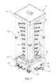
- FIG. 1shows a perspective view of an exemplary portable microorganism sanitation system having a plurality of UV light sources, such as elongated UV lamps, configured around a lamp tower having reflective panels and an air moving device the that draws air into the unit from the base and forces sanitized air out from air outlets configured along the lamp tower.
- UV light sourcessuch as elongated UV lamps
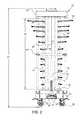
- FIG. 2shows a front view of the exemplary portable microorganism sanitation system shown in FIG. 1 .
- FIG. 3shows a side view of the exemplary portable microorganism sanitation system shown in FIG. 1 .
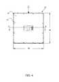
- FIG. 4shows a top view of the exemplary portable microorganism sanitation system shown in FIG. 1 .
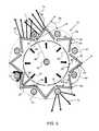
- FIG. 5shows a cross sectional view of the lamp tower taken along line 5 - 5 in FIG. 3 , wherein the lamp tower has eight reflective cells.
- FIG. 6shows a cross sectional view of the portable microorganism sanitation system taken along line 6 - 6 in FIG. 4 .
- FIG. 7shows a front view of an exemplary portable microorganism sanitation system having UV lamps and reflective panels at offset angles to vertical.
- FIG. 8shows a cross sectional view of the lamp tower taken along line 5 - 5 in FIG. 3 .
- FIG. 9shows a table of MERV ratings for air filters.
- the terms “comprises,” “comprising”, “includes,” “including,” “has,” “having” or any other variation thereof,are intended to cover a non-exclusive inclusion.
- a process, method, article, or apparatus that comprises a list of elementsis not necessarily limited to only those elements but may include other elements not expressly listed or inherent to such process, method, article, or apparatus.
- use of “a” or “an”are employed to describe elements and components described herein. This is done merely for convenience and to give a general sense of the scope of the invention. This description should be read to include one or at least one and the singular also includes the plural unless it is obvious that it is meant otherwise.
- destroysincludes deactivating and/or destroying or killing microorganisms such that they are no longer active and/or alive.
- an exemplary portable microorganism sanitation system 10has a plurality of UV light sources 50 , such as elongated UV lamps 51 , configured around a lamp tower 60 having reflective panels 63 , 65 configured to reflect light from the UV lamps 51 .
- the UV lampsextend a length 53 from a bottom end 52 to a top end 54 .
- the eight UV lampsare configured around the perimeter of the lamp tower and the reflective panels reflect the UV light in a plurality of reflected angles to ensure effective exposure to surfaces to be sanitized.
- the exemplar portable microorganism sanitation system 10is configured on a portable frame 30 , having a height 33 from the top 32 to the floor, or the bottom of the wheels 36 .
- the controller 25is configured in the base 34 along with an air-moving device 80 , such as a fan or blower. Air is drawn into the exemplary portable microorganism sanitation system 10 through an air inlet 82 in the base 34 and is expelled out of air outlets 84 configured in the lamp tower 60 .
- a plurality of air outlet slots 85are configured along the length of the air tower and in an exemplary embodiment are configured between the first reflective panel 63 and second reflective panel 65 .
- the flow or air out of the exemplary portable microorganism sanitation systemmay be configured to be greater at the top than at the bottom to ensure better air exchange and mixing in the room.
- the interior of the lamp towermay have a UV light source and the interior wall or panel surfaces may comprise a photocatalyst that kill or deactivates microorganisms.
- the exemplary portable microorganism sanitation system 10can be rolled into a room and turned on to sanitize the room through UV light exposure of surfaces and through active air treatment.
- the portable framehas a width 38 and depth 39 and the width and depth may be less than a doorway opening, such as less than about 36 inches, less than about 32 inches, or less than about 24 inches.
- an exemplary lamp tower taken 60comprises a first reflective light panel 63 , and a second reflective panel 65 configured around the UV lamp 51 .
- the first and second reflective light, panelsare configured at offset angles to form a reflective cell 61 , wherein the inclusive reflective angle 64 between the first and second reflective panels is less than 180 degrees.
- the reflective panelsare configured at a normal offset angle 66 , or angle offset from a line normal of a radial line, a line that extends radially from a center of the lamp tower 60 . Put another way, the first and second reflective panels are configured at a reflective inclusive angle to each other 64 , that is less than 180 degrees.
- the two reflective panels 63 , 65form an acute angle to a radial line 99 drawn through an intersection 62 between the two reflective panels.
- This configuration of reflective panels around the UV lampsproduces reflected UV light 74 that is emitted at a plurality of angles.
- the exemplary portable microorganism sanitation system 10therefore produces UV light 72 emitted directly from the UV light source 50 , as well as reflected UV light, that is emitted at various reflected angles to provide a large range of emitted UV light angles for direct impingement on surfaces.
- the reflective surfaces 67 of the reflective panelsmay comprises a photocatalyst 68 to treat air as it flows out from the lamp tower.
- the UV lamps 51are configured along a radial line that, extends through the intersection 62 of the two reflective panels, 63 , 65 .
- the UV light sources 50are configured within the reflective cells 61 , or within a perimeter shown by the dashed circle that extends around a perimeter of the reflective panels.
- Airflow 22flows up through the lamp tower 60 from an air inlet 82 in the base and flows through an air conduit 88 configured within the air tower.
- the airflow 22 ′then flows between the air conduit 88 and the interior of the lamp tower 60 and finally out of the lamp tower through air outlets 84 , such as air outlet slots 85 between the reflective panels.
- the airflowmay be exposed to UV light as it travels up through the air conduit from the interior UV lamp 58 .
- the interior surface of the air conduitmay comprise a photocatalyst 69 ′ to deactivate and destroy microorganisms.
- the interior surfaces of the lamp towermay comprise a photocatalyst 69 and the exterior surfaces of the air conduit 88 may comprise a photocatalyst 69 ′′ to destroy microorganisms in the return airflow conduit 87 .
- the reflective panelmay also comprise an exterior photocatalyst 68 .
- the airflow 22flows through the airflow conduit 88 and then the airflow 22 ′ flows into the space between the airflow conduit and the lamp tower 60 and finally the airflow 22 ′′ flows out of the lamp tower. This flow path of the airflow may ensure a long exposure time and therefore may more effectively destroy microorganisms.
- the airflow conduitmay be transparent to allow the UV light from the interior lamp 58 to project through the airflow conduit and into the return airflow conduit 87 , or the space between the airflow conduit and interior of the lamp tower 60 .
- a portion of the airflow conduitmay comprise a photocatalyst, such as strips or patches of photocatalyst material on the interior or external surface.
- the airflowmay be directed to flow around the UV lamp 51 to keep the lamps cool and to provide high intensity exposure of the airflow to the UV light.
- An air filter 81may be configured to filter out particles as air enters into the airflow conduit 88 .
- An ozone generator 92may be configured to produce ozone 94 that flows along with the airflow through the system to destroy microorganisms.
- an exemplary portable microorganism sanitation system 10has UV light sources 50 , such as UV lamps 51 and reflective panels 63 , 65 at offset angles 56 to vertical. This may produce a better mixing of air around the unit and provides emitted UV light rays at offset angles.
- UV light sources 50such as UV lamps 51 and reflective panels 63 , 65 at offset angles 56 to vertical. This may produce a better mixing of air around the unit and provides emitted UV light rays at offset angles.
- exemplary portable microorganism sanitation system 10has a lamp tower 60 having sixteen reflective cells 61 , each having a first, reflective panel 63 and second reflective panel 65 configured at a reflective angle 64 .
- a UV light source 50is configured between the two reflective panels.
- An airflow conduit 88is configured within the lamp tower and has a photocatalyst 69 on the interior surface.
- a UV light source, or interior UV lamp 58is configured within, the airflow conduit. Ozone gas may flow up through the airflow conduit and then back down through the return airflow conduit 87 .
- Airflow 22flows through the interior air conduit 88 and out the air conduit outlets 89 and subsequently out of the air outlet slots 85 .
- FIG. 9show a table of MERV ratings.
Landscapes
- Health & Medical Sciences (AREA)
- Epidemiology (AREA)
- Life Sciences & Earth Sciences (AREA)
- Animal Behavior & Ethology (AREA)
- General Health & Medical Sciences (AREA)
- Public Health (AREA)
- Veterinary Medicine (AREA)
- Chemical & Material Sciences (AREA)
- Chemical Kinetics & Catalysis (AREA)
- General Chemical & Material Sciences (AREA)
- Disinfection, Sterilisation Or Deodorisation Of Air (AREA)
Abstract
Description
Claims (19)
Priority Applications (1)
| Application Number | Priority Date | Filing Date | Title |
|---|---|---|---|
| US16/119,023US10328174B2 (en) | 2017-08-31 | 2018-08-31 | Portable microorganism sanitation system |
Applications Claiming Priority (2)
| Application Number | Priority Date | Filing Date | Title |
|---|---|---|---|
| US201762552998P | 2017-08-31 | 2017-08-31 | |
| US16/119,023US10328174B2 (en) | 2017-08-31 | 2018-08-31 | Portable microorganism sanitation system |
Publications (2)
| Publication Number | Publication Date |
|---|---|
| US20190060505A1 US20190060505A1 (en) | 2019-02-28 |
| US10328174B2true US10328174B2 (en) | 2019-06-25 |
Family
ID=65434683
Family Applications (1)
| Application Number | Title | Priority Date | Filing Date |
|---|---|---|---|
| US16/119,023Expired - Fee RelatedUS10328174B2 (en) | 2017-08-31 | 2018-08-31 | Portable microorganism sanitation system |
Country Status (1)
| Country | Link |
|---|---|
| US (1) | US10328174B2 (en) |
Cited By (2)
| Publication number | Priority date | Publication date | Assignee | Title |
|---|---|---|---|---|
| US11291742B1 (en)* | 2020-09-22 | 2022-04-05 | S.M.Doctor Co., Ltd | Air stertilization lamp device |
| US11369712B1 (en) | 2021-01-25 | 2022-06-28 | Evgeny Antonov | Baffles for modifying airflow in UV air sterilization device |
Families Citing this family (5)
| Publication number | Priority date | Publication date | Assignee | Title |
|---|---|---|---|---|
| US20220202984A1 (en)* | 2020-03-16 | 2022-06-30 | UL Med Inc. | Germicidal devices and applications of same |
| DE102021109717A1 (en) | 2020-04-19 | 2021-10-21 | Metralabs Gmbh Neue Technologien Und Systeme | System, device and method for disinfection |
| CN212005597U (en)* | 2020-04-24 | 2020-11-24 | 深圳市冠科科技有限公司 | Induction component and ultraviolet germicidal lamp |
| US20210353797A1 (en)* | 2020-05-12 | 2021-11-18 | Nemesis UVC LLC | Ultraviolet light tower |
| CN213454100U (en)* | 2020-10-13 | 2021-06-15 | 陶传山 | Sterilizing device for building air circulation system |
Citations (23)
| Publication number | Priority date | Publication date | Assignee | Title |
|---|---|---|---|---|
| US3418069A (en) | 1965-12-22 | 1968-12-24 | Detec Sa | Ultra-violet ray sterilizers |
| US4087925A (en)* | 1975-12-06 | 1978-05-09 | Artur Bienek | Hand drier |
| US4591724A (en)* | 1984-03-07 | 1986-05-27 | Japan Synthetic Rubber Co., Ltd. | Curing apparatus |
| US4896042A (en) | 1988-09-06 | 1990-01-23 | Dora Dicamillo 1988 Trust | Dual mode germicidal apparatus |
| US5144146A (en) | 1990-07-06 | 1992-09-01 | Ultraviolet Energy Generators, Inc. | Method for destruction of toxic substances with ultraviolet radiation |
| US5330722A (en)* | 1991-02-27 | 1994-07-19 | William E. Pick | Germicidal air filter |
| US5712487A (en)* | 1994-10-25 | 1998-01-27 | Ushiodenki Kabushiki Kaisha | Light irradiator |
| US5932886A (en)* | 1996-03-27 | 1999-08-03 | Ushiodenki Kabushiki Kaisha | Ultraviolet irradiation device |
| US5997812A (en)* | 1996-06-20 | 1999-12-07 | Coolant Treatment Systems, L.L.C. | Methods and apparatus for the application of combined fields to disinfect fluids |
| US6242753B1 (en) | 1997-12-25 | 2001-06-05 | Kabushiki Kaisha Lucent | Portable sterilizing apparatus |
| US20020085947A1 (en) | 2000-09-19 | 2002-07-04 | Deal Jeffery L. | Ultraviolet area sterilizer and method of area sterilization using ultraviolet radiation |
| US20030155531A1 (en) | 1996-05-22 | 2003-08-21 | Clark Reginald Wayne | Sterilization of packages and their contents using light |
| US20040052702A1 (en) | 2002-07-03 | 2004-03-18 | Shuman Randal L. | Food product surface sterilization apparatus and method |
| US6759664B2 (en) | 2000-12-20 | 2004-07-06 | Alcatel | Ultraviolet curing system and bulb |
| US6773584B2 (en) | 2001-10-17 | 2004-08-10 | Honeywell International Inc. | Apparatus for disinfecting water using ultraviolet radiation |
| US6797966B2 (en) | 2001-01-26 | 2004-09-28 | Engineering Dynamics, Ltd. | Quick-install irradiation unit and method of making same |
| US20060284109A1 (en) | 2005-06-21 | 2006-12-21 | Robert Scheir | Mobile germicidal system |
| US7326387B2 (en)* | 2002-05-20 | 2008-02-05 | Theodore A. M. Arts | Air decontamination devices |
| US20110293471A1 (en) | 1999-03-01 | 2011-12-01 | Brown-Skrobot Susan K | Method and Apparatus of Sterilization Using Monochromic UV Radiation Source |
| US20140158917A1 (en)* | 2012-12-07 | 2014-06-12 | Xenex Healthcare Services, Llc | Lamp and Reflector Arrangements for Apparatuses with Multiple Germicidal Lamps |
| US20160271282A1 (en)* | 2011-04-15 | 2016-09-22 | Samuel Richard Trapani | Room sterilization method and system |
| US9707306B2 (en) | 2010-06-01 | 2017-07-18 | Bluemorph, Llc | UV sterilization of containers |
| US9782505B2 (en) | 2009-12-08 | 2017-10-10 | Surfacide, Llc | Hard-surface disinfection system |
- 2018
- 2018-08-31USUS16/119,023patent/US10328174B2/ennot_activeExpired - Fee Related
Patent Citations (23)
| Publication number | Priority date | Publication date | Assignee | Title |
|---|---|---|---|---|
| US3418069A (en) | 1965-12-22 | 1968-12-24 | Detec Sa | Ultra-violet ray sterilizers |
| US4087925A (en)* | 1975-12-06 | 1978-05-09 | Artur Bienek | Hand drier |
| US4591724A (en)* | 1984-03-07 | 1986-05-27 | Japan Synthetic Rubber Co., Ltd. | Curing apparatus |
| US4896042A (en) | 1988-09-06 | 1990-01-23 | Dora Dicamillo 1988 Trust | Dual mode germicidal apparatus |
| US5144146A (en) | 1990-07-06 | 1992-09-01 | Ultraviolet Energy Generators, Inc. | Method for destruction of toxic substances with ultraviolet radiation |
| US5330722A (en)* | 1991-02-27 | 1994-07-19 | William E. Pick | Germicidal air filter |
| US5712487A (en)* | 1994-10-25 | 1998-01-27 | Ushiodenki Kabushiki Kaisha | Light irradiator |
| US5932886A (en)* | 1996-03-27 | 1999-08-03 | Ushiodenki Kabushiki Kaisha | Ultraviolet irradiation device |
| US20030155531A1 (en) | 1996-05-22 | 2003-08-21 | Clark Reginald Wayne | Sterilization of packages and their contents using light |
| US5997812A (en)* | 1996-06-20 | 1999-12-07 | Coolant Treatment Systems, L.L.C. | Methods and apparatus for the application of combined fields to disinfect fluids |
| US6242753B1 (en) | 1997-12-25 | 2001-06-05 | Kabushiki Kaisha Lucent | Portable sterilizing apparatus |
| US20110293471A1 (en) | 1999-03-01 | 2011-12-01 | Brown-Skrobot Susan K | Method and Apparatus of Sterilization Using Monochromic UV Radiation Source |
| US20020085947A1 (en) | 2000-09-19 | 2002-07-04 | Deal Jeffery L. | Ultraviolet area sterilizer and method of area sterilization using ultraviolet radiation |
| US6759664B2 (en) | 2000-12-20 | 2004-07-06 | Alcatel | Ultraviolet curing system and bulb |
| US6797966B2 (en) | 2001-01-26 | 2004-09-28 | Engineering Dynamics, Ltd. | Quick-install irradiation unit and method of making same |
| US6773584B2 (en) | 2001-10-17 | 2004-08-10 | Honeywell International Inc. | Apparatus for disinfecting water using ultraviolet radiation |
| US7326387B2 (en)* | 2002-05-20 | 2008-02-05 | Theodore A. M. Arts | Air decontamination devices |
| US20040052702A1 (en) | 2002-07-03 | 2004-03-18 | Shuman Randal L. | Food product surface sterilization apparatus and method |
| US20060284109A1 (en) | 2005-06-21 | 2006-12-21 | Robert Scheir | Mobile germicidal system |
| US9782505B2 (en) | 2009-12-08 | 2017-10-10 | Surfacide, Llc | Hard-surface disinfection system |
| US9707306B2 (en) | 2010-06-01 | 2017-07-18 | Bluemorph, Llc | UV sterilization of containers |
| US20160271282A1 (en)* | 2011-04-15 | 2016-09-22 | Samuel Richard Trapani | Room sterilization method and system |
| US20140158917A1 (en)* | 2012-12-07 | 2014-06-12 | Xenex Healthcare Services, Llc | Lamp and Reflector Arrangements for Apparatuses with Multiple Germicidal Lamps |
Cited By (2)
| Publication number | Priority date | Publication date | Assignee | Title |
|---|---|---|---|---|
| US11291742B1 (en)* | 2020-09-22 | 2022-04-05 | S.M.Doctor Co., Ltd | Air stertilization lamp device |
| US11369712B1 (en) | 2021-01-25 | 2022-06-28 | Evgeny Antonov | Baffles for modifying airflow in UV air sterilization device |
Also Published As
| Publication number | Publication date |
|---|---|
| US20190060505A1 (en) | 2019-02-28 |
Similar Documents
| Publication | Publication Date | Title |
|---|---|---|
| US10328174B2 (en) | Portable microorganism sanitation system | |
| US11285237B2 (en) | Fluid sterilization system | |
| CA2230865C (en) | Photocatalytic air disinfection | |
| US7674436B1 (en) | Portable indoor air purification system | |
| US9981056B2 (en) | Air treatment system | |
| CN107708749B (en) | Method for electrohydrodynamic enhanced destruction of chemical air pollutants and air inactivation of biological agents | |
| US20050163648A1 (en) | Method and apparatus for sterilizing air in large volumes by radiation of ultraviolet rays | |
| US20060057020A1 (en) | Cleaning of air | |
| US20080112845A1 (en) | Air Cleaning Unit, and Method of Air Disinfection | |
| US11938252B2 (en) | Medical air handling system with laminar flow and energy-based air decontamination | |
| JP2021514231A (en) | Air sterilization unit | |
| KR102181069B1 (en) | Photo-catalyst purifying apparatus for air sterilization purifying and lighting apparatus using the same | |
| US20160000960A1 (en) | Device for air filtration and purification | |
| US20220170651A1 (en) | Method and system for air ventilation, sterilization and filtration | |
| CN112539505A (en) | Miniaturized circulating air purification and sterilization device | |
| KR102456705B1 (en) | Clean air system for virus removal | |
| CA2249924A1 (en) | Method and portable apparatus for improving indoor air quality by means of ultraviolet radiation sterilization | |
| US20240082454A1 (en) | Adaptive air quality control system | |
| US12194206B2 (en) | Expandable system for purification and disinfection of air | |
| RU2846906C2 (en) | Nanofiltration device for deactivating pathogens filtered from air | |
| CN202751626U (en) | Ceiling type air disinfection machine | |
| CN2675128Y (en) | Air sterilization and purification device using photocatalytic oxidation technology | |
| EP4098284A2 (en) | Air filtering apparatus, method and system | |
| US20240033395A1 (en) | Air sterilisation unit | |
| WO2023002361A1 (en) | Air purification device |
Legal Events
| Date | Code | Title | Description |
|---|---|---|---|
| FEPP | Fee payment procedure | Free format text:ENTITY STATUS SET TO UNDISCOUNTED (ORIGINAL EVENT CODE: BIG.); ENTITY STATUS OF PATENT OWNER: SMALL ENTITY | |
| FEPP | Fee payment procedure | Free format text:ENTITY STATUS SET TO SMALL (ORIGINAL EVENT CODE: SMAL); ENTITY STATUS OF PATENT OWNER: SMALL ENTITY | |
| AS | Assignment | Owner name:RADIANT INDUSTRIAL SOLUTIONS, LLC, TEXAS Free format text:ASSIGNMENT OF ASSIGNORS INTEREST;ASSIGNORS:JAWORSKI, DREW;SMITH, TROY;REEL/FRAME:046956/0696 Effective date:20180829 | |
| STPP | Information on status: patent application and granting procedure in general | Free format text:DOCKETED NEW CASE - READY FOR EXAMINATION | |
| STPP | Information on status: patent application and granting procedure in general | Free format text:NOTICE OF ALLOWANCE MAILED -- APPLICATION RECEIVED IN OFFICE OF PUBLICATIONS | |
| STPP | Information on status: patent application and granting procedure in general | Free format text:PUBLICATIONS -- ISSUE FEE PAYMENT VERIFIED | |
| STCF | Information on status: patent grant | Free format text:PATENTED CASE | |
| FEPP | Fee payment procedure | Free format text:MAINTENANCE FEE REMINDER MAILED (ORIGINAL EVENT CODE: REM.); ENTITY STATUS OF PATENT OWNER: SMALL ENTITY | |
| LAPS | Lapse for failure to pay maintenance fees | Free format text:PATENT EXPIRED FOR FAILURE TO PAY MAINTENANCE FEES (ORIGINAL EVENT CODE: EXP.); ENTITY STATUS OF PATENT OWNER: SMALL ENTITY | |
| STCH | Information on status: patent discontinuation | Free format text:PATENT EXPIRED DUE TO NONPAYMENT OF MAINTENANCE FEES UNDER 37 CFR 1.362 | |
| FP | Lapsed due to failure to pay maintenance fee | Effective date:20230625 |