US10327933B2 - Medical cannulae, delivery systems and methods - Google Patents
Medical cannulae, delivery systems and methodsDownload PDFInfo
- Publication number
- US10327933B2 US10327933B2US15/140,028US201615140028AUS10327933B2US 10327933 B2US10327933 B2US 10327933B2US 201615140028 AUS201615140028 AUS 201615140028AUS 10327933 B2US10327933 B2US 10327933B2
- Authority
- US
- United States
- Prior art keywords
- openings
- cannula
- tubular member
- delivery system
- pattern
- Prior art date
- Legal status (The legal status is an assumption and is not a legal conclusion. Google has not performed a legal analysis and makes no representation as to the accuracy of the status listed.)
- Active, expires
Links
- 238000000034methodMethods0.000titleabstractdescription23
- 229910052751metalInorganic materials0.000claimsdescription4
- 239000002184metalSubstances0.000claimsdescription4
- 239000010935stainless steelSubstances0.000claimsdescription2
- 229910001220stainless steelInorganic materials0.000claimsdescription2
- 230000004323axial lengthEffects0.000description62
- 239000000463materialSubstances0.000description30
- 238000005520cutting processMethods0.000description11
- 239000011295pitchSubstances0.000description9
- 239000012530fluidSubstances0.000description6
- 230000003247decreasing effectEffects0.000description5
- 238000004519manufacturing processMethods0.000description5
- 239000007787solidSubstances0.000description5
- 230000001154acute effectEffects0.000description4
- 238000004891communicationMethods0.000description4
- 238000005452bendingMethods0.000description3
- 238000013459approachMethods0.000description2
- 230000007423decreaseEffects0.000description2
- 238000011010flushing procedureMethods0.000description2
- 230000001788irregularEffects0.000description2
- 150000002739metalsChemical class0.000description2
- 238000012805post-processingMethods0.000description2
- 238000005096rolling processMethods0.000description2
- 239000002893slagSubstances0.000description2
- 230000009466transformationEffects0.000description2
- 210000002073venous valveAnatomy0.000description2
- 238000003466weldingMethods0.000description2
- 229910000684Cobalt-chromeInorganic materials0.000description1
- 239000004677NylonSubstances0.000description1
- 239000004952PolyamideSubstances0.000description1
- 239000004809TeflonSubstances0.000description1
- 229920006362Teflon®Polymers0.000description1
- HZEWFHLRYVTOIW-UHFFFAOYSA-N[Ti].[Ni]Chemical compound[Ti].[Ni]HZEWFHLRYVTOIW-UHFFFAOYSA-N0.000description1
- 229910045601alloyInorganic materials0.000description1
- 239000000956alloySubstances0.000description1
- 210000003484anatomyAnatomy0.000description1
- 230000009286beneficial effectEffects0.000description1
- 239000011248coating agentSubstances0.000description1
- 238000000576coating methodMethods0.000description1
- 239000010952cobalt-chromeSubstances0.000description1
- 238000010276constructionMethods0.000description1
- 238000011161developmentMethods0.000description1
- 230000018109developmental processEffects0.000description1
- 210000003709heart valveAnatomy0.000description1
- 238000003698laser cuttingMethods0.000description1
- 229910001000nickel titaniumInorganic materials0.000description1
- 229920001778nylonPolymers0.000description1
- 239000004033plasticSubstances0.000description1
- 229920003023plasticPolymers0.000description1
- 229920002647polyamidePolymers0.000description1
- 229920002635polyurethanePolymers0.000description1
- 239000004814polyurethaneSubstances0.000description1
- 229910001285shape-memory alloyInorganic materials0.000description1
- 230000007704transitionEffects0.000description1
- 238000009834vaporizationMethods0.000description1
- 230000008016vaporizationEffects0.000description1
Images


Classifications
- A—HUMAN NECESSITIES
- A61—MEDICAL OR VETERINARY SCIENCE; HYGIENE
- A61F—FILTERS IMPLANTABLE INTO BLOOD VESSELS; PROSTHESES; DEVICES PROVIDING PATENCY TO, OR PREVENTING COLLAPSING OF, TUBULAR STRUCTURES OF THE BODY, e.g. STENTS; ORTHOPAEDIC, NURSING OR CONTRACEPTIVE DEVICES; FOMENTATION; TREATMENT OR PROTECTION OF EYES OR EARS; BANDAGES, DRESSINGS OR ABSORBENT PADS; FIRST-AID KITS
- A61F2/00—Filters implantable into blood vessels; Prostheses, i.e. artificial substitutes or replacements for parts of the body; Appliances for connecting them with the body; Devices providing patency to, or preventing collapsing of, tubular structures of the body, e.g. stents
- A61F2/95—Instruments specially adapted for placement or removal of stents or stent-grafts
- A61F2/962—Instruments specially adapted for placement or removal of stents or stent-grafts having an outer sleeve
- A61F2/966—Instruments specially adapted for placement or removal of stents or stent-grafts having an outer sleeve with relative longitudinal movement between outer sleeve and prosthesis, e.g. using a push rod
- A—HUMAN NECESSITIES
- A61—MEDICAL OR VETERINARY SCIENCE; HYGIENE
- A61B—DIAGNOSIS; SURGERY; IDENTIFICATION
- A61B17/00—Surgical instruments, devices or methods
- A61B17/00234—Surgical instruments, devices or methods for minimally invasive surgery
- A—HUMAN NECESSITIES
- A61—MEDICAL OR VETERINARY SCIENCE; HYGIENE
- A61B—DIAGNOSIS; SURGERY; IDENTIFICATION
- A61B17/00—Surgical instruments, devices or methods
- A61B17/34—Trocars; Puncturing needles
- A61B17/3417—Details of tips or shafts, e.g. grooves, expandable, bendable; Multiple coaxial sliding cannulas, e.g. for dilating
- A61B17/3421—Cannulas
- A—HUMAN NECESSITIES
- A61—MEDICAL OR VETERINARY SCIENCE; HYGIENE
- A61B—DIAGNOSIS; SURGERY; IDENTIFICATION
- A61B17/00—Surgical instruments, devices or methods
- A61B17/34—Trocars; Puncturing needles
- A61B17/3468—Trocars; Puncturing needles for implanting or removing devices, e.g. prostheses, implants, seeds, wires
- A—HUMAN NECESSITIES
- A61—MEDICAL OR VETERINARY SCIENCE; HYGIENE
- A61M—DEVICES FOR INTRODUCING MEDIA INTO, OR ONTO, THE BODY; DEVICES FOR TRANSDUCING BODY MEDIA OR FOR TAKING MEDIA FROM THE BODY; DEVICES FOR PRODUCING OR ENDING SLEEP OR STUPOR
- A61M25/00—Catheters; Hollow probes
- A61M25/0009—Making of catheters or other medical or surgical tubes
- A61M25/0013—Weakening parts of a catheter tubing, e.g. by making cuts in the tube or reducing thickness of a layer at one point to adjust the flexibility
- A—HUMAN NECESSITIES
- A61—MEDICAL OR VETERINARY SCIENCE; HYGIENE
- A61M—DEVICES FOR INTRODUCING MEDIA INTO, OR ONTO, THE BODY; DEVICES FOR TRANSDUCING BODY MEDIA OR FOR TAKING MEDIA FROM THE BODY; DEVICES FOR PRODUCING OR ENDING SLEEP OR STUPOR
- A61M25/00—Catheters; Hollow probes
- A61M25/0043—Catheters; Hollow probes characterised by structural features
- A61M25/0054—Catheters; Hollow probes characterised by structural features with regions for increasing flexibility
- A—HUMAN NECESSITIES
- A61—MEDICAL OR VETERINARY SCIENCE; HYGIENE
- A61M—DEVICES FOR INTRODUCING MEDIA INTO, OR ONTO, THE BODY; DEVICES FOR TRANSDUCING BODY MEDIA OR FOR TAKING MEDIA FROM THE BODY; DEVICES FOR PRODUCING OR ENDING SLEEP OR STUPOR
- A61M25/00—Catheters; Hollow probes
- A61M25/01—Introducing, guiding, advancing, emplacing or holding catheters
- A61M25/0105—Steering means as part of the catheter or advancing means; Markers for positioning
- A61M25/0133—Tip steering devices
- A61M25/0138—Tip steering devices having flexible regions as a result of weakened outer material, e.g. slots, slits, cuts, joints or coils
- A—HUMAN NECESSITIES
- A61—MEDICAL OR VETERINARY SCIENCE; HYGIENE
- A61B—DIAGNOSIS; SURGERY; IDENTIFICATION
- A61B17/00—Surgical instruments, devices or methods
- A61B17/00234—Surgical instruments, devices or methods for minimally invasive surgery
- A61B2017/00292—Surgical instruments, devices or methods for minimally invasive surgery mounted on or guided by flexible, e.g. catheter-like, means
- A61B2017/003—Steerable
- A61B2017/00305—Constructional details of the flexible means
- A61B2017/00309—Cut-outs or slits
- A—HUMAN NECESSITIES
- A61—MEDICAL OR VETERINARY SCIENCE; HYGIENE
- A61B—DIAGNOSIS; SURGERY; IDENTIFICATION
- A61B17/00—Surgical instruments, devices or methods
- A61B17/00234—Surgical instruments, devices or methods for minimally invasive surgery
- A61B2017/00292—Surgical instruments, devices or methods for minimally invasive surgery mounted on or guided by flexible, e.g. catheter-like, means
- A61B2017/00336—Surgical instruments, devices or methods for minimally invasive surgery mounted on or guided by flexible, e.g. catheter-like, means with a protective sleeve, e.g. retractable or slidable
- A—HUMAN NECESSITIES
- A61—MEDICAL OR VETERINARY SCIENCE; HYGIENE
- A61F—FILTERS IMPLANTABLE INTO BLOOD VESSELS; PROSTHESES; DEVICES PROVIDING PATENCY TO, OR PREVENTING COLLAPSING OF, TUBULAR STRUCTURES OF THE BODY, e.g. STENTS; ORTHOPAEDIC, NURSING OR CONTRACEPTIVE DEVICES; FOMENTATION; TREATMENT OR PROTECTION OF EYES OR EARS; BANDAGES, DRESSINGS OR ABSORBENT PADS; FIRST-AID KITS
- A61F2/00—Filters implantable into blood vessels; Prostheses, i.e. artificial substitutes or replacements for parts of the body; Appliances for connecting them with the body; Devices providing patency to, or preventing collapsing of, tubular structures of the body, e.g. stents
- A61F2/95—Instruments specially adapted for placement or removal of stents or stent-grafts
- A—HUMAN NECESSITIES
- A61—MEDICAL OR VETERINARY SCIENCE; HYGIENE
- A61F—FILTERS IMPLANTABLE INTO BLOOD VESSELS; PROSTHESES; DEVICES PROVIDING PATENCY TO, OR PREVENTING COLLAPSING OF, TUBULAR STRUCTURES OF THE BODY, e.g. STENTS; ORTHOPAEDIC, NURSING OR CONTRACEPTIVE DEVICES; FOMENTATION; TREATMENT OR PROTECTION OF EYES OR EARS; BANDAGES, DRESSINGS OR ABSORBENT PADS; FIRST-AID KITS
- A61F2250/00—Special features of prostheses classified in groups A61F2/00 - A61F2/26 or A61F2/82 or A61F9/00 or A61F11/00 or subgroups thereof
- A61F2250/0014—Special features of prostheses classified in groups A61F2/00 - A61F2/26 or A61F2/82 or A61F9/00 or A61F11/00 or subgroups thereof having different values of a given property or geometrical feature, e.g. mechanical property or material property, at different locations within the same prosthesis
- A61F2250/0018—Special features of prostheses classified in groups A61F2/00 - A61F2/26 or A61F2/82 or A61F9/00 or A61F11/00 or subgroups thereof having different values of a given property or geometrical feature, e.g. mechanical property or material property, at different locations within the same prosthesis differing in elasticity, stiffness or compressibility
Definitions
- the disclosurerelates generally to the field of medical devices. More particularly, the disclosure relates to the fields of cannulae, delivery systems, and methods of making medical devices.
- Delivery systems for implanting intraluminal medical devices at a point of treatment within a body vesselrequire both pushability and flexibility. Development of delivery systems and delivery system components that provide these desirable characteristics continues.
- An example cannulacomprises an elongate tubular member having a circumferential wall extending between a proximal end and a distal end and defining an interior lumen; a pattern of openings extends along a portion of the axial length of the cannula.
- Another example cannulacomprises an elongate tubular member having a circumferential wall extending between a proximal end and a distal end and defining an interior lumen; a pattern of openings extends along the entire axial length of the cannula.
- Another example cannulacomprises an elongate tubular member having a circumferential wall extending between a proximal end and a distal end and defining an interior lumen; a pattern of openings extends along an intermediate portion of the axial length of the cannula that is disposed between proximal and distal portions of the cannula that are free of the pattern of openings.
- Another example cannulacomprises an elongate tubular member having a circumferential wall extending between a proximal end and a distal end and defining an interior lumen; a pattern of openings extends along an intermediate portion of the axial length of the cannula that is disposed between proximal and distal portions of the cannula that are free of the pattern of openings; the proximal portion is longer than the distal portion.
- An example delivery systemcomprises a cannula comprising an elongate tubular member having a circumferential wall extending between a proximal end and a distal end and defining an interior lumen; a pattern of openings extending along an intermediate portion of the axial length of the cannula that is disposed between proximal and distal portions of the cannula that are free of the pattern of openings; the proximal portion is longer than the distal portion; an intraluminal medical device disposed on the distal portion of the cannula; and an elongate outer tubular member defining an outer tubular member lumen.
- the cannulais disposed within the outer tubular member lumen such that the intraluminal medical device is circumferentially disposed about the cannula and within the outer tubular member lumen.
- An example method of making a cannulacomprises identifying a cannula material and a cannula wall thickness that provides a desired global stiffness for said cannula; identifying one or more axial lengths of said cannula along which a localized stiffness, different from the desired global stiffness, is desired; identifying a pattern of openings that will provide the desired localized stiffness when cut into a cannula formed of the cannula material and having the cannula wall thickness; and cutting the pattern of openings into a cannula formed of the cannula material and having the cannula wall thickness at axial positions that correspond to the one or more axial lengths.
- An example method of making a delivery systemcomprises identifying a cannula material and a cannula wall thickness that provides a desired global stiffness for said cannula; identifying one or more axial lengths of said cannula along which a localized stiffness, different from the desired global stiffness, is desired; identifying a pattern of openings that will provide the desired localized stiffness when cut into a cannula formed of the cannula material and having the cannula wall thickness; cutting the pattern of openings into a cannula formed of the cannula material and having the cannula wall thickness at axial positions that correspond to the one or more axial lengths; disposing an intraluminal medical device on a portion of the cannula that is free of the pattern of openings; and inserting the cannula into an elongate tubular member defining a lumen such that the intraluminal medical device is circumferentially disposed about the cannul
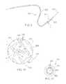
- FIG. 1is a perspective view of an example cannula.
- FIG. 2is a magnified view of area I in FIG. 1 .
- FIG. 3is a magnified sectional view of the example cannula illustrated in FIG. 1 , taken along line 3 - 3 .
- FIG. 4Ais a magnified view of a portion of an alternative cannula.
- FIG. 4Bis a magnified view of a portion of another alternative cannula.
- FIG. 4Cis a magnified view of a portion of another alternative cannula.
- FIG. 5is a magnified view of a portion of another example cannula.
- FIG. 6is a side view, partially broken away, of another example cannula.
- FIG. 7is a side view, partially broken away, of another example cannula.
- FIG. 8is a side view, partially broken away, of another example cannula.
- FIG. 9is a perspective view of another example cannula.
- FIG. 10is a magnified view of area I in FIG. 9 .
- FIG. 11is a schematic view of a transverse sectional view of the cannula illustrated in FIG. 9 , taking within area I.
- FIG. 12Ais a magnified view of another example cannula.
- FIG. 12Bis a magnified view of another example cannula.
- FIG. 12Cis a magnified view of another example cannula.
- FIG. 13is a side view, partially broken away, of another example cannula.
- FIG. 14is a magnified view of another example cannula.
- FIG. 15is a transverse cross-sectional view of the cannula illustrated in FIG. 14 .
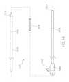
- FIG. 16is an exploded view of an example delivery system.
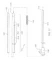
- FIG. 17is an exploded view of another example delivery system.
- FIG. 18is an exploded view of another example delivery system.
- FIG. 19is an exploded view of another example delivery system.
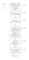
- FIG. 20is a flowchart representation of an example method of making a cannula.
- FIG. 21is a flowchart representation of an example method of making a cannula.
- FIG. 22is a schematic representation of a transformation of matter that occurs with performance of the method illustrated in FIG. 21 .
- FIG. 23is a flowchart representation of an example method of making a delivery system.
- openingrefers to a passage defined by a member between opposing or substantially opposing surfaces of the member.
- the termdoes not require any particular configuration of the passage. Indeed, the term includes rectangular passages, generally rectangular passages, square passages, generally square passages, circular passages, generally circular passages, triangular passages, generally triangular passages, and irregular passages.
- slitrefers to an opening that has a rectangular or generally rectangular shape when the surfaces between which the passage extends lie on parallel planes.
- FIGS. 1, 2 and 3illustrate a first example cannula 100 .
- the cannula 100is an elongate tubular member having a circumferential wall 112 extending between a proximal end 114 and a distal end 116 .
- the circumferential wall 112defines an interior lumen 118 .
- a proximal opening 120 on the proximal end 114provides access to the interior lumen 118 .
- a distal opening 122 on the distal end 116provides access to the interior lumen 118 .
- a longitudinal axis 101extends centrally through the lumen.
- each of a plurality of transverse axessuch as transverse axis 102 , lies on an individual plane that orthogonally intersects the longitudinal axis 101 at a point along its length.
- a pattern of openings 124extends along a portion of the axial length of the cannula 100 .
- the pattern of openings 124extends along the entire axial length of the cannula 100 , extending between the proximal 114 and distal 116 ends.
- the pattern of openings 124can extend along any suitable portion of the axial length of the cannula 100 , though, and the entire axial length, as in the illustrated cannula 100 , is only an example.
- a skilled artisanwill be able to select a suitable portion of the axial length of the cannula along which the pattern of openings is to extend based on various considerations, including any need or desire for axial portions having a greater stiffness than that provided by an axial portion along which the pattern of openings extends. For example, if it is desirable to have an axial portion that has the global stiffness of the cannula material itself, the cannula can be made so that the pattern of openings does not extend along the axial portion for which the global stiffness is desired.
- FIGS. 5, 6, and 7illustrated in detail below, illustrates an example cannula in which the pattern of openings does not extend along the entire axial length of the cannula.
- the pattern of openings 124comprises a plurality of openings 126 arranged in an interrupted spiral 128 that extends circumferentially along the circumferential wall 112 of the cannula 100 .
- each opening 130 of the plurality of openings 126comprises a slit that extends through the entire wall thickness of the circumferential wall 112 to provide access to the lumen 118 of the cannula 100 .
- the slit of each openinghas a generally rectangular shape having a major axis m disposed on a plane that is transverse to the longitudinal axis 101 of the cannula 100 .
- One end 132 of the slit of each opening 130has a slightly enlarged width, measured along the minor axis of the oblong rectangle of the slit.
- the overall pattern of openings 124takes a spiral 128 configuration relative to the longitudinal axis of the cannula 100 because the major axis m of each opening is disposed on a plane that intersects the longitudinal axis 101 of the cannula 100 at a non-orthogonal angle ⁇ .
- opening 134 in FIG. 2which is illustrated relative to longitudinal axis 101 and transverse axis 102 of cannula 100 , is slightly skewed relative to transverse axis 102 , as are all other openings 130 in the plurality of openings 124 .
- the inventorshave determined that various parameters of the pattern of openings 124 can be manipulated to achieve a desired stiffness in the cannula 100 along an axial portion of the cannula 100 .
- the distance between revolutions of the spiralillustrated in FIG. 2 as the gap 136 between openings 130 in immediately adjacent revolutions of the spiral, can be increased or decreased to achieve a desired number of revolutions of the spiral per unit of length of the cannula 100 , which, in turn, increases or decreases, respectively, the stiffness of the cannula along the axial portion containing the pattern of openings 124 .
- the pitch of the spiral path along which the openings extend on the cannulacan be increased or decreased to achieve a desired stiffness along the axial portion containing the pattern of openings 124 .
- the distance between openings within a revolution of the spiral, illustrated in FIG. 2 as the gap 138 between openings,can be increased or decreased to achieve a desired number of openings in a revolution of the spiral.
- the major length 140 of the oblong rectangle formed by the openings 130can be varied as well.
- the ratio of the major length 140 of the oblong rectangle of the opening to the distance between openings within a revolution of the spiral, i.e., gap 138can be increased or decreased to achieve a desired number of openings in a revolution of the spiral, which, in turn, increases or decreases, respectively, the stiffness of the cannula along the axial portion containing the pattern of openings 124 .
- the angle ⁇ at which a plane containing the major axis m of individual openings 130 intersects the longitudinal axis 101 of the cannula 100can also be increased or decreased to achieve a desired flexibility.
- a cannula made in this mannerretains enough stiffness to effectively serve as the innermost member of a delivery system useful for placing an intraluminal medical device at a point of treatment within a body vessel.
- such a cannulais able to carry the intraluminal medical device of the delivery system, such as a stent, valve, filter or other expandable intraluminal medical device, and, effectively, serve as a pusher that provides the pushability and/or trackability needed for navigation of the delivery system to an intraluminal point of treatment.
- the intraluminal medical device of the delivery systemsuch as a stent, valve, filter or other expandable intraluminal medical device
- openings 130 in the illustrated embodimentcomprise slits
- any suitable openingcan be used in a cannula according to a particular embodiment, including openings that provide rectangular passages, openings that provide generally rectangular passages, openings that provide square passages, openings that provide generally square passages, openings that provide circular passages, openings that provide generally circular passages, openings that provide triangular passages, openings that provide generally triangular passages, and openings that provide irregular passages.
- slitsare particularly advantageous at least because of the relative ease with which they can be formed in an elongate tubular member and the ease with which they can be aligned along a spiral path on an elongate tubular member.
- FIGS. 4A, 4B, and 4Cillustrates an alternative cannula with wall openings arranged in an alternative pattern achieved by manipulating one or more of the parameters described above.
- the gap 136 ′ between openings 130 ′ in immediately adjacent revolutions of the spiralis larger than the gap 136 used in cannula 100 illustrated in FIGS. 1 through 3 .
- the gap between openings in immediately adjacent revolutions of the spiral in a cannulacan have any suitable length as measured along the longitudinal axis of the cannula.
- a skilled artisanwill be able to select an appropriate length for this gap for a particular cannula according to various considerations, including the nature of the material from which the cannula is formed and any desired flexibility in the axial length of the cannula along which the pattern of openings that contains the gaps extends.
- the inventorshave determined that a gap the is between about 0.5 and about 40.0 times the axial width of the openings in the pattern of openings is suitable for a cannula intended to be used in an intraluminal medical device delivery system as described herein.
- the inventorsalso consider a gap that is between about 1 and about 5 times the axial width of the openings in the pattern of openings to be suitable for a cannula intended to be used in an intraluminal medical device delivery system as described herein.
- the inventorsalso consider a gap that is between about 1.5 and about 2.5 times the axial width of the openings in the pattern of openings to be suitable for a cannula intended to be used in an intraluminal medical device delivery system as described herein.
- the inventorsalso consider a gap that is about 2 times the axial width of the openings in the pattern of openings to be suitable for a cannula intended to be used in an intraluminal medical device delivery system as described herein.
- the gap 138 ′′ between openings 130 ′′ within a revolution of the spiralis larger than the gap 138 used in cannula 100 illustrated in FIGS. 1 through 3 .
- the gap between openings within a revolution of the spiral in a cannulacan have any suitable length as measured along the major axis of the openings of revolution.
- a skilled artisanwill be able to select an appropriate length for this gap for a particular cannula according to various considerations, including the nature of the material from which the cannula is formed and any desired flexibility in the axial length of the cannula along which the pattern of openings that contains the gaps extends.
- the inventorshave determined that a gap that is between about 0.1 and about 2 times the axial length of the openings in the pattern of openings is suitable for a cannula intended to be used in an intraluminal medical device delivery system as described herein.
- the inventorsconsider a gap that is between about 0.25 and about 1.5 times the axial length of the openings in the pattern of openings to be suitable for a cannula intended to be used in an intraluminal medical device delivery system as described herein.
- the inventorsalso consider a gap that is between about 0.5 and about 1.25 times the axial length of the openings in the pattern of openings to be suitable for a cannula intended to be used in an intraluminal medical device delivery system as described herein.
- the inventorsalso consider a gap that is about 0.5 times the axial length of the openings in the pattern of openings to be suitable for a cannula intended to be used in an intraluminal medical device delivery system as described herein.
- the angle ⁇ ′ at which each of the planes containing a major axis of an opening 130 ′ intersects the longitudinal axis 101 ′′′ of the cannula 100 ′′′is smaller, or more acute, than the angle ⁇ used in cannula 100 illustrated in FIGS. 1 through 3 .
- the angle at which each of the planes containing a major axis of an opening intersects the longitudinal axis of a cannulacan have any suitable measure.
- a skilled artisanwill be able to select an appropriate measure for this angle for a particular cannula according to various considerations, including the nature of the material from which the cannula is formed and any desired flexibility in the axial length of the cannula along which the pattern of openings that contains the angle extends.
- the inventorshave determined that an angle that is between about 5 degrees and about 89 degrees is suitable for a cannula intended to be used in an intraluminal medical device delivery system as described herein.
- the inventorsconsider an angle that is between about 45 degrees and about 89 degrees to be suitable for a cannula intended to be used in an intraluminal medical device delivery system as described herein.
- the inventorsalso consider an angle that is between about 75 degrees and about 89 degrees to be suitable for a cannula intended to be used in an intraluminal medical device delivery system as described herein.
- the inventorsalso consider an angle that is about 85 degrees to be suitable for a cannula intended to be used in an intraluminal medical device delivery system as described herein.
- the anglecan be disposed in either direction relative to the cannula.
- the openings in the pattern of openings in a cannula according to a particular embodimentcan extend toward the proximal end of the cannula or toward the distal end of the cannula.
- the pattern of openings 124is uniform in that the various parameters described above—the distance between revolutions of the spiral, i.e., gap 136 and, therefore, the pitch of the spiral path along which the openings 130 extend, the distance between openings within a revolution of the spiral, i.e., gap 138 , the major length 140 of the oblong rectangle formed by the openings 130 , the ratio of the major length 140 of the oblong rectangle of the openings 130 to the distance between openings within a revolution of the spiral, i.e., gap 138 , of the openings 130 —are uniform throughout the pattern of openings 124 .
- the each of the parametershas a substantially constant value that does not vary within the axial portion of the cannula along which the pattern of openings 124 extends.
- FIG. 5illustrates an example cannula 200 in which some of these parameters vary within the axial portion of the cannula 200 along which the pattern of openings 224 extends.
- an intermediate portion 224 a of the pattern of openingsincludes a first distance between revolutions of the spiral, i.e., gap 236 a , and a first distance between openings within a revolution of the spiral, i.e., gap 238 a .
- a proximal portion 224 b of the pattern of openingsincludes a second distance between revolutions of the spiral, i.e., gap 236 b , and a second distance between openings within a revolution of the spiral, i.e., gap 238 b .
- Gap 236 bis shorter in length that gap 236 a .
- gap 238 bis shorter in length that gap 238 a .
- a distal portion 224 c of the cannula 200is free of the pattern of openings 224 .
- This constructionwhere one or more of the parameters described above is varied within a single plurality of openings along an axial portion of a cannula, can be advantageously used in a cannula according to a particular example to provide a stiffness transition between an axial portion of relatively low stiffness, such as proximal portion 224 b in cannula 200 , to an axial portion of the cannula of relatively high stiffness, such as distal portion 224 c of cannula 200 , along which the pattern of openings 224 does not extend.
- a pattern of openingscan extend along the entire axial length of a cannula, such as in the first example cannula 100
- a pattern of openingscan extend along any suitable axial length of a cannula according to a particular embodiment.
- a skilled artisanwill be able to select an appropriate axial length for a pattern of openings in a cannula according to a particular embodiment based on various considerations, including whether it is desirable to include any axial portions of the cannula that have a localized stiffness that is greater than the stiffness of the axial portions along which the pattern of openings extends.
- FIGS. 6, 7, and 8illustrates a cannula having a pattern of openings that extends along only a portion, or portions, of the entire axial length of the example cannula.
- the cannula 300 illustrated in FIG. 6has a pattern of openings 310 that extends along an intermediate portion 350 of the axial length of the cannula 300 .
- the pattern of openings 310can be any suitable pattern of openings according to an embodiment, including those described above.
- the intermediate portion 350extends between a proximal portion 352 and a distal portion 354 , each of which is free of the pattern of openings 310 and, indeed, comprises a solid, non-interrupted circumferential wall.
- This structural configurationis considered advantageous at least because it provides a relatively stiff distal portion 354 that is suitable for carrying an intraluminal medical device when the cannula 300 is included as a component in a delivery system, such as those described below.
- this configurationprovides a relatively stiff proximal portion 352 that facilitates manipulation of the cannula 300 , or a delivery system that includes the cannula, by a user.
- Each of the intermediate 350 , proximal 352 and distal 354 portionscan extend along any suitable axial length of the cannula 300 , and a skilled artisan will be able to determine suitable axial lengths for each portion in a particular cannula based on various considerations, including the axial length of any intraluminal medical device with which the cannula is intended to be used.
- the portionscan have any suitable relative axial lengths.
- the proximal portion 352is longer than the distal portion 354 . It is noted, though, that an opposite relationship could be used, i.e., the distal portion of a cannula can have a longer axial length than a proximal portion.
- the cannula 400 illustrated in FIG. 7has a pattern of openings 410 that extends along a distal portion 454 of the axial length of the cannula 400 .
- the pattern of openings 410can be any suitable pattern of openings according to an embodiment, including those described above.
- the distal portion 454includes the distal end 456 of the cannula 400 .
- a proximal portion 452is free of the pattern of openings 410 and, indeed, comprises a solid, non-interrupted circumferential wall.
- This structural configurationis considered advantageous at least because it provides a relatively flexible distal portion 454 that is suitable for carrying some intraluminal medical devices through tortuous anatomy, such as neurovascular stents.
- this configurationprovides a relatively stiff proximal portion 452 that facilitates manipulation of the cannula 400 , or a delivery system that includes the cannula, by a user.
- Each of the proximal 452 and distal 454 portionscan extend along any suitable axial length of the cannula 400 , and a skilled artisan will be able to determine suitable axial lengths for each portion in a particular cannula based on various considerations, including the axial length of any intraluminal medical device with which the cannula is intended to be used.
- the portionscan have any suitable relative axial lengths.
- the proximal portion 452is shorter than the distal portion 454 . It is noted, though, that an opposite relationship could be used, i.e., the distal portion of a cannula can have a longer axial length than a proximal portion.
- the cannula 500 illustrated in FIG. 8has a pattern of openings 510 that comprises distinct sections 510 a , 510 b , and 510 c that are separated from each other by intervening sections 562 , 564 .
- the cannula 500also includes a proximal portion 552 and a distal portion 554 , each of which is free of the pattern of openings 510 and, indeed, comprises a solid, non-interrupted circumferential wall.
- the pattern of openings 510can be any suitable pattern of openings according to an embodiment, including those described above.
- each of the distinct sections 510 a , 510 b , 510 ccan be the same pattern as in the other distinct sections 510 a , 510 b , 510 c .
- the pattern of openings in each of the distinct sections 510 a , 510 b , 510 ccan be different from the pattern of openings in one or two of the other distinct sections 510 a , 510 b , 510 c .
- each of the distinct sections 510 a , 510 b , 510 ccan have any suitable axial length along the cannula 500 .
- each of the distinct sections 510 a , 510 b , 510 cextends along an axial length of the cannula 500 that is the same as the axial length along which the other of the distinct sections 510 a , 510 b , 510 c extends along. It is noted, though, that each of the distinct sections 510 a , 510 b , 510 c can extend along an axial length that id different from the axial length along which one or more of the other distinct sections 510 a , 510 b , 510 c extends along. Also, in any given embodiment, any suitable number of distinct sections can be used.
- one or more openings in the pattern of openings that are positioned at specific locations on the cannulaare arranged relative to other openings in the pattern of openings such that these openings vary from the interrupted spiral that extends circumferentially along the circumferential wall of the cannula.
- This structural configurationcan be used to provide desired structural characteristics, such as preferential bending and resistance to bending, at distinct locations within the pattern of openings and, indeed, on the cannula itself.
- This structural arrangementcan provide particular desirable characteristics when a particular lengthwise axis that lies on the circumferential surface of a cannula is designated as the specific location for openings that vary from the interrupted spiral that extends along the circumferential wall of the cannula.
- FIGS. 9, 10 and 11illustrate an example cannula 600 in which all openings that intersect a particular lengthwise axis 602 that lies on the circumferential surface 604 of the cannula 600 are disposed at an angle relative to the central longitudinal axis 601 of the cannula 600 that is different than the angle at which openings that do not intersect lengthwise axis 602 are disposed relative to the central longitudinal axis 601 of the cannula 600 .
- FIG. 9, 10 and 11illustrate an example cannula 600 in which all openings that intersect a particular lengthwise axis 602 that lies on the circumferential surface 604 of the cannula 600 are disposed at an angle relative to the central longitudinal axis 601 of the cannula 600 that is different than the angle at which openings that do not intersect lengthwise axis 602 are disposed relative to the central longitudinal axis 601 of the cannula 600 .
- cannula 600has a pattern of openings 610 that includes a first set of openings 620 that are disposed on planes 622 , 624 that intersect the central longitudinal axis 601 at a first angle ⁇ 1 and a second set of openings 630 that are disposed on planes, such as plane 632 , that intersect the central longitudinal axis 601 at a second angle ⁇ 2 .
- each of the openings in the second set of openings 630intersects the particular lengthwise axis 602 and, therefore, intersects a particular circumferential point 650 .
- first al and second ⁇ 2 anglescan differ by any suitable amount, and a skilled artisan will be able to select a suitable difference between the angles in a cannula according to a particular embodiment based on various considerations, including any desired degree of stiffness balances against any desired structural characteristic provided by the use of first and second angles, such as preferential bending.
- both anglescan be acute or obtuse, or one angle can be acute and another can be obtuse.
- the illustrated embodiment, in which both the first ⁇ 1 and second ⁇ 2 angles are acute but first al angle is greater than the second ⁇ 2 angle,is one example structural arrangement of many that can be used.
- FIGS. 12A, 12B , and 12 Cillustrate example cannulae 700 , 800 , 900 formed in this manner.
- cannula 700has a pattern of openings 710 that includes a first set of openings 720 that are disposed on planes, such as planes 722 , 724 , that intersect the central longitudinal axis 701 at a first angle ⁇ 1 and a second set of openings 730 that are disposed on planes, such as plane 732 , that intersect the central longitudinal axis 701 at a second angle ⁇ 2 that is different than the first angle ⁇ 1 .
- Each opening in the second set of openings 730intersects a longitudinal axis 702 that lies along a longitudinal seam 703 in the cannula 700 .
- cannula 800has a pattern of openings 810 that includes a first set of openings 820 and a second set of openings 830 .
- Each opening in the second set of openings 830intersects a longitudinal axis 802 that lies along a longitudinal seam 803 in the cannula 800 .
- each opening in the second set of openings 830has a larger width and length than that of each opening in the first set of openings 820 .
- each opening of the second set of openings 830has a greater total open area than each opening in the first set of openings 820 .
- cannula 900has a pattern of openings 910 that only includes a first set of openings 920 . There are no openings in the pattern of openings 910 that intersect a longitudinal axis 902 that lies along a longitudinal seam 903 in the cannula 900 . Any opening that would intersect the longitudinal axis 902 and longitudinal seam 903 due to the regular pattern of the pattern of openings 910 extending along a spiral path on the circumferential surface 904 of the cannula has been omitted from the pattern of openings and never formed in the cannula.
- This structural arrangementmay be beneficial in cannulae in which a greater degree of stiffness is desired along a particular lengthwise axis, such as one that lies along a lengthwise seam.
- a cannulacan include a second pattern of openings that extends along any suitable axial portion of the axial length along which the first pattern of openings extends.
- the second pattern of openingscan have the same or different structural properties of the first pattern of openings.
- the second pattern of openingscan have openings of the same size, shape and configuration as those of the first pattern of openings and the second pattern of openings can extend along a spiral path on the cannula having the same pitch as that along which the first pattern of openings extends.
- the second pattern of openingscan have openings having different structural properties of those of the first pattern of openings and/or the openings of the second pattern of openings can extend along a spiral path on the cannula that has a different pitch than that along which the first pattern of openings extends.
- FIG. 13illustrates an example cannula 1000 having first 1080 and second 1090 patterns of openings.
- the second pattern of openings 1090extends along an axial portion 1092 of the axial length 1082 along which the first pattern of openings 1080 extends.
- the axial portion 1092is located within the axial length 1082 such that the axial length 1082 includes proximal 1084 and distal 1086 regions that extend beyond the axial portion 1092 .
- cannula 1000includes proximal 1050 and distal 1060 axial portions that are free of both patterns of openings 1080 , 1090 .
- the second pattern of openings 1090extends along a spiral path on the circumference of the cannula that has a different pitch, a greater pitch, than the pitch of the spiral path along which the first pattern of openings 1080 extends.
- the first 1080 and second 1090 pattern of openingscan extend along spiral paths having different pitches, as illustrated, or the same pitches.
- the openings in the first second 1090 patterns of openings in the illustrated embodimentare longer and wider than the openings in the first pattern of openings.
- the openings of the first 1080 and second 1090 patterns of openingscan have different structural characteristics, as illustrated, or can have identical or substantially identical structural characteristics.
- a cannulacan include one or more additional components.
- an inner membersuch as a polymeric shaft or wire member
- An outer membersuch as an outer sheath or coating, can be disposed circumferentially about a cannula.
- FIGS. 14 and 15illustrate an example cannula 1100 around which an outer sheath 1175 has been disposed.
- the outer sheath 1175comprises a length of tubing that has been disposed circumferentially about the elongate member of the cannula 1100 and shrunk down onto the circumferential surface of the cannula, such as by exposure to heat.
- inclusion of an outer sheath in this mannercan be advantageous when certain properties are desired for the cannula.
- the inclusion of an outer Teflon or polyurethane sheathcan provide lubriciousness for the cannula, which may be desirable when the cannula is intended to be used as an outer member in a delivery system or on its own.
- the openings of the pattern of openingscan be covered by the outer sheath.
- the outer sheathcan be disrupted to provide access to one, at least one, some, a plurality of, or all of the openings of the pattern of openings. This may be desirable when fluid access between the lumen of the cannula and the external environment is desired, such as when fluid flushing from the lumen to the external environment, or vice versa, is desired.
- a first set of openings 1120 of the pattern of openingsremain covered by the outer sheath 1175 while the outer sheath 1175 includes disruptions 1130 that provide access to a second set 1140 of openings of the pattern of openings 1110 .
- each opening of the second set of openings 1140intersects a longitudinal seam 1103 of the cannula 1100 , which lies on a longitudinal axis 1102 on the circumferential surface 1104 of the cannula 1100 .
- the disruptions 1130 in the outer sheath 1175provide access to the lumen 1118 defined by the cannula 1110 .
- the disruptions 1130 and the points at which fluid access to the lumen 1118 existshave a known circumferential position on the cannula 1100 —the longitudinal seam 1103 .
- multiple outer sheathscan be disposed circumferentially about the cannula such that they are axially spaced from each other along the length of the cannula, leaving an axial gap between them.
- a cannula according to an examplecan be made of any suitable material.
- a skilled artisanwill be able to select an appropriate material for a cannula according to a particular example based on various considerations, including any desired overall stiffness and/or flexibility of the cannula and the point of treatment at which the cannula is intended to be used.
- Metalsare considered advantageous for the examples described and illustrated herein, but polymeric, including plastic materials currently considered suitable for use in medical devices, and other materials can be used.
- Stainless steelis considered particularly advantageous for the example cannulae described and illustrated herein at least because of its well-characterized nature, acceptance as a material used in medical devices temporarily placed within body lumens, and ready availability.
- Examples of other metals considered suitable for use in cannulae according to particular examplesinclude cobalt-chrome and shape memory alloys, such as nickel-titanium alloys.
- Examples of polymeric materials considered suitable for use in cannulae according to particular examplesinclude polyamide materials, such as nylon, and other polymeric materials.
- a cannulacan include multiple materials, too, if desired. For example, an axial length of one material can be joined to an axial length of another material to create a cannula. The pattern of openings in such a cannula can be disposed on any suitable axial portion of the cannula, such as an axial portion comprising only the first material, an axial portion comprising only the second material, or an axial portion comprising both the first and the second material.
- a cannula according to a particular examplecan have a lumen of any suitable diameter and that the dimensions of the lumen of the cannulae described and illustrated herein are illustrative only. A skilled artisan will be able to select an appropriate lumen size for a cannula according to a particular example based on various considerations, including the dimensions of the lumen of the body vessel within which the cannula and/or delivery system is intended to be used.
- a cannula according to a particular examplecan have a circumferential wall of any suitable wall thickness and that the wall thicknesses of the circumferential wall of the cannulae described and illustrated herein are illustrative only. A skilled artisan will be able to select an appropriate wall thickness for a cannula according to a particular embodiment based on various considerations, including any desired overall stiffness of the cannula. Indeed, the inventors have determined that a wall thickness can be selected when making a cannula according to a particular example that provides a desired stiffness to any axial portions of the cannula not having a pattern of openings disposed on the portion of the circumferential wall within that particular axial portion. As described in detail below, combining a selected wall thickness with one or more selected patterns of openings along the axial length of a cannula allows a user to make a cannula with desired global and local stiffnesses.
- the cannulaecan be used as a component of a delivery system useful for delivering an intraluminal medical device to a point of treatment within a lumen of a body vessel. Indeed, structural characteristics of the cannulae make the cannulae useful as various components of a delivery system.
- the cannulaecan be used as an inner core member in a delivery system, as a pusher in a delivery system, and/or as an outer tubular member of a delivery system.
- the desirable stiffness properties of the cannulaeprovide delivery systems that are particularly well suited for delivering a variety of intraluminal medical devices to points of treatment within various body vessels.
- delivery systems that include example cannulaeare expected to be well-suited for delivery of prosthetic venous valves, stents, filters, occluders, neurovascular stents and other intraluminal medical devices.
- an intraluminal medical devicecan be disposed circumferentially about, and carried by, the cannula, which is then surrounded by an outer elongate tubular member, such as a conventional delivery system sheath.
- FIG. 16illustrates a first example delivery system 1200 in which a cannula according to an embodiment is included as an inner core member.
- the delivery system 1200includes a cannula 1210 according to an embodiment disposed within the lumen 1214 defined by an outer tubular member 1212 .
- An intraluminal medical device 1216is circumferentially disposed around the cannula 1210 and within the lumen 1214 of the outer tubular member 1212 .
- the cannula 1210can comprise any suitable cannula according to an embodiment and a skilled artisan will be able to select a suitable cannula for inclusion in a particular delivery system based on various considerations, including the nature, size and configuration of the intraluminal medical device 1216 and any desired local and/or global flexibility and/or stiffness properties for the delivery system 1200 .
- a cannula 1210 having a pattern of openings 1220 that extends along the entire axial length of the cannula 1210is included in the delivery system 1200 . This is considered particularly advantageous for delivery systems for which overall flexibility is the primary desired characteristic.
- the intraluminal medical device 1216can comprise any suitable intraluminal medical device.
- the delivery systemsare particularly well-suited, however, for use with self-expandable medical devices, including stents, valves, such as venous valve and cardiac valves, filters, occluders, and other intraluminal medical devices.
- Additional componentscan be attached to the cannula 1210 using conventional approaches.
- a conical distal tip 1270has been disposed on and secured to the distal end of the cannula 1210 .
- additional componentscan be attached to the elongate tubular member 1214 using conventional approaches.
- a hub 1280 providing a side-arm connector 1282is disposed on and secured to the proximal end of the elongate tubular member 1212 .
- the cannula 1210provides desirable flexibility and pushability characteristics for the delivery system 1200 such that additional components, such as a pusher, are not required for its use.
- the delivery systemcan consist only of a cannula according to an embodiment, such as cannula 1210 , an elongate tubular member 1212 , and an intraluminal medical device 1216 . If desired or necessary, the delivery system 1200 can be advanced over a previously-placed wireguide (not shown) for conventional navigation purposes.
- FIG. 17illustrates a second example delivery system 1300 in which a cannula according to an embodiment is included as an inner core member.
- Delivery system 1300is similar to delivery system 1200 described above and illustrated in FIG. 16 , except as detailed below.
- delivery system 1300includes a cannula 1310 according to an embodiment disposed within the lumen 1314 defined by an outer tubular member 1312 .
- An intraluminal medical device 1316is circumferentially disposed around the cannula 1310 and within the lumen 1314 of the outer tubular member 1312 .
- An elongate double-tapered distal tip 1370has been disposed on and secured to the distal end of the cannula 1310 .
- a hub 1380 providing a side-arm connector 1382is disposed on and secured to the proximal end of the elongate tubular member 1312 .
- the delivery system 1300also includes tubular pusher 1320 that is slidably disposed over the cannula 1310 .
- the tubular pusher 1320can be axially advanced over the cannula 1310 toward the intraluminal medical device 1316 until the distal end 1322 of the tubular pusher 1320 abuts or otherwise engages the proximal end of the intraluminal medical device 1316 .
- the tubular pusher 1320can continue to be distally advanced, thereby forcing distal advancement of the intraluminal medical device 1316 until it exits the lumen 1314 defined by the outer tubular member 1312 .
- the outer tubular member 1312can be proximally withdrawn while the position of the tubular pusher 1320 is maintained until the intraluminal medical device 1316 exits the lumen 1314 defined by the outer tubular member 1312 .
- the cannula 1310can comprise any suitable cannula according to an embodiment and a skilled artisan will be able to select a suitable cannula for inclusion in a particular delivery system based on various considerations, including the nature, size and configuration of the intraluminal medical device 1316 and any desired local and/or global flexibility and/or stiffness properties for the delivery system 1300 .
- the cannula 1310is similar to the cannula 300 illustrated in FIG. 6 .
- the cannula 1310has a pattern of openings 1330 that extends along an intermediate portion 1352 of the axial length 1350 of the cannula 1310 .
- the pattern of openings 1310can be any suitable pattern of openings according to an embodiment, including those described above.
- the intermediate portion 1352extends between a proximal portion 1354 and a distal portion 1356 , each of which is free of the pattern of openings 1300 and, indeed, comprises a solid, non-interrupted circumferential wall.
- This structural configurationis considered advantageous at least because it provides a relatively stiff distal portion 1356 that is suitable for carrying the intraluminal medical device 1316 and provides a relatively stiff proximal portion 1354 that facilitates manipulation of the delivery system 1300 during use.
- This arrangementis considered advantageous for use with low profile intraluminal medical devices, such as stents.
- FIG. 18illustrates an example delivery system 1400 in which a cannula according to an embodiment is included as a pusher and, along with an intraluminal medical device, is disposed circumferentially about an inner member.
- delivery system 1400includes a cannula 1410 according to an embodiment disposed within the lumen 1414 defined by an outer tubular member 1412 .
- An intraluminal medical device 1416is circumferentially disposed within the lumen 1414 of the outer tubular member 1412 and distal to the cannula 1410 .
- the intraluminal medical deviceis not disposed about the cannula 1410 in the fully assembled delivery system 1400 .
- a hub 1480 providing a side-arm connector 1482is disposed on and secured to the proximal end of the elongate tubular member 1412 .
- the cannula 1410 and intraluminal medical device 1416are each circumferentially disposed about an inner core member 1440 , such as a solid core member, a lumen-defining member, or a wire.
- the cannula 1410is positioned for use as a pusher on the intraluminal medical device 1416 .
- the cannula 1410can be axially advanced over the inner core member 1440 toward the intraluminal medical device 1416 until the distal end 1422 of the cannula 1410 abuts or otherwise engages the proximal end 1424 of the intraluminal medical device 1416 .
- the cannula 1410can continue to be distally advanced, thereby forcing distal advancement of the intraluminal medical device 1416 until it exits the lumen 1414 defined by the outer tubular member 1412 .
- the outer tubular member 1412can be proximally withdrawn while the position of the cannula 1410 is maintained until the intraluminal medical device 1416 exits the lumen 1414 defined by the outer tubular member 1412 .
- the cannula 1410can comprise any suitable cannula according to an embodiment and a skilled artisan will be able to select a suitable cannula for inclusion in a particular delivery system based on various considerations, including the nature, size and configuration of the intraluminal medical device 1416 and any desired local and/or global flexibility and/or stiffness properties for the delivery system 1400 .
- the cannula 1410is similar to the cannula 1000 illustrated in FIG. 13 .
- the cannula 1410has a first pattern of openings 1450 that extends along a first axial length 1460 of the cannula 1410 and a second pattern of openings 1470 that extends along a second axial length 1470 of the cannula 1410 .
- the second axial length 1460is a portion of the first axial length 1480 , which provides an axial length 1490 of the cannula 1410 along which both the first 1450 and second 1470 pattern of openings extend.
- the second pattern of openings 1470is a plurality of openings that extends linearly along only a single side of the intermediate axial portion of the cannula 1410 .
- the openings of the second pattern of openings 1470are interspersed with the openings of the first pattern of openings 1450 .
- This structural configurationis considered advantageous at least because it provides a relatively stiff distal portion 1456 that is suitable for contacting and pushing the intraluminal medical device 1416 and provides an axial length 1490 having enhanced flexibility.
- FIG. 19illustrates an example delivery system 1500 in which a cannula 1510 according to an embodiment is included as an outer tubular member that is disposed circumferentially about inner components of the delivery system. That is, an inner member, such as a dilator 1512 on which an intraluminal medical device 1516 is circumferentially disposed, is disposed within a lumen 1514 defined by the cannula 1510 .
- the cannula 1510includes a full-length outer sheath 1550 disposed over and secured to the cannula 1510 .
- the cannula 1510includes a pattern of openings 1520 .
- a first set of openings 1522 of the pattern of openings 1520are covered by the outer sheath and a second set of openings 1524 are adjacent disruptions 1552 in the outer sheath 1550 that establish communication between the external environment and the lumen 1514 defined by the cannula 1510 .
- This structural configurationis considered advantageous at least because it provides fluid communication channels that can be used for flushing the delivery system 1500 before, during or after deployment of the intraluminal medical device 1516 at a point of treatment.
- FIG. 20illustrates an example method 1600 of making a cannula.
- a first step 1602comprises identifying a cannula material and a cannula wall thickness that provides a desired global stiffness for said cannula.
- Another step 1604comprises identifying one or more axial lengths of said cannula along which a localized stiffness, different from the desired global stiffness, is desired.
- Another step 1606comprises identifying a pattern of openings that will provide the desired localized stiffness when cut into a cannula formed of the cannula material and having the cannula wall thickness.
- Another step 1608comprises cutting the pattern of openings into a cannula formed of the cannula material and having the cannula wall thickness at axial positions that correspond to the one or more axial lengths.
- FIG. 21illustrates another example method 1700 of making a cannula.
- a first step 1702comprises rolling a section of flat stock to form a slotted tube in which opposite sides of the flat stock are disposed opposite one another relative to a slot in the slotted tube.
- Another step 1704comprises securing the opposite sides to one another, to close, substantially close, or partially close the slot to form a cannula.
- Another step 1706comprises cutting a pattern of openings into the cannula.
- the step 1702 of rolling a sheet of flat stockcan be performed in any suitable manner and using any suitable technique and/or equipment.
- the step 1704 of securing the opposite sides to one anothercan be performed in any suitable manner and using any suitable technique and/or equipment. Welding the sides to each other and adhering the sides to each other are examples of suitable techniques that can be used.
- the step 1706 of cutting a pattern of openings into the cannulacan be performed in any suitable manner and using any suitable technique and/or equipment. Furthermore, any suitable pattern of openings can be made during performance of this step, including the various patterns of openings described and illustrated herein.
- an initial step of cutting a pattern of openings into the section of flat stockis included.
- the step 1706 of cutting a pattern of openings into the cannulais eliminated and an initial step of cutting a pattern of openings into the section of flat stock is included.
- FIG. 22is a schematic illustration of a transformation of matter that occurs with performance of steps of the method illustrated in FIG. 21 .
- a section of flat stock, such as ribbon 1800is rolled to form slotted tube 1802 having longitudinal slot 1804 .
- a longitudinal weld join 1806is formed to close longitudinal slot and to form cannula 1808 .
- a pattern of openingscan then be cut into the cannula 1806 using any suitable technique and/or process, such as laser cutting followed by post-processing to remove any slag created as a result of the cutting.
- a suitable laser capable of cutting the pattern of openings entirely by vaporizationcan be used to avoid the need for removal of slag in post-processing.
- FIG. 23illustrates an example method 1800 of making a delivery system.
- a first step 1802comprises identifying a cannula material and a cannula wall thickness that provides a desired global stiffness for said cannula.
- Another step 1804comprises identifying one or more axial lengths of said cannula along which a localized stiffness, different from the desired global stiffness, is desired.
- Another step 1806comprises identifying a pattern of openings that will provide the desired localized stiffness when cut into a cannula formed of the cannula material and having the cannula wall thickness.
- Another step 1808comprises cutting the pattern of openings into a cannula formed of the cannula material and having the cannula wall thickness at axial positions that correspond to the one or more axial lengths.
- Another step 1810comprises disposing an intraluminal medical device on a portion of the cannula that is free of the pattern of openings.
- Another step 1812comprises inserting the cannula into an elongate tubular member defining a lumen such that the intraluminal medical device is circumferentially disposed about the cannula and within the lumen.
Landscapes
- Health & Medical Sciences (AREA)
- Life Sciences & Earth Sciences (AREA)
- Engineering & Computer Science (AREA)
- Biomedical Technology (AREA)
- General Health & Medical Sciences (AREA)
- Public Health (AREA)
- Heart & Thoracic Surgery (AREA)
- Veterinary Medicine (AREA)
- Animal Behavior & Ethology (AREA)
- Surgery (AREA)
- Hematology (AREA)
- Biophysics (AREA)
- Pulmonology (AREA)
- Anesthesiology (AREA)
- Nuclear Medicine, Radiotherapy & Molecular Imaging (AREA)
- Molecular Biology (AREA)
- Medical Informatics (AREA)
- Pathology (AREA)
- Cardiology (AREA)
- Oral & Maxillofacial Surgery (AREA)
- Transplantation (AREA)
- Vascular Medicine (AREA)
- Media Introduction/Drainage Providing Device (AREA)
Abstract
Description
Claims (18)
Priority Applications (3)
| Application Number | Priority Date | Filing Date | Title |
|---|---|---|---|
| US15/140,028US10327933B2 (en) | 2015-04-28 | 2016-04-27 | Medical cannulae, delivery systems and methods |
| US16/450,070US11523924B2 (en) | 2015-04-28 | 2019-06-24 | Medical cannulae, delivery systems and methods |
| US18/079,500US12376979B2 (en) | 2015-04-28 | 2022-12-12 | Medical cannulae, delivery systems and methods |
Applications Claiming Priority (2)
| Application Number | Priority Date | Filing Date | Title |
|---|---|---|---|
| US201562153814P | 2015-04-28 | 2015-04-28 | |
| US15/140,028US10327933B2 (en) | 2015-04-28 | 2016-04-27 | Medical cannulae, delivery systems and methods |
Related Child Applications (1)
| Application Number | Title | Priority Date | Filing Date |
|---|---|---|---|
| US16/450,070ContinuationUS11523924B2 (en) | 2015-04-28 | 2019-06-24 | Medical cannulae, delivery systems and methods |
Publications (2)
| Publication Number | Publication Date |
|---|---|
| US20160317335A1 US20160317335A1 (en) | 2016-11-03 |
| US10327933B2true US10327933B2 (en) | 2019-06-25 |
Family
ID=55953426
Family Applications (3)
| Application Number | Title | Priority Date | Filing Date |
|---|---|---|---|
| US15/140,028Active2036-11-15US10327933B2 (en) | 2015-04-28 | 2016-04-27 | Medical cannulae, delivery systems and methods |
| US16/450,070Active2037-11-15US11523924B2 (en) | 2015-04-28 | 2019-06-24 | Medical cannulae, delivery systems and methods |
| US18/079,500Active2036-08-02US12376979B2 (en) | 2015-04-28 | 2022-12-12 | Medical cannulae, delivery systems and methods |
Family Applications After (2)
| Application Number | Title | Priority Date | Filing Date |
|---|---|---|---|
| US16/450,070Active2037-11-15US11523924B2 (en) | 2015-04-28 | 2019-06-24 | Medical cannulae, delivery systems and methods |
| US18/079,500Active2036-08-02US12376979B2 (en) | 2015-04-28 | 2022-12-12 | Medical cannulae, delivery systems and methods |
Country Status (3)
| Country | Link |
|---|---|
| US (3) | US10327933B2 (en) |
| EP (2) | EP4606318A2 (en) |
| WO (1) | WO2016176393A1 (en) |
Cited By (2)
| Publication number | Priority date | Publication date | Assignee | Title |
|---|---|---|---|---|
| US20200230359A1 (en)* | 2019-01-21 | 2020-07-23 | Transit Scientific, LLC | Hypotube catheters |
| US12376979B2 (en) | 2015-04-28 | 2025-08-05 | Cook Medical Technologies Llc | Medical cannulae, delivery systems and methods |
Families Citing this family (2)
| Publication number | Priority date | Publication date | Assignee | Title |
|---|---|---|---|---|
| US10675057B2 (en) | 2015-04-28 | 2020-06-09 | Cook Medical Technologies Llc | Variable stiffness cannulae and associated delivery systems and methods |
| US10555756B2 (en) | 2016-06-27 | 2020-02-11 | Cook Medical Technologies Llc | Medical devices having coaxial cannulae |
Citations (125)
| Publication number | Priority date | Publication date | Assignee | Title |
|---|---|---|---|---|
| US4580568A (en)* | 1984-10-01 | 1986-04-08 | Cook, Incorporated | Percutaneous endovascular stent and method for insertion thereof |
| US4781186A (en) | 1984-05-30 | 1988-11-01 | Devices For Vascular Intervention, Inc. | Atherectomy device having a flexible housing |
| EP0315290A1 (en) | 1987-10-23 | 1989-05-10 | SCHNEIDER (USA) INC., a Pfizer Company | Atherectomy catheter |
| US4911148A (en)* | 1989-03-14 | 1990-03-27 | Intramed Laboratories, Inc. | Deflectable-end endoscope with detachable flexible shaft assembly |
| WO1990011313A1 (en) | 1989-03-17 | 1990-10-04 | Dow Mitsubishi Kasei Limited | Method of producing rigid polyurethane foam |
| US5053004A (en) | 1990-08-24 | 1991-10-01 | Medical Components, Inc. | Catheter having two coaxial lumens |
| US5195962A (en) | 1987-12-22 | 1993-03-23 | Vas-Cath Incorporated | Triple lumen catheter |
| US5228441A (en) | 1991-02-15 | 1993-07-20 | Lundquist Ingemar H | Torquable catheter and method |
| US5284128A (en) | 1992-01-24 | 1994-02-08 | Applied Medical Resources Corporation | Surgical manipulator |
| US5304131A (en)* | 1991-07-15 | 1994-04-19 | Paskar Larry D | Catheter |
| US5315996A (en) | 1991-02-15 | 1994-05-31 | Lundquist Ingemar H | Torquable catheter and method |
| US5322064A (en) | 1991-02-15 | 1994-06-21 | Lundquist Ingemar H | Torquable catheter and method |
| US5322505A (en) | 1990-02-07 | 1994-06-21 | Smith & Nephew Dyonics, Inc. | Surgical instrument |
| US5329923A (en)* | 1991-02-15 | 1994-07-19 | Lundquist Ingemar H | Torquable catheter |
| US5381782A (en)* | 1992-01-09 | 1995-01-17 | Spectrum Medsystems Corporation | Bi-directional and multi-directional miniscopes |
| US5425723A (en) | 1993-12-30 | 1995-06-20 | Boston Scientific Corporation | Infusion catheter with uniform distribution of fluids |
| US5437288A (en)* | 1992-09-04 | 1995-08-01 | Mayo Foundation For Medical Education And Research | Flexible catheter guidewire |
| US5454787A (en) | 1991-02-15 | 1995-10-03 | Lundquist; Ingemar H. | Torquable tubular assembly and torquable catheter utilizing the same |
| US5460187A (en) | 1994-07-01 | 1995-10-24 | Boston Scientific Corp. | Fluoroscopically viewable guidewire |
| US5507766A (en) | 1993-01-26 | 1996-04-16 | Terumo Kabushiki Kaisha | Vascular dilatation instrument and catheter |
| US5573520A (en) | 1991-09-05 | 1996-11-12 | Mayo Foundation For Medical Education And Research | Flexible tubular device for use in medical applications |
| US5605543A (en)* | 1994-03-10 | 1997-02-25 | Schneider (Usa) Inc. | Catheter having shaft of varying stiffness |
| US5741429A (en)* | 1991-09-05 | 1998-04-21 | Cardia Catheter Company | Flexible tubular device for use in medical applications |
| US5746701A (en)* | 1995-09-14 | 1998-05-05 | Medtronic, Inc. | Guidewire with non-tapered tip |
| US5755714A (en) | 1996-09-17 | 1998-05-26 | Eclipse Surgical Technologies, Inc. | Shaped catheter for transmyocardial revascularization |
| US5833692A (en) | 1993-01-29 | 1998-11-10 | Smith & Nephew, Inc. | Surgical instrument |
| US5843050A (en)* | 1995-11-13 | 1998-12-01 | Micro Therapeutics, Inc. | Microcatheter |
| US5897533A (en) | 1997-09-02 | 1999-04-27 | Delcath Systems, Inc. | Catheter flow and lateral movement controller |
| US5922003A (en) | 1997-05-09 | 1999-07-13 | Xomed Surgical Products, Inc. | Angled rotary tissue cutting instrument and method of fabricating the same |
| EP0937481A1 (en) | 1998-02-19 | 1999-08-25 | Precision Vascular Systems, Inc. | Catheter or guidewire with varying flexibility |
| US6019778A (en)* | 1998-03-13 | 2000-02-01 | Cordis Corporation | Delivery apparatus for a self-expanding stent |
| US6059769A (en) | 1998-10-02 | 2000-05-09 | Medtronic, Inc. | Medical catheter with grooved soft distal segment |
| US6102890A (en) | 1998-10-23 | 2000-08-15 | Scimed Life Systems, Inc. | Catheter having improved proximal shaft design |
| US6146373A (en) | 1997-10-17 | 2000-11-14 | Micro Therapeutics, Inc. | Catheter system and method for injection of a liquid embolic composition and a solidification agent |
| US6228073B1 (en) | 1998-12-15 | 2001-05-08 | Medtronic, Inc. | Angiography luer hub having wings proximal to the plurality of grips and strain relief |
| US6246914B1 (en) | 1999-08-12 | 2001-06-12 | Irvine Biomedical, Inc. | High torque catheter and methods thereof |
| US6273404B1 (en) | 1995-06-05 | 2001-08-14 | Scimed Life Systems, Inc. | Method of making monolithic hub and strain relief |
| US6286555B1 (en) | 1997-11-03 | 2001-09-11 | Stm Medizintechnik Starnberg Gmbh | Reinforced roll-back tube for use with endoscopes and the like |
| US6312454B1 (en)* | 1996-06-13 | 2001-11-06 | Nitinol Devices & Components | Stent assembly |
| US20020016597A1 (en)* | 2000-08-02 | 2002-02-07 | Dwyer Clifford J. | Delivery apparatus for a self-expanding stent |
| US6350253B1 (en) | 1999-07-19 | 2002-02-26 | I-Flow Corporation | Catheter for uniform delivery of medication |
| WO2002055146A1 (en) | 2001-01-09 | 2002-07-18 | Microvention, Inc. | Embolectomy catheters and method for treatment |
| US6428489B1 (en) | 1995-12-07 | 2002-08-06 | Precision Vascular Systems, Inc. | Guidewire system |
| US6585718B2 (en)* | 2001-05-02 | 2003-07-01 | Cardiac Pacemakers, Inc. | Steerable catheter with shaft support system for resisting axial compressive loads |
| US6611720B2 (en) | 1999-08-12 | 2003-08-26 | Irvine Biomedical Inc. | High torque catheter possessing multi-directional deflectability and methods thereof |
| US6623491B2 (en) | 2001-01-18 | 2003-09-23 | Ev3 Peripheral, Inc. | Stent delivery system with spacer member |
| US6652508B2 (en) | 2001-11-09 | 2003-11-25 | Scimed Life Systems, Inc. | Intravascular microcatheter having hypotube proximal shaft with transition |
| US20040097880A1 (en) | 2002-11-19 | 2004-05-20 | Angiodynamics, Inc. | Combination thrombolytic infusion catheter and dilator system |
| US6749560B1 (en)* | 1999-10-26 | 2004-06-15 | Circon Corporation | Endoscope shaft with slotted tube |
| US20040148007A1 (en)* | 2003-01-23 | 2004-07-29 | Jackson Karen Paulette | Friction reducing lubricant for stent loading and stent delivery systems |
| US20050010276A1 (en)* | 2001-12-03 | 2005-01-13 | Xtent, Inc. | Apparatus and methods for positioning prostheses for deployment from a catheter |
| US6860898B2 (en) | 1999-05-17 | 2005-03-01 | Advanced Cardiovascular Systems, Inc. | Self-expanding stent with enhanced delivery precision and stent delivery system |
| US20050125053A1 (en) | 2002-05-23 | 2005-06-09 | Daniel Yachia | Medical device having a tubular portion |
| US20050234503A1 (en)* | 1998-09-25 | 2005-10-20 | Ravenscroft Adrian C | Removeable embolus blood clot filter and filter delivery unit |
| US20060004346A1 (en)* | 2004-06-17 | 2006-01-05 | Begg John D | Bend relief |
| US20060025844A1 (en)* | 2004-07-28 | 2006-02-02 | Majercak David C | Reduced deployment force delivery device |
| US7001369B2 (en)* | 2003-03-27 | 2006-02-21 | Scimed Life Systems, Inc. | Medical device |
| US20060100687A1 (en)* | 2004-11-10 | 2006-05-11 | Creganna Technologies Limited | Elongate tubular member for use in medical device shafts |
| US20060282147A1 (en)* | 2005-06-08 | 2006-12-14 | Xtent, Inc., A Delaware Corporation | Apparatus and methods for deployment of multiple custom-length prostheses (1) |
| US20070067012A1 (en)* | 2001-12-03 | 2007-03-22 | Xtent, Inc. | Custom length stent apparatus |
| US20070112331A1 (en)* | 2005-11-16 | 2007-05-17 | Jan Weber | Variable stiffness shaft |
| US20070208405A1 (en)* | 2006-03-06 | 2007-09-06 | Boston Scientific Scimed, Inc. | Stent delivery catheter |
| US7276062B2 (en)* | 2003-03-12 | 2007-10-02 | Biosence Webster, Inc. | Deflectable catheter with hinge |
| US20080021408A1 (en) | 2002-07-25 | 2008-01-24 | Precision Vascular Systems, Inc. | Medical device for navigation through anatomy and method of making same |
| US20080077085A1 (en) | 2006-09-27 | 2008-03-27 | Boston Scientific Scimed, Inc. | Catheter shaft designs |
| US20080097398A1 (en)* | 2006-07-31 | 2008-04-24 | Vladimir Mitelberg | Interventional medical device component having an interrupted spiral section and method of making the same |
| US20080294231A1 (en) | 2007-05-16 | 2008-11-27 | Boston Scientific Scimed, Inc. | Stent Delivery Catheter |
| US20090036832A1 (en) | 2007-08-03 | 2009-02-05 | Boston Scientific Scimed, Inc. | Guidewires and methods for manufacturing guidewires |
| US20090043372A1 (en) | 2007-08-06 | 2009-02-12 | Boston Scientific Scimed, Inc. | Alternative micromachined structures |
| US20090043283A1 (en)* | 2007-08-07 | 2009-02-12 | Boston Scientific Scimed, Inc. | Microfabricated catheter with improved bonding structure |
| US20090043228A1 (en) | 2007-08-06 | 2009-02-12 | Boston Scientific Scimed, Inc. | Laser shock peening of medical devices |
| US20090118704A1 (en)* | 2007-11-02 | 2009-05-07 | Boston Scientific Scimed, Inc. | Interconnected ribbon coils, medical devices including an interconnected ribbon coil, and methods for manufacturing an interconnected ribbon coil |
| US20090177040A1 (en)* | 2008-01-04 | 2009-07-09 | Gyrus Medical Limited | Instrument shaft |
| US20090192584A1 (en)* | 2008-01-30 | 2009-07-30 | Boston Scientific Scimed, Inc. | Medical Systems and Related Methods |
| US20090204197A1 (en)* | 2005-06-16 | 2009-08-13 | Dorn Juergen | Catheter Device |
| US20100022948A1 (en)* | 2008-06-13 | 2010-01-28 | Cardiosolutions | Steerable Catheter and Dilator and System and Method for Implanting a Heart Implant |
| US20100036364A1 (en)* | 2008-08-06 | 2010-02-11 | C. R. Bard, Inc. | Catheter Introducer |
| US20100063479A1 (en) | 2008-09-10 | 2010-03-11 | Boston Scientific Scimed, Inc. | Small profile, tubular component design and method of manufacture |
| US20100069882A1 (en)* | 2008-09-18 | 2010-03-18 | Boston Scientific Scimed, Inc. | Medical device with preferential bending |
| US20100087906A1 (en)* | 2005-06-16 | 2010-04-08 | Angiomed Gmbh & Co. Medizintechnik Ag | Catheter Device |
| US20100145308A1 (en)* | 2008-12-10 | 2010-06-10 | Boston Scientific Scimed, Inc. | Medical devices with a slotted tubular member having improved stress distribution |
| US20100256605A1 (en)* | 2009-04-03 | 2010-10-07 | Scientia Vascular, Llc | Micro-fabricated Catheter Devices Formed With Hybrid Materials |
| US20100286756A1 (en)* | 2005-06-16 | 2010-11-11 | C.R. Bard Inc. | Catheter Device |
| US20100331776A1 (en)* | 2009-06-24 | 2010-12-30 | Amr Salahieh | Steerable Medical Delivery Devices and Methods of Use |
| WO2011008538A1 (en) | 2009-06-29 | 2011-01-20 | Med Institute, Inc. | Slotted pusher rod for flexible delivery system |
| US20110022069A1 (en) | 2009-07-21 | 2011-01-27 | Miroslav Mitusina | Flexible Inner Member Having a Flexible Region Composed of Longitudinally and Rotationally Offset Partial Circumferential Cuts |
| US7914467B2 (en) | 2002-07-25 | 2011-03-29 | Boston Scientific Scimed, Inc. | Tubular member having tapered transition for use in a medical device |
| US7918819B2 (en) | 2002-11-15 | 2011-04-05 | Health & Human Services - NIH | Variable curve catheter |
| US7989042B2 (en)* | 2004-11-24 | 2011-08-02 | Boston Scientific Scimed, Inc. | Medical devices with highly flexible coated hypotube |
| US8007434B2 (en)* | 2006-03-06 | 2011-08-30 | Boston Scientific Scimed, Inc. | Variable stiffness medical device shaft |
| EP2364746A1 (en) | 2010-03-12 | 2011-09-14 | Terumo Kabushiki Kaisha | Catheter |
| US20110251519A1 (en) | 2010-04-09 | 2011-10-13 | Alexandre Romoscanu | Variable stiffness steering mechanism for catheters |
| US20110276034A1 (en)* | 2009-01-15 | 2011-11-10 | Cathrx Ltd | Steerable stylet |
| US8092444B2 (en) | 2004-02-09 | 2012-01-10 | Boston Scientific Scimed, Inc. | Catheter articulation segment with alternating cuts |
| US8105246B2 (en) | 2007-08-03 | 2012-01-31 | Boston Scientific Scimed, Inc. | Elongate medical device having enhanced torque and methods thereof |
| US20120053419A1 (en) | 2010-08-24 | 2012-03-01 | Eliot Bloom | Highly Articulable Catheter |
| US20120157935A1 (en) | 2009-07-21 | 2012-06-21 | Wueebbeling Martin | Force-Transmitting Element for Use in Medical Catheters |
| US8256428B2 (en)* | 2003-03-12 | 2012-09-04 | Biosense Webster, Inc. | Method for treating tissue |
| US8262563B2 (en) | 2008-07-14 | 2012-09-11 | Ethicon Endo-Surgery, Inc. | Endoscopic translumenal articulatable steerable overtube |
| US20120265229A1 (en) | 2009-09-03 | 2012-10-18 | Dan Rottenberg | Lancet micro-catheter |
| US8292827B2 (en)* | 2005-12-12 | 2012-10-23 | Boston Scientific Scimed, Inc. | Micromachined medical devices |
| US20120271410A1 (en)* | 2011-04-19 | 2012-10-25 | Myles Douglas | Branch endograft delivery |
| US20120310269A1 (en)* | 2011-06-06 | 2012-12-06 | Fearnot Neal E | Vascular occlusion devices and methods |
| US8376961B2 (en) | 2008-04-07 | 2013-02-19 | Boston Scientific Scimed, Inc. | Micromachined composite guidewire structure with anisotropic bending properties |
| US20130046285A1 (en) | 2005-10-27 | 2013-02-21 | Boston Scientific Scimed, Inc. | Elongate Medical Device with Continuous Reinforcement Member |
| US8409114B2 (en)* | 2007-08-02 | 2013-04-02 | Boston Scientific Scimed, Inc. | Composite elongate medical device including distal tubular member |
| US20130123768A1 (en)* | 2006-04-04 | 2013-05-16 | The Spectranetics Corporation | Laser-assisted guidewire having a variable stiffness shaft |
| US20130296718A1 (en)* | 2012-05-03 | 2013-11-07 | St. Jude Medical Systems Ab | Tube and sensor guide wire comprising tube |
| US20130304035A1 (en)* | 2012-05-13 | 2013-11-14 | Oz Cabiri | Steering tool |
| US20140031843A1 (en) | 2011-04-11 | 2014-01-30 | Dan Rottenberg | Hypotube based support catheter |
| US20140053940A1 (en)* | 2012-08-24 | 2014-02-27 | Olympus Medical Systems Corp. | Curved pipe for endoscopes |
| US8684953B2 (en)* | 2012-05-13 | 2014-04-01 | Ozca Engineering Solutions Ltd. | Steering tool |
| US8708953B2 (en)* | 2009-06-24 | 2014-04-29 | Shifamed Holdings, Llc | Steerable medical delivery devices and methods of use |
| US20140121590A1 (en) | 2012-10-31 | 2014-05-01 | Sequana Medical Ag | Implantable catheters with staggered slits, and methods of using same |
| US8728010B2 (en) | 2006-08-24 | 2014-05-20 | Boston Scientific Scimed, Inc. | Elongate medical device including deformable distal end |
| US8728116B1 (en) | 2013-07-29 | 2014-05-20 | Insera Therapeutics, Inc. | Slotted catheters |
| US20140188205A1 (en)* | 2003-12-23 | 2014-07-03 | J.W. Medical Systems Ltd. | Devices and methods for controlling and indicating the length of an interventional element |
| EP2762189A1 (en) | 2013-01-31 | 2014-08-06 | Asahi Intecc Co., Ltd. | Slitted pipe and guide wire using the same |
| US20140277405A1 (en)* | 2013-03-15 | 2014-09-18 | Cardiosolutions, Inc. | Mitral valve spacer and system and method for implanting the same |
| US8961550B2 (en)* | 2012-04-17 | 2015-02-24 | Indian Wells Medical, Inc. | Steerable endoluminal punch |
| US20150081000A1 (en)* | 2013-09-13 | 2015-03-19 | Abbott Cardiovascular Systems Inc. | Braided scaffolds |
| US9023095B2 (en)* | 2010-05-27 | 2015-05-05 | Idev Technologies, Inc. | Stent delivery system with pusher assembly |
| US9144665B2 (en)* | 2010-08-09 | 2015-09-29 | Boston Scientific Limited | Flexible sheath assemblies and interventional catheter systems incorporating them |
| US20150342580A1 (en) | 2014-05-30 | 2015-12-03 | Cook Medical Technologies Llc | Laser cut needle cannula with increased flexibility |
| WO2016176393A1 (en) | 2015-04-28 | 2016-11-03 | Cook Medical Technologies Llc | Medical cannulae, delivery systems and methods |
Family Cites Families (32)
| Publication number | Priority date | Publication date | Assignee | Title |
|---|---|---|---|---|
| JPS522328B1 (en) | 1969-10-29 | 1977-01-21 | ||
| JPS5196062A (en) | 1975-02-21 | 1976-08-23 | Purintokairobanno seizoho | |
| GB9522332D0 (en)* | 1995-11-01 | 1996-01-03 | Biocompatibles Ltd | Braided stent |
| AU8764998A (en) | 1997-09-04 | 1999-03-22 | Alcon Laboratories, Inc. | Flexible tube with circular grooves of varying width and depth |
| US7171275B2 (en) | 1999-08-12 | 2007-01-30 | Irvine Biomedical Inc. | High torque balloon catheter possessing multi-directional deflectability and methods thereof |
| US6780151B2 (en) | 1999-10-26 | 2004-08-24 | Acmi Corporation | Flexible ureteropyeloscope |
| US20030135266A1 (en)* | 2001-12-03 | 2003-07-17 | Xtent, Inc. | Apparatus and methods for delivery of multiple distributed stents |
| US7137993B2 (en)* | 2001-12-03 | 2006-11-21 | Xtent, Inc. | Apparatus and methods for delivery of multiple distributed stents |
| FR2843297B1 (en)* | 2002-08-09 | 2004-12-31 | Braun Medical | MEDICAL ASSEMBLY AND METHOD FOR THE CONTROLLED EXIT OF AN EXPANDABLE PROSTHESIS IN A BODY CONDUIT |
| US20050043682A1 (en) | 2003-08-22 | 2005-02-24 | Cannuflow Incorporated | Flexible inflow/outflow cannula and flexible instrument port |
| US7338495B2 (en)* | 2003-10-22 | 2008-03-04 | Medtronic Xomed, Inc. | Angled tissue cutting instruments having flexible inner tubular members of tube and sleeve construction |
| US20050177131A1 (en) | 2004-02-09 | 2005-08-11 | Lentz David J. | Catheter articulation segment with alternating cuts |
| US8092483B2 (en) | 2004-03-06 | 2012-01-10 | Medtronic, Inc. | Steerable device having a corewire within a tube and combination with a functional medical component |
| AU2005202575A1 (en) | 2004-06-17 | 2006-01-12 | Ventracor Limited | Improved Bend Relief |
| US20050288766A1 (en)* | 2004-06-28 | 2005-12-29 | Xtent, Inc. | Devices and methods for controlling expandable prostheses during deployment |
| JP4137019B2 (en) | 2004-07-05 | 2008-08-20 | トヨタ自動車株式会社 | Resin cylinder head cover |
| US8070799B2 (en)* | 2006-12-19 | 2011-12-06 | Sorin Biomedica Cardio S.R.L. | Instrument and method for in situ deployment of cardiac valve prostheses |
| US20080255653A1 (en)* | 2007-04-13 | 2008-10-16 | Medtronic Vascular, Inc. | Multiple Stent Delivery System and Method |
| KR100822045B1 (en)* | 2007-04-23 | 2008-04-15 | (주) 태웅메디칼 | Stent insertion device for body stenosis |
| US8764816B2 (en)* | 2007-05-07 | 2014-07-01 | W. L. Gore & Associates, Inc. | Stent delivery and deployment system |
| AT506914B1 (en) | 2008-06-06 | 2010-11-15 | Rolic Invest Sarl | CABLE CAR, CABLE CAR AND CABIN FLOOR HIEFÜR |
| WO2010009070A1 (en) | 2008-07-14 | 2010-01-21 | Ethicon Endo-Surgery, Inc. | Endoscopic translumenal articulatable and steerable flexible overtube |
| US8721714B2 (en)* | 2008-09-17 | 2014-05-13 | Medtronic Corevalve Llc | Delivery system for deployment of medical devices |
| JP5662692B2 (en) | 2010-03-26 | 2015-02-04 | 株式会社フジシールインターナショナル | Film opening mechanism |
| WO2012141749A1 (en) | 2011-04-11 | 2012-10-18 | Upstream Peripheral Technologies | Device and method for capturing guidewires |
| EP2696929A1 (en) | 2011-04-11 | 2014-02-19 | The Spectranetics Corporation | Needle and guidewire holder |
| DK2919844T3 (en) | 2012-11-14 | 2022-09-26 | Hollister Inc | URINARY CATHETERS WITH VARIOUS FLEXIBILITY |
| US8679150B1 (en) | 2013-03-15 | 2014-03-25 | Insera Therapeutics, Inc. | Shape-set textile structure based mechanical thrombectomy methods |
| US8690907B1 (en) | 2013-03-15 | 2014-04-08 | Insera Therapeutics, Inc. | Vascular treatment methods |
| EP2990071B1 (en)* | 2013-04-26 | 2020-01-22 | Terumo Kabushiki Kaisha | Medical elongated body |
| US10675057B2 (en)* | 2015-04-28 | 2020-06-09 | Cook Medical Technologies Llc | Variable stiffness cannulae and associated delivery systems and methods |
| AT517602B1 (en) | 2016-04-25 | 2017-03-15 | Friedrich Strasser | Device for training a horse |
- 2016
- 2016-04-27USUS15/140,028patent/US10327933B2/enactiveActive
- 2016-04-28EPEP25169293.5Apatent/EP4606318A2/enactivePending
- 2016-04-28WOPCT/US2016/029670patent/WO2016176393A1/ennot_activeCeased
- 2016-04-28EPEP16721596.1Apatent/EP3288624B1/enactiveActive
- 2019
- 2019-06-24USUS16/450,070patent/US11523924B2/enactiveActive
- 2022
- 2022-12-12USUS18/079,500patent/US12376979B2/enactiveActive
Patent Citations (143)
| Publication number | Priority date | Publication date | Assignee | Title |
|---|---|---|---|---|
| US4781186A (en) | 1984-05-30 | 1988-11-01 | Devices For Vascular Intervention, Inc. | Atherectomy device having a flexible housing |
| US4580568A (en)* | 1984-10-01 | 1986-04-08 | Cook, Incorporated | Percutaneous endovascular stent and method for insertion thereof |
| EP0315290A1 (en) | 1987-10-23 | 1989-05-10 | SCHNEIDER (USA) INC., a Pfizer Company | Atherectomy catheter |
| US5195962A (en) | 1987-12-22 | 1993-03-23 | Vas-Cath Incorporated | Triple lumen catheter |
| US4911148A (en)* | 1989-03-14 | 1990-03-27 | Intramed Laboratories, Inc. | Deflectable-end endoscope with detachable flexible shaft assembly |
| WO1990011313A1 (en) | 1989-03-17 | 1990-10-04 | Dow Mitsubishi Kasei Limited | Method of producing rigid polyurethane foam |
| US5322505A (en) | 1990-02-07 | 1994-06-21 | Smith & Nephew Dyonics, Inc. | Surgical instrument |
| US5053004A (en) | 1990-08-24 | 1991-10-01 | Medical Components, Inc. | Catheter having two coaxial lumens |
| US5329923A (en)* | 1991-02-15 | 1994-07-19 | Lundquist Ingemar H | Torquable catheter |
| US5454787A (en) | 1991-02-15 | 1995-10-03 | Lundquist; Ingemar H. | Torquable tubular assembly and torquable catheter utilizing the same |
| US5315996A (en) | 1991-02-15 | 1994-05-31 | Lundquist Ingemar H | Torquable catheter and method |
| US5322064A (en) | 1991-02-15 | 1994-06-21 | Lundquist Ingemar H | Torquable catheter and method |
| US5228441A (en) | 1991-02-15 | 1993-07-20 | Lundquist Ingemar H | Torquable catheter and method |
| US5685868A (en) | 1991-02-15 | 1997-11-11 | Lundquist; Ingemar H. | Torquable tubular assembly and torquable catheter utilizing the same |
| US5477856A (en) | 1991-02-15 | 1995-12-26 | Lundquist; Ingemar H. | Torquable catheter and torquable tubular member for use therewith |
| US5304131A (en)* | 1991-07-15 | 1994-04-19 | Paskar Larry D | Catheter |
| US5741429A (en)* | 1991-09-05 | 1998-04-21 | Cardia Catheter Company | Flexible tubular device for use in medical applications |
| US5573520A (en) | 1991-09-05 | 1996-11-12 | Mayo Foundation For Medical Education And Research | Flexible tubular device for use in medical applications |
| US5381782A (en)* | 1992-01-09 | 1995-01-17 | Spectrum Medsystems Corporation | Bi-directional and multi-directional miniscopes |
| US5284128A (en) | 1992-01-24 | 1994-02-08 | Applied Medical Resources Corporation | Surgical manipulator |
| US5437288A (en)* | 1992-09-04 | 1995-08-01 | Mayo Foundation For Medical Education And Research | Flexible catheter guidewire |
| US5507766A (en) | 1993-01-26 | 1996-04-16 | Terumo Kabushiki Kaisha | Vascular dilatation instrument and catheter |
| US5833692A (en) | 1993-01-29 | 1998-11-10 | Smith & Nephew, Inc. | Surgical instrument |
| US5425723A (en) | 1993-12-30 | 1995-06-20 | Boston Scientific Corporation | Infusion catheter with uniform distribution of fluids |
| US5605543A (en)* | 1994-03-10 | 1997-02-25 | Schneider (Usa) Inc. | Catheter having shaft of varying stiffness |
| US5460187A (en) | 1994-07-01 | 1995-10-24 | Boston Scientific Corp. | Fluoroscopically viewable guidewire |
| US6273404B1 (en) | 1995-06-05 | 2001-08-14 | Scimed Life Systems, Inc. | Method of making monolithic hub and strain relief |
| US5746701A (en)* | 1995-09-14 | 1998-05-05 | Medtronic, Inc. | Guidewire with non-tapered tip |
| US5843050A (en)* | 1995-11-13 | 1998-12-01 | Micro Therapeutics, Inc. | Microcatheter |
| US6428489B1 (en) | 1995-12-07 | 2002-08-06 | Precision Vascular Systems, Inc. | Guidewire system |
| US6312454B1 (en)* | 1996-06-13 | 2001-11-06 | Nitinol Devices & Components | Stent assembly |
| US5755714A (en) | 1996-09-17 | 1998-05-26 | Eclipse Surgical Technologies, Inc. | Shaped catheter for transmyocardial revascularization |
| US5922003A (en) | 1997-05-09 | 1999-07-13 | Xomed Surgical Products, Inc. | Angled rotary tissue cutting instrument and method of fabricating the same |
| US5897533A (en) | 1997-09-02 | 1999-04-27 | Delcath Systems, Inc. | Catheter flow and lateral movement controller |
| US6146373A (en) | 1997-10-17 | 2000-11-14 | Micro Therapeutics, Inc. | Catheter system and method for injection of a liquid embolic composition and a solidification agent |
| US6286555B1 (en) | 1997-11-03 | 2001-09-11 | Stm Medizintechnik Starnberg Gmbh | Reinforced roll-back tube for use with endoscopes and the like |
| EP0937481A1 (en) | 1998-02-19 | 1999-08-25 | Precision Vascular Systems, Inc. | Catheter or guidewire with varying flexibility |
| US6019778A (en)* | 1998-03-13 | 2000-02-01 | Cordis Corporation | Delivery apparatus for a self-expanding stent |
| US20050234503A1 (en)* | 1998-09-25 | 2005-10-20 | Ravenscroft Adrian C | Removeable embolus blood clot filter and filter delivery unit |
| US6059769A (en) | 1998-10-02 | 2000-05-09 | Medtronic, Inc. | Medical catheter with grooved soft distal segment |
| US6102890A (en) | 1998-10-23 | 2000-08-15 | Scimed Life Systems, Inc. | Catheter having improved proximal shaft design |
| US6228073B1 (en) | 1998-12-15 | 2001-05-08 | Medtronic, Inc. | Angiography luer hub having wings proximal to the plurality of grips and strain relief |
| US6860898B2 (en) | 1999-05-17 | 2005-03-01 | Advanced Cardiovascular Systems, Inc. | Self-expanding stent with enhanced delivery precision and stent delivery system |
| US6350253B1 (en) | 1999-07-19 | 2002-02-26 | I-Flow Corporation | Catheter for uniform delivery of medication |
| US6611720B2 (en) | 1999-08-12 | 2003-08-26 | Irvine Biomedical Inc. | High torque catheter possessing multi-directional deflectability and methods thereof |
| US6246914B1 (en) | 1999-08-12 | 2001-06-12 | Irvine Biomedical, Inc. | High torque catheter and methods thereof |
| US6749560B1 (en)* | 1999-10-26 | 2004-06-15 | Circon Corporation | Endoscope shaft with slotted tube |
| US20020016597A1 (en)* | 2000-08-02 | 2002-02-07 | Dwyer Clifford J. | Delivery apparatus for a self-expanding stent |
| WO2002055146A1 (en) | 2001-01-09 | 2002-07-18 | Microvention, Inc. | Embolectomy catheters and method for treatment |
| US6623491B2 (en) | 2001-01-18 | 2003-09-23 | Ev3 Peripheral, Inc. | Stent delivery system with spacer member |
| US6585718B2 (en)* | 2001-05-02 | 2003-07-01 | Cardiac Pacemakers, Inc. | Steerable catheter with shaft support system for resisting axial compressive loads |
| US6652508B2 (en) | 2001-11-09 | 2003-11-25 | Scimed Life Systems, Inc. | Intravascular microcatheter having hypotube proximal shaft with transition |
| US20070067012A1 (en)* | 2001-12-03 | 2007-03-22 | Xtent, Inc. | Custom length stent apparatus |
| US20050010276A1 (en)* | 2001-12-03 | 2005-01-13 | Xtent, Inc. | Apparatus and methods for positioning prostheses for deployment from a catheter |
| US20050125053A1 (en) | 2002-05-23 | 2005-06-09 | Daniel Yachia | Medical device having a tubular portion |
| US20080021407A1 (en) | 2002-07-25 | 2008-01-24 | Precision Vascular Systems, Inc. | Medical device for navigation through anatomy and method of making same |
| US20080021406A1 (en) | 2002-07-25 | 2008-01-24 | Precision Vascular Systems, Inc. | Medical device for navigation through anatomy and method of making same |
| US7914467B2 (en) | 2002-07-25 | 2011-03-29 | Boston Scientific Scimed, Inc. | Tubular member having tapered transition for use in a medical device |
| US20080021405A1 (en) | 2002-07-25 | 2008-01-24 | Precision Vascular Systems, Inc. | Medical device for navigation through anatomy and method of making same |
| US8048004B2 (en) | 2002-07-25 | 2011-11-01 | Precision Vascular Systems, Inc. | Medical device for navigation through anatomy and method of making same |
| US8257279B2 (en) | 2002-07-25 | 2012-09-04 | Boston Scientific Scimed, Inc. | Medical device for navigation through anatomy and method of making same |
| US20080021402A1 (en) | 2002-07-25 | 2008-01-24 | Precision Vascular Systems, Inc. | Medical device for navigation through anatomy and method of making same |
| US20080021347A1 (en) | 2002-07-25 | 2008-01-24 | Precision Vascular Systems, Inc. | Medical device for navigation through anatomy and method of making same |
| US20080021401A1 (en) | 2002-07-25 | 2008-01-24 | Precision Vascular Systems, Inc. | Medical device for navigation through anatomy and method of making same |
| US20080021403A1 (en) | 2002-07-25 | 2008-01-24 | Precision Vascular Systems, Inc. | Medical device for navigation through anatomy and method of making same |
| US20080021400A1 (en) | 2002-07-25 | 2008-01-24 | Precision Vascular Systems, Inc. | Medical device for navigation through anatomy and method of making same |
| US20080021408A1 (en) | 2002-07-25 | 2008-01-24 | Precision Vascular Systems, Inc. | Medical device for navigation through anatomy and method of making same |
| US7918819B2 (en) | 2002-11-15 | 2011-04-05 | Health & Human Services - NIH | Variable curve catheter |
| US20040097880A1 (en) | 2002-11-19 | 2004-05-20 | Angiodynamics, Inc. | Combination thrombolytic infusion catheter and dilator system |
| US20040148007A1 (en)* | 2003-01-23 | 2004-07-29 | Jackson Karen Paulette | Friction reducing lubricant for stent loading and stent delivery systems |
| US8256428B2 (en)* | 2003-03-12 | 2012-09-04 | Biosense Webster, Inc. | Method for treating tissue |
| US20080086047A1 (en) | 2003-03-12 | 2008-04-10 | Biosense Webster, Inc. | Deflectable catheter with hinge |
| US7276062B2 (en)* | 2003-03-12 | 2007-10-02 | Biosence Webster, Inc. | Deflectable catheter with hinge |
| US8182465B2 (en) | 2003-03-27 | 2012-05-22 | Boston Scientific Scimed, Inc. | Medical device |
| US7001369B2 (en)* | 2003-03-27 | 2006-02-21 | Scimed Life Systems, Inc. | Medical device |
| US8636716B2 (en) | 2003-03-27 | 2014-01-28 | Boston Scientific Scimed, Inc. | Medical device |
| US20140188205A1 (en)* | 2003-12-23 | 2014-07-03 | J.W. Medical Systems Ltd. | Devices and methods for controlling and indicating the length of an interventional element |
| US8092444B2 (en) | 2004-02-09 | 2012-01-10 | Boston Scientific Scimed, Inc. | Catheter articulation segment with alternating cuts |
| US20060004346A1 (en)* | 2004-06-17 | 2006-01-05 | Begg John D | Bend relief |
| US20060025844A1 (en)* | 2004-07-28 | 2006-02-02 | Majercak David C | Reduced deployment force delivery device |
| EP1656963A1 (en) | 2004-11-10 | 2006-05-17 | Creganna Technologies Limited | Elongate tubular member for use in medical device shafts |
| US20060100687A1 (en)* | 2004-11-10 | 2006-05-11 | Creganna Technologies Limited | Elongate tubular member for use in medical device shafts |
| US7989042B2 (en)* | 2004-11-24 | 2011-08-02 | Boston Scientific Scimed, Inc. | Medical devices with highly flexible coated hypotube |
| US20060282147A1 (en)* | 2005-06-08 | 2006-12-14 | Xtent, Inc., A Delaware Corporation | Apparatus and methods for deployment of multiple custom-length prostheses (1) |
| US20100087906A1 (en)* | 2005-06-16 | 2010-04-08 | Angiomed Gmbh & Co. Medizintechnik Ag | Catheter Device |
| US20090204197A1 (en)* | 2005-06-16 | 2009-08-13 | Dorn Juergen | Catheter Device |
| US20100286756A1 (en)* | 2005-06-16 | 2010-11-11 | C.R. Bard Inc. | Catheter Device |
| US20130046285A1 (en) | 2005-10-27 | 2013-02-21 | Boston Scientific Scimed, Inc. | Elongate Medical Device with Continuous Reinforcement Member |
| US20070112331A1 (en)* | 2005-11-16 | 2007-05-17 | Jan Weber | Variable stiffness shaft |
| US20130072904A1 (en) | 2005-12-12 | 2013-03-21 | Boston Scientific Scimed, Inc. | Micromachined medical devices |
| US8292827B2 (en)* | 2005-12-12 | 2012-10-23 | Boston Scientific Scimed, Inc. | Micromachined medical devices |
| US20070208405A1 (en)* | 2006-03-06 | 2007-09-06 | Boston Scientific Scimed, Inc. | Stent delivery catheter |
| US8007434B2 (en)* | 2006-03-06 | 2011-08-30 | Boston Scientific Scimed, Inc. | Variable stiffness medical device shaft |
| US20130123768A1 (en)* | 2006-04-04 | 2013-05-16 | The Spectranetics Corporation | Laser-assisted guidewire having a variable stiffness shaft |
| US20080097398A1 (en)* | 2006-07-31 | 2008-04-24 | Vladimir Mitelberg | Interventional medical device component having an interrupted spiral section and method of making the same |
| US8728010B2 (en) | 2006-08-24 | 2014-05-20 | Boston Scientific Scimed, Inc. | Elongate medical device including deformable distal end |
| US20080077085A1 (en) | 2006-09-27 | 2008-03-27 | Boston Scientific Scimed, Inc. | Catheter shaft designs |
| US20080294231A1 (en) | 2007-05-16 | 2008-11-27 | Boston Scientific Scimed, Inc. | Stent Delivery Catheter |
| US8409114B2 (en)* | 2007-08-02 | 2013-04-02 | Boston Scientific Scimed, Inc. | Composite elongate medical device including distal tubular member |
| US20090036832A1 (en) | 2007-08-03 | 2009-02-05 | Boston Scientific Scimed, Inc. | Guidewires and methods for manufacturing guidewires |
| US8105246B2 (en) | 2007-08-03 | 2012-01-31 | Boston Scientific Scimed, Inc. | Elongate medical device having enhanced torque and methods thereof |
| US20090043372A1 (en) | 2007-08-06 | 2009-02-12 | Boston Scientific Scimed, Inc. | Alternative micromachined structures |
| US20090043228A1 (en) | 2007-08-06 | 2009-02-12 | Boston Scientific Scimed, Inc. | Laser shock peening of medical devices |
| US20090043283A1 (en)* | 2007-08-07 | 2009-02-12 | Boston Scientific Scimed, Inc. | Microfabricated catheter with improved bonding structure |
| US20090118704A1 (en)* | 2007-11-02 | 2009-05-07 | Boston Scientific Scimed, Inc. | Interconnected ribbon coils, medical devices including an interconnected ribbon coil, and methods for manufacturing an interconnected ribbon coil |
| US20090177040A1 (en)* | 2008-01-04 | 2009-07-09 | Gyrus Medical Limited | Instrument shaft |
| US20090192584A1 (en)* | 2008-01-30 | 2009-07-30 | Boston Scientific Scimed, Inc. | Medical Systems and Related Methods |
| US8376961B2 (en) | 2008-04-07 | 2013-02-19 | Boston Scientific Scimed, Inc. | Micromachined composite guidewire structure with anisotropic bending properties |
| US20100022948A1 (en)* | 2008-06-13 | 2010-01-28 | Cardiosolutions | Steerable Catheter and Dilator and System and Method for Implanting a Heart Implant |
| US8262563B2 (en) | 2008-07-14 | 2012-09-11 | Ethicon Endo-Surgery, Inc. | Endoscopic translumenal articulatable steerable overtube |
| US20100036364A1 (en)* | 2008-08-06 | 2010-02-11 | C. R. Bard, Inc. | Catheter Introducer |
| US20100063479A1 (en) | 2008-09-10 | 2010-03-11 | Boston Scientific Scimed, Inc. | Small profile, tubular component design and method of manufacture |
| US20100069882A1 (en)* | 2008-09-18 | 2010-03-18 | Boston Scientific Scimed, Inc. | Medical device with preferential bending |
| US20100145308A1 (en)* | 2008-12-10 | 2010-06-10 | Boston Scientific Scimed, Inc. | Medical devices with a slotted tubular member having improved stress distribution |
| US20110276034A1 (en)* | 2009-01-15 | 2011-11-10 | Cathrx Ltd | Steerable stylet |
| US20100256605A1 (en)* | 2009-04-03 | 2010-10-07 | Scientia Vascular, Llc | Micro-fabricated Catheter Devices Formed With Hybrid Materials |
| US20100331776A1 (en)* | 2009-06-24 | 2010-12-30 | Amr Salahieh | Steerable Medical Delivery Devices and Methods of Use |
| US8708953B2 (en)* | 2009-06-24 | 2014-04-29 | Shifamed Holdings, Llc | Steerable medical delivery devices and methods of use |
| WO2011008538A1 (en) | 2009-06-29 | 2011-01-20 | Med Institute, Inc. | Slotted pusher rod for flexible delivery system |
| US20110022069A1 (en) | 2009-07-21 | 2011-01-27 | Miroslav Mitusina | Flexible Inner Member Having a Flexible Region Composed of Longitudinally and Rotationally Offset Partial Circumferential Cuts |
| US20120157935A1 (en) | 2009-07-21 | 2012-06-21 | Wueebbeling Martin | Force-Transmitting Element for Use in Medical Catheters |
| US20120265229A1 (en) | 2009-09-03 | 2012-10-18 | Dan Rottenberg | Lancet micro-catheter |
| EP2364746A1 (en) | 2010-03-12 | 2011-09-14 | Terumo Kabushiki Kaisha | Catheter |
| US9795765B2 (en)* | 2010-04-09 | 2017-10-24 | St. Jude Medical International Holding S.À R.L. | Variable stiffness steering mechanism for catheters |
| US20110251519A1 (en) | 2010-04-09 | 2011-10-13 | Alexandre Romoscanu | Variable stiffness steering mechanism for catheters |
| US9023095B2 (en)* | 2010-05-27 | 2015-05-05 | Idev Technologies, Inc. | Stent delivery system with pusher assembly |
| US9144665B2 (en)* | 2010-08-09 | 2015-09-29 | Boston Scientific Limited | Flexible sheath assemblies and interventional catheter systems incorporating them |
| US20120053419A1 (en) | 2010-08-24 | 2012-03-01 | Eliot Bloom | Highly Articulable Catheter |
| US20140031843A1 (en) | 2011-04-11 | 2014-01-30 | Dan Rottenberg | Hypotube based support catheter |
| US20120271410A1 (en)* | 2011-04-19 | 2012-10-25 | Myles Douglas | Branch endograft delivery |
| US20120310269A1 (en)* | 2011-06-06 | 2012-12-06 | Fearnot Neal E | Vascular occlusion devices and methods |
| US8961550B2 (en)* | 2012-04-17 | 2015-02-24 | Indian Wells Medical, Inc. | Steerable endoluminal punch |
| US20130296718A1 (en)* | 2012-05-03 | 2013-11-07 | St. Jude Medical Systems Ab | Tube and sensor guide wire comprising tube |
| US20130304035A1 (en)* | 2012-05-13 | 2013-11-14 | Oz Cabiri | Steering tool |
| US8684953B2 (en)* | 2012-05-13 | 2014-04-01 | Ozca Engineering Solutions Ltd. | Steering tool |
| US20140053940A1 (en)* | 2012-08-24 | 2014-02-27 | Olympus Medical Systems Corp. | Curved pipe for endoscopes |
| US20140121590A1 (en) | 2012-10-31 | 2014-05-01 | Sequana Medical Ag | Implantable catheters with staggered slits, and methods of using same |
| EP2762189A1 (en) | 2013-01-31 | 2014-08-06 | Asahi Intecc Co., Ltd. | Slitted pipe and guide wire using the same |
| US20140277405A1 (en)* | 2013-03-15 | 2014-09-18 | Cardiosolutions, Inc. | Mitral valve spacer and system and method for implanting the same |
| US8728116B1 (en) | 2013-07-29 | 2014-05-20 | Insera Therapeutics, Inc. | Slotted catheters |
| US20150081000A1 (en)* | 2013-09-13 | 2015-03-19 | Abbott Cardiovascular Systems Inc. | Braided scaffolds |
| US20150342580A1 (en) | 2014-05-30 | 2015-12-03 | Cook Medical Technologies Llc | Laser cut needle cannula with increased flexibility |
| WO2016176393A1 (en) | 2015-04-28 | 2016-11-03 | Cook Medical Technologies Llc | Medical cannulae, delivery systems and methods |
Non-Patent Citations (6)
| Title |
|---|
| European Patent Office, Communication pursuant to Rule 161(1) and 162 for Application No. 16721596.1, dated Dec. 6, 2017, pp. 1-2. |
| European Patent Office, Extended European Search Report for Application No. EP17178169, dated Nov. 13, 2017, pp. 1 through 8. |
| International Searching Authority, "International Preliminary Report on Patentability," for International Application No. PCT/US2016/029670, dated Oct. 31, 2017, pp. 1 through 7. |
| International Searching Authority, International Preliminary Report on Patentability for Application No. PCT/US2016/029670, dated Oct. 31, 2017, pp. 1-7. |
| International Searching Authority, The International Search Report And Written Opinion of the International Searching Authority, dated Jul. 15, 2016, for International Application No. PCT/U62016/029670. |
| United States Patent and Trademark Office. Office Action for U.S. Appl. No. 15/139,889, dated Jan. 24, 2019. |
Cited By (2)
| Publication number | Priority date | Publication date | Assignee | Title |
|---|---|---|---|---|
| US12376979B2 (en) | 2015-04-28 | 2025-08-05 | Cook Medical Technologies Llc | Medical cannulae, delivery systems and methods |
| US20200230359A1 (en)* | 2019-01-21 | 2020-07-23 | Transit Scientific, LLC | Hypotube catheters |
Also Published As
| Publication number | Publication date |
|---|---|
| US20190307590A1 (en) | 2019-10-10 |
| US11523924B2 (en) | 2022-12-13 |
| US20230115266A1 (en) | 2023-04-13 |
| US12376979B2 (en) | 2025-08-05 |
| EP3288624A1 (en) | 2018-03-07 |
| EP4606318A2 (en) | 2025-08-27 |
| EP3288624B1 (en) | 2025-04-09 |
| WO2016176393A1 (en) | 2016-11-03 |
| US20160317335A1 (en) | 2016-11-03 |
Similar Documents
| Publication | Publication Date | Title |
|---|---|---|
| US12376979B2 (en) | Medical cannulae, delivery systems and methods | |
| US10675057B2 (en) | Variable stiffness cannulae and associated delivery systems and methods | |
| CN109789292B (en) | Modular vascular catheter | |
| US20190240462A1 (en) | Guidewire with adjustable stiffness | |
| JP7130712B2 (en) | ureteral stent | |
| US20230082226A1 (en) | Intravascular guidewire and microcatheter system | |
| US7785317B2 (en) | Joined metal tubing and method of manufacture | |
| US9757541B2 (en) | Dilator systems and methods | |
| US8197442B2 (en) | Interventional medical device system having a slotted section and radiopaque marker and method of making the same | |
| EP2452719B1 (en) | Introducer assembly and dilator tip therefor | |
| US20130304030A1 (en) | Medical guidewire system with plural parallel guidewires | |
| US20050283178A1 (en) | Delivery system that facilitates visual inspection of an intraluminal medical device | |
| JP2020500636A (en) | Introducer with extended functions | |
| JP7155269B2 (en) | Guided extension catheter | |
| CN111184554A (en) | Catheter device | |
| JP2010524631A (en) | Guidewire with adjustable stiffness | |
| US11439792B2 (en) | Catheter with a side port and methods for use thereof | |
| US20080027380A1 (en) | Vascular access device and method | |
| EP3263168B1 (en) | Medical devices having inner and outer cannulae | |
| EP3011937B1 (en) | Elongate medical device | |
| CA2994262A1 (en) | Coronary guide catheter | |
| JP2016064068A (en) | Guide wire |
Legal Events
| Date | Code | Title | Description |
|---|---|---|---|
| AS | Assignment | Owner name:COOK MEDICAL TECHNOLOGIES LLC, INDIANA Free format text:ASSIGNMENT OF ASSIGNORS INTEREST;ASSIGNOR:COOK RESEARCH INCORPORATED;REEL/FRAME:041073/0048 Effective date:20160808 Owner name:COOK RESEARCH INCORPORATED, INDIANA Free format text:ASSIGNMENT OF ASSIGNORS INTEREST;ASSIGNOR:LONN, MELISSA;REEL/FRAME:041072/0731 Effective date:20160729 Owner name:COOK MEDICAL TECHNOLOGIES LLC, INDIANA Free format text:ASSIGNMENT OF ASSIGNORS INTEREST;ASSIGNOR:COOK INCORPORATED;REEL/FRAME:041073/0565 Effective date:20160802 Owner name:COOK INCORPORATED, INDIANA Free format text:ASSIGNMENT OF ASSIGNORS INTEREST;ASSIGNOR:KRIEGER, JOSHUA FRYE;REEL/FRAME:041073/0258 Effective date:20160729 | |
| STPP | Information on status: patent application and granting procedure in general | Free format text:NOTICE OF ALLOWANCE MAILED -- APPLICATION RECEIVED IN OFFICE OF PUBLICATIONS | |
| STPP | Information on status: patent application and granting procedure in general | Free format text:PUBLICATIONS -- ISSUE FEE PAYMENT VERIFIED | |
| STCF | Information on status: patent grant | Free format text:PATENTED CASE | |
| MAFP | Maintenance fee payment | Free format text:PAYMENT OF MAINTENANCE FEE, 4TH YEAR, LARGE ENTITY (ORIGINAL EVENT CODE: M1551); ENTITY STATUS OF PATENT OWNER: LARGE ENTITY Year of fee payment:4 | |
| AS | Assignment | Owner name:WILMINGTON TRUST, NATIONAL ASSOCIATION, AS COLLATERAL AGENT, DELAWARE Free format text:SECURITY INTEREST;ASSIGNOR:COOK MEDICAL TECHNOLOGIES LLC;REEL/FRAME:066700/0277 Effective date:20240227 |