US10327919B2 - Variable angle spinal surgery instrument - Google Patents
Variable angle spinal surgery instrumentDownload PDFInfo
- Publication number
- US10327919B2 US10327919B2US15/137,514US201615137514AUS10327919B2US 10327919 B2US10327919 B2US 10327919B2US 201615137514 AUS201615137514 AUS 201615137514AUS 10327919 B2US10327919 B2US 10327919B2
- Authority
- US
- United States
- Prior art keywords
- coupling member
- shaft
- slide
- spinal implant
- end member
- Prior art date
- Legal status (The legal status is an assumption and is not a legal conclusion. Google has not performed a legal analysis and makes no representation as to the accuracy of the status listed.)
- Expired - Lifetime, expires
Links
Images


Classifications
- A—HUMAN NECESSITIES
- A61—MEDICAL OR VETERINARY SCIENCE; HYGIENE
- A61F—FILTERS IMPLANTABLE INTO BLOOD VESSELS; PROSTHESES; DEVICES PROVIDING PATENCY TO, OR PREVENTING COLLAPSING OF, TUBULAR STRUCTURES OF THE BODY, e.g. STENTS; ORTHOPAEDIC, NURSING OR CONTRACEPTIVE DEVICES; FOMENTATION; TREATMENT OR PROTECTION OF EYES OR EARS; BANDAGES, DRESSINGS OR ABSORBENT PADS; FIRST-AID KITS
- A61F2/00—Filters implantable into blood vessels; Prostheses, i.e. artificial substitutes or replacements for parts of the body; Appliances for connecting them with the body; Devices providing patency to, or preventing collapsing of, tubular structures of the body, e.g. stents
- A61F2/02—Prostheses implantable into the body
- A61F2/30—Joints
- A61F2/46—Special tools for implanting artificial joints
- A61F2/4603—Special tools for implanting artificial joints for insertion or extraction of endoprosthetic joints or of accessories thereof
- A61F2/4611—Special tools for implanting artificial joints for insertion or extraction of endoprosthetic joints or of accessories thereof of spinal prostheses
- A—HUMAN NECESSITIES
- A61—MEDICAL OR VETERINARY SCIENCE; HYGIENE
- A61B—DIAGNOSIS; SURGERY; IDENTIFICATION
- A61B17/00—Surgical instruments, devices or methods
- A61B17/16—Instruments for performing osteoclasis; Drills or chisels for bones; Trepans
- A61B17/1659—Surgical rasps, files, planes, or scrapers
- A—HUMAN NECESSITIES
- A61—MEDICAL OR VETERINARY SCIENCE; HYGIENE
- A61B—DIAGNOSIS; SURGERY; IDENTIFICATION
- A61B17/00—Surgical instruments, devices or methods
- A61B17/16—Instruments for performing osteoclasis; Drills or chisels for bones; Trepans
- A61B17/1662—Instruments for performing osteoclasis; Drills or chisels for bones; Trepans for particular parts of the body
- A61B17/1671—Instruments for performing osteoclasis; Drills or chisels for bones; Trepans for particular parts of the body for the spine
- A—HUMAN NECESSITIES
- A61—MEDICAL OR VETERINARY SCIENCE; HYGIENE
- A61F—FILTERS IMPLANTABLE INTO BLOOD VESSELS; PROSTHESES; DEVICES PROVIDING PATENCY TO, OR PREVENTING COLLAPSING OF, TUBULAR STRUCTURES OF THE BODY, e.g. STENTS; ORTHOPAEDIC, NURSING OR CONTRACEPTIVE DEVICES; FOMENTATION; TREATMENT OR PROTECTION OF EYES OR EARS; BANDAGES, DRESSINGS OR ABSORBENT PADS; FIRST-AID KITS
- A61F2/00—Filters implantable into blood vessels; Prostheses, i.e. artificial substitutes or replacements for parts of the body; Appliances for connecting them with the body; Devices providing patency to, or preventing collapsing of, tubular structures of the body, e.g. stents
- A61F2/02—Prostheses implantable into the body
- A61F2/30—Joints
- A61F2/44—Joints for the spine, e.g. vertebrae, spinal discs
- A61F2/4455—Joints for the spine, e.g. vertebrae, spinal discs for the fusion of spinal bodies, e.g. intervertebral fusion of adjacent spinal bodies, e.g. fusion cages
- A61F2/4465—Joints for the spine, e.g. vertebrae, spinal discs for the fusion of spinal bodies, e.g. intervertebral fusion of adjacent spinal bodies, e.g. fusion cages having a circular or kidney shaped cross-section substantially perpendicular to the axis of the spine
- A—HUMAN NECESSITIES
- A61—MEDICAL OR VETERINARY SCIENCE; HYGIENE
- A61B—DIAGNOSIS; SURGERY; IDENTIFICATION
- A61B17/00—Surgical instruments, devices or methods
- A61B2017/0046—Surgical instruments, devices or methods with a releasable handle; with handle and operating part separable
- A61B2017/00464—Surgical instruments, devices or methods with a releasable handle; with handle and operating part separable for use with different instruments
- A—HUMAN NECESSITIES
- A61—MEDICAL OR VETERINARY SCIENCE; HYGIENE
- A61B—DIAGNOSIS; SURGERY; IDENTIFICATION
- A61B17/00—Surgical instruments, devices or methods
- A61B2017/0046—Surgical instruments, devices or methods with a releasable handle; with handle and operating part separable
- A61B2017/00469—Surgical instruments, devices or methods with a releasable handle; with handle and operating part separable for insertion of instruments, e.g. guide wire, optical fibre
- A—HUMAN NECESSITIES
- A61—MEDICAL OR VETERINARY SCIENCE; HYGIENE
- A61F—FILTERS IMPLANTABLE INTO BLOOD VESSELS; PROSTHESES; DEVICES PROVIDING PATENCY TO, OR PREVENTING COLLAPSING OF, TUBULAR STRUCTURES OF THE BODY, e.g. STENTS; ORTHOPAEDIC, NURSING OR CONTRACEPTIVE DEVICES; FOMENTATION; TREATMENT OR PROTECTION OF EYES OR EARS; BANDAGES, DRESSINGS OR ABSORBENT PADS; FIRST-AID KITS
- A61F2/00—Filters implantable into blood vessels; Prostheses, i.e. artificial substitutes or replacements for parts of the body; Appliances for connecting them with the body; Devices providing patency to, or preventing collapsing of, tubular structures of the body, e.g. stents
- A61F2/02—Prostheses implantable into the body
- A61F2/30—Joints
- A61F2/46—Special tools for implanting artificial joints
- A61F2/4603—Special tools for implanting artificial joints for insertion or extraction of endoprosthetic joints or of accessories thereof
- A—HUMAN NECESSITIES
- A61—MEDICAL OR VETERINARY SCIENCE; HYGIENE
- A61F—FILTERS IMPLANTABLE INTO BLOOD VESSELS; PROSTHESES; DEVICES PROVIDING PATENCY TO, OR PREVENTING COLLAPSING OF, TUBULAR STRUCTURES OF THE BODY, e.g. STENTS; ORTHOPAEDIC, NURSING OR CONTRACEPTIVE DEVICES; FOMENTATION; TREATMENT OR PROTECTION OF EYES OR EARS; BANDAGES, DRESSINGS OR ABSORBENT PADS; FIRST-AID KITS
- A61F2/00—Filters implantable into blood vessels; Prostheses, i.e. artificial substitutes or replacements for parts of the body; Appliances for connecting them with the body; Devices providing patency to, or preventing collapsing of, tubular structures of the body, e.g. stents
- A61F2/02—Prostheses implantable into the body
- A61F2/30—Joints
- A61F2002/30001—Additional features of subject-matter classified in A61F2/28, A61F2/30 and subgroups thereof
- A61F2002/30108—Shapes
- A61F2002/3011—Cross-sections or two-dimensional shapes
- A61F2002/30112—Rounded shapes, e.g. with rounded corners
- A61F2002/30133—Rounded shapes, e.g. with rounded corners kidney-shaped or bean-shaped
- A—HUMAN NECESSITIES
- A61—MEDICAL OR VETERINARY SCIENCE; HYGIENE
- A61F—FILTERS IMPLANTABLE INTO BLOOD VESSELS; PROSTHESES; DEVICES PROVIDING PATENCY TO, OR PREVENTING COLLAPSING OF, TUBULAR STRUCTURES OF THE BODY, e.g. STENTS; ORTHOPAEDIC, NURSING OR CONTRACEPTIVE DEVICES; FOMENTATION; TREATMENT OR PROTECTION OF EYES OR EARS; BANDAGES, DRESSINGS OR ABSORBENT PADS; FIRST-AID KITS
- A61F2/00—Filters implantable into blood vessels; Prostheses, i.e. artificial substitutes or replacements for parts of the body; Appliances for connecting them with the body; Devices providing patency to, or preventing collapsing of, tubular structures of the body, e.g. stents
- A61F2/02—Prostheses implantable into the body
- A61F2/30—Joints
- A61F2002/30001—Additional features of subject-matter classified in A61F2/28, A61F2/30 and subgroups thereof
- A61F2002/30316—The prosthesis having different structural features at different locations within the same prosthesis; Connections between prosthetic parts; Special structural features of bone or joint prostheses not otherwise provided for
- A61F2002/30329—Connections or couplings between prosthetic parts, e.g. between modular parts; Connecting elements
- A61F2002/30518—Connections or couplings between prosthetic parts, e.g. between modular parts; Connecting elements with possibility of relative movement between the prosthetic parts
- A61F2002/30523—Connections or couplings between prosthetic parts, e.g. between modular parts; Connecting elements with possibility of relative movement between the prosthetic parts by means of meshing gear teeth
- A—HUMAN NECESSITIES
- A61—MEDICAL OR VETERINARY SCIENCE; HYGIENE
- A61F—FILTERS IMPLANTABLE INTO BLOOD VESSELS; PROSTHESES; DEVICES PROVIDING PATENCY TO, OR PREVENTING COLLAPSING OF, TUBULAR STRUCTURES OF THE BODY, e.g. STENTS; ORTHOPAEDIC, NURSING OR CONTRACEPTIVE DEVICES; FOMENTATION; TREATMENT OR PROTECTION OF EYES OR EARS; BANDAGES, DRESSINGS OR ABSORBENT PADS; FIRST-AID KITS
- A61F2/00—Filters implantable into blood vessels; Prostheses, i.e. artificial substitutes or replacements for parts of the body; Appliances for connecting them with the body; Devices providing patency to, or preventing collapsing of, tubular structures of the body, e.g. stents
- A61F2/02—Prostheses implantable into the body
- A61F2/30—Joints
- A61F2002/30001—Additional features of subject-matter classified in A61F2/28, A61F2/30 and subgroups thereof
- A61F2002/30316—The prosthesis having different structural features at different locations within the same prosthesis; Connections between prosthetic parts; Special structural features of bone or joint prostheses not otherwise provided for
- A61F2002/30535—Special structural features of bone or joint prostheses not otherwise provided for
- A61F2002/30537—Special structural features of bone or joint prostheses not otherwise provided for adjustable
- A61F2002/30538—Special structural features of bone or joint prostheses not otherwise provided for adjustable for adjusting angular orientation
- A61F2002/4623—
- A—HUMAN NECESSITIES
- A61—MEDICAL OR VETERINARY SCIENCE; HYGIENE
- A61F—FILTERS IMPLANTABLE INTO BLOOD VESSELS; PROSTHESES; DEVICES PROVIDING PATENCY TO, OR PREVENTING COLLAPSING OF, TUBULAR STRUCTURES OF THE BODY, e.g. STENTS; ORTHOPAEDIC, NURSING OR CONTRACEPTIVE DEVICES; FOMENTATION; TREATMENT OR PROTECTION OF EYES OR EARS; BANDAGES, DRESSINGS OR ABSORBENT PADS; FIRST-AID KITS
- A61F2/00—Filters implantable into blood vessels; Prostheses, i.e. artificial substitutes or replacements for parts of the body; Appliances for connecting them with the body; Devices providing patency to, or preventing collapsing of, tubular structures of the body, e.g. stents
- A61F2/02—Prostheses implantable into the body
- A61F2/30—Joints
- A61F2/46—Special tools for implanting artificial joints
- A61F2/4603—Special tools for implanting artificial joints for insertion or extraction of endoprosthetic joints or of accessories thereof
- A61F2002/4625—Special tools for implanting artificial joints for insertion or extraction of endoprosthetic joints or of accessories thereof with relative movement between parts of the instrument during use
- A61F2002/4627—Special tools for implanting artificial joints for insertion or extraction of endoprosthetic joints or of accessories thereof with relative movement between parts of the instrument during use with linear motion along or rotating motion about the instrument axis or the implantation direction, e.g. telescopic, along a guiding rod, screwing inside the instrument
- A—HUMAN NECESSITIES
- A61—MEDICAL OR VETERINARY SCIENCE; HYGIENE
- A61F—FILTERS IMPLANTABLE INTO BLOOD VESSELS; PROSTHESES; DEVICES PROVIDING PATENCY TO, OR PREVENTING COLLAPSING OF, TUBULAR STRUCTURES OF THE BODY, e.g. STENTS; ORTHOPAEDIC, NURSING OR CONTRACEPTIVE DEVICES; FOMENTATION; TREATMENT OR PROTECTION OF EYES OR EARS; BANDAGES, DRESSINGS OR ABSORBENT PADS; FIRST-AID KITS
- A61F2/00—Filters implantable into blood vessels; Prostheses, i.e. artificial substitutes or replacements for parts of the body; Appliances for connecting them with the body; Devices providing patency to, or preventing collapsing of, tubular structures of the body, e.g. stents
- A61F2/02—Prostheses implantable into the body
- A61F2/30—Joints
- A61F2/46—Special tools for implanting artificial joints
- A61F2/4603—Special tools for implanting artificial joints for insertion or extraction of endoprosthetic joints or of accessories thereof
- A61F2002/4625—Special tools for implanting artificial joints for insertion or extraction of endoprosthetic joints or of accessories thereof with relative movement between parts of the instrument during use
- A61F2002/4628—Special tools for implanting artificial joints for insertion or extraction of endoprosthetic joints or of accessories thereof with relative movement between parts of the instrument during use with linear motion along or rotating motion about an axis transverse to the instrument axis or to the implantation direction, e.g. clamping
- A—HUMAN NECESSITIES
- A61—MEDICAL OR VETERINARY SCIENCE; HYGIENE
- A61F—FILTERS IMPLANTABLE INTO BLOOD VESSELS; PROSTHESES; DEVICES PROVIDING PATENCY TO, OR PREVENTING COLLAPSING OF, TUBULAR STRUCTURES OF THE BODY, e.g. STENTS; ORTHOPAEDIC, NURSING OR CONTRACEPTIVE DEVICES; FOMENTATION; TREATMENT OR PROTECTION OF EYES OR EARS; BANDAGES, DRESSINGS OR ABSORBENT PADS; FIRST-AID KITS
- A61F2220/00—Fixations or connections for prostheses classified in groups A61F2/00 - A61F2/26 or A61F2/82 or A61F9/00 or A61F11/00 or subgroups thereof
- A61F2220/0025—Connections or couplings between prosthetic parts, e.g. between modular parts; Connecting elements
- A—HUMAN NECESSITIES
- A61—MEDICAL OR VETERINARY SCIENCE; HYGIENE
- A61F—FILTERS IMPLANTABLE INTO BLOOD VESSELS; PROSTHESES; DEVICES PROVIDING PATENCY TO, OR PREVENTING COLLAPSING OF, TUBULAR STRUCTURES OF THE BODY, e.g. STENTS; ORTHOPAEDIC, NURSING OR CONTRACEPTIVE DEVICES; FOMENTATION; TREATMENT OR PROTECTION OF EYES OR EARS; BANDAGES, DRESSINGS OR ABSORBENT PADS; FIRST-AID KITS
- A61F2230/00—Geometry of prostheses classified in groups A61F2/00 - A61F2/26 or A61F2/82 or A61F9/00 or A61F11/00 or subgroups thereof
- A61F2230/0002—Two-dimensional shapes, e.g. cross-sections
- A61F2230/0004—Rounded shapes, e.g. with rounded corners
- A61F2230/0015—Kidney-shaped, e.g. bean-shaped
- A—HUMAN NECESSITIES
- A61—MEDICAL OR VETERINARY SCIENCE; HYGIENE
- A61F—FILTERS IMPLANTABLE INTO BLOOD VESSELS; PROSTHESES; DEVICES PROVIDING PATENCY TO, OR PREVENTING COLLAPSING OF, TUBULAR STRUCTURES OF THE BODY, e.g. STENTS; ORTHOPAEDIC, NURSING OR CONTRACEPTIVE DEVICES; FOMENTATION; TREATMENT OR PROTECTION OF EYES OR EARS; BANDAGES, DRESSINGS OR ABSORBENT PADS; FIRST-AID KITS
- A61F2250/00—Special features of prostheses classified in groups A61F2/00 - A61F2/26 or A61F2/82 or A61F9/00 or A61F11/00 or subgroups thereof
- A61F2250/0004—Special features of prostheses classified in groups A61F2/00 - A61F2/26 or A61F2/82 or A61F9/00 or A61F11/00 or subgroups thereof adjustable
- A61F2250/0006—Special features of prostheses classified in groups A61F2/00 - A61F2/26 or A61F2/82 or A61F9/00 or A61F11/00 or subgroups thereof adjustable for adjusting angular orientation
Definitions
- the present inventiongenerally relates to the field of medical devices. Some embodiments of the invention relate to instruments used during surgical procedures to install a spinal implant in a human spine. Some embodiments of the invention relate to instruments used in evaluating and/or preparing a disc space for a spinal implant. Some embodiments of the invention relate to an instrument used to manipulate and/or position a spinal implant between human vertebrae.
- An intervertebral discmay degenerate. Degeneration may be caused by trauma, disease, and/or aging. An intervertebral disc that becomes degenerated may have to be partially or fully removed from a spinal column. Partial or full removal of an intervertebral disc may destabilize the spinal column. Destabilization of a spinal column may result in alteration of a natural separation distance between adjacent vertebrae. Maintaining the natural separation between vertebrae may prevent pressure from being applied to nerves that pass between vertebral bodies. Excessive pressure applied to the nerves may cause pain and/or nerve damage.
- a spinal implantmay be inserted in a space created by the removal or partial removal of an intervertebral disc between adjacent vertebrae. The spinal implant may maintain the height of the spine and restore stability to the spine. Bone growth may fuse the implant to adjacent vertebrae.
- a spinal implantmay be inserted during a spinal fixation procedure using an anterior, lateral, posterior, or transverse spinal approach.
- a discectomymay be performed to remove or partially remove a defective or damaged intervertebral disc. The discectomy may create a space for one or more spinal implants. The amount of removed disc material may correspond to the size and type of the spinal implant or spinal implants to be inserted.
- Spinal surgerymay be complex due in part to the proximity of the spinal cord and/or the cauda equina. Preparation instruments and spinal implants may need to be carefully inserted to avoid damage to nerve tissue. Alignment and spacing of a spinal implant that is to be inserted into a patient may be determined before surgery. Achieving the predetermined alignment and spacing during surgery may be important to achieve optimal fusion of adjacent vertebrae.
- U.S. Pat. No. 6,682,534 to Patel et al.which is incorporated by reference as if fully set forth herein, describes an endplate preparation instrument for preparing endplates of adjacent vertebral bodies.
- the instrumentincludes an elongated member that rotates in a housing member.
- the elongated memberincludes a cutting element that penetrates and removes bone from the endplates when the elongated member is rotated.
- an instrumentmay be used in a procedure to insert a spinal implant.
- the spinal implantmay be inserted into an intervertebral disc space.
- the spinal implantmay provide stability and promote fusion of adjacent vertebrae.
- an instrumentmay include a shaft assembly and an end member.
- the end membermay rotate with respect to the shaft assembly.
- an angle of the end member relative to the shaft assemblymay be varied while the end member is in a disc space.
- the ability to rotate an end member relative to a shaft assemblymay simplify and facilitate positioning of the end member at a desired location in the disc space.
- the ability to rotate the end member relative to the shaft assemblymay decrease the size of an incision and opening needed to provide room for preparing a disc space and inserting a spinal implant in the disc space.
- an instrument set for a spinal fusion proceduremay include end members that are coupled to shaft assemblies such that separation of the end members from the shaft assemblies is inhibited.
- the end membersmay be coupled to the shaft assemblies by rivets, press fit connections, adhesives, or other fastening systems.
- An end membermay be rotated and set in desired positions relative to a shaft assembly prior to insertion of the end member into a patient and during use of the end member.
- an instrument setmay include a shaft assembly and modular end members. Various end members may be removably coupled to the shaft assembly.
- the instrument setmay include end members for various steps in a procedure for installing a spinal implant, such as disc preparation, disc space evaluation, and implantation.
- an end member of an instrumentmay be separable from a shaft assembly of the instrument when the end member is placed in a selected orientation relative to the shaft assembly.
- An end membermay include a slot. A portion of the shaft assembly may engage the slot to allow the end member to be selectively coupled to or separated from the shaft assembly.
- a shaft assembly of an instrumentmay include a slide.
- the slidemay engage an end member of the instrument to secure the end member at a selected angle with respect to the shaft assembly.
- the slide and the end membermay include cooperative capture elements.
- the capture elementsmay engage to inhibit rotation of the end member with respect to the shaft assembly.
- the capture elementsmay be frictional surfaces.
- the capture elementsinclude meshing teeth that form an interference fit to inhibit undesired rotation of the end member relative to the shaft assembly.
- the shaft assemblymay include a locking member to lock a slide in position against an end member.
- a shaft assemblymay include a biasing member to urge a slide into engagement with an end member.
- an end member of an instrumentmay be a trial member for evaluating a size and/or shape of a disc space.
- An instrument setmay include trial members of various sizes that can be removably coupled to a shaft assembly. Sizes of the trial members may correspond to the sizes of implants available to a surgeon. In an embodiment, a surgeon may vary an angle of the trial member with respect to the shaft assembly to facilitate positioning of the trial member in the disc space.
- an end member of an instrumentmay be a tamp for positioning a spinal implant in a disc space.
- the tampmay include an end that engages the spinal implant to advance the spinal implant in the disc space.
- a surgeonmay vary an angle of the tamp with respect to a shaft assembly during insertion to facilitate positioning of the spinal implant in a desired location.
- an angle of an end member relative to a shaft assemblymay be controlled during a surgical procedure to allow a proximal end of a shaft assembly to be maintained in a relatively small range at an incision at a surface of the body.
- the angle of the end member relative to the shaft assemblymay be adjusted at selected points of advancement of the instrument into a disc space.
- the angle of the end member relative to the shaft assemblymay also be adjusted during removal of the end member from the disc space.
- an end membermay be secured at a first angle relative to a shaft assembly.
- An end membermay be moved to a first position along a path in a disc space while the end member is secured at the first angle.
- a capture element of the end membermay be disengaged to allow the end member to rotate with respect to the shaft assembly.
- the angle of the end member with respect to the shaft assemblymay be adjusted to a second angle.
- the end membermay be secured to the shaft assembly at the second angle.
- the end membermay be advanced to a second position on the path while the end member is secured at the second angle.
- the end membermay be successively adjusted and advanced until the end member is in a desired position in the disc space.
- FIG. 1depicts a perspective view of an embodiment of an instrument including a shaft assembly and a separable end member.
- FIG. 2depicts a perspective view of an embodiment of an instrument with a non-separable end member.
- FIG. 3depicts a front view of an embodiment of a shaft assembly.
- FIG. 4depicts a side view of an embodiment of a shaft assembly.
- FIG. 5depicts a cross-sectional view of the embodiment of the shaft assembly, taken substantially along line 5 - 5 of FIG. 4 .
- FIG. 6depicts a detail view of the embodiment of the locking member shown in FIG. 5 .
- FIG. 7depicts a detail view of an embodiment of a locking mechanism.
- FIG. 8depicts a detail view of an embodiment of a distal portion of a shaft assembly in a closed position.
- FIG. 9depicts a detail view of an embodiment of a distal portion of a shaft assembly in an open position.
- FIG. 10depicts a detail view of an embodiment of teeth on a collar of a shaft.
- FIG. 11depicts an end view of an embodiment of a collar of a shaft.
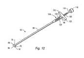
- FIG. 12depicts a perspective view an embodiment of a shaft assembly with a portion of a bias section of the shaft assembly shown in cut-away to show a biasing member of the shaft assembly.
- FIG. 13depicts a top view of an embodiment of a rasp.
- FIG. 14depicts a front view of an embodiment of a rasp.
- FIG. 15depicts a top view of an embodiment of a trial member.
- FIG. 16depicts a front view of an embodiment of a trial member.
- FIG. 17depicts a top view of an embodiment of a tamp.
- FIG. 18depicts a front view of an embodiment of a tamp.
- FIGS. 19A-19Ddepict schematic representations of installation of an end member onto a shaft assembly.
- FIGS. 20A-20Edepict-schematic representations of use of a rasp to prepare a disc space.
- FIGS. 21A-21Ddepict schematic representations of use of a tamp to position a spinal implant in a disc space.
- an instrumentmay be used in a procedure to insert a spinal implant between human vertebrae.
- the instrumentmay include a shaft assembly and an end member.
- the end membermay rotate (e.g., pivot or angulate) with respect to the shaft assembly.
- the shaft assemblymay include a slide that engages the end member to secure the end member at a selected angle with respect to the shaft assembly. To facilitate use of the instrument, the angle of the end member relative to the shaft assembly may be adjusted while the end member is in use in a patient.
- Components of instrumentsmay be made of materials including, but not limited to, metals, ceramics, and/or polymers.
- the metalsmay include, but are not limited to, stainless steel, titanium, and titanium alloys.
- Some components of instrumentsmay be autoclaved and/or chemically sterilized.
- Components that may not be autoclaved and/or chemically sterilizedmay be made of sterile materials.
- an instrumentmay include end members that are coupled to shaft assemblies such that separation of the end members from the shaft assemblies is inhibited.
- the end membersmay be coupled to the shaft assemblies by rivets, press fit connections, adhesives, threaded connectors or other fastening systems.
- An end membermay be rotated and set in desired positions relative to a shaft assembly prior to insertion of the end member into a patient and during use of the end member.
- an instrument setmay include a shaft assembly and modular end members.
- the end membersmay be removably coupled to the shaft assembly.
- An instrument setmay include different end members for various steps of a procedure, including, but not limited to, distraction, disc preparation, disc space evaluation, and implantation.
- End members used for disc preparationmay include, but are not limited to, rasps, trials, chisels, curettes, or distractors.
- End members used for implantationmay include, but are not limited to, inserters, tamps, or guides.
- An instrument including an adjustable end membermay allow preparation of a disc space and insertion of a spinal implant between human vertebrae to be effected from above an incision in a patient through a relatively small opening in the patient.
- the instrumentmay allow simple, efficient, and safe preparation of a disc space for receiving a spinal implant, including preparation of the contralateral (opposite) side of the disc space.
- the instrumentmay allow spinal implant insertion through a relatively small opening in the patient while maintaining maneuverability and visibility of the surgical site, spinal implant, and instruments during the procedure.
- FIG. 1depicts a perspective view of an embodiment of instrument 50 .
- Instrument 50may include shaft assembly 52 and end member 54 .
- End member 54may be pivotably coupled to shaft assembly 52 .
- end member 54may be separable from shaft assembly 52 .
- Shaft assembly 52may be included in a modular instrument set having one or more end members.
- Shaft assembly 52may include shaft 56 , slide 58 , handle 60 , locking member 62 , and connector 64 .
- Handle 60may be coupled to shaft 56 .
- slide 58 of shaft assembly 52is able to move longitudinally relative to shaft 56 .
- a distal portion of slide 58may engage an end member to inhibit undesired rotation of the end member relative to shaft 56 .
- Locking member 62may limit movement of shaft 56 relative to slide 58 to fix an angular position of an end member coupled to shaft assembly 52 .
- “slide”includes any element that moves (e.g., translates and/or rotates) with respect to another element.
- the slidemay be positioned outside, inside, or along side the other element.
- a slidemay be, but is not limited to, a shaft, a tube, a rod, a bar, a beam, or a combination thereof. In certain embodiments, a slide may threadably engage another element.
- slide 58may be an outer shaft that surrounds a portion of shaft 56 .
- Distal end 66 of slide 58may engage end member 54 to hold the end member at a desired angle relative to shaft 56 .
- Locking member 62may be coupled to slide 58 .
- Locking member 62may be operated to control axial position of slide 58 relative to shaft 56 .
- locking member 62may include a spring or other bias element that applies force to move slide 58 towards connector 64 of shaft 56 .
- shaft 56 of instrument 50may be a single member.
- a shaftmay include multiple members.
- Distal portion 68 of shaft 56may include connector 64 .
- Connector 64may be oriented perpendicular to a longitudinal axis of shaft 56 .
- Connector 64may form a “tee” shape in distal portion 68 of shaft 56 .
- End member 54may include body opening 70 , and surfaces 72 , 74 . End member 54 may be coupled to connector 64 of distal portion 68 of shaft 56 . Pivoting end member 54 relative to shaft 56 about connector 64 may allow the end member to be positioned at various angles relative to the shaft during use of instrument 50 .
- a rotational range of motion of end member 54 relative to shaft assembly 52may be limited by a surface of the end member that defines opening 70 .
- the surface of the end member that defines opening 70is a planar surface so that the range of motion of end member 54 relative to shaft assembly 52 is 180°. In other embodiments, the surface of the end member that defines opening 70 may be angled or curved so that the range of motion of end member 54 relative to shaft assembly 52 is less than or greater than 180°.
- end member 54may be separable from shaft assembly 52 . In certain embodiments, end member 54 may be separated from shaft assembly 52 when the end member is in a selected orientation with respect to the shaft assembly. For example, end member 54 may be separable from shaft assembly 52 when distal portion 68 of shaft 56 is aligned in slot 76 . To separate end member 54 from shaft assembly 52 , end member 54 may be rotated about connector 64 until distal portion 68 of shaft 56 is aligned in slot 76 . Slide 58 may be retracted from connector 64 , and end member 54 may be removed from distal portion 68 .
- slide 58 and end member 54may include complementary capture elements.
- capture elementincludes any element that directly or indirectly contacts or engages another element to at least partially inhibit relative motion (e.g., translation, rotation) of the elements.
- a capture elementmay include, but is not limited to, a detent, a spring, a groove, a ridge, a tab, a pin, a projection, a slot, a hole, a notch, roughened or textured surfaces or threading.
- slide 58may include teeth 78 and end member 54 may include complementary teeth 80 .
- a capture elementmay be a separate component or may be a part of another element.
- a capture elementmay automatically release when a predetermined amount of force is applied to the element that is captured. In other embodiments, release of a capture element may require a separate action by a user (e.g., user actuated movement of the slide relative to the shaft).
- Capture elementsmay be positioned over a subset of the range that end member 54 is able to rotate relative to shaft assembly 52 to define an instrument use range of the end member relative to the shaft assembly.
- teeth 80may be formed on end member 54 so that the instrument use range of the end member relative to the shaft assembly is from about 20° to about 180°, where 0° is the angle formed between the shaft assembly and the end member when a shaft of the shaft assembly is positioned in slot 76 such that the shaft assembly can be removed from the end member.
- the instrument use range of the end member relative to the shaft assemblymay be less or greater than the range of 20° to 180° (e.g., 30° to 180°, 10° to 180°, 10° to 190°, 45° to 135°).
- a slide of a shaft assemblymay include detents or pins that engage holes or slots in an end member.
- a slide of a shaft assemblymay include holes or slots that engage detents or pins on an end member.
- engaging surfaces of a slide and/or end membermay be textured to inhibit relative motion between a shaft assembly and an end member when the slide is biased against the end member.
- turning (e.g., clockwise rotation) locking member 62 in a first directionmay move slide 58 toward end member 54 .
- Distal end 66 of slide 58may engage end member 54 .
- Turning locking member 62 in an opposite directione.g., counterclockwise
- Distal end 66 of slide 58may disengage from end member 54 .
- end member 54may pivot with respect to shaft 56 about connector 64 .
- FIG. 2depicts an embodiment of instrument 50 that has end member 54 fixed to shaft assembly 52 .
- Connector 64may be a pin that is press fit into end member 54 . A portion of the pin passes through shaft 56 so that end member is able to rotate relative to shaft assembly 52 about connector 64 .
- Locking member 62may move slide 58 so that capture elements of the slide engage with, or disengage from, capture elements of end member 54 .
- FIG. 3 and FIG. 4depict front and side views of an embodiment of shaft assembly 52 .
- FIG. 5depicts a cross-sectional view of an embodiment of shaft assembly 52 .
- Shaft 56may include tip 82 , body 84 , and sleeve 86 .
- Tip 82 , body 84 , and sleeve 86may be coupled by various methods including, but not limited to, application of an adhesive, welding, press-fitting, threading, pins, and/or rivets.
- Tip 82may have an elongated section and connector 64 .
- a cross-sectional shape of the elongated section perpendicular to the longitudinal axis of the elongated sectionmay be substantially square.
- Handle 60may be coupled to sleeve 86 and shaft 56 by a pin.
- Slide 58may include tube 88 and collar 90 .
- tube 88may have a substantially cylindrical outer surface.
- An opening through collar 90may have a substantially square shape that corresponds to a shape of the elongated section of tip 82 . The shape of the opening in collar 90 and the shape of the elongated section of tip 82 may inhibit rotation of slide 58 relative to shaft 56 .
- Slide 58may include indicia 92 .
- Indicia 92may indicate insertion depth of an end member into a patient.
- Handle 60may be used to hold shaft assembly 52 .
- locking member 62may be rotated with fingers of the same hand with which a user is holding handle 60 .
- a top of handle 60may be an impact surface.
- a mallet or other impact instrumentmay strike the impact surface to drive an end member coupled to the shaft assembly into a disc space.
- some embodiments of handle 60may include spring 94 and pin 96 .
- An end of a slap hammermay include a keyway that engages pin 96 to couple the slap hammer to shaft assembly 52 .
- Spring 94may apply force to the slap hammer that holds the shaft assembly and the slap hammer together. The slap hammer may be used to remove an end member from a disc space.
- FIG. 6depicts a detail view of an embodiment of locking member 62 .
- Locking member 62may include portions 62 A and 62 B. Portions 62 A and 62 B may be fixedly coupled (e.g., by adhesive, welding, threads, or soldering) after the portions are properly positioned relative to shaft 56 and slide 58 .
- Capture washer 98may be coupled to a distal end of portion 62 A. Capture washer 98 may engage rim 100 of slide 58 when locking member 62 is rotated to move the slide away from a connector of the shaft assembly.
- Belleville washers 102may be positioned between end face 104 of slide 58 and end face 106 of portion 62 B. When locking member 62 is rotated to move slide 58 towards connector 64 (depicted in FIGS. 3-5 ), end face 106 may push against Belleville washers 102 . Belleville washers 102 may push against slide 58 to move the slide towards the connector.
- Threading 108 on portion 62 Bmay mate with threading 110 of sleeve 86 .
- Locking member 62may be rotated in a first direction to move slide 58 towards a connector of a shaft assembly. Teeth of the slide may engage teeth of an end member to fix the angular position of the end member relative to the shaft assembly. Locking member 62 may be rotated in an opposite direction to move slide 58 away from the connector. When the slide is moved away from the connector, teeth of the slide may disengage from teeth of the end member to allow the angular position of the end member relative to the shaft to be changed.
- collar 90may be placed on tip 82 .
- Tip 82may be welded to body 84 .
- Retainer washer 98may be welded to portion 62 A.
- Portion 62 Amay be placed on tube 88 .
- Tube 88may be welded to collar 90 .
- Sleeve 86may be press-fit into handle 60 .
- Portion 62 Bmay be threaded onto thread 110 of sleeve 86 .
- Belleville washersmay be placed about shaft 56 .
- An opening in sleeve 86may be aligned with an opening in shaft 56 and a pin may be press fit into the openings to couple the sleeve and handle 60 to the shaft.
- Portion 62 Amay be positioned against portion 62 B.
- Portion 62 A and portion 62 Bmay be welded together to form locking member 62 and the complete shaft assembly.
- FIG. 7depicts a cross-sectional view of a portion of an embodiment of a shaft assembly.
- Capture washer 98may be positioned on slide 58 .
- a tipmay be placed in a collar.
- the tipmay be coupled to a body.
- the bodymay be positioned in slide 58 .
- the collarmay be coupled to slide 58 .
- Locking member 62may be positioned on slide 58 .
- An adhesivee.g., Loctite Engineering Adhesive
- Capture washer 98may be threaded on locking member 62 .
- Sleeve 86may be press fit in handle 60 so that an opening through the sleeve aligns with an opening through the handle.
- Sleeve 86may be threaded in locking member 62 until an opening in body 84 aligns with the openings through the sleeve and handle 60 .
- Pin 111may be positioned in handle to fix the position of body 84 relative to sleeve 86 and handle 60 .
- Rotating locking member 62advances or retracts slide 58 relative to handle 60 .
- FIG. 8depicts a distal portion of a shaft assembly when a locking member of the shaft assembly is rotated to drive slide 58 towards connector 64 of shaft 56 .
- FIG. 9depicts a distal portion of an embodiment of a shaft assembly when the locking member of the shaft assembly is disengaged to drive slide 58 away from connector 64 of shaft 56 .
- FIG. 10depicts a detail view of an embodiment of teeth 78 of collar 90 of a slide.
- collar 90may include from 1 to about 8 teeth 78 .
- collar 90includes 4 teeth.
- an angular spacing between teeth 78may be from about 5 to about 30°. In an embodiment, the angular spacing between teeth is about 14°.
- an angle between sides of tooth 78may be from about 150° to about 5°. In an embodiment, the angle between sides of a tooth is about 60°.
- FIG. 11depicts an end view of an embodiment of a collar of a slide.
- Opening 112may receive a tip of a shaft of a shaft assembly.
- opening 112may have a shape other than square or rectangular, such as, but not limited to, circular, diamond-shaped, or hexagonal.
- a slide of an instrumentmay translate on a shaft without rotation of the slide relative to the shaft. Engaging surfaces of the shaft and the collar may inhibit rotation of the shaft with respect to the collar.
- a shaft positioned in the collarmay include a slot.
- a pinmay be press fit into the slide through the slot so that rotation of the shaft relative to the slide is inhibited, while still allowing for axial movement of the slide relative to the shaft.
- a shaft assemblymay include a biasing member that urges a slide toward a distal portion of a shaft assembly.
- a biasing membermay include, but is not limited to, a coil spring, Belleville washers, or an elastomeric member.
- FIG. 12depicts shaft assembly 52 including shaft 56 and slide 58 .
- Shaft 56may include a distal portion and a proximal portion.
- Distal portion 68may include connector 64 .
- Proximal portion 114may include knob 116 .
- Knob 116may be an impact surface that allows an end member that is coupled to connector 64 to be driven into a disc space. Knob 116 may also be positioned against a user's palm or thumb during use to allow a user to move slide 58 relative to shaft 56 .
- Shaft assembly 52may include bias section 118 .
- a portion of bias section 118 of FIG. 12is shown in cut-away to reveal some of the inner features of the bias section.
- Bias section 118may include biasing member 120 , and grips 122 .
- a first end of biasing member 120may be positioned against a portion of bias section 118 .
- a second end of biasing member 120may be positioned against ledge 124 of shaft 56 .
- ledge 124may be formed by reducing a diameter of a portion of shaft 56 .
- a ledgemay be formed by placing a weld bead or other obstruction on the shaft.
- a ledgemay be formed by a pin or washer coupled to the shaft.
- Biasing member 120may provide a force to slide 58 that moves the slide towards connector 64 of shaft 56 .
- a usermay grasp grips 122 with fingers while knob 116 is positioned against the user's palm or thumb. Grips 122 may be pulled away from connector 64 to move slide 58 away from the connector. When grips 122 are released, biasing member 120 may move slide 58 towards connector 64 .
- Teeth 78may engage portions of the end member to set a desired angle of the end member relative to shaft assembly 52 .
- the angle of the end member relative to the shaft assemblymay be adjusted during use by repositioning slide 58 relative to the end member.
- shaft assembly 52may include lock 126 .
- Lock 126may include thread that complements a threaded portion of shaft 56 .
- lock 126may be rotated to position an end of the locking member against bias section 118 .
- Positioning locking member 126 against biasing section 118may inhibit movement of slide 58 relative to the end member, thus inhibiting rotation of the end member relative to shaft assembly 52 .
- locking member 126may be rotated to move the locking member away from bias section 118 so that slide 58 can be moved to allow the teeth of the slide to be repositioned with respect to the end member.
- an end membermay be a rasp that is used to abrade surfaces of vertebrae.
- FIGS. 13 and 14depict top and front views, respectively, of rasp 128 .
- Rasp 128may include opening 70 , slot 76 , and hole 130 .
- Rasp 128may couple with a shaft of a shaft assembly.
- Hole 130may receive a portion of a connector of the shaft.
- Opening 70may allow rasp 128 to pivot relative to the shaft of the shaft assembly.
- Rasp 128may include posterior side 132 and anterior side 134 .
- Sides 132 , 134may be curved.
- Sides 132 , 134may have substantially the same curvature as a spinal implant to be inserted in a disc space formed using the rasp.
- the curvature of posterior side 132may be substantially the same as the curvature of anterior side 134 .
- the curvature of posterior side 132may be different than the curvature of anterior side 134 .
- posterior side 132may have a smaller radius of curvature than anterior side 134 .
- posterior side 132 and/or anterior side 134may include no significant curvature.
- Distal end 136 of rasp 128may be tapered and/or curved. Tapered and/or curved surfaces of distal end 136 may facilitate insertion of rasp 128 in a disc space. In some embodiments, the tapered and/or curved surfaces of distal end 136 may be textured. The textured surface may facilitate removal of intervertebral disc material during use. In some embodiments, distal end 136 may not be tapered and/or curved. Proximal end 138 of rasp 128 may be blunt and/or rounded. In some embodiments, upper surface 72 and lower surface 74 of rasp 128 may be angled relative to each other. Angled upper surface 72 and lower surface 74 may facilitate removal of intervertebral disc material during use.
- Upper surface 72 and lower surface 74 of rasp 128may be textured to abrade and/or cut vertebral bone. Texturing may be provided by methods including, but not limited to, sanding the surface, forming grooves in the surface, shot peening the surface, scoring the surface using an electrical discharge process, and/or embedding hard particles in the surface.
- Rasp 128may include teeth 80 .
- Teeth 80may engage cooperating elements of a slide of a shaft assembly to secure a position of rasp 128 relative to the shaft.
- Teeth 80may allow an angle of rasp 128 relative to a shaft to be selectively set in range R.
- range Rmay be at least about 90°.
- range Rmay be about 150°, about 120°, about 90°, or about 45°.
- Slot 76may allow rasp 128 to be separated from the shaft assembly when a portion of the shaft is aligned with slot 76 .
- Slot 76may be located on rasp 128 such that the portion of the shaft cannot be aligned with slot 76 when the rasp is positioned between vertebrae in a patient.
- an end membermay be a trial member used to evaluate size and/or shape of a disc space.
- FIGS. 15 and 16depict top and front views, respectively, of trial member 140 .
- Trial member 140may include various tapered, curved and/or flat outer surfaces.
- Trial member 140may include opening 70 , slot 76 , and hole 130 that allow the trial member to be removably coupled to a shaft of a shaft assembly.
- Slot 76may be located on trial member 140 such that the shaft of the shaft assembly cannot be aligned with slot 76 when the trial member is positioned between vertebrae in a patient.
- Trial member 140may include teeth 80 . Teeth 80 may allow the trial member to be set at a desired angle relative to the shaft of the shaft assembly.
- Trial member 140may include marker 142 .
- Marker 142may be color coded or include indicia to indicate to which instrument set the trial belongs.
- An instrument setmay include trial members of various sizes.
- the instrument setmay include a trial member for each spinal implant size included in the instrument set.
- a trial membermay have the same dimensions as the dimensions of a corresponding spinal implant.
- one or more dimensions of a trial membermay differ from those of a corresponding spinal implant. For example, a height of each trial member may be undersized relative to a height of a corresponding spinal implant for each trial.
- an end membermay be a tamp used to position a spinal implant in a disc space.
- FIGS. 17 and 18depict top and front views, respectively, of tamp 144 .
- Tamp 144may include opening 70 , slot 76 , and hole 130 that allow the tamp to be removably coupled to a shaft of a shaft assembly.
- Slot 76may be located on tamp 144 such that the shaft of the shaft assembly cannot be aligned with slot 76 when the tamp is positioned between vertebrae in a patient.
- Tamp 144may include teeth 80 that allow the tamp to be set at a desired angle relative to the shaft of the shaft assembly.
- Tamp 144may include end face 146 and tips 148 . End face 146 may contact a spinal implant that is partially inserted into a disc space.
- An instrument formed of a shaft assembly and tamp 144may be pushed or impacted with a mallet to advance the spinal implant into a desired position in a disc space.
- End face 146may include any of a variety of profiles, including, but not limited to, flat, convex, concave, arcuate, wedge-shaped, u-shaped, or yea-shaped. End face 146 may have various surface contours, including, but not limited to, smooth, textured, or padded.
- a tampmay include elements such as tabs, pins, or protrusions for engaging a portion of a spinal implant. Such elements may facilitate manipulation of the spinal implant with the tamp. For example, tips 148 (shown in FIG. 17 ) on tamp 144 may engage a groove or notch on a spinal implant to facilitate placement of the spinal implant using the tamp.
- FIGS. 19A-19Ddepict coupling of end member 54 with shaft assembly 52 .
- Pin 64may be aligned with hole 130 (shown in FIGS. 13-18 ).
- distal portion 68 of shaft 56may be aligned with slot 76 .
- Pin 64 and distal portion 68may be placed in slot 76 .
- FIG. 19Bdepicts pin 64 may engaged with hole 130 (shown in FIGS. 13-18 ).
- End member 54may be pivoted about pin 64 .
- distal portion 68 of shaft 56may be positioned in opening 70 away from slot 76 .
- Slide 58may be translated toward end member 54 .
- teeth 78 on distal end 66 of slide 58may engage teeth 80 of end member 54 . Engagement of teeth 78 , 80 may inhibit rotation of end member 54 relative to shaft assembly 52 .
- an instrumentmay be used in a procedure to insert a spinal implant in a disc space between adjacent vertebrae.
- the spinal implantmay replace all or a portion of an intervertebral disc that has degenerated due to wear, trauma, and/or disease.
- the spinal implantmay restore a normal separation distance between adjacent vertebrae and promote fusion of the vertebrae.
- a spinal implantmay be inserted in a space formed between two portions of a bone to extend the length of the bone.
- a discectomymay be performed to remove disc material from a disc space.
- a distractormay be positioned in the disc space to establish a separation distance between the vertebrae.
- a disc spacemay be prepared using instruments such as, but not limited to, scalpels, drills, curettes, chisels, or rongeurs.
- a chiselmay be used to remove portions of vertebral bone and form channels in the vertebral endplates adjacent to the disc space.
- an angle of an end member relative to a shaft assemblymay be adjusted while the end member is in a disc space. Pivoting the end member may facilitate positioning of the end member in various regions of the disc space. The ability to pivot an end member may allow a user to maintain the shaft assembly of an instrument in a desired range without requiring a large working space. For example, an angle of the end member relative to the shaft assembly may be controlled such that a position of the shaft assembly is maintained in a relatively small range within a surgical opening in the patient at a surface of the body as the end member is advanced in the disc space. The angle may be adjusted at selected points of advancement of the instrument into and/or withdrawal of the instrument from a disc space.
- an angle of an end member with respect to a shaft assemblyis adjusted twice during advancement of the end member and twice during withdrawal of the end member. In other embodiments, an angle of the end member with respect to the shaft assembly is adjusted three or more times during advancement of the end member and three and/or more times during withdrawal of the end member.
- an end membermay be allowed to pivot freely relative to the shaft assembly as the end member is withdrawn from an incision.
- the end membermay deflect as the end member encounters tissue during withdrawal. Pivoting of an end member during withdrawal may reduce damage to tissue that might occur if the end member were locked at a fixed angle during withdrawal of the end member.
- Vertebral surfacesmay require preparation before insertion of a spinal implant in a disc space.
- a raspmay be inserted in an intervertebral disc space from a posterior or transverse approach to abrade vertebral surfaces. Vertebral surfaces may be abraded to remove osteophytes and/or to smooth rough surfaces.
- an instrument with an end member that is a raspmay be used to roughen vertebral endplates. Roughening of vertebral endplates may initiate a healing response that promotes bone growth. The bone growth may promote fusion of adjacent vertebrae with an installed spinal implant.
- an instrument including a raspmay be used to prepare a disc space for a spinal implant.
- An angle of the rasp with respect to a shaft assembly of the instrumentmay be adjusted to facilitate positioning of the rasp in the disc space.
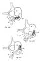
- FIGS. 20A-20Edepict use of instrument 50 including rasp 128 .
- Rasp 128may be placed in disc space 150 at various angles relative to shaft assembly 52 of instrument 50 . Vertebral surfaces may be abraded by moving shaft assembly 52 back and forth with rasp 128 in disc space 150 .
- An angle of rasp 128 relative to shaft assembly 52may be selected to allow rasp 128 to be inserted in disc space 150 during a transverse approach. After insertion, an angle of rasp 128 relative to shaft assembly 52 may be adjusted to allow instrument 50 to be positioned and used at different locations within disc space 150 , including but not limited to the area across midline of the vertebral body.
- Shaft assembly 52may be pivoted relative to rasp 128 by moving a slide of the shaft assembly and angling the shaft assembly relative to rasp 128 . After a desired angle is obtained, the slide may be moved against rasp 128 to secure the position of the rasp relative to shaft assembly 52 .
- Rasp 128may be forced against an endplate of a first vertebra. Rasp 128 may be moved to treat the vertebral surface of the first vertebra. Rasp 128 may be forced against the endplate of a second vertebra. Rasp 128 may be moved to treat the vertebral surface of the second vertebra.
- a discectomymay be performed to remove a portion of an intervertebral disc.
- the discectomymay form an initial path between vertebrae.
- rasp 128may be used to extend the path in a desired trajectory.
- rasp 128may be initially secured in first orientation A relative to shaft assembly 52 .
- Rasp 128may be advanced in disc space 150 in an initial space formed during a discectomy.
- shaft assembly 52may be adjusted from orientation A to orientation B. Frictional engagement of rasp 128 with adjacent disc 152 may stabilize rasp 128 sufficiently to allow shaft assembly 52 to be angled by moving a slide of the shaft assembly and angling the shaft assembly.
- FIG. 20Bdepicts a representation of disc 152 after rasp 128 has been used to extend disc space 150 .
- Shaft assembly 52may be adjusted from orientation B to orientation C. Rasp 128 may be further advanced into disc into 152 to establish desired disc space 150 , as depicted in FIG. 20C .
- Instrument 50may be removed from disc space 150 by reversing the steps used for insertion of the instrument. For example, with shaft assembly 52 at orientation C, rasp 128 may be partially withdrawn from disc space 150 ( FIG. 20D ). Shaft assembly 52 may be adjusted to orientation B. Rasp 128 may be further withdrawn from disc space 150 ( FIG. 20E ). Shaft assembly 52 may be adjusted to orientation A, and instrument 50 may be removed from the incision.
- an instrument including a trial membermay be used to gauge a disc space before insertion of a spinal implant.
- a raspmay be removed from a shaft assembly after a disc space is prepared.
- a trialmay be attached to the shaft assembly.
- the instrument with the trial attachedmay be inserted into the disc space.
- the trialmay have the same outer shape as the shape of a spinal implant in an instrumentation set provided for the spinal implant insertion procedure. If the trial is easily inserted into the disc space, the corresponding spinal implant may not have sufficient height. If the trial cannot be inserted, the corresponding spinal implant may have too much height. Insertion of the trial should be achieved with some impact on an end of the shaft assembly.
- the trialmay be fully inserted along the established disc space to ensure that the corresponding spinal implant will be able to follow the same path.
- the angle of the shaft assembly relative to the trialmay be adjusted during insertion of the trial into the disc space. After complete insertion, the trial may be removed from the disc space.
- an instrumentmay be used to position, guide, and/or manipulate a spinal implant in a disc space.
- FIGS. 21A-21Ddepict positioning of spinal implant 156 in disc space 150 .
- bone growth promoting materialmay be placed in the disc space and/or in openings in the spinal implant to minimize or eliminate gaps between the spinal implant and walls defining the disc space.
- the bone growth promoting materialmay be, but is not limited to, autologous bone, allograft bone, xenograft bone, calcium phosphates, collagen, calcium sulfates, demineralized bone matrix, bone morphogenetic proteins, platelet derived growth factors, bone marrow aspirate, and/or blood.
- Spinal implant 156may be placed in an initial position in disc space 150 using a spinal implant inserter 158 ( FIG. 21A ).
- instrument 50 with tamp 144 and shaft assembly 52may be coupled to spinal implant 156 .
- Tamp 144may be angled relative to shaft assembly 52 in orientation A.
- Shaft assembly 52may be advanced to drive tamp 144 and spinal implant 156 in disc space 150 ( FIG. 21C ).
- a malletmay be used to strike shaft assembly 52 of instrument 50 to advance spinal implant 156 in disc space 150 .
- Shaft assembly 52may be changed from orientation A to orientation B while tamp 144 remains in place in disc space 150 .
- instrument 50may be withdrawn slightly from spinal implant 156 to facilitate angular adjustment.
- Tamp 144may be secured to shaft assembly 52 when the tamp is positioned in orientation B.
- Instrument 50may be used to further advance spinal implant 156 into disc space 150 .
- Tamp 144may be used to push spinal implant 156 fully into disc space 150 .
- a position of spinal implant 156may be monitored using radiological techniques. After full insertion of spinal implant 156 , instrument 50 may be withdrawn from the surgical site.
Landscapes
- Health & Medical Sciences (AREA)
- Engineering & Computer Science (AREA)
- Biomedical Technology (AREA)
- Orthopedic Medicine & Surgery (AREA)
- Life Sciences & Earth Sciences (AREA)
- Animal Behavior & Ethology (AREA)
- General Health & Medical Sciences (AREA)
- Surgery (AREA)
- Public Health (AREA)
- Veterinary Medicine (AREA)
- Oral & Maxillofacial Surgery (AREA)
- Heart & Thoracic Surgery (AREA)
- Transplantation (AREA)
- Neurology (AREA)
- Vascular Medicine (AREA)
- Cardiology (AREA)
- Dentistry (AREA)
- Nuclear Medicine, Radiotherapy & Molecular Imaging (AREA)
- Medical Informatics (AREA)
- Molecular Biology (AREA)
- Physical Education & Sports Medicine (AREA)
- Prostheses (AREA)
- Surgical Instruments (AREA)
Abstract
Description
Claims (16)
Priority Applications (1)
| Application Number | Priority Date | Filing Date | Title |
|---|---|---|---|
| US15/137,514US10327919B2 (en) | 2003-08-01 | 2016-04-25 | Variable angle spinal surgery instrument |
Applications Claiming Priority (5)
| Application Number | Priority Date | Filing Date | Title |
|---|---|---|---|
| US10/633,371US7806932B2 (en) | 2003-08-01 | 2003-08-01 | Spinal implant |
| US62327404P | 2004-10-29 | 2004-10-29 | |
| US11/257,745US20060229627A1 (en) | 2004-10-29 | 2005-10-25 | Variable angle spinal surgery instrument |
| US12/698,691US9345586B2 (en) | 2003-08-01 | 2010-02-02 | Variable angle spinal surgery instrument |
| US15/137,514US10327919B2 (en) | 2003-08-01 | 2016-04-25 | Variable angle spinal surgery instrument |
Related Parent Applications (1)
| Application Number | Title | Priority Date | Filing Date |
|---|---|---|---|
| US12/698,691ContinuationUS9345586B2 (en) | 2003-08-01 | 2010-02-02 | Variable angle spinal surgery instrument |
Publications (2)
| Publication Number | Publication Date |
|---|---|
| US20160235552A1 US20160235552A1 (en) | 2016-08-18 |
| US10327919B2true US10327919B2 (en) | 2019-06-25 |
Family
ID=37084037
Family Applications (3)
| Application Number | Title | Priority Date | Filing Date |
|---|---|---|---|
| US11/257,745AbandonedUS20060229627A1 (en) | 2003-08-01 | 2005-10-25 | Variable angle spinal surgery instrument |
| US12/698,691Expired - Fee RelatedUS9345586B2 (en) | 2003-08-01 | 2010-02-02 | Variable angle spinal surgery instrument |
| US15/137,514Expired - LifetimeUS10327919B2 (en) | 2003-08-01 | 2016-04-25 | Variable angle spinal surgery instrument |
Family Applications Before (2)
| Application Number | Title | Priority Date | Filing Date |
|---|---|---|---|
| US11/257,745AbandonedUS20060229627A1 (en) | 2003-08-01 | 2005-10-25 | Variable angle spinal surgery instrument |
| US12/698,691Expired - Fee RelatedUS9345586B2 (en) | 2003-08-01 | 2010-02-02 | Variable angle spinal surgery instrument |
Country Status (1)
| Country | Link |
|---|---|
| US (3) | US20060229627A1 (en) |
Cited By (2)
| Publication number | Priority date | Publication date | Assignee | Title |
|---|---|---|---|---|
| US12279972B2 (en) | 2008-05-22 | 2025-04-22 | Spinal Surgical Strategies, Inc. | Spinal fusion cage system with inserter |
| US12370058B2 (en) | 2022-04-05 | 2025-07-29 | Spine Wave, Inc. | Belt driven expandable interbody fusion device |
Families Citing this family (126)
| Publication number | Priority date | Publication date | Assignee | Title |
|---|---|---|---|---|
| US8388684B2 (en) | 2002-05-23 | 2013-03-05 | Pioneer Signal Technology, Inc. | Artificial disc device |
| US7806932B2 (en) | 2003-08-01 | 2010-10-05 | Zimmer Spine, Inc. | Spinal implant |
| US20060229627A1 (en) | 2004-10-29 | 2006-10-12 | Hunt Margaret M | Variable angle spinal surgery instrument |
| WO2006058221A2 (en) | 2004-11-24 | 2006-06-01 | Abdou Samy M | Devices and methods for inter-vertebral orthopedic device placement |
| US7959675B2 (en)* | 2005-04-08 | 2011-06-14 | G&L Consulting, Llc | Spine implant insertion device and method |
| US7575580B2 (en)* | 2005-04-15 | 2009-08-18 | Warsaw Orthopedic, Inc. | Instruments, implants and methods for positioning implants into a spinal disc space |
| US7988695B2 (en) | 2005-12-21 | 2011-08-02 | Theken Spine, Llc | Articulated delivery instrument |
| US8409290B2 (en)* | 2006-03-08 | 2013-04-02 | Seaspine, Inc. | Interbody device for spinal applications |
| US20070213826A1 (en)* | 2006-03-08 | 2007-09-13 | Seaspine, Inc. | Intervertebral spacer and insertion tool providing multiple angles of insertion |
| US8157845B2 (en)* | 2006-03-22 | 2012-04-17 | Beacon Biomedical, Llc | Pivotable vetrebral spacer |
| US9345587B2 (en) | 2006-03-22 | 2016-05-24 | Beacon Biomedical, Llc | Pivotal lateral cage and method of insertion |
| US7976549B2 (en) | 2006-03-23 | 2011-07-12 | Theken Spine, Llc | Instruments for delivering spinal implants |
| US8118872B2 (en)* | 2006-08-10 | 2012-02-21 | Pioneer Surgical Technology, Inc. | System and methods for inserting a spinal disc device into an intervertebral space |
| US8506636B2 (en) | 2006-09-08 | 2013-08-13 | Theken Spine, Llc | Offset radius lordosis |
| US8372084B2 (en)* | 2006-09-22 | 2013-02-12 | Pioneer Surgical Technology, Inc. | System and methods for inserting a spinal disc device into an intervertebral space |
| US20080077150A1 (en)* | 2006-09-22 | 2008-03-27 | Linh Nguyen | Steerable rasp/trial member inserter and method of use |
| US8641764B2 (en)* | 2006-10-11 | 2014-02-04 | G&L Consulting, Llc | Spine implant insertion device and method |
| WO2008070863A2 (en) | 2006-12-07 | 2008-06-12 | Interventional Spine, Inc. | Intervertebral implant |
| US20080140085A1 (en)* | 2006-12-11 | 2008-06-12 | G&L Consulting, Llc | Steerable spine implant insertion device and method |
| US20080161929A1 (en) | 2006-12-29 | 2008-07-03 | Mccormack Bruce | Cervical distraction device |
| US8900307B2 (en) | 2007-06-26 | 2014-12-02 | DePuy Synthes Products, LLC | Highly lordosed fusion cage |
| US8398649B2 (en)* | 2007-08-06 | 2013-03-19 | Us Spine, Inc. | Articulating transforaminal lumbar interbody fusion inserter device and associated method of use |
| US8801758B2 (en)* | 2007-08-13 | 2014-08-12 | Stryker Spine | Insertion instrument for intervertebral implants |
| WO2009089367A2 (en) | 2008-01-09 | 2009-07-16 | Providence Medical Technology, Inc. | Methods and apparatus for accessing and treating the facet joint |
| EP2237748B1 (en) | 2008-01-17 | 2012-09-05 | Synthes GmbH | An expandable intervertebral implant |
| US8216317B2 (en) | 2008-03-31 | 2012-07-10 | Stryker Spine | Spinal implant apparatus and methods |
| US8936641B2 (en) | 2008-04-05 | 2015-01-20 | DePuy Synthes Products, LLC | Expandable intervertebral implant |
| US11224521B2 (en) | 2008-06-06 | 2022-01-18 | Providence Medical Technology, Inc. | Cervical distraction/implant delivery device |
| US9333086B2 (en) | 2008-06-06 | 2016-05-10 | Providence Medical Technology, Inc. | Spinal facet cage implant |
| CA2725811A1 (en) | 2008-06-06 | 2009-12-10 | Providence Medical Technology, Inc. | Facet joint implants and delivery tools |
| US8267966B2 (en) | 2008-06-06 | 2012-09-18 | Providence Medical Technology, Inc. | Facet joint implants and delivery tools |
| US8147554B2 (en)* | 2008-10-13 | 2012-04-03 | Globus Medical, Inc. | Intervertebral spacer |
| US8545566B2 (en)* | 2008-10-13 | 2013-10-01 | Globus Medical, Inc. | Articulating spacer |
| AU2009329873A1 (en) | 2008-12-26 | 2011-11-03 | Scott Spann | Minimally-invasive retroperitoneal lateral approach for spinal surgery |
| US9526620B2 (en) | 2009-03-30 | 2016-12-27 | DePuy Synthes Products, Inc. | Zero profile spinal fusion cage |
| US9642722B2 (en) | 2009-07-02 | 2017-05-09 | Atlas Spine, Inc. | Intervertebral expandable spacer |
| ES2563172T3 (en)* | 2009-07-09 | 2016-03-11 | R Tree Innovations, Llc | Flexible intersomatic implant |
| US9668882B2 (en)* | 2009-10-02 | 2017-06-06 | Amedica Corporation | Biomedical implant inserters and related apparatus, systems, and methods |
| US9028553B2 (en) | 2009-11-05 | 2015-05-12 | DePuy Synthes Products, Inc. | Self-pivoting spinal implant and associated instrumentation |
| AU2009354956B2 (en)* | 2009-11-05 | 2015-02-19 | Synthes Gmbh | Self-pivoting spinal implant and associated instrumentation |
| US8764806B2 (en) | 2009-12-07 | 2014-07-01 | Samy Abdou | Devices and methods for minimally invasive spinal stabilization and instrumentation |
| US9393129B2 (en) | 2009-12-10 | 2016-07-19 | DePuy Synthes Products, Inc. | Bellows-like expandable interbody fusion cage |
| US8870880B2 (en) | 2010-04-12 | 2014-10-28 | Globus Medical, Inc. | Angling inserter tool for expandable vertebral implant |
| US8628535B2 (en) | 2010-05-14 | 2014-01-14 | Beacon Biomedical, Llc | Bone fixation rod and implantation device for insertion thereof |
| US9907560B2 (en) | 2010-06-24 | 2018-03-06 | DePuy Synthes Products, Inc. | Flexible vertebral body shavers |
| US8979860B2 (en) | 2010-06-24 | 2015-03-17 | DePuy Synthes Products. LLC | Enhanced cage insertion device |
| US8623091B2 (en) | 2010-06-29 | 2014-01-07 | DePuy Synthes Products, LLC | Distractible intervertebral implant |
| US9066814B2 (en) | 2010-08-02 | 2015-06-30 | Ulrich Medical Usa, Inc. | Implant assembly having an angled head |
| US8425529B2 (en) | 2010-09-30 | 2013-04-23 | Stryker Spine | Instrument for inserting surgical implant with guiding rail |
| US8603175B2 (en) | 2010-09-30 | 2013-12-10 | Stryker Spine | Method of inserting surgical implant with guiding rail |
| US8858637B2 (en)* | 2010-09-30 | 2014-10-14 | Stryker Spine | Surgical implant with guiding rail |
| US9402732B2 (en) | 2010-10-11 | 2016-08-02 | DePuy Synthes Products, Inc. | Expandable interspinous process spacer implant |
| US8486076B2 (en)* | 2011-01-28 | 2013-07-16 | DePuy Synthes Products, LLC | Oscillating rasp for use in an orthopaedic surgical procedure |
| EP3485851B1 (en) | 2011-03-22 | 2021-08-25 | DePuy Synthes Products, LLC | Universal trial for lateral cages |
| ES2629031T3 (en) | 2011-04-29 | 2017-08-07 | Medacta International S.A. | Intervertebral implant for fusion between two vertebral bodies of a spine and the corresponding positioning instrument |
| ES2555065T3 (en) | 2011-06-14 | 2015-12-28 | Biedermann Technologies Gmbh & Co. Kg | Device for inserting an intervertebral implant into a body and system comprising an intervertebral implant and a device for inserting it |
| US8845728B1 (en) | 2011-09-23 | 2014-09-30 | Samy Abdou | Spinal fixation devices and methods of use |
| US8584853B2 (en) | 2012-02-16 | 2013-11-19 | Biomedical Enterprises, Inc. | Method and apparatus for an orthopedic fixation system |
| US20130226240A1 (en) | 2012-02-22 | 2013-08-29 | Samy Abdou | Spinous process fixation devices and methods of use |
| US9226764B2 (en) | 2012-03-06 | 2016-01-05 | DePuy Synthes Products, Inc. | Conformable soft tissue removal instruments |
| KR101194219B1 (en)* | 2012-04-09 | 2012-10-29 | (주)비엠코리아 | The cage for transforaminal lumbar interbody fusion and the insertion assembly thereof |
| US8986307B2 (en) | 2012-07-10 | 2015-03-24 | X-Spine Systems, Inc. | Surgical instrument with pivotable implant holder |
| US9198767B2 (en) | 2012-08-28 | 2015-12-01 | Samy Abdou | Devices and methods for spinal stabilization and instrumentation |
| US9320617B2 (en) | 2012-10-22 | 2016-04-26 | Cogent Spine, LLC | Devices and methods for spinal stabilization and instrumentation |
| USD732667S1 (en) | 2012-10-23 | 2015-06-23 | Providence Medical Technology, Inc. | Cage spinal implant |
| WO2014074389A1 (en) | 2012-11-06 | 2014-05-15 | Alphatec Spine, Inc. | Instrument and method for in situ rod adjustment |
| US10022245B2 (en) | 2012-12-17 | 2018-07-17 | DePuy Synthes Products, Inc. | Polyaxial articulating instrument |
| US9717601B2 (en) | 2013-02-28 | 2017-08-01 | DePuy Synthes Products, Inc. | Expandable intervertebral implant, system, kit and method |
| US9522070B2 (en) | 2013-03-07 | 2016-12-20 | Interventional Spine, Inc. | Intervertebral implant |
| TWI566739B (en)* | 2013-09-24 | 2017-01-21 | Baui Biotech Co Ltd | Improved interbody fusion device and implant instrument and method of operation thereof |
| US10478313B1 (en) | 2014-01-10 | 2019-11-19 | Nuvasive, Inc. | Spinal fusion implant and related methods |
| US10456130B2 (en) | 2014-05-07 | 2019-10-29 | Biomedical Enterprises, Inc. | Method and apparatus for loading and implanting a shape memory implant |
| US10456131B2 (en) | 2014-05-07 | 2019-10-29 | Biomedical Enterprises, Inc. | Method and apparatus for loading and implanting a shape memory implant |
| AU2015267055B2 (en) | 2014-05-27 | 2020-04-02 | Christopher U. Phan | Lateral mass fixation implant |
| JP2017520357A (en) | 2014-05-28 | 2017-07-27 | プロビデンス メディカル テクノロジー インコーポレイテッド | Outer mass fixing system |
| EP3164080A4 (en) | 2014-07-06 | 2018-06-27 | Garcia-Bengochea, Javier | Methods and devices for surgical access |
| WO2017008087A1 (en) | 2015-07-06 | 2017-01-12 | Javier Garcia-Bengochea | Methods and devices for surgical access |
| CN104116552B (en)* | 2014-08-04 | 2017-01-25 | 上海三友医疗器械股份有限公司 | Intervertebral fusion device and installation tool thereof |
| US11426290B2 (en) | 2015-03-06 | 2022-08-30 | DePuy Synthes Products, Inc. | Expandable intervertebral implant, system, kit and method |
| TWI547259B (en)* | 2015-04-28 | 2016-09-01 | 鐿鈦科技股份有限公司 | Spinal fusion surgery instrument for implanting and intervertebral cage thereof |
| WO2017040732A2 (en) | 2015-09-03 | 2017-03-09 | Biomedical Enterprises, Inc. | Elastic orthopedic implant and method of manufacture thereof |
| WO2017059375A1 (en)* | 2015-09-30 | 2017-04-06 | Beacon Biomedical, Llc | Surgical instrument for implant insertion |
| US10857003B1 (en) | 2015-10-14 | 2020-12-08 | Samy Abdou | Devices and methods for vertebral stabilization |
| US10219917B2 (en)* | 2015-11-03 | 2019-03-05 | Warsaw Orthopedic, Inc. | Spinal implant inserter utilizing offset striking arms |
| US9895235B2 (en)* | 2015-12-18 | 2018-02-20 | Warsaw Orthopedic, Inc. | Spinal implant system and method |
| US10765529B2 (en)* | 2015-12-18 | 2020-09-08 | Ctl Medical Corporation | Articulating intervertebral devices, related tools, systems, and methods |
| US11510788B2 (en) | 2016-06-28 | 2022-11-29 | Eit Emerging Implant Technologies Gmbh | Expandable, angularly adjustable intervertebral cages |
| TW201806562A (en) | 2016-06-28 | 2018-03-01 | 普羅維登斯醫療科技公司 | Spinal implant and methods of using the same |
| EP3474784A2 (en) | 2016-06-28 | 2019-05-01 | Eit Emerging Implant Technologies GmbH | Expandable and angularly adjustable intervertebral cages with articulating joint |
| CN106420121B (en)* | 2016-08-31 | 2018-09-14 | 广州爱锘德医疗器械有限公司 | The operating mechanism of arc fusion device |
| US10004609B2 (en)* | 2016-09-23 | 2018-06-26 | Warsaw Orthopedic, Inc. | Surgical instrument and method |
| US10744000B1 (en) | 2016-10-25 | 2020-08-18 | Samy Abdou | Devices and methods for vertebral bone realignment |
| US10973648B1 (en) | 2016-10-25 | 2021-04-13 | Samy Abdou | Devices and methods for vertebral bone realignment |
| US10080671B2 (en) | 2016-11-01 | 2018-09-25 | Warsaw Orhtopedic, Inc. | Trial and method for use thereof |
| US10932807B2 (en) | 2017-02-08 | 2021-03-02 | Covidien Lp | Assembly tool for ultrasonic surgical instruments and kits and methods including the same |
| US10716553B2 (en) | 2017-04-19 | 2020-07-21 | Pantheon Spinal, Llc | Spine surgery retractor system and related methods |
| US10398563B2 (en) | 2017-05-08 | 2019-09-03 | Medos International Sarl | Expandable cage |
| US11871968B2 (en) | 2017-05-19 | 2024-01-16 | Providence Medical Technology, Inc. | Spinal fixation access and delivery system |
| US11344424B2 (en) | 2017-06-14 | 2022-05-31 | Medos International Sarl | Expandable intervertebral implant and related methods |
| US11931269B2 (en)* | 2017-07-10 | 2024-03-19 | Xtant Medical, Inc. | Delivery systems for interspinous, interlaminar stabilization devices and methods of use |
| US10966843B2 (en) | 2017-07-18 | 2021-04-06 | DePuy Synthes Products, Inc. | Implant inserters and related methods |
| US11045331B2 (en) | 2017-08-14 | 2021-06-29 | DePuy Synthes Products, Inc. | Intervertebral implant inserters and related methods |
| WO2019051260A1 (en) | 2017-09-08 | 2019-03-14 | Pioneer Surgical Technology, Inc. | Intervertebral implants, instruments, and methods |
| USD907771S1 (en) | 2017-10-09 | 2021-01-12 | Pioneer Surgical Technology, Inc. | Intervertebral implant |
| US10973658B2 (en) | 2017-11-27 | 2021-04-13 | Titan Spine, Inc. | Rotating implant and associated instrumentation |
| US11648128B2 (en) | 2018-01-04 | 2023-05-16 | Providence Medical Technology, Inc. | Facet screw and delivery device |
| WO2019209256A1 (en) | 2018-04-23 | 2019-10-31 | Eca Medical Instruments | Disposable rasp for medical instruments |
| WO2020061464A1 (en) | 2018-09-21 | 2020-03-26 | Providence Medical Technology, Inc. | Vertebral joint access and decortication devices and methods of using |
| US11179248B2 (en) | 2018-10-02 | 2021-11-23 | Samy Abdou | Devices and methods for spinal implantation |
| US11446156B2 (en) | 2018-10-25 | 2022-09-20 | Medos International Sarl | Expandable intervertebral implant, inserter instrument, and related methods |
| US11039931B2 (en)* | 2019-02-01 | 2021-06-22 | Globus Medical, Inc. | Intervertebral spinal implant |
| USD933230S1 (en) | 2019-04-15 | 2021-10-12 | Providence Medical Technology, Inc. | Cervical cage |
| US11517450B2 (en) | 2019-06-27 | 2022-12-06 | Pioneer Surgical Technology, Inc. | Intervertebral implant inserter tool |
| EP3795120B1 (en)* | 2019-09-18 | 2023-11-01 | Biedermann Technologies GmbH & Co. KG | Intervertebral implant and insertion device therefor |
| EP4034002B1 (en) | 2019-09-24 | 2025-09-10 | Simplify Medical Pty Limited | Surgical cutter instrument with trial |
| US11844725B2 (en)* | 2019-10-16 | 2023-12-19 | Alcon Inc. | Visually traceable vitrectomy probe cap |
| US12042386B2 (en) | 2020-01-29 | 2024-07-23 | DePuy Synthes Products, Inc. | Shape memory implants and methods and apparatus for the loading and implanting thereof |
| US11523820B2 (en) | 2020-01-29 | 2022-12-13 | DePuy Synthes Products, Inc. | Shape memory implants and a method and apparatus for the loading and implanting thereof |
| USD945621S1 (en) | 2020-02-27 | 2022-03-08 | Providence Medical Technology, Inc. | Spinal cage |
| US11426286B2 (en) | 2020-03-06 | 2022-08-30 | Eit Emerging Implant Technologies Gmbh | Expandable intervertebral implant |
| EP3970645B1 (en) | 2020-09-22 | 2025-06-11 | Biedermann Technologies GmbH & Co. KG | Implant, insertion device and plate assembly |
| US11850160B2 (en) | 2021-03-26 | 2023-12-26 | Medos International Sarl | Expandable lordotic intervertebral fusion cage |
| US11752009B2 (en) | 2021-04-06 | 2023-09-12 | Medos International Sarl | Expandable intervertebral fusion cage |
| CN118042995A (en)* | 2021-09-22 | 2024-05-14 | 脊柱外科策略有限公司 | Surgical instrument |
| US11951021B2 (en)* | 2021-11-30 | 2024-04-09 | DePuy Synthes Products, Inc. | Surgical implant position detection |
| US12090064B2 (en) | 2022-03-01 | 2024-09-17 | Medos International Sarl | Stabilization members for expandable intervertebral implants, and related systems and methods |
Citations (91)
| Publication number | Priority date | Publication date | Assignee | Title |
|---|---|---|---|---|
| US3867728A (en) | 1971-12-30 | 1975-02-25 | Cutter Lab | Prosthesis for spinal repair |
| US4743256A (en) | 1985-10-04 | 1988-05-10 | Brantigan John W | Surgical prosthetic implant facilitating vertebral interbody fusion and method |
| US4768787A (en) | 1987-06-15 | 1988-09-06 | Shira Chester S | Golf club including high friction striking face |
| US4834757A (en) | 1987-01-22 | 1989-05-30 | Brantigan John W | Prosthetic implant |
| US4964641A (en) | 1990-01-26 | 1990-10-23 | Diversified Metal Incorporated | Golf club with electrical discharge machined face |
| US5019081A (en) | 1986-12-10 | 1991-05-28 | Watanabe Robert S | Laminectomy surgical process |
| US5171278A (en) | 1991-02-22 | 1992-12-15 | Madhavan Pisharodi | Middle expandable intervertebral disk implants |
| US5192327A (en) | 1991-03-22 | 1993-03-09 | Brantigan John W | Surgical prosthetic implant for vertebrae |
| US5306307A (en) | 1991-07-22 | 1994-04-26 | Calcitek, Inc. | Spinal disk implant |
| US5424772A (en) | 1988-10-04 | 1995-06-13 | Asahi Kogaku Kogyo Kabushiki Kaisha | Mode changing device for still video camera and still video camera used therewith |
| US5429863A (en) | 1991-06-03 | 1995-07-04 | Acromed Corporation | Fiber reinforced composite structure |
| US5443514A (en) | 1993-10-01 | 1995-08-22 | Acromed Corporation | Method for using spinal implants |
| US5526664A (en) | 1994-09-07 | 1996-06-18 | Progressive Technologies, Inc. | Method of forming a textured pattern on a metal plate which pattern is transformed to a plastic part, and a press plate and plastic part produced thereby |
| FR2736537A1 (en) | 1995-07-12 | 1997-01-17 | Vila Thierry | Intersomatic implant for restoring normal anatomical space between vertebrae, to relieve pressure on nerve roots |
| US5609635A (en) | 1988-06-28 | 1997-03-11 | Michelson; Gary K. | Lordotic interbody spinal fusion implants |
| WO1997015248A1 (en) | 1995-10-20 | 1997-05-01 | Synthes Ag Chur | Inter-vertebral implant |
| JPH09122160A (en) | 1995-10-31 | 1997-05-13 | Kyocera Corp | Artificial intervertebral spacer |
| US5653763A (en) | 1996-03-29 | 1997-08-05 | Fastenetix, L.L.C. | Intervertebral space shape conforming cage device |
| US5713899A (en) | 1995-04-27 | 1998-02-03 | Societe Jbs Sa | Cervical cage designed for the performance of intersomatic arthrodesis |
| US5716415A (en) | 1993-10-01 | 1998-02-10 | Acromed Corporation | Spinal implant |
| US5717006A (en) | 1994-02-08 | 1998-02-10 | Centre National De La Recherche Scientifique (C.N.R.S.) | Composition for biomaterial; preparation process |
| US5733290A (en) | 1995-12-21 | 1998-03-31 | Johnson & Johnson Professional, Inc. | Quick-release tibial alignment handle |
| WO1998017209A2 (en) | 1996-10-23 | 1998-04-30 | Sdgi Holdings, Inc. | Spinal spacer |
| US5766252A (en) | 1995-01-24 | 1998-06-16 | Osteonics Corp. | Interbody spinal prosthetic implant and method |
| US5769897A (en) | 1991-12-13 | 1998-06-23 | Haerle; Anton | Synthetic bone |
| US5814084A (en) | 1996-01-16 | 1998-09-29 | University Of Florida Tissue Bank, Inc. | Diaphysial cortical dowel |
| US5836958A (en) | 1996-10-30 | 1998-11-17 | Ralph; James D. | Surgical curette having a variably angled handle |
| WO1998056319A1 (en) | 1997-06-11 | 1998-12-17 | Sdgi Holdings, Inc. | Reinforced bone graft sustitutes |
| DE29901611U1 (en) | 1999-01-30 | 1999-04-22 | Aesculap AG & Co. KG, 78532 Tuttlingen | Surgical instrument for inserting intervertebral implants |
| US5918821A (en) | 1996-07-19 | 1999-07-06 | G&G Technologies, Inc. | Modular bone grinder and snap-in grinder head |
| US5984922A (en) | 1993-07-09 | 1999-11-16 | Mckay; Douglas William | Spinal fixation device and method |
| US5989289A (en) | 1995-10-16 | 1999-11-23 | Sdgi Holdings, Inc. | Bone grafts |
| US6025538A (en) | 1998-11-20 | 2000-02-15 | Musculoskeletal Transplant Foundation | Compound bone structure fabricated from allograft tissue |
| US6113639A (en) | 1999-03-23 | 2000-09-05 | Raymedica, Inc. | Trial implant and trial implant kit for evaluating an intradiscal space |
| US6143032A (en) | 1997-11-12 | 2000-11-07 | Schafer Micomed Gmbh | Intervertebral implant |
| US6143033A (en) | 1998-01-30 | 2000-11-07 | Synthes (Usa) | Allogenic intervertebral implant |
| US6159211A (en) | 1998-10-22 | 2000-12-12 | Depuy Acromed, Inc. | Stackable cage system for corpectomy/vertebrectomy |
| US6174311B1 (en) | 1998-10-28 | 2001-01-16 | Sdgi Holdings, Inc. | Interbody fusion grafts and instrumentation |
| US6190414B1 (en) | 1996-10-31 | 2001-02-20 | Surgical Dynamics Inc. | Apparatus for fusion of adjacent bone structures |
| US6200347B1 (en) | 1999-01-05 | 2001-03-13 | Lifenet | Composite bone graft, method of making and using same |
| WO2001028469A2 (en) | 1999-10-21 | 2001-04-26 | Sdgi Holdings, Inc. | Devices and techniques for a posterior lateral disc space approach |
| US6224607B1 (en) | 1999-01-25 | 2001-05-01 | Gary K. Michelson | Instrumentation and method for creating an intervertebral space for receiving an implant |
| US6241770B1 (en) | 1999-03-05 | 2001-06-05 | Gary K. Michelson | Interbody spinal fusion implant having an anatomically conformed trailing end |
| US6245108B1 (en) | 1999-02-25 | 2001-06-12 | Spineco | Spinal fusion implant |
| US6277149B1 (en) | 1999-06-08 | 2001-08-21 | Osteotech, Inc. | Ramp-shaped intervertebral implant |
| US20010021853A1 (en) | 2000-03-10 | 2001-09-13 | Richard Wolf Gmbh | Surgical instrument for applying implants |
| US6290724B1 (en) | 1998-05-27 | 2001-09-18 | Nuvasive, Inc. | Methods for separating and stabilizing adjacent vertebrae |
| US6294187B1 (en) | 1999-02-23 | 2001-09-25 | Osteotech, Inc. | Load-bearing osteoimplant, method for its manufacture and method of repairing bone using same |
| JP2002501315A (en) | 1997-12-31 | 2002-01-15 | トムソン マルチメディア | Electromagnetic wave transmitter / receiver |
| US6346123B1 (en) | 1996-10-24 | 2002-02-12 | Sdgi Holdings, Inc. | Ceramic fusion implants and compositions |
| WO2002017823A1 (en) | 2000-08-28 | 2002-03-07 | Koo Ja Kyo | A prosthetic implant for spinal interbody fusion and a inserting apparatus thereof |
| WO2002047587A2 (en) | 2000-10-25 | 2002-06-20 | Sdgi Holdings, Inc. | Vertically expanding intervertebral body fusion device |
| US20020077700A1 (en) | 2000-06-12 | 2002-06-20 | Ortho Development Corporation | Intervertebral spacer |
| US20020087212A1 (en) | 2000-12-29 | 2002-07-04 | James Stephen B. | Spinal implant |
| US6468311B2 (en) | 2001-01-22 | 2002-10-22 | Sdgi Holdings, Inc. | Modular interbody fusion implant |
| US20020165612A1 (en) | 2001-05-03 | 2002-11-07 | David Gerber | Intervertebral implant for transforaminal posterior lumbar interbody fusion procedure |
| US20020177897A1 (en) | 2001-02-04 | 2002-11-28 | Michelson Gary K. | Instrumentation and method for inserting and deploying and expandable interbody spinal fusion implant |
| US6517544B1 (en) | 1998-06-09 | 2003-02-11 | Gary K. Michelson | Device and method for preparing a space between adjacent vertebrae to receive an insert |
| US6530956B1 (en) | 1998-09-10 | 2003-03-11 | Kevin A. Mansmann | Resorbable scaffolds to promote cartilage regeneration |
| US6537589B1 (en) | 2000-04-03 | 2003-03-25 | Kyung Won Medical Co., Ltd. | Calcium phosphate artificial bone as osteoconductive and biodegradable bone substitute material |
| US20030069586A1 (en)* | 2001-07-16 | 2003-04-10 | Errico Joseph P. | Instrumentation and methods for use in implanting an artificial intervertebral disc |
| US20030100950A1 (en) | 2000-03-22 | 2003-05-29 | Olivier Moret | Cage-type intervertebral implant |
| US20030114931A1 (en)* | 2001-12-13 | 2003-06-19 | Lee Choon Sung | Spinal prosthetic implant and insertion instrument |
| US6613089B1 (en) | 2000-10-25 | 2003-09-02 | Sdgi Holdings, Inc. | Laterally expanding intervertebral fusion device |
| US6648915B2 (en) | 1999-12-23 | 2003-11-18 | John A. Sazy | Intervertebral cage and method of use |
| US6682534B2 (en) | 2001-08-02 | 2004-01-27 | Depuy Acromed, Inc. | Endplate preparation instrument and associated method |
| US20040127990A1 (en) | 2002-12-31 | 2004-07-01 | Bartish, Charles M. | Novel banana cage |
| US6764491B2 (en) | 1999-10-21 | 2004-07-20 | Sdgi Holdings, Inc. | Devices and techniques for a posterior lateral disc space approach |
| US20040153065A1 (en) | 2003-02-03 | 2004-08-05 | Lim Roy K. | Expanding interbody implant and articulating inserter and method |
| US6830570B1 (en) | 1999-10-21 | 2004-12-14 | Sdgi Holdings, Inc. | Devices and techniques for a posterior lateral disc space approach |
| US20050004671A1 (en) | 2003-07-01 | 2005-01-06 | Thomas Ross | Spinal spacer assembly |
| US20050027360A1 (en) | 2003-08-01 | 2005-02-03 | Webb Scott A. | Spinal implant |
| US20050096745A1 (en) | 2003-10-29 | 2005-05-05 | Eurosurgical Sa | Intersomatic cage for lumbar fusion by transforaminal approach and its cage carrying device |
| US6974480B2 (en) | 2001-05-03 | 2005-12-13 | Synthes (Usa) | Intervertebral implant for transforaminal posterior lumbar interbody fusion procedure |
| US20060004376A1 (en) | 2004-07-02 | 2006-01-05 | Kenneth Shipp | Device for inserting implants |
| US20060074427A1 (en) | 2002-12-27 | 2006-04-06 | Lieberman Isador H | Articulatable apparatus for cutting bone |
| US20060095043A1 (en) | 2004-10-19 | 2006-05-04 | Martz Erik O | Adjustable instrumentation for spinal implant insertion |
| US20060229627A1 (en) | 2004-10-29 | 2006-10-12 | Hunt Margaret M | Variable angle spinal surgery instrument |
| US20060241761A1 (en) | 2005-04-08 | 2006-10-26 | G&L Consulting | Spine implant insertion device and method |
| US20070142843A1 (en) | 2005-12-21 | 2007-06-21 | Justin Dye | Articulated delivery instrument |
| US20070213826A1 (en) | 2006-03-08 | 2007-09-13 | Seaspine, Inc. | Intervertebral spacer and insertion tool providing multiple angles of insertion |
| US20070213737A1 (en) | 2006-03-08 | 2007-09-13 | Seaspine, Inc. | Insertion tool for an intervertebral spacer providing multiple angles of insertion |
| US20070225808A1 (en) | 2006-03-22 | 2007-09-27 | Warnick David R | Pivotable interbody spacer |
| US20070225726A1 (en) | 2006-03-23 | 2007-09-27 | Justin Dye | Instruments for delivering spinal implants |
| US20080009880A1 (en) | 2006-03-22 | 2008-01-10 | Warnick David R | Pivotable Vetrebral Spacer |
| US20080027544A1 (en) | 2006-07-28 | 2008-01-31 | Warsaw Orthopedic Inc. | Instruments and techniques for engaging spinal implants for insertion into a spinal space |
| US20080065082A1 (en) | 2006-09-08 | 2008-03-13 | Narissa Chang | Steerable rasp/trial inserter |
| US20080077241A1 (en) | 2006-09-22 | 2008-03-27 | Linh Nguyen | Removable rasp/trial member insert, kit and method of use |
| US20080091211A1 (en) | 2006-10-11 | 2008-04-17 | G & L Consulting | Spine implant insertion device and method |
| US20080132901A1 (en) | 2006-09-05 | 2008-06-05 | Coligne Ag | Spinal implant and instrument |
| US20100256760A1 (en) | 2009-04-02 | 2010-10-07 | Noah Hansell | Method of Installation of Intervertebral Spacers |
Family Cites Families (1)
| Publication number | Priority date | Publication date | Assignee | Title |
|---|---|---|---|---|
| US5425772A (en) | 1993-09-20 | 1995-06-20 | Brantigan; John W. | Prosthetic implant for intervertebral spinal fusion |
- 2005
- 2005-10-25USUS11/257,745patent/US20060229627A1/ennot_activeAbandoned
- 2010
- 2010-02-02USUS12/698,691patent/US9345586B2/ennot_activeExpired - Fee Related
- 2016
- 2016-04-25USUS15/137,514patent/US10327919B2/ennot_activeExpired - Lifetime
Patent Citations (109)
| Publication number | Priority date | Publication date | Assignee | Title |
|---|---|---|---|---|
| US3867728A (en) | 1971-12-30 | 1975-02-25 | Cutter Lab | Prosthesis for spinal repair |
| US4743256A (en) | 1985-10-04 | 1988-05-10 | Brantigan John W | Surgical prosthetic implant facilitating vertebral interbody fusion and method |
| US5019081A (en) | 1986-12-10 | 1991-05-28 | Watanabe Robert S | Laminectomy surgical process |
| US4834757A (en) | 1987-01-22 | 1989-05-30 | Brantigan John W | Prosthetic implant |
| US4878915A (en) | 1987-01-22 | 1989-11-07 | Brantigan John W | Surgical prosthetic implant facilitating vertebral interbody fusion |
| US4768787A (en) | 1987-06-15 | 1988-09-06 | Shira Chester S | Golf club including high friction striking face |
| US5609635A (en) | 1988-06-28 | 1997-03-11 | Michelson; Gary K. | Lordotic interbody spinal fusion implants |
| US5424772A (en) | 1988-10-04 | 1995-06-13 | Asahi Kogaku Kogyo Kabushiki Kaisha | Mode changing device for still video camera and still video camera used therewith |
| US4964641A (en) | 1990-01-26 | 1990-10-23 | Diversified Metal Incorporated | Golf club with electrical discharge machined face |
| US5171278A (en) | 1991-02-22 | 1992-12-15 | Madhavan Pisharodi | Middle expandable intervertebral disk implants |
| US5192327A (en) | 1991-03-22 | 1993-03-09 | Brantigan John W | Surgical prosthetic implant for vertebrae |
| US5429863A (en) | 1991-06-03 | 1995-07-04 | Acromed Corporation | Fiber reinforced composite structure |
| US5306307A (en) | 1991-07-22 | 1994-04-26 | Calcitek, Inc. | Spinal disk implant |
| US5769897A (en) | 1991-12-13 | 1998-06-23 | Haerle; Anton | Synthetic bone |
| US5984922A (en) | 1993-07-09 | 1999-11-16 | Mckay; Douglas William | Spinal fixation device and method |
| US5443514A (en) | 1993-10-01 | 1995-08-22 | Acromed Corporation | Method for using spinal implants |
| US5716415A (en) | 1993-10-01 | 1998-02-10 | Acromed Corporation | Spinal implant |
| US5717006A (en) | 1994-02-08 | 1998-02-10 | Centre National De La Recherche Scientifique (C.N.R.S.) | Composition for biomaterial; preparation process |
| US5526664A (en) | 1994-09-07 | 1996-06-18 | Progressive Technologies, Inc. | Method of forming a textured pattern on a metal plate which pattern is transformed to a plastic part, and a press plate and plastic part produced thereby |
| US5766252A (en) | 1995-01-24 | 1998-06-16 | Osteonics Corp. | Interbody spinal prosthetic implant and method |
| US5713899A (en) | 1995-04-27 | 1998-02-03 | Societe Jbs Sa | Cervical cage designed for the performance of intersomatic arthrodesis |
| FR2736537A1 (en) | 1995-07-12 | 1997-01-17 | Vila Thierry | Intersomatic implant for restoring normal anatomical space between vertebrae, to relieve pressure on nerve roots |
| US5989289A (en) | 1995-10-16 | 1999-11-23 | Sdgi Holdings, Inc. | Bone grafts |
| WO1997015248A1 (en) | 1995-10-20 | 1997-05-01 | Synthes Ag Chur | Inter-vertebral implant |
| US5888227A (en) | 1995-10-20 | 1999-03-30 | Synthes (U.S.A.) | Inter-vertebral implant |
| JPH09122160A (en) | 1995-10-31 | 1997-05-13 | Kyocera Corp | Artificial intervertebral spacer |
| JP3692169B2 (en) | 1995-10-31 | 2005-09-07 | 京セラ株式会社 | Artificial intervertebral spacer |
| US5733290A (en) | 1995-12-21 | 1998-03-31 | Johnson & Johnson Professional, Inc. | Quick-release tibial alignment handle |
| US5814084A (en) | 1996-01-16 | 1998-09-29 | University Of Florida Tissue Bank, Inc. | Diaphysial cortical dowel |
| US5653763A (en) | 1996-03-29 | 1997-08-05 | Fastenetix, L.L.C. | Intervertebral space shape conforming cage device |
| US5918821A (en) | 1996-07-19 | 1999-07-06 | G&G Technologies, Inc. | Modular bone grinder and snap-in grinder head |
| WO1998017209A2 (en) | 1996-10-23 | 1998-04-30 | Sdgi Holdings, Inc. | Spinal spacer |
| US6346123B1 (en) | 1996-10-24 | 2002-02-12 | Sdgi Holdings, Inc. | Ceramic fusion implants and compositions |
| US5836958A (en) | 1996-10-30 | 1998-11-17 | Ralph; James D. | Surgical curette having a variably angled handle |
| US6190414B1 (en) | 1996-10-31 | 2001-02-20 | Surgical Dynamics Inc. | Apparatus for fusion of adjacent bone structures |
| WO1998056319A1 (en) | 1997-06-11 | 1998-12-17 | Sdgi Holdings, Inc. | Reinforced bone graft sustitutes |
| US6143032A (en) | 1997-11-12 | 2000-11-07 | Schafer Micomed Gmbh | Intervertebral implant |
| JP2002501315A (en) | 1997-12-31 | 2002-01-15 | トムソン マルチメディア | Electromagnetic wave transmitter / receiver |
| US6143033A (en) | 1998-01-30 | 2000-11-07 | Synthes (Usa) | Allogenic intervertebral implant |
| US6290724B1 (en) | 1998-05-27 | 2001-09-18 | Nuvasive, Inc. | Methods for separating and stabilizing adjacent vertebrae |
| US6517544B1 (en) | 1998-06-09 | 2003-02-11 | Gary K. Michelson | Device and method for preparing a space between adjacent vertebrae to receive an insert |
| US6530956B1 (en) | 1998-09-10 | 2003-03-11 | Kevin A. Mansmann | Resorbable scaffolds to promote cartilage regeneration |
| US6159211A (en) | 1998-10-22 | 2000-12-12 | Depuy Acromed, Inc. | Stackable cage system for corpectomy/vertebrectomy |
| US6174311B1 (en) | 1998-10-28 | 2001-01-16 | Sdgi Holdings, Inc. | Interbody fusion grafts and instrumentation |
| US6025538A (en) | 1998-11-20 | 2000-02-15 | Musculoskeletal Transplant Foundation | Compound bone structure fabricated from allograft tissue |
| US6200347B1 (en) | 1999-01-05 | 2001-03-13 | Lifenet | Composite bone graft, method of making and using same |
| US6224607B1 (en) | 1999-01-25 | 2001-05-01 | Gary K. Michelson | Instrumentation and method for creating an intervertebral space for receiving an implant |
| US6599294B2 (en) | 1999-01-30 | 2003-07-29 | Aesculap Ag & Co. Kg | Surgical instrument for introducing intervertebral implants |
| DE29901611U1 (en) | 1999-01-30 | 1999-04-22 | Aesculap AG & Co. KG, 78532 Tuttlingen | Surgical instrument for inserting intervertebral implants |
| DE19903762C1 (en) | 1999-01-30 | 2000-11-16 | Aesculap Ag & Co Kg | Surgical instrument for inserting intervertebral implants |
| WO2000044288A1 (en) | 1999-01-30 | 2000-08-03 | Aesculap Ag & Co. Kg | Surgical instrument for inserting intervertebral implants |
| US6294187B1 (en) | 1999-02-23 | 2001-09-25 | Osteotech, Inc. | Load-bearing osteoimplant, method for its manufacture and method of repairing bone using same |
| US6245108B1 (en) | 1999-02-25 | 2001-06-12 | Spineco | Spinal fusion implant |
| US20020143400A1 (en) | 1999-02-25 | 2002-10-03 | Depuy Acromed, Inc. | Spinal fusion implant |
| US6241770B1 (en) | 1999-03-05 | 2001-06-05 | Gary K. Michelson | Interbody spinal fusion implant having an anatomically conformed trailing end |
| US6113639A (en) | 1999-03-23 | 2000-09-05 | Raymedica, Inc. | Trial implant and trial implant kit for evaluating an intradiscal space |
| US6277149B1 (en) | 1999-06-08 | 2001-08-21 | Osteotech, Inc. | Ramp-shaped intervertebral implant |
| US6764491B2 (en) | 1999-10-21 | 2004-07-20 | Sdgi Holdings, Inc. | Devices and techniques for a posterior lateral disc space approach |
| US7060073B2 (en) | 1999-10-21 | 2006-06-13 | Sdgi Holdings, Inc. | Devices and techniques for a posterior lateral disc space approach |
| WO2001028469A2 (en) | 1999-10-21 | 2001-04-26 | Sdgi Holdings, Inc. | Devices and techniques for a posterior lateral disc space approach |
| US6830570B1 (en) | 1999-10-21 | 2004-12-14 | Sdgi Holdings, Inc. | Devices and techniques for a posterior lateral disc space approach |
| US6648915B2 (en) | 1999-12-23 | 2003-11-18 | John A. Sazy | Intervertebral cage and method of use |
| WO2001054629A1 (en) | 2000-01-31 | 2001-08-02 | Spineco | Spinal fusion implant |
| US20010021853A1 (en) | 2000-03-10 | 2001-09-13 | Richard Wolf Gmbh | Surgical instrument for applying implants |
| US6699288B2 (en) | 2000-03-22 | 2004-03-02 | Scolio Gmbh | Cage-type intervertebral implant |
| US20030100950A1 (en) | 2000-03-22 | 2003-05-29 | Olivier Moret | Cage-type intervertebral implant |
| US6537589B1 (en) | 2000-04-03 | 2003-03-25 | Kyung Won Medical Co., Ltd. | Calcium phosphate artificial bone as osteoconductive and biodegradable bone substitute material |
| US6852127B2 (en) | 2000-06-12 | 2005-02-08 | Ortho Development Corporation | Method of implanting an intervertebral spacer |
| US6579318B2 (en) | 2000-06-12 | 2003-06-17 | Ortho Development Corporation | Intervertebral spacer |
| US20020077700A1 (en) | 2000-06-12 | 2002-06-20 | Ortho Development Corporation | Intervertebral spacer |
| WO2002017823A1 (en) | 2000-08-28 | 2002-03-07 | Koo Ja Kyo | A prosthetic implant for spinal interbody fusion and a inserting apparatus thereof |
| US6613089B1 (en) | 2000-10-25 | 2003-09-02 | Sdgi Holdings, Inc. | Laterally expanding intervertebral fusion device |
| WO2002047587A2 (en) | 2000-10-25 | 2002-06-20 | Sdgi Holdings, Inc. | Vertically expanding intervertebral body fusion device |
| US20020087212A1 (en) | 2000-12-29 | 2002-07-04 | James Stephen B. | Spinal implant |
| US6468311B2 (en) | 2001-01-22 | 2002-10-22 | Sdgi Holdings, Inc. | Modular interbody fusion implant |
| US20020177897A1 (en) | 2001-02-04 | 2002-11-28 | Michelson Gary K. | Instrumentation and method for inserting and deploying and expandable interbody spinal fusion implant |
| US20020165612A1 (en) | 2001-05-03 | 2002-11-07 | David Gerber | Intervertebral implant for transforaminal posterior lumbar interbody fusion procedure |
| US6719794B2 (en) | 2001-05-03 | 2004-04-13 | Synthes (U.S.A.) | Intervertebral implant for transforaminal posterior lumbar interbody fusion procedure |
| US6974480B2 (en) | 2001-05-03 | 2005-12-13 | Synthes (Usa) | Intervertebral implant for transforaminal posterior lumbar interbody fusion procedure |
| US20030069586A1 (en)* | 2001-07-16 | 2003-04-10 | Errico Joseph P. | Instrumentation and methods for use in implanting an artificial intervertebral disc |
| US6682534B2 (en) | 2001-08-02 | 2004-01-27 | Depuy Acromed, Inc. | Endplate preparation instrument and associated method |
| US20030114931A1 (en)* | 2001-12-13 | 2003-06-19 | Lee Choon Sung | Spinal prosthetic implant and insertion instrument |
| US20060074427A1 (en) | 2002-12-27 | 2006-04-06 | Lieberman Isador H | Articulatable apparatus for cutting bone |
| US7500991B2 (en) | 2002-12-31 | 2009-03-10 | Depuy Acromed, Inc. | Banana cage |
| US20040127990A1 (en) | 2002-12-31 | 2004-07-01 | Bartish, Charles M. | Novel banana cage |
| US20040153065A1 (en) | 2003-02-03 | 2004-08-05 | Lim Roy K. | Expanding interbody implant and articulating inserter and method |
| US20050004671A1 (en) | 2003-07-01 | 2005-01-06 | Thomas Ross | Spinal spacer assembly |
| US20050027360A1 (en) | 2003-08-01 | 2005-02-03 | Webb Scott A. | Spinal implant |
| US9345586B2 (en) | 2003-08-01 | 2016-05-24 | Zimmer Spine, Inc. | Variable angle spinal surgery instrument |
| US7806932B2 (en) | 2003-08-01 | 2010-10-05 | Zimmer Spine, Inc. | Spinal implant |
| US20100137922A1 (en) | 2003-08-01 | 2010-06-03 | Hunt Margaret M | Variable angle spinal surgery instrument |
| US20050096745A1 (en) | 2003-10-29 | 2005-05-05 | Eurosurgical Sa | Intersomatic cage for lumbar fusion by transforaminal approach and its cage carrying device |
| US20060004376A1 (en) | 2004-07-02 | 2006-01-05 | Kenneth Shipp | Device for inserting implants |
| US20060095043A1 (en) | 2004-10-19 | 2006-05-04 | Martz Erik O | Adjustable instrumentation for spinal implant insertion |
| US20060229627A1 (en) | 2004-10-29 | 2006-10-12 | Hunt Margaret M | Variable angle spinal surgery instrument |
| US20060241761A1 (en) | 2005-04-08 | 2006-10-26 | G&L Consulting | Spine implant insertion device and method |
| US20070142843A1 (en) | 2005-12-21 | 2007-06-21 | Justin Dye | Articulated delivery instrument |
| US20070213737A1 (en) | 2006-03-08 | 2007-09-13 | Seaspine, Inc. | Insertion tool for an intervertebral spacer providing multiple angles of insertion |
| US20070213826A1 (en) | 2006-03-08 | 2007-09-13 | Seaspine, Inc. | Intervertebral spacer and insertion tool providing multiple angles of insertion |
| US20080009880A1 (en) | 2006-03-22 | 2008-01-10 | Warnick David R | Pivotable Vetrebral Spacer |
| US20070225808A1 (en) | 2006-03-22 | 2007-09-27 | Warnick David R | Pivotable interbody spacer |
| US20070225726A1 (en) | 2006-03-23 | 2007-09-27 | Justin Dye | Instruments for delivering spinal implants |
| US20080027544A1 (en) | 2006-07-28 | 2008-01-31 | Warsaw Orthopedic Inc. | Instruments and techniques for engaging spinal implants for insertion into a spinal space |
| US20080132901A1 (en) | 2006-09-05 | 2008-06-05 | Coligne Ag | Spinal implant and instrument |
| US20080065082A1 (en) | 2006-09-08 | 2008-03-13 | Narissa Chang | Steerable rasp/trial inserter |
| US20080077150A1 (en) | 2006-09-22 | 2008-03-27 | Linh Nguyen | Steerable rasp/trial member inserter and method of use |
| US20080077241A1 (en) | 2006-09-22 | 2008-03-27 | Linh Nguyen | Removable rasp/trial member insert, kit and method of use |
| US20080091211A1 (en) | 2006-10-11 | 2008-04-17 | G & L Consulting | Spine implant insertion device and method |
| US20100256760A1 (en) | 2009-04-02 | 2010-10-07 | Noah Hansell | Method of Installation of Intervertebral Spacers |
Non-Patent Citations (31)
Cited By (2)
| Publication number | Priority date | Publication date | Assignee | Title |
|---|---|---|---|---|
| US12279972B2 (en) | 2008-05-22 | 2025-04-22 | Spinal Surgical Strategies, Inc. | Spinal fusion cage system with inserter |
| US12370058B2 (en) | 2022-04-05 | 2025-07-29 | Spine Wave, Inc. | Belt driven expandable interbody fusion device |
Also Published As
| Publication number | Publication date |
|---|---|
| US20100137922A1 (en) | 2010-06-03 |
| US20060229627A1 (en) | 2006-10-12 |
| US9345586B2 (en) | 2016-05-24 |
| US20160235552A1 (en) | 2016-08-18 |
Similar Documents
| Publication | Publication Date | Title |
|---|---|---|
| US10327919B2 (en) | Variable angle spinal surgery instrument | |
| US8641764B2 (en) | Spine implant insertion device and method | |
| EP1653892B1 (en) | Spinal implant | |
| US7938857B2 (en) | Spinal implant | |
| CA2199462C (en) | Method and instrumentation for implant insertion | |
| US6896680B2 (en) | Arcuate dynamic lordotic guard with movable extensions for creating an implantation space posteriorly in the lumbar spine | |
| EP1207792B1 (en) | Minimal exposure posterior spinal interbody instrumentation | |
| US7959675B2 (en) | Spine implant insertion device and method | |
| CA2712243C (en) | Instruments and methods for inserting artificial intervertebral implants | |
| US20080140085A1 (en) | Steerable spine implant insertion device and method | |
| EP1470804A1 (en) | Methods and instruments for interbody fusion | |
| US20020068941A1 (en) | Bone preparation instruments and methods | |
| US20040059337A1 (en) | Bone preparation instruments and methods | |
| US10667801B2 (en) | Implant delivery systems, devices, and methods | |
| WO2024226906A1 (en) | Devices and instruments for spinal fusion and methods | |
| AU2003231687A1 (en) | Methods and Instruments for Interbody Fusion | |
| AU2005202085A1 (en) | Bone cutting device having a cutting end with a non-extending centre |
Legal Events
| Date | Code | Title | Description |
|---|---|---|---|
| STPP | Information on status: patent application and granting procedure in general | Free format text:NOTICE OF ALLOWANCE MAILED -- APPLICATION RECEIVED IN OFFICE OF PUBLICATIONS | |
| STPP | Information on status: patent application and granting procedure in general | Free format text:PUBLICATIONS -- ISSUE FEE PAYMENT VERIFIED | |
| STCF | Information on status: patent grant | Free format text:PATENTED CASE | |
| CC | Certificate of correction | ||
| AS | Assignment | Owner name:ZIMMER BIOMET SPINE, INC., INDIANA Free format text:MERGER;ASSIGNOR:ZIMMER SPINE, INC.;REEL/FRAME:059232/0356 Effective date:20160930 | |
| AS | Assignment | Owner name:JPMORGAN CHASE BANK, N.A., AS ADMINISTRATIVE AGENT, NEW YORK Free format text:SECURITY INTEREST;ASSIGNORS:BIOMET 3I, LLC;EBI, LLC;ZIMMER BIOMET SPINE, INC.;AND OTHERS;REEL/FRAME:059293/0213 Effective date:20220228 | |
| MAFP | Maintenance fee payment | Free format text:PAYMENT OF MAINTENANCE FEE, 4TH YEAR, LARGE ENTITY (ORIGINAL EVENT CODE: M1551); ENTITY STATUS OF PATENT OWNER: LARGE ENTITY Year of fee payment:4 | |
| AS | Assignment | Owner name:ZIMMER BIOMET SPINE, INC., COLORADO Free format text:MERGER;ASSIGNOR:ZIMMER SPINE, INC.;REEL/FRAME:066894/0402 Effective date:20160927 Owner name:ZIMMER SPINE AUSTIN, INC., TEXAS Free format text:CHANGE OF NAME;ASSIGNOR:ABBOTT SPINE INC.;REEL/FRAME:066885/0109 Effective date:20081215 Owner name:ABBOTT SPINE INC., TEXAS Free format text:ASSIGNMENT OF ASSIGNORS INTEREST;ASSIGNORS:HUNT, MARGARET M.;WEBB, SCOTT A.;MORENO, ANTHONY P.;SIGNING DATES FROM 20051229 TO 20060523;REEL/FRAME:066884/0761 Owner name:ZIMMER SPINE, INC., MINNESOTA Free format text:MERGER AND CHANGE OF NAME;ASSIGNORS:ZIMMER SPINE AUSTIN, INC.;ZIMMER SPINE, INC.;REEL/FRAME:066885/0754 Effective date:20090828 | |
| AS | Assignment | Owner name:CERBERUS BUSINESS FINANCE AGENCY, LLC, NEW YORK Free format text:GRANT OF A SECURITY INTEREST -- PATENTS;ASSIGNORS:ZIMMER BIOMET SPINE, LLC;EBI, LLC;REEL/FRAME:066970/0806 Effective date:20240401 | |
| AS | Assignment | Owner name:ZIMMER BIOMET SPINE, LLC (F/K/A ZIMMER BIOMET SPINE, INC.), COLORADO Free format text:RELEASE BY SECURED PARTY;ASSIGNOR:JPMORGAN CHASE BANK, N.A.;REEL/FRAME:066973/0833 Effective date:20240401 Owner name:EBI, LLC, NEW JERSEY Free format text:RELEASE BY SECURED PARTY;ASSIGNOR:JPMORGAN CHASE BANK, N.A.;REEL/FRAME:066973/0833 Effective date:20240401 | |
| AS | Assignment | Owner name:ZIMMER BIOMET SPINE, LLC, COLORADO Free format text:CHANGE OF NAME;ASSIGNOR:ZIMMER BIOMET SPINE, INC.;REEL/FRAME:069772/0121 Effective date:20240220 Owner name:HIGHRIDGE MEDICAL, LLC, COLORADO Free format text:CHANGE OF NAME;ASSIGNOR:ZIMMER BIOMET SPINE, LLC;REEL/FRAME:069772/0248 Effective date:20240405 |