US10327845B2 - System and method for monitoring ablation size - Google Patents
System and method for monitoring ablation sizeDownload PDFInfo
- Publication number
- US10327845B2 US10327845B2US15/805,430US201715805430AUS10327845B2US 10327845 B2US10327845 B2US 10327845B2US 201715805430 AUS201715805430 AUS 201715805430AUS 10327845 B2US10327845 B2US 10327845B2
- Authority
- US
- United States
- Prior art keywords
- apart electrodes
- microwave antenna
- distal
- elongate shaft
- electrode
- Prior art date
- Legal status (The legal status is an assumption and is not a legal conclusion. Google has not performed a legal analysis and makes no representation as to the accuracy of the status listed.)
- Active
Links
Images


Classifications
- A—HUMAN NECESSITIES
- A61—MEDICAL OR VETERINARY SCIENCE; HYGIENE
- A61B—DIAGNOSIS; SURGERY; IDENTIFICATION
- A61B18/00—Surgical instruments, devices or methods for transferring non-mechanical forms of energy to or from the body
- A61B18/18—Surgical instruments, devices or methods for transferring non-mechanical forms of energy to or from the body by applying electromagnetic radiation, e.g. microwaves
- A61B18/1815—Surgical instruments, devices or methods for transferring non-mechanical forms of energy to or from the body by applying electromagnetic radiation, e.g. microwaves using microwaves
- A—HUMAN NECESSITIES
- A61—MEDICAL OR VETERINARY SCIENCE; HYGIENE
- A61B—DIAGNOSIS; SURGERY; IDENTIFICATION
- A61B18/00—Surgical instruments, devices or methods for transferring non-mechanical forms of energy to or from the body
- A61B18/18—Surgical instruments, devices or methods for transferring non-mechanical forms of energy to or from the body by applying electromagnetic radiation, e.g. microwaves
- A—HUMAN NECESSITIES
- A61—MEDICAL OR VETERINARY SCIENCE; HYGIENE
- A61B—DIAGNOSIS; SURGERY; IDENTIFICATION
- A61B18/00—Surgical instruments, devices or methods for transferring non-mechanical forms of energy to or from the body
- A61B2018/00571—Surgical instruments, devices or methods for transferring non-mechanical forms of energy to or from the body for achieving a particular surgical effect
- A61B2018/00577—Ablation
- A—HUMAN NECESSITIES
- A61—MEDICAL OR VETERINARY SCIENCE; HYGIENE
- A61B—DIAGNOSIS; SURGERY; IDENTIFICATION
- A61B18/00—Surgical instruments, devices or methods for transferring non-mechanical forms of energy to or from the body
- A61B2018/00636—Sensing and controlling the application of energy
- A61B2018/00666—Sensing and controlling the application of energy using a threshold value
- A61B2018/00678—Sensing and controlling the application of energy using a threshold value upper
- A—HUMAN NECESSITIES
- A61—MEDICAL OR VETERINARY SCIENCE; HYGIENE
- A61B—DIAGNOSIS; SURGERY; IDENTIFICATION
- A61B18/00—Surgical instruments, devices or methods for transferring non-mechanical forms of energy to or from the body
- A61B2018/00636—Sensing and controlling the application of energy
- A61B2018/00696—Controlled or regulated parameters
- A61B2018/00702—Power or energy
- A—HUMAN NECESSITIES
- A61—MEDICAL OR VETERINARY SCIENCE; HYGIENE
- A61B—DIAGNOSIS; SURGERY; IDENTIFICATION
- A61B18/00—Surgical instruments, devices or methods for transferring non-mechanical forms of energy to or from the body
- A61B2018/00636—Sensing and controlling the application of energy
- A61B2018/00696—Controlled or regulated parameters
- A61B2018/00738—Depth, e.g. depth of ablation
- A—HUMAN NECESSITIES
- A61—MEDICAL OR VETERINARY SCIENCE; HYGIENE
- A61B—DIAGNOSIS; SURGERY; IDENTIFICATION
- A61B18/00—Surgical instruments, devices or methods for transferring non-mechanical forms of energy to or from the body
- A61B2018/00636—Sensing and controlling the application of energy
- A61B2018/00773—Sensed parameters
- A61B2018/00875—Resistance or impedance
- A—HUMAN NECESSITIES
- A61—MEDICAL OR VETERINARY SCIENCE; HYGIENE
- A61B—DIAGNOSIS; SURGERY; IDENTIFICATION
- A61B18/00—Surgical instruments, devices or methods for transferring non-mechanical forms of energy to or from the body
- A61B18/18—Surgical instruments, devices or methods for transferring non-mechanical forms of energy to or from the body by applying electromagnetic radiation, e.g. microwaves
- A61B18/1815—Surgical instruments, devices or methods for transferring non-mechanical forms of energy to or from the body by applying electromagnetic radiation, e.g. microwaves using microwaves
- A61B2018/1823—Generators therefor
Definitions
- the present disclosurerelates to systems and methods that may be used in tissue ablation procedures. More particularly, the present disclosure relates to systems and methods for monitoring ablation size during tissue ablation procedures in real-time.
- Microwave ablation procedurese.g., such as those performed for menorrhagia, are typically done to ablate the targeted tissue to denature or kill the tissue.
- Many procedures and types of devices utilizing electromagnetic radiation therapyare known in the art.
- Such microwave therapyis typically used in the treatment of tissue and organs such as the prostate, heart, and liver.
- One non-invasive proceduregenerally involves the treatment of tissue (e.g., a tumor) underlying the skin via the use of microwave energy.
- tissuee.g., a tumor
- the microwave energyis able to non-invasively penetrate the skin to reach the underlying tissue.
- this non-invasive proceduremay result in the unwanted heating of healthy tissue.
- the non-invasive use of microwave energyrequires a great deal of control.
- one or more types of sensorsare operably associated with the microwave ablation device.
- a microwave ablation devicethat includes a monopole antenna configuration
- an elongated microwave conductormay be in operative communication with a sensor exposed at an end of the microwave conductor. This type of sensor is sometimes surrounded by a dielectric sleeve.
- the foregoing types of sensorsare configured to function (e.g., provide feedback to a controller for controlling the power output of a power source) when the microwave ablation device is inactive, i.e., not radiating. That is, the foregoing sensors do not function in real-time.
- the power sourceis powered off or pulsed off when the sensors are providing feedback (e.g., tissue temperature) to the controller and/or other device(s) configured to control the power source.
- the present disclosureprovides a system for monitoring ablation size in real-time.
- the systemincludes a power source.
- a microwave antennais configured to deliver microwave energy from the power source to tissue to form an ablation zone.
- a plurality of spaced-apart electrodesis operably disposed along a length of the microwave antenna. The electrodes are disposed in electrical communication with one another. Each of the electrodes has a threshold impedance associated therewith corresponding to the radius of the ablation zone.
- the present disclosureprovides a microwave antenna adapted to connect to a power source configured for performing an ablation procedure.
- the microwave antennaincludes a radiating section configured to deliver microwave energy from the power source to tissue to form an ablation zone.
- the microwave antennaincludes a plurality of spaced-apart electrodes operably disposed along a length of the microwave antenna. The electrodes are disposed in electrical communication with one another. Each of the electrodes has a threshold impedance associated therewith corresponding to the radius of the ablation zone.
- the present disclosurealso provides a method for monitoring tissue undergoing ablation.
- the methodincludes the initial step of transmitting microwave energy from a power source to a microwave antenna to form a tissue ablation zone.
- a step of the methodincludes monitoring one or more electrodes impedance along the microwave antenna as the tissue ablation zone forms. Triggering a detection signal when a predetermined electrode impedance is reached at the at least one electrode along the microwave antenna is another step of the method.
- the methodincludes adjusting the amount of microwave energy from the power source to the microwave antenna.
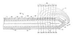
- FIG. 1is a perspective view of a system for monitoring ablation size according to an embodiment of the present disclosure
- FIG. 2is partial, side view illustrating internal components of a distal tip of a microwave antenna depicted in FIG. 1 ;
- FIG. 3is a functional block diagram showing a power source for use with the system depicted in FIG. 1 ;
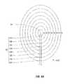
- FIG. 4Ais a schematic, plan view of a tip of the microwave antenna depicted in FIG. 2 illustrating radial ablation zones having a generally spherical configuration
- FIG. 4Bis a schematic, plan view of a tip of the microwave antenna depicted in FIG. 2 illustrating radial ablation zones having a generally ellipsoidal configuration
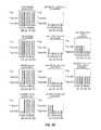
- FIG. 5Ais a schematic, plan view of a portion of the microwave antenna depicted in FIG. 1 showing a sequenced insertion of the microwave antenna into tissue;
- FIG. 5Bis a graphical representation of corresponding impedances associated with respective electrodes of the microwave antenna depicted in FIG. 5A ;
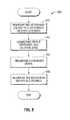
- FIG. 6is a flow chart illustrating a method for monitoring temperature of tissue undergoing ablation in accordance with the present disclosure
- FIG. 7is partial, side view illustrating internal components of a distal tip of a microwave antenna according to an alternate embodiment of the present disclosure.
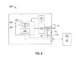
- FIG. 8is a functional block diagram showing a power source for use with the microwave antenna depicted in FIG. 7 .
- distalrefers to the portion which is furthest from the user and the term “proximal” refers to the portion that is closest to the user.
- proximalrefers to the portion that is closest to the user.
- terms such as “above”, “below”, “forward”, “rearward”, etc.refer to the orientation of the figures or the direction of components and are simply used for convenience of description.
- a microwave antenna 12operably couples to generator 100 and includes a controller 200 that connects to the generator 100 via a flexible coaxial cable 14 .
- generator 100is configured to provide microwave energy at an operational frequency from about 500 MHz to about 10 GHz.
- Microwave antenna 12includes a radiating section or portion 16 ( FIGS. 1 and 2 ) that is connected by a feedline or shaft 18 to coaxial cable 14 and extends from the proximal end of the microwave antenna 12 .
- Cable 14includes an inner conductor 13 that is operably disposed within the shaft 18 and in electrical communication with a radiating section 16 ( FIGS. 1 and 2 ).
- Microwave antenna 12couples to the cable 14 through a connection hub 22 .
- the connection hub 22includes an outlet fluid port 24 and an inlet fluid port 26 connected in fluid communication with a sheath or cannula 28 ( FIG. 2 ).
- Cannula 28is configured to circulate coolant fluid 30 from ports 24 and 26 around the antenna assembly 12 via respective fluid lumens 32 and 34 ( FIG. 2 ).
- Ports 24 and 26couple to a supply pump 40 .
- two or more spaced-apart electrodes 52 and 54are operably disposed along a length of the shaft 18 . More particularly, the electrodes 52 and 54 are disposed in proximity to a distal end 19 of the shaft 18 .
- electrodes 52include a series of proximal spaced-apart electrodes 52 a - 52 h and a distal electrode 54 .
- a series of electrodesis meant to mean two or more electrodes.
- the series of proximal spaced-apart electrodes 52 a - 52 hreferred to proximal electrodes 52 .
- the configuration of the electrodes 52 and 54enables physical space sampling of an ablation site. More particularly, in one particular embodiment, during the delivery of microwave energy to the microwave antenna 12 , impedance between one or more of the proximal electrodes 52 , e.g., proximal electrode 52 a , and the distal electrode 54 is measured and compared with known impedance values associated with the microwave antenna 12 and/or proximal electrodes 52 , e.g., proximal electrode 52 a .
- the configuration of each proximal electrodes 52 a - 52 h and distal electrode 54provides a separate closed loop path for current to flow, i.e., an electrical circuit, when the microwave antenna 12 is inserted into tissue at a target tissue site. Impedance is measured between each proximal electrode 52 a - 52 h and the distal electrode 54 , as described in greater detail below.
- Proximal electrodes 52 a - 52 hmay be formed from any suitable conductive or partially conductive material.
- proximal electrodes 52 a - 52 hmay be formed from copper, silver, gold, etc.
- Proximal electrodes 52 a - 52 hare operably positioned along an outer peripheral surface 38 of the shaft 18 in a manner suitable for the intended purposes described herein.
- the proximal electrodes 52 a - 52 hmay extend circumferentially along the outer peripheral surface 38 or partially along a length of the shaft 18 .
- proximal electrodes 52 a - 52 hextend partially along the outer peripheral surface 38 in a linear manner forming a generally linear array along the outer peripheral surface 38 of the shaft 18 .
- Proximal electrodes 52 a - 52 hmay be secured to the outer peripheral surface 38 and/or the shaft 18 via any suitable method(s).
- the proximal electrodes 52 a - 52 hare secured to the outer peripheral surface 38 via an epoxy adhesive (or other suitable adhesive).
- Proximal electrodes 52 a - 52 hare in operative communication with one or more modules, e.g., ablation zone control module 232 (AZCM), associated with the generator 100 and/or controller 200 .
- AZCMablation zone control module
- proximal electrodes 52 a - 52 hconnects to one or more electrical leads (not explicitly shown) that provide an electrical interface for the proximal electrodes 52 a - 52 h and the AZCM 232 .
- the electrical leadsprovide an electrical interface that supplies current, i.e., from a current source (or other suitable device configured to generate current, voltage source, power source, etc.) to the proximal electrodes 52 a - 52 h.
- one or more sensorsmay be in operative communication with a respective one or corresponding proximal electrode 52 a - 52 h (as best seen in FIG. 2 ).
- the sensors 53 a - 53 hmay be configured to provide real-time information pertaining to the proximal electrodes 52 a - 52 h .
- the sensors 53 a - 53 hmay be configured to provide real-time information pertaining to one or more electrical parameters (e.g., impedance, power, voltage, current, etc.) and/or other parameters associated with the proximal electrodes 52 a - 52 h .
- the sensors 53 a - 53 hmay be in the form of one or more types of thermal sensors such as, for example, a thermocouple, a thermistor, an optical fiber, etc.
- the sensors 53 a - 53 hare thermocouples 53 a - 53 h.
- Distal electrode 54may be formed from any suitable conductive or partially conductive material, e.g., copper, silver, gold, etc. Distal electrode 54 may have any suitable configuration. For illustrative purposes, distal electrode 54 is shown operably disposed at a distal tip 21 of the shaft 18 . In the illustrated embodiment, distal electrode 54 defines a conductive tissue piercing tip. In this instance, the distal electrode 54 facilitates insertion of the microwave antenna 12 into tissue at a target tissue site. Alternatively, distal electrode 54 may have a relatively blunt configuration. An electrical lead (not explicitly shown) provides an electrical interface for returning current from the distal electrode 54 back to the current source.
- An electrical lead(not explicitly shown) provides an electrical interface for returning current from the distal electrode 54 back to the current source.
- distal electrode 54may be in operative communication with one or more modules, e.g., AZCM 232 , associated with the generator 100 and/or controller 200 .
- the electrical leadmay provide an electrical interface for the distal electrode 54 and the AZCM 232 .
- one or more sensorsmay be in operative communication with the distal electrodes 54 (see FIG. 2 , for example) and may provide information relevant to the proper operation of distal electrode 54 to the AZCM 232 .
- Sensor 55may be any suitable type of sensor such as, for example, one or more types of thermal sensors previously described above, e.g., a thermocouple.
- a dielectric sheath 60 having a suitable thickness and made from a suitable materialis operably positioned along a length of the microwave antenna 12 and substantially encases the proximal electrodes 52 a - 52 h and distal electrode 54 in a manner that allows current to flow from the proximal electrodes 52 a - 52 h to the distal electrode 54 .
- Dielectric sheath 60may be made from any suitable material and may be affixed to the microwave antenna 12 by any suitable affixing methods.
- the dielectric sheath 60is a vapor deposited dielectric material, such as, for example, parylene, that is applied to the microwave antenna 12 .
- Substantially encasing the microwave antenna 12 with dielectric sheath 60results in capacitive impedance that can allow RF current flow to/from the electrodes 52 a - 52 h and tissue. More particularly, during transmission of microwave energy from the generator 100 to the microwave antenna 12 and when the proximal electrodes 52 a - 52 h and distal electrode 54 are positioned within tissue adjacent a target tissue site, current flows from proximal electrodes 52 a - 52 h to the electrode 54 .
- Dielectric sheath 60is configured to focus current densities “I” at the proximal electrodes 52 a - 52 h and/or the distal electrode 54 , which, in turn, provides comprehensive and/or more accurate measurements of impedance at the proximal electrode 52 a - 52 h , as best seen in FIG. 2 .
- the dielectric sheath 60may fully encase the proximal electrodes 52 a - 52 h and distal electrode 54 .
- the dielectric sheath 60includes a thickness that allows current to pass from the proximal electrodes 52 a - 52 h through the dielectric sheath 60 and to the distal electrode 54 .
- the thickness of the dielectric material of the dielectric sheath 60ranges from about 0.0001 inches to about 0.001 inches.
- proximal electrodes 52 a - 52 h(and in some instances distal electrode 54 ) is in operative communication with the generator 100 including AZCM 232 and/or controller 200 . More particularly, the proximal electrodes 52 a - 52 h and distal electrode 54 couple to the generator 100 and/or controller 200 via one or more suitable conductive mediums (e.g., a wire or cable 56 ) that extends from proximal electrodes 52 a - 52 h and distal electrode 54 to the proximal end of the microwave antenna 12 and connects to the generator 100 (see FIG. 2 , for example). In the illustrated embodiment, wire 56 is operably disposed within cable 14 .
- suitable conductive mediumse.g., a wire or cable 56
- Wire 56electrically connects to the proximal electrodes 52 a - 52 h and distal electrode 54 via the one or more leads previously described.
- the configuration of wire 56 , proximal electrodes 52 a - 52 h and distal electrode 54forms a closed loop current path when the electrodes 52 and distal electrode 54 are positioned within tissue adjacent a target tissue site.
- the wire 56extends along the outer peripheral surface 38 of the shaft 18 and is encased by the dielectric sheath 60 .
- the wire 56may extend within and along a length of the shaft 18 .
- the generator 100includes a controller 200 including one or more modules (e.g., an AZCM 232 ), a power supply 137 , a microwave output stage 138 .
- generator 100is described with respect to the delivery of microwave energy.
- the power supply 137provides DC power to the microwave output stage 138 which then converts the DC power into microwave energy and delivers the microwave energy to the radiating section 16 of the microwave antenna 12 (see FIG. 2 ).
- a portion of the DC poweris directed to the AZCM 232 , described in greater detail below.
- the controller 200may include analog and/or logic circuitry for processing sensed analog responses, e.g., impedance response, generated by the proximal electrodes 52 a - 52 h and determining the control signals that are sent to the generator 100 and/or supply pump 40 via the microprocessor 235 . More particularly, the controller 200 accepts one or more signals indicative of impedance associated with proximal electrodes 52 a - 52 h adjacent an ablation zone and/or the microwave antenna 12 , namely, the signals generated by the AZCM 232 as a result of the impedance measured and/or produced by proximal electrodes 52 a - 52 h .
- sensed analog responsese.g., impedance response
- One or more modules e.g., AZCM 232 , of the controller 200monitors and/or analyzes the impedance produced by the proximal electrodes 52 a - 52 h and determines if a threshold impedance has been met. If the threshold impedance has been met, then the AZCM 232 , microprocessor 235 and/or the controller 200 instructs the generator 100 to adjust the microwave output stage 138 and/or the power supply 137 accordingly. Additionally, the controller 200 may also signal the supply pump to adjust the amount of cooling fluid to the microwave antenna 12 and/or the surrounding tissue.
- the controller 200includes microprocessor 235 having memory 236 which may be volatile type memory (e.g., RAM) and/or non-volatile type memory (e.g., flash media, disk media, etc.).
- the microprocessor 235is in operative communication with the power supply 137 and/or microwave output stage 138 allowing the microprocessor 235 to control the output of the generator 100 according to either open and/or closed control loop schemes.
- the microprocessor 235is capable of executing software instructions for processing data received by the AZCM 232 , and for outputting control signals to the generator 100 and/or supply pump 40 , accordingly.
- the software instructions, which are executable by the controller 200are stored in the memory 236 .
- the microwave antenna 12is configured to create an ablation zone “A” having any suitable configuration, such as, for example, spherical ( FIG. 4A ), hemispherical, ellipsoidal ( FIG. 4B where the ablation zone is designated “A- 2 ”), and so forth.
- microwave antenna 12is configured to create an ablation zone “A” that is spherical ( FIG. 4A ).
- ablation zone “A”is being defined having a plurality of concentric ablation zones having radii r 1 -r 8 when measured from the center of the ablation zone “A,” collectively referred to as radii r.
- proximal electrodes 52 a - 52 h in combination with distal electrode 54are configured to provide comprehensive monitoring of an ablation zone “A” ( FIGS. 4A and 5A at microwave position J). More particularly, the concept of the integration of impedance Z associated with proximal electrodes 52 over time may be used to indicate tissue damage, e.g., death or necrosis. For a given microwave antenna 12 , each of the proximal electrodes 52 a - 52 h has a predetermined threshold impedance Z associated therewith.
- the predetermined threshold impedance Z associated with a corresponding electrode 52 a - 52 h , e.g., electrode 52 a , and a corresponding radius “r,” e.g., r 1 ,may be determined via any suitable methods.
- predetermined threshold impedances Zmay be determined via known experimental test data, model equations, functions and graphs, or combination thereof.
- a control algorithm of the present disclosureuses known (or in certain instances predicted) threshold impedances Z at specific radii to create an ablation zone “A” having a radius “r.” That is, impedances Z associated with proximal electrodes 52 a - 52 h that correspond to specific radii are compiled into one or more look-up tables “D” and are stored in memory, e.g., memory 236 , accessible by the microprocessor 235 and/or the AZCM 232 ( FIG. 3 ).
- the AZCM 232includes control circuitry that receives information from the proximal electrodes 52 a - 52 h , and provides the information and the source of the information (e.g., the particular proximal electrode 52 providing the information) to the controller 200 and/or microprocessor 235 . More particularly, AZCM 232 monitors the impedance Z at the proximal electrodes 52 , e.g., proximal electrode 52 a , and triggers a command signal in response to the proximal electrode 52 a reaching a predetermined impedance Z such that the electrosurgical output power from the generator 100 may be adjusted (see FIG. 5A at microwave antenna 12 position F).
- AZCM 232may be configured to monitor impedance Z at the proximal electrodes 52 a - 52 h by any known method(s).
- the voltage V and current Iis known and the AZCM 232 calculates the impedance Z.
- the sensor(s) 53 a - 53 hmay provide thermal measurements at a respective electrode 52 a - 52 h .
- AZCM 232 , microprocessor 235 and/or controller 200may access the one or more look-up tables “D” and confirm that the threshold impedance Z has been met and, subsequently, instruct the generator 100 to adjust the amount of microwave energy being delivered to the microwave antenna 12 , see FIG. 5B at corresponding graphical representation F.
- This combination of eventswill provide an ablation zone “A” with a radius approximately equal to r 3 , i.e., an ablation zone approximately equal to 3 cm by 1 cm. It should be noted, that in this instance, the ablation zone “A” is more ellipsoidal than spherical.
- one or more control algorithmsmay utilize interpolation between the radii associated with the electrodes 52 a - 52 h to calculate impedance between discreetly measured radii, e.g., impedance measured between electrode 52 a and electrode 52 b . More particularly, various (and commonly known) interpolation techniques may be utilized via curve fitting along the electrodes 52 a - 52 h.
- the one or more data look-up tablesmay be stored into memory during the manufacture process of the generator 100 and/or controller 200 or downloaded during programming; this is particularly useful in the instance where the generator 100 is configured for use with a single type of microwave antenna.
- the one or more data look-up tablesmay be downloaded into memory 236 at a time prior to use of the system 10 ; this is particularly useful in the instance where the generator 100 is configured for use with multiple microwave antennas that are configured to perform various ablation procedures.
- data look-up table “D”may be stored in a memory storage device 73 associated with the microwave antenna 12 . More particularly, a data look-up table “D” may be stored in a memory storage device 73 operatively associated with the microwave antenna 12 and may be downloaded, read and stored into microprocessor 235 and/or memory 236 and, subsequently, accessed and utilized in a manner described above; this would dispose of the step of reprogramming the generator 100 and/or controller 200 for a specific microwave antenna. More particularly, the memory storage device 73 may be operably disposed on the microwave antenna 12 , such as, for example, on or adjacent the hub 22 ( FIG. 1 ).
- the information contained in the memory storage devicemay be automatically read, downloaded and stored into the generator 100 and accessed for future use.
- the memory storage device 73may also include information pertaining to the microwave antenna 12 .
- Informationsuch as, for example, the type of microwave antenna, the type of tissue that the microwave antenna is configured to treat, the type of ablation zone desired, etc., may be stored into the storage device 73 associated with the microwave antenna 12 .
- the generator 100is shown operably coupled to fluid supply pump 40 .
- the supply pump 40is, in turn, operably coupled to a supply tank 44 .
- the microprocessor 235is in operative communication with the supply pump 40 via one or more suitable types of interfaces, e.g., a port 140 operatively disposed on the generator 100 , that allows the microprocessor 235 to control the output of a cooling fluid 30 from the supply pump 40 to the microwave antenna 12 according to either open and/or closed control loop schemes.
- the controller 200may signal the supply pump 40 to control the output of cooling fluid 30 from the supply tank 44 to the microwave antenna 12 . In this way, cooling fluid 30 is automatically circulated to the microwave antenna 12 and back to the supply pump 40 .
- a clinicianmay manually control the supply pump 40 to cause cooling fluid 30 to be expelled from the microwave antenna 12 into and/or proximate the surrounding tissue.
- proximal electrodes 52 a - 52 hmay be considered as individual anodes and distal electrode 54 may be considered as a cathode.
- Each of the proximal electrodes 52 a - 52 hincludes a predetermined threshold impedance Z that has been previously determined by any of the aforementioned methods, e.g., experimental test data.
- microwave antenna 12is connected to generator 100 .
- one or more modules, e.g., AZCM 232 , associated with the generator 100 and/or controller 200reads and/or downloads data, e.g., the type of microwave antenna, the type of tissue that is to be treated, data look-up tables, etc., from storage device 73 associated with the antenna 12 .
- datae.g., the type of microwave antenna, the type of tissue that is to be treated, data look-up tables, etc.
- the AZCM module 232recognizes the microwave antenna 12 as having 8 proximal electrodes 52 a - 52 h each with a predetermined threshold impedance Z that corresponds to a specific ablation zone “A.”
- the generator 100prompts a user to enter the desired ablation zone size, e.g., ablation zone equal to 5 cm by 5 cm having a generally spherical configuration, see FIGS. 4A and 5A at microwave antenna 12 position J.
- the AZCM 232matches the desired ablation zone size with the particular electrode 52 a - 52 h , e.g., proximal electrode 52 h .
- the AZCM 232sets the threshold impedance Z, e.g., Z ablated, for that particular proximal electrode. Thereafter, the generator 100 may be activated supplying microwave energy to the radiating section 16 of the microwave antenna 12 such that the tissue may be ablated.
- Zthreshold impedance
- AZCM 232transmits DC current (or in some instances an RF signal, e.g., in the KHz or low MHz frequency spectrum) to each of the proximal electrodes 52 a - 52 h .
- impedance Z associated with each of the plurality of proximal electrodes 52 a - 52 his relatively high, e.g., infinite; this is because an open circuit exists between the proximal electrodes 52 a - 52 h and the distal electrode 54 .
- Microwave antenna 12 including proximal electrodes 52 a - 52 hmay then be positioned within tissue (see FIGS.
- Impedance Z associated with each of the plurality of proximal electrodes 52 a - 52 his relatively low, e.g., non-zero; this is because uncooked tissue has a finite or infinitesimal impedance.
- the AZCM 232monitors impedance Z of the proximal electrodes 52 a - 52 h .
- a predetermined threshold impedancesuch as the impedance Z that corresponds to radius r 8
- the AZCM 232instructs the generator 100 to adjust the microwave energy accordingly.
- the proximal electrodes 52 a - 52 h , distal electrode 54 and AZCM 232function in real-time controlling the amount of microwave energy to the ablation zone such that a uniform ablation zone of suitable proportion is formed with minimal or no damage to adjacent tissue.
- a usermay adjust the previously inputted ablation zone size information. More particularly, if a user determines that during the course of the microwave ablation procedure the original ablation zone size needs to be adjusted, e.g., original ablation zone size is too big or too small, a user may simply input the new ablation zone size, and the AZCM 232 will adjust automatically. For example, if during the above example a user decides to adjust the ablation zone size to 4 cm by 4 cm (see FIGS. 5A and 5B at microwave antenna position I) the AZCM 232 monitors proximal electrode 52 e until proximal electrode 52 e reaches the predetermined threshold impedance Z.
- a method 400 for monitoring tissue undergoing ablationis illustrated.
- microwave energy from a generator 100is transmitted to a microwave antenna 12 adjacent a tissue ablation site.
- one or more electrodes' impedance at the ablation siteis monitored.
- a detection signalis triggered when a predetermined electrode impedance is reached at the one or more electrodes along the microwave antenna.
- the amount of microwave energy from the generator 200 to the microwave antennamay be adjusted.
- system 10may be adapted to connect to an RF electrosurgical power source, e.g., an RF generator that includes or is in operative communication with one or more controllers 200 including an AZCM 232 .
- an RF electrosurgical power sourcee.g., an RF generator that includes or is in operative communication with one or more controllers 200 including an AZCM 232 .
- the electrodes 52have been described herein as including a series of proximal electrodes 52 a - 52 h and a distal electrode 54 that is positioned at a distal tip 21 of the shaft 18 , it is within the purview of the present disclosure that the distal electrode 54 may be positioned anywhere along the shaft 18 , e.g., positioned adjacent the series of proximal electrodes 52 a - 52 h . Or, in another embodiment, a distal electrode 54 may not be utilized. In this instance, one of the series of proximal electrodes 52 a - 52 h may be configured to function in a manner as described above with respect to distal electrode 54 .
- DC block 58are operatively associated with the microwave antenna 12 . More particularly, DC block 58 is operably disposed within the generator 100 and in electrical communication with the inner conductor 13 , shown schematically in FIG. 8 . The DC block 58 prevents and/or limits direct current (DC) frequencies present at the distal electrode 54 from interfering with the microwave signals produced by the radiating section 16 .
- DC block 58may be configured in a manner that is conventional in the art.
- DC block 58may include one or more capacitors “C” configured in series with inner conductor 13 of the coaxial conductor 14 , in series with an outer conductor (not explicitly shown) of the coaxial conductor 14 , or in series with both the inner conductor 13 and outer conductor of the coaxial conductor 14 .
- DC block 58may be configured to function as a notch filter and designed to allow impedance measurement signals, i.e., impedance measurement signals that are in the KHz frequency range.
- lead wire 56couples to the plurality of electrodes 52 a - 52 h in a manner described above. Lead wire 56 is dimensioned to accommodate a respective RF signal that is transmitted to the distal electrode 54 and/or plurality of electrodes 52 a - 52 h from the AZCM 232 .
- AZCM 232is configured to transmit an RF impedance measurement signal to the proximal electrodes 52 a - 52 h and/or the distal electrode 54 .
- AZCMis configured to transmit an RF impedance measurement signal to the proximal electrodes 52 a - 52 h and/or the distal electrode 54 that ranges from about 3 KHz to about 300 MHz.
- Operation of system 10that includes a generator 100 with a DC block 58 that is in operative communication with a microwave antenna 12 is substantially similar to that of a generator 100 without a DC block 58 and, as a result thereof, is not described herein.
Landscapes
- Health & Medical Sciences (AREA)
- Surgery (AREA)
- Life Sciences & Earth Sciences (AREA)
- Biomedical Technology (AREA)
- Medical Informatics (AREA)
- Nuclear Medicine, Radiotherapy & Molecular Imaging (AREA)
- Electromagnetism (AREA)
- Engineering & Computer Science (AREA)
- Physics & Mathematics (AREA)
- Heart & Thoracic Surgery (AREA)
- Otolaryngology (AREA)
- Molecular Biology (AREA)
- Animal Behavior & Ethology (AREA)
- General Health & Medical Sciences (AREA)
- Public Health (AREA)
- Veterinary Medicine (AREA)
- Surgical Instruments (AREA)
Abstract
Description
Claims (13)
Priority Applications (1)
| Application Number | Priority Date | Filing Date | Title |
|---|---|---|---|
| US15/805,430US10327845B2 (en) | 2010-01-25 | 2017-11-07 | System and method for monitoring ablation size |
Applications Claiming Priority (3)
| Application Number | Priority Date | Filing Date | Title |
|---|---|---|---|
| US12/692,856US8764744B2 (en) | 2010-01-25 | 2010-01-25 | System for monitoring ablation size |
| US14/306,865US9820813B2 (en) | 2010-01-25 | 2014-06-17 | System and method for monitoring ablation size |
| US15/805,430US10327845B2 (en) | 2010-01-25 | 2017-11-07 | System and method for monitoring ablation size |
Related Parent Applications (1)
| Application Number | Title | Priority Date | Filing Date |
|---|---|---|---|
| US14/306,865ContinuationUS9820813B2 (en) | 2010-01-25 | 2014-06-17 | System and method for monitoring ablation size |
Publications (2)
| Publication Number | Publication Date |
|---|---|
| US20180055567A1 US20180055567A1 (en) | 2018-03-01 |
| US10327845B2true US10327845B2 (en) | 2019-06-25 |
Family
ID=43784635
Family Applications (3)
| Application Number | Title | Priority Date | Filing Date |
|---|---|---|---|
| US12/692,856Active2032-10-05US8764744B2 (en) | 2010-01-25 | 2010-01-25 | System for monitoring ablation size |
| US14/306,865Active2031-06-30US9820813B2 (en) | 2010-01-25 | 2014-06-17 | System and method for monitoring ablation size |
| US15/805,430ActiveUS10327845B2 (en) | 2010-01-25 | 2017-11-07 | System and method for monitoring ablation size |
Family Applications Before (2)
| Application Number | Title | Priority Date | Filing Date |
|---|---|---|---|
| US12/692,856Active2032-10-05US8764744B2 (en) | 2010-01-25 | 2010-01-25 | System for monitoring ablation size |
| US14/306,865Active2031-06-30US9820813B2 (en) | 2010-01-25 | 2014-06-17 | System and method for monitoring ablation size |
Country Status (3)
| Country | Link |
|---|---|
| US (3) | US8764744B2 (en) |
| EP (2) | EP2347727B1 (en) |
| JP (2) | JP6139816B2 (en) |
Families Citing this family (54)
| Publication number | Priority date | Publication date | Assignee | Title |
|---|---|---|---|---|
| GR1002336B (en) | 1992-05-06 | 1996-05-21 | Ethicon Inc. | Endoscopic surgical apparatus capable of ligation and division. |
| US5304190A (en) | 1992-05-08 | 1994-04-19 | Ethicon, Inc. | Endoscopic cutting apparatus |
| US7197363B2 (en) | 2002-04-16 | 2007-03-27 | Vivant Medical, Inc. | Microwave antenna having a curved configuration |
| US7553309B2 (en) | 2004-10-08 | 2009-06-30 | Covidien Ag | Electrosurgical system employing multiple electrodes and method thereof |
| US10363092B2 (en) | 2006-03-24 | 2019-07-30 | Neuwave Medical, Inc. | Transmission line with heat transfer ability |
| US11389235B2 (en) | 2006-07-14 | 2022-07-19 | Neuwave Medical, Inc. | Energy delivery systems and uses thereof |
| US10376314B2 (en) | 2006-07-14 | 2019-08-13 | Neuwave Medical, Inc. | Energy delivery systems and uses thereof |
| US7951144B2 (en) | 2007-01-19 | 2011-05-31 | Mahajan Roop L | Thermal and electrical conductivity probes and methods of making the same |
| US9949794B2 (en) | 2008-03-27 | 2018-04-24 | Covidien Lp | Microwave ablation devices including expandable antennas and methods of use |
| EP3549544B1 (en) | 2009-07-28 | 2021-01-06 | Neuwave Medical, Inc. | DEVICE FOR ABLATION |
| US9095359B2 (en) | 2009-09-18 | 2015-08-04 | Covidien Lp | Tissue ablation system with energy distribution |
| US8568401B2 (en)* | 2009-10-27 | 2013-10-29 | Covidien Lp | System for monitoring ablation size |
| EP3556308B1 (en) | 2009-11-05 | 2023-12-20 | Stratus Medical, LLC | Systems for spinal radio frequency neurotomy |
| US8764744B2 (en) | 2010-01-25 | 2014-07-01 | Covidien Lp | System for monitoring ablation size |
| US8728067B2 (en) | 2010-03-08 | 2014-05-20 | Covidien Lp | Microwave antenna probe having a deployable ground plane |
| ES2856026T3 (en) | 2010-05-03 | 2021-09-27 | Neuwave Medical Inc | Power supply systems |
| US9561076B2 (en) | 2010-05-11 | 2017-02-07 | Covidien Lp | Electrosurgical devices with balun structure for air exposure of antenna radiating section and method of directing energy to tissue using same |
| KR101632429B1 (en) | 2010-05-21 | 2016-06-21 | 님버스 컨셉츠, 엘엘씨 | Systems and methods for tissue ablation |
| US9192436B2 (en) | 2010-05-25 | 2015-11-24 | Covidien Lp | Flow rate verification monitor for fluid-cooled microwave ablation probe |
| US8652127B2 (en) | 2010-05-26 | 2014-02-18 | Covidien Lp | System and method for chemically cooling an ablation antenna |
| US9241762B2 (en) | 2010-06-03 | 2016-01-26 | Covidien Lp | Specific absorption rate measurement and energy-delivery device characterization using image analysis |
| US8672933B2 (en)* | 2010-06-30 | 2014-03-18 | Covidien Lp | Microwave antenna having a reactively-loaded loop configuration |
| US10588684B2 (en) | 2010-07-19 | 2020-03-17 | Covidien Lp | Hydraulic conductivity monitoring to initiate tissue division |
| US9055957B2 (en) | 2010-12-23 | 2015-06-16 | Covidien Lp | Microwave field-detecting needle assemblies, methods of manufacturing same, methods of adjusting an ablation field radiating into tissue using same, and systems including same |
| US9770294B2 (en) | 2011-01-05 | 2017-09-26 | Covidien Lp | Energy-delivery devices with flexible fluid-cooled shaft, inflow/outflow junctions suitable for use with same, and systems including same |
| US9028476B2 (en) | 2011-02-03 | 2015-05-12 | Covidien Lp | Dual antenna microwave resection and ablation device, system and method of use |
| US10335230B2 (en) | 2011-03-09 | 2019-07-02 | Covidien Lp | Systems for thermal-feedback-controlled rate of fluid flow to fluid-cooled antenna assembly and methods of directing energy to tissue using same |
| ES2864589T3 (en)* | 2011-04-12 | 2021-10-14 | Thermedical Inc | Devices for conformal therapy in fluid-enhanced ablation |
| US9192438B2 (en) | 2011-12-21 | 2015-11-24 | Neuwave Medical, Inc. | Energy delivery systems and uses thereof |
| US9119648B2 (en) | 2012-01-06 | 2015-09-01 | Covidien Lp | System and method for treating tissue using an expandable antenna |
| US9113931B2 (en) | 2012-01-06 | 2015-08-25 | Covidien Lp | System and method for treating tissue using an expandable antenna |
| US10022176B2 (en) | 2012-08-15 | 2018-07-17 | Thermedical, Inc. | Low profile fluid enhanced ablation therapy devices and methods |
| US9901399B2 (en)* | 2012-12-17 | 2018-02-27 | Covidien Lp | Ablation probe with tissue sensing configuration |
| US9033972B2 (en) | 2013-03-15 | 2015-05-19 | Thermedical, Inc. | Methods and devices for fluid enhanced microwave ablation therapy |
| US9610396B2 (en) | 2013-03-15 | 2017-04-04 | Thermedical, Inc. | Systems and methods for visualizing fluid enhanced ablation therapy |
| AU2014317930B2 (en) | 2013-09-06 | 2018-11-08 | Covidien Lp | Microwave ablation catheter, handle, and system |
| CN113367788B (en) | 2015-10-26 | 2024-09-06 | 纽韦弗医疗设备公司 | Energy delivery systems and uses thereof |
| US10531917B2 (en) | 2016-04-15 | 2020-01-14 | Neuwave Medical, Inc. | Systems and methods for energy delivery |
| GB2552165B (en)* | 2016-07-11 | 2019-11-06 | Gyrus Medical Ltd | System for monitoring a microwave tissue ablation process |
| GB2552166B (en)* | 2016-07-11 | 2021-02-10 | Gyrus Medical Ltd | System and method for monitoring tissue temperature |
| US9743984B1 (en) | 2016-08-11 | 2017-08-29 | Thermedical, Inc. | Devices and methods for delivering fluid to tissue during ablation therapy |
| EP3522807B1 (en) | 2016-10-04 | 2025-07-09 | Avent, Inc. | Cooled rf probes |
| GB2563386A (en) | 2017-06-08 | 2018-12-19 | Creo Medical Ltd | Electrosurgical instrument |
| US10716619B2 (en) | 2017-06-19 | 2020-07-21 | Covidien Lp | Microwave and radiofrequency energy-transmitting tissue ablation systems |
| US11147621B2 (en) | 2017-11-02 | 2021-10-19 | Covidien Lp | Systems and methods for ablating tissue |
| US11672596B2 (en) | 2018-02-26 | 2023-06-13 | Neuwave Medical, Inc. | Energy delivery devices with flexible and adjustable tips |
| US11083871B2 (en) | 2018-05-03 | 2021-08-10 | Thermedical, Inc. | Selectively deployable catheter ablation devices |
| US10686715B2 (en) | 2018-05-09 | 2020-06-16 | Biosig Technologies, Inc. | Apparatus and methods for removing a large-signal voltage offset from a biomedical signal |
| MX2020012624A (en) | 2018-05-30 | 2021-01-29 | Avent Inc | Varying the length of a temperature sensing element of a radiofrequency probe based on desired lesion size. |
| EP3801339B1 (en) | 2018-05-30 | 2025-10-01 | Avent, Inc. | System for generating lesions of a certain size by controlling energy delivered and pump flow rate |
| US12232801B2 (en) | 2018-05-30 | 2025-02-25 | Avent, Inc. | System and method for mitigating rising impedance via a pump assembly during use of cooled radiofrequency probes |
| US11918277B2 (en) | 2018-07-16 | 2024-03-05 | Thermedical, Inc. | Inferred maximum temperature monitoring for irrigated ablation therapy |
| US11540881B2 (en)* | 2018-08-23 | 2023-01-03 | Boston Scientific Scimed, Inc. | Microwave ablation probe with radiofrequency impedance sensing |
| US11832879B2 (en) | 2019-03-08 | 2023-12-05 | Neuwave Medical, Inc. | Systems and methods for energy delivery |
Citations (179)
| Publication number | Priority date | Publication date | Assignee | Title |
|---|---|---|---|---|
| DE390937C (en) | 1922-10-13 | 1924-03-03 | Adolf Erb | Device for internal heating of furnace furnaces for hardening, tempering, annealing, quenching and melting |
| DE1099658B (en) | 1959-04-29 | 1961-02-16 | Siemens Reiniger Werke Ag | Automatic switch-on device for high-frequency surgical devices |
| FR1275415A (en) | 1960-09-26 | 1961-11-10 | Device for detecting disturbances for electrical installations, in particular electrosurgery | |
| DE1139927B (en) | 1961-01-03 | 1962-11-22 | Friedrich Laber | High-frequency surgical device |
| DE1149832B (en) | 1961-02-25 | 1963-06-06 | Siemens Reiniger Werke Ag | High frequency surgical apparatus |
| FR1347865A (en) | 1962-11-22 | 1964-01-04 | Improvements to diathermo-coagulation devices | |
| DE1439302A1 (en) | 1963-10-26 | 1969-01-23 | Siemens Ag | High-frequency surgical device |
| SU401367A1 (en) | 1971-10-05 | 1973-10-12 | Тернопольский государственный медицинский институт | BIAKTIVNYE ELECTRO SURGICAL INSTRUMENT |
| FR2235669A1 (en) | 1973-07-07 | 1975-01-31 | Lunacek Boris | Gynaecological sterilisation instrument - has hollow electrode protruding from the end of a curved ended tube |
| DE2439587A1 (en) | 1973-08-23 | 1975-02-27 | Matburn Holdings Ltd | ELECTROSURGICAL DEVICE |
| DE2455174A1 (en) | 1973-11-21 | 1975-05-22 | Termiflex Corp | INPUT / OUTPUT DEVICE FOR DATA EXCHANGE WITH DATA PROCESSING DEVICES |
| DE2407559A1 (en) | 1974-02-16 | 1975-08-28 | Dornier System Gmbh | Tissue heat treatment probe - has water cooling system which ensures heat development only in treated tissues |
| DE2415263A1 (en) | 1974-03-29 | 1975-10-02 | Aesculap Werke Ag | Surgical H.F. coagulation probe has electrode tongs - with exposed ends of insulated conductors forming tong-jaws |
| DE2429021A1 (en) | 1974-06-18 | 1976-01-08 | Erbe Elektromedizin | Remote control for HF surgical instruments - uses cable with two conductors at most |
| FR2276027A1 (en) | 1974-06-25 | 1976-01-23 | Medical Plastics Inc | Plate electrode with connector - is clamped between connector jaws held by releasable locking device |
| DE2460481A1 (en) | 1974-12-20 | 1976-06-24 | Delma Elektro Med App | Electrode grip for remote HF surgical instrument switching - has shaped insulated piece with contact ring of sterilizable (silicon) rubber |
| DE2602517A1 (en) | 1975-01-23 | 1976-07-29 | Dentsply Int Inc | ELECTROSURGICAL DEVICE |
| DE2504280A1 (en) | 1975-02-01 | 1976-08-05 | Hans Heinrich Prof Dr Meinke | DEVICE FOR ELECTRIC TISSUE CUTTING IN SURGERY |
| FR2313708A1 (en) | 1975-06-02 | 1976-12-31 | Sybron Corp | Electro surgical instrument impulse control circuit - has potentiometer between patient electrodes and threshold switch for excessive voltage |
| DE2627679A1 (en) | 1975-06-26 | 1977-01-13 | Marcel Lamidey | HEMATISTIC HIGH FREQUENCY EXTRACTOR FORCEPS |
| DE2540968A1 (en) | 1975-09-13 | 1977-03-17 | Erbe Elektromedizin | Circuit for bipolar coagulation tweezers - permits preparation of tissues prior to coagulation |
| DE2820908A1 (en) | 1977-05-16 | 1978-11-23 | Joseph Skovajsa | DEVICE FOR THE LOCAL TREATMENT OF A PATIENT IN PARTICULAR FOR ACUPUNCTURE OR AURICULAR THERAPY |
| DE2803275A1 (en) | 1978-01-26 | 1979-08-02 | Aesculap Werke Ag | HF surgical appts. with active treatment and patient electrodes - has sensor switching generator to small voltage when hand-operated switch is closed |
| DE2823291A1 (en) | 1978-05-27 | 1979-11-29 | Rainer Ing Grad Koch | Coagulation instrument automatic HF switching circuit - has first lead to potentiometer and second to transistor base |
| SU727201A2 (en) | 1977-11-02 | 1980-04-15 | Киевский Научно-Исследовательский Институт Нейрохирургии | Electric surgical apparatus |
| DE2946728A1 (en) | 1979-11-20 | 1981-05-27 | Erbe Elektromedizin GmbH & Co KG, 7400 Tübingen | HF surgical appts. for use with endoscope - provides cutting or coagulation current at preset intervals and of selected duration |
| USD263020S (en) | 1980-01-22 | 1982-02-16 | Rau Iii David M | Retractable knife |
| DE3143421A1 (en) | 1980-11-04 | 1982-05-27 | The Agency of Industrial Science and Technology, Tokyo | Laser scalpel |
| DE3045996A1 (en) | 1980-12-05 | 1982-07-08 | Medic Eschmann Handelsgesellschaft für medizinische Instrumente mbH, 2000 Hamburg | Electro-surgical scalpel instrument - has power supply remotely controlled by surgeon |
| FR2502935A1 (en) | 1981-03-31 | 1982-10-08 | Dolley Roger | Diathermic knife for coagulating tissues - has monitoring current added to HF coagulating current in order to control end of operation as function or resistance of coagulating tissues |
| DE3120102A1 (en) | 1981-05-20 | 1982-12-09 | F.L. Fischer GmbH & Co, 7800 Freiburg | ARRANGEMENT FOR HIGH-FREQUENCY COAGULATION OF EGG WHITE FOR SURGICAL PURPOSES |
| FR2517953A1 (en) | 1981-12-10 | 1983-06-17 | Alvar Electronic | Diaphanometer for optical examination of breast tissue structure - measures tissue transparency using two plates and optical fibre bundle cooperating with photoelectric cells |
| FR2573301A1 (en) | 1984-11-16 | 1986-05-23 | Lamidey Gilles | Surgical forceps and its control and monitoring apparatus |
| DE3510586A1 (en) | 1985-03-23 | 1986-10-02 | Erbe Elektromedizin GmbH, 7400 Tübingen | Control device for a high-frequency surgical instrument |
| DE3604823A1 (en) | 1986-02-15 | 1987-08-27 | Flachenecker Gerhard | HIGH FREQUENCY GENERATOR WITH AUTOMATIC PERFORMANCE CONTROL FOR HIGH FREQUENCY SURGERY |
| EP0246350A1 (en) | 1986-05-23 | 1987-11-25 | Erbe Elektromedizin GmbH. | Coagulation electrode |
| DE8712328U1 (en) | 1987-09-11 | 1988-02-18 | Jakoubek, Franz, 7201 Emmingen-Liptingen | Endoscopy forceps |
| USD295893S (en) | 1985-09-25 | 1988-05-24 | Acme United Corporation | Disposable surgical clamp |
| USD295894S (en) | 1985-09-26 | 1988-05-24 | Acme United Corporation | Disposable surgical scissors |
| DE3711511C1 (en) | 1987-04-04 | 1988-06-30 | Hartmann & Braun Ag | Method for determining gas concentrations in a gas mixture and sensor for measuring thermal conductivity |
| DE3904558A1 (en) | 1989-02-15 | 1990-08-23 | Flachenecker Gerhard | Radio-frequency generator with automatic power control for radio-frequency surgery |
| DE3942998A1 (en) | 1989-12-27 | 1991-07-04 | Delma Elektro Med App | Electro-surgical HF instrument for contact coagulation - has monitoring circuit evaluating HF voltage at electrodes and delivering switch=off signal |
| EP0521264A2 (en) | 1991-07-03 | 1993-01-07 | W.L. Gore & Associates GmbH | Antenna device with feed |
| JPH055106A (en) | 1990-07-31 | 1993-01-14 | Matsushita Electric Works Ltd | Production of alloy sintered body |
| JPH0540112A (en) | 1991-02-08 | 1993-02-19 | Tokico Ltd | Sample liquid component analyzer |
| DE4238263A1 (en) | 1991-11-15 | 1993-05-19 | Minnesota Mining & Mfg | Adhesive comprising hydrogel and crosslinked polyvinyl:lactam - is used in electrodes for biomedical application providing low impedance and good mechanical properties when water and/or moisture is absorbed from skin |
| EP0556705A1 (en) | 1992-02-20 | 1993-08-25 | DELMA ELEKTRO-UND MEDIZINISCHE APPARATEBAU GESELLSCHAFT mbH | High frequency surgery device |
| EP0558429A1 (en) | 1992-02-26 | 1993-09-01 | PECHINEY RECHERCHE (Groupement d'Intérêt Economique géré par l'ordonnance no. 67-821 du 23 Septembre 1967) | Method of simultaneous measuring of electrical resistivety and thermal conductivity |
| JPH06343644A (en) | 1993-05-04 | 1994-12-20 | Gyrus Medical Ltd | Surgical peritoneoscope equipment |
| US5383917A (en) | 1991-07-05 | 1995-01-24 | Jawahar M. Desai | Device and method for multi-phase radio-frequency ablation |
| DE4303882C2 (en) | 1993-02-10 | 1995-02-09 | Kernforschungsz Karlsruhe | Combination instrument for separation and coagulation for minimally invasive surgery |
| US5398683A (en) | 1991-05-24 | 1995-03-21 | Ep Technologies, Inc. | Combination monophasic action potential/ablation catheter and high-performance filter system |
| US5405346A (en)* | 1993-05-14 | 1995-04-11 | Fidus Medical Technology Corporation | Tunable microwave ablation catheter |
| DE4339049A1 (en) | 1993-11-16 | 1995-05-18 | Erbe Elektromedizin | Surgical system and instruments configuration device |
| JPH07265328A (en) | 1993-11-01 | 1995-10-17 | Gyrus Medical Ltd | Electrode assembly for electric surgery device and electric surgery device using it |
| JPH0856955A (en) | 1994-06-29 | 1996-03-05 | Gyrus Medical Ltd | Electric surgical apparatus |
| JPH08252263A (en) | 1994-12-21 | 1996-10-01 | Gyrus Medical Ltd | Electronic surgical incision instrument and electronic surgical incision device using the same |
| WO1996034571A1 (en) | 1995-05-04 | 1996-11-07 | Cosman Eric R | Cool-tip electrode thermosurgery system |
| DE29616210U1 (en) | 1996-09-18 | 1996-11-14 | Olympus Winter & Ibe Gmbh, 22045 Hamburg | Handle for surgical instruments |
| JPH0910223A (en) | 1995-06-23 | 1997-01-14 | Gyrus Medical Ltd | Generator and system for electric operation |
| DE19608716C1 (en) | 1996-03-06 | 1997-04-17 | Aesculap Ag | Bipolar surgical holding instrument |
| EP0836868A2 (en) | 1996-10-18 | 1998-04-22 | Gebr. Berchtold GmbH & Co. | High frequency surgical apparatus and method for operating same |
| DE19751106A1 (en) | 1996-11-27 | 1998-05-28 | Eastman Kodak Co | Laser printer with array of laser diodes |
| US5800484A (en)* | 1995-08-15 | 1998-09-01 | Rita Medical Systems, Inc. | Multiple antenna ablation apparatus with expanded electrodes |
| JPH10243947A (en) | 1997-03-04 | 1998-09-14 | Olympus Optical Co Ltd | High-frequency device |
| US5810803A (en)* | 1996-10-16 | 1998-09-22 | Fidus Medical Technology Corporation | Conformal positioning assembly for microwave ablation catheter |
| DE19717411A1 (en) | 1997-04-25 | 1998-11-05 | Aesculap Ag & Co Kg | Monitoring of thermal loading of patient tissue in contact region of neutral electrode of HF treatment unit |
| EP0882955A1 (en) | 1997-06-06 | 1998-12-09 | Endress + Hauser GmbH + Co. | Level measuring apparatus using microwaves |
| US5863290A (en) | 1995-08-15 | 1999-01-26 | Rita Medical Systems | Multiple antenna ablation apparatus and method |
| WO1999004710A1 (en) | 1997-07-25 | 1999-02-04 | Cosman Eric R | Cluster ablation electrode system |
| DE19751108A1 (en) | 1997-11-18 | 1999-05-20 | Beger Frank Michael Dipl Desig | Electrosurgical operation tool, especially for diathermy |
| DE19801173C1 (en) | 1998-01-15 | 1999-07-15 | Kendall Med Erzeugnisse Gmbh | Clamp connector for film electrodes |
| JPH11244298A (en) | 1997-12-19 | 1999-09-14 | Gyrus Medical Ltd | Electric surgical instrument |
| WO1999056644A1 (en) | 1998-05-05 | 1999-11-11 | Cardiac Pacemakers, Inc. | Rf ablation apparatus and method using unipolar and bipolar techniques |
| WO1999056649A1 (en) | 1998-05-05 | 1999-11-11 | Cardiac Pacemakers, Inc. | Catheter having common lead for electrode and sensor |
| USD424694S (en) | 1998-10-23 | 2000-05-09 | Sherwood Services Ag | Forceps |
| USD425201S (en) | 1998-10-23 | 2000-05-16 | Sherwood Services Ag | Disposable electrode assembly |
| DE19848540A1 (en) | 1998-10-21 | 2000-05-25 | Reinhard Kalfhaus | Circuit layout and method for operating a single- or multiphase current inverter connects an AC voltage output to a primary winding and current and a working resistance to a transformer's secondary winding and current. |
| JP2000342599A (en) | 1999-05-21 | 2000-12-12 | Gyrus Medical Ltd | Generator for electrosurgical operation, electrosurgical operation system, method for operating this system and method for performing amputation and resection of tissue by electrosurgical operation |
| JP2000350732A (en) | 1999-05-21 | 2000-12-19 | Gyrus Medical Ltd | Electrosurgical system, generator for electrosurgery, and method for cutting or excising tissue by electrosurgery |
| JP2001008944A (en) | 1999-05-28 | 2001-01-16 | Gyrus Medical Ltd | Electric surgical signal generator and electric surgical system |
| JP2001029356A (en) | 1999-06-11 | 2001-02-06 | Gyrus Medical Ltd | Electric and surgical signal generator |
| JP2001037776A (en) | 1999-07-26 | 2001-02-13 | Olympus Optical Co Ltd | Treatment device |
| JP2001037775A (en) | 1999-07-26 | 2001-02-13 | Olympus Optical Co Ltd | Treatment device |
| JP2001128990A (en) | 1999-05-28 | 2001-05-15 | Gyrus Medical Ltd | Electro surgical instrument and electrosurgical tool converter |
| US6241725B1 (en) | 1993-12-15 | 2001-06-05 | Sherwood Services Ag | High frequency thermal ablation of cancerous tumors and functional targets with image data assistance |
| USD449886S1 (en) | 1998-10-23 | 2001-10-30 | Sherwood Services Ag | Forceps with disposable electrode |
| EP1159926A2 (en) | 2000-06-03 | 2001-12-05 | Aesculap Ag | Scissor- or forceps-like surgical instrument |
| US6391024B1 (en) | 1999-06-17 | 2002-05-21 | Cardiac Pacemakers, Inc. | RF ablation apparatus and method having electrode/tissue contact assessment scheme and electrocardiogram filtering |
| USD457959S1 (en) | 2001-04-06 | 2002-05-28 | Sherwood Services Ag | Vessel sealer |
| USD457958S1 (en) | 2001-04-06 | 2002-05-28 | Sherwood Services Ag | Vessel sealer and divider |
| US6478793B1 (en) | 1999-06-11 | 2002-11-12 | Sherwood Services Ag | Ablation treatment of bone metastases |
| US20020169445A1 (en) | 2001-03-01 | 2002-11-14 | Jain Mudit K. | Radio frequency ablation system and method linking energy delivery with fluid flow |
| US6530922B2 (en) | 1993-12-15 | 2003-03-11 | Sherwood Services Ag | Cluster ablation electrode system |
| US6575969B1 (en) | 1995-05-04 | 2003-06-10 | Sherwood Services Ag | Cool-tip radiofrequency thermosurgery electrode system for tumor ablation |
| US6622731B2 (en) | 2001-01-11 | 2003-09-23 | Rita Medical Systems, Inc. | Bone-treatment instrument and method |
| US20030195501A1 (en) | 1998-05-05 | 2003-10-16 | Sherman Marshall L. | RF ablation system and method having automatic temperature control |
| DE10224154A1 (en) | 2002-05-27 | 2003-12-18 | Celon Ag Medical Instruments | Application device for electrosurgical device for body tissue removal via of HF current has electrode subset selected from active electrode set in dependence on measured impedance of body tissue |
| USD496997S1 (en) | 2003-05-15 | 2004-10-05 | Sherwood Services Ag | Vessel sealer and divider |
| USD499181S1 (en) | 2003-05-15 | 2004-11-30 | Sherwood Services Ag | Handle for a vessel sealer and divider |
| US20050015081A1 (en)* | 2003-07-18 | 2005-01-20 | Roman Turovskiy | Devices and methods for cooling microwave antennas |
| DE10328514B3 (en) | 2003-06-20 | 2005-03-03 | Aesculap Ag & Co. Kg | Endoscopic surgical scissor instrument has internal pushrod terminating at distal end in transverse cylindrical head |
| US20050107781A1 (en) | 2003-11-18 | 2005-05-19 | Isaac Ostrovsky | System and method for tissue ablation |
| FR2862813A1 (en) | 2003-11-20 | 2005-05-27 | Pellenc Sa | METHOD FOR BALANCED LOADING OF LITHIUM-ION OR POLYMER LITHIUM BATTERY |
| FR2864439A1 (en) | 2003-12-30 | 2005-07-01 | Image Guided Therapy | Tumor treating device for use by surgeon, has generator applying voltage to each of active electrodes in manner independent from other electrodes and having sinusoidal voltage generation unit adjusting amplitude and phase of voltage |
| DE102004022206A1 (en) | 2004-05-04 | 2005-12-01 | Bundesrepublik Deutschland, vertr. d. d. Bundesministerium für Wirtschaft und Arbeit, dieses vertr. d. d. Präsidenten der Physikalisch-Technischen Bundesanstalt | Sensor for measuring thermal conductivity comprises a strip composed of two parallel sections, and two outer heating strips |
| DE202005015147U1 (en) | 2005-09-26 | 2006-02-09 | Health & Life Co., Ltd., Chung-Ho | Biosensor test strip with identifying function for biological measuring instruments has functioning electrode and counter electrode, identification zones with coating of electrically conductive material and reaction zone |
| EP1645234A1 (en) | 2004-10-08 | 2006-04-12 | Sherwood Services AG | Electrosurgical system employing multiple electrodes |
| EP1645235A1 (en) | 2004-10-08 | 2006-04-12 | Sherwood Services AG | Electrosurgical system employing multiple electrode |
| US20060079885A1 (en) | 2004-10-08 | 2006-04-13 | Rick Kyle R | Cool-tip combined electrode introducer |
| USD525361S1 (en) | 2004-10-06 | 2006-07-18 | Sherwood Services Ag | Hemostat style elongated dissecting and dividing instrument |
| USD531311S1 (en) | 2004-10-06 | 2006-10-31 | Sherwood Services Ag | Pistol grip style elongated dissecting and dividing instrument |
| JP2006314785A (en) | 2005-05-10 | 2006-11-24 | Vivant Medical Inc | Reinforced high-strength microwave antenna |
| USD533942S1 (en) | 2004-06-30 | 2006-12-19 | Sherwood Services Ag | Open vessel sealer with mechanical cutter |
| USD535027S1 (en) | 2004-10-06 | 2007-01-09 | Sherwood Services Ag | Low profile vessel sealing and cutting mechanism |
| USD541418S1 (en) | 2004-10-06 | 2007-04-24 | Sherwood Services Ag | Lung sealing device |
| USD541938S1 (en) | 2004-04-09 | 2007-05-01 | Sherwood Services Ag | Open vessel sealer with mechanical cutter |
| US7223264B2 (en) | 2002-08-21 | 2007-05-29 | Resect Medical, Inc. | Thermal coagulation of tissue during tissue resection |
| US20070129720A1 (en) | 2002-04-08 | 2007-06-07 | Ardian, Inc. | Methods and apparatus for performing a non-continuous circumferential treatment of a body lumen |
| US20070179491A1 (en) | 2006-01-31 | 2007-08-02 | Medtronic, Inc. | Sensing needle for ablation therapy |
| US7344533B2 (en) | 2001-09-28 | 2008-03-18 | Angiodynamics, Inc. | Impedance controlled tissue ablation apparatus and method |
| USD564662S1 (en) | 2004-10-13 | 2008-03-18 | Sherwood Services Ag | Hourglass-shaped knife for electrosurgical forceps |
| US20080125772A1 (en) | 2004-09-10 | 2008-05-29 | Minnow Medical, Inc | Tuned RF energy and electrical tissue characterization for selective treatment of target tissues |
| JP2008142467A (en) | 2006-12-13 | 2008-06-26 | Murata Mfg Co Ltd | Coaxial probe |
| US20090030477A1 (en) | 2007-07-24 | 2009-01-29 | Asthmatx, Inc. | System and method for controlling power based on impedance detection, such as controlling power to tissue treatment devices |
| US20100057074A1 (en) | 2008-09-02 | 2010-03-04 | Roman Ricardo D | Irrigated Ablation Catheter System and Methods |
| US20100076422A1 (en) | 2008-09-24 | 2010-03-25 | Tyco Healthcare Group Lp | Thermal Treatment of Nucleus Pulposus |
| US20100087808A1 (en) | 2008-10-03 | 2010-04-08 | Vivant Medical, Inc. | Combined Frequency Microwave Ablation System, Devices and Methods of Use |
| US20100262134A1 (en) | 2009-04-14 | 2010-10-14 | Vivant Medical, Inc. | Frequency Identification for Microwave Ablation Probes |
| US20100331834A1 (en) | 2009-06-29 | 2010-12-30 | Vivant Medical,Inc. | Ablation Probe Fixation |
| US7863984B1 (en) | 2009-07-17 | 2011-01-04 | Vivant Medical, Inc. | High efficiency microwave amplifier |
| US20110054459A1 (en) | 2009-08-27 | 2011-03-03 | Vivant Medical, Inc. | Ecogenic Cooled Microwave Ablation Antenna |
| US20110054458A1 (en) | 2009-08-25 | 2011-03-03 | Vivan Medical, Inc. | Microwave Ablation with Tissue Temperature Monitoring |
| US20110098695A1 (en) | 2009-10-27 | 2011-04-28 | Vivant Medical,Inc. | System and Method for Monitoring Ablation Size |
| US20110098697A1 (en) | 2009-10-28 | 2011-04-28 | Vivant Medical, Inc. | System and Method for Monitoring Ablation Size |
| US20110118731A1 (en) | 2009-11-16 | 2011-05-19 | Tyco Healthcare Group Lp | Multi-Phase Electrode |
| US20110238056A1 (en) | 2010-03-26 | 2011-09-29 | Tim Koss | Impedance mediated control of power delivery for electrosurgery |
| US8035570B2 (en) | 2001-11-02 | 2011-10-11 | Vivant Medical, Inc. | High-strength microwave antenna assemblies |
| US8038693B2 (en) | 2009-10-21 | 2011-10-18 | Tyco Healthcare Group Ip | Methods for ultrasonic tissue sensing and feedback |
| US8118808B2 (en) | 2009-03-10 | 2012-02-21 | Vivant Medical, Inc. | Cooled dielectrically buffered microwave dipole antenna |
| US8197473B2 (en) | 2009-02-20 | 2012-06-12 | Vivant Medical, Inc. | Leaky-wave antennas for medical applications |
| US8202270B2 (en) | 2009-02-20 | 2012-06-19 | Vivant Medical, Inc. | Leaky-wave antennas for medical applications |
| US8216227B2 (en) | 2009-05-06 | 2012-07-10 | Vivant Medical, Inc. | Power-stage antenna integrated system with junction member |
| US8235981B2 (en) | 2009-06-02 | 2012-08-07 | Vivant Medical, Inc. | Electrosurgical devices with directional radiation pattern |
| US8251987B2 (en) | 2008-08-28 | 2012-08-28 | Vivant Medical, Inc. | Microwave antenna |
| US8282632B2 (en) | 2009-09-28 | 2012-10-09 | Vivant Medical, Inc. | Feedpoint optimization for microwave ablation dipole antenna with integrated tip |
| US8292881B2 (en) | 2009-05-27 | 2012-10-23 | Vivant Medical, Inc. | Narrow gauge high strength choked wet tip microwave ablation antenna |
| US8328800B2 (en) | 2009-08-05 | 2012-12-11 | Vivant Medical, Inc. | Directive window ablation antenna with dielectric loading |
| US8328801B2 (en) | 2009-08-17 | 2012-12-11 | Vivant Medical, Inc. | Surface ablation antenna with dielectric loading |
| US8328799B2 (en) | 2009-08-05 | 2012-12-11 | Vivant Medical, Inc. | Electrosurgical devices having dielectric loaded coaxial aperture with distally positioned resonant structure |
| US8334812B2 (en) | 2009-06-19 | 2012-12-18 | Vivant Medical, Inc. | Microwave ablation antenna radiation detector |
| US8343145B2 (en) | 2009-09-28 | 2013-01-01 | Vivant Medical, Inc. | Microwave surface ablation using conical probe |
| US8355803B2 (en) | 2009-09-16 | 2013-01-15 | Vivant Medical, Inc. | Perfused core dielectrically loaded dipole microwave antenna probe |
| US8353903B2 (en) | 2009-05-06 | 2013-01-15 | Vivant Medical, Inc. | Power-stage antenna integrated system |
| US8394086B2 (en) | 2008-09-03 | 2013-03-12 | Vivant Medical, Inc. | Microwave shielding apparatus |
| US8394087B2 (en) | 2009-09-24 | 2013-03-12 | Vivant Medical, Inc. | Optical detection of interrupted fluid flow to ablation probe |
| US8394092B2 (en) | 2009-11-17 | 2013-03-12 | Vivant Medical, Inc. | Electromagnetic energy delivery devices including an energy applicator array and electrosurgical systems including same |
| US8409187B2 (en) | 2009-09-08 | 2013-04-02 | Covidien Lp | Microwave antenna probe with high-strength ceramic coupler |
| US20130096549A1 (en) | 2011-10-15 | 2013-04-18 | Diros Technology Inc. | Method and apparatus for precisely controlling the size and shape of radiofrequency ablations |
| US8430871B2 (en) | 2009-10-28 | 2013-04-30 | Covidien Lp | System and method for monitoring ablation size |
| US8463396B2 (en) | 2009-05-06 | 2013-06-11 | Covidien LLP | Power-stage antenna integrated system with high-strength shaft |
| US8512328B2 (en) | 2008-10-13 | 2013-08-20 | Covidien Lp | Antenna assemblies for medical applications |
| US8545493B2 (en) | 2009-09-29 | 2013-10-01 | Covidien Lp | Flow rate monitor for fluid cooled microwave ablation probe |
| US8552915B2 (en) | 2009-06-19 | 2013-10-08 | Covidien Lp | Microwave ablation antenna radiation detector |
| US8556889B2 (en) | 2009-09-29 | 2013-10-15 | Covidien Lp | Flow rate monitor for fluid cooled microwave ablation probe |
| US8764744B2 (en) | 2010-01-25 | 2014-07-01 | Covidien Lp | System for monitoring ablation size |
| US8834460B2 (en) | 2009-05-29 | 2014-09-16 | Covidien Lp | Microwave ablation safety pad, microwave safety pad system and method of use |
| US8876814B2 (en) | 2009-09-29 | 2014-11-04 | Covidien Lp | Fluid cooled choke dielectric and coaxial cable dielectric |
| US8906007B2 (en) | 2009-09-28 | 2014-12-09 | Covidien Lp | Electrosurgical devices, directional reflector assemblies coupleable thereto, and electrosurgical systems including same |
| US9024237B2 (en) | 2009-09-29 | 2015-05-05 | Covidien Lp | Material fusing apparatus, system and method of use |
| US9031668B2 (en) | 2009-08-06 | 2015-05-12 | Covidien Lp | Vented positioner and spacer and method of use |
| US9095359B2 (en) | 2009-09-18 | 2015-08-04 | Covidien Lp | Tissue ablation system with energy distribution |
| US9113624B2 (en) | 2008-10-15 | 2015-08-25 | Covidien Lp | System and method for perfusing biological organs |
| US9113924B2 (en) | 2008-10-17 | 2015-08-25 | Covidien Lp | Choked dielectric loaded tip dipole microwave antenna |
| US9113926B2 (en) | 2009-09-29 | 2015-08-25 | Covidien Lp | Management of voltage standing wave ratio at skin surface during microwave ablation |
| US9113925B2 (en) | 2009-09-09 | 2015-08-25 | Covidien Lp | System and method for performing an ablation procedure |
| US9277969B2 (en) | 2009-04-01 | 2016-03-08 | Covidien Lp | Microwave ablation system with user-controlled ablation size and method of use |
| US9375273B2 (en) | 2009-09-18 | 2016-06-28 | Covidien Lp | System and method for checking high power microwave ablation system status on startup |
| US9375272B2 (en) | 2008-10-13 | 2016-06-28 | Covidien Lp | Antenna assemblies for medical applications |
Family Cites Families (3)
| Publication number | Priority date | Publication date | Assignee | Title |
|---|---|---|---|---|
| JP2683427B2 (en)* | 1989-09-05 | 1997-11-26 | オリンパス光学工業株式会社 | Microwave therapy device |
| US7435248B2 (en)* | 2003-09-26 | 2008-10-14 | Boston Scientific Scimed, Inc. | Medical probes for creating and diagnosing circumferential lesions within or around the ostium of a vessel |
| JP2009106358A (en)* | 2007-10-26 | 2009-05-21 | Mizuho Co Ltd | Microwave surgical instrument |
- 2010
- 2010-01-25USUS12/692,856patent/US8764744B2/enactiveActive
- 2011
- 2011-01-19JPJP2011008938Apatent/JP6139816B2/enactiveActive
- 2011-01-24EPEP11000548.5Apatent/EP2347727B1/ennot_activeNot-in-force
- 2011-01-24EPEP18201827.5Apatent/EP3453354B1/enactiveActive
- 2014
- 2014-06-17USUS14/306,865patent/US9820813B2/enactiveActive
- 2015
- 2015-12-15JPJP2015244462Apatent/JP6259441B2/ennot_activeExpired - Fee Related
- 2017
- 2017-11-07USUS15/805,430patent/US10327845B2/enactiveActive
Patent Citations (197)
| Publication number | Priority date | Publication date | Assignee | Title |
|---|---|---|---|---|
| DE390937C (en) | 1922-10-13 | 1924-03-03 | Adolf Erb | Device for internal heating of furnace furnaces for hardening, tempering, annealing, quenching and melting |
| DE1099658B (en) | 1959-04-29 | 1961-02-16 | Siemens Reiniger Werke Ag | Automatic switch-on device for high-frequency surgical devices |
| FR1275415A (en) | 1960-09-26 | 1961-11-10 | Device for detecting disturbances for electrical installations, in particular electrosurgery | |
| DE1139927B (en) | 1961-01-03 | 1962-11-22 | Friedrich Laber | High-frequency surgical device |
| DE1149832B (en) | 1961-02-25 | 1963-06-06 | Siemens Reiniger Werke Ag | High frequency surgical apparatus |
| FR1347865A (en) | 1962-11-22 | 1964-01-04 | Improvements to diathermo-coagulation devices | |
| DE1439302A1 (en) | 1963-10-26 | 1969-01-23 | Siemens Ag | High-frequency surgical device |
| SU401367A1 (en) | 1971-10-05 | 1973-10-12 | Тернопольский государственный медицинский институт | BIAKTIVNYE ELECTRO SURGICAL INSTRUMENT |
| FR2235669A1 (en) | 1973-07-07 | 1975-01-31 | Lunacek Boris | Gynaecological sterilisation instrument - has hollow electrode protruding from the end of a curved ended tube |
| DE2439587A1 (en) | 1973-08-23 | 1975-02-27 | Matburn Holdings Ltd | ELECTROSURGICAL DEVICE |
| DE2455174A1 (en) | 1973-11-21 | 1975-05-22 | Termiflex Corp | INPUT / OUTPUT DEVICE FOR DATA EXCHANGE WITH DATA PROCESSING DEVICES |
| DE2407559A1 (en) | 1974-02-16 | 1975-08-28 | Dornier System Gmbh | Tissue heat treatment probe - has water cooling system which ensures heat development only in treated tissues |
| DE2415263A1 (en) | 1974-03-29 | 1975-10-02 | Aesculap Werke Ag | Surgical H.F. coagulation probe has electrode tongs - with exposed ends of insulated conductors forming tong-jaws |
| DE2429021A1 (en) | 1974-06-18 | 1976-01-08 | Erbe Elektromedizin | Remote control for HF surgical instruments - uses cable with two conductors at most |
| FR2276027A1 (en) | 1974-06-25 | 1976-01-23 | Medical Plastics Inc | Plate electrode with connector - is clamped between connector jaws held by releasable locking device |
| DE2460481A1 (en) | 1974-12-20 | 1976-06-24 | Delma Elektro Med App | Electrode grip for remote HF surgical instrument switching - has shaped insulated piece with contact ring of sterilizable (silicon) rubber |
| DE2602517A1 (en) | 1975-01-23 | 1976-07-29 | Dentsply Int Inc | ELECTROSURGICAL DEVICE |
| DE2504280A1 (en) | 1975-02-01 | 1976-08-05 | Hans Heinrich Prof Dr Meinke | DEVICE FOR ELECTRIC TISSUE CUTTING IN SURGERY |
| FR2313708A1 (en) | 1975-06-02 | 1976-12-31 | Sybron Corp | Electro surgical instrument impulse control circuit - has potentiometer between patient electrodes and threshold switch for excessive voltage |
| DE2627679A1 (en) | 1975-06-26 | 1977-01-13 | Marcel Lamidey | HEMATISTIC HIGH FREQUENCY EXTRACTOR FORCEPS |
| DE2540968A1 (en) | 1975-09-13 | 1977-03-17 | Erbe Elektromedizin | Circuit for bipolar coagulation tweezers - permits preparation of tissues prior to coagulation |
| DE2820908A1 (en) | 1977-05-16 | 1978-11-23 | Joseph Skovajsa | DEVICE FOR THE LOCAL TREATMENT OF A PATIENT IN PARTICULAR FOR ACUPUNCTURE OR AURICULAR THERAPY |
| SU727201A2 (en) | 1977-11-02 | 1980-04-15 | Киевский Научно-Исследовательский Институт Нейрохирургии | Electric surgical apparatus |
| DE2803275A1 (en) | 1978-01-26 | 1979-08-02 | Aesculap Werke Ag | HF surgical appts. with active treatment and patient electrodes - has sensor switching generator to small voltage when hand-operated switch is closed |
| DE2823291A1 (en) | 1978-05-27 | 1979-11-29 | Rainer Ing Grad Koch | Coagulation instrument automatic HF switching circuit - has first lead to potentiometer and second to transistor base |
| DE2946728A1 (en) | 1979-11-20 | 1981-05-27 | Erbe Elektromedizin GmbH & Co KG, 7400 Tübingen | HF surgical appts. for use with endoscope - provides cutting or coagulation current at preset intervals and of selected duration |
| USD263020S (en) | 1980-01-22 | 1982-02-16 | Rau Iii David M | Retractable knife |
| DE3143421A1 (en) | 1980-11-04 | 1982-05-27 | The Agency of Industrial Science and Technology, Tokyo | Laser scalpel |
| DE3045996A1 (en) | 1980-12-05 | 1982-07-08 | Medic Eschmann Handelsgesellschaft für medizinische Instrumente mbH, 2000 Hamburg | Electro-surgical scalpel instrument - has power supply remotely controlled by surgeon |
| FR2502935A1 (en) | 1981-03-31 | 1982-10-08 | Dolley Roger | Diathermic knife for coagulating tissues - has monitoring current added to HF coagulating current in order to control end of operation as function or resistance of coagulating tissues |
| DE3120102A1 (en) | 1981-05-20 | 1982-12-09 | F.L. Fischer GmbH & Co, 7800 Freiburg | ARRANGEMENT FOR HIGH-FREQUENCY COAGULATION OF EGG WHITE FOR SURGICAL PURPOSES |
| FR2517953A1 (en) | 1981-12-10 | 1983-06-17 | Alvar Electronic | Diaphanometer for optical examination of breast tissue structure - measures tissue transparency using two plates and optical fibre bundle cooperating with photoelectric cells |
| FR2573301A1 (en) | 1984-11-16 | 1986-05-23 | Lamidey Gilles | Surgical forceps and its control and monitoring apparatus |
| DE3510586A1 (en) | 1985-03-23 | 1986-10-02 | Erbe Elektromedizin GmbH, 7400 Tübingen | Control device for a high-frequency surgical instrument |
| USD295893S (en) | 1985-09-25 | 1988-05-24 | Acme United Corporation | Disposable surgical clamp |
| USD295894S (en) | 1985-09-26 | 1988-05-24 | Acme United Corporation | Disposable surgical scissors |
| DE3604823A1 (en) | 1986-02-15 | 1987-08-27 | Flachenecker Gerhard | HIGH FREQUENCY GENERATOR WITH AUTOMATIC PERFORMANCE CONTROL FOR HIGH FREQUENCY SURGERY |
| EP0246350A1 (en) | 1986-05-23 | 1987-11-25 | Erbe Elektromedizin GmbH. | Coagulation electrode |
| DE3711511C1 (en) | 1987-04-04 | 1988-06-30 | Hartmann & Braun Ag | Method for determining gas concentrations in a gas mixture and sensor for measuring thermal conductivity |
| DE8712328U1 (en) | 1987-09-11 | 1988-02-18 | Jakoubek, Franz, 7201 Emmingen-Liptingen | Endoscopy forceps |
| DE3904558A1 (en) | 1989-02-15 | 1990-08-23 | Flachenecker Gerhard | Radio-frequency generator with automatic power control for radio-frequency surgery |
| DE3942998A1 (en) | 1989-12-27 | 1991-07-04 | Delma Elektro Med App | Electro-surgical HF instrument for contact coagulation - has monitoring circuit evaluating HF voltage at electrodes and delivering switch=off signal |
| JPH055106A (en) | 1990-07-31 | 1993-01-14 | Matsushita Electric Works Ltd | Production of alloy sintered body |
| JPH0540112A (en) | 1991-02-08 | 1993-02-19 | Tokico Ltd | Sample liquid component analyzer |
| US5398683A (en) | 1991-05-24 | 1995-03-21 | Ep Technologies, Inc. | Combination monophasic action potential/ablation catheter and high-performance filter system |
| EP0521264A2 (en) | 1991-07-03 | 1993-01-07 | W.L. Gore & Associates GmbH | Antenna device with feed |
| US5383917A (en) | 1991-07-05 | 1995-01-24 | Jawahar M. Desai | Device and method for multi-phase radio-frequency ablation |
| DE4238263A1 (en) | 1991-11-15 | 1993-05-19 | Minnesota Mining & Mfg | Adhesive comprising hydrogel and crosslinked polyvinyl:lactam - is used in electrodes for biomedical application providing low impedance and good mechanical properties when water and/or moisture is absorbed from skin |
| EP0556705A1 (en) | 1992-02-20 | 1993-08-25 | DELMA ELEKTRO-UND MEDIZINISCHE APPARATEBAU GESELLSCHAFT mbH | High frequency surgery device |
| EP0558429A1 (en) | 1992-02-26 | 1993-09-01 | PECHINEY RECHERCHE (Groupement d'Intérêt Economique géré par l'ordonnance no. 67-821 du 23 Septembre 1967) | Method of simultaneous measuring of electrical resistivety and thermal conductivity |
| DE4303882C2 (en) | 1993-02-10 | 1995-02-09 | Kernforschungsz Karlsruhe | Combination instrument for separation and coagulation for minimally invasive surgery |
| JPH06343644A (en) | 1993-05-04 | 1994-12-20 | Gyrus Medical Ltd | Surgical peritoneoscope equipment |
| US5405346A (en)* | 1993-05-14 | 1995-04-11 | Fidus Medical Technology Corporation | Tunable microwave ablation catheter |
| JPH07265328A (en) | 1993-11-01 | 1995-10-17 | Gyrus Medical Ltd | Electrode assembly for electric surgery device and electric surgery device using it |
| DE4339049A1 (en) | 1993-11-16 | 1995-05-18 | Erbe Elektromedizin | Surgical system and instruments configuration device |
| US6241725B1 (en) | 1993-12-15 | 2001-06-05 | Sherwood Services Ag | High frequency thermal ablation of cancerous tumors and functional targets with image data assistance |
| US6530922B2 (en) | 1993-12-15 | 2003-03-11 | Sherwood Services Ag | Cluster ablation electrode system |
| JPH0856955A (en) | 1994-06-29 | 1996-03-05 | Gyrus Medical Ltd | Electric surgical apparatus |
| JPH08252263A (en) | 1994-12-21 | 1996-10-01 | Gyrus Medical Ltd | Electronic surgical incision instrument and electronic surgical incision device using the same |
| US6506189B1 (en) | 1995-05-04 | 2003-01-14 | Sherwood Services Ag | Cool-tip electrode thermosurgery system |
| US6575969B1 (en) | 1995-05-04 | 2003-06-10 | Sherwood Services Ag | Cool-tip radiofrequency thermosurgery electrode system for tumor ablation |
| WO1996034571A1 (en) | 1995-05-04 | 1996-11-07 | Cosman Eric R | Cool-tip electrode thermosurgery system |
| JPH0910223A (en) | 1995-06-23 | 1997-01-14 | Gyrus Medical Ltd | Generator and system for electric operation |
| US5863290A (en) | 1995-08-15 | 1999-01-26 | Rita Medical Systems | Multiple antenna ablation apparatus and method |
| US5800484A (en)* | 1995-08-15 | 1998-09-01 | Rita Medical Systems, Inc. | Multiple antenna ablation apparatus with expanded electrodes |
| DE19608716C1 (en) | 1996-03-06 | 1997-04-17 | Aesculap Ag | Bipolar surgical holding instrument |
| DE29616210U1 (en) | 1996-09-18 | 1996-11-14 | Olympus Winter & Ibe Gmbh, 22045 Hamburg | Handle for surgical instruments |
| US5810803A (en)* | 1996-10-16 | 1998-09-22 | Fidus Medical Technology Corporation | Conformal positioning assembly for microwave ablation catheter |
| EP0836868A2 (en) | 1996-10-18 | 1998-04-22 | Gebr. Berchtold GmbH & Co. | High frequency surgical apparatus and method for operating same |
| DE19751106A1 (en) | 1996-11-27 | 1998-05-28 | Eastman Kodak Co | Laser printer with array of laser diodes |
| JPH10243947A (en) | 1997-03-04 | 1998-09-14 | Olympus Optical Co Ltd | High-frequency device |
| DE19717411A1 (en) | 1997-04-25 | 1998-11-05 | Aesculap Ag & Co Kg | Monitoring of thermal loading of patient tissue in contact region of neutral electrode of HF treatment unit |
| EP0882955A1 (en) | 1997-06-06 | 1998-12-09 | Endress + Hauser GmbH + Co. | Level measuring apparatus using microwaves |
| WO1999004710A1 (en) | 1997-07-25 | 1999-02-04 | Cosman Eric R | Cluster ablation electrode system |
| DE19751108A1 (en) | 1997-11-18 | 1999-05-20 | Beger Frank Michael Dipl Desig | Electrosurgical operation tool, especially for diathermy |
| JPH11244298A (en) | 1997-12-19 | 1999-09-14 | Gyrus Medical Ltd | Electric surgical instrument |
| DE19801173C1 (en) | 1998-01-15 | 1999-07-15 | Kendall Med Erzeugnisse Gmbh | Clamp connector for film electrodes |
| JP2002513622A (en) | 1998-05-05 | 2002-05-14 | カーディアック ペースメーカーズ,インコーポレイテッド | Catheter with common lead for electrodes and sensors |
| WO1999056644A1 (en) | 1998-05-05 | 1999-11-11 | Cardiac Pacemakers, Inc. | Rf ablation apparatus and method using unipolar and bipolar techniques |
| WO1999056649A1 (en) | 1998-05-05 | 1999-11-11 | Cardiac Pacemakers, Inc. | Catheter having common lead for electrode and sensor |
| US20030195501A1 (en) | 1998-05-05 | 2003-10-16 | Sherman Marshall L. | RF ablation system and method having automatic temperature control |
| US6049737A (en) | 1998-05-05 | 2000-04-11 | Cardiac Pacemakers, Inc. | Catheter having common lead for electrode and sensor |
| DE19848540A1 (en) | 1998-10-21 | 2000-05-25 | Reinhard Kalfhaus | Circuit layout and method for operating a single- or multiphase current inverter connects an AC voltage output to a primary winding and current and a working resistance to a transformer's secondary winding and current. |
| USD425201S (en) | 1998-10-23 | 2000-05-16 | Sherwood Services Ag | Disposable electrode assembly |
| USD424694S (en) | 1998-10-23 | 2000-05-09 | Sherwood Services Ag | Forceps |
| USD449886S1 (en) | 1998-10-23 | 2001-10-30 | Sherwood Services Ag | Forceps with disposable electrode |
| JP2000342599A (en) | 1999-05-21 | 2000-12-12 | Gyrus Medical Ltd | Generator for electrosurgical operation, electrosurgical operation system, method for operating this system and method for performing amputation and resection of tissue by electrosurgical operation |
| JP2000350732A (en) | 1999-05-21 | 2000-12-19 | Gyrus Medical Ltd | Electrosurgical system, generator for electrosurgery, and method for cutting or excising tissue by electrosurgery |
| JP2001008944A (en) | 1999-05-28 | 2001-01-16 | Gyrus Medical Ltd | Electric surgical signal generator and electric surgical system |
| JP2001128990A (en) | 1999-05-28 | 2001-05-15 | Gyrus Medical Ltd | Electro surgical instrument and electrosurgical tool converter |
| US7480533B2 (en) | 1999-06-11 | 2009-01-20 | Covidien Ag | Ablation treatment of bone metastases |
| US6881214B2 (en) | 1999-06-11 | 2005-04-19 | Sherwood Services Ag | Ablation treatment of bone metastases |
| US6478793B1 (en) | 1999-06-11 | 2002-11-12 | Sherwood Services Ag | Ablation treatment of bone metastases |
| JP2001029356A (en) | 1999-06-11 | 2001-02-06 | Gyrus Medical Ltd | Electric and surgical signal generator |
| US6391024B1 (en) | 1999-06-17 | 2002-05-21 | Cardiac Pacemakers, Inc. | RF ablation apparatus and method having electrode/tissue contact assessment scheme and electrocardiogram filtering |
| JP2001037775A (en) | 1999-07-26 | 2001-02-13 | Olympus Optical Co Ltd | Treatment device |
| JP2001037776A (en) | 1999-07-26 | 2001-02-13 | Olympus Optical Co Ltd | Treatment device |
| EP1159926A3 (en) | 2000-06-03 | 2003-03-19 | Aesculap Ag | Scissor- or forceps-like surgical instrument |
| EP1159926A2 (en) | 2000-06-03 | 2001-12-05 | Aesculap Ag | Scissor- or forceps-like surgical instrument |
| US6622731B2 (en) | 2001-01-11 | 2003-09-23 | Rita Medical Systems, Inc. | Bone-treatment instrument and method |
| US7108696B2 (en) | 2001-01-11 | 2006-09-19 | Rita Medical Systems, Inc. | Bone-treatment instrument and method |
| US20020169445A1 (en) | 2001-03-01 | 2002-11-14 | Jain Mudit K. | Radio frequency ablation system and method linking energy delivery with fluid flow |
| USD457958S1 (en) | 2001-04-06 | 2002-05-28 | Sherwood Services Ag | Vessel sealer and divider |
| USD457959S1 (en) | 2001-04-06 | 2002-05-28 | Sherwood Services Ag | Vessel sealer |
| US20080287944A1 (en) | 2001-09-28 | 2008-11-20 | Angiodynamics, Inc. | Tissue ablation apparatus and method |
| US7344533B2 (en) | 2001-09-28 | 2008-03-18 | Angiodynamics, Inc. | Impedance controlled tissue ablation apparatus and method |
| US8035570B2 (en) | 2001-11-02 | 2011-10-11 | Vivant Medical, Inc. | High-strength microwave antenna assemblies |
| US20070129720A1 (en) | 2002-04-08 | 2007-06-07 | Ardian, Inc. | Methods and apparatus for performing a non-continuous circumferential treatment of a body lumen |
| DE10224154A1 (en) | 2002-05-27 | 2003-12-18 | Celon Ag Medical Instruments | Application device for electrosurgical device for body tissue removal via of HF current has electrode subset selected from active electrode set in dependence on measured impedance of body tissue |
| US7223264B2 (en) | 2002-08-21 | 2007-05-29 | Resect Medical, Inc. | Thermal coagulation of tissue during tissue resection |
| USD496997S1 (en) | 2003-05-15 | 2004-10-05 | Sherwood Services Ag | Vessel sealer and divider |
| USD499181S1 (en) | 2003-05-15 | 2004-11-30 | Sherwood Services Ag | Handle for a vessel sealer and divider |
| DE10328514B3 (en) | 2003-06-20 | 2005-03-03 | Aesculap Ag & Co. Kg | Endoscopic surgical scissor instrument has internal pushrod terminating at distal end in transverse cylindrical head |
| JP2007532024A (en) | 2003-07-18 | 2007-11-08 | ビバント メディカル インコーポレイテッド | Apparatus and method for cooling a microwave antenna |
| US20050015081A1 (en)* | 2003-07-18 | 2005-01-20 | Roman Turovskiy | Devices and methods for cooling microwave antennas |
| US20050107781A1 (en) | 2003-11-18 | 2005-05-19 | Isaac Ostrovsky | System and method for tissue ablation |
| FR2862813A1 (en) | 2003-11-20 | 2005-05-27 | Pellenc Sa | METHOD FOR BALANCED LOADING OF LITHIUM-ION OR POLYMER LITHIUM BATTERY |
| FR2864439A1 (en) | 2003-12-30 | 2005-07-01 | Image Guided Therapy | Tumor treating device for use by surgeon, has generator applying voltage to each of active electrodes in manner independent from other electrodes and having sinusoidal voltage generation unit adjusting amplitude and phase of voltage |
| USD541938S1 (en) | 2004-04-09 | 2007-05-01 | Sherwood Services Ag | Open vessel sealer with mechanical cutter |
| DE102004022206A1 (en) | 2004-05-04 | 2005-12-01 | Bundesrepublik Deutschland, vertr. d. d. Bundesministerium für Wirtschaft und Arbeit, dieses vertr. d. d. Präsidenten der Physikalisch-Technischen Bundesanstalt | Sensor for measuring thermal conductivity comprises a strip composed of two parallel sections, and two outer heating strips |
| USD533942S1 (en) | 2004-06-30 | 2006-12-19 | Sherwood Services Ag | Open vessel sealer with mechanical cutter |
| US20080125772A1 (en) | 2004-09-10 | 2008-05-29 | Minnow Medical, Inc | Tuned RF energy and electrical tissue characterization for selective treatment of target tissues |
| USD531311S1 (en) | 2004-10-06 | 2006-10-31 | Sherwood Services Ag | Pistol grip style elongated dissecting and dividing instrument |
| USD541418S1 (en) | 2004-10-06 | 2007-04-24 | Sherwood Services Ag | Lung sealing device |
| USD525361S1 (en) | 2004-10-06 | 2006-07-18 | Sherwood Services Ag | Hemostat style elongated dissecting and dividing instrument |
| USD535027S1 (en) | 2004-10-06 | 2007-01-09 | Sherwood Services Ag | Low profile vessel sealing and cutting mechanism |
| EP1645235A1 (en) | 2004-10-08 | 2006-04-12 | Sherwood Services AG | Electrosurgical system employing multiple electrode |
| US7282049B2 (en) | 2004-10-08 | 2007-10-16 | Sherwood Services Ag | Electrosurgical system employing multiple electrodes and method thereof |
| US20060079887A1 (en) | 2004-10-08 | 2006-04-13 | Buysse Steven P | Electrosurgical system employing multiple electrodes and method thereof |
| US20080021448A1 (en) | 2004-10-08 | 2008-01-24 | Orszulak James H | Electrosurgical system employing multiple electrodes and method thereof |
| US7553309B2 (en) | 2004-10-08 | 2009-06-30 | Covidien Ag | Electrosurgical system employing multiple electrodes and method thereof |
| US20090054891A1 (en) | 2004-10-08 | 2009-02-26 | Buysse Steven P | Electrosurgical system employing multiple electrodes and method thereof |
| EP1645234A1 (en) | 2004-10-08 | 2006-04-12 | Sherwood Services AG | Electrosurgical system employing multiple electrodes |
| US20060079885A1 (en) | 2004-10-08 | 2006-04-13 | Rick Kyle R | Cool-tip combined electrode introducer |
| USD564662S1 (en) | 2004-10-13 | 2008-03-18 | Sherwood Services Ag | Hourglass-shaped knife for electrosurgical forceps |
| JP2006314785A (en) | 2005-05-10 | 2006-11-24 | Vivant Medical Inc | Reinforced high-strength microwave antenna |
| DE202005015147U1 (en) | 2005-09-26 | 2006-02-09 | Health & Life Co., Ltd., Chung-Ho | Biosensor test strip with identifying function for biological measuring instruments has functioning electrode and counter electrode, identification zones with coating of electrically conductive material and reaction zone |
| US20070179491A1 (en) | 2006-01-31 | 2007-08-02 | Medtronic, Inc. | Sensing needle for ablation therapy |
| JP2008142467A (en) | 2006-12-13 | 2008-06-26 | Murata Mfg Co Ltd | Coaxial probe |
| US20090030477A1 (en) | 2007-07-24 | 2009-01-29 | Asthmatx, Inc. | System and method for controlling power based on impedance detection, such as controlling power to tissue treatment devices |
| US8251987B2 (en) | 2008-08-28 | 2012-08-28 | Vivant Medical, Inc. | Microwave antenna |
| US20100057074A1 (en) | 2008-09-02 | 2010-03-04 | Roman Ricardo D | Irrigated Ablation Catheter System and Methods |
| US8394086B2 (en) | 2008-09-03 | 2013-03-12 | Vivant Medical, Inc. | Microwave shielding apparatus |
| US20100076422A1 (en) | 2008-09-24 | 2010-03-25 | Tyco Healthcare Group Lp | Thermal Treatment of Nucleus Pulposus |
| US20100087808A1 (en) | 2008-10-03 | 2010-04-08 | Vivant Medical, Inc. | Combined Frequency Microwave Ablation System, Devices and Methods of Use |
| US9375272B2 (en) | 2008-10-13 | 2016-06-28 | Covidien Lp | Antenna assemblies for medical applications |
| US8512328B2 (en) | 2008-10-13 | 2013-08-20 | Covidien Lp | Antenna assemblies for medical applications |
| US9113624B2 (en) | 2008-10-15 | 2015-08-25 | Covidien Lp | System and method for perfusing biological organs |
| US9113924B2 (en) | 2008-10-17 | 2015-08-25 | Covidien Lp | Choked dielectric loaded tip dipole microwave antenna |
| US8197473B2 (en) | 2009-02-20 | 2012-06-12 | Vivant Medical, Inc. | Leaky-wave antennas for medical applications |
| US8202270B2 (en) | 2009-02-20 | 2012-06-19 | Vivant Medical, Inc. | Leaky-wave antennas for medical applications |
| US8118808B2 (en) | 2009-03-10 | 2012-02-21 | Vivant Medical, Inc. | Cooled dielectrically buffered microwave dipole antenna |
| US9277969B2 (en) | 2009-04-01 | 2016-03-08 | Covidien Lp | Microwave ablation system with user-controlled ablation size and method of use |
| US20100262134A1 (en) | 2009-04-14 | 2010-10-14 | Vivant Medical, Inc. | Frequency Identification for Microwave Ablation Probes |
| US8353903B2 (en) | 2009-05-06 | 2013-01-15 | Vivant Medical, Inc. | Power-stage antenna integrated system |
| US8216227B2 (en) | 2009-05-06 | 2012-07-10 | Vivant Medical, Inc. | Power-stage antenna integrated system with junction member |
| US8463396B2 (en) | 2009-05-06 | 2013-06-11 | Covidien LLP | Power-stage antenna integrated system with high-strength shaft |
| US8292881B2 (en) | 2009-05-27 | 2012-10-23 | Vivant Medical, Inc. | Narrow gauge high strength choked wet tip microwave ablation antenna |
| US8834460B2 (en) | 2009-05-29 | 2014-09-16 | Covidien Lp | Microwave ablation safety pad, microwave safety pad system and method of use |
| US8235981B2 (en) | 2009-06-02 | 2012-08-07 | Vivant Medical, Inc. | Electrosurgical devices with directional radiation pattern |
| US8334812B2 (en) | 2009-06-19 | 2012-12-18 | Vivant Medical, Inc. | Microwave ablation antenna radiation detector |
| US8552915B2 (en) | 2009-06-19 | 2013-10-08 | Covidien Lp | Microwave ablation antenna radiation detector |
| US20100331834A1 (en) | 2009-06-29 | 2010-12-30 | Vivant Medical,Inc. | Ablation Probe Fixation |
| US7863984B1 (en) | 2009-07-17 | 2011-01-04 | Vivant Medical, Inc. | High efficiency microwave amplifier |
| US8328800B2 (en) | 2009-08-05 | 2012-12-11 | Vivant Medical, Inc. | Directive window ablation antenna with dielectric loading |
| US8328799B2 (en) | 2009-08-05 | 2012-12-11 | Vivant Medical, Inc. | Electrosurgical devices having dielectric loaded coaxial aperture with distally positioned resonant structure |
| US9031668B2 (en) | 2009-08-06 | 2015-05-12 | Covidien Lp | Vented positioner and spacer and method of use |
| US8328801B2 (en) | 2009-08-17 | 2012-12-11 | Vivant Medical, Inc. | Surface ablation antenna with dielectric loading |
| US20110054458A1 (en) | 2009-08-25 | 2011-03-03 | Vivan Medical, Inc. | Microwave Ablation with Tissue Temperature Monitoring |
| US20110054459A1 (en) | 2009-08-27 | 2011-03-03 | Vivant Medical, Inc. | Ecogenic Cooled Microwave Ablation Antenna |
| US8409187B2 (en) | 2009-09-08 | 2013-04-02 | Covidien Lp | Microwave antenna probe with high-strength ceramic coupler |
| US9113925B2 (en) | 2009-09-09 | 2015-08-25 | Covidien Lp | System and method for performing an ablation procedure |
| US8355803B2 (en) | 2009-09-16 | 2013-01-15 | Vivant Medical, Inc. | Perfused core dielectrically loaded dipole microwave antenna probe |
| US9095359B2 (en) | 2009-09-18 | 2015-08-04 | Covidien Lp | Tissue ablation system with energy distribution |
| US9375273B2 (en) | 2009-09-18 | 2016-06-28 | Covidien Lp | System and method for checking high power microwave ablation system status on startup |
| US8394087B2 (en) | 2009-09-24 | 2013-03-12 | Vivant Medical, Inc. | Optical detection of interrupted fluid flow to ablation probe |
| US8282632B2 (en) | 2009-09-28 | 2012-10-09 | Vivant Medical, Inc. | Feedpoint optimization for microwave ablation dipole antenna with integrated tip |
| US8906007B2 (en) | 2009-09-28 | 2014-12-09 | Covidien Lp | Electrosurgical devices, directional reflector assemblies coupleable thereto, and electrosurgical systems including same |
| US8343145B2 (en) | 2009-09-28 | 2013-01-01 | Vivant Medical, Inc. | Microwave surface ablation using conical probe |
| US8876814B2 (en) | 2009-09-29 | 2014-11-04 | Covidien Lp | Fluid cooled choke dielectric and coaxial cable dielectric |
| US8568398B2 (en) | 2009-09-29 | 2013-10-29 | Covidien Lp | Flow rate monitor for fluid cooled microwave ablation probe |
| US8556889B2 (en) | 2009-09-29 | 2013-10-15 | Covidien Lp | Flow rate monitor for fluid cooled microwave ablation probe |
| US8545493B2 (en) | 2009-09-29 | 2013-10-01 | Covidien Lp | Flow rate monitor for fluid cooled microwave ablation probe |
| US9024237B2 (en) | 2009-09-29 | 2015-05-05 | Covidien Lp | Material fusing apparatus, system and method of use |
| US9113926B2 (en) | 2009-09-29 | 2015-08-25 | Covidien Lp | Management of voltage standing wave ratio at skin surface during microwave ablation |
| US8038693B2 (en) | 2009-10-21 | 2011-10-18 | Tyco Healthcare Group Ip | Methods for ultrasonic tissue sensing and feedback |
| US8568401B2 (en) | 2009-10-27 | 2013-10-29 | Covidien Lp | System for monitoring ablation size |
| US20110098695A1 (en) | 2009-10-27 | 2011-04-28 | Vivant Medical,Inc. | System and Method for Monitoring Ablation Size |
| US8430871B2 (en) | 2009-10-28 | 2013-04-30 | Covidien Lp | System and method for monitoring ablation size |
| US8382750B2 (en) | 2009-10-28 | 2013-02-26 | Vivant Medical, Inc. | System and method for monitoring ablation size |
| US20110098697A1 (en) | 2009-10-28 | 2011-04-28 | Vivant Medical, Inc. | System and Method for Monitoring Ablation Size |
| US20110118731A1 (en) | 2009-11-16 | 2011-05-19 | Tyco Healthcare Group Lp | Multi-Phase Electrode |
| US8394092B2 (en) | 2009-11-17 | 2013-03-12 | Vivant Medical, Inc. | Electromagnetic energy delivery devices including an energy applicator array and electrosurgical systems including same |
| US8764744B2 (en) | 2010-01-25 | 2014-07-01 | Covidien Lp | System for monitoring ablation size |
| US9820813B2 (en) | 2010-01-25 | 2017-11-21 | Covidien Lp | System and method for monitoring ablation size |
| US20110238056A1 (en) | 2010-03-26 | 2011-09-29 | Tim Koss | Impedance mediated control of power delivery for electrosurgery |
| US20130096549A1 (en) | 2011-10-15 | 2013-04-18 | Diros Technology Inc. | Method and apparatus for precisely controlling the size and shape of radiofrequency ablations |
Non-Patent Citations (229)
| Title |
|---|
| Alexander et al., "Magnetic Resonance Image-Directed Stereotactic Neurosurgery: Use of Image Fusion with Computerized Tomography to Enhance Spatial Accuracy" Journal Neurosurgery, 83 (1995), pp. 271-276. |
| Anderson et al., "A Numerical Study of Rapid Heating for High Temperature Radio Frequency Hyperthermia" International Journal of Bio-Medical Computing, 35 (1994), pp. 297-307. |
| Anonymous. (1987) Homer Mammalok.TM. Breast Lesion Needle/Wire Localizer, Namic .RTM. Angiographic Systems Division, Glens Falls, New York, (Hospital products price list), 4 pages. |
| Anonymous. (1999) Auto Suture MIBB Site Marker: Single Use Clip Applier, United States Surgical (Product instructions), 2 pages. |
| Anonymous. (1999) MIBB Site Marker, United States Surgical (Sales brochure), 4 pages. |
| Anonymous. (2001) Disposable Chiba Biopsy Needles and Trays, Biopsy and Special Purpose Needles Cook Diagnostic and Interventional Products Catalog (products list), 4 pages. |
| Anonymous. Blunt Tubes with Finished Ends. Pointed Cannula, Popper & Sons Biomedical Instrument Division, (Products Price List), one page, Jul. 19, 2000. |
| Anonymous. Ground Cannulae, ISPG, New Milford, CT, (Advertisement) one page, Jul. 19, 2000. |
| B. F. Mullan et al., (May 1999) "Lung Nodules: Improved Wire for CT-Guided Localization," Radiology 211:561-565. |
| B. Levy M.D. et al., "Randomized Trial of Suture Versus Electrosurgical Bipolar Vessel Sealing in Vaginal Hysterectomy" Obstetrics & Gynecology, vol. 102, No. 1, Jul. 2003. |
| B. Levy M.D. et al., "Update on Hysterectomy New Technologies and Techniques" OBG Management, Feb. 2003. |
| B. Levy M.D., "Use of a New Vessel Ligation Device During Vaginal Hysterectomy" FIGO 2000, Washington, D.C. |
| B. T. Heniford M.D. et al., "Initial Research and Clinical Results with an Electrothermal Bipolar Vessel Sealer" Oct. 1999. |
| Bergdahl et al., "Studies on Coagulation and the Development of an Automatic Computerized Bipolar Coagulator" Journal of Neurosurgery 75:1 (Jul. 1991), pp. 148-151. |
| Bulletin of the American Physical Society, vol. 47, No. 5, Aug. 2002, p. 41. |
| C. F. Gottlieb et al., "Interstitial Microwave Hyperthermia Applicators having Submillimetre Diameters", Int. J. Hyperthermia, vol. 6, No. 3, pp. 707-714, 1990. |
| C. H. Durney et al., "Antennas for Medical Applications", Antenna Handbook: Theory Application and Design, p. 24-40, Van Nostrand Reinhold, 1988 New York, V.T. Lo, S.W. Lee. |
| Carbonell et al., "Comparison of the Gyrus PlasmaKinetic Sealer and the Valleylab LigaSure.TM. Device in the Hemostasis of Small, Medium, and Large-Sized Arteries" Carolinas Laparoscopic and Advanced Surgery Program, Carolinas MedicalCenter,Charlotte, NC 2003. |
| Carus et al., "Initial Experience With the LigaSure.TM. Vessel Sealing System in Abdominal Surgery" Innovations That Work, Jun. 2002. |
| Chicharo et al., "A Sliding Goertzel Algorithm" Aug. 1996 DOS pp. 283-297 Signal Processing, Elsevier Science Publishers B.V. Amsterdam, NL, vol. 52, No. 3. |
| Chou, C.K., (1995) "Radiofrequency Hyperthermia in Cancer Therapy," Chapter 941n Biologic Effects of Nonionizing Electromagnetic Fields, CRC Press, Inc., pp. 1424-1428. |
| Chung et al., "Clinical Experience of Sutureless Closed Hemorrhoidectomy with LigaSure.TM." Diseases of the Colon & Rectum, vol. 46, No. 1, Jan. 2003. |
| Cosman et al., "Methods of Making Nervous System Lesions" in William RH, Rengachary SS (eds): Neurosurgery, New York: McGraw.cndotHill, vol. 111, (1984), pp. 2490-2499. |
| Cosman et al., "Radiofrequency Lesion Generation and its Effect on Tissue Impedence", Applied Neurophysiology, 51:230-242, 1988. |
| Cosman et al., Theoretical Aspects of "Radiofrequency Lesions in the Dorsal Root Entry Zone" Neurosurgery 15: (1984), pp. 945-950. |
| Crawford et al., "Use of the LigaSure.TM. Vessel Sealing System in Urologic Cancer Surger" Grand Rounds in Urology 1999, vol. 1, Issue 4, pp. 10-17. |
| Dulemba et al., "Use of a Bipolar Electrothermal Vessel Sealer in Laparoscopically Assisted Vaginal Hysterectomy" Sales/Product Literature; Jan. 2004. |
| E. David Crawford, "Evaluation of a New Vessel Sealing Device in Urologic Cancer Surgery" Sales/Product Literature 2000. |
| E. David Crawford, "Use of a Novel Vessel Sealing Technology in Management of the Dorsal Veinous Complex" Sales/Product Literature 2000. |
| Esterline Product Literature, "Light Key: Visualize a Virtual Keyboard. One With No Moving Parts", Nov. 1, 2003; 4 pages. |
| Esterline, "Light Key Projection Keyboard" 2004 Advanced Input Systems, located at: <http://www.advanced-input.com/lightkey> last visited on Feb. 10, 2005. |
| European Communication, dated Mar. 7, 2017, corresponding to European Application No. 11000548.5; 7 pages. |
| European Search Report EP 03721482 dated Feb. 6, 2006. |
| European Search Report EP 04009964 dated Jul. 28, 2004. |
| European Search Report EP 04013772 dated Apr. 11, 2005. |
| European Search Report EP 04015980 dated Nov. 3, 2004. |
| European Search Report EP 04015981.6 dated Oct. 25, 2004. |
| European Search Report EP 04027314 dated Mar. 31, 2005. |
| European Search Report EP 04027479 dated Mar. 17, 2005. |
| European Search Report EP 04027705 dated Feb. 10, 2005. |
| European Search Report EP 04710258 dated Oct. 15, 2004. |
| European Search Report EP 04752343.6 dated Jul. 31, 2007. |
| European Search Report EP 04778192.7 dated Jul. 1, 2009. |
| European Search Report EP 05002027.0 dated May 12, 2005. |
| European Search Report EP 05002769.7 dated Jun. 19, 2006. |
| European Search Report EP 05013463.4 dated Oct. 7, 2005. |
| European Search Report EP 05013895 dated Oct. 21, 2005. |
| European Search Report EP 05014156.3 dated Jan. 4, 2006. |
| European Search Report EP 05016399 dated Jan. 13, 2006. |
| European Search Report EP 05017281 dated Nov. 24, 2005. |
| European Search Report EP 05019130.3 dated Oct. 27, 2005. |
| European Search Report EP 05019882 dated Feb. 16, 2006. |
| European Search Report EP 05020665.5 dated Feb. 27, 2006. |
| European Search Report EP 05020666.3 dated Feb. 27, 2006. |
| European Search Report EP 05021025.1 dated Mar. 13, 2006. |
| European Search Report EP 05021197.8 dated Feb. 20, 2006. |
| European Search Report EP 05021777 dated Feb. 23, 2006. |
| European Search Report EP 05021779.3 dated Feb. 2, 2006. |
| European Search Report EP 05021780.1 dated Feb. 23, 2006. |
| European Search Report EP 05021935 dated Jan. 27, 2006. |
| European Search Report EP 05021936.9 dated Feb. 6, 2006. |
| European Search Report EP 05021937.7 dated Jan. 23, 2006. |
| European Search Report EP 05021939 dated Jan. 27, 2006. |
| European Search Report EP 05021944.3 dated Jan. 25, 2006. |
| European Search Report EP 05022350.2 dated Jan. 30, 2006. |
| European Search Report EP 05023017.6 dated Feb. 24, 2006. |
| European Search Report EP 05025423.4 dated Jan. 19, 2007. |
| European Search Report EP 05025424 dated Jan. 30, 2007. |
| European Search Report EP 05810523 dated Jan. 29, 2009. |
| European Search Report EP 06000708.5 dated May 15, 2006. |
| European Search Report EP 06002279.5 dated Mar. 30, 2006. |
| European Search Report EP 06005185.1 dated May 10, 2006. |
| European Search Report EP 06005540 dated Sep. 24, 2007. |
| European Search Report EP 06006717.0 dated Aug. 11, 2006. |
| European Search Report EP 06006961 dated Oct. 22, 2007. |
| European Search Report EP 06006963 dated Jul. 25, 2006. |
| European Search Report EP 06008779.8 dated Jul. 13, 2006. |
| European Search Report EP 06009435 dated Jul. 13, 2006. |
| European Search Report EP 06010499.9 dated Jan. 29, 2008. |
| European Search Report EP 06014461.5 dated Oct. 31, 2006. |
| European Search Report EP 06018206.0 dated Oct. 20, 2006. |
| European Search Report EP 06019768 dated Jan. 17, 2007. |
| European Search Report EP 06020574.7 dated Oct. 2, 2007. |
| European Search Report EP 06020583.8 dated Feb. 7, 2007. |
| European Search Report EP 06020584.6 dated Feb. 1, 2007. |
| European Search Report EP 06020756.0 dated Feb. 16, 2007. |
| European Search Report EP 06022028.2 dated Feb. 13, 2007. |
| European Search Report EP 06023756.7 dated Feb. 21, 2008. |
| European Search Report EP 06024122.1 dated Apr. 16, 2007. |
| European Search Report EP 06024123.9 dated Mar. 6, 2007. |
| European Search Report EP 06025700.3 dated Apr. 12, 2007. |
| European Search Report EP 07000885.9 dated May 15, 2007. |
| European Search Report EP 07001480.8 dated Apr. 19, 2007. |
| European Search Report EP 07001481.6 dated May 2, 2007. |
| European Search Report EP 07001485.7 dated May 23, 2007. |
| European Search Report EP 07001488.1 dated Jun. 5, 2007. |
| European Search Report EP 07001489.9 dated Dec. 20, 2007. |
| European Search Report EP 07001491 dated Jun. 6, 2007. |
| European Search Report EP 07001527.6 dated May 18, 2007. |
| European Search Report EP 07007783.9 dated Aug. 14, 2007. |
| European Search Report EP 07008207.8 dated Sep. 13, 2007. |
| European Search Report EP 07009026.1 dated Oct. 8, 2007. |
| European Search Report EP 07009028 dated Jul. 16, 2007. |
| European Search Report EP 07009029.5 dated Jul. 20, 2007. |
| European Search Report EP 07009321.6 dated Aug. 28, 2007. |
| European Search Report EP 07009322.4 dated Jan. 14, 2008. |
| European Search Report EP 07010672.9 dated Oct. 16, 2007. |
| European Search Report EP 07010673.7 dated Oct. 5, 2007. |
| European Search Report EP 07013779.9 dated Oct. 26, 2007. |
| European Search Report EP 07015191.5 dated Jan. 23, 2007. |
| European Search Report EP 07015601.3 dated Jan. 4, 2007. |
| European Search Report EP 07015602.1 dated Dec. 20, 2007. |
| European Search Report EP 07018375.1 dated Jan. 8, 2008. |
| European Search Report EP 07018821 dated Jan. 14, 2008. |
| European Search Report EP 07019173.9 dated Feb. 12, 2008. |
| European Search Report EP 07019174.7 dated Jan. 29, 2008. |
| European Search Report EP 07019178.8 dated Feb. 12, 2008. |
| European Search Report EP 07020283.3 dated Feb. 5, 2008. |
| European Search Report EP 07253835.8 dated Dec. 20, 2007. |
| European Search Report EP 08001019 dated Sep. 23, 2008. |
| European Search Report EP 08004975 dated Jul. 24, 2008. |
| European Search Report EP 08006731.7 dated Jul. 29, 2008. |
| European Search Report EP 08006733 dated Jul. 7, 2008. |
| European Search Report EP 08006734.1 dated Aug. 18, 2008. |
| European Search Report EP 08006735.8 dated Jan. 8, 2009. |
| European Search Report EP 08011282 dated Aug. 14, 2009. |
| European Search Report EP 08011705 dated Aug. 20, 2009. |
| European Search Report EP 08011705.4 dated Nov. 4, 2009. |
| European Search Report EP 08012829.1 dated Oct. 29, 2008. |
| European Search Report EP 08015842 dated Dec. 5, 2008. |
| European Search Report EP 08019920.1 dated Mar. 27, 2009. |
| European Search Report EP 08169973.8 dated Apr. 6, 2009. |
| European Search Report EP 09010873.9 dated Nov. 13, 2009. |
| European Search Report EP 09010877.0 dated Dec. 3, 2009. |
| European Search Report EP 09156861.8 dated Aug. 4, 2009. |
| European Search Report EP 09161502.1 dated Oct. 30, 2009. |
| European Search Report EP 09161502.1 dated Sep. 2, 2009. |
| European Search Report EP 09166708 dated Oct. 15, 2009. |
| European Search Report EP 09169376.2 dated Dec. 16, 2009. |
| European Search Report EP 98300964.8 dated Dec. 13, 2000. |
| European Search Report EP 98944778 dated Nov. 7, 2000. |
| European Search Report EP 98958575.7 dated Oct. 29, 2002. |
| European Search Report for European Application No. 11000548 dated Apr. 14, 2011. |
| Geddes et al., "The Measurement of Physiologic Events by Electrical Impedence" Am. J. MI, Jan. Mar. 1964, pp. 16-27. |
| Goldberg et al., "Image-guided Radiofrequency Tumor Ablation: Challenges and Opportunities—Part I", (2001) J Vasc. Interv. Radiol, vol. 12, pp. 1021-1032. |
| Goldberg et al., "Tissue Ablation with Radiofrequency: Effect of Probe Size, Gauge, Duration, and Temperature on Lesion Volume" Acad Radio (1995) vol. 2, No. 5, pp. 399-404. |
| H. Schwarzmaier et al., "Magnetic Resonance Imaging of Microwave Induced Tissue Heating" Dept. of Laser Medicine & Dept. of Diagnostic Radiology; Heinrich-Heine-University, Duesseldorf, Germany; Dec. 8, 1994; pp. 729-731. |
| Heniford et al., "Initial Results with an Electrothermal Bipolar Vessel Sealer" Surgical Endoscopy (2001) 15:799-801. |
| Herman at al., "Laparoscopic Intestinal Resection With the LigaSure.TM. Vessel Sealing System: A Case Report" Innovations That Work, Feb. 2002. |
| Humphries Jr. et al., "Finite.cndot.Element Codes to Model Electrical Heating and Non.cndot.LInear Thermal Transport in Biological Media", Proc. ASME HTD-355, 131 (1997). |
| Ian D. McRury et al., The Effect of Ablation Sequence and Duration on Lesion Shape Using Rapidly Pulsed Radiofrequency Energy Through Electrodes, Feb. 2000, Springer Netherlands, vol. 4; No. 1, pp. 307-320. |
| International Search Report PCT/US01/11218 dated Aug. 14, 2001. |
| International Search Report PCT/US01/11224 dated Nov. 13, 2001. |
| International Search Report PCT/US01/11340 dated Aug. 16, 2001. |
| International Search Report PCT/US01/11420 dated Oct. 16, 2001. |
| International Search Report PCT/US02/01890 dated Jul. 25, 2002. |
| International Search Report PCT/US02/11100 dated Jul. 16, 2002. |
| International Search Report PCT/US03/09483 dated Aug. 13, 2003. |
| International Search Report PCT/US03/22900 dated Dec. 2, 2003. |
| International Search Report PCT/US03/37110 dated Jul. 25, 2005. |
| International Search Report PCT/US03/37111 dated Jul. 28, 2004. |
| International Search Report PCT/US03/37310 dated Aug. 13, 2004. |
| International Search Report PCT/US04/04685 dated Aug. 27, 2004. |
| International Search Report PCT/US04/13273 dated Dec. 15, 2004. |
| International Search Report PCT/US04/15311 dated Jan. 12, 2004. |
| International Search Report PCT/US05/36168 dated Aug. 28, 2006. |
| International Search Report PCT/US08/052460 dated Apr. 24, 2008. |
| International Search Report PCT/US09/31658 dated Mar. 11, 2009. |
| International Search Report PCT/US98/18640 dated Jan. 29, 1998. |
| International Search Report PCT/US98/23950 dated Jan. 14, 1998. |
| International Search Report PCT/US99/24869 dated Feb. 11, 2000. |
| Japanese Decision of Rejection (with English translation), dated Aug. 18, 2015, corresponding to Japanese Patent Application No. 2011-008938; 8 totalpages, including English translation. |
| Japanese Office Action (with English translation), dated Jun. 6, 2017, corresponding to Japanese Patent Application No. 2015-244462; 9 total pages. |
| Japanese Office Action (With English Translation), dated Nov. 22, 2016, corresponding to Japanese Application No. 2015-244462; 10 total pages. |
| Japanese Office Action with English Translation, dated May 27, 2014; 6 Pages. |
| Jarrett et al., "Use of the LigaSure.TM. Vessel Sealing System for Peri-Hilar Vessels in Laparoscopic Nephrectomy" Sales/Product Literature 2000. |
| Johnson et al., "Evaluation of a Bipolar Electrothermal Vessel Sealing Device in Hemorrhoidectomy" Sales/Product Literature, Jan. 2004. |
| Johnson, "Evaluation of the LigaSure.TM. Vessel Sealing System in Hemorrhoidectormy" American College of Surgeons (ACS) Clinic La Congress Poster (2000). |
| Johnson, "Use of the LigaSure.TM. Vessel Sealing System in Bloodless Hemorrhoidectomy" Innovations That Work, Mar. 2000. |
| Joseph G. Andriole M.D. et al., "Biopsy Needle Characteristics Assessed in the Laboratory", Radiology 148: 659-662, Sep. 1983. |
| Joseph Ortenberg, "LigaSure.TM. System Used in Laparoscopic 1st and 2nd Stage Orchiopexy" Innovations That Work, Nov. 2002. |
| Kennedy et al., "High-burst-strength, feedback-controlled bipolar vessel sealing" Surgical Endoscopy (1998) 12: 876-878. |
| Kopans, D.B. et al., (Nov. 1985) "Spring Hookwire Breast Lesion Localizer: Use with Rigid-Compression. Mammographic Systems," Radiology 157(2):537-538. |
| Koyle et al., "Laparoscopic Palomo Varicocele Ligation in Children and Adolescents" Pediatric Endosurgery & Innovative Techniques, vol. 6, No. 1, 2002. |
| LigaSure.TM. Vessel Sealing System, the Seal of Confidence in General , Gynecologic, Urologic, and Laparaoscopic Surgery, Sales/Product Literature, Jan. 2004. |
| Livraghi et al., (1995) "Saline-enhanced RF Tissue Ablation in the Treatment of Liver Metastases", Radiology, pp. 205-210. |
| Lyndon B. Johnson Space Center, Houston, Texas, "Compact Directional Microwave Antenna for Localized Heating," NASA Tech Briefs, Mar. 2008. |
| M. A. Astrahan, "A Localized Current Field Hyperthermia System for Use with 192-Iridium Interstitial Implants" Medical Physics. 9(3), May/Jun. 1982. |
| Magdy F. Iskander et al., "Design Optimization of Interstitial Antennas", IEEE Transactions on Biomedical Engineering, vol. 36, No. 2, Feb. 1989, pp. 238-246. |
| McGahan et al., (1995) "Percutaneous Ultrasound-guided Radiofrequency Electrocautery Ablation of Prostate Tissue in Dogs", Acad Radiol, vol. 2, No. 1: pp. 61-65. |
| McLellan et al., "Vessel Sealing for Hemostasis During Pelvic Surgery" Int'l Federation of Gynecology and Obstetrics FIGO World Congress 2000, Washington, DC. |
| MDTECH product literature (Dec. 1999) "FlexStrand": product description, 1 page. |
| MDTECH product literature (Mar. 2000) I'D Wire: product description, 1 page. |
| Medtrex Brochure "The O.R. Pro 300" 1 page, Sep. 1998. |
| Michael Choti, "Abdominoperineal Resection with the LigaSure.TM. Vessel Sealing System and LigaSure.TM. Atlas 20 cm Open Instrument" Innovations That Work, Jun. 2003. |
| Muller et al., "Extended Left Hemicolectomy Using the LigaSure.TM. Vessel Sealing System" Innovations That Work. LJ, Sep. 1999. |
| Murakami, R. et al., (1995). "Treatment of Hepatocellular Carcinoma: Value of Percutaneous Microwave Coagulation," American Journal of Radiology (AJR) 164:1159-1164. |
| Ni Wei et al., "A Signal Processing Method for the Coriolis Mass Flowmeter Based on a Normalized . . ." Journal of Applied Sciences.cndot.Yingyong Kexue Xuebao, Shangha CN, vol. 23, No. 2:(Mar. 2005); pp. 160-184. |
| Ogden, "Goertzel Alternative to the Fourier Transform" Jun. 1993 pp. 485-487 Electronics World; Reed Business Publishing, Sutton, Surrey, BG, vol. 99, No. 9, 1687. |
| Olsson M.D. et al., "Radical Cystectomy in Females" Current Surgical Techniques in Urology, vol. 14, Issue 3, 2001. |
| Organ, L W., "Electrophysiologic Principles of Radiofrequency Lesion Making" Appl. Neurophysiol, vol. 39: pp. 69-76 (1976/77). |
| P.R. Stauffer et al., "Interstitial Heating Technologies", Thermoradiotheray and Thermochemotherapy (1995) vol. I, Biology, Physiology, Physics, pp. 279-320. |
| Palazzo et al., "Randomized clinical trial of LigaSure.TM. versus open haemorrhoidectomy" British Journal of Surgery 2002,89,154-157 "Innovations in Electrosurgery" Sales/Product Literature; Dec. 31, 2000. |
| Paul G. Horgan, "A Novel Technique for Parenchymal Division During Hepatectomy" The American Journal of Surgery, vol. 181, No. 3, Apr. 2001, pp. 236-237. |
| Peterson et al., "Comparison of Healing Process Following Ligation with Sutures and Bipolar Vessel Sealing" Surgical Technology International (2001). |
| R. Gennari et al., (Jun. 2000) "Use of Technetium-99m-Labeled Colloid Albumin for Preoperative and Intraoperative Localization of Non palpable Breast Lesions," American College of Surgeons. 190(6):692-699. |
| Reidenbach, (1995) "First Experimental Results with Special Applicators for High-Frequency Interstitial Thermotherapy", Society Minimally Invasive Therapy, 4(Suppl 1):40 (Abstr). |
| Richard Wolf Medical Instruments Corp. Brochure, "Kleppinger Bipolar Forceps & Bipolar Generator" 3 pages, Jan. 1989. |
| Rothenberg et al., "Use of the LigaSure.TM. Vessel Sealing System in Minimally Invasive Surgery in Children" Int'l Pediatric Endosurgery Group (I PEG) 2000. |
| Sayfan et al., "Sutureless Closed Hemorrhoidectomy: A New Technique" Annals of Surgery, vol. 234, No. 1, Jul. 2001, pp. 21-24. |
| Sengupta et al., "Use of a Computer-Controlled Bipolar Diathermy System in Radical Prostatectomies and Other Open Urological Surgery" ANZ Journal of Surgery (2001) 71.9 pp. 538-540. |
| Sigel et al., "The Mechanism of Blood Vessel Closure by High Frequency Electrocoagulation" Surgery Gynecology & Obstetrics, Oct. 1965 pp. 823-831. |
| Solbiati et al., (2001) "Percutaneous Radio-frequency Ablation of Hepatic Metastases from Colorectal Cancer: Long-term Results in 117 Patients", Radiology, vol. 221, pp. 159-166. |
| Strasberg et al., "Use of a Bipolar Vassel-Sealing Device for Parenchymal Transection During Liver Surgery" Journal of Gastrointestinal Surgery, vol. 6, No. 4, Jul./Aug. 2002 pp. 569-574. |
| Sugita et al., "Bipolar Coagulator with Automatic Thermocontrol" J. Neurosurg., vol. 41, Dec. 1944, pp. 777-779. |
| Sylvain Labonte et al., "Monopole Antennas for Microwave Catheter Ablation", IEEE Trans. on Microwave Theory and Techniques, vol. 44, No. 10, pp. 1832-1840, Oct. 1995. |
| T. Matsukawa et al., "Percutaneous Microwave Coagulation Therapy in Liver Tumors", Acta Radiologica, vol. 38, pp. 410-415, 1997. |
| T. Seki et al., (1994) "Ultrasonically Guided Percutaneous Microwave Coagulation Therapy for Small Hepatocellular Carcinoma," Cancer 74(3):817.cndot.825. |
| U.S. Appl. No. 08/136,098, filed Oct. 14, 1993. |
| U.S. Appl. No. 08/483,742, filed Jun. 7, 1995. |
| Urologix, Inc.—Medical Professionals: Targis.TM. Technology (Date Unknown). "Overcoming the Challenge" located at: <http://www.urologix.com!medicaUtechnology.html > last visited on Apr. 27, 2001, 3 pages. |
| Urrutia et al., (1988). "Retractable-Barb Needle for Breast Lesion Localization: Use in 60 Cases," Radiology 169(3):845-847. |
| ValleyLab Brochure, "Electosurgery: A Historical Overview", Innovations in Electrosurgery, 1999. |
| Valleylab Brochure, "Reducing Needlestick Injuries in the Operating Room" 1 page, Mar. 2001. |
| Valleylab Brochure, "Valleylab Electroshield Monitoring System" 2 pages, Nov. 1995. |
| Vallfors et al., "Automatically Controlled Bipolar Electrocoagulation—‘COA-COMP’" Neurosurgical Review 7:2-3 (1984) pp. 187-190. |
| W. Scott Helton, "LigaSure.TM. Vessel Sealing System: Revolutionary Hemostasis Product for General Surgery" Sales/Product Literature 1999. |
| Wald et al., "Accidental Burns", JAMA, Aug. 16, 1971, vol. 217, No. 7, pp. 916-921. |
| Walt Boyles, "Instrumentation Reference Book", 2002, Butterworth-Heinemann, pp. 262-264. |
Also Published As
| Publication number | Publication date |
|---|---|
| US9820813B2 (en) | 2017-11-21 |
| JP2011152414A (en) | 2011-08-11 |
| EP2347727B1 (en) | 2018-10-24 |
| JP2016064168A (en) | 2016-04-28 |
| US20110184403A1 (en) | 2011-07-28 |
| JP6139816B2 (en) | 2017-05-31 |
| JP6259441B2 (en) | 2018-01-10 |
| US8764744B2 (en) | 2014-07-01 |
| US20140296841A1 (en) | 2014-10-02 |
| EP3453354B1 (en) | 2022-01-05 |
| US20180055567A1 (en) | 2018-03-01 |
| EP2347727A1 (en) | 2011-07-27 |
| EP3453354A1 (en) | 2019-03-13 |
Similar Documents
| Publication | Publication Date | Title |
|---|---|---|
| US10327845B2 (en) | System and method for monitoring ablation size | |
| EP2361583B1 (en) | System for monitoring ablation size | |
| US10874459B2 (en) | System and method for monitoring ablation size | |
| EP2316370B1 (en) | System for monitoring ablation size | |
| US10004559B2 (en) | System and method for monitoring ablation size | |
| US9814525B2 (en) | System and method for ablation procedure monitoring using electrodes |
Legal Events
| Date | Code | Title | Description |
|---|---|---|---|
| AS | Assignment | Owner name:VIVANT MEDICAL, INC., COLORADO Free format text:ASSIGNMENT OF ASSIGNORS INTEREST;ASSIGNOR:BRANNAN, JOSEPH D.;REEL/FRAME:044051/0594 Effective date:20100125 | |
| FEPP | Fee payment procedure | Free format text:ENTITY STATUS SET TO UNDISCOUNTED (ORIGINAL EVENT CODE: BIG.); ENTITY STATUS OF PATENT OWNER: LARGE ENTITY | |
| AS | Assignment | Owner name:COVIDIEN LP, MASSACHUSETTS Free format text:MERGER;ASSIGNOR:VIVANT MEDICAL LLC;REEL/FRAME:044198/0558 Effective date:20121228 Owner name:VIVANT MEDICAL LLC, COLORADO Free format text:CHANGE OF NAME;ASSIGNOR:VIVANT MEDICAL, INC.;REEL/FRAME:044803/0538 Effective date:20121226 Owner name:COVIDIEN LP, MASSACHUSETTS Free format text:ASSIGNMENT OF ASSIGNORS INTEREST;ASSIGNOR:VIVANT MEDICAL LLC;REEL/FRAME:044803/0579 Effective date:20121228 | |
| STPP | Information on status: patent application and granting procedure in general | Free format text:NOTICE OF ALLOWANCE MAILED -- APPLICATION RECEIVED IN OFFICE OF PUBLICATIONS | |
| STPP | Information on status: patent application and granting procedure in general | Free format text:PUBLICATIONS -- ISSUE FEE PAYMENT VERIFIED | |
| STCF | Information on status: patent grant | Free format text:PATENTED CASE | |
| MAFP | Maintenance fee payment | Free format text:PAYMENT OF MAINTENANCE FEE, 4TH YEAR, LARGE ENTITY (ORIGINAL EVENT CODE: M1551); ENTITY STATUS OF PATENT OWNER: LARGE ENTITY Year of fee payment:4 |