US10327743B2 - Device and methods for endoscopic annuloplasty - Google Patents
Device and methods for endoscopic annuloplastyDownload PDFInfo
- Publication number
- US10327743B2 US10327743B2US11/411,441US41144106AUS10327743B2US 10327743 B2US10327743 B2US 10327743B2US 41144106 AUS41144106 AUS 41144106AUS 10327743 B2US10327743 B2US 10327743B2
- Authority
- US
- United States
- Prior art keywords
- valve
- leaflets
- catheter
- chordae
- annulus
- Prior art date
- Legal status (The legal status is an assumption and is not a legal conclusion. Google has not performed a legal analysis and makes no representation as to the accuracy of the status listed.)
- Expired - Lifetime, expires
Links
- WSRSPJKCIMNPIK-UHFFFAOYSA-NCC1C(CCN)C1Chemical compoundCC1C(CCN)C1WSRSPJKCIMNPIK-UHFFFAOYSA-N0.000description1
Images


Classifications
- A—HUMAN NECESSITIES
- A61—MEDICAL OR VETERINARY SCIENCE; HYGIENE
- A61B—DIAGNOSIS; SURGERY; IDENTIFICATION
- A61B17/00—Surgical instruments, devices or methods
- A61B17/00234—Surgical instruments, devices or methods for minimally invasive surgery
- A—HUMAN NECESSITIES
- A61—MEDICAL OR VETERINARY SCIENCE; HYGIENE
- A61B—DIAGNOSIS; SURGERY; IDENTIFICATION
- A61B17/00—Surgical instruments, devices or methods
- A61B17/04—Surgical instruments, devices or methods for suturing wounds; Holders or packages for needles or suture materials
- A61B17/0487—Suture clamps, clips or locks, e.g. for replacing suture knots; Instruments for applying or removing suture clamps, clips or locks
- A—HUMAN NECESSITIES
- A61—MEDICAL OR VETERINARY SCIENCE; HYGIENE
- A61B—DIAGNOSIS; SURGERY; IDENTIFICATION
- A61B17/00—Surgical instruments, devices or methods
- A61B17/064—Surgical staples, i.e. penetrating the tissue
- A—HUMAN NECESSITIES
- A61—MEDICAL OR VETERINARY SCIENCE; HYGIENE
- A61B—DIAGNOSIS; SURGERY; IDENTIFICATION
- A61B17/00—Surgical instruments, devices or methods
- A61B17/064—Surgical staples, i.e. penetrating the tissue
- A61B17/0643—Surgical staples, i.e. penetrating the tissue with separate closing member, e.g. for interlocking with staple
- A—HUMAN NECESSITIES
- A61—MEDICAL OR VETERINARY SCIENCE; HYGIENE
- A61B—DIAGNOSIS; SURGERY; IDENTIFICATION
- A61B17/00—Surgical instruments, devices or methods
- A61B17/064—Surgical staples, i.e. penetrating the tissue
- A61B17/0644—Surgical staples, i.e. penetrating the tissue penetrating the tissue, deformable to closed position
- A—HUMAN NECESSITIES
- A61—MEDICAL OR VETERINARY SCIENCE; HYGIENE
- A61B—DIAGNOSIS; SURGERY; IDENTIFICATION
- A61B17/00—Surgical instruments, devices or methods
- A61B17/068—Surgical staplers, e.g. containing multiple staples or clamps
- A61B17/072—Surgical staplers, e.g. containing multiple staples or clamps for applying a row of staples in a single action, e.g. the staples being applied simultaneously
- A61B17/07207—Surgical staplers, e.g. containing multiple staples or clamps for applying a row of staples in a single action, e.g. the staples being applied simultaneously the staples being applied sequentially
- A—HUMAN NECESSITIES
- A61—MEDICAL OR VETERINARY SCIENCE; HYGIENE
- A61B—DIAGNOSIS; SURGERY; IDENTIFICATION
- A61B17/00—Surgical instruments, devices or methods
- A61B17/08—Wound clamps or clips, i.e. not or only partly penetrating the tissue ; Devices for bringing together the edges of a wound
- A—HUMAN NECESSITIES
- A61—MEDICAL OR VETERINARY SCIENCE; HYGIENE
- A61B—DIAGNOSIS; SURGERY; IDENTIFICATION
- A61B17/00—Surgical instruments, devices or methods
- A61B17/28—Surgical forceps
- A61B17/29—Forceps for use in minimally invasive surgery
- A—HUMAN NECESSITIES
- A61—MEDICAL OR VETERINARY SCIENCE; HYGIENE
- A61B—DIAGNOSIS; SURGERY; IDENTIFICATION
- A61B17/00—Surgical instruments, devices or methods
- A61B17/28—Surgical forceps
- A61B17/29—Forceps for use in minimally invasive surgery
- A61B17/2909—Handles
- A—HUMAN NECESSITIES
- A61—MEDICAL OR VETERINARY SCIENCE; HYGIENE
- A61B—DIAGNOSIS; SURGERY; IDENTIFICATION
- A61B17/00—Surgical instruments, devices or methods
- A61B17/00234—Surgical instruments, devices or methods for minimally invasive surgery
- A61B2017/00238—Type of minimally invasive operation
- A61B2017/00243—Type of minimally invasive operation cardiac
- A—HUMAN NECESSITIES
- A61—MEDICAL OR VETERINARY SCIENCE; HYGIENE
- A61B—DIAGNOSIS; SURGERY; IDENTIFICATION
- A61B17/00—Surgical instruments, devices or methods
- A61B2017/00743—Type of operation; Specification of treatment sites
- A61B2017/00778—Operations on blood vessels
- A61B2017/00783—Valvuloplasty
- A—HUMAN NECESSITIES
- A61—MEDICAL OR VETERINARY SCIENCE; HYGIENE
- A61B—DIAGNOSIS; SURGERY; IDENTIFICATION
- A61B17/00—Surgical instruments, devices or methods
- A61B2017/00831—Material properties
- A61B2017/00867—Material properties shape memory effect
- A—HUMAN NECESSITIES
- A61—MEDICAL OR VETERINARY SCIENCE; HYGIENE
- A61B—DIAGNOSIS; SURGERY; IDENTIFICATION
- A61B17/00—Surgical instruments, devices or methods
- A61B17/04—Surgical instruments, devices or methods for suturing wounds; Holders or packages for needles or suture materials
- A61B17/0401—Suture anchors, buttons or pledgets, i.e. means for attaching sutures to bone, cartilage or soft tissue; Instruments for applying or removing suture anchors
- A61B2017/0409—Instruments for applying suture anchors
- A—HUMAN NECESSITIES
- A61—MEDICAL OR VETERINARY SCIENCE; HYGIENE
- A61B—DIAGNOSIS; SURGERY; IDENTIFICATION
- A61B17/00—Surgical instruments, devices or methods
- A61B17/04—Surgical instruments, devices or methods for suturing wounds; Holders or packages for needles or suture materials
- A61B17/0401—Suture anchors, buttons or pledgets, i.e. means for attaching sutures to bone, cartilage or soft tissue; Instruments for applying or removing suture anchors
- A61B2017/0417—T-fasteners
- A—HUMAN NECESSITIES
- A61—MEDICAL OR VETERINARY SCIENCE; HYGIENE
- A61B—DIAGNOSIS; SURGERY; IDENTIFICATION
- A61B17/00—Surgical instruments, devices or methods
- A61B17/04—Surgical instruments, devices or methods for suturing wounds; Holders or packages for needles or suture materials
- A61B17/0401—Suture anchors, buttons or pledgets, i.e. means for attaching sutures to bone, cartilage or soft tissue; Instruments for applying or removing suture anchors
- A61B2017/0446—Means for attaching and blocking the suture in the suture anchor
- A61B2017/0448—Additional elements on or within the anchor
- A61B2017/045—Additional elements on or within the anchor snug fit within the anchor
- A—HUMAN NECESSITIES
- A61—MEDICAL OR VETERINARY SCIENCE; HYGIENE
- A61B—DIAGNOSIS; SURGERY; IDENTIFICATION
- A61B17/00—Surgical instruments, devices or methods
- A61B17/04—Surgical instruments, devices or methods for suturing wounds; Holders or packages for needles or suture materials
- A61B17/0469—Suturing instruments for use in minimally invasive surgery, e.g. endoscopic surgery
- A61B2017/0474—Knot pushers
- A—HUMAN NECESSITIES
- A61—MEDICAL OR VETERINARY SCIENCE; HYGIENE
- A61B—DIAGNOSIS; SURGERY; IDENTIFICATION
- A61B17/00—Surgical instruments, devices or methods
- A61B17/04—Surgical instruments, devices or methods for suturing wounds; Holders or packages for needles or suture materials
- A61B17/0487—Suture clamps, clips or locks, e.g. for replacing suture knots; Instruments for applying or removing suture clamps, clips or locks
- A61B2017/0488—Instruments for applying suture clamps, clips or locks
- A—HUMAN NECESSITIES
- A61—MEDICAL OR VETERINARY SCIENCE; HYGIENE
- A61B—DIAGNOSIS; SURGERY; IDENTIFICATION
- A61B17/00—Surgical instruments, devices or methods
- A61B17/04—Surgical instruments, devices or methods for suturing wounds; Holders or packages for needles or suture materials
- A61B2017/0496—Surgical instruments, devices or methods for suturing wounds; Holders or packages for needles or suture materials for tensioning sutures
- A—HUMAN NECESSITIES
- A61—MEDICAL OR VETERINARY SCIENCE; HYGIENE
- A61B—DIAGNOSIS; SURGERY; IDENTIFICATION
- A61B17/00—Surgical instruments, devices or methods
- A61B17/04—Surgical instruments, devices or methods for suturing wounds; Holders or packages for needles or suture materials
- A61B17/06—Needles ; Sutures; Needle-suture combinations; Holders or packages for needles or suture materials
- A61B2017/06052—Needle-suture combinations in which a suture is extending inside a hollow tubular needle, e.g. over the entire length of the needle
- A—HUMAN NECESSITIES
- A61—MEDICAL OR VETERINARY SCIENCE; HYGIENE
- A61B—DIAGNOSIS; SURGERY; IDENTIFICATION
- A61B17/00—Surgical instruments, devices or methods
- A61B17/04—Surgical instruments, devices or methods for suturing wounds; Holders or packages for needles or suture materials
- A61B17/06—Needles ; Sutures; Needle-suture combinations; Holders or packages for needles or suture materials
- A61B17/06066—Needles, e.g. needle tip configurations
- A61B2017/06076—Needles, e.g. needle tip configurations helically or spirally coiled
- A—HUMAN NECESSITIES
- A61—MEDICAL OR VETERINARY SCIENCE; HYGIENE
- A61B—DIAGNOSIS; SURGERY; IDENTIFICATION
- A61B17/00—Surgical instruments, devices or methods
- A61B17/04—Surgical instruments, devices or methods for suturing wounds; Holders or packages for needles or suture materials
- A61B17/06—Needles ; Sutures; Needle-suture combinations; Holders or packages for needles or suture materials
- A61B17/06166—Sutures
- A61B2017/06171—Sutures helically or spirally coiled
- A—HUMAN NECESSITIES
- A61—MEDICAL OR VETERINARY SCIENCE; HYGIENE
- A61B—DIAGNOSIS; SURGERY; IDENTIFICATION
- A61B17/00—Surgical instruments, devices or methods
- A61B17/064—Surgical staples, i.e. penetrating the tissue
- A61B2017/0641—Surgical staples, i.e. penetrating the tissue having at least three legs as part of one single body
- A—HUMAN NECESSITIES
- A61—MEDICAL OR VETERINARY SCIENCE; HYGIENE
- A61B—DIAGNOSIS; SURGERY; IDENTIFICATION
- A61B17/00—Surgical instruments, devices or methods
- A61B17/064—Surgical staples, i.e. penetrating the tissue
- A61B2017/0649—Coils or spirals
- A—HUMAN NECESSITIES
- A61—MEDICAL OR VETERINARY SCIENCE; HYGIENE
- A61B—DIAGNOSIS; SURGERY; IDENTIFICATION
- A61B17/00—Surgical instruments, devices or methods
- A61B17/08—Wound clamps or clips, i.e. not or only partly penetrating the tissue ; Devices for bringing together the edges of a wound
- A61B2017/088—Sliding fasteners
- A—HUMAN NECESSITIES
- A61—MEDICAL OR VETERINARY SCIENCE; HYGIENE
- A61B—DIAGNOSIS; SURGERY; IDENTIFICATION
- A61B17/00—Surgical instruments, devices or methods
- A61B17/28—Surgical forceps
- A61B17/29—Forceps for use in minimally invasive surgery
- A61B2017/2901—Details of shaft
- A61B2017/2905—Details of shaft flexible
- A—HUMAN NECESSITIES
- A61—MEDICAL OR VETERINARY SCIENCE; HYGIENE
- A61B—DIAGNOSIS; SURGERY; IDENTIFICATION
- A61B17/00—Surgical instruments, devices or methods
- A61B17/28—Surgical forceps
- A61B17/29—Forceps for use in minimally invasive surgery
- A61B2017/2926—Details of heads or jaws
- A61B2017/2927—Details of heads or jaws the angular position of the head being adjustable with respect to the shaft
- A—HUMAN NECESSITIES
- A61—MEDICAL OR VETERINARY SCIENCE; HYGIENE
- A61B—DIAGNOSIS; SURGERY; IDENTIFICATION
- A61B17/00—Surgical instruments, devices or methods
- A61B17/28—Surgical forceps
- A61B17/29—Forceps for use in minimally invasive surgery
- A61B2017/2926—Details of heads or jaws
- A61B2017/2932—Transmission of forces to jaw members
- A61B2017/2944—Translation of jaw members
- A—HUMAN NECESSITIES
- A61—MEDICAL OR VETERINARY SCIENCE; HYGIENE
- A61B—DIAGNOSIS; SURGERY; IDENTIFICATION
- A61B17/00—Surgical instruments, devices or methods
- A61B17/28—Surgical forceps
- A61B17/29—Forceps for use in minimally invasive surgery
- A61B2017/2946—Locking means
- A—HUMAN NECESSITIES
- A61—MEDICAL OR VETERINARY SCIENCE; HYGIENE
- A61B—DIAGNOSIS; SURGERY; IDENTIFICATION
- A61B17/00—Surgical instruments, devices or methods
- A61B17/30—Surgical pincettes, i.e. surgical tweezers without pivotal connections
- A61B2017/306—Surgical pincettes, i.e. surgical tweezers without pivotal connections holding by means of suction
- A—HUMAN NECESSITIES
- A61—MEDICAL OR VETERINARY SCIENCE; HYGIENE
- A61F—FILTERS IMPLANTABLE INTO BLOOD VESSELS; PROSTHESES; DEVICES PROVIDING PATENCY TO, OR PREVENTING COLLAPSING OF, TUBULAR STRUCTURES OF THE BODY, e.g. STENTS; ORTHOPAEDIC, NURSING OR CONTRACEPTIVE DEVICES; FOMENTATION; TREATMENT OR PROTECTION OF EYES OR EARS; BANDAGES, DRESSINGS OR ABSORBENT PADS; FIRST-AID KITS
- A61F2/00—Filters implantable into blood vessels; Prostheses, i.e. artificial substitutes or replacements for parts of the body; Appliances for connecting them with the body; Devices providing patency to, or preventing collapsing of, tubular structures of the body, e.g. stents
- A61F2/02—Prostheses implantable into the body
- A61F2/24—Heart valves ; Vascular valves, e.g. venous valves; Heart implants, e.g. passive devices for improving the function of the native valve or the heart muscle; Transmyocardial revascularisation [TMR] devices; Valves implantable in the body
- A61F2/2427—Devices for manipulating or deploying heart valves during implantation
- A—HUMAN NECESSITIES
- A61—MEDICAL OR VETERINARY SCIENCE; HYGIENE
- A61F—FILTERS IMPLANTABLE INTO BLOOD VESSELS; PROSTHESES; DEVICES PROVIDING PATENCY TO, OR PREVENTING COLLAPSING OF, TUBULAR STRUCTURES OF THE BODY, e.g. STENTS; ORTHOPAEDIC, NURSING OR CONTRACEPTIVE DEVICES; FOMENTATION; TREATMENT OR PROTECTION OF EYES OR EARS; BANDAGES, DRESSINGS OR ABSORBENT PADS; FIRST-AID KITS
- A61F2/00—Filters implantable into blood vessels; Prostheses, i.e. artificial substitutes or replacements for parts of the body; Appliances for connecting them with the body; Devices providing patency to, or preventing collapsing of, tubular structures of the body, e.g. stents
- A61F2/02—Prostheses implantable into the body
- A61F2/24—Heart valves ; Vascular valves, e.g. venous valves; Heart implants, e.g. passive devices for improving the function of the native valve or the heart muscle; Transmyocardial revascularisation [TMR] devices; Valves implantable in the body
- A61F2/2442—Annuloplasty rings or inserts for correcting the valve shape; Implants for improving the function of a native heart valve
- A61F2/2445—Annuloplasty rings in direct contact with the valve annulus
- A—HUMAN NECESSITIES
- A61—MEDICAL OR VETERINARY SCIENCE; HYGIENE
- A61F—FILTERS IMPLANTABLE INTO BLOOD VESSELS; PROSTHESES; DEVICES PROVIDING PATENCY TO, OR PREVENTING COLLAPSING OF, TUBULAR STRUCTURES OF THE BODY, e.g. STENTS; ORTHOPAEDIC, NURSING OR CONTRACEPTIVE DEVICES; FOMENTATION; TREATMENT OR PROTECTION OF EYES OR EARS; BANDAGES, DRESSINGS OR ABSORBENT PADS; FIRST-AID KITS
- A61F2/00—Filters implantable into blood vessels; Prostheses, i.e. artificial substitutes or replacements for parts of the body; Appliances for connecting them with the body; Devices providing patency to, or preventing collapsing of, tubular structures of the body, e.g. stents
- A61F2/02—Prostheses implantable into the body
- A61F2/24—Heart valves ; Vascular valves, e.g. venous valves; Heart implants, e.g. passive devices for improving the function of the native valve or the heart muscle; Transmyocardial revascularisation [TMR] devices; Valves implantable in the body
- A61F2/2442—Annuloplasty rings or inserts for correcting the valve shape; Implants for improving the function of a native heart valve
- A61F2/2466—Delivery devices therefor
- A—HUMAN NECESSITIES
- A61—MEDICAL OR VETERINARY SCIENCE; HYGIENE
- A61M—DEVICES FOR INTRODUCING MEDIA INTO, OR ONTO, THE BODY; DEVICES FOR TRANSDUCING BODY MEDIA OR FOR TAKING MEDIA FROM THE BODY; DEVICES FOR PRODUCING OR ENDING SLEEP OR STUPOR
- A61M25/00—Catheters; Hollow probes
- A61M25/01—Introducing, guiding, advancing, emplacing or holding catheters
- A61M25/0105—Steering means as part of the catheter or advancing means; Markers for positioning
- A61M25/0133—Tip steering devices
- A61M25/0147—Tip steering devices with movable mechanical means, e.g. pull wires
- A—HUMAN NECESSITIES
- A61—MEDICAL OR VETERINARY SCIENCE; HYGIENE
- A61M—DEVICES FOR INTRODUCING MEDIA INTO, OR ONTO, THE BODY; DEVICES FOR TRANSDUCING BODY MEDIA OR FOR TAKING MEDIA FROM THE BODY; DEVICES FOR PRODUCING OR ENDING SLEEP OR STUPOR
- A61M25/00—Catheters; Hollow probes
- A61M25/01—Introducing, guiding, advancing, emplacing or holding catheters
- A61M25/0105—Steering means as part of the catheter or advancing means; Markers for positioning
- A61M25/0133—Tip steering devices
- A61M25/0152—Tip steering devices with pre-shaped mechanisms, e.g. pre-shaped stylets or pre-shaped outer tubes
Definitions
- the present disclosurerelates generally to medical methods, devices, and systems.
- the present disclosurerelates to methods, devices, and systems for the endovascular or minimally invasive surgical repair of the atrioventricular valves of the heart, particularly the mitral valve.
- Mitral valve regurgitationis characterized by retrograde flow from the left ventricle of a heart through an incompetent mitral valve into the left atrium.
- the mitral valveacts as a check valve to prevent flow of oxygenated blood back into the left atrium. In this way, the oxygenated blood is pumped into the aorta through the aortic valve.
- Regurgitation of the valvecan significantly decrease the pumping efficiency of the heart, placing the patient at risk of severe, progressive heart failure.
- Mitral valve regurgitationcan result from a number of different mechanical defects in the mitral valve.
- the valve leaflets, the valve chordae which connect the leaflets to the papillary muscles, or the papillary muscles themselvesmay be damaged or otherwise dysfunctional.
- the valve annulusmay be damaged, dilated, or weakened limiting the ability of the mitral valve to close adequately against the high pressures of the left ventricle.
- valve annuloplastyA recent technique for mitral valve repair which relies on suturing adjacent segments of the opposed valve leaflets together is referred to as the “bow-tie” or “edge-to-edge” technique. While all these techniques can be very effective, they usually rely on open heart surgery where the patient's chest is opened, typically via a sternotomy, and the patient placed on cardiopulmonary bypass. The need to both open the chest and place the patient on bypass is traumatic and has associated morbidity.
- Such methods, devices, and systemsshould preferably not require open chest access and be capable of being performed endovascularly, i.e., using devices which are advanced to the heart from a point in the patient's vasculature remote from the heart. Still more preferably, the methods, devices, and systems should not require that the heart be bypassed, although the methods, devices, and systems should be useful with patients who are bypassed and/or whose heart may be temporarily stopped by drugs or other techniques.
- the present disclosureprovides methods, devices, and systems for the endovascular repair of cardiac valves, particularly the atrioventricular valves which inhibit back flow of blood from a heart ventricle during contraction (systole), most particularly the mitral valve between the left atrium and the left ventricle.
- endovascularit is meant that the procedure(s) are performed with interventional tools, guides, and supporting catheters and other equipment introduced to the heart chambers from the patient's arterial or venous vasculature remote from the heart.
- the interventional tools and other equipmentmay be introduced percutaneously, i.e., through an access sheath, or may be introduced via a surgical cut down, and then advanced from the remote access site through the vasculature until they reach the heart.
- the procedureswill generally not require penetrations made directly through the exterior heart muscle, i.e., myocardium, although there may be some instances where penetrations will be made interior to the heart, e.g., through the interatrial septum to provide for a desired access route.
- the procedureswill usually be percutaneous and intravascular, many of the tools will find use in minimally invasive and open surgical procedures as well that includes a surgical incision or port access through the heart wall.
- the tools for capturing the valve leaflets prior to attachmentcan find use in virtually any type of procedure for modifying cardiac valve function.
- the atrioventricular valvesare located at the junctions of the atria and their respective ventricles.
- the atrioventricular valve between the right atrium and the right ventriclehas three valve leaflets (cusps) and is referred to as the tricuspid or right atrioventricular valve.
- the atrioventricular valve between the left atrium and the left ventricleis a bicuspid valve having only two leaflets (cusps) and is generally referred to as the mitral valve.
- the valve leafletsare connected to the base of the atrial chamber in a region referred to as the valve annulus, and the valve leaflets extend generally downwardly from the annulus into the associated ventricle.
- valve leafletsopen during diastole when the heart atria fill with blood, allowing the blood to pass into the ventricle.
- the valve leafletsare pushed together and closed to prevent back flow of blood into the atria.
- the lower ends of the valve leafletsare connected through tendon-like tissue structures called the chordae, which in turn are connected at their lower ends to the papillary muscles.
- Interventions described hereinmay be directed at any one of the leaflets, chordae, annulus, or papillary muscles, or combinations thereof. It will be the general purpose of such interventions to modify the manner in which the valve leaflets coapt or close during systole so that back flow or regurgitation is minimized or prevented. While the procedures will be most useful with the atrioventricular valves, at least some of the tools described hereinafter may be useful in the repair of other cardiac valves, including the aortic valve.
- the methods described hereinwill usually comprise accessing a patient's vasculature at a location remote from the heart, advancing an interventional tool through the vasculature to a ventricle and/or atrium, and engaging the tool against a tissue structure which forms or supports the atrioventricular valve.
- the tissue structureis modified in a manner that reduces valve leakage or regurgitation during ventricular systole.
- the tissue structuremay be any of one or more of the group consisting of the valve leaflets, chordae, the valve annulus, and the papillary muscles, atrial wall, ventricular wall or adjacent structures.
- the interventional toolwill be oriented relative to the atrioventricular valve and/or tissue structure prior to engaging the tool against the tissue structure.
- the interventional toolmay be self-orienting (e.g., pre-shaped) or may include active mechanisms to steer, adjust, or otherwise position the tool.
- orientation of the interventional toolmay be accomplished in whole or in part using a separate guide catheter, where the guide catheter may be pre-shaped and/or include active steering or other positioning means such as those devices set forth in U.S.
- Such orienting stepmay comprise positioning the tool relative to a line of coaptation in the atrioventricular valve, e.g., engaging positioning elements in the valve commissures and confirming the desired location using a variety of imaging means such as MRI, intracardiac echocardiography (ICE), transesophageal echo (TEE), fluoroscopy, endoscopy, intravascular ultrasound (IVUS) and the like.
- imaging meanssuch as MRI, intracardiac echocardiography (ICE), transesophageal echo (TEE), fluoroscopy, endoscopy, intravascular ultrasound (IVUS) and the like.
- the tissue structurecomprises the valve leaflets and the engaging step comprises attaching one or more opposed points on or along the valve leaflets together.
- the attachment pointsmay be located at or near the center of each leaflet, creating a generally symmetric structure with two openings, i.e., between the attachment point(s) and each of the two commissures. Alternatively, the attachment points may be close to each of the commissures. Both will effectively reduce the area in which the valve can open. In the case of the tricuspid valve, any two of the three leaflets can be partially or totally closed together or all three may be partially closed together.
- the attachment of the valve leafletsmay be performed in a variety of ways, including suturing, clipping, stapling, riveting, gluing, fusing, or the like. While each of these approaches may differ significantly in the protocols and devices used for performing them, the end result will be the same, i.e., improved ability of the atrioventricular valve to close against the elevated pressures within the ventricle during systole.
- the attachment point within the valve leafletwill be located from 1 mm to 4 mm inward from the free edge.
- stabilizationis intended primarily to couple motion of the interventional tool to the motion of the heart so that the tool may then engage the valve leaflets or other target tissue structures with minimum differential motion.
- the stabilizationmay be achieved either through the interventional tool or through a guide catheter or other platform which is used to deliver the interventional tool. In both cases, stabilization will usually be achieved by engaging a tissue structure of the heart, such as the interatrial septum, the atrial wall, the valve annulus, the valve chordae, the papillary muscles, or the like.
- the methodsmay comprise up to four separate steps or phases prior to valve affixation. First, the interventional tool and/or guide catheter may be positioned, either actively or passively. Second, the interventional tool and/or guide catheter may be stabilized within the heart. Next, the interventional tool may be used to capture the valve leaflets.
- valve leafletsmay be positioned and, if necessary, repositioned in order to determine that a particular coaptation and affixation are capable of inhibiting the valve regurgitation. Finally, once adequate regurgitation inhibition has been confirmed, the valve leaflets may be affixed in any of the manners described below.
- the interventional toolmay be stabilized by mechanically fixing the shape of the tool after the tool has been advanced to a position proximate the atrioventricular valve.
- the interventional toolcan comprise a plurality of linked elements which can be locked into place, e.g., a “goose-neck” device.
- Such mechanically lockable devicesmay be used by themselves or in conjunction with any of the other stabilization devices described herein.
- the leafletscan be captured using forceps or other graspers introduced as part of or separately from the interventional tool.
- flow through the valvecan be observed by conventional cardiac imaging techniques, such as trans-esophegeal echocardiography (TEE), intracardiac echocardiography (ICE) or other ultrasonic imaging technique, fluoroscopy, angioscopy, catheter based magnetic resonance imaging (MRI), computed tomography (CT) and the like.
- TEEtrans-esophegeal echocardiography
- ICEintracardiac echocardiography
- MRIcatheter based magnetic resonance imaging
- CTcomputed tomography
- valve leafletsmay be repositioned and the presence or absence of regurgitation again determined. Such repositioning steps may be continued until a position is identified in which the regurgitation is sufficiently inhibited. Additionally, other considerations, such as position of the attachment within the leaflet, stress placed on the leaflet, and other factors can be visualized before deciding on the final attachment point(s).
- the valve leafletsmay be coapted by a grasping instrument which also has a fixation mechanism, such as stapling, suturing, clipping or riveting as previously described, so that once a desirable attachment configuration is temporarily achieved, the final attachment can be made using the same instrument.
- Grasping of the valve leafletscan be accomplished using articulated graspers, vacuum-assisted graspers, grasping pins, or other temporary attachment modes as described in more detail below. After the leaflets are in the desired configuration, they may be permanently secured together by any of the techniques described above.
- the tissue structurecomprises the chordae and the engaging step comprises linking opposed chordae together, i.e., chordae attached to different valve leaflets.
- the chordaewill be partially gathered or coupled together using a suture or other loop structure. In some instances it may be desirable to closely tie the chordae together at one or more locations.
- the tissue structurecomprises the chordae and the engaging step comprises applying energy to shorten the chordae.
- energy to shorten the chordaeParticular forms of heat energy, most particularly radiofrequency energy, have been found to be able to modify and shrink collagen so that supporting chordae may be tightened.
- the chordaewill be initially grasped or captured and manipulated to temporarily apply tension to the valve leaflets. The effect of such temporary shortening can then be visually assessed and, if a desired improvement in valve performance is observed, energy can be applied to shorten the chordae.
- the tissue structurecomprises the valve annulus and the engaging step comprises circumferentially tightening or shortening the annulus.
- the annuluswill be strengthened by positioning and attaching a supporting structure over the annulus in a manner broadly analogous to the open surgical placement of an annuloplasty ring.
- the annuluscan be tightened by surgical plication techniques, or in some instances by shrinking tissue within the annulus by applying radiofrequency energy as generally described above in connection with shortening of the chordae.
- the tissue structurecomprises the papillary muscles and the engaging step comprises capturing and drawing opposed points or portions of the papillary muscles together.
- This approachis similar in many respects to capture of the chordae, and will generally comprise suturing or otherwise forming a linkage between the opposed portions of the papillary muscles. As with the chordae, it will generally not be desirable to fully close the papillary muscles together, although in some instances such an approach may also find use.
- the heartwill usually remain beating while the interventional tool is engaged against the tissue structure.
- it may be desirable to temporarily stop valve action during at least a portion of the procedureparticularly to facilitate grasping of the valve leaflets when such a technique is being employed.
- the valve actioncan be slowed temporarily by decreasing the heart rate with intravenous infusion of a beta blocker, such as esmolol, or can be completely stopped for a brief time, e.g., five to ten seconds, by infusion of a drug, such as adenosine.
- the valve actioncan be stopped by temporarily raising the pressure in the associated ventricle to a pressure above that in the atrium during diastole.
- cardiopulmonary bypasscan be achieved by any presently available technique, including both conventional systems and recently developed endovascular bypass systems, such as those available from Heartport, Inc., Redwood City, Calif.
- Stabilization mechanismsmay be separate from or integral with any part of the system or device, including but not limited to guidewires, guiding catheters and interventional tools. Likewise, the stabilization mechanisms may provide one or more additional functions in the tissue modification procedure, such as steering, orientation assessment, grasping, coaptation, adjustment and fixation. Therefore, many components in the system may have dual purposes.
- Coaptationmay be performed by a number of methods, such as capturing the leaflets or by releasably capturing the chordae attached to each leaflet.
- An exemplary capture devicewill comprise a snare, or a pair of snares, which are advanced through the chordae to capture or entangle individual chordae. This snare or snares may then be tightened to draw the chordae partially together and limit valve motion, at least partially.
- the valve leaflets, chordae, papillary muscles, or annulusmay then be engaged and modified, e.g., the leaflets may be attached, using a separate interventional tool, as described above and elsewhere herein.
- a permanent link, bridge, or capture of the chordaeif the temporary coaptation appears sufficient to repair valve function. In some instances, it may be sufficient to simply detach the snare or other capture mechanism and leave it in place permanently. In other instances, it will be possible to exchange the snare for a more permanent attachment structure, such as a suture loop or metallic coil. For example, once the snare is in place, if the valve function is acceptably repaired, the snare may be drawn out from the chordae through the placement catheter, where the snare pulls a length of suture in the manner of a needle passing through tissue. The suture can then be tied or otherwise fastened to form a permanent capture loop for the chordae. Alternatively, a separate attachment structure, such as a metal coil, barb, malecot, or the like, may be advanced around the snared chordae to effect permanent capture, where a structure will be detached and left in place.
- a separate attachment structuresuch as a metal coil, barb, male
- the methods described abovemay be performed using either antegrade or retrograde endovascular access through the vasculature.
- the following descriptionwill describe both antegrade and retrograde access approaches for gaining access to the mitral valve.
- Mitral valve accessis generally more difficult than tricuspid valve access.
- the interventional tool, optional guiding catheter, and any other supporting deviceswill be introduced through distal arterial vasculature and over the aortic arch and into the left ventricle through the aortic valve.
- the aortic arch or via a brachial approachwill be approached through a conventional femoral artery access route, but could also be approached through the brachial artery, axillary artery, or a carotid artery.
- the interventional toolWhen entering the left ventricle, the interventional tool will generally be directed downwardly and away from the mitral valve structure. Thus, the interventional tool will usually be curved or turned so that it approaches the mitral valve from below, usually through the chordae toward the valve annulus.
- the interventional toolcan enter the left ventricle through the aortic valve and then be deflected or otherwise steered to turn 90° to directly approach the mitral valve and chordae. Steering of the tool can be accomplished by deflecting a supporting catheter using pull wires, pre-formed curved catheters, or the like.
- the papillary musclescould be more directly accessed since they generally lie below the aortic valve and inline with the tool as it enters the left ventricle.
- the guide cathetermay be placed from an access point, e.g., the femoral artery at the patient's groin, so that it passes over the aortic arch, through the aortic valve, and into the left ventricle where it will form an access path to the target tissue structure.
- the guide catheterwill usually have to be curved or be everted or turned backward so that it can turn the interventional tool around. Additionally, it may be desirable to provide for stabilization of the distal end of the guide catheter.
- Stabilizationmay be provided by extendible elements, wires, cages, balloons, or other structures which engage the valve annulus, chordae or ventricular wall portions.
- two or more stabilizing extensionsmay be provided to project forwardly from the guide catheter and seat in the valve commissures to position and hold the guide catheter in place.
- Such extendible elementsmay also be used to stabilize guidewires, interventional tools and other types of catheter systems. Specific stabilization structures will be described in more detail below.
- Access for an antegrade endovascular approachwill be through the inferior vena cava or superior vena cava into the right atrium. Such antegrade access may, in itself, be sufficient to perform procedures on the tricuspid valve from the top of the valve. Such procedures, however, will not be described in detail herein.
- To access the mitral valveit will be necessary to pass from the right atrium into the left atrium, typically by passing the tool through the interatrial septum.
- the interatrial septummay be endovascularly penetrated by conventional techniques, typically using a Brockenbrough needle, as described in the valvuloplasty literature. Once the interatrial septum has been penetrated, the interventional tool may be passed into the left atrium so that it approaches the mitral valve from the top. Such an approach will require that the access path turn downward, typically through an angle in the range from 0° to 120°.
- the superior vena cavamay be accessed through a variety of conventional peripheral access sites, such as the internal jugular vein, while the inferior vena cava may be accessed through the femoral vein. Such access may be performed percutaneously or by surgical cut down techniques.
- the antegrade venous approachmay utilize placement of a guide catheter.
- the guide catheterWith the use of a guidewire, the guide catheter will be configured to pass from the initial access location, through either the superior vena cava or inferior vena cava into the right atrium. The guide catheter will then be adapted to pass through an interatrial penetration and into the left atrium, where it will be pre-shaped or deflected to approach the mitral valve from the top.
- the guidewire, guide catheter and/or the interventional catheter which carries the interventional toolmay be steerable and may optionally have stabilizing elements.
- the guide cathetermay have two or more laterally extensible steering wires and/or a plurality of stabilizing arms which project forwardly and seat around the valve annulus or commissures to hold the guide catheter in place.
- the interventional toolmay then be deployed through the guide catheter to perform the desired valve repair technique.
- Systems described hereincomprise a guide catheter configured to pass from the remote vasculature of a patient to a position within the heart adjacent to a target atrioventricular or other cardiac valve.
- the systemsfurther comprise an interventional catheter configured to pass through the guide catheter and to engage the atrioventricular or other cardiac valve and/or associated cardiac structures and an interventional tool on the interventional catheter adapted to modify the atrioventricular or other cardiac valve leaflets, valve annulus, valve chordae or papillary muscles to reduce regurgitation.
- the guide cathetercan be configured for either an antegrade or retrograde approach to the mitral valve, as described above.
- the guide cathetermay further comprise a stabilizing element for engaging tissue within the heart to reduce relative movement between the guide catheter and the tissue while the heart remains beating.
- the structurecan be any of the cages, wires, or the like, which have previously been described in connection with the method.
- the interventional cathetermay also comprise a stabilizing element for engaging a tissue structure within the heart to reduce relative motion between the interventional catheter and the tissue.
- the stabilizing elementcan also be an expansible cage, steering wires, or the like and may include vacuum and/or surface finishes to enhancing coupling.
- Specific interventional toolsinclude suturing devices, stapling devices, clip-applying devices, radiofrequency electrodes, surgical adhesive applicators, annuloplasty rings, and the like.
- Both the interventional tool and the guide cathetermay employ stabilizing mechanisms intended to engage a tissue structure within the heart to reduce relative movement between the interventional tool and/or guide catheter relative to the heart, and in particular relative to the atrioventricular valve.
- the stabilization mechanisms in both casesmay be the same.
- the stabilization mechanismswill be adapted to engage at least one tissue structure selected from the group consisting of the interatrial septum, the atrial wall, the valve annulus, the valve commissures, the valve chordae, and the papillary muscles.
- the stabilizing mechanismmay comprise one or more extensible wires which are deployable radially outwardly to engage the tissue structure, such as the valve commissures.
- the stabilizing mechanismcould comprise an expansible cage that can be deployed to occupy all or at least a major portion of the atrium above the atrioventricular valve.
- the stabilizing mechanismcould be a pair of inflatable balloons which are spaced-apart and adapted to engage the interatrial septum when the interventional tool and/or guide catheter are passed therethrough.
- the interventional toolmay comprise a valve leaflet capture device intended for temporarily holding the valve leaflets prior to modification, e.g., affixation.
- the valve leaflet capture devicemay comprise a pair of extensible elements which may be advanced from a distal end of the interventional tool to engage and capture the two mitral valve leaflets or three aortic valve leaflets.
- the particular capture toolsmay grasp the leaflets by pinching, partially or fully penetrating or piercing, and/or suctioning the leaflets.
- the toolsmay comprise jawed devices, looped devices, coiled devices or pronged devices, or vacuum devices to grasp and hold the leaflets.
- the present disclosurefurther provides methods for grasping an atrioventricular or other cardiac valve, particularly the mitral valve, to facilitate subsequent intervention or for other purposes.
- the grasping methodcomprises capturing chordae attached to at least one leaflet of the valve while the heart is beating. Capture of the chordae from beneath the valve can modify leaflet movement and improve valve function, optionally closing portions of opposed valve leaflets against each other. Usually, chordae attached to valve leaflets (or possibly three valve leaflets in the case of tricuspid valves) are captured simultaneously.
- one or more snaressuch as helical coils, can be advanced into the chordae to capture and immobilize portions thereof.
- a loop elementcan be advanced through the valve chordae and tightened in order to modify valve function.
- capture of the chordaecan be made permanent and will be sufficient to treat the underlying regurgitation.
- capture of the chordaewill be primarily for leaflet coaptation, and the leaflets will be affixed by a subsequent interventional step.
- the subsequent interventional stepis performed while the chordae remain captured. The chordae can then be released after the leaflets or other tissue structures have been modified.
- the present disclosurestill further provides a chordae capture catheter comprising a catheter body having a proximal end and a distal end. Means are provided at or near the distal end of the catheter body for capturing the chordae.
- a first exemplary meanscomprises one or more coils which are extensible from the distal end of the catheter and which engage and entangle the chordae when they are advanced therein.
- a second exemplary capture meanscomprises a loop element which is extensible from the distal end of the catheter and which is pre-formed to pass through the chordae on one or both, preferably both valve leaflets in order to draw the chordae together and modify valve function.
- a further method for grasping an atrioventricular or other cardiac valve leafletscomprises capturing two valve leaflets separately and preferably sequentially. Such capture is effected by a leaflet capture catheter having at least three grasping jaws or prongs. A first valve leaflet is captured between a first pair of prongs, and second valve leaflet is captured between a second pair of prongs.
- the two prong pairscan have a common center prong, typically where the center prong is fixed (immobile) and the two outer prongs pivot in order to provide a pair of adjacent jaw-type graspers.
- the leafletsmay be grasped simultaneously. If the improvement is adequate, the valves can be permanently affixed in a separate step.
- the leaflet capture cathetercan include a device for fixing the valves, e.g., it can carry a clip which can be applied on to the valves as the capture catheter is withdrawn.
- the present disclosurestill further provides leaflet capture catheters suited for performing the method just described.
- the catheterscomprise a catheter body having a proximal end and a distal end.
- a leaflet grasperis provided at or near the distal end of the catheter body and includes at least three prongs wherein at least two of the three prongs are pivotable so that they may be separately actuated to separately capture individual leaflets or simultaneously actuated to capture the leaflets together.
- the cathetersfurther comprise means for affixing the valve leaflets after they have been captured, preferably comprising a clip-applier.
- the present disclosurefurther includes leaflet capture catheters and tools which utilize a vacuum for grasping the valve leaflets and manipulating the post leaflets into a desired apposition.
- the catheterwill have at least two vacuum channels at a distal end where the channels are preferably separately positionable and independently actuable. In that way, at least two valve leaflets can be separately captured and positioned while the base catheter remains stationary.
- the cathetermay be positioned in an antegrade or retrograde manner with the tool entering between the valve leaflets and optionally between the chordae.
- the tool and/or cathetermay optionally further include modification devices, such as suture appliers, clip appliers, staplers, rivet appliers, adhesive applicators, heating elements for shortening the chordae, and others of the specific interventional tools described hereinafter.
- modification devicessuch as suture appliers, clip appliers, staplers, rivet appliers, adhesive applicators, heating elements for shortening the chordae, and others of the specific interventional tools described hereinafter.
- the present disclosurefurther includes catheters and tools which include lumens for monitoring pressures within the chambers of the heart, and/or infusion of radiopaque contrast solution.
- the present disclosurefurther includes a method of modifying a heart valve of a patient.
- the methodcomprises advancing a catheter through the patient's vasculature into the heart from a vascular access point remote from the heart.
- the catheterhas at least one structure releasably coupled thereto.
- the methodfurther comprises deploying the structure from the catheter into a gutter on a ventricular side of annulus of the heart valve, the structure adapted to modify the annulus so as to reduce regurgitation in the heart valve; and, in combination with deploying the structure, holding leaflets of the heart valve together so as to reduce regurgitation in the heart valve.
- the present disclosurefurther includes a method of modifying a heart valve of a patient.
- the methodcomprises advancing a catheter through the patient's vasculature into the heart from a vascular access point remote from the hear.
- the catheterhas an annuloplasty device releasably coupled thereto.
- the methodfurther comprises performing an intervention on a gutter on a ventricular side of the heart valve to modify an annulus of the heart valve and reduce regurgitation in the heart valve; and in combination with performing an intervention, modifying a spatial relationship between a first valve leaflet and a second valve leaflet of the heart valve so as to reduce regurgitation in the heart valve.
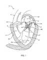
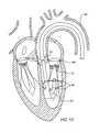
- FIG. 1is a schematic illustration of the left ventricle of a heart showing blood flow during systole with arrows.
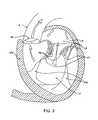
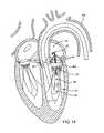
- FIG. 2is a schematic illustration of the left ventricle of a heart having prolapsed leaflets in the mitral valve.
- FIG. 3is a schematic illustration of a heart in a patient suffering from cardiomyopathy where the heart is dilated and the leaflets do not meet.
- FIG. 3Ashows normal closure of the leaflets
- FIG. 3Bshows abnormal closure in the dilated heart.
- FIG. 4illustrates mitral valve regurgitation in the left ventricle of a heart having impaired papillary muscles.
- FIG. 5is a schematic illustration showing direct attachment of opposed valve leaflets to reduce valve regurgitation.
- FIG. 6is a schematic illustration showing attachment of valve chordae to treat valve regurgitation.
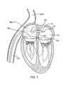
- FIGS. 7-8show exemplary antegrade approaches to the mitral valve from the venous vasculature.
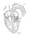
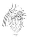
- FIGS. 9-10show exemplary retrograde approaches to the mitral valve through the aortic valve and arterial vasculature.
- FIGS. 11-14illustrate the use of adjustment wires for steering capability.
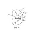
- FIGS. 15A-15Dillustrate the use of pre-shaped mandrels to steer a component or structure.
- FIGS. 16-20, 21A-21C, and 22A-22Bdepict various orientation assessment tools.
- FIG. 23is a schematic illustration of an interatrial septum stabilization device.
- FIG. 24is a schematic illustration of a catheter shaft designed to provide stabilization against a structure, such as the interatrial septum, or for flexible adjustment and locking stability in various positions.
- FIG. 25is a schematic illustration of an atrial stabilization device.
- FIGS. 26-29illustrate stabilization mechanisms which utilize coupling to the valve annulus.
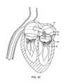
- FIGS. 30, and 31A-31Dillustrate stabilization mechanisms which utilize coupling with the valve commissures and/or leaflets.
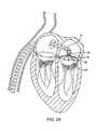
- FIGS. 32A and 32Billustrate mitral valve stabilization using snares for capturing the valve chordae.
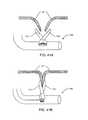
- FIGS. 33A and 33Billustrate an antegrade approach for snaring valve chordae and optionally suturing the chordae together to treat valve regurgitation.
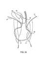
- FIG. 34illustrates an antegrade approach for snaring valve chordae to stabilize the mitral valve.
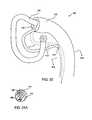
- FIGS. 35 and 35Aillustrate a snaring catheter particularly intended for capturing valve chordae from a retrograde approach.
- FIGS. 36A and 36Billustrate use of the catheter FIG. 35 for snaring valve chordae.
- FIGS. 37 and 38illustrate a catheter similar to that shown in FIGS. 35 and 35A , except that it includes a working channel for introducing interventional catheters and tools to treat the mitral or other atrioventricular valve.
- FIGS. 39A and 39Billustrate a coil which can be implanted within the valve chordae to stabilize the mitral valve.
- FIG. 40illustrates placement of the coil of FIGS. 39A and 39B from a retrograde approach.
- FIGS. 41A-41B, 42A-42B and 43illustrate valve leaflet grasping devices which utilizes a pinching method.
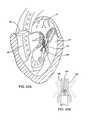
- FIGS. 44A-44Dare schematic illustrations of an atrial-ventricular valve leaflet grasping device which utilizes a pinching method.
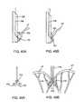
- FIGS. 45A-45Bare schematic illustrations of a grasping device which utilizes rollers in a pinching method.
- FIGS. 46A-46Bare schematic illustrations of a grasping device which utilizes a pair of opposing coils in a pinching method.
- FIGS. 47A-Dillustrate a pronged valve leaflet device which utilizes a pinching, partially penetrating or piercing method.
- FIG. 48illustrates a vacuum-assisted stabilization catheter for use in the methods described herein.
- FIG. 49illustrates an embodiment of a valve suturing device.
- FIGS. 49A-49Cillustrate an additional embodiment of a valve suturing device.
- FIG. 50illustrates a further embodiment of a valve suturing device.
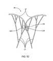
- FIG. 51illustrates use of the catheter for capturing and suturing opposed mitral valve leaflets.
- FIG. 52illustrates the mitral valve leaflets which have been secured as shown in FIG. 51 .
- FIGS. 53 and 54illustrate an alternative anchor which can be used with the suturing devices.
- FIGS. 55A-55Billustrate the use of an expansible anchor in fixation.
- FIGS. 56 and 57illustrate yet another suturing device.
- FIG. 58illustrates use of the suturing device of FIGS. 56 and 57 to place sutures between valve leaflets of the mitral valve.
- FIG. 59illustrates yet another embodiment of a suturing device.
- FIG. 60illustrates use of the device of FIG. 59 and suturing opposed mitral valve leaflets.
- FIGS. 61A and 61Billustrate a stapling device which can be used to staple opposed leaflets of an atrioventricular valve.
- FIGS. 62A-Dare schematic illustrations of fixation devices.
- FIG. 63illustrates an alternative two part fixation stapling device.
- FIG. 64illustrates use of the stapling device of FIG. 63 for stapling opposed valve leaflets of a mitral valve.
- FIG. 65A-65Care schematic illustrations of coiled fixation devices.
- FIG. 66illustrates use of a self-securing anchor for attaching opposed surfaces on the leaflets of the mitral valve.
- FIGS. 66A-66Bare schematic illustrations of penetrating fixation devices.
- FIGS. 67 and 68are schematic illustrations of penetrating fixation devices with barb-like distal ends.
- FIGS. 69A-C and 70 A-Bare schematic illustrations of clips used as fixation devices.
- FIGS. 71, and 72A-72Bare schematic illustrations of clips involving the use of graspers in the fixation mechanism.
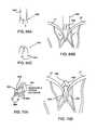
- FIGS. 73A-73Cillustrate a three-jaw clip-applier.
- FIG. 74illustrates a clip which has been applied by the clip-applier of FIGS. 73A-73C .
- FIG. 75illustrates a device for applying radiofrequency energy to shorten valve chordae.
- FIGS. 76, and 77A-77Billustrates devices used to plicate and shorten valve chordae.
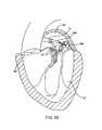
- FIG. 78illustrates a first exemplary approach for placing an annuloplasty ring.
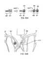
- FIGS. 79 and 80illustrate a second exemplary approach for placing an annuloplasty ring.
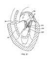
- FIG. 81illustrates a method for placing an anchored filament about a mitral valve annulus that can be used to tighten the annulus.
- FIG. 82illustrates a method for placing multiple sutures about a mitral valve annulus, where the individual suture plicate and tighten the annulus.
- FIGS. 83-85illustrate an embodiment of an atrial device for valve tissue modification.
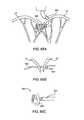
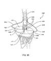
- FIGS. 86, and 87A-87Cillustrate an embodiment of an atrial-ventricular device for valve tissue modification.
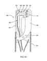
- FIGS. 88-89 , and FIGS. 90A-90Billustrate an embodiment of a ventricular device for valve tissue modification.
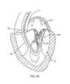
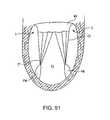
- FIG. 91shows a cutaway representation of the left ventricle.
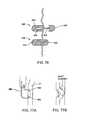
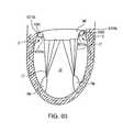
- FIGS. 92A and 92Bshows an annuloplasty device for positioning in a gutter of the left ventricle.
- FIG. 93shows a cutaway representation of the left ventricle with the annuloplasty device positioned in the gutter.
- FIG. 94is a cross-sectional view of the heart showing the mitral valve, valve leaflets, annulus, and coronary sinus.
- the left ventricle LV of a normal heart H in systoleis illustrated in FIG. 1 .
- the left ventricle LVis contracting and blood flows outwardly through the tricuspid (aortic) valve AV in the direction of the arrows.
- Back flow of blood or “regurgitation” through the mitral valve MVis prevented since the mitral valve is configured as a “check valve” which prevents back flow when pressure in the left ventricle is higher than that in the left atrium LA.
- the mitral valve MVcomprises a pair of leaflets having free edges FE which meet evenly to close, as illustrated in FIG. 1 .
- the opposite ends of the leaflets LFare attached to the surrounding heart structure along an annular region referred to as the annulus AN.
- chordae tendineae CT(referred to hereinafter as the chordae) which include plurality of branching tendons secured over the lower surfaces of each of the valve leaflets LF.
- the chordae CTin turn, are attached to the papillary muscles PM which extend upwardly from the lower portions of the left ventricle and interventricular septum IVS.
- FIGS. 2-4a number of structural defects in the heart can cause mitral valve regurgitation.
- Ruptured chordae RCTas shown in FIG. 2 , can cause a valve leaflet LF 2 to prolapse since inadequate tension is transmitted to the leaflet via the chordae. While the other leaflet LF 1 maintains a normal profile, the two valve leaflets do not properly meet and leakage from the left ventricle LV into the left atrium LA will occur, as shown by the arrow.
- Regurgitationalso occurs in the patients suffering from cardiomyopathy where the heart is dilated and the increased size prevents the valve leaflets LF from meeting properly, as shown in FIG. 3 .
- the enlargement of the heartcauses the mitral annulus to become enlarged, making it impossible for the free edges FE to meet during systole.
- the free edges of the anterior and posterior leafletsnormally meet along a line of coaptation C as shown in FIG. 3A , but a significant gap G can be left in patients suffering from cardiomyopathy, as shown in FIG. 3B .
- Mitral valve regurgitationcan also occur in patients who have suffered ischemic heart disease where the functioning of the papillary muscles PM is impaired, as illustrated in FIG. 4 .
- the papillary muscles PMdo not contract sufficiently to effect proper closure.
- the leaflets LF 1 and LF 2then prolapse, as illustrated. Leakage again occurs from the left ventricle LV to the left atrium LA, as shown by the arrow.
- valve leaflets LFmay be directly attached or coupled to each other by a structure S or other means.
- Typical structuresinclude suture, staples, clips, pins, or other closure devices of a type commonly used in attaching opposed tissue surfaces.
- the opposed surfaces on the valve leafletscould be attached using adhesives, fusion energy, including radiofrequency current, laser energy, microwave, ultrasonic energy, or the like.
- chordaeA second and often preferred interventional point will be in the chordae, as shown in FIG. 6 .
- an attachment structure Sis shown to couple individual chordae or tendons which are attached to each of the two leaflets LF.
- a variety of specific structurescan be utilized, such as snares, staples, sutures, coils, clips, snaps, rivets, adhesives, and the like.
- Opposed chordaewill usually also be attached directly, optionally employing any of the same structures listed above.
- opposed chordaemay be indirectly tied or coupled together by a structure which links or couples their movement, but which does not physically attach chordae from each of the valve leaflets directly together.
- chordal interventioncan include shortening the chordae, e.g., by applying energy to shrink the collagen therein, or may utilize mechanical plication devices, such as clips, to physically shorten the chordae.
- a third interventional pointis the annulus AN (shown in FIG. 1 ) of the mitral valve AV.
- An annuloplasty devicesuch as a ring or a partial ring, can be positioned on the annulus to strengthen or re-shape the annulus.
- the atrial side of the annulushas a smooth, sloping surface around the circumference of the mitral valve.
- the ventricular side of the annulushas a concave, annular “gutter” around the valve.
- the gutterprovides a location in which an annuloplasty device can be located and held while it is fastened to tissue.
- percutaneous annuloplastycould be more readily attainable by delivering an annuloplasty ring to the ventricular side rather than the atrial side of the valve, as described more fully below.
- Access to the mitral valve or other atrioventricular valvewill preferably be accomplished through the patient's vasculature in a “percutaneous” manner.
- percutaneousit is meant that a location of the vasculature remote from the heart is accessed through the skin, typically using a surgical cut down procedure or a minimally invasive procedure, such as using needle access through, for example, the Seldinger technique.
- the ability to percutaneously access the remote vasculatureis well-known and described in the patent and medical literature.
- the approach to the mitral valvemay be “antegrade” and require entry into the left atrium by crossing the interatrial septum.
- approach to the mitral valvecan be “retrograde” where the left ventricle is entered through the aortic valve.
- the interventional tools and supporting catheter(s)will be advanced to the heart intravascularly where they may be positioned adjacent the target cardiac valve in a variety of manners, as described elsewhere herein. While the methods will preferably be percutaneous and intravascular, many of the tools described herein will, of course, also be useful for performing open surgical techniques where the heart is stopped and the heart valve accessed through the myocardial tissue. Many of the tools will also find use in minimally invasive procedures where access is achieved thorascopically and where the heart will usually be stopped but in some instances could remain beating.
- FIGS. 7 and 8A typical antegrade approach to the mitral valve is depicted in FIGS. 7 and 8 .
- the mitral valve MVmay be accessed by an approach from the inferior vena cava IVC or superior vena cava SVC, through the right atrium RA, across the interatrial septum IAS and into the left atrium LA above the mitral valve MV.
- a catheter 10 having a needle 12may be advanced from the inferior vena cava IVC into the right atrium RA. Once the catheter 10 reaches the anterior side of the interatrial septum IAS, the needle 12 may be advanced so that it penetrates through the septum at the fossa ovalis FO or the foramen ovale into the left atrium LA.
- a guidewiremay be exchanged for the needle 12 and the catheter 10 withdrawn.
- access through the interatrial septum IASwill usually be maintained by the placement of a guide catheter 14 , typically over a guidewire 16 which has been placed as described above.
- the guide catheter 14affords subsequent access to permit introduction of the interventional tool(s) which will be used for performing the valve or tissue modification, as described in more detail below.
- the antegrade approach to the mitral valveis advantageous in a number of respects.
- the use of the antegrade approachwill usually allow for more precise and effective centering and stabilization of the guide catheter and/or interventional tool. Precise positioning, of course, facilitates accuracy in the tissue modification, particularly affixation of the valve leaflets or chordae.
- the antegrade approachalso reduces the risk of damaging the subvalvular apparatus during catheter and interventional tool introduction and manipulation. Additionally, the antegrade approach eliminates the risks associated with crossing the aortic valve. This is particularly relevant to patients with prosthetic aortic valves which cannot be crossed.
- chordal fixationWhen employing chordal fixation, the tools can be placed very close to the free edge of the leaflet since they will be removed in a direction away from the chordae which are being fixed. Additionally, an antegrade approach allows more direct access to the valve leaflets unimpeded by presence of the chordae.
- FIG. 9A typical retrograde approach to the mitral valve is depicted in FIG. 9 .
- the mitral valve MVmay be accessed by an approach from the aortic arch M, across the aortic valve AV, and into the left ventricle below the mitral valve MV.
- the aortic arch AAmay be accessed through a conventional femoral artery access route, as well as through more direct approaches via the brachial artery, axillary artery, or a radial or carotid artery.
- Such accessmay be achieved with the use of a guidewire 42 .
- a guide catheter 40may be tracked over the guidewire 42 .
- the guide catheter 40affords subsequent access to permit introduction of the interventional tool(s) which will be used for performing the valve or tissue modification, as described in more detail below.
- a retrograde arterial approach to the mitral valvewill be preferred due to its advantages.
- Use of the retrograde approachwill eliminate the need for a trans-septal puncture.
- the retrograde approachis also more commonly used by cardiologists and thus has the advantage of familiarity. Additionally, the retrograde approach provides more direct access to the chordae.
- the interventional tool(s) used for performing the valve or tissue modificationsmay be specifically designed for the approach or they may be interchangeable.
- toolsmay be specifically designed for an antegrade or retrograde approach, or they may be designed to be used with either approach.
- toolsmay be used in any appropriate fashion to achieve a desired result.
- a nomenclaturehas been developed to describe the common usage of such tools.
- Tools which perform the modification procedure while primarily residing primarily in the atriumare referred to as “atrial” tools. These utilize an antegrade approach.
- Tools which perform the modification procedure while primarily residing in the ventricleare referred to as “ventricular” tools, and likewise utilize a retrograde approach.
- Tools which cross over the valve to perform the modification procedure, residing in both the atrium and the ventricleare referred to as “atrial-ventricular” tools, and may utilize either an antegrade or retrograde approach.
- a steerable guidewiremay be used to introduce a guide catheter, interventional tool and/or treatment device into the proper position.
- the guide cathetermay be introduced, for example, using a surgical cut down or Seldinger access to the femoral artery in the patient's groin. After placing a guidewire, the guide catheter may be introduced over the guidewire to the desired position. Alternatively, a shorter and differently shaped guide catheter could be introduced through the other routes described above.
- a guide cathetermay be pre-shaped to provide a desired orientation relative to the mitral valve.
- guide catheter 40may have a pre-shaped J-tip which is configured so that it turns toward the mitral valve MV after it is placed over the aortic arch AA and through the aortic valve AV.
- the guide catheter 40may be configured to extend down into the left ventricle LV and to evert so that the orientation of an interventional tool or catheter is more closely aligned with the axis of the mitral valve MV.
- the guide catheter 40 of FIG. 10orients an interventional catheter (not shown) in a lateral direction relative to the access of the mitral valve MV.
- each of the guide catheters 40 shown in FIGS. 9 and 10may find use under different circumstances.
- the guide catheter 40 of FIG. 10might be particularly suited for introducing tools which modify the chordae CT, while the catheter 40 of FIG. 9 may be more useful for engaging tools against the valve leaflets.
- a guidewire 42may be positioned from the tip of the guide catheter 40 directly through the opening of the mitral valve MV. Interventional tools can then be directed over the guidewire 42 to form the particular procedures described hereinafter.
- the interventional toolitself may be pre-shaped to provide a desired orientation.
- the guidewire, guide catheter or interventional toolmay be actively deflected, e.g., having push/pull wires which permit selective deflection of the distal end in 1, 2, 3, or 4 directions depending on the number of pull wires, having shape memory nitinol, or having balloons, wires, wire cages or similar mesh structures to direct the device away from a cardiac structure and therefore into a desired position, to name a few.
- Either of the guide catheters 40 shown in FIG. 9 or 10may be provided with steering capabilities.
- two or more adjustment wires 46may be provided at the distal tip of the guide catheter 40 as shown in FIG. 11 . These adjustment wires may be active or passive, and may be positioned within the valve commissures to enhance alignment of the guide catheter with the mitral valve MV. As shown in FIGS. 12A and 12B , the adjustment wires 46 may be positioned in the medial commissure MVC and lateral commissure LVC, and the guide catheter 40 may thus be moved from a central location, as shown in FIG. 12A to a more medial position, as shown in FIG. 12B . The catheter could of course also be moved in the lateral direction (not shown).
- Steering wires 50 on a guide catheter 40may also be provided to engage opposed surfaces within the left ventricle LV, as shown in FIG. 13 .
- the distal tip of the guide catheter 40can be moved further downward from the mitral valve.
- Catheter 40 of FIG. 13would be particularly useful in combination with an interventional catheter which itself has steering capabilities which engage portions of the mitral valve, such as the valve commissures as described above.
- the guidewire 52may have laterally deflectable steering elements 54 which may be positioned in, for example, the valve commissures as described previously. This way, the guidewire 52 may be positioned toward the medial or lateral sides of the mitral valve MV, and an interventional catheter 56 introduced over the guidewire to a desired target structure within or surrounding the mitral valve MV.
- an interventional catheter 56introduced over the guidewire to a desired target structure within or surrounding the mitral valve MV.
- the guidewiremay then pass in an antegrade direction through the aortic valve, through the ascending and descending aorta, and then percutaneously out of the vasculature at a location remote from the heart, such as the femoral artery.
- a single guidewirein this manner provides a continuous “rail” through the heart, allowing placement of separate devices in both an antegrade and retrograde direction. Additionally, any interaction or cooperation between the devices is facilitated since they will necessarily advance toward one another in an alignment which is controlled and assured by the guidewire, e.g., when fully advanced any two devices will necessarily meet.
- one devicewould extend inward from the venous side of the heart in an anterior antegrade direction to the mitral valve, and a second device would enter through the arterial side of the heart in a retrograde direction. The two devices would then be precisely located relative to each other as they approach and optionally meet at or near the mitral valve.
- a stabilizing cathetercould be introduced in a retrograde direction to approach the chordae and underside of the mitral valve leaflets to provide for temporary stabilization and/or leaflet coaptation, as generally described above.
- a catheter carrying a fixation devicecould then be advanced in an antegrade direction to approach the valve leaflets from above.
- the second devicecould then be separately actuated to affix the valve leaflets once the proper temporary stabilization has been achieved with the first device.
- the guidewire, guide catheter or interventional toolmay be positioned with the use of a floating balloon. This may be most useful for use with an antegrade approach.
- the distal balloon of a balloon tipped guidewire or balloon tipped floppy cathetermay be inflated and floated antegrade through the mitral valve. If the heart is slowly beating, blood will be flowing from the left atrium, through the mitral valve to the left ventricle. A floating balloon may be carried along this flow trajectory, carrying the guidewire or catheter with it. The balloon may then be deflated and newly placed guidewire or catheter may be utilized as desired.
- a hollow guidewire, guide catheter or interventional or other toolmay be positioned with the use of a rigid, pre-shaped mandrel or insertable member.
- the mandrel 600may be comprised of wire, metal, plastic or any suitable material that may be formed to hold a desired shape 601 , such as a bend or bump.
- the mandrel 600may then be inserted into a lumen in a flexible structure 602 to be positioned.
- a structuremay be a hollow guidewire, guide catheter, interventional tool or any other tool or component of a structure.
- the flexible structure 602conforms to the shape 601 as it is passed through. This may be utilized to position a structure or component of a structure in a desired location for later steps in the procedure.
- any of the devices, systems and methods used for gross steeringmay be also be applied to refined steering of the device or device components to achieve a desired result.
- itmay be desired to independently or dependently manipulate components of the interventional tools throughout the procedure.
- Such steeringmay allow urging of the components relative to the leaflets, annulus, atrial wall or other specific cardiac structures. This may be achieved with any of the devices or methods described above.
- Cardiac structures to which orientation is desiredmay include the atrial walls, interatrial septum, valve annulus, valve leaflets, valve commissures, valve chordae, papillary muscles and ventricle walls, to name a few.
- Assessment of the orientation of the components and devicesmay be achieved by a number of mechanisms and methodologies.
- orientationmay be assessed by tactile feedback.
- Introduction and manipulation of the devices and componentsmay allow them to contact cardiac structures or other devices. Such contact may guide the devices into proper position and relevant orientation.
- the forcemay be translated along its length to its proximal end to provide feedback to the physician or operator.
- sensorsmay be used to achieve a similar result.
- the catheter or toolmay have a lumen to allow for pressure monitoring. This may provide feedback throughout the procedure which may indicate the presence and level of mitral regurgitation.
- orientationmay be assessed by visualization of the devices and components themselves.
- the components or the overall systemmay be modified for enhanced echogenic and/or fluoroscopic visibility.
- Echogenicity of a material in a blood mediumis dependent on the difference in acoustic impedance (product of velocity of sound and density of the medium through which the sound wave is traveling) between the material and blood. Therefore, a thin polymer coating on the components or the overall system may provide modulation of the acoustic impedance at the interface of the component and blood, thereby improving echovisibility.
- microscopic air bubbles trapped on the surface or embedded within the coatingmay also improve echovisibility.
- fluoroscopic visibilitymay be improved with radiopaque coatings, radiopaque marker bands, or the like.
- a lumen within the catheter or toolmay be provided to inject radiopaque contrast solution to improve fluoroscopic visibility or surrounding tissues.
- radiopaque contrast solutionmay provide visualization of the devices and components themselves or any structures or elements used throughout the treatment procedure.
- angioscopic visionmay be used to access the orientation throughout the procedure.
- orientation elementsmay be used to assess orientation of the components and/or systems in relation to cardiac structures, specifically the target valve.
- orientation elementsmay be any structure or feature that provides information as to the orientation of the component, device or system described herein.
- the elementsmay be separate from or integral with any part of the system or device. They may be removably or fixedly mounted on the guidewire, guide catheter, interventional tool and/or other device.
- the elementsmay be components or parts of components of the device which provide one or more additional functions in the tissue modification procedure, such as stabilization, grasping, coaptation, adjustment or fixation.
- the elementsmay be atrial, ventricular or atrial-ventricular devices such that they may or may not cross the valve in the orientation assessment process. In addition, such elements may be used to steer and/or orient the components and systems prior to or simultaneous with assessment.
- Orientation elementsmay be in the form of propellers, wings, petals, arms, loops, and the like. One or more of these elements may be present, typically extending radially from a central shaft. When two elements are present, they are commonly placed 120 to 180 degrees apart around the central shaft; more than two elements are typically arranged in a radial pattern around the central shaft. In the preferred embodiments, the orientation elements are typically placed either perpendicular to the line of coaptation or following the line of coaptation. This may provide the most useful reference, however many other placement orientations may be used.
- FIG. 16is a short axis view of the mitral valve MV with an orientation element 612 shown having a pair of orientation structures 613 arranged 180 degrees apart around a central shaft 614 .
- the orientation element 612is shown perpendicular to the line of coaptation C.
- Such positioning of the element 612may indicate that the device is in its desired orientation, specific components are in a desired orientation, or devices or components may be oriented in relation to the positioned element which may be more visible than other parts of the device.
- FIG. 17is a long axis view of the mitral valve MV.
- a guidewire 615 with a pair of orientation propellers 616is shown inserted through the mitral valve MV via a retrograde approach.
- Visualization of the propellers 616may allow repositioning of the guidewire 615 until the propellers are perpendicular to the line of coaptation C.
- a guide catheter, interventional or other toolmay be tracked over the catheter in the desired orientation. Such tracking may be facilitated with the use of a keyed, notched, oval or similar lumen for guidance.
- orientation propellers 616may be mounted on a guide catheter with a keyed lumen for guided insertion of interventional tools.
- FIGS. 18 and 19Examples of orientation elements placed along the line of coaptation are depicted in FIGS. 18 and 19 .
- FIG. 18is a long axis view of an orientation element 620 inserted into the valve opening along the line of coaptation C.
- An end view shown in FIG. 19illustrates the penetration of the element 620 through the valve opening and the valve leaflets LF sealing against the element 620 .
- portions of the orientation element 620may contact the commissures CM at each end of the valve opening for support and/or for reference.
- the location of a variety of cardiac structures, particularly the valve leaflets LFare known.
- orientation elements 620may be used to infer the relation of those components to the cardiac structures.
- orientation elementsare known to be perpendicular to the graspers, positioning of the orientation elements in the manner described above would ensure that the graspers would be aligned perpendicular to the line of coaptation C or in a desirable location to grasp the valve leaflets LF.
- the orientation element 620is shown as an inflatable bladder coaxially attached to a distal central shaft 621 .
- a bladdermay be comprised of a compliant or noncompliant material, such as PET, PUR, Silicone, Chronoprene, or the like.
- the bladder materialitself may be echo or fluorogenic, or it may be filled with an echo or fluorogenic liquid or suitable medium, such as carbon dioxide or agitated saline.
- the bladderIn its inflated state, it is preferred that the bladder is wide or thick enough to so that the endview of the bladder is visible in a short axis view of the mitral valve, as shown in FIG. 19 , and that the bladder is long or high enough so that the anterior and posterior leaflets may seal against the bladder in systole.
- the bladder 625may be supported by a frame 626 .
- the frame 626may be comprised of any suitable material, such as nitinol, stainless steel, plastic or any combination thereof, of any consistent or variable flexibility, and any cross-sectional shape, such as round wire, hollow tube or flat ribbon. This material may be echo or fluorogenic or treated for such effects.
- the shape of the frame 626may be of any suitable symmetrical or nonsymmetrical geometry, including but not limited to triangular, rectangular, circular, oblong, and single or multi-humped. A rectangular geometry is depicted in FIG. 20 .
- the frame 626may be expandable as shown in FIGS. 21A-C . In the collapsed state, FIG.
- the bladder 625 and enclosed frame 626may be inserted through a lumen in a guide catheter or interventional tool.
- the frame 626When appropriately positioned, the frame 626 may be gradually expanded, FIG. 21B , to a desired geometry, FIG. 21C .
- the orientation elementmay function without inflation of the bladder 625 or with just the frame 625 and no bladder.
- orientationmay be assessed by visualization of flow patterns resulting from system or component position with respect to cardiac structures.
- the heartmay be slowly beating throughout the tissue modification procedure. As the heart beats, blood may be flowing from the left atrium, through the mitral valve, to the left ventricle. Visualization of these flow patterns using Color Doppler Echocardiography may allow inferences as to how systems or components are positioned. For example, as shown in FIG. 22A , if a thin planar structure 650 is inserted in the valve opening with its long axis perpendicular to the line of coaptation C, a higher level of regurgitation may result due to blood flow through the unsealed portions 651 .
- a lower level of regurgitationmay result due to more adequate sealing of the valve leaflets LF against the structure 650 .
- a structure 650 or similarly designed devicemay be used as an orientation element.
- stabilizationit is meant that the interventional tool will be somehow coupled to a cardiac structure so that any existing relative motion between the tool and the structure is lessened.
- Cardiac structureswhich may be utilized for coupling include the atrial walls, interatrial septum, valve annulus, valve leaflets, valve commissures, valve chordae, papillary muscles and ventricle walls, to name a few. Such stabilization is performed in order to facilitate a subsequent intervention.
- an access cathetermay be mechanically coupled to the valve or tissue surrounding the valve, such as the annulus or the chordae, and the interventional tool deployed from the catheter to perform a desired intervention, such as suturing, stapling, snaring, annuloplasty, RF tissue modification, or the like.
- a desired interventionsuch as suturing, stapling, snaring, annuloplasty, RF tissue modification, or the like.
- the stabilizationwill usually be terminated after the particular valve modification is completed, but in some instances the stabilization could be terminated and redeployed multiple times at various points throughout the procedure.
- the stabilization mechanismsmay be separate from or integral with any part of the system or device. They may be removably or fixedly mounted on the guidewire, guide catheter, interventional tool and/or other device. Likewise, the elements may be components or parts of components of the device which provide one or more additional functions in the tissue modification procedure, such as steering, orientation assessment, grasping, coaptation, adjustment or fixation. Further the mechanisms may be atrial, ventricular or atrial-ventricular devices such that they may or may not cross the valve in the stabilization process. In particular, such mechanisms may be used to steer and/or orient the components and systems prior to or simultaneous with stabilization.
- stabilization mechanismsmay be formed for descriptive purposes: 1) stabilization against the atrial septum, atrial walls or ventricle walls, 2) stabilization against the valve, and 3) stabilization against the chordae or papillary muscles.
- Stabilization against the atrial septummay be useful when approaching antegrade with atrial or atrial-ventricular devices.
- an antegrade approachinvolves crossing from the right atrium RA to the left atrium LA by penetrating the interatrial septum IAS. This may be accomplished with a needle bearing catheter, which may then be exchanged for an introducer, guide catheter or similar catheter. Interventional tools may be introduced through this catheter for tissue modification treatment.
- a stabilization mechanismmay be used to engage and lock the catheter to the interatrial septum.
- FIG. 23depicts a catheter shaft 660 having a distal balloon 661 and a proximal balloon 662 inflated on opposite sides of the interarterial septum IAS. Inflation of the balloons 661 , 662 against the septum couples the shaft 660 to the septum and stabilizes the system. It may be appreciated that a number of components, such as disks, cages, balls, mesh, or other structures, may be used in place of one or more of the balloons to achieve a similar result.
- Stabilization against the atrial septummay also be achieved by forming an introducer or guide catheter which is rigid through the interatrial septum and left atrium.
- introducers or guide cathetersare flexible along their length to facilitate introduction through the tortuous paths of the vascular system.
- the catheterIn an antegrade approach as described, the catheter may be inserted through the interatrial septum with its distal end suspended in the left atrium. In the case of a flexible catheter, movements at the septum may not be translated linearly to the catheter tip. Therefore, there may be relative movement between the distal end and the portion passing through the septum. This may be reduced by coupling the distal end to the portion passing through the septum.
- the catheter shaft between and including the distal end and the portion passing through the septummay be made rigid.
- the catheter shaft 670may be comprised of stacked elements 671 .
- the elements 671may be domed disks or collar segments with domed ends which are mechanically coupled by a structure 672 .
- the structure 672may connect the centers of the elements 671 , as shown, in a flexible manner so that the shaft 670 may be shaped in any desired geometry suitable for use in the tissue modification treatment. Once a desired shape is formed, the structure 672 may be rigidified to hold the shape. Such rigidity may allow any movement of the interatrial septum to be translated to the distal end of the catheter shaft, thus coupling the catheter to the movements of the heart.
- a variably rigid shaft as describedmay be utilized for coupling to any cardiac feature and may be used with or as part of any device component or device in the procedure.
- the featuremay be utilized to lock any device component, catheter or tool into place once it has been manipulated into a desired shape. This may be useful in a variety of situations in addition to those mentioned above.
- Stabilization against the valvemay be most useful when approaching antegrade with atrial or atrial-ventricular devices, however it may also be useful when approaching retrograde with ventricular or atrial-ventricular devices.
- stabilizationmay be most easily achieved by coupling one or more components of the device to the atrial walls, valve annulus, valve leaflets, and/or valve commissures.
- Coupling to the atrial wallsmay be accomplished by a number of stabilization mechanisms.
- structuressuch as wires, ribbons, mesh, cages or balloons extend outwardly from the device, contacting and applying radial force to the atrial walls. Such contact may couple the movements of the atrium with the device for stabilization.
- a preferred embodimentis shown in FIG. 25 .
- flexible wires 680bend out radially from the catheter shaft 681 with curved portions contacting the atrial walls AW. It may be appreciated that any number of wire patterns or means of extending from the shaft may be utilized, as mentioned above.
- Coupling to the valve annulusmay also be accomplished by a number of stabilization mechanisms, many of which include simultaneous coupling to other valve features, such as the leaflets and/or commissures.
- such stabilization mechanismsmay be comprised of loops, rings, wings, petals, arms, and the like. Coupling can be enhanced by varying surface friction and/or combining structures with vacuum.
- One or more of these mechanismsmay be present, typically extending radially from a central shaft. When two elements are present, they are commonly placed 90 to 180 degrees, preferably 120 to 180 degrees, apart around the central shaft. More than two elements are typically arranged in a radial pattern around the central shaft. Structure, size, angle and arrangement may be adjustable to fit individual patient anatomy.
- a guide catheter 14may have deployable adjustment wires 20 to serve as a stabilization mechanism.
- the wires 20are typically attached at one end to the distal tip of the guide catheter 14 and may be advanced at their other ends so that they selectively deploy from the guide catheter to engage the mitral valve MV.
- the adjustment wires 20may act to stabilize or anchor the guide catheter relative to the mitral valve MV by coupling to the valve annulus, leaflets or commissures.
- the guide catheter 14may have any number of stabilization elements, as illustrated in FIGS. 27-29 .
- the stabilization elementsmay be comprised of a number of petals 22 arranged around the distal tip of the catheter 14 .
- the stabilization elementmay be a single large loop 25 , as depicted in FIG. 28 .
- the interventional catheter 30may have a plurality of stabilizing arms 34 ( FIG. 29 ) which both position and anchor the distal tip of the interventional catheter 30 relative to the valve annulus. Usually, at least three stabilizing arms will be utilized, with four being illustrated, however any number may be used.
- the stabilizing arms 34may be pre-shaped, resilient metal rods (for example, formed from nitinol or other shape memory or superelastic alloy), ribbons, tubes, polymers or composites thereof that may be selectively extended from the tip of the interventional catheter 30 to engage the valve annulus.
- the interventional catheter 30 of FIG. 29is shown with a separately extendable interventional tool 36 which performs the desired valve or tissue modification, as described in more detail below.
- Such stabilization elementsmay preferably engage the annulus located about the mitral valve MV and apply forward pressure against the annulus to maintain contact and provide axial stabilization.
- Stabilizationmay also be achieved by applying radial pressure to the commissures.
- a pair of stabilization elements 32may extend radially from a guide catheter 14 or interventional tool 30 to contact the commissures. The distance between the elements 32 may be equal to or slightly greater than the distance between the commissures to apply radial force against the commissures.
- the stabilization elements 32may be comprised of any suitable material, such as nitinol, stainless steel, plastic or any combination thereof, of any consistent or variable flexibility, and any cross-sectional shape, such as round wire, flat ribbon or hollow tube. As shown in FIGS.
- the shape of the stabilization elementmay be of any suitable symmetrical or nonsymmetrical geometry, including but limited to triangular ( FIG. 31A ), rectangular ( FIG. 31B ), circular, oblong, double-humped ( FIG. 31C ) or single-humped ( FIG. 31D ). It may be appreciated that such stabilization mechanisms may also serve in orientation assessment, particularly as the frame 626 ( FIG. 20 ) previously described. Thus, they may be echo or fluorogenic or treated for such effects. In addition, it may be appreciated that such stabilization elements may be passive, i.e., pre-sized and shaped to fit the patient anatomy so that they engage the valve annulus without adjustment, or may be active so that they can be used to steer the guide catheter as previously described.
- the double-humped elementshown in FIG. 31C , has a superior hump 700 which may protrude into the left atrium, contacting the superior aspect of the annulus and possibly the left atrial wall, and an inferior hump 701 which may protrude into the left ventricle, contacting the inferior aspect of the annulus and possibly the left ventricle wall or chordal tissue.
- the superior hump 700may apply a downward axial force on the annulus and the inferior hump 701 may apply an upward axial force.
- the waist 702 between the humpsmay be dimensioned or adjustably sized to fit between the commissures and to apply a radial force on the commissures.
- a single-humped elementshown in FIG. 31D , may provide similar stabilization without the added support from the protruding inferior hump. Additionally, this design may be easier to position in the mitral valve.
- the last general category of stabilization mechanisms for descriptive purposesis stabilization against the chordae. Stabilization against the chordae may be most useful when approaching retrograde with ventricular or atrial-ventricular devices. Coupling to the chordae may be useful in stabilization for tissue modification to the valve, the chordae, the annulus or a combination of these.
- the contact with the valve structurestypically grasping of the valve leaflets
- additional contactsuch as grasping the chordae
- stabilization methodsmay include this step. Therefore, stabilization against the chordae will be discussed in Section VIII Grasping.
- Immobilizationrefers to substantially retarding or diminishing the motion of the cardiac structures or intermittently or temporarily stopping the cardiac cycle. This may be accomplished with a variety of methodologies.
- drugsmay be injected to temporarily slow or stop the cardiac cycle.
- Such drugsmay include but are not limited to esmolol, adenosine, isofluorane and transarrest mixture, with or without electrical pacing.
- induced atrial fibrillationmay interrupt the cardiac cycle.
- valve actioncan be diminished or stopped by raising the pressure in the associated ventricle to a pressure above that in the atrium during diastole.
- a suitable liquidcan be infused into the ventricle to raise the intraventricular pressure, or the aortic valve could be temporarily incapacitated allowing aortic regurgitation and raising the ventricular diastolic pressure.
- interventional tools and/or catheters carrying such toolsmay simply be mechanically stabilized against the valve, valve annulus, valve commissures, ventricular wall, atrial wall, generally as described above.
- Immobilizationwill usually involve more interaction with the valve than simple stabilization. Immobilization will usually involve either capture and immobilization of either or both valve leaflets (or all three valve leaflets in the case of a tricuspid valve) or capture and immobilization of the chordae. For example, balloons or mesh cages may be used and placed under one or both leaflets to hold them partially closed. By temporarily immobilizing or adjusting the valve action, such as changing the point of coaptation, it is possible to see if a particular modification will be sufficient to treat the regurgitation.
- valve regurgitationcan be examined in real time via conventional imaging techniques, such as TEE. If the temporary valve modification appears sufficient, it can then be made permanent using any one of a variety of interventional techniques.
- Valve or tissue modifications or interventionsmost commonly require grasping a portion of the valve or tissue to be modified.
- Such graspingmay be useful in adjusting tissues (such as coapting valve leaflets) for appropriate modification, checking the positioning of the tissues for improved biological function, and stabilizing or immobilizing the tissue for the modification procedure.
- tissuesuch as coapting valve leaflets
- stabilizing or immobilizing the tissue for the modification procedureAs previously described, such grasping may also be useful to stabilize another tissue which will be modified in the procedure, such as the grasping the chordae to stabilize the valve for valve modification. Since the most common procedures may involve valve modification or chordal modification, grasping of these cardiac structures will be discussed. However, it may be appreciated that described grasping devices, systems and methods may apply to any cardiac or other structure.
- Grasping of the chordaemay involve capturing and anchoring the chordae, as illustrated in FIGS. 32-40 .
- a guide catheter 40can deploy a first capture coil 60 and a second capture coil 62 through a pair of deployment catheters 64 and 66 , respectively.
- the coilswill be positioned while visualizing so that the first coil 60 captures chordae attached to a first valve leaflet LF and coil 62 captures chordae attached to a second valve leaflet LF.
- the capture coilswill typically be elastic wires, preferably composed of a superelastic material such as nitinol, which are delivered through the deployment catheters in a straightened configuration. When they are advanced out of the deployment catheters, the capture coils will assume a helical or other configuration that can be advanced into and entangle the chordae.
- the coils 60 and 62may then be brought together laterally preferably coapt the leaflets LF together by advancing a retaining ring 68 which is secured at the distal end of a deployment wire 70 , as illustrated in FIG. 32B .
- the leafletsare thus brought together and immobilized for a subsequent intervention.
- immobilization via the coils 60 and 62is sufficient in itself, it will be possible to make the deployment permanent. It is a particular advantage of the temporary immobilization that the valve action can be examined via the real time imaging techniques to see if regurgitation has been adequately addressed. If it hasn't, the coils can be redeployed or the relative positions of the two coils 60 and 62 can be changed until an adequate pair has been effected.
- FIGS. 33A and 33BAn antegrade approach for deploying a single chordae snare 74 and optionally securing a suture loop about the captured chordae is illustrated in FIGS. 33A and 33B .
- a guide catheter 14 deployed over the leaflets LF of the mitral valve MVmay be deployed as described previously.
- a pair of deployment catheters 76 and 78are advanced from the distal end of the guide catheter 14 and observed in real time via any of the imaging techniques described previously.
- the pre-shaped snare 74is advanced out of the first deployment catheter 76 and is advanced through both of the chordae CT, as illustrated in FIG. 33A .
- a capture loop 80is advanced from the second deployment catheter 78 and positioned so that it lies in the path of the pre-shaped snare 74 as it is advanced through the chordae CT. After a capture tip 82 passes through the capture loop 80 , the loop can be tightened to secure to the capture tip 82 and draw the tip into the second deployment catheter 78 .
- the capture tip 82is attached to an end of a length of suture 84 ( FIG. 33B ) which runs back through a lumen in the snare 74 . In this way, the suture may be pulled into the second deployment catheter 78 , while the snare 74 is withdrawn back into the first deployment catheter 76 , leaving only the suture in place grasping both the chordae.
- valve coaptation of the valve leaflets LFcan be modified in a desired way.
- a particular advantage of this approachis that the valve coaptation can first be viewed using the real time imaging capability to assure that valve regurgitation is adequately addressed before making the chordae capture permanent.
- FIG. 34An alternative technique for deploying suture to capture chordae CT is illustrated in FIG. 34 .
- First deployment catheter 90(positioned through a guide catheter which is not shown) is positioned through the opening between valve leaflets LF.
- a balloon 93 at the distal end of chordae snare 92is extended through the chordae, as described previously.
- the balloon 93is inflated and floated through the mitral valve during regurgitation.
- the balloonwill pass through the previously deployed capture snare 95 .
- the chordae snare 92could be shaped so that it will encircle the chordae and then pass outwardly through the valve opening and into the previously deployed capture snare 95 .
- FIG. 35A chordae stabilization catheter 100 which is particularly suited for a retrograde approach is illustrated in FIG. 35 .
- the catheter 100includes a catheter body 102 having a pair of lumens 104 and 106 extending from a proximal end (not shown) to a distal end which is illustrated in FIG. 35A .
- the main lumen 104extends fully to the distal tip of the catheter body 102 and a chordal snare 108 is slidably received in the lumen.
- the snare 108has a loop pre-formed over its distal end so that, when extended from the catheter 100 , it will assume the shape shown in FIG. 35 .
- the loophas a diameter generally in the range from 3 mm to 20 mm and is shaped so that it will evert backwardly into a secondary loop formed by a capture snare 112 .
- the capture snare 112is disposed in the secondary lumen 106 and emerges from an opening 114 space proximally from the distal end of the catheter 100 .
- the distal tip of the capture snare 112is fixed at an anchor point 116 in the distal tip of the catheter body 102 .
- the capture loopcan be moved between the position shown in full line and broken line.
- the catheter 100is introduced in a retrograde direction (although antegrade would also be possible), typically through a guide catheter 40 as generally described above. Under direct (e.g., fluoroscopic) observation, the distal end of the catheter 100 will be guided to a position generally within the chordae CT, as illustrated in FIG. 36A . The chordae snare 108 will then be extended from the distal tip so that it passes through and becomes entangled with the chordae CT attached to both of the leaflets LF.
- the distal tip of the chordal snare 108will eventually pass through the loop defined by the capture snare 112 , also as illustrated in FIG. 36A .
- the capture snarewill then be tightened to hold the distal tip of the chordae snare 108 , and the chordae snare then retracted so that the loop of the snare which passes through the chordae will be tightened, generally as shown in FIG. 36B .
- the catheter 100will not be intended for permanently affixing the chordae CT. Instead, immobilization of the valve leaflets LF will be intended to facilitate a subsequent treatment step, as described hereinafter. Use of the retrograde approach for immobilizing the chordae CT will be particularly advantageous when used with antegrade interventions.
- the catheter 120could, however, be modified to facilitate performance of retrograde interventions while the chordae are stabilized.
- the catheter 120includes a catheter body 122 which is generally the same as that shown for catheter 100 in FIG. 35 (with common components being given identical reference numbers), except that a third working lumen 124 is provided.
- the working lumen 124can be used to deliver and position a wide variety of interventional tools for performing at least most of the specific interventions described elsewhere in this application.
- the catheter 120will, of course, be particularly useful for performing interventions which rely on retrograde stabilization of the chordae CT of the type provided by the catheter.
- the lumen 124may be used to position an RF energy delivery tool for heating the chordae to cause shrinkage, as described in more detail below.
- the working lumen 124could be used to position a chordae stabilization coil 130 , generally as described in FIGS. 39A and 39B .
- the coilis typically a helical filament having a secondary helical structure comprising, for example, three major loops.
- the coilmay comprise an inner element composed of a shape memory material, such as nitinol, inserted into an outer coil 132 made of a radiopaque material, such as a platinum alloy.
- the shape memory coil 134is formed into a “stacked coil” configuration (with no space between adjacent windings of the coil) and then programmed so that it will assume the stacked coil configuration at a temperature slightly above body temperature.
- the coil assembly 130is formed by heat treating the platinum 132 to a diameter D 1 and length L 1 , as shown in FIG. 39A .
- the shape memory coil 134is then stretched to a near linear configuration and inserted into the platinum coil 132 , and the two are coupled at the end. Upon heating, the shape memory coil contracts back into its tightly stacked coil shape, compressing the platinum coil 132 , and causing the entire assembly 130 to assume a smaller diameter D 2 and length L 2 , as shown in FIG. 39B .
- the coil 130may be delivered using a pusher catheter through the working lumen 124 so that it deploys within and entangles the chordae CT, as shown in FIG. 40 .
- the pusher catheter(not shown) could be configured similarly to embolic coil delivery catheters, such as those described in U.S. Pat. Nos. 5,226,911; 5,234,437; 5,250,071; 5,261,916; 5,312,415; 5,350,397; and 5,690,671, the full disclosures of which are incorporated herein by reference.
- Valve leaflet graspingmay be accomplished using a number of methods, most commonly the following three: 1) pinching, 2) partially or fully penetrating or piercing, and 3) the use of suction or vacuum. Pinching involves grasping the surface or edge of the leaflet without penetrating the tissue. This may be accomplished by an antegrade or retrograde approach using atrial, ventricular or atrial-ventricular devices. It may be appreciated that although the following embodiments are examples which are described relative to a specific approach (antegrade or retrograde), each device or component may be used or adapted to be used in all approaches.
- pinching of the valve leaflets LFcan be achieved, for example, by using a grasping catheter introduced in a retrograde direction to temporarily capture the free ends of the valve leaflets LF. It may be possible to use a simple two-jaw tool at the distal end of a catheter to capture both opposed leaflets. Such a two-jaw tool 710 is depicted in its open position in FIG. 41A . In this position, opposing jaws 711 may be positioned on opposite sides of the free ends of the valve leaflets LF. In its closed position, depicted in FIG. 41B , the leaflets may be drawn together and pinched to immobilize the valve.
- the catheter 140can be delivered through a guide catheter generally as described above.
- the catheterincludes a tool 142 at its distal end.
- Tool 142includes a fixed center jaw 144 and a pair of pivotable outer jaws 146 and 148 .
- the jaws 146 and 148may be independently opened to a “capture” position as shown in broken line in FIG. 42B .
- Actuation of the jaws 146 and 148may be achieved in a variety of conventional manners, including pull wires, push wires, inflatable balloons, heat memory alloy motors, and the like.
- a first leaflet LFcan first be captured.
- the catheter 140can then be manipulated and positioned, typically under real time imaging, to capture the second leaflet LF, as shown in FIG. 43 .
- independent capture of the leafletsgreatly facilitates the procedure. Use of a single pair of capture jaws requires that the leaflets be captured at the instant when they are properly opposed. In the case of prolapsed valves, such an instance may never occur.
- the valve leafletscan then be modified in any one of a variety of ways, as described elsewhere in the application.
- valve leaflets LFmay be pinched between a superior loop 720 and an inferior loop 721 .
- the grasperis comprised of a nitinol flat ribbon heat set in the shape of double loops 720 , 721 .
- the ribbonmay be mounted on a series of three coaxial shafts, an interior shaft 725 , a central shaft 726 and an exterior shaft 727 .
- the distal end of the ribbonmay be attached to the distal end 730 of the interior shaft 725 , a midportion of the ribbon may be attached to the distal end 731 of the central shaft 726 , and the proximal end of the ribbon may be attached to the distal end 732 of the exterior shaft 727 .
- One or more ribbonsmay be mounted on the coaxial shafts; in this example, two ribbons are shown 180 degrees apart.
- the grasperWhen extended, as shown in FIG. 44A , the grasper may be pulled flat against the shafts 725 , 726 , 727 for ease of insertion through a guide catheter or tool and into a desired position between the valve leaflets LF.
- the central shaft 726is retracted or the exterior shaft 727 advanced, as shown in FIG.
- the superior loops 720may extend radially from the shafts.
- the superior loops 720may rest on the superior surface of the valve leaflets LF in the atrium, as shown in FIG. 44D .
- the superior loops 720may aid in orientation assessment, as the superior loops may be echo or fluorogenic and may be easily visible in relation to the cardiac structures or other devices or components.
- the interior shaft 725may then be retracted, as shown in FIG. 44C , to extend the inferior loops 721 radially from the shafts.
- the inferior loops 721may be in contact with the inferior surface of the valve leaflets LF in the ventricle.
- the valve leaflets LFmay be pinched between the inferior loop 721 and superior loop 720 . It may also be appreciated that the inferior loops 721 may be deployed prior to the superior loops 720 .
- the valve leaflets LFmay be pinched between a superior roller 750 and an inferior roller 751 .
- the rollers 750 , 751may be mounted on a shaft 755 and connected by a pull actuation wire 756 .
- the rollers 750 , 751may be serrated or surface treated in a directional pattern to facilitate grasping of the valve leaflets LF.
- the rollers 750 , 751may be placed against the surface or free edge of the leaflet LF.
- Pulling of the actuation wire 756may rotate the superior roller 750 and inferior roller 751 toward each other. This may draw the leaflet LF between the rollers 750 , 751 , as shown in FIG. 45B .
- the leaflets LFmay be individually grasped for treatment.
- each coil 770may be comprised of nitinol flat ribbon heat set in the shape of a coil.
- the coils 770may be linked together with opposing curvature by a clip 772 . Movement of the clip 772 along the coils 770 may uncurl the coils 770 to a straightened configuration. As shown in FIG. 46B , this may also be accomplished by a catheter shaft 773 placed over the coils 770 .
- the coils 770may be inserted between the valve leaflets LF in an atrial-ventricular position so that the distal ends 775 of the coils 770 are in the ventricle.
- the coils 770may begin curling radially beneath the valve leaflets LF and upwardly so that the distal ends 775 of the coils 770 contact the inferior surface of the valve leaflets LF.
- a portion of the flat ribbon proximal to the distal end 775may contact the valve leaflet.
- the leafletsmay be grasped for treatment.
- Such a grasping devicemay also serve as a fixation device with the pair of coils 770 left in place, as will be described in a later portion of the application.
- a valve or tissue structuremay also be grasped by atraumatic partial or full penetration or piercing. This may be accomplished with a variety of grasping mechanisms.
- Preferred embodimentsinclude one or more prongs extending from an interventional tool in an arrangement to grasp a specific structure. Specifically, three opposing prongs may extend from a grasping sheath with distal ends configured to pinch, partially penetrate or pierce. Such ends may be pointed or may be soft, as in the case of rounded, urethane coated or solder coated ends. Referring to FIG. 47A , the opposing prongs 800 may be retracted into a grasping sheath 801 to hold the prongs 800 in a closed configuration. It may be preferred to orient the device to a desired position in this configuration.
- the prongs 800may be extended to grasp the tissue structure, as shown in FIG. 47B . This may be accomplished by either extending the prongs 800 axially or retracting the grasping sheath 801 .
- the target tissuemay be pinched, partially penetrated or pierced with the prongs 800 in this configuration, or such action may be facilitated by closing or partially closing the prongs 800 as previously depicted in FIG. 47A .
- the prongs 800may be attached to or integral with a prong-tipped tube 802 , as shown in FIG. 47C . Such a design may be more conducive to the insertion of tools or fixation devices for further treatment steps, such as tissue modification.
- Tools or devicesmay be inserted through a lumen in the prong-tipped tube 802 , depicted by arrows 804 , for use at or near the grasping location.
- tools or fixation devicesmay be inserted through a lumen in a hollow prong 806 , as depicted in FIG. 47D .
- one or more prongs 806may be hollow, and the remaining prongs 808 may be comprised of solid wire or a suitable material.
- Tools or devicesmay be inserted through a lumen in the hollow prong 806 , depicted by arrows 810 , for use at or near the grasping location.
- Prongs, hollow or solidmay be made from stainless steel, NiTi, plastic or other suitable material.
- the prongsmay be coated or coiled to enhance visibility.
- the geometries of the prongsmay be varied to facilitate grasping of the desired amount of tissue.
- the distal tip sharpness and surface finishcan be varied to establish the amount, if any, of piercing.
- a catheter 812comprises a shaft having a pair of vacuum applicator rods 813 and 814 .
- the vacuum applicator rods 813 and 814will comprise separate shafts which may be axially translated relative to the main shaft of the catheter. Further optionally, the shafts could be articulated or otherwise manipulable so that they can be independently positioned relative to the valve leaflets or other tissue structures once the catheter 812 is in place.
- the vacuum applicatorshave one or more apertures to permit contact and adherence to tissue when the applicators are attached to external vacuum sources.
- the shaftwill be placed across the valve, either in an antegrade or retrograde fashion, and the applicators positioned to grasp and manipulate the valve leaflets.
- the catheter 812may comprise additional stabilizing and/or steering wires of the type previously described.
- a steering wire 815(and optionally a second steering wire on the opposite side) may be provided for engaging against the valve commissures to permit positioning of the catheter with respect to the valve leaflets.
- the vacuum applicatorswould further be independently positionable to engage the valves in the desired fashion. Using this catheter, the leaflets can be grasped and the competency of the valve evaluated using the methods described previously.
- valve adjustmentcan then be effected using any of the interventional approaches described herein. Further, it may be appreciated that in each embodiment, timing of grasping may be facilitated by the use of gating with the patient's EKG, pressure waves of the cardiac cycle, audio heart sounds, electronic pressure or contact sensors on the graspers.
- valve leafletsmay be coapted or brought together and held in a preferred apposition.
- the valve functionmay then be evaluated for indications of improved valve function, such as reduced regurgitation. If further improvement is desired, the valve leaflets may be additionally manipulated or adjusted. Adjustment should primarily occur in a superior/inferior (up/down) motion in order to bring the leaflets to a final positioning where regurgitation is minimized.
- one or both leafletsmay be released and recaptured with new positioning.
- the valve leafletsmay be fixated in the desired position by an appropriate fixation device. In the case of chordae shortening or other tissue modification, similar steps may be taken.
- Repair of atrioventricular or other cardiac valvesis effected by modifying the valve or a supporting tissue structure in some way to affect blood flow through the valve during a phase of the cardiac cycle, for example to permit blood flow through the valve during diastole when the associated ventricle is filling with blood but which inhibits or prevents blood regurgitation back through the valve during systole.
- a number of techniques for modifying the valve closure by capturing or grasping the chordae attached to each valve leaflethave been described above. These techniques are often used just for valve grasping and/or coaptation and adjustment prior to a separate valve modification step, but they may also be made permanent to provide the final valve modification.
- Suturecan be delivered through the valve leaflets and then tied in a manner analogous to an open surgical procedure.
- a suturing tool 200shown in FIG. 49 , may be positioned at the distal end of an interventional catheter.
- the interventional catheterwill usually be advanced in an antegrade direction (i.e., from above the mitral valve), either directly through a guiding catheter or through a working lumen in a stabilization catheter.
- the tool 200carries a length of suture 202 attached to a pair of needles 204 at either end thereof.
- the suturemay be comprised of conventional suture material or of wire, typically stainless steel, nitinol or other material.
- the needlesare held on a reciprocating shaft 206 disposed within a lumen of a retrieval sheath 208 .
- the tool 200can be positioned to capture the opposed free ends of the mitral valve leaflets LF, generally as shown in FIG. 49 .
- the needlescan then be advanced through the leaflets LF by drawing the shaft 206 toward the sheath 208 so that the needles 204 penetrate the leaflet and are captured in needle receptacles 210 formed in the sheath 208 .
- the sheathcan then be withdrawn.
- a knotcan be tied in the suture, and the knot then advanced through the associated catheter to tighten over the valve leaflets.
- the tool 200can carry two, three, four, or even more lengths of suture which may be simultaneously or sequentially introduced into the valve leaflets in order to permit multiple suture loops to be placed.
- the resulting tied suture loopswill be similar to the “bow tie” sutures placed in open surgical procedures which have been described in the medical literature as described above.
- a hollow suturing coil 1300shown in FIG. 49A , may be positioned at or near the distal end of an interventional catheter.
- the suturing coil 1300may be comprised of any material of sufficient rigidity to pierce and penetrate through valve leaflets LF, such as stainless steel, various shape memory or superelastic materials, metal alloys and various polymers, to name a few.
- the hollow suturing coil 1300may contain a suture 1302 comprised of conventional suture material or of wire, typically stainless steel, nitinol or other material.
- the suture 1302may be secured at the tip 1304 of the coil 1300 with a toggle rod 1305 .
- the suturing coil 1300may be advanced in a corkscrew fashion through the valve leaflets LF, as shown in FIG. 49A . Though such advancement is shown from above, advancement may be made from any direction through any number and configuration of valve leaflet layers. When advancing, the sharpened tip 1304 of the coil 1300 may pierce through the leaflets LF any number of times.
- corkscrew piercingmay be made through the middle portions of the leaflets such that a pierce is made at each half-rotation, or the piercings may be made along the edges of the leaflets such that a pierce is made at each full-rotation, to name a few.
- the toggle rod 1305may be secured against a leaflet LF to hold the suture 1302 in place.
- the coil 1300may be removed by retracting the coil 1300 in a reverse corkscrew fashion, as depicted in FIG. 49B , leaving the suture 1302 behind. Since the coil 1300 may be much larger in diameter than the thickness of the leaflets (to aid in placement), the suture 1302 may be loose-fitting and the valve leaflets LF insufficiently modified. The suture 1302 may then be tightened, as shown in FIG. 49C , so that the suture 1302 holds the leaflets LF together in a desired configuration.
- a soft-tipped catheter 1306which may be advanced to contact the surfaces of the leaflets LF when tightening to prevent the leaflets LF from prolapsing.
- a restrictive collar 1308may be deployed from the catheter 1306 or another device to secure and terminate the suture 1302 .
- a restrictive collar 1308may be comprised of any suitable material, such as heat-shrink tubing, nitinol shape-memory or superelastic coil or the like.
- a short length of suture 220may be positioned using a curved needle 222 which can be extended from the distal tip 224 of an interventional catheter 225 .
- the needle 222is formed from an elastic material, such as a shape memory alloy, and may be constrained in a generally straightened configuration within the catheter 224 .
- When extended, as shown in FIG. 50it assumes a curved shape so that it may be advanced through the atrioventricular or other cardiac valve leaflets LF, as shown in FIG. 51 .
- a distal anchor 226is secured to the distal end of the suture 220 while a slideable, locking anchor 228 is placed over a portion of the suture located proximally to the distal anchor 226 as shown in FIG. 50 .
- the catheter 225may be advanced to the valve leaflets LF in a retrograde approach, as shown in FIG. 51 , using a guide catheter 40 , as generally described above.
- the distal end 224 of the catheter 225is positioned adjacent to the underside of a valve leaflet, and the needle 222 then advanced outwardly from the distal tip so that it passes through both valve leaflets.
- valve leafletsmay be coapted and observed using any of the techniques described previously.
- a deployment sleeve 230is advanced to release the slideable anchoring catheter 228 from the needle and advance it toward an underside of the valve leaflet LF.
- tension on the suture 220will pull the distal anchor 226 from the needle.
- the deployment sleeve 230can be advanced sufficiently to draw the two anchors 226 and 228 together on opposite sides of the valve leaflets, as seen in FIG. 52 .
- the suturecan then be tied off or, alternatively, locked in place using a mechanical lock 232 . If the suture is comprised of a malleable wire, as previously described, the wire may be twisted together. In either case, the suture is then severed and the catheter 225 withdrawn.
- the anchors 226 and 228 shown in FIG. 50are generally oval shaped and have a length dimension which is greater than the width of the needle used to introduce them. Thus, when pulled laterally, they can seal against the opposed surfaces of the two valve leaflets. In some instances, however, it will be desirable to have anchors which are capable of expanding to a much larger dimension to assure that they do not pull through the relatively fragile tissue of the leaflets.
- An exemplary expansible anchor 240is shown in its collapsed configuration within a needle 242 in FIG. 53 and its expanded configuration in FIG. 54 .
- the anchor 240is connected to a length of suture 244 and could be used with a similar slideable, expansible anchor (not shown) analogous to the non-expansible anchor 228 of FIG. 50 .
- the anchoris comprised of an expanding randomly oriented wire coil.
- the coilis made from a shape memory nitinol wire that is annealed (heat set) in a straight configuration and then coiled.
- different sections 820 , 821 of the coilmay be processed to have different properties by varying the diameter and tension in the coil along its length.
- T 1a specified level
- RF energya designated portion 821 of the coil will become a randomly oriented mass of wire 824 with self-locking struts to prevent disentanglement.
- the coilmay be introduced through the valve leaflets LF with the use of a shape memory, super elastic or heat/current activated needle introducer 826 . Once the valve leaflets LF are pierced, an anchor 824 may be activated and deployed distally. The introducer 826 may then be retracted to the proximal side of the second leaflet LF 2 and the second anchor (not shown) may be deployed in the same manner.
- the amount of tension between the anchors 824 , 825may be affected with the shape memory or super elastic properties of the expanding anchor. It may be appreciated that the heat activated expanding coil may alternatively take other forms, such as a wire mesh, for example. Additional expansible anchors may be in the form of inflatable chambers filled with a liquid that may optionally partially or fully solidify.
- FIGS. 56 and 57Yet another form of detachable anchor attached to a length of suture is illustrated in FIGS. 56 and 57 .
- FIG. 56is a front view
- FIG. 57is a side view of the same structure.
- a self-penetrating anchor 260 attached to a length of suture 262is carried on a pair of rods 264 .
- the rodsare mounted within an open lumen of a deployment catheter 266 .
- the anchor 260can pivot on a detent structure 268 formed between the distal ends of the deployment rods 264 .
- the anchorhas a sharpened distal tip 270 which permits the anchor to be directly penetrated through the valve leaflet tissue when the rods are extended from the catheter 266 .
- the catheter 266may be deployed over the leaflets LF of the mitral valve MV in an antegrade direction through a guide catheter 14 as generally described above.
- the catheter 266can be used to deliver a pair of the anchors 260 sequentially.
- a first anchor 260 ahas been deployed through a first leaflet and a second anchor 260 b has just been placed through the second leaflet.
- the anchors 260 a and 260 bare deployed by pushing them through the leaflet tissue while the sharpened tip 270 remains generally in a distal or forward direction.
- the anchor 260 a / 260 bcan be turned, either by pulling back on the deployment rods 264 or by pulling backwardly on the suture 262 .
- the two ends of suture 262can then either be tied or fastened using a mechanical fastener in order to draw the opposed leaflets into proper apposition.
- a deployment catheter 290 having a needle 280 with sharpened distal tip 282can be used to place suture loops in individual valve leaflets.
- a needle 280is carried on a pair of actuator rods 284 with a length of suture 286 attached to the needle.
- the needle 280is first passed through the leaflet in a generally axial orientation with respect to the catheter 290 .
- the needleis canted at an angle from 20° to 30° and passed back through the leaflet at a different position.
- a locking groove 288 on the needleis captured on a bar 292 in the distal end of the catheter 290 .
- the needle 280may thus be detached from the rods 284 to pull suture 286 in a loop back through the leaflet.
- loops of suturemay be placed successively through both leaflets LF of a mitral valve MV, as shown in FIG. 60 .
- the suture loopsmay then be tied off, connected with fasteners, fused together using RF, microwave or ultrasound energy, or otherwise secured to close the valves together in a desired apposition.
- opposed points on the valve leaflets and/or chordaecan be attached with a variety of staples and tissue-penetrating fasteners.
- the staples and other fastenerscan be delivered through guide catheters, generally as described above, and may be positioned during or after valve grasping, coaptation and adjustment, also as described above.
- FIGS. 61A and 61Bstaple applying catheter 300 is schematically illustrated.
- the leaflets LF of a mitral or other atrioventricular valvewill first be accessed by any of the techniques described above.
- the catheter 300will then be introduced in a retrograde fashion, for example, as illustrated previously.
- a staple 302is held in an open position at the distal tip of the catheter 300 and has a generally W-shaped profile with two recesses for receiving each of the leaflets LF, as shown in FIG. 61A .
- the staple 302may be closed over the leaflets so that the tips penetrate opposed points on each leaflet by pulling on an actuator cord 304 , as shown in FIG. 61B .
- the actuator cordcan then be detached and the catheter 300 withdrawn, leaving the staple 302 in place to hold the leaflets together.
- additional clipscan be placed in a like manner to further strengthen the affixation of the leaflets.
- the clipis a malleable clip which undergoes plastic deformation for emplacement.
- the clipcould be formed of an elastic material, such as a shape memory alloy, and held in its open position as shown in FIG. 61A .
- the clipcould then be placed by releasing it to return to its memory (closed) configuration, as shown in FIG. 61B .
- Other actuation mechanismscould also be used, such as the use of heat to induce a shape change in a heat memory alloy staple.
- two part snaps, rivets and staplesmay be used to hold leaflets in place by locking together. This may be achieved by a number of device designs. Preferred embodiments involve two disks 850 , pledgets, or the like, placed on opposite sides of tissues or leaflets LF to be bound together, as shown in FIG. 62A . Typically a shaft 852 , pin or needle may pierce the leaflets LF and connect the two disks 850 . The disks 850 may then be snapped or joined together by interlocking one or both disks 850 to the shaft 852 and/or portions of the shaft 852 to each other.
- Such a fixation devicemay be introduced through a lumen of a specialized catheter 854 , introducer or component of an interventional tool, as shown in FIG. 62B .
- the disks 850may be solid and/or rigid requiring placement on each side of the tissue, or the disks 850 may be flexible, collapsible and/or inflatable such that they may be inserted through the tissue for placement on the other side of the tissue.
- Preferred embodimentsalso involve two disks 855 , pledgets, or the like, which are placed between tissues or leaflets LF to be bound together, as shown in FIG. 62C .
- the disks 855have penetrating prongs 856 at each end to pierce and grasp tissue.
- a stapling mechanism 322 at the distal end of a catheter 320comprises a first jaw 324 which carries a fastener 326 and a second jaw 328 which carries a retaining ring 330 .
- the fastenerhas a collapsible cone 332 at its distal end so that it may be forced into an aperture 334 in the retaining ring 330 .
- the jaws 324 and 328are pivotally mounted within the distal end 340 of the catheter so that they may be opened and closed to grasp the free ends of the valve leaflets therebetween.
- the closing of the jaws 324 and 328does not lock the fastener 326 into the retaining ring 330 .
- the valve leafletscan be temporarily grasped and the improvement in valve regurgitation visually assessed. If the improvement is sufficient, the fastener 332 can be driven into the tissue and locked in the retaining ring 330 . If the improvement is not sufficient, the jaws can be repositioned on the valve leaflets one or more additional times until an adequate or optimized repositioning of the leaflets is obtained.
- the fastener 332can be driven into the retaining ring in a variety of ways.
- a cam device 342is slidably mounted behind an inclined surface 344 on the rear of the fastener 326 . By drawing the cam actuator 342 downwardly using draw cord 348 , the rivet can be driven through the valve leaflets and into the retaining ring 330 , as illustrated in FIG. 64 .
- coilsmay be used in a similar manner to fix valve leaflets in a desirable arrangement, as shown in FIG. 65A .
- Coils 900may be comprised of a superelastic material and pre-shaped in a coil configuration for engagement with the leaflets.
- the coil 900may be advanced from an introducer sheath 902 to deploy the coil 900 in an orientation that will approximate the leaflets in compression.
- the coil 900may be comprised of a heat or current activated shape memory material
- the coil 900may be straightened in its initial configuration for ease of piercing and advancing through the leaflets LF.
- the materialWhen positioned, the material may be activated by heat or current to assume a shape memory coil configuration corresponding with FIG. 65A . Again, the coils may be oriented to approximate the leaflets in compression.
- a super elastic or shape memory coil 900may be delivered in a manner that places the coil in an inverted orientation across the leaflets, as illustrated in FIG. 65C . This may be accomplished with the use of a specialized delivery system 904 . When released from the delivery system 904 , the distal end 905 of the coil produces a compressive force as the coil attempts to achieve a non-inverted orientation.
- a cinch-type fastener 360may be positioned in a loop through opposed valve leaflets LF, as shown in FIG. 66 .
- the fastener 360could be advanced from either a retrograde or antegrade direction, but the antegrade direction is illustrated for convenience.
- a positioning catheter 362can be introduced through a guide catheter 14 which has been previously positioned by any of the techniques described above. After advancing the cinch-type fastener 360 through the leaflets, for example by pushing a pre-shaped fastener 360 through the leaflets so that it returns to the distal tip of the placement catheter 360 , a fastening collar 364 may then be advanced to tighten the fastener loop 360 until the leaflets are positioned in a desired fashion.
- the fastener 360may be twisted to constrict the open loop.
- the fastener 360has chevrons or other one-way surface features so that the locking column may be advanced and will remain in place without loosening over time, or in the case of twisting, untwisting over time.
- the fastener 360is then released and, if desired, additional fasteners positioned in a like manner.
- the fastening collar 364may alternatively be used to secure the sutures shown previously in FIG. 49 .
- the collar 364may be crimped onto the sutures 202 or locked in place by the use of a combination of one-way surface features on the collar 364 and sutures 202 .
- a variety of penetrating and non-penetrating clips, barbs, grappling hooks, and the like,may be used to fasten valve leaflets in a desired configuration.
- a pair of flat coilsmay also be used as a fixation device.
- the coils 770may be linked together with opposing curvature by a clip 772 .
- the coils 770may be permanently joined in this orientation and may remain as a permanent implant.
- the coils 910may pierce the leaflets LF to hold them in place as shown in FIGS.
- the coil 910may be inserted through a delivery catheter 911 in a straight configuration and pierce the leaflets LF in this form, allowing the free distal end 912 of the coil 910 to curl after it has penetrated the leaflets LF, as shown in FIG. 66A .
- the proximal endmay then curl after it disengages from the delivery catheter 911 to remain as an implant as shown in FIG. 66B .
- a variety of barb-like structuresmay be used in a similar fashion to fasten valve leaflets in a desired configuration.
- a shaft 920 with one or several curved barb-like distal ends 922may be positioned so that the distal ends partially or fully penetrate each leaflet LF to be fixed.
- the shaft 920may be a shape memory or super elastic wire.
- discontinuous barbs 922may be tensioned and coapted using a crimping or coupling and trimming system.
- a shaft 924 with expanding barb-like distal ends 926may be positioned so that the distal ends 926 penetrate each leaflet LF to be fixed.
- the distal ends 926may be comprised of one or more struts 927 which expand to further prevent retraction of the shaft 924 .
- Such expansionmay be achieved by activation of the shaft 924 with heat or current or allowing the device to assume its pre-configured shape.
- the shaft 924may be approximated to coapt the leaflets or several discontinuous shafts may be tensioned and coapted using a crimping or coupling and trimming system.
- clipsmay be used to draw leaflets together in a suitable coaptation configuration. While temporarily holding two or more leaflets in a desired configuration, such as with grasping tools, a clip may be deployed to maintain the desired position or to further manipulate the leaflets.
- a clip 940may be mounted on a delivery catheter or interventional tool 942 , as shown in FIG. 69A . It may then be positioned in a desired location to hold the leaflets LF, as shown in FIG. 69B . In the deployed and activated state, depicted in FIG. 69C , the clip 940 may tend to pinch inwardly, pulling the leaflets together, as indicated by arrows 944 . This may be achieved by activation of super elastic or shape memory material.
- the clip 945may pinch inwardly, indicated by arrows 944 , by manual crimping of the spine 946 or interlocking of the piercing legs 948 .
- the leafletsWhen positioned appropriately between the valve leaflets LF, as shown in FIG. 70B , the leaflets may be drawn together by crimping the spine 946 of the clip 945 with the use of a removable actuator 950 .
- the spine 946As the actuator 950 passes over the spine 946 , the spine 946 may be plastically deformed to a new configuration. Or, as the actuator 950 passes over the spine 946 , the proximal ends of the piercing legs 948 may become interlocked. In either case, inward movement of the clip 945 may be controlled by passing the actuator 950 only over portions of the spine 946 in which such pinching is desired. Therefore, a single clip may provide variable inward forces.
- Inward forcesmay also be applied by components of an interventional tool, such as a by graspers.
- Graspersas previously described, are devices which grasp and hold tissues (such as coapting valve leaflets) for appropriate modification, such as fixation. Thus, graspers are most likely in place while a fixation device is deployed and positioned.
- FIG. 71an embodiment of graspers 960 is shown holding the leaflets LF on opposite sides of a deployed clip 962 .
- Inward forcemay be applied to the clip 962 by moving or applying force to the graspers 960 in an inward direction, as depicted by arrows.
- the graspersmay serve as a grasping device and as an implantable fixation device.
- FIG. 72Aan embodiment of graspers 960 is shown coapting and holding the leaflets LF together. The graspers 960 may then be joined by a coupling device 964 and detached for implantation, as shown in FIG. 72B .
- leafletsmay be fused together in a desired coaptation position by applying laser, RF, microwave or ultrasonic energy at specified coaptation points.
- external clipswhich are partially penetrating or non-penetrating may be used.
- a variety of deformable and elastic clipscan be utilized, and clips will usually be deployed in a retrograde fashion so that an opening in the clip can be placed over the undersides of the adjacent valve leaflets.
- a preferred clip-applying catheter 380 inis depicted in FIGS. 73A, 73B, and 73C .
- the catheter 380has a three-jaw clip-applying device 382 at its distal end.
- the three-jaw structureallows the clip-applier to be used as a three-jaw grasping device before final deployment of the clip. Such grasping has been described earlier with reference to FIGS. 42A, 42B, and 43 above.
- a center jaw 384 of the devicehas a tubular structure and allows the catheter to be introduced over a guidewire 386 , where the guidewire may be placed through the atrioventricular valve prior to catheter positioning.
- a clip 388has a V-shaped structure and is normally closed so that a force is required to open the distal ends of the clip.
- Jaws 390 and 392hold the clip and can open the clip by selectively opening either jaw, with jaw 392 shown in open in broken line in FIG. 73A .
- jaw 392may be opened first to capture a free end of a first valve leaflet.
- the catheter 380With the catheter 380 thus attached to just the first valve leaflet, the catheter can be repositioned so that the other jaw 390 can be opened and used to capture the second valve leaflet. After the valve leaflets are captured and held in a proper orientation, valve improvement can be confirmed by visual observation. If improvement is sufficient, the clip can be detached from the catheter and left in place, as shown in FIG. 74 .
- valve leaflet closurecan be improved by shrinking portions of either or both of the chordae attached to the two valve leaflets.
- An exemplary catheter 400 having an energy-applying coil 402 at its distal endis shown in FIG. 75 .
- Such energymay be in the form of radiofrequency (RF), microwave, ultrasound, laser, heat or current.
- the catheter 400may be deployed in either an antegrade or retrograde direction, with retrograde generally being preferred to facilitate access to the chordae.
- One or more chordae CTare captured within the coil and RF energy, for example, applied from a conventional power supply.
- chordaewhich are composed of collagen and other normal tissue constituents
- shrinkage of the tissueto a length which is shorter than the original length L.
- energy applying chordal snare or similar deviceBy applying such shortening of the chordae, valve conditions, such as prolapsed valves can be effectively treated.
- chordaecan be plicated using mechanical plication devices 420 , as illustrated in FIG. 76 .
- Each of the devices 420comprise a cap piece 422 and a receptacle 424 .
- a receptaclehas a channel 426 which receives a pin 428 on the cap piece 422 .
- There is sufficient clearance between the pin 428 and channel 426so that a portion of the chordae CT can be captured and folded therein by placing the cap into the receptacle.
- Each plication device 420will thus shorten a portion of the chordae by a predetermined amount. Multiple devices can be used to achieve a desired overall shortening of the chordae.
- chordaemay be mechanically plicated with the use of suture loops.
- a suture 980may penetrate the chordae CT at a first location 982 and then penetrate the chordae CT again at a second location 984 forming a loop.
- the suture loopmay then be fixed and trimmed for implantation. This may be repeated along a chordae to form multiple individual or continuous loops, and/or it may be repeated on along more than one chordae.
- such plicationmay also be achieved with the use of a shape memory or super elastic wire coil which may penetrate a chordae at one or more points and draw the tissue together upon activation.
- the intravascular approaches described hereincan also be used to place annuloplasty devices, such as supporting rings and other devices, around the atrioventricular valve annulus, including the mitral valve annulus AN (shown in FIG. 1 ).
- annuloplasty devicescan provide support which is analogous to that provided by annuloplasty rings implanted in open surgical procedures.
- annuloplasty devicecan be positioned on either the atrial side or the ventricular side of the annulus.
- An advantage to positioning the annuloplasty device on the ventricular side of the annulusis that the device can be positioned within an annular gutter G that is located immediately adjacent the ventricular side of the mitral valve MV.
- the gutter Gis shown in the cutaway representation of the left ventricle LV in FIG. 91 .
- the gutter Ghas a concave shape, which provides a geometrically-supportive location in which the annuloplasty device can be securely nested during and after deployment of the device.
- the rounded, concave shape of the gutter Gprovides an increased amount of contact area between the wall of the left ventricle and an annuloplasty device positioned in the gutter.
- the annuloplasty devicecan have a variety of configurations.
- the annuloplasty device 1090can be shaped as a ring ( FIG. 92A ) or as a partial ring ( FIG. 92B ).
- the annuloplasty device 1090can be equipped with any of a variety of securing or retaining structures for securing the device to the heart, including hooks, barbs, prongs, adhesive fasteners, bendable legs, etc.
- secondary attachment devices or materialscan be coupled to the annuloplasty device 1090 , such as, for example, staples or adhesive, for permanently or temporarily securing the device to the annulus.
- FIG. 78shows another exemplary annuloplasty device comprised of an annuloplasty ring 500 .
- the annuloplasty ring 500includes an outer ring having radially-extending spokes 504 , which can be used to open the outer ring.
- the annuloplasty ringcan be deployed using a catheter 502 positioned through a guide catheter 14 , as described more fully below.
- the ringcan be secured in place using sutures, staples, tissue adhesives, or other conventional techniques.
- the catheter 502may then be removed, together with the deployment spokes 504 , leaving the ring permanently in place.
- One or more of the spokescan be attached to one or more clips that coapt the valve flaps.
- the spokescan be stiff or the spokes can be sutures or other flexible material to allow free or limited movement of the clips.
- rigid or flexible members in the form of sutures or pins/postscould extend upwardly from the annuloplasty device and penetrate through the annulus tissue to the left atrium where members fasten to the atrial side of the clip in tension. This could help to anchor the annuloplasty device in place and could partially or totally immobilize the clip, should that be desirable.
- Magnetscan also be used to secure the annuloplasty device 1090 to the heart. This is described in more detail with reference to FIG. 93 , which shows the annuloplasty device positioned in the gutter G.
- a pair of magnets 9310 a and 9310 bsandwich at least a portion of the annuloplasty device therebetween.
- the magnet 9310 ais located on a ventricular side of the mitral valve and the magnet 9310 b is located on the atrial side of the mitral valve.
- the magnetsare of opposite polarity such that they exert an attractive force on one another to force the device against the wall of the gutter G and retain the annuloplasty device in the gutter G.
- the magnet 9310 acan be replaced with magnetic material that is integrally formed within the annuloplasty device.
- the atrial magnet 9310 bcan be left in place permanently or it can be removed once annuloplasty device is permanently secured either through fixation devices of through tissue growth.
- the annuloplasty deviceis configured to be-reshaped after placement in the annulus.
- the annuloplasty devicecan be malleable such that it can be reformed into a desired shape after placement of the device by using an endovascular grasping/shaping tool.
- a pull wirespans the circumference of the device.
- the pull wirehas a grasping means, such as a loop, handle, snare, etc. After the annuloplasty device has been deployed, the end of the pull wire is grasped and pulled by a catheter so as to cause the wire to constrict the device into a smaller diameter or to re-shape the device in a predetermined manner.
- the pull wirecan alternatively extend from the annuloplasty device to an extra-cardiac location, either in the chest cavity or in a peripheral vessel for later access.
- the pull wirecan be left in a subcutaneous location like a pacing lead to facilitate easy access.
- the pull wire and/or the annuloplasty devicecan be coated with agents to prevent endothelialization, tissue encapsulation, and infection.
- the annuloplasty deviceis formed at least partially of a thermal shape memory material that changes shape upon heating.
- a source of heatsuch as an electrical lead through which current could be delivered, can be coupled to the annuloplasty device at a desired time to cause the device to change shape.
- the annuloplasty devicecould have a mechanism that is remotely controllable (from outside the body) so that it can be transitioned to the desired shape at any time during or after the procedure without further intervention.
- the devicecould have magnetic components to allow the shape to be controlled via MRI steering technology. Other remotely controllable mechanisms are also possible.
- the devicehas one or more articulating joints with one-way locking or ratchet mechanisms in each joint that allow the device to be shaped (e.g. by pulling a wire attached to one end) from straight into a curved or bent shape.
- the annuloplasty devicecan then be locked into the re-shaped configuration with any desired degree of curvature or angle.
- the annuloplasty devicecan be resiliently flexible such that it can be compressed into a state of reduced size that would fit through the lumen of a guide or delivery catheter.
- the annuloplasty devicecan comprise a flattened ring in a straightened configuration.
- the annuloplasty deviceresiliently returns to a predetermined shape, such as the ring or partial ring shown in FIGS. 92A and 92B .
- a predetermined shapesuch as the ring or partial ring shown in FIGS. 92A and 92B .
- the annuloplasty devicecan comprise of a plurality of structures that collectively re-shape the annulus when positioned therein.
- a plurality of attachment memberssuch as staples or clips, can be positioned in an annular formation around the entire circumference of the annulus or along a portion of the annulus.
- Each attachment memberis attached to the annulus in such a manner that it re-shapes a local portion of the tissue.
- the plurality of attachment memberscollectively re-shape a global area of the annulus.
- FIG. 81shows a plurality of anchors comprised of as staples 540 about the annulus of the mitral valve, such as in the gutter described above.
- a suture 542 or other filamentcan then be placed through the anchors 540 and tightened in a “purse string” fashion. The suture filament can then be tied off to maintain the desired tightening and enforcement of the valve annulus.
- valve annuluscan be plicated by positioning a plurality of staples about the annulus, as shown in FIG. 82 .
- each staple 560plicates or shortens a small peripheral segment of the annulus.
- a staple applying catheter 562may have the same general structures described above in connection with FIGS. 61A and 61B .
- a period of timeelapses after placement of the annuloplasty device in the annulus.
- the annuloplasty deviceis then re-shaped after passage of the period of time.
- the tissue around the annulusforms scar tissue where the annuloplasty device has been attached.
- the annuloplasty devicecan be covered with a suitable material, such as Dacron, that promotes tissue healing and growth.
- the scar tissuestrengthens the attachment between the tissue and the annuloplasty device and reduces the likelihood of injury to the tissue or detachment from the tissue during reshaping.
- the amount of the time periodcan vary.
- the annuloplasty deviceis deployed in the annulus and the annuloplasty device is re-shaped after a time period of four to twenty four weeks has elapsed.
- the annuloplasty devicecan be delivered to the annulus in a variety of manners and using various devices.
- the annuloplasty devicecan be delivered using an antegrade approach or a retrograde approach.
- the annuloplasty deviceis introduced by deploying a delivery device through distal arterial vasculature and over the aortic arch and into the left ventricle through the aortic valve.
- a guidewire 42can be used to provide initial access to the left ventricle.
- a guide catheter 40is then tracked over the guidewire 42 to the left ventricle.
- An interior lumen of the guide catheter 40provides subsequent access to the left ventricle for a delivery catheter that holds the annuloplasty device at its tip.
- the delivery catheterWhen entering through the left ventricle, the delivery catheter may be required to curve or turn such that it approaches the gutter of the mitral valve annulus from below.
- the delivery cathetermay have a predetermined shape that facilitates such an approach.
- the delivery cathetercan also have a deflectable distal tip that can be deflected (such as via a pull wire) so that the distal tip angles outwardly and upwardly toward the gutter region of the annulus.
- the delivery catheterthen deploys the annuloplasty device in the gutter region and the annuloplasty device is secured in place.
- a second cathetercan also be deployed to the gutter to secure the annuloplasty in place while the delivery catheter temporarily holds the annuloplasty device in position. It should be appreciated that the delivery devices and methods for approaching the mitral valve annulus described above can be used in delivering the annuloplasty device.
- the deviceis introduced through the inferior vena cava IVC or superior vena cava SVC into the right atrium RA, as described above with reference to FIGS. 7 and 8 .
- the interatrial septum IASis then penetrated such as using a catheter 10 having a needle 12 , as shown in FIG. 7 .
- access through the interatrial septum IAScan be maintained by the placement of a guide catheter 14 , typically over a guidewire 16 .
- the guide catheter 14permits introduction to the left atrium LA of a delivery device having the annuloplasty device at a distal end.
- the delivery deviceis passed downward through the mitral valve MV such that it approaches the gutter region from below the mitral valve MV.
- the delivery cathetercan be preshaped to facilitate such an approach or it can be equipped with a mechanism that enables the distal region of the delivery catheter to be deflected toward the gutter region.
- annuloplasty ring 520can be delivered on a balloon catheter 522 as shown in FIGS. 79 and 80 .
- the ring 520can be formed from a deformable material, and the balloon 520 inflated within the valve annulus to expand and deploy the ring, as shown in FIG. 80 .
- the balloon cathetermay be placed directly over a guidewire 524 , but will more usually be positioned using a combination of a guide catheter and guidewire. Once the ring 520 is deployed, it can be sutured, stapled, glued, or otherwise affixed around the valve annulus.
- annulus remodelingis accomplished by applying RF energy to the gutter region of the annulus to shrink or otherwise change the annulus shape.
- a catheter having one or more RF electrodes at a distal tipis inserted through the guide catheter to the gutter region of the annulus.
- the RF electrodesare energized to deliver energy delivered to the annulus or to the surrounding tissue for remodeling.
- the cathetercan include a suction port for applying suction to the heart tissue near the annulus to stabilize the device. Again the catheter would be steerable by means of pull wires or the like.
- Placement of the annuloplasty devicecan be combined with any of the other procedures described herein.
- chordal grasping and/or valve leaflet graspingcan be employed in combination with deployment of the annuloplasty device.
- the annuloplasty device delivery cathetercan include grasping arms at a distal end to grasp the valve leaflets during delivery of the annuloplasty device.
- Placement of the annuloplasty devicecan also be combined with temporary or permanent tissue modifications, such as fixation of the valve leaflets or shortening of the chordae, which tissue modifications are described in detail above.
- the delivery catheter that is used to deliver the annuloplasty devicecan be combined with a suturing tool 200 (shown in FIG. 49 ) or variations of the suturing tool described herein.
- the staple applying catheter 300(shown in FIGS. 61 a and 61 b ) can also be used to deliver the annuloplasty device.
- the stapling mechanism catheter 320(shown in FIG. 63 ) can be equipped with a separate lumen for delivery of the annuloplasty device.
- one of the catheters described hereinis used to apply a clip or staple to the leaflets or to suture the leaflets.
- the annuloplasty deviceis deployed in the gutter G of the mitral valve annulus AN. It should be appreciated that any of the delivery or interventional devices described herein can be modified for use with the annuloplasty device.
- FIG. 94is a cross-sectional view of the heart showing the mitral valve MV, valve leaflets LF, annulus AN, and coronary sinus CS.
- the coronary sinus CSis positioned adjacent the mitral valve MV. Because the coronary sinus substantially encircles the mitral valve annulus AN, a re-shaping of the coronary sinus CS will results in a re-shaping of the annulus AN.
- a device of predetermined shapecan be implanted into the coronary sinus CS and allowed to heal in place so as to form scar tissue adjacent the device. The shape of the device is then subsequently changed to also re-shape the coronary sinus CAS and the adjacent annulus AN in a desired manner. The scar tissue strengthens the tissue to provide a strong attachment to the device and also reduce the risk of injury.
- the atrial device 1000is comprised of a catheter shaft 1002 having a distal end 1004 and a proximal end 1006 .
- the catheter shaft 1002is comprised of, among others, a conduit 1008 , a coaxial outer sheath 1010 , and a central guidewire lumen 1011 .
- a pair of stabilizers 1012 having a single-hump shapeare fixedly mounted on the outer sheath 1010 at their proximal end 1014 and fixedly attached or hinged to extenders 1016 at their distal end 1018 .
- the stabilizers 1012are shown in an outwardly bowed position, however they may be inwardly collapsed by either extending the extenders 1016 or retracting the outer sheath 1010 . Bowing may be achieved by the reverse process.
- the atrial device 1000may be used with a typical antegrade approach to the mitral valve MV.
- a typical antegrade approachmay involve penetrating the interatrial septum IAS and maintaining such access with a guide catheter 14 .
- the guide catheter 14permits introduction of the atrial device 1000 to the left atrium LA and mitral valve MV.
- the stabilizers 1012must be in a collapsed position as shown.
- graspersdescribed below, may be fully retracted to avoid damage to cardiac structures. Thus, they are not visible in FIG. 84 .
- the atrial device 1000may be stabilized against the mitral valve MV.
- the stabilizers 1012may be inserted through the mitral valve MV and may be aligned with the line of coaptation C between the valve leaflets LF 1 , LF 2 .
- the stabilizers 1012may be located approximately 120 degrees apart. This angle may be fixed or adjustably variable.
- the single-humped shape of the stabilizers 1012may allow the inferior portion 1030 to pass within the valve and apply radial pressure to the commissures CM and the superior portion 1032 (or hump) to rest upon and apply axial pressure to the commissures CM.
- a pair of grasperscomprised of grasping sheaths 1020 and three opposing prongs 1021 configured to partially or fully penetrate or pierce, are shown extended from the conduit 1008 in the plane bisecting the angle of the stabilizers 1012 (i.e. approaches the middle of the leaflets). This angle may be fixed or variable. When not in use, however, the graspers may be fully retracted within the conduit 1008 . Tension from lateral steering wires 1022 cause the graspers to deflect away from each other and approximate the most desirable angle for grasping. Amount of deflection may be controlled from the proximal end of the device by the steering wires 1022 . When the graspers are positioned in a desired location as shown in FIG.
- the prongs 1021may be deployed and opened by either retraction of the grasping sheath 1020 or advancement of the prongs 1021 beyond the grasping sheath 1020 .
- Retraction of the sheath 1020does not significantly affect the position of the graspers, thus enabling the user to contact the valve leaflets LF 1 , LF 2 with the prongs 1021 housed within the sheath 1020 and then to initiate grasping the leaflets at the contacted location by retracting the grasping sheaths 1020 .
- the opposing prongs 1021may be closed to grasp (pinch, partially penetrate or pierce) the leaflet tissue by advancing the grasping sheaths 1020 or retracting the prongs 1021 within the sheaths 1020 .
- the conduit 1008is advanced over the grasping sheaths 1020 .
- Such advancementdraws the sheaths 1020 , and grasped leaflets, together for coaptation.
- the mitral valve regurgitationis evaluated to determine if the locations which are grasped are appropriate for fixation. If the grasping points are not appropriate, the leaflets may be released and regrasped individually or simultaneously by the above described methods. If the grasping points are appropriate, the preferred embodiment allows for exchange of the guidewire, located in the guidewire lumen 1011 , for a fixation device.
- the fixation devicemay use, for example, staples, sutures, clips, rivets, coils, fusing devices, zippers, snares, clamps, hooks, chordal fixation or shortening devices to repair the mitral valve regurgitation.
- the fixation devicemay be the hollow suturing coil 1300 shown previously in FIGS. 49A-C .
- the hollow suturing coil 1300 containing suture 1302(not shown) may be deployed through the guidewire lumen 1011 in a coiled configuration.
- the coil 1300may expand or change shape once it is deployed from the lumen 1011 , providing the coil 1300 is comprised of a suitable shape memory or superelastic material.
- the suturing coil 1300may be deployed through the guidewire lumen 1011 in a straightened configuration such that it coils and/or expands or changes shape once it is deployed from the lumen 1011 .
- the above described componentsmay be manipulated and controlled by a handle 1026 connected to the proximal end 1006 of the catheter shaft 1002 , as shown in FIG. 83 .
- the handle 1026permits independent control of the components, including but not limited to retraction and extension of extenders 1016 , deployment of stabilizers 1012 , adjustment and locking of outer sheath 1010 , translation and deflection of grasping sheaths 1020 , stopping and locking of grasping sheaths 1020 and axial sliding of the conduit 1008 .
- the devicemay be readily adapted to approach the mitral valve trans-atrially for a minimally invasive surgical (MIS) procedure, with either beating or stopped heart.
- MISminimally invasive surgical
- the atrial-ventricular device 1100is comprised of a catheter shaft 1102 having a distal end 1104 and a proximal end 1106 .
- the catheter shaft 1102is comprised of, among others, a conduit 1108 , a coaxial outer sheath 1110 , a central lumen 1111 through which a double-jaw grasper 1113 may be inserted, and a central guidewire lumen 1105 .
- a pair of stabilizers 1112 having a triangular shapeare fixedly mounted on the outer sheath 1110 at their proximal end 1114 and fixedly attached to extenders 1116 at their distal end 1118 .
- the stabilizers 1112are shown in an outwardly bowed position, however they may be inwardly collapsed by either extending the extenders 1116 or retracting the outer sheath 1110 . Bowing may be achieved by the reverse process.
- the double-jaw grasper 1113is comprised of two articulating jaw arms 1120 which may be opened and closed against the central shaft 1122 (movement depicted by arrows) either independently or in tandem.
- the grasper 1113is shown in the open position in FIG. 86 .
- the surfaces of the jaw arms 1120 and central shaft 1122may be toothed, as shown, or may have differing surface textures for varying degrees of friction.
- the atrial-ventricular device 1100may be used with a typical antegrade approach to the mitral valve MV, as previously described and depicted in FIGS. 7 and 8 .
- the double-jaw grasper 1113extends through the valve such that the leaflets L 1 , L 2 are grasped from below.
- the device 1100is termed “atrial-ventricular.”
- the atrial device 1100may be stabilized against the mitral valve MV.
- the stabilizers 1112may be positioned on the superior surface of the valve leaflets LF 1 , LF 2 at a 90 degree angle to the line of coaptation.
- the grasper 1113may be advanced in its closed position from the conduit 1108 between the leaflets LF 1 , LF 2 until the jaw arms 1120 are fully below the leaflets in the ventricle. At this point, the grasper 1113 may be opened and retracted so that the jaw arms 1120 engage the inferior surface of the leaflets LF 1 , LF 2 . In this manner, the leaflets are secured between the stabilizers 1112 and the jaw arms 1120 .
- Cardiomyopathic valvesare often enlarged and distorted so that they coapt irregularly. Such irregularity creates difficulty in mechanically coapting such valves for tissue modification.
- the action of the grasper 1113overcomes much of these difficulties.
- the grasper 1113will gradually close, drawing the leaflets LF 1 , LF 2 together while maintaining a secure hold on the leaflets between the jaw arms 1120 and the stabilizers 1112 .
- the stabilizers 1112may be gradually collapsed by either extending the extenders 1116 or retracting the outer sheath 1110 .
- the jaw arms 1120may collapse due to spring loading to gradually close the grasper 1113 .
- the jaw arms 1120may be actuated to close against the central shaft 1122 applying force to the stabilizers 1112 causing them to collapse.
- such actionallows the stabilizers 1112 to simultaneously vertically retract and withdraw from the leaflets as the leaflets are clamped between the jaw arms 1120 and the central shaft 1122 .
- the leafletsare effectively “transferred” to the grasper 1113 .
- FIG. 87Conce the collapsed stabilizers 1112 are completely withdrawn, the leaflets LF 1 , LF 2 are held in vertical opposition by the grasper 1113 in a more natural coaptation geometry. At this point the leaflets may be adjusted and fixated. Fixation may be achieved with an external element or the grasper 1113 may be left in place as a fixation device.
- the above described componentsmay be manipulated and controlled by a handle 1126 connected to the proximal end 1106 of the catheter shaft 1102 , as shown in FIG. 86 .
- the handle 1026permits independent control of the components described above.
- the ventricular device 1200is comprised of a catheter shaft 1202 having a distal end 1204 and a proximal end 1206 .
- the distal end 1204is comprised of a joining coil 1208 , an upper jaw 1210 , a lower jaw 1212 , an actuator 1214 and a central lumen 1216 through which a guidewire 1218 or other wires may be inserted.
- the upper jaw 1210may open and close (depicted by arrows) against the lower jaw 1212 by action of the actuator 1214 .
- the upper jaw 1210is shown in the open position.
- These componentsmay be manipulated and controlled by a handle 1226 connected to the proximal end 1206 of the catheter shaft 1202 as shown.
- the ventricular device 1200may be used with a typical retrograde approach to the mitral valve MV, as previously described and depicted in FIG. 9 .
- the mitral valve MVmay be accessed by an approach from the aortic arch AA across the aortic valve AV, and into the left ventricle LV below the mitral valve MV.
- Such accessmay be maintained with a guide catheter 40 through which the ventricular device 1200 may be introduced.
- the ventricular device 1200may be inserted through the guide catheter 40 with the upper jaw 1210 in the closed position. After it exits the guide catheter 40 just below the aortic valve AV, the device 1200 may be advanced toward the mitral valve MV.
- the catheter shaft 1202may be pre-shaped to provide favorable curvature in positioning the distal end 1204 beneath the valve leaflets ALF, PLF. Additionally, two mandrels with favorable shapes may be advanced into a lumen in the catheter shaft 1202 . By changing the location of the mandrels with respect to each other and to the catheter shaft 1202 , the general curvature of the shaft 1202 may be altered in-situ.
- the distal end 1204 of the device 1200is desired to position the distal end 1204 of the device 1200 beneath the mitral valve leaflets ALF, PLF with the upper jaw 1210 in the open configuration.
- the lower jaw 1212is to be proximal to the anterior leaflet ALF and the upper jaw 1210 is to be distal of the posterior leaflet PLF, as shown in FIG. 89 , such that the leaflets may be secured between the jaws 1210 , 1212 .
- the device 1200may be required to flex at an extreme angle in the region of the joining coil 1208 . Therefore, the joining coil 1208 is designed to provide such flexibility.
- a balloon wire 1250may be used.
- the balloon wire 1250may first be inserted through the aortic valve AV, advanced down to the apex of the ventricle and then back upwards towards the mitral valve MV behind the posterior leaflet PLF. Once positioned, the balloon 1252 may be inflated to assist in holding the position stationary.
- a cuff wire 1260may then be inserted through the aortic valve AV.
- the cuff wire 1260may track along the balloon wire 1250 by means of a locking ring 1262 .
- the cuff wire 1260may track down to the apex of the ventricle and then back upwards toward the mitral valve MV.
- the locking ring 1262may be actuated to lock the cuff wire 1260 to the balloon wire 1250 .
- a typical means of actuationis by inflation of the locking ring. 1262 .
- the ventricular device 1200may then be tracked over the cuff wire 1260 to the desired position, as shown in FIG. 89 .
- the balloon, or balloon wire 1250may also be used to walk or urge the posterior leaflet towards the center of the valve to facilitate grasping.
- the upper jaw 1210may be closed against the lower jaw 1212 such that the leaflets are grasped between them. It is often desirable to adjust or manipulate the leaflets once they are grasped. Manipulation should occur only in a superior/inferior (up/down) motion in order to bring the leaflets to a final position where regurgitation is minimized.
- the lower jaw 1212may be fitted with a travel mechanism for extending or retracting the jaw 1212 . This would move one leaflet up or down with respect to the other leaflet. Once the leaflets are sufficiently adjusted, fixation may occur in any manner previously described. In a preferred embodiment, fixation may achieved through the lower jaw 1212 , as depicted in FIGS. 90A and 90B . As shown in FIG.
- a cutout 1270may be present in the lower jaw 1212 accessing a lumen 1272 which extends through the catheter shaft 1202 and lower jaw 1212 ; such a lumen may also serve as the guidewire lumen 1216 .
- the valve leaflets LFmay be captured between the jaws.
- FIG. 90Bthe captured leaflets LF may protrude into through the cutout 1270 into the lumen 1272 .
- a fixation device 1274may then be inserted through the lumen 1272 (in the direction of the arrow) and may affix the leaflets LF together. It may be appreciated that such a method of fixation may be used in a number of devices involving jaw-type graspers, such as the atrial ventricular device 1100 depicted in FIG. 86 .
Landscapes
- Health & Medical Sciences (AREA)
- Life Sciences & Earth Sciences (AREA)
- Surgery (AREA)
- Heart & Thoracic Surgery (AREA)
- Engineering & Computer Science (AREA)
- Biomedical Technology (AREA)
- Nuclear Medicine, Radiotherapy & Molecular Imaging (AREA)
- Medical Informatics (AREA)
- Molecular Biology (AREA)
- Animal Behavior & Ethology (AREA)
- General Health & Medical Sciences (AREA)
- Public Health (AREA)
- Veterinary Medicine (AREA)
- Prostheses (AREA)
- Surgical Instruments (AREA)
Abstract
Description
Claims (14)
Priority Applications (1)
| Application Number | Priority Date | Filing Date | Title |
|---|---|---|---|
| US11/411,441US10327743B2 (en) | 1999-04-09 | 2006-04-25 | Device and methods for endoscopic annuloplasty |
Applications Claiming Priority (6)
| Application Number | Priority Date | Filing Date | Title |
|---|---|---|---|
| US12869099P | 1999-04-09 | 1999-04-09 | |
| US09/544,930US6629534B1 (en) | 1999-04-09 | 2000-04-07 | Methods and apparatus for cardiac valve repair |
| US10/635,776US7704269B2 (en) | 1999-04-09 | 2003-08-05 | Methods and apparatus for cardiac valve repair |
| US10/820,581US20050033446A1 (en) | 1999-04-09 | 2004-04-07 | Methods and apparatus for cardiac valve repair |
| US67493105P | 2005-04-25 | 2005-04-25 | |
| US11/411,441US10327743B2 (en) | 1999-04-09 | 2006-04-25 | Device and methods for endoscopic annuloplasty |
Related Parent Applications (1)
| Application Number | Title | Priority Date | Filing Date |
|---|---|---|---|
| US10/820,581Continuation-In-PartUS20050033446A1 (en) | 1999-04-09 | 2004-04-07 | Methods and apparatus for cardiac valve repair |
Publications (2)
| Publication Number | Publication Date |
|---|---|
| US20070038293A1 US20070038293A1 (en) | 2007-02-15 |
| US10327743B2true US10327743B2 (en) | 2019-06-25 |
Family
ID=37743541
Family Applications (1)
| Application Number | Title | Priority Date | Filing Date |
|---|---|---|---|
| US11/411,441Expired - LifetimeUS10327743B2 (en) | 1999-04-09 | 2006-04-25 | Device and methods for endoscopic annuloplasty |
Country Status (1)
| Country | Link |
|---|---|
| US (1) | US10327743B2 (en) |
Cited By (406)
| Publication number | Priority date | Publication date | Assignee | Title |
|---|---|---|---|---|
| USD879808S1 (en) | 2017-06-20 | 2020-03-31 | Ethicon Llc | Display panel with graphical user interface |
| USD879809S1 (en) | 2017-06-20 | 2020-03-31 | Ethicon Llc | Display panel with changeable graphical user interface |
| US10610224B2 (en) | 2016-12-21 | 2020-04-07 | Ethicon Llc | Lockout arrangements for surgical end effectors and replaceable tool assemblies |
| US10617416B2 (en) | 2013-03-14 | 2020-04-14 | Ethicon Llc | Control systems for surgical instruments |
| US10617418B2 (en) | 2015-08-17 | 2020-04-14 | Ethicon Llc | Implantable layers for a surgical instrument |
| US10617417B2 (en) | 2014-11-06 | 2020-04-14 | Ethicon Llc | Staple cartridge comprising a releasable adjunct material |
| US10617412B2 (en) | 2015-03-06 | 2020-04-14 | Ethicon Llc | System for detecting the mis-insertion of a staple cartridge into a surgical stapler |
| US10624635B2 (en) | 2016-12-21 | 2020-04-21 | Ethicon Llc | Firing members with non-parallel jaw engagement features for surgical end effectors |
| US10624861B2 (en) | 2010-09-30 | 2020-04-21 | Ethicon Llc | Tissue thickness compensator configured to redistribute compressive forces |
| US10631859B2 (en) | 2017-06-27 | 2020-04-28 | Ethicon Llc | Articulation systems for surgical instruments |
| US10639036B2 (en) | 2008-02-14 | 2020-05-05 | Ethicon Llc | Robotically-controlled motorized surgical cutting and fastening instrument |
| US10646220B2 (en) | 2017-06-20 | 2020-05-12 | Ethicon Llc | Systems and methods for controlling displacement member velocity for a surgical instrument |
| US10653435B2 (en) | 2006-01-31 | 2020-05-19 | Ethicon Llc | Motor-driven surgical cutting and fastening instrument with tactile position feedback |
| US10660640B2 (en) | 2008-02-14 | 2020-05-26 | Ethicon Llc | Motorized surgical cutting and fastening instrument |
| US10667808B2 (en) | 2012-03-28 | 2020-06-02 | Ethicon Llc | Staple cartridge comprising an absorbable adjunct |
| US10667809B2 (en) | 2016-12-21 | 2020-06-02 | Ethicon Llc | Staple cartridge and staple cartridge channel comprising windows defined therein |
| US10675028B2 (en) | 2006-01-31 | 2020-06-09 | Ethicon Llc | Powered surgical instruments with firing system lockout arrangements |
| US10682134B2 (en) | 2017-12-21 | 2020-06-16 | Ethicon Llc | Continuous use self-propelled stapling instrument |
| US10682142B2 (en) | 2008-02-14 | 2020-06-16 | Ethicon Llc | Surgical stapling apparatus including an articulation system |
| US10682138B2 (en) | 2016-12-21 | 2020-06-16 | Ethicon Llc | Bilaterally asymmetric staple forming pocket pairs |
| US10687812B2 (en) | 2012-06-28 | 2020-06-23 | Ethicon Llc | Surgical instrument system including replaceable end effectors |
| US10687813B2 (en) | 2017-12-15 | 2020-06-23 | Ethicon Llc | Adapters with firing stroke sensing arrangements for use in connection with electromechanical surgical instruments |
| US10687809B2 (en) | 2016-12-21 | 2020-06-23 | Ethicon Llc | Surgical staple cartridge with movable camming member configured to disengage firing member lockout features |
| US10687817B2 (en) | 2004-07-28 | 2020-06-23 | Ethicon Llc | Stapling device comprising a firing member lockout |
| US10687806B2 (en) | 2015-03-06 | 2020-06-23 | Ethicon Llc | Adaptive tissue compression techniques to adjust closure rates for multiple tissue types |
| US10695063B2 (en) | 2012-02-13 | 2020-06-30 | Ethicon Llc | Surgical cutting and fastening instrument with apparatus for determining cartridge and firing motion status |
| US10695062B2 (en) | 2010-10-01 | 2020-06-30 | Ethicon Llc | Surgical instrument including a retractable firing member |
| US10695058B2 (en) | 2014-12-18 | 2020-06-30 | Ethicon Llc | Surgical instrument systems comprising an articulatable end effector and means for adjusting the firing stroke of a firing member |
| US10695057B2 (en) | 2017-06-28 | 2020-06-30 | Ethicon Llc | Surgical instrument lockout arrangement |
| US10702266B2 (en) | 2013-04-16 | 2020-07-07 | Ethicon Llc | Surgical instrument system |
| US10702267B2 (en) | 2007-03-15 | 2020-07-07 | Ethicon Llc | Surgical stapling instrument having a releasable buttress material |
| US10716614B2 (en) | 2017-06-28 | 2020-07-21 | Ethicon Llc | Surgical shaft assemblies with slip ring assemblies with increased contact pressure |
| US10716565B2 (en) | 2017-12-19 | 2020-07-21 | Ethicon Llc | Surgical instruments with dual articulation drivers |
| USD890784S1 (en) | 2017-06-20 | 2020-07-21 | Ethicon Llc | Display panel with changeable graphical user interface |
| US10729509B2 (en) | 2017-12-19 | 2020-08-04 | Ethicon Llc | Surgical instrument comprising closure and firing locking mechanism |
| US10736634B2 (en) | 2011-05-27 | 2020-08-11 | Ethicon Llc | Robotically-driven surgical instrument including a drive system |
| US10736636B2 (en) | 2014-12-10 | 2020-08-11 | Ethicon Llc | Articulatable surgical instrument system |
| US10736633B2 (en) | 2015-09-30 | 2020-08-11 | Ethicon Llc | Compressible adjunct with looping members |
| US10736628B2 (en) | 2008-09-23 | 2020-08-11 | Ethicon Llc | Motor-driven surgical cutting instrument |
| US10736630B2 (en) | 2014-10-13 | 2020-08-11 | Ethicon Llc | Staple cartridge |
| US10743875B2 (en) | 2017-12-15 | 2020-08-18 | Ethicon Llc | Surgical end effectors with jaw stiffener arrangements configured to permit monitoring of firing member |
| US10743877B2 (en) | 2010-09-30 | 2020-08-18 | Ethicon Llc | Surgical stapler with floating anvil |
| US10743874B2 (en) | 2017-12-15 | 2020-08-18 | Ethicon Llc | Sealed adapters for use with electromechanical surgical instruments |
| US10743873B2 (en) | 2014-12-18 | 2020-08-18 | Ethicon Llc | Drive arrangements for articulatable surgical instruments |
| US10743872B2 (en) | 2017-09-29 | 2020-08-18 | Ethicon Llc | System and methods for controlling a display of a surgical instrument |
| US10743851B2 (en) | 2008-02-14 | 2020-08-18 | Ethicon Llc | Interchangeable tools for surgical instruments |
| US10743870B2 (en) | 2008-02-14 | 2020-08-18 | Ethicon Llc | Surgical stapling apparatus with interlockable firing system |
| US10743849B2 (en) | 2006-01-31 | 2020-08-18 | Ethicon Llc | Stapling system including an articulation system |
| US10751076B2 (en) | 2009-12-24 | 2020-08-25 | Ethicon Llc | Motor-driven surgical cutting instrument with electric actuator directional control assembly |
| US10758230B2 (en) | 2016-12-21 | 2020-09-01 | Ethicon Llc | Surgical instrument with primary and safety processors |
| US10758229B2 (en) | 2016-12-21 | 2020-09-01 | Ethicon Llc | Surgical instrument comprising improved jaw control |
| US10765429B2 (en) | 2017-09-29 | 2020-09-08 | Ethicon Llc | Systems and methods for providing alerts according to the operational state of a surgical instrument |
| US10765427B2 (en) | 2017-06-28 | 2020-09-08 | Ethicon Llc | Method for articulating a surgical instrument |
| US10765432B2 (en) | 2008-02-14 | 2020-09-08 | Ethicon Llc | Surgical device including a control system |
| US10772625B2 (en) | 2015-03-06 | 2020-09-15 | Ethicon Llc | Signal and power communication system positioned on a rotatable shaft |
| US10772629B2 (en) | 2017-06-27 | 2020-09-15 | Ethicon Llc | Surgical anvil arrangements |
| US10779825B2 (en) | 2017-12-15 | 2020-09-22 | Ethicon Llc | Adapters with end effector position sensing and control arrangements for use in connection with electromechanical surgical instruments |
| US10779821B2 (en) | 2018-08-20 | 2020-09-22 | Ethicon Llc | Surgical stapler anvils with tissue stop features configured to avoid tissue pinch |
| US10779824B2 (en) | 2017-06-28 | 2020-09-22 | Ethicon Llc | Surgical instrument comprising an articulation system lockable by a closure system |
| US10779820B2 (en) | 2017-06-20 | 2020-09-22 | Ethicon Llc | Systems and methods for controlling motor speed according to user input for a surgical instrument |
| US10779826B2 (en) | 2017-12-15 | 2020-09-22 | Ethicon Llc | Methods of operating surgical end effectors |
| US10779903B2 (en) | 2017-10-31 | 2020-09-22 | Ethicon Llc | Positive shaft rotation lock activated by jaw closure |
| US10779823B2 (en) | 2016-12-21 | 2020-09-22 | Ethicon Llc | Firing member pin angle |
| US10780539B2 (en) | 2011-05-27 | 2020-09-22 | Ethicon Llc | Stapling instrument for use with a robotic system |
| US10806450B2 (en) | 2008-02-14 | 2020-10-20 | Ethicon Llc | Surgical cutting and fastening instrument having a control system |
| US10806448B2 (en) | 2014-12-18 | 2020-10-20 | Ethicon Llc | Surgical instrument assembly comprising a flexible articulation system |
| US10806449B2 (en) | 2005-11-09 | 2020-10-20 | Ethicon Llc | End effectors for surgical staplers |
| US10813639B2 (en) | 2017-06-20 | 2020-10-27 | Ethicon Llc | Closed loop feedback control of motor velocity of a surgical stapling and cutting instrument based on system conditions |
| US10828032B2 (en) | 2013-08-23 | 2020-11-10 | Ethicon Llc | End effector detection systems for surgical instruments |
| US10828033B2 (en) | 2017-12-15 | 2020-11-10 | Ethicon Llc | Handheld electromechanical surgical instruments with improved motor control arrangements for positioning components of an adapter coupled thereto |
| US10835330B2 (en) | 2017-12-19 | 2020-11-17 | Ethicon Llc | Method for determining the position of a rotatable jaw of a surgical instrument attachment assembly |
| US10835251B2 (en) | 2010-09-30 | 2020-11-17 | Ethicon Llc | Surgical instrument assembly including an end effector configurable in different positions |
| US10842489B2 (en) | 2005-08-31 | 2020-11-24 | Ethicon Llc | Fastener cartridge assembly comprising a cam and driver arrangement |
| US10842492B2 (en) | 2018-08-20 | 2020-11-24 | Ethicon Llc | Powered articulatable surgical instruments with clutching and locking arrangements for linking an articulation drive system to a firing drive system |
| US10842490B2 (en) | 2017-10-31 | 2020-11-24 | Ethicon Llc | Cartridge body design with force reduction based on firing completion |
| US10856869B2 (en) | 2017-06-27 | 2020-12-08 | Ethicon Llc | Surgical anvil arrangements |
| US10856870B2 (en) | 2018-08-20 | 2020-12-08 | Ethicon Llc | Switching arrangements for motor powered articulatable surgical instruments |
| US10863986B2 (en) | 2015-09-23 | 2020-12-15 | Ethicon Llc | Surgical stapler having downstream current-based motor control |
| US10863981B2 (en) | 2014-03-26 | 2020-12-15 | Ethicon Llc | Interface systems for use with surgical instruments |
| US10869666B2 (en) | 2017-12-15 | 2020-12-22 | Ethicon Llc | Adapters with control systems for controlling multiple motors of an electromechanical surgical instrument |
| USD906355S1 (en) | 2017-06-28 | 2020-12-29 | Ethicon Llc | Display screen or portion thereof with a graphical user interface for a surgical instrument |
| US10881396B2 (en) | 2017-06-20 | 2021-01-05 | Ethicon Llc | Surgical instrument with variable duration trigger arrangement |
| US10881399B2 (en) | 2017-06-20 | 2021-01-05 | Ethicon Llc | Techniques for adaptive control of motor velocity of a surgical stapling and cutting instrument |
| US10888321B2 (en) | 2017-06-20 | 2021-01-12 | Ethicon Llc | Systems and methods for controlling velocity of a displacement member of a surgical stapling and cutting instrument |
| USD907647S1 (en) | 2017-09-29 | 2021-01-12 | Ethicon Llc | Display screen or portion thereof with animated graphical user interface |
| USD907648S1 (en) | 2017-09-29 | 2021-01-12 | Ethicon Llc | Display screen or portion thereof with animated graphical user interface |
| US10893864B2 (en) | 2016-12-21 | 2021-01-19 | Ethicon | Staple cartridges and arrangements of staples and staple cavities therein |
| US10893867B2 (en) | 2013-03-14 | 2021-01-19 | Ethicon Llc | Drive train control arrangements for modular surgical instruments |
| US10898183B2 (en) | 2017-06-29 | 2021-01-26 | Ethicon Llc | Robotic surgical instrument with closed loop feedback techniques for advancement of closure member during firing |
| US10903685B2 (en) | 2017-06-28 | 2021-01-26 | Ethicon Llc | Surgical shaft assemblies with slip ring assemblies forming capacitive channels |
| US10905422B2 (en) | 2016-12-21 | 2021-02-02 | Ethicon Llc | Surgical instrument for use with a robotic surgical system |
| US10905423B2 (en) | 2014-09-05 | 2021-02-02 | Ethicon Llc | Smart cartridge wake up operation and data retention |
| US10905418B2 (en) | 2014-10-16 | 2021-02-02 | Ethicon Llc | Staple cartridge comprising a tissue thickness compensator |
| US10912644B2 (en) | 2018-10-05 | 2021-02-09 | Shifamed Holdings, Llc | Prosthetic cardiac valve devices, systems, and methods |
| US10912559B2 (en) | 2018-08-20 | 2021-02-09 | Ethicon Llc | Reinforced deformable anvil tip for surgical stapler anvil |
| US10918380B2 (en) | 2006-01-31 | 2021-02-16 | Ethicon Llc | Surgical instrument system including a control system |
| USD910847S1 (en) | 2017-12-19 | 2021-02-16 | Ethicon Llc | Surgical instrument assembly |
| US10918386B2 (en) | 2007-01-10 | 2021-02-16 | Ethicon Llc | Interlock and surgical instrument including same |
| US10932778B2 (en) | 2008-10-10 | 2021-03-02 | Ethicon Llc | Powered surgical cutting and stapling apparatus with manually retractable firing system |
| US10932772B2 (en) | 2017-06-29 | 2021-03-02 | Ethicon Llc | Methods for closed loop velocity control for robotic surgical instrument |
| US10932775B2 (en) | 2012-06-28 | 2021-03-02 | Ethicon Llc | Firing system lockout arrangements for surgical instruments |
| US10945731B2 (en) | 2010-09-30 | 2021-03-16 | Ethicon Llc | Tissue thickness compensator comprising controlled release and expansion |
| US10945728B2 (en) | 2014-12-18 | 2021-03-16 | Ethicon Llc | Locking arrangements for detachable shaft assemblies with articulatable surgical end effectors |
| US10959725B2 (en) | 2012-06-15 | 2021-03-30 | Ethicon Llc | Articulatable surgical instrument comprising a firing drive |
| USD914878S1 (en) | 2018-08-20 | 2021-03-30 | Ethicon Llc | Surgical instrument anvil |
| US10966627B2 (en) | 2015-03-06 | 2021-04-06 | Ethicon Llc | Time dependent evaluation of sensor data to determine stability, creep, and viscoelastic elements of measures |
| US10966718B2 (en) | 2017-12-15 | 2021-04-06 | Ethicon Llc | Dynamic clamping assemblies with improved wear characteristics for use in connection with electromechanical surgical instruments |
| US10980535B2 (en) | 2008-09-23 | 2021-04-20 | Ethicon Llc | Motorized surgical instrument with an end effector |
| US10980537B2 (en) | 2017-06-20 | 2021-04-20 | Ethicon Llc | Closed loop feedback control of motor velocity of a surgical stapling and cutting instrument based on measured time over a specified number of shaft rotations |
| US10980539B2 (en) | 2015-09-30 | 2021-04-20 | Ethicon Llc | Implantable adjunct comprising bonded layers |
| US10987102B2 (en) | 2010-09-30 | 2021-04-27 | Ethicon Llc | Tissue thickness compensator comprising a plurality of layers |
| USD917500S1 (en) | 2017-09-29 | 2021-04-27 | Ethicon Llc | Display screen or portion thereof with graphical user interface |
| US10993716B2 (en) | 2017-06-27 | 2021-05-04 | Ethicon Llc | Surgical anvil arrangements |
| US10993717B2 (en) | 2006-01-31 | 2021-05-04 | Ethicon Llc | Surgical stapling system comprising a control system |
| US11000275B2 (en) | 2006-01-31 | 2021-05-11 | Ethicon Llc | Surgical instrument |
| US11007022B2 (en) | 2017-06-29 | 2021-05-18 | Ethicon Llc | Closed loop velocity control techniques based on sensed tissue parameters for robotic surgical instrument |
| US11006951B2 (en) | 2007-01-10 | 2021-05-18 | Ethicon Llc | Surgical instrument with wireless communication between control unit and sensor transponders |
| US11006955B2 (en) | 2017-12-15 | 2021-05-18 | Ethicon Llc | End effectors with positive jaw opening features for use with adapters for electromechanical surgical instruments |
| US11013511B2 (en) | 2007-06-22 | 2021-05-25 | Ethicon Llc | Surgical stapling instrument with an articulatable end effector |
| US11020112B2 (en) | 2017-12-19 | 2021-06-01 | Ethicon Llc | Surgical tools configured for interchangeable use with different controller interfaces |
| US11020115B2 (en) | 2014-02-12 | 2021-06-01 | Cilag Gmbh International | Deliverable surgical instrument |
| US11026678B2 (en) | 2015-09-23 | 2021-06-08 | Cilag Gmbh International | Surgical stapler having motor control based on an electrical parameter related to a motor current |
| US11026684B2 (en) | 2016-04-15 | 2021-06-08 | Ethicon Llc | Surgical instrument with multiple program responses during a firing motion |
| US11033267B2 (en) | 2017-12-15 | 2021-06-15 | Ethicon Llc | Systems and methods of controlling a clamping member firing rate of a surgical instrument |
| US11039834B2 (en) | 2018-08-20 | 2021-06-22 | Cilag Gmbh International | Surgical stapler anvils with staple directing protrusions and tissue stability features |
| US11039836B2 (en) | 2007-01-11 | 2021-06-22 | Cilag Gmbh International | Staple cartridge for use with a surgical stapling instrument |
| US11045192B2 (en) | 2018-08-20 | 2021-06-29 | Cilag Gmbh International | Fabricating techniques for surgical stapler anvils |
| US11045270B2 (en) | 2017-12-19 | 2021-06-29 | Cilag Gmbh International | Robotic attachment comprising exterior drive actuator |
| US11051807B2 (en) | 2019-06-28 | 2021-07-06 | Cilag Gmbh International | Packaging assembly including a particulate trap |
| US11051813B2 (en) | 2006-01-31 | 2021-07-06 | Cilag Gmbh International | Powered surgical instruments with firing system lockout arrangements |
| US11051810B2 (en) | 2016-04-15 | 2021-07-06 | Cilag Gmbh International | Modular surgical instrument with configurable operating mode |
| US11058422B2 (en) | 2015-12-30 | 2021-07-13 | Cilag Gmbh International | Mechanisms for compensating for battery pack failure in powered surgical instruments |
| US11071554B2 (en) | 2017-06-20 | 2021-07-27 | Cilag Gmbh International | Closed loop feedback control of motor velocity of a surgical stapling and cutting instrument based on magnitude of velocity error measurements |
| US11071543B2 (en) | 2017-12-15 | 2021-07-27 | Cilag Gmbh International | Surgical end effectors with clamping assemblies configured to increase jaw aperture ranges |
| US11071545B2 (en) | 2014-09-05 | 2021-07-27 | Cilag Gmbh International | Smart cartridge wake up operation and data retention |
| US11076853B2 (en) | 2017-12-21 | 2021-08-03 | Cilag Gmbh International | Systems and methods of displaying a knife position during transection for a surgical instrument |
| US11076929B2 (en) | 2015-09-25 | 2021-08-03 | Cilag Gmbh International | Implantable adjunct systems for determining adjunct skew |
| US11083454B2 (en) | 2015-12-30 | 2021-08-10 | Cilag Gmbh International | Mechanisms for compensating for drivetrain failure in powered surgical instruments |
| US11083453B2 (en) | 2014-12-18 | 2021-08-10 | Cilag Gmbh International | Surgical stapling system including a flexible firing actuator and lateral buckling supports |
| US11083452B2 (en) | 2010-09-30 | 2021-08-10 | Cilag Gmbh International | Staple cartridge including a tissue thickness compensator |
| US11083458B2 (en) | 2018-08-20 | 2021-08-10 | Cilag Gmbh International | Powered surgical instruments with clutching arrangements to convert linear drive motions to rotary drive motions |
| US11090075B2 (en) | 2017-10-30 | 2021-08-17 | Cilag Gmbh International | Articulation features for surgical end effector |
| US11090045B2 (en) | 2005-08-31 | 2021-08-17 | Cilag Gmbh International | Staple cartridges for forming staples having differing formed staple heights |
| US11090046B2 (en) | 2017-06-20 | 2021-08-17 | Cilag Gmbh International | Systems and methods for controlling displacement member motion of a surgical stapling and cutting instrument |
| US11096689B2 (en) | 2016-12-21 | 2021-08-24 | Cilag Gmbh International | Shaft assembly comprising a lockout |
| US11109859B2 (en) | 2015-03-06 | 2021-09-07 | Cilag Gmbh International | Surgical instrument comprising a lockable battery housing |
| US11133106B2 (en) | 2013-08-23 | 2021-09-28 | Cilag Gmbh International | Surgical instrument assembly comprising a retraction assembly |
| US11129615B2 (en) | 2009-02-05 | 2021-09-28 | Cilag Gmbh International | Surgical stapling system |
| US11129613B2 (en) | 2015-12-30 | 2021-09-28 | Cilag Gmbh International | Surgical instruments with separable motors and motor control circuits |
| US11129616B2 (en) | 2011-05-27 | 2021-09-28 | Cilag Gmbh International | Surgical stapling system |
| US11129680B2 (en) | 2017-12-21 | 2021-09-28 | Cilag Gmbh International | Surgical instrument comprising a projector |
| US11134942B2 (en) | 2016-12-21 | 2021-10-05 | Cilag Gmbh International | Surgical stapling instruments and staple-forming anvils |
| US11135352B2 (en) | 2004-07-28 | 2021-10-05 | Cilag Gmbh International | End effector including a gradually releasable medical adjunct |
| US11134938B2 (en) | 2007-06-04 | 2021-10-05 | Cilag Gmbh International | Robotically-controlled shaft based rotary drive systems for surgical instruments |
| US11134944B2 (en) | 2017-10-30 | 2021-10-05 | Cilag Gmbh International | Surgical stapler knife motion controls |
| US11134947B2 (en) | 2005-08-31 | 2021-10-05 | Cilag Gmbh International | Fastener cartridge assembly comprising a camming sled with variable cam arrangements |
| US11141153B2 (en) | 2014-10-29 | 2021-10-12 | Cilag Gmbh International | Staple cartridges comprising driver arrangements |
| US11147553B2 (en) | 2019-03-25 | 2021-10-19 | Cilag Gmbh International | Firing drive arrangements for surgical systems |
| US11147673B2 (en) | 2018-05-22 | 2021-10-19 | Boston Scientific Scimed, Inc. | Percutaneous papillary muscle relocation |
| US11147554B2 (en) | 2016-04-18 | 2021-10-19 | Cilag Gmbh International | Surgical instrument system comprising a magnetic lockout |
| US11147551B2 (en) | 2019-03-25 | 2021-10-19 | Cilag Gmbh International | Firing drive arrangements for surgical systems |
| US11154301B2 (en) | 2015-02-27 | 2021-10-26 | Cilag Gmbh International | Modular stapling assembly |
| US11154296B2 (en) | 2010-09-30 | 2021-10-26 | Cilag Gmbh International | Anvil layer attached to a proximal end of an end effector |
| US11154297B2 (en) | 2008-02-15 | 2021-10-26 | Cilag Gmbh International | Layer arrangements for surgical staple cartridges |
| US11173030B2 (en) | 2018-05-09 | 2021-11-16 | Neochord, Inc. | Suture length adjustment for minimally invasive heart valve repair |
| US11172929B2 (en) | 2019-03-25 | 2021-11-16 | Cilag Gmbh International | Articulation drive arrangements for surgical systems |
| US11179155B2 (en) | 2016-12-21 | 2021-11-23 | Cilag Gmbh International | Anvil arrangements for surgical staplers |
| US11179150B2 (en) | 2016-04-15 | 2021-11-23 | Cilag Gmbh International | Systems and methods for controlling a surgical stapling and cutting instrument |
| US11191545B2 (en) | 2016-04-15 | 2021-12-07 | Cilag Gmbh International | Staple formation detection mechanisms |
| US11197671B2 (en) | 2012-06-28 | 2021-12-14 | Cilag Gmbh International | Stapling assembly comprising a lockout |
| US11197670B2 (en) | 2017-12-15 | 2021-12-14 | Cilag Gmbh International | Surgical end effectors with pivotal jaws configured to touch at their respective distal ends when fully closed |
| US11202633B2 (en) | 2014-09-26 | 2021-12-21 | Cilag Gmbh International | Surgical stapling buttresses and adjunct materials |
| US11207064B2 (en) | 2011-05-27 | 2021-12-28 | Cilag Gmbh International | Automated end effector component reloading system for use with a robotic system |
| US11207065B2 (en) | 2018-08-20 | 2021-12-28 | Cilag Gmbh International | Method for fabricating surgical stapler anvils |
| US11213293B2 (en) | 2016-02-09 | 2022-01-04 | Cilag Gmbh International | Articulatable surgical instruments with single articulation link arrangements |
| US11213302B2 (en) | 2017-06-20 | 2022-01-04 | Cilag Gmbh International | Method for closed loop control of motor velocity of a surgical stapling and cutting instrument |
| US11219455B2 (en) | 2019-06-28 | 2022-01-11 | Cilag Gmbh International | Surgical instrument including a lockout key |
| US11224426B2 (en) | 2016-02-12 | 2022-01-18 | Cilag Gmbh International | Mechanisms for compensating for drivetrain failure in powered surgical instruments |
| US11224427B2 (en) | 2006-01-31 | 2022-01-18 | Cilag Gmbh International | Surgical stapling system including a console and retraction assembly |
| US11224497B2 (en) | 2019-06-28 | 2022-01-18 | Cilag Gmbh International | Surgical systems with multiple RFID tags |
| US11224428B2 (en) | 2016-12-21 | 2022-01-18 | Cilag Gmbh International | Surgical stapling systems |
| US11224423B2 (en) | 2015-03-06 | 2022-01-18 | Cilag Gmbh International | Smart sensors with local signal processing |
| US11229437B2 (en) | 2019-06-28 | 2022-01-25 | Cilag Gmbh International | Method for authenticating the compatibility of a staple cartridge with a surgical instrument |
| US11234698B2 (en) | 2019-12-19 | 2022-02-01 | Cilag Gmbh International | Stapling system comprising a clamp lockout and a firing lockout |
| US11241230B2 (en) | 2012-06-28 | 2022-02-08 | Cilag Gmbh International | Clip applier tool for use with a robotic surgical system |
| US11246590B2 (en) | 2005-08-31 | 2022-02-15 | Cilag Gmbh International | Staple cartridge including staple drivers having different unfired heights |
| US11246592B2 (en) | 2017-06-28 | 2022-02-15 | Cilag Gmbh International | Surgical instrument comprising an articulation system lockable to a frame |
| US11246678B2 (en) | 2019-06-28 | 2022-02-15 | Cilag Gmbh International | Surgical stapling system having a frangible RFID tag |
| US11246618B2 (en) | 2013-03-01 | 2022-02-15 | Cilag Gmbh International | Surgical instrument soft stop |
| US11253256B2 (en) | 2018-08-20 | 2022-02-22 | Cilag Gmbh International | Articulatable motor powered surgical instruments with dedicated articulation motor arrangements |
| US11253254B2 (en) | 2019-04-30 | 2022-02-22 | Cilag Gmbh International | Shaft rotation actuator on a surgical instrument |
| US11253360B2 (en) | 2018-05-09 | 2022-02-22 | Neochord, Inc. | Low profile tissue anchor for minimally invasive heart valve repair |
| US11259803B2 (en) | 2019-06-28 | 2022-03-01 | Cilag Gmbh International | Surgical stapling system having an information encryption protocol |
| US11259805B2 (en) | 2017-06-28 | 2022-03-01 | Cilag Gmbh International | Surgical instrument comprising firing member supports |
| US11259799B2 (en) | 2014-03-26 | 2022-03-01 | Cilag Gmbh International | Interface systems for use with surgical instruments |
| US11266405B2 (en) | 2017-06-27 | 2022-03-08 | Cilag Gmbh International | Surgical anvil manufacturing methods |
| US11266409B2 (en) | 2014-04-16 | 2022-03-08 | Cilag Gmbh International | Fastener cartridge comprising a sled including longitudinally-staggered ramps |
| US11272938B2 (en) | 2006-06-27 | 2022-03-15 | Cilag Gmbh International | Surgical instrument including dedicated firing and retraction assemblies |
| US11278279B2 (en) | 2006-01-31 | 2022-03-22 | Cilag Gmbh International | Surgical instrument assembly |
| US11284898B2 (en) | 2014-09-18 | 2022-03-29 | Cilag Gmbh International | Surgical instrument including a deployable knife |
| US11291440B2 (en) | 2018-08-20 | 2022-04-05 | Cilag Gmbh International | Method for operating a powered articulatable surgical instrument |
| US11291441B2 (en) | 2007-01-10 | 2022-04-05 | Cilag Gmbh International | Surgical instrument with wireless communication between control unit and remote sensor |
| US11291449B2 (en) | 2009-12-24 | 2022-04-05 | Cilag Gmbh International | Surgical cutting instrument that analyzes tissue thickness |
| US11291451B2 (en) | 2019-06-28 | 2022-04-05 | Cilag Gmbh International | Surgical instrument with battery compatibility verification functionality |
| US11291447B2 (en) | 2019-12-19 | 2022-04-05 | Cilag Gmbh International | Stapling instrument comprising independent jaw closing and staple firing systems |
| US11298132B2 (en) | 2019-06-28 | 2022-04-12 | Cilag GmbH Inlernational | Staple cartridge including a honeycomb extension |
| US11298127B2 (en) | 2019-06-28 | 2022-04-12 | Cilag GmbH Interational | Surgical stapling system having a lockout mechanism for an incompatible cartridge |
| US11298125B2 (en) | 2010-09-30 | 2022-04-12 | Cilag Gmbh International | Tissue stapler having a thickness compensator |
| US11304695B2 (en) | 2017-08-03 | 2022-04-19 | Cilag Gmbh International | Surgical system shaft interconnection |
| US11304696B2 (en) | 2019-12-19 | 2022-04-19 | Cilag Gmbh International | Surgical instrument comprising a powered articulation system |
| US11311294B2 (en) | 2014-09-05 | 2022-04-26 | Cilag Gmbh International | Powered medical device including measurement of closure state of jaws |
| US11311292B2 (en) | 2016-04-15 | 2022-04-26 | Cilag Gmbh International | Surgical instrument with detection sensors |
| US11311290B2 (en) | 2017-12-21 | 2022-04-26 | Cilag Gmbh International | Surgical instrument comprising an end effector dampener |
| US11317913B2 (en) | 2016-12-21 | 2022-05-03 | Cilag Gmbh International | Lockout arrangements for surgical end effectors and replaceable tool assemblies |
| US11317917B2 (en) | 2016-04-18 | 2022-05-03 | Cilag Gmbh International | Surgical stapling system comprising a lockable firing assembly |
| US11324501B2 (en) | 2018-08-20 | 2022-05-10 | Cilag Gmbh International | Surgical stapling devices with improved closure members |
| US11324503B2 (en) | 2017-06-27 | 2022-05-10 | Cilag Gmbh International | Surgical firing member arrangements |
| US11344303B2 (en) | 2016-02-12 | 2022-05-31 | Cilag Gmbh International | Mechanisms for compensating for drivetrain failure in powered surgical instruments |
| US20220168036A1 (en)* | 2020-11-30 | 2022-06-02 | Evalve, Inc. | Systems, apparatuses, and methods for removing a medical implant from cardiac tissue |
| US11350932B2 (en) | 2016-04-15 | 2022-06-07 | Cilag Gmbh International | Surgical instrument with improved stop/start control during a firing motion |
| US11350928B2 (en) | 2016-04-18 | 2022-06-07 | Cilag Gmbh International | Surgical instrument comprising a tissue thickness lockout and speed control system |
| US11376126B2 (en) | 2019-04-16 | 2022-07-05 | Neochord, Inc. | Transverse helical cardiac anchor for minimally invasive heart valve repair |
| US11376098B2 (en) | 2019-06-28 | 2022-07-05 | Cilag Gmbh International | Surgical instrument system comprising an RFID system |
| US11382638B2 (en) | 2017-06-20 | 2022-07-12 | Cilag Gmbh International | Closed loop feedback control of motor velocity of a surgical stapling and cutting instrument based on measured time over a specified displacement distance |
| US11382627B2 (en) | 2014-04-16 | 2022-07-12 | Cilag Gmbh International | Surgical stapling assembly comprising a firing member including a lateral extension |
| US11399837B2 (en) | 2019-06-28 | 2022-08-02 | Cilag Gmbh International | Mechanisms for motor control adjustments of a motorized surgical instrument |
| US11399829B2 (en) | 2017-09-29 | 2022-08-02 | Cilag Gmbh International | Systems and methods of initiating a power shutdown mode for a surgical instrument |
| US11406380B2 (en) | 2008-09-23 | 2022-08-09 | Cilag Gmbh International | Motorized surgical instrument |
| US11419606B2 (en) | 2016-12-21 | 2022-08-23 | Cilag Gmbh International | Shaft assembly comprising a clutch configured to adapt the output of a rotary firing member to two different systems |
| US11426167B2 (en) | 2019-06-28 | 2022-08-30 | Cilag Gmbh International | Mechanisms for proper anvil attachment surgical stapling head assembly |
| US11426251B2 (en) | 2019-04-30 | 2022-08-30 | Cilag Gmbh International | Articulation directional lights on a surgical instrument |
| US11432816B2 (en) | 2019-04-30 | 2022-09-06 | Cilag Gmbh International | Articulation pin for a surgical instrument |
| US11439470B2 (en) | 2011-05-27 | 2022-09-13 | Cilag Gmbh International | Robotically-controlled surgical instrument with selectively articulatable end effector |
| US11446029B2 (en) | 2019-12-19 | 2022-09-20 | Cilag Gmbh International | Staple cartridge comprising projections extending from a curved deck surface |
| US11452528B2 (en) | 2019-04-30 | 2022-09-27 | Cilag Gmbh International | Articulation actuators for a surgical instrument |
| US11452526B2 (en) | 2020-10-29 | 2022-09-27 | Cilag Gmbh International | Surgical instrument comprising a staged voltage regulation start-up system |
| US11457918B2 (en) | 2014-10-29 | 2022-10-04 | Cilag Gmbh International | Cartridge assemblies for surgical staplers |
| US11464601B2 (en) | 2019-06-28 | 2022-10-11 | Cilag Gmbh International | Surgical instrument comprising an RFID system for tracking a movable component |
| US11464513B2 (en) | 2012-06-28 | 2022-10-11 | Cilag Gmbh International | Surgical instrument system including replaceable end effectors |
| US11464512B2 (en) | 2019-12-19 | 2022-10-11 | Cilag Gmbh International | Staple cartridge comprising a curved deck surface |
| USD966512S1 (en) | 2020-06-02 | 2022-10-11 | Cilag Gmbh International | Staple cartridge |
| US11471157B2 (en) | 2019-04-30 | 2022-10-18 | Cilag Gmbh International | Articulation control mapping for a surgical instrument |
| US11471155B2 (en) | 2017-08-03 | 2022-10-18 | Cilag Gmbh International | Surgical system bailout |
| US11471282B2 (en) | 2019-03-19 | 2022-10-18 | Shifamed Holdings, Llc | Prosthetic cardiac valve devices, systems, and methods |
| USD967421S1 (en) | 2020-06-02 | 2022-10-18 | Cilag Gmbh International | Staple cartridge |
| US11478247B2 (en) | 2010-07-30 | 2022-10-25 | Cilag Gmbh International | Tissue acquisition arrangements and methods for surgical stapling devices |
| US11478241B2 (en) | 2019-06-28 | 2022-10-25 | Cilag Gmbh International | Staple cartridge including projections |
| US11484311B2 (en) | 2005-08-31 | 2022-11-01 | Cilag Gmbh International | Staple cartridge comprising a staple driver arrangement |
| US11484312B2 (en) | 2005-08-31 | 2022-11-01 | Cilag Gmbh International | Staple cartridge comprising a staple driver arrangement |
| US11497488B2 (en) | 2014-03-26 | 2022-11-15 | Cilag Gmbh International | Systems and methods for controlling a segmented circuit |
| US11497492B2 (en) | 2019-06-28 | 2022-11-15 | Cilag Gmbh International | Surgical instrument including an articulation lock |
| US11504116B2 (en) | 2011-04-29 | 2022-11-22 | Cilag Gmbh International | Layer of material for a surgical end effector |
| US11504122B2 (en) | 2019-12-19 | 2022-11-22 | Cilag Gmbh International | Surgical instrument comprising a nested firing member |
| US11504064B2 (en)* | 2016-07-28 | 2022-11-22 | Evalve, Inc. | Systems and methods for intra-procedural cardiac pressure monitoring |
| US11517315B2 (en) | 2014-04-16 | 2022-12-06 | Cilag Gmbh International | Fastener cartridges including extensions having different configurations |
| US11517325B2 (en) | 2017-06-20 | 2022-12-06 | Cilag Gmbh International | Closed loop feedback control of motor velocity of a surgical stapling and cutting instrument based on measured displacement distance traveled over a specified time interval |
| US11517390B2 (en) | 2020-10-29 | 2022-12-06 | Cilag Gmbh International | Surgical instrument comprising a limited travel switch |
| US11523822B2 (en) | 2019-06-28 | 2022-12-13 | Cilag Gmbh International | Battery pack including a circuit interrupter |
| US11523821B2 (en) | 2014-09-26 | 2022-12-13 | Cilag Gmbh International | Method for creating a flexible staple line |
| US11523823B2 (en) | 2016-02-09 | 2022-12-13 | Cilag Gmbh International | Surgical instruments with non-symmetrical articulation arrangements |
| US11529137B2 (en) | 2019-12-19 | 2022-12-20 | Cilag Gmbh International | Staple cartridge comprising driver retention members |
| US11529139B2 (en) | 2019-12-19 | 2022-12-20 | Cilag Gmbh International | Motor driven surgical instrument |
| US11529138B2 (en) | 2013-03-01 | 2022-12-20 | Cilag Gmbh International | Powered surgical instrument including a rotary drive screw |
| US11534259B2 (en) | 2020-10-29 | 2022-12-27 | Cilag Gmbh International | Surgical instrument comprising an articulation indicator |
| USD974560S1 (en) | 2020-06-02 | 2023-01-03 | Cilag Gmbh International | Staple cartridge |
| USD975278S1 (en) | 2020-06-02 | 2023-01-10 | Cilag Gmbh International | Staple cartridge |
| USD975850S1 (en) | 2020-06-02 | 2023-01-17 | Cilag Gmbh International | Staple cartridge |
| US11553971B2 (en) | 2019-06-28 | 2023-01-17 | Cilag Gmbh International | Surgical RFID assemblies for display and communication |
| USD975851S1 (en) | 2020-06-02 | 2023-01-17 | Cilag Gmbh International | Staple cartridge |
| USD976401S1 (en) | 2020-06-02 | 2023-01-24 | Cilag Gmbh International | Staple cartridge |
| US11559304B2 (en) | 2019-12-19 | 2023-01-24 | Cilag Gmbh International | Surgical instrument comprising a rapid closure mechanism |
| US11564682B2 (en) | 2007-06-04 | 2023-01-31 | Cilag Gmbh International | Surgical stapler device |
| US11564686B2 (en) | 2017-06-28 | 2023-01-31 | Cilag Gmbh International | Surgical shaft assemblies with flexible interfaces |
| US11571231B2 (en) | 2006-09-29 | 2023-02-07 | Cilag Gmbh International | Staple cartridge having a driver for driving multiple staples |
| US11571215B2 (en) | 2010-09-30 | 2023-02-07 | Cilag Gmbh International | Layer of material for a surgical end effector |
| US11576672B2 (en) | 2019-12-19 | 2023-02-14 | Cilag Gmbh International | Surgical instrument comprising a closure system including a closure member and an opening member driven by a drive screw |
| USD980425S1 (en) | 2020-10-29 | 2023-03-07 | Cilag Gmbh International | Surgical instrument assembly |
| US11607239B2 (en) | 2016-04-15 | 2023-03-21 | Cilag Gmbh International | Systems and methods for controlling a surgical stapling and cutting instrument |
| US11607219B2 (en) | 2019-12-19 | 2023-03-21 | Cilag Gmbh International | Staple cartridge comprising a detachable tissue cutting knife |
| US11612389B2 (en) | 2018-03-23 | 2023-03-28 | Neochord, Inc. | Device for suture attachment for minimally invasive heart valve repair |
| US11617577B2 (en) | 2020-10-29 | 2023-04-04 | Cilag Gmbh International | Surgical instrument comprising a sensor configured to sense whether an articulation drive of the surgical instrument is actuatable |
| US11622766B2 (en) | 2012-06-28 | 2023-04-11 | Cilag Gmbh International | Empty clip cartridge lockout |
| US11622763B2 (en) | 2013-04-16 | 2023-04-11 | Cilag Gmbh International | Stapling assembly comprising a shiftable drive |
| US11627959B2 (en) | 2019-06-28 | 2023-04-18 | Cilag Gmbh International | Surgical instruments including manual and powered system lockouts |
| US11627960B2 (en) | 2020-12-02 | 2023-04-18 | Cilag Gmbh International | Powered surgical instruments with smart reload with separately attachable exteriorly mounted wiring connections |
| US11638587B2 (en) | 2019-06-28 | 2023-05-02 | Cilag Gmbh International | RFID identification systems for surgical instruments |
| US11638582B2 (en) | 2020-07-28 | 2023-05-02 | Cilag Gmbh International | Surgical instruments with torsion spine drive arrangements |
| US11642125B2 (en) | 2016-04-15 | 2023-05-09 | Cilag Gmbh International | Robotic surgical system including a user interface and a control circuit |
| US11648005B2 (en) | 2008-09-23 | 2023-05-16 | Cilag Gmbh International | Robotically-controlled motorized surgical instrument with an end effector |
| US11648009B2 (en) | 2019-04-30 | 2023-05-16 | Cilag Gmbh International | Rotatable jaw tip for a surgical instrument |
| US11653915B2 (en) | 2020-12-02 | 2023-05-23 | Cilag Gmbh International | Surgical instruments with sled location detection and adjustment features |
| US11653920B2 (en) | 2020-12-02 | 2023-05-23 | Cilag Gmbh International | Powered surgical instruments with communication interfaces through sterile barrier |
| US11653914B2 (en) | 2017-06-20 | 2023-05-23 | Cilag Gmbh International | Systems and methods for controlling motor velocity of a surgical stapling and cutting instrument according to articulation angle of end effector |
| US11660163B2 (en) | 2019-06-28 | 2023-05-30 | Cilag Gmbh International | Surgical system with RFID tags for updating motor assembly parameters |
| US11678877B2 (en) | 2014-12-18 | 2023-06-20 | Cilag Gmbh International | Surgical instrument including a flexible support configured to support a flexible firing member |
| US11678882B2 (en) | 2020-12-02 | 2023-06-20 | Cilag Gmbh International | Surgical instruments with interactive features to remedy incidental sled movements |
| US11684434B2 (en) | 2019-06-28 | 2023-06-27 | Cilag Gmbh International | Surgical RFID assemblies for instrument operational setting control |
| US11690623B2 (en) | 2015-09-30 | 2023-07-04 | Cilag Gmbh International | Method for applying an implantable layer to a fastener cartridge |
| US11696757B2 (en) | 2021-02-26 | 2023-07-11 | Cilag Gmbh International | Monitoring of internal systems to detect and track cartridge motion status |
| US11696761B2 (en) | 2019-03-25 | 2023-07-11 | Cilag Gmbh International | Firing drive arrangements for surgical systems |
| US11701113B2 (en) | 2021-02-26 | 2023-07-18 | Cilag Gmbh International | Stapling instrument comprising a separate power antenna and a data transfer antenna |
| US11701111B2 (en) | 2019-12-19 | 2023-07-18 | Cilag Gmbh International | Method for operating a surgical stapling instrument |
| US11717289B2 (en) | 2020-10-29 | 2023-08-08 | Cilag Gmbh International | Surgical instrument comprising an indicator which indicates that an articulation drive is actuatable |
| US11717291B2 (en) | 2021-03-22 | 2023-08-08 | Cilag Gmbh International | Staple cartridge comprising staples configured to apply different tissue compression |
| US11717294B2 (en) | 2014-04-16 | 2023-08-08 | Cilag Gmbh International | End effector arrangements comprising indicators |
| US11717406B2 (en) | 2019-05-22 | 2023-08-08 | TriFlo Cardiovascular Inc. | Heart valve support device |
| US11723662B2 (en) | 2021-05-28 | 2023-08-15 | Cilag Gmbh International | Stapling instrument comprising an articulation control display |
| US11723657B2 (en) | 2021-02-26 | 2023-08-15 | Cilag Gmbh International | Adjustable communication based on available bandwidth and power capacity |
| US11723658B2 (en) | 2021-03-22 | 2023-08-15 | Cilag Gmbh International | Staple cartridge comprising a firing lockout |
| US11730473B2 (en) | 2021-02-26 | 2023-08-22 | Cilag Gmbh International | Monitoring of manufacturing life-cycle |
| US11737751B2 (en) | 2020-12-02 | 2023-08-29 | Cilag Gmbh International | Devices and methods of managing energy dissipated within sterile barriers of surgical instrument housings |
| US11737749B2 (en) | 2021-03-22 | 2023-08-29 | Cilag Gmbh International | Surgical stapling instrument comprising a retraction system |
| US11744581B2 (en) | 2020-12-02 | 2023-09-05 | Cilag Gmbh International | Powered surgical instruments with multi-phase tissue treatment |
| US11744603B2 (en) | 2021-03-24 | 2023-09-05 | Cilag Gmbh International | Multi-axis pivot joints for surgical instruments and methods for manufacturing same |
| US11744583B2 (en) | 2021-02-26 | 2023-09-05 | Cilag Gmbh International | Distal communication array to tune frequency of RF systems |
| US11749877B2 (en) | 2021-02-26 | 2023-09-05 | Cilag Gmbh International | Stapling instrument comprising a signal antenna |
| US11751869B2 (en) | 2021-02-26 | 2023-09-12 | Cilag Gmbh International | Monitoring of multiple sensors over time to detect moving characteristics of tissue |
| US11759202B2 (en) | 2021-03-22 | 2023-09-19 | Cilag Gmbh International | Staple cartridge comprising an implantable layer |
| US11766259B2 (en) | 2016-12-21 | 2023-09-26 | Cilag Gmbh International | Method of deforming staples from two different types of staple cartridges with the same surgical stapling instrument |
| US11766260B2 (en) | 2016-12-21 | 2023-09-26 | Cilag Gmbh International | Methods of stapling tissue |
| US11771419B2 (en) | 2019-06-28 | 2023-10-03 | Cilag Gmbh International | Packaging for a replaceable component of a surgical stapling system |
| US11779420B2 (en) | 2012-06-28 | 2023-10-10 | Cilag Gmbh International | Robotic surgical attachments having manually-actuated retraction assemblies |
| US11779330B2 (en) | 2020-10-29 | 2023-10-10 | Cilag Gmbh International | Surgical instrument comprising a jaw alignment system |
| US11786243B2 (en) | 2021-03-24 | 2023-10-17 | Cilag Gmbh International | Firing members having flexible portions for adapting to a load during a surgical firing stroke |
| US11786239B2 (en) | 2021-03-24 | 2023-10-17 | Cilag Gmbh International | Surgical instrument articulation joint arrangements comprising multiple moving linkage features |
| US11793522B2 (en) | 2015-09-30 | 2023-10-24 | Cilag Gmbh International | Staple cartridge assembly including a compressible adjunct |
| US11793514B2 (en) | 2021-02-26 | 2023-10-24 | Cilag Gmbh International | Staple cartridge comprising sensor array which may be embedded in cartridge body |
| US11793516B2 (en) | 2021-03-24 | 2023-10-24 | Cilag Gmbh International | Surgical staple cartridge comprising longitudinal support beam |
| US11793518B2 (en) | 2006-01-31 | 2023-10-24 | Cilag Gmbh International | Powered surgical instruments with firing system lockout arrangements |
| US11806011B2 (en) | 2021-03-22 | 2023-11-07 | Cilag Gmbh International | Stapling instrument comprising tissue compression systems |
| US11812964B2 (en) | 2021-02-26 | 2023-11-14 | Cilag Gmbh International | Staple cartridge comprising a power management circuit |
| US11826042B2 (en) | 2021-03-22 | 2023-11-28 | Cilag Gmbh International | Surgical instrument comprising a firing drive including a selectable leverage mechanism |
| US11826132B2 (en) | 2015-03-06 | 2023-11-28 | Cilag Gmbh International | Time dependent evaluation of sensor data to determine stability, creep, and viscoelastic elements of measures |
| US11826012B2 (en) | 2021-03-22 | 2023-11-28 | Cilag Gmbh International | Stapling instrument comprising a pulsed motor-driven firing rack |
| US11826048B2 (en) | 2017-06-28 | 2023-11-28 | Cilag Gmbh International | Surgical instrument comprising selectively actuatable rotatable couplers |
| US11833047B2 (en) | 2016-12-21 | 2023-12-05 | TriFlo Cardiovascular Inc. | Heart valve support device and methods for making and using the same |
| US11832816B2 (en) | 2021-03-24 | 2023-12-05 | Cilag Gmbh International | Surgical stapling assembly comprising nonplanar staples and planar staples |
| US11833034B2 (en) | 2016-01-13 | 2023-12-05 | Shifamed Holdings, Llc | Prosthetic cardiac valve devices, systems, and methods |
| US11839352B2 (en) | 2007-01-11 | 2023-12-12 | Cilag Gmbh International | Surgical stapling device with an end effector |
| US11844518B2 (en) | 2020-10-29 | 2023-12-19 | Cilag Gmbh International | Method for operating a surgical instrument |
| US11844520B2 (en) | 2019-12-19 | 2023-12-19 | Cilag Gmbh International | Staple cartridge comprising driver retention members |
| US11849945B2 (en) | 2021-03-24 | 2023-12-26 | Cilag Gmbh International | Rotary-driven surgical stapling assembly comprising eccentrically driven firing member |
| US11849943B2 (en) | 2020-12-02 | 2023-12-26 | Cilag Gmbh International | Surgical instrument with cartridge release mechanisms |
| US11849944B2 (en) | 2021-03-24 | 2023-12-26 | Cilag Gmbh International | Drivers for fastener cartridge assemblies having rotary drive screws |
| US11849952B2 (en) | 2010-09-30 | 2023-12-26 | Cilag Gmbh International | Staple cartridge comprising staples positioned within a compressible portion thereof |
| US11849941B2 (en) | 2007-06-29 | 2023-12-26 | Cilag Gmbh International | Staple cartridge having staple cavities extending at a transverse angle relative to a longitudinal cartridge axis |
| US11857183B2 (en) | 2021-03-24 | 2024-01-02 | Cilag Gmbh International | Stapling assembly components having metal substrates and plastic bodies |
| US11877745B2 (en) | 2021-10-18 | 2024-01-23 | Cilag Gmbh International | Surgical stapling assembly having longitudinally-repeating staple leg clusters |
| USD1013170S1 (en) | 2020-10-29 | 2024-01-30 | Cilag Gmbh International | Surgical instrument assembly |
| US11883026B2 (en) | 2014-04-16 | 2024-01-30 | Cilag Gmbh International | Fastener cartridge assemblies and staple retainer cover arrangements |
| US11883020B2 (en) | 2006-01-31 | 2024-01-30 | Cilag Gmbh International | Surgical instrument having a feedback system |
| US11890012B2 (en) | 2004-07-28 | 2024-02-06 | Cilag Gmbh International | Staple cartridge comprising cartridge body and attached support |
| US11890010B2 (en) | 2020-12-02 | 2024-02-06 | Cllag GmbH International | Dual-sided reinforced reload for surgical instruments |
| US11896217B2 (en) | 2020-10-29 | 2024-02-13 | Cilag Gmbh International | Surgical instrument comprising an articulation lock |
| US11896219B2 (en) | 2021-03-24 | 2024-02-13 | Cilag Gmbh International | Mating features between drivers and underside of a cartridge deck |
| US11896218B2 (en) | 2021-03-24 | 2024-02-13 | Cilag Gmbh International | Method of using a powered stapling device |
| US11903582B2 (en) | 2021-03-24 | 2024-02-20 | Cilag Gmbh International | Leveraging surfaces for cartridge installation |
| US11903581B2 (en) | 2019-04-30 | 2024-02-20 | Cilag Gmbh International | Methods for stapling tissue using a surgical instrument |
| US11911032B2 (en) | 2019-12-19 | 2024-02-27 | Cilag Gmbh International | Staple cartridge comprising a seating cam |
| US11918212B2 (en) | 2015-03-31 | 2024-03-05 | Cilag Gmbh International | Surgical instrument with selectively disengageable drive systems |
| US11918220B2 (en) | 2012-03-28 | 2024-03-05 | Cilag Gmbh International | Tissue thickness compensator comprising tissue ingrowth features |
| US11925349B2 (en) | 2021-02-26 | 2024-03-12 | Cilag Gmbh International | Adjustment to transfer parameters to improve available power |
| US11931025B2 (en) | 2020-10-29 | 2024-03-19 | Cilag Gmbh International | Surgical instrument comprising a releasable closure drive lock |
| US11931033B2 (en) | 2019-12-19 | 2024-03-19 | Cilag Gmbh International | Staple cartridge comprising a latch lockout |
| US11937816B2 (en) | 2021-10-28 | 2024-03-26 | Cilag Gmbh International | Electrical lead arrangements for surgical instruments |
| US11944338B2 (en) | 2015-03-06 | 2024-04-02 | Cilag Gmbh International | Multiple level thresholds to modify operation of powered surgical instruments |
| US11944300B2 (en) | 2017-08-03 | 2024-04-02 | Cilag Gmbh International | Method for operating a surgical system bailout |
| US11944336B2 (en) | 2021-03-24 | 2024-04-02 | Cilag Gmbh International | Joint arrangements for multi-planar alignment and support of operational drive shafts in articulatable surgical instruments |
| US11944296B2 (en) | 2020-12-02 | 2024-04-02 | Cilag Gmbh International | Powered surgical instruments with external connectors |
| US11950777B2 (en) | 2021-02-26 | 2024-04-09 | Cilag Gmbh International | Staple cartridge comprising an information access control system |
| US11950779B2 (en) | 2021-02-26 | 2024-04-09 | Cilag Gmbh International | Method of powering and communicating with a staple cartridge |
| US11957337B2 (en) | 2021-10-18 | 2024-04-16 | Cilag Gmbh International | Surgical stapling assembly with offset ramped drive surfaces |
| US11974742B2 (en) | 2017-08-03 | 2024-05-07 | Cilag Gmbh International | Surgical system comprising an articulation bailout |
| US11980363B2 (en) | 2021-10-18 | 2024-05-14 | Cilag Gmbh International | Row-to-row staple array variations |
| US11980366B2 (en) | 2006-10-03 | 2024-05-14 | Cilag Gmbh International | Surgical instrument |
| US11980362B2 (en) | 2021-02-26 | 2024-05-14 | Cilag Gmbh International | Surgical instrument system comprising a power transfer coil |
| US11986183B2 (en) | 2008-02-14 | 2024-05-21 | Cilag Gmbh International | Surgical cutting and fastening instrument comprising a plurality of sensors to measure an electrical parameter |
| US11998198B2 (en) | 2004-07-28 | 2024-06-04 | Cilag Gmbh International | Surgical stapling instrument incorporating a two-piece E-beam firing mechanism |
| US12004740B2 (en) | 2019-06-28 | 2024-06-11 | Cilag Gmbh International | Surgical stapling system having an information decryption protocol |
| US12004745B2 (en) | 2016-12-21 | 2024-06-11 | Cilag Gmbh International | Surgical instrument system comprising an end effector lockout and a firing assembly lockout |
| US12016564B2 (en) | 2014-09-26 | 2024-06-25 | Cilag Gmbh International | Circular fastener cartridges for applying radially expandable fastener lines |
| US12035913B2 (en) | 2019-12-19 | 2024-07-16 | Cilag Gmbh International | Staple cartridge comprising a deployable knife |
| US12053175B2 (en) | 2020-10-29 | 2024-08-06 | Cilag Gmbh International | Surgical instrument comprising a stowed closure actuator stop |
| US12053371B2 (en) | 2020-08-31 | 2024-08-06 | Shifamed Holdings, Llc | Prosthetic valve delivery system |
| US12089841B2 (en) | 2021-10-28 | 2024-09-17 | Cilag CmbH International | Staple cartridge identification systems |
| US12102323B2 (en) | 2021-03-24 | 2024-10-01 | Cilag Gmbh International | Rotary-driven surgical stapling assembly comprising a floatable component |
| US12108951B2 (en) | 2021-02-26 | 2024-10-08 | Cilag Gmbh International | Staple cartridge comprising a sensing array and a temperature control system |
| US12137897B2 (en) | 2018-09-07 | 2024-11-12 | Neochord, Inc. | Device for suture attachment for minimally invasive heart valve repair |
| US12171507B2 (en) | 2016-08-16 | 2024-12-24 | Cilag Gmbh International | Surgical tool with manual control of end effector jaws |
| US12201521B2 (en) | 2021-03-22 | 2025-01-21 | Shifamed Holdings, Llc | Anchor position verification for prosthetic cardiac valve devices |
| US12208007B2 (en) | 2020-01-16 | 2025-01-28 | Neochord, Inc. | Helical cardiac anchors for minimally invasive heart valve repair |
| US12213666B2 (en) | 2010-09-30 | 2025-02-04 | Cilag Gmbh International | Tissue thickness compensator comprising layers |
| US12232723B2 (en) | 2014-03-26 | 2025-02-25 | Cilag Gmbh International | Systems and methods for controlling a segmented circuit |
| US12239317B2 (en) | 2021-10-18 | 2025-03-04 | Cilag Gmbh International | Anvil comprising an arrangement of forming pockets proximal to tissue stop |
| US12245764B2 (en) | 2016-12-21 | 2025-03-11 | Cilag Gmbh International | Shaft assembly comprising a lockout |
| US12262888B2 (en) | 2018-08-20 | 2025-04-01 | Cilag Gmbh International | Surgical instruments with progressive jaw closure arrangements |
| US12274442B2 (en) | 2016-12-21 | 2025-04-15 | Cilag Gmbh International | Surgical staple cartridge alignment features |
| US12285166B2 (en) | 2014-03-26 | 2025-04-29 | Cilag Gmbh International | Feedback algorithms for manual bailout systems for surgical instruments |
| US12290456B2 (en) | 2018-08-21 | 2025-05-06 | Shifamed Holdings, Llc | Prosthetic cardiac valve devices, systems, and methods |
| US12324580B2 (en) | 2021-02-26 | 2025-06-10 | Cilag Gmbh International | Method of powering and communicating with a staple cartridge |
| US12329635B2 (en) | 2020-12-04 | 2025-06-17 | Shifamed Holdings, Llc | Flared prosthetic cardiac valve delivery devices and systems |
| US12336705B2 (en) | 2017-12-21 | 2025-06-24 | Cilag Gmbh International | Continuous use self-propelled stapling instrument |
| US12383267B2 (en) | 2012-06-28 | 2025-08-12 | Cilag Gmbh International | Robotically powered surgical device with manually-actuatable reversing system |
| US12403008B2 (en) | 2018-10-19 | 2025-09-02 | Shifamed Holdings, Llc | Adjustable medical device |
| US12432790B2 (en) | 2021-10-28 | 2025-09-30 | Cilag Gmbh International | Method and device for transmitting UART communications over a security short range wireless communication |
| US12440208B2 (en) | 2023-08-23 | 2025-10-14 | Cilag Gmbh International | Powered surgical instrument |
Families Citing this family (263)
| Publication number | Priority date | Publication date | Assignee | Title |
|---|---|---|---|---|
| US7883539B2 (en)* | 1997-01-02 | 2011-02-08 | Edwards Lifesciences Llc | Heart wall tension reduction apparatus and method |
| FR2768324B1 (en) | 1997-09-12 | 1999-12-10 | Jacques Seguin | SURGICAL INSTRUMENT FOR PERCUTANEOUSLY FIXING TWO AREAS OF SOFT TISSUE, NORMALLY MUTUALLY REMOTE, TO ONE ANOTHER |
| US8216256B2 (en)* | 1999-04-09 | 2012-07-10 | Evalve, Inc. | Detachment mechanism for implantable fixation devices |
| US6752813B2 (en) | 1999-04-09 | 2004-06-22 | Evalve, Inc. | Methods and devices for capturing and fixing leaflets in valve repair |
| US7226467B2 (en)* | 1999-04-09 | 2007-06-05 | Evalve, Inc. | Fixation device delivery catheter, systems and methods of use |
| AU770243B2 (en) | 1999-04-09 | 2004-02-19 | Evalve, Inc. | Methods and apparatus for cardiac valve repair |
| US7811296B2 (en) | 1999-04-09 | 2010-10-12 | Evalve, Inc. | Fixation devices for variation in engagement of tissue |
| US20040044350A1 (en) | 1999-04-09 | 2004-03-04 | Evalve, Inc. | Steerable access sheath and methods of use |
| US6723038B1 (en)* | 2000-10-06 | 2004-04-20 | Myocor, Inc. | Methods and devices for improving mitral valve function |
| US6575971B2 (en)* | 2001-11-15 | 2003-06-10 | Quantum Cor, Inc. | Cardiac valve leaflet stapler device and methods thereof |
| US6764510B2 (en) | 2002-01-09 | 2004-07-20 | Myocor, Inc. | Devices and methods for heart valve treatment |
| WO2003105670A2 (en) | 2002-01-10 | 2003-12-24 | Guided Delivery Systems, Inc. | Devices and methods for heart valve repair |
| US7048754B2 (en)* | 2002-03-01 | 2006-05-23 | Evalve, Inc. | Suture fasteners and methods of use |
| US9949829B2 (en) | 2002-06-13 | 2018-04-24 | Ancora Heart, Inc. | Delivery devices and methods for heart valve repair |
| US7753922B2 (en)* | 2003-09-04 | 2010-07-13 | Guided Delivery Systems, Inc. | Devices and methods for cardiac annulus stabilization and treatment |
| US8641727B2 (en) | 2002-06-13 | 2014-02-04 | Guided Delivery Systems, Inc. | Devices and methods for heart valve repair |
| US20060241656A1 (en)* | 2002-06-13 | 2006-10-26 | Starksen Niel F | Delivery devices and methods for heart valve repair |
| US7753858B2 (en)* | 2002-06-13 | 2010-07-13 | Guided Delivery Systems, Inc. | Delivery devices and methods for heart valve repair |
| US7588582B2 (en)* | 2002-06-13 | 2009-09-15 | Guided Delivery Systems Inc. | Methods for remodeling cardiac tissue |
| US8287555B2 (en)* | 2003-02-06 | 2012-10-16 | Guided Delivery Systems, Inc. | Devices and methods for heart valve repair |
| US7666193B2 (en) | 2002-06-13 | 2010-02-23 | Guided Delivery Sytems, Inc. | Delivery devices and methods for heart valve repair |
| US7758637B2 (en)* | 2003-02-06 | 2010-07-20 | Guided Delivery Systems, Inc. | Delivery devices and methods for heart valve repair |
| US20060122633A1 (en)* | 2002-06-13 | 2006-06-08 | John To | Methods and devices for termination |
| US7883538B2 (en) | 2002-06-13 | 2011-02-08 | Guided Delivery Systems Inc. | Methods and devices for termination |
| US20050107811A1 (en) | 2002-06-13 | 2005-05-19 | Guided Delivery Systems, Inc. | Delivery devices and methods for heart valve repair |
| US8172856B2 (en) | 2002-08-02 | 2012-05-08 | Cedars-Sinai Medical Center | Methods and apparatus for atrioventricular valve repair |
| AU2003277118A1 (en)* | 2002-10-01 | 2004-04-23 | Ample Medical, Inc. | Devices for retaining native heart valve leaflet |
| US7112219B2 (en) | 2002-11-12 | 2006-09-26 | Myocor, Inc. | Devices and methods for heart valve treatment |
| US10631871B2 (en) | 2003-05-19 | 2020-04-28 | Evalve, Inc. | Fixation devices, systems and methods for engaging tissue |
| CA2526347C (en)* | 2003-05-20 | 2010-07-06 | The Cleveland Clinic Foundation | Apparatus and methods for repair of a cardiac valve |
| US7534204B2 (en)* | 2003-09-03 | 2009-05-19 | Guided Delivery Systems, Inc. | Cardiac visualization devices and methods |
| US20050273138A1 (en)* | 2003-12-19 | 2005-12-08 | Guided Delivery Systems, Inc. | Devices and methods for anchoring tissue |
| US7641686B2 (en)* | 2004-04-23 | 2010-01-05 | Direct Flow Medical, Inc. | Percutaneous heart valve with stentless support |
| CA2563426C (en) | 2004-05-05 | 2013-12-24 | Direct Flow Medical, Inc. | Unstented heart valve with formed in place support structure |
| JP4774048B2 (en)* | 2004-05-14 | 2011-09-14 | エヴァルヴ インコーポレイテッド | Locking mechanism of fixing device engaged with tissue and tissue engaging method |
| WO2006037073A2 (en) | 2004-09-27 | 2006-04-06 | Evalve, Inc. | Methods and devices for tissue grasping and assessment |
| US8052592B2 (en)* | 2005-09-27 | 2011-11-08 | Evalve, Inc. | Methods and devices for tissue grasping and assessment |
| WO2011034628A1 (en)* | 2005-02-07 | 2011-03-24 | Evalve, Inc. | Methods, systems and devices for cardiac valve repair |
| CA2597066C (en) | 2005-02-07 | 2014-04-15 | Evalve, Inc. | Methods, systems and devices for cardiac valve repair |
| US8608797B2 (en) | 2005-03-17 | 2013-12-17 | Valtech Cardio Ltd. | Mitral valve treatment techniques |
| US8333777B2 (en) | 2005-04-22 | 2012-12-18 | Benvenue Medical, Inc. | Catheter-based tissue remodeling devices and methods |
| US20060247672A1 (en)* | 2005-04-27 | 2006-11-02 | Vidlund Robert M | Devices and methods for pericardial access |
| CA2610669A1 (en)* | 2005-06-07 | 2006-12-14 | Direct Flow Medical, Inc. | Stentless aortic valve replacement with high radial strength |
| US8951285B2 (en) | 2005-07-05 | 2015-02-10 | Mitralign, Inc. | Tissue anchor, anchoring system and methods of using the same |
| US20070055206A1 (en)* | 2005-08-10 | 2007-03-08 | Guided Delivery Systems, Inc. | Methods and devices for deployment of tissue anchors |
| US8128691B2 (en)* | 2005-09-07 | 2012-03-06 | Medtentia International Ltd. Oy | Device and method for improving the function of a heart valve |
| EP1986559B1 (en) | 2006-02-24 | 2012-03-28 | Terumo Kabushiki Kaisha | Pfo closing device |
| GB2437921B (en)* | 2006-05-10 | 2011-08-03 | Francis Wells | Heart valve repair |
| US8388680B2 (en)* | 2006-10-18 | 2013-03-05 | Guided Delivery Systems, Inc. | Methods and devices for catheter advancement and delivery of substances therethrough |
| US7935144B2 (en)* | 2006-10-19 | 2011-05-03 | Direct Flow Medical, Inc. | Profile reduction of valve implant |
| US8133213B2 (en) | 2006-10-19 | 2012-03-13 | Direct Flow Medical, Inc. | Catheter guidance through a calcified aortic valve |
| US11259924B2 (en) | 2006-12-05 | 2022-03-01 | Valtech Cardio Ltd. | Implantation of repair devices in the heart |
| US9883943B2 (en) | 2006-12-05 | 2018-02-06 | Valtech Cardio, Ltd. | Implantation of repair devices in the heart |
| US20080177380A1 (en)* | 2007-01-19 | 2008-07-24 | Starksen Niel F | Methods and devices for heart tissue repair |
| US11660190B2 (en) | 2007-03-13 | 2023-05-30 | Edwards Lifesciences Corporation | Tissue anchors, systems and methods, and devices |
| EP2008600B1 (en)* | 2007-06-25 | 2010-09-22 | Terumo Kabushiki Kaisha | Medical device |
| WO2009026563A2 (en)* | 2007-08-23 | 2009-02-26 | Direct Flow Medical, Inc. | Translumenally implantable heart valve with formed in place support |
| EP2184019B1 (en)* | 2007-08-28 | 2015-12-09 | Terumo Kabushiki Kaisha | Device for opening/closing biological tissue |
| JP2009050588A (en)* | 2007-08-28 | 2009-03-12 | Terumo Corp | Pfo closing device |
| JP2009050589A (en)* | 2007-08-28 | 2009-03-12 | Terumo Corp | Pfo closing device |
| US20090105815A1 (en)* | 2007-10-19 | 2009-04-23 | Matthew Krever | Push-in retainer system for use in the direct plication annuloplasty treatment of mitral valve regurgitation |
| US8197464B2 (en) | 2007-10-19 | 2012-06-12 | Cordis Corporation | Deflecting guide catheter for use in a minimally invasive medical procedure for the treatment of mitral valve regurgitation |
| EP2227177A4 (en)* | 2007-12-02 | 2014-08-06 | Mor Research Applic Ltd | LEFT-HAND ACCESS AND MOBILITY REDUCTION OF MITRAL VALVULE CUSPID |
| EP2072027B1 (en) | 2007-12-21 | 2020-06-17 | Medtentia International Ltd Oy | pre-annuloplasty device and method |
| US8790367B2 (en)* | 2008-02-06 | 2014-07-29 | Guided Delivery Systems Inc. | Multi-window guide tunnel |
| US8382829B1 (en) | 2008-03-10 | 2013-02-26 | Mitralign, Inc. | Method to reduce mitral regurgitation by cinching the commissure of the mitral valve |
| US8096985B2 (en) | 2008-05-07 | 2012-01-17 | Guided Delivery Systems Inc. | Deflectable guide |
| JP2012505049A (en) | 2008-10-10 | 2012-03-01 | ガイデッド デリバリー システムズ, インコーポレイテッド | Tether tensioning device and related methods |
| BRPI0920406A2 (en) | 2008-10-10 | 2019-09-24 | Guided Delivery Systems Inc | termination devices and related methods. |
| WO2010073246A2 (en) | 2008-12-22 | 2010-07-01 | Valtech Cardio, Ltd. | Adjustable annuloplasty devices and adjustment mechanisms therefor |
| US8911494B2 (en) | 2009-05-04 | 2014-12-16 | Valtech Cardio, Ltd. | Deployment techniques for annuloplasty ring |
| US8715342B2 (en) | 2009-05-07 | 2014-05-06 | Valtech Cardio, Ltd. | Annuloplasty ring with intra-ring anchoring |
| US8241351B2 (en) | 2008-12-22 | 2012-08-14 | Valtech Cardio, Ltd. | Adjustable partial annuloplasty ring and mechanism therefor |
| US10517719B2 (en) | 2008-12-22 | 2019-12-31 | Valtech Cardio, Ltd. | Implantation of repair devices in the heart |
| EP2389218A4 (en)* | 2009-01-20 | 2012-06-13 | Guided Delivery Systems Inc | Diagnostic catheters, guide catheters, visualization devices and chord manipulation devices, and related kits and methods |
| WO2010085456A1 (en) | 2009-01-20 | 2010-07-29 | Guided Delivery Systems Inc. | Anchor deployment devices and related methods |
| US8353956B2 (en) | 2009-02-17 | 2013-01-15 | Valtech Cardio, Ltd. | Actively-engageable movement-restriction mechanism for use with an annuloplasty structure |
| US8444549B2 (en)* | 2009-04-16 | 2013-05-21 | Covidien Lp | Self-steering endoscopic device |
| US9968452B2 (en) | 2009-05-04 | 2018-05-15 | Valtech Cardio, Ltd. | Annuloplasty ring delivery cathethers |
| EP2477555B1 (en) | 2009-09-15 | 2013-12-25 | Evalve, Inc. | Device for cardiac valve repair |
| US10098737B2 (en) | 2009-10-29 | 2018-10-16 | Valtech Cardio, Ltd. | Tissue anchor for annuloplasty device |
| US9180007B2 (en) | 2009-10-29 | 2015-11-10 | Valtech Cardio, Ltd. | Apparatus and method for guide-wire based advancement of an adjustable implant |
| US8734467B2 (en) | 2009-12-02 | 2014-05-27 | Valtech Cardio, Ltd. | Delivery tool for implantation of spool assembly coupled to a helical anchor |
| US8870950B2 (en) | 2009-12-08 | 2014-10-28 | Mitral Tech Ltd. | Rotation-based anchoring of an implant |
| US9107749B2 (en) | 2010-02-03 | 2015-08-18 | Edwards Lifesciences Corporation | Methods for treating a heart |
| US20110224785A1 (en) | 2010-03-10 | 2011-09-15 | Hacohen Gil | Prosthetic mitral valve with tissue anchors |
| US11653910B2 (en) | 2010-07-21 | 2023-05-23 | Cardiovalve Ltd. | Helical anchor implantation |
| US9763657B2 (en) | 2010-07-21 | 2017-09-19 | Mitraltech Ltd. | Techniques for percutaneous mitral valve replacement and sealing |
| WO2012031204A2 (en) | 2010-09-03 | 2012-03-08 | Guided Delivery Systems Inc. | Devices and methods for anchoring tissue |
| WO2012040865A1 (en)* | 2010-10-01 | 2012-04-05 | Alberto Weber | Medical apparatus and method for heart valve repair |
| EP2661239B1 (en)* | 2011-01-04 | 2019-04-10 | The Cleveland Clinic Foundation | Apparatus for treating a regurgitant heart valve |
| EP2675397B1 (en)* | 2011-02-15 | 2015-09-23 | Medivalve Ltd. | Percutaneous positioning device |
| US10792152B2 (en) | 2011-06-23 | 2020-10-06 | Valtech Cardio, Ltd. | Closed band for percutaneous annuloplasty |
| EP3345573B1 (en) | 2011-06-23 | 2020-01-29 | Valtech Cardio, Ltd. | Closure element for use with annuloplasty structure |
| US20140172076A1 (en)* | 2011-08-03 | 2014-06-19 | Aeeg Ab | Delivery Device For Medical Implant And Medical Procedure |
| US8852272B2 (en) | 2011-08-05 | 2014-10-07 | Mitraltech Ltd. | Techniques for percutaneous mitral valve replacement and sealing |
| WO2013021374A2 (en) | 2011-08-05 | 2013-02-14 | Mitraltech Ltd. | Techniques for percutaneous mitral valve replacement and sealing |
| EP2739214B1 (en) | 2011-08-05 | 2018-10-10 | Cardiovalve Ltd | Percutaneous mitral valve replacement and sealing |
| US9011468B2 (en) | 2011-09-13 | 2015-04-21 | Abbott Cardiovascular Systems Inc. | Independent gripper |
| US8945177B2 (en) | 2011-09-13 | 2015-02-03 | Abbott Cardiovascular Systems Inc. | Gripper pusher mechanism for tissue apposition systems |
| US8858623B2 (en) | 2011-11-04 | 2014-10-14 | Valtech Cardio, Ltd. | Implant having multiple rotational assemblies |
| EP3656434B1 (en) | 2011-11-08 | 2021-10-20 | Valtech Cardio, Ltd. | Controlled steering functionality for implant-delivery tool |
| EP2881083B1 (en) | 2011-12-12 | 2017-03-22 | David Alon | Heart valve repair device |
| US10213187B1 (en) | 2012-01-25 | 2019-02-26 | Mubin I. Syed | Method and apparatus for percutaneous superficial temporal artery access for carotid artery stenting |
| US10076414B2 (en) | 2012-02-13 | 2018-09-18 | Mitraspan, Inc. | Method and apparatus for repairing a mitral valve |
| CA2900930A1 (en) | 2012-02-13 | 2013-08-22 | Mitraspan, Inc. | Method and apparatus for repairing a mitral valve |
| CA2863672C (en) | 2012-03-06 | 2017-02-14 | Georg Bortlein | Treatment catheter member with encircling function |
| CN104244869A (en)* | 2012-04-12 | 2014-12-24 | 梅迪瓦尔夫有限公司 | Intracorporeal imaging aid (IMA) |
| CA2872611C (en)* | 2012-05-16 | 2020-09-15 | Edwards Lifesciences Corporation | Systems and methods for placing a coapting member between valvular leaflets |
| US9510946B2 (en) | 2012-09-06 | 2016-12-06 | Edwards Lifesciences Corporation | Heart valve sealing devices |
| US9216018B2 (en) | 2012-09-29 | 2015-12-22 | Mitralign, Inc. | Plication lock delivery system and method of use thereof |
| EP2911593B1 (en) | 2012-10-23 | 2020-03-25 | Valtech Cardio, Ltd. | Percutaneous tissue anchor techniques |
| WO2014064694A2 (en) | 2012-10-23 | 2014-05-01 | Valtech Cardio, Ltd. | Controlled steering functionality for implant-delivery tool |
| WO2014081947A1 (en) | 2012-11-21 | 2014-05-30 | Syed Mubin I | System for the intravascular placement of a medical device |
| WO2014087402A1 (en) | 2012-12-06 | 2014-06-12 | Valtech Cardio, Ltd. | Techniques for guide-wire based advancement of a tool |
| EP2941210B1 (en) | 2013-01-07 | 2016-11-16 | Pi-Cardia Ltd. | Stabilizer assembly for fracturing calcifications in heart valves |
| US20150351906A1 (en) | 2013-01-24 | 2015-12-10 | Mitraltech Ltd. | Ventricularly-anchored prosthetic valves |
| EP2948100B1 (en)* | 2013-01-25 | 2021-05-05 | Medtentia International Ltd Oy | A system for cardiac valve repair |
| JP6600558B2 (en) | 2013-01-25 | 2019-10-30 | メドテンシア インターナショナル エルティーディー オーワイ | Device, medical system and method for collection of chordae and / or leaflets |
| CA2898989C (en)* | 2013-01-25 | 2021-03-23 | Medtentia International Ltd Oy | A removable implantable non-indwelling valve |
| EP2961351B1 (en) | 2013-02-26 | 2018-11-28 | Mitralign, Inc. | Devices for percutaneous tricuspid valve repair |
| WO2014138482A1 (en) | 2013-03-07 | 2014-09-12 | Cedars-Sinai Medical Center | Method and apparatus for percutaneous delivery and deployment of a cardiovascular prosthesis |
| US10080657B2 (en) | 2013-03-07 | 2018-09-25 | Cedars-Sinai Medical Center | Catheter based apical approach heart prostheses delivery system |
| US10449333B2 (en) | 2013-03-14 | 2019-10-22 | Valtech Cardio, Ltd. | Guidewire feeder |
| CN105283214B (en) | 2013-03-15 | 2018-10-16 | 北京泰德制药股份有限公司 | Translate conduit, system and its application method |
| US9801710B2 (en)* | 2013-07-09 | 2017-10-31 | Edwards Lifesciences Corporation | Collapsible cardiac implant and deployment system and methods |
| US10070857B2 (en) | 2013-08-31 | 2018-09-11 | Mitralign, Inc. | Devices and methods for locating and implanting tissue anchors at mitral valve commissure |
| WO2015059699A2 (en) | 2013-10-23 | 2015-04-30 | Valtech Cardio, Ltd. | Anchor magazine |
| US9610162B2 (en) | 2013-12-26 | 2017-04-04 | Valtech Cardio, Ltd. | Implantation of flexible implant |
| US9572666B2 (en) | 2014-03-17 | 2017-02-21 | Evalve, Inc. | Mitral valve fixation device removal devices and methods |
| US10390943B2 (en) | 2014-03-17 | 2019-08-27 | Evalve, Inc. | Double orifice device for transcatheter mitral valve replacement |
| EP3174502B1 (en) | 2014-07-30 | 2022-04-06 | Cardiovalve Ltd | Apparatus for implantation of an articulatable prosthetic valve |
| WO2016040526A1 (en) | 2014-09-10 | 2016-03-17 | Cedars-Sinai Medical Center | Method and apparatus for percutaneous delivery and deployment of a cardiac valve prosthesis |
| EP3922213A1 (en) | 2014-10-14 | 2021-12-15 | Valtech Cardio, Ltd. | Leaflet-restraining techniques |
| US9700445B2 (en) | 2014-11-04 | 2017-07-11 | Abbott Cardiovascular Systems, Inc. | One-way actuator knob |
| US10758265B2 (en) | 2014-11-14 | 2020-09-01 | Cedars-Sinai Medical Center | Cardiovascular access and device delivery system |
| WO2016090308A1 (en) | 2014-12-04 | 2016-06-09 | Edwards Lifesciences Corporation | Percutaneous clip for repairing a heart valve |
| US10188392B2 (en) | 2014-12-19 | 2019-01-29 | Abbott Cardiovascular Systems, Inc. | Grasping for tissue repair |
| US9974651B2 (en) | 2015-02-05 | 2018-05-22 | Mitral Tech Ltd. | Prosthetic valve with axially-sliding frames |
| CN110141399B (en) | 2015-02-05 | 2021-07-27 | 卡迪尔维尔福股份有限公司 | Prosthetic valve with axial sliding frame |
| US10105226B2 (en) | 2015-02-10 | 2018-10-23 | Edwards Lifesciences Corporation | Offset cardiac leaflet coaptation element |
| US10058321B2 (en) | 2015-03-05 | 2018-08-28 | Ancora Heart, Inc. | Devices and methods of visualizing and determining depth of penetration in cardiac tissue |
| US20160256269A1 (en) | 2015-03-05 | 2016-09-08 | Mitralign, Inc. | Devices for treating paravalvular leakage and methods use thereof |
| US10524912B2 (en) | 2015-04-02 | 2020-01-07 | Abbott Cardiovascular Systems, Inc. | Tissue fixation devices and methods |
| US9636244B2 (en) | 2015-04-09 | 2017-05-02 | Mubin I. Syed | Apparatus and method for proximal to distal stent deployment |
| EP3087952A1 (en) | 2015-04-29 | 2016-11-02 | Kephalios S.A.S. | An annuloplasty system and a method for monitoring the effectiveness of an annuloplasty treatment |
| CN107847320B (en) | 2015-04-30 | 2020-03-17 | 瓦尔泰克卡迪欧有限公司 | Valvuloplasty techniques |
| AU2016260305B2 (en) | 2015-05-12 | 2022-01-06 | Ancora Heart, Inc. | Device and method for releasing catheters from cardiac structures |
| EP3294219B1 (en) | 2015-05-14 | 2020-05-13 | Edwards Lifesciences Corporation | Heart valve sealing devices and delivery devices therefor |
| US10376673B2 (en) | 2015-06-19 | 2019-08-13 | Evalve, Inc. | Catheter guiding system and methods |
| US10238494B2 (en) | 2015-06-29 | 2019-03-26 | Evalve, Inc. | Self-aligning radiopaque ring |
| US10667815B2 (en) | 2015-07-21 | 2020-06-02 | Evalve, Inc. | Tissue grasping devices and related methods |
| EP3324855B1 (en) | 2015-07-23 | 2024-03-20 | Cedars-Sinai Medical Center | Device for securing heart valve leaflets |
| US10413408B2 (en) | 2015-08-06 | 2019-09-17 | Evalve, Inc. | Delivery catheter systems, methods, and devices |
| US10238495B2 (en) | 2015-10-09 | 2019-03-26 | Evalve, Inc. | Delivery catheter handle and methods of use |
| US10779976B2 (en) | 2015-10-30 | 2020-09-22 | Ram Medical Innovations, Llc | Apparatus and method for stabilization of procedural catheter in tortuous vessels |
| US11020256B2 (en) | 2015-10-30 | 2021-06-01 | Ram Medical Innovations, Inc. | Bifurcated “Y” anchor support for coronary interventions |
| US10327929B2 (en) | 2015-10-30 | 2019-06-25 | Ram Medical Innovations, Llc | Apparatus and method for stabilization of procedural catheter in tortuous vessels |
| US9980838B2 (en) | 2015-10-30 | 2018-05-29 | Ram Medical Innovations Llc | Apparatus and method for a bifurcated catheter for use in hostile aortic arches |
| US10492936B2 (en) | 2015-10-30 | 2019-12-03 | Ram Medical Innovations, Llc | Apparatus and method for improved access of procedural catheter in tortuous vessels |
| US10828160B2 (en) | 2015-12-30 | 2020-11-10 | Edwards Lifesciences Corporation | System and method for reducing tricuspid regurgitation |
| US10751182B2 (en) | 2015-12-30 | 2020-08-25 | Edwards Lifesciences Corporation | System and method for reshaping right heart |
| CN108778187A (en) | 2015-12-30 | 2018-11-09 | 管道医疗技术股份有限公司 | tethered mitral valve leaflets |
| US10531866B2 (en) | 2016-02-16 | 2020-01-14 | Cardiovalve Ltd. | Techniques for providing a replacement valve and transseptal communication |
| US10702274B2 (en) | 2016-05-26 | 2020-07-07 | Edwards Lifesciences Corporation | Method and system for closing left atrial appendage |
| US10173031B2 (en) | 2016-06-20 | 2019-01-08 | Mubin I. Syed | Interchangeable flush/selective catheter |
| EP3868306A1 (en) | 2016-06-20 | 2021-08-25 | Evalve, Inc. | Transapical removal device |
| US10736632B2 (en) | 2016-07-06 | 2020-08-11 | Evalve, Inc. | Methods and devices for valve clip excision |
| GB201611910D0 (en) | 2016-07-08 | 2016-08-24 | Valtech Cardio Ltd | Adjustable annuloplasty device with alternating peaks and troughs |
| US20190231525A1 (en) | 2016-08-01 | 2019-08-01 | Mitraltech Ltd. | Minimally-invasive delivery systems |
| CA3031187A1 (en) | 2016-08-10 | 2018-02-15 | Cardiovalve Ltd. | Prosthetic valve with concentric frames |
| CN109996490B (en)* | 2016-09-28 | 2023-01-10 | 项目莫里股份有限公司 | Base station, charging station and/or server for robotic catheter systems and other uses, and improved articulation apparatus and systems |
| US11071564B2 (en) | 2016-10-05 | 2021-07-27 | Evalve, Inc. | Cardiac valve cutting device |
| US10363138B2 (en) | 2016-11-09 | 2019-07-30 | Evalve, Inc. | Devices for adjusting the curvature of cardiac valve structures |
| US10398553B2 (en) | 2016-11-11 | 2019-09-03 | Evalve, Inc. | Opposing disk device for grasping cardiac valve tissue |
| US10398552B2 (en) | 2016-11-15 | 2019-09-03 | Abbott Cardiovascular Systems Inc. | Fixation devices, systems and methods for heart valve leaf repair |
| US10426616B2 (en) | 2016-11-17 | 2019-10-01 | Evalve, Inc. | Cardiac implant delivery system |
| US10667914B2 (en) | 2016-11-18 | 2020-06-02 | Ancora Heart, Inc. | Myocardial implant load sharing device and methods to promote LV function |
| US10779837B2 (en) | 2016-12-08 | 2020-09-22 | Evalve, Inc. | Adjustable arm device for grasping tissues |
| US10314586B2 (en) | 2016-12-13 | 2019-06-11 | Evalve, Inc. | Rotatable device and method for fixing tricuspid valve tissue |
| US11083580B2 (en) | 2016-12-30 | 2021-08-10 | Pipeline Medical Technologies, Inc. | Method of securing a leaflet anchor to a mitral valve leaflet |
| US9877833B1 (en) | 2016-12-30 | 2018-01-30 | Pipeline Medical Technologies, Inc. | Method and apparatus for transvascular implantation of neo chordae tendinae |
| US10925731B2 (en) | 2016-12-30 | 2021-02-23 | Pipeline Medical Technologies, Inc. | Method and apparatus for transvascular implantation of neo chordae tendinae |
| WO2018140535A1 (en) | 2017-01-25 | 2018-08-02 | Cedars-Sinai Medical Center | Device for securing heart valve leaflets |
| US10675017B2 (en)* | 2017-02-07 | 2020-06-09 | Edwards Lifesciences Corporation | Transcatheter heart valve leaflet plication |
| WO2018164766A1 (en)* | 2017-03-06 | 2018-09-13 | Ram Medical Innovations Llc | Apparatus and method for improved access of procedural catheter in tortuous vessels |
| EP4613214A2 (en) | 2017-04-18 | 2025-09-10 | Edwards Lifesciences Corporation | Heart valve sealing devices and delivery devices therefor |
| US11045627B2 (en) | 2017-04-18 | 2021-06-29 | Edwards Lifesciences Corporation | Catheter system with linear actuation control mechanism |
| US11224511B2 (en) | 2017-04-18 | 2022-01-18 | Edwards Lifesciences Corporation | Heart valve sealing devices and delivery devices therefor |
| US10959846B2 (en) | 2017-05-10 | 2021-03-30 | Edwards Lifesciences Corporation | Mitral valve spacer device |
| WO2018209313A1 (en) | 2017-05-12 | 2018-11-15 | Evalve, Inc. | Long arm valve repair clip |
| US11246704B2 (en) | 2017-08-03 | 2022-02-15 | Cardiovalve Ltd. | Prosthetic heart valve |
| US11793633B2 (en) | 2017-08-03 | 2023-10-24 | Cardiovalve Ltd. | Prosthetic heart valve |
| US12064347B2 (en) | 2017-08-03 | 2024-08-20 | Cardiovalve Ltd. | Prosthetic heart valve |
| US11051940B2 (en) | 2017-09-07 | 2021-07-06 | Edwards Lifesciences Corporation | Prosthetic spacer device for heart valve |
| EP3681439B1 (en) | 2017-09-12 | 2021-07-28 | Boston Scientific Scimed, Inc. | Percutaneous papillary muscle relocation |
| US20190083242A1 (en) | 2017-09-19 | 2019-03-21 | Cardiovalve Ltd. | Systems and methods for implanting a prosthetic valve within a native heart valve |
| US10835221B2 (en) | 2017-11-02 | 2020-11-17 | Valtech Cardio, Ltd. | Implant-cinching devices and systems |
| US11135062B2 (en) | 2017-11-20 | 2021-10-05 | Valtech Cardio Ltd. | Cinching of dilated heart muscle |
| GB201720803D0 (en) | 2017-12-13 | 2018-01-24 | Mitraltech Ltd | Prosthetic Valve and delivery tool therefor |
| US10238493B1 (en) | 2018-01-09 | 2019-03-26 | Edwards Lifesciences Corporation | Native valve repair devices and procedures |
| FI3964175T3 (en) | 2018-01-09 | 2024-12-03 | Edwards Lifesciences Corp | Native valve repair devices |
| US10136993B1 (en) | 2018-01-09 | 2018-11-27 | Edwards Lifesciences Corporation | Native valve repair devices and procedures |
| US10973639B2 (en) | 2018-01-09 | 2021-04-13 | Edwards Lifesciences Corporation | Native valve repair devices and procedures |
| US10507109B2 (en) | 2018-01-09 | 2019-12-17 | Edwards Lifesciences Corporation | Native valve repair devices and procedures |
| US10245144B1 (en) | 2018-01-09 | 2019-04-02 | Edwards Lifesciences Corporation | Native valve repair devices and procedures |
| US10105222B1 (en) | 2018-01-09 | 2018-10-23 | Edwards Lifesciences Corporation | Native valve repair devices and procedures |
| US10123873B1 (en) | 2018-01-09 | 2018-11-13 | Edwards Lifesciences Corporation | Native valve repair devices and procedures |
| US10231837B1 (en) | 2018-01-09 | 2019-03-19 | Edwards Lifesciences Corporation | Native valve repair devices and procedures |
| US10111751B1 (en) | 2018-01-09 | 2018-10-30 | Edwards Lifesciences Corporation | Native valve repair devices and procedures |
| US10159570B1 (en) | 2018-01-09 | 2018-12-25 | Edwards Lifesciences Corporation | Native valve repair devices and procedures |
| US10076415B1 (en) | 2018-01-09 | 2018-09-18 | Edwards Lifesciences Corporation | Native valve repair devices and procedures |
| US10130475B1 (en) | 2018-01-09 | 2018-11-20 | Edwards Lifesciences Corporation | Native valve repair devices and procedures |
| CN116531147A (en) | 2018-01-24 | 2023-08-04 | 爱德华兹生命科学创新(以色列)有限公司 | Contraction of annuloplasty structures |
| EP4248904A3 (en) | 2018-01-26 | 2023-11-29 | Edwards Lifesciences Innovation (Israel) Ltd. | Techniques for facilitating heart valve tethering and chord replacement |
| US11291544B2 (en) | 2018-02-02 | 2022-04-05 | Cedars-Sinai Medical Center | Delivery platforms, devices, and methods for tricuspid valve repair |
| WO2019154847A1 (en)* | 2018-02-06 | 2019-08-15 | Septulus Ab | Negative pressure-based gripping system and method |
| US11007075B2 (en) | 2018-02-18 | 2021-05-18 | Ram Medical Innovations, Inc. | Vascular access devices and methods for lower limb interventions |
| US11285003B2 (en) | 2018-03-20 | 2022-03-29 | Medtronic Vascular, Inc. | Prolapse prevention device and methods of use thereof |
| US11026791B2 (en) | 2018-03-20 | 2021-06-08 | Medtronic Vascular, Inc. | Flexible canopy valve repair systems and methods of use |
| US11224512B2 (en)* | 2018-03-21 | 2022-01-18 | Edwards Lifesciences Corporation | Coronary artery check valve |
| US11389297B2 (en) | 2018-04-12 | 2022-07-19 | Edwards Lifesciences Corporation | Mitral valve spacer device |
| US11207181B2 (en) | 2018-04-18 | 2021-12-28 | Edwards Lifesciences Corporation | Heart valve sealing devices and delivery devices therefor |
| EP3790509A4 (en)* | 2018-05-09 | 2022-03-09 | NeoChord, Inc. | SYSTEMS AND METHODS FOR TRANSCATHETER VALVE REPAIR |
| EP3820406B1 (en) | 2018-07-12 | 2023-12-20 | Edwards Lifesciences Innovation (Israel) Ltd. | Annuloplasty systems and locking tools therefor |
| US10945844B2 (en) | 2018-10-10 | 2021-03-16 | Edwards Lifesciences Corporation | Heart valve sealing devices and delivery devices therefor |
| US12102531B2 (en) | 2018-10-22 | 2024-10-01 | Evalve, Inc. | Tissue cutting systems, devices and methods |
| EP3962417A4 (en) | 2019-05-02 | 2023-01-18 | University of Maryland, Baltimore | VALVE TRANSLOCATION DEVICE AND METHODS FOR TREATMENT OF FUNCTIONAL VALVE REGURGITATION |
| US11534303B2 (en) | 2020-04-09 | 2022-12-27 | Evalve, Inc. | Devices and systems for accessing and repairing a heart valve |
| SG11202112651QA (en) | 2019-05-29 | 2021-12-30 | Valtech Cardio Ltd | Tissue anchor handling systems and methods |
| US11672524B2 (en) | 2019-07-15 | 2023-06-13 | Ancora Heart, Inc. | Devices and methods for tether cutting |
| CA3147410A1 (en) | 2019-07-15 | 2021-01-21 | Evalve, Inc. | Proximal element actuator fixation and release mechanisms |
| JP7543391B2 (en) | 2019-07-15 | 2024-09-02 | エバルブ,インコーポレイティド | Method of Actuating Individual Proximal Elements |
| JP7566004B2 (en) | 2019-07-15 | 2024-10-11 | エバルブ,インコーポレイティド | Wide clip with non-deforming wings |
| US12364606B2 (en) | 2019-07-23 | 2025-07-22 | Edwards Lifesciences Innovation (Israel) Ltd. | Fluoroscopic visualization of heart valve anatomy |
| JP2022546160A (en) | 2019-08-30 | 2022-11-04 | エドワーズ ライフサイエンシーズ イノベーション (イスラエル) リミテッド | Anchor channel tip |
| EP4034042A1 (en) | 2019-09-25 | 2022-08-03 | Cardiac Implants LLC | Cardiac valve annulus reduction system |
| EP4033970B1 (en) | 2019-09-26 | 2024-11-20 | Evalve, Inc. | Systems for intra-procedural cardiac pressure monitoring |
| US11464636B2 (en) | 2019-10-11 | 2022-10-11 | Evalve, Inc. | Repair clip for variable tissue thickness |
| EP4193934A1 (en) | 2019-10-29 | 2023-06-14 | Edwards Lifesciences Innovation (Israel) Ltd. | Annuloplasty and tissue anchor technologies |
| WO2021092107A1 (en) | 2019-11-06 | 2021-05-14 | Evalve, Inc. | Stabilizer for a medical delivery system |
| EP4292546B1 (en) | 2019-11-08 | 2025-04-23 | Evalve, Inc. | Medical device delivery system with locking system |
| US11701229B2 (en) | 2019-11-14 | 2023-07-18 | Evalve, Inc. | Kit with coaptation aid and fixation system and methods for valve repair |
| US11801140B2 (en) | 2019-11-14 | 2023-10-31 | Evalve, Inc. | Catheter assembly with coaptation aid and methods for valve repair |
| US12109115B2 (en) | 2019-12-18 | 2024-10-08 | Evalve, Inc. | Wide clip with deformable width |
| US12171485B2 (en) | 2020-05-06 | 2024-12-24 | Evalve, Inc. | Systems and methods for leaflet cutting using a hook catheter |
| US12171486B2 (en) | 2020-05-06 | 2024-12-24 | Evalve, Inc. | Devices and methods for clip separation |
| US12414811B2 (en) | 2020-05-06 | 2025-09-16 | Evalve, Inc. | Devices and methods for leaflet cutting |
| US12048448B2 (en) | 2020-05-06 | 2024-07-30 | Evalve, Inc. | Leaflet grasping and cutting device |
| US12178444B2 (en) | 2020-05-06 | 2024-12-31 | Evalve, Inc. | Clip removal systems and methods |
| US11969347B2 (en) | 2020-05-13 | 2024-04-30 | Evalve, Inc. | Methods, systems, and devices for deploying an implant |
| US12023247B2 (en) | 2020-05-20 | 2024-07-02 | Edwards Lifesciences Corporation | Reducing the diameter of a cardiac valve annulus with independent control over each of the anchors that are launched into the annulus |
| CA3182316A1 (en) | 2020-06-19 | 2021-12-23 | Edwards Lifesciences Innovation (Israel) Ltd. | Self-stopping tissue anchors |
| JP7482709B2 (en)* | 2020-07-17 | 2024-05-14 | 富士フイルム株式会社 | Catheter device and catheter package |
| EP4196015A4 (en)* | 2020-08-14 | 2024-08-21 | Cardio Voyage Innovations, LLC | Method of delivering a transcutaneous dual valve replacement device to a patient and device therefor |
| US11857417B2 (en) | 2020-08-16 | 2024-01-02 | Trilio Medical Ltd. | Leaflet support |
| WO2022081328A1 (en) | 2020-10-15 | 2022-04-21 | Evalve, Inc. | Biased distal assemblies with locking mechanism |
| US12357459B2 (en) | 2020-12-03 | 2025-07-15 | Cardiovalve Ltd. | Transluminal delivery system |
| EP4082481B1 (en) | 2021-04-30 | 2024-04-17 | Evalve Inc. | Fixation device having a flexure portion |
| EP4108185A1 (en)* | 2021-06-22 | 2022-12-28 | BariaTek Medical | Apparatus for forming an anastomosis |
| US20250241756A1 (en)* | 2022-03-25 | 2025-07-31 | V2Vmedtech, Inc. | Clips Implanted in the Heart and Great Vessels That Allow Their Complete or Partial Removal, Kits and Methods to Perform Such Removal |
| EP4608280A1 (en)* | 2022-10-28 | 2025-09-03 | Edwards Lifesciences Corporation | Extendable leaflet-grasping device |
| CN117562709B (en)* | 2024-01-08 | 2024-03-22 | 杭州德晋医疗科技有限公司 | Transcatheter atrioventricular valve clamp device |
Citations (302)
| Publication number | Priority date | Publication date | Assignee | Title |
|---|---|---|---|---|
| US2097018A (en) | 1936-07-17 | 1937-10-26 | Coleman R Chamberlin | Multiple purpose guide and retention clip |
| US2108206A (en) | 1937-03-09 | 1938-02-15 | Lillian Pearl Mecker | Tenaculum |
| US3378010A (en) | 1965-07-28 | 1968-04-16 | Coldling | Surgical clip with means for releasing the clamping pressure |
| US3671979A (en) | 1969-09-23 | 1972-06-27 | Univ Utah | Catheter mounted artificial heart valve for implanting in close proximity to a defective natural heart valve |
| US3874338A (en) | 1972-10-09 | 1975-04-01 | Fritz Happel | Milking cup |
| US4056854A (en) | 1976-09-28 | 1977-11-08 | The United States Of America As Represented By The Department Of Health, Education And Welfare | Aortic heart valve catheter |
| US4064881A (en) | 1975-06-06 | 1977-12-27 | Rocket Of London Limited | Surgical clip applicator |
| US4112951A (en) | 1976-01-26 | 1978-09-12 | Research Corporation | Surgical clip |
| WO1981000668A1 (en) | 1979-09-07 | 1981-03-19 | A Jansen | Medical device for connecting two portions of the intestine,ancillary device for use therewith,and method for insertion of an intestinal button suture with the aid of this device |
| GB1598111A (en) | 1977-02-23 | 1981-09-16 | Davis R B | Heart valve prosthesis |
| US4297749A (en) | 1977-04-25 | 1981-11-03 | Albany International Corp. | Heart valve prosthesis |
| US4484579A (en) | 1982-07-19 | 1984-11-27 | University Of Pittsburgh | Commissurotomy catheter apparatus and method |
| US4498476A (en) | 1981-08-27 | 1985-02-12 | Ethicon, Inc. | Non-metallic, bio-compatible hemostatic clips with interlocking latch means |
| US4510934A (en) | 1983-05-13 | 1985-04-16 | Batra Subhash K | Suture |
| GB2151142A (en) | 1983-12-13 | 1985-07-17 | Wolf Gmbh Richard | Endoscope and auxiliary instrument with a deflectable leading end |
| DE3504292C1 (en) | 1985-02-08 | 1986-07-24 | Richard Wolf Gmbh, 7134 Knittlingen | Instrument for endoscopic interventions, especially for percutaneous gallstone removal or gallbladder surgery |
| US4641366A (en) | 1984-10-04 | 1987-02-03 | Nec Corporation | Portable radio communication apparatus comprising an antenna member for a broad-band signal |
| US4809695A (en) | 1981-10-21 | 1989-03-07 | Owen M. Gwathmey | Suturing assembly and method |
| EP0179562B1 (en) | 1984-09-28 | 1989-07-12 | The University of Glasgow, University Court | A heart valve prosthesis |
| US4917089A (en) | 1988-08-29 | 1990-04-17 | Sideris Eleftherios B | Buttoned device for the transvenous occlusion of intracardiac defects |
| US4944295A (en) | 1981-10-21 | 1990-07-31 | Owen Gwathmay | Suturing assembly |
| US4994077A (en) | 1989-04-21 | 1991-02-19 | Dobben Richard L | Artificial heart valve for implantation in a blood vessel |
| WO1991001689A1 (en) | 1989-07-28 | 1991-02-21 | Jacob Segalowitz | Valvulotome catheter |
| US5015249A (en) | 1989-12-26 | 1991-05-14 | Nakao Naomi L | Endoscopic stapling device and method |
| US5042707A (en) | 1990-10-16 | 1991-08-27 | Taheri Syde A | Intravascular stapler, and method of operating same |
| US5047041A (en) | 1989-08-22 | 1991-09-10 | Samuels Peter B | Surgical apparatus for the excision of vein valves in situ |
| US5049153A (en) | 1989-12-26 | 1991-09-17 | Nakao Naomi L | Endoscopic stapling device and method |
| US5061277A (en) | 1986-08-06 | 1991-10-29 | Baxter International Inc. | Flexible cardiac valvular support prosthesis |
| US5069679A (en) | 1989-02-16 | 1991-12-03 | Taheri Syde A | Method and apparatus for removing venous valves |
| WO1991018881A1 (en) | 1990-06-07 | 1991-12-12 | Pfizer Inc. | Derivatives of hydroxy and alkoxy pyridines |
| US5108368A (en) | 1990-01-04 | 1992-04-28 | Pilot Cardiovascular System, Inc. | Steerable medical device |
| US5125758A (en) | 1990-12-06 | 1992-06-30 | Dewan Thomas E | Piercing clamp |
| WO1992012690A1 (en) | 1991-01-24 | 1992-08-06 | Autogenics | Heart valve with tissue alignment and clamping |
| US5171252A (en) | 1991-02-05 | 1992-12-15 | Friedland Thomas W | Surgical fastening clip formed of a shape memory alloy, a method of making such a clip and a method of using such a clip |
| US5190554A (en) | 1992-04-08 | 1993-03-02 | Eastern Virginia Medical School | Appendix extractor |
| US5195968A (en) | 1990-02-02 | 1993-03-23 | Ingemar Lundquist | Catheter steering mechanism |
| US5209756A (en) | 1989-11-03 | 1993-05-11 | Bahaa Botros Seedhom | Ligament fixation staple |
| US5226911A (en) | 1991-10-02 | 1993-07-13 | Target Therapeutics | Vasoocclusion coil with attached fibrous element(s) |
| US5226429A (en) | 1991-06-20 | 1993-07-13 | Inamed Development Co. | Laparoscopic gastric band and method |
| US5234437A (en) | 1991-12-12 | 1993-08-10 | Target Therapeutics, Inc. | Detachable pusher-vasoocclusion coil assembly with threaded coupling |
| EP0558031A2 (en) | 1992-02-27 | 1993-09-01 | United States Surgical Corporation | Apparatus and method for subcuticular stapling of body tissue |
| US5250071A (en) | 1992-09-22 | 1993-10-05 | Target Therapeutics, Inc. | Detachable embolic coil assembly using interlocking clasps and method of use |
| US5254130A (en) | 1992-04-13 | 1993-10-19 | Raychem Corporation | Surgical device |
| US5261916A (en) | 1991-12-12 | 1993-11-16 | Target Therapeutics | Detachable pusher-vasoocclusive coil assembly with interlocking ball and keyway coupling |
| US5275578A (en) | 1991-01-11 | 1994-01-04 | Adams Andy W | Clip |
| US5312415A (en) | 1992-09-22 | 1994-05-17 | Target Therapeutics, Inc. | Assembly for placement of embolic coils using frictional placement |
| US5314424A (en) | 1992-04-06 | 1994-05-24 | United States Surgical Corporation | Surgical instrument locking mechanism |
| US5318525A (en) | 1992-04-10 | 1994-06-07 | Medtronic Cardiorhythm | Steerable electrode catheter |
| US5320632A (en) | 1991-11-13 | 1994-06-14 | Harald Heidmueller | Surgical suturing apparatus |
| US5325845A (en) | 1992-06-08 | 1994-07-05 | Adair Edwin Lloyd | Steerable sheath for use with selected removable optical catheter |
| US5332402A (en) | 1992-05-12 | 1994-07-26 | Teitelbaum George P | Percutaneously-inserted cardiac valve |
| WO1994018893A1 (en) | 1993-02-22 | 1994-09-01 | Valleylab, Inc. | A laparoscopic dissection tension retractor device and method |
| US5350397A (en) | 1992-11-13 | 1994-09-27 | Target Therapeutics, Inc. | Axially detachable embolic coil assembly |
| US5359994A (en) | 1994-01-24 | 1994-11-01 | Welch Allyn, Inc. | Proximal steering cable adjustment |
| US5368601A (en) | 1992-04-30 | 1994-11-29 | Lasersurge, Inc. | Trocar wound closure device |
| US5368564A (en) | 1992-12-23 | 1994-11-29 | Angeion Corporation | Steerable catheter |
| US5383886A (en) | 1992-10-13 | 1995-01-24 | Kensey Nash Corporation | Methods and instruments for performing medical procedures percutaneously without a trocar |
| US5403312A (en) | 1993-07-22 | 1995-04-04 | Ethicon, Inc. | Electrosurgical hemostatic device |
| US5403326A (en) | 1993-02-01 | 1995-04-04 | The Regents Of The University Of California | Method for performing a gastric wrap of the esophagus for use in the treatment of esophageal reflux |
| US5411552A (en) | 1990-05-18 | 1995-05-02 | Andersen; Henning R. | Valve prothesis for implantation in the body and a catheter for implanting such valve prothesis |
| WO1995011620A2 (en) | 1993-10-20 | 1995-05-04 | Applied Medical Resources Corporation | Laparoscopic surgical clamp |
| US5417700A (en) | 1992-03-30 | 1995-05-23 | Thomas D. Egan | Automatic suturing and ligating device |
| US5417699A (en) | 1992-12-10 | 1995-05-23 | Perclose Incorporated | Device and method for the percutaneous suturing of a vascular puncture site |
| US5423882A (en) | 1991-12-26 | 1995-06-13 | Cordis-Webster, Inc. | Catheter having electrode with annular recess and method of using same |
| US5423858A (en) | 1993-09-30 | 1995-06-13 | United States Surgical Corporation | Septoplasty fasteners and device for applying same |
| US5431666A (en) | 1994-02-24 | 1995-07-11 | Lasersurge, Inc. | Surgical suture instrument |
| US5437681A (en) | 1994-01-13 | 1995-08-01 | Suturtek Inc. | Suturing instrument with thread management |
| US5450860A (en) | 1993-08-31 | 1995-09-19 | W. L. Gore & Associates, Inc. | Device for tissue repair and method for employing same |
| US5456684A (en) | 1994-09-08 | 1995-10-10 | Hutchinson Technology Incorporated | Multifunctional minimally invasive surgical instrument |
| US5462527A (en) | 1993-06-29 | 1995-10-31 | C.R. Bard, Inc. | Actuator for use with steerable catheter |
| EP0684012A2 (en) | 1994-05-28 | 1995-11-29 | Forschungszentrum Karlsruhe GmbH | Thread for applying a surgical suture, transfer holder and surgical suturing instrument |
| US5472044A (en) | 1993-10-20 | 1995-12-05 | E. I. Du Pont De Nemours And Company | Method and apparatus for interacting a gas and liquid on a convoluted array of tubes |
| US5476470A (en) | 1994-04-15 | 1995-12-19 | Fitzgibbons, Jr.; Robert J. | Trocar site suturing device |
| US5478309A (en) | 1994-05-27 | 1995-12-26 | William P. Sweezer, Jr. | Catheter system and method for providing cardiopulmonary bypass pump support during heart surgery |
| US5478353A (en) | 1987-05-14 | 1995-12-26 | Yoon; Inbae | Suture tie device system and method for suturing anatomical tissue proximate an opening |
| US5487746A (en) | 1994-11-23 | 1996-01-30 | Yu; George W. | Surgical clip having a longitudinal opening through which clamped tissue protrudes |
| US5520701A (en) | 1993-06-16 | 1996-05-28 | Lerch; Karl-Dieter | Set for the treatment of vascular deformations |
| US5527322A (en) | 1993-11-08 | 1996-06-18 | Perclose, Inc. | Device and method for suturing of internal puncture sites |
| US5527313A (en) | 1992-09-23 | 1996-06-18 | United States Surgical Corporation | Bipolar surgical instruments |
| WO1996020655A1 (en) | 1994-12-30 | 1996-07-11 | Vnus Medical Technologies, Inc. | Method and apparatus for minimally invasive treatment of chronic venous insufficiency |
| US5536251A (en) | 1993-02-22 | 1996-07-16 | Heartport, Inc. | Thoracoscopic devices and methods for arresting the heart |
| US5540705A (en) | 1995-05-19 | 1996-07-30 | Suturtek, Inc. | Suturing instrument with thread management |
| US5542949A (en) | 1987-05-14 | 1996-08-06 | Yoon; Inbae | Multifunctional clip applier instrument |
| EP0727239A2 (en) | 1995-02-14 | 1996-08-21 | Daig Corporation | Guiding introducers for use in the treatment of accessory pathways around the mitral valve using a retrograde approach |
| US5554185A (en) | 1994-07-18 | 1996-09-10 | Block; Peter C. | Inflatable prosthetic cardiovascular valve for percutaneous transluminal implantation of same |
| US5562678A (en) | 1995-06-02 | 1996-10-08 | Cook Pacemaker Corporation | Needle's eye snare |
| US5571215A (en) | 1993-02-22 | 1996-11-05 | Heartport, Inc. | Devices and methods for intracardiac procedures |
| US5571137A (en) | 1992-07-02 | 1996-11-05 | Marlow Surgical Technologies, Inc. | Endoscopic instrument system and method |
| US5571085A (en) | 1995-03-24 | 1996-11-05 | Electro-Catheter Corporation | Steerable open lumen catheter |
| US5582611A (en) | 1992-05-19 | 1996-12-10 | Olympus Optical Co., Ltd. | Surgical device for stapling and/or fastening body tissues |
| US5593424A (en) | 1994-08-10 | 1997-01-14 | Segmed, Inc. | Apparatus and method for reducing and stabilizing the circumference of a vascular structure |
| US5593435A (en) | 1994-07-29 | 1997-01-14 | Baxter International Inc. | Distensible annuloplasty ring for surgical remodelling of an atrioventricular valve and nonsurgical method for post-implantation distension thereof to accommodate patient growth |
| US5618306A (en) | 1994-02-14 | 1997-04-08 | Heartport, Inc. | Endoscopic microsurgical instruments and methods |
| US5620452A (en) | 1994-12-22 | 1997-04-15 | Yoon; Inbae | Surgical clip with ductile tissue penetrating members |
| US5634932A (en) | 1995-10-10 | 1997-06-03 | Industrial & Scientific Designs, Ltd. | Cantilever aneurysm clip system |
| US5636634A (en) | 1993-03-16 | 1997-06-10 | Ep Technologies, Inc. | Systems using guide sheaths for introducing, deploying, and stabilizing cardiac mapping and ablation probes |
| US5649937A (en) | 1992-06-04 | 1997-07-22 | Olympus Optical Co., Ltd. | Tissue-fixing surgical device, and method of fixing tissues |
| US5669917A (en) | 1994-02-24 | 1997-09-23 | Lasersurge, Inc. | Surgical crimping device and method of use |
| WO1997039688A2 (en) | 1996-04-22 | 1997-10-30 | Vnus Medical Technologies, Inc. | Method and apparatus for delivery of an appliance in a vessel |
| US5690671A (en) | 1994-12-13 | 1997-11-25 | Micro Interventional Systems, Inc. | Embolic elements and methods and apparatus for their delivery |
| US5706824A (en) | 1996-05-20 | 1998-01-13 | Symbiosis Corporation | Endoscopic biopsy forceps instrument having a constant force spring biasing the jaws closed |
| US5713910A (en) | 1992-09-04 | 1998-02-03 | Laurus Medical Corporation | Needle guidance system for endoscopic suture device |
| US5716367A (en) | 1995-10-18 | 1998-02-10 | Nissho Corporation | Catheter assembly for intracardiac suture |
| US5715817A (en) | 1993-06-29 | 1998-02-10 | C.R. Bard, Inc. | Bidirectional steering catheter |
| US5718725A (en) | 1992-12-03 | 1998-02-17 | Heartport, Inc. | Devices and methods for intracardiac procedures |
| WO1998007375A1 (en) | 1996-08-22 | 1998-02-26 | The Trustees Of Columbia University | Endovascular flexible stapling device |
| US5722421A (en) | 1995-09-15 | 1998-03-03 | Symbiosis Corporation | Clevis having deflection limiting stops for use in an endoscopic biopsy forceps instrument |
| US5741280A (en) | 1994-01-18 | 1998-04-21 | Coral Medical | Knot tying method and apparatus |
| WO1998024372A1 (en) | 1996-12-02 | 1998-06-11 | Angiotrax, Inc. | Apparatus and methods for percutaneously performing surgery |
| US5769863A (en) | 1994-08-10 | 1998-06-23 | Heartport, Inc. | Surgical knot pusher and method of use |
| US5769812A (en) | 1991-07-16 | 1998-06-23 | Heartport, Inc. | System for cardiac procedures |
| US5772578A (en) | 1995-09-14 | 1998-06-30 | Richard Wolf Gmbh | Endoscopic instrument |
| WO1998030153A1 (en) | 1997-01-09 | 1998-07-16 | Coalescent Surgical, Inc. | Pinned retainer surgical fasteners, instruments and methods for minimally invasive vascular and endoscopic surgery |
| US5782845A (en) | 1996-07-31 | 1998-07-21 | Shewchuk; Dwight | Trocar site suturing device |
| WO1998035638A1 (en) | 1997-02-18 | 1998-08-20 | Hearten Medical, Inc. | Method and device for soft tissue modification |
| US5797960A (en) | 1993-02-22 | 1998-08-25 | Stevens; John H. | Method and apparatus for thoracoscopic intracardiac procedures |
| US5797927A (en) | 1995-09-22 | 1998-08-25 | Yoon; Inbae | Combined tissue clamping and suturing instrument |
| US5810849A (en) | 1997-06-09 | 1998-09-22 | Cardiologics, L.L.C. | Device and method for suturing blood vessels and the like |
| US5810876A (en) | 1995-10-03 | 1998-09-22 | Akos Biomedical, Inc. | Flexible forceps device |
| US5814029A (en) | 1994-11-03 | 1998-09-29 | Daig Corporation | Guiding introducer system for use in ablation and mapping procedures in the left ventricle |
| US5820631A (en) | 1996-08-01 | 1998-10-13 | Nr Medical, Inc. | Device and method for suturing tissue adjacent to a blood vessel |
| US5820592A (en) | 1996-07-16 | 1998-10-13 | Hammerslag; Gary R. | Angiographic and/or guide catheter |
| US5824065A (en) | 1995-12-01 | 1998-10-20 | Medtronic, Inc. | Sewing tube for a xenograft mitral valve |
| US5827237A (en) | 1996-06-17 | 1998-10-27 | Cardeon Corporation | Dual lumen catheter with controlled antegrade and retrograde fluid flow |
| US5833671A (en) | 1996-06-17 | 1998-11-10 | Cardeon Corporation | Triple lumen catheter with controllable antegrade and retrograde fluid flow |
| US5836955A (en) | 1995-07-14 | 1998-11-17 | C.R. Bard, Inc. | Wound closure apparatus and method |
| US5840081A (en) | 1990-05-18 | 1998-11-24 | Andersen; Henning Rud | System and method for implanting cardiac valves |
| US5843031A (en) | 1994-10-24 | 1998-12-01 | Medtronic, Inc. | Large-diameter introducer sheath having hemostasis valve and removable steering mechanism |
| US5855590A (en) | 1995-04-03 | 1999-01-05 | Heartport, Inc. | Clamp assembly and method of use |
| WO1999000059A1 (en) | 1997-06-27 | 1999-01-07 | The Trustees Of Columbia University In The City Of New York | Method and apparatus for circulatory valve repair |
| WO1999001377A1 (en) | 1997-07-01 | 1999-01-14 | Kempro Italiana S.R.L. | Process to obtain a high-concentration colloidal silica suspension and product thus obtained |
| US5860990A (en) | 1995-08-24 | 1999-01-19 | Nr Medical, Inc. | Method and apparatus for suturing |
| WO1999007354A2 (en) | 1997-08-08 | 1999-02-18 | Duke University | Compositions, apparatus and methods for facilitating surgical procedures |
| US5879307A (en) | 1996-03-15 | 1999-03-09 | Pulse Metric, Inc. | Non-invasive method and apparatus for diagnosing and monitoring aortic valve abnormalities, such a aortic regurgitation |
| FR2768324A1 (en) | 1997-09-12 | 1999-03-19 | Jacques Seguin | Surgical instrument for joining soft tissues through percutaneous access |
| US5885271A (en) | 1997-03-14 | 1999-03-23 | Millennium Cardiac Strategies, Inc. | Device for regional immobilization of a compliant body |
| JPH1189937A (en) | 1997-09-19 | 1999-04-06 | Atsuo Mori | Catheter for mitral regurgitation test |
| US5891160A (en) | 1996-02-23 | 1999-04-06 | Cardiovascular Technologies, Llc | Fastener delivery and deployment mechanism and method for placing the fastener in minimally invasive surgery |
| US5916147A (en) | 1997-09-22 | 1999-06-29 | Boury; Harb N. | Selectively manipulable catheter |
| US5928224A (en) | 1997-01-24 | 1999-07-27 | Hearten Medical, Inc. | Device for the treatment of damaged heart valve leaflets and methods of using the device |
| US5947363A (en) | 1994-06-17 | 1999-09-07 | Heartport, Inc. | Surgical stapling instrument and method thereof |
| US5954732A (en) | 1997-09-10 | 1999-09-21 | Hart; Charles C. | Suturing apparatus and method |
| US5972030A (en) | 1993-02-22 | 1999-10-26 | Heartport, Inc. | Less-invasive devices and methods for treatment of cardiac valves |
| US5980455A (en) | 1993-02-22 | 1999-11-09 | Heartport, Inc. | Method for manipulating a tissue structure within a thoracic cavity |
| WO2000003759A2 (en) | 1998-07-15 | 2000-01-27 | St. Jude Medical, Inc. | Mitral and tricuspid valve repair |
| US6019722A (en) | 1997-09-17 | 2000-02-01 | Guidant Corporation | Device to permit offpump beating heart coronary bypass surgery |
| US6033378A (en) | 1990-02-02 | 2000-03-07 | Ep Technologies, Inc. | Catheter steering mechanism |
| US6036699A (en) | 1992-12-10 | 2000-03-14 | Perclose, Inc. | Device and method for suturing tissue |
| US6060628A (en) | 1995-02-28 | 2000-05-09 | Daikin Industries Ltd. | Manufacturing method for 1,1,1,3,3-pentafluoropropane |
| US6060629A (en) | 1996-07-03 | 2000-05-09 | Alliedsignal Inc. | Azeotrope-like composition of 1,1,1,3,3-pentafluoropropane and hydrogen fluoride |
| US6066146A (en) | 1998-06-24 | 2000-05-23 | Carroll; Brendan J. | Laparascopic incision closure device |
| US6077214A (en) | 1998-07-29 | 2000-06-20 | Myocor, Inc. | Stress reduction apparatus and method |
| US6086600A (en) | 1997-11-03 | 2000-07-11 | Symbiosis Corporation | Flexible endoscopic surgical instrument for invagination and fundoplication |
| US6117144A (en) | 1995-08-24 | 2000-09-12 | Sutura, Inc. | Suturing device and method for sealing an opening in a blood vessel or other biological structure |
| US6123699A (en) | 1997-09-05 | 2000-09-26 | Cordis Webster, Inc. | Omni-directional steerable catheter |
| WO2000059382A1 (en) | 1999-04-01 | 2000-10-12 | Bjerken David B | Vacuum-assisted remote suture placement system |
| US6132447A (en) | 1996-04-09 | 2000-10-17 | Dorsey; William R. | Umbilical scissors |
| WO2000060995A2 (en) | 1999-04-09 | 2000-10-19 | Evalve, Inc. | Methods and apparatus for cardiac valve repair |
| US6136010A (en) | 1999-03-04 | 2000-10-24 | Perclose, Inc. | Articulating suturing device and method |
| US6143024A (en) | 1998-06-04 | 2000-11-07 | Sulzer Carbomedics Inc. | Annuloplasty ring having flexible anterior portion |
| US6162233A (en) | 1996-02-23 | 2000-12-19 | Cardiovascular Technologies, Llc | Wire fasteners for use in minimally invasive surgery and means and methods for handling those fasteners |
| US6187003B1 (en) | 1997-11-12 | 2001-02-13 | Sherwood Services Ag | Bipolar electrosurgical instrument for sealing vessels |
| US6190408B1 (en) | 1998-03-05 | 2001-02-20 | The University Of Cincinnati | Device and method for restructuring the heart chamber geometry |
| US6203553B1 (en) | 1999-09-08 | 2001-03-20 | United States Surgical | Stapling apparatus and method for heart valve replacement |
| US6210432B1 (en) | 1999-06-29 | 2001-04-03 | Jan Otto Solem | Device and method for treatment of mitral insufficiency |
| WO2001026586A1 (en) | 1999-10-12 | 2001-04-19 | Jacques Seguin | Annuloplasty device for use in minimally invasive procedure |
| WO2001026557A1 (en) | 1999-10-13 | 2001-04-19 | The Hospital Corporation, Doing Business As Massachusetts General Hospital General | Devices and methods for percutaneous mitral valve repair |
| WO2001028432A1 (en) | 1999-10-21 | 2001-04-26 | Edwards Lifesciences Corporation | Minimally invasive mitral valve repair method and apparatus |
| US6241728B1 (en)* | 1997-12-18 | 2001-06-05 | Medtronic, Inc. | Left atrium ablation catheter and method |
| US6267746B1 (en) | 1999-03-22 | 2001-07-31 | Biosense Webster, Inc. | Multi-directional steerable catheters and control handles |
| WO2001054618A1 (en) | 2000-01-31 | 2001-08-02 | Mitralife | Percutaneous mitral annuloplasty and cardiac reinforcement |
| US6269534B1 (en) | 1997-12-04 | 2001-08-07 | Mannesmann Vdo Ag | Method for producing an electric resistor and a mechano-electric transducer |
| US6299637B1 (en) | 1999-08-20 | 2001-10-09 | Samuel M. Shaolian | Transluminally implantable venous valve |
| US6306133B1 (en) | 1999-10-02 | 2001-10-23 | Quantum Cor Incorporated | Ablation catheter system and methods for repairing a valvular annulus |
| US20010037084A1 (en) | 2000-04-28 | 2001-11-01 | Mahase Nardeo | Steerable medical catheter with bendable encapsulated metal spring tip fused to polymeric shaft |
| US6319250B1 (en) | 1998-11-23 | 2001-11-20 | C.R. Bard, Inc | Tricuspid annular grasp catheter |
| US6322559B1 (en) | 1998-07-06 | 2001-11-27 | Vnus Medical Technologies, Inc. | Electrode catheter having coil structure |
| DE10116168A1 (en) | 2001-03-31 | 2001-11-29 | Joachim Heinzl | Clip has gripper arms operated by articulated lever mechanism and joined by spacer piece, tie rod, pulley cable, locking mechanism with cogging and pawl |
| US6332893B1 (en) | 1997-12-17 | 2001-12-25 | Myocor, Inc. | Valve to myocardium tension members device and method |
| WO2002003892A1 (en) | 2000-07-06 | 2002-01-17 | Medtentia Ab | Annuloplasty devices |
| US20020013571A1 (en) | 1999-04-09 | 2002-01-31 | Evalve, Inc. | Methods and devices for capturing and fixing leaflets in valve repair |
| US6355030B1 (en) | 1998-09-25 | 2002-03-12 | Cardiothoracic Systems, Inc. | Instruments and methods employing thermal energy for the repair and replacement of cardiac valves |
| US20020035361A1 (en) | 1999-06-25 | 2002-03-21 | Houser Russell A. | Apparatus and methods for treating tissue |
| US20020055767A1 (en) | 2000-10-18 | 2002-05-09 | Forde Sean T. | Over-the-wire interlock attachment/detachment mechanism |
| US6406420B1 (en) | 1997-01-02 | 2002-06-18 | Myocor, Inc. | Methods and devices for improving cardiac function in hearts |
| US20020087148A1 (en) | 1998-02-24 | 2002-07-04 | Brock David L. | Flexible instrument |
| EP1230899A1 (en) | 2001-02-07 | 2002-08-14 | Karl Storz Imaging Inc. | Deployable surgical clamp with delivery/retrieval device and actuator |
| US20020156526A1 (en) | 2001-04-24 | 2002-10-24 | Hlavka Edwin J. | Method and apparatus for catheter-based annuloplasty |
| US20020161378A1 (en) | 2000-06-20 | 2002-10-31 | Downing Stephen W. | Apparatuses and methods for performing minimally invasive diagnostic and surgical procedures inside of a beating heart |
| US20020169360A1 (en) | 1998-07-16 | 2002-11-14 | Cardiothoracic Systems, Inc., A California Corporation | Surgical procedures and devices for increasing cardiac output of the heart |
| US20020183835A1 (en) | 2001-02-05 | 2002-12-05 | Taylor Daniel C. | Method and apparatus for improving mitral valve function |
| US20030050693A1 (en) | 2001-09-10 | 2003-03-13 | Quijano Rodolfo C. | Minimally invasive delivery system for annuloplasty rings |
| WO2003020179A1 (en) | 2001-08-31 | 2003-03-13 | Mitral Interventions | Apparatus for valve repair |
| US20030069636A1 (en) | 1999-06-30 | 2003-04-10 | Solem Jan Otto | Method for treatment of mitral insufficiency |
| WO2003028558A2 (en) | 2001-10-01 | 2003-04-10 | Ample Medical Corporation | Methods and devices for heart valve treatments |
| US20030069570A1 (en) | 1999-10-02 | 2003-04-10 | Witzel Thomas H. | Methods for repairing mitral valve annulus percutaneously |
| US20030074012A1 (en) | 2000-10-10 | 2003-04-17 | Coalescent Surgical, Inc. | Minimally invasive annuloplasty procedure and apparatus |
| US20030078654A1 (en) | 2001-08-14 | 2003-04-24 | Taylor Daniel C. | Method and apparatus for improving mitral valve function |
| US20030083742A1 (en) | 2000-02-02 | 2003-05-01 | Paul A. Spence | Heart valve repair apparatus and methods |
| WO2003037171A2 (en) | 2001-11-01 | 2003-05-08 | Cardiac Dimensions, Inc. | Focused compression mitral valve device and method |
| US6562052B2 (en) | 1995-08-24 | 2003-05-13 | Sutura, Inc. | Suturing device and method |
| US20030105519A1 (en) | 1997-09-04 | 2003-06-05 | Roland Fasol | Artificial chordae replacement |
| US6575971B2 (en) | 2001-11-15 | 2003-06-10 | Quantum Cor, Inc. | Cardiac valve leaflet stapler device and methods thereof |
| WO2003047467A1 (en) | 2001-12-04 | 2003-06-12 | Edwards Lifesciences Corporation | Minimally-invasive annuloplasty repair segment delivery template system |
| WO2003049619A2 (en) | 2001-12-08 | 2003-06-19 | Lattouf Omar M | Treatments for a patient with congestive heart failure |
| US20030120341A1 (en) | 2001-12-21 | 2003-06-26 | Hani Shennib | Devices and methods of repairing cardiac valves |
| US6585761B2 (en) | 2001-03-01 | 2003-07-01 | Syde A. Taheri | Prosthetic vein valve and method |
| US20030130730A1 (en) | 2001-10-26 | 2003-07-10 | Cohn William E. | Method and apparatus for reducing mitral regurgitation |
| US20030167071A1 (en) | 2002-03-01 | 2003-09-04 | Evalve, Inc. | Suture fasteners and methods of use |
| US6616684B1 (en) | 2000-10-06 | 2003-09-09 | Myocor, Inc. | Endovascular splinting devices and methods |
| US20030187467A1 (en) | 2002-03-26 | 2003-10-02 | Stefan Schreck | Sequential heart valve leaflet repair device and method of use |
| WO2003082129A2 (en) | 2002-03-26 | 2003-10-09 | Novare Surgical Systems, Inc. | Handleless clamping device |
| US6641592B1 (en) | 1999-11-19 | 2003-11-04 | Lsi Solutions, Inc. | System for wound closure |
| US20030208231A1 (en) | 1999-05-11 | 2003-11-06 | Williamson Warren P. | Surgical clamp devices and methods especially useful in cardiac surgery |
| US20030229395A1 (en) | 1998-06-16 | 2003-12-11 | Cardiac Concepts, Inc. | Mitral valve annuloplasty ring |
| WO2003105667A2 (en) | 2002-06-12 | 2003-12-24 | Mitral Interventions, Inc. | Method and apparatus for tissue connection |
| WO2004004607A1 (en) | 2002-07-08 | 2004-01-15 | Edwards Lifesciences Corporation | Mitral valve annuloplasty ring having a posterior bow |
| WO2004012583A2 (en) | 2002-08-01 | 2004-02-12 | The General Hospital Corporation | Cardiac devices and methods for minimally invasive repair of ischemic mitral regurgitation |
| WO2004012789A2 (en) | 2002-08-02 | 2004-02-12 | Cedars-Sinai Medical Center | Methods and apparatus for atrioventricular valve repair |
| US20040039443A1 (en) | 1999-06-30 | 2004-02-26 | Solem Jan Otto | Method and device for treatment of mitral insufficiency |
| US20040044350A1 (en) | 1999-04-09 | 2004-03-04 | Evalve, Inc. | Steerable access sheath and methods of use |
| US6701929B2 (en) | 1999-03-03 | 2004-03-09 | Hany Hussein | Device and method for treatment of congestive heart failure |
| US6702826B2 (en) | 2000-06-23 | 2004-03-09 | Viacor, Inc. | Automated annular plication for mitral valve repair |
| WO2004019811A2 (en) | 2002-08-28 | 2004-03-11 | Heart Leaflet Technologies | Method and device for treating diseased valve |
| US20040049207A1 (en) | 1999-04-09 | 2004-03-11 | Evalve, Inc., A Delaware Corporation | Fixation device and methods for engaging tissue |
| US6709382B1 (en) | 1999-05-04 | 2004-03-23 | Simon Marcus Horner | Cardiac assist method and apparatus |
| WO2004030570A2 (en) | 2002-10-01 | 2004-04-15 | Ample Medical, Inc. | Devices for retaining native heart valve leaflet |
| US20040073302A1 (en) | 2002-02-05 | 2004-04-15 | Jonathan Rourke | Method and apparatus for improving mitral valve function |
| US6723038B1 (en) | 2000-10-06 | 2004-04-20 | Myocor, Inc. | Methods and devices for improving mitral valve function |
| US20040078053A1 (en) | 1998-01-30 | 2004-04-22 | St. Jude Medical Atg, Inc. | Medical graft connector or plug structures, and methods of making and installing same |
| US6726716B2 (en) | 2001-08-24 | 2004-04-27 | Edwards Lifesciences Corporation | Self-molding annuloplasty ring |
| WO2004037317A2 (en) | 2002-10-21 | 2004-05-06 | Mitralign Incorporated | Method and apparatus for performing catheter-based annuloplasty using local plications |
| US20040097979A1 (en) | 2002-11-14 | 2004-05-20 | Oleg Svanidze | Aortic valve implantation device |
| US6740107B2 (en) | 2001-12-19 | 2004-05-25 | Trimedyne, Inc. | Device for treatment of atrioventricular valve regurgitation |
| WO2004045463A2 (en) | 2002-11-15 | 2004-06-03 | Advanced Cardiovascular Systems, Inc. | Apparatuses and methods for hart valve repair |
| WO2004045378A2 (en) | 2002-11-15 | 2004-06-03 | The Government Of The United States Of America As Represented By The Secretary Of Health And Human Services | Method and device for catheter-based repair of cardiac valves |
| US20040106989A1 (en) | 2002-07-03 | 2004-06-03 | Wilson Robert F. | Leaflet reinforcement for regurgitant valves |
| US6746471B2 (en) | 1998-07-29 | 2004-06-08 | Myocor, Inc. | Transventricular implant tools and devices |
| US20040111099A1 (en) | 2000-10-10 | 2004-06-10 | Coalescent Surgical, Inc. | Minimally invasive valve repair procedure and apparatus |
| WO2004047679A1 (en) | 1999-08-09 | 2004-06-10 | Cardiokinetix, Inc. | A device with a porous membrane for improving cardiac function |
| US20040122448A1 (en) | 2002-08-13 | 2004-06-24 | The General Hospital Corporation | Cardiac devices and methods for percutaneous repair of atrioventricular valves |
| US6755777B2 (en) | 1997-01-02 | 2004-06-29 | Myocor, Inc. | Heart wall tension reduction apparatus and method |
| US20040127982A1 (en)* | 2002-10-01 | 2004-07-01 | Ample Medical, Inc. | Devices, systems, and methods for reshaping a heart valve annulus |
| US20040133062A1 (en) | 2002-10-11 | 2004-07-08 | Suresh Pai | Minimally invasive cardiac force transfer structures |
| US20040133240A1 (en) | 2003-01-07 | 2004-07-08 | Cardiac Dimensions, Inc. | Electrotherapy system, device, and method for treatment of cardiac valve dysfunction |
| US20040133220A1 (en) | 2000-01-31 | 2004-07-08 | Randall Lashinski | Adjustable transluminal annuloplasty system |
| US6764510B2 (en) | 2002-01-09 | 2004-07-20 | Myocor, Inc. | Devices and methods for heart valve treatment |
| US6767349B2 (en) | 2001-03-01 | 2004-07-27 | Pentax Corporation | Bipolar forceps for endoscopes |
| US20040148021A1 (en) | 2002-08-29 | 2004-07-29 | Cartledge Richard G. | Implantable devices for controlling the internal circumference of an anatomic orifice or lumen |
| US20040158123A1 (en) | 1998-10-09 | 2004-08-12 | Swaminathan Jayaraman | Modification of properties and geometry of heart tissue to influence function |
| US20040162610A1 (en) | 2001-12-26 | 2004-08-19 | Tradinco Ab | Mitral and tricuspid vlave repair |
| US20040186566A1 (en) | 2003-03-18 | 2004-09-23 | Hindrichs Paul J. | Body tissue remodeling methods and apparatus |
| US6797001B2 (en) | 2002-03-11 | 2004-09-28 | Cardiac Dimensions, Inc. | Device, assembly and method for mitral valve repair |
| WO2004082523A2 (en) | 2003-03-14 | 2004-09-30 | Edwards Lifesciences Corporation | Mitral valve repair system |
| US20040193191A1 (en) | 2003-02-06 | 2004-09-30 | Guided Delivery Systems, Inc. | Devices and methods for heart valve repair |
| US20040215339A1 (en) | 2002-10-24 | 2004-10-28 | Drasler William J. | Venous valve apparatus and method |
| US20040220657A1 (en) | 2003-05-02 | 2004-11-04 | Cardiac Dimensions, Inc., A Washington Corporation | Tissue shaping device with conformable anchors |
| WO2004093730A2 (en) | 2003-04-21 | 2004-11-04 | Medtronic Vascular, Inc. | Method and repair device for treating mitral valve insufficiency |
| US20040220593A1 (en) | 2003-05-01 | 2004-11-04 | Secant Medical, Llc | Restraining clip for mitral valve repair |
| US20040260393A1 (en) | 2000-09-20 | 2004-12-23 | Ample Medical, Inc. | Devices, systems, and methods for reshaping a heart valve annulus |
| WO2004112651A2 (en) | 2003-06-20 | 2004-12-29 | Medtronic Vascular, Inc. | Chordae tendinae girdle |
| WO2004112585A2 (en) | 2003-06-20 | 2004-12-29 | Medtronic Vascular, Inc. | Valve annulus reduction system |
| US20050004665A1 (en) | 2003-07-02 | 2005-01-06 | Lishan Aklog | Annuloplasty rings and methods for repairing cardiac valves |
| US20050004668A1 (en) | 2003-07-02 | 2005-01-06 | Flexcor, Inc. | Annuloplasty rings and methods for repairing cardiac valves |
| US20050010287A1 (en)* | 2000-09-20 | 2005-01-13 | Ample Medical, Inc. | Devices, systems, and methods for supplementing, repairing, or replacing a native heart valve leaflet |
| US20050038508A1 (en) | 2003-08-13 | 2005-02-17 | Shlomo Gabbay | Implantable cardiac prosthesis for mitigating prolapse of a heart valve |
| US20050049698A1 (en) | 2001-11-13 | 2005-03-03 | Bolling Steven F. | Methods of implanting a mitral valve annuloplasty ring to correct mitral regurgitation |
| WO2005018507A2 (en) | 2003-07-18 | 2005-03-03 | Ev3 Santa Rosa, Inc. | Remotely activated mitral annuloplasty system and methods |
| US20050055089A1 (en) | 2000-09-20 | 2005-03-10 | Ample Medical, Inc. | Devices, systems, and methods for reshaping a heart valve annulus |
| US20050059351A1 (en) | 2002-08-30 | 2005-03-17 | Patrick Cauwels | User-specified outputs in mobile wireless communication devices and methods therefor |
| WO2005027797A1 (en) | 2003-09-23 | 2005-03-31 | Ersin Erek | A mitral web apparatus for mitral valve insufficiencies |
| WO2005032421A2 (en) | 2003-09-15 | 2005-04-14 | Medtronic Vascular, Inc. | Apparatus and method for elongation of a papillary muscle |
| US20050137700A1 (en)* | 2003-12-23 | 2005-06-23 | Spence Paul A. | Tissue fastening systems and methods utilizing magnetic guidance |
| US20050149178A1 (en)* | 2000-07-06 | 2005-07-07 | Medtentia Ab | Annuloplasty instrument |
| WO2005062931A2 (en) | 2003-12-23 | 2005-07-14 | Mitralign, Inc. | Tissue fastening systems and methods utilizing magnetic guidance |
| US20050159810A1 (en) | 2004-01-15 | 2005-07-21 | Farzan Filsoufi | Devices and methods for repairing cardiac valves |
| US20050197695A1 (en) | 2004-03-03 | 2005-09-08 | Sorin Biomedica Cardio S.R.L. | Minimally-invasive cardiac-valve prosthesis |
| US20050197694A1 (en) | 2001-10-16 | 2005-09-08 | Extensia Medical, Inc. | Systems for heart treatment |
| US6945978B1 (en) | 2002-11-15 | 2005-09-20 | Advanced Cardiovascular Systems, Inc. | Heart valve catheter |
| US20050228495A1 (en) | 2004-01-15 | 2005-10-13 | Macoviak John A | Suspended heart valve devices, systems, and methods for supplementing, repairing, or replacing a native heart valve |
| US20050228422A1 (en) | 2002-11-26 | 2005-10-13 | Ample Medical, Inc. | Devices, systems, and methods for reshaping a heart valve annulus, including the use of magnetic tools |
| US6966914B2 (en) | 2001-05-17 | 2005-11-22 | The Regents Of The University Of California | Retrieval catheter |
| US20050267493A1 (en) | 2001-02-06 | 2005-12-01 | Schreck Stefan G | Method and system for tissue repair using dual catheters |
| WO2005112792A2 (en) | 2004-05-14 | 2005-12-01 | Evalve, Inc. | Locking mechanisms for fixation devices and methods of engaging tissue |
| US20050273160A1 (en) | 2004-04-23 | 2005-12-08 | Lashinski Randall T | Pulmonary vein valve implant |
| US20060004247A1 (en) | 2004-06-30 | 2006-01-05 | Ethicon Incorporated | Systems and methods for assisting cardiac valve coaptation |
| US6986775B2 (en) | 2002-06-13 | 2006-01-17 | Guided Delivery Systems, Inc. | Devices and methods for heart valve repair |
| US20060015003A1 (en) | 2004-07-15 | 2006-01-19 | Micardia Corporation | Magnetic devices and methods for reshaping heart anatomy |
| US20060030867A1 (en) | 2004-07-09 | 2006-02-09 | Reza Zadno | Device and method for repairing tissue |
| US20060030885A1 (en) | 2002-10-15 | 2006-02-09 | Hyde Gregory M | Apparatuses and methods for heart valve repair |
| US7011669B2 (en) | 2000-08-11 | 2006-03-14 | Edwards Lifesciences Corporation | Device and method for treatment of atrioventricular regurgitation |
| US20060058871A1 (en) | 2004-09-14 | 2006-03-16 | Edwards Lifesciences, Ag | Device and method for treatment of heart valve regurgitation |
| US20060089671A1 (en) | 1999-04-09 | 2006-04-27 | Evalve, Inc. | Fixation devices for variation in engagement of tissue |
| EP1674040A2 (en) | 1999-10-21 | 2006-06-28 | Edwards Lifesciences Corporation | Minimally invasive mitral valve repair |
| WO2006086434A1 (en) | 2005-02-07 | 2006-08-17 | Evalve, Inc. | Methods, systems and devices for cardiac valve repair |
| WO2006105008A1 (en) | 2005-03-25 | 2006-10-05 | Ample Medical, Inc. | Device, systems, and methods for reshaping a heart valve annulus |
| WO2006115876A2 (en) | 2005-04-22 | 2006-11-02 | Wilk Patent, Llc | Medical closure device and associated method |
| WO2006116558A2 (en) | 1999-04-09 | 2006-11-02 | Evalve, Inc. | Device and methods for endoscopic annuloplasty |
| WO2006115875A2 (en) | 2005-04-21 | 2006-11-02 | Micardia Corporation | Magnetic implants and methods for reshaping tissue |
| US20070198082A1 (en) | 2005-12-15 | 2007-08-23 | The Cleveland Clinic Foundation | Apparatus and method for treating a regurgitant valve |
| US20080039935A1 (en) | 2006-08-14 | 2008-02-14 | Wally Buch | Methods and apparatus for mitral valve repair |
| US7981152B1 (en)* | 2004-12-10 | 2011-07-19 | Advanced Cardiovascular Systems, Inc. | Vascular delivery system for accessing and delivering devices into coronary sinus and other vascular sites |
- 2006
- 2006-04-25USUS11/411,441patent/US10327743B2/ennot_activeExpired - Lifetime
Patent Citations (399)
| Publication number | Priority date | Publication date | Assignee | Title |
|---|---|---|---|---|
| US2097018A (en) | 1936-07-17 | 1937-10-26 | Coleman R Chamberlin | Multiple purpose guide and retention clip |
| US2108206A (en) | 1937-03-09 | 1938-02-15 | Lillian Pearl Mecker | Tenaculum |
| US3378010A (en) | 1965-07-28 | 1968-04-16 | Coldling | Surgical clip with means for releasing the clamping pressure |
| US3671979A (en) | 1969-09-23 | 1972-06-27 | Univ Utah | Catheter mounted artificial heart valve for implanting in close proximity to a defective natural heart valve |
| US3874338A (en) | 1972-10-09 | 1975-04-01 | Fritz Happel | Milking cup |
| US4064881A (en) | 1975-06-06 | 1977-12-27 | Rocket Of London Limited | Surgical clip applicator |
| US4112951A (en) | 1976-01-26 | 1978-09-12 | Research Corporation | Surgical clip |
| US4056854A (en) | 1976-09-28 | 1977-11-08 | The United States Of America As Represented By The Department Of Health, Education And Welfare | Aortic heart valve catheter |
| GB1598111A (en) | 1977-02-23 | 1981-09-16 | Davis R B | Heart valve prosthesis |
| US4297749A (en) | 1977-04-25 | 1981-11-03 | Albany International Corp. | Heart valve prosthesis |
| WO1981000668A1 (en) | 1979-09-07 | 1981-03-19 | A Jansen | Medical device for connecting two portions of the intestine,ancillary device for use therewith,and method for insertion of an intestinal button suture with the aid of this device |
| US4498476A (en) | 1981-08-27 | 1985-02-12 | Ethicon, Inc. | Non-metallic, bio-compatible hemostatic clips with interlocking latch means |
| US4944295A (en) | 1981-10-21 | 1990-07-31 | Owen Gwathmay | Suturing assembly |
| US4809695A (en) | 1981-10-21 | 1989-03-07 | Owen M. Gwathmey | Suturing assembly and method |
| US4484579A (en) | 1982-07-19 | 1984-11-27 | University Of Pittsburgh | Commissurotomy catheter apparatus and method |
| US4510934A (en) | 1983-05-13 | 1985-04-16 | Batra Subhash K | Suture |
| GB2151142A (en) | 1983-12-13 | 1985-07-17 | Wolf Gmbh Richard | Endoscope and auxiliary instrument with a deflectable leading end |
| EP0179562B1 (en) | 1984-09-28 | 1989-07-12 | The University of Glasgow, University Court | A heart valve prosthesis |
| US4641366A (en) | 1984-10-04 | 1987-02-03 | Nec Corporation | Portable radio communication apparatus comprising an antenna member for a broad-band signal |
| US4686965A (en) | 1985-02-08 | 1987-08-18 | Richard Wolf Gmbh | Instrument for endoscopic operations |
| DE3504292C1 (en) | 1985-02-08 | 1986-07-24 | Richard Wolf Gmbh, 7134 Knittlingen | Instrument for endoscopic interventions, especially for percutaneous gallstone removal or gallbladder surgery |
| US5061277A (en) | 1986-08-06 | 1991-10-29 | Baxter International Inc. | Flexible cardiac valvular support prosthesis |
| US5061277B1 (en) | 1986-08-06 | 2000-02-29 | Baxter Travenol Lab | Flexible cardiac valvular support prosthesis |
| US5542949A (en) | 1987-05-14 | 1996-08-06 | Yoon; Inbae | Multifunctional clip applier instrument |
| US5478353A (en) | 1987-05-14 | 1995-12-26 | Yoon; Inbae | Suture tie device system and method for suturing anatomical tissue proximate an opening |
| US4917089A (en) | 1988-08-29 | 1990-04-17 | Sideris Eleftherios B | Buttoned device for the transvenous occlusion of intracardiac defects |
| US5069679A (en) | 1989-02-16 | 1991-12-03 | Taheri Syde A | Method and apparatus for removing venous valves |
| US4994077A (en) | 1989-04-21 | 1991-02-19 | Dobben Richard L | Artificial heart valve for implantation in a blood vessel |
| WO1991001689A1 (en) | 1989-07-28 | 1991-02-21 | Jacob Segalowitz | Valvulotome catheter |
| US5047041A (en) | 1989-08-22 | 1991-09-10 | Samuels Peter B | Surgical apparatus for the excision of vein valves in situ |
| US5209756A (en) | 1989-11-03 | 1993-05-11 | Bahaa Botros Seedhom | Ligament fixation staple |
| US5049153A (en) | 1989-12-26 | 1991-09-17 | Nakao Naomi L | Endoscopic stapling device and method |
| US5015249A (en) | 1989-12-26 | 1991-05-14 | Nakao Naomi L | Endoscopic stapling device and method |
| US5108368A (en) | 1990-01-04 | 1992-04-28 | Pilot Cardiovascular System, Inc. | Steerable medical device |
| US5195968A (en) | 1990-02-02 | 1993-03-23 | Ingemar Lundquist | Catheter steering mechanism |
| US6033378A (en) | 1990-02-02 | 2000-03-07 | Ep Technologies, Inc. | Catheter steering mechanism |
| US5840081A (en) | 1990-05-18 | 1998-11-24 | Andersen; Henning Rud | System and method for implanting cardiac valves |
| US5411552A (en) | 1990-05-18 | 1995-05-02 | Andersen; Henning R. | Valve prothesis for implantation in the body and a catheter for implanting such valve prothesis |
| WO1991018881A1 (en) | 1990-06-07 | 1991-12-12 | Pfizer Inc. | Derivatives of hydroxy and alkoxy pyridines |
| US5042707A (en) | 1990-10-16 | 1991-08-27 | Taheri Syde A | Intravascular stapler, and method of operating same |
| US5125758A (en) | 1990-12-06 | 1992-06-30 | Dewan Thomas E | Piercing clamp |
| US5275578A (en) | 1991-01-11 | 1994-01-04 | Adams Andy W | Clip |
| WO1992012690A1 (en) | 1991-01-24 | 1992-08-06 | Autogenics | Heart valve with tissue alignment and clamping |
| US5171252A (en) | 1991-02-05 | 1992-12-15 | Friedland Thomas W | Surgical fastening clip formed of a shape memory alloy, a method of making such a clip and a method of using such a clip |
| US5226429A (en) | 1991-06-20 | 1993-07-13 | Inamed Development Co. | Laparoscopic gastric band and method |
| US5769812A (en) | 1991-07-16 | 1998-06-23 | Heartport, Inc. | System for cardiac procedures |
| US5226911A (en) | 1991-10-02 | 1993-07-13 | Target Therapeutics | Vasoocclusion coil with attached fibrous element(s) |
| US5320632A (en) | 1991-11-13 | 1994-06-14 | Harald Heidmueller | Surgical suturing apparatus |
| US5234437A (en) | 1991-12-12 | 1993-08-10 | Target Therapeutics, Inc. | Detachable pusher-vasoocclusion coil assembly with threaded coupling |
| US5261916A (en) | 1991-12-12 | 1993-11-16 | Target Therapeutics | Detachable pusher-vasoocclusive coil assembly with interlocking ball and keyway coupling |
| US5423882A (en) | 1991-12-26 | 1995-06-13 | Cordis-Webster, Inc. | Catheter having electrode with annular recess and method of using same |
| US5522873A (en) | 1991-12-26 | 1996-06-04 | Webster Laboratories, Inc. | Catheter having electrode with annular recess and method of using same |
| EP0558031A2 (en) | 1992-02-27 | 1993-09-01 | United States Surgical Corporation | Apparatus and method for subcuticular stapling of body tissue |
| US5417700A (en) | 1992-03-30 | 1995-05-23 | Thomas D. Egan | Automatic suturing and ligating device |
| US5314424A (en) | 1992-04-06 | 1994-05-24 | United States Surgical Corporation | Surgical instrument locking mechanism |
| US5190554A (en) | 1992-04-08 | 1993-03-02 | Eastern Virginia Medical School | Appendix extractor |
| US5318525A (en) | 1992-04-10 | 1994-06-07 | Medtronic Cardiorhythm | Steerable electrode catheter |
| US5254130A (en) | 1992-04-13 | 1993-10-19 | Raychem Corporation | Surgical device |
| US5368601A (en) | 1992-04-30 | 1994-11-29 | Lasersurge, Inc. | Trocar wound closure device |
| US5626588A (en) | 1992-04-30 | 1997-05-06 | Lasersurge, Inc. | Trocar wound closure device |
| US5507757A (en) | 1992-04-30 | 1996-04-16 | Lasersurge, Inc. | Method of closing puncture wounds |
| US5332402A (en) | 1992-05-12 | 1994-07-26 | Teitelbaum George P | Percutaneously-inserted cardiac valve |
| US5582611A (en) | 1992-05-19 | 1996-12-10 | Olympus Optical Co., Ltd. | Surgical device for stapling and/or fastening body tissues |
| US5649937A (en) | 1992-06-04 | 1997-07-22 | Olympus Optical Co., Ltd. | Tissue-fixing surgical device, and method of fixing tissues |
| US5325845A (en) | 1992-06-08 | 1994-07-05 | Adair Edwin Lloyd | Steerable sheath for use with selected removable optical catheter |
| US5571137A (en) | 1992-07-02 | 1996-11-05 | Marlow Surgical Technologies, Inc. | Endoscopic instrument system and method |
| US5713910A (en) | 1992-09-04 | 1998-02-03 | Laurus Medical Corporation | Needle guidance system for endoscopic suture device |
| US5312415A (en) | 1992-09-22 | 1994-05-17 | Target Therapeutics, Inc. | Assembly for placement of embolic coils using frictional placement |
| US5250071A (en) | 1992-09-22 | 1993-10-05 | Target Therapeutics, Inc. | Detachable embolic coil assembly using interlocking clasps and method of use |
| US5527313A (en) | 1992-09-23 | 1996-06-18 | United States Surgical Corporation | Bipolar surgical instruments |
| US5383886A (en) | 1992-10-13 | 1995-01-24 | Kensey Nash Corporation | Methods and instruments for performing medical procedures percutaneously without a trocar |
| US5350397A (en) | 1992-11-13 | 1994-09-27 | Target Therapeutics, Inc. | Axially detachable embolic coil assembly |
| US5718725A (en) | 1992-12-03 | 1998-02-17 | Heartport, Inc. | Devices and methods for intracardiac procedures |
| US6036699A (en) | 1992-12-10 | 2000-03-14 | Perclose, Inc. | Device and method for suturing tissue |
| US5417699A (en) | 1992-12-10 | 1995-05-23 | Perclose Incorporated | Device and method for the percutaneous suturing of a vascular puncture site |
| US5368564A (en) | 1992-12-23 | 1994-11-29 | Angeion Corporation | Steerable catheter |
| US5507725A (en) | 1992-12-23 | 1996-04-16 | Angeion Corporation | Steerable catheter |
| US5403326A (en) | 1993-02-01 | 1995-04-04 | The Regents Of The University Of California | Method for performing a gastric wrap of the esophagus for use in the treatment of esophageal reflux |
| WO1994018893A1 (en) | 1993-02-22 | 1994-09-01 | Valleylab, Inc. | A laparoscopic dissection tension retractor device and method |
| US5829447A (en) | 1993-02-22 | 1998-11-03 | Heartport, Inc. | Method and apparatus for thoracoscopic intracardiac procedures |
| US5972030A (en) | 1993-02-22 | 1999-10-26 | Heartport, Inc. | Less-invasive devices and methods for treatment of cardiac valves |
| US5571215A (en) | 1993-02-22 | 1996-11-05 | Heartport, Inc. | Devices and methods for intracardiac procedures |
| US5797960A (en) | 1993-02-22 | 1998-08-25 | Stevens; John H. | Method and apparatus for thoracoscopic intracardiac procedures |
| US5855614A (en) | 1993-02-22 | 1999-01-05 | Heartport, Inc. | Method and apparatus for thoracoscopic intracardiac procedures |
| US5536251A (en) | 1993-02-22 | 1996-07-16 | Heartport, Inc. | Thoracoscopic devices and methods for arresting the heart |
| US5980455A (en) | 1993-02-22 | 1999-11-09 | Heartport, Inc. | Method for manipulating a tissue structure within a thoracic cavity |
| US5823956A (en) | 1993-02-22 | 1998-10-20 | Heartport, Inc. | Method and apparatus for thoracoscopic intracardiac procedures |
| US5636634A (en) | 1993-03-16 | 1997-06-10 | Ep Technologies, Inc. | Systems using guide sheaths for introducing, deploying, and stabilizing cardiac mapping and ablation probes |
| US5520701A (en) | 1993-06-16 | 1996-05-28 | Lerch; Karl-Dieter | Set for the treatment of vascular deformations |
| US5715817A (en) | 1993-06-29 | 1998-02-10 | C.R. Bard, Inc. | Bidirectional steering catheter |
| US5462527A (en) | 1993-06-29 | 1995-10-31 | C.R. Bard, Inc. | Actuator for use with steerable catheter |
| US5403312A (en) | 1993-07-22 | 1995-04-04 | Ethicon, Inc. | Electrosurgical hemostatic device |
| US5450860A (en) | 1993-08-31 | 1995-09-19 | W. L. Gore & Associates, Inc. | Device for tissue repair and method for employing same |
| US5423858A (en) | 1993-09-30 | 1995-06-13 | United States Surgical Corporation | Septoplasty fasteners and device for applying same |
| US5472044A (en) | 1993-10-20 | 1995-12-05 | E. I. Du Pont De Nemours And Company | Method and apparatus for interacting a gas and liquid on a convoluted array of tubes |
| WO1995011620A2 (en) | 1993-10-20 | 1995-05-04 | Applied Medical Resources Corporation | Laparoscopic surgical clamp |
| US6206893B1 (en) | 1993-11-08 | 2001-03-27 | Perclose, Inc. | Device and method for suturing of internal puncture sites |
| US5527322A (en) | 1993-11-08 | 1996-06-18 | Perclose, Inc. | Device and method for suturing of internal puncture sites |
| US5437681A (en) | 1994-01-13 | 1995-08-01 | Suturtek Inc. | Suturing instrument with thread management |
| US5741280A (en) | 1994-01-18 | 1998-04-21 | Coral Medical | Knot tying method and apparatus |
| US5359994A (en) | 1994-01-24 | 1994-11-01 | Welch Allyn, Inc. | Proximal steering cable adjustment |
| US5618306A (en) | 1994-02-14 | 1997-04-08 | Heartport, Inc. | Endoscopic microsurgical instruments and methods |
| US5669917A (en) | 1994-02-24 | 1997-09-23 | Lasersurge, Inc. | Surgical crimping device and method of use |
| US5431666A (en) | 1994-02-24 | 1995-07-11 | Lasersurge, Inc. | Surgical suture instrument |
| US5476470A (en) | 1994-04-15 | 1995-12-19 | Fitzgibbons, Jr.; Robert J. | Trocar site suturing device |
| US5478309A (en) | 1994-05-27 | 1995-12-26 | William P. Sweezer, Jr. | Catheter system and method for providing cardiopulmonary bypass pump support during heart surgery |
| EP0684012A2 (en) | 1994-05-28 | 1995-11-29 | Forschungszentrum Karlsruhe GmbH | Thread for applying a surgical suture, transfer holder and surgical suturing instrument |
| US5947363A (en) | 1994-06-17 | 1999-09-07 | Heartport, Inc. | Surgical stapling instrument and method thereof |
| US5554185A (en) | 1994-07-18 | 1996-09-10 | Block; Peter C. | Inflatable prosthetic cardiovascular valve for percutaneous transluminal implantation of same |
| US5593435A (en) | 1994-07-29 | 1997-01-14 | Baxter International Inc. | Distensible annuloplasty ring for surgical remodelling of an atrioventricular valve and nonsurgical method for post-implantation distension thereof to accommodate patient growth |
| US5593424A (en) | 1994-08-10 | 1997-01-14 | Segmed, Inc. | Apparatus and method for reducing and stabilizing the circumference of a vascular structure |
| US5769863A (en) | 1994-08-10 | 1998-06-23 | Heartport, Inc. | Surgical knot pusher and method of use |
| US5456684A (en) | 1994-09-08 | 1995-10-10 | Hutchinson Technology Incorporated | Multifunctional minimally invasive surgical instrument |
| US5843031A (en) | 1994-10-24 | 1998-12-01 | Medtronic, Inc. | Large-diameter introducer sheath having hemostasis valve and removable steering mechanism |
| US5814029A (en) | 1994-11-03 | 1998-09-29 | Daig Corporation | Guiding introducer system for use in ablation and mapping procedures in the left ventricle |
| US20030233038A1 (en) | 1994-11-03 | 2003-12-18 | Hassett James A. | Guiding introducer system for use in medical procedures in the left ventricle |
| US20050251001A1 (en) | 1994-11-03 | 2005-11-10 | Hassett James A | Guiding introducer system for use in medical procedures in the left ventricle |
| US5487746A (en) | 1994-11-23 | 1996-01-30 | Yu; George W. | Surgical clip having a longitudinal opening through which clamped tissue protrudes |
| US5690671A (en) | 1994-12-13 | 1997-11-25 | Micro Interventional Systems, Inc. | Embolic elements and methods and apparatus for their delivery |
| US5620452A (en) | 1994-12-22 | 1997-04-15 | Yoon; Inbae | Surgical clip with ductile tissue penetrating members |
| WO1996020655A1 (en) | 1994-12-30 | 1996-07-11 | Vnus Medical Technologies, Inc. | Method and apparatus for minimally invasive treatment of chronic venous insufficiency |
| US5810847A (en) | 1994-12-30 | 1998-09-22 | Vnus Medical Technologies, Inc. | Method and apparatus for minimally invasive treatment of chronic venous insufficiency |
| US5609598A (en) | 1994-12-30 | 1997-03-11 | Vnus Medical Technologies, Inc. | Method and apparatus for minimally invasive treatment of chronic venous insufficiency |
| US5640955A (en) | 1995-02-14 | 1997-06-24 | Daig Corporation | Guiding introducers for use in the treatment of accessory pathways around the mitral valve using a retrograde approach |
| EP0727239A2 (en) | 1995-02-14 | 1996-08-21 | Daig Corporation | Guiding introducers for use in the treatment of accessory pathways around the mitral valve using a retrograde approach |
| US5868733A (en) | 1995-02-14 | 1999-02-09 | Daig Corporation | Guiding introducer system for use in the treatment of accessory pathways around the mitral valve using a retrograde approach |
| US6060628A (en) | 1995-02-28 | 2000-05-09 | Daikin Industries Ltd. | Manufacturing method for 1,1,1,3,3-pentafluoropropane |
| US5571085A (en) | 1995-03-24 | 1996-11-05 | Electro-Catheter Corporation | Steerable open lumen catheter |
| US5855590A (en) | 1995-04-03 | 1999-01-05 | Heartport, Inc. | Clamp assembly and method of use |
| US5540705A (en) | 1995-05-19 | 1996-07-30 | Suturtek, Inc. | Suturing instrument with thread management |
| US5562678A (en) | 1995-06-02 | 1996-10-08 | Cook Pacemaker Corporation | Needle's eye snare |
| US5836955A (en) | 1995-07-14 | 1998-11-17 | C.R. Bard, Inc. | Wound closure apparatus and method |
| US6117144A (en) | 1995-08-24 | 2000-09-12 | Sutura, Inc. | Suturing device and method for sealing an opening in a blood vessel or other biological structure |
| US6245079B1 (en) | 1995-08-24 | 2001-06-12 | Sutura, Inc. | Suturing device and method for sealing an opening in a blood vessel or other biological structure |
| US5860990A (en) | 1995-08-24 | 1999-01-19 | Nr Medical, Inc. | Method and apparatus for suturing |
| US6551331B2 (en) | 1995-08-24 | 2003-04-22 | Sutura, Inc. | Suturing device and method for sealing an opening in a blood vessel or other biological structure |
| US6562052B2 (en) | 1995-08-24 | 2003-05-13 | Sutura, Inc. | Suturing device and method |
| US5772578A (en) | 1995-09-14 | 1998-06-30 | Richard Wolf Gmbh | Endoscopic instrument |
| US5722421A (en) | 1995-09-15 | 1998-03-03 | Symbiosis Corporation | Clevis having deflection limiting stops for use in an endoscopic biopsy forceps instrument |
| US5797927A (en) | 1995-09-22 | 1998-08-25 | Yoon; Inbae | Combined tissue clamping and suturing instrument |
| US5810876A (en) | 1995-10-03 | 1998-09-22 | Akos Biomedical, Inc. | Flexible forceps device |
| US5634932A (en) | 1995-10-10 | 1997-06-03 | Industrial & Scientific Designs, Ltd. | Cantilever aneurysm clip system |
| US5716367A (en) | 1995-10-18 | 1998-02-10 | Nissho Corporation | Catheter assembly for intracardiac suture |
| US5824065A (en) | 1995-12-01 | 1998-10-20 | Medtronic, Inc. | Sewing tube for a xenograft mitral valve |
| US6162233A (en) | 1996-02-23 | 2000-12-19 | Cardiovascular Technologies, Llc | Wire fasteners for use in minimally invasive surgery and means and methods for handling those fasteners |
| US5891160A (en) | 1996-02-23 | 1999-04-06 | Cardiovascular Technologies, Llc | Fastener delivery and deployment mechanism and method for placing the fastener in minimally invasive surgery |
| US5879307A (en) | 1996-03-15 | 1999-03-09 | Pulse Metric, Inc. | Non-invasive method and apparatus for diagnosing and monitoring aortic valve abnormalities, such a aortic regurgitation |
| US6132447A (en) | 1996-04-09 | 2000-10-17 | Dorsey; William R. | Umbilical scissors |
| WO1997039688A2 (en) | 1996-04-22 | 1997-10-30 | Vnus Medical Technologies, Inc. | Method and apparatus for delivery of an appliance in a vessel |
| US5706824A (en) | 1996-05-20 | 1998-01-13 | Symbiosis Corporation | Endoscopic biopsy forceps instrument having a constant force spring biasing the jaws closed |
| US5833671A (en) | 1996-06-17 | 1998-11-10 | Cardeon Corporation | Triple lumen catheter with controllable antegrade and retrograde fluid flow |
| US5827237A (en) | 1996-06-17 | 1998-10-27 | Cardeon Corporation | Dual lumen catheter with controlled antegrade and retrograde fluid flow |
| US6060629A (en) | 1996-07-03 | 2000-05-09 | Alliedsignal Inc. | Azeotrope-like composition of 1,1,1,3,3-pentafluoropropane and hydrogen fluoride |
| US5820592A (en) | 1996-07-16 | 1998-10-13 | Hammerslag; Gary R. | Angiographic and/or guide catheter |
| US5782845A (en) | 1996-07-31 | 1998-07-21 | Shewchuk; Dwight | Trocar site suturing device |
| US5820631A (en) | 1996-08-01 | 1998-10-13 | Nr Medical, Inc. | Device and method for suturing tissue adjacent to a blood vessel |
| US6482224B1 (en) | 1996-08-22 | 2002-11-19 | The Trustees Of Columbia University In The City Of New York | Endovascular flexible stapling device |
| WO1998007375A1 (en) | 1996-08-22 | 1998-02-26 | The Trustees Of Columbia University | Endovascular flexible stapling device |
| WO1998024372A1 (en) | 1996-12-02 | 1998-06-11 | Angiotrax, Inc. | Apparatus and methods for percutaneously performing surgery |
| US6406420B1 (en) | 1997-01-02 | 2002-06-18 | Myocor, Inc. | Methods and devices for improving cardiac function in hearts |
| US6755777B2 (en) | 1997-01-02 | 2004-06-29 | Myocor, Inc. | Heart wall tension reduction apparatus and method |
| US20040133063A1 (en) | 1997-01-02 | 2004-07-08 | Myocor | Methods and devices for improving cardiac function in hearts |
| WO1998030153A1 (en) | 1997-01-09 | 1998-07-16 | Coalescent Surgical, Inc. | Pinned retainer surgical fasteners, instruments and methods for minimally invasive vascular and endoscopic surgery |
| US5928224A (en) | 1997-01-24 | 1999-07-27 | Hearten Medical, Inc. | Device for the treatment of damaged heart valve leaflets and methods of using the device |
| WO1998035638A1 (en) | 1997-02-18 | 1998-08-20 | Hearten Medical, Inc. | Method and device for soft tissue modification |
| US5989284A (en) | 1997-02-18 | 1999-11-23 | Hearten Medical, Inc. | Method and device for soft tissue modification |
| US5885271A (en) | 1997-03-14 | 1999-03-23 | Millennium Cardiac Strategies, Inc. | Device for regional immobilization of a compliant body |
| US5810849A (en) | 1997-06-09 | 1998-09-22 | Cardiologics, L.L.C. | Device and method for suturing blood vessels and the like |
| US20050004583A1 (en) | 1997-06-27 | 2005-01-06 | Oz Mehmet C. | Method and apparatus for circulatory valve repair |
| US6269819B1 (en) | 1997-06-27 | 2001-08-07 | The Trustees Of Columbia University In The City Of New York | Method and apparatus for circulatory valve repair |
| WO1999000059A1 (en) | 1997-06-27 | 1999-01-07 | The Trustees Of Columbia University In The City Of New York | Method and apparatus for circulatory valve repair |
| WO1999001377A1 (en) | 1997-07-01 | 1999-01-14 | Kempro Italiana S.R.L. | Process to obtain a high-concentration colloidal silica suspension and product thus obtained |
| WO1999007354A2 (en) | 1997-08-08 | 1999-02-18 | Duke University | Compositions, apparatus and methods for facilitating surgical procedures |
| US20030105519A1 (en) | 1997-09-04 | 2003-06-05 | Roland Fasol | Artificial chordae replacement |
| US6123699A (en) | 1997-09-05 | 2000-09-26 | Cordis Webster, Inc. | Omni-directional steerable catheter |
| US5954732A (en) | 1997-09-10 | 1999-09-21 | Hart; Charles C. | Suturing apparatus and method |
| US20040236354A1 (en) | 1997-09-12 | 2004-11-25 | Evalve, Inc. | Surgical device for connecting soft tissue |
| FR2768324A1 (en) | 1997-09-12 | 1999-03-19 | Jacques Seguin | Surgical instrument for joining soft tissues through percutaneous access |
| US20020183766A1 (en) | 1997-09-12 | 2002-12-05 | Evalve, Inc. | Surgical device for connecting soft tissue |
| US6461366B1 (en) | 1997-09-12 | 2002-10-08 | Evalve, Inc. | Surgical device for connecting soft tissue |
| US6770083B2 (en) | 1997-09-12 | 2004-08-03 | Evalve, Inc. | Surgical device for connecting soft tissue |
| US6019722A (en) | 1997-09-17 | 2000-02-01 | Guidant Corporation | Device to permit offpump beating heart coronary bypass surgery |
| JPH1189937A (en) | 1997-09-19 | 1999-04-06 | Atsuo Mori | Catheter for mitral regurgitation test |
| US5916147A (en) | 1997-09-22 | 1999-06-29 | Boury; Harb N. | Selectively manipulable catheter |
| US6086600A (en) | 1997-11-03 | 2000-07-11 | Symbiosis Corporation | Flexible endoscopic surgical instrument for invagination and fundoplication |
| US6187003B1 (en) | 1997-11-12 | 2001-02-13 | Sherwood Services Ag | Bipolar electrosurgical instrument for sealing vessels |
| US6269534B1 (en) | 1997-12-04 | 2001-08-07 | Mannesmann Vdo Ag | Method for producing an electric resistor and a mechano-electric transducer |
| US6332893B1 (en) | 1997-12-17 | 2001-12-25 | Myocor, Inc. | Valve to myocardium tension members device and method |
| US20040127983A1 (en) | 1997-12-17 | 2004-07-01 | Myocor, Inc. | Valve to myocardium tension members device and method |
| US20060195012A1 (en) | 1997-12-17 | 2006-08-31 | Myocor, Inc. | Valve to myocardium tension members device and method |
| US6241728B1 (en)* | 1997-12-18 | 2001-06-05 | Medtronic, Inc. | Left atrium ablation catheter and method |
| US20040078053A1 (en) | 1998-01-30 | 2004-04-22 | St. Jude Medical Atg, Inc. | Medical graft connector or plug structures, and methods of making and installing same |
| US20020087169A1 (en) | 1998-02-24 | 2002-07-04 | Brock David L. | Flexible instrument |
| US20020087148A1 (en) | 1998-02-24 | 2002-07-04 | Brock David L. | Flexible instrument |
| US6190408B1 (en) | 1998-03-05 | 2001-02-20 | The University Of Cincinnati | Device and method for restructuring the heart chamber geometry |
| US6143024A (en) | 1998-06-04 | 2000-11-07 | Sulzer Carbomedics Inc. | Annuloplasty ring having flexible anterior portion |
| US20030229395A1 (en) | 1998-06-16 | 2003-12-11 | Cardiac Concepts, Inc. | Mitral valve annuloplasty ring |
| US6066146A (en) | 1998-06-24 | 2000-05-23 | Carroll; Brendan J. | Laparascopic incision closure device |
| US6322559B1 (en) | 1998-07-06 | 2001-11-27 | Vnus Medical Technologies, Inc. | Electrode catheter having coil structure |
| US6165183A (en) | 1998-07-15 | 2000-12-26 | St. Jude Medical, Inc. | Mitral and tricuspid valve repair |
| US6695866B1 (en) | 1998-07-15 | 2004-02-24 | St. Jude Medical, Inc. | Mitral and tricuspid valve repair |
| US20040167539A1 (en) | 1998-07-15 | 2004-08-26 | St. Jude Medical, Inc. | Mitral and tricuspid valve repair |
| WO2000003759A2 (en) | 1998-07-15 | 2000-01-27 | St. Jude Medical, Inc. | Mitral and tricuspid valve repair |
| US20020169360A1 (en) | 1998-07-16 | 2002-11-14 | Cardiothoracic Systems, Inc., A California Corporation | Surgical procedures and devices for increasing cardiac output of the heart |
| US6746471B2 (en) | 1998-07-29 | 2004-06-08 | Myocor, Inc. | Transventricular implant tools and devices |
| US6077214A (en) | 1998-07-29 | 2000-06-20 | Myocor, Inc. | Stress reduction apparatus and method |
| US6355030B1 (en) | 1998-09-25 | 2002-03-12 | Cardiothoracic Systems, Inc. | Instruments and methods employing thermal energy for the repair and replacement of cardiac valves |
| US20040158123A1 (en) | 1998-10-09 | 2004-08-12 | Swaminathan Jayaraman | Modification of properties and geometry of heart tissue to influence function |
| US6319250B1 (en) | 1998-11-23 | 2001-11-20 | C.R. Bard, Inc | Tricuspid annular grasp catheter |
| US6701929B2 (en) | 1999-03-03 | 2004-03-09 | Hany Hussein | Device and method for treatment of congestive heart failure |
| US6136010A (en) | 1999-03-04 | 2000-10-24 | Perclose, Inc. | Articulating suturing device and method |
| US6267746B1 (en) | 1999-03-22 | 2001-07-31 | Biosense Webster, Inc. | Multi-directional steerable catheters and control handles |
| WO2000059382A1 (en) | 1999-04-01 | 2000-10-12 | Bjerken David B | Vacuum-assisted remote suture placement system |
| US6464707B1 (en) | 1999-04-01 | 2002-10-15 | David B. Bjerken | Vacuum-assisted remote suture placement system |
| US20020013571A1 (en) | 1999-04-09 | 2002-01-31 | Evalve, Inc. | Methods and devices for capturing and fixing leaflets in valve repair |
| US6752813B2 (en) | 1999-04-09 | 2004-06-22 | Evalve, Inc. | Methods and devices for capturing and fixing leaflets in valve repair |
| US20040225300A1 (en) | 1999-04-09 | 2004-11-11 | Evalve, Inc. | Methods and devices for capturing and fixing leaflets in valve repair |
| WO2000060995A2 (en) | 1999-04-09 | 2000-10-19 | Evalve, Inc. | Methods and apparatus for cardiac valve repair |
| US20060089671A1 (en) | 1999-04-09 | 2006-04-27 | Evalve, Inc. | Fixation devices for variation in engagement of tissue |
| US20040044350A1 (en) | 1999-04-09 | 2004-03-04 | Evalve, Inc. | Steerable access sheath and methods of use |
| US20040049207A1 (en) | 1999-04-09 | 2004-03-11 | Evalve, Inc., A Delaware Corporation | Fixation device and methods for engaging tissue |
| US6629534B1 (en) | 1999-04-09 | 2003-10-07 | Evalve, Inc. | Methods and apparatus for cardiac valve repair |
| US20060020275A1 (en) | 1999-04-09 | 2006-01-26 | Evalve, Inc. | Locking mechanisms for fixation devices and methods of engaging tissue |
| US20040003819A1 (en) | 1999-04-09 | 2004-01-08 | Evalve, Inc. | Methods and apparatus for cardiac valve repair |
| US20050021056A1 (en) | 1999-04-09 | 2005-01-27 | Evalve, Inc. | Leaflet structuring |
| WO2006116558A2 (en) | 1999-04-09 | 2006-11-02 | Evalve, Inc. | Device and methods for endoscopic annuloplasty |
| US20050021057A1 (en) | 1999-04-09 | 2005-01-27 | Evalve, Inc. | Leaflet structuring |
| US20040039442A1 (en) | 1999-04-09 | 2004-02-26 | Evalve, Inc. | Methods and apparatus for cardiac valve repair |
| US20040030382A1 (en) | 1999-04-09 | 2004-02-12 | Evalve, Inc. | Methods and apparatus for cardiac valve repair |
| US20050033446A1 (en) | 1999-04-09 | 2005-02-10 | Evalve, Inc. A California Corporation | Methods and apparatus for cardiac valve repair |
| US20040092962A1 (en) | 1999-04-09 | 2004-05-13 | Evalve, Inc., A Delaware Corporation | Multi-catheter steerable guiding system and methods of use |
| US20040087975A1 (en) | 1999-04-09 | 2004-05-06 | Evalve, Inc. | Fixation device delivery catheter, systems and methods of use |
| US7226467B2 (en) | 1999-04-09 | 2007-06-05 | Evalve, Inc. | Fixation device delivery catheter, systems and methods of use |
| US20080051703A1 (en) | 1999-04-09 | 2008-02-28 | Evalve, Inc. | Multi-catheter steerable guiding system and methods of use |
| US6709382B1 (en) | 1999-05-04 | 2004-03-23 | Simon Marcus Horner | Cardiac assist method and apparatus |
| US20030208231A1 (en) | 1999-05-11 | 2003-11-06 | Williamson Warren P. | Surgical clamp devices and methods especially useful in cardiac surgery |
| US20020035361A1 (en) | 1999-06-25 | 2002-03-21 | Houser Russell A. | Apparatus and methods for treating tissue |
| US6626899B2 (en) | 1999-06-25 | 2003-09-30 | Nidus Medical, Llc | Apparatus and methods for treating tissue |
| US20040133192A1 (en) | 1999-06-25 | 2004-07-08 | Houser Russell A. | Apparatus and methods for treating tissue |
| US6210432B1 (en) | 1999-06-29 | 2001-04-03 | Jan Otto Solem | Device and method for treatment of mitral insufficiency |
| US20030069636A1 (en) | 1999-06-30 | 2003-04-10 | Solem Jan Otto | Method for treatment of mitral insufficiency |
| US20040039443A1 (en) | 1999-06-30 | 2004-02-26 | Solem Jan Otto | Method and device for treatment of mitral insufficiency |
| WO2004047679A1 (en) | 1999-08-09 | 2004-06-10 | Cardiokinetix, Inc. | A device with a porous membrane for improving cardiac function |
| US6299637B1 (en) | 1999-08-20 | 2001-10-09 | Samuel M. Shaolian | Transluminally implantable venous valve |
| US6203553B1 (en) | 1999-09-08 | 2001-03-20 | United States Surgical | Stapling apparatus and method for heart valve replacement |
| US20030069570A1 (en) | 1999-10-02 | 2003-04-10 | Witzel Thomas H. | Methods for repairing mitral valve annulus percutaneously |
| US6306133B1 (en) | 1999-10-02 | 2001-10-23 | Quantum Cor Incorporated | Ablation catheter system and methods for repairing a valvular annulus |
| WO2001026586A1 (en) | 1999-10-12 | 2001-04-19 | Jacques Seguin | Annuloplasty device for use in minimally invasive procedure |
| US6689164B1 (en) | 1999-10-12 | 2004-02-10 | Jacques Seguin | Annuloplasty device for use in minimally invasive procedure |
| US20040153144A1 (en) | 1999-10-12 | 2004-08-05 | Jacques Seguin | Annuloplasty device for use in minimally invasive procedure |
| US6312447B1 (en) | 1999-10-13 | 2001-11-06 | The General Hospital Corporation | Devices and methods for percutaneous mitral valve repair |
| US6875224B2 (en) | 1999-10-13 | 2005-04-05 | Massachusetts General Hospital | Devices and methods for percutaneous mitral valve repair |
| WO2001026557A1 (en) | 1999-10-13 | 2001-04-19 | The Hospital Corporation, Doing Business As Massachusetts General Hospital General | Devices and methods for percutaneous mitral valve repair |
| US7112207B2 (en) | 1999-10-21 | 2006-09-26 | Edwards Lifesciences Corporation | Minimally invasive mitral valve repair method and apparatus |
| US6626930B1 (en) | 1999-10-21 | 2003-09-30 | Edwards Lifesciences Corporation | Minimally invasive mitral valve repair method and apparatus |
| US20060064115A1 (en) | 1999-10-21 | 2006-03-23 | Allen William J | Minimally invasive mitral valve repair method and apparatus |
| US20060064116A1 (en) | 1999-10-21 | 2006-03-23 | Allen William J | Minimally invasive mitral valve repair method and apparatus |
| WO2001028432A1 (en) | 1999-10-21 | 2001-04-26 | Edwards Lifesciences Corporation | Minimally invasive mitral valve repair method and apparatus |
| EP1674040A2 (en) | 1999-10-21 | 2006-06-28 | Edwards Lifesciences Corporation | Minimally invasive mitral valve repair |
| US6641592B1 (en) | 1999-11-19 | 2003-11-04 | Lsi Solutions, Inc. | System for wound closure |
| US20040138744A1 (en) | 2000-01-31 | 2004-07-15 | Randall Lashinski | Transluminal mitral annuloplasty with active anchoring |
| US6537314B2 (en) | 2000-01-31 | 2003-03-25 | Ev3 Santa Rosa, Inc. | Percutaneous mitral annuloplasty and cardiac reinforcement |
| US6402781B1 (en) | 2000-01-31 | 2002-06-11 | Mitralife | Percutaneous mitral annuloplasty and cardiac reinforcement |
| WO2001054618A1 (en) | 2000-01-31 | 2001-08-02 | Mitralife | Percutaneous mitral annuloplasty and cardiac reinforcement |
| US20040133220A1 (en) | 2000-01-31 | 2004-07-08 | Randall Lashinski | Adjustable transluminal annuloplasty system |
| US6709456B2 (en) | 2000-01-31 | 2004-03-23 | Ev3 Santa Rosa, Inc. | Percutaneous mitral annuloplasty with hemodynamic monitoring |
| US20030083742A1 (en) | 2000-02-02 | 2003-05-01 | Paul A. Spence | Heart valve repair apparatus and methods |
| US20040088047A1 (en) | 2000-02-02 | 2004-05-06 | Paul A. Spence | Heart valve repair apparatus and methods |
| US6797002B2 (en) | 2000-02-02 | 2004-09-28 | Paul A. Spence | Heart valve repair apparatus and methods |
| US20010037084A1 (en) | 2000-04-28 | 2001-11-01 | Mahase Nardeo | Steerable medical catheter with bendable encapsulated metal spring tip fused to polymeric shaft |
| US20020161378A1 (en) | 2000-06-20 | 2002-10-31 | Downing Stephen W. | Apparatuses and methods for performing minimally invasive diagnostic and surgical procedures inside of a beating heart |
| US6840246B2 (en)* | 2000-06-20 | 2005-01-11 | University Of Maryland, Baltimore | Apparatuses and methods for performing minimally invasive diagnostic and surgical procedures inside of a beating heart |
| US20040024414A1 (en) | 2000-06-20 | 2004-02-05 | Downing Stephen W. | Apparatuses and methods for performing minimally invasive diagnostic and surgical procedures inside of a beating heart |
| US6702826B2 (en) | 2000-06-23 | 2004-03-09 | Viacor, Inc. | Automated annular plication for mitral valve repair |
| WO2002003892A1 (en) | 2000-07-06 | 2002-01-17 | Medtentia Ab | Annuloplasty devices |
| US20020173841A1 (en)* | 2000-07-06 | 2002-11-21 | Paul A. Spence | Annuloplasty devices and related heart valve repair methods |
| US20050149178A1 (en)* | 2000-07-06 | 2005-07-07 | Medtentia Ab | Annuloplasty instrument |
| US7011669B2 (en) | 2000-08-11 | 2006-03-14 | Edwards Lifesciences Corporation | Device and method for treatment of atrioventricular regurgitation |
| US20060064118A1 (en) | 2000-08-11 | 2006-03-23 | Kimblad Per O | Device and a method for treatment of atrioventricular regurgitation |
| US20050010287A1 (en)* | 2000-09-20 | 2005-01-13 | Ample Medical, Inc. | Devices, systems, and methods for supplementing, repairing, or replacing a native heart valve leaflet |
| US20060252984A1 (en) | 2000-09-20 | 2006-11-09 | Ample Medical, Inc. | Devices, systems, and methods for reshaping a heart valve annulus |
| US20040260393A1 (en) | 2000-09-20 | 2004-12-23 | Ample Medical, Inc. | Devices, systems, and methods for reshaping a heart valve annulus |
| US20040127981A1 (en) | 2000-09-20 | 2004-07-01 | Ample Medical, Inc. | Devices, systems, and methods for retaining a native heart valve leaflet |
| US20050055089A1 (en) | 2000-09-20 | 2005-03-10 | Ample Medical, Inc. | Devices, systems, and methods for reshaping a heart valve annulus |
| US6723038B1 (en) | 2000-10-06 | 2004-04-20 | Myocor, Inc. | Methods and devices for improving mitral valve function |
| US20040152947A1 (en) | 2000-10-06 | 2004-08-05 | Schroeder Richard F. | Methods and devices for improving mitral valve function |
| US6616684B1 (en) | 2000-10-06 | 2003-09-09 | Myocor, Inc. | Endovascular splinting devices and methods |
| US20040111099A1 (en) | 2000-10-10 | 2004-06-10 | Coalescent Surgical, Inc. | Minimally invasive valve repair procedure and apparatus |
| US20030074012A1 (en) | 2000-10-10 | 2003-04-17 | Coalescent Surgical, Inc. | Minimally invasive annuloplasty procedure and apparatus |
| US20020055767A1 (en) | 2000-10-18 | 2002-05-09 | Forde Sean T. | Over-the-wire interlock attachment/detachment mechanism |
| US20020183835A1 (en) | 2001-02-05 | 2002-12-05 | Taylor Daniel C. | Method and apparatus for improving mitral valve function |
| US6656221B2 (en) | 2001-02-05 | 2003-12-02 | Viacor, Inc. | Method and apparatus for improving mitral valve function |
| US20050267493A1 (en) | 2001-02-06 | 2005-12-01 | Schreck Stefan G | Method and system for tissue repair using dual catheters |
| EP1230899A1 (en) | 2001-02-07 | 2002-08-14 | Karl Storz Imaging Inc. | Deployable surgical clamp with delivery/retrieval device and actuator |
| US6585761B2 (en) | 2001-03-01 | 2003-07-01 | Syde A. Taheri | Prosthetic vein valve and method |
| US6767349B2 (en) | 2001-03-01 | 2004-07-27 | Pentax Corporation | Bipolar forceps for endoscopes |
| DE10116168A1 (en) | 2001-03-31 | 2001-11-29 | Joachim Heinzl | Clip has gripper arms operated by articulated lever mechanism and joined by spacer piece, tie rod, pulley cable, locking mechanism with cogging and pawl |
| US20040019378A1 (en) | 2001-04-24 | 2004-01-29 | Hlavka Edwin J. | Method and apparatus for performing catheter-based annuloplasty |
| US20020156526A1 (en) | 2001-04-24 | 2002-10-24 | Hlavka Edwin J. | Method and apparatus for catheter-based annuloplasty |
| US20030220685A1 (en)* | 2001-04-24 | 2003-11-27 | Hlavka Edwin J. | Method and apparatus for catheter-based annuloplasty using local plications |
| US6619291B2 (en) | 2001-04-24 | 2003-09-16 | Edwin J. Hlavka | Method and apparatus for catheter-based annuloplasty |
| US6966914B2 (en) | 2001-05-17 | 2005-11-22 | The Regents Of The University Of California | Retrieval catheter |
| WO2003001893A2 (en) | 2001-06-27 | 2003-01-09 | Evalve, Inc. | Capturing and fixing leaflets in valve repair |
| WO2003003930A1 (en) | 2001-07-03 | 2003-01-16 | Nidus Medical Llc | Apparatus and methods for treating tissue |
| US20030078654A1 (en) | 2001-08-14 | 2003-04-24 | Taylor Daniel C. | Method and apparatus for improving mitral valve function |
| US6726716B2 (en) | 2001-08-24 | 2004-04-27 | Edwards Lifesciences Corporation | Self-molding annuloplasty ring |
| US20030069593A1 (en)* | 2001-08-31 | 2003-04-10 | Tremulis William S. | Method and apparatus for valve repair |
| WO2003020179A1 (en) | 2001-08-31 | 2003-03-13 | Mitral Interventions | Apparatus for valve repair |
| US20030050693A1 (en) | 2001-09-10 | 2003-03-13 | Quijano Rodolfo C. | Minimally invasive delivery system for annuloplasty rings |
| US20040138745A1 (en) | 2001-10-01 | 2004-07-15 | Ample Medical, Inc. | Methods and devices for heart valve treatments |
| WO2003028558A2 (en) | 2001-10-01 | 2003-04-10 | Ample Medical Corporation | Methods and devices for heart valve treatments |
| US20050197694A1 (en) | 2001-10-16 | 2005-09-08 | Extensia Medical, Inc. | Systems for heart treatment |
| US20030130730A1 (en) | 2001-10-26 | 2003-07-10 | Cohn William E. | Method and apparatus for reducing mitral regurgitation |
| US20040249452A1 (en) | 2001-11-01 | 2004-12-09 | Adams John M. | Focused compression mitral valve device and method |
| US6949122B2 (en) | 2001-11-01 | 2005-09-27 | Cardiac Dimensions, Inc. | Focused compression mitral valve device and method |
| WO2003037171A2 (en) | 2001-11-01 | 2003-05-08 | Cardiac Dimensions, Inc. | Focused compression mitral valve device and method |
| US20050049698A1 (en) | 2001-11-13 | 2005-03-03 | Bolling Steven F. | Methods of implanting a mitral valve annuloplasty ring to correct mitral regurgitation |
| US20050149014A1 (en) | 2001-11-15 | 2005-07-07 | Quantumcor, Inc. | Cardiac valve leaflet attachment device and methods thereof |
| US6575971B2 (en) | 2001-11-15 | 2003-06-10 | Quantum Cor, Inc. | Cardiac valve leaflet stapler device and methods thereof |
| WO2003047467A1 (en) | 2001-12-04 | 2003-06-12 | Edwards Lifesciences Corporation | Minimally-invasive annuloplasty repair segment delivery template system |
| WO2003049619A2 (en) | 2001-12-08 | 2003-06-19 | Lattouf Omar M | Treatments for a patient with congestive heart failure |
| US6740107B2 (en) | 2001-12-19 | 2004-05-25 | Trimedyne, Inc. | Device for treatment of atrioventricular valve regurgitation |
| US20030120341A1 (en) | 2001-12-21 | 2003-06-26 | Hani Shennib | Devices and methods of repairing cardiac valves |
| US20040162610A1 (en) | 2001-12-26 | 2004-08-19 | Tradinco Ab | Mitral and tricuspid vlave repair |
| US6764510B2 (en) | 2002-01-09 | 2004-07-20 | Myocor, Inc. | Devices and methods for heart valve treatment |
| US20040243229A1 (en) | 2002-01-09 | 2004-12-02 | Myocor, Inc. | Devices and methods for heart valve treatment |
| US20040019377A1 (en) | 2002-01-14 | 2004-01-29 | Taylor Daniel C. | Method and apparatus for reducing mitral regurgitation |
| US20040073302A1 (en) | 2002-02-05 | 2004-04-15 | Jonathan Rourke | Method and apparatus for improving mitral valve function |
| US7048754B2 (en) | 2002-03-01 | 2006-05-23 | Evalve, Inc. | Suture fasteners and methods of use |
| WO2003073913A2 (en) | 2002-03-01 | 2003-09-12 | Evalve, Inc. | Suture fasteners and methods of use |
| US20030167071A1 (en) | 2002-03-01 | 2003-09-04 | Evalve, Inc. | Suture fasteners and methods of use |
| US6797001B2 (en) | 2002-03-11 | 2004-09-28 | Cardiac Dimensions, Inc. | Device, assembly and method for mitral valve repair |
| US20030187467A1 (en) | 2002-03-26 | 2003-10-02 | Stefan Schreck | Sequential heart valve leaflet repair device and method of use |
| WO2003082129A2 (en) | 2002-03-26 | 2003-10-09 | Novare Surgical Systems, Inc. | Handleless clamping device |
| US20060030866A1 (en) | 2002-03-26 | 2006-02-09 | Stefan Schreck | Sequential heart valve leaflet repair device and method of use |
| US20040049211A1 (en) | 2002-06-12 | 2004-03-11 | Mitral Interventions, Inc. | Method and apparatus for tissue connection |
| WO2003105667A2 (en) | 2002-06-12 | 2003-12-24 | Mitral Interventions, Inc. | Method and apparatus for tissue connection |
| US6986775B2 (en) | 2002-06-13 | 2006-01-17 | Guided Delivery Systems, Inc. | Devices and methods for heart valve repair |
| US20040106989A1 (en) | 2002-07-03 | 2004-06-03 | Wilson Robert F. | Leaflet reinforcement for regurgitant valves |
| WO2004004607A1 (en) | 2002-07-08 | 2004-01-15 | Edwards Lifesciences Corporation | Mitral valve annuloplasty ring having a posterior bow |
| WO2004012583A2 (en) | 2002-08-01 | 2004-02-12 | The General Hospital Corporation | Cardiac devices and methods for minimally invasive repair of ischemic mitral regurgitation |
| WO2004012789A2 (en) | 2002-08-02 | 2004-02-12 | Cedars-Sinai Medical Center | Methods and apparatus for atrioventricular valve repair |
| US20040122448A1 (en) | 2002-08-13 | 2004-06-24 | The General Hospital Corporation | Cardiac devices and methods for percutaneous repair of atrioventricular valves |
| WO2004019811A2 (en) | 2002-08-28 | 2004-03-11 | Heart Leaflet Technologies | Method and device for treating diseased valve |
| US20040148021A1 (en) | 2002-08-29 | 2004-07-29 | Cartledge Richard G. | Implantable devices for controlling the internal circumference of an anatomic orifice or lumen |
| US20040249453A1 (en) | 2002-08-29 | 2004-12-09 | Cartledge Richard G. | Methods for controlling the internal circumference of an anatomic orifice or lumen |
| US20050059351A1 (en) | 2002-08-30 | 2005-03-17 | Patrick Cauwels | User-specified outputs in mobile wireless communication devices and methods therefor |
| US20040127982A1 (en)* | 2002-10-01 | 2004-07-01 | Ample Medical, Inc. | Devices, systems, and methods for reshaping a heart valve annulus |
| WO2004030570A2 (en) | 2002-10-01 | 2004-04-15 | Ample Medical, Inc. | Devices for retaining native heart valve leaflet |
| US20040133062A1 (en) | 2002-10-11 | 2004-07-08 | Suresh Pai | Minimally invasive cardiac force transfer structures |
| US20060030885A1 (en) | 2002-10-15 | 2006-02-09 | Hyde Gregory M | Apparatuses and methods for heart valve repair |
| WO2004037317A2 (en) | 2002-10-21 | 2004-05-06 | Mitralign Incorporated | Method and apparatus for performing catheter-based annuloplasty using local plications |
| US20040215339A1 (en) | 2002-10-24 | 2004-10-28 | Drasler William J. | Venous valve apparatus and method |
| WO2004045370A2 (en) | 2002-11-14 | 2004-06-03 | 3F Therapeutics, Inc. | Aortic valve implantation device |
| US20040097979A1 (en) | 2002-11-14 | 2004-05-20 | Oleg Svanidze | Aortic valve implantation device |
| US6945978B1 (en) | 2002-11-15 | 2005-09-20 | Advanced Cardiovascular Systems, Inc. | Heart valve catheter |
| US20050216039A1 (en) | 2002-11-15 | 2005-09-29 | Lederman Robert J | Method and device for catheter based repair of cardiac valves |
| US20040133273A1 (en) | 2002-11-15 | 2004-07-08 | Cox Daniel L. | Apparatuses and methods for heart valve repair |
| WO2004045378A2 (en) | 2002-11-15 | 2004-06-03 | The Government Of The United States Of America As Represented By The Secretary Of Health And Human Services | Method and device for catheter-based repair of cardiac valves |
| WO2004045463A2 (en) | 2002-11-15 | 2004-06-03 | Advanced Cardiovascular Systems, Inc. | Apparatuses and methods for hart valve repair |
| US20050228422A1 (en) | 2002-11-26 | 2005-10-13 | Ample Medical, Inc. | Devices, systems, and methods for reshaping a heart valve annulus, including the use of magnetic tools |
| US20040133240A1 (en) | 2003-01-07 | 2004-07-08 | Cardiac Dimensions, Inc. | Electrotherapy system, device, and method for treatment of cardiac valve dysfunction |
| WO2004062725A1 (en) | 2003-01-07 | 2004-07-29 | Cardiac Dimensions, Inc. | Electrotherapy system, device, and method for treatment of cardiac valve dysfunction |
| US20040193191A1 (en) | 2003-02-06 | 2004-09-30 | Guided Delivery Systems, Inc. | Devices and methods for heart valve repair |
| WO2004082523A2 (en) | 2003-03-14 | 2004-09-30 | Edwards Lifesciences Corporation | Mitral valve repair system |
| US20040186566A1 (en) | 2003-03-18 | 2004-09-23 | Hindrichs Paul J. | Body tissue remodeling methods and apparatus |
| WO2004082538A2 (en) | 2003-03-18 | 2004-09-30 | St. Jude Medical, Inc. | Body tissue remodeling apparatus |
| WO2004093730A2 (en) | 2003-04-21 | 2004-11-04 | Medtronic Vascular, Inc. | Method and repair device for treating mitral valve insufficiency |
| US20040220593A1 (en) | 2003-05-01 | 2004-11-04 | Secant Medical, Llc | Restraining clip for mitral valve repair |
| US20040220657A1 (en) | 2003-05-02 | 2004-11-04 | Cardiac Dimensions, Inc., A Washington Corporation | Tissue shaping device with conformable anchors |
| WO2004112651A2 (en) | 2003-06-20 | 2004-12-29 | Medtronic Vascular, Inc. | Chordae tendinae girdle |
| WO2004112585A2 (en) | 2003-06-20 | 2004-12-29 | Medtronic Vascular, Inc. | Valve annulus reduction system |
| US20050004668A1 (en) | 2003-07-02 | 2005-01-06 | Flexcor, Inc. | Annuloplasty rings and methods for repairing cardiac valves |
| WO2005002424A2 (en) | 2003-07-02 | 2005-01-13 | Flexcor, Inc. | Annuloplasty rings and methods for repairing cardiac valves |
| US20050004665A1 (en) | 2003-07-02 | 2005-01-06 | Lishan Aklog | Annuloplasty rings and methods for repairing cardiac valves |
| WO2005018507A2 (en) | 2003-07-18 | 2005-03-03 | Ev3 Santa Rosa, Inc. | Remotely activated mitral annuloplasty system and methods |
| US20050038508A1 (en) | 2003-08-13 | 2005-02-17 | Shlomo Gabbay | Implantable cardiac prosthesis for mitigating prolapse of a heart valve |
| WO2005032421A2 (en) | 2003-09-15 | 2005-04-14 | Medtronic Vascular, Inc. | Apparatus and method for elongation of a papillary muscle |
| WO2005027797A1 (en) | 2003-09-23 | 2005-03-31 | Ersin Erek | A mitral web apparatus for mitral valve insufficiencies |
| US20050137700A1 (en)* | 2003-12-23 | 2005-06-23 | Spence Paul A. | Tissue fastening systems and methods utilizing magnetic guidance |
| WO2005062931A2 (en) | 2003-12-23 | 2005-07-14 | Mitralign, Inc. | Tissue fastening systems and methods utilizing magnetic guidance |
| US20050159810A1 (en) | 2004-01-15 | 2005-07-21 | Farzan Filsoufi | Devices and methods for repairing cardiac valves |
| US20050228495A1 (en) | 2004-01-15 | 2005-10-13 | Macoviak John A | Suspended heart valve devices, systems, and methods for supplementing, repairing, or replacing a native heart valve |
| US20050197695A1 (en) | 2004-03-03 | 2005-09-08 | Sorin Biomedica Cardio S.R.L. | Minimally-invasive cardiac-valve prosthesis |
| US20050273160A1 (en) | 2004-04-23 | 2005-12-08 | Lashinski Randall T | Pulmonary vein valve implant |
| WO2005112792A2 (en) | 2004-05-14 | 2005-12-01 | Evalve, Inc. | Locking mechanisms for fixation devices and methods of engaging tissue |
| US20060004247A1 (en) | 2004-06-30 | 2006-01-05 | Ethicon Incorporated | Systems and methods for assisting cardiac valve coaptation |
| US20060030867A1 (en) | 2004-07-09 | 2006-02-09 | Reza Zadno | Device and method for repairing tissue |
| US20060015003A1 (en) | 2004-07-15 | 2006-01-19 | Micardia Corporation | Magnetic devices and methods for reshaping heart anatomy |
| US20060058871A1 (en) | 2004-09-14 | 2006-03-16 | Edwards Lifesciences, Ag | Device and method for treatment of heart valve regurgitation |
| US7981152B1 (en)* | 2004-12-10 | 2011-07-19 | Advanced Cardiovascular Systems, Inc. | Vascular delivery system for accessing and delivering devices into coronary sinus and other vascular sites |
| US20060229708A1 (en) | 2005-02-07 | 2006-10-12 | Powell Ferolyn T | Methods, systems and devices for cardiac valve repair |
| WO2006086434A1 (en) | 2005-02-07 | 2006-08-17 | Evalve, Inc. | Methods, systems and devices for cardiac valve repair |
| WO2006105009A1 (en) | 2005-03-25 | 2006-10-05 | Ample Medical, Inc. | Devices, systems, and methods for reshaping a heart valve annulus |
| WO2006105008A1 (en) | 2005-03-25 | 2006-10-05 | Ample Medical, Inc. | Device, systems, and methods for reshaping a heart valve annulus |
| WO2006115875A2 (en) | 2005-04-21 | 2006-11-02 | Micardia Corporation | Magnetic implants and methods for reshaping tissue |
| WO2006115876A2 (en) | 2005-04-22 | 2006-11-02 | Wilk Patent, Llc | Medical closure device and associated method |
| US20070198082A1 (en) | 2005-12-15 | 2007-08-23 | The Cleveland Clinic Foundation | Apparatus and method for treating a regurgitant valve |
| US20080039935A1 (en) | 2006-08-14 | 2008-02-14 | Wally Buch | Methods and apparatus for mitral valve repair |
Non-Patent Citations (79)
Cited By (802)
| Publication number | Priority date | Publication date | Assignee | Title |
|---|---|---|---|---|
| US10687817B2 (en) | 2004-07-28 | 2020-06-23 | Ethicon Llc | Stapling device comprising a firing member lockout |
| US12029423B2 (en) | 2004-07-28 | 2024-07-09 | Cilag Gmbh International | Surgical stapling instrument comprising a staple cartridge |
| US11684365B2 (en) | 2004-07-28 | 2023-06-27 | Cilag Gmbh International | Replaceable staple cartridges for surgical instruments |
| US12011165B2 (en) | 2004-07-28 | 2024-06-18 | Cilag Gmbh International | Surgical stapling instrument comprising replaceable staple cartridge |
| US11998198B2 (en) | 2004-07-28 | 2024-06-04 | Cilag Gmbh International | Surgical stapling instrument incorporating a two-piece E-beam firing mechanism |
| US11083456B2 (en) | 2004-07-28 | 2021-08-10 | Cilag Gmbh International | Articulating surgical instrument incorporating a two-piece firing mechanism |
| US11116502B2 (en) | 2004-07-28 | 2021-09-14 | Cilag Gmbh International | Surgical stapling instrument incorporating a two-piece firing mechanism |
| US11135352B2 (en) | 2004-07-28 | 2021-10-05 | Cilag Gmbh International | End effector including a gradually releasable medical adjunct |
| US11963679B2 (en) | 2004-07-28 | 2024-04-23 | Cilag Gmbh International | Articulating surgical stapling instrument incorporating a two-piece E-beam firing mechanism |
| US11896225B2 (en) | 2004-07-28 | 2024-02-13 | Cilag Gmbh International | Staple cartridge comprising a pan |
| US11890012B2 (en) | 2004-07-28 | 2024-02-06 | Cilag Gmbh International | Staple cartridge comprising cartridge body and attached support |
| US11882987B2 (en) | 2004-07-28 | 2024-01-30 | Cilag Gmbh International | Articulating surgical stapling instrument incorporating a two-piece E-beam firing mechanism |
| US10716563B2 (en) | 2004-07-28 | 2020-07-21 | Ethicon Llc | Stapling system comprising an instrument assembly including a lockout |
| US11812960B2 (en) | 2004-07-28 | 2023-11-14 | Cilag Gmbh International | Method of segmenting the operation of a surgical stapling instrument |
| US10842489B2 (en) | 2005-08-31 | 2020-11-24 | Ethicon Llc | Fastener cartridge assembly comprising a cam and driver arrangement |
| US11771425B2 (en) | 2005-08-31 | 2023-10-03 | Cilag Gmbh International | Stapling assembly for forming staples to different formed heights |
| US11172927B2 (en) | 2005-08-31 | 2021-11-16 | Cilag Gmbh International | Staple cartridges for forming staples having differing formed staple heights |
| US11246590B2 (en) | 2005-08-31 | 2022-02-15 | Cilag Gmbh International | Staple cartridge including staple drivers having different unfired heights |
| US10932774B2 (en) | 2005-08-31 | 2021-03-02 | Ethicon Llc | Surgical end effector for forming staples to different heights |
| US11793512B2 (en) | 2005-08-31 | 2023-10-24 | Cilag Gmbh International | Staple cartridges for forming staples having differing formed staple heights |
| US11134947B2 (en) | 2005-08-31 | 2021-10-05 | Cilag Gmbh International | Fastener cartridge assembly comprising a camming sled with variable cam arrangements |
| US11272928B2 (en) | 2005-08-31 | 2022-03-15 | Cilag GmbH Intemational | Staple cartridges for forming staples having differing formed staple heights |
| US11090045B2 (en) | 2005-08-31 | 2021-08-17 | Cilag Gmbh International | Staple cartridges for forming staples having differing formed staple heights |
| US11730474B2 (en) | 2005-08-31 | 2023-08-22 | Cilag Gmbh International | Fastener cartridge assembly comprising a movable cartridge and a staple driver arrangement |
| US11576673B2 (en) | 2005-08-31 | 2023-02-14 | Cilag Gmbh International | Stapling assembly for forming staples to different heights |
| US11484312B2 (en) | 2005-08-31 | 2022-11-01 | Cilag Gmbh International | Staple cartridge comprising a staple driver arrangement |
| US11484311B2 (en) | 2005-08-31 | 2022-11-01 | Cilag Gmbh International | Staple cartridge comprising a staple driver arrangement |
| US11179153B2 (en) | 2005-08-31 | 2021-11-23 | Cilag Gmbh International | Staple cartridges for forming staples having differing formed staple heights |
| US11839375B2 (en) | 2005-08-31 | 2023-12-12 | Cilag Gmbh International | Fastener cartridge assembly comprising an anvil and different staple heights |
| US11399828B2 (en) | 2005-08-31 | 2022-08-02 | Cilag Gmbh International | Fastener cartridge assembly comprising a fixed anvil and different staple heights |
| US10993713B2 (en) | 2005-11-09 | 2021-05-04 | Ethicon Llc | Surgical instruments |
| US11793511B2 (en) | 2005-11-09 | 2023-10-24 | Cilag Gmbh International | Surgical instruments |
| US10806449B2 (en) | 2005-11-09 | 2020-10-20 | Ethicon Llc | End effectors for surgical staplers |
| US10653435B2 (en) | 2006-01-31 | 2020-05-19 | Ethicon Llc | Motor-driven surgical cutting and fastening instrument with tactile position feedback |
| US12433584B2 (en) | 2006-01-31 | 2025-10-07 | Cilag Gmbh International | Robotically-controlled end effector |
| US11660110B2 (en) | 2006-01-31 | 2023-05-30 | Cilag Gmbh International | Motor-driven surgical cutting and fastening instrument with tactile position feedback |
| US11051813B2 (en) | 2006-01-31 | 2021-07-06 | Cilag Gmbh International | Powered surgical instruments with firing system lockout arrangements |
| US11058420B2 (en) | 2006-01-31 | 2021-07-13 | Cilag Gmbh International | Surgical stapling apparatus comprising a lockout system |
| US10993717B2 (en) | 2006-01-31 | 2021-05-04 | Ethicon Llc | Surgical stapling system comprising a control system |
| US10709468B2 (en) | 2006-01-31 | 2020-07-14 | Ethicon Llc | Motor-driven surgical cutting and fastening instrument |
| US11648024B2 (en) | 2006-01-31 | 2023-05-16 | Cilag Gmbh International | Motor-driven surgical cutting and fastening instrument with position feedback |
| US10952728B2 (en) | 2006-01-31 | 2021-03-23 | Ethicon Llc | Powered surgical instruments with firing system lockout arrangements |
| US11364046B2 (en) | 2006-01-31 | 2022-06-21 | Cilag Gmbh International | Motor-driven surgical cutting and fastening instrument with tactile position feedback |
| US11883020B2 (en) | 2006-01-31 | 2024-01-30 | Cilag Gmbh International | Surgical instrument having a feedback system |
| US11350916B2 (en) | 2006-01-31 | 2022-06-07 | Cilag Gmbh International | Endoscopic surgical instrument with a handle that can articulate with respect to the shaft |
| US11648008B2 (en) | 2006-01-31 | 2023-05-16 | Cilag Gmbh International | Surgical instrument having force feedback capabilities |
| US10893853B2 (en) | 2006-01-31 | 2021-01-19 | Ethicon Llc | Stapling assembly including motor drive systems |
| US11890008B2 (en) | 2006-01-31 | 2024-02-06 | Cilag Gmbh International | Surgical instrument with firing lockout |
| US11801051B2 (en) | 2006-01-31 | 2023-10-31 | Cilag Gmbh International | Accessing data stored in a memory of a surgical instrument |
| US12161329B2 (en) | 2006-01-31 | 2024-12-10 | Cilag Gmbh International | Surgical systems comprising a control circuit including a timer |
| US11103269B2 (en) | 2006-01-31 | 2021-08-31 | Cilag Gmbh International | Motor-driven surgical cutting and fastening instrument with tactile position feedback |
| US11890029B2 (en) | 2006-01-31 | 2024-02-06 | Cilag Gmbh International | Motor-driven surgical cutting and fastening instrument |
| US11020113B2 (en) | 2006-01-31 | 2021-06-01 | Cilag Gmbh International | Surgical instrument having force feedback capabilities |
| US10806479B2 (en) | 2006-01-31 | 2020-10-20 | Ethicon Llc | Motor-driven surgical cutting and fastening instrument with tactile position feedback |
| US10743849B2 (en) | 2006-01-31 | 2020-08-18 | Ethicon Llc | Stapling system including an articulation system |
| US11278279B2 (en) | 2006-01-31 | 2022-03-22 | Cilag Gmbh International | Surgical instrument assembly |
| US11793518B2 (en) | 2006-01-31 | 2023-10-24 | Cilag Gmbh International | Powered surgical instruments with firing system lockout arrangements |
| US11000275B2 (en) | 2006-01-31 | 2021-05-11 | Ethicon Llc | Surgical instrument |
| US11612393B2 (en) | 2006-01-31 | 2023-03-28 | Cilag Gmbh International | Robotically-controlled end effector |
| US11246616B2 (en) | 2006-01-31 | 2022-02-15 | Cilag Gmbh International | Motor-driven surgical cutting and fastening instrument with tactile position feedback |
| US10675028B2 (en) | 2006-01-31 | 2020-06-09 | Ethicon Llc | Powered surgical instruments with firing system lockout arrangements |
| US11166717B2 (en) | 2006-01-31 | 2021-11-09 | Cilag Gmbh International | Surgical instrument with firing lockout |
| US11224427B2 (en) | 2006-01-31 | 2022-01-18 | Cilag Gmbh International | Surgical stapling system including a console and retraction assembly |
| US11224454B2 (en) | 2006-01-31 | 2022-01-18 | Cilag Gmbh International | Motor-driven surgical cutting and fastening instrument with tactile position feedback |
| US10918380B2 (en) | 2006-01-31 | 2021-02-16 | Ethicon Llc | Surgical instrument system including a control system |
| US11944299B2 (en) | 2006-01-31 | 2024-04-02 | Cilag Gmbh International | Surgical instrument having force feedback capabilities |
| US12171508B2 (en) | 2006-03-23 | 2024-12-24 | Cilag Gmbh International | Robotically-controlled surgical instrument with selectively articulatable end effector |
| US11272938B2 (en) | 2006-06-27 | 2022-03-15 | Cilag Gmbh International | Surgical instrument including dedicated firing and retraction assemblies |
| US11622785B2 (en) | 2006-09-29 | 2023-04-11 | Cilag Gmbh International | Surgical staples having attached drivers and stapling instruments for deploying the same |
| US11571231B2 (en) | 2006-09-29 | 2023-02-07 | Cilag Gmbh International | Staple cartridge having a driver for driving multiple staples |
| US11382626B2 (en) | 2006-10-03 | 2022-07-12 | Cilag Gmbh International | Surgical system including a knife bar supported for rotational and axial travel |
| US11877748B2 (en) | 2006-10-03 | 2024-01-23 | Cilag Gmbh International | Robotically-driven surgical instrument with E-beam driver |
| US12178434B2 (en) | 2006-10-03 | 2024-12-31 | Cilag Gmbh International | Surgical stapling system including control circuit to monitor clamping pressure |
| US11980366B2 (en) | 2006-10-03 | 2024-05-14 | Cilag Gmbh International | Surgical instrument |
| US11849947B2 (en) | 2007-01-10 | 2023-12-26 | Cilag Gmbh International | Surgical system including a control circuit and a passively-powered transponder |
| US11006951B2 (en) | 2007-01-10 | 2021-05-18 | Ethicon Llc | Surgical instrument with wireless communication between control unit and sensor transponders |
| US11918211B2 (en) | 2007-01-10 | 2024-03-05 | Cilag Gmbh International | Surgical stapling instrument for use with a robotic system |
| US11134943B2 (en) | 2007-01-10 | 2021-10-05 | Cilag Gmbh International | Powered surgical instrument including a control unit and sensor |
| US10918386B2 (en) | 2007-01-10 | 2021-02-16 | Ethicon Llc | Interlock and surgical instrument including same |
| US11771426B2 (en) | 2007-01-10 | 2023-10-03 | Cilag Gmbh International | Surgical instrument with wireless communication |
| US10945729B2 (en) | 2007-01-10 | 2021-03-16 | Ethicon Llc | Interlock and surgical instrument including same |
| US11812961B2 (en) | 2007-01-10 | 2023-11-14 | Cilag Gmbh International | Surgical instrument including a motor control system |
| US10952727B2 (en) | 2007-01-10 | 2021-03-23 | Ethicon Llc | Surgical instrument for assessing the state of a staple cartridge |
| US11666332B2 (en) | 2007-01-10 | 2023-06-06 | Cilag Gmbh International | Surgical instrument comprising a control circuit configured to adjust the operation of a motor |
| US12082806B2 (en) | 2007-01-10 | 2024-09-10 | Cilag Gmbh International | Surgical instrument with wireless communication between control unit and sensor transponders |
| US11350929B2 (en) | 2007-01-10 | 2022-06-07 | Cilag Gmbh International | Surgical instrument with wireless communication between control unit and sensor transponders |
| US11291441B2 (en) | 2007-01-10 | 2022-04-05 | Cilag Gmbh International | Surgical instrument with wireless communication between control unit and remote sensor |
| US11844521B2 (en) | 2007-01-10 | 2023-12-19 | Cilag Gmbh International | Surgical instrument for use with a robotic system |
| US11937814B2 (en) | 2007-01-10 | 2024-03-26 | Cilag Gmbh International | Surgical instrument for use with a robotic system |
| US11166720B2 (en) | 2007-01-10 | 2021-11-09 | Cilag Gmbh International | Surgical instrument including a control module for assessing an end effector |
| US11064998B2 (en) | 2007-01-10 | 2021-07-20 | Cilag Gmbh International | Surgical instrument with wireless communication between a control unit of a robotic system and remote sensor |
| US11000277B2 (en) | 2007-01-10 | 2021-05-11 | Ethicon Llc | Surgical instrument with wireless communication between control unit and remote sensor |
| US12004743B2 (en) | 2007-01-10 | 2024-06-11 | Cilag Gmbh International | Staple cartridge comprising a sloped wall |
| US11931032B2 (en) | 2007-01-10 | 2024-03-19 | Cilag Gmbh International | Surgical instrument with wireless communication between a control unit of a robotic system and remote sensor |
| US11839352B2 (en) | 2007-01-11 | 2023-12-12 | Cilag Gmbh International | Surgical stapling device with an end effector |
| US11039836B2 (en) | 2007-01-11 | 2021-06-22 | Cilag Gmbh International | Staple cartridge for use with a surgical stapling instrument |
| US10702267B2 (en) | 2007-03-15 | 2020-07-07 | Ethicon Llc | Surgical stapling instrument having a releasable buttress material |
| US11337693B2 (en) | 2007-03-15 | 2022-05-24 | Cilag Gmbh International | Surgical stapling instrument having a releasable buttress material |
| US12023024B2 (en) | 2007-06-04 | 2024-07-02 | Cilag Gmbh International | Robotically-controlled shaft based rotary drive systems for surgical instruments |
| US11147549B2 (en) | 2007-06-04 | 2021-10-19 | Cilag Gmbh International | Stapling instrument including a firing system and a closure system |
| US11672531B2 (en) | 2007-06-04 | 2023-06-13 | Cilag Gmbh International | Rotary drive systems for surgical instruments |
| US11911028B2 (en) | 2007-06-04 | 2024-02-27 | Cilag Gmbh International | Surgical instruments for use with a robotic surgical system |
| US11857181B2 (en) | 2007-06-04 | 2024-01-02 | Cilag Gmbh International | Robotically-controlled shaft based rotary drive systems for surgical instruments |
| US11648006B2 (en) | 2007-06-04 | 2023-05-16 | Cilag Gmbh International | Robotically-controlled shaft based rotary drive systems for surgical instruments |
| US11154298B2 (en) | 2007-06-04 | 2021-10-26 | Cilag Gmbh International | Stapling system for use with a robotic surgical system |
| US11134938B2 (en) | 2007-06-04 | 2021-10-05 | Cilag Gmbh International | Robotically-controlled shaft based rotary drive systems for surgical instruments |
| US11992208B2 (en) | 2007-06-04 | 2024-05-28 | Cilag Gmbh International | Rotary drive systems for surgical instruments |
| US12035906B2 (en) | 2007-06-04 | 2024-07-16 | Cilag Gmbh International | Surgical instrument including a handle system for advancing a cutting member |
| US11564682B2 (en) | 2007-06-04 | 2023-01-31 | Cilag Gmbh International | Surgical stapler device |
| US11559302B2 (en) | 2007-06-04 | 2023-01-24 | Cilag Gmbh International | Surgical instrument including a firing member movable at different speeds |
| US11013511B2 (en) | 2007-06-22 | 2021-05-25 | Ethicon Llc | Surgical stapling instrument with an articulatable end effector |
| US11998200B2 (en) | 2007-06-22 | 2024-06-04 | Cilag Gmbh International | Surgical stapling instrument with an articulatable end effector |
| US11849941B2 (en) | 2007-06-29 | 2023-12-26 | Cilag Gmbh International | Staple cartridge having staple cavities extending at a transverse angle relative to a longitudinal cartridge axis |
| US11925346B2 (en) | 2007-06-29 | 2024-03-12 | Cilag Gmbh International | Surgical staple cartridge including tissue supporting surfaces |
| US12023025B2 (en) | 2007-06-29 | 2024-07-02 | Cilag Gmbh International | Surgical stapling instrument having a releasable buttress material |
| US11446034B2 (en) | 2008-02-14 | 2022-09-20 | Cilag Gmbh International | Surgical stapling assembly comprising first and second actuation systems configured to perform different functions |
| US12213671B2 (en) | 2008-02-14 | 2025-02-04 | Cilag Gmbh International | Motorized system having a plurality of power sources |
| US11986183B2 (en) | 2008-02-14 | 2024-05-21 | Cilag Gmbh International | Surgical cutting and fastening instrument comprising a plurality of sensors to measure an electrical parameter |
| US10898194B2 (en) | 2008-02-14 | 2021-01-26 | Ethicon Llc | Detachable motor powered surgical instrument |
| US10716568B2 (en) | 2008-02-14 | 2020-07-21 | Ethicon Llc | Surgical stapling apparatus with control features operable with one hand |
| US10874396B2 (en) | 2008-02-14 | 2020-12-29 | Ethicon Llc | Stapling instrument for use with a surgical robot |
| US11464514B2 (en) | 2008-02-14 | 2022-10-11 | Cilag Gmbh International | Motorized surgical stapling system including a sensing array |
| US10905427B2 (en) | 2008-02-14 | 2021-02-02 | Ethicon Llc | Surgical System |
| US10888330B2 (en) | 2008-02-14 | 2021-01-12 | Ethicon Llc | Surgical system |
| US10905426B2 (en) | 2008-02-14 | 2021-02-02 | Ethicon Llc | Detachable motor powered surgical instrument |
| US11484307B2 (en) | 2008-02-14 | 2022-11-01 | Cilag Gmbh International | Loading unit coupleable to a surgical stapling system |
| US11638583B2 (en) | 2008-02-14 | 2023-05-02 | Cilag Gmbh International | Motorized surgical system having a plurality of power sources |
| US10898195B2 (en) | 2008-02-14 | 2021-01-26 | Ethicon Llc | Detachable motor powered surgical instrument |
| US11717285B2 (en) | 2008-02-14 | 2023-08-08 | Cilag Gmbh International | Surgical cutting and fastening instrument having RF electrodes |
| US10743851B2 (en) | 2008-02-14 | 2020-08-18 | Ethicon Llc | Interchangeable tools for surgical instruments |
| US10925605B2 (en) | 2008-02-14 | 2021-02-23 | Ethicon Llc | Surgical stapling system |
| US10888329B2 (en) | 2008-02-14 | 2021-01-12 | Ethicon Llc | Detachable motor powered surgical instrument |
| US11801047B2 (en) | 2008-02-14 | 2023-10-31 | Cilag Gmbh International | Surgical stapling system comprising a control circuit configured to selectively monitor tissue impedance and adjust control of a motor |
| US11998206B2 (en) | 2008-02-14 | 2024-06-04 | Cilag Gmbh International | Detachable motor powered surgical instrument |
| US10743870B2 (en) | 2008-02-14 | 2020-08-18 | Ethicon Llc | Surgical stapling apparatus with interlockable firing system |
| US11612395B2 (en) | 2008-02-14 | 2023-03-28 | Cilag Gmbh International | Surgical system including a control system having an RFID tag reader |
| US10682142B2 (en) | 2008-02-14 | 2020-06-16 | Ethicon Llc | Surgical stapling apparatus including an articulation system |
| US10806450B2 (en) | 2008-02-14 | 2020-10-20 | Ethicon Llc | Surgical cutting and fastening instrument having a control system |
| US10765432B2 (en) | 2008-02-14 | 2020-09-08 | Ethicon Llc | Surgical device including a control system |
| US10660640B2 (en) | 2008-02-14 | 2020-05-26 | Ethicon Llc | Motorized surgical cutting and fastening instrument |
| US11571212B2 (en) | 2008-02-14 | 2023-02-07 | Cilag Gmbh International | Surgical stapling system including an impedance sensor |
| US10639036B2 (en) | 2008-02-14 | 2020-05-05 | Ethicon Llc | Robotically-controlled motorized surgical cutting and fastening instrument |
| US10722232B2 (en) | 2008-02-14 | 2020-07-28 | Ethicon Llc | Surgical instrument for use with different cartridges |
| US11154297B2 (en) | 2008-02-15 | 2021-10-26 | Cilag Gmbh International | Layer arrangements for surgical staple cartridges |
| US11998194B2 (en) | 2008-02-15 | 2024-06-04 | Cilag Gmbh International | Surgical stapling assembly comprising an adjunct applicator |
| US10736628B2 (en) | 2008-09-23 | 2020-08-11 | Ethicon Llc | Motor-driven surgical cutting instrument |
| US12029415B2 (en) | 2008-09-23 | 2024-07-09 | Cilag Gmbh International | Motor-driven surgical cutting instrument |
| US10980535B2 (en) | 2008-09-23 | 2021-04-20 | Ethicon Llc | Motorized surgical instrument with an end effector |
| US11406380B2 (en) | 2008-09-23 | 2022-08-09 | Cilag Gmbh International | Motorized surgical instrument |
| US11871923B2 (en) | 2008-09-23 | 2024-01-16 | Cilag Gmbh International | Motorized surgical instrument |
| US11103241B2 (en) | 2008-09-23 | 2021-08-31 | Cilag Gmbh International | Motor-driven surgical cutting instrument |
| US11684361B2 (en) | 2008-09-23 | 2023-06-27 | Cilag Gmbh International | Motor-driven surgical cutting instrument |
| US11045189B2 (en) | 2008-09-23 | 2021-06-29 | Cilag Gmbh International | Robotically-controlled motorized surgical instrument with an end effector |
| US11617575B2 (en) | 2008-09-23 | 2023-04-04 | Cilag Gmbh International | Motor-driven surgical cutting instrument |
| US11517304B2 (en) | 2008-09-23 | 2022-12-06 | Cilag Gmbh International | Motor-driven surgical cutting instrument |
| US11812954B2 (en) | 2008-09-23 | 2023-11-14 | Cilag Gmbh International | Robotically-controlled motorized surgical instrument with an end effector |
| US11648005B2 (en) | 2008-09-23 | 2023-05-16 | Cilag Gmbh International | Robotically-controlled motorized surgical instrument with an end effector |
| US11617576B2 (en) | 2008-09-23 | 2023-04-04 | Cilag Gmbh International | Motor-driven surgical cutting instrument |
| US10898184B2 (en) | 2008-09-23 | 2021-01-26 | Ethicon Llc | Motor-driven surgical cutting instrument |
| US11583279B2 (en) | 2008-10-10 | 2023-02-21 | Cilag Gmbh International | Powered surgical cutting and stapling apparatus with manually retractable firing system |
| US10932778B2 (en) | 2008-10-10 | 2021-03-02 | Ethicon Llc | Powered surgical cutting and stapling apparatus with manually retractable firing system |
| US11730477B2 (en) | 2008-10-10 | 2023-08-22 | Cilag Gmbh International | Powered surgical system with manually retractable firing system |
| US11793521B2 (en) | 2008-10-10 | 2023-10-24 | Cilag Gmbh International | Powered surgical cutting and stapling apparatus with manually retractable firing system |
| US11129615B2 (en) | 2009-02-05 | 2021-09-28 | Cilag Gmbh International | Surgical stapling system |
| US12207835B2 (en) | 2009-12-24 | 2025-01-28 | Cilag Gmbh International | Motor-driven surgical cutting instrument with electric actuator directional control assembly |
| US11291449B2 (en) | 2009-12-24 | 2022-04-05 | Cilag Gmbh International | Surgical cutting instrument that analyzes tissue thickness |
| US10751076B2 (en) | 2009-12-24 | 2020-08-25 | Ethicon Llc | Motor-driven surgical cutting instrument with electric actuator directional control assembly |
| US11478247B2 (en) | 2010-07-30 | 2022-10-25 | Cilag Gmbh International | Tissue acquisition arrangements and methods for surgical stapling devices |
| US11602340B2 (en) | 2010-09-30 | 2023-03-14 | Cilag Gmbh International | Adhesive film laminate |
| US11559496B2 (en) | 2010-09-30 | 2023-01-24 | Cilag Gmbh International | Tissue thickness compensator configured to redistribute compressive forces |
| US11395651B2 (en) | 2010-09-30 | 2022-07-26 | Cilag Gmbh International | Adhesive film laminate |
| US11406377B2 (en) | 2010-09-30 | 2022-08-09 | Cilag Gmbh International | Adhesive film laminate |
| US11850310B2 (en) | 2010-09-30 | 2023-12-26 | Cilag Gmbh International | Staple cartridge including an adjunct |
| US11849952B2 (en) | 2010-09-30 | 2023-12-26 | Cilag Gmbh International | Staple cartridge comprising staples positioned within a compressible portion thereof |
| US11883025B2 (en) | 2010-09-30 | 2024-01-30 | Cilag Gmbh International | Tissue thickness compensator comprising a plurality of layers |
| US11672536B2 (en) | 2010-09-30 | 2023-06-13 | Cilag Gmbh International | Layer of material for a surgical end effector |
| US10743877B2 (en) | 2010-09-30 | 2020-08-18 | Ethicon Llc | Surgical stapler with floating anvil |
| US11812965B2 (en) | 2010-09-30 | 2023-11-14 | Cilag Gmbh International | Layer of material for a surgical end effector |
| US11911027B2 (en) | 2010-09-30 | 2024-02-27 | Cilag Gmbh International | Adhesive film laminate |
| US11298125B2 (en) | 2010-09-30 | 2022-04-12 | Cilag Gmbh International | Tissue stapler having a thickness compensator |
| US10888328B2 (en) | 2010-09-30 | 2021-01-12 | Ethicon Llc | Surgical end effector |
| US10987102B2 (en) | 2010-09-30 | 2021-04-27 | Ethicon Llc | Tissue thickness compensator comprising a plurality of layers |
| US10898193B2 (en) | 2010-09-30 | 2021-01-26 | Ethicon Llc | End effector for use with a surgical instrument |
| US11540824B2 (en) | 2010-09-30 | 2023-01-03 | Cilag Gmbh International | Tissue thickness compensator |
| US11925354B2 (en) | 2010-09-30 | 2024-03-12 | Cilag Gmbh International | Staple cartridge comprising staples positioned within a compressible portion thereof |
| US11857187B2 (en) | 2010-09-30 | 2024-01-02 | Cilag Gmbh International | Tissue thickness compensator comprising controlled release and expansion |
| US11944292B2 (en) | 2010-09-30 | 2024-04-02 | Cilag Gmbh International | Anvil layer attached to a proximal end of an end effector |
| US11571215B2 (en) | 2010-09-30 | 2023-02-07 | Cilag Gmbh International | Layer of material for a surgical end effector |
| US11737754B2 (en) | 2010-09-30 | 2023-08-29 | Cilag Gmbh International | Surgical stapler with floating anvil |
| US11583277B2 (en) | 2010-09-30 | 2023-02-21 | Cilag Gmbh International | Layer of material for a surgical end effector |
| US11154296B2 (en) | 2010-09-30 | 2021-10-26 | Cilag Gmbh International | Anvil layer attached to a proximal end of an end effector |
| US11957795B2 (en) | 2010-09-30 | 2024-04-16 | Cilag Gmbh International | Tissue thickness compensator configured to redistribute compressive forces |
| US12213666B2 (en) | 2010-09-30 | 2025-02-04 | Cilag Gmbh International | Tissue thickness compensator comprising layers |
| US10835251B2 (en) | 2010-09-30 | 2020-11-17 | Ethicon Llc | Surgical instrument assembly including an end effector configurable in different positions |
| US12178432B2 (en) | 2010-09-30 | 2024-12-31 | Cilag Gmbh International | Tissue thickness compensator comprising laterally offset layers |
| US10945731B2 (en) | 2010-09-30 | 2021-03-16 | Ethicon Llc | Tissue thickness compensator comprising controlled release and expansion |
| US10624861B2 (en) | 2010-09-30 | 2020-04-21 | Ethicon Llc | Tissue thickness compensator configured to redistribute compressive forces |
| US11083452B2 (en) | 2010-09-30 | 2021-08-10 | Cilag Gmbh International | Staple cartridge including a tissue thickness compensator |
| US11684360B2 (en) | 2010-09-30 | 2023-06-27 | Cilag Gmbh International | Staple cartridge comprising a variable thickness compressible portion |
| US11529142B2 (en) | 2010-10-01 | 2022-12-20 | Cilag Gmbh International | Surgical instrument having a power control circuit |
| US10695062B2 (en) | 2010-10-01 | 2020-06-30 | Ethicon Llc | Surgical instrument including a retractable firing member |
| US11504116B2 (en) | 2011-04-29 | 2022-11-22 | Cilag Gmbh International | Layer of material for a surgical end effector |
| US11207064B2 (en) | 2011-05-27 | 2021-12-28 | Cilag Gmbh International | Automated end effector component reloading system for use with a robotic system |
| US11266410B2 (en) | 2011-05-27 | 2022-03-08 | Cilag Gmbh International | Surgical device for use with a robotic system |
| US12290261B2 (en) | 2011-05-27 | 2025-05-06 | Cilag Gmbh International | Robotically-driven surgical instrument with E-beam driver |
| US11612394B2 (en) | 2011-05-27 | 2023-03-28 | Cilag Gmbh International | Automated end effector component reloading system for use with a robotic system |
| US11439470B2 (en) | 2011-05-27 | 2022-09-13 | Cilag Gmbh International | Robotically-controlled surgical instrument with selectively articulatable end effector |
| US12059154B2 (en) | 2011-05-27 | 2024-08-13 | Cilag Gmbh International | Surgical instrument with detachable motor control unit |
| US10980534B2 (en) | 2011-05-27 | 2021-04-20 | Ethicon Llc | Robotically-controlled motorized surgical instrument with an end effector |
| US11918208B2 (en) | 2011-05-27 | 2024-03-05 | Cilag Gmbh International | Robotically-controlled shaft based rotary drive systems for surgical instruments |
| US11583278B2 (en) | 2011-05-27 | 2023-02-21 | Cilag Gmbh International | Surgical stapling system having multi-direction articulation |
| US11974747B2 (en) | 2011-05-27 | 2024-05-07 | Cilag Gmbh International | Surgical stapling instruments with rotatable staple deployment arrangements |
| US10736634B2 (en) | 2011-05-27 | 2020-08-11 | Ethicon Llc | Robotically-driven surgical instrument including a drive system |
| US12256930B2 (en) | 2011-05-27 | 2025-03-25 | Cilag Gmbh International | Robotically-driven surgical instrument with E-beam driver |
| US12239316B2 (en) | 2011-05-27 | 2025-03-04 | Cilag Gmbh International | Automated end effector component reloading system for use with a robotic system |
| US11129616B2 (en) | 2011-05-27 | 2021-09-28 | Cilag Gmbh International | Surgical stapling system |
| US10813641B2 (en) | 2011-05-27 | 2020-10-27 | Ethicon Llc | Robotically-driven surgical instrument |
| US10780539B2 (en) | 2011-05-27 | 2020-09-22 | Ethicon Llc | Stapling instrument for use with a robotic system |
| US10695063B2 (en) | 2012-02-13 | 2020-06-30 | Ethicon Llc | Surgical cutting and fastening instrument with apparatus for determining cartridge and firing motion status |
| US10667808B2 (en) | 2012-03-28 | 2020-06-02 | Ethicon Llc | Staple cartridge comprising an absorbable adjunct |
| US11793509B2 (en) | 2012-03-28 | 2023-10-24 | Cilag Gmbh International | Staple cartridge including an implantable layer |
| US12121234B2 (en) | 2012-03-28 | 2024-10-22 | Cilag Gmbh International | Staple cartridge assembly comprising a compensator |
| US11918220B2 (en) | 2012-03-28 | 2024-03-05 | Cilag Gmbh International | Tissue thickness compensator comprising tissue ingrowth features |
| US11406378B2 (en) | 2012-03-28 | 2022-08-09 | Cilag Gmbh International | Staple cartridge comprising a compressible tissue thickness compensator |
| US10959725B2 (en) | 2012-06-15 | 2021-03-30 | Ethicon Llc | Articulatable surgical instrument comprising a firing drive |
| US11707273B2 (en) | 2012-06-15 | 2023-07-25 | Cilag Gmbh International | Articulatable surgical instrument comprising a firing drive |
| US11058423B2 (en) | 2012-06-28 | 2021-07-13 | Cilag Gmbh International | Stapling system including first and second closure systems for use with a surgical robot |
| US10932775B2 (en) | 2012-06-28 | 2021-03-02 | Ethicon Llc | Firing system lockout arrangements for surgical instruments |
| US11464513B2 (en) | 2012-06-28 | 2022-10-11 | Cilag Gmbh International | Surgical instrument system including replaceable end effectors |
| US11039837B2 (en) | 2012-06-28 | 2021-06-22 | Cilag Gmbh International | Firing system lockout arrangements for surgical instruments |
| US11278284B2 (en) | 2012-06-28 | 2022-03-22 | Cilag Gmbh International | Rotary drive arrangements for surgical instruments |
| US11622766B2 (en) | 2012-06-28 | 2023-04-11 | Cilag Gmbh International | Empty clip cartridge lockout |
| US10874391B2 (en) | 2012-06-28 | 2020-12-29 | Ethicon Llc | Surgical instrument system including replaceable end effectors |
| US11154299B2 (en) | 2012-06-28 | 2021-10-26 | Cilag Gmbh International | Stapling assembly comprising a firing lockout |
| US11197671B2 (en) | 2012-06-28 | 2021-12-14 | Cilag Gmbh International | Stapling assembly comprising a lockout |
| US11109860B2 (en) | 2012-06-28 | 2021-09-07 | Cilag Gmbh International | Surgical end effectors for use with hand-held and robotically-controlled rotary powered surgical systems |
| US12369911B2 (en) | 2012-06-28 | 2025-07-29 | Cilag Gmbh International | Firing system lockout arrangements for surgical instruments |
| US11141156B2 (en) | 2012-06-28 | 2021-10-12 | Cilag Gmbh International | Surgical stapling assembly comprising flexible output shaft |
| US11141155B2 (en) | 2012-06-28 | 2021-10-12 | Cilag Gmbh International | Drive system for surgical tool |
| US11779420B2 (en) | 2012-06-28 | 2023-10-10 | Cilag Gmbh International | Robotic surgical attachments having manually-actuated retraction assemblies |
| US11602346B2 (en) | 2012-06-28 | 2023-03-14 | Cilag Gmbh International | Robotically powered surgical device with manually-actuatable reversing system |
| US11918213B2 (en) | 2012-06-28 | 2024-03-05 | Cilag Gmbh International | Surgical stapler including couplers for attaching a shaft to an end effector |
| US12343013B2 (en) | 2012-06-28 | 2025-07-01 | Cilag Gmbh International | Interconnected joint segments forming drive tube for stapling assembly |
| US11241230B2 (en) | 2012-06-28 | 2022-02-08 | Cilag Gmbh International | Clip applier tool for use with a robotic surgical system |
| US11510671B2 (en) | 2012-06-28 | 2022-11-29 | Cilag Gmbh International | Firing system lockout arrangements for surgical instruments |
| US11806013B2 (en) | 2012-06-28 | 2023-11-07 | Cilag Gmbh International | Firing system arrangements for surgical instruments |
| US12383267B2 (en) | 2012-06-28 | 2025-08-12 | Cilag Gmbh International | Robotically powered surgical device with manually-actuatable reversing system |
| US10687812B2 (en) | 2012-06-28 | 2020-06-23 | Ethicon Llc | Surgical instrument system including replaceable end effectors |
| US11083457B2 (en) | 2012-06-28 | 2021-08-10 | Cilag Gmbh International | Surgical instrument system including replaceable end effectors |
| US11857189B2 (en) | 2012-06-28 | 2024-01-02 | Cilag Gmbh International | Surgical instrument including first and second articulation joints |
| US11534162B2 (en) | 2012-06-28 | 2022-12-27 | Cilag GmbH Inlernational | Robotically powered surgical device with manually-actuatable reversing system |
| US11540829B2 (en) | 2012-06-28 | 2023-01-03 | Cilag Gmbh International | Surgical instrument system including replaceable end effectors |
| US11202631B2 (en) | 2012-06-28 | 2021-12-21 | Cilag Gmbh International | Stapling assembly comprising a firing lockout |
| US11373755B2 (en) | 2012-08-23 | 2022-06-28 | Cilag Gmbh International | Surgical device drive system including a ratchet mechanism |
| US11246618B2 (en) | 2013-03-01 | 2022-02-15 | Cilag Gmbh International | Surgical instrument soft stop |
| US11529138B2 (en) | 2013-03-01 | 2022-12-20 | Cilag Gmbh International | Powered surgical instrument including a rotary drive screw |
| US12433627B2 (en) | 2013-03-01 | 2025-10-07 | Cilag Gmbh International | Surgical instrument soft stop |
| US11957345B2 (en) | 2013-03-01 | 2024-04-16 | Cilag Gmbh International | Articulatable surgical instruments with conductive pathways for signal communication |
| US10893867B2 (en) | 2013-03-14 | 2021-01-19 | Ethicon Llc | Drive train control arrangements for modular surgical instruments |
| US11266406B2 (en) | 2013-03-14 | 2022-03-08 | Cilag Gmbh International | Control systems for surgical instruments |
| US10617416B2 (en) | 2013-03-14 | 2020-04-14 | Ethicon Llc | Control systems for surgical instruments |
| US11992214B2 (en) | 2013-03-14 | 2024-05-28 | Cilag Gmbh International | Control systems for surgical instruments |
| US11690615B2 (en) | 2013-04-16 | 2023-07-04 | Cilag Gmbh International | Surgical system including an electric motor and a surgical instrument |
| US11622763B2 (en) | 2013-04-16 | 2023-04-11 | Cilag Gmbh International | Stapling assembly comprising a shiftable drive |
| US12161320B2 (en) | 2013-04-16 | 2024-12-10 | Cilag Gmbh International | Powered surgical stapler |
| US11638581B2 (en) | 2013-04-16 | 2023-05-02 | Cilag Gmbh International | Powered surgical stapler |
| US10702266B2 (en) | 2013-04-16 | 2020-07-07 | Ethicon Llc | Surgical instrument system |
| US11564679B2 (en) | 2013-04-16 | 2023-01-31 | Cilag Gmbh International | Powered surgical stapler |
| US12178429B2 (en) | 2013-04-16 | 2024-12-31 | Cilag Gmbh International | Surgical instruments having modular end effector selectively coupleable to housing assembly |
| US11633183B2 (en) | 2013-04-16 | 2023-04-25 | Cilag International GmbH | Stapling assembly comprising a retraction drive |
| US10888318B2 (en) | 2013-04-16 | 2021-01-12 | Ethicon Llc | Powered surgical stapler |
| US11395652B2 (en) | 2013-04-16 | 2022-07-26 | Cilag Gmbh International | Powered surgical stapler |
| US11406381B2 (en) | 2013-04-16 | 2022-08-09 | Cilag Gmbh International | Powered surgical stapler |
| US11133106B2 (en) | 2013-08-23 | 2021-09-28 | Cilag Gmbh International | Surgical instrument assembly comprising a retraction assembly |
| US11918209B2 (en) | 2013-08-23 | 2024-03-05 | Cilag Gmbh International | Torque optimization for surgical instruments |
| US11701110B2 (en) | 2013-08-23 | 2023-07-18 | Cilag Gmbh International | Surgical instrument including a drive assembly movable in a non-motorized mode of operation |
| US11389160B2 (en) | 2013-08-23 | 2022-07-19 | Cilag Gmbh International | Surgical system comprising a display |
| US11504119B2 (en) | 2013-08-23 | 2022-11-22 | Cilag Gmbh International | Surgical instrument including an electronic firing lockout |
| US10869665B2 (en) | 2013-08-23 | 2020-12-22 | Ethicon Llc | Surgical instrument system including a control system |
| US11376001B2 (en) | 2013-08-23 | 2022-07-05 | Cilag Gmbh International | Surgical stapling device with rotary multi-turn retraction mechanism |
| US11134940B2 (en) | 2013-08-23 | 2021-10-05 | Cilag Gmbh International | Surgical instrument including a variable speed firing member |
| US10828032B2 (en) | 2013-08-23 | 2020-11-10 | Ethicon Llc | End effector detection systems for surgical instruments |
| US10898190B2 (en) | 2013-08-23 | 2021-01-26 | Ethicon Llc | Secondary battery arrangements for powered surgical instruments |
| US11026680B2 (en) | 2013-08-23 | 2021-06-08 | Cilag Gmbh International | Surgical instrument configured to operate in different states |
| US12053176B2 (en) | 2013-08-23 | 2024-08-06 | Cilag Gmbh International | End effector detention systems for surgical instruments |
| US11109858B2 (en) | 2013-08-23 | 2021-09-07 | Cilag Gmbh International | Surgical instrument including a display which displays the position of a firing element |
| US11000274B2 (en) | 2013-08-23 | 2021-05-11 | Ethicon Llc | Powered surgical instrument |
| US11020115B2 (en) | 2014-02-12 | 2021-06-01 | Cilag Gmbh International | Deliverable surgical instrument |
| US11259799B2 (en) | 2014-03-26 | 2022-03-01 | Cilag Gmbh International | Interface systems for use with surgical instruments |
| US12232723B2 (en) | 2014-03-26 | 2025-02-25 | Cilag Gmbh International | Systems and methods for controlling a segmented circuit |
| US10898185B2 (en) | 2014-03-26 | 2021-01-26 | Ethicon Llc | Surgical instrument power management through sleep and wake up control |
| US12023023B2 (en) | 2014-03-26 | 2024-07-02 | Cilag Gmbh International | Interface systems for use with surgical instruments |
| US12285166B2 (en) | 2014-03-26 | 2025-04-29 | Cilag Gmbh International | Feedback algorithms for manual bailout systems for surgical instruments |
| US10863981B2 (en) | 2014-03-26 | 2020-12-15 | Ethicon Llc | Interface systems for use with surgical instruments |
| US11497488B2 (en) | 2014-03-26 | 2022-11-15 | Cilag Gmbh International | Systems and methods for controlling a segmented circuit |
| US12023022B2 (en) | 2014-03-26 | 2024-07-02 | Cilag Gmbh International | Systems and methods for controlling a segmented circuit |
| US12274445B2 (en) | 2014-04-16 | 2025-04-15 | Cilag Gmbh International | Fastener cartridges including extensions having different configurations |
| US11382627B2 (en) | 2014-04-16 | 2022-07-12 | Cilag Gmbh International | Surgical stapling assembly comprising a firing member including a lateral extension |
| US11883026B2 (en) | 2014-04-16 | 2024-01-30 | Cilag Gmbh International | Fastener cartridge assemblies and staple retainer cover arrangements |
| US11266409B2 (en) | 2014-04-16 | 2022-03-08 | Cilag Gmbh International | Fastener cartridge comprising a sled including longitudinally-staggered ramps |
| US11925353B2 (en) | 2014-04-16 | 2024-03-12 | Cilag Gmbh International | Surgical stapling instrument comprising internal passage between stapling cartridge and elongate channel |
| US11918222B2 (en) | 2014-04-16 | 2024-03-05 | Cilag Gmbh International | Stapling assembly having firing member viewing windows |
| US12089849B2 (en) | 2014-04-16 | 2024-09-17 | Cilag Gmbh International | Staple cartridges including a projection |
| US12256931B2 (en) | 2014-04-16 | 2025-03-25 | Cilag Gmbh International | Fastener cartridges including extensions having different configurations |
| US11517315B2 (en) | 2014-04-16 | 2022-12-06 | Cilag Gmbh International | Fastener cartridges including extensions having different configurations |
| US11298134B2 (en) | 2014-04-16 | 2022-04-12 | Cilag Gmbh International | Fastener cartridge comprising non-uniform fasteners |
| US11963678B2 (en) | 2014-04-16 | 2024-04-23 | Cilag Gmbh International | Fastener cartridges including extensions having different configurations |
| US11944307B2 (en) | 2014-04-16 | 2024-04-02 | Cilag Gmbh International | Surgical stapling system including jaw windows |
| US11974746B2 (en) | 2014-04-16 | 2024-05-07 | Cilag Gmbh International | Anvil for use with a surgical stapling assembly |
| US12324585B2 (en) | 2014-04-16 | 2025-06-10 | Cilag Gmbh International | Fastener cartridges including extensions having different configurations |
| US11382625B2 (en) | 2014-04-16 | 2022-07-12 | Cilag Gmbh International | Fastener cartridge comprising non-uniform fasteners |
| US11596406B2 (en) | 2014-04-16 | 2023-03-07 | Cilag Gmbh International | Fastener cartridges including extensions having different configurations |
| US12285171B2 (en) | 2014-04-16 | 2025-04-29 | Cilag Gmbh International | Fastener cartridges including extensions having different configurations |
| US11717294B2 (en) | 2014-04-16 | 2023-08-08 | Cilag Gmbh International | End effector arrangements comprising indicators |
| US11071545B2 (en) | 2014-09-05 | 2021-07-27 | Cilag Gmbh International | Smart cartridge wake up operation and data retention |
| US11717297B2 (en) | 2014-09-05 | 2023-08-08 | Cilag Gmbh International | Smart cartridge wake up operation and data retention |
| US12414768B2 (en) | 2014-09-05 | 2025-09-16 | Cilag Gmbh International | Staple cartridge electrical contacts |
| US11406386B2 (en) | 2014-09-05 | 2022-08-09 | Cilag Gmbh International | End effector including magnetic and impedance sensors |
| US10905423B2 (en) | 2014-09-05 | 2021-02-02 | Ethicon Llc | Smart cartridge wake up operation and data retention |
| US11653918B2 (en) | 2014-09-05 | 2023-05-23 | Cilag Gmbh International | Local display of tissue parameter stabilization |
| US11389162B2 (en) | 2014-09-05 | 2022-07-19 | Cilag Gmbh International | Smart cartridge wake up operation and data retention |
| US12042147B2 (en) | 2014-09-05 | 2024-07-23 | Cllag GmbH International | Smart cartridge wake up operation and data retention |
| US11076854B2 (en) | 2014-09-05 | 2021-08-03 | Cilag Gmbh International | Smart cartridge wake up operation and data retention |
| US12336709B2 (en) | 2014-09-05 | 2025-06-24 | Cilag Gmbh International | Smart cartridge wake up operation and data retention |
| US11311294B2 (en) | 2014-09-05 | 2022-04-26 | Cilag Gmbh International | Powered medical device including measurement of closure state of jaws |
| US11284898B2 (en) | 2014-09-18 | 2022-03-29 | Cilag Gmbh International | Surgical instrument including a deployable knife |
| US12076017B2 (en) | 2014-09-18 | 2024-09-03 | Cilag Gmbh International | Surgical instrument including a deployable knife |
| US11202633B2 (en) | 2014-09-26 | 2021-12-21 | Cilag Gmbh International | Surgical stapling buttresses and adjunct materials |
| US12016564B2 (en) | 2014-09-26 | 2024-06-25 | Cilag Gmbh International | Circular fastener cartridges for applying radially expandable fastener lines |
| US11523821B2 (en) | 2014-09-26 | 2022-12-13 | Cilag Gmbh International | Method for creating a flexible staple line |
| US12383259B2 (en) | 2014-09-26 | 2025-08-12 | Cilag Gmbh International | Method for creating a flexible staple line |
| US10736630B2 (en) | 2014-10-13 | 2020-08-11 | Ethicon Llc | Staple cartridge |
| US11931031B2 (en) | 2014-10-16 | 2024-03-19 | Cilag Gmbh International | Staple cartridge comprising a deck including an upper surface and a lower surface |
| US10905418B2 (en) | 2014-10-16 | 2021-02-02 | Ethicon Llc | Staple cartridge comprising a tissue thickness compensator |
| US12004741B2 (en) | 2014-10-16 | 2024-06-11 | Cilag Gmbh International | Staple cartridge comprising a tissue thickness compensator |
| US11918210B2 (en) | 2014-10-16 | 2024-03-05 | Cilag Gmbh International | Staple cartridge comprising a cartridge body including a plurality of wells |
| US11185325B2 (en) | 2014-10-16 | 2021-11-30 | Cilag Gmbh International | End effector including different tissue gaps |
| US11701114B2 (en) | 2014-10-16 | 2023-07-18 | Cilag Gmbh International | Staple cartridge |
| US11141153B2 (en) | 2014-10-29 | 2021-10-12 | Cilag Gmbh International | Staple cartridges comprising driver arrangements |
| US11241229B2 (en) | 2014-10-29 | 2022-02-08 | Cilag Gmbh International | Staple cartridges comprising driver arrangements |
| US11931038B2 (en) | 2014-10-29 | 2024-03-19 | Cilag Gmbh International | Cartridge assemblies for surgical staplers |
| US11864760B2 (en) | 2014-10-29 | 2024-01-09 | Cilag Gmbh International | Staple cartridges comprising driver arrangements |
| US11457918B2 (en) | 2014-10-29 | 2022-10-04 | Cilag Gmbh International | Cartridge assemblies for surgical staplers |
| US10617417B2 (en) | 2014-11-06 | 2020-04-14 | Ethicon Llc | Staple cartridge comprising a releasable adjunct material |
| US11337698B2 (en) | 2014-11-06 | 2022-05-24 | Cilag Gmbh International | Staple cartridge comprising a releasable adjunct material |
| US11382628B2 (en) | 2014-12-10 | 2022-07-12 | Cilag Gmbh International | Articulatable surgical instrument system |
| US10736636B2 (en) | 2014-12-10 | 2020-08-11 | Ethicon Llc | Articulatable surgical instrument system |
| US12114859B2 (en) | 2014-12-10 | 2024-10-15 | Cilag Gmbh International | Articulatable surgical instrument system |
| US11517311B2 (en) | 2014-12-18 | 2022-12-06 | Cilag Gmbh International | Surgical instrument systems comprising an articulatable end effector and means for adjusting the firing stroke of a firing member |
| US12108950B2 (en) | 2014-12-18 | 2024-10-08 | Cilag Gmbh International | Surgical instrument assembly comprising a flexible articulation system |
| US10806448B2 (en) | 2014-12-18 | 2020-10-20 | Ethicon Llc | Surgical instrument assembly comprising a flexible articulation system |
| US11553911B2 (en) | 2014-12-18 | 2023-01-17 | Cilag Gmbh International | Surgical instrument assembly comprising a flexible articulation system |
| US11571207B2 (en) | 2014-12-18 | 2023-02-07 | Cilag Gmbh International | Surgical system including lateral supports for a flexible drive member |
| US10695058B2 (en) | 2014-12-18 | 2020-06-30 | Ethicon Llc | Surgical instrument systems comprising an articulatable end effector and means for adjusting the firing stroke of a firing member |
| US11547403B2 (en) | 2014-12-18 | 2023-01-10 | Cilag Gmbh International | Surgical instrument having a laminate firing actuator and lateral buckling supports |
| US11547404B2 (en) | 2014-12-18 | 2023-01-10 | Cilag Gmbh International | Surgical instrument assembly comprising a flexible articulation system |
| US10945728B2 (en) | 2014-12-18 | 2021-03-16 | Ethicon Llc | Locking arrangements for detachable shaft assemblies with articulatable surgical end effectors |
| US10743873B2 (en) | 2014-12-18 | 2020-08-18 | Ethicon Llc | Drive arrangements for articulatable surgical instruments |
| US11678877B2 (en) | 2014-12-18 | 2023-06-20 | Cilag Gmbh International | Surgical instrument including a flexible support configured to support a flexible firing member |
| US11812958B2 (en) | 2014-12-18 | 2023-11-14 | Cilag Gmbh International | Locking arrangements for detachable shaft assemblies with articulatable surgical end effectors |
| US11083453B2 (en) | 2014-12-18 | 2021-08-10 | Cilag Gmbh International | Surgical stapling system including a flexible firing actuator and lateral buckling supports |
| US12029419B2 (en) | 2014-12-18 | 2024-07-09 | Cilag Gmbh International | Surgical instrument including a flexible support configured to support a flexible firing member |
| US11399831B2 (en) | 2014-12-18 | 2022-08-02 | Cilag Gmbh International | Drive arrangements for articulatable surgical instruments |
| US11154301B2 (en) | 2015-02-27 | 2021-10-26 | Cilag Gmbh International | Modular stapling assembly |
| US11744588B2 (en) | 2015-02-27 | 2023-09-05 | Cilag Gmbh International | Surgical stapling instrument including a removably attachable battery pack |
| US11324506B2 (en) | 2015-02-27 | 2022-05-10 | Cilag Gmbh International | Modular stapling assembly |
| US12076018B2 (en) | 2015-02-27 | 2024-09-03 | Cilag Gmbh International | Modular stapling assembly |
| US10966627B2 (en) | 2015-03-06 | 2021-04-06 | Ethicon Llc | Time dependent evaluation of sensor data to determine stability, creep, and viscoelastic elements of measures |
| US11826132B2 (en) | 2015-03-06 | 2023-11-28 | Cilag Gmbh International | Time dependent evaluation of sensor data to determine stability, creep, and viscoelastic elements of measures |
| US10687806B2 (en) | 2015-03-06 | 2020-06-23 | Ethicon Llc | Adaptive tissue compression techniques to adjust closure rates for multiple tissue types |
| US11109859B2 (en) | 2015-03-06 | 2021-09-07 | Cilag Gmbh International | Surgical instrument comprising a lockable battery housing |
| US10617412B2 (en) | 2015-03-06 | 2020-04-14 | Ethicon Llc | System for detecting the mis-insertion of a staple cartridge into a surgical stapler |
| US11350843B2 (en) | 2015-03-06 | 2022-06-07 | Cilag Gmbh International | Time dependent evaluation of sensor data to determine stability, creep, and viscoelastic elements of measures |
| US11944338B2 (en) | 2015-03-06 | 2024-04-02 | Cilag Gmbh International | Multiple level thresholds to modify operation of powered surgical instruments |
| US10772625B2 (en) | 2015-03-06 | 2020-09-15 | Ethicon Llc | Signal and power communication system positioned on a rotatable shaft |
| US11224423B2 (en) | 2015-03-06 | 2022-01-18 | Cilag Gmbh International | Smart sensors with local signal processing |
| US11426160B2 (en) | 2015-03-06 | 2022-08-30 | Cilag Gmbh International | Smart sensors with local signal processing |
| US11918212B2 (en) | 2015-03-31 | 2024-03-05 | Cilag Gmbh International | Surgical instrument with selectively disengageable drive systems |
| US10617418B2 (en) | 2015-08-17 | 2020-04-14 | Ethicon Llc | Implantable layers for a surgical instrument |
| US11058425B2 (en) | 2015-08-17 | 2021-07-13 | Ethicon Llc | Implantable layers for a surgical instrument |
| US10835249B2 (en) | 2015-08-17 | 2020-11-17 | Ethicon Llc | Implantable layers for a surgical instrument |
| US10863986B2 (en) | 2015-09-23 | 2020-12-15 | Ethicon Llc | Surgical stapler having downstream current-based motor control |
| US11344299B2 (en) | 2015-09-23 | 2022-05-31 | Cilag Gmbh International | Surgical stapler having downstream current-based motor control |
| US11849946B2 (en) | 2015-09-23 | 2023-12-26 | Cilag Gmbh International | Surgical stapler having downstream current-based motor control |
| US11026678B2 (en) | 2015-09-23 | 2021-06-08 | Cilag Gmbh International | Surgical stapler having motor control based on an electrical parameter related to a motor current |
| US11490889B2 (en) | 2015-09-23 | 2022-11-08 | Cilag Gmbh International | Surgical stapler having motor control based on an electrical parameter related to a motor current |
| US12245901B2 (en) | 2015-09-25 | 2025-03-11 | Cilag Gmbh International | Implantable layer comprising boundary indicators |
| US11076929B2 (en) | 2015-09-25 | 2021-08-03 | Cilag Gmbh International | Implantable adjunct systems for determining adjunct skew |
| US11712244B2 (en) | 2015-09-30 | 2023-08-01 | Cilag Gmbh International | Implantable layer with spacer fibers |
| US11890015B2 (en) | 2015-09-30 | 2024-02-06 | Cilag Gmbh International | Compressible adjunct with crossing spacer fibers |
| US10932779B2 (en) | 2015-09-30 | 2021-03-02 | Ethicon Llc | Compressible adjunct with crossing spacer fibers |
| US10736633B2 (en) | 2015-09-30 | 2020-08-11 | Ethicon Llc | Compressible adjunct with looping members |
| US11903586B2 (en) | 2015-09-30 | 2024-02-20 | Cilag Gmbh International | Compressible adjunct with crossing spacer fibers |
| US10980539B2 (en) | 2015-09-30 | 2021-04-20 | Ethicon Llc | Implantable adjunct comprising bonded layers |
| US11944308B2 (en) | 2015-09-30 | 2024-04-02 | Cilag Gmbh International | Compressible adjunct with crossing spacer fibers |
| US12137912B2 (en) | 2015-09-30 | 2024-11-12 | Cilag Gmbh International | Compressible adjunct with attachment regions |
| US11690623B2 (en) | 2015-09-30 | 2023-07-04 | Cilag Gmbh International | Method for applying an implantable layer to a fastener cartridge |
| US11553916B2 (en) | 2015-09-30 | 2023-01-17 | Cilag Gmbh International | Compressible adjunct with crossing spacer fibers |
| US11793522B2 (en) | 2015-09-30 | 2023-10-24 | Cilag Gmbh International | Staple cartridge assembly including a compressible adjunct |
| US11484309B2 (en) | 2015-12-30 | 2022-11-01 | Cilag Gmbh International | Surgical stapling system comprising a controller configured to cause a motor to reset a firing sequence |
| US11058422B2 (en) | 2015-12-30 | 2021-07-13 | Cilag Gmbh International | Mechanisms for compensating for battery pack failure in powered surgical instruments |
| US12324579B2 (en) | 2015-12-30 | 2025-06-10 | Cilag Gmbh International | Mechanisms for compensating for battery pack failure in powered surgical instruments |
| US11129613B2 (en) | 2015-12-30 | 2021-09-28 | Cilag Gmbh International | Surgical instruments with separable motors and motor control circuits |
| US11759208B2 (en) | 2015-12-30 | 2023-09-19 | Cilag Gmbh International | Mechanisms for compensating for battery pack failure in powered surgical instruments |
| US11083454B2 (en) | 2015-12-30 | 2021-08-10 | Cilag Gmbh International | Mechanisms for compensating for drivetrain failure in powered surgical instruments |
| US12156653B2 (en) | 2015-12-30 | 2024-12-03 | Cilag Gmbh International | Surgical instruments with motor control circuits |
| US11833034B2 (en) | 2016-01-13 | 2023-12-05 | Shifamed Holdings, Llc | Prosthetic cardiac valve devices, systems, and methods |
| US11523823B2 (en) | 2016-02-09 | 2022-12-13 | Cilag Gmbh International | Surgical instruments with non-symmetrical articulation arrangements |
| US11213293B2 (en) | 2016-02-09 | 2022-01-04 | Cilag Gmbh International | Articulatable surgical instruments with single articulation link arrangements |
| US11730471B2 (en) | 2016-02-09 | 2023-08-22 | Cilag Gmbh International | Articulatable surgical instruments with single articulation link arrangements |
| US11826045B2 (en) | 2016-02-12 | 2023-11-28 | Cilag Gmbh International | Mechanisms for compensating for drivetrain failure in powered surgical instruments |
| US11224426B2 (en) | 2016-02-12 | 2022-01-18 | Cilag Gmbh International | Mechanisms for compensating for drivetrain failure in powered surgical instruments |
| US11344303B2 (en) | 2016-02-12 | 2022-05-31 | Cilag Gmbh International | Mechanisms for compensating for drivetrain failure in powered surgical instruments |
| US11779336B2 (en) | 2016-02-12 | 2023-10-10 | Cilag Gmbh International | Mechanisms for compensating for drivetrain failure in powered surgical instruments |
| US11317910B2 (en) | 2016-04-15 | 2022-05-03 | Cilag Gmbh International | Surgical instrument with detection sensors |
| US11179150B2 (en) | 2016-04-15 | 2021-11-23 | Cilag Gmbh International | Systems and methods for controlling a surgical stapling and cutting instrument |
| US11607239B2 (en) | 2016-04-15 | 2023-03-21 | Cilag Gmbh International | Systems and methods for controlling a surgical stapling and cutting instrument |
| US11311292B2 (en) | 2016-04-15 | 2022-04-26 | Cilag Gmbh International | Surgical instrument with detection sensors |
| US11284891B2 (en) | 2016-04-15 | 2022-03-29 | Cilag Gmbh International | Surgical instrument with multiple program responses during a firing motion |
| US11350932B2 (en) | 2016-04-15 | 2022-06-07 | Cilag Gmbh International | Surgical instrument with improved stop/start control during a firing motion |
| US11642125B2 (en) | 2016-04-15 | 2023-05-09 | Cilag Gmbh International | Robotic surgical system including a user interface and a control circuit |
| US12144500B2 (en) | 2016-04-15 | 2024-11-19 | Cilag Gmbh International | Surgical instrument with multiple program responses during a firing motion |
| US11517306B2 (en) | 2016-04-15 | 2022-12-06 | Cilag Gmbh International | Surgical instrument with detection sensors |
| US11026684B2 (en) | 2016-04-15 | 2021-06-08 | Ethicon Llc | Surgical instrument with multiple program responses during a firing motion |
| US11931028B2 (en) | 2016-04-15 | 2024-03-19 | Cilag Gmbh International | Surgical instrument with multiple program responses during a firing motion |
| US11191545B2 (en) | 2016-04-15 | 2021-12-07 | Cilag Gmbh International | Staple formation detection mechanisms |
| US11051810B2 (en) | 2016-04-15 | 2021-07-06 | Cilag Gmbh International | Modular surgical instrument with configurable operating mode |
| US11811253B2 (en) | 2016-04-18 | 2023-11-07 | Cilag Gmbh International | Surgical robotic system with fault state detection configurations based on motor current draw |
| US11559303B2 (en) | 2016-04-18 | 2023-01-24 | Cilag Gmbh International | Cartridge lockout arrangements for rotary powered surgical cutting and stapling instruments |
| US11350928B2 (en) | 2016-04-18 | 2022-06-07 | Cilag Gmbh International | Surgical instrument comprising a tissue thickness lockout and speed control system |
| US12261471B2 (en) | 2016-04-18 | 2025-03-25 | Cilag Gmbh International | Technologies for detection of drive train failures in a surgical instrument |
| US11317917B2 (en) | 2016-04-18 | 2022-05-03 | Cilag Gmbh International | Surgical stapling system comprising a lockable firing assembly |
| US11147554B2 (en) | 2016-04-18 | 2021-10-19 | Cilag Gmbh International | Surgical instrument system comprising a magnetic lockout |
| US11504064B2 (en)* | 2016-07-28 | 2022-11-22 | Evalve, Inc. | Systems and methods for intra-procedural cardiac pressure monitoring |
| US12171507B2 (en) | 2016-08-16 | 2024-12-24 | Cilag Gmbh International | Surgical tool with manual control of end effector jaws |
| US10695055B2 (en) | 2016-12-21 | 2020-06-30 | Ethicon Llc | Firing assembly comprising a lockout |
| US11571210B2 (en) | 2016-12-21 | 2023-02-07 | Cilag Gmbh International | Firing assembly comprising a multiple failed-state fuse |
| US10959727B2 (en) | 2016-12-21 | 2021-03-30 | Ethicon Llc | Articulatable surgical end effector with asymmetric shaft arrangement |
| US11179155B2 (en) | 2016-12-21 | 2021-11-23 | Cilag Gmbh International | Anvil arrangements for surgical staplers |
| US11766259B2 (en) | 2016-12-21 | 2023-09-26 | Cilag Gmbh International | Method of deforming staples from two different types of staple cartridges with the same surgical stapling instrument |
| US11564688B2 (en) | 2016-12-21 | 2023-01-31 | Cilag Gmbh International | Robotic surgical tool having a retraction mechanism |
| US10893864B2 (en) | 2016-12-21 | 2021-01-19 | Ethicon | Staple cartridges and arrangements of staples and staple cavities therein |
| US11191540B2 (en) | 2016-12-21 | 2021-12-07 | Cilag Gmbh International | Protective cover arrangements for a joint interface between a movable jaw and actuator shaft of a surgical instrument |
| US11766260B2 (en) | 2016-12-21 | 2023-09-26 | Cilag Gmbh International | Methods of stapling tissue |
| US11957344B2 (en) | 2016-12-21 | 2024-04-16 | Cilag Gmbh International | Surgical stapler having rows of obliquely oriented staples |
| US12226100B2 (en) | 2016-12-21 | 2025-02-18 | Cilag Gmbh International | Method of deforming staples from two different types of staple cartridges with the same surgical stapling instrument |
| US10667809B2 (en) | 2016-12-21 | 2020-06-02 | Ethicon Llc | Staple cartridge and staple cartridge channel comprising windows defined therein |
| US11191543B2 (en) | 2016-12-21 | 2021-12-07 | Cilag Gmbh International | Assembly comprising a lock |
| US11191539B2 (en) | 2016-12-21 | 2021-12-07 | Cilag Gmbh International | Shaft assembly comprising a manually-operable retraction system for use with a motorized surgical instrument system |
| US10973516B2 (en) | 2016-12-21 | 2021-04-13 | Ethicon Llc | Surgical end effectors and adaptable firing members therefor |
| US10639035B2 (en) | 2016-12-21 | 2020-05-05 | Ethicon Llc | Surgical stapling instruments and replaceable tool assemblies thereof |
| US10682138B2 (en) | 2016-12-21 | 2020-06-16 | Ethicon Llc | Bilaterally asymmetric staple forming pocket pairs |
| US11160553B2 (en) | 2016-12-21 | 2021-11-02 | Cilag Gmbh International | Surgical stapling systems |
| US11160551B2 (en) | 2016-12-21 | 2021-11-02 | Cilag Gmbh International | Articulatable surgical stapling instruments |
| US10856868B2 (en) | 2016-12-21 | 2020-12-08 | Ethicon Llc | Firing member pin configurations |
| US12245764B2 (en) | 2016-12-21 | 2025-03-11 | Cilag Gmbh International | Shaft assembly comprising a lockout |
| US10779823B2 (en) | 2016-12-21 | 2020-09-22 | Ethicon Llc | Firing member pin angle |
| US11931034B2 (en) | 2016-12-21 | 2024-03-19 | Cilag Gmbh International | Surgical stapling instruments with smart staple cartridges |
| US10624635B2 (en) | 2016-12-21 | 2020-04-21 | Ethicon Llc | Firing members with non-parallel jaw engagement features for surgical end effectors |
| US11224428B2 (en) | 2016-12-21 | 2022-01-18 | Cilag Gmbh International | Surgical stapling systems |
| US10888322B2 (en) | 2016-12-21 | 2021-01-12 | Ethicon Llc | Surgical instrument comprising a cutting member |
| US10687809B2 (en) | 2016-12-21 | 2020-06-23 | Ethicon Llc | Surgical staple cartridge with movable camming member configured to disengage firing member lockout features |
| US11497499B2 (en) | 2016-12-21 | 2022-11-15 | Cilag Gmbh International | Articulatable surgical stapling instruments |
| US11918215B2 (en) | 2016-12-21 | 2024-03-05 | Cilag Gmbh International | Staple cartridge with array of staple pockets |
| US10758229B2 (en) | 2016-12-21 | 2020-09-01 | Ethicon Llc | Surgical instrument comprising improved jaw control |
| US10758230B2 (en) | 2016-12-21 | 2020-09-01 | Ethicon Llc | Surgical instrument with primary and safety processors |
| US11134942B2 (en) | 2016-12-21 | 2021-10-05 | Cilag Gmbh International | Surgical stapling instruments and staple-forming anvils |
| US11833047B2 (en) | 2016-12-21 | 2023-12-05 | TriFlo Cardiovascular Inc. | Heart valve support device and methods for making and using the same |
| US10881401B2 (en) | 2016-12-21 | 2021-01-05 | Ethicon Llc | Staple firing member comprising a missing cartridge and/or spent cartridge lockout |
| US11701115B2 (en) | 2016-12-21 | 2023-07-18 | Cilag Gmbh International | Methods of stapling tissue |
| US11369376B2 (en) | 2016-12-21 | 2022-06-28 | Cilag Gmbh International | Surgical stapling systems |
| US11849948B2 (en) | 2016-12-21 | 2023-12-26 | Cilag Gmbh International | Method for resetting a fuse of a surgical instrument shaft |
| US12274442B2 (en) | 2016-12-21 | 2025-04-15 | Cilag Gmbh International | Surgical staple cartridge alignment features |
| US11419606B2 (en) | 2016-12-21 | 2022-08-23 | Cilag Gmbh International | Shaft assembly comprising a clutch configured to adapt the output of a rotary firing member to two different systems |
| US12185946B2 (en) | 2016-12-21 | 2025-01-07 | Cilag Gmbh International | Articulatable surgical stapling instruments |
| US11317913B2 (en) | 2016-12-21 | 2022-05-03 | Cilag Gmbh International | Lockout arrangements for surgical end effectors and replaceable tool assemblies |
| US11653917B2 (en) | 2016-12-21 | 2023-05-23 | Cilag Gmbh International | Surgical stapling systems |
| US12004745B2 (en) | 2016-12-21 | 2024-06-11 | Cilag Gmbh International | Surgical instrument system comprising an end effector lockout and a firing assembly lockout |
| US12011166B2 (en) | 2016-12-21 | 2024-06-18 | Cilag Gmbh International | Articulatable surgical stapling instruments |
| US11992213B2 (en) | 2016-12-21 | 2024-05-28 | Cilag Gmbh International | Surgical stapling instruments with replaceable staple cartridges |
| US11096689B2 (en) | 2016-12-21 | 2021-08-24 | Cilag Gmbh International | Shaft assembly comprising a lockout |
| US11090048B2 (en) | 2016-12-21 | 2021-08-17 | Cilag Gmbh International | Method for resetting a fuse of a surgical instrument shaft |
| US10610224B2 (en) | 2016-12-21 | 2020-04-07 | Ethicon Llc | Lockout arrangements for surgical end effectors and replaceable tool assemblies |
| US11350935B2 (en) | 2016-12-21 | 2022-06-07 | Cilag Gmbh International | Surgical tool assemblies with closure stroke reduction features |
| US10905422B2 (en) | 2016-12-21 | 2021-02-02 | Ethicon Llc | Surgical instrument for use with a robotic surgical system |
| US10898186B2 (en) | 2016-12-21 | 2021-01-26 | Ethicon Llc | Staple forming pocket arrangements comprising primary sidewalls and pocket sidewalls |
| US11350934B2 (en) | 2016-12-21 | 2022-06-07 | Cilag Gmbh International | Staple forming pocket arrangement to accommodate different types of staples |
| US11871939B2 (en) | 2017-06-20 | 2024-01-16 | Cilag Gmbh International | Method for closed loop control of motor velocity of a surgical stapling and cutting instrument |
| US11071554B2 (en) | 2017-06-20 | 2021-07-27 | Cilag Gmbh International | Closed loop feedback control of motor velocity of a surgical stapling and cutting instrument based on magnitude of velocity error measurements |
| US11793513B2 (en) | 2017-06-20 | 2023-10-24 | Cilag Gmbh International | Systems and methods for controlling motor speed according to user input for a surgical instrument |
| US10888321B2 (en) | 2017-06-20 | 2021-01-12 | Ethicon Llc | Systems and methods for controlling velocity of a displacement member of a surgical stapling and cutting instrument |
| USD879809S1 (en) | 2017-06-20 | 2020-03-31 | Ethicon Llc | Display panel with changeable graphical user interface |
| US10779820B2 (en) | 2017-06-20 | 2020-09-22 | Ethicon Llc | Systems and methods for controlling motor speed according to user input for a surgical instrument |
| US11517325B2 (en) | 2017-06-20 | 2022-12-06 | Cilag Gmbh International | Closed loop feedback control of motor velocity of a surgical stapling and cutting instrument based on measured displacement distance traveled over a specified time interval |
| US11672532B2 (en) | 2017-06-20 | 2023-06-13 | Cilag Gmbh International | Techniques for adaptive control of motor velocity of a surgical stapling and cutting instrument |
| US10646220B2 (en) | 2017-06-20 | 2020-05-12 | Ethicon Llc | Systems and methods for controlling displacement member velocity for a surgical instrument |
| US10881399B2 (en) | 2017-06-20 | 2021-01-05 | Ethicon Llc | Techniques for adaptive control of motor velocity of a surgical stapling and cutting instrument |
| US11653914B2 (en) | 2017-06-20 | 2023-05-23 | Cilag Gmbh International | Systems and methods for controlling motor velocity of a surgical stapling and cutting instrument according to articulation angle of end effector |
| USD890784S1 (en) | 2017-06-20 | 2020-07-21 | Ethicon Llc | Display panel with changeable graphical user interface |
| US10881396B2 (en) | 2017-06-20 | 2021-01-05 | Ethicon Llc | Surgical instrument with variable duration trigger arrangement |
| US11382638B2 (en) | 2017-06-20 | 2022-07-12 | Cilag Gmbh International | Closed loop feedback control of motor velocity of a surgical stapling and cutting instrument based on measured time over a specified displacement distance |
| USD879808S1 (en) | 2017-06-20 | 2020-03-31 | Ethicon Llc | Display panel with graphical user interface |
| US12274438B2 (en) | 2017-06-20 | 2025-04-15 | Cilag Gmbh International | Systems and methods for controlling motor velocity of a surgical stapling and cutting instrument according to articulation angle of end effector |
| US11213302B2 (en) | 2017-06-20 | 2022-01-04 | Cilag Gmbh International | Method for closed loop control of motor velocity of a surgical stapling and cutting instrument |
| USD1039559S1 (en) | 2017-06-20 | 2024-08-20 | Cilag Gmbh International | Display panel with changeable graphical user interface |
| US11090046B2 (en) | 2017-06-20 | 2021-08-17 | Cilag Gmbh International | Systems and methods for controlling displacement member motion of a surgical stapling and cutting instrument |
| US10813639B2 (en) | 2017-06-20 | 2020-10-27 | Ethicon Llc | Closed loop feedback control of motor velocity of a surgical stapling and cutting instrument based on system conditions |
| US10980537B2 (en) | 2017-06-20 | 2021-04-20 | Ethicon Llc | Closed loop feedback control of motor velocity of a surgical stapling and cutting instrument based on measured time over a specified number of shaft rotations |
| US10856869B2 (en) | 2017-06-27 | 2020-12-08 | Ethicon Llc | Surgical anvil arrangements |
| US12207820B2 (en) | 2017-06-27 | 2025-01-28 | Cilag Gmbh International | Surgical anvil arrangements |
| US11766258B2 (en) | 2017-06-27 | 2023-09-26 | Cilag Gmbh International | Surgical anvil arrangements |
| US11090049B2 (en) | 2017-06-27 | 2021-08-17 | Cilag Gmbh International | Staple forming pocket arrangements |
| US11324503B2 (en) | 2017-06-27 | 2022-05-10 | Cilag Gmbh International | Surgical firing member arrangements |
| US12161326B2 (en) | 2017-06-27 | 2024-12-10 | Cilag Gmbh International | Surgical anvil manufacturing methods |
| US11141154B2 (en) | 2017-06-27 | 2021-10-12 | Cilag Gmbh International | Surgical end effectors and anvils |
| US11266405B2 (en) | 2017-06-27 | 2022-03-08 | Cilag Gmbh International | Surgical anvil manufacturing methods |
| US10631859B2 (en) | 2017-06-27 | 2020-04-28 | Ethicon Llc | Articulation systems for surgical instruments |
| US10993716B2 (en) | 2017-06-27 | 2021-05-04 | Ethicon Llc | Surgical anvil arrangements |
| US10772629B2 (en) | 2017-06-27 | 2020-09-15 | Ethicon Llc | Surgical anvil arrangements |
| US11642128B2 (en) | 2017-06-28 | 2023-05-09 | Cilag Gmbh International | Method for articulating a surgical instrument |
| US11696759B2 (en) | 2017-06-28 | 2023-07-11 | Cilag Gmbh International | Surgical stapling instruments comprising shortened staple cartridge noses |
| US10758232B2 (en) | 2017-06-28 | 2020-09-01 | Ethicon Llc | Surgical instrument with positive jaw opening features |
| USD1018577S1 (en) | 2017-06-28 | 2024-03-19 | Cilag Gmbh International | Display screen or portion thereof with a graphical user interface for a surgical instrument |
| US11020114B2 (en) | 2017-06-28 | 2021-06-01 | Cilag Gmbh International | Surgical instruments with articulatable end effector with axially shortened articulation joint configurations |
| US11529140B2 (en) | 2017-06-28 | 2022-12-20 | Cilag Gmbh International | Surgical instrument lockout arrangement |
| US11246592B2 (en) | 2017-06-28 | 2022-02-15 | Cilag Gmbh International | Surgical instrument comprising an articulation system lockable to a frame |
| US11000279B2 (en) | 2017-06-28 | 2021-05-11 | Ethicon Llc | Surgical instrument comprising an articulation system ratio |
| US10765427B2 (en) | 2017-06-28 | 2020-09-08 | Ethicon Llc | Method for articulating a surgical instrument |
| US11058424B2 (en) | 2017-06-28 | 2021-07-13 | Cilag Gmbh International | Surgical instrument comprising an offset articulation joint |
| US11259805B2 (en) | 2017-06-28 | 2022-03-01 | Cilag Gmbh International | Surgical instrument comprising firing member supports |
| USD906355S1 (en) | 2017-06-28 | 2020-12-29 | Ethicon Llc | Display screen or portion thereof with a graphical user interface for a surgical instrument |
| US10779824B2 (en) | 2017-06-28 | 2020-09-22 | Ethicon Llc | Surgical instrument comprising an articulation system lockable by a closure system |
| US11389161B2 (en) | 2017-06-28 | 2022-07-19 | Cilag Gmbh International | Surgical instrument comprising selectively actuatable rotatable couplers |
| US11083455B2 (en) | 2017-06-28 | 2021-08-10 | Cilag Gmbh International | Surgical instrument comprising an articulation system ratio |
| US11484310B2 (en) | 2017-06-28 | 2022-11-01 | Cilag Gmbh International | Surgical instrument comprising a shaft including a closure tube profile |
| US11678880B2 (en) | 2017-06-28 | 2023-06-20 | Cilag Gmbh International | Surgical instrument comprising a shaft including a housing arrangement |
| US10695057B2 (en) | 2017-06-28 | 2020-06-30 | Ethicon Llc | Surgical instrument lockout arrangement |
| US11564686B2 (en) | 2017-06-28 | 2023-01-31 | Cilag Gmbh International | Surgical shaft assemblies with flexible interfaces |
| US10786253B2 (en) | 2017-06-28 | 2020-09-29 | Ethicon Llc | Surgical end effectors with improved jaw aperture arrangements |
| US12324581B2 (en) | 2017-06-28 | 2025-06-10 | Cilag Gmbh International | Surgical instrument comprising selectively actuatable rotatable couplers |
| US10903685B2 (en) | 2017-06-28 | 2021-01-26 | Ethicon Llc | Surgical shaft assemblies with slip ring assemblies forming capacitive channels |
| US11826048B2 (en) | 2017-06-28 | 2023-11-28 | Cilag Gmbh International | Surgical instrument comprising selectively actuatable rotatable couplers |
| US11478242B2 (en) | 2017-06-28 | 2022-10-25 | Cilag Gmbh International | Jaw retainer arrangement for retaining a pivotable surgical instrument jaw in pivotable retaining engagement with a second surgical instrument jaw |
| US10716614B2 (en) | 2017-06-28 | 2020-07-21 | Ethicon Llc | Surgical shaft assemblies with slip ring assemblies with increased contact pressure |
| US11007022B2 (en) | 2017-06-29 | 2021-05-18 | Ethicon Llc | Closed loop velocity control techniques based on sensed tissue parameters for robotic surgical instrument |
| US11890005B2 (en) | 2017-06-29 | 2024-02-06 | Cilag Gmbh International | Methods for closed loop velocity control for robotic surgical instrument |
| US10932772B2 (en) | 2017-06-29 | 2021-03-02 | Ethicon Llc | Methods for closed loop velocity control for robotic surgical instrument |
| US10898183B2 (en) | 2017-06-29 | 2021-01-26 | Ethicon Llc | Robotic surgical instrument with closed loop feedback techniques for advancement of closure member during firing |
| US11944300B2 (en) | 2017-08-03 | 2024-04-02 | Cilag Gmbh International | Method for operating a surgical system bailout |
| US11304695B2 (en) | 2017-08-03 | 2022-04-19 | Cilag Gmbh International | Surgical system shaft interconnection |
| US11974742B2 (en) | 2017-08-03 | 2024-05-07 | Cilag Gmbh International | Surgical system comprising an articulation bailout |
| US11471155B2 (en) | 2017-08-03 | 2022-10-18 | Cilag Gmbh International | Surgical system bailout |
| USD917500S1 (en) | 2017-09-29 | 2021-04-27 | Ethicon Llc | Display screen or portion thereof with graphical user interface |
| US11998199B2 (en) | 2017-09-29 | 2024-06-04 | Cllag GmbH International | System and methods for controlling a display of a surgical instrument |
| US10765429B2 (en) | 2017-09-29 | 2020-09-08 | Ethicon Llc | Systems and methods for providing alerts according to the operational state of a surgical instrument |
| US11399829B2 (en) | 2017-09-29 | 2022-08-02 | Cilag Gmbh International | Systems and methods of initiating a power shutdown mode for a surgical instrument |
| USD907647S1 (en) | 2017-09-29 | 2021-01-12 | Ethicon Llc | Display screen or portion thereof with animated graphical user interface |
| USD907648S1 (en) | 2017-09-29 | 2021-01-12 | Ethicon Llc | Display screen or portion thereof with animated graphical user interface |
| US10743872B2 (en) | 2017-09-29 | 2020-08-18 | Ethicon Llc | System and methods for controlling a display of a surgical instrument |
| US12076011B2 (en) | 2017-10-30 | 2024-09-03 | Cilag Gmbh International | Surgical stapler knife motion controls |
| US11090075B2 (en) | 2017-10-30 | 2021-08-17 | Cilag Gmbh International | Articulation features for surgical end effector |
| US11134944B2 (en) | 2017-10-30 | 2021-10-05 | Cilag Gmbh International | Surgical stapler knife motion controls |
| US11478244B2 (en) | 2017-10-31 | 2022-10-25 | Cilag Gmbh International | Cartridge body design with force reduction based on firing completion |
| US10779903B2 (en) | 2017-10-31 | 2020-09-22 | Ethicon Llc | Positive shaft rotation lock activated by jaw closure |
| US11963680B2 (en) | 2017-10-31 | 2024-04-23 | Cilag Gmbh International | Cartridge body design with force reduction based on firing completion |
| US10842490B2 (en) | 2017-10-31 | 2020-11-24 | Ethicon Llc | Cartridge body design with force reduction based on firing completion |
| US10828033B2 (en) | 2017-12-15 | 2020-11-10 | Ethicon Llc | Handheld electromechanical surgical instruments with improved motor control arrangements for positioning components of an adapter coupled thereto |
| US11197670B2 (en) | 2017-12-15 | 2021-12-14 | Cilag Gmbh International | Surgical end effectors with pivotal jaws configured to touch at their respective distal ends when fully closed |
| US10687813B2 (en) | 2017-12-15 | 2020-06-23 | Ethicon Llc | Adapters with firing stroke sensing arrangements for use in connection with electromechanical surgical instruments |
| US10869666B2 (en) | 2017-12-15 | 2020-12-22 | Ethicon Llc | Adapters with control systems for controlling multiple motors of an electromechanical surgical instrument |
| US11033267B2 (en) | 2017-12-15 | 2021-06-15 | Ethicon Llc | Systems and methods of controlling a clamping member firing rate of a surgical instrument |
| US10743874B2 (en) | 2017-12-15 | 2020-08-18 | Ethicon Llc | Sealed adapters for use with electromechanical surgical instruments |
| US11006955B2 (en) | 2017-12-15 | 2021-05-18 | Ethicon Llc | End effectors with positive jaw opening features for use with adapters for electromechanical surgical instruments |
| US10743875B2 (en) | 2017-12-15 | 2020-08-18 | Ethicon Llc | Surgical end effectors with jaw stiffener arrangements configured to permit monitoring of firing member |
| US11896222B2 (en) | 2017-12-15 | 2024-02-13 | Cilag Gmbh International | Methods of operating surgical end effectors |
| US10779825B2 (en) | 2017-12-15 | 2020-09-22 | Ethicon Llc | Adapters with end effector position sensing and control arrangements for use in connection with electromechanical surgical instruments |
| US10779826B2 (en) | 2017-12-15 | 2020-09-22 | Ethicon Llc | Methods of operating surgical end effectors |
| US11071543B2 (en) | 2017-12-15 | 2021-07-27 | Cilag Gmbh International | Surgical end effectors with clamping assemblies configured to increase jaw aperture ranges |
| US10966718B2 (en) | 2017-12-15 | 2021-04-06 | Ethicon Llc | Dynamic clamping assemblies with improved wear characteristics for use in connection with electromechanical surgical instruments |
| US11020112B2 (en) | 2017-12-19 | 2021-06-01 | Ethicon Llc | Surgical tools configured for interchangeable use with different controller interfaces |
| US10729509B2 (en) | 2017-12-19 | 2020-08-04 | Ethicon Llc | Surgical instrument comprising closure and firing locking mechanism |
| US10716565B2 (en) | 2017-12-19 | 2020-07-21 | Ethicon Llc | Surgical instruments with dual articulation drivers |
| US11284953B2 (en) | 2017-12-19 | 2022-03-29 | Cilag Gmbh International | Method for determining the position of a rotatable jaw of a surgical instrument attachment assembly |
| US11045270B2 (en) | 2017-12-19 | 2021-06-29 | Cilag Gmbh International | Robotic attachment comprising exterior drive actuator |
| USD910847S1 (en) | 2017-12-19 | 2021-02-16 | Ethicon Llc | Surgical instrument assembly |
| US10835330B2 (en) | 2017-12-19 | 2020-11-17 | Ethicon Llc | Method for determining the position of a rotatable jaw of a surgical instrument attachment assembly |
| US12076096B2 (en) | 2017-12-19 | 2024-09-03 | Cilag Gmbh International | Method for determining the position of a rotatable jaw of a surgical instrument attachment assembly |
| US11576668B2 (en) | 2017-12-21 | 2023-02-14 | Cilag Gmbh International | Staple instrument comprising a firing path display |
| US10743868B2 (en) | 2017-12-21 | 2020-08-18 | Ethicon Llc | Surgical instrument comprising a pivotable distal head |
| US11311290B2 (en) | 2017-12-21 | 2022-04-26 | Cilag Gmbh International | Surgical instrument comprising an end effector dampener |
| US11849939B2 (en) | 2017-12-21 | 2023-12-26 | Cilag Gmbh International | Continuous use self-propelled stapling instrument |
| US11179151B2 (en) | 2017-12-21 | 2021-11-23 | Cilag Gmbh International | Surgical instrument comprising a display |
| US11179152B2 (en) | 2017-12-21 | 2021-11-23 | Cilag Gmbh International | Surgical instrument comprising a tissue grasping system |
| US11751867B2 (en) | 2017-12-21 | 2023-09-12 | Cilag Gmbh International | Surgical instrument comprising sequenced systems |
| US11364027B2 (en) | 2017-12-21 | 2022-06-21 | Cilag Gmbh International | Surgical instrument comprising speed control |
| US11583274B2 (en) | 2017-12-21 | 2023-02-21 | Cilag Gmbh International | Self-guiding stapling instrument |
| US11076853B2 (en) | 2017-12-21 | 2021-08-03 | Cilag Gmbh International | Systems and methods of displaying a knife position during transection for a surgical instrument |
| US10682134B2 (en) | 2017-12-21 | 2020-06-16 | Ethicon Llc | Continuous use self-propelled stapling instrument |
| US11369368B2 (en) | 2017-12-21 | 2022-06-28 | Cilag Gmbh International | Surgical instrument comprising synchronized drive systems |
| US11883019B2 (en) | 2017-12-21 | 2024-01-30 | Cilag Gmbh International | Stapling instrument comprising a staple feeding system |
| US12336705B2 (en) | 2017-12-21 | 2025-06-24 | Cilag Gmbh International | Continuous use self-propelled stapling instrument |
| US11337691B2 (en) | 2017-12-21 | 2022-05-24 | Cilag Gmbh International | Surgical instrument configured to determine firing path |
| US11129680B2 (en) | 2017-12-21 | 2021-09-28 | Cilag Gmbh International | Surgical instrument comprising a projector |
| US11612389B2 (en) | 2018-03-23 | 2023-03-28 | Neochord, Inc. | Device for suture attachment for minimally invasive heart valve repair |
| US12310577B2 (en) | 2018-03-23 | 2025-05-27 | Neochord, Inc. | Device for suture attachment for minimally invasive heart valve repair |
| US11253360B2 (en) | 2018-05-09 | 2022-02-22 | Neochord, Inc. | Low profile tissue anchor for minimally invasive heart valve repair |
| US11957584B2 (en) | 2018-05-09 | 2024-04-16 | Neochord, Inc. | Suture length adjustment for minimally invasive heart valve repair |
| US11173030B2 (en) | 2018-05-09 | 2021-11-16 | Neochord, Inc. | Suture length adjustment for minimally invasive heart valve repair |
| US11147673B2 (en) | 2018-05-22 | 2021-10-19 | Boston Scientific Scimed, Inc. | Percutaneous papillary muscle relocation |
| US12290438B2 (en) | 2018-05-22 | 2025-05-06 | Boston Scientific Scimed, Inc. | Percutaneous papillary muscle relocation |
| US11678988B2 (en) | 2018-05-22 | 2023-06-20 | Boston Scientific Scimed, Inc. | Percutaneous papillary muscle relocation |
| US10779821B2 (en) | 2018-08-20 | 2020-09-22 | Ethicon Llc | Surgical stapler anvils with tissue stop features configured to avoid tissue pinch |
| US12262888B2 (en) | 2018-08-20 | 2025-04-01 | Cilag Gmbh International | Surgical instruments with progressive jaw closure arrangements |
| US11039834B2 (en) | 2018-08-20 | 2021-06-22 | Cilag Gmbh International | Surgical stapler anvils with staple directing protrusions and tissue stability features |
| US11207065B2 (en) | 2018-08-20 | 2021-12-28 | Cilag Gmbh International | Method for fabricating surgical stapler anvils |
| US11045192B2 (en) | 2018-08-20 | 2021-06-29 | Cilag Gmbh International | Fabricating techniques for surgical stapler anvils |
| US11324501B2 (en) | 2018-08-20 | 2022-05-10 | Cilag Gmbh International | Surgical stapling devices with improved closure members |
| USD914878S1 (en) | 2018-08-20 | 2021-03-30 | Ethicon Llc | Surgical instrument anvil |
| US10912559B2 (en) | 2018-08-20 | 2021-02-09 | Ethicon Llc | Reinforced deformable anvil tip for surgical stapler anvil |
| US11253256B2 (en) | 2018-08-20 | 2022-02-22 | Cilag Gmbh International | Articulatable motor powered surgical instruments with dedicated articulation motor arrangements |
| US11957339B2 (en) | 2018-08-20 | 2024-04-16 | Cilag Gmbh International | Method for fabricating surgical stapler anvils |
| US11083458B2 (en) | 2018-08-20 | 2021-08-10 | Cilag Gmbh International | Powered surgical instruments with clutching arrangements to convert linear drive motions to rotary drive motions |
| US10842492B2 (en) | 2018-08-20 | 2020-11-24 | Ethicon Llc | Powered articulatable surgical instruments with clutching and locking arrangements for linking an articulation drive system to a firing drive system |
| US11291440B2 (en) | 2018-08-20 | 2022-04-05 | Cilag Gmbh International | Method for operating a powered articulatable surgical instrument |
| US12076008B2 (en) | 2018-08-20 | 2024-09-03 | Cilag Gmbh International | Method for operating a powered articulatable surgical instrument |
| US10856870B2 (en) | 2018-08-20 | 2020-12-08 | Ethicon Llc | Switching arrangements for motor powered articulatable surgical instruments |
| US12290456B2 (en) | 2018-08-21 | 2025-05-06 | Shifamed Holdings, Llc | Prosthetic cardiac valve devices, systems, and methods |
| US12137897B2 (en) | 2018-09-07 | 2024-11-12 | Neochord, Inc. | Device for suture attachment for minimally invasive heart valve repair |
| US10912644B2 (en) | 2018-10-05 | 2021-02-09 | Shifamed Holdings, Llc | Prosthetic cardiac valve devices, systems, and methods |
| US12419743B2 (en) | 2018-10-05 | 2025-09-23 | Shifamed Holdings, Llc | Prosthetic cardiac valve devices, systems, and methods |
| US11672657B2 (en) | 2018-10-05 | 2023-06-13 | Shifamed Holdings, Llc | Prosthetic cardiac valve devices, systems, and methods |
| US11986389B2 (en) | 2018-10-05 | 2024-05-21 | Shifamed Holdings, Llc | Prosthetic cardiac valve devices, systems, and methods |
| US12403008B2 (en) | 2018-10-19 | 2025-09-02 | Shifamed Holdings, Llc | Adjustable medical device |
| US11471282B2 (en) | 2019-03-19 | 2022-10-18 | Shifamed Holdings, Llc | Prosthetic cardiac valve devices, systems, and methods |
| US12290259B2 (en) | 2019-03-25 | 2025-05-06 | Cilag Gmbh International | Firing drive arrangements for surgical systems |
| US11147551B2 (en) | 2019-03-25 | 2021-10-19 | Cilag Gmbh International | Firing drive arrangements for surgical systems |
| US11147553B2 (en) | 2019-03-25 | 2021-10-19 | Cilag Gmbh International | Firing drive arrangements for surgical systems |
| US11696761B2 (en) | 2019-03-25 | 2023-07-11 | Cilag Gmbh International | Firing drive arrangements for surgical systems |
| US11172929B2 (en) | 2019-03-25 | 2021-11-16 | Cilag Gmbh International | Articulation drive arrangements for surgical systems |
| US11918468B2 (en) | 2019-04-16 | 2024-03-05 | Neochord, Inc. | Transverse helical cardiac anchor for minimally invasive heart valve repair |
| US11376126B2 (en) | 2019-04-16 | 2022-07-05 | Neochord, Inc. | Transverse helical cardiac anchor for minimally invasive heart valve repair |
| US11648009B2 (en) | 2019-04-30 | 2023-05-16 | Cilag Gmbh International | Rotatable jaw tip for a surgical instrument |
| US11253254B2 (en) | 2019-04-30 | 2022-02-22 | Cilag Gmbh International | Shaft rotation actuator on a surgical instrument |
| US11426251B2 (en) | 2019-04-30 | 2022-08-30 | Cilag Gmbh International | Articulation directional lights on a surgical instrument |
| US11903581B2 (en) | 2019-04-30 | 2024-02-20 | Cilag Gmbh International | Methods for stapling tissue using a surgical instrument |
| US11432816B2 (en) | 2019-04-30 | 2022-09-06 | Cilag Gmbh International | Articulation pin for a surgical instrument |
| US11452528B2 (en) | 2019-04-30 | 2022-09-27 | Cilag Gmbh International | Articulation actuators for a surgical instrument |
| US11471157B2 (en) | 2019-04-30 | 2022-10-18 | Cilag Gmbh International | Articulation control mapping for a surgical instrument |
| US11717406B2 (en) | 2019-05-22 | 2023-08-08 | TriFlo Cardiovascular Inc. | Heart valve support device |
| US11478241B2 (en) | 2019-06-28 | 2022-10-25 | Cilag Gmbh International | Staple cartridge including projections |
| US11771419B2 (en) | 2019-06-28 | 2023-10-03 | Cilag Gmbh International | Packaging for a replaceable component of a surgical stapling system |
| US11684369B2 (en) | 2019-06-28 | 2023-06-27 | Cilag Gmbh International | Method of using multiple RFID chips with a surgical assembly |
| US11219455B2 (en) | 2019-06-28 | 2022-01-11 | Cilag Gmbh International | Surgical instrument including a lockout key |
| US11229437B2 (en) | 2019-06-28 | 2022-01-25 | Cilag Gmbh International | Method for authenticating the compatibility of a staple cartridge with a surgical instrument |
| US11497492B2 (en) | 2019-06-28 | 2022-11-15 | Cilag Gmbh International | Surgical instrument including an articulation lock |
| US11224497B2 (en) | 2019-06-28 | 2022-01-18 | Cilag Gmbh International | Surgical systems with multiple RFID tags |
| US11241235B2 (en) | 2019-06-28 | 2022-02-08 | Cilag Gmbh International | Method of using multiple RFID chips with a surgical assembly |
| US11684434B2 (en) | 2019-06-28 | 2023-06-27 | Cilag Gmbh International | Surgical RFID assemblies for instrument operational setting control |
| US11660163B2 (en) | 2019-06-28 | 2023-05-30 | Cilag Gmbh International | Surgical system with RFID tags for updating motor assembly parameters |
| US11523822B2 (en) | 2019-06-28 | 2022-12-13 | Cilag Gmbh International | Battery pack including a circuit interrupter |
| US11246678B2 (en) | 2019-06-28 | 2022-02-15 | Cilag Gmbh International | Surgical stapling system having a frangible RFID tag |
| US11464601B2 (en) | 2019-06-28 | 2022-10-11 | Cilag Gmbh International | Surgical instrument comprising an RFID system for tracking a movable component |
| US11426167B2 (en) | 2019-06-28 | 2022-08-30 | Cilag Gmbh International | Mechanisms for proper anvil attachment surgical stapling head assembly |
| US11638587B2 (en) | 2019-06-28 | 2023-05-02 | Cilag Gmbh International | RFID identification systems for surgical instruments |
| US11627959B2 (en) | 2019-06-28 | 2023-04-18 | Cilag Gmbh International | Surgical instruments including manual and powered system lockouts |
| US11259803B2 (en) | 2019-06-28 | 2022-03-01 | Cilag Gmbh International | Surgical stapling system having an information encryption protocol |
| US11291451B2 (en) | 2019-06-28 | 2022-04-05 | Cilag Gmbh International | Surgical instrument with battery compatibility verification functionality |
| US11051807B2 (en) | 2019-06-28 | 2021-07-06 | Cilag Gmbh International | Packaging assembly including a particulate trap |
| US11298132B2 (en) | 2019-06-28 | 2022-04-12 | Cilag GmbH Inlernational | Staple cartridge including a honeycomb extension |
| US11399837B2 (en) | 2019-06-28 | 2022-08-02 | Cilag Gmbh International | Mechanisms for motor control adjustments of a motorized surgical instrument |
| US12004740B2 (en) | 2019-06-28 | 2024-06-11 | Cilag Gmbh International | Surgical stapling system having an information decryption protocol |
| US11298127B2 (en) | 2019-06-28 | 2022-04-12 | Cilag GmbH Interational | Surgical stapling system having a lockout mechanism for an incompatible cartridge |
| US11553919B2 (en) | 2019-06-28 | 2023-01-17 | Cilag Gmbh International | Method for authenticating the compatibility of a staple cartridge with a surgical instrument |
| US11553971B2 (en) | 2019-06-28 | 2023-01-17 | Cilag Gmbh International | Surgical RFID assemblies for display and communication |
| US11376098B2 (en) | 2019-06-28 | 2022-07-05 | Cilag Gmbh International | Surgical instrument system comprising an RFID system |
| US11744593B2 (en) | 2019-06-28 | 2023-09-05 | Cilag Gmbh International | Method for authenticating the compatibility of a staple cartridge with a surgical instrument |
| US11350938B2 (en) | 2019-06-28 | 2022-06-07 | Cilag Gmbh International | Surgical instrument comprising an aligned rfid sensor |
| US11576672B2 (en) | 2019-12-19 | 2023-02-14 | Cilag Gmbh International | Surgical instrument comprising a closure system including a closure member and an opening member driven by a drive screw |
| US11844520B2 (en) | 2019-12-19 | 2023-12-19 | Cilag Gmbh International | Staple cartridge comprising driver retention members |
| US11529139B2 (en) | 2019-12-19 | 2022-12-20 | Cilag Gmbh International | Motor driven surgical instrument |
| US11701111B2 (en) | 2019-12-19 | 2023-07-18 | Cilag Gmbh International | Method for operating a surgical stapling instrument |
| US11446029B2 (en) | 2019-12-19 | 2022-09-20 | Cilag Gmbh International | Staple cartridge comprising projections extending from a curved deck surface |
| US11529137B2 (en) | 2019-12-19 | 2022-12-20 | Cilag Gmbh International | Staple cartridge comprising driver retention members |
| US11234698B2 (en) | 2019-12-19 | 2022-02-01 | Cilag Gmbh International | Stapling system comprising a clamp lockout and a firing lockout |
| US11931033B2 (en) | 2019-12-19 | 2024-03-19 | Cilag Gmbh International | Staple cartridge comprising a latch lockout |
| US12035913B2 (en) | 2019-12-19 | 2024-07-16 | Cilag Gmbh International | Staple cartridge comprising a deployable knife |
| US11304696B2 (en) | 2019-12-19 | 2022-04-19 | Cilag Gmbh International | Surgical instrument comprising a powered articulation system |
| US11559304B2 (en) | 2019-12-19 | 2023-01-24 | Cilag Gmbh International | Surgical instrument comprising a rapid closure mechanism |
| US11504122B2 (en) | 2019-12-19 | 2022-11-22 | Cilag Gmbh International | Surgical instrument comprising a nested firing member |
| US11464512B2 (en) | 2019-12-19 | 2022-10-11 | Cilag Gmbh International | Staple cartridge comprising a curved deck surface |
| US11911032B2 (en) | 2019-12-19 | 2024-02-27 | Cilag Gmbh International | Staple cartridge comprising a seating cam |
| US11607219B2 (en) | 2019-12-19 | 2023-03-21 | Cilag Gmbh International | Staple cartridge comprising a detachable tissue cutting knife |
| US11291447B2 (en) | 2019-12-19 | 2022-04-05 | Cilag Gmbh International | Stapling instrument comprising independent jaw closing and staple firing systems |
| US12208007B2 (en) | 2020-01-16 | 2025-01-28 | Neochord, Inc. | Helical cardiac anchors for minimally invasive heart valve repair |
| USD967421S1 (en) | 2020-06-02 | 2022-10-18 | Cilag Gmbh International | Staple cartridge |
| USD975850S1 (en) | 2020-06-02 | 2023-01-17 | Cilag Gmbh International | Staple cartridge |
| USD966512S1 (en) | 2020-06-02 | 2022-10-11 | Cilag Gmbh International | Staple cartridge |
| USD975278S1 (en) | 2020-06-02 | 2023-01-10 | Cilag Gmbh International | Staple cartridge |
| USD975851S1 (en) | 2020-06-02 | 2023-01-17 | Cilag Gmbh International | Staple cartridge |
| USD974560S1 (en) | 2020-06-02 | 2023-01-03 | Cilag Gmbh International | Staple cartridge |
| USD976401S1 (en) | 2020-06-02 | 2023-01-24 | Cilag Gmbh International | Staple cartridge |
| US11638582B2 (en) | 2020-07-28 | 2023-05-02 | Cilag Gmbh International | Surgical instruments with torsion spine drive arrangements |
| US12161323B2 (en) | 2020-07-28 | 2024-12-10 | Cilag Gmbh International | Surgical instruments with torsion spine drive arrangements |
| US11857182B2 (en) | 2020-07-28 | 2024-01-02 | Cilag Gmbh International | Surgical instruments with combination function articulation joint arrangements |
| US11660090B2 (en) | 2020-07-28 | 2023-05-30 | Cllag GmbH International | Surgical instruments with segmented flexible drive arrangements |
| US11864756B2 (en) | 2020-07-28 | 2024-01-09 | Cilag Gmbh International | Surgical instruments with flexible ball chain drive arrangements |
| US11737748B2 (en) | 2020-07-28 | 2023-08-29 | Cilag Gmbh International | Surgical instruments with double spherical articulation joints with pivotable links |
| US11871925B2 (en) | 2020-07-28 | 2024-01-16 | Cilag Gmbh International | Surgical instruments with dual spherical articulation joint arrangements |
| US11974741B2 (en) | 2020-07-28 | 2024-05-07 | Cilag Gmbh International | Surgical instruments with differential articulation joint arrangements for accommodating flexible actuators |
| US11883024B2 (en) | 2020-07-28 | 2024-01-30 | Cilag Gmbh International | Method of operating a surgical instrument |
| US11826013B2 (en) | 2020-07-28 | 2023-11-28 | Cilag Gmbh International | Surgical instruments with firing member closure features |
| US12220126B2 (en) | 2020-07-28 | 2025-02-11 | Cilag Gmbh International | Surgical instruments with double pivot articulation joint arrangements |
| US12064107B2 (en) | 2020-07-28 | 2024-08-20 | Cilag Gmbh International | Articulatable surgical instruments with articulation joints comprising flexible exoskeleton arrangements |
| US12053371B2 (en) | 2020-08-31 | 2024-08-06 | Shifamed Holdings, Llc | Prosthetic valve delivery system |
| US11517390B2 (en) | 2020-10-29 | 2022-12-06 | Cilag Gmbh International | Surgical instrument comprising a limited travel switch |
| US11896217B2 (en) | 2020-10-29 | 2024-02-13 | Cilag Gmbh International | Surgical instrument comprising an articulation lock |
| US11779330B2 (en) | 2020-10-29 | 2023-10-10 | Cilag Gmbh International | Surgical instrument comprising a jaw alignment system |
| US11931025B2 (en) | 2020-10-29 | 2024-03-19 | Cilag Gmbh International | Surgical instrument comprising a releasable closure drive lock |
| USD1013170S1 (en) | 2020-10-29 | 2024-01-30 | Cilag Gmbh International | Surgical instrument assembly |
| US12076194B2 (en) | 2020-10-29 | 2024-09-03 | Cilag Gmbh International | Surgical instrument comprising an articulation indicator |
| US11452526B2 (en) | 2020-10-29 | 2022-09-27 | Cilag Gmbh International | Surgical instrument comprising a staged voltage regulation start-up system |
| US11534259B2 (en) | 2020-10-29 | 2022-12-27 | Cilag Gmbh International | Surgical instrument comprising an articulation indicator |
| US12226099B2 (en) | 2020-10-29 | 2025-02-18 | Cilag Gmbh International | Surgical stapler with pulse width modulated driven adjustable speed staple firing stroke |
| US12029421B2 (en) | 2020-10-29 | 2024-07-09 | Cilag Gmbh International | Surgical instrument comprising a staged voltage regulation start-up system |
| US11717289B2 (en) | 2020-10-29 | 2023-08-08 | Cilag Gmbh International | Surgical instrument comprising an indicator which indicates that an articulation drive is actuatable |
| USD980425S1 (en) | 2020-10-29 | 2023-03-07 | Cilag Gmbh International | Surgical instrument assembly |
| US12053175B2 (en) | 2020-10-29 | 2024-08-06 | Cilag Gmbh International | Surgical instrument comprising a stowed closure actuator stop |
| US11844518B2 (en) | 2020-10-29 | 2023-12-19 | Cilag Gmbh International | Method for operating a surgical instrument |
| US11617577B2 (en) | 2020-10-29 | 2023-04-04 | Cilag Gmbh International | Surgical instrument comprising a sensor configured to sense whether an articulation drive of the surgical instrument is actuatable |
| US20220168036A1 (en)* | 2020-11-30 | 2022-06-02 | Evalve, Inc. | Systems, apparatuses, and methods for removing a medical implant from cardiac tissue |
| US11653915B2 (en) | 2020-12-02 | 2023-05-23 | Cilag Gmbh International | Surgical instruments with sled location detection and adjustment features |
| US11890010B2 (en) | 2020-12-02 | 2024-02-06 | Cllag GmbH International | Dual-sided reinforced reload for surgical instruments |
| US11744581B2 (en) | 2020-12-02 | 2023-09-05 | Cilag Gmbh International | Powered surgical instruments with multi-phase tissue treatment |
| US12133648B2 (en) | 2020-12-02 | 2024-11-05 | Cilag Gmbh International | Surgical instrument with cartridge release mechanisms |
| US12232724B2 (en) | 2020-12-02 | 2025-02-25 | Cilag Gmbh International | Surgical instruments with sled location detection and adjustment features |
| US11627960B2 (en) | 2020-12-02 | 2023-04-18 | Cilag Gmbh International | Powered surgical instruments with smart reload with separately attachable exteriorly mounted wiring connections |
| US12171427B2 (en) | 2020-12-02 | 2024-12-24 | Cilag Gmbh International | Powered surgical instruments with smart reload with separately attachable exteriorly mounted wiring connections |
| US11678882B2 (en) | 2020-12-02 | 2023-06-20 | Cilag Gmbh International | Surgical instruments with interactive features to remedy incidental sled movements |
| US12369912B2 (en) | 2020-12-02 | 2025-07-29 | Cilag Gmbh International | Surgical instruments with interactive features to remedy incidental sled movements |
| US11653920B2 (en) | 2020-12-02 | 2023-05-23 | Cilag Gmbh International | Powered surgical instruments with communication interfaces through sterile barrier |
| US11849943B2 (en) | 2020-12-02 | 2023-12-26 | Cilag Gmbh International | Surgical instrument with cartridge release mechanisms |
| US11737751B2 (en) | 2020-12-02 | 2023-08-29 | Cilag Gmbh International | Devices and methods of managing energy dissipated within sterile barriers of surgical instrument housings |
| US11944296B2 (en) | 2020-12-02 | 2024-04-02 | Cilag Gmbh International | Powered surgical instruments with external connectors |
| US12329635B2 (en) | 2020-12-04 | 2025-06-17 | Shifamed Holdings, Llc | Flared prosthetic cardiac valve delivery devices and systems |
| US11925349B2 (en) | 2021-02-26 | 2024-03-12 | Cilag Gmbh International | Adjustment to transfer parameters to improve available power |
| US11701113B2 (en) | 2021-02-26 | 2023-07-18 | Cilag Gmbh International | Stapling instrument comprising a separate power antenna and a data transfer antenna |
| US11696757B2 (en) | 2021-02-26 | 2023-07-11 | Cilag Gmbh International | Monitoring of internal systems to detect and track cartridge motion status |
| US12369909B2 (en) | 2021-02-26 | 2025-07-29 | Cilag Gmbh International | Monitoring of multiple sensors over time to detect moving characteristics of tissue |
| US12035912B2 (en) | 2021-02-26 | 2024-07-16 | Cilag Gmbh International | Adjustable communication based on available bandwidth and power capacity |
| US12357309B2 (en) | 2021-02-26 | 2025-07-15 | Cilag Gmbh International | Staple cartridge comprising a power management circuit |
| US11950777B2 (en) | 2021-02-26 | 2024-04-09 | Cilag Gmbh International | Staple cartridge comprising an information access control system |
| US11950779B2 (en) | 2021-02-26 | 2024-04-09 | Cilag Gmbh International | Method of powering and communicating with a staple cartridge |
| US11793514B2 (en) | 2021-02-26 | 2023-10-24 | Cilag Gmbh International | Staple cartridge comprising sensor array which may be embedded in cartridge body |
| US12144501B2 (en) | 2021-02-26 | 2024-11-19 | Cilag Gmbh International | Monitoring of manufacturing life-cycle |
| US11980362B2 (en) | 2021-02-26 | 2024-05-14 | Cilag Gmbh International | Surgical instrument system comprising a power transfer coil |
| US11812964B2 (en) | 2021-02-26 | 2023-11-14 | Cilag Gmbh International | Staple cartridge comprising a power management circuit |
| US12035911B2 (en) | 2021-02-26 | 2024-07-16 | Cilag Gmbh International | Stapling instrument comprising a separate power antenna and a data transfer antenna |
| US12324580B2 (en) | 2021-02-26 | 2025-06-10 | Cilag Gmbh International | Method of powering and communicating with a staple cartridge |
| US12035910B2 (en) | 2021-02-26 | 2024-07-16 | Cllag GmbH International | Monitoring of internal systems to detect and track cartridge motion status |
| US11723657B2 (en) | 2021-02-26 | 2023-08-15 | Cilag Gmbh International | Adjustable communication based on available bandwidth and power capacity |
| US11751869B2 (en) | 2021-02-26 | 2023-09-12 | Cilag Gmbh International | Monitoring of multiple sensors over time to detect moving characteristics of tissue |
| US11749877B2 (en) | 2021-02-26 | 2023-09-05 | Cilag Gmbh International | Stapling instrument comprising a signal antenna |
| US11730473B2 (en) | 2021-02-26 | 2023-08-22 | Cilag Gmbh International | Monitoring of manufacturing life-cycle |
| US12108951B2 (en) | 2021-02-26 | 2024-10-08 | Cilag Gmbh International | Staple cartridge comprising a sensing array and a temperature control system |
| US11744583B2 (en) | 2021-02-26 | 2023-09-05 | Cilag Gmbh International | Distal communication array to tune frequency of RF systems |
| US11717291B2 (en) | 2021-03-22 | 2023-08-08 | Cilag Gmbh International | Staple cartridge comprising staples configured to apply different tissue compression |
| US11826012B2 (en) | 2021-03-22 | 2023-11-28 | Cilag Gmbh International | Stapling instrument comprising a pulsed motor-driven firing rack |
| US11737749B2 (en) | 2021-03-22 | 2023-08-29 | Cilag Gmbh International | Surgical stapling instrument comprising a retraction system |
| US12042146B2 (en) | 2021-03-22 | 2024-07-23 | Cilag Gmbh International | Surgical stapling instrument comprising a retraction system |
| US11826042B2 (en) | 2021-03-22 | 2023-11-28 | Cilag Gmbh International | Surgical instrument comprising a firing drive including a selectable leverage mechanism |
| US11806011B2 (en) | 2021-03-22 | 2023-11-07 | Cilag Gmbh International | Stapling instrument comprising tissue compression systems |
| US12201521B2 (en) | 2021-03-22 | 2025-01-21 | Shifamed Holdings, Llc | Anchor position verification for prosthetic cardiac valve devices |
| US11759202B2 (en) | 2021-03-22 | 2023-09-19 | Cilag Gmbh International | Staple cartridge comprising an implantable layer |
| US11723658B2 (en) | 2021-03-22 | 2023-08-15 | Cilag Gmbh International | Staple cartridge comprising a firing lockout |
| US12023026B2 (en) | 2021-03-22 | 2024-07-02 | Cilag Gmbh International | Staple cartridge comprising a firing lockout |
| US11793516B2 (en) | 2021-03-24 | 2023-10-24 | Cilag Gmbh International | Surgical staple cartridge comprising longitudinal support beam |
| US11944336B2 (en) | 2021-03-24 | 2024-04-02 | Cilag Gmbh International | Joint arrangements for multi-planar alignment and support of operational drive shafts in articulatable surgical instruments |
| US11849945B2 (en) | 2021-03-24 | 2023-12-26 | Cilag Gmbh International | Rotary-driven surgical stapling assembly comprising eccentrically driven firing member |
| US12102323B2 (en) | 2021-03-24 | 2024-10-01 | Cilag Gmbh International | Rotary-driven surgical stapling assembly comprising a floatable component |
| US11744603B2 (en) | 2021-03-24 | 2023-09-05 | Cilag Gmbh International | Multi-axis pivot joints for surgical instruments and methods for manufacturing same |
| US11832816B2 (en) | 2021-03-24 | 2023-12-05 | Cilag Gmbh International | Surgical stapling assembly comprising nonplanar staples and planar staples |
| US11903582B2 (en) | 2021-03-24 | 2024-02-20 | Cilag Gmbh International | Leveraging surfaces for cartridge installation |
| US11786239B2 (en) | 2021-03-24 | 2023-10-17 | Cilag Gmbh International | Surgical instrument articulation joint arrangements comprising multiple moving linkage features |
| US11896219B2 (en) | 2021-03-24 | 2024-02-13 | Cilag Gmbh International | Mating features between drivers and underside of a cartridge deck |
| US11849944B2 (en) | 2021-03-24 | 2023-12-26 | Cilag Gmbh International | Drivers for fastener cartridge assemblies having rotary drive screws |
| US11786243B2 (en) | 2021-03-24 | 2023-10-17 | Cilag Gmbh International | Firing members having flexible portions for adapting to a load during a surgical firing stroke |
| US11896218B2 (en) | 2021-03-24 | 2024-02-13 | Cilag Gmbh International | Method of using a powered stapling device |
| US11857183B2 (en) | 2021-03-24 | 2024-01-02 | Cilag Gmbh International | Stapling assembly components having metal substrates and plastic bodies |
| US11723662B2 (en) | 2021-05-28 | 2023-08-15 | Cilag Gmbh International | Stapling instrument comprising an articulation control display |
| US11826047B2 (en) | 2021-05-28 | 2023-11-28 | Cilag Gmbh International | Stapling instrument comprising jaw mounts |
| US11998201B2 (en) | 2021-05-28 | 2024-06-04 | Cilag CmbH International | Stapling instrument comprising a firing lockout |
| US11918217B2 (en) | 2021-05-28 | 2024-03-05 | Cilag Gmbh International | Stapling instrument comprising a staple cartridge insertion stop |
| US11957337B2 (en) | 2021-10-18 | 2024-04-16 | Cilag Gmbh International | Surgical stapling assembly with offset ramped drive surfaces |
| US12239317B2 (en) | 2021-10-18 | 2025-03-04 | Cilag Gmbh International | Anvil comprising an arrangement of forming pockets proximal to tissue stop |
| US11980363B2 (en) | 2021-10-18 | 2024-05-14 | Cilag Gmbh International | Row-to-row staple array variations |
| US11877745B2 (en) | 2021-10-18 | 2024-01-23 | Cilag Gmbh International | Surgical stapling assembly having longitudinally-repeating staple leg clusters |
| US12089841B2 (en) | 2021-10-28 | 2024-09-17 | Cilag CmbH International | Staple cartridge identification systems |
| US12432790B2 (en) | 2021-10-28 | 2025-09-30 | Cilag Gmbh International | Method and device for transmitting UART communications over a security short range wireless communication |
| US11937816B2 (en) | 2021-10-28 | 2024-03-26 | Cilag Gmbh International | Electrical lead arrangements for surgical instruments |
| US12440213B2 (en) | 2022-12-05 | 2025-10-14 | Cilag Gmbh International | Surgical instrument having a power control circuit |
| US12440209B2 (en) | 2023-05-09 | 2025-10-14 | Cilag Gmbh International | Surgical instrument with multiple program responses during a firing motion |
| US12440208B2 (en) | 2023-08-23 | 2025-10-14 | Cilag Gmbh International | Powered surgical instrument |
Also Published As
| Publication number | Publication date |
|---|---|
| US20070038293A1 (en) | 2007-02-15 |
Similar Documents
| Publication | Publication Date | Title |
|---|---|---|
| US10327743B2 (en) | Device and methods for endoscopic annuloplasty | |
| US7753923B2 (en) | Leaflet suturing | |
| AU2006241065B2 (en) | Device and methods for endoscopic annuloplasty | |
| WO2006116558A9 (en) | Device and methods for endoscopic annuloplasty | |
| US20210393404A1 (en) | Methods, systems and devices for cardiac valve repair | |
| US10499905B2 (en) | Methods and apparatus for atrioventricular valve repair | |
| US20190350710A1 (en) | Methods, systems and devices for cardiac valve repair | |
| US20020013571A1 (en) | Methods and devices for capturing and fixing leaflets in valve repair |
Legal Events
| Date | Code | Title | Description |
|---|---|---|---|
| AS | Assignment | Owner name:EVALVE, INC., CALIFORNIA Free format text:ASSIGNMENT OF ASSIGNORS INTEREST;ASSIGNORS:ST. GOAR, FREDERICK G.;FANN, JAMES I-LIN;DEEM, MARK E.;AND OTHERS;SIGNING DATES FROM 20060818 TO 20061003;REEL/FRAME:018413/0011 Owner name:EVALVE, INC., CALIFORNIA Free format text:ASSIGNMENT OF ASSIGNORS INTEREST;ASSIGNORS:ST. GOAR, FREDERICK G.;FANN, JAMES I-LIN;DEEM, MARK E.;AND OTHERS;REEL/FRAME:018413/0011;SIGNING DATES FROM 20060818 TO 20061003 | |
| AS | Assignment | Owner name:ABBOTT VASCULAR INC., CALIFORNIA Free format text:SECURITY AGREEMENT;ASSIGNOR:EVALVE, INC.;REEL/FRAME:023245/0637 Effective date:20090909 Owner name:ABBOTT VASCULAR INC.,CALIFORNIA Free format text:SECURITY AGREEMENT;ASSIGNOR:EVALVE, INC.;REEL/FRAME:023245/0637 Effective date:20090909 | |
| STPP | Information on status: patent application and granting procedure in general | Free format text:PUBLICATIONS -- ISSUE FEE PAYMENT VERIFIED | |
| STCF | Information on status: patent grant | Free format text:PATENTED CASE | |
| FEPP | Fee payment procedure | Free format text:MAINTENANCE FEE REMINDER MAILED (ORIGINAL EVENT CODE: REM.); ENTITY STATUS OF PATENT OWNER: SMALL ENTITY | |
| FEPP | Fee payment procedure | Free format text:ENTITY STATUS SET TO UNDISCOUNTED (ORIGINAL EVENT CODE: BIG.); ENTITY STATUS OF PATENT OWNER: LARGE ENTITY | |
| FEPP | Fee payment procedure | Free format text:SURCHARGE FOR LATE PAYMENT, LARGE ENTITY (ORIGINAL EVENT CODE: M1554); ENTITY STATUS OF PATENT OWNER: LARGE ENTITY | |
| MAFP | Maintenance fee payment | Free format text:PAYMENT OF MAINTENANCE FEE, 4TH YEAR, LARGE ENTITY (ORIGINAL EVENT CODE: M1551); ENTITY STATUS OF PATENT OWNER: LARGE ENTITY Year of fee payment:4 |