US10325486B2 - System and method for optimized appliance control - Google Patents
System and method for optimized appliance controlDownload PDFInfo
- Publication number
- US10325486B2 US10325486B2US15/789,547US201715789547AUS10325486B2US 10325486 B2US10325486 B2US 10325486B2US 201715789547 AUS201715789547 AUS 201715789547AUS 10325486 B2US10325486 B2US 10325486B2
- Authority
- US
- United States
- Prior art keywords
- appliance
- command
- uce
- home theater
- controllable
- Prior art date
- Legal status (The legal status is an assumption and is not a legal conclusion. Google has not performed a legal analysis and makes no representation as to the accuracy of the status listed.)
- Active
Links
- 238000000034methodMethods0.000titleclaimsabstractdescription63
- 230000006854communicationEffects0.000claimsabstractdescription27
- 238000004891communicationMethods0.000claimsabstractdescription27
- 230000004044responseEffects0.000claimsabstractdescription6
- 230000006870functionEffects0.000claimsdescription33
- 230000005540biological transmissionEffects0.000claimsdescription22
- 238000009877renderingMethods0.000claimsdescription7
- 208000033748Device issuesDiseases0.000claims1
- 238000012876topographyMethods0.000abstractdescription3
- 230000000694effectsEffects0.000description41
- 239000011159matrix materialSubstances0.000description37
- 230000015654memoryEffects0.000description31
- 230000008901benefitEffects0.000description8
- 230000009471actionEffects0.000description7
- 238000012790confirmationMethods0.000description7
- 238000012544monitoring processMethods0.000description7
- 238000012545processingMethods0.000description7
- 238000001514detection methodMethods0.000description6
- 238000012360testing methodMethods0.000description6
- 238000012913prioritisationMethods0.000description5
- 230000008569processEffects0.000description5
- 230000007175bidirectional communicationEffects0.000description3
- 238000010276constructionMethods0.000description3
- 238000010586diagramMethods0.000description3
- 230000003993interactionEffects0.000description3
- 238000003860storageMethods0.000description3
- 230000002457bidirectional effectEffects0.000description2
- 238000012937correctionMethods0.000description2
- 238000004519manufacturing processMethods0.000description2
- 238000013507mappingMethods0.000description2
- 230000003287optical effectEffects0.000description2
- 230000035755proliferationEffects0.000description2
- 238000012546transferMethods0.000description2
- 238000012795verificationMethods0.000description2
- 208000000260WartsDiseases0.000description1
- 230000004913activationEffects0.000description1
- 230000002730additional effectEffects0.000description1
- 230000009850completed effectEffects0.000description1
- 239000002131composite materialSubstances0.000description1
- 230000001419dependent effectEffects0.000description1
- 238000009826distributionMethods0.000description1
- 238000005516engineering processMethods0.000description1
- 238000007689inspectionMethods0.000description1
- 238000012423maintenanceMethods0.000description1
- 230000007246mechanismEffects0.000description1
- 239000000203mixtureSubstances0.000description1
- 238000012986modificationMethods0.000description1
- 230000004048modificationEffects0.000description1
- 230000008054signal transmissionEffects0.000description1
- 201000010153skin papillomaDiseases0.000description1
Images


Classifications
- G—PHYSICS
- G08—SIGNALLING
- G08C—TRANSMISSION SYSTEMS FOR MEASURED VALUES, CONTROL OR SIMILAR SIGNALS
- G08C17/00—Arrangements for transmitting signals characterised by the use of a wireless electrical link
- G08C17/02—Arrangements for transmitting signals characterised by the use of a wireless electrical link using a radio link
- G—PHYSICS
- G08—SIGNALLING
- G08C—TRANSMISSION SYSTEMS FOR MEASURED VALUES, CONTROL OR SIMILAR SIGNALS
- G08C23/00—Non-electrical signal transmission systems, e.g. optical systems
- G08C23/04—Non-electrical signal transmission systems, e.g. optical systems using light waves, e.g. infrared
- H—ELECTRICITY
- H04—ELECTRIC COMMUNICATION TECHNIQUE
- H04N—PICTORIAL COMMUNICATION, e.g. TELEVISION
- H04N21/00—Selective content distribution, e.g. interactive television or video on demand [VOD]
- H04N21/40—Client devices specifically adapted for the reception of or interaction with content, e.g. set-top-box [STB]; Operations thereof
- H04N21/41—Structure of client; Structure of client peripherals
- H04N21/422—Input-only peripherals, i.e. input devices connected to specially adapted client devices, e.g. global positioning system [GPS]
- H04N21/42204—User interfaces specially adapted for controlling a client device through a remote control device; Remote control devices therefor
- H04N21/42226—Reprogrammable remote control devices
- G—PHYSICS
- G08—SIGNALLING
- G08C—TRANSMISSION SYSTEMS FOR MEASURED VALUES, CONTROL OR SIMILAR SIGNALS
- G08C2201/00—Transmission systems of control signals via wireless link
- G08C2201/20—Binding and programming of remote control devices
- G—PHYSICS
- G08—SIGNALLING
- G08C—TRANSMISSION SYSTEMS FOR MEASURED VALUES, CONTROL OR SIMILAR SIGNALS
- G08C2201/00—Transmission systems of control signals via wireless link
- G08C2201/30—User interface
- G—PHYSICS
- G08—SIGNALLING
- G08C—TRANSMISSION SYSTEMS FOR MEASURED VALUES, CONTROL OR SIMILAR SIGNALS
- G08C2201/00—Transmission systems of control signals via wireless link
- G08C2201/40—Remote control systems using repeaters, converters, gateways
- G—PHYSICS
- G08—SIGNALLING
- G08C—TRANSMISSION SYSTEMS FOR MEASURED VALUES, CONTROL OR SIMILAR SIGNALS
- G08C2201/00—Transmission systems of control signals via wireless link
- G08C2201/70—Device selection
- G—PHYSICS
- G08—SIGNALLING
- G08C—TRANSMISSION SYSTEMS FOR MEASURED VALUES, CONTROL OR SIMILAR SIGNALS
- G08C2201/00—Transmission systems of control signals via wireless link
- G08C2201/90—Additional features
- G08C2201/92—Universal remote control
- G—PHYSICS
- G08—SIGNALLING
- G08C—TRANSMISSION SYSTEMS FOR MEASURED VALUES, CONTROL OR SIMILAR SIGNALS
- G08C2201/00—Transmission systems of control signals via wireless link
- G08C2201/90—Additional features
- G08C2201/93—Remote control using other portable devices, e.g. mobile phone, PDA, laptop
- H—ELECTRICITY
- H04—ELECTRIC COMMUNICATION TECHNIQUE
- H04N—PICTORIAL COMMUNICATION, e.g. TELEVISION
- H04N21/00—Selective content distribution, e.g. interactive television or video on demand [VOD]
- H04N21/40—Client devices specifically adapted for the reception of or interaction with content, e.g. set-top-box [STB]; Operations thereof
- H04N21/41—Structure of client; Structure of client peripherals
- H04N21/422—Input-only peripherals, i.e. input devices connected to specially adapted client devices, e.g. global positioning system [GPS]
- H04N21/42204—User interfaces specially adapted for controlling a client device through a remote control device; Remote control devices therefor
- H04N21/42206—User interfaces specially adapted for controlling a client device through a remote control device; Remote control devices therefor characterized by hardware details
- H04N21/42225—User interfaces specially adapted for controlling a client device through a remote control device; Remote control devices therefor characterized by hardware details characterized by types of remote control, e.g. universal remote control
- H—ELECTRICITY
- H04—ELECTRIC COMMUNICATION TECHNIQUE
- H04N—PICTORIAL COMMUNICATION, e.g. TELEVISION
- H04N21/00—Selective content distribution, e.g. interactive television or video on demand [VOD]
- H04N21/40—Client devices specifically adapted for the reception of or interaction with content, e.g. set-top-box [STB]; Operations thereof
- H04N21/43—Processing of content or additional data, e.g. demultiplexing additional data from a digital video stream; Elementary client operations, e.g. monitoring of home network or synchronising decoder's clock; Client middleware
- H04N21/436—Interfacing a local distribution network, e.g. communicating with another STB or one or more peripheral devices inside the home
- H04N21/4363—Adapting the video stream to a specific local network, e.g. a Bluetooth® network
Definitions
- Controlling devicesfor example remote controls, for use in issuing commands to entertainment and other appliances, and the features and functionality provided by such controlling devices are well known in the art.
- various communication protocols, command formats, and interface methodshave been implemented by appliance manufacturers to enable operational control of entertainment and other appliances, also as well known in the art.
- wireless and wired communication and/or digital interconnection methodssuch as WiFi, Bluetooth, HDMI, etc.
- appliance manufacturer adoption of such newer methodsremains inconsistent and fragmented. This, together with the large installed base of prior generation appliances, may cause confusion, mis-operation, or other problems when a user or manufacturer of a controlling device, such as a remote control, attempts to take advantage of the enhanced features and functionalities of these new control methods.
- This inventionrelates generally to enhanced methods for appliance control via use of a controlling device, such as a remote control, smart phone, tablet computer, etc., and in particular to methods for taking advantage of improved appliance control communication methods and/or command formats in a reliable manner which is largely transparent to a user and/or seamlessly integrated with legacy appliance control technology.
- a controlling devicesuch as a remote control, smart phone, tablet computer, etc.
- the instant inventioncomprises a modular hardware and software solution, hereafter referred to as a Universal Control Engine (UCE), which is adapted to provide device control across a variety of available control methodologies and communication media, such as for example various infrared (IR) remote control protocols; Consumer Electronic Control (CEC) as may be implemented over a wired HDMI connection; internet protocol (IP), wired or wireless; RF4CE wireless; Bluetooth (BT) wireless personal area network(s); UPnP protocol utilizing wired USB connections; or any other available standard or proprietary appliance command methodology. Since each individual control paradigm may have its own strengths and weaknesses, the UCE may be adapted to combine various control methods in order to realize the best control option for each individual command for each individual device.
- IRinfrared
- CECConsumer Electronic Control
- IPinternet protocol
- RF4CEwireless
- BTBluetooth
- UPnP protocolutilizing wired USB connections
- the UCEitself may be adapted to receive commands from a controlling device, for example, a conventional remote control or a remote control app resident on a smart device such as a phone or tablet, etc., utilizing any convenient protocol and command structure (IR, RF4CE, BT, proprietary RF, etc.)
- a controlling devicefor example, a conventional remote control or a remote control app resident on a smart device such as a phone or tablet, etc.
- the controlling devicemay range from a very simple unidirectional IR device to a fully functional WiFi enabled smart phone or the like.
- the UCEmay receive command requests from such a controlling device and apply the optimum methodology to propagate the command function(s) to each intended target appliance, such as for example a TV, AV receiver, DVD player, etc.
- the UCEmay enable a single controlling device to command the operation of all appliances in a home theater system while coordinating available methods of controlling each particular appliance in order to select the best and most reliable method for issuing each command to each given device.
- a UCEmay utilize IR commands to power on an AV receiver appliance while CEC commands or another method may be used to select inputs or power down the same AV receiver appliance; or CEC commands may be used to power on and select inputs on a TV appliance while IR commands may be used to control the volume on the same TV appliance.
- a UCEmay comprise modular hardware and software which may be embodied in a standalone device suitable for use in an existing home theater equipment configuration, or may be incorporated into any one of the appliances such as a STB, TV, AV receiver, HDMI switch etc. Further, when incorporated into an appliance, UCE functionality may be provisioned as a separate hardware module or may be incorporated together with other hardware functionality, e.g., as part of an HDMI interface IC or chip set, etc.
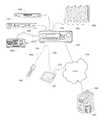
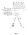
- FIGS. 1 and 2illustrate exemplary systems in which a standalone UEC device may be utilized to command operation of several appliances
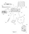
- FIGS. 3 and 4illustrate exemplary systems in which UEC functionality may be incorporated into an appliance which is part of a home entertainment system
- FIG. 5illustrates a block diagram of an exemplary UEC device
- FIG. 6illustrates a graphical representation of an exemplary UCE-based control environment
- FIG. 7illustrates an exemplary preferred command matrix for use in a UCE-based control environment, for example as illustrated in FIG. 6 ;
- FIG. 8illustrates a block diagram of an exemplary smart device which may support a remote control app and a setup method for use in configuring a UCE;
- FIG. 9illustrates an exemplary series of steps which may be performed in order to set up and configure an exemplary UCE
- FIG. 10illustrates an exemplary series of steps which may be performed in order to define to a UCE an appliance configuration which corresponds to a user activity
- FIG. 11illustrates exemplary activity configuration matrices such as may be defined during the steps of FIG. 10 ;
- FIG. 12illustrates an exemplary current appliance state matrix which may be maintained by a UCE for use in determining the commands necessary to invoke one of the states defined by the matrix of FIG. 11 ;
- FIG. 14illustrates an exemplary series of steps which may be performed by a UCE in establishing appliance states matching a desired activity defined in one of the matrices of FIG. 11 ;
- FIG. 15illustrates an exemplary series of steps which may be performed by a smart device to setup command control macros.
- a UCE device 100may be used to issue commands to control various controllable appliances, such as a television 106 , a cable set top box combined with a digital video recorder (“STB/DVR”) 110 , a DVD player 108 , and an AV receiver 120 .
- STB/DVRdigital video recorder
- controllable appliancesmay include, but need not be limited to, televisions, VCRs, DVRs, DVD players, cable or satellite converter set-top boxes (“STBs”), amplifiers, CD players, game consoles, home lighting, drapery, fans, HVAC systems, thermostats, personal computers, etc.
- STBsset-top boxes
- appliance commandsmay be issued by UCE 100 in response to infrared (“IR”) request signals 116 received from a remote control device 102 , radio frequency (“RF”) request signals 118 received from an app 124 resident on a smart device 104 , or any other device from which UCE 100 may be adapted to receive requests, using any appropriate communication method.
- IRinfrared
- RFradio frequency
- transmission of the requested appliance commands from the UCE to appliances 106 , 108 , 112 , 120may take the form of wireless IR signals 114 or CEC commands issued over a wired HDMI interface 112 , as appropriate to the capabilities of the particular appliance to which each command may be directed.
- AV receiver 120may not support HDMI inputs, being connected to audio source appliances 108 , 110 via, for example S/PDIF interfaces 122 .
- UCE 100may be constrained to transmit all commands destined for AV receiver 120 exclusively as IR signals, while commands destined for the other appliances 106 through 110 may take the form of either CEC or IR signals as appropriate for each command.
- certain TV manufacturersmay elect not to support volume adjustment via CEC. If the illustrative TV 106 is of such manufacture, UCE 100 may relay volume adjustment requests to TV 106 as IR signals 114 , while other requests such as power on/off or input selections may be relayed in the form of CEC commands over HDMI connection 112 .
- transmissions to and from UCE device 100may take the form of any convenient IR, RF, hardwired, point-to-point, or networked protocol, as necessary for a particular embodiment.
- wireless communications 116 , 118 , etc., between exemplary devicesare illustrated herein as direct links, it should be appreciated that in some instances such communication may take place via a local area network or personal area network, and as such may involve various intermediary devices such as routers, bridges, access points, etc. Since these items are not necessary for an understanding of the instant invention, they are omitted from this and subsequent Figures for the sake of clarity.
- UCE 100may receive wireless request signals from a remote control 200 and/or an app resident on a tablet computer 202 .
- command transmissions to appliances 106 , 108 , 110may take the form of wired CEC commands or wireless IR commands.
- remote control 200may be in bi-directional communication 208 with UCE 100 and accordingly the UCE may delegate the transmission of IR commands 210 to the remote control device 200 , i.e., use remote control 200 as a relay device for those commands determined to be best executed via IR transmissions.
- remote control 200may be in bi-directional communication 208 with UCE 100 and accordingly the UCE may delegate the transmission of IR commands 210 to the remote control device 200 , i.e., use remote control 200 as a relay device for those commands determined to be best executed via IR transmissions.
- a setup app 214 executing on a smart device such as tablet computer 202may be utilized in conjunction with an Internet ( 212 , 204 ) accessible or cloud based server 206 and associated database 207 to initially configure UCE 100 for operation with the specific group of appliances to be controlled, i.e., to communicate to UCE 100 a matching command code set and capability profile for each particular appliance to be controlled, for example based on type, manufacture, model number, etc., as will be described in greater detail hereafter.
- UCE functionality 100 ′may be embedded in an appliance, for example STB/DVR 310 .
- remote control 102 and/or smart device 104may transmit wireless request signals directly to STB/DVR 310 for action by the built-in UCE function 100 ′, which actions may, as before, comprise CEC command transmissions via HDMI connection 112 or IR command transmissions 114 , originating in this instance from an IR blaster provisioned to the STB/DVR appliance 310 .
- a set up application resident in STB/DVR 310may be utilized to configure UEC 100 ′, using for example an Internet connection 304 accessible through a cable modem and/or cable distribution system headend.
- UCE functionality 100 ′may be embedded in an AV receiver 420 which may serve as an HDMI switch between various content sources such as a STB/DVR 110 or a DVD player 108 and a rendering device such as TV 106 .
- AV receiver 420may also support various other input formats, for example analog inputs such as the illustrative 404 from CD player 408 ; composite or component video; S/PDIF coaxial or fiberoptic; etc.
- request signals 406may be directed to AV receiver 420 , for example from remote control 402 , for action by UCE function 100 ′.
- resulting appliance commandsmay be transmitted using CEC signals transmitted over HDMI connections 112 , or via IR signals 114 transmitted from an associated IR blaster.
- initial configuration of UCE 100 ′ to match the equipment to be controlledmay be performed by an Internet-connected app resident in AV receiver 420 , or by an app resident in tablet computer 202 or other smart device, as mentioned previously in conjunction with FIG. 2 .
- UCE function 100 ′may be incorporated into an Internet-capable TV, an HDMI switch, a game console, etc.; appliance command set and capability database 207 may be located at an internet cloud or a cable system headend, may be stored locally (in all or in part), which local storage may take the form of internal memory within the UCE itself or in an appliance such as a TV, STB or AV receiver, or may take the form of a memory stick or the like attachable to a smart device or appliance; etc.
- an exemplary UCE device 100may include, as needed for a particular application, a processor 500 coupled to a memory 502 which memory may comprise a combination of ROM memory, RAM memory, and/or non-volatile read/write memory and may take the form of a chip, a hard disk, a magnetic disk, an optical disk, a memory stick, etc., or any combination thereof. It will also be appreciated that some or all of the illustrated memory may be physically incorporated within the same IC chip as the processor 500 (a so called “microcontroller”) and, as such, it is shown separately in FIG. 5 only for the sake of clarity.
- Interface hardware provisioned as part of the exemplary UCE platformmay include IR receiver circuitry 504 and IR transmitter circuitry 506 ; an HDMI interface 508 ; a WiFi transceiver and interface 510 ; an Ethernet interface 512 ; and any other wired or wireless I/O interface(s) 514 as appropriate for a particular embodiment, by way of example without limitation Bluetooth, RF4CE, USB, Zigbee, Zensys, X10/Insteon, HomePlug, HomePNA, etc.
- the electronic components comprising the exemplary UCE device 100may be powered by an external power source 516 . In the case of a standalone UCE device such as illustrated in FIG.
- thismay comprise for example a compact AC adapter “wall wart,” while integrated UCE devices such as illustrated in FIG. 3 or 4 may draw operating power from the appliance into which they are integrated. It will also be appreciated that in the latter case, in certain embodiments processor 500 and/or memory 502 and/or certain portions of interface hardware items 504 through 514 may be shared with other functionalities of the host appliance.
- the memory 502may include executable instructions that are intended to be executed by the processor 500 to control the operation of the UCE device 100 (collectively, the UCE programming) as well as data which serves to define the necessary control protocols and command values for use in transmitting command signals to controllable appliances (collectively, the command data).
- the processor 500may be programmed to control the various electronic components within the exemplary UCE device 100 , e.g., to monitor the communication means 504 , 510 for incoming request messages from controlling devices, to cause the transmission of appliance command signals, etc.
- the UCE device 100may be adapted to be responsive to events, such as a received request message from remote control 102 or smart device 104 , changes in connected appliance status reported over HDMI interface 508 , WiFi interface 510 , or Ethernet interface 512 , etc. In response to an event, appropriate instructions within the UCE programming may be executed.
- eventssuch as a received request message from remote control 102 or smart device 104 , changes in connected appliance status reported over HDMI interface 508 , WiFi interface 510 , or Ethernet interface 512 , etc.
- appropriate instructions within the UCE programmingmay be executed.
- the UCE device 100may retrieve from the command data stored in memory 502 a preferred command transmission medium (e.g., IR, CEC over HDMI, IP over WiFi, etc.) and a corresponding command value and control protocol to be used in transmitting that command to an intended target appliance, e.g., TV 106 , in a format recognizable by that appliance to thereby control one or more functional operations of that appliance.
- a preferred command transmission mediume.g., IR, CEC over HDMI, IP over WiFi, etc.
- the status of connected appliancesmay be monitored and/or tabulated by the UCE programming in order to facilitate adjustment of appliance settings to match user-defined activity profiles, e.g. “Watch TV”, “View a movie”, etc.
- the UCE programming of an exemplary UCE device 100may comprise a universal control engine core 650 together with a series of scalable software modules 652 through 660 , each module supporting a particular appliance command protocol or method and provisioned as appropriate for a particular embodiment.
- the illustrative embodiment of FIG. 6may include an internet protocol (IP) module 652 , a CEC over HDMI module 654 , a Bluetooth module 656 , an IR module 660 , and other modules(s) 658 , as appropriate for the particular application.
- IPinternet protocol
- the appliances to be controlledmay include an IP enabled AV receiver 620 , an IP enabled STB/DVR 610 , TV 106 , DVD player 108 , and CD player 408 . As illustrated, certain of these devices may be interconnected via HDMI 112 and/or Ethernet 670 interfaces. (In this regard, it should be appreciated that the illustrative interconnections 112 and 670 of FIG. 6 are intended to depict logical topography only, and accordingly details of exact physical cabling structure and/or the presence of any necessary switches, routers, hubs, repeaters, interconnections, etc., are omitted for the sake of clarity.)
- the preferred method/protocol/medium for issuance of commands to the exemplary appliances of FIG. 6may vary by both appliance and by the function to be performed.
- volume control and analog input selection commands 622 targeted to AV receiver 620may be required to be issued via IR transmissions
- power on/off and HDMI input selection functionality commands 624may be better communicated via CEC commands and advanced functionality commands 626 such as sound field configuration may be best communicated via an Ethernet connection.
- the various operational functions of the other appliancesmay best commanded via a mixture of mediums, methods, and protocols, as illustrated.
- a particular appliancemay support receipt of an operational command via more than one path, for example the power on/off function of AV receiver 620 may be available not only as a CEC command, but also via an IR command.
- the UCE preferred command formatmay be that which has been determined to offer the greatest reliability, for example in the above instance the CEC command may be preferred since this form of command is not dependent on line-of-sight and also permits confirmation that the action has been performed by the target appliance.
- the exemplary UCE core program 650may be provisioned with a preferred command matrix 700 , as illustrated in FIG. 7 .
- Exemplary preferred command matrix 700may comprise a series of data cells or elements, e.g. cells 712 , each corresponding to a specific command 702 and a specific one of the appliances to be controlled 704 .
- the data content of such a cell or elementmay comprise identification of a form of command/transmission to be used and a pointer to the required data value and formatting information for the specific command.
- the data element 712 corresponding to the “Input 2” command 706 for the configured TV appliance 708may comprise an indicator that a CEC command is to be used, i.e., an indicator of the transmission device that is to be used to communicate the command to the intended target appliance, together with a pointer to the appropriate command data value and HDMI-CEC bus address; while data element 714 corresponding to the same command function for the configured AV receiver 710 may comprise an indicator that an IR command is to be used, together with a pointer to appropriate command data and formatting information within an IR code library stored elsewhere in UCE memory 502 .
- one or more secondary command matrices 716may also be provisioned, allowing for the use of alternate command methods in the event it is determined by the UCE programming that a preferred command was unsuccessful.
- Command matrix 700may also contain null entries, for example 718 , where a particular function is not available on or not supported by a specific appliance.
- command matrix 700may be created and loaded into the memory 502 of UCE 100 during an initialization and set-up process, as will now be described in further detail.
- a setup applicationmay be provided.
- such a set up applicationmay take the form of programming to be executed on any convenient device with a suitable user interface and capable of establishing communication with the UCE, such as without limitation a smart phone, tablet computer, personal computer, set top box, TV, etc., as appropriate for a particular embodiment.
- such a set up applicationmay be incorporated into the UCE programming itself, utilizing for example a connected TV screen and an associated controlling device as the user interface.
- the series of steps which may be performed by a UCE set up application when configuring a UCE device for operation with a specific set of appliancesremains similar. Accordingly, it will be appreciated that the methods comprising the illustrative UCE set up application presented below in conjunction with FIGS. 8 and 9 may be generally applied, mutatis mutandis, to various alternative set up application embodiments.
- a tablet computersuch as the exemplary device 202 of FIG. 2 may comprise, as needed for a particular application, a processor 800 memory 802 which memory may comprise a combination of ROM memory, RAM memory, and/or non-volatile read/write memory and may take the form of a chip, a hard disk, a magnetic disk, an optical disk, a memory stick, etc., or any combination thereof.
- a processor 800 memory 802which memory may comprise a combination of ROM memory, RAM memory, and/or non-volatile read/write memory and may take the form of a chip, a hard disk, a magnetic disk, an optical disk, a memory stick, etc., or any combination thereof.
- external memory 804may take the form of an SD card, memory stick, or the like.
- Hardware provisioned as part of an exemplary tablet computer platformmay include an LCD touchscreen 810 with associated display driver 806 and touch interface 808 ; hard keys 812 such as for example a power on/off key; a USB port 816 ; WiFi transceiver and interface 818 ; a Bluetooth transceiver and interface 820 ; a camera 822 ; and various other features 824 as appropriate for a particular embodiment, for example an accelerometer, GPS, ambient light sensor, near field communicator; etc.
- the electronic components comprising the exemplary tablet computer device 202may be powered by a battery-based internal power source 814 , rechargeable for example via USB interface 816 .
- Memory 802may include executable instructions that are intended to be executed by the processor 800 to control the operation of the tablet computer device 202 and to implement various functionalities such as Web browsing, game playing, video streaming, etc.
- programming comprising additional functionalitiesmay be downloaded into tablet computer 202 via, for example, WiFi interface 818 , USB 816 , external memory 804 , or any other convenient method.
- one such appmay comprise a remote control app, for example as that described in co-pending U.S. patent application Ser. No.
- tablet computer 202may also be provisioned with a setup app 214 , either as part of a remote control app or as separately downloadable item.
- such a setup appupon being invoked at step 902 may initially request that the user place all of the appliances to be controlled into a known state, e.g., powered on, in order to enable the appliance detection and/or testing steps which follow.
- the setup appmay determine the identity of those appliances which are CEC-enabled. This may be accomplished by communicating a request to the associated UCE, which at step 906 which may cause the UCE programming to scan connected HDMI devices for appliances which are CEC-enabled and/or identifiable via interaction over the HDMI interface, for example as described in co-pending U.S. patent application Ser. No.
- the setup applicationmay determine if additional non-CEC appliances are connected to the UCE device via the HDMI interface. This may be accomplished by requesting the UCE programming to scan for any further HDMI connections at step 910 and communicate the findings back to the setup application. Though not illustrated, it will be appreciated that where appropriate for a particular embodiment the UCE programming may conduct similar scans to in order to discover appliances connected via Ethernet, USB, Bluetooth, RF4CE, WiFi etc., where such interfaces may be provisioned to a UCE.
- the setup applicationmay display a listing of detected appliances (both identified and not yet identified) to the user.
- the usermay be prompted to enter appliance identifying information for those HDMI or otherwise connected appliances which were detected but not identified, as well as identifying information regarding any additional appliances which may form part of the system to be controlled but are not discoverable as described above (for example appliances such as AV receiver 120 or CD player 408 which may be responsive only to unidirectional IR commands).
- such identifying informationmay take the form of user-entered data such as an appliance type, brand and model number, or a setup code from a listing in a user guide; or may take the form of scanned or electronic information such as a digital picture of the appliance itself or of a bar code, QR code, or the like associated with appliance; near field acquisition of RFID tag data; etc.; or any combination thereof as appropriate for a particular embodiment.
- the setup appmay communicate that information to a database server, for example server 206 , for performance of step 918 , comprising identification of and retrieval of command codeset and capability data corresponding to the identified appliances from a database 207 , and provision of this data to the setup application for processing and ultimate transfer to the UCE device.
- the transferred codeset datamay comprise complete command data values and formatting information, may comprise pointers to command data values and formatting information already stored in the memories 502 and/or 802 / 804 of the UCE or the device upon which the setup application is currently resident, or a combination thereof.
- a suitable preferred command matrixfor example as illustrated in FIG. 7 , may be constructed and stored into the memory 502 of exemplary UCE device 100 , the matrix being constructed by considering the communication capabilities and functionalities of the devices identified via the above-described processes.
- any suitable methodmay be utilized, for example a system-wide prioritization of command media and methods by desirability (e.g. apply IP, CEC, IR in descending order); appliance-specific command maps by brand and/or model; function-specific preference and/or priority maps (e.g. all volume function commands via IR where available); etc.; or any combination thereof.
- the exact selection of command method priorities or mappingmay take into account factors such connection reliability, e.g. wired versus wireless, bidirectional versus unidirectional communication, etc.; speed of command transmission or execution; internal priorities within an appliance, e.g. received IP received packets processed before CEC packets, etc.; type of protocol support (e.g. error correction versus error detection; ack/nak, etc.); or any other factors which may applied in order to achieve optimum performance of a particular embodiment.
- said preferred command matrixmay be performed at the database server or within the setup application, or a combination thereof, depending on the particular embodiment.
- a preferred command matrixhas been finalized and stored in the UCE device, at step 932 a series of desired appliance configurations associated with specific user activities may be configured and stored into the UCE device, as will be now be described.
- an exemplary setup applicationmay subsequently guide a user through a series of steps in order to establish the desired appliance configurations for a series of possible activities.
- the usermay be presented with a list of possible activities, e.g., “Watch TV”, “Watch a movie”, “Listen to music”, etc.
- the usermay also be able to edit activity titles and/or create additional user defined activities.
- a usermay select a particular activity for configuration, for example “Watch TV”.
- the usermay be prompted to identify the content source for the activity being configured, for example cable STB/DVR 110 for the exemplary “Watch TV” activity.
- Such a promptmay take the form of a listing of eligible appliances as determined during the foregoing appliance set up steps; explicit user entry of an appliance type; etc.
- the usermay be prompted in a similar manner to select video and audio rendering appliances for use in this activity, for example TV 106 and AVR receiver 120 respectively.
- the set up application in concert with UCE programmingmay be able to ascertain which input port of each rendering appliance is attached to the content source appliance identified for this activity and/or if any intermediate switching appliance is in use (for example AV receiver 420 of the system illustrated in FIG. 4 ).
- the set up applicationmay automatically create all or part of an appropriate rendering device input selection for the activity being configured. If not, at steps 1008 and 1010 , the user may be additionally requested to identify the applicable content route(s) to the rendering appliances, e.g., input port numbers, presence of intermediate switches, etc.
- the set up applicationmay construct an activity matrix, for example as illustrated in FIG. 11 .
- activity matrix 1100 for a “Watch TV” activitymay comprise a series of cells, for example 1110 or 1112 , each corresponding to a desired configuration of a particular state 1106 or function 1108 of a specific appliance 1104 during the specified activity.
- cell 1110may indicate that the input of AV receiver 120 is to be set to “S/PDIF2”, while cells 1112 and 1114 may indicate that transport function commands (e.g., “play”, “pause”, “fast forward” etc.) are to be directed to STB/DVR 110 and not to DVD 114 .
- transport function commandse.g., “play”, “pause”, “fast forward” etc.
- the assignment of functions such as, for example, volume control, to specific appliances during a particular activitymay be performed within an individual controlling device, i.e., the controlling device may determine the appliance to which volume control commands are to be directed, in a preferred embodiment this assignment may be performed within the UCE, thereby ensuring consistency across each activity when multiple controlling devices are present in an environment, for example devices 102 and 104 of the environment illustrated in FIG. 1 .
- the newly-constructed activity matrix 1100may be tested by causing the UCE programming, utilizing preferred command matrix 700 , to issue the commands necessary to place the identified appliances into the desired state and thereafter receiving verification at step 1018 that the desired activity was successfully initiated.
- verificationmay comprise, for example, detection and reporting of HDMI or other content streams and/or appliance status by UCE programming by directly monitoring CEC status or by using methods such as described for example in U.S. patent application Ser. No. 13/240,604; solicitation of user input confirming correct operation; monitoring for presence or absence of analog input signals; recording of appliance status or error messages; etc.; or any combination thereof as appropriate for a particular embodiment.
- step 1018the set up application may return to step 1002 to allow reconfiguration of that activity and/or definition of alternative activities. If testing was successful, at steps 1020 and 1022 the completed activity matrix, for example 1100 as illustrated in FIG. 11 , may be transferred to the UCE 100 for storage in UCE memory 502 . Thereafter, at step 1024 the user may be offered the opportunity to return to step 1002 to define additional activity configurations, for example 1101 , 1102 as illustrated in FIG. 11 , or to exit the activity configuration process.
- the series of steps performed by the UCE programming in order to convey a function command to an appliance in accordance with a command request 1300 received from a controlling device such as remote control 102 or 200 , smart device 104 or 202 , etc., or in accordance with an internally generated requirement resulting from receipt of an activity requestmay initially comprise retrieval from a preferred command matrix that data element which corresponds to the requested command and target appliance.
- a controlling devicesuch as remote control 102 or 200 , smart device 104 or 202 , etc.
- an internally generated requirement resulting from receipt of an activity requestmay initially comprise retrieval from a preferred command matrix that data element which corresponds to the requested command and target appliance.
- a preferred command matrixthat data element which corresponds to the requested command and target appliance.
- the UCE programmingmay determine if the retrieved value constitutes a null element. If so, the referenced appliance does not support the requested command and accordingly at step 1314 an error message may be generated and the process thereafter terminated.
- error messagemay depend upon the particular embodiment and/or the requesting controlling device: for example, if the request originated from a controlling device which is in bidirectional communication with the UCE the error may be communicated back to the requesting device for action, i.e., display to the user, illuminate a LED, activate a buzzer, etc. as appropriate.
- actioni.e., display to the user, illuminate a LED, activate a buzzer, etc.
- that appliance's front panel displaymay be utilized.
- the UCEmay communicate the corresponding function command to the target appliance using the indicated command value and transmission method, e.g., for the exemplary data element 720 this may comprise issuing a CEC “power on” command to CEC logical device address zero (TV) via the UCE HDMI interface 508 .
- the UCE programmingmay determine if the communication interface and protocol used in issuing the command provides for any confirmation mechanism, i.e., explicit acknowledgement of receipt, monitoring of HDMI status on an interface, detection of a media stream or HDCP handshake, etc.
- the UCE programmingmay simply assume that the command was successful and processing is complete. If however confirmation means exists, at step 1310 the UCE programming may wait to determine if the command was successfully executed. Once positive confirmation is received, processing is complete. If no confirmation or a negative confirmation is received, at step 1312 the UCE programming may determine if an alternative method is available to communicate the command to the target appliance.
- thismay comprise accessing a secondary command matrix 716 in order to determine if an alternative communication method is available for the specific function, e.g., “TV power on.” If an alternative does exist, at step 1316 the substitute command value and transmission method may be retrieved and processing may return to step 1306 to initiate an alternative attempt.
- an IR “power on” command encoded according to SIRCSSpin Infrared Control System
- an exemplary UCEmay also support activity selection, whereby receipt of a single user request from a controlling device may cause a series of commands to be issued to various appliances in order to configure a system appropriately for a particular user activity, such as for example, watching television.
- activity selectionwhereby receipt of a single user request from a controlling device may cause a series of commands to be issued to various appliances in order to configure a system appropriately for a particular user activity, such as for example, watching television.
- a set of matrices defining desired equipment states suitable to various activitiesmay be stored in UCE memory 502 for access by UCE programming when executing such a request.
- the programming of an exemplary UCEmay maintain an additional matrix 1200 representative of the current state of the controlled appliances, arranged for example by appliance 1202 and by operational state 1204 .
- data elements 1206 and 1208 in the illustrative table 1200may indicate that TV 106 is currently powered on ( 1208 ) with HDMI port number 2 selected as the input ( 1206 ).
- the data contents of the elements in such a tablemay be maintained in any convenient manner as appropriate to a particular embodiment, for example without limitation retrieval of HDMI/CEC status; monitoring input media streams and/or HDCP status; measuring power consumption; construction of a simulated appliance state such as described for example in U.S. Pat. No. 6,784,805; etc.; or any combination thereof.
- certain appliancessuch as for example AV receiver 120 which may be controllable only via unidirectional IR, the current state of the appliance may not be discernible.
- a null data element 1210maybe entered into exemplary matrix 1200 to indicate that this appliance may require configuration using discrete commands only and/or user interaction.
- the data contents of the illustrative tablemay be maintained in memory 502 on an ongoing basis by UCE programming, while in other embodiments this data may be gathered “on the fly” at the time the activity request is being processed. Combinations of these methods may also be used, for example “on the fly” gathering for appliances connected via an HDMI bus combined with maintenance of a simulated state for appliances controlled via IR signals.
- UCE programmingmay compare a desired state matrix, for example 1100 , to a current state matrix, for example 1200 , element by element, issuing commands as necessary to bring appliances to the desired state.
- a desired state matrixfor example 1100
- a current state matrixfor example 1200
- FIG. 14an exemplary series of steps which may be performed by the programming of a UCE in order to effect a “Watch TV” activity configuration will now be presented in conjunction with FIG. 14 .
- the readermay also wish to reference the equipment configuration of FIG. 1 and the activity and current state matrices 1100 and 1200 of FIGS. 11 and 12 .
- the exemplary UCE programmingmay access an applicable appliance state matrix 1100 .
- communication of the “power on” command to TV 106may comprise a CEC command issued over HDMI connection 112 .
- a “mute” commandmay be communicated to TV 106 , since element 1116 of illustrative matrix 1100 indicates that TV 106 is not the primary audio rendering appliance.
- communication of the “mute” command to TV 106may comprise an IR transmission 114 .
- the active input of TV 106may be set to “HDMI1” via a CEC command, and at steps 1414 , 1416 a CEC “power on” command may be communicated to STB/DVR 110 if that appliance is not already powered on.
- the exemplary UCE programmingmay set an internal status to indicate that future transport command requests (e.g., play, pause, FF, etc.) should be routed to STB/DVR 110 , as indicated by element 1112 of matrix 1100 .
- future transport command requestse.g., play, pause, FF, etc.
- steps 1420 , 1422a CEC “power off” command may be communicated to STB/DVR 108 if that appliance is not already powered off.
- steps 1424 and 1426 “power on” and “input S/PDIF2” commandsmay be communicated to AV receiver 120 via IR signals.
- the exemplary UCE programmingmay set an internal status to indicate that future volume control command requests (e.g. volume up/down, mute) should be routed to AV receiver 120 , as indicated by element 1118 of matrix 1100 , where after processing of the activity request is complete.
- future volume control command requestse.g. volume up/down, mute
- the setup appmay determine the identity of those appliances which are CEC-enabled or IP enabled. This may be accomplished by communicating a request to the associated UCE, which at step 1506 may cause the UCE programming to scan connected HDMI devices for appliances which are CEC-enabled and/or identifiable via interaction over the HDMI interface, for example as described in co-pending U.S. patent application Ser. No. 13/198,072, of like assignee and incorporated herein by reference in its entirety, and communicate such appliance identities to the setup application.
- the setup appmay also determine if the appliances has any associated icon information (for example stored as metadata on the appliance, available from a remote server, or the like) as well as information related to interface connection types, e.g., WI-FI, HDMI input/output, for use in the creation of supported macros. If the icon information is available, the icon information may be sent to the smart device by the appliance and/or retrieved by the smart device using other information provided by the appliance as appropriate as shown in step 1526 .
- icon informationfor example stored as metadata on the appliance, available from a remote server, or the like
- information related to interface connection typese.g., WI-FI, HDMI input/output
- the setup applicationmay display a listing of detected appliances (both identified and not yet identified) to the user.
- the usermay then be prompted to enter appliance identifying information for those HDMI or otherwise connected appliances which were detected but not identified, as well as identifying information regarding any additional appliances which may form part of the system to be controlled but which were not discoverable as described above (for example appliances such as AV receiver 120 or CD player 408 which may be responsive only to unidirectional IR commands).
- such identifying informationmay take the form of user-entered data such as an appliance type, brand and model number, or a setup code from a listing in a user guide; or may take the form of scanned or electronic information such as a digital picture of the appliance itself or of a bar code, QR code, or the like associated with appliance; near field acquisition of RFID tag data; MAC address; etc.; or any combination thereof as appropriate for a particular embodiment.
- the setup appmay communicate that information to a database server, for example server 206 , for performance of step 1520 in which the database server uses the identification information to retrieve icon information as needed (e.g., when such data was not obtainable from the appliance), command information as discussed previously, and in step 1522 , to automatically generate macros which correspond to the appliance or a plurality of appliances considering their capability data as maintained in a database 207 and/or as retrieved from the appliances. Any such data gathered from and/or created by the server 206 will then be provisioned to the setup application for processing and ultimate transfer to the smart device and/or UCE as required.
- a database serverfor example server 206
- a suitable preferred user profile 1524may be constructed and stored into the memory 502 of exemplary UCE device 100 , the user profile 1524 being constructed by considering the communication capabilities and functionalities of the devices identified via the above-described processes.
- said construction of said user profile 1524may be performed at the database server or within the setup application, or a combination thereof, depending on the particular embodiment.
- the programming of an exemplary UCEmay utilize a command prioritization list, for example a prioritization list “IP, CEC, IR” may cause the UCE programming to first determine if the requested command can be issued using Internet Protocol, only if not, then determine if the requested command can be issued using a CEC command over the HDMI interface, and only if not, then attempt to issue the requested command via an infrared signal.
- a prioritizationreflects an exemplary preference of using bi-directional communication protocols over uni-directional communication protocols over line of sight communication protocols, e.g., IR, when supported by the intended target appliance.
Landscapes
- Engineering & Computer Science (AREA)
- Physics & Mathematics (AREA)
- General Physics & Mathematics (AREA)
- Computer Networks & Wireless Communication (AREA)
- Human Computer Interaction (AREA)
- Multimedia (AREA)
- Signal Processing (AREA)
- Selective Calling Equipment (AREA)
- Two-Way Televisions, Distribution Of Moving Picture Or The Like (AREA)
Abstract
Description
Claims (9)
Priority Applications (35)
| Application Number | Priority Date | Filing Date | Title |
|---|---|---|---|
| US15/789,547US10325486B2 (en) | 2011-10-28 | 2017-10-20 | System and method for optimized appliance control |
| US15/900,232US10339797B2 (en) | 2011-10-28 | 2018-02-20 | System and method for optimized appliance control |
| US15/900,342US10922958B2 (en) | 2011-10-28 | 2018-02-20 | System and method for optimized appliance control |
| US15/899,971US10943469B2 (en) | 2011-10-28 | 2018-02-20 | System and method for optimized appliance control |
| US15/900,089US10325487B2 (en) | 2011-10-28 | 2018-02-20 | System and method for optimized appliance control |
| US16/114,762US10937305B2 (en) | 2011-10-28 | 2018-08-28 | System and method for optimized appliance control |
| US16/156,766US10593195B2 (en) | 2011-10-28 | 2018-10-10 | System and method for optimized appliance control |
| US16/196,756US10614704B2 (en) | 2011-10-28 | 2018-11-20 | System and method for optimized appliance control |
| US16/197,552US10636288B2 (en) | 2011-10-28 | 2018-11-21 | System and method for optimized appliance control |
| US16/197,748US10593196B2 (en) | 2011-10-28 | 2018-11-21 | System and method for optimized appliance control |
| US16/199,463US10937306B2 (en) | 2011-10-28 | 2018-11-26 | System and method for optimized appliance control |
| US16/457,309US10937308B2 (en) | 2011-10-28 | 2019-06-28 | System and method for optimized appliance control |
| US16/540,635US10970997B2 (en) | 2011-10-28 | 2019-08-14 | System and method for optimized appliance control |
| US16/778,638US10991239B2 (en) | 2011-10-28 | 2020-01-31 | System and method for optimized appliance control |
| US16/778,241US11113954B2 (en) | 2011-10-28 | 2020-01-31 | System and method for optimized appliance control |
| US16/783,971US10970999B2 (en) | 2011-10-28 | 2020-02-06 | System and method for optimized appliance control |
| US16/814,493US11145189B2 (en) | 2011-10-28 | 2020-03-10 | System and method for optimized appliance control |
| US16/838,736US11170636B2 (en) | 2011-10-28 | 2020-04-02 | System and method for optimized appliance control |
| US16/999,986US11295603B2 (en) | 2011-10-28 | 2020-08-21 | System and method for optimized appliance control |
| US17/375,566US11410542B2 (en) | 2011-10-28 | 2021-07-14 | System and method for optimized appliance control |
| US17/461,237US11651677B2 (en) | 2011-10-28 | 2021-08-30 | System and method for optimized appliance control |
| US17/527,390US11295605B2 (en) | 2011-10-28 | 2021-11-16 | System and method for optimized appliance control |
| US17/527,532US11308796B2 (en) | 2011-10-28 | 2021-11-16 | System and method for optimized appliance control |
| US17/528,297US11315410B2 (en) | 2011-10-28 | 2021-11-17 | System and method for optimized appliance control |
| US17/528,485US11295606B2 (en) | 2011-10-28 | 2021-11-17 | System and method for optimized appliance control |
| US17/529,341US11322016B2 (en) | 2011-10-28 | 2021-11-18 | System and method for optimized appliance control |
| US17/665,219US11769397B2 (en) | 2011-10-28 | 2022-02-04 | System and method for optimized appliance control |
| US17/673,145US11756412B2 (en) | 2011-10-28 | 2022-02-16 | Systems and methods for associating services and/or devices with a voice assistant |
| US17/686,180US11887469B2 (en) | 2011-10-28 | 2022-03-03 | System and method for optimized appliance control |
| US17/686,039US12073711B2 (en) | 2011-10-28 | 2022-03-03 | System and method for optimized appliance control |
| US18/227,065US12307884B2 (en) | 2011-10-28 | 2023-07-27 | Systems and methods for associating services and/or devices with a voice assistant |
| US18/233,192US12217601B2 (en) | 2011-10-28 | 2023-08-11 | System and method for optimized appliance control |
| US18/775,369US20240371256A1 (en) | 2011-10-28 | 2024-07-17 | System and method for optimized appliance control |
| US19/001,768US20250148905A1 (en) | 2011-10-28 | 2024-12-26 | System and method for optimized appliance control |
| US19/189,003US20250259533A1 (en) | 2011-10-28 | 2025-04-24 | Systems and methods for associating services and/or devices with a voice assistant |
Applications Claiming Priority (7)
| Application Number | Priority Date | Filing Date | Title |
|---|---|---|---|
| US201161552857P | 2011-10-28 | 2011-10-28 | |
| US201261680876P | 2012-08-08 | 2012-08-08 | |
| US13/657,176US9215394B2 (en) | 2011-10-28 | 2012-10-22 | System and method for optimized appliance control |
| US13/899,671US9437105B2 (en) | 2011-10-28 | 2013-05-22 | System and method for optimized appliance control |
| US14/136,023US9449500B2 (en) | 2012-08-08 | 2013-12-20 | System and method for optimized appliance control |
| US15/259,847US9842492B2 (en) | 2011-10-28 | 2016-09-08 | System and method for optimized appliance control |
| US15/789,547US10325486B2 (en) | 2011-10-28 | 2017-10-20 | System and method for optimized appliance control |
Related Parent Applications (1)
| Application Number | Title | Priority Date | Filing Date |
|---|---|---|---|
| US15/259,847ContinuationUS9842492B2 (en) | 2011-10-28 | 2016-09-08 | System and method for optimized appliance control |
Related Child Applications (8)
| Application Number | Title | Priority Date | Filing Date |
|---|---|---|---|
| US15/900,089ContinuationUS10325487B2 (en) | 2011-10-28 | 2018-02-20 | System and method for optimized appliance control |
| US15/900,342ContinuationUS10922958B2 (en) | 2011-10-28 | 2018-02-20 | System and method for optimized appliance control |
| US15/899,971ContinuationUS10943469B2 (en) | 2011-10-28 | 2018-02-20 | System and method for optimized appliance control |
| US15/900,232ContinuationUS10339797B2 (en) | 2011-10-28 | 2018-02-20 | System and method for optimized appliance control |
| US16/114,762ContinuationUS10937305B2 (en) | 2011-10-28 | 2018-08-28 | System and method for optimized appliance control |
| US16/196,756ContinuationUS10614704B2 (en) | 2011-10-28 | 2018-11-20 | System and method for optimized appliance control |
| US16/197,552ContinuationUS10636288B2 (en) | 2011-10-28 | 2018-11-21 | System and method for optimized appliance control |
| US16/197,748ContinuationUS10593196B2 (en) | 2011-10-28 | 2018-11-21 | System and method for optimized appliance control |
Publications (2)
| Publication Number | Publication Date |
|---|---|
| US20180040237A1 US20180040237A1 (en) | 2018-02-08 |
| US10325486B2true US10325486B2 (en) | 2019-06-18 |
Family
ID=50484835
Family Applications (18)
| Application Number | Title | Priority Date | Filing Date |
|---|---|---|---|
| US14/136,023Active2033-08-26US9449500B2 (en) | 2011-10-28 | 2013-12-20 | System and method for optimized appliance control |
| US15/259,847ActiveUS9842492B2 (en) | 2011-10-28 | 2016-09-08 | System and method for optimized appliance control |
| US15/789,547ActiveUS10325486B2 (en) | 2011-10-28 | 2017-10-20 | System and method for optimized appliance control |
| US15/900,342Active2033-08-06US10922958B2 (en) | 2011-10-28 | 2018-02-20 | System and method for optimized appliance control |
| US15/900,232ActiveUS10339797B2 (en) | 2011-10-28 | 2018-02-20 | System and method for optimized appliance control |
| US15/900,089ActiveUS10325487B2 (en) | 2011-10-28 | 2018-02-20 | System and method for optimized appliance control |
| US15/899,971ActiveUS10943469B2 (en) | 2011-10-28 | 2018-02-20 | System and method for optimized appliance control |
| US16/114,762ActiveUS10937305B2 (en) | 2011-10-28 | 2018-08-28 | System and method for optimized appliance control |
| US16/196,756ActiveUS10614704B2 (en) | 2011-10-28 | 2018-11-20 | System and method for optimized appliance control |
| US16/197,552ActiveUS10636288B2 (en) | 2011-10-28 | 2018-11-21 | System and method for optimized appliance control |
| US16/197,748ActiveUS10593196B2 (en) | 2011-10-28 | 2018-11-21 | System and method for optimized appliance control |
| US16/199,463ActiveUS10937306B2 (en) | 2011-10-28 | 2018-11-26 | System and method for optimized appliance control |
| US16/540,635ActiveUS10970997B2 (en) | 2011-10-28 | 2019-08-14 | System and method for optimized appliance control |
| US16/778,241ActiveUS11113954B2 (en) | 2011-10-28 | 2020-01-31 | System and method for optimized appliance control |
| US16/778,638ActiveUS10991239B2 (en) | 2011-10-28 | 2020-01-31 | System and method for optimized appliance control |
| US16/814,493ActiveUS11145189B2 (en) | 2011-10-28 | 2020-03-10 | System and method for optimized appliance control |
| US16/838,736ActiveUS11170636B2 (en) | 2011-10-28 | 2020-04-02 | System and method for optimized appliance control |
| US17/375,566ActiveUS11410542B2 (en) | 2011-10-28 | 2021-07-14 | System and method for optimized appliance control |
Family Applications Before (2)
| Application Number | Title | Priority Date | Filing Date |
|---|---|---|---|
| US14/136,023Active2033-08-26US9449500B2 (en) | 2011-10-28 | 2013-12-20 | System and method for optimized appliance control |
| US15/259,847ActiveUS9842492B2 (en) | 2011-10-28 | 2016-09-08 | System and method for optimized appliance control |
Family Applications After (15)
| Application Number | Title | Priority Date | Filing Date |
|---|---|---|---|
| US15/900,342Active2033-08-06US10922958B2 (en) | 2011-10-28 | 2018-02-20 | System and method for optimized appliance control |
| US15/900,232ActiveUS10339797B2 (en) | 2011-10-28 | 2018-02-20 | System and method for optimized appliance control |
| US15/900,089ActiveUS10325487B2 (en) | 2011-10-28 | 2018-02-20 | System and method for optimized appliance control |
| US15/899,971ActiveUS10943469B2 (en) | 2011-10-28 | 2018-02-20 | System and method for optimized appliance control |
| US16/114,762ActiveUS10937305B2 (en) | 2011-10-28 | 2018-08-28 | System and method for optimized appliance control |
| US16/196,756ActiveUS10614704B2 (en) | 2011-10-28 | 2018-11-20 | System and method for optimized appliance control |
| US16/197,552ActiveUS10636288B2 (en) | 2011-10-28 | 2018-11-21 | System and method for optimized appliance control |
| US16/197,748ActiveUS10593196B2 (en) | 2011-10-28 | 2018-11-21 | System and method for optimized appliance control |
| US16/199,463ActiveUS10937306B2 (en) | 2011-10-28 | 2018-11-26 | System and method for optimized appliance control |
| US16/540,635ActiveUS10970997B2 (en) | 2011-10-28 | 2019-08-14 | System and method for optimized appliance control |
| US16/778,241ActiveUS11113954B2 (en) | 2011-10-28 | 2020-01-31 | System and method for optimized appliance control |
| US16/778,638ActiveUS10991239B2 (en) | 2011-10-28 | 2020-01-31 | System and method for optimized appliance control |
| US16/814,493ActiveUS11145189B2 (en) | 2011-10-28 | 2020-03-10 | System and method for optimized appliance control |
| US16/838,736ActiveUS11170636B2 (en) | 2011-10-28 | 2020-04-02 | System and method for optimized appliance control |
| US17/375,566ActiveUS11410542B2 (en) | 2011-10-28 | 2021-07-14 | System and method for optimized appliance control |
Country Status (1)
| Country | Link |
|---|---|
| US (18) | US9449500B2 (en) |
Families Citing this family (42)
| Publication number | Priority date | Publication date | Assignee | Title |
|---|---|---|---|---|
| US11769398B2 (en) | 2005-09-08 | 2023-09-26 | Universal Electronics Inc. | System and method for widget-assisted setup of a universal remote control |
| US9019435B2 (en) | 2011-09-22 | 2015-04-28 | Universal Electronics Inc. | System and method for configuring controlling device functionality |
| US11756412B2 (en) | 2011-10-28 | 2023-09-12 | Universal Electronics Inc. | Systems and methods for associating services and/or devices with a voice assistant |
| US11792185B2 (en) | 2019-01-08 | 2023-10-17 | Universal Electronics Inc. | Systems and methods for associating services and/or devices with a voice assistant |
| US11451618B2 (en) | 2014-05-15 | 2022-09-20 | Universal Electronics Inc. | Universal voice assistant |
| US11295603B2 (en) | 2011-10-28 | 2022-04-05 | Universal Electronics Inc. | System and method for optimized appliance control |
| US11700412B2 (en) | 2019-01-08 | 2023-07-11 | Universal Electronics Inc. | Universal voice assistant |
| US20140181683A1 (en)* | 2012-12-21 | 2014-06-26 | Samsung Electronics Co., Ltd. | Method and system for controlling external device |
| KR101623162B1 (en)* | 2013-05-16 | 2016-05-20 | 주식회사 서비전자 | Wireless extender with universal remote code and employment method thereof |
| US11445011B2 (en) | 2014-05-15 | 2022-09-13 | Universal Electronics Inc. | Universal voice assistant |
| US10063625B2 (en) | 2014-05-15 | 2018-08-28 | Universal Electronics Inc. | System and method for appliance detection and app configuration |
| KR102075464B1 (en)* | 2014-09-25 | 2020-02-10 | 엘지전자 주식회사 | Device identification device and control method of the device |
| US9942229B2 (en)* | 2014-10-03 | 2018-04-10 | Gopro, Inc. | Authenticating a limited input device via an authenticated application |
| JP2016076831A (en)* | 2014-10-07 | 2016-05-12 | ヤマハ株式会社 | Instruction device, program and instruction system |
| WO2016081636A1 (en)* | 2014-11-18 | 2016-05-26 | Branch Media Labs, Inc. | Seamless setup and control for home entertainment devices and content |
| US11575534B2 (en)* | 2015-02-10 | 2023-02-07 | Universal Electronics Inc. | System and method for aggregating and analyzing the status of a system |
| US9847017B2 (en)* | 2015-05-20 | 2017-12-19 | Steven Yuh-Ming Chien | Remote control apparatus commanded wirelessly by a user device for controlling a target device |
| KR102398488B1 (en)* | 2015-06-26 | 2022-05-13 | 엘지전자 주식회사 | Mobile terminal capable of remotely controlling a plurality of device |
| TWI570529B (en)* | 2015-09-25 | 2017-02-11 | 友勁科技股份有限公司 | Smart appliance control system |
| KR102479578B1 (en)* | 2016-02-03 | 2022-12-20 | 삼성전자주식회사 | Electronic apparatus and control method thereof |
| WO2018089671A1 (en)* | 2016-11-10 | 2018-05-17 | Caavo Inc | Soft universal remote controller |
| US10904727B2 (en) | 2016-12-13 | 2021-01-26 | Universal Electronics Inc. | Apparatus, system and method for promoting apps to smart devices |
| WO2018148439A1 (en)* | 2017-02-10 | 2018-08-16 | Caavo Inc | Determining state signatures for consumer electronic devices coupled to an audio/video switch |
| JP6763352B2 (en)* | 2017-07-05 | 2020-09-30 | Smk株式会社 | Equipment control devices, programs and remote control systems |
| US10447537B2 (en)* | 2017-07-11 | 2019-10-15 | Roku, Inc. | Automatic determination of display device functionality |
| US11489691B2 (en) | 2017-07-12 | 2022-11-01 | Universal Electronics Inc. | Apparatus, system and method for directing voice input in a controlling device |
| US10032365B1 (en) | 2017-10-16 | 2018-07-24 | Universal Electronics Inc. | Apparatus, system and method for using a universal controlling device for displaying a graphical user element in a display device |
| US10169984B1 (en)* | 2017-11-13 | 2019-01-01 | Grand Mate Co., Ltd. | Method for transmitting data in wireless system |
| US11044352B2 (en)* | 2017-12-16 | 2021-06-22 | Caavo Inc | Adaptive multi-protocol control of a media device |
| US11095875B2 (en)* | 2017-12-16 | 2021-08-17 | Caavo Inc | Automatic testing of home entertainment automation systems for controlling connected devices |
| US11665757B2 (en) | 2019-01-08 | 2023-05-30 | Universal Electronics Inc. | Universal audio device pairing assistant |
| US11776539B2 (en) | 2019-01-08 | 2023-10-03 | Universal Electronics Inc. | Voice assistant with sound metering capabilities |
| EP3930337A4 (en)* | 2019-02-18 | 2022-10-12 | LG Electronics Inc. | Display device and method for operating same |
| US10986392B2 (en)* | 2019-06-07 | 2021-04-20 | Charter Communications Operating, Llc | Hybrid IR/RF remote control system |
| US11445107B2 (en)* | 2019-08-08 | 2022-09-13 | Qorvo Us, Inc. | Supervised setup for control device with imager |
| US20210218591A1 (en) | 2020-01-15 | 2021-07-15 | Universal Electronics Inc. | System and method for optimized appliance utilization |
| CN111343058B (en)* | 2020-02-07 | 2022-02-08 | 北京小米移动软件有限公司 | Device control method, device, control device and storage medium |
| WO2021183772A1 (en)* | 2020-03-12 | 2021-09-16 | Universal Electronics Inc. | Universal voice assistant |
| WO2021251519A1 (en) | 2020-06-10 | 2021-12-16 | 엘지전자 주식회사 | Display apparatus and operation method therefor |
| US11503372B2 (en)* | 2020-06-17 | 2022-11-15 | Google Llc | Automation and recommendation based on device control protocols |
| US12294756B2 (en) | 2020-09-22 | 2025-05-06 | Universal Electronics Inc. | System and method for facilitating an enabling of a device functionality |
| EP4321986A4 (en)* | 2021-08-12 | 2024-10-23 | Samsung Electronics Co., Ltd. | DISPLAY APPARATUS AND METHOD OF OPERATING THE SAME |
Citations (80)
| Publication number | Priority date | Publication date | Assignee | Title |
|---|---|---|---|---|
| US5959539A (en) | 1995-12-23 | 1999-09-28 | Deutsche Thomson-Brandt Gmbh | Apparatus for the remote control of electronic devices with key allocation |
| US6160491A (en) | 1994-11-10 | 2000-12-12 | Matsushita Electric Industrial Co., Ltd. | Remote controller, remote control interface, and remote control system including a remote controller and a remote control interface |
| US6259892B1 (en) | 1997-09-19 | 2001-07-10 | Richard J. Helferich | Pager transceiver and methods for performing action on information at desired times |
| US6529556B1 (en) | 1997-01-31 | 2003-03-04 | Thomson Licensing S.A. | Remote control apparatus and method |
| US20030095156A1 (en) | 2001-11-20 | 2003-05-22 | Universal Electronics Inc. | Hand held remote control device having an improved user interface |
| US20040163073A1 (en) | 2002-06-27 | 2004-08-19 | Openpeak Inc. | Method, system, and computer program product for automatically managing components within a controlled environment |
| US20040210933A1 (en) | 2003-01-07 | 2004-10-21 | Universal Electronics Inc. | User interface for a remote control application |
| US20040255329A1 (en) | 2003-03-31 | 2004-12-16 | Matthew Compton | Video processing |
| US20050028208A1 (en) | 1998-07-17 | 2005-02-03 | United Video Properties, Inc. | Interactive television program guide with remote access |
| US20050195823A1 (en) | 2003-01-16 | 2005-09-08 | Jian-Rong Chen | Video/audio network |
| US6968399B2 (en) | 2001-10-16 | 2005-11-22 | Sony Corporation | Transmission/reception apparatus, transmission/reception method, and transmission/reception system |
| US20060146184A1 (en) | 2003-01-16 | 2006-07-06 | Gillard Clive H | Video network |
| US20060168618A1 (en) | 2003-04-01 | 2006-07-27 | Dong-Wook Choi | System and method for home automation using wireless control rf remocon module based on network |
| US20060197753A1 (en) | 2005-03-04 | 2006-09-07 | Hotelling Steven P | Multi-functional hand-held device |
| US20060227032A1 (en) | 2005-04-11 | 2006-10-12 | Alberto Vidal | Apparatus and method to facilitate universal remote control |
| EP1722341A1 (en) | 2004-02-29 | 2006-11-15 | Netac Technology Co., Ltd. | A system for controlling household digital equipment based of wireless |
| US20070220150A1 (en) | 2006-03-01 | 2007-09-20 | Cypress Semiconductor Corp. | Source Switching Method for Multimedia Interface |
| US20070225828A1 (en) | 2006-03-24 | 2007-09-27 | Universal Electronics Inc. | System and method for defining a controlled device command set |
| US20070229465A1 (en) | 2006-03-31 | 2007-10-04 | Sony Corporation | Remote control system |
| US20070292135A1 (en) | 2006-06-09 | 2007-12-20 | Yong Guo | Integrated remote control signaling |
| US20080005764A1 (en) | 2001-07-13 | 2008-01-03 | Universal Electronics Inc. | System and method for presenting program guide information in an electronic portable device |
| US20080120673A1 (en) | 2006-11-16 | 2008-05-22 | Sui Wu Dong | Multimedia client/server system with remote control signalling and methods for use therewith |
| US7379778B2 (en) | 2003-11-04 | 2008-05-27 | Universal Electronics, Inc. | System and methods for home appliance identification and control in a networked environment |
| US20080168519A1 (en) | 2007-01-05 | 2008-07-10 | Radiospire Networks, Inc. | System, method and apparatus for connecting multiple audio/video sources to an audio/video sink |
| US20080187028A1 (en) | 2007-02-07 | 2008-08-07 | Eyran Lida | Method and apparatus for communicating different types of data over a same network |
| US7436346B2 (en)* | 2005-01-20 | 2008-10-14 | At&T Intellectual Property I, L.P. | System, method and interface for controlling multiple electronic devices of a home entertainment system via a single control device |
| US20080278567A1 (en) | 2007-05-11 | 2008-11-13 | Sony Corporation | Communication system, video signal transmission method, transmitter, transmitting method, receiver, and receiving method |
| US20090015723A1 (en) | 2007-06-18 | 2009-01-15 | Sony Corporation Of Japan | Media switching device |
| US7519393B2 (en) | 2002-05-01 | 2009-04-14 | Microsoft Corporation | Method for wireless capability discovery and protocol negotiation, and wireless device including same |
| US20090156051A1 (en) | 2007-12-17 | 2009-06-18 | Paul Doyle | HDMI source detection |
| US20090167555A1 (en) | 2007-12-31 | 2009-07-02 | Universal Electronics Inc. | System and method for interactive appliance control |
| US20090207039A1 (en) | 2008-02-18 | 2009-08-20 | Smk Corporation | Cec control apparatus |
| US7589642B1 (en) | 2003-12-16 | 2009-09-15 | Uei Cayman Inc. | Relaying key code signals through a remote control device |
| US20090239587A1 (en) | 2008-03-19 | 2009-09-24 | Universal Electronics Inc. | System and method for appliance control via a personal communication or entertainment device |
| US20090248909A1 (en) | 2008-03-26 | 2009-10-01 | Sony Corporation | Method and Apparatus for Simulating Consumer Electronic Control Functionality for Devices |
| US20100079682A1 (en) | 2008-09-30 | 2010-04-01 | Echostar Technologies Llc | Systems and methods for automatic configuration of a remote control device |
| US20100134317A1 (en) | 2007-02-01 | 2010-06-03 | St-Ericsson Sa | Method for configuring a wireless communication device as a remote control, remotely controllable electronic device and wireless communication device |
| US20100138764A1 (en) | 2004-09-08 | 2010-06-03 | Universal Electronics, Inc. | System and method for flexible configuration of a controlling device |
| US20100157169A1 (en) | 2008-04-04 | 2010-06-24 | Sony Corporation | Electronic device and control signal sending method in electronic device |
| US20100177245A1 (en) | 2007-07-10 | 2010-07-15 | Atsushi Ohnuma | Display system and dsiplay apparatus |
| US7814516B2 (en)* | 2001-05-03 | 2010-10-12 | Mitsubishi Digital Electronics America, Inc. | Control system and user interface for network of input devices |
| US20100271560A1 (en) | 2009-04-22 | 2010-10-28 | Sony Corporation | Audio processing apparatus and audio processing method |
| US20100328547A1 (en) | 2009-06-25 | 2010-12-30 | Echostar Technologies L.L.C. | Systems and methods for smart remote-control devices |
| US20100332979A1 (en)* | 2009-06-25 | 2010-12-30 | Universal Electronics Inc. | System and method for configuration of macro commands in a controlling device |
| US20110102230A1 (en) | 2007-01-19 | 2011-05-05 | Uei Cayman Inc. | Dynamic linking of codesets in universal remote control devices |
| WO2011053008A2 (en) | 2009-10-30 | 2011-05-05 | Samsung Electronics Co., Ltd. | Method and apparatus for controlling home network system using mobile terminal |
| US20110156944A1 (en) | 2009-12-30 | 2011-06-30 | Eldon Technology Limited | Device control bus command translation for noncompliant and incompatible devices |
| US8040888B1 (en) | 2007-12-17 | 2011-10-18 | Integrated Device Technology, Inc. | Packet switch with port route tables |
| US20110274008A1 (en) | 2008-11-16 | 2011-11-10 | Valens Semiconductor Ltd. | Configurable switch for asymmetric communication |
| US20110273287A1 (en) | 2007-08-31 | 2011-11-10 | Lalonde John | Medical Data Transport over Wireless Life Critical Network |
| US20110283129A1 (en) | 2010-05-05 | 2011-11-17 | Nxp B.V. | System and method for operating an electronic device having an hdmi port that is shared between hdmi source function and an hdmi sink function of the electronic device |
| US20110285818A1 (en) | 2010-05-20 | 2011-11-24 | Samsung Electronics Co., Ltd. | Source device and sink device and method of transmitting and receiving multimedia service and related data |
| US20110289113A1 (en) | 2008-04-18 | 2011-11-24 | Universal Electronics Inc. | System and method for configuring the remote control functionality of a portable device |
| US20120013807A1 (en) | 2010-07-15 | 2012-01-19 | Gaurav Arora | Method and apparatus for fast source switching and/or automatic source switching |
| US20120084452A1 (en) | 2010-10-01 | 2012-04-05 | Microsoft Corporation | Remote control command translation |
| US20120144299A1 (en)* | 2010-09-30 | 2012-06-07 | Logitech Europe S.A. | Blind Navigation for Touch Interfaces |
| US20120173003A1 (en) | 2010-12-30 | 2012-07-05 | Samsung Electronics Co., Ltd. | User terminal apparatus and ui providing method thereof |
| US8218090B2 (en)* | 2009-09-17 | 2012-07-10 | Sony Corporation | Integrated user interface and control in HDMI/CEC |
| US8269892B2 (en) | 2007-12-06 | 2012-09-18 | Sony Corporation | Receiving device, and input switching control method in receiving device |
| US20120236161A1 (en) | 2011-03-15 | 2012-09-20 | Lg Electronics Inc. | Method of controlling electronic device and portable terminal thereof |
| US20120242526A1 (en) | 2011-03-25 | 2012-09-27 | Universal Electronics Inc. | System and method for facilitating appliance control via a smart device |
| US20120249890A1 (en)* | 2011-03-31 | 2012-10-04 | Logitech Europe S.A. | Apparatus and method for configuration and operation of a remote-control system |
| US20120249690A1 (en) | 2009-06-30 | 2012-10-04 | Yonglin Xie | Flow through drop dispenser including porous member |
| US20120278693A1 (en) | 2008-06-27 | 2012-11-01 | Universal Electronics Inc. | System and method for ubiquitous appliance control |
| US20120274857A1 (en) | 2011-03-31 | 2012-11-01 | Conrad Arlo Maxwell | Method, apparatus and system for transitioning an audio/video device between a source mode and a sink mode |
| US20120274547A1 (en) | 2011-04-29 | 2012-11-01 | Logitech Inc. | Techniques for content navigation using proximity sensing |
| US20120291128A1 (en) | 2009-12-11 | 2012-11-15 | At&T Intellectual Property I, L.P. | System and Method for Location, Time-of-Day, and Quality-of-Service Based Prioritized Access Control |
| US20120297040A1 (en) | 2011-05-20 | 2012-11-22 | Naoki Amano | Information processing apparatus, information processing method, and program |
| US20120330943A1 (en) | 2003-03-06 | 2012-12-27 | Thomson Licensing S.A. | Simplified searching for media services using a control device |
| US20130107131A1 (en) | 2011-10-28 | 2013-05-02 | Universal Electronics Inc. | System and method for optimized appliance control |
| US8477179B2 (en) | 2009-05-14 | 2013-07-02 | Panasonic Corporation | Method of transmitting video data for wirelessly transmitting three-dimensional video data |
| US20130249679A1 (en) | 2011-10-28 | 2013-09-26 | Universal Electronics Inc. | System and method for optimized appliance control |
| US8633986B1 (en) | 2010-11-05 | 2014-01-21 | Google Inc. | Methods and systems for acquiring specifications for remotely controlling electronics |
| US20140085059A1 (en) | 2012-09-21 | 2014-03-27 | Hon Hai Precision Industry Co., Ltd. | Signal conversion device and smart home network system using the same |
| US8810732B1 (en) | 2007-02-09 | 2014-08-19 | Aliphcom | Auto-select algorithm for a high-definition multimedia interface switch |
| US20140235526A1 (en) | 2010-04-28 | 2014-08-21 | The J. David Gladstone Institutes | Methods for Generating Cardiomyocytes |
| US20140235265A1 (en) | 2013-02-19 | 2014-08-21 | Homersoft Sp. Zo.O. | Dynamic proximity control system |
| US8839334B2 (en) | 2011-12-21 | 2014-09-16 | Humax Co., Ltd. | Method for controlling interface |
| US8881205B2 (en) | 2008-09-12 | 2014-11-04 | At&T Intellectual Property I, Lp | System for controlling media presentation devices |
| US9900657B2 (en)* | 2011-12-08 | 2018-02-20 | Lg Electronics Inc. | Network TV and method for operating network TV |
Family Cites Families (90)
| Publication number | Priority date | Publication date | Assignee | Title |
|---|---|---|---|---|
| US6850252B1 (en)* | 1999-10-05 | 2005-02-01 | Steven M. Hoffberg | Intelligent electronic appliance system and method |
| US6157319A (en)* | 1998-07-23 | 2000-12-05 | Universal Electronics Inc. | Universal remote control system with device activated setup |
| US7831930B2 (en)* | 2001-11-20 | 2010-11-09 | Universal Electronics Inc. | System and method for displaying a user interface for a remote control application |
| US7586398B2 (en)* | 1998-07-23 | 2009-09-08 | Universal Electronics, Inc. | System and method for setting up a universal remote control |
| US7218243B2 (en)* | 1998-07-23 | 2007-05-15 | Universal Electronics Inc. | System and method for automatically setting up a universal remote control |
| US20010005197A1 (en) | 1998-12-21 | 2001-06-28 | Animesh Mishra | Remotely controlling electronic devices |
| US20010033243A1 (en) | 2000-03-15 | 2001-10-25 | Harris Glen Mclean | Online remote control configuration system |
| US7690017B2 (en) | 2001-05-03 | 2010-03-30 | Mitsubishi Digital Electronics America, Inc. | Control system and user interface for network of input devices |
| US8291457B2 (en)* | 2001-05-24 | 2012-10-16 | Vixs Systems, Inc. | Channel selection in a multimedia system |
| US20090031419A1 (en)* | 2001-05-24 | 2009-01-29 | Indra Laksono | Multimedia system and server and methods for use therewith |
| JP2002373129A (en) | 2001-06-14 | 2002-12-26 | Fujitsu Ltd | Equipment control system |
| US20020194596A1 (en) | 2001-06-18 | 2002-12-19 | Srivastava Gopal K. | Control of multiple AV-devices by a single master controller using infrared transmitted commands and bus transmitted commands |
| EP1493138B1 (en) | 2002-03-29 | 2017-12-20 | Home Control Singapore Pte. Ltd. | Programmable remote control and method for programming a programmable remote control, a readable memory and a program |
| JP4369214B2 (en) | 2002-12-11 | 2009-11-18 | パナソニック株式会社 | AV system |
| KR100514191B1 (en) | 2003-01-23 | 2005-09-13 | 삼성전자주식회사 | remote controller and set-top-box for it |
| US7457879B2 (en) | 2003-04-01 | 2008-11-25 | Microsoft Corporation | Notification platform architecture |
| US7298962B2 (en) | 2003-05-12 | 2007-11-20 | Macrovision Corporation | Method and apparatus for reducing and restoring the effectiveness of a commercial skip system |
| US7363028B2 (en)* | 2003-11-04 | 2008-04-22 | Universal Electronics, Inc. | System and method for controlling device location determination |
| GB2412825B (en) | 2004-03-31 | 2007-05-23 | Sony Uk Ltd | Packet-based video network |
| US20060020962A1 (en)* | 2004-04-30 | 2006-01-26 | Vulcan Inc. | Time-based graphical user interface for multimedia content |
| CN101243688A (en) | 2004-06-07 | 2008-08-13 | 斯灵媒体公司 | Personal Media Broadcasting System |
| US20080007616A1 (en) | 2004-12-06 | 2008-01-10 | Ftd Technology Pte. Ltd. | Universal multimedia display adapter |
| US8230456B2 (en) | 2005-01-05 | 2012-07-24 | Yahoo! Inc. | Framework for delivering a plurality of content and providing for interaction with the same in a television environment |
| US7499462B2 (en) | 2005-03-15 | 2009-03-03 | Radiospire Networks, Inc. | System, method and apparatus for wireless delivery of content from a generalized content source to a generalized content sink |
| KR100694107B1 (en) | 2005-04-28 | 2007-03-12 | 삼성전자주식회사 | Apparatus and method for providing a content list of a mobile device |
| US20070022015A1 (en)* | 2005-07-22 | 2007-01-25 | Tarinelli Gillian J | System and method for the on-line purchase of products through a guest registration |
| US7907222B2 (en) | 2005-09-08 | 2011-03-15 | Universal Electronics Inc. | System and method for simplified setup of a universal remote control |
| JP5016670B2 (en) | 2006-05-03 | 2012-09-05 | クラウド システムズ, インコーポレイテッド | System and method for managing, routing, and controlling connection between devices |
| US20070268360A1 (en) | 2006-05-19 | 2007-11-22 | Sony Ericsson Mobile Communications Ab | Remote control programming system and method |
| WO2008013132A1 (en) | 2006-07-28 | 2008-01-31 | Sharp Kabushiki Kaisha | Display apparatus |
| US9319741B2 (en) | 2006-09-07 | 2016-04-19 | Rateze Remote Mgmt Llc | Finding devices in an entertainment system |
| JP4187037B2 (en)* | 2006-10-12 | 2008-11-26 | 船井電機株式会社 | Remote control system |
| JP5218845B2 (en)* | 2006-11-07 | 2013-06-26 | ソニー株式会社 | COMMUNICATION SYSTEM, TRANSMISSION DEVICE, RECEPTION DEVICE, COMMUNICATION METHOD, PROGRAM, AND COMMUNICATION CABLE |
| WO2008069304A1 (en) | 2006-12-08 | 2008-06-12 | Panasonic Corporation | Remote control system |
| US20080231762A1 (en) | 2007-03-22 | 2008-09-25 | Sony Corporation | System and method for application dependent universal remote control |
| US8429713B2 (en) | 2007-04-02 | 2013-04-23 | Sony Corporation | Method and apparatus to speed transmission of CEC commands |
| US8510798B2 (en)* | 2007-04-02 | 2013-08-13 | Sony Corporation | Authentication in an audio/visual system having multiple signaling paths |
| US20090040091A1 (en) | 2007-08-08 | 2009-02-12 | Lance Carlson | Systems and methods for programming a remote control |
| US8060631B2 (en)* | 2007-12-10 | 2011-11-15 | Deluxe Digital Studios, Inc. | Method and system for use in coordinating multimedia devices |
| JP4440338B2 (en) | 2008-01-30 | 2010-03-24 | パナソニック株式会社 | Wireless control system |
| JP5161599B2 (en)* | 2008-01-31 | 2013-03-13 | シャープ株式会社 | Electronic device, remote control system, signal processing method, control program, and recording medium |
| US8068183B2 (en) | 2008-04-08 | 2011-11-29 | Mitsubishi Electric Visual Solutions America, Inc. | Control system for network of input devices with automatic audio/video receiver detection and control configuration |
| US9350850B2 (en)* | 2008-04-18 | 2016-05-24 | Uei Cayman Inc. | Using HDMI-CEC to identify a codeset |
| JP2009278310A (en) | 2008-05-14 | 2009-11-26 | Panasonic Corp | Apparatus controller |
| TW201012225A (en)* | 2008-09-02 | 2010-03-16 | Weltrend Semiconductor Inc | Multimedia system with CEC right transferring mechanism and method thereof |
| JP2010098699A (en) | 2008-10-20 | 2010-04-30 | Canon Inc | Receiving apparatus, and control method thereof |
| US8286210B2 (en) | 2008-11-13 | 2012-10-09 | Sony Corporation | HDMI switching technology for the coupling of consumer electronic control and/or non-consumer electronic control devices in an audio/visual environment |
| TWI364638B (en) | 2008-11-27 | 2012-05-21 | Wistron Corp | An electronic device and the method of automatically controlling the operation of the electronic device |
| US8374346B2 (en)* | 2009-01-09 | 2013-02-12 | Silicon Image, Inc. | Method, apparatus, and system for pre-authentication and keep-authentication of content protected ports |
| JP5330039B2 (en)* | 2009-03-16 | 2013-10-30 | シャープ株式会社 | Wireless transmission system, relay device, wireless sink device, and wireless source device |
| GB2480737A (en) | 2009-03-24 | 2011-11-30 | Logitech Europ Sa | Apparatus and method of operation for a remote control system |
| CN102422552B (en)* | 2009-03-26 | 2016-05-04 | Xped控股股份有限公司 | Arrangement for managing wireless communication between devices |
| EP2415274B1 (en) | 2009-03-31 | 2017-08-23 | NXP USA, Inc. | Radio frequency remote controller device, integrated circuit and method for selecting at least one device to be controlled |
| JP5609010B2 (en)* | 2009-05-26 | 2014-10-22 | ヤマハ株式会社 | AV equipment control device |
| JPWO2010140199A1 (en) | 2009-06-01 | 2012-11-15 | パナソニック株式会社 | Video data transmission method |
| EP2280542A1 (en)* | 2009-07-21 | 2011-02-02 | Nxp B.V. | Fast HDMI switching with conditional reset mechanism |
| KR20110023441A (en)* | 2009-08-31 | 2011-03-08 | 삼성전자주식회사 | Digital interface system supporting Ethernet and its cable connection status |
| TWI446176B (en)* | 2009-10-20 | 2014-07-21 | Wistron Corp | Detection method and detection device and multimedia device |
| US8348145B2 (en)* | 2009-11-14 | 2013-01-08 | At&T Intellectual Property I, L.P. | Systems and methods for programming a remote control device |
| US20110181386A1 (en) | 2009-12-10 | 2011-07-28 | Monster Cable Products, Inc. | Providing Guidance During Operation of a Universal Remote Control |
| US8885552B2 (en) | 2009-12-11 | 2014-11-11 | At&T Intellectual Property I, L.P. | Remote control via local area network |
| US8242940B2 (en)* | 2009-12-17 | 2012-08-14 | Analog Devices, Inc. | Transitioning digital data processors between power savings and non-power savings modes |
| US9599981B2 (en) | 2010-02-04 | 2017-03-21 | Echostar Uk Holdings Limited | Electronic appliance status notification via a home entertainment system |
| EP2540032B1 (en)* | 2010-02-23 | 2020-08-26 | LG Electronics Inc. | A method and an apparatus for transmitting messages in home network system |
| US9294800B2 (en) | 2010-05-10 | 2016-03-22 | Comcast Cable Communications, Llc | Intelligent remote control |
| CN102893599B (en) | 2010-05-19 | 2013-11-06 | 夏普株式会社 | Playback device, display device, television receiver, system, identification method, program, and recording medium |
| US10104183B2 (en) | 2010-06-22 | 2018-10-16 | Microsoft Technology Licensing, Llc | Networked device authentication, pairing and resource sharing |
| US9786159B2 (en)* | 2010-07-23 | 2017-10-10 | Tivo Solutions Inc. | Multi-function remote control device |
| US8734035B2 (en)* | 2010-07-29 | 2014-05-27 | Brady Worldwide, Inc. | Media cartridge with shifting ribs |
| EP2431956B1 (en) | 2010-09-17 | 2014-10-22 | Eldon Technology Limited trading as Echostar Europe | A method and device for operating a television located in a premises to simulate occupation of the premises |
| US20120068857A1 (en)* | 2010-09-22 | 2012-03-22 | Apple Inc. | Configurable remote control |
| US8233803B2 (en) | 2010-09-30 | 2012-07-31 | Transmitive, LLC | Versatile remote control device and system |
| US20120131245A1 (en)* | 2010-11-19 | 2012-05-24 | Silicon Image, Inc. | Transfer of control bus signaling on packet-switched network |
| US9124853B2 (en) | 2010-11-30 | 2015-09-01 | Verizon Patent And Licensing Inc. | HDMI device and interoperability testing systems and methods |
| US8937534B2 (en) | 2010-12-08 | 2015-01-20 | At&T Intellectual Property I, L.P. | Remote control of electronic devices via mobile device |
| US20130258918A1 (en) | 2010-12-14 | 2013-10-03 | Koninklijke Philips Electronics N.V. | Method of commanding wireless devices |
| US9794731B2 (en) | 2010-12-31 | 2017-10-17 | Google Technology Holdings LLC | Method and apparatus for providing secure communication in a self-organizing network |
| US9451331B2 (en) | 2011-01-15 | 2016-09-20 | Lattice Semiconductor Corporation | Proxy device operation in command and control network |
| US8786410B2 (en)* | 2011-01-20 | 2014-07-22 | Echostar Technologies L.L.C. | Configuring remote control devices utilizing matrix codes |
| KR20120087635A (en) | 2011-01-28 | 2012-08-07 | 삼성전자주식회사 | Method and apparatus for remotely controlling consumer electronics device using wireless personal area network proxy |
| US8918719B2 (en) | 2011-02-14 | 2014-12-23 | Universal Electronics Inc. | Graphical user interface and data transfer methods in a controlling device |
| US9226020B2 (en) | 2011-05-03 | 2015-12-29 | Lg Electronics Inc. | Electronic device and method for operating the same |
| US8260975B1 (en) | 2011-06-14 | 2012-09-04 | Hydra Connect LLC | Consumer electronics control (CEC) processor |
| DE102012212514A1 (en)* | 2011-07-18 | 2013-02-21 | Logitech Europe S.A. | Remote control user interface for handheld device |
| US9049496B2 (en) | 2011-09-01 | 2015-06-02 | Gracenote, Inc. | Media source identification |
| CN102541547B (en) | 2011-12-22 | 2015-12-02 | 华为技术有限公司 | A kind of disposal route for realizing control objectives equipment and device |
| US11044352B2 (en) | 2017-12-16 | 2021-06-22 | Caavo Inc | Adaptive multi-protocol control of a media device |
| US11095875B2 (en) | 2017-12-16 | 2021-08-17 | Caavo Inc | Automatic testing of home entertainment automation systems for controlling connected devices |
| US11356636B2 (en) | 2018-01-19 | 2022-06-07 | Caavo Inc | Device identification and power state determination using media device information |
| US11190606B2 (en) | 2018-08-09 | 2021-11-30 | Caavo Inc | Automatic switching device operation determination based on received notifications |
- 2013
- 2013-12-20USUS14/136,023patent/US9449500B2/enactiveActive
- 2016
- 2016-09-08USUS15/259,847patent/US9842492B2/enactiveActive
- 2017
- 2017-10-20USUS15/789,547patent/US10325486B2/enactiveActive
- 2018
- 2018-02-20USUS15/900,342patent/US10922958B2/enactiveActive
- 2018-02-20USUS15/900,232patent/US10339797B2/enactiveActive
- 2018-02-20USUS15/900,089patent/US10325487B2/enactiveActive
- 2018-02-20USUS15/899,971patent/US10943469B2/enactiveActive
- 2018-08-28USUS16/114,762patent/US10937305B2/enactiveActive
- 2018-11-20USUS16/196,756patent/US10614704B2/enactiveActive
- 2018-11-21USUS16/197,552patent/US10636288B2/enactiveActive
- 2018-11-21USUS16/197,748patent/US10593196B2/enactiveActive
- 2018-11-26USUS16/199,463patent/US10937306B2/enactiveActive
- 2019
- 2019-08-14USUS16/540,635patent/US10970997B2/enactiveActive
- 2020
- 2020-01-31USUS16/778,241patent/US11113954B2/enactiveActive
- 2020-01-31USUS16/778,638patent/US10991239B2/enactiveActive
- 2020-03-10USUS16/814,493patent/US11145189B2/enactiveActive
- 2020-04-02USUS16/838,736patent/US11170636B2/enactiveActive
- 2021
- 2021-07-14USUS17/375,566patent/US11410542B2/enactiveActive
Patent Citations (82)
| Publication number | Priority date | Publication date | Assignee | Title |
|---|---|---|---|---|
| US6160491A (en) | 1994-11-10 | 2000-12-12 | Matsushita Electric Industrial Co., Ltd. | Remote controller, remote control interface, and remote control system including a remote controller and a remote control interface |
| US5959539A (en) | 1995-12-23 | 1999-09-28 | Deutsche Thomson-Brandt Gmbh | Apparatus for the remote control of electronic devices with key allocation |
| US6529556B1 (en) | 1997-01-31 | 2003-03-04 | Thomson Licensing S.A. | Remote control apparatus and method |
| US6259892B1 (en) | 1997-09-19 | 2001-07-10 | Richard J. Helferich | Pager transceiver and methods for performing action on information at desired times |
| US20050028208A1 (en) | 1998-07-17 | 2005-02-03 | United Video Properties, Inc. | Interactive television program guide with remote access |
| US7814516B2 (en)* | 2001-05-03 | 2010-10-12 | Mitsubishi Digital Electronics America, Inc. | Control system and user interface for network of input devices |
| US20080005764A1 (en) | 2001-07-13 | 2008-01-03 | Universal Electronics Inc. | System and method for presenting program guide information in an electronic portable device |
| US6968399B2 (en) | 2001-10-16 | 2005-11-22 | Sony Corporation | Transmission/reception apparatus, transmission/reception method, and transmission/reception system |
| US20030095156A1 (en) | 2001-11-20 | 2003-05-22 | Universal Electronics Inc. | Hand held remote control device having an improved user interface |
| US7519393B2 (en) | 2002-05-01 | 2009-04-14 | Microsoft Corporation | Method for wireless capability discovery and protocol negotiation, and wireless device including same |
| US20040163073A1 (en) | 2002-06-27 | 2004-08-19 | Openpeak Inc. | Method, system, and computer program product for automatically managing components within a controlled environment |
| US20040210933A1 (en) | 2003-01-07 | 2004-10-21 | Universal Electronics Inc. | User interface for a remote control application |
| US20050195823A1 (en) | 2003-01-16 | 2005-09-08 | Jian-Rong Chen | Video/audio network |
| US20060146184A1 (en) | 2003-01-16 | 2006-07-06 | Gillard Clive H | Video network |
| US20120330943A1 (en) | 2003-03-06 | 2012-12-27 | Thomson Licensing S.A. | Simplified searching for media services using a control device |
| US20040255329A1 (en) | 2003-03-31 | 2004-12-16 | Matthew Compton | Video processing |
| US20060168618A1 (en) | 2003-04-01 | 2006-07-27 | Dong-Wook Choi | System and method for home automation using wireless control rf remocon module based on network |
| US7379778B2 (en) | 2003-11-04 | 2008-05-27 | Universal Electronics, Inc. | System and methods for home appliance identification and control in a networked environment |
| US7589642B1 (en) | 2003-12-16 | 2009-09-15 | Uei Cayman Inc. | Relaying key code signals through a remote control device |
| US20070165555A1 (en) | 2004-02-29 | 2007-07-19 | Netac Technology Co., Ltd. | Wireless control systems for digital household appliance |
| EP1722341A1 (en) | 2004-02-29 | 2006-11-15 | Netac Technology Co., Ltd. | A system for controlling household digital equipment based of wireless |
| US20100138764A1 (en) | 2004-09-08 | 2010-06-03 | Universal Electronics, Inc. | System and method for flexible configuration of a controlling device |
| US7436346B2 (en)* | 2005-01-20 | 2008-10-14 | At&T Intellectual Property I, L.P. | System, method and interface for controlling multiple electronic devices of a home entertainment system via a single control device |
| US20060197753A1 (en) | 2005-03-04 | 2006-09-07 | Hotelling Steven P | Multi-functional hand-held device |
| US20060227032A1 (en) | 2005-04-11 | 2006-10-12 | Alberto Vidal | Apparatus and method to facilitate universal remote control |
| US20070220150A1 (en) | 2006-03-01 | 2007-09-20 | Cypress Semiconductor Corp. | Source Switching Method for Multimedia Interface |
| US20070225828A1 (en) | 2006-03-24 | 2007-09-27 | Universal Electronics Inc. | System and method for defining a controlled device command set |
| US20070229465A1 (en) | 2006-03-31 | 2007-10-04 | Sony Corporation | Remote control system |
| US20070292135A1 (en) | 2006-06-09 | 2007-12-20 | Yong Guo | Integrated remote control signaling |
| US20080120673A1 (en) | 2006-11-16 | 2008-05-22 | Sui Wu Dong | Multimedia client/server system with remote control signalling and methods for use therewith |
| US20080168519A1 (en) | 2007-01-05 | 2008-07-10 | Radiospire Networks, Inc. | System, method and apparatus for connecting multiple audio/video sources to an audio/video sink |
| US20110102230A1 (en) | 2007-01-19 | 2011-05-05 | Uei Cayman Inc. | Dynamic linking of codesets in universal remote control devices |
| US20100134317A1 (en) | 2007-02-01 | 2010-06-03 | St-Ericsson Sa | Method for configuring a wireless communication device as a remote control, remotely controllable electronic device and wireless communication device |
| US20080187028A1 (en) | 2007-02-07 | 2008-08-07 | Eyran Lida | Method and apparatus for communicating different types of data over a same network |
| US8810732B1 (en) | 2007-02-09 | 2014-08-19 | Aliphcom | Auto-select algorithm for a high-definition multimedia interface switch |
| US20080278567A1 (en) | 2007-05-11 | 2008-11-13 | Sony Corporation | Communication system, video signal transmission method, transmitter, transmitting method, receiver, and receiving method |
| US20090015723A1 (en) | 2007-06-18 | 2009-01-15 | Sony Corporation Of Japan | Media switching device |
| US20100177245A1 (en) | 2007-07-10 | 2010-07-15 | Atsushi Ohnuma | Display system and dsiplay apparatus |
| US20110273287A1 (en) | 2007-08-31 | 2011-11-10 | Lalonde John | Medical Data Transport over Wireless Life Critical Network |
| US8373556B2 (en) | 2007-08-31 | 2013-02-12 | Cardiac Pacemakers, Inc. | Medical data transport over wireless life critical network |
| US8269892B2 (en) | 2007-12-06 | 2012-09-18 | Sony Corporation | Receiving device, and input switching control method in receiving device |
| US20090156051A1 (en) | 2007-12-17 | 2009-06-18 | Paul Doyle | HDMI source detection |
| US8040888B1 (en) | 2007-12-17 | 2011-10-18 | Integrated Device Technology, Inc. | Packet switch with port route tables |
| US20090167555A1 (en) | 2007-12-31 | 2009-07-02 | Universal Electronics Inc. | System and method for interactive appliance control |
| US20090207039A1 (en) | 2008-02-18 | 2009-08-20 | Smk Corporation | Cec control apparatus |
| US20090239587A1 (en) | 2008-03-19 | 2009-09-24 | Universal Electronics Inc. | System and method for appliance control via a personal communication or entertainment device |
| US20090248909A1 (en) | 2008-03-26 | 2009-10-01 | Sony Corporation | Method and Apparatus for Simulating Consumer Electronic Control Functionality for Devices |
| US20100157169A1 (en) | 2008-04-04 | 2010-06-24 | Sony Corporation | Electronic device and control signal sending method in electronic device |
| US20110289113A1 (en) | 2008-04-18 | 2011-11-24 | Universal Electronics Inc. | System and method for configuring the remote control functionality of a portable device |
| US20120278693A1 (en) | 2008-06-27 | 2012-11-01 | Universal Electronics Inc. | System and method for ubiquitous appliance control |
| US8881205B2 (en) | 2008-09-12 | 2014-11-04 | At&T Intellectual Property I, Lp | System for controlling media presentation devices |
| US20100079682A1 (en) | 2008-09-30 | 2010-04-01 | Echostar Technologies Llc | Systems and methods for automatic configuration of a remote control device |
| US20110274008A1 (en) | 2008-11-16 | 2011-11-10 | Valens Semiconductor Ltd. | Configurable switch for asymmetric communication |
| US20100271560A1 (en) | 2009-04-22 | 2010-10-28 | Sony Corporation | Audio processing apparatus and audio processing method |
| US8477179B2 (en) | 2009-05-14 | 2013-07-02 | Panasonic Corporation | Method of transmitting video data for wirelessly transmitting three-dimensional video data |
| US20100332979A1 (en)* | 2009-06-25 | 2010-12-30 | Universal Electronics Inc. | System and method for configuration of macro commands in a controlling device |
| US20100328547A1 (en) | 2009-06-25 | 2010-12-30 | Echostar Technologies L.L.C. | Systems and methods for smart remote-control devices |
| US20120249690A1 (en) | 2009-06-30 | 2012-10-04 | Yonglin Xie | Flow through drop dispenser including porous member |
| US8218090B2 (en)* | 2009-09-17 | 2012-07-10 | Sony Corporation | Integrated user interface and control in HDMI/CEC |
| WO2011053008A2 (en) | 2009-10-30 | 2011-05-05 | Samsung Electronics Co., Ltd. | Method and apparatus for controlling home network system using mobile terminal |
| US20120291128A1 (en) | 2009-12-11 | 2012-11-15 | At&T Intellectual Property I, L.P. | System and Method for Location, Time-of-Day, and Quality-of-Service Based Prioritized Access Control |
| US20110156944A1 (en) | 2009-12-30 | 2011-06-30 | Eldon Technology Limited | Device control bus command translation for noncompliant and incompatible devices |
| US20140235526A1 (en) | 2010-04-28 | 2014-08-21 | The J. David Gladstone Institutes | Methods for Generating Cardiomyocytes |
| US20110283129A1 (en) | 2010-05-05 | 2011-11-17 | Nxp B.V. | System and method for operating an electronic device having an hdmi port that is shared between hdmi source function and an hdmi sink function of the electronic device |
| US20110285818A1 (en) | 2010-05-20 | 2011-11-24 | Samsung Electronics Co., Ltd. | Source device and sink device and method of transmitting and receiving multimedia service and related data |
| US20120013807A1 (en) | 2010-07-15 | 2012-01-19 | Gaurav Arora | Method and apparatus for fast source switching and/or automatic source switching |
| US20120144299A1 (en)* | 2010-09-30 | 2012-06-07 | Logitech Europe S.A. | Blind Navigation for Touch Interfaces |
| US20120084452A1 (en) | 2010-10-01 | 2012-04-05 | Microsoft Corporation | Remote control command translation |
| US8633986B1 (en) | 2010-11-05 | 2014-01-21 | Google Inc. | Methods and systems for acquiring specifications for remotely controlling electronics |
| US20120173003A1 (en) | 2010-12-30 | 2012-07-05 | Samsung Electronics Co., Ltd. | User terminal apparatus and ui providing method thereof |
| US20120236161A1 (en) | 2011-03-15 | 2012-09-20 | Lg Electronics Inc. | Method of controlling electronic device and portable terminal thereof |
| US20120242526A1 (en) | 2011-03-25 | 2012-09-27 | Universal Electronics Inc. | System and method for facilitating appliance control via a smart device |
| US20120274857A1 (en) | 2011-03-31 | 2012-11-01 | Conrad Arlo Maxwell | Method, apparatus and system for transitioning an audio/video device between a source mode and a sink mode |
| US20120249890A1 (en)* | 2011-03-31 | 2012-10-04 | Logitech Europe S.A. | Apparatus and method for configuration and operation of a remote-control system |
| US20120274547A1 (en) | 2011-04-29 | 2012-11-01 | Logitech Inc. | Techniques for content navigation using proximity sensing |
| US20120297040A1 (en) | 2011-05-20 | 2012-11-22 | Naoki Amano | Information processing apparatus, information processing method, and program |
| US20130107131A1 (en) | 2011-10-28 | 2013-05-02 | Universal Electronics Inc. | System and method for optimized appliance control |
| US20130249679A1 (en) | 2011-10-28 | 2013-09-26 | Universal Electronics Inc. | System and method for optimized appliance control |
| US9900657B2 (en)* | 2011-12-08 | 2018-02-20 | Lg Electronics Inc. | Network TV and method for operating network TV |
| US8839334B2 (en) | 2011-12-21 | 2014-09-16 | Humax Co., Ltd. | Method for controlling interface |
| US20140085059A1 (en) | 2012-09-21 | 2014-03-27 | Hon Hai Precision Industry Co., Ltd. | Signal conversion device and smart home network system using the same |
| US20140235265A1 (en) | 2013-02-19 | 2014-08-21 | Homersoft Sp. Zo.O. | Dynamic proximity control system |
Non-Patent Citations (14)
| Title |
|---|
| European Patent Office, extended European Search Report issued on European patent application No. 12844121,9, dated Mar. 5. 2015, 6 pages. |
| European Patent Office, extended European Search Report issued on European patent application No. 14801064.8, dated Apr. 18, 2016, 8 pages. |
| European Patent Office, extended European Search Report issued on European patent application No. 14872863.7, dated Nov. 25, 2016, 8 pages. |
| ISA/US, Int. Search Report and Written Opinion of the Int. Searching Authority issued on Int. Appin. No. PCT/US12/62161, received Jan. 23, 2013, 12 pages. |
| ISA/US, Int. Search Report and Written Opinion of the Int. Searching Authority issued on Int. Appin. No. PCT/US14/38151, received Jun. 27, 2014, 10 pages. |
| ISA/US, Int. Search Report and Written Opinion of the Int. Searching Authority issued on Int. AppLn. No. PCT/US14/38151, received Jun. 27, 2014, 10 pages. |
| United States Patent and Trademark Office, Final Office Action issued on U.S. Appl. No. 15/626,357, Notification dated Nov. 3, 2017, 10 pages. |
| United States Patent and Trademark Office, Final Office Action issued on U.S. Appl. No. 15/789,547, Notification dated Jan. 25, 2018, 15 pages. |
| United States Patent and Trademark Office, Final Office Action issued on U.S. Appl. No. 15/900,232, Notification dated Dec. 13, 15 pgs.. |
| United States Patent and Trademark Office, Final Office Action issued on U.S. Appl. No. 15/900,342, Notification dated Nov. 29, 2018, 19 pgs. |
| United States Patent and Trademark Office, Non-Final Office Action issued on U.S. Appl. No. 15/899,971, Notification dated Apr. 19, 2018, 11 pgs. |
| United States Patent and Trademark Office, Non-Final Office Action issued on U.S. Appl. No. 15/900,089, Notification dated May 10, 2018, 13 pgs. |
| United States Patent and Trademark Office, Non-Final Office Action issued on U.S. Appl. No. 15/900,232, Notification dated May 17, 2018, 14 pgs. |
| United States Patent and Trademark Office, Non-Final Office Action issued on U.S. Appl. No. 15/900,342, Notification dated May 9, 2018, 14 pgs. |
Also Published As
Similar Documents
| Publication | Publication Date | Title |
|---|---|---|
| US11410542B2 (en) | System and method for optimized appliance control | |
| US11769397B2 (en) | System and method for optimized appliance control | |
| US10937308B2 (en) | System and method for optimized appliance control |
Legal Events
| Date | Code | Title | Description |
|---|---|---|---|
| AS | Assignment | Owner name:UNIVERSAL ELECTRONICS INC., CALIFORNIA Free format text:ASSIGNMENT OF ASSIGNORS INTEREST;ASSIGNOR:ARLING, PAUL D.;REEL/FRAME:043915/0662 Effective date:20131223 | |
| FEPP | Fee payment procedure | Free format text:ENTITY STATUS SET TO UNDISCOUNTED (ORIGINAL EVENT CODE: BIG.); ENTITY STATUS OF PATENT OWNER: LARGE ENTITY | |
| STPP | Information on status: patent application and granting procedure in general | Free format text:NOTICE OF ALLOWANCE MAILED -- APPLICATION RECEIVED IN OFFICE OF PUBLICATIONS | |
| STCF | Information on status: patent grant | Free format text:PATENTED CASE | |
| AS | Assignment | Owner name:UNIVERSAL ELECTRONICS INC., CALIFORNIA Free format text:ASSIGNMENT OF ASSIGNORS INTEREST;ASSIGNOR:BARNETT, BRIAN;REEL/FRAME:053806/0861 Effective date:20200911 | |
| IPR | Aia trial proceeding filed before the patent and appeal board: inter partes review | Free format text:TRIAL NO: IPR2021-00455 Opponent name:ROKU, INC. Effective date:20210211 | |
| MAFP | Maintenance fee payment | Free format text:PAYMENT OF MAINTENANCE FEE, 4TH YEAR, LARGE ENTITY (ORIGINAL EVENT CODE: M1551); ENTITY STATUS OF PATENT OWNER: LARGE ENTITY Year of fee payment:4 | |
| AS | Assignment | Owner name:U.S. BANK NATIONAL ASSOCIATION, CALIFORNIA Free format text:SECURITY INTEREST;ASSIGNOR:UNIVERSAL ELECTRONICS INC.;REEL/FRAME:067417/0402 Effective date:20120914 |