US10325350B2 - System and method for forming a video stream containing GIS data in real-time - Google Patents
System and method for forming a video stream containing GIS data in real-timeDownload PDFInfo
- Publication number
- US10325350B2 US10325350B2US13/492,107US201213492107AUS10325350B2US 10325350 B2US10325350 B2US 10325350B2US 201213492107 AUS201213492107 AUS 201213492107AUS 10325350 B2US10325350 B2US 10325350B2
- Authority
- US
- United States
- Prior art keywords
- data
- video frames
- video
- geo
- gis
- Prior art date
- Legal status (The legal status is an assumption and is not a legal conclusion. Google has not performed a legal analysis and makes no representation as to the accuracy of the status listed.)
- Active, expires
Links
Images


Classifications
- G—PHYSICS
- G06—COMPUTING OR CALCULATING; COUNTING
- G06T—IMAGE DATA PROCESSING OR GENERATION, IN GENERAL
- G06T3/00—Geometric image transformations in the plane of the image
- G06T3/40—Scaling of whole images or parts thereof, e.g. expanding or contracting
- G06T3/4038—Image mosaicing, e.g. composing plane images from plane sub-images
- G—PHYSICS
- G06—COMPUTING OR CALCULATING; COUNTING
- G06T—IMAGE DATA PROCESSING OR GENERATION, IN GENERAL
- G06T1/00—General purpose image data processing
- G06T1/0007—Image acquisition
Definitions
- imagerymay be used to capture views of a geographic area.
- the imagerymay be used to measure objects and structures within images, as well as, to be able to determine geographic locations of points within images.
- Geo-referenced imagesmay include two basic categories: captured imagery (images as captured by the camera or sensor employed), and projected imagery (images processed and converted to confirm to a mathematical projection).
- Geo-referenced aerial imagesmay be produced using hardware and/or software systems that may geo-reference airborne sensor data. For example, methods and apparatus for mapping and measuring land are described in U.S. Pat. No. 5,247,356, which is hereby incorporated by reference in its entirety.
- a system produced by Applanix Corporation of Richmond Hill, Ontario, Canada and sold under the trademark “POS AV”includes a hardware and software system for directly geo-referencing sensor data. This system may be mounted on a moving platform, such as an airplane, and directed towards the ground.
- Imagerymay begin as captured imagery.
- the captured imagerymay need further processing to create projected imagery that is geo-referenced.
- the conventional method for processing captured imagery into projected imageryis ortho-rectification.
- Ortho-rectificationaligns an image to an orthogonal or rectilinear grid (i.e., composed of rectangles).
- Captured imagery used to create an ortho-rectified imagemay typically include a nadir image—that is, an image captured with the camera pointing straight down.
- Direct geo-referencingis the direct measurement of sensor position and orientation (e.g., exterior orientation parameters), without the need for additional ground information over the project area.
- These parametersmay include data from an airborne sensor that may be geo-referenced to the Earth and/or local mapping frame.
- airborne sensorsmay include: aerial cameras (digital or film-based), multi-spectral or hyper-spectral scanners, SAR, or LIDAR.
- Geographical location data and/or geospatial datamay be stored, organized, and/or analyzed in a Geographical Information System (hereinafter “GIS” or “GISs”).
- GISGeographical Information System
- captured aerial imagesmay be warped to fit a pre-defined mapping grid (e.g., U.S. State Plane, 1983 North American Datum, in U.S. Survey Feet).
- GISGeographical Information System
- Each geographic point locationmay be then translated from geographic coordinates (e.g., latitude/longitude, X/Y coordinates) to image frame coordinates (e.g., pixel row/column) using mapping information surrounding the image frame.
- mapping gride.g., using an ortho-rectification process
- oblique imageryhowever, such translation may be more complex, and computation-intensive as some three dimensional features may become distorted during image processing.
- Multiple captured imagesmay also be combined into one or more larger composite images.
- the larger composite imagesmay cover larger geographic areas.
- the composite imagemay be an ortho-mosaic image created from a series of overlapping or adjacent captured nadir images.
- the overlapping or adjacent imagesmay be mathematically combined into a single ortho-rectified processed composite image.
- the rectilinear gridmay include an ortho-mosaic image, wherein every grid pixel covers the same amount of area on the ground.
- the location of each grid pixelmay be determined from the mathematical definition of the grid.
- the gridmay include a starting or origin location (e.g., X and Y location), and a grid/pixel size (e.g., X and Y grid/pixel size).
- the available nadir imagesmay be evaluated to determine if the images cover the same point on the ground as the grid pixel being filled. If so, a mathematical formula may be used to determine where that point on the ground projects up onto the camera's pixel image map, and that resulting pixel value may be then transferred to the grid pixel.
- Existing systems overlaying information onto full motion video streams in real-timemay operate by calibrating to specific targets.
- a fan of the National Football Leaguemay be familiar with overlay graphics on the line of scrimmage, the first down marker, and the like.
- Such systemswork, not through geo-referencing of the imagery, but by calibrating the cameras to the field in that specific football stadium, and including manual information input for the computers to then overlay on the video stream via chroma-key methodology. If the cameras are pointed anywhere but that particular football field for which they are calibrated, the overlays may not be at the correct location because the images are not georeferenced.
- a recent image processing techniquewarps a grid to an image instead of warping the image to fit the grid.
- Thisis especially interesting for oblique image processing, as oblique images (i.e., non-nadir images) may typically introduce gross three dimensional object distortions when warped to fit a mapping grid.
- oblique imagesi.e., non-nadir images
- the development of a tessellated ground planeincludes a means to define the surface of the Earth under an oblique image.
- the systems and methods for determining tessellated ground planesare further described in detail in U.S. Pat. No. 7,424,133, which is hereby incorporated by reference in its entirety.
- Pictometrymay be able to determine locations, derive measurements, and/or overlay GIS data all with a degree of accuracy previously unachieved for oblique imagery.
- Pictometry International Corporationincludes the systems and methods for single ray projection also described in U.S. Pat. No. 7,424,133. These methods, while more accurate than ortho-rectification, may be too slow for real-time processing at full motion video frame rates.
- FIG. 1is a perspective view of an exemplary video frame geo-referencing system constructed in accordance with the present disclosure.
- FIG. 2is a perspective view of another example of a video frame geo-referencing system constructed in accordance with the present disclosure.
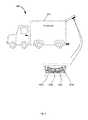
- FIG. 3is a perspective view of yet another example of a video frame geo-referencing system constructed in accordance with the present disclosure.
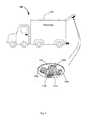
- FIG. 4is a perspective view of yet another example of a video frame geo-referencing system constructed in accordance with the present disclosure.
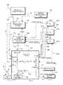
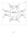
- FIG. 5is a block diagram of an exemplary video frame geo-referencing system constructed in accordance with the present disclosure.
- FIG. 6is a diagrammatic view of exemplary multi-processor architecture of a system constructed in accordance with the present disclosure.
- FIG. 7is a block diagram of an exemplary logic flow of a system constructed in accordance with the present disclosure.
- FIG. 8is a block diagram of exemplary marshaling steps of a system constructed in accordance with the present disclosure.
- FIG. 9is a block diagram of another embodiment of exemplary marshaling steps of a system constructed in accordance with the present disclosure.
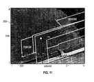
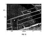
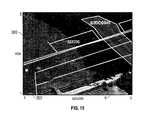
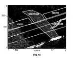
- FIG. 10-18are exemplary composite video frames 1 - 9 from a series of video frames 1 -N according to the instant disclosure.
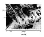
- FIG. 19is another exemplary composite video frame according to the instant disclosure showing overlaid GIS data of residential home foundations.
- the terms “comprises”, “comprising”, includes”, “including”, “has”, “having”, or any other variation thereof,are intended to cover a non-exclusive inclusion.
- a process, method, article, or apparatus that comprises a list of elementsis not necessarily limited to only those elements, but may include other elements not expressly listed or inherent to such process, method, article, or apparatus.
- the terms “provide”, “providing”, and variations thereofcomprise displaying or providing for display a webpage to one or more users interfacing with a computer and/or computer network(s) and/or allowing the one or more user(s) to participate, such as by interacting with one or more mechanisms on a webpage by sending and/or receiving signals (e.g., analog, digital, optical, and/or the like) via a computer network interface (e.g., Ethernet port, TCP/IP post, optical port, cable modem, and/or the like).
- signalse.g., analog, digital, optical, and/or the like
- a computer network interfacee.g., Ethernet port, TCP/IP post, optical port, cable modem, and/or the like.
- a usermay be provided with a web page in a web browser, or in a software application, for example.
- a condition A or Bis satisfied by any one of the following: A is true (or present) and B is false (or not present), A is false (or not present) and B is true (or present), and both A and B is true (or present).
- references to “one embodiment”, “an embodiment”, “one example”, or “an example”means that a particular element, feature, structure, or characteristic described in connection with the embodiment may be included in at least one embodiment.
- the appearance of the phrase “in one embodiment” or “one example” in various places within the instant specificationare not necessarily all referring to the same embodiment or example.
- Circuitrymay be analog and/or digital, components, or one or more suitably programmed microprocessors and associated hardware and/or software, or hardwired logic.
- componentsmay perform one or more functions.
- the term “component”,may include hardware, such as a processor, an application specific integrated circuit (ASIC), or a field programmable gate array (FPGA), or a combination of hardware and software.
- Softwaremay include one or more computer executable instructions that when executed by one or more components may cause the component to perform a specified function. It should be understood that the algorithms described herein may be stored on one or more non-transient memory.
- Exemplary non-transient memorymay include random access memory, read only memory, flash memory, and/or the like. Such non-transient memory may be electrically based, optically based, and/or the like.
- real-timeAs used herein, the terms “real-time”, “calculating in real-time”, “storing in real-time”, and similar terms containing “real-time” shall be interpreted to mean completing the process/operation within a certain predetermined time period or number of sequences of completed instructions relating to a certain event and system response. Such time period may vary, but will generally be relatively short. In contrast, the term “non-real-time” may be used to indicate periods of time other than real-time.
- full motion videoof “FMV” shall be interpreted to mean digital or analog video comprising a series of video frames which are captured and/or displayed.
- frame ratesmay be between approximately seven frames per second (fps) to about thirty fps. In some embodiments, the frame rate may be about twenty-four frames per second (fps). It is to be understood that such frame rates are exemplary only, and should not be construed as limiting in any way. It is to be understood that full motion video may be captured and/or displayed at lower or higher frame rates depending on specific system applications. A system according to the inventive concept disclosed herein may be capable of operating at higher or lower frame rates as will be apparent to a person of ordinary skill in the art presented with the instant disclosure.
- GIS dataAs used herein, the term “GIS data”, “geographic information system data”, “geographical information system data”, or “geospatial information system data” shall be interpreted to mean data that may be captured, stored, analyzed, processed, transmitted, and/or otherwise associated with geographical location data.
- GIS datamay, for example, be indicative of a geographical location of an object on the Earth's surface, may relate such location to sea level, and/or any other object by using conventional coordinates or monitoring systems (e.g., latitude/longitude, GPS, XYZ coordinates, and/or the like).
- GIS datamay include, but is not limited to, one or more layers comprising country information, county information, city information, street information, traffic information, quadrant information, location of easements, buildings, pipelines, elevated transmission lines, latitude and longitude, GPS coordinates, elevation relative to sea level, weather information, topographical information, soil information, advertising information, election information, routing information, membership information, and/or other similar information.
- GIS datamay be organized, provided, and/or stored as a GIS database or a collection of GIS databases. Databases may include one or more fields for position of the GIS data (e.g., X/Y coordinates, latitude/longitude, and the like), and/or the GIS data itself.
- GIS datamay be stored in Extensible Markup Language (XML) based KML files (a file format used to display geographic data in a web browser) with one file for each piece of GIS data.
- XMLExtensible Markup Language
- internal geometry calibration datamay be interpreted to mean data indicative of positions and/or orientations of each pixel of the sensor field of a video frame capture device 102 a - n .
- internal geometry calibration datamay include internal geometry of the sensor field of the video frame capture device 102 a - n .
- Such internal geometry calibration datamay be calibrated to compensate for any error inherent in and/or due to a video frame capture device 102 a - n , (e.g., error due to calibrated focal length, sensor size, radial distortion, principal point offset, alignment, and/or the like).
- marshalingmay be interpreted to mean transforming the memory representation of an object to a data format suitable for analysis by one or more processors. Additionally, “marshaling” may include storing, transmitting, distributing, providing, and/or otherwise communicating the memory representation of an object to one or more processors of a bank of processors.
- the memory representation of an objectmay be one or more video frames of a series of video frames. The opposite process may be referred to as de-marshaling or un-marshaling herein.
- a-nAs used herein, the designation “a-n”, “a-d”, “a-e”, “1-n”, “1-N”, “1-m”, and other similar designations, whether capitalized or lower-case, are used solely as a convenient shorthand expressions signifying two or more of the elements such designations are appended to.
- a designation “a-d”may be understood to mean a plurality of the element it is appended to, and is not necessarily limiting of the quantity of four.
- a multi-core processormay include eight cores, any number of cores may be included in a multi-core processor used with the inventive concept disclosed herein.
- a multi-core processormay include a bank of processors comprising two, three, four, five, six, seven, ten, one hundred, or a plurality of cores, which may comprise processors, FPGAs, and combinations thereof.
- the video frame geo-referencing system 100may include one or more video frame capture devices 102 mounted in any pattern.
- the video frame geo-referencing system 100includes four video frame capture devices 102 a - d mounted in a sweep pattern.
- the video frame geo-referencing system 100includes five video frame capture devices 102 a - e mounted in a 360° pattern (e.g., video frame capture devices 102 a - e pointing fore, aft, port, starboard and straight down). It is to be understood, however, that any number of video frame capture devices 102 mounted in any pattern may be used.
- the geo-referencing system 100 and/or portions of the geo-referencing system 100may be stationary and/or mounted to a moving platform 104 .
- the video frame geo-referencing system 100may be mounted to a moving platform 104 as depicted in FIGS. 1-4 .
- the moving platform 104may be any type of device and/or system capable of movement through space in a predetermined and/or random manner. For example, in FIGS. 1 and 2 , the moving platform 104 is shown as an airplane and in FIGS. 3 and 4 , the moving platform 104 is shown as an automobile.
- the moving platform 104may be implemented in any device and/or system capable of movement through space in a predetermined and/or random manner.
- the moving platform 104may be implemented as, but is not limited to, one or more manned or unmanned aerial vehicles, helicopters, trains, automobiles such as vans, ships, boats, four wheelers, snowmobiles, motorcycles, tractors, hot air balloons, helium balloons, orbital vehicles, satellites, submarines, and/or the like.
- one or more portions of the geo-referencing system 100may be stationary.
- one or more video frame capture devices 102may be mounted on a moving platform 104 while one or more video frame capture devices 102 are mounted on a stationary platform in a fixed location.
- the video frame capture devices 102may be calibrated such that the exact positions and orientations of each of the video frame capture devices 102 are known with respect to at least a portion of the stationary and/or moving platforms 104 .
- the video frame capture devices 102 a - emay be mounted onto a common substrate 106 .
- the position of each of the video frame capture devices 102 a - emay be calibrated with respect to the common substrate 106 .
- the common substrate 106having the video frame capture devices 102 a - e mounted thereto, may be then mounted to the moving platform 104 .
- the video frame capture devices 102may be mounted internally to the moving platform 104 .
- FIG. 1illustrates an exemplary embodiment wherein the video frame capture devices 102 a - d may be mounted internally to the moving platform 104 .
- the moving platform 104may include one or more openings 109 for the video frame capture devices 102 a - d to sense data through.
- one or more of the video frame capture devices 102may be mounted externally to the moving platform 104 .
- FIG. 2the video frame capture devices 102 a - e are shown mounted to an under-wing pod 107 external to the moving platform 104 .
- FIG. 5illustrates a block diagram of the video frame geo-referencing system 100 .
- the video frame geo-referencing system 100may include one or more video frame capture devices 102 a - n , one or more event multiplexer systems 110 , one or more monitoring systems 112 , one or more computer systems 114 , one or more output devices 116 , and one or more input devices 118 .
- the video frame geo-referencing system 100may be used for capturing, processing, and/or providing video imaging.
- Video imagingmay include, but is not limited to, aerial video images, surface-based imaging (e.g., terrestrial-based), water-based imaging, space-based imaging, and/or the like.
- the video frames used with the instant inventive conceptmay comprise oblique images, orthogonal images, nadir images, combinations thereof, and/or the like. Such video frames may be captured, processed, and/or provided.
- the video frame capture devices 102 a - nmay be included, but are not limited to, analog video cameras, digital video cameras, digital cameras, digital single-lens reflex cameras, electronic image sensors, web cameras, combinations thereof, and/or the like.
- the video frame capture devices 102 a - nmay be capable of capturing images with varying resolutions.
- the video frame capture devices 102 a - nmay be able to detect various wavelengths such as infrared, visible light, and ultraviolet light for example.
- each of the video frame capture devices 102 a - nmay be capable of sensing and/or capturing data, such as a series of video frames 1 -N.
- Such video framesmay include one or more pixels.
- Each of the video frame capture devices 102 a - nmay include one or more event channels 108 a - n .
- the event channelmay be capable of distributing an event signal indicating the approximate and/or exact time of capture of a video frame by the video frame capture device 102 a - n .
- the event channel 108 a - nmay be implemented as any device that transmits a signal coincident with the approximate and/or exact time of capture of a video frame by the video frame capture devices 102 a - n .
- the event channel 108 a - nmay include, but is not limited to, devices such as flash outputs, synchronization outputs, intervalometers, and/or the like.
- the video frame capture devices 102 a - nmay capture, store, and/or provide one or more series of video frames 1 -N having one or more pixels in an analog manner, digital manner, and/or on film.
- the video frame capture devices 102 a - nmay be capable of capturing one or more series of video frames 1 -N at full motion video frame rates.
- Video frame capture devices 102 a - nmay capture one or more series of video frames 1 -N at rates lower than FMV and/or rates exceeding FMV rates.
- the video frame capture devices 102 a - nmay be referred to as “camera” or “cameras” herein for the sake of brevity.
- the event multiplexer system 110may include one or more video frame capture inputs 120 a - n and one or more output ports 122 a - n .
- Each video frame capture input 120 a - nmay receive signals from the event channel 108 a - n of one or more of the video frame capture devices 102 a - n .
- the event multiplexer system 110may output one or more event signals indicative of the approximate time each video frame 1 -N was captured. Such event signals may be transmitted by the video frame capture devices 102 a - n . Additionally, an identification (CID) of each video frame capture devices 102 a - n may be transmitted via input 120 a - n.
- CIDidentification
- the monitoring system 112may record data indicative of the capturing of video frames 1 - n .
- the monitoring system 112may record position data as a function of time, time data, orientation data, and/or any information related to the moving platform 104 .
- the monitoring system 112may automatically and/or continuously read and/or record the data.
- the monitoring system 112may be capable of reading and/or recording data in other manners.
- the monitoring system 112may be capable of reading and/or recording data on a periodic basis, upon receipt of a signal actuating the monitoring system 112 , and/or the like.
- the event signals produced by the event multiplexer system 110may be transmitted to the monitoring system 112 enabling the monitoring system 112 to read and/or record the data indicative of position as a function of time related to the moving platform 104 .
- the monitoring system 112may include one or more processors.
- the monitoring system 112may include one or more processes implemented as one or more CPU, one or more microprocessor, one or more FPGA, one or more application-specific integrated circuits, combinations thereof, and/or the like.
- the monitoring system 112may receive data indicative of the timing and location of the moving platform 104 during the capture of one or more video frames 1 - n .
- the monitoring system 112may receive data indicative of the timing and location during capture from an inertial measurement unit 124 .
- the monitoring system 112may store data internally and/or output data to the computer system 114 .
- the monitoring system 112may output data in any other suitable manner, such as storing such data on an external magnetic, optical storage system, and/or the like.
- Position related to the moving platform 104may include any suitable coordinate system (e.g., XYZ coordinate system).
- the monitoring system 112may include a satellite receiver 126 .
- the receiver 126may receive monitoring and/or timing signals from the satellite constellation 128 .
- the receiver 126may receive monitoring and/or timing signals using protocols including, but not limited to, global monitoring satellite (GPS), loran, and/or the like. It should be noted other types of position determining systems may be used including, but not limited to, cell phone triangulation, wireless application protocol, and/or the like.
- the receiver 126may communicate with the satellite constellation 128 via a GPS wireless communication channel 130 .
- the monitoring system 112may receive data from the inertial measurement unit 124 .
- Data from the inertial measurement unit 124may include data associated to the moving platform 104 (e.g., orientation of the moving platform 104 ).
- the inertial measurement unit 124may include one or more sensors. Sensors may include, but are not limited to, accelerometers, gyroscopes, and/or the like. In some embodiments, sensors may be used to transmit data regarding roll, pitch and/or yaw related to the moving platform 104 .
- the inertial measurement unit 124may be capable of communicating with the computer system 114 via path 132 .
- the position and/or orientation informationmay not necessarily be related to position and/or orientation of the moving platform 104 .
- the position and orientation for each video frame capture device 102 a - nmay be determined in contrast to determination of position and/or orientation of the moving platform 104 .
- the position and orientation for each video frame capture device 102 a - nmay be determined by the monitoring system 112 based upon position and orientation relative to the moving platform 104 .
- the computer system 114may receive and record the approximate time wherein each video frame is captured by a video frame capture device 102 a - n in relation to the position and orientation of the moving platform 104 .
- approximate timemay be determined using a ‘shutter open’ output of each video frame capture device 102 a - n , an event trigger input on the inertial measurement unit 124 , event multiplexer 110 , monitoring system 112 , the computer system 114 , and/or the like.
- the approximate timemay be determined using event trigger inputs on the monitoring system 112 .
- the event multiplexer system 110may also be used in conjunction to record approximate time.
- the event multiplexer system 110may include a number of video frame capture inputs 120 a - n equal to or larger than the number of video frame capture devices 102 a - n .
- the event multiplexer system 110may be used to record approximate time of video frames 1 -N captured in relation to the position and orientation of the moving platform 104 . Such data may be transmitted to the computer system 114 .
- the computer system 114may include one or more processors 136 capable of executing processor executable code, and one or more raw storage 138 capable of storing processor executable code.
- the processor 136may be capable of communicating with the one or more memory 138 via path 140 . Additionally, the processor 136 may be capable of communicating with the one or more video frame capture devices 102 a - n via paths 134 a - n .
- the processor 136may be implemented as any processor known in the art such as a microprocessor, a CPU, a FPGA, and combinations thereof. For example, the processor 136 may be implemented as a multi-core processor having a bank of processors as will be described in detail with reference to FIG. 6 below.
- the raw storage 138may be implemented as any conventional non-transient memory such as a hard drive, a flash memory, a random access memory, a solid state drive, and combinations thereof, for example.
- the raw storage 138may be local and/or remote with respect to the processor 136 .
- the raw storage 138may be accessible by the processor 136 via path 140 , wherein path 140 may be implemented as a data bus capable of transferring data between the raw storage 138 and the processor 136 .
- the path 140may be a hardwire connection and/or a network connection.
- the processor 136may store in the raw storage 138 information indicative of the series of video frames 1 -N captured by video frame capture devices 102 a - n via path 140 .
- the processor 136may also store information including, but not limited to, the identification, geographical position, orientation, internal geometry calibration data of each of the particular video frame capture devices 102 a - n , and/or the like.
- the computer system 114may receive, store and/or provide information indicative of the approximate and/or exact time each video frame 1 -N was taken by the video frame capture devices 102 a - n , and/or identification of the video frame capture devices 102 a - n including the frames 1 -N.
- the computer system 114may also optionally receive, store and/or provide the video frames 1 -N (e.g., from the memory 138 ) captured by the video frame capture devices 102 a - n.
- the position related to the moving platform 104may be transmitted to the computer system 114 by the monitoring system 112 via path 135 .
- the positionmay be transmitted in any suitable coordinate system including, but not limited to, an X, Y, Z coordinate system, a WGSI984 latitude/longitude coordinate system, and/or the like.
- the computer system 114may be able to communicate with a GIS database 144 via paths 146 and 148 .
- paths 146 and 148may be a similar physical path.
- Paths 146 and 148may be constructed similarly to paths 134 a - n and 140 .
- the GIS database 144may be any conventional GIS database 144 that includes GIS data. Additionally, the GIS database 144 may include GIS data containing one layer or multiple layers. In some embodiments, the computer system 114 may communicate with the GIS database 144 in real-time. The GIS database 144 may be implemented at the same location as the computer system 114 , i.e. mounted on the moving platform 104 . Alternatively, the GIS database 144 may be implemented at a location remote from the location of computer system 114 . In some embodiments, the remotely located GIS database 144 may be located in one or more physical locations. For example, the GIS database 144 may communicate with the computer system 114 over a network including, but not limited to, the internet, satellite wireless channels, cellular networks, combinations thereof, and/or the like.
- the video frame geo-referencing system 100may optionally include one or more output devices 116 and one or more input devices 118 .
- the output device 116may communicate with the computer system 114 via path 145 .
- the input device 118may communicate with the computer system 114 via path 147 .
- paths 145 and 147may be wired and/or non-wired communication channels including, but not limited to, cables, wires, Ethernet, USB ports, Wi-Fi, Bluetooth, Radio Frequency (RF) communication channels, local area networks, wireless Internet, cellular network communication channels, satellite communication channels, infrared ports, combinations thereof and/or the like.
- RFRadio Frequency
- the output device 116may transmit information from the computer system 114 to a user or another computer system, such that the information may be perceived by the user or other computer system.
- the output device 116may include, but is not limited to, implementations such as a computer monitor, a speaker, a printer, a web server, a website, a video player, a “smart” video player, a cell phone, a tablet, a printer, a projector, a laptop monitor, combinations thereof, and/or the like.
- Information transmitted by the output device 116may include, but is not limited to, one or more video frames, one or more series of video frames (e.g., outputted at FMV rates), and/or the like. Such information may be provided by the computer system 114 to the output device 116 in real-time.
- the input device 118may transmit data to the computer system 114 .
- Input devices 118may include, but are not limited to, implementations as touchscreens, keyboards, mouse, cell phones, tablets, PDAs, modems, websites, servers, Ethernet cables, microphones, network adapters, combinations thereof, and/or the like, for example.
- the input devices 118may be located in the same physical location as the computer system 114 , may be remotely located, and/or partially or completely network-based. It is to be understood that the output device 116 and the input device 118 may be integrated in a single device such as a touchscreen tablet, a cellular phone, a website, a server, a laptop, and combinations thereof, for example.
- the processor 136may include a master central processing unit (MCPU) 150 , and one or more slave processors 152 a - n . It is to be understood that while eight processors 152 a - n are shown in FIG. 6 , any number of processors may be used with the inventive concept disclosed herein. For example, in some embodiments, a single slave processor 152 may be used.
- MCPUmaster central processing unit
- slave processors 152 a - nany number of processors may be used with the inventive concept disclosed herein.
- a single slave processor 152may be used.
- the MCPU 150may be implemented as any conventional processor capable of executing processor executable code such as a microprocessor, a CPU, a FPGA, or combinations thereof.
- the MCPU 150is capable of communicating with the one or more slave processors 152 a - n via paths 154 a - n , which may be implemented as any conventional databus capable of transferring data between the MCPU 150 and the slave processors 152 a - n .
- the MCPU 150 and the slave processors 152 a - nmay be located in the same physical location, may be remotely located, and/or partially or completely network-based. Additionally, each slave processor 152 a - n may be located in the same physical location as other slave processors, may be remotely located, and/or partially or completely network-based.
- the one or more slave processors 152 a - nmay be referred to herein after as a “bank of processors.”
- the slave processors 152 a - nmay be implemented similarly to the MCPU 150 .
- the function of the MCPU 150 and the slave processors 152 a - nwill be described below.
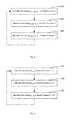
- FIG. 7illustrates a flow chart of an exemplary embodiment of a method for operating the video frame geo-referencing system 100 according to the instant disclosure.
- the moving platform 104may be actuated and the video frame geo-referencing system 100 may begin to capture one or more series of video frames 1 -N.
- the video frame geo-referencing system 100may begin to capture one or more series of video frames 1 -N at FMV rates with the video frame capture devices 102 a - n .
- each series of video frames 1 -Nmay be captured with one of the video frame capture devices 102 a - n .
- information regarding the approximate and/or exact time each video frame 1 -Nmay be captured and transmitted to the computer system 114 .
- the video frame geo-referencing system 100includes four video frame capture devices 102 a - d , then four series of video frames 1 - 4 may be captured simultaneously.
- the video frame capture devices 102 a - nmay be independently controlled by software running on the computer system 114 .
- the series of video frames 1 -Nmay be transmitted to the computer system 114 , and may be stored in the raw storage 138 .
- the monitoring system 112may collect position and orientation data of the moving platform 104 while the series of video frames 1 -N are captured.
- the position and orientation datamay be transmitted to the computer system 114 .
- the computer system 114may store the position and orientation data in the memory 138 .
- the series of video frames 1 -N and/or position and orientation datamay be stored on any non-transient memory accessible by the computer system 114 .
- the series of video frames 1 -N and/or position and orientation datamay be stored as a local memory of the video frame capture devices 102 a - n , local memory of the monitoring system 112 , and/or the like.
- the location and timing of the capturing of the series of video frames 1 -Nmay be pre-determined.
- the computer system 114may transmit the collected series of video frames 1 -N, timing data for each video frame 1 -N, position and orientation data of the moving platform 104 , and/or calibration data for each video frame capture device 102 a - n to the processor 136 for association of such data with video frames 1 -N.
- the processor 136may utilize the geographic position data, the orientation data, and/or the interior calibration data, to determine geo-referencing information for each of the video frames 1 -N. Geo-referencing may determine the location of each pixel from the rows/columns of pixels comprising the video frames 1 -N. In some embodiments, the processor 136 may marshal one or more video frame to one or more of the slave processors 152 a - n as will be described with reference to FIGS. 8-9 below.
- the processor 136may overlay, embed, or otherwise associate the geo-referencing information determined in step 204 with each video frame 1 -N from the series of video frames 1 -N.
- points indicative of the boundary of the video frames 1 - nmay be determined.
- the geographic coordinates of the four corners of the video frames 1 -Nmay be determined by the processor 136 .
- the geographic coordinates of the four corners of the video frames 1 -Nmay be determined using the geo-referencing information determined in step 206 .
- the processor 136uses the geographic coordinates of the points (e.g., four corners of the video frames 1 -N) to find the geographic bounds of the video frames 1 -N.
- the geographic bounds of each video frame 1 -Ne.g., one or more pixels within the video frame
- the geo-referencing information associated with each video frame 1 -Nmay be used to determine the position of the GIS data on the particular video frame 1 -N.
- determine of the position of the GIS datamay include marshaling one or more video frames 1 -N to one or more of the slave processors 152 a - n of the bank of processors 152 a - n as will be described with reference to FIGS. 8-9 .
- each geographic point location from the GIS datamay be translated from geographic coordinates (e.g., latitude/longitude or X/Y) to video frame coordinates (e.g., pixel row/column) using the geo-referencing information associated with the video frame.
- geographic coordinatese.g., latitude/longitude or X/Y
- video frame coordinatese.g., pixel row/column
- the geo-referencing information associated with a single video framemay be used to determine position of another video frame.
- the geo-referencing information associated with a single video frame 1may be used to determine the position of GIS data for video frame 1 .
- the precise position of the center (or any other corresponding part) of video frame 2may be determined.
- the GIS data position determined for video frame 1may then be shifted by an offset between the determined center positions of video frame 1 to video frame 2 .
- the offsetmay be used to determine the position of GIS data for video frame 2 . This process may be repeated for one or more additional video frames 3 -N.
- the processor 136may determine GIS data position for a single video frame and shift positions of a set of frames based on the single frame. For example, the processor 136 may determine GIS data position for video frame 1 , and shift such positions according to the offset of video frames 2 - 9 . Then, the processor 136 may determine GIS data position for video frame 10 , and shift such positions according to the offset of video frames 11 - 19 . The GIS data positions for the remaining video frames 20 -N may be determined in a similar fashion.
- the processor 136may calculate GIS data position for a single video frame and shift positions of tangential frames. For example, the processor 136 may determine GIS data position for video frame 1 , and shift such positions according to the offset of video frame 2 . Then, the processor 136 may determine GIS data position for video frame 3 , and shift such positions according to the offset of video frame 4 . The GIS data positions for the remaining video frames 5 -N may be determined in a similar fashion.
- the ratio of video frames 1 -N for which the GIS data positions are determined to video frames 1 -N for which the position is determined by the offset shiftmay be varied depending on processor 136 capabilities and configuration, as well as quality and resolution of the video frames 1 -N and layers of GIS data overlaid on such video frames 1 -N.
- the GIS datamay be overlaid onto video frames 1 -N at the positions calculated in step 214 .
- Such video frames 1 -N containing overlaid GIS datawill be referred to as composite video frames 1 -M.
- GIS datamay be associated with video frames 1 -N rather than overlaying GIS data on video frames 1 -N.
- a “smart” player capable of overlaying the associated GIS data to an appropriate composite video frame 1 -Mmay be used to overlay the GIS data over the series of composite video frames 1 -M at a later time.
- the smart playermay be capable of overlaying one or more GIS data layers onto composite video frames 1 -M in response to user preferences.
- One or more layers of GIS datamay be overlaid onto composite video frames 1 -M. Additionally, one or more layers of GIS data may be associated with the composite video frames 1 -M. Overlaid GIS data and/or associated GIS data may allow the output device 116 to output the one or more overlaid layers of GIS data when outputting the composite video frames 1 -N. As such, a user may be able to selectively display the one or more associated layers of GIS data onto the composite video frames 1 -M.
- the composite video frames 1 -Mmay be assembled into a FMV stream of composite video frames 1 -M, stored into memory 138 , and/or provided in real-time.
- the composite video frames 1 -Mmay be stored in a removable memory device such as a CD, a DVD, a Blue-Ray, a flash drive, a hard drive, or solid state drive, for example.
- the composite video frames 1 -Mmay be stored separately from the video frames 1 -N, the composite video frames 1 -M may replace the video frames 1 -N, or alternatively, the composite video frames 1 -M may be stored over the video frames 1 -N.
- the composite video frames 1 -Mmay be transmitted to the output device 116 in real-time, and may be transmitted to remote output devices over a network such as the internet, a cellular network, or a satellite communication network, for example.
- FIG. 8illustrates an exemplary embodiment of a method for marshaling video frames to processors.
- video frames 1 -Nmay be marshaled to the slave processors 152 a - n .
- video frame 1may be marshaled to slave processor 152 a .
- video frame 2may be marshaled to slave processor 152 b .
- video frame 3may be marshaled to slave processor 152 c in a step 224 .
- the remaining video frames 4 -N in the series of video frames 1 -Nmay be marshaled to slave processors 152 a - n in a similar fashion until all video frames from the series 1 -N are marshaled to one or more slave processors 152 a - n .
- video frames 1 , 4 , 7 , 10 , and 13may be marshaled to slave processor 152 a ;
- video frames 2 , 5 , 8 , 11 , and 14may be marshaled to slave processor 152 b ;
- video frames 3 , 6 , 9 , 12 , and 15may be marshaled to slave processor 152 c in a round-robin fashion.
- FIG. 9illustrates another exemplary embodiment of a method for marshaling video frames to processors.
- each video frameis marshaled to a separate processor.
- the MCPU 150may marshal video frames 1 - 5 to slave processors 152 a - e , with video frame 1 being marshaled to slave processor 152 a , video frame 2 being marshaled to slave processor 152 b , video frame 3 being marshaled to slave processor 152 c , video frame 4 being marshaled to slave processor 152 d , and video frame 5 being marshaled to slave processor 152 e .
- video frames 6 - 10may be marshaled to slave processors 152 e - h in a similar fashion.
- video frames 11 - 15may be marshaled to slave processors 152 i - m in a similar fashion.
- video frames 1 -Nmay be marshaled to the bank of slave processors 152 a - n in other ways depending on the number of video frames 1 -N and slave processors 152 a - n , for example. It is to also be understood that a combination of the methods shown in FIGS. 8 and 9 may be used to marshal video frames 1 -N to the slave processors 152 a - n.
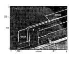
- the composite video frame series 1 -Mmay include a plurality of rows 1 - x and a plurality of columns 1 - y .
- the composite video frames 1 -Mmay include image data 300 in the form of pixels with GIS data 302 replacing the pixels of the image data.
- the composite video frames 1 -Mmay display one or more layers of GIS data, such as for example dimensions of a portion of a composite video frame 1 -M, coordinates of an object shown in a composite video frame 1 -M, and/or county and quadrant of a portion of a composite video frame 1 -M. As shown in FIGS.
- the GIS data 302is moving in a single direction as different geographical areas are captured within the image data 300 of the composite video frames 1 -M. It is to be understood that other layers of GIS data may be overlaid on the composite video frames 1 -M such as elevation, latitude and longitude, street names, business locations, country information, traffic information, weather information, and city information, for example, as will be understood by a person of ordinary skill in the art presented with the instant disclosure.
- the video frame geo-referencing systemmay actuate the moving platform 104 to begin moving through space.
- a user of the video frame geo-referencing system 100may actuate the moving platform 104 to begin moving through space.
- One or more of the video frame capture devices 102 a - nmay initiate capture of video frames 1 -N.
- the video frames 1 -Nmay be representative of a pre-determined geographic area.
- the video frame geo-referencing system 100may use data from the positional system and internal calibration data to geo-reference the series of video frames 1 -N. The geographical boundary of the video frames 1 -N may be determined.
- the video frame geo-referencing system 100may use the determined geographical boundary of the series of video frames 1 -N to obtain one or more layers of GIS data from the GIS database 144 .
- the one or more layers of GIS data to be obtainedmay be specified by the user via the input device 118 .
- the video frame geo-referencing systemoverlays one or more layers of GIS data over one or more frames of the series of video frames 1 -N to create a series of composite video frames 1 -M.
- the usermay select one or more layers of GIS data to be overlaid onto the series of video frames 1 -N in order to create the series of composite video frames 1 -M.
- the usermay optionally cause the video frame geo-referencing system 100 to store the series of composite frames 1 -M separately from the series of video frames 1 -N, or to replace the series of video frames 1 -N with a corresponding series of composite video frames 1 -M.
- the video frame geo-referencing system 100may provide one or more composite video frame, or series of composite video frames 1 -M to one or more output devices 116 .
- the series of composite video frames 1 -Mmay be in the form of full motion video.
- a series of composite video frames 1 -M and video frames 1 -Ncan be interleaved and provided to the one or more output device 116 .
- the video frame geo-referencing system 100may not have to geo-reference and overlay GIS data onto as many video frames.
- flickermay be introduced in this embodiment.
- the usermay optionally select one or more additional layers of GIS data to be displayed on the composite video frames 1 -M via the input device 118 . Additionally, the user may select one or more layers of GIS data to be removed from the displayed composite video frames 1 -M.
Landscapes
- Physics & Mathematics (AREA)
- General Physics & Mathematics (AREA)
- Engineering & Computer Science (AREA)
- Theoretical Computer Science (AREA)
- Image Analysis (AREA)
- Two-Way Televisions, Distribution Of Moving Picture Or The Like (AREA)
- Television Signal Processing For Recording (AREA)
Abstract
Description
XOriginXSize×XColumn Pixel=XPixel (EQ. 1)
YOriginYSize×XRow Pixel=YPixel (EQ. 2)
The available nadir images may be evaluated to determine if the images cover the same point on the ground as the grid pixel being filled. If so, a mathematical formula may be used to determine where that point on the ground projects up onto the camera's pixel image map, and that resulting pixel value may be then transferred to the grid pixel.
Claims (25)
Priority Applications (2)
| Application Number | Priority Date | Filing Date | Title |
|---|---|---|---|
| US13/492,107US10325350B2 (en) | 2011-06-10 | 2012-06-08 | System and method for forming a video stream containing GIS data in real-time |
| US16/443,111US11941778B2 (en) | 2011-06-10 | 2019-06-17 | System and method for forming a video stream containing GIS data in real-time |
Applications Claiming Priority (2)
| Application Number | Priority Date | Filing Date | Title |
|---|---|---|---|
| US201161495775P | 2011-06-10 | 2011-06-10 | |
| US13/492,107US10325350B2 (en) | 2011-06-10 | 2012-06-08 | System and method for forming a video stream containing GIS data in real-time |
Related Child Applications (1)
| Application Number | Title | Priority Date | Filing Date |
|---|---|---|---|
| US16/443,111ContinuationUS11941778B2 (en) | 2011-06-10 | 2019-06-17 | System and method for forming a video stream containing GIS data in real-time |
Publications (2)
| Publication Number | Publication Date |
|---|---|
| US20120314068A1 US20120314068A1 (en) | 2012-12-13 |
| US10325350B2true US10325350B2 (en) | 2019-06-18 |
Family
ID=47292863
Family Applications (2)
| Application Number | Title | Priority Date | Filing Date |
|---|---|---|---|
| US13/492,107Active2033-11-30US10325350B2 (en) | 2011-06-10 | 2012-06-08 | System and method for forming a video stream containing GIS data in real-time |
| US16/443,111ActiveUS11941778B2 (en) | 2011-06-10 | 2019-06-17 | System and method for forming a video stream containing GIS data in real-time |
Family Applications After (1)
| Application Number | Title | Priority Date | Filing Date |
|---|---|---|---|
| US16/443,111ActiveUS11941778B2 (en) | 2011-06-10 | 2019-06-17 | System and method for forming a video stream containing GIS data in real-time |
Country Status (7)
| Country | Link |
|---|---|
| US (2) | US10325350B2 (en) |
| EP (1) | EP2719163B1 (en) |
| AU (1) | AU2012364820B2 (en) |
| BR (1) | BR112013031128A2 (en) |
| CA (1) | CA2835290C (en) |
| MX (1) | MX339356B (en) |
| WO (1) | WO2013106080A2 (en) |
Cited By (2)
| Publication number | Priority date | Publication date | Assignee | Title |
|---|---|---|---|---|
| US20210325182A1 (en)* | 2019-03-27 | 2021-10-21 | Chengdu Rainpoo Technology Co., Ltd. | Aerial survey method and apparatus capable of eliminating redundant aerial photos |
| US20230007171A1 (en)* | 2012-11-02 | 2023-01-05 | Diversified Innovations Fund, Lllp | Wide area imaging system and method |
Families Citing this family (22)
| Publication number | Priority date | Publication date | Assignee | Title |
|---|---|---|---|---|
| US10354407B2 (en) | 2013-03-15 | 2019-07-16 | Spatial Cam Llc | Camera for locating hidden objects |
| US11119396B1 (en) | 2008-05-19 | 2021-09-14 | Spatial Cam Llc | Camera system with a plurality of image sensors |
| US9736368B2 (en) | 2013-03-15 | 2017-08-15 | Spatial Cam Llc | Camera in a headframe for object tracking |
| US10585344B1 (en) | 2008-05-19 | 2020-03-10 | Spatial Cam Llc | Camera system with a plurality of image sensors |
| US12140855B2 (en) | 2008-05-19 | 2024-11-12 | Peter Lablans | Camera system with a plurality of image sensors |
| US10896327B1 (en) | 2013-03-15 | 2021-01-19 | Spatial Cam Llc | Device with a camera for locating hidden object |
| US10168153B2 (en) | 2010-12-23 | 2019-01-01 | Trimble Inc. | Enhanced position measurement systems and methods |
| EP2511659A1 (en)* | 2011-04-14 | 2012-10-17 | Hexagon Technology Center GmbH | Geodesic marking system for marking target points |
| US9235763B2 (en)* | 2012-11-26 | 2016-01-12 | Trimble Navigation Limited | Integrated aerial photogrammetry surveys |
| US9488630B2 (en) | 2013-11-08 | 2016-11-08 | Dow Agrosciences Llc | Integrated remote aerial sensing system |
| US9688403B2 (en) | 2014-05-20 | 2017-06-27 | Infatics, Inc. | Method for adaptive mission execution on an unmanned aerial vehicle |
| US9373360B2 (en) | 2014-07-02 | 2016-06-21 | International Business Machines Corporation | Instantaneous preview of data associated with a video |
| US10515416B2 (en) | 2014-09-03 | 2019-12-24 | Infatics, Inc. | System and methods for hosting missions with unmanned aerial vehicles |
| FR3030091B1 (en)* | 2014-12-12 | 2018-01-26 | Airbus Operations | METHOD AND SYSTEM FOR AUTOMATICALLY DETECTING A DISALLIATION IN OPERATION OF A MONITORING SENSOR OF AN AIRCRAFT. |
| CN105667816A (en)* | 2016-04-13 | 2016-06-15 | 上海优伟斯智能系统有限公司 | Fixing device with externally-hung pod and fixed-wing unmanned aerial vehicle |
| US20180033124A1 (en)* | 2016-07-28 | 2018-02-01 | The Texas A&M University System | Method and apparatus for radiometric calibration and mosaicking of aerial images |
| WO2018144929A1 (en) | 2017-02-02 | 2018-08-09 | Infatics, Inc. (DBA DroneDeploy) | System and methods for improved aerial mapping with aerial vehicles |
| US12387429B2 (en) | 2017-02-02 | 2025-08-12 | DroneDeploy, Inc. | System and methods for improved aerial mapping with aerial vehicles |
| US10586349B2 (en) | 2017-08-24 | 2020-03-10 | Trimble Inc. | Excavator bucket positioning via mobile device |
| GB2583728B (en) | 2019-05-06 | 2021-06-16 | Wildgate Consultancy Solutions Ltd | An imaging system for superimposing at least two images and a related method |
| US10943360B1 (en) | 2019-10-24 | 2021-03-09 | Trimble Inc. | Photogrammetric machine measure up |
| CN111147830B (en)* | 2019-11-29 | 2022-01-28 | 中国航空工业集团公司洛阳电光设备研究所 | Method for realizing fusion of real-time video and GIS |
Citations (174)
| Publication number | Priority date | Publication date | Assignee | Title |
|---|---|---|---|---|
| US2273876A (en) | 1940-02-12 | 1942-02-24 | Frederick W Lutz | Apparatus for indicating tilt of cameras |
| US3153784A (en) | 1959-12-24 | 1964-10-20 | Us Industries Inc | Photo radar ground contour mapping system |
| US3594556A (en) | 1969-01-08 | 1971-07-20 | Us Navy | Optical sight with electronic image stabilization |
| US3614410A (en) | 1969-06-12 | 1971-10-19 | Knight V Bailey | Image rectifier |
| US3621326A (en) | 1968-09-30 | 1971-11-16 | Itek Corp | Transformation system |
| US3661061A (en) | 1969-05-05 | 1972-05-09 | Atomic Energy Commission | Picture position finder |
| US3716669A (en) | 1971-05-14 | 1973-02-13 | Japan Eng Dev Co | Mapping rectifier for generating polarstereographic maps from satellite scan signals |
| US3725563A (en) | 1971-12-23 | 1973-04-03 | Singer Co | Method of perspective transformation in scanned raster visual display |
| US3864513A (en) | 1972-09-11 | 1975-02-04 | Grumman Aerospace Corp | Computerized polarimetric terrain mapping system |
| US3866602A (en) | 1973-05-29 | 1975-02-18 | Olympus Optical Co | Endoscope camera with orientation indicator |
| US3877799A (en) | 1974-02-06 | 1975-04-15 | United Kingdom Government | Method of recording the first frame in a time index system |
| US4015080A (en) | 1973-04-30 | 1977-03-29 | Elliott Brothers (London) Limited | Display devices |
| US4044879A (en) | 1975-03-07 | 1977-08-30 | Siemens Aktiengesellschaft | Arrangement for recording characters using mosaic recording mechanisms |
| US4184711A (en) | 1977-10-14 | 1980-01-22 | Yasuo Wakimoto | Folding canvas chair |
| US4240108A (en) | 1977-10-03 | 1980-12-16 | Grumman Aerospace Corporation | Vehicle controlled raster display system |
| US4281354A (en) | 1978-05-19 | 1981-07-28 | Raffaele Conte | Apparatus for magnetic recording of casual events relating to movable means |
| US4344683A (en) | 1979-09-29 | 1982-08-17 | Agfa-Gevaert Aktiengesellschaft | Quality control method and apparatus for photographic pictures |
| US4360876A (en) | 1979-07-06 | 1982-11-23 | Thomson-Csf | Cartographic indicator system |
| US4382678A (en) | 1981-06-29 | 1983-05-10 | The United States Of America As Represented By The Secretary Of The Army | Measuring of feature for photo interpretation |
| US4387056A (en) | 1981-04-16 | 1983-06-07 | E. I. Du Pont De Nemours And Company | Process for separating zero-valent nickel species from divalent nickel species |
| US4396942A (en) | 1979-04-19 | 1983-08-02 | Jackson Gates | Video surveys |
| US4463380A (en) | 1981-09-25 | 1984-07-31 | Vought Corporation | Image processing system |
| US4489322A (en) | 1983-01-27 | 1984-12-18 | The United States Of America As Represented By The Secretary Of The Air Force | Radar calibration using direct measurement equipment and oblique photometry |
| US4490742A (en) | 1982-04-23 | 1984-12-25 | Vcs, Incorporated | Encoding apparatus for a closed circuit television system |
| US4491399A (en) | 1982-09-27 | 1985-01-01 | Coherent Communications, Inc. | Method and apparatus for recording a digital signal on motion picture film |
| US4495500A (en) | 1982-01-26 | 1985-01-22 | Sri International | Topographic data gathering method |
| US4527055A (en) | 1982-11-15 | 1985-07-02 | Honeywell Inc. | Apparatus for selectively viewing either of two scenes of interest |
| US4543603A (en) | 1982-11-30 | 1985-09-24 | Societe Nationale Industrielle Et Aerospatiale | Reconnaissance system comprising an air-borne vehicle rotating about its longitudinal axis |
| US4586138A (en) | 1982-07-29 | 1986-04-29 | The United States Of America As Represented By The United States Department Of Energy | Route profile analysis system and method |
| US4635136A (en) | 1984-02-06 | 1987-01-06 | Rochester Institute Of Technology | Method and apparatus for storing a massive inventory of labeled images |
| US4653136A (en) | 1985-06-21 | 1987-03-31 | Denison James W | Wiper for rear view mirror |
| US4653316A (en) | 1986-03-14 | 1987-03-31 | Kabushiki Kaisha Komatsu Seisakusho | Apparatus mounted on vehicles for detecting road surface conditions |
| US4673988A (en) | 1985-04-22 | 1987-06-16 | E.I. Du Pont De Nemours And Company | Electronic mosaic imaging process |
| US4686474A (en) | 1984-04-05 | 1987-08-11 | Deseret Research, Inc. | Survey system for collection and real time processing of geophysical data |
| US4688092A (en) | 1986-05-06 | 1987-08-18 | Ford Aerospace & Communications Corporation | Satellite camera image navigation |
| US4689748A (en) | 1979-10-09 | 1987-08-25 | Messerschmitt-Bolkow-Blohm Gesellschaft Mit Beschrankter Haftung | Device for aircraft and spacecraft for producing a digital terrain representation |
| US4707698A (en) | 1976-03-04 | 1987-11-17 | Constant James N | Coordinate measurement and radar device using image scanner |
| US4758850A (en) | 1985-08-01 | 1988-07-19 | British Aerospace Public Limited Company | Identification of ground targets in airborne surveillance radar returns |
| US4805033A (en) | 1987-02-18 | 1989-02-14 | Olympus Optical Co., Ltd. | Method of forming oblique dot pattern |
| US4807024A (en) | 1987-06-08 | 1989-02-21 | The University Of South Carolina | Three-dimensional display methods and apparatus |
| US4814711A (en) | 1984-04-05 | 1989-03-21 | Deseret Research, Inc. | Survey system and method for real time collection and processing of geophysicals data using signals from a global positioning satellite network |
| US4814896A (en) | 1987-03-06 | 1989-03-21 | Heitzman Edward F | Real time video data acquistion systems |
| US4843463A (en) | 1988-05-23 | 1989-06-27 | Michetti Joseph A | Land vehicle mounted audio-visual trip recorder |
| US4899296A (en) | 1987-11-13 | 1990-02-06 | Khattak Anwar S | Pavement distress survey system |
| US4906198A (en) | 1988-12-12 | 1990-03-06 | International Business Machines Corporation | Circuit board assembly and contact pin for use therein |
| US4953227A (en) | 1986-01-31 | 1990-08-28 | Canon Kabushiki Kaisha | Image mosaic-processing method and apparatus |
| US4956872A (en) | 1986-10-31 | 1990-09-11 | Canon Kabushiki Kaisha | Image processing apparatus capable of random mosaic and/or oil-painting-like processing |
| US5034812A (en) | 1988-11-14 | 1991-07-23 | Smiths Industries Public Limited Company | Image processing utilizing an object data store to determine information about a viewed object |
| US5086314A (en) | 1990-05-21 | 1992-02-04 | Nikon Corporation | Exposure control apparatus for camera |
| US5121222A (en) | 1989-06-14 | 1992-06-09 | Toshiaki Endoh | Method and apparatus for producing binary picture with detection and retention of plural binary picture blocks having a thin line pattern including an oblique line |
| US5138444A (en) | 1991-09-05 | 1992-08-11 | Nec Corporation | Image pickup system capable of producing correct image signals of an object zone |
| US5155597A (en) | 1990-11-28 | 1992-10-13 | Recon/Optical, Inc. | Electro-optical imaging array with motion compensation |
| US5164825A (en) | 1987-03-30 | 1992-11-17 | Canon Kabushiki Kaisha | Image processing method and apparatus for mosaic or similar processing therefor |
| US5166789A (en) | 1989-08-25 | 1992-11-24 | Space Island Products & Services, Inc. | Geographical surveying using cameras in combination with flight computers to obtain images with overlaid geographical coordinates |
| US5191174A (en) | 1990-08-01 | 1993-03-02 | International Business Machines Corporation | High density circuit board and method of making same |
| US5200793A (en) | 1990-10-24 | 1993-04-06 | Kaman Aerospace Corporation | Range finding array camera |
| US5210586A (en) | 1990-06-27 | 1993-05-11 | Siemens Aktiengesellschaft | Arrangement for recognizing obstacles for pilots of low-flying aircraft |
| US5231435A (en) | 1991-07-12 | 1993-07-27 | Blakely Bruce W | Aerial camera mounting apparatus |
| US5247356A (en) | 1992-02-14 | 1993-09-21 | Ciampa John A | Method and apparatus for mapping and measuring land |
| US5251037A (en) | 1992-02-18 | 1993-10-05 | Hughes Training, Inc. | Method and apparatus for generating high resolution CCD camera images |
| US5265173A (en) | 1991-03-20 | 1993-11-23 | Hughes Aircraft Company | Rectilinear object image matcher |
| US5267042A (en) | 1991-01-11 | 1993-11-30 | Pioneer Electronic Corporation | Image pickup device for automatically recording the location where an image is recorded |
| US5270756A (en) | 1992-02-18 | 1993-12-14 | Hughes Training, Inc. | Method and apparatus for generating high resolution vidicon camera images |
| US5296884A (en) | 1990-02-23 | 1994-03-22 | Minolta Camera Kabushiki Kaisha | Camera having a data recording function |
| US5335072A (en) | 1990-05-30 | 1994-08-02 | Minolta Camera Kabushiki Kaisha | Photographic system capable of storing information on photographed image data |
| US5342999A (en) | 1992-12-21 | 1994-08-30 | Motorola, Inc. | Apparatus for adapting semiconductor die pads and method therefor |
| US5345086A (en) | 1962-11-28 | 1994-09-06 | Eaton Corporation | Automatic map compilation system |
| US5353055A (en) | 1991-04-16 | 1994-10-04 | Nec Corporation | Image pickup system with an image pickup device for control |
| US5369443A (en) | 1991-04-12 | 1994-11-29 | Abekas Video Systems, Inc. | Digital video effects generator |
| US5402170A (en) | 1991-12-11 | 1995-03-28 | Eastman Kodak Company | Hand-manipulated electronic camera tethered to a personal computer |
| US5414462A (en) | 1993-02-11 | 1995-05-09 | Veatch; John W. | Method and apparatus for generating a comprehensive survey map |
| US5467271A (en) | 1993-12-17 | 1995-11-14 | Trw, Inc. | Mapping and analysis system for precision farming applications |
| US5481479A (en) | 1992-12-10 | 1996-01-02 | Loral Fairchild Corp. | Nonlinear scanning to optimize sector scan electro-optic reconnaissance system performance |
| US5486948A (en) | 1989-03-24 | 1996-01-23 | Canon Hanbai Kabushiki Kaisha | Stereo image forming apparatus having a light deflection member in each optical path |
| US5506644A (en) | 1992-08-18 | 1996-04-09 | Olympus Optical Co., Ltd. | Camera |
| US5508736A (en) | 1993-05-14 | 1996-04-16 | Cooper; Roger D. | Video signal processing apparatus for producing a composite signal for simultaneous display of data and video information |
| US5555018A (en) | 1991-04-25 | 1996-09-10 | Von Braun; Heiko S. | Large-scale mapping of parameters of multi-dimensional structures in natural environments |
| US5604534A (en) | 1995-05-24 | 1997-02-18 | Omni Solutions International, Ltd. | Direct digital airborne panoramic camera system and method |
| US5617224A (en) | 1989-05-08 | 1997-04-01 | Canon Kabushiki Kaisha | Imae processing apparatus having mosaic processing feature that decreases image resolution without changing image size or the number of pixels |
| US5633946A (en) | 1994-05-19 | 1997-05-27 | Geospan Corporation | Method and apparatus for collecting and processing visual and spatial position information from a moving platform |
| US5668593A (en) | 1995-06-07 | 1997-09-16 | Recon/Optical, Inc. | Method and camera system for step frame reconnaissance with motion compensation |
| US5677515A (en) | 1991-10-18 | 1997-10-14 | Trw Inc. | Shielded multilayer printed wiring board, high frequency, high isolation |
| US5798786A (en) | 1996-05-07 | 1998-08-25 | Recon/Optical, Inc. | Electro-optical imaging detector array for a moving vehicle which includes two axis image motion compensation and transfers pixels in row directions and column directions |
| US5835133A (en) | 1996-01-23 | 1998-11-10 | Silicon Graphics, Inc. | Optical system for single camera stereo video |
| US5841574A (en) | 1996-06-28 | 1998-11-24 | Recon/Optical, Inc. | Multi-special decentered catadioptric optical system |
| US5844602A (en) | 1996-05-07 | 1998-12-01 | Recon/Optical, Inc. | Electro-optical imaging array and camera system with pitch rate image motion compensation which can be used in an airplane in a dive bomb maneuver |
| US5852753A (en) | 1997-11-10 | 1998-12-22 | Lo; Allen Kwok Wah | Dual-lens camera with shutters for taking dual or single images |
| US5894323A (en) | 1996-03-22 | 1999-04-13 | Tasc, Inc, | Airborne imaging system using global positioning system (GPS) and inertial measurement unit (IMU) data |
| WO1999018732A1 (en) | 1997-10-06 | 1999-04-15 | Ciampa John A | Digital-image mapping |
| US5899945A (en) | 1995-04-17 | 1999-05-04 | Space Systems/Loral, Inc. | Attitude control and navigation system for high resolution imaging |
| US5963664A (en) | 1995-06-22 | 1999-10-05 | Sarnoff Corporation | Method and system for image combination using a parallax-based technique |
| US6037945A (en) | 1997-12-16 | 2000-03-14 | Xactware, Inc. | Graphical method for modeling and estimating construction costs |
| EP1010966A1 (en) | 1998-12-15 | 2000-06-21 | Aerowest GmbH | Method for generating a three dimensional object description |
| US6094215A (en) | 1998-01-06 | 2000-07-25 | Intel Corporation | Method of determining relative camera orientation position to create 3-D visual images |
| US6097854A (en) | 1997-08-01 | 2000-08-01 | Microsoft Corporation | Image mosaic construction system and apparatus with patch-based alignment, global block adjustment and pair-wise motion-based local warping |
| US6108032A (en) | 1996-11-05 | 2000-08-22 | Lockheed Martin Fairchild Systems | System and method for image motion compensation of a CCD image sensor |
| CA2402234A1 (en) | 1999-03-08 | 2000-09-14 | Tci Incorporated | Electric mammograph |
| US6130705A (en) | 1998-07-10 | 2000-10-10 | Recon/Optical, Inc. | Autonomous electro-optical framing camera system with constant ground resolution, unmanned airborne vehicle therefor, and methods of use |
| US6157747A (en) | 1997-08-01 | 2000-12-05 | Microsoft Corporation | 3-dimensional image rotation method and apparatus for producing image mosaics |
| US6222583B1 (en) | 1997-03-27 | 2001-04-24 | Nippon Telegraph And Telephone Corporation | Device and system for labeling sight images |
| US6236886B1 (en) | 1996-12-11 | 2001-05-22 | Technology Commercialization International | Method for producing a tomographic image of the body and electric impedance tomograph |
| US6256057B1 (en) | 1996-11-05 | 2001-07-03 | Lockhead Martin Corporation | Electro-optical reconnaissance system with forward motion compensation |
| US20020041328A1 (en) | 2000-03-29 | 2002-04-11 | Astrovision International, Inc. | Direct broadcast imaging satellite system apparatus and method for providing real-time, continuous monitoring of earth from geostationary earth orbit and related services |
| US20020041717A1 (en) | 2000-08-30 | 2002-04-11 | Ricoh Company, Ltd. | Image processing method and apparatus and computer-readable storage medium using improved distortion correction |
| US6421610B1 (en) | 2000-09-15 | 2002-07-16 | Ernest A. Carroll | Method of preparing and disseminating digitized geospatial data |
| US6434280B1 (en) | 1997-11-10 | 2002-08-13 | Gentech Corporation | System and method for generating super-resolution-enhanced mosaic images |
| US20020114536A1 (en) | 1998-09-25 | 2002-08-22 | Yalin Xiong | Aligning rectilinear images in 3D through projective registration and calibration |
| US20020118295A1 (en)* | 2001-01-03 | 2002-08-29 | Marta Karczewicz | Video decoder architecture and method for using same |
| US20030014224A1 (en) | 2001-07-06 | 2003-01-16 | Yanlin Guo | Method and apparatus for automatically generating a site model |
| US20030043824A1 (en) | 2001-08-31 | 2003-03-06 | Remboski Donald J. | Vehicle active network and device |
| US20030088362A1 (en) | 2000-08-16 | 2003-05-08 | Imagelinks, Inc. | 3-dimensional interactive image modeling system |
| US6597818B2 (en) | 1997-05-09 | 2003-07-22 | Sarnoff Corporation | Method and apparatus for performing geo-spatial registration of imagery |
| US20030164962A1 (en) | 2002-03-01 | 2003-09-04 | Nims Jerry C. | Multiple angle display produced from remote optical sensing devices |
| US6639596B1 (en) | 1999-09-20 | 2003-10-28 | Microsoft Corporation | Stereo reconstruction from multiperspective panoramas |
| JP2003317089A (en) | 2002-04-24 | 2003-11-07 | Dainippon Printing Co Ltd | Image correction method and system |
| US20030214585A1 (en) | 2002-01-09 | 2003-11-20 | Bakewell Charles Adams | Mobile enforcement platform with aimable violation identification and documentation system for multiple traffic violation types across all lanes in moving traffic, generating composite display images and data to support citation generation, homeland security, and monitoring |
| US20040010801A1 (en) | 2002-07-13 | 2004-01-15 | Kim Kyong Ho | Video geographic information system |
| US6711475B2 (en) | 2000-03-16 | 2004-03-23 | The Johns Hopkins University | Light detection and ranging (LIDAR) mapping system |
| US6731329B1 (en) | 1999-05-14 | 2004-05-04 | Zsp Geodaetische Systeme Gmbh | Method and an arrangement for determining the spatial coordinates of at least one object point |
| WO2004044692A2 (en) | 2002-11-08 | 2004-05-27 | Pictometry International Corp. | Oblique geolocation and measurement system |
| US6747686B1 (en) | 2001-10-05 | 2004-06-08 | Recon/Optical, Inc. | High aspect stereoscopic mode camera and method |
| US20040167709A1 (en) | 2002-09-20 | 2004-08-26 | M7 Visual Intelligence, Lp | Vehicle based data collection and processing system |
| US6810383B1 (en) | 2000-01-21 | 2004-10-26 | Xactware, Inc. | Automated task management and evaluation |
| US6826539B2 (en) | 1999-12-31 | 2004-11-30 | Xactware, Inc. | Virtual structure data repository and directory |
| US6829584B2 (en) | 1999-12-31 | 2004-12-07 | Xactware, Inc. | Virtual home data repository and directory |
| US6834128B1 (en) | 2000-06-16 | 2004-12-21 | Hewlett-Packard Development Company, L.P. | Image mosaicing system and method adapted to mass-market hand-held digital cameras |
| US6876763B2 (en) | 2000-02-03 | 2005-04-05 | Alst Technical Excellence Center | Image resolution improvement using a color mosaic sensor |
| US20050073241A1 (en) | 1999-06-21 | 2005-04-07 | Semiconductor Energy Laboratory Co., Ltd. | EL display device, driving method thereof, and electronic equipment provided with the display device |
| US20050083412A1 (en)* | 2003-10-21 | 2005-04-21 | Murphy Scott D. | Internet interactive realtime video image acquisition system based in low earth orbit |
| US20050088251A1 (en) | 2003-10-23 | 2005-04-28 | Nihon Dempa Kogyo Co., Ltd. | Crystal oscillator |
| US20050169521A1 (en) | 2004-01-31 | 2005-08-04 | Yacov Hel-Or | Processing of mosaic digital images |
| US20050195206A1 (en)* | 2004-03-04 | 2005-09-08 | Eric Wogsberg | Compositing multiple full-motion video streams for display on a video monitor |
| WO2005088251A1 (en) | 2004-02-27 | 2005-09-22 | Intergraph Software Technologies Company | Forming a single image from overlapping images |
| US20060028550A1 (en) | 2004-08-06 | 2006-02-09 | Palmer Robert G Jr | Surveillance system and method |
| US7009638B2 (en) | 2001-05-04 | 2006-03-07 | Vexcel Imaging Gmbh | Self-calibrating, digital, large format camera with single or multiple detector arrays and single or multiple optical systems |
| US7018050B2 (en) | 2003-09-08 | 2006-03-28 | Hewlett-Packard Development Company, L.P. | System and method for correcting luminance non-uniformity of obliquely projected images |
| US20060092043A1 (en) | 2004-11-03 | 2006-05-04 | Lagassey Paul J | Advanced automobile accident detection, data recordation and reporting system |
| US7046401B2 (en) | 2001-06-01 | 2006-05-16 | Hewlett-Packard Development Company, L.P. | Camera-based document scanning system using multiple-pass mosaicking |
| US7061650B2 (en) | 1999-05-25 | 2006-06-13 | Silverbrook Research Pty Ltd | Method and apparatus for bayer mosaic image conversion |
| US7065260B2 (en) | 2000-10-27 | 2006-06-20 | Microsoft Corporation | Rebinning methods and arrangements for use in compressing image-based rendering (IBR) data |
| EP1696204A2 (en) | 2002-11-08 | 2006-08-30 | Pictometry International Corp. | Method and apparatus for capturing, geolocating and measuring oblique images |
| US20060238383A1 (en) | 2005-04-21 | 2006-10-26 | Microsoft Corporation | Virtual earth rooftop overlay and bounding |
| US7133551B2 (en) | 2002-02-07 | 2006-11-07 | National Central University | Semi-automatic reconstruction method of 3-D building models using building outline segments |
| US20060250515A1 (en) | 1998-09-16 | 2006-11-09 | Olympus Optical Co., Ltd. | Image pickup apparatus |
| US7142984B2 (en) | 2005-02-08 | 2006-11-28 | Harris Corporation | Method and apparatus for enhancing a digital elevation model (DEM) for topographical modeling |
| US20060271949A1 (en) | 1998-06-05 | 2006-11-30 | Decisionmark Corp. | Method and apparatus for limiting access to video communications |
| US20070024612A1 (en) | 2005-07-27 | 2007-02-01 | Balfour Technologies Llc | System for viewing a collection of oblique imagery in a three or four dimensional virtual scene |
| US20070043504A1 (en)* | 2004-03-24 | 2007-02-22 | A9.Com, Inc. | System and method for automatically collecting images of objects at geographic locations and displaying same in online directories |
| US7184072B1 (en) | 2000-06-15 | 2007-02-27 | Power View Company, L.L.C. | Airborne inventory and inspection system and apparatus |
| US20070046448A1 (en) | 2002-09-20 | 2007-03-01 | M7 Visual Intelligence | Vehicle based data collection and processing system and imaging sensor system and methods thereof |
| US20070096012A1 (en)* | 2005-11-02 | 2007-05-03 | Hunter Engineering Company | Vehicle Service System Digital Camera Interface |
| US7233691B2 (en) | 1999-12-29 | 2007-06-19 | Geospan Corporation | Any aspect passive volumetric image processing method |
| US20070237420A1 (en) | 2006-04-10 | 2007-10-11 | Microsoft Corporation | Oblique image stitching |
| WO2008028040A2 (en) | 2006-08-30 | 2008-03-06 | Pictometry International Corp. | Mosaic oblique images and methods of making and using same |
| US20080068507A1 (en) | 2006-09-18 | 2008-03-20 | Rgb Networks, Inc. | Methods, apparatus, and systems for managing the insertion of overlay content into a video signal |
| US20080120031A1 (en) | 2006-11-16 | 2008-05-22 | Daniel Rosenfeld | Tracking method |
| US20080158256A1 (en) | 2006-06-26 | 2008-07-03 | Lockheed Martin Corporation | Method and system for providing a perspective view image by intelligent fusion of a plurality of sensor data |
| US20080183030A1 (en)* | 2005-09-26 | 2008-07-31 | Hadasit Medical Research Services & Development Company Ltd. | system and method for treating chronic pain |
| US20080204570A1 (en)* | 2007-02-15 | 2008-08-28 | Stephen Schultz | Event Multiplexer For Managing The Capture of Images |
| US20080211908A1 (en)* | 2005-05-16 | 2008-09-04 | Human Monitoring Ltd | Monitoring Method and Device |
| US20090177458A1 (en) | 2007-06-19 | 2009-07-09 | Ch2M Hill, Inc. | Systems and methods for solar mapping, determining a usable area for solar energy production and/or providing solar information |
| US20090208095A1 (en) | 2008-02-15 | 2009-08-20 | Microsoft Corporation | Site modeling using image data fusion |
| US20090304227A1 (en) | 2008-02-01 | 2009-12-10 | Daniel Ian Kennedy | Methods and Systems for Provisioning Energy Systems |
| US20100110074A1 (en)* | 2008-10-31 | 2010-05-06 | Eagle View Technologies, Inc. | Pitch determination systems and methods for aerial roof estimation |
| US7728833B2 (en) | 2004-08-18 | 2010-06-01 | Sarnoff Corporation | Method for generating a three-dimensional model of a roof structure |
| US20100136952A1 (en)* | 2008-12-02 | 2010-06-03 | Broadcom Corporation | Mobile communication device with video application for display on a remote monitor and methods for use therewith |
| US7832267B2 (en) | 2007-04-25 | 2010-11-16 | Ecometriks, Llc | Method for determining temporal solar irradiance values |
| US20100296693A1 (en) | 2009-05-22 | 2010-11-25 | Thornberry Dale R | System and process for roof measurement using aerial imagery |
| US7844499B2 (en) | 2005-12-23 | 2010-11-30 | Sharp Electronics Corporation | Integrated solar agent business model |
| US20110033110A1 (en) | 2008-04-23 | 2011-02-10 | Pasco Corporation | Building roof outline recognizing device, building roof outline recognizing method, and building roof outline recognizing program |
| US20110043627A1 (en)* | 2009-08-20 | 2011-02-24 | Northrop Grumman Information Technology, Inc. | Locative Video for Situation Awareness |
| US8078396B2 (en) | 2004-08-31 | 2011-12-13 | Meadow William D | Methods for and apparatus for generating a continuum of three dimensional image data |
| US20130246204A1 (en) | 2012-03-19 | 2013-09-19 | Chris T. Thornberry | Method and System for Quick Square Roof Reporting |
| US8705843B2 (en) | 2006-10-11 | 2014-04-22 | Gta Geoinformatik Gmbh | Method for texturizing virtual three-dimensional objects |
Family Cites Families (7)
| Publication number | Priority date | Publication date | Assignee | Title |
|---|---|---|---|---|
| US6895126B2 (en)* | 2000-10-06 | 2005-05-17 | Enrico Di Bernardo | System and method for creating, storing, and utilizing composite images of a geographic location |
| US8587664B2 (en)* | 2004-02-02 | 2013-11-19 | Rochester Institute Of Technology | Target identification and location system and a method thereof |
| CA2559726C (en)* | 2004-03-24 | 2015-10-20 | A9.Com, Inc. | System and method for displaying images in an online directory |
| KR100712966B1 (en)* | 2004-12-27 | 2007-05-02 | 주식회사 엔지스테크널러지 | Navigation service method and terminal accordingly |
| US20100265329A1 (en)* | 2006-10-06 | 2010-10-21 | Doneker Robert L | Lightweight platform for remote sensing of point source mixing and system for mixing model validation and calibration |
| US20090245581A1 (en)* | 2008-03-31 | 2009-10-01 | Sean Dey | Airborne terrain acquisition and processing system with fluid detection |
| BR112012007309A2 (en)* | 2009-10-19 | 2016-04-19 | Intergraph Technologies Co | data search, analyzer and synchronization of video and telemetry data |
- 2012
- 2012-06-08USUS13/492,107patent/US10325350B2/enactiveActive
- 2012-06-08BRBR112013031128Apatent/BR112013031128A2/ennot_activeIP Right Cessation
- 2012-06-08CACA2835290Apatent/CA2835290C/enactiveActive
- 2012-06-08WOPCT/US2012/041524patent/WO2013106080A2/enactiveIP Right Grant
- 2012-06-08EPEP12864857.3Apatent/EP2719163B1/enactiveActive
- 2012-06-08MXMX2013014535Apatent/MX339356B/enactiveIP Right Grant
- 2012-06-08AUAU2012364820Apatent/AU2012364820B2/enactiveActive
- 2019
- 2019-06-17USUS16/443,111patent/US11941778B2/enactiveActive
Patent Citations (197)
| Publication number | Priority date | Publication date | Assignee | Title |
|---|---|---|---|---|
| US2273876A (en) | 1940-02-12 | 1942-02-24 | Frederick W Lutz | Apparatus for indicating tilt of cameras |
| US3153784A (en) | 1959-12-24 | 1964-10-20 | Us Industries Inc | Photo radar ground contour mapping system |
| US5345086A (en) | 1962-11-28 | 1994-09-06 | Eaton Corporation | Automatic map compilation system |
| US3621326A (en) | 1968-09-30 | 1971-11-16 | Itek Corp | Transformation system |
| US3594556A (en) | 1969-01-08 | 1971-07-20 | Us Navy | Optical sight with electronic image stabilization |
| US3661061A (en) | 1969-05-05 | 1972-05-09 | Atomic Energy Commission | Picture position finder |
| US3614410A (en) | 1969-06-12 | 1971-10-19 | Knight V Bailey | Image rectifier |
| US3716669A (en) | 1971-05-14 | 1973-02-13 | Japan Eng Dev Co | Mapping rectifier for generating polarstereographic maps from satellite scan signals |
| US3725563A (en) | 1971-12-23 | 1973-04-03 | Singer Co | Method of perspective transformation in scanned raster visual display |
| US3864513A (en) | 1972-09-11 | 1975-02-04 | Grumman Aerospace Corp | Computerized polarimetric terrain mapping system |
| US4015080A (en) | 1973-04-30 | 1977-03-29 | Elliott Brothers (London) Limited | Display devices |
| US3866602A (en) | 1973-05-29 | 1975-02-18 | Olympus Optical Co | Endoscope camera with orientation indicator |
| US3877799A (en) | 1974-02-06 | 1975-04-15 | United Kingdom Government | Method of recording the first frame in a time index system |
| US4044879A (en) | 1975-03-07 | 1977-08-30 | Siemens Aktiengesellschaft | Arrangement for recording characters using mosaic recording mechanisms |
| US4707698A (en) | 1976-03-04 | 1987-11-17 | Constant James N | Coordinate measurement and radar device using image scanner |
| US4240108A (en) | 1977-10-03 | 1980-12-16 | Grumman Aerospace Corporation | Vehicle controlled raster display system |
| US4184711A (en) | 1977-10-14 | 1980-01-22 | Yasuo Wakimoto | Folding canvas chair |
| US4281354A (en) | 1978-05-19 | 1981-07-28 | Raffaele Conte | Apparatus for magnetic recording of casual events relating to movable means |
| US4396942A (en) | 1979-04-19 | 1983-08-02 | Jackson Gates | Video surveys |
| US4360876A (en) | 1979-07-06 | 1982-11-23 | Thomson-Csf | Cartographic indicator system |
| US4344683A (en) | 1979-09-29 | 1982-08-17 | Agfa-Gevaert Aktiengesellschaft | Quality control method and apparatus for photographic pictures |
| US4689748A (en) | 1979-10-09 | 1987-08-25 | Messerschmitt-Bolkow-Blohm Gesellschaft Mit Beschrankter Haftung | Device for aircraft and spacecraft for producing a digital terrain representation |
| US4387056A (en) | 1981-04-16 | 1983-06-07 | E. I. Du Pont De Nemours And Company | Process for separating zero-valent nickel species from divalent nickel species |
| US4382678A (en) | 1981-06-29 | 1983-05-10 | The United States Of America As Represented By The Secretary Of The Army | Measuring of feature for photo interpretation |
| US4463380A (en) | 1981-09-25 | 1984-07-31 | Vought Corporation | Image processing system |
| US4495500A (en) | 1982-01-26 | 1985-01-22 | Sri International | Topographic data gathering method |
| US4490742A (en) | 1982-04-23 | 1984-12-25 | Vcs, Incorporated | Encoding apparatus for a closed circuit television system |
| US4586138A (en) | 1982-07-29 | 1986-04-29 | The United States Of America As Represented By The United States Department Of Energy | Route profile analysis system and method |
| US4491399A (en) | 1982-09-27 | 1985-01-01 | Coherent Communications, Inc. | Method and apparatus for recording a digital signal on motion picture film |
| US4527055A (en) | 1982-11-15 | 1985-07-02 | Honeywell Inc. | Apparatus for selectively viewing either of two scenes of interest |
| US4543603A (en) | 1982-11-30 | 1985-09-24 | Societe Nationale Industrielle Et Aerospatiale | Reconnaissance system comprising an air-borne vehicle rotating about its longitudinal axis |
| US4489322A (en) | 1983-01-27 | 1984-12-18 | The United States Of America As Represented By The Secretary Of The Air Force | Radar calibration using direct measurement equipment and oblique photometry |
| US4635136A (en) | 1984-02-06 | 1987-01-06 | Rochester Institute Of Technology | Method and apparatus for storing a massive inventory of labeled images |
| US4814711A (en) | 1984-04-05 | 1989-03-21 | Deseret Research, Inc. | Survey system and method for real time collection and processing of geophysicals data using signals from a global positioning satellite network |
| US4686474A (en) | 1984-04-05 | 1987-08-11 | Deseret Research, Inc. | Survey system for collection and real time processing of geophysical data |
| US4673988A (en) | 1985-04-22 | 1987-06-16 | E.I. Du Pont De Nemours And Company | Electronic mosaic imaging process |
| US4653136A (en) | 1985-06-21 | 1987-03-31 | Denison James W | Wiper for rear view mirror |
| US4758850A (en) | 1985-08-01 | 1988-07-19 | British Aerospace Public Limited Company | Identification of ground targets in airborne surveillance radar returns |
| US4953227A (en) | 1986-01-31 | 1990-08-28 | Canon Kabushiki Kaisha | Image mosaic-processing method and apparatus |
| US4653316A (en) | 1986-03-14 | 1987-03-31 | Kabushiki Kaisha Komatsu Seisakusho | Apparatus mounted on vehicles for detecting road surface conditions |
| US4688092A (en) | 1986-05-06 | 1987-08-18 | Ford Aerospace & Communications Corporation | Satellite camera image navigation |
| US4956872A (en) | 1986-10-31 | 1990-09-11 | Canon Kabushiki Kaisha | Image processing apparatus capable of random mosaic and/or oil-painting-like processing |
| US4805033A (en) | 1987-02-18 | 1989-02-14 | Olympus Optical Co., Ltd. | Method of forming oblique dot pattern |
| US4814896A (en) | 1987-03-06 | 1989-03-21 | Heitzman Edward F | Real time video data acquistion systems |
| US5164825A (en) | 1987-03-30 | 1992-11-17 | Canon Kabushiki Kaisha | Image processing method and apparatus for mosaic or similar processing therefor |
| US4807024A (en) | 1987-06-08 | 1989-02-21 | The University Of South Carolina | Three-dimensional display methods and apparatus |
| US4899296A (en) | 1987-11-13 | 1990-02-06 | Khattak Anwar S | Pavement distress survey system |
| US4843463A (en) | 1988-05-23 | 1989-06-27 | Michetti Joseph A | Land vehicle mounted audio-visual trip recorder |
| US5034812A (en) | 1988-11-14 | 1991-07-23 | Smiths Industries Public Limited Company | Image processing utilizing an object data store to determine information about a viewed object |
| US4906198A (en) | 1988-12-12 | 1990-03-06 | International Business Machines Corporation | Circuit board assembly and contact pin for use therein |
| US5486948A (en) | 1989-03-24 | 1996-01-23 | Canon Hanbai Kabushiki Kaisha | Stereo image forming apparatus having a light deflection member in each optical path |
| US5617224A (en) | 1989-05-08 | 1997-04-01 | Canon Kabushiki Kaisha | Imae processing apparatus having mosaic processing feature that decreases image resolution without changing image size or the number of pixels |
| US5121222A (en) | 1989-06-14 | 1992-06-09 | Toshiaki Endoh | Method and apparatus for producing binary picture with detection and retention of plural binary picture blocks having a thin line pattern including an oblique line |
| US5166789A (en) | 1989-08-25 | 1992-11-24 | Space Island Products & Services, Inc. | Geographical surveying using cameras in combination with flight computers to obtain images with overlaid geographical coordinates |
| US5296884A (en) | 1990-02-23 | 1994-03-22 | Minolta Camera Kabushiki Kaisha | Camera having a data recording function |
| US5086314A (en) | 1990-05-21 | 1992-02-04 | Nikon Corporation | Exposure control apparatus for camera |
| US5335072A (en) | 1990-05-30 | 1994-08-02 | Minolta Camera Kabushiki Kaisha | Photographic system capable of storing information on photographed image data |
| US5210586A (en) | 1990-06-27 | 1993-05-11 | Siemens Aktiengesellschaft | Arrangement for recognizing obstacles for pilots of low-flying aircraft |
| US5191174A (en) | 1990-08-01 | 1993-03-02 | International Business Machines Corporation | High density circuit board and method of making same |
| US5200793A (en) | 1990-10-24 | 1993-04-06 | Kaman Aerospace Corporation | Range finding array camera |
| US5155597A (en) | 1990-11-28 | 1992-10-13 | Recon/Optical, Inc. | Electro-optical imaging array with motion compensation |
| US5267042A (en) | 1991-01-11 | 1993-11-30 | Pioneer Electronic Corporation | Image pickup device for automatically recording the location where an image is recorded |
| US5265173A (en) | 1991-03-20 | 1993-11-23 | Hughes Aircraft Company | Rectilinear object image matcher |
| US5369443A (en) | 1991-04-12 | 1994-11-29 | Abekas Video Systems, Inc. | Digital video effects generator |
| US5353055A (en) | 1991-04-16 | 1994-10-04 | Nec Corporation | Image pickup system with an image pickup device for control |
| US5555018A (en) | 1991-04-25 | 1996-09-10 | Von Braun; Heiko S. | Large-scale mapping of parameters of multi-dimensional structures in natural environments |
| US5231435A (en) | 1991-07-12 | 1993-07-27 | Blakely Bruce W | Aerial camera mounting apparatus |
| US5138444A (en) | 1991-09-05 | 1992-08-11 | Nec Corporation | Image pickup system capable of producing correct image signals of an object zone |
| US5677515A (en) | 1991-10-18 | 1997-10-14 | Trw Inc. | Shielded multilayer printed wiring board, high frequency, high isolation |
| US5402170A (en) | 1991-12-11 | 1995-03-28 | Eastman Kodak Company | Hand-manipulated electronic camera tethered to a personal computer |
| US5247356A (en) | 1992-02-14 | 1993-09-21 | Ciampa John A | Method and apparatus for mapping and measuring land |
| US5251037A (en) | 1992-02-18 | 1993-10-05 | Hughes Training, Inc. | Method and apparatus for generating high resolution CCD camera images |
| US5270756A (en) | 1992-02-18 | 1993-12-14 | Hughes Training, Inc. | Method and apparatus for generating high resolution vidicon camera images |
| US5506644A (en) | 1992-08-18 | 1996-04-09 | Olympus Optical Co., Ltd. | Camera |
| US5481479A (en) | 1992-12-10 | 1996-01-02 | Loral Fairchild Corp. | Nonlinear scanning to optimize sector scan electro-optic reconnaissance system performance |
| US5342999A (en) | 1992-12-21 | 1994-08-30 | Motorola, Inc. | Apparatus for adapting semiconductor die pads and method therefor |
| US5414462A (en) | 1993-02-11 | 1995-05-09 | Veatch; John W. | Method and apparatus for generating a comprehensive survey map |
| US5508736A (en) | 1993-05-14 | 1996-04-16 | Cooper; Roger D. | Video signal processing apparatus for producing a composite signal for simultaneous display of data and video information |
| US5467271A (en) | 1993-12-17 | 1995-11-14 | Trw, Inc. | Mapping and analysis system for precision farming applications |
| US5633946A (en) | 1994-05-19 | 1997-05-27 | Geospan Corporation | Method and apparatus for collecting and processing visual and spatial position information from a moving platform |
| US5899945A (en) | 1995-04-17 | 1999-05-04 | Space Systems/Loral, Inc. | Attitude control and navigation system for high resolution imaging |
| US5604534A (en) | 1995-05-24 | 1997-02-18 | Omni Solutions International, Ltd. | Direct digital airborne panoramic camera system and method |
| US5668593A (en) | 1995-06-07 | 1997-09-16 | Recon/Optical, Inc. | Method and camera system for step frame reconnaissance with motion compensation |
| US5963664A (en) | 1995-06-22 | 1999-10-05 | Sarnoff Corporation | Method and system for image combination using a parallax-based technique |
| US5835133A (en) | 1996-01-23 | 1998-11-10 | Silicon Graphics, Inc. | Optical system for single camera stereo video |
| US5894323A (en) | 1996-03-22 | 1999-04-13 | Tasc, Inc, | Airborne imaging system using global positioning system (GPS) and inertial measurement unit (IMU) data |
| US5798786A (en) | 1996-05-07 | 1998-08-25 | Recon/Optical, Inc. | Electro-optical imaging detector array for a moving vehicle which includes two axis image motion compensation and transfers pixels in row directions and column directions |
| US5844602A (en) | 1996-05-07 | 1998-12-01 | Recon/Optical, Inc. | Electro-optical imaging array and camera system with pitch rate image motion compensation which can be used in an airplane in a dive bomb maneuver |
| US6088055A (en) | 1996-05-07 | 2000-07-11 | Recon /Optical, Inc. | Electro-optical imaging array and camera system with pitch rate image motion compensation |
| US5841574A (en) | 1996-06-28 | 1998-11-24 | Recon/Optical, Inc. | Multi-special decentered catadioptric optical system |
| US6373522B2 (en) | 1996-11-05 | 2002-04-16 | Bae Systems Information And Electronic Systems Integration Inc. | Electro-optical reconnaissance system with forward motion compensation |
| US6256057B1 (en) | 1996-11-05 | 2001-07-03 | Lockhead Martin Corporation | Electro-optical reconnaissance system with forward motion compensation |
| US6108032A (en) | 1996-11-05 | 2000-08-22 | Lockheed Martin Fairchild Systems | System and method for image motion compensation of a CCD image sensor |
| US6236886B1 (en) | 1996-12-11 | 2001-05-22 | Technology Commercialization International | Method for producing a tomographic image of the body and electric impedance tomograph |
| US6222583B1 (en) | 1997-03-27 | 2001-04-24 | Nippon Telegraph And Telephone Corporation | Device and system for labeling sight images |
| US6597818B2 (en) | 1997-05-09 | 2003-07-22 | Sarnoff Corporation | Method and apparatus for performing geo-spatial registration of imagery |
| US6157747A (en) | 1997-08-01 | 2000-12-05 | Microsoft Corporation | 3-dimensional image rotation method and apparatus for producing image mosaics |
| US6097854A (en) | 1997-08-01 | 2000-08-01 | Microsoft Corporation | Image mosaic construction system and apparatus with patch-based alignment, global block adjustment and pair-wise motion-based local warping |
| WO1999018732A1 (en) | 1997-10-06 | 1999-04-15 | Ciampa John A | Digital-image mapping |
| US6434280B1 (en) | 1997-11-10 | 2002-08-13 | Gentech Corporation | System and method for generating super-resolution-enhanced mosaic images |
| US5852753A (en) | 1997-11-10 | 1998-12-22 | Lo; Allen Kwok Wah | Dual-lens camera with shutters for taking dual or single images |
| US6816819B1 (en) | 1997-12-16 | 2004-11-09 | Xactware, Inc. | Graphical method and system for modeling and estimating construction parameters |
| US6037945A (en) | 1997-12-16 | 2000-03-14 | Xactware, Inc. | Graphical method for modeling and estimating construction costs |
| US6094215A (en) | 1998-01-06 | 2000-07-25 | Intel Corporation | Method of determining relative camera orientation position to create 3-D visual images |
| US20060271949A1 (en) | 1998-06-05 | 2006-11-30 | Decisionmark Corp. | Method and apparatus for limiting access to video communications |
| US6130705A (en) | 1998-07-10 | 2000-10-10 | Recon/Optical, Inc. | Autonomous electro-optical framing camera system with constant ground resolution, unmanned airborne vehicle therefor, and methods of use |
| US20060250515A1 (en) | 1998-09-16 | 2006-11-09 | Olympus Optical Co., Ltd. | Image pickup apparatus |
| US20020114536A1 (en) | 1998-09-25 | 2002-08-22 | Yalin Xiong | Aligning rectilinear images in 3D through projective registration and calibration |
| EP1010966A1 (en) | 1998-12-15 | 2000-06-21 | Aerowest GmbH | Method for generating a three dimensional object description |
| CA2402234A1 (en) | 1999-03-08 | 2000-09-14 | Tci Incorporated | Electric mammograph |
| US6167300A (en) | 1999-03-08 | 2000-12-26 | Tci Incorporated | Electric mammograph |
| WO2000053090A1 (en) | 1999-03-08 | 2000-09-14 | Tci Incorporated | Electric mammograph |
| EP1180967A1 (en) | 1999-03-08 | 2002-02-27 | TCI Incorporated | Electric mammograph |
| DE60017384T2 (en) | 1999-03-08 | 2006-03-02 | Tci Inc., Albuquerque | ELECTRIC MAMMOGRAPH |
| US6731329B1 (en) | 1999-05-14 | 2004-05-04 | Zsp Geodaetische Systeme Gmbh | Method and an arrangement for determining the spatial coordinates of at least one object point |
| US7061650B2 (en) | 1999-05-25 | 2006-06-13 | Silverbrook Research Pty Ltd | Method and apparatus for bayer mosaic image conversion |
| US7123382B2 (en) | 1999-05-25 | 2006-10-17 | Silverbrook Research Pty Ltd | Method for bayer mosaic image conversion |
| US20050073241A1 (en) | 1999-06-21 | 2005-04-07 | Semiconductor Energy Laboratory Co., Ltd. | EL display device, driving method thereof, and electronic equipment provided with the display device |
| US6639596B1 (en) | 1999-09-20 | 2003-10-28 | Microsoft Corporation | Stereo reconstruction from multiperspective panoramas |
| US7233691B2 (en) | 1999-12-29 | 2007-06-19 | Geospan Corporation | Any aspect passive volumetric image processing method |
| US6829584B2 (en) | 1999-12-31 | 2004-12-07 | Xactware, Inc. | Virtual home data repository and directory |
| US6826539B2 (en) | 1999-12-31 | 2004-11-30 | Xactware, Inc. | Virtual structure data repository and directory |
| US6810383B1 (en) | 2000-01-21 | 2004-10-26 | Xactware, Inc. | Automated task management and evaluation |
| US6876763B2 (en) | 2000-02-03 | 2005-04-05 | Alst Technical Excellence Center | Image resolution improvement using a color mosaic sensor |
| US6711475B2 (en) | 2000-03-16 | 2004-03-23 | The Johns Hopkins University | Light detection and ranging (LIDAR) mapping system |
| US20020041328A1 (en) | 2000-03-29 | 2002-04-11 | Astrovision International, Inc. | Direct broadcast imaging satellite system apparatus and method for providing real-time, continuous monitoring of earth from geostationary earth orbit and related services |
| US7184072B1 (en) | 2000-06-15 | 2007-02-27 | Power View Company, L.L.C. | Airborne inventory and inspection system and apparatus |
| US6834128B1 (en) | 2000-06-16 | 2004-12-21 | Hewlett-Packard Development Company, L.P. | Image mosaicing system and method adapted to mass-market hand-held digital cameras |
| US20030088362A1 (en) | 2000-08-16 | 2003-05-08 | Imagelinks, Inc. | 3-dimensional interactive image modeling system |
| US20020041717A1 (en) | 2000-08-30 | 2002-04-11 | Ricoh Company, Ltd. | Image processing method and apparatus and computer-readable storage medium using improved distortion correction |
| US6421610B1 (en) | 2000-09-15 | 2002-07-16 | Ernest A. Carroll | Method of preparing and disseminating digitized geospatial data |
| US7065260B2 (en) | 2000-10-27 | 2006-06-20 | Microsoft Corporation | Rebinning methods and arrangements for use in compressing image-based rendering (IBR) data |
| US20020118295A1 (en)* | 2001-01-03 | 2002-08-29 | Marta Karczewicz | Video decoder architecture and method for using same |
| US7009638B2 (en) | 2001-05-04 | 2006-03-07 | Vexcel Imaging Gmbh | Self-calibrating, digital, large format camera with single or multiple detector arrays and single or multiple optical systems |
| US7046401B2 (en) | 2001-06-01 | 2006-05-16 | Hewlett-Packard Development Company, L.P. | Camera-based document scanning system using multiple-pass mosaicking |
| US20030014224A1 (en) | 2001-07-06 | 2003-01-16 | Yanlin Guo | Method and apparatus for automatically generating a site model |
| US7509241B2 (en) | 2001-07-06 | 2009-03-24 | Sarnoff Corporation | Method and apparatus for automatically generating a site model |
| US20030043824A1 (en) | 2001-08-31 | 2003-03-06 | Remboski Donald J. | Vehicle active network and device |
| US6747686B1 (en) | 2001-10-05 | 2004-06-08 | Recon/Optical, Inc. | High aspect stereoscopic mode camera and method |
| US20030214585A1 (en) | 2002-01-09 | 2003-11-20 | Bakewell Charles Adams | Mobile enforcement platform with aimable violation identification and documentation system for multiple traffic violation types across all lanes in moving traffic, generating composite display images and data to support citation generation, homeland security, and monitoring |
| US7262790B2 (en) | 2002-01-09 | 2007-08-28 | Charles Adams Bakewell | Mobile enforcement platform with aimable violation identification and documentation system for multiple traffic violation types across all lanes in moving traffic, generating composite display images and data to support citation generation, homeland security, and monitoring |
| US7133551B2 (en) | 2002-02-07 | 2006-11-07 | National Central University | Semi-automatic reconstruction method of 3-D building models using building outline segments |
| US20030164962A1 (en) | 2002-03-01 | 2003-09-04 | Nims Jerry C. | Multiple angle display produced from remote optical sensing devices |
| JP2003317089A (en) | 2002-04-24 | 2003-11-07 | Dainippon Printing Co Ltd | Image correction method and system |
| US20040010801A1 (en) | 2002-07-13 | 2004-01-15 | Kim Kyong Ho | Video geographic information system |
| US7127348B2 (en) | 2002-09-20 | 2006-10-24 | M7 Visual Intelligence, Lp | Vehicle based data collection and processing system |
| US20070046448A1 (en) | 2002-09-20 | 2007-03-01 | M7 Visual Intelligence | Vehicle based data collection and processing system and imaging sensor system and methods thereof |
| US20040167709A1 (en) | 2002-09-20 | 2004-08-26 | M7 Visual Intelligence, Lp | Vehicle based data collection and processing system |
| EP1418402B1 (en) | 2002-11-08 | 2006-06-21 | Pictometry International Corp. | Method and apparatus for capturing, geolocating and measuring oblique images |
| BR0316110A (en) | 2002-11-08 | 2005-09-27 | Pictometry Int Corp | Systems for capturing images and geolocation data corresponding to them and for viewing, geolocating and measuring based on oblique captured images and methods for taking measurements within an obliquely viewed image and for capturing oblique images of an area of interest. |
| ES2266704T3 (en) | 2002-11-08 | 2007-03-01 | Pictometry International Corp. | PROCEDURE AND APPARATUS TO CAPTURE, GEOLOCALIZE AND MEASURE OBLIQUE IMAGES. |
| MXPA05004987A (en) | 2002-11-08 | 2006-02-17 | Pictometry Int Corp | Oblique geolocation and measurement system. |
| CN1735897A (en) | 2002-11-08 | 2006-02-15 | 皮克托米特里国际公司 | Tilt Geolocation and Measurement System |
| ATE331204T1 (en) | 2002-11-08 | 2006-07-15 | Pictometry Int Corp | METHOD AND DEVICE FOR CAPTURE, GEOLOCALIZATION AND MEASURING OBLIQUELY TAKEN IMAGES |
| EP1696204A2 (en) | 2002-11-08 | 2006-08-30 | Pictometry International Corp. | Method and apparatus for capturing, geolocating and measuring oblique images |
| WO2004044692A2 (en) | 2002-11-08 | 2004-05-27 | Pictometry International Corp. | Oblique geolocation and measurement system |
| DK1418402T3 (en) | 2002-11-08 | 2006-10-23 | Pictometry Int Corp | Method and apparatus for recording, geolocating and measuring oblique images |
| US20040105090A1 (en) | 2002-11-08 | 2004-06-03 | Schultz Stephen L. | Method and apparatus for capturing, geolocating and measuring oblique images |
| CA2505566A1 (en) | 2002-11-08 | 2004-05-27 | Stephen Schultz | Oblique geolocation and measurement system |
| DE60306301T2 (en) | 2002-11-08 | 2006-11-16 | Pictometry International Corp. | Method and device for detecting, geolocating and measuring obliquely recorded images |
| US7018050B2 (en) | 2003-09-08 | 2006-03-28 | Hewlett-Packard Development Company, L.P. | System and method for correcting luminance non-uniformity of obliquely projected images |
| US20050083412A1 (en)* | 2003-10-21 | 2005-04-21 | Murphy Scott D. | Internet interactive realtime video image acquisition system based in low earth orbit |
| US20050088251A1 (en) | 2003-10-23 | 2005-04-28 | Nihon Dempa Kogyo Co., Ltd. | Crystal oscillator |
| US20050169521A1 (en) | 2004-01-31 | 2005-08-04 | Yacov Hel-Or | Processing of mosaic digital images |
| WO2005088251A1 (en) | 2004-02-27 | 2005-09-22 | Intergraph Software Technologies Company | Forming a single image from overlapping images |
| US20050195206A1 (en)* | 2004-03-04 | 2005-09-08 | Eric Wogsberg | Compositing multiple full-motion video streams for display on a video monitor |
| US20070043504A1 (en)* | 2004-03-24 | 2007-02-22 | A9.Com, Inc. | System and method for automatically collecting images of objects at geographic locations and displaying same in online directories |
| US20060028550A1 (en) | 2004-08-06 | 2006-02-09 | Palmer Robert G Jr | Surveillance system and method |
| US7728833B2 (en) | 2004-08-18 | 2010-06-01 | Sarnoff Corporation | Method for generating a three-dimensional model of a roof structure |
| US8078396B2 (en) | 2004-08-31 | 2011-12-13 | Meadow William D | Methods for and apparatus for generating a continuum of three dimensional image data |
| US20060092043A1 (en) | 2004-11-03 | 2006-05-04 | Lagassey Paul J | Advanced automobile accident detection, data recordation and reporting system |
| US7348895B2 (en) | 2004-11-03 | 2008-03-25 | Lagassey Paul J | Advanced automobile accident detection, data recordation and reporting system |
| US7142984B2 (en) | 2005-02-08 | 2006-11-28 | Harris Corporation | Method and apparatus for enhancing a digital elevation model (DEM) for topographical modeling |
| US20060238383A1 (en) | 2005-04-21 | 2006-10-26 | Microsoft Corporation | Virtual earth rooftop overlay and bounding |
| US20080211908A1 (en)* | 2005-05-16 | 2008-09-04 | Human Monitoring Ltd | Monitoring Method and Device |
| US20070024612A1 (en) | 2005-07-27 | 2007-02-01 | Balfour Technologies Llc | System for viewing a collection of oblique imagery in a three or four dimensional virtual scene |
| US20080183030A1 (en)* | 2005-09-26 | 2008-07-31 | Hadasit Medical Research Services & Development Company Ltd. | system and method for treating chronic pain |
| US20070096012A1 (en)* | 2005-11-02 | 2007-05-03 | Hunter Engineering Company | Vehicle Service System Digital Camera Interface |
| US7844499B2 (en) | 2005-12-23 | 2010-11-30 | Sharp Electronics Corporation | Integrated solar agent business model |
| US20070237420A1 (en) | 2006-04-10 | 2007-10-11 | Microsoft Corporation | Oblique image stitching |
| US20080158256A1 (en) | 2006-06-26 | 2008-07-03 | Lockheed Martin Corporation | Method and system for providing a perspective view image by intelligent fusion of a plurality of sensor data |
| WO2008028040A2 (en) | 2006-08-30 | 2008-03-06 | Pictometry International Corp. | Mosaic oblique images and methods of making and using same |
| US20080123994A1 (en) | 2006-08-30 | 2008-05-29 | Stephen Schultz | Mosaic Oblique Images and Methods of Making and Using Same |
| US20080068507A1 (en) | 2006-09-18 | 2008-03-20 | Rgb Networks, Inc. | Methods, apparatus, and systems for managing the insertion of overlay content into a video signal |
| US8705843B2 (en) | 2006-10-11 | 2014-04-22 | Gta Geoinformatik Gmbh | Method for texturizing virtual three-dimensional objects |
| US20080120031A1 (en) | 2006-11-16 | 2008-05-22 | Daniel Rosenfeld | Tracking method |
| US20080204570A1 (en)* | 2007-02-15 | 2008-08-28 | Stephen Schultz | Event Multiplexer For Managing The Capture of Images |
| US7832267B2 (en) | 2007-04-25 | 2010-11-16 | Ecometriks, Llc | Method for determining temporal solar irradiance values |
| US20090177458A1 (en) | 2007-06-19 | 2009-07-09 | Ch2M Hill, Inc. | Systems and methods for solar mapping, determining a usable area for solar energy production and/or providing solar information |
| US20090304227A1 (en) | 2008-02-01 | 2009-12-10 | Daniel Ian Kennedy | Methods and Systems for Provisioning Energy Systems |
| US20090208095A1 (en) | 2008-02-15 | 2009-08-20 | Microsoft Corporation | Site modeling using image data fusion |
| US20110033110A1 (en) | 2008-04-23 | 2011-02-10 | Pasco Corporation | Building roof outline recognizing device, building roof outline recognizing method, and building roof outline recognizing program |
| US20100110074A1 (en)* | 2008-10-31 | 2010-05-06 | Eagle View Technologies, Inc. | Pitch determination systems and methods for aerial roof estimation |
| US20100136952A1 (en)* | 2008-12-02 | 2010-06-03 | Broadcom Corporation | Mobile communication device with video application for display on a remote monitor and methods for use therewith |
| US20100296693A1 (en) | 2009-05-22 | 2010-11-25 | Thornberry Dale R | System and process for roof measurement using aerial imagery |
| US20110043627A1 (en)* | 2009-08-20 | 2011-02-24 | Northrop Grumman Information Technology, Inc. | Locative Video for Situation Awareness |
| US20130246204A1 (en) | 2012-03-19 | 2013-09-19 | Chris T. Thornberry | Method and System for Quick Square Roof Reporting |
Non-Patent Citations (109)
| Title |
|---|
| "Airvideo Analysis", MicroImages, Inc., Lincoln, NE, 1 page, Dec. 1992. |
| "Image Measurement and Aerial Photography", Magazine for all branches of Photogrammetry and its fringe areas, Organ of the German Photogrammetry Association, Berlin-Wilmersdorf, No. 1, 1958. |
| "Mobile Mapping Systems Lesson 4", Lesson 4 SURE 382 Geographic Information Systems II, pp. 1-29, Jul. 2, 2006. |
| "POS AV" Applanix, Product Outline, airborne@applanix.com, 3 pages, Mar. 28, 2007. |
| "POS AV" georeferenced by APPLANIX aided inertial technology, http://www.applanix.com/products/posav_index.php. |
| "POSTrack V5 Specifications" 2005. |
| "Protecting Natural Resources with Remote Sensing", Proceeding of the Third Forest Service Remote Sensing Applications Conference—Apr. 9-13, 1990. |
| "Remote Sensing for Resource Inventory Planning and Monitoring", Proceeding of the Second Forest Service Remote Sensing Applications Conference—Slidell, Louisiana and NSTL, Mississippi, Apr. 11-15, 1988. |
| "RGB Spectrum Videographics Report, vol. 4, No. 1, McDonnell Douglas Integrates RGB Spectrum Systems in Helicopter Simulators", pp. 1-6, 1995. |
| "Standards for Digital Orthophotos", National Mapping Program Technical Instructions, US Department of the Interior, Dec. 1996. |
| "The First Scan Converter with Digital Video Output", Introducing . . . The RGB/Videolink 1700D-1, RGB Spectrum, 2 pages, 1995. |
| Ackermann, Prospects of Kinematic GPS Aerial Triangulation, ITC Journal, 1992. |
| AeroDach® Online Roof Evaluation Standard Delivery Format and 3D Data File: Document Version 01.00.2002 with publication in 2002, 13 pages. |
| Aerowest Pricelist of Geodata as of Oct. 21, 2005 and translations to English 3 pages. |
| Anonymous, "Live automatic coordinates for aerial images," Advanced Imaging, 12(6):51, Jun. 1997. |
| Anonymous, "Pictometry and US Geological Survey announce—Cooperative Research and Development Agreement," Press Release published Oct. 20, 1999. |
| Applicad Online Product Bulletin archive from Jan. 7, 2003, 4 pages. |
| Applicad Reports dated Nov. 25, 1999-Mar. 9, 2005, 50 pages. |
| Applicad Sorcerer Guide, Version 3, Sep. 8, 1999, 142 pages. |
| Artes F., & Hutton, J., "GPS and Inertial Navigation Delivering", Sep. 2005, GEOconnexion International Magazine, p. 52-53, Sep. 2005. |
| Bignone et al, Automatic Extraction of Generic House Roofs from High Resolution Aerial Imagery, Communication Technology Laboratory, Swiss Federal Institute of Technology ETH, CH-8092 Zurich, Switzerland, 12 pages, 1996. |
| Chen et al., Streaming Mobile Augmented Reality on Mobile Phones, Mar. 2009. |
| Ciampa, J. A., Oversee, Presented at Reconstruction After Urban earthquakes, Buffalo, NY, 1989. |
| Ciampa, John A., "Pictometry Digital Video Mapping", SPIE, vol. 2598, pp. 140-148, 1995. |
| Dillow, "Grin, or bare it, for aerial shot," Orange County Register (California), Feb. 25, 2001. |
| Dunford et al., Remote Sensing for Rural Development Planning in Africa, The Journal for the International Institute for Aerial Survey and Earth Sciences, 2:99-108, 1983. |
| ERDAS Field Guide, Version 7.4, A Manual for a commercial image processing system, 1990. |
| European Patent Office, Supplementary European Search Report and Written Opinion regarding Application No. 12864857.3-1906, dated Aug. 10, 2015. |
| Fotheringham et al.; Spatial Video and GIS, International Journal of Geographical Information Science, May 1, 2011, p. 697, http://www.tandfonline.com/doi/abs/10.1080/13658816.2010.505196. |
| Gagnon, P.A., Agnard, J. P., Nolette, C., & Boulianne, M., "A Micro-Computer based General Photogrammetric System", Photogrammetric Engineering and Remote Sensing, vol. 56, No. 5., pp. 623-625, 1990. |
| Garrett, "Pictometry: Aerial photography on steroids," Law Enforcement Technology 29(7):114-116, Jul. 2002. |
| Geospan 2007 Job proposal. |
| Goodchild et al.; Integrating GIS and Spatial Data Analysis—Problems and Possibilities, Int. J. Geographical Information Systems, Jan. 1, 1992, pp. 407-423, http://www.geog.ucsb.edu/˜good/papers/184.pdf. |
| Graham, Horita TRG-50 SMPTE Time-Code Reader, Generator, Window Inserter, 1990. |
| Graham, Lee A., "Airborne Video for Near-Real-Time Vegetation Mapping", Journal of Forestry, 8:28-32, 1993. |
| Greening et al., Commercial Applications of GPS-Assisted Photogrammetry, Presented at GIS/LIS Annual Conference and Exposition, Phoenix, AZ, Oct. 1994. |
| Heipke, et al, "Test Goals and Test Set Up for the OEEPE Test—Integrated Sensor Orientation", 1999. |
| Hess, L.L, et al., "Geocoded Digital Videography for Validation of Land Cover Mapping in the Amazon Basin", International Journal of Remote Sensing, vol. 23, No. 7, pp. 1527-1555, 2002. |
| Hiatt, "Sensor Integration Aids Mapping at Ground Zero", Photogrammetric Engineering and Remote Sensing, Sep. 2002, p. 877-878. |
| Hinthorne, J., et al., "Image Processing in the Grass GIS", Geoscience and Remote Sensing Symposium, 4:2227-2229, 1991. |
| Hwang et al.; MPEG-7 Metadata for Video-Based GIS Applications; Learning from Earth's Shapes and Sizes: IGARSS 2003; 2003 IEEE International Geoscience and Remote Symposium, Centre de Congres Pierre Baudis, Toulouse, France, Jul. 21-25, 2003, Proceedings IEEE International Geoscience and Remote Sensing Sym, vol. 6, Jul. 21, 2003, pp. 3641-3643. |
| Imhof, Ralph K., "Mapping from Oblique Photographs", Manual of Photogrammetry, Chapter 18, 1966. |
| IP Australia—Australian Government, Patent Examination Report No. 1 regarding Australian Patent Application No. 2012364820, dated Jan. 27, 2016. |
| Jensen, John R., Introductory Digital Image Processing: A Remote Sensing Perspective, Prentice-Hall, 1986; 399 pages. |
| Konecny, G., "Analytical Aerial Triangulation with Convergent Photography", Department of Surveying Engineering, University of New Brunswick, pp. 37-57, 1966. |
| Konecny, G., "Interior Orientation and Convergent Photography", Photogrammetric Engineering, pp. 625-634, 1965. |
| Konecny, G., "Issues of Digital Mapping", Leibniz University Hannover, Germany, GIS Ostrava 2008, Ostrava 27.—Jan. 30, 2008, pp. 1-8. |
| Konecny, G., "Mechanische Radialtriangulation mit Konvergentaufnahmen", Bildmessung and Luftbildwesen, 1958, Nr. 1. |
| Kumar, et al., "Registration of Video to Georeferenced Imagery", Sarnoff Corporation, CN5300, Princeton, NJ, 1998. |
| Lapine, Lewis A., "Practical Photogrammetric Control by Kinematic GPS", GPS World, 1(3):44-49, 1990. |
| Lapine, Lewis A., Airborne Kinematic GPS Positioning for Photogrammetry—The Determination of the Camera Exposure Station, Silver Spring, MD, 11 pages, at least as early as 2000. |
| Lewis, Paul; Linking Spatial Video and GIS; PhD Thesis, Jan. 1, 2009, http://eprints.nuim.ie/1828. |
| Linden et al., Airborne Video Automated Processing, US Forest Service Internal report, Fort Collins, CO, 1993. |
| McConnel, Proceedings Aerial Pest Detection and Monitoring Workshop—1994.pdf, USDA Forest Service Forest Pest Management, Northern Region, Intermountain region, Forest Insects and Diseases, Pacific Northwest Region. |
| Mexican Institute of Industrial Property; Official Letter regarding patent application MX/a/2013/014535 "System and Method for Forming a Video Stream Containing GIS Data in Real-Time"; Jul. 29, 2015. |
| Miller, "Digital software gives small Arlington the Big Picture," Government Computer NewsState & Local, 7(12), Dec. 2001. |
| Mobile Mixed Reality The Vision, Nokia Technology Insights Series, Nokia Research Center, Jun. 2009. |
| Mostafa, "Camera/IMU Boresight Calibration: New Advances and Performance Analysis", Proceedings of the ASPRS Annual Meeting, Washington, D.C., Apr. 21-26, 2002. |
| Mostafa, "ISAT Direct Exterior Orientation QA/QC Strategy Using POS Data", Proceedings of OEEPE Workshop: Integrated Sensor Operation, Hanover, Germany, Sep. 17-18, 2001. |
| Mostafa, "Precision Aircraft GPS Positioning Using CORS", Photogrammetric Engineering and Remote Sensing, Nov. 2002, p. 1125-1126. |
| Mostafa, et al., "Airborne DGPS Without Dedicated Base Stations for Mapping Applications", Proceedings of ION-GPS 2001, Salt Lake City, Utah, USA, Sep. 11-14. |
| Mostafa, et al., "Airborne Direct Georeferencing of Frame Imagery: An Error Budget", The 3rd International Symposium on Mobile Mapping Technology, Cairo, Egypt, Jan. 3-5, 2001. |
| Mostafa, et al., "Digital image georeferencing from a multiple camera system by GPS/INS," ISP RS Journal of Photogrammetty & Remote Sensing, 56(I): 1-12, Jun. 2001. |
| Mostafa, et al., "Direct Positioning and Orientation Systems How do they Work? What is the Attainable Accuracy?", Proceeding, American Society of Photogrammetry and Remote Sensing Annual Meeting, St. Louis, MO, Apr. 24-27, 2001. |
| Mostafa, et al., "Ground Accuracy from Directly Georeferenced Imagery", Published in GIM International vol. 14 N. Dec. 12, 2000. |
| Mostafa, et al., System Performance Analysis of INS/DGPS Integrated System for Mobile Mapping System (MMS), Department of Geomatics Engineering, University of Calgary, Commission VI, WG VI/4, Mar. 2004. |
| Mostafa, M.R. and Hutton, J., "Airborne Kinematic Positioning and Attitude Determination Without Base Stations", Proceedings, International Symposium on Kinematic Systems in Geodesy, Geomatics, and Navigation (KIS 2001) Banff, Alberta, Canada, Jun. 4-8, 2001. |
| Myhre et al., "Airborne Video Technology", Forest Pest Management/Methods Application Group, Fort Collins, CP, pp. 1-6, at least as early as Jul. 30, 2006. |
| Myhre et al., "Airborne Videography—A Potential Tool for Resource Managers"—Proceedings: Resource Technology 90, 2nd International Symposium on Advanced Technology in Natural Resource Management, 5 pages, 1990. |
| Myhre et al., "An Airborne Video System Developed Within Forest Pest Management—Status and Activities", 10 pages, 1992. |
| Myhre et al., Aerial Photography for Forest Pest Management, Proceedings of Second Forest Service Remote Sensing Applications Conference, Slidell, Louisiana, 153-162, 1988. |
| Myhre, "ASPRS/ACSM/RT 92" Technical papers, Washington, D.C., vol. 5 Resource Technology 92, Aug. 3-8, 1992. |
| Myhre, Dick, "Airborne Video System Users Guide", USDA Forest Service, Forest Pest Management Applications Group, published by Management Assistance Corporation of America, 6 pages, 1992. |
| Noronha et al., "Detection and Modeling of Building from Multiple Aerial Images," Institute for Robotics and Intelligent Systems, University of Southern California, Nov. 27, 2001, 32 pages. |
| Norton-Griffiths et al., "Aerial Point Sampling for Land Use Surveys", Journal of Biogeography, 15:149-156, 1988. |
| Norton-Griffiths et al., 1982. "Sample surveys from light aircraft combining visual observations and very large scale color photography". University of Arizona Remote Sensing Newsletter 82-2:1-4. |
| Novak, Rectification of Digital Imagery, Photogrammetric Engineering and Remote Sensing, 339-344, 1992. |
| PCT Search Report & Written Opinion dated Jun. 8, 2013 for Application No. PCT/US2002041524. |
| Pictometry International Corp.; Response to Australian Patent Examination Report No. 1 regarding Australian Patent Application No 2012364820, dated May 17, 2016. |
| Pictometry International Corp.; Response to European Patent Office Supplementary European Search Report and Written Opinion regarding EPO Application No. 12864857.3-1906, dated Feb. 26, 2016. |
| POS AV "Digital Frame Camera Applications", 3001 Inc., Brochure, 2007. |
| POS AV "Digital Scanner Applications", Earthdata Brochure, Mar. 2007. |
| POS AV "Film Camera Applications" AeroMap Brochure, Mar. 2007. |
| POS AV "LIDAR Applications" MD Atlantic Brochure, Mar. 2007. |
| POS AV "OEM System Specifications", 2005. |
| POS AV "Synthetic Aperture Radar Applications", Overview, Orbisat Brochure, Mar. 2007. |
| POSTrack, "Factsheet", Applanix, Ontario, Canada, www.applanix.com, Mar. 2007. |
| Rattigan, "Towns get new view from above," The Boston Globe, Sep. 5, 2002. |
| Reed, "Firm gets latitude to map O.C. In 3D," Orange County Register (California), Sep. 27, 2000. |
| Reyes, "Orange County freezes ambitious aerial photography project," Los Angeles Times, Oct. 16, 2000. |
| RGB "Computer Wall", RGB Spectrum, 4 pages, 1995. |
| Slaymaker et al., Mapping Deciduous Forests in Southern New England using Aerial Videography and Hyperclustered Multi-Temporal Landsat TM Imagery, Department of Forestry and Wildlife Management, University of Massachusetts, 1996. |
| Slaymaker, Dana M., "Point Sampling Surveys with GPS-logged Aerial Videography", Gap Bulletin No. 5, University of Idaho, http://www.gap.uidaho.edu/Bulletins/5/PSSwGPS.html, 1996. |
| Slaymaker, et al., "A System for Real-time Generation of Geo-referenced Terrain Models", 4232A-08, SPIE Enabling Technologies for Law Enforcement Boston, MA, ftp://vis-ftp.cs.umass.edu/Papers/schultz/spie2000.pdf, 2000. |
| Slaymaker, et al., "Calculating Forest Biomass With Small Format Aerial Photography, Videography and a Profiling Laser", In Proceedings of the 17th Biennial Workshop on Color Photography and Videography in Resource Assessment, Reno, NV, 1999. |
| Slaymaker, et al., "Cost-effective Determination of Biomass from Aerial Images", Lecture Notes in Computer Science, 1737:67-76, http://portal.acm.org/citation.cfm?id=648004.743267&coll=GUIDE&dl=, 1999. |
| Slaymaker, et al., "Madagascar Protected Areas Mapped with GPS-logged Aerial Video and 35mm Air Photos", Earth Observation magazine, vol. 9, No. 1, http://www.eomonline.com/Common/Archives/2000jan/00jan_tableofcontents.html, pp. 1-4, 2000. |
| Slaymaker, et al.,"Integrating Small Format Aerial Photography, Videography, and a Laser Profiler for Environmental Monitoring", In ISPRS WG III/1 Workshop on Integrated Sensor Calibration and Orientation, Portland, Maine, 1999. |
| Star et al., "Geographic Information Systems an Introduction", Prentice-Hall, 1990. |
| Tao, "Mobile Mapping Technology for Road Network Data Acquisition", Journal of Geospatial Engineering, vol. 2, No. 2, pp. 1-13, 2000. |
| Tomasi et al., "Shape and Motion from Image Streams: a Factorization Method"—Full Report on the Orthographic Case, pp. 9795-9802, 1992. |
| Warren, Fire Mapping with the Fire Mousetrap, Aviation and Fire Management, Advanced Electronics System Development Group, USDA Forest Service, 1986. |
| Weaver, "County gets an eyeful," The Post-Standard (Syracuse, NY), May 18, 2002. |
| Welch, R., "Desktop Mapping with Personal Computers", Photogrammetric Engineering and Remote Sensing, 1651-1662, 1989. |
| Westervelt, James, "Introduction to GRASS 4", pp. 1-25, 1991. |
| www.archive.org Web site showing archive of German AeroDach Web Site http://www.aerodach.de from Jun. 13, 2004 (retrieved Sep. 20, 2012) and translations to English 4 pages. |
| Xactimate Claims Estimating Software archive from Feb. 12, 2010, 8 pages. |
| Zheng et al.; Research and Applications on Georeferenced Multimedia: A Survey; Multimedia Tools and Applications, Kluwer Academic Publishers, Bo, vol. 51, No. 1, Nov. 5, 2010, pp. 77-98. |
| Zhu, Zhigang, Hanson, Allen R., "Mosaic-Based 3D Scene Representation and Rendering", Image Processing, 2005, ICIP 2005, IEEE International Conference on 1(2005). |
Cited By (4)
| Publication number | Priority date | Publication date | Assignee | Title |
|---|---|---|---|---|
| US20230007171A1 (en)* | 2012-11-02 | 2023-01-05 | Diversified Innovations Fund, Lllp | Wide area imaging system and method |
| US12192637B2 (en)* | 2012-11-02 | 2025-01-07 | Diversified Innovations Fund, Lllp | Wide area imaging system and method |
| US20210325182A1 (en)* | 2019-03-27 | 2021-10-21 | Chengdu Rainpoo Technology Co., Ltd. | Aerial survey method and apparatus capable of eliminating redundant aerial photos |
| US11927442B2 (en)* | 2019-03-27 | 2024-03-12 | Chengdu Rainpoo Technology Co., Ltd. | Aerial survey method and apparatus capable of eliminating redundant aerial photos |
Also Published As
| Publication number | Publication date |
|---|---|
| EP2719163A4 (en) | 2015-09-09 |
| WO2013106080A2 (en) | 2013-07-18 |
| CA2835290A1 (en) | 2013-07-18 |
| US20190304062A1 (en) | 2019-10-03 |
| US20120314068A1 (en) | 2012-12-13 |
| AU2012364820A1 (en) | 2013-11-07 |
| MX2013014535A (en) | 2014-04-30 |
| BR112013031128A2 (en) | 2017-06-27 |
| MX339356B (en) | 2016-05-17 |
| EP2719163B1 (en) | 2025-09-03 |
| CA2835290C (en) | 2020-09-08 |
| US11941778B2 (en) | 2024-03-26 |
| AU2012364820B2 (en) | 2016-11-10 |
| EP2719163A2 (en) | 2014-04-16 |
| WO2013106080A3 (en) | 2013-09-26 |
Similar Documents
| Publication | Publication Date | Title |
|---|---|---|
| US11941778B2 (en) | System and method for forming a video stream containing GIS data in real-time | |
| Mostafa et al. | Digital image georeferencing from a multiple camera system by GPS/INS | |
| KR100762891B1 (en) | Geometric Correction Method and Device of Image Using LOS Vector Adjustment Model | |
| US20170314926A1 (en) | System and method for effectuating presentation of a terrain around a vehicle on a display in the vehicle | |
| KR102075028B1 (en) | Unmanned High-speed Flying Precision Position Image Acquisition Device and Accurate Position Acquisition Method Using the same | |
| JP6950832B2 (en) | Position coordinate estimation device, position coordinate estimation method and program | |
| CN111436216A (en) | Method and system for color point cloud generation | |
| BR102015003962A2 (en) | method and system for real-time detection of an object | |
| US20170314927A1 (en) | System and method for providing persistent mission data to a fleet of vehicles | |
| JP2008524684A (en) | How to process images using automatic georeferencing of images obtained from pairs of images acquired in the same focal plane | |
| US9451166B1 (en) | System and method for imaging device motion compensation | |
| Gomes Pessoa et al. | Assessment of UAV-based digital surface model and the effects of quantity and distribution of ground control points | |
| JP4077385B2 (en) | Global coordinate acquisition device using image processing | |
| Kim et al. | Investigating applicability of unmanned aerial vehicle to the tidal flat zone | |
| CN115797438A (en) | Object positioning method, device, computer equipment, storage medium and program product | |
| CN119992140A (en) | A UAV visual positioning method and system based on satellite image map matching | |
| JP2017182612A (en) | Image arrangement method and image arrangement computer program | |
| Zhang et al. | Exterior orientation parameter refinement of the first Chinese airborne three-line scanner mapping system AMS-3000 | |
| Dev et al. | Production of orthophoto map using mobile photogrammetry and comparative assessment of cost and accuracy with satellite imagery for corridor mapping: a case study in Manesar, Haryana, India | |
| Hrabar et al. | PTZ camera pose estimation by tracking a 3D target | |
| Liu et al. | Calibration of digital camera integration accuracy for low-cost oblique aerial photogrammetry | |
| Li et al. | Terrestrial mobile mapping towards real-time geospatial data collection | |
| Pritt et al. | Georegistration of multiple-camera wide area motion imagery | |
| Pritt et al. | Georegistration of motion imagery with error propagation | |
| Orlik et al. | 3D modelling using aerial oblique images with close range UAV based data for single objects |
Legal Events
| Date | Code | Title | Description |
|---|---|---|---|
| AS | Assignment | Owner name:PICTOMETRY INTERNATIONAL CORP., NEW YORK Free format text:ASSIGNMENT OF ASSIGNORS INTEREST;ASSIGNOR:SCHULTZ, STEPHEN L.;REEL/FRAME:031477/0223 Effective date:20131023 | |
| AS | Assignment | Owner name:MORGAN STANLEY SENIOR FUNDING, INC., NEW YORK Free format text:SECOND LIEN PATENT SECURITY AGREEMENT;ASSIGNORS:PICTOMETRY INTERNATIONAL CORP.;EAGLE VIEW TECHNOLOGIES, INC.;REEL/FRAME:036130/0873 Effective date:20150715 Owner name:MORGAN STANLEY SENIOR FUNDING, INC., NEW YORK Free format text:FIRST LIEN PATENT SECURITY AGREEMENT;ASSIGNORS:PICTOMETRY INTERNATIONAL CORP.;EAGLE VIEW TECHNOLOGIES, INC.;REEL/FRAME:036130/0899 Effective date:20150715 | |
| AS | Assignment | Owner name:EAGLE VIEW TECHNOLOGIES, INC., WASHINGTON Free format text:RELEASE OF SECOND LIEN SECURITY INTEREST;ASSIGNOR:MORGAN STANLEY SENIOR FUNDING, INC.;REEL/FRAME:043955/0128 Effective date:20170921 Owner name:OMNIEARTH, INC., VIRGINIA Free format text:RELEASE OF SECOND LIEN SECURITY INTEREST;ASSIGNOR:MORGAN STANLEY SENIOR FUNDING, INC.;REEL/FRAME:043955/0128 Effective date:20170921 Owner name:PICTOMETRY INTERNATIONAL CORP., NEW YORK Free format text:RELEASE OF SECOND LIEN SECURITY INTEREST;ASSIGNOR:MORGAN STANLEY SENIOR FUNDING, INC.;REEL/FRAME:043955/0128 Effective date:20170921 | |
| AS | Assignment | Owner name:HPS INVESTMENT PARTNERS, LLC,, NEW YORK Free format text:SECOND LIEN PATENT SECURITY AGREEMENT;ASSIGNOR:PICTOMETRY INTERNATIONAL CORP.;REEL/FRAME:046823/0755 Effective date:20180814 | |
| AS | Assignment | Owner name:MORGAN STANLEY SENIOR FUNDING, INC., AS COLLATERAL AGENT, NEW YORK Free format text:FIRST LIEN PATENT SECURITY AGREEMENT;ASSIGNOR:PICTOMETRY INTERNATIONAL CORP.;REEL/FRAME:046919/0065 Effective date:20180814 Owner name:MORGAN STANLEY SENIOR FUNDING, INC., AS COLLATERAL Free format text:FIRST LIEN PATENT SECURITY AGREEMENT;ASSIGNOR:PICTOMETRY INTERNATIONAL CORP.;REEL/FRAME:046919/0065 Effective date:20180814 | |
| AS | Assignment | Owner name:EAGLE VIEW TECHNOLOGIES, INC., WASHINGTON Free format text:RELEASE OF FIRST LIEN SECURITY INTEREST IN PATENTS;ASSIGNOR:MORGAN STANLEY SENIOR FUNDING, INC., AS COLLATERAL AGENT;REEL/FRAME:046970/0875 Effective date:20180814 Owner name:OMNIEARTH, INC., VIRGINIA Free format text:RELEASE OF FIRST LIEN SECURITY INTEREST IN PATENTS;ASSIGNOR:MORGAN STANLEY SENIOR FUNDING, INC., AS COLLATERAL AGENT;REEL/FRAME:046970/0875 Effective date:20180814 Owner name:PICTOMETRY INTERNATIONAL CORP., NEW YORK Free format text:RELEASE OF FIRST LIEN SECURITY INTEREST IN PATENTS;ASSIGNOR:MORGAN STANLEY SENIOR FUNDING, INC., AS COLLATERAL AGENT;REEL/FRAME:046970/0875 Effective date:20180814 | |
| STPP | Information on status: patent application and granting procedure in general | Free format text:NOTICE OF ALLOWANCE MAILED -- APPLICATION RECEIVED IN OFFICE OF PUBLICATIONS | |
| FEPP | Fee payment procedure | Free format text:ENTITY STATUS SET TO UNDISCOUNTED (ORIGINAL EVENT CODE: BIG.); ENTITY STATUS OF PATENT OWNER: LARGE ENTITY | |
| STCF | Information on status: patent grant | Free format text:PATENTED CASE | |
| AS | Assignment | Owner name:MORGAN STANLEY SENIOR FUNDING, INC., AS COLLATERAL Free format text:FIRST LIEN PATENT SECURITY AGREEMENT SUPPLEMENT;ASSIGNOR:PICTOMETRY INTERNATIONAL CORP.;REEL/FRAME:050741/0128 Effective date:20190712 | |
| MAFP | Maintenance fee payment | Free format text:PAYMENT OF MAINTENANCE FEE, 4TH YEAR, LARGE ENTITY (ORIGINAL EVENT CODE: M1551); ENTITY STATUS OF PATENT OWNER: LARGE ENTITY Year of fee payment:4 | |
| AS | Assignment | Owner name:MORGAN STANLEY SENIOR FUNDING, INC., MARYLAND Free format text:FIRST LIEN SECURITY AGREEMENT;ASSIGNORS:EAGLE VIEW TECHNOLOGIES, INC.;PICTOMETRY INTERNATIONAL CORP.;REEL/FRAME:070671/0078 Effective date:20250327 | |
| AS | Assignment | Owner name:OMNIEARTH, INC., VIRGINIA Free format text:RELEASE OF FIRST LIEN SECURITY INTEREST IN PATENTS;ASSIGNOR:MORGAN STANLEY SENIOR FUNDING, INC.;REEL/FRAME:070786/0022 Effective date:20250407 Owner name:EAGLE VIEW TECHNOLOGIES, INC., WASHINGTON Free format text:RELEASE OF FIRST LIEN SECURITY INTEREST IN PATENTS;ASSIGNOR:MORGAN STANLEY SENIOR FUNDING, INC.;REEL/FRAME:070786/0022 Effective date:20250407 Owner name:PICTOMETRY INTERNATIONAL CORP., NEW YORK Free format text:RELEASE OF FIRST LIEN SECURITY INTEREST IN PATENTS;ASSIGNOR:MORGAN STANLEY SENIOR FUNDING, INC.;REEL/FRAME:070786/0022 Effective date:20250407 | |
| AS | Assignment | Owner name:PICTOMETRY INTERNATIONAL CORP., NEW YORK Free format text:RELEASE BY SECURED PARTY;ASSIGNOR:HPS INVESTMENT PARTNERS, LLC;REEL/FRAME:070828/0266 Effective date:20250411 |