US10323484B2 - Combined multi-coupler for a top drive and a method for using the same for constructing a wellbore - Google Patents
Combined multi-coupler for a top drive and a method for using the same for constructing a wellboreDownload PDFInfo
- Publication number
- US10323484B2 US10323484B2US15/004,736US201615004736AUS10323484B2US 10323484 B2US10323484 B2US 10323484B2US 201615004736 AUS201615004736 AUS 201615004736AUS 10323484 B2US10323484 B2US 10323484B2
- Authority
- US
- United States
- Prior art keywords
- tool
- stem
- drive
- coupler
- junction
- Prior art date
- Legal status (The legal status is an assumption and is not a legal conclusion. Google has not performed a legal analysis and makes no representation as to the accuracy of the status listed.)
- Active, expires
Links
Images


Classifications
- E—FIXED CONSTRUCTIONS
- E21—EARTH OR ROCK DRILLING; MINING
- E21B—EARTH OR ROCK DRILLING; OBTAINING OIL, GAS, WATER, SOLUBLE OR MELTABLE MATERIALS OR A SLURRY OF MINERALS FROM WELLS
- E21B41/00—Equipment or details not covered by groups E21B15/00 - E21B40/00
- E—FIXED CONSTRUCTIONS
- E21—EARTH OR ROCK DRILLING; MINING
- E21B—EARTH OR ROCK DRILLING; OBTAINING OIL, GAS, WATER, SOLUBLE OR MELTABLE MATERIALS OR A SLURRY OF MINERALS FROM WELLS
- E21B19/00—Handling rods, casings, tubes or the like outside the borehole, e.g. in the derrick; Apparatus for feeding the rods or cables
- E21B19/16—Connecting or disconnecting pipe couplings or joints
- E—FIXED CONSTRUCTIONS
- E21—EARTH OR ROCK DRILLING; MINING
- E21B—EARTH OR ROCK DRILLING; OBTAINING OIL, GAS, WATER, SOLUBLE OR MELTABLE MATERIALS OR A SLURRY OF MINERALS FROM WELLS
- E21B19/00—Handling rods, casings, tubes or the like outside the borehole, e.g. in the derrick; Apparatus for feeding the rods or cables
- E21B19/20—Combined feeding from rack and connecting, e.g. automatically
- E—FIXED CONSTRUCTIONS
- E21—EARTH OR ROCK DRILLING; MINING
- E21B—EARTH OR ROCK DRILLING; OBTAINING OIL, GAS, WATER, SOLUBLE OR MELTABLE MATERIALS OR A SLURRY OF MINERALS FROM WELLS
- E21B3/00—Rotary drilling
- E21B3/02—Surface drives for rotary drilling
- E—FIXED CONSTRUCTIONS
- E21—EARTH OR ROCK DRILLING; MINING
- E21B—EARTH OR ROCK DRILLING; OBTAINING OIL, GAS, WATER, SOLUBLE OR MELTABLE MATERIALS OR A SLURRY OF MINERALS FROM WELLS
- E21B3/00—Rotary drilling
- E21B3/02—Surface drives for rotary drilling
- E21B3/022—Top drives
- Y—GENERAL TAGGING OF NEW TECHNOLOGICAL DEVELOPMENTS; GENERAL TAGGING OF CROSS-SECTIONAL TECHNOLOGIES SPANNING OVER SEVERAL SECTIONS OF THE IPC; TECHNICAL SUBJECTS COVERED BY FORMER USPC CROSS-REFERENCE ART COLLECTIONS [XRACs] AND DIGESTS
- Y02—TECHNOLOGIES OR APPLICATIONS FOR MITIGATION OR ADAPTATION AGAINST CLIMATE CHANGE
- Y02E—REDUCTION OF GREENHOUSE GAS [GHG] EMISSIONS, RELATED TO ENERGY GENERATION, TRANSMISSION OR DISTRIBUTION
- Y02E10/00—Energy generation through renewable energy sources
- Y02E10/10—Geothermal energy
Definitions
- the present disclosuregenerally relates to a combined multi-coupler for a top drive.
- a wellboreis formed to access hydrocarbon-bearing formations (e.g., crude oil and/or natural gas) or for geothermal power generation by the use of drilling. Drilling is accomplished by utilizing a drill bit that is mounted on the end of a drill string. To drill within the wellbore to a predetermined depth, the drill string is often rotated by a top drive on a drilling rig. After drilling to a predetermined depth, the drill string and drill bit are removed and a string of casing is lowered into the wellbore. An annulus is thus formed between the casing string and the wellbore. The casing string is hung from the wellhead. A cementing operation is then conducted in order to fill the annulus with cement.
- hydrocarbon-bearing formationse.g., crude oil and/or natural gas
- the casing stringis cemented into the wellbore by circulating cement into the annulus defined between the outer wall of the casing and the borehole.
- the combination of cement and casingstrengthens the wellbore and facilitates the isolation of certain areas of the formation behind the casing for the production of hydrocarbons.
- the present disclosuregenerally relates to a combined multi-coupler for a top drive.
- Embodiment of the present disclosureincludes a combined multi-coupler, comprising a first tubular member having a first load profile and a first junction member, and a second tubular member having a second load profile and a second junction member. Engagement of the first tubular member to the second tubular member forms a connection between the first and second load profiles to transfer at least one of axial load and torsional load and a connection between the first and second junction members to transfer fluid or signals.
- a combined multi-couplerincludes a first tubular member having a first axial load profile, a first torque profile, and a first junction member, and a second tubular member having a second axial load profile, a second torque profile, and a second junction member.
- the engagement of the first tubular member to the second tubular memberforms connections between the first and second axial load profiles, the first and second torque profiles, and the first and second junction members.
- a method for constructing a wellborecomprising engaging a tool dock to a drive stem connected to a top drive to formed a connection, transferring at least one of axial load and torsional load through the connection, and transferring at least at least one of hydraulic fluid, electric power, electric signals, data, and pneumatic signals through the junction.
- FIG. 1Another embodiment provides a modular top drive system for construction of a wellbore.
- the systemincludes a tool, a tool dock connected to the tool, wherein the tool dock has a first axial load profile, a first torque profile, and a first junction member, a top drive, and a drive stem connected to the top drive, wherein the drive stem has a second axial load profile, a second torque profile, and a second junction member.
- Engagement of the tool dock and the drive stemforms a connection between the first and second axial profiles for axial load transfer, a connection between the first and second torque profiles for torsional load transfer, and a connection between the first and second junction member for fluid or electric communication between the tool and the top drive.
- Another embodimentprovides a method for constructing a wellbore.
- the methodincludes engaging a tool dock to a drive stem connected to a top drive.
- the tool dockhas a first axial load profile, a first torque profile, and a first junction member
- the drive stemhas a second axial load profile, a second torque profile, and a second junction member
- the engagement of the tool dock and the drive stemforms a connection between the first and second axial profiles for axial load transfer, a connection between the first and second torque profiles for torsional load transfer, and a connection between the first and second junction member for fluid or electric communication between the tool and the top drive.
- a combined multi-coupler for a top driveincludes: a shaft for being rotated by a motor unit of the top drive; a stem for connecting a drilling unit, a casing unit, or a cementing unit to the shaft; a bore formed through the shaft and the stem for transporting fluid from the top drive to a tubular string connected to one of the units; a latch connected to a flange of the shaft and operable to engage a flange of the stem for longitudinally connecting the shaft and the stem; a fluid junction and an electrical junction, each junction comprising a member connected to the shaft flange and a member connected to the stem flange; a torsional coupling formed in the shaft; and a torsional coupling formed in the stem. Engagement of the stem with the shaft mates the torsional couplings and the junction members.
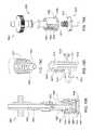
- FIG. 1illustrates a drilling system in a drilling mode, according to one embodiment of the present disclosure.
- FIGS. 2 and 2Aillustrate a top drive of the drilling system.
- FIG. 2Acorresponds to the portion of FIG. 2 within the boxed region.
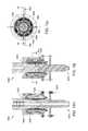
- FIGS. 3, 4A, and 4Billustrate a combined multi-coupler of the top drive in a docked mode.
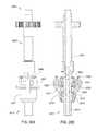
- FIGS. 5A and 8illustrate the combined multi-coupler in a release mode.
- FIGS. 5B and 5Cillustrate a torque shaft of a latch head of the combined multi-coupler.
- FIG. 6Aillustrates a latch actuator of the latch head.
- FIG. 6Billustrates a latch sensor of the latch head.
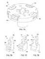
- FIG. 7Aillustrates a typical stem of the combined multi-coupler.
- FIG. 7Billustrates a latch block of the combined multi-coupler.
- FIGS. 7C and 7Dillustrate alternative latch blocks for the combined multi-coupler, according to other embodiments of the present disclosure.
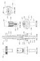
- FIG. 9illustrates a unit handler of the top drive transporting a drilling unit thereof from a motor unit thereof.
- FIG. 10illustrates a casing unit of the top drive.
- FIG. 11illustrates the unit handler transporting the casing unit to the motor unit.
- FIG. 12illustrates the unit handler transporting a casing joint to the casing unit.
- FIG. 13Aillustrates the drilling system in a casing mode.
- FIG. 13Billustrates a cementing unit of the top drive.
- FIG. 14illustrates the drilling system in a cementing mode.
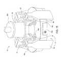
- FIG. 15illustrates an alternative latch head, according to another embodiment of the present disclosure.
- FIG. 16Aillustrates the alternative latch head in the docked mode.
- FIG. 16Billustrates the alternative latch head in the release mode.
- FIGS. 17A-17Dschematically illustrate a combined multi-coupler according to another embodiment of the present disclosure.
- FIGS. 18A-18Cschematically illustrate a combined multi-coupler according to another embodiment of the present disclosure.
- FIGS. 19A-19Pschematically illustrate a combined multi-coupler according to another embodiment of the present disclosure.
- FIGS. 20A-20Eschematically illustrate a combined multi-coupler according to another embodiment of the present disclosure.
- FIGS. 21A-21Ischematically illustrate a combined multi-coupler according to another embodiment of the present disclosure.
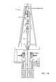
- FIG. 1illustrates a drilling system 1 in a drilling mode, according to one embodiment of the present disclosure.
- the drilling system 1may include a drilling rig 1 r , a fluid handling system 1 f , a pressure control assembly (PCA) 1 p , and a drill string 2 .
- the drilling rig 1 rmay include a derrick 3 d , a floor 3 f , a top drive 4 , and a hoist 5 .
- the rig floor 3 fmay have an opening through which the drill string 2 extends downwardly into the PCA 1 p.
- the drill string 2may include a bottomhole assembly (BHA) and a pipe string 2 p .
- the pipe string 2 pmay include joints of drill pipe connected together, such as by threaded couplings.
- the BHAmay be connected to the pipe string 2 p , such as by threaded couplings.
- the BHAmay include one or more drill collars (not shown) and a drill bit 2 b . Each BHA component may be connected to adjacent component(s), such as by threaded couplings.
- the drill bit 2 bmay be rotated 6 r by the top drive 4 via the pipe string 2 p and/or the BHA may further include a drilling motor (not shown) for rotating the drill bit.
- the BHAmay further include an instrumentation sub (not shown), such as a measurement while drilling (MWD) and/or a logging while drilling (LWD) sub.
- MWDmeasurement while drilling
- LWDlogging while drilling
- the top drive 4may include a control unit 4 n ( FIG. 2 ), a motor unit 4 m , a drilling unit 4 d , a casing unit 4 c ( FIG. 10 ), a cementing unit 4 s ( FIG. 13 ), a pipe handler 4 p , a backup wrench 4 w , a rail 4 r , a unit handler 4 u ( FIG. 9 ), and a combined multi-coupler (CMC) 4 y .
- a control unit 4 nFIG. 2
- the top drive 4may include a control unit 4 n ( FIG. 2 ), a motor unit 4 m , a drilling unit 4 d , a casing unit 4 c ( FIG. 10 ), a cementing unit 4 s ( FIG. 13 ), a pipe handler 4 p , a backup wrench 4 w , a rail 4 r , a unit handler 4 u ( FIG. 9 ), and a combined multi-coupler (CMC
- the top drive 4may be assembled as part of the drilling rig 1 r by connecting ends of the rail 4 r to the derrick 3 d such that a front of the rail is adjacent to a drill string opening in the rig floor 3 f .
- the rail 4 rmay have a length sufficient for the top drive 4 to handle stands 2 s ( FIG. 12 ) of two to four joints of drill pipe.
- the rail lengthmay be greater than or equal to twenty-five meters and less than or equal to one hundred meters.
- the top drive 4may include twin rails instead of the monorail.
- the lower end of the rail 4 rmay be connected to the rig floor 3 f instead of the derrick 3 d.
- the hoist 5may include a hook 5 h carried by a traveling block 5 t supported by wire rope 5 r .
- An upper end of the wire ripe 5 rmay be coupled to a crown block 5 c .
- the wire rope 5 rmay be woven through sheaves of the blocks 5 c,t and extend to drawworks 5 d for reeling thereof, thereby raising or lowering the traveling block 5 t relative to the derrick 3 d.
- the PCA 1 pmay include a blowout preventer (BOP) and a flow cross.
- BOPblowout preventer
- a housing of the BOP and the flow crossmay each be interconnected and/or connected to a wellhead 7 , such as by a flanged connection.
- the wellhead 7may be mounted on a casing string 8 which has been deployed into a wellbore 9 drilled from a surface 10 s of the earth and cemented into the wellbore.
- the casing string 8may extend to a depth adjacent a bottom of an upper formation 10 u .
- the upper formation 10 umay be non-productive and a lower formation 10 b may be a hydrocarbon-bearing reservoir.
- the lower formation 10 bmay be non-productive (e.g., a depleted zone), environmentally sensitive, such as an aquifer, or unstable.
- the wellbore 9may be subsea having a wellhead located adjacent to the waterline and the drilling rig 1 r may be a located on a platform adjacent the wellhead.
- the wellbore 9may be subsea having a wellhead located adjacent to the seafloor and the drilling rig 1 r may be a located on an offshore drilling unit.
- the fluid systemif may include a pressure gauge 11 , a mud pump 12 , a reservoir of drilling fluid 13 d , such as a pit 14 or tank, a solids separator, such as a shale shaker 15 , a return line 16 r , a feed line, and a supply line 16 s .
- a first end of the return line 16 rmay be connected to a branch of the flow cross and a second end of the return line may be connected to an inlet of the shaker 15 .
- a lower end of the supply line 16 smay be connected to an outlet of the mud pump 12 and an upper end of the supply line may be connected to the top drive 4 .
- the pressure gauge 11may be assembled as part of the supply line 16 s .
- a lower end of the feed linemay be connected to an outlet of the pit 14 and an upper end of the feed line may be connected to an inlet of the mud pump 12 .
- the pressure gauge 11may be used to monitor discharge pressure of the mud pump
- the drilling fluid 13 dmay include a base liquid.
- the base liquidmay be refined and/or synthetic oil, water, brine, or a water/oil emulsion.
- the drilling fluid 13 dmay further include solids dissolved or suspended in the base liquid, such as organophilic clay, lignite, and/or asphalt, thereby forming a mud.
- the mud pump 12may pump the drilling fluid 13 d from the pit 14 , through the supply line 16 s to the top drive 4 .
- the drilling fluid 13 dmay flow from the supply line 16 s and into the drill string 2 via the top drive 4 .
- the drilling fluid 13 dmay be pumped down through the drill string 2 and exit the drill bit 2 b , where the fluid may circulate the cuttings away from the bit and return the cuttings up an annulus 17 formed between an inner surface of the casing string 8 or wellbore 9 and an outer surface of the drill string 2 .
- the returns 13 rmay flow up the annulus 17 to the wellhead 7 and exit the wellhead at the flow cross.
- the returns 13 rmay continue through the return line 16 r and into the shale shaker 15 and be processed thereby to remove the cuttings, thereby completing a cycle.
- the drill string 2may be rotated 6 r by the top drive 4 and lowered 6 a by the traveling block 5 t , thereby extending the wellbore 9 into the lower formation 10 b.
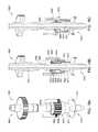
- FIG. 2illustrates the top drive 4 .
- the control unit 4 nmay be located on the rig floor 3 f and include a hydraulic power unit (HPU) 27 , a motor driver 25 , a control console 29 , and an air supply unit 30 .
- the HPU 27may include a pump 27 p , a check valve 27 k , an accumulator 27 a , a reservoir 27 r of hydraulic fluid, and a manifold 27 m .
- the motor driver 25may be one or more (three shown) phase and include a rectifier 25 r and an inverter 25 i .
- the inverter 25 imay be capable of speed control of the motor unit 4 m , such as being a pulse width modulator.
- the air supply unit 30may include a filter 30 f , a compressor 30 c , a cooler 30 r , a dryer 30 d , an accumulator 30 a , and a manifold 30 m .
- Each of the HPU manifold 27 m , the pneumatic manifold 30 m , and the motor driver 25may be in data communication with the control console 29 for control of the various functions of the top drive 4 .
- control unit 4 nmay further include a video monitoring unit having a video camera and a light source such that a technician (not shown) may visually monitor operation of the top drive 4 from the rig floor 3 f or control room (not shown) especially during shifting of the modes.
- the video monitoring unitmay be mounted on the motor unit 4 m.
- the motor unit 4 mmay include one or more (pair shown) drive motors 18 , a becket 19 , a hose nipple 20 , a mud swivel 21 , a drive body 22 , a drive ring, such as a gear 23 g , a quill 23 q , a trolley (not shown), a down thrust bearing 24 d , and an up thrust bearing 24 u .
- the drive body 22may be rectangular, may have a thrust chamber formed therein, and may have a central opening formed therethrough.
- the drive gear 23 gmay be longitudinally and torsionally connected to the quill 23 q .
- the drive motors 18may be electric (shown) or hydraulic (not shown) and have a rotor and a stator.
- a stator of each drive motor 18may be connected to the drive body 22 , such as by fastening, and be in electrical communication with the motor driver 25 via a power cable 26 a .
- the rotor of each drive motor 18may be torsionally connected to the drive gear 23 g for rotation 6 r thereof.
- the motor unit 4 mmay instead be a direct drive unit having the drive motor 18 centrally located.
- Each thrust bearing 24 u,dmay include a shaft washer, a housing washer, a cage, and a plurality of rollers extending through respective openings formed in the cage.
- the shaft washer of the down thrust bearing 24 dmay be connected to the drive gear 23 g adjacent to a bottom thereof.
- the housing washer of the down thrust bearing 24 dmay be connected to the drive body 22 .
- the cage and rollers of the down thrust bearing 24 dmay be trapped between the washers thereof, thereby supporting rotation 6 r of the drive gear 23 g (and the quill 23 q ) relative to the drive body 22 .
- the down thrust bearing 24 dmay be capable of sustaining weight of the drill string 2 during rotation thereof.
- the shaft washer of the up thrust bearing 24 umay be connected to the drive gear 23 g adjacent to a top thereof.
- the housing washer of the up thrust bearing 24 umay be connected to the drive body 22 .
- the cage and rollers of the up thrust bearing 24 umay be trapped between the washers thereof.
- the trolleymay be connected to a back of the drive body 22 , such as by fastening.
- the trolleymay be transversely connected to a front of the rail 4 r and may ride along the rail, thereby torsionally restraining the drive body 22 while allowing vertical movement of the motor unit 4 m with the travelling block 5 t .
- the becket 19may be connected to the drive body 22 , such as by fastening, and the becket may receive the hook 5 h to suspend the motor unit 4 m from the derrick 3 d.
- motor unit 4 mmay include a block-becket instead of the becket 19 and the block-becket may obviate the need for a separate traveling block 5 t.
- the hose nipple 20may be connected to the mud swivel 21 and receive a mud hose of the supply line 16 s .
- the mud hosemay deliver the drilling fluid 13 d from a standpipe of the supply line 16 s to the hose nipple 20 .
- the mud swivel 21may have an outer non-rotating barrel connected to the hose nipple 20 and an inner rotating barrel.
- the mud swivel 21may have a bearing (not shown) and a dynamic seal (not shown) for accommodating rotation of the rotating barrel relative to the non-rotating barrel.
- the outer non-rotating barrelmay be connected to the drive body 22 , such as by fastening.
- the inner rotating barrelmay be disposed in the outer non-rotating barrel and have a stinger portion (not shown) extending therefrom.
- a lower end of the stinger portionmay carry a stab seal for engagement with an inner seal receptacle of the quill 23 q , thereby sealing an interface formed between the mud swivel 21 and the quill.
- the pipe handler 4 pmay include a body, a drill pipe elevator (not shown), a pair of bails, and a link tilt (not shown).
- the handler bodymay be connected to a bottom of the drive body 22 , such as by fastening.
- Each bailmay have an eyelet formed at each longitudinal end thereof.
- An upper eyelet of each bailmay be received by a respective knuckle of the handler body.
- the link tiltmay include a pair of piston and cylinder assemblies for swinging the elevator relative to the handler body.
- Each piston and cylinder assemblymay have a coupling, such as a hinge knuckle, formed at each longitudinal end thereof.
- An upper hinge knuckle of each piston and cylinder assemblymay be received by a respective lifting lug of the handler body and pivotally connected thereto, such as by fastening.
- a lower hinge knuckle of each piston and cylinder assemblymay be received by a complementary hinge knuckle of the respective bail and pivotally connected thereto, such as by fastening.
- a piston of each piston and cylinder assemblymay be disposed in a bore of the respective cylinder.
- the pistonmay divide the cylinder bore into a raising chamber and a lowering chamber and the cylinder may have ports formed through a wall thereof and each port may be in fluid communication with a respective chamber.
- Each portmay be in fluid communication with the manifold 27 m via a respective control line 28 a (only one shown).
- Supply of hydraulic fluid to the raising portmay lift the drill pipe elevator by increasing a tilt angle (measured from a longitudinal axis of the rail 4 r ).
- Supply of hydraulic fluid to the lowering portmay drop the drill pipe elevator by decreasing the tilt angle.
- the drill pipe elevatormay be manually opened and closed or the pipe handler 4 p may include an actuator (not shown) for opening and closing the drill pipe elevator.
- the drill pipe elevatormay include a bushing having a profile, such as a bottleneck, complementary to an upset formed in an outer surface of a joint of the drill pipe adjacent to the threaded coupling thereof.
- the bushingmay receive the drill pipe for hoisting one or more joints thereof, such as the stand 2 s .
- the bushingmay allow rotation of the stand 2 s relative to the pipe handler 4 p .
- the pipe handler 4 pmay deliver the stand to the drill string 2 where the stand may be assembled therewith to extend the drill string during a drilling operation.
- the pipe handler 4 pmay be capable of supporting the weight of the drill string 2 to expedite tripping of the drill string.
- the CMC 4 ymay include a latch head 31 and a stem 32 d,c,s ( 32 c in FIG. 7A, 32 s in FIG. 8 ) for the respective drilling 4 d , casing 4 c , and cementing 4 s units.
- the drilling unit 4 dmay include the drilling stem 32 d , a thread saver 33 , and an internal blowout preventer (IBOP) 34 .
- the components of the drilling unit 4 dmay be connected to each other by threaded couplings.
- the IBOP 34may include one or more shutoff valves 34 u,b .
- One 34 u of the shutoff valves 34 u,bmay be actuated and the other 34 b may be manual.
- the IBOP valve actuatormay include an opening port and/or a closing port and each port may be in fluid communication with the HPU manifold 27 m via the control lines 28 b,c.
- the backup wrench 4 wmay include a pair of hinges, a tong, a guide, an arm, and a tong actuator (not shown).
- the tongmay be transversely connected to the arm.
- the upper hingemay pivotally connect the arm to the handler body.
- the upper hingemay include a pair of knuckles fastened or welded to the handler body and a pin extending through the knuckles and a hole formed through a top of the arm.
- the tongmay include a pair of semi-annular segments and the lower hinge may pivotally connect the segments to the arm.
- the tong actuatormay include a pair of piston and cylinder assemblies each having an end pivotally connected to the arm and another end pivotally connected to the respective tong segment.
- the pistonmay divide the cylinder bore into an activation chamber and a stowing chamber and the cylinder may have ports formed through a wall thereof and each port may be in fluid communication with a respective chamber. Each port may be in fluid communication with the HPU manifold 27 m via a respective control line 28 d (only one shown).
- Supply of hydraulic fluid to the activation portmay pivot the tong segments about the lower hinge toward an engaged position with the drill string 2 .
- Supply of hydraulic fluid to the stowing portmay pivot the tong segments about the lower hinge toward a stowed position adjacent to the rail 4 r .
- the stowed positionmay accommodate connection and removal of the units 4 d,c,s to/from the latch head 31 .
- Each tong segmentmay include a housing and a jaw (not shown) and the jaws may engage an outer surface of the drill string 2 when the tong segments are in the engaged position.
- the guidemay be a pair of cone segments connected to a lower end of the tong housings, such as by fastening, for receiving a threaded coupling, such as a box, of the drill string 2 .
- the thread saver 33may extend into the tong opening for stabbing into the drill pipe box. Once stabbed, the tong actuator may be operated to engage the drill pipe box, thereby torsionally connecting the drill pipe box to the drive body 22 . The motor unit 4 m may then be operated to rotate the thread saver 33 relative to the drill pipe box, thereby connecting the drilling unit 4 d to the drill string 2 .
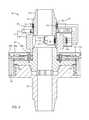
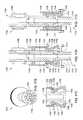
- FIGS. 3, 4A, and 4Billustrate the CMC 4 y in a docked mode.
- the latch head 31may include a torque shaft 35 , a control swivel 36 , a seal sleeve 37 ( FIG. 2 ), a plurality of latch members, such as blocks 38 , a latch actuator 39 for each latch block, one or more junction members 40 d,e,h,p ( 40 d in FIG. 5A ), and a torque sub.
- the torque submay include a recess 35 r of the torque shaft 35 , one or more load cells 41 a,t , one or more wireless couplings, such as a wireless power coupling 42 and a wireless data coupling 43 , a shaft electronics package 44 r , a turns counter 45 , a non-rotating interface box 47 , and an interface electronics package 44 s .
- the interface box 47may be connected to a non-rotating outer barrel of the control swivel 36 , such as by fastening.
- the load cell 41 tmay include a circuit of one or more torsional strain gages and the load cell 41 a may include a circuit of one or more longitudinal strain gages, each strain gage attached to the recess of the torque shaft 35 , such as by adhesive.
- the strain gagesmay each be made from metallic foil, semiconductor, or optical fiber.
- the load cell 41 amay include a set of strain gages disposed around the torque shaft 35 such that one or more bending moments exerted on the torque shaft may be determined from the strain gage measurements.
- Each wireless coupling 42 , 43may include a shaft member 42 r , 43 r connected to the torque shaft 35 and an interface member 42 s , 43 s housed in an encapsulation on the interface box 47 .
- the wireless power coupling members 42 r,smay each be inductive coils and the wireless data coupling members 43 r,s may each be antennas.
- the shaft electronicsmay be connected by leads and the electronics package 44 r , load cells 41 a,t , and the shaft member 43 r may be encapsulated into the recess.
- the torque shaft 35may carry a power source, such as a battery, capacitor, and/or inductor, and the wireless power coupling 42 may be omitted or used only to charge the power source.
- a power sourcesuch as a battery, capacitor, and/or inductor
- the shaft electronics package 44 rmay include a microcontroller, a power converter, an ammeter and a transmitter.
- the power convertermay receive an AC power signal from the power coupling 42 r and convert the signal to a DC power signal for operation of the shaft electronics.
- the DC power signalmay be supplied to the load cells 41 a,t and the ammeter may measure the current.
- the microcontrollermay receive the measurements from the ammeter and digitally encode the measurements.
- the transmittermay receive the digitally encoded measurements, modulate them onto a carrier signal, and supply the modulated signal to the shaft member 43 r.
- the interface electronics package 44 smay be housed in the interface box 47 .
- the interface member 43 smay receive the modulated signal and the interface electronics package 44 s may include a receiver for demodulating the signal.
- the interface electronics package 44 smay further include a microcontroller for digitally decoding the measurements and converting the measurements to torque and longitudinal load.
- the interface electronics package 44 smay send the converted measurements to the control console 29 via a data cable 26 b ( FIG. 2 ).
- the interface package 44 smay further include a power converter for supplying the interface data coupling with the AC power signal.
- the interface electronics package 44 smay also be powered by the data cable 26 b or include a battery.
- the turns counter 45may include a base 45 h torsionally connected to the torque shaft 35 , a turns gear 45 g connected to the base, and a proximity sensor 45 s housed in the interface box 47 and located adjacent to the turns gear.
- the turns gear 45 gmay be made from an electrically conductive metal or alloy and the proximity sensor 45 s may be inductive.
- the proximity sensor 45 smay include a transmitting coil, a receiving coil, an inverter for powering the transmitting coil, and a detector circuit connected to the receiving coil.
- a magnetic field generated by the transmitting coilmay induce an eddy current in the turns gear 45 g .
- the magnetic field generated by the eddy currentmay be measured by the detector circuit and supplied to the interface microcontroller.
- the interface microcontrollermay then convert the measurement to angular movement and/or speed and supply the converted measurement to the control console 29 .
- the proximity sensor 45 smay be Hall effect, ultrasonic, or optical.
- the turns counter 45may include a gear box instead of a single turns gear 45 g to improve resolution.
- FIGS. 5B and 5Cillustrate the torque shaft 35 .
- the torque shaft 35may have a bore formed therethrough and may have a tubular portion and a flange portion extending outward from the tubular portion.
- the tubular portion of the torque shaft 35may have a coupling, such as a threaded box or pin 35 p ( FIG. 3 ), formed at a top thereof, may have the recess 35 r formed in an outer surface thereof, and may have a torsional coupling, such as keys 35 k , formed in an a bottom thereof.
- the flange portion of the torque shaft 35may have receptacles 35 j formed in a lower face and an outer surface thereof for receiving the respective junction members 40 d,e,h,p , may have one or more slots 35 s ( FIG. 5A ) formed in an upper face thereof for receiving the respective latch actuator 39 , may have cavities 35 c formed in an outer surface thereof for receiving the latch blocks 38 , and may have an alignment feature, such as pins 35 f , extending from the lower face thereof.
- Each junction member 40 d,e,h,pmay be disposed in the respective receptacle 35 j and connected to the torque shaft 35 , such as by fastening.
- the quill 23 qmay have a coupling, such as a threaded box (shown) or pin, formed at a lower end thereof and an upper end of the torque shaft 35 may be longitudinally and torsionally connected to the lower end of the quill 23 q , such as by mating of the threaded couplings 35 p.
- a couplingsuch as a threaded box (shown) or pin
- FIG. 7Aillustrates a stem 32 typical of the stems 32 d,c,s .
- the stem 32may have a bore formed therethrough and may have a tubular portion and a flange portion extending outward from the tubular portion.
- the tubular portion of the stem 32may have a polished receptacle formed in an inner surface thereof and adjacent to a top thereof, may have a torsional coupling, such as keyways, formed in the top thereof, and may have a coupling, such as a threaded box or pin, formed at a bottom thereof.
- the flange portion of the stem 32may have receptacles formed in an upper face and outer surface thereof for receiving respective junction members 48 d,e,h,p , may have one or more latch profiles formed in an outer surface thereof for receiving the latch blocks 38 , and may have an alignment feature, such as pinholes, extending from the upper face thereof.
- Each junction member 48 d,e,h,pmay be disposed in the respective receptacle of the stem 32 and be connected thereto, such as by fastening.
- Alignment and orientation of the pins 35 f with the pinholes of the stem 32may orient the keys 35 k with respect to the keyways of the stem 32 such that when the upper face of the stem 32 is engaged with the lower face of the torque shaft 35 , the keys may mate with the keyways, thereby torsionally connecting the respective unit 4 c,d,s to the latch head 31 , and the latch profiles may be aligned with the cavities 35 c , thereby allowing the latch actuator 39 to engage the latch bocks 38 therewith for longitudinally connecting the respective unit to the latch head.
- the alignment features 35 fmay be part of the torsional couplings instead of being located on the flange portions.
- the seal sleeve 37may have an upper threaded portion (thread not shown), a lower stinger portion, and a shoulder connecting the portions.
- the upper threaded portion of the seal sleeve 37may carry a seal (not shown) for engagement with a seal bore of the torque shaft 35 upon engagement of the upper threaded portion with an inner thread formed adjacent to the lower face of the torque shaft.
- a lower end of the stinger portion of the seal sleeve 37may carry a stab seal (not shown) for engagement with the inner seal receptacle of each stem 32 c,d,s when the respective unit 4 d,c,s is connected to the latch head 31 , thereby sealing an interface formed between the units.
- the control swivel 36may include a rotating inner barrel and the non-rotating outer barrel.
- the inner barrelmay be disposed around and connected to the torque shaft 35 and the outer barrel may be supported from the inner barrel by one or more bearings.
- the control swivel 36may further include a torsional arrestor (not shown), such as a bracket, connected to the outer barrel and engaged with the rail 4 r .
- the outer barrelmay have one or more ports (not shown) for each of the hydraulic 40 h and pneumatic 40 p junction members formed through a wall thereof, each port in fluid communication with a respective passage (not shown) formed through the inner barrel. An interface between each port and passage may be straddled by dynamic seals (not shown) for isolation thereof.
- the outer barrel portsmay be in fluid communication with the respective manifolds 27 m , 30 m via respective control lines 28 e,f ( FIG. 2 , only one shown for each) and the inner barrel passages may be in fluid communication with the respective hydraulic 40 h and pneumatic 40 p junction members via control lines 28 g,h ( FIG. 3 ).
- the outer barrel portsmay be disposed along the outer barrel.
- the inner barrelmay have a mandrel portion extending along the outer barrel and a foot portion extending below the outer barrel. The foot portion may connect to the torque shaft 35 and have the ports extending therearound.
- the outer barrelmay also have one or more electrical couplings (not shown) for each of the electric power 40 e and data 40 d junction members and conduits extending therefrom and formed through a wall thereof, each conduit in electrical communication with a respective conduit formed through the inner barrel.
- the outer barrel couplingsmay be in electrical communication with the respective rectifier 25 r or control console 29 via respective control cables 26 c,b ( FIG. 2 , only one shown for each) and the inner barrel passages may be in fluid communication with the respective electric power 40 e and data 40 d junction members via control cables 26 d,e ( FIG. 3 ).
- Each fluid junction member 40 h,p , 48 h,pmay include a radial connection plate facing outward from the respective latch head 31 or stem 32 c,d,s and a longitudinal stab plate facing upward or downward from the respective stem or latch head.
- Each connection platemay include a nipple for each control line 28 g,h and a passage for each control line.
- a male stab plate of one of each fluid junction member 40 h,p , 48 h,pmay have a stinger for each control line 28 g,h , each stinger in fluid communication with a respective passage and carrying a seal.
- a female stab plate of the other one of each fluid junction member 40 h,p , 48 h,pmay have a seal receptacle for each control line 28 g,h , each receptacle in fluid communication with a respective passage and configured to receive each stinger.
- Each electrical junction member 40 d,e , 48 d,emay include a radial connection plate facing outward from the respective latch head 31 or stem 32 c,d,s and a longitudinal stab plate facing upward or downward from the respective stem or latch head.
- Each connection platemay include an electrical coupling for each control cable 26 d,e , and a conduit for each control cable.
- a male stab plate of one of each electrical junction member 40 d,e , 48 d,emay have a conductive plug for each cable 26 d,e , each plug in electrical communication with a respective conduit.
- a female stab plate of the other one of each electrical junction member 40 d,e , 48 d,emay have a conductive socket for each control cable 26 d,e , each socket in electrical communication with a respective conduit and configured to receive each plug.
- the junction members 40 d,e,h,pmay mate with the respective junction members 48 d,e,h,p , thereby establishing data, electrical, hydraulic, and pneumatic communication between the respective stem and the control swivel 36 . If a particular one of the stems 32 c,d,s does not require all four medias of communication, then the particular stem may have one or more blank or plugged junction members (not shown) for the unused media(s).
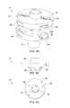
- FIG. 6Aillustrates a typical one of the latch actuators 39 .
- Each latch actuator 39may be disposed in a respective slot 35 s and connected to the torque shaft 35 , such as by a first fastener 39 a ( FIG. 3 ).
- the latch actuator 39may further include an inner block 39 n , an outer block 39 o , one or more second fasteners 39 b connecting the inner and outer blocks, a rod 39 r , and a spring 39 s , such as a compression spring.
- the inner 39 n and outer 390 blocksmay be spaced apart along the respective slot 35 s .
- the outer block 390may have a bore formed therethrough.
- the rod 39 rmay have a head formed at an inner end thereof, may have a coupling, such as a threaded pin, formed at an outer end thereof, and may have a shank connecting the head and the threaded pin.
- the shank of the rod 39 rmay extend through the bore of the outer block 390 and the rod may be radially movable relative to the inner 39 n and outer blocks between a retracted position (shown) and an extended position ( FIG. 8 ).
- An inner end of the spring 39 smay bear against a shoulder of the rod 39 r formed between the head and the skank thereof and an outer end of the spring may bear against the outer latch block 39 o , thereby biasing the rod toward the retracted position.
- Each latch block 38may have a coupling, such as a threaded box, formed in a lug 38 g thereof and mated with the threaded pin of the respective rod 39 r , thereby connecting the rod and the latch block. Movement of each rod 39 r to the extended position may disengage the respective latch block 38 from the respective latch profile of the stem 32 and movement of each rod 39 r to the retracted position may engage the respective latch block 38 with the respective latch profile.
- the latch actuator 39may further include a solenoid (not shown) wrapped around second fasteners 39 b and a power converter (not shown) connected to the solenoid and in electrical communication with the rectifier 25 r via control cable 26 f,g ( FIG. 2 ).
- the head of the rod 39 rmay be made from a magnetic material and energization of the solenoid may move the rod 39 r to the extended position against the bias of the spring 39 s.
- the latch actuator 39may include a cylinder instead of the solenoid and the head of the rod 39 r may be a piston in sealing engagement with the cylinder and the rod may be moved to the extended position by supply of pressurized fluid to a chamber formed between the piston and the cylinder.
- FIG. 6Billustrates a typical latch sensor 49 of the latch head 31 .
- the latch head 31may further include one of the latch sensors 49 for each latch block 38 .
- Each latch sensor 49may be disposed in a respective cutout 35 o ( FIG. 3 ) formed in the lower face of the torque shaft 35 in alignment with the respective slot 35 s .
- the latch sensor 49may be connected to the torque shaft 35 , such as by fastening.
- Each latch sensor 49may be in fluid communication with the pneumatic manifold 30 m via a respective control line 28 j,k ( FIG. 2 ).
- the latch sensor 49may be a valve movable between an open position and a closed position and biased toward the closed position by pneumatic pressure.
- the valveWhen the latch blocks 38 are in the disengaged position, the valve may be closed, thereby resulting in no air flow through the control lines.
- inner surfaces of the latch blocksmay engage valve members of the latch sensors 49 , thereby opening the valves and causing air flow through the control lines which is detectable by flow meters of the pneumatic manifold 30 m .
- the pneumatic manifold 30 mmay then report detection of successful engagement of the latch blocks 38 to the control console 29 .
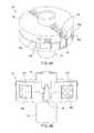
- FIG. 7Billustrates a typical one of the latch blocks 38 .
- the latch block 38may have a central backbone 38 b , plates 38 p extending from sides and an inner surface of the backbone, a neck 38 n extending upward from the backbone 38 b , and the lug 38 g formed on top of the neck.
- the plates 38 pmay mate with the respective latch profile of the stem 32 and the neck 38 n may mate with the respective cavity 35 c of the torque shaft 35 , thereby longitudinally connecting the respective unit 4 c,d,s to the latch head 31 .
- FIGS. 7C and 7Dillustrate alternative latch blocks 50 , 51 for the CMC 4 y , according to other embodiments of the present disclosure.
- a first alternative latch block 50may have an outer base 50 b , inner teeth 50 t extending from and along an inner surface of the base, a neck 50 n extending upward from the base, and a lug 50 g formed on top of the neck.
- a second alternative latch block 51may have a base 51 b with a wedge 51 w formed on an inner surface thereof, a neck 51 n extending upward from the base, and a lug 51 g formed on top of the neck.
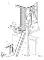
- FIGS. 5A and 8illustrate the CMC 4 y in a release mode.
- Drillingmay be halted by stopping rotation 6 r of the motor unit 4 m , stopping lowering 6 a of the traveling block 5 t , stopping injection of the drilling fluid 13 d , and removing weight from the drill bit 2 b .
- a spider 52FIG. 1
- the tong actuator of the backup wrench 4 wmay be operated via control line 28 d to engage the backup wrench tong with a top coupling of the drill string 2 .
- the drive motors 18may then be operated to loosen and counter-spin the connection between the thread saver 33 and the top coupling of the drill string 2 .
- the pipe handler 4 pmay then be raised by the hoist 5 until the drill pipe elevator is adjacent a top of the stand 2 s to be added to the drill string 2 .
- the elevatormay be engaged with the stand 2 s , the hoist 5 operated to lift the stand from a pipe rack of the drilling rig 1 r , and the link tilt operated to swing the stand from the pipe rack to a location adjacent a top of the drill string 2 .
- a set of tongsmay be used to screw the stand 2 s into the top of the drill string 2 .
- the top drive 4may then be lowered by the hoist 5 until the thread saver 33 is adjacent to a top of the stand 2 .
- the backup wrench 4 wmay then be engaged with the top of the stand 2 s and the drive motors 18 operated to spin and tighten the connection between the thread saver 33 and the top coupling of the stand.
- the spider 52may then be released and drilling may continue.
- the drill string 2may be tripped out from the wellbore 9 .
- the backup wrench 4 wmay be shifted to the stowed position and the drilling unit 4 d may be released from the motor unit 4 m by operation of the actuator 39 .
- the drilling elevatormay be removed from the pipe handler 4 p and the link tilt operated to move the bails to a stowed position.
- FIG. 9illustrates the unit handler 4 u .
- the unit handler 4 umay transport the units 4 d,c,s between a unit rack 4 k located on or adjacent to a structure of the drilling rig 1 r and the motor unit 4 m .
- a unit rack 4 kmay include one or more tool receiving slots for storing the tool units.
- Each tool receiving slotmay include a coupling profile for receiving a tool.
- the coupling profile in each tool receiving slotmay be the same as the coupling profile in the motor unit 4 m .
- the rig structuremay be a subfloor structure, such as a catwalk 3 c or pad (not shown).
- the unit handler 4 umay include a post 54 p , a slide hinge 54 s , an arm 54 a , a holder 54 h , a base 54 b , and one or more actuators (not shown).
- the base 54 bmay mount the post 54 p on or adjacent to the catwalk 3 c (or other rig structure discussed above).
- the post 54 pmay extend vertically from the base 54 b to a height above the rig floor 3 f such that the unit handler 4 u may transport any of the units 4 d,c,s between the unit rack and the motor unit 4 m .
- the arm 54 amay be connected to the slide hinge 54 s , such as by fastening.
- the slide hinge 54 smay be transversely connected to the post 54 p , such as by a slide joint, while being free to move longitudinally along the post.
- the slide hinge 54 smay also be pivotally connected to a linear actuator (not shown), such as by fastening.
- the slide hinge 54 smay longitudinally support the arm 54 a from the linear actuator while allowing pivoting of the arm relative to the post 54 p .
- the unit handler 4 umay further include an electric or hydraulic slew motor (not shown) for pivoting the arm 54 a about the slide hinge 54 s.
- the linear actuatormay have a lower end pivotally connected to the base 54 b and an upper end pivotally connected to the slide hinge 54 s .
- the linear actuatormay include a cylinder and a piston disposed in a bore of the cylinder.
- the pistonmay divide the cylinder bore into a raising chamber and a lowering chamber and the cylinder may have ports formed through a wall thereof and each port may be in fluid communication with a respective chamber.
- Each portmay be in fluid communication with the hydraulic manifold 27 m via a control line (not shown).
- Supply of hydraulic fluid to the raising portmay move the slide hinge 54 s and arm 54 a upward to the rig floor 3 f .
- Supply of hydraulic fluid to the lowering portmay move the slide hinge 54 s and arm 54 a downward toward the base 54 b.
- the linear actuatormay include an electro-mechanical linear actuator, such as a motor and lead screw or pinion and gear rod, instead of the piston and cylinder assembly.
- an electro-mechanical linear actuatorsuch as a motor and lead screw or pinion and gear rod, instead of the piston and cylinder assembly.
- the arm 54 amay include a forearm, an aft-arm, and an actuated joint, such as an elbow, connecting the arm segments.
- the holder 54 hmay be releasably connected to the forearm, such as by fastening.
- the arm 54 amay further include an actuator (not shown) for selectively curling and extending the forearm and relative to the aft-arm.
- the arm actuatormay have an end pivotally connected to the forearm and another end pivotally connected to the aft-arm.
- the arm actuatormay include a cylinder and a piston disposed in a bore of the cylinder.
- the pistonmay divide the cylinder bore into an extension chamber and a curling chamber and the cylinder may have ports formed through a wall thereof and each port may be in fluid communication with a respective chamber. Each port may be in fluid communication with the HPU manifold 27 m via a control line (not shown). Supply of hydraulic fluid to the respective ports may articulate the forearm and holder 54 h relative to the aft-arm toward the respective positions.
- the arm actuatormay include an electro-mechanical linear actuator, such as a motor and lead screw or pinion and gear rod, instead of the piston and cylinder assembly.
- the actuated jointmay be a telescopic joint instead of an elbow.
- the holder 54 hmay include a safety latch for retaining any of the units 4 c,d,s thereto after engagement of the holder therewith to prevent unintentional release of the units during handling thereof.
- the holder 54 hmay include a brake for torsionally connecting any of the units 4 c,d,s thereto after engagement of the holder therewith to facilitate connection to the motor unit 4 m.
- the unit handler 4 uBefore release of the drilling unit 4 d from the motor unit 4 m , the unit handler 4 u may be operated to engage the holder 54 h with the lower face of the drilling stem 32 d . The drilling unit 4 d may then be released from the motor unit 4 m into the grasp of the holder 54 h . The unit handler 4 u may then be operated to deliver the drilling unit 4 d to the unit rack.
- FIG. 10illustrates the casing unit 4 c .
- the casing unit 4 cmay include the casing stem 32 c , a thread compensator 55 , an adapter 56 , a clamp, such as a spear 57 , one or more control lines 58 a,b , and a fill up tool 59 .
- the casing stem 32 c , thread compensator 55 , adapter 56 , spear 57 , and fill up tool 59may be connected together, such as by threaded couplings.
- the thread compensator 55may include a cap 55 c , a housing 55 h , a mandrel 55 m , a seal sleeve 55 s , and an actuator 55 a .
- the mandrel 55 mmay be longitudinally movable relative to the housing 55 h between a retracted position and an engaged position by the actuator 55 a .
- the actuator 55 amay include one or more piston and cylinder assemblies. Upper ends of the piston and cylinder assemblies may be connected to the housing 55 h , such as by a collar. Ports of the piston and cylinder assemblies may be in fluid communication with the HPU manifold 27 m via the control line 58 a for operation of the thread compensator 55 .
- the actuator 55 amay be pneumatically operated instead of hydraulically operated and the control line 58 a may be pneumatic instead of hydraulic.
- the cap 55 cmay be annular and have a bore therethrough.
- An upper end of the cap 55 cmay include a coupling, such as a threaded box, for connection with the threaded pin of the casing stem 32 c , thereby longitudinally and torsionally connecting the stem and the cap.
- the cap 55 cmay taper outwardly so that a lower end thereof may have a substantially greater diameter than the upper end.
- An inner surface of the cap 55 c lower endmay be threaded for receiving a threaded upper end of the housing 55 h , thereby longitudinally and torsionally connecting the cap and the housing.
- the housing 55 hmay be tubular and have a bore formed therethrough.
- a lower end of the housing 55 hmay be longitudinally splined for engaging longitudinal splines formed on an outer surface of the mandrel 55 m , thereby torsionally connecting the housing and the mandrel while allowing relative longitudinal movement therebetween.
- the housing 55 h lower endmay form a shoulder for receiving a corresponding shoulder formed at an upper end of the mandrel 55 m when the thread compensator 55 is in a hoisting position, thereby longitudinally connecting the housing and the mandrel.
- the piston and cylinder assembliesmay be capable of supporting weight of a casing joint 60 j ( FIG.
- a stroke length of the actuator 55 amay correspond to, such as being equal to or slightly greater than, a makeup length of the casing joint 60 j.
- a lower end of the mandrel 55 mmay form a threaded coupling, such as a pin, for mating with a threaded coupling, such as a box, formed at an upper end of the adapter 56 .
- the seal sleeve 55 smay have an upper threaded portion and a polished portion extending therefrom.
- the upper threaded portion of the seal sleeve 55 smay carry a seal for engagement with a seal bore of the cap 55 c upon engagement of the upper threaded portion with an inner thread of the cap.
- the mandrel 55 mmay carry a sliding seal in an inner surface thereof adjacent to a top thereof for engagement with the polished portion of the seal sleeve 55 s , thereby sealing an interface between the two members.
- the spear 57may be capable of supporting weight of the casing string 60 .
- the spear 57may include a linear actuator 57 a , a bumper 57 b , a collar 57 c , a mandrel 57 m , a set of grippers, such as slips 57 s , a seal joint 57 j , and a sleeve 57 v .
- the collar 57 cmay have an inner thread formed at each longitudinal end thereof. The collar upper thread may be engaged with an outer thread formed at a lower end of the adapter 56 , thereby connecting the two members.
- the collar lower threadmay be engaged with an outer thread formed at an upper end of the mandrel 57 m and the mandrel may have an outer flange formed adjacent to the upper thread and engaged with a bottom of the collar 57 c , thereby connecting the two members.
- the seal joint 57 jmay include an inner barrel, an outer barrel, and a nut.
- the inner barrelmay have an outer thread engaged with an inner thread of the lower portion of the adapter 56 and an outer portion carrying a seal engaged with a seal bore portion of the casing stem.
- the mandrel 57 mmay have a bore formed therethrough and an inner receptacle formed at an upper portion thereof and in communication with the bore.
- the mandrel receptaclemay have an upper conical portion, a threaded mid portion, and a recessed lower portion.
- the outer barrelmay be disposed in the recessed portion of the mandrel 57 m and trapped therein by engagement of an outer thread of the nut with the threaded mid portion of the mandrel receptacle.
- the outer barrelmay have a seal bore formed therethrough and a lower portion of the inner barrel may be disposed therein and carry a stab seal engaged therewith.
- the linear actuator 57 amay include a housing, an upper flange, a plurality of piston and cylinder assemblies, and a lower flange.
- the housingmay be cylindrical, may enclose the cylinders of the assemblies, and may be connected to the upper flange, such as by fastening.
- the collar 57 cmay also have an outer thread formed at the upper end thereof.
- the upper flangemay have an inner thread engaged with the outer collar thread, thereby connecting the two members.
- Each flangemay have a pair of lugs for each piston and cylinder assembly connected, such as by fastening or welding, thereto and extending from opposed surfaces thereof.
- Each cylinder of the linear actuator 57 amay have a coupling, such as a hinge knuckle, formed at an upper end thereof.
- the upper hinge knuckle of each cylindermay be received by a respective pair of lugs of the upper flange and pivotally connected thereto, such as by fastening.
- Each piston of the linear actuator 57 amay have a coupling, such as a hinge knuckle, formed at a lower end thereof.
- Each piston of the linear actuator 57 amay be disposed in a bore of the respective cylinder.
- the pistonmay divide the cylinder bore into a raising chamber and a lowering chamber and the cylinder may have ports formed through a wall thereof and each port may be in fluid communication with a respective chamber.
- Each portmay be in fluid communication with the HPU manifold 27 m via the respective control line 58 b (only one shown).
- Supply of hydraulic fluid to the raising portmay lift the lower flange to a retracted position (shown).
- Supply of hydraulic fluid to the lowering portmay drop the lower flange toward an extended position (not shown).
- the piston and cylinder assembliesmay share an extension control line and a retraction control line via a splitter (not shown).
- the sleeve 57 vmay have an outer shoulder formed in an upper end thereof trapped between upper and lower retainers.
- a washermay have an inner shoulder formed in a lower end thereof engaged with a bottom of the lower retainer.
- the washermay be connected to the lower flange, such as by fastening, thereby longitudinally connecting the sleeve 57 v to the linear actuator 57 a .
- the sleeve 57 vmay also have one or more (pair shown) slots formed through a wall thereof at an upper portion thereof.
- the bumper 57 bmay be connected to the mandrel 57 m , such as by one or more threaded fasteners, each fastener extending through a hole thereof, through a respective slot of the sleeve 57 v , and into a respective threaded socket formed in an outer surface of the mandrel, thereby also torsionally connecting the sleeve to the mandrel while allowing limited longitudinal movement of the sleeve relative to the mandrel to accommodate operation of the slips 57 s .
- a lower portion of the spear 57may be stabbed into the casing joint 60 j until the bumper 57 b engages a top of the casing joint.
- the bumper 57 bmay cushion impact with the top of the casing joint 60 j to avoid damage thereto.
- the sleeve 57 vmay extend along the outer surface of the mandrel from the lower flange of the linear actuator 57 a to the slips 57 s .
- a lower end of the sleeve 57 vmay be connected to upper portions of each of the slips 57 s , such as by a flanged (i.e., T-flange and T-slot) connection.
- Each slip 57 smay be radially movable between an extended position and a retracted position by longitudinal movement of the sleeve 57 v relative to the slips.
- a slip receptaclemay be formed in an outer surface of the mandrel 57 m for receiving the slips 57 s .
- the slip receptaclemay include a pocket for each slip 57 s , each pocket receiving a lower portion of the respective slip.
- the mandrel 57 mmay be connected to lower portions of the slips 57 s by reception thereof in the pockets.
- Each slip pocketmay have one or more (three shown) inclined surfaces formed in the outer surface of the mandrel 57 m for extension of the respective slip.
- a lower portion of each slip 57 smay have one or more (three shown) inclined inner surfaces corresponding to the inclined slip pocket surfaces.
- each slip 57 smay also have a guide profile, such as tabs, extending from sides thereof.
- Each slip pocketmay also have a mating guide profile, such as grooves, for retracting the slips 57 s when the sleeve 57 v moves upward away from the slips.
- Each slip 57 smay have teeth formed along an outer surface thereof. The teeth may be made from a hard material, such as tool steel, ceramic, or cermet for engaging and penetrating an inner surface of the casing joint 60 j , thereby anchoring the spear 57 to the casing joint.
- the fill up tool 59may include a flow tube, a stab seal, such as a cup seal, a release valve, and a mud saver valve.
- the cup sealmay have an outer diameter slightly greater than an inner diameter of the casing joint to engage the inner surface thereof during stabbing of the spear 57 therein.
- the cup sealmay be directional and oriented such that pressure in the casing bore energizes the seal into engagement with the casing joint inner surface.
- An upper end of the flow tubemay be connected to a lower end of the mandrel 57 m , such as by threaded couplings.
- the mud saver valvemay be connected to a lower end of the flow tube, such as by threaded couplings.
- the cup seal and release valvemay be disposed along the flow tube and trapped between a bottom of the mandrel and a top of the mudsaver valve.
- the casing unit 4 cmay include one or more sensors (not shown), such as a position sensor for the thread compensator 55 , a position sensor for the linear actuator 57 a , and a position sensor for the bumper 57 b .
- the sensorsmay be data communication with the control console 29 via one or more control cables (not shown) connecting the sensors to the casing stem 32 c .
- the spear 57may include one or more pneumatically operated control valves (not shown) in fluid communication with the pneumatic manifold 30 m via one or more control lines (not shown) connecting the control valves to the casing stem 32 c .
- the linear actuator 57 amay be electrically or pneumatically operated instead of hydraulically operated and the control line 58 b may be a control cable or pneumatic control line instead of a hydraulic control line.
- the clampmay be a torque head instead of the spear 57 .
- the torque headmay be similar to the spear 57 except for receiving an upper portion of the casing joint 60 j therein and having the grippers for engaging an outer surface of the casing joint instead of the inner surface of the casing joint.
- FIG. 11illustrates the unit handler 4 u transporting the casing unit 4 c to the motor unit 4 m .
- the unit handler 4 umay be operated to retrieve the casing unit 4 c from the unit rack, to hoist the casing unit above the rig floor 3 f , and to a position the casing unit adjacent to the motor unit 4 m .
- the drive motors 18may then be operated to rotate the latch head 31 until the pins 35 f are properly oriented with respect to the pinholes of the casing stem 32 c .
- the unit handler 4 umay then be operated to raise the casing stem 32 c into engagement with the torque shaft 35 and the actuator 39 operated to engage the latch blocks 38 with the latch profiles of the casing stem.
- FIG. 12illustrates the unit handler 4 u transporting the casing joint 60 j to the casing unit 4 c .
- the holder 54 hmay be disconnected from the arm 54 a and stowed on the unit rack.
- a pipe clamp 54 cmay then be connected to the arm 54 a and the unit handler 4 u operated to engage the pipe clamp with the casing joint 60 j .
- the pipe clamp 54 cmay be manually actuated between an engaged and disengaged position or include an actuator, such as a hydraulic actuator, for actuation between the positions.
- the casing joint 60 jmay initially be located below the rig floor 3 f and the unit handler 4 u may be operated to raise the casing joint to the rig floor.
- the unit handler 4 umay deliver the casing joint 60 j to the rig floor 3 f and into alignment with the casing unit 4 c .
- the unit handlermay hold the casing joint 60 j while the spear 57 and fill up tool 59 are stabbed therein until the bumper 57 b engages a top thereof or the unit handler may raise the casing joint to do the stabbing.
- the linear actuator 57 amay then be operated to engage the slips 57 s with the casing joint 60 j and the pipe clamp 54 c released therefrom.
- FIG. 13Aillustrates the drilling system 1 in a casing mode.
- Injection of the drilling fluid 13 d into the casing joint 60 j and rotation thereof by the drive motors 18may allow the casing joint to be reamed into the wellbore 9 .
- the spider 52may then be installed into the rotary table 53 , thereby longitudinally supporting the casing joint 60 j from the rig floor 3 f .
- the slips 57 smay be released and the unit handler 4 u again operated to deliver an additional joint of casing to the casing unit 4 c .
- the actuator 55 amay then be operated to shift the thread compensator 55 from the hoisting position to a ready position.
- the top drive 4may then be lowered to stab the additional casing joint into the casing joint 60 j .
- the rotary table 53may be locked or a backup tong (not shown) may be engaged with the top of the casing joint 60 j and the drive motors 18 may be operated to spin and tighten the threaded connection between the casing joints 60 j , thereby forming the casing string 60 .
- the thread compensator 55may lower the additional casing joint during spinning and tightening to maintain the threaded connection in a neutral condition.
- the spider 52may then be released and running of the casing string 60 may continue.
- FIG. 13Billustrates the cementing unit 4 s .
- the cementing unit 4 smay include the cementing stem 32 s , the thread saver 33 , the IBOP 34 , one or more control lines 61 , and a cementing head 62 .
- the cementing head 62may include a cementing swivel 63 , a launcher 64 , and a release plug, such as a dart 65 .
- the cementing swivel 63may include a housing torsionally connected to the drive body 22 or rail 4 r , such as by a bar (not shown).
- the cementing swivel 63may further include a mandrel and bearings for supporting the housing from the mandrel while accommodating rotation of the mandrel.
- An upper end of the mandrelmay be connected to a lower end of the thread saver 33 , such as by threaded couplings.
- the cementing swivel 63may further include an inlet formed through a wall of the housing and in fluid communication with a port formed through the mandrel and a seal assembly for isolating the inlet-port communication.
- the mandrel portmay provide fluid communication between a bore of the cementing head 62 and the housing inlet.
- the launcher 64may include a body, a deflector, a canister, a gate, the actuator, and an adapter.
- the bodymay be tubular and may have a bore therethrough.
- An upper end of the bodymay be connected to a lower end of the cementing swivel 63 , such as by threaded couplings, and a lower end of the body may be connected to the adapter, such as by threaded couplings.
- the canister and deflectormay each be disposed in the body bore.
- the deflectormay be connected to the cementing swivel mandrel, such as by threaded couplings.
- the canistermay be longitudinally movable relative to the body.
- the canistermay be tubular and have ribs formed along and around an outer surface thereof. Bypass passages (only one shown) may be formed between the ribs.
- the canistermay further have a landing shoulder formed in a lower end thereof for receipt by a landing shoulder of the adapter.
- the deflectormay be operable to divert fluid received from a cement line 74 ( FIG. 14 ) away from a bore of the canister and toward the bypass passages.
- the adaptermay have a threaded coupling, such as a threaded pin, formed at a lower end thereof for connection to a work string 67 ( FIG. 14 ).
- the dart 65may be disposed in the canister bore.
- the dart 65may be made from one or more drillable materials and include a finned seal and mandrel.
- the mandrelmay be made from a metal or alloy and may have a landing shoulder and carry a landing seal for engagement with the seat and seal bore of a wiper plug (not shown) of the work string 67 .
- the gate of the launcher 64may include a housing, a plunger, and a shaft.
- the housingmay be connected to a respective lug formed in an outer surface of the body, such as by threaded couplings.
- the plungermay be radially movable relative to the body between a capture position and a release position. The plunger may be moved between the positions by a linkage, such as a jackscrew, with the shaft.
- the shaftmay be connected to and rotatable relative to the housing.
- the actuatormay be a hydraulic motor operable to rotate the shaft relative to the housing.
- the actuatormay include a reservoir (not shown) for receiving the spent hydraulic fluid or the cementing unit 4 s may include a second hydraulic conduit (not shown) for returning the spent hydraulic fluid to the HPU 27 .
- the console 29may be operated to supply hydraulic fluid to the launcher actuator via the control line 61 .
- the launcher actuatormay then move the plunger to the release position.
- the canister and dart 65may then move downward relative to the launcher body until the landing shoulders engage. Engagement of the landing shoulders may close the canister bypass passages, thereby forcing chaser fluid 68 ( FIG. 14 ) to flow into the canister bore.
- the chaser fluid 68may then propel the dart 65 from the canister bore, down a bore of the adapter, and onward through the work string 67 .
- the cementing unit 4 smay include a sensor (not shown), such as a dart detector for confirming successful launching of the dart 65 .
- the sensormay be data communication with the control console 29 via one or more control cables (not shown) connecting the sensors to the cementing stem 32 s .
- the launcher actuatormay be electrically or pneumatically operated instead of hydraulically operated and the control line 61 may be a pneumatic control line or control cable instead of a hydraulic control cable.
- FIG. 14illustrates the drilling system 1 in a cementing mode.
- a shoe (not shown) of the casing string 60nears a desired deployment depth of the casing string, such as adjacent a bottom of the lower formation 10 b , a casing hanger 60 h may be assembled with the casing string 60 .
- the spider 52may be set.
- the casing unit 4 cmay be released from the motor unit 4 m and replaced by the cementing unit 4 s using the unit handler 4 u .
- the work string 67may be connected to the casing hanger 60 h and the work string extended until the casing hanger 60 h seats in the wellhead 7 .
- the work string 67may include a casing deployment assembly (CDA) 67 d and a pipe string 67 s , such as such as one or more joints of drill pipe connected together, such as by threaded couplings.
- An upper end of the CDA 67 dmay be connected a lower end of the pipe string 67 s , such as by threaded couplings.
- the CDA 67 dmay be connected to the casing hanger 60 h , such as by engagement of a bayonet lug (not shown) with a mating bayonet profile (not shown) formed the casing hanger.
- the CDA 67 dmay include a running tool, a plug release system (not shown), and a packoff.
- the plug release systemmay include an equalization valve and a wiper plug. The wiper plug may be releasably connected to the equalization valve, such as by a shearable fastener.
- an upper end of the cement line 74may be connected to an inlet of the cementing swivel 63 .
- a lower end of the cement line 74may be connected to an outlet of a cement pump 69 .
- a cement shutoff valve 74 v and a cement pressure gauge 74 gmay be assembled as part of the cement line 74 .
- An upper end of a cement feed line 70may be connected to an outlet of a cement mixer 71 and a lower end of the cement feed line may be connected to an inlet of the cement pump 69 .
- the IBOP 34may be closed and the drive motors 18 may be operated to rotate the work string 67 and casing string 60 during the cementing operation.
- the cement pump 69may then be operated to inject conditioner 72 from the mixer 71 and down the casing string 60 via the feed line 70 , the cement line 74 , the cementing head 62 , and a bore of the work string 67 .
- cement slurry 73may be pumped from the mixer 71 into the cementing swivel 63 by the cement pump 69 .
- the cement slurry 73may flow into the launcher 64 and be diverted past the dart 65 (not shown) via the diverter and bypass passages. Once the desired quantity of cement slurry 73 has been pumped, the dart 65 may be released from the launcher 64 by operating the launcher actuator.
- the chaser fluid 68may be pumped into the cementing swivel 63 by the cement pump 69 .
- the chaser fluid 68may flow into the launcher 64 and be forced behind the dart 65 by closing of the bypass passages, thereby launching the dart.
- Pumping of the chaser fluid 68 by the cement pump 69may continue until residual cement in the cement line 74 has been purged. Pumping of the chaser fluid 68 may then be transferred to the mud pump 12 by closing the valve 74 v and opening the IBOP 34 .
- the dart 65 and cement slurry 73may be driven through the work string bore by the chaser fluid 68 .
- the dart 65may land onto the wiper plug and continued pumping of the chaser fluid 68 may increase pressure in the work string bore against the seated dart 65 until a release pressure is achieved, thereby fracturing the shearable fastener.
- Continued pumping of the chaser fluid 68may drive the dart 65 , wiper plug, and cement slurry 73 through the casing bore.
- the cement slurry 73may flow through a float collar (not shown) and the shoe of the casing string 60 , and upward into the annulus.
- Pumping of the chaser fluid 68may continue to drive the cement slurry 73 into the annulus until the wiper plug bumps the float collar. Pumping of the chaser fluid 68 may then be halted and rotation of the casing string 60 may also be halted. The float collar may close in response to halting of the pumping. The work string 67 may then be lowered to set a packer of the casing hanger 60 h . The bayonet connection may be released and the work string 67 may be retrieved to the rig 1 r.
- the drilling unit 4 dmay be used again after the casing or liner string is assembled for assembling a work string (not shown) used to deploy the assembled casing or liner string into the wellbore 9 .
- the top drive 4may be shifted back to the drilling mode for assembly of the work string.
- the work stringmay include a casing or liner deployment assembly and a string of drill pipe such that the drilling unit 4 d may be employed to assemble the pipe string.
- the motor unit 4 mmay be operated for reaming the casing or liner string into the wellbore 9 .
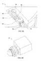
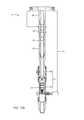
- FIG. 15illustrates an alternative latch head 75 , according to another embodiment of the present disclosure.
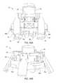
- FIG. 16Aillustrates the alternative latch head 75 in the docked mode.
- FIG. 16Billustrates the alternative latch head 75 in the release mode.
- An alternative CMCmay include the alternative latch head 75 and an alternative stem (not shown) for the respective drilling 4 d , casing 4 c , and cementing 4 s units.
- the alternative CMCmay be used with the top drive 4 instead of the CMC 4 y .
- the alternative latch head 75may include a torque shaft 76 , a control swivel (not shown), a seal sleeve (not shown), a grapple 77 , the (one or more) junction members 40 d,e,h,p , and the torque sub (not shown).
- the grapple 77may include a plurality of clamps 78 , one or more actuators 79 , a hinge 80 for each clamp, a cam mechanism 81 for each clamp, and a leveling ring 82 .
- the torque shaft 76may have a bore formed therethrough and may have a tubular portion and a flange portion extending outward from the tubular portion.
- the tubular portion of the torque shaft 76may be similar to the tubular portion of the torque shaft 35 .
- the flange portion of the torque shaft 76may have the receptacles 35 j formed in a lower face and outer surface thereof for receiving the respective junction members 40 d,e,h,p , may have one or more compartments 76 m formed in an upper face thereof for receiving the respective actuator 79 , may have cavities 76 c formed in an outer surface thereof for receiving the clamps 78 , and may have the alignment feature, such as the pins 35 f , extending from the lower face thereof.
- the alternative latch head 75may further include a latch sensor (not shown) for each clamp 78 similar to the latch sensor 49 and the torque shaft 76 may further have a cutout formed in the lower face thereof adjacent to each cavity 76 c for housing the respective latch sensor.
- Each alternative stemmay have a bore formed therethrough and may have a tubular portion and a flange portion extending outward from the tubular portion.
- the tubular portion of each alternative stemmay have a polished receptacle formed in an inner surface thereof and adjacent to a top thereof, may have the torsional coupling, such as the keyways, formed in the top thereof, and may have the coupling, such as the threaded box or pin, formed at a bottom thereof.
- each alternative stemmay have receptacles formed in an upper face thereof for receiving the respective junction members 48 d,e,h,p , may have clamp profiles formed in an outer surface thereof for receiving the clamps 78 , and may have the alignment feature, such as the pinholes, extending from the upper face thereof.
- a lower portion of each clamp 78may have a tongue formed on an inner surface thereof for being received by a groove of each clamp profile, thereby longitudinally connecting the torque shaft 76 and the respective alternative stem.
- Each hinge 80may pivotally connect the respective clamp 78 to the torque shaft 76 .
- Each hinge 80may include a pair of knuckles mounted to the upper face of the flange portion of the torque shaft 76 .
- An upper portion of each clamp 78may have a knuckle formed in an inner surface thereof.
- the hinge knucklesmay be spaced apart for receiving and straddling the respective clamp knuckle.
- Each knucklemay have a hole formed therethrough and a hinge pin may be inserted through the respective holes to assemble the respective hinge 80 .
- the leveling ring 82may surround the tubular portion of the torque shaft 76 and may be longitudinally movable relative thereto between an upper position ( FIG. 16B ) and a lower position ( FIGS. 15 and 16A ) by operation of the actuators 79 .
- Each actuator 79may be linear, such as a piston and cylinder assembly, for moving the leveling ring 82 between the upper and lower positions.
- Each piston and cylinder assemblymay have a coupling, such as a hinge knuckle, formed at each longitudinal end thereof.
- An upper hinge knuckle of each piston and cylinder assemblymay be received by respective knuckles of the leveling ring 82 and pivotally connected thereto, such as by fastening.
- a lower hinge knuckle of each piston and cylinder assemblymay be received by knuckles mounted in the respective compartment 76 m and pivotally connected to the torque shaft 76 , such as by fastening.
- a piston of each piston and cylinder assemblymay be disposed in a bore of the respective cylinder.
- the pistonmay divide the cylinder bore into a raising chamber and a lowering chamber and the cylinder may have ports formed through a wall thereof and each port may be in fluid communication with a respective chamber Each port may also be in fluid communication with the manifold 27 m via a respective control line (not shown) and the control swivel.
- Supply of hydraulic fluid to the raising portmay lift the leveling ring 82 to the upper position.
- Supply of hydraulic fluid to the lowering portmay drop the leveling ring 82 to the lower position.
- Each cam mechanism 81may pivot the clamps 78 into engagement ( FIG. 16A ) with and out to disengagement ( FIG. 16B ) from the clamp profiles of the stems in response to movement of the leveling ring 82 between the upper and lower positions, thereby longitudinally connecting and disconnecting the stems to/from the torque shaft 76 .
- Each cam mechanism 81may include a pair of lugs mounted to the leveling ring 82 .
- the upper portion of each clamp 78may also serve as a lug.
- the cam lugsmay be spaced apart for receiving and straddling the respective clamp lug.
- the cam lugsmay each have a J-slot formed therethrough, the clamp lug may have a hole formed therethrough, and a follower pin may be inserted through the respective hole and J-slots to assemble the respective cam mechanism 81 .
- a tubular adapter(not shown) may be used to connect either torque shaft 35 , 76 to the quill 23 q .
- the quill 23 qmay then be a threaded pin instead of a threaded box and the adapter may include a threaded coupling at each longitudinal end thereof for accommodating the connection between the quill and either torque shaft 35 , 76 .
- the CMC 4 y or alternative CMC including the alternative latch head 75 of FIG. 15may be used with any other top drive tool, such as a completion tool, a wireline tool, a fracturing tool, a pump, or a sand screen.
- FIGS. 17-21illustrate alternative embodiments of CMCs according to the present disclosure.
- the CMCs described belowmay be used in place of the CMC 4 y.
- FIGS. 17A-17Dillustrates a CMC 1700 according to another embodiment of the present disclosure.
- the CMC 1700includes a tool dock 1710 and a drive stem 1720 .
- the tool dock 1710 and the drive stem 1720may be joined together using a set of locking clamps 1730 .
- the tool dock 1710may be attached to or integrated on a tool, such as drilling tool, a completion tool, a wireline tool, a fracturing tool, a pump, or a sand screen.
- the tool dock 1710may include a stem 1711 having a central bore 1712 .
- a shoulder 1717may be formed at an upper end of the stem 1711 .
- the shoulder 1717may be used to engage the plurality of locking clamps 1730 .
- the tool dock 1710may also include torque tabs 1716 formed above the shoulder 1717 for transferring torsional loads.
- An upper end of the tool dock 1710may include a seal profile 1715 shaped to make a fluid connection with the drive stem 1720 .
- a flange 1713may extend from the stem 1711 .
- One or more junction members 1714may be disposed on the flange 1713 to be connected with matching couplers from a top drive. Similar to one of the junction members 48 d,e,h,p , each of the junction members 1714 may be configured to establish data, electrical, hydraulic, pneumatic communication, or any other signals.
- the drive stem 1720may include a mandrel 1721 having a central bore 1722 .
- a seal profile 1723may be formed at a lower end of the mandrel 1721 .
- the seal profile 1723matches the seal profile 1715 of the tool dock 1710 to seal the connection between the drive stem 1720 and tool dock 1710 preventing high pressure fluids from leaking out of the connection.
- Torque tabs 1724may be formed on the mandrel 1721 .
- the torque tabs 1724match the torque tab 1716 on the tool dock 1710 to transfer torsional loads.
- FIG. 17Bis a perspective view of the drive stem 1720 .
- An exemplary design of the torque tabs 1724is shown in FIG. 17B .
- other torque transfer profilesuch as a spline type profile, a gear type profile, may be used in place of the torque tabs 1724 .
- the drive stem 1720may include an internal blow out preventer 1725 .
- the internal blow out preventer 1725may be remotely actuated blow out preventer.
- a hydraulic swivel 1726may be attached to the mandrel 1721 .
- a groove 1727may be formed around the mandrel 1721 to receive the plurality of locking clamps 1730 .
- the plurality of locking clamps 1730may be radially distributed around the mandrel 1721 .
- FIG. 17Cis an enlarged partial view of the drive stem 1720 showing details of the locking clamps 1730 .
- Each locking clamp 1730may have a “C” shape profile.
- An upper end 1731 of each locking clamp 1730is disposed in the groove 1727 .
- the profile of the upper end 1731 and the groove 1727are shaped to allow the locking clamps 1730 to pivot in the groove 1727 relative to the mandrel 1721 .
- An external sleeve 1733may be disposed around the plurality of locking clamps 1730 to pivot in the groove 1727 therefore open and close.
- the external sleeve 1733may move vertically by an actuator 1736 .
- the actuator 1736may be a hydraulic actuator, or an actuator powered by other forms of power.
- the locking clamps 1730open/close when a contact surface 1734 near the upper end 1731 of each locking clamp 1730 interacts with an inner groove 1735 of the external sleeve 1736 .
- the internal groove 1735 in the external sleeve 1733pushes the external profile of the locking clamps 1730 creating an angular movement tilting the locking clamps 1730 outwards, as shown in FIG. 17A .
- An internal profile in the upper end 1731 of each locking clamp 1730mates with an angled profile of the groove 1727 facilitating the angular movement of the locking clamp 1730 .
- the locking clamps 1730pivot up to certain degree to allow access for the tool dock 1710 to make a connection.
- the external sleeve 1733lowers and the lower section of the external sleeve 1733 pushes the locking clamps 1730 inward.
- Multiple section of contact surfaceare created between the external sleeve 1733 and the locking clamps 1730 eliminating any possible clearance or play between the drive stem 1720 and the tool dock 1710 .
- the locking clamps 1730 and the external sleeve 1733function as a locking mechanism to secure the connection between the drive stem 1720 and the tool dock 1710 .
- FIG. 17Dis a schematic sectional view of the CMC 1700 in a connected position.
- the upper end 1731 of each locking clamp 1730has a load shoulder 1742 .
- the load shoulder 1742 on the locking clamp 1730clamps on a load shoulder 1737 in the groove 1727 of the drive stem 1720 .
- the lower end 1732 of each locking clamp 1730has a load shoulder 1740 .
- the load shoulder 1740 of the locking clamp 1730clamps on the shoulder 1717 of the tool dock 1710 .
- the “C” shaped profile of the locking clamps 1730transfer the axial load between the drive stem 1720 to the tool dock 1710 through the connections between the load shoulder 1742 and 1737 and the load shoulders 1740 and 1717 .
- one or both load shoulder pairs 1742 , 1737 and 1740 , 1717may be tapered to eliminate the clearance needed for the connection. Tapered load shoulders also provides preload to the connection.
- the contact surface 1734 of the locking clamp 1730 and the inner groove 1735 on the external sleeve 1733may be tapered too.
- the tapered contact surfaces between the locking clamps 1730 and the external sleeve 1733allows the external sleeve 1733 to push the locking clamps radially against the load shoulders 1742 , 1737 , therefore, preventing the force from the external sleeve 1733 to preload the connection.
- one or more junction members 1738may be disposed on a flange 1739 of the external sleeve 1733 .
- the junction members 1733couple with a corresponding one of the junction members 1714 on the tool dock 1710 to facilitate connections of data, electrical, hydraulic, pneumatic communication, or any other signals.
- the junction membersmay be incorporated in the mandrel 1721 of the drive stem 1720 and the stem 1711 of the tool dock 1710 . Flow channels may be drilled through to the mandrel 1721 and the stem 1711 to allow fluid transfer and data transmission.
- junction members 1714 , 1738may be spring loaded to provide compensation to the variation of end positions of the external sleeve 1733 .
- the flange 1739 or the flange 1713may be movable relative to the external sleeve 1733 or the stem 1711 to compensate the variable end position.
- FIGS. 18A-18Cillustrates a CMC 1800 according to another embodiment of the present disclosure.
- the CMC 1800includes a tool dock 1810 and a drive stem 1820 .
- FIG. 18Ais a schematic perspective view of the CMC 1800 at an open position.
- FIG. 18Bis a schematic sectional view of the CMC 1800 at the open position.
- FIG. 18Cis a schematic sectional view of the CMC 1800 at a connected position.
- the tool dock 1810is similar to the tool dock 1710 except that the tool dock 1810 has external thread 1811 formed on an upper portion 1812 .
- the external thread 1811is configured to engage the drive stem 1820 and support axial loads.
- the drive stem 1820includes a mandrel 1821 .
- the mandrel 1821may include a load shoulder 1822 near a lower end.
- the load shoulder 1822has an upper surface 1824 .
- the mandrel 1821has external threads 1823 formed above the load shoulder 1822 .
- the drive stem 1820 and the tool dock 1810may be connected by a load nut 1830 and a guide ring 1840 .
- the load nut 1830may have a cylindrical outer surface 1837 .
- Gears 1832may be formed on the outer surface 1837 .
- One or more drive gears 1834may mate with gears 1832 so that the rotation of the drive gears 1834 rotates the load nut 1830 .
- the load nut 1830may include an inner shoulder 1838 .
- Internal threads 1831may be formed on an inner surface 1839 below the inner shoulder 1838 .
- the internal threads 1831are configured to couple with the external threads 1811 on the tool dock 1810 .
- the coupling between the internal threads 1831 and the external threads 1811transfers axial loads between the load nut 1830 and the tool dock 1810 .
- the guide ring 1840includes internal threads 1835 sized to couple with the external thread 1823 on the mandrel 1821 .
- the guide ring 1840is attached to the load nut 1830 by one or more pins 1836 .
- the one or more pins 1836prevent the guide ring 1840 and the load nut 1830 from rotating relative to each other, but allow some vertical movement between the load nut 1830 and the guide ring 1840 .
- the one or more pins 1836may be screws with extended lengths.
- the one or more pins 1836may be spring loaded to allow the load nut 1830 to move down relative to the guide ring 1840 .
- the internal threads 1835 of the guide ring 1840engage the external threads 1823 enabling the guide ring 1840 and the load nut 1830 to move vertically up or down the mandrel 1821 .
- the drive stem 1820 and the tool dock 1820may also matching torque transfer profiles to transfer torsional loads therebetween.
- the torque transfer profilecan be a spline type, gear type, tab type.
- Seal profilesmay be formed on the drive stem 1820 and the tool dock 1810 to seal the connection between the drive stem 1820 and tool dock 1810 preventing high pressure fluids from leaking out of the connection.
- junction members 1813similar to the junction members 1733 and 1714 may also be disposed on the drive stem 1820 and the tool dock 1810 to facilitate connections of data, electrical, hydraulic, pneumatic communication, or any other signals.
- the junction membersmay be incorporated in the drive stem 1820 and the tool dock 1810 through flow channels drilled therethrough.
- the drive gears 1834rotate to turn the load nut 1830 , and the load nut 1830 turns the guide ring 1840 so that the load nut 1830 and the guide ring 1840 move downward relative to the mandrel 1821 .
- the downward movement of the load nut 1830allows the tool dock 1810 to engage the load nut 1830 through the internal threads 1831 .
- the relative distance between the guide ring 1840 and the load nut 1830guarantees the correct thread engagement between the load nut 1830 and the tool dock thread 1840 .
- the load nut 1830may move downward until the shoulder 1838 engages the upper surface 1824 of the load shoulder 1822 to transfer axial loads between the mandrel 1821 and the load nut 1830 .
- the load nut 1830transfers the axial loads to the tool dock 1810 through the connections between the internal threads 1831 and the external threads 1811 .
- the drive gears 1834simply rotates along the opposition direction to disengage the internal threads 1831 and the external threads 1811 .
- FIGS. 19A-190illustrates a CMC 1900 according to another embodiment of the present disclosure.
- the CMC 1900includes a tool dock 1910 and a drive stem 1920 connectable by a set of locking wedges.
- FIG. 19Ais a schematic perspective view of the CMC 1900 .
- FIG. 19Bis a schematic sectional view of the drive stem 1920 .
- FIG. 19Cis a schematic perspective view of the drive stem 1920 showing the load profiles.
- FIG. 19Dis a schematic sectional view of the tool dock 1910 .
- the tool dock 1910may be attached to or integrated on a tool, such as drilling tool, a completion tool, a wireline tool, a fracturing tool, a pump, or a sand screen.
- the tool dock 1910may include a stem 1911 having a central bore 1912 .
- An axial load profile 1917may be formed on an outer surface of the stem 1911 .
- the axial load profile 1917may include multiple grooves.
- the axial load profile 1917includes multiple grooves formed on a tapered surface.
- the tool dock 1910may also include torque tabs 1916 for transferring torsional loads.
- An upper end of the tool dock 1910may include a seal profile 1915 shaped to make a fluid connection with the drive stem 1920 .
- a flange 1913may extend from the stem 1911 .
- One or more junction members 1914may be disposed on the flange 1913 to be connected with matching junction members on the drive stem 1920 to establish data, electrical, hydraulic, pneumatic communication, or any other signals.
- the drive stem 1920may include a mandrel 1921 having a central bore 1922 .
- a seal profile 1923may be formed at a lower end of the mandrel 1921 .
- the seal profile 1723matches the seal profile 1915 of the tool dock 1910 to seal the connection between the drive stem 1920 and tool dock 1910 preventing high pressure fluids from leaking out of the connection.
- Torque tabs 1924may be formed on the mandrel 1921 .
- the torque tabs 1924match the torque tab 1916 on the tool dock 1910 to transfer torsional loads.
- other torque transfer profilesuch as a spline type profile, a gear type profile, may be used in place of the torque tabs 1924 .
- An axial load profile 1927may be formed around an outer surface of the mandrel 1921 .
- the axial load profile 1927may include multiple grooves.
- the axial load profile 1927includes multiple grooves formed on a tapered surface.
- the drive stem 1920further includes a plurality of locking wedges 1930 .
- Each locking wedge 1930may be a section of a ring.
- the plurality of locking wedges 1930may be radially distributed around the mandrel 1921 .
- the plurality of locking wedges 1930may be held in place by an internal carrier 1933 to form a circle.
- the internal carrier 1933may be a tubular having a plurality of cutouts to receive the locking wedges 1930 .
- the internal carrier 1933may be fixedly attached to the mandrel 1921 .
- the locking wedges 1930can move radially inward and outward relative to the internal carrier 1933 .
- Each of the locking wedge 1930may include an upper load profile 1931 and a lower load profile 1932 formed in an inner surface.
- the upper load profile 1931may include multiple grooves that match the axial load profile 1927 on the mandrel 1921 .
- the lower load profilemay include multiple grooves that match the axial load profile 1917 of the tool dock 1910 .
- Each locking wedge 1930may be coupled to the mandrel 1921 and the tool dock 1910 through the upper and lower load profiles 1931 , 1932 to transfer axial load between the tool dock 1910 and the mandrel 1921 .
- the plurality of locking wedges 1930may be moved radially inward to engage the mandrel 1921 and the tool dock 1910 and radially outward to disengage the mandrel 1921 and the tool dock 1910 .
- the drive stem 1920further includes a sleeve 1940 disposed radially outside the plurality of locking wedges 1930 .
- a plurality of cam blocks 1941may be disposed inside the sleeve 1940 .
- FIG. 19Gis a sectional top view of the drive stem 1920 .
- the plurality of locking wedges 1930may be wedged between neighboring cam blocks 1941 .
- Each cam block 1941may have guiding slots 1944 formed on side surfaces.
- Each cam block 1941may be connected to the neighboring locking wedge 1930 by a pin 1942 .
- One end of each pin 1942may be disposed in the guiding slot 1944 of a cam block 1941 .
- the guiding slots 1944are shaped to transfer the vertical movement of the sleeve 1940 to radial movement of the locking wedges 1930 .
- the plurality of wedges 1930may be moved radially inward or outward by moving the sleeve 1940 downward or upward.
- the sleeve 1940may be connected to an actuator 1945 .
- the actuator 1945may be configured to move the sleeve 1940 vertically along the mandrel 1920 .
- the actuator 1945may be a hydraulic actuator, or an actuator powered by other forms of power.
- one or more junction members 1938may be disposed on a flange 1939 of the sleeve 1940 .
- the junction members 1938couple with a corresponding one of the junction members 1914 on the tool dock 1910 to facilitate connections of data, electrical, hydraulic, pneumatic communication, or any other signals.
- one or both of the junction members 1914 , 1938may be spring loaded to provide compensation to the variation of end positions of the sleeve 1940 due to the tapered shape and the wear of the contact surface.
- the flange 1939 or the flange 1913may be movable relative to the mandrel 1921 or the stem 1911 to compensate the variable end position.
- the junction membersmay be incorporated in the mandrel 1921 of the drive stem 1920 and the stem 1911 of the tool dock 1910 . Flow channels may be drilled through to the mandrel 1921 and the stem 1911 to allow fluid transfer and data transmission.
- FIGS. 19E, 19F, and 19Gschematically illustrate the CMC 1900 at an open position.
- the sleeve 1940is moved up so that the plurality of locking wedges 1930 can open to allow the tool dock 1910 to be inserted into the drive stem 1920 .
- FIGS. 19H, 19I, and 19Jthe tool dock 1910 is inserted into the drive stem 1920 and a seal connection is formed between the seal profiles 1923 and 1915 .
- the torque tabs 1924 and 1916also matches.
- the plurality of locking wedges 1930remain open.
- FIGS. 19K, 19L, and 19Mthe sleeve 1940 is moved downward urging the plurality of locking wedges 1930 radially inward towards the mandrel 1921 and the stem 1911 .
- FIGS. 19K, 19L, and 19Mthe sleeve 1940 is moved downward urging the plurality of locking wedges 1930 radially inward towards the mandrel 1921 and the stem 1911 .
- the sleeve 1940is moved to the connecting position, the upper and lower load profiles 1931 , 1932 of the plurality of locking wedges 1930 are coupled with the axial load profiles 1927 and 1917 on the mandrel 1921 and the stem 1911 respectively.
- the junction members 1914 and 1938also connected.
- the drive stem 1920 and the tool dock 1910are connected.
- the locking wedges 1930 and the sleeve 1940function as a locking mechanism to secure the connection between the drive stem 1920 and the tool dock 1910 .
- the sleeve 1940is moved up to open the plurality of locking wedges 1930 .
- the tool dock 1910can then be moved away from the drive stem 1920 .
- FIGS. 20A-20Eillustrates a CMC 2000 according to another embodiment of the present disclosure.
- the CMC 2000includes a tool dock 2010 and a drive stem 2020 joined by locking pins.
- FIG. 20Ais a schematic perspective view of the CMC 2000 at a connected position.
- FIG. 20Bis a schematic sectional view of the CMC 2000 at the connected position.
- FIG. 20Cis a schematic view of the CMC 2000 at an open position.
- the tool dock 2010is similar to the tool dock 1710 except that the tool dock 2010 has a lower housing 2017 attached.
- the tool dock 2010includes a stem 2011 . Similar to the stem 1711 , the stem 2011 may include a seal profile and torque tabs to connect with the drive stem 2020 .
- a load nut 2019may be connected to the drive stem 2011 by load threads. Locking tabs 2016 may be used to prevent the load nut 2019 from backing out of the threaded connection.
- the lower housing 2017contacts the load nut 2019 at a load surface 2012 to transfer axial loads.
- the lower housing 2017may include pin openings 2018 .
- the drive stem 2020includes a mandrel 2021 .
- the mandrel 2021is similar to the mandrel 1721 except that the mandrel 2021 has an upper housing 2027 and a load nut 2029 attached.
- the load nut 2029may be connected to the mandrel 2021 by load threads.
- Locking tabs 2026may be used to prevent the load nut 2029 from backing out of the threaded connection.
- the upper housing 2027contacts the load nut 2029 at a load surface 2022 to transfer axial loads.
- the upper housing 2027may have pin openings 2028 formed therein.
- the pin openings 2028 , 2018may be aligned and load pins 2030 may be inserted through the pin opening 2028 , 2018 to join the upper housing 2027 and the lower housing 2017 together.
- Two or more load pins 2030may be used to join the upper housing 2027 and the lower housing 2017 .
- each load pin 2030may be coupled to an actuator 2040 .
- the actuator 2040is configured to move the load pin 2030 in and out the pin openings 2028 , 2018 .
- the actuator 2040may be hydraulic, pneumatic, electric actuators.
- the load pins 2030may be inserted and removed manually.
- the load pins 2030function as a locking mechanism to secure the connection between the drive stem 2020 and the tool dock 2010 .
- FIGS. 20C, 20D, and 20Eschematically illustrate the process of connecting the drive stem 2020 and the tool dock 2010 .
- junction memberssimilar to the junction members 1733 and 1714 may also be disposed on the drive stem 2020 and the tool dock 2010 to facilitate connections of data, electrical, hydraulic, pneumatic communication, or any other signals.
- the junction membersmay be incorporated in the drive stem 2020 and the tool dock 2010 through flow channels drilled therethrough.
- the CMC 2000may include split or segmented upper and lower housing to incorporate load profiles in the housings, thereby eliminating the need of load nuts.
- the housing halves or segmentsmay be attached together using screws or locking pins.
- FIGS. 21A-21Iillustrates a CMC 2100 according to another embodiment of the present disclosure.
- the CMC 2100includes a tool dock 2110 and a drive stem 2120 having segmented buttress load profiles.
- FIG. 21Ais a schematic view of the CMC 2100 in a connected position.
- FIG. 21Bis a schematic sectional view of the CMC 2100 at the connected position.
- FIG. 20Cis a schematic view of the drive stem 2120 .
- FIG. 21Dis a schematic view of the tool dock 2110 .
- the tool dock 2110may be attached to or integrated on a tool, such as drilling tool, a completion tool, a wireline tool, a fracturing tool, a pump, or a sand screen.
- the tool dock 2110may include a stem 2111 having a central bore 2112 .
- the tool dock 2110may also include a seal profile 2115 near an upper end of the central bore 2112 and shaped to make a fluid connection with the drive stem 2120 .
- An axial load profile 2117may be formed inside the stem 2111 near an upper end of the stem 2111 .
- the axial load profile 2117may be a segmented buttress profile.
- a flange 2113may extend from the stem 2111 .
- a torque profile 2116may be formed above the flange 2113 for transferring torsional loads.
- the torque profile 2116may be a tab type, a spline type, a gear type, or any suitable type of torque profile.
- junction members 2114may be disposed on the flange 2113 to be connected with matching couplers from a top drive.
- the junction members 2114may be configured to establish data, electrical, hydraulic, pneumatic communication, or any other signals.
- the drive stem 2120may include a mandrel 2121 having a central bore 2122 .
- a seal profile 2123may be formed at a lower end of the mandrel 2121 .
- the seal profile 2123matches the seal profile 2115 of the tool dock 2110 to seal the connection between the drive stem 2120 and tool dock 2110 preventing high pressure fluids from leaking out of the connection.
- An axial load profile 2127may be formed around the mandrel 2121 .
- the axial load profile 2127matches the axial load profile 2117 of the tool dock 2110 .
- the axial load profile 2127may be a segmented buttress profile.
- the mandrel 2121may include a spline profile 2126 formed above the axial load profile 2127 .
- a torque ring 2130may be connected to the mandrel 2121 through the spline profile 2126 .
- the torque ring 2130may have a spline profile 2131 formed in an inner surface to couple with the spline profile 2126 so that the torque ring 2130 can move vertically along the mandrel 2121 .
- the torque ring 2130may have a torque profile 2124 formed at a lower surface. The torque profile 2124 matches the torque profile 2116 of the tool dock 2110 .
- a cover sleeve 2132may be coupled to the torque ring 2130 .
- One or more junction members 2135may be disposed the cover sleeve 2132 .
- the junction members 2135may couple with a corresponding one of the junction members 2114 on the tool dock 2110 to facilitate connections of data, electrical, hydraulic, pneumatic communication, or any other signals.
- the junction membersmay be incorporated in the mandrel 2121 of the drive stem 2120 and the stem 1711 of the tool dock 2110 .
- Flow channelsmay be drilled through to the mandrel 2121 and the stem 2111 to allow fluid transfer and data transmission.
- FIGS. 21F-21Ischematically illustrate the process of making the connection between the drive stem 2120 and the tool dock 2110 .
- the actuator 2140raises up the torque ring 2130 and the cover sleeve 2132 .
- the drive stem 2120 and the tool dock 2110may rotate relative to each other so that the axial load files 2117 and 2127 are in alignment for insertion.
- the tool dock 2110is stabbed to the drive stem 2120 until a seal connection is make between the seal profiles 2115 , 2123 .
- FIG. 21Gthe tool dock 2110 is stabbed to the drive stem 2120 until a seal connection is make between the seal profiles 2115 , 2123 .
- the tool dock 2110 and the drive stem 2120rotate relative to each other to couple the axial load profiles 2117 and 2127 so that axial loads can be transferred between the tool dock 2110 and the drive stem 2120 .
- the actuator 2140lowers down the torque ring 2130 and the cover sleeve 2132 to couple the torque profiles 2116 , 2124 .
- the junction members 2114 and 2135are also connected.
- the tool dock 2110 and the drive stem 2120are connected.
- the torque ring 2130 and the cover sleeve 2132function as a locking mechanism to secure the connection between the drive stem 2120 and the tool dock 2110 .
- the torque ring 2130 and the cover sleeve 2132may be raised first to disconnect the torque coupling and the junction members 2135 , 2114 .
- the tool dock 2110 and the drive stem 2120can then be rotated relative to each other to disengage the axial load profiles 2127 , 2117 .
- the tool dock 2110can then be moved away from the drive stem 2120 .
- the CMCs 1700 , 1800 , 1900 , 2000 , and 2100 disclosed abovemay be used in place of the CMC 4 y with any suitable top drive tools, such as a drilling tool, a cementing tool, a casing tool, a completion tool, a wireline tool, a fracturing tool, a pump, or a sand screen.
- a drilling toolsuch as a drill tool, a cementing tool, a casing tool, a completion tool, a wireline tool, a fracturing tool, a pump, or a sand screen.
- coupling profiles used in any of the above CMCsmay be also used in a unit rack, such as the unit rack 4 k , for storing tools.
- Each tool dockmay be secured to a tool receiving spot in the unit rack having the same profile as the profile in the drive stem.
- the tool docksare connected to a tool and the drive stems are connected to a top drive unit
- structures of the tool docksmay be connected to a top drive unit while structures of the corresponding drive stems may be connected to a tool.
- the combined multi-couplerincludes a shaft for being rotated by a motor unit of the top drive, a stem for connecting a drilling unit, a casing unit, or a cementing unit to the shaft, a bore formed through the shaft and the stem for transporting fluid from the top drive to a tubular string connected to one of the units, a latch connected to a flange of the shaft and operable to engage a flange of the stem for longitudinally connecting the shaft and the stem, a fluid junction and an electrical junction, each junction comprising a member connected to the shaft flange and a member connected to the stem flange, a torsional coupling formed in the shaft, and a torsional coupling formed in the stem, wherein engagement of the stem with the shaft mates the torsional couplings and the junction members.
- the fluid junctionmay be a hydraulic junction.
- the electrical junctionmay be an electric power junction.
- the combined multi-couplermay further comprise a data junction and a pneumatic junction.
- Each of the data and pneumatic junctionsmay comprise a member connected to the shaft flange and a member connected to the stem flange.
- the above combined multi-couplermay include a control swivel disposed around and connected to the shaft, control lines connecting the shaft members of the fluid junctions to a rotating member of the control swivel, and a control cable connecting the electric power junction to the rotating member, and a control cable connecting the data junction to the rotating member.
- the latchmay include a plurality of latch blocks and an actuator for each latch block, each actuator is connected to the respective latch block, each actuator is disposed in a slot formed in an upper face of the shaft flange and connected to the shaft, each actuator is operable to radially move the respective latch block between an engaged position and a disengaged position, and each latch block mates with a cavity of the shaft flange and a latch profile of the stem flange in the engaged position and is clear thereof in the disengaged position.
- the above combined multi-couplermay further include a position sensor for each latch block and disposed in a respective cutout formed in a lower face of the shaft flange, each position sensor operable by movement of the respective latch block from the disengaged position to the engaged position.
- each latch blockmay have a central backbone, plates extending from sides and an inner surface of the backbone, a neck extending upward from the backbone, and a lug formed on top of the neck.
- each latch blockmay have an outer base, inner teeth extending from and along an inner surface of the base, a neck extending upward from the base, and a lug formed on top of the neck.
- each latch blockmay have a base with a wedge formed on an inner surface thereof, a neck extending upward from the base, and a lug formed on top of the neck.
- the latchmay be a grapple.
- the grapplemay include a plurality of clamps, a plurality of hinges pivotally connecting the clamps to the shaft flange, and a leveling ring surrounding the shaft.
- the grapplemay further include one or more actuators for raising and lowering the leveling ring relative to the shaft, and a plurality of cam mechanisms linking the clamps to the leveling ring for pivoting the clamps between an engaged position and a disengaged position in response to raising and lowering of the leveling ring, and each clamp mates with a clamp profile of the stem flange in the engaged position and is clear thereof in the disengaged position.
- the shaftmay be a torque shaft.
- the above combined multi-couplermay further include a torque sub.
- the torque subincludes a non-rotating interface, a recess formed in an outer surface of the torque shaft, a strain gage disposed on the torque shaft at the recess and oriented to measure torque exerted thereon, a transmitter disposed on the torque shaft, in communication with the strain gage, and operable to wirelessly transmit the torque measurement to the interface, a turns gear torsionally connected to the torque shaft, and a proximity sensor connected to the interface and located adjacent to the turns gear.
- the above combined multi-couplermay further include a seal sleeve connected to the shaft, engaged with a seal bore thereof, and carrying a stab seal for engagement with a seal receptacle of the stem upon engagement of the stem with the shaft.
- the drill unitmay include the stem, a thread saver, and an internal blowout preventer connecting the thread saver to the stem.
- the casing unitincludes the stem, a thread compensator connecting a clamp to the stem, the clamp comprising a set of grippers for engaging a surface of a joint of casing, thereby anchoring the casing joint to the casing unit, and an actuator for selectively engaging and disengaging the clamp with a casing joint, and a stab seal for engaging an inner surface of the casing joint.
- the cementing unitincludes the stem, an internal blowout preventer, and a cementing swivel.
- the cementing swivelincludes a housing having an inlet formed through a wall thereof for connection of a cement line, a mandrel connected to the respective quill and having a port formed through a wall thereof in fluid communication with the inlet, a bearing for supporting rotation of the mandrel relative to the housing, and a seal assembly for isolating the inlet-port communication.
- the cementing unitfurther comprises a launcher.
- the launchercomprises a body connected to the mandrel of the cementing swivel, a dart disposed in the launcher body, and a gate having a portion extending into the launcher body for capturing the dart therein and movable to a release position allowing the dart to travel past the gate.
- FIG. 1Another embodiment provides a modular top drive system for construction of a wellbore.
- the systemincludes any of the above combined multi-couplers, a rail for connection to a drilling rig, and the motor unit.
- the motor unitincludes a drive body, a drive motor having a stator connected to the drive body, a trolley for connecting the drive body to the rail, and a quill connecting the shaft to a rotor of the drive motor.
- the above systemfurther includes a pipe handler.
- the pipe handlerincludes a handler body connected to the drive body, a pair of bails pivotally connected to the handler body, and a backup wrench.
- the backup wrenchincludes an arm, an upper hinge pivotally connecting the arm to the handler body, a pair of tong segments, a lower hinge pivotally connecting the tong segments to the arm, and a tong actuator pivotally connected to the arm and the tong segments and operable to move the tong segments between an engaged position with a drill string and a stowed position adjacent to the rail.
- the motor unitfurther comprises a becket for connection to a hoist of the drilling rig, a mud swivel comprising an outer barrel connected to the drive body and an inner barrel having an upper portion disposed in the outer barrel and a stinger portion for stabbing into a seal receptacle of the quill, a nipple connected to the outer barrel for receiving a mud hose, and a down thrust bearing for supporting the quill for rotation relative to the drive body.
- a becketfor connection to a hoist of the drilling rig
- a mud swivelcomprising an outer barrel connected to the drive body and an inner barrel having an upper portion disposed in the outer barrel and a stinger portion for stabbing into a seal receptacle of the quill
- a nippleconnected to the outer barrel for receiving a mud hose
- a down thrust bearingfor supporting the quill for rotation relative to the drive body.
- the above systemfurther includes a unit handler locatable on or adjacent to a structure of the drilling rig and operable to retrieve any one of the drilling, casing, and cementing units from a rack and deliver the retrieved unit to the motor unit.
- the unit handlercomprises an arm, and a holder releasably connected to the arm and operable to carry any one of the drilling, casing, and cementing units.
- the unit handlerfurther comprises a pipe clamp releasably connected to the arm and operable to carry a joint of casing or liner for delivery to the casing unit.
- the unit handlerfurther comprises a base for mounting the unit handler to a subfloor structure of the drilling rig, a post extending from the base to a height above a floor of the drilling rig, a slide hinge transversely connected to the post, and the arm connected to the slide hinge and comprising a forearm segment, an aft-arm segment, and an actuated joint connecting the arm segments.
- Embodiment of the present disclosureincludes a combined multi-coupler, comprising a first tubular member having a first load profile and a first junction member, and a second tubular member having a second load profile and a second junction member. Engagement of the first tubular member to the second tubular member forms a connection between the first and second load profiles to transfer at least one of axial load and torsional load and a connection between the first and second junction members to transfer fluid or signals.
- one of the first tubular member and the second tubular memberis a tool dock for connecting to one of a drilling tool, a cementing tool, a casing tool, a completion tool, a wireline tool, a fracturing tool, a pump, and a sand screen.
- the other one of the first tubular member and the second tubular memberis a drive stem connected to a top drive.
- the first and second junction memberscomprise one or more of a hydraulic junction, an electric power junction, a data junction, and a pneumatic junction.
- the first tubular memberhas a first central bore and a first seal profile around the first central bore
- the second tubular memberhas a second central bore and a second seal profile around the second central bore
- engagement of the first and second tubularsforms a sealed connection between the first and second central bores.
- the first tubular membercomprises a stem having the first central bore, and a flange extended from the stem, wherein the first junction member is disposed on the flange.
- the second tubular membercomprises a mandrel having the second central bore, and a latch head coupled to the mandrel, and a latch disposed on the latch head to engage the first and second tubular members.
- the second tubular membercomprises a mandrel having the second central bore, a plurality of locking clamps movably disposed around the mandrel, and a sleeve disposed outside the plurality of locking clamps, wherein vertical movement of the sleeve opens and closes the plurality of locking clamps.
- each locking clamphas a C-shaped body, a first end of the C-shaped body couples with the second load profile.
- the second tubular membercomprises a mandrel having the second central bore and an external threads, a guide ring coupled to the mandrel through the external threads, a load nut connected to the guide ring, wherein the load nut has an internal load thread matching the first load profile on the first tubular member and a load shoulder matching the second load profile.
- the second tubular memberfurther comprises a drive gear coupled to gears formed on an outer surface of the load nut.
- the second tubular membercomprises a mandrel having the second central bore, a plurality of locking wedges disposed radially around the central bore, wherein each locking wedge includes an upper load profile matching the second load profile and a lower load profile matching the first load profile, and a sleeve disposed outside the plurality of locking wedges, wherein vertical movement of the sleeve moves the plurality of locking wedges radially inward and outward.
- the first tubular membercomprises a stem having the first central bore, and a first housing coupled to the stem
- the second tubular membercomprises a mandrel having the second central bore, and a second housing coupled to the mandrel, and one or more load pins selectively joining the first housing to the second housing.
- the second tubular memberfurther comprises a load nut coupled to the mandrel through the second load profile, and the second housing contacts the load nut.
- One or more embodimentsfurther includes a locking mechanism actuated by a hydraulic, pneumatic, electric, or other power source to lock the first and second tubular members to transfer axial load and/or torque.
- the second tubular membercomprises a mandrel having the second central bore, wherein the second load profile includes a segmented buttress profile formed on the mandrel, and a torque ring movably disposed around the mandrel.
- the second tubular memberfurther comprises an actuator coupled to the torque ring.
- a modular top drive system for construction of a wellboreincludes a tool, a tool dock connected to the tool, wherein the tool dock has a first load profile and a first junction member, a top drive, and a drive stem connected to the top drive, wherein the drive stem has a second load profile and a second junction member.
- Engagement of the tool dock and the drive stemforms a connection between the first and second load profiles for transferring at least one of axial load and torsional load, and a connection between the first and second junction member for transferring fluid or electric communication between the tool and the top drive.
- the toolis one of a drilling tool, a cementing tool, a casing tool, a completion tool, a wireline tool, a fracturing tool, a pump, and a sand screen.
- a method for constructing a wellborecomprising engaging a tool dock to a drive stem connected to a top drive to formed a connection, transferring at least one of axial load and torsional load through the connection, and transferring at least at least one of hydraulic fluid, electric power, electric signals, data, and pneumatic signals through the junction.
- the method for constructing a wellborefurther comprising performing through a tool coupled to the tool dock at least one of a drilling operation, a casing operation, a cementing operation, a completion operation, a logging operation, a fracturing operation, and an oil recovery operation.
- the method for constructing a wellborefurther comprising locking the engagement of the tool dock and the drive stem by a locking mechanism.
- the locking mechanismis activated by hydraulic power, electric power, or other source of power.
- the locking mechanismis activated by at least at least one of hydraulic fluid, electric power, electric signals, data, and pneumatic signals transferred through the junction.
- the locking mechanismtranslates and/or rotates the tool dock or the drive stem to secure the engagement between the tool dock and the drive stem.
- the first load profilecomprises a first axial load profile and a first torque profile
- the second load profilecomprises a second axial load profile corresponding to the first axial load profile and a second torque profile corresponding to the first torque profile
Landscapes
- Engineering & Computer Science (AREA)
- Life Sciences & Earth Sciences (AREA)
- Geology (AREA)
- Mining & Mineral Resources (AREA)
- Physics & Mathematics (AREA)
- Environmental & Geological Engineering (AREA)
- Fluid Mechanics (AREA)
- General Life Sciences & Earth Sciences (AREA)
- Geochemistry & Mineralogy (AREA)
- Mechanical Engineering (AREA)
- Earth Drilling (AREA)
Abstract
Description
Claims (19)
Priority Applications (4)
| Application Number | Priority Date | Filing Date | Title |
|---|---|---|---|
| US15/004,736US10323484B2 (en) | 2015-09-04 | 2016-01-22 | Combined multi-coupler for a top drive and a method for using the same for constructing a wellbore |
| PCT/US2016/049462WO2017040508A1 (en) | 2015-09-04 | 2016-08-30 | Combined multi-coupler for top drive |
| CA2997214ACA2997214C (en) | 2015-09-04 | 2016-08-30 | Combined multi-coupler for top drive |
| EP16760375.2AEP3344845B1 (en) | 2015-09-04 | 2016-08-30 | Combined multi-coupler for top drive |
Applications Claiming Priority (2)
| Application Number | Priority Date | Filing Date | Title |
|---|---|---|---|
| US201562214310P | 2015-09-04 | 2015-09-04 | |
| US15/004,736US10323484B2 (en) | 2015-09-04 | 2016-01-22 | Combined multi-coupler for a top drive and a method for using the same for constructing a wellbore |
Publications (2)
| Publication Number | Publication Date |
|---|---|
| US20170067320A1 US20170067320A1 (en) | 2017-03-09 |
| US10323484B2true US10323484B2 (en) | 2019-06-18 |
Family
ID=56853941
Family Applications (1)
| Application Number | Title | Priority Date | Filing Date |
|---|---|---|---|
| US15/004,736Active2036-04-09US10323484B2 (en) | 2015-09-04 | 2016-01-22 | Combined multi-coupler for a top drive and a method for using the same for constructing a wellbore |
Country Status (4)
| Country | Link |
|---|---|
| US (1) | US10323484B2 (en) |
| EP (1) | EP3344845B1 (en) |
| CA (1) | CA2997214C (en) |
| WO (1) | WO2017040508A1 (en) |
Cited By (18)
| Publication number | Priority date | Publication date | Assignee | Title |
|---|---|---|---|---|
| US10844684B2 (en)* | 2018-05-31 | 2020-11-24 | DynaEnergetics Europe GmbH | Delivery system |
| US10858901B1 (en)* | 2018-02-20 | 2020-12-08 | Shazam Rahim | Remotely operated connecting assembly and method |
| US11021917B2 (en) | 2017-04-28 | 2021-06-01 | Black Diamond Oilfield Rentals LLC | Piston-style drilling mud screen system and methods thereof |
| US11028656B2 (en) | 2017-04-28 | 2021-06-08 | Black Diamond Oilfield Rentals LLC | Drilling mud screen system and methods thereof |
| US11156042B2 (en)* | 2017-04-28 | 2021-10-26 | Black Diamond Oilfield Rentals LLC | Piston-style drilling mud screen system and methods thereof |
| US11408279B2 (en) | 2018-08-21 | 2022-08-09 | DynaEnergetics Europe GmbH | System and method for navigating a wellbore and determining location in a wellbore |
| US11434713B2 (en)* | 2018-05-31 | 2022-09-06 | DynaEnergetics Europe GmbH | Wellhead launcher system and method |
| US11434725B2 (en) | 2019-06-18 | 2022-09-06 | DynaEnergetics Europe GmbH | Automated drone delivery system |
| US11441413B2 (en) | 2019-07-07 | 2022-09-13 | Barry J. Nield | Apparatus and method for monitoring a power swivel system |
| US11578553B2 (en)* | 2017-11-07 | 2023-02-14 | Fmc Technologies, Inc. | Tubing hanger assembly with adjustable load nut |
| US11619105B2 (en) | 2017-04-28 | 2023-04-04 | Black Diamond Oilfield Rentals LLC | Apparatus and methods for piston-style drilling mud screen system |
| US12000267B2 (en) | 2021-09-24 | 2024-06-04 | DynaEnergetics Europe GmbH | Communication and location system for an autonomous frack system |
| US12060757B2 (en) | 2020-03-18 | 2024-08-13 | DynaEnergetics Europe GmbH | Self-erecting launcher assembly |
| US12253339B2 (en) | 2021-10-25 | 2025-03-18 | DynaEnergetics Europe GmbH | Adapter and shaped charge apparatus for optimized perforation jet |
| US12312922B2 (en) | 2021-01-08 | 2025-05-27 | DynaEnergetics Europe GmbH | Perforating gun assembly and components |
| US12312925B2 (en) | 2021-12-22 | 2025-05-27 | DynaEnergetics Europe GmbH | Manually oriented internal shaped charge alignment system and method of use |
| US12320238B2 (en) | 2020-12-21 | 2025-06-03 | DynaEnergetics Europe GmbH | Encapsulated shaped charge |
| US12404732B2 (en) | 2017-04-28 | 2025-09-02 | Black Diamond Oilfield Rentals LLC | Trapdoor-style drilling mud screen system and methods thereof |
Families Citing this family (38)
| Publication number | Priority date | Publication date | Assignee | Title |
|---|---|---|---|---|
| US8210268B2 (en) | 2007-12-12 | 2012-07-03 | Weatherford/Lamb, Inc. | Top drive system |
| US10626683B2 (en) | 2015-08-11 | 2020-04-21 | Weatherford Technology Holdings, Llc | Tool identification |
| US10465457B2 (en) | 2015-08-11 | 2019-11-05 | Weatherford Technology Holdings, Llc | Tool detection and alignment for tool installation |
| MX384089B (en) | 2015-08-20 | 2025-03-14 | Weatherford Tech Holdings Llc | UPPER DRIVE TORQUE MEASURING DEVICE. |
| US10323484B2 (en) | 2015-09-04 | 2019-06-18 | Weatherford Technology Holdings, Llc | Combined multi-coupler for a top drive and a method for using the same for constructing a wellbore |
| CA2997615A1 (en) | 2015-09-08 | 2017-03-16 | Weatherford Technology Holdings, Llc | Genset for top drive unit |
| US10590744B2 (en) | 2015-09-10 | 2020-03-17 | Weatherford Technology Holdings, Llc | Modular connection system for top drive |
| WO2017053330A1 (en)* | 2015-09-22 | 2017-03-30 | Schlumberger Technology Corporation | Downhole generator system |
| US9644443B1 (en) | 2015-12-07 | 2017-05-09 | Fhe Usa Llc | Remotely-operated wellhead pressure control apparatus |
| US10167671B2 (en) | 2016-01-22 | 2019-01-01 | Weatherford Technology Holdings, Llc | Power supply for a top drive |
| US11162309B2 (en) | 2016-01-25 | 2021-11-02 | Weatherford Technology Holdings, Llc | Compensated top drive unit and elevator links |
| DE102016216469A1 (en)* | 2016-08-31 | 2018-03-01 | Klaus Biester | Blowout Preventer Stack |
| US10648243B1 (en)* | 2016-09-21 | 2020-05-12 | Downing Wellhead Equipment, Llc | Casing string torque transfer and suspension system and method for mandrel casing hangers |
| US10704364B2 (en)* | 2017-02-27 | 2020-07-07 | Weatherford Technology Holdings, Llc | Coupler with threaded connection for pipe handler |
| US10954753B2 (en) | 2017-02-28 | 2021-03-23 | Weatherford Technology Holdings, Llc | Tool coupler with rotating coupling method for top drive |
| US10480247B2 (en) | 2017-03-02 | 2019-11-19 | Weatherford Technology Holdings, Llc | Combined multi-coupler with rotating fixations for top drive |
| US10132118B2 (en) | 2017-03-02 | 2018-11-20 | Weatherford Technology Holdings, Llc | Dual torque transfer for top drive system |
| US11131151B2 (en) | 2017-03-02 | 2021-09-28 | Weatherford Technology Holdings, Llc | Tool coupler with sliding coupling members for top drive |
| US10443326B2 (en) | 2017-03-09 | 2019-10-15 | Weatherford Technology Holdings, Llc | Combined multi-coupler |
| US10247246B2 (en) | 2017-03-13 | 2019-04-02 | Weatherford Technology Holdings, Llc | Tool coupler with threaded connection for top drive |
| US10711574B2 (en) | 2017-05-26 | 2020-07-14 | Weatherford Technology Holdings, Llc | Interchangeable swivel combined multicoupler |
| US10526852B2 (en)* | 2017-06-19 | 2020-01-07 | Weatherford Technology Holdings, Llc | Combined multi-coupler with locking clamp connection for top drive |
| US10544631B2 (en) | 2017-06-19 | 2020-01-28 | Weatherford Technology Holdings, Llc | Combined multi-coupler for top drive |
| US10527104B2 (en)* | 2017-07-21 | 2020-01-07 | Weatherford Technology Holdings, Llc | Combined multi-coupler for top drive |
| US10355403B2 (en) | 2017-07-21 | 2019-07-16 | Weatherford Technology Holdings, Llc | Tool coupler for use with a top drive |
| US10745978B2 (en)* | 2017-08-07 | 2020-08-18 | Weatherford Technology Holdings, Llc | Downhole tool coupling system |
| US11047175B2 (en) | 2017-09-29 | 2021-06-29 | Weatherford Technology Holdings, Llc | Combined multi-coupler with rotating locking method for top drive |
| US11441412B2 (en) | 2017-10-11 | 2022-09-13 | Weatherford Technology Holdings, Llc | Tool coupler with data and signal transfer methods for top drive |
| US11208856B2 (en) | 2018-11-02 | 2021-12-28 | Downing Wellhead Equipment, Llc | Subterranean formation fracking and well stack connector |
| US20190301260A1 (en) | 2018-03-28 | 2019-10-03 | Fhe Usa Llc | Remotely operated fluid connection |
| US12252949B2 (en) | 2018-03-28 | 2025-03-18 | Fhe Usa Llc | Fluid connection assembly with adapter release |
| CN108547571B (en)* | 2018-04-08 | 2019-09-03 | 西南石油大学 | An eccentric torsional percussion drilling tool |
| US10385632B1 (en)* | 2018-04-20 | 2019-08-20 | Drawworks, L.P. | Casing grapple |
| AU2020405626A1 (en)* | 2019-12-16 | 2022-07-14 | Steven Gregory Webster | A separator for a fluid stream and method therein |
| US20220065072A1 (en)* | 2020-06-23 | 2022-03-03 | Controlled Fluids, Inc. | Manifold implemented in multi-channel system for controlling flow of fluids in oil well |
| US11959339B2 (en)* | 2020-12-17 | 2024-04-16 | McClinton Energy Group, LLC | Cementing adapter systems and methods |
| US12312917B2 (en) | 2021-08-09 | 2025-05-27 | Nabors Drilling Technologies Usa, Inc. | Electric top drive |
| GB2639589A (en)* | 2024-03-18 | 2025-10-01 | Rotojar Innovations Ltd | Swivel apparatus |
Citations (284)
| Publication number | Priority date | Publication date | Assignee | Title |
|---|---|---|---|---|
| US1367156A (en) | 1920-03-16 | 1921-02-01 | Budd D Mcalvay | Interlocking casing-reducing nipple |
| US1610977A (en) | 1924-12-03 | 1926-12-14 | Henry T Scott | Coupling |
| US1822444A (en) | 1930-01-20 | 1931-09-08 | John W Macclatchie | Cementing head |
| US2370354A (en)* | 1943-06-07 | 1945-02-27 | George L Hurst | Quick detachable coupling |
| US3096999A (en)* | 1958-07-07 | 1963-07-09 | Cameron Iron Works Inc | Pipe joint having remote control coupling means |
| US3147992A (en) | 1961-04-27 | 1964-09-08 | Shell Oil Co | Wellhead connector |
| US3354951A (en) | 1964-02-24 | 1967-11-28 | Offshore Co | Marine drilling apparatus |
| US3385370A (en) | 1966-06-29 | 1968-05-28 | Halliburton Co | Self-fill and flow control safety valve |
| US3662842A (en) | 1970-04-14 | 1972-05-16 | Automatic Drilling Mach | Automatic coupling system |
| US3698426A (en) | 1970-07-29 | 1972-10-17 | Smith International | Mud saver valve and method |
| US3747675A (en) | 1968-11-25 | 1973-07-24 | C Brown | Rotary drive connection for casing drilling string |
| US3766991A (en) | 1971-04-02 | 1973-10-23 | Brown Oil Tools | Electric power swivel and system for use in rotary well drilling |
| US3774697A (en) | 1971-12-09 | 1973-11-27 | C Brown | Rotary drive assembly for handling tubular members |
| US3776320A (en) | 1971-12-23 | 1973-12-04 | C Brown | Rotating drive assembly |
| US3842619A (en) | 1972-08-16 | 1974-10-22 | A Bychurch | Reversible kelly system for rotary drilling |
| US3888318A (en) | 1971-09-16 | 1975-06-10 | Cicero C Brown | Well drilling apparatus |
| US3899024A (en) | 1975-01-10 | 1975-08-12 | Production Data Inc | Auxiliary oil well tubing shut-off assembly |
| US3913687A (en) | 1974-03-04 | 1975-10-21 | Ingersoll Rand Co | Pipe handling system |
| US3915244A (en) | 1974-06-06 | 1975-10-28 | Cicero C Brown | Break out elevators for rotary drive assemblies |
| US3964552A (en) | 1975-01-23 | 1976-06-22 | Brown Oil Tools, Inc. | Drive connector with load compensator |
| US4022284A (en) | 1975-03-17 | 1977-05-10 | Dresser Industries, Inc. | Automatic alignment system for earth boring rig |
| US4051587A (en) | 1976-08-02 | 1977-10-04 | Varco International, Inc. | Pile handling apparatus and methods |
| GB1487948A (en) | 1974-12-16 | 1977-10-05 | Hunting Oilfield Services Ltd | Pipe connectors |
| US4100968A (en) | 1976-08-30 | 1978-07-18 | Charles George Delano | Technique for running casing |
| US4192155A (en) | 1977-07-21 | 1980-03-11 | Bralorne Resources Limited | Floating cushion sub |
| US4199847A (en) | 1979-01-29 | 1980-04-29 | Armco Inc. | Well riser support having elastomeric bearings |
| US4235469A (en) | 1979-05-11 | 1980-11-25 | Den-Con Tool Company | Pipe handling apparatus |
| GB2077812A (en) | 1980-06-16 | 1981-12-23 | Regan Offshore Int | Subsea well riser |
| US4364407A (en) | 1981-02-23 | 1982-12-21 | Hilliard David R | Mud saver valve |
| US4377179A (en) | 1980-10-28 | 1983-03-22 | Bernhardt & Frederick Co., Inc. | Pressure balanced ball valve device |
| US4402239A (en) | 1979-04-30 | 1983-09-06 | Eckel Manufacturing Company, Inc. | Back-up power tongs and method |
| US4449596A (en) | 1982-08-03 | 1984-05-22 | Varco International, Inc. | Drilling of wells with top drive unit |
| US4478244A (en) | 1983-01-05 | 1984-10-23 | Garrett William R | Mud saver valve |
| US4497224A (en) | 1983-08-11 | 1985-02-05 | Norton Christensen, Inc. | Apparatus for making and breaking screw couplings |
| US4593773A (en) | 1984-01-25 | 1986-06-10 | Maritime Hydraulics A.S. | Well drilling assembly |
| GB2180027A (en) | 1983-02-18 | 1987-03-18 | Novacorp Int Consult | Subsea oil pipeline connection |
| US4693497A (en)* | 1986-06-19 | 1987-09-15 | Cameron Iron Works, Inc. | Collet connector |
| US4762187A (en) | 1987-07-29 | 1988-08-09 | W-N Apache Corporation | Internal wrench for a top head drive assembly |
| US4776617A (en) | 1986-02-14 | 1988-10-11 | Kabushiki Kaisha Suiken Technology | Telescopic swivel pipe joint |
| US4779688A (en) | 1986-07-23 | 1988-10-25 | Baugh Benton F | Mud saver valve |
| US4791997A (en) | 1988-01-07 | 1988-12-20 | Vetco Gray Inc. | Pipe handling apparatus and method |
| US4813493A (en) | 1987-04-14 | 1989-03-21 | Triten Corporation | Hydraulic top drive for wells |
| US4815546A (en) | 1987-04-02 | 1989-03-28 | W-N Apache Corporation | Top head drive assembly with axially movable quill |
| US4821814A (en) | 1987-04-02 | 1989-04-18 | 501 W-N Apache Corporation | Top head drive assembly for earth drilling machine and components thereof |
| US4844181A (en) | 1988-08-19 | 1989-07-04 | Grey Bassinger | Floating sub |
| US4867236A (en) | 1987-10-09 | 1989-09-19 | W-N Apache Corporation | Compact casing tongs for use on top head drive earth drilling machine |
| GB2228025A (en) | 1989-02-08 | 1990-08-15 | Canadian Rig Ltd | Improved drilling rig |
| US4955949A (en) | 1989-02-01 | 1990-09-11 | Drilex Systems, Inc. | Mud saver valve with increased flow check valve |
| US4962819A (en) | 1989-02-01 | 1990-10-16 | Drilex Systems, Inc. | Mud saver valve with replaceable inner sleeve |
| US4972741A (en) | 1988-10-13 | 1990-11-27 | Franks Casing Crew And Rental Tools, Inc. | Isolated torsional-transfer combined tong apparatus |
| US4981180A (en) | 1989-07-14 | 1991-01-01 | National-Oilwell | Positive lock of a drive assembly |
| US4997042A (en) | 1990-01-03 | 1991-03-05 | Jordan Ronald A | Casing circulator and method |
| US5036927A (en)* | 1989-03-10 | 1991-08-06 | W-N Apache Corporation | Apparatus for gripping a down hole tubular for rotation |
| US5099725A (en) | 1990-10-19 | 1992-03-31 | Franks Casing Crew And Rental Tools, Inc. | Torque transfer apparatus |
| US5152554A (en) | 1990-12-18 | 1992-10-06 | Lafleur Petroleum Services, Inc. | Coupling apparatus |
| US5172940A (en) | 1988-11-21 | 1992-12-22 | Usui Kokusai Sangyo Kaisha, Ltd. | Connector device for connecting small diameter pipe |
| US5191939A (en) | 1990-01-03 | 1993-03-09 | Tam International | Casing circulator and method |
| US5215153A (en) | 1991-11-08 | 1993-06-01 | Younes Joseph F | Apparatus for use in driving or withdrawing such earth entering elements as drills and casings |
| US5245877A (en) | 1991-03-12 | 1993-09-21 | Weatherford U.S., Inc. | Tong load cell assembly |
| US5297833A (en) | 1992-11-12 | 1994-03-29 | W-N Apache Corporation | Apparatus for gripping a down hole tubular for support and rotation |
| US5348351A (en) | 1990-12-18 | 1994-09-20 | Lafleur Petroleum Services, Inc. | Coupling apparatus |
| US5385514A (en) | 1993-08-11 | 1995-01-31 | Excelermalic Inc. | High ratio planetary transmission |
| US5433279A (en) | 1993-07-20 | 1995-07-18 | Tessari; Robert M. | Portable top drive assembly |
| US5441310A (en) | 1994-03-04 | 1995-08-15 | Fmc Corporation | Cement head quick connector |
| US5456320A (en) | 1993-12-06 | 1995-10-10 | Total Tool, Inc. | Casing seal and spool for use in fracturing wells |
| US5479988A (en) | 1991-11-30 | 1996-01-02 | Robert Patrick Appleton | Mud check valves in drilling apparatus (wells) |
| US5486223A (en) | 1994-01-19 | 1996-01-23 | Alyn Corporation | Metal matrix compositions and method of manufacture thereof |
| US5501280A (en) | 1994-10-27 | 1996-03-26 | Halliburton Company | Casing filling and circulating apparatus and method |
| US5509442A (en) | 1995-03-28 | 1996-04-23 | Claycomb; Jackson R. | Mud saver valve |
| US5577566A (en) | 1995-08-09 | 1996-11-26 | Weatherford U.S., Inc. | Releasing tool |
| US5584343A (en) | 1995-04-28 | 1996-12-17 | Davis-Lynch, Inc. | Method and apparatus for filling and circulating fluid in a wellbore during casing running operations |
| US5645131A (en) | 1994-06-14 | 1997-07-08 | Soilmec S.P.A. | Device for joining threaded rods and tubular casing elements forming a string of a drilling rig |
| US5664310A (en) | 1995-06-23 | 1997-09-09 | Bilco Tools, Inc. | Combination power and backup tong support and method |
| US5682952A (en) | 1996-03-27 | 1997-11-04 | Tam International | Extendable casing circulator and method |
| GB2314391A (en) | 1996-06-20 | 1997-12-24 | B D Kendle Engineering Ltd | High strength quick connector for tools |
| US5735348A (en) | 1996-10-04 | 1998-04-07 | Frank's International, Inc. | Method and multi-purpose apparatus for dispensing and circulating fluid in wellbore casing |
| US5778742A (en) | 1995-11-07 | 1998-07-14 | Eckel Manufacturing Company, Inc. | Hydraulic backup tong |
| US5839330A (en) | 1996-07-31 | 1998-11-24 | Weatherford/Lamb, Inc. | Mechanism for connecting and disconnecting tubulars |
| US5909768A (en) | 1997-01-17 | 1999-06-08 | Frank's Casing Crews And Rental Tools, Inc. | Apparatus and method for improved tubular grip assurance |
| US5918673A (en) | 1996-10-04 | 1999-07-06 | Frank's International, Inc. | Method and multi-purpose apparatus for dispensing and circulating fluid in wellbore casing |
| US5950724A (en) | 1996-09-04 | 1999-09-14 | Giebeler; James F. | Lifting top drive cement head |
| US5971079A (en) | 1997-09-05 | 1999-10-26 | Mullins; Albert Augustus | Casing filling and circulating apparatus |
| US5992520A (en) | 1997-09-15 | 1999-11-30 | Halliburton Energy Services, Inc. | Annulus pressure operated downhole choke and associated methods |
| US6003412A (en) | 1998-04-20 | 1999-12-21 | White Bear Energy Services Ltd. | Back-up tong body |
| US6053191A (en) | 1997-02-13 | 2000-04-25 | Hussey; James J. | Mud-saver valve |
| US6102116A (en) | 1997-04-22 | 2000-08-15 | Soilmec S.P.A. | Locking device to load and to screw a drill stem and casing tubes for drill rigs |
| US6142545A (en) | 1998-11-13 | 2000-11-07 | Bj Services Company | Casing pushdown and rotating tool |
| US6161617A (en) | 1996-09-13 | 2000-12-19 | Hitec Asa | Device for connecting casings |
| US6173777B1 (en) | 1999-02-09 | 2001-01-16 | Albert Augustus Mullins | Single valve for a casing filling and circulating apparatus |
| US6276450B1 (en) | 1999-05-02 | 2001-08-21 | Varco International, Inc. | Apparatus and method for rapid replacement of upper blowout preventers |
| US6279654B1 (en) | 1996-10-04 | 2001-08-28 | Donald E. Mosing | Method and multi-purpose apparatus for dispensing and circulating fluid in wellbore casing |
| US6289911B1 (en) | 1999-04-16 | 2001-09-18 | Smith International, Inc. | Mud saver kelly valve |
| US6309002B1 (en) | 1999-04-09 | 2001-10-30 | Frank's Casing Crew And Rental Tools, Inc. | Tubular running tool |
| US6311792B1 (en)* | 1999-10-08 | 2001-11-06 | Tesco Corporation | Casing clamp |
| US6328343B1 (en) | 1998-08-14 | 2001-12-11 | Abb Vetco Gray, Inc. | Riser dog screw with fail safe mechanism |
| US20020043403A1 (en) | 1999-03-05 | 2002-04-18 | Varco International, Inc. | Load compensator for a pipe running tool |
| US6378630B1 (en) | 1999-10-28 | 2002-04-30 | Canadian Downhole Drill Systems Inc. | Locking swivel device |
| US6390190B2 (en) | 1998-05-11 | 2002-05-21 | Offshore Energy Services, Inc. | Tubular filling system |
| US6401811B1 (en) | 1999-04-30 | 2002-06-11 | Davis-Lynch, Inc. | Tool tie-down |
| US20020074132A1 (en) | 1999-03-05 | 2002-06-20 | Daniel Juhasz | Pipe running tool |
| US6431626B1 (en) | 1999-04-09 | 2002-08-13 | Frankis Casing Crew And Rental Tools, Inc. | Tubular running tool |
| US20020129934A1 (en) | 1998-09-25 | 2002-09-19 | Mullins Albert Augustus | Tubular filling system |
| US6460620B1 (en) | 1999-11-29 | 2002-10-08 | Weatherford/Lamb, Inc. | Mudsaver valve |
| US20020170720A1 (en) | 2001-05-17 | 2002-11-21 | Weatherford/Lamb, Inc. | Apparatus and methods for tubular makeup interlock |
| US6527047B1 (en) | 1998-08-24 | 2003-03-04 | Weatherford/Lamb, Inc. | Method and apparatus for connecting tubulars using a top drive |
| US6536520B1 (en) | 2000-04-17 | 2003-03-25 | Weatherford/Lamb, Inc. | Top drive casing system |
| US20030098150A1 (en) | 2001-11-28 | 2003-05-29 | Technicoil Corporation | Mast and trolley arrangement for mobile multi-function rig |
| US6571876B2 (en) | 2001-05-24 | 2003-06-03 | Halliburton Energy Services, Inc. | Fill up tool and mud saver for top drives |
| US20030107260A1 (en) | 2001-11-29 | 2003-06-12 | Andrew Ording | Composite bicycle rim with seamless braking surface |
| US6578632B2 (en) | 2001-08-15 | 2003-06-17 | Albert August Mullins | Swing mounted fill-up and circulating tool |
| US6622796B1 (en) | 1998-12-24 | 2003-09-23 | Weatherford/Lamb, Inc. | Apparatus and method for facilitating the connection of tubulars using a top drive |
| US6637526B2 (en) | 1999-03-05 | 2003-10-28 | Varco I/P, Inc. | Offset elevator for a pipe running tool and a method of using a pipe running tool |
| US20030221519A1 (en) | 2000-03-14 | 2003-12-04 | Haugen David M. | Methods and apparatus for connecting tubulars while drilling |
| US6666273B2 (en) | 2002-05-10 | 2003-12-23 | Weatherford/Lamb, Inc. | Valve assembly for use in a wellbore |
| US20040003490A1 (en) | 1997-09-02 | 2004-01-08 | David Shahin | Positioning and spinning device |
| US6675889B1 (en) | 1998-05-11 | 2004-01-13 | Offshore Energy Services, Inc. | Tubular filling system |
| US6679333B2 (en) | 2001-10-26 | 2004-01-20 | Canrig Drilling Technology, Ltd. | Top drive well casing system and method |
| US6705405B1 (en) | 1998-08-24 | 2004-03-16 | Weatherford/Lamb, Inc. | Apparatus and method for connecting tubulars using a top drive |
| US6719046B2 (en) | 2002-03-20 | 2004-04-13 | Albert Augustus Mullins | Apparatus for controlling the annulus of an inner string and casing string |
| US20040069497A1 (en) | 2002-07-30 | 2004-04-15 | Jones Franklin B. | Actuator control system for hydraulic devices |
| US6725938B1 (en) | 1998-12-24 | 2004-04-27 | Weatherford/Lamb, Inc. | Apparatus and method for facilitating the connection of tubulars using a top drive |
| US6732819B2 (en) | 2001-12-03 | 2004-05-11 | William Ray Wenzel | Mudsaver valve with retrievable inner sleeve |
| US6732822B2 (en) | 2000-03-22 | 2004-05-11 | Noetic Engineering Inc. | Method and apparatus for handling tubular goods |
| US6742584B1 (en) | 1998-09-25 | 2004-06-01 | Tesco Corporation | Apparatus for facilitating the connection of tubulars using a top drive |
| WO2004079153A2 (en) | 2003-03-05 | 2004-09-16 | Weatherford/Lamb Inc. | Casing running and drilling system |
| WO2004101417A2 (en) | 2003-05-15 | 2004-11-25 | Mechlift As | Internal running elevator |
| US6832656B2 (en) | 2002-06-26 | 2004-12-21 | Weartherford/Lamb, Inc. | Valve for an internal fill up tool and associated method |
| US20050000691A1 (en) | 2000-04-17 | 2005-01-06 | Weatherford/Lamb, Inc. | Methods and apparatus for handling and drilling with tubulars or casing |
| US6883605B2 (en) | 2002-11-27 | 2005-04-26 | Offshore Energy Services, Inc. | Wellbore cleanout tool and method |
| US6892835B2 (en) | 2002-07-29 | 2005-05-17 | Weatherford/Lamb, Inc. | Flush mounted spider |
| US6908121B2 (en) | 2001-10-22 | 2005-06-21 | Weatherford/Lamb, Inc. | Locking arrangement for a threaded connector |
| US20050173154A1 (en) | 2004-01-28 | 2005-08-11 | Gerald Lesko | Method and system for connecting pipe to a top drive motor |
| US20050206163A1 (en) | 2004-03-01 | 2005-09-22 | Jean Guesnon | Connector for high-pressure riser |
| US20050257933A1 (en) | 2004-05-20 | 2005-11-24 | Bernd-Georg Pietras | Casing running head |
| US20050269104A1 (en) | 2004-06-07 | 2005-12-08 | Folk Robert A | Top drive systems |
| US20050269105A1 (en) | 1998-07-22 | 2005-12-08 | Weatherford/Lamb, Inc. | Apparatus for facilitating the connection of tubulars using a top drive |
| US20050274508A1 (en) | 2004-06-07 | 2005-12-15 | Folk Robert A | Wellbore top drive systems |
| US6976298B1 (en) | 1998-08-24 | 2005-12-20 | Weatherford/Lamb, Inc. | Methods and apparatus for connecting tubulars using a top drive |
| EP1619349A2 (en) | 2004-07-20 | 2006-01-25 | Weatherford/Lamb, Inc. | Top drive for connecting casing |
| US6994176B2 (en) | 2002-07-29 | 2006-02-07 | Weatherford/Lamb, Inc. | Adjustable rotating guides for spider or elevator |
| US7000503B2 (en) | 2004-04-27 | 2006-02-21 | Mccoy Bros. Inc. | Support system for power tong assembly |
| US7001065B2 (en) | 2003-05-05 | 2006-02-21 | Ray Dishaw | Oilfield thread makeup and breakout verification system and method |
| US20060037784A1 (en) | 2003-01-30 | 2006-02-23 | Walter Bruno H | Valve method for drilling with casing using pressurized drilling fluid |
| US7007753B2 (en) | 2002-09-09 | 2006-03-07 | Mako Rentals, Inc. | Top drive swivel apparatus and method |
| US7017671B2 (en) | 2004-02-27 | 2006-03-28 | Williford Gary M | Mud saver valve |
| US7025130B2 (en) | 2001-10-12 | 2006-04-11 | Weatherford/Lamb, Inc. | Methods and apparatus to control downhole tools |
| US20060124353A1 (en) | 1999-03-05 | 2006-06-15 | Daniel Juhasz | Pipe running tool having wireless telemetry |
| US20060151181A1 (en) | 2005-01-12 | 2006-07-13 | David Shahin | One-position fill-up and circulating tool |
| US20060180315A1 (en) | 2005-01-18 | 2006-08-17 | David Shahin | Top drive torque booster |
| US7114235B2 (en) | 2002-09-12 | 2006-10-03 | Weatherford/Lamb, Inc. | Automated pipe joining system and method |
| US7140443B2 (en) | 2003-11-10 | 2006-11-28 | Tesco Corporation | Pipe handling device, method and system |
| US7147254B2 (en) | 2000-10-16 | 2006-12-12 | Weatherford/Lamb, Inc. | Coupling apparatus |
| WO2007001887A2 (en) | 2005-06-24 | 2007-01-04 | Varco I/P, Inc. | Pipe running tool having a cement path |
| US7159654B2 (en) | 2004-04-15 | 2007-01-09 | Varco I/P, Inc. | Apparatus identification systems and methods |
| US20070030167A1 (en) | 2005-08-04 | 2007-02-08 | Qiming Li | Surface communication apparatus and method for use with drill string telemetry |
| US7178612B2 (en) | 2003-08-29 | 2007-02-20 | National Oilwell, L.P. | Automated arm for positioning of drilling tools such as an iron roughneck |
| US20070044973A1 (en) | 2005-08-23 | 2007-03-01 | Vetco Gray Inc. | Riser joint coupling |
| US20070074588A1 (en) | 2005-10-05 | 2007-04-05 | Honda Motor Co., Ltd. | Magnetostrictive torque sensor and electrically powered steering apparatus using same |
| US20070074874A1 (en) | 2005-04-18 | 2007-04-05 | Canrig Drilling Technology, Ltd. | Quill saver sub |
| US20070102992A1 (en) | 2005-11-09 | 2007-05-10 | Dt Swiss Inc. | Rim, and method for manufacturing a rim |
| US20070131416A1 (en) | 2003-03-05 | 2007-06-14 | Odell Albert C Ii | Apparatus for gripping a tubular on a drilling rig |
| WO2007070805A2 (en) | 2005-12-12 | 2007-06-21 | Weatherford/Lamb, Inc. | Apparatus for gripping a tubular on a drilling rig |
| US20070140801A1 (en) | 2005-12-20 | 2007-06-21 | Canrig Drilling Technology, Ltd. | Modular Top Drive |
| US20070158076A1 (en) | 2006-01-11 | 2007-07-12 | Hollingsworth Jimmy L Jr | Stand compensator |
| US7270189B2 (en) | 2004-11-09 | 2007-09-18 | Tesco Corporation | Top drive assembly |
| US7281451B2 (en) | 2002-02-12 | 2007-10-16 | Weatherford/Lamb, Inc. | Tong |
| US20070251699A1 (en) | 2006-04-28 | 2007-11-01 | Wells Lawrence E | Top drive systems |
| US20070251701A1 (en) | 2006-04-27 | 2007-11-01 | Michael Jahn | Torque sub for use with top drive |
| WO2007127737A2 (en) | 2006-04-25 | 2007-11-08 | Nabors Global Holdings Ltd. | Tubular running tool |
| US20070257811A1 (en) | 2006-04-21 | 2007-11-08 | Hall David R | System and Method for Wirelessly Communicating with a Downhole Drill String |
| US7303022B2 (en) | 2002-10-11 | 2007-12-04 | Weatherford/Lamb, Inc. | Wired casing |
| WO2008005767A1 (en) | 2006-07-05 | 2008-01-10 | Frank's International, Inc. | Stabbing guide adapted for use with saver sub |
| US20080093127A1 (en) | 2004-11-08 | 2008-04-24 | Tesco Corporation | Wellbore Tubular Handling Torque Multiplier |
| US20080099196A1 (en) | 1996-10-04 | 2008-05-01 | Latiolais Burney J | Casing make-up and running tool adapted for fluid and cement control |
| US20080125876A1 (en) | 2006-11-17 | 2008-05-29 | Boutwell Doyle F | Top drive interlock |
| US20080202812A1 (en) | 2007-02-23 | 2008-08-28 | Atwood Oceanics, Inc. | Simultaneous tubular handling system |
| DE102007016822A1 (en) | 2007-04-05 | 2008-10-16 | Tracto-Technik Gmbh & Co. Kg | Linkage coupling with pin |
| US20080308281A1 (en) | 2007-06-15 | 2008-12-18 | Boutwell Jr Doyle Frederic | Control line running system |
| US7503397B2 (en) | 2004-07-30 | 2009-03-17 | Weatherford/Lamb, Inc. | Apparatus and methods of setting and retrieving casing with drilling latch and bottom hole assembly |
| US20090151934A1 (en) | 2007-12-12 | 2009-06-18 | Karsten Heidecke | Top drive system |
| US20090159294A1 (en) | 2006-06-14 | 2009-06-25 | Abdolreza Abdollahi | Systems and methods for autonomous tripping of oil well pipes |
| EP2085566A2 (en) | 2008-01-11 | 2009-08-05 | TERRA AG fuer Tiefbautechnik | Drilling assembly |
| US20090200038A1 (en) | 2006-02-08 | 2009-08-13 | Pilot Drilling Control Limited | Hydraulic connector apparatuses and methods of use with downhole tubulars |
| US20090205836A1 (en) | 2006-02-08 | 2009-08-20 | Frank's International, Inc. | Hydraulic connector apparatuses and methods of use with downhole tubulars |
| US20090205820A1 (en) | 2004-04-15 | 2009-08-20 | Koederitz William L | Systems and methods for monitored drilling |
| US20090205837A1 (en) | 2006-02-08 | 2009-08-20 | Frank's International, Inc. | Hydraulic connector apparatuses and methods of use with downhole tubulars |
| US20090205827A1 (en) | 2006-02-08 | 2009-08-20 | Frank's International, Inc. | Hydraulic connector apparatuses and methods of use with downhole tubulars |
| US20090229837A1 (en) | 2008-03-11 | 2009-09-17 | Jimmy Duane Wiens | Flowback tool |
| US20090266532A1 (en) | 2006-03-23 | 2009-10-29 | Sven Revheim | Wellbore Tool for Filling, Circulating and Backflowing Fluids |
| US20090272537A1 (en) | 2008-05-04 | 2009-11-05 | Alikin Rudolf S | Aluminum riser assembly |
| US20090274545A1 (en) | 2008-05-02 | 2009-11-05 | Martin Liess | Tubular Handling Apparatus |
| US20090274544A1 (en) | 2008-05-02 | 2009-11-05 | Martin Liess | Apparatus and methods for wedge lock prevention |
| US20090316528A1 (en) | 2008-06-23 | 2009-12-24 | Schlumberger Technology Corporation | Job monitoring methods and apparatus for logging-while-drilling equipment |
| US20090321086A1 (en) | 2008-06-30 | 2009-12-31 | Tesco Corporation (Us) | Power Screw Actuator for Pipe Gripper |
| US7665515B2 (en) | 2005-06-10 | 2010-02-23 | Albert Augustus Mullins | Casing and drill pipe filling and circulating method |
| US7665530B2 (en) | 2006-12-12 | 2010-02-23 | National Oilwell Varco L.P. | Tubular grippers and top drive systems |
| US7690422B2 (en) | 2006-02-08 | 2010-04-06 | Pilot Drilling Control Limited | Drill-string connector |
| US7694730B2 (en) | 2004-03-19 | 2010-04-13 | Tesco Corporation | Spear type blow out preventer |
| US7699121B2 (en) | 1999-03-05 | 2010-04-20 | Varco I/P, Inc. | Pipe running tool having a primary load path |
| US20100101805A1 (en) | 2007-08-28 | 2010-04-29 | Frank's Casing Crew And Rental Tools, Inc. | External grip tubular running tool |
| US7730698B1 (en) | 2004-12-16 | 2010-06-08 | Montano Louis M | Split crimper for heat sealing packaging material |
| US20100200222A1 (en) | 2009-01-22 | 2010-08-12 | Blackhawk Specialty Tools, Llc | Method and apparatus for performing cementing operations |
| US20100206584A1 (en) | 2006-02-08 | 2010-08-19 | Pilot Drilling Control Limited | Downhole tubular connector |
| US20100206583A1 (en) | 2006-02-08 | 2010-08-19 | Pilot Drilling Control Limited | Downhole tubular connector |
| US7779922B1 (en) | 2007-05-04 | 2010-08-24 | John Allen Harris | Breakout device with support structure |
| US20100236777A1 (en) | 2009-03-19 | 2010-09-23 | Ashers Partouche | Power systems for wireline well service using wired pipe string |
| US7841415B2 (en) | 2007-03-22 | 2010-11-30 | National Oilwell Varco, L.P. | Iron roughneck extension systems |
| US7878237B2 (en) | 2004-03-19 | 2011-02-01 | Tesco Corporation | Actuation system for an oilfield tubular handling system |
| US20110036586A1 (en) | 2009-08-17 | 2011-02-17 | Tace Parley Hart | Self Aligning Mud Saver Valve Seat |
| US20110039086A1 (en) | 2008-04-21 | 2011-02-17 | Zircotec Limited | Article and a method of making an article |
| US20110088495A1 (en) | 2007-04-27 | 2011-04-21 | Buck David A | Tong Gear Shift System |
| EP2322357A1 (en) | 2010-09-10 | 2011-05-18 | Brainco Composites Inc. | Carbon fibre reinforced plastic bicycle rim with ceramic brake portion |
| US7958787B2 (en) | 2006-08-24 | 2011-06-14 | Canrig Drilling Technology Ltd. | Oilfield tubular torque wrench |
| US7971637B2 (en) | 2009-02-26 | 2011-07-05 | Devin International, Inc. | Dual mini well surface control system |
| US20110214919A1 (en) | 2010-03-05 | 2011-09-08 | Mcclung Iii Guy L | Dual top drive systems and methods |
| US20120048574A1 (en) | 2010-08-09 | 2012-03-01 | Jimmy Duane Wiens | Fill up tool |
| AU2012201644A1 (en) | 2007-12-12 | 2012-04-12 | Weatherford Technology Holdings, Llc | Top drive system |
| US8176986B2 (en)* | 2008-08-01 | 2012-05-15 | Tesco Corporation | Method of circulating while retrieving bottom hole assembly in casing |
| US20120152530A1 (en) | 2010-12-17 | 2012-06-21 | Michael Wiedecke | Electronic control system for a tubular handling tool |
| US20120160517A1 (en) | 2010-12-23 | 2012-06-28 | Bouligny Vernon J | Wellbore tubular running devices, systems and methods |
| WO2012100019A1 (en) | 2011-01-21 | 2012-07-26 | 2M-Tek, Inc. | Tubular running device and method |
| US20120212326A1 (en) | 2011-02-17 | 2012-08-23 | National Oilwell Varco, L.P. | System and method for tracking pipe activity on a rig |
| WO2012115717A2 (en) | 2011-02-24 | 2012-08-30 | Mcclung Guy L Iii | Nanotag indentification systems and methods |
| US20120234107A1 (en) | 2010-08-26 | 2012-09-20 | Halliburton Energy Services, Inc. | Non-contact torque measurement apparatus and methd |
| US8307903B2 (en) | 2009-06-24 | 2012-11-13 | Weatherford / Lamb, Inc. | Methods and apparatus for subsea well intervention and subsea wellhead retrieval |
| US20120298376A1 (en) | 2011-05-25 | 2012-11-29 | Twardowski Eric M | Tubular coupling device |
| US20130055858A1 (en) | 2008-02-12 | 2013-03-07 | Warrior Rig Ltd. | Top drive with slewing power transmission |
| US20130056977A1 (en) | 2011-09-02 | 2013-03-07 | Kris Henderson | Connection Assembly for Tubular Goods |
| US20130075077A1 (en) | 2011-08-29 | 2013-03-28 | Premiere, Inc. | Modular Apparatus for Assembling Tubular Goods |
| US20130075106A1 (en) | 2011-09-28 | 2013-03-28 | Lap Tan Tran | Electrical generator for a cementing manifold |
| US20130105178A1 (en) | 1998-12-24 | 2013-05-02 | Weatherford/Lamb, Inc. | Apparatus and methods for facilitating the connection of tubulars using a top drive |
| US8459361B2 (en) | 2007-04-11 | 2013-06-11 | Halliburton Energy Services, Inc. | Multipart sliding joint for floating rig |
| US20130168106A1 (en)* | 2011-12-28 | 2013-07-04 | Tesco Corporation | Pipe drive sealing system and method |
| US20130207382A1 (en) | 2012-02-07 | 2013-08-15 | Premiere, Inc. | Connection Assembly for Tubular Goods and Accessories |
| US20130207388A1 (en) | 2010-10-18 | 2013-08-15 | Sandvik Intellectual Property Ab | Pipe Coupling |
| US20130233624A1 (en) | 2010-09-30 | 2013-09-12 | Suk Shin In | Drilling apparatus having head |
| US20130275100A1 (en) | 2012-04-16 | 2013-10-17 | Canrig Drilling Technology Ltd. | Wellsite control employing three-dimensional imaging |
| US8601910B2 (en) | 2009-08-06 | 2013-12-10 | Frank's Casing Crew And Rental Tools, Inc. | Tubular joining apparatus |
| US8636067B2 (en) | 2009-08-28 | 2014-01-28 | Blackhawk Specialty Tools, Llc | Method and apparatus for performing cementing operations on top drive rigs |
| US8651175B2 (en) | 2011-01-14 | 2014-02-18 | Tesco Corporation | Top drive output torque measurement method |
| US8668003B2 (en) | 2008-10-23 | 2014-03-11 | Seawell Oil Tools As | Cement head with integrated energy supply for operating valves |
| US20140090856A1 (en) | 2012-10-02 | 2014-04-03 | Weatherford/Lamb, Inc. | Compensating bails |
| WO2014056092A1 (en) | 2012-10-09 | 2014-04-17 | Noetic Technologies Inc. | Tool for gripping tubular items |
| US20140131052A1 (en) | 2012-10-25 | 2014-05-15 | Warrior Rig Ltd. | Integrated casing drive |
| US8783339B2 (en) | 2010-01-15 | 2014-07-22 | Frank's International, Inc. | Tubular member adaptor apparatus |
| US20140202767A1 (en) | 2013-01-23 | 2014-07-24 | Weatherford/Lamb, Inc. | Contingent continuous circulation drilling system |
| US20140233804A1 (en) | 2011-09-29 | 2014-08-21 | Voca As | Method and apparatus for finding stick-up height of a pipe or finding a joint between two pipes in a drilling environment |
| AU2014215938A1 (en) | 2007-12-12 | 2014-09-11 | Weatherford Technology Holdings, Llc | Top drive system |
| US20140262521A1 (en) | 2013-03-15 | 2014-09-18 | Cameron Rig Solutions, Inc. | Top Drive Main Shaft with Threaded Load Nut |
| US20140305662A1 (en) | 2013-04-11 | 2014-10-16 | Richard Lee Giroux | Crossover tool for reverse cementing a liner string |
| US20140352944A1 (en) | 2013-05-28 | 2014-12-04 | Weatherford/Lamb, Inc. | Packoff for liner deployment assembly |
| US20140360780A1 (en) | 2011-12-21 | 2014-12-11 | Bentec Gmbh Drilling & Oilfield Systems | Handling Device for Drill Rods and So-Called Top Drive Having Such a Handling Device |
| WO2015000023A1 (en) | 2013-07-05 | 2015-01-08 | Precision Alignment Holdings Pty Ltd | Alignment system for alignment of a drill rod during drilling |
| US20150014063A1 (en) | 2013-07-15 | 2015-01-15 | Canrig Drilling Technology Ltd. | Top Drive Module Connector and Methods |
| US20150083391A1 (en) | 2012-04-25 | 2015-03-26 | Mccoy Corporation | Casing running tool |
| US20150107385A1 (en) | 2013-10-17 | 2015-04-23 | DrawWorks LP | Top Drive Operated Casing Running Tool |
| US9068406B2 (en) | 2009-11-19 | 2015-06-30 | Weatherford Technology Holdings, Llc | Tong positioning arm |
| CA2841654A1 (en) | 2014-02-03 | 2015-08-03 | Warrior Rig Ltd. | Top drive coupling for drilling |
| WO2015119509A1 (en) | 2014-02-07 | 2015-08-13 | Kvik Con As | Connector for riser and lubricator |
| WO2015127433A1 (en) | 2014-02-24 | 2015-08-27 | Baker Hughes Incorporated | Electromagnetic directional coupler wired pipe transmission device |
| CA2944327A1 (en) | 2014-03-31 | 2015-10-08 | Wellpartner As | A coupling apparatus for connecting two drill pipe sections and a method of using same |
| WO2015176121A1 (en) | 2014-05-23 | 2015-11-26 | Ignis Technologies Pty Ltd | Bit retaining system |
| US20150337648A1 (en) | 2014-05-21 | 2015-11-26 | Weatherford/Lamb, Inc. | Dart detector for wellbore tubular cementation |
| US9206851B2 (en) | 2012-08-16 | 2015-12-08 | The Charles Machine Works, Inc. | Horizontal directional drill pipe drive connection with locking feature |
| US20150361723A1 (en)* | 2014-06-13 | 2015-12-17 | Tesco Corporation | Tubular drive system |
| US20160024862A1 (en) | 2014-07-28 | 2016-01-28 | Tesco Corporation | System and method for establishing tubular connections |
| US20160138348A1 (en) | 2014-11-13 | 2016-05-19 | Canrig Drilling Technology Ltd. | Thread Compensation Apparatus |
| US20160145954A1 (en) | 2014-11-26 | 2016-05-26 | Weatherford Technology Holdings, Llc | Modular top drive |
| EP3032025A1 (en) | 2014-12-12 | 2016-06-15 | Services Pétroliers Schlumberger | Stabilizer assembly |
| US20160177639A1 (en) | 2011-01-21 | 2016-06-23 | 2M-Tek, Inc. | Actuator assembly for tubular running device |
| US20160215592A1 (en) | 2015-01-26 | 2016-07-28 | Weatherford Technology Holdings, Llc | Modular top drive system |
| US20160230481A1 (en) | 2013-03-20 | 2016-08-11 | Navalimpianti S.P.A. | System for handling riser pipe |
| WO2016197255A1 (en) | 2015-06-10 | 2016-12-15 | Warrior Energy Technologies Limited | High efficiency drilling and tripping system |
| US20170044875A1 (en) | 2015-08-11 | 2017-02-16 | Weatherford Technology Holdings, Llc | Tool identification |
| US20170044854A1 (en) | 2015-08-11 | 2017-02-16 | Weatherford Technology Holdings, Llc | Tool detection and alignment for tool installation |
| US20170051568A1 (en) | 2015-08-20 | 2017-02-23 | Weatherford Technology Holdings, Llc | Top drive torque measurement device |
| US20170067320A1 (en) | 2015-09-04 | 2017-03-09 | Weatherford Technology Holdings, Llc | Combined multi-coupler for top drive |
| US20170067303A1 (en) | 2015-09-08 | 2017-03-09 | Weatherford Technology Holdings, Llc | Genset for top drive unit |
| WO2017044384A1 (en) | 2015-09-10 | 2017-03-16 | Weatherford Technology Holdings, Llc | Modular connection system for top drive |
| US9617819B2 (en)* | 2015-06-24 | 2017-04-11 | Trendsetter Engineering, Inc. | Subsea collet connection system |
| US9631438B2 (en) | 2011-05-19 | 2017-04-25 | Subsea Technologies Group Limited | Connector |
| US20170211343A1 (en) | 2016-01-25 | 2017-07-27 | Weatherford Technology Holdings, Llc | Compensated top drive unit and elevator links |
| US20170211327A1 (en) | 2016-01-22 | 2017-07-27 | Weatherford Technology Holdings, Llc | Power supply for a top drive |
| US20170284164A1 (en) | 2014-09-30 | 2017-10-05 | Hydril USA Distribution LLC | Sil rated system for blowout preventer control |
- 2016
- 2016-01-22USUS15/004,736patent/US10323484B2/enactiveActive
- 2016-08-30CACA2997214Apatent/CA2997214C/enactiveActive
- 2016-08-30WOPCT/US2016/049462patent/WO2017040508A1/ennot_activeCeased
- 2016-08-30EPEP16760375.2Apatent/EP3344845B1/enactiveActive
Patent Citations (374)
| Publication number | Priority date | Publication date | Assignee | Title |
|---|---|---|---|---|
| US1367156A (en) | 1920-03-16 | 1921-02-01 | Budd D Mcalvay | Interlocking casing-reducing nipple |
| US1610977A (en) | 1924-12-03 | 1926-12-14 | Henry T Scott | Coupling |
| US1822444A (en) | 1930-01-20 | 1931-09-08 | John W Macclatchie | Cementing head |
| US2370354A (en)* | 1943-06-07 | 1945-02-27 | George L Hurst | Quick detachable coupling |
| US3096999A (en)* | 1958-07-07 | 1963-07-09 | Cameron Iron Works Inc | Pipe joint having remote control coupling means |
| US3147992A (en) | 1961-04-27 | 1964-09-08 | Shell Oil Co | Wellhead connector |
| US3354951A (en) | 1964-02-24 | 1967-11-28 | Offshore Co | Marine drilling apparatus |
| US3385370A (en) | 1966-06-29 | 1968-05-28 | Halliburton Co | Self-fill and flow control safety valve |
| US3747675A (en) | 1968-11-25 | 1973-07-24 | C Brown | Rotary drive connection for casing drilling string |
| US3662842A (en) | 1970-04-14 | 1972-05-16 | Automatic Drilling Mach | Automatic coupling system |
| US3698426A (en) | 1970-07-29 | 1972-10-17 | Smith International | Mud saver valve and method |
| US3766991A (en) | 1971-04-02 | 1973-10-23 | Brown Oil Tools | Electric power swivel and system for use in rotary well drilling |
| US3888318A (en) | 1971-09-16 | 1975-06-10 | Cicero C Brown | Well drilling apparatus |
| US3774697A (en) | 1971-12-09 | 1973-11-27 | C Brown | Rotary drive assembly for handling tubular members |
| US3776320A (en) | 1971-12-23 | 1973-12-04 | C Brown | Rotating drive assembly |
| US3842619A (en) | 1972-08-16 | 1974-10-22 | A Bychurch | Reversible kelly system for rotary drilling |
| US3913687A (en) | 1974-03-04 | 1975-10-21 | Ingersoll Rand Co | Pipe handling system |
| US3915244A (en) | 1974-06-06 | 1975-10-28 | Cicero C Brown | Break out elevators for rotary drive assemblies |
| GB1487948A (en) | 1974-12-16 | 1977-10-05 | Hunting Oilfield Services Ltd | Pipe connectors |
| US3899024A (en) | 1975-01-10 | 1975-08-12 | Production Data Inc | Auxiliary oil well tubing shut-off assembly |
| US3964552A (en) | 1975-01-23 | 1976-06-22 | Brown Oil Tools, Inc. | Drive connector with load compensator |
| US4022284A (en) | 1975-03-17 | 1977-05-10 | Dresser Industries, Inc. | Automatic alignment system for earth boring rig |
| US4051587A (en) | 1976-08-02 | 1977-10-04 | Varco International, Inc. | Pile handling apparatus and methods |
| US4100968A (en) | 1976-08-30 | 1978-07-18 | Charles George Delano | Technique for running casing |
| US4192155A (en) | 1977-07-21 | 1980-03-11 | Bralorne Resources Limited | Floating cushion sub |
| US4199847A (en) | 1979-01-29 | 1980-04-29 | Armco Inc. | Well riser support having elastomeric bearings |
| US4402239A (en) | 1979-04-30 | 1983-09-06 | Eckel Manufacturing Company, Inc. | Back-up power tongs and method |
| US4235469A (en) | 1979-05-11 | 1980-11-25 | Den-Con Tool Company | Pipe handling apparatus |
| GB2077812A (en) | 1980-06-16 | 1981-12-23 | Regan Offshore Int | Subsea well riser |
| US4377179A (en) | 1980-10-28 | 1983-03-22 | Bernhardt & Frederick Co., Inc. | Pressure balanced ball valve device |
| US4364407A (en) | 1981-02-23 | 1982-12-21 | Hilliard David R | Mud saver valve |
| US4449596A (en) | 1982-08-03 | 1984-05-22 | Varco International, Inc. | Drilling of wells with top drive unit |
| US4478244A (en) | 1983-01-05 | 1984-10-23 | Garrett William R | Mud saver valve |
| GB2180027A (en) | 1983-02-18 | 1987-03-18 | Novacorp Int Consult | Subsea oil pipeline connection |
| US4497224A (en) | 1983-08-11 | 1985-02-05 | Norton Christensen, Inc. | Apparatus for making and breaking screw couplings |
| US4593773A (en) | 1984-01-25 | 1986-06-10 | Maritime Hydraulics A.S. | Well drilling assembly |
| US4776617A (en) | 1986-02-14 | 1988-10-11 | Kabushiki Kaisha Suiken Technology | Telescopic swivel pipe joint |
| EP0250072A2 (en) | 1986-06-19 | 1987-12-23 | Cooper Industries, Inc. | Collet connector |
| EP0250072B1 (en) | 1986-06-19 | 1991-04-17 | Cooper Industries, Inc. | Collet connector |
| US4693497A (en)* | 1986-06-19 | 1987-09-15 | Cameron Iron Works, Inc. | Collet connector |
| US4779688A (en) | 1986-07-23 | 1988-10-25 | Baugh Benton F | Mud saver valve |
| US4815546A (en) | 1987-04-02 | 1989-03-28 | W-N Apache Corporation | Top head drive assembly with axially movable quill |
| US4821814A (en) | 1987-04-02 | 1989-04-18 | 501 W-N Apache Corporation | Top head drive assembly for earth drilling machine and components thereof |
| US4813493A (en) | 1987-04-14 | 1989-03-21 | Triten Corporation | Hydraulic top drive for wells |
| US4762187A (en) | 1987-07-29 | 1988-08-09 | W-N Apache Corporation | Internal wrench for a top head drive assembly |
| US4867236A (en) | 1987-10-09 | 1989-09-19 | W-N Apache Corporation | Compact casing tongs for use on top head drive earth drilling machine |
| US4791997A (en) | 1988-01-07 | 1988-12-20 | Vetco Gray Inc. | Pipe handling apparatus and method |
| US4844181A (en) | 1988-08-19 | 1989-07-04 | Grey Bassinger | Floating sub |
| US4972741A (en) | 1988-10-13 | 1990-11-27 | Franks Casing Crew And Rental Tools, Inc. | Isolated torsional-transfer combined tong apparatus |
| US5172940A (en) | 1988-11-21 | 1992-12-22 | Usui Kokusai Sangyo Kaisha, Ltd. | Connector device for connecting small diameter pipe |
| US4962819A (en) | 1989-02-01 | 1990-10-16 | Drilex Systems, Inc. | Mud saver valve with replaceable inner sleeve |
| US4955949A (en) | 1989-02-01 | 1990-09-11 | Drilex Systems, Inc. | Mud saver valve with increased flow check valve |
| GB2228025A (en) | 1989-02-08 | 1990-08-15 | Canadian Rig Ltd | Improved drilling rig |
| US5036927A (en)* | 1989-03-10 | 1991-08-06 | W-N Apache Corporation | Apparatus for gripping a down hole tubular for rotation |
| US4981180A (en) | 1989-07-14 | 1991-01-01 | National-Oilwell | Positive lock of a drive assembly |
| US4997042A (en) | 1990-01-03 | 1991-03-05 | Jordan Ronald A | Casing circulator and method |
| US5191939A (en) | 1990-01-03 | 1993-03-09 | Tam International | Casing circulator and method |
| US5099725A (en) | 1990-10-19 | 1992-03-31 | Franks Casing Crew And Rental Tools, Inc. | Torque transfer apparatus |
| US5152554A (en) | 1990-12-18 | 1992-10-06 | Lafleur Petroleum Services, Inc. | Coupling apparatus |
| US5282653A (en) | 1990-12-18 | 1994-02-01 | Lafleur Petroleum Services, Inc. | Coupling apparatus |
| US5348351A (en) | 1990-12-18 | 1994-09-20 | Lafleur Petroleum Services, Inc. | Coupling apparatus |
| US5245877A (en) | 1991-03-12 | 1993-09-21 | Weatherford U.S., Inc. | Tong load cell assembly |
| US5215153A (en) | 1991-11-08 | 1993-06-01 | Younes Joseph F | Apparatus for use in driving or withdrawing such earth entering elements as drills and casings |
| US5479988A (en) | 1991-11-30 | 1996-01-02 | Robert Patrick Appleton | Mud check valves in drilling apparatus (wells) |
| US5297833A (en) | 1992-11-12 | 1994-03-29 | W-N Apache Corporation | Apparatus for gripping a down hole tubular for support and rotation |
| US5433279A (en) | 1993-07-20 | 1995-07-18 | Tessari; Robert M. | Portable top drive assembly |
| US5385514A (en) | 1993-08-11 | 1995-01-31 | Excelermalic Inc. | High ratio planetary transmission |
| US5456320A (en) | 1993-12-06 | 1995-10-10 | Total Tool, Inc. | Casing seal and spool for use in fracturing wells |
| US5486223A (en) | 1994-01-19 | 1996-01-23 | Alyn Corporation | Metal matrix compositions and method of manufacture thereof |
| US5441310A (en) | 1994-03-04 | 1995-08-15 | Fmc Corporation | Cement head quick connector |
| US5645131A (en) | 1994-06-14 | 1997-07-08 | Soilmec S.P.A. | Device for joining threaded rods and tubular casing elements forming a string of a drilling rig |
| US5501280A (en) | 1994-10-27 | 1996-03-26 | Halliburton Company | Casing filling and circulating apparatus and method |
| US5509442A (en) | 1995-03-28 | 1996-04-23 | Claycomb; Jackson R. | Mud saver valve |
| US5584343A (en) | 1995-04-28 | 1996-12-17 | Davis-Lynch, Inc. | Method and apparatus for filling and circulating fluid in a wellbore during casing running operations |
| US5664310A (en) | 1995-06-23 | 1997-09-09 | Bilco Tools, Inc. | Combination power and backup tong support and method |
| US5577566A (en) | 1995-08-09 | 1996-11-26 | Weatherford U.S., Inc. | Releasing tool |
| US5778742A (en) | 1995-11-07 | 1998-07-14 | Eckel Manufacturing Company, Inc. | Hydraulic backup tong |
| US5682952A (en) | 1996-03-27 | 1997-11-04 | Tam International | Extendable casing circulator and method |
| GB2314391A (en) | 1996-06-20 | 1997-12-24 | B D Kendle Engineering Ltd | High strength quick connector for tools |
| US5839330A (en) | 1996-07-31 | 1998-11-24 | Weatherford/Lamb, Inc. | Mechanism for connecting and disconnecting tubulars |
| US5950724A (en) | 1996-09-04 | 1999-09-14 | Giebeler; James F. | Lifting top drive cement head |
| US6161617A (en) | 1996-09-13 | 2000-12-19 | Hitec Asa | Device for connecting casings |
| US6279654B1 (en) | 1996-10-04 | 2001-08-28 | Donald E. Mosing | Method and multi-purpose apparatus for dispensing and circulating fluid in wellbore casing |
| US7866390B2 (en) | 1996-10-04 | 2011-01-11 | Frank's International, Inc. | Casing make-up and running tool adapted for fluid and cement control |
| US5735348A (en) | 1996-10-04 | 1998-04-07 | Frank's International, Inc. | Method and multi-purpose apparatus for dispensing and circulating fluid in wellbore casing |
| US20020084069A1 (en) | 1996-10-04 | 2002-07-04 | Mosing Donald E. | Method and multi-purpose apparatus for dispensing and circulating fluid in wellbore casing |
| US5918673A (en) | 1996-10-04 | 1999-07-06 | Frank's International, Inc. | Method and multi-purpose apparatus for dispensing and circulating fluid in wellbore casing |
| US7874361B2 (en) | 1996-10-04 | 2011-01-25 | Frank's International, Inc. | Methods and devices for forming a wellbore with casing |
| US20080099196A1 (en) | 1996-10-04 | 2008-05-01 | Latiolais Burney J | Casing make-up and running tool adapted for fluid and cement control |
| US7096948B2 (en) | 1996-10-04 | 2006-08-29 | Frank's International, Inc. | Method and multi-purpose apparatus for dispensing and circulating fluid in wellbore casing |
| US6595288B2 (en) | 1996-10-04 | 2003-07-22 | Frank's International, Inc. | Method and multi-purpose apparatus for dispensing and circulating fluid in wellbore casing |
| US7635026B2 (en) | 1996-10-04 | 2009-12-22 | Frank's International, Inc. | Methods and devices for forming a wellbore with casing |
| US5909768A (en) | 1997-01-17 | 1999-06-08 | Frank's Casing Crews And Rental Tools, Inc. | Apparatus and method for improved tubular grip assurance |
| US6053191A (en) | 1997-02-13 | 2000-04-25 | Hussey; James J. | Mud-saver valve |
| US6102116A (en) | 1997-04-22 | 2000-08-15 | Soilmec S.P.A. | Locking device to load and to screw a drill stem and casing tubes for drill rigs |
| US7509722B2 (en) | 1997-09-02 | 2009-03-31 | Weatherford/Lamb, Inc. | Positioning and spinning device |
| US20040003490A1 (en) | 1997-09-02 | 2004-01-08 | David Shahin | Positioning and spinning device |
| US5971079A (en) | 1997-09-05 | 1999-10-26 | Mullins; Albert Augustus | Casing filling and circulating apparatus |
| US5992520A (en) | 1997-09-15 | 1999-11-30 | Halliburton Energy Services, Inc. | Annulus pressure operated downhole choke and associated methods |
| US6003412A (en) | 1998-04-20 | 1999-12-21 | White Bear Energy Services Ltd. | Back-up tong body |
| US6390190B2 (en) | 1998-05-11 | 2002-05-21 | Offshore Energy Services, Inc. | Tubular filling system |
| US6715542B2 (en) | 1998-05-11 | 2004-04-06 | Albert Augustus Mullins | Tubular filling system |
| US6675889B1 (en) | 1998-05-11 | 2004-01-13 | Offshore Energy Services, Inc. | Tubular filling system |
| US6415862B1 (en) | 1998-05-11 | 2002-07-09 | Albert Augustus Mullins | Tubular filling system |
| US6722425B2 (en) | 1998-05-11 | 2004-04-20 | Offshore Energy Services, Inc. | Tubular filling system |
| US6604578B2 (en) | 1998-05-11 | 2003-08-12 | Albert Augustus Mullins | Tubular filling system |
| US7665531B2 (en) | 1998-07-22 | 2010-02-23 | Weatherford/Lamb, Inc. | Apparatus for facilitating the connection of tubulars using a top drive |
| US20050269105A1 (en) | 1998-07-22 | 2005-12-08 | Weatherford/Lamb, Inc. | Apparatus for facilitating the connection of tubulars using a top drive |
| US7137454B2 (en) | 1998-07-22 | 2006-11-21 | Weatherford/Lamb, Inc. | Apparatus for facilitating the connection of tubulars using a top drive |
| US6328343B1 (en) | 1998-08-14 | 2001-12-11 | Abb Vetco Gray, Inc. | Riser dog screw with fail safe mechanism |
| US7353880B2 (en) | 1998-08-24 | 2008-04-08 | Weatherford/Lamb, Inc. | Method and apparatus for connecting tubulars using a top drive |
| US7090021B2 (en) | 1998-08-24 | 2006-08-15 | Bernd-Georg Pietras | Apparatus for connecting tublars using a top drive |
| US6527047B1 (en) | 1998-08-24 | 2003-03-04 | Weatherford/Lamb, Inc. | Method and apparatus for connecting tubulars using a top drive |
| US7617866B2 (en) | 1998-08-24 | 2009-11-17 | Weatherford/Lamb, Inc. | Methods and apparatus for connecting tubulars using a top drive |
| US6976298B1 (en) | 1998-08-24 | 2005-12-20 | Weatherford/Lamb, Inc. | Methods and apparatus for connecting tubulars using a top drive |
| US7451826B2 (en) | 1998-08-24 | 2008-11-18 | Weatherford/Lamb, Inc. | Apparatus for connecting tubulars using a top drive |
| US6688398B2 (en) | 1998-08-24 | 2004-02-10 | Weatherford/Lamb, Inc. | Method and apparatus for connecting tubulars using a top drive |
| US6705405B1 (en) | 1998-08-24 | 2004-03-16 | Weatherford/Lamb, Inc. | Apparatus and method for connecting tubulars using a top drive |
| US7513300B2 (en) | 1998-08-24 | 2009-04-07 | Weatherford/Lamb, Inc. | Casing running and drilling system |
| US7021374B2 (en) | 1998-08-24 | 2006-04-04 | Weatherford/Lamb, Inc. | Method and apparatus for connecting tubulars using a top drive |
| US7669662B2 (en) | 1998-08-24 | 2010-03-02 | Weatherford/Lamb, Inc. | Casing feeder |
| US7219744B2 (en) | 1998-08-24 | 2007-05-22 | Weatherford/Lamb, Inc. | Method and apparatus for connecting tubulars using a top drive |
| US6779599B2 (en) | 1998-09-25 | 2004-08-24 | Offshore Energy Services, Inc. | Tubular filling system |
| US20020129934A1 (en) | 1998-09-25 | 2002-09-19 | Mullins Albert Augustus | Tubular filling system |
| US6742584B1 (en) | 1998-09-25 | 2004-06-01 | Tesco Corporation | Apparatus for facilitating the connection of tubulars using a top drive |
| US6142545A (en) | 1998-11-13 | 2000-11-07 | Bj Services Company | Casing pushdown and rotating tool |
| US20130105178A1 (en) | 1998-12-24 | 2013-05-02 | Weatherford/Lamb, Inc. | Apparatus and methods for facilitating the connection of tubulars using a top drive |
| US7213656B2 (en) | 1998-12-24 | 2007-05-08 | Weatherford/Lamb, Inc. | Apparatus and method for facilitating the connection of tubulars using a top drive |
| US7128161B2 (en) | 1998-12-24 | 2006-10-31 | Weatherford/Lamb, Inc. | Apparatus and methods for facilitating the connection of tubulars using a top drive |
| US6725938B1 (en) | 1998-12-24 | 2004-04-27 | Weatherford/Lamb, Inc. | Apparatus and method for facilitating the connection of tubulars using a top drive |
| US6622796B1 (en) | 1998-12-24 | 2003-09-23 | Weatherford/Lamb, Inc. | Apparatus and method for facilitating the connection of tubulars using a top drive |
| US7004259B2 (en) | 1998-12-24 | 2006-02-28 | Weatherford/Lamb, Inc. | Apparatus and method for facilitating the connection of tubulars using a top drive |
| US6173777B1 (en) | 1999-02-09 | 2001-01-16 | Albert Augustus Mullins | Single valve for a casing filling and circulating apparatus |
| US20020043403A1 (en) | 1999-03-05 | 2002-04-18 | Varco International, Inc. | Load compensator for a pipe running tool |
| US6691801B2 (en) | 1999-03-05 | 2004-02-17 | Varco I/P, Inc. | Load compensator for a pipe running tool |
| US7591304B2 (en) | 1999-03-05 | 2009-09-22 | Varco I/P, Inc. | Pipe running tool having wireless telemetry |
| US6637526B2 (en) | 1999-03-05 | 2003-10-28 | Varco I/P, Inc. | Offset elevator for a pipe running tool and a method of using a pipe running tool |
| US20060124353A1 (en) | 1999-03-05 | 2006-06-15 | Daniel Juhasz | Pipe running tool having wireless telemetry |
| US7699121B2 (en) | 1999-03-05 | 2010-04-20 | Varco I/P, Inc. | Pipe running tool having a primary load path |
| US6443241B1 (en) | 1999-03-05 | 2002-09-03 | Varco I/P, Inc. | Pipe running tool |
| US20020074132A1 (en) | 1999-03-05 | 2002-06-20 | Daniel Juhasz | Pipe running tool |
| US6309002B1 (en) | 1999-04-09 | 2001-10-30 | Frank's Casing Crew And Rental Tools, Inc. | Tubular running tool |
| US6431626B1 (en) | 1999-04-09 | 2002-08-13 | Frankis Casing Crew And Rental Tools, Inc. | Tubular running tool |
| US6289911B1 (en) | 1999-04-16 | 2001-09-18 | Smith International, Inc. | Mud saver kelly valve |
| US6640824B2 (en) | 1999-04-16 | 2003-11-04 | Smith International, Inc. | Mud saver kelly valve |
| US6401811B1 (en) | 1999-04-30 | 2002-06-11 | Davis-Lynch, Inc. | Tool tie-down |
| US6276450B1 (en) | 1999-05-02 | 2001-08-21 | Varco International, Inc. | Apparatus and method for rapid replacement of upper blowout preventers |
| US6311792B1 (en)* | 1999-10-08 | 2001-11-06 | Tesco Corporation | Casing clamp |
| US6378630B1 (en) | 1999-10-28 | 2002-04-30 | Canadian Downhole Drill Systems Inc. | Locking swivel device |
| US6460620B1 (en) | 1999-11-29 | 2002-10-08 | Weatherford/Lamb, Inc. | Mudsaver valve |
| US20030221519A1 (en) | 2000-03-14 | 2003-12-04 | Haugen David M. | Methods and apparatus for connecting tubulars while drilling |
| US6732822B2 (en) | 2000-03-22 | 2004-05-11 | Noetic Engineering Inc. | Method and apparatus for handling tubular goods |
| US6536520B1 (en) | 2000-04-17 | 2003-03-25 | Weatherford/Lamb, Inc. | Top drive casing system |
| US7793719B2 (en) | 2000-04-17 | 2010-09-14 | Weatherford/Lamb, Inc. | Top drive casing system |
| US7918273B2 (en) | 2000-04-17 | 2011-04-05 | Weatherford/Lamb, Inc. | Top drive casing system |
| US7325610B2 (en) | 2000-04-17 | 2008-02-05 | Weatherford/Lamb, Inc. | Methods and apparatus for handling and drilling with tubulars or casing |
| US20080059073A1 (en) | 2000-04-17 | 2008-03-06 | Giroux Richard L | Methods and apparatus for handling and drilling with tubulars or casing |
| US7712523B2 (en) | 2000-04-17 | 2010-05-11 | Weatherford/Lamb, Inc. | Top drive casing system |
| US20050000691A1 (en) | 2000-04-17 | 2005-01-06 | Weatherford/Lamb, Inc. | Methods and apparatus for handling and drilling with tubulars or casing |
| US7147254B2 (en) | 2000-10-16 | 2006-12-12 | Weatherford/Lamb, Inc. | Coupling apparatus |
| US7073598B2 (en) | 2001-05-17 | 2006-07-11 | Weatherford/Lamb, Inc. | Apparatus and methods for tubular makeup interlock |
| US20020170720A1 (en) | 2001-05-17 | 2002-11-21 | Weatherford/Lamb, Inc. | Apparatus and methods for tubular makeup interlock |
| US7281587B2 (en) | 2001-05-17 | 2007-10-16 | Weatherford/Lamb, Inc. | Apparatus and methods for tubular makeup interlock |
| US6938697B2 (en) | 2001-05-17 | 2005-09-06 | Weatherford/Lamb, Inc. | Apparatus and methods for tubular makeup interlock |
| US6742596B2 (en) | 2001-05-17 | 2004-06-01 | Weatherford/Lamb, Inc. | Apparatus and methods for tubular makeup interlock |
| US7896084B2 (en) | 2001-05-17 | 2011-03-01 | Weatherford/Lamb, Inc. | Apparatus and methods for tubular makeup interlock |
| US6571876B2 (en) | 2001-05-24 | 2003-06-03 | Halliburton Energy Services, Inc. | Fill up tool and mud saver for top drives |
| US6578632B2 (en) | 2001-08-15 | 2003-06-17 | Albert August Mullins | Swing mounted fill-up and circulating tool |
| US7025130B2 (en) | 2001-10-12 | 2006-04-11 | Weatherford/Lamb, Inc. | Methods and apparatus to control downhole tools |
| US6908121B2 (en) | 2001-10-22 | 2005-06-21 | Weatherford/Lamb, Inc. | Locking arrangement for a threaded connector |
| US6679333B2 (en) | 2001-10-26 | 2004-01-20 | Canrig Drilling Technology, Ltd. | Top drive well casing system and method |
| US20030098150A1 (en) | 2001-11-28 | 2003-05-29 | Technicoil Corporation | Mast and trolley arrangement for mobile multi-function rig |
| US20030107260A1 (en) | 2001-11-29 | 2003-06-12 | Andrew Ording | Composite bicycle rim with seamless braking surface |
| US6732819B2 (en) | 2001-12-03 | 2004-05-11 | William Ray Wenzel | Mudsaver valve with retrievable inner sleeve |
| US7281451B2 (en) | 2002-02-12 | 2007-10-16 | Weatherford/Lamb, Inc. | Tong |
| US6719046B2 (en) | 2002-03-20 | 2004-04-13 | Albert Augustus Mullins | Apparatus for controlling the annulus of an inner string and casing string |
| US6666273B2 (en) | 2002-05-10 | 2003-12-23 | Weatherford/Lamb, Inc. | Valve assembly for use in a wellbore |
| US6832656B2 (en) | 2002-06-26 | 2004-12-21 | Weartherford/Lamb, Inc. | Valve for an internal fill up tool and associated method |
| US6994176B2 (en) | 2002-07-29 | 2006-02-07 | Weatherford/Lamb, Inc. | Adjustable rotating guides for spider or elevator |
| US20070144730A1 (en) | 2002-07-29 | 2007-06-28 | David Shahin | Flush mounted spider |
| US6892835B2 (en) | 2002-07-29 | 2005-05-17 | Weatherford/Lamb, Inc. | Flush mounted spider |
| US7448456B2 (en) | 2002-07-29 | 2008-11-11 | Weatherford/Lamb, Inc. | Adjustable rotating guides for spider or elevator |
| US7143849B2 (en) | 2002-07-29 | 2006-12-05 | Weatherford/Lamb, Inc. | Flush mounted spider |
| US20040069497A1 (en) | 2002-07-30 | 2004-04-15 | Jones Franklin B. | Actuator control system for hydraulic devices |
| US6925807B2 (en) | 2002-07-30 | 2005-08-09 | Comprehensive Power, Inc. | Actuator control system for hydraulic devices |
| US7007753B2 (en) | 2002-09-09 | 2006-03-07 | Mako Rentals, Inc. | Top drive swivel apparatus and method |
| US7114235B2 (en) | 2002-09-12 | 2006-10-03 | Weatherford/Lamb, Inc. | Automated pipe joining system and method |
| US7303022B2 (en) | 2002-10-11 | 2007-12-04 | Weatherford/Lamb, Inc. | Wired casing |
| US6883605B2 (en) | 2002-11-27 | 2005-04-26 | Offshore Energy Services, Inc. | Wellbore cleanout tool and method |
| US20060037784A1 (en) | 2003-01-30 | 2006-02-23 | Walter Bruno H | Valve method for drilling with casing using pressurized drilling fluid |
| US8567512B2 (en) | 2003-03-05 | 2013-10-29 | Weatherford/Lamb, Inc. | Apparatus for gripping a tubular on a drilling rig |
| US20040216924A1 (en) | 2003-03-05 | 2004-11-04 | Bernd-Georg Pietras | Casing running and drilling system |
| US20070131416A1 (en) | 2003-03-05 | 2007-06-14 | Odell Albert C Ii | Apparatus for gripping a tubular on a drilling rig |
| WO2004079153A2 (en) | 2003-03-05 | 2004-09-16 | Weatherford/Lamb Inc. | Casing running and drilling system |
| US7874352B2 (en) | 2003-03-05 | 2011-01-25 | Weatherford/Lamb, Inc. | Apparatus for gripping a tubular on a drilling rig |
| US20140116686A1 (en) | 2003-03-05 | 2014-05-01 | Weatherford/Lamb, Inc. | Apparatus for gripping a tubular on a drilling rig |
| US7001065B2 (en) | 2003-05-05 | 2006-02-21 | Ray Dishaw | Oilfield thread makeup and breakout verification system and method |
| WO2004101417A2 (en) | 2003-05-15 | 2004-11-25 | Mechlift As | Internal running elevator |
| US7178612B2 (en) | 2003-08-29 | 2007-02-20 | National Oilwell, L.P. | Automated arm for positioning of drilling tools such as an iron roughneck |
| US7140443B2 (en) | 2003-11-10 | 2006-11-28 | Tesco Corporation | Pipe handling device, method and system |
| US20050173154A1 (en) | 2004-01-28 | 2005-08-11 | Gerald Lesko | Method and system for connecting pipe to a top drive motor |
| US7017671B2 (en) | 2004-02-27 | 2006-03-28 | Williford Gary M | Mud saver valve |
| US20050206163A1 (en) | 2004-03-01 | 2005-09-22 | Jean Guesnon | Connector for high-pressure riser |
| US7694730B2 (en) | 2004-03-19 | 2010-04-13 | Tesco Corporation | Spear type blow out preventer |
| US7878237B2 (en) | 2004-03-19 | 2011-02-01 | Tesco Corporation | Actuation system for an oilfield tubular handling system |
| US20090205820A1 (en) | 2004-04-15 | 2009-08-20 | Koederitz William L | Systems and methods for monitored drilling |
| US7159654B2 (en) | 2004-04-15 | 2007-01-09 | Varco I/P, Inc. | Apparatus identification systems and methods |
| US7000503B2 (en) | 2004-04-27 | 2006-02-21 | Mccoy Bros. Inc. | Support system for power tong assembly |
| US20050257933A1 (en) | 2004-05-20 | 2005-11-24 | Bernd-Georg Pietras | Casing running head |
| US20050269072A1 (en) | 2004-06-07 | 2005-12-08 | Folk Robert A | Wellbore top drive power systems & methods of use |
| EP1961912A1 (en) | 2004-06-07 | 2008-08-27 | National Oilwell Varco, L.P. | Top drive |
| EP1961913A1 (en) | 2004-06-07 | 2008-08-27 | National Oilwell Varco, L.P. | Top drive |
| US20050269104A1 (en) | 2004-06-07 | 2005-12-08 | Folk Robert A | Top drive systems |
| US7231969B2 (en) | 2004-06-07 | 2007-06-19 | Varco I/P, Inc. | Wellbore top drive power systems and methods of use |
| US20050274508A1 (en) | 2004-06-07 | 2005-12-15 | Folk Robert A | Wellbore top drive systems |
| EP1619349A2 (en) | 2004-07-20 | 2006-01-25 | Weatherford/Lamb, Inc. | Top drive for connecting casing |
| US7503397B2 (en) | 2004-07-30 | 2009-03-17 | Weatherford/Lamb, Inc. | Apparatus and methods of setting and retrieving casing with drilling latch and bottom hole assembly |
| US20080093127A1 (en) | 2004-11-08 | 2008-04-24 | Tesco Corporation | Wellbore Tubular Handling Torque Multiplier |
| US7270189B2 (en) | 2004-11-09 | 2007-09-18 | Tesco Corporation | Top drive assembly |
| US7730698B1 (en) | 2004-12-16 | 2010-06-08 | Montano Louis M | Split crimper for heat sealing packaging material |
| US20060151181A1 (en) | 2005-01-12 | 2006-07-13 | David Shahin | One-position fill-up and circulating tool |
| US7694744B2 (en) | 2005-01-12 | 2010-04-13 | Weatherford/Lamb, Inc. | One-position fill-up and circulating tool and method |
| US20060180315A1 (en) | 2005-01-18 | 2006-08-17 | David Shahin | Top drive torque booster |
| US20070074874A1 (en) | 2005-04-18 | 2007-04-05 | Canrig Drilling Technology, Ltd. | Quill saver sub |
| US7665515B2 (en) | 2005-06-10 | 2010-02-23 | Albert Augustus Mullins | Casing and drill pipe filling and circulating method |
| WO2007001887A2 (en) | 2005-06-24 | 2007-01-04 | Varco I/P, Inc. | Pipe running tool having a cement path |
| US7817062B1 (en) | 2005-08-04 | 2010-10-19 | Intelliserv, LLC. | Surface communication apparatus and method for use with drill string telemetry |
| US20070030167A1 (en) | 2005-08-04 | 2007-02-08 | Qiming Li | Surface communication apparatus and method for use with drill string telemetry |
| US7975768B2 (en)* | 2005-08-23 | 2011-07-12 | Vetco Gray Inc. | Riser joint coupling |
| US20070044973A1 (en) | 2005-08-23 | 2007-03-01 | Vetco Gray Inc. | Riser joint coupling |
| EP1772715A2 (en) | 2005-10-05 | 2007-04-11 | HONDA MOTOR CO., Ltd. | Magnetostrictive torque sensor and electrically powered steering apparatus using same |
| US20070074588A1 (en) | 2005-10-05 | 2007-04-05 | Honda Motor Co., Ltd. | Magnetostrictive torque sensor and electrically powered steering apparatus using same |
| US20070102992A1 (en) | 2005-11-09 | 2007-05-10 | Dt Swiss Inc. | Rim, and method for manufacturing a rim |
| WO2007070805A2 (en) | 2005-12-12 | 2007-06-21 | Weatherford/Lamb, Inc. | Apparatus for gripping a tubular on a drilling rig |
| AU2013205714A1 (en) | 2005-12-12 | 2013-05-23 | Weatherford Technology Holdings, Llc | Apparatus for gripping a tubular on a drilling rig |
| US20130299247A1 (en) | 2005-12-20 | 2013-11-14 | Canrig Drilling Technology Ltd. | Direct modular top drive with pipe handler module and methods |
| US8839884B2 (en) | 2005-12-20 | 2014-09-23 | Canrig Drilling Technology Ltd. | Direct modular top drive with pipe handler module and methods |
| US7828085B2 (en) | 2005-12-20 | 2010-11-09 | Canrig Drilling Technology Ltd. | Modular top drive |
| US20070140801A1 (en) | 2005-12-20 | 2007-06-21 | Canrig Drilling Technology, Ltd. | Modular Top Drive |
| US20070158076A1 (en) | 2006-01-11 | 2007-07-12 | Hollingsworth Jimmy L Jr | Stand compensator |
| US20090200038A1 (en) | 2006-02-08 | 2009-08-13 | Pilot Drilling Control Limited | Hydraulic connector apparatuses and methods of use with downhole tubulars |
| US7690422B2 (en) | 2006-02-08 | 2010-04-06 | Pilot Drilling Control Limited | Drill-string connector |
| US20090205827A1 (en) | 2006-02-08 | 2009-08-20 | Frank's International, Inc. | Hydraulic connector apparatuses and methods of use with downhole tubulars |
| US20090205836A1 (en) | 2006-02-08 | 2009-08-20 | Frank's International, Inc. | Hydraulic connector apparatuses and methods of use with downhole tubulars |
| US20090205837A1 (en) | 2006-02-08 | 2009-08-20 | Frank's International, Inc. | Hydraulic connector apparatuses and methods of use with downhole tubulars |
| US20100206584A1 (en) | 2006-02-08 | 2010-08-19 | Pilot Drilling Control Limited | Downhole tubular connector |
| US20100206583A1 (en) | 2006-02-08 | 2010-08-19 | Pilot Drilling Control Limited | Downhole tubular connector |
| US20090266532A1 (en) | 2006-03-23 | 2009-10-29 | Sven Revheim | Wellbore Tool for Filling, Circulating and Backflowing Fluids |
| US20070257811A1 (en) | 2006-04-21 | 2007-11-08 | Hall David R | System and Method for Wirelessly Communicating with a Downhole Drill String |
| WO2007127737A2 (en) | 2006-04-25 | 2007-11-08 | Nabors Global Holdings Ltd. | Tubular running tool |
| US7757759B2 (en) | 2006-04-27 | 2010-07-20 | Weatherford/Lamb, Inc. | Torque sub for use with top drive |
| US8281856B2 (en) | 2006-04-27 | 2012-10-09 | Weatherford/Lamb, Inc. | Torque sub for use with top drive |
| US20070251701A1 (en) | 2006-04-27 | 2007-11-01 | Michael Jahn | Torque sub for use with top drive |
| US20070251699A1 (en) | 2006-04-28 | 2007-11-01 | Wells Lawrence E | Top drive systems |
| US7878254B2 (en) | 2006-06-14 | 2011-02-01 | Nabors Canada | Systems, apparatus, and methods for autonomous tripping of well pipes |
| US20090159294A1 (en) | 2006-06-14 | 2009-06-25 | Abdolreza Abdollahi | Systems and methods for autonomous tripping of oil well pipes |
| WO2008005767A1 (en) | 2006-07-05 | 2008-01-10 | Frank's International, Inc. | Stabbing guide adapted for use with saver sub |
| US7490677B2 (en) | 2006-07-05 | 2009-02-17 | Frank's International | Stabbing guide adapted for use with saver sub |
| US7958787B2 (en) | 2006-08-24 | 2011-06-14 | Canrig Drilling Technology Ltd. | Oilfield tubular torque wrench |
| US20080125876A1 (en) | 2006-11-17 | 2008-05-29 | Boutwell Doyle F | Top drive interlock |
| US7882902B2 (en) | 2006-11-17 | 2011-02-08 | Weatherford/Lamb, Inc. | Top drive interlock |
| US7665530B2 (en) | 2006-12-12 | 2010-02-23 | National Oilwell Varco L.P. | Tubular grippers and top drive systems |
| US20080202812A1 (en) | 2007-02-23 | 2008-08-28 | Atwood Oceanics, Inc. | Simultaneous tubular handling system |
| US7841415B2 (en) | 2007-03-22 | 2010-11-30 | National Oilwell Varco, L.P. | Iron roughneck extension systems |
| DE102007016822A1 (en) | 2007-04-05 | 2008-10-16 | Tracto-Technik Gmbh & Co. Kg | Linkage coupling with pin |
| US8459361B2 (en) | 2007-04-11 | 2013-06-11 | Halliburton Energy Services, Inc. | Multipart sliding joint for floating rig |
| US20110088495A1 (en) | 2007-04-27 | 2011-04-21 | Buck David A | Tong Gear Shift System |
| US7779922B1 (en) | 2007-05-04 | 2010-08-24 | John Allen Harris | Breakout device with support structure |
| US20080308281A1 (en) | 2007-06-15 | 2008-12-18 | Boutwell Jr Doyle Frederic | Control line running system |
| US20130062074A1 (en) | 2007-08-28 | 2013-03-14 | Jeremy R. Angelle | External grip tubular running tool |
| US20100101805A1 (en) | 2007-08-28 | 2010-04-29 | Frank's Casing Crew And Rental Tools, Inc. | External grip tubular running tool |
| US8210268B2 (en)* | 2007-12-12 | 2012-07-03 | Weatherford/Lamb, Inc. | Top drive system |
| CA2707050A1 (en) | 2007-12-12 | 2009-06-18 | Weatherford/Lamb, Inc. | Top drive system |
| US20170037683A1 (en) | 2007-12-12 | 2017-02-09 | Weatherford Technology Holdings, Llc | Method of using a top drive system |
| US20090151934A1 (en) | 2007-12-12 | 2009-06-18 | Karsten Heidecke | Top drive system |
| US9528326B2 (en) | 2007-12-12 | 2016-12-27 | Weatherford Technology Holdings, Llc | Method of using a top drive system |
| AU2012201644A1 (en) | 2007-12-12 | 2012-04-12 | Weatherford Technology Holdings, Llc | Top drive system |
| US20140326468A1 (en) | 2007-12-12 | 2014-11-06 | Weatherford/Lamb, Inc. | Method of using a top drive system |
| US8727021B2 (en) | 2007-12-12 | 2014-05-20 | Weatherford/Lamb, Inc. | Top drive system |
| WO2009076648A2 (en) | 2007-12-12 | 2009-06-18 | Weatherford/Lamb, Inc. | Top drive system |
| AU2014215938A1 (en) | 2007-12-12 | 2014-09-11 | Weatherford Technology Holdings, Llc | Top drive system |
| EP2085566A2 (en) | 2008-01-11 | 2009-08-05 | TERRA AG fuer Tiefbautechnik | Drilling assembly |
| US20130055858A1 (en) | 2008-02-12 | 2013-03-07 | Warrior Rig Ltd. | Top drive with slewing power transmission |
| US8118106B2 (en) | 2008-03-11 | 2012-02-21 | Weatherford/Lamb, Inc. | Flowback tool |
| US20090229837A1 (en) | 2008-03-11 | 2009-09-17 | Jimmy Duane Wiens | Flowback tool |
| US20110039086A1 (en) | 2008-04-21 | 2011-02-17 | Zircotec Limited | Article and a method of making an article |
| US8365834B2 (en) | 2008-05-02 | 2013-02-05 | Weatherford/Lamb, Inc. | Tubular handling apparatus |
| US8708055B2 (en) | 2008-05-02 | 2014-04-29 | Weatherford/Lamb, Inc. | Apparatus and methods for wedge lock prevention |
| US20130269926A1 (en) | 2008-05-02 | 2013-10-17 | Weatherford/Lamb, Inc. | Tubular handling apparatus |
| US20090274545A1 (en) | 2008-05-02 | 2009-11-05 | Martin Liess | Tubular Handling Apparatus |
| US20090274544A1 (en) | 2008-05-02 | 2009-11-05 | Martin Liess | Apparatus and methods for wedge lock prevention |
| US8141642B2 (en) | 2008-05-02 | 2012-03-27 | Weatherford/Lamb, Inc. | Fill up and circulation tool and mudsaver valve |
| US8776898B2 (en) | 2008-05-02 | 2014-07-15 | Weatherford/Lamb, Inc. | Apparatus and methods for wedge lock prevention |
| US20100032162A1 (en) | 2008-05-02 | 2010-02-11 | Delaney Michael Olstad | Fill up and circulation tool and mudsaver valve |
| US20090272537A1 (en) | 2008-05-04 | 2009-11-05 | Alikin Rudolf S | Aluminum riser assembly |
| US20090316528A1 (en) | 2008-06-23 | 2009-12-24 | Schlumberger Technology Corporation | Job monitoring methods and apparatus for logging-while-drilling equipment |
| US7854265B2 (en) | 2008-06-30 | 2010-12-21 | Tesco Corporation | Pipe gripping assembly with power screw actuator and method of gripping pipe on a rig |
| US20090321086A1 (en) | 2008-06-30 | 2009-12-31 | Tesco Corporation (Us) | Power Screw Actuator for Pipe Gripper |
| US8176986B2 (en)* | 2008-08-01 | 2012-05-15 | Tesco Corporation | Method of circulating while retrieving bottom hole assembly in casing |
| US8668003B2 (en) | 2008-10-23 | 2014-03-11 | Seawell Oil Tools As | Cement head with integrated energy supply for operating valves |
| US20100200222A1 (en) | 2009-01-22 | 2010-08-12 | Blackhawk Specialty Tools, Llc | Method and apparatus for performing cementing operations |
| US7971637B2 (en) | 2009-02-26 | 2011-07-05 | Devin International, Inc. | Dual mini well surface control system |
| US20100236777A1 (en) | 2009-03-19 | 2010-09-23 | Ashers Partouche | Power systems for wireline well service using wired pipe string |
| US8307903B2 (en) | 2009-06-24 | 2012-11-13 | Weatherford / Lamb, Inc. | Methods and apparatus for subsea well intervention and subsea wellhead retrieval |
| US8601910B2 (en) | 2009-08-06 | 2013-12-10 | Frank's Casing Crew And Rental Tools, Inc. | Tubular joining apparatus |
| US20110036586A1 (en) | 2009-08-17 | 2011-02-17 | Tace Parley Hart | Self Aligning Mud Saver Valve Seat |
| US8636067B2 (en) | 2009-08-28 | 2014-01-28 | Blackhawk Specialty Tools, Llc | Method and apparatus for performing cementing operations on top drive rigs |
| US9068406B2 (en) | 2009-11-19 | 2015-06-30 | Weatherford Technology Holdings, Llc | Tong positioning arm |
| US8783339B2 (en) | 2010-01-15 | 2014-07-22 | Frank's International, Inc. | Tubular member adaptor apparatus |
| US20110280104A1 (en) | 2010-03-05 | 2011-11-17 | Mcclung Iii Guy L | Dual top drive systems and methods for wellbore operations |
| US20110214919A1 (en) | 2010-03-05 | 2011-09-08 | Mcclung Iii Guy L | Dual top drive systems and methods |
| US20120048574A1 (en) | 2010-08-09 | 2012-03-01 | Jimmy Duane Wiens | Fill up tool |
| US20150053424A1 (en) | 2010-08-09 | 2015-02-26 | Weatherford/Lamb, Inc. | Fill up tool |
| US20120234107A1 (en) | 2010-08-26 | 2012-09-20 | Halliburton Energy Services, Inc. | Non-contact torque measurement apparatus and methd |
| EP2322357A1 (en) | 2010-09-10 | 2011-05-18 | Brainco Composites Inc. | Carbon fibre reinforced plastic bicycle rim with ceramic brake portion |
| US20130233624A1 (en) | 2010-09-30 | 2013-09-12 | Suk Shin In | Drilling apparatus having head |
| US20130207388A1 (en) | 2010-10-18 | 2013-08-15 | Sandvik Intellectual Property Ab | Pipe Coupling |
| US20120152530A1 (en) | 2010-12-17 | 2012-06-21 | Michael Wiedecke | Electronic control system for a tubular handling tool |
| US20120160517A1 (en) | 2010-12-23 | 2012-06-28 | Bouligny Vernon J | Wellbore tubular running devices, systems and methods |
| US8651175B2 (en) | 2011-01-14 | 2014-02-18 | Tesco Corporation | Top drive output torque measurement method |
| WO2012100019A1 (en) | 2011-01-21 | 2012-07-26 | 2M-Tek, Inc. | Tubular running device and method |
| US20160177639A1 (en) | 2011-01-21 | 2016-06-23 | 2M-Tek, Inc. | Actuator assembly for tubular running device |
| US20120212326A1 (en) | 2011-02-17 | 2012-08-23 | National Oilwell Varco, L.P. | System and method for tracking pipe activity on a rig |
| WO2012115717A2 (en) | 2011-02-24 | 2012-08-30 | Mcclung Guy L Iii | Nanotag indentification systems and methods |
| US9631438B2 (en) | 2011-05-19 | 2017-04-25 | Subsea Technologies Group Limited | Connector |
| US20120298376A1 (en) | 2011-05-25 | 2012-11-29 | Twardowski Eric M | Tubular coupling device |
| US8893772B2 (en) | 2011-08-29 | 2014-11-25 | Kris Henderson | Modular apparatus for assembling tubular goods |
| US20130075077A1 (en) | 2011-08-29 | 2013-03-28 | Premiere, Inc. | Modular Apparatus for Assembling Tubular Goods |
| US8505984B2 (en) | 2011-09-02 | 2013-08-13 | Kris Henderson | Connection assembly for tubular goods |
| US20130056977A1 (en) | 2011-09-02 | 2013-03-07 | Kris Henderson | Connection Assembly for Tubular Goods |
| US20130075106A1 (en) | 2011-09-28 | 2013-03-28 | Lap Tan Tran | Electrical generator for a cementing manifold |
| US20140233804A1 (en) | 2011-09-29 | 2014-08-21 | Voca As | Method and apparatus for finding stick-up height of a pipe or finding a joint between two pipes in a drilling environment |
| US20140360780A1 (en) | 2011-12-21 | 2014-12-11 | Bentec Gmbh Drilling & Oilfield Systems | Handling Device for Drill Rods and So-Called Top Drive Having Such a Handling Device |
| US20130168106A1 (en)* | 2011-12-28 | 2013-07-04 | Tesco Corporation | Pipe drive sealing system and method |
| US20130207382A1 (en) | 2012-02-07 | 2013-08-15 | Premiere, Inc. | Connection Assembly for Tubular Goods and Accessories |
| US20130275100A1 (en) | 2012-04-16 | 2013-10-17 | Canrig Drilling Technology Ltd. | Wellsite control employing three-dimensional imaging |
| US20130271576A1 (en) | 2012-04-16 | 2013-10-17 | Canrig Drilling Technology Ltd | Device control employing three-dimensional imaging |
| US20150083391A1 (en) | 2012-04-25 | 2015-03-26 | Mccoy Corporation | Casing running tool |
| US9206851B2 (en) | 2012-08-16 | 2015-12-08 | The Charles Machine Works, Inc. | Horizontal directional drill pipe drive connection with locking feature |
| US20140090856A1 (en) | 2012-10-02 | 2014-04-03 | Weatherford/Lamb, Inc. | Compensating bails |
| WO2014056092A1 (en) | 2012-10-09 | 2014-04-17 | Noetic Technologies Inc. | Tool for gripping tubular items |
| US20140131052A1 (en) | 2012-10-25 | 2014-05-15 | Warrior Rig Ltd. | Integrated casing drive |
| US20140202767A1 (en) | 2013-01-23 | 2014-07-24 | Weatherford/Lamb, Inc. | Contingent continuous circulation drilling system |
| US20140262521A1 (en) | 2013-03-15 | 2014-09-18 | Cameron Rig Solutions, Inc. | Top Drive Main Shaft with Threaded Load Nut |
| US20160230481A1 (en) | 2013-03-20 | 2016-08-11 | Navalimpianti S.P.A. | System for handling riser pipe |
| US20140305662A1 (en) | 2013-04-11 | 2014-10-16 | Richard Lee Giroux | Crossover tool for reverse cementing a liner string |
| US20140352944A1 (en) | 2013-05-28 | 2014-12-04 | Weatherford/Lamb, Inc. | Packoff for liner deployment assembly |
| WO2015000023A1 (en) | 2013-07-05 | 2015-01-08 | Precision Alignment Holdings Pty Ltd | Alignment system for alignment of a drill rod during drilling |
| US20150014063A1 (en) | 2013-07-15 | 2015-01-15 | Canrig Drilling Technology Ltd. | Top Drive Module Connector and Methods |
| US20150107385A1 (en) | 2013-10-17 | 2015-04-23 | DrawWorks LP | Top Drive Operated Casing Running Tool |
| CA2841654A1 (en) | 2014-02-03 | 2015-08-03 | Warrior Rig Ltd. | Top drive coupling for drilling |
| WO2015119509A1 (en) | 2014-02-07 | 2015-08-13 | Kvik Con As | Connector for riser and lubricator |
| WO2015127433A1 (en) | 2014-02-24 | 2015-08-27 | Baker Hughes Incorporated | Electromagnetic directional coupler wired pipe transmission device |
| CA2944327A1 (en) | 2014-03-31 | 2015-10-08 | Wellpartner As | A coupling apparatus for connecting two drill pipe sections and a method of using same |
| US20150337648A1 (en) | 2014-05-21 | 2015-11-26 | Weatherford/Lamb, Inc. | Dart detector for wellbore tubular cementation |
| WO2015176121A1 (en) | 2014-05-23 | 2015-11-26 | Ignis Technologies Pty Ltd | Bit retaining system |
| US20150361723A1 (en)* | 2014-06-13 | 2015-12-17 | Tesco Corporation | Tubular drive system |
| US20160024862A1 (en) | 2014-07-28 | 2016-01-28 | Tesco Corporation | System and method for establishing tubular connections |
| US20170284164A1 (en) | 2014-09-30 | 2017-10-05 | Hydril USA Distribution LLC | Sil rated system for blowout preventer control |
| US20160138348A1 (en) | 2014-11-13 | 2016-05-19 | Canrig Drilling Technology Ltd. | Thread Compensation Apparatus |
| US20160145954A1 (en) | 2014-11-26 | 2016-05-26 | Weatherford Technology Holdings, Llc | Modular top drive |
| EP3032025A1 (en) | 2014-12-12 | 2016-06-15 | Services Pétroliers Schlumberger | Stabilizer assembly |
| US20160215592A1 (en) | 2015-01-26 | 2016-07-28 | Weatherford Technology Holdings, Llc | Modular top drive system |
| WO2016197255A1 (en) | 2015-06-10 | 2016-12-15 | Warrior Energy Technologies Limited | High efficiency drilling and tripping system |
| US9617819B2 (en)* | 2015-06-24 | 2017-04-11 | Trendsetter Engineering, Inc. | Subsea collet connection system |
| US20170044875A1 (en) | 2015-08-11 | 2017-02-16 | Weatherford Technology Holdings, Llc | Tool identification |
| US20170044854A1 (en) | 2015-08-11 | 2017-02-16 | Weatherford Technology Holdings, Llc | Tool detection and alignment for tool installation |
| US20170051568A1 (en) | 2015-08-20 | 2017-02-23 | Weatherford Technology Holdings, Llc | Top drive torque measurement device |
| US20170067320A1 (en) | 2015-09-04 | 2017-03-09 | Weatherford Technology Holdings, Llc | Combined multi-coupler for top drive |
| US20170067303A1 (en) | 2015-09-08 | 2017-03-09 | Weatherford Technology Holdings, Llc | Genset for top drive unit |
| WO2017044384A1 (en) | 2015-09-10 | 2017-03-16 | Weatherford Technology Holdings, Llc | Modular connection system for top drive |
| US20170074075A1 (en)* | 2015-09-10 | 2017-03-16 | Weatherford Technology Holdings, Llc | Modular connection system for top drive |
| US20170211327A1 (en) | 2016-01-22 | 2017-07-27 | Weatherford Technology Holdings, Llc | Power supply for a top drive |
| US20170211343A1 (en) | 2016-01-25 | 2017-07-27 | Weatherford Technology Holdings, Llc | Compensated top drive unit and elevator links |
Non-Patent Citations (69)
| Title |
|---|
| 3PS, Inc.; Enhanced Torque and Tension Sub with Integrated Turns; date unknown; 2 total pages. |
| A123 System; 14Ah Prismatic Pouch Cell; Nanophosphate® Lithium-Ion; www.a123systems.com; date unknown; 1 page. |
| Amezaga et al.; Tool Coupler With Data and Signal Transfer Methods for Top Drive; U.S. Appl. No. 15/730,305, filed Oct. 11, 2017. (Application not attached to IDS). |
| Amezaga et al; Tool Coupler With Threaded Connection for Top Drive; U.S. Appl. No. 15/457,572, filed Mar. 13, 2017. (Application not attached to IDS.). |
| Amezaga; Dual Torque Transfer for Top Drive System; U.S. Appl. No. 15/447,881, filed Mar. 2, 2017. (Application not attached to IDS.). |
| Australian Examination Report for Application No. 2008334992; dated Apr. 5, 2011; 2 total pages. |
| Australian Examination Report for Application No. 2012201644; dated May 15, 2013; 3 total pages. |
| Australian Examination Report for Application No. 2014215938; dated Feb. 4, 2016; 3 total pages. |
| Australian Examination Report for Application No. 2017200371; dated Feb. 8, 2018; 6 total pages. |
| Australian Examination Report for Application No. 2017200371; dated May 2, 2018; 4 total pages. |
| Australian Examination Report for Application No. 2017200371; dated Sep. 19, 2017; 5 total pages. |
| Balltec Lifting Solutions, CoilLOKTM™ Brochure, "Highest integrity hand-held coiled tubing handling tools," 2 pages. |
| Balltec Lifting Solutions, LiftLOK™ Brochure, "Highest integrity lifting tools for the harshest environments," 2 pages. |
| Bell; Interchangeable Swivel Combined Multicoupler; U.S. Appl. No. 15/607,159, filed May 26, 2017 (Application not attached to IDS.). |
| Canadian Office Action for Application No. 2,837,581; dated Apr. 25, 2016; 3 total pages. |
| Canadian Office Action for Application No. 2,837,581; dated Aug. 24, 2015; 3 total pages. |
| Canadian Office Action for Application No. 2,955,754; dated Mar. 28, 2018; 3 total pages. |
| Canadian Office Action for Application No. 2,974,298; dated May 16, 2018; 3 total pages. |
| Canadian Office Action in related application CA 2,955,754 dated Jul. 17, 2018. |
| Cookson, Colter, "Inventions Speed Drilling, Cut Costs," The American Oil & Gas Reporter, Sep. 2015, 2 pages. |
| Eaton; Spool Valve Hydraulic Motors; dated Sep. 2011; 16 total pages. |
| Ennaifer, Amine et al. , "Step Change in Well Testing Operations," Oilfield Review, Autumn 2014: 26, No. 3, pp. 32-41. |
| EPO Extended European Search Report dated Jul. 17, 2018, for European Application No. 181580507. |
| EPO Extended European Search Report dated Jul. 19, 2018, for European Application No. 18159595.0. |
| EPO Extended European Search Report dated Nov. 6, 2018, for European Application No. 18159597.6. |
| EPO Extended European Search Report dated Oct. 5, 2018, for European Patent Application No. 18173275.1. |
| EPO Partial European Search Report dated Jul. 31, 2018, for European Application No. 18159597.6. |
| EPO Partial European Search Report dated Oct. 4, 2018, for European Patent Application No. 18159598.4. |
| European Extended Search Report for Application No. 12153779.9-2315; dated Apr. 5, 2012; 4 total pages. |
| European Extended Search Report for Application No. 15166062.8-1610; dated Nov. 23, 2015; 6 total pages. |
| European Extended Search Report for Application No. 17152458.0-1609; dated Jun. 8, 2017; 7 total pages. |
| European Extended Search Report for Application No. 17195552.9-1614; dated Dec. 4, 2017; 6 total pages. |
| European Office Action in related application EP 16760375.2 dated Mar. 25, 2019. |
| European Patent Office; Extended European Search Report for Application No. 18157915.2; dated Jun. 6, 2018; 8 total pages. |
| European Patent Office; Extended Search Report for Application No. 18160808.4; dated Sep. 20, 2018; 8 total pages. |
| European Search Report for Application No. 08 860 261.0-2315; dated Apr. 12, 2011; 4 total pages. |
| Extended Search Report in application EP18177312.8 dated Nov. 6, 2018. |
| Fuehring et al.; Tool Coupler With Rotating Coupling Method for Top Drive; U.S. Appl. No. 15/445,758, filed Feb. 28, 2017. (Application not attached to IDS.). |
| Henke et al.; Tool Coupler With Sliding Coupling Members for Top Drive; U.S. Appl. No. 15/448,297, filed Mar. 2, 2017. (Application not attached to IDS.). |
| Hydraulic Pumps & Motors; Fundamentals of Hydraulic Motors; dated Jun. 26, 2014; 6 total pages. |
| International Search Report and Written Opinion in PCT/US2018/042812 dated Oct. 17, 2018. |
| Lefevre, et al.; Drilling Technology; Deeper, more deviated wells push development of smart drill stem rotary shouldered connections; dated 2008; 2 total pages. |
| Liess et al.; Combined Multi-Coupler; U.S. Appl. No. 15/656,684, filed Jul. 21, 2017. (Application not attached to IDS). |
| Liess; Combined Multi-Coupler for Top Drive; U.S. Appl. No. 15/656,914, filed Jul. 21, 2017. (Application not attached to IDS.). |
| Liess; Downhole Tool Coupling System; U.S. Appl. 15/670,897, filed Aug. 7, 2017. (Application not attached to IDS.). |
| Liess; Tool Coupler With Threaded Connection for Top Drive; U.S. Appl. No. 15/806,560, filed Nov. 8, 2017. (Application not attached to IDS). |
| Metzlaff et al.; Combined Multi-Coupler for Top Drive; U.S. Appl. No. 15/627,237, filed Jun. 19, 2017. (Application not attached to IDS.). |
| Muller et al; Combined Multi-Coupler With Rotating Locking Method for Top Drive; U.S. Appl. No. 15/721,216, filed Sep. 29, 2017. (Application not attached to IDS.). |
| National Oilwell Varco; Rotary Shoulder Handbook; dated 2010; 116 total pages. |
| PCT International Search Report and Written Opinion dated Nov. 22, 2016, for International Patent Application No. PCT/US2016/049462. |
| PCT Invitaiton to Pay Additional Fees for International Application No. PCT/US2008/086699; dated Sep. 9, 2009; 7 total pages. |
| PCT Notification of Transmittal of the International Search Report and the Written Opinion of the International Searching Authority for International Application No. PCT/US2008/086699; dated Sep. 11, 2009; 19 total pages. |
| PCT Notification of Transmittal of the International Search Report and the Written Opinion of the International Searching Authority for International Application No. PCT/US2015/061960; dated Jul. 25, 2016; 16 total pages. |
| PCT Notification of Transmittal of the International Search Report and the Written Opinion of the International Searching Authority for International Application No. PCT/US2016/046458; dated Dec. 14, 2016; 16 total pages. |
| PCT Notification of Transmittal of the International Search Report and the Written Opinion of the International Searching Authority for International Application No. PCT/US2016/047813; dated Jan. 12, 2017; 15 total pages. |
| PCT Notification of Transmittal of the International Search Report and the Written Opinion of the International Searching Authority for International Application No. PCT/US2016/049462; dated Nov. 22, 2016; 14 total pages. |
| PCT Notification of Transmittal of the International Search Report and the Written Opinion of the International Searching Authority for International Application No. PCT/US2016/050139; dated Feb. 20, 2017; 20 total pages. |
| PCT Notification of Transmittal of the International Search Report and the Written Opinion of the International Searching Authority for International Application No. PCT/US2016/050542; dated Nov. 25, 2016; 13 total pages. |
| PCT Notification of Transmittal of the International Search Report and the Written Opinion of the International Searching Authority for International Application No. PCT/US2017/014224; dated Jun. 8, 2017; 15 total pages. |
| PCT Notification of Transmittal of the International Search Report and the Written Opinion of the International Searching Authority for International Application No. PCT/US2017/014646; dated Apr. 4, 2017; 14 total pages. |
| Peters; Tool Coupler for Use With a Top Drive; U.S. Appl. No. 15/656,508, filed Jul. 21, 2017. (Application not attached to IDS.). |
| Rexroth; Bosch Group; Motors and Gearboxes; Asynchronous high-speed motors 1 MB for high speeds; dated Apr. 13, 2016; 6 total pages. |
| Schoknecht et al.; Combined Multi-Coupler With Rotating Fixations for Top Drive; U.S. Appl. No. 15/447,926, filed Mar. 2, 2017. (Application not attached to IDS.). |
| Streicher Load/Torque Cell Systems; date unknown; 1 page. |
| WARRIOR; 250E Electric Top Drive (250-TON); 250H Hydraulic Top Drive (250-TON); dated Apr. 2014; 4 total pages. |
| WARRIOR; Move Pipe Better; 500E Electric Top Drive (500 Ton—1000 hp); dated May 2015; 4 total pages. |
| Weatherford; TorkSub™ Stand-Alone Torque Measuring System; dated 2011-2014; 4 total pages. |
| Wiens; Combined Multi-Coupler With Locking Clamp Connection for Top Drive; U.S. Appl. No. 15/627,428, filed Jun. 19, 2017. (Application not attached to IDS.). |
| Zouhair; Coupler With Threaded Connection for Pipe Handler; U.S. Appl. No. 15/444,016, filed Feb. 27, 2017. (Application not attached to IDS.). |
Cited By (25)
| Publication number | Priority date | Publication date | Assignee | Title |
|---|---|---|---|---|
| US12163388B2 (en) | 2017-04-28 | 2024-12-10 | Black Diamond Oilfield Rentals LLC | Drilling mud screen system and methods thereof |
| US11021917B2 (en) | 2017-04-28 | 2021-06-01 | Black Diamond Oilfield Rentals LLC | Piston-style drilling mud screen system and methods thereof |
| US11028656B2 (en) | 2017-04-28 | 2021-06-08 | Black Diamond Oilfield Rentals LLC | Drilling mud screen system and methods thereof |
| US11156042B2 (en)* | 2017-04-28 | 2021-10-26 | Black Diamond Oilfield Rentals LLC | Piston-style drilling mud screen system and methods thereof |
| US11802453B2 (en) | 2017-04-28 | 2023-10-31 | Black Diamond Oilfield Rentals LLC | Valve style drilling mud screen system and methods thereof |
| US11585168B2 (en) | 2017-04-28 | 2023-02-21 | Black Diamond Oilfield Rentals LLC | Drilling mud screen system and methods thereof |
| US11619105B2 (en) | 2017-04-28 | 2023-04-04 | Black Diamond Oilfield Rentals LLC | Apparatus and methods for piston-style drilling mud screen system |
| US12404732B2 (en) | 2017-04-28 | 2025-09-02 | Black Diamond Oilfield Rentals LLC | Trapdoor-style drilling mud screen system and methods thereof |
| US20230184048A1 (en)* | 2017-11-07 | 2023-06-15 | Fmc Technologies, Inc. | Tubing Hanger Assembly with Adjustable Load Nut |
| US11920423B2 (en)* | 2017-11-07 | 2024-03-05 | Fmc Technologies, Inc. | Tubing hanger assembly with adjustable load nut |
| US11578553B2 (en)* | 2017-11-07 | 2023-02-14 | Fmc Technologies, Inc. | Tubing hanger assembly with adjustable load nut |
| US10858901B1 (en)* | 2018-02-20 | 2020-12-08 | Shazam Rahim | Remotely operated connecting assembly and method |
| US11486219B2 (en)* | 2018-05-31 | 2022-11-01 | DynaEnergetics Europe GmbH | Delivery system |
| US10844684B2 (en)* | 2018-05-31 | 2020-11-24 | DynaEnergetics Europe GmbH | Delivery system |
| US11434713B2 (en)* | 2018-05-31 | 2022-09-06 | DynaEnergetics Europe GmbH | Wellhead launcher system and method |
| US11408279B2 (en) | 2018-08-21 | 2022-08-09 | DynaEnergetics Europe GmbH | System and method for navigating a wellbore and determining location in a wellbore |
| US11434725B2 (en) | 2019-06-18 | 2022-09-06 | DynaEnergetics Europe GmbH | Automated drone delivery system |
| US11441413B2 (en) | 2019-07-07 | 2022-09-13 | Barry J. Nield | Apparatus and method for monitoring a power swivel system |
| US12060757B2 (en) | 2020-03-18 | 2024-08-13 | DynaEnergetics Europe GmbH | Self-erecting launcher assembly |
| US12416210B2 (en) | 2020-03-18 | 2025-09-16 | DynaEnergetics Europe GmbH | Self-erecting launcher assembly |
| US12320238B2 (en) | 2020-12-21 | 2025-06-03 | DynaEnergetics Europe GmbH | Encapsulated shaped charge |
| US12312922B2 (en) | 2021-01-08 | 2025-05-27 | DynaEnergetics Europe GmbH | Perforating gun assembly and components |
| US12000267B2 (en) | 2021-09-24 | 2024-06-04 | DynaEnergetics Europe GmbH | Communication and location system for an autonomous frack system |
| US12253339B2 (en) | 2021-10-25 | 2025-03-18 | DynaEnergetics Europe GmbH | Adapter and shaped charge apparatus for optimized perforation jet |
| US12312925B2 (en) | 2021-12-22 | 2025-05-27 | DynaEnergetics Europe GmbH | Manually oriented internal shaped charge alignment system and method of use |
Also Published As
| Publication number | Publication date |
|---|---|
| CA2997214C (en) | 2022-05-17 |
| CA2997214A1 (en) | 2017-03-09 |
| WO2017040508A1 (en) | 2017-03-09 |
| US20170067320A1 (en) | 2017-03-09 |
| EP3344845B1 (en) | 2023-04-19 |
| EP3344845A1 (en) | 2018-07-11 |
Similar Documents
| Publication | Publication Date | Title |
|---|---|---|
| US10323484B2 (en) | Combined multi-coupler for a top drive and a method for using the same for constructing a wellbore | |
| AU2021201817B2 (en) | Modular top drive system | |
| US10590744B2 (en) | Modular connection system for top drive | |
| AU2021201152B2 (en) | Modular top drive | |
| EP3347559B1 (en) | Genset for top drive unit | |
| US9951570B2 (en) | Compensating bails | |
| OA18336A (en) | Modular top drive. |
Legal Events
| Date | Code | Title | Description |
|---|---|---|---|
| AS | Assignment | Owner name:WEATHERFORD TECHNOLOGY HOLDINGS, LLC, TEXAS Free format text:ASSIGNMENT OF ASSIGNORS INTEREST;ASSIGNORS:ZOUHAIR, AICAM;THIEMANN, BJOERN;LIESS, MARTIN;AND OTHERS;SIGNING DATES FROM 20160125 TO 20160203;REEL/FRAME:037788/0489 | |
| STPP | Information on status: patent application and granting procedure in general | Free format text:NOTICE OF ALLOWANCE MAILED -- APPLICATION RECEIVED IN OFFICE OF PUBLICATIONS | |
| STCF | Information on status: patent grant | Free format text:PATENTED CASE | |
| AS | Assignment | Owner name:WELLS FARGO BANK NATIONAL ASSOCIATION AS AGENT, TEXAS Free format text:SECURITY INTEREST;ASSIGNORS:WEATHERFORD TECHNOLOGY HOLDINGS LLC;WEATHERFORD NETHERLANDS B.V.;WEATHERFORD NORGE AS;AND OTHERS;REEL/FRAME:051891/0089 Effective date:20191213 | |
| AS | Assignment | Owner name:DEUTSCHE BANK TRUST COMPANY AMERICAS, AS ADMINISTR Free format text:SECURITY INTEREST;ASSIGNORS:WEATHERFORD TECHNOLOGY HOLDINGS, LLC;WEATHERFORD NETHERLANDS B.V.;WEATHERFORD NORGE AS;AND OTHERS;REEL/FRAME:051419/0140 Effective date:20191213 Owner name:DEUTSCHE BANK TRUST COMPANY AMERICAS, AS ADMINISTRATIVE AGENT, NEW YORK Free format text:SECURITY INTEREST;ASSIGNORS:WEATHERFORD TECHNOLOGY HOLDINGS, LLC;WEATHERFORD NETHERLANDS B.V.;WEATHERFORD NORGE AS;AND OTHERS;REEL/FRAME:051419/0140 Effective date:20191213 | |
| AS | Assignment | Owner name:PRECISION ENERGY SERVICES ULC, TEXAS Free format text:RELEASE BY SECURED PARTY;ASSIGNOR:WELLS FARGO BANK, NATIONAL ASSOCIATION;REEL/FRAME:053838/0323 Effective date:20200828 Owner name:WEATHERFORD NORGE AS, TEXAS Free format text:RELEASE BY SECURED PARTY;ASSIGNOR:WELLS FARGO BANK, NATIONAL ASSOCIATION;REEL/FRAME:053838/0323 Effective date:20200828 Owner name:WEATHERFORD U.K. LIMITED, TEXAS Free format text:RELEASE BY SECURED PARTY;ASSIGNOR:WELLS FARGO BANK, NATIONAL ASSOCIATION;REEL/FRAME:053838/0323 Effective date:20200828 Owner name:HIGH PRESSURE INTEGRITY, INC., TEXAS Free format text:RELEASE BY SECURED PARTY;ASSIGNOR:WELLS FARGO BANK, NATIONAL ASSOCIATION;REEL/FRAME:053838/0323 Effective date:20200828 Owner name:PRECISION ENERGY SERVICES, INC., TEXAS Free format text:RELEASE BY SECURED PARTY;ASSIGNOR:WELLS FARGO BANK, NATIONAL ASSOCIATION;REEL/FRAME:053838/0323 Effective date:20200828 Owner name:WEATHERFORD CANADA LTD., TEXAS Free format text:RELEASE BY SECURED PARTY;ASSIGNOR:WELLS FARGO BANK, NATIONAL ASSOCIATION;REEL/FRAME:053838/0323 Effective date:20200828 Owner name:WEATHERFORD TECHNOLOGY HOLDINGS, LLC, TEXAS Free format text:RELEASE BY SECURED PARTY;ASSIGNOR:WELLS FARGO BANK, NATIONAL ASSOCIATION;REEL/FRAME:053838/0323 Effective date:20200828 Owner name:WEATHERFORD SWITZERLAND TRADING AND DEVELOPMENT GMBH, TEXAS Free format text:RELEASE BY SECURED PARTY;ASSIGNOR:WELLS FARGO BANK, NATIONAL ASSOCIATION;REEL/FRAME:053838/0323 Effective date:20200828 Owner name:WEATHERFORD NETHERLANDS B.V., TEXAS Free format text:RELEASE BY SECURED PARTY;ASSIGNOR:WELLS FARGO BANK, NATIONAL ASSOCIATION;REEL/FRAME:053838/0323 Effective date:20200828 Owner name:WILMINGTON TRUST, NATIONAL ASSOCIATION, MINNESOTA Free format text:SECURITY INTEREST;ASSIGNORS:WEATHERFORD TECHNOLOGY HOLDINGS, LLC;WEATHERFORD NETHERLANDS B.V.;WEATHERFORD NORGE AS;AND OTHERS;REEL/FRAME:054288/0302 Effective date:20200828 | |
| AS | Assignment | Owner name:WILMINGTON TRUST, NATIONAL ASSOCIATION, MINNESOTA Free format text:SECURITY INTEREST;ASSIGNORS:WEATHERFORD TECHNOLOGY HOLDINGS, LLC;WEATHERFORD NETHERLANDS B.V.;WEATHERFORD NORGE AS;AND OTHERS;REEL/FRAME:057683/0706 Effective date:20210930 Owner name:WEATHERFORD U.K. LIMITED, TEXAS Free format text:RELEASE BY SECURED PARTY;ASSIGNOR:WILMINGTON TRUST, NATIONAL ASSOCIATION;REEL/FRAME:057683/0423 Effective date:20210930 Owner name:PRECISION ENERGY SERVICES ULC, TEXAS Free format text:RELEASE BY SECURED PARTY;ASSIGNOR:WILMINGTON TRUST, NATIONAL ASSOCIATION;REEL/FRAME:057683/0423 Effective date:20210930 Owner name:WEATHERFORD SWITZERLAND TRADING AND DEVELOPMENT GMBH, TEXAS Free format text:RELEASE BY SECURED PARTY;ASSIGNOR:WILMINGTON TRUST, NATIONAL ASSOCIATION;REEL/FRAME:057683/0423 Effective date:20210930 Owner name:WEATHERFORD CANADA LTD, TEXAS Free format text:RELEASE BY SECURED PARTY;ASSIGNOR:WILMINGTON TRUST, NATIONAL ASSOCIATION;REEL/FRAME:057683/0423 Effective date:20210930 Owner name:PRECISION ENERGY SERVICES, INC., TEXAS Free format text:RELEASE BY SECURED PARTY;ASSIGNOR:WILMINGTON TRUST, NATIONAL ASSOCIATION;REEL/FRAME:057683/0423 Effective date:20210930 Owner name:HIGH PRESSURE INTEGRITY, INC., TEXAS Free format text:RELEASE BY SECURED PARTY;ASSIGNOR:WILMINGTON TRUST, NATIONAL ASSOCIATION;REEL/FRAME:057683/0423 Effective date:20210930 Owner name:WEATHERFORD NORGE AS, TEXAS Free format text:RELEASE BY SECURED PARTY;ASSIGNOR:WILMINGTON TRUST, NATIONAL ASSOCIATION;REEL/FRAME:057683/0423 Effective date:20210930 Owner name:WEATHERFORD NETHERLANDS B.V., TEXAS Free format text:RELEASE BY SECURED PARTY;ASSIGNOR:WILMINGTON TRUST, NATIONAL ASSOCIATION;REEL/FRAME:057683/0423 Effective date:20210930 Owner name:WEATHERFORD TECHNOLOGY HOLDINGS, LLC, TEXAS Free format text:RELEASE BY SECURED PARTY;ASSIGNOR:WILMINGTON TRUST, NATIONAL ASSOCIATION;REEL/FRAME:057683/0423 Effective date:20210930 | |
| MAFP | Maintenance fee payment | Free format text:PAYMENT OF MAINTENANCE FEE, 4TH YEAR, LARGE ENTITY (ORIGINAL EVENT CODE: M1551); ENTITY STATUS OF PATENT OWNER: LARGE ENTITY Year of fee payment:4 | |
| AS | Assignment | Owner name:WELLS FARGO BANK, NATIONAL ASSOCIATION, NORTH CAROLINA Free format text:PATENT SECURITY INTEREST ASSIGNMENT AGREEMENT;ASSIGNOR:DEUTSCHE BANK TRUST COMPANY AMERICAS;REEL/FRAME:063470/0629 Effective date:20230131 |