US10322067B2 - Dilation device for placing catheter tubes - Google Patents
Dilation device for placing catheter tubesDownload PDFInfo
- Publication number
- US10322067B2 US10322067B2US15/530,336US201615530336AUS10322067B2US 10322067 B2US10322067 B2US 10322067B2US 201615530336 AUS201615530336 AUS 201615530336AUS 10322067 B2US10322067 B2US 10322067B2
- Authority
- US
- United States
- Prior art keywords
- dilation
- region
- balloon
- needle
- tract
- Prior art date
- Legal status (The legal status is an assumption and is not a legal conclusion. Google has not performed a legal analysis and makes no representation as to the accuracy of the status listed.)
- Active, expires
Links
- 230000010339dilationEffects0.000titleclaimsabstractdescription216
- 230000014759maintenance of locationEffects0.000claimsabstractdescription49
- 230000037361pathwayEffects0.000claimsabstractdescription8
- 238000000034methodMethods0.000claimsdescription42
- 230000002792vascularEffects0.000claimsdescription40
- 210000003815abdominal wallAnatomy0.000claimsdescription22
- 239000012530fluidSubstances0.000claimsdescription7
- 230000003187abdominal effectEffects0.000claimsdescription4
- 238000002559palpationMethods0.000claimsdescription3
- 210000002784stomachAnatomy0.000description38
- 230000002496gastric effectEffects0.000description20
- 210000003491skinAnatomy0.000description14
- 239000000463materialSubstances0.000description6
- 210000001015abdomenAnatomy0.000description5
- 238000003780insertionMethods0.000description5
- 230000037431insertionEffects0.000description5
- 210000001156gastric mucosaAnatomy0.000description3
- 208000014674injuryDiseases0.000description3
- 239000007788liquidSubstances0.000description3
- 230000008733traumaEffects0.000description3
- 238000004873anchoringMethods0.000description2
- 230000008901benefitEffects0.000description2
- 210000000936intestineAnatomy0.000description2
- 229920000642polymerPolymers0.000description2
- 229920002635polyurethanePolymers0.000description2
- 239000004814polyurethaneSubstances0.000description2
- 210000001519tissueAnatomy0.000description2
- 238000012800visualizationMethods0.000description2
- DSUFPYCILZXJFF-UHFFFAOYSA-N4-[[4-[[4-(pentoxycarbonylamino)cyclohexyl]methyl]cyclohexyl]carbamoyloxy]butyl n-[4-[[4-(butoxycarbonylamino)cyclohexyl]methyl]cyclohexyl]carbamateChemical compoundC1CC(NC(=O)OCCCCC)CCC1CC1CCC(NC(=O)OCCCCOC(=O)NC2CCC(CC3CCC(CC3)NC(=O)OCCCC)CC2)CC1DSUFPYCILZXJFF-UHFFFAOYSA-N0.000description1
- RYECOJGRJDOGPP-UHFFFAOYSA-NEthylureaChemical compoundCCNC(N)=ORYECOJGRJDOGPP-UHFFFAOYSA-N0.000description1
- 239000004721Polyphenylene oxideSubstances0.000description1
- 239000004433Thermoplastic polyurethaneSubstances0.000description1
- 125000001931aliphatic groupChemical group0.000description1
- 230000000916dilatatory effectEffects0.000description1
- 229940079593drugDrugs0.000description1
- 239000003814drugSubstances0.000description1
- 210000001198duodenumAnatomy0.000description1
- 238000001839endoscopyMethods0.000description1
- 210000003238esophagusAnatomy0.000description1
- 210000003405ileumAnatomy0.000description1
- 238000009434installationMethods0.000description1
- 230000000968intestinal effectEffects0.000description1
- 210000001630jejunumAnatomy0.000description1
- 238000004519manufacturing processMethods0.000description1
- 238000012986modificationMethods0.000description1
- 230000004048modificationEffects0.000description1
- 235000015097nutrientsNutrition0.000description1
- 235000016709nutritionNutrition0.000description1
- 210000003200peritoneal cavityAnatomy0.000description1
- 229920000570polyetherPolymers0.000description1
- 230000004044responseEffects0.000description1
- 230000000087stabilizing effectEffects0.000description1
- 229920002803thermoplastic polyurethanePolymers0.000description1
Images


Classifications
- A—HUMAN NECESSITIES
- A61—MEDICAL OR VETERINARY SCIENCE; HYGIENE
- A61J—CONTAINERS SPECIALLY ADAPTED FOR MEDICAL OR PHARMACEUTICAL PURPOSES; DEVICES OR METHODS SPECIALLY ADAPTED FOR BRINGING PHARMACEUTICAL PRODUCTS INTO PARTICULAR PHYSICAL OR ADMINISTERING FORMS; DEVICES FOR ADMINISTERING FOOD OR MEDICINES ORALLY; BABY COMFORTERS; DEVICES FOR RECEIVING SPITTLE
- A61J15/00—Feeding-tubes for therapeutic purposes
- A61J15/0015—Gastrostomy feeding-tubes
- A—HUMAN NECESSITIES
- A61—MEDICAL OR VETERINARY SCIENCE; HYGIENE
- A61J—CONTAINERS SPECIALLY ADAPTED FOR MEDICAL OR PHARMACEUTICAL PURPOSES; DEVICES OR METHODS SPECIALLY ADAPTED FOR BRINGING PHARMACEUTICAL PRODUCTS INTO PARTICULAR PHYSICAL OR ADMINISTERING FORMS; DEVICES FOR ADMINISTERING FOOD OR MEDICINES ORALLY; BABY COMFORTERS; DEVICES FOR RECEIVING SPITTLE
- A61J15/00—Feeding-tubes for therapeutic purposes
- A—HUMAN NECESSITIES
- A61—MEDICAL OR VETERINARY SCIENCE; HYGIENE
- A61B—DIAGNOSIS; SURGERY; IDENTIFICATION
- A61B17/00—Surgical instruments, devices or methods
- A61B17/28—Surgical forceps
- A61B17/29—Forceps for use in minimally invasive surgery
- A—HUMAN NECESSITIES
- A61—MEDICAL OR VETERINARY SCIENCE; HYGIENE
- A61B—DIAGNOSIS; SURGERY; IDENTIFICATION
- A61B17/00—Surgical instruments, devices or methods
- A61B17/34—Trocars; Puncturing needles
- A61B17/3415—Trocars; Puncturing needles for introducing tubes or catheters, e.g. gastrostomy tubes, drain catheters
- A—HUMAN NECESSITIES
- A61—MEDICAL OR VETERINARY SCIENCE; HYGIENE
- A61J—CONTAINERS SPECIALLY ADAPTED FOR MEDICAL OR PHARMACEUTICAL PURPOSES; DEVICES OR METHODS SPECIALLY ADAPTED FOR BRINGING PHARMACEUTICAL PRODUCTS INTO PARTICULAR PHYSICAL OR ADMINISTERING FORMS; DEVICES FOR ADMINISTERING FOOD OR MEDICINES ORALLY; BABY COMFORTERS; DEVICES FOR RECEIVING SPITTLE
- A61J15/00—Feeding-tubes for therapeutic purposes
- A61J15/0026—Parts, details or accessories for feeding-tubes
- A61J15/003—Means for fixing the tube inside the body, e.g. balloons, retaining means
- A61J15/0034—Retainers adjacent to a body opening to prevent that the tube slips through, e.g. bolsters
- A61J15/0038—Retainers adjacent to a body opening to prevent that the tube slips through, e.g. bolsters expandable, e.g. umbrella type
- A61J15/0042—Retainers adjacent to a body opening to prevent that the tube slips through, e.g. bolsters expandable, e.g. umbrella type inflatable
- A—HUMAN NECESSITIES
- A61—MEDICAL OR VETERINARY SCIENCE; HYGIENE
- A61M—DEVICES FOR INTRODUCING MEDIA INTO, OR ONTO, THE BODY; DEVICES FOR TRANSDUCING BODY MEDIA OR FOR TAKING MEDIA FROM THE BODY; DEVICES FOR PRODUCING OR ENDING SLEEP OR STUPOR
- A61M13/00—Insufflators for therapeutic or disinfectant purposes, i.e. devices for blowing a gas, powder or vapour into the body
- A61M13/003—Blowing gases other than for carrying powders, e.g. for inflating, dilating or rinsing
- A—HUMAN NECESSITIES
- A61—MEDICAL OR VETERINARY SCIENCE; HYGIENE
- A61M—DEVICES FOR INTRODUCING MEDIA INTO, OR ONTO, THE BODY; DEVICES FOR TRANSDUCING BODY MEDIA OR FOR TAKING MEDIA FROM THE BODY; DEVICES FOR PRODUCING OR ENDING SLEEP OR STUPOR
- A61M25/00—Catheters; Hollow probes
- A61M25/01—Introducing, guiding, advancing, emplacing or holding catheters
- A61M25/09—Guide wires
- A—HUMAN NECESSITIES
- A61—MEDICAL OR VETERINARY SCIENCE; HYGIENE
- A61M—DEVICES FOR INTRODUCING MEDIA INTO, OR ONTO, THE BODY; DEVICES FOR TRANSDUCING BODY MEDIA OR FOR TAKING MEDIA FROM THE BODY; DEVICES FOR PRODUCING OR ENDING SLEEP OR STUPOR
- A61M25/00—Catheters; Hollow probes
- A61M25/10—Balloon catheters
- A61M25/1002—Balloon catheters characterised by balloon shape
- A—HUMAN NECESSITIES
- A61—MEDICAL OR VETERINARY SCIENCE; HYGIENE
- A61M—DEVICES FOR INTRODUCING MEDIA INTO, OR ONTO, THE BODY; DEVICES FOR TRANSDUCING BODY MEDIA OR FOR TAKING MEDIA FROM THE BODY; DEVICES FOR PRODUCING OR ENDING SLEEP OR STUPOR
- A61M25/00—Catheters; Hollow probes
- A61M25/10—Balloon catheters
- A61M25/1011—Multiple balloon catheters
- A—HUMAN NECESSITIES
- A61—MEDICAL OR VETERINARY SCIENCE; HYGIENE
- A61M—DEVICES FOR INTRODUCING MEDIA INTO, OR ONTO, THE BODY; DEVICES FOR TRANSDUCING BODY MEDIA OR FOR TAKING MEDIA FROM THE BODY; DEVICES FOR PRODUCING OR ENDING SLEEP OR STUPOR
- A61M29/00—Dilators with or without means for introducing media, e.g. remedies
- A61M29/02—Dilators made of swellable material
- A—HUMAN NECESSITIES
- A61—MEDICAL OR VETERINARY SCIENCE; HYGIENE
- A61M—DEVICES FOR INTRODUCING MEDIA INTO, OR ONTO, THE BODY; DEVICES FOR TRANSDUCING BODY MEDIA OR FOR TAKING MEDIA FROM THE BODY; DEVICES FOR PRODUCING OR ENDING SLEEP OR STUPOR
- A61M39/00—Tubes, tube connectors, tube couplings, valves, access sites or the like, specially adapted for medical use
- A61M39/08—Tubes; Storage means specially adapted therefor
- A—HUMAN NECESSITIES
- A61—MEDICAL OR VETERINARY SCIENCE; HYGIENE
- A61M—DEVICES FOR INTRODUCING MEDIA INTO, OR ONTO, THE BODY; DEVICES FOR TRANSDUCING BODY MEDIA OR FOR TAKING MEDIA FROM THE BODY; DEVICES FOR PRODUCING OR ENDING SLEEP OR STUPOR
- A61M25/00—Catheters; Hollow probes
- A61M25/10—Balloon catheters
- A61M25/1011—Multiple balloon catheters
- A61M2025/1013—Multiple balloon catheters with concentrically mounted balloons, e.g. being independently inflatable
Definitions
- This disclosurerelates to catheters such as feeding tubes and their placement in the body of a patient.
- a stomais formed in the stomach or intestinal wall and a catheter is placed through the stoma. This surgical opening and/or the procedure to create the opening is commonly referred to as “gastrostomy”. Feeding solutions can be injected through the catheter to provide nutrients directly to the stomach or intestines (known as enteral feeding).
- enteral feedingA variety of different catheters intended for enteral feeding have been developed over the years, including some having a “low profile” relative to the portion of the catheter which sits on a patient's skin, as well as those having the more traditional or non-low profile configuration.
- percutaneous transconduit catheters(sometimes referred to as “percutaneous transconduit tubes”) are frequently referred to as “gastrostomy catheters”, “percutaneous gastrostomy catheters”, “PEG catheters” or “enteral feeding catheters”.
- gastrostomy catheters“percutaneous gastrostomy catheters”
- PEG catheterspercutaneous gastrostomy catheters”
- enteral feeding cathetersenteral feeding catheters.
- PEGpercutaneous endoscopic gastrostomy
- a PEG tubeis placed using endoscopic guidance or x-ray guidance.
- an endoscopeis used to observe that the patient's esophagus is unobstructed and to inspect and inflate the stomach to see that the area selected for the gastrostomy can be distended.
- this spotis selected.
- the anterior wall of the gastric lumene.g., the stomach
- Insufflation of the gastric lumenhas also been found to be successful in maintaining the lumen in close proximity of the abdominal wall in some procedures. This procedure is also applicable to jejunostomy or gastro-jejunostomy as well as the gastrostomy procedure referred to above. Similar procedures may also be applicable or desirable for other catheter tubes such as peritoneal drainage tubes.
- a needleis inserted into the patient in the area in the appropriate location. Additionally, a small incision may be made in the skin.
- An endoscopistwill then typically watch through the endoscope as a needle pushes through the patient's skin, then through the abdominal wall, and enters the gastric lumen in the selected area to form a needle tract.
- a guide wireis passed through the needle into the gastric lumen (e.g., the stomach).
- the endoscopistwill use an endoscopic snare to grasp the guide wire firmly.
- the snarepassed through the working channel of the endoscope, firmly grabs the guide wire.
- Both the endoscope and snareare then withdrawn together through the patient's mouth, pulling the guide wire with them.
- the end of the guide wire that extends out from the patient's mouthis subsequently attached to a PEG tube and the other end of the guide wire remains outside the patient's skin in the abdominal region.
- the PEG tubeis guided into the patient's mouth (while the endoscope is completely removed from the patient) and pulled into the patient's gastric lumen as the guide wire is pulled from the end that remains outside the patient's skin.
- the PEG tubeis pulled partially through the gastric and abdominal walls until a bumper of the PEG tube is snug against the gastric mucosa.
- the original needle tractmust be dilated. This dilation is carried out with conventional dilation devices that employ a tapered dilator at the distal end of the PEG tube so that it dilates the opening as it is pulled through the gastric mucosa.
- the endoscopeis again passed into the patient and subsequently used to visually observe that the bumper of the PEG tube is snug against the gastric mucosa.
- x-ray techniquesare used to help select a particularly suitable location in the patient's body (e.g., the stomach) for the introduction of the PEG tube.
- X-rayis used for guiding the PEG tube placement and for inspecting the PEG tube's final position.
- a needleis used to pierce a patient's abdominal wall to place one or more fasteners in a patient's gastric lumen.
- a fastenersuch as a “T-bar” fastener, carried at or near the tip of the needle is desirably deployed by the needle so that it can be positioned against an inner wall of the gastric lumen.
- a tensioning sutureis connected to the fastener and, at an opposite end of the suture on the outer surface of the patient's body, the suture is desirably also connected to a suture holder, which permits adjustment of the tension on the suture.
- a patient's gastric lumen wallis more closely positioned to the outer surface of the patient's body, and the gastric lumen is stabilized in a position.
- at least three and desirably four fastenersare placed in a triangular, square, or diamond-shaped configuration through a patient's skin and into the gastric lumen.
- the dilation deviceis an inflatable device that is used for placing catheter tubes in a non-vascular lumen, desirably under direct visualization using an endoscope.
- a conventional endoscopeis advanced into the stomach to insufflate and allow palpation to locate an appropriate site.
- a needleis inserted into the stomach through the abdomen from outside the body to form a needle tract.
- a guide wireis then introduced into the stomach through the needle, and a system is provided for: positioning a dilation device in the needle tract; maintaining the dilation device in the desired position; dilation of the needle tract, and removal of the dilation device.
- the dilation deviceincludes an inflatable balloon including a dilation region forming a first portion of the device and a retention region forming a second portion of the device, an inflation lumen to inflate and deflate the inflatable balloon, a tubular support, and a continuous pathway through the device that accommodates a guide wire.
- the inflatable balloonmay be compliant, semi-compliant, or non-compliant.
- the inflatable balloon(also referred to as a “dilation balloon”) is located towards the distal end of the device.
- the dilation balloonincludes a distal section and an opposing proximal section.
- the dilation balloonhas a length with a pre-determined diameter upon full inflation to fit a specific sized catheter tube device. Alternatively, the dilation balloon may be dilated to various effective diameters using respectively different inflation pressures to fit various catheter tubes.
- the proximal section of the dilation balloon(that portion of the dilation balloon that is positioned in the non-vascular lumen) may be designed to have substantially the same diameter features of the distal section or it may have a section with a larger diameter than any diameters of the distal section.
- the balloon section with the largest diameteris referred to as the “retention section” or the proximal retention balloon component”. Once this section is inflated, it functions to provide retention of the dilation device within the non-vascular lumen (e.g., the stomach).
- the proximal retention balloon componentmay be compliant, semi-compliant, or non-compliant.
- the inflatable ballooni.e., the dilation balloon
- the tubular support of the dilation devicesupports the dilation balloon.
- the dilation devicealso has at least one inflation lumen to inflate and deflate the dilation balloon component. It is contemplated that any of the inflation lumens included in the dilation device can serve as the tubular support for the dilation balloon. In other words, the tubular support may define the relevant inflation lumens.
- the dilation devicemay have a continuous single pathway through its entirety to accommodate a guide wire.
- This pathwaymay include the inflation lumen for the dilation balloon and the tubular support; or it may be a separate lumen that is contained within the walls of an inflation lumen, the tubular support; or combinations thereof.
- the dilation devicemay be utilized in “inside-out” or “outside-in” dilation procedures.
- Inside-out dilation proceduresinvolve attachment of the dilation device to the guide wire outside of the patient's mouth or inside the non-vascular lumen (e.g., the stomach or other space).
- a non-limiting example of attachment outside the patient's mouthmay involve the following steps: insertion of an endoscope that extends from outside the mouth to inside the stomach; conventional placement of a guide wire through the skin, abdominal wall and stomach wall utilizing a needle; insertion of a standard endoscopic forceps or an endoscopic snare through the working channel of the endoscope; using the forceps or snare to grasp the guide wire portion that is in the stomach and then pulling the guide wire through the working channel of the endoscope and out of the patient's mouth (unlike current practice where the entire endoscope is removed from the patient); securely attaching the end of the dilation device that is closest to the dilation balloon (not the retention balloon portion of the dilation device) to the end of the guide wire that extends from the patient's mouth; pulling the guide wire and attached dilation device back through the working channel of the endoscope so that the dilation balloon exits the working channel into the stomach via the guide wire portion that remains outside the skin.
- the dilation devicecontains a fixture (magnet, hook, loop, snare, etc.) at the end that is closest to the dilation balloon (the side that enters the mouth first); the dilation device is pushed through the working channel of the endoscope so that the fixture exits the working channel; the fixture is attached under visualization of the endoscope by connecting the fixture to the guide wire (that was inserted through the needle); pulling the guide wire portion that remains outside the skin so that the dilation device pulls through the working channel and into the stomach.
- a fixturemagnet, hook, loop, snare, etc.
- the dilation deviceafter placement in the stomach it is pulled into and partially through the needle tract so that at least a portion of the deflated dilation balloon extends through the abdominal tissue and the skin and the retention balloon resides in the stomach.
- Outside-in dilation proceduresdiffer from inside-out procedures in that they do not pass the dilation device through the working channel of the endoscope in order to position the dilation device in the stomach, nor is there any need to attach the dilation device to a guide wire that extends from the patient's stomach through the mouth.
- Outside-in proceduresmay involve the following steps: insertion of an endoscope that extends through the mouth to inside of the stomach; conventional initial placement of a guide wire through the skin, abdominal wall, and stomach wall through an inserted needle and then removal of the needle with the guide wire in place; mounting the dilation device over the end of the guide wire that is outside of the patient's skin; partial insertion of the dilation device into the needle tract so that the retention balloon enters the stomach before any portion of the dilation balloon.
- the dilation balloonIn positioning the dilation device, the dilation balloon must be in a deflated state so that the dilation device easily slides through the working channel of the endoscope and/or it penetrates the needle tract without excessive force.
- the dilation device in this deflated statedesirably wraps and folds around the tubular support as much as possible to minimize the effective cross-sectional area of the dilation device during insertion through the endoscope and/or needle tract.
- Such folding and wrappingis achieved by intentionally folding the balloon walls in pre-planned arrangements, via the use of a pleater and/or folder manufacturing apparatus, or by random overlapping and folding afforded by the flexible nature and thinness of the balloon walls.
- the dilation devicecontains only one balloon.
- the dilation balloon of the dilation deviceis inflated by gradually introducing controlled amounts of fluid (e.g., liquid or gas) to increase pressure in this balloon.
- the dilation balloonmay have a length of a single diameter or it may have varying diameters.
- the portion of the balloon that has a length of a single diameteris placed in the needle tract and inflates radially to provide atraumatic dilation (as compared to serial dilation) of the entire needle tract to create the stoma tract.
- the proximal retention balloon component portion of the deviceinflates inside the stomach and not in the needle tract. It is used to stabilize the device and to help prevent the device from pulling out of the stoma tract during the procedure.
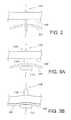
- FIG. 1is a side cross-sectional view illustrating an exemplary dilation device that has a tubular support upon which is mounted the inflatable dilation balloon.
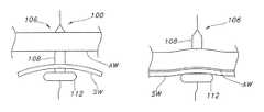
- FIG. 2is a side cross-sectional view illustrating the position of an exemplary dilation device pulled through the gastric lumen wall and abdominal wall prior to inflation of the device.
- FIGS. 3A and 3Bare side cross-sectional views of an exemplary dilation device showing an inflated dilation balloon and inflated retention stabilizing the lumen wall against the abdominal wall.
- the inflatable dilation balloonis in position with the retention portion within the lumen but the lumen is not snugly against the inside of the abdominal wall.
- the gastric lumenhas been pulled snugly against the inside of the abdominal wall.
- FIGS. 4A and 4Bare side cross-sectional views of an exemplary catheter tube inserted through a dilated stoma tract in the lumen wall and abdominal wall.
- the catheter tubeis shown fitting over the fully or partially inflated dilation region through the dilated stoma tract and into the portion of the lumen stabilized by the inflated retention region.
- FIG. 4Billustrates the stoma dilation device deflated and at least a portion of the device being withdrawn through the catheter tube.
- stomachis a common example of a non-vascular lumen
- gastric lumenor “stomach” is representative of all other non-vascular lumens or spaces (e.g., duodenum, jejunum, ileum, peritoneal cavity, etc.), unless otherwise specified.
- FIG. 1in side, cross-sectional view, an exemplary stoma dilation device 100 that includes a tubular support 102 defining at least one continuous pathway 104 through the device.
- the continuous pathwayis configured to accommodate a guide wire.
- the tubular support 102has a length, width and a longitudinal axis “LA”.
- the tubular support 102should be flexible but not too flexible as to readily collapse or kink when pressure is applied radially or axially.
- the width of the tubular supportshould be sufficiently small that it may fit in the working channel of an endoscope.
- the tubular supportmay have a width of from about 0.2 to about 2 millimeters. More desirably, the tubular support may have a width of from about 0.5 to about 1.75 millimeters.
- the tubular supportmay be made of a variety of suitable materials. Exemplary materials include thermoplastic polyurethanes such as TECOFLEX® medical-grade aliphatic polyether polyurethanes available from Lubrizol Advanced Materials, Inc., ThermedicsTM Polymer Products, Wilmington, Mass.
- the device 100includes an inflatable dilation balloon 106 located on the tubular support 102 having at least one inflatable dilation section 108 at a distal portion 110 of the device and at least one inflatable retention balloon component 112 located on a proximal portion of the device 114 (i.e., the proximal retention balloon component 112 ).
- the dilation balloon 106has at least one dilation balloon inflation lumen 116 to inflate and deflate the dilation balloon.
- the inflation lumen 116is integrated in the tubular support 102 .
- the tubular support 102may define multiple lumens.
- the tubular supportmay define a continuous pathway 104 , at least one dilation balloon inflation lumen 116 to inflate and deflate the dilation balloon 106 . It is contemplated that the inflation lumens may be separated from the tubular support and be in the form of pilot tubes or the like.
- the proximal retention balloon component 112is configured to have an effective cross-section upon full, unrestrained inflation that is greater than the largest cross-sectional diameter of the dilation section 108 upon inflation as is generally illustrated in FIG. 1 .
- the dilation section 108 of the balloonhas a length and a circular cross-section with a pre-determined diameter upon full inflation to fit a specific sized catheter tube device.
- the dilation section 108may be dilated to various effective diameters using respectively different inflation pressures to fit various catheter tubes.
- the effective inflated diameter of the dilation section 108may range from about 3 to about 10 millimeters.
- the effective inflated diameter of the dilation section 108may range from about 2 to about 8 millimeters.
- the proximal portion 114 of the dilation balloon 106incorporates the retention section 112 (also referred to as the “proximal retention balloon component”) having a substantially larger cross section or diameter than any diameters of the dilation section 108 .
- the proximal retention balloon componentmay have a cross section or diameter that is about 1.5 times to about 3 times the diameter of the dilation section 108 .
- the proximal retention balloon component 112may have a circular or non-circular cross section as long as it is able to function as described above.
- the retention balloonmay have or lack a cross section with one axis of symmetry.
- the proximal retention balloon component 112may, for example, have a square, rectangular, triangular, elliptical, oval or other geometric.
- the proximal retention balloon component 112may incorporate lobes, fingers or projections that contribute to its cross-section so it is greater than the diameter of the dilation section 108 .
- the dilation balloon 106desirably includes two opposing open ends. The open ends may be attached to the tubular support.
- the dilation balloon 106may have open ends 118 and 120 .
- the dilation balloonmay be formed of materials such that the balloons are compliant, semi-compliant, or non-compliant. That is, the balloon may be relatively elastic (e.g., compliant) so that it stretches as well as expands upon inflation. The balloon may also be somewhat elastic (e.g., semi-compliant) so that it expands but has limited stretch upon inflation. The balloon may be inelastic (e.g., non-compliant) so that it expands without significant stretch upon inflation. Desirably, the balloons may be formed of polyurethane material identified as Pellethane® 2363-90A, available from Lubrizol Advanced Materials, Inc., ThermedicsTM Polymer Products.
- Pellethane® 2363-90Aavailable from Lubrizol Advanced Materials, Inc., ThermedicsTM Polymer Products.
- This disclosurealso covers a system for dilating a stoma and inserting a non-vascular catheter tube, the system includes a stoma dilation device as described above.
- the systemalso includes a non-vascular catheter tube 122 configured to fit over the fully or partially inflated dilation balloon 106 (i.e., the dilation section 108 ) through the dilated stoma tract and into the portion of the non-vascular lumen stabilized by the retention section (i.e., the proximal retention balloon component).
- the stoma dilation deviceis configured to be deflated and at least a portion of the device withdrawn through the non-vascular catheter tube.
- an endoscopemay be advanced into a non-vascular lumen (e.g., the stomach) to insufflate and allow palpation to locate a catheter tube location site (e.g., a PEG location site).
- a catheter tube location sitee.g., a PEG location site.
- Standard endoscopic forceps, an endoscopic snare, or a balloon attachment fixturemay be inserted through the working channel of the endoscope.
- the forceps, snare or fixtureis used to grasp the guide wire and the guide wire is pulled up through the working channel of the endoscope and out of the patient's mouth.
- a dilation device with its attached inflation lumenis secured to the end of the guide wire and is pulled through the working channel of the endoscope using the guide wire and into the stomach.
- the dilation devicemay have a dilation balloon having a distally located dilation section having pre-determined volume and diameter upon full inflation and a proximal retention balloon component having a diameter upon full inflation that is greater than the diameter of the dilation section.
- the dilation devicehas a diameter that fits within the working channel of the endoscope. Typically, the diameter is in the range of about 2 millimeters or less.
- the needleis removed from the stomach, while retaining the guide wire in the needle tract.
- the dilation deviceis pulled up into and partially through the needle tract so that it reaches the abdominal tissue and the skin on the exterior of the patient as illustrated in FIG. 2 .
- the dilation balloon 106 of the dilation device 100is then inflated by gradually introducing controlled amounts of fluid (e.g., liquid or gas) to increase pressure in the balloon so the dilation section 108 smoothly and gradually expands the needle tract into a stoma tract.
- the proximal retention balloon component 112 of the dilation balloon 106is also inflated as the dilation section 108 is inflated.
- the proximal retention balloon component 112becomes larger than the dilation section 108 and expands to full inflation, it stabilizes the stomach wall “SW” by bringing it up against the wall of the abdomen “AW” as illustrated in FIG. 3B .
- the fully inflated diameters of the dilation balloonmay be selected from a range to match the diameter of the catheter tube device 122 (e.g., the PEG device) that will be inserted.
- the dilation balloon 106can have variable diameters such that the dilation section 108 may have at least one diameter(s) and the retention section 112 (the proximal retention balloon component) may have at least one diameter that is greater than the dilation section 108 .
- a peel-away sheathis placed over the distal-most portion of the dilation device (i.e., from the outside of the patient).
- the dilation balloon of the dilation deviceis deflated by only a small amount (e.g. partially deflated) to allow the peel-away sheath to pass over the distal end of the dilation device and through the stoma tract into the stomach.
- a catheter tube 122(e.g., a PEG device) is then threaded over the guide wire and the distal end of PEG device is inserted through the peel away sheath.
- the distal end of the PEG device 122is now in a position to hold the gastric lumen against the abdominal wall so the dilation balloon 106 may be fully deflated and withdrawn through the peel-away sheath.
- the syringe inflation connectormust be cut off of the inflation lumen in order to withdraw the dilation device through the abdominal wall.
- the peel-away sheathis then separated and removed from the stoma tract. Any other placement tools are removed, and the retainer (not shown) on the distal, in-dwelling end of the PEG device 122 holds the PEG device in place.
- the PEG device 122may be inserted over the deflated dilation balloon 106 without the use of the peel away sheath. This places the PED device in a position to hold the gastric lumen against the abdominal wall so the dilation balloon may be fully deflated and withdrawn through the PEG device.
- the dilation deviceonce it has its balloon completely deflated and while it is still attached to the guide wire, may be removed through the working channel of the endoscope by withdrawing the guide wire through the working channel of the endoscope.
Landscapes
- Health & Medical Sciences (AREA)
- Life Sciences & Earth Sciences (AREA)
- Animal Behavior & Ethology (AREA)
- General Health & Medical Sciences (AREA)
- Public Health (AREA)
- Veterinary Medicine (AREA)
- Heart & Thoracic Surgery (AREA)
- Engineering & Computer Science (AREA)
- Biomedical Technology (AREA)
- Anesthesiology (AREA)
- Hematology (AREA)
- Surgery (AREA)
- Pulmonology (AREA)
- Gastroenterology & Hepatology (AREA)
- Biophysics (AREA)
- Nuclear Medicine, Radiotherapy & Molecular Imaging (AREA)
- Medical Informatics (AREA)
- Molecular Biology (AREA)
- Child & Adolescent Psychology (AREA)
- Pathology (AREA)
- Vascular Medicine (AREA)
- Ophthalmology & Optometry (AREA)
- Media Introduction/Drainage Providing Device (AREA)
- Medical Preparation Storing Or Oral Administration Devices (AREA)
- Surgical Instruments (AREA)
- Endoscopes (AREA)
- Materials For Medical Uses (AREA)
- Infusion, Injection, And Reservoir Apparatuses (AREA)
- Orthopedics, Nursing, And Contraception (AREA)
Abstract
Description
Claims (19)
Priority Applications (1)
| Application Number | Priority Date | Filing Date | Title |
|---|---|---|---|
| US15/530,336US10322067B2 (en) | 2010-09-27 | 2016-10-13 | Dilation device for placing catheter tubes |
Applications Claiming Priority (4)
| Application Number | Priority Date | Filing Date | Title |
|---|---|---|---|
| US38679310P | 2010-09-27 | 2010-09-27 | |
| US201161446229P | 2011-02-24 | 2011-02-24 | |
| US13/245,577US20120078039A1 (en) | 2010-09-27 | 2011-09-26 | Dilation Device for Placing Catheter Tubes |
| US15/530,336US10322067B2 (en) | 2010-09-27 | 2016-10-13 | Dilation device for placing catheter tubes |
Related Parent Applications (1)
| Application Number | Title | Priority Date | Filing Date |
|---|---|---|---|
| US13/245,577DivisionUS20120078039A1 (en) | 2010-09-27 | 2011-09-26 | Dilation Device for Placing Catheter Tubes |
Publications (2)
| Publication Number | Publication Date |
|---|---|
| US20170135908A1 US20170135908A1 (en) | 2017-05-18 |
| US10322067B2true US10322067B2 (en) | 2019-06-18 |
Family
ID=45871306
Family Applications (5)
| Application Number | Title | Priority Date | Filing Date |
|---|---|---|---|
| US13/245,552Active2033-03-17US9125800B2 (en) | 2010-09-27 | 2011-09-26 | Stoma length indicator assembly and positioning system |
| US13/245,562ActiveUS9339442B2 (en) | 2010-09-27 | 2011-09-26 | Multi-balloon dilation device for placing catheter tubes |
| US13/245,577AbandonedUS20120078039A1 (en) | 2010-09-27 | 2011-09-26 | Dilation Device for Placing Catheter Tubes |
| US13/245,542Active2034-08-09US9211234B2 (en) | 2010-09-27 | 2011-09-26 | Configurable percutaneous endoscopic gastrostomy tube |
| US15/530,336Active2032-11-21US10322067B2 (en) | 2010-09-27 | 2016-10-13 | Dilation device for placing catheter tubes |
Family Applications Before (4)
| Application Number | Title | Priority Date | Filing Date |
|---|---|---|---|
| US13/245,552Active2033-03-17US9125800B2 (en) | 2010-09-27 | 2011-09-26 | Stoma length indicator assembly and positioning system |
| US13/245,562ActiveUS9339442B2 (en) | 2010-09-27 | 2011-09-26 | Multi-balloon dilation device for placing catheter tubes |
| US13/245,577AbandonedUS20120078039A1 (en) | 2010-09-27 | 2011-09-26 | Dilation Device for Placing Catheter Tubes |
| US13/245,542Active2034-08-09US9211234B2 (en) | 2010-09-27 | 2011-09-26 | Configurable percutaneous endoscopic gastrostomy tube |
Country Status (11)
| Country | Link |
|---|---|
| US (5) | US9125800B2 (en) |
| EP (4) | EP2621378B1 (en) |
| JP (5) | JP5830103B2 (en) |
| KR (4) | KR101908933B1 (en) |
| CN (4) | CN103124533B (en) |
| AU (5) | AU2011309685B2 (en) |
| BR (4) | BR112013007168A2 (en) |
| CA (4) | CA2811308C (en) |
| MX (5) | MX2013003336A (en) |
| RU (5) | RU2604042C2 (en) |
| WO (4) | WO2012042473A1 (en) |
Families Citing this family (76)
| Publication number | Priority date | Publication date | Assignee | Title |
|---|---|---|---|---|
| MX350734B (en) | 2010-09-08 | 2017-09-15 | Covidien Lp | Catheter with imaging assembly. |
| US9125800B2 (en) | 2010-09-27 | 2015-09-08 | Avent, Inc. | Stoma length indicator assembly and positioning system |
| EP2744445B1 (en)* | 2011-08-20 | 2018-01-31 | Advanced Medical Balloons GmbH | Trans-anal inflow catheter for intermittently triggering a reflex-coordinated defecation |
| US20140066966A1 (en)* | 2012-08-30 | 2014-03-06 | Children's National Medical Center | Endopyloric tool and method to treat hypertropic pyloric stenosis |
| USD735343S1 (en) | 2012-09-07 | 2015-07-28 | Covidien Lp | Console |
| US9517184B2 (en) | 2012-09-07 | 2016-12-13 | Covidien Lp | Feeding tube with insufflation device and related methods therefor |
| USD717340S1 (en) | 2012-09-07 | 2014-11-11 | Covidien Lp | Display screen with enteral feeding icon |
| US9198835B2 (en) | 2012-09-07 | 2015-12-01 | Covidien Lp | Catheter with imaging assembly with placement aid and related methods therefor |
| USD716841S1 (en) | 2012-09-07 | 2014-11-04 | Covidien Lp | Display screen with annotate file icon |
| US9108024B2 (en)* | 2012-09-28 | 2015-08-18 | Avent, Inc. | Retention component for placement of enteral feeding tubes |
| US9492644B2 (en)* | 2012-12-21 | 2016-11-15 | Avent, Inc. | Dilation device for placing catheter tubes |
| US9522253B2 (en)* | 2013-03-13 | 2016-12-20 | Vascular Solutions, Inc. | Drainage or feeding catheter assembly |
| US9833350B2 (en) | 2013-03-15 | 2017-12-05 | Ez-Off Weightloss, Llc | Anchorable size-varying gastric balloons for weight loss |
| EP2967818B1 (en) | 2013-03-15 | 2018-05-16 | Ez Off Weightloss, LLC | System for gastric restriction and malabsorption |
| CN103263280A (en)* | 2013-06-04 | 2013-08-28 | 赵远思 | Intestine stoma fixing device |
| EP3030307B1 (en) | 2013-08-05 | 2019-12-11 | Endo-Tagss, LLC | Transabdominal gastric surgery system |
| US10219799B2 (en) | 2013-08-05 | 2019-03-05 | Endo-Tagss, Llc | Transabdominal gastric device and method |
| CN103405297A (en)* | 2013-08-27 | 2013-11-27 | 林建江 | Complete flow turning type intestinal fistulization tube |
| BR112016011279B1 (en)* | 2013-11-18 | 2022-09-06 | Halkey-Roberts Corporation | MEDICAL CONNECTOR ASSEMBLY |
| MX369672B (en) | 2013-12-17 | 2019-11-15 | Standard Bariatrics Inc | Resection line guide for a medical procedure and method of using same. |
| AU2015241193B2 (en) | 2014-03-29 | 2020-01-02 | Standard Bariatrics, Inc. | End effectors surgical stapling devices, and methods of using same |
| WO2015153324A1 (en) | 2014-03-29 | 2015-10-08 | Standard Bariatrics, Inc. | End effectors, surgical stapling devices, and methods of using same |
| WO2016037158A1 (en) | 2014-09-05 | 2016-03-10 | Standard Bariatrics, Inc. | Sleeve gastrectomy calibration tube and method of using same |
| US10206595B2 (en)* | 2014-11-17 | 2019-02-19 | 3VO Medical, Inc. | Intrauterine balloon apparatus, system, and method for augmenting uterine birthing forces during parturition |
| CN104606767B (en)* | 2014-11-26 | 2017-12-19 | 潘湘斌 | Foley's tube for ultrasound-guided percutaneous pulmonary valve balloon dilatation |
| WO2016097824A1 (en)* | 2014-12-18 | 2016-06-23 | Evoluzione S.R.L. | Medical device for performing ileostomies and/or jejunostomies |
| US10080874B2 (en) | 2015-04-09 | 2018-09-25 | Boston Scientific Scimed, Inc. | Trap balloon catheter with trap balloon retainer |
| CN107980007B (en)* | 2015-04-09 | 2020-12-11 | 波士顿科学国际有限公司 | Capture balloon catheter with capture balloon retainer |
| US9808282B2 (en)* | 2015-06-04 | 2017-11-07 | Medos International Sarl | Surgical cannula system and method of use |
| US10285837B1 (en) | 2015-09-16 | 2019-05-14 | Standard Bariatrics, Inc. | Systems and methods for measuring volume of potential sleeve in a sleeve gastrectomy |
| KR101725235B1 (en)* | 2015-12-01 | 2017-04-11 | 충남대학교산학협력단 | Surgical Trocar |
| CN106182730B (en)* | 2016-07-28 | 2018-10-16 | 七星电气股份有限公司 | A kind of expansion mold for cool condensing electric cable accessories |
| WO2018034658A1 (en)* | 2016-08-17 | 2018-02-22 | Avent, Inc. | Enteral feeding satiation device |
| WO2018067690A1 (en) | 2016-10-04 | 2018-04-12 | Ez-Off Weight Loss, Llc | Sleeve-anchorable gastric balloon for weight loss |
| CN109843152B (en)* | 2016-10-14 | 2022-02-25 | M·D·诺亚 | Balloon structure with anchoring portion for anchoring in body passage |
| WO2018150219A1 (en)* | 2017-02-16 | 2018-08-23 | N.V. Nutricia | Gastrostomy device with an improved retaining element |
| CN110678159A (en)* | 2017-02-16 | 2020-01-10 | 纽崔西亚公司 | Gastrostomy device with pressure monitoring |
| JP6995869B2 (en)* | 2017-02-23 | 2022-01-17 | ボストン サイエンティフィック サイムド,インコーポレイテッド | Mounting equipment used with medical equipment |
| CN107174315B (en)* | 2017-05-04 | 2019-10-11 | 温州市人民医院 | Peritoneo-puncture needle fixes device |
| CN107348976B (en)* | 2017-05-19 | 2019-11-19 | 薛运章 | A kind of mesenterium support device and method for supporting |
| US11338112B2 (en) | 2017-07-03 | 2022-05-24 | Cathaid, Inc. | Devices for monitoring movement of a secured catheter during a procedure |
| US10912562B2 (en) | 2017-08-14 | 2021-02-09 | Standard Bariatrics, Inc. | End effectors, surgical stapling devices, and methods of using same |
| RU2691924C1 (en)* | 2017-12-25 | 2019-06-18 | Арчил Зурабович Цулая | Method for gastrostomy using polypropylene mesh |
| KR101984878B1 (en) | 2018-01-10 | 2019-05-31 | 강석진 | Dry edible Materials pulverization machine |
| CN112930208A (en) | 2018-06-01 | 2021-06-08 | 恩多Rx有限责任公司 | Dilation device and method of use thereof |
| EP3856308B1 (en)* | 2018-09-27 | 2025-08-13 | Coloplast A/S | Tracheostoma device holder |
| US11412260B2 (en)* | 2018-10-29 | 2022-08-09 | Google Llc | Geometric transforms for image compression |
| CN114126516A (en)* | 2018-11-30 | 2022-03-01 | 快管医疗有限责任公司 | Method and device for the treatment of tension pneumothorax using a rapidly deployable thoracic port |
| CN109700525A (en)* | 2018-12-28 | 2019-05-03 | 先健科技(深圳)有限公司 | Stoma instrument |
| US11666696B2 (en) | 2019-03-25 | 2023-06-06 | Ellen McGrath | Enterostomy drainage methods and devices |
| USD896365S1 (en)* | 2019-06-24 | 2020-09-15 | Mark Sipe | Medical port disc |
| CN211856471U (en) | 2019-08-22 | 2020-11-03 | 贝克顿·迪金森公司 | Quantitative testing system for echogenicity of echogenic medical instrument |
| KR102049701B1 (en)* | 2019-08-22 | 2020-01-08 | 이지희 | A liquid medicine injection machine Of Balloon type |
| CN211884905U (en) | 2019-08-22 | 2020-11-10 | 贝克顿·迪金森公司 | Balloon dilatation catheter and balloon thereof |
| CN112401971B (en) | 2019-08-23 | 2025-09-09 | 贝克顿·迪金森公司 | Stone extraction for percutaneous nephroscope surgical design kit |
| CN110801312A (en)* | 2019-10-21 | 2020-02-18 | 复旦大学附属中山医院 | Intervene valve release stop device |
| BR112022008009A2 (en) | 2019-11-04 | 2022-07-12 | Standard Bariatrics Inc | SYSTEMS AND METHODS OF PERFORMING SURGERY USING LAPLACE'S LAW TENSION RETRACTION DURING SURGERY |
| US12274635B2 (en) | 2019-11-04 | 2025-04-15 | Standard Bariatrics, Inc. | Systems and methods of performing surgery using laplace's law tension retraction during surgery |
| CN111375121B (en)* | 2020-03-18 | 2022-05-17 | 南京鼓楼医院 | Nerve block sleeve assembly |
| JP2021154089A (en)* | 2020-03-30 | 2021-10-07 | テルモ株式会社 | Transfistula tube device |
| CN111450392B (en)* | 2020-05-11 | 2025-01-14 | 上海市东方医院(同济大学附属东方医院) | Multi-level fistula dilatation puncture drainage tube with balloon |
| CN115955943A (en) | 2020-06-30 | 2023-04-11 | 标准肥胖病研究公司 | Systems, devices, and methods for preventing or reducing insufflation loss during laparoscopic procedures |
| CN111840754A (en)* | 2020-08-17 | 2020-10-30 | 安卓医疗技术(山东)有限公司 | An internal fixation device for a pipe and a method of using the same |
| CN112245772B (en)* | 2020-10-19 | 2022-05-06 | 四川大学华西医院 | Monitoring regulation and control device of adjustable two sacs three chambeies intraductal air pressure |
| AU2022242751B2 (en) | 2021-03-23 | 2024-05-02 | Standard Bariatrics, Inc. | Systems and methods for preventing tissue migration in surgical staplers |
| CN113244502B (en)* | 2021-04-20 | 2025-04-29 | 青岛博泰医疗器械有限责任公司 | Visualized pressure regulating catheter |
| CN113576578B (en)* | 2021-07-29 | 2022-09-13 | 宿州微腾企业管理咨询服务有限公司 | Intracardiac branch of academic or vocational study hemostasis constriction device |
| KR102597188B1 (en) | 2021-08-20 | 2023-11-02 | 주식회사 파인메딕스 | Gastrostomy Tube Kit |
| CN113941074B (en)* | 2021-11-12 | 2024-05-24 | 北京大学深圳医院 | Pharyngeal expansion device for gastroscopy of elderly patients |
| CN114099912B (en)* | 2021-11-18 | 2024-03-22 | 南京脉创医疗科技有限公司 | Intracranial balloon dilation catheter |
| TWI773597B (en)* | 2021-11-25 | 2022-08-01 | 長庚學校財團法人長庚科技大學 | Guided operation and detection device for gastrostomy care |
| CN114082086B (en)* | 2021-12-23 | 2024-03-29 | 赛诺神畅医疗科技有限公司 | Balloon guiding catheter |
| CN114159009A (en)* | 2021-12-31 | 2022-03-11 | 上海博方医疗科技有限公司 | Capsule endoscope system and operation method |
| CN115814244B (en)* | 2022-12-30 | 2025-09-23 | 中国人民解放军总医院第八医学中心 | Coronary artery delivery catheter and delivery device for cardiac interventional therapy |
| CN116899036A (en)* | 2023-08-08 | 2023-10-20 | 首都医科大学附属北京朝阳医院 | Drainage device |
| KR20250121771A (en)* | 2024-02-05 | 2025-08-12 | 부산대학교 산학협력단 | Hemostatic Bronchoscope Balloon Device for Forward Viewing with Simultaneous Blood Suction |
Citations (26)
| Publication number | Priority date | Publication date | Assignee | Title |
|---|---|---|---|---|
| US5458583A (en) | 1993-01-07 | 1995-10-17 | Medical Innovations Corporation | Gastrostomy catheter system |
| US6019746A (en) | 1996-05-17 | 2000-02-01 | Applied Medical Technology, Inc. | Low profile balloon feeding device |
| US6236879B1 (en) | 1997-01-23 | 2001-05-22 | Centrum Rrn Academisch Ziekenhuis Utrecht | Fiber optic catheter system |
| US6293924B1 (en) | 1996-12-12 | 2001-09-25 | Advanced Cardiovascular Systems, Inc. | Balloon assembly with separately inflatable sections |
| WO2002019890A2 (en) | 2000-09-05 | 2002-03-14 | Patents Exploitation Company B.V. | Apparatus for placement of a percutaneous endoscopic gastrostomy tube |
| US20030100909A1 (en) | 1998-08-17 | 2003-05-29 | Yutaka Suzuki | Method of gastrostomy, and an infection preventive cover, kit or catheter kit, and a gastrostomy catheter kit |
| US20030225312A1 (en) | 2002-03-18 | 2003-12-04 | Anthony Kalloo | Endoscopic system for treating inside of body cavity |
| US20060095066A1 (en) | 2004-04-21 | 2006-05-04 | Exploramed Nc1, Inc. | Devices, systems and methods for treating disorders of the ear, nose and throat |
| US7137993B2 (en) | 2001-12-03 | 2006-11-21 | Xtent, Inc. | Apparatus and methods for delivery of multiple distributed stents |
| US7273056B2 (en) | 2001-06-19 | 2007-09-25 | The Trustees Of The University Of Pennsylvania | Optical guidance system for invasive catheter placement |
| US20070225677A1 (en) | 2006-03-03 | 2007-09-27 | Boston Scientific Scimed, Inc. | Balloon catheter |
| US20070255209A1 (en) | 2006-04-21 | 2007-11-01 | C.R. Bard, Inc. | Feeding device and bolster apparatus and method for making the same |
| US7396354B2 (en) | 2002-08-05 | 2008-07-08 | Rychnovsky Steven J | Light delivery catheter |
| US20080167606A1 (en) | 2006-09-25 | 2008-07-10 | Valentx, Inc. | Toposcopic access and delivery devices |
| US20080194973A1 (en) | 2005-09-13 | 2008-08-14 | Imam Farhad B | Light-guided transluminal catheter |
| US20080228066A1 (en) | 2007-03-14 | 2008-09-18 | Waitzman Kathryn A Mckenzie | Methods and systems for locating a feeding tube inside of a patient |
| US20080287983A1 (en) | 2007-05-17 | 2008-11-20 | Boston Scientific Scimed, Inc. | Tissue securing and sealing apparatus and related methods of use |
| WO2008154533A1 (en) | 2007-06-11 | 2008-12-18 | The Trustees Of The University Pennsylvania | Three-dimensional optical guidance for catheter placement |
| US20090281379A1 (en) | 2008-05-12 | 2009-11-12 | Xlumena, Inc. | System and method for transluminal access |
| US20090318798A1 (en) | 2008-06-23 | 2009-12-24 | Errol Singh | Flexible visually directed medical intubation instrument and method |
| US20090318757A1 (en) | 2008-06-23 | 2009-12-24 | Percuvision, Llc | Flexible visually directed medical intubation instrument and method |
| US20100087706A1 (en) | 2008-09-30 | 2010-04-08 | Intrapace, Inc. | Lead Access |
| US20100198005A1 (en) | 2009-01-30 | 2010-08-05 | Ethicon Endo-Surgery, Inc. | Surgical access device |
| WO2011159590A2 (en) | 2010-06-14 | 2011-12-22 | The General Hospital Corporation | Stricture treatment and drainage catheter |
| US8795311B2 (en) | 2007-08-31 | 2014-08-05 | Kimberly-Clark Worldwide, Inc. | Stoma dilator |
| US9339442B2 (en) | 2010-09-27 | 2016-05-17 | Avent, Inc. | Multi-balloon dilation device for placing catheter tubes |
Family Cites Families (99)
| Publication number | Priority date | Publication date | Assignee | Title |
|---|---|---|---|---|
| US3397699A (en) | 1966-05-05 | 1968-08-20 | Gerald C. Kohl | Retaining catheter having resiliently biased wing flanges |
| US3633579A (en) | 1967-05-24 | 1972-01-11 | Sherwood Medical Ind Inc | Catheter placement device and method |
| US3915171A (en) | 1974-06-06 | 1975-10-28 | Dennis William Shermeta | Gastrostomy tube |
| US4315513A (en) | 1980-03-10 | 1982-02-16 | Nawash Michael S | Gastrostomy and other percutaneous transport tubes |
| US4393873A (en) | 1980-03-10 | 1983-07-19 | Nawash Michael S | Gastrostomy and other percutaneous transport tubes |
| US4531943A (en) | 1983-08-08 | 1985-07-30 | Angiomedics Corporation | Catheter with soft deformable tip |
| US4627838A (en) | 1983-12-09 | 1986-12-09 | Bard Limited | Stylet actuated winged catheter |
| US4758219A (en) | 1985-05-17 | 1988-07-19 | Microvasive, Inc. | Enteral feeding device |
| US4763654A (en)* | 1986-09-10 | 1988-08-16 | Jang G David | Tandem independently inflatable/deflatable multiple diameter balloon angioplasty catheter systems and method of use |
| US4850953A (en) | 1987-07-27 | 1989-07-25 | Habley Medical Technology Corporation | Gastrostomy valve |
| US4861334A (en) | 1988-06-24 | 1989-08-29 | Nawaz Arain | Self-retaining gastrostomy tube |
| US4944732A (en) | 1988-08-15 | 1990-07-31 | Sandoz Nutrition Corporation | Gastrostomy feeding port |
| JPH0249547U (en)* | 1988-09-30 | 1990-04-06 | ||
| US4972845A (en) | 1989-01-05 | 1990-11-27 | Abbott Laboratories | Stoma measuring device |
| US5073166A (en) | 1989-02-15 | 1991-12-17 | Medical Innovations Corporation | Method and apparatus for emplacement of a gastrostomy catheter |
| US5374254A (en) | 1990-11-29 | 1994-12-20 | Buma; Shelley J. | Catheters with adjustable external locking bolsters |
| US5092850A (en) | 1990-11-29 | 1992-03-03 | Buma Shelley J | Catheter with adjustable external locking bolster |
| US5112310A (en) | 1991-02-06 | 1992-05-12 | Grobe James L | Apparatus and methods for percutaneous endoscopic gastrostomy |
| DE69228257T2 (en) | 1991-11-06 | 1999-07-08 | Inbae M.D. Phoenix Yoon, Md. | HOLDER FOR SURGICAL INSTRUMENTS |
| US5356391A (en) | 1992-06-22 | 1994-10-18 | Medical Innovations Corp. | Flexible retainer flange for gastrostomy tube and the method of installing it |
| US5484420A (en) | 1992-07-09 | 1996-01-16 | Wilson-Cook Medical Inc. | Retention bolsters for percutaneous catheters |
| US5248302A (en) | 1992-08-05 | 1993-09-28 | Biosearch Medical Products Inc. | Percutaneous obturatable internal anchoring device |
| US5702365A (en)* | 1992-09-08 | 1997-12-30 | King; Toby St. John | Daul-lumen catheter |
| US5413565A (en) | 1993-01-15 | 1995-05-09 | Sandoz Nutrition Ltd. | Gastrostomy feeding port with elastic adjustable tip |
| US5336203A (en) | 1993-05-28 | 1994-08-09 | Abbott Laboratories | Low profile gastrostomy device with dome |
| US5505698A (en)* | 1993-10-29 | 1996-04-09 | Medtronic, Inc. | Cardioplegia catheter with elongated cuff |
| US5429598A (en) | 1994-04-19 | 1995-07-04 | Applied Medical Resources Corporation | Surgical access device and procedure |
| US5860952A (en) | 1996-01-11 | 1999-01-19 | C. R. Bard, Inc. | Corporeal access tube assembly and method |
| US6036673A (en)* | 1996-01-11 | 2000-03-14 | C. R. Bard, Inc. | Bolster for corporeal access tube assembly |
| DE69732810T2 (en)* | 1996-01-11 | 2006-04-06 | C.R. Bard, Inc. | Support pad for body access tube |
| DE19634116C2 (en) | 1996-08-23 | 1998-08-20 | Fresenius Ag | Catheter for percutaneous enteral nutrition |
| US6494848B1 (en) | 1996-12-19 | 2002-12-17 | St. Jude Medical Puerto Rico B.V. | Measuring device for use with a hemostatic puncture closure device |
| SE9700373L (en)* | 1997-02-04 | 1998-07-13 | Stig Bengmark | Probe for providing fluid communication with the small intestine |
| US5928260A (en) | 1997-07-10 | 1999-07-27 | Scimed Life Systems, Inc. | Removable occlusion system for aneurysm neck |
| US6077250A (en) | 1997-10-01 | 2000-06-20 | Boston Scientific Corporation | Apparatus and method for percutaneously placing gastrostomy tubes |
| US6186985B1 (en) | 1997-10-03 | 2001-02-13 | Boston Scientific Corporation | Gastro-intestinal tube with dissolvable support bolster |
| US6464686B1 (en)* | 1998-01-21 | 2002-10-15 | Abbott Laboratories | Polyurethane feeding tube and associated adaptors |
| US6364858B1 (en) | 1998-03-31 | 2002-04-02 | Applied Medical Research, Inc. | Collapsible internal bolster for gastrostomy device |
| US6039714A (en) | 1998-05-12 | 2000-03-21 | Novartis Nutrition Ag | Collapsible retention bolster for gastrostomy and other ostomy tubes |
| EP1674125B1 (en)* | 1998-08-17 | 2009-04-29 | Yutaka Suzuki | A method of gastrostomy and an infection preventive cover and a gastrostomy catheter kit |
| US6030406A (en) | 1998-10-05 | 2000-02-29 | Origin Medsystems, Inc. | Method and apparatus for tissue dissection |
| US6030361A (en) | 1999-01-25 | 2000-02-29 | Miyashiro; Augusto M. | Gastrostomy apparatus |
| US6322538B1 (en) | 1999-02-18 | 2001-11-27 | Scimed Life Systems, Inc. | Gastro-intestinal tube placement device |
| US6231547B1 (en) | 1999-02-18 | 2001-05-15 | Abbott Laboratories | External retaining device for a catheter and catheter assembly and method using same |
| US20050085771A1 (en)* | 1999-04-16 | 2005-04-21 | Lyon Thomas R. | Clear view cannula |
| US6231549B1 (en) | 1999-08-17 | 2001-05-15 | Sherwood Services, Ag | Shim device for enteral feeding system |
| US6881420B2 (en) | 2000-06-23 | 2005-04-19 | Teva Pharmaceutical Industries Ltd. | Compositions and dosage forms for gastric delivery of irinotecan and methods of treatment that use it to inhibit cancer cell proliferation |
| US6692458B2 (en)* | 2000-12-19 | 2004-02-17 | Edwards Lifesciences Corporation | Intra-pericardial drug delivery device with multiple balloons and method for angiogenesis |
| US6743207B2 (en)* | 2001-04-19 | 2004-06-01 | Scimed Life Systems, Inc. | Apparatus and method for the insertion of a medical device |
| DE10139644B4 (en) | 2001-08-11 | 2004-04-01 | Fresenius Kabi Deutschland Gmbh | Mounting part for an adapter of a PEG probe and adapter for a PEG probe with such a mounting part |
| US7736336B2 (en) | 2001-09-13 | 2010-06-15 | Allegiance Corporation | Paracentesis device having multiple detachable components |
| US6896665B2 (en) | 2001-12-10 | 2005-05-24 | Applied Medical Research | Gastrostomy device package and method of assembly |
| US20030163114A1 (en) | 2002-02-26 | 2003-08-28 | Gershowitz Arthur D. | Retrograde cannula having manually retractable sealing member |
| US6666853B2 (en) | 2002-03-27 | 2003-12-23 | Scimed Life Systems, Inc. | Low profile adaptor for use with a medical catheter |
| US7083595B2 (en) | 2002-05-01 | 2006-08-01 | Scimed Lipe Systems, Inc. | Medical catheter assembly and method of using the same |
| JP2004099584A (en) | 2002-05-02 | 2004-04-02 | Keio Gijuku | Anti-tumor agent using HSV |
| US6764453B2 (en) | 2002-05-08 | 2004-07-20 | Sherwood Services Ag | Stoma measuring device |
| US6878130B2 (en)* | 2002-05-28 | 2005-04-12 | Sherwood Services Ag | External inflation indicator for a low profile gastrostomy tube |
| US20030225392A1 (en) | 2002-05-31 | 2003-12-04 | Kimberly-Clark Worldwide, Inc. | Low profile transpyloric jejunostomy system and method to enable |
| US6942641B2 (en) | 2003-05-30 | 2005-09-13 | J. Michael Seddon | Catheter |
| WO2004112877A1 (en) | 2003-06-20 | 2004-12-29 | Ranier Limited | A medical device |
| WO2004112879A1 (en)* | 2003-06-20 | 2004-12-29 | Coloplast A/S | A medical device comprising a braided portion |
| US7220252B2 (en)* | 2003-07-18 | 2007-05-22 | Polyzen, Inc. | Inflatable dual balloon catheter |
| US20070203445A1 (en)* | 2004-02-26 | 2007-08-30 | V-Kardia Pty Ltd | Isolating cardiac circulation |
| JP4588356B2 (en)* | 2004-04-30 | 2010-12-01 | 日本シャーウッド株式会社 | Gastrostomy tube extender |
| JP4623548B2 (en)* | 2004-04-30 | 2011-02-02 | 日本シャーウッド株式会社 | Gastrostomy tube extender |
| US7654980B2 (en) | 2004-05-14 | 2010-02-02 | Boston Scientific Scimed, Inc. | Method for percutaneously implanting a medical catheter and medical catheter implanting assembly |
| US20060030818A1 (en) | 2004-08-09 | 2006-02-09 | Mcvey Robert D | System and method for securing a medical access device |
| US7582072B2 (en) | 2004-09-09 | 2009-09-01 | Kimberly-Clark Worldwide, Inc. | Artificial stoma and method of use |
| JP4721329B2 (en) | 2005-04-21 | 2011-07-13 | 日本シャーウッド株式会社 | Indwelling device |
| US20060270989A1 (en)* | 2005-05-27 | 2006-11-30 | Mcmichael Donald J | Gastric fastening system |
| US7691089B2 (en)* | 2005-06-21 | 2010-04-06 | Tyco Healthcare Group Lp | Adjustable trocar washer |
| GB2428198A (en) | 2005-07-11 | 2007-01-24 | Stavros Michael Stivaros | A self-retaining surgical tube |
| US8709018B2 (en) | 2005-09-16 | 2014-04-29 | Applied Medical Technology, Inc. | Non-balloon low profile feed device with insertion/removal tool |
| JP2007167082A (en)* | 2005-12-19 | 2007-07-05 | Michiaki Kudo | Guide instrument of in-vivo insertion tube via gastric fistula and instrument kit for changing percutaneous gastrostoma-tube to jejunum tube via gastric fistula |
| US7771396B2 (en) | 2006-03-22 | 2010-08-10 | Ethicon Endo-Surgery, Inc. | Intubation device for enteral feeding |
| US20070255222A1 (en) | 2006-03-27 | 2007-11-01 | Changqing Li | Catheter assembly including internal bolster |
| US20070239171A1 (en) | 2006-03-30 | 2007-10-11 | Ethicon Endo-Surgery, Inc. | Medical snaring device |
| US20070233005A1 (en)* | 2006-04-03 | 2007-10-04 | Mcmichael Donald J | Surgical fastening tool |
| JP2009542349A (en) | 2006-07-05 | 2009-12-03 | アスピレーション・メディカル・テクノロジー・エルエルシー | Short-circuit device to treat obesity by extracting food |
| FR2904531B1 (en) | 2006-08-02 | 2009-06-12 | Eleph Ent Technology | PERCUTANEOUS GASTROSTOMY PROBE |
| US8062285B2 (en) | 2006-08-03 | 2011-11-22 | Aspire Bariatrics, Llc | Systems and methods for removing ingested material from a stomach |
| US7547303B2 (en) | 2006-08-03 | 2009-06-16 | Boston Scientific Scimed, Inc. | Catheter assembly including foldable internal bolster |
| WO2008027375A2 (en) | 2006-08-31 | 2008-03-06 | Cook Incorporated | Rotationally actuated fixation mechanism |
| JP2008099917A (en) | 2006-10-19 | 2008-05-01 | Goodman Co Ltd | Catheter indeflator |
| US8414611B2 (en)* | 2006-11-03 | 2013-04-09 | Boston Scientific Scimed, Inc. | Main vessel constraining side-branch access balloon |
| US9078997B2 (en) | 2007-03-29 | 2015-07-14 | Boston Scientific Scimed, Inc. | Catheter assembly including coiled internal bolster |
| JP5474779B2 (en) | 2007-06-12 | 2014-04-16 | コンバテック・テクノロジーズ・インコーポレイテッド | Ostomy device |
| WO2009155537A1 (en) | 2008-06-19 | 2009-12-23 | Bristol-Myers Squibb Company | Ostomy appliances for directing effluent output |
| US20090318873A1 (en) | 2008-06-24 | 2009-12-24 | Cook Incorporated | Medical malecot with magnets |
| US9107810B2 (en) | 2008-06-24 | 2015-08-18 | Cook Medical Technologies Llc | Gastric port system |
| DE102008037916A1 (en) | 2008-08-14 | 2010-02-18 | Fresenius Kabi Deutschland Gmbh | Device for creating a percutaneous endoscopic gastrostomy |
| BRPI0919195A2 (en)* | 2008-09-18 | 2019-09-24 | Acclarent Inc | Methods and Apparatus for the Treatment of Ear, Nose, and Throat Disorders |
| US20100081991A1 (en)* | 2008-09-30 | 2010-04-01 | Tyco Healthcare Group Lp | Skin level device for use with gastrostomy tube |
| WO2010075032A2 (en) | 2008-12-22 | 2010-07-01 | Cook Incorporated | Low-profile external fitting |
| WO2010115102A1 (en) | 2009-04-02 | 2010-10-07 | Radius International Limited Partnership | Low profile and tension monitoring external peg bolster |
| EP2451512A1 (en)* | 2009-07-07 | 2012-05-16 | C.R. Bard Inc. | Extensible internal bolster for a medical device |
| WO2011053242A1 (en) | 2009-10-29 | 2011-05-05 | Ah San Pang | A spacer and a method of using the same |
| US9108024B2 (en)* | 2012-09-28 | 2015-08-18 | Avent, Inc. | Retention component for placement of enteral feeding tubes |
- 2011
- 2011-09-26USUS13/245,552patent/US9125800B2/enactiveActive
- 2011-09-26USUS13/245,562patent/US9339442B2/enactiveActive
- 2011-09-26USUS13/245,577patent/US20120078039A1/ennot_activeAbandoned
- 2011-09-26USUS13/245,542patent/US9211234B2/enactiveActive
- 2011-09-27AUAU2011309685Apatent/AU2011309685B2/enactiveActive
- 2011-09-27MXMX2013003336Apatent/MX2013003336A/enactiveIP Right Grant
- 2011-09-27CACA2811308Apatent/CA2811308C/enactiveActive
- 2011-09-27WOPCT/IB2011/054251patent/WO2012042473A1/enactiveApplication Filing
- 2011-09-27KRKR1020137007495Apatent/KR101908933B1/ennot_activeExpired - Fee Related
- 2011-09-27CACA2811425Apatent/CA2811425C/enactiveActive
- 2011-09-27CNCN201180046593.XApatent/CN103124533B/ennot_activeExpired - Fee Related
- 2011-09-27CNCN201180045973.1Apatent/CN103298421B/ennot_activeExpired - Fee Related
- 2011-09-27WOPCT/IB2011/054253patent/WO2012042475A1/enactiveApplication Filing
- 2011-09-27BRBR112013007168Apatent/BR112013007168A2/ennot_activeApplication Discontinuation
- 2011-09-27MXMX2013003485Apatent/MX2013003485A/ennot_activeApplication Discontinuation
- 2011-09-27RURU2013116380/14Apatent/RU2604042C2/ennot_activeIP Right Cessation
- 2011-09-27EPEP11776543.8Apatent/EP2621378B1/enactiveActive
- 2011-09-27JPJP2013529764Apatent/JP5830103B2/ennot_activeExpired - Fee Related
- 2011-09-27MXMX2013003487Apatent/MX342252B/enactiveIP Right Grant
- 2011-09-27KRKR1020137006363Apatent/KR101841949B1/ennot_activeExpired - Fee Related
- 2011-09-27JPJP2013529766Apatent/JP5834081B2/enactiveActive
- 2011-09-27BRBR112013007169Apatent/BR112013007169A2/ennot_activeApplication Discontinuation
- 2011-09-27CNCN201180046595.9Apatent/CN103189034B/ennot_activeExpired - Fee Related
- 2011-09-27RURU2013116382/15Apatent/RU2586254C2/ennot_activeIP Right Cessation
- 2011-09-27BRBR112013007171-0Apatent/BR112013007171A2/ennot_activeIP Right Cessation
- 2011-09-27EPEP11776887.9Apatent/EP2621379B1/ennot_activeNot-in-force
- 2011-09-27KRKR1020137006482Apatent/KR20130138204A/ennot_activeCeased
- 2011-09-27JPJP2013529767Apatent/JP6042336B2/enactiveActive
- 2011-09-27MXMX2016009389Apatent/MX353296B/enunknown
- 2011-09-27EPEP20110776542patent/EP2621454B1/ennot_activeNot-in-force
- 2011-09-27AUAU2011309683Apatent/AU2011309683B2/enactiveActive
- 2011-09-27WOPCT/IB2011/054254patent/WO2012042476A1/enactiveApplication Filing
- 2011-09-27RURU2013116381/14Apatent/RU2600278C2/ennot_activeIP Right Cessation
- 2011-09-27CACA2811246Apatent/CA2811246A1/ennot_activeAbandoned
- 2011-09-27BRBR112013007170Apatent/BR112013007170A2/ennot_activeApplication Discontinuation
- 2011-09-27MXMX2013003488Apatent/MX341777B/enactiveIP Right Grant
- 2011-09-27WOPCT/IB2011/054252patent/WO2012042474A1/enactiveApplication Filing
- 2011-09-27RURU2013116379/15Apatent/RU2589686C2/ennot_activeIP Right Cessation
- 2011-09-27CACA2812720Apatent/CA2812720C/enactiveActive
- 2011-09-27EPEP11776251.8Apatent/EP2621453B1/enactiveActive
- 2011-09-27CNCN201180046599.7Apatent/CN103124548B/ennot_activeExpired - Fee Related
- 2011-09-27KRKR1020137007643Apatent/KR101835381B1/ennot_activeExpired - Fee Related
- 2011-09-27JPJP2013529765Apatent/JP5977747B2/enactiveActive
- 2011-09-27AUAU2011309682Apatent/AU2011309682B2/ennot_activeCeased
- 2011-09-27AUAU2011309684Apatent/AU2011309684B2/ennot_activeCeased
- 2011-09-27RURU2016136325Apatent/RU2016136325A/ennot_activeApplication Discontinuation
- 2015
- 2015-12-03JPJP2015236225Apatent/JP6127118B2/ennot_activeExpired - Fee Related
- 2016
- 2016-02-03AUAU2016200661Apatent/AU2016200661B2/enactiveActive
- 2016-10-13USUS15/530,336patent/US10322067B2/enactiveActive
Patent Citations (27)
| Publication number | Priority date | Publication date | Assignee | Title |
|---|---|---|---|---|
| US5458583A (en) | 1993-01-07 | 1995-10-17 | Medical Innovations Corporation | Gastrostomy catheter system |
| US6019746A (en) | 1996-05-17 | 2000-02-01 | Applied Medical Technology, Inc. | Low profile balloon feeding device |
| US6293924B1 (en) | 1996-12-12 | 2001-09-25 | Advanced Cardiovascular Systems, Inc. | Balloon assembly with separately inflatable sections |
| US6236879B1 (en) | 1997-01-23 | 2001-05-22 | Centrum Rrn Academisch Ziekenhuis Utrecht | Fiber optic catheter system |
| US20030100909A1 (en) | 1998-08-17 | 2003-05-29 | Yutaka Suzuki | Method of gastrostomy, and an infection preventive cover, kit or catheter kit, and a gastrostomy catheter kit |
| WO2002019890A2 (en) | 2000-09-05 | 2002-03-14 | Patents Exploitation Company B.V. | Apparatus for placement of a percutaneous endoscopic gastrostomy tube |
| US7757695B2 (en) | 2001-06-19 | 2010-07-20 | The Trustees Of The University Of Pennsylvania | Method for catheter placement |
| US7273056B2 (en) | 2001-06-19 | 2007-09-25 | The Trustees Of The University Of Pennsylvania | Optical guidance system for invasive catheter placement |
| US7137993B2 (en) | 2001-12-03 | 2006-11-21 | Xtent, Inc. | Apparatus and methods for delivery of multiple distributed stents |
| US20030225312A1 (en) | 2002-03-18 | 2003-12-04 | Anthony Kalloo | Endoscopic system for treating inside of body cavity |
| US7396354B2 (en) | 2002-08-05 | 2008-07-08 | Rychnovsky Steven J | Light delivery catheter |
| US20060095066A1 (en) | 2004-04-21 | 2006-05-04 | Exploramed Nc1, Inc. | Devices, systems and methods for treating disorders of the ear, nose and throat |
| US20080194973A1 (en) | 2005-09-13 | 2008-08-14 | Imam Farhad B | Light-guided transluminal catheter |
| US20070225677A1 (en) | 2006-03-03 | 2007-09-27 | Boston Scientific Scimed, Inc. | Balloon catheter |
| US20070255209A1 (en) | 2006-04-21 | 2007-11-01 | C.R. Bard, Inc. | Feeding device and bolster apparatus and method for making the same |
| US20080167606A1 (en) | 2006-09-25 | 2008-07-10 | Valentx, Inc. | Toposcopic access and delivery devices |
| US20080228066A1 (en) | 2007-03-14 | 2008-09-18 | Waitzman Kathryn A Mckenzie | Methods and systems for locating a feeding tube inside of a patient |
| US20080287983A1 (en) | 2007-05-17 | 2008-11-20 | Boston Scientific Scimed, Inc. | Tissue securing and sealing apparatus and related methods of use |
| WO2008154533A1 (en) | 2007-06-11 | 2008-12-18 | The Trustees Of The University Pennsylvania | Three-dimensional optical guidance for catheter placement |
| US8795311B2 (en) | 2007-08-31 | 2014-08-05 | Kimberly-Clark Worldwide, Inc. | Stoma dilator |
| US20090281379A1 (en) | 2008-05-12 | 2009-11-12 | Xlumena, Inc. | System and method for transluminal access |
| US20090318798A1 (en) | 2008-06-23 | 2009-12-24 | Errol Singh | Flexible visually directed medical intubation instrument and method |
| US20090318757A1 (en) | 2008-06-23 | 2009-12-24 | Percuvision, Llc | Flexible visually directed medical intubation instrument and method |
| US20100087706A1 (en) | 2008-09-30 | 2010-04-08 | Intrapace, Inc. | Lead Access |
| US20100198005A1 (en) | 2009-01-30 | 2010-08-05 | Ethicon Endo-Surgery, Inc. | Surgical access device |
| WO2011159590A2 (en) | 2010-06-14 | 2011-12-22 | The General Hospital Corporation | Stricture treatment and drainage catheter |
| US9339442B2 (en) | 2010-09-27 | 2016-05-17 | Avent, Inc. | Multi-balloon dilation device for placing catheter tubes |
Also Published As
Similar Documents
| Publication | Publication Date | Title |
|---|---|---|
| US10322067B2 (en) | Dilation device for placing catheter tubes | |
| AU677286B2 (en) | Gastrostomy catheter system | |
| US10130559B2 (en) | Dilation device for placing catheter tubes |
Legal Events
| Date | Code | Title | Description |
|---|---|---|---|
| AS | Assignment | Owner name:CITIBANK, N.A., NEW YORK Free format text:SECURITY INTEREST;ASSIGNORS:COOLSYSTEMS, INC.;AVENT, INC.;REEL/FRAME:048117/0410 Effective date:20181228 | |
| STPP | Information on status: patent application and granting procedure in general | Free format text:NOTICE OF ALLOWANCE MAILED -- APPLICATION RECEIVED IN OFFICE OF PUBLICATIONS | |
| STCF | Information on status: patent grant | Free format text:PATENTED CASE | |
| AS | Assignment | Owner name:JPMORGAN CHASE BANK, N.A., AS ADMINISTRATIVE AGENT, ILLINOIS Free format text:SECURITY INTEREST;ASSIGNOR:AVENT, INC.;REEL/FRAME:060441/0445 Effective date:20220624 | |
| AS | Assignment | Owner name:AVANOS MEDICAL SALES, LLC, GEORGIA Free format text:RELEASE BY SECURED PARTY;ASSIGNOR:CITIBANK, N.A.;REEL/FRAME:060557/0062 Effective date:20220624 Owner name:AVENT, INC., GEORGIA Free format text:RELEASE BY SECURED PARTY;ASSIGNOR:CITIBANK, N.A.;REEL/FRAME:060557/0062 Effective date:20220624 | |
| MAFP | Maintenance fee payment | Free format text:PAYMENT OF MAINTENANCE FEE, 4TH YEAR, LARGE ENTITY (ORIGINAL EVENT CODE: M1551); ENTITY STATUS OF PATENT OWNER: LARGE ENTITY Year of fee payment:4 |