US10321528B2 - Targeted content delivery using outdoor lighting networks (OLNs) - Google Patents
Targeted content delivery using outdoor lighting networks (OLNs)Download PDFInfo
- Publication number
- US10321528B2 US10321528B2US13/549,823US201213549823AUS10321528B2US 10321528 B2US10321528 B2US 10321528B2US 201213549823 AUS201213549823 AUS 201213549823AUS 10321528 B2US10321528 B2US 10321528B2
- Authority
- US
- United States
- Prior art keywords
- lighting
- network
- data
- remote computing
- computing system
- Prior art date
- Legal status (The legal status is an assumption and is not a legal conclusion. Google has not performed a legal analysis and makes no representation as to the accuracy of the status listed.)
- Active, expires
Links
Images


Classifications
- G—PHYSICS
- G06—COMPUTING OR CALCULATING; COUNTING
- G06Q—INFORMATION AND COMMUNICATION TECHNOLOGY [ICT] SPECIALLY ADAPTED FOR ADMINISTRATIVE, COMMERCIAL, FINANCIAL, MANAGERIAL OR SUPERVISORY PURPOSES; SYSTEMS OR METHODS SPECIALLY ADAPTED FOR ADMINISTRATIVE, COMMERCIAL, FINANCIAL, MANAGERIAL OR SUPERVISORY PURPOSES, NOT OTHERWISE PROVIDED FOR
- G06Q30/00—Commerce
- G06Q30/02—Marketing; Price estimation or determination; Fundraising
- G06Q30/0201—Market modelling; Market analysis; Collecting market data
- H05B33/0845—
- G—PHYSICS
- G06—COMPUTING OR CALCULATING; COUNTING
- G06Q—INFORMATION AND COMMUNICATION TECHNOLOGY [ICT] SPECIALLY ADAPTED FOR ADMINISTRATIVE, COMMERCIAL, FINANCIAL, MANAGERIAL OR SUPERVISORY PURPOSES; SYSTEMS OR METHODS SPECIALLY ADAPTED FOR ADMINISTRATIVE, COMMERCIAL, FINANCIAL, MANAGERIAL OR SUPERVISORY PURPOSES, NOT OTHERWISE PROVIDED FOR
- G06Q30/00—Commerce
- G06Q30/02—Marketing; Price estimation or determination; Fundraising
- G06Q30/0241—Advertisements
- H—ELECTRICITY
- H04—ELECTRIC COMMUNICATION TECHNIQUE
- H04B—TRANSMISSION
- H04B10/00—Transmission systems employing electromagnetic waves other than radio-waves, e.g. infrared, visible or ultraviolet light, or employing corpuscular radiation, e.g. quantum communication
- H04B10/11—Arrangements specific to free-space transmission, i.e. transmission through air or vacuum
- H04B10/114—Indoor or close-range type systems
- H04B10/116—Visible light communication
- H—ELECTRICITY
- H04—ELECTRIC COMMUNICATION TECHNIQUE
- H04W—WIRELESS COMMUNICATION NETWORKS
- H04W4/00—Services specially adapted for wireless communication networks; Facilities therefor
- H04W4/30—Services specially adapted for particular environments, situations or purposes
- H04W4/38—Services specially adapted for particular environments, situations or purposes for collecting sensor information
- H05B33/0803—
- H05B33/0818—
- H05B37/0218—
- H05B37/0245—
- H05B37/0272—
- H—ELECTRICITY
- H05—ELECTRIC TECHNIQUES NOT OTHERWISE PROVIDED FOR
- H05B—ELECTRIC HEATING; ELECTRIC LIGHT SOURCES NOT OTHERWISE PROVIDED FOR; CIRCUIT ARRANGEMENTS FOR ELECTRIC LIGHT SOURCES, IN GENERAL
- H05B45/00—Circuit arrangements for operating light-emitting diodes [LED]
- H05B45/10—Controlling the intensity of the light
- H05B45/12—Controlling the intensity of the light using optical feedback
- H—ELECTRICITY
- H05—ELECTRIC TECHNIQUES NOT OTHERWISE PROVIDED FOR
- H05B—ELECTRIC HEATING; ELECTRIC LIGHT SOURCES NOT OTHERWISE PROVIDED FOR; CIRCUIT ARRANGEMENTS FOR ELECTRIC LIGHT SOURCES, IN GENERAL
- H05B47/00—Circuit arrangements for operating light sources in general, i.e. where the type of light source is not relevant
- H05B47/10—Controlling the light source
- H05B47/105—Controlling the light source in response to determined parameters
- H05B47/11—Controlling the light source in response to determined parameters by determining the brightness or colour temperature of ambient light
- H—ELECTRICITY
- H05—ELECTRIC TECHNIQUES NOT OTHERWISE PROVIDED FOR
- H05B—ELECTRIC HEATING; ELECTRIC LIGHT SOURCES NOT OTHERWISE PROVIDED FOR; CIRCUIT ARRANGEMENTS FOR ELECTRIC LIGHT SOURCES, IN GENERAL
- H05B47/00—Circuit arrangements for operating light sources in general, i.e. where the type of light source is not relevant
- H05B47/10—Controlling the light source
- H05B47/175—Controlling the light source by remote control
- H05B47/19—Controlling the light source by remote control via wireless transmission
- H—ELECTRICITY
- H04—ELECTRIC COMMUNICATION TECHNIQUE
- H04W—WIRELESS COMMUNICATION NETWORKS
- H04W4/00—Services specially adapted for wireless communication networks; Facilities therefor
- H04W4/02—Services making use of location information
- H04W4/021—Services related to particular areas, e.g. point of interest [POI] services, venue services or geofences
- H—ELECTRICITY
- H05—ELECTRIC TECHNIQUES NOT OTHERWISE PROVIDED FOR
- H05B—ELECTRIC HEATING; ELECTRIC LIGHT SOURCES NOT OTHERWISE PROVIDED FOR; CIRCUIT ARRANGEMENTS FOR ELECTRIC LIGHT SOURCES, IN GENERAL
- H05B45/00—Circuit arrangements for operating light-emitting diodes [LED]
- H05B45/30—Driver circuits
- H—ELECTRICITY
- H05—ELECTRIC TECHNIQUES NOT OTHERWISE PROVIDED FOR
- H05B—ELECTRIC HEATING; ELECTRIC LIGHT SOURCES NOT OTHERWISE PROVIDED FOR; CIRCUIT ARRANGEMENTS FOR ELECTRIC LIGHT SOURCES, IN GENERAL
- H05B47/00—Circuit arrangements for operating light sources in general, i.e. where the type of light source is not relevant
- H05B47/10—Controlling the light source
- H05B47/165—Controlling the light source following a pre-assigned programmed sequence; Logic control [LC]
- H—ELECTRICITY
- H05—ELECTRIC TECHNIQUES NOT OTHERWISE PROVIDED FOR
- H05B—ELECTRIC HEATING; ELECTRIC LIGHT SOURCES NOT OTHERWISE PROVIDED FOR; CIRCUIT ARRANGEMENTS FOR ELECTRIC LIGHT SOURCES, IN GENERAL
- H05B47/00—Circuit arrangements for operating light sources in general, i.e. where the type of light source is not relevant
- H05B47/10—Controlling the light source
- H05B47/175—Controlling the light source by remote control
- H05B47/196—Controlling the light source by remote control characterised by user interface arrangements
- H05B47/197—Sound control or voice control
- Y—GENERAL TAGGING OF NEW TECHNOLOGICAL DEVELOPMENTS; GENERAL TAGGING OF CROSS-SECTIONAL TECHNOLOGIES SPANNING OVER SEVERAL SECTIONS OF THE IPC; TECHNICAL SUBJECTS COVERED BY FORMER USPC CROSS-REFERENCE ART COLLECTIONS [XRACs] AND DIGESTS
- Y02—TECHNOLOGIES OR APPLICATIONS FOR MITIGATION OR ADAPTATION AGAINST CLIMATE CHANGE
- Y02B—CLIMATE CHANGE MITIGATION TECHNOLOGIES RELATED TO BUILDINGS, e.g. HOUSING, HOUSE APPLIANCES OR RELATED END-USER APPLICATIONS
- Y02B20/00—Energy efficient lighting technologies, e.g. halogen lamps or gas discharge lamps
- Y02B20/40—Control techniques providing energy savings, e.g. smart controller or presence detection
- Y02B20/46—
Definitions
- the present inventionrelates to computer networks and lighting systems. More particularly, the invention relates to devices, methods and systems for integrating illumination with data manipulation and transmission functions for lighting devices and network devices, as well as methods for using the foregoing.
- LBSLocation based services
- a location-based servicecan be defined as an information or entertainment service, which is accessible with mobile devices through the mobile network and which uses information on the geographical position of the mobile device.
- Advertisingis one of the main applications taking advantage of LBS.
- Userscustomers
- Advertisersbusinesseses
- Advertiserscan use such feedback and/or historic data to adapt their priorities in terms of target areas or user profiles for ads. Advertisers can also configure location information used for targeting ads in the Ad servers as well as biding pricing to the Ad Provider for a certain ad associate to a given area.
- Ad performancecan be measured, for instance, by the number of actual business transactions linked to the ad or number of times the ad is viewed.
- a major problem for advertisers and ad providersis to target advertising more accurately using LBS to improve performance of the ads.
- businessesneed to decide where and when to advertise, and how much to pay in order to get priority in relation to other advertisers.
- ad providertypically an ad server, which will use it to implement the ad display procedure by prioritizing the given ad based on the advertiser's preferences and pricing agreements.
- ad providerscan target the ads to users based on their location, which is known as location based advertising services.
- the prioritization or configuration of adsis based on past performance. For example, historical data about user interaction with the ad can be collected and used to adapt the ad configuration with the ad server. Context information is also used to target ads, including location, website, search keywords . . . . However, this information is typically used in the phase of delivering the ad to the users, and not to configure the priorities and pricing scheme of the ad between the advertisers and the ad provider (ad server). For instance, the current location of the user can be obtained and used to deliver ads from businesses around that location.
- no real-time information such as traffic and events associated with certain areasis used by advertisers to change their priorities or configure their ads dynamically with the ad service provider. It would be desirable to know when certain events happen in a certain area and then be able to decide whether any of such events provide a business opportunity, which could be captured by increasing the priority of the ad for such an area. For instance, it would also be desirable to know when conditions associated with a given area change over time (e.g. traffic pattern increases or decreases). This information could be used to prioritize ads. Increasing the priority may be done by changing the geolocation targeting area and/or the geolocation bidding price for the ad. Thus, by way of example advertisers could offer more money to get priority in a given area because of knowledge gained about what is happening in that area. The ad provider could also change the pricing of ads per area based on the new data.
- the present inventionmakes use of the ubiquitous availability of lighting infrastructure in and around cities and buildings to collect very precise traffic information. Furthermore, by attaching sensors to the lighting infrastructure, it is possible to monitor the flow of people, and even distinguish the type of traffic (cars, bikes, pedestrians . . . ). Additional sensors could also be used, to measure environmental conditions, such as pollution, noise, or temperature. The present invention thus collects time sensitive data related to various conditions associated with a given area that would impact advertising performance.
- the present inventionmakes use of such a lighting infrastructure to improve upon the capabilities of LBS target advertising.
- informationis collected by the OLN and associated devices to configure ad priorities with a third party ad provider who is responsible for the content/ad delivery service.
- This interaction with such third party ad providerscan be done dynamically in order to greatly improve the effectiveness of ad performance.
- the inventionpermits configuration of the OLN operation and measurements based on preferences and inputs from ad providers, advertisers, or both.
- the present inventioncomprises the use of an OLN infrastructure.
- Thisrealizes several advantages over more conventional computer networks.
- the advent of computer networkshas provided users with a host of capabilities that were previously unavailable.
- Distributed userscan communicate data using local area networks, wide area networks, and global networks, such as the Internet.
- Computer software programs running on computers at geographically remote locationscan store, manipulate and retrieve data, including data sent from other locations.
- Computer networksprovide benefits of computing power without requiring a large computer at every point at which data is gathered, retrieved or displayed. For this reason, computer networks have become widespread in many commercial environments, such as corporate offices, factories, and the like.
- Computer networksare now installed in other locations as well, such as homes, retail environments, and the like.
- current computer network technologysuffers a number of significant limitations that inhibit its use in non-traditional environments, such as retail store locations and homes.
- a major problem with current computer network technologyis the need for wiring.
- Most modern buildingsare strung throughout with a plethora of wires and cords: computer cables, telephone wires, electrical lines, speakers, security systems, alarm systems, cable television and modems, and others. This complexity results in a variety of problems.
- the appropriate set of wiresmust be sorted from each other. Frayed wires can short circuit and start fires, a problem compounded by the presence of multiple wire systems. New systems are frequently developed, often requiring a new wiring system.
- New wiring systemscan be expensive to install in existing structures, because such systems are generally placed within the walls, and the installation is generally either invasive, requiring tearing up and patching walls, or complicated, with wires being gradually and gingerly eased throughout the maze of wires, pipes, and supports located behind the walls.
- computer networksthat require significant wiring inhibit installation in environments where that wiring is difficult or unsightly (such as a retail environment) or where expertise is not available (such as in a typical home).
- Another problem with current computer networksis that current wiring techniques inhibit installation of many devices at convenient locations. For example, wiring that comes through phone outlets is not typically suitable for placement of networked devices such as cameras, that requiring a line of sight to an item to be viewed from a remote location, without requiring significant additional wiring within the room in which the camera is located. Thus, a wiring scheme that provides more convenient locations for networked devices is desirable.
- Outdoor lighting polesare natural choices to place surveillance cameras to monitoring streets, parking lots, parks, and other outdoor areas.
- Outdoor lighting networksexist that are used to control and manage outdoor lighting units. OLNs can be also used to transmit data from cameras and sensors installed on lighting poles to monitoring centers. Thus, utilizing OLNs has the potential of significantly reducing the cost of implementing a monitoring network for a large scale environment.
- the systems and methods described hereinrelate to lighting devices which include a lighting element and a microprocessor.
- the lighting elementmay include, in various embodiments, a light emitting semiconductor, such as a light emitting diode or other similar device, or any of a wide variety of other lighting elements.
- a light emitting semiconductorsuch as a light emitting diode or other similar device
- Use of the terms LED, or light emitting diode, herein,should be understood to encompass any light emitting semiconductor or other lighting element, except where the context precludes such an understanding.
- the devicesfurther include one or more connections for attaching additional electronic components. In embodiments, the connections permit interchangeable use of modular components on a device.
- the lighting devicespermit communication between the components and the microprocessor, e.g., to permit control of the lighting element based on input from sensor components, or facilitate electronic communication by mediating the transmission of signals to or from other devices. In certain embodiments, such communication is facilitated by utilizing a network of lighting devices.
- the lighting deviceis adapted to be interchangeable with a traditional lighting element, such as a halogen bulb, an Edison mount (screw-type) bulb, a fluorescent bulb, etc.
- a systemprovides LED's whose outputs can provide ordinary lighting while being modulated at high speed for wireless communication.
- LED intensitycan be controlled by controlling the duty cycle of a control signal, while a higher rate modulation scheme is used encode independent data in the same control signal.
- the inventionin one embodiment, utilizes wireless data transmission/reception with networking capabilities to permit the LEDs to communicate with several different devices within a network. These devices are fitted with signal receivers that can decode data in optical signals from the LEDs.
- the devicesmay include various element, such as a substrate carrying a plurality of electrical connections coupled to a power adapter, one or more lighting elements or elements, coupled to an electrical connection, for emitting light, one or more sensors for generating or modulating an electrical signal based on an external stimulus, and a processor, coupled to an electrical connection, for processing signals from the sensor.
- various elementsuch as a substrate carrying a plurality of electrical connections coupled to a power adapter, one or more lighting elements or elements, coupled to an electrical connection, for emitting light, one or more sensors for generating or modulating an electrical signal based on an external stimulus, and a processor, coupled to an electrical connection, for processing signals from the sensor.
- the lighting elementscan be light emitting semiconductors, LEDs, or other lighting elements.
- the processorcan be a microprocessor.
- the sensorcan be any sensor for sensing any environmental condition, ranging from any electromagnetic signals to acoustic signals to biological or chemical signals to other signals. Examples include an IR detector, a camera, a motion detector, an ozone detector, a carbon monoxide detector, other chemical detectors, a proximity detector, a photovoltaic sensor, a photoconductive sensor, a photodiode, a phototransistor, a photoemissive sensor, a photoelectromagnetic sensor, a microwave receiver, a UV sensor, a magnetic sensor, a magnetoresistive sensor, and a position sensor.
- the sensorscan be sensitive to temperature.
- the sensormight be a thermocouple, a thermistor, a radiation pyrometer, a radiation thermometer, a fiber optic temperature sensor, a semiconductor temperature sensor, and a resistance temperature detector.
- the sensormight also be sensitive to sound, e.g., a microphone, a piezoelectric material, or an ultrasonic sensor.
- the sensormight be sensitive to vibrations, humidity, or concentration of a vapor, particulate or gas.
- the devicemight include a data connection for coupling the processor to a data network, or a communication connection between the sensor and the processor for transmitting signals from the sensor to the processor.
- multifunctional lighting deviceswhich may include a substrate carrying a plurality of electrical connections coupled to a power adapter, a lighting element, coupled to an electrical connection, for emitting light, a signal unit for emitting a signal, and a processor, coupled to an electrical connection, for instructing the signal unit to emit a signal.
- the methodsinclude various steps, such as providing a substrate carrying a plurality of electrical connections coupled to a power adapter, providing a lighting element coupled to an electrical connection, providing a sensor, providing a processor coupled to an electrical connection and to the sensor, receiving a stimulus with the sensor, and transmitting signals representative of the stimulus from the sensor to the processor.
- the methodmay include sending instructions to an actuator to alter the position of the lighting element.
- the methodsmay include providing a substrate carrying a plurality of electrical connections coupled to a power adapter, a lighting element coupled to an electrical connection, a signal unit for emitting a signal, and a processor coupled to an electrical connection and to the signal unit, and transmitting signal instructions from the processor to the signal unit.
- This inventionaddresses various problems in the prior art by using the ubiquitous outdoor lighting devices (lighting units) connected as an OLN to manage the capture, storage and retrieval of data that is associated with targeted content delivery.
- FIG. 1depicts a smart lighting device as described herein
- FIG. 2depicts a smart lighting network comprising a plurality of smart lighting devices as described herein;
- FIG. 3shows an LED encoder and an LED decoder according to the principles of the invention
- FIG. 4shows the composition of a control signal according to the principles of the invention
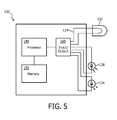
- FIG. 5shows a lighting subsystem according to the principles of the invention
- FIG. 6shows a networked lighting system according to the principles of the invention
- FIG. 7shows a modular lighting subsystem according to the principles of the invention
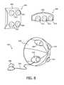
- FIG. 8shows several embodiments of modular lighting subsystems according to the principles of the invention.
- FIG. 9shows a retail environment according to the invention.
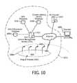
- FIG. 10illustrates the system architecture of an exemplary embodiment of the present invention
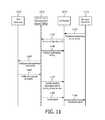
- FIG. 11illustrates the targeted content delivery configuration and provisioning procedure in an embodiment of the present invention
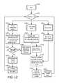
- FIG. 12is a flowchart illustrating the Central Management Server CMS providing the target content delivery service according to an embodiment of the present invention.
- the systems and methods described hereinrelate to electronic devices such as the device 1 of FIG. 1 , referred to herein as smart lighting devices, which include a substrate 10 carrying a lighting element 20 and a processor 30 , as well as a plurality of connections 40 for the attachment of additional electronic components, such as sensors, emitters, and actuators.
- the lighting element 20may also be coupled to the processor 30 , to permit variation of the emitted light as a function of input from a sensor, or a predetermined program executed by the processor 30 , particularly when LED lighting elements are employed.
- the lighting element 20may be an incandescent, halogen, LED, fluorescent, or other lighting element capable of emitting sufficient light to illuminate an area, such as an amount of light similar to at least a 25 W incandescent light bulb.
- LED lighting elementsare particularly well suited for such networks, because they can be configured to be responsive to electronic signals, including digital data protocols such as DMX. Additionally, the voltage, current, and control used to operate LED lighting elements can be adapted to more closely resemble those used for conventional electronic and/or digital devices. See U.S. patent application Ser. Nos.
- the lighting element 20may also include any system that is capable of receiving an electrical signal and producing a color of light in response to the signal.
- the lighting element 20may include light emitting diodes of all types, light emitting polymers, semiconductor dies that produce light in response to current, organic LEDs, electro-luminescent strips, and other such systems.
- the lighting element 20may refer to a single light emitting diode having multiple semiconductor dies that are individually controlled.
- the lighting element 20may include any type of light-emitting semiconductor, including organic LED's, light-emitting plastics, and so forth.
- the lighting element 20may also, or instead, include any other illumination source including any LED system, as well as incandescent sources, including filament lamps, gyro-luminescent sources, such as flames, candle-luminescent sources, such as gas mantles and carbon arch radiation sources, as well as photo-luminescent sources, including gaseous discharges, flourescent sources, phosphorescence sources, lasers, electro-luminescent sources, such as electro-luminescent lamps, light emitting diodes, and cathode luminescent sources using electronic satiation, as well as miscellaneous luminescent sources including galvano-luminescent sources, crystallo-luminescent sources, kine-luminescent sources, thermo-luminescent sources, triboluminescent sources, sonoluminescent sources, and radioluminescent sources.
- Illumination sourcesmay also include luminescent polymers capable of producing primary colors.
- the processor 30may be any data processing device, such as a microprocessor.
- the connections 40may include power connections to provide electricity or other energy to the electronic components and/or a data connection to the processor 30 for communication between the processor 30 and a component coupled to the connection 40 .
- data and powermay be transmitted simultaneously over the same connections, e.g., using pulse-width modulation protocols, other carrier wave protocols, or the like.
- the smart lighting device 1includes a power adapter 42 for connection to a power source.
- the power adapter 42may be adapted for connection to a power source through a conventional lighting jack, e.g., a halogen, fluorescent, or Edison-mount (screw-type) fixture.
- the connections 40permit modular reconfiguration of interchangeable sensor and emitter components, so that the various input and output types of the smart lighting device 1 may be varied to accommodate changing needs and situations.
- components which may be used as sensorsinclude sensors sensitive to electromagnetic signals (e.g., cameras, motion detectors, proximity detectors, photovoltaic sensors, UV sensors, photoconductive sensors, photodiodes, phototransistors, photoemissive sensors, photoelectric sensors, electromagnetic sensors, microwave receivers, magnetic sensors, magnetoresistive sensors, position sensors, etc.), sensors sensitive to temperature (e.g., thermocouples, thermistors, radiation pyrometers, radiation thermometers, fiber optic temperature sensors, semiconductor temperature sensors, resistance temperature detectors, etc.), sensors sensitive to sound (e.g., microphones, piezoelectric materials, ultrasonic sensors, etc.), sensors sensitive to vibrations, humidity, chemicals (such as concentration of a vapor or gas), or any other type of sensing device capable of generating a detectable signal in response to a stimulus.
- electromagnetic signalse.g
- Examples of components which may be used as emittersinclude those which emit electromagnetic radiation (such as infrared, microwave, radio, or other types of signals), acoustic signals (such as speakers, ultrasonic emitters, or other devices which emit sound waves), or other devices which emit signals, especially communication signals.
- Actuators capable of generating a force in response to an electronic signalmay also be coupled to a smart lighting device 1 , e.g., to alter the position of the smart lighting device 1 , or to effect another physical change in the vicinity of the smart lighting device 1 .
- sensors, actuators, and emittersmay be coupled to connections 40 on a smart lighting device 1 , and may communicate with the processor 30 , e.g., to generate or alter an output from the lighting element 20 , an emitter, and/or an actuator in response to a stimulus detected by a sensor, such as in combination with instructions carried out by the processor 30 .
- a plurality of smart lighting devices 1may be coupled together to form networks 44 , as shown in FIG. 2 .
- Datamay be transmitted between smart lighting devices 1 over any physical medium, including a twisted pair, coaxial cables, fiber optics, or a wireless link using, for example, infrared, microwave, or radio frequency transmissions.
- Any suitable data networking protocolmay be used for data transmission, including TCP/IP, variations of Ethernet, Universal Serial Bus (“USB”), Bluetooth, Firewire, DMX, a token ring, a token bus, serial bus, or any other suitable wireless or wired protocol.
- the network 44may also use combinations of these physical media and data protocols, and may include links using known networks such as the Internet and the Public Switched Telephone Network (“PSTN”).
- PSTNPublic Switched Telephone Network
- lighting fixtures in a buildingmay be fitted with smart lighting devices 1 as described herein.
- Smart lighting devices 1 situated in ceiling fixturesmay be wired into a central network, and may communicate with lighting devices in lamps, for example, using infrared transmissions. Commands could be sent to the central network of smart lighting elements over the Internet from a remote location.
- Smart lighting elementsmay be employed for any of a variety of diverse functions.
- the following examplesare exemplary uses, possible in a building, such as a home or office, wherein, for example, overhead light fixtures comprise smart lighting elements as described herein.
- smart lighting elementsmay be employed in displays, in lighted floors or wall panels, cove lighting, or in any other desired configuration.
- Other configurations and applications of smart lighting elements capable of the functions below or other functionsare considered to fall within the compass of the present invention.
- a smart lighting networkmay be used to facilitate mobile communications technology.
- Cellular telephones, wireless data transmitters (such as Apple Computer's AirPort technology), and other mobile communication devicescommonly require high-energy transmissions or proximal receivers in order to connect with a suitable network.
- each roommay be configured with a smart lighting device including an infrared, radio frequency, microwave, or other suitable transceiver.
- traffic management techniquessuch as those currently employed in dense networks or mobile telephone communications, for example, one or more cordless telephones can be made to function throughout a building using low-power signals, thereby lessening the demand for battery power.
- This techniquemay also be employed with wireless telephones, and has particular application with, for example, third generation wireless telephony solutions that permit micro-cells within a cellular infrastructure.
- a micro-cellmay be created inside a building, with connections established through the smart lighting network to an external wireless network, or directly to the PSTN.
- Such an approachmay conserve wireless device energy that would otherwise be required to transmit signals through building walls to an external cellular/wireless base station.
- a portable computercan remain connected to the Internet or other data network while being transported throughout a building.
- Signals from remote controlse.g., for a television or stereo system, can be received in one room, transported over the smart lighting network, and transmitted to a room containing the corresponding component (or over the entire network) to increase the range of remote control, and permit, for example, control of a stereo system from any room in a house.
- a networkmay reduce the number of cords and wires required to maintain connections, potentially liberating and simplifying common communication systems.
- a deskmay be located in any corner of an office without regard to the positions of data or telephone jacks.
- Computer componentsmay communicate through space rather than over wires, making it possible for components such as monitors, computers, printers, etc. to be situated in configurations or relocated in ways that are difficult or impossible using wire connections. For example, a printer could be moved to different room of an office building without rewiring to create a connection, even while data was being transmitted from a computer to the printer.
- the methods and systems disclosed hereincan offer a wireless alternative to structured wiring for a variety of functions.
- a smart lighting networkmay be used to deliver audiovisual stimuli.
- the networkmay include devices that have or incorporate speakers and processor-controlled lighting elements.
- the smart lighting networkmay reproduce the audio portion of the transmission or recording.
- Surround Sound technologyor other spatial audio imaging techniques, can be used to create multi-channel surround sound effects, and may be mediated by a central controller or through the individual processors of the smart lighting devices.
- Remote componentsmay communicate through the smart lighting network. For example, satellite speakers of a Surround Sound system can receive audio signals wirelessly through the smart lighting network.
- the lighting elements of the smart lighting networkmay be used to create lighting effects coordinated with the traditional audiovisual program.
- effectssuch as lightning, sunsets, fiery red glows, or other effects that can be generated by modulating the color and/or brightness of ambient lighting can be used to enhance the effect of a traditional television or movie experience, for example.
- audio feedsuch as music or intercom applications, can be broadcast over an entire smart lighting network, or directed to a particular smart lighting element within the network, without requiring a separate system wired throughout a building.
- a preexisting lighting, intercom, or speaker systemcan be modified or adapted to provide a smart lighting system without requiring extensive rewiring or invasive renovation.
- Similar smart lighting networkscould be used in a theater, music hall, auditorium, or other performance arena.
- a stagecould be provided with a smart lighting network including lighting elements, microphones, and sensors, e.g., for tracking the motion of performers, actors, etc.
- the smart lighting networkcould be programmed with a lighting sequence designed for a particular play, opera, musical, or other theatrical event.
- the networkcould monitor the progress of the event, e.g., by tracking the location and/or movement of the actors, etc., and effect lighting changes, e.g., between scenes, or to provide effects, such as lightning, deepening dusk, sunrise, power outages (including brownout and momentary flickers), programmed to coincide with staged events.
- such a lighting systemcould include smart lighting elements disposed in a seating area, e.g., over an audience.
- These lighting elementscould include microphones, for reproducing sound from a stage or production area, including prerecorded sound effects.
- prerecorded sound effectsincluding thunder, car horns, telephone rings, tire skids, barking dogs, etc., like the lighting effects discussed above, can also be triggered by sensor input from smart lighting elements over a stage in accord with a program designed for the event.
- lighting elements in a seating areacan reproduce on-stage lighting effects throughout the entire audience, to mimic, for example, the flickering glow of a fire, a flash of lightning, daybreak, or any other lighting effect.
- a smart lighting devicecan operate as a voice-activated telephone, dialing numbers or contacting parties by voice commands. The communicating party is thus liberated from hand-held telephone devices, and a larger area and larger number of participants may be served by a smart lighting network than may generally be served by, for example, a speaker-phone.
- camerasmay be included in the smart lighting network, enabling videophone applications.
- a smart lighting systemcan be configured to respond to a voice by activating a camera in the nearest smart lighting device and, optionally, pointing the camera at the speaker using an actuator.
- a smart lighting networkcan be configured to pinpoint the location of a speaker or other audio input by triangulation or other means. The methods and systems disclosed herein can be further used by such methods as an indoor positioning system for objects.
- Smart lighting devicescan be equipped with light sensors appropriately positioned to detect ambient light and modify the output of the lighting element to achieve a predetermined brightness or hue.
- Such networksmay be particularly appropriate in sensitive environments such as operating rooms, photography studios, or agricultural operations.
- the smart lighting devicesmay include sensors, such as humidity or temperature sensors, to permit responsive control and maintenance of optimal growing conditions by regulating lighting as well as other systems, such as computer-controlled humidification, heating, irrigation or watering systems.
- Smart lighting devicesmay be equipped with chemical sensors, e.g., for detecting smoke, carbon monoxide, radon, gas leaks, etc., to provide an integrated sensor/alarm system in a home, business, or vehicle.
- Vibration sensorscan be used for earthquake monitoring.
- Proximity and/or motion detectorscan be used for security systems, optionally in conjunction with camera components.
- Such networkscan also be used for child monitoring, e.g., with a microphone and/or camera operating in a baby's room and transmitting data to another room, or over a networks such as the Internet.
- Speakers and/or lightscan be used to generate alarms or warning signals when designated stimuli are detected.
- Access to such a smart lighting network over a larger networkcan allow a security company to control lighting and other functions of a building from a remote location to deter burglary more effectively than simple light timers, and can similarly permit remote video monitoring for security purposes, or to distinguish false alarms from actual threats.
- smart lighting elementsmay be placed in public spaces, such as retail stores, convention halls, public streets, sports venues, entertainment spots, etc., to monitor the flow of people, vehicles, or other objects.
- a smart lighting elementmay, for example, determine the number of people or objects which pass by the unit, the speed at which the people or objects pass the unit, or any other suitable measurement.
- the collected datamay then be analyzed, e.g., using a processor connected to the smart lighting network, or by downloading the collected information to a suitable processor, etc., to determine traffic flow, traffic patterns, points of congestion, etc.
- This analysismay be useful, for example, to determine points where traffic is congested, to help identify a change in the layout or configuration that may help redirect traffic flow or ease passage and congestion, or to determine, for example, how customers prefer to navigate through a supermarket or find seats in a theater.
- a smart lighting element in a display, or a smart lighting network in a retail environmentmay collect information such as how long customers view a display on average, whether a display attracts people from distant parts of a store, or even capture or analyze features such as facial expressions, to gauge customer's interest in and reaction to a retail display, advertisement, or other display meant to attract attention.
- Such informationmay further be correlated with information such as sales data, e.g., collected at check-out lines, cash registers, or other inventory systems, to determine the overall effectiveness of retail displays and advertisements.
- an object in the range of a sensor of a smart lighting elemente.g., a camera, microphone, motion detector, etc.
- the networkcan track the motion of the object, determine where the object is going, identify the smart lighting element associated with that location, and track the object as it moves into the range of the second smart lighting element, e.g., by a hand-off technique or other protocol.
- smart lighting networksA variety of entertainment uses are possible for smart lighting networks. For example, theater or other lighting systems can be rapidly set up in outdoor environments, or in indoor environments not wired for complex lighting systems. Appropriate smart lighting devices may, for example, be situated near electrical outlets and, rather than being wired together, may be controlled by wireless commands. Such a network may also function as a sound system by incorporating speakers in the smart lighting elements. Modular networks which function using minimal wiring facilitate set-up for travelling performances, or in environments, such as a high school gym, a stone church, a tent, outdoor gatherings, fountains or other water displays, etc., where complex wiring arrangements may be unsightly, dangerous, or difficult to set up. The combination of light and audio functions further simplifies and shortens required set-up procedures.
- smart lighting devicescan be outfitted with sensors, such as microphones or proximity detectors that can be used to interactively modulate audiovisual output, for example, in response to proximity of dancers or spectators, in response to tempo or dynamics of music, etc. Responsive and interactive smart lighting devices can also be used in a fun house or other interactive environments for entertainment purposes.
- sensorssuch as microphones or proximity detectors that can be used to interactively modulate audiovisual output, for example, in response to proximity of dancers or spectators, in response to tempo or dynamics of music, etc.
- Responsive and interactive smart lighting devicescan also be used in a fun house or other interactive environments for entertainment purposes.
- a smart lighting networkmay be controlled by a centralized system, or cooperatively through the collective microprocessors of the smart lighting network.
- Appliances and other household, business, industrial, or other devicescan be outfitted for remote control, e.g., through infrared, microwave, or radio signals, and subjected to control by the centralized system using the smart lighting network.
- Such systemscan be used to automate building systems functions and electrical devices, e.g., without requiring extensive or particularized rewiring. Uses can be as diverse as starting a coffee machine, booting up a computer, raising the thermostat, starting and warming up a car at a specified time, or continuously controlling the major functions of a processing plant.
- Including sensors in the systemenables more complex, interactive functions, such as turning on a light when a person enters a room and turning it off when the room is empty.
- Individualscan be equipped with badges that transmit signals based on identity or a general classification scheme, thus permitting the system to moderate access control to various sites of a building, play music in a room that matches the predetermined preference of its occupant, monitor activity and locations of a building's occupants, and perform other functions.
- Voice commandscan be received, interpreted, and carried out at distant locations in the building, optionally depending on the status of the issuer of the command, as determined, for example, by an identifying badge, voice or face recognition, etc.
- the environment of a smart lighting networkcan be monitored and/or modified from a remote location. For example, business operations, home security, and other conditions may be verified by receiving output from sensors in the smart lighting network at a terminal in a remote location, e.g., using a web browser or other suitable interface. Commands can be sent from a remote location as well, permitting modulation of any functions, such as building temperature, lighting control, appliance or machine operation, etc., which is subject to control or mediation by the smart lighting network.
- a smart lighting networkmay comprise smart lighting elements and smart units that do not include lighting elements, but include other functionality, such as sensors, transmitters, indicators, speakers, or the like, e.g., to gather or transmit information in environments where lighting is not necessary or desirable, although network connectivity is desired.
- a digital lighting networkmay be usefully employed in retail environments. Fundamentally, retail stores and chains try to attract people and cause them to spend more money on their products and services. Human observers are typically employed to observe shoppers, from which observations trends, responses, and other valuable information may be extracted. A smart lighting network augmented with sensing devices could provide the same observation capability and automatically produce detailed reports of shoppers. The resulting information, which may continuously monitor an entire store, can be used to reveal traffic flow, provide feedback on merchandising, analyze product placement trials, assess the effects of placement, lighting, merchandising, graphics, store fixtures and so on. This knowledge, normally not easily captured, is invaluable to a store or chain owner.
- Supermarkets and other retailers with thin marginsmay advantageously employ a digital lighting network to provide good traffic flow and easy access to goods, and to more accurately price shelf space for suppliers and wholesalers.
- Suppliers and wholesalerswho may already pay for shelf space and location, would find tracking information very useful in assessing how people move within a store.
- Stores with smart lighting networkscould offer such information to the wholesale giants at a fee, benefiting the stores, the suppliers, and the customers.
- Information collected in a retail applicationmay be presented at a central location, such as a computer, and may include software for controlling various outputs within the digital lighting network, such as sound systems, lights, and other devices.
- a digital lighting network of smart lighting elementsmay be usefully employed in an office or other commercial location.
- Smart lighting networks which employ wireless technologycan be easily expanded or adapted as a company grows or changes in size, and may be provided as an alternative, or an enhancement, to wireless local area networking in a commercial setting. Local wireless will enable network access throughout a building or corporate campus and the ability to transfer and access information will be greatly facilitated.
- a digital lighting network of smart lighting elementsmay be usefully employed in theme parks, resorts, hotels, casinos, and entertainment companies, all of which require careful and constant tracking of customers. With a smart lighting network, key areas that people avoid or are attracted to can be quickly identified.
- the hardware and network of the digital lighting networkmay employ readily available and standardized technologies as modular components of smart lighting elements. Installation costs can be reduced through the use of existing power wiring and the use of emerging wireless standards such as the 802.11 wireless LAN standard, Bluetooth, or standards from the Infrared Data Association (“IrDA”).
- IEEE 802.11 wireless LAN standardsuch as the 802.11 wireless LAN standard, Bluetooth, or standards from the Infrared Data Association (“IrDA”).
- the smart lighting elementsare fully modular.
- Each smart lighting elementis a modular I/O and networking device that may be seamlessly added or removed from a digital lighting network.
- Use of an open architecturemay permit the use and development of a wide variety of different smart lighting elements and other compatible devices for different applications.
- the frameworkmay include, for each smart lighting element or other device (collectively “modules”), power and a conduit to wired networks and a minimum set of I/O features. Both elements can be designed to make it simple and effective to add or change modules depending on desired feature sets.
- a mapmay provide an intuitive graphical user interface for displaying a room or area. For example, a store map can be displayed and modules may be placed within the map using drag-and-drop operations. Modules may then be double-clicked to open a configuration window or menu, and, if the configuration is on-line, the module can be queried for functionality. This may open a different window or frame that lists the features and the results of a self-test. If the functionality or type of a module is known a priori, this may be entered directly into the configuration window, or selected as an item for drag-and-drop on to the area map. Since modules may include output devices (such as speakers, lights, moving systems), programs or effects can be written or developed through the control software, or independently, and incorporated into the module over the digital lighting network.
- output devicessuch as speakers, lights, moving systems
- a digital lighting networkmay be usefully employed as a data acquisition tool. Data gathering may be automated for monitoring traffic flow through hallways, open areas, elevators, as well as entrances and exits, and the traffic flow may be correlated to time, place, or other factors.
- a clothing chain that markets to teenage girls in malls throughout the northeast UScan install modules with a variety of sensor devices including cameras and proximity detectors and digital lighting.
- the modulescan each be installed with only a single power connection, and one of the modules can also be tied into the store's data network which uses a telephone line for data communications with the store's headquarters.
- the systemmay further be connected to the point-of-sale data collection system to permit exchange and integration of captured data.
- a mapcan be generated from the day's data collection to display people traffic and dwell time at various points in the store. The information can make it apparent, for example, that an aisle of shirts and accessories is the least visited area of the store. Although the aisle may be easily accessible, the manager might investigate and discover a rack of clothes has unintentionally obscured the aisle from view as customers approach that area.
- the day's receiptsmay also uncover a curious anomaly: the clustering of data, which can be used to draw inferences about buying habits, may show that girls who are buying smaller size pants, skirts are also buying much larger shirts that don't correspond to the pants size. The manager might move those items closer together in the store to see if this generates increased sales and traffic in that area.
- a quick tracking analysismight reveal that people are not stopping by displays at the entrance but are sweeping through the entrance quickly into the store, which might prompt moving the entrance displays further into the store or jazzing up the entrance displays.
- Traffic near an aisle of blousesmight be identified as being normal even when sales are much lower than normal.
- the informationmight indicate that if two or more people are in that area, then one or both moved quickly through. After investigating, the manager might find that the cases have been moved closer together than would be comfortable for two people and then move the displays away from each other.
- the modulesmay thus facilitate measuring effectiveness of display areas.
- Price changesmay be transmitted dynamically through the smart lighting network. For example, where a customer spends a significant amount of time in front of a display, the price for a product may be lowered (e.g., by providing the user's mobile device with a coupon) to lure the customer to make a purchase. Further, the price for a customer may be personalized by tracking the customer to a cash register and providing the customer with a price displayed when the customer selected the item. Alternatively, pricing may be increased if, for example, fifty percent of the inventory is sold in a single morning. More complex pricing schemes may also be implemented, and may be personalized to individual customers according to their observed shopping habits.
- Secure transmissionsmay be implemented using a number of cryptographic techniques or other techniques, and may be implemented, for example, as a physical layer, network layer, or application layer encryption system, depending upon the complexity and processing power of each smart lighting network node. Further, security may be negotiated individually for each communication link, or each smart lighting element may have its own encryption key, or a single key may be provided for an entire smart lighting network.
- a sports arenamay host hockey and basketball games and other sporting events as well as rock concerts.
- the eventsmay have very different types of crowds that may behave differently.
- the existing CCTV camera systemsmay have been adequate, but did not help track the flow of people before, during, and after the events. Modules, however, may facilitate tracking people during events.
- the smart lighting networkmay provide a detailed map of traffic flow that enables simple reconfiguration and redesign of the exits and entrances. Additionally, the system may also be able to identify several configurations of concessions and restrooms that caused substantial bottlenecks during certain events. By closing some concessions and opening others the problems may be reduced or eliminated.
- roving bands of fansmight cause considerable damage and harm to others.
- the tracking features and sensing devices of the smart lighting networkmight pinpoint and follow the perpetrators, enabling security officers to intercept, with plenty of time to plan and implement the interception.
- modulation of the LEDs of the smart lighting devices disclosed hereincan provide communications functions between smart lighting devices or between a smart lighting device and another networked device.
- LED'sare configured as saturation devices, that is, they have a single, “on” intensity determined by a regulated current.
- the perceived intensity of LED's in these systemsis controlled by rapidly turning the LED's on and off with a control signal that has a regulated duty cycle. While the period of the control signal is sufficiently short that a human eye cannot detect the progression of “on” and “off” states, there remains significant additional switching speed in conventional LED's.
- a data signalis modulated onto a carrier signal such as a radio frequency, visible light (laser), or infrared carrier, with an appropriate modulation scheme selected according to the transmission medium.
- a carrier signalsuch as a radio frequency, visible light (laser), or infrared carrier
- LED'shave been used for wireless data transmission, typically using pulse code modulation (“PCM”)
- PCMpulse code modulation
- visible light LED'shave been used for illumination.
- LED'sprovide significant design flexibility since LED's with different wavelengths, i.e., colors, may be mixed to generate desired lighting effects and desired colors.
- systems of LED's, and more particularly visible light LED'srequire additional, independent data communication hardware in order to operate as a networked lighting system. This may include twisted pair wire leads, or some other bus structure, which must physically interconnect one or more control units to lighting subsystems that are to be controlled.
- an LED systememploys pulse-width modulation (“PWM”) to control illumination intensity and pulse code modulation (“PCM”) to carry data.
- PWMpulse-width modulation
- PCMpulse code modulation
- the methods and systems described hereincan be suitably adapted to many other modulation schemes suitable to LED's, and may further be used in combination with many known data networking techniques.
- the principles of the inventionare particularly applicable to any environment where the dual functions of illumination and wireless data communication are desired.
- FIG. 3shows an LED encoder and an LED decoder according to the principles of the invention. It will be appreciated that numerous LED's and decoders may be used in combination, as will be discussed in more detail below.
- the single LED systemincludes a transmitter 50 comprising an illumination signal input 60 , a data input 65 , a processor 70 , an LED driver 75 , and an LED 80 .
- the systemfurther includes a receiver 82 comprising an optical transducer 85 , a decoder 90 , and a data output 95 .
- the illumination signal applied to the illumination signal input 60is converted to a pulse width modulated (“PWM”) signal that is provided as a control signal to the LED driver 75 .
- PWMpulse width modulated
- the perceived intensity of the LED 80is a function of the duty cycle, or average “on” time, of the control signal.
- this control signalmay be further modulated by a data signal applied to the data input 65 , while retaining the duty cycle of the control signal such that the intensity of the LED 80 is still controlled by the illumination signal.
- the processor 70may include a buffer 97 , which stores data received at the data input 65 when a received data rate exceeds a data capacity of the control signal.
- the processor 70 or decoder 90may be a microprocessor, microcontroller, programmable digital signal processor, application-specific integrated circuit, programmable logic device, programmable gate array, or other device capable of receiving and manipulating input and output signals consistent with the principles of the invention.
- the processor 70 and decoder 90may also include analog components such as operational amplifiers and transistors, discrete logic components, or be a combination of analog, discrete logic, and other processing components.
- the receiver 82applies known techniques to decode PCM signals impressed upon the optical transducer 85 .
- the optical transducer 85may be a phototransistor, photodiode, or any other device capable of detecting incident light having the wavelength emitted by the LED 80 .
- the decoder 90receives a signal from the optical transducer and recovers PCM signals having a predetermined center frequency.
- the decoder 90converts the recovered PCM signals into a data output signal at the data output 95 .
- the processor 70uses the same center frequency to encode the data signal using PCM.
- FIG. 4shows the composition of a control signal according to the principles of the invention.
- the control signal of FIG. 4is particularly applicable to those environments where it is desired to control illumination and transmit data within a shared optical channel.
- the PWM signal 100is “on” from 0 to t, and “off” from t to T.
- the duty cycle for this signalmay be expressed as a ratio of the length of the “on” state, t, to the period of the entire PWM signal, T.
- a data signal 110is also shown.
- the data signal 110preferably has a shorter period than the PWM signal 100 , with the period determined by the center frequency of the decoder 90 .
- an inverted form of the data signal 110is also generated by the processor 70 , beginning at the end of the original PWM signal 100 .
- the control signal 120is generated by taking an exclusive OR (“XOR”) of the PWM signal 100 and the data signal 110 .
- the control signal 120is transmitted to the LED driver 75 where it is used to activate the LED 80 .
- the LED 80In response to the control signal 120 , the LED 80 generates visible light having a color determined by the LED 80 and an intensity determined by the average “on” time of the control signal 120 .
- the applications incorporated by reference hereinprovide further details as to PWM and other carrier wave techniques, and it should be understood that the method of PWM control disclosed herein is but one illustrative embodiment, and that other PWM embodiments are within the scope of the present disclosure.
- the visible light from the LED 80falls upon the optical transducer 85 , which generates signals to the decoder 90 .
- the decoder 90demodulates the PCM data contained in the visible light to reconstruct the data output signal.
- the data carrying capacity of the control signal 120will depend upon the duty cycle of the PWM signal 100 and the data signal 110 .
- an illumination signal indicating that the LED 80 should always be off (duty cycle of 0%) or always be on (duty cycle of 100%)has no information carrying capacity.
- PPMpulse position modulation
- data signalsmay be transmitted with infrared LED's, and illumination signals may be transmitted using visible light LED's.
- illumination signalsmay be transmitted using visible light LED's.
- datamay be transmitted for a time, followed by illumination.
- Data and illumination signalsmay alternate on a fixed period, or data may be transmitted only during a power up phase, or data may be preceded by a modulated data header which signals to a receiver that data will follow.
- lightingmay be provided by any conventional light source, such as an incandescent or fluorescent light, while data may be transmitted using a modulated LED. Any of these techniques, or other techniques, may be used to practice a networked lighting system.
- FIG. 5shows a lighting subsystem according to the principles of the invention.
- a lighting subsystem 130may include a light source 132 responsive to an illumination signal 134 , and a transmitter 136 and a receiver 138 such as the transmitter and receiver described in reference to FIG. 1 . It will be appreciated that, although not shown in FIG. 3 , the transmitter 136 and the light source 132 may be embodied in a single optical device, such as an LED described above.
- the lighting subsystem 130may also include a processor 140 , a memory 150 , and input/output circuitry 160 .
- the transmitter 136 and the receiver 138may provide a physical link to a lighting network over which the lighting subsystem 130 may send and receive data.
- the lighting subsystem 130may receive illumination data from the receiver 138 , as well as any other data or control signals that may be transmitted over a network.
- the light source 132may be any known light source, including an LED light, programmable LED array, incandescent lamp, floodlight, high-voltage spotlight, track light, flourescent light, neon light, halogen light, or any other illumination source.
- the input/output circuitry 160includes any suitable analog/digital and digital/analog circuitry, and other signal processing circuitry for transforming signals from the processor 140 into signals for the light source 132 and the transmitter 136 , as well as for transforming signals from the receiver 138 into signals for the processor 140 .
- the input/output circuitry 160may include the components described in reference to FIG. 3 .
- the memory 150may store information relating to the lighting subsystem 132 .
- the memory 150may store a date of manufacture for the lighting subsystem 132 , a serial number of the lighting subsystem 132 , an address of the lighting subsystem 132 , capabilities of the lighting subsystem 132 , and any settings or other information relating to the lighting subsystem 132 .
- the addressmay be an identifier or digital signature that uniquely identifies the lighting subsystem 132 from among a plurality of lighting subsystems 132 or other devices. The address may then be used as a source or destination address for data carried over a lighting network, such as the network described below.
- the date of manufacture and the serial numbermay be used, for example, to identify the lighting subsystems 132 and any known capabilities of the lighting subsystem 132 . Or, as noted above, specific capabilities of the lighting subsystem 132 may be explicitly communicated using the transmitter 136 .
- Settingsmay also be stored in the memory 150 . This may include any settings corresponding to the lighting subsystem 132 .
- the settingsmay include programming information for the array.
- the settingsmay also include, for example, configurable lighting effects such as fades, timers, or the like.
- the settingsmay also include a flag for the lighting subsystem 132 to operate as a control unit for other lighting subsystems 132 , or to operate as a communication node for other lighting subsystems 132 , or to operate as a slave to another device.
- the memory 150may be a flash memory, read-only memory, or some other non-volatile memory, or the memory may be a random access memory, dynamic random access memory, or some other volatile memory.
- the lighting subsystem 132may include a processor 140 .
- the processor 140may be a microprocessor, microcontroller, application specific integrated circuit, programmable logic device, or any other device that may be configured to control operation of the lighting subsystem 132 . Where the lighting subsystem 132 is a battery powered device, the processor 140 may be a low-powered processor.
- the memory 150 of the lighting subsystem 132may include programming code for autonomous execution by the processor 140 of the lighting subsystem 132 .
- the programming codemay include information to control lighting by the lighting subsystem 132 , or information to control operation of the lighting subsystem 132 as a communication node in a lighting network.
- the programming codemay include one or more diagnostic routines to automatically test capabilities of the lighting subsystem 132 each time that the lighting subsystem 132 is powered up, or at other times when specifically requested, such as by control signals received on the receiver 138 .
- FIG. 6shows a networked lighting system according to the principles of the invention.
- a networked lighting system 200may generally include a plurality of lighting subsystems 202 , 212 , 214 , 216 , other networked devices 204 , and one or more control units 206 , sharing data over a lighting network 208 .
- the control unit 206may also be connected to a data network 210 for remote access to the control unit 206 and the lighting network 208 .
- Each of the lighting subsystems 202may be a lighting subsystem such as the one described in reference to FIG. 5 .
- Each lighting subsystem 202may be connected to the lighting network 208 to form a communicating relationship with other lighting subsystems 202 , other networked devices 204 , and the control unit 206 .
- the lighting subsystem 212includes the components of one of the lighting subsystems 202 .
- the lighting subsystem 212is configured to operate as a node that connects additional lighting subsystems 214 , 216 to the lighting network 208 , as well as to the control unit 206 and the networked devices 204 connected thereto.
- the additional lighting subsystems 214 , 216may additionally be configured to communicate with one another independent of the lighting network 208 , in order to exchange control information, such as information to provide a totally intensity of illumination within an area, or to control a color of illumination through mixing of color sources available at each of the lighting subsystems 214 , 216 .
- each networked device 204may include a receiver and a transmitter for communicating over the lighting network 208 , as well as a processor and a memory such as the processor and the memory described above.
- Networked devices 204may include lighting fixtures, thermostats, motion sensors, light sensors, timers, switches, power controls, fans, electronically operable window blinds and curtains, alarms or audible signal generators, or any other sensor, transducer, or actuator for operation with the lighting network 208 .
- Other networked devices 204 which may be used with the inventionmay include devices such as smoke making machines, audio and video presentation equipment, strobe lights, electronic doors, and so forth.
- the networked device 204may physically situated such that the networked device 204 may communicate through the lighting network 208 , and may provide sensor data and/or receive control information without a need for wired connections to other devices connected to the lighting network 208 .
- the networked devices 204may be configured to operate as communication nodes in the lighting network 208 , or to operate in slave or control configurations.
- One or more of the lighting subsystems 202 , 204 , 206 , 210 , 212 , 214may be configured to operate independently, each sending and/or receiving data over the lighting network 208 to other ones of the lighting subsystems.
- the network 208may be decentralized, consisting of one or more subnetworks interconnecting, for example, a first subgroup of the lighting subsystems 202 , 204 , 206 in a first subnetwork, and subconnecting a second subgroup of the lighting subsystems 210 , 212 , 214 in a second subnetwork.
- the network 208may be configured to operate as a peer network shared by a number of autonomous network nodes, or the network 208 , or any subnetwork thereof, may be configured to operate as a client-server network with one lighting subsystem arbitrating communications among the other lighting subsystems.
- one nodemay operate as a master that controls operation of other lighting subsystems connected to the subnetwork or the network 208 .
- the networked lighting system 200may include a control unit 206 .
- the control unit 206may be a programmable device such as a personal computer, or any other device that can receive user input and maintain control information for the lighting network 208 .
- the control unit 206may include a transmitter and receiver for establishing communications over the lighting network 208 .
- Theremay also be provided any other software tools designed for management of the lighting network 208 , including an interface to manage, monitor, control, and troubleshoot the lighting network 208 , as well as perform other functions consistent with the lighting network 208 .
- the control unit 206may be used to download control programs to one or more of the lighting subsystems 202 or networked devices 204 for autonomous execution on those devices and subsystems.
- the control unit 206may be used to synchronize effects or control of environmental conditions provided by the system 200 , and the networked devices 204 and the lighting subsystems 202 attached thereto.
- the control unit 206may also be connected to a conventional data network 210 , such as a local area network, wide area network, private area network, or a public network such as the Internet. Through this connection, control information for the lighting network 208 may be provided remotely through any device connected to the data network 210 . Additionally, data from sensors associated with the lighting subsystems 202 or the networked devices 204 may be retrieved and viewed from a remote device connected to the data network 210 , either for simple monitoring functions or for interactive control of the system 200 .
- the control unit 206may include known security features such as password protection and secure communications, in order to maintain privacy of data available from the lighting network 208 , and to prevent unauthorized tampering with devices attached to the lighting network 208 .
- the networked lighting system 200may be used in any controlled lighting environment, such as a theater lighting system, home lighting system, a commercial display such as a window display, interior lighting system for social functions, exterior lighting system configured in an architectural or landscaping design, or any other system where information may be usefully communicated among a number of lighting subsystems.
- a spectral sensormay be provided as a networked device 204 , and may receive illumination from a number of lighting subsystems 202 , each of which contains a different colored light source. The spectral sensor may communicate with the lighting subsystems 202 to automatically provide lighting of a predetermined color.
- the networked lighting system 200may also be used as a replacement for other communications networks, such as wireless computer networks. That is, the data carrying functions of lighting subsystems may be used, independent of the lighting functions, to form data links between computers, or other devices that might typically be networked, that bridge physical gaps between connection points of the computers.
- FIG. 7shows a modular lighting subsystem according to the principles of the invention.
- the modular lighting subsystem 700may include a base 702 that forms a universal platform for a number of modules 710 , 712 , 714 , 716 .
- the base 702may include a light 720 , such as an LED source or some other light source.
- the light 720may form a discrete lighting area, such as a lens, within the base 702 , or the base 702 may be formed of a diffusing material so that the light 720 provides illumination throughout the base 702 .
- the base 702is shown in FIG. 7 as circular in shape, that the base 702 may have any shape, and may include hooks, screw holes, adhesive, or other components for mounting in a location.
- the base 702may also include an electrical cord and a plug for attachment to, for example, an 110V AC outlet, or a low voltage DC outlet.
- Each module 710 , 712 , 714 , 716may fit into a cradle within the base 702 , which may be any shape adapted to receive the module.
- the cradlemay include electrical contacts for forming power connections with the modules, and may also include electrical contacts for forming data connections between the base 702 and the modules 710 , 712 , 714 , 716 , as well as among the modules 710 , 712 , 714 , 716 .
- the modulesmay include components for expanding or changing the functionality of the lighting subsystem 700 .
- a first module 710may provide power, and may include a battery or a converter for converting an external power source into a power source suitable for the lighting subsystem 700 .
- a second module 712may provide input/output, including a network interface such as a physical interface to an infrared or radio frequency network, and any network protocol stack required to form communication links between the lighting subsystem 700 and other nodes of a network.
- a third module 714may provide sensors such as microphones, temperature sensors, digital cameras, or, for example, any of the sensors discussed above.
- a fourth module 716may provide output devices such as a speaker, an LED or LCD display, additional lights or LED's, or some other output device. Other modules may include, for example, a processor or other device.
- each cradleis the same, so that any module may be inserted into any cradle.
- the base 702may include circuitry for detecting module types and forming a suitable connection to each module.
- FIG. 8shows several embodiments of modular lighting subsystems according to the principles of the invention.
- each module 810may provide additional functionality such as sensing and communication.
- the modules 810may connect to a base 820 with a simple mechanical and/or electrical connection. Suitable mechanisms for forming connections are known in the art, such as cellular phone and personal digital assistant power and data connections, light bulb connections, dual in-line pin package sockets, zero insertion-force sockets, cradles, modular jacks for phone and network connections, electrical sockets, game cartridge slots for gaming platforms, docking stations for computers, and so forth.
- An additional locking featuresuch as a mechanical level or bayonet mounting may be used to insure that all modules 810 remain in place as others are removed and inserted.
- External cabling 840 to high-bandwidth devices such as a camera 850may be included in a module 810 as shown, or directly attached to a port in the base 820 .
- the base 820may provide a central connection for a variety of sensing and communications modules 810 .
- a variety of physical formscan be made that would fit into different styles and decors without appearing to be out of place, as shown generally in FIG. 8 .
- the functionalitymay be the same for each base 820 , or the functionality may be specialized for one or more different types of bases 820 .
- FIG. 9shows a retail environment according to the invention.
- a computer monitor 910may display information in a useful graphic form of a plan view 920 of the store that includes information relating to, for example, time and traffic through the store.
- the plan view 920can take many forms, including graphs, tabular data, bar charts, and the like. As one example, graphical representations may offer a powerful and easy to interpret means of showing relevant data.
- people 930may view, for example, two displays: a first display 940 to the left and a second display 950 to the right. Both displays 940 , 950 may attract people though attention-getting visual merchandising techniques.
- sensorssuch as cameras with image interpretation or proximity sensors, may be used to detect and track people, and to display the location of people on the plan view 920 of one of the displays 940 , 950 .
- lines 960 on the floor and one or more clocks 970may graphically represent the paths and the duration of patrons during the course of the day.
- the thickness or width of the lines 960may represent the amount of traffic along that path.
- the clocks 970may represent an average amount of time spent at a display 940 , 950 . In this way, visual-merchandising techniques can be quickly and easily compared for their attention-getting ability, percentage of traffic effectiveness, and interaction.
- the lines 960 and clocks 970might be displayed on the plan view 920 of the computer monitor 910 for review by a store owner or manager.
- the displays 940themselves can be monitored and controlled with respect to customer interaction. For example, changing lighting, or kinetic devices can be compared and analyzed for their ability to attract customers.
- the displays 940themselves may be used as a part of a data collection process that includes other sensors throughout the retail environment 900 .
- the current inventionhas particular applicability to Outdoor Lighting Networks (OLNs).
- OTNsOutdoor Lighting Networks
- the inventionenables new business scenarios where operators and/or owners of a city's lighting infrastructure can provide a value added service or generate revenue from ad providers and local businesses by leveraging the data acquired through the lighting and adjacent infrastructure (e.g. sensors) to help the businesses to increase their LBS advertising performance/targets.
- FIG. 10illustrates the main system components of an exemplary embodiment of this aspect of the invention.
- the OLN 1010can consist of one or more lighting sub-networks across a geographical area. In FIG. 10 one such sub-network is depicted which contains Light Units (LUs) within an Area of Interest 1090 . In larger implementations (e.g., an entire city or region) numerous sub-networks would comprise the overall OLN 010 .
- the OLN 1010is typically managed through a Central Management Server (CMS) 1020 .
- An operator(s) 1080having priorities to control/manage the lighting infrastructure, may connect remotely as depicted in the figure.
- the CMS 1020usually has a database 1030 of the overall installed base of LUs 1040 managed by the CMS 1020 .
- This databasemay also include detailed capabilities and configuration information for the devices that are part of or connected to the OLN.
- the CMS 1020may also connect to an area information database 1050 , which may include information, statistics or other types of data associated with the city's infrastructure, including, but not limited to, lighting.
- the OLN 1010also maintains a database 1060 to store information related to the targeted content delivery service, where it can store preferences and service configurations from businesses/users that can be obtained from the Ad Provider 1070 .
- the Ad Provideris responsible for interacting with the advertising businesses (users) and configuring the actual delivery of the content based on configurations and preferences agreed by the businesses/users.
- This inventiondescribes a method for the CMS 1020 to capture data from the OLN 1010 and analyze, identify events/alerts and contact the Ad Provider 1070 in order to configure the advertising delivery strategies and priorities.
- FIG. 10depicts the above described components as being contained within the OLN 1010 .
- the inventionis not so limited. That is, by way of example one or more operators 1080 , Ad Provider(s) 1070 or databases (e.g., items 1050 or 1060 ) may reside outside of the OLN 1010 structure, per se. In these situations, the necessary communication with the Central Management Server and the databases of the OLN is provided by various communication means to include, for example, Internet or other communication links.
- the CMSmay be located remotely, i.e. outside the OLN. That is, the CMS can be a cloud service, an Internet server or a local server in a private network. In such embodiments, the CMS can use various remote communication means to connect/manage the OLN (e.g. wired/wireless, 3G/4G cellular service, WiFi, etc)
- the Ad Provider 1070interacts with one or more businesses 1110 and collects information 1120 regarding the preferences and interests from these businesses.
- This informationcontains, but is not limited to, aspects of the contemplated advertisements, such as the type of content, target audience, target area and events of interest, etc.
- the Ad Provider 1070may aggregate and/or filter some of the user data before providing service configuration information 1130 to the CMS 1020 .
- One possible use caseis a restaurant along a highway that could be interested in delivering ads to drivers and would be interested attracting more customers during traffic events, such as traffic jams, accidents, etc.
- the business ownercould use the Ad Provider's service, and therefore provide all the relevant information and preferences to help target the ads.
- the Ad Provider 1070could then process the data and send the information in the format of a service configuration request 1130 to the CMS 1020 .
- the format of the requestmay include: target area of interest, time schedule with priority hours (i.e. specific times of interest for the business), type of content, target customer profile, target traffic profile, types of events of interest etc.
- the CMSOnce the CMS receives a service configuration request, it will determine the Area of Interest (AOI) for the request and verify what lighting and/or sensing infrastructure is available. It may also contact other third party infrastructure (not shown) if capability is not directly available to provide information needed to support the service request. For instance, if the CMS 1020 has infrastructure set up to identify traffic condition changes (e.g. traffic jam or accident) in the AOI it will confirm the request 1140 . Otherwise, if capability is unavailable, it may deny the request and/or suggest changes (not shown).
- AOIArea of Interest
- the measurement capabilities of the OLN and/or adjacent sensing infrastructuremay include:
- the CMS 1020will, at step 1150 , configure measurements, if needed, and define events or alerts associated with the service, which can be identified through analysis of the data collected from the OLN Database 1030 .
- the lighting and sensing infrastructurereports measurements to the CMS 1020 , both periodically and on demand.
- On demand reportsmay be used to indicate unusual situation or changes in normal patterns, such as an accident or traffic jam being detected.
- the CMS 1020continuously analyzes the incoming data, e.g. searching for well-known data patterns or alert message that characterizes a given event. Once an event is identified, it is mapped to one or more relevant active services, if available. For instance, if an accident is detected, the CMS will search for the active services that have registered interests on accidents in such AOI. For every relevant active service identified, the CMS communicates the information 1170 to the Ad Provider 1070 , which can adjust that ad's targeting information on behalf of the business. For instance, the CMS 1020 could recommend to the Ad Provider an increase in the AOI and bidding price for ad(s) associated with an active service.
- the Ad Provider 1070can also set up coupons for ads from a restaurant along a highway if the CMS 1020 communicates that traffic conditions deteriorated considerably or if a serious accident is detected along the highway. In this way, the local businesses could attract more customers based on real-time conditions identified by the lighting and sensing infrastructure.
- the CMS 1020may also send an event report 1180 to the Ad Provider 1070 , which could then be forwarded at step 1190 to the Business Advertiser(s) 1110 (e.g., business owner or manager).
- the CMS and the Ad Providerare controlled by a single entity or have a cooperation agreement in place, the CMS may send alerts and recommendations directly to selected Business Advertisers, so they can act and change their ad configuration and priorities directly with the Ad Provider.
- FIG. 12is a flowchart illustrating the Central Management Server CMS providing the target content delivery service according to an embodiment of the present invention.
- the systemcommences action upon the detection of three types of events.
- a service configuration request 1230is processed at step 1240 to determine the Area of Interest (AOI) for the request and verify what lighting and/or sensing infrastructure is available.
- the systemat step 1250 then determines whether or not the capability exists to provide the information needed to support the service request. If it does not, it will deny the request and propose configuration changes at step 1260 . If the capability does exist, a confirmation is sent at step 1270 and the system configures the appropriate measurements and alerts at step 1280 .
- AOIArea of Interest
- step 1220detects a traffic data report 1290 , the provided traffic information is analyzed at step 1300 . The determined event is then mapped to one or more active services (step 1310 ) and a decision is made as to updating the appropriate Ad related information (Step 1320 ). An Ad configuration update is then sent to the Ad Provider at step 1330 as well as an event/update report at step 1340 .
- step 1220detects a device alert 1350 , the type of analysis required for a traffic event is not necessary. That is the detected alert is readily mapped to an active service at step 1360 and the system then proceeds in the same manner as in steps 1320 , 1330 and 1340 described above.
- the OLN 1010 and Ad Provider(s) 1070belong to the same entity.
- the CMS 1020 and the Ad Provider 1070 functionalitiesmay be integrated.
- the OLN operator 1080may decide to also provide LBS advertising services as value added to the usual lighting services.
- the coordination and method shown in FIGS. 11 and 12may be simplified.
Landscapes
- Engineering & Computer Science (AREA)
- Business, Economics & Management (AREA)
- Accounting & Taxation (AREA)
- Development Economics (AREA)
- Finance (AREA)
- Strategic Management (AREA)
- Computer Networks & Wireless Communication (AREA)
- Physics & Mathematics (AREA)
- Signal Processing (AREA)
- Entrepreneurship & Innovation (AREA)
- Electromagnetism (AREA)
- Game Theory and Decision Science (AREA)
- General Business, Economics & Management (AREA)
- General Physics & Mathematics (AREA)
- Theoretical Computer Science (AREA)
- Marketing (AREA)
- Economics (AREA)
- Data Mining & Analysis (AREA)
- Circuit Arrangement For Electric Light Sources In General (AREA)
Abstract
Description
- Traffic density, volume, average speed, etc. in roadways, bikeways and walkways;
- Identification of Traffic Type/Profile: vehicles (different types and sizes), pedestrians (which can be further classified according to age, gender, and other demography measure), bicycles, etc.;
- Pattern recognition (e.g. identify when a group of people gather in certain area and what type of activities the group is engaged);
Claims (8)
Priority Applications (1)
| Application Number | Priority Date | Filing Date | Title |
|---|---|---|---|
| US13/549,823US10321528B2 (en) | 2007-10-26 | 2012-07-16 | Targeted content delivery using outdoor lighting networks (OLNs) |
Applications Claiming Priority (2)
| Application Number | Priority Date | Filing Date | Title |
|---|---|---|---|
| US11/924,737US9955541B2 (en) | 2000-08-07 | 2007-10-26 | Universal lighting network methods and systems |
| US13/549,823US10321528B2 (en) | 2007-10-26 | 2012-07-16 | Targeted content delivery using outdoor lighting networks (OLNs) |
Related Parent Applications (1)
| Application Number | Title | Priority Date | Filing Date |
|---|---|---|---|
| US11/924,737Continuation-In-PartUS9955541B2 (en) | 2000-08-07 | 2007-10-26 | Universal lighting network methods and systems |
Publications (2)
| Publication Number | Publication Date |
|---|---|
| US20120310703A1 US20120310703A1 (en) | 2012-12-06 |
| US10321528B2true US10321528B2 (en) | 2019-06-11 |
Family
ID=47262361
Family Applications (1)
| Application Number | Title | Priority Date | Filing Date |
|---|---|---|---|
| US13/549,823Active2031-01-02US10321528B2 (en) | 2007-10-26 | 2012-07-16 | Targeted content delivery using outdoor lighting networks (OLNs) |
Country Status (1)
| Country | Link |
|---|---|
| US (1) | US10321528B2 (en) |
Cited By (1)
| Publication number | Priority date | Publication date | Assignee | Title |
|---|---|---|---|---|
| US11211538B1 (en) | 2020-12-23 | 2021-12-28 | Joseph L. Pikulski | Thermal management system for electrically-powered devices |
Families Citing this family (44)
| Publication number | Priority date | Publication date | Assignee | Title |
|---|---|---|---|---|
| US10321528B2 (en)* | 2007-10-26 | 2019-06-11 | Philips Lighting Holding B.V. | Targeted content delivery using outdoor lighting networks (OLNs) |
| US9709965B2 (en)* | 2008-12-04 | 2017-07-18 | Baselayer Technology, Llc | Data center intelligent control and optimization |
| CA2864464C (en) | 2012-02-15 | 2018-07-31 | Lumenpulse Lighting Inc. | Led lighting systems |
| US10467670B2 (en)* | 2012-10-24 | 2019-11-05 | Signify Holdng B.V. | Assisting a user in selecting a lighting device design |
| US10372765B2 (en)* | 2012-10-24 | 2019-08-06 | Signify Holding B.V. | Assisting a user in selecting a lighting device design |
| US9706426B2 (en)* | 2012-11-27 | 2017-07-11 | Extreme Networks, Inc. | Systems and methods for visible light communications personal area network and wireless local area network interworking |
| US9525486B2 (en) | 2012-11-27 | 2016-12-20 | Extreme Networks, Inc. | Visible light communications personal area network controller and access point systems and methods |
| EP2755445B1 (en) | 2013-01-11 | 2020-06-24 | ams AG | Electronic lighting system and method for lighting synchronization |
| US20140266777A1 (en)* | 2013-03-15 | 2014-09-18 | Leeo, Inc. | Environmental monitoring device |
| CN105191505B (en)* | 2013-03-18 | 2019-01-15 | 飞利浦灯具控股公司 | The method and apparatus of information management and control for outdoor lighting network |
| WO2014147510A1 (en)* | 2013-03-18 | 2014-09-25 | Koninklijke Philips N.V. | Methods and apparatus for information management and control of outdoor lighting networks |
| US9116137B1 (en) | 2014-07-15 | 2015-08-25 | Leeo, Inc. | Selective electrical coupling based on environmental conditions |
| TWI531962B (en)* | 2013-07-19 | 2016-05-01 | 致伸科技股份有限公司 | Audio playback system |
| WO2015036886A2 (en)* | 2013-09-10 | 2015-03-19 | Koninklijke Philips N.V. | External control lighting systems based on third party content |
| US9922301B2 (en)* | 2014-01-09 | 2018-03-20 | Panasonic Intellectual Property Corporation Of America | Information display method for store work relating to lighting control system, and lighting control method |
| US20150200725A1 (en)* | 2014-01-13 | 2015-07-16 | Infineon Technologies Austria Ag | Lighting System Communication |
| CH709355A1 (en)* | 2014-03-13 | 2015-09-15 | Alessandro Pasquali | Method and systems for connections using light beams. |
| US9979476B2 (en)* | 2014-03-25 | 2018-05-22 | Osram Sylvania Inc. | Techniques for indoor navigation with hazard avoidance via light-based communication |
| US9357622B2 (en) | 2014-04-10 | 2016-05-31 | Cooper Technologies Company | Wireless configuration and diagnostics of airfield lighting fixtures |
| US10623096B2 (en)* | 2014-06-20 | 2020-04-14 | Legasus Networks, Inc. | Deployment of a wireless communication network by retrofitting spatially distributed electric lamps with integrated light/communicator modules |
| US20160071219A1 (en)* | 2014-09-08 | 2016-03-10 | Leeo, Inc. | Dynamic insurance based on environmental monitoring |
| US10026304B2 (en) | 2014-10-20 | 2018-07-17 | Leeo, Inc. | Calibrating an environmental monitoring device |
| US11209972B2 (en) | 2015-09-02 | 2021-12-28 | D&M Holdings, Inc. | Combined tablet screen drag-and-drop interface |
| US11113022B2 (en)* | 2015-05-12 | 2021-09-07 | D&M Holdings, Inc. | Method, system and interface for controlling a subwoofer in a networked audio system |
| WO2017004718A1 (en)* | 2015-07-08 | 2017-01-12 | Wave Force Electronics Inc. | Bioresonance frequency emitting device, system, and method |
| EP3329616B1 (en)* | 2015-07-27 | 2019-03-27 | Signify Holding B.V. | Light emitting device for generating light with embedded information |
| US10715972B2 (en)* | 2015-07-31 | 2020-07-14 | CityBeacon IP BV | Multifunctional interactive beacon with mobile device interaction |
| US10805775B2 (en) | 2015-11-06 | 2020-10-13 | Jon Castor | Electronic-device detection and activity association |
| US9801013B2 (en) | 2015-11-06 | 2017-10-24 | Leeo, Inc. | Electronic-device association based on location duration |
| AU2016360730B2 (en) | 2015-11-26 | 2021-05-13 | Philips Lighting Holding B.V. | System and method for targeted data communication |
| TWI636240B (en)* | 2015-12-31 | 2018-09-21 | 群光電能科技股份有限公司 | Light sensor |
| EP3217400B1 (en)* | 2016-03-10 | 2018-11-07 | Philips Lighting Holding B.V. | Pollution estimation system |
| TWI584691B (en)* | 2016-03-31 | 2017-05-21 | 晶睿通訊股份有限公司 | Illuminating control system and method for controlling illuminating device |
| US10529221B2 (en) | 2016-04-19 | 2020-01-07 | Navio International, Inc. | Modular approach for smart and customizable security solutions and other applications for a smart city |
| WO2017182512A1 (en)* | 2016-04-22 | 2017-10-26 | Philips Lighting Holding B.V. | A retail lighting system |
| EP3542338A1 (en) | 2016-11-17 | 2019-09-25 | Signify Holding B.V. | System and method for managing lighting based on population mobility patterns |
| WO2018141640A1 (en)* | 2017-02-01 | 2018-08-09 | Philips Lighting Holding B.V. | A system and method to select dimming profiles for outdoor lighting based on spatial characteristics of the effected areas |
| US10498452B1 (en)* | 2017-07-07 | 2019-12-03 | Facebook Technologies, Llc | Integrated light emitting diode device for optical communication systems |
| AU2019262900B2 (en)* | 2018-05-04 | 2021-06-03 | Hunter Industries, Inc. | Systems and methods to manage themes in lighting modules |
| US11540364B2 (en) | 2018-05-04 | 2022-12-27 | Hunter Industries, Inc. | Systems and methods to manage themes in lighting modules |
| US10624179B2 (en)* | 2018-05-11 | 2020-04-14 | Te Connectivity Corporation | Local luminaire area control system |
| CN110855358A (en)* | 2019-09-18 | 2020-02-28 | 广州极汇信息科技有限公司 | LIFI indoor positioning advertisement system, method, electronic equipment and storage medium |
| NL2025858B1 (en)* | 2020-06-18 | 2022-02-17 | Schreder Sa | Luminaire network management method |
| CN118944753B (en)* | 2024-07-25 | 2025-04-15 | 广东海洋大学 | A high-confidential lighting sensor integration method and system |
Citations (271)
| Publication number | Priority date | Publication date | Assignee | Title |
|---|---|---|---|---|
| US2909097A (en) | 1956-12-04 | 1959-10-20 | Twentieth Cent Fox Film Corp | Projection apparatus |
| US3318185A (en) | 1964-11-27 | 1967-05-09 | Publication Corp | Instrument for viewing separation color transparencies |
| US3561719A (en) | 1969-09-24 | 1971-02-09 | Gen Electric | Light fixture support |
| US3586936A (en) | 1969-10-16 | 1971-06-22 | C & B Corp | Visual tuning electronic drive circuitry for ultrasonic dental tools |
| US3601621A (en) | 1969-08-18 | 1971-08-24 | Edwin E Ritchie | Proximity control apparatus |
| US3643088A (en) | 1969-12-24 | 1972-02-15 | Gen Electric | Luminaire support |
| US3746918A (en) | 1970-05-23 | 1973-07-17 | Daimler Benz Ag | Fog rear light |
| US3818216A (en) | 1973-03-14 | 1974-06-18 | P Larraburu | Manually operated lamphouse |
| US3832503A (en) | 1973-08-10 | 1974-08-27 | Keene Corp | Two circuit track lighting system |
| US3858086A (en) | 1973-10-29 | 1974-12-31 | Gte Sylvania Inc | Extended life, double coil incandescent lamp |
| US3909670A (en) | 1973-06-27 | 1975-09-30 | Nippon Soken | Light emitting system |
| US3924120A (en) | 1972-02-29 | 1975-12-02 | Iii Charles H Cox | Heater remote control system |
| US3958885A (en) | 1972-09-05 | 1976-05-25 | Wild Heerbrugg Aktiengesellschaft | Optical surveying apparatus, such as transit, with artificial light scale illuminating system |
| US3974637A (en) | 1975-03-28 | 1976-08-17 | Time Computer, Inc. | Light emitting diode wristwatch with angular display |
| US4001571A (en) | 1974-07-26 | 1977-01-04 | National Service Industries, Inc. | Lighting system |
| US4054814A (en) | 1975-10-31 | 1977-10-18 | Western Electric Company, Inc. | Electroluminescent display and method of making |
| US4082395A (en) | 1977-02-22 | 1978-04-04 | Lightolier Incorporated | Light track device with connector module |
| US4096349A (en) | 1977-04-04 | 1978-06-20 | Lightolier Incorporated | Flexible connector for track lighting systems |
| GB2045098A (en) | 1979-01-19 | 1980-10-29 | Group Nh Ltd | Soft toys |
| US4241295A (en) | 1979-02-21 | 1980-12-23 | Williams Walter E Jr | Digital lighting control system |
| US4271408A (en) | 1978-10-17 | 1981-06-02 | Stanley Electric Co., Ltd. | Colored-light emitting display |
| US4272689A (en) | 1978-09-22 | 1981-06-09 | Harvey Hubbell Incorporated | Flexible wiring system and components therefor |
| US4273999A (en) | 1980-01-18 | 1981-06-16 | The United States Of America As Represented By The Secretary Of The Navy | Equi-visibility lighting control system |
| US4298869A (en) | 1978-06-29 | 1981-11-03 | Zaidan Hojin Handotai Kenkyu Shinkokai | Light-emitting diode display |
| US4329625A (en) | 1978-07-24 | 1982-05-11 | Zaidan Hojin Handotai Kenkyu Shinkokai | Light-responsive light-emitting diode display |
| US4367464A (en) | 1979-05-29 | 1983-01-04 | Mitsubishi Denki Kabushiki Kaisha | Large scale display panel apparatus |
| US4388567A (en) | 1980-02-25 | 1983-06-14 | Toshiba Electric Equipment Corporation | Remote lighting-control apparatus |
| US4388589A (en) | 1980-06-23 | 1983-06-14 | Molldrem Jr Bernhard P | Color-emitting DC level indicator |
| US4392187A (en) | 1981-03-02 | 1983-07-05 | Vari-Lite, Ltd. | Computer controlled lighting system having automatically variable position, color, intensity and beam divergence |
| US4420711A (en) | 1981-06-15 | 1983-12-13 | Victor Company Of Japan, Limited | Circuit arrangement for different color light emission |
| GB2135536A (en) | 1982-12-24 | 1984-08-30 | Wobbot International Limited | Sound responsive lighting system and devices incorporating same |
| US4500796A (en) | 1983-05-13 | 1985-02-19 | Emerson Electric Co. | System and method of electrically interconnecting multiple lighting fixtures |
| US4622881A (en) | 1984-12-06 | 1986-11-18 | Michael Rand | Visual display system with triangular cells |
| US4625152A (en) | 1983-07-18 | 1986-11-25 | Matsushita Electric Works, Ltd. | Tricolor fluorescent lamp |
| GB2176042A (en) | 1985-05-28 | 1986-12-10 | Integrated Systems Eng | Solid state color display system and light emitting diode pixels therefore |
| US4635052A (en) | 1982-07-27 | 1987-01-06 | Toshiba Denzai Kabushiki Kaisha | Large size image display apparatus |
| US4647217A (en) | 1986-01-08 | 1987-03-03 | Karel Havel | Variable color digital timepiece |
| US4656398A (en) | 1985-12-02 | 1987-04-07 | Michael Anthony J | Lighting assembly |
| US4668895A (en) | 1985-03-18 | 1987-05-26 | Omega Electronics S.A. | Driving arrangement for a varying color light emitting element |
| US4682079A (en) | 1984-10-04 | 1987-07-21 | Hallmark Cards, Inc. | Light string ornament circuitry |
| US4686425A (en) | 1986-04-28 | 1987-08-11 | Karel Havel | Multicolor display device |
| US4688154A (en) | 1983-10-19 | 1987-08-18 | Nilssen Ole K | Track lighting system with plug-in adapters |
| US4687340A (en) | 1986-01-08 | 1987-08-18 | Karel Havel | Electronic timepiece with transducers |
| US4688869A (en) | 1985-12-12 | 1987-08-25 | Kelly Steven M | Modular electrical wiring track arrangement |
| US4695769A (en) | 1981-11-27 | 1987-09-22 | Wide-Lite International | Logarithmic-to-linear photocontrol apparatus for a lighting system |
| US4701669A (en) | 1984-05-14 | 1987-10-20 | Honeywell Inc. | Compensated light sensor system |
| US4705406A (en) | 1986-01-08 | 1987-11-10 | Karel Havel | Electronic timepiece with physical transducer |
| US4727289A (en) | 1985-07-22 | 1988-02-23 | Stanley Electric Co., Ltd. | LED lamp |
| US4740882A (en) | 1986-06-27 | 1988-04-26 | Environmental Computer Systems, Inc. | Slave processor for controlling environments |
| US4753148A (en) | 1986-12-01 | 1988-06-28 | Johnson Tom A | Sound emphasizer |
| US4771274A (en) | 1986-01-08 | 1988-09-13 | Karel Havel | Variable color digital display device |
| US4780621A (en) | 1987-06-30 | 1988-10-25 | Frank J. Bartleucci | Ornamental lighting system |
| US4783137A (en) | 1983-11-15 | 1988-11-08 | Kosman Karel J | Fiber optic coupling system |
| US4818072A (en) | 1986-07-22 | 1989-04-04 | Raychem Corporation | Method for remotely detecting an electric field using a liquid crystal device |
| WO1989005086A1 (en) | 1987-11-25 | 1989-06-01 | Advanced Lighting Systems (Scotland) Limited | Programmable control system |
| US4837565A (en) | 1987-08-13 | 1989-06-06 | Digital Equipment Corporation | Tri-state function indicator |
| US4843627A (en) | 1986-08-05 | 1989-06-27 | Stebbins Russell T | Circuit and method for providing a light energy response to an event in real time |
| US4845481A (en) | 1986-01-08 | 1989-07-04 | Karel Havel | Continuously variable color display device |
| US4845745A (en) | 1986-01-08 | 1989-07-04 | Karel Havel | Display telephone with transducer |
| US4857801A (en) | 1983-04-18 | 1989-08-15 | Litton Systems Canada Limited | Dense LED matrix for high resolution full color video |
| US4863223A (en) | 1986-04-18 | 1989-09-05 | Zumtobel Gmbh & Co. | Workstation arrangement for laboratories, production facilities and the like |
| US4874320A (en) | 1988-05-24 | 1989-10-17 | Freed Herbert D | Flexible light rail |
| US4887074A (en) | 1988-01-20 | 1989-12-12 | Michael Simon | Light-emitting diode display system |
| US4922154A (en) | 1988-01-11 | 1990-05-01 | Alain Cacoub | Chromatic lighting display |
| US4934852A (en) | 1987-03-13 | 1990-06-19 | Karel Havel | Variable color display typewriter |
| FR2640791A2 (en) | 1987-11-05 | 1990-06-22 | Cheng Eric | Dot-matrix, light-emitting-diode display for construction of a large dot-matrix, light-emitting-diode display assembly |
| US4962687A (en) | 1988-09-06 | 1990-10-16 | Belliveau Richard S | Variable color lighting system |
| US4965561A (en) | 1986-01-08 | 1990-10-23 | Karel Havel | Continuously variable color optical device |
| US4969146A (en) | 1987-11-10 | 1990-11-06 | Echelon Systems Corporation | Protocol for network having a plurality of intelligent cells |
| US4973835A (en) | 1989-11-30 | 1990-11-27 | Etsurou Kurosu | Actively-illuminated accessory |
| US4979081A (en) | 1989-12-07 | 1990-12-18 | Courtney Pope Lighting Limited | Electrical supply system |
| US4980806A (en) | 1986-07-17 | 1990-12-25 | Vari-Lite, Inc. | Computer controlled lighting system with distributed processing |
| US4992704A (en) | 1989-04-17 | 1991-02-12 | Basic Electronics, Inc. | Variable color light emitting diode |
| US5003227A (en) | 1988-08-15 | 1991-03-26 | Nilssen Ole K | Power distribution for lighting systems |
| US5008788A (en) | 1990-04-02 | 1991-04-16 | Electronic Research Associates, Inc. | Multi-color illumination apparatus |
| US5008595A (en) | 1985-12-18 | 1991-04-16 | Laser Link, Inc. | Ornamental light display apparatus |
| US5010459A (en) | 1986-07-17 | 1991-04-23 | Vari-Lite, Inc. | Console/lamp unit coordination and communication in lighting systems |
| US5027262A (en) | 1988-05-24 | 1991-06-25 | Lucifier Lighting Company | Flexible light rail |
| US5034807A (en) | 1986-03-10 | 1991-07-23 | Kohorn H Von | System for evaluation and rewarding of responses and predictions |
| US5034622A (en) | 1990-03-07 | 1991-07-23 | Snc Manufacturing Co., Inc. | Power supply interface apparatus for communication facilities at a power station |
| US5036248A (en) | 1989-03-31 | 1991-07-30 | Ledstar Inc. | Light emitting diode clusters for display signs |
| US5038255A (en) | 1989-09-09 | 1991-08-06 | Stanley Electric Co., Ltd. | Vehicle lamp |
| US5072216A (en) | 1989-12-07 | 1991-12-10 | Robert Grange | Remote controlled track lighting system |
| US5078039A (en) | 1988-09-06 | 1992-01-07 | Lightwave Research | Microprocessor controlled lamp flashing system with cooldown protection |
| US5083063A (en) | 1989-08-16 | 1992-01-21 | De La Rue Systems Limited | Radiation generator control apparatus |
| US5086385A (en) | 1989-01-31 | 1992-02-04 | Custom Command Systems | Expandable home automation system |
| US5113498A (en) | 1987-11-10 | 1992-05-12 | Echelon Corporation | Input/output section for an intelligent cell which provides sensing, bidirectional communications and control |
| US5126634A (en) | 1990-09-25 | 1992-06-30 | Beacon Light Products, Inc. | Lamp bulb with integrated bulb control circuitry and method of manufacture |
| US5128595A (en) | 1990-10-23 | 1992-07-07 | Minami International Corporation | Fader for miniature lights |
| EP0495305A2 (en) | 1991-01-14 | 1992-07-22 | Vari-Lite, Inc. | Creating and controlling lighting designs |
| US5134387A (en) | 1989-11-06 | 1992-07-28 | Texas Digital Systems, Inc. | Multicolor display system |
| US5142199A (en) | 1990-11-29 | 1992-08-25 | Novitas, Inc. | Energy efficient infrared light switch and method of making same |
| US5154641A (en) | 1991-04-30 | 1992-10-13 | Lucifer Lighting Company | Adapter to energize a light rail |
| US5164715A (en) | 1989-05-25 | 1992-11-17 | Stanley Electric Co. Ltd. | Color display device |
| US5184114A (en) | 1982-11-04 | 1993-02-02 | Integrated Systems Engineering, Inc. | Solid state color display system and light emitting diode pixels therefor |
| US5194854A (en) | 1986-01-15 | 1993-03-16 | Karel Havel | Multicolor logic device |
| US5209560A (en) | 1986-07-17 | 1993-05-11 | Vari-Lite, Inc. | Computer controlled lighting system with intelligent data distribution network |
| US5225765A (en) | 1984-08-15 | 1993-07-06 | Michael Callahan | Inductorless controlled transition and other light dimmers |
| US5226723A (en) | 1992-05-11 | 1993-07-13 | Chen Der Jong | Light emitting diode display |
| US5254910A (en) | 1991-04-09 | 1993-10-19 | Yang Tai Her | Color-differential type light display device |
| US5256948A (en) | 1992-04-03 | 1993-10-26 | Boldin Charles D | Tri-color flasher for strings of dual polarity light emitting diodes |
| US5282121A (en) | 1991-04-30 | 1994-01-25 | Vari-Lite, Inc. | High intensity lighting projectors |
| JPH0643830A (en) | 1992-03-25 | 1994-02-18 | Nec Corp | Brightness control circuit for display device |
| US5294865A (en) | 1992-09-18 | 1994-03-15 | Gte Products Corporation | Lamp with integrated electronic module |
| US5329431A (en) | 1986-07-17 | 1994-07-12 | Vari-Lite, Inc. | Computer controlled lighting system with modular control resources |
| WO1994018809A1 (en) | 1993-02-11 | 1994-08-18 | Phares Louis A | Controlled lighting system |
| US5350977A (en) | 1992-06-15 | 1994-09-27 | Matsushita Electric Works, Ltd. | Luminaire of variable color temperature for obtaining a blend color light of a desired color temperature from different emission-color light sources |
| US5357170A (en) | 1993-02-12 | 1994-10-18 | Lutron Electronics Co., Inc. | Lighting control system with priority override |
| US5371618A (en) | 1993-01-05 | 1994-12-06 | Brite View Technologies | Color liquid crystal display employing dual cells driven with an EXCLUSIVE OR relationship |
| US5375043A (en) | 1992-07-27 | 1994-12-20 | Inoue Denki Co., Inc. | Lighting unit |
| US5374876A (en) | 1991-12-19 | 1994-12-20 | Hiroshi Horibata | Portable multi-color signal light with selectively switchable LED and incandescent illumination |
| JPH0739120A (en) | 1993-07-23 | 1995-02-07 | Toshiba Corp | Method for treating varnish of winding body and apparatus for treating varnish |
| US5388357A (en) | 1993-04-08 | 1995-02-14 | Computer Power Inc. | Kit using led units for retrofitting illuminated signs |
| US5392431A (en) | 1992-10-05 | 1995-02-21 | Pfisterer; Richard N. | TV projection lens including a graded index element |
| US5404282A (en) | 1993-09-17 | 1995-04-04 | Hewlett-Packard Company | Multiple light emitting diode module |
| US5402702A (en) | 1992-07-14 | 1995-04-04 | Jalco Co., Ltd. | Trigger circuit unit for operating light emitting members such as leds or motors for use in personal ornament or toy in synchronization with music |
| US5406176A (en) | 1994-01-12 | 1995-04-11 | Aurora Robotics Limited | Computer controlled stage lighting system |
| US5410328A (en) | 1994-03-28 | 1995-04-25 | Trans-Lux Corporation | Replaceable intelligent pixel module for large-scale LED displays |
| US5412552A (en) | 1993-03-25 | 1995-05-02 | Fernandes; Mark | Lighting lamp bar |
| US5412284A (en) | 1992-03-25 | 1995-05-02 | Moore; Martha H. | Two photocell controlled lighting system employing filters for the two photocells that control on/off operation for the system |
| WO1995013498A1 (en) | 1993-11-12 | 1995-05-18 | Colortran, Inc. | Theatrical lighting control network |
| US5421059A (en) | 1993-05-24 | 1995-06-06 | Leffers, Jr.; Murray J. | Traverse support rod |
| US5432408A (en) | 1991-04-09 | 1995-07-11 | Ken Hayashibara | Filling composition for incandescent lamp, and incandescent lamp containing the same and its use |
| US5436535A (en) | 1992-12-29 | 1995-07-25 | Yang; Tai-Her | Multi-color display unit |
| US5450301A (en) | 1993-10-05 | 1995-09-12 | Trans-Lux Corporation | Large scale display using leds |
| US5461188A (en) | 1994-03-07 | 1995-10-24 | Drago; Marcello S. | Synthesized music, sound and light system |
| US5463280A (en) | 1994-03-03 | 1995-10-31 | National Service Industries, Inc. | Light emitting diode retrofit lamp |
| US5465144A (en) | 1990-05-31 | 1995-11-07 | Parkervision, Inc. | Remote tracking system for moving picture cameras and method |
| US5465115A (en)* | 1993-05-14 | 1995-11-07 | Rct Systems, Inc. | Video traffic monitor for retail establishments and the like |
| EP0534710B1 (en) | 1991-09-26 | 1996-01-17 | Vari-Lite, Inc. | Computer controlled lighting system with intelligent data distribution networks |
| US5489827A (en) | 1994-05-06 | 1996-02-06 | Philips Electronics North America Corporation | Light controller with occupancy sensor |
| US5491402A (en) | 1993-07-20 | 1996-02-13 | Echelon Corporation | Apparatus and method for providing AC isolation while supplying DC power |
| US5504395A (en) | 1993-03-08 | 1996-04-02 | Beacon Light Products, Inc. | Lamp bulb having integrated RFI suppression and method of restricting RFI to selected level |
| JPH08106264A (en) | 1994-10-04 | 1996-04-23 | Kinki Nippon Tetsudo Kk | Light control device |
| US5519496A (en) | 1994-01-07 | 1996-05-21 | Applied Intelligent Systems, Inc. | Illumination system and method for generating an image of an object |
| US5519878A (en) | 1992-03-18 | 1996-05-21 | Echelon Corporation | System for installing and configuring (grouping and node address assignment) household devices in an automated environment |
| US5539393A (en) | 1991-03-22 | 1996-07-23 | Esel-Krabbe Systems A/S | Information system |
| US5545950A (en) | 1993-11-05 | 1996-08-13 | Cho; Sung H. | Adapter, fitting into an incandescent socket, for receiving a compact flourescent lamp |
| US5552780A (en) | 1995-03-09 | 1996-09-03 | Siemens Automotive Corporation | Method and apparatus for transmitting coded light through low transmissible materials |
| US5559681A (en) | 1994-05-13 | 1996-09-24 | Cnc Automation, Inc. | Flexible, self-adhesive, modular lighting system |
| US5561346A (en) | 1994-08-10 | 1996-10-01 | Byrne; David J. | LED lamp construction |
| US5565855A (en) | 1991-05-06 | 1996-10-15 | U.S. Philips Corporation | Building management system |
| US5575459A (en) | 1995-04-27 | 1996-11-19 | Uniglo Canada Inc. | Light emitting diode lamp |
| US5575554A (en) | 1991-05-13 | 1996-11-19 | Guritz; Steven P. W. | Multipurpose optical display for articulating surfaces |
| CA2178432A1 (en) | 1995-06-07 | 1996-12-08 | Brooks W. Taylor | Computer controlled lighting system with distributed control resources |
| US5592051A (en) | 1991-11-13 | 1997-01-07 | Korkala; Heikki | Intelligent lamp or intelligent contact terminal for a lamp |
| US5600471A (en) | 1994-04-28 | 1997-02-04 | Victor Company Of Japan, Ltd. | Optical wireless data transmission system and optical wireless data transmitting/receiving apparatus |
| US5621282A (en) | 1995-04-10 | 1997-04-15 | Haskell; Walter | Programmable distributively controlled lighting system |
| US5633629A (en)* | 1995-02-08 | 1997-05-27 | Hochstein; Peter A. | Traffic information system using light emitting diodes |
| US5634711A (en) | 1993-09-13 | 1997-06-03 | Kennedy; John | Portable light emitting apparatus with a semiconductor emitter array |
| US5640061A (en) | 1993-11-05 | 1997-06-17 | Vari-Lite, Inc. | Modular lamp power supply system |
| US5642129A (en) | 1994-03-23 | 1997-06-24 | Kopin Corporation | Color sequential display panels |
| US5701058A (en) | 1996-01-04 | 1997-12-23 | Honeywell Inc. | Method of semiautomatic ambient light sensor calibration in an automatic control system |
| US5712650A (en) | 1995-06-22 | 1998-01-27 | Mikohn Gaming Corporation | Large incandescent live image display system |
| EP0823812A2 (en) | 1996-08-07 | 1998-02-11 | Victor Company Of Japan, Ltd. | Horizontal S-shape correction circuit |
| US5721471A (en) | 1995-03-10 | 1998-02-24 | U.S. Philips Corporation | Lighting system for controlling the color temperature of artificial light under the influence of the daylight level |
| US5734590A (en) | 1992-10-16 | 1998-03-31 | Tebbe; Gerold | Recording medium and device for generating sounds and/or pictures |
| US5751118A (en) | 1995-07-07 | 1998-05-12 | Magnetek | Universal input dimmer interface |
| US5752766A (en) | 1997-03-11 | 1998-05-19 | Bailey; James Tam | Multi-color focusable LED stage light |
| US5784006A (en)* | 1996-07-05 | 1998-07-21 | Hochstein; Peter A. | Annunciator system with mobile receivers |
| US5803579A (en) | 1996-06-13 | 1998-09-08 | Gentex Corporation | Illuminator assembly incorporating light emitting diodes |
| US5808689A (en) | 1994-04-20 | 1998-09-15 | Shoot The Moon Products, Inc. | Method and apparatus for nesting secondary signals within a television signal |
| US5821695A (en) | 1996-08-06 | 1998-10-13 | Appleton Electric Company | Encapsulated explosion-proof pilot light |
| US5838116A (en) | 1996-04-15 | 1998-11-17 | Jrs Technology, Inc. | Fluorescent light ballast with information transmission circuitry |
| US5836676A (en) | 1996-05-07 | 1998-11-17 | Koha Co., Ltd. | Light emitting display apparatus |
| US5844888A (en) | 1987-11-10 | 1998-12-01 | Echelon Corporation | Network and intelligent cell for providing sensing, bidirectional communications and control |
| US5850126A (en) | 1997-04-11 | 1998-12-15 | Kanbar; Maurice S. | Screw-in led lamp |
| US5848837A (en) | 1995-08-28 | 1998-12-15 | Stantech | Integrally formed linear light strip with light emitting diodes |
| US5851063A (en) | 1996-10-28 | 1998-12-22 | General Electric Company | Light-emitting diode white light source |
| US5852658A (en) | 1997-06-12 | 1998-12-22 | Knight; Nelson E. | Remote meter reading system |
| USRE36030E (en) | 1993-01-08 | 1999-01-05 | Intermatic Incorporated | Electric distributing system |
| US5859508A (en) | 1991-02-25 | 1999-01-12 | Pixtech, Inc. | Electronic fluorescent display system with simplified multiple electrode structure and its processing |
| US5896010A (en) | 1995-09-29 | 1999-04-20 | Ford Motor Company | System for controlling lighting in an illuminating indicating device |
| US5912653A (en) | 1994-09-15 | 1999-06-15 | Fitch; Stephan J. | Garment with programmable video display unit |
| US5923252A (en) | 1995-04-06 | 1999-07-13 | Marvel Corporation Pty Limited | Audio/visual marketing device and marketing system |
| US5924784A (en) | 1995-08-21 | 1999-07-20 | Chliwnyj; Alex | Microprocessor based simulated electronic flame |
| EP0935234A1 (en) | 1998-02-05 | 1999-08-11 | Casio Computer Co., Ltd. | Musical performance training data transmission |
| US5946209A (en) | 1995-02-02 | 1999-08-31 | Hubbell Incorporated | Motion sensing system with adaptive timing for controlling lighting fixtures |
| US5952680A (en) | 1994-10-11 | 1999-09-14 | International Business Machines Corporation | Monolithic array of light emitting diodes for the generation of light at multiple wavelengths and its use for multicolor display applications |
| EP0942631A2 (en) | 1998-03-11 | 1999-09-15 | BRUNSWICK BOWLING & BILLIARDS CORPORATION | Bowling center lighting system |
| US5959547A (en) | 1995-02-09 | 1999-09-28 | Baker Hughes Incorporated | Well control systems employing downhole network |
| US5963185A (en) | 1986-07-07 | 1999-10-05 | Texas Digital Systems, Inc. | Display device with variable color background area |
| US5974553A (en) | 1996-07-31 | 1999-10-26 | Mediaflow, Inc. | Method for powering elements connected in a two-wire bus network transmitting both power supply and data information pulses |
| US5973732A (en)* | 1997-02-19 | 1999-10-26 | Guthrie; Thomas C. | Object tracking system for monitoring a controlled space |
| US6008783A (en) | 1996-05-28 | 1999-12-28 | Kawai Musical Instruments Manufacturing Co. Ltd. | Keyboard instrument with the display device employing fingering guide |
| US6016038A (en) | 1997-08-26 | 2000-01-18 | Color Kinetics, Inc. | Multicolored LED lighting method and apparatus |
| US6018237A (en) | 1986-01-15 | 2000-01-25 | Texas Digital Systems, Inc. | Variable color display system |
| US6037721A (en) | 1996-01-11 | 2000-03-14 | Lutron Electronics, Co., Inc. | System for individual and remote control of spaced lighting fixtures |
| US6060825A (en) | 1997-04-16 | 2000-05-09 | Lg Electronics, Inc. | Color cathode ray tube inner shield and method for fabricating the same |
| US6068383A (en) | 1998-03-02 | 2000-05-30 | Robertson; Roger | Phosphorous fluorescent light assembly excited by light emitting diodes |
| US6072280A (en) | 1998-08-28 | 2000-06-06 | Fiber Optic Designs, Inc. | Led light string employing series-parallel block coupling |
| EP1020352A2 (en) | 1999-01-12 | 2000-07-19 | Dacor Corporation | Programmable dive computer |
| US6097352A (en) | 1994-03-23 | 2000-08-01 | Kopin Corporation | Color sequential display panels |
| US6095661A (en) | 1998-03-19 | 2000-08-01 | Ppt Vision, Inc. | Method and apparatus for an L.E.D. flashlight |
| US6135604A (en) | 1999-10-25 | 2000-10-24 | Lin; Kuo Jung | Decorative water lamp |
| US6183086B1 (en) | 1999-03-12 | 2001-02-06 | Bausch & Lomb Surgical, Inc. | Variable multiple color LED illumination system |
| US6184628B1 (en) | 1999-11-30 | 2001-02-06 | Douglas Ruthenberg | Multicolor led lamp bulb for underwater pool lights |
| US6196471B1 (en) | 1999-11-30 | 2001-03-06 | Douglas Ruthenberg | Apparatus for creating a multi-colored illuminated waterfall or water fountain |
| US6198230B1 (en) | 1998-04-15 | 2001-03-06 | Talking Lights | Dual-use electronic transceiver set for wireless data networks |
| US6211626B1 (en) | 1997-08-26 | 2001-04-03 | Color Kinetics, Incorporated | Illumination components |
| US6215409B1 (en) | 1996-05-17 | 2001-04-10 | Solaglo Pty Ltd. | Display apparatus |
| US6250774B1 (en) | 1997-01-23 | 2001-06-26 | U.S. Philips Corp. | Luminaire |
| EP1113215A2 (en) | 1999-12-29 | 2001-07-04 | Spx Corporation | Multi-colored industrial signal device |
| US6259862B1 (en) | 1995-04-11 | 2001-07-10 | Eastman Kodak Company | Red-eye reduction using multiple function light source |
| US6273338B1 (en) | 1998-09-22 | 2001-08-14 | Timothy White | Low cost color-programmable focusing ring light |
| US6292901B1 (en) | 1997-08-26 | 2001-09-18 | Color Kinetics Incorporated | Power/data protocol |
| US20010033488A1 (en) | 2000-02-14 | 2001-10-25 | Alex Chliwnyj | Electronic flame |
| US6323832B1 (en) | 1986-09-27 | 2001-11-27 | Junichi Nishizawa | Color display device |
| US20020038157A1 (en) | 2000-06-21 | 2002-03-28 | Dowling Kevin J. | Method and apparatus for controlling a lighting system in response to an audio input |
| US6374079B1 (en) | 2000-01-04 | 2002-04-16 | Pni Corporation | Modular RF communication module for automated home and vehicle systems |
| US20020044066A1 (en) | 2000-07-27 | 2002-04-18 | Dowling Kevin J. | Lighting control using speech recognition |
| US20020047569A1 (en) | 1997-08-26 | 2002-04-25 | Dowling Kevin J. | Systems and methods for color changing device and enclosure |
| US20020048169A1 (en) | 1997-08-26 | 2002-04-25 | Dowling Kevin J. | Light-emitting diode based products |
| US20020057061A1 (en) | 1997-08-26 | 2002-05-16 | Mueller George G. | Multicolored LED lighting method and apparatus |
| US20020070688A1 (en) | 1997-08-26 | 2002-06-13 | Dowling Kevin J. | Light-emitting diode based products |
| US20020074559A1 (en) | 1997-08-26 | 2002-06-20 | Dowling Kevin J. | Ultraviolet light emitting diode systems and methods |
| US20020078221A1 (en) | 1999-07-14 | 2002-06-20 | Blackwell Michael K. | Method and apparatus for authoring and playing back lighting sequences |
| US20020101197A1 (en) | 1997-08-26 | 2002-08-01 | Lys Ihor A. | Packaged information systems |
| US6430603B2 (en) | 1999-04-28 | 2002-08-06 | World Theatre, Inc. | System for direct placement of commercial advertising, public service announcements and other content on electronic billboard displays |
| WO2002061328A1 (en) | 2001-01-31 | 2002-08-08 | Ilight Technologies, Inc. | Illumination device for simulation of neon lighting |
| US20020130627A1 (en) | 1997-08-26 | 2002-09-19 | Morgan Frederick M. | Light sources for illumination of liquids |
| US6459919B1 (en) | 1997-08-26 | 2002-10-01 | Color Kinetics, Incorporated | Precision illumination methods and systems |
| US20020145869A1 (en) | 2001-04-04 | 2002-10-10 | Dowling Kevin J. | Indication systems and methods |
| US20020145394A1 (en) | 2000-08-07 | 2002-10-10 | Frederick Morgan | Systems and methods for programming illumination devices |
| US20020152045A1 (en) | 1997-08-26 | 2002-10-17 | Kevin Dowling | Information systems |
| US20020153851A1 (en) | 1997-08-26 | 2002-10-24 | Morgan Frederick M. | Methods and apparatus for remotely controlled illumination of liquids |
| US20020158583A1 (en) | 1997-08-26 | 2002-10-31 | Lys Ihor A. | Automotive information systems |
| US20020163316A1 (en) | 1997-08-26 | 2002-11-07 | Lys Ihor A. | Methods and apparatus for sensor responsive illumination of liquids |
| US20020171378A1 (en) | 1997-08-26 | 2002-11-21 | Morgan Frederick M. | Methods and apparatus for controlling illumination |
| US20020171365A1 (en) | 1997-08-26 | 2002-11-21 | Morgan Frederick M. | Light fixtures for illumination of liquids |
| US20020171377A1 (en) | 1997-08-26 | 2002-11-21 | Mueller George G. | Methods and apparatus for illumination of liquids |
| US20020176259A1 (en) | 1999-11-18 | 2002-11-28 | Ducharme Alfred D. | Systems and methods for converting illumination |
| US20020195975A1 (en) | 2001-03-13 | 2002-12-26 | Schanberger Eric K. | Systems and methods for synchronizing lighting effects |
| US20030011538A1 (en) | 1997-08-26 | 2003-01-16 | Lys Ihor A. | Linear lighting apparatus and methods |
| US20030028260A1 (en) | 1999-07-14 | 2003-02-06 | Blackwell Michael K. | Systems and methods for controlling programmable lighting systems |
| US6528954B1 (en) | 1997-08-26 | 2003-03-04 | Color Kinetics Incorporated | Smart light bulb |
| US20030057890A1 (en) | 1997-08-26 | 2003-03-27 | Lys Ihor A. | Systems and methods for controlling illumination sources |
| US20030057884A1 (en) | 1997-12-17 | 2003-03-27 | Dowling Kevin J. | Systems and methods for digital entertainment |
| US20030057886A1 (en) | 1997-08-26 | 2003-03-27 | Lys Ihor A. | Methods and apparatus for controlling devices in a networked lighting system |
| US20030057887A1 (en) | 1997-08-26 | 2003-03-27 | Dowling Kevin J. | Systems and methods of controlling light systems |
| US6548967B1 (en)* | 1997-08-26 | 2003-04-15 | Color Kinetics, Inc. | Universal lighting network methods and systems |
| US20030076281A1 (en) | 1997-08-26 | 2003-04-24 | Frederick Marshall Morgan | Diffuse illumination systems and methods |
| US6577080B2 (en) | 1997-08-26 | 2003-06-10 | Color Kinetics Incorporated | Lighting entertainment system |
| US20030133292A1 (en) | 1999-11-18 | 2003-07-17 | Mueller George G. | Methods and apparatus for generating and modulating white light illumination conditions |
| US20030137258A1 (en) | 1997-08-26 | 2003-07-24 | Colin Piepgras | Light emitting diode based products |
| US6608453B2 (en) | 1997-08-26 | 2003-08-19 | Color Kinetics Incorporated | Methods and apparatus for controlling devices in a networked lighting system |
| US6624597B2 (en) | 1997-08-26 | 2003-09-23 | Color Kinetics, Inc. | Systems and methods for providing illumination in machine vision systems |
| US20040032226A1 (en) | 2000-08-07 | 2004-02-19 | Lys Ihor A. | Automatic configuration systems and methods for lighting and other applications |
| US20040036006A1 (en) | 2002-02-19 | 2004-02-26 | Color Kinetics, Inc. | Methods and apparatus for camouflaging objects |
| US20040052076A1 (en) | 1997-08-26 | 2004-03-18 | Mueller George G. | Controlled lighting methods and apparatus |
| US20040090787A1 (en) | 2002-08-28 | 2004-05-13 | Color Kinetics, Inc. | Methods and systems for illuminating environments |
| US20040105261A1 (en) | 1997-12-17 | 2004-06-03 | Color Kinetics, Incorporated | Methods and apparatus for generating and modulating illumination conditions |
| US20040113568A1 (en) | 2000-09-01 | 2004-06-17 | Color Kinetics, Inc. | Systems and methods for providing illumination in machine vision systems |
| US20040116039A1 (en) | 2002-04-26 | 2004-06-17 | Mueller George G. | Methods and apparatus for enhancing inflatable devices |
| US20040130909A1 (en) | 2002-10-03 | 2004-07-08 | Color Kinetics Incorporated | Methods and apparatus for illuminating environments |
| US20040212321A1 (en) | 2001-03-13 | 2004-10-28 | Lys Ihor A | Methods and apparatus for providing power to lighting devices |
| US20040212320A1 (en) | 1997-08-26 | 2004-10-28 | Dowling Kevin J. | Systems and methods of generating control signals |
| US20040212993A1 (en) | 1997-08-26 | 2004-10-28 | Color Kinetics, Inc. | Methods and apparatus for controlling illumination |
| WO2004109956A1 (en) | 2003-06-10 | 2004-12-16 | Koninklijke Philips Electronics N.V. | Led system for illumination and data transmission |
| US20040257007A1 (en) | 1997-12-17 | 2004-12-23 | Color Kinetics, Incorporated | Geometric panel lighting apparatus and methods |
| US20060053447A1 (en) | 2002-06-27 | 2006-03-09 | Openpeak Inc. | Method, system, and computer program product for managing controlled residential or non-residential environments |
| US7038398B1 (en) | 1997-08-26 | 2006-05-02 | Color Kinetics, Incorporated | Kinetic illumination system and methods |
| US20100002079A1 (en)* | 2006-06-16 | 2010-01-07 | Koninklijke Philips Electronics N.V. | Multi-view display devices |
| US7734746B2 (en)* | 2002-03-18 | 2010-06-08 | Panasonic Corporation | Method and apparatus for configuring and controlling network resources in content delivery with distributed rules |
| US20100223112A1 (en)* | 2009-02-27 | 2010-09-02 | Research In Motion Limited | Adaptive roadside billboard system and related methods |
| US7882653B2 (en)* | 2005-05-31 | 2011-02-08 | Frog Marketing, Inc. | Mobile billboard advertising system and apparatuses |
| US20120310703A1 (en)* | 2007-10-26 | 2012-12-06 | Koninklijke Philips Electronics N.V. | TARGETED CONTENT DELIVERY USING OUTDOOR LIGHTING NETWORKS (OLNs) |
| US8588830B2 (en)* | 2007-02-02 | 2013-11-19 | Inovus Solar, Inc | Wireless autonomous solar-powered outdoor lighting and energy and information management network |
| US20140070706A1 (en)* | 2012-09-13 | 2014-03-13 | Panasonic Corporation | Lighting system |
| US9293042B1 (en)* | 2014-05-19 | 2016-03-22 | Allstate Insurance Company | Electronic display systems connected to vehicles and vehicle-based systems |
| US9907147B2 (en)* | 2013-03-18 | 2018-02-27 | Philips Lighting Holding B.V. | Methods and apparatus for information management and control of outdoor lighting networks |
- 2012
- 2012-07-16USUS13/549,823patent/US10321528B2/enactiveActive
Patent Citations (299)
| Publication number | Priority date | Publication date | Assignee | Title |
|---|---|---|---|---|
| US2909097A (en) | 1956-12-04 | 1959-10-20 | Twentieth Cent Fox Film Corp | Projection apparatus |
| US3318185A (en) | 1964-11-27 | 1967-05-09 | Publication Corp | Instrument for viewing separation color transparencies |
| US3601621A (en) | 1969-08-18 | 1971-08-24 | Edwin E Ritchie | Proximity control apparatus |
| US3561719A (en) | 1969-09-24 | 1971-02-09 | Gen Electric | Light fixture support |
| US3586936A (en) | 1969-10-16 | 1971-06-22 | C & B Corp | Visual tuning electronic drive circuitry for ultrasonic dental tools |
| US3643088A (en) | 1969-12-24 | 1972-02-15 | Gen Electric | Luminaire support |
| US3746918A (en) | 1970-05-23 | 1973-07-17 | Daimler Benz Ag | Fog rear light |
| US3924120A (en) | 1972-02-29 | 1975-12-02 | Iii Charles H Cox | Heater remote control system |
| US3958885A (en) | 1972-09-05 | 1976-05-25 | Wild Heerbrugg Aktiengesellschaft | Optical surveying apparatus, such as transit, with artificial light scale illuminating system |
| US3818216A (en) | 1973-03-14 | 1974-06-18 | P Larraburu | Manually operated lamphouse |
| US3909670A (en) | 1973-06-27 | 1975-09-30 | Nippon Soken | Light emitting system |
| US3832503A (en) | 1973-08-10 | 1974-08-27 | Keene Corp | Two circuit track lighting system |
| US3858086A (en) | 1973-10-29 | 1974-12-31 | Gte Sylvania Inc | Extended life, double coil incandescent lamp |
| US4001571A (en) | 1974-07-26 | 1977-01-04 | National Service Industries, Inc. | Lighting system |
| US3974637A (en) | 1975-03-28 | 1976-08-17 | Time Computer, Inc. | Light emitting diode wristwatch with angular display |
| US4054814A (en) | 1975-10-31 | 1977-10-18 | Western Electric Company, Inc. | Electroluminescent display and method of making |
| US4082395A (en) | 1977-02-22 | 1978-04-04 | Lightolier Incorporated | Light track device with connector module |
| US4096349A (en) | 1977-04-04 | 1978-06-20 | Lightolier Incorporated | Flexible connector for track lighting systems |
| US4298869A (en) | 1978-06-29 | 1981-11-03 | Zaidan Hojin Handotai Kenkyu Shinkokai | Light-emitting diode display |
| US4329625A (en) | 1978-07-24 | 1982-05-11 | Zaidan Hojin Handotai Kenkyu Shinkokai | Light-responsive light-emitting diode display |
| US4272689A (en) | 1978-09-22 | 1981-06-09 | Harvey Hubbell Incorporated | Flexible wiring system and components therefor |
| US4271408A (en) | 1978-10-17 | 1981-06-02 | Stanley Electric Co., Ltd. | Colored-light emitting display |
| GB2045098A (en) | 1979-01-19 | 1980-10-29 | Group Nh Ltd | Soft toys |
| US4241295A (en) | 1979-02-21 | 1980-12-23 | Williams Walter E Jr | Digital lighting control system |
| US4367464A (en) | 1979-05-29 | 1983-01-04 | Mitsubishi Denki Kabushiki Kaisha | Large scale display panel apparatus |
| US4273999A (en) | 1980-01-18 | 1981-06-16 | The United States Of America As Represented By The Secretary Of The Navy | Equi-visibility lighting control system |
| US4388567A (en) | 1980-02-25 | 1983-06-14 | Toshiba Electric Equipment Corporation | Remote lighting-control apparatus |
| US4388589A (en) | 1980-06-23 | 1983-06-14 | Molldrem Jr Bernhard P | Color-emitting DC level indicator |
| US4392187A (en) | 1981-03-02 | 1983-07-05 | Vari-Lite, Ltd. | Computer controlled lighting system having automatically variable position, color, intensity and beam divergence |
| US4420711A (en) | 1981-06-15 | 1983-12-13 | Victor Company Of Japan, Limited | Circuit arrangement for different color light emission |
| US4695769A (en) | 1981-11-27 | 1987-09-22 | Wide-Lite International | Logarithmic-to-linear photocontrol apparatus for a lighting system |
| US4635052A (en) | 1982-07-27 | 1987-01-06 | Toshiba Denzai Kabushiki Kaisha | Large size image display apparatus |
| US5184114A (en) | 1982-11-04 | 1993-02-02 | Integrated Systems Engineering, Inc. | Solid state color display system and light emitting diode pixels therefor |
| GB2135536A (en) | 1982-12-24 | 1984-08-30 | Wobbot International Limited | Sound responsive lighting system and devices incorporating same |
| US4857801A (en) | 1983-04-18 | 1989-08-15 | Litton Systems Canada Limited | Dense LED matrix for high resolution full color video |
| US4500796A (en) | 1983-05-13 | 1985-02-19 | Emerson Electric Co. | System and method of electrically interconnecting multiple lighting fixtures |
| US4625152A (en) | 1983-07-18 | 1986-11-25 | Matsushita Electric Works, Ltd. | Tricolor fluorescent lamp |
| US4688154A (en) | 1983-10-19 | 1987-08-18 | Nilssen Ole K | Track lighting system with plug-in adapters |
| US4783137A (en) | 1983-11-15 | 1988-11-08 | Kosman Karel J | Fiber optic coupling system |
| US4701669A (en) | 1984-05-14 | 1987-10-20 | Honeywell Inc. | Compensated light sensor system |
| US5225765A (en) | 1984-08-15 | 1993-07-06 | Michael Callahan | Inductorless controlled transition and other light dimmers |
| US4682079A (en) | 1984-10-04 | 1987-07-21 | Hallmark Cards, Inc. | Light string ornament circuitry |
| US4622881A (en) | 1984-12-06 | 1986-11-18 | Michael Rand | Visual display system with triangular cells |
| US4668895A (en) | 1985-03-18 | 1987-05-26 | Omega Electronics S.A. | Driving arrangement for a varying color light emitting element |
| GB2176042A (en) | 1985-05-28 | 1986-12-10 | Integrated Systems Eng | Solid state color display system and light emitting diode pixels therefore |
| US4727289A (en) | 1985-07-22 | 1988-02-23 | Stanley Electric Co., Ltd. | LED lamp |
| US4656398A (en) | 1985-12-02 | 1987-04-07 | Michael Anthony J | Lighting assembly |
| US4688869A (en) | 1985-12-12 | 1987-08-25 | Kelly Steven M | Modular electrical wiring track arrangement |
| US5008595A (en) | 1985-12-18 | 1991-04-16 | Laser Link, Inc. | Ornamental light display apparatus |
| US4647217A (en) | 1986-01-08 | 1987-03-03 | Karel Havel | Variable color digital timepiece |
| US4845745A (en) | 1986-01-08 | 1989-07-04 | Karel Havel | Display telephone with transducer |
| US4771274A (en) | 1986-01-08 | 1988-09-13 | Karel Havel | Variable color digital display device |
| US4965561A (en) | 1986-01-08 | 1990-10-23 | Karel Havel | Continuously variable color optical device |
| US4705406A (en) | 1986-01-08 | 1987-11-10 | Karel Havel | Electronic timepiece with physical transducer |
| US4687340A (en) | 1986-01-08 | 1987-08-18 | Karel Havel | Electronic timepiece with transducers |
| US4845481A (en) | 1986-01-08 | 1989-07-04 | Karel Havel | Continuously variable color display device |
| US4707141A (en) | 1986-01-08 | 1987-11-17 | Karel Havel | Variable color analog timepiece |
| US5194854A (en) | 1986-01-15 | 1993-03-16 | Karel Havel | Multicolor logic device |
| US6018237A (en) | 1986-01-15 | 2000-01-25 | Texas Digital Systems, Inc. | Variable color display system |
| US5034807A (en) | 1986-03-10 | 1991-07-23 | Kohorn H Von | System for evaluation and rewarding of responses and predictions |
| US4863223A (en) | 1986-04-18 | 1989-09-05 | Zumtobel Gmbh & Co. | Workstation arrangement for laboratories, production facilities and the like |
| US4686425A (en) | 1986-04-28 | 1987-08-11 | Karel Havel | Multicolor display device |
| US4740882A (en) | 1986-06-27 | 1988-04-26 | Environmental Computer Systems, Inc. | Slave processor for controlling environments |
| US5963185A (en) | 1986-07-07 | 1999-10-05 | Texas Digital Systems, Inc. | Display device with variable color background area |
| US5209560A (en) | 1986-07-17 | 1993-05-11 | Vari-Lite, Inc. | Computer controlled lighting system with intelligent data distribution network |
| US5329431A (en) | 1986-07-17 | 1994-07-12 | Vari-Lite, Inc. | Computer controlled lighting system with modular control resources |
| US5010459A (en) | 1986-07-17 | 1991-04-23 | Vari-Lite, Inc. | Console/lamp unit coordination and communication in lighting systems |
| US5769527A (en)* | 1986-07-17 | 1998-06-23 | Vari-Lite, Inc. | Computer controlled lighting system with distributed control resources |
| US4980806A (en) | 1986-07-17 | 1990-12-25 | Vari-Lite, Inc. | Computer controlled lighting system with distributed processing |
| US4818072A (en) | 1986-07-22 | 1989-04-04 | Raychem Corporation | Method for remotely detecting an electric field using a liquid crystal device |
| US4843627A (en) | 1986-08-05 | 1989-06-27 | Stebbins Russell T | Circuit and method for providing a light energy response to an event in real time |
| US6323832B1 (en) | 1986-09-27 | 2001-11-27 | Junichi Nishizawa | Color display device |
| US4753148A (en) | 1986-12-01 | 1988-06-28 | Johnson Tom A | Sound emphasizer |
| US4934852A (en) | 1987-03-13 | 1990-06-19 | Karel Havel | Variable color display typewriter |
| US4780621A (en) | 1987-06-30 | 1988-10-25 | Frank J. Bartleucci | Ornamental lighting system |
| US4837565A (en) | 1987-08-13 | 1989-06-06 | Digital Equipment Corporation | Tri-state function indicator |
| FR2640791A2 (en) | 1987-11-05 | 1990-06-22 | Cheng Eric | Dot-matrix, light-emitting-diode display for construction of a large dot-matrix, light-emitting-diode display assembly |
| US4969146A (en) | 1987-11-10 | 1990-11-06 | Echelon Systems Corporation | Protocol for network having a plurality of intelligent cells |
| US5113498A (en) | 1987-11-10 | 1992-05-12 | Echelon Corporation | Input/output section for an intelligent cell which provides sensing, bidirectional communications and control |
| US5844888A (en) | 1987-11-10 | 1998-12-01 | Echelon Corporation | Network and intelligent cell for providing sensing, bidirectional communications and control |
| WO1989005086A1 (en) | 1987-11-25 | 1989-06-01 | Advanced Lighting Systems (Scotland) Limited | Programmable control system |
| US4922154A (en) | 1988-01-11 | 1990-05-01 | Alain Cacoub | Chromatic lighting display |
| US4887074A (en) | 1988-01-20 | 1989-12-12 | Michael Simon | Light-emitting diode display system |
| US5027262A (en) | 1988-05-24 | 1991-06-25 | Lucifier Lighting Company | Flexible light rail |
| US4874320A (en) | 1988-05-24 | 1989-10-17 | Freed Herbert D | Flexible light rail |
| US5003227A (en) | 1988-08-15 | 1991-03-26 | Nilssen Ole K | Power distribution for lighting systems |
| US5078039A (en) | 1988-09-06 | 1992-01-07 | Lightwave Research | Microprocessor controlled lamp flashing system with cooldown protection |
| US4962687A (en) | 1988-09-06 | 1990-10-16 | Belliveau Richard S | Variable color lighting system |
| US5086385A (en) | 1989-01-31 | 1992-02-04 | Custom Command Systems | Expandable home automation system |
| US5036248A (en) | 1989-03-31 | 1991-07-30 | Ledstar Inc. | Light emitting diode clusters for display signs |
| US4992704A (en) | 1989-04-17 | 1991-02-12 | Basic Electronics, Inc. | Variable color light emitting diode |
| US5164715A (en) | 1989-05-25 | 1992-11-17 | Stanley Electric Co. Ltd. | Color display device |
| US5083063A (en) | 1989-08-16 | 1992-01-21 | De La Rue Systems Limited | Radiation generator control apparatus |
| US5038255A (en) | 1989-09-09 | 1991-08-06 | Stanley Electric Co., Ltd. | Vehicle lamp |
| US5278542A (en) | 1989-11-06 | 1994-01-11 | Texas Digital Systems, Inc. | Multicolor display system |
| US5134387A (en) | 1989-11-06 | 1992-07-28 | Texas Digital Systems, Inc. | Multicolor display system |
| US4973835A (en) | 1989-11-30 | 1990-11-27 | Etsurou Kurosu | Actively-illuminated accessory |
| US4979081A (en) | 1989-12-07 | 1990-12-18 | Courtney Pope Lighting Limited | Electrical supply system |
| US5072216A (en) | 1989-12-07 | 1991-12-10 | Robert Grange | Remote controlled track lighting system |
| US5034622A (en) | 1990-03-07 | 1991-07-23 | Snc Manufacturing Co., Inc. | Power supply interface apparatus for communication facilities at a power station |
| US5008788A (en) | 1990-04-02 | 1991-04-16 | Electronic Research Associates, Inc. | Multi-color illumination apparatus |
| US5465144A (en) | 1990-05-31 | 1995-11-07 | Parkervision, Inc. | Remote tracking system for moving picture cameras and method |
| US5126634A (en) | 1990-09-25 | 1992-06-30 | Beacon Light Products, Inc. | Lamp bulb with integrated bulb control circuitry and method of manufacture |
| US5128595A (en) | 1990-10-23 | 1992-07-07 | Minami International Corporation | Fader for miniature lights |
| US5142199A (en) | 1990-11-29 | 1992-08-25 | Novitas, Inc. | Energy efficient infrared light switch and method of making same |
| US5307295A (en) | 1991-01-14 | 1994-04-26 | Vari-Lite, Inc. | Creating and controlling lighting designs |
| EP0495305A2 (en) | 1991-01-14 | 1992-07-22 | Vari-Lite, Inc. | Creating and controlling lighting designs |
| US5859508A (en) | 1991-02-25 | 1999-01-12 | Pixtech, Inc. | Electronic fluorescent display system with simplified multiple electrode structure and its processing |
| US5539393A (en) | 1991-03-22 | 1996-07-23 | Esel-Krabbe Systems A/S | Information system |
| US5254910A (en) | 1991-04-09 | 1993-10-19 | Yang Tai Her | Color-differential type light display device |
| US5432408A (en) | 1991-04-09 | 1995-07-11 | Ken Hayashibara | Filling composition for incandescent lamp, and incandescent lamp containing the same and its use |
| US5154641A (en) | 1991-04-30 | 1992-10-13 | Lucifer Lighting Company | Adapter to energize a light rail |
| US5282121A (en) | 1991-04-30 | 1994-01-25 | Vari-Lite, Inc. | High intensity lighting projectors |
| US5565855A (en) | 1991-05-06 | 1996-10-15 | U.S. Philips Corporation | Building management system |
| US5575554A (en) | 1991-05-13 | 1996-11-19 | Guritz; Steven P. W. | Multipurpose optical display for articulating surfaces |
| EP0534710B1 (en) | 1991-09-26 | 1996-01-17 | Vari-Lite, Inc. | Computer controlled lighting system with intelligent data distribution networks |
| US5592051A (en) | 1991-11-13 | 1997-01-07 | Korkala; Heikki | Intelligent lamp or intelligent contact terminal for a lamp |
| US5374876A (en) | 1991-12-19 | 1994-12-20 | Hiroshi Horibata | Portable multi-color signal light with selectively switchable LED and incandescent illumination |
| US5519878A (en) | 1992-03-18 | 1996-05-21 | Echelon Corporation | System for installing and configuring (grouping and node address assignment) household devices in an automated environment |
| JPH0643830A (en) | 1992-03-25 | 1994-02-18 | Nec Corp | Brightness control circuit for display device |
| US5412284A (en) | 1992-03-25 | 1995-05-02 | Moore; Martha H. | Two photocell controlled lighting system employing filters for the two photocells that control on/off operation for the system |
| US5256948A (en) | 1992-04-03 | 1993-10-26 | Boldin Charles D | Tri-color flasher for strings of dual polarity light emitting diodes |
| US5226723A (en) | 1992-05-11 | 1993-07-13 | Chen Der Jong | Light emitting diode display |
| US5350977A (en) | 1992-06-15 | 1994-09-27 | Matsushita Electric Works, Ltd. | Luminaire of variable color temperature for obtaining a blend color light of a desired color temperature from different emission-color light sources |
| US5402702A (en) | 1992-07-14 | 1995-04-04 | Jalco Co., Ltd. | Trigger circuit unit for operating light emitting members such as leds or motors for use in personal ornament or toy in synchronization with music |
| US5375043A (en) | 1992-07-27 | 1994-12-20 | Inoue Denki Co., Inc. | Lighting unit |
| US5294865A (en) | 1992-09-18 | 1994-03-15 | Gte Products Corporation | Lamp with integrated electronic module |
| US5392431A (en) | 1992-10-05 | 1995-02-21 | Pfisterer; Richard N. | TV projection lens including a graded index element |
| US5734590A (en) | 1992-10-16 | 1998-03-31 | Tebbe; Gerold | Recording medium and device for generating sounds and/or pictures |
| US5436535A (en) | 1992-12-29 | 1995-07-25 | Yang; Tai-Her | Multi-color display unit |
| US5371618A (en) | 1993-01-05 | 1994-12-06 | Brite View Technologies | Color liquid crystal display employing dual cells driven with an EXCLUSIVE OR relationship |
| USRE36030E (en) | 1993-01-08 | 1999-01-05 | Intermatic Incorporated | Electric distributing system |
| US5420482A (en) | 1993-02-11 | 1995-05-30 | Phares; Louis A. | Controlled lighting system |
| WO1994018809A1 (en) | 1993-02-11 | 1994-08-18 | Phares Louis A | Controlled lighting system |
| US5357170A (en) | 1993-02-12 | 1994-10-18 | Lutron Electronics Co., Inc. | Lighting control system with priority override |
| US5504395A (en) | 1993-03-08 | 1996-04-02 | Beacon Light Products, Inc. | Lamp bulb having integrated RFI suppression and method of restricting RFI to selected level |
| US5412552A (en) | 1993-03-25 | 1995-05-02 | Fernandes; Mark | Lighting lamp bar |
| US5388357A (en) | 1993-04-08 | 1995-02-14 | Computer Power Inc. | Kit using led units for retrofitting illuminated signs |
| US5465115A (en)* | 1993-05-14 | 1995-11-07 | Rct Systems, Inc. | Video traffic monitor for retail establishments and the like |
| US5421059A (en) | 1993-05-24 | 1995-06-06 | Leffers, Jr.; Murray J. | Traverse support rod |
| US5491402A (en) | 1993-07-20 | 1996-02-13 | Echelon Corporation | Apparatus and method for providing AC isolation while supplying DC power |
| JPH0739120A (en) | 1993-07-23 | 1995-02-07 | Toshiba Corp | Method for treating varnish of winding body and apparatus for treating varnish |
| US5634711A (en) | 1993-09-13 | 1997-06-03 | Kennedy; John | Portable light emitting apparatus with a semiconductor emitter array |
| US5404282A (en) | 1993-09-17 | 1995-04-04 | Hewlett-Packard Company | Multiple light emitting diode module |
| US5450301A (en) | 1993-10-05 | 1995-09-12 | Trans-Lux Corporation | Large scale display using leds |
| US5640061A (en) | 1993-11-05 | 1997-06-17 | Vari-Lite, Inc. | Modular lamp power supply system |
| US5545950A (en) | 1993-11-05 | 1996-08-13 | Cho; Sung H. | Adapter, fitting into an incandescent socket, for receiving a compact flourescent lamp |
| WO1995013498A1 (en) | 1993-11-12 | 1995-05-18 | Colortran, Inc. | Theatrical lighting control network |
| US5519496A (en) | 1994-01-07 | 1996-05-21 | Applied Intelligent Systems, Inc. | Illumination system and method for generating an image of an object |
| US5406176A (en) | 1994-01-12 | 1995-04-11 | Aurora Robotics Limited | Computer controlled stage lighting system |
| US5463280A (en) | 1994-03-03 | 1995-10-31 | National Service Industries, Inc. | Light emitting diode retrofit lamp |
| US5461188A (en) | 1994-03-07 | 1995-10-24 | Drago; Marcello S. | Synthesized music, sound and light system |
| US6097352A (en) | 1994-03-23 | 2000-08-01 | Kopin Corporation | Color sequential display panels |
| US5642129A (en) | 1994-03-23 | 1997-06-24 | Kopin Corporation | Color sequential display panels |
| US5673059A (en) | 1994-03-23 | 1997-09-30 | Kopin Corporation | Head-mounted display apparatus with color sequential illumination |
| US5410328A (en) | 1994-03-28 | 1995-04-25 | Trans-Lux Corporation | Replaceable intelligent pixel module for large-scale LED displays |
| US5808689A (en) | 1994-04-20 | 1998-09-15 | Shoot The Moon Products, Inc. | Method and apparatus for nesting secondary signals within a television signal |
| US5600471A (en) | 1994-04-28 | 1997-02-04 | Victor Company Of Japan, Ltd. | Optical wireless data transmission system and optical wireless data transmitting/receiving apparatus |
| US5489827A (en) | 1994-05-06 | 1996-02-06 | Philips Electronics North America Corporation | Light controller with occupancy sensor |
| US5559681A (en) | 1994-05-13 | 1996-09-24 | Cnc Automation, Inc. | Flexible, self-adhesive, modular lighting system |
| US5561346A (en) | 1994-08-10 | 1996-10-01 | Byrne; David J. | LED lamp construction |
| US5912653A (en) | 1994-09-15 | 1999-06-15 | Fitch; Stephan J. | Garment with programmable video display unit |
| JPH08106264A (en) | 1994-10-04 | 1996-04-23 | Kinki Nippon Tetsudo Kk | Light control device |
| US5952680A (en) | 1994-10-11 | 1999-09-14 | International Business Machines Corporation | Monolithic array of light emitting diodes for the generation of light at multiple wavelengths and its use for multicolor display applications |
| US5946209A (en) | 1995-02-02 | 1999-08-31 | Hubbell Incorporated | Motion sensing system with adaptive timing for controlling lighting fixtures |
| US5633629A (en)* | 1995-02-08 | 1997-05-27 | Hochstein; Peter A. | Traffic information system using light emitting diodes |
| US5959547A (en) | 1995-02-09 | 1999-09-28 | Baker Hughes Incorporated | Well control systems employing downhole network |
| US5552780A (en) | 1995-03-09 | 1996-09-03 | Siemens Automotive Corporation | Method and apparatus for transmitting coded light through low transmissible materials |
| US5721471A (en) | 1995-03-10 | 1998-02-24 | U.S. Philips Corporation | Lighting system for controlling the color temperature of artificial light under the influence of the daylight level |
| US5923252A (en) | 1995-04-06 | 1999-07-13 | Marvel Corporation Pty Limited | Audio/visual marketing device and marketing system |
| US5621282A (en) | 1995-04-10 | 1997-04-15 | Haskell; Walter | Programmable distributively controlled lighting system |
| US6259862B1 (en) | 1995-04-11 | 2001-07-10 | Eastman Kodak Company | Red-eye reduction using multiple function light source |
| US5575459A (en) | 1995-04-27 | 1996-11-19 | Uniglo Canada Inc. | Light emitting diode lamp |
| CA2178432A1 (en) | 1995-06-07 | 1996-12-08 | Brooks W. Taylor | Computer controlled lighting system with distributed control resources |
| WO1996041098A1 (en) | 1995-06-07 | 1996-12-19 | Vari-Lite, Inc. | Computer controlled lighting system with modular control resources |
| EP0752632A2 (en) | 1995-06-07 | 1997-01-08 | Vari-Lite, Inc. | Computer controlled lighting system with distributed control resources |
| JPH09320766A (en) | 1995-06-07 | 1997-12-12 | Barry Wright Inc | Lighting system |
| EP0752632A3 (en) | 1995-06-07 | 1997-08-20 | Vari Lite Inc | Computer controlled lighting system with distributed control resources |
| AU6267996A (en) | 1995-06-07 | 1996-12-30 | Vari-Lite, Inc. | Computer controlled lighting system with distributed control resources |
| US5712650A (en) | 1995-06-22 | 1998-01-27 | Mikohn Gaming Corporation | Large incandescent live image display system |
| US5751118A (en) | 1995-07-07 | 1998-05-12 | Magnetek | Universal input dimmer interface |
| US5924784A (en) | 1995-08-21 | 1999-07-20 | Chliwnyj; Alex | Microprocessor based simulated electronic flame |
| US5848837A (en) | 1995-08-28 | 1998-12-15 | Stantech | Integrally formed linear light strip with light emitting diodes |
| US5896010A (en) | 1995-09-29 | 1999-04-20 | Ford Motor Company | System for controlling lighting in an illuminating indicating device |
| US5701058A (en) | 1996-01-04 | 1997-12-23 | Honeywell Inc. | Method of semiautomatic ambient light sensor calibration in an automatic control system |
| US6037721A (en) | 1996-01-11 | 2000-03-14 | Lutron Electronics, Co., Inc. | System for individual and remote control of spaced lighting fixtures |
| US5838116A (en) | 1996-04-15 | 1998-11-17 | Jrs Technology, Inc. | Fluorescent light ballast with information transmission circuitry |
| US5836676A (en) | 1996-05-07 | 1998-11-17 | Koha Co., Ltd. | Light emitting display apparatus |
| US6215409B1 (en) | 1996-05-17 | 2001-04-10 | Solaglo Pty Ltd. | Display apparatus |
| US6008783A (en) | 1996-05-28 | 1999-12-28 | Kawai Musical Instruments Manufacturing Co. Ltd. | Keyboard instrument with the display device employing fingering guide |
| US5803579A (en) | 1996-06-13 | 1998-09-08 | Gentex Corporation | Illuminator assembly incorporating light emitting diodes |
| US6132072A (en) | 1996-06-13 | 2000-10-17 | Gentex Corporation | Led assembly |
| US5784006A (en)* | 1996-07-05 | 1998-07-21 | Hochstein; Peter A. | Annunciator system with mobile receivers |
| US5974553A (en) | 1996-07-31 | 1999-10-26 | Mediaflow, Inc. | Method for powering elements connected in a two-wire bus network transmitting both power supply and data information pulses |
| US5821695A (en) | 1996-08-06 | 1998-10-13 | Appleton Electric Company | Encapsulated explosion-proof pilot light |
| EP0823812A2 (en) | 1996-08-07 | 1998-02-11 | Victor Company Of Japan, Ltd. | Horizontal S-shape correction circuit |
| US5851063A (en) | 1996-10-28 | 1998-12-22 | General Electric Company | Light-emitting diode white light source |
| US6250774B1 (en) | 1997-01-23 | 2001-06-26 | U.S. Philips Corp. | Luminaire |
| US5973732A (en)* | 1997-02-19 | 1999-10-26 | Guthrie; Thomas C. | Object tracking system for monitoring a controlled space |
| US5752766A (en) | 1997-03-11 | 1998-05-19 | Bailey; James Tam | Multi-color focusable LED stage light |
| US5850126A (en) | 1997-04-11 | 1998-12-15 | Kanbar; Maurice S. | Screw-in led lamp |
| US6060825A (en) | 1997-04-16 | 2000-05-09 | Lg Electronics, Inc. | Color cathode ray tube inner shield and method for fabricating the same |
| US5852658A (en) | 1997-06-12 | 1998-12-22 | Knight; Nelson E. | Remote meter reading system |
| US20020057061A1 (en) | 1997-08-26 | 2002-05-16 | Mueller George G. | Multicolored LED lighting method and apparatus |
| US20020171377A1 (en) | 1997-08-26 | 2002-11-21 | Mueller George G. | Methods and apparatus for illumination of liquids |
| US6608453B2 (en) | 1997-08-26 | 2003-08-19 | Color Kinetics Incorporated | Methods and apparatus for controlling devices in a networked lighting system |
| US6577080B2 (en) | 1997-08-26 | 2003-06-10 | Color Kinetics Incorporated | Lighting entertainment system |
| US20030100837A1 (en) | 1997-08-26 | 2003-05-29 | Ihor Lys | Precision illumination methods and systems |
| US7453217B2 (en) | 1997-08-26 | 2008-11-18 | Philips Solid-State Lighting Solutions, Inc. | Marketplace illumination methods and apparatus |
| US6150774A (en) | 1997-08-26 | 2000-11-21 | Color Kinetics, Incorporated | Multicolored LED lighting method and apparatus |
| US6166496A (en) | 1997-08-26 | 2000-12-26 | Color Kinetics Incorporated | Lighting entertainment system |
| US20030076281A1 (en) | 1997-08-26 | 2003-04-24 | Frederick Marshall Morgan | Diffuse illumination systems and methods |
| US7309965B2 (en) | 1997-08-26 | 2007-12-18 | Color Kinetics Incorporated | Universal lighting network methods and systems |
| US7038398B1 (en) | 1997-08-26 | 2006-05-02 | Color Kinetics, Incorporated | Kinetic illumination system and methods |
| US6548967B1 (en)* | 1997-08-26 | 2003-04-15 | Color Kinetics, Inc. | Universal lighting network methods and systems |
| US6211626B1 (en) | 1997-08-26 | 2001-04-03 | Color Kinetics, Incorporated | Illumination components |
| US20030057887A1 (en) | 1997-08-26 | 2003-03-27 | Dowling Kevin J. | Systems and methods of controlling light systems |
| US20030137258A1 (en) | 1997-08-26 | 2003-07-24 | Colin Piepgras | Light emitting diode based products |
| US20030057886A1 (en) | 1997-08-26 | 2003-03-27 | Lys Ihor A. | Methods and apparatus for controlling devices in a networked lighting system |
| US20030057890A1 (en) | 1997-08-26 | 2003-03-27 | Lys Ihor A. | Systems and methods for controlling illumination sources |
| US6528954B1 (en) | 1997-08-26 | 2003-03-04 | Color Kinetics Incorporated | Smart light bulb |
| US6292901B1 (en) | 1997-08-26 | 2001-09-18 | Color Kinetics Incorporated | Power/data protocol |
| US20040240890A1 (en) | 1997-08-26 | 2004-12-02 | Color Kinetics, Inc. | Methods and apparatus for controlling devices in a networked lighting system |
| US6016038A (en) | 1997-08-26 | 2000-01-18 | Color Kinetics, Inc. | Multicolored LED lighting method and apparatus |
| US6340868B1 (en) | 1997-08-26 | 2002-01-22 | Color Kinetics Incorporated | Illumination components |
| US20040212993A1 (en) | 1997-08-26 | 2004-10-28 | Color Kinetics, Inc. | Methods and apparatus for controlling illumination |
| US20040212320A1 (en) | 1997-08-26 | 2004-10-28 | Dowling Kevin J. | Systems and methods of generating control signals |
| US20040178751A1 (en) | 1997-08-26 | 2004-09-16 | Color Kinetics, Incorporated | Multicolored lighting method and apparatus |
| US20020047569A1 (en) | 1997-08-26 | 2002-04-25 | Dowling Kevin J. | Systems and methods for color changing device and enclosure |
| US20020048169A1 (en) | 1997-08-26 | 2002-04-25 | Dowling Kevin J. | Light-emitting diode based products |
| US6624597B2 (en) | 1997-08-26 | 2003-09-23 | Color Kinetics, Inc. | Systems and methods for providing illumination in machine vision systems |
| US20030011538A1 (en) | 1997-08-26 | 2003-01-16 | Lys Ihor A. | Linear lighting apparatus and methods |
| US20020158583A1 (en) | 1997-08-26 | 2002-10-31 | Lys Ihor A. | Automotive information systems |
| US20020171365A1 (en) | 1997-08-26 | 2002-11-21 | Morgan Frederick M. | Light fixtures for illumination of liquids |
| US20020101197A1 (en) | 1997-08-26 | 2002-08-01 | Lys Ihor A. | Packaged information systems |
| US20030222587A1 (en) | 1997-08-26 | 2003-12-04 | Color Kinetics, Inc. | Universal lighting network methods and systems |
| US20040090191A1 (en) | 1997-08-26 | 2004-05-13 | Color Kinetics, Incorporated | Multicolored led lighting method and apparatus |
| US20020130627A1 (en) | 1997-08-26 | 2002-09-19 | Morgan Frederick M. | Light sources for illumination of liquids |
| US6459919B1 (en) | 1997-08-26 | 2002-10-01 | Color Kinetics, Incorporated | Precision illumination methods and systems |
| US6720745B2 (en) | 1997-08-26 | 2004-04-13 | Color Kinetics, Incorporated | Data delivery track |
| US6717376B2 (en) | 1997-08-26 | 2004-04-06 | Color Kinetics, Incorporated | Automotive information systems |
| US20020152045A1 (en) | 1997-08-26 | 2002-10-17 | Kevin Dowling | Information systems |
| US20020153851A1 (en) | 1997-08-26 | 2002-10-24 | Morgan Frederick M. | Methods and apparatus for remotely controlled illumination of liquids |
| US20020074559A1 (en) | 1997-08-26 | 2002-06-20 | Dowling Kevin J. | Ultraviolet light emitting diode systems and methods |
| US20020163316A1 (en) | 1997-08-26 | 2002-11-07 | Lys Ihor A. | Methods and apparatus for sensor responsive illumination of liquids |
| US20020171378A1 (en) | 1997-08-26 | 2002-11-21 | Morgan Frederick M. | Methods and apparatus for controlling illumination |
| US20040052076A1 (en) | 1997-08-26 | 2004-03-18 | Mueller George G. | Controlled lighting methods and apparatus |
| US20020070688A1 (en) | 1997-08-26 | 2002-06-13 | Dowling Kevin J. | Light-emitting diode based products |
| US20040257007A1 (en) | 1997-12-17 | 2004-12-23 | Color Kinetics, Incorporated | Geometric panel lighting apparatus and methods |
| US20030057884A1 (en) | 1997-12-17 | 2003-03-27 | Dowling Kevin J. | Systems and methods for digital entertainment |
| US20040105261A1 (en) | 1997-12-17 | 2004-06-03 | Color Kinetics, Incorporated | Methods and apparatus for generating and modulating illumination conditions |
| US6025550A (en) | 1998-02-05 | 2000-02-15 | Casio Computer Co., Ltd. | Musical performance training data transmitters and receivers, and storage mediums which contain a musical performance training program |
| EP0935234A1 (en) | 1998-02-05 | 1999-08-11 | Casio Computer Co., Ltd. | Musical performance training data transmission |
| US6068383A (en) | 1998-03-02 | 2000-05-30 | Robertson; Roger | Phosphorous fluorescent light assembly excited by light emitting diodes |
| US6031343A (en) | 1998-03-11 | 2000-02-29 | Brunswick Bowling & Billiards Corporation | Bowling center lighting system |
| EP0942631A2 (en) | 1998-03-11 | 1999-09-15 | BRUNSWICK BOWLING & BILLIARDS CORPORATION | Bowling center lighting system |
| US6095661A (en) | 1998-03-19 | 2000-08-01 | Ppt Vision, Inc. | Method and apparatus for an L.E.D. flashlight |
| US6198230B1 (en) | 1998-04-15 | 2001-03-06 | Talking Lights | Dual-use electronic transceiver set for wireless data networks |
| US6072280A (en) | 1998-08-28 | 2000-06-06 | Fiber Optic Designs, Inc. | Led light string employing series-parallel block coupling |
| US6273338B1 (en) | 1998-09-22 | 2001-08-14 | Timothy White | Low cost color-programmable focusing ring light |
| EP1020352A2 (en) | 1999-01-12 | 2000-07-19 | Dacor Corporation | Programmable dive computer |
| US6183086B1 (en) | 1999-03-12 | 2001-02-06 | Bausch & Lomb Surgical, Inc. | Variable multiple color LED illumination system |
| US6430603B2 (en) | 1999-04-28 | 2002-08-06 | World Theatre, Inc. | System for direct placement of commercial advertising, public service announcements and other content on electronic billboard displays |
| US20030028260A1 (en) | 1999-07-14 | 2003-02-06 | Blackwell Michael K. | Systems and methods for controlling programmable lighting systems |
| US20020078221A1 (en) | 1999-07-14 | 2002-06-20 | Blackwell Michael K. | Method and apparatus for authoring and playing back lighting sequences |
| US6135604A (en) | 1999-10-25 | 2000-10-24 | Lin; Kuo Jung | Decorative water lamp |
| US7959320B2 (en) | 1999-11-18 | 2011-06-14 | Philips Solid-State Lighting Solutions, Inc. | Methods and apparatus for generating and modulating white light illumination conditions |
| US7572028B2 (en) | 1999-11-18 | 2009-08-11 | Philips Solid-State Lighting Solutions, Inc. | Methods and apparatus for generating and modulating white light illumination conditions |
| US20020176259A1 (en) | 1999-11-18 | 2002-11-28 | Ducharme Alfred D. | Systems and methods for converting illumination |
| US20030133292A1 (en) | 1999-11-18 | 2003-07-17 | Mueller George G. | Methods and apparatus for generating and modulating white light illumination conditions |
| US6184628B1 (en) | 1999-11-30 | 2001-02-06 | Douglas Ruthenberg | Multicolor led lamp bulb for underwater pool lights |
| US6196471B1 (en) | 1999-11-30 | 2001-03-06 | Douglas Ruthenberg | Apparatus for creating a multi-colored illuminated waterfall or water fountain |
| EP1113215A2 (en) | 1999-12-29 | 2001-07-04 | Spx Corporation | Multi-colored industrial signal device |
| US6374079B1 (en) | 2000-01-04 | 2002-04-16 | Pni Corporation | Modular RF communication module for automated home and vehicle systems |
| US20010033488A1 (en) | 2000-02-14 | 2001-10-25 | Alex Chliwnyj | Electronic flame |
| US20020038157A1 (en) | 2000-06-21 | 2002-03-28 | Dowling Kevin J. | Method and apparatus for controlling a lighting system in response to an audio input |
| US20020044066A1 (en) | 2000-07-27 | 2002-04-18 | Dowling Kevin J. | Lighting control using speech recognition |
| US20020145394A1 (en) | 2000-08-07 | 2002-10-10 | Frederick Morgan | Systems and methods for programming illumination devices |
| US20040032226A1 (en) | 2000-08-07 | 2004-02-19 | Lys Ihor A. | Automatic configuration systems and methods for lighting and other applications |
| US20040113568A1 (en) | 2000-09-01 | 2004-06-17 | Color Kinetics, Inc. | Systems and methods for providing illumination in machine vision systems |
| WO2002061328A1 (en) | 2001-01-31 | 2002-08-08 | Ilight Technologies, Inc. | Illumination device for simulation of neon lighting |
| US20020195975A1 (en) | 2001-03-13 | 2002-12-26 | Schanberger Eric K. | Systems and methods for synchronizing lighting effects |
| US20040212321A1 (en) | 2001-03-13 | 2004-10-28 | Lys Ihor A | Methods and apparatus for providing power to lighting devices |
| US20020145869A1 (en) | 2001-04-04 | 2002-10-10 | Dowling Kevin J. | Indication systems and methods |
| US20040036006A1 (en) | 2002-02-19 | 2004-02-26 | Color Kinetics, Inc. | Methods and apparatus for camouflaging objects |
| US7734746B2 (en)* | 2002-03-18 | 2010-06-08 | Panasonic Corporation | Method and apparatus for configuring and controlling network resources in content delivery with distributed rules |
| US20040116039A1 (en) | 2002-04-26 | 2004-06-17 | Mueller George G. | Methods and apparatus for enhancing inflatable devices |
| US20060053447A1 (en) | 2002-06-27 | 2006-03-09 | Openpeak Inc. | Method, system, and computer program product for managing controlled residential or non-residential environments |
| US20040090787A1 (en) | 2002-08-28 | 2004-05-13 | Color Kinetics, Inc. | Methods and systems for illuminating environments |
| US20040130909A1 (en) | 2002-10-03 | 2004-07-08 | Color Kinetics Incorporated | Methods and apparatus for illuminating environments |
| WO2004109956A1 (en) | 2003-06-10 | 2004-12-16 | Koninklijke Philips Electronics N.V. | Led system for illumination and data transmission |
| US7882653B2 (en)* | 2005-05-31 | 2011-02-08 | Frog Marketing, Inc. | Mobile billboard advertising system and apparatuses |
| US20100002079A1 (en)* | 2006-06-16 | 2010-01-07 | Koninklijke Philips Electronics N.V. | Multi-view display devices |
| US8588830B2 (en)* | 2007-02-02 | 2013-11-19 | Inovus Solar, Inc | Wireless autonomous solar-powered outdoor lighting and energy and information management network |
| US20120310703A1 (en)* | 2007-10-26 | 2012-12-06 | Koninklijke Philips Electronics N.V. | TARGETED CONTENT DELIVERY USING OUTDOOR LIGHTING NETWORKS (OLNs) |
| US20100223112A1 (en)* | 2009-02-27 | 2010-09-02 | Research In Motion Limited | Adaptive roadside billboard system and related methods |
| US20140070706A1 (en)* | 2012-09-13 | 2014-03-13 | Panasonic Corporation | Lighting system |
| US9907147B2 (en)* | 2013-03-18 | 2018-02-27 | Philips Lighting Holding B.V. | Methods and apparatus for information management and control of outdoor lighting networks |
| US9293042B1 (en)* | 2014-05-19 | 2016-03-22 | Allstate Insurance Company | Electronic display systems connected to vehicles and vehicle-based systems |
Non-Patent Citations (11)
| Title |
|---|
| "DS2003 / DA9667 / DS2004 High Current / Voltage Darlington Drivers", National Semiconductor Corporation, Dec. 1995, pp. 1-8. |
| "DS96177 RS-485 / RS-422 Differential Bus Repeater", National Semiconductor Corporation, Feb. 1996, pp. 1-8. |
| "http://www.luminus.cx/projects/chaser", (Nov. 13, 2000), pp. 1-16. |
| "LM117/LM317A/LM317 3-Terminal Adjustable Regulator", National Semiconductor Corporation, May 1997, pp. 1-20. |
| "LM140A / LM140/ LM340A / LM7800C Series 3—Terminal Positive Regulators", National Semiconductor Corporation, Jan. 1995, pp. 1-14. |
| Artistic License, AL4000 DMX512 Processors, Revision 3.4, Jun. 2000, Excerpts (Cover, pp. 7, 92 through 102). |
| Artistic License, Miscellaneous Documents (2 sheets Feb. 1995 and Apr. 1996). |
| Artistic License, Miscellaneous Drawings (3 sheets) Jan. 12, 1995. |
| High End Systems, Inc., Trackspot User Manual, Aug. 1997, Excerpts (Cover, Title page, pp. ii through iii and 2-13 through 2-14). |
| U.S. Appl. No. 90/007,455 by Dowling et al., filed Mar. 7, 2005. |
| Yuichi Tanaka et al., "Indoor Visible Light Data Transmission System Utilizing White LED Lights", IEICE Trans. Commun., vol. E86-B, No. 8, Aug. 2013. |
Cited By (1)
| Publication number | Priority date | Publication date | Assignee | Title |
|---|---|---|---|---|
| US11211538B1 (en) | 2020-12-23 | 2021-12-28 | Joseph L. Pikulski | Thermal management system for electrically-powered devices |
Also Published As
| Publication number | Publication date |
|---|---|
| US20120310703A1 (en) | 2012-12-06 |
Similar Documents
| Publication | Publication Date | Title |
|---|---|---|
| US10321528B2 (en) | Targeted content delivery using outdoor lighting networks (OLNs) | |
| US9955541B2 (en) | Universal lighting network methods and systems | |
| US10911144B2 (en) | LED light broad band over power line communication system | |
| CN208956147U (en) | Camera components for deployment in smart home environments | |
| US9655189B2 (en) | LED light control and management system | |
| US9258864B2 (en) | LED light control and management system | |
| CA2962217C (en) | Systems and apparatus for light-based social communications | |
| US9572227B2 (en) | Intelligent lighting network for generating light avatars | |
| US20150124088A1 (en) | Tubular camera module | |
| KR20140034712A (en) | Networked lighting infrastructure for sensing applications | |
| US10445046B2 (en) | System and method for displaying dynamic information from a remote information source at locations within a premises |
Legal Events
| Date | Code | Title | Description |
|---|---|---|---|
| AS | Assignment | Owner name:KONINKLIJKE PHILIPS ELECTRONICS N.V., NETHERLANDS Free format text:ASSIGNMENT OF ASSIGNORS INTEREST;ASSIGNORS:CAVALCANTI, DAVE ALBERTO TAVARES;DOWLING, KEVIN J.;FREDERICK, MORGAN M.;AND OTHERS;SIGNING DATES FROM 20120703 TO 20120716;REEL/FRAME:028557/0081 | |
| AS | Assignment | Owner name:KONINKLIJKE PHILIPS N.V., NETHERLANDS Free format text:CHANGE OF NAME;ASSIGNOR:KONINKLIJKE PHILIPS ELECTRONICS N.V.;REEL/FRAME:039428/0606 Effective date:20130515 | |
| AS | Assignment | Owner name:PHILIPS LIGHTING HOLDING B.V., NETHERLANDS Free format text:ASSIGNMENT OF ASSIGNORS INTEREST;ASSIGNOR:KONINKLIJKE PHILIPS N.V.;REEL/FRAME:040060/0009 Effective date:20160607 | |
| STCB | Information on status: application discontinuation | Free format text:ABANDONMENT FOR FAILURE TO CORRECT DRAWINGS/OATH/NONPUB REQUEST | |
| STCF | Information on status: patent grant | Free format text:PATENTED CASE | |
| AS | Assignment | Owner name:SIGNIFY HOLDING B.V., NETHERLANDS Free format text:CHANGE OF NAME;ASSIGNOR:PHILIPS LIGHTING HOLDING B.V.;REEL/FRAME:049683/0222 Effective date:20190205 | |
| MAFP | Maintenance fee payment | Free format text:PAYMENT OF MAINTENANCE FEE, 4TH YEAR, LARGE ENTITY (ORIGINAL EVENT CODE: M1551); ENTITY STATUS OF PATENT OWNER: LARGE ENTITY Year of fee payment:4 |