US10321101B2 - System and method of sharing or connecting security and home control system - Google Patents
System and method of sharing or connecting security and home control systemDownload PDFInfo
- Publication number
- US10321101B2 US10321101B2US14/699,199US201514699199AUS10321101B2US 10321101 B2US10321101 B2US 10321101B2US 201514699199 AUS201514699199 AUS 201514699199AUS 10321101 B2US10321101 B2US 10321101B2
- Authority
- US
- United States
- Prior art keywords
- security system
- security
- user interface
- control
- functions
- Prior art date
- Legal status (The legal status is an assumption and is not a legal conclusion. Google has not performed a legal analysis and makes no representation as to the accuracy of the status listed.)
- Active, expires
Links
Images


Classifications
- G—PHYSICS
- G08—SIGNALLING
- G08B—SIGNALLING OR CALLING SYSTEMS; ORDER TELEGRAPHS; ALARM SYSTEMS
- G08B25/00—Alarm systems in which the location of the alarm condition is signalled to a central station, e.g. fire or police telegraphic systems
- G08B25/01—Alarm systems in which the location of the alarm condition is signalled to a central station, e.g. fire or police telegraphic systems characterised by the transmission medium
- G08B25/08—Alarm systems in which the location of the alarm condition is signalled to a central station, e.g. fire or police telegraphic systems characterised by the transmission medium using communication transmission lines
- H—ELECTRICITY
- H04—ELECTRIC COMMUNICATION TECHNIQUE
- H04N—PICTORIAL COMMUNICATION, e.g. TELEVISION
- H04N7/00—Television systems
- H04N7/18—Closed-circuit television [CCTV] systems, i.e. systems in which the video signal is not broadcast
- H04N7/183—Closed-circuit television [CCTV] systems, i.e. systems in which the video signal is not broadcast for receiving images from a single remote source
- G—PHYSICS
- G06—COMPUTING OR CALCULATING; COUNTING
- G06F—ELECTRIC DIGITAL DATA PROCESSING
- G06F3/00—Input arrangements for transferring data to be processed into a form capable of being handled by the computer; Output arrangements for transferring data from processing unit to output unit, e.g. interface arrangements
- G06F3/01—Input arrangements or combined input and output arrangements for interaction between user and computer
- G06F3/048—Interaction techniques based on graphical user interfaces [GUI]
- G06F3/0484—Interaction techniques based on graphical user interfaces [GUI] for the control of specific functions or operations, e.g. selecting or manipulating an object, an image or a displayed text element, setting a parameter value or selecting a range
- G06F3/04842—Selection of displayed objects or displayed text elements
- G—PHYSICS
- G08—SIGNALLING
- G08B—SIGNALLING OR CALLING SYSTEMS; ORDER TELEGRAPHS; ALARM SYSTEMS
- G08B13/00—Burglar, theft or intruder alarms
- G08B13/18—Actuation by interference with heat, light, or radiation of shorter wavelength; Actuation by intruding sources of heat, light, or radiation of shorter wavelength
- G08B13/189—Actuation by interference with heat, light, or radiation of shorter wavelength; Actuation by intruding sources of heat, light, or radiation of shorter wavelength using passive radiation detection systems
- G08B13/19—Actuation by interference with heat, light, or radiation of shorter wavelength; Actuation by intruding sources of heat, light, or radiation of shorter wavelength using passive radiation detection systems using infrared-radiation detection systems
- G—PHYSICS
- G08—SIGNALLING
- G08B—SIGNALLING OR CALLING SYSTEMS; ORDER TELEGRAPHS; ALARM SYSTEMS
- G08B17/00—Fire alarms; Alarms responsive to explosion
- G08B17/10—Actuation by presence of smoke or gases, e.g. automatic alarm devices for analysing flowing fluid materials by the use of optical means
- G—PHYSICS
- G08—SIGNALLING
- G08B—SIGNALLING OR CALLING SYSTEMS; ORDER TELEGRAPHS; ALARM SYSTEMS
- G08B25/00—Alarm systems in which the location of the alarm condition is signalled to a central station, e.g. fire or police telegraphic systems
- G08B25/009—Signalling of the alarm condition to a substation whose identity is signalled to a central station, e.g. relaying alarm signals in order to extend communication range
- H—ELECTRICITY
- H04—ELECTRIC COMMUNICATION TECHNIQUE
- H04L—TRANSMISSION OF DIGITAL INFORMATION, e.g. TELEGRAPHIC COMMUNICATION
- H04L51/00—User-to-user messaging in packet-switching networks, transmitted according to store-and-forward or real-time protocols, e.g. e-mail
- H04L51/04—Real-time or near real-time messaging, e.g. instant messaging [IM]
- H04L51/046—Interoperability with other network applications or services
- G—PHYSICS
- G08—SIGNALLING
- G08B—SIGNALLING OR CALLING SYSTEMS; ORDER TELEGRAPHS; ALARM SYSTEMS
- G08B25/00—Alarm systems in which the location of the alarm condition is signalled to a central station, e.g. fire or police telegraphic systems
- G08B25/14—Central alarm receiver or annunciator arrangements
Definitions
- This applicationrelates to security systems and more particular to the control of security systems.
- Systemsare known to protect people and assets within secured areas. Such systems are typically based upon the use of one more sensors that detect threats within the secured area.
- Threats to people and assetsmay originate from any of number of different sources. For example, a fire may kill or injure occupants who have become trapped by a fire in a home. Similarly, carbon monoxide from a fire may kill people in their sleep.
- an unauthorized intrudersuch as a burglar, may present a threat to assets within the area.
- Intrudershave also been known to injure or kill people living within the area.
- sensorsmay be placed in different areas based upon the respective uses of those areas. For example, if people are present during some portions of a normal day and not at other times, then sensors may be placed along a periphery of the space to provide protection while the space is occupied while additional sensors may be placed within an interior of the space and used when the space is not occupied.
- threat detectorsare connected to a local control panel.
- the control panelmay sound a local audible alarm.
- the control panelmay also send a signal to a central monitoring station.
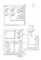
- FIG. 1illustrates a block diagram of a security system network in accordance herewith
- FIG. 2depicts a three-dimensional map of the secured area of FIG. 1 .
- FIG. 1is a block diagram of a network 10 of security systems shown generally in accordance with an illustrated embodiment.
- the networkmay include any of a number of local security systems 12 , 14 all connected to a central monitoring station 16 through the Internet 18 .
- Each of the individual security systemsmay include a number of sensors 20 , 22 that detect threats within a respective secured geographic area 24 .
- the sensorsmay be chosen to detect any of a number of threats.
- some of the sensorsmay be limit switches placed on the doors and/or windows located on a periphery of the secured areas and that detect intruders entering the secured area.
- Other of the sensorsmay be passive infrared (PIR) detectors placed within the interior of the spaces for the detection of intruders who have been able to circumvent the sensors located along the periphery.
- Other of the sensorsmay be environmental detectors (e.g., smoke, fire, carbon monoxide, etc.).
- the sensors of each of the security systemsmay be monitored via a respective control panel 26 located within the area (as shown in FIG. 1 ) or located remotely. Upon activation of one of the sensors, the control panel may send an alarm message to the central monitoring station. The central monitoring station may respond by summoning help (e.g., police, fire department, etc.).
- helpe.g., police, fire department, etc.
- control panel and the sensors of each of the local security systemsmay be one or more processor apparatus (processors) 28 , 30 each operating under control of one or more computer programs 32 , 34 loaded from a computer readable medium (memory) 36 .
- processor apparatusprocessors
- computer programs32 , 34 loaded from a computer readable medium (memory) 36 .
- reference to a step performed by a computer programis also reference to the processor that executed that step.
- a user interface 38 , 40used by an authorized human user to control the local security system.
- the user interfacemay include a display 42 that shows alarm system status and a user input device (e.g., a keyboard) 44 through which the user enters instructions for controlling the security system.
- a user input devicee.g., a keyboard
- the display and keyboardmay be combined into a touchscreen.
- a user interfacemay refer to the display and keyboard, to a touchscreen or to a window presented on the display.
- buttons 46 , 48used to entering instructions through the user interface.
- one of the iconsmay be an arm away instruction.
- Another iconmay be an arm stay instruction.
- a thirdmay be a disarm instruction.
- the usermay activate the arm away icon.
- the usermay enter a personal identification number (PIN) followed by activation of the disarm command or he/she may simply enter his/her PIN.
- PINpersonal identification number
- an alarm processor within the local control panel of the security systemmay monitor each of the sensors. Upon activation of one of the sensors, the alarm processor may send the alarm message to the central monitoring station.
- the alarm messagemay include an identifier of the security system (e.g., an account number, identifier of the sensor and a time).
- a human user of a first local security systemmay allow a human user of a second security system to control the first security system through the user interface of the second security system. This may be important where a family member (e.g., a parent) is leaving on vacation and wants a child (living separately from the parent) to be able to control the parent's security system through the child's security system.
- a family membere.g., a parent
- a childliving separately from the parent
- the remote control of security systemsis accomplished via a remote control processor of the central monitoring station based upon the information contained within a number of user files 50 , 52 .
- a file (e.g., file 50 ) of the parentmay include an identifier 54 of the child and a file (e.g., file 52 ) of the child may include an identifier of the parent.
- the identifiersmay include a respective identifier of the parent and child security systems as well as PINs of the authorized parent and of the authorized child.
- the file of the parentmay include a number of identifiers of people who the parent is willing to allow to control the parent's security system. This may include other children, relatives or close neighbors. In each case, the identifier of the other person would include identifiers of corresponding security systems and persons authorized to use those security systems.
- the parentmay activate a system control transfer icon on the user interface of the parent.
- the parentmay then be prompted to enter his/her PIN in order to ensure that the user has the proper authorization for making this change.
- a control transfer processor within the control panel of the security system of the parentmay receive the instruction and compare the entered PIN with a local reference PIN previously saved in memory. If the PIN indicates an authorized user, then the parent will be prompted to select or otherwise designate a person to be placed in control of the parent's security system. Once the designated party is selected, the local control transfer processor may transfer the request to the remote control processor. The local transfer processor may also send a chat message to the person indicating that control of the patent's security system has been given to the person through the person's home security system.
- the remote control processormay perform a similar set of validation steps before implementing transfer of control.
- the remote control processormay implement a control connection between the two security systems (e.g. the parent's security system and the child's security system).
- the control connectionmay be based upon a corresponding processor within the parent and child security systems that emulate the control features and behavior of the parent user interface on the child user interface.
- the parent's user interfacemay be presented as an additional zone in the child's user interface.
- the parent's user interfacemay be accessed through the child's user interface by selecting an access control icon associated with the parent's identifier.
- the remotely presented user interface of the security system of the parentmay be presented within a separate parent window 58 on the user interface of the security system of the child in real time.
- a monitoring processor associated with the child user interfacemay monitor control features or icons of the parent window for activation for the child user.
- an indication of the feature activatedis transferred back to a corresponding monitoring processor of the parent security system for execution.
- real time status updates from the parent systemare presented within the parent window on the child's user interface.
- the parent ormay decide to give control of his/her security system to a child (or second user), but only on a limited basis.
- the first usermay only want to enable the arm/disarm functions and reporting of security breaches to the second user.
- the first usermay not want to allow the second user to bypass any alarms or to disable any cameras that continuously record images from the secured space of the first user.
- the first personwould access the control transfer icon on the user interface of his/her security system and be presented with a list of functions that the first user wants to transfer to and be accessible by the second user through the second user interface.
- the first usermay select the arm and disarm function and a reporting function.
- the first usermay then select the second user and activate a control transfer button.
- the remote control processormay establish the link between the first and second security system and send a chat message to the second user including a list of functions granted to the second user. Chat messages are also used to notify the second person of security events occurring within the secured area of the first person.
- the remotely accessible user interfacemay include a three-dimensional (3D) map of the remotely controlled, secured area as shown in FIG. 2 .
- the 3D mapmay be displayed on a user interface of the first security system and that, alternatively, may be presented through a window 102 displayed on the user interface 100 of the second security system.
- the 3D mapmay show the locations of one or more sensors 104 .
- the windowmay also include one or more functions controls 106 such as arm and/or disarm.
- the user of the first systemmay grant control of a home automation system located within the first area to the second user through the second user interface.
- the home automation systemmay be displayed as a separate icon on the first user interface and which may be, alternatively, presented and controlled through the second user interface.
- FIGS. 1 and 2operate based upon the social networking/sharing concept.
- the central monitoring systemprovides the sharing services as part of the alarm reporting services for the system. This provides worldwide secured sharing and access which connects multiple systems together for security and home automation access control and management.
- the central monitoring systemalso provides full or partial access to security systems for alarm, fire and other critical event monitoring and control when the user is away from home and on travel, etc. for trusted users. Other users can easily access the shared system at least partially through their app, system or conventional alarm software in order to monitor a parent's house, etc.
- the central monitoring systemprovides full or partial access to home automation systems (e.g., home appliance, lighting, HVAC, door, garage door, water valves, flood sensors, etc.) and health monitoring control when the primary user is away from home for use by trusted users.
- home automation systemse.g., home appliance, lighting, HVAC, door, garage door, water valves, flood sensors, etc.
- Other userscan easily access the shared system through their respective apps or systems to monitor a parent's house, etc.
- the systemprovides temporary access by neighbors who can help take care of people, households, appliances in case of medical emergencies, healthcare events, childcare events, shipping delivery, natural calamities, floods, etc.
- Existing systems available in the marketdo not provide any comparable functionality.
- the system of FIG. 1is very useful during floods or other natural calamities.
- the system of FIGS. 1provides full or partial access through the 3D maps of FIG. 2 to friends, relatives, neighbors, visitors and family members worldwide. In this regard, access is based on the social network sharing concept.
- the central monitoring stationprovides the sharing services, chat application and notification as part of an existing monitoring system.
- the central monitoring stationalso provides neighboring and external systems information displayed on the 3D map via a chat application used for sharing and notification.
- a usercan schedule restricted access to a zone/area for a temporary period of time to friends, relatives, neighbors, visitors, servants via separate access codes using, at least in part, existing applications. Existing applications can keep owners updated on home events.
- the system of FIG. 1operates by providing a plurality of security systems, each detecting threats within a different respective secured geographic area and each reporting detected threats to a central monitoring station, a human user of a first of the plurality of security systems sending a notification to an authorized human user of a second of the plurality of security systems through the central monitoring station, the notification authorizing control of the first security system by the user of the second security system, in response to the notification, the central monitoring station forming a control connection between the first and second security systems and the user of the second security system controlling the first security system through a user interface of the second security system.
- the systemincludes a plurality of security systems, each detecting threats within a different respective secured geographic area and each reporting detected threats to a central monitoring station, a user interface of a first of the plurality of security systems that receives an instruction from a human user of the first security system and that causes the first security system to send a notification to an authorized human user of a second of the plurality of security systems through the central monitoring station, the notification authorizing control of the first security system by the user of the second security system, a processor of the central monitoring station that forms a control connection between the first and second security systems and a control interface of the second security system that allows the user of the second security system to control the first security system through a user interface of the second security system.
- the systemincludes a central monitoring station, a plurality of security systems, each having at least one sensor that detects threats within a respective secured geographic area and reports the detected threats to the central monitoring station, a processor of a first of the plurality of security systems that sends an instruction from a human user of the first security system to a corresponding processor of the central monitoring station, the instruction causing the corresponding processor to establish a control connection for control of the first security system by a second of the plurality of security systems and an interface of the second security system that allows a human user of the second security system to control the first security system through a user interface of the second security system.
Landscapes
- Engineering & Computer Science (AREA)
- General Physics & Mathematics (AREA)
- Physics & Mathematics (AREA)
- Business, Economics & Management (AREA)
- Emergency Management (AREA)
- Signal Processing (AREA)
- Theoretical Computer Science (AREA)
- General Engineering & Computer Science (AREA)
- Human Computer Interaction (AREA)
- Multimedia (AREA)
- Computer Networks & Wireless Communication (AREA)
- Analytical Chemistry (AREA)
- Chemical & Material Sciences (AREA)
- Alarm Systems (AREA)
- Telephonic Communication Services (AREA)
Abstract
Description
Claims (20)
Priority Applications (5)
| Application Number | Priority Date | Filing Date | Title |
|---|---|---|---|
| US14/699,199US10321101B2 (en) | 2015-04-29 | 2015-04-29 | System and method of sharing or connecting security and home control system |
| EP16165890.1AEP3089132B1 (en) | 2015-04-29 | 2016-04-18 | System and method of sharing or connecting security and home control system |
| ES16165890.1TES2669353T3 (en) | 2015-04-29 | 2016-04-18 | System and method for sharing or connecting a home security and control system |
| CA2927933ACA2927933A1 (en) | 2015-04-29 | 2016-04-21 | System and method of sharing or connecting security and home control system |
| CN201610465035.1ACN106157567A (en) | 2015-04-29 | 2016-04-28 | System and method for sharing or connecting security and home control systems |
Applications Claiming Priority (1)
| Application Number | Priority Date | Filing Date | Title |
|---|---|---|---|
| US14/699,199US10321101B2 (en) | 2015-04-29 | 2015-04-29 | System and method of sharing or connecting security and home control system |
Publications (2)
| Publication Number | Publication Date |
|---|---|
| US20160323548A1 US20160323548A1 (en) | 2016-11-03 |
| US10321101B2true US10321101B2 (en) | 2019-06-11 |
Family
ID=56087071
Family Applications (1)
| Application Number | Title | Priority Date | Filing Date |
|---|---|---|---|
| US14/699,199Active2035-12-12US10321101B2 (en) | 2015-04-29 | 2015-04-29 | System and method of sharing or connecting security and home control system |
Country Status (5)
| Country | Link |
|---|---|
| US (1) | US10321101B2 (en) |
| EP (1) | EP3089132B1 (en) |
| CN (1) | CN106157567A (en) |
| CA (1) | CA2927933A1 (en) |
| ES (1) | ES2669353T3 (en) |
Families Citing this family (34)
| Publication number | Priority date | Publication date | Assignee | Title |
|---|---|---|---|---|
| US9900177B2 (en) | 2013-12-11 | 2018-02-20 | Echostar Technologies International Corporation | Maintaining up-to-date home automation models |
| US9769522B2 (en) | 2013-12-16 | 2017-09-19 | Echostar Technologies L.L.C. | Methods and systems for location specific operations |
| US9824578B2 (en) | 2014-09-03 | 2017-11-21 | Echostar Technologies International Corporation | Home automation control using context sensitive menus |
| US9989507B2 (en) | 2014-09-25 | 2018-06-05 | Echostar Technologies International Corporation | Detection and prevention of toxic gas |
| US9983011B2 (en) | 2014-10-30 | 2018-05-29 | Echostar Technologies International Corporation | Mapping and facilitating evacuation routes in emergency situations |
| US9511259B2 (en) | 2014-10-30 | 2016-12-06 | Echostar Uk Holdings Limited | Fitness overlay and incorporation for home automation system |
| US9967614B2 (en) | 2014-12-29 | 2018-05-08 | Echostar Technologies International Corporation | Alert suspension for home automation system |
| US9729989B2 (en) | 2015-03-27 | 2017-08-08 | Echostar Technologies L.L.C. | Home automation sound detection and positioning |
| US9948477B2 (en) | 2015-05-12 | 2018-04-17 | Echostar Technologies International Corporation | Home automation weather detection |
| US9946857B2 (en)* | 2015-05-12 | 2018-04-17 | Echostar Technologies International Corporation | Restricted access for home automation system |
| US9960980B2 (en) | 2015-08-21 | 2018-05-01 | Echostar Technologies International Corporation | Location monitor and device cloning |
| US11122041B2 (en)* | 2015-09-25 | 2021-09-14 | Siemens Industry, Inc. | System and method for location-based credentialing |
| US9996066B2 (en) | 2015-11-25 | 2018-06-12 | Echostar Technologies International Corporation | System and method for HVAC health monitoring using a television receiver |
| US11221731B2 (en)* | 2015-12-14 | 2022-01-11 | Afero, Inc. | System and method for sharing internet of things (IOT) devices |
| US10101717B2 (en) | 2015-12-15 | 2018-10-16 | Echostar Technologies International Corporation | Home automation data storage system and methods |
| US10091017B2 (en) | 2015-12-30 | 2018-10-02 | Echostar Technologies International Corporation | Personalized home automation control based on individualized profiling |
| US10073428B2 (en) | 2015-12-31 | 2018-09-11 | Echostar Technologies International Corporation | Methods and systems for control of home automation activity based on user characteristics |
| US10060644B2 (en) | 2015-12-31 | 2018-08-28 | Echostar Technologies International Corporation | Methods and systems for control of home automation activity based on user preferences |
| US9882736B2 (en) | 2016-06-09 | 2018-01-30 | Echostar Technologies International Corporation | Remote sound generation for a home automation system |
| US10389987B2 (en) | 2016-06-12 | 2019-08-20 | Apple Inc. | Integrated accessory control user interface |
| US10294600B2 (en) | 2016-08-05 | 2019-05-21 | Echostar Technologies International Corporation | Remote detection of washer/dryer operation/fault condition |
| US10049515B2 (en)* | 2016-08-24 | 2018-08-14 | Echostar Technologies International Corporation | Trusted user identification and management for home automation systems |
| US20180182270A1 (en) | 2016-12-22 | 2018-06-28 | Hewlett-Packard Development Company, L.P. | Displays representative of remote subjects |
| US20190146441A1 (en)* | 2017-11-16 | 2019-05-16 | Associated Materials, Llc | Methods and systems for home automation using an internet of things platform |
| US10636278B2 (en)* | 2018-02-02 | 2020-04-28 | Ademco Inc. | Systems and methods for arming a security system |
| US10733872B2 (en)* | 2018-03-05 | 2020-08-04 | Ademco Inc. | Systems and methods for preventing remote disarming of a portion of a monitored region |
| TWI662808B (en)* | 2018-03-16 | 2019-06-11 | 中強光電股份有限公司 | Remote management system and method |
| US11028633B2 (en)* | 2018-12-06 | 2021-06-08 | The Chamberlain Group, Inc. | Automatic control of a movable barrier |
| US11163434B2 (en) | 2019-01-24 | 2021-11-02 | Ademco Inc. | Systems and methods for using augmenting reality to control a connected home system |
| US12165495B2 (en)* | 2019-02-28 | 2024-12-10 | Nice North America Llc | Virtual partition of a security system |
| US11626010B2 (en)* | 2019-02-28 | 2023-04-11 | Nortek Security & Control Llc | Dynamic partition of a security system |
| EP3731197A1 (en) | 2019-04-26 | 2020-10-28 | Carrier Corporation | Geolocation based security in intrusion systems |
| US11578527B2 (en) | 2019-07-08 | 2023-02-14 | The Chamberlain Group Llc | In-vehicle device for controlling a movable barrier operator |
| WO2022201912A1 (en)* | 2021-03-22 | 2022-09-29 | パナソニック インテレクチュアル プロパティ コーポレーション オブ アメリカ | Information processing method and information processing system |
Citations (9)
| Publication number | Priority date | Publication date | Assignee | Title |
|---|---|---|---|---|
| US20050253706A1 (en) | 2004-05-12 | 2005-11-17 | Honeywell International Inc. | Method and apparatus for interfacing security systems |
| US7113090B1 (en)* | 2001-04-24 | 2006-09-26 | Alarm.Com Incorporated | System and method for connecting security systems to a wireless device |
| US20070298772A1 (en)* | 2004-08-27 | 2007-12-27 | Owens Steve B | System and method for an interactive security system for a home |
| US20090231189A1 (en)* | 2006-07-03 | 2009-09-17 | Tanla Solutions Limited | Vehicle tracking and security using an ad-hoc wireless mesh and method thereof |
| US20090243852A1 (en) | 2007-10-23 | 2009-10-01 | La Crosse Technology, Ltd. | Remote Location Monitoring |
| US20120200711A1 (en)* | 2011-02-03 | 2012-08-09 | American Remote Video, Inc. | System and method for integrated surveillance and event notification |
| US20140191994A1 (en)* | 2013-01-08 | 2014-07-10 | Samsung Electronics Co., Ltd. | Touch event processing method and portable device implementing the same |
| US8810657B1 (en)* | 2009-10-02 | 2014-08-19 | Alarm.Com Incorporated | Video monitoring and alarm verification technology |
| US20140266681A1 (en)* | 2013-03-14 | 2014-09-18 | Vivint, Inc. | Dynamic linking of security systems |
- 2015
- 2015-04-29USUS14/699,199patent/US10321101B2/enactiveActive
- 2016
- 2016-04-18ESES16165890.1Tpatent/ES2669353T3/enactiveActive
- 2016-04-18EPEP16165890.1Apatent/EP3089132B1/enactiveActive
- 2016-04-21CACA2927933Apatent/CA2927933A1/ennot_activeAbandoned
- 2016-04-28CNCN201610465035.1Apatent/CN106157567A/enactivePending
Patent Citations (9)
| Publication number | Priority date | Publication date | Assignee | Title |
|---|---|---|---|---|
| US7113090B1 (en)* | 2001-04-24 | 2006-09-26 | Alarm.Com Incorporated | System and method for connecting security systems to a wireless device |
| US20050253706A1 (en) | 2004-05-12 | 2005-11-17 | Honeywell International Inc. | Method and apparatus for interfacing security systems |
| US20070298772A1 (en)* | 2004-08-27 | 2007-12-27 | Owens Steve B | System and method for an interactive security system for a home |
| US20090231189A1 (en)* | 2006-07-03 | 2009-09-17 | Tanla Solutions Limited | Vehicle tracking and security using an ad-hoc wireless mesh and method thereof |
| US20090243852A1 (en) | 2007-10-23 | 2009-10-01 | La Crosse Technology, Ltd. | Remote Location Monitoring |
| US8810657B1 (en)* | 2009-10-02 | 2014-08-19 | Alarm.Com Incorporated | Video monitoring and alarm verification technology |
| US20120200711A1 (en)* | 2011-02-03 | 2012-08-09 | American Remote Video, Inc. | System and method for integrated surveillance and event notification |
| US20140191994A1 (en)* | 2013-01-08 | 2014-07-10 | Samsung Electronics Co., Ltd. | Touch event processing method and portable device implementing the same |
| US20140266681A1 (en)* | 2013-03-14 | 2014-09-18 | Vivint, Inc. | Dynamic linking of security systems |
Non-Patent Citations (1)
| Title |
|---|
| Extended European search report from corresponding EP patent application 16165890.1, dated Jul. 21, 2016. |
Also Published As
| Publication number | Publication date |
|---|---|
| CA2927933A1 (en) | 2016-10-29 |
| EP3089132B1 (en) | 2018-03-28 |
| ES2669353T3 (en) | 2018-05-25 |
| US20160323548A1 (en) | 2016-11-03 |
| CN106157567A (en) | 2016-11-23 |
| EP3089132A1 (en) | 2016-11-02 |
Similar Documents
| Publication | Publication Date | Title |
|---|---|---|
| US10321101B2 (en) | System and method of sharing or connecting security and home control system | |
| US11823556B2 (en) | Community security system using intelligent information sharing | |
| US10217090B2 (en) | Methods for providing notifications for follow-up actions in response to events detected by an automation system, and systems and devices related thereto | |
| CA2887729C (en) | System and method to access/restrict a security system for temporary users using a mobile application | |
| US20180075720A1 (en) | Emergency alert system | |
| KR102038559B1 (en) | Security in a smart-sensored home | |
| US11017106B2 (en) | Emergency notification, access control, and monitoring systems and methods | |
| US20200211346A1 (en) | Sharing video stream during an alarm event | |
| US9799182B1 (en) | Systems and methods for a smart door chime system | |
| EP3098792B1 (en) | System and method for audibly announcing location of unauthorized party | |
| US10062265B2 (en) | Adaptive exit arm times based on real time events and historical data in a home security system | |
| US9269250B2 (en) | Immediate response security system | |
| CN106059862A (en) | Wifi access based actions/scenes execution in home automation security panels | |
| US9686223B2 (en) | System and method of creating a network based dynamic response list | |
| Haesler et al. | Getting the Residents’ Attention: The Perception of Warning Channels in Smart Home Warning Systems | |
| CA2810115A1 (en) | System and method for providing security on demand | |
| Alharbi et al. | Collection and Analysis of Digital Forensic Data from Devices in the Internet of Things | |
| US12444294B2 (en) | Community security system using intelligent information sharing | |
| EP4560599A1 (en) | Security monitoring systems and methods | |
| Hazazi | Understanding and Improving the Usability, Security, and Privacy of Smart Locks from the Perspective of the End User | |
| Inusah | A secure iot-based smart daycare implementation in Ghana. a case study of Lambussie District | |
| Puteh et al. | Design and Development of a Closed Room Monitoring System |
Legal Events
| Date | Code | Title | Description |
|---|---|---|---|
| AS | Assignment | Owner name:HONEYWELL INTERNATIONAL INC., NEW JERSEY Free format text:ASSIGNMENT OF ASSIGNORS INTEREST;ASSIGNORS:KHOT, BHARAT BALASO;OH, ERIC;CHHOKAR, AJAY PARTAP SINGH;AND OTHERS;REEL/FRAME:035525/0603 Effective date:20150223 | |
| AS | Assignment | Owner name:JPMORGAN CHASE BANK, N.A., AS ADMINISTRATIVE AGENT, NEW YORK Free format text:SECURITY INTEREST;ASSIGNOR:ADEMCO INC.;REEL/FRAME:047337/0577 Effective date:20181025 Owner name:JPMORGAN CHASE BANK, N.A., AS ADMINISTRATIVE AGENT Free format text:SECURITY INTEREST;ASSIGNOR:ADEMCO INC.;REEL/FRAME:047337/0577 Effective date:20181025 | |
| AS | Assignment | Owner name:ADEMCO INC., MINNESOTA Free format text:ASSIGNMENT OF ASSIGNORS INTEREST;ASSIGNOR:HONEYWELL INTERNATIONAL INC.;REEL/FRAME:047909/0425 Effective date:20181029 | |
| STPP | Information on status: patent application and granting procedure in general | Free format text:NOTICE OF ALLOWANCE MAILED -- APPLICATION RECEIVED IN OFFICE OF PUBLICATIONS | |
| STPP | Information on status: patent application and granting procedure in general | Free format text:PUBLICATIONS -- ISSUE FEE PAYMENT RECEIVED | |
| STPP | Information on status: patent application and granting procedure in general | Free format text:PUBLICATIONS -- ISSUE FEE PAYMENT VERIFIED | |
| STCF | Information on status: patent grant | Free format text:PATENTED CASE | |
| AS | Assignment | Owner name:ADEMCO INC., MINNESOTA Free format text:CORRECTIVE ASSIGNMENT TO CORRECT THE PREVIOUS RECORDING BY NULLIFICATION. THE INCORRECTLY RECORDED PATENT NUMBERS 8545483, 8612538 AND 6402691 PREVIOUSLY RECORDED AT REEL: 047909 FRAME: 0425. ASSIGNOR(S) HEREBY CONFIRMS THE ASSIGNMENT;ASSIGNOR:HONEYWELL INTERNATIONAL INC.;REEL/FRAME:050431/0053 Effective date:20190215 | |
| MAFP | Maintenance fee payment | Free format text:PAYMENT OF MAINTENANCE FEE, 4TH YEAR, LARGE ENTITY (ORIGINAL EVENT CODE: M1551); ENTITY STATUS OF PATENT OWNER: LARGE ENTITY Year of fee payment:4 | |
| AS | Assignment | Owner name:RESIDEO LLC, DELAWARE Free format text:CHANGE OF NAME;ASSIGNOR:ADEMCO INC.;REEL/FRAME:071546/0001 Effective date:20241227 |