US10319165B2 - Wireless locking device - Google Patents
Wireless locking deviceDownload PDFInfo
- Publication number
- US10319165B2 US10319165B2US16/196,548US201816196548AUS10319165B2US 10319165 B2US10319165 B2US 10319165B2US 201816196548 AUS201816196548 AUS 201816196548AUS 10319165 B2US10319165 B2US 10319165B2
- Authority
- US
- United States
- Prior art keywords
- electronic
- lock
- input
- interactions
- short
- Prior art date
- Legal status (The legal status is an assumption and is not a legal conclusion. Google has not performed a legal analysis and makes no representation as to the accuracy of the status listed.)
- Active
Links
- 230000003993interactionEffects0.000claimsabstractdescription55
- 230000007704transitionEffects0.000claimsabstractdescription33
- 230000007246mechanismEffects0.000claimsdescription24
- 238000000034methodMethods0.000claimsdescription21
- 230000000007visual effectEffects0.000claims1
- 238000013475authorizationMethods0.000abstractdescription30
- 230000010399physical interactionEffects0.000abstractdescription11
- 238000004891communicationMethods0.000description16
- 238000010586diagramMethods0.000description8
- 230000004044responseEffects0.000description7
- 239000000463materialSubstances0.000description4
- 230000009471actionEffects0.000description3
- 230000006870functionEffects0.000description3
- 230000003287optical effectEffects0.000description3
- 238000012545processingMethods0.000description3
- 238000003491arrayMethods0.000description2
- 238000012790confirmationMethods0.000description2
- 238000005516engineering processMethods0.000description2
- 238000012986modificationMethods0.000description2
- 230000004048modificationEffects0.000description2
- 230000008569processEffects0.000description2
- 238000012546transferMethods0.000description2
- 238000013459approachMethods0.000description1
- 230000005540biological transmissionEffects0.000description1
- 230000008859changeEffects0.000description1
- 239000003795chemical substances by applicationSubstances0.000description1
- 239000003086colorantSubstances0.000description1
- 230000000694effectsEffects0.000description1
- 230000010354integrationEffects0.000description1
- 230000007774longtermEffects0.000description1
- 230000005055memory storageEffects0.000description1
- 230000006855networkingEffects0.000description1
- 239000013307optical fiberSubstances0.000description1
- 229920001296polysiloxanePolymers0.000description1
- 238000009877renderingMethods0.000description1
- 239000004065semiconductorSubstances0.000description1
- 239000007787solidSubstances0.000description1
- 230000003068static effectEffects0.000description1
- 239000004557technical materialSubstances0.000description1
- 238000012795verificationMethods0.000description1
- 230000002618waking effectEffects0.000description1
Images


Classifications
- G—PHYSICS
- G07—CHECKING-DEVICES
- G07C—TIME OR ATTENDANCE REGISTERS; REGISTERING OR INDICATING THE WORKING OF MACHINES; GENERATING RANDOM NUMBERS; VOTING OR LOTTERY APPARATUS; ARRANGEMENTS, SYSTEMS OR APPARATUS FOR CHECKING NOT PROVIDED FOR ELSEWHERE
- G07C9/00—Individual registration on entry or exit
- G07C9/00174—Electronically operated locks; Circuits therefor; Nonmechanical keys therefor, e.g. passive or active electrical keys or other data carriers without mechanical keys
- G07C9/00571—Electronically operated locks; Circuits therefor; Nonmechanical keys therefor, e.g. passive or active electrical keys or other data carriers without mechanical keys operated by interacting with a central unit
- E—FIXED CONSTRUCTIONS
- E05—LOCKS; KEYS; WINDOW OR DOOR FITTINGS; SAFES
- E05B—LOCKS; ACCESSORIES THEREFOR; HANDCUFFS
- E05B47/00—Operating or controlling locks or other fastening devices by electric or magnetic means
- E05B2047/0094—Mechanical aspects of remotely controlled locks
- E05B2047/0095—Mechanical aspects of locks controlled by telephone signals, e.g. by mobile phones
- E—FIXED CONSTRUCTIONS
- E05—LOCKS; KEYS; WINDOW OR DOOR FITTINGS; SAFES
- E05B—LOCKS; ACCESSORIES THEREFOR; HANDCUFFS
- E05B67/00—Padlocks; Details thereof
- G—PHYSICS
- G07—CHECKING-DEVICES
- G07C—TIME OR ATTENDANCE REGISTERS; REGISTERING OR INDICATING THE WORKING OF MACHINES; GENERATING RANDOM NUMBERS; VOTING OR LOTTERY APPARATUS; ARRANGEMENTS, SYSTEMS OR APPARATUS FOR CHECKING NOT PROVIDED FOR ELSEWHERE
- G07C9/00—Individual registration on entry or exit
- G07C9/00174—Electronically operated locks; Circuits therefor; Nonmechanical keys therefor, e.g. passive or active electrical keys or other data carriers without mechanical keys
- G07C9/00658—Electronically operated locks; Circuits therefor; Nonmechanical keys therefor, e.g. passive or active electrical keys or other data carriers without mechanical keys operated by passive electrical keys
- G07C2009/00746—Electronically operated locks; Circuits therefor; Nonmechanical keys therefor, e.g. passive or active electrical keys or other data carriers without mechanical keys operated by passive electrical keys by knocking on a surface for inputting the code, e.g. detecting a series of taps on a surface
Definitions
- the present disclosurerelates to locking devices and more specifically to locking devices configured to communicate over wireless channels.
- FIG. 1is a perspective view illustrating an electronic locking device consistent with embodiments disclosed herein.
- FIG. 2is an exploded diagram illustrating the electronic locking device of FIG. 1 consistent with embodiments disclosed herein.
- FIG. 3is a system diagram illustrating a system configured to provide services to the electronic locking device of FIG. 1 consistent with embodiments disclosed herein.
- FIG. 4is an illustration of a user interface for configuring a secondary unlocking interaction consistent with embodiments disclosed herein.
- FIG. 5is an illustration of a user interface for authorizing a user to unlock an electronic locking device consistent with embodiments disclosed herein.
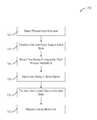
- FIG. 6is a flow chart illustrating a method for unlocking an electronic lock consistent with embodiments disclosed herein.
- FIG. 7is a flow chart illustrating an alternative method for unlocking an electronic lock consistent with embodiments disclosed herein.
- FIG. 8is a diagram of a mobile device consistent with embodiments disclosed herein.
- FIG. 9is a schematic diagram of a computing system consistent with embodiments disclosed herein.
- an electronic locking devicecan use a combination of physical input and discovery of an authorized mobile device to enable transition from a locked state to an unlocked state.
- the electronic locking devicecan receive a physical input, causing the electronic locking device to transition from a low power state to an active state.
- the electronic locking devicecan determine if a wireless device is present. If a wireless device is present, the electronic locking device can determine whether the wireless device is authorized to unlock the electronic locking device. If the wireless device is authorized, the electronic locking device can transition to an unlocked state.
- an electronic lockcan be placed on a locker.
- a userpushes on a u-bend at the top of the electronic lock and on a bottom of a cylinder of the lock, causing the u-bend to move toward the cylinder of the lock.
- the movement of the u-bendcan cause an end of the u-bend to contact an electronic switch.
- the switchcan provide a signal that causes a processor in the electronic lock to transition from a sleep state to an awake state.
- the processorcan cause a BluetoothTM low power beacon to be transmitted.
- a smartphoneconfigured with an application to access a lock service can respond to the beacon.
- the smartphonecan provide an authorization payload (e.g., a token, key, and/or code) proving authorization to access the electronic lock.
- an authorization payloade.g., a token, key, and/or code
- the electronic lockcan transition from a locked state to an unlocked state and release a locking mechanism (e.g., as shown in FIG. 2 ).
- the lockcan be re-engaged by resetting the u-bend into the cylinder of the lock and pressing the u-bend into the cylinder. The pressing of the u-bend can cause the switch to activate and the lock to transition from an unlocked state to a locked state and lock the locking mechanism.
- the electronic lockdoes not require physical input.
- the electronic lockcan send out a beacon over a long duration interval to conserve battery power (e.g., one-second intervals).
- a mobile devicecan respond to the beacon and prove authorization to access the electronic lock.
- the electronic lockcan transition from a locked state to an unlocked state and release a locking mechanism.
- an electronic locking devicecan match a series of long and/or short physical interactions to a series of stored interactions to enable the transition from a locked state to an unlocked state.
- the electronic locking devicecan detect a first physical interaction that causes it to transition from a low power state to an active state.
- an indicator(such as an LED light or sound) can indicate the transition is complete.
- a usercan then interact with the locking device through a series of long and/or short physical input interactions. When a series of physical input actions matches a stored set of input actions, the electronic locking device can transition from a locked state to an unlocked state and release a locking mechanism.
- an electronic padlockcan be placed on a hasp to secure a shed door.
- a usercan touch a capacitive touch sensing front panel to cause the electronic padlock to wake from a sleep state.
- the electronic padlockcan flash a green light and/or sound a short beep to indicate the lock is ready for input.
- a usercan repeat the code to the lock by touching the capacitive touch sensing front panel. If the input code matches the stored code, the lock can transition from a locked state to an unlocked state and release a captured shackle (also known as a shank).
- a captured shacklealso known as a shank
- Various sensorscan be used to provide input to the electronic locking device alone or in combination through a physical interface.
- Physical inputscan include use of accelerometers (e.g., activated by shaking and/or movement of a lock), light sensors (e.g., activated by waving a hand between a light source and/or the lock), infrared sensors (e.g., activated by waving a hand in front of the lock), front buttons (e.g., activated by pushing on a front of the lock body), shank buttons (e.g., activated by pushing the shank into the lock body), switches (e.g., activated by pushing a spring-loaded switch to a second position that returns to a first position), capacitive touch sensors (e.g., activated by touching a panel and/or lock body), resistive touch sensors (e.g., activated by pressing on a panel), light-based touch sensors (e.g., activated by breaking a beam across the lock body), etc.
- accelerometerse
- a combination of sensorsalso can be used.
- a light sensoris used in combination with an accelerometer.
- the lockcan remain in a low power state until both the light sensor detects a change in light and the accelerometer detects shaking of the device.
- This combinationcan help preserve battery power, such as on occasions when a lock is in a backpack.
- a sole accelerometer inputmight cause the lock to wake up when the backpack is jostled during walking or riding a bike. With both sensors, however, the light may remain dim while in the backpack, causing the lock to remain in a low power state.
- Electronic inputscan include use of wireless local area network interface (also known as WiFiTM), BluetoothTM, ZigBeeTM, ethernet, USBTM, Long Term Evolution (LTETM), near field communication (NFC), etc.
- the electronic padlockcan first attempt to connect to an authorized electronic device. For example, after receiving the input from a capacitive touch sensor, the electronic padlock can transmit one or more BluetoothTM beacons indicating the lock is awake. After receiving no response, the electronic padlock can then indicate to a user that it is available for physical input attempts by lighting the green light and/or sounding the short beep. In one embodiment, the lock can continue to send out BluetoothTM beacons. In other embodiments, the electronic padlock may use an indicator and a user must wait a set amount of time (such as one second) before the padlock is ready to receive input.
- the electronic padlockcan be reset so that another code can be attempted. In an embodiment, if an input code is incorrectly input, the lock will reset if no activity is sensed for two seconds. In one embodiment, an extra-long press held for two seconds will reset the electronic padlock. In other embodiments, the electronic padlock gives an indication of success or failure by emitting a red light and/or long beep.
- an electronic locking devicecan provide access to a replaceable power supply.
- the electronic locking devicecan include a hole in which a small rod can be inserted (e.g., a paper clip).
- the rodcan contact a latch mechanism that releases a latch on a battery cover of the electronic locking device.
- the latchis self-locking such that when the battery cover is replaced, the latch locks automatically (e.g., mechanically, electrically, etc.).
- an electronic locking devicecan be a lock.
- Lockscan take various forms, such as a padlock as shown in FIG. 1 , having a horizontal cylindrical shape. Other shapes are also possible, such as cubic shapes, trapezoid shapes, vertical cylindrical shapes, etc.
- FIG. 1is a perspective view illustrating an electronic locking device 100 consistent with embodiments disclosed herein.
- the electronic locking device 100can be a padlock that includes a lock body 102 , a front end cap 104 , a back end cap 106 , and a shank 108 .
- An LED status light 110can show status by displaying multiple colors, multiple blink patterns, solid lights, and/or nothing.
- the status light 110can show states including waking up, going to sleep, locked, unlocked, entry type (e.g., short or long), successful password, unsuccessful password, communication speed, communication status, channel, connectivity, and/or reset.
- the end caps 104 and 106can be removed. In one example, the end caps 104 and 106 can be removed when in an unlocked state, but not when in a locked state. In another example, the front end cap 104 can only be removed in an unlocked state, but the back end cap 106 can be removed to expose a removable battery (such as described above). Other combinations are also possible.
- Electronicscan be housed inside the lock body 102 , and antennas can be built into the circuit boards and/or the external case (such as the lock body 102 , the end cap 104 or 106 , or the shank 108 ).
- the front end cap 104includes an antenna strip.
- the back end cap 106is configured to be transparent to wireless signals.
- FIG. 2shows an exploded diagram of an embodiment of the electronic locking device shown in FIG. 1 .
- an electronic locking device 200can include two locking body gaskets 212 , a locking body 202 , a front end cap 204 , a back end cap 206 , a controller board 214 , a motor 216 , a battery board 218 , a battery 220 , a shank 208 , two shank gaskets 222 , a shank guide 224 , a locking spindle 226 , two ball bearings 228 , a shank clip 230 , a shank spring 232 , four sets of screws 234 and a retaining disc 236 .
- the locking body gaskets 212can provide weather protection between the locking body 202 and the end caps 204 and 206 .
- the locking body gaskets 212are made from silicone.
- the locking body gaskets 212form a seal as the end caps 204 and 206 are tightened by screwing the threaded end caps 204 and 206 onto the locking body 202 .
- the locking body 202can be formed to receive components of the electronic locking device 200 .
- the locking body 202includes two chambers 238 and 240 separated by a wall to prevent tampering with the electronic locking device 200 .
- a first chamber 238can house a locking mechanism that can only be accessed when the electronic locking device 200 is unlocked.
- a second chamber 240(not shown) can house the battery 220 such that it can be accessed even when the electronic locking device 200 lacks power (e.g., a dead battery).
- the front end cap 204can attach to and cover the first chamber 238 .
- the back end cap 206can attach to and cover the second chamber 240 .
- the end caps 204 and 206can attach through various methods including threading (to screw a cap onto the locking body 202 ), press-fit connections (to press such that a ridge of one side connects to a valley on the other side), pins, screws, latches, etc.
- the controller board 214can house a processor 242 , memory, computer-readable media, wireless interfaces, antennas 244 , and other supporting electronic components of the electronic locking device 200 .
- the controller board 214can include a BluetoothTM low power interface and/or a WiFiTM interface.
- the BluetoothTM low power interfaceallows communication channels to be formed with mobile devices that are authorized to unlock the electronic locking device 200 .
- the WiFiTM interfaceallows channels to be formed with mobile devices that are authorized to unlock the electronic locking device 200 .
- the WiFiTM interfaceallows connection to a locking service through an access point.
- a controller on the controller boardcan then query the service as to whether a connected mobile device is authorized to operate the electronic locking device 200 and/or grant permissions for operating the electronic locking device 200 (e.g., unlock-only, lock-only, lock/unlock, administrative access, granting permissions to other users, etc.).
- the controllercauses permissions to be stored locally on the electronic locking device 200 .
- the controllerqueries a locking service to determine permissions.
- a hybridis used such that permissions are stored locally on the electronic locking device 200 and updated from the locking service.
- a hybrid authorization serviceis used such that some permissions are stored locally (e.g., unrestricted grantees) on the electronic locking device 200 , while other permissions are queried from the service (e.g., restricted grantees).
- a hybrid approachis used where the electronic locking device 200 first searches for grantee permissions locally and, if not finding them, requests permissions from the locking service. Other combinations are also possible.
- a mobile deviceis “paired” (such as a BluetoothTM pairing) such that the electronic locking device 200 can connect with a paired mobile device.
- Authorization to unlockis accomplished by the electronic locking device 200 verifying a presence of a paired device.
- a pre-shared keycan be used in a challenge/response scenario.
- Authorizationcan be accomplished by receiving a correct response to a challenge. The correct response causes the electronic locking device 200 to transition into an unlocked state.
- an applicationcan use a wireless interface of a mobile device to communicate with a service. Upon verifying credentials (such as a token) of the mobile device and/or position of the mobile device (such as GPS location and/or a beacon received from the electronic locking device 200 ), the service can provide authorization for the electronic locking device 200 to unlock.
- the battery board 218can reside in the second chamber 240 of the locking body 202 and can provide connectivity and information about the battery 220 . In one embodiment, the battery board 218 determines remaining battery life and notifies the controller of any problems. In an embodiment and if problems are detected, the battery board 218 can report the problems to a controller on the controller board 214 . The controller can communicate with the locking service over a WiFiTM communications channel and transmit a message describing the problem. The locking service can then communicate the problem to a user, such as through a text message, an application notification, a phone call, an email, etc. The battery board 218 can receive a battery 220 and be covered by an back end cap 206 .
- the shank 208can be used as part of a locking mechanism of the electronic locking device 200 .
- the shank 208can be received by the locking body 202 .
- the shank 208can have horizontal movement (e.g., play) reduced by the shank guide 224 .
- the shank gaskets 222can be added to reduce play and aid in weatherproofing the locking body 202 at shank entrances.
- the shank guide 224can also help contain the locking spindle 226 within the locking body 202 .
- the locking spindle 226can include raised and recessed portions that move the ball bearings 228 outward from its axis.
- the locking spindle 226can be controllably turned by the motor 216 , controlled by the processor 242 on the controller board 214 .
- the locking spindle 226When turned at a first angle relative to the locking body 202 , the locking spindle 226 can be in a locking state. When in a locking state, the locking spindle 226 can cause the ball bearings 228 to be pushed within recesses of the shank 208 . When the ball bearings 228 are present within the recesses of the shank 208 , the shank 208 is prevented from moving out of a locked position (e.g., vertically) within the locking body 202 . When turned at a second angle relative to the locking body 202 , the locking spindle 226 can be in an unlocked state.
- a locked positione.g., vertically
- the ball bearings 228When in an unlocked state, the ball bearings 228 can be pushed into the recesses of the locking spindle 226 , and the shank 208 can move (e.g., vertically).
- the shank clip 230may be attached to a longer end of the shank 208 to prevent the shank 208 from exiting the locking body 202 .
- the shank spring 232can provide vertical lift when transitioning to an unlocked state and/or resistance to locking when transitioning to a locked state.
- the retaining disc 236can be placed over the locking body 202 to enclose moving parts within the locking body 202 and provide support to the moving parts (e.g., the ball bearings 228 , etc.).
- the four sets of screws 234are used to fasten circuit boards to the locking body 202 .
- the end caps 204 and 206include threads that screw onto the locking body 202 .
- other fastening systems and/or devicescan also be used.
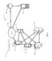
- FIG. 3is a system diagram illustrating a system 300 configured to provide services to the electronic locking device of FIG. 1 consistent with embodiments disclosed herein.
- An electronic lock 318can communicate with a mobile device 320 and/or a lock application service 316 (also known as a locking service) over an Internet 314 as described above.
- the lock application service 316can include load balancers 302 capable of decryption, application servers 304 , storage 306 , control servers 310 , and/or a logging service 308 (which can include one or more logging servers).
- a usercan set up an account with the lock application service 316 using an application on the mobile device 320 .
- the userregisters the electronic lock 318 with the lock application service 316 .
- the lock application service 316can store user credentials in storage 306 and associate the user credentials with an electronic lock identifier for the electronic lock 318 .
- Permissionscan be restricted to days, times, number of times unlocking is granted, a period of time, a repeating schedule, and/or other restrictions on timing and use of the electronic lock 318 . Permissions can be stored in storage 306 .
- permissionscan be stored locally on the electronic lock 318 and/or in the lock application service 316 .
- the electronic lock 318can be transitioned to an awake state by a user interaction and connect to the mobile device 320 over BluetoothTM.
- the mobile device 320can transmit credentials to the electronic lock 318 .
- the electronic lock 318can send the credentials (or a message based on the credentials, e.g., a cryptographic hash) to the lock application service 316 for determination of whether the mobile device 320 is authorized to unlock the electronic lock 318 .
- the lock application service 316can transmit a message indicating authorization or failure to the electronic lock 318 and log the attempt in the logging service 308 . If authorization is successful, the electronic lock 318 can transition to an unlocked state and release the locking mechanism. If authorization is not successful, the electronic lock 318 can stay in the same state and provide an indicator of the failure (e.g., light, sound, etc.).
- the electronic lock 318when permissions are stored solely by the electronic lock 318 , the electronic lock 318 can be transitioned to an awake state by a user interaction and connect to the mobile device 320 over BluetoothTM.
- the mobile device 320can transmit credentials to the electronic lock 318 .
- the electronic lock 318can determine whether the credentials match credentials available locally to the electronic lock 318 . If a match is found and the user is authorized, the electronic lock 318 can transition to an unlocked state and release the locking mechanism. If the user is not authorized, the electronic lock 318 can stay in the same state and provide an indicator of the failure (e.g., light, sound, etc.).
- the electronic lock 318when permissions are stored by the electronic lock 318 and the lock application service 316 , the electronic lock 318 can be transitioned to an awake state by a user interaction and connect to the mobile device 320 over BluetoothTM.
- the mobile device 320can transmit credentials to the electronic lock 318 .
- the electronic lock 318can determine whether the credentials match credentials available locally to the electronic lock 318 . If a match is found and the user is authorized, the electronic lock 318 can transition to an unlocked state and release the locking mechanism. If no match is found, the electronic lock 318 can send the credentials (or a message based on the credentials, e.g., a cryptographic hash) to the lock application service 316 for determination of whether the mobile device 320 is authorized to unlock the electronic lock 318 .
- the lock application service 316can transmit a message indicating authorization or failure to the electronic lock 318 and log the attempt in the logging service 308 . If authorization is successful, the electronic lock 318 can transition to an unlocked state and release the locking mechanism. If authorization is not successful, the electronic lock 318 can stay in the same state and provide an indicator of the failure (e.g., light, sound, etc.).
- an indicator of the failuree.g., light, sound, etc.
- the electronic lock 318can transition to an awake state in response to a user interaction (such as pressing on the shank).
- the electronic lock 318can transmit a beacon over a first communication channel (such as BluetoothTM).
- the mobile device 320can receive the beacon and transmit proof of receipt of the beacon (or a message based on the beacon, e.g., a cryptographic hash) to the lock application service 316 over a second communication channel (e.g., WiFiTM).
- the lock application service 316can determine whether the mobile device 320 is authorized to unlock the electronic lock 318 .
- the lock application service 316can transmit a message indicating authorization, if successful, to the electronic lock 318 over the second communication channel (e.g., WiFiTM) and log the attempt in the logging service 308 .
- the electronic lock 318can transition to an unlocked state and release the locking mechanism. If authorization is not successful, the electronic lock 318 can stay in the same state, and an application on the mobile device 320 can provide an indicator of the failure (e.g., light, sound, message, etc.).
- the beaconcan be transmitted over the second communication channel and only one communication channel is used.
- Logged historycan be made available to a user of the electronic lock 318 (e.g., an owner, administrator, authorized user, etc.). History can include various events, attempts, and permissions related to the electronic lock 318 . This can include current status of the electronic lock 318 (locked, unlocked, battery power, etc.), prior status of the electronic lock 318 , user requests received, failed attempts, successful attempts, network connectivity issues, last updates, updated permissions, and/or other interactions with the electronic lock 318 or the lock application service 316 .
- FIG. 4is an illustration of a user interface 400 for configuring a secondary unlocking interaction consistent with embodiments disclosed herein.
- a usercan access an application on a mobile device.
- the applicationcan verify user credentials with a locking service before access is allowed.
- an electronic lockcan operate without a locking service, and a direct connection with the lock is established through a setup procedure (e.g., using an initial set of physical interactions to access the device).
- the applicationcan enable a user to alter settings of an electronic lock using the user interface 400 as shown in FIG. 4 .
- a usercan alter a name of the lock, provide a photograph of the lock, and set a series of physical interactions that will unlock the lock.
- a usercan type a new name in a name field 402 .
- a picturecan be added by clicking an add photo button 404 and then taking a new photo or selecting an existing photo (such as a photo stored on the mobile device). Added pictures can then be displayed in a photo area 406 .
- the series of physical interactionscan be displayed in an interaction settings field 408 .
- the seriescan be edited by using buttons below the interaction settings field 408 (such as an insert short interaction button 410 , an insert long interaction button 412 , and a delete button 414 ).
- a save button 416can cause settings displayed on the screen to be stored and used in device and/or service configurations.
- a navigation button 418(such as a back button) can aid in moving between user interfaces (or screens of a user interlace).
- physical interactioncan be used as a backup when an authorized mobile device is lost or unavailable.
- a usercan set a series of three dots (e.g., short pushes), three dashes (e.g., three long pushes), and three dots, and click on the save button 416 .
- the usercan push on the shank of the lock using the series entered previously to open the lock (e.g., three clicks, three holds, and three clicks). This interaction can allow the lock to open.
- the lockcan transition temporarily to credential-free operation when the series is correctly entered.
- a usercan access settings (such as the user interface 400 in FIG. 4 ) or add devices within a time threshold after the lock is opened using the physical interaction method.
- the series of physical interactionscan be used to reset the lock to a default state.
- a usercan connect to the locking service to request authorization, successfully perform the series of physical interactions, and then receive access to the electronic lock (as the electronic lock can report the successful interaction to the locking service).
- FIG. 5is an illustration of a user interface for authorizing a user to unlock an electronic locking device consistent with embodiments disclosed herein.
- the usercan access a settings screen 500 that allows an administrative user to define permissions for an authorized user (and/or invite a new user to accept permissions to the lock).
- a lockcan be identified in a title location 502 and a picture location 506 .
- An authorized usercan be identified by a user identifier 504 (such as an email, login, name, etc.).
- Permissionscan be tailored to the user. Permissions can be set for permanent or single use, or further refined by days, times, and/or an expiration date.
- Permissionscan be entered by clicking a permanent button 506 , a one time button 508 , or a custom button 510 .
- the custom button 510can be used to enable a date selection input area 512 in which days of weeks, times and/or an expiration date can be entered.
- the usercan activate the send button 514 to send an authorization or invitation to share access to the lock.
- the settings screen 500can include an edit button 526 to enable editing of a current lock.
- an add button or plus button 528can be used to add an additional lock (e.g., pair a lock) to the application and/or mobile device.
- this authorizationis sent by email to a user, inviting the user to accept the permissions, download a mobile application, and/or create an account with the service.
- Other user interface screenscan include a list of locks, a history of interactions with the locks and/or service, lock settings, and/or application settings. These screens can be accessed by a menu row 524 , including buttons 516 , 518 , 520 and 522 .
- FIG. 6is a flow chart illustrating a method 600 for unlocking an electronic lock consistent with embodiments disclosed herein.
- the method 600can be accomplished by the system 300 shown in FIG. 3 , including the electronic lock 318 , the mobile device 320 , and the lock application service 316 .
- the lockdetects physical input from a user.
- the physical inputcauses the lock to transition from a low power state to an active state.
- the lockcan detect a mobile device (such as through a mobile device responding to a beacon transmitted over a wireless channel).
- the lockcan confirm authorization of the mobile device to perform an action on the lock (e.g., open request).
- the authorizationcan be based on direct communication with the mobile device or communication through an intermediary (such as a locking service).
- the lockcan transition from a locked state to an unlocked state.
- the lockcan release a locking mechanism.
- the operation in boxes 606 - 608can be performed by a locking service.
- the mobile devicecan send a message to a locking service that identifies a wireless beacon received by the mobile device and credentials of a user of the device.
- the receipt of the beaconcan prove the mobile device is within the physical proximity of the lock.
- the locking servicecan confirm the authorization of the user to access the lock and transmit a message to the lock to cause the lock to transition from a locked state to an unlocked state.
- the active stateis still a lower power state than when operating a lock.
- Lock operation componentsand/or other components, such as wireless components
- FIG. 7is a flow chart illustrating an alternative method 700 for unlocking an electronic lock consistent with embodiments disclosed herein.
- the method 700can be accomplished by the system 300 shown in FIG. 3 , including the electronic lock 318 , the mobile device 320 , and the lock application service 316 .
- the lockcan detect physical input from a user.
- the lockcan transition from a low power state to an active state.
- the lockcan detect an input series of long and/or short physical interactions with the device (e.g., long clicks with short clicks, long touches with short touches, longer duration shakes and shorter duration shakes, etc.).
- a long duration interactioncan last half a second or longer, and a short duration interaction can be for less than half a second. In another embodiment, a long duration interaction can last more than one second, and a short duration interaction can be for one second or less.
- the input seriescan be matched against a stored series that was configured prior to the input series.
- the lockcan transition from a locked state to an unlocked state.
- the lockcan release a locking mechanism allowing a physical unlocking of the lock from a captured object (e.g., hatch, latch, cable, etc.).
- the electronic lock 318can be operated with or without the lock application service 316 .
- the lock or application on a mobile devicecan provide locking services (such as emailing authorization keys, peer-to-peer transfer of authorization keys, etc.). Verification of authorization can be performed onboard the lock by the processor.
- FIG. 8is a diagram of a mobile device 800 consistent with embodiments disclosed herein.
- the mobile device 800can include multiple antennas, a speaker, a non-volatile memory port, a keyboard (electronic or physical), a microphone, a display (such as an LCD screen), a touch screen, an application processor, a graphics processor, and internal memory.
- the mobile device 800can connect to one or more wireless services through wireless protocols such as LTETM by the third generation partnership project (3GPP)TM, WiFiTM as defined by IEEE 802.11 standards, BluetoothTM by Bluetooth SIG, Inc. (including BluetoothTM 4.0/BluetoothTM Low Power), etc.
- the mobile device 800can process instructions on its application processor and graphics processor using internal memory and render one or more user interfaces (which can include one or more screens) to the display.
- FIG. 9is a schematic diagram of a computing system 900 consistent with embodiments disclosed herein.
- the computing system 900can be viewed as an information passing bus that connects various components.
- the computing system 900includes a processor 902 having logic for processing instructions. Instructions can be stored in and/or retrieved from memory 906 and a storage device 908 that includes a computer-readable storage medium. Instructions and/or data can arrive from a network interface 910 that can include wired 914 or wireless 912 capabilities. Instructions and/or data can also come from an I/O interface 916 that can include such things as expansion cards, secondary buses (e.g., USB, etc.), devices, etc.
- a usercan interact with the computing system 900 though a user interface device 918 and a rendering interface 904 that allows the computer to receive and provide feedback to the user.
- Embodiments and implementations of the systems and methods described hereinmay include various operations, which may be embodied in machine-executable instructions to be executed by a computer system.
- a computer systemmay include one or more general-purpose or special-purpose computers (or other electronic devices).
- the computer systemmay include hardware components that include specific logic for performing the operations or may include a combination of hardware, software, and/or firmware.
- Suitable networks for configuration and/or use as described hereininclude one or more local area networks, wide area networks, metropolitan area networks, and/or Internet or IP networks, such as the World Wide Web, a private Internet, a secure Internet, a value-added network, a virtual private network, an extranet, an intranet, or even stand-alone machines that communicate with other machines by physical transport of media.
- a suitable networkmay be formed from parts or entireties of two or more other networks, including networks using disparate hardware and network communication technologies.
- One suitable networkincludes a server and one or more clients; other suitable networks may contain other combinations of servers, clients, and/or peer-to-peer nodes, and a given computer system may function both as a client and as a server.
- Each networkincludes at least two computers or computer systems, such as the server and/or clients.
- a computer systemmay include a workstation, laptop computer, disconnectable mobile computer, server, mainframe, cluster, so-called “network computer” or “thin client,” tablet, smartphone, personal digital assistant or other hand-held computing device, “smart” consumer electronics device or appliance, medical device, or a combination thereof.
- Suitable networksmay include communications or networking software, such as the software available from Novell®, Microsoft®, and other vendors, and may operate using TCP/IP, SPX, IPX, and other protocols over twisted pair, coaxial, or optical fiber cables; telephone lines; radio waves; satellites; microwave relays; modulated AC power lines; physical media transfer; and/or other data transmission “wires” known to those of skill in the art.
- the networkmay encompass smaller networks and/or be connectable to other networks through a gateway or similar mechanism.
- Various techniques, or certain aspects or portions thereof,may take the form of program code (i.e., instructions) embodied in tangible media, such as floppy diskettes, CD-ROMs, hard drives, magnetic or optical cards, solid-state memory devices, a nontransitory computer-readable storage medium, or any other machine-readable storage medium wherein, when the program code is loaded into and executed by a machine, such as a computer, the machine becomes an apparatus for practicing the various techniques.
- the computing devicemay include a processor, a storage medium readable by the processor (including volatile and nonvolatile memory and/or storage elements), at least one input device, and at least one output device.
- the volatile and nonvolatile memory and/or storage elementsmay be a RAM, an EPROM, a flash drive, an optical drive, a magnetic hard drive, or other medium for storing electronic data.
- One or more programs that may implement or utilize the various techniques described hereinmay use an application programming interface (API), reusable controls, and the like. Such programs may be implemented in a high-level procedural or an object-oriented programming language to communicate with a computer system. However, the program(s) may be implemented in assembly or machine language, if desired. In any case, the language may be a compiled or interpreted language, and combined with hardware implementations.
- APIapplication programming interface
- Each computer systemincludes one or more processors and/or memory; computer systems may also include various input devices and/or output devices.
- the processormay include a general-purpose device, such as an Intel®, AMD®, or other “off-the-shelf” microprocessor.
- the processormay include a special-purpose processing device, such as ASIC, SoC, SiP, FPGA, PAL, PLA, FPLA, PLD, or other customized or programmable device.
- the memorymay include static RAM, dynamic RAM, flash memory, one or more flip-flops, ROM, CD-ROM, DVD, disk, tape, or magnetic, optical, or other computer storage medium.
- the input device(s)may include a keyboard, mouse, touch screen, light pen, tablet, microphone, sensor, or other hardware with accompanying firmware and/or software.
- the output device(s)may include a monitor or other display, printer, speech or text synthesizer, switch, signal line, or other hardware with accompanying firmware and/or software.
- a componentmay be implemented as a hardware circuit comprising custom very large scale integration (VLSI) circuits or gate arrays, or off-the-shelf semiconductors such as logic chips, transistors, or other discrete components.
- VLSIvery large scale integration
- a componentmay also be implemented in programmable hardware devices such as field programmable gate arrays, programmable array logic, programmable logic devices, or the like.
- Componentsmay also be implemented in software for execution by various types of processors.
- An identified component of executable codemay, for instance, comprise one or more physical or logical blocks of computer instructions, which may, for instance, be organized as an object, a procedure, or a function. Nevertheless, the executables of an identified component need not be physically located together, but may comprise disparate instructions stored in different locations that, when joined logically together, comprise the component and achieve the stated purpose for the component.
- a component of executable codemay be a single instruction, or many instructions, and may even be distributed over several different code segments, among different programs, and across several memory devices.
- operational datamay be identified and illustrated herein within components, and may be embodied in any suitable form and organized within any suitable type of data structure. The operational data may be collected as a single data set, or may be distributed over different locations including over different storage devices, and may exist, at least partially, merely as electronic signals on a system or network.
- the componentsmay be passive or active, including agents operable to perform desired functions.
- a software module or componentmay include any type of computer instruction or computer-executable code located within a memory device.
- a software modulemay, for instance, include one or more physical or logical blocks of computer instructions, which may be organized as a routine, program, object, component, data structure, etc., that perform one or more tasks or implement particular data types. It is appreciated that a software module may be implemented in hardware and/or firmware instead of or in addition to software.
- One or more of the functional modules described hereinmay be separated into sub-modules and/or combined into a single or smaller number of modules.
- a particular software modulemay include disparate instructions stored in different locations of a memory device, different memory devices, or different computers, which together implement the described functionality of the module.
- a modulemay include a single instruction or many instructions, and may be distributed over several different code segments, among different programs, and across several memory devices.
- Some embodimentsmay be practiced in a distributed computing environment where tasks are performed by a remote processing device linked through a communications network.
- software modulesmay be located in local and/or remote memory storage devices.
- data being tied or rendered together in a database recordmay be resident in the same memory device, or across several memory devices, and may be linked together in fields of a record in a database across a network.
Landscapes
- Physics & Mathematics (AREA)
- General Physics & Mathematics (AREA)
- Telephone Function (AREA)
- Lock And Its Accessories (AREA)
Abstract
Description
Claims (20)
Priority Applications (1)
| Application Number | Priority Date | Filing Date | Title |
|---|---|---|---|
| US16/196,548US10319165B2 (en) | 2014-08-18 | 2018-11-20 | Wireless locking device |
Applications Claiming Priority (4)
| Application Number | Priority Date | Filing Date | Title |
|---|---|---|---|
| US201462038774P | 2014-08-18 | 2014-08-18 | |
| US14/610,578US9747739B2 (en) | 2014-08-18 | 2015-01-30 | Wireless locking device |
| US15/669,807US10176656B2 (en) | 2014-08-18 | 2017-08-04 | Wireless locking device |
| US16/196,548US10319165B2 (en) | 2014-08-18 | 2018-11-20 | Wireless locking device |
Related Parent Applications (1)
| Application Number | Title | Priority Date | Filing Date |
|---|---|---|---|
| US15/669,807ContinuationUS10176656B2 (en) | 2014-08-18 | 2017-08-04 | Wireless locking device |
Publications (2)
| Publication Number | Publication Date |
|---|---|
| US20190088057A1 US20190088057A1 (en) | 2019-03-21 |
| US10319165B2true US10319165B2 (en) | 2019-06-11 |
Family
ID=55301766
Family Applications (3)
| Application Number | Title | Priority Date | Filing Date |
|---|---|---|---|
| US14/610,578ActiveUS9747739B2 (en) | 2014-08-18 | 2015-01-30 | Wireless locking device |
| US15/669,807ActiveUS10176656B2 (en) | 2014-08-18 | 2017-08-04 | Wireless locking device |
| US16/196,548ActiveUS10319165B2 (en) | 2014-08-18 | 2018-11-20 | Wireless locking device |
Family Applications Before (2)
| Application Number | Title | Priority Date | Filing Date |
|---|---|---|---|
| US14/610,578ActiveUS9747739B2 (en) | 2014-08-18 | 2015-01-30 | Wireless locking device |
| US15/669,807ActiveUS10176656B2 (en) | 2014-08-18 | 2017-08-04 | Wireless locking device |
Country Status (2)
| Country | Link |
|---|---|
| US (3) | US9747739B2 (en) |
| WO (1) | WO2016028697A1 (en) |
Cited By (4)
| Publication number | Priority date | Publication date | Assignee | Title |
|---|---|---|---|---|
| US20190180541A1 (en)* | 2015-01-28 | 2019-06-13 | Noke, Inc. | Electronic locks with duration-based touch sensor unlock codes |
| US11639617B1 (en) | 2019-04-03 | 2023-05-02 | The Chamberlain Group Llc | Access control system and method |
| US20240087385A1 (en)* | 2020-12-29 | 2024-03-14 | Essence Security International (E.S.I.) Ltd. | A Padlock |
| US12444256B2 (en)* | 2020-12-29 | 2025-10-14 | Essence Security International (E.S.1.) Ltd. | Padlock |
Families Citing this family (39)
| Publication number | Priority date | Publication date | Assignee | Title |
|---|---|---|---|---|
| WO2010127404A1 (en)* | 2009-05-08 | 2010-11-11 | Michael Peter Wildon | Identification device, system and method |
| US9228388B2 (en)* | 2012-12-10 | 2016-01-05 | Capital One Financial Corporation | Systems and methods for marking individuals with an identifying substance |
| US9109379B1 (en)* | 2014-08-12 | 2015-08-18 | Dog & Bone Holdings Pty Ltd | Keyless padlock, system and method of use |
| US9747739B2 (en) | 2014-08-18 | 2017-08-29 | Noke, Inc. | Wireless locking device |
| KR101645631B1 (en)* | 2015-02-26 | 2016-08-05 | 김범수 | Record management system for electronic locking apparatus |
| CN106661902B (en) | 2015-07-09 | 2019-10-25 | 莱南科技私人有限公司 | Padlock |
| US10614641B2 (en)* | 2015-12-11 | 2020-04-07 | The Sun Lock Company, Ltd. | Electronic combination lock with different levels of access control |
| JP6728390B2 (en) | 2016-04-06 | 2020-07-22 | オーチス エレベータ カンパニーOtis Elevator Company | Mobile visitor management |
| US10096182B2 (en) | 2016-09-08 | 2018-10-09 | Honeywell International Inc. | Using a light up feature of a mobile device to trigger door access |
| ES2943290T3 (en)* | 2016-10-19 | 2023-06-12 | Dormakaba Usa Inc | electromechanical lock core |
| US9842449B1 (en)* | 2016-11-18 | 2017-12-12 | Motogo, Llc | Secure transport container |
| AU2017364644B2 (en)* | 2016-11-25 | 2021-02-25 | Beijing Qisheng Science And Technology Co., Ltd. | Systems and methods for controlling a lock |
| US10585608B2 (en)* | 2017-03-22 | 2020-03-10 | Oracle International Corporation | System and method for securely isolating a system feature |
| CN107100448B (en)* | 2017-06-19 | 2020-04-03 | 舟山安特佳智能科技有限公司 | Remote control vehicle lock and remote control vehicle locking method |
| US11183086B2 (en)* | 2017-07-19 | 2021-11-23 | Globe Tracker, ApS | Wireless security for freight container seals |
| USD833257S1 (en)* | 2017-08-09 | 2018-11-13 | Safe Skies, Llc | Locking apparatus |
| WO2019051337A1 (en) | 2017-09-08 | 2019-03-14 | Dormakaba Usa Inc. | Electro-mechanical lock core |
| WO2019077632A1 (en)* | 2017-10-17 | 2019-04-25 | Deepak Pathania | Smart lock converter |
| DE102017218841A1 (en)* | 2017-10-23 | 2019-04-25 | Robert Bosch Gmbh | Electronic component and method for its activation |
| US10125519B1 (en)* | 2017-12-05 | 2018-11-13 | Noke, Inc. | Wireless-enabled interchangeable locking core |
| US10573109B2 (en) | 2018-01-04 | 2020-02-25 | Taiwan Fu Hsing Industrial Co., Ltd. | Electric lock and method for adding a user of the same |
| US10515498B2 (en) | 2018-01-04 | 2019-12-24 | Taiwan Fu Hsing Industrial Co., Ltd. | Electric lock and control method thereof |
| USD871190S1 (en)* | 2018-01-10 | 2019-12-31 | Zhejiang Pujiang Plum-Blossom Lock Industry (Group) Co., Ltd. | Padlock |
| WO2019140529A1 (en) | 2018-01-19 | 2019-07-25 | Konnex Enterprises Inc. | Systems and methods for controlling access to a secured space |
| USD927728S1 (en) | 2018-02-23 | 2021-08-10 | Safe Skies, Llc | Trade show booth display |
| CN112752891B (en) | 2018-04-13 | 2022-08-05 | 多玛卡巴美国公司 | Electromechanical lock cylinder |
| US11466473B2 (en) | 2018-04-13 | 2022-10-11 | Dormakaba Usa Inc | Electro-mechanical lock core |
| DE102018111301A1 (en)* | 2018-05-11 | 2019-11-14 | ABUS August Bremicker Söhne KG | Mobile castle |
| US10846964B2 (en)* | 2018-06-01 | 2020-11-24 | Sentrilock, Llc | Electronic lockbox with interface to other electronic locks |
| US20200048931A1 (en)* | 2018-08-10 | 2020-02-13 | Yao-Kun Yang | Combination lock |
| US11861544B2 (en) | 2018-12-21 | 2024-01-02 | Motogo, Llc | System and method for conditional delivery of a transport container |
| USD945013S1 (en) | 2018-12-28 | 2022-03-01 | Safe Skies, Llc | Trade show booth display |
| US11352817B2 (en) | 2019-01-25 | 2022-06-07 | Noke, Inc. | Electronic lock and interchangeable shackles |
| US10614646B1 (en) | 2019-01-30 | 2020-04-07 | Eaton Intelligent Power Limited | Lockout/tagout system and method including multi-user lockout device with electronic locking and wireless control interface |
| CN109826505A (en)* | 2019-03-14 | 2019-05-31 | 深圳中集智能科技有限公司 | Intelligent electronic lock |
| US20210058474A1 (en)* | 2019-08-22 | 2021-02-25 | Carrier Corporation | Method and system to transmit audit/s of a lock to a messaging application |
| US11282313B2 (en)* | 2019-12-31 | 2022-03-22 | 3M Innovative Properties Company | Smart locking systems and methods |
| US11568693B2 (en) | 2020-07-24 | 2023-01-31 | Konnex Enterprises Inc. | Systems, devices, and methods for controlling access to a secure space |
| KR102388051B1 (en)* | 2020-11-02 | 2022-04-19 | 서울과학기술대학교 산학협력단 | Fiber-based wearable patch antenna |
Citations (140)
| Publication number | Priority date | Publication date | Assignee | Title |
|---|---|---|---|---|
| US1882794A (en) | 1925-09-14 | 1932-10-18 | Dudley Lock Corp | Lock |
| US2049416A (en) | 1930-09-24 | 1936-08-04 | American Cabinet Hardware Corp | Lock |
| US3838395A (en) | 1972-12-04 | 1974-09-24 | Commplex Inc | Electronic variable combination lock and monitoring system |
| US4499462A (en) | 1980-09-04 | 1985-02-12 | Battelle Institut E.V. | Circuit arrangement for the electronic code locking of locks |
| US5646605A (en) | 1994-07-05 | 1997-07-08 | Motorola, Inc. | Method and apparatus for remote control of locks |
| US6411195B1 (en) | 1997-03-07 | 2002-06-25 | Ilan Goldman | Data transmission system and components thereof |
| US20020088256A1 (en) | 2001-01-10 | 2002-07-11 | Stop Lock, Inc. | Combination push button and/or key operated padlock |
| US6442983B1 (en) | 1997-03-05 | 2002-09-03 | Michael Reed Thomas | Digital electronic lock |
| US6505774B1 (en) | 1998-12-09 | 2003-01-14 | Miti Manufacturing Company | Automated fee collection and parking ticket dispensing machine |
| US20030011719A1 (en) | 2001-07-11 | 2003-01-16 | Geun-Sik Jang | Apparatus and method for eliminating afterimage state |
| US20030016847A1 (en) | 2001-07-17 | 2003-01-23 | Richard Quintana | Fingerprint-actuated padlock |
| US20040064309A1 (en) | 1999-02-18 | 2004-04-01 | Mitsubishi Denki Kabushiki Kaisha | Mobile communicator and method for deciding speech coding rate in mobile communicator |
| US20040108938A1 (en) | 2002-12-10 | 2004-06-10 | Entrekin David A. | Portable electronic locking system and method |
| US20050099262A1 (en) | 2003-11-07 | 2005-05-12 | Childress Robert N. | Electronic wireless locking system |
| US6898952B1 (en) | 2004-04-30 | 2005-05-31 | Ez Trend Technology Co., Ltd. | Electric padlock |
| US20050201076A1 (en) | 2004-03-11 | 2005-09-15 | Master Lock Company | Illuminating Mechanism For A Lock |
| US20050210283A1 (en) | 2004-02-27 | 2005-09-22 | Oki Electric Industry Co., Ltd. | Wireless key system |
| US20050213441A1 (en) | 2004-03-26 | 2005-09-29 | Christopher Voltz | Systems and methods for overriding an ejection lock |
| US6989732B2 (en) | 2002-06-14 | 2006-01-24 | Sentrilock, Inc. | Electronic lock system and method for its use with card only mode |
| US20060061549A1 (en) | 2004-09-17 | 2006-03-23 | Paten Wireless Technology Inc. | [multi-drectional cursor control device] |
| US7021092B2 (en) | 2003-05-16 | 2006-04-04 | Stanton Concepts Inc. | Multiple function lock |
| US20060179903A1 (en) | 2003-03-06 | 2006-08-17 | Ilan Goldman | Electronic locking mechanism and lock containing it |
| US20060283216A1 (en) | 2005-05-31 | 2006-12-21 | Marcelle Jesse A | Electronic security device |
| US20060288744A1 (en) | 2005-06-28 | 2006-12-28 | William Smith | Alarm lock |
| US20070017977A1 (en) | 2005-07-19 | 2007-01-25 | Kabushiki Kaisha Toshiba | Image processing apparatus and authentication processing method |
| WO2007020574A2 (en) | 2005-08-12 | 2007-02-22 | Nxp B.V. | Software application security method and system |
| US20070126551A1 (en) | 2005-09-11 | 2007-06-07 | Slevin Richard S | Biometric padlock |
| US20070132552A1 (en) | 2005-12-12 | 2007-06-14 | Denso International America, Inc. | Hands-free vehicle door opener |
| US7236085B1 (en) | 2002-06-18 | 2007-06-26 | Smartlok Systems, Inc. | Lock with remotely activated lockout feature |
| US20070216764A1 (en) | 2006-01-09 | 2007-09-20 | Samsung Electronics Co., Ltd. | Access authentication system and method using smart communicator |
| US20070229257A1 (en) | 2005-03-18 | 2007-10-04 | Olle Bliding | Wake-up device and method for generating a control signal |
| US20080024272A1 (en) | 2003-07-18 | 2008-01-31 | Fiske Michael S | Biometric authentication lock machine |
| US20080047783A1 (en) | 2006-07-26 | 2008-02-28 | Wolfgang Vogl | Method of controlling access to an elevator car |
| US20080068128A1 (en) | 2006-08-31 | 2008-03-20 | Riad Ghabra | Keyless passive entry system |
| US20080100417A1 (en) | 2006-10-30 | 2008-05-01 | Mitsubishi Electric Corporation | Vehicle antitheft system and vehicle antitheft method |
| US20080118014A1 (en) | 2006-11-16 | 2008-05-22 | Nokia Corporation | Utilizing wake-up signals for synchronizing multiradio timing |
| US20080129473A1 (en) | 2006-12-04 | 2008-06-05 | Fujitsu Ten Limited | Starting control apparatus and tuner device |
| US20080136587A1 (en) | 2006-12-08 | 2008-06-12 | Research In Motion Limited | System and method for locking and unlocking access to an electronic device |
| US20080215841A1 (en) | 2005-07-21 | 2008-09-04 | Clevx, Llc | Memory Lock System |
| US7423515B1 (en) | 2003-04-10 | 2008-09-09 | Biogy Inc. | FPALM II fingerprint authentication lock mechanism II |
| US20080230086A1 (en) | 2007-03-19 | 2008-09-25 | Murphy Peter D | Powered cosmetic dispenser |
| US20080252415A1 (en) | 2007-04-12 | 2008-10-16 | Larson Wayne F | Restricted range lockbox, access device and methods |
| US20090153291A1 (en) | 2007-11-12 | 2009-06-18 | Ge Security, Inc. | Method and apparatus for communicating access to a lockbox |
| US20090189747A1 (en) | 2007-11-21 | 2009-07-30 | E.G.O. Elektro-Geraetebau Gmbh | Control mechanism for an electrical appliance and method for operating the control |
| US20090256676A1 (en) | 2008-04-14 | 2009-10-15 | The Eastern Company | Smart lock system |
| US20090261945A1 (en) | 2008-04-22 | 2009-10-22 | Jae Woo Yang | Passive entry system and method for performing function thereof |
| US20090312051A1 (en) | 2008-06-13 | 2009-12-17 | Sony Ericsson Mobile Communications Ab | Mobile electronic device |
| US20100053861A1 (en) | 2008-09-02 | 2010-03-04 | Chi-Young Kim | Mobile terminal |
| US20100073129A1 (en) | 2008-08-20 | 2010-03-25 | Iloq Oy | Electromechanical lock |
| US20100083713A1 (en) | 2008-10-07 | 2010-04-08 | Yiqi Wu Woodling | Padlock Device Using an Electromagnetic Switch Actuated System with Fingerprint Identification System |
| KR20100049321A (en) | 2008-11-03 | 2010-05-12 | 이중재 | Door lock with touch pad and it's unlocking control process |
| US20100158327A1 (en) | 2008-12-22 | 2010-06-24 | International Business Machines Corporation | Apparatus, system, and method for sequenced biometric authentication |
| US20100166207A1 (en) | 2008-12-26 | 2010-07-01 | Sony Corporation | Headphone apparatus and reproducing apparatus |
| US20100222940A1 (en) | 2007-10-11 | 2010-09-02 | Puetsch Felix | Locking system, especially bluetooth car key |
| US20100245289A1 (en) | 2009-03-31 | 2010-09-30 | Miroslav Svajda | Apparatus and method for optical proximity sensing and touch input control |
| US20100306718A1 (en) | 2009-05-26 | 2010-12-02 | Samsung Electronics Co., Ltd. | Apparatus and method for unlocking a locking mode of portable terminal |
| US20110001603A1 (en) | 2007-12-10 | 2011-01-06 | Nicholas Hedley Willis | Methods and apparatus relating to a security system |
| US20110090047A1 (en) | 2001-02-20 | 2011-04-21 | Patel Pankaj B | Biometric switch and indicating means |
| US20110259063A1 (en) | 2008-03-27 | 2011-10-27 | Ivan Foti | Alarm lock |
| US20120011902A1 (en) | 2010-07-15 | 2012-01-19 | Master Lock Company Llc | Padlock |
| US20120186308A1 (en) | 2011-01-20 | 2012-07-26 | Abus August Bremicker Soehne Kg | Padlock for securing and monitoring a switch |
| US20120229251A1 (en) | 2011-03-08 | 2012-09-13 | Security Enhancement Systems, Llc | Lock |
| US20120280783A1 (en) | 2011-05-02 | 2012-11-08 | Apigy Inc. | Systems and methods for controlling a locking mechanism using a portable electronic device |
| US20120306748A1 (en) | 2011-06-05 | 2012-12-06 | Christopher Brian Fleizach | Devices, Methods, and Graphical User Interfaces for Providing Control of a Touch-Based User Interface Absent Physical Touch Capabilities |
| US20120312956A1 (en)* | 2011-06-11 | 2012-12-13 | Tom Chang | Light sensor system for object detection and gesture recognition, and object detection method |
| US20120324968A1 (en) | 2011-06-22 | 2012-12-27 | The Stanley Works Israel Ltd. | Electronic and manual lock assembly |
| US20120324967A1 (en) | 2011-06-22 | 2012-12-27 | The Stanley Works Israel Ltd. | Electronic and manual lock assembly |
| US20130021273A1 (en) | 2011-07-19 | 2013-01-24 | Lg Electronics Inc. | Mobile terminal and display controlling method thereof |
| US20130055773A1 (en) | 2010-05-25 | 2013-03-07 | Hui Hong Jim Kery Li | Electronic Combination Lock |
| US20130076206A1 (en) | 2010-06-07 | 2013-03-28 | Baran Advanced Technologies (1986) Ltd. | Touch pad controller |
| US20130099893A1 (en) | 2009-11-17 | 2013-04-25 | Q Developments, Llc | Lock control system using rfid |
| US20130110264A1 (en) | 2010-11-01 | 2013-05-02 | Nike, Inc. | Wearable Device Having Athletic Functionality |
| US20130118216A1 (en) | 2011-11-11 | 2013-05-16 | Master Lock Company | Battery access and power supply arrangements |
| US20130127706A1 (en) | 2011-11-18 | 2013-05-23 | Asustek Computer Inc. | Method for unlocking screen |
| EP2607582A2 (en) | 2011-12-20 | 2013-06-26 | EVVA Sicherheitstechnologie GmbH | Padlock |
| US8477011B2 (en) | 2009-05-08 | 2013-07-02 | Icontrol, Inc. | mLOCK device and associated methods |
| US20130169549A1 (en) | 2011-12-29 | 2013-07-04 | Eric T. Seymour | Devices, Methods, and Graphical User Interfaces for Providing Multitouch Inputs and Hardware-Based Features Using a Single Touch Input |
| US20130203348A1 (en) | 2012-02-02 | 2013-08-08 | Samsung Electronics Co. Ltd. | Near field communication electronic device and operating method thereof |
| US20130257590A1 (en) | 2012-03-30 | 2013-10-03 | Onity, Inc. | Methods and systems for an authenticating lock with bar code |
| US20130257716A1 (en) | 2012-03-31 | 2013-10-03 | Smart Technologies Ulc | Interactive input system and method |
| US20130293368A1 (en) | 2011-09-20 | 2013-11-07 | Chikezie Ottah | Esom security |
| WO2013170292A1 (en) | 2012-05-14 | 2013-11-21 | Burchat Clinton Graeme | Mobile device powered lock |
| US20130312956A1 (en) | 2012-05-24 | 2013-11-28 | Halliburton Energy Services, Inc. | Spectral Analysis Techniques for Fluid Monitoring |
| US20130332848A1 (en) | 2012-06-06 | 2013-12-12 | Wilfred Lam | Creating new connections on social networks using gestures |
| US20130335193A1 (en) | 2011-11-29 | 2013-12-19 | 1556053 Alberta Ltd. | Electronic wireless lock |
| US20130342314A1 (en) | 2012-06-22 | 2013-12-26 | Gun Chen | Smart lock structure and operating method thereof |
| WO2013189721A1 (en) | 2012-06-22 | 2013-12-27 | Schneider Electric Industries Sas | Electronic padlock, mobile terminal adapted for controlling the electronic padlock, and method for controlling the electronic padlock |
| US20140015737A1 (en) | 2011-03-28 | 2014-01-16 | Denso Corporation | Information presentation system and in-vehicle apparatus |
| US8633799B1 (en)* | 2007-06-25 | 2014-01-21 | Glen L. Aronson | Lock with remotely activated lockout feature |
| US20140028443A1 (en) | 2010-11-09 | 2014-01-30 | Master Lock Company Llc | Electronically Monitored Safety Lockout Devices, Systems and Methods |
| US20140056033A1 (en) | 2012-08-23 | 2014-02-27 | Samsung Electronics Co., Ltd. | Electronic apparatus and power controlling method thereof |
| US20140077929A1 (en) | 2012-03-08 | 2014-03-20 | Unikey Technologies, Inc. | Wireless access control system and related methods |
| US20140109631A1 (en) | 2012-10-19 | 2014-04-24 | Brian Asquith | Theft deterrent lock |
| US20140113563A1 (en) | 2012-10-23 | 2014-04-24 | Kwikset Corporation | Electronic lock having hardware based multi-wireless profile detection and setting |
| US20140150502A1 (en) | 2012-12-03 | 2014-06-05 | 13876 Yukon Inc. | Wireless portable lock system |
| US20140195841A1 (en) | 2012-12-03 | 2014-07-10 | Lg Electronics Inc. | Portable device and method for providing voice recognition service |
| US8791790B2 (en) | 2009-02-10 | 2014-07-29 | Yikes Llc | System and method for accessing a structure using a mobile device |
| US20140210592A1 (en) | 2013-01-25 | 2014-07-31 | Ford Global Technologies, Llc | Apparatus and method for interfacing a wireless communication device to a communication device keypad in a vehicle |
| US20140218167A1 (en) | 2013-02-04 | 2014-08-07 | K-Jump Health Co., Ltd. | Wirelessly sensed and controlled locking device |
| US20140250954A1 (en) | 2013-03-06 | 2014-09-11 | James F. Buzhardt | Smart padlock |
| US20140265359A1 (en) | 2013-03-15 | 2014-09-18 | August Home, Inc. | Intelligent Door Lock System |
| US20140266588A1 (en) | 2013-03-15 | 2014-09-18 | Mesh Motion, Inc. | Peer-to-peer bike sharing system |
| US20140260452A1 (en) | 2013-03-14 | 2014-09-18 | Hsu-Chih CHEN | Electronic Lock |
| US20140292481A1 (en) | 2011-03-17 | 2014-10-02 | Unikey Technologies, Inc. | Wireless access control system and related methods |
| US8850858B2 (en) | 2012-12-06 | 2014-10-07 | Master Lock Company Llc | Lock subassembly |
| US20140310653A1 (en) | 2013-04-10 | 2014-10-16 | Samsung Electronics Co., Ltd. | Displaying history information for application |
| US8875550B1 (en) | 2011-11-08 | 2014-11-04 | Bryan Daniel Spunt | Double shackle bicycle padlock with RFID unlocking |
| US20140326027A1 (en) | 2013-05-03 | 2014-11-06 | Meir Avganim | Smart lock |
| US8881558B2 (en) | 2003-08-05 | 2014-11-11 | The Eastern Company | Combination and key operated locks with indicators |
| CN204002132U (en) | 2014-08-11 | 2014-12-10 | 江海 | A kind of intelligent bluetooth padlock |
| US20140360232A1 (en) | 2013-06-07 | 2014-12-11 | Velo Labs, Inc. | Wireless ultra-low power portable lock |
| US20140375422A1 (en) | 2013-06-20 | 2014-12-25 | Parakeet, Llc | Technologies and methods for security access |
| US8919024B2 (en) | 2013-02-06 | 2014-12-30 | Karl F. Milde, Jr. | Secure smartphone-operated gun trigger lock |
| US8922333B1 (en) | 2013-09-10 | 2014-12-30 | Gregory Paul Kirkjan | Contactless electronic access control system |
| US20150076989A1 (en) | 2013-09-13 | 2015-03-19 | Kenneth Dale Walma | Artificial Light Source Based Messaging Platform |
| US20150102902A1 (en) | 2013-10-16 | 2015-04-16 | Jie-Fu Chen | Bluetooth Remote-Control Electronic Lock |
| US20150120151A1 (en) | 2013-10-29 | 2015-04-30 | Audi Ag | Vehicle system for activating a vehicle component |
| US20150143260A1 (en) | 2013-11-18 | 2015-05-21 | Facebook, Inc. | State-Machine-Driven User-Interface Interactions |
| US9057210B2 (en) | 2011-03-17 | 2015-06-16 | Unikey Technologies, Inc. | Wireless access control system and related methods |
| US20150170447A1 (en) | 2013-12-12 | 2015-06-18 | James F Buzhardt | Smart door lock |
| US20150168099A1 (en) | 2013-12-13 | 2015-06-18 | RPH Engineering | Secure storage systems and methods |
| US20150178532A1 (en) | 2012-06-20 | 2015-06-25 | David Allen Brulé | Wearable rfid storage devices |
| US9077716B2 (en) | 2010-06-16 | 2015-07-07 | Delphian Systems, LLC | Wireless device enabled locking system |
| US20150220918A1 (en) | 2014-02-04 | 2015-08-06 | Lenovo (Singapore) Pte. Ltd. | Biometric account card |
| US20150225986A1 (en) | 2012-09-13 | 2015-08-13 | Knock N'lock Ltd. | Padlock |
| US9109379B1 (en) | 2014-08-12 | 2015-08-18 | Dog & Bone Holdings Pty Ltd | Keyless padlock, system and method of use |
| US9115511B1 (en) | 2012-08-08 | 2015-08-25 | Donald M. Schmidt | Padlock with alarm and shackle locking mechanism |
| US20150240531A1 (en) | 2014-02-27 | 2015-08-27 | LifeStyleLock, LLC | Wireless locking system and method |
| US20150292244A1 (en) | 2014-04-10 | 2015-10-15 | Gleyn Beatty | Proximity Padlock |
| US20160002953A1 (en) | 2014-07-01 | 2016-01-07 | Jeffrey Sada | Electronic time lock |
| US20160035163A1 (en) | 2014-07-30 | 2016-02-04 | Master Lock Company | Location tracking for locking device |
| US20160042582A1 (en) | 2014-08-08 | 2016-02-11 | RPH Engineering | Electronic locking system |
| US20160047142A1 (en) | 2014-08-18 | 2016-02-18 | Fuz Designs LLC | Wireless locking device |
| US20160142093A1 (en) | 2014-11-14 | 2016-05-19 | Wayne Phang | Protective Case Accessory With Multi-Function Button For Smart-phone Device |
| US20160217637A1 (en) | 2015-01-28 | 2016-07-28 | Noke, Llc | Electronic padlocks and related methods |
| US9437062B2 (en) | 2012-08-16 | 2016-09-06 | Schlage Lock Company Llc | Electronic lock authentication method and system |
| US20160299680A1 (en) | 2014-01-10 | 2016-10-13 | Samsung Electronics Co., Ltd. | Apparatus and method of copying and pasting content in a computing device |
| US20160330244A1 (en) | 2014-01-06 | 2016-11-10 | Maxwell Forest Pty Ltd | Secure Storage of Data Among Multiple Devices |
| US9495820B1 (en) | 2010-05-25 | 2016-11-15 | DigiPas USA, LLC | Electronic combination lock |
| US20180215841A1 (en) | 2015-07-30 | 2018-08-02 | DÖHLER GmbH | Gum arabic from acacia seyal |
Family Cites Families (3)
| Publication number | Priority date | Publication date | Assignee | Title |
|---|---|---|---|---|
| US7437322B1 (en)* | 2000-07-06 | 2008-10-14 | Prana Fund Manager, Llc | Managing investment assets |
| WO2009129285A1 (en)* | 2008-04-15 | 2009-10-22 | Zimmer, Inc. | Fibrous implants for cartilage repair or replacement |
| US8468139B1 (en)* | 2012-07-16 | 2013-06-18 | Dell Products L.P. | Acceleration of cloud-based migration/backup through pre-population |
- 2015
- 2015-01-30USUS14/610,578patent/US9747739B2/enactiveActive
- 2015-08-17WOPCT/US2015/045541patent/WO2016028697A1/enactiveApplication Filing
- 2017
- 2017-08-04USUS15/669,807patent/US10176656B2/enactiveActive
- 2018
- 2018-11-20USUS16/196,548patent/US10319165B2/enactiveActive
Patent Citations (147)
| Publication number | Priority date | Publication date | Assignee | Title |
|---|---|---|---|---|
| US1882794A (en) | 1925-09-14 | 1932-10-18 | Dudley Lock Corp | Lock |
| US2049416A (en) | 1930-09-24 | 1936-08-04 | American Cabinet Hardware Corp | Lock |
| US3838395A (en) | 1972-12-04 | 1974-09-24 | Commplex Inc | Electronic variable combination lock and monitoring system |
| US4499462A (en) | 1980-09-04 | 1985-02-12 | Battelle Institut E.V. | Circuit arrangement for the electronic code locking of locks |
| US5646605A (en) | 1994-07-05 | 1997-07-08 | Motorola, Inc. | Method and apparatus for remote control of locks |
| US6442983B1 (en) | 1997-03-05 | 2002-09-03 | Michael Reed Thomas | Digital electronic lock |
| US6411195B1 (en) | 1997-03-07 | 2002-06-25 | Ilan Goldman | Data transmission system and components thereof |
| US6505774B1 (en) | 1998-12-09 | 2003-01-14 | Miti Manufacturing Company | Automated fee collection and parking ticket dispensing machine |
| US20040064309A1 (en) | 1999-02-18 | 2004-04-01 | Mitsubishi Denki Kabushiki Kaisha | Mobile communicator and method for deciding speech coding rate in mobile communicator |
| US20020088256A1 (en) | 2001-01-10 | 2002-07-11 | Stop Lock, Inc. | Combination push button and/or key operated padlock |
| US20110090047A1 (en) | 2001-02-20 | 2011-04-21 | Patel Pankaj B | Biometric switch and indicating means |
| US20030011719A1 (en) | 2001-07-11 | 2003-01-16 | Geun-Sik Jang | Apparatus and method for eliminating afterimage state |
| US20030016847A1 (en) | 2001-07-17 | 2003-01-23 | Richard Quintana | Fingerprint-actuated padlock |
| US6989732B2 (en) | 2002-06-14 | 2006-01-24 | Sentrilock, Inc. | Electronic lock system and method for its use with card only mode |
| US7236085B1 (en) | 2002-06-18 | 2007-06-26 | Smartlok Systems, Inc. | Lock with remotely activated lockout feature |
| US20040108938A1 (en) | 2002-12-10 | 2004-06-10 | Entrekin David A. | Portable electronic locking system and method |
| US20060179903A1 (en) | 2003-03-06 | 2006-08-17 | Ilan Goldman | Electronic locking mechanism and lock containing it |
| US7423515B1 (en) | 2003-04-10 | 2008-09-09 | Biogy Inc. | FPALM II fingerprint authentication lock mechanism II |
| US7021092B2 (en) | 2003-05-16 | 2006-04-04 | Stanton Concepts Inc. | Multiple function lock |
| US20080024272A1 (en) | 2003-07-18 | 2008-01-31 | Fiske Michael S | Biometric authentication lock machine |
| US8881558B2 (en) | 2003-08-05 | 2014-11-11 | The Eastern Company | Combination and key operated locks with indicators |
| US20050099262A1 (en) | 2003-11-07 | 2005-05-12 | Childress Robert N. | Electronic wireless locking system |
| US20050210283A1 (en) | 2004-02-27 | 2005-09-22 | Oki Electric Industry Co., Ltd. | Wireless key system |
| US20050201076A1 (en) | 2004-03-11 | 2005-09-15 | Master Lock Company | Illuminating Mechanism For A Lock |
| US20050213441A1 (en) | 2004-03-26 | 2005-09-29 | Christopher Voltz | Systems and methods for overriding an ejection lock |
| US6898952B1 (en) | 2004-04-30 | 2005-05-31 | Ez Trend Technology Co., Ltd. | Electric padlock |
| US20060061549A1 (en) | 2004-09-17 | 2006-03-23 | Paten Wireless Technology Inc. | [multi-drectional cursor control device] |
| US20070229257A1 (en) | 2005-03-18 | 2007-10-04 | Olle Bliding | Wake-up device and method for generating a control signal |
| US20060283216A1 (en) | 2005-05-31 | 2006-12-21 | Marcelle Jesse A | Electronic security device |
| US20060288744A1 (en) | 2005-06-28 | 2006-12-28 | William Smith | Alarm lock |
| US20070017977A1 (en) | 2005-07-19 | 2007-01-25 | Kabushiki Kaisha Toshiba | Image processing apparatus and authentication processing method |
| US20150278124A1 (en) | 2005-07-21 | 2015-10-01 | Clevx, Llc | Memory lock system with manipulatable input device and method of operation thereof |
| US20080215841A1 (en) | 2005-07-21 | 2008-09-04 | Clevx, Llc | Memory Lock System |
| WO2007020574A2 (en) | 2005-08-12 | 2007-02-22 | Nxp B.V. | Software application security method and system |
| US20070126551A1 (en) | 2005-09-11 | 2007-06-07 | Slevin Richard S | Biometric padlock |
| US20070132552A1 (en) | 2005-12-12 | 2007-06-14 | Denso International America, Inc. | Hands-free vehicle door opener |
| US20070216764A1 (en) | 2006-01-09 | 2007-09-20 | Samsung Electronics Co., Ltd. | Access authentication system and method using smart communicator |
| US20080047783A1 (en) | 2006-07-26 | 2008-02-28 | Wolfgang Vogl | Method of controlling access to an elevator car |
| US20080068128A1 (en) | 2006-08-31 | 2008-03-20 | Riad Ghabra | Keyless passive entry system |
| US20080100417A1 (en) | 2006-10-30 | 2008-05-01 | Mitsubishi Electric Corporation | Vehicle antitheft system and vehicle antitheft method |
| US20080118014A1 (en) | 2006-11-16 | 2008-05-22 | Nokia Corporation | Utilizing wake-up signals for synchronizing multiradio timing |
| US20080129473A1 (en) | 2006-12-04 | 2008-06-05 | Fujitsu Ten Limited | Starting control apparatus and tuner device |
| US20080136587A1 (en) | 2006-12-08 | 2008-06-12 | Research In Motion Limited | System and method for locking and unlocking access to an electronic device |
| US20080230086A1 (en) | 2007-03-19 | 2008-09-25 | Murphy Peter D | Powered cosmetic dispenser |
| US20080252415A1 (en) | 2007-04-12 | 2008-10-16 | Larson Wayne F | Restricted range lockbox, access device and methods |
| US8633799B1 (en)* | 2007-06-25 | 2014-01-21 | Glen L. Aronson | Lock with remotely activated lockout feature |
| US20100222940A1 (en) | 2007-10-11 | 2010-09-02 | Puetsch Felix | Locking system, especially bluetooth car key |
| US20090153291A1 (en) | 2007-11-12 | 2009-06-18 | Ge Security, Inc. | Method and apparatus for communicating access to a lockbox |
| US20090189747A1 (en) | 2007-11-21 | 2009-07-30 | E.G.O. Elektro-Geraetebau Gmbh | Control mechanism for an electrical appliance and method for operating the control |
| US20110001603A1 (en) | 2007-12-10 | 2011-01-06 | Nicholas Hedley Willis | Methods and apparatus relating to a security system |
| US20110259063A1 (en) | 2008-03-27 | 2011-10-27 | Ivan Foti | Alarm lock |
| US20090256676A1 (en) | 2008-04-14 | 2009-10-15 | The Eastern Company | Smart lock system |
| US8274365B2 (en) | 2008-04-14 | 2012-09-25 | The Eastern Company | Smart lock system |
| US20090261945A1 (en) | 2008-04-22 | 2009-10-22 | Jae Woo Yang | Passive entry system and method for performing function thereof |
| US20090312051A1 (en) | 2008-06-13 | 2009-12-17 | Sony Ericsson Mobile Communications Ab | Mobile electronic device |
| US20100073129A1 (en) | 2008-08-20 | 2010-03-25 | Iloq Oy | Electromechanical lock |
| US20100053861A1 (en) | 2008-09-02 | 2010-03-04 | Chi-Young Kim | Mobile terminal |
| US20100083713A1 (en) | 2008-10-07 | 2010-04-08 | Yiqi Wu Woodling | Padlock Device Using an Electromagnetic Switch Actuated System with Fingerprint Identification System |
| KR20100049321A (en) | 2008-11-03 | 2010-05-12 | 이중재 | Door lock with touch pad and it's unlocking control process |
| US20100158327A1 (en) | 2008-12-22 | 2010-06-24 | International Business Machines Corporation | Apparatus, system, and method for sequenced biometric authentication |
| US20100166207A1 (en) | 2008-12-26 | 2010-07-01 | Sony Corporation | Headphone apparatus and reproducing apparatus |
| US8791790B2 (en) | 2009-02-10 | 2014-07-29 | Yikes Llc | System and method for accessing a structure using a mobile device |
| US20100245289A1 (en) | 2009-03-31 | 2010-09-30 | Miroslav Svajda | Apparatus and method for optical proximity sensing and touch input control |
| US8477011B2 (en) | 2009-05-08 | 2013-07-02 | Icontrol, Inc. | mLOCK device and associated methods |
| US20100306718A1 (en) | 2009-05-26 | 2010-12-02 | Samsung Electronics Co., Ltd. | Apparatus and method for unlocking a locking mode of portable terminal |
| US20130099893A1 (en) | 2009-11-17 | 2013-04-25 | Q Developments, Llc | Lock control system using rfid |
| US9121199B2 (en) | 2010-05-25 | 2015-09-01 | DigiPas USA, LLC | Electronic combination lock |
| US9495820B1 (en) | 2010-05-25 | 2016-11-15 | DigiPas USA, LLC | Electronic combination lock |
| US20130055773A1 (en) | 2010-05-25 | 2013-03-07 | Hui Hong Jim Kery Li | Electronic Combination Lock |
| US20130076206A1 (en) | 2010-06-07 | 2013-03-28 | Baran Advanced Technologies (1986) Ltd. | Touch pad controller |
| US9077716B2 (en) | 2010-06-16 | 2015-07-07 | Delphian Systems, LLC | Wireless device enabled locking system |
| US20120011902A1 (en) | 2010-07-15 | 2012-01-19 | Master Lock Company Llc | Padlock |
| US20130110264A1 (en) | 2010-11-01 | 2013-05-02 | Nike, Inc. | Wearable Device Having Athletic Functionality |
| US20140028443A1 (en) | 2010-11-09 | 2014-01-30 | Master Lock Company Llc | Electronically Monitored Safety Lockout Devices, Systems and Methods |
| US20120186308A1 (en) | 2011-01-20 | 2012-07-26 | Abus August Bremicker Soehne Kg | Padlock for securing and monitoring a switch |
| US20120229251A1 (en) | 2011-03-08 | 2012-09-13 | Security Enhancement Systems, Llc | Lock |
| US20140292481A1 (en) | 2011-03-17 | 2014-10-02 | Unikey Technologies, Inc. | Wireless access control system and related methods |
| US9057210B2 (en) | 2011-03-17 | 2015-06-16 | Unikey Technologies, Inc. | Wireless access control system and related methods |
| US20140015737A1 (en) | 2011-03-28 | 2014-01-16 | Denso Corporation | Information presentation system and in-vehicle apparatus |
| US20120280783A1 (en) | 2011-05-02 | 2012-11-08 | Apigy Inc. | Systems and methods for controlling a locking mechanism using a portable electronic device |
| US20120306748A1 (en) | 2011-06-05 | 2012-12-06 | Christopher Brian Fleizach | Devices, Methods, and Graphical User Interfaces for Providing Control of a Touch-Based User Interface Absent Physical Touch Capabilities |
| US20120312956A1 (en)* | 2011-06-11 | 2012-12-13 | Tom Chang | Light sensor system for object detection and gesture recognition, and object detection method |
| US20120324968A1 (en) | 2011-06-22 | 2012-12-27 | The Stanley Works Israel Ltd. | Electronic and manual lock assembly |
| US20120324967A1 (en) | 2011-06-22 | 2012-12-27 | The Stanley Works Israel Ltd. | Electronic and manual lock assembly |
| US20130021273A1 (en) | 2011-07-19 | 2013-01-24 | Lg Electronics Inc. | Mobile terminal and display controlling method thereof |
| US20130293368A1 (en) | 2011-09-20 | 2013-11-07 | Chikezie Ottah | Esom security |
| US8875550B1 (en) | 2011-11-08 | 2014-11-04 | Bryan Daniel Spunt | Double shackle bicycle padlock with RFID unlocking |
| US20130118216A1 (en) | 2011-11-11 | 2013-05-16 | Master Lock Company | Battery access and power supply arrangements |
| US20130127706A1 (en) | 2011-11-18 | 2013-05-23 | Asustek Computer Inc. | Method for unlocking screen |
| US20130335193A1 (en) | 2011-11-29 | 2013-12-19 | 1556053 Alberta Ltd. | Electronic wireless lock |
| EP2607582A2 (en) | 2011-12-20 | 2013-06-26 | EVVA Sicherheitstechnologie GmbH | Padlock |
| US20130169549A1 (en) | 2011-12-29 | 2013-07-04 | Eric T. Seymour | Devices, Methods, and Graphical User Interfaces for Providing Multitouch Inputs and Hardware-Based Features Using a Single Touch Input |
| US20130203348A1 (en) | 2012-02-02 | 2013-08-08 | Samsung Electronics Co. Ltd. | Near field communication electronic device and operating method thereof |
| US20140077929A1 (en) | 2012-03-08 | 2014-03-20 | Unikey Technologies, Inc. | Wireless access control system and related methods |
| US20130257590A1 (en) | 2012-03-30 | 2013-10-03 | Onity, Inc. | Methods and systems for an authenticating lock with bar code |
| US20130257716A1 (en) | 2012-03-31 | 2013-10-03 | Smart Technologies Ulc | Interactive input system and method |
| WO2013170292A1 (en) | 2012-05-14 | 2013-11-21 | Burchat Clinton Graeme | Mobile device powered lock |
| US20130312956A1 (en) | 2012-05-24 | 2013-11-28 | Halliburton Energy Services, Inc. | Spectral Analysis Techniques for Fluid Monitoring |
| US20130332848A1 (en) | 2012-06-06 | 2013-12-12 | Wilfred Lam | Creating new connections on social networks using gestures |
| US20150178532A1 (en) | 2012-06-20 | 2015-06-25 | David Allen Brulé | Wearable rfid storage devices |
| US20130342314A1 (en) | 2012-06-22 | 2013-12-26 | Gun Chen | Smart lock structure and operating method thereof |
| WO2013189721A1 (en) | 2012-06-22 | 2013-12-27 | Schneider Electric Industries Sas | Electronic padlock, mobile terminal adapted for controlling the electronic padlock, and method for controlling the electronic padlock |
| US9115511B1 (en) | 2012-08-08 | 2015-08-25 | Donald M. Schmidt | Padlock with alarm and shackle locking mechanism |
| US9437062B2 (en) | 2012-08-16 | 2016-09-06 | Schlage Lock Company Llc | Electronic lock authentication method and system |
| US20140056033A1 (en) | 2012-08-23 | 2014-02-27 | Samsung Electronics Co., Ltd. | Electronic apparatus and power controlling method thereof |
| US20150225986A1 (en) | 2012-09-13 | 2015-08-13 | Knock N'lock Ltd. | Padlock |
| US20140109631A1 (en) | 2012-10-19 | 2014-04-24 | Brian Asquith | Theft deterrent lock |
| US20140113563A1 (en) | 2012-10-23 | 2014-04-24 | Kwikset Corporation | Electronic lock having hardware based multi-wireless profile detection and setting |
| US20140150502A1 (en) | 2012-12-03 | 2014-06-05 | 13876 Yukon Inc. | Wireless portable lock system |
| US20140195841A1 (en) | 2012-12-03 | 2014-07-10 | Lg Electronics Inc. | Portable device and method for providing voice recognition service |
| US8850858B2 (en) | 2012-12-06 | 2014-10-07 | Master Lock Company Llc | Lock subassembly |
| US20140210592A1 (en) | 2013-01-25 | 2014-07-31 | Ford Global Technologies, Llc | Apparatus and method for interfacing a wireless communication device to a communication device keypad in a vehicle |
| US20140218167A1 (en) | 2013-02-04 | 2014-08-07 | K-Jump Health Co., Ltd. | Wirelessly sensed and controlled locking device |
| US8919024B2 (en) | 2013-02-06 | 2014-12-30 | Karl F. Milde, Jr. | Secure smartphone-operated gun trigger lock |
| US20140250954A1 (en) | 2013-03-06 | 2014-09-11 | James F. Buzhardt | Smart padlock |
| US20140260452A1 (en) | 2013-03-14 | 2014-09-18 | Hsu-Chih CHEN | Electronic Lock |
| US20140266588A1 (en) | 2013-03-15 | 2014-09-18 | Mesh Motion, Inc. | Peer-to-peer bike sharing system |
| US20140265359A1 (en) | 2013-03-15 | 2014-09-18 | August Home, Inc. | Intelligent Door Lock System |
| US20140310653A1 (en) | 2013-04-10 | 2014-10-16 | Samsung Electronics Co., Ltd. | Displaying history information for application |
| US20140326027A1 (en) | 2013-05-03 | 2014-11-06 | Meir Avganim | Smart lock |
| US20140360232A1 (en) | 2013-06-07 | 2014-12-11 | Velo Labs, Inc. | Wireless ultra-low power portable lock |
| US20140375422A1 (en) | 2013-06-20 | 2014-12-25 | Parakeet, Llc | Technologies and methods for security access |
| US8922333B1 (en) | 2013-09-10 | 2014-12-30 | Gregory Paul Kirkjan | Contactless electronic access control system |
| US20150076989A1 (en) | 2013-09-13 | 2015-03-19 | Kenneth Dale Walma | Artificial Light Source Based Messaging Platform |
| US20150102902A1 (en) | 2013-10-16 | 2015-04-16 | Jie-Fu Chen | Bluetooth Remote-Control Electronic Lock |
| US20150120151A1 (en) | 2013-10-29 | 2015-04-30 | Audi Ag | Vehicle system for activating a vehicle component |
| US20150143260A1 (en) | 2013-11-18 | 2015-05-21 | Facebook, Inc. | State-Machine-Driven User-Interface Interactions |
| US20150170447A1 (en) | 2013-12-12 | 2015-06-18 | James F Buzhardt | Smart door lock |
| US20150168099A1 (en) | 2013-12-13 | 2015-06-18 | RPH Engineering | Secure storage systems and methods |
| US20160330244A1 (en) | 2014-01-06 | 2016-11-10 | Maxwell Forest Pty Ltd | Secure Storage of Data Among Multiple Devices |
| US20160299680A1 (en) | 2014-01-10 | 2016-10-13 | Samsung Electronics Co., Ltd. | Apparatus and method of copying and pasting content in a computing device |
| US20150220918A1 (en) | 2014-02-04 | 2015-08-06 | Lenovo (Singapore) Pte. Ltd. | Biometric account card |
| US20150240531A1 (en) | 2014-02-27 | 2015-08-27 | LifeStyleLock, LLC | Wireless locking system and method |
| US20150292244A1 (en) | 2014-04-10 | 2015-10-15 | Gleyn Beatty | Proximity Padlock |
| US20160002953A1 (en) | 2014-07-01 | 2016-01-07 | Jeffrey Sada | Electronic time lock |
| US20160035163A1 (en) | 2014-07-30 | 2016-02-04 | Master Lock Company | Location tracking for locking device |
| US20160042582A1 (en) | 2014-08-08 | 2016-02-11 | RPH Engineering | Electronic locking system |
| CN204002132U (en) | 2014-08-11 | 2014-12-10 | 江海 | A kind of intelligent bluetooth padlock |
| US9109379B1 (en) | 2014-08-12 | 2015-08-18 | Dog & Bone Holdings Pty Ltd | Keyless padlock, system and method of use |
| US20160047142A1 (en) | 2014-08-18 | 2016-02-18 | Fuz Designs LLC | Wireless locking device |
| US9747739B2 (en) | 2014-08-18 | 2017-08-29 | Noke, Inc. | Wireless locking device |
| US10176656B2 (en) | 2014-08-18 | 2019-01-08 | Noke, Inc. | Wireless locking device |
| US20160142093A1 (en) | 2014-11-14 | 2016-05-19 | Wayne Phang | Protective Case Accessory With Multi-Function Button For Smart-phone Device |
| US20160217637A1 (en) | 2015-01-28 | 2016-07-28 | Noke, Llc | Electronic padlocks and related methods |
| US9728022B2 (en) | 2015-01-28 | 2017-08-08 | Noke, Inc. | Electronic padlocks and related methods |
| US10210686B2 (en) | 2015-01-28 | 2019-02-19 | Noke, Inc. | Electronic padlocks and related methods |
| US20180215841A1 (en) | 2015-07-30 | 2018-08-02 | DÖHLER GmbH | Gum arabic from acacia seyal |
Non-Patent Citations (32)
| Title |
|---|
| Activekey, "ActiveKEY User Manual", http://www.supraekey.com/Documents/ActiveKEY_user_manual.pdf, Feb. 2013. |
| Amadas, "Amadas Smart Lock: The Truly UserCentric", Per KickStarter Jul. 2014 Idea & design; Protoype in Jan. 2015; (not availableon Wayback Machine) https://www.kickstarter.com/projects/2033716885/amadas-smart-lockthe-truly-user-centricsecurity? ref=nav_search, Jul. 31, 2014. |
| Bitlock, "Toss your bike key with BitLock Bluetooth lock", https://www.cnet.com/news/toss-your-bike-key-with-bitlock-bluetoothlock/, Oct. 15, 2013. |
| Gengler, U.S. Appl. No. 15/669,811, Notice of Allowance dated Dec. 13, 2018. |
| Ha, "Are Smart Locks Secure, or Just Dumb?", http://gizmodo.com/aresmart-locks-secure-or-just-dumb-511093690, Jun. 5, 2013. |
| Lockitron, "Lockitron turns your smartphone into a house key", http://newatlas.com/lockitron-turns-your smartphone-into-a-housekey/24422/, Oct. 4, 2012. |
| Padlock Evolution, "The padlock evolution", From ProQuest, Apr. 1999. |
| Paoli, "Betty Brachman's connections", From Proquest, Oct. 8, 2000. |
| PCT International Search Report; International App. No. PCT/US2015/045541; dated Jan. 12, 2016. |
| PR100, "PR100", http://www.assaabloyamericasuniversity.com/Other/AssaAbloyAmericasUniv/Lesson%20Resources/SARAperioHowToOrder/PR100%20Catalog%20For%20Training.pdf, 2012. |
| Ritchie et al, "The future of authentication: Biometrics, multi-factor, and co-dependency", http://web.archive.org/web/20131210115341/http://www.androidcentral.com/talk-mobile/future-authentication-biometrics-multi-factor-and-aodependency-talk-mobile, Dec. 10, 2013. |
| Saluki, "Project Proposal Generic Wireless Lock",http://www.engr.siu.edu/ugrad/me495a/S13-GLCK/Documentation/[495]%20Proposal%20s13_44_GLCK_2nd.pdf, May 2, 2013. |
| Sharekey, "ShareKey smartphone app replaces your house keys", http://newatlas.com/sharekey-smartphone-nfc-house-keys/25653/, Jan. 6, 2013. |
| Skylock, "Meet Skylock", http://web.archive.org/web/20140712040738/https://skylock.cc, Jul. 12, 2004. |
| Skylock2, "Skylock bike lock uses the power of the sun to thwart thieves and connect to riders", http://newatlas.com/skylock-solarpowered-bike-lock/32157/, May 20, 2014. |
| Supraekey, "Real-Time Wireless Key Management", http://www.supraekey.com/Documents/Realtime_Wireless.pdf, 2010. |
| Teo, "Teo Bluetooth Padlock lets you secure school lockers, chains & gates with Apple's iPhone", http://appleinsider.com/articles/14/01/11/teobluetooth- padlock-lets-you-secure-school-lockers-chains-gates-withapples-iphone, Jan. 11, 2014. |
| Todorovic, "Lockbox realtor's dream", From ProQuest, Sep. 17, 2005. |
| U.S. Appl. No. 15/669,811, Final Office Action dated Sep. 28, 2018. |
| U.S. Appl. No. 15/669,811, Non-Final Office Action dated Dec. 29, 2017. |
| UniKey, "UniKey replaces physical door lock key with an app", http://newatlas.com/unikey-door-lock-app/22635/, May 22, 2012. |
| USPTO Final Office Action; U.S. Appl. No. 14/610,578; dated Jul. 29, 2016. |
| USPTO Final Office Action; U.S. Appl. No. 14/610,578; dated Nov. 19, 2015. |
| USPTO Non-final Office Action; U.S. Appl. No. 14/610,578; dated Apr. 15, 2016. |
| USPTO Non-final Office Action; U.S. Appl. No. 14/610,578; dated Apr. 8, 2015. |
| USPTO Non-final Office Action; U.S. Appl. No. 14/610,578; dated Dec. 14, 2016. |
| USPTO Non-final Office Action; U.S. Appl. No. 15/009,640; dated Dec. 22, 2016. |
| USPTO Notice of Allowance; U.S. Appl. No. 14610,578; dated Jun. 16, 2017. |
| USPTO Notice of Allowance; U.S. Appl. No. 15/009,640; dated Jun. 15, 2017. |
| Woollaston, "The smart lock that lets you open your front door using just your phone-and can even let in guests when you're not home", http://www.dailymail.co.uk/sciencetech/article-2333375/The-smart-locklets-open-door-using-just-phone-let-guests-youre-home.html, May 30, 2013. |
| Woollaston, "The smart lock that lets you open your front door using just your phone—and can even let in guests when you're not home", http://www.dailymail.co.uk/sciencetech/article-2333375/The-smart-locklets-open-door-using-just-phone—let-guests-youre-home.html, May 30, 2013. |
| Youtube, "2 Factor Authentication Lock", https://www.youtube.com/watch?v=qm7NaEbcoLA, Dec. 3, 2013. |
Cited By (5)
| Publication number | Priority date | Publication date | Assignee | Title |
|---|---|---|---|---|
| US20190180541A1 (en)* | 2015-01-28 | 2019-06-13 | Noke, Inc. | Electronic locks with duration-based touch sensor unlock codes |
| US10713868B2 (en)* | 2015-01-28 | 2020-07-14 | Noke, Inc. | Electronic locks with duration-based touch sensor unlock codes |
| US11639617B1 (en) | 2019-04-03 | 2023-05-02 | The Chamberlain Group Llc | Access control system and method |
| US20240087385A1 (en)* | 2020-12-29 | 2024-03-14 | Essence Security International (E.S.I.) Ltd. | A Padlock |
| US12444256B2 (en)* | 2020-12-29 | 2025-10-14 | Essence Security International (E.S.1.) Ltd. | Padlock |
Also Published As
| Publication number | Publication date |
|---|---|
| US20160047142A1 (en) | 2016-02-18 |
| US10176656B2 (en) | 2019-01-08 |
| US9747739B2 (en) | 2017-08-29 |
| US20190088057A1 (en) | 2019-03-21 |
| WO2016028697A1 (en) | 2016-02-25 |
| US20180018843A1 (en) | 2018-01-18 |
Similar Documents
| Publication | Publication Date | Title |
|---|---|---|
| US10319165B2 (en) | Wireless locking device | |
| US10713868B2 (en) | Electronic locks with duration-based touch sensor unlock codes | |
| US11348390B2 (en) | Padlock device, systems including a padlock device, and methods of operating therefor | |
| US12136305B2 (en) | Secure container for package delivery | |
| US20240224013A1 (en) | Selective pairing of wireless devices using shared keys | |
| AU2016334381B2 (en) | Visible light communication of an access credential in an access control system | |
| US20130335193A1 (en) | Electronic wireless lock | |
| US20140049366A1 (en) | Near field communication based key sharing techniques | |
| US10776474B2 (en) | Token execution system for access control | |
| US11798327B2 (en) | Universal smart interface for electronic locks | |
| US20170104807A1 (en) | Systems and methods for remote control of computers | |
| CN117616480A (en) | Emergency entry mechanism for safe storage cabinet | |
| JP2015176317A (en) | Information processor, information processing method and computer program | |
| US12333879B2 (en) | Door lock remote calibration | |
| HK40077964A (en) | Universal smart interface for electronic locks | |
| KR20240021156A (en) | Method and apparatus for shared device access control | |
| BR112018075343B1 (en) | LOCK DEVICE, LOCK SYSTEM AND PROCESSOR-IMPLEMENTED METHOD FOR OPERATING A LOCK DEVICE |
Legal Events
| Date | Code | Title | Description |
|---|---|---|---|
| FEPP | Fee payment procedure | Free format text:ENTITY STATUS SET TO UNDISCOUNTED (ORIGINAL EVENT CODE: BIG.); ENTITY STATUS OF PATENT OWNER: LARGE ENTITY | |
| FEPP | Fee payment procedure | Free format text:ENTITY STATUS SET TO SMALL (ORIGINAL EVENT CODE: SMAL); ENTITY STATUS OF PATENT OWNER: LARGE ENTITY | |
| STPP | Information on status: patent application and granting procedure in general | Free format text:NON FINAL ACTION MAILED | |
| AS | Assignment | Owner name:UBS AG, STAMFORD BRANCH, AS COLLATERAL AGENT, CONN Free format text:SECURITY INTEREST;ASSIGNOR:NOKE, INC.;REEL/FRAME:048446/0115 Effective date:20190221 Owner name:UBS AG, STAMFORD BRANCH, AS COLLATERAL AGENT, CONN Free format text:SECURITY INTEREST;ASSIGNOR:NOKE, INC.;REEL/FRAME:048446/0121 Effective date:20190221 | |
| AS | Assignment | Owner name:WELLS FARGO BANK, NATIONAL ASSOCIATION, CALIFORNIA Free format text:SECURITY INTEREST;ASSIGNOR:NOKE, INC.;REEL/FRAME:048458/0474 Effective date:20190221 | |
| FEPP | Fee payment procedure | Free format text:ENTITY STATUS SET TO UNDISCOUNTED (ORIGINAL EVENT CODE: BIG.); ENTITY STATUS OF PATENT OWNER: LARGE ENTITY | |
| STPP | Information on status: patent application and granting procedure in general | Free format text:RESPONSE TO NON-FINAL OFFICE ACTION ENTERED AND FORWARDED TO EXAMINER | |
| STPP | Information on status: patent application and granting procedure in general | Free format text:PUBLICATIONS -- ISSUE FEE PAYMENT RECEIVED | |
| STCF | Information on status: patent grant | Free format text:PATENTED CASE | |
| AS | Assignment | Owner name:NOKE, INC., UTAH Free format text:RELEASE BY SECURED PARTY;ASSIGNOR:UBS AG, STAMFORD BRANCH, AS ADMINISTRATIVE AGENT;REEL/FRAME:050064/0215 Effective date:20190812 | |
| MAFP | Maintenance fee payment | Free format text:PAYMENT OF MAINTENANCE FEE, 4TH YEAR, LARGE ENTITY (ORIGINAL EVENT CODE: M1551); ENTITY STATUS OF PATENT OWNER: LARGE ENTITY Year of fee payment:4 | |
| AS | Assignment | Owner name:NOKE, INC., UTAH Free format text:RELEASE OF SECURITY INTEREST RECORDED AT REEL/FRAME 048458/0474;ASSIGNOR:WELLS FARGO BANK, NATIONAL ASSOCIATION;REEL/FRAME:064516/0938 Effective date:20230803 | |
| AS | Assignment | Owner name:JPMORGAN CHASE BANK, N.A., ILLINOIS Free format text:SECURITY INTEREST;ASSIGNORS:JANUS INTERNATIONAL GROUP, LLC;NOKE, INC.;REEL/FRAME:064519/0151 Effective date:20230803 |