US10318836B2 - System and method for designating surveillance camera regions of interest - Google Patents
System and method for designating surveillance camera regions of interestDownload PDFInfo
- Publication number
- US10318836B2 US10318836B2US15/076,704US201615076704AUS10318836B2US 10318836 B2US10318836 B2US 10318836B2US 201615076704 AUS201615076704 AUS 201615076704AUS 10318836 B2US10318836 B2US 10318836B2
- Authority
- US
- United States
- Prior art keywords
- interest
- regions
- image data
- cameras
- surveillance cameras
- Prior art date
- Legal status (The legal status is an assumption and is not a legal conclusion. Google has not performed a legal analysis and makes no representation as to the accuracy of the status listed.)
- Active, expires
Links
Images


Classifications
- G06K9/3241—
- G—PHYSICS
- G06—COMPUTING OR CALCULATING; COUNTING
- G06V—IMAGE OR VIDEO RECOGNITION OR UNDERSTANDING
- G06V20/00—Scenes; Scene-specific elements
- G06V20/50—Context or environment of the image
- G06V20/52—Surveillance or monitoring of activities, e.g. for recognising suspicious objects
- G06K9/00771—
- G—PHYSICS
- G06—COMPUTING OR CALCULATING; COUNTING
- G06V—IMAGE OR VIDEO RECOGNITION OR UNDERSTANDING
- G06V10/00—Arrangements for image or video recognition or understanding
- G06V10/20—Image preprocessing
- G06V10/25—Determination of region of interest [ROI] or a volume of interest [VOI]
- G—PHYSICS
- G06—COMPUTING OR CALCULATING; COUNTING
- G06V—IMAGE OR VIDEO RECOGNITION OR UNDERSTANDING
- G06V10/00—Arrangements for image or video recognition or understanding
- G06V10/20—Image preprocessing
- G06V10/255—Detecting or recognising potential candidate objects based on visual cues, e.g. shapes
- G06K2009/3291—
- G—PHYSICS
- G06—COMPUTING OR CALCULATING; COUNTING
- G06V—IMAGE OR VIDEO RECOGNITION OR UNDERSTANDING
- G06V10/00—Arrangements for image or video recognition or understanding
- G06V10/40—Extraction of image or video features
- G06V10/62—Extraction of image or video features relating to a temporal dimension, e.g. time-based feature extraction; Pattern tracking
Definitions
- This applicationis related to:
- Analytics systemshave the capability to automatically analyze image data from surveillance cameras. Often, the analytics systems will track moving objects against fixed background models. More sophisticated functions include object detection to determine the presence of an object or a type of the object. Even higher level functions include object analysis and recognizing temporal and spatial events associated with the image data.
- the analytics systemsgenerate video primitives or metadata for the detected objects and determined events, which the analytics systems can further process or send over the data networks to other systems for storage and incorporation into the image data as metadata, for example.
- These objects of interestare described via a set of “video primitives,” which may be a text description of some or all of the objects and observable features within a video. These video primitives also may include descriptions of the objects, their locations, velocities, shape, colors, location of body parts, etc.
- Regions of interestsuch as points, lines and/or areas within the image data can function as virtual tripwires or other bases for analysis of the image data. For example, there might be regions of interest associated with the threshold of a door or point of sale terminal or a portion where customer would form a queue.
- the analytics systemsdetect that objects within the image data have crossed, entered, left, and/or overlapped with regions of interest, the analytics systems generate video primitives in response.
- the video primitivesmight be associated with security events or other events of interest that operators of the surveillance camera systems want to identify.
- Operatorsconfigure the analytics systems by using a separate computer system. Operators typically utilize a graphical user interface (GUI) application of the separate computer system that might provide a graphical drawing tool. The operator can iteratively “draw” the regions of interest upon the displayed scenes from the cameras's fields of view. The operator then sends defined regions of interest to the analytics systems to be used in the image data analysis, and repeats this process for each of the surveillance cameras.
- GUIgraphical user interface
- the analytics systemscan require a separate computer system on which the operators observe and highlight important aspects of the scenes as part of the configuration of the video analytics systems, i.e., to define the regions of interest such as tripwires and other regions, points or lines within the scenes captured by the cameras.
- defining the regions of interestmust be repeated for each surveillance camera. This is an important consideration, because many times multiple cameras are oriented to monitor the same region of interest by overlapping their fields of view.
- Such an applicationprovides the operators with different views of the same region of interest across the cameras. For example, it is often useful to position the fields of view of an overhead camera and a wall mounted camera to include a region of interest that surrounds the same cash register in a point of sale area.
- the overhead camera and the wall mounted cameraeach provide a different view or perspective of activities occurring near or within the common region of interest surrounding the cash register. Though the intended region of interest is the same across both cameras, the operator must define the region of interest separately for the overhead camera and the wall camera to accomplish this objective due to the different fields of view of the cameras.
- the inventionfeatures a method of designating regions of interest in the fields of view of surveillance cameras.
- the methodcomprises capturing image data with the surveillance cameras and analyzing the image data for designation of regions of interest.
- the designation of the regions of interestcomprises tracking a portable computing device as it is moved with respect to desired regions of interest to thereby define the regions of interest.
- the portable computing devicecan be controlled to display images during the defining of the regions of interest.
- the designation of the regions of interestcomprises tracking a light spot projected into fields of view of the surveillance cameras as it is moved to thereby define the regions of interest.
- the analytics systemcan then utilize the designated regions of interest to analyze the image data from the surveillance cameras.
- metadata for the image datacan be generated in response to detecting events relative to the regions and/or the predetermined optical patterns. More specific examples include tracking movement of objects or persons relative to 1) point of sale terminals or 2) product displays and/or 3) thresholds of doors or 4) along streets or hallways that are identified by the regions.
- the analytics systemscan be embedded in the surveillance cameras external analytics systems and/or analytics systems executing on a portable computing device to determine the designated regions of interest.
- the inventionfeatures a surveillance camera system.
- the systemcomprises one or more surveillance cameras capturing image data and an analytics system analyzing the image data for designation of regions of interest.
- the inventionfeatures method of analyzing image data from a surveillance camera.
- the methodcomprises installing mechanisms for generating predetermined optical patterns in response to events of interest in a scene monitored by the surveillance camera, monitoring image data for the predetermined optical patterns, and generating metadata for the image data in response to detecting the predetermined optical patterns.
- the inventionfeatures a system for analyzing image data.
- the systemcomprises mechanisms for generating predetermined optical patterns in response to events of interest a surveillance camera capturing image data including the optical patterns, and an analytics system for analyzing the image data for the predetermined optical patterns and generating metadata for the image data in response to detecting or not detecting the predetermined optical patterns.
- the inventionfeatures a method of designating regions of interest in the fields of view of surveillance cameras.
- the methodcomprises capturing image data with the surveillance cameras wherein the fields of view of the cameras are overlapping and analyzing the image data for designation of the same regions of interest in each of the different fields for the different cameras simultaneously.
- the inventionfeatures a surveillance camera system.
- the systemcomprises surveillance cameras capturing image data and having overlapping fields of view and an analytics system analyzing the image data from the surveillance cameras for designation of regions of interest.
- FIG. 1is a schematic diagram showing a network or system of surveillance cameras installed at a client premises and a user device for accessing image data from the surveillance cameras as part of a setup process;
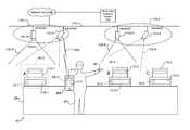
- FIG. 2is a schematic diagram showing four exemplary surveillance cameras that each capture image data of scenes at a customer premises, where two pairs of the cameras each focus on different point of sale terminals, and where an installer utilizes a user mobile computing device to define regions of interest for the first pair of surveillance cameras and utilizes a laser pointer in conjunction with the user mobile computing device to define regions of interest for the second pair of surveillance cameras, as part of a setup process;
- FIG. 3is a schematic diagram showing some of the components of the surveillance cameras according to an embodiment
- FIG. 4is a sequence diagram that describes a first embodiment of a setup process enabling an installer to designate regions of interest and to do so across multiple surveillance cameras simultaneously that have overlapping fields of view, via a user device;
- FIG. 5is a sequence diagram that describes a second embodiment of a setup process enabling an installer to simultaneously designate regions of interest across multiple surveillance cameras that have overlapping fields of view, via a user device in conjunction with a laser pointing device;
- FIG. 6shows an image representation of image data from a surveillance camera, where the image data includes regions of interest defined in accordance with either of the setup processes described in the sequence diagrams of FIG. 4 or FIG. 5 ;
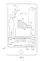
- FIG. 7is a schematic diagram of a user interface of an application displayed on the user device, where the application enables the definition of the regions of interest across the surveillance cameras, and where the application presents an image representation of the image data including the defined regions of interest for user acceptance in accordance with the process described in the sequence diagram of FIG. 5 ;
- FIG. 8is a flow diagram showing a process for analyzing optical signals sent from devices within the scene.
- the term “and/or”includes any and all combinations of one or more of the associated listed items. Further, the singular forms including the articles “a”, “an” and “the” are intended to include the plural forms as well, unless expressly stated otherwise. It will be further understood that the terms: includes, comprises, including and/or comprising, when used in this specification, specify the presence of stated features, integers, steps, operations, elements, and/or components, but do not preclude the presence or addition of one or more other features, integers, steps, operations, elements, components, and/or groups thereof. Further, it will be understood that when an element, including component or subsystem, is referred to and/or shown as being connected or coupled to another element, it can be directly connected or coupled to the other element or intervening elements may be present.
- FIG. 1shows an exemplary surveillance camera system 10 to which the present invention is applicable.
- the system 10includes surveillance cameras 103 and other components installed at a premises 52 .
- the surveillance cameras 103 - 1 / 103 - 2generate image data 250 of scenes corresponding to their respective fields of view 105 - 1 / 105 - 2 and communicate with each other and with other security devices over a local network 210 .
- the local network 210may be wired, wireless, or a hybrid of wired and wireless links.
- the video analytics system 312is typically managed by a third party hosting company and is presented to the enterprise local network 210 as a single virtual entity, in one example. In other examples, the analytics system is installed on the local network 210 and may be owned by the same business entity as the surveillance camera system 10 .
- Operators 60 holding user mobile computing devices 400communicate with the surveillance cameras 103 and/or the analytics system 312 .
- the user devices 400exchange messages 264 between each surveillance camera 103 and/or the analytics system 312 for this purpose.
- Examples of user devices 400include smartphones, tablet computing devices, and laptop computers. These devices might run operating systems such as Windows, Android, Linux, or 108 , in examples.
- Each user device 400includes a display screen 410 and one or more applications 412 , or “apps.” The apps 412 execute upon the operating systems of the user devices 400 .
- the wireless messages 264enable the user devices 400 to access the image data 250 on the surveillance cameras 103 and to configure regions of interest 82 for the surveillance cameras 103 .
- the wireless messages 264include both control and data wireless messages in one example, data wireless messages 264 include frames of image data 250 that the surveillance cameras 103 send to the user mobile computing devices 400 .
- camera 1 103 - 1is focused upon a door 62 located within an aisle 70 or entryway to the premises 52 .
- the field of view 105 - 1 of camera 1 103 - 1includes the door 62 and region of interest 82 - 1 (threshold of door 62 ) for analyzing movement of objects near a threshold of the door 62
- Camera 2is positioned to monitor a different area within the premises 52 than camera 1 103 - 1 .
- Camera 2 103 - 2is focused upon a point of sale area 100 .
- the point of sale area 100includes a cash register or point of sale terminal 72 located on top of a desk 68 .
- LED light 76 included within a drawer 74 of the point of sale terminal 72emits a light beam 84 when the drawer 74 is opened.
- the field of view 105 - 2 of camera 2 103 - 2includes the operator 60 and the user device 400 , the point of sale terminal 72 , and region of interest 82 - 2 .
- Region of interest 82 - 2surrounds the point of sale terminal 72 .
- the region of interestmight correspond to region where customers stand in a queue for the point of sale terminal, or a product isle or hallway or specific display case, to give a few examples. Further, the region of interest might further correspond to a position of the LED light source 74 when the drawer 76 is in an open position.
- FIG. 2shows another exemplary surveillance camera system 10 to which the present invention is applicable.
- the system 10includes four surveillance cameras, camera 3 103 - 3 through camera 6 103 - 6 , and point of sale terminals 72 - 1 through 72 - 3 labeled A, B, and C.
- Each of the terminals 72 - 1 through 72 - 3includes a drawer 74 - 1 through 74 - 3 , respectively.
- Each drawer 74 - 1 through 74 - 3includes an LED light 76 - 1 through 76 - 3 , respectively.
- Camera 3 103 - 3 and camera 4 103 - 4form a first pair 178 - 1 of cameras, while camera 5 103 - 5 and camera 6 103 - 6 form a second pair 178 - 2 of cameras 103 .
- Each of the pairs 178focuses upon an area of the premises 52 that includes a different point of sale terminal 72 .
- the fields of view of 105 - 3 / 150 - 4 of camera 3 103 - 3 and camera. 4 103 - 4overlap, including point of sale terminal A 72 - 1 and region of interest 82 - 3 that surrounds point of sale terminal A 72 - 1 .
- the fields of view of 105 - 5 / 150 - 6 of camera 5 103 - 5 and camera 6 103 - 6include point of sale terminal B 72 - 2 and region of interest 82 - 4 that surrounds point of sale terminal B 72 - 2 .
- the operator 60designates a region of interest 82 - 3 across the cameras 103 - 3 and 103 - 4 of pair 178 - 1 using a setup process between the user device 400 and the cameras 103 - 3 and 103 - 4 .
- the user device 400enables the definition of the same region of interest 82 - 3 for camera 3 103 - 3 and camera 4 103 - 4 of pair 178 - 1 .
- the surveillance cameras 103 - 3 and 103 - 4 participating in the setup processtrack the user device 400 using integrated image data analytics systems or the external analytics system 312 or even an analytics system executing on the user device 400 as the operator 60 moves the user device 400 within the scene and their respective fields of view.
- the operator 60initiates the setup process between the user device 400 and the surveillance cameras and/or the external analytics system 312 via messages 264 exchanged between the app 412 of the user device 400 and each of the cameras 103 - 3 / 103 - 4 and/or the external analytics system 312 .
- the operator 60moves the user device 400 within the scene in a manner that traces or outlines or fills-in the desired region of interest 82 - 3 .
- the app 412preferably displays a predetermined sequence of images on the display 410 of the user mobile computing device 400 .
- Cameras 103 - 3 and 103 - 4detect the predetermined sequence of images.
- One or more analytics systeme.g., external (local or remote) analytic system 312 , analytics systems integrated on the surveillance cameras 103 , and/or an analytics system executing on the user device 400 interpret the sequence of images, and render an electronic version of the region of interest 82 in response.
- Each camera 103 - 3 and 103 - 4 or other of the analytics systemsthen saves the electronic version of the region of interest 82 within local storage of each camera 103 and/or in a setup file containing the definitions of the regions of interest in the analytics system 312 for each of the cameras, for example.
- the operator 60designates a region of interest 82 - 4 across the cameras 103 - 5 and 103 - 6 of pair 178 - 2 using a setup process between the user device 400 and the cameras 103 - 5 and 103 - 6 , in conjunction with a laser or similar optical pointing device 80 .
- the setup processcan be performed for multiple cameras simultaneously.
- the user device 400enables the definition of the same region of interest 82 - 4 for camera 5 103 - 5 and camera 6 103 - 6 of pair 178 - 1 .
- the surveillance cameras 103 - 5 and 103 - 6 participating in the setup processtrack a beam of light emitted from the laser pointer device 80 .
- the app 412initiates the setup process between the user device 400 and the surveillance cameras via messages 264 exchanged between the app 412 of the user device 400 and each of the cameras 103 - 5 / 103 - 6 of pair 178 - 2 and/or the analytics system 312 .
- the operator 60moves the laser pointer device 80 within the scene such that the light emitted from the laser pointer device 80 is projected onto and traces or outlines the desired region of interest 82 - 4 .
- the operator 60can outline the region of interest 82 - 4 by directing the light shone by the laser pointer device 80 to “paint” portions of an object within the scene with light.
- the operator 60moves the laser pointer device 80 to direct its emitted light in a scanned fashion upon point of sale terminal B 72 - 2 to thereby designate a point of sale terminal region of interest for the analytics system 312 .
- analytics system in each of the cameras 103 - 5 and 103 - 6 or independent analytics systems 312 and/or analytic systems executing on the device 400analyze the image data for designation of regions of interest and then renders and saves an electronic version of the region of interest 82 - 4 within local storage of each camera 103 - 5 and 103 - 6 or the other analytics systems and/or send the coordinates of the region of interest 82 - 4 within the image data to the analytics system 312 .
- the designation of the regions of interest 82 across the cameras 102 provided by the system 10does not require any specific positioning of the cameras 103 in advance nor requires an installer to specify a degree of overlap among the fields of view 105 of the cameras 103 in advance.
- an analytics systempreferably analyzes the image data 250 from the cameras 103 to determine any designated regions of interest 82 .
- the analytics systemin one embodiment generates metadata associated with each pair of surveillance cameras 178 - 1 , 178 - 2 specifying the degree of overlap of their fields of view. This metadata is generated by the analytics systems by analyzing the movement of the spot from the laser pointer 80 or the user device 400 and when the spot or user device is simultaneously within the fields of both cameras.
- FIG. 3shows some of the components of an exemplary surveillance camera 103 that includes an integrated analytics system 176 as discussed above.
- the camera 103includes a processing unit (CPU) 138 , an imager 140 , a camera image data storage system 174 and a network interface 142 .
- An operating system 136runs on top of the CPU 138 .
- a number of processes or applicationsare executed by the operating system 136 .
- the processesinclude a control process 162 and a camera analytics system 176 .
- the camera 103saves image data 250 captured by the imager 140 to the camera image data storage system 174 in one example. Each camera 103 can support one or more streams of image data 250 .
- the control process 162receives and sends messages 264 via its network interface 142 .
- the camera 103renders and saves an electronic version of the region of interest 82 to its camera image data storage system 174 .
- Each camera 103also saves event metadata 160 . Note that more than one region of interest 82 can be defined for each camera 103 .
- the control process 162sends the regions of interest 82 along with the image data to the integrated camera analytics system 176 for analysis in some cases.
- the camera analytics system 176analyzes the image data 250 based on the regions of interest 82 .
- the camera analytics system 176generates meta data and video primitives 296 in response to the analysis, and stores the video primitives 296 to the camera image data storage system 174 .
- the camera 103may also or alternatively stream image data to the user device 400 or the external analytics system 312 and these analytics systems analyze the image data to detect the designation of the regions of interest.
- FIG. 4is a sequence diagram that describes a first embodiment of a setup process that enables an installer to simultaneously designate regions of interest 82 and also possibly designate the regions across multiple surveillance cameras 103 simultaneously.
- the setup processutilizes a user device 400 to trace the regions of interest 82 within the scene.
- step 502an operator selects ENTER button 141 - 5 within the app 412 of user device 400 to direct the cameras 103 to begin a communication session 308 with the app 412 .
- the app 412sends a pairing request message to one or more surveillance cameras 103 pointed at same scene.
- the cameras 103 and the app 412exchange messages 264 using standard communications protocols such as those based on Internet Protocol (IP), but propriety protocols can also be used.
- IPInternet Protocol
- the operatorsconfigure the pairing request message to include the destination addresses of each surveillance camera 103 participating in the configuration process.
- each camera 103 receiving the message 264sends a pairing response message, the result of which establishes a two-way communications session 308 between each of the cameras 103 and the app 412 excutign on the user device.
- the app 412accesses a video stream from one of the cameras 103 and downloads representative image data 250 of the scene (e.g. a still frame of image data 250 ).
- the app 412presents user interface buttons 414 - 1 and 414 - 2 to start and stop definition of the region of interest 82 for the cameras 103 .
- the app 412sends an instruction to place the surveillance cameras 103 and/or the analytics systems in a Region of Interest (ROI) configuration mode, according to step 510 .
- ROIRegion of Interest
- each camera 103places itself in ROI configuration mode.
- the app 412instructs the display screen 410 of the user device 400 to present a predetermined image or sequence of images as the operator 60 defines the region of interest 82 , where the operator defines the region of interest 82 by outlining an area within the scene via the user device 400 .
- the app 412displays the predetermined sequence of images on the display screen 410 of the user device 400 in step 516 as the operator moves the device through space so that the user device is located in front of the region of interested from the perspective of the one or more surveillance cameras.
- each of the cameras 103captures the image data from their fields of view.
- the one or more analytics systemsthen detect the predetermined sequence of images displayed on the display screen 410 of the user device 400 within the camera's field of view.
- the imagesare a series of alternating test pattern images which integrated camera analytics systems 176 of the cameras 103 or the local or cloud analytics system 312 or even the analytics system in the user device 400 recognizes when the cameras 103 are in ROI configuration mode and the image data is sent to the analytics systems.
- the analytics system(s)interpret the detected sequence of images and define an associated electronic region of interest 82 in response.
- step 522in response to “Stop” button 414 - 2 selection, the app 414 sends an instruction to the cameras 103 to signal end of ROI definition mode.
- the cameras 103receive the stop instruction and save the electronic region of interest 82 to a buffer.
- step 526one of the cameras sends its electronic region of interest 82 to the app 412 for verification by the operator 60 .
- step 527 - 1the app 412 superimposes the received region of interest 82 upon the representative image data 250 of the scene, and renders an image of the resultant scene on the display screen 410 . This allows the operator 60 to view and confirm placement of the region of interest 82 within the scene.
- the app 412presents user interface buttons “OK” 414 - 3 and “Cancel” 414 - 4 for the operator to accept or cancel the region of interest 82 definition, respectfully.
- the operator 60determines that the region of interest 82 is acceptable, operator selects the “OK” button 414 - 3 .
- the app 414sends an instruction to the cameras 103 and/or analytics system to accept the region of interest 82 definition.
- the cameras 103 and/or analytics systemsstore the electronic region of interest 82 by copying the electronic region of interest from the temporary buffer to its local device storage (e.g. camera image data storage system 174 ), for example.
- the operator 60determines that the region of interest 82 is not acceptable, the operator selects the “Cancel” button 414 - 1 in step 534 .
- the app 412sends a “cancel” instruction to the cameras 103 to cancel definition of the region of interest 82 and end ROI configuration mode.
- each camera 103flushes the contents of the temporary' buffer to discard the currently defined electronic region of interest 82 and ends ROI config mode.
- the operator 60can repeat the definition of the region of interest 82 as required.
- control within the apppasses to point “X” in the diagram to await selection of the START button 414 - 1 by the operator 60 to instruct the cameras 103 to re-enter ROI configuration mode to restart definition of the region of interest 82 .
- step 540the operator 60 selects the EXIT button 414 - 6 , and the app 412 sends an instruction to the cameras 103 and/or analytics systems to exit ROI configuration mode and tear down the communications session 308 between the app 412 and the cameras 103 .
- the setup process described in this sequence diagramenables the definition of multiple regions of interest 82 across the participating cameras 103 .
- the electronic regions of interest 82 stored within each camera 103can differ slightly across the cameras 103 . This difference reflects the difference in perspective of the scene that each camera has.
- FIG. 5is a sequence diagram that describes a second embodiment of a setup process that enables an installer to simultaneously designate regions of interest 82 across multiple surveillance cameras 103 .
- the setup processutilizes a user device 400 in conjunction with an optical device such as a laser pointer 80 to trace the regions of interest 82 within the scene or upon objects in the scene.
- Steps 602 , 604 , 606 , 608for setup of the communications session 308 between the app 418 and the cameras 103 , and for preparing the app 412 to signal start and stop of the definition of the region of interest 82 , are identical to the functionality provided by steps 602 , 604 , 606 , and 608 of FIG. 4 , respectively.
- steps 610 and 612 for enabling the cameras 103 and/or analytics systems to enter ROI configuration modeare identical to the functionality provided by steps 510 and 512 in FIG. 4 , respectively.
- step 614the operator 60 defines a region of interest 82 within the scene by outlining/scanning an object and/or tracing an area within the scene with the laser pointer 80 .
- the cameras 103 and/or analytics systemsdetect the light from the laser pointer 80 in step 616 , and interpret the detected light and define an electronic region of interest 82 in response in step 618 .
- Steps 622 , 624 , 626 , 627 - 1 , and 628 for saving a temporary copy of the electronic region of interest within each camera 103 and presenting it for operator verification on the display screen 410 of the user device 400are identical to the functionality provided by steps 522 , 524 , 526 , 527 - 1 , and 528 of FIG. 4 , respectively.
- steps 630 , 632 , 634 , 636 , 638 , and 640 for accepting or rejecting the definition of the region of the interest 82 , storing the region of interest 82 upon acceptance, and exiting the setup processare identical to the functionality provided by steps 530 , 532 , 534 , 536 , 538 , and 540 of FIG. 4 , respectively.
- FIG. 6shows an image of an exemplary frame of image data 250 - 1 from a surveillance camera 103 that includes a defined region of interest 82 - 5 superimposed upon the image data 250 - 1 .
- the image data 250 - 1shows that the defined region of interest 82 can be associated with entry or exit areas between rooms, in one example.
- region of interest 82 - 5is defined around a threshold of entryway 66 - 5 .
- the imageis what an operator might view within the display screen 410 of the user device 400 upon conclusion of step 527 - 1 for the setup process in FIG. 4 and/or upon conclusion of step 627 - 1 for the setup process in FIG. 5 .
- regions of interestmight correspond to point of sale terminals or product displays or thresholds of doors or areas around gaming tables or machines in casinos, to list a few examples.
- FIG. 7shows an example user interface of the app 412 during setup of the region of interest 82 in accordance with the process described in the sequence diagram of FIG. 5 ,
- buttons 414are displayed that control the setup process for defining the regions of interest 82 .
- the buttons 414include ENTER 414 - 5 , Start 414 - 1 , Stop 414 - 2 , OK 412 - 3 , CANCEL 414 - 4 , and EXIT 414 - 6 buttons.
- ENTER 414 - 5 and EXIT 415 - 6signal the cameras 103 to enter and exit ROI configuration mode, respectively.
- Start 414 - 1 and Stop 414 - 2 buttonsenable the start and completion of the definition of the region of interest 82 .
- OK 414 - 3 and CANCEL 414 - 4 buttonsenable the operator to accept (e.g, save to local storage) or cancel the definition of the region of interest 82 .
- the display screen 410is presenting image data 250 - 2 that includes a superimposed region of interest 82 defined by one of the surveillance cameras 103 . Users 60 - 1 and 60 - 2 are within the scene.
- the region of interest 82is configured to highlight an area within the scene that coincides with point of sale terminal 72 within the scene.
- each of the LED lights deployed in the system 10can be configured to modulate their light at different unique frequencies to provide a predetermined “identity stamp” upon detection of the light 84 by the surveillance cameras 84 .
- FIG. 8shows a method for a surveillance camera and an analytics system integrated in the surveillance camera or a separate analytics system 312 .
- the camera 103 or a separate analytics system 312monitors image data 250 of the scene to detect predetermined optical signals generated in the scene.
- the camera 103 or a separate analytics system 312can then generate metadata associated with security events of interest and execute actions for the security events.
- the methodstarts at step 802 .
- the camera analytics system 176 of the surveillance camera 103 or the separate analytics system 312analyzes image data 250 of the scene to detect optical signals sent from devices located within a region of interest 82 , where the optical signals are associated with events (e.g. for a cash register region of interest, detect transmission of a laser light beam of known frequency and duty cycle in response to opening of the cash register drawer).
- the deviceis the LED light 76 , which emits optical signals via its light beam 84 when the drawer 74 is opened.
- the camera analytics system 176 of the camera 103 or the separate analytics system 312determines if the detected optical signals match a predetermined optical pattern and are coming from a predetermined area with in the scene captured by the camera. If this test resolves to true, the method transitions to step 808 . Otherwise, the method transitions back to the beginning of step 804 .
- the camera analytics system 174 or the separate analytics system 312generates event metadata 160 in response to the matching predetermined optical patterns (e.g. “cash register drawer of point of sale terminal A opened.
- the camera analytics system 174typically includes a time stamp within the event metadata 160 and stores the event metadata 160 to the camera image data storage system 174 .
- control process 162reads the event metadata 160 and executes actions in response to the event metadata 160 .
- the actionsinclude increasing priority of image data 250 associated with the event metadata 160 and initiating recording of new image data 250 .
Landscapes
- Engineering & Computer Science (AREA)
- Physics & Mathematics (AREA)
- General Physics & Mathematics (AREA)
- Multimedia (AREA)
- Theoretical Computer Science (AREA)
- Closed-Circuit Television Systems (AREA)
- Studio Devices (AREA)
Abstract
Description
Claims (16)
Priority Applications (1)
| Application Number | Priority Date | Filing Date | Title |
|---|---|---|---|
| US15/076,704US10318836B2 (en) | 2016-03-22 | 2016-03-22 | System and method for designating surveillance camera regions of interest |
Applications Claiming Priority (1)
| Application Number | Priority Date | Filing Date | Title |
|---|---|---|---|
| US15/076,704US10318836B2 (en) | 2016-03-22 | 2016-03-22 | System and method for designating surveillance camera regions of interest |
Publications (2)
| Publication Number | Publication Date |
|---|---|
| US20170277967A1 US20170277967A1 (en) | 2017-09-28 |
| US10318836B2true US10318836B2 (en) | 2019-06-11 |
Family
ID=59898734
Family Applications (1)
| Application Number | Title | Priority Date | Filing Date |
|---|---|---|---|
| US15/076,704Active2036-09-15US10318836B2 (en) | 2016-03-22 | 2016-03-22 | System and method for designating surveillance camera regions of interest |
Country Status (1)
| Country | Link |
|---|---|
| US (1) | US10318836B2 (en) |
Cited By (1)
| Publication number | Priority date | Publication date | Assignee | Title |
|---|---|---|---|---|
| US20190080575A1 (en)* | 2016-04-07 | 2019-03-14 | Hanwha Techwin Co., Ltd. | Surveillance system and control method thereof |
Families Citing this family (9)
| Publication number | Priority date | Publication date | Assignee | Title |
|---|---|---|---|---|
| US10475315B2 (en) | 2016-03-22 | 2019-11-12 | Sensormatic Electronics, LLC | System and method for configuring surveillance cameras using mobile computing devices |
| US10665071B2 (en) | 2016-03-22 | 2020-05-26 | Sensormatic Electronics, LLC | System and method for deadzone detection in surveillance camera network |
| US9965680B2 (en) | 2016-03-22 | 2018-05-08 | Sensormatic Electronics, LLC | Method and system for conveying data from monitored scene via surveillance cameras |
| US11601583B2 (en) | 2016-03-22 | 2023-03-07 | Johnson Controls Tyco IP Holdings LLP | System and method for controlling surveillance cameras |
| US11216847B2 (en) | 2016-03-22 | 2022-01-04 | Sensormatic Electronics, LLC | System and method for retail customer tracking in surveillance camera network |
| US10347102B2 (en) | 2016-03-22 | 2019-07-09 | Sensormatic Electronics, LLC | Method and system for surveillance camera arbitration of uplink consumption |
| US10764539B2 (en) | 2016-03-22 | 2020-09-01 | Sensormatic Electronics, LLC | System and method for using mobile device of zone and correlated motion detection |
| EP4106328B1 (en)* | 2021-06-17 | 2025-10-08 | Honeywell International Inc. | Video surveillance system with distributed intelligence |
| US20230377434A1 (en)* | 2022-05-17 | 2023-11-23 | Honeywell International Inc. | Methods and systems for reducing redundant alarm notifications in a security system |
Citations (115)
| Publication number | Priority date | Publication date | Assignee | Title |
|---|---|---|---|---|
| US3217098A (en)* | 1962-08-29 | 1965-11-09 | Robert A Oswald | Method of policing horse races |
| US4940925A (en)* | 1985-08-30 | 1990-07-10 | Texas Instruments Incorporated | Closed-loop navigation system for mobile robots |
| US5164827A (en)* | 1991-08-22 | 1992-11-17 | Sensormatic Electronics Corporation | Surveillance system with master camera control of slave cameras |
| US5204536A (en)* | 1991-06-14 | 1993-04-20 | Shlomo Vardi | Electro-optical monitoring system utilizing optical signal transmitters in predetermined geometrical patterns |
| US5317394A (en)* | 1992-04-30 | 1994-05-31 | Westinghouse Electric Corp. | Distributed aperture imaging and tracking system |
| US5729471A (en)* | 1995-03-31 | 1998-03-17 | The Regents Of The University Of California | Machine dynamic selection of one video camera/image of a scene from multiple video cameras/images of the scene in accordance with a particular perspective on the scene, an object in the scene, or an event in the scene |
| US5850352A (en)* | 1995-03-31 | 1998-12-15 | The Regents Of The University Of California | Immersive video, including video hypermosaicing to generate from multiple video views of a scene a three-dimensional video mosaic from which diverse virtual video scene images are synthesized, including panoramic, scene interactive and stereoscopic images |
| US5940538A (en)* | 1995-08-04 | 1999-08-17 | Spiegel; Ehud | Apparatus and methods for object border tracking |
| US5969755A (en)* | 1996-02-05 | 1999-10-19 | Texas Instruments Incorporated | Motion based event detection system and method |
| US6341183B1 (en)* | 1998-10-27 | 2002-01-22 | The Regents Of The University Of California | Graphical user interface for image acquisition and processing |
| US6359647B1 (en)* | 1998-08-07 | 2002-03-19 | Philips Electronics North America Corporation | Automated camera handoff system for figure tracking in a multiple camera system |
| US20020104098A1 (en) | 2001-01-31 | 2002-08-01 | Zustak Fred J. | Subscriber class television channel with class member programming |
| JP2003151048A (en) | 2001-09-05 | 2003-05-23 | Sick Ag | Monitoring method and photoelectronic sensor |
| US20030107649A1 (en)* | 2001-12-07 | 2003-06-12 | Flickner Myron D. | Method of detecting and tracking groups of people |
| US6581000B2 (en)* | 2001-01-04 | 2003-06-17 | Carnegie Mellon University | Position location system and method |
| US20030169337A1 (en) | 2002-03-08 | 2003-09-11 | Wilson Jeremy Craig | Access control system with symbol recognition |
| US6724421B1 (en)* | 1994-11-22 | 2004-04-20 | Sensormatic Electronics Corporation | Video surveillance system with pilot and slave cameras |
| US6812835B2 (en)* | 2000-02-28 | 2004-11-02 | Hitachi Kokusai Electric Inc. | Intruding object monitoring method and intruding object monitoring system |
| US20050012817A1 (en) | 2003-07-15 | 2005-01-20 | International Business Machines Corporation | Selective surveillance system with active sensor management policies |
| US20050057653A1 (en) | 2002-05-07 | 2005-03-17 | Matsushita Electric Industrial Co., Ltd. | Surveillance system and a surveillance camera |
| US6970083B2 (en)* | 2001-10-09 | 2005-11-29 | Objectvideo, Inc. | Video tripwire |
| US20060001742A1 (en) | 2004-07-05 | 2006-01-05 | Samsung Electronics Co., Ltd. | System keyboard and remotely controlled surveillance system using the system keyboard |
| US7091949B2 (en)* | 1999-07-06 | 2006-08-15 | Hansen Karl C | Computer presentation system and method with optical tracking of wireless pointer |
| US20060181612A1 (en) | 2005-02-15 | 2006-08-17 | Matsushita Electric Industrial Co., Ltd. | Secure and private iSCSI camera network |
| US20060239645A1 (en)* | 2005-03-31 | 2006-10-26 | Honeywell International Inc. | Event packaged video sequence |
| US20060243798A1 (en)* | 2004-06-21 | 2006-11-02 | Malay Kundu | Method and apparatus for detecting suspicious activity using video analysis |
| WO2007030168A1 (en) | 2005-09-02 | 2007-03-15 | Intellivid Corporation | Object tracking and alerts |
| US7242423B2 (en) | 2003-06-16 | 2007-07-10 | Active Eye, Inc. | Linking zones for object tracking and camera handoff |
| US20070178823A1 (en) | 2004-11-12 | 2007-08-02 | Aronstam Peter S | Airflow control system |
| US7286157B2 (en) | 2003-09-11 | 2007-10-23 | Intellivid Corporation | Computerized method and apparatus for determining field-of-view relationships among multiple image sensors |
| US20070279494A1 (en)* | 2004-04-16 | 2007-12-06 | Aman James A | Automatic Event Videoing, Tracking And Content Generation |
| US20070294207A1 (en) | 2006-06-16 | 2007-12-20 | Lisa Marie Brown | People searches by multisensor event correlation |
| US20080004036A1 (en) | 2006-06-28 | 2008-01-03 | Motorola, Inc. | Method and system for personal area networks |
| US7342489B1 (en)* | 2001-09-06 | 2008-03-11 | Siemens Schweiz Ag | Surveillance system control unit |
| US20080101789A1 (en) | 2006-10-30 | 2008-05-01 | Tyco Safety Products Canada Ltd. | Method and apparatus for setting camera viewpoint based on alarm event or condition |
| US20080114477A1 (en) | 2006-11-09 | 2008-05-15 | David Wu | Method and system for asynchronous pipeline architecture for multiple independent dual/stereo channel pcm processing |
| US7382244B1 (en) | 2007-10-04 | 2008-06-03 | Kd Secure | Video surveillance, storage, and alerting system having network management, hierarchical data storage, video tip processing, and vehicle plate analysis |
| US20080158336A1 (en) | 2006-10-11 | 2008-07-03 | Richard Benson | Real time video streaming to video enabled communication device, with server based processing and optional control |
| US7409076B2 (en)* | 2005-05-27 | 2008-08-05 | International Business Machines Corporation | Methods and apparatus for automatically tracking moving entities entering and exiting a specified region |
| US7450735B1 (en) | 2003-10-16 | 2008-11-11 | University Of Central Florida Research Foundation, Inc. | Tracking across multiple cameras with disjoint views |
| US7456596B2 (en) | 2005-08-19 | 2008-11-25 | Cisco Technology, Inc. | Automatic radio site survey using a robot |
| US7460149B1 (en) | 2007-05-28 | 2008-12-02 | Kd Secure, Llc | Video data storage, search, and retrieval using meta-data and attribute data in a video surveillance system |
| US20090237508A1 (en)* | 2000-03-07 | 2009-09-24 | L-3 Communications Corporation | Method and apparatus for providing immersive surveillance |
| US20090268033A1 (en) | 2005-08-30 | 2009-10-29 | Norimichi Ukita | Method for estimating connection relation among wide-area distributed camera and program for estimating connection relation |
| US20090273663A1 (en) | 2007-01-15 | 2009-11-05 | Olympus Imaging Corp. | Image file processing apparatus, image file reproduction apparatus and image file working/editing apparatus |
| US20090284601A1 (en) | 2008-05-15 | 2009-11-19 | Jayakrishnan Kumar Eledath | Apparatus for intelligent and autonomous video content generation and streaming |
| US7623152B1 (en) | 2003-07-14 | 2009-11-24 | Arecont Vision, Llc | High resolution network camera with automatic bandwidth control |
| US7623676B2 (en)* | 2004-12-21 | 2009-11-24 | Sarnoff Corporation | Method and apparatus for tracking objects over a wide area using a network of stereo sensors |
| US20100013917A1 (en)* | 2003-08-12 | 2010-01-21 | Keith Hanna | Method and system for performing surveillance |
| EP2164003A1 (en) | 2008-09-12 | 2010-03-17 | March Networks Corporation | Distributed video surveillance system |
| JP2010074382A (en) | 2008-09-17 | 2010-04-02 | Toshiba Corp | Monitor camera system and monitor video generation method |
| US20100110212A1 (en) | 2008-11-05 | 2010-05-06 | Mitsubishi Electric Corporation | Camera device |
| US7733375B2 (en)* | 2005-03-23 | 2010-06-08 | Marvell International Technology Ltd. | Setting imager parameters based on configuration patterns |
| US20100153182A1 (en) | 2007-05-01 | 2010-06-17 | Thomson Licensing | Product advertising and supply chain integration |
| US20110043631A1 (en)* | 2008-03-03 | 2011-02-24 | Videoiq, Inc. | Use of video camera analytics for content aware detection and redundant storage of occurrences of events of interest |
| US20110128384A1 (en) | 2009-12-02 | 2011-06-02 | Apple Inc. | Systems and methods for receiving infrared data with a camera designed to detect images based on visible light |
| US20110246626A1 (en) | 2010-03-30 | 2011-10-06 | Peterson Nathan J | Local and remote client computer system booting |
| US20120072420A1 (en) | 2010-09-16 | 2012-03-22 | Madhav Moganti | Content capture device and methods for automatically tagging content |
| US20120206605A1 (en) | 2005-03-25 | 2012-08-16 | Buehler Christopher J | Intelligent Camera Selection and Object Tracking |
| US8249301B2 (en)* | 2008-08-28 | 2012-08-21 | International Business Machines Corporation | Video object classification |
| US20120226526A1 (en) | 2007-10-04 | 2012-09-06 | Kd Secure Llc | Systems and methods for business process monitoring |
| US8300102B2 (en) | 2007-08-27 | 2012-10-30 | Ajou University Industry Cooperation Foundation | Apparatus and method for inferencing topology of multiple cameras network by tracking movement |
| US8325979B2 (en)* | 2006-10-30 | 2012-12-04 | Tomtom Global Content B.V. | Method and apparatus for detecting objects from terrestrial based mobile mapping data |
| EP2538672A1 (en) | 2011-06-21 | 2012-12-26 | Axis AB | Method for configuring networked cameras |
| US20130169801A1 (en) | 2011-12-28 | 2013-07-04 | Pelco, Inc. | Visual Command Processing |
| US8482609B1 (en)* | 2006-11-22 | 2013-07-09 | Sightlogix, Inc. | Methods and apparatus related to surveillance system marketing, planning and/or integration |
| US8483490B2 (en)* | 2008-08-28 | 2013-07-09 | International Business Machines Corporation | Calibration of video object classification |
| US20130223625A1 (en) | 2012-02-27 | 2013-08-29 | Gvbb Holdings S.A.R.L. | Configuring audiovisual systems |
| WO2013141742A1 (en) | 2012-03-21 | 2013-09-26 | Ptitsyn Nikolay Vadimovich | Method for video data ranking |
| US20130278780A1 (en) | 2012-04-20 | 2013-10-24 | Robert P. Cazier | Configuring an Image Capturing Device Based on a Configuration Image |
| US8594482B2 (en)* | 2010-05-13 | 2013-11-26 | International Business Machines Corporation | Auditing video analytics through essence generation |
| US20130343731A1 (en) | 2008-09-11 | 2013-12-26 | Nice-Systems Ltd | Method and system for utilizing storage in network video recorders |
| US8675074B2 (en)* | 2007-07-20 | 2014-03-18 | Honeywell International Inc. | Custom video composites for surveillance applications |
| US20140085480A1 (en) | 2008-03-03 | 2014-03-27 | Videolq, Inc. | Content-aware computer networking devices with video analytics for reducing video storage and video communication bandwidth requirements of a video surveillance network camera system |
| US8723952B1 (en) | 2009-11-01 | 2014-05-13 | Leonid Rozenboim | Tamper-resistant video surveillance network |
| WO2014114754A1 (en) | 2013-01-24 | 2014-07-31 | Eilertsen Roger André | A video sharing system for road users |
| US20140211018A1 (en) | 2013-01-29 | 2014-07-31 | Hewlett-Packard Development Company, L.P. | Device configuration with machine-readable identifiers |
| US20140218520A1 (en) | 2009-06-03 | 2014-08-07 | Flir Systems, Inc. | Smart surveillance camera systems and methods |
| US20140330729A1 (en) | 2013-05-03 | 2014-11-06 | Patrick Colangelo | Payment processing using biometric identification |
| US20150039458A1 (en) | 2013-07-24 | 2015-02-05 | Volitional Partners, Inc. | Method and system for automated retail checkout using context recognition |
| US8995712B2 (en)* | 2008-12-25 | 2015-03-31 | National Chiao Tung University | Method for automatic detection and tracking of multiple targets with multiple cameras and system therefor |
| US20150092052A1 (en) | 2013-09-27 | 2015-04-02 | Samsung Techwin Co., Ltd. | Image monitoring system and surveillance camera |
| US9015167B1 (en) | 2014-01-27 | 2015-04-21 | Tipbit Inc. | User isolated indexes for determining the context and relevance of relationships |
| US20150121470A1 (en) | 2013-10-25 | 2015-04-30 | Qualcomm Incorporated | Peer-to-peer onboarding of internet of things (iot) devices over various communication interfaces |
| US9058520B2 (en)* | 2011-09-22 | 2015-06-16 | Siemens Corporation | Systems and methods for hands free inspection |
| US20150208040A1 (en) | 2014-01-22 | 2015-07-23 | Honeywell International Inc. | Operating a surveillance system |
| US20150215583A1 (en) | 2013-12-04 | 2015-07-30 | Rasilient Systems, Inc. | Cloud Video Surveillance |
| US20150249496A1 (en) | 2012-09-10 | 2015-09-03 | Koninklijke Philips N.V. | Light detection system and method |
| US9129179B1 (en) | 2012-05-10 | 2015-09-08 | Amazon Technologies, Inc. | Image-based object location |
| US9158975B2 (en)* | 2005-05-31 | 2015-10-13 | Avigilon Fortress Corporation | Video analytics for retail business process monitoring |
| US9168882B1 (en) | 2014-09-30 | 2015-10-27 | Verizon Patent And Licensing Inc. | Method and apparatus for providing vehicle sensor data access and storage |
| US9197861B2 (en)* | 2012-11-15 | 2015-11-24 | Avo Usa Holding 2 Corporation | Multi-dimensional virtual beam detection for video analytics |
| US20150358576A1 (en) | 2013-01-15 | 2015-12-10 | Mitsubishi Electric Corporation | Monitoring system and monitoring camera |
| US20150379729A1 (en) | 2013-03-28 | 2015-12-31 | International Business Machines Corporation | Automatically determining field of view overlap among multiple cameras |
| US20160065615A1 (en) | 2014-08-28 | 2016-03-03 | International Business Machines Corporation | Cloud-based surveillance with intelligent tamper protection |
| US9280833B2 (en) | 2013-03-05 | 2016-03-08 | International Business Machines Corporation | Topology determination for non-overlapping camera network |
| US20160269631A1 (en)* | 2015-03-09 | 2016-09-15 | Fujitsu Limited | Image generation method, system, and apparatus |
| US9495614B1 (en) | 2015-02-27 | 2016-11-15 | Google Inc. | Verifying labels for images using image recognition |
| US20160379074A1 (en) | 2015-06-25 | 2016-12-29 | Appropolis Inc. | System and a method for tracking mobile objects using cameras and tag devices |
| US9594963B2 (en)* | 2012-08-21 | 2017-03-14 | International Business Machines Corporation | Determination of object presence and motion state |
| US9641763B2 (en)* | 2012-08-29 | 2017-05-02 | Conduent Business Services, Llc | System and method for object tracking and timing across multiple camera views |
| US20170193673A1 (en)* | 2012-12-14 | 2017-07-06 | Faro Technologies, Inc. | Device for optically scanning and measuring an environment |
| US20170280102A1 (en)* | 2016-03-22 | 2017-09-28 | Sensormatic Electronics, LLC | Method and system for pooled local storage by surveillance cameras |
| US20170278365A1 (en)* | 2016-03-22 | 2017-09-28 | Tyco International Management Company | System and method for configuring surveillance cameras using mobile computing devices |
| US20170280043A1 (en)* | 2016-03-22 | 2017-09-28 | Tyco International Management Company | System and method for controlling surveillance cameras |
| US20170278367A1 (en)* | 2016-03-22 | 2017-09-28 | Tyco International Management Company | System and method for overlap detection in surveillance camera network |
| US20170277947A1 (en) | 2016-03-22 | 2017-09-28 | Sensormatic Electronics, LLC | Method and system for conveying data from monitored scene via surveillance cameras |
| US20170278366A1 (en) | 2016-03-22 | 2017-09-28 | Sensormatic Electronics, LLC | System and method for deadzone detection in surveillance camera network |
| US20170277785A1 (en) | 2016-03-22 | 2017-09-28 | Sensormatic Electronics, LLC | Method and system for modeling image of interest to users |
| US20170280103A1 (en)* | 2016-03-22 | 2017-09-28 | Sensormatic Electronics, LLC | System and method for using mobile device of zone and correlated motion detection |
| US20170278137A1 (en) | 2016-03-22 | 2017-09-28 | Sensormatic Electronics, LLC | System and method for retail customer tracking in surveillance camera network |
| US20170278368A1 (en)* | 2016-03-22 | 2017-09-28 | Sensormatic Electronics, LLC | Method and system for surveillance camera arbitration of uplink consumption |
| US9785898B2 (en) | 2011-06-20 | 2017-10-10 | Hi-Tech Solutions Ltd. | System and method for identifying retail products and determining retail product arrangements |
| US9860554B2 (en)* | 2007-01-26 | 2018-01-02 | Telefonaktiebolaget Lm Ericsson (Publ) | Motion estimation for uncovered frame regions |
| US9967446B2 (en)* | 2015-09-09 | 2018-05-08 | Itx-M2M Co., Ltd. | Personalized shopping mall system using virtual camera |
- 2016
- 2016-03-22USUS15/076,704patent/US10318836B2/enactiveActive
Patent Citations (123)
| Publication number | Priority date | Publication date | Assignee | Title |
|---|---|---|---|---|
| US3217098A (en)* | 1962-08-29 | 1965-11-09 | Robert A Oswald | Method of policing horse races |
| US4940925A (en)* | 1985-08-30 | 1990-07-10 | Texas Instruments Incorporated | Closed-loop navigation system for mobile robots |
| US5204536A (en)* | 1991-06-14 | 1993-04-20 | Shlomo Vardi | Electro-optical monitoring system utilizing optical signal transmitters in predetermined geometrical patterns |
| US5164827A (en)* | 1991-08-22 | 1992-11-17 | Sensormatic Electronics Corporation | Surveillance system with master camera control of slave cameras |
| US5317394A (en)* | 1992-04-30 | 1994-05-31 | Westinghouse Electric Corp. | Distributed aperture imaging and tracking system |
| US6724421B1 (en)* | 1994-11-22 | 2004-04-20 | Sensormatic Electronics Corporation | Video surveillance system with pilot and slave cameras |
| US5850352A (en)* | 1995-03-31 | 1998-12-15 | The Regents Of The University Of California | Immersive video, including video hypermosaicing to generate from multiple video views of a scene a three-dimensional video mosaic from which diverse virtual video scene images are synthesized, including panoramic, scene interactive and stereoscopic images |
| US5729471A (en)* | 1995-03-31 | 1998-03-17 | The Regents Of The University Of California | Machine dynamic selection of one video camera/image of a scene from multiple video cameras/images of the scene in accordance with a particular perspective on the scene, an object in the scene, or an event in the scene |
| US5940538A (en)* | 1995-08-04 | 1999-08-17 | Spiegel; Ehud | Apparatus and methods for object border tracking |
| US5969755A (en)* | 1996-02-05 | 1999-10-19 | Texas Instruments Incorporated | Motion based event detection system and method |
| US6359647B1 (en)* | 1998-08-07 | 2002-03-19 | Philips Electronics North America Corporation | Automated camera handoff system for figure tracking in a multiple camera system |
| US6341183B1 (en)* | 1998-10-27 | 2002-01-22 | The Regents Of The University Of California | Graphical user interface for image acquisition and processing |
| US7091949B2 (en)* | 1999-07-06 | 2006-08-15 | Hansen Karl C | Computer presentation system and method with optical tracking of wireless pointer |
| US6812835B2 (en)* | 2000-02-28 | 2004-11-02 | Hitachi Kokusai Electric Inc. | Intruding object monitoring method and intruding object monitoring system |
| US20090237508A1 (en)* | 2000-03-07 | 2009-09-24 | L-3 Communications Corporation | Method and apparatus for providing immersive surveillance |
| US6581000B2 (en)* | 2001-01-04 | 2003-06-17 | Carnegie Mellon University | Position location system and method |
| US20020104098A1 (en) | 2001-01-31 | 2002-08-01 | Zustak Fred J. | Subscriber class television channel with class member programming |
| JP2003151048A (en) | 2001-09-05 | 2003-05-23 | Sick Ag | Monitoring method and photoelectronic sensor |
| US7342489B1 (en)* | 2001-09-06 | 2008-03-11 | Siemens Schweiz Ag | Surveillance system control unit |
| US6970083B2 (en)* | 2001-10-09 | 2005-11-29 | Objectvideo, Inc. | Video tripwire |
| US20030107649A1 (en)* | 2001-12-07 | 2003-06-12 | Flickner Myron D. | Method of detecting and tracking groups of people |
| US20030169337A1 (en) | 2002-03-08 | 2003-09-11 | Wilson Jeremy Craig | Access control system with symbol recognition |
| US20050057653A1 (en) | 2002-05-07 | 2005-03-17 | Matsushita Electric Industrial Co., Ltd. | Surveillance system and a surveillance camera |
| US7242423B2 (en) | 2003-06-16 | 2007-07-10 | Active Eye, Inc. | Linking zones for object tracking and camera handoff |
| US7623152B1 (en) | 2003-07-14 | 2009-11-24 | Arecont Vision, Llc | High resolution network camera with automatic bandwidth control |
| US20050012817A1 (en) | 2003-07-15 | 2005-01-20 | International Business Machines Corporation | Selective surveillance system with active sensor management policies |
| US20100013917A1 (en)* | 2003-08-12 | 2010-01-21 | Keith Hanna | Method and system for performing surveillance |
| US7286157B2 (en) | 2003-09-11 | 2007-10-23 | Intellivid Corporation | Computerized method and apparatus for determining field-of-view relationships among multiple image sensors |
| US7450735B1 (en) | 2003-10-16 | 2008-11-11 | University Of Central Florida Research Foundation, Inc. | Tracking across multiple cameras with disjoint views |
| US20070279494A1 (en)* | 2004-04-16 | 2007-12-06 | Aman James A | Automatic Event Videoing, Tracking And Content Generation |
| US9094615B2 (en)* | 2004-04-16 | 2015-07-28 | Intheplay, Inc. | Automatic event videoing, tracking and content generation |
| US20060243798A1 (en)* | 2004-06-21 | 2006-11-02 | Malay Kundu | Method and apparatus for detecting suspicious activity using video analysis |
| US20060001742A1 (en) | 2004-07-05 | 2006-01-05 | Samsung Electronics Co., Ltd. | System keyboard and remotely controlled surveillance system using the system keyboard |
| US20070178823A1 (en) | 2004-11-12 | 2007-08-02 | Aronstam Peter S | Airflow control system |
| US7623676B2 (en)* | 2004-12-21 | 2009-11-24 | Sarnoff Corporation | Method and apparatus for tracking objects over a wide area using a network of stereo sensors |
| US20060181612A1 (en) | 2005-02-15 | 2006-08-17 | Matsushita Electric Industrial Co., Ltd. | Secure and private iSCSI camera network |
| US7733375B2 (en)* | 2005-03-23 | 2010-06-08 | Marvell International Technology Ltd. | Setting imager parameters based on configuration patterns |
| US8502868B2 (en)* | 2005-03-25 | 2013-08-06 | Sensormatic Electronics, LLC | Intelligent camera selection and object tracking |
| US20120206605A1 (en) | 2005-03-25 | 2012-08-16 | Buehler Christopher J | Intelligent Camera Selection and Object Tracking |
| US20060239645A1 (en)* | 2005-03-31 | 2006-10-26 | Honeywell International Inc. | Event packaged video sequence |
| US7409076B2 (en)* | 2005-05-27 | 2008-08-05 | International Business Machines Corporation | Methods and apparatus for automatically tracking moving entities entering and exiting a specified region |
| US7529388B2 (en)* | 2005-05-27 | 2009-05-05 | International Business Machines Corporation | Methods for automatically tracking moving entities entering and exiting a specified region |
| US9158975B2 (en)* | 2005-05-31 | 2015-10-13 | Avigilon Fortress Corporation | Video analytics for retail business process monitoring |
| US7456596B2 (en) | 2005-08-19 | 2008-11-25 | Cisco Technology, Inc. | Automatic radio site survey using a robot |
| US20090268033A1 (en) | 2005-08-30 | 2009-10-29 | Norimichi Ukita | Method for estimating connection relation among wide-area distributed camera and program for estimating connection relation |
| US20150244992A1 (en) | 2005-09-02 | 2015-08-27 | Sensormatic Electronics, LLC | Object tracking and alerts |
| WO2007030168A1 (en) | 2005-09-02 | 2007-03-15 | Intellivid Corporation | Object tracking and alerts |
| US20070294207A1 (en) | 2006-06-16 | 2007-12-20 | Lisa Marie Brown | People searches by multisensor event correlation |
| US20080004036A1 (en) | 2006-06-28 | 2008-01-03 | Motorola, Inc. | Method and system for personal area networks |
| US20080158336A1 (en) | 2006-10-11 | 2008-07-03 | Richard Benson | Real time video streaming to video enabled communication device, with server based processing and optional control |
| US20080101789A1 (en) | 2006-10-30 | 2008-05-01 | Tyco Safety Products Canada Ltd. | Method and apparatus for setting camera viewpoint based on alarm event or condition |
| US8325979B2 (en)* | 2006-10-30 | 2012-12-04 | Tomtom Global Content B.V. | Method and apparatus for detecting objects from terrestrial based mobile mapping data |
| US20080114477A1 (en) | 2006-11-09 | 2008-05-15 | David Wu | Method and system for asynchronous pipeline architecture for multiple independent dual/stereo channel pcm processing |
| US8482609B1 (en)* | 2006-11-22 | 2013-07-09 | Sightlogix, Inc. | Methods and apparatus related to surveillance system marketing, planning and/or integration |
| US20090273663A1 (en) | 2007-01-15 | 2009-11-05 | Olympus Imaging Corp. | Image file processing apparatus, image file reproduction apparatus and image file working/editing apparatus |
| US9860554B2 (en)* | 2007-01-26 | 2018-01-02 | Telefonaktiebolaget Lm Ericsson (Publ) | Motion estimation for uncovered frame regions |
| US20100153182A1 (en) | 2007-05-01 | 2010-06-17 | Thomson Licensing | Product advertising and supply chain integration |
| US7460149B1 (en) | 2007-05-28 | 2008-12-02 | Kd Secure, Llc | Video data storage, search, and retrieval using meta-data and attribute data in a video surveillance system |
| US8675074B2 (en)* | 2007-07-20 | 2014-03-18 | Honeywell International Inc. | Custom video composites for surveillance applications |
| US8300102B2 (en) | 2007-08-27 | 2012-10-30 | Ajou University Industry Cooperation Foundation | Apparatus and method for inferencing topology of multiple cameras network by tracking movement |
| US20120226526A1 (en) | 2007-10-04 | 2012-09-06 | Kd Secure Llc | Systems and methods for business process monitoring |
| US7382244B1 (en) | 2007-10-04 | 2008-06-03 | Kd Secure | Video surveillance, storage, and alerting system having network management, hierarchical data storage, video tip processing, and vehicle plate analysis |
| US20140085480A1 (en) | 2008-03-03 | 2014-03-27 | Videolq, Inc. | Content-aware computer networking devices with video analytics for reducing video storage and video communication bandwidth requirements of a video surveillance network camera system |
| US20110043631A1 (en)* | 2008-03-03 | 2011-02-24 | Videoiq, Inc. | Use of video camera analytics for content aware detection and redundant storage of occurrences of events of interest |
| US20090284601A1 (en) | 2008-05-15 | 2009-11-19 | Jayakrishnan Kumar Eledath | Apparatus for intelligent and autonomous video content generation and streaming |
| US8483490B2 (en)* | 2008-08-28 | 2013-07-09 | International Business Machines Corporation | Calibration of video object classification |
| US8249301B2 (en)* | 2008-08-28 | 2012-08-21 | International Business Machines Corporation | Video object classification |
| US20130343731A1 (en) | 2008-09-11 | 2013-12-26 | Nice-Systems Ltd | Method and system for utilizing storage in network video recorders |
| EP2164003A1 (en) | 2008-09-12 | 2010-03-17 | March Networks Corporation | Distributed video surveillance system |
| JP2010074382A (en) | 2008-09-17 | 2010-04-02 | Toshiba Corp | Monitor camera system and monitor video generation method |
| US20100110212A1 (en) | 2008-11-05 | 2010-05-06 | Mitsubishi Electric Corporation | Camera device |
| US8995712B2 (en)* | 2008-12-25 | 2015-03-31 | National Chiao Tung University | Method for automatic detection and tracking of multiple targets with multiple cameras and system therefor |
| US9674458B2 (en) | 2009-06-03 | 2017-06-06 | Flir Systems, Inc. | Smart surveillance camera systems and methods |
| US20140218520A1 (en) | 2009-06-03 | 2014-08-07 | Flir Systems, Inc. | Smart surveillance camera systems and methods |
| US8723952B1 (en) | 2009-11-01 | 2014-05-13 | Leonid Rozenboim | Tamper-resistant video surveillance network |
| US20110128384A1 (en) | 2009-12-02 | 2011-06-02 | Apple Inc. | Systems and methods for receiving infrared data with a camera designed to detect images based on visible light |
| US20110246626A1 (en) | 2010-03-30 | 2011-10-06 | Peterson Nathan J | Local and remote client computer system booting |
| US8594482B2 (en)* | 2010-05-13 | 2013-11-26 | International Business Machines Corporation | Auditing video analytics through essence generation |
| US20120072420A1 (en) | 2010-09-16 | 2012-03-22 | Madhav Moganti | Content capture device and methods for automatically tagging content |
| US9785898B2 (en) | 2011-06-20 | 2017-10-10 | Hi-Tech Solutions Ltd. | System and method for identifying retail products and determining retail product arrangements |
| EP2538672A1 (en) | 2011-06-21 | 2012-12-26 | Axis AB | Method for configuring networked cameras |
| US9058520B2 (en)* | 2011-09-22 | 2015-06-16 | Siemens Corporation | Systems and methods for hands free inspection |
| US20130169801A1 (en) | 2011-12-28 | 2013-07-04 | Pelco, Inc. | Visual Command Processing |
| US20130223625A1 (en) | 2012-02-27 | 2013-08-29 | Gvbb Holdings S.A.R.L. | Configuring audiovisual systems |
| WO2013141742A1 (en) | 2012-03-21 | 2013-09-26 | Ptitsyn Nikolay Vadimovich | Method for video data ranking |
| US20130278780A1 (en) | 2012-04-20 | 2013-10-24 | Robert P. Cazier | Configuring an Image Capturing Device Based on a Configuration Image |
| US9129179B1 (en) | 2012-05-10 | 2015-09-08 | Amazon Technologies, Inc. | Image-based object location |
| US9594963B2 (en)* | 2012-08-21 | 2017-03-14 | International Business Machines Corporation | Determination of object presence and motion state |
| US9641763B2 (en)* | 2012-08-29 | 2017-05-02 | Conduent Business Services, Llc | System and method for object tracking and timing across multiple camera views |
| US20150249496A1 (en) | 2012-09-10 | 2015-09-03 | Koninklijke Philips N.V. | Light detection system and method |
| US9197861B2 (en)* | 2012-11-15 | 2015-11-24 | Avo Usa Holding 2 Corporation | Multi-dimensional virtual beam detection for video analytics |
| US9412269B2 (en)* | 2012-11-15 | 2016-08-09 | Avigilon Analytics Corporation | Object detection based on image pixels |
| US20170193673A1 (en)* | 2012-12-14 | 2017-07-06 | Faro Technologies, Inc. | Device for optically scanning and measuring an environment |
| US20150358576A1 (en) | 2013-01-15 | 2015-12-10 | Mitsubishi Electric Corporation | Monitoring system and monitoring camera |
| WO2014114754A1 (en) | 2013-01-24 | 2014-07-31 | Eilertsen Roger André | A video sharing system for road users |
| US20140211018A1 (en) | 2013-01-29 | 2014-07-31 | Hewlett-Packard Development Company, L.P. | Device configuration with machine-readable identifiers |
| US9280833B2 (en) | 2013-03-05 | 2016-03-08 | International Business Machines Corporation | Topology determination for non-overlapping camera network |
| US20150379729A1 (en) | 2013-03-28 | 2015-12-31 | International Business Machines Corporation | Automatically determining field of view overlap among multiple cameras |
| US20140330729A1 (en) | 2013-05-03 | 2014-11-06 | Patrick Colangelo | Payment processing using biometric identification |
| US20150039458A1 (en) | 2013-07-24 | 2015-02-05 | Volitional Partners, Inc. | Method and system for automated retail checkout using context recognition |
| US20150092052A1 (en) | 2013-09-27 | 2015-04-02 | Samsung Techwin Co., Ltd. | Image monitoring system and surveillance camera |
| US20150121470A1 (en) | 2013-10-25 | 2015-04-30 | Qualcomm Incorporated | Peer-to-peer onboarding of internet of things (iot) devices over various communication interfaces |
| US20150215583A1 (en) | 2013-12-04 | 2015-07-30 | Rasilient Systems, Inc. | Cloud Video Surveillance |
| US20150208040A1 (en) | 2014-01-22 | 2015-07-23 | Honeywell International Inc. | Operating a surveillance system |
| US9015167B1 (en) | 2014-01-27 | 2015-04-21 | Tipbit Inc. | User isolated indexes for determining the context and relevance of relationships |
| US20160065615A1 (en) | 2014-08-28 | 2016-03-03 | International Business Machines Corporation | Cloud-based surveillance with intelligent tamper protection |
| US9168882B1 (en) | 2014-09-30 | 2015-10-27 | Verizon Patent And Licensing Inc. | Method and apparatus for providing vehicle sensor data access and storage |
| US9495614B1 (en) | 2015-02-27 | 2016-11-15 | Google Inc. | Verifying labels for images using image recognition |
| US20160269631A1 (en)* | 2015-03-09 | 2016-09-15 | Fujitsu Limited | Image generation method, system, and apparatus |
| US20160379074A1 (en) | 2015-06-25 | 2016-12-29 | Appropolis Inc. | System and a method for tracking mobile objects using cameras and tag devices |
| US9967446B2 (en)* | 2015-09-09 | 2018-05-08 | Itx-M2M Co., Ltd. | Personalized shopping mall system using virtual camera |
| US20170280102A1 (en)* | 2016-03-22 | 2017-09-28 | Sensormatic Electronics, LLC | Method and system for pooled local storage by surveillance cameras |
| US20170277947A1 (en) | 2016-03-22 | 2017-09-28 | Sensormatic Electronics, LLC | Method and system for conveying data from monitored scene via surveillance cameras |
| US20170278366A1 (en) | 2016-03-22 | 2017-09-28 | Sensormatic Electronics, LLC | System and method for deadzone detection in surveillance camera network |
| US20170277785A1 (en) | 2016-03-22 | 2017-09-28 | Sensormatic Electronics, LLC | Method and system for modeling image of interest to users |
| US20170280103A1 (en)* | 2016-03-22 | 2017-09-28 | Sensormatic Electronics, LLC | System and method for using mobile device of zone and correlated motion detection |
| US20170278137A1 (en) | 2016-03-22 | 2017-09-28 | Sensormatic Electronics, LLC | System and method for retail customer tracking in surveillance camera network |
| US20170278368A1 (en)* | 2016-03-22 | 2017-09-28 | Sensormatic Electronics, LLC | Method and system for surveillance camera arbitration of uplink consumption |
| US20170278367A1 (en)* | 2016-03-22 | 2017-09-28 | Tyco International Management Company | System and method for overlap detection in surveillance camera network |
| US20170280043A1 (en)* | 2016-03-22 | 2017-09-28 | Tyco International Management Company | System and method for controlling surveillance cameras |
| US20170278365A1 (en)* | 2016-03-22 | 2017-09-28 | Tyco International Management Company | System and method for configuring surveillance cameras using mobile computing devices |
| US9965680B2 (en) | 2016-03-22 | 2018-05-08 | Sensormatic Electronics, LLC | Method and system for conveying data from monitored scene via surveillance cameras |
| US20180218209A1 (en) | 2016-03-22 | 2018-08-02 | Sensormatic Electronics, LLC | Method and system for conveying data from monitored scene via surveillance cameras |
Non-Patent Citations (10)
| Title |
|---|
| International Preliminary Report on Patentability, dated Oct. 4, 2018, from International Application No. PCT/US2017/023430, filed Mar. 21, 2017. Eight pages. |
| International Preliminary Report on Patentability, dated Oct. 4, 2018, from International Application No. PCT/US2017/023434, filed on Mar. 21, 2017. Eight pages. |
| International Preliminary Report on Patentability, dated Oct. 4, 2018, from International Application No. PCT/US2017/023436, filed on Mar. 21, 2017. Eight pages. |
| International Preliminary Report on Patentability, dated Oct. 4, 2018, from International Application No. PCT/US2017/023440, filed on Mar. 21, 2017. Eight pages. |
| International Preliminary Report on Patentability, dated Oct. 4, 2018, from International Application No. PCT/US2017/023444, filed on Mar. 21, 2017. Seven pages. |
| International Search Report and the Written Opinion of the International Searching Authority, dated Jun. 12, 2017, from International Application No. PCT/US2017/023440, filed on Mar. 21, 2017. Fourteen pages. |
| International Search Report and the Written Opinion of the International Searching Authority, dated Jun. 19, 2017, from International Application No. PCT/US2017/023436, filed on Mar. 21, 2017. Fourteen pages. |
| International Search Report and the Written Opinion of the International Searching Authority, dated Jun. 21, 2017, from International Application No. PCT/US2017/023444, filed on Mar. 2, 2017. Thirteen pages. |
| International Search Report and the Written Opinion of the International Searching Authority, dated Jun. 28, 2017, from International Application No. PCT/US2017/023434, filed on Mar. 21, 2017. Thirteen pages. |
| International Search Report and the Written Opinion of the International Searching Authority, dated May 31, 2017, from International Application No. PCT/US2017/023430, filed Mar. 21, 2017. Fourteen pages. |
Cited By (2)
| Publication number | Priority date | Publication date | Assignee | Title |
|---|---|---|---|---|
| US20190080575A1 (en)* | 2016-04-07 | 2019-03-14 | Hanwha Techwin Co., Ltd. | Surveillance system and control method thereof |
| US11538316B2 (en)* | 2016-04-07 | 2022-12-27 | Hanwha Techwin Co., Ltd. | Surveillance system and control method thereof |
Also Published As
| Publication number | Publication date |
|---|---|
| US20170277967A1 (en) | 2017-09-28 |
Similar Documents
| Publication | Publication Date | Title |
|---|---|---|
| US10318836B2 (en) | System and method for designating surveillance camera regions of interest | |
| US10475315B2 (en) | System and method for configuring surveillance cameras using mobile computing devices | |
| US11561519B2 (en) | Systems and methods of gestural interaction in a pervasive computing environment | |
| US10192414B2 (en) | System and method for overlap detection in surveillance camera network | |
| US7671728B2 (en) | Systems and methods for distributed monitoring of remote sites | |
| US7825792B2 (en) | Systems and methods for distributed monitoring of remote sites | |
| US9153110B2 (en) | Video surveillance system and method for configuring a video surveillance system | |
| CN105306884B (en) | Monitoring device, monitoring system and monitoring method | |
| EP2581888A1 (en) | Systems and methods for distributed monitoring of remote sites | |
| US10665071B2 (en) | System and method for deadzone detection in surveillance camera network | |
| KR101844726B1 (en) | Drone for construction suprvision and the method of supervision using the same | |
| US20140003674A1 (en) | Skin-Based User Recognition | |
| US20160328627A1 (en) | Imaging device, recording device, and moving image output control device | |
| US20150047024A1 (en) | Surveillance camera renting service | |
| US10769935B2 (en) | Method and apparatus for unified mobile application for installation of security products | |
| CN107076999B (en) | It is docked using eye contact via head-up display | |
| US11216666B2 (en) | Understanding normality of an environment using semantic information from images | |
| US20210295550A1 (en) | Information processing device, information processing method, and program | |
| CN104335562A (en) | Transmitting initiation details from a mobile device | |
| US20250022272A1 (en) | Covert Spying Device Detector | |
| US12316999B2 (en) | Systems and methods for detection and display of whiteboard text and/or an active speaker | |
| US10867502B1 (en) | Method and apparatus for reuniting group members in a retail store | |
| JP7207028B2 (en) | Information processing device, information processing system, electronic blackboard device, control method, and program | |
| WO2023239708A1 (en) | System and method for authenticating presence in a room | |
| Fuchs et al. | SmartLobby: A 24/7 Human-Machine-Interaction Space within an Office Environment. |
Legal Events
| Date | Code | Title | Description |
|---|---|---|---|
| AS | Assignment | Owner name:SENSORMATIC ELECTRONICS, LLC, FLORIDA Free format text:ASSIGNMENT OF ASSIGNORS INTEREST;ASSIGNORS:BURKE, ANTHONY;BIRKEL, PETER JOSEPH;SIGNING DATES FROM 20170404 TO 20170515;REEL/FRAME:046057/0112 | |
| STPP | Information on status: patent application and granting procedure in general | Free format text:NOTICE OF ALLOWANCE MAILED -- APPLICATION RECEIVED IN OFFICE OF PUBLICATIONS | |
| STCF | Information on status: patent grant | Free format text:PATENTED CASE | |
| AS | Assignment | Owner name:JOHNSON CONTROLS TYCO IP HOLDINGS LLP, WISCONSIN Free format text:ASSIGNMENT OF ASSIGNORS INTEREST;ASSIGNOR:JOHNSON CONTROLS INC;REEL/FRAME:058600/0126 Effective date:20210617 Owner name:JOHNSON CONTROLS INC, WISCONSIN Free format text:ASSIGNMENT OF ASSIGNORS INTEREST;ASSIGNOR:JOHNSON CONTROLS US HOLDINGS LLC;REEL/FRAME:058600/0080 Effective date:20210617 Owner name:JOHNSON CONTROLS US HOLDINGS LLC, WISCONSIN Free format text:ASSIGNMENT OF ASSIGNORS INTEREST;ASSIGNOR:SENSORMATIC ELECTRONICS LLC;REEL/FRAME:058600/0001 Effective date:20210617 | |
| AS | Assignment | Owner name:JOHNSON CONTROLS US HOLDINGS LLC, WISCONSIN Free format text:NUNC PRO TUNC ASSIGNMENT;ASSIGNOR:SENSORMATIC ELECTRONICS, LLC;REEL/FRAME:058957/0138 Effective date:20210806 Owner name:JOHNSON CONTROLS TYCO IP HOLDINGS LLP, WISCONSIN Free format text:NUNC PRO TUNC ASSIGNMENT;ASSIGNOR:JOHNSON CONTROLS, INC.;REEL/FRAME:058955/0472 Effective date:20210806 Owner name:JOHNSON CONTROLS, INC., WISCONSIN Free format text:NUNC PRO TUNC ASSIGNMENT;ASSIGNOR:JOHNSON CONTROLS US HOLDINGS LLC;REEL/FRAME:058955/0394 Effective date:20210806 | |
| MAFP | Maintenance fee payment | Free format text:PAYMENT OF MAINTENANCE FEE, 4TH YEAR, LARGE ENTITY (ORIGINAL EVENT CODE: M1551); ENTITY STATUS OF PATENT OWNER: LARGE ENTITY Year of fee payment:4 | |
| AS | Assignment | Owner name:TYCO FIRE & SECURITY GMBH, SWITZERLAND Free format text:ASSIGNMENT OF ASSIGNORS INTEREST;ASSIGNOR:JOHNSON CONTROLS TYCO IP HOLDINGS LLP;REEL/FRAME:068494/0384 Effective date:20240201 |