US10315150B2 - Carbon dioxide recovery - Google Patents
Carbon dioxide recoveryDownload PDFInfo
- Publication number
- US10315150B2 US10315150B2US15/883,614US201815883614AUS10315150B2US 10315150 B2US10315150 B2US 10315150B2US 201815883614 AUS201815883614 AUS 201815883614AUS 10315150 B2US10315150 B2US 10315150B2
- Authority
- US
- United States
- Prior art keywords
- gas mixture
- rotor
- melter
- stream
- gas
- Prior art date
- Legal status (The legal status is an assumption and is not a legal conclusion. Google has not performed a legal analysis and makes no representation as to the accuracy of the status listed.)
- Expired - Fee Related
Links
Images


Classifications
- B—PERFORMING OPERATIONS; TRANSPORTING
- B01—PHYSICAL OR CHEMICAL PROCESSES OR APPARATUS IN GENERAL
- B01D—SEPARATION
- B01D53/00—Separation of gases or vapours; Recovering vapours of volatile solvents from gases; Chemical or biological purification of waste gases, e.g. engine exhaust gases, smoke, fumes, flue gases, aerosols
- B01D53/002—Separation of gases or vapours; Recovering vapours of volatile solvents from gases; Chemical or biological purification of waste gases, e.g. engine exhaust gases, smoke, fumes, flue gases, aerosols by condensation
- F—MECHANICAL ENGINEERING; LIGHTING; HEATING; WEAPONS; BLASTING
- F01—MACHINES OR ENGINES IN GENERAL; ENGINE PLANTS IN GENERAL; STEAM ENGINES
- F01K—STEAM ENGINE PLANTS; STEAM ACCUMULATORS; ENGINE PLANTS NOT OTHERWISE PROVIDED FOR; ENGINES USING SPECIAL WORKING FLUIDS OR CYCLES
- F01K5/00—Plants characterised by use of means for storing steam in an alkali to increase steam pressure, e.g. of Honigmann or Koenemann type
- F01K5/02—Plants characterised by use of means for storing steam in an alkali to increase steam pressure, e.g. of Honigmann or Koenemann type used in regenerative installation
- F—MECHANICAL ENGINEERING; LIGHTING; HEATING; WEAPONS; BLASTING
- F23—COMBUSTION APPARATUS; COMBUSTION PROCESSES
- F23C—METHODS OR APPARATUS FOR COMBUSTION USING FLUID FUEL OR SOLID FUEL SUSPENDED IN A CARRIER GAS OR AIR
- F23C9/00—Combustion apparatus characterised by arrangements for returning combustion products or flue gases to the combustion chamber
- F—MECHANICAL ENGINEERING; LIGHTING; HEATING; WEAPONS; BLASTING
- F23—COMBUSTION APPARATUS; COMBUSTION PROCESSES
- F23J—REMOVAL OR TREATMENT OF COMBUSTION PRODUCTS OR COMBUSTION RESIDUES; FLUES
- F23J15/00—Arrangements of devices for treating smoke or fumes
- F23J15/06—Arrangements of devices for treating smoke or fumes of coolers
- F—MECHANICAL ENGINEERING; LIGHTING; HEATING; WEAPONS; BLASTING
- F25—REFRIGERATION OR COOLING; COMBINED HEATING AND REFRIGERATION SYSTEMS; HEAT PUMP SYSTEMS; MANUFACTURE OR STORAGE OF ICE; LIQUEFACTION SOLIDIFICATION OF GASES
- F25J—LIQUEFACTION, SOLIDIFICATION OR SEPARATION OF GASES OR GASEOUS OR LIQUEFIED GASEOUS MIXTURES BY PRESSURE AND COLD TREATMENT OR BY BRINGING THEM INTO THE SUPERCRITICAL STATE
- F25J3/00—Processes or apparatus for separating the constituents of gaseous or liquefied gaseous mixtures involving the use of liquefaction or solidification
- F25J3/02—Processes or apparatus for separating the constituents of gaseous or liquefied gaseous mixtures involving the use of liquefaction or solidification by rectification, i.e. by continuous interchange of heat and material between a vapour stream and a liquid stream
- F25J3/0228—Processes or apparatus for separating the constituents of gaseous or liquefied gaseous mixtures involving the use of liquefaction or solidification by rectification, i.e. by continuous interchange of heat and material between a vapour stream and a liquid stream characterised by the separated product stream
- F25J3/0266—Processes or apparatus for separating the constituents of gaseous or liquefied gaseous mixtures involving the use of liquefaction or solidification by rectification, i.e. by continuous interchange of heat and material between a vapour stream and a liquid stream characterised by the separated product stream separation of carbon dioxide
- B—PERFORMING OPERATIONS; TRANSPORTING
- B01—PHYSICAL OR CHEMICAL PROCESSES OR APPARATUS IN GENERAL
- B01D—SEPARATION
- B01D2251/00—Reactants
- B01D2251/30—Alkali metal compounds
- B01D2251/306—Alkali metal compounds of potassium
- B—PERFORMING OPERATIONS; TRANSPORTING
- B01—PHYSICAL OR CHEMICAL PROCESSES OR APPARATUS IN GENERAL
- B01D—SEPARATION
- B01D2256/00—Main component in the product gas stream after treatment
- B01D2256/22—Carbon dioxide
- B—PERFORMING OPERATIONS; TRANSPORTING
- B01—PHYSICAL OR CHEMICAL PROCESSES OR APPARATUS IN GENERAL
- B01D—SEPARATION
- B01D2257/00—Components to be removed
- B01D2257/10—Single element gases other than halogens
- B01D2257/102—Nitrogen
- B—PERFORMING OPERATIONS; TRANSPORTING
- B01—PHYSICAL OR CHEMICAL PROCESSES OR APPARATUS IN GENERAL
- B01D—SEPARATION
- B01D2257/00—Components to be removed
- B01D2257/80—Water
- B—PERFORMING OPERATIONS; TRANSPORTING
- B01—PHYSICAL OR CHEMICAL PROCESSES OR APPARATUS IN GENERAL
- B01D—SEPARATION
- B01D2258/00—Sources of waste gases
- B01D2258/02—Other waste gases
- B01D2258/0283—Flue gases
- B—PERFORMING OPERATIONS; TRANSPORTING
- B01—PHYSICAL OR CHEMICAL PROCESSES OR APPARATUS IN GENERAL
- B01D—SEPARATION
- B01D53/00—Separation of gases or vapours; Recovering vapours of volatile solvents from gases; Chemical or biological purification of waste gases, e.g. engine exhaust gases, smoke, fumes, flue gases, aerosols
- B01D53/14—Separation of gases or vapours; Recovering vapours of volatile solvents from gases; Chemical or biological purification of waste gases, e.g. engine exhaust gases, smoke, fumes, flue gases, aerosols by absorption
- B01D53/1456—Removing acid components
- B01D53/1475—Removing carbon dioxide
- B—PERFORMING OPERATIONS; TRANSPORTING
- B01—PHYSICAL OR CHEMICAL PROCESSES OR APPARATUS IN GENERAL
- B01D—SEPARATION
- B01D53/00—Separation of gases or vapours; Recovering vapours of volatile solvents from gases; Chemical or biological purification of waste gases, e.g. engine exhaust gases, smoke, fumes, flue gases, aerosols
- B01D53/34—Chemical or biological purification of waste gases
- B01D53/74—General processes for purification of waste gases; Apparatus or devices specially adapted therefor
- B01D53/75—Multi-step processes
- C—CHEMISTRY; METALLURGY
- C10—PETROLEUM, GAS OR COKE INDUSTRIES; TECHNICAL GASES CONTAINING CARBON MONOXIDE; FUELS; LUBRICANTS; PEAT
- C10L—FUELS NOT OTHERWISE PROVIDED FOR; NATURAL GAS; SYNTHETIC NATURAL GAS OBTAINED BY PROCESSES NOT COVERED BY SUBCLASSES C10G OR C10K; LIQUIFIED PETROLEUM GAS; USE OF ADDITIVES TO FUELS OR FIRES; FIRE-LIGHTERS
- C10L3/00—Gaseous fuels; Natural gas; Synthetic natural gas obtained by processes not covered by subclass C10G, C10K; Liquefied petroleum gas
- C10L3/06—Natural gas; Synthetic natural gas obtained by processes not covered by C10G, C10K3/02 or C10K3/04
- C10L3/10—Working-up natural gas or synthetic natural gas
- C10L3/101—Removal of contaminants
- C10L3/102—Removal of contaminants of acid contaminants
- C10L3/104—Carbon dioxide
- F—MECHANICAL ENGINEERING; LIGHTING; HEATING; WEAPONS; BLASTING
- F01—MACHINES OR ENGINES IN GENERAL; ENGINE PLANTS IN GENERAL; STEAM ENGINES
- F01K—STEAM ENGINE PLANTS; STEAM ACCUMULATORS; ENGINE PLANTS NOT OTHERWISE PROVIDED FOR; ENGINES USING SPECIAL WORKING FLUIDS OR CYCLES
- F01K23/00—Plants characterised by more than one engine delivering power external to the plant, the engines being driven by different fluids
- F01K23/02—Plants characterised by more than one engine delivering power external to the plant, the engines being driven by different fluids the engine cycles being thermally coupled
- F01K23/06—Plants characterised by more than one engine delivering power external to the plant, the engines being driven by different fluids the engine cycles being thermally coupled combustion heat from one cycle heating the fluid in another cycle
- F01K23/10—Plants characterised by more than one engine delivering power external to the plant, the engines being driven by different fluids the engine cycles being thermally coupled combustion heat from one cycle heating the fluid in another cycle with exhaust fluid of one cycle heating the fluid in another cycle
- F—MECHANICAL ENGINEERING; LIGHTING; HEATING; WEAPONS; BLASTING
- F23—COMBUSTION APPARATUS; COMBUSTION PROCESSES
- F23J—REMOVAL OR TREATMENT OF COMBUSTION PRODUCTS OR COMBUSTION RESIDUES; FLUES
- F23J2900/00—Special arrangements for conducting or purifying combustion fumes; Treatment of fumes or ashes
- F23J2900/15061—Deep cooling or freezing of flue gas rich of CO2 to deliver CO2-free emissions, or to deliver liquid CO2
- Y—GENERAL TAGGING OF NEW TECHNOLOGICAL DEVELOPMENTS; GENERAL TAGGING OF CROSS-SECTIONAL TECHNOLOGIES SPANNING OVER SEVERAL SECTIONS OF THE IPC; TECHNICAL SUBJECTS COVERED BY FORMER USPC CROSS-REFERENCE ART COLLECTIONS [XRACs] AND DIGESTS
- Y02—TECHNOLOGIES OR APPLICATIONS FOR MITIGATION OR ADAPTATION AGAINST CLIMATE CHANGE
- Y02C—CAPTURE, STORAGE, SEQUESTRATION OR DISPOSAL OF GREENHOUSE GASES [GHG]
- Y02C20/00—Capture or disposal of greenhouse gases
- Y02C20/40—Capture or disposal of greenhouse gases of CO2
- Y—GENERAL TAGGING OF NEW TECHNOLOGICAL DEVELOPMENTS; GENERAL TAGGING OF CROSS-SECTIONAL TECHNOLOGIES SPANNING OVER SEVERAL SECTIONS OF THE IPC; TECHNICAL SUBJECTS COVERED BY FORMER USPC CROSS-REFERENCE ART COLLECTIONS [XRACs] AND DIGESTS
- Y02—TECHNOLOGIES OR APPLICATIONS FOR MITIGATION OR ADAPTATION AGAINST CLIMATE CHANGE
- Y02E—REDUCTION OF GREENHOUSE GAS [GHG] EMISSIONS, RELATED TO ENERGY GENERATION, TRANSMISSION OR DISTRIBUTION
- Y02E20/00—Combustion technologies with mitigation potential
- Y02E20/16—Combined cycle power plant [CCPP], or combined cycle gas turbine [CCGT]
- Y—GENERAL TAGGING OF NEW TECHNOLOGICAL DEVELOPMENTS; GENERAL TAGGING OF CROSS-SECTIONAL TECHNOLOGIES SPANNING OVER SEVERAL SECTIONS OF THE IPC; TECHNICAL SUBJECTS COVERED BY FORMER USPC CROSS-REFERENCE ART COLLECTIONS [XRACs] AND DIGESTS
- Y02—TECHNOLOGIES OR APPLICATIONS FOR MITIGATION OR ADAPTATION AGAINST CLIMATE CHANGE
- Y02E—REDUCTION OF GREENHOUSE GAS [GHG] EMISSIONS, RELATED TO ENERGY GENERATION, TRANSMISSION OR DISTRIBUTION
- Y02E20/00—Combustion technologies with mitigation potential
- Y02E20/30—Technologies for a more efficient combustion or heat usage
- Y—GENERAL TAGGING OF NEW TECHNOLOGICAL DEVELOPMENTS; GENERAL TAGGING OF CROSS-SECTIONAL TECHNOLOGIES SPANNING OVER SEVERAL SECTIONS OF THE IPC; TECHNICAL SUBJECTS COVERED BY FORMER USPC CROSS-REFERENCE ART COLLECTIONS [XRACs] AND DIGESTS
- Y02—TECHNOLOGIES OR APPLICATIONS FOR MITIGATION OR ADAPTATION AGAINST CLIMATE CHANGE
- Y02E—REDUCTION OF GREENHOUSE GAS [GHG] EMISSIONS, RELATED TO ENERGY GENERATION, TRANSMISSION OR DISTRIBUTION
- Y02E20/00—Combustion technologies with mitigation potential
- Y02E20/32—Direct CO2 mitigation
- Y02E20/326—
- Y02E20/363—
Definitions
- the present disclosurerelates generally to carbon dioxide (CO 2 ) recovery. More particularly, the present disclosure relates to systems and methods for recovering CO 2 from a gas mixture via a CO 2 separation system that includes a rotating freezer/melter.
- CO 2carbon dioxide
- a conventional gas turbine engineoften has a turbine compressor that is mechanically linked to an expander turbine through a shaft.
- the turbine compressorcan be used to compress a flow of air ingested by the turbine compressor.
- the compressed airis then flowed to a combustor.
- fuelis injected and ignited to create a continuous flame.
- the high pressure exhaust gases from the flameare flowed into the expander turbine, which generates mechanical energy from the exhaust gas as it expands.
- the exhaust gasmay include a mixture of nitrogen (N 2 ), carbon dioxide (CO 2 ), water (H 2 O), and any number of other gaseous components.
- N 2nitrogen
- CO 2carbon dioxide
- H 2 Owater
- solvent based separation processes, amine processes, pressure swing adsorption processes, or the likeare used to recover the desired CO 2 product.
- the CO 2 product that is recovered using such processesis at a low pressure and must be compressed as a gas to a high pressure for use in enhanced oil recovery (EOR) or carbon storage applications.
- EORenhanced oil recovery
- An exemplary embodiment of the present techniquesprovides a system for recovering carbon dioxide (CO 2 ).
- the systemincludes a CO 2 separation system configured to recover the CO 2 from a gas mixture.
- the CO 2 separation systemincludes a rotating freezer/melter.
- Another exemplary embodimentprovides a method for recovering carbon dioxide (CO 2 ).
- the methodincludes recovering the CO 2 from a gas mixture including the CO 2 via a CO 2 separation system.
- the CO 2 separation systemincludes a rotating freezer/melter.
- the rotating freezer/melterincludes a freezing zone, a melting zone, and a rotor configured to rotate through the freezing zone and the melting zone.
- Solid CO 2 formed from a gas mixtureis captured on the rotor while the rotor is rotating through the freezing zone, and the solid CO 2 melts and flows through the rotor as liquid CO 2 while the rotor is rotating through the melting zone.
- FIG. 1is a block diagram of a system for power generation and carbon dioxide (CO 2 ) recovery
- FIG. 2is a process flow diagram of a combined cycle power plant that can be used to produce electricity and generate a diluent gas mixture including CO 2 ;
- FIG. 3is a process flow diagram of a system for low emissions power generation and CO 2 recovery
- FIG. 4is a process flow diagram of another system for low emissions power generation and CO 2 recovery
- FIG. 5is a perspective view of a rotating freezer/melter that may be used to recover CO 2 from a gas mixture
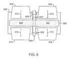
- FIG. 6is a cross-sectional view of the rotating freezer/melter that may be used to recover CO 2 from a gas mixture
- FIG. 7is a perspective view of the rotor of the rotating freezer/melter of FIGS. 5 and 6 ;
- FIG. 8is a schematic showing flow paths within a section of the rotor of FIG. 7 ;
- FIG. 9is a perspective view of another rotor that may be used for the rotating freezer/melter of FIGS. 5 and 6 ;
- FIG. 10is a process flow diagram of a method for power generation and CO 2 recovery
- FIG. 11is a generalized process flow diagram of a method for recovering CO 2 from a gas mixture.
- FIG. 12is a block diagram of a system for recovering CO 2 from a natural gas stream.
- a “combined cycle power plant”is generally the combination of an open Brayton Cycle and a Rankine cycle.
- Combined cycle power plantstypically use both steam and gas turbines to generate power, although other working fluids besides water and steam may be used in the Rankine cycle.
- the combined cycle gas/steam power plantsgenerally have a higher energy conversion efficiency than gas or steam only plants.
- a combined cycle plant's efficienciescan be as high as 50% to 60% of a lower heating value (LHV).
- LHVlower heating value
- the higher combined cycle efficienciesresult from synergistic utilization of a combination of the gas turbine with the steam turbine.
- combined cycle power plantsutilize heat from the gas turbine exhaust to boil water to generate steam.
- the boilers in typical combined cycle plantscan be referred to as heat recovery steam generator (HRSG).
- the steam generatedis utilized to power a steam turbine in the combined cycle plant.
- the gas turbine and the steam turbinecan be utilized to separately power independent generators, or in the alternative, the steam turbine can be combined with the gas turbine
- a “compressor”includes any type of equipment designed to increase the pressure of a fluid or working fluid, and includes any one type or combination of similar or different types of compression equipment.
- a compressormay also include auxiliary equipment associated with the compressor, such as motors, and drive systems, among others.
- the compressormay utilize one or more compression stages, for example, in series.
- Illustrative compressorsmay include, but are not limited to, positive displacement types, such as reciprocating and rotary compressors for example, and dynamic types, such as centrifugal and axial flow compressors, for example.
- a compressormay be a first stage in a gas turbine engine, as discussed in further detail below.
- coolingbroadly refers to lowering and/or dropping a temperature and/or internal energy of a substance, such as by any suitable amount. Cooling may include a temperature drop of at least about 1 degree Celsius, at least about 5 degrees Celsius, at least about 10 degrees Celsius, at least about 15 degrees Celsius, at least about 25 degrees Celsius, at least about 50 degrees Celsius, at least about 100 degrees Celsius, and/or the like.
- the coolingmay use any suitable heat sink, such as steam generation, hot water heating, cooling water, air, refrigerant, other process streams (integration), and combinations thereof.
- One or more sources of coolingmay be combined and/or cascaded to reach a desired outlet temperature.
- the cooling stepmay use a cooling unit with any suitable device and/or equipment.
- coolingmay include indirect heat exchange, such as with one or more heat exchangers.
- Heat exchangersmay include any suitable design, such as shell and tube, plate and frame, counter current, concurrent, extended surface, and/or the like.
- the coolingmay use evaporative (heat of vaporization) cooling and/or direct heat exchange, such as a liquid sprayed directly into a process stream.
- “Cryogenic temperature”refers to a temperature that is about ⁇ 50° C. or below.
- a “diluent”is a gas used to lower the concentration of an oxidant fed to a gas turbine to combust a fuel, a gas used to lower the concentration of a fuel fed to a gas turbine that is combusted with an oxidant, a gas used to reduce the temperature of the products of combustion of a fuel and an oxidant fed to a gas turbine, or any combination thereof.
- the diluentmay be an excess of nitrogen, carbon dioxide, combustion exhaust, or any number of other gases.
- the diluentmay also provide cooling to a combustor.
- Enhanced oil recoveryor “EOR” refers to processes for enhancing the recovery of hydrocarbons from subterranean reservoirs by the introduction of materials not naturally occurring in the reservoir.
- an “equivalence ratio”refers to the mass ratio of fuel to oxygen entering a combustor divided by the mass ratio of fuel to oxygen when the ratio is stoichiometric.
- a perfect combustion of fuel and oxygen to form carbon dioxide and waterwould have an equivalence ratio of 1.
- a too lean mixture, e.g., having more oxygen than fuel,would provide an equivalence ratio less than 1, while a too rich mixture, e.g., having more fuel than oxygen, would provide an equivalence ratio greater than 1.
- a “fuel”includes any number of hydrocarbons that may be combusted with an oxidant to power a gas turbine.
- Such hydrocarbonsmay include natural gas, treated natural gas, kerosene, gasoline, or any number of other natural or synthetic hydrocarbons.
- natural gas from an oil fieldis purified and used to power the turbine.
- a reformed gasfor example, created by processing a hydrocarbon in a steam reforming process may be used to power the turbine.
- gasis used interchangeably with “vapor,” and is defined as a substance or mixture of substances in the gaseous state as distinguished from the liquid or solid state.
- liquidmeans a substance or mixture of substances in the liquid state as distinguished from the gas or solid state.
- a “gas turbine engine”operates on the Brayton cycle. If the exhaust gas is vented to the atmosphere, this is termed an open Brayton cycle, while recycling of the exhaust gas gives a closed Brayton cycle.
- a “gas turbine”typically includes a compressor section, a number of combustors, and an expander turbine section. The compressor may be used to compress an oxidant, which is mixed with a fuel and channeled to the combustors. The mixture of fuel and oxidant is then ignited to generate hot combustion gases. The combustion gases are channeled to the expander turbine section which extracts energy from the combustion gases for powering the compressor, as well as producing useful work to power a load.
- the oxidantmay be provided to the combustors by an external compressor, which may or may not be mechanically linked to the shaft of the gas turbine engine. Further, in embodiments, the compressor section may be used to compress a diluent, such as recycled exhaust gases, which may be fed to the combustors as a coolant.
- a diluentsuch as recycled exhaust gases
- a “heat exchanger”broadly means any device capable of transferring heat from one media to another media, including particularly any structure, e.g., device commonly referred to as a heat exchanger.
- Heat exchangersinclude “direct heat exchangers” and “indirect heat exchangers.”
- a heat exchangermay be a plate-and-frame, shell-and-tube, spiral, hairpin, core, core-and-kettle, double-pipe or any other type of known heat exchanger.
- Heat exchangermay also refer to any column, tower, unit or other arrangement adapted to allow the passage of one or more streams therethrough, and to affect direct or indirect heat exchange between one or more lines of refrigerant, and one or more feed streams.
- a “heat recovery steam generator” or “HRSG”is a heat exchanger or boiler that recovers heat from a hot gas stream. It produces steam that can be used in a process or used to drive a steam turbine.
- HRSGheat recovery steam generator
- a common application for an HRSGis in a combined-cycle power plant, where hot exhaust from a gas turbine is fed to the HRSG to generate steam which in turn drives a steam turbine. This combination produces electricity more efficiently than either the gas turbine or steam turbine alone.
- hydrocarbonis an organic compound that primarily includes the elements hydrogen and carbon, although nitrogen, sulfur, oxygen, metals, or any number of other elements may be present in small amounts.
- hydrocarbonsgenerally refer to components found in raw natural gas, such as CH 4 , C 2 H 2 , C 2 H 4 , C 2 H 6 , C 3 isomers, C 4 isomers, benzene, and the like.
- Natural gasrefers to a multi-component gas obtained from a crude oil well or from a subterranean gas-bearing formation.
- the composition and pressure of natural gascan vary significantly.
- a typical natural gas streamcontains methane (CH 4 ) as a major component, i.e., greater than 50 mol % of the natural gas stream is methane.
- the natural gas streamcan also contain ethane (C 2 H 6 ), higher molecular weight hydrocarbons (e.g., C 3 -C 20 hydrocarbons), one or more acid gases (e.g., carbon dioxide or hydrogen sulfide), or any combinations thereof.
- the natural gascan also contain minor amounts of contaminants such as water, nitrogen, iron sulfide, wax, crude oil, or any combinations thereof.
- the natural gas streammay be substantially purified prior to use in embodiments, so as to remove compounds that may act as poisons.
- an “oxidant”is a gas mixture that can be flowed into the combustors of a gas turbine engine to combust a fuel.
- the oxidantmay be oxygen mixed with any number of other gases as diluents, including carbon dioxide (CO 2 ), nitrogen (N 2 ), air, combustion exhaust, and the like.
- gases that function as oxidizersmay be present in the oxidant mixture in addition to oxygen, including ozone, hydrogen peroxide, NOxs, and the like.
- Pressureis the force exerted per unit area by the gas on the walls of the volume. Pressure can be shown as pounds per square inch (psi). “Atmospheric pressure” refers to the local pressure of the air. “Absolute pressure” (psia) refers to the sum of the atmospheric pressure (14.7 psia at standard conditions) plus the gage pressure (psig). “Gauge pressure” (psig) refers to the pressure measured by a gauge, which indicates only the pressure exceeding the local atmospheric pressure (i.e., a gauge pressure of 0 psig corresponds to an absolute pressure of 14.7 psia). The term “vapor pressure” has the usual thermodynamic meaning. For a pure component in an enclosed system at a given pressure, the component vapor pressure is essentially equal to the total pressure in the system.
- Embodiments described hereinprovide a system and method for recovering CO 2 from a gas mixture via a CO 2 separation system that includes a rotating freezer/melter. More specifically, embodiments described herein provide a system and method for recovering CO 2 from an exhaust gas exiting a power plant or a natural gas stream including CO 2 , for example.
- poweris generated via a power plant, and CO 2 is recovered from the exhaust gas exiting the power plant.
- a gas mixture including CO 2 , H 2 O, and inert gasis generated by a power plant during the generation of power.
- a dehydration systemdehydrates the gas mixture, and a CO 2 separation system recovers the CO 2 from the dehydrated gas mixture.
- the CO 2 separation systemincludes a rotating freezer/melter for recovering the CO 2 from the dehydrated gas mixture.
- FIG. 1is a block diagram of a system 100 for power generation and CO 2 recovery.
- oxidant 102 and fuel gas 104are provided to a power plant 106 , for example, a gas turbine generator (GTG), at a substantially stoichiometric ratio.
- the oxidant 102can be air having about 78% N 2 and about 21% oxygen and, thus, the ratio would be calculated between the fuel gas 104 and the oxygen portion of the oxidant 102 .
- the fuel gas 102 and oxygenare substantially completely combusted in the GTG of the power plant 106 to form an exhaust gas that includes CO 2 , H 2 O, and inert gas such as N 2 .
- the exhaust gasmay also include trace amounts of carbon monoxide (CO), nitrogen oxides (NOx), oxygen (O 2 ), and fuel.
- COcarbon monoxide
- NOxnitrogen oxides
- O 2oxygen
- the energy from the exhaust gasis used to drive an expander turbine that turns a shaft.
- a generator coupled to the shaftgenerates electricity 108 .
- the power plant 106is a semi-closed Brayton cycle power plant.
- the power plant 106may be a combined cycle power plant that includes both a semi-closed Brayton cycle and a Rankine cycle.
- the exhaust stream from the expander turbine of the semi-closed Brayton cyclecan be used to boil water or other heat transfer fluids in a heat recovery steam generator (HRSG) that can be used to power the Rankine cycle power plant.
- HRSGheat recovery steam generator
- the steam or other vaporcan be used to drive a turbine and generate more electricity 108 .
- the treated stream from the power plant 106forms a gas mixture 110 .
- the gas mixture 110may include primarily CO 2 , H 2 O, and inert gas.
- the gas mixture 110is flowed through a dehydration system 112 , in which the H 2 O 114 is separated from the CO 2 and inert gas within the gas mixture 110 .
- the dehydrated gas mixture 116is then flowed into a CO 2 separation system 118 .
- the CO 2 120is separated from the inert gas 122 within the dehydrated gas mixture 116 .
- thisis accomplished using a rotating freezer/melter within the CO 2 separation system 118 , as discussed further with respect to FIGS. 3-10 .
- the block diagram of FIG. 1is not intended to indicate that the system 100 is to include all of the components shown in FIG. 1 . Moreover, the system 100 may include any number of additional components not shown in FIG. 1 , depending on the details of the specific implementation.
- the gas mixture 110is flowed through a precooler before being flowed into the dehydration system 112 .
- the precoolermay lower the temperature of the gas mixture 110 in preparation for the recovery of the CO 2 120 from the gas mixture 110 .
- FIG. 2is a process flow diagram of a combined cycle power plant 200 that can be used to produce electricity 202 and generate a diluent gas mixture including CO 2 .
- the combined cycle power plant 200includes a semi-closed Brayton cycle including, for example, an expander turbine 206 , and a Rankine cycle including, for example, a HRSG 208 .
- oxidant 210 and fuel gas 212are fed to a combustor 214 to be burned.
- a compressed diluent stream 216is also fed to the combustor 214 to lower the total amount of oxidant 201 and fuel gas 212 that is used, which allows the combustion process to be run at near stoichiometric conditions without overheating the combustor 214 or the expander turbine 206 .
- the amount of O 2 and CO generated in the combustion processis decreased, and hot exhaust gas 218 exiting the combustor includes mostly CO 2 , H 2 O, and N 2 , in addition to some trace gases, such as CO, H 2 and NOx.
- the oxidant 210 and fuel gas 212 pressuresmay be increased, for example, using compressors, to boost the pressure to match the injection pressure of the compressed diluent stream 216 at the combustor 214 .
- the hot exhaust gas 218 from the combustor 214is flowed to the expander turbine 206 , which uses the energy of the hot exhaust gas 218 to spin a shaft 220 .
- the shaft 220provides mechanical energy to a compressor, completing the Brayton cycle.
- the shaft 220may also provide mechanical energy to an electric generator 222 to generate electricity 202 .
- the electric generator 222may be directly coupled to the shaft 220 from the expander turbine 206 , or may be coupled to the shaft 220 by a gear box, clutch, or other device.
- the hot exhaust gas 218is flowed to the HRSG 208 .
- the HRSG 208may boil a water stream 224 with the energy from the hot exhaust gas 218 to generate steam 226 .
- the steam 226 that is generatedcan be used to drive a steam turbine 228 and spin a shaft 230 .
- the resulting low pressure steam 232can be cooled and condensed, and can be used as the water stream 224 to feed the HRSG 208 .
- the shaft 230 from the steam turbine 228can provide mechanical energy to an electric generator 234 to generate the electricity 202 , or may be used power other devices, such as compressors.
- the electric generator 234may be directly coupled to the shaft 230 from the steam turbine 228 , or may be coupled to the shaft 230 by a gear box, clutch, or other device.
- the expander turbine 206 and the steam turbine 228are coupled to separate electric generators 222 and 234 .
- the expander turbine 206 and the steam turbine 228may also be coupled, directly or indirectly, to one common electric generator.
- the hot gas stream 236 exiting the HRSG 208is flowed to a cooler 238 .
- the cooler 238chills the hot gas stream 236 , causing the water vapor formed in the combustion process to condense out, allowing its removal as a separate water stream 240 .
- the chilled gas mixture 242is provided to a compressor 244 for recompression, prior to feeding the compressed diluent stream 216 to the combustor 214 to aid in cooling the combustor 214 .
- the recycling of the hot gas stream 236 as the diluent stream 216partially closes the Brayton cycle in the combined cycle power plant 200 , resulting in a semi-closed Brayton cycle.
- the diluent stream 216may include CO 2 , H 2 O, and inert gas.
- the diluent stream 216 exiting the combined cycle power plant 200is flowed into a dehydration system, in which the H 2 O is removed from the diluent stream 216 .
- the dehydrated diluent stream 216is then flowed into a CO 2 separation system.
- the CO 2is recovered from the diluent stream 216 using a rotating freezer/melter. The process of recovering the CO 2 from the diluent stream 216 is discussed further with respect to FIGS. 3-10 .
- FIG. 3is a process flow diagram of a system 300 for low emissions power generation and CO 2 recovery.
- the system 300provides for low emissions power generation using a combined cycle power plant including a semi-closed Brayton cycle that utilizes a gas turbine engine 302 and a Rankine cycle that utilizes an HRSG 304 .
- the system 300provides for the recovery of CO 2 from exhaust gases exiting the combined cycle power plant.
- air 306 and fuel gas 308are fed to a combustor 310 to be burned within the semi-closed Brayton cycle. While air 306 is used as the oxidant in the embodiment shown in FIG. 3 , it is to be understood that any other suitable type of oxidant may also be used in conjunction with the system 300 .
- a compressed diluent stream 312is also fed to the combustor 310 to lower the total amount of air 306 and fuel gas 308 that is utilized for the combustion process. This may allow the combustion process to be run at or near stoichiometric conditions without overheating. As a result, the amount of O 2 and CO generated in the combustion process is decreased, and hot exhaust gas 314 exiting the combustor includes mostly CO 2 , H 2 O, and inert gas such as N 2 .
- the air 306 and fuel gas 308 pressuresmay be increased, for example, using compressors, to boost the pressure to match the injection pressure of the compressed diluent stream 312 at the combustor 310 .
- the air 306is compressed within an air compressor 316 .
- the air compressor 316includes at least one compression stage, and may include intercoolers, knock out drums, and any other suitable equipment.
- the compressed air 306is then fed into the combustor 310 to be burned.
- the hot exhaust gas 314 from the combustor 310is flowed to an expander turbine 322 of the gas turbine engine 302 , which uses the energy of the hot exhaust gas 314 to spin a shaft 324 .
- the shaft 324provides mechanical energy to an electric generator 326 to generate electricity 328 .
- the electric generator 326may be directly coupled to the shaft 324 from the expander turbine 322 , or may be coupled to the shaft 324 by a gear box, clutch, or other device.
- the hot exhaust gas 314is flowed to the HRSG 304 within the Rankine cycle of the combined cycle power plant.
- the HRSG 304boils a water stream 330 to generate steam 332 with the energy from the hot exhaust gas 314 .
- the generated steam 332is used to drive the steam turbine, which uses the energy of the steam 332 to spin a shaft.
- the shaftmay provide mechanical energy to an electric generator to generate additional electricity.
- the hot gas stream 334 exiting the HRSG 304is flowed to an exhaust gas recirculation (EGR) blower 336 .
- the EGR blower 336compresses the hot gas stream 334 and feeds the resulting compressed gas stream 338 into an EGR cooler 340 .
- the EGR cooler 340chills the compressed gas stream 338 , producing a diluent stream 342 . Cooling the hot gas stream 334 may also condense out water, drying the diluent stream 342 .
- the diluent stream 342is then fed into a compressor 344 .
- the compressor 344compresses the diluent stream 342 , producing the compressed diluent stream 312 .
- the compressor 344is coupled to the shaft 324 , and the mechanical energy provided by the spinning of the shaft 324 by the expander turbine 322 is used to drive the compressor 344 .
- the compressed diluent stream 312is fed to the combustor 310 to aid in cooling the combustor 310 .
- the recycling of the hot gas stream 334 as the compressed diluent stream 312partially closes the Brayton cycle in the combined cycle power plant, resulting in the semi-closed Brayton cycle.
- a portion of the compressed diluent stream 312is continuously removed.
- a portion of the diluent stream 312may be removed as a gas mixture 346 including primarily CO 2 , H 2 O, and inert gas.
- the gas mixture 346may be extracted from the combustor 310 after it has been burned and used to drive the expander turbine 322 .
- the gas mixture 346may be extracted from the expander turbine 322 at about 2206 kilopascals (kPa) and 427 degrees Celsius (° C.).
- the gas mixture 346is then cooled using a purge cooler 348 and, optionally, used to generate steam 332 within the HRSG 304 .
- the gas mixture 346is fed into a dehydration system 350 .
- the gas mixture 346is dehydrated to remove the H 2 O 352 .
- the gas mixture 346is dehydrated such that there is a very low amount of H 2 O 352 remaining in the gas mixture 346 .
- the dew point of the resulting dehydrated gas mixture 354may be less than about ⁇ 70° C., or lower.
- the resulting dehydrated gas mixture 354 exiting the dehydration system 350may be at about 2206 kPa and 49° C.
- the dehydrated gas mixture 354is flowed into a CO 2 separation system 356 for the recovery of the CO 2 358 from the dehydrated gas mixture 354 .
- the dehydrated gas mixture 354is flowed into a heat exchanger 360 within the CO 2 separation system 356 .
- the dehydrated gas mixture 354is cooled to about ⁇ 68° C. via indirect heat exchange with a low-temperature inert gas stream 362 .
- the resulting low-temperature gas mixture 364is flowed through a cryogenic expander 366 .
- the cryogenic expander 366lowers the pressure and temperature of the low-temperature gas mixture 364 to about 138 kPa and ⁇ 101° C., respectively.
- a portion of the CO 2 within the gas mixture 364freezes to pure solid CO 2 , resulting in the generation of a multiphase stream 368 including solid CO 2 and inert gas including some amount of residual CO 2 .
- the multiphase stream 368is flowed into a rotating freezer/melter 370 including a freezing zone 372 , a melting zone 374 , and a rotor (not shown) that rotates throughout both the freezing zone 372 and the melting zone 374 .
- the multiphase stream 368is flowed into the freezing zone 372 of the rotating freezer/melter 370 .
- the rotorprovides a porous media upon which the solid CO 2 within the multiphase stream 368 crystallizes and accumulates.
- the rotoralso allows the inert gas including the residual CO 2 to pass through the porous media and exit the rotating freezer/melter as the low-temperature inert gas stream 362 at about 138 kPa and ⁇ 101° C.
- the solid CO 2 that has accumulated on the rotorenters the melting zone 374 of the rotating freezer/melter 370 .
- the solid CO 2is melted via contact with a high-pressure, high-temperature CO 2 stream 376 flowing though the melting zone 374 .
- the resulting liquid CO 2 378flows through the rotor and exits the rotating freezer/melter 370 at about 1,034 kPa and ⁇ 44° C.
- the liquid CO 2 378is pumped to a pressure and temperature of about 13,790 kPa and ⁇ 39° C. via a pump 380 .
- the high-pressure liquid CO 2 382is converted to a vapor CO 2 stream via a refrigeration load 386 of about 33 MBTU/hr.
- the refrigeration load 386may be internal or external to the combined cycle power plant and the CO 2 recovery system 356 . In some embodiments, if the refrigeration load 386 is internal to the combined cycle power plant or the CO 2 recovery system 356 , the refrigeration load 386 can be used to chill cooling water for the EGR cooler 340 .
- the refrigeration load 386can be used to enhance the recovery of natural gas liquids from a hydrocarbon reservoir, for example.
- the vapor CO 2 streamis then flowed out of the system 300 as the final CO 2 product 358 .
- the final CO 2 product 358may be used for EOR operations, or the CO 2 may be sequestered in a carbon storage system, such as a subterranean saline aquifer or depleted oil or gas reservoir, for example.
- the inert gas stream 362 exiting the freezing zone 372 of the rotating freezer/melter 370may include about 93.8% nitrogen, 5.0% carbon dioxide, and 1.12% argon, for example.
- the inert gas stream 362is used to cool the dehydrated gas mixture 354 within the heat exchanger 360 , resulting in the generation of a high-temperature inert gas stream 388 at about 103 kPa and 35° C.
- the resulting high-temperature inert gas stream 388is flowed into a CO 2 separation device 390 .
- the CO 2 separation device 390separates any remaining carbon dioxide from the nitrogen and argon within the high-temperature inert gas stream 388 , resulting the generation of a vent gas stream 392 and a vapor CO 2 stream 394 at about 103 kPa and 38° C.
- the CO 2 separation device 390separates the carbon dioxide from the nitrogen and argon via an amine separation process, a potassium carbonate separation process, or any other suitable type of separation process.
- the vapor CO 2 stream 394is compressed within a compressor 396 , producing the high-pressure, high-temperature CO 2 stream 376 at about 1,034 kPa and 38° C.
- the high-pressure, high-temperature CO 2 stream 376is then flowed through the melting zone 374 of the rotating freezer/melter 370 and is used to melt the solid CO 2 that has accumulated on the rotor.
- the rotating freezer/melter 370includes an additional zone for melting and removing accumulated water-ice that may result from inadequate dehydration of the gas mixture 354 .
- a portion of the vent gas stream 392may be used to melt any accumulated water-ice within the additional zone. This de-icing procedure may be performed continuously or intermittently, depending on the details of the specific implementation.
- Tables 1A and 1Blist the properties of the streams flowing through various components of the system 300 of FIG. 3 .
- the streams flowing through the components of the system 300 of FIG. 3are not limited to the properties shown in Tables 1A and 1B. Rather, the properties shown in Tables 1A and 1B merely represent one exemplary embodiment of the operation of the system 300 of FIG. 3 .
- FIG. 3The process flow diagram of FIG. 3 is not intended to indicate that the system 300 is to include all of the components shown in FIG. 3 . Moreover, the system 300 may include any number of additional components not shown in FIG. 3 , depending on the details of the specific implementation.
- the porous media of the rotating freezer/melter 370may be arranged on a linear conveyor belt or similar device to pass the media successively through freezing and melting zones in a similar manner as described herein.
- similar functionalitymay be achieved by the use of a number of vessels that contain similar porous media that may be sequenced by the action of valves or similar devices from a freezing mode to a melting mode.
- FIG. 4is a process flow diagram of another system 400 for low emissions power generation and CO 2 recovery. Like numbered items are as described with respect to FIG. 3 .
- the system 400 of FIG. 4is similar to the system 300 of FIG. 3 .
- the CO 2 separation system 402 of the system 400 of FIG. 4does not include the CO 2 separation device 390 that is included within the CO 2 separation system 356 of the system 300 of FIG. 3 . Therefore, the system 400 of FIG. 4 may not recover as much CO 2 from the gas mixture 346 exiting the combined cycle power plant as the system 300 of FIG. 3 .
- the system 300 of FIG. 3may recover over 60% of the CO 2 from the gas mixture 346
- the system 400 of FIG. 4may recover only about 60% or less of the CO 2 from the gas mixture 346 .
- the inert gas stream 362 exiting the freezing zone 372 of the rotating freezer/melter 370is used to cool the dehydrated gas mixture 354 within the heat exchanger 360 , resulting in the generation of the high-temperature inert gas stream at about 103 kPa and 35° C.
- the high-temperature inert gas stream within the system 400 of FIG. 4is not flowed to the CO 2 separation device 390 discussed with respect to FIG. 3 . Rather, the high-temperature inert gas stream exiting the heat exchanger 360 is flowed out of the system 400 as a vent gas stream 404 .
- the liquid CO 2 378exits the rotating freezer/melter 370 at about 1034 kPa and ⁇ 44° C.
- a portion 406e.g., about 50%, of the liquid CO 2 378 is removed upstream of the pump 380 .
- the remaining portion of the liquid CO 2 378is then pumped to a pressure and temperature of about 13,790 kPa and ⁇ 39° C. via the pump 380 .
- the high-pressure liquid CO 2 382is converted to a vapor CO 2 stream via a refrigeration load 386 of about 33 MBTU/hr.
- the vapor CO 2 streamis then flowed out of the system 300 as the final CO 2 product 358 .
- the portion 406 of the liquid CO 2 378 that is removed upstream of the pump 380is flowed to a second pump 408 .
- the second pump 408increases the pressure of the liquid CO 2 378 to about 1,103 kPa, generating a vapor CO 2 stream 410 .
- the temperature of the vapor CO 2 stream 410is increased to about 38° C. via a refrigeration load 412 of about 24 MBTU/hr.
- the resulting high-pressure, high-temperature CO 2 stream 414is then flowed through the melting zone 374 of the rotating freezer/melter 370 and is used to melt the solid CO 2 that has accumulated on the rotor.
- the process flow diagram of FIG. 4is not intended to indicate that the system 400 is to include all of the components shown in FIG. 4 . Moreover, the system 400 may include any number of additional components not shown in FIG. 4 , depending on the details of the specific implementation. Further, it can be noted that the system described herein is not limited to using a combined cycle power plant, but may also be used with the exhaust from Rankine power plants, or other sources of CO 2 contaminated gases, such as high CO 2 content natural gas.
- FIG. 5is a perspective view of a rotating freezer/melter 500 that may be used to recover CO 2 from a gas mixture.
- the rotating freezer/melter 500 of FIG. 5may be used as the rotating freezer/melter 370 within the systems 300 and 400 of FIGS. 3 and 4 .
- the rotating freezer/melter 500includes a freezing zone 502 , a melting zone 504 , and a rotor 506 .
- the rotor 506may continuously rotate through both the freezing zone 502 and the melting zone 504 of the rotating freezer/melter 500 , as indicated by arrow 508 .
- the rotor 506may be constructed of crinkle wire mesh, packing, porous ceramic, or any other suitable porous material that provides enough surface area for solid CO 2 to accumulate on the rotor 506 without blocking the flow of gases or liquids through the rotor 506 .
- a multiphase stream 510 including solid CO 2flows into the freezing zone 502 of the rotating freezer/melter 500 .
- the solid CO 2 within the multiphase stream 510crystallizes and accumulates on the rotor 506 , while the inert gas flows through the rotor 506 and exits as an inert gas stream 512 including residual CO 2 .
- the solid CO 2 that has accumulated on the rotor 506passes through the melting zone 504 of the rotating freezer/melter 500 .
- the solid CO 2comes in contact with a high-pressure, high-temperature CO 2 stream 514 flowing through the melting zone 504 .
- the solid CO 2is melted, and the high-pressure, high-temperature CO 2 stream is condensed, forming a combined liquid CO 2 stream 516 .
- the liquid CO 2 stream 516flows through the rotor 506 and out of the rotating freezer/melter 500 as the recovered CO 2 product.
- FIG. 5is not intended to indicate that the rotating freezer/melter 500 is to include all of the components shown in FIG. 5 . Moreover, the rotating freezer/melter 500 may include any number of additional components not shown in FIG. 5 , depending on the details of the specific implementation.
- FIG. 6is a cross-sectional view of the rotating freezer/melter 500 that may be used to recover CO 2 from a gas mixture. Like numbered items are as described with respect to FIG. 5 . As shown in FIG. 6 , the rotor 506 rotates about an axis 600 that extends through the center of the rotating freezer/melter 500 .
- a brush seal 602 or other sealing deviceis used to individually seal both the freezing zone 502 and the melting zone 504 of the rotating freezer/melter 500 . Sealing both the freezing zone 502 and the melting zone 504 of the rotating freezer/melter 500 prevents gases or liquids from flowing from the freezing zone 502 to the melting zone 504 , or vice versa.
- U.S. Patent Application Publication No. 2008/0251234 by Wilson et al. and U.S. Patent Application Publication No. 2009/0000762 by Wilson et al.describe a rotary air-preheater using brush seals and other sealing improvements that may be adapted to seal the freezing and melting zones 502 and 504 of the rotating freezer/melter 500 .
- the freezing zone 502 and the melting zone 504may include separate inlets and outlets to allow gases or liquids to flow into and out of the two zones 502 and 504 of the rotating freezer/melter 500 without mixing.
- the freezing zone 502includes a freezer inlet 604 and a freezer outlet 606 .
- the multiphase stream 510may flow into the freezing zone 502 via the freezer inlet 604
- the inert gas stream 512may flow out of the freezing zone 502 via the freezer outlet 606 .
- the melting zone 504includes a melter inlet 608 and a melter outlet 610 .
- the high-pressure, high-temperature CO 2 stream 514flows into the melting zone 504 via the melter inlet 608 , and the liquid CO 2 stream 516 flows out of the melting zone 504 via the melter outlet 610 . Therefore, the freezing zone 502 and the melting zone 504 of the rotating freezer/melter 500 include separate flow paths that are only connected via the rotor 506 .
- FIG. 6is not intended to indicate that the rotating freezer/melter 500 is to include all of the components shown in FIG. 6 . Moreover, the rotating freezer/melter 500 may include any number of additional components not shown in FIG. 6 , depending on the details of the specific implementation.
- FIG. 7is a perspective view of the rotor 506 of the rotating freezer/melter 500 of FIGS. 5 and 6 .
- the rotor 506may be constructed of a material including a number of pores 700 , such as porous ceramic, for example.
- the pores 700may provide enough surface area for solid CO 2 to accumulate on the rotor 506 without blocking the flow of gases or liquids through the rotor 506 .
- the flow path for the flow of gases or liquids through the rotor 506may vary depending on specific conditions, as discussed further with respect to FIG. 8 .
- FIG. 7is not intended to indicate that the rotor 700 is to include all of the components shown in FIG. 7 . Moreover, the rotor 700 may include any number of additional components not shown in FIG. 7 , depending on the details of the specific implementation.
- FIG. 8is a schematic showing flow paths 800 within a section 802 of the rotor 506 of FIG. 7 .
- the pores 700 within the rotor 506may cause the flow path 800 for a substance passing through the rotor 506 to be tortuous rather than straight.
- the flow path 800may vary depending on specific conditions.
- the flow path 800 of a substance passing through the rotor 506may depend at least in part on whether the pores are evenly or unevenly spaced, and whether the pores 700 are of a uniform size or differing sizes.
- the flow path 800 for a substance passing through the rotor 506may depend on whether the substance is in the gas phase or the liquid phase, as well as the pressure and temperature of the substance.
- FIG. 8The schematic of FIG. 8 is not intended to indicate that the gas flow paths 800 within the rotor 700 are to be exactly as shown in FIG. 8 . Rather, the gas flow paths 800 within the rotor 700 may include any suitable variation of those shown in FIG. 7 , depending on the details of the specific implementation.
- FIG. 9is a perspective view of another rotor 900 that may be used for the rotating freezer/melter 500 of FIGS. 5 and 6 .
- the rotor 900includes a number of layers 902 of metal mesh screens 904 .
- Each metal mesh screen 904may include a number of small holes 906 .
- the holes 906may provide enough surface area for solid CO 2 to accumulate on the rotor 900 without blocking the flow of the gases or liquids through the rotor 900 .
- the flow path for the flow of gases or liquids through the rotor 900may vary depending on conditions that are similar to those discussed with respect to FIG. 8 .
- FIG. 9is not intended to indicate that the rotor 900 is to include all of the components shown in FIG. 9 . Moreover, the rotor 900 may include any number of additional components not shown in FIG. 9 , depending on the details of the specific implementation.
- FIG. 10is a process flow diagram of a method 1000 for power generation and CO 2 recovery.
- the method 1000may be implemented by any of the systems 100 - 400 described with respect to FIGS. 1-4 .
- the method 1000may also be implemented by any variation of the systems 100 - 400 described with respect to FIGS. 1-4 , or any suitable alternative system that is capable of integrating power generation with CO 2 recovery.
- the rotating freezer/melter 500 discussed with respect to FIGS. 5-9may be used to implement the method 1000 .
- the method 1000begins at block 1002 , at which power is produced via a power plant.
- An exhaust gas from the power plantprovides a gas mixture including CO 2 , H 2 O, and inert gas.
- the inert gasmay include nitrogen, argon, and any number of other trace gases.
- producing power via the power plantincludes providing mechanical energy via an expander turbine of a gas turbine engine using energy extracted from the gas mixture after combustion of the gas mixture in a combustor and generating electricity via a generator using the mechanical energy provided by the expander turbine. Further, in various embodiments, producing power via the power plant also includes generating steam via a HRSG by heating a boiler with an exhaust stream from the expander turbine, providing mechanical energy via a steam turbine using energy extracted from the steam generated by the HRSG, and generating electricity via a generator using the mechanical energy provided by the steam turbine. In some embodiments, one common generator is used to generate electricity from the mechanical energy provided by the expander turbine and the steam turbine, while, in other embodiments, separate generators are used.
- the CO 2is recovered from the gas mixture via a CO 2 separation system including a rotating freezer/melter. This may be accomplished by capturing solid CO 2 on a rotor of the rotating freezer/melter while the rotor is in a freezing zone of the rotating freezer/melter and flowing an inert gas stream through the rotor while the rotor is in the freezing zone.
- the solid CO 2 that is captured on the rotormay be melted to form liquid CO 2 while the rotor is in a melting zone of the rotating freezer/melter, and the liquid CO 2 may be flowed through the rotor while the rotor is in the melting zone.
- a portion of the liquid CO 2is recycled to the melting zone of the rotating freezer/melter and is used to melt the solid CO 2 within the melting zone.
- residual CO 2is recovered from the inert gas stream exiting the rotating melter/freezer via a CO 2 separation device downstream of the freezing zone of the rotating freezer/melter.
- the recovered CO 2may be pressurized via a compressor to produce a pressurized CO 2 vapor stream, and the pressurized CO 2 vapor stream may be used to melt the solid CO 2 within the melting zone of the rotating freezer/melter.
- the H 2 Ois removed from the gas mixture via a dehydration system upstream of the CO 2 separation system.
- the solid CO 2may be formed from the CO 2 within the gas mixture using a heat exchanger and an expander upstream of the rotating freezer/melter.
- the process flow diagram of FIG. 10is not intended to indicate that the steps of the method 1000 are to be executed in any particular order, or that all of the steps of the method 1000 are to be included in every case. Further, any number of additional steps may be included within the method 1000 , depending on the details of the specific implementation.
- FIG. 11is a generalized process flow diagram of a method 1100 for recovering CO 2 from a gas mixture.
- the method 1100may be used to recover CO 2 from any gas mixture including a substantial amount of CO 2 .
- the method 1100is used to remove CO 2 from an exhaust gas exiting a power plant.
- the method 1000may be implemented by any of the systems 100 - 400 described with respect to FIGS. 1-4 , for example.
- the method 1100is used to remove CO 2 from a natural gas stream including a substantial amount of CO 2 .
- the method 1100may be implemented by the system 1200 discussed with respect to FIG. 12 .
- the rotating freezer/melter 500 discussed with respect to FIGS. 5-9may be used to implement the method 1100 .
- the method 1100begins at block 1102 , at which a gas mixture including CO 2 is obtained.
- the gas mixturemay also include any number of other gaseous components.
- the gas mixturemay be an exhaust gas including CO 2 , nitrogen, and any number of other inert gases, or the gas mixture may be a natural gas stream including natural gas, CO 2 , and any number of other residual gases.
- the CO 2is recovered from the gas mixture via a CO 2 separation system including a rotating freezer/melter. This may be accomplished by capturing solid CO 2 on a rotor of the rotating freezer/melter while the rotor is in a freezing zone of the rotating freezer/melter and flowing the gas mixture through the rotor while the rotor is in the freezing zone.
- the solid CO 2 that is captured on the rotormay be melted to form liquid CO 2 while the rotor is in a melting zone of the rotating freezer/melter.
- the liquid CO 2may then be flowed through the rotor while the rotor is in the melting zone and recovered as the CO 2 product.
- the process flow diagram of FIG. 11is not intended to indicate that the steps of the method 1100 are to be executed in any particular order, or that all of the steps of the method 1100 are to be included in every case. Further, any number of additional steps may be included within the method 1100 , depending on the details of the specific implementation.
- FIG. 12is a block diagram of a system 1200 for recovering CO 2 from natural gas.
- a high CO 2 natural gas stream 1202is obtained from a high CO 2 natural gas field 1204 .
- the high CO 2 natural gas stream 1202is flowed through a dehydration system 1206 .
- H 2 O 1208is separated from the high CO 2 natural gas stream 1202 , producing a dehydrated high CO 2 natural gas stream 1210 .
- the dehydrated high CO 2 natural gas stream 1210is then flowed into a CO 2 separation system 1212 .
- CO 2is separated from the dehydrated high CO 2 natural gas stream 1216 , producing a purified natural gas stream 1214 and a CO 2 product stream 1216 .
- thisis accomplished using a rotating freezer/melter within the CO 2 separation system 1212 , such as the rotating freezer/melter 500 discussed with respect to FIGS. 5-9 .
- FIG. 12The block diagram of FIG. 12 is not intended to indicate that the system 1200 is to include all of the components shown in FIG. 12 . Moreover, the system 1200 may include any number of additional components not shown in FIG. 12 , depending on the details of the specific implementation.
Landscapes
- Engineering & Computer Science (AREA)
- Chemical & Material Sciences (AREA)
- Mechanical Engineering (AREA)
- General Engineering & Computer Science (AREA)
- Combustion & Propulsion (AREA)
- Chemical Kinetics & Catalysis (AREA)
- General Chemical & Material Sciences (AREA)
- Analytical Chemistry (AREA)
- Oil, Petroleum & Natural Gas (AREA)
- Thermal Sciences (AREA)
- Physics & Mathematics (AREA)
- Treating Waste Gases (AREA)
- Engine Equipment That Uses Special Cycles (AREA)
- Carbon And Carbon Compounds (AREA)
Abstract
Description
This application is a divisional of U.S. patent application Ser. No. 14/181,885 filed on Feb. 17, 2014 which claims the priority benefit of U.S. Patent Application 61/775,164 filed Mar. 8, 2013 entitled CARBON DIOXIDE RECOVERY, the entirety of which is incorporated herein by reference for all purposes.
The present disclosure relates generally to carbon dioxide (CO2) recovery. More particularly, the present disclosure relates to systems and methods for recovering CO2from a gas mixture via a CO2separation system that includes a rotating freezer/melter.
This section is intended to introduce various aspects of the art, which may be associated with exemplary embodiments of the present techniques. This discussion is believed to assist in providing a framework to facilitate a better understanding of particular aspects of the present techniques. Accordingly, it should be understood that this section should be read in this light, and not necessarily as admissions of prior art.
A conventional gas turbine engine often has a turbine compressor that is mechanically linked to an expander turbine through a shaft. The turbine compressor can be used to compress a flow of air ingested by the turbine compressor. The compressed air is then flowed to a combustor. In the combustor, fuel is injected and ignited to create a continuous flame. The high pressure exhaust gases from the flame are flowed into the expander turbine, which generates mechanical energy from the exhaust gas as it expands.
The exhaust gas may include a mixture of nitrogen (N2), carbon dioxide (CO2), water (H2O), and any number of other gaseous components. In some cases, it may be desirable to remove at least a portion of the CO2from the exhaust gas as a CO2product. According to current techniques, solvent based separation processes, amine processes, pressure swing adsorption processes, or the like are used to recover the desired CO2product. However, the CO2product that is recovered using such processes is at a low pressure and must be compressed as a gas to a high pressure for use in enhanced oil recovery (EOR) or carbon storage applications.
One technique for removing CO2from the flue gas of a power station is described in U.S. Patent Application Publication No. 2011/0226010 by Baxter. Moisture is removed from the flue gas to yield a dried flue gas, and the dried flue gas is compressed to yield a compressed flue gas. The temperature of the compressed flue gas is then decreased using a first heat exchanger and a second heat exchanger. At least a portion of the CO2within the compressed flue gas condenses within the first and second heat exchangers, yielding a solid or liquid condensed-phase CO2component and a light-gas component. The condensed-phase CO2component can then be recovered. However, recovering the CO2product from the flue gas using such techniques may be costly due to the high degree of compression that is required.
An exemplary embodiment of the present techniques provides a system for recovering carbon dioxide (CO2). The system includes a CO2separation system configured to recover the CO2from a gas mixture. The CO2separation system includes a rotating freezer/melter.
Another exemplary embodiment provides a method for recovering carbon dioxide (CO2). The method includes recovering the CO2from a gas mixture including the CO2via a CO2separation system. The CO2separation system includes a rotating freezer/melter.
Another exemplary embodiment provides a rotating freezer/melter for recovering carbon dioxide (CO2) from a gas mixture. The rotating freezer/melter includes a freezing zone, a melting zone, and a rotor configured to rotate through the freezing zone and the melting zone. Solid CO2formed from a gas mixture is captured on the rotor while the rotor is rotating through the freezing zone, and the solid CO2melts and flows through the rotor as liquid CO2while the rotor is rotating through the melting zone.
The advantages of the present techniques are better understood by referring to the following detailed description and the attached drawings, in which:
In the following detailed description section, specific embodiments of the present techniques are described. However, to the extent that the following description is specific to a particular embodiment or a particular use of the present techniques, this is intended to be for exemplary purposes only and simply provides a description of the exemplary embodiments. Accordingly, the techniques are not limited to the specific embodiments described below, but rather, include all alternatives, modifications, and equivalents falling within the true spirit and scope of the appended claims.
At the outset, for ease of reference, certain terms used in this application and their meanings as used in this context are set forth. To the extent a term used herein is not defined below, it should be given the broadest definition persons in the pertinent art have given that term as reflected in at least one printed publication or issued patent. Further, the present techniques are not limited by the usage of the terms shown below, as all equivalents, synonyms, new developments, and terms or techniques that serve the same or a similar purpose are considered to be within the scope of the present claims.
A “combined cycle power plant” is generally the combination of an open Brayton Cycle and a Rankine cycle. Combined cycle power plants typically use both steam and gas turbines to generate power, although other working fluids besides water and steam may be used in the Rankine cycle. The combined cycle gas/steam power plants generally have a higher energy conversion efficiency than gas or steam only plants. A combined cycle plant's efficiencies can be as high as 50% to 60% of a lower heating value (LHV). The higher combined cycle efficiencies result from synergistic utilization of a combination of the gas turbine with the steam turbine. Typically, combined cycle power plants utilize heat from the gas turbine exhaust to boil water to generate steam. The boilers in typical combined cycle plants can be referred to as heat recovery steam generator (HRSG). The steam generated is utilized to power a steam turbine in the combined cycle plant. The gas turbine and the steam turbine can be utilized to separately power independent generators, or in the alternative, the steam turbine can be combined with the gas turbine to jointly drive a single generator via a common drive shaft.
As used herein, a “compressor” includes any type of equipment designed to increase the pressure of a fluid or working fluid, and includes any one type or combination of similar or different types of compression equipment. A compressor may also include auxiliary equipment associated with the compressor, such as motors, and drive systems, among others. The compressor may utilize one or more compression stages, for example, in series. Illustrative compressors may include, but are not limited to, positive displacement types, such as reciprocating and rotary compressors for example, and dynamic types, such as centrifugal and axial flow compressors, for example. For example, a compressor may be a first stage in a gas turbine engine, as discussed in further detail below.
As used herein, “cooling” broadly refers to lowering and/or dropping a temperature and/or internal energy of a substance, such as by any suitable amount. Cooling may include a temperature drop of at least about 1 degree Celsius, at least about 5 degrees Celsius, at least about 10 degrees Celsius, at least about 15 degrees Celsius, at least about 25 degrees Celsius, at least about 50 degrees Celsius, at least about 100 degrees Celsius, and/or the like. The cooling may use any suitable heat sink, such as steam generation, hot water heating, cooling water, air, refrigerant, other process streams (integration), and combinations thereof. One or more sources of cooling may be combined and/or cascaded to reach a desired outlet temperature. The cooling step may use a cooling unit with any suitable device and/or equipment. According to one embodiment, cooling may include indirect heat exchange, such as with one or more heat exchangers. Heat exchangers may include any suitable design, such as shell and tube, plate and frame, counter current, concurrent, extended surface, and/or the like. In the alternative, the cooling may use evaporative (heat of vaporization) cooling and/or direct heat exchange, such as a liquid sprayed directly into a process stream.
“Cryogenic temperature” refers to a temperature that is about −50° C. or below.
A “diluent” is a gas used to lower the concentration of an oxidant fed to a gas turbine to combust a fuel, a gas used to lower the concentration of a fuel fed to a gas turbine that is combusted with an oxidant, a gas used to reduce the temperature of the products of combustion of a fuel and an oxidant fed to a gas turbine, or any combination thereof. The diluent may be an excess of nitrogen, carbon dioxide, combustion exhaust, or any number of other gases. In embodiments, the diluent may also provide cooling to a combustor.
“Enhanced oil recovery” or “EOR” refers to processes for enhancing the recovery of hydrocarbons from subterranean reservoirs by the introduction of materials not naturally occurring in the reservoir.
An “equivalence ratio” refers to the mass ratio of fuel to oxygen entering a combustor divided by the mass ratio of fuel to oxygen when the ratio is stoichiometric. A perfect combustion of fuel and oxygen to form carbon dioxide and water would have an equivalence ratio of 1. A too lean mixture, e.g., having more oxygen than fuel, would provide an equivalence ratio less than 1, while a too rich mixture, e.g., having more fuel than oxygen, would provide an equivalence ratio greater than 1.
A “fuel” includes any number of hydrocarbons that may be combusted with an oxidant to power a gas turbine. Such hydrocarbons may include natural gas, treated natural gas, kerosene, gasoline, or any number of other natural or synthetic hydrocarbons. In one embodiment, natural gas from an oil field is purified and used to power the turbine. In another embodiment, a reformed gas, for example, created by processing a hydrocarbon in a steam reforming process may be used to power the turbine.
The term “gas” is used interchangeably with “vapor,” and is defined as a substance or mixture of substances in the gaseous state as distinguished from the liquid or solid state. Likewise, the term “liquid” means a substance or mixture of substances in the liquid state as distinguished from the gas or solid state.
A “gas turbine engine” operates on the Brayton cycle. If the exhaust gas is vented to the atmosphere, this is termed an open Brayton cycle, while recycling of the exhaust gas gives a closed Brayton cycle. As used herein, a “gas turbine” typically includes a compressor section, a number of combustors, and an expander turbine section. The compressor may be used to compress an oxidant, which is mixed with a fuel and channeled to the combustors. The mixture of fuel and oxidant is then ignited to generate hot combustion gases. The combustion gases are channeled to the expander turbine section which extracts energy from the combustion gases for powering the compressor, as well as producing useful work to power a load. In embodiments discussed herein, the oxidant may be provided to the combustors by an external compressor, which may or may not be mechanically linked to the shaft of the gas turbine engine. Further, in embodiments, the compressor section may be used to compress a diluent, such as recycled exhaust gases, which may be fed to the combustors as a coolant.
A “heat exchanger” broadly means any device capable of transferring heat from one media to another media, including particularly any structure, e.g., device commonly referred to as a heat exchanger. Heat exchangers include “direct heat exchangers” and “indirect heat exchangers.” Thus, a heat exchanger may be a plate-and-frame, shell-and-tube, spiral, hairpin, core, core-and-kettle, double-pipe or any other type of known heat exchanger. “Heat exchanger” may also refer to any column, tower, unit or other arrangement adapted to allow the passage of one or more streams therethrough, and to affect direct or indirect heat exchange between one or more lines of refrigerant, and one or more feed streams.
A “heat recovery steam generator” or “HRSG” is a heat exchanger or boiler that recovers heat from a hot gas stream. It produces steam that can be used in a process or used to drive a steam turbine. A common application for an HRSG is in a combined-cycle power plant, where hot exhaust from a gas turbine is fed to the HRSG to generate steam which in turn drives a steam turbine. This combination produces electricity more efficiently than either the gas turbine or steam turbine alone.
A “hydrocarbon” is an organic compound that primarily includes the elements hydrogen and carbon, although nitrogen, sulfur, oxygen, metals, or any number of other elements may be present in small amounts. As used herein, hydrocarbons generally refer to components found in raw natural gas, such as CH4, C2H2, C2H4, C2H6, C3isomers, C4isomers, benzene, and the like.
“Natural gas” refers to a multi-component gas obtained from a crude oil well or from a subterranean gas-bearing formation. The composition and pressure of natural gas can vary significantly. A typical natural gas stream contains methane (CH4) as a major component, i.e., greater than 50 mol % of the natural gas stream is methane. The natural gas stream can also contain ethane (C2H6), higher molecular weight hydrocarbons (e.g., C3-C20hydrocarbons), one or more acid gases (e.g., carbon dioxide or hydrogen sulfide), or any combinations thereof. The natural gas can also contain minor amounts of contaminants such as water, nitrogen, iron sulfide, wax, crude oil, or any combinations thereof. The natural gas stream may be substantially purified prior to use in embodiments, so as to remove compounds that may act as poisons.
An “oxidant” is a gas mixture that can be flowed into the combustors of a gas turbine engine to combust a fuel. As used herein, the oxidant may be oxygen mixed with any number of other gases as diluents, including carbon dioxide (CO2), nitrogen (N2), air, combustion exhaust, and the like. Other gases that function as oxidizers may be present in the oxidant mixture in addition to oxygen, including ozone, hydrogen peroxide, NOxs, and the like.
“Pressure” is the force exerted per unit area by the gas on the walls of the volume. Pressure can be shown as pounds per square inch (psi). “Atmospheric pressure” refers to the local pressure of the air. “Absolute pressure” (psia) refers to the sum of the atmospheric pressure (14.7 psia at standard conditions) plus the gage pressure (psig). “Gauge pressure” (psig) refers to the pressure measured by a gauge, which indicates only the pressure exceeding the local atmospheric pressure (i.e., a gauge pressure of 0 psig corresponds to an absolute pressure of 14.7 psia). The term “vapor pressure” has the usual thermodynamic meaning. For a pure component in an enclosed system at a given pressure, the component vapor pressure is essentially equal to the total pressure in the system.
“Substantial” when used in reference to a quantity or amount of a material, or a specific characteristic thereof, refers to an amount that is sufficient to provide an effect that the material or characteristic was intended to provide. The exact degree of deviation allowable may in some cases depend on the specific context.
Overview
Embodiments described herein provide a system and method for recovering CO2from a gas mixture via a CO2separation system that includes a rotating freezer/melter. More specifically, embodiments described herein provide a system and method for recovering CO2from an exhaust gas exiting a power plant or a natural gas stream including CO2, for example. For example, in various embodiments, power is generated via a power plant, and CO2is recovered from the exhaust gas exiting the power plant. According to such embodiments, a gas mixture including CO2, H2O, and inert gas is generated by a power plant during the generation of power. A dehydration system dehydrates the gas mixture, and a CO2separation system recovers the CO2from the dehydrated gas mixture. Furthermore, according to embodiments described herein, the CO2separation system includes a rotating freezer/melter for recovering the CO2from the dehydrated gas mixture.
Systems for Power Generation and CO2Recovery
In some embodiments, thepower plant 106 is a semi-closed Brayton cycle power plant. Thepower plant 106 may be a combined cycle power plant that includes both a semi-closed Brayton cycle and a Rankine cycle. In such embodiments, the exhaust stream from the expander turbine of the semi-closed Brayton cycle can be used to boil water or other heat transfer fluids in a heat recovery steam generator (HRSG) that can be used to power the Rankine cycle power plant. In the Rankine cycle power plant, the steam or other vapor can be used to drive a turbine and generatemore electricity 108.
The treated stream from thepower plant 106 forms agas mixture 110. Thegas mixture 110 may include primarily CO2, H2O, and inert gas. Thegas mixture 110 is flowed through a dehydration system112, in which the H2O114 is separated from the CO2and inert gas within thegas mixture 110.
Thedehydrated gas mixture 116 is then flowed into a CO2separation system118. Within the CO2separation system118, theCO 2120 is separated from theinert gas 122 within thedehydrated gas mixture 116. In various embodiments, this is accomplished using a rotating freezer/melter within the CO2separation system118, as discussed further with respect toFIGS. 3-10 .
The block diagram ofFIG. 1 is not intended to indicate that thesystem 100 is to include all of the components shown inFIG. 1 . Moreover, thesystem 100 may include any number of additional components not shown inFIG. 1 , depending on the details of the specific implementation. For example, in various embodiments, thegas mixture 110 is flowed through a precooler before being flowed into the dehydration system112. The precooler may lower the temperature of thegas mixture 110 in preparation for the recovery of theCO 2120 from thegas mixture 110.
Within the combinedcycle power plant 200,oxidant 210 andfuel gas 212 are fed to acombustor 214 to be burned. Acompressed diluent stream 216 is also fed to thecombustor 214 to lower the total amount of oxidant201 andfuel gas 212 that is used, which allows the combustion process to be run at near stoichiometric conditions without overheating thecombustor 214 or theexpander turbine 206. As a result, the amount of O2and CO generated in the combustion process is decreased, andhot exhaust gas 218 exiting the combustor includes mostly CO2, H2O, and N2, in addition to some trace gases, such as CO, H2and NOx.
Theoxidant 210 andfuel gas 212 pressures may be increased, for example, using compressors, to boost the pressure to match the injection pressure of the compresseddiluent stream 216 at thecombustor 214. Thehot exhaust gas 218 from thecombustor 214 is flowed to theexpander turbine 206, which uses the energy of thehot exhaust gas 218 to spin ashaft 220. Theshaft 220 provides mechanical energy to a compressor, completing the Brayton cycle. Theshaft 220 may also provide mechanical energy to anelectric generator 222 to generateelectricity 202. Theelectric generator 222 may be directly coupled to theshaft 220 from theexpander turbine 206, or may be coupled to theshaft 220 by a gear box, clutch, or other device.
From theexpander turbine 206, thehot exhaust gas 218 is flowed to theHRSG 208. TheHRSG 208 may boil awater stream 224 with the energy from thehot exhaust gas 218 to generatesteam 226. Thesteam 226 that is generated can be used to drive asteam turbine 228 and spin ashaft 230. After exiting thesteam turbine 228, the resultinglow pressure steam 232 can be cooled and condensed, and can be used as thewater stream 224 to feed theHRSG 208.
Theshaft 230 from thesteam turbine 228 can provide mechanical energy to anelectric generator 234 to generate theelectricity 202, or may be used power other devices, such as compressors. Theelectric generator 234 may be directly coupled to theshaft 230 from thesteam turbine 228, or may be coupled to theshaft 230 by a gear box, clutch, or other device. Further, in the embodiment shown inFIG. 2 , theexpander turbine 206 and thesteam turbine 228 are coupled to separateelectric generators expander turbine 206 and thesteam turbine 228 may also be coupled, directly or indirectly, to one common electric generator.
Thehot gas stream 236 exiting theHRSG 208 is flowed to a cooler238. The cooler238 chills thehot gas stream 236, causing the water vapor formed in the combustion process to condense out, allowing its removal as aseparate water stream 240. After removal of thewater stream 240, the chilledgas mixture 242 is provided to acompressor 244 for recompression, prior to feeding the compresseddiluent stream 216 to thecombustor 214 to aid in cooling thecombustor 214. The recycling of thehot gas stream 236 as thediluent stream 216 partially closes the Brayton cycle in the combinedcycle power plant 200, resulting in a semi-closed Brayton cycle.
As thefuel gas 212 and theoxidant 210 are continuously being fed to the combinedcycle power plant 200 to maintain the combustion, aportion 246 of thediluent stream 216 is continuously removed to maintain the mass balance in the semi-closed Brayton cycle. Thediluent stream 216 may include CO2, H2O, and inert gas.
According to embodiments described herein, thediluent stream 216 exiting the combinedcycle power plant 200 is flowed into a dehydration system, in which the H2O is removed from thediluent stream 216. Thedehydrated diluent stream 216 is then flowed into a CO2separation system. Within the CO2separation system, the CO2is recovered from thediluent stream 216 using a rotating freezer/melter. The process of recovering the CO2from thediluent stream 216 is discussed further with respect toFIGS. 3-10 .
As shown inFIG. 3 ,air 306 andfuel gas 308 are fed to acombustor 310 to be burned within the semi-closed Brayton cycle. Whileair 306 is used as the oxidant in the embodiment shown inFIG. 3 , it is to be understood that any other suitable type of oxidant may also be used in conjunction with thesystem 300.
Acompressed diluent stream 312 is also fed to thecombustor 310 to lower the total amount ofair 306 andfuel gas 308 that is utilized for the combustion process. This may allow the combustion process to be run at or near stoichiometric conditions without overheating. As a result, the amount of O2and CO generated in the combustion process is decreased, andhot exhaust gas 314 exiting the combustor includes mostly CO2, H2O, and inert gas such as N2.
Theair 306 andfuel gas 308 pressures may be increased, for example, using compressors, to boost the pressure to match the injection pressure of the compresseddiluent stream 312 at thecombustor 310. For example, according to the embodiment shown inFIG. 3 , theair 306 is compressed within anair compressor 316. Theair compressor 316 includes at least one compression stage, and may include intercoolers, knock out drums, and any other suitable equipment. Thecompressed air 306 is then fed into thecombustor 310 to be burned.
Thehot exhaust gas 314 from thecombustor 310 is flowed to anexpander turbine 322 of thegas turbine engine 302, which uses the energy of thehot exhaust gas 314 to spin ashaft 324. Theshaft 324 provides mechanical energy to anelectric generator 326 to generateelectricity 328. Theelectric generator 326 may be directly coupled to theshaft 324 from theexpander turbine 322, or may be coupled to theshaft 324 by a gear box, clutch, or other device.
From theexpander turbine 322, thehot exhaust gas 314 is flowed to theHRSG 304 within the Rankine cycle of the combined cycle power plant. TheHRSG 304 boils awater stream 330 to generatesteam 332 with the energy from thehot exhaust gas 314. In various embodiments, the generatedsteam 332 is used to drive the steam turbine, which uses the energy of thesteam 332 to spin a shaft. The shaft may provide mechanical energy to an electric generator to generate additional electricity.
Thehot gas stream 334 exiting theHRSG 304 is flowed to an exhaust gas recirculation (EGR)blower 336. TheEGR blower 336 compresses thehot gas stream 334 and feeds the resultingcompressed gas stream 338 into anEGR cooler 340. The EGR cooler340 chills thecompressed gas stream 338, producing adiluent stream 342. Cooling thehot gas stream 334 may also condense out water, drying thediluent stream 342.
Thediluent stream 342 is then fed into acompressor 344. Thecompressor 344 compresses thediluent stream 342, producing the compresseddiluent stream 312. In the embodiment shown inFIG. 3 , thecompressor 344 is coupled to theshaft 324, and the mechanical energy provided by the spinning of theshaft 324 by theexpander turbine 322 is used to drive thecompressor 344.
From thecompressor 344, the compresseddiluent stream 312 is fed to thecombustor 310 to aid in cooling thecombustor 310. The recycling of thehot gas stream 334 as the compresseddiluent stream 312 partially closes the Brayton cycle in the combined cycle power plant, resulting in the semi-closed Brayton cycle.
As theair 306 and thefuel gas 308 are continuously being fed to thecombustor 310 to maintain the combustion process, at least a portion of the compresseddiluent stream 312 is continuously removed. For example, a portion of thediluent stream 312 may be removed as agas mixture 346 including primarily CO2, H2O, and inert gas.
In some embodiments, thegas mixture 346 may be extracted from thecombustor 310 after it has been burned and used to drive theexpander turbine 322. For example, thegas mixture 346 may be extracted from theexpander turbine 322 at about 2206 kilopascals (kPa) and 427 degrees Celsius (° C.). Thegas mixture 346 is then cooled using apurge cooler 348 and, optionally, used to generatesteam 332 within theHRSG 304.
After thegas mixture 346 has been cooled within thepurge cooler 348, thegas mixture 346 is fed into adehydration system 350. Within thedehydration system 350, thegas mixture 346 is dehydrated to remove the H2O352. In various embodiments, thegas mixture 346 is dehydrated such that there is a very low amount of H2O352 remaining in thegas mixture 346. For example, the dew point of the resultingdehydrated gas mixture 354 may be less than about −70° C., or lower. The resultingdehydrated gas mixture 354 exiting thedehydration system 350 may be at about 2206 kPa and 49° C.
Thedehydrated gas mixture 354 is flowed into a CO2separation system356 for the recovery of theCO 2358 from thedehydrated gas mixture 354. Specifically, thedehydrated gas mixture 354 is flowed into aheat exchanger 360 within the CO2separation system356. Within theheat exchanger 360, thedehydrated gas mixture 354 is cooled to about −68° C. via indirect heat exchange with a low-temperatureinert gas stream 362.
From theheat exchanger 360, the resulting low-temperature gas mixture 364 is flowed through acryogenic expander 366. Thecryogenic expander 366 lowers the pressure and temperature of the low-temperature gas mixture 364 to about 138 kPa and −101° C., respectively. At this condition, a portion of the CO2within thegas mixture 364 freezes to pure solid CO2, resulting in the generation of amultiphase stream 368 including solid CO2and inert gas including some amount of residual CO2.
Themultiphase stream 368 is flowed into a rotating freezer/melter 370 including a freezingzone 372, amelting zone 374, and a rotor (not shown) that rotates throughout both the freezingzone 372 and themelting zone 374. Specifically, themultiphase stream 368 is flowed into the freezingzone 372 of the rotating freezer/melter 370. The rotor provides a porous media upon which the solid CO2within themultiphase stream 368 crystallizes and accumulates. The rotor also allows the inert gas including the residual CO2to pass through the porous media and exit the rotating freezer/melter as the low-temperatureinert gas stream 362 at about 138 kPa and −101° C.
As the rotor rotates through the rotating freezer/melter 370, the solid CO2that has accumulated on the rotor enters themelting zone 374 of the rotating freezer/melter 370. Within themelting zone 374 of the rotating freezer/melter 370, the solid CO2is melted via contact with a high-pressure, high-temperature CO2stream376 flowing though themelting zone 374. The resultingliquid CO 2378 flows through the rotor and exits the rotating freezer/melter 370 at about 1,034 kPa and −44° C.
Theliquid CO 2378 is pumped to a pressure and temperature of about 13,790 kPa and −39° C. via apump 380. The high-pressure liquid CO 2382 is converted to a vapor CO2stream via arefrigeration load 386 of about 33 MBTU/hr. Therefrigeration load 386 may be internal or external to the combined cycle power plant and the CO2recovery system356. In some embodiments, if therefrigeration load 386 is internal to the combined cycle power plant or the CO2recovery system356, therefrigeration load 386 can be used to chill cooling water for theEGR cooler 340. In other embodiments, if therefrigeration load 386 is external to the combined cycle power plant and the CO2recovery system356, therefrigeration load 386 can be used to enhance the recovery of natural gas liquids from a hydrocarbon reservoir, for example. The vapor CO2stream is then flowed out of thesystem 300 as the final CO2product358. The final CO2product358 may be used for EOR operations, or the CO2may be sequestered in a carbon storage system, such as a subterranean saline aquifer or depleted oil or gas reservoir, for example.
Theinert gas stream 362 exiting the freezingzone 372 of the rotating freezer/melter 370 may include about 93.8% nitrogen, 5.0% carbon dioxide, and 1.12% argon, for example. Theinert gas stream 362 is used to cool thedehydrated gas mixture 354 within theheat exchanger 360, resulting in the generation of a high-temperatureinert gas stream 388 at about 103 kPa and 35° C.
After removal of most the CO2from the multiphase stream on themelting zone 374 of the rotating freezer/melter 370, the resulting high-temperatureinert gas stream 388 is flowed into a CO2separation device390. The CO2separation device390 separates any remaining carbon dioxide from the nitrogen and argon within the high-temperatureinert gas stream 388, resulting the generation of avent gas stream 392 and a vapor CO2stream394 at about 103 kPa and 38° C. In various embodiments, the CO2separation device390 separates the carbon dioxide from the nitrogen and argon via an amine separation process, a potassium carbonate separation process, or any other suitable type of separation process.
The vapor CO2stream394 is compressed within acompressor 396, producing the high-pressure, high-temperature CO2stream376 at about 1,034 kPa and 38° C. The high-pressure, high-temperature CO2stream376 is then flowed through themelting zone 374 of the rotating freezer/melter 370 and is used to melt the solid CO2that has accumulated on the rotor.
In some embodiments, the rotating freezer/melter 370 includes an additional zone for melting and removing accumulated water-ice that may result from inadequate dehydration of thegas mixture 354. For example, a portion of thevent gas stream 392 may be used to melt any accumulated water-ice within the additional zone. This de-icing procedure may be performed continuously or intermittently, depending on the details of the specific implementation.
Tables 1A and 1B list the properties of the streams flowing through various components of thesystem 300 ofFIG. 3 . However, it is to be understood that the streams flowing through the components of thesystem 300 ofFIG. 3 are not limited to the properties shown in Tables 1A and 1B. Rather, the properties shown in Tables 1A and 1B merely represent one exemplary embodiment of the operation of thesystem 300 ofFIG. 3 .
| TABLE 1A |
| Properties of Streams Flowing through Various Components of FIG. 3 |
| 354 | 358 | 362 | 364 | 366 | 368 | 368 | 376 | |
| Phase | Vapor | Super | Vapor | Vapor | Vapor | Solid | Vapor | |
| Critical | ||||||||
| Mole flow rate (kmol/sec) | 10.76 | 1.17 | 9.98 | 10.76 | 9.98 | 0.79 | 0.39 | |
| Temperature (degC.) | 48.89 | 37.78 | −101.31 | −67.78 | −101.31 | −101.31 | 37.78 | |
| Pressure (kPa) | 2206 | 13720 | 138 | 2172 | 138 | 138 | 1103 | |
| External Power Added (MW) | −26.68 | |||||||
| External Heat Added (MW) | ||||||||
| Composition (mole fraction) | ||||||||
| Water | 0.000 | 0.000 | 0.000 | 0.000 | 0.000 | 0.000 | 0.000 | |
| Nitrogen | 0.870 | 0.000 | 0.938 | 0.870 | 0.938 | 0.000 | 0.000 | |
| CO2 | 0.119 | 1.000 | 0.050 | 0.119 | 0.050 | 1.000 | 1.000 | |
| Argon | 0.010 | 0.000 | 0.011 | 0.010 | 0.011 | 0.000 | 0.000 | |
| Carbon Monoxide | 0.001 | 0.000 | 0.001 | 0.001 | 0.001 | 0.000 | 0.000 | |
| Total | 1.000 | 1.000 | 1.000 | 1.000 | 1.000 | 1.000 | 1.000 | |
| TABLE 1B |
| Properties of Streams Flowing through Various Components of FIG 3. |
| 378 | 380 | 382 | 386 | 388 | 392 | 394 | 396 | |
| Phase | Liquid | Super | Vapor | Vapor | Vapor | |||
| Critical | ||||||||
| Mole flow rate (kmol/sec) | 1.17 | 1.17 | 9.98 | 9.59 | 0.39 | |||
| Temperature (degC.) | −44.38 | −39.63 | 35.35 | 37.78 | 37.78 | |||
| Pressure (kPa) | 1034 | 13789 | 103 | 103 | 103 | |||
| External Power Added (MW) | 0.85 | 3.78 | ||||||
| External Heat Added (MW) | 9.80 | −3.92 | ||||||
| Composition (mole fraction) | ||||||||
| Water | 0.000 | 0.000 | 0.000 | 0.000 | 0.000 | |||
| Nitrogen | 0.000 | 0.000 | 0.938 | 0.976 | 0.000 | |||
| CO2 | 1.000 | 1.000 | 0.050 | 0.012 | 1.000 | |||
| Argon | 0.000 | 0.000 | 0.011 | 0.012 | 0.000 | |||
| Carbon Monoxide | 0.000 | 0.000 | 0.001 | 0.001 | 0.000 | |||
| Total | 1.000 | 1.000 | 1.000 | 1.000 | 1.000 | |||
The process flow diagram ofFIG. 3 is not intended to indicate that thesystem 300 is to include all of the components shown inFIG. 3 . Moreover, thesystem 300 may include any number of additional components not shown inFIG. 3 , depending on the details of the specific implementation.
It is to be understood that any number of alternatives to the rotating freezer/melter 370 may be used according to embodiments described herein. For example, the porous media of the rotating freezer/melter 370 may be arranged on a linear conveyor belt or similar device to pass the media successively through freezing and melting zones in a similar manner as described herein. In addition, similar functionality may be achieved by the use of a number of vessels that contain similar porous media that may be sequenced by the action of valves or similar devices from a freezing mode to a melting mode.
As discussed with respect to thesystem 300 ofFIG. 3 , theinert gas stream 362 exiting the freezingzone 372 of the rotating freezer/melter 370 is used to cool thedehydrated gas mixture 354 within theheat exchanger 360, resulting in the generation of the high-temperature inert gas stream at about 103 kPa and 35° C. However, in contrast to thesystem 300 ofFIG. 3 , the high-temperature inert gas stream within thesystem 400 ofFIG. 4 is not flowed to the CO2separation device390 discussed with respect toFIG. 3 . Rather, the high-temperature inert gas stream exiting theheat exchanger 360 is flowed out of thesystem 400 as avent gas stream 404.
Furthermore, as discussed with respect to thesystem 300 ofFIG. 3 , theliquid CO 2378 exits the rotating freezer/melter 370 at about 1034 kPa and −44° C. However, instead of pumping all of theliquid CO 2378 out of thesystem 400 as the final CO2product358, aportion 406, e.g., about 50%, of theliquid CO 2378 is removed upstream of thepump 380. The remaining portion of theliquid CO 2378 is then pumped to a pressure and temperature of about 13,790 kPa and −39° C. via thepump 380. The high-pressure liquid CO 2382 is converted to a vapor CO2stream via arefrigeration load 386 of about 33 MBTU/hr. The vapor CO2stream is then flowed out of thesystem 300 as the final CO2product358.
Theportion 406 of theliquid CO 2378 that is removed upstream of thepump 380 is flowed to asecond pump 408. Thesecond pump 408 increases the pressure of theliquid CO 2378 to about 1,103 kPa, generating a vapor CO2stream410. The temperature of the vapor CO2stream410 is increased to about 38° C. via arefrigeration load 412 of about 24 MBTU/hr. The resulting high-pressure, high-temperature CO2stream414 is then flowed through themelting zone 374 of the rotating freezer/melter 370 and is used to melt the solid CO2that has accumulated on the rotor.
The process flow diagram ofFIG. 4 is not intended to indicate that thesystem 400 is to include all of the components shown inFIG. 4 . Moreover, thesystem 400 may include any number of additional components not shown inFIG. 4 , depending on the details of the specific implementation. Further, it can be noted that the system described herein is not limited to using a combined cycle power plant, but may also be used with the exhaust from Rankine power plants, or other sources of CO2contaminated gases, such as high CO2content natural gas.
Rotating Freezer/Melter for CO2Recovery
The rotating freezer/melter 500 includes a freezingzone 502, amelting zone 504, and arotor 506. Therotor 506 may continuously rotate through both the freezingzone 502 and themelting zone 504 of the rotating freezer/melter 500, as indicated byarrow 508. Therotor 506 may be constructed of crinkle wire mesh, packing, porous ceramic, or any other suitable porous material that provides enough surface area for solid CO2to accumulate on therotor 506 without blocking the flow of gases or liquids through therotor 506.
Amultiphase stream 510 including solid CO2flows into the freezingzone 502 of the rotating freezer/melter 500. The solid CO2within themultiphase stream 510 crystallizes and accumulates on therotor 506, while the inert gas flows through therotor 506 and exits as aninert gas stream 512 including residual CO2.
As the rotor rotates through the rotating freezer/melter 500, the solid CO2that has accumulated on therotor 506 passes through themelting zone 504 of the rotating freezer/melter 500. Within themelting zone 504 of the rotating freezer/melter 500, the solid CO2comes in contact with a high-pressure, high-temperature CO2stream514 flowing through themelting zone 504. As a result, the solid CO2is melted, and the high-pressure, high-temperature CO2stream is condensed, forming a combined liquid CO2stream516. The liquid CO2stream516 flows through therotor 506 and out of the rotating freezer/melter 500 as the recovered CO2product.
According to embodiments described herein, only the solid CO2that has accumulated on therotor 506 is to be allowed to pass directly from the freezingzone 502 to themelting zone 504 of the rotating freezer/melter 500. Thus, in various embodiments, abrush seal 602 or other sealing device is used to individually seal both the freezingzone 502 and themelting zone 504 of the rotating freezer/melter 500. Sealing both the freezingzone 502 and themelting zone 504 of the rotating freezer/melter 500 prevents gases or liquids from flowing from the freezingzone 502 to themelting zone 504, or vice versa. U.S. Patent Application Publication No. 2008/0251234 by Wilson et al. and U.S. Patent Application Publication No. 2009/0000762 by Wilson et al. describe a rotary air-preheater using brush seals and other sealing improvements that may be adapted to seal the freezing andmelting zones melter 500.
Furthermore, the freezingzone 502 and themelting zone 504 may include separate inlets and outlets to allow gases or liquids to flow into and out of the twozones melter 500 without mixing. Specifically, the freezingzone 502 includes afreezer inlet 604 and afreezer outlet 606. Themultiphase stream 510 may flow into the freezingzone 502 via thefreezer inlet 604, and theinert gas stream 512 may flow out of the freezingzone 502 via thefreezer outlet 606. Themelting zone 504 includes amelter inlet 608 and amelter outlet 610. The high-pressure, high-temperature CO2stream514 flows into themelting zone 504 via themelter inlet 608, and the liquid CO2stream516 flows out of themelting zone 504 via themelter outlet 610. Therefore, the freezingzone 502 and themelting zone 504 of the rotating freezer/melter 500 include separate flow paths that are only connected via therotor 506.
The schematic ofFIG. 8 is not intended to indicate that thegas flow paths 800 within therotor 700 are to be exactly as shown inFIG. 8 . Rather, thegas flow paths 800 within therotor 700 may include any suitable variation of those shown inFIG. 7 , depending on the details of the specific implementation.
Method for Power Generation and CO2Recovery
Themethod 1000 begins atblock 1002, at which power is produced via a power plant. An exhaust gas from the power plant provides a gas mixture including CO2, H2O, and inert gas. The inert gas may include nitrogen, argon, and any number of other trace gases.
In various embodiments, producing power via the power plant includes providing mechanical energy via an expander turbine of a gas turbine engine using energy extracted from the gas mixture after combustion of the gas mixture in a combustor and generating electricity via a generator using the mechanical energy provided by the expander turbine. Further, in various embodiments, producing power via the power plant also includes generating steam via a HRSG by heating a boiler with an exhaust stream from the expander turbine, providing mechanical energy via a steam turbine using energy extracted from the steam generated by the HRSG, and generating electricity via a generator using the mechanical energy provided by the steam turbine. In some embodiments, one common generator is used to generate electricity from the mechanical energy provided by the expander turbine and the steam turbine, while, in other embodiments, separate generators are used.
Atblock 1004, the CO2is recovered from the gas mixture via a CO2separation system including a rotating freezer/melter. This may be accomplished by capturing solid CO2on a rotor of the rotating freezer/melter while the rotor is in a freezing zone of the rotating freezer/melter and flowing an inert gas stream through the rotor while the rotor is in the freezing zone. The solid CO2that is captured on the rotor may be melted to form liquid CO2while the rotor is in a melting zone of the rotating freezer/melter, and the liquid CO2may be flowed through the rotor while the rotor is in the melting zone.
In some embodiments, a portion of the liquid CO2is recycled to the melting zone of the rotating freezer/melter and is used to melt the solid CO2within the melting zone. In addition, in some embodiments, residual CO2is recovered from the inert gas stream exiting the rotating melter/freezer via a CO2separation device downstream of the freezing zone of the rotating freezer/melter. The recovered CO2may be pressurized via a compressor to produce a pressurized CO2vapor stream, and the pressurized CO2vapor stream may be used to melt the solid CO2within the melting zone of the rotating freezer/melter.
Furthermore, in some embodiments, the H2O is removed from the gas mixture via a dehydration system upstream of the CO2separation system. In addition, the solid CO2may be formed from the CO2within the gas mixture using a heat exchanger and an expander upstream of the rotating freezer/melter.
The process flow diagram ofFIG. 10 is not intended to indicate that the steps of themethod 1000 are to be executed in any particular order, or that all of the steps of themethod 1000 are to be included in every case. Further, any number of additional steps may be included within themethod 1000, depending on the details of the specific implementation.
Themethod 1100 begins atblock 1102, at which a gas mixture including CO2is obtained. The gas mixture may also include any number of other gaseous components. For example, the gas mixture may be an exhaust gas including CO2, nitrogen, and any number of other inert gases, or the gas mixture may be a natural gas stream including natural gas, CO2, and any number of other residual gases.
Atblock 1104, the CO2is recovered from the gas mixture via a CO2separation system including a rotating freezer/melter. This may be accomplished by capturing solid CO2on a rotor of the rotating freezer/melter while the rotor is in a freezing zone of the rotating freezer/melter and flowing the gas mixture through the rotor while the rotor is in the freezing zone. The solid CO2that is captured on the rotor may be melted to form liquid CO2while the rotor is in a melting zone of the rotating freezer/melter. The liquid CO2may then be flowed through the rotor while the rotor is in the melting zone and recovered as the CO2product.
The process flow diagram ofFIG. 11 is not intended to indicate that the steps of themethod 1100 are to be executed in any particular order, or that all of the steps of themethod 1100 are to be included in every case. Further, any number of additional steps may be included within themethod 1100, depending on the details of the specific implementation.
System for Recovering CO2from Natural Gas
The dehydrated high CO2natural gas stream 1210 is then flowed into a CO2separation system1212. Within the CO2separation system1212, CO2is separated from the dehydrated high CO2natural gas stream 1216, producing a purifiednatural gas stream 1214 and a CO2product stream1216. In various embodiments, this is accomplished using a rotating freezer/melter within the CO2separation system1212, such as the rotating freezer/melter 500 discussed with respect toFIGS. 5-9 .
The block diagram ofFIG. 12 is not intended to indicate that thesystem 1200 is to include all of the components shown inFIG. 12 . Moreover, thesystem 1200 may include any number of additional components not shown inFIG. 12 , depending on the details of the specific implementation.
While the present techniques may be susceptible to various modifications and alternative forms, the exemplary embodiments discussed herein have been shown only by way of example. However, it should again be understood that the techniques is not intended to be limited to the particular embodiments disclosed herein. Indeed, the present techniques include all alternatives, modifications, and equivalents falling within the true spirit and scope of the appended claims.
Claims (18)
1. A method for recovering carbon dioxide (CO2), comprising:
receiving, in a CO2separation system, a gas mixture from a power plant, wherein the gas mixture comprises CO2, and the CO2separation system comprises:
a rotating freezer/melter having a freezing zone, a melting zone, and a rotor;
a CO2separation device downstream of the freezing zone of the rotating freezer/melter; and
a compressor downstream of the CO2separation device;
flowing the gas mixture through the rotor while the rotor is in the freezing zone;
capturing solid CO2from the gas mixture on the rotor while the rotor is in the freezing zone;
melting the solid CO2captured on the rotor while the rotor is in the melting zone, thereby forming liquid CO2;
flowing the liquid CO2through the rotor while the rotor is in the melting zone;
maintaining the melting zone at a higher pressure than the freezing zone to preserve the melted CO2in a liquid state as it exits the melting zone;
routing the remaining gas mixture out of the freezing zone and into the CO2separation device;
recovering residual CO2from the remaining gas mixture using the CO2separation device;
pressurizing the residual CO2using the compressor to produce a pressurized CO2vapor stream; and
using the pressurized CO2vapor stream to melt the solid CO2within the melting zone of the rotating freezer/melter.
2. The method ofclaim 1 , further comprising pumping at least a portion of the melted CO2using a pump disposed downstream of the rotating freezer/melter, thereby generating pressurized liquid CO2.
3. The method ofclaim 2 , further comprising converting the pressurized liquid CO2to a vapor CO2stream using a refrigeration load.
4. The method ofclaim 3 , further comprising using the refrigeration load to chill cooling water for the power plant.
5. The method ofclaim 3 , further comprising using the vapor CO2stream in enhanced oil recovery (EOR) operations.
6. The method ofclaim 1 , further using a dehydration system to remove H2O from the gas mixture prior to receiving the gas mixture in the CO2separation system.
7. The method ofclaim 1 , wherein the CO2separation system further comprises a heat exchanger and a first expander.
8. The method ofclaim 7 , further comprising, prior to flowing the gas mixture through the rotor:
cooling the gas mixture using the heat exchanger; and
flowing the gas mixture through the first expander, thereby forming solid CO2from at least a portion of the CO2in the gas mixture.
9. The method ofclaim 8 , wherein the gas mixture is cooled via indirect heat exchange.
10. The method ofclaim 8 , further comprising flowing the remaining gas mixture to the heat exchanger prior to routing the remaining gas mixture to the CO2separation device, wherein the heat exchanger cools the gas mixture via indirect exchange with the remaining gas mixture.
11. The method ofclaim 8 , wherein the first expander lowers the pressure and temperature of the gas mixture thereby freezing at least a portion of CO2within the gas mixture to pure solid CO2.
12. The method ofclaim 1 , wherein the CO2separation device recovers the residual CO2from the remaining gas mixture via a potassium carbonate separation process.
13. The method ofclaim 1 , further comprising:
recycling a portion of the liquid CO2to the melting zone of the rotating freezer/melter; and
using the portion of the liquid CO2to melt the solid CO2within the melting zone.
14. The method ofclaim 1 , wherein an exhaust gas from the power plant provides the gas mixture.
15. The method ofclaim 1 , comprising producing power via the power plant.
16. The method ofclaim 15 , wherein producing power via the power plant comprises:
providing mechanical energy via an expander turbine using energy extracted from the gas mixture after combustion of the gas mixture in a combustor; and
generating electricity via a generator using the mechanical energy provided by the expander turbine.
17. The method ofclaim 15 , wherein producing the power via the power plant comprises:
providing mechanical energy via an expander turbine using energy extracted from the gas mixture after combustion of the gas mixture in a combustor;
generating steam via a heat recovery steam generator (HRSG) by heating a boiler with an exhaust stream from the expander turbine;
providing mechanical energy via a steam turbine using energy extracted from the steam generated by the HRSG; and
generating electricity via a generator using the mechanical energy provided by the expander turbine and the steam turbine.
18. The method ofclaim 1 , further comprising recycling a portion of the gas mixture to the power plant.
Priority Applications (1)
| Application Number | Priority Date | Filing Date | Title |
|---|---|---|---|
| US15/883,614US10315150B2 (en) | 2013-03-08 | 2018-01-30 | Carbon dioxide recovery |
Applications Claiming Priority (3)
| Application Number | Priority Date | Filing Date | Title |
|---|---|---|---|
| US201361775164P | 2013-03-08 | 2013-03-08 | |
| US14/181,885US20140250945A1 (en) | 2013-03-08 | 2014-02-17 | Carbon Dioxide Recovery |
| US15/883,614US10315150B2 (en) | 2013-03-08 | 2018-01-30 | Carbon dioxide recovery |
Related Parent Applications (1)
| Application Number | Title | Priority Date | Filing Date |
|---|---|---|---|
| US14/181,885DivisionUS20140250945A1 (en) | 2013-03-08 | 2014-02-17 | Carbon Dioxide Recovery |
Publications (2)
| Publication Number | Publication Date |
|---|---|
| US20180154300A1 US20180154300A1 (en) | 2018-06-07 |
| US10315150B2true US10315150B2 (en) | 2019-06-11 |
Family
ID=51486107
Family Applications (2)
| Application Number | Title | Priority Date | Filing Date |
|---|---|---|---|
| US14/181,885AbandonedUS20140250945A1 (en) | 2013-03-08 | 2014-02-17 | Carbon Dioxide Recovery |
| US15/883,614Expired - Fee RelatedUS10315150B2 (en) | 2013-03-08 | 2018-01-30 | Carbon dioxide recovery |
Family Applications Before (1)
| Application Number | Title | Priority Date | Filing Date |
|---|---|---|---|
| US14/181,885AbandonedUS20140250945A1 (en) | 2013-03-08 | 2014-02-17 | Carbon Dioxide Recovery |
Country Status (1)
| Country | Link |
|---|---|
| US (2) | US20140250945A1 (en) |
Cited By (10)
| Publication number | Priority date | Publication date | Assignee | Title |
|---|---|---|---|---|
| US11161076B1 (en)* | 2020-08-26 | 2021-11-02 | Next Carbon Solutions, Llc | Devices, systems, facilities, and processes of liquid natural gas processing for power generation |
| US20220249974A1 (en)* | 2021-02-05 | 2022-08-11 | Next Carbon Solutions, Llc | Liquid natural gas processing |
| WO2022169385A1 (en) | 2021-02-08 | 2022-08-11 | Алексей Леонидович ЗАПАДИНСКИЙ | System for extracting a hydrocarbon-containing fluid from a hydrocarbon deposit |
| US11484825B1 (en)* | 2021-12-20 | 2022-11-01 | Next Carbon Solutions, Llc | Devices, systems, facilities and processes for carbon capture optimization in industrial facilities |
| US11754229B2 (en) | 2021-03-24 | 2023-09-12 | Next Carbon Solutions, Llc | Processes, apparatuses, and systems for capturing pigging and blowdown emissions in natural gas pipelines |
| US11852376B2 (en) | 2022-03-15 | 2023-12-26 | Next Carbon Solutions, Llc | Devices, systems, facilities and processes for CO2 capture/sequestration and direct air capture |
| US20240001282A1 (en)* | 2022-07-01 | 2024-01-04 | Air Products And Chemicals, Inc. | Dehydration of carbon dioxide |
| US11865494B2 (en) | 2021-11-22 | 2024-01-09 | Next Carbon Solutions, Llc | Devices, systems, facilities and processes for bio fermentation based facilities |
| US11959637B2 (en) | 2022-04-06 | 2024-04-16 | Next Carbon Solutions, Llc | Devices, systems, facilities and processes for CO2 post combustion capture incorporated at a data center |
| US20240207772A1 (en)* | 2022-12-21 | 2024-06-27 | Aleksandr Kravets | System, apparatus, and method for capture of multi-pollutants from industrial gases and/or exhausts |
Families Citing this family (6)
| Publication number | Priority date | Publication date | Assignee | Title |
|---|---|---|---|---|
| US9216377B1 (en)* | 2015-02-24 | 2015-12-22 | Chevron U.S.A. Inc. | Method and system for removing impurities from gas streams using rotating packed beds |
| US11035364B2 (en)* | 2015-05-29 | 2021-06-15 | Sten Kreuger | Pressure changing device |
| WO2018208165A1 (en)* | 2017-05-08 | 2018-11-15 | Equinor Energy As | Exhaust gas power and water recovery |
| US20190170440A1 (en)* | 2017-12-05 | 2019-06-06 | Larry Baxter | Pressure-Regulated Melting of Solids |
| US20190170441A1 (en)* | 2017-12-05 | 2019-06-06 | Larry Baxter | Pressure-Regulated Melting of Solids with Warm Fluids |
| ES2738663B2 (en)* | 2018-07-23 | 2023-04-13 | Mohedano Javier Carlos Velloso | An installation for the generation of mechanical energy through a Combined Cycle of power |
Citations (643)
| Publication number | Priority date | Publication date | Assignee | Title |
|---|---|---|---|---|
| US2488911A (en) | 1946-11-09 | 1949-11-22 | Surface Combustion Corp | Combustion apparatus for use with turbines |
| GB776269A (en) | 1952-11-08 | 1957-06-05 | Licentia Gmbh | A gas turbine plant |
| US2884758A (en) | 1956-09-10 | 1959-05-05 | Bbc Brown Boveri & Cie | Regulating device for burner operating with simultaneous combustion of gaseous and liquid fuel |
| US3561895A (en) | 1969-06-02 | 1971-02-09 | Exxon Research Engineering Co | Control of fuel gas combustion properties in inspirating burners |
| US3631672A (en) | 1969-08-04 | 1972-01-04 | Gen Electric | Eductor cooled gas turbine casing |
| US3643430A (en) | 1970-03-04 | 1972-02-22 | United Aircraft Corp | Smoke reduction combustion chamber |
| US3705492A (en) | 1971-01-11 | 1972-12-12 | Gen Motors Corp | Regenerative gas turbine system |
| US3841382A (en) | 1973-03-16 | 1974-10-15 | Maloney Crawford Tank | Glycol regenerator using controller gas stripping under vacuum |
| US3949548A (en) | 1974-06-13 | 1976-04-13 | Lockwood Jr Hanford N | Gas turbine regeneration system |
| US4018046A (en) | 1975-07-17 | 1977-04-19 | Avco Corporation | Infrared radiation suppressor for gas turbine engine |
| US4043395A (en) | 1975-03-13 | 1977-08-23 | Continental Oil Company | Method for removing methane from coal |
| US4050239A (en) | 1974-09-11 | 1977-09-27 | Motoren- Und Turbinen-Union Munchen Gmbh | Thermodynamic prime mover with heat exchanger |
| US4066214A (en) | 1976-10-14 | 1978-01-03 | The Boeing Company | Gas turbine exhaust nozzle for controlled temperature flow across adjoining airfoils |
| US4077206A (en) | 1976-04-16 | 1978-03-07 | The Boeing Company | Gas turbine mixer apparatus for suppressing engine core noise and engine fan noise |
| US4085578A (en) | 1975-11-24 | 1978-04-25 | General Electric Company | Production of water gas as a load leveling approach for coal gasification power plants |
| US4092095A (en) | 1977-03-18 | 1978-05-30 | Combustion Unlimited Incorporated | Combustor for waste gases |
| US4101294A (en) | 1977-08-15 | 1978-07-18 | General Electric Company | Production of hot, saturated fuel gas |
| US4112676A (en) | 1977-04-05 | 1978-09-12 | Westinghouse Electric Corp. | Hybrid combustor with staged injection of pre-mixed fuel |
| US4117671A (en) | 1976-12-30 | 1978-10-03 | The Boeing Company | Noise suppressing exhaust mixer assembly for ducted-fan, turbojet engine |
| US4160640A (en) | 1977-08-30 | 1979-07-10 | Maev Vladimir A | Method of fuel burning in combustion chambers and annular combustion chamber for carrying same into effect |
| US4165609A (en) | 1977-03-02 | 1979-08-28 | The Boeing Company | Gas turbine mixer apparatus |
| US4171349A (en) | 1977-08-12 | 1979-10-16 | Institutul De Cercetari Si Proiectari Pentru Petrol Si Gaze | Desulfurization process and installation for hydrocarbon reservoir fluids produced by wells |
| US4204401A (en) | 1976-07-19 | 1980-05-27 | The Hydragon Corporation | Turbine engine with exhaust gas recirculation |
| US4222240A (en) | 1978-02-06 | 1980-09-16 | Castellano Thomas P | Turbocharged engine |
| US4224991A (en) | 1978-03-01 | 1980-09-30 | Messerschmitt-Bolkow-Blohm Gmbh | Method and apparatus for extracting crude oil from previously tapped deposits |
| US4236378A (en) | 1978-03-01 | 1980-12-02 | General Electric Company | Sectoral combustor for burning low-BTU fuel gas |
| US4253301A (en) | 1978-10-13 | 1981-03-03 | General Electric Company | Fuel injection staged sectoral combustor for burning low-BTU fuel gas |
| US4271664A (en) | 1977-07-21 | 1981-06-09 | Hydragon Corporation | Turbine engine with exhaust gas recirculation |
| US4344486A (en) | 1981-02-27 | 1982-08-17 | Standard Oil Company (Indiana) | Method for enhanced oil recovery |
| US4345426A (en) | 1980-03-27 | 1982-08-24 | Egnell Rolf A | Device for burning fuel with air |
| US4352269A (en) | 1980-07-25 | 1982-10-05 | Mechanical Technology Incorporated | Stirling engine combustor |
| US4380895A (en) | 1976-09-09 | 1983-04-26 | Rolls-Royce Limited | Combustion chamber for a gas turbine engine having a variable rate diffuser upstream of air inlet means |
| US4399652A (en) | 1981-03-30 | 1983-08-23 | Curtiss-Wright Corporation | Low BTU gas combustor |
| GB2117053A (en) | 1982-02-18 | 1983-10-05 | Boc Group Plc | Gas turbines and engines |
| US4414334A (en) | 1981-08-07 | 1983-11-08 | Phillips Petroleum Company | Oxygen scavenging with enzymes |
| US4435153A (en) | 1980-07-21 | 1984-03-06 | Hitachi, Ltd. | Low Btu gas burner |
| US4434613A (en) | 1981-09-02 | 1984-03-06 | General Electric Company | Closed cycle gas turbine for gaseous production |
| US4442665A (en) | 1980-10-17 | 1984-04-17 | General Electric Company | Coal gasification power generation plant |
| US4445842A (en) | 1981-11-05 | 1984-05-01 | Thermal Systems Engineering, Inc. | Recuperative burner with exhaust gas recirculation means |
| US4479484A (en) | 1980-12-22 | 1984-10-30 | Arkansas Patents, Inc. | Pulsing combustion |
| US4480985A (en) | 1980-12-22 | 1984-11-06 | Arkansas Patents, Inc. | Pulsing combustion |
| US4488865A (en) | 1980-12-22 | 1984-12-18 | Arkansas Patents, Inc. | Pulsing combustion |
| US4498289A (en) | 1982-12-27 | 1985-02-12 | Ian Osgerby | Carbon dioxide power cycle |
| US4498288A (en) | 1978-10-13 | 1985-02-12 | General Electric Company | Fuel injection staged sectoral combustor for burning low-BTU fuel gas |
| US4528811A (en) | 1983-06-03 | 1985-07-16 | General Electric Co. | Closed-cycle gas turbine chemical processor |
| US4543784A (en) | 1980-08-15 | 1985-10-01 | Rolls-Royce Limited | Exhaust flow mixers and nozzles |
| US4548034A (en) | 1983-05-05 | 1985-10-22 | Rolls-Royce Limited | Bypass gas turbine aeroengines and exhaust mixers therefor |
| US4561245A (en) | 1983-11-14 | 1985-12-31 | Atlantic Richfield Company | Turbine anti-icing system |
| US4577462A (en) | 1983-11-08 | 1986-03-25 | Rolls-Royce Limited | Exhaust mixing in turbofan aeroengines |
| US4602614A (en) | 1983-11-30 | 1986-07-29 | United Stirling, Inc. | Hybrid solar/combustion powered receiver |
| US4606721A (en) | 1984-11-07 | 1986-08-19 | Tifa Limited | Combustion chamber noise suppressor |
| US4613299A (en) | 1984-06-05 | 1986-09-23 | Tommy Backheim | Device for combustion of a fuel and oxygen mixed with a part of the combustion gases formed during the combustion |
| US4637792A (en) | 1980-12-22 | 1987-01-20 | Arkansas Patents, Inc. | Pulsing combustion |
| US4651712A (en) | 1985-10-11 | 1987-03-24 | Arkansas Patents, Inc. | Pulsing combustion |
| US4653278A (en) | 1985-08-23 | 1987-03-31 | General Electric Company | Gas turbine engine carburetor |
| US4681678A (en) | 1986-10-10 | 1987-07-21 | Combustion Engineering, Inc. | Sample dilution system for supercritical fluid chromatography |
| US4684465A (en) | 1986-10-10 | 1987-08-04 | Combustion Engineering, Inc. | Supercritical fluid chromatograph with pneumatically controlled pump |
| US4753666A (en) | 1986-07-24 | 1988-06-28 | Chevron Research Company | Distillative processing of CO2 and hydrocarbons for enhanced oil recovery |
| US4762543A (en) | 1987-03-19 | 1988-08-09 | Amoco Corporation | Carbon dioxide recovery |
| US4817387A (en) | 1986-10-27 | 1989-04-04 | Hamilton C. Forman, Trustee | Turbocharger/supercharger control device |
| US4858428A (en) | 1986-04-24 | 1989-08-22 | Paul Marius A | Advanced integrated propulsion system with total optimized cycle for gas turbines |
| US4895710A (en) | 1986-01-23 | 1990-01-23 | Helge G. Gran | Nitrogen injection |
| US4898001A (en) | 1984-07-10 | 1990-02-06 | Hitachi, Ltd. | Gas turbine combustor |
| US4946597A (en) | 1989-03-24 | 1990-08-07 | Esso Resources Canada Limited | Low temperature bitumen recovery process |
| US4976100A (en) | 1989-06-01 | 1990-12-11 | Westinghouse Electric Corp. | System and method for heat recovery in a combined cycle power plant |
| US5014785A (en) | 1988-09-27 | 1991-05-14 | Amoco Corporation | Methane production from carbonaceous subterranean formations |
| US5044932A (en) | 1989-10-19 | 1991-09-03 | It-Mcgill Pollution Control Systems, Inc. | Nitrogen oxide control using internally recirculated flue gas |
| US5073105A (en) | 1991-05-01 | 1991-12-17 | Callidus Technologies Inc. | Low NOx burner assemblies |
| US5084438A (en) | 1988-03-23 | 1992-01-28 | Nec Corporation | Electronic device substrate using silicon semiconductor substrate |
| US5085274A (en) | 1991-02-11 | 1992-02-04 | Amoco Corporation | Recovery of methane from solid carbonaceous subterranean of formations |
| US5098282A (en) | 1990-09-07 | 1992-03-24 | John Zink Company | Methods and apparatus for burning fuel with low NOx formation |
| US5123248A (en) | 1990-03-28 | 1992-06-23 | General Electric Company | Low emissions combustor |
| US5135387A (en) | 1989-10-19 | 1992-08-04 | It-Mcgill Environmental Systems, Inc. | Nitrogen oxide control using internally recirculated flue gas |
| US5141049A (en) | 1990-08-09 | 1992-08-25 | The Badger Company, Inc. | Treatment of heat exchangers to reduce corrosion and by-product reactions |
| US5142866A (en) | 1990-06-20 | 1992-09-01 | Toyota Jidosha Kabushiki Kaisha | Sequential turbocharger system for an internal combustion engine |
| US5147111A (en) | 1991-08-02 | 1992-09-15 | Atlantic Richfield Company | Cavity induced stimulation method of coal degasification wells |
| US5154596A (en) | 1990-09-07 | 1992-10-13 | John Zink Company, A Division Of Koch Engineering Company, Inc. | Methods and apparatus for burning fuel with low NOx formation |
| US5183232A (en) | 1992-01-31 | 1993-02-02 | Gale John A | Interlocking strain relief shelf bracket |
| US5195884A (en) | 1992-03-27 | 1993-03-23 | John Zink Company, A Division Of Koch Engineering Company, Inc. | Low NOx formation burner apparatus and methods |
| US5197289A (en) | 1990-11-26 | 1993-03-30 | General Electric Company | Double dome combustor |
| US5238395A (en) | 1992-03-27 | 1993-08-24 | John Zink Company | Low nox gas burner apparatus and methods |
| US5255506A (en) | 1991-11-25 | 1993-10-26 | General Motors Corporation | Solid fuel combustion system for gas turbine engine |
| US5265410A (en) | 1990-04-18 | 1993-11-30 | Mitsubishi Jukogyo Kabushiki Kaisha | Power generation system |
| US5271905A (en) | 1990-04-27 | 1993-12-21 | Mobil Oil Corporation | Apparatus for multi-stage fast fluidized bed regeneration of catalyst |
| US5295350A (en) | 1992-06-26 | 1994-03-22 | Texaco Inc. | Combined power cycle with liquefied natural gas (LNG) and synthesis or fuel gas |
| US5304362A (en) | 1989-11-20 | 1994-04-19 | Abb Carbon Ab | Method in cleaning flue gas in a PFBC plant including a gas turbine driven thereby |
| US5325660A (en) | 1989-03-20 | 1994-07-05 | Hitachi, Ltd. | Method of burning a premixed gas in a combustor cap |
| US5332036A (en) | 1992-05-15 | 1994-07-26 | The Boc Group, Inc. | Method of recovery of natural gases from underground coal formations |
| US5345756A (en) | 1993-10-20 | 1994-09-13 | Texaco Inc. | Partial oxidation process with production of power |
| US5355668A (en) | 1993-01-29 | 1994-10-18 | General Electric Company | Catalyst-bearing component of gas turbine engine |
| US5359847A (en) | 1993-06-01 | 1994-11-01 | Westinghouse Electric Corporation | Dual fuel ultra-low NOX combustor |
| US5361586A (en) | 1993-04-15 | 1994-11-08 | Westinghouse Electric Corporation | Gas turbine ultra low NOx combustor |
| US5388395A (en) | 1993-04-27 | 1995-02-14 | Air Products And Chemicals, Inc. | Use of nitrogen from an air separation unit as gas turbine air compressor feed refrigerant to improve power output |
| US5394688A (en) | 1993-10-27 | 1995-03-07 | Westinghouse Electric Corporation | Gas turbine combustor swirl vane arrangement |
| US5402847A (en) | 1994-07-22 | 1995-04-04 | Conoco Inc. | Coal bed methane recovery |
| US5444971A (en) | 1993-04-28 | 1995-08-29 | Holenberger; Charles R. | Method and apparatus for cooling the inlet air of gas turbine and internal combustion engine prime movers |
| US5457951A (en) | 1993-12-10 | 1995-10-17 | Cabot Corporation | Improved liquefied natural gas fueled combined cycle power plant |
| US5458481A (en) | 1994-01-26 | 1995-10-17 | Zeeco, Inc. | Burner for combusting gas with low NOx production |
| US5468270A (en) | 1993-07-08 | 1995-11-21 | Borszynski; Wac Aw | Assembly for wet cleaning of combustion gases derived from combustion processes, especially the combustion of coal, coke and fuel oil |
| US5467722A (en) | 1994-08-22 | 1995-11-21 | Meratla; Zoher M. | Method and apparatus for removing pollutants from flue gas |
| US5490378A (en) | 1991-03-30 | 1996-02-13 | Mtu Motoren- Und Turbinen-Union Muenchen Gmbh | Gas turbine combustor |
| US5542840A (en) | 1994-01-26 | 1996-08-06 | Zeeco Inc. | Burner for combusting gas and/or liquid fuel with low NOx production |
| US5566756A (en) | 1994-04-01 | 1996-10-22 | Amoco Corporation | Method for recovering methane from a solid carbonaceous subterranean formation |
| US5572862A (en) | 1993-07-07 | 1996-11-12 | Mowill Rolf Jan | Convectively cooled, single stage, fully premixed fuel/air combustor for gas turbine engine modules |
| US5581998A (en) | 1994-06-22 | 1996-12-10 | Craig; Joe D. | Biomass fuel turbine combuster |
| US5584182A (en) | 1994-04-02 | 1996-12-17 | Abb Management Ag | Combustion chamber with premixing burner and jet propellent exhaust gas recirculation |
| US5590518A (en) | 1993-10-19 | 1997-01-07 | California Energy Commission | Hydrogen-rich fuel, closed-loop cooled, and reheat enhanced gas turbine powerplants |
| EP0770771A1 (en) | 1995-10-26 | 1997-05-02 | Asea Brown Boveri Ag | Compressor with intercooling |
| US5628182A (en) | 1993-07-07 | 1997-05-13 | Mowill; R. Jan | Star combustor with dilution ports in can portions |
| US5634329A (en) | 1992-04-30 | 1997-06-03 | Abb Carbon Ab | Method of maintaining a nominal working temperature of flue gases in a PFBC power plant |
| US5638675A (en) | 1995-09-08 | 1997-06-17 | United Technologies Corporation | Double lobed mixer with major and minor lobes |
| US5640840A (en) | 1994-12-12 | 1997-06-24 | Westinghouse Electric Corporation | Recuperative steam cooled gas turbine method and apparatus |
| US5657631A (en) | 1995-03-13 | 1997-08-19 | B.B.A. Research & Development, Inc. | Injector for turbine engines |
| US5680764A (en) | 1995-06-07 | 1997-10-28 | Clean Energy Systems, Inc. | Clean air engines transportation and other power applications |
| US5685158A (en) | 1995-03-31 | 1997-11-11 | General Electric Company | Compressor rotor cooling system for a gas turbine |
| US5709077A (en) | 1994-08-25 | 1998-01-20 | Clean Energy Systems, Inc. | Reduce pollution hydrocarbon combustion gas generator |
| US5725054A (en) | 1995-08-22 | 1998-03-10 | Board Of Supervisors Of Louisiana State University And Agricultural & Mechanical College | Enhancement of residual oil recovery using a mixture of nitrogen or methane diluted with carbon dioxide in a single-well injection process |
| US5724805A (en) | 1995-08-21 | 1998-03-10 | University Of Massachusetts-Lowell | Power plant with carbon dioxide capture and zero pollutant emissions |
| US5740786A (en) | 1996-05-10 | 1998-04-21 | Mercedes-Benz Ag | Internal combustion engine with an exhaust gas recirculation system |
| US5743079A (en) | 1995-09-30 | 1998-04-28 | Rolls-Royce Plc | Turbine engine control system |
| US5765363A (en) | 1993-07-07 | 1998-06-16 | Mowill; R. Jan | Convectively cooled, single stage, fully premixed controllable fuel/air combustor with tangential admission |
| US5771868A (en) | 1997-07-03 | 1998-06-30 | Turbodyne Systems, Inc. | Turbocharging systems for internal combustion engines |
| US5771867A (en) | 1997-07-03 | 1998-06-30 | Caterpillar Inc. | Control system for exhaust gas recovery system in an internal combustion engine |
| CA2231749A1 (en) | 1997-03-19 | 1998-09-19 | Mitsubishi Heavy Industries, Ltd. | Low-nox combustor and gas turbine apparatus employing said combustor |
| US5819540A (en) | 1995-03-24 | 1998-10-13 | Massarani; Madhat | Rich-quench-lean combustor for use with a fuel having a high vanadium content and jet engine or gas turbine system having such combustors |
| US5832712A (en) | 1994-02-15 | 1998-11-10 | Kvaerner Asa | Method for removing carbon dioxide from exhaust gases |
| US5836164A (en) | 1995-01-30 | 1998-11-17 | Hitachi, Ltd. | Gas turbine combustor |
| US5839283A (en) | 1995-12-29 | 1998-11-24 | Abb Research Ltd. | Mixing ducts for a gas-turbine annular combustion chamber |
| US5850732A (en) | 1997-05-13 | 1998-12-22 | Capstone Turbine Corporation | Low emissions combustion system for a gas turbine engine |
| WO1999006674A1 (en) | 1997-07-31 | 1999-02-11 | Nonox Engineering Ab | Environment friendly high efficiency power generation method based on gaseous fuels and a combined cycle with a nitrogen free gas turbine and a conventional steam turbine |
| US5901547A (en) | 1996-06-03 | 1999-05-11 | Air Products And Chemicals, Inc. | Operation method for integrated gasification combined cycle power generation system |
| US5924275A (en) | 1995-08-08 | 1999-07-20 | General Electric Co. | Center burner in a multi-burner combustor |
| US5930990A (en) | 1996-05-14 | 1999-08-03 | The Dow Chemical Company | Method and apparatus for achieving power augmentation in gas turbines via wet compression |
| US5937634A (en) | 1997-05-30 | 1999-08-17 | Solar Turbines Inc | Emission control for a gas turbine engine |
| US5950417A (en) | 1996-07-19 | 1999-09-14 | Foster Wheeler Energy International Inc. | Topping combustor for low oxygen vitiated air streams |
| US5968349A (en) | 1998-11-16 | 1999-10-19 | Bhp Minerals International Inc. | Extraction of bitumen from bitumen froth and biotreatment of bitumen froth tailings generated from tar sands |
| US5974780A (en) | 1993-02-03 | 1999-11-02 | Santos; Rolando R. | Method for reducing the production of NOX in a gas turbine |
| US5992388A (en) | 1995-06-12 | 1999-11-30 | Patentanwalt Hans Rudolf Gachnang | Fuel gas admixing process and device |
| WO1999063210A1 (en) | 1998-06-02 | 1999-12-09 | Aker Engineering | Improved power plant with carbon dioxide capture |
| US6032465A (en) | 1997-12-18 | 2000-03-07 | Alliedsignal Inc. | Integral turbine exhaust gas recirculation control valve |
| US6035641A (en) | 1996-02-29 | 2000-03-14 | Membane Technology And Research, Inc. | Membrane-augmented power generation |
| US6062026A (en) | 1997-05-30 | 2000-05-16 | Turbodyne Systems, Inc. | Turbocharging systems for internal combustion engines |
| US6079974A (en) | 1997-10-14 | 2000-06-27 | Beloit Technologies, Inc. | Combustion chamber to accommodate a split-stream of recycled gases |
| US6082093A (en) | 1998-05-27 | 2000-07-04 | Solar Turbines Inc. | Combustion air control system for a gas turbine engine |
| US6089855A (en) | 1998-07-10 | 2000-07-18 | Thermo Power Corporation | Low NOx multistage combustor |
| US6094916A (en) | 1995-06-05 | 2000-08-01 | Allison Engine Company | Dry low oxides of nitrogen lean premix module for industrial gas turbine engines |
| US6101983A (en) | 1999-08-11 | 2000-08-15 | General Electric Co. | Modified gas turbine system with advanced pressurized fluidized bed combustor cycle |
| US6148602A (en) | 1998-08-12 | 2000-11-21 | Norther Research & Engineering Corporation | Solid-fueled power generation system with carbon dioxide sequestration and method therefor |
| US6170264B1 (en) | 1997-09-22 | 2001-01-09 | Clean Energy Systems, Inc. | Hydrocarbon combustion power generation system with CO2 sequestration |
| US6183241B1 (en) | 1999-02-10 | 2001-02-06 | Midwest Research Institute | Uniform-burning matrix burner |
| US6201029B1 (en) | 1996-02-13 | 2001-03-13 | Marathon Oil Company | Staged combustion of a low heating value fuel gas for driving a gas turbine |
| US6202574B1 (en) | 1999-07-09 | 2001-03-20 | Abb Alstom Power Inc. | Combustion method and apparatus for producing a carbon dioxide end product |
| US6202442B1 (en) | 1999-04-05 | 2001-03-20 | L'air Liquide, Societe Anonyme Pour L'etude Et L'expoitation Des Procedes Georges Claude | Integrated apparatus for generating power and/or oxygen enriched fluid and process for the operation thereof |
| US6202400B1 (en) | 1993-07-14 | 2001-03-20 | Hitachi, Ltd. | Gas turbine exhaust recirculation method and apparatus |
| US20010000049A1 (en) | 1997-06-27 | 2001-03-22 | Masaki Kataoka | Exhaust gas recirculation type combined plant |
| US6209325B1 (en) | 1996-03-29 | 2001-04-03 | European Gas Turbines Limited | Combustor for gas- or liquid-fueled turbine |
| US6216459B1 (en) | 1998-12-11 | 2001-04-17 | Daimlerchrysler Ag | Exhaust gas re-circulation arrangement |
| US6216549B1 (en) | 1998-12-11 | 2001-04-17 | The United States Of America As Represented By The Secretary Of The Interior | Collapsible bag sediment/water quality flow-weighted sampler |
| US6230103B1 (en) | 1998-11-18 | 2001-05-08 | Power Tech Associates, Inc. | Method of determining concentration of exhaust components in a gas turbine engine |
| US6237339B1 (en) | 1997-06-06 | 2001-05-29 | Norsk Hydro Asa | Process for generating power and/or heat comprising a mixed conducting membrane reactor |
| US6248794B1 (en) | 1999-08-05 | 2001-06-19 | Atlantic Richfield Company | Integrated process for converting hydrocarbon gas to liquids |
| US6247315B1 (en) | 2000-03-08 | 2001-06-19 | American Air Liquids, Inc. | Oxidant control in co-generation installations |
| US6247316B1 (en) | 2000-03-22 | 2001-06-19 | Clean Energy Systems, Inc. | Clean air engines for transportation and other power applications |
| US6253555B1 (en) | 1998-08-21 | 2001-07-03 | Rolls-Royce Plc | Combustion chamber comprising mixing ducts with fuel injectors varying in number and cross-sectional area |
| US6256994B1 (en) | 1999-06-04 | 2001-07-10 | Air Products And Chemicals, Inc. | Operation of an air separation process with a combustion engine for the production of atmospheric gas products and electric power |
| US6263659B1 (en) | 1999-06-04 | 2001-07-24 | Air Products And Chemicals, Inc. | Air separation process integrated with gas turbine combustion engine driver |
| US6266954B1 (en) | 1999-12-15 | 2001-07-31 | General Electric Co. | Double wall bearing cone |
| US6269882B1 (en) | 1995-12-27 | 2001-08-07 | Shell Oil Company | Method for ignition of flameless combustor |
| US6276171B1 (en) | 1999-04-05 | 2001-08-21 | L'air Liquide, Societe Anonyme Pour L'etude Et L'exploitation Des Procedes Georges Claude | Integrated apparatus for generating power and/or oxygen enriched fluid, process for the operation thereof |
| US6282901B1 (en) | 2000-07-19 | 2001-09-04 | L'air Liquide, Societe Anonyme Pour L'etude Et L'exploitation Des Procedes Georges Claude | Integrated air separation process |
| US6283087B1 (en) | 1999-06-01 | 2001-09-04 | Kjell Isaksen | Enhanced method of closed vessel combustion |
| US6289677B1 (en) | 1998-05-22 | 2001-09-18 | Pratt & Whitney Canada Corp. | Gas turbine fuel injector |
| US6289666B1 (en) | 1992-10-27 | 2001-09-18 | Ginter Vast Corporation | High efficiency low pollution hybrid Brayton cycle combustor |
| US6298654B1 (en) | 1999-09-07 | 2001-10-09 | VERMES GéZA | Ambient pressure gas turbine system |
| US6298664B1 (en) | 1997-06-06 | 2001-10-09 | Norsk Hydro Asa | Process for generating power including a combustion process |
| US6298652B1 (en) | 1999-12-13 | 2001-10-09 | Exxon Mobil Chemical Patents Inc. | Method for utilizing gas reserves with low methane concentrations and high inert gas concentrations for fueling gas turbines |
| US6301888B1 (en) | 1999-07-22 | 2001-10-16 | The United States Of America As Represented By The Administrator Of The Environmental Protection Agency | Low emission, diesel-cycle engine |
| US6301889B1 (en) | 2000-09-21 | 2001-10-16 | Caterpillar Inc. | Turbocharger with exhaust gas recirculation |
| US20010029732A1 (en) | 2000-01-13 | 2001-10-18 | Rolf Bachmann | Process for the recovery of water from the flue gas of a combined cycle power station, and combined cycle power station for performing the process |
| US6305929B1 (en) | 1999-05-24 | 2001-10-23 | Suk Ho Chung | Laser-induced ignition system using a cavity |
| US20010037728A1 (en) | 2000-03-31 | 2001-11-08 | Armin Schimkat | Method for removing carbon dioxide from the exhaust gas from a gas turbine plant, and device for carrying out the method |
| US6314721B1 (en) | 1998-09-04 | 2001-11-13 | United Technologies Corporation | Tabbed nozzle for jet noise suppression |
| US6324867B1 (en) | 1999-06-15 | 2001-12-04 | Exxonmobil Oil Corporation | Process and system for liquefying natural gas |
| US6332313B1 (en) | 1999-05-22 | 2001-12-25 | Rolls-Royce Plc | Combustion chamber with separate, valved air mixing passages for separate combustion zones |
| US6345493B1 (en) | 1999-06-04 | 2002-02-12 | Air Products And Chemicals, Inc. | Air separation process and system with gas turbine drivers |
| US6360528B1 (en) | 1997-10-31 | 2002-03-26 | General Electric Company | Chevron exhaust nozzle for a gas turbine engine |
| US6367258B1 (en) | 1999-07-22 | 2002-04-09 | Bechtel Corporation | Method and apparatus for vaporizing liquid natural gas in a combined cycle power plant |
| US6370870B1 (en) | 1998-10-14 | 2002-04-16 | Nissan Motor Co., Ltd. | Exhaust gas purifying device |
| US6374594B1 (en) | 2000-07-12 | 2002-04-23 | Power Systems Mfg., Llc | Silo/can-annular low emissions combustor |
| US6374591B1 (en) | 1995-02-14 | 2002-04-23 | Tractebel Lng North America Llc | Liquified natural gas (LNG) fueled combined cycle power plant and a (LNG) fueled gas turbine plant |
| US6383461B1 (en) | 1999-10-26 | 2002-05-07 | John Zink Company, Llc | Fuel dilution methods and apparatus for NOx reduction |
| US20020053207A1 (en) | 2000-10-10 | 2002-05-09 | Helmut Finger | Internal combustion engine with exhaust gas turbocharger and compound power turbine |
| US20020069648A1 (en) | 1999-08-09 | 2002-06-13 | Yeshayahou Levy | Novel design of adiabatic combustors |
| US6405536B1 (en) | 2000-03-27 | 2002-06-18 | Wu-Chi Ho | Gas turbine combustor burning LBTU fuel gas |
| US6412559B1 (en) | 2000-11-24 | 2002-07-02 | Alberta Research Council Inc. | Process for recovering methane and/or sequestering fluids |
| US6412302B1 (en) | 2001-03-06 | 2002-07-02 | Abb Lummus Global, Inc. - Randall Division | LNG production using dual independent expander refrigeration cycles |
| US6412278B1 (en) | 2000-11-10 | 2002-07-02 | Borgwarner, Inc. | Hydraulically powered exhaust gas recirculation system |
| US6418725B1 (en) | 1994-02-24 | 2002-07-16 | Kabushiki Kaisha Toshiba | Gas turbine staged control method |
| US6429020B1 (en) | 2000-06-02 | 2002-08-06 | The United States Of America As Represented By The United States Department Of Energy | Flashback detection sensor for lean premix fuel nozzles |
| US6450256B2 (en) | 1998-06-23 | 2002-09-17 | The University Of Wyoming Research Corporation | Enhanced coalbed gas production system |
| US6461147B1 (en) | 1998-10-23 | 2002-10-08 | Leiv Eiriksson Nyfotek As | Gas Burner |
| US6467270B2 (en) | 2001-01-31 | 2002-10-22 | Cummins Inc. | Exhaust gas recirculation air handling system for an internal combustion engine |
| US6477859B2 (en) | 1999-10-29 | 2002-11-12 | Praxair Technology, Inc. | Integrated heat exchanger system for producing carbon dioxide |
| US6484507B1 (en) | 2001-06-05 | 2002-11-26 | Louis A. Pradt | Method and apparatus for controlling liquid droplet size and quantity in a stream of gas |
| US6484503B1 (en) | 2000-01-12 | 2002-11-26 | Arie Raz | Compression and condensation of turbine exhaust steam |
| US6487863B1 (en) | 2001-03-30 | 2002-12-03 | Siemens Westinghouse Power Corporation | Method and apparatus for cooling high temperature components in a gas turbine |
| US6490858B2 (en) | 2001-02-16 | 2002-12-10 | Ashley J. Barrett | Catalytic converter thermal aging method and apparatus |
| US20020187449A1 (en) | 2001-06-01 | 2002-12-12 | Klaus Doebbeling | Burner with exhaust gas recirculation |
| US6499990B1 (en) | 2001-03-07 | 2002-12-31 | Zeeco, Inc. | Low NOx burner apparatus and method |
| US6502383B1 (en) | 2000-08-31 | 2003-01-07 | General Electric Company | Stub airfoil exhaust nozzle |
| US20030005698A1 (en) | 2001-05-30 | 2003-01-09 | Conoco Inc. | LNG regassification process and system |
| US6505683B2 (en) | 2000-04-27 | 2003-01-14 | Institut Francais Du Petrole | Process for purification by combination of an effluent that contains carbon dioxide and hydrocarbons |
| US6505567B1 (en) | 2001-11-26 | 2003-01-14 | Alstom (Switzerland) Ltd | Oxygen fired circulating fluidized bed steam generator |
| US6508209B1 (en) | 2000-04-03 | 2003-01-21 | R. Kirk Collier, Jr. | Reformed natural gas for powering an internal combustion engine |
| US6532745B1 (en) | 2002-04-10 | 2003-03-18 | David L. Neary | Partially-open gas turbine cycle providing high thermal efficiencies and ultra-low emissions |
| US6584775B1 (en) | 1999-09-20 | 2003-07-01 | Alstom | Control of primary measures for reducing the formation of thermal nitrogen oxides in gas turbines |
| US20030134241A1 (en) | 2002-01-14 | 2003-07-17 | Ovidiu Marin | Process and apparatus of combustion for reduction of nitrogen oxide emissions |
| US20030131582A1 (en) | 2001-12-03 | 2003-07-17 | Anderson Roger E. | Coal and syngas fueled power generation systems featuring zero atmospheric emissions |
| US6598399B2 (en) | 2000-01-19 | 2003-07-29 | Alstom (Switzerland) Ltd | Integrated power plant and method of operating such an integrated power plant |
| US6606861B2 (en) | 2001-02-26 | 2003-08-19 | United Technologies Corporation | Low emissions combustor for a gas turbine engine |
| US6612291B2 (en) | 2000-06-12 | 2003-09-02 | Nissan Motor Co., Ltd. | Fuel injection controlling system for a diesel engine |
| US6615576B2 (en) | 2001-03-29 | 2003-09-09 | Honeywell International Inc. | Tortuous path quiet exhaust eductor system |
| US6615589B2 (en) | 2000-10-18 | 2003-09-09 | Air Products And Chemicals, Inc. | Process and apparatus for the generation of power |
| US6622645B2 (en) | 2001-06-15 | 2003-09-23 | Honeywell International Inc. | Combustion optimization with inferential sensor |
| US6622470B2 (en) | 2000-05-12 | 2003-09-23 | Clean Energy Systems, Inc. | Semi-closed brayton cycle gas turbine power systems |
| US6640548B2 (en) | 2001-09-26 | 2003-11-04 | Siemens Westinghouse Power Corporation | Apparatus and method for combusting low quality fuel |
| US6644041B1 (en) | 2002-06-03 | 2003-11-11 | Volker Eyermann | System in process for the vaporization of liquefied natural gas |
| US6655150B1 (en) | 1999-02-19 | 2003-12-02 | Norsk Hydro Asa | Method for removing and recovering CO2 from exhaust gas |
| US20030221409A1 (en) | 2002-05-29 | 2003-12-04 | Mcgowan Thomas F. | Pollution reduction fuel efficient combustion turbine |
| US6668541B2 (en) | 1998-08-11 | 2003-12-30 | Allison Advanced Development Company | Method and apparatus for spraying fuel within a gas turbine engine |
| US6675579B1 (en) | 2003-02-06 | 2004-01-13 | Ford Global Technologies, Llc | HCCI engine intake/exhaust systems for fast inlet temperature and pressure control with intake pressure boosting |
| US20040006994A1 (en) | 2002-05-16 | 2004-01-15 | Walsh Philip P. | Gas turbine engine |
| US6684643B2 (en) | 2000-12-22 | 2004-02-03 | Alstom Technology Ltd | Process for the operation of a gas turbine plant |
| US6694735B2 (en) | 2001-10-25 | 2004-02-24 | Daimlerchrysler Ag | Internal combustion engine with an exhaust turbocharger and an exhaust-gas recirculation device |
| US6698412B2 (en) | 2001-01-08 | 2004-03-02 | Catalytica Energy Systems, Inc. | Catalyst placement in combustion cylinder for reduction on NOx and particulate soot |
| US6702570B2 (en) | 2002-06-28 | 2004-03-09 | Praxair Technology Inc. | Firing method for a heat consuming device utilizing oxy-fuel combustion |
| US20040068981A1 (en) | 1999-01-04 | 2004-04-15 | Siefker Robert G. | Exhaust mixer and apparatus using same |
| US6722436B2 (en) | 2002-01-25 | 2004-04-20 | Precision Drilling Technology Services Group Inc. | Apparatus and method for operating an internal combustion engine to reduce free oxygen contained within engine exhaust gas |
| US6725665B2 (en) | 2002-02-04 | 2004-04-27 | Alstom Technology Ltd | Method of operation of gas turbine having multiple burners |
| US6731501B1 (en) | 2003-01-03 | 2004-05-04 | Jian-Roung Cheng | Heat dissipating device for dissipating heat generated by a disk drive module inside a computer housing |
| US6732531B2 (en) | 2001-03-16 | 2004-05-11 | Capstone Turbine Corporation | Combustion system for a gas turbine engine with variable airflow pressure actuated premix injector |
| US6742506B1 (en) | 1999-06-30 | 2004-06-01 | Saab Automobile Ab | Combustion engine having exhaust gas recirculation |
| US6743829B2 (en) | 2002-01-18 | 2004-06-01 | Bp Corporation North America Inc. | Integrated processing of natural gas into liquid products |
| US6745573B2 (en) | 2001-03-23 | 2004-06-08 | American Air Liquide, Inc. | Integrated air separation and power generation process |
| US6748004B2 (en) | 2002-07-25 | 2004-06-08 | Air Liquide America, L.P. | Methods and apparatus for improved energy efficient control of an electric arc furnace fume extraction system |
| US6745624B2 (en) | 2002-02-05 | 2004-06-08 | Ford Global Technologies, Llc | Method and system for calibrating a tire pressure sensing system for an automotive vehicle |
| US6752620B2 (en) | 2002-01-31 | 2004-06-22 | Air Products And Chemicals, Inc. | Large scale vortex devices for improved burner operation |
| US6767527B1 (en) | 1998-12-04 | 2004-07-27 | Norsk Hydro Asa | Method for recovering CO2 |
| US6772583B2 (en) | 2002-09-11 | 2004-08-10 | Siemens Westinghouse Power Corporation | Can combustor for a gas turbine engine |
| US20040166034A1 (en) | 2000-10-04 | 2004-08-26 | Alstom Technology Ltd | Process for the regeneration of a catalyst plant and apparatus for performing the process |
| US20040170559A1 (en) | 2003-02-28 | 2004-09-02 | Frank Hershkowitz | Hydrogen manufacture using pressure swing reforming |
| US6790030B2 (en) | 2001-11-20 | 2004-09-14 | The Regents Of The University Of California | Multi-stage combustion using nitrogen-enriched air |
| US6805483B2 (en) | 2001-02-08 | 2004-10-19 | General Electric Company | System for determining gas turbine firing and combustion reference temperature having correction for water content in combustion air |
| US6813889B2 (en) | 2001-08-29 | 2004-11-09 | Hitachi, Ltd. | Gas turbine combustor and operating method thereof |
| US20040223408A1 (en) | 2003-05-08 | 2004-11-11 | Peter Mathys | Static mixer |
| US6817187B2 (en) | 2001-03-12 | 2004-11-16 | Alstom (Switzerland) Ltd. | Re-fired gas turbine engine |
| US6821501B2 (en) | 2001-03-05 | 2004-11-23 | Shell Oil Company | Integrated flameless distributed combustion/steam reforming membrane reactor for hydrogen production and use thereof in zero emissions hybrid power system |
| US6820428B2 (en) | 2003-01-30 | 2004-11-23 | Wylie Inventions Company, Inc. | Supercritical combined cycle for generating electric power |
| US6823852B2 (en) | 2002-02-19 | 2004-11-30 | Collier Technologies, Llc | Low-emission internal combustion engine |
| US20040238654A1 (en) | 2003-01-22 | 2004-12-02 | Hagen David L. | Thermodynamic cycles using thermal diluent |
| US6826913B2 (en) | 2002-10-31 | 2004-12-07 | Honeywell International Inc. | Airflow modulation technique for low emissions combustors |
| US6838071B1 (en) | 1998-09-16 | 2005-01-04 | Den Norske Stats Oljeselskap A.S. | Process for preparing a H2-rich gas and a CO2-rich gas at high pressure |
| US6851413B1 (en) | 2003-01-10 | 2005-02-08 | Ronnell Company, Inc. | Method and apparatus to increase combustion efficiency and to reduce exhaust gas pollutants from combustion of a fuel |
| US20050028529A1 (en) | 2003-06-02 | 2005-02-10 | Bartlett Michael Adam | Method of generating energy in a power plant comprising a gas turbine, and power plant for carrying out the method |
| US6868677B2 (en) | 2001-05-24 | 2005-03-22 | Clean Energy Systems, Inc. | Combined fuel cell and fuel combustion power generation systems |
| US6886334B2 (en) | 2001-04-27 | 2005-05-03 | Nissan Motor Co., Ltd. | Combustion control of diesel engine |
| US6899859B1 (en) | 1998-09-16 | 2005-05-31 | Den Norske Stats Oljeselskap A.S. | Method for preparing a H2-rich gas and a CO2-rich gas at high pressure |
| US6901760B2 (en) | 2000-10-11 | 2005-06-07 | Alstom Technology Ltd | Process for operation of a burner with controlled axial central air mass flow |
| US6904815B2 (en) | 2003-10-28 | 2005-06-14 | General Electric Company | Configurable multi-point sampling method and system for representative gas composition measurements in a stratified gas flow stream |
| US20050144961A1 (en) | 2003-12-24 | 2005-07-07 | General Electric Company | System and method for cogeneration of hydrogen and electricity |
| US6923915B2 (en) | 2001-08-30 | 2005-08-02 | Tda Research, Inc. | Process for the removal of impurities from combustion fullerenes |
| US6939130B2 (en) | 2003-12-05 | 2005-09-06 | Gas Technology Institute | High-heat transfer low-NOx combustion system |
| US20050197267A1 (en) | 2004-03-02 | 2005-09-08 | Troxler Electronics Laboratories, Inc. | Solvent compositions for removing petroleum residue from a substrate and methods of use thereof |
| US6945029B2 (en) | 2002-11-15 | 2005-09-20 | Clean Energy Systems, Inc. | Low pollution power generation system with ion transfer membrane air separation |
| US6945052B2 (en) | 2001-10-01 | 2005-09-20 | Alstom Technology Ltd. | Methods and apparatus for starting up emission-free gas-turbine power stations |
| US6945089B2 (en) | 1999-10-15 | 2005-09-20 | Forschungszentrum Karlsruhe Gmbh | Mass-sensitive sensor |
| US20050229585A1 (en) | 2001-03-03 | 2005-10-20 | Webster John R | Gas turbine engine exhaust nozzle |
| US6969123B2 (en) | 2001-10-24 | 2005-11-29 | Shell Oil Company | Upgrading and mining of coal |
| US6971242B2 (en) | 2004-03-02 | 2005-12-06 | Caterpillar Inc. | Burner for a gas turbine engine |
| US6981358B2 (en) | 2002-06-26 | 2006-01-03 | Alstom Technology Ltd. | Reheat combustion system for a gas turbine |
| US6988549B1 (en) | 2003-11-14 | 2006-01-24 | John A Babcock | SAGD-plus |
| US6993901B2 (en) | 2001-09-18 | 2006-02-07 | Nissan Motor Co., Ltd. | Excess air factor control of diesel engine |
| US6994491B2 (en) | 2003-01-16 | 2006-02-07 | Kittle Paul A | Gas recovery from landfills using aqueous foam |
| US6993916B2 (en) | 2004-06-08 | 2006-02-07 | General Electric Company | Burner tube and method for mixing air and gas in a gas turbine engine |
| US7007487B2 (en) | 2003-07-31 | 2006-03-07 | Mes International, Inc. | Recuperated gas turbine engine system and method employing catalytic combustion |
| US7011154B2 (en) | 2000-04-24 | 2006-03-14 | Shell Oil Company | In situ recovery from a kerogen and liquid hydrocarbon containing formation |
| US7010921B2 (en) | 2004-06-01 | 2006-03-14 | General Electric Company | Method and apparatus for cooling combustor liner and transition piece of a gas turbine |
| US7015271B2 (en) | 1999-08-19 | 2006-03-21 | Ppg Industries Ohio, Inc. | Hydrophobic particulate inorganic oxides and polymeric compositions containing same |
| US7032388B2 (en) | 2003-11-17 | 2006-04-25 | General Electric Company | Method and system for incorporating an emission sensor into a gas turbine controller |
| US7040400B2 (en) | 2001-04-24 | 2006-05-09 | Shell Oil Company | In situ thermal processing of a relatively impermeable formation using an open wellbore |
| US7043898B2 (en) | 2003-06-23 | 2006-05-16 | Pratt & Whitney Canada Corp. | Combined exhaust duct and mixer for a gas turbine engine |
| US7045553B2 (en) | 2003-02-28 | 2006-05-16 | Exxonmobil Research And Engineering Company | Hydrocarbon synthesis process using pressure swing reforming |
| US7053128B2 (en) | 2003-02-28 | 2006-05-30 | Exxonmobil Research And Engineering Company | Hydrocarbon synthesis process using pressure swing reforming |
| US20060112675A1 (en) | 2004-12-01 | 2006-06-01 | Honeywell International, Inc. | Twisted mixer with open center body |
| US7056482B2 (en) | 2003-06-12 | 2006-06-06 | Cansolv Technologies Inc. | Method for recovery of CO2 from gas streams |
| US7059152B2 (en) | 2002-11-19 | 2006-06-13 | The Boc Group Plc | Nitrogen rejection method and apparatus |
| US7065953B1 (en) | 1999-06-10 | 2006-06-27 | Enhanced Turbine Output Holding | Supercharging system for gas turbines |
| US7065972B2 (en) | 2004-05-21 | 2006-06-27 | Honeywell International, Inc. | Fuel-air mixing apparatus for reducing gas turbine combustor exhaust emissions |
| US7074033B2 (en) | 2003-03-22 | 2006-07-11 | David Lloyd Neary | Partially-open fired heater cycle providing high thermal efficiencies and ultra-low emissions |
| US7077199B2 (en) | 2001-10-24 | 2006-07-18 | Shell Oil Company | In situ thermal processing of an oil reservoir formation |
| US20060158961A1 (en) | 2005-01-17 | 2006-07-20 | Hans Ruscheweyh | Mixing device and mixing method |
| US7089743B2 (en) | 1998-02-25 | 2006-08-15 | Alstom | Method for operating a power plant by means of a CO2 process |
| US20060183009A1 (en) | 2005-02-11 | 2006-08-17 | Berlowitz Paul J | Fuel cell fuel processor with hydrogen buffering |
| US7096942B1 (en) | 2001-04-24 | 2006-08-29 | Shell Oil Company | In situ thermal processing of a relatively permeable formation while controlling pressure |
| US7097925B2 (en) | 2000-10-30 | 2006-08-29 | Questair Technologies Inc. | High temperature fuel cell power plant |
| US20060196812A1 (en) | 2005-03-02 | 2006-09-07 | Beetge Jan H | Zone settling aid and method for producing dry diluted bitumen with reduced losses of asphaltenes |
| US7104319B2 (en) | 2001-10-24 | 2006-09-12 | Shell Oil Company | In situ thermal processing of a heavy oil diatomite formation |
| US7104784B1 (en) | 1999-08-16 | 2006-09-12 | Nippon Furnace Kogyo Kaisha, Ltd. | Device and method for feeding fuel |
| US7124589B2 (en) | 2003-12-22 | 2006-10-24 | David Neary | Power cogeneration system and apparatus means for improved high thermal efficiencies and ultra-low emissions |
| US20060248888A1 (en) | 2005-04-18 | 2006-11-09 | Behr Gmbh & Co. Kg | System for exhaust gas recirculation in a motor vehicle |
| US7137623B2 (en) | 2004-09-17 | 2006-11-21 | Spx Cooling Technologies, Inc. | Heating tower apparatus and method with isolation of outlet and inlet air |
| US7137256B1 (en) | 2005-02-28 | 2006-11-21 | Peter Stuttaford | Method of operating a combustion system for increased turndown capability |
| US7143572B2 (en) | 2001-11-09 | 2006-12-05 | Kawasaki Jukogyo Kabushiki Kaisha | Gas turbine system comprising closed system of fuel and combustion gas using underground coal layer |
| US7143606B2 (en) | 2002-11-01 | 2006-12-05 | L'air Liquide-Societe Anonyme A'directoire Et Conseil De Surveillance Pour L'etide Et L'exploitation Des Procedes Georges Claude | Combined air separation natural gas liquefaction plant |
| US7148261B2 (en) | 2003-12-17 | 2006-12-12 | Exxonmobil Chemical Patents Inc. | Methanol manufacture using pressure swing reforming |
| US7146969B2 (en) | 2001-06-30 | 2006-12-12 | Daimlerchrysler Ag | Motor vehicle comprising an activated carbon filter and method for regenerating an activated carbon filter |
| US7152409B2 (en) | 2003-01-17 | 2006-12-26 | Kawasaki Jukogyo Kabushiki Kaisha | Dynamic control system and method for multi-combustor catalytic gas turbine engine |
| US20070000242A1 (en) | 2005-06-30 | 2007-01-04 | Caterpillar Inc. | Regeneration assembly |
| US7162875B2 (en) | 2003-10-04 | 2007-01-16 | Rolls-Royce Plc | Method and system for controlling fuel supply in a combustion turbine engine |
| US7168488B2 (en) | 2001-08-31 | 2007-01-30 | Statoil Asa | Method and plant or increasing oil recovery by gas injection |
| US7168265B2 (en) | 2003-03-27 | 2007-01-30 | Bp Corporation North America Inc. | Integrated processing of natural gas into liquid products |
| US20070044475A1 (en) | 2005-08-23 | 2007-03-01 | Stefan Leser | Exhaust gas guide of a gas turbine and method for mixing the exhaust gas of the gas turbine |
| US20070044479A1 (en) | 2005-08-10 | 2007-03-01 | Harry Brandt | Hydrogen production from an oxyfuel combustor |
| US7185497B2 (en) | 2004-05-04 | 2007-03-06 | Honeywell International, Inc. | Rich quick mix combustion system |
| US7194869B2 (en) | 2005-03-08 | 2007-03-27 | Siemens Power Generation, Inc. | Turbine exhaust water recovery system |
| US7197880B2 (en) | 2004-06-10 | 2007-04-03 | United States Department Of Energy | Lean blowoff detection sensor |
| US20070089425A1 (en) | 2005-10-24 | 2007-04-26 | General Electric Company | Methods and systems for low emission gas turbine energy generation |
| US7217303B2 (en) | 2003-02-28 | 2007-05-15 | Exxonmobil Research And Engineering Company | Pressure swing reforming for fuel cell systems |
| US20070107430A1 (en) | 2004-02-28 | 2007-05-17 | Wolfram Schmid | Internal combustion engine having two exhaust gas turbocharger |
| US7225623B2 (en) | 2005-08-23 | 2007-06-05 | General Electric Company | Trapped vortex cavity afterburner |
| WO2007068682A1 (en) | 2005-12-12 | 2007-06-21 | Shell Internationale Research Maatschappij B.V. | Enhanced oil recovery process and a process for the sequestration of carbon dioxide |
| US20070144747A1 (en) | 2005-12-02 | 2007-06-28 | Hce, Llc | Coal bed pretreatment for enhanced carbon dioxide sequestration |
| US7237385B2 (en) | 2003-01-31 | 2007-07-03 | Alstom Technology Ltd. | Method of using a combustion chamber for a gas turbine |
| CA2645450A1 (en) | 2006-03-07 | 2007-09-13 | Western Oil Sands Usa, Inc. | Processing asphaltene-containing tailings |
| US20070231233A1 (en) | 2006-03-31 | 2007-10-04 | Ranendra Bose | Methane gas recovery and usage system for coalmines, municipal land fills and oil refinery distillation tower vent stacks |
| US20070234702A1 (en) | 2003-01-22 | 2007-10-11 | Hagen David L | Thermodynamic cycles with thermal diluent |
| US7284362B2 (en) | 2002-02-11 | 2007-10-23 | L'Air Liquide, Société Anonyme à Directoire et Conseil de Surveillance pour l'Étude et l'Exploitation des Procedes Georges Claude | Integrated air separation and oxygen fired power generation system |
| US20070249738A1 (en) | 2006-04-25 | 2007-10-25 | Haynes Joel M | Premixed partial oxidation syngas generator |
| US20070245736A1 (en) | 2006-04-25 | 2007-10-25 | Eastman Chemical Company | Process for superheated steam |
| US7299619B2 (en) | 2003-12-13 | 2007-11-27 | Siemens Power Generation, Inc. | Vaporization of liquefied natural gas for increased efficiency in power cycles |
| US7299868B2 (en) | 2001-03-15 | 2007-11-27 | Alexei Zapadinski | Method and system for recovery of hydrocarbons from a hydrocarbon-bearing information |
| US20070272201A1 (en) | 2004-02-10 | 2007-11-29 | Ebara Corporation | Combustion Apparatus and Combustion Method |
| US7302801B2 (en) | 2004-04-19 | 2007-12-04 | Hamilton Sundstrand Corporation | Lean-staged pyrospin combustor |
| US7305831B2 (en) | 2001-10-26 | 2007-12-11 | Alstom Technology Ltd. | Gas turbine having exhaust recirculation |
| US7305817B2 (en) | 2004-02-09 | 2007-12-11 | General Electric Company | Sinuous chevron exhaust nozzle |
| US7313916B2 (en) | 2002-03-22 | 2008-01-01 | Philip Morris Usa Inc. | Method and apparatus for generating power by combustion of vaporized fuel |
| US20080000229A1 (en) | 2004-08-18 | 2008-01-03 | Alfred Kuspert | Internal combustion engine having an exhaust gas turbocharge and an exhaust gas recirculation system |
| US20080006561A1 (en) | 2006-07-05 | 2008-01-10 | Moran Lyle E | Dearomatized asphalt |
| US20080010967A1 (en) | 2004-08-11 | 2008-01-17 | Timothy Griffin | Method for Generating Energy in an Energy Generating Installation Having a Gas Turbine, and Energy Generating Installation Useful for Carrying Out the Method |
| US20080034727A1 (en) | 2004-05-19 | 2008-02-14 | Fluor Technologies Corporation | Triple Cycle Power Plant |
| US20080047280A1 (en) | 2006-08-24 | 2008-02-28 | Bhp Billiton Limited | Heat recovery system |
| US7343742B2 (en) | 2004-08-24 | 2008-03-18 | Bayerische Motoren Werke Aktiengesellschaft | Exhaust turbocharger |
| US20080066443A1 (en) | 2001-09-24 | 2008-03-20 | Alstom Technology Ltd | Gas turbine plant for a working medium in the form of a carbon dioxide/water mixture |
| US7353655B2 (en) | 2001-12-06 | 2008-04-08 | Alstom Technology Ltd | Method and apparatus for achieving power augmentation in gas turbine using wet compression |
| US7357857B2 (en) | 2004-11-29 | 2008-04-15 | Baker Hughes Incorporated | Process for extracting bitumen |
| US7363764B2 (en) | 2002-11-08 | 2008-04-29 | Alstom Technology Ltd | Gas turbine power plant and method of operating the same |
| US7363756B2 (en) | 2002-12-11 | 2008-04-29 | Alstom Technology Ltd | Method for combustion of a fuel |
| US20080115478A1 (en) | 2006-11-16 | 2008-05-22 | Siemens Power Generation, Inc. | System and method for generation of high pressure air in an integrated gasification combined cycle system |
| US20080118310A1 (en) | 2006-11-20 | 2008-05-22 | Graham Robert G | All-ceramic heat exchangers, systems in which they are used and processes for the use of such systems |
| US7381393B2 (en) | 2004-10-07 | 2008-06-03 | The Regents Of The University Of California | Process for sulfur removal suitable for treating high-pressure gas streams |
| US20080127632A1 (en) | 2006-11-30 | 2008-06-05 | General Electric Company | Carbon dioxide capture systems and methods |
| US20080155984A1 (en) | 2007-01-03 | 2008-07-03 | Ke Liu | Reforming system for combined cycle plant with partial CO2 capture |
| US7401577B2 (en) | 2003-03-19 | 2008-07-22 | American Air Liquide, Inc. | Real time optimization and control of oxygen enhanced boilers |
| US20080178611A1 (en) | 2007-01-30 | 2008-07-31 | Foster Wheeler Usa Corporation | Ecological Liquefied Natural Gas (LNG) Vaporizer System |
| US7410525B1 (en) | 2005-09-12 | 2008-08-12 | Uop Llc | Mixed matrix membranes incorporating microporous polymers as fillers |
| US20080202123A1 (en) | 2007-02-27 | 2008-08-28 | Siemens Power Generation, Inc. | System and method for oxygen separation in an integrated gasification combined cycle system |
| US20080223038A1 (en) | 2005-10-10 | 2008-09-18 | Behr Gmbh & Co. Kg | Arrangement for Recirculating and Cooling Exhaust Gas of an Internal Combustion Engine |
| US7434384B2 (en) | 2004-10-25 | 2008-10-14 | United Technologies Corporation | Fluid mixer with an integral fluid capture ducts forming auxiliary secondary chutes at the discharge end of said ducts |
| US20080250795A1 (en) | 2007-04-16 | 2008-10-16 | Conocophillips Company | Air Vaporizer and Its Use in Base-Load LNG Regasification Plant |
| US20080251234A1 (en) | 2007-04-16 | 2008-10-16 | Wilson Turbopower, Inc. | Regenerator wheel apparatus |
| US7438744B2 (en) | 2004-05-14 | 2008-10-21 | Eco/Technologies, Llc | Method and system for sequestering carbon emissions from a combustor/boiler |
| WO2008142009A1 (en) | 2007-05-23 | 2008-11-27 | L'air Liquide Societe Anonyme Pour L'etude Et L'exploitation Des Procedes Georges Claude | Process for purifying a gas by cpsa having two regeneration stages, and purification unit for implementing this process |
| US20080290719A1 (en) | 2007-05-25 | 2008-11-27 | Kaminsky Robert D | Process for producing Hydrocarbon fluids combining in situ heating, a power plant and a gas plant |
| US20080309087A1 (en) | 2007-06-13 | 2008-12-18 | General Electric Company | Systems and methods for power generation with exhaust gas recirculation |
| US7467942B2 (en) | 2004-03-30 | 2008-12-23 | Alstom Technology Ltd. | Device and method for flame stabilization in a burner |
| US7468173B2 (en) | 2004-02-25 | 2008-12-23 | Sunstone Corporation | Method for producing nitrogen to use in under balanced drilling, secondary recovery production operations and pipeline maintenance |
| US20090000762A1 (en) | 2007-06-29 | 2009-01-01 | Wilson Turbopower, Inc. | Brush-seal and matrix for regenerative heat exchanger, and method of adjusting same |
| US7472550B2 (en) | 2004-06-14 | 2009-01-06 | University Of Florida Research Foundation, Inc. | Combined cooling and power plant with water extraction |
| US7482500B2 (en) | 2003-12-30 | 2009-01-27 | Basf Aktiengesellschaft | Preparation of butadiene |
| US7481275B2 (en) | 2002-12-13 | 2009-01-27 | Statoil Asa | Plant and a method for increased oil recovery |
| US20090025390A1 (en) | 2005-04-05 | 2009-01-29 | Sargas As | Low CO2 Thermal Powerplant |
| US7485761B2 (en) | 2003-10-27 | 2009-02-03 | Basf Aktiengesellschaft | Method for producing 1-butene |
| US7488857B2 (en) | 2003-12-30 | 2009-02-10 | Basf Aktiengesellschaft | Method for the production of butadiene and 1-butene |
| US20090038247A1 (en) | 2007-08-09 | 2009-02-12 | Tapco International Corporation | Exterior trim pieces with weather stripping and colored protective layer |
| US7490472B2 (en) | 2003-02-11 | 2009-02-17 | Statoil Asa | Efficient combined cycle power plant with CO2 capture and a combustor arrangement with separate flows |
| US7491250B2 (en) | 2002-06-25 | 2009-02-17 | Exxonmobil Research And Engineering Company | Pressure swing reforming |
| US7492054B2 (en) | 2006-10-24 | 2009-02-17 | Catlin Christopher S | River and tidal power harvester |
| US7493769B2 (en) | 2005-10-25 | 2009-02-24 | General Electric Company | Assembly and method for cooling rear bearing and exhaust frame of gas turbine |
| US7498009B2 (en) | 2004-08-16 | 2009-03-03 | Dana Uv, Inc. | Controlled spectrum ultraviolet radiation pollution control process |
| US20090056342A1 (en) | 2007-09-04 | 2009-03-05 | General Electric Company | Methods and Systems for Gas Turbine Part-Load Operating Conditions |
| US20090064653A1 (en) | 2003-01-22 | 2009-03-12 | Hagen David L | Partial load combustion cycles |
| US7503178B2 (en) | 2003-12-23 | 2009-03-17 | Alstom Technology Ltd | Thermal power plant with sequential combustion and reduced-CO2 emission, and a method for operating a plant of this type |
| US7503948B2 (en) | 2003-05-23 | 2009-03-17 | Exxonmobil Research And Engineering Company | Solid oxide fuel cell systems having temperature swing reforming |
| US7506501B2 (en) | 2004-12-01 | 2009-03-24 | Honeywell International Inc. | Compact mixer with trimmable open centerbody |
| US7513099B2 (en) | 2003-03-28 | 2009-04-07 | Siemens Aktiengesellschaft | Temperature measuring device and regulation of the temperature of hot gas of a gas turbine |
| US7516626B2 (en) | 2004-12-03 | 2009-04-14 | Linde Aktiengesellschaft | Apparatus for the low-temperature separation of a gas mixture, in particular air |
| US7520134B2 (en) | 2006-09-29 | 2009-04-21 | General Electric Company | Methods and apparatus for injecting fluids into a turbine engine |
| US20090107141A1 (en) | 2007-10-30 | 2009-04-30 | General Electric Company | System for recirculating the exhaust of a turbomachine |
| US20090117024A1 (en) | 2005-03-14 | 2009-05-07 | Geoffrey Gerald Weedon | Process for the Production of Hydrogen with Co-Production and Capture of Carbon Dioxide |
| US20090120087A1 (en) | 2006-04-28 | 2009-05-14 | Siegfried Sumser | Exhaust gas turbocharger in an internal combustion engine |
| US7536252B1 (en) | 2007-12-10 | 2009-05-19 | General Electric Company | Method and system for controlling a flowrate of a recirculated exhaust gas |
| US7536873B2 (en) | 2005-02-11 | 2009-05-26 | Linde Aktiengesellschaft | Process and device for cooling a gas by direct heat exchange with a cooling liquid |
| US20090157230A1 (en) | 2007-12-14 | 2009-06-18 | General Electric Company | Method for controlling a flowrate of a recirculated exhaust gas |
| US7559977B2 (en) | 2003-11-06 | 2009-07-14 | Sargas As | Purification works for thermal power plant |
| US7562519B1 (en) | 2005-09-03 | 2009-07-21 | Florida Turbine Technologies, Inc. | Gas turbine engine with an air cooled bearing |
| US7566394B2 (en) | 2006-10-20 | 2009-07-28 | Saudi Arabian Oil Company | Enhanced solvent deasphalting process for heavy hydrocarbon feedstocks utilizing solid adsorbent |
| US20090193809A1 (en) | 2008-02-04 | 2009-08-06 | Mark Stewart Schroder | Method and system to facilitate combined cycle working fluid modification and combustion thereof |
| US7574856B2 (en) | 2004-07-14 | 2009-08-18 | Fluor Technologies Corporation | Configurations and methods for power generation with integrated LNG regasification |
| US20090205334A1 (en) | 2008-02-19 | 2009-08-20 | General Electric Company | Systems and Methods for Exhaust Gas Recirculation (EGR) for Turbine Engines |
| US20090218821A1 (en) | 2007-09-28 | 2009-09-03 | General Electric Company | Low emission turbine system and method |
| US20090223227A1 (en) | 2008-03-05 | 2009-09-10 | General Electric Company | Combustion cap with crown mixing holes |
| US20090229263A1 (en) | 2008-03-11 | 2009-09-17 | General Electric Company | Method for controlling a flowrate of a recirculated exhaust gas |
| US20090235637A1 (en) | 2008-02-12 | 2009-09-24 | Foret Plasma Labs, Llc | System, method and apparatus for lean combustion with plasma from an electrical arc |
| US7594386B2 (en) | 2004-01-13 | 2009-09-29 | Compressor Controls Corporation | Apparatus for the prevention of critical process variable excursions in one or more turbomachines |
| US20090241506A1 (en) | 2008-04-01 | 2009-10-01 | Siemens Aktiengesellschaft | Gas turbine system and method |
| US20090255242A1 (en) | 2008-04-09 | 2009-10-15 | Woodward Governor Company | Low Pressure Drop Mixer for Radial Mixing of Internal Combustion Engine Exhaust Flows, Combustor Incorporating Same, and Methods of Mixing |
| US20090262599A1 (en) | 2008-04-21 | 2009-10-22 | Heinrich Gillet Gmbh (Tenneco)) | Method for mixing an exhaust gas flow |
| US7610752B2 (en) | 2002-11-15 | 2009-11-03 | Eaton Corporation | Devices and methods for reduction of NOx emissions from lean burn engines |
| US7610759B2 (en) | 2004-10-06 | 2009-11-03 | Hitachi, Ltd. | Combustor and combustion method for combustor |
| US7614352B2 (en) | 2003-04-29 | 2009-11-10 | Her Majesty The Queen In Right Of Canada, As Represented By The Minister Of Natural Resources | In-situ capture of carbon dioxide and sulphur dioxide in a fluidized bed combustor |
| US7618606B2 (en) | 2003-02-06 | 2009-11-17 | The Ohio State University | Separation of carbon dioxide (CO2) from gas mixtures |
| US20090284013A1 (en) | 2008-05-15 | 2009-11-19 | General Electric Company | Dry 3-way catalytic reduction of gas turbine NOx |
| US20090301054A1 (en) | 2008-06-04 | 2009-12-10 | Simpson Stanley F | Turbine system having exhaust gas recirculation and reheat |
| US20090301099A1 (en) | 2006-06-23 | 2009-12-10 | Nello Nigro | Power Generation |
| US7631493B2 (en) | 2004-12-28 | 2009-12-15 | Nissan Motor Co., Ltd. | Exhaust gas purification control of diesel engine |
| US7635408B2 (en) | 2004-01-20 | 2009-12-22 | Fluor Technologies Corporation | Methods and configurations for acid gas enrichment |
| US7634915B2 (en) | 2005-12-13 | 2009-12-22 | General Electric Company | Systems and methods for power generation and hydrogen production with carbon dioxide isolation |
| US7637093B2 (en) | 2003-03-18 | 2009-12-29 | Fluor Technologies Corporation | Humid air turbine cycle with carbon dioxide recovery |
| US20100003123A1 (en) | 2008-07-01 | 2010-01-07 | Smith Craig F | Inlet air heating system for a gas turbine engine |
| US7644573B2 (en) | 2006-04-18 | 2010-01-12 | General Electric Company | Gas turbine inlet conditioning system and method |
| US7650744B2 (en) | 2006-03-24 | 2010-01-26 | General Electric Company | Systems and methods of reducing NOx emissions in gas turbine systems and internal combustion engines |
| US20100018218A1 (en) | 2008-07-25 | 2010-01-28 | Riley Horace E | Power plant with emissions recovery |
| US7654320B2 (en) | 2006-04-07 | 2010-02-02 | Occidental Energy Ventures Corp. | System and method for processing a mixture of hydrocarbon and CO2 gas produced from a hydrocarbon reservoir |
| US7654330B2 (en) | 2007-05-19 | 2010-02-02 | Pioneer Energy, Inc. | Apparatus, methods, and systems for extracting petroleum using a portable coal reformer |
| US7655071B2 (en) | 2005-12-16 | 2010-02-02 | Shell Oil Company | Process for cooling down a hot flue gas stream |
| US20100024476A1 (en) | 2008-07-29 | 2010-02-04 | Minish Mahendra Shah | Recovery of carbon dioxide from flue gas |
| US7670135B1 (en) | 2005-07-13 | 2010-03-02 | Zeeco, Inc. | Burner and method for induction of flue gas |
| US7673454B2 (en) | 2006-03-30 | 2010-03-09 | Mitsubishi Heavy Industries, Ltd. | Combustor of gas turbine and combustion control method for gas turbine |
| US7674443B1 (en) | 2008-08-18 | 2010-03-09 | Irvin Davis | Zero emission gasification, power generation, carbon oxides management and metallurgical reduction processes, apparatus, systems, and integration thereof |
| US7673685B2 (en) | 2002-12-13 | 2010-03-09 | Statoil Asa | Method for oil recovery from an oil field |
| US20100058732A1 (en) | 2007-01-29 | 2010-03-11 | Peter Kaufmann | Combustion chamber for a gas turbine |
| US7681394B2 (en) | 2005-03-25 | 2010-03-23 | The United States Of America, As Represented By The Administrator Of The U.S. Environmental Protection Agency | Control methods for low emission internal combustion system |
| US7682597B2 (en) | 2003-07-28 | 2010-03-23 | Uhde Gmbh | Method for extracting hydrogen from a gas that contains methane, especially natural gas, and system for carrying out said method |
| US7691788B2 (en) | 2006-06-26 | 2010-04-06 | Schlumberger Technology Corporation | Compositions and methods of using same in producing heavy oil and bitumen |
| US7690204B2 (en) | 2005-10-12 | 2010-04-06 | Praxair Technology, Inc. | Method of maintaining a fuel Wobbe index in an IGCC installation |
| US7695703B2 (en) | 2008-02-01 | 2010-04-13 | Siemens Energy, Inc. | High temperature catalyst and process for selective catalytic reduction of NOx in exhaust gases of fossil fuel combustion |
| US20100115960A1 (en) | 2007-06-19 | 2010-05-13 | Alstom Technology Ltd | Gas Turbine Installation with Flue Gas Recirculation |
| US7717173B2 (en) | 1998-07-06 | 2010-05-18 | Ecycling, LLC | Methods of improving oil or gas production with recycled, increased sodium water |
| US7721543B2 (en) | 2006-10-23 | 2010-05-25 | Southwest Research Institute | System and method for cooling a combustion gas charge |
| US20100126176A1 (en) | 2008-11-26 | 2010-05-27 | Ik Soo Kim | Dual swirler |
| US20100126906A1 (en) | 2007-05-03 | 2010-05-27 | Ken Sury | Process For Recovering Solvent From Ashphaltene Containing Tailings Resulting From A Separation Process |
| US7726114B2 (en) | 2005-12-07 | 2010-06-01 | General Electric Company | Integrated combustor-heat exchanger and systems for power generation using the same |
| US7734408B2 (en) | 2006-09-15 | 2010-06-08 | Toyota Jidosha Kabushiki Kaisha | Electric parking brake system and method for controlling the electric parking brake system |
| US7739864B2 (en) | 2006-11-07 | 2010-06-22 | General Electric Company | Systems and methods for power generation with carbon dioxide isolation |
| US20100162703A1 (en) | 2007-01-25 | 2010-07-01 | Shell Internationale Research Maatschappij B.V. | Process for reducing carbon dioxide emission in a power plant |
| US7749311B2 (en) | 2004-09-29 | 2010-07-06 | Taiheiyo Cement Corporation | System and method for treating dust contained in extracted cement kiln combustion gas |
| US20100170253A1 (en) | 2009-01-07 | 2010-07-08 | General Electric Company | Method and apparatus for fuel injection in a turbine engine |
| US7752850B2 (en) | 2005-07-01 | 2010-07-13 | Siemens Energy, Inc. | Controlled pilot oxidizer for a gas turbine combustor |
| US7752848B2 (en) | 2004-03-29 | 2010-07-13 | General Electric Company | System and method for co-production of hydrogen and electrical energy |
| US7753039B2 (en) | 2006-06-08 | 2010-07-13 | Toyota Jidosha Kabushiki Kaisha | Exhaust gas control apparatus of an internal combustion engine |
| US7753972B2 (en) | 2008-08-17 | 2010-07-13 | Pioneer Energy, Inc | Portable apparatus for extracting low carbon petroleum and for generating low carbon electricity |
| US20100180565A1 (en) | 2009-01-16 | 2010-07-22 | General Electric Company | Methods for increasing carbon dioxide content in gas turbine exhaust and systems for achieving the same |
| US7763163B2 (en) | 2006-10-20 | 2010-07-27 | Saudi Arabian Oil Company | Process for removal of nitrogen and poly-nuclear aromatics from hydrocracker feedstocks |
| US7762084B2 (en) | 2004-11-12 | 2010-07-27 | Rolls-Royce Canada, Ltd. | System and method for controlling the working line position in a gas turbine engine compressor |
| US7763227B2 (en) | 2006-09-18 | 2010-07-27 | Shell Oil Company | Process for the manufacture of carbon disulphide |
| US7765810B2 (en) | 2005-11-15 | 2010-08-03 | Precision Combustion, Inc. | Method for obtaining ultra-low NOx emissions from gas turbines operating at high turbine inlet temperatures |
| US7788897B2 (en) | 2004-06-11 | 2010-09-07 | Vast Power Portfolio, Llc | Low emissions combustion apparatus and method |
| US7789944B2 (en) | 2004-09-29 | 2010-09-07 | Taiheiyo Cement Corporation | System and method for treating dust contained in extracted cement kiln combustion gas |
| US7789658B2 (en) | 2006-12-14 | 2010-09-07 | Uop Llc | Fired heater |
| US7789159B1 (en) | 2005-05-27 | 2010-09-07 | Bader Mansour S | Methods to de-sulfate saline streams |
| US7793494B2 (en) | 2006-03-02 | 2010-09-14 | J. Eberspaecher Gmbh & Co., Kg | Static mixer and exhaust gas treatment device |
| US7802434B2 (en) | 2006-12-18 | 2010-09-28 | General Electric Company | Systems and processes for reducing NOx emissions |
| US7815892B2 (en) | 2003-02-28 | 2010-10-19 | Exxonmobil Research And Engineering Company | Integration of hydrogen and power generation using pressure swing reforming |
| US7815873B2 (en) | 2006-12-15 | 2010-10-19 | Exxonmobil Research And Engineering Company | Controlled combustion for regenerative reactors with mixer/flow distributor |
| US7819951B2 (en) | 2007-01-23 | 2010-10-26 | Air Products And Chemicals, Inc. | Purification of carbon dioxide |
| US7827794B1 (en) | 2005-11-04 | 2010-11-09 | Clean Energy Systems, Inc. | Ultra low emissions fast starting power plant |
| US7827778B2 (en) | 2006-11-07 | 2010-11-09 | General Electric Company | Power plants that utilize gas turbines for power generation and processes for lowering CO2 emissions |
| US7841186B2 (en) | 2007-01-31 | 2010-11-30 | Power Systems Mfg., Llc | Inlet bleed heat and power augmentation for a gas turbine engine |
| US20100300102A1 (en) | 2009-05-28 | 2010-12-02 | General Electric Company | Method and apparatus for air and fuel injection in a turbine |
| US7845406B2 (en) | 2007-08-30 | 2010-12-07 | George Nitschke | Enhanced oil recovery system for use with a geopressured-geothermal conversion system |
| US7846401B2 (en) | 2005-12-23 | 2010-12-07 | Exxonmobil Research And Engineering Company | Controlled combustion for regenerative reactors |
| US20100310439A1 (en) | 2007-08-30 | 2010-12-09 | Theodorus Johannes Brok | Process for removal of hydrogen sulphide and carbon dioxide from an acid gas stream |
| US20100322759A1 (en) | 2008-01-10 | 2010-12-23 | Mitsubishi Heavy Industries, Ltd. | Structure of exhaust section of gas turbine and gas turbine |
| US20100326084A1 (en) | 2009-03-04 | 2010-12-30 | Anderson Roger E | Methods of oxy-combustion power generation using low heating value fuel |
| US20110000671A1 (en) | 2008-03-28 | 2011-01-06 | Frank Hershkowitz | Low Emission Power Generation and Hydrocarbon Recovery Systems and Methods |
| US20110000221A1 (en) | 2008-03-28 | 2011-01-06 | Moses Minta | Low Emission Power Generation and Hydrocarbon Recovery Systems and Methods |
| WO2011003606A1 (en) | 2009-07-08 | 2011-01-13 | Bergen Teknologioverføring As | Method of enhanced oil recovery from geological reservoirs |
| US7874140B2 (en) | 2007-06-08 | 2011-01-25 | Foster Wheeler North America Corp. | Method of and power plant for generating power by oxyfuel combustion |
| US7874350B2 (en) | 2005-05-23 | 2011-01-25 | Precision Combustion, Inc. | Reducing the energy requirements for the production of heavy oil |
| US7875402B2 (en) | 2005-02-23 | 2011-01-25 | Exxonmobil Research And Engineering Company | Proton conducting solid oxide fuel cell systems having temperature swing reforming |
| US7882692B2 (en) | 2004-04-16 | 2011-02-08 | Clean Energy Systems, Inc. | Zero emissions closed rankine cycle power system |
| US7886522B2 (en) | 2006-06-05 | 2011-02-15 | Kammel Refaat | Diesel gas turbine system and related methods |
| US20110036082A1 (en) | 2008-04-29 | 2011-02-17 | Faurecia Systemes D'echappement | Exhaust element comprising a static means for mixing an additive into the exhaust gases |
| US7895822B2 (en) | 2006-11-07 | 2011-03-01 | General Electric Company | Systems and methods for power generation with carbon dioxide isolation |
| US7896105B2 (en) | 2005-11-18 | 2011-03-01 | Exxonmobil Upstream Research Company | Method of drilling and production hydrocarbons from subsurface formations |
| US20110048010A1 (en) | 2009-09-03 | 2011-03-03 | Alstom Technology Ltd | Apparatus and method for close coupling of heat recovery steam generators with gas turbines |
| US20110048002A1 (en) | 2009-08-27 | 2011-03-03 | Bha Group, Inc. | turbine exhaust recirculation |
| US7906304B2 (en) | 2005-04-05 | 2011-03-15 | Geosynfuels, Llc | Method and bioreactor for producing synfuel from carbonaceous material |
| US7909898B2 (en) | 2006-02-01 | 2011-03-22 | Air Products And Chemicals, Inc. | Method of treating a gaseous mixture comprising hydrogen and carbon dioxide |
| US7914749B2 (en) | 2005-06-27 | 2011-03-29 | Solid Gas Technologies | Clathrate hydrate modular storage, applications and utilization processes |
| US20110072779A1 (en) | 2009-09-30 | 2011-03-31 | General Electric Company | System and method using low emissions gas turbine cycle with partial air separation |
| US7918906B2 (en) | 2007-05-20 | 2011-04-05 | Pioneer Energy Inc. | Compact natural gas steam reformer with linear countercurrent heat exchanger |
| US7921633B2 (en) | 2006-11-21 | 2011-04-12 | Siemens Energy, Inc. | System and method employing direct gasification for power generation |
| US7922871B2 (en) | 2008-01-18 | 2011-04-12 | Recycled Carbon Fibre Limited | Recycling carbon fibre |
| US7926292B2 (en) | 2008-03-19 | 2011-04-19 | Gas Technology Institute | Partial oxidation gas turbine cooling |
| US20110088379A1 (en) | 2009-10-15 | 2011-04-21 | General Electric Company | Exhaust gas diffuser |
| US7931888B2 (en) | 2008-09-22 | 2011-04-26 | Praxair Technology, Inc. | Hydrogen production method |
| US7931731B2 (en) | 2008-08-21 | 2011-04-26 | Shell Oil Company | Process for production of elemental iron |
| US7934926B2 (en) | 2004-05-06 | 2011-05-03 | Deka Products Limited Partnership | Gaseous fuel burner |
| US20110110759A1 (en) | 2009-11-10 | 2011-05-12 | General Electric Company | Method and system for reducing the impact on the performance of a turbomachine operating an extraction system |
| US7942008B2 (en) | 2006-10-09 | 2011-05-17 | General Electric Company | Method and system for reducing power plant emissions |
| US7942003B2 (en) | 2007-01-23 | 2011-05-17 | Snecma | Dual-injector fuel injector system |
| US7943097B2 (en) | 2007-01-09 | 2011-05-17 | Catalytic Solutions, Inc. | Reactor system for reducing NOx emissions from boilers |
| US20110126512A1 (en) | 2009-11-30 | 2011-06-02 | Honeywell International Inc. | Turbofan gas turbine engine aerodynamic mixer |
| US7955403B2 (en) | 2008-07-16 | 2011-06-07 | Kellogg Brown & Root Llc | Systems and methods for producing substitute natural gas |
| US20110138766A1 (en) | 2009-12-15 | 2011-06-16 | General Electric Company | System and method of improving emission performance of a gas turbine |
| US7966822B2 (en) | 2005-06-30 | 2011-06-28 | General Electric Company | Reverse-flow gas turbine combustion system |
| US20110162353A1 (en) | 2008-09-19 | 2011-07-07 | Renault Trucks | Mixing device in an exhaust gas pipe |
| US7976803B2 (en) | 2005-08-16 | 2011-07-12 | Co2Crc Technologies Pty Ltd. | Plant and process for removing carbon dioxide from gas streams |
| US7980312B1 (en) | 2005-06-20 | 2011-07-19 | Hill Gilman A | Integrated in situ retorting and refining of oil shale |
| US7985399B2 (en) | 2008-03-27 | 2011-07-26 | Praxair Technology, Inc. | Hydrogen production method and facility |
| US7988750B2 (en) | 2006-07-31 | 2011-08-02 | Korea Advanced Institute Of Science And Technology | Method for recovering methane gas from natural gas hydrate |
| US8001789B2 (en) | 2008-03-26 | 2011-08-23 | Alstom Technologies Ltd., Llc | Utilizing inlet bleed heat to improve mixing and engine turndown |
| US20110205837A1 (en) | 2010-02-23 | 2011-08-25 | Iav Gmbh Ingenieurgesellschaft Auto Und Verkehr | Static mixer for an exhaust gas system of an internal combustion engine |
| US20110226010A1 (en) | 2007-11-28 | 2011-09-22 | Brigham Young University | Carbon dioxide capture from flue gas |
| US20110227346A1 (en) | 2008-11-24 | 2011-09-22 | Ares Turbine As | Gas turbine with external combustion, applying a rotating regenerating heat exchanger |
| US20110232545A1 (en) | 2008-12-10 | 2011-09-29 | Her Majesty The Queen In Right Of Canada As Represented By The Minister Of Natural Resources | High Pressure Direct Contact Oxy-Fired Steam Generator |
| US8029273B2 (en) | 2004-03-31 | 2011-10-04 | Alstom Technology Ltd | Burner |
| US20110239653A1 (en) | 2010-04-06 | 2011-10-06 | General Electric Company | Annular ring-manifold quaternary fuel distributor |
| US8036813B2 (en) | 2008-02-19 | 2011-10-11 | C.R.F. Societa Consortile Per Azioni | EGR control system |
| US8038416B2 (en) | 2007-02-13 | 2011-10-18 | Yamada Manufacturing Co., Ltd. | Oil pump pressure control device |
| US8038773B2 (en) | 2005-12-28 | 2011-10-18 | Jupiter Oxygen Corporation | Integrated capture of fossil fuel gas pollutants including CO2 with energy recovery |
| US8038746B2 (en) | 2007-05-04 | 2011-10-18 | Clark Steve L | Reduced-emission gasification and oxidation of hydrocarbon materials for liquid fuel production |
| US8047007B2 (en) | 2009-09-23 | 2011-11-01 | Pioneer Energy Inc. | Methods for generating electricity from carbonaceous material with substantially no carbon dioxide emissions |
| US8046986B2 (en) | 2007-12-10 | 2011-11-01 | General Electric Company | Method and system for controlling an exhaust gas recirculation system |
| US20110265447A1 (en) | 2010-04-29 | 2011-11-03 | Cunningham Mark Huzzard | Gas turbine engine exhaust mixer |
| US8061120B2 (en) | 2007-07-30 | 2011-11-22 | Herng Shinn Hwang | Catalytic EGR oxidizer for IC engines and gas turbines |
| US8062617B2 (en) | 2009-09-24 | 2011-11-22 | Haldor Topsøe A/S | Process and catalyst system for SCR of NOx |
| US8065870B2 (en) | 2000-05-02 | 2011-11-29 | Volvo Technology Corporation | Device and method for reduction of a gas component in an exhaust gas flow of a combustion engine |
| US8065874B2 (en) | 2009-06-29 | 2011-11-29 | Lightsale Energy, Inc. | Compressed air energy storage system utilizing two-phase flow to facilitate heat exchange |
| US20110300493A1 (en) | 2008-10-14 | 2011-12-08 | Franklin F Mittricker | Methods and Systems For Controlling The Products of Combustion |
| US8080225B2 (en) | 2005-11-07 | 2011-12-20 | Specialist Process Technologies Limited | Functional fluid and a process for the preparation of the functional fluid |
| US8083474B2 (en) | 2006-10-06 | 2011-12-27 | Tofuji E.M.I.Co., Ltd. | Turbocharger |
| WO2012003489A2 (en) | 2010-07-02 | 2012-01-05 | Exxonmobil Upstream Research Company | Systems and methods for controlling combustion of a fuel |
| US8097230B2 (en) | 2006-07-07 | 2012-01-17 | Shell Oil Company | Process for the manufacture of carbon disulphide and use of a liquid stream comprising carbon disulphide for enhanced oil recovery |
| US8101146B2 (en) | 2011-04-08 | 2012-01-24 | Johnson Matthey Public Limited Company | Catalysts for the reduction of ammonia emission from rich-burn exhaust |
| US8105559B2 (en) | 2006-10-20 | 2012-01-31 | Johnson Matthey Public Limited Company | Thermally regenerable nitric oxide adsorbent |
| US20120023957A1 (en) | 2011-08-25 | 2012-02-02 | General Electric Company | Power plant and method of operation |
| US20120023954A1 (en) | 2011-08-25 | 2012-02-02 | General Electric Company | Power plant and method of operation |
| US20120023966A1 (en) | 2011-08-25 | 2012-02-02 | General Electric Company | Power plant start-up method |
| US20120023962A1 (en) | 2011-08-25 | 2012-02-02 | General Electric Company | Power plant and method of operation |
| US20120023956A1 (en) | 2011-08-25 | 2012-02-02 | General Electric Company | Power plant and method of operation |
| US20120023958A1 (en) | 2011-08-25 | 2012-02-02 | General Electric Company | Power plant and control method |
| US20120023955A1 (en) | 2011-08-25 | 2012-02-02 | General Electric Company | Power plant and method of operation |
| US20120023960A1 (en) | 2011-08-25 | 2012-02-02 | General Electric Company | Power plant and control method |
| US20120023963A1 (en) | 2011-08-25 | 2012-02-02 | General Electric Company | Power plant and method of operation |
| US8110012B2 (en) | 2008-07-31 | 2012-02-07 | Alstom Technology Ltd | System for hot solids combustion and gasification |
| US20120032810A1 (en) | 2010-08-05 | 2012-02-09 | General Electric Company | Thermal measurement system for fault detection within a power generation system |
| US20120031581A1 (en) | 2010-08-05 | 2012-02-09 | General Electric Company | Thermal control system for fault detection and mitigation within a power generation system |
| US8117825B2 (en) | 2005-03-31 | 2012-02-21 | Alstom Technology Ltd. | Gas turbine installation |
| US8117846B2 (en) | 2006-02-15 | 2012-02-21 | Siemens Aktiengesellschaft | Gas turbine burner and method of mixing fuel and air in a swirling area of a gas turbine burner |
| US8127936B2 (en) | 2009-03-27 | 2012-03-06 | Uop Llc | High performance cross-linked polybenzoxazole and polybenzothiazole polymer membranes |
| US8127937B2 (en) | 2009-03-27 | 2012-03-06 | Uop Llc | High performance cross-linked polybenzoxazole and polybenzothiazole polymer membranes |
| US8127558B2 (en) | 2007-08-31 | 2012-03-06 | Siemens Energy, Inc. | Gas turbine engine adapted for use in combination with an apparatus for separating a portion of oxygen from compressed air |
| US8133298B2 (en) | 2007-12-06 | 2012-03-13 | Air Products And Chemicals, Inc. | Blast furnace iron production with integrated power generation |
| US20120085100A1 (en) | 2010-10-11 | 2012-04-12 | General Electric Company | Combustor with a Lean Pre-Nozzle Fuel Injection System |
| US20120096870A1 (en) | 2010-10-22 | 2012-04-26 | General Electric Company | Combined cycle power plant including a carbon dioxide collection system |
| US8166766B2 (en) | 2010-09-23 | 2012-05-01 | General Electric Company | System and method to generate electricity |
| US8167960B2 (en) | 2007-10-22 | 2012-05-01 | Osum Oil Sands Corp. | Method of removing carbon dioxide emissions from in-situ recovery of bitumen and heavy oil |
| US8176982B2 (en) | 2008-02-06 | 2012-05-15 | Osum Oil Sands Corp. | Method of controlling a recovery and upgrading operation in a reservoir |
| US20120119512A1 (en) | 2011-08-25 | 2012-05-17 | General Electric Company | Power plant and method of operation |
| US20120131925A1 (en) | 2009-06-05 | 2012-05-31 | Exxonmobil Upstream Research Company | Combustor systems and methods for using same |
| US8196413B2 (en) | 2005-03-30 | 2012-06-12 | Fluor Technologies Corporation | Configurations and methods for thermal integration of LNG regasification and power plants |
| US8196387B2 (en) | 2006-12-15 | 2012-06-12 | Praxair Technology, Inc. | Electrical power generation apparatus |
| US20120144837A1 (en) | 2009-09-01 | 2012-06-14 | Chad Rasmussen | Low Emission Power Generation and Hydrocarbon Recovery Systems and Methods |
| US8209192B2 (en) | 2008-05-20 | 2012-06-26 | Osum Oil Sands Corp. | Method of managing carbon reduction for hydrocarbon producers |
| US8206669B2 (en) | 2010-07-27 | 2012-06-26 | Air Products And Chemicals, Inc. | Method and apparatus for treating a sour gas |
| US8220248B2 (en) | 2010-09-13 | 2012-07-17 | Membrane Technology And Research, Inc | Power generation process with partial recycle of carbon dioxide |
| US8220268B2 (en) | 2007-11-28 | 2012-07-17 | Caterpillar Inc. | Turbine engine having fuel-cooled air intercooling |
| US8220247B2 (en) | 2010-09-13 | 2012-07-17 | Membrane Technology And Research, Inc. | Power generation process with partial recycle of carbon dioxide |
| US20120185144A1 (en) | 2011-01-13 | 2012-07-19 | Samuel David Draper | Stoichiometric exhaust gas recirculation and related combustion control |
| US8226912B2 (en) | 2010-07-13 | 2012-07-24 | Air Products And Chemicals, Inc. | Method of treating a gaseous mixture comprising hydrogen, carbon dioxide and hydrogen sulphide |
| US8225600B2 (en) | 2005-05-19 | 2012-07-24 | Theis Joseph R | Method for remediating emissions |
| US20120192565A1 (en) | 2011-01-31 | 2012-08-02 | General Electric Company | System for premixing air and fuel in a fuel nozzle |
| US8240153B2 (en) | 2008-05-14 | 2012-08-14 | General Electric Company | Method and system for controlling a set point for extracting air from a compressor to provide turbine cooling air in a gas turbine |
| US8247462B2 (en) | 2007-02-12 | 2012-08-21 | Sasol Technology (Proprietary) Limited | Co-production of power and hydrocarbons |
| US8262343B2 (en) | 2005-05-02 | 2012-09-11 | Vast Power Portfolio, Llc | Wet compression apparatus and method |
| US8266913B2 (en) | 2011-08-25 | 2012-09-18 | General Electric Company | Power plant and method of use |
| US8268044B2 (en) | 2010-07-13 | 2012-09-18 | Air Products And Chemicals, Inc. | Separation of a sour syngas stream |
| WO2012128929A2 (en) | 2011-03-22 | 2012-09-27 | Exxonmobil Upstream Research Company | Low emission power generation systems and methods incorporating carbon dioxide separation |
| WO2012128928A1 (en) | 2011-03-22 | 2012-09-27 | Exxonmobile Upstream Research Company | Systems and methods for carbon dioxide capture in low emission combined turbine systems |
| US20120247105A1 (en) | 2008-03-28 | 2012-10-04 | Exxonmobile Upstream Research Company | Low Emission Power Generation and Hydrocarbon Recovery Systems and Methods |
| US8281596B1 (en) | 2011-05-16 | 2012-10-09 | General Electric Company | Combustor assembly for a turbomachine |
| US20120260660A1 (en) | 2011-04-15 | 2012-10-18 | General Electric Company | Stoichiometric Exhaust Gas Recirculation Combustor |
| US8316784B2 (en) | 2008-09-26 | 2012-11-27 | Air Products And Chemicals, Inc. | Oxy/fuel combustion system with minimized flue gas recirculation |
| US8316665B2 (en) | 2005-03-30 | 2012-11-27 | Fluor Technologies Corporation | Integration of LNG regasification with refinery and power generation |
| WO2012170114A1 (en) | 2011-06-10 | 2012-12-13 | Exxonmobil Upstream Research Company | Methods and systems for providing steam |
| US8337613B2 (en) | 2010-01-11 | 2012-12-25 | Bert Zauderer | Slagging coal combustor for cementitious slag production, metal oxide reduction, shale gas and oil recovery, enviromental remediation, emission control and CO2 sequestration |
| US8348551B2 (en) | 2009-07-29 | 2013-01-08 | Terratherm, Inc. | Method and system for treating contaminated materials |
| US8372251B2 (en) | 2010-05-21 | 2013-02-12 | General Electric Company | System for protecting gasifier surfaces from corrosion |
| US8377184B2 (en) | 2009-02-27 | 2013-02-19 | Mitsubishi Heavy Industries, Ltd. | CO2 recovery apparatus and CO2 recovery method |
| US8377401B2 (en) | 2007-07-11 | 2013-02-19 | Air Liquid Process & Construction, Inc. | Process and apparatus for the separation of a gaseous mixture |
| US8398757B2 (en) | 2009-06-04 | 2013-03-19 | Mitsubishi Heavy Industries, Ltd. | CO2 recovering apparatus |
| US8409307B2 (en) | 2006-08-23 | 2013-04-02 | Praxair Technology, Inc. | Gasification and steam methane reforming integrated polygeneration method and system |
| US8414694B2 (en) | 2009-06-17 | 2013-04-09 | Mitsubishi Heavy Industries, Ltd. | CO2 recovery apparatus and CO2 recovery method |
| US20130089406A1 (en) | 2011-10-06 | 2013-04-11 | Hamilton Sundstrand Space Systems International, Inc. | Turbine outlet frozen gas capture apparatus and method |
| US20130086916A1 (en) | 2010-07-02 | 2013-04-11 | Russell H. Oelfke | Low Emission Power Generation Systems and Methods |
| US20130086917A1 (en) | 2011-10-06 | 2013-04-11 | Ilya Aleksandrovich Slobodyanskiy | Apparatus for head end direct air injection with enhanced mixing capabilities |
| US20130091854A1 (en) | 2010-07-02 | 2013-04-18 | Himanshu Gupta | Stoichiometric Combustion of Enriched Air With Exhaust Gas Recirculation |
| US20130091853A1 (en) | 2010-07-02 | 2013-04-18 | Robert D. Denton | Stoichiometric Combustion With Exhaust Gas Recirculation and Direct Contact Cooler |
| US8424601B2 (en) | 2008-12-12 | 2013-04-23 | Ex-Tar Technologies Inc. | System and method for minimizing the negative enviromental impact of the oilsands industry |
| US8424282B2 (en) | 2007-12-06 | 2013-04-23 | Alstom Technology Ltd. | Combined-cycle power plant with exhaust gas recycling and CO2 separation, and method for operating a combined cycle power plant |
| US20130104562A1 (en) | 2010-07-02 | 2013-05-02 | Russell H. Oelfke | Low Emission Tripe-Cycle Power Generation Systems and Methods |
| US20130104563A1 (en) | 2010-07-02 | 2013-05-02 | Russell H. Oelfke | Low Emission Triple-Cycle Power Generation Systems and Methods |
| US8436489B2 (en) | 2009-06-29 | 2013-05-07 | Lightsail Energy, Inc. | Compressed air energy storage system utilizing two-phase flow to facilitate heat exchange |
| US20130125554A1 (en) | 2010-08-06 | 2013-05-23 | Franklin F. Mittricker | Systems and Methods For Exhaust Gas Extraction |
| US20130125555A1 (en) | 2010-08-06 | 2013-05-23 | Franklin F. Mittricker | Systems and Methods For Optimizing Stoichiometric Combustion |
| US8454350B2 (en) | 2008-10-29 | 2013-06-04 | General Electric Company | Diluent shroud for combustor |
| US8453583B2 (en) | 2004-05-11 | 2013-06-04 | Itea S.P.A. | High-efficiency combustors with reduced environmental impact and processes for power generation derivable therefrom |
| US20130232980A1 (en) | 2012-03-12 | 2013-09-12 | General Electric Company | System for supplying a working fluid to a combustor |
| US8539749B1 (en) | 2012-04-12 | 2013-09-24 | General Electric Company | Systems and apparatus relating to reheat combustion turbine engines with exhaust gas recirculation |
| WO2013147632A1 (en) | 2012-03-29 | 2013-10-03 | General Electric Company | Bi-directional end cover with extraction capability for gas turbine combustor |
| WO2013147633A1 (en) | 2012-03-29 | 2013-10-03 | General Electric Company | Turbomachine combustor assembly |
| US8555796B2 (en) | 2008-09-26 | 2013-10-15 | Air Products And Chemicals, Inc. | Process temperature control in oxy/fuel combustion system |
| US20130269356A1 (en) | 2012-04-12 | 2013-10-17 | General Electric Company | Method and system for controlling a stoichiometric egr system on a regenerative reheat system |
| US20130269355A1 (en) | 2012-04-12 | 2013-10-17 | General Electric Company | Method and system for controlling an extraction pressure and temperature of a stoichiometric egr system |
| US20130269357A1 (en) | 2012-04-12 | 2013-10-17 | General Electric Company | Method and system for controlling a secondary flow system |
| US20130269362A1 (en) | 2012-04-12 | 2013-10-17 | General Electric Company | Methods, systems and apparatus relating to combustion turbine power plants with exhaust gas recirculation |
| US20130269310A1 (en) | 2012-04-12 | 2013-10-17 | General Electric Company | Systems and apparatus relating to reheat combustion turbine engines with exhaust gas recirculation |
| US20130269358A1 (en) | 2012-04-12 | 2013-10-17 | General Electric Company | Methods, systems and apparatus relating to reheat combustion turbine engines with exhaust gas recirculation |
| US20130269360A1 (en) | 2012-04-12 | 2013-10-17 | General Electric Company | Method and system for controlling a powerplant during low-load operations |
| WO2013155214A1 (en) | 2012-04-12 | 2013-10-17 | General Electric Company | System and method for a stoichiometric exhaust gas recirculation gas turbine system |
| US20130269361A1 (en) | 2012-04-12 | 2013-10-17 | General Electric Company | Methods relating to reheat combustion turbine engines with exhaust gas recirculation |
| US8567200B2 (en) | 2006-12-18 | 2013-10-29 | Peter Holroyd Brook | Process |
| WO2013163045A1 (en) | 2012-04-26 | 2013-10-31 | General Electric Company | System and method of recirculating exhaust gas for use in a plurality of flow paths in a gas turbine engine |
| US20130283808A1 (en) | 2012-04-26 | 2013-10-31 | General Electric Company | System and method for cooling a gas turbine with an exhaust gas provided by the gas turbine |
| US8616294B2 (en) | 2007-05-20 | 2013-12-31 | Pioneer Energy, Inc. | Systems and methods for generating in-situ carbon dioxide driver gas for use in enhanced oil recovery |
| US20140000271A1 (en) | 2011-03-22 | 2014-01-02 | Franklin F. Mittricker | Systems and Methods For Controlling Stoichiometric Combustion In Low Emission Turbine Systems |
| US20140000273A1 (en) | 2011-03-22 | 2014-01-02 | Franklin F. Mittricker | Low Emission Turbine Systems Incorporating Inlet Compressor Oxidant Control Apparatus And Methods Related Thereto |
| US20140007590A1 (en) | 2011-03-22 | 2014-01-09 | Richard A. Huntington | Systems and Methods For Carbon Dioxide Capture In Low Emission Turbine Systems |
| US8627643B2 (en) | 2010-08-05 | 2014-01-14 | General Electric Company | System and method for measuring temperature within a turbine system |
| US20140013766A1 (en) | 2011-03-22 | 2014-01-16 | Franklin F. Mittricker | Systems and Methods For Carbon Dioxide Captrue and Power Generation In Low Emission Turbine Systems |
| US20140020398A1 (en) | 2011-03-22 | 2014-01-23 | Franklin F. Mittricker | Methods of Varying Low Emission Turbine Gas Recycle Circuits and Systems and Apparatus Related Thereto |
- 2014
- 2014-02-17USUS14/181,885patent/US20140250945A1/ennot_activeAbandoned
- 2018
- 2018-01-30USUS15/883,614patent/US10315150B2/ennot_activeExpired - Fee Related
Patent Citations (714)
| Publication number | Priority date | Publication date | Assignee | Title |
|---|---|---|---|---|
| US2488911A (en) | 1946-11-09 | 1949-11-22 | Surface Combustion Corp | Combustion apparatus for use with turbines |
| GB776269A (en) | 1952-11-08 | 1957-06-05 | Licentia Gmbh | A gas turbine plant |
| US2884758A (en) | 1956-09-10 | 1959-05-05 | Bbc Brown Boveri & Cie | Regulating device for burner operating with simultaneous combustion of gaseous and liquid fuel |
| US3561895A (en) | 1969-06-02 | 1971-02-09 | Exxon Research Engineering Co | Control of fuel gas combustion properties in inspirating burners |
| US3631672A (en) | 1969-08-04 | 1972-01-04 | Gen Electric | Eductor cooled gas turbine casing |
| US3643430A (en) | 1970-03-04 | 1972-02-22 | United Aircraft Corp | Smoke reduction combustion chamber |
| US3705492A (en) | 1971-01-11 | 1972-12-12 | Gen Motors Corp | Regenerative gas turbine system |
| US3841382A (en) | 1973-03-16 | 1974-10-15 | Maloney Crawford Tank | Glycol regenerator using controller gas stripping under vacuum |
| US3949548A (en) | 1974-06-13 | 1976-04-13 | Lockwood Jr Hanford N | Gas turbine regeneration system |
| US4050239A (en) | 1974-09-11 | 1977-09-27 | Motoren- Und Turbinen-Union Munchen Gmbh | Thermodynamic prime mover with heat exchanger |
| US4043395A (en) | 1975-03-13 | 1977-08-23 | Continental Oil Company | Method for removing methane from coal |
| US4018046A (en) | 1975-07-17 | 1977-04-19 | Avco Corporation | Infrared radiation suppressor for gas turbine engine |
| US4085578A (en) | 1975-11-24 | 1978-04-25 | General Electric Company | Production of water gas as a load leveling approach for coal gasification power plants |
| US4077206A (en) | 1976-04-16 | 1978-03-07 | The Boeing Company | Gas turbine mixer apparatus for suppressing engine core noise and engine fan noise |
| US4204401A (en) | 1976-07-19 | 1980-05-27 | The Hydragon Corporation | Turbine engine with exhaust gas recirculation |
| US4380895A (en) | 1976-09-09 | 1983-04-26 | Rolls-Royce Limited | Combustion chamber for a gas turbine engine having a variable rate diffuser upstream of air inlet means |
| US4066214A (en) | 1976-10-14 | 1978-01-03 | The Boeing Company | Gas turbine exhaust nozzle for controlled temperature flow across adjoining airfoils |
| US4117671A (en) | 1976-12-30 | 1978-10-03 | The Boeing Company | Noise suppressing exhaust mixer assembly for ducted-fan, turbojet engine |
| US4165609A (en) | 1977-03-02 | 1979-08-28 | The Boeing Company | Gas turbine mixer apparatus |
| US4092095A (en) | 1977-03-18 | 1978-05-30 | Combustion Unlimited Incorporated | Combustor for waste gases |
| US4112676A (en) | 1977-04-05 | 1978-09-12 | Westinghouse Electric Corp. | Hybrid combustor with staged injection of pre-mixed fuel |
| US4271664A (en) | 1977-07-21 | 1981-06-09 | Hydragon Corporation | Turbine engine with exhaust gas recirculation |
| US4171349A (en) | 1977-08-12 | 1979-10-16 | Institutul De Cercetari Si Proiectari Pentru Petrol Si Gaze | Desulfurization process and installation for hydrocarbon reservoir fluids produced by wells |
| US4101294A (en) | 1977-08-15 | 1978-07-18 | General Electric Company | Production of hot, saturated fuel gas |
| US4160640A (en) | 1977-08-30 | 1979-07-10 | Maev Vladimir A | Method of fuel burning in combustion chambers and annular combustion chamber for carrying same into effect |
| US4222240A (en) | 1978-02-06 | 1980-09-16 | Castellano Thomas P | Turbocharged engine |
| US4224991A (en) | 1978-03-01 | 1980-09-30 | Messerschmitt-Bolkow-Blohm Gmbh | Method and apparatus for extracting crude oil from previously tapped deposits |
| US4236378A (en) | 1978-03-01 | 1980-12-02 | General Electric Company | Sectoral combustor for burning low-BTU fuel gas |
| US4498288A (en) | 1978-10-13 | 1985-02-12 | General Electric Company | Fuel injection staged sectoral combustor for burning low-BTU fuel gas |
| US4253301A (en) | 1978-10-13 | 1981-03-03 | General Electric Company | Fuel injection staged sectoral combustor for burning low-BTU fuel gas |
| US4345426A (en) | 1980-03-27 | 1982-08-24 | Egnell Rolf A | Device for burning fuel with air |
| US4435153A (en) | 1980-07-21 | 1984-03-06 | Hitachi, Ltd. | Low Btu gas burner |
| US4352269A (en) | 1980-07-25 | 1982-10-05 | Mechanical Technology Incorporated | Stirling engine combustor |
| US4543784A (en) | 1980-08-15 | 1985-10-01 | Rolls-Royce Limited | Exhaust flow mixers and nozzles |
| US4442665A (en) | 1980-10-17 | 1984-04-17 | General Electric Company | Coal gasification power generation plant |
| US4637792A (en) | 1980-12-22 | 1987-01-20 | Arkansas Patents, Inc. | Pulsing combustion |
| US4569310A (en) | 1980-12-22 | 1986-02-11 | Arkansas Patents, Inc. | Pulsing combustion |
| US4479484A (en) | 1980-12-22 | 1984-10-30 | Arkansas Patents, Inc. | Pulsing combustion |
| US4480985A (en) | 1980-12-22 | 1984-11-06 | Arkansas Patents, Inc. | Pulsing combustion |
| US4488865A (en) | 1980-12-22 | 1984-12-18 | Arkansas Patents, Inc. | Pulsing combustion |
| US4344486A (en) | 1981-02-27 | 1982-08-17 | Standard Oil Company (Indiana) | Method for enhanced oil recovery |
| US4399652A (en) | 1981-03-30 | 1983-08-23 | Curtiss-Wright Corporation | Low BTU gas combustor |
| US4414334A (en) | 1981-08-07 | 1983-11-08 | Phillips Petroleum Company | Oxygen scavenging with enzymes |
| US4434613A (en) | 1981-09-02 | 1984-03-06 | General Electric Company | Closed cycle gas turbine for gaseous production |
| US4445842A (en) | 1981-11-05 | 1984-05-01 | Thermal Systems Engineering, Inc. | Recuperative burner with exhaust gas recirculation means |
| GB2117053A (en) | 1982-02-18 | 1983-10-05 | Boc Group Plc | Gas turbines and engines |
| US4498289A (en) | 1982-12-27 | 1985-02-12 | Ian Osgerby | Carbon dioxide power cycle |
| US4548034A (en) | 1983-05-05 | 1985-10-22 | Rolls-Royce Limited | Bypass gas turbine aeroengines and exhaust mixers therefor |
| US4528811A (en) | 1983-06-03 | 1985-07-16 | General Electric Co. | Closed-cycle gas turbine chemical processor |
| US4577462A (en) | 1983-11-08 | 1986-03-25 | Rolls-Royce Limited | Exhaust mixing in turbofan aeroengines |
| US4561245A (en) | 1983-11-14 | 1985-12-31 | Atlantic Richfield Company | Turbine anti-icing system |
| US4602614A (en) | 1983-11-30 | 1986-07-29 | United Stirling, Inc. | Hybrid solar/combustion powered receiver |
| US4613299A (en) | 1984-06-05 | 1986-09-23 | Tommy Backheim | Device for combustion of a fuel and oxygen mixed with a part of the combustion gases formed during the combustion |
| US4898001A (en) | 1984-07-10 | 1990-02-06 | Hitachi, Ltd. | Gas turbine combustor |
| US4606721A (en) | 1984-11-07 | 1986-08-19 | Tifa Limited | Combustion chamber noise suppressor |
| US4653278A (en) | 1985-08-23 | 1987-03-31 | General Electric Company | Gas turbine engine carburetor |
| US4651712A (en) | 1985-10-11 | 1987-03-24 | Arkansas Patents, Inc. | Pulsing combustion |
| US4895710A (en) | 1986-01-23 | 1990-01-23 | Helge G. Gran | Nitrogen injection |
| US4858428A (en) | 1986-04-24 | 1989-08-22 | Paul Marius A | Advanced integrated propulsion system with total optimized cycle for gas turbines |
| US4753666A (en) | 1986-07-24 | 1988-06-28 | Chevron Research Company | Distillative processing of CO2 and hydrocarbons for enhanced oil recovery |
| US4684465A (en) | 1986-10-10 | 1987-08-04 | Combustion Engineering, Inc. | Supercritical fluid chromatograph with pneumatically controlled pump |
| US4681678A (en) | 1986-10-10 | 1987-07-21 | Combustion Engineering, Inc. | Sample dilution system for supercritical fluid chromatography |
| US4817387A (en) | 1986-10-27 | 1989-04-04 | Hamilton C. Forman, Trustee | Turbocharger/supercharger control device |
| US4762543A (en) | 1987-03-19 | 1988-08-09 | Amoco Corporation | Carbon dioxide recovery |
| US5084438A (en) | 1988-03-23 | 1992-01-28 | Nec Corporation | Electronic device substrate using silicon semiconductor substrate |
| US5014785A (en) | 1988-09-27 | 1991-05-14 | Amoco Corporation | Methane production from carbonaceous subterranean formations |
| US5325660A (en) | 1989-03-20 | 1994-07-05 | Hitachi, Ltd. | Method of burning a premixed gas in a combustor cap |
| US4946597A (en) | 1989-03-24 | 1990-08-07 | Esso Resources Canada Limited | Low temperature bitumen recovery process |
| US4976100A (en) | 1989-06-01 | 1990-12-11 | Westinghouse Electric Corp. | System and method for heat recovery in a combined cycle power plant |
| US5044932A (en) | 1989-10-19 | 1991-09-03 | It-Mcgill Pollution Control Systems, Inc. | Nitrogen oxide control using internally recirculated flue gas |
| US5135387A (en) | 1989-10-19 | 1992-08-04 | It-Mcgill Environmental Systems, Inc. | Nitrogen oxide control using internally recirculated flue gas |
| US5304362A (en) | 1989-11-20 | 1994-04-19 | Abb Carbon Ab | Method in cleaning flue gas in a PFBC plant including a gas turbine driven thereby |
| US5123248A (en) | 1990-03-28 | 1992-06-23 | General Electric Company | Low emissions combustor |
| US5265410A (en) | 1990-04-18 | 1993-11-30 | Mitsubishi Jukogyo Kabushiki Kaisha | Power generation system |
| US5271905A (en) | 1990-04-27 | 1993-12-21 | Mobil Oil Corporation | Apparatus for multi-stage fast fluidized bed regeneration of catalyst |
| US5142866A (en) | 1990-06-20 | 1992-09-01 | Toyota Jidosha Kabushiki Kaisha | Sequential turbocharger system for an internal combustion engine |
| US5141049A (en) | 1990-08-09 | 1992-08-25 | The Badger Company, Inc. | Treatment of heat exchangers to reduce corrosion and by-product reactions |
| US5098282A (en) | 1990-09-07 | 1992-03-24 | John Zink Company | Methods and apparatus for burning fuel with low NOx formation |
| US5344307A (en) | 1990-09-07 | 1994-09-06 | Koch Engineering Company, Inc. | Methods and apparatus for burning fuel with low Nox formation |
| US5154596A (en) | 1990-09-07 | 1992-10-13 | John Zink Company, A Division Of Koch Engineering Company, Inc. | Methods and apparatus for burning fuel with low NOx formation |
| US5197289A (en) | 1990-11-26 | 1993-03-30 | General Electric Company | Double dome combustor |
| US5085274A (en) | 1991-02-11 | 1992-02-04 | Amoco Corporation | Recovery of methane from solid carbonaceous subterranean of formations |
| US5490378A (en) | 1991-03-30 | 1996-02-13 | Mtu Motoren- Und Turbinen-Union Muenchen Gmbh | Gas turbine combustor |
| US5073105A (en) | 1991-05-01 | 1991-12-17 | Callidus Technologies Inc. | Low NOx burner assemblies |
| US5147111A (en) | 1991-08-02 | 1992-09-15 | Atlantic Richfield Company | Cavity induced stimulation method of coal degasification wells |
| US5255506A (en) | 1991-11-25 | 1993-10-26 | General Motors Corporation | Solid fuel combustion system for gas turbine engine |
| US5183232A (en) | 1992-01-31 | 1993-02-02 | Gale John A | Interlocking strain relief shelf bracket |
| US5238395A (en) | 1992-03-27 | 1993-08-24 | John Zink Company | Low nox gas burner apparatus and methods |
| US5195884A (en) | 1992-03-27 | 1993-03-23 | John Zink Company, A Division Of Koch Engineering Company, Inc. | Low NOx formation burner apparatus and methods |
| US5275552A (en) | 1992-03-27 | 1994-01-04 | John Zink Company, A Division Of Koch Engineering Co. Inc. | Low NOx gas burner apparatus and methods |
| US5634329A (en) | 1992-04-30 | 1997-06-03 | Abb Carbon Ab | Method of maintaining a nominal working temperature of flue gases in a PFBC power plant |
| US5332036A (en) | 1992-05-15 | 1994-07-26 | The Boc Group, Inc. | Method of recovery of natural gases from underground coal formations |
| US5295350A (en) | 1992-06-26 | 1994-03-22 | Texaco Inc. | Combined power cycle with liquefied natural gas (LNG) and synthesis or fuel gas |
| US6289666B1 (en) | 1992-10-27 | 2001-09-18 | Ginter Vast Corporation | High efficiency low pollution hybrid Brayton cycle combustor |
| US5355668A (en) | 1993-01-29 | 1994-10-18 | General Electric Company | Catalyst-bearing component of gas turbine engine |
| US5974780A (en) | 1993-02-03 | 1999-11-02 | Santos; Rolando R. | Method for reducing the production of NOX in a gas turbine |
| US5361586A (en) | 1993-04-15 | 1994-11-08 | Westinghouse Electric Corporation | Gas turbine ultra low NOx combustor |
| US5713206A (en) | 1993-04-15 | 1998-02-03 | Westinghouse Electric Corporation | Gas turbine ultra low NOx combustor |
| US5388395A (en) | 1993-04-27 | 1995-02-14 | Air Products And Chemicals, Inc. | Use of nitrogen from an air separation unit as gas turbine air compressor feed refrigerant to improve power output |
| US5444971A (en) | 1993-04-28 | 1995-08-29 | Holenberger; Charles R. | Method and apparatus for cooling the inlet air of gas turbine and internal combustion engine prime movers |
| US5359847A (en) | 1993-06-01 | 1994-11-01 | Westinghouse Electric Corporation | Dual fuel ultra-low NOX combustor |
| US5359847B1 (en) | 1993-06-01 | 1996-04-09 | Westinghouse Electric Corp | Dual fuel ultra-flow nox combustor |
| US5765363A (en) | 1993-07-07 | 1998-06-16 | Mowill; R. Jan | Convectively cooled, single stage, fully premixed controllable fuel/air combustor with tangential admission |
| US5628182A (en) | 1993-07-07 | 1997-05-13 | Mowill; R. Jan | Star combustor with dilution ports in can portions |
| US5572862A (en) | 1993-07-07 | 1996-11-12 | Mowill Rolf Jan | Convectively cooled, single stage, fully premixed fuel/air combustor for gas turbine engine modules |
| US5468270A (en) | 1993-07-08 | 1995-11-21 | Borszynski; Wac Aw | Assembly for wet cleaning of combustion gases derived from combustion processes, especially the combustion of coal, coke and fuel oil |
| US6202400B1 (en) | 1993-07-14 | 2001-03-20 | Hitachi, Ltd. | Gas turbine exhaust recirculation method and apparatus |
| US5590518A (en) | 1993-10-19 | 1997-01-07 | California Energy Commission | Hydrogen-rich fuel, closed-loop cooled, and reheat enhanced gas turbine powerplants |
| US5345756A (en) | 1993-10-20 | 1994-09-13 | Texaco Inc. | Partial oxidation process with production of power |
| US5394688A (en) | 1993-10-27 | 1995-03-07 | Westinghouse Electric Corporation | Gas turbine combustor swirl vane arrangement |
| US5457951A (en) | 1993-12-10 | 1995-10-17 | Cabot Corporation | Improved liquefied natural gas fueled combined cycle power plant |
| US5458481A (en) | 1994-01-26 | 1995-10-17 | Zeeco, Inc. | Burner for combusting gas with low NOx production |
| US5542840A (en) | 1994-01-26 | 1996-08-06 | Zeeco Inc. | Burner for combusting gas and/or liquid fuel with low NOx production |
| US5832712A (en) | 1994-02-15 | 1998-11-10 | Kvaerner Asa | Method for removing carbon dioxide from exhaust gases |
| US6418725B1 (en) | 1994-02-24 | 2002-07-16 | Kabushiki Kaisha Toshiba | Gas turbine staged control method |
| US5566756A (en) | 1994-04-01 | 1996-10-22 | Amoco Corporation | Method for recovering methane from a solid carbonaceous subterranean formation |
| US5584182A (en) | 1994-04-02 | 1996-12-17 | Abb Management Ag | Combustion chamber with premixing burner and jet propellent exhaust gas recirculation |
| US5581998A (en) | 1994-06-22 | 1996-12-10 | Craig; Joe D. | Biomass fuel turbine combuster |
| US5402847A (en) | 1994-07-22 | 1995-04-04 | Conoco Inc. | Coal bed methane recovery |
| US5467722A (en) | 1994-08-22 | 1995-11-21 | Meratla; Zoher M. | Method and apparatus for removing pollutants from flue gas |
| US5956937A (en) | 1994-08-25 | 1999-09-28 | Clean Energy Systems, Inc. | Reduced pollution power generation system having multiple turbines and reheater |
| US5709077A (en) | 1994-08-25 | 1998-01-20 | Clean Energy Systems, Inc. | Reduce pollution hydrocarbon combustion gas generator |
| US5715673A (en) | 1994-08-25 | 1998-02-10 | Clean Energy Systems, Inc. | Reduced pollution power generation system |
| US5640840A (en) | 1994-12-12 | 1997-06-24 | Westinghouse Electric Corporation | Recuperative steam cooled gas turbine method and apparatus |
| US5836164A (en) | 1995-01-30 | 1998-11-17 | Hitachi, Ltd. | Gas turbine combustor |
| US6374591B1 (en) | 1995-02-14 | 2002-04-23 | Tractebel Lng North America Llc | Liquified natural gas (LNG) fueled combined cycle power plant and a (LNG) fueled gas turbine plant |
| US5657631A (en) | 1995-03-13 | 1997-08-19 | B.B.A. Research & Development, Inc. | Injector for turbine engines |
| US5819540A (en) | 1995-03-24 | 1998-10-13 | Massarani; Madhat | Rich-quench-lean combustor for use with a fuel having a high vanadium content and jet engine or gas turbine system having such combustors |
| US5685158A (en) | 1995-03-31 | 1997-11-11 | General Electric Company | Compressor rotor cooling system for a gas turbine |
| US6094916A (en) | 1995-06-05 | 2000-08-01 | Allison Engine Company | Dry low oxides of nitrogen lean premix module for industrial gas turbine engines |
| US5680764A (en) | 1995-06-07 | 1997-10-28 | Clean Energy Systems, Inc. | Clean air engines transportation and other power applications |
| US6389814B2 (en) | 1995-06-07 | 2002-05-21 | Clean Energy Systems, Inc. | Hydrocarbon combustion power generation system with CO2 sequestration |
| US6598398B2 (en) | 1995-06-07 | 2003-07-29 | Clean Energy Systems, Inc. | Hydrocarbon combustion power generation system with CO2 sequestration |
| US7043920B2 (en) | 1995-06-07 | 2006-05-16 | Clean Energy Systems, Inc. | Hydrocarbon combustion power generation system with CO2 sequestration |
| US5992388A (en) | 1995-06-12 | 1999-11-30 | Patentanwalt Hans Rudolf Gachnang | Fuel gas admixing process and device |
| US5924275A (en) | 1995-08-08 | 1999-07-20 | General Electric Co. | Center burner in a multi-burner combustor |
| US5724805A (en) | 1995-08-21 | 1998-03-10 | University Of Massachusetts-Lowell | Power plant with carbon dioxide capture and zero pollutant emissions |
| US5725054A (en) | 1995-08-22 | 1998-03-10 | Board Of Supervisors Of Louisiana State University And Agricultural & Mechanical College | Enhancement of residual oil recovery using a mixture of nitrogen or methane diluted with carbon dioxide in a single-well injection process |
| US5638675A (en) | 1995-09-08 | 1997-06-17 | United Technologies Corporation | Double lobed mixer with major and minor lobes |
| US5743079A (en) | 1995-09-30 | 1998-04-28 | Rolls-Royce Plc | Turbine engine control system |
| EP0770771A1 (en) | 1995-10-26 | 1997-05-02 | Asea Brown Boveri Ag | Compressor with intercooling |
| US6269882B1 (en) | 1995-12-27 | 2001-08-07 | Shell Oil Company | Method for ignition of flameless combustor |
| US5839283A (en) | 1995-12-29 | 1998-11-24 | Abb Research Ltd. | Mixing ducts for a gas-turbine annular combustion chamber |
| US6201029B1 (en) | 1996-02-13 | 2001-03-13 | Marathon Oil Company | Staged combustion of a low heating value fuel gas for driving a gas turbine |
| US6035641A (en) | 1996-02-29 | 2000-03-14 | Membane Technology And Research, Inc. | Membrane-augmented power generation |
| US6209325B1 (en) | 1996-03-29 | 2001-04-03 | European Gas Turbines Limited | Combustor for gas- or liquid-fueled turbine |
| US5740786A (en) | 1996-05-10 | 1998-04-21 | Mercedes-Benz Ag | Internal combustion engine with an exhaust gas recirculation system |
| US5930990A (en) | 1996-05-14 | 1999-08-03 | The Dow Chemical Company | Method and apparatus for achieving power augmentation in gas turbines via wet compression |
| US5901547A (en) | 1996-06-03 | 1999-05-11 | Air Products And Chemicals, Inc. | Operation method for integrated gasification combined cycle power generation system |
| US5950417A (en) | 1996-07-19 | 1999-09-14 | Foster Wheeler Energy International Inc. | Topping combustor for low oxygen vitiated air streams |
| CA2231749A1 (en) | 1997-03-19 | 1998-09-19 | Mitsubishi Heavy Industries, Ltd. | Low-nox combustor and gas turbine apparatus employing said combustor |
| US5850732A (en) | 1997-05-13 | 1998-12-22 | Capstone Turbine Corporation | Low emissions combustion system for a gas turbine engine |
| US6016658A (en) | 1997-05-13 | 2000-01-25 | Capstone Turbine Corporation | Low emissions combustion system for a gas turbine engine |
| US5894720A (en) | 1997-05-13 | 1999-04-20 | Capstone Turbine Corporation | Low emissions combustion system for a gas turbine engine employing flame stabilization within the injector tube |
| US6062026A (en) | 1997-05-30 | 2000-05-16 | Turbodyne Systems, Inc. | Turbocharging systems for internal combustion engines |
| US5937634A (en) | 1997-05-30 | 1999-08-17 | Solar Turbines Inc | Emission control for a gas turbine engine |
| US6298664B1 (en) | 1997-06-06 | 2001-10-09 | Norsk Hydro Asa | Process for generating power including a combustion process |
| US6237339B1 (en) | 1997-06-06 | 2001-05-29 | Norsk Hydro Asa | Process for generating power and/or heat comprising a mixed conducting membrane reactor |
| US6598402B2 (en) | 1997-06-27 | 2003-07-29 | Hitachi, Ltd. | Exhaust gas recirculation type combined plant |
| US6363709B2 (en) | 1997-06-27 | 2002-04-02 | Hitachi, Ltd. | Exhaust gas recirculation type combined plant |
| US20010000049A1 (en) | 1997-06-27 | 2001-03-22 | Masaki Kataoka | Exhaust gas recirculation type combined plant |
| US20020043063A1 (en) | 1997-06-27 | 2002-04-18 | Masaki Kataoka | Exhaust gas recirculation type combined plant |
| US6256976B1 (en) | 1997-06-27 | 2001-07-10 | Hitachi, Ltd. | Exhaust gas recirculation type combined plant |
| US5771867A (en) | 1997-07-03 | 1998-06-30 | Caterpillar Inc. | Control system for exhaust gas recovery system in an internal combustion engine |
| US5771868A (en) | 1997-07-03 | 1998-06-30 | Turbodyne Systems, Inc. | Turbocharging systems for internal combustion engines |
| WO1999006674A1 (en) | 1997-07-31 | 1999-02-11 | Nonox Engineering Ab | Environment friendly high efficiency power generation method based on gaseous fuels and a combined cycle with a nitrogen free gas turbine and a conventional steam turbine |
| US6170264B1 (en) | 1997-09-22 | 2001-01-09 | Clean Energy Systems, Inc. | Hydrocarbon combustion power generation system with CO2 sequestration |
| US6079974A (en) | 1997-10-14 | 2000-06-27 | Beloit Technologies, Inc. | Combustion chamber to accommodate a split-stream of recycled gases |
| US6360528B1 (en) | 1997-10-31 | 2002-03-26 | General Electric Company | Chevron exhaust nozzle for a gas turbine engine |
| US6032465A (en) | 1997-12-18 | 2000-03-07 | Alliedsignal Inc. | Integral turbine exhaust gas recirculation control valve |
| US7089743B2 (en) | 1998-02-25 | 2006-08-15 | Alstom | Method for operating a power plant by means of a CO2 process |
| US6289677B1 (en) | 1998-05-22 | 2001-09-18 | Pratt & Whitney Canada Corp. | Gas turbine fuel injector |
| US6082093A (en) | 1998-05-27 | 2000-07-04 | Solar Turbines Inc. | Combustion air control system for a gas turbine engine |
| WO1999063210A1 (en) | 1998-06-02 | 1999-12-09 | Aker Engineering | Improved power plant with carbon dioxide capture |
| US6450256B2 (en) | 1998-06-23 | 2002-09-17 | The University Of Wyoming Research Corporation | Enhanced coalbed gas production system |
| US7717173B2 (en) | 1998-07-06 | 2010-05-18 | Ecycling, LLC | Methods of improving oil or gas production with recycled, increased sodium water |
| US6089855A (en) | 1998-07-10 | 2000-07-18 | Thermo Power Corporation | Low NOx multistage combustor |
| US6668541B2 (en) | 1998-08-11 | 2003-12-30 | Allison Advanced Development Company | Method and apparatus for spraying fuel within a gas turbine engine |
| US6148602A (en) | 1998-08-12 | 2000-11-21 | Norther Research & Engineering Corporation | Solid-fueled power generation system with carbon dioxide sequestration and method therefor |
| US6253555B1 (en) | 1998-08-21 | 2001-07-03 | Rolls-Royce Plc | Combustion chamber comprising mixing ducts with fuel injectors varying in number and cross-sectional area |
| US6314721B1 (en) | 1998-09-04 | 2001-11-13 | United Technologies Corporation | Tabbed nozzle for jet noise suppression |
| US6838071B1 (en) | 1998-09-16 | 2005-01-04 | Den Norske Stats Oljeselskap A.S. | Process for preparing a H2-rich gas and a CO2-rich gas at high pressure |
| US6899859B1 (en) | 1998-09-16 | 2005-05-31 | Den Norske Stats Oljeselskap A.S. | Method for preparing a H2-rich gas and a CO2-rich gas at high pressure |
| US6370870B1 (en) | 1998-10-14 | 2002-04-16 | Nissan Motor Co., Ltd. | Exhaust gas purifying device |
| US6461147B1 (en) | 1998-10-23 | 2002-10-08 | Leiv Eiriksson Nyfotek As | Gas Burner |
| US5968349A (en) | 1998-11-16 | 1999-10-19 | Bhp Minerals International Inc. | Extraction of bitumen from bitumen froth and biotreatment of bitumen froth tailings generated from tar sands |
| US6230103B1 (en) | 1998-11-18 | 2001-05-08 | Power Tech Associates, Inc. | Method of determining concentration of exhaust components in a gas turbine engine |
| US6767527B1 (en) | 1998-12-04 | 2004-07-27 | Norsk Hydro Asa | Method for recovering CO2 |
| US6216459B1 (en) | 1998-12-11 | 2001-04-17 | Daimlerchrysler Ag | Exhaust gas re-circulation arrangement |
| US6216549B1 (en) | 1998-12-11 | 2001-04-17 | The United States Of America As Represented By The Secretary Of The Interior | Collapsible bag sediment/water quality flow-weighted sampler |
| US20040068981A1 (en) | 1999-01-04 | 2004-04-15 | Siefker Robert G. | Exhaust mixer and apparatus using same |
| US6183241B1 (en) | 1999-02-10 | 2001-02-06 | Midwest Research Institute | Uniform-burning matrix burner |
| US6655150B1 (en) | 1999-02-19 | 2003-12-02 | Norsk Hydro Asa | Method for removing and recovering CO2 from exhaust gas |
| US6276171B1 (en) | 1999-04-05 | 2001-08-21 | L'air Liquide, Societe Anonyme Pour L'etude Et L'exploitation Des Procedes Georges Claude | Integrated apparatus for generating power and/or oxygen enriched fluid, process for the operation thereof |
| US6202442B1 (en) | 1999-04-05 | 2001-03-20 | L'air Liquide, Societe Anonyme Pour L'etude Et L'expoitation Des Procedes Georges Claude | Integrated apparatus for generating power and/or oxygen enriched fluid and process for the operation thereof |
| US6332313B1 (en) | 1999-05-22 | 2001-12-25 | Rolls-Royce Plc | Combustion chamber with separate, valved air mixing passages for separate combustion zones |
| US6305929B1 (en) | 1999-05-24 | 2001-10-23 | Suk Ho Chung | Laser-induced ignition system using a cavity |
| US6283087B1 (en) | 1999-06-01 | 2001-09-04 | Kjell Isaksen | Enhanced method of closed vessel combustion |
| US6263659B1 (en) | 1999-06-04 | 2001-07-24 | Air Products And Chemicals, Inc. | Air separation process integrated with gas turbine combustion engine driver |
| US6256994B1 (en) | 1999-06-04 | 2001-07-10 | Air Products And Chemicals, Inc. | Operation of an air separation process with a combustion engine for the production of atmospheric gas products and electric power |
| US6345493B1 (en) | 1999-06-04 | 2002-02-12 | Air Products And Chemicals, Inc. | Air separation process and system with gas turbine drivers |
| US7065953B1 (en) | 1999-06-10 | 2006-06-27 | Enhanced Turbine Output Holding | Supercharging system for gas turbines |
| US6324867B1 (en) | 1999-06-15 | 2001-12-04 | Exxonmobil Oil Corporation | Process and system for liquefying natural gas |
| US6742506B1 (en) | 1999-06-30 | 2004-06-01 | Saab Automobile Ab | Combustion engine having exhaust gas recirculation |
| US6202574B1 (en) | 1999-07-09 | 2001-03-20 | Abb Alstom Power Inc. | Combustion method and apparatus for producing a carbon dioxide end product |
| US20010045090A1 (en) | 1999-07-22 | 2001-11-29 | Gray Charles L. | Low emission, diesel-cycle engine |
| US6301888B1 (en) | 1999-07-22 | 2001-10-16 | The United States Of America As Represented By The Administrator Of The Environmental Protection Agency | Low emission, diesel-cycle engine |
| US6470682B2 (en) | 1999-07-22 | 2002-10-29 | The United States Of America As Represented By The Administrator Of The United States Environmental Protection Agency | Low emission, diesel-cycle engine |
| US6367258B1 (en) | 1999-07-22 | 2002-04-09 | Bechtel Corporation | Method and apparatus for vaporizing liquid natural gas in a combined cycle power plant |
| US6248794B1 (en) | 1999-08-05 | 2001-06-19 | Atlantic Richfield Company | Integrated process for converting hydrocarbon gas to liquids |
| US6826912B2 (en) | 1999-08-09 | 2004-12-07 | Yeshayahou Levy | Design of adiabatic combustors |
| US20020069648A1 (en) | 1999-08-09 | 2002-06-13 | Yeshayahou Levy | Novel design of adiabatic combustors |
| US6101983A (en) | 1999-08-11 | 2000-08-15 | General Electric Co. | Modified gas turbine system with advanced pressurized fluidized bed combustor cycle |
| US7104784B1 (en) | 1999-08-16 | 2006-09-12 | Nippon Furnace Kogyo Kaisha, Ltd. | Device and method for feeding fuel |
| US7824179B2 (en) | 1999-08-16 | 2010-11-02 | Nfk Holdings Co. | Device and method for feeding fuel |
| US7015271B2 (en) | 1999-08-19 | 2006-03-21 | Ppg Industries Ohio, Inc. | Hydrophobic particulate inorganic oxides and polymeric compositions containing same |
| US6298654B1 (en) | 1999-09-07 | 2001-10-09 | VERMES GéZA | Ambient pressure gas turbine system |
| US6584775B1 (en) | 1999-09-20 | 2003-07-01 | Alstom | Control of primary measures for reducing the formation of thermal nitrogen oxides in gas turbines |
| US6945089B2 (en) | 1999-10-15 | 2005-09-20 | Forschungszentrum Karlsruhe Gmbh | Mass-sensitive sensor |
| US6383461B1 (en) | 1999-10-26 | 2002-05-07 | John Zink Company, Llc | Fuel dilution methods and apparatus for NOx reduction |
| US6477859B2 (en) | 1999-10-29 | 2002-11-12 | Praxair Technology, Inc. | Integrated heat exchanger system for producing carbon dioxide |
| US6298652B1 (en) | 1999-12-13 | 2001-10-09 | Exxon Mobil Chemical Patents Inc. | Method for utilizing gas reserves with low methane concentrations and high inert gas concentrations for fueling gas turbines |
| US6907737B2 (en) | 1999-12-13 | 2005-06-21 | Exxon Mobil Upstream Research Company | Method for utilizing gas reserves with low methane concentrations and high inert gas concentrations for fueling gas turbines |
| US6266954B1 (en) | 1999-12-15 | 2001-07-31 | General Electric Co. | Double wall bearing cone |
| US6484503B1 (en) | 2000-01-12 | 2002-11-26 | Arie Raz | Compression and condensation of turbine exhaust steam |
| US6449954B2 (en) | 2000-01-13 | 2002-09-17 | Alstom (Switzerland) Ltd | Process and apparatus for the recovery of water from the flue gas of a combined cycle power station |
| US20010029732A1 (en) | 2000-01-13 | 2001-10-18 | Rolf Bachmann | Process for the recovery of water from the flue gas of a combined cycle power station, and combined cycle power station for performing the process |
| US6598399B2 (en) | 2000-01-19 | 2003-07-29 | Alstom (Switzerland) Ltd | Integrated power plant and method of operating such an integrated power plant |
| US6247315B1 (en) | 2000-03-08 | 2001-06-19 | American Air Liquids, Inc. | Oxidant control in co-generation installations |
| US6523349B2 (en) | 2000-03-22 | 2003-02-25 | Clean Energy Systems, Inc. | Clean air engines for transportation and other power applications |
| US6247316B1 (en) | 2000-03-22 | 2001-06-19 | Clean Energy Systems, Inc. | Clean air engines for transportation and other power applications |
| US6405536B1 (en) | 2000-03-27 | 2002-06-18 | Wu-Chi Ho | Gas turbine combustor burning LBTU fuel gas |
| US20010037728A1 (en) | 2000-03-31 | 2001-11-08 | Armin Schimkat | Method for removing carbon dioxide from the exhaust gas from a gas turbine plant, and device for carrying out the method |
| US6508209B1 (en) | 2000-04-03 | 2003-01-21 | R. Kirk Collier, Jr. | Reformed natural gas for powering an internal combustion engine |
| US7011154B2 (en) | 2000-04-24 | 2006-03-14 | Shell Oil Company | In situ recovery from a kerogen and liquid hydrocarbon containing formation |
| US6505683B2 (en) | 2000-04-27 | 2003-01-14 | Institut Francais Du Petrole | Process for purification by combination of an effluent that contains carbon dioxide and hydrocarbons |
| US8065870B2 (en) | 2000-05-02 | 2011-11-29 | Volvo Technology Corporation | Device and method for reduction of a gas component in an exhaust gas flow of a combustion engine |
| US6910335B2 (en) | 2000-05-12 | 2005-06-28 | Clean Energy Systems, Inc. | Semi-closed Brayton cycle gas turbine power systems |
| US6824710B2 (en) | 2000-05-12 | 2004-11-30 | Clean Energy Systems, Inc. | Working fluid compositions for use in semi-closed brayton cycle gas turbine power systems |
| US20050236602A1 (en) | 2000-05-12 | 2005-10-27 | Fermin Viteri | Working fluid compositions for use in semi-closed Brayton cycle gas turbine power systems |
| US6622470B2 (en) | 2000-05-12 | 2003-09-23 | Clean Energy Systems, Inc. | Semi-closed brayton cycle gas turbine power systems |
| US6637183B2 (en) | 2000-05-12 | 2003-10-28 | Clean Energy Systems, Inc. | Semi-closed brayton cycle gas turbine power systems |
| US6887069B1 (en) | 2000-06-02 | 2005-05-03 | The United States Of America As Represented By The United States Department Of Energy | Real-time combustion controls and diagnostics sensors (CCADS) |
| US6429020B1 (en) | 2000-06-02 | 2002-08-06 | The United States Of America As Represented By The United States Department Of Energy | Flashback detection sensor for lean premix fuel nozzles |
| US6612291B2 (en) | 2000-06-12 | 2003-09-02 | Nissan Motor Co., Ltd. | Fuel injection controlling system for a diesel engine |
| US6374594B1 (en) | 2000-07-12 | 2002-04-23 | Power Systems Mfg., Llc | Silo/can-annular low emissions combustor |
| US6282901B1 (en) | 2000-07-19 | 2001-09-04 | L'air Liquide, Societe Anonyme Pour L'etude Et L'exploitation Des Procedes Georges Claude | Integrated air separation process |
| US6502383B1 (en) | 2000-08-31 | 2003-01-07 | General Electric Company | Stub airfoil exhaust nozzle |
| US6301889B1 (en) | 2000-09-21 | 2001-10-16 | Caterpillar Inc. | Turbocharger with exhaust gas recirculation |
| US20040166034A1 (en) | 2000-10-04 | 2004-08-26 | Alstom Technology Ltd | Process for the regeneration of a catalyst plant and apparatus for performing the process |
| US7611681B2 (en) | 2000-10-04 | 2009-11-03 | Alstom Technology Ltd | Process for the regeneration of a catalyst plant and apparatus for performing the process |
| US6946419B2 (en) | 2000-10-04 | 2005-09-20 | Alstom Technology Ltd | Process for the regeneration of a catalyst plant and apparatus for performing the process |
| US6539716B2 (en) | 2000-10-10 | 2003-04-01 | Daimlerchrysler Ag | Internal combustion engine with exhaust gas turbocharger and compound power turbine |
| US20020053207A1 (en) | 2000-10-10 | 2002-05-09 | Helmut Finger | Internal combustion engine with exhaust gas turbocharger and compound power turbine |
| US6901760B2 (en) | 2000-10-11 | 2005-06-07 | Alstom Technology Ltd | Process for operation of a burner with controlled axial central air mass flow |
| US6615589B2 (en) | 2000-10-18 | 2003-09-09 | Air Products And Chemicals, Inc. | Process and apparatus for the generation of power |
| US7097925B2 (en) | 2000-10-30 | 2006-08-29 | Questair Technologies Inc. | High temperature fuel cell power plant |
| US6412278B1 (en) | 2000-11-10 | 2002-07-02 | Borgwarner, Inc. | Hydraulically powered exhaust gas recirculation system |
| US6412559B1 (en) | 2000-11-24 | 2002-07-02 | Alberta Research Council Inc. | Process for recovering methane and/or sequestering fluids |
| US6684643B2 (en) | 2000-12-22 | 2004-02-03 | Alstom Technology Ltd | Process for the operation of a gas turbine plant |
| US6698412B2 (en) | 2001-01-08 | 2004-03-02 | Catalytica Energy Systems, Inc. | Catalyst placement in combustion cylinder for reduction on NOx and particulate soot |
| US6467270B2 (en) | 2001-01-31 | 2002-10-22 | Cummins Inc. | Exhaust gas recirculation air handling system for an internal combustion engine |
| US6805483B2 (en) | 2001-02-08 | 2004-10-19 | General Electric Company | System for determining gas turbine firing and combustion reference temperature having correction for water content in combustion air |
| US6490858B2 (en) | 2001-02-16 | 2002-12-10 | Ashley J. Barrett | Catalytic converter thermal aging method and apparatus |
| US6606861B2 (en) | 2001-02-26 | 2003-08-19 | United Technologies Corporation | Low emissions combustor for a gas turbine engine |
| US6810673B2 (en) | 2001-02-26 | 2004-11-02 | United Technologies Corporation | Low emissions combustor for a gas turbine engine |
| US20050229585A1 (en) | 2001-03-03 | 2005-10-20 | Webster John R | Gas turbine engine exhaust nozzle |
| US6821501B2 (en) | 2001-03-05 | 2004-11-23 | Shell Oil Company | Integrated flameless distributed combustion/steam reforming membrane reactor for hydrogen production and use thereof in zero emissions hybrid power system |
| US6412302B1 (en) | 2001-03-06 | 2002-07-02 | Abb Lummus Global, Inc. - Randall Division | LNG production using dual independent expander refrigeration cycles |
| US6499990B1 (en) | 2001-03-07 | 2002-12-31 | Zeeco, Inc. | Low NOx burner apparatus and method |
| US6817187B2 (en) | 2001-03-12 | 2004-11-16 | Alstom (Switzerland) Ltd. | Re-fired gas turbine engine |
| US7299868B2 (en) | 2001-03-15 | 2007-11-27 | Alexei Zapadinski | Method and system for recovery of hydrocarbons from a hydrocarbon-bearing information |
| US6732531B2 (en) | 2001-03-16 | 2004-05-11 | Capstone Turbine Corporation | Combustion system for a gas turbine engine with variable airflow pressure actuated premix injector |
| US6745573B2 (en) | 2001-03-23 | 2004-06-08 | American Air Liquide, Inc. | Integrated air separation and power generation process |
| US6615576B2 (en) | 2001-03-29 | 2003-09-09 | Honeywell International Inc. | Tortuous path quiet exhaust eductor system |
| US6487863B1 (en) | 2001-03-30 | 2002-12-03 | Siemens Westinghouse Power Corporation | Method and apparatus for cooling high temperature components in a gas turbine |
| US7096942B1 (en) | 2001-04-24 | 2006-08-29 | Shell Oil Company | In situ thermal processing of a relatively permeable formation while controlling pressure |
| US7040400B2 (en) | 2001-04-24 | 2006-05-09 | Shell Oil Company | In situ thermal processing of a relatively impermeable formation using an open wellbore |
| US6886334B2 (en) | 2001-04-27 | 2005-05-03 | Nissan Motor Co., Ltd. | Combustion control of diesel engine |
| US6868677B2 (en) | 2001-05-24 | 2005-03-22 | Clean Energy Systems, Inc. | Combined fuel cell and fuel combustion power generation systems |
| US20030005698A1 (en) | 2001-05-30 | 2003-01-09 | Conoco Inc. | LNG regassification process and system |
| US20020187449A1 (en) | 2001-06-01 | 2002-12-12 | Klaus Doebbeling | Burner with exhaust gas recirculation |
| US6672863B2 (en) | 2001-06-01 | 2004-01-06 | Alstom Technology Ltd | Burner with exhaust gas recirculation |
| US6484507B1 (en) | 2001-06-05 | 2002-11-26 | Louis A. Pradt | Method and apparatus for controlling liquid droplet size and quantity in a stream of gas |
| US6622645B2 (en) | 2001-06-15 | 2003-09-23 | Honeywell International Inc. | Combustion optimization with inferential sensor |
| US7146969B2 (en) | 2001-06-30 | 2006-12-12 | Daimlerchrysler Ag | Motor vehicle comprising an activated carbon filter and method for regenerating an activated carbon filter |
| US6813889B2 (en) | 2001-08-29 | 2004-11-09 | Hitachi, Ltd. | Gas turbine combustor and operating method thereof |
| US6923915B2 (en) | 2001-08-30 | 2005-08-02 | Tda Research, Inc. | Process for the removal of impurities from combustion fullerenes |
| US7168488B2 (en) | 2001-08-31 | 2007-01-30 | Statoil Asa | Method and plant or increasing oil recovery by gas injection |
| US6993901B2 (en) | 2001-09-18 | 2006-02-07 | Nissan Motor Co., Ltd. | Excess air factor control of diesel engine |
| US20080066443A1 (en) | 2001-09-24 | 2008-03-20 | Alstom Technology Ltd | Gas turbine plant for a working medium in the form of a carbon dioxide/water mixture |
| US6640548B2 (en) | 2001-09-26 | 2003-11-04 | Siemens Westinghouse Power Corporation | Apparatus and method for combusting low quality fuel |
| US6945052B2 (en) | 2001-10-01 | 2005-09-20 | Alstom Technology Ltd. | Methods and apparatus for starting up emission-free gas-turbine power stations |
| US7077199B2 (en) | 2001-10-24 | 2006-07-18 | Shell Oil Company | In situ thermal processing of an oil reservoir formation |
| US6969123B2 (en) | 2001-10-24 | 2005-11-29 | Shell Oil Company | Upgrading and mining of coal |
| US7104319B2 (en) | 2001-10-24 | 2006-09-12 | Shell Oil Company | In situ thermal processing of a heavy oil diatomite formation |
| US6694735B2 (en) | 2001-10-25 | 2004-02-24 | Daimlerchrysler Ag | Internal combustion engine with an exhaust turbocharger and an exhaust-gas recirculation device |
| US7305831B2 (en) | 2001-10-26 | 2007-12-11 | Alstom Technology Ltd. | Gas turbine having exhaust recirculation |
| US7143572B2 (en) | 2001-11-09 | 2006-12-05 | Kawasaki Jukogyo Kabushiki Kaisha | Gas turbine system comprising closed system of fuel and combustion gas using underground coal layer |
| US6790030B2 (en) | 2001-11-20 | 2004-09-14 | The Regents Of The University Of California | Multi-stage combustion using nitrogen-enriched air |
| US6505567B1 (en) | 2001-11-26 | 2003-01-14 | Alstom (Switzerland) Ltd | Oxygen fired circulating fluidized bed steam generator |
| US20030131582A1 (en) | 2001-12-03 | 2003-07-17 | Anderson Roger E. | Coal and syngas fueled power generation systems featuring zero atmospheric emissions |
| US7353655B2 (en) | 2001-12-06 | 2008-04-08 | Alstom Technology Ltd | Method and apparatus for achieving power augmentation in gas turbine using wet compression |
| US20030134241A1 (en) | 2002-01-14 | 2003-07-17 | Ovidiu Marin | Process and apparatus of combustion for reduction of nitrogen oxide emissions |
| US6743829B2 (en) | 2002-01-18 | 2004-06-01 | Bp Corporation North America Inc. | Integrated processing of natural gas into liquid products |
| US6722436B2 (en) | 2002-01-25 | 2004-04-20 | Precision Drilling Technology Services Group Inc. | Apparatus and method for operating an internal combustion engine to reduce free oxygen contained within engine exhaust gas |
| US6752620B2 (en) | 2002-01-31 | 2004-06-22 | Air Products And Chemicals, Inc. | Large scale vortex devices for improved burner operation |
| US6725665B2 (en) | 2002-02-04 | 2004-04-27 | Alstom Technology Ltd | Method of operation of gas turbine having multiple burners |
| US6945087B2 (en) | 2002-02-05 | 2005-09-20 | Ford Global Technologies, Llc | Method and system for calibrating a tire pressure sensing system for an automotive vehicle |
| US6745624B2 (en) | 2002-02-05 | 2004-06-08 | Ford Global Technologies, Llc | Method and system for calibrating a tire pressure sensing system for an automotive vehicle |
| US7284362B2 (en) | 2002-02-11 | 2007-10-23 | L'Air Liquide, Société Anonyme à Directoire et Conseil de Surveillance pour l'Étude et l'Exploitation des Procedes Georges Claude | Integrated air separation and oxygen fired power generation system |
| US6823852B2 (en) | 2002-02-19 | 2004-11-30 | Collier Technologies, Llc | Low-emission internal combustion engine |
| US7313916B2 (en) | 2002-03-22 | 2008-01-01 | Philip Morris Usa Inc. | Method and apparatus for generating power by combustion of vaporized fuel |
| US6532745B1 (en) | 2002-04-10 | 2003-03-18 | David L. Neary | Partially-open gas turbine cycle providing high thermal efficiencies and ultra-low emissions |
| US20040006994A1 (en) | 2002-05-16 | 2004-01-15 | Walsh Philip P. | Gas turbine engine |
| US20030221409A1 (en) | 2002-05-29 | 2003-12-04 | Mcgowan Thomas F. | Pollution reduction fuel efficient combustion turbine |
| US6644041B1 (en) | 2002-06-03 | 2003-11-11 | Volker Eyermann | System in process for the vaporization of liquefied natural gas |
| US7491250B2 (en) | 2002-06-25 | 2009-02-17 | Exxonmobil Research And Engineering Company | Pressure swing reforming |
| US6981358B2 (en) | 2002-06-26 | 2006-01-03 | Alstom Technology Ltd. | Reheat combustion system for a gas turbine |
| US6702570B2 (en) | 2002-06-28 | 2004-03-09 | Praxair Technology Inc. | Firing method for a heat consuming device utilizing oxy-fuel combustion |
| US6748004B2 (en) | 2002-07-25 | 2004-06-08 | Air Liquide America, L.P. | Methods and apparatus for improved energy efficient control of an electric arc furnace fume extraction system |
| US6772583B2 (en) | 2002-09-11 | 2004-08-10 | Siemens Westinghouse Power Corporation | Can combustor for a gas turbine engine |
| US6826913B2 (en) | 2002-10-31 | 2004-12-07 | Honeywell International Inc. | Airflow modulation technique for low emissions combustors |
| US7143606B2 (en) | 2002-11-01 | 2006-12-05 | L'air Liquide-Societe Anonyme A'directoire Et Conseil De Surveillance Pour L'etide Et L'exploitation Des Procedes Georges Claude | Combined air separation natural gas liquefaction plant |
| US7363764B2 (en) | 2002-11-08 | 2008-04-29 | Alstom Technology Ltd | Gas turbine power plant and method of operating the same |
| US7610752B2 (en) | 2002-11-15 | 2009-11-03 | Eaton Corporation | Devices and methods for reduction of NOx emissions from lean burn engines |
| US6945029B2 (en) | 2002-11-15 | 2005-09-20 | Clean Energy Systems, Inc. | Low pollution power generation system with ion transfer membrane air separation |
| US7059152B2 (en) | 2002-11-19 | 2006-06-13 | The Boc Group Plc | Nitrogen rejection method and apparatus |
| US7363756B2 (en) | 2002-12-11 | 2008-04-29 | Alstom Technology Ltd | Method for combustion of a fuel |
| US7673685B2 (en) | 2002-12-13 | 2010-03-09 | Statoil Asa | Method for oil recovery from an oil field |
| US7677309B2 (en) | 2002-12-13 | 2010-03-16 | Statoil Asa | Method for increased oil recovery from an oil field |
| US7481275B2 (en) | 2002-12-13 | 2009-01-27 | Statoil Asa | Plant and a method for increased oil recovery |
| US6731501B1 (en) | 2003-01-03 | 2004-05-04 | Jian-Roung Cheng | Heat dissipating device for dissipating heat generated by a disk drive module inside a computer housing |
| US6851413B1 (en) | 2003-01-10 | 2005-02-08 | Ronnell Company, Inc. | Method and apparatus to increase combustion efficiency and to reduce exhaust gas pollutants from combustion of a fuel |
| US6994491B2 (en) | 2003-01-16 | 2006-02-07 | Kittle Paul A | Gas recovery from landfills using aqueous foam |
| US7152409B2 (en) | 2003-01-17 | 2006-12-26 | Kawasaki Jukogyo Kabushiki Kaisha | Dynamic control system and method for multi-combustor catalytic gas turbine engine |
| US20090064653A1 (en) | 2003-01-22 | 2009-03-12 | Hagen David L | Partial load combustion cycles |
| US20070234702A1 (en) | 2003-01-22 | 2007-10-11 | Hagen David L | Thermodynamic cycles with thermal diluent |
| US7523603B2 (en) | 2003-01-22 | 2009-04-28 | Vast Power Portfolio, Llc | Trifluid reactor |
| US20090071166A1 (en) | 2003-01-22 | 2009-03-19 | Hagen David L | Thermodynamic cycles using thermal diluent |
| US20040238654A1 (en) | 2003-01-22 | 2004-12-02 | Hagen David L. | Thermodynamic cycles using thermal diluent |
| US7416137B2 (en) | 2003-01-22 | 2008-08-26 | Vast Power Systems, Inc. | Thermodynamic cycles using thermal diluent |
| US6820428B2 (en) | 2003-01-30 | 2004-11-23 | Wylie Inventions Company, Inc. | Supercritical combined cycle for generating electric power |
| US7318317B2 (en) | 2003-01-31 | 2008-01-15 | Alstom Technology Ltd. | Combustion chamber for a gas turbine |
| US7237385B2 (en) | 2003-01-31 | 2007-07-03 | Alstom Technology Ltd. | Method of using a combustion chamber for a gas turbine |
| US7618606B2 (en) | 2003-02-06 | 2009-11-17 | The Ohio State University | Separation of carbon dioxide (CO2) from gas mixtures |
| US6675579B1 (en) | 2003-02-06 | 2004-01-13 | Ford Global Technologies, Llc | HCCI engine intake/exhaust systems for fast inlet temperature and pressure control with intake pressure boosting |
| US7490472B2 (en) | 2003-02-11 | 2009-02-17 | Statoil Asa | Efficient combined cycle power plant with CO2 capture and a combustor arrangement with separate flows |
| US7217303B2 (en) | 2003-02-28 | 2007-05-15 | Exxonmobil Research And Engineering Company | Pressure swing reforming for fuel cell systems |
| US7053128B2 (en) | 2003-02-28 | 2006-05-30 | Exxonmobil Research And Engineering Company | Hydrocarbon synthesis process using pressure swing reforming |
| US7914764B2 (en) | 2003-02-28 | 2011-03-29 | Exxonmobil Research And Engineering Company | Hydrogen manufacture using pressure swing reforming |
| US7045553B2 (en) | 2003-02-28 | 2006-05-16 | Exxonmobil Research And Engineering Company | Hydrocarbon synthesis process using pressure swing reforming |
| US7815892B2 (en) | 2003-02-28 | 2010-10-19 | Exxonmobil Research And Engineering Company | Integration of hydrogen and power generation using pressure swing reforming |
| US20040170559A1 (en) | 2003-02-28 | 2004-09-02 | Frank Hershkowitz | Hydrogen manufacture using pressure swing reforming |
| US7637093B2 (en) | 2003-03-18 | 2009-12-29 | Fluor Technologies Corporation | Humid air turbine cycle with carbon dioxide recovery |
| US7401577B2 (en) | 2003-03-19 | 2008-07-22 | American Air Liquide, Inc. | Real time optimization and control of oxygen enhanced boilers |
| US7074033B2 (en) | 2003-03-22 | 2006-07-11 | David Lloyd Neary | Partially-open fired heater cycle providing high thermal efficiencies and ultra-low emissions |
| US7147461B2 (en) | 2003-03-22 | 2006-12-12 | David Lloyd Neary | Partially-open fired heater cycle providing high thermal efficiencies and ultra-low emissions |
| US7168265B2 (en) | 2003-03-27 | 2007-01-30 | Bp Corporation North America Inc. | Integrated processing of natural gas into liquid products |
| US7513099B2 (en) | 2003-03-28 | 2009-04-07 | Siemens Aktiengesellschaft | Temperature measuring device and regulation of the temperature of hot gas of a gas turbine |
| US7614352B2 (en) | 2003-04-29 | 2009-11-10 | Her Majesty The Queen In Right Of Canada, As Represented By The Minister Of Natural Resources | In-situ capture of carbon dioxide and sulphur dioxide in a fluidized bed combustor |
| US20040223408A1 (en) | 2003-05-08 | 2004-11-11 | Peter Mathys | Static mixer |
| US7503948B2 (en) | 2003-05-23 | 2009-03-17 | Exxonmobil Research And Engineering Company | Solid oxide fuel cell systems having temperature swing reforming |
| US20050028529A1 (en) | 2003-06-02 | 2005-02-10 | Bartlett Michael Adam | Method of generating energy in a power plant comprising a gas turbine, and power plant for carrying out the method |
| US7056482B2 (en) | 2003-06-12 | 2006-06-06 | Cansolv Technologies Inc. | Method for recovery of CO2 from gas streams |
| US7043898B2 (en) | 2003-06-23 | 2006-05-16 | Pratt & Whitney Canada Corp. | Combined exhaust duct and mixer for a gas turbine engine |
| US7682597B2 (en) | 2003-07-28 | 2010-03-23 | Uhde Gmbh | Method for extracting hydrogen from a gas that contains methane, especially natural gas, and system for carrying out said method |
| US7007487B2 (en) | 2003-07-31 | 2006-03-07 | Mes International, Inc. | Recuperated gas turbine engine system and method employing catalytic combustion |
| US7162875B2 (en) | 2003-10-04 | 2007-01-16 | Rolls-Royce Plc | Method and system for controlling fuel supply in a combustion turbine engine |
| US7485761B2 (en) | 2003-10-27 | 2009-02-03 | Basf Aktiengesellschaft | Method for producing 1-butene |
| US6904815B2 (en) | 2003-10-28 | 2005-06-14 | General Electric Company | Configurable multi-point sampling method and system for representative gas composition measurements in a stratified gas flow stream |
| US7559977B2 (en) | 2003-11-06 | 2009-07-14 | Sargas As | Purification works for thermal power plant |
| US6988549B1 (en) | 2003-11-14 | 2006-01-24 | John A Babcock | SAGD-plus |
| US7032388B2 (en) | 2003-11-17 | 2006-04-25 | General Electric Company | Method and system for incorporating an emission sensor into a gas turbine controller |
| US6939130B2 (en) | 2003-12-05 | 2005-09-06 | Gas Technology Institute | High-heat transfer low-NOx combustion system |
| US7299619B2 (en) | 2003-12-13 | 2007-11-27 | Siemens Power Generation, Inc. | Vaporization of liquefied natural gas for increased efficiency in power cycles |
| US7148261B2 (en) | 2003-12-17 | 2006-12-12 | Exxonmobil Chemical Patents Inc. | Methanol manufacture using pressure swing reforming |
| US7183328B2 (en) | 2003-12-17 | 2007-02-27 | Exxonmobil Chemical Patents Inc. | Methanol manufacture using pressure swing reforming |
| US7124589B2 (en) | 2003-12-22 | 2006-10-24 | David Neary | Power cogeneration system and apparatus means for improved high thermal efficiencies and ultra-low emissions |
| US7503178B2 (en) | 2003-12-23 | 2009-03-17 | Alstom Technology Ltd | Thermal power plant with sequential combustion and reduced-CO2 emission, and a method for operating a plant of this type |
| US20050144961A1 (en) | 2003-12-24 | 2005-07-07 | General Electric Company | System and method for cogeneration of hydrogen and electricity |
| US7482500B2 (en) | 2003-12-30 | 2009-01-27 | Basf Aktiengesellschaft | Preparation of butadiene |
| US7488857B2 (en) | 2003-12-30 | 2009-02-10 | Basf Aktiengesellschaft | Method for the production of butadiene and 1-butene |
| US7594386B2 (en) | 2004-01-13 | 2009-09-29 | Compressor Controls Corporation | Apparatus for the prevention of critical process variable excursions in one or more turbomachines |
| US7635408B2 (en) | 2004-01-20 | 2009-12-22 | Fluor Technologies Corporation | Methods and configurations for acid gas enrichment |
| US7305817B2 (en) | 2004-02-09 | 2007-12-11 | General Electric Company | Sinuous chevron exhaust nozzle |
| US20070272201A1 (en) | 2004-02-10 | 2007-11-29 | Ebara Corporation | Combustion Apparatus and Combustion Method |
| US7468173B2 (en) | 2004-02-25 | 2008-12-23 | Sunstone Corporation | Method for producing nitrogen to use in under balanced drilling, secondary recovery production operations and pipeline maintenance |
| US20070107430A1 (en) | 2004-02-28 | 2007-05-17 | Wolfram Schmid | Internal combustion engine having two exhaust gas turbocharger |
| US7540150B2 (en) | 2004-02-28 | 2009-06-02 | Daimler Ag | Internal combustion engine having two exhaust gas turbocharger |
| US20050197267A1 (en) | 2004-03-02 | 2005-09-08 | Troxler Electronics Laboratories, Inc. | Solvent compositions for removing petroleum residue from a substrate and methods of use thereof |
| US6971242B2 (en) | 2004-03-02 | 2005-12-06 | Caterpillar Inc. | Burner for a gas turbine engine |
| US7752848B2 (en) | 2004-03-29 | 2010-07-13 | General Electric Company | System and method for co-production of hydrogen and electrical energy |
| US7467942B2 (en) | 2004-03-30 | 2008-12-23 | Alstom Technology Ltd. | Device and method for flame stabilization in a burner |
| US8029273B2 (en) | 2004-03-31 | 2011-10-04 | Alstom Technology Ltd | Burner |
| US7882692B2 (en) | 2004-04-16 | 2011-02-08 | Clean Energy Systems, Inc. | Zero emissions closed rankine cycle power system |
| US7302801B2 (en) | 2004-04-19 | 2007-12-04 | Hamilton Sundstrand Corporation | Lean-staged pyrospin combustor |
| US7185497B2 (en) | 2004-05-04 | 2007-03-06 | Honeywell International, Inc. | Rich quick mix combustion system |
| US7934926B2 (en) | 2004-05-06 | 2011-05-03 | Deka Products Limited Partnership | Gaseous fuel burner |
| US8453583B2 (en) | 2004-05-11 | 2013-06-04 | Itea S.P.A. | High-efficiency combustors with reduced environmental impact and processes for power generation derivable therefrom |
| US7438744B2 (en) | 2004-05-14 | 2008-10-21 | Eco/Technologies, Llc | Method and system for sequestering carbon emissions from a combustor/boiler |
| US20080034727A1 (en) | 2004-05-19 | 2008-02-14 | Fluor Technologies Corporation | Triple Cycle Power Plant |
| US7065972B2 (en) | 2004-05-21 | 2006-06-27 | Honeywell International, Inc. | Fuel-air mixing apparatus for reducing gas turbine combustor exhaust emissions |
| US7010921B2 (en) | 2004-06-01 | 2006-03-14 | General Electric Company | Method and apparatus for cooling combustor liner and transition piece of a gas turbine |
| US6993916B2 (en) | 2004-06-08 | 2006-02-07 | General Electric Company | Burner tube and method for mixing air and gas in a gas turbine engine |
| US7197880B2 (en) | 2004-06-10 | 2007-04-03 | United States Department Of Energy | Lean blowoff detection sensor |
| US7788897B2 (en) | 2004-06-11 | 2010-09-07 | Vast Power Portfolio, Llc | Low emissions combustion apparatus and method |
| US8475160B2 (en) | 2004-06-11 | 2013-07-02 | Vast Power Portfolio, Llc | Low emissions combustion apparatus and method |
| US7472550B2 (en) | 2004-06-14 | 2009-01-06 | University Of Florida Research Foundation, Inc. | Combined cooling and power plant with water extraction |
| US7574856B2 (en) | 2004-07-14 | 2009-08-18 | Fluor Technologies Corporation | Configurations and methods for power generation with integrated LNG regasification |
| US20080010967A1 (en) | 2004-08-11 | 2008-01-17 | Timothy Griffin | Method for Generating Energy in an Energy Generating Installation Having a Gas Turbine, and Energy Generating Installation Useful for Carrying Out the Method |
| US7498009B2 (en) | 2004-08-16 | 2009-03-03 | Dana Uv, Inc. | Controlled spectrum ultraviolet radiation pollution control process |
| US20080000229A1 (en) | 2004-08-18 | 2008-01-03 | Alfred Kuspert | Internal combustion engine having an exhaust gas turbocharge and an exhaust gas recirculation system |
| US7562529B2 (en) | 2004-08-18 | 2009-07-21 | Daimler Ag | Internal combustion engine having an exhaust gas turbocharger and an exhaust gas recirculation system |
| US7343742B2 (en) | 2004-08-24 | 2008-03-18 | Bayerische Motoren Werke Aktiengesellschaft | Exhaust turbocharger |
| US7137623B2 (en) | 2004-09-17 | 2006-11-21 | Spx Cooling Technologies, Inc. | Heating tower apparatus and method with isolation of outlet and inlet air |
| US7749311B2 (en) | 2004-09-29 | 2010-07-06 | Taiheiyo Cement Corporation | System and method for treating dust contained in extracted cement kiln combustion gas |
| US7789944B2 (en) | 2004-09-29 | 2010-09-07 | Taiheiyo Cement Corporation | System and method for treating dust contained in extracted cement kiln combustion gas |
| US7610759B2 (en) | 2004-10-06 | 2009-11-03 | Hitachi, Ltd. | Combustor and combustion method for combustor |
| US7381393B2 (en) | 2004-10-07 | 2008-06-03 | The Regents Of The University Of California | Process for sulfur removal suitable for treating high-pressure gas streams |
| US7434384B2 (en) | 2004-10-25 | 2008-10-14 | United Technologies Corporation | Fluid mixer with an integral fluid capture ducts forming auxiliary secondary chutes at the discharge end of said ducts |
| US7762084B2 (en) | 2004-11-12 | 2010-07-27 | Rolls-Royce Canada, Ltd. | System and method for controlling the working line position in a gas turbine engine compressor |
| US7357857B2 (en) | 2004-11-29 | 2008-04-15 | Baker Hughes Incorporated | Process for extracting bitumen |
| US7506501B2 (en) | 2004-12-01 | 2009-03-24 | Honeywell International Inc. | Compact mixer with trimmable open centerbody |
| US20060112675A1 (en) | 2004-12-01 | 2006-06-01 | Honeywell International, Inc. | Twisted mixer with open center body |
| US7516626B2 (en) | 2004-12-03 | 2009-04-14 | Linde Aktiengesellschaft | Apparatus for the low-temperature separation of a gas mixture, in particular air |
| US7631493B2 (en) | 2004-12-28 | 2009-12-15 | Nissan Motor Co., Ltd. | Exhaust gas purification control of diesel engine |
| US20060158961A1 (en) | 2005-01-17 | 2006-07-20 | Hans Ruscheweyh | Mixing device and mixing method |
| US7536873B2 (en) | 2005-02-11 | 2009-05-26 | Linde Aktiengesellschaft | Process and device for cooling a gas by direct heat exchange with a cooling liquid |
| US20080038598A1 (en) | 2005-02-11 | 2008-02-14 | Berlowitz Paul J | Fuel cell fuel processor with hydrogen buffering and staged membrane |
| US20060183009A1 (en) | 2005-02-11 | 2006-08-17 | Berlowitz Paul J | Fuel cell fuel processor with hydrogen buffering |
| US7875402B2 (en) | 2005-02-23 | 2011-01-25 | Exxonmobil Research And Engineering Company | Proton conducting solid oxide fuel cell systems having temperature swing reforming |
| US7137256B1 (en) | 2005-02-28 | 2006-11-21 | Peter Stuttaford | Method of operating a combustion system for increased turndown capability |
| US20060196812A1 (en) | 2005-03-02 | 2006-09-07 | Beetge Jan H | Zone settling aid and method for producing dry diluted bitumen with reduced losses of asphaltenes |
| US7194869B2 (en) | 2005-03-08 | 2007-03-27 | Siemens Power Generation, Inc. | Turbine exhaust water recovery system |
| US20090117024A1 (en) | 2005-03-14 | 2009-05-07 | Geoffrey Gerald Weedon | Process for the Production of Hydrogen with Co-Production and Capture of Carbon Dioxide |
| US7681394B2 (en) | 2005-03-25 | 2010-03-23 | The United States Of America, As Represented By The Administrator Of The U.S. Environmental Protection Agency | Control methods for low emission internal combustion system |
| US8316665B2 (en) | 2005-03-30 | 2012-11-27 | Fluor Technologies Corporation | Integration of LNG regasification with refinery and power generation |
| US8196413B2 (en) | 2005-03-30 | 2012-06-12 | Fluor Technologies Corporation | Configurations and methods for thermal integration of LNG regasification and power plants |
| US8117825B2 (en) | 2005-03-31 | 2012-02-21 | Alstom Technology Ltd. | Gas turbine installation |
| US7906304B2 (en) | 2005-04-05 | 2011-03-15 | Geosynfuels, Llc | Method and bioreactor for producing synfuel from carbonaceous material |
| US20090025390A1 (en) | 2005-04-05 | 2009-01-29 | Sargas As | Low CO2 Thermal Powerplant |
| US20060248888A1 (en) | 2005-04-18 | 2006-11-09 | Behr Gmbh & Co. Kg | System for exhaust gas recirculation in a motor vehicle |
| US8262343B2 (en) | 2005-05-02 | 2012-09-11 | Vast Power Portfolio, Llc | Wet compression apparatus and method |
| US8225600B2 (en) | 2005-05-19 | 2012-07-24 | Theis Joseph R | Method for remediating emissions |
| US7874350B2 (en) | 2005-05-23 | 2011-01-25 | Precision Combustion, Inc. | Reducing the energy requirements for the production of heavy oil |
| US7789159B1 (en) | 2005-05-27 | 2010-09-07 | Bader Mansour S | Methods to de-sulfate saline streams |
| US8261823B1 (en) | 2005-06-20 | 2012-09-11 | Hill Gilman A | Integrated in situ retorting and refining of oil shale |
| US7980312B1 (en) | 2005-06-20 | 2011-07-19 | Hill Gilman A | Integrated in situ retorting and refining of oil shale |
| US7914749B2 (en) | 2005-06-27 | 2011-03-29 | Solid Gas Technologies | Clathrate hydrate modular storage, applications and utilization processes |
| US7966822B2 (en) | 2005-06-30 | 2011-06-28 | General Electric Company | Reverse-flow gas turbine combustion system |
| US20070000242A1 (en) | 2005-06-30 | 2007-01-04 | Caterpillar Inc. | Regeneration assembly |
| US7481048B2 (en) | 2005-06-30 | 2009-01-27 | Caterpillar Inc. | Regeneration assembly |
| US7752850B2 (en) | 2005-07-01 | 2010-07-13 | Siemens Energy, Inc. | Controlled pilot oxidizer for a gas turbine combustor |
| US7670135B1 (en) | 2005-07-13 | 2010-03-02 | Zeeco, Inc. | Burner and method for induction of flue gas |
| US20070044479A1 (en) | 2005-08-10 | 2007-03-01 | Harry Brandt | Hydrogen production from an oxyfuel combustor |
| US7976803B2 (en) | 2005-08-16 | 2011-07-12 | Co2Crc Technologies Pty Ltd. | Plant and process for removing carbon dioxide from gas streams |
| US8388919B2 (en) | 2005-08-16 | 2013-03-05 | Co2Crc Technologies Pty Ltd | Plant and process for removing carbon dioxide from gas streams |
| US20070044475A1 (en) | 2005-08-23 | 2007-03-01 | Stefan Leser | Exhaust gas guide of a gas turbine and method for mixing the exhaust gas of the gas turbine |
| US7225623B2 (en) | 2005-08-23 | 2007-06-05 | General Electric Company | Trapped vortex cavity afterburner |
| US7562519B1 (en) | 2005-09-03 | 2009-07-21 | Florida Turbine Technologies, Inc. | Gas turbine engine with an air cooled bearing |
| US7410525B1 (en) | 2005-09-12 | 2008-08-12 | Uop Llc | Mixed matrix membranes incorporating microporous polymers as fillers |
| US20080223038A1 (en) | 2005-10-10 | 2008-09-18 | Behr Gmbh & Co. Kg | Arrangement for Recirculating and Cooling Exhaust Gas of an Internal Combustion Engine |
| US7690204B2 (en) | 2005-10-12 | 2010-04-06 | Praxair Technology, Inc. | Method of maintaining a fuel Wobbe index in an IGCC installation |
| US20070089425A1 (en) | 2005-10-24 | 2007-04-26 | General Electric Company | Methods and systems for low emission gas turbine energy generation |
| US7513100B2 (en) | 2005-10-24 | 2009-04-07 | General Electric Company | Systems for low emission gas turbine energy generation |
| US7493769B2 (en) | 2005-10-25 | 2009-02-24 | General Electric Company | Assembly and method for cooling rear bearing and exhaust frame of gas turbine |
| US7827794B1 (en) | 2005-11-04 | 2010-11-09 | Clean Energy Systems, Inc. | Ultra low emissions fast starting power plant |
| US8080225B2 (en) | 2005-11-07 | 2011-12-20 | Specialist Process Technologies Limited | Functional fluid and a process for the preparation of the functional fluid |
| US7765810B2 (en) | 2005-11-15 | 2010-08-03 | Precision Combustion, Inc. | Method for obtaining ultra-low NOx emissions from gas turbines operating at high turbine inlet temperatures |
| US7896105B2 (en) | 2005-11-18 | 2011-03-01 | Exxonmobil Upstream Research Company | Method of drilling and production hydrocarbons from subsurface formations |
| US20070144747A1 (en) | 2005-12-02 | 2007-06-28 | Hce, Llc | Coal bed pretreatment for enhanced carbon dioxide sequestration |
| US7726114B2 (en) | 2005-12-07 | 2010-06-01 | General Electric Company | Integrated combustor-heat exchanger and systems for power generation using the same |
| WO2007068682A1 (en) | 2005-12-12 | 2007-06-21 | Shell Internationale Research Maatschappij B.V. | Enhanced oil recovery process and a process for the sequestration of carbon dioxide |
| US7634915B2 (en) | 2005-12-13 | 2009-12-22 | General Electric Company | Systems and methods for power generation and hydrogen production with carbon dioxide isolation |
| US7655071B2 (en) | 2005-12-16 | 2010-02-02 | Shell Oil Company | Process for cooling down a hot flue gas stream |
| US7846401B2 (en) | 2005-12-23 | 2010-12-07 | Exxonmobil Research And Engineering Company | Controlled combustion for regenerative reactors |
| US8038773B2 (en) | 2005-12-28 | 2011-10-18 | Jupiter Oxygen Corporation | Integrated capture of fossil fuel gas pollutants including CO2 with energy recovery |
| US7909898B2 (en) | 2006-02-01 | 2011-03-22 | Air Products And Chemicals, Inc. | Method of treating a gaseous mixture comprising hydrogen and carbon dioxide |
| US8117846B2 (en) | 2006-02-15 | 2012-02-21 | Siemens Aktiengesellschaft | Gas turbine burner and method of mixing fuel and air in a swirling area of a gas turbine burner |
| US7793494B2 (en) | 2006-03-02 | 2010-09-14 | J. Eberspaecher Gmbh & Co., Kg | Static mixer and exhaust gas treatment device |
| CA2645450A1 (en) | 2006-03-07 | 2007-09-13 | Western Oil Sands Usa, Inc. | Processing asphaltene-containing tailings |
| US7650744B2 (en) | 2006-03-24 | 2010-01-26 | General Electric Company | Systems and methods of reducing NOx emissions in gas turbine systems and internal combustion engines |
| US7673454B2 (en) | 2006-03-30 | 2010-03-09 | Mitsubishi Heavy Industries, Ltd. | Combustor of gas turbine and combustion control method for gas turbine |
| US20070231233A1 (en) | 2006-03-31 | 2007-10-04 | Ranendra Bose | Methane gas recovery and usage system for coalmines, municipal land fills and oil refinery distillation tower vent stacks |
| US7591866B2 (en) | 2006-03-31 | 2009-09-22 | Ranendra Bose | Methane gas recovery and usage system for coalmines, municipal land fills and oil refinery distillation tower vent stacks |
| US7654320B2 (en) | 2006-04-07 | 2010-02-02 | Occidental Energy Ventures Corp. | System and method for processing a mixture of hydrocarbon and CO2 gas produced from a hydrocarbon reservoir |
| US7644573B2 (en) | 2006-04-18 | 2010-01-12 | General Electric Company | Gas turbine inlet conditioning system and method |
| US20070245736A1 (en) | 2006-04-25 | 2007-10-25 | Eastman Chemical Company | Process for superheated steam |
| US20070249738A1 (en) | 2006-04-25 | 2007-10-25 | Haynes Joel M | Premixed partial oxidation syngas generator |
| US20090120087A1 (en) | 2006-04-28 | 2009-05-14 | Siegfried Sumser | Exhaust gas turbocharger in an internal combustion engine |
| US7886522B2 (en) | 2006-06-05 | 2011-02-15 | Kammel Refaat | Diesel gas turbine system and related methods |
| US7753039B2 (en) | 2006-06-08 | 2010-07-13 | Toyota Jidosha Kabushiki Kaisha | Exhaust gas control apparatus of an internal combustion engine |
| US20090301099A1 (en) | 2006-06-23 | 2009-12-10 | Nello Nigro | Power Generation |
| US7691788B2 (en) | 2006-06-26 | 2010-04-06 | Schlumberger Technology Corporation | Compositions and methods of using same in producing heavy oil and bitumen |
| US20080006561A1 (en) | 2006-07-05 | 2008-01-10 | Moran Lyle E | Dearomatized asphalt |
| US8097230B2 (en) | 2006-07-07 | 2012-01-17 | Shell Oil Company | Process for the manufacture of carbon disulphide and use of a liquid stream comprising carbon disulphide for enhanced oil recovery |
| US7988750B2 (en) | 2006-07-31 | 2011-08-02 | Korea Advanced Institute Of Science And Technology | Method for recovering methane gas from natural gas hydrate |
| US8409307B2 (en) | 2006-08-23 | 2013-04-02 | Praxair Technology, Inc. | Gasification and steam methane reforming integrated polygeneration method and system |
| US20080047280A1 (en) | 2006-08-24 | 2008-02-28 | Bhp Billiton Limited | Heat recovery system |
| US7734408B2 (en) | 2006-09-15 | 2010-06-08 | Toyota Jidosha Kabushiki Kaisha | Electric parking brake system and method for controlling the electric parking brake system |
| US7763227B2 (en) | 2006-09-18 | 2010-07-27 | Shell Oil Company | Process for the manufacture of carbon disulphide |
| US7520134B2 (en) | 2006-09-29 | 2009-04-21 | General Electric Company | Methods and apparatus for injecting fluids into a turbine engine |
| US8083474B2 (en) | 2006-10-06 | 2011-12-27 | Tofuji E.M.I.Co., Ltd. | Turbocharger |
| US7942008B2 (en) | 2006-10-09 | 2011-05-17 | General Electric Company | Method and system for reducing power plant emissions |
| US8105559B2 (en) | 2006-10-20 | 2012-01-31 | Johnson Matthey Public Limited Company | Thermally regenerable nitric oxide adsorbent |
| US7763163B2 (en) | 2006-10-20 | 2010-07-27 | Saudi Arabian Oil Company | Process for removal of nitrogen and poly-nuclear aromatics from hydrocracker feedstocks |
| US7566394B2 (en) | 2006-10-20 | 2009-07-28 | Saudi Arabian Oil Company | Enhanced solvent deasphalting process for heavy hydrocarbon feedstocks utilizing solid adsorbent |
| US7721543B2 (en) | 2006-10-23 | 2010-05-25 | Southwest Research Institute | System and method for cooling a combustion gas charge |
| US7492054B2 (en) | 2006-10-24 | 2009-02-17 | Catlin Christopher S | River and tidal power harvester |
| US7895822B2 (en) | 2006-11-07 | 2011-03-01 | General Electric Company | Systems and methods for power generation with carbon dioxide isolation |
| US7827778B2 (en) | 2006-11-07 | 2010-11-09 | General Electric Company | Power plants that utilize gas turbines for power generation and processes for lowering CO2 emissions |
| US7739864B2 (en) | 2006-11-07 | 2010-06-22 | General Electric Company | Systems and methods for power generation with carbon dioxide isolation |
| US20080115478A1 (en) | 2006-11-16 | 2008-05-22 | Siemens Power Generation, Inc. | System and method for generation of high pressure air in an integrated gasification combined cycle system |
| US20080118310A1 (en) | 2006-11-20 | 2008-05-22 | Graham Robert G | All-ceramic heat exchangers, systems in which they are used and processes for the use of such systems |
| US7921633B2 (en) | 2006-11-21 | 2011-04-12 | Siemens Energy, Inc. | System and method employing direct gasification for power generation |
| US20080127632A1 (en) | 2006-11-30 | 2008-06-05 | General Electric Company | Carbon dioxide capture systems and methods |
| US7789658B2 (en) | 2006-12-14 | 2010-09-07 | Uop Llc | Fired heater |
| US7815873B2 (en) | 2006-12-15 | 2010-10-19 | Exxonmobil Research And Engineering Company | Controlled combustion for regenerative reactors with mixer/flow distributor |
| US8196387B2 (en) | 2006-12-15 | 2012-06-12 | Praxair Technology, Inc. | Electrical power generation apparatus |
| US7802434B2 (en) | 2006-12-18 | 2010-09-28 | General Electric Company | Systems and processes for reducing NOx emissions |
| US8567200B2 (en) | 2006-12-18 | 2013-10-29 | Peter Holroyd Brook | Process |
| US20080155984A1 (en) | 2007-01-03 | 2008-07-03 | Ke Liu | Reforming system for combined cycle plant with partial CO2 capture |
| US7943097B2 (en) | 2007-01-09 | 2011-05-17 | Catalytic Solutions, Inc. | Reactor system for reducing NOx emissions from boilers |
| US7819951B2 (en) | 2007-01-23 | 2010-10-26 | Air Products And Chemicals, Inc. | Purification of carbon dioxide |
| US7942003B2 (en) | 2007-01-23 | 2011-05-17 | Snecma | Dual-injector fuel injector system |
| US8257476B2 (en) | 2007-01-23 | 2012-09-04 | Air Products And Chemicals, Inc. | Purification of carbon dioxide |
| US20100162703A1 (en) | 2007-01-25 | 2010-07-01 | Shell Internationale Research Maatschappij B.V. | Process for reducing carbon dioxide emission in a power plant |
| US20100058732A1 (en) | 2007-01-29 | 2010-03-11 | Peter Kaufmann | Combustion chamber for a gas turbine |
| US20080178611A1 (en) | 2007-01-30 | 2008-07-31 | Foster Wheeler Usa Corporation | Ecological Liquefied Natural Gas (LNG) Vaporizer System |
| US7841186B2 (en) | 2007-01-31 | 2010-11-30 | Power Systems Mfg., Llc | Inlet bleed heat and power augmentation for a gas turbine engine |
| US8247462B2 (en) | 2007-02-12 | 2012-08-21 | Sasol Technology (Proprietary) Limited | Co-production of power and hydrocarbons |
| US8038416B2 (en) | 2007-02-13 | 2011-10-18 | Yamada Manufacturing Co., Ltd. | Oil pump pressure control device |
| US20080202123A1 (en) | 2007-02-27 | 2008-08-28 | Siemens Power Generation, Inc. | System and method for oxygen separation in an integrated gasification combined cycle system |
| US20080251234A1 (en) | 2007-04-16 | 2008-10-16 | Wilson Turbopower, Inc. | Regenerator wheel apparatus |
| US20080250795A1 (en) | 2007-04-16 | 2008-10-16 | Conocophillips Company | Air Vaporizer and Its Use in Base-Load LNG Regasification Plant |
| US20100126906A1 (en) | 2007-05-03 | 2010-05-27 | Ken Sury | Process For Recovering Solvent From Ashphaltene Containing Tailings Resulting From A Separation Process |
| US8038746B2 (en) | 2007-05-04 | 2011-10-18 | Clark Steve L | Reduced-emission gasification and oxidation of hydrocarbon materials for liquid fuel production |
| US7654330B2 (en) | 2007-05-19 | 2010-02-02 | Pioneer Energy, Inc. | Apparatus, methods, and systems for extracting petroleum using a portable coal reformer |
| US7918906B2 (en) | 2007-05-20 | 2011-04-05 | Pioneer Energy Inc. | Compact natural gas steam reformer with linear countercurrent heat exchanger |
| US7931712B2 (en) | 2007-05-20 | 2011-04-26 | Pioneer Energy Inc. | Natural gas steam reforming method with linear countercurrent heat exchanger |
| US8616294B2 (en) | 2007-05-20 | 2013-12-31 | Pioneer Energy, Inc. | Systems and methods for generating in-situ carbon dioxide driver gas for use in enhanced oil recovery |
| WO2008142009A1 (en) | 2007-05-23 | 2008-11-27 | L'air Liquide Societe Anonyme Pour L'etude Et L'exploitation Des Procedes Georges Claude | Process for purifying a gas by cpsa having two regeneration stages, and purification unit for implementing this process |
| US20080290719A1 (en) | 2007-05-25 | 2008-11-27 | Kaminsky Robert D | Process for producing Hydrocarbon fluids combining in situ heating, a power plant and a gas plant |
| US7874140B2 (en) | 2007-06-08 | 2011-01-25 | Foster Wheeler North America Corp. | Method of and power plant for generating power by oxyfuel combustion |
| US20080309087A1 (en) | 2007-06-13 | 2008-12-18 | General Electric Company | Systems and methods for power generation with exhaust gas recirculation |
| US20100115960A1 (en) | 2007-06-19 | 2010-05-13 | Alstom Technology Ltd | Gas Turbine Installation with Flue Gas Recirculation |
| US20090000762A1 (en) | 2007-06-29 | 2009-01-01 | Wilson Turbopower, Inc. | Brush-seal and matrix for regenerative heat exchanger, and method of adjusting same |
| US8377401B2 (en) | 2007-07-11 | 2013-02-19 | Air Liquid Process & Construction, Inc. | Process and apparatus for the separation of a gaseous mixture |
| US8061120B2 (en) | 2007-07-30 | 2011-11-22 | Herng Shinn Hwang | Catalytic EGR oxidizer for IC engines and gas turbines |
| US20090038247A1 (en) | 2007-08-09 | 2009-02-12 | Tapco International Corporation | Exterior trim pieces with weather stripping and colored protective layer |
| US20100310439A1 (en) | 2007-08-30 | 2010-12-09 | Theodorus Johannes Brok | Process for removal of hydrogen sulphide and carbon dioxide from an acid gas stream |
| US7845406B2 (en) | 2007-08-30 | 2010-12-07 | George Nitschke | Enhanced oil recovery system for use with a geopressured-geothermal conversion system |
| US8127558B2 (en) | 2007-08-31 | 2012-03-06 | Siemens Energy, Inc. | Gas turbine engine adapted for use in combination with an apparatus for separating a portion of oxygen from compressed air |
| US20090056342A1 (en) | 2007-09-04 | 2009-03-05 | General Electric Company | Methods and Systems for Gas Turbine Part-Load Operating Conditions |
| US20090218821A1 (en) | 2007-09-28 | 2009-09-03 | General Electric Company | Low emission turbine system and method |
| US8167960B2 (en) | 2007-10-22 | 2012-05-01 | Osum Oil Sands Corp. | Method of removing carbon dioxide emissions from in-situ recovery of bitumen and heavy oil |
| US20090107141A1 (en) | 2007-10-30 | 2009-04-30 | General Electric Company | System for recirculating the exhaust of a turbomachine |
| US7861511B2 (en) | 2007-10-30 | 2011-01-04 | General Electric Company | System for recirculating the exhaust of a turbomachine |
| US20110226010A1 (en) | 2007-11-28 | 2011-09-22 | Brigham Young University | Carbon dioxide capture from flue gas |
| US8220268B2 (en) | 2007-11-28 | 2012-07-17 | Caterpillar Inc. | Turbine engine having fuel-cooled air intercooling |
| US8133298B2 (en) | 2007-12-06 | 2012-03-13 | Air Products And Chemicals, Inc. | Blast furnace iron production with integrated power generation |
| US8424282B2 (en) | 2007-12-06 | 2013-04-23 | Alstom Technology Ltd. | Combined-cycle power plant with exhaust gas recycling and CO2 separation, and method for operating a combined cycle power plant |
| US7536252B1 (en) | 2007-12-10 | 2009-05-19 | General Electric Company | Method and system for controlling a flowrate of a recirculated exhaust gas |
| US8046986B2 (en) | 2007-12-10 | 2011-11-01 | General Electric Company | Method and system for controlling an exhaust gas recirculation system |
| US20090157230A1 (en) | 2007-12-14 | 2009-06-18 | General Electric Company | Method for controlling a flowrate of a recirculated exhaust gas |
| US20100322759A1 (en) | 2008-01-10 | 2010-12-23 | Mitsubishi Heavy Industries, Ltd. | Structure of exhaust section of gas turbine and gas turbine |
| US7922871B2 (en) | 2008-01-18 | 2011-04-12 | Recycled Carbon Fibre Limited | Recycling carbon fibre |
| US7695703B2 (en) | 2008-02-01 | 2010-04-13 | Siemens Energy, Inc. | High temperature catalyst and process for selective catalytic reduction of NOx in exhaust gases of fossil fuel combustion |
| US20090193809A1 (en) | 2008-02-04 | 2009-08-06 | Mark Stewart Schroder | Method and system to facilitate combined cycle working fluid modification and combustion thereof |
| US8176982B2 (en) | 2008-02-06 | 2012-05-15 | Osum Oil Sands Corp. | Method of controlling a recovery and upgrading operation in a reservoir |
| US8074439B2 (en) | 2008-02-12 | 2011-12-13 | Foret Plasma Labs, Llc | System, method and apparatus for lean combustion with plasma from an electrical arc |
| US20090235637A1 (en) | 2008-02-12 | 2009-09-24 | Foret Plasma Labs, Llc | System, method and apparatus for lean combustion with plasma from an electrical arc |
| US20090205334A1 (en) | 2008-02-19 | 2009-08-20 | General Electric Company | Systems and Methods for Exhaust Gas Recirculation (EGR) for Turbine Engines |
| US8051638B2 (en) | 2008-02-19 | 2011-11-08 | General Electric Company | Systems and methods for exhaust gas recirculation (EGR) for turbine engines |
| US8036813B2 (en) | 2008-02-19 | 2011-10-11 | C.R.F. Societa Consortile Per Azioni | EGR control system |
| US20090223227A1 (en) | 2008-03-05 | 2009-09-10 | General Electric Company | Combustion cap with crown mixing holes |
| US20090229263A1 (en) | 2008-03-11 | 2009-09-17 | General Electric Company | Method for controlling a flowrate of a recirculated exhaust gas |
| US7926292B2 (en) | 2008-03-19 | 2011-04-19 | Gas Technology Institute | Partial oxidation gas turbine cooling |
| US8001789B2 (en) | 2008-03-26 | 2011-08-23 | Alstom Technologies Ltd., Llc | Utilizing inlet bleed heat to improve mixing and engine turndown |
| US7985399B2 (en) | 2008-03-27 | 2011-07-26 | Praxair Technology, Inc. | Hydrogen production method and facility |
| US20110000671A1 (en) | 2008-03-28 | 2011-01-06 | Frank Hershkowitz | Low Emission Power Generation and Hydrocarbon Recovery Systems and Methods |
| US20110000221A1 (en) | 2008-03-28 | 2011-01-06 | Moses Minta | Low Emission Power Generation and Hydrocarbon Recovery Systems and Methods |
| US20120247105A1 (en) | 2008-03-28 | 2012-10-04 | Exxonmobile Upstream Research Company | Low Emission Power Generation and Hydrocarbon Recovery Systems and Methods |
| US20090241506A1 (en) | 2008-04-01 | 2009-10-01 | Siemens Aktiengesellschaft | Gas turbine system and method |
| US20090255242A1 (en) | 2008-04-09 | 2009-10-15 | Woodward Governor Company | Low Pressure Drop Mixer for Radial Mixing of Internal Combustion Engine Exhaust Flows, Combustor Incorporating Same, and Methods of Mixing |
| US20090262599A1 (en) | 2008-04-21 | 2009-10-22 | Heinrich Gillet Gmbh (Tenneco)) | Method for mixing an exhaust gas flow |
| US20110036082A1 (en) | 2008-04-29 | 2011-02-17 | Faurecia Systemes D'echappement | Exhaust element comprising a static means for mixing an additive into the exhaust gases |
| US8240153B2 (en) | 2008-05-14 | 2012-08-14 | General Electric Company | Method and system for controlling a set point for extracting air from a compressor to provide turbine cooling air in a gas turbine |
| US8397482B2 (en) | 2008-05-15 | 2013-03-19 | General Electric Company | Dry 3-way catalytic reduction of gas turbine NOx |
| US20090284013A1 (en) | 2008-05-15 | 2009-11-19 | General Electric Company | Dry 3-way catalytic reduction of gas turbine NOx |
| US8209192B2 (en) | 2008-05-20 | 2012-06-26 | Osum Oil Sands Corp. | Method of managing carbon reduction for hydrocarbon producers |
| US20090301054A1 (en) | 2008-06-04 | 2009-12-10 | Simpson Stanley F | Turbine system having exhaust gas recirculation and reheat |
| US20100003123A1 (en) | 2008-07-01 | 2010-01-07 | Smith Craig F | Inlet air heating system for a gas turbine engine |
| US7955403B2 (en) | 2008-07-16 | 2011-06-07 | Kellogg Brown & Root Llc | Systems and methods for producing substitute natural gas |
| US20100018218A1 (en) | 2008-07-25 | 2010-01-28 | Riley Horace E | Power plant with emissions recovery |
| US20100024476A1 (en) | 2008-07-29 | 2010-02-04 | Minish Mahendra Shah | Recovery of carbon dioxide from flue gas |
| US8110012B2 (en) | 2008-07-31 | 2012-02-07 | Alstom Technology Ltd | System for hot solids combustion and gasification |
| US7753972B2 (en) | 2008-08-17 | 2010-07-13 | Pioneer Energy, Inc | Portable apparatus for extracting low carbon petroleum and for generating low carbon electricity |
| US7674443B1 (en) | 2008-08-18 | 2010-03-09 | Irvin Davis | Zero emission gasification, power generation, carbon oxides management and metallurgical reduction processes, apparatus, systems, and integration thereof |
| US7931731B2 (en) | 2008-08-21 | 2011-04-26 | Shell Oil Company | Process for production of elemental iron |
| US20110162353A1 (en) | 2008-09-19 | 2011-07-07 | Renault Trucks | Mixing device in an exhaust gas pipe |
| US7931888B2 (en) | 2008-09-22 | 2011-04-26 | Praxair Technology, Inc. | Hydrogen production method |
| US8316784B2 (en) | 2008-09-26 | 2012-11-27 | Air Products And Chemicals, Inc. | Oxy/fuel combustion system with minimized flue gas recirculation |
| US8555796B2 (en) | 2008-09-26 | 2013-10-15 | Air Products And Chemicals, Inc. | Process temperature control in oxy/fuel combustion system |
| US20110300493A1 (en) | 2008-10-14 | 2011-12-08 | Franklin F Mittricker | Methods and Systems For Controlling The Products of Combustion |
| US8454350B2 (en) | 2008-10-29 | 2013-06-04 | General Electric Company | Diluent shroud for combustor |
| US20110227346A1 (en) | 2008-11-24 | 2011-09-22 | Ares Turbine As | Gas turbine with external combustion, applying a rotating regenerating heat exchanger |
| US20100126176A1 (en) | 2008-11-26 | 2010-05-27 | Ik Soo Kim | Dual swirler |
| US20110232545A1 (en) | 2008-12-10 | 2011-09-29 | Her Majesty The Queen In Right Of Canada As Represented By The Minister Of Natural Resources | High Pressure Direct Contact Oxy-Fired Steam Generator |
| US8424601B2 (en) | 2008-12-12 | 2013-04-23 | Ex-Tar Technologies Inc. | System and method for minimizing the negative enviromental impact of the oilsands industry |
| US20100170253A1 (en) | 2009-01-07 | 2010-07-08 | General Electric Company | Method and apparatus for fuel injection in a turbine engine |
| US20100180565A1 (en) | 2009-01-16 | 2010-07-22 | General Electric Company | Methods for increasing carbon dioxide content in gas turbine exhaust and systems for achieving the same |
| US8377184B2 (en) | 2009-02-27 | 2013-02-19 | Mitsubishi Heavy Industries, Ltd. | CO2 recovery apparatus and CO2 recovery method |
| US20100326084A1 (en) | 2009-03-04 | 2010-12-30 | Anderson Roger E | Methods of oxy-combustion power generation using low heating value fuel |
| US8127937B2 (en) | 2009-03-27 | 2012-03-06 | Uop Llc | High performance cross-linked polybenzoxazole and polybenzothiazole polymer membranes |
| US8127936B2 (en) | 2009-03-27 | 2012-03-06 | Uop Llc | High performance cross-linked polybenzoxazole and polybenzothiazole polymer membranes |
| US20100300102A1 (en) | 2009-05-28 | 2010-12-02 | General Electric Company | Method and apparatus for air and fuel injection in a turbine |
| US8398757B2 (en) | 2009-06-04 | 2013-03-19 | Mitsubishi Heavy Industries, Ltd. | CO2 recovering apparatus |
| US20120131925A1 (en) | 2009-06-05 | 2012-05-31 | Exxonmobil Upstream Research Company | Combustor systems and methods for using same |
| US8414694B2 (en) | 2009-06-17 | 2013-04-09 | Mitsubishi Heavy Industries, Ltd. | CO2 recovery apparatus and CO2 recovery method |
| US8065874B2 (en) | 2009-06-29 | 2011-11-29 | Lightsale Energy, Inc. | Compressed air energy storage system utilizing two-phase flow to facilitate heat exchange |
| US8436489B2 (en) | 2009-06-29 | 2013-05-07 | Lightsail Energy, Inc. | Compressed air energy storage system utilizing two-phase flow to facilitate heat exchange |
| US8240142B2 (en) | 2009-06-29 | 2012-08-14 | Lightsail Energy Inc. | Compressed air energy storage system utilizing two-phase flow to facilitate heat exchange |
| US8191360B2 (en) | 2009-06-29 | 2012-06-05 | Lightsail Energy, Inc. | Compressed air energy storage system utilizing two-phase flow to facilitate heat exchange |
| US8191361B2 (en) | 2009-06-29 | 2012-06-05 | Lightsail Energy, Inc. | Compressed air energy storage system utilizing two-phase flow to facilitate heat exchange |
| US8215105B2 (en) | 2009-06-29 | 2012-07-10 | Lightsail Energy Inc. | Compressed air energy storage system utilizing two-phase flow to facilitate heat exchange |
| US8201402B2 (en) | 2009-06-29 | 2012-06-19 | Lightsail Energy, Inc. | Compressed air energy storage system utilizing two-phase flow to facilitate heat exchange |
| WO2011003606A1 (en) | 2009-07-08 | 2011-01-13 | Bergen Teknologioverføring As | Method of enhanced oil recovery from geological reservoirs |
| US8348551B2 (en) | 2009-07-29 | 2013-01-08 | Terratherm, Inc. | Method and system for treating contaminated materials |
| US20110048002A1 (en) | 2009-08-27 | 2011-03-03 | Bha Group, Inc. | turbine exhaust recirculation |
| US20120144837A1 (en) | 2009-09-01 | 2012-06-14 | Chad Rasmussen | Low Emission Power Generation and Hydrocarbon Recovery Systems and Methods |
| US20110048010A1 (en) | 2009-09-03 | 2011-03-03 | Alstom Technology Ltd | Apparatus and method for close coupling of heat recovery steam generators with gas turbines |
| US8047007B2 (en) | 2009-09-23 | 2011-11-01 | Pioneer Energy Inc. | Methods for generating electricity from carbonaceous material with substantially no carbon dioxide emissions |
| US8062617B2 (en) | 2009-09-24 | 2011-11-22 | Haldor Topsøe A/S | Process and catalyst system for SCR of NOx |
| US20110072779A1 (en) | 2009-09-30 | 2011-03-31 | General Electric Company | System and method using low emissions gas turbine cycle with partial air separation |
| US20110088379A1 (en) | 2009-10-15 | 2011-04-21 | General Electric Company | Exhaust gas diffuser |
| US20110110759A1 (en) | 2009-11-10 | 2011-05-12 | General Electric Company | Method and system for reducing the impact on the performance of a turbomachine operating an extraction system |
| US20110126512A1 (en) | 2009-11-30 | 2011-06-02 | Honeywell International Inc. | Turbofan gas turbine engine aerodynamic mixer |
| US20110138766A1 (en) | 2009-12-15 | 2011-06-16 | General Electric Company | System and method of improving emission performance of a gas turbine |
| US8337613B2 (en) | 2010-01-11 | 2012-12-25 | Bert Zauderer | Slagging coal combustor for cementitious slag production, metal oxide reduction, shale gas and oil recovery, enviromental remediation, emission control and CO2 sequestration |
| US20110205837A1 (en) | 2010-02-23 | 2011-08-25 | Iav Gmbh Ingenieurgesellschaft Auto Und Verkehr | Static mixer for an exhaust gas system of an internal combustion engine |
| US20110239653A1 (en) | 2010-04-06 | 2011-10-06 | General Electric Company | Annular ring-manifold quaternary fuel distributor |
| US20110265447A1 (en) | 2010-04-29 | 2011-11-03 | Cunningham Mark Huzzard | Gas turbine engine exhaust mixer |
| US8372251B2 (en) | 2010-05-21 | 2013-02-12 | General Electric Company | System for protecting gasifier surfaces from corrosion |
| US20130086916A1 (en) | 2010-07-02 | 2013-04-11 | Russell H. Oelfke | Low Emission Power Generation Systems and Methods |
| US20130091854A1 (en) | 2010-07-02 | 2013-04-18 | Himanshu Gupta | Stoichiometric Combustion of Enriched Air With Exhaust Gas Recirculation |
| WO2012003489A2 (en) | 2010-07-02 | 2012-01-05 | Exxonmobil Upstream Research Company | Systems and methods for controlling combustion of a fuel |
| US20130104563A1 (en) | 2010-07-02 | 2013-05-02 | Russell H. Oelfke | Low Emission Triple-Cycle Power Generation Systems and Methods |
| US20130104562A1 (en) | 2010-07-02 | 2013-05-02 | Russell H. Oelfke | Low Emission Tripe-Cycle Power Generation Systems and Methods |
| US20130091853A1 (en) | 2010-07-02 | 2013-04-18 | Robert D. Denton | Stoichiometric Combustion With Exhaust Gas Recirculation and Direct Contact Cooler |
| US8268044B2 (en) | 2010-07-13 | 2012-09-18 | Air Products And Chemicals, Inc. | Separation of a sour syngas stream |
| US8226912B2 (en) | 2010-07-13 | 2012-07-24 | Air Products And Chemicals, Inc. | Method of treating a gaseous mixture comprising hydrogen, carbon dioxide and hydrogen sulphide |
| US8206669B2 (en) | 2010-07-27 | 2012-06-26 | Air Products And Chemicals, Inc. | Method and apparatus for treating a sour gas |
| US8627643B2 (en) | 2010-08-05 | 2014-01-14 | General Electric Company | System and method for measuring temperature within a turbine system |
| US20120031581A1 (en) | 2010-08-05 | 2012-02-09 | General Electric Company | Thermal control system for fault detection and mitigation within a power generation system |
| US20120032810A1 (en) | 2010-08-05 | 2012-02-09 | General Electric Company | Thermal measurement system for fault detection within a power generation system |
| US20130125554A1 (en) | 2010-08-06 | 2013-05-23 | Franklin F. Mittricker | Systems and Methods For Exhaust Gas Extraction |
| US20130125555A1 (en) | 2010-08-06 | 2013-05-23 | Franklin F. Mittricker | Systems and Methods For Optimizing Stoichiometric Combustion |
| US8220247B2 (en) | 2010-09-13 | 2012-07-17 | Membrane Technology And Research, Inc. | Power generation process with partial recycle of carbon dioxide |
| US8220248B2 (en) | 2010-09-13 | 2012-07-17 | Membrane Technology And Research, Inc | Power generation process with partial recycle of carbon dioxide |
| US8166766B2 (en) | 2010-09-23 | 2012-05-01 | General Electric Company | System and method to generate electricity |
| US8371100B2 (en) | 2010-09-23 | 2013-02-12 | General Electric Company | System and method to generate electricity |
| US20120085100A1 (en) | 2010-10-11 | 2012-04-12 | General Electric Company | Combustor with a Lean Pre-Nozzle Fuel Injection System |
| US20120096870A1 (en) | 2010-10-22 | 2012-04-26 | General Electric Company | Combined cycle power plant including a carbon dioxide collection system |
| US20120185144A1 (en) | 2011-01-13 | 2012-07-19 | Samuel David Draper | Stoichiometric exhaust gas recirculation and related combustion control |
| US20120192565A1 (en) | 2011-01-31 | 2012-08-02 | General Electric Company | System for premixing air and fuel in a fuel nozzle |
| US20140020398A1 (en) | 2011-03-22 | 2014-01-23 | Franklin F. Mittricker | Methods of Varying Low Emission Turbine Gas Recycle Circuits and Systems and Apparatus Related Thereto |
| WO2012128929A2 (en) | 2011-03-22 | 2012-09-27 | Exxonmobil Upstream Research Company | Low emission power generation systems and methods incorporating carbon dioxide separation |
| US20140013766A1 (en) | 2011-03-22 | 2014-01-16 | Franklin F. Mittricker | Systems and Methods For Carbon Dioxide Captrue and Power Generation In Low Emission Turbine Systems |
| US20140000273A1 (en) | 2011-03-22 | 2014-01-02 | Franklin F. Mittricker | Low Emission Turbine Systems Incorporating Inlet Compressor Oxidant Control Apparatus And Methods Related Thereto |
| WO2012128928A1 (en) | 2011-03-22 | 2012-09-27 | Exxonmobile Upstream Research Company | Systems and methods for carbon dioxide capture in low emission combined turbine systems |
| US20140000271A1 (en) | 2011-03-22 | 2014-01-02 | Franklin F. Mittricker | Systems and Methods For Controlling Stoichiometric Combustion In Low Emission Turbine Systems |
| US20140007590A1 (en) | 2011-03-22 | 2014-01-09 | Richard A. Huntington | Systems and Methods For Carbon Dioxide Capture In Low Emission Turbine Systems |
| US8101146B2 (en) | 2011-04-08 | 2012-01-24 | Johnson Matthey Public Limited Company | Catalysts for the reduction of ammonia emission from rich-burn exhaust |
| US20120260660A1 (en) | 2011-04-15 | 2012-10-18 | General Electric Company | Stoichiometric Exhaust Gas Recirculation Combustor |
| US8281596B1 (en) | 2011-05-16 | 2012-10-09 | General Electric Company | Combustor assembly for a turbomachine |
| WO2012170114A1 (en) | 2011-06-10 | 2012-12-13 | Exxonmobil Upstream Research Company | Methods and systems for providing steam |
| US20120023963A1 (en) | 2011-08-25 | 2012-02-02 | General Electric Company | Power plant and method of operation |
| US8453462B2 (en) | 2011-08-25 | 2013-06-04 | General Electric Company | Method of operating a stoichiometric exhaust gas recirculation power plant |
| US20120023956A1 (en) | 2011-08-25 | 2012-02-02 | General Electric Company | Power plant and method of operation |
| US20120023954A1 (en) | 2011-08-25 | 2012-02-02 | General Electric Company | Power plant and method of operation |
| US20120023958A1 (en) | 2011-08-25 | 2012-02-02 | General Electric Company | Power plant and control method |
| US20120023955A1 (en) | 2011-08-25 | 2012-02-02 | General Electric Company | Power plant and method of operation |
| US20120023957A1 (en) | 2011-08-25 | 2012-02-02 | General Electric Company | Power plant and method of operation |
| US8205455B2 (en) | 2011-08-25 | 2012-06-26 | General Electric Company | Power plant and method of operation |
| US20120023962A1 (en) | 2011-08-25 | 2012-02-02 | General Electric Company | Power plant and method of operation |
| US8453461B2 (en) | 2011-08-25 | 2013-06-04 | General Electric Company | Power plant and method of operation |
| US8266913B2 (en) | 2011-08-25 | 2012-09-18 | General Electric Company | Power plant and method of use |
| US20120023966A1 (en) | 2011-08-25 | 2012-02-02 | General Electric Company | Power plant start-up method |
| US20120023960A1 (en) | 2011-08-25 | 2012-02-02 | General Electric Company | Power plant and control method |
| US8266883B2 (en) | 2011-08-25 | 2012-09-18 | General Electric Company | Power plant start-up method and method of venting the power plant |
| US20120119512A1 (en) | 2011-08-25 | 2012-05-17 | General Electric Company | Power plant and method of operation |
| US8347600B2 (en) | 2011-08-25 | 2013-01-08 | General Electric Company | Power plant and method of operation |
| US8245492B2 (en) | 2011-08-25 | 2012-08-21 | General Electric Company | Power plant and method of operation |
| US8245493B2 (en) | 2011-08-25 | 2012-08-21 | General Electric Company | Power plant and control method |
| US20130086917A1 (en) | 2011-10-06 | 2013-04-11 | Ilya Aleksandrovich Slobodyanskiy | Apparatus for head end direct air injection with enhanced mixing capabilities |
| US20130089406A1 (en) | 2011-10-06 | 2013-04-11 | Hamilton Sundstrand Space Systems International, Inc. | Turbine outlet frozen gas capture apparatus and method |
| US20130232980A1 (en) | 2012-03-12 | 2013-09-12 | General Electric Company | System for supplying a working fluid to a combustor |
| WO2013147633A1 (en) | 2012-03-29 | 2013-10-03 | General Electric Company | Turbomachine combustor assembly |
| WO2013147632A1 (en) | 2012-03-29 | 2013-10-03 | General Electric Company | Bi-directional end cover with extraction capability for gas turbine combustor |
| US20130269356A1 (en) | 2012-04-12 | 2013-10-17 | General Electric Company | Method and system for controlling a stoichiometric egr system on a regenerative reheat system |
| US20130269361A1 (en) | 2012-04-12 | 2013-10-17 | General Electric Company | Methods relating to reheat combustion turbine engines with exhaust gas recirculation |
| US20130269311A1 (en) | 2012-04-12 | 2013-10-17 | General Electric Company | Systems and apparatus relating to reheat combustion turbine engines with exhaust gas recirculation |
| WO2013155214A1 (en) | 2012-04-12 | 2013-10-17 | General Electric Company | System and method for a stoichiometric exhaust gas recirculation gas turbine system |
| US20130269360A1 (en) | 2012-04-12 | 2013-10-17 | General Electric Company | Method and system for controlling a powerplant during low-load operations |
| US20130269358A1 (en) | 2012-04-12 | 2013-10-17 | General Electric Company | Methods, systems and apparatus relating to reheat combustion turbine engines with exhaust gas recirculation |
| US20130269310A1 (en) | 2012-04-12 | 2013-10-17 | General Electric Company | Systems and apparatus relating to reheat combustion turbine engines with exhaust gas recirculation |
| US20130269362A1 (en) | 2012-04-12 | 2013-10-17 | General Electric Company | Methods, systems and apparatus relating to combustion turbine power plants with exhaust gas recirculation |
| US20130269357A1 (en) | 2012-04-12 | 2013-10-17 | General Electric Company | Method and system for controlling a secondary flow system |
| US20130269355A1 (en) | 2012-04-12 | 2013-10-17 | General Electric Company | Method and system for controlling an extraction pressure and temperature of a stoichiometric egr system |
| US8539749B1 (en) | 2012-04-12 | 2013-09-24 | General Electric Company | Systems and apparatus relating to reheat combustion turbine engines with exhaust gas recirculation |
| WO2013163045A1 (en) | 2012-04-26 | 2013-10-31 | General Electric Company | System and method of recirculating exhaust gas for use in a plurality of flow paths in a gas turbine engine |
| US20130283808A1 (en) | 2012-04-26 | 2013-10-31 | General Electric Company | System and method for cooling a gas turbine with an exhaust gas provided by the gas turbine |
Non-Patent Citations (61)
| Title |
|---|
| Ahmed, S. et al. (1998) "Catalytic Partial Oxidation Reforming of Hydrocarbon Fuels," 1998 Fuel Cell Seminar, Nov. 16-19, 1998, 7 pgs. |
| Air Separation Technology Ion Transport Membrane-Air Products 2008. |
| Air Separation Technology Ion Transport Membrane—Air Products 2008. |
| Air Separation Technology Ion Transport Membrane-Air Products 2011. |
| Air Separation Technology Ion Transport Membrane—Air Products 2011. |
| Anderson, R. E. (2006) "Durability and Reliability Demonstration of a Near-Zero-Emission Gas-Fired Power Plant," California Energy Comm., CEC 500-2006-074, 80 pgs. |
| Baxter, E. et al. (2003) "Fabricate and Test an Advanced Non-Polluting Turbine Drive Gas Generator," U. S. Dept. of Energy, Nat'l Energy Tech. Lab., DE-FC26-00NT 40804, 51 pgs. |
| Bolland, O. et al. (1998) "Removal of CO2 From Gas Turbine Power Plants Evaluation of Pre- and Postcombustion Methods," SINTEF Group, 1998, www.energy.sintef.no/publ/xergi/98/3/art-8engelsk.htm, 11 pgs. |
| BP Press Release (2006) "BP and Edison Mission Group Plan Major Hydrogen Power Project for California," Feb. 10, 2006, www.bp.com/hydrogenpower, 2 pgs. |
| Bryngelsson, M. et al. (2005) "Feasibility Study of CO2 Removal From Pressurized Flue Gas in a Fully Fired Combined Cycle-The Sargas Project," KTH-Royal Institute Of Technology, Dept. of Chemical Engineering And Technology, 9 pgs. |
| Bryngelsson, M. et al. (2005) "Feasibility Study of CO2 Removal From Pressurized Flue Gas in a Fully Fired Combined Cycle—The Sargas Project," KTH—Royal Institute Of Technology, Dept. of Chemical Engineering And Technology, 9 pgs. |
| Cho, J. H. et al. (2005) "Marrying LNG and Power Generation," Energy Markets; Oct./Nov. 2005; 10, 8; ABI/INFORM Trade & Industry, p. 28. |
| Ciulia, Vincent "Auto Repair. How the Engine Works," About.com. 2001-2003. |
| Clark, Hal (2002) "Development of a Unique Gas Generator for a Non-Polluting Power Plant," California Energy Commission Feasibility Analysis, P500-02-011F, Mar. 2002, 42 pgs. |
| Corti, A. et al. (1988) "Athabasca Mineable Oil Sands: The RTR/Gulf Extraction Process Theoretical Model of Bitumen Detachment," 4th UNITAR/UNDP Int'l Conf. on Heavy Crude and Tar Sands Proceedings, v.5, paper No. 81, Edmonton, AB, Canada, Aug. 7-12, 1988, pp. 41-44. |
| Cryogenics. Science Clarified. 2012. http://www.scienceclarified.com/Co-Di/Cryogenics.html. |
| Defrate, L. A. et al. (1959) "Optimum Design of Ejector Using Digital Computers" Chem. Eng. Prog. Symp. Ser., 55 (21) pp. 46. |
| Ditaranto, M. et al. (2006) "Combustion Instabilities in Sudden Expansion Oxy-Fuel Flames," ScienceDirect, Combustion And Flame, v.146, Jun. 30, 2006, pp. 493-451. |
| Elwell, L. C. et al. (2005) "Technical Overview of Carbon Dioxide Capture Technologies for Coal-Fired Power Plants," MPR Associates, Inc., Jun. 22, 2005, 15 pgs. |
| Eriksson, Sara (2005) Licentiate Thesis, KTH-"Development of Methane Oxidation Catalysts for Different Gas Turbine Combustor Concepts." The Royal Institute of Technology, Department of Chemical Engineering and Technology, Chemical Technology, Stockholm Sweden, p. 22. |
| Eriksson, Sara (2005) Licentiate Thesis, KTH—"Development of Methane Oxidation Catalysts for Different Gas Turbine Combustor Concepts." The Royal Institute of Technology, Department of Chemical Engineering and Technology, Chemical Technology, Stockholm Sweden, p. 22. |
| Ertesvag, I. S. et al. (2005) "Energy Analysis of a Gas-Turbine Combined-Cycle Power Plant With Precombustion CO2 Capture," Elsevier, 2004 pp. 5-39. |
| Evulet, Andrei T. et al. (2009) "Application of Exhaust Gas Recirculation in a DLN F-Class Combustion System for Post Combustion Carbon Capture" ASME J. Engineering for Gas Turbines and Power, v131, May 2009. |
| Evulet, Andrei T. et al. (2009) "On the Performance and Operability of GE's Dry Low Nox Combustors utilizing Exhaust Gas Recirculation for Post-Combustion Carbon Capture" Energy Procedia, pp. 3809-3816. |
| Foy, Kirsten et al. (2005) "Comparison of Ion Transport Membranes"-Fourth Annual Conference on Carbon Capture and Sequestration, DOE/NETL; May 2005, 11 pages. |
| Foy, Kirsten et al. (2005) "Comparison of Ion Transport Membranes"—Fourth Annual Conference on Carbon Capture and Sequestration, DOE/NETL; May 2005, 11 pages. |
| http://www.turbineinletcooling.org/resources/papers/CTIC_WetCompression_Shepherd_ASMETurboExpo2011.pdf , Shepherd, IGTI 2011-CTIC Wet Compression, Jun. 8, 2011. |
| http://www.turbineinletcooling.org/resources/papers/CTIC_WetCompression_Shepherd_ASMETurboExpo2011.pdf , Shepherd, IGTI 2011—CTIC Wet Compression, Jun. 8, 2011. |
| Luby, P. et al. (2003) "Zero Carbon Power Generation: IGCC as the Premium Option," Powergen International, 19 pgs. |
| MacAdam, S. et al. (2008) "Coal-Based Oxy-Fuel System Evaluation and Combustor Development," Clean Energy Systems, Inc. 6 pgs. |
| Morehead, H. (2007) "Siemens Global Gasification and IGCC Update," Siemens, Coal-Gen, Aug. 3, 2007, 17 pgs. |
| Nanda, R. et al. (2007) "Utilizing Air Based Technologies as Heat Source for LNG Vaporization," presented at the 86th Annual convention of the Gas Processors of America (GPA 2007), Mar. 11-14, 2007, San Antonio, TX. |
| PCT/RU2013/000162, filed Feb. 28, 2013, General Electric Company. |
| PCT/US13/036020, filed Apr. 10, 2013, General Electric Company/ExxonMobil Upstream Company. |
| Reeves, S. R. (2001) "Geological Sequestration of CO2 in Deep, Unmineable Coalbeds: An Integrated Research and Commercial-Scale Field Demonstration Project," SPE 71749, 10 pgs. |
| Reeves, S. R. (2003) "Enhanced Coalbed Methane Recovery," SPE 101466-DL, 8 pgs. |
| Richards, G. A. et al. (2001) "Advanced Steam Generators," National Energy Technology Laboratory, 7 pgs. |
| Rosetta, M. J. et al. (2006) "Integrating Ambient Air Vaporization Technology with Waste Heat Recovery-A Fresh Approach to LNG Vaporization," presented at the 85th annual convention of the Gas Processors of America (GPA 2006), Grapevine, Texas, Mar. 5-8, 2006. |
| Rosetta, M. J. et al. (2006) "Integrating Ambient Air Vaporization Technology with Waste Heat Recovery—A Fresh Approach to LNG Vaporization," presented at the 85th annual convention of the Gas Processors of America (GPA 2006), Grapevine, Texas, Mar. 5-8, 2006. |
| Snarheim, D. et al. (2006) "Control Design for a Gas Turbine Cycle With CO2 Capture Capabilities," Modeling, Identification and Control, vol. 00, 10 pgs. |
| U.S. Appl. No. 13/596,684, filed Aug. 28, 2012, Slobodyanskiy et al. |
| U.S. Appl. No. 14/066,488, filed Oct. 29, 2013, Pramod K. Biyani et al. |
| U.S. Appl. No. 14/066,551, filed Oct. 29, 2013, Minto. |
| U.S. Appl. No. 14/066,579, filed Oct. 29, 2013, Huntington et al. |
| U.S. Appl. No. 14/067,486, filed Oct. 30, 2013, Huntington et al. |
| U.S. Appl. No. 14/067,537, filed Oct. 30, 2013, Huntington et al. |
| U.S. Appl. No. 14/067,552, filed Oct. 30, 2013, Huntington et al. |
| U.S. Appl. No. 14/067,559, filed Oct. 30, 2013, Lucas John Stoia et al. |
| U.S. Appl. No. 14/067,563, filed Oct. 30, 2013, Huntington et al. |
| U.S. Appl. No. 14/067,679, filed Oct. 30, 2013, Elizabeth Angelyn Fadde et al. |
| U.S. Appl. No. 14/067,714, filed Oct. 30, 2013, Carolyn Ashley Antoniono et al. |
| U.S. Appl. No. 14/067,726, filed Oct. 30, 2013, Carolyn Ashley Antoniono et al. |
| U.S. Appl. No. 14/067,731, filed Oct. 30, 2013, Carolyn Ashley Antoniono et al. |
| U.S. Appl. No. 14/067,739, filed Oct. 30, 2013, Carolyn Ashley Antoniono et al. |
| U.S. Appl. No. 14/067,797, filed Oct. 31, 2013, Anthony Wayne Krull et al. |
| U.S. Appl. No. 14/067,844, filed Oct. 30, 2013, John Farrior Woodall et al. |
| U.S. Appl. No. 14/135,055, filed Dec. 19, 2013, Pramod K. Biyani et al. |
| U.S. Appl. No. 14/144,511, filed Dec. 30, 2013, Thatcher et al. |
| Ulfsnes, R. E. et al. (2003) "Investigation of Physical Properties for CO2/H2O Mixtures for use in Semi-Closed O2/CO2 Gas Turbine Cycle With CO2-Capture," Department of Energy and Process Eng., Norwegian Univ. of Science and Technology, 9 pgs. |
| VanHemert, P. et al. (2006) "Adsorption of Carbon Dioxide and a Hydrogen-Carbon Dioxide Mixture," Intn'l Coalbed Methane Symposium (Tuscaloosa, AL) Paper 0615, 9 pgs. |
| Zhu, J. et al. (2002) "Recovery of Coalbed Methane by Gas Injection," SPE 75255 , 15 pgs. |
Cited By (17)
| Publication number | Priority date | Publication date | Assignee | Title |
|---|---|---|---|---|
| US11161076B1 (en)* | 2020-08-26 | 2021-11-02 | Next Carbon Solutions, Llc | Devices, systems, facilities, and processes of liquid natural gas processing for power generation |
| WO2022046550A1 (en)* | 2020-08-26 | 2022-03-03 | Next Carbon Solutions, Llc | Devices, systems, facilities, and processes of liquid natural gas processing for power generation |
| US11806664B2 (en) | 2020-08-26 | 2023-11-07 | Next Carbon Solutions, Llc | Devices, systems, facilities, and processes of liquid natural gas processing for power generation |
| US20220249974A1 (en)* | 2021-02-05 | 2022-08-11 | Next Carbon Solutions, Llc | Liquid natural gas processing |
| US11446587B2 (en)* | 2021-02-05 | 2022-09-20 | Next Carbon Solutions, Llc | Liquid natural gas processing |
| WO2022169385A1 (en) | 2021-02-08 | 2022-08-11 | Алексей Леонидович ЗАПАДИНСКИЙ | System for extracting a hydrocarbon-containing fluid from a hydrocarbon deposit |
| US11754229B2 (en) | 2021-03-24 | 2023-09-12 | Next Carbon Solutions, Llc | Processes, apparatuses, and systems for capturing pigging and blowdown emissions in natural gas pipelines |
| US11865494B2 (en) | 2021-11-22 | 2024-01-09 | Next Carbon Solutions, Llc | Devices, systems, facilities and processes for bio fermentation based facilities |
| US11819797B2 (en) | 2021-12-20 | 2023-11-21 | Next Carbon Solutions, Llc | Devices, systems, facilities and processes for carbon capture optimization in industrial facilities |
| US11484825B1 (en)* | 2021-12-20 | 2022-11-01 | Next Carbon Solutions, Llc | Devices, systems, facilities and processes for carbon capture optimization in industrial facilities |
| US12257546B2 (en)* | 2021-12-20 | 2025-03-25 | Next Carbon Solutions, Llc | Devices, systems, facilities and processes for carbon capture optimization in industrial facilities |
| US11852376B2 (en) | 2022-03-15 | 2023-12-26 | Next Carbon Solutions, Llc | Devices, systems, facilities and processes for CO2 capture/sequestration and direct air capture |
| US11959637B2 (en) | 2022-04-06 | 2024-04-16 | Next Carbon Solutions, Llc | Devices, systems, facilities and processes for CO2 post combustion capture incorporated at a data center |
| US20240001282A1 (en)* | 2022-07-01 | 2024-01-04 | Air Products And Chemicals, Inc. | Dehydration of carbon dioxide |
| US12280330B2 (en)* | 2022-07-01 | 2025-04-22 | Air Products And Chemicals, Inc. | Dehydration of carbon dioxide |
| US20240207772A1 (en)* | 2022-12-21 | 2024-06-27 | Aleksandr Kravets | System, apparatus, and method for capture of multi-pollutants from industrial gases and/or exhausts |
| US12251658B2 (en)* | 2022-12-21 | 2025-03-18 | Aleksandr Kravets | System, apparatus, and method for capture of multi-pollutants from industrial gases and/or exhausts |
Also Published As
| Publication number | Publication date |
|---|---|
| US20180154300A1 (en) | 2018-06-07 |
| US20140250945A1 (en) | 2014-09-11 |
Similar Documents
| Publication | Publication Date | Title |
|---|---|---|
| US10315150B2 (en) | Carbon dioxide recovery | |
| US9618261B2 (en) | Power generation and LNG production | |
| US9689309B2 (en) | Systems and methods for carbon dioxide capture in low emission combined turbine systems | |
| JP6923629B2 (en) | Generation of low-pressure liquid carbon dioxide from power generation systems and methods | |
| US9784182B2 (en) | Power generation and methane recovery from methane hydrates | |
| US9611785B2 (en) | System and method for high efficiency power generation using a nitrogen gas working fluid | |
| EP2588727B1 (en) | Stoichiometric combustion with exhaust gas recirculation and direct contact cooler | |
| CA2828339C (en) | Systems and methods for carbon dioxide capture and power generation in low emission turbine systems | |
| CA2828417C (en) | Methods of varying low emission turbine gas recycle circuits and systems and apparatus related thereto | |
| CA2828768C (en) | Systems and methods for controlling stoichiometric combustion in low emission turbine systems | |
| US20140007590A1 (en) | Systems and Methods For Carbon Dioxide Capture In Low Emission Turbine Systems | |
| JP2017533371A5 (en) | ||
| CN102589249A (en) | Carbon dioxide liquefaction system | |
| TW201303142A (en) | Systems and methods for carbon dioxide capture in low emission turbine systems |
Legal Events
| Date | Code | Title | Description |
|---|---|---|---|
| FEPP | Fee payment procedure | Free format text:ENTITY STATUS SET TO UNDISCOUNTED (ORIGINAL EVENT CODE: BIG.); ENTITY STATUS OF PATENT OWNER: LARGE ENTITY | |
| STPP | Information on status: patent application and granting procedure in general | Free format text:NOTICE OF ALLOWANCE MAILED -- APPLICATION RECEIVED IN OFFICE OF PUBLICATIONS | |
| STPP | Information on status: patent application and granting procedure in general | Free format text:PUBLICATIONS -- ISSUE FEE PAYMENT RECEIVED | |
| STCF | Information on status: patent grant | Free format text:PATENTED CASE | |
| FEPP | Fee payment procedure | Free format text:MAINTENANCE FEE REMINDER MAILED (ORIGINAL EVENT CODE: REM.); ENTITY STATUS OF PATENT OWNER: LARGE ENTITY | |
| LAPS | Lapse for failure to pay maintenance fees | Free format text:PATENT EXPIRED FOR FAILURE TO PAY MAINTENANCE FEES (ORIGINAL EVENT CODE: EXP.); ENTITY STATUS OF PATENT OWNER: LARGE ENTITY | |
| STCH | Information on status: patent discontinuation | Free format text:PATENT EXPIRED DUE TO NONPAYMENT OF MAINTENANCE FEES UNDER 37 CFR 1.362 | |
| FP | Lapsed due to failure to pay maintenance fee | Effective date:20230611 |