US10315007B2 - Vascular access system and method of use - Google Patents
Vascular access system and method of useDownload PDFInfo
- Publication number
- US10315007B2 US10315007B2US14/798,901US201514798901AUS10315007B2US 10315007 B2US10315007 B2US 10315007B2US 201514798901 AUS201514798901 AUS 201514798901AUS 10315007 B2US10315007 B2US 10315007B2
- Authority
- US
- United States
- Prior art keywords
- catheter
- centering device
- proximal
- distal
- distal end
- Prior art date
- Legal status (The legal status is an assumption and is not a legal conclusion. Google has not performed a legal analysis and makes no representation as to the accuracy of the status listed.)
- Active, expires
Links
Images


Classifications
- A—HUMAN NECESSITIES
- A61—MEDICAL OR VETERINARY SCIENCE; HYGIENE
- A61M—DEVICES FOR INTRODUCING MEDIA INTO, OR ONTO, THE BODY; DEVICES FOR TRANSDUCING BODY MEDIA OR FOR TAKING MEDIA FROM THE BODY; DEVICES FOR PRODUCING OR ENDING SLEEP OR STUPOR
- A61M25/00—Catheters; Hollow probes
- A61M25/01—Introducing, guiding, advancing, emplacing or holding catheters
- A61M25/0105—Steering means as part of the catheter or advancing means; Markers for positioning
- A—HUMAN NECESSITIES
- A61—MEDICAL OR VETERINARY SCIENCE; HYGIENE
- A61M—DEVICES FOR INTRODUCING MEDIA INTO, OR ONTO, THE BODY; DEVICES FOR TRANSDUCING BODY MEDIA OR FOR TAKING MEDIA FROM THE BODY; DEVICES FOR PRODUCING OR ENDING SLEEP OR STUPOR
- A61M25/00—Catheters; Hollow probes
- A61M25/01—Introducing, guiding, advancing, emplacing or holding catheters
- A61M25/09—Guide wires
- A—HUMAN NECESSITIES
- A61—MEDICAL OR VETERINARY SCIENCE; HYGIENE
- A61M—DEVICES FOR INTRODUCING MEDIA INTO, OR ONTO, THE BODY; DEVICES FOR TRANSDUCING BODY MEDIA OR FOR TAKING MEDIA FROM THE BODY; DEVICES FOR PRODUCING OR ENDING SLEEP OR STUPOR
- A61M25/00—Catheters; Hollow probes
- A61M25/01—Introducing, guiding, advancing, emplacing or holding catheters
- A61M2025/0183—Rapid exchange or monorail catheters
- A—HUMAN NECESSITIES
- A61—MEDICAL OR VETERINARY SCIENCE; HYGIENE
- A61M—DEVICES FOR INTRODUCING MEDIA INTO, OR ONTO, THE BODY; DEVICES FOR TRANSDUCING BODY MEDIA OR FOR TAKING MEDIA FROM THE BODY; DEVICES FOR PRODUCING OR ENDING SLEEP OR STUPOR
- A61M25/00—Catheters; Hollow probes
- A61M25/01—Introducing, guiding, advancing, emplacing or holding catheters
- A61M25/09—Guide wires
- A61M2025/09008—Guide wires having a balloon
- A—HUMAN NECESSITIES
- A61—MEDICAL OR VETERINARY SCIENCE; HYGIENE
- A61M—DEVICES FOR INTRODUCING MEDIA INTO, OR ONTO, THE BODY; DEVICES FOR TRANSDUCING BODY MEDIA OR FOR TAKING MEDIA FROM THE BODY; DEVICES FOR PRODUCING OR ENDING SLEEP OR STUPOR
- A61M25/00—Catheters; Hollow probes
- A61M25/01—Introducing, guiding, advancing, emplacing or holding catheters
- A61M25/09—Guide wires
- A61M2025/09175—Guide wires having specific characteristics at the distal tip
- A61M2025/09183—Guide wires having specific characteristics at the distal tip having tools at the distal tip
- A—HUMAN NECESSITIES
- A61—MEDICAL OR VETERINARY SCIENCE; HYGIENE
- A61M—DEVICES FOR INTRODUCING MEDIA INTO, OR ONTO, THE BODY; DEVICES FOR TRANSDUCING BODY MEDIA OR FOR TAKING MEDIA FROM THE BODY; DEVICES FOR PRODUCING OR ENDING SLEEP OR STUPOR
- A61M25/00—Catheters; Hollow probes
- A61M25/01—Introducing, guiding, advancing, emplacing or holding catheters
- A61M25/02—Holding devices, e.g. on the body
- A61M25/04—Holding devices, e.g. on the body in the body, e.g. expansible
Definitions
- the present disclosurepertains generally to systems and methods for accessing a vascular system. More particularly, the present disclosure pertains to systems and methods for facilitating the navigation of elongate medical devices through the vasculature to a target site in a blood vessel.
- intravascular medical deviceshave become an effective method for treating many types of vascular disease.
- a suitable intravascular devicesuch as an intravascular catheter, is inserted into a patient's vascular system, and then navigated through the patient's vasculature to a target site to be treated.
- a target site in the patient's vascular systemmay be accessed, including the coronary, cerebral, and peripheral vasculature.
- Cathetersare often utilized for intraluminal procedures, including delivery of medical implants or embolic materials, at a desired location within a body lumen.
- a cathetertypically enters the patient's vasculature at a convenient location, such as a blood vessel in the neck or near the groin. Once a distal portion of the catheter has entered the patient's vascular system, the distal tip may be urged toward the target site by applying an axial force to the proximal portion of the catheter.
- Catheters having a relatively high level of pushability and kink resistancemore effectively communicate this axial force to be “steered” into the target site.
- Such treatment cathetersmay need to be navigated a tortuous path through the patient's vasculature, including travel within relatively fragile blood vessels, such as in the brain, and are often required to change direction and to even double back on themselves.
- the treatment cathetersmust be flexible enough to navigate tortuous path, while avoiding damaging the blood vessels through which they travel, in addition to having a relatively high level of torqueability to facilitate the steering process.
- guidewiresinclude so-called “over-the-wire” and “rapid-exchange” systems.
- a catheteris introduced into the patient over a guidewire that has been previously introduced into the vasculature; the guidewire extends through the entire length of the catheter, i.e., through an axial lumen of the catheter.
- the guidewireextends through only a distal portion of the catheter from the distal tip to a guidewire port located proximal of the distal tip.
- a catheter being pushed through a patient's vasculature(whether or not assisted by a guidewire) will usually follow a path of least resistance through a blood vessel, and may end up inadvertently colliding into and/or scraping the inner wall of the vessel being navigated, especially in a tortuous vascular system, and at bifurcated vessels walls, aneurysms, and other anatomical features.
- Such navigational difficultiescan undesirably increase the time needed for positioning the distal end of the catheter at the target location for performing a medical procedure, as well as further increase the risk of trauma or damage to the blood vessels as the catheter is navigated there through.
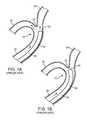
- FIGS. 1A-Billustrate a method of accessing a bifurcated vasculature 10 using a conventional catheter 30 , without guidewire assistance.
- the bifurcated vasculature 10includes a main blood vessel 20 , a first blood vessel branch 22 , a second blood vessel branch 26 , and a bifurcated angle 24 between the first 22 and second 26 branches.
- the catheter 30 distal portion 32is advanced through the main blood vessel 20 and maneuvered to access a target site within the first blood vessel branch 22 .
- the catheter 30advances along a path of least resistance by sliding through the main blood vessel 20 , and favoring access to the second blood vessel branch 26 ( FIG. 1A ).
- a distal tip 34 of the catheter 30may still catch and bump the bifurcated angle 24 ( FIG. 1B ), which can damage the blood vessel, particularly, a relatively fragile vessel, if in the brain, increasing risk of an undesirable rupture or piercing of the blood vessel walls.
- FIGS. 2A-Cillustrate a method of accessing the bifurcated vasculature 10 , in which a guidewire 40 is used to facilitate navigation of the catheter 30 .
- the catheter distal tip 34may still catch and cause trauma to the bifurcated angle 24 ( FIG. 2B ); since the guidewire 40 is not disposed in a concentric configuration within (i.e., is not axially aligned with) the catheter 30 .
- the guidewire 40off-center from the catheter 30 , which may force a withdrawal of the catheter 30 , with further attempts to advance the catheter distal end tip 34 into the desired first blood vessel branch 22 increasing the risk of trauma to the blood vessel.
- vascular access systemfor navigating a catheter to a target site in a vasculature in a manner wherein the catheter tends to stay centered within the lumen of a vessel being navigated, thereby minimizing undesired contact with vessel walls and other navigational difficulties caused by misalignment of the catheter.
- a vascular access systemincludes a catheter having an inner lumen in communication with an open distal end of the catheter; an elongate, flexible navigational member at least partially positioned in the catheter lumen, with a distal end portion of the navigational member extending out the open distal end of the catheter, the navigational member and catheter being movable relative to each other; a proximal stop secured to the navigational member at a first location; a distal stop secured to the navigational member at a second location distal of the first location; and a centering device slidably mounted on the navigational member between the proximal and distal stops so that the centering device may move freely within the catheter lumen relative to the navigational member between the proximal and distal stops, wherein the centering device substantially aligns a longitudinal axis of the catheter with a longitudinal axis of the navigational member proximate the centering device.
- the centering deviceis positioned within the catheter lumen.
- the open distal end of the catheterbeing tapered or otherwise shaped so as to allow travel of the distal stop, but prevent travel of the centering device, respectively, there through.
- the centering devicehas a proximal portion, distal portion and central lumen through which the navigational member extends, wherein the proximal portion has a cross-section larger than a cross-section of the distal portion.
- the respective proximal and distal portionshave arcuate, atraumatic shapes.
- the centering devicehas a proximal portion, middle portion, distal portion and central lumen through which the navigational member extends, wherein the middle portion has a cross-section that is larger than respective cross-sections of the proximal and distal portions.
- the respective proximal and distal portionshave arcuate, atraumatic shapes.
- the centering devicemay be made of a biocompatible polymer, such as silicone, and has an olive-like, football-like, prolate spheroid, ellipsoid, conical and/or elongate configuration.
- the proximal and distal stopsare made from a metal, metal alloy, polymer and/or metal-polymer composite, and are secured to the navigational member by an adhesive or thermal bonding.
- the navigational membermay be a conventional guidewire.
- FIGS. 1A-Bare cross-sectional views of a conventional (Prior Art) catheter distal end portion being introduced into a bifurcated vasculature;
- FIGS. 2A-Care cross-sectional views of a conventional (Prior Art) catheter and guidewire system being introduced into a bifurcated vasculature;
- FIGS. 3A-Care cross sectional views of vascular access systems according to embodiments of the disclosed inventions.
- FIGS. 4A-Care cross sectional views of centering devices according to embodiments of the disclosed inventions.
- FIGS. 5A-Care cross-sectional views of a method of accessing a vasculature system using the vascular access systems of FIGS. 3A-B ;
- FIGS. 6A-Care cross-sectional views of a method of accessing a bifurcation in a vasculature system using the vascular access system of FIG. 3A ;
- FIGS. 7A-Eare cross-sectional views depicting a method of accessing a bifurcation in a vasculature system using the vascular access system of FIG. 3B .
- FIG. 3Aillustrates a vascular access system 100 , constructed in accordance with one embodiment of the disclosed inventions.
- the vascular access system 100includes an outer elongate member 50 (i.e. catheter) having a proximal end portion (not shown), a distal end portion 52 , and a lumen 60 extending therebetween.
- the catheter 50further includes an open distal end 54 having a tapered configuration with an inner diameter less than the inner diameter of catheter lumen in the distal end portion 52 of the catheter.
- the catheter 50may include one or more, or a plurality of regions along its length having different configurations and/or characteristics, and may be formed of suitable materials, such as, polymeric materials, metals, alloys or the like, or combinations thereof.
- the distal portion 52 of the catheter 50may have an outer diameter less than the outer diameter of the proximal portion (not shown) to reduce the profile of the distal portion 52 and help facilitate navigation in tortuous portion of the vasculature.
- the distal portion 52may be more flexible than the proximal portion.
- the proximal portionmay be formed from material that is stiffer than the distal portion 52 , so that the proximal portion has sufficient pushability to advance through the patient's vascular system, while the distal portion 52 may be formed of a more flexible material so that the distal portion 52 may remain flexible and track more easily, for example, over a guidewire to access remote locations in tortuous regions of the vasculature.
- the proximal and/or distal portionsmay include a reinforcement layer, such a braided layer or coiled layer to enhance the pushability and kink resistance of the catheter 50 .
- the distal end tip 54may include a radiopaque material or marker to aid in visualization.
- the vascular access system 100further includes an inner elongate member 70 , which may be a conventional guidewire modified as described herein, slidably disposed in the catheter lumen 60 .
- the elongate member 70hereinafter referred to as a guidewire, is preferably made of a torqueable material; some examples can include metals, metal alloys, polymers, metal-polymer composites, and the like, or any other suitable material.
- the guidewire 70may include nickel-titanium alloy, stainless steel, a composite of nickel-titanium alloy and stainless steel.
- guidewire 70can be made of the same material along its length, or in some embodiments, can include portions or sections made of different materials.
- the material used to construct guidewire 70is chosen to impart varying flexibility and stiffness characteristics to different portions of guidewire 70 .
- the proximal regioncan be formed of stainless steel, and the distal region can be formed of a nickel-titanium alloy.
- any suitable material or combination of materialmay be used for the guidewire 70 , as desired.
- the guidewire 70may have shapeable or pre-shaped distal tip 74 , preferably including an atraumatic distal end, to aid in the advancement of the guidewire 70 .
- the distal tip 74may include a radiopaque material or marker to aid in visualization.
- the guidewire 70is provided respective proximal and distal stops, 82 84 , secured to a distal portion thereof.
- the proximal and distal stops 82 and 84may be made of metals, metal alloys, polymers, metal-polymer composites, and the like, or any other suitable materials, that are fixedly secured to the guidewire 70 by adhesive, thermal bonding or the like, or combinations thereof, or by any other suitable method.
- the stops 82 and 84may be radiopaque, in which case they also function as markers, and may have a spherical, conical, elongate or any other suitable configuration, so long as the stops 82 and 84 function to adequately retain a centering device 90 slidably mounted on the guidewire 70 between the stops 82 and 84 , as described below.
- the illustrated centering device 90 of FIGS. 3A, 4A -B, and 5 A- 6 Chas a “pitted olive” configuration, with a central lumen 98 passing there through.
- the centering device 90may have an alternate shape, such as bullet, conical, or other suitable configuration in which a diameter D 1 of a proximal portion 92 of the centering device 90 is greater that a D 2 of a distal portion 94 of the centering device 90 (best seen in FIG. 4A ).
- a suitable centering device 90includes non-traumatic proximal and distal portions, 92 and 94 , respectively, having substantially rounded shoulders-like configurations with gentle slopes there between or having further elongated configurations, as shown in FIGS.
- the centering device 90may be made of low durometer materials, such as polyurethane, pebax, silicone or the like, or combination thereof. Alternatively, the centering device 90 may be made of metals, metal alloys, or metal-polymer materials with suitable biocompatible properties. Additionally, the centering device 90 may include a radiopaque material, marker members or marker bands made of radiopacified polymers or other suitable radiopaque material to aid in visualization. The centering device 90 may include a lubricious coating to facilitate advancement and withdrawal of the device 90 within the catheter 50 .
- the centering device 90is slidably disposed over the guidewire 70 between the respective proximal and distal stops 82 and 84 , such that the stops 82 and 84 limit movement of the centering device 90 to the distance D 3 between the stops 82 and 84 , and allow for placement and/or withdrawal of the centering device 90 at the distal end tip 54 of catheter 50 , as further described below in conjunction with FIGS. 5A-B .
- the tapered open distal end 54 of the catheter 50also prevents and/or limits movement of the centering device 90 out of a distal end opening 56 of the catheter 50 , so that the distal end tip 54 snuggling held, at least, the proximal portion 92 of the centering device 90 ( FIG. 3A ).
- the centering device 90is configured to place the guidewire 70 in a concentric configuration relative to the catheter 50 distal end portion 52 ( FIG. 3C ).
- FIG. 3Billustrates an alternative embodiment of the vascular access system 100 ′ constructed in accordance with the disclosed inventions.
- the vascular access system 100 ′ of FIG. 3Bincludes a catheter 50 ′ having a proximal end portion (not shown), a distal end portion 52 , and a lumen 60 extending therebetween.
- the catheter 50 ′further includes an open distal end 54 ′ having an inner diameter that is substantially the same as the inner diameter of the distal end portion 52 of the catheter, i.e. a non-tapered distal end 54 ′.
- the vascular access system 100 ′further includes a centering device 90 ′ slidably mounted on the guidewire 70 between the stops 82 and 84 .
- the centering device 90 ′ of FIGS. 3B, 4C, and 7A -Ehave an American football-like configuration, with a central lumen 98 passing there through. It should be appreciated that the centering device 90 ′ may have a prolate spheroid, ellipsoid, or other suitable configuration in which diameters D 4 and D 6 are substantially the same, and diameter D 5 is larger than D 4 or D 6 (best seen in FIG. 4C ).
- the centering device 90 ′is slidably disposed over the guidewire 70 between the respective proximal and distal stops 82 and 84 , such that the stops 82 and 84 limit movement of the centering device 90 ′ to the distance D 3 between the stops 82 and 84 , and allow for advancement and/or withdrawal of the centering device 90 ′ through a vasculature of a patient and/or lumen 60 of catheter 50 ′, as further described below in conjunction with FIGS. 7A-E .
- the centering device 90 ′When the centering device 90 ′ is disposed at the distal end tip 54 ′ of the catheter 50 ′, the centering device 90 ′ is configured to place the guidewire 70 in a concentric configuration relative to the catheter 50 ′ distal end portion 52 ( FIG. 3C ). It will be appreciated that the non-tapered open distal end 54 ′ of the catheter 50 ′ allows movement of the centering device 90 ′ out of the distal end opening 56 the catheter 50 ′ ( FIG. 5C ).
- FIGS. 5A-Billustrate an exemplary method of accessing a blood vessel 150 and navigating within a blood vessel lumen 155 using the vascular access system 100 , constructed in accordance with the disclosed inventions.
- FIG. 5Aillustrates the introduction of the guidewire 70 within the catheter 50 and advancement of the centering device 90 towards the distal end tip 54 and distal end opening 56 .
- the proximal stop 82engages the proximal end portion 92 pushing and moving the centering device 90 towards the distal end tip 54 of the catheter 50 , until the centering device 90 is engaged and snuggling held by the distal end tip 54 ( FIG. 3A ).
- FIG. 3Aillustrates the introduction of the guidewire 70 within the catheter 50 and advancement of the centering device 90 towards the distal end tip 54 and distal end opening 56 .
- 5Billustrates the withdrawal of the guidewire 70 from the catheter 50 and consequent withdrawal of the centering device 90 .
- the distal stop 84engages the distal end portion 94 pushing and moving the centering device 90 towards the proximal portion of the catheter 50 , until the centering device 90 is disengaged by the distal end tip 54 .
- the guidewire 70 including the centering device 90may be withdrawn from the catheter after a desired target site is reached by the distal end tip 54 of the catheter.
- the centering device 90 ′ of vascular access system 100 ′is advanced and/or withdrawn within the lumen 60 of the catheter 50 ′ using the guidewire 70 and stops 82 and 84 interface, similar to the above description of FIGS. 5A-B .
- the centering device 90 ′may be advanced out of the distal end opening 54 ′ the catheter 50 ′, as shown in FIG. 5C , since the distal end tip 54 ′ of catheter 50 ′ is non-tapered and therefore allows advancement of the centering device 90 ′ out of the open distal end 54 ′ of the catheter 50 ′.
- FIGS. 6A-Cillustrate an exemplary method of accessing the bifurcated blood vessel 10 using the vascular access system 100 , constructed in accordance with embodiments of the disclosed inventions.
- the vascular access system 100having the guidewire 70 loaded therein and having the centering device 90 disposed within the distal end tip 54 of the catheter 50 , is inserted into main blood vessel 20 ( FIG. 6A ).
- the access system 100is advanced until the distal tip 74 of the guidewire 70 is inserted into the desired first blood vessel branch 22 , such that the distal portion 52 of the catheter 50 is disposed toward a target site within the first blood vessel branch 22 .
- the access system 100is then further advanced so that the distal portion 94 of the centering device 90 is positioned at an entrance portion 23 first blood vessel branch 22 , which allows for advancement of the system catheter 50 in a substantially smooth and non-traumatic fashion, while avoiding catching and bumping against the bifurcated angle 24 of the blood vessel ( FIGS. 6B-C ).
- the centering device 90allows the distal end tip 54 and distal portion 52 of the catheter 50 to be centered and concentric with respect to the blood vessel branch 22 , and further centers the guidewire 70 within the lumen 60 of the catheter 50 .
- the guidewire 70 including the centering device 90may be withdrawn ( FIG. 5B ), so that the lumen 60 of the catheter 50 is substantially free and available for a desired intravascular application (e.g. delivery of medical implants, or embolic materials) (not shown).
- a desired intravascular applicatione.g. delivery of medical implants, or embolic materials
- the catheter 50is withdrawn from the bifurcated blood vessel 10 and vasculature of a patient.
- the catheter 50 , the centering device 90 , and the guidewire 70are jointly advanced through the vasculature into the target site in a blood vessel, when using the vascular access system 100 as illustrated in FIGS. 6A-C .
- the catheter 50 ′ of the vascular access system 100 ′moves relative to the guidewire 70 and centering device 90 ′ during advancement into the target site in a blood vessel ( FIGS. 7A-E ), as described below.
- FIGS. 7A-Eillustrate an exemplary method of accessing the bifurcated blood vessel 10 using the vascular access system 100 ′, constructed in accordance with embodiments of the disclosed inventions.
- the guidewire 70 carrying the centering device 90 ′is inserted into the main blood vessel 20 , and is advanced into the desired first blood vessel branch 22 .
- the proximal stop 82engages the proximal end portion 92 ′ pushing and moving the centering device 90 ′ towards the entrance portion 23 of the first blood vessel branch 22 ( FIG.
- the catheter 50 ′is advanced over the guidewire 70 ( FIG. 7C ) so that the distal tip end 54 ′ reaches and “swallows” the proximal portion 92 ′ of the centering device 90 ′ ( FIG. 7D ). Having the centering device 90 ′ disposed within the entrance portion 23 of the desired first blood vessel branch 22 , allows for the guidewire 70 to be centered and concentric with respect to the blood vessel branch 22 .
- proximal portion 92 ′ of the centering device 90 ′“sticking out” the entrance portion 23 , allows the distal end tip 54 ′ of the catheter 50 ′ to advance over the centering device 90 ′ substantially centered and concentric with respect to the blood vessel branch 22 ; allowing the catheter 50 ′ to advance in a smooth and non-traumatic fashion, while avoiding catching and bumping against the bifurcated angle 24 of the blood vessel.
- the catheter 50 ′may be further advanced into the blood vessel branch 22 , swallowing the centering device 90 ′ and moving beyond the location of the centering device 90 ′ ( FIG. 7E ). Further, after the distal end tip 54 ′ of the catheter 50 ′ has reached the target site, the guidewire 70 including the centering device 90 ′ may be withdrawn, so that the lumen 60 of the catheter 50 ′ is substantially free and available for a desired intravascular application (e.g. delivery of medical implants, or embolic materials) (not shown). After completion of the desired intravascular application, the catheter 50 ′ is withdrawn from the bifurcated blood vessel 10 and vasculature of a patient.
- a desired intravascular applicatione.g. delivery of medical implants, or embolic materials
- FIGS. 5A-C , 6 A-C and 7 A-E using the vascular access systems 100 and 100 ′may be contemplated to deliver tubular prosthesis, implants, stents, fluid diverters, agents or the like, in vascular and non-vascular applications.
Landscapes
- Health & Medical Sciences (AREA)
- Life Sciences & Earth Sciences (AREA)
- Biophysics (AREA)
- Pulmonology (AREA)
- Engineering & Computer Science (AREA)
- Anesthesiology (AREA)
- Biomedical Technology (AREA)
- Heart & Thoracic Surgery (AREA)
- Hematology (AREA)
- Animal Behavior & Ethology (AREA)
- General Health & Medical Sciences (AREA)
- Public Health (AREA)
- Veterinary Medicine (AREA)
- Surgical Instruments (AREA)
- Media Introduction/Drainage Providing Device (AREA)
Abstract
Description
Claims (12)
Priority Applications (1)
| Application Number | Priority Date | Filing Date | Title |
|---|---|---|---|
| US14/798,901US10315007B2 (en) | 2014-07-15 | 2015-07-14 | Vascular access system and method of use |
Applications Claiming Priority (2)
| Application Number | Priority Date | Filing Date | Title |
|---|---|---|---|
| US201462024707P | 2014-07-15 | 2014-07-15 | |
| US14/798,901US10315007B2 (en) | 2014-07-15 | 2015-07-14 | Vascular access system and method of use |
Publications (2)
| Publication Number | Publication Date |
|---|---|
| US20160015935A1 US20160015935A1 (en) | 2016-01-21 |
| US10315007B2true US10315007B2 (en) | 2019-06-11 |
Family
ID=53761546
Family Applications (1)
| Application Number | Title | Priority Date | Filing Date |
|---|---|---|---|
| US14/798,901Active2037-06-21US10315007B2 (en) | 2014-07-15 | 2015-07-14 | Vascular access system and method of use |
Country Status (2)
| Country | Link |
|---|---|
| US (1) | US10315007B2 (en) |
| WO (1) | WO2016010996A1 (en) |
Cited By (1)
| Publication number | Priority date | Publication date | Assignee | Title |
|---|---|---|---|---|
| US20220401115A1 (en)* | 2020-01-17 | 2022-12-22 | Wright Medical Technology, Inc. | Guidance tools, systems, and methods |
Families Citing this family (65)
| Publication number | Priority date | Publication date | Assignee | Title |
|---|---|---|---|---|
| DE10233085B4 (en) | 2002-07-19 | 2014-02-20 | Dendron Gmbh | Stent with guide wire |
| EP1986568B1 (en) | 2006-02-03 | 2017-04-05 | Covidien LP | Methods and devices for restoring blood flow within blocked vasculature |
| US10076346B2 (en) | 2007-04-17 | 2018-09-18 | Covidien Lp | Complex wire formed devices |
| US11202646B2 (en) | 2007-04-17 | 2021-12-21 | Covidien Lp | Articulating retrieval devices |
| US10123803B2 (en) | 2007-10-17 | 2018-11-13 | Covidien Lp | Methods of managing neurovascular obstructions |
| US11337714B2 (en) | 2007-10-17 | 2022-05-24 | Covidien Lp | Restoring blood flow and clot removal during acute ischemic stroke |
| US8545526B2 (en) | 2007-12-26 | 2013-10-01 | Lazarus Effect, Inc. | Retrieval systems and methods for use thereof |
| JP5457373B2 (en) | 2008-02-22 | 2014-04-02 | コヴィディエン リミテッド パートナーシップ | Device for blood flow recovery |
| WO2012009675A2 (en) | 2010-07-15 | 2012-01-19 | Lazarus Effect, Inc. | Retrieval systems and methods for use thereof |
| ES2683178T3 (en) | 2011-05-23 | 2018-09-25 | Covidien Lp | Extraction systems |
| EP4101399B1 (en) | 2011-08-05 | 2025-04-09 | Route 92 Medical, Inc. | System for treatment of acute ischemic stroke |
| US10779855B2 (en) | 2011-08-05 | 2020-09-22 | Route 92 Medical, Inc. | Methods and systems for treatment of acute ischemic stroke |
| US9072624B2 (en) | 2012-02-23 | 2015-07-07 | Covidien Lp | Luminal stenting |
| US9314248B2 (en) | 2012-11-06 | 2016-04-19 | Covidien Lp | Multi-pivot thrombectomy device |
| US10076399B2 (en) | 2013-09-13 | 2018-09-18 | Covidien Lp | Endovascular device engagement |
| US9592139B2 (en) | 2013-10-04 | 2017-03-14 | Covidien Lp | Stents twisted prior to deployment and untwisted during deployment |
| WO2015073704A1 (en) | 2013-11-13 | 2015-05-21 | Covidien Lp | Galvanically assisted attachment of medical devices to thrombus |
| US9265512B2 (en) | 2013-12-23 | 2016-02-23 | Silk Road Medical, Inc. | Transcarotid neurovascular catheter |
| US10456552B2 (en)* | 2014-07-28 | 2019-10-29 | Mayank Goyal | System and methods for intracranial vessel access |
| US11065019B1 (en) | 2015-02-04 | 2021-07-20 | Route 92 Medical, Inc. | Aspiration catheter systems and methods of use |
| US10426497B2 (en) | 2015-07-24 | 2019-10-01 | Route 92 Medical, Inc. | Anchoring delivery system and methods |
| CN119949953A (en) | 2015-02-04 | 2025-05-09 | 92号医疗公司 | Intravascular access system, dilator and system including dilator |
| EP3256200A1 (en) | 2015-02-11 | 2017-12-20 | Covidien LP | Expandable tip medical devices and methods |
| EP3302311B1 (en) | 2015-06-03 | 2019-11-20 | Covidien LP | Flexible intravascular treatment devices |
| CN108135619B (en) | 2015-09-25 | 2021-08-13 | 柯惠有限合伙公司 | Medical Device Delivery System |
| WO2017053798A1 (en)* | 2015-09-25 | 2017-03-30 | Mark Taber | Guide wires, catheters, and guide wire catheter systems and methods |
| US10537344B2 (en) | 2015-10-23 | 2020-01-21 | Covidien Lp | Rotatable connection between an intervention member and a manipulation member of an endovascular device |
| US10874410B2 (en) | 2015-11-04 | 2020-12-29 | Covidien Lp | Clot removal by adhesion |
| AU2015350919B8 (en)* | 2015-11-27 | 2018-02-01 | Komatsu Ltd. | Mining machine control system, mining machine, mining machine management system, and mining machine management method. |
| US10265089B2 (en) | 2016-02-12 | 2019-04-23 | Covidien Lp | Vascular device visibility |
| US10052185B2 (en) | 2016-02-12 | 2018-08-21 | Covidien Lp | Vascular device marker attachment |
| CN110392591B (en) | 2017-01-10 | 2022-06-03 | 92号医疗公司 | Aspiration catheter system and method of use |
| US10864350B2 (en) | 2017-01-20 | 2020-12-15 | Route 92 Medical, Inc. | Single operator intracranial medical device delivery systems and methods of use |
| US11129630B2 (en) | 2017-05-12 | 2021-09-28 | Covidien Lp | Retrieval of material from vessel lumens |
| US11298145B2 (en) | 2017-05-12 | 2022-04-12 | Covidien Lp | Retrieval of material from vessel lumens |
| US10722257B2 (en) | 2017-05-12 | 2020-07-28 | Covidien Lp | Retrieval of material from vessel lumens |
| US10709464B2 (en) | 2017-05-12 | 2020-07-14 | Covidien Lp | Retrieval of material from vessel lumens |
| US11191555B2 (en) | 2017-05-12 | 2021-12-07 | Covidien Lp | Retrieval of material from vessel lumens |
| WO2018226809A1 (en) | 2017-06-07 | 2018-12-13 | Covidien Lp | Systems and methods for detecting strokes |
| WO2018232044A1 (en) | 2017-06-12 | 2018-12-20 | Covidien Lp | Tools for sheathing treatment devices and associated systems and methods |
| US10478322B2 (en) | 2017-06-19 | 2019-11-19 | Covidien Lp | Retractor device for transforming a retrieval device from a deployed position to a delivery position |
| US10575864B2 (en) | 2017-06-22 | 2020-03-03 | Covidien Lp | Securing element for resheathing an intravascular device and associated systems and methods |
| US10342686B2 (en) | 2017-08-10 | 2019-07-09 | Covidien Lp | Thin film mesh hybrid for treating vascular defects |
| US10835398B2 (en) | 2017-11-03 | 2020-11-17 | Covidien Lp | Meshes and devices for treating vascular defects |
| US12318126B2 (en) | 2021-06-25 | 2025-06-03 | Covidien Lp | Current generator for a medical treatment system |
| US11058444B2 (en) | 2017-12-11 | 2021-07-13 | Covidien Lp | Electrically enhanced retrieval of material from vessel lumens |
| US10874411B2 (en) | 2018-06-22 | 2020-12-29 | Covidien Lp | Electrically enhanced retrieval of material from vessel lumens |
| US11974752B2 (en) | 2019-12-12 | 2024-05-07 | Covidien Lp | Electrically enhanced retrieval of material from vessel lumens |
| US10709463B2 (en) | 2017-12-11 | 2020-07-14 | Covidien Lp | Electrically enhanced retrieval of material from vessel lumens |
| US12004803B2 (en) | 2021-03-15 | 2024-06-11 | Covidien Lp | Thrombectomy treatment system |
| JP7616642B2 (en) | 2018-05-17 | 2025-01-17 | ルート92メディカル・インコーポレイテッド | Suction catheter system and method of use |
| US11612430B2 (en) | 2019-03-19 | 2023-03-28 | Covidien Lp | Electrically enhanced retrieval of material from vessel lumens |
| US11523838B2 (en) | 2019-06-12 | 2022-12-13 | Covidien Lp | Retrieval of material from corporeal lumens |
| US11191558B2 (en) | 2019-06-12 | 2021-12-07 | Covidien Lp | Retrieval of material from corporeal lumens |
| CR20220218A (en) | 2019-11-14 | 2022-08-22 | Edwards Lifesciences Corp | Transcatheter medical implant delivery |
| US11395668B2 (en) | 2019-12-12 | 2022-07-26 | Covidien Lp | Electrically enhanced retrieval of material from vessel lumens |
| US12364397B2 (en) | 2020-02-17 | 2025-07-22 | Covidien Lp | Systems and methods for detecting strokes |
| US12263020B2 (en) | 2020-02-17 | 2025-04-01 | Covidien Lp | Systems and methods for detecting strokes |
| CN111760170B (en)* | 2020-07-23 | 2025-01-10 | 赛诺医疗科学技术股份有限公司 | Guide wire withdrawing device |
| EP4203770A1 (en) | 2020-08-28 | 2023-07-05 | Covidien LP | Detection of patient conditions using signals sensed on or near the head |
| WO2022076893A1 (en) | 2020-10-09 | 2022-04-14 | Route 92 Medical, Inc. | Aspiration catheter systems and methods of use |
| US11963713B2 (en) | 2021-06-02 | 2024-04-23 | Covidien Lp | Medical treatment system |
| US20230001156A1 (en)* | 2021-07-02 | 2023-01-05 | Becton, Dickinson And Company | Vascular Access Device with Non-Contact Guidewire Advancement |
| US11944374B2 (en) | 2021-08-30 | 2024-04-02 | Covidien Lp | Electrical signals for retrieval of material from vessel lumens |
| US12076020B2 (en) | 2021-11-18 | 2024-09-03 | Covidien Lp | Retrieval of material from corporeal lumens |
Citations (27)
| Publication number | Priority date | Publication date | Assignee | Title |
|---|---|---|---|---|
| US4728319A (en)* | 1986-03-20 | 1988-03-01 | Helmut Masch | Intravascular catheter |
| US4926858A (en)* | 1984-05-30 | 1990-05-22 | Devices For Vascular Intervention, Inc. | Atherectomy device for severe occlusions |
| US5938582A (en) | 1997-09-26 | 1999-08-17 | Medtronic, Inc. | Radiation delivery centering catheter |
| US5989210A (en)* | 1998-02-06 | 1999-11-23 | Possis Medical, Inc. | Rheolytic thrombectomy catheter and method of using same |
| US6068611A (en) | 1996-07-05 | 2000-05-30 | Delft Instruments Intellectual Property B.V. | Catheter having centering means |
| US6290720B1 (en)* | 1998-11-16 | 2001-09-18 | Endotex Interventional Systems, Inc. | Stretchable anti-buckling coiled-sheet stent |
| US6371971B1 (en)* | 1999-11-15 | 2002-04-16 | Scimed Life Systems, Inc. | Guidewire filter and methods of use |
| US6454775B1 (en)* | 1999-12-06 | 2002-09-24 | Bacchus Vascular Inc. | Systems and methods for clot disruption and retrieval |
| US6579302B2 (en) | 2001-03-06 | 2003-06-17 | Cordis Corporation | Total occlusion guidewire device |
| US6802835B2 (en) | 1999-09-24 | 2004-10-12 | Omnisonics Medical Technologies, Inc. | Apparatus and method for using a steerable catheter device |
| US20040230219A1 (en) | 2003-05-12 | 2004-11-18 | Roucher Leo R. | Anchoring, supporting and centering catheter system for treating chronic total occlusions |
| US6887256B2 (en)* | 1997-11-07 | 2005-05-03 | Salviac Limited | Embolic protection system |
| US6945989B1 (en)* | 2000-09-18 | 2005-09-20 | Endotex Interventional Systems, Inc. | Apparatus for delivering endoluminal prostheses and methods of making and using them |
| US7101380B2 (en)* | 2001-06-28 | 2006-09-05 | Lithotech Medical Ltd. | Surgical device for retrieval of foreign objects from a body |
| WO2007022592A1 (en) | 2005-08-25 | 2007-03-01 | Baker Medical Research Institute | Devices and methods for perfusing an organ |
| WO2007133736A2 (en) | 2006-05-12 | 2007-11-22 | Velosum, Inc. | Systems and methods for digital pen stroke correction |
| US20090082800A1 (en)* | 2007-09-21 | 2009-03-26 | Insera Therapeutics Llc | Distal Embolic Protection Devices With A Variable Thickness Microguidewire And Methods For Their Use |
| US7547304B2 (en) | 2002-12-19 | 2009-06-16 | Gore Enterprise Holdings, Inc. | Guidewire-centering catheter tip |
| US20110125181A1 (en)* | 2008-07-22 | 2011-05-26 | Eamon Brady | Clot capture systems and associated methods |
| US7951243B2 (en)* | 2008-01-25 | 2011-05-31 | Clear Catheter Systems, Inc. | Methods and devices to clear obstructions from medical tubes |
| WO2011133736A2 (en) | 2010-04-21 | 2011-10-27 | The Regents Of The University Of Michigan | Fluoroscopy-independent, endovascular aortic occlusion system |
| US20130144326A1 (en)* | 2008-07-22 | 2013-06-06 | Eamon Brady | Clot capture systems and associated methods |
| US8491614B2 (en) | 2010-06-22 | 2013-07-23 | Lemaitre Vascular, Inc. | Over-the-wire valvulotomes |
| US8597454B2 (en) | 2008-09-23 | 2013-12-03 | Cook Medical Technologies Llc | Catheter tip assembly |
| WO2014066412A1 (en) | 2012-10-22 | 2014-05-01 | Roxwood Medical, Inc. | Method and apparatus for centering a microcatheter within a vasculature |
| US20140180387A1 (en)* | 2012-12-21 | 2014-06-26 | Stryker Nv Operations Limited | Stent delivery system |
| US8900265B1 (en)* | 2014-01-03 | 2014-12-02 | Legacy Ventures LLC | Clot retrieval system |
- 2015
- 2015-07-14USUS14/798,901patent/US10315007B2/enactiveActive
- 2015-07-14WOPCT/US2015/040332patent/WO2016010996A1/enactiveApplication Filing
Patent Citations (29)
| Publication number | Priority date | Publication date | Assignee | Title |
|---|---|---|---|---|
| US4926858A (en)* | 1984-05-30 | 1990-05-22 | Devices For Vascular Intervention, Inc. | Atherectomy device for severe occlusions |
| US4728319A (en)* | 1986-03-20 | 1988-03-01 | Helmut Masch | Intravascular catheter |
| US6068611A (en) | 1996-07-05 | 2000-05-30 | Delft Instruments Intellectual Property B.V. | Catheter having centering means |
| US5938582A (en) | 1997-09-26 | 1999-08-17 | Medtronic, Inc. | Radiation delivery centering catheter |
| US6887256B2 (en)* | 1997-11-07 | 2005-05-03 | Salviac Limited | Embolic protection system |
| US5989210A (en)* | 1998-02-06 | 1999-11-23 | Possis Medical, Inc. | Rheolytic thrombectomy catheter and method of using same |
| US6290720B1 (en)* | 1998-11-16 | 2001-09-18 | Endotex Interventional Systems, Inc. | Stretchable anti-buckling coiled-sheet stent |
| US6802835B2 (en) | 1999-09-24 | 2004-10-12 | Omnisonics Medical Technologies, Inc. | Apparatus and method for using a steerable catheter device |
| US6371971B1 (en)* | 1999-11-15 | 2002-04-16 | Scimed Life Systems, Inc. | Guidewire filter and methods of use |
| US6454775B1 (en)* | 1999-12-06 | 2002-09-24 | Bacchus Vascular Inc. | Systems and methods for clot disruption and retrieval |
| US6945989B1 (en)* | 2000-09-18 | 2005-09-20 | Endotex Interventional Systems, Inc. | Apparatus for delivering endoluminal prostheses and methods of making and using them |
| US6579302B2 (en) | 2001-03-06 | 2003-06-17 | Cordis Corporation | Total occlusion guidewire device |
| US7101380B2 (en)* | 2001-06-28 | 2006-09-05 | Lithotech Medical Ltd. | Surgical device for retrieval of foreign objects from a body |
| US7547304B2 (en) | 2002-12-19 | 2009-06-16 | Gore Enterprise Holdings, Inc. | Guidewire-centering catheter tip |
| US20090247988A1 (en) | 2002-12-19 | 2009-10-01 | Eric G Johnson | Guidewire-Centering Catheter Tip |
| US20040230219A1 (en) | 2003-05-12 | 2004-11-18 | Roucher Leo R. | Anchoring, supporting and centering catheter system for treating chronic total occlusions |
| WO2007022592A1 (en) | 2005-08-25 | 2007-03-01 | Baker Medical Research Institute | Devices and methods for perfusing an organ |
| WO2007133736A2 (en) | 2006-05-12 | 2007-11-22 | Velosum, Inc. | Systems and methods for digital pen stroke correction |
| US20090082800A1 (en)* | 2007-09-21 | 2009-03-26 | Insera Therapeutics Llc | Distal Embolic Protection Devices With A Variable Thickness Microguidewire And Methods For Their Use |
| US9034007B2 (en)* | 2007-09-21 | 2015-05-19 | Insera Therapeutics, Inc. | Distal embolic protection devices with a variable thickness microguidewire and methods for their use |
| US7951243B2 (en)* | 2008-01-25 | 2011-05-31 | Clear Catheter Systems, Inc. | Methods and devices to clear obstructions from medical tubes |
| US20110125181A1 (en)* | 2008-07-22 | 2011-05-26 | Eamon Brady | Clot capture systems and associated methods |
| US20130144326A1 (en)* | 2008-07-22 | 2013-06-06 | Eamon Brady | Clot capture systems and associated methods |
| US8597454B2 (en) | 2008-09-23 | 2013-12-03 | Cook Medical Technologies Llc | Catheter tip assembly |
| WO2011133736A2 (en) | 2010-04-21 | 2011-10-27 | The Regents Of The University Of Michigan | Fluoroscopy-independent, endovascular aortic occlusion system |
| US8491614B2 (en) | 2010-06-22 | 2013-07-23 | Lemaitre Vascular, Inc. | Over-the-wire valvulotomes |
| WO2014066412A1 (en) | 2012-10-22 | 2014-05-01 | Roxwood Medical, Inc. | Method and apparatus for centering a microcatheter within a vasculature |
| US20140180387A1 (en)* | 2012-12-21 | 2014-06-26 | Stryker Nv Operations Limited | Stent delivery system |
| US8900265B1 (en)* | 2014-01-03 | 2014-12-02 | Legacy Ventures LLC | Clot retrieval system |
Non-Patent Citations (1)
| Title |
|---|
| International Search Report and Written Opinion for International Application No. PCT/US2015/040332. Applicant Stryker Corporation, dated Nov. 2, 2015 (11 pages). |
Cited By (2)
| Publication number | Priority date | Publication date | Assignee | Title |
|---|---|---|---|---|
| US20220401115A1 (en)* | 2020-01-17 | 2022-12-22 | Wright Medical Technology, Inc. | Guidance tools, systems, and methods |
| US12396739B2 (en)* | 2020-01-17 | 2025-08-26 | Wright Medical Technology, Inc. | Guidance tools, systems, and methods |
Also Published As
| Publication number | Publication date |
|---|---|
| WO2016010996A1 (en) | 2016-01-21 |
| US20160015935A1 (en) | 2016-01-21 |
Similar Documents
| Publication | Publication Date | Title |
|---|---|---|
| US10315007B2 (en) | Vascular access system and method of use | |
| US12102341B2 (en) | Suction catheter systems for applying effective aspiration in remote vessels, especially cerebral arteries | |
| US11027093B2 (en) | Slide guide catheter and methods for use thereof | |
| US10478535B2 (en) | Suction catheter systems for applying effective aspiration in remote vessels, especially cerebral arteries | |
| US10974028B2 (en) | Guidewire fixation | |
| US8313493B2 (en) | Hydraulic guidewire advancement system | |
| EP3332830B1 (en) | Guide extension catheter | |
| US9144661B2 (en) | Reinforced elongate medical device and method of manufacture | |
| US8535294B2 (en) | Carotid sheath with flexible distal section | |
| EP3132823B1 (en) | Catheter including leak resistant proximal shaft | |
| US20080269641A1 (en) | Method of using a guidewire with stiffened distal section | |
| US20100168619A1 (en) | Combination wire guide and method of use thereof | |
| US20140323965A1 (en) | Medical device system and method for pushability | |
| EP3629949B1 (en) | Suction catheter systems for applying effective aspiration in remote vessels, especially cerebral arteries | |
| US8777873B2 (en) | Wire guide having a rib for coil attachment | |
| US8613713B2 (en) | Wire guide having variable flexibility and method of use thereof | |
| HK1237688B (en) | Guidewire fixation |
Legal Events
| Date | Code | Title | Description |
|---|---|---|---|
| AS | Assignment | Owner name:STRYKER NV OPERATIONS LIMITED, IRELAND Free format text:ASSIGNMENT OF ASSIGNORS INTEREST;ASSIGNORS:CHAN, JASON;CHAN, HUEY;SIGNING DATES FROM 20140715 TO 20140716;REEL/FRAME:037937/0138 Owner name:STRYKER CORPORATION, MICHIGAN Free format text:ASSIGNMENT OF ASSIGNORS INTEREST;ASSIGNORS:CHAN, JASON;CHAN, HUEY;SIGNING DATES FROM 20140715 TO 20140716;REEL/FRAME:037937/0138 | |
| AS | Assignment | Owner name:STRYKER MEDTECH LIMITED, MALTA Free format text:NUNC PRO TUNC ASSIGNMENT;ASSIGNOR:STRYKER NV OPERATIONS LIMITED;REEL/FRAME:038061/0281 Effective date:20151013 | |
| AS | Assignment | Owner name:STRYKER EUROPEAN HOLDINGS I, LLC, MICHIGAN Free format text:NUNC PRO TUNC ASSIGNMENT;ASSIGNOR:STRYKER MEDTECH LIMITED;REEL/FRAME:038236/0001 Effective date:20151013 | |
| STPP | Information on status: patent application and granting procedure in general | Free format text:NOTICE OF ALLOWANCE MAILED -- APPLICATION RECEIVED IN OFFICE OF PUBLICATIONS | |
| STCF | Information on status: patent grant | Free format text:PATENTED CASE | |
| CC | Certificate of correction | ||
| AS | Assignment | Owner name:STRYKER EUROPEAN HOLDINGS III, LLC, DELAWARE Free format text:NUNC PRO TUNC ASSIGNMENT;ASSIGNOR:STRYKER EUROPEAN HOLDINGS I, LLC;REEL/FRAME:056969/0771 Effective date:20210219 Owner name:STRYKER EUROPEAN OPERATIONS HOLDINGS LLC, MICHIGAN Free format text:CHANGE OF NAME;ASSIGNOR:STRYKER EUROPEAN HOLDINGS III, LLC;REEL/FRAME:056969/0893 Effective date:20190226 | |
| MAFP | Maintenance fee payment | Free format text:PAYMENT OF MAINTENANCE FEE, 4TH YEAR, LARGE ENTITY (ORIGINAL EVENT CODE: M1551); ENTITY STATUS OF PATENT OWNER: LARGE ENTITY Year of fee payment:4 | |
| AS | Assignment | Owner name:STRYKER CORPORATION, MICHIGAN Free format text:CHANGE OF ADDRESS;ASSIGNOR:STRYKER CORPORATION;REEL/FRAME:069737/0184 Effective date:20241217 Owner name:STRYKER EUROPEAN OPERATIONS HOLDINGS LLC, MICHIGAN Free format text:CHANGE OF ADDRESS;ASSIGNOR:STRYKER EUROPEAN OPERATIONS HOLDINGS LLC;REEL/FRAME:069730/0754 Effective date:20241217 |