US10314624B2 - Instruments and methods for manipulating vertebra - Google Patents
Instruments and methods for manipulating vertebraDownload PDFInfo
- Publication number
- US10314624B2 US10314624B2US15/434,899US201715434899AUS10314624B2US 10314624 B2US10314624 B2US 10314624B2US 201715434899 AUS201715434899 AUS 201715434899AUS 10314624 B2US10314624 B2US 10314624B2
- Authority
- US
- United States
- Prior art keywords
- vertebra
- instrument
- bone
- bone anchor
- connector
- Prior art date
- Legal status (The legal status is an assumption and is not a legal conclusion. Google has not performed a legal analysis and makes no representation as to the accuracy of the status listed.)
- Expired - Lifetime
Links
- 238000000034methodMethods0.000titleclaimsabstractdescription58
- 210000000988bone and boneAnatomy0.000claimsabstractdescription196
- 230000007246mechanismEffects0.000claimsdescription17
- 230000008878couplingEffects0.000claimsdescription7
- 238000010168coupling processMethods0.000claimsdescription7
- 238000005859coupling reactionMethods0.000claimsdescription7
- 238000012937correctionMethods0.000claimsdescription4
- 230000000694effectsEffects0.000claimsdescription4
- 230000006835compressionEffects0.000description5
- 238000007906compressionMethods0.000description5
- 230000003247decreasing effectEffects0.000description4
- 230000000295complement effectEffects0.000description3
- 239000007943implantSubstances0.000description3
- 238000001356surgical procedureMethods0.000description2
- 206010058907Spinal deformityDiseases0.000description1
- RTAQQCXQSZGOHL-UHFFFAOYSA-NTitaniumChemical compound[Ti]RTAQQCXQSZGOHL-UHFFFAOYSA-N0.000description1
- 238000013459approachMethods0.000description1
- 239000000560biocompatible materialSubstances0.000description1
- 239000000919ceramicSubstances0.000description1
- 239000002131composite materialSubstances0.000description1
- -1for exampleSubstances0.000description1
- 238000002513implantationMethods0.000description1
- 230000014759maintenance of locationEffects0.000description1
- 238000004519manufacturing processMethods0.000description1
- 229910052751metalInorganic materials0.000description1
- 239000002184metalSubstances0.000description1
- 150000002739metalsChemical class0.000description1
- 238000012986modificationMethods0.000description1
- 230000004048modificationEffects0.000description1
- 229920000642polymerPolymers0.000description1
- 230000000717retained effectEffects0.000description1
- 238000000926separation methodMethods0.000description1
- 229910001220stainless steelInorganic materials0.000description1
- 239000010935stainless steelSubstances0.000description1
- 210000000115thoracic cavityAnatomy0.000description1
- 239000010936titaniumSubstances0.000description1
- 229910052719titaniumInorganic materials0.000description1
- 238000013519translationMethods0.000description1
Images


Classifications
- A—HUMAN NECESSITIES
- A61—MEDICAL OR VETERINARY SCIENCE; HYGIENE
- A61B—DIAGNOSIS; SURGERY; IDENTIFICATION
- A61B17/00—Surgical instruments, devices or methods
- A61B17/56—Surgical instruments or methods for treatment of bones or joints; Devices specially adapted therefor
- A61B17/58—Surgical instruments or methods for treatment of bones or joints; Devices specially adapted therefor for osteosynthesis, e.g. bone plates, screws or setting implements
- A61B17/68—Internal fixation devices, including fasteners and spinal fixators, even if a part thereof projects from the skin
- A61B17/70—Spinal positioners or stabilisers, e.g. stabilisers comprising fluid filler in an implant
- A61B17/7074—Tools specially adapted for spinal fixation operations other than for bone removal or filler handling
- A61B17/7076—Tools specially adapted for spinal fixation operations other than for bone removal or filler handling for driving, positioning or assembling spinal clamps or bone anchors specially adapted for spinal fixation
- A61B17/7077—Tools specially adapted for spinal fixation operations other than for bone removal or filler handling for driving, positioning or assembling spinal clamps or bone anchors specially adapted for spinal fixation for moving bone anchors attached to vertebrae, thereby displacing the vertebrae
- A61B17/708—Tools specially adapted for spinal fixation operations other than for bone removal or filler handling for driving, positioning or assembling spinal clamps or bone anchors specially adapted for spinal fixation for moving bone anchors attached to vertebrae, thereby displacing the vertebrae with tubular extensions coaxially mounted on the bone anchors
- A—HUMAN NECESSITIES
- A61—MEDICAL OR VETERINARY SCIENCE; HYGIENE
- A61B—DIAGNOSIS; SURGERY; IDENTIFICATION
- A61B17/00—Surgical instruments, devices or methods
- A61B17/56—Surgical instruments or methods for treatment of bones or joints; Devices specially adapted therefor
- A61B17/58—Surgical instruments or methods for treatment of bones or joints; Devices specially adapted therefor for osteosynthesis, e.g. bone plates, screws or setting implements
- A61B17/88—Osteosynthesis instruments; Methods or means for implanting or extracting internal or external fixation devices
- A61B17/8866—Osteosynthesis instruments; Methods or means for implanting or extracting internal or external fixation devices for gripping or pushing bones, e.g. approximators
- A—HUMAN NECESSITIES
- A61—MEDICAL OR VETERINARY SCIENCE; HYGIENE
- A61B—DIAGNOSIS; SURGERY; IDENTIFICATION
- A61B17/00—Surgical instruments, devices or methods
- A61B17/56—Surgical instruments or methods for treatment of bones or joints; Devices specially adapted therefor
- A61B17/58—Surgical instruments or methods for treatment of bones or joints; Devices specially adapted therefor for osteosynthesis, e.g. bone plates, screws or setting implements
- A61B17/68—Internal fixation devices, including fasteners and spinal fixators, even if a part thereof projects from the skin
- A61B17/70—Spinal positioners or stabilisers, e.g. stabilisers comprising fluid filler in an implant
- A61B17/7001—Screws or hooks combined with longitudinal elements which do not contact vertebrae
- A61B17/7032—Screws or hooks with U-shaped head or back through which longitudinal rods pass
- A—HUMAN NECESSITIES
- A61—MEDICAL OR VETERINARY SCIENCE; HYGIENE
- A61B—DIAGNOSIS; SURGERY; IDENTIFICATION
- A61B17/00—Surgical instruments, devices or methods
- A61B17/56—Surgical instruments or methods for treatment of bones or joints; Devices specially adapted therefor
- A61B17/58—Surgical instruments or methods for treatment of bones or joints; Devices specially adapted therefor for osteosynthesis, e.g. bone plates, screws or setting implements
- A61B17/68—Internal fixation devices, including fasteners and spinal fixators, even if a part thereof projects from the skin
- A61B17/70—Spinal positioners or stabilisers, e.g. stabilisers comprising fluid filler in an implant
- A61B17/7001—Screws or hooks combined with longitudinal elements which do not contact vertebrae
- A61B17/7035—Screws or hooks, wherein a rod-clamping part and a bone-anchoring part can pivot relative to each other
- A61B17/7038—Screws or hooks, wherein a rod-clamping part and a bone-anchoring part can pivot relative to each other to a different extent in different directions, e.g. within one plane only
- A—HUMAN NECESSITIES
- A61—MEDICAL OR VETERINARY SCIENCE; HYGIENE
- A61B—DIAGNOSIS; SURGERY; IDENTIFICATION
- A61B17/00—Surgical instruments, devices or methods
- A61B17/02—Surgical instruments, devices or methods for holding wounds open, e.g. retractors; Tractors
- A61B17/025—Joint distractors
- A61B2017/0256—Joint distractors for the spine
Definitions
- the curvature of the spinecan be corrected by the implantation of a construct of bone anchors (e.g., hooks or bone screws) and spinal fixation elements (e.g., rods or tethers).
- spinal fixation elementse.g., rods or tethers
- the angular relationship of one or more vertebrae relative to other vertebraemay also be corrected.
- Conventional surgical procedures for corrected the angular relationship of a vertebrainvolve rotating the spinal fixation element, for example, a spinal rod, connected to the vertebra by a bone anchor. In the case of constructs including a spinal rod, this procedure is typically referred to as rod derotation.
- Rod derotationcan place significant stress on the interface between the bone anchors connected to the rotated spinal rod and the vertebra in which each bone anchor is implanted. This stress can cause a failure of one or more of the bone anchors or vertebrae. Accordingly, there is a need for improved instruments and methods for manipulating, e.g., rotating a vertebra.
- the instruments and methods disclosed hereinare particularly suited to facilitate rotation of a vertebra relative to another vertebra to correct the angular relationship of the vertebrae.
- an instrument for manipulating a vertebramay comprise an inner shaft having a proximal end, a distal end and a lumen extending between the proximal end and the distal end, a pair of fingers disposed at the distal end of the inner shaft, and an outer sleeve disposed about the inner shaft.
- the inner shaftin the exemplary embodiment, may be movable relative to the outer sleeve between a first position in which the fingers are advanced beyond a distal end of the outer sleeve and a second position in which a substantial portion of the fingers are disposed within the sleeve.
- the fingerswhen in the first position, may be configured to capture a spinal rod receiving member of the bone anchor therebetween to permit rotation of the bone anchor and a vertebra in which the bone anchor is engaged by manipulation of the instrument.
- a system for manipulating one or more vertebramay comprise a first instrument having a distal end configured to engage a first bone anchor connected to a first vertebra, a second instrument having a distal end configured to engage a second bone anchor connected to a second vertebra, and a connector connecting the first instrument and the second instrument.
- the connectorin the exemplary embodiment, may include a first receiving element for receiving the first instrument and a second receiving element for receiving the second instrument.
- the first receiving elementmay be adjustable relative to the second receiving element.
- a method for manipulating a vertebramay comprise connecting a first bone anchor to a first vertebra, connecting a second bone anchor to a second bone anchor, positioning a spinal rod in a receiving member of the first bone anchor and in a receiving member of the second bone anchor, connecting a first instrument to the receiving member of the first bone anchor, and manipulating the first instrument to rotate first bone anchor and the first vertebra relative to the second vertebra.
- a method for manipulating a vertebramay comprise engaging a first bone anchor to a first vertebra, the receiving member of the first bone anchor being adjustable relative to a bone engaging shaft of the first bone anchor in a first direction and restricted from motion in a second direction, connecting a first instrument to the receiving member of the first bone anchor, and moving the first instrument in a direction approximately parallel to the second direction to manipulate first bone anchor and the first vertebra.
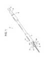
- FIG. 1is a perspective view of an exemplary embodiment of an instrument for manipulating a vertebra, illustrating the instrument in a first position for engaging a bone anchor;
- FIG. 2is a perspective view of the distal end of the instrument of FIG. 1 , illustrating the instrument in the first position for engaging a bone anchor;
- FIG. 3is a perspective view of the distal end of the instrument of FIG. 1 , illustrating the instrument in a second position;
- FIGS. 4A-4Care side elevational views in cross section of the instrument of FIG. 1 , illustrating the instrument in the first position;
- FIGS. 5A-5Care side elevational views in cross section of the instrument of FIG. 1 , illustrating the instrument in the second position;
- FIG. 6is a side elevational view in cross section of the distal end of the instrument of FIG. 1 taken along the line A-A of FIG. 4B ;
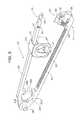
- FIG. 7is a perspective view of a connector for connecting two instruments, such as the instrument of FIG. 1 , illustrating the connector in an open position;
- FIG. 8is a partial cut away side view of the connector of FIG. 7 , illustrating the connector in an open position
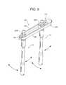
- FIG. 9is a perspective view of the connector of FIG. 7 , illustrating the connector in the closed position and connecting two instruments such as the instrument of FIG. 1 ;
- FIG. 10is a perspective view of the connector of FIG. 7 , illustrating the connector in the closed position and connecting two instruments such as the instrument of FIG. 1 ;
- FIG. 11is a perspective view of a first instrument connected to a first bone anchor engaged to a first vertebra and a second instrument connected to a second bone anchor engaged to a second vertebra, illustrating a method of adjusting the first vertebra relative to the second vertebra;
- FIGS. 12 and 13are perspective views of a connector connecting a first instrument to a second instrument, illustrating a method of adjusting a first and third vertebra relative to a second vertebra;
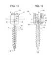
- FIG. 14is an exploded perspective view of the receiving member of a bone anchor in which the receiving member is adjustable relative to the bone engaging shaft of the bone anchor in a first direction and restricted from motion in a second direction;
- FIG. 15is a side elevation view of the bone anchor of FIG. 14 ;
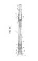
- FIG. 16is a side elevation view in cross section of the bone anchor of FIG. 14 , taken along the line B-B of FIG. 15 ;
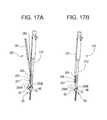
- FIGS. 17A and 17Bare perspective views of an exemplary embodiment of an instrument for manipulating a vertebra, illustrating the instrument in a first position for capturing a bone anchor ( FIG. 17A ) and a second position for retaining the bone anchor ( FIG. 17B ).
- an elementmeans one element or more than one element.
- FIGS. 1-6illustrate an exemplary embodiment of an instrument 10 for manipulating a vertebra.
- the exemplary instrument 10includes an inner shaft 12 , an implant engagement mechanism 14 disposed at the distal end 18 of the inner shaft 12 , and an outer sleeve 16 disposed about the inner shaft 12 .
- the exemplary instrument 10may be employed to engage a bone anchor 60 implanted in a vertebra and maneuver the bone anchor 60 and the vertebra by manipulating the instrument 10 .
- the exemplary instrument 10may be employed to rotate the bone anchor 60 and the vertebra relative to other vertebrae and thereby by correct the angular orientation of the vertebra.
- the instrument 10when employed in the exemplary manner, thus may be used to effect segmental correction of the angular orientation of the vertebrae of the spine.
- the inner shaft 12 of the exemplary instrument 10may have a distal end 18 , a proximal end 20 , and a lumen 22 extending between the proximal end 20 and the distal end 18 .
- the inner shaft 12is generally tubular in shape having an approximately circular cross section.
- the inner shaft 12may have other cross sectional shapes including elliptical or rectilinear.
- the lumen 22 of the inner shaft 12may be sized to receive an instrument, such as a screw driver or the like, therethrough.
- the outer sleeve 16 of the exemplary instrument 10is disposed about the inner shaft 12 and may have a distal end 24 , a proximal end 26 , and a lumen 28 extending between the proximal end 26 and the distal end 24 .
- the outer sleeve 16 and the inner shaft 12may have complementary shapes to facilitate positioning of the inner shaft 12 within the outer sleeve 16 .
- the outer sleeveis generally tubular in shape have an approximately circular cross section and the longitudinal axis of the elongate shaft 12 is coincident with the longitudinal axis of the outer sleeve 16 .
- the inner shaft 12may be disposed within the lumen 28 of the outer sleeve 16 and may be movable within the lumen 28 relative to the outer sleeve 16 .
- the inner shaft 12may be movable along the longitudinal axis of the outer sleeve 16 .
- the proximal end 20 of the inner shaft 12may include a mechanism to retain the inner shaft 12 in a position relative to the outer sleeve 16 .
- an annular ridge 30may be provided proximate the proximal end 20 of the inner shaft 12 or at other locations along the length of the shaft 12 .
- the annular ridge 30may be an increased diameter segment of the shaft 12 that is sized, shaped, and positioned to engage a shoulder 32 provided within the lumen 28 of the outer sleeve 16 and maintain the inner shaft 12 in a predetermined position relative to the outer sleeve 16 .
- the shoulder 32may be annular in shape and may be defined by a narrowing of the inner diameter of the lumen 28 of the sleeve 16 .
- the shoulder 32may have a sloped outer surface to minimize the effect of wear on the shoulder 32 .
- the annular ridge 30may be selectively engaged and disengaged to permit the inner shaft 12 to be selectively moved relative to the outer sleeve 16 .
- the proximal end 20 of the inner shaft 12may be moved between an increased diameter configuration, in which the ridge 30 engages the shoulder 32 to maintain the inner shaft 12 in position relative to the outer sleeve 16 , as illustrated in FIGS.
- the proximal end 20 of the inner shaft 12is generally U-shaped in cross section having a pair of tabs 34 A, 34 B spaced apart by a slot 36 .
- the tabs 34 A, 34 Bmay be compressed toward one another to facilitate movement of the proximal end 28 of the inner shaft 12 from the increase diameter configuration to the decreased diameter configuration.
- the tabs 34 A, 34 Bmay be biased to the increased diameter configuration in which the tabs 34 A, 34 B are positioned generally parallel to one another.
- the exemplary instrument 10may include a plunger 40 positioned within the outer sleeve 16 at the proximal end 26 of the outer sleeve 16 .
- the plunger 40in the exemplary embodiment, is engageable with the proximal end 20 of the inner shaft 12 and is operable to move inner shaft 12 relative to the outer sleeve 16 .
- the plunger 40may have a distal end 42 configured to move the proximal end 20 of the inner shaft 12 from the increased diameter configuration to the decreased diameter configuration.
- the distal end 42 of the plunger 40may be generally cylindrical in shape and may have an inner diameter less than the diameter of the annular ridge 30 .
- the plunger 40may be advanced from a proximal position, illustrated in FIGS. 4A-C , to a distal position in which the distal end 42 is advanced about the proximal end 20 of the inner shaft 12 to engage the annular ridge 30 and compress the tabs 34 A, 34 B towards one another.
- the annular ridge 30may have a sloped outer surface to facilitate engagement with the proximal end 42 of the plunger 40 and translation of the proximal end 28 from the increased diameter configuration to the decreased diameter configuration.
- the instrument 10may include a proximal spring 44 positioned between the outer sleeve 12 and the plunger 40 to bias the plunger 40 to a proximal position.
- the outer sleeve 16may include external threads for connecting with an internally threaded collar.
- the collarmay engage the inner shaft to advance and/or retract the inner shaft 12 by rotation of the collar about the outer sleeve 16 .
- the exemplary instrument 10includes an implant engagement mechanism 14 configured to engage a bone anchor 60 , such as, for example, a hook, a monoaxial bone screw, or a polyaxial bone screw, and thereby by connect the instrument to the bone anchor 60 in a manner sufficient to permit manipulation of the bone anchor and the vertebra in which the bone anchor is implanted.
- the implant engagement mechanism 14is a pair of fingers 50 A,B at the distal end 18 of the inner shaft 12 .
- the fingers 50 A and 50 Bare defined by the sidewalls of the inner tube 12 and are separated by slots 52 A and 52 B.
- fingers 50 A and 50 Bmay be flexible and resilient in the radial direction to facilitate connection to a bone anchor.
- the fingers 50 A and 50 Bmay be flexed apart in the radial direction from a first, relaxed position to facilitate advancement of the fingers longitudinally over a portion of the bone anchor. Once positioned about a portion of the bone anchor, the fingers 50 A and 50 B may provide a radially compressive force on the bone anchor as the fingers 50 A and 50 B attempt to return to the first, relaxed position. In other exemplary embodiments, including the exemplary instrument 10 , the fingers 50 A and 50 B need not be flexible and resilient.
- the inner shaft 12may be movable relative to the outer sleeve 16 between a first, distal position in which the fingers 50 A, 50 B are advanced beyond a distal end 24 of the outer sleeve 16 , as illustrated in FIGS. 1, 2, and 4A-4C , and a second, proximal position in which a substantial portion of the fingers 50 A, B are disposed within the sleeve 16 , as illustrated in FIGS. 3 and 5A -C.
- the fingers 50 A, 50 Cwhen the inner shaft 12 is in the first position, may be configured to capture the bone anchor 60 therebetween.
- fingers 50 A, 50 Bmay move apart from one another when the inner shaft 12 is moved to the first position to facilitate positioning of the spinal rod receiving member 62 of the bone anchor 60 , between the fingers 50 A, 50 B.
- the fingers 50 A, Bwhen the inner shaft 12 is moved to the second, proximal position, may move toward one another to retain the bone anchor 60 between the fingers 50 A, 50 B.
- the fingers 50 A, 50 Bmay be inhibited from separating by the outer sleeve 16 when the inner shaft is in the second, proximal position.
- the fingers 50 A, 50 B, when the inner shaft is in the second, proximal positionare spaced apart a distance sufficient to retain the bone anchor between the fingers 50 A, 50 B.
- the bone anchor 60is retained between the fingers 50 A, 50 B in a manner sufficient to permit maneuvering of the bone anchor and a vertebra in which the bone anchor is implanted by manipulation of the instrument.
- the bone anchor 60 and vertebramay be rotated, moved along the axis of the instrument 10 , and/or moved in a direction perpendicular to the axis to the instrument 10 by the instrument 10 .
- each finger 50 A and 50 Bmay include one or more radially inward facing projection MA, MB that is sized and shaped to seat within an opening provided in a portion of the bone anchor to facilitate retention of the bone anchor 60 by the fingers 50 A, 50 B.
- the size, shape and number of projectionscan be varied depending on, for example, the opening(s) provided on the bone anchor and type of connection desired.
- each projection MA, MBis generally arcuate in shape and has a cross section that is complementary to an arcuate groove 64 provided in the spinal fixation element receiving member 62 of the exemplary bone anchor 60 .
- An exemplary bone anchor having an arcuate groove to facilitate connection with an instrumentis described in detail in U.S.
- the outer sleeve 16 of the instrument 10may include one or more projections 70 on the inner surface thereof.
- the projections 70may be positioned at the distal end 24 of the outer sleeve 16 to facilitate separation of the fingers 50 A, 50 B as inner shaft 12 , and, thus, the fingers 50 A, 50 B are moved to the first, distal position.
- a pair of cylindrical shaped projections 70are spaced diametrically opposed to one another at the distal end 24 of the outer sleeve 16 .
- the projections 70 A, 70 Bin the exemplary embodiment, are positioned within the slots 52 A, 52 B, respectively.
- the slots 52 A, 52 Bnarrow in the proximal direction. Advancement of the projections 70 A, 70 B within the slots 52 A, 52 B causes the fingers 50 A, 50 B to separate.
- the projections 70 A, 70 Bmay not be provided.
- the fingers 50 A, 50 Bmay remain approximately parallel to one another when the inner shaft 12 is advance to the first position.
- the fingers 50 A, 50 Bmay be rotated into engagement with the bone anchor by, for example, positioning the fingers 50 A, 50 B in the rod slots of the receiving member 62 of the bone anchor 60 and rotating the fingers 50 A, 50 B such that the projections MA, MB each engage a groove 64 .
- the fingers 50 A, 50 Bmay be flexed apart as the fingers 50 A, 50 B engage the receiving member 62 and, as the inner shaft 12 is advanced distally relative to the receiving member 62 , each projection MA, MB may snap into engagement with a groove 64 .
- the instrument 10may include one or more springs to bias the inner shaft 12 to the first position or the second position.
- a distal spring 75may engage the inner shaft 12 and the outer sleeve 16 to bias the inner shaft 12 to the first, distal position.
- the exemplary instrument 10may include a connection element configure to engage a connector, such as the exemplary connector 200 described below, for connecting the instrument 10 to another instrument, for example, another instrument for manipulating a vertebra.
- a connectorsuch as the exemplary connector 200 described below
- the outer sleeve 16includes a connection element 80 positioned at the proximal end 26 of the outer sleeve 16 .
- the connection element 80may be configured to permit polyaxial motion of the instrument 10 relative to the connector.
- the connection element 80 of the exemplary embodimentmay have be at least partially spherical in shape to engage a complementary shaped receiving element of the connector.
- the exemplary instrument 10may be constructed of any biocompatible material including, for example, metals, such as stainless steel or titanium, polymers, ceramics, or composites thereof.
- the length and diameter of the instrument 10may vary depending on the area of the spine being treated (e.g., lumbar, thoracic, or cervical) and the approach (e.g., posterior, anterior, or lateral).
- the length of the instrument 10may be selected to at least span from a skin incision to proximate a vertebra.
- the diameter of the instrument 10may be selected to facilitate positioning of the instrument 10 through an open incision or a minimally invasive incision.
- the diameter of the instrumentmay be selected to facilitate delivery of the instrument 10 through a minimally invasive access device such as a cannula or expandable retractor.
- FIGS. 7-10illustrate an exemplary embodiment of a connector 200 for connecting two or more instruments and facilitating cooperative movement of the instruments.
- the exemplary connector 200is particularly suited to connecting one or more instruments for manipulating a vertebra, such as the instrument 10 described above.
- the connector 200may be used to connect any type of spinal or surgical instruments.
- the exemplary connector 200may include a plurality of receiving elements 202 , each of which connects to an instrument. Any number of the receiving elements 202 may be provided.
- the connector 200includes a first adjustable receiving element 202 A for receiving a first instrument and a second receiving element 202 B for receiving a second instrument.
- the first receiving element 202 A and/or the second receiving element 202 Bmay be adjustable relative to one another to facilitate connection to two spaced apart instruments.
- the first receiving element 202 Ais adjustable relative to the second receiving element 202 B and the connector 200 and the second receiving element 202 B is fixed relative to the connector 200 .
- the exemplary connector 200may include a first arm 204 pivotably connected to second arm 206 at a pivot point defined by a hinge pin 208 .
- the exemplary connector 200may be movable between an open position in which the first end 210 of the first arm 204 is separated from the first end 212 of the second arm 206 , as illustrated in FIGS. 7 and 8 , and a closed position in which the first end 210 of the first arm 204 is coupled to the first end 212 of the second arm 206 , as illustrated in FIGS. 9 and 10 .
- the open positionfacilitates connection of the instruments to the receiving elements 202 and adjustment of an adjustable receiving element, such receiving element 202 A.
- the exemplary connector 200may include a latch mechanism 214 for selective coupling the first end 210 of the first arm 204 to the first end 212 of the second arm 206 .
- the latch mechanism 214may include hook 220 positioned on the first arm 204 that may selectively engage a hook retaining element 222 positioned on the second arm 206 .
- a cylindrically-shaped push button 226is connected to the hook 222 . Movement of the push button in a direction toward the hinge 208 causes the hook 220 to disengage from the hook retaining element 222 and, thus, releases the first arm 204 from the second arm 206 .
- a spring 228biases the push button 226 in a direction away from the hinge 208 and, thus, biases the hook 208 into an engagement position.
- the outer surface 228 of the hook 220may be curved or angled to provide a camming surface that, when engaged by the bottom surface of the hook retaining element 222 , causes the hook 220 to move from the engagement position toward the hinge 208 , thus, allowing the hook 220 to engage the hook retaining element 222 .
- the first and/or second arm 204 / 206may include a retaining member for retaining the adjustable receiving elements 202 on the arms when the connector is in the open position.
- the second arm 206 of the exemplary connector 200includes a retaining pin 225 for retaining the first receiving element 202 A on the second arm 206 .
- the retaining pin 225may be adjusted along it is axis between an extended position in which the pin 225 impedes motion of the receiving element along the arm 206 and retracted position that facilitates removal and placement of the receiving element 202 on the arm 206 .
- a spring 227may be provided to bias the pin 225 to the extended position.
- the first receiving element 202 Ain the exemplary embodiment, includes a slot 232 for receiving the second arm 206 and permitting motion of the first receiving element 202 A relative to the second arm 206 and other receiving elements, such as the second receiving element 202 B.
- the first arm 204includes a plurality of teeth 230 for engaging a plurality of teeth on one or more of the receiving elements, for example, the first receiving element 202 A, when the connector 200 is in the closed position.
- the engagement of the teeth 230 with teeth provided on an adjustable receiving element, for example, the adjustable receiving element 202 Amay inhibit motion of the adjustable receiving element, thereby fixing the adjustable receiving element in position relative to the first arm 204 , the second arm 206 , and the other receiving elements.
- the first receiving element 202 Ais generally C-shaped having an opening 234 to facilitate positioning of an instrument within the receiving element 202 A.
- the first arm 204may be positioned across the opening 234 when the connector is in the closed position to retain the instrument in the first receiving element 202 A.
- the first receiving element 202 Amay be configured to permit polyaxial motion of an instrument relative to the receiving element 202 A and, thus, the connector 200 .
- the first receiving element 202 Amay include a partially spherically shaped surface 236 that defines a seat or engagement surface for the connection element of the instrument, for example, the partially spherically shaped connection element 80 of the exemplary instrument 10 , described above.
- the instrument 10when connected to the first receiving element 202 A of the connector 200 , may be moved in a plurality of directions, for example, perpendicular to, parallel to, and about the axis of the instrument 10 , as illustrated in FIGS. 9 and 10 .
- the second receiving element 202 Bmay be defined by a first arcuate surface 240 A provided on the first arm 204 and a second arcuate surface 240 B provided on the second arm 206 .
- the first arcuate surface 240 Amay be spaced apart from the second arcuate surface 240 B when the connector 200 is in the open position, as illustrated in FIGS. 7 and 8 , to facilitate positioning of an instrument within the second receiving element 202 B.
- the first arcuate surface 240 A and the second arcuate surface 240 Bare spaced apart a distance sufficient to retain the instrument within the second receiving element 202 B.
- the second receiving element 202 Bmay be configured to permit polyaxial motion of an instrument relative to the receiving element 202 B and, thus, the connector 200 .
- the first arcuate surface 240 A and the second arcuate surface 240 Bmay each have a partially spherically shaped surface 242 A, 242 B that cooperatively define a seat or engagement surface for the connection element of the instrument, for example, the partially spherically shaped connection element 80 of the exemplary instrument 10 , described above.
- the instrument 10when connected to the second receiving element 202 B of the connector 200 , may be moved in a plurality of directions, for example, perpendicular to, parallel to, and about the axis of the instrument 10 , as illustrated in FIGS. 9 and 10 .
- the exemplary embodiment of the connector 200is described and illustrated as having two receiving elements, the number and type (i.e., fixed or adjustable) of receiving elements may be varied to accommodate the number of instruments desired to be connected.
- the exemplary connector 200 illustrated in FIGS. 12 and 13includes three receiving elements—a fixed receiving element and two adjustable receiving elements.
- the exemplary instrument 10may be employed to manipulate a bone anchor and the vertebra in which the bone anchor is implanted.
- the instrument 10may be coupled to the receiving member or other portion of a bone anchor.
- a first instrument 10 Amay be coupled to the receiving member 62 of a bone anchor 60 .
- a spinal construct including a plurality of bone anchors implanted in a plurality of vertebra and a spinal rod connecting the bone anchorsmay be positioned in advance of using the first instrument to manipulate a vertebra.
- a first bone anchor 60 Amay be connected to a first vertebra VB 1
- a second bone anchor 60 Bmay be connected to a second vertebra VB 2
- a third bone anchor 60 Cmay be connected to a third vertebra VB 3
- a fourth vertebra 60 Dmay be connected to a fourth vertebra VB 4 .
- the first, second, third, and fourth vertebraeare adjacent one another.
- the bone anchorsmay be connected to non-adjacent vertebra to create the spinal construct.
- the bone anchorsmay be implanted into any suitable portion of the vertebrae.
- each bone anchoris implanted into a pedicle of the vertebra.
- a spinal rod 90 Amay be positioned relative to the bone anchors.
- the spinal rodmay be positioned in the receiving member 62 of each bone anchor 60 .
- a closure mechanismsuch as, for example, an inner set screw 68 may be positioned in the receiving member 62 of the bone anchors 60 to retain the spinal rod relative to the bone anchor.
- a second constructmay be positioned on the contra-lateral side of the spine from the first construct.
- a fifth bone anchor 60 Eis connected to the first vertebra VB 1 opposite the first bone anchor 60 A
- a sixth bone anchor 60 Fis connected to the second vertebra VB 2 opposite the second bone anchor 60 B
- a seventh bone anchor 60 Fis connected to the third vertebra VB 3 opposite the third bone anchor 60 C
- an eighth bone anchor 60 Gis connected to the fourth vertebra VB 4 opposite the fourth bone anchor 60 D.
- a second spinal rod 90 Bmay be connected to the bone anchors 60 E-G.
- FIGURESare exemplary constructs for facilitating the description of the use of the instruments and methods described herein.
- Other constructs employing the same or different bone anchors and fixation elementsmay be employed without departing from the scope of the present invention.
- the first instrument 10 Amay be manipulated to maneuver the second bone anchor 60 B and the second vertebra VB 2 relative to the first vertebra VB 1 , third vertebra VB 3 , and the fourth vertebra VB 4 .
- the first instrument 10 Amay be moved a direction about the axis A of the spine, as indicated by arrow R in FIG. 11 , to rotate the second vertebra VB 2 about the axis A of the spine.
- the instrument 10may be used to maneuver the second bone anchor 60 B and the second vertebra VB 2 in any direction.
- a second instrument 10 Bmay be connected to the fifth bone anchor 60 E, which is connected to the first vertebra VB 1 .
- the second instrument 10 B and the first instrument 10 Amay be manipulated to maneuver the first vertebra VB 1 and the second vertebra VB 2 relative to one another.
- the first instrument 10 Amay be rotated about the axis A of the spine to rotate the second vertebra VB 2 about the spine and the second instrument 10 B may be rotated about the axis A of the spine to rotate the first vertebra VB 1 about the axis A of the spine.
- the first instrument 10 A and the second instrument 10 Bmay provide counter-torque to one another to facilitate motion of the first and second vertebrae.
- the first instrument 10 A and the second instrument 10 Bmay be rotated in opposite directions about the axis A of the spine to facilitate correction of the angular orientation of the second vertebra VB 2 and the first vertebra VB 1 .
- a driver instrumentmay be inserted through the lumen 22 of the inner shaft 12 of the first instrument 10 to effect tightening of the closure mechanism 68 B of the second bone anchor 60 B.
- a screw driver or the likemay be advanced into engagement with the set screw of the bone anchor and may be manipulated to tighten the set screw to restrict motion of the spinal rod 90 A relative to bone anchor 60 B.
- the closure mechanismmay be tightened after the angular orientation/position of the vertebra is adjusted by the first instrument 10 A.
- FIGS. 12 and 13illustrate an exemplary method for manipulating a plurality of vertebrae.
- a first instrument 10 Amay be connected to a bone anchor 60 B connected to a second vertebra.
- a second instrument 10 Bmay be connected to a bone anchor 60 E connected to a first vertebra and a third instrument 10 C may be connected to a bone anchor 60 H connected to a fourth vertebra VB 4 .
- the second and third instruments 10 B, 10 Cmay be connected by a connector, such as the connector 200 described above.
- the first receiving element 202 Amay be adjusted relative to the second receiving element 202 B to facilitate connection of the second instrument 10 B to the first receiving element 202 A and the third instrument 10 B to the second receiving element 202 B.
- the connector 200may be moved to manipulate the second instrument 10 B and the third instrument 10 C to rotate the first vertebra VB 1 and the fourth vertebra VB 4 relative to one another.
- the connector 200may be rotated in a direction indicated by arrow R about the axis A to rotate the first vertebra VB 1 and the fourth vertebra VB 2 about the axis A of the spine and relative to the second vertebra VB 2 and the third vertebra VB 3 .
- first instrument 10 Amay be rotated in cooperation with the connector 200 to rotate the second vertebra VB 2 about the axis A of the spine.
- the connector 200 , and the second instrument 10 B and third instrument 10 C connected thereto, and the first instrument 10 Bmay provide counter torque to one another.
- the connector 200 and the first instrument 10 Amay be rotated in opposite directions about the axis A of the spine to facilitate correction of the angular orientation of the first vertebra VB 1 , the second vertebra VB 2 , and the fourth vertebra VB 4 .
- FIGS. 14-16illustrates an exemplary embodiment of a bone screw 100 having a receiving member 140 that is adjustable relative to the bone engaging shaft 114 of the bone anchor 100 in a first direction and restricted from motion in a second direction.
- a compression and restriction member 180 for seating the head 116 of the bone engaging shaft 114 within the rod receiving member 140includes restriction protrusions 192 , 194 or other suitable mechanisms for selectively limiting the movement of the bone engaging shaft 114 relative to the receiving member 140 .
- Such a bone anchoris described in detail in U.S. Pat. No. 7,951,172, entitled Constrained Motion Bone Screw Assembly, incorporated herein by reference.
- the bone engaging shaft 114may include one or more bone engagement mechanisms, such as, for example, an external thread 118 .
- the receiving member 140receives the proximal head 116 of the bone anchor to couple the bone anchor 114 thereto, thereby coupling the bone to a rod or other element received in the rod-receiving member 140 .
- the longitudinal axis 122 of the bone anchoraligns with a longitudinal axis 142 extending through the receiving member 140 .
- the bone engaging shaft 114is pivotable relative to the receiving member 140 about the proximal head 116 in one or more selected directions to angulate the longitudinal axis 122 relative to the longitudinal axis 142 .
- the bone anchor 100further includes one or more components, illustrated as the compression and restriction member 180 , for preventing a pivoting movement of the bone engaging shaft 114 in one or more directions, so that the bone engaging shaft 114 cannot pivot in all 360 degrees around the receiving member 140 , thereby increasing the stability of the screw assembly in one or more planes.
- the shaftis pivotable about axis T-T, but constrained from pivoting about axis R-R.
- Axis R-Ris aligned with and parallel to the longitudinal axis r-r of the rod 12 in a selected plane and perpendicular to axis T-T, intersecting T-T at pivot point P, and may be substantially parallel to the longitudinal axis r-r of a rod to be received in the receiving portion 140 .
- the anchor head 116 of the bone engaging shaft 114may be configured to facilitate controlled adjustment of the bone engaging shaft 114 relative to the receiving member 140 of the bone screw assembly.
- the illustrative anchor head 116may be substantially spherical and include curved side surfaces 161 , 162 that are shaped to permit pivoting of the bone engaging shaft 114 relative to the receiving member 140 in one or more selected directions.
- the curved side surfaces 161 , 162are preferably curved in three-dimensions to facilitate rotation of the bone engaging shaft 114 relative to the receiving member 140 .
- the illustrative anchor head 116further includes two opposed flat side surfaces 163 , 165 for constraining the pivoting movement to the one or more selected directions.
- the flat surfaces 163 , 165preferably extend substantially parallel to the longitudinal axis 122 of the shaft 114 . While the illustrative embodiment shows two opposed flat side surfaces 163 , 165 , one skilled in the art will recognize that the head can have any suitable number of flat surfaces or other selected feature for limiting the path of the shaft 114 relative to the receiving portion 140 about any selected axis or axes.
- the top surface 167 of the anchor head 116may be a generally planar surface to facilitate seating of the anchor within the rod-receiving portion 140 of the screw assembly.
- the anchor head 116may also have surface texturing, knurling and/or ridges.
- the illustrative bone screw 100further includes a compression and restriction member 180 for seating the anchor head 116 within the rod-receiving portion 140 of the screw 100 and for cooperating with the flat surfaces 163 , 165 to constrain the movement of the anchor portion relative to the rod-receiving portion 140 .
- the compression and restriction member 180preferably forms a proximal rod seat 182 for seating a rod or other spinal fixation element and an opposed distal anchor seat 197 for engaging the anchor head 116 .
- the illustrative compression and restriction member 180includes a cap 181 and restricting protrusions 192 , 194 that extend from a lower surface 184 of the cap 181 .
- the restricting protrusions 192 , 194form a track-like region 197 for receiving the anchor head 116 therebetween.
- the restricting protrusions 192 , 194are configured to mate with the flat surfaces 163 , 165 of the anchor head 116 when the bone screw 100 is assembled to guide and constrain the pivoting movement of the anchor head 116 relative to the receiving member 140 .
- the illustrative restricting protrusions 192 , 194restrict movement of the anchor head 116 about axis T-T through a plane that is parallel to the flat faces 163 , 165 of the proximal head 116 and the protrusions 192 , 194 .
- the plane through which the bone engaging shaft 114 pivotsis preferably defined by the longitudinal axis r-r of a rod inserted in the receiving member 140 when the bone screw 100 is assembled and the longitudinal axis 142 of the receiving member 142 .
- the screw 100may also be made to pivot in one or more other directions relative to the rod-receiving member 140 .
- the illustrated bone screw 100facilitates positioning of the spinal rod 12 relative to the receiver member 140 by permitting the receiver member 140 to pivot relative to the shaft 114 about axis T-T, (e.g., the receiver member 140 is movable in the sagittal plane). Moreover, the illustrated bone screw 100 facilitates adjustment of the angular orientation of the vertebra in which the bone screw is implanted by an instrument connected to the bone anchor 100 , such as the exemplary instrument 10 described above. For example, the bone screw 100 provides stability in the transverse plane by restricting pivoting of the receiver member 140 about the axis R-R. The stability of the bone screw in the transverse plane facilitates movement of the bone screw 100 and vertebra in the transverse plane, e.g., facilitates rotation of the bone anchor 100 and the vertebra about axis R-R.
- FIGS. 17A & 17Billustrate an alternative embodiment of an instrument 210 for manipulating a vertebra.
- the exemplary instrument 210includes an elongate shaft 212 including a pair of fingers 250 A, 250 B positioned at the distal end of the shaft 212 .
- a first finger 250 Ais movable relative to a second finger 50 B to allow the fingers 250 A, 250 B to capture a portion of a bone anchor 60 there-between.
- the first finger 250 Amay be pivotably connected by a hinge 251 to the shaft 212 and the second finger 250 B is integral to the shaft 212 .
- the first finger 250 Ais movable between a first position, illustrated in FIG.
- FIG. 17Ain which the first finger 250 A is spaced apart from the second finger 250 B to allow the fingers 250 A, 250 B to receive a portion of a bone anchor 60 there-between, and a second position, illustrated in FIG. 17B , in which the first finger 250 A is proximate the second FIG. 250B to retain the portion of bone anchor between the fingers 250 A,B.
- a lever arm 261 or other actuation mechanismmay be coupled to the first finger 250 A to facilitate movement of the first finger 250 A between the first and second position.
- the lever arm 261in the exemplary embodiment, is coupled to the first finger 250 A through a plurality of pivot points, e.g. hinges 251 , 253 , 258 .
- the lever arm 261may be moved towards or away from the shaft 212 to move the first finger 250 A between the first and second positions.
- a leaf spring 263or other spring, may be provided to bias the lever arm 261 away from the shaft 212 , as illustrated in FIG. 17A .
- a latch 265may be provided at the proximal end of the shaft 212 to selectively retain the lever arm 261 in contact with the shaft 212 , as illustrated in FIG. 17B .
Landscapes
- Health & Medical Sciences (AREA)
- Orthopedic Medicine & Surgery (AREA)
- Neurology (AREA)
- Life Sciences & Earth Sciences (AREA)
- Surgery (AREA)
- Heart & Thoracic Surgery (AREA)
- Engineering & Computer Science (AREA)
- Biomedical Technology (AREA)
- Nuclear Medicine, Radiotherapy & Molecular Imaging (AREA)
- Medical Informatics (AREA)
- Molecular Biology (AREA)
- Animal Behavior & Ethology (AREA)
- General Health & Medical Sciences (AREA)
- Public Health (AREA)
- Veterinary Medicine (AREA)
- Surgical Instruments (AREA)
- Prostheses (AREA)
Abstract
Description
This application is a continuation application of U.S. Ser. No. 14/200,891, filed Mar. 7, 2014, which is a continuation of U.S. Ser. No. 13/188,161, filed Jul. 21, 2011, which is a continuation application of U.S. Ser. No. 11/707,471, filed Feb. 16, 2007, now U.S. Pat. No. 8,007,516, which is a divisional application of U.S. Ser. No. 11/073,352, filed Mar. 4, 2005, now U.S. Pat. No. 7,951,175, the contents of which are incorporated herein.
In spinal deformity surgical procedures, the curvature of the spine, for example, the coronal curvature and/or the sagittal curvature of the spine, can be corrected by the implantation of a construct of bone anchors (e.g., hooks or bone screws) and spinal fixation elements (e.g., rods or tethers). In addition to correcting the curvature of the spine, the angular relationship of one or more vertebrae relative to other vertebrae may also be corrected. Conventional surgical procedures for corrected the angular relationship of a vertebra involve rotating the spinal fixation element, for example, a spinal rod, connected to the vertebra by a bone anchor. In the case of constructs including a spinal rod, this procedure is typically referred to as rod derotation. Rod derotation can place significant stress on the interface between the bone anchors connected to the rotated spinal rod and the vertebra in which each bone anchor is implanted. This stress can cause a failure of one or more of the bone anchors or vertebrae. Accordingly, there is a need for improved instruments and methods for manipulating, e.g., rotating a vertebra.
Disclosed herein are instruments and methods for manipulating a vertebra. The instruments and methods disclosed herein are particularly suited to facilitate rotation of a vertebra relative to another vertebra to correct the angular relationship of the vertebrae.
In accordance with one exemplary embodiment, an instrument for manipulating a vertebra may comprise an inner shaft having a proximal end, a distal end and a lumen extending between the proximal end and the distal end, a pair of fingers disposed at the distal end of the inner shaft, and an outer sleeve disposed about the inner shaft. The inner shaft, in the exemplary embodiment, may be movable relative to the outer sleeve between a first position in which the fingers are advanced beyond a distal end of the outer sleeve and a second position in which a substantial portion of the fingers are disposed within the sleeve. The fingers, when in the first position, may be configured to capture a spinal rod receiving member of the bone anchor therebetween to permit rotation of the bone anchor and a vertebra in which the bone anchor is engaged by manipulation of the instrument.
In accordance with another exemplary embodiment, a system for manipulating one or more vertebra may comprise a first instrument having a distal end configured to engage a first bone anchor connected to a first vertebra, a second instrument having a distal end configured to engage a second bone anchor connected to a second vertebra, and a connector connecting the first instrument and the second instrument. The connector, in the exemplary embodiment, may include a first receiving element for receiving the first instrument and a second receiving element for receiving the second instrument. The first receiving element may be adjustable relative to the second receiving element.
In accordance with another exemplary embodiment, a method for manipulating a vertebra may comprise connecting a first bone anchor to a first vertebra, connecting a second bone anchor to a second bone anchor, positioning a spinal rod in a receiving member of the first bone anchor and in a receiving member of the second bone anchor, connecting a first instrument to the receiving member of the first bone anchor, and manipulating the first instrument to rotate first bone anchor and the first vertebra relative to the second vertebra.
In accordance with another exemplary embodiment, a method for manipulating a vertebra may comprise engaging a first bone anchor to a first vertebra, the receiving member of the first bone anchor being adjustable relative to a bone engaging shaft of the first bone anchor in a first direction and restricted from motion in a second direction, connecting a first instrument to the receiving member of the first bone anchor, and moving the first instrument in a direction approximately parallel to the second direction to manipulate first bone anchor and the first vertebra.
These and other features and advantages of the instruments and methods disclosed herein will be more fully understood by reference to the following detailed description in conjunction with the attached drawings in which like reference numerals refer to like elements through the different views. The drawings illustrate principles of the instruments and methods disclosed herein and, although not to scale, show relative dimensions.
Certain exemplary embodiments will now be described to provide an overall understanding of the principles of the structure, function, manufacture, and use of the instruments and methods disclosed herein. One or more examples of these embodiments are illustrated in the accompanying drawings. Those of ordinary skill in the art will understand that the instruments and methods specifically described herein and illustrated in the accompanying drawings are non-limiting exemplary embodiments and that the scope of the present invention is defined solely by the claims. The features illustrated or described in connection with one exemplary embodiment may be combined with the features of other embodiments. Such modifications and variations are intended to be included within the scope of the present invention.
The articles “a” and “an” are used herein to refer to one or to more than one (i.e. to at least one) of the grammatical object of the article. By way of example, “an element” means one element or more than one element.
The terms “comprise,” “include,” and “have,” and the derivatives thereof, are used herein interchangeably as comprehensive, open-ended terms. For example, use of “comprising,” “including,” or “having” means that whatever element is comprised, had, or included, is not the only element encompassed by the subject of the clause that contains the verb.
Theinner shaft 12 of theexemplary instrument 10 may have adistal end 18, aproximal end 20, and alumen 22 extending between theproximal end 20 and thedistal end 18. In the exemplary embodiment, theinner shaft 12 is generally tubular in shape having an approximately circular cross section. One skilled in the art will appreciate that theinner shaft 12 may have other cross sectional shapes including elliptical or rectilinear. Thelumen 22 of theinner shaft 12 may be sized to receive an instrument, such as a screw driver or the like, therethrough. Theouter sleeve 16 of theexemplary instrument 10 is disposed about theinner shaft 12 and may have adistal end 24, aproximal end 26, and alumen 28 extending between theproximal end 26 and thedistal end 24. Theouter sleeve 16 and theinner shaft 12 may have complementary shapes to facilitate positioning of theinner shaft 12 within theouter sleeve 16. For example, in the illustrated embodiment, the outer sleeve is generally tubular in shape have an approximately circular cross section and the longitudinal axis of theelongate shaft 12 is coincident with the longitudinal axis of theouter sleeve 16. Theinner shaft 12 may be disposed within thelumen 28 of theouter sleeve 16 and may be movable within thelumen 28 relative to theouter sleeve 16. For example, theinner shaft 12 may be movable along the longitudinal axis of theouter sleeve 16.
Theproximal end 20 of theinner shaft 12 may include a mechanism to retain theinner shaft 12 in a position relative to theouter sleeve 16. For example, in the exemplary embodiment, anannular ridge 30 may be provided proximate theproximal end 20 of theinner shaft 12 or at other locations along the length of theshaft 12. Theannular ridge 30 may be an increased diameter segment of theshaft 12 that is sized, shaped, and positioned to engage ashoulder 32 provided within thelumen 28 of theouter sleeve 16 and maintain theinner shaft 12 in a predetermined position relative to theouter sleeve 16. Theshoulder 32 may be annular in shape and may be defined by a narrowing of the inner diameter of thelumen 28 of thesleeve 16. Theshoulder 32 may have a sloped outer surface to minimize the effect of wear on theshoulder 32. In the exemplary embodiment, theannular ridge 30 may be selectively engaged and disengaged to permit theinner shaft 12 to be selectively moved relative to theouter sleeve 16. For example, theproximal end 20 of theinner shaft 12 may be moved between an increased diameter configuration, in which theridge 30 engages theshoulder 32 to maintain theinner shaft 12 in position relative to theouter sleeve 16, as illustrated inFIGS. 4A-C , and a decreased diameter configuration, in which theridge 30 disengages theshoulder 32 to permit theinner shaft 12 to move relative to theouter sleeve 16, as illustrated inFIGS. 5A-C . In the exemplary embodiment, theproximal end 20 of theinner shaft 12 is generally U-shaped in cross section having a pair oftabs slot 36. Thetabs proximal end 28 of theinner shaft 12 from the increase diameter configuration to the decreased diameter configuration. Thetabs tabs
Theexemplary instrument 10 may include aplunger 40 positioned within theouter sleeve 16 at theproximal end 26 of theouter sleeve 16. Theplunger 40, in the exemplary embodiment, is engageable with theproximal end 20 of theinner shaft 12 and is operable to moveinner shaft 12 relative to theouter sleeve 16. In the exemplary embodiment, theplunger 40 may have adistal end 42 configured to move theproximal end 20 of theinner shaft 12 from the increased diameter configuration to the decreased diameter configuration. For example, thedistal end 42 of theplunger 40 may be generally cylindrical in shape and may have an inner diameter less than the diameter of theannular ridge 30. In operation, theplunger 40 may be advanced from a proximal position, illustrated inFIGS. 4A-C , to a distal position in which thedistal end 42 is advanced about theproximal end 20 of theinner shaft 12 to engage theannular ridge 30 and compress thetabs annular ridge 30 may have a sloped outer surface to facilitate engagement with theproximal end 42 of theplunger 40 and translation of theproximal end 28 from the increased diameter configuration to the decreased diameter configuration. Theinstrument 10 may include aproximal spring 44 positioned between theouter sleeve 12 and theplunger 40 to bias theplunger 40 to a proximal position.
One skilled in the art will appreciate that other mechanisms for moving theinner shaft 12 relative to theouter sleeve 16 may be employed. For example, theouter sleeve 16 may include external threads for connecting with an internally threaded collar. The collar may engage the inner shaft to advance and/or retract theinner shaft 12 by rotation of the collar about theouter sleeve 16.
Theexemplary instrument 10 includes animplant engagement mechanism 14 configured to engage abone anchor 60, such as, for example, a hook, a monoaxial bone screw, or a polyaxial bone screw, and thereby by connect the instrument to thebone anchor 60 in a manner sufficient to permit manipulation of the bone anchor and the vertebra in which the bone anchor is implanted. In the exemplary embodiment, theimplant engagement mechanism 14 is a pair offingers 50A,B at thedistal end 18 of theinner shaft 12. In the exemplary embodiment, thefingers inner tube 12 and are separated byslots fingers fingers fingers fingers exemplary instrument 10, thefingers
Theinner shaft 12, in the exemplary embodiment, may be movable relative to theouter sleeve 16 between a first, distal position in which thefingers distal end 24 of theouter sleeve 16, as illustrated inFIGS. 1, 2, and 4A-4C , and a second, proximal position in which a substantial portion of thefingers 50A, B are disposed within thesleeve 16, as illustrated inFIGS. 3 and 5A -C. Thefingers 50A,50C, when theinner shaft 12 is in the first position, may be configured to capture thebone anchor 60 therebetween. In the exemplary embodiment, for example,fingers inner shaft 12 is moved to the first position to facilitate positioning of the spinalrod receiving member 62 of thebone anchor 60, between thefingers
Thefingers 50A, B, when theinner shaft 12 is moved to the second, proximal position, may move toward one another to retain thebone anchor 60 between thefingers fingers outer sleeve 16 when the inner shaft is in the second, proximal position. Thefingers fingers bone anchor 60 is retained between thefingers bone anchor 60 and vertebra may be rotated, moved along the axis of theinstrument 10, and/or moved in a direction perpendicular to the axis to theinstrument 10 by theinstrument 10.
In the illustrated exemplary embodiment, eachfinger bone anchor 60 by thefingers arcuate groove 64 provided in the spinal fixationelement receiving member 62 of theexemplary bone anchor 60. An exemplary bone anchor having an arcuate groove to facilitate connection with an instrument is described in detail in U.S. patent application Ser. No. 10/738,286, filed Dec. 16, 2003, incorporated herein by reference.
In the exemplary embodiment, theouter sleeve 16 of theinstrument 10 may include one or more projections70 on the inner surface thereof. The projections70 may be positioned at thedistal end 24 of theouter sleeve 16 to facilitate separation of thefingers inner shaft 12, and, thus, thefingers distal end 24 of theouter sleeve 16. Theprojections slots slots projections slots fingers
In alternative exemplary embodiments, theprojections fingers inner shaft 12 is advance to the first position. Thefingers fingers member 62 of thebone anchor 60 and rotating thefingers groove 64. Alternatively, thefingers fingers member 62 and, as theinner shaft 12 is advanced distally relative to the receivingmember 62, each projection MA, MB may snap into engagement with agroove 64.
Theinstrument 10 may include one or more springs to bias theinner shaft 12 to the first position or the second position. In the exemplary embodiment, for example, adistal spring 75 may engage theinner shaft 12 and theouter sleeve 16 to bias theinner shaft 12 to the first, distal position.
Theexemplary instrument 10 may include a connection element configure to engage a connector, such as theexemplary connector 200 described below, for connecting theinstrument 10 to another instrument, for example, another instrument for manipulating a vertebra. In the illustrated exemplary embodiment, for example theouter sleeve 16 includes aconnection element 80 positioned at theproximal end 26 of theouter sleeve 16. Theconnection element 80 may be configured to permit polyaxial motion of theinstrument 10 relative to the connector. For example, theconnection element 80 of the exemplary embodiment may have be at least partially spherical in shape to engage a complementary shaped receiving element of the connector.
Theexemplary instrument 10 may be constructed of any biocompatible material including, for example, metals, such as stainless steel or titanium, polymers, ceramics, or composites thereof. The length and diameter of theinstrument 10 may vary depending on the area of the spine being treated (e.g., lumbar, thoracic, or cervical) and the approach (e.g., posterior, anterior, or lateral). For example, the length of theinstrument 10 may be selected to at least span from a skin incision to proximate a vertebra. The diameter of theinstrument 10 may be selected to facilitate positioning of theinstrument 10 through an open incision or a minimally invasive incision. In certain exemplary embodiments, for example, the diameter of the instrument may be selected to facilitate delivery of theinstrument 10 through a minimally invasive access device such as a cannula or expandable retractor.
Theexemplary connector 200 may include a plurality of receiving elements202, each of which connects to an instrument. Any number of the receiving elements202 may be provided. In the illustrated exemplary embodiment, theconnector 200 includes a firstadjustable receiving element 202A for receiving a first instrument and asecond receiving element 202B for receiving a second instrument. Thefirst receiving element 202A and/or thesecond receiving element 202B may be adjustable relative to one another to facilitate connection to two spaced apart instruments. For example, in the illustrated exemplary embodiment, thefirst receiving element 202A is adjustable relative to thesecond receiving element 202B and theconnector 200 and thesecond receiving element 202B is fixed relative to theconnector 200.
Theexemplary connector 200 may include afirst arm 204 pivotably connected tosecond arm 206 at a pivot point defined by ahinge pin 208. Theexemplary connector 200 may be movable between an open position in which thefirst end 210 of thefirst arm 204 is separated from thefirst end 212 of thesecond arm 206, as illustrated inFIGS. 7 and 8 , and a closed position in which thefirst end 210 of thefirst arm 204 is coupled to thefirst end 212 of thesecond arm 206, as illustrated inFIGS. 9 and 10 . The open position facilitates connection of the instruments to the receiving elements202 and adjustment of an adjustable receiving element, such receivingelement 202A. Theexemplary connector 200 may include alatch mechanism 214 for selective coupling thefirst end 210 of thefirst arm 204 to thefirst end 212 of thesecond arm 206. In the exemplary embodiment, thelatch mechanism 214 may includehook 220 positioned on thefirst arm 204 that may selectively engage ahook retaining element 222 positioned on thesecond arm 206. A cylindrically-shapedpush button 226 is connected to thehook 222. Movement of the push button in a direction toward thehinge 208 causes thehook 220 to disengage from thehook retaining element 222 and, thus, releases thefirst arm 204 from thesecond arm 206. Aspring 228 biases thepush button 226 in a direction away from thehinge 208 and, thus, biases thehook 208 into an engagement position. Theouter surface 228 of thehook 220 may be curved or angled to provide a camming surface that, when engaged by the bottom surface of thehook retaining element 222, causes thehook 220 to move from the engagement position toward thehinge 208, thus, allowing thehook 220 to engage thehook retaining element 222.
The first and/orsecond arm 204/206 may include a retaining member for retaining the adjustable receiving elements202 on the arms when the connector is in the open position. For example, thesecond arm 206 of theexemplary connector 200 includes a retainingpin 225 for retaining thefirst receiving element 202A on thesecond arm 206. The retainingpin 225 may be adjusted along it is axis between an extended position in which thepin 225 impedes motion of the receiving element along thearm 206 and retracted position that facilitates removal and placement of the receiving element202 on thearm 206. Aspring 227 may be provided to bias thepin 225 to the extended position.
Thefirst receiving element 202A, in the exemplary embodiment, includes aslot 232 for receiving thesecond arm 206 and permitting motion of thefirst receiving element 202A relative to thesecond arm 206 and other receiving elements, such as thesecond receiving element 202B. In the exemplary embodiment, thefirst arm 204 includes a plurality ofteeth 230 for engaging a plurality of teeth on one or more of the receiving elements, for example, thefirst receiving element 202A, when theconnector 200 is in the closed position. The engagement of theteeth 230 with teeth provided on an adjustable receiving element, for example, theadjustable receiving element 202A, may inhibit motion of the adjustable receiving element, thereby fixing the adjustable receiving element in position relative to thefirst arm 204, thesecond arm 206, and the other receiving elements.
Thefirst receiving element 202A is generally C-shaped having anopening 234 to facilitate positioning of an instrument within the receivingelement 202A. Thefirst arm 204 may be positioned across theopening 234 when the connector is in the closed position to retain the instrument in thefirst receiving element 202A. Thefirst receiving element 202A may be configured to permit polyaxial motion of an instrument relative to the receivingelement 202A and, thus, theconnector 200. For example, thefirst receiving element 202A may include a partially spherically shapedsurface 236 that defines a seat or engagement surface for the connection element of the instrument, for example, the partially spherically shapedconnection element 80 of theexemplary instrument 10, described above. Theinstrument 10, when connected to thefirst receiving element 202A of theconnector 200, may be moved in a plurality of directions, for example, perpendicular to, parallel to, and about the axis of theinstrument 10, as illustrated inFIGS. 9 and 10 .
Thesecond receiving element 202B, in the exemplary embodiment, may be defined by a firstarcuate surface 240A provided on thefirst arm 204 and a secondarcuate surface 240B provided on thesecond arm 206. The firstarcuate surface 240A may be spaced apart from the secondarcuate surface 240B when theconnector 200 is in the open position, as illustrated inFIGS. 7 and 8 , to facilitate positioning of an instrument within thesecond receiving element 202B. When theconnector 200 is in the closed position, as illustrated inFIGS. 9 and 10 , the firstarcuate surface 240A and the secondarcuate surface 240B are spaced apart a distance sufficient to retain the instrument within thesecond receiving element 202B. Thesecond receiving element 202B, like thefirst receiving element 202A, may be configured to permit polyaxial motion of an instrument relative to the receivingelement 202B and, thus, theconnector 200. For example, the firstarcuate surface 240A and the secondarcuate surface 240B may each have a partially spherically shapedsurface connection element 80 of theexemplary instrument 10, described above. Theinstrument 10, when connected to thesecond receiving element 202B of theconnector 200, may be moved in a plurality of directions, for example, perpendicular to, parallel to, and about the axis of theinstrument 10, as illustrated inFIGS. 9 and 10 .
While the exemplary embodiment of theconnector 200 is described and illustrated as having two receiving elements, the number and type (i.e., fixed or adjustable) of receiving elements may be varied to accommodate the number of instruments desired to be connected. For example, theexemplary connector 200 illustrated inFIGS. 12 and 13 includes three receiving elements—a fixed receiving element and two adjustable receiving elements.
Theexemplary instrument 10 may be employed to manipulate a bone anchor and the vertebra in which the bone anchor is implanted. In one exemplary method of manipulating a vertebra, theinstrument 10 may be coupled to the receiving member or other portion of a bone anchor. Referring toFIG. 11 , for example, afirst instrument 10A may be coupled to the receivingmember 62 of abone anchor 60.
In the exemplary method, a spinal construct including a plurality of bone anchors implanted in a plurality of vertebra and a spinal rod connecting the bone anchors may be positioned in advance of using the first instrument to manipulate a vertebra. For example, afirst bone anchor 60A may be connected to a first vertebra VB1, asecond bone anchor 60B may be connected to a second vertebra VB2, athird bone anchor 60C may be connected to a third vertebra VB3, and afourth vertebra 60D may be connected to a fourth vertebra VB4. In the exemplary method, the first, second, third, and fourth vertebrae are adjacent one another. In other exemplary methods, the bone anchors may be connected to non-adjacent vertebra to create the spinal construct. The bone anchors may be implanted into any suitable portion of the vertebrae. In the exemplary method, for example, each bone anchor is implanted into a pedicle of the vertebra.
Aspinal rod 90A may be positioned relative to the bone anchors. For example, the spinal rod may be positioned in the receivingmember 62 of eachbone anchor 60. In the exemplary method, a closure mechanism, such as, for example, an inner set screw68 may be positioned in the receivingmember 62 of the bone anchors60 to retain the spinal rod relative to the bone anchor.
In certain exemplary embodiments, a second construct may be positioned on the contra-lateral side of the spine from the first construct. In the exemplary method, afifth bone anchor 60E is connected to the first vertebra VB1 opposite thefirst bone anchor 60A, asixth bone anchor 60F is connected to the second vertebra VB2 opposite thesecond bone anchor 60B, aseventh bone anchor 60F is connected to the third vertebra VB3 opposite thethird bone anchor 60C, and aneighth bone anchor 60G is connected to the fourth vertebra VB4 opposite thefourth bone anchor 60D. A secondspinal rod 90B may be connected to the bone anchors60E-G.
One skilled in the art will appreciate that the constructs illustrated in the FIGURES are exemplary constructs for facilitating the description of the use of the instruments and methods described herein. Other constructs employing the same or different bone anchors and fixation elements may be employed without departing from the scope of the present invention.
After connecting thefirst instrument 10A, thefirst instrument 10A may be manipulated to maneuver thesecond bone anchor 60B and the second vertebra VB2 relative to the first vertebra VB1, third vertebra VB3, and the fourth vertebra VB4. For example, thefirst instrument 10A may be moved a direction about the axis A of the spine, as indicated by arrow R inFIG. 11 , to rotate the second vertebra VB2 about the axis A of the spine. Moreover, theinstrument 10 may be used to maneuver thesecond bone anchor 60B and the second vertebra VB2 in any direction.
In the exemplary method, asecond instrument 10B may be connected to thefifth bone anchor 60E, which is connected to the first vertebra VB1. Thesecond instrument 10B and thefirst instrument 10A may be manipulated to maneuver the first vertebra VB1 and the second vertebra VB2 relative to one another. For example, thefirst instrument 10A may be rotated about the axis A of the spine to rotate the second vertebra VB2 about the spine and thesecond instrument 10B may be rotated about the axis A of the spine to rotate the first vertebra VB1 about the axis A of the spine. Thefirst instrument 10A and thesecond instrument 10B may provide counter-torque to one another to facilitate motion of the first and second vertebrae. For example, thefirst instrument 10A and thesecond instrument 10B may be rotated in opposite directions about the axis A of the spine to facilitate correction of the angular orientation of the second vertebra VB2 and the first vertebra VB1.
In the exemplary method, a driver instrument may be inserted through thelumen 22 of theinner shaft 12 of thefirst instrument 10 to effect tightening of the closure mechanism68B of thesecond bone anchor 60B. For example, a screw driver or the like may be advanced into engagement with the set screw of the bone anchor and may be manipulated to tighten the set screw to restrict motion of thespinal rod 90A relative tobone anchor 60B. In the exemplary method, the closure mechanism may be tightened after the angular orientation/position of the vertebra is adjusted by thefirst instrument 10A.
The exemplary instruments described here in may be used with any type of bone anchor including, for example, a monoaxial bone screw, a polyaxial screw, or a hook.FIGS. 14-16 illustrates an exemplary embodiment of abone screw 100 having a receivingmember 140 that is adjustable relative to thebone engaging shaft 114 of thebone anchor 100 in a first direction and restricted from motion in a second direction. A compression andrestriction member 180 for seating thehead 116 of thebone engaging shaft 114 within therod receiving member 140 includesrestriction protrusions bone engaging shaft 114 relative to the receivingmember 140. Such a bone anchor is described in detail in U.S. Pat. No. 7,951,172, entitled Constrained Motion Bone Screw Assembly, incorporated herein by reference.
Thebone engaging shaft 114 may include one or more bone engagement mechanisms, such as, for example, anexternal thread 118. The receivingmember 140 receives theproximal head 116 of the bone anchor to couple thebone anchor 114 thereto, thereby coupling the bone to a rod or other element received in the rod-receivingmember 140. In a rest position, thelongitudinal axis 122 of the bone anchor aligns with alongitudinal axis 142 extending through the receivingmember 140. Thebone engaging shaft 114 is pivotable relative to the receivingmember 140 about theproximal head 116 in one or more selected directions to angulate thelongitudinal axis 122 relative to thelongitudinal axis 142. Thebone anchor 100 further includes one or more components, illustrated as the compression andrestriction member 180, for preventing a pivoting movement of thebone engaging shaft 114 in one or more directions, so that thebone engaging shaft 114 cannot pivot in all 360 degrees around the receivingmember 140, thereby increasing the stability of the screw assembly in one or more planes. For example, referring toFIGS. 15 and 16 , the shaft is pivotable about axis T-T, but constrained from pivoting about axis R-R. Axis R-R is aligned with and parallel to the longitudinal axis r-r of therod 12 in a selected plane and perpendicular to axis T-T, intersecting T-T at pivot point P, and may be substantially parallel to the longitudinal axis r-r of a rod to be received in the receivingportion 140.
Theanchor head 116 of thebone engaging shaft 114 may be configured to facilitate controlled adjustment of thebone engaging shaft 114 relative to the receivingmember 140 of the bone screw assembly. For example, theillustrative anchor head 116 may be substantially spherical and include curved side surfaces161,162 that are shaped to permit pivoting of thebone engaging shaft 114 relative to the receivingmember 140 in one or more selected directions. The curved side surfaces161,162 are preferably curved in three-dimensions to facilitate rotation of thebone engaging shaft 114 relative to the receivingmember 140. Theillustrative anchor head 116 further includes two opposed flat side surfaces163,165 for constraining the pivoting movement to the one or more selected directions. Theflat surfaces longitudinal axis 122 of theshaft 114. While the illustrative embodiment shows two opposed flat side surfaces163,165, one skilled in the art will recognize that the head can have any suitable number of flat surfaces or other selected feature for limiting the path of theshaft 114 relative to the receivingportion 140 about any selected axis or axes. Thetop surface 167 of theanchor head 116 may be a generally planar surface to facilitate seating of the anchor within the rod-receivingportion 140 of the screw assembly. Theanchor head 116 may also have surface texturing, knurling and/or ridges.
Theillustrative bone screw 100 further includes a compression andrestriction member 180 for seating theanchor head 116 within the rod-receivingportion 140 of thescrew 100 and for cooperating with theflat surfaces portion 140. The compression andrestriction member 180 preferably forms aproximal rod seat 182 for seating a rod or other spinal fixation element and an opposed distal anchor seat197 for engaging theanchor head 116. The illustrative compression andrestriction member 180 includes acap 181 and restrictingprotrusions cap 181. The restrictingprotrusions anchor head 116 therebetween. The restrictingprotrusions flat surfaces anchor head 116 when thebone screw 100 is assembled to guide and constrain the pivoting movement of theanchor head 116 relative to the receivingmember 140. The illustrative restrictingprotrusions anchor head 116 about axis T-T through a plane that is parallel to the flat faces163,165 of theproximal head 116 and theprotrusions
In illustrative embodiment, the plane through which thebone engaging shaft 114 pivots is preferably defined by the longitudinal axis r-r of a rod inserted in the receivingmember 140 when thebone screw 100 is assembled and thelongitudinal axis 142 of the receivingmember 142. However, one skilled in the art will recognize that thescrew 100 may also be made to pivot in one or more other directions relative to the rod-receivingmember 140.
The illustratedbone screw 100 facilitates positioning of thespinal rod 12 relative to thereceiver member 140 by permitting thereceiver member 140 to pivot relative to theshaft 114 about axis T-T, (e.g., thereceiver member 140 is movable in the sagittal plane). Moreover, the illustratedbone screw 100 facilitates adjustment of the angular orientation of the vertebra in which the bone screw is implanted by an instrument connected to thebone anchor 100, such as theexemplary instrument 10 described above. For example, thebone screw 100 provides stability in the transverse plane by restricting pivoting of thereceiver member 140 about the axis R-R. The stability of the bone screw in the transverse plane facilitates movement of thebone screw 100 and vertebra in the transverse plane, e.g., facilitates rotation of thebone anchor 100 and the vertebra about axis R-R.
Alever arm 261 or other actuation mechanism may be coupled to thefirst finger 250A to facilitate movement of thefirst finger 250A between the first and second position. Thelever arm 261, in the exemplary embodiment, is coupled to thefirst finger 250A through a plurality of pivot points, e.g. hinges251,253,258. Thelever arm 261 may be moved towards or away from theshaft 212 to move thefirst finger 250A between the first and second positions. Aleaf spring 263, or other spring, may be provided to bias thelever arm 261 away from theshaft 212, as illustrated inFIG. 17A . A latch265 may be provided at the proximal end of theshaft 212 to selectively retain thelever arm 261 in contact with theshaft 212, as illustrated inFIG. 17B .
While the instruments and methods of the present invention have been particularly shown and described with reference to the exemplary embodiments thereof, those of ordinary skill in the art will understand that various changes may be made in the form and details herein without departing from the spirit and scope of the present invention. Those of ordinary skill in the art will recognize or be able to ascertain many equivalents to the exemplary embodiments described specifically herein by using no more than routine experimentation. Such equivalents are intended to be encompassed by the scope of the present invention and the appended claims.
Claims (25)
1. A method for manipulating one or more vertebra, the method comprising:
connecting a first bone anchor to a first vertebra, the first bone anchor having a first bone engaging shaft and being operably coupled to a first receiving member such that the first receiving member is capable of rotating relative to the first bone engaging shaft in only a first plane;
connecting a second bone anchor to a second vertebra, the second bone anchor having a second bone engaging shaft and being operably coupled to a second receiving member such that the second receiving member is capable of rotating relative to the second bone engaging shaft only in the first plane;
engaging a first instrument with the first bone anchor and engaging a second instrument with the second bone anchor;
coupling the first and second instruments to a connector, wherein the first instrument is coupled to a first receiving element of the connector and the second instrument is coupled to a second receiving element of the connector;
manipulating the connector to simultaneously move the first instrument and the second instrument to rotate the first vertebra and the second vertebra; and
adjusting a position of the first receiving element of the connector relative to a position of the second receiving element of the connector.
2. The method ofclaim 1 , further comprising positioning a spinal rod in the first receiving member of the first bone anchor and in the second receiving member of the second bone anchor, and retaining the spinal rod with a closure mechanism.
3. The method ofclaim 2 , wherein the first plane is parallel to a longitudinal axis of the spinal rod.
4. The method ofclaim 2 , wherein the connector is manipulated to rotate the first and second vertebrae about an axis parallel to a longitudinal axis of the spinal rod.
5. The method ofclaim 1 , wherein the method is used to effect segmental correction of the angular orientation of vertebrae of the spine.
6. The method ofclaim 1 , further comprising:
connecting a third bone anchor to a third vertebra, the third bone anchor having a third bone engaging shaft and being operably coupled to a third receiving member such that the third receiving member is capable of rotating relative to the third bone engaging shaft in only the first plane;
engaging a third instrument with the third bone anchor;
coupling the third instrument to the connector; and
manipulating the connector to move the third instrument simultaneously with moving the first and second instruments to rotate the first, second, and third vertebrae.
7. The method ofclaim 1 , further comprising:
connecting a third bone anchor to a third vertebra, the third bone anchor having a third bone engaging shaft and being operably coupled to a third receiving member such that the third receiving member is capable of rotating relative to the third bone engaging shaft only in a plane parallel to the first plane;
engaging a third instrument with the third bone anchor;
manipulating the connector having the first and second instruments coupled thereto simultaneously with moving to the third instrument, to rotate the first and second vertebrae in a first direction simultaneously with rotating the third vertebra in a second, opposite direction.
8. The method ofclaim 7 , wherein the third instrument is not coupled to a connector.
9. The method ofclaim 1 , wherein the first vertebra and the second vertebra are not adjacent to one another.
10. A method for manipulating one or more vertebra, the method comprising:
connecting each of a plurality of bone anchors to at least one of a plurality of vertebra, each of the bone anchors having a bone engaging shaft and being operably coupled to a receiving member such that the receiving member is capable of rotating relative to the bone engaging shaft in only a single plane;
engaging each of a plurality of instruments to one of the plurality of bone anchors;
coupling at least two of the instruments to a connector;
manipulating the connector to simultaneously move the at least two instruments to rotate the corresponding vertebrae; and
adjusting a position of at least one first receiving element of the connector relative to a position of at least one second receiving element of the connector.
11. The method ofclaim 10 , wherein at least two of the plurality of bone anchors are connected to the same vertebra.
12. The method ofclaim 10 , further comprising positioning a spinal rod in the receiving members and retaining the spinal rod with a closure mechanism.
13. The method ofclaim 12 , wherein the single plane is parallel to a longitudinal axis of the spinal rod.
14. The method ofclaim 12 , wherein the connector is manipulated to rotate the plurality of vertebrae about an axis parallel to a longitudinal axis of the spinal rod.
15. A method for manipulating one or more vertebra, the method comprising:
connecting a first bone anchor to a first vertebra, the first bone anchor having a first bone engaging shaft and being operably coupled to a first receiving member such that the first receiving member is capable of rotating relative to the first bone engaging shaft in only a first plane;
connecting a second bone anchor to a second vertebra, the second bone anchor having a second bone engaging shaft and being operably coupled to a second receiving member such that the second receiving member is capable of rotating relative to the second bone engaging shaft only in the first plane;
engaging a first instrument with the first bone anchor and engaging a second instrument with the second bone anchor;
coupling the first and second instruments to a connector;
connecting a third bone anchor to a third vertebra, the third bone anchor having a third bone engaging shaft and being operably coupled to a third receiving member such that the third receiving member is capable of rotating relative to the third bone engaging shaft only in a plane parallel to the first plane;
engaging a third instrument with the third bone anchor;
manipulating the connector having the first and second instruments coupled thereto simultaneously with moving to the third instrument, to rotate the first and second vertebrae in a first direction simultaneously with rotating the third vertebra in a second, opposite direction.
16. The method ofclaim 15 , further comprising positioning a spinal rod in the first receiving member of the first bone anchor and in the second receiving member of the second bone anchor, and retaining the spinal rod with a closure mechanism.
17. The method ofclaim 16 , wherein the first plane is parallel to a longitudinal axis of the spinal rod.
18. The method ofclaim 16 , wherein the connector is manipulated to rotate the first and second vertebrae about an axis parallel to a longitudinal axis of the spinal rod.
19. The method ofclaim 15 , further comprising:
manipulating the connector to move the third instrument simultaneously with moving the first and second instruments to rotate the first, second, and third vertebrae.
20. The method ofclaim 15 , wherein the third instrument is not coupled to a connector.
21. The method ofclaim 15 , wherein the first vertebra and the second vertebra are not adjacent to one another.
22. A method for manipulating one or more vertebra, the method comprising:
connecting each of a plurality of bone anchors to at least one of a plurality of vertebra, each of the bone anchors having a bone engaging shaft and being operably coupled to a receiving member such that the receiving member is capable of rotating relative to the bone engaging shaft in only a single plane;
engaging each of a plurality of instruments to one of the plurality of bone anchors;
coupling at least two of the instruments to a connector; and
manipulating the connector to simultaneously move the at least two instruments to rotate the corresponding vertebrae;
wherein at least two of the plurality of bone anchors are connected to the same vertebra.
23. The method ofclaim 22 , further comprising positioning a spinal rod in the receiving members and retaining the spinal rod with a closure mechanism.
24. The method ofclaim 23 , wherein the single plane is parallel to a longitudinal axis of the spinal rod.
25. The method ofclaim 23 , wherein the connector is manipulated to rotate the plurality of vertebrae about an axis parallel to a longitudinal axis of the spinal rod.
Priority Applications (2)
| Application Number | Priority Date | Filing Date | Title |
|---|---|---|---|
| US15/434,899US10314624B2 (en) | 2005-03-04 | 2017-02-16 | Instruments and methods for manipulating vertebra |
| US16/436,471US11446066B2 (en) | 2005-03-04 | 2019-06-10 | Instruments and methods for manipulating vertebra |
Applications Claiming Priority (5)
| Application Number | Priority Date | Filing Date | Title |
|---|---|---|---|
| US11/073,352US7951175B2 (en) | 2005-03-04 | 2005-03-04 | Instruments and methods for manipulating a vertebra |
| US11/707,471US8007516B2 (en) | 2005-03-04 | 2007-02-16 | Instruments and methods for manipulating vertebra |
| US13/188,161US8709044B2 (en) | 2005-03-04 | 2011-07-21 | Instruments and methods for manipulating vertebra |
| US14/200,891US20140188182A1 (en) | 2005-03-04 | 2014-03-07 | Instruments and methods for manipulating vertebra |
| US15/434,899US10314624B2 (en) | 2005-03-04 | 2017-02-16 | Instruments and methods for manipulating vertebra |
Related Parent Applications (1)
| Application Number | Title | Priority Date | Filing Date |
|---|---|---|---|
| US14/200,891ContinuationUS20140188182A1 (en) | 2005-03-04 | 2014-03-07 | Instruments and methods for manipulating vertebra |
Related Child Applications (1)
| Application Number | Title | Priority Date | Filing Date |
|---|---|---|---|
| US16/436,471ContinuationUS11446066B2 (en) | 2005-03-04 | 2019-06-10 | Instruments and methods for manipulating vertebra |
Publications (2)
| Publication Number | Publication Date |
|---|---|
| US20170156765A1 US20170156765A1 (en) | 2017-06-08 |
| US10314624B2true US10314624B2 (en) | 2019-06-11 |
Family
ID=36945060
Family Applications (7)
| Application Number | Title | Priority Date | Filing Date |
|---|---|---|---|
| US11/073,352Expired - LifetimeUS7951175B2 (en) | 2005-03-04 | 2005-03-04 | Instruments and methods for manipulating a vertebra |
| US11/707,471Active2028-05-30US8007516B2 (en) | 2005-03-04 | 2007-02-16 | Instruments and methods for manipulating vertebra |
| US11/707,696Active2028-04-17US7951168B2 (en) | 2005-03-04 | 2007-02-16 | Instruments and methods for manipulating vertebra |
| US13/188,161Expired - LifetimeUS8709044B2 (en) | 2005-03-04 | 2011-07-21 | Instruments and methods for manipulating vertebra |
| US14/200,891AbandonedUS20140188182A1 (en) | 2005-03-04 | 2014-03-07 | Instruments and methods for manipulating vertebra |
| US15/434,899Expired - LifetimeUS10314624B2 (en) | 2005-03-04 | 2017-02-16 | Instruments and methods for manipulating vertebra |
| US16/436,471Expired - LifetimeUS11446066B2 (en) | 2005-03-04 | 2019-06-10 | Instruments and methods for manipulating vertebra |
Family Applications Before (5)
| Application Number | Title | Priority Date | Filing Date |
|---|---|---|---|
| US11/073,352Expired - LifetimeUS7951175B2 (en) | 2005-03-04 | 2005-03-04 | Instruments and methods for manipulating a vertebra |
| US11/707,471Active2028-05-30US8007516B2 (en) | 2005-03-04 | 2007-02-16 | Instruments and methods for manipulating vertebra |
| US11/707,696Active2028-04-17US7951168B2 (en) | 2005-03-04 | 2007-02-16 | Instruments and methods for manipulating vertebra |
| US13/188,161Expired - LifetimeUS8709044B2 (en) | 2005-03-04 | 2011-07-21 | Instruments and methods for manipulating vertebra |
| US14/200,891AbandonedUS20140188182A1 (en) | 2005-03-04 | 2014-03-07 | Instruments and methods for manipulating vertebra |
Family Applications After (1)
| Application Number | Title | Priority Date | Filing Date |
|---|---|---|---|
| US16/436,471Expired - LifetimeUS11446066B2 (en) | 2005-03-04 | 2019-06-10 | Instruments and methods for manipulating vertebra |
Country Status (3)
| Country | Link |
|---|---|
| US (7) | US7951175B2 (en) |
| EP (2) | EP1853180A4 (en) |
| WO (1) | WO2006096516A2 (en) |
Cited By (5)
| Publication number | Priority date | Publication date | Assignee | Title |
|---|---|---|---|---|
| US10973556B2 (en) | 2008-06-17 | 2021-04-13 | DePuy Synthes Products, Inc. | Adjustable implant assembly |
| US20210128131A1 (en)* | 2019-09-12 | 2021-05-06 | Retrospine Pty Ltd | Distraction and retraction assembly incorporating locking feature |
| US11000315B2 (en) | 2005-03-04 | 2021-05-11 | Medos International Sarl | Constrained motion bone screw assembly |
| US11439442B2 (en) | 2020-04-16 | 2022-09-13 | Warsaw Orthopedic, Inc. | Modular screw system with head locker and derotator |
| US11617602B2 (en) | 2020-04-16 | 2023-04-04 | Medtronic, Inc. | Systems, methods of use and surgical instruments employing a secure slide lock to fasten a head |
Families Citing this family (196)
| Publication number | Priority date | Publication date | Assignee | Title |
|---|---|---|---|---|
| US7833250B2 (en) | 2004-11-10 | 2010-11-16 | Jackson Roger P | Polyaxial bone screw with helically wound capture connection |
| US10258382B2 (en) | 2007-01-18 | 2019-04-16 | Roger P. Jackson | Rod-cord dynamic connection assemblies with slidable bone anchor attachment members along the cord |
| US10729469B2 (en) | 2006-01-09 | 2020-08-04 | Roger P. Jackson | Flexible spinal stabilization assembly with spacer having off-axis core member |
| US8292926B2 (en) | 2005-09-30 | 2012-10-23 | Jackson Roger P | Dynamic stabilization connecting member with elastic core and outer sleeve |
| US8353932B2 (en) | 2005-09-30 | 2013-01-15 | Jackson Roger P | Polyaxial bone anchor assembly with one-piece closure, pressure insert and plastic elongate member |
| US7862587B2 (en) | 2004-02-27 | 2011-01-04 | Jackson Roger P | Dynamic stabilization assemblies, tool set and method |
| US8876868B2 (en) | 2002-09-06 | 2014-11-04 | Roger P. Jackson | Helical guide and advancement flange with radially loaded lip |
| US7887539B2 (en) | 2003-01-24 | 2011-02-15 | Depuy Spine, Inc. | Spinal rod approximators |
| US7621918B2 (en) | 2004-11-23 | 2009-11-24 | Jackson Roger P | Spinal fixation tool set and method |
| US7377923B2 (en) | 2003-05-22 | 2008-05-27 | Alphatec Spine, Inc. | Variable angle spinal screw assembly |
| US7776067B2 (en) | 2005-05-27 | 2010-08-17 | Jackson Roger P | Polyaxial bone screw with shank articulation pressure insert and method |
| US8366753B2 (en) | 2003-06-18 | 2013-02-05 | Jackson Roger P | Polyaxial bone screw assembly with fixed retaining structure |
| US7766915B2 (en) | 2004-02-27 | 2010-08-03 | Jackson Roger P | Dynamic fixation assemblies with inner core and outer coil-like member |
| US7967850B2 (en) | 2003-06-18 | 2011-06-28 | Jackson Roger P | Polyaxial bone anchor with helical capture connection, insert and dual locking assembly |
| US8926670B2 (en) | 2003-06-18 | 2015-01-06 | Roger P. Jackson | Polyaxial bone screw assembly |
| US7967826B2 (en) | 2003-10-21 | 2011-06-28 | Theken Spine, Llc | Connector transfer tool for internal structure stabilization systems |
| US7588575B2 (en) | 2003-10-21 | 2009-09-15 | Innovative Spinal Technologies | Extension for use with stabilization systems for internal structures |
| US7527638B2 (en) | 2003-12-16 | 2009-05-05 | Depuy Spine, Inc. | Methods and devices for minimally invasive spinal fixation element placement |
| US11419642B2 (en) | 2003-12-16 | 2022-08-23 | Medos International Sarl | Percutaneous access devices and bone anchor assemblies |
| US7179261B2 (en) | 2003-12-16 | 2007-02-20 | Depuy Spine, Inc. | Percutaneous access devices and bone anchor assemblies |
| US9451990B2 (en)* | 2004-02-17 | 2016-09-27 | Globus Medical, Inc. | Facet joint replacement instruments and methods |
| US11241261B2 (en) | 2005-09-30 | 2022-02-08 | Roger P Jackson | Apparatus and method for soft spinal stabilization using a tensionable cord and releasable end structure |
| US8152810B2 (en) | 2004-11-23 | 2012-04-10 | Jackson Roger P | Spinal fixation tool set and method |
| JP2007525274A (en) | 2004-02-27 | 2007-09-06 | ロジャー・ピー・ジャクソン | Orthopedic implant rod reduction instrument set and method |
| US7160300B2 (en) | 2004-02-27 | 2007-01-09 | Jackson Roger P | Orthopedic implant rod reduction tool set and method |
| EP1814472B1 (en)* | 2004-09-08 | 2018-10-24 | NuVasive, Inc. | Systems for performing spinal fixation |
| US7651502B2 (en) | 2004-09-24 | 2010-01-26 | Jackson Roger P | Spinal fixation tool set and method for rod reduction and fastener insertion |
| US8926672B2 (en) | 2004-11-10 | 2015-01-06 | Roger P. Jackson | Splay control closure for open bone anchor |
| US8444681B2 (en) | 2009-06-15 | 2013-05-21 | Roger P. Jackson | Polyaxial bone anchor with pop-on shank, friction fit retainer and winged insert |
| US9168069B2 (en) | 2009-06-15 | 2015-10-27 | Roger P. Jackson | Polyaxial bone anchor with pop-on shank and winged insert with lower skirt for engaging a friction fit retainer |
| US9216041B2 (en) | 2009-06-15 | 2015-12-22 | Roger P. Jackson | Spinal connecting members with tensioned cords and rigid sleeves for engaging compression inserts |
| WO2006057837A1 (en) | 2004-11-23 | 2006-06-01 | Jackson Roger P | Spinal fixation tool attachment structure |
| WO2006058221A2 (en) | 2004-11-24 | 2006-06-01 | Abdou Samy M | Devices and methods for inter-vertebral orthopedic device placement |
| US7776072B2 (en)* | 2004-12-30 | 2010-08-17 | Barry Mark A | System and method for aligning vertebrae in the amelioration of aberrant spinal column deviation conditions |
| US9339301B2 (en) | 2004-12-30 | 2016-05-17 | Mark A. Barry | System and method for aligning vertebrae in the amelioration of aberrant spinal column deviation conditions |
| US7951175B2 (en) | 2005-03-04 | 2011-05-31 | Depuy Spine, Inc. | Instruments and methods for manipulating a vertebra |
| FR2887756B1 (en)* | 2005-07-01 | 2007-09-21 | Spinevision Sa | INSTRUMENT FOR MOVING A VERTEBRA |
| US7909830B2 (en)* | 2005-08-25 | 2011-03-22 | Synthes Usa, Llc | Methods of spinal fixation and instrumentation |
| DE102005044445A1 (en)* | 2005-09-09 | 2007-03-22 | Aesculap Ag & Co. Kg | Screwdrivers for bone screws |
| WO2007038654A2 (en)* | 2005-09-26 | 2007-04-05 | Pioneer Surgical Technology, Inc. | Apparatus and method for implantation of surgical devices |
| US7988694B2 (en)* | 2005-09-29 | 2011-08-02 | K2M, Inc. | Spinal fixation system having locking and unlocking devices for use with a multi-planar, taper lock screw |
| US7771430B2 (en)* | 2005-09-29 | 2010-08-10 | K2M, Inc. | Single action anti-torque rod reducer |
| US8105368B2 (en) | 2005-09-30 | 2012-01-31 | Jackson Roger P | Dynamic stabilization connecting member with slitted core and outer sleeve |
| US7722651B2 (en) | 2005-10-21 | 2010-05-25 | Depuy Spine, Inc. | Adjustable bone screw assembly |
| GB0521582D0 (en) | 2005-10-22 | 2005-11-30 | Depuy Int Ltd | An implant for supporting a spinal column |
| US7704271B2 (en) | 2005-12-19 | 2010-04-27 | Abdou M Samy | Devices and methods for inter-vertebral orthopedic device placement |
| GB0600662D0 (en) | 2006-01-13 | 2006-02-22 | Depuy Int Ltd | Spinal support rod kit |
| US8348952B2 (en) | 2006-01-26 | 2013-01-08 | Depuy International Ltd. | System and method for cooling a spinal correction device comprising a shape memory material for corrective spinal surgery |
| US7931654B2 (en)* | 2006-03-09 | 2011-04-26 | K2M, Inc. | Dual action rod reducing and locking device and method |
| US8512344B2 (en)* | 2006-08-16 | 2013-08-20 | Pioneer Surgical Technology, Inc. | Insertion instrument for a spinal fixation system |
| US20080065072A1 (en)* | 2006-09-08 | 2008-03-13 | James Spitler | Kit for Implant Retrieval and Method of Use |
| US7918857B2 (en)* | 2006-09-26 | 2011-04-05 | Depuy Spine, Inc. | Minimally invasive bone anchor extensions |
| US8038699B2 (en)* | 2006-09-26 | 2011-10-18 | Ebi, Llc | Percutaneous instrument assembly |
| US8211110B1 (en) | 2006-11-10 | 2012-07-03 | Lanx, Inc. | Minimally invasive tool to facilitate implanting a pedicle screw and housing |
| US9101401B2 (en)* | 2006-11-20 | 2015-08-11 | Aesculap Implant Systems, Llc | Bone repair device and method |
| CA2670988C (en) | 2006-12-08 | 2014-03-25 | Roger P. Jackson | Tool system for dynamic spinal implants |
| US20080172062A1 (en)* | 2007-01-12 | 2008-07-17 | Depuy Spine, Inc. | Bone anchor manipulation device |
| US8475498B2 (en) | 2007-01-18 | 2013-07-02 | Roger P. Jackson | Dynamic stabilization connecting member with cord connection |
| US8366745B2 (en) | 2007-05-01 | 2013-02-05 | Jackson Roger P | Dynamic stabilization assembly having pre-compressed spacers with differential displacements |
| US8403940B2 (en)* | 2007-02-19 | 2013-03-26 | Lanx, Inc. | Tool to dissect or compress and measure a vertebral body segment |
| WO2008122446A1 (en)* | 2007-04-10 | 2008-10-16 | Stryker Trauma Gmbh | Bone screw holding device |
| US7922725B2 (en) | 2007-04-19 | 2011-04-12 | Zimmer Spine, Inc. | Method and associated instrumentation for installation of spinal dynamic stabilization system |
| US8979904B2 (en) | 2007-05-01 | 2015-03-17 | Roger P Jackson | Connecting member with tensioned cord, low profile rigid sleeve and spacer with torsion control |
| US10383660B2 (en) | 2007-05-01 | 2019-08-20 | Roger P. Jackson | Soft stabilization assemblies with pretensioned cords |
| US8016832B2 (en) | 2007-05-02 | 2011-09-13 | Zimmer Spine, Inc. | Installation systems for spinal stabilization system and related methods |
| EP3009089B1 (en)* | 2007-05-18 | 2017-06-21 | Stryker European Holdings I, LLC | System for direct vertebral rotation |
| US8623019B2 (en)* | 2007-07-03 | 2014-01-07 | Pioneer Surgical Technology, Inc. | Bone plate system |
| US8512343B2 (en)* | 2007-08-31 | 2013-08-20 | DePuy Synthes Products, LLC | Methods and instruments for approximating misaligned vertebra |
| US8414588B2 (en)* | 2007-10-04 | 2013-04-09 | Depuy Spine, Inc. | Methods and devices for minimally invasive spinal connection element delivery |
| WO2009055026A1 (en)* | 2007-10-23 | 2009-04-30 | Alphatec Spine, Inc. | Systems and methods for spinal fixation |
| GB0720762D0 (en) | 2007-10-24 | 2007-12-05 | Depuy Spine Sorl | Assembly for orthopaedic surgery |
| DE102007052173B4 (en)* | 2007-10-30 | 2012-01-12 | Kilian Kraus | Handling tool for a medical implant |
| US8007522B2 (en) | 2008-02-04 | 2011-08-30 | Depuy Spine, Inc. | Methods for correction of spinal deformities |
| US8439922B1 (en) | 2008-02-06 | 2013-05-14 | NiVasive, Inc. | Systems and methods for holding and implanting bone anchors |
| US8608746B2 (en) | 2008-03-10 | 2013-12-17 | DePuy Synthes Products, LLC | Derotation instrument with reduction functionality |
| US8709015B2 (en) | 2008-03-10 | 2014-04-29 | DePuy Synthes Products, LLC | Bilateral vertebral body derotation system |
| US8900248B2 (en)* | 2008-06-13 | 2014-12-02 | The University Of Toledo | Insertion assembly for minimally invasive spinal surgery |
| AU2009261934B2 (en)* | 2008-06-27 | 2014-09-04 | K2M, Inc. | System and method for performing spinal surgery |
| AU2010260521C1 (en) | 2008-08-01 | 2013-08-01 | Roger P. Jackson | Longitudinal connecting member with sleeved tensioned cords |
| US20100036434A1 (en)* | 2008-08-05 | 2010-02-11 | Abbott Spine Inc. | Rescue reduction bone anchor |
| US8308775B2 (en)* | 2008-10-14 | 2012-11-13 | Medicrea International | Method for rotating a vertebra or vertebrae |
| ES2477417T3 (en) | 2008-10-23 | 2014-07-16 | Alphatec Spine, Inc. | Fixation systems for the spine |
| US8206394B2 (en) | 2009-05-13 | 2012-06-26 | Depuy Spine, Inc. | Torque limited instrument for manipulating a spinal rod relative to a bone anchor |
| US11229457B2 (en) | 2009-06-15 | 2022-01-25 | Roger P. Jackson | Pivotal bone anchor assembly with insert tool deployment |
| US8998959B2 (en) | 2009-06-15 | 2015-04-07 | Roger P Jackson | Polyaxial bone anchors with pop-on shank, fully constrained friction fit retainer and lock and release insert |
| CN103826560A (en) | 2009-06-15 | 2014-05-28 | 罗杰.P.杰克逊 | Polyaxial Bone Anchor with Socket Stem and Winged Inserts with Friction Fit Compression Collars |
| US9707019B2 (en) | 2009-08-11 | 2017-07-18 | Zimmer Spine, Inc. | System and method for performing vertebral reduction using a sleeve |
| US8657856B2 (en) | 2009-08-28 | 2014-02-25 | Pioneer Surgical Technology, Inc. | Size transition spinal rod |
| US8894648B2 (en) | 2009-08-28 | 2014-11-25 | Stryker Trauma Sa | Surgical clamping device |
| WO2011037969A1 (en) | 2009-09-23 | 2011-03-31 | Depuy Spine, Inc. | Methods and devices for manipulating a vertebra |
| EP2485654B1 (en) | 2009-10-05 | 2021-05-05 | Jackson P. Roger | Polyaxial bone anchor with non-pivotable retainer and pop-on shank, some with friction fit |
| US9655658B2 (en) | 2009-10-14 | 2017-05-23 | Ebi, Llc | Deformable device for minimally invasive fixation |
| US8277453B2 (en)* | 2009-10-30 | 2012-10-02 | Warsaw Orthopedic, Inc. | Instruments and systems for vertebral column manipulation |
| US8986349B1 (en) | 2009-11-11 | 2015-03-24 | Nuvasive, Inc. | Systems and methods for correcting spinal deformities |
| US8764806B2 (en) | 2009-12-07 | 2014-07-01 | Samy Abdou | Devices and methods for minimally invasive spinal stabilization and instrumentation |
| US8545505B2 (en)* | 2010-01-15 | 2013-10-01 | Pioneer Surgical Technology, Inc. | Low friction rod persuader |
| US20110245875A1 (en)* | 2010-04-05 | 2011-10-06 | Neurosurj Research & Development, LLC | Sublaminar wired screwed device for spinal fusion |
| WO2011127065A1 (en) | 2010-04-06 | 2011-10-13 | Seaspine, Inc. | System and methods for correcting spinal deformities |
| DE102010016448A1 (en)* | 2010-04-14 | 2011-10-20 | Aesculap Ag | Orthopedic fixation system and target device for such a fixation system |
| US8512383B2 (en) | 2010-06-18 | 2013-08-20 | Spine Wave, Inc. | Method of percutaneously fixing a connecting rod to a spine |
| US8206395B2 (en)* | 2010-06-18 | 2012-06-26 | Spine Wave, Inc. | Surgical instrument and method for the distraction or compression of bones |
| AU2011299558A1 (en) | 2010-09-08 | 2013-05-02 | Roger P. Jackson | Dynamic stabilization members with elastic and inelastic sections |
| US8623022B2 (en) | 2010-09-20 | 2014-01-07 | Zimmer Spine, Inc. | Surgical instrument support system and method |
| US8685029B2 (en) | 2010-09-27 | 2014-04-01 | DePuy Synthes Products, LLC | Rod reduction instrument and methods of rod reduction |
| US9198698B1 (en) | 2011-02-10 | 2015-12-01 | Nuvasive, Inc. | Minimally invasive spinal fixation system and related methods |
| US8764756B2 (en) | 2011-02-22 | 2014-07-01 | K2M, Inc. | Single action anti-torque rod reducer |
| US8882775B2 (en)* | 2011-04-15 | 2014-11-11 | DePuy Synthes Products, LLC | Fixation assembly |
| US9907582B1 (en) | 2011-04-25 | 2018-03-06 | Nuvasive, Inc. | Minimally invasive spinal fixation system and related methods |
| US8556904B2 (en)* | 2011-05-05 | 2013-10-15 | Warsaw Orthopedic, Inc. | Anchors extender assemblies and methods for using |
| US9204909B2 (en) | 2011-07-13 | 2015-12-08 | Warsaw Orthopedic, Inc. | Spinal rod system and method |
| US9247962B2 (en)* | 2011-08-15 | 2016-02-02 | K2M, Inc. | Laminar hook insertion device |
| US8845728B1 (en) | 2011-09-23 | 2014-09-30 | Samy Abdou | Spinal fixation devices and methods of use |
| US9241743B2 (en)* | 2011-10-25 | 2016-01-26 | Warsaw Orthopedic, Inc. | Bone screw extender reattachment system and methods |
| US9125703B2 (en) | 2012-01-16 | 2015-09-08 | K2M, Inc. | Rod reducer, compressor, distractor system |
| US9561055B1 (en) | 2012-01-18 | 2017-02-07 | Neurosurj Research and Development, LLC | Spinal fixation method and apparatus |
| US8951257B2 (en)* | 2012-02-15 | 2015-02-10 | Warsaw Orthopedic, Inc. | Spinal correction system and method |
| US8936626B1 (en) | 2012-02-17 | 2015-01-20 | Nuvasive, Inc. | Bi-cortical screw fixation |
| US20130226240A1 (en) | 2012-02-22 | 2013-08-29 | Samy Abdou | Spinous process fixation devices and methods of use |
| USD692562S1 (en)* | 2012-02-28 | 2013-10-29 | Spinal Simplicity Llc | Graduated bone tap |
| US10098665B2 (en) | 2012-08-01 | 2018-10-16 | DePuy Synthes Products, Inc. | Spine derotation system |
| US9011450B2 (en) | 2012-08-08 | 2015-04-21 | DePuy Synthes Products, LLC | Surgical instrument |
| US9572598B2 (en)* | 2012-08-09 | 2017-02-21 | Spine Craft, LLC | Uniplanar surgical screw assembly |
| US9066758B2 (en)* | 2012-08-17 | 2015-06-30 | Warsaw Orthopedic, Inc. | Spinal implant system and method |
| US9451998B2 (en)* | 2012-08-17 | 2016-09-27 | Warsaw Orthopedic, Inc. | Spinal implant system and method |
| US9066761B2 (en)* | 2012-08-17 | 2015-06-30 | Warsaw Orthopedic, Inc. | Spinal implant system and method |
| US9480505B2 (en) | 2012-08-23 | 2016-11-01 | DePuy Synthes Products, Inc. | Bi-planar persuader |
| US9198767B2 (en) | 2012-08-28 | 2015-12-01 | Samy Abdou | Devices and methods for spinal stabilization and instrumentation |
| US9782204B2 (en) | 2012-09-28 | 2017-10-10 | Medos International Sarl | Bone anchor assemblies |
| US9320617B2 (en) | 2012-10-22 | 2016-04-26 | Cogent Spine, LLC | Devices and methods for spinal stabilization and instrumentation |
| US9155573B2 (en)* | 2012-10-24 | 2015-10-13 | Warsaw Orthopedic, Inc. | Spinal correction system |
| US9763702B2 (en) | 2012-11-16 | 2017-09-19 | DePuy Synthes Products, Inc. | Bone fixation assembly |
| US8911478B2 (en) | 2012-11-21 | 2014-12-16 | Roger P. Jackson | Splay control closure for open bone anchor |
| US10058354B2 (en) | 2013-01-28 | 2018-08-28 | Roger P. Jackson | Pivotal bone anchor assembly with frictional shank head seating surfaces |
| US8852239B2 (en) | 2013-02-15 | 2014-10-07 | Roger P Jackson | Sagittal angle screw with integral shank and receiver |
| WO2014134534A2 (en)* | 2013-02-28 | 2014-09-04 | Alphatec Spine, Inc. | Spinal deformity correction instruments and methods |
| US9241742B2 (en) | 2013-03-14 | 2016-01-26 | DePuy Synthes Products, Inc. | Methods and devices for polyaxial screw alignment |
| US9259247B2 (en) | 2013-03-14 | 2016-02-16 | Medos International Sarl | Locking compression members for use with bone anchor assemblies and methods |
| US10342582B2 (en) | 2013-03-14 | 2019-07-09 | DePuy Synthes Products, Inc. | Bone anchor assemblies and methods with improved locking |
| US20140277155A1 (en) | 2013-03-14 | 2014-09-18 | K2M, Inc. | Taper lock hook |
| US9724145B2 (en) | 2013-03-14 | 2017-08-08 | Medos International Sarl | Bone anchor assemblies with multiple component bottom loading bone anchors |
| CA2846149C (en) | 2013-03-14 | 2018-03-20 | Stryker Spine | Systems and methods for percutaneous spinal fusion |
| US20140277153A1 (en) | 2013-03-14 | 2014-09-18 | DePuy Synthes Products, LLC | Bone Anchor Assemblies and Methods With Improved Locking |
| US9775660B2 (en) | 2013-03-14 | 2017-10-03 | DePuy Synthes Products, Inc. | Bottom-loading bone anchor assemblies and methods |
| US9173687B2 (en)* | 2013-03-15 | 2015-11-03 | DePuy Synthes Products, Inc. | Fulcrum cap for spinal constructs |
| US9486256B1 (en) | 2013-03-15 | 2016-11-08 | Nuvasive, Inc. | Rod reduction assemblies and related methods |
| DE102013108362A1 (en) | 2013-08-02 | 2015-02-05 | Aesculap Ag | Medical instrument for holding and manipulating a surgical fastener and spinal stabilization system |
| EP3054871B1 (en) | 2013-10-07 | 2022-05-18 | K2M, Inc. | Rod reducer |
| DE102013111683A1 (en) | 2013-10-23 | 2015-04-23 | Aesculap Ag | Spine stabilization system, medical instrumentation and medical device for aligning medical instruments in parallel |
| US9566092B2 (en) | 2013-10-29 | 2017-02-14 | Roger P. Jackson | Cervical bone anchor with collet retainer and outer locking sleeve |
| AU2014259592B2 (en) | 2013-11-15 | 2019-05-16 | K2M, Inc. | System for corrective spinal surgery and method of use |
| US9717533B2 (en) | 2013-12-12 | 2017-08-01 | Roger P. Jackson | Bone anchor closure pivot-splay control flange form guide and advancement structure |
| US9451993B2 (en) | 2014-01-09 | 2016-09-27 | Roger P. Jackson | Bi-radial pop-on cervical bone anchor |
| EP2918236B1 (en)* | 2014-03-14 | 2018-10-10 | Biedermann Technologies GmbH & Co. KG | Device for placing a receiving part onto a head of a bone anchoring element |
| US10918419B2 (en) | 2014-04-01 | 2021-02-16 | K2M, Inc. | Spinal fixation device |
| CN103908331B (en)* | 2014-04-02 | 2015-10-28 | 山东冠龙医疗用品有限公司 | A kind of Minimally Invasive Surgery pedicle nail |
| US9597119B2 (en) | 2014-06-04 | 2017-03-21 | Roger P. Jackson | Polyaxial bone anchor with polymer sleeve |
| US10064658B2 (en) | 2014-06-04 | 2018-09-04 | Roger P. Jackson | Polyaxial bone anchor with insert guides |
| EP2957246B1 (en)* | 2014-06-17 | 2017-04-19 | Biedermann Technologies GmbH & Co. KG | Extension device for a bone anchor, in particular for minimally invasive surgery |
| US9795370B2 (en) | 2014-08-13 | 2017-10-24 | Nuvasive, Inc. | Minimally disruptive retractor and associated methods for spinal surgery |
| EP3047811B1 (en) | 2015-01-15 | 2022-05-18 | K2M, Inc. | Rod reducer |
| US11602379B2 (en) | 2015-03-23 | 2023-03-14 | Globus Medical, Inc. | Orthopedic derotation devices and methods of installation thereof |
| US9681899B2 (en) | 2015-03-23 | 2017-06-20 | Globus Medical, Inc. | Orthopedic derotation devices and methods of installation thereof |
| US10603094B2 (en) | 2015-03-31 | 2020-03-31 | Depuy Ireland Unlimited Company | System and method for attaching a surgical instrument to a patient's bone |
| EP3288473B1 (en) | 2015-04-30 | 2022-12-28 | K2M, Inc. | Rod reducer |
| CN104905872B (en)* | 2015-05-12 | 2017-05-31 | 山东威高骨科材料股份有限公司 | A kind of breast-stroke clamps binding clip |
| US9974577B1 (en) | 2015-05-21 | 2018-05-22 | Nuvasive, Inc. | Methods and instruments for performing leveraged reduction during single position spine surgery |
| US10117678B2 (en) | 2015-05-28 | 2018-11-06 | K2M, Inc. | Surgical system for bone screw insertion and rod reduction |
| EP3103406B1 (en) | 2015-06-10 | 2017-10-04 | Biedermann Technologies GmbH & Co. KG | Receiving part of a bone anchoring device and bone anchoring device with such a receiving part |
| JP2018517507A (en)* | 2015-06-11 | 2018-07-05 | ハウメディカ・オステオニクス・コーポレイション | Spinal fixation targeting system and method for posterior spine surgery |
| US10278687B2 (en)* | 2015-08-18 | 2019-05-07 | Globus Medical, Inc. | Devices and systems for surgical retraction |
| US10857003B1 (en) | 2015-10-14 | 2020-12-08 | Samy Abdou | Devices and methods for vertebral stabilization |
| DE102015223479B4 (en)* | 2015-11-26 | 2017-07-27 | Silony Medical International AG | Handling instrument for a bone screw |
| US10194960B1 (en) | 2015-12-03 | 2019-02-05 | Nuvasive, Inc. | Spinal compression instrument and related methods |
| US10524843B2 (en) | 2016-05-06 | 2020-01-07 | K2M, Inc. | Rotation shaft for a rod reducer |
| USD818592S1 (en) | 2016-06-02 | 2018-05-22 | Spinal Simplicity, Llc | Graduated bone tap |
| US10420593B2 (en)* | 2016-07-21 | 2019-09-24 | Warsaw Orthopedic, Inc. | Spinal correction system and method |
| US10080594B2 (en) | 2016-08-05 | 2018-09-25 | Amendia, Inc. | Clip-on reducer |
| EP3287088B1 (en) | 2016-08-24 | 2019-01-09 | Biedermann Technologies GmbH & Co. KG | Instrument for locking and unlocking a head of a bone anchor in a polyaxial bone anchoring device |
| US10398481B2 (en) | 2016-10-03 | 2019-09-03 | Nuvasive, Inc. | Spinal fixation system |
| US10973648B1 (en) | 2016-10-25 | 2021-04-13 | Samy Abdou | Devices and methods for vertebral bone realignment |
| US10744000B1 (en) | 2016-10-25 | 2020-08-18 | Samy Abdou | Devices and methods for vertebral bone realignment |
| US10779866B2 (en) | 2016-12-29 | 2020-09-22 | K2M, Inc. | Rod reducer assembly |
| US10485590B2 (en) | 2017-01-18 | 2019-11-26 | K2M, Inc. | Rod reducing device |
| US10610265B1 (en) | 2017-07-31 | 2020-04-07 | K2M, Inc. | Polyaxial bone screw with increased angulation |
| US11518005B2 (en)* | 2017-12-12 | 2022-12-06 | Bae Systems Information And Electronic Systems Integration Inc. | Apparatus for engaging a guide pin |
| US10615559B2 (en)* | 2017-12-15 | 2020-04-07 | Lockheed Martin Corporation | Insertion tool for right-angled RF connectors |
| EP3517062B1 (en)* | 2018-01-26 | 2021-03-17 | Aesculap AG | Spinal repositioning instrument and spinal repositioning system |
| US11051861B2 (en) | 2018-06-13 | 2021-07-06 | Nuvasive, Inc. | Rod reduction assemblies and related methods |
| US11179248B2 (en) | 2018-10-02 | 2021-11-23 | Samy Abdou | Devices and methods for spinal implantation |
| EP3636185B1 (en)* | 2018-10-09 | 2023-12-06 | Biedermann Technologies GmbH & Co. KG | System for correcting the position of bones, bone parts or vertebrae |
| US11849981B2 (en) | 2019-01-30 | 2023-12-26 | Medos International Sarl | Systems and methods for en bloc derotation of a spinal column |
| EP3838196B1 (en) | 2019-12-18 | 2024-01-31 | Biedermann Technologies GmbH & Co. KG | Coupling device and instrument for placing a coupling device to a head of a bone anchor |
| US11877779B2 (en) | 2020-03-26 | 2024-01-23 | Xtant Medical Holdings, Inc. | Bone plate system |
| WO2022184797A1 (en) | 2021-03-05 | 2022-09-09 | Medos International Sarl | Selectively locking polyaxial screw |
| US20250169860A1 (en)* | 2023-11-27 | 2025-05-29 | Warsaw Orthopedic, Inc. | Surgical instrument and method |
| EP4620413A1 (en)* | 2024-03-22 | 2025-09-24 | Aesculap AG | Medical instrument for vertebral manipulation |
Citations (348)
| Publication number | Priority date | Publication date | Assignee | Title |
|---|---|---|---|---|
| US410780A (en) | 1889-09-10 | Maurice cah | ||
| US445513A (en) | 1891-01-27 | powell | ||
| US1116532A (en) | 1912-03-14 | 1914-11-10 | Ralph A Armstrong | Screw-driver attachment. |
| US1470313A (en) | 1922-09-19 | 1923-10-09 | L M Tryer | Piston-ring squeezer |
| US1628144A (en) | 1924-05-16 | 1927-05-10 | Herrmann William | Screw driver |
| US1709766A (en) | 1926-09-16 | 1929-04-16 | Shawmut Eng Co | Yarn carrier |
| US1889330A (en) | 1932-02-23 | 1932-11-29 | Homer C Humes | Screw holding attachment for screw drivers |
| US1925385A (en) | 1932-11-08 | 1933-09-05 | Homer C Humes | Screw driver with screw holders |
| US2113246A (en) | 1937-05-17 | 1938-04-05 | Wappler Frederick Charles | Endoscopic forceps |
| US2248054A (en) | 1939-06-07 | 1941-07-08 | Becker Joseph | Screw driver |
| US2248057A (en) | 1939-01-25 | 1941-07-08 | Bell Telephone Labor Inc | Electrical cutting device |
| US2291413A (en) | 1941-06-13 | 1942-07-28 | John R Siebrandt | Bone clamping and wire adjusting means |
| US2370407A (en) | 1944-01-05 | 1945-02-27 | Zimmer Mfg Company | Screw driver |
| US2669896A (en) | 1951-01-19 | 1954-02-23 | Robert S Clough | Retractable jaw wrench having parallel resilient jaws |
| US2800820A (en) | 1954-06-04 | 1957-07-30 | Groov Pin Corp | Driver tool for self tapping inserts, struds, screw bolts, and the like |
| US2952285A (en) | 1958-12-09 | 1960-09-13 | Gramiger A G Geb | Screwdrivers |
| US3604487A (en) | 1969-03-10 | 1971-09-14 | Richard S Gilbert | Orthopedic screw driving means |
| US3960147A (en) | 1975-03-10 | 1976-06-01 | Murray William M | Compression bone staples and methods of compressing bone segments |
| US4237875A (en) | 1979-02-23 | 1980-12-09 | Towmotor Corporation | Dynamic intramedullary compression nailing |
| US4271836A (en) | 1976-06-28 | 1981-06-09 | Wyzsza Szkola Inzynierska Im. Jurija Gagarina | Appliance for correction of spinal curvatures |
| US4363250A (en) | 1980-04-04 | 1982-12-14 | Asakichi Suga | Device for driving screw, pin, rivet or the like |
| US4411259A (en) | 1980-02-04 | 1983-10-25 | Drummond Denis S | Apparatus for engaging a hook assembly to a spinal column |
| US4445513A (en) | 1981-05-29 | 1984-05-01 | Max Bernhard Ulrich | Device for straightening spinal column |
| US4655223A (en) | 1985-08-05 | 1987-04-07 | Kim Daniel S Y | Frenotomy method and apparatus |
| US4733657A (en) | 1984-04-16 | 1988-03-29 | Patrick Kluger | Apparatus for aligning a spinal column having damaged vertebrae |
| US4743260A (en) | 1985-06-10 | 1988-05-10 | Burton Charles V | Method for a flexible stabilization system for a vertebral column |
| US4809695A (en) | 1981-10-21 | 1989-03-07 | Owen M. Gwathmey | Suturing assembly and method |
| EP0328883A2 (en) | 1988-02-18 | 1989-08-23 | Howmedica GmbH | Supporting device for the human spinal column |
| US4887596A (en) | 1988-03-02 | 1989-12-19 | Synthes (U.S.A.) | Open backed pedicle screw |
| US4896661A (en) | 1988-02-05 | 1990-01-30 | Pfizer, Inc. | Multi purpose orthopedic ratcheting forceps |
| WO1990002527A1 (en) | 1988-09-09 | 1990-03-22 | Australian Defence Industries Pty. Limited | Spinal distractor |
| EP0381588A1 (en) | 1989-02-03 | 1990-08-08 | Francis Henri Bréard | Intervertebral flexible stabilizer and process and device for determining or controlling its tension before implantation in the spine |
| US4950269A (en) | 1988-06-13 | 1990-08-21 | Acromed Corporation | Spinal column fixation device |
| US4957495A (en) | 1987-04-01 | 1990-09-18 | Patrick Kluger | Device for setting the spinal column |
| US4987892A (en) | 1989-04-04 | 1991-01-29 | Krag Martin H | Spinal fixation device |
| DE3923996A1 (en) | 1989-07-20 | 1991-01-31 | Lutz Biedermann | RECORDING PART FOR JOINTLY CONNECTING TO A SCREW FOR MAKING A PEDICLE SCREW |
| US5005562A (en) | 1988-06-24 | 1991-04-09 | Societe De Fabrication De Material Orthopedique | Implant for spinal osteosynthesis device, in particular in traumatology |
| US5014407A (en) | 1989-09-28 | 1991-05-14 | Boughten Larry R | Tube expanding device |
| US5020519A (en) | 1990-12-07 | 1991-06-04 | Zimmer, Inc. | Sagittal approximator |
| EP0441729A1 (en) | 1990-02-08 | 1991-08-14 | STRYKER CORPORATION (a Michigan corporation) | Swivelling fastening device for spinal osteosynthesis rods |
| US5067955A (en) | 1989-04-13 | 1991-11-26 | Societe De Fabrication De Material Orthopedique | Vertebral implant for osteosynthesis device |
| DE9110203U1 (en) | 1991-08-17 | 1991-11-28 | Aesculap AG, 7200 Tuttlingen | Internal fixator for repositioning a lumbar spondylolisthesis |
| EP0487895A1 (en) | 1990-11-26 | 1992-06-03 | Synthes AG, Chur | Anchoring device |
| US5120171A (en) | 1990-11-27 | 1992-06-09 | Stuart Surgical | Bone screw with improved threads |
| DE4107480A1 (en) | 1991-03-08 | 1992-09-10 | Heinrich Ulrich | Screw for fixing appliance for correcting spinal column - has specially shaped head to receive appliance rod |
| FR2677242A1 (en) | 1991-06-05 | 1992-12-11 | Jeanson Jean Francois | Push-bar device for spinal support |
| US5176678A (en) | 1991-03-14 | 1993-01-05 | Tsou Paul M | Orthopaedic device with angularly adjustable anchor attachments to the vertebrae |
| US5181971A (en) | 1986-05-20 | 1993-01-26 | Canon Kabushiki Kaisha | Magnet and method of manufacturing the same |
| US5181917A (en) | 1990-06-19 | 1993-01-26 | Chaim Rogozinski | System and method for instrumentation of the spine in the treatment of spinal deformities |
| FR2680314A1 (en) | 1991-08-16 | 1993-02-19 | Lebosse Guy | Straight or curved coeliosurgery scissors with electrocoagulating fields in bipolar mode |
| US5219349A (en) | 1991-02-15 | 1993-06-15 | Howmedica, Inc. | Spinal fixator reduction frame |
| US5226766A (en) | 1990-11-27 | 1993-07-13 | Stuart Surgical | Bone screw with improved threads |
| EP0558883A1 (en) | 1992-03-02 | 1993-09-08 | Howmedica GmbH | Apparatus for bracing a plurality of vertebras of the human spine |
| US5261913A (en) | 1989-07-26 | 1993-11-16 | J.B.S. Limited Company | Device for straightening, securing, compressing and elongating the spinal column |
| US5263939A (en) | 1992-10-09 | 1993-11-23 | Surgin Surgical Instrumentation, Inc. | Retainer for laparoscopic cannula |
| EP0572790A1 (en) | 1992-06-04 | 1993-12-08 | Synthes AG, Chur | Osteosynthesis anchoring element |
| US5282801A (en) | 1993-02-17 | 1994-02-01 | Danek Medical, Inc. | Top tightening clamp assembly for a spinal fixation system |
| EP0592266A1 (en) | 1992-10-07 | 1994-04-13 | Jean-Claude Bouvet | Rod locking device, especially for osteosynthesis or arthrodesis |
| USD346217S (en) | 1992-07-13 | 1994-04-19 | Acromed Corporation | Combined hook holder and rod mover for spinal surgery |
| US5306248A (en) | 1992-04-07 | 1994-04-26 | C. R. Bard, Inc. | Selectively controllable inflation-deflation device adapted for use in angioplasty procedures |
| DE4238339A1 (en) | 1992-11-13 | 1994-05-19 | Peter Brehm | Fastening screw for spinal column support rod - has hollow slotted head with female thread to accommodate grub-screw to firmly clamp rod in place |
| US5330474A (en) | 1991-09-23 | 1994-07-19 | Lin Chih I | Vertebral locking and retrieving system |
| US5334203A (en) | 1992-09-30 | 1994-08-02 | Amei Technologies Inc. | Spinal fixation system and methods |
| US5360431A (en) | 1990-04-26 | 1994-11-01 | Cross Medical Products | Transpedicular screw system and method of use |
| US5364397A (en) | 1993-06-01 | 1994-11-15 | Zimmer, Inc. | Spinal coupler seater with dual jaws and an independent plunger |
| US5385565A (en) | 1992-09-21 | 1995-01-31 | Danek Medical, Inc. | Tool and method for derotating scoliotic spine |
| US5387213A (en) | 1991-02-05 | 1995-02-07 | Safir S.A.R.L. | Osseous surgical implant particularly for an intervertebral stabilizer |
| US5391170A (en) | 1991-12-13 | 1995-02-21 | David A. McGuire | Angled surgical screw driver and methods of arthroscopic ligament reconstruction |
| US5415661A (en) | 1993-03-24 | 1995-05-16 | University Of Miami | Implantable spinal assist device |
| US5429641A (en) | 1993-03-28 | 1995-07-04 | Gotfried; Yechiel | Surgical device for connection of fractured bones |
| US5431658A (en) | 1994-02-14 | 1995-07-11 | Moskovich; Ronald | Facilitator for vertebrae grafts and prostheses |
| EP0669109A1 (en) | 1994-02-28 | 1995-08-30 | SULZER Medizinaltechnik AG | Stabilizer for adjacent vertebrae |
| US5468241A (en) | 1988-02-18 | 1995-11-21 | Howmedica Gmbh | Support device for the human vertebral column |
| US5478340A (en) | 1992-01-31 | 1995-12-26 | Kluger; Patrick | Vertebral column implant and repositioning instrument |
| US5484440A (en) | 1992-11-03 | 1996-01-16 | Zimmer, Inc. | Bone screw and screwdriver |
| US5487744A (en) | 1993-04-08 | 1996-01-30 | Advanced Spine Fixation Systems, Inc. | Closed connector for spinal fixation systems |
| US5499983A (en) | 1994-02-23 | 1996-03-19 | Smith & Nephew Richards, Inc. | Variable angle spinal screw |
| US5501684A (en) | 1992-06-25 | 1996-03-26 | Synthes (U.S.A.) | Osteosynthetic fixation device |
| US5522816A (en) | 1994-03-09 | 1996-06-04 | Acromed Corporation | Transverse connection for spinal column corrective devices |
| US5536127A (en) | 1994-10-13 | 1996-07-16 | Pennig; Dietmar | Headed screw construction for use in fixing the position of an intramedullary nail |
| US5536268A (en) | 1992-12-23 | 1996-07-16 | Plus Endoprothetik Ag | System for osteosynthesis at the vertebral column, connecting element for such a system and tool for its placement and removal |
| WO1996021396A1 (en) | 1995-01-12 | 1996-07-18 | Euros | Spinal fixator |
| US5540688A (en) | 1991-05-30 | 1996-07-30 | Societe "Psi" | Intervertebral stabilization device incorporating dampers |
| US5545165A (en) | 1992-10-09 | 1996-08-13 | Biedermann Motech Gmbh | Anchoring member |
| US5549608A (en) | 1995-07-13 | 1996-08-27 | Fastenetix, L.L.C. | Advanced polyaxial locking screw and coupling element device for use with rod fixation apparatus |
| US5551320A (en) | 1994-05-13 | 1996-09-03 | Horobec; Bill R. | System for the removing of threaded fasteners |
| US5591235A (en) | 1995-03-15 | 1997-01-07 | Kuslich; Stephen D. | Spinal fixation device |
| US5591166A (en) | 1995-03-27 | 1997-01-07 | Smith & Nephew Richards, Inc. | Multi angle bone bolt |
| US5616143A (en) | 1995-02-06 | 1997-04-01 | Schlapfer; Johannes F. | Surgical forceps |
| US5649931A (en) | 1996-01-16 | 1997-07-22 | Zimmer, Inc. | Orthopaedic apparatus for driving and/or removing a bone screw |
| EP0784693A1 (en) | 1995-07-24 | 1997-07-23 | Transgene S.A. | Viral vectors and line for gene therapy |
| US5667513A (en) | 1995-06-07 | 1997-09-16 | Smith & Nephew Dyonics Inc. | Soft tissue anchor delivery apparatus |
| US5672175A (en) | 1993-08-27 | 1997-09-30 | Martin; Jean Raymond | Dynamic implanted spinal orthosis and operative procedure for fitting |
| US5672176A (en) | 1995-03-15 | 1997-09-30 | Biedermann; Lutz | Anchoring member |
| US5683399A (en) | 1995-12-01 | 1997-11-04 | Stelkast Incorporated | Acetabular cup insertion tool |
| US5697933A (en) | 1995-12-18 | 1997-12-16 | Medicinelodge, Inc. | Bone-tendon-bone drill guide |
| US5702393A (en) | 1995-12-07 | 1997-12-30 | Groupe Lepine | Assembly device for elongate components of osteosynthesis, especially spinal, equipment |
| US5707371A (en) | 1992-02-28 | 1998-01-13 | Howmedica Gmbh | Repositioning tool |
| US5720751A (en) | 1996-11-27 | 1998-02-24 | Jackson; Roger P. | Tools for use in seating spinal rods in open ended implants |
| US5725532A (en) | 1996-09-10 | 1998-03-10 | Shoemaker; Steven | Integrated surgical reduction clamp and drill guide |
| US5746757A (en) | 1996-01-17 | 1998-05-05 | Mcguire; David A. | Suturing jig and method for using same |
| WO1998022033A1 (en) | 1996-11-15 | 1998-05-28 | Stryker France S.A. | Osteosynthesis system with elastic deformation for spinal column |
| WO1998025534A1 (en) | 1996-12-12 | 1998-06-18 | Synthes Ag Chur | Device for connecting a longitudinal support to a pedicle screw |
| DE29806563U1 (en) | 1998-04-09 | 1998-06-18 | Howmedica GmbH, 24232 Schönkirchen | Pedicle screw and assembly aid for it |
| US5782831A (en) | 1996-11-06 | 1998-07-21 | Sdgi Holdings, Inc. | Method an device for spinal deformity reduction using a cable and a cable tensioning system |
| US5797910A (en) | 1993-08-27 | 1998-08-25 | Paulette Fairant | Operative equipment for correcting a spinal deformity |
| US5797911A (en) | 1996-09-24 | 1998-08-25 | Sdgi Holdings, Inc. | Multi-axial bone screw assembly |
| US5810878A (en) | 1997-02-12 | 1998-09-22 | Sdgi Holdings, Inc. | Rod introducer forceps |
| US5814046A (en) | 1992-11-13 | 1998-09-29 | Sofamor S.N.C. | Pedicular screw and posterior spinal instrumentation |
| EP0880344A1 (en) | 1996-02-15 | 1998-12-02 | Plus Endoprothetik Ag | Osteosynthetic mounting element |
| EP0885598A2 (en) | 1997-06-16 | 1998-12-23 | Howmedica GmbH | A receiving part for a retaining component of a vertebral column implant |
| US5879350A (en) | 1996-09-24 | 1999-03-09 | Sdgi Holdings, Inc. | Multi-axial bone screw assembly |
| US5882350A (en) | 1995-04-13 | 1999-03-16 | Fastenetix, Llc | Polyaxial pedicle screw having a threaded and tapered compression locking mechanism |
| US5885285A (en) | 1995-08-14 | 1999-03-23 | Simonson; Peter Melott | Spinal implant connection assembly |
| USRE36221E (en) | 1989-02-03 | 1999-06-01 | Breard; Francis Henri | Flexible inter-vertebral stabilizer as well as process and apparatus for determining or verifying its tension before installation on the spinal column |
| US5910141A (en) | 1997-02-12 | 1999-06-08 | Sdgi Holdings, Inc. | Rod introduction apparatus |
| US5941885A (en) | 1996-10-08 | 1999-08-24 | Jackson; Roger P. | Tools for use in installing osteosynthesis apparatus utilizing set screw with break-off head |
| WO1999044527A1 (en) | 1998-03-04 | 1999-09-10 | Dimso (Distribution Medicale Du Sud-Ouest) | Backbone osteosynthesis system with ligament |
| US5951564A (en) | 1996-12-18 | 1999-09-14 | Bristol-Myers Squibb Company | Orthopaedic positioning apparatus |
| US5951579A (en) | 1997-10-06 | 1999-09-14 | Dykes; Ronald E. | Incision guide for intra-ocular surgery |
| US5951555A (en) | 1996-03-27 | 1999-09-14 | Rehak; Lubos | Device for the correction of spinal deformities |
| US5964760A (en) | 1996-10-18 | 1999-10-12 | Spinal Innovations | Spinal implant fixation assembly |
| US5976133A (en) | 1997-04-23 | 1999-11-02 | Trustees Of Tufts College | External fixator clamp and system |
| US5989254A (en) | 1997-05-20 | 1999-11-23 | Katz; Akiva Raphael | Pedicle screw assembly |
| US5989250A (en) | 1996-10-24 | 1999-11-23 | Spinal Concepts, Inc. | Method and apparatus for spinal fixation |
| US6010509A (en) | 1998-07-01 | 2000-01-04 | The Dana Center For Orthopaedic Implants | Patella resection drill and prosthesis implantation device |
| US6050997A (en) | 1999-01-25 | 2000-04-18 | Mullane; Thomas S. | Spinal fixation system |
| US6090113A (en) | 1996-12-27 | 2000-07-18 | Stryker France S.A. | Adjustable osteosynthesis system of the rachis |
| EP1023873A2 (en) | 1999-01-30 | 2000-08-02 | Ja-Kyo Gu | Spinal fixation system |
| US6099528A (en) | 1997-05-29 | 2000-08-08 | Sofamor S.N.C. | Vertebral rod for spinal osteosynthesis instrumentation and osteosynthesis instrumentation, including said rod |
| US6123707A (en) | 1999-01-13 | 2000-09-26 | Spinal Concepts, Inc. | Reduction instrument |
| US6139549A (en) | 1996-04-09 | 2000-10-31 | Waldemar Link (Gmbh & Co.) | Spinal fixing device |
| US6146383A (en) | 1998-02-02 | 2000-11-14 | Sulzer Orthopadie Ag | Pivotal securing system at a bone screw |
| US6189422B1 (en) | 1998-07-17 | 2001-02-20 | Karl Storz Gmbh & Co. Kg | Screwdriver |
| US6210330B1 (en) | 1999-08-04 | 2001-04-03 | Rontech Medical Ltd. | Apparatus, system and method for real-time endovaginal sonography guidance of intra-uterine, cervical and tubal procedures |
| EP1090595A2 (en) | 1999-10-07 | 2001-04-11 | Stryker Spine SA | Slotted head pedicle screw assembly |
| US6235028B1 (en) | 2000-02-14 | 2001-05-22 | Sdgi Holdings, Inc. | Surgical guide rod |
| US6251112B1 (en) | 2000-04-18 | 2001-06-26 | Roger P. Jackson | Thin profile closure cap for open ended medical implant |
| WO2001045576A1 (en) | 1999-12-20 | 2001-06-28 | Synthes Ag Chur | Device for the stabilisation of two adjacent verterbral bodies of the spine |
| US6254602B1 (en) | 1999-05-28 | 2001-07-03 | Sdgi Holdings, Inc. | Advanced coupling device using shape-memory technology |
| US6258090B1 (en) | 2000-04-28 | 2001-07-10 | Roger P. Jackson | Closure for open ended medical implant and removal tool |
| DE10005385A1 (en) | 2000-02-07 | 2001-08-09 | Ulrich Gmbh & Co Kg | Pedicle screw |
| DE10005386A1 (en) | 2000-02-07 | 2001-08-09 | Ulrich Gmbh & Co Kg | Pedicle screw for spinal implants takes round bar whose longitudinally rotating shoe notchably accepts notch-legged clip for bar. |
| US6280442B1 (en) | 1999-09-01 | 2001-08-28 | Sdgi Holdings, Inc. | Multi-axial bone screw assembly |
| US6287309B1 (en) | 1997-09-23 | 2001-09-11 | Dimso (Distribution Medicale Du Sudouest) | Screw and plate system for backbone osteosynthesis |
| US6299616B1 (en) | 1998-11-07 | 2001-10-09 | Aesculap Ag & Co. Kg | Endoscopic insertion apparatus |
| US20010029376A1 (en) | 1998-05-12 | 2001-10-11 | Sater Ghaleb A. | Manual bone anchor placement devices |
| US6302888B1 (en) | 1999-03-19 | 2001-10-16 | Interpore Cross International | Locking dovetail and self-limiting set screw assembly for a spinal stabilization member |
| US6309389B1 (en) | 1997-02-26 | 2001-10-30 | Stryker France, S.A. | Ring for an angulation osteosynthesis device and osteosynthesis device incorporating same |
| WO2002007622A1 (en) | 2000-07-25 | 2002-01-31 | Spine Next | Flexible linking piece for stabilising the spine |
| US20020035366A1 (en) | 2000-09-18 | 2002-03-21 | Reto Walder | Pedicle screw for intervertebral support elements |
| US6368321B1 (en) | 2000-12-04 | 2002-04-09 | Roger P. Jackson | Lockable swivel head bone screw |
| US6371973B1 (en) | 1999-08-04 | 2002-04-16 | Ron-Tech Medical Ltd. | Forceps useful for intrabody guiding and/or positioning of a medical instrument |
| US6379357B1 (en) | 1994-10-25 | 2002-04-30 | Sdgi Holdings, Inc. | Modular spinal system |
| US20020082599A1 (en) | 2000-03-15 | 2002-06-27 | Dennis Crandall | Multidirectional pivoting bone screw and fixation system |
| US20020095153A1 (en) | 2001-09-12 | 2002-07-18 | Jones Robert J. | Spinal rod translation instrument |
| US6423065B2 (en) | 2000-02-25 | 2002-07-23 | Bret A. Ferree | Cross-coupled vertebral stabilizers including cam-operated cable connectors |
| US6440137B1 (en) | 2000-04-18 | 2002-08-27 | Andres A. Horvath | Medical fastener cap system |
| US6440144B1 (en) | 2000-04-19 | 2002-08-27 | Karl Storz Gmbh & Co. Kg | Medical instrument having a lockable force transmitting element |
| US6440133B1 (en) | 2001-07-03 | 2002-08-27 | Sdgi Holdings, Inc. | Rod reducer instruments and methods |
| US6440142B1 (en) | 2001-04-27 | 2002-08-27 | Third Millennium Engineering, Llc | Femoral ring loader |
| US6443953B1 (en) | 2000-02-08 | 2002-09-03 | Cross Medical Products, Inc. | Self-aligning cap nut for use with a spinal rod anchor |
| US20020133155A1 (en) | 2000-02-25 | 2002-09-19 | Ferree Bret A. | Cross-coupled vertebral stabilizers incorporating spinal motion restriction |
| US20020143341A1 (en) | 2001-03-27 | 2002-10-03 | Lutz Biedermann | Anchoring element |
| DE20207851U1 (en) | 2002-05-21 | 2002-10-10 | Metz-Stavenhagen, Peter, Dr.med., 34537 Bad Wildungen | Anchoring element for fastening a rod of a device for setting up a human or animal spine to a vertebral bone |
| US6478798B1 (en) | 2001-05-17 | 2002-11-12 | Robert S. Howland | Spinal fixation apparatus and methods for use |
| WO2002102259A2 (en) | 2001-06-16 | 2002-12-27 | Dilip Kumar Sengupta | An assembly for the stabilisation of vertebral bodies of the spine |
| US6511484B2 (en) | 2001-06-29 | 2003-01-28 | Depuy Acromed, Inc. | Tool and system for aligning and applying fastener to implanted anchor |
| WO2003007828A1 (en) | 2001-07-18 | 2003-01-30 | Frederic Fortin | Flexible vertebral linking device |
| US20030028195A1 (en) | 2001-07-25 | 2003-02-06 | Stephane Bette | Ancillary for spinal osteosynthesis system and process for implanting a spinal osteosynthesis system using the said ancillary |
| US20030045875A1 (en) | 2001-09-04 | 2003-03-06 | Bertranou Patrick P. | Spinal assembly plate |
| US6530929B1 (en) | 1999-10-20 | 2003-03-11 | Sdgi Holdings, Inc. | Instruments for stabilization of bony structures |
| EP1295566A1 (en) | 1999-06-30 | 2003-03-26 | Surgival Co., S.A. | Polyaxial vertebral fixing system |
| US6540748B2 (en) | 1999-09-27 | 2003-04-01 | Blackstone Medical, Inc. | Surgical screw system and method of use |
| US20030073995A1 (en) | 2001-10-15 | 2003-04-17 | Reed Gary Jack | Orthopedic stabilization device and method |
| WO2003032863A2 (en) | 2001-10-15 | 2003-04-24 | Reed Gary J | Orthopedic stabilization device and method |
| US20030083657A1 (en) | 2001-10-30 | 2003-05-01 | Drewry Troy D. | Flexible spinal stabilization system and method |
| US20030083747A1 (en) | 2001-10-30 | 2003-05-01 | Osteotech, Inc. | Bone implant and isertion tools |
| US20030088248A1 (en) | 2001-11-07 | 2003-05-08 | Reed Gary Jack | Orthopedic stabilization device and method |
| US6565567B1 (en) | 1996-12-20 | 2003-05-20 | Thomas T. Haider | Pedicle screw for osteosynthesis |
| US20030100896A1 (en) | 2001-11-27 | 2003-05-29 | Lutz Biedermann | Element with a shank and a holding element connected to it for connecting to a rod |
| US20030105460A1 (en) | 2000-03-15 | 2003-06-05 | Dennis Crandall | Multidirectional pivoting bone screw and fixation system |
| US20030109880A1 (en) | 2001-08-01 | 2003-06-12 | Showa Ika Kohgyo Co., Ltd. | Bone connector |
| US20030114852A1 (en) | 2001-01-12 | 2003-06-19 | Lutz Biedermann | Connector element for bone rods or spinal rods |
| WO2003049629A1 (en) | 2001-12-12 | 2003-06-19 | Ldr Medical | Implant for osseous anchoring with polyaxial head |
| US20030125750A1 (en) | 2001-11-05 | 2003-07-03 | Zwirnmann Ralph Fritz | Spring loaded fixation element insertion device |
| US6597279B1 (en) | 1998-03-06 | 2003-07-22 | Sony Corporation | Portable information terminal and method of setting the same |
| US20030149438A1 (en) | 2001-04-30 | 2003-08-07 | Howmedica Osteonics Corp. | Insertion instrument |
| US20030171749A1 (en) | 2000-07-25 | 2003-09-11 | Regis Le Couedic | Semirigid linking piece for stabilizing the spine |
| US20030176861A1 (en) | 2002-03-15 | 2003-09-18 | Reed Gary J. | Orthopedic stabilization device and method |
| US6623485B2 (en) | 2001-10-17 | 2003-09-23 | Hammill Manufacturing Company | Split ring bone screw for a spinal fixation system |
| US20030191470A1 (en) | 2002-04-05 | 2003-10-09 | Stephen Ritland | Dynamic fixation device and method of use |
| US20030191370A1 (en) | 2002-04-05 | 2003-10-09 | Phillips Burns P. | Side loading surgical retractor |
| US20030199872A1 (en) | 2002-04-17 | 2003-10-23 | Stryker Spine | Rod persuader |
| US6648888B1 (en) | 2002-09-06 | 2003-11-18 | Endius Incorporated | Surgical instrument for moving a vertebra |
| US6652523B1 (en) | 1998-12-29 | 2003-11-25 | Delegation General Pour L'armement | Monolateral orthopedic device with external fixing for immobilizing a fractured bone |
| EP1364622A2 (en) | 2002-05-21 | 2003-11-26 | Spinelab GmbH | Elastical system for stabilising the spine |
| US20030220643A1 (en) | 2002-05-24 | 2003-11-27 | Ferree Bret A. | Devices to prevent spinal extension |
| US20030225408A1 (en) | 2002-06-04 | 2003-12-04 | Howmedica Osteonics Corp. | Apparatus for securing a spinal rod system |
| US20040002708A1 (en) | 2002-05-08 | 2004-01-01 | Stephen Ritland | Dynamic fixation device and method of use |
| WO2004004549A2 (en) | 2002-07-10 | 2004-01-15 | Joseph Aferzon | Spinal support coupling device |
| US6689137B2 (en) | 2001-10-15 | 2004-02-10 | Gary Jack Reed | Orthopedic fastener and method |
| US6695843B2 (en) | 2000-12-22 | 2004-02-24 | Biedermann Motech Gmbh | Fixing element |
| US20040036254A1 (en) | 2002-08-21 | 2004-02-26 | Patton Prudence R. | System and method for costuming and decorating a wheelchair |
| US20040049190A1 (en) | 2002-08-09 | 2004-03-11 | Biedermann Motech Gmbh | Dynamic stabilization device for bones, in particular for vertebrae |
| WO2004019755A2 (en) | 2002-08-28 | 2004-03-11 | Ashman Richard B | Variable angle spinal implant connection assembly |
| US6716214B1 (en) | 2003-06-18 | 2004-04-06 | Roger P. Jackson | Polyaxial bone screw with spline capture connection |
| US20040073215A1 (en) | 2002-10-14 | 2004-04-15 | Scient ' X | Dynamic intervertebral connection device with controlled multidirectional deflection |
| US6733502B2 (en) | 2002-05-15 | 2004-05-11 | Cross Medical Products, Inc. | Variable locking spinal screw having a knurled collar |
| US20040092931A1 (en) | 2000-11-07 | 2004-05-13 | Jean Taylor | Vertebral arthrodesis equipment |
| US20040102789A1 (en) | 2002-11-22 | 2004-05-27 | Scimed Life Systems, Inc. | Selectively locking device |
| US6743231B1 (en) | 2000-10-02 | 2004-06-01 | Sulzer Spine-Tech Inc. | Temporary spinal fixation apparatuses and methods |
| US6749613B1 (en) | 1999-02-18 | 2004-06-15 | Stryker Spine | Distraction/contraction device for spinal osteosynthesis system |
| US6752832B2 (en) | 2000-12-27 | 2004-06-22 | Ulrich Gmbh & Co., Kg | Vertebral implant and setting tool therefor |
| US6755829B1 (en) | 2000-09-22 | 2004-06-29 | Depuy Acromed, Inc. | Lock cap anchor assembly for orthopaedic fixation |
| US20040147937A1 (en) | 2003-01-24 | 2004-07-29 | Depuy Spine, Inc. | Spinal rod approximators |
| US20040147936A1 (en) | 2003-01-28 | 2004-07-29 | Rosenberg William S. | Spinal rod approximator |
| US20040158257A1 (en) | 2003-02-12 | 2004-08-12 | Bonati Alfred O. | Extractor tube for removing orthopaedic hardware |
| US20040158258A1 (en) | 2003-02-12 | 2004-08-12 | Bonati Alfred O. | Method for removing orthopaedic hardware |
| US20040172057A1 (en) | 2003-02-27 | 2004-09-02 | Guillebon Henri De | Super atraumatic grasper apparatus |
| US20040176779A1 (en) | 2003-02-03 | 2004-09-09 | Guido Casutt | Targeting aid |
| US6790208B2 (en) | 2000-03-28 | 2004-09-14 | Showa Ika Kohgyo Co., Ltd. | Rod gripper |
| US20040181224A1 (en) | 2003-03-11 | 2004-09-16 | Biedermann Motech Gmbh | Anchoring element for use in spine or bone surgery, methods for use and production thereof |
| US20040186473A1 (en) | 2003-03-21 | 2004-09-23 | Cournoyer John R. | Spinal fixation devices of improved strength and rigidity |
| US20040204711A1 (en) | 2003-04-09 | 2004-10-14 | Jackson Roger P. | Polyaxial bone screw locking mechanism |
| US20040220567A1 (en) | 2003-02-12 | 2004-11-04 | Sdgi Holdings, Inc. | Instruments and methods for aligning implants for insertion |
| US20040225289A1 (en) | 2003-05-07 | 2004-11-11 | Biedermann Motech Gmbh | Dynamic anchoring device and dynamic stabilization device for bones, in particular for vertebrae, with such an anchoring device |
| US20040243139A1 (en) | 2003-04-28 | 2004-12-02 | Lewis Derek S. | Multiple screw delivery apparatus |
| US6827722B1 (en) | 2001-12-11 | 2004-12-07 | Biomet, Inc. | Method and apparatus for use of a guide wire capturing surgical instrument |
| US20040254576A1 (en) | 2003-06-16 | 2004-12-16 | Depuy Acromed, Inc. | Rod reduction nut and driver tool |
| US20040267260A1 (en) | 2003-06-16 | 2004-12-30 | Thomas Mack | Implant for correction and stabilization of the spinal column |
| US20040267264A1 (en) | 2003-06-27 | 2004-12-30 | Konieczynski David D. | Polyaxial bone screw |
| US20040267275A1 (en) | 2003-06-26 | 2004-12-30 | Cournoyer John R. | Spinal implant holder and rod reduction systems and methods |
| US6837889B2 (en) | 2002-03-01 | 2005-01-04 | Endius Incorporated | Apparatus for connecting a longitudinal member to a bone portion |
| US20050015095A1 (en) | 2003-07-15 | 2005-01-20 | Cervitech, Inc. | Insertion instrument for cervical prostheses |
| WO2005006948A2 (en) | 2003-07-03 | 2005-01-27 | Hfsc Company | Top loading spinal fixation device and instruments for loading and handling the same |
| US20050033295A1 (en) | 2003-08-08 | 2005-02-10 | Paul Wisnewski | Implants formed of shape memory polymeric material for spinal fixation |
| US20050033291A1 (en) | 2003-05-22 | 2005-02-10 | Sohei Ebara | Surgical device for correction of spinal deformity and method for using same |
| US20050055031A1 (en) | 2003-09-10 | 2005-03-10 | Roy Lim | Devices and methods for inserting spinal implants |
| US20050059969A1 (en) | 2003-09-17 | 2005-03-17 | Depuy Acromed, Inc. | Rod approximator |
| US20050065514A1 (en) | 2001-12-07 | 2005-03-24 | Armin Studer | Damping element |
| US20050065517A1 (en) | 2003-09-24 | 2005-03-24 | Chin Kingsley Richard | Methods and devices for improving percutaneous access in minimally invasive surgeries |
| US20050065515A1 (en) | 2003-09-24 | 2005-03-24 | Tae-Ahn Jahng | Marking and guidance method and system for flexible fixation of a spine |
| US20050070917A1 (en) | 2003-09-29 | 2005-03-31 | Justis Jeff R. | Instruments and methods for securing a connecting element along a bony segment |
| WO2005030065A1 (en) | 2003-09-26 | 2005-04-07 | Synthes Gmbh | Device for connecting a longitudinal carrier to a bone |
| US20050079909A1 (en) | 2003-10-14 | 2005-04-14 | Lertyos Singhaseni | Method for player-influenced random distribution of game tokens |
| US20050085813A1 (en) | 2003-10-21 | 2005-04-21 | Innovative Spinal Technologies | System and method for stabilizing of internal structures |
| US20050085815A1 (en) | 2003-10-17 | 2005-04-21 | Biedermann Motech Gmbh | Rod-shaped implant element for application in spine surgery or trauma surgery, stabilization apparatus comprising said rod-shaped implant element, and production method for the rod-shaped implant element |
| US20050090824A1 (en) | 2003-10-22 | 2005-04-28 | Endius Incorporated | Method and surgical tool for inserting a longitudinal member |
| WO2005044123A1 (en) | 2003-11-07 | 2005-05-19 | Biedermann Motech Gmbh | Bone fixing element and stabilising device comprising one such bone fixing element |
| WO2005044117A2 (en) | 2003-11-07 | 2005-05-19 | Biedermann Motech Gmbh | Spring element for a bone stabilizing device, and method for the production of said spring element |
| US20050131420A1 (en) | 2003-12-16 | 2005-06-16 | Techiera Richard C. | Pivoting implant holder |
| US20050131422A1 (en) | 2003-12-16 | 2005-06-16 | Anderson David G. | Methods and devices for spinal fixation element placement |
| US20050131408A1 (en) | 2003-12-16 | 2005-06-16 | Sicvol Christopher W. | Percutaneous access devices and bone anchor assemblies |
| US20050131421A1 (en) | 2003-12-16 | 2005-06-16 | Anderson David G. | Methods and devices for minimally invasive spinal fixation element placement |
| US20050143749A1 (en) | 2003-12-31 | 2005-06-30 | Depuy Spine, Inc. | Inserter instrument and implant clip |
| US20050149053A1 (en) | 2003-12-17 | 2005-07-07 | Varieur Michael S. | Instruments and methods for bone anchor engagement and spinal rod reduction |
| US20050149048A1 (en) | 2003-12-23 | 2005-07-07 | Eurosurgical Sa | Surgical instrument of the releaser type for a spinal implant |
| US20050159650A1 (en) | 2003-12-18 | 2005-07-21 | Depuy Spine, Inc. | Surgical methods and surgical kits |
| US20050177163A1 (en) | 2003-12-29 | 2005-08-11 | Abdou M. S. | Plating system for bone fixation and method of implantation |
| US20050192573A1 (en) | 2004-02-27 | 2005-09-01 | Custom Spine, Inc. | Biased angle polyaxial pedicle screw assembly |
| US20050192570A1 (en) | 2004-02-27 | 2005-09-01 | Jackson Roger P. | Orthopedic implant rod reduction tool set and method |
| US20050192589A1 (en) | 2004-02-06 | 2005-09-01 | Douglas Raymond | Devices and methods for inserting a spinal fixation element |
| US20050192579A1 (en) | 2004-02-27 | 2005-09-01 | Jackson Roger P. | Orthopedic implant rod reduction tool set and method |
| EP1574175A1 (en) | 2004-03-09 | 2005-09-14 | Showa IKA Kohgyo Co., Ltd. | Auxiliary instrument for fixing rod |
| US20050228376A1 (en) | 2004-03-31 | 2005-10-13 | Boomer Mark C | Adjustable-angle spinal fixation element |
| US20050228400A1 (en) | 2004-03-31 | 2005-10-13 | Chao Nam T | Instrument for inserting, adjusting and removing pedicle screws and other orthopedic implants |
| US20050228380A1 (en) | 2004-04-09 | 2005-10-13 | Depuy Spine Inc. | Instruments and methods for minimally invasive spine surgery |
| US20050228392A1 (en) | 2004-04-12 | 2005-10-13 | Keyer Thomas R | Rod persuader |
| US20050245928A1 (en) | 2004-05-03 | 2005-11-03 | Innovative Spinal Technologies | System and method for displacement of bony structures |
| US20050261687A1 (en) | 2004-04-20 | 2005-11-24 | Laszlo Garamszegi | Pedicle screw assembly |
| US20050283244A1 (en) | 2003-08-05 | 2005-12-22 | Gordon Charles R | Method of insertion of an expandable intervertebral implant |
| US20050288668A1 (en) | 2002-06-24 | 2005-12-29 | Bernhard Brinkhaus | Spinal column support system |
| US20060009775A1 (en) | 2004-07-06 | 2006-01-12 | Brian Dec | Spinal rod insertion instrument |
| US20060036254A1 (en) | 2004-08-10 | 2006-02-16 | Roy Lim | Reducing instrument for spinal surgery |
| US20060036260A1 (en) | 2004-08-06 | 2006-02-16 | Runco Thomas J | Instrument for guiding a rod into an implant in a spinal fixation system |
| US20060036255A1 (en) | 2004-08-13 | 2006-02-16 | Pond John D Jr | System and method for positioning a connecting member adjacent the spinal column in minimally invasive procedures |
| US20060069391A1 (en) | 2004-02-27 | 2006-03-30 | Jackson Roger P | Spinal fixation tool attachment structure |
| US20060074418A1 (en) | 2004-09-24 | 2006-04-06 | Jackson Roger P | Spinal fixation tool set and method for rod reduction and fastener insertion |
| US20060079909A1 (en) | 2003-12-17 | 2006-04-13 | Runco Thomas J | Instruments and methods for bone anchor engagement and spinal rod reduction |
| US20060089651A1 (en) | 2004-10-26 | 2006-04-27 | Trudeau Jeffrey L | Apparatus and method for anchoring a surgical rod |
| US20060095035A1 (en) | 2004-11-03 | 2006-05-04 | Jones Robert J | Instruments and methods for reduction of vertebral bodies |
| US20060111712A1 (en) | 2004-11-23 | 2006-05-25 | Jackson Roger P | Spinal fixation tool set and method |
| US20060111713A1 (en) | 2004-11-23 | 2006-05-25 | Jackson Roger P | Spinal fixation tool set and method |
| US20060111730A1 (en) | 2004-11-23 | 2006-05-25 | Medical Innovators, Inc. | Deformity reduction instrument and method |
| US20060149236A1 (en) | 2004-12-30 | 2006-07-06 | Barry Mark A | System and method for aligning vertebrae in the amelioration of aberrant spinal column deviation conditions |
| US20060166534A1 (en) | 2005-01-26 | 2006-07-27 | Brumfield David L | Reducing instrument for spinal surgery |
| US7083621B2 (en) | 2003-04-25 | 2006-08-01 | Sdgi Holdings, Inc. | Articulating spinal fixation rod and system |
| US20060173454A1 (en) | 2003-10-21 | 2006-08-03 | Innovative Spinal Technologies | Internal structure stabilization system for spanning three or more structures |
| US7090677B2 (en) | 2002-02-12 | 2006-08-15 | Medicine Lodge, Inc. | Surgical milling instrument for shaping a bone cavity |
| US20060195092A1 (en) | 2004-12-30 | 2006-08-31 | Barry Mark A | System and method for aligning vertebrae in the amelioration of aberrant spinal column deviation conditions |
| US20060200132A1 (en) | 2005-03-04 | 2006-09-07 | Chao Nam T | Instruments and methods for manipulating a vertebra |
| US20060200131A1 (en) | 2005-03-04 | 2006-09-07 | Depuy Spine Sarl | Constrained motion bone screw assembly |
| US20060217735A1 (en) | 2005-03-11 | 2006-09-28 | Macdonald Joel | Bone repair device and method |
| US20060229605A1 (en) | 2005-03-18 | 2006-10-12 | Olsen Ron A | Adjustable splint for osteosynthesis with incrementing assembly for adjustment in predetermined increments |
| US20060247630A1 (en) | 2005-04-27 | 2006-11-02 | Andrew Iott | Percutaneous vertebral stabilization system |
| US20060264934A1 (en) | 2005-05-18 | 2006-11-23 | Medicinelodge, Inc. | System and method for orthopedic implant configuration |
| US20060271050A1 (en) | 2005-03-30 | 2006-11-30 | Gabriel Piza Vallespir | Instrumentation and methods for reducing spinal deformities |
| US20060282073A1 (en) | 2003-04-03 | 2006-12-14 | Naum Simanovsky | Implant for treating idiopathic scoliosis and a method for using the same |
| US20060293692A1 (en) | 2005-06-02 | 2006-12-28 | Whipple Dale E | Instruments and methods for manipulating a spinal fixation element |
| US20060293690A1 (en) | 2005-05-23 | 2006-12-28 | Custom Spine, Inc. | Rod reducer |
| US7179254B2 (en) | 2004-03-09 | 2007-02-20 | Ethicon, Inc. | High intensity ablation device |
| US7189234B2 (en) | 1998-10-20 | 2007-03-13 | St. Francis Medical Technologies, Inc. | Interspinous process implant sizer and distractor with a split head and size indicator and method |
| US20070078460A1 (en) | 2005-08-25 | 2007-04-05 | Robert Frigg | Methods of spinal fixation and instrumentation |
| US20070093849A1 (en) | 2005-09-29 | 2007-04-26 | Jones Scott A | Single action anti-torque rod reducer |
| US20070161998A1 (en) | 2005-10-28 | 2007-07-12 | Dale Whipple | Instruments and Methods For Manipulating A Spinal Rod |
| US20070173831A1 (en) | 2005-11-14 | 2007-07-26 | Abdou M S | Device and method for the placement of spinal fixators |
| US7250052B2 (en) | 2002-10-30 | 2007-07-31 | Abbott Spine Inc. | Spinal stabilization systems and methods |
| US20070185375A1 (en) | 2006-02-06 | 2007-08-09 | Depuy Spine, Inc. | Medical device installation tool |
| WO2007092870A2 (en) | 2006-02-07 | 2007-08-16 | Warsaw Orthopedic, Inc. | Surgical instruments and techniques for percutaneous placement of spinal stabilization elements |
| WO2007092797A2 (en) | 2006-02-09 | 2007-08-16 | Warsaw Orthopedic, Inc | Spinal derotation instruments and methods |
| WO2007092876A2 (en) | 2006-02-09 | 2007-08-16 | Warsaw Orthopedic, Inc. | Methods and instruments for spinal derotation |
| US20070191836A1 (en) | 2006-01-27 | 2007-08-16 | Sdgi Holdings, Inc. | Methods and devices for a minimally invasive placement of a rod within a patient |
| JP2007525274A (en) | 2004-02-27 | 2007-09-06 | ロジャー・ピー・ジャクソン | Orthopedic implant rod reduction instrument set and method |
| US20070213722A1 (en) | 2006-03-09 | 2007-09-13 | Jones Scott A | Dual action rod reducing and locking device and method |
| US20070233079A1 (en) | 2006-02-06 | 2007-10-04 | Stryker Spine | Rod contouring apparatus and method for percutaneous pedicle screw extension |
| US20070231059A1 (en) | 2006-02-22 | 2007-10-04 | Mullaney Michael W | Articulation apparatus for external fixation device |
| US20070270880A1 (en) | 2006-04-28 | 2007-11-22 | Lindemann Gary S | Bone screw revision tools and methods of use |
| WO2007149426A2 (en) | 2006-06-16 | 2007-12-27 | Alphatec Spine, Inc. | Systems and methods for manipulating and/or installing a pedicle screw |
| US7320689B2 (en) | 2003-07-15 | 2008-01-22 | Cervitech, Inc. | Multi-part cervical endoprosthesis with insertion instrument |
| US20080045956A1 (en) | 2005-02-23 | 2008-02-21 | Pioneer Laboratories, Inc. | Minimally invasive surcigal system |
| WO2008024937A2 (en) | 2006-08-23 | 2008-02-28 | Pioneer Surgical Technology, Inc. | Minimally invasive surgical system |
| US20080077135A1 (en) | 2006-09-26 | 2008-03-27 | Depuy Spine, Inc. | Minimally invasive bone anchor extensions |
| US20080086130A1 (en) | 2006-10-06 | 2008-04-10 | Depuy Spine, Inc. | Torsionally stable fixation |
| US20080172062A1 (en) | 2007-01-12 | 2008-07-17 | Depuy Spine, Inc. | Bone anchor manipulation device |
| US20080195159A1 (en) | 2005-02-08 | 2008-08-14 | Henning Kloss | Spine Fixator |
| US20080243190A1 (en) | 2007-03-29 | 2008-10-02 | Depuy Spine, Inc. | In-line rod reduction device and methods |
| US20080255574A1 (en) | 2007-04-13 | 2008-10-16 | Zimmer Technology, Inc. | Instrument for insertion of prosthetic components |
| US20090018541A1 (en) | 2007-06-27 | 2009-01-15 | Abraham Lavi | Multi-angle clamp |
| US20090030419A1 (en) | 2007-07-26 | 2009-01-29 | Depuy Spine, Inc. | Spinal rod reduction instruments and methods for use |
| US7485120B2 (en) | 2003-12-31 | 2009-02-03 | Ray Charles D | Tapered bone fusion cages or blocks, implantation means and method |
| US7491208B2 (en) | 2005-04-28 | 2009-02-17 | Warsaw Orthopedic, Inc. | Instrument and method for guiding surgical implants and instruments during surgery |
| US20090054902A1 (en) | 2007-08-21 | 2009-02-26 | Depuy Spine, Inc. | Tether tensioning instrument |
| US20090062857A1 (en) | 2007-08-31 | 2009-03-05 | Ramsay Christopher L | Minimally invasive guide system |
| US20090082811A1 (en) | 2007-09-26 | 2009-03-26 | Depuy Spine, Inc. | Devices and methods for positioning a spinal fixation element |
| US20090088764A1 (en) | 2007-09-28 | 2009-04-02 | Depuy Spine, Inc. | Dual pivot instrument for reduction of a fixation element and method of use |
| US20090143828A1 (en) | 2007-10-04 | 2009-06-04 | Shawn Stad | Methods and Devices For Minimally Invasive Spinal Connection Element Delivery |
| US20090228053A1 (en) | 2008-03-10 | 2009-09-10 | Eric Kolb | Derotation instrument with reduction functionality |
| US20090228051A1 (en) | 2008-03-10 | 2009-09-10 | Eric Kolb | Bilateral vertebral body derotation system |
| US7588585B2 (en) | 2002-03-26 | 2009-09-15 | Novare Surgical Systems, Inc. | Handleless clamping device |
| US7591836B2 (en) | 2004-07-30 | 2009-09-22 | Zimmer Spine, Inc. | Surgical devices and methods for vertebral shifting utilizing spinal fixation systems |
| US20090281579A1 (en) | 2008-05-08 | 2009-11-12 | Aesculap Implant Systems, Inc. | Minimally invasive spinal stabilization system |
| US7666189B2 (en) | 2004-09-29 | 2010-02-23 | Synthes Usa, Llc | Less invasive surgical system and methods |
| US20100063544A1 (en) | 2008-09-10 | 2010-03-11 | Butler Michael S | Spinal Rod |
| US7867237B2 (en) | 2005-10-31 | 2011-01-11 | Depuy Spine, Inc. | Arthroplasty revision device and method |
| US20110077689A1 (en) | 2009-09-23 | 2011-03-31 | Depuy Spine, Inc. | Methods and Devices for Manipulating a Vertebra |
| US8192438B2 (en) | 2006-05-18 | 2012-06-05 | Phygen, LLC. | Rod reducer |
| US20140277198A1 (en) | 2013-03-14 | 2014-09-18 | DePuy Synthes Products, LLC | Methods and devices for polyaxial screw alignment |
Family Cites Families (15)
| Publication number | Priority date | Publication date | Assignee | Title |
|---|---|---|---|---|
| US552689A (en)* | 1896-01-07 | Telephone-transmitter | ||
| JP3158405B2 (en)* | 1989-07-21 | 2001-04-23 | ブラザー工業株式会社 | Communication management information processing device for facsimile machine |
| FR2731344B1 (en) | 1995-03-06 | 1997-08-22 | Dimso Sa | SPINAL INSTRUMENTATION ESPECIALLY FOR A ROD |
| US6852739B1 (en) | 1999-02-26 | 2005-02-08 | Nitromed Inc. | Methods using proton pump inhibitors and nitric oxide donors |
| DE19944120B4 (en)* | 1999-09-15 | 2008-08-28 | Ulrich Gmbh & Co. Kg | Bone screw for variable angle connection with a side member |
| US6554831B1 (en) | 2000-09-01 | 2003-04-29 | Hopital Sainte-Justine | Mobile dynamic system for treating spinal disorder |
| JP2004524887A (en) | 2001-01-12 | 2004-08-19 | デピュイ スパイン、インコーポレイテッド | Multi-axis screw with improved fixation |
| JP3832721B2 (en)* | 2001-05-21 | 2006-10-11 | ソニー株式会社 | Printing system, printing method, and recording medium |
| US7111385B2 (en) | 2003-09-30 | 2006-09-26 | Hitachi Global Storage Technologies | Method for improving hard bias properties of layers in a magnetoresistive sensor |
| US20050143737A1 (en) | 2003-12-31 | 2005-06-30 | John Pafford | Dynamic spinal stabilization system |
| CN101316559A (en) | 2005-09-30 | 2008-12-03 | 帕拉迪格脊骨有限责任公司 | Hinged polyaxial screw and methods of use |
| US7722651B2 (en) | 2005-10-21 | 2010-05-25 | Depuy Spine, Inc. | Adjustable bone screw assembly |
| US20100045155A1 (en) | 2006-12-01 | 2010-02-25 | World Properties, Inc. | EL Panel with Thermally Rear Electrode |
| US20080161853A1 (en) | 2006-12-28 | 2008-07-03 | Depuy Spine, Inc. | Spine stabilization system with dynamic screw |
| US20090005815A1 (en) | 2007-06-28 | 2009-01-01 | Scott Ely | Dynamic stabilization system |
- 2005
- 2005-03-04USUS11/073,352patent/US7951175B2/ennot_activeExpired - Lifetime
- 2006
- 2006-03-03WOPCT/US2006/007619patent/WO2006096516A2/enactiveApplication Filing
- 2006-03-03EPEP20060736870patent/EP1853180A4/ennot_activeWithdrawn
- 2006-03-03EPEP14165981.3Apatent/EP2777574B1/enactiveActive
- 2007
- 2007-02-16USUS11/707,471patent/US8007516B2/enactiveActive
- 2007-02-16USUS11/707,696patent/US7951168B2/enactiveActive
- 2011
- 2011-07-21USUS13/188,161patent/US8709044B2/ennot_activeExpired - Lifetime
- 2014
- 2014-03-07USUS14/200,891patent/US20140188182A1/ennot_activeAbandoned
- 2017
- 2017-02-16USUS15/434,899patent/US10314624B2/ennot_activeExpired - Lifetime
- 2019
- 2019-06-10USUS16/436,471patent/US11446066B2/ennot_activeExpired - Lifetime
Patent Citations (457)
| Publication number | Priority date | Publication date | Assignee | Title |
|---|---|---|---|---|
| US410780A (en) | 1889-09-10 | Maurice cah | ||
| US445513A (en) | 1891-01-27 | powell | ||
| US1116532A (en) | 1912-03-14 | 1914-11-10 | Ralph A Armstrong | Screw-driver attachment. |
| US1470313A (en) | 1922-09-19 | 1923-10-09 | L M Tryer | Piston-ring squeezer |
| US1628144A (en) | 1924-05-16 | 1927-05-10 | Herrmann William | Screw driver |
| US1709766A (en) | 1926-09-16 | 1929-04-16 | Shawmut Eng Co | Yarn carrier |
| US1889330A (en) | 1932-02-23 | 1932-11-29 | Homer C Humes | Screw holding attachment for screw drivers |
| US1925385A (en) | 1932-11-08 | 1933-09-05 | Homer C Humes | Screw driver with screw holders |
| US2113246A (en) | 1937-05-17 | 1938-04-05 | Wappler Frederick Charles | Endoscopic forceps |
| US2248057A (en) | 1939-01-25 | 1941-07-08 | Bell Telephone Labor Inc | Electrical cutting device |
| US2248054A (en) | 1939-06-07 | 1941-07-08 | Becker Joseph | Screw driver |
| US2291413A (en) | 1941-06-13 | 1942-07-28 | John R Siebrandt | Bone clamping and wire adjusting means |
| US2370407A (en) | 1944-01-05 | 1945-02-27 | Zimmer Mfg Company | Screw driver |
| US2669896A (en) | 1951-01-19 | 1954-02-23 | Robert S Clough | Retractable jaw wrench having parallel resilient jaws |
| US2800820A (en) | 1954-06-04 | 1957-07-30 | Groov Pin Corp | Driver tool for self tapping inserts, struds, screw bolts, and the like |
| US2952285A (en) | 1958-12-09 | 1960-09-13 | Gramiger A G Geb | Screwdrivers |
| US3604487A (en) | 1969-03-10 | 1971-09-14 | Richard S Gilbert | Orthopedic screw driving means |
| US3960147A (en) | 1975-03-10 | 1976-06-01 | Murray William M | Compression bone staples and methods of compressing bone segments |
| US4271836A (en) | 1976-06-28 | 1981-06-09 | Wyzsza Szkola Inzynierska Im. Jurija Gagarina | Appliance for correction of spinal curvatures |
| US4237875A (en) | 1979-02-23 | 1980-12-09 | Towmotor Corporation | Dynamic intramedullary compression nailing |
| US4411259A (en) | 1980-02-04 | 1983-10-25 | Drummond Denis S | Apparatus for engaging a hook assembly to a spinal column |
| US4363250A (en) | 1980-04-04 | 1982-12-14 | Asakichi Suga | Device for driving screw, pin, rivet or the like |
| US4445513A (en) | 1981-05-29 | 1984-05-01 | Max Bernhard Ulrich | Device for straightening spinal column |
| US4809695A (en) | 1981-10-21 | 1989-03-07 | Owen M. Gwathmey | Suturing assembly and method |
| US4733657A (en) | 1984-04-16 | 1988-03-29 | Patrick Kluger | Apparatus for aligning a spinal column having damaged vertebrae |
| US4743260A (en) | 1985-06-10 | 1988-05-10 | Burton Charles V | Method for a flexible stabilization system for a vertebral column |
| US5282863A (en) | 1985-06-10 | 1994-02-01 | Charles V. Burton | Flexible stabilization system for a vertebral column |
| US4655223A (en) | 1985-08-05 | 1987-04-07 | Kim Daniel S Y | Frenotomy method and apparatus |
| US5181971A (en) | 1986-05-20 | 1993-01-26 | Canon Kabushiki Kaisha | Magnet and method of manufacturing the same |
| US4957495A (en) | 1987-04-01 | 1990-09-18 | Patrick Kluger | Device for setting the spinal column |
| US4896661A (en) | 1988-02-05 | 1990-01-30 | Pfizer, Inc. | Multi purpose orthopedic ratcheting forceps |
| US5468241A (en) | 1988-02-18 | 1995-11-21 | Howmedica Gmbh | Support device for the human vertebral column |
| EP0328883A2 (en) | 1988-02-18 | 1989-08-23 | Howmedica GmbH | Supporting device for the human spinal column |
| US4887596A (en) | 1988-03-02 | 1989-12-19 | Synthes (U.S.A.) | Open backed pedicle screw |
| US4950269A (en) | 1988-06-13 | 1990-08-21 | Acromed Corporation | Spinal column fixation device |
| US5005562A (en) | 1988-06-24 | 1991-04-09 | Societe De Fabrication De Material Orthopedique | Implant for spinal osteosynthesis device, in particular in traumatology |
| WO1990002527A1 (en) | 1988-09-09 | 1990-03-22 | Australian Defence Industries Pty. Limited | Spinal distractor |
| US5092866A (en) | 1989-02-03 | 1992-03-03 | Breard Francis H | Flexible inter-vertebral stabilizer as well as process and apparatus for determining or verifying its tension before installation on the spinal column |
| EP0381588A1 (en) | 1989-02-03 | 1990-08-08 | Francis Henri Bréard | Intervertebral flexible stabilizer and process and device for determining or controlling its tension before implantation in the spine |
| USRE36221E (en) | 1989-02-03 | 1999-06-01 | Breard; Francis Henri | Flexible inter-vertebral stabilizer as well as process and apparatus for determining or verifying its tension before installation on the spinal column |
| US4987892A (en) | 1989-04-04 | 1991-01-29 | Krag Martin H | Spinal fixation device |
| US5067955A (en) | 1989-04-13 | 1991-11-26 | Societe De Fabrication De Material Orthopedique | Vertebral implant for osteosynthesis device |
| DE3923996A1 (en) | 1989-07-20 | 1991-01-31 | Lutz Biedermann | RECORDING PART FOR JOINTLY CONNECTING TO A SCREW FOR MAKING A PEDICLE SCREW |
| US5261913A (en) | 1989-07-26 | 1993-11-16 | J.B.S. Limited Company | Device for straightening, securing, compressing and elongating the spinal column |
| US5014407A (en) | 1989-09-28 | 1991-05-14 | Boughten Larry R | Tube expanding device |
| US5176680A (en) | 1990-02-08 | 1993-01-05 | Vignaud Jean Louis | Device for the adjustable fixing of spinal osteosynthesis rods |
| EP0441729A1 (en) | 1990-02-08 | 1991-08-14 | STRYKER CORPORATION (a Michigan corporation) | Swivelling fastening device for spinal osteosynthesis rods |
| US5360431A (en) | 1990-04-26 | 1994-11-01 | Cross Medical Products | Transpedicular screw system and method of use |
| US5181917A (en) | 1990-06-19 | 1993-01-26 | Chaim Rogozinski | System and method for instrumentation of the spine in the treatment of spinal deformities |
| EP0487895A1 (en) | 1990-11-26 | 1992-06-03 | Synthes AG, Chur | Anchoring device |
| US5190543A (en) | 1990-11-26 | 1993-03-02 | Synthes (U.S.A.) | Anchoring device |
| US5226766A (en) | 1990-11-27 | 1993-07-13 | Stuart Surgical | Bone screw with improved threads |
| US5120171A (en) | 1990-11-27 | 1992-06-09 | Stuart Surgical | Bone screw with improved threads |
| US5020519A (en) | 1990-12-07 | 1991-06-04 | Zimmer, Inc. | Sagittal approximator |
| US5387213A (en) | 1991-02-05 | 1995-02-07 | Safir S.A.R.L. | Osseous surgical implant particularly for an intervertebral stabilizer |
| US5219349A (en) | 1991-02-15 | 1993-06-15 | Howmedica, Inc. | Spinal fixator reduction frame |
| DE4107480A1 (en) | 1991-03-08 | 1992-09-10 | Heinrich Ulrich | Screw for fixing appliance for correcting spinal column - has specially shaped head to receive appliance rod |
| US5176678A (en) | 1991-03-14 | 1993-01-05 | Tsou Paul M | Orthopaedic device with angularly adjustable anchor attachments to the vertebrae |
| US5540688A (en) | 1991-05-30 | 1996-07-30 | Societe "Psi" | Intervertebral stabilization device incorporating dampers |
| FR2677242A1 (en) | 1991-06-05 | 1992-12-11 | Jeanson Jean Francois | Push-bar device for spinal support |
| FR2680314A1 (en) | 1991-08-16 | 1993-02-19 | Lebosse Guy | Straight or curved coeliosurgery scissors with electrocoagulating fields in bipolar mode |
| DE9110203U1 (en) | 1991-08-17 | 1991-11-28 | Aesculap AG, 7200 Tuttlingen | Internal fixator for repositioning a lumbar spondylolisthesis |
| US5330474A (en) | 1991-09-23 | 1994-07-19 | Lin Chih I | Vertebral locking and retrieving system |
| US5391170A (en) | 1991-12-13 | 1995-02-21 | David A. McGuire | Angled surgical screw driver and methods of arthroscopic ligament reconstruction |
| US5478340A (en) | 1992-01-31 | 1995-12-26 | Kluger; Patrick | Vertebral column implant and repositioning instrument |
| US5707371A (en) | 1992-02-28 | 1998-01-13 | Howmedica Gmbh | Repositioning tool |
| US6090110A (en) | 1992-03-02 | 2000-07-18 | Howmedica Gmbh | Apparatus for bracing vertebrae |
| US20010020169A1 (en) | 1992-03-02 | 2001-09-06 | Peter Metz-Stavenhagen | Apparatus for bracing vertebrae |
| US6261287B1 (en) | 1992-03-02 | 2001-07-17 | Stryker Trauma Gmbh | Apparatus for bracing vertebrae |
| EP0558883A1 (en) | 1992-03-02 | 1993-09-08 | Howmedica GmbH | Apparatus for bracing a plurality of vertebras of the human spine |
| US5306248A (en) | 1992-04-07 | 1994-04-26 | C. R. Bard, Inc. | Selectively controllable inflation-deflation device adapted for use in angioplasty procedures |
| US5520689A (en) | 1992-06-04 | 1996-05-28 | Synthes (U.S.A.) | Osteosynthetic fastening device |
| EP0572790A1 (en) | 1992-06-04 | 1993-12-08 | Synthes AG, Chur | Osteosynthesis anchoring element |
| US5501684A (en) | 1992-06-25 | 1996-03-26 | Synthes (U.S.A.) | Osteosynthetic fixation device |
| USD346217S (en) | 1992-07-13 | 1994-04-19 | Acromed Corporation | Combined hook holder and rod mover for spinal surgery |
| US5385565A (en) | 1992-09-21 | 1995-01-31 | Danek Medical, Inc. | Tool and method for derotating scoliotic spine |
| US5334203A (en) | 1992-09-30 | 1994-08-02 | Amei Technologies Inc. | Spinal fixation system and methods |
| EP0592266A1 (en) | 1992-10-07 | 1994-04-13 | Jean-Claude Bouvet | Rod locking device, especially for osteosynthesis or arthrodesis |
| US5545165A (en) | 1992-10-09 | 1996-08-13 | Biedermann Motech Gmbh | Anchoring member |
| US5263939A (en) | 1992-10-09 | 1993-11-23 | Surgin Surgical Instrumentation, Inc. | Retainer for laparoscopic cannula |
| US5484440A (en) | 1992-11-03 | 1996-01-16 | Zimmer, Inc. | Bone screw and screwdriver |
| DE4238339A1 (en) | 1992-11-13 | 1994-05-19 | Peter Brehm | Fastening screw for spinal column support rod - has hollow slotted head with female thread to accommodate grub-screw to firmly clamp rod in place |
| US5814046A (en) | 1992-11-13 | 1998-09-29 | Sofamor S.N.C. | Pedicular screw and posterior spinal instrumentation |
| US5536268A (en) | 1992-12-23 | 1996-07-16 | Plus Endoprothetik Ag | System for osteosynthesis at the vertebral column, connecting element for such a system and tool for its placement and removal |
| US5282801A (en) | 1993-02-17 | 1994-02-01 | Danek Medical, Inc. | Top tightening clamp assembly for a spinal fixation system |
| US5415661A (en) | 1993-03-24 | 1995-05-16 | University Of Miami | Implantable spinal assist device |
| US5429641A (en) | 1993-03-28 | 1995-07-04 | Gotfried; Yechiel | Surgical device for connection of fractured bones |
| US5487744A (en) | 1993-04-08 | 1996-01-30 | Advanced Spine Fixation Systems, Inc. | Closed connector for spinal fixation systems |
| US5364397A (en) | 1993-06-01 | 1994-11-15 | Zimmer, Inc. | Spinal coupler seater with dual jaws and an independent plunger |
| US5672175A (en) | 1993-08-27 | 1997-09-30 | Martin; Jean Raymond | Dynamic implanted spinal orthosis and operative procedure for fitting |
| US5797910A (en) | 1993-08-27 | 1998-08-25 | Paulette Fairant | Operative equipment for correcting a spinal deformity |
| US5431658A (en) | 1994-02-14 | 1995-07-11 | Moskovich; Ronald | Facilitator for vertebrae grafts and prostheses |
| US5499983A (en) | 1994-02-23 | 1996-03-19 | Smith & Nephew Richards, Inc. | Variable angle spinal screw |
| EP0669109A1 (en) | 1994-02-28 | 1995-08-30 | SULZER Medizinaltechnik AG | Stabilizer for adjacent vertebrae |
| US5522816A (en) | 1994-03-09 | 1996-06-04 | Acromed Corporation | Transverse connection for spinal column corrective devices |
| US5551320A (en) | 1994-05-13 | 1996-09-03 | Horobec; Bill R. | System for the removing of threaded fasteners |
| US5536127A (en) | 1994-10-13 | 1996-07-16 | Pennig; Dietmar | Headed screw construction for use in fixing the position of an intramedullary nail |
| US6379357B1 (en) | 1994-10-25 | 2002-04-30 | Sdgi Holdings, Inc. | Modular spinal system |
| WO1996021396A1 (en) | 1995-01-12 | 1996-07-18 | Euros | Spinal fixator |
| FR2729291A1 (en) | 1995-01-12 | 1996-07-19 | Euros Sa | RACHIDIAN IMPLANT |
| US5616143A (en) | 1995-02-06 | 1997-04-01 | Schlapfer; Johannes F. | Surgical forceps |
| US5591235A (en) | 1995-03-15 | 1997-01-07 | Kuslich; Stephen D. | Spinal fixation device |
| US5672176A (en) | 1995-03-15 | 1997-09-30 | Biedermann; Lutz | Anchoring member |
| US5591166A (en) | 1995-03-27 | 1997-01-07 | Smith & Nephew Richards, Inc. | Multi angle bone bolt |
| US5882350A (en) | 1995-04-13 | 1999-03-16 | Fastenetix, Llc | Polyaxial pedicle screw having a threaded and tapered compression locking mechanism |
| US5667513A (en) | 1995-06-07 | 1997-09-16 | Smith & Nephew Dyonics Inc. | Soft tissue anchor delivery apparatus |
| US5549608A (en) | 1995-07-13 | 1996-08-27 | Fastenetix, L.L.C. | Advanced polyaxial locking screw and coupling element device for use with rod fixation apparatus |
| US20030203488A1 (en) | 1995-07-24 | 2003-10-30 | Majid Mehtali | Viral vectors and line for gene therapy |
| EP0784693A1 (en) | 1995-07-24 | 1997-07-23 | Transgene S.A. | Viral vectors and line for gene therapy |
| US6204060B1 (en) | 1995-07-24 | 2001-03-20 | Transgene S.A. | Viral vectors and line for gene therapy |
| US5885285A (en) | 1995-08-14 | 1999-03-23 | Simonson; Peter Melott | Spinal implant connection assembly |
| US5683399A (en) | 1995-12-01 | 1997-11-04 | Stelkast Incorporated | Acetabular cup insertion tool |
| US5702393A (en) | 1995-12-07 | 1997-12-30 | Groupe Lepine | Assembly device for elongate components of osteosynthesis, especially spinal, equipment |
| US5697933A (en) | 1995-12-18 | 1997-12-16 | Medicinelodge, Inc. | Bone-tendon-bone drill guide |
| US5649931A (en) | 1996-01-16 | 1997-07-22 | Zimmer, Inc. | Orthopaedic apparatus for driving and/or removing a bone screw |
| US5746757A (en) | 1996-01-17 | 1998-05-05 | Mcguire; David A. | Suturing jig and method for using same |
| EP0880344A1 (en) | 1996-02-15 | 1998-12-02 | Plus Endoprothetik Ag | Osteosynthetic mounting element |
| US5951555A (en) | 1996-03-27 | 1999-09-14 | Rehak; Lubos | Device for the correction of spinal deformities |
| US6139549A (en) | 1996-04-09 | 2000-10-31 | Waldemar Link (Gmbh & Co.) | Spinal fixing device |
| US5725532A (en) | 1996-09-10 | 1998-03-10 | Shoemaker; Steven | Integrated surgical reduction clamp and drill guide |
| US5879350A (en) | 1996-09-24 | 1999-03-09 | Sdgi Holdings, Inc. | Multi-axial bone screw assembly |
| US5797911A (en) | 1996-09-24 | 1998-08-25 | Sdgi Holdings, Inc. | Multi-axial bone screw assembly |
| US5941885A (en) | 1996-10-08 | 1999-08-24 | Jackson; Roger P. | Tools for use in installing osteosynthesis apparatus utilizing set screw with break-off head |
| US5964760A (en) | 1996-10-18 | 1999-10-12 | Spinal Innovations | Spinal implant fixation assembly |
| US5989250A (en) | 1996-10-24 | 1999-11-23 | Spinal Concepts, Inc. | Method and apparatus for spinal fixation |
| US5782831A (en) | 1996-11-06 | 1998-07-21 | Sdgi Holdings, Inc. | Method an device for spinal deformity reduction using a cable and a cable tensioning system |
| WO1998022033A1 (en) | 1996-11-15 | 1998-05-28 | Stryker France S.A. | Osteosynthesis system with elastic deformation for spinal column |
| EP0951246A1 (en) | 1996-11-15 | 1999-10-27 | Stryker France S.A. | Osteosynthesis system with elastic deformation for spinal column |
| US5720751A (en) | 1996-11-27 | 1998-02-24 | Jackson; Roger P. | Tools for use in seating spinal rods in open ended implants |
| US6063090A (en) | 1996-12-12 | 2000-05-16 | Synthes (U.S.A.) | Device for connecting a longitudinal support to a pedicle screw |
| WO1998025534A1 (en) | 1996-12-12 | 1998-06-18 | Synthes Ag Chur | Device for connecting a longitudinal support to a pedicle screw |
| US5951564A (en) | 1996-12-18 | 1999-09-14 | Bristol-Myers Squibb Company | Orthopaedic positioning apparatus |
| US6565567B1 (en) | 1996-12-20 | 2003-05-20 | Thomas T. Haider | Pedicle screw for osteosynthesis |
| US6090113A (en) | 1996-12-27 | 2000-07-18 | Stryker France S.A. | Adjustable osteosynthesis system of the rachis |
| US6036692A (en) | 1997-02-12 | 2000-03-14 | Sdgi Holdings, Inc. | Rod introducer forceps |
| US5910141A (en) | 1997-02-12 | 1999-06-08 | Sdgi Holdings, Inc. | Rod introduction apparatus |
| US5810878A (en) | 1997-02-12 | 1998-09-22 | Sdgi Holdings, Inc. | Rod introducer forceps |
| US6309389B1 (en) | 1997-02-26 | 2001-10-30 | Stryker France, S.A. | Ring for an angulation osteosynthesis device and osteosynthesis device incorporating same |
| US5976133A (en) | 1997-04-23 | 1999-11-02 | Trustees Of Tufts College | External fixator clamp and system |
| US5989254A (en) | 1997-05-20 | 1999-11-23 | Katz; Akiva Raphael | Pedicle screw assembly |
| US6099528A (en) | 1997-05-29 | 2000-08-08 | Sofamor S.N.C. | Vertebral rod for spinal osteosynthesis instrumentation and osteosynthesis instrumentation, including said rod |
| US6074391A (en) | 1997-06-16 | 2000-06-13 | Howmedica Gmbh | Receiving part for a retaining component of a vertebral column implant |
| EP0885598A2 (en) | 1997-06-16 | 1998-12-23 | Howmedica GmbH | A receiving part for a retaining component of a vertebral column implant |
| US6287309B1 (en) | 1997-09-23 | 2001-09-11 | Dimso (Distribution Medicale Du Sudouest) | Screw and plate system for backbone osteosynthesis |
| US5951579A (en) | 1997-10-06 | 1999-09-14 | Dykes; Ronald E. | Incision guide for intra-ocular surgery |
| US6146383A (en) | 1998-02-02 | 2000-11-14 | Sulzer Orthopadie Ag | Pivotal securing system at a bone screw |
| WO1999044527A1 (en) | 1998-03-04 | 1999-09-10 | Dimso (Distribution Medicale Du Sud-Ouest) | Backbone osteosynthesis system with ligament |
| US6597279B1 (en) | 1998-03-06 | 2003-07-22 | Sony Corporation | Portable information terminal and method of setting the same |
| US6183472B1 (en) | 1998-04-09 | 2001-02-06 | Howmedica Gmbh | Pedicle screw and an assembly aid therefor |
| DE29806563U1 (en) | 1998-04-09 | 1998-06-18 | Howmedica GmbH, 24232 Schönkirchen | Pedicle screw and assembly aid for it |
| EP0948939A2 (en) | 1998-04-09 | 1999-10-13 | Howmedica GmbH | Pedicle screw and mounting tool |
| US6589249B2 (en) | 1998-05-12 | 2003-07-08 | Scimed Life Systems, Inc. | Manual bone anchor placement devices |
| US20010029376A1 (en) | 1998-05-12 | 2001-10-11 | Sater Ghaleb A. | Manual bone anchor placement devices |
| US6010509A (en) | 1998-07-01 | 2000-01-04 | The Dana Center For Orthopaedic Implants | Patella resection drill and prosthesis implantation device |
| US6189422B1 (en) | 1998-07-17 | 2001-02-20 | Karl Storz Gmbh & Co. Kg | Screwdriver |
| US7189234B2 (en) | 1998-10-20 | 2007-03-13 | St. Francis Medical Technologies, Inc. | Interspinous process implant sizer and distractor with a split head and size indicator and method |
| US6299616B1 (en) | 1998-11-07 | 2001-10-09 | Aesculap Ag & Co. Kg | Endoscopic insertion apparatus |
| US6652523B1 (en) | 1998-12-29 | 2003-11-25 | Delegation General Pour L'armement | Monolateral orthopedic device with external fixing for immobilizing a fractured bone |
| US6123707A (en) | 1999-01-13 | 2000-09-26 | Spinal Concepts, Inc. | Reduction instrument |
| US6050997A (en) | 1999-01-25 | 2000-04-18 | Mullane; Thomas S. | Spinal fixation system |
| US6280443B1 (en) | 1999-01-30 | 2001-08-28 | Ja-Kyo Gu | Spinal fixation system |
| EP1023873A2 (en) | 1999-01-30 | 2000-08-02 | Ja-Kyo Gu | Spinal fixation system |
| US6749613B1 (en) | 1999-02-18 | 2004-06-15 | Stryker Spine | Distraction/contraction device for spinal osteosynthesis system |
| US6302888B1 (en) | 1999-03-19 | 2001-10-16 | Interpore Cross International | Locking dovetail and self-limiting set screw assembly for a spinal stabilization member |
| US6254602B1 (en) | 1999-05-28 | 2001-07-03 | Sdgi Holdings, Inc. | Advanced coupling device using shape-memory technology |
| EP1295566A1 (en) | 1999-06-30 | 2003-03-26 | Surgival Co., S.A. | Polyaxial vertebral fixing system |
| US6210330B1 (en) | 1999-08-04 | 2001-04-03 | Rontech Medical Ltd. | Apparatus, system and method for real-time endovaginal sonography guidance of intra-uterine, cervical and tubal procedures |
| US6371973B1 (en) | 1999-08-04 | 2002-04-16 | Ron-Tech Medical Ltd. | Forceps useful for intrabody guiding and/or positioning of a medical instrument |
| US6280442B1 (en) | 1999-09-01 | 2001-08-28 | Sdgi Holdings, Inc. | Multi-axial bone screw assembly |
| US6540748B2 (en) | 1999-09-27 | 2003-04-01 | Blackstone Medical, Inc. | Surgical screw system and method of use |
| EP1090595A2 (en) | 1999-10-07 | 2001-04-11 | Stryker Spine SA | Slotted head pedicle screw assembly |
| US20060229614A1 (en) | 1999-10-20 | 2006-10-12 | Foley Kevin T | Instruments and methods for stabilization of bony structures |
| US20050021031A1 (en) | 1999-10-20 | 2005-01-27 | Foley Kevin T. | Instruments and methods for stabilization of bony structures |
| US6530929B1 (en) | 1999-10-20 | 2003-03-11 | Sdgi Holdings, Inc. | Instruments for stabilization of bony structures |
| WO2001045576A1 (en) | 1999-12-20 | 2001-06-28 | Synthes Ag Chur | Device for the stabilisation of two adjacent verterbral bodies of the spine |
| DE10005385A1 (en) | 2000-02-07 | 2001-08-09 | Ulrich Gmbh & Co Kg | Pedicle screw |
| DE10005386A1 (en) | 2000-02-07 | 2001-08-09 | Ulrich Gmbh & Co Kg | Pedicle screw for spinal implants takes round bar whose longitudinally rotating shoe notchably accepts notch-legged clip for bar. |
| US6443953B1 (en) | 2000-02-08 | 2002-09-03 | Cross Medical Products, Inc. | Self-aligning cap nut for use with a spinal rod anchor |
| US6235028B1 (en) | 2000-02-14 | 2001-05-22 | Sdgi Holdings, Inc. | Surgical guide rod |
| US20020133155A1 (en) | 2000-02-25 | 2002-09-19 | Ferree Bret A. | Cross-coupled vertebral stabilizers incorporating spinal motion restriction |
| US6423065B2 (en) | 2000-02-25 | 2002-07-23 | Bret A. Ferree | Cross-coupled vertebral stabilizers including cam-operated cable connectors |
| US20020082599A1 (en) | 2000-03-15 | 2002-06-27 | Dennis Crandall | Multidirectional pivoting bone screw and fixation system |
| US20030105460A1 (en) | 2000-03-15 | 2003-06-05 | Dennis Crandall | Multidirectional pivoting bone screw and fixation system |
| US7322979B2 (en) | 2000-03-15 | 2008-01-29 | Warsaw Orthopedic, Inc. | Multidirectional pivoting bone screw and fixation system |
| US6790208B2 (en) | 2000-03-28 | 2004-09-14 | Showa Ika Kohgyo Co., Ltd. | Rod gripper |
| US6251112B1 (en) | 2000-04-18 | 2001-06-26 | Roger P. Jackson | Thin profile closure cap for open ended medical implant |
| US6440137B1 (en) | 2000-04-18 | 2002-08-27 | Andres A. Horvath | Medical fastener cap system |
| US6440144B1 (en) | 2000-04-19 | 2002-08-27 | Karl Storz Gmbh & Co. Kg | Medical instrument having a lockable force transmitting element |
| US6258090B1 (en) | 2000-04-28 | 2001-07-10 | Roger P. Jackson | Closure for open ended medical implant and removal tool |
| US20030171749A1 (en) | 2000-07-25 | 2003-09-11 | Regis Le Couedic | Semirigid linking piece for stabilizing the spine |
| US20040049189A1 (en) | 2000-07-25 | 2004-03-11 | Regis Le Couedic | Flexible linking piece for stabilising the spine |
| WO2002007622A1 (en) | 2000-07-25 | 2002-01-31 | Spine Next | Flexible linking piece for stabilising the spine |
| US20020035366A1 (en) | 2000-09-18 | 2002-03-21 | Reto Walder | Pedicle screw for intervertebral support elements |
| US6755829B1 (en) | 2000-09-22 | 2004-06-29 | Depuy Acromed, Inc. | Lock cap anchor assembly for orthopaedic fixation |
| US7081117B2 (en) | 2000-09-22 | 2006-07-25 | Depuy Acromed, Inc. | Locking cap assembly for spinal fixation instrumentation |
| US6743231B1 (en) | 2000-10-02 | 2004-06-01 | Sulzer Spine-Tech Inc. | Temporary spinal fixation apparatuses and methods |
| US20050137593A1 (en) | 2000-10-02 | 2005-06-23 | Sulzer Spine-Tech Inc. | Temporary spinal fixation apparatuses and methods |
| US20040092931A1 (en) | 2000-11-07 | 2004-05-13 | Jean Taylor | Vertebral arthrodesis equipment |
| US6368321B1 (en) | 2000-12-04 | 2002-04-09 | Roger P. Jackson | Lockable swivel head bone screw |
| US6695843B2 (en) | 2000-12-22 | 2004-02-24 | Biedermann Motech Gmbh | Fixing element |
| US6752832B2 (en) | 2000-12-27 | 2004-06-22 | Ulrich Gmbh & Co., Kg | Vertebral implant and setting tool therefor |
| US20030114852A1 (en) | 2001-01-12 | 2003-06-19 | Lutz Biedermann | Connector element for bone rods or spinal rods |
| US20020143341A1 (en) | 2001-03-27 | 2002-10-03 | Lutz Biedermann | Anchoring element |
| US6440142B1 (en) | 2001-04-27 | 2002-08-27 | Third Millennium Engineering, Llc | Femoral ring loader |
| US20030149438A1 (en) | 2001-04-30 | 2003-08-07 | Howmedica Osteonics Corp. | Insertion instrument |
| US6478798B1 (en) | 2001-05-17 | 2002-11-12 | Robert S. Howland | Spinal fixation apparatus and methods for use |
| US20020173789A1 (en) | 2001-05-17 | 2002-11-21 | Howland Robert S. | Spinal fixation apparatus and methods for use |
| WO2002102259A2 (en) | 2001-06-16 | 2002-12-27 | Dilip Kumar Sengupta | An assembly for the stabilisation of vertebral bodies of the spine |
| US6511484B2 (en) | 2001-06-29 | 2003-01-28 | Depuy Acromed, Inc. | Tool and system for aligning and applying fastener to implanted anchor |
| JP2003052708A (en) | 2001-06-29 | 2003-02-25 | Depuy Acromed Inc | Tool for aligning and applying fastener to implanted anchor |
| US6440133B1 (en) | 2001-07-03 | 2002-08-27 | Sdgi Holdings, Inc. | Rod reducer instruments and methods |
| US6790209B2 (en) | 2001-07-03 | 2004-09-14 | Sdgi Holdings, Inc. | Rod reducer instruments and methods |
| US20030009168A1 (en) | 2001-07-03 | 2003-01-09 | Beale Jeffrey W. | Rod reducer instruments and methods |
| WO2003007828A1 (en) | 2001-07-18 | 2003-01-30 | Frederic Fortin | Flexible vertebral linking device |
| US20030028195A1 (en) | 2001-07-25 | 2003-02-06 | Stephane Bette | Ancillary for spinal osteosynthesis system and process for implanting a spinal osteosynthesis system using the said ancillary |
| US6726692B2 (en) | 2001-07-25 | 2004-04-27 | Spinevision | Ancillary for spinal osteosynthesis system and process for implanting a spinal osteosynthesis system using the said ancillary |
| US20030109880A1 (en) | 2001-08-01 | 2003-06-12 | Showa Ika Kohgyo Co., Ltd. | Bone connector |
| US20030045875A1 (en) | 2001-09-04 | 2003-03-06 | Bertranou Patrick P. | Spinal assembly plate |
| US6746449B2 (en) | 2001-09-12 | 2004-06-08 | Spinal Concepts, Inc. | Spinal rod translation instrument |
| US20020095153A1 (en) | 2001-09-12 | 2002-07-18 | Jones Robert J. | Spinal rod translation instrument |
| US6692500B2 (en) | 2001-10-15 | 2004-02-17 | Gary Jack Reed | Orthopedic stabilization device and method |
| US20030073995A1 (en) | 2001-10-15 | 2003-04-17 | Reed Gary Jack | Orthopedic stabilization device and method |
| WO2003032863A2 (en) | 2001-10-15 | 2003-04-24 | Reed Gary J | Orthopedic stabilization device and method |
| US6689137B2 (en) | 2001-10-15 | 2004-02-10 | Gary Jack Reed | Orthopedic fastener and method |
| US6623485B2 (en) | 2001-10-17 | 2003-09-23 | Hammill Manufacturing Company | Split ring bone screw for a spinal fixation system |
| US20040172025A1 (en) | 2001-10-30 | 2004-09-02 | Drewry Troy D. | Flexible spinal stabilization system and method |
| US20030083747A1 (en) | 2001-10-30 | 2003-05-01 | Osteotech, Inc. | Bone implant and isertion tools |
| US6783527B2 (en) | 2001-10-30 | 2004-08-31 | Sdgi Holdings, Inc. | Flexible spinal stabilization system and method |
| US20030083657A1 (en) | 2001-10-30 | 2003-05-01 | Drewry Troy D. | Flexible spinal stabilization system and method |
| US20030125750A1 (en) | 2001-11-05 | 2003-07-03 | Zwirnmann Ralph Fritz | Spring loaded fixation element insertion device |
| US6800078B2 (en) | 2001-11-07 | 2004-10-05 | Lock-N-Stitch, Inc. | Orthopedic stabilization device and method |
| US20030088248A1 (en) | 2001-11-07 | 2003-05-08 | Reed Gary Jack | Orthopedic stabilization device and method |
| US20030100896A1 (en) | 2001-11-27 | 2003-05-29 | Lutz Biedermann | Element with a shank and a holding element connected to it for connecting to a rod |
| US20050065514A1 (en) | 2001-12-07 | 2005-03-24 | Armin Studer | Damping element |
| US6827722B1 (en) | 2001-12-11 | 2004-12-07 | Biomet, Inc. | Method and apparatus for use of a guide wire capturing surgical instrument |
| WO2003049629A1 (en) | 2001-12-12 | 2003-06-19 | Ldr Medical | Implant for osseous anchoring with polyaxial head |
| US7090677B2 (en) | 2002-02-12 | 2006-08-15 | Medicine Lodge, Inc. | Surgical milling instrument for shaping a bone cavity |
| US6837889B2 (en) | 2002-03-01 | 2005-01-04 | Endius Incorporated | Apparatus for connecting a longitudinal member to a bone portion |
| US6800079B2 (en) | 2002-03-15 | 2004-10-05 | Lock-N-Stitch, Inc. | Orthopedic stabilization device and method |
| US20030176861A1 (en) | 2002-03-15 | 2003-09-18 | Reed Gary J. | Orthopedic stabilization device and method |
| US20060155277A1 (en) | 2002-03-21 | 2006-07-13 | Peter Metz-Stavenhagen | Anchoring element for securing a rod of a device for adjusting a human or animal vertrebal column on a vertreba |
| US7588585B2 (en) | 2002-03-26 | 2009-09-15 | Novare Surgical Systems, Inc. | Handleless clamping device |
| US20030191370A1 (en) | 2002-04-05 | 2003-10-09 | Phillips Burns P. | Side loading surgical retractor |
| US20030191470A1 (en) | 2002-04-05 | 2003-10-09 | Stephen Ritland | Dynamic fixation device and method of use |
| US20040049191A1 (en) | 2002-04-17 | 2004-03-11 | Stryker Spine | System for use in spinal stabilization |
| US20030199872A1 (en) | 2002-04-17 | 2003-10-23 | Stryker Spine | Rod persuader |
| US6660006B2 (en) | 2002-04-17 | 2003-12-09 | Stryker Spine | Rod persuader |
| US20040002708A1 (en) | 2002-05-08 | 2004-01-01 | Stephen Ritland | Dynamic fixation device and method of use |
| US6733502B2 (en) | 2002-05-15 | 2004-05-11 | Cross Medical Products, Inc. | Variable locking spinal screw having a knurled collar |
| DE20207851U1 (en) | 2002-05-21 | 2002-10-10 | Metz-Stavenhagen, Peter, Dr.med., 34537 Bad Wildungen | Anchoring element for fastening a rod of a device for setting up a human or animal spine to a vertebral bone |
| US20030220642A1 (en) | 2002-05-21 | 2003-11-27 | Stefan Freudiger | Elastic stabilization system for vertebral columns |
| US7766944B2 (en) | 2002-05-21 | 2010-08-03 | Peter Metz-Stavenhagen | Anchoring element for fastening a rod of a device for adjusting a human or animal vertebral column on a vertebra |
| WO2003096915A1 (en) | 2002-05-21 | 2003-11-27 | Peter Metz-Stavenhagen | Anchoring element for securing a rod of a device for adjusting a human or animal vertebral column on a vertebra |
| EP1364622A2 (en) | 2002-05-21 | 2003-11-26 | Spinelab GmbH | Elastical system for stabilising the spine |
| US20030220643A1 (en) | 2002-05-24 | 2003-11-27 | Ferree Bret A. | Devices to prevent spinal extension |
| US20030225408A1 (en) | 2002-06-04 | 2003-12-04 | Howmedica Osteonics Corp. | Apparatus for securing a spinal rod system |
| US7278995B2 (en) | 2002-06-04 | 2007-10-09 | Howmedica Osteonics Corp. | Apparatus for securing a spinal rod system |
| US20050288668A1 (en) | 2002-06-24 | 2005-12-29 | Bernhard Brinkhaus | Spinal column support system |
| WO2004004549A2 (en) | 2002-07-10 | 2004-01-15 | Joseph Aferzon | Spinal support coupling device |
| US20050234449A1 (en) | 2002-07-10 | 2005-10-20 | Joseph Aferzon | Spinal support coupling device |
| US20040049190A1 (en) | 2002-08-09 | 2004-03-11 | Biedermann Motech Gmbh | Dynamic stabilization device for bones, in particular for vertebrae |
| US20040036254A1 (en) | 2002-08-21 | 2004-02-26 | Patton Prudence R. | System and method for costuming and decorating a wheelchair |
| WO2004019755A2 (en) | 2002-08-28 | 2004-03-11 | Ashman Richard B | Variable angle spinal implant connection assembly |
| US6648888B1 (en) | 2002-09-06 | 2003-11-18 | Endius Incorporated | Surgical instrument for moving a vertebra |
| US20050033299A1 (en) | 2002-09-06 | 2005-02-10 | Shluzas Alan E. | Surgical instrument for moving a vertebra |
| US20040073215A1 (en) | 2002-10-14 | 2004-04-15 | Scient ' X | Dynamic intervertebral connection device with controlled multidirectional deflection |
| WO2004034916A1 (en) | 2002-10-14 | 2004-04-29 | Scient'x | Dynamic device for intervertebral linkage with multidirectional controlled displacement |
| US7491218B2 (en) | 2002-10-30 | 2009-02-17 | Abbott Spine, Inc. | Spinal stabilization systems and methods using minimally invasive surgical procedures |
| US7250052B2 (en) | 2002-10-30 | 2007-07-31 | Abbott Spine Inc. | Spinal stabilization systems and methods |
| US20040102789A1 (en) | 2002-11-22 | 2004-05-27 | Scimed Life Systems, Inc. | Selectively locking device |
| US20110034962A1 (en) | 2003-01-24 | 2011-02-10 | Dunbar Jr William L | Spinal Rod Approximator |
| US7887539B2 (en) | 2003-01-24 | 2011-02-15 | Depuy Spine, Inc. | Spinal rod approximators |
| US20040147937A1 (en) | 2003-01-24 | 2004-07-29 | Depuy Spine, Inc. | Spinal rod approximators |
| US20040147936A1 (en) | 2003-01-28 | 2004-07-29 | Rosenberg William S. | Spinal rod approximator |
| US20110144695A1 (en) | 2003-01-28 | 2011-06-16 | Depuy Spine, Inc. | Spinal rod approximator |
| US7988698B2 (en) | 2003-01-28 | 2011-08-02 | Depuy Spine, Inc. | Spinal rod approximator |
| US20040176779A1 (en) | 2003-02-03 | 2004-09-09 | Guido Casutt | Targeting aid |
| US20040158258A1 (en) | 2003-02-12 | 2004-08-12 | Bonati Alfred O. | Method for removing orthopaedic hardware |
| US20040220567A1 (en) | 2003-02-12 | 2004-11-04 | Sdgi Holdings, Inc. | Instruments and methods for aligning implants for insertion |
| US20040158257A1 (en) | 2003-02-12 | 2004-08-12 | Bonati Alfred O. | Extractor tube for removing orthopaedic hardware |
| US20040172057A1 (en) | 2003-02-27 | 2004-09-02 | Guillebon Henri De | Super atraumatic grasper apparatus |
| US20040181224A1 (en) | 2003-03-11 | 2004-09-16 | Biedermann Motech Gmbh | Anchoring element for use in spine or bone surgery, methods for use and production thereof |
| US20040186473A1 (en) | 2003-03-21 | 2004-09-23 | Cournoyer John R. | Spinal fixation devices of improved strength and rigidity |
| US20060282073A1 (en) | 2003-04-03 | 2006-12-14 | Naum Simanovsky | Implant for treating idiopathic scoliosis and a method for using the same |
| US20040204711A1 (en) | 2003-04-09 | 2004-10-14 | Jackson Roger P. | Polyaxial bone screw locking mechanism |
| US6964666B2 (en) | 2003-04-09 | 2005-11-15 | Jackson Roger P | Polyaxial bone screw locking mechanism |
| US7083621B2 (en) | 2003-04-25 | 2006-08-01 | Sdgi Holdings, Inc. | Articulating spinal fixation rod and system |
| US20040243139A1 (en) | 2003-04-28 | 2004-12-02 | Lewis Derek S. | Multiple screw delivery apparatus |
| US20040225289A1 (en) | 2003-05-07 | 2004-11-11 | Biedermann Motech Gmbh | Dynamic anchoring device and dynamic stabilization device for bones, in particular for vertebrae, with such an anchoring device |
| US20050033291A1 (en) | 2003-05-22 | 2005-02-10 | Sohei Ebara | Surgical device for correction of spinal deformity and method for using same |
| US20040267260A1 (en) | 2003-06-16 | 2004-12-30 | Thomas Mack | Implant for correction and stabilization of the spinal column |
| US20040254576A1 (en) | 2003-06-16 | 2004-12-16 | Depuy Acromed, Inc. | Rod reduction nut and driver tool |
| US7156849B2 (en) | 2003-06-16 | 2007-01-02 | Depuy Spine, Inc. | Rod reduction nut and driver tool |
| US20050222570A1 (en) | 2003-06-18 | 2005-10-06 | Jackson Roger P | Upload shank swivel head bone screw spinal implant |
| US6716214B1 (en) | 2003-06-18 | 2004-04-06 | Roger P. Jackson | Polyaxial bone screw with spline capture connection |
| US20040267275A1 (en) | 2003-06-26 | 2004-12-30 | Cournoyer John R. | Spinal implant holder and rod reduction systems and methods |
| US20040267264A1 (en) | 2003-06-27 | 2004-12-30 | Konieczynski David D. | Polyaxial bone screw |
| US20060025768A1 (en) | 2003-07-03 | 2006-02-02 | Andy Iott | Top loading spinal fixation device and instruments for loading and handling the same |
| WO2005006948A2 (en) | 2003-07-03 | 2005-01-27 | Hfsc Company | Top loading spinal fixation device and instruments for loading and handling the same |
| US20050015095A1 (en) | 2003-07-15 | 2005-01-20 | Cervitech, Inc. | Insertion instrument for cervical prostheses |
| US7320689B2 (en) | 2003-07-15 | 2008-01-22 | Cervitech, Inc. | Multi-part cervical endoprosthesis with insertion instrument |
| US20050283244A1 (en) | 2003-08-05 | 2005-12-22 | Gordon Charles R | Method of insertion of an expandable intervertebral implant |
| US20050033295A1 (en) | 2003-08-08 | 2005-02-10 | Paul Wisnewski | Implants formed of shape memory polymeric material for spinal fixation |
| WO2005013839A2 (en) | 2003-08-08 | 2005-02-17 | Sdgi Holdings, Inc. | Implants formed of shape memory polymeric material for spinal fixation |
| US20050055031A1 (en) | 2003-09-10 | 2005-03-10 | Roy Lim | Devices and methods for inserting spinal implants |
| US20050059969A1 (en) | 2003-09-17 | 2005-03-17 | Depuy Acromed, Inc. | Rod approximator |
| US20050065517A1 (en) | 2003-09-24 | 2005-03-24 | Chin Kingsley Richard | Methods and devices for improving percutaneous access in minimally invasive surgeries |
| US20050065515A1 (en) | 2003-09-24 | 2005-03-24 | Tae-Ahn Jahng | Marking and guidance method and system for flexible fixation of a spine |
| US20050065516A1 (en) | 2003-09-24 | 2005-03-24 | Tae-Ahn Jahng | Method and apparatus for flexible fixation of a spine |
| WO2005030065A1 (en) | 2003-09-26 | 2005-04-07 | Synthes Gmbh | Device for connecting a longitudinal carrier to a bone |
| US7455685B2 (en) | 2003-09-29 | 2008-11-25 | Warsaw Orthopedic, Inc. | Instruments and methods for securing a connecting element along a bony segment |
| US20050070917A1 (en) | 2003-09-29 | 2005-03-31 | Justis Jeff R. | Instruments and methods for securing a connecting element along a bony segment |
| US20050079909A1 (en) | 2003-10-14 | 2005-04-14 | Lertyos Singhaseni | Method for player-influenced random distribution of game tokens |
| US20050085815A1 (en) | 2003-10-17 | 2005-04-21 | Biedermann Motech Gmbh | Rod-shaped implant element for application in spine surgery or trauma surgery, stabilization apparatus comprising said rod-shaped implant element, and production method for the rod-shaped implant element |
| US20060173454A1 (en) | 2003-10-21 | 2006-08-03 | Innovative Spinal Technologies | Internal structure stabilization system for spanning three or more structures |
| US20050085813A1 (en) | 2003-10-21 | 2005-04-21 | Innovative Spinal Technologies | System and method for stabilizing of internal structures |
| US20050090824A1 (en) | 2003-10-22 | 2005-04-28 | Endius Incorporated | Method and surgical tool for inserting a longitudinal member |
| WO2005044123A1 (en) | 2003-11-07 | 2005-05-19 | Biedermann Motech Gmbh | Bone fixing element and stabilising device comprising one such bone fixing element |
| WO2005044117A2 (en) | 2003-11-07 | 2005-05-19 | Biedermann Motech Gmbh | Spring element for a bone stabilizing device, and method for the production of said spring element |
| WO2005072081A2 (en) | 2003-11-08 | 2005-08-11 | Stryker Spine | Methods and devices for improving percutaneous access in minimally invasive surgeries |
| US20050131422A1 (en) | 2003-12-16 | 2005-06-16 | Anderson David G. | Methods and devices for spinal fixation element placement |
| US7666188B2 (en) | 2003-12-16 | 2010-02-23 | Depuy Spine, Inc. | Methods and devices for spinal fixation element placement |
| US20070233097A1 (en) | 2003-12-16 | 2007-10-04 | Depuy Spine, Inc. | Methods and devices for spinal fixation element placement |
| US7708763B2 (en) | 2003-12-16 | 2010-05-04 | Depuy Spine, Inc. | Methods and devices for minimally invasive spinal fixation element placement |
| US20090138056A1 (en) | 2003-12-16 | 2009-05-28 | Depuy Spine, Inc. | Methods and devices for minimally invasive spinal fixation element placement |
| US7527638B2 (en) | 2003-12-16 | 2009-05-05 | Depuy Spine, Inc. | Methods and devices for minimally invasive spinal fixation element placement |
| US20100137915A1 (en) | 2003-12-16 | 2010-06-03 | Depuy Spine, Inc. | Methods and devices for spinal fixation element placement |
| US20050131420A1 (en) | 2003-12-16 | 2005-06-16 | Techiera Richard C. | Pivoting implant holder |
| US20070167954A1 (en) | 2003-12-16 | 2007-07-19 | Christopher Sicvol | Percutaneous Access Devices And Bone Anchor Assemblies |
| US20050131408A1 (en) | 2003-12-16 | 2005-06-16 | Sicvol Christopher W. | Percutaneous access devices and bone anchor assemblies |
| US20050131421A1 (en) | 2003-12-16 | 2005-06-16 | Anderson David G. | Methods and devices for minimally invasive spinal fixation element placement |
| US20070129731A1 (en) | 2003-12-16 | 2007-06-07 | Christopher Sicvol | Percutaneous Access Devices And Bone Anchor Assemblies |
| US7179261B2 (en) | 2003-12-16 | 2007-02-20 | Depuy Spine, Inc. | Percutaneous access devices and bone anchor assemblies |
| US20050154389A1 (en) | 2003-12-16 | 2005-07-14 | Depuy Spine, Inc. | Methods and devices for minimally invasive spinal fixation element placement |
| US7842044B2 (en) | 2003-12-17 | 2010-11-30 | Depuy Spine, Inc. | Instruments and methods for bone anchor engagement and spinal rod reduction |
| US20060079909A1 (en) | 2003-12-17 | 2006-04-13 | Runco Thomas J | Instruments and methods for bone anchor engagement and spinal rod reduction |
| US7824411B2 (en) | 2003-12-17 | 2010-11-02 | Depuy Spine, Inc. | Instruments and methods for bone anchor engagement and spinal rod reduction |
| US7824413B2 (en) | 2003-12-17 | 2010-11-02 | Depuy Spine, Inc. | Instruments and methods for bone anchor engagement and spinal rod reduction |
| US20110093022A1 (en) | 2003-12-17 | 2011-04-21 | Runco Thomas J | Instruments and Methods for Bone Anchor Engagement and Spinal Rod Reduction |
| US20050149036A1 (en) | 2003-12-17 | 2005-07-07 | Varieur Michael S. | Instruments and methods for bone anchor engagement and spinal rod reduction |
| US20050149053A1 (en) | 2003-12-17 | 2005-07-07 | Varieur Michael S. | Instruments and methods for bone anchor engagement and spinal rod reduction |
| US20050159650A1 (en) | 2003-12-18 | 2005-07-21 | Depuy Spine, Inc. | Surgical methods and surgical kits |
| US20050149048A1 (en) | 2003-12-23 | 2005-07-07 | Eurosurgical Sa | Surgical instrument of the releaser type for a spinal implant |
| US20050177163A1 (en) | 2003-12-29 | 2005-08-11 | Abdou M. S. | Plating system for bone fixation and method of implantation |
| US7485120B2 (en) | 2003-12-31 | 2009-02-03 | Ray Charles D | Tapered bone fusion cages or blocks, implantation means and method |
| US20050143749A1 (en) | 2003-12-31 | 2005-06-30 | Depuy Spine, Inc. | Inserter instrument and implant clip |
| US20050192589A1 (en) | 2004-02-06 | 2005-09-01 | Douglas Raymond | Devices and methods for inserting a spinal fixation element |
| US20080288005A1 (en) | 2004-02-27 | 2008-11-20 | Jackson Roger P | Orthopedic implant rod reduction tool set and method |
| US20060069391A1 (en) | 2004-02-27 | 2006-03-30 | Jackson Roger P | Spinal fixation tool attachment structure |
| US7470279B2 (en) | 2004-02-27 | 2008-12-30 | Jackson Roger P | Orthopedic implant rod reduction tool set and method |
| US20050192579A1 (en) | 2004-02-27 | 2005-09-01 | Jackson Roger P. | Orthopedic implant rod reduction tool set and method |
| US20050192570A1 (en) | 2004-02-27 | 2005-09-01 | Jackson Roger P. | Orthopedic implant rod reduction tool set and method |
| US20050192573A1 (en) | 2004-02-27 | 2005-09-01 | Custom Spine, Inc. | Biased angle polyaxial pedicle screw assembly |
| US7160300B2 (en) | 2004-02-27 | 2007-01-09 | Jackson Roger P | Orthopedic implant rod reduction tool set and method |
| JP2007525274A (en) | 2004-02-27 | 2007-09-06 | ロジャー・ピー・ジャクソン | Orthopedic implant rod reduction instrument set and method |
| US7179254B2 (en) | 2004-03-09 | 2007-02-20 | Ethicon, Inc. | High intensity ablation device |
| US20050261702A1 (en) | 2004-03-09 | 2005-11-24 | Showa Ika Kohgyo Co., Ltd. | Auxiliary instrument for fixing rod |
| EP1574175A1 (en) | 2004-03-09 | 2005-09-14 | Showa IKA Kohgyo Co., Ltd. | Auxiliary instrument for fixing rod |
| US20050228400A1 (en) | 2004-03-31 | 2005-10-13 | Chao Nam T | Instrument for inserting, adjusting and removing pedicle screws and other orthopedic implants |
| US20050228376A1 (en) | 2004-03-31 | 2005-10-13 | Boomer Mark C | Adjustable-angle spinal fixation element |
| US20050228380A1 (en) | 2004-04-09 | 2005-10-13 | Depuy Spine Inc. | Instruments and methods for minimally invasive spine surgery |
| US20050228392A1 (en) | 2004-04-12 | 2005-10-13 | Keyer Thomas R | Rod persuader |
| US7491207B2 (en) | 2004-04-12 | 2009-02-17 | Synthes Usa, Llc | Rod persuader |
| US20050261687A1 (en) | 2004-04-20 | 2005-11-24 | Laszlo Garamszegi | Pedicle screw assembly |
| US20050245928A1 (en) | 2004-05-03 | 2005-11-03 | Innovative Spinal Technologies | System and method for displacement of bony structures |
| US20060009775A1 (en) | 2004-07-06 | 2006-01-12 | Brian Dec | Spinal rod insertion instrument |
| US7371239B2 (en) | 2004-07-06 | 2008-05-13 | Synthes (U.S.A.) | Spinal rod insertion instrument |
| US7591836B2 (en) | 2004-07-30 | 2009-09-22 | Zimmer Spine, Inc. | Surgical devices and methods for vertebral shifting utilizing spinal fixation systems |
| US7572281B2 (en) | 2004-08-06 | 2009-08-11 | Depuy Spine, Inc. | Instrument for guiding a rod into an implant in a spinal fixation system |
| US20060036260A1 (en) | 2004-08-06 | 2006-02-16 | Runco Thomas J | Instrument for guiding a rod into an implant in a spinal fixation system |
| US7462182B2 (en) | 2004-08-10 | 2008-12-09 | Warsaw Orthopedic, Inc. | Reducing instrument for spinal surgery |
| US20060036254A1 (en) | 2004-08-10 | 2006-02-16 | Roy Lim | Reducing instrument for spinal surgery |
| WO2006020443A1 (en) | 2004-08-10 | 2006-02-23 | Sdgi Holdings, Inc. | Reducing instrument for spinal surgery |
| US7465306B2 (en) | 2004-08-13 | 2008-12-16 | Warsaw Orthopedic, Inc. | System and method for positioning a connecting member adjacent the spinal column in minimally invasive procedures |
| US20060036255A1 (en) | 2004-08-13 | 2006-02-16 | Pond John D Jr | System and method for positioning a connecting member adjacent the spinal column in minimally invasive procedures |
| US20060074418A1 (en) | 2004-09-24 | 2006-04-06 | Jackson Roger P | Spinal fixation tool set and method for rod reduction and fastener insertion |
| US7651502B2 (en) | 2004-09-24 | 2010-01-26 | Jackson Roger P | Spinal fixation tool set and method for rod reduction and fastener insertion |
| US7666189B2 (en) | 2004-09-29 | 2010-02-23 | Synthes Usa, Llc | Less invasive surgical system and methods |
| US20060089651A1 (en) | 2004-10-26 | 2006-04-27 | Trudeau Jeffrey L | Apparatus and method for anchoring a surgical rod |
| US20060095035A1 (en) | 2004-11-03 | 2006-05-04 | Jones Robert J | Instruments and methods for reduction of vertebral bodies |
| US20060111730A1 (en) | 2004-11-23 | 2006-05-25 | Medical Innovators, Inc. | Deformity reduction instrument and method |
| US7621918B2 (en) | 2004-11-23 | 2009-11-24 | Jackson Roger P | Spinal fixation tool set and method |
| US20060111713A1 (en) | 2004-11-23 | 2006-05-25 | Jackson Roger P | Spinal fixation tool set and method |
| US20060111712A1 (en) | 2004-11-23 | 2006-05-25 | Jackson Roger P | Spinal fixation tool set and method |
| US20060149236A1 (en) | 2004-12-30 | 2006-07-06 | Barry Mark A | System and method for aligning vertebrae in the amelioration of aberrant spinal column deviation conditions |
| US20060195092A1 (en) | 2004-12-30 | 2006-08-31 | Barry Mark A | System and method for aligning vertebrae in the amelioration of aberrant spinal column deviation conditions |
| US20060166535A1 (en) | 2005-01-26 | 2006-07-27 | Brumfield David L | Reducing instrument for spinal surgery |
| US20060166534A1 (en) | 2005-01-26 | 2006-07-27 | Brumfield David L | Reducing instrument for spinal surgery |
| US20080195159A1 (en) | 2005-02-08 | 2008-08-14 | Henning Kloss | Spine Fixator |
| US20080045956A1 (en) | 2005-02-23 | 2008-02-21 | Pioneer Laboratories, Inc. | Minimally invasive surcigal system |
| US7951168B2 (en) | 2005-03-04 | 2011-05-31 | Depuy Spine, Inc. | Instruments and methods for manipulating vertebra |
| US20110282402A1 (en) | 2005-03-04 | 2011-11-17 | Depuy Spine, Inc. | Instruments and methods for manipulating vertebra |
| US7951172B2 (en) | 2005-03-04 | 2011-05-31 | Depuy Spine Sarl | Constrained motion bone screw assembly |
| US7951175B2 (en) | 2005-03-04 | 2011-05-31 | Depuy Spine, Inc. | Instruments and methods for manipulating a vertebra |
| US20060200132A1 (en) | 2005-03-04 | 2006-09-07 | Chao Nam T | Instruments and methods for manipulating a vertebra |
| US20070162009A1 (en) | 2005-03-04 | 2007-07-12 | Chao Nam T | Instruments and methods for manipulating vertebra |
| US20060200131A1 (en) | 2005-03-04 | 2006-09-07 | Depuy Spine Sarl | Constrained motion bone screw assembly |
| US20070162010A1 (en) | 2005-03-04 | 2007-07-12 | Chao Nam T | Instruments and methods for manipulating vertebra |
| US8007516B2 (en) | 2005-03-04 | 2011-08-30 | Depuy Spine, Inc. | Instruments and methods for manipulating vertebra |
| US8709044B2 (en) | 2005-03-04 | 2014-04-29 | DePuy Synthes Products, LLC | Instruments and methods for manipulating vertebra |
| US20060217735A1 (en) | 2005-03-11 | 2006-09-28 | Macdonald Joel | Bone repair device and method |
| US20060229605A1 (en) | 2005-03-18 | 2006-10-12 | Olsen Ron A | Adjustable splint for osteosynthesis with incrementing assembly for adjustment in predetermined increments |
| US20060271050A1 (en) | 2005-03-30 | 2006-11-30 | Gabriel Piza Vallespir | Instrumentation and methods for reducing spinal deformities |
| US20060247630A1 (en) | 2005-04-27 | 2006-11-02 | Andrew Iott | Percutaneous vertebral stabilization system |
| US7491208B2 (en) | 2005-04-28 | 2009-02-17 | Warsaw Orthopedic, Inc. | Instrument and method for guiding surgical implants and instruments during surgery |
| US20060264934A1 (en) | 2005-05-18 | 2006-11-23 | Medicinelodge, Inc. | System and method for orthopedic implant configuration |
| US20060293690A1 (en) | 2005-05-23 | 2006-12-28 | Custom Spine, Inc. | Rod reducer |
| US20070260261A1 (en) | 2005-06-02 | 2007-11-08 | Depuy Spine, Inc. | Instruments and methods for manipulating a spinal fixation element |
| US8647347B2 (en) | 2005-06-02 | 2014-02-11 | DePuy Synthes Products, LLC | Instruments and methods for manipulating a spinal fixation element |
| US8216241B2 (en) | 2005-06-02 | 2012-07-10 | Depuy Spine, Inc. | Instruments and methods for manipulating a spinal fixation element |
| US20060293692A1 (en) | 2005-06-02 | 2006-12-28 | Whipple Dale E | Instruments and methods for manipulating a spinal fixation element |
| US20070078460A1 (en) | 2005-08-25 | 2007-04-05 | Robert Frigg | Methods of spinal fixation and instrumentation |
| US20070093849A1 (en) | 2005-09-29 | 2007-04-26 | Jones Scott A | Single action anti-torque rod reducer |
| US20070161998A1 (en) | 2005-10-28 | 2007-07-12 | Dale Whipple | Instruments and Methods For Manipulating A Spinal Rod |
| US7867237B2 (en) | 2005-10-31 | 2011-01-11 | Depuy Spine, Inc. | Arthroplasty revision device and method |
| US20070173831A1 (en) | 2005-11-14 | 2007-07-26 | Abdou M S | Device and method for the placement of spinal fixators |
| US20070191836A1 (en) | 2006-01-27 | 2007-08-16 | Sdgi Holdings, Inc. | Methods and devices for a minimally invasive placement of a rod within a patient |
| US20070233079A1 (en) | 2006-02-06 | 2007-10-04 | Stryker Spine | Rod contouring apparatus and method for percutaneous pedicle screw extension |
| US20070185375A1 (en) | 2006-02-06 | 2007-08-09 | Depuy Spine, Inc. | Medical device installation tool |
| WO2007092870A2 (en) | 2006-02-07 | 2007-08-16 | Warsaw Orthopedic, Inc. | Surgical instruments and techniques for percutaneous placement of spinal stabilization elements |
| US20070213715A1 (en) | 2006-02-09 | 2007-09-13 | Sdgi Holdings, Inc. | Spinal derotation instruments and methods |
| WO2007092797A2 (en) | 2006-02-09 | 2007-08-16 | Warsaw Orthopedic, Inc | Spinal derotation instruments and methods |
| WO2007092876A2 (en) | 2006-02-09 | 2007-08-16 | Warsaw Orthopedic, Inc. | Methods and instruments for spinal derotation |
| US7794464B2 (en) | 2006-02-09 | 2010-09-14 | Warsaw Orthopedic, Inc. | Spinal derotation instruments and methods |
| US20070213716A1 (en) | 2006-02-09 | 2007-09-13 | Sdgi Holdings, Inc. | Methods and instruments for spinal derotation |
| US20070231059A1 (en) | 2006-02-22 | 2007-10-04 | Mullaney Michael W | Articulation apparatus for external fixation device |
| US8888777B2 (en) | 2006-02-22 | 2014-11-18 | Zimmer, Inc. | Articulation apparatus for external fixation device |
| US7708736B2 (en) | 2006-02-22 | 2010-05-04 | Extraortho, Inc. | Articulation apparatus for external fixation device |
| US20070213722A1 (en) | 2006-03-09 | 2007-09-13 | Jones Scott A | Dual action rod reducing and locking device and method |
| US20070270880A1 (en) | 2006-04-28 | 2007-11-22 | Lindemann Gary S | Bone screw revision tools and methods of use |
| US8192438B2 (en) | 2006-05-18 | 2012-06-05 | Phygen, LLC. | Rod reducer |
| WO2007149426A2 (en) | 2006-06-16 | 2007-12-27 | Alphatec Spine, Inc. | Systems and methods for manipulating and/or installing a pedicle screw |
| WO2008024937A2 (en) | 2006-08-23 | 2008-02-28 | Pioneer Surgical Technology, Inc. | Minimally invasive surgical system |
| US20080077135A1 (en) | 2006-09-26 | 2008-03-27 | Depuy Spine, Inc. | Minimally invasive bone anchor extensions |
| US20080077134A1 (en) | 2006-09-26 | 2008-03-27 | Depuy Spine, Inc. | Minimally invasive bone anchor extensions |
| US20080086130A1 (en) | 2006-10-06 | 2008-04-10 | Depuy Spine, Inc. | Torsionally stable fixation |
| US20080172062A1 (en) | 2007-01-12 | 2008-07-17 | Depuy Spine, Inc. | Bone anchor manipulation device |
| US8172847B2 (en) | 2007-03-29 | 2012-05-08 | Depuy Spine, Inc. | In-line rod reduction device and methods |
| US20080243190A1 (en) | 2007-03-29 | 2008-10-02 | Depuy Spine, Inc. | In-line rod reduction device and methods |
| US20080255574A1 (en) | 2007-04-13 | 2008-10-16 | Zimmer Technology, Inc. | Instrument for insertion of prosthetic components |
| US20090018541A1 (en) | 2007-06-27 | 2009-01-15 | Abraham Lavi | Multi-angle clamp |
| US7887541B2 (en) | 2007-07-26 | 2011-02-15 | Depuy Spine, Inc. | Spinal rod reduction instruments and methods for use |
| US20090030420A1 (en) | 2007-07-26 | 2009-01-29 | Depuy Spine, Inc. | Spinal rod reduction instruments and methods for use |
| US20110034961A1 (en) | 2007-07-26 | 2011-02-10 | Depuy Spine, Inc. | Spinal rod reduction instruments and methods for use |
| US20090030419A1 (en) | 2007-07-26 | 2009-01-29 | Depuy Spine, Inc. | Spinal rod reduction instruments and methods for use |
| US20090054902A1 (en) | 2007-08-21 | 2009-02-26 | Depuy Spine, Inc. | Tether tensioning instrument |
| US20090062857A1 (en) | 2007-08-31 | 2009-03-05 | Ramsay Christopher L | Minimally invasive guide system |
| US20090082811A1 (en) | 2007-09-26 | 2009-03-26 | Depuy Spine, Inc. | Devices and methods for positioning a spinal fixation element |
| US20090088764A1 (en) | 2007-09-28 | 2009-04-02 | Depuy Spine, Inc. | Dual pivot instrument for reduction of a fixation element and method of use |
| US20090143828A1 (en) | 2007-10-04 | 2009-06-04 | Shawn Stad | Methods and Devices For Minimally Invasive Spinal Connection Element Delivery |
| US8608746B2 (en) | 2008-03-10 | 2013-12-17 | DePuy Synthes Products, LLC | Derotation instrument with reduction functionality |
| US20090228053A1 (en) | 2008-03-10 | 2009-09-10 | Eric Kolb | Derotation instrument with reduction functionality |
| US20090228051A1 (en) | 2008-03-10 | 2009-09-10 | Eric Kolb | Bilateral vertebral body derotation system |
| US20090281579A1 (en) | 2008-05-08 | 2009-11-12 | Aesculap Implant Systems, Inc. | Minimally invasive spinal stabilization system |
| US20100063544A1 (en) | 2008-09-10 | 2010-03-11 | Butler Michael S | Spinal Rod |
| US20110077689A1 (en) | 2009-09-23 | 2011-03-31 | Depuy Spine, Inc. | Methods and Devices for Manipulating a Vertebra |
| US20140277198A1 (en) | 2013-03-14 | 2014-09-18 | DePuy Synthes Products, LLC | Methods and devices for polyaxial screw alignment |
Non-Patent Citations (8)
| Title |
|---|
| European Office Action for Application No. 06735464.7, dated Apr. 14, 2010. |
| European Office Action for Application No. 06736870, dated Dec. 18, 2009. |
| International Search Report and Written Opinion for Application No. PCT/US06/07619 dated Apr. 16, 2007 (5 Pages). |
| International Search Report and Written Opinion for Application No. PCT/US06/40621, dated May 18, 2007. |
| International Search Report for Application No. PCT/US06/05811, dated Sep. 13, 2007. |
| International Search Report for Application No. PCT/US2008/068515, 3 pages, dated Jan. 2, 2009. |
| Sofamor, The Spine Specialist, "Introducteur-Centreur De Tige," 7 pages (1994). |
| Wiltse, Leon L. et al., "History of Pedicle Screw Fixation of the Spine," Spine, State of the Art Reviews, vol. 6 (1 ):1-10 (1992). |
Cited By (9)
| Publication number | Priority date | Publication date | Assignee | Title |
|---|---|---|---|---|
| US11000315B2 (en) | 2005-03-04 | 2021-05-11 | Medos International Sarl | Constrained motion bone screw assembly |
| US11849978B2 (en) | 2005-03-04 | 2023-12-26 | Medos International Sarl | Constrained motion bone screw assembly |
| US10973556B2 (en) | 2008-06-17 | 2021-04-13 | DePuy Synthes Products, Inc. | Adjustable implant assembly |
| US11992245B2 (en) | 2008-06-17 | 2024-05-28 | DePuy Synthes Products, Inc. | Adjustable implant assembly |
| US20210128131A1 (en)* | 2019-09-12 | 2021-05-06 | Retrospine Pty Ltd | Distraction and retraction assembly incorporating locking feature |
| US11723643B2 (en)* | 2019-09-12 | 2023-08-15 | Retrospine Pty Ltd | Distraction and retraction assembly incorporating locking feature |
| US11439442B2 (en) | 2020-04-16 | 2022-09-13 | Warsaw Orthopedic, Inc. | Modular screw system with head locker and derotator |
| US11617602B2 (en) | 2020-04-16 | 2023-04-04 | Medtronic, Inc. | Systems, methods of use and surgical instruments employing a secure slide lock to fasten a head |
| US11717331B2 (en) | 2020-04-16 | 2023-08-08 | Warsaw Orthopedic, Inc. | Systems, methods of use and surgical instruments employing a secure slide lock to fasten a head |
Also Published As
| Publication number | Publication date |
|---|---|
| US20190307492A1 (en) | 2019-10-10 |
| US20070162009A1 (en) | 2007-07-12 |
| US20070162010A1 (en) | 2007-07-12 |
| US20060200132A1 (en) | 2006-09-07 |
| US20110282402A1 (en) | 2011-11-17 |
| WO2006096516A3 (en) | 2007-06-07 |
| EP2777574A1 (en) | 2014-09-17 |
| US7951168B2 (en) | 2011-05-31 |
| WO2006096516A2 (en) | 2006-09-14 |
| EP1853180A4 (en) | 2010-01-20 |
| US20140188182A1 (en) | 2014-07-03 |
| US8007516B2 (en) | 2011-08-30 |
| US11446066B2 (en) | 2022-09-20 |
| EP2777574B1 (en) | 2016-05-04 |
| US20170156765A1 (en) | 2017-06-08 |
| EP1853180A2 (en) | 2007-11-14 |
| US7951175B2 (en) | 2011-05-31 |
| US8709044B2 (en) | 2014-04-29 |
Similar Documents
| Publication | Publication Date | Title |
|---|---|---|
| US11446066B2 (en) | Instruments and methods for manipulating vertebra | |
| US20080172062A1 (en) | Bone anchor manipulation device | |
| US11849978B2 (en) | Constrained motion bone screw assembly | |
| US9326798B2 (en) | Derotation instrument with reduction functionality | |
| US8685029B2 (en) | Rod reduction instrument and methods of rod reduction | |
| US8016832B2 (en) | Installation systems for spinal stabilization system and related methods | |
| US9517099B2 (en) | System for corrective spinal surgery and method of use |
Legal Events
| Date | Code | Title | Description |
|---|---|---|---|
| STPP | Information on status: patent application and granting procedure in general | Free format text:NOTICE OF ALLOWANCE MAILED -- APPLICATION RECEIVED IN OFFICE OF PUBLICATIONS | |
| STCF | Information on status: patent grant | Free format text:PATENTED CASE | |
| MAFP | Maintenance fee payment | Free format text:PAYMENT OF MAINTENANCE FEE, 4TH YEAR, LARGE ENTITY (ORIGINAL EVENT CODE: M1551); ENTITY STATUS OF PATENT OWNER: LARGE ENTITY Year of fee payment:4 |