US10314605B2 - Apparatus and methods for disrupting intervertebral disc tissue - Google Patents
Apparatus and methods for disrupting intervertebral disc tissueDownload PDFInfo
- Publication number
- US10314605B2 US10314605B2US14/792,956US201514792956AUS10314605B2US 10314605 B2US10314605 B2US 10314605B2US 201514792956 AUS201514792956 AUS 201514792956AUS 10314605 B2US10314605 B2US 10314605B2
- Authority
- US
- United States
- Prior art keywords
- tissue
- end portion
- distal end
- barrier member
- configuration
- Prior art date
- Legal status (The legal status is an assumption and is not a legal conclusion. Google has not performed a legal analysis and makes no representation as to the accuracy of the status listed.)
- Active, expires
Links
Images


Classifications
- A—HUMAN NECESSITIES
- A61—MEDICAL OR VETERINARY SCIENCE; HYGIENE
- A61B—DIAGNOSIS; SURGERY; IDENTIFICATION
- A61B17/00—Surgical instruments, devices or methods
- A61B17/28—Surgical forceps
- A61B17/29—Forceps for use in minimally invasive surgery
- A61B17/295—Forceps for use in minimally invasive surgery combined with cutting implements
- A—HUMAN NECESSITIES
- A61—MEDICAL OR VETERINARY SCIENCE; HYGIENE
- A61B—DIAGNOSIS; SURGERY; IDENTIFICATION
- A61B17/00—Surgical instruments, devices or methods
- A61B17/32—Surgical cutting instruments
- A61B17/320016—Endoscopic cutting instruments, e.g. arthroscopes, resectoscopes
- A—HUMAN NECESSITIES
- A61—MEDICAL OR VETERINARY SCIENCE; HYGIENE
- A61B—DIAGNOSIS; SURGERY; IDENTIFICATION
- A61B17/00—Surgical instruments, devices or methods
- A61B17/00234—Surgical instruments, devices or methods for minimally invasive surgery
- A61B2017/00238—Type of minimally invasive operation
- A61B2017/00261—Discectomy
- A—HUMAN NECESSITIES
- A61—MEDICAL OR VETERINARY SCIENCE; HYGIENE
- A61B—DIAGNOSIS; SURGERY; IDENTIFICATION
- A61B17/00—Surgical instruments, devices or methods
- A61B17/28—Surgical forceps
- A61B17/29—Forceps for use in minimally invasive surgery
- A61B2017/2926—Details of heads or jaws
- A—HUMAN NECESSITIES
- A61—MEDICAL OR VETERINARY SCIENCE; HYGIENE
- A61B—DIAGNOSIS; SURGERY; IDENTIFICATION
- A61B17/00—Surgical instruments, devices or methods
- A61B17/28—Surgical forceps
- A61B17/29—Forceps for use in minimally invasive surgery
- A61B2017/2926—Details of heads or jaws
- A61B2017/2927—Details of heads or jaws the angular position of the head being adjustable with respect to the shaft
- A—HUMAN NECESSITIES
- A61—MEDICAL OR VETERINARY SCIENCE; HYGIENE
- A61B—DIAGNOSIS; SURGERY; IDENTIFICATION
- A61B17/00—Surgical instruments, devices or methods
- A61B17/28—Surgical forceps
- A61B17/29—Forceps for use in minimally invasive surgery
- A61B2017/2926—Details of heads or jaws
- A61B2017/2932—Transmission of forces to jaw members
- A61B2017/2939—Details of linkages or pivot points
- A—HUMAN NECESSITIES
- A61—MEDICAL OR VETERINARY SCIENCE; HYGIENE
- A61B—DIAGNOSIS; SURGERY; IDENTIFICATION
- A61B17/00—Surgical instruments, devices or methods
- A61B17/32—Surgical cutting instruments
- A61B2017/320004—Surgical cutting instruments abrasive
- A—HUMAN NECESSITIES
- A61—MEDICAL OR VETERINARY SCIENCE; HYGIENE
- A61B—DIAGNOSIS; SURGERY; IDENTIFICATION
- A61B17/00—Surgical instruments, devices or methods
- A61B17/32—Surgical cutting instruments
- A61B2017/320004—Surgical cutting instruments abrasive
- A61B2017/320008—Scrapers
- A—HUMAN NECESSITIES
- A61—MEDICAL OR VETERINARY SCIENCE; HYGIENE
- A61B—DIAGNOSIS; SURGERY; IDENTIFICATION
- A61B17/00—Surgical instruments, devices or methods
- A61B17/32—Surgical cutting instruments
- A61B2017/320004—Surgical cutting instruments abrasive
- A61B2017/320012—Brushes
- A—HUMAN NECESSITIES
- A61—MEDICAL OR VETERINARY SCIENCE; HYGIENE
- A61B—DIAGNOSIS; SURGERY; IDENTIFICATION
- A61B17/00—Surgical instruments, devices or methods
- A61B17/32—Surgical cutting instruments
- A61B2017/32006—Surgical cutting instruments with a cutting strip, band or chain, e.g. like a chainsaw
- A—HUMAN NECESSITIES
- A61—MEDICAL OR VETERINARY SCIENCE; HYGIENE
- A61B—DIAGNOSIS; SURGERY; IDENTIFICATION
- A61B17/00—Surgical instruments, devices or methods
- A61B17/32—Surgical cutting instruments
- A61B17/3205—Excision instruments
- A61B17/3207—Atherectomy devices working by cutting or abrading; Similar devices specially adapted for non-vascular obstructions
- A61B2017/320733—Atherectomy devices working by cutting or abrading; Similar devices specially adapted for non-vascular obstructions with a flexible cutting or scraping element, e.g. with a whip-like distal filament member
- A—HUMAN NECESSITIES
- A61—MEDICAL OR VETERINARY SCIENCE; HYGIENE
- A61B—DIAGNOSIS; SURGERY; IDENTIFICATION
- A61B90/00—Instruments, implements or accessories specially adapted for surgery or diagnosis and not covered by any of the groups A61B1/00 - A61B50/00, e.g. for luxation treatment or for protecting wound edges
- A61B90/08—Accessories or related features not otherwise provided for
- A61B2090/0801—Prevention of accidental cutting or pricking
- A61B2090/08021—Prevention of accidental cutting or pricking of the patient or his organs
Definitions
- the present disclosuregenerally relates to apparatus and methods employed in surgical procedures to disrupt tissue of a patient, and more particularly, to apparatus and methods that may be utilized in minimally invasive surgical procedures to prepare the intervertebral disc space for other procedures, such as implantation of prosthetics, by forming a barrier around selected tissue to be disrupted within the intervertebral disc space.
- a major cause of chronic, and often disabling, back painis herniation or degeneration of an intervertebral disc.
- the spineis comprised of bony vertebrae separated by intervertebral discs. Each intervertebral disc connects adjacent vertebrae and forms a joint that allows movement of the vertebral column.
- An intervertebral discis generally divided into two regions—the nucleus pulposus and the annulus fibrosus.
- the nucleus pulposusis a gelatinous-like tissue that lies at the center of the disc and provides a cushion between adjacent vertebrae.
- the annulusis made up of collagen fibers that form concentric lamellae that surround and contain the nucleus pulposus.
- intervertebral discs degenerationThere are many causes of intervertebral discs degeneration, which can be broadly categorized as mechanical, genetic and biochemical.
- Mechanical damageincludes herniation in which a portion of the nucleus pulposus projects through a fissure or tear in the annulus fibrosus.
- Genetic and biochemical causesusually result from changes in the biochemical processes of a disc. Such changes can be attributed to genetic disorders or environmental influences.
- Degenerative disc conditionis commonly caused by a change in the biochemical process of an intervertebral disc. Such degeneration is a progressive process that usually begins with a decrease in the ability of the nucleus pulposus to absorb water.
- disc heightplays an important role in the functionality of the intervertebral disc and spinal column, and changes in disc height can have both local and wider effects.
- decreased disc heightmay result in increased pressure in the nucleus pulposus, which can lead to a decrease in normal cell operation and an increase in cell death and disintegration.
- increases in intra-discal pressuremay create an unfavorable environment for fluid transfer into the disc, which can cause a further decrease in disc height.
- Decreased disc heightalso results in significant changes in the larger mechanical stability of the spine. With decreasing height of the disc, the facet joints bear increasing loads and may undergo hypertrophy and degeneration. Decreased stiffness of the spinal column and increased range of motion resulting from loss of disc height can lead to further instability of the spine, as well as back pain.
- Several disc defectsmay be treated by implantation of a prosthetic into the nuclear space of the intervertebral disc.
- Some procedures that may include insertion of a prosthetic into the discare spinal fusion and disc repair and replacement.
- a discectomyis often performed to prepare the nuclear space for implantation of the prosthetic and, when spinal fusion is desired, to facilitate bony fusion between the vertebral bodies.
- Some implantation proceduresmay require a total discectomy in which the majority (and usually all) of the volume of the nucleus pulposus is removed.
- Othersmay require a partial discectomy in which only a portion of the nucleus pulposus is removed.
- discectomy proceduresare performed with the use of simple manual instruments, such as curettes, which are cupped scrapers with a variety of end configurations, pituitary rongeurs, which are jaw like gripping or cutting members, and rasps, which include a rough surface that is employed to roughen and scrape endplate tissue of adjacent vertebrae.
- curetteswhich are cupped scrapers with a variety of end configurations
- pituitary rongeurswhich are jaw like gripping or cutting members
- raspswhich include a rough surface that is employed to roughen and scrape endplate tissue of adjacent vertebrae.
- curettes and rongeursare used to cut, tear, and remove nucleus pulposus tissue one piece at a time, and the rasps are utilized to roughen or scrape the endplates of adjacent vertebrae.
- the present disclosureprovides devices and methods for disrupting tissue within an intervertebral disc space.
- the devices and methodsmay include use of a barrier member that isolates tissue to be disrupted from other adjacent or surrounding tissue.
- the barrier memberis inserted into the intervertebral disc space and defines a perimeter of working region which may include tissue selected for disruption.
- the barriermay be inserted under fluoroscope or other visual aid prior to insertion of disruption tools. With the barrier in place, the risk of unintentional disruption of tissue adjacent to the working region is reduced.
- While such a barriermay be used in any procedure in the disc space, it may be particularly useful in percutaneous minimally invasive procedures wherein the surgeon has limited visibility of the treatment site and is disrupting tissue by feel because the barrier provides a boundary between the working region and other surrounding or adjacent material.
- the present disclosureis generally directed to an apparatus for disrupting tissue in the intervertebral disc space that includes a barrier member having a first configuration for insertion into the disc space and a second configuration when deployed within the disc space.
- the second configuration of the barrier memberat least partially defines a perimeter of a working region within the disc space.
- the apparatusalso includes a tissue disruption tool that is insertion into the working region.
- a method for disrupting tissue in the intervertebral disc spaceincludes forming a barrier in the intervertebral disc space wherein the barrier at least partially defines a perimeter of a working region within the disc space and disrupting tissue within the working region.
- an apparatus for disrupting tissue in the intervertebral disc spaceincludes an elongated member including a distal end portion having an arcuate configuration when unstressed.
- the elongated memberis substantially straightened for insertion into the disc space and assumes the arcuate configuration when inserted into the intervertebral disc space.
- the elongated memberdefines a perimeter of a working region.
- the apparatusalso includes a tissue disruption tool configured to be inserted into the working region.
- an apparatus for disrupting tissue in the intervertebral disc spaceincludes a first elongated member including a distal end portion having a substantially linear configuration for insertion into the intervertebral disc space and is configured to change to a curved configuration within the disc space to form a barrier that at least partially surrounds disc tissue to be disrupted.
- the apparatusalso includes a second elongated member including a distal end portion wherein the distal end portion of the second elongated member includes a tissue disruptor configured to be inserted into the working region.
- an apparatus for protecting tissue within the intervertebral disc spaceincludes an elongated member having a distal end portion sized and configured to be deployed into the intervertebral disc space through a percutaneous access.
- the distal end portion of the elongated memberhas a curved configuration, when deployed within the intervertebral disc space, which forms a barrier that isolates tissue selected for disruption from selected other tissue, such as selected annulus fibrosis tissue.
- a tissue disruption toolin yet another aspect, includes a first elongated shaft having a proximal end portion and a distal end portion and a second elongated shaft having a proximal end portion and a distal end portion and extending generally parallel to the first elongated shaft.
- the toolalso includes a first jaw pivotally attached to the distal end portion of the first elongated shaft and a link pivotally attached to the distal end portion of the second elongated shaft.
- the toolincludes a second jaw being pivotally attached to the link and to the first jaw.
- the first and second shaftsare relatively linearly movable to move the first and second jaws between a first configuration relatively in-line with respect to the elongated shafts and a second configuration extending at an angle relative to the shafts. Additionally, one of the jaws may be biased to the second configuration.
- FIG. 1Ais a side view of a vertebral column
- FIG. 1Bis a perspective view of an intervertebral disc and its associated inferior vertebra
- FIG. 2Ais a top view of one embodiment of a tissue disruption apparatus in accordance with the present disclosure and shown accessing the an intervertebral disc space;
- FIG. 2Bis a top view of the tissue disruption apparatus of FIG. 2A shown with the distal end portion of the elongated member deployed within the intervertebral disc space to define a working region and a tissue disruption tool partially deployed within the working region;
- FIG. 3is a top view of the tissue disruption apparatus of FIG. 2A shown with the distal end portion of the elongated member and the tissue disruption tool deployed within the intervertebral disc space;
- FIG. 4Ais a perspective view of one embodiment of an elongated member that forms a barrier in accordance with the present disclosure
- FIG. 4Bis a perspective view of another embodiment of an elongated member that forms a barrier in accordance with the present disclosure
- FIGS. 5-7are perspective views of different configurations of tissue disruptors that may be associated with the distal end portion of the tissue disruption tool
- FIGS. 8A and 8Bare top views of one embodiment of a tissue disruption tool in accordance with the present disclosure.
- FIG. 9is a top view of another embodiment of a tissue disruption tool in accordance with the present disclosure.
- FIG. 10Ais a perspective view of one embodiment of a tissue disruption apparatus in accordance with the present disclosure.
- FIG. 10Bis a cross-sectional view of the tissue disruption apparatus of FIG. 10A ;
- FIG. 10Cis an end elevational view of the tissue disruption apparatus of FIG. 10A ;
- FIG. 11is an enlarged partial perspective view of the distal end portion of the tissue disruption apparatus shown in FIG. 10A .
- FIG. 12is a perspective view of the tissue disruption apparatus of FIG. 10A shown with the elongated member in the deployed position;
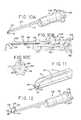
- FIG. 13is a perspective view of another embodiment of a tissue disruption apparatus in accordance with the present disclosure.
- FIG. 14is a perspective view of another embodiment of a tissue disruption apparatus in accordance with the present disclosure.
- FIG. 15is a perspective view of another embodiment of a tissue disruption apparatus in accordance with the present disclosure.
- FIG. 16is a perspective view of one embodiment of a obturator in accordance with the present disclosure.
- FIG. 17Ais a perspective view of the tissue disruption apparatus of FIG. 10A shown with the obturator of FIG. 16 inserted therethrough;
- FIG. 17Bis an enlarged cross-sectional view of the proximal end portion of the housing of the tissue disruption apparatus shown in FIG. 17A ;
- FIG. 18is a perspective view of another embodiment of a tissue disruption tool of the present disclosure.
- FIG. 19is an enlarged perspective view of the distal end portion of the tissue disruption tool of FIG. 18 ;
- FIG. 20is a perspective view of the distal end portion of the tissue disruption tool of FIG. 18 shown in the extended/deployed position;
- FIG. 21is a cross-sectional view of the tissue disruption tool taken along lines 21 - 21 of FIG. 18 ;
- FIG. 22is a perspective view of the tissue disruption tool of FIG. 18 shown with the protector located over the tissue disruptor;
- FIG. 23is an enlarged perspective view showing the distal end portion of the tissue disruption tool of FIG. 18 shown with the protector positioned over the tissue disruptor;
- FIG. 24is an enlarged cross-sectional view of the distal end portion of the tissue disruption tool taken along lines 24 - 24 of FIG. 23 ;
- FIG. 25is a perspective view of another embodiment of a tissue disruption tool in accordance with the present disclosure.
- FIG. 26is an enlarged perspective view of the distal end portion of the tissue disruption tool of FIG. 25 ;
- FIG. 27Ais a cross-sectional view of the tissue disruption apparatus of FIG. 10A shown with the elongated member in the extended or deployed configuration and a tissue disruption tool partially deployed into the working region defined by the elongated member;
- FIG. 27Bis a partial cross-sectional view of the proximal end portion of the housing of the tissue disruption apparatus of FIG. 27A ;
- FIG. 27Cis a perspective view of the distal end portion of the tissue disruption apparatus of FIG. 27A shown with the elongated member in the extended or deployed configuration and a tissue disruption tool partially deployed into the working region defined by the elongated member;
- FIG. 28Ais a perspective view of the distal end portion of the tissue disruption apparatus of FIG. 27A shown with the elongated member in the extended or deployed configuration and the tissue disruption tool deployed within the working region;
- FIG. 28Bis a top view of the tissue disruption apparatus of FIG. 28A shown deployed within an intervertebral disc space;
- FIGS. 29 and 30are cross-sectional views of another embodiment of a tissue disruption tool in accordance with the present disclosure.
- FIG. 31is a perspective view of the distal end portion of the tissue disruption tool of FIG. 29 shown with the tissue disruptor partial extended;
- FIGS. 32-34are perspective views of different configurations of tissue disruptors that may be associated with a tissue disruption tool of the present disclosure
- FIGS. 35-40are perspective views of different embodiments of tissue disruptors that may be associated with a tissue disruption tool of in accordance with the present disclosure
- FIG. 41is a top view of a tissue disruption apparatus shown with the elongated member and the tissue disruption tool in their respective deployed configurations;
- FIGS. 42 and 43are perspective views of a tissue disruption apparatus schematically shown contacting and disrupting superior and inferior endplate tissue, respectively;
- FIG. 44is a perspective view of a tissue disruption apparatus shown with the elongated member and the disruption tool in their respective deployed configurations;
- FIG. 45is a perspective view of a tissue disruption apparatus shown with the elongated member and the disruption tool in their respective deployed configurations;
- FIG. 46is a perspective view of one embodiment of a tissue disruption tool in accordance with the present disclosure.
- FIGS. 47-49are enlarged top views of the distal end portion of the tissue disruption tool of FIG. 46 showing actuation of the jaws;
- FIG. 50is a cross-sectional view of the distal end portion of the surgical instrument taken along lines 50 - 50 of FIG. 49 ;
- FIG. 51is a cross-sectional view of the distal end portion of the tissue disruption tool taken along lines 51 - 51 of FIG. 49 ;
- FIG. 52is a partial perspective view of the distal end portion of the tissue disruption tool of FIG. 46 ;
- FIGS. 53 and 54are perspective views of another embodiment of a tissue disruption tool in accordance with the present disclosure.
- FIGS. 55 and 56are perspective views of another embodiment of a tissue disruption tool in accordance with the present disclosure.
- FIGS. 57 and 58are perspective views of another embodiment of a tissue disruption tool in accordance with the present disclosure.
- FIGS. 59 and 60are perspective views of a tissue disruption tool including an actuator for moving the position of the tissue disruptor;
- FIG. 61is a top view of another embodiment of a tissue disruption tool in accordance with the present disclosure.
- FIG. 62is a top view of the distal end portion of the tissue disruptor of FIG. 61 ;
- FIG. 63is a side view of another embodiment of a tissue disruption tool in accordance with the present disclosure.
- FIG. 64is a side view of the tissue disruption tool of FIG. 63 shown with the jaws in an open configuration and a portion of the handle cut away;
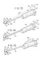
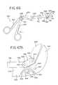
- FIG. 65is a side view of the tissue disruption tool of FIG. 63 shown with the jaws in a closed position;
- FIG. 66is a side view of the tissue disruption tool of FIG. 63 shown with the jaws in a closed position and the distal end portion in a substantially straight configuration;
- FIGS. 67A-67Care partial side views of one embodiment of the jaws of the tissue disruption tool of FIG. 63 ;
- FIGS. 68 and 69are partial side views of another embodiment of jaws of the tissue disruption tool of FIG. 63 ;
- FIG. 70is a side view of another embodiment of a tissue disruption tool in accordance with the present disclosure.
- FIG. 71is a perspective view of another embodiment of a tissue disruption tool in accordance with the present disclosure.
- FIG. 72is a perspective view of another embodiment of a tissue disruption tool in accordance with the present disclosure.
- FIG. 73is a perspective view of another embodiment of a tissue disruption tool in accordance with the present disclosure.
- FIGS. 74-77are cross-sectional views of exemplary profiles of the tissue disruption tools of FIGS. 72 and 73 ;
- FIG. 78is a perspective view of another embodiment of a tissue disruption tool in accordance with the present disclosure.
- FIGS. 79 and 80are cross-sectional views of exemplary profiles of the tissue disruption tool of FIG. 78 ;
- FIGS. 81-83are side views of exemplary profiles of the tissue disruption tool of FIG. 78 ;
- FIG. 84is a perspective view of another embodiment of a tissue disruption tool in accordance with the present disclosure.
- FIG. 85is a perspective view of another embodiment of a tissue disruption tool in accordance with the present disclosure.
- FIG. 86is a cross-sectional view taken along lines 86 - 86 of FIG. 85 ;
- FIGS. 87 and 88are side views of other embodiment of tissue disruption tools in accordance with the present disclosure.
- the tissue disruption apparatus, tools and methods of the present disclosuremay be utilized in any number of surgical procedures to disrupt (cut, scrape, brush, puncture, tear, grasp, extract, remove, etc.) tissue of a patient, but are particularly well suited for performing endoscopic discectomy procedures and preparing intervertebral discs for prosthetic implantation and spinal fusion.
- tissue disruption apparatus and toolsmay be utilized in minimally invasive procedures that are conducted through an access port that has a diameter of between about 0.2 inches (5 mm) and about 1.2 inches (30 mm), and is typically between about 10 mm and about 12 mm.
- the tissue disruption apparatus and tools disclosed hereinmay be made from materials or include materials that are visible under x-ray, fluoroscopy or any other suitable imaging system.
- Such apparatus and toolsmay also be made of disposable materials, which are configured for single use applications. Alternatively, such apparatus and tools may be configured for multiple or repeat use.
- the apparatus and toolsmay be manually operated or operated by an automated apparatus.
- one of the devices disclosed hereinis a barrier member that is inserted into the intervertebral disc space to isolate a working region within the disc space.
- the barrier membermay, for instance, at least partial isolate or enclose intervertebral disc tissue which is selected for disruption and separate such tissue from other tissue adjacent to the treatment area.
- the present disclosurealso discloses various tissue disruption tools that may be inserted into the working region defined by the barrier member to disrupt tissue contained within the working region.
- the barrier membermay be used with any of the tissue disruption tools disclosed herein or any other suitable disruption tools, such as traditional curettes, rongeurs and rasps.
- the disruption tools disclosed hereinmay be used in combination with any of the barrier members disclosed herein or may be used to disrupt tissue in procedures that do not use a barrier member.
- FIG. 1illustrates a section of a healthy vertebral (spinal) column, generally designated as 20 .
- Vertebral column 20includes vertebrae 22 and intervertebral discs 24 separating adjacent vertebrae 22 .
- Intervertebral discs 24connect the adjacent vertebra 22 together, providing a joint between the vertebrae that allows movement and flexing of the vertebral column 20 .
- Intervertebral discs 24also provide a cushion between the adjacent vertebrae 22 .
- FIG. 2illustrates a perspective view of one of the intervertebral discs 24 and an associated inferior vertebra 22 .
- the intervertebral disc 24includes a nucleus pulposus 26 surrounded by an annulus fibrosus 28 .
- the nucleus pulposus 26is a gelatinous-like material that provides cushioning between adjacent vertebrae.
- the annulus fibrosus 28is made up of tougher fiberous material that contains the nucleus pulposus 26 in the nuclear space.
- FIGS. 2A-3illustrate one embodiment of a tissue disruption apparatus 30 that may be inserted through an access cannula 32 in a minimally invasive procedure to perform a discectomy or prepare intervertebral disc 24 for insertion of an implant.
- distal end portion 34 of access cannula 32is inserted through the annulus fibrosus 28 of disc 24 , using a percutaneous posterior approach, to access nucleus pulpous 26 .
- an anterior approachmay be employed.
- a proximal end portion 36 of access cannula 32may remain outside of the patient.
- Access cannula 32includes a proximal end opening 38 and a distal end opening 40 and a lumen (not shown) in communication with openings 38 , 40 .
- the tissue disruption apparatus 30optionally, includes a first delivery cannula 42 having a proximal end portion 44 defining a proximal end opening 46 and a distal end portion 48 defining a distal end opening 50 .
- a lumen(not shown) extends and is in communication with proximal and distal end openings 46 , 50 .
- an elongated member 52is advanceable through delivery cannula 42 and into intervertebral disc 24 .
- Elongated member 52may be an elongated barrier member that includes a proximal end portion 54 and a distal end portion 56 ( FIGS. 2B and 3 ).
- Proximal end portion 54may, optionally, include a knob or handle 58 that may be used to advance and retract the elongated member 52 into and out of the intervertebral disc 26 , or advance and retracted elongated member 52 through delivery cannula 42 , when one is present.
- a knob or handle 58may be used to advance and retract the elongated member 52 into and out of the intervertebral disc 26 , or advance and retracted elongated member 52 through delivery cannula 42 , when one is present.
- At least the distal end portion 56 of the elongated member 52includes a first configuration for insertion/deployment into intervertebral disc 24 .
- distal end portion 56 of elongated member 56has a second configuration which forms a barrier 60 that at least partially defines a working region 62 within disc 24 .
- Barrier 60defines at least a portion of a perimeter or boundary of working region 62 for tissue disruption.
- the tissue to be disruptedmay be substantially the entire nucleus pulpous 26 , a portion of the nucleus pulpous 26 and/or a portion of the annulus fibrous 28 .
- barrier 60surrounds substantially the entire nucleus pulpous.
- Barrier 60also separates the tissue to be disrupted from other surrounding tissue.
- barrier 60may isolated disc tissue which is selected for disruption from other surrounding tissue.
- At least the distal end portion 56 of elongated member 52includes a first substantially linear configuration for advancement through the lumen of delivery cannula 42 for deployment into disc 24 .
- distal end portion 56 of elongated member 52As distal end portion 56 of elongated member 52 is advance into the disc space, it transverses through the disc space and curves into a second, less linear configuration that at least partially surrounds and isolates tissue selected for disruption.
- Distal end portionmay extend to form a barrier that at least partially surrounds ipsilateral and/or contralateral disc tissue.
- the distal end portion 56 of elongated member 52extends contralaterally so as to define a working region that includes at least in part a section of the contralateral area.
- distal end portion 56 of elongated member 52changes from a first substantially linear configuration into a second generally arcuate configuration.
- the generally arcuate shapemay be a generally circular shape (e.g., right circular shaped, oval, ellipse, etc.).
- the second configuration of the distal end portion 56 of elongated member 52may also be other regular and irregular geometric shapes depending on the desired application. Additionally, the second configuration may be any portion of a geometric shape.
- the second generally arcuate configurationmay be a quarter, half or three-quarters of a circular shape.
- the second generally arcuate configurationmay be a circular shape that extends almost a full circle (almost 360 degrees), but leaves an opening or open region 64 for ingress and egress of disruption tools.
- the distal end portion of 56 of the elongated member 52may extend in a circular shape and come into contact with one or more of the access cannula 32 or tool delivery cannula 68 so as to fully enclose the working region.
- the distal end portion 56 of the elongated member 52 in the second configurationmay extend between about 270 degrees and 355 degrees so as to leave an open region to access the working region. In one embodiment, the distal end portion extends between about 345 degrees and 355 degrees.
- the elongated membermay be made of a one-piece construct or multiple-piece construct.
- the elongated member 52 aincludes a shaft 53 a wherein the distal end portion 56 a of the elongated member 52 a is attached to the shaft 53 a by a fastener 66 , such as a screw, rivet or any other suitable fastener.
- the elongated member 52is a one-piece strip of material, such as a ribbon of material.
- At least the distal end portion 56 , 56 a of the elongated member 52 , 52 amay be made of a shape memory material, such as a shape memory metal or polymer.
- a shape memory materialis Nitinol.
- the distal end portion 56 , 56 a of the elongated member 52 , 52 amay have a predetermined or preset initial shape, such as the illustrated generally circular or ring shape.
- the distal end portion 56 , 56 amay be constrained into a substantially straight configuration, by for example, the inner surface of the delivery cannula 42 .
- distal end portion 56 , 56 a of the elongated member 52 , 52 ais advanced out of the distal opening 50 of cannula 42 , it is freed from constraint, which allows the distal end portion 56 , 56 a to return to its initial predetermined shape, thereby forming a barrier in situ that defines a working region 62 .
- tissue disruption apparatus 30may, optionally, include a second delivery cannula 68 for deploying a disruption tool 78 .
- Second delivery cannula 68includes a proximal end portion 70 having a proximal end opening 72 and a distal end portion 74 having a distal end opening 76 .
- a lumenextends through the second delivery cannula 68 and is in communication with the proximal and distal end openings 72 and 76 .
- Tissue disruption tool 78may comprise and elongated member 80 that includes a proximal end portion 82 and a distal end portion 84 ( FIGS. 2B and 3 ).
- the elongated member 80may be made of metal or polymeric material.
- the proximal end portion 82may, optionally, include a knob or handle 86 that may be used to advance and retract the tissue disruption tool 78 .
- a tissue disruptor 88is associated with the distal end portion 84 of the tissue disruption tool 78 .
- the tissue disruptor 88may be configured to cut, scrape, brush, puncture, tear, grasp, extract, and/or remove tissue.
- Tissue disruptor 88may be a tissue cutter, scraper, brush, grasper, jaws, curette, rasp or the like. Tissue disruptor 88 may be one-piece with elongated member 80 or may be attached to elongated member 80 . In the embodiment illustrated in FIGS. 2B, 3 and 6 , tissue disruptor 88 is a brush-like member that includes a plurality of bristles or tines 90 .
- the tissue disruption toolmay include any suitable tissue disruptor depending on the desired application.
- the tissue disruptor 92 shown in FIG. 5includes a plurality of geometrically shaped members 94 that include sharp edges, blades and points 96 .
- the geometrically shaped members 94are generally rectangular and/or triangular configurations that include sharp edges, blades and points 96 for cutting tissue.
- the distal tip 98 of the illustrated tissue disruption tool and any of the other disruption tools disclosed hereinmay be pointed or beveled or otherwise configured for piercing through tissue.
- the tissue disruptor 104may include bristles or tines 106 that extend in random directions from the disruption tool. Bristles and tines 88 and 106 may be employed to scrape, brush and/or tear tissue and/or also may be employed to capture or grasp tissue to be removed from the disc.
- distal end portion 84 of the disruption tool 78may be advanced out of the distal opening 76 of second delivery cannula 68 , through the open region 64 of barrier 60 and into the working region 62 defined by barrier 60 .
- distal end portion 84 of tissue disruption tool 78may slide or extend along barrier 60 , which guides the distal end portion 84 of disruption tool 78 along the perimeter of working region 62 .
- distal end portion 84slides along barrier 60 and the barrier serves as a track that guides distal end portion 84 in a curved path.
- the tissue disruptor 88is orientated or faces towards the center of the working region 62 .
- the tissue disruption tool 78may be made from a metal or polymeric material that is sufficiently rigid to be advanced through the disc material, but sufficiently flexible to follow along the barrier.
- tissue disruption tool 78may be made from a shape memory material that has a pre-determined curve that may or may not follow along the barrier 60 . For example, if the tissue to be disrupted is generally located in the center of working region 62 or more ipsilateral, the curvature of the distal on portion 84 of the disruption tool 78 being made from a shape memory material may be smaller than that of the barrier 60 so that the distal end portion 84 can reach such tissue.
- disruption tool 78contacts and disrupts tissue.
- the disruption tool 78transverses through the working region 62 in any suitable manner to disrupt tissue.
- the disruption tool 78may be moved back and forth within the working region 62 to disrupt tissue.
- the disruption toolalso may be rotated or angle within the working region 62 .
- barrier 60contains tissue disruptor 88 within the working region 62 and protects adjacent tissue outside of working region 62 from inadvertently being disrupted. This is helpful during minimally invasive procedures wherein the surgeon's vision is limited, which increases risk and injury from inadvertent disruption of surrounding tissue. In such minimally invasive procedures, barrier 60 protects surrounding tissue and reduces the risk that such surrounding tissue will be damaged.
- disruption tool 78After disruption tool 78 has disrupted a desired amount of tissue in working region 62 , it is retracted from disc 24 and one or more subsequent tools may, optionally, be inserted into the disc space.
- the subsequent toolsmay be the same or similar type of tool or may be a different type of tool. Accordingly, multiple types of disruption tools in any desired order may be inserted and removed from working region 62 . For example, cutting tools may first be inserted to cut tissue. Extraction tools may then be inserted to remove tissue. Puncture and scraping tool may be inserted to puncture and/or scrape the surfaces of the endplates within the perimeter of working region 62 .
- Disruption tool 78may be retracted from the disc 24 by retracting the distal end portion 84 back into delivery cannula 68 and then removing delivery cannula 68 from access cannula 32 , or disruption tool 78 may be retracted through delivery cannula 68 , wherein delivery cannula 68 remains in place for insertion of subsequent disruption tools.
- FIGS. 8A and 8Billustrate another embodiment of a tissue disruption tool 78 a and associated delivery cannula 68 a shown positioned within access cannula 32 a .
- delivery cannula 68 aincludes a distal end extension 69 a that extends beyond the distal end opening 76 a of the delivery cannula 68 a .
- distal end extension 69 amay protect tissue disruptor 88 a .
- tissue disruption tool 78 awhen tissue disruption tool 78 a is made from a shape memory material that has a preset curved configuration, distal end extension 69 a may maintain distal end portion 84 a of the tool is a substantially straight configuration during insertion through the access cannula 32 a . Referring to FIG. 8B , when the distal end portion 84 a of tool 78 a is deployed, it resumes its predefined configuration.
- Tissue disruption tool 78 amay also include a handle 86 a for advancing and retracting the disruption tool into and out of delivery cannula 68 a.
- tissue disruption tool 78 bmay be of a two-piece construct that includes a shaft 79 b wherein the distal end portion 84 b of the tissue disruption tool 78 b , carrying a tissue disruptor 88 b , is attached to shaft 79 b .
- Tissue disruption tool 78 bmay also include a handle 86 b for manipulating the disruption tool.
- shaft 79 b and distal end portion 84 bmay be made of the same or different materials.
- distal end portion 84 bmay be made from a shape memory material while shaft 79 b may be made from a different, non-shape memory material.
- FIGS. 10A-15show a tissue disruption apparatus 108 that includes a housing 110 and at least one delivery cannula 112 extending therefrom.
- the delivery cannula 112includes a first delivery lumen 114 ( FIGS. 10B and 11 ) and a second delivery lumen 116 .
- the at least one delivery cannulamay be two separate cannulas each having its own lumen.
- delivery cannula 112includes a proximal end portion 118 that is connected to and extends into the housing 110 .
- Delivery cannula 112also includes a distal end portion 120 that is configured for insertion into a disc space through an access cannula, similar to that shown in FIG. 2A , or without an access cannula.
- an elongated member 122that is configured to form a barrier within the disc space, similar to elongated member 52 discussed above, is located within first lumen 114 , as shown in FIG. 10B .
- Elongated member 122may come pre-assembled in lumen 114 of tissue disruption apparatus 108 .
- Elongated member 122includes a proximal end portion 124 ( FIG. 10B ) and a distal end portion 126 .
- Proximal end portion 124is operatively connected to any suitable deployment/retraction mechanism or actuator 128 for advancing and retracting elongated member 122 through lumen 114 .
- deployment/retraction mechanism 128includes a rotatable knob 130 having a threaded post 132 extending therefrom and which rotates therewith.
- a carriage 134is located on post 132 and includes internal threads that complement the threads of post 132 such that when the post is rotated in one direction, carriage 134 travels distally along post 132 , and when the post is rotated in the other direction, carriage 134 travels proximally along post 132 .
- Proximal end portion 124 of elongated member 122is attached to carriage 134 such that as the carriage travels distally along post 132 , elongated member 122 advances distally through lumen 114 and out distal opening 115 . Conversely, as carriage 134 travels proximally along post 132 , elongated member 122 is retracted proximally within lumen 114 .
- distal end portion 120 of deployment cannula 112may be inserted into the disc space during a minimally invasive procedure.
- distal end portion 126 of elongated member 122is located within lumen 114 in a first configuration, as shown in FIGS. 10B and 11 .
- distal end portion 126 of elongated member 122is in a generally linear configuration.
- the userrotates knob 130 to advance distal end portion 126 of elongated member 122 out of a distal opening 115 that is in communication with lumen 114 .
- distal end portion 126As distal end portion 126 exits out of distal opening 115 , it changes into a second configuration, such as the illustrated generally circular configuration, shown in FIG. 12 , to form a barrier 136 that defines at least a portion of a perimeter or boundary of a working region 138 .
- the second configuration of elongated member 122may be similar to and have the same or similar characteristics as the second configuration described above with respect to elongated member 52 .
- barrier 136may have an open region 140 for the insertion of disruption tools.
- the tissue disruption apparatus 108may include a deployment aid or enhancer that may assist in the deployment of distal end portion 126 of elongated member 122 .
- the endplates and/or discsmay be highly calcified, in which case, distal end portion 126 of the elongated member 122 may encounter resistance as it is advanced through the disc space. Such resistance may impede insertion of distal end portion 126 into the disc space and also may impede the ability of distal end portion 126 to form the desired or pre-set shape of the barrier 136 . As illustrated in FIGS.
- the deployment enhancemay include a pull wire, such as tether 142 , that may be pulled or otherwise tensioned to assist in advancing distal end portion 126 of the elongated member 122 through the disc space and/or forming distal end portion 126 into a desired shape barrier 136 .
- tether 142is attached to distal end portion 126 of the elongated member 122 .
- Tether 142passes through an opening 144 in distal end portion 120 of delivery cannula 112 so that when it is pulled or otherwise tensioned, it pulls or guides the distal tip 146 of the elongated member 122 toward distal end portion 120 of delivery cannula 112 to assist traversing distal end portion 126 of elongated member 122 through the disc space and/or to assist forming it into the desired shape.
- tether 142assists in forming the distal end portion of the elongated member into a circular configuration.
- tether 142may extend through a first opening 144 and into lumen 16 of delivery cannula 112 and then extend out through a second opening 148 .
- Tether 142extends proximally outside of the tissue disruption apparatus 108 and a handle 150 is associated with the proximal end portion 152 of tether 142 .
- handle 150located outside of the proximal end opening of the access channel so that the user may grasp and pull the handle 150 during use.
- tether 142extends through opening 144 in delivery cannula 112 , through lumen 116 and out of the proximal opening of housing 110 .
- tether 142may extend through opening 144 in delivery cannula 112 and through lumen 116 .
- the proximal end portion of tether 112may be attached to an actuator 154 that is actuated by the user to place tension on the tether.
- the actuator 154is a level pivotally attached to the housing 110 wherein the leveler is moved to place tension on the tether.
- housing 110may include an opening 156 for receiving a tool therethrough and into second lumen 116 .
- knob 130may also include openings 158 therethrough so that the tools may access opening 156 .
- FIG. 16illustrates one exemplary embodiment of an obturator 160 that may be inserted into and through lumen 116 ( FIG. 10B ).
- Obturator 160has an elongated shaft 162 having a proximal end portion 164 and a distal end portion 166 .
- obturator 160may be inserted through opening 158 in knob 130 and opening 156 in housing 110 ( FIG. 10C ) to insert shaft 162 into and through lumen 116 . As shown in FIG.
- the distal tip 170 of obturator 160is pointed and/or sharp and extends out of opening 117 of lumen 116 and distally of the distal end portion 120 of cannula 112 .
- Obturator 160may be employed to assist in inserting cannula 112 into and through tissue in that distal tip 170 of obturator 160 may be used to pierce tissue as cannula 112 is inserted into and through the tissue.
- cannula 112with obturator 160 located therein, may be inserted percutaneously through the skin and soft tissue without the need for a previously inserted access cannula.
- hub 168may include a releasable locking mechanism that mates with knob 130 to releasably lock obturator 160 to tissue disruption apparatus 108 .
- the locking mechanismmay include a depressible lever 172 in which the distal end 174 thereof is pivotally connected to hub 168 .
- the proximal end 176is biased upward to a locked position by a biasing member 178 , such as the illustrated spring.
- Lever 172includes a surface 180 which contacts a surface 182 of knob 130 in an opposed relationship to lock obturator 160 into position within tissue disruption apparatus 108 .
- Locking obturator 160 to knob 130assists in maintaining obturator 160 in position as cannula 112 is inserted and pushed through tissue.
- the proximal end surface 184 of hub 160also may be flat or otherwise conducive to striking with a hammer or mallet to aid in inserting cannula 112 into and through tissue.
- proximal end 176 of lever 172may be depressed to disengage surface 180 from knob 130 .
- Obturator 160may then be removed from tissue disruption apparatus 108 and other tools may be inserted into and through lumen 116 .
- FIGS. 18-24show one embodiment of a tissue disruption tool 186 that may be used with tissue disruption apparatus 108 .
- tissue disruption tool 186includes a shaft 188 having a proximal portion 190 and a distal end portion 192 .
- Shaft 188also includes a lumen 194 extending therethrough.
- An elongated member 196extends through lumen 194 .
- Elongated member 196has a proximal end portion 198 , an intermediate portion and a distal end portion 202 .
- proximal end portion 198 of elongated member 196extends proximally out of proximal end portion 190 of shaft 188 and distal end portion 202 of elongated member 196 extends distally out of distal end portion 192 of shaft 188 .
- a handle 204is associated with proximal end portion 198 of elongated member 196 . Handle 204 may be grasped by a user to move elongated member 196 distally and proximally with lumen 194 of shaft 188 .
- elongated member 196may include a stop (not shown) that limits the movement of the elongated member 196 within the lumen 194 of shaft 188 .
- Such a stopmay include a post (not shown) which extends from elongated member 190 into channel 195 of shaft 188 .
- the stopmay abut the distal end 197 ( FIGS. 19 and 20 ) of channel 195 to limit the distal advancement of the elongated member 196 .
- Channel 195may also be used to access and assemble elongated member 196 when it is of a multi-piece construct. For example, channel 195 may be accessed to attach pieces of the elongated member 196 to form the same.
- tissue disruptor 206is associated within with distal end portion 202 of elongated member 196 .
- Tissue disruptor 206may be any tissue disruptor disclosed herein or any other suitable tissue disruptor or end effector.
- tissue disruptor 206includes three hollow members 208 having generally square profiles. The hollow members include edges 210 for cutting tissue.
- Distal end portion 202 of elongated member 196may be made of a material that has sufficient flexibility to bend or curve when inserted along the barrier member, or may be made of a shape memory material that has a preset shape.
- handle 204may be used to move elongated member 196 between an initial retracted position shown in FIG. 19 and an extended or deployed position shown in FIG. 20 .
- Tissue disruption tool 186may include a protector 214 which protects tissue disruptor 206 prior to insertion into tissue disruption apparatus 108 ( FIG. 10A ).
- protector 214may be a sleeve having a lumen for receiving the shaft 188 therethrough. In these figures, protector 214 is shown in an initial position extending over and covering tissue disruptor 206 .
- protector 214 and shaftmay be relatively moveable to one another such that protector 214 may be moved on shaft 188 from the initial distal position to a proximal position. Referring to FIGS.
- protector 214may include a tab 216 that has a projection 218 that projects into a slot 220 of the distal end portion 192 of shaft 188 to releasably lock protector 214 in the initial position.
- protector 214will be released and shaft 188 will pass through it to move protector 214 into a more proximal position shown in FIG. 18 .
- FIGS. 25 and 26illustrate another embodiment of a tissue disruption tool 222 , which includes substantially the same features and functions in substantially the same manner as tissue disruption tool 186 .
- Tissue disruption tool 222includes a disruptor 224 associated with distal end portion 198 of elongated member 196 .
- Disruptor 224includes a single hollow cutting element 230 that has a generally square profile and cutting edges 230 .
- FIGS. 27A-27Cillustrate the use of tool 222 with apparatus 108 .
- Cannula 112 of tissue disruption apparatus 108is inserted into the disc space and distal end portion 126 of elongated member 122 is deployed to form a barrier 136 .
- the distal end portion 126 of elongated member 122may extend almost a full 360 degrees.
- the distal end portion 126comes into contact with the distal end portion 192 of the shaft and/or the distal end portion 120 of the delivery cannula 112 to fully enclose the tissue to be disrupted.
- tissue disruption toolsuch as any of the tissue disruption tools disclosed herein or any other suitable tissue disruption tool, is inserted into the lumen 116 of tissue disruption apparatus 108 ( FIG. 10B ).
- tissue disruption tool 222is shown inserted into tissue disruption apparatus 108 .
- Tissue disruption tool 222may be inserted through opening 158 in knob 130 and distal opening 156 of housing 110 ( FIG. 10C ).
- FIG. 27Bwhen tissue disruption tool 222 is inserted into opening 156 of housing 110 , protector 214 enters and is maintained in a cavity 232 defined by housing 110 . As shaft 188 is advanced through housing 110 , protector 214 enters and remains in cavity 232 ( FIG. 10B ).
- distal end 192 of shaft 188 of tissue disruption tool 222aligns with opening 117 of cannula 112 and distal end portion 202 and associated tissue disruptor 224 partially enter working region 138 through opening 140 of the barrier 136 .
- the useruses handle 204 ( FIG. 25 ) to advance distal end portion 202 and associated disruptor 224 into working region 138 .
- distal end portion 202has sufficient flexibility to curve along barrier 136 and sufficient rigidity to traverse and disrupt tissue within barrier 136 .
- tissue disruption tool 222may be removed from tissue disruption apparatus 108 and a similar type or different type of tissue disruption tool may be inserted and the process may be repeated. After the selected tissue has been disrupted, tissue disruption apparatus 108 may be removed from the patient.
- FIGS. 29-40illustrate various tissue disruption tools that may be used in combination with any of the barriers disclosed herein. Such tissue disruption tools may also be used in procedures that do not include the use of a barrier. Additionally, the disruption tools may be used to disrupt intervertebral disc and/or endplate tissue.
- tissue disruption tool 240includes a cannula 242 which defines a lumen 244 .
- Cannula 242includes a proximal end opening 246 and a distal end opening 248 .
- a shaft or elongated member 250is located within the lumen 244 .
- the proximal end 252 of shaft 250includes a threaded portion 254 which mates with threads in proximal end opening 246 of cannula 242 .
- a knob 257may be associated with threaded portion 254 and used to rotate threaded portion 254 within opening 246 .
- Threaded portion 254 of shaft 250may be rotatable connected to an intermediate portion 255 of shaft 250 so that threaded portion 254 may be rotated relative to the remaining portions of shaft 250 .
- tissue disruptor 258is a generally open cubicle member having an opening 260 defined by sharp edges 262 .
- Tissue disruptor 258includes a cavity 263 that may act as a scoop for scooping tissue.
- the distal end 256 of shaft 250 and associated tissue disruptor 258may be advanced out of distal end opening 248 by rotating knob 257 .
- Rotating knob 257 in one directioncauses shaft 250 to advance distally and rotating knob 257 in the other direction causes shaft 250 to retract proximally.
- the disruptormay be advanced and retracted by other mechanism such as a ratcheting or rack and pinion system or a handle and worm gear.
- Distal end 249 of cannula 242optionally, may be enlarged to accommodate the profile of tissue disruptor 258 .
- Distal end portion 256 of shaft 250may be made of a shape memory material that has a pre-set curved shape when unrestrained or may be made of a flexible material that curves along a barrier when advanced therealong. Additionally, the distal end portion 256 of elongated member 250 may have a radius of curvature between about 5 mm and about 50 mm. In one embodiment, the radius of curvature is sufficient so that the disruptor 258 may reach contralateral material. For example, the radius of curvature may be about 25 mm. The length of the distal end portion 256 may be between about 4 inches and about 12 inches.
- Disruptor 258may be inserted into the disc space to clear loose or partially detached nucleus tissue from the disc space before an implant is inserted into the space. Additionally, sharp edges 262 may contact and separate tissue from the inferior and superior endplates.
- the profile of disruptor and the curvature of distal end portion 256 of elongated member 250may be selected to match or mimic the insertion of an implant, so that disruption tool 240 may be used to test that the removal of tissue (e.g., discectomy) is adequate for insertion or the implant.
- FIGS. 32-34show exemplary embodiments of tissue disruptors that may be associated with any of the tissue disruption tools disclosed herein.
- tissue disruptor 264has a generally round hollow profile that is generally cylindrically shaped.
- Tissue disruptor 264includes a round sharpened edge 266 configured to disrupt tissue.
- the disc materialmay pass through the opening in the disruptor 264 as it is advanced through the disc. While the illustrated profile is round, the disruptor may have any hollow profile having wherein one or both ends are open.
- FIG. 33illustrates a tissue disruptor 268 that has a generally triangular profile having an open end defined by sharpened edges 270 .
- FIG. 34illustrates a tissue disruptor 272 which has a generally spade-like shape including an edge for cutting 273 and piercing tissue.
- Edge 273may be particularly configured for disrupting tissue of the endplates and the edge may provide a down bite (surfaces configured to scrape or otherwise disrupt tissue when the disruptor is advanced) or an up bite (surfaces configured to scrape or otherwise disrupt tissue when the disruptor is retracted). Additionally, one side of the disruptor 272 or the other may be particularly suited for scraping the superior or inferior endplate.
- FIGS. 35-40illustrate additional tissue disruption tools that may be particularly well suited for disrupting endplate tissue, but may also be employed to disrupt disc tissue.
- the tools illustrated in these figuresmay include a delivery cannula 275 and a shaft 277 having a tissue disruptor associated with a distal end portion 278 of shaft 277 . Similar to the above discussed embodiments, the distal end portion 278 of shaft 277 may have a radius of curvature and/or length of distal end portion 256 of shaft 250 .
- FIG. 35shows a tissue disruptor 274 that includes a generally ogive or oblong shape.
- Disruptor 274may be formed from a plurality of layers 276 stacked on both sides of the distal end portion 278 of shaft 277 and attached by fasteners 282 . Each of the layers 276 may include edges that are sharp or otherwise configured to cut, scrape or puncture endplate tissue.
- FIG. 36shows a tissue disruptor 284 that has a generally rectangular cuboid shape. Tissue disruptor 284 may include upper and/or lower cavities 286 and edges 288 that may be sharp or otherwise configured to cut, scrape or puncture endplate tissue.
- FIGS. 37 and 38show a tissue disruptor 290 that is generally ogive or oblong shaped and includes edges 283 for scraping or cutting endplate tissue. In FIG.
- tissue disruptor 290is angled or titled upward relative to distal end portion 278 of shaft 277 .
- the upward anglemay be particularly suited for disrupting tissue of a superior endplate.
- tissue disruptor 290is angled or titled downward relative to distal end portion 278 of shaft 277 . This downward angle may be particularly well suited for disrupting tissue of an inferior endplate.
- FIG. 39shows a tissue disruptor 296 that has a generally rectangular cuboid or cubic shape.
- the upper and/or lower surfaces 298may include a texture configured for disrupting endplate tissue.
- the surfacesmay include spikes or serrations.
- FIG. 40shows a looped tissue disruptor 300 that may include upper edge 302 and lower edge 303 that may be sharp or otherwise configured to contact and, disrupt endplate tissue.
- the surfacemay be particularly configured to provide a down bite or an up bite.
- FIGS. 41-45show tissue disruptor 274 being used with tissue disruption apparatus 108 and deployed within working region 138 defined by barrier 136 . It will be understood that any of the tissue disruptors shown in FIGS. 35-40 may be used with tissue disruption apparatus 108 in a similar manner.
- cannula 112 of the tissue disruption apparatus 108is inserted into the disc space and between superior and inferior end plates 304 , 306 and elongated member has been deployed to form barrier 136 .
- FIG. 42shows tissue disruptor 274 being rotated or angled upward to disrupt tissue of superior endplate 304 within the working region defined by barrier 136 .
- FIG. 43shows tissue disruptor 274 being rotated or angled downward to disrupt tissue of inferior endplate 306 within the working region. In both instances tissue disruptor 274 may manipulated to contact and scrape endplate tissue by back and forth and rotational movement.
- distal end portions of the tissue disruption toolsmay have configurations that are particularly conducive for reaching a more contralateral or ipsilateral region.
- FIGS. 44 and 45FIG. 44 shows an embodiment wherein distal end portion 278 of shaft 277 has a tighter radius of curvature.
- FIG. 45shows an embodiment wherein distal end portion 278 of shaft 277 has a larger radius of curvature.
- FIGS. 46-52illustrate another embodiment of a tissue disruption tool 310 that may be used with the tissue disruption apparatus disclosed herein or may be used as a tool on its own. Furthermore, tissue disruption tool 310 may be particularly well suited for scraping endplate tissue.
- Tissue disruption tool 310may include a first elongated shaft 312 having a proximal end portion 314 and a distal end portion 316 and a second elongated shaft 318 having a proximal end portion 320 and a distal end portion 322 .
- the second shaft 318may be positioned in an axially extending channel 324 of the first shaft 312 , as shown in FIG. 50 .
- a first jaw 326is attached or extends from the distal end portion 316 of the first shaft 312 .
- a second jaw 328includes a portion 327 that extends through a slot 329 ( FIG. 52 ) in first shaft 312 so that it can be pivotally attached to the distal end portion 322 of the second shaft 318 at a first joint 330 , such as a joint that uses a pivot pin.
- the second jaw 328is also pivotally attached to the first jaw 326 or the first shaft 312 at a second joint 332 , such as a pivot pin joint, that is at a location distal of the first joint 330 when the jaws are in a closed position.
- the first and second shafts 312 , 318are moveable linearly relative to one another and when the second shaft 318 is moved distally relative to the first shaft 312 , the second jaw 328 pivots relative to the second shaft 318 at joint 330 and pivots relative to the first shaft 312 or jaw 326 at joint 332 , thereby moving the second jaw 328 away from the first jaw 326 and placing the jaws in an open position.
- the rear wall 333 of jaw 328may contact the first shaft at 335 .
- Such contactacts as a stop to prevent movement beyond a set maximum open position. In the illustrated embodiment, the maximum open position is 90 degrees, which could be greater or smaller depending on the procedure. The stop assists in preventing the jaw from damaging other tissue.
- the second shaft 318is moved proximally relative to first shaft 312 , the second jaw 328 moves toward the first jaw 326 , thereby placing the jaws in a closed position.
- the second jaw 328is oversized and bigger than the first jaw 326 .
- the oversized second jaw 328may be helpful in reaching contralateral tissue.
- moveable jaw 328may have sharp edges 336 for that may contact and scrape endplate tissue. Sharp edges 336 may also be used to cut tissue when the jaws perform a scissoring action. The edges 336 may be beveled, scalloped or serrated.
- Second jaw 328also may have a concaved inner surface 334 for scoping tissue.
- First 326may also include sharp edges 337 that may be used to scrape endplate tissue.
- tissue disruption toolmay be associated with a housing or handle 338 that includes an actuation member 340 , such a rotatable knob, that is actuated to move the second shaft 318 relative to the first shaft 312 .
- FIGS. 53-60illustrate tissue disruption tools that include an articulating tissue disruptor associated with the distal end of the tool.
- the toolincludes a first shaft 342 having a distal end 344 and second shaft 346 having a distal end 348 .
- the toolincludes a disruptor pivotally attached to the first shaft 342 at a first joint 350 and pivotally attached to the second shaft 346 at a second joint 352 .
- the shafts 342 and 346may be linearly moveable relative to one another to move the disruptor from a first configuration relatively in-line with the shafts 342 and 346 to a second configuration wherein the disruptor extends at an angle to the shafts 342 and 346 .
- tissue disruptor 354has a generally ogive shape that includes a pointed distal end portion 356 which may be suited for puncturing endplates. Additionally, the surfaces 358 on one or both sides of disruptor 354 may be beveled or angled in toward a center opening 360 .
- the outer edges 362 of side surfaces 358may be sharp or otherwise configured to cut and/or scrape tissue. For example, outer edges 362 may be configured to contact the superior and inferior endplates of the vertebral body.
- Center opening 360may collect disrupted tissue for removal for the disc space when the tool is removed.
- the tissue disruptor 354is articulated by moving the first and second shafts 342 and 346 relative to one another. For example, as shown in FIG.
- the tissue disruptor 354may have an initial generally straight configuration that is generally in-line with shafts 342 and 346 . This generally linear configuration may be particularly suited for inserting the tissue disruption tool into the disc space.
- the tissue disruptor 354pivots at the first and second joints 350 , 352 to thereby result in the tissue disruptor to articulate relative to the shafts.
- the disruptormay be moved back and forth in the straight, in-line or angled configurations to disrupt tissue.
- tissue disruptor 364has a generally ogive shape, wherein the upper and lower surfaces 366 are beveled or angles inward toward a center opening 368 .
- the outer edges 370 of the upper and lower surfaces 366may be sharp or otherwise configured to cut and/or scrape tissue, such as endplate tissue.
- tissue disruptor 372has a generally ogive shape, wherein the upper and lower surfaces 374 are beveled or angled outwardly and meet at an edge 376 that may be sharp or otherwise configured to cut and/or scrape tissue, such as endplate tissue.
- FIGS. 59 and 60illustrate an embodiment wherein the tissue disruption tool includes an actuator, such as handle 378 , which may be used to move the first and second shafts 342 and 346 relative to one another.
- the handle 378includes a stationary grip 380 and a pivotal grip 382 pivotally connected to the handle 378 .
- the handle 378also includes a biasing member 384 that biased the pivotal grip 382 away from the stationary grip 380 .
- the pivotal grip 382is moved toward the stationary grip 380 , the second shaft 346 moves distally relative to the first shaft 342 to articulate the tissue disruptor.
- FIGS. 61 and 62illustrate another embodiment of tissue disruption tool 400 that includes an articulating tissue disruptor 402 .
- Tissue disruption tool 400includes a shaft 404 that has a proximal end 406 and distal end 408 . The tool is shown inserted into a disc space through an access cannula 410 .
- the disruptor 402is pivotally attached to the distal end portion 408 at joint 409 .
- Disruptor 402includes upper and/or lower sharp edges 403 that are configured to disrupt tissue. Such edges 403 may be particularly suited to disrupt endplate tissue.
- Disruptor 402also may include a blunt end 405 that protects tissue as the tool is inserted and disrupts tissue.
- An actuatorsuch a handle 412 , is located at the proximal end portion 406 of shaft 404 .
- the handle 412includes a stationary grip 414 and a pivotal grip 416 pivotally connected to the handle 412 .
- the pivotal grip 416When the pivotal grip 416 is moved toward the stationary grip 414 , the disruptor 402 moves from a first configuration generally in-line with the shaft 404 to a second angled configuration relative to shaft 404 .
- the actuatormay be used to move disruptor 402 back and forth and/or disruptor 402 may be pushed back and forth by the shafts.
- FIGS. 63-69illustrate another embodiment of a tissue disruption tool 420 , which includes articulating jaws associated with the distal ends of the shafts of the tool.
- the jawsare moveable between a first, generally linear configuration in which the jaws are generally in-line with the shafts of the tool to a second condition in which the jaws extend at an angle to the shafts.
- the jawsmay be placed in the first, generally in-line configuration to insert the jaws into the treatment site. In the treatment site, the jaws may be moved to the second, angled configuration to reach tissue contralateral to the access site.
- disruption tool 420includes a first elongated shaft 422 having a proximal end portion 424 and a distal end portion 426 .
- the tool 420also includes a second elongated shaft 428 that has a proximal end portion 430 and a distal end portion 432 .
- tool 420includes a first jaw 434 pivotally attached to the distal end 426 of the first shaft 422 at joint 436 .
- the tool 420also included a second jaw 438 opposed to first jaw 434 .
- the second jaw 438is pivotally attached to the distal end 440 of a link 442 at joint 444 .
- the proximal end 446 of the link 442is pivotally attached to the distal end 432 of the second shaft 428 at joint 448 .
- the proximal end 450 of second jaw 438is pivotally attached to the first jaw at joint 452 .
- the first jawincludes a biasing member 454 .
- tool 420includes a torsion spring that is centered about joint 436 and resides in a cavity 456 between first jaw 434 and distal end portion 426 of shaft 422 .
- the terminal ends 458 of the torsion springcontact the first jaw 434 and distal end portion 426 to bias the jaw to the angle configuration.
- tool 420includes a actuator, such as handle 460 which includes a stationary grip 462 connected to the proximal end portion 424 of the first shaft 422 .
- the handle 460also includes a pivotal grip 464 which is pivotally attached to handle 460 at joint 466 and pivotally attached to the proximal end portion 430 of second shaft 428 at joint 468 .
- FIGS. 65 and 67Ashow jaws 434 and 438 in their initial configuration, biased to the angled configuration wherein the jaws 434 and 438 extend at an angle to shafts 422 and 428 .
- FIGS. 66 and 67Bwhen the pivotal grip 464 is moved toward stationary grip 462 , the second shaft 428 moves distally relative first shaft 422 , moving jaws 434 and 438 into an in-line or generally straight configuration.
- This generally in-line configurationmay be the first configuration the jaws 434 and 438 are placed into for insertion into a treatment site.
- the jaws 434 and 438being in-line with the shafts 422 and 428 make it easier to insert the tool through an access cannula.
- the pivotal grip 464may be moved back into the position shown in FIGS. 65 and 67A , thereby moving the second shaft 428 proximally and placing the jaws back into an angled configuration.
- the pivotal grip 464may be moved further away from stationary grip 462 to move shaft 428 further distally relative to shaft 422 , thereby opening jaws 434 and 438 .
- the jaws 434 and 438may then be place to grasp or cut tissue in a scissor action and moved back into the closed position shown in FIGS. 65 and 67A .
- the jaws 434 and 438may then be placed back into the in-line configuration shown in FIGS. 66 and 67B to remove the jaws 434 and 438 and tissue therebetween from the treatment site.
- FIGS. 68 and 69illustrate an embodiment wherein the tool includes a flat or leaf spring 470 attached to shaft 422 and jaw 434 to bias the jaws 434 and 438 to the angled configuration.
- tissue disruption tool 474may include an elongated member 476 that may be inserted into a disc space 24 through a cannula 478 .
- Tool 474may include a housing 479 that has an actuator 480 associated therewith to advance and retract the elongated member 476 into our out of the distal end 482 of the cannula 478 .
- the actuatormay be of a similar construct to that of tool 240 of FIG. 29 .
- At least the distal end portion 484 of the elongated member 476is made from a shape memory material that has an initial curved configuration and is constrained by the cannula into a generally straight configuration for deployment into the treatment site.
- the curved configurationis a generally circular configuration, such as circle, oval or ellipse, that extends contralateral to reach tissue contralateral to the access site.
- the elongated membermay have edges or other features that are conducive for disrupting tissue.
- the distal end portion 484 of elongated member 476may have a ball 486 associated with the distal end portion 484 .
- the ball tip 486may be atraumatic and reduce the risk of the distal end portion from piercing or cutting adjacent or surrounding tissue.
- the upper and/or lower edges 485may be sharpened or otherwise configured to disrupt tissue when inserted into the disc space.
- the ball tip 486may follow along the annulus without piercing or cutting it.
- the distal end portion 484 of elongated member 476may have a double diamond profile or cross-section in which the upper and lower edges 492 , 494 are sharp or otherwise configured to disrupt tissue.
- the upper and lower edgesmay be particularly configured to scrape endplate tissue.
- the upper and lower edges of distal portion 484may have other configurations as well, such as those showing in FIGS. 74-77 .
- the upper cutting edge 488may be smooth while the lower cutting edge may come to a pointed edge 490 .
- both the upper cutting edge 492 and the lower cutting edge 494may come to a pointed edge.
- the upper edge 496 and the lower edge 498may be rounded.
- the upper edge 500 and lower edge 502may be scalloped in one direction or the other.
- the elongate member 476may include a lumen 506 for passage of another tissue disruption tool therethrough, such as tissue grasper 508 .
- tissue grasper 508may include a distal end portion 510 that includes bristles or tines 512 for capturing or grasping tissue 504 for removal from the treatment site.
- FIG. 78illustrates another embodiment of tissue disruption tool 514 that includes a delivery cannula 516 and an elongated member 518 that may be inserted into the treatment site through the delivery cannula.
- the distal end portion 520 of the elongated member 518is generally looped shaped and may be about 10 mm in diameter. Also, the height of the loop may be such that the top surface and the bottom surface 526 , 528 of the loop contact the upper and lower endplates simultaneously.
- the looped distal end portion 520may be passed through the cannula 516 in a compact or linear configuration and upon exiting the cannula 516 , the distal end portion 520 opens into the looped shape shown.
- the looped shape distal end portion 520may then be drawn back into the cannula 516 for removal from the treatment site.
- the looped shaped distal end portion 520may have any suitable profile for disrupting tissue. Referring to FIG. 79 , for example, the profile or cross-section of the distal end portion 520 may be generally square. Referring to FIG. 80 , the profile or cross-section of the distal end portion 520 may be trapezoidal wherein the inner and outer edges 522 and 524 are beveled. As illustrated in FIGS. 81-83 , the upper 526 and lower surfaces 528 may be flat ( FIG. 81 ), serrated ( FIG. 82 ) or scalloped ( FIG. 83 ).
- the distal end portionmay also include any of the profiles shown in FIGS. 74-77 .
- FIG. 84illustrated another embodiment of a tissue disruption tool 529 that includes an elongated member 530 that is inserted through a cannula 532 .
- the elongated memberincludes a distal end portion 534 that includes at least two arms 536 and 538 that are closely adjacent to each other for passage through the cannula and then extend away from each other when they exit the cannula.
- FIG. 87also shows an elongated member 540 which includes a distal end portion 542 include two arms 544 and 546 that may come together for passage through a cannula and then separate outside of the cannula. In this embodiment one or both of the arms may have pointed distal ends 548 .
- the arms of these embodimentsmay include any of the profiles shown in FIGS. 74-77 and 79-83 . Additionally, the arms may be configured to cut and scrape endplate tissue.
- FIGS. 85 and 86show another embodiment of a tissue disruption tool 550 of the present disclosure.
- Tool 550includes an elongated member 552 that may be inserted through a cannula 554 in a straight configuration wherein at least the distal end portion 556 of the elongated 552 forms a curved configuration when it is advanced out of the cannula.
- the distal end portionincludes a spoon-like scallop 558 for disrupting tissue extending along the inner curved surface of the distal end portion 556 .
- the upper and lower edges 557 , 558may be configured to disrupt endplate tissue.
- FIG. 88illustrates another embodiment of a tissue disruption tool 560 of the present disclose.
- Tool 560includes an elongated member 562 that has a slight curved distal end portion 564 having a pointed tip 566 .
- the elongated member 562may be passed through cannula 568 for insertion into the disc space.
- the slight curvemay be in the distal end portion 564 may be orientated so that the pointed tip contacts the upper or lower endplate.
- any of the disruption surfaces and/or edges of the tissue disruptors disclosed hereinmay have any suitable edge or surface for disrupting tissue.
- the surface or edgemay be sharp, beveled, serrated, scalloped or the like.
Landscapes
- Health & Medical Sciences (AREA)
- Life Sciences & Earth Sciences (AREA)
- Surgery (AREA)
- Engineering & Computer Science (AREA)
- Biomedical Technology (AREA)
- Animal Behavior & Ethology (AREA)
- Heart & Thoracic Surgery (AREA)
- General Health & Medical Sciences (AREA)
- Public Health (AREA)
- Veterinary Medicine (AREA)
- Nuclear Medicine, Radiotherapy & Molecular Imaging (AREA)
- Medical Informatics (AREA)
- Molecular Biology (AREA)
- Orthopedic Medicine & Surgery (AREA)
- Ophthalmology & Optometry (AREA)
- Prostheses (AREA)
- Neurology (AREA)
- Transplantation (AREA)
- Cardiology (AREA)
- Oral & Maxillofacial Surgery (AREA)
- Vascular Medicine (AREA)
- Physical Education & Sports Medicine (AREA)
Abstract
Description
Claims (15)
Priority Applications (4)
| Application Number | Priority Date | Filing Date | Title |
|---|---|---|---|
| US14/792,956US10314605B2 (en) | 2014-07-08 | 2015-07-07 | Apparatus and methods for disrupting intervertebral disc tissue |
| US16/366,523US11224453B2 (en) | 2014-07-08 | 2019-03-27 | Apparatus and methods for disrupting intervertebral disc tissue |
| US17/544,283US12053196B2 (en) | 2014-07-08 | 2021-12-07 | Apparatus and methods for disrupting inter vertebral disc tissue |
| US18/762,380US20240366252A1 (en) | 2014-07-08 | 2024-07-02 | Apparatus and methods for disrupting intervertebral disc tissue |
Applications Claiming Priority (2)
| Application Number | Priority Date | Filing Date | Title |
|---|---|---|---|
| US201462021960P | 2014-07-08 | 2014-07-08 | |
| US14/792,956US10314605B2 (en) | 2014-07-08 | 2015-07-07 | Apparatus and methods for disrupting intervertebral disc tissue |
Related Child Applications (1)
| Application Number | Title | Priority Date | Filing Date |
|---|---|---|---|
| US16/366,523DivisionUS11224453B2 (en) | 2014-07-08 | 2019-03-27 | Apparatus and methods for disrupting intervertebral disc tissue |
Publications (2)
| Publication Number | Publication Date |
|---|---|
| US20160008141A1 US20160008141A1 (en) | 2016-01-14 |
| US10314605B2true US10314605B2 (en) | 2019-06-11 |
Family
ID=55066140
Family Applications (4)
| Application Number | Title | Priority Date | Filing Date |
|---|---|---|---|
| US14/792,956Active2036-11-24US10314605B2 (en) | 2014-07-08 | 2015-07-07 | Apparatus and methods for disrupting intervertebral disc tissue |
| US16/366,523Active2036-02-10US11224453B2 (en) | 2014-07-08 | 2019-03-27 | Apparatus and methods for disrupting intervertebral disc tissue |
| US17/544,283Active2036-01-04US12053196B2 (en) | 2014-07-08 | 2021-12-07 | Apparatus and methods for disrupting inter vertebral disc tissue |
| US18/762,380PendingUS20240366252A1 (en) | 2014-07-08 | 2024-07-02 | Apparatus and methods for disrupting intervertebral disc tissue |
Family Applications After (3)
| Application Number | Title | Priority Date | Filing Date |
|---|---|---|---|
| US16/366,523Active2036-02-10US11224453B2 (en) | 2014-07-08 | 2019-03-27 | Apparatus and methods for disrupting intervertebral disc tissue |
| US17/544,283Active2036-01-04US12053196B2 (en) | 2014-07-08 | 2021-12-07 | Apparatus and methods for disrupting inter vertebral disc tissue |
| US18/762,380PendingUS20240366252A1 (en) | 2014-07-08 | 2024-07-02 | Apparatus and methods for disrupting intervertebral disc tissue |
Country Status (1)
| Country | Link |
|---|---|
| US (4) | US10314605B2 (en) |
Cited By (7)
| Publication number | Priority date | Publication date | Assignee | Title |
|---|---|---|---|---|
| US20190008549A1 (en)* | 2006-06-30 | 2019-01-10 | DePuy Synthes Products, Inc. | Disc nucleus removal devices and methods |
| US11224453B2 (en) | 2014-07-08 | 2022-01-18 | Spinal Elements, Inc. | Apparatus and methods for disrupting intervertebral disc tissue |
| US11471145B2 (en) | 2018-03-16 | 2022-10-18 | Spinal Elements, Inc. | Articulated instrumentation and methods of using the same |
| US11564811B2 (en) | 2015-02-06 | 2023-01-31 | Spinal Elements, Inc. | Graft material injector system and method |
| US11583327B2 (en) | 2018-01-29 | 2023-02-21 | Spinal Elements, Inc. | Minimally invasive interbody fusion |
| US11771483B2 (en) | 2017-03-22 | 2023-10-03 | Spinal Elements, Inc. | Minimal impact access system to disc space |
| USRE49994E1 (en) | 2013-03-14 | 2024-06-04 | Spinal Elements, Inc. | Spinal fusion implants and devices and methods for deploying such implants |
Families Citing this family (5)
| Publication number | Priority date | Publication date | Assignee | Title |
|---|---|---|---|---|
| US10660623B2 (en) | 2016-01-15 | 2020-05-26 | Covidien Lp | Centering mechanism for articulation joint |
| EP3357437A1 (en)* | 2017-02-01 | 2018-08-08 | Spinal Stabilization Technologies Ltd | A surgical cutting instrument |
| EP3586776A1 (en)* | 2018-06-29 | 2020-01-01 | Swibrace SA | Medical instrument for percutaneous release procedures |
| US20220175412A1 (en)* | 2020-12-04 | 2022-06-09 | Gyrus Acmi, Inc. D/B/A Olympus Surgical Technologies America | Surgical instrument with flexible end effector |
| US20230157689A1 (en)* | 2021-11-23 | 2023-05-25 | Life Spine, Inc. | Articulating pituitary rongeur for use with a cannula |
Citations (177)
| Publication number | Priority date | Publication date | Assignee | Title |
|---|---|---|---|---|
| US3807390A (en) | 1972-12-04 | 1974-04-30 | American Optical Corp | Fiber optic catheter |
| US4846175A (en) | 1986-12-18 | 1989-07-11 | Erintrud Frimberger | Probe for introduction into the human or animal body, in particular a papillotome |
| US5129889A (en) | 1987-11-03 | 1992-07-14 | Hahn John L | Synthetic absorbable epidural catheter |
| US5219358A (en) | 1991-08-29 | 1993-06-15 | Ethicon, Inc. | Shape memory effect surgical needles |
| DE4222121C1 (en) | 1992-07-06 | 1993-09-30 | Kernforschungsz Karlsruhe | Multidirectional trocar for examining inaccessible location or as endoscope instrument for min. invasive surgery - has flexible distal end section with adjacent hollow cylindrical pivot segments deflected under control of tension cable |
| US5267994A (en) | 1992-02-10 | 1993-12-07 | Conmed Corporation | Electrosurgical probe |
| US5342394A (en) | 1990-05-16 | 1994-08-30 | Olympus Optical Co., Ltd. | Apparatus for blocking a vein branch and method of blocking a vein branch |
| US5345945A (en) | 1990-08-29 | 1994-09-13 | Baxter International Inc. | Dual coil guidewire with radiopaque distal tip |
| US5366490A (en) | 1992-08-12 | 1994-11-22 | Vidamed, Inc. | Medical probe device and method |
| US5383884A (en) | 1992-12-04 | 1995-01-24 | American Biomed, Inc. | Spinal disc surgical instrument |
| US5397304A (en) | 1992-04-10 | 1995-03-14 | Medtronic Cardiorhythm | Shapable handle for steerable electrode catheter |
| US5423806A (en) | 1993-10-01 | 1995-06-13 | Medtronic, Inc. | Laser extractor for an implanted object |
| US5433739A (en) | 1993-11-02 | 1995-07-18 | Sluijter; Menno E. | Method and apparatus for heating an intervertebral disc for relief of back pain |
| EP0682910A1 (en) | 1994-05-19 | 1995-11-22 | Friedrich Tieber | Instrument for the percutaneous treatment of organic tissue |
| US5487757A (en) | 1993-07-20 | 1996-01-30 | Medtronic Cardiorhythm | Multicurve deflectable catheter |
| US5500012A (en) | 1992-07-15 | 1996-03-19 | Angeion Corporation | Ablation catheter system |
| US5554163A (en) | 1995-04-27 | 1996-09-10 | Shturman Cardiology Systems, Inc. | Atherectomy device |
| US5571147A (en) | 1993-11-02 | 1996-11-05 | Sluijter; Menno E. | Thermal denervation of an intervertebral disc for relief of back pain |
| US5599346A (en) | 1993-11-08 | 1997-02-04 | Zomed International, Inc. | RF treatment system |
| US5697909A (en) | 1992-01-07 | 1997-12-16 | Arthrocare Corporation | Methods and apparatus for surgical cutting |
| WO1998017190A2 (en) | 1996-10-23 | 1998-04-30 | Oratec Interventions, Inc. | Method and apparatus for treating intervertebral discs |
| US5755732A (en) | 1994-03-16 | 1998-05-26 | United States Surgical Corporation | Surgical instruments useful for endoscopic spinal procedures |
| US5788713A (en) | 1994-07-22 | 1998-08-04 | University Of Washington | Method and apparatus for stereotactic implantation |
| US5851214A (en) | 1994-10-07 | 1998-12-22 | United States Surgical Corporation | Surgical instrument useful for endoscopic procedures |
| US5871501A (en) | 1994-01-18 | 1999-02-16 | Datascope Investment Corp. | Guide wire with releasable barb anchor |
| US5885217A (en) | 1995-01-20 | 1999-03-23 | Tyco Group S.A.R.L. | Catheter introducer |
| US5916166A (en) | 1996-11-19 | 1999-06-29 | Interventional Technologies, Inc. | Medical guidewire with fully hardened core |
| WO1999047058A2 (en) | 1998-03-19 | 1999-09-23 | Oratec Interventions, Inc. | Catheter for delivery of energy to a surgical site |
| US5980504A (en) | 1996-08-13 | 1999-11-09 | Oratec Interventions, Inc. | Method for manipulating tissue of an intervertebral disc |
| US5980471A (en) | 1997-10-10 | 1999-11-09 | Advanced Cardiovascular System, Inc. | Guidewire with tubular connector |
| US6007570A (en) | 1996-08-13 | 1999-12-28 | Oratec Interventions, Inc. | Apparatus with functional element for performing function upon intervertebral discs |
| US6099514A (en) | 1996-08-13 | 2000-08-08 | Oratec Interventions, Inc. | Method and apparatus for delivering or removing material from the interior of an intervertebral disc |
| US6224630B1 (en) | 1998-05-29 | 2001-05-01 | Advanced Bio Surfaces, Inc. | Implantable tissue repair device |
| US6245107B1 (en) | 1999-05-28 | 2001-06-12 | Bret A. Ferree | Methods and apparatus for treating disc herniation |
| US6277112B1 (en) | 1996-07-16 | 2001-08-21 | Arthrocare Corporation | Methods for electrosurgical spine surgery |
| US20010031981A1 (en) | 2000-03-31 | 2001-10-18 | Evans Michael A. | Method and device for locating guidewire and treating chronic total occlusions |
| US20020019637A1 (en) | 1999-10-21 | 2002-02-14 | George Frey | Devices and techniques for a posterior lateral disc space approach |
| US20020026197A1 (en) | 2000-08-11 | 2002-02-28 | Foley Kevin T. | Surgical instrumentation and method for treatment of the spine |
| US6375635B1 (en) | 1999-05-18 | 2002-04-23 | Hydrocision, Inc. | Fluid jet surgical instruments |
| US6387130B1 (en) | 1999-04-16 | 2002-05-14 | Nuvasive, Inc. | Segmented linked intervertebral implant systems |
| US6419704B1 (en) | 1999-10-08 | 2002-07-16 | Bret Ferree | Artificial intervertebral disc replacement methods and apparatus |
| US20020147444A1 (en) | 2001-04-09 | 2002-10-10 | Krishan Shah | Intradiscal lesioning apparatus |
| US6468270B1 (en) | 1995-06-07 | 2002-10-22 | Arthocare Corporation | System and method for electrosurgical treatment of intervertebral discs |
| US20020156530A1 (en) | 1999-08-18 | 2002-10-24 | Lambrecht Gregory H. | Intervertebral diagnostic and manipulation device |
| US6488710B2 (en) | 1999-07-02 | 2002-12-03 | Petrus Besselink | Reinforced expandable cage and method of deploying |
| US6491690B1 (en) | 1997-07-18 | 2002-12-10 | Gyrus Medical Limited | Electrosurgical instrument |
| US20030014047A1 (en) | 1995-06-07 | 2003-01-16 | Jean Woloszko | Apparatus and methods for treating cervical inter-vertebral discs |
| US20030040796A1 (en) | 1999-10-08 | 2003-02-27 | Ferree Bret A. | Devices used to treat disc herniation and attachment mechanisms therefore |
| US6530926B1 (en) | 2000-08-01 | 2003-03-11 | Endius Incorporated | Method of securing vertebrae |
| US20030065358A1 (en) | 2001-08-06 | 2003-04-03 | Frecker Mary I. | Multifunctional tool and method for minimally invasive surgery |
| US6551319B2 (en) | 2000-11-08 | 2003-04-22 | The Cleveland Clinic Foundation | Apparatus for implantation into bone |
| US6558386B1 (en) | 2000-02-16 | 2003-05-06 | Trans1 Inc. | Axial spinal implant and method and apparatus for implanting an axial spinal implant within the vertebrae of the spine |
| US6558390B2 (en) | 2000-02-16 | 2003-05-06 | Axiamed, Inc. | Methods and apparatus for performing therapeutic procedures in the spine |
| US6592625B2 (en) | 1999-10-20 | 2003-07-15 | Anulex Technologies, Inc. | Spinal disc annulus reconstruction method and spinal disc annulus stent |
| US6602248B1 (en) | 1995-06-07 | 2003-08-05 | Arthro Care Corp. | Methods for repairing damaged intervertebral discs |
| US6607530B1 (en) | 1999-05-10 | 2003-08-19 | Highgate Orthopedics, Inc. | Systems and methods for spinal fixation |
| US20030158545A1 (en) | 2000-09-28 | 2003-08-21 | Arthrocare Corporation | Methods and apparatus for treating back pain |
| US6670505B1 (en) | 2000-03-07 | 2003-12-30 | Eastman Chemical Company | Process for the recovery of organic acids from aqueous solutions |
| US20040015218A1 (en) | 1999-12-21 | 2004-01-22 | Finch Philip P.M. | Apparatus for thermal treatment of an intervertebral disc |
| US20040024463A1 (en) | 2001-08-27 | 2004-02-05 | Thomas James C. | Expandable implant for partial disc replacement and reinforcement of a disc partially removed in a discectomy and for reduction and maintenance of alignment of cancellous bone fractures and methods and apparatuses for same |
| US20040049180A1 (en) | 1996-07-16 | 2004-03-11 | Arthrocare Corporation | Systems and methods for electrosurgical prevention of disc herniations |
| US6714822B2 (en) | 1998-04-30 | 2004-03-30 | Medtronic, Inc. | Apparatus and method for expanding a stimulation lead body in situ |
| US20040073216A1 (en) | 2000-10-05 | 2004-04-15 | The Cleveland Clinic Foundation | Apparatus and method for attaching adjacent bones |
| US6726684B1 (en) | 1996-07-16 | 2004-04-27 | Arthrocare Corporation | Methods for electrosurgical spine surgery |
| US6733496B2 (en) | 2001-06-06 | 2004-05-11 | Oratec Interventions, Inc. | Intervertebral disc device employing flexible probe |
| US20040092988A1 (en) | 2002-11-08 | 2004-05-13 | Shaolian Samuel M. | Transpedicular intervertebral disk access methods and devices |
| US20040116922A1 (en) | 2002-09-05 | 2004-06-17 | Arthrocare Corporation | Methods and apparatus for treating intervertebral discs |
| US20040127893A1 (en) | 2002-12-13 | 2004-07-01 | Arthrocare Corporation | Methods for visualizing and treating intervertebral discs |
| US20040148028A1 (en) | 2002-12-19 | 2004-07-29 | Ferree Bret A. | Artificial disc replacement (ADR) extraction methods and apparatus |
| US6773432B1 (en) | 1999-10-14 | 2004-08-10 | Applied Medical Resources Corporation | Electrosurgical snare |
| US20040167625A1 (en) | 1999-01-27 | 2004-08-26 | Disc-O-Tech Orthopedic Technologies Inc. | Spacer filler |
| US6830570B1 (en) | 1999-10-21 | 2004-12-14 | Sdgi Holdings, Inc. | Devices and techniques for a posterior lateral disc space approach |
| US20040260305A1 (en) | 2003-06-20 | 2004-12-23 | Bogomir Gorensek | Device for delivering an implant through an annular defect in an intervertebral disc |
| US20050021030A1 (en) | 2000-08-01 | 2005-01-27 | Endius Incorporated | Method of securing vertebrae |
| US20050033292A1 (en) | 2003-05-30 | 2005-02-10 | Teitelbaum George P. | Methods and devices for transpedicular discectomy |
| US20050049623A1 (en) | 2003-09-02 | 2005-03-03 | Moore Jeffrey D. | Devices and techniques for a minimally invasive disc space preparation and implant insertion |
| US6878155B2 (en) | 2000-02-25 | 2005-04-12 | Oratec Interventions, Inc. | Method of treating intervertebral disc tissue employing attachment mechanism |
| US20050090833A1 (en) | 2003-10-24 | 2005-04-28 | Dipoto Gene | Methods and apparatuses for fixation of the spine through an access device |
| US20050090899A1 (en) | 2003-10-24 | 2005-04-28 | Dipoto Gene | Methods and apparatuses for treating the spine through an access device |
| US20050113832A1 (en) | 2003-11-20 | 2005-05-26 | Molz Fred J.Iv | Methods and devices for inserting and engaging vertebral implants in minimally invasive procedures |
| US20050131540A1 (en) | 2000-08-30 | 2005-06-16 | Trieu Hai H. | Instruments for delivery of intervertebral disc implants |
| US20050137601A1 (en) | 2003-10-23 | 2005-06-23 | Assell Robert L. | Spinal nucleus extraction tool |
| US20050187537A1 (en) | 2004-02-19 | 2005-08-25 | Loeb Marvin P. | Angular deflection apparatus for use in confined spaces and method of use |
| US6939351B2 (en) | 2002-01-17 | 2005-09-06 | Concept Matrix, Llc | Diskectomy instrument and method |
| US20050203527A1 (en) | 2004-03-03 | 2005-09-15 | Scimed Life Systems, Inc. | Apparatus and methods for removing vertebral bone and disc tissue |
| US6953458B2 (en) | 2002-12-20 | 2005-10-11 | Trimedyne, Inc. | Device and method for delivery of long wavelength laser energy to a tissue site |
| US20050240171A1 (en) | 2004-04-23 | 2005-10-27 | Forrest Leonard E | Device and method for treatment of intervertebral disc disruption |
| US20050251134A1 (en) | 2004-05-07 | 2005-11-10 | Arthrocare Corporation | Apparatus and methods for electrosurgical ablation and resection of target tissue |
| US20050251177A1 (en) | 2004-05-07 | 2005-11-10 | Usgi Medical Inc. | Apparatus and methods for rapid deployment of tissue anchors |
| US6964667B2 (en) | 2000-06-23 | 2005-11-15 | Sdgi Holdings, Inc. | Formed in place fixation system with thermal acceleration |
| US20050261692A1 (en) | 2004-05-21 | 2005-11-24 | Scimed Life Systems, Inc. | Articulating tissue removal probe and methods of using the same |
| US6976949B2 (en) | 2002-10-11 | 2005-12-20 | Proxima Therapeutics, Inc. | Treatment of spinal metastases |
| US20060015131A1 (en) | 2004-07-15 | 2006-01-19 | Kierce Paul C | Cannula for in utero surgery |
| US20060036241A1 (en) | 2004-08-11 | 2006-02-16 | Tzony Siegal | Spinal surgery system and method |
| US20060041295A1 (en) | 2004-08-17 | 2006-02-23 | Osypka Thomas P | Positive fixation percutaneous epidural neurostimulation lead |
| US7004970B2 (en) | 1999-10-20 | 2006-02-28 | Anulex Technologies, Inc. | Methods and devices for spinal disc annulus reconstruction and repair |
| US20060058826A1 (en) | 2004-08-25 | 2006-03-16 | Evans Avery J | Tissue cavitation device |
| US20060074425A1 (en) | 2002-09-11 | 2006-04-06 | Chester Sutterlin | Systems and methods for removing body tissue |
| US7025765B2 (en) | 2000-03-31 | 2006-04-11 | Rita Medical Systems, Inc. | Tissue biopsy and treatment apparatus and method |
| US7052516B2 (en) | 1999-10-20 | 2006-05-30 | Anulex Technologies, Inc. | Spinal disc annulus reconstruction method and deformable spinal disc annulus stent |
| US20060149268A1 (en) | 2004-11-19 | 2006-07-06 | Csaba Truckai | Bone treatment systems and methods |
| US20060161162A1 (en) | 1999-08-18 | 2006-07-20 | Lambrecht Gregory H | Method of deploying spinal implants |
| US20060178666A1 (en) | 2001-08-03 | 2006-08-10 | Cosman Eric R | Over-the-wire high frequency electrode |
| US20060195091A1 (en) | 2005-02-15 | 2006-08-31 | Mcgraw J K | Percutaneous spinal stabilization device and method |
| US20060206116A1 (en) | 2003-05-07 | 2006-09-14 | Yeung Jeffrey E | Injection device for the invertebral disc |
| US20060217811A1 (en) | 1999-08-18 | 2006-09-28 | Lambrecht Gregory H | Method of performing a procedure within a disc |
| US7114501B2 (en) | 2000-08-14 | 2006-10-03 | Spine Wave, Inc. | Transverse cavity device and method |
| US20060224154A1 (en) | 2001-12-07 | 2006-10-05 | Shadduck John H | Medical instrument and method of use |
| US20060229625A1 (en) | 2004-11-10 | 2006-10-12 | Csaba Truckai | Bone treatment systems and methods |
| US20060235418A1 (en) | 2005-04-13 | 2006-10-19 | Sdgi Holdings, Inc. | Method and device for preparing a surface for receiving an implant |
| US20060247784A1 (en) | 2005-05-02 | 2006-11-02 | Kim Daniel H | Devices, systems and methods for augmenting intervertebral discs |
| US20060247600A1 (en) | 2003-05-07 | 2006-11-02 | Yeung Jeffrey E | Device for treating back pain by re-establishing the exchage of nutrient & waste |
| US20060265076A1 (en) | 2005-05-03 | 2006-11-23 | Disc Dynamics, Inc. | Catheter holder for spinal implant |
| US20060287726A1 (en) | 2005-06-15 | 2006-12-21 | Jerome Segal | Mechanical apparatus and method for artificial disc replacement |
| US20060287730A1 (en) | 2005-06-15 | 2006-12-21 | Jerome Segal | Mechanical apparatus and method for artificial disc replacement |
| US20060287727A1 (en) | 2005-06-15 | 2006-12-21 | Jerome Segal | Mechanical apparatus and method for artificial disc replacement |
| US20060287729A1 (en) | 2005-06-15 | 2006-12-21 | Jerome Segal | Mechanical apparatus and method for artificial disc replacement |
| US20070016273A1 (en) | 2005-05-26 | 2007-01-18 | Smith & Nephew, Inc. | Electrothermal intervertebral disc treatment |
| US20070027545A1 (en) | 2005-08-01 | 2007-02-01 | Sdgi Holdings, Inc. | System, device, and method for percutaneous interbody device and nucleus removal system |
| US7179225B2 (en) | 2003-08-26 | 2007-02-20 | Shluzas Alan E | Access systems and methods for minimally invasive surgery |
| US20070055262A1 (en) | 2005-05-10 | 2007-03-08 | Mani., Inc. | Surgical saw |
| US20070055259A1 (en) | 2005-08-17 | 2007-03-08 | Norton Britt K | Apparatus and methods for removal of intervertebral disc tissues |
| US20070060935A1 (en) | 2005-07-11 | 2007-03-15 | Schwardt Jeffrey D | Apparatus and methods of tissue removal within a spine |
| US20070067035A1 (en) | 2005-09-16 | 2007-03-22 | Falahee Mark H | Steerable interbody fusion cage |
| US20070093822A1 (en) | 2005-09-28 | 2007-04-26 | Christof Dutoit | Apparatus and methods for vertebral augmentation using linked expandable bodies |
| US20070093899A1 (en) | 2005-09-28 | 2007-04-26 | Christof Dutoit | Apparatus and methods for treating bone |
| US7211055B2 (en) | 2002-01-15 | 2007-05-01 | The Regents Of The University Of California | System and method providing directional ultrasound therapy to skeletal joints |
| US20070118219A1 (en) | 2004-03-25 | 2007-05-24 | Hyde Edward R Jr | Transosseous spine core approach method implant and instrumentation |
| US20070123986A1 (en) | 2005-08-16 | 2007-05-31 | Laurent Schaller | Methods of Distracting Tissue Layers of the Human Spine |
| US20070123888A1 (en) | 2004-10-15 | 2007-05-31 | Baxano, Inc. | Flexible tissue rasp |
| US20070149990A1 (en) | 2005-07-11 | 2007-06-28 | Palmer Erika I | Apparatus and methods of tissue removal within a spine |
| US20070162127A1 (en) | 2005-12-08 | 2007-07-12 | Sdgi Holdings, Inc. | Instruments and techniques for delivering non-rigid implant members in surgical procedures |
| US20070162062A1 (en) | 2005-12-08 | 2007-07-12 | Norton Britt K | Reciprocating apparatus and methods for removal of intervertebral disc tissues |
| US20070162135A1 (en) | 2005-06-15 | 2007-07-12 | Jerome Segal | Mechanical apparatus and method for artificial disc replacement |
| US20070168041A1 (en) | 2006-01-17 | 2007-07-19 | Sudhakar Kadiyala | Method and instruments for intervertebral disc augmentation through a pedicular approach |
| US20070168043A1 (en) | 2006-01-13 | 2007-07-19 | Anova Corporation | Percutaneous cervical disc reconstruction |
| US20070175959A1 (en) | 2006-01-31 | 2007-08-02 | Shelton Frederick E Iv | Motor-driven surgical cutting and fastening instrument with articulatable end effector |
| US20070198021A1 (en) | 1999-10-20 | 2007-08-23 | Wales Lawrence W | Method and apparatus for enhanced delivery of treatment device to the intervertebral disc annulus |
| US20070198025A1 (en) | 2000-08-30 | 2007-08-23 | Trieu Hai H | Method and apparatus for delivering an intervertebral disc implant |
| US20070208426A1 (en) | 2006-03-03 | 2007-09-06 | Sdgi Holdings, Inc. | Spinal implant with improved surface properties for delivery |
| WO2007100914A2 (en) | 2006-02-28 | 2007-09-07 | Trans1 Inc. | Cutter for preparing intervertebral disc space |
| US20070213734A1 (en) | 2006-03-13 | 2007-09-13 | Bleich Jeffery L | Tissue modification barrier devices and methods |
| US20070213735A1 (en) | 2004-10-15 | 2007-09-13 | Vahid Saadat | Powered tissue modification devices and methods |
| US20070213704A1 (en) | 1999-05-24 | 2007-09-13 | Arqos Surgical Inc. | Electrical discharge devices and techniques for medical procedures |
| US20070213733A1 (en) | 2004-10-15 | 2007-09-13 | Bleich Jeffery L | Mechanical tissue modification devices and methods |
| US20070225703A1 (en) | 2005-10-15 | 2007-09-27 | Baxano, Inc. | Flexible Tissue Removal Devices and Methods |
| US7282020B2 (en) | 2001-04-24 | 2007-10-16 | Microspherix Llc | Deflectable implantation device and method of use |
| US20070255286A1 (en) | 2006-04-27 | 2007-11-01 | Sdgi Holdings, Inc. | Devices, apparatus, and methods for improved disc augmentation |
| US20070255406A1 (en) | 2006-04-27 | 2007-11-01 | Sdgi Holdings, Inc. | Devices, apparatus, and methods for bilateral approach to disc augmentation |
| US20070255703A1 (en) | 2006-05-01 | 2007-11-01 | Canon Kabushiki Kaisha | Program search apparatus and program search method for same |
| US20070260270A1 (en) | 2000-02-16 | 2007-11-08 | Trans1 Inc. | Cutter for preparing intervertebral disc space |
| US20070260252A1 (en) | 2006-05-04 | 2007-11-08 | Baxano, Inc. | Tissue Removal with at Least Partially Flexible Devices |
| US20070265652A1 (en) | 2000-02-16 | 2007-11-15 | Trans1 Inc. | Specialized cutter blades for preparing intervertebral disc space |
| US20070265691A1 (en) | 2006-04-28 | 2007-11-15 | John Swanson | Spinal cord stimulation paddle lead and method of making the same |
| US20070299521A1 (en) | 2004-11-23 | 2007-12-27 | Glenn Bradley J | Minimally invasive spinal disc stabilizer and insertion tool |
| US20080009877A1 (en) | 2006-07-07 | 2008-01-10 | Meera Sankaran | Medical device with expansion mechanism |
| US20080009847A1 (en) | 1995-06-07 | 2008-01-10 | Arthrocare Corporation | Methods for electrosurgical treatment of spinal tissue |
| US20080009826A1 (en) | 2004-04-16 | 2008-01-10 | Kyphon, Inc. | Spinal diagnostic methods and apparatus |
| US20080033465A1 (en) | 2006-08-01 | 2008-02-07 | Baxano, Inc. | Multi-Wire Tissue Cutter |
| US7331963B2 (en) | 1997-10-06 | 2008-02-19 | Warsaw Orthopedic, Inc. | Drill head for use in placing an intervertebral disc device |
| US20080086157A1 (en) | 2006-06-30 | 2008-04-10 | Depuy Spine, Inc. | Disc Nucleus Removal Devices and Methods |
| US20080147113A1 (en) | 2006-12-14 | 2008-06-19 | Ethicon Endo-Surgery, Inc. | Manually articulating devices |
| US20080161809A1 (en)* | 2006-10-03 | 2008-07-03 | Baxano, Inc. | Articulating Tissue Cutting Device |
| US20080228135A1 (en)* | 2007-03-05 | 2008-09-18 | Elizabeth Ann Snoderly | Apparatus for treating a damaged spinal disc |
| US20090012612A1 (en) | 2007-04-10 | 2009-01-08 | David White | Devices and methods for push-delivery of implants |
| US20090143716A1 (en) | 2007-11-27 | 2009-06-04 | David Lowry | Methods and systems for repairing an intervertebral disc using a transcorporal approach |
| US20100131005A1 (en) | 2008-11-25 | 2010-05-27 | Ethicon Endo-Surgery, Inc. | Rotational coupling device for surgical instrument with flexible actuators |
| US20100262147A1 (en) | 2008-07-27 | 2010-10-14 | Nonlinear Technologies Ltd. | Tool and corresponding method for removal of material from within a body |
| US20100286782A1 (en) | 2009-05-08 | 2010-11-11 | Konrad Schaller | Expandable bone implant |
| US20100298864A1 (en) | 2009-01-15 | 2010-11-25 | Michael Castro | Articulating rigid grasper |
| US7963915B2 (en) | 2004-10-15 | 2011-06-21 | Baxano, Inc. | Devices and methods for tissue access |
| US20110313529A1 (en) | 2008-12-23 | 2011-12-22 | Benvenue Medical, Inc. | Tissue Removal Tools And Methods Of Use |
| US20120022651A1 (en) | 2010-04-15 | 2012-01-26 | Medicinelodge, Inc. Dba Imds Co-Innovation | Direct lateral spine system instruments, implants and associated methods |
| US8123750B2 (en) | 2005-08-17 | 2012-02-28 | Corespine Technologies, Llc | Apparatus and methods for removal of intervertebral disc tissues |
| US20120283748A1 (en) | 2006-03-23 | 2012-11-08 | Ethicon Endo-Surgery, Inc. | Surgical fastener and cutter with mimicking end effector |
| US8394102B2 (en) | 2009-06-25 | 2013-03-12 | Baxano, Inc. | Surgical tools for treatment of spinal stenosis |
| US8470043B2 (en) | 2008-12-23 | 2013-06-25 | Benvenue Medical, Inc. | Tissue removal tools and methods of use |
Family Cites Families (243)
| Publication number | Priority date | Publication date | Assignee | Title |
|---|---|---|---|---|
| US2002021A (en) | 1934-02-27 | 1935-05-21 | Rouse Howard | Surgical fracture extension appliance |
| GB8620937D0 (en) | 1986-08-29 | 1986-10-08 | Shepperd J A N | Spinal implant |
| DE3707097A1 (en) | 1986-12-05 | 1988-06-09 | S & G Implants Gmbh | PLIERS FOR SPREADING SPINE BODIES |
| US4862891A (en) | 1988-03-14 | 1989-09-05 | Canyon Medical Products | Device for sequential percutaneous dilation |
| US7491205B1 (en) | 1988-06-13 | 2009-02-17 | Warsaw Orthopedic, Inc. | Instrumentation for the surgical correction of human thoracic and lumbar spinal disease from the lateral aspect of the spine |
| CA2007210C (en) | 1989-05-10 | 1996-07-09 | Stephen D. Kuslich | Intervertebral reamer |
| US5059193A (en) | 1989-11-20 | 1991-10-22 | Spine-Tech, Inc. | Expandable spinal implant and surgical method |
| US5192327A (en) | 1991-03-22 | 1993-03-09 | Brantigan John W | Surgical prosthetic implant for vertebrae |
| US5201742A (en) | 1991-04-16 | 1993-04-13 | Hasson Harrith M | Support jig for a surgical instrument |
| DE4128332A1 (en) | 1991-08-27 | 1993-03-04 | Man Ceramics Gmbh | SPINE BONE REPLACEMENT |
| NL9200288A (en) | 1992-02-17 | 1993-09-16 | Acromed Bv | DEVICE FOR FIXING AT LEAST A PART OF THE CERVICAL AND / OR THORACAL SPIRIT COLUMN. |
| EP0621020A1 (en) | 1993-04-21 | 1994-10-26 | SULZER Medizinaltechnik AG | Intervertebral prosthesis and method of implanting such a prosthesis |
| US5755661A (en) | 1993-06-17 | 1998-05-26 | Schwartzman; Alexander | Planar abdominal wall retractor for laparoscopic surgery |
| US5397364A (en) | 1993-10-12 | 1995-03-14 | Danek Medical, Inc. | Anterior interbody fusion device |
| US7879095B2 (en) | 1994-03-18 | 2011-02-01 | Madhavan Pisharodi | Method of inserting, rotating and releasing a spring-loaded artificial disk |
| EP0751753B1 (en) | 1994-03-23 | 1997-10-22 | Schnorrenberg Chirurgiemechanik GmbH | Positioning and support device for the spinal column |
| US5571189A (en) | 1994-05-20 | 1996-11-05 | Kuslich; Stephen D. | Expandable fabric implant for stabilizing the spinal motion segment |
| US5470043A (en) | 1994-05-26 | 1995-11-28 | Lockheed Idaho Technologies Company | Magnetic latching solenoid |
| US5540696A (en) | 1995-01-06 | 1996-07-30 | Zimmer, Inc. | Instrumentation for use in orthopaedic surgery |
| EP0758874B1 (en) | 1995-03-08 | 2001-08-22 | Synthes AG, Chur | Intervertebral implant |
| US6245072B1 (en) | 1995-03-27 | 2001-06-12 | Sdgi Holdings, Inc. | Methods and instruments for interbody fusion |
| DE59510855D1 (en) | 1995-11-08 | 2004-03-18 | Ct Pulse Orthopedics Ltd | Intervertebral prosthesis |
| US5716416A (en) | 1996-09-10 | 1998-02-10 | Lin; Chih-I | Artificial intervertebral disk and method for implanting the same |
| US5782832A (en) | 1996-10-01 | 1998-07-21 | Surgical Dynamics, Inc. | Spinal fusion implant and method of insertion thereof |
| US6048329A (en) | 1996-12-19 | 2000-04-11 | Ep Technologies, Inc. | Catheter distal assembly with pull wires |
| US6068630A (en) | 1997-01-02 | 2000-05-30 | St. Francis Medical Technologies, Inc. | Spine distraction implant |
| US5718707A (en) | 1997-01-22 | 1998-02-17 | Mikhail; W. E. Michael | Method and apparatus for positioning and compacting bone graft |
| WO1998034552A1 (en) | 1997-02-06 | 1998-08-13 | Surgical Dynamics | Expandable non-threaded spinal fusion device |
| US6039761A (en) | 1997-02-12 | 2000-03-21 | Li Medical Technologies, Inc. | Intervertebral spacer and tool and method for emplacement thereof |
| DE19710392C1 (en) | 1997-03-13 | 1999-07-01 | Haehnel Michael | Slipped disc implant comprises an extensible, hinged or wound body |
| US5865809A (en) | 1997-04-29 | 1999-02-02 | Stephen P. Moenning | Apparatus and method for securing a cannula of a trocar assembly to a body of a patient |
| US6019765A (en) | 1998-05-06 | 2000-02-01 | Johnson & Johnson Professional, Inc. | Morsellized bone allograft applicator device |
| US6126689A (en) | 1998-06-15 | 2000-10-03 | Expanding Concepts, L.L.C. | Collapsible and expandable interbody fusion device |
| US6231609B1 (en) | 1998-07-09 | 2001-05-15 | Hamid M. Mehdizadeh | Disc replacement prosthesis |
| US6126660A (en) | 1998-07-29 | 2000-10-03 | Sofamor Danek Holdings, Inc. | Spinal compression and distraction devices and surgical methods |
| AU760821B2 (en) | 1998-10-02 | 2003-05-22 | Synthes Gmbh | Spinal disc space distractor |
| US6554833B2 (en) | 1998-10-26 | 2003-04-29 | Expanding Orthopedics, Inc. | Expandable orthopedic device |
| US6228022B1 (en) | 1998-10-28 | 2001-05-08 | Sdgi Holdings, Inc. | Methods and instruments for spinal surgery |
| BR9805340B1 (en) | 1998-12-14 | 2009-01-13 | variable expansion insert for spinal stabilization. | |
| US6183517B1 (en) | 1998-12-16 | 2001-02-06 | Loubert Suddaby | Expandable intervertebral fusion implant and applicator |
| FR2794362B1 (en) | 1999-06-02 | 2001-09-21 | Henry Graf | INTERVERTEBRAL IMPLANT AND POSITIONING ASSEMBLY OF SUCH AN IMPLANT |
| US7824445B2 (en) | 1999-07-26 | 2010-11-02 | Ladislau Biro | Corpectomy vertebral body replacement implant system |
| US6454806B1 (en) | 1999-07-26 | 2002-09-24 | Advanced Prosthetic Technologies, Inc. | Spinal surgical prosthesis |
| WO2002009626A1 (en) | 1999-07-26 | 2002-02-07 | Advanced Prosthetic Technologies, Inc. | Improved spinal surgical prosthesis |
| NL1012719C1 (en) | 1999-07-28 | 2001-01-30 | Veldhuizen Dr Ag | Spine prosthesis. |
| NZ518391A (en) | 1999-12-10 | 2004-05-28 | Synthes Ag | Device for distracting or compressing bones or bone parts |
| US6500205B1 (en) | 2000-04-19 | 2002-12-31 | Gary K. Michelson | Expandable threaded arcuate interbody spinal fusion implant with cylindrical configuration during insertion |
| US6575979B1 (en) | 2000-02-16 | 2003-06-10 | Axiamed, Inc. | Method and apparatus for providing posterior or anterior trans-sacral access to spinal vertebrae |
| DE60119002T2 (en) | 2000-02-16 | 2006-11-23 | Sherwood Services Ag | Electrosurgical device with enriched inert gas |
| US6332895B1 (en) | 2000-03-08 | 2001-12-25 | Loubert Suddaby | Expandable intervertebral fusion implant having improved stability |
| EP1157676B1 (en) | 2000-05-26 | 2005-08-03 | Zimmer GmbH | Spinal disc replacement for the core of an intervertebral disc |
| US6852126B2 (en) | 2000-07-17 | 2005-02-08 | Nuvasive, Inc. | Stackable interlocking intervertebral support system |
| US6620196B1 (en) | 2000-08-30 | 2003-09-16 | Sdgi Holdings, Inc. | Intervertebral disc nucleus implants and methods |
| CA2428546A1 (en) | 2000-11-13 | 2002-05-16 | Frank H. Boehm, Jr. | Device and method for lumbar interbody fusion |
| FR2817463B1 (en) | 2000-12-05 | 2003-04-04 | Stryker Spine Sa | IN-SITU DISTRACTABLE SPINAL INTERSOMATIC IMPLANT |
| US6595998B2 (en) | 2001-03-08 | 2003-07-22 | Spinewave, Inc. | Tissue distraction device |
| US7128760B2 (en) | 2001-03-27 | 2006-10-31 | Warsaw Orthopedic, Inc. | Radially expanding interbody spinal fusion implants, instrumentation, and methods of insertion |
| US6575978B2 (en)* | 2001-04-05 | 2003-06-10 | Spineology, Inc. | Circumferential resecting reamer tool |
| NL1018438C1 (en) | 2001-07-02 | 2003-01-08 | Baat Medical Engineering B V | Foldable and foldable tools for placement in a spine. |
| DE10132588C2 (en) | 2001-07-05 | 2003-05-22 | Fehling Instr Gmbh | Disc prosthesis |
| US6375682B1 (en) | 2001-08-06 | 2002-04-23 | Lewis W. Fleischmann | Collapsible, rotatable and expandable spinal hydraulic prosthetic device |
| WO2003024344A1 (en) | 2001-09-14 | 2003-03-27 | The Regents Of The University Of California | System and method for fusing spinal vertebrae |
| US7267687B2 (en) | 2001-10-02 | 2007-09-11 | Rex Medical, L.P | Spinal implant and method of use |
| EP1439802A2 (en) | 2001-10-30 | 2004-07-28 | Osteotech, Inc. | Bone implant and insertion tools |
| US20050080425A1 (en) | 2002-03-18 | 2005-04-14 | Mohit Bhatnagar | Minimally invasive bone manipulation device and method of use |
| AU2003218189A1 (en) | 2002-03-18 | 2003-10-08 | American Osteomedix, Inc. | Minimally invasive bone manipulation device and method of use |
| US20040010315A1 (en) | 2002-03-29 | 2004-01-15 | Song John K. | Self-expanding intervertebral device |
| JP2005521516A (en) | 2002-04-04 | 2005-07-21 | マシーズ メディツィナルテヒニク アクチエンゲゼルシャフト | Intervertebral disc prosthesis or nuclear replacement prosthesis |
| US7087055B2 (en) | 2002-06-25 | 2006-08-08 | Sdgi Holdings, Inc. | Minimally invasive expanding spacer and method |
| US7070598B2 (en) | 2002-06-25 | 2006-07-04 | Sdgi Holdings, Inc. | Minimally invasive expanding spacer and method |
| US6793678B2 (en) | 2002-06-27 | 2004-09-21 | Depuy Acromed, Inc. | Prosthetic intervertebral motion disc having dampening |
| US20040087994A1 (en) | 2002-08-29 | 2004-05-06 | Loubert Suddaby | Mechanical bone tamping device for repair of osteoporotic bone fractures |
| EP1558184A2 (en) | 2002-10-08 | 2005-08-03 | SDGI Holdings, Inc. | Insertion device and techniques for orthopaedic implants |
| EP2305812A3 (en) | 2002-11-14 | 2012-06-06 | Dharmacon, Inc. | Fuctional and hyperfunctional sirna |
| AU2003298670A1 (en) | 2002-11-21 | 2004-06-18 | Sdgi Holdings, Inc. | Systems and techniques for intravertebral spinal stabilization with expandable devices |
| WO2004047689A1 (en) | 2002-11-21 | 2004-06-10 | Sdgi Holdings, Inc. | Systems and techniques for intravertebral spinal stablization with expandable devices |
| AU2004212942A1 (en) | 2003-02-14 | 2004-09-02 | Depuy Spine, Inc. | In-situ formed intervertebral fusion device |
| IL155146A0 (en) | 2003-03-30 | 2003-10-31 | Expandis Ltd | Minimally invasive distraction device and method |
| WO2004089191A2 (en) | 2003-03-31 | 2004-10-21 | Spine Wave, Inc. | Tissue distraction device |
| WO2004103152A2 (en) | 2003-05-16 | 2004-12-02 | Spine Wave, Inc. | Tissue distraction device |
| DE602004019917D1 (en) | 2003-06-02 | 2009-04-23 | Warsaw Orthopedic Inc | BAND DISC IMPLANTS AND METHODS FOR THE PRODUCTION THEREOF |
| US7351262B2 (en) | 2003-06-05 | 2008-04-01 | Warsaw Orthopedic, Inc. | Bone implants and methods of making same |
| WO2005009299A1 (en) | 2003-07-25 | 2005-02-03 | Impliant Ltd. | Elastomeric spinal disc nucleus replacement |
| US7204853B2 (en) | 2003-08-05 | 2007-04-17 | Flexuspine, Inc. | Artificial functional spinal unit assemblies |
| US7753958B2 (en) | 2003-08-05 | 2010-07-13 | Gordon Charles R | Expandable intervertebral implant |
| US7252686B2 (en) | 2003-08-13 | 2007-08-07 | Boston Scientific Scimed | Methods for reducing bone compression fractures using wedges |
| US7513900B2 (en) | 2003-09-29 | 2009-04-07 | Boston Scientific Scimed, Inc. | Apparatus and methods for reducing compression bone fractures using high strength ribbed members |
| AU2003304546A1 (en) | 2003-11-10 | 2005-06-08 | Umc Utrecht Holding B.V. | Expandable implant for treating fractured and/or collapsed bone |
| DE502004010737D1 (en) | 2003-12-09 | 2010-03-25 | Biedermann Motech Gmbh | Height-adjustable intervertebral implant |
| US7585300B2 (en) | 2003-12-19 | 2009-09-08 | Spinascope, Inc. | Dissecting high speed burr for spinal surgery |
| US7789912B2 (en) | 2004-01-08 | 2010-09-07 | Spine Wave, Inc. | Apparatus and method for injecting fluent material at a distracted tissue site |
| EP1713408B1 (en) | 2004-02-09 | 2010-09-15 | DePuy Spine, Inc. | Systems for spinal surgery |
| US7763028B2 (en) | 2004-02-13 | 2010-07-27 | Warsaw Orthopedic, Inc. | Spacer with height and angle adjustments for spacing vertebral members |
| US20050234493A1 (en) | 2004-03-31 | 2005-10-20 | Carr John P | Methods and devices for cavity creation in mammalian bone tissue |
| US20050222683A1 (en) | 2004-03-31 | 2005-10-06 | Sdgi Holdings | Shape memory alloy disc replacement device |
| US7507241B2 (en) | 2004-04-05 | 2009-03-24 | Expanding Orthopedics Inc. | Expandable bone device |
| US7776051B2 (en) | 2004-05-03 | 2010-08-17 | Theken Spine, Llc | System and method for displacement of bony structures |
| FR2871366A1 (en) | 2004-06-09 | 2005-12-16 | Ceravic Soc Par Actions Simpli | PROSTHETIC EXPANSIBLE BONE IMPLANT |
| US20050278027A1 (en) | 2004-06-11 | 2005-12-15 | Hyde Edward R Jr | Annulus fibrosus stent |
| JP2008503275A (en) | 2004-06-16 | 2008-02-07 | ウォーソー・オーソペディック・インコーポレーテッド | Surgical instruments and methods for treatment of spinal structures |
| US7582109B2 (en) | 2004-08-04 | 2009-09-01 | Delegge Rebecca | Thermal transition methods and devices |
| US7905920B2 (en) | 2004-08-19 | 2011-03-15 | Foster-Miller, Inc. | Support system for intervertebral fusion |
| US7776045B2 (en) | 2004-08-20 | 2010-08-17 | Warsaw Orthopedic, Inc. | Instrumentation and methods for vertebral distraction |
| US7799081B2 (en) | 2004-09-14 | 2010-09-21 | Aeolin, Llc | System and method for spinal fusion |
| WO2006042334A2 (en) | 2004-10-12 | 2006-04-20 | Stout Medical Group, L.P. | Expandable support device and method of use |
| US8128662B2 (en) | 2004-10-20 | 2012-03-06 | Vertiflex, Inc. | Minimally invasive tooling for delivery of interspinous spacer |
| US8409282B2 (en) | 2004-10-20 | 2013-04-02 | Vertiflex, Inc. | Systems and methods for posterior dynamic stabilization of the spine |
| JP2008517723A (en) | 2004-10-25 | 2008-05-29 | アルファスパイン インコーポレイテッド | Expandable intervertebral spacer method and device |
| US20060089646A1 (en) | 2004-10-26 | 2006-04-27 | Bonutti Peter M | Devices and methods for stabilizing tissue and implants |
| EP1833375B1 (en) | 2005-01-05 | 2013-07-17 | NLT Spine Ltd. | Straight introduction device that assumes curved configuration |
| US20060265077A1 (en) | 2005-02-23 | 2006-11-23 | Zwirkoski Paul A | Spinal repair |
| ATE531346T1 (en) | 2005-02-24 | 2011-11-15 | Morphogeny Llc | CONNECTED, SLIDING AND MATCHABLE ROTATABLE COMPONENTS |
| US7731751B2 (en) | 2005-03-31 | 2010-06-08 | Life Spine, Inc. | Expandable spinal devices and method of insertion |
| US9034041B2 (en) | 2005-03-31 | 2015-05-19 | Life Spine, Inc. | Expandable spinal interbody and intravertebral body devices |
| US9848993B2 (en) | 2005-04-12 | 2017-12-26 | Nathan C. Moskowitz | Zero-profile expandable intervertebral spacer devices for distraction and spinal fusion and a universal tool for their placement and expansion |
| WO2006116761A2 (en) | 2005-04-27 | 2006-11-02 | Stout Medical Group, L.P. | Expandable support device and methods of use |
| US8435302B2 (en) | 2005-05-06 | 2013-05-07 | Titan Spine, Llc | Instruments and interbody spinal implants enhancing disc space distraction |
| US20070010848A1 (en) | 2005-07-11 | 2007-01-11 | Andrea Leung | Systems and methods for providing cavities in interior body regions |
| US20070032791A1 (en) | 2005-07-14 | 2007-02-08 | Greenhalgh E S | Expandable support device and method of use |
| EP1903949A2 (en) | 2005-07-14 | 2008-04-02 | Stout Medical Group, L.P. | Expandable support device and method of use |
| WO2008103781A2 (en) | 2007-02-21 | 2008-08-28 | Benvenue Medical, Inc. | Devices for treating the spine |
| US20070050030A1 (en) | 2005-08-23 | 2007-03-01 | Kim Richard C | Expandable implant device with interchangeable spacer |
| US20070050032A1 (en) | 2005-09-01 | 2007-03-01 | Spinal Kinetics, Inc. | Prosthetic intervertebral discs |
| CN100340215C (en) | 2005-09-19 | 2007-10-03 | 吴乃庆 | Bone dilator |
| US7993376B2 (en) | 2005-09-29 | 2011-08-09 | Depuy Spine, Inc. | Methods of implanting a motion segment repair system |
| US20070123903A1 (en) | 2005-10-31 | 2007-05-31 | Depuy Spine, Inc. | Medical Device installation tool and methods of use |
| WO2007078692A2 (en) | 2005-12-23 | 2007-07-12 | The Board Of Trustees Of The Leland Stanford Junior University | Systems and methods for fixation of bone with an expandable device |
| EP1965713A2 (en) | 2005-12-28 | 2008-09-10 | Stout Medical Group, L.P. | Expandable support device and method of use |
| US20080015639A1 (en) | 2006-01-19 | 2008-01-17 | Bjork Todd M | Anchorless non-invasive force dissipation system for orthopedic instrumentation |
| US7682376B2 (en) | 2006-01-27 | 2010-03-23 | Warsaw Orthopedic, Inc. | Interspinous devices and methods of use |
| US7875034B2 (en) | 2006-03-14 | 2011-01-25 | Warsaw Orthopedic, Inc. | Spinal disc space preparation instruments and methods for interbody spinal implants |
| US8926506B2 (en) | 2009-03-06 | 2015-01-06 | Ethicon Endo-Surgery, Inc. | Methods and devices for providing access into a body cavity |
| US20070260315A1 (en) | 2006-05-03 | 2007-11-08 | Foley Kevin T | Devices and methods for disc height restoration |
| FR2900814B1 (en) | 2006-05-15 | 2008-12-12 | Hassan Razian | INTERSOMATIC CAGE MAY BE INTERCALE BETWEEN TWO CONSECUTIVE VERTEBRA, AND INSTRUMENT FOR IMPLANTING SUCH AN INTERSOMATIC CAGE BETWEEN TWO CONSECUTIVE VERTEBERS |
| WO2008021972A2 (en) | 2006-08-10 | 2008-02-21 | Pioneer Surgical Technology, Inc. | Intervertebral disc space sizing tools and methods |
| US8128700B2 (en) | 2006-09-13 | 2012-03-06 | Synthes Usa, Llc | Allograft intervertebral implant and method of manufacturing the same |
| US8025697B2 (en) | 2006-09-21 | 2011-09-27 | Custom Spine, Inc. | Articulating interbody spacer, vertebral body replacement |
| US20080114367A1 (en) | 2006-11-10 | 2008-05-15 | Syberspine Limited | Method and relaxable distracters for in-situ formation of intervertebral disc prosthesis |
| CA2668655A1 (en) | 2006-11-16 | 2008-05-29 | Rex Medical, L.P. | Spinal implant and method of use |
| US7947078B2 (en) | 2007-01-09 | 2011-05-24 | Nonlinear Technologies Ltd. | Devices for forming curved or closed-loop structures |
| EP2099390A2 (en) | 2007-01-09 | 2009-09-16 | Nonlinear Technologies Ltd. | Devices for forming curved or closed-loop structures |
| FR2912304B1 (en) | 2007-02-14 | 2009-05-15 | Scient X Sa | INSTRUMENT FOR REDUCING FRACTURE OF BONE BODY. |
| EP2124778B1 (en) | 2007-02-21 | 2019-09-25 | Benvenue Medical, Inc. | Devices for treating the spine |
| US8021429B2 (en) | 2007-03-08 | 2011-09-20 | Zimmer Spine, Inc. | Deployable segmented TLIF device |
| JP5631597B2 (en) | 2007-03-12 | 2014-11-26 | スタウト メディカル グループ,エル.ピー. | Expandable mounting device and method |
| US8137401B2 (en) | 2007-03-30 | 2012-03-20 | Depuy Spine, Inc. | Intervertebral device having expandable endplates |
| CA2720977A1 (en) | 2007-04-09 | 2008-10-16 | Vertiflex, Inc. | Multi-component interbody device |
| US8454622B2 (en) | 2007-04-25 | 2013-06-04 | Spinal Elements, Inc. | Spinal implant distractor/inserter |
| US8377070B2 (en) | 2007-05-17 | 2013-02-19 | Michael T. Gauthier | Compressor distractor tool |
| FR2917287B1 (en) | 2007-06-15 | 2010-09-03 | Ldr Medical | INTERVERTEBRAL PROSTHESIS |
| US7922767B2 (en) | 2007-07-07 | 2011-04-12 | Jmea Corporation | Disk fusion implant |
| US8133232B2 (en) | 2007-07-17 | 2012-03-13 | Expanding Orthopedics Inc. | Expandable bone device |
| WO2009019669A1 (en) | 2007-08-09 | 2009-02-12 | Nonlinear Technologies Ltd. | Device and method for spinous process distraction |
| US8328818B1 (en) | 2007-08-31 | 2012-12-11 | Globus Medical, Inc. | Devices and methods for treating bone |
| US8597301B2 (en) | 2007-10-19 | 2013-12-03 | David Mitchell | Cannula with lateral access and directional exit port |
| FR2923153B1 (en) | 2007-11-05 | 2009-12-11 | Medicrea International | INSTRUMENT FOR THE INSTALLATION OF A BONE SCREW, IN PARTICULAR A "POLYAXIAL" SCREW OF A VERTEBRAL OSTEOSYNTHESIS EQUIPMENT |
| EP2231073A4 (en) | 2007-12-12 | 2013-07-17 | Intelligent Implant Systems | Load sharing interbody fusion device |
| US9101491B2 (en) | 2007-12-28 | 2015-08-11 | Nuvasive, Inc. | Spinal surgical implant and related methods |
| US7799056B2 (en) | 2007-12-31 | 2010-09-21 | Warsaw Orthopedic, Inc. | Bone fusion device and methods |
| US20090198241A1 (en) | 2008-02-04 | 2009-08-06 | Phan Christopher U | Spine distraction tools and methods of use |
| US8083796B1 (en) | 2008-02-29 | 2011-12-27 | Nuvasive, Inc. | Implants and methods for spinal fusion |
| EP2249747B1 (en) | 2008-03-07 | 2013-12-25 | Synthes GmbH | Expandable interbody spacer device |
| EP2271377A2 (en) | 2008-03-12 | 2011-01-12 | Nonlinear Technologies Ltd. | Spinal implant with structural support and bone interface surfaces formed from uhmwpe |
| WO2009114523A1 (en) | 2008-03-14 | 2009-09-17 | Synthes Usa, Llc | Nested expandable sleeve implant |
| US20090275966A1 (en) | 2008-05-05 | 2009-11-05 | Miroslav Mitusina | Flexible inner members having flexible regions comprising a plurality of intertwined helical cuts |
| US8414592B2 (en) | 2008-07-11 | 2013-04-09 | Q-Spine, Llc | Spinal measuring device and distractor |
| WO2010008353A1 (en) | 2008-07-15 | 2010-01-21 | Hays Saglik Urunleri Ic Ve Dis Ticaret Limited Sirketi | Less invasive intervertebral fusion cage |
| US20100030216A1 (en) | 2008-07-30 | 2010-02-04 | Arcenio Gregory B | Discectomy tool having counter-rotating nucleus disruptors |
| US8252001B2 (en) | 2008-08-28 | 2012-08-28 | Q-Spine Llc | Apparatus and methods for inter-operative verification of appropriate spinal prosthesis size and placement |
| US8496661B2 (en) | 2008-11-03 | 2013-07-30 | Omni Surgical LLC | System and method for micro-invasive transfacet lumbar interbody fusion |
| US8523944B2 (en) | 2008-12-31 | 2013-09-03 | Spinex Tec, Llc | Methods and apparatus for vertebral body distraction and fusion employing flexure members |
| US8252054B2 (en) | 2009-01-14 | 2012-08-28 | Stout Medical Group, L.P. | Expandable support device and method of use |
| US8936598B2 (en) | 2009-01-14 | 2015-01-20 | DePuy Synthes Products, LLC | Spinal disc preparation tool |
| EP2405835B1 (en) | 2009-03-12 | 2017-11-15 | Vexim | Apparatus for bone restoration of the spine |
| US8628577B1 (en) | 2009-03-19 | 2014-01-14 | Ex Technology, Llc | Stable device for intervertebral distraction and fusion |
| WO2010111246A1 (en) | 2009-03-23 | 2010-09-30 | Soteira, Inc. | Devices and methods for vertebrostenting |
| EP2416721B1 (en)* | 2009-04-09 | 2013-07-10 | Synthes GmbH | Minimally invasive spine augmentation and stabilization system |
| FR2946525B1 (en) | 2009-06-10 | 2012-06-15 | Creaspine | INTERVERTEBRAL IMPLANT AND ITS IMPLEMENTATION TOOL |
| US8277456B2 (en) | 2009-07-17 | 2012-10-02 | Ulrich Gmbh & Co. Kg | Spinal-column distractor |
| US8906028B2 (en) | 2009-09-18 | 2014-12-09 | Spinal Surgical Strategies, Llc | Bone graft delivery device and method of using the same |
| US8685031B2 (en) | 2009-09-18 | 2014-04-01 | Spinal Surgical Strategies, Llc | Bone graft delivery system |
| US9060877B2 (en) | 2009-09-18 | 2015-06-23 | Spinal Surgical Strategies, Llc | Fusion cage with combined biological delivery system |
| US9198675B2 (en) | 2009-09-24 | 2015-12-01 | Imds Llc | Reciprocating surgical instrument |
| CA2777526C (en) | 2009-10-13 | 2018-11-13 | Materna Medical, Inc. | Methods and apparatus for preventing vaginal lacerations during childbirth |
| US8685098B2 (en) | 2010-06-25 | 2014-04-01 | Globus Medical, Inc. | Expandable fusion device and method of installation thereof |
| US8062375B2 (en) | 2009-10-15 | 2011-11-22 | Globus Medical, Inc. | Expandable fusion device and method of installation thereof |
| EP2485682A4 (en) | 2009-11-10 | 2013-10-23 | Zimmer Spine Inc | TISSUE SPACING ELEMENT IMPLANT, IMPLANTATION TOOL, AND METHODS OF USING THE SAME |
| EP2498732B1 (en) | 2009-11-12 | 2017-12-06 | Tony Rocklin | Hip traction device and methods |
| US8764806B2 (en) | 2009-12-07 | 2014-07-01 | Samy Abdou | Devices and methods for minimally invasive spinal stabilization and instrumentation |
| US8435174B2 (en) | 2009-12-11 | 2013-05-07 | Ethicon Endo-Surgery, Inc. | Methods and devices for accessing a body cavity |
| US9265622B2 (en) | 2010-03-22 | 2016-02-23 | Amendia, Inc. | Percutaneous arthrodesis method and system |
| WO2011123439A2 (en) | 2010-03-31 | 2011-10-06 | Kitchen Michael S | Intervertebral spacer and methods of use |
| US9198779B2 (en) | 2010-05-10 | 2015-12-01 | Coyote Design And Manufacturing, Inc. | Lever-actuated device for external prosthesis |
| WO2011150350A1 (en) | 2010-05-28 | 2011-12-01 | Benvenue Medical, Inc. | Disc space sizing devices and methods of using the same |
| US20170007349A1 (en) | 2010-06-10 | 2017-01-12 | Matthew S. Solar | Trajectory guide, access port, and fiducial marker alignment |
| US8979860B2 (en) | 2010-06-24 | 2015-03-17 | DePuy Synthes Products. LLC | Enhanced cage insertion device |
| BR112013002765A2 (en) | 2010-07-15 | 2017-09-19 | Nlt Spine Ltd | deflectable implant, system and methods for implantation |
| CN103096843A (en) | 2010-07-21 | 2013-05-08 | Nlt脊椎有限公司 | Spinal surgery implants and delivery system |
| US20120071980A1 (en) | 2010-09-16 | 2012-03-22 | Alphatec Spine, Inc. | Steerable spine implant and system |
| WO2012048187A2 (en) | 2010-10-07 | 2012-04-12 | Benvenue Medical, Inc. | Devices and methods for injecting fluid into the body |
| US8828018B2 (en) | 2010-12-13 | 2014-09-09 | Ashraf A. Ragab | Bone cage placement device |
| US8518087B2 (en) | 2011-03-10 | 2013-08-27 | Interventional Spine, Inc. | Method and apparatus for minimally invasive insertion of intervertebral implants |
| US20120277861A1 (en) | 2011-04-28 | 2012-11-01 | Warsaw Orthopedic, Inc. | Expandable spinal interbody implant |
| US9307972B2 (en) | 2011-05-10 | 2016-04-12 | Nuvasive, Inc. | Method and apparatus for performing spinal fusion surgery |
| CN103648415A (en) | 2011-05-12 | 2014-03-19 | Nlt脊椎有限公司 | Tissue disruption device and corresponding methods |
| US8814873B2 (en) | 2011-06-24 | 2014-08-26 | Benvenue Medical, Inc. | Devices and methods for treating bone tissue |
| LT2731758T (en) | 2011-07-15 | 2021-12-27 | Medicaltree Patent Ltd | Convertible surgical access port |
| EP2758008B1 (en) | 2011-09-20 | 2019-09-11 | The University of Toledo | Expandable inter-vertebral cage |
| US20130116791A1 (en) | 2011-11-04 | 2013-05-09 | Boo Holdings, Llc | Expandable intervertebral spacer implant |
| US9526627B2 (en) | 2011-11-17 | 2016-12-27 | Exactech, Inc. | Expandable interbody device system and method |
| US8585726B2 (en)* | 2012-01-31 | 2013-11-19 | Globus Medical, Inc. | Surgical disc removal tool |
| US9060870B2 (en) | 2012-02-05 | 2015-06-23 | Michael J. Milella, Jr. | In-situ formed spinal implant |
| EP2849686B1 (en) | 2012-05-18 | 2019-06-26 | Trinity Orthopedics, LLC | Articulating interbody cage |
| US9532881B2 (en) | 2012-08-12 | 2017-01-03 | Brian Albert Hauck | Memory material implant system and methods of use |
| US9226831B2 (en) | 2012-08-27 | 2016-01-05 | Globus Medical, Inc. | Intervertebral implant |
| US9351851B2 (en) | 2012-11-09 | 2016-05-31 | Bevenue Medical, Inc. | Disc space sizing devices and methods for using the same |
| US9247944B2 (en) | 2012-12-07 | 2016-02-02 | DePuy Synthes Products, Inc. | Vertebral scraper |
| US9308022B2 (en) | 2012-12-10 | 2016-04-12 | Nevro Corporation | Lead insertion devices and associated systems and methods |
| US8663332B1 (en) | 2012-12-13 | 2014-03-04 | Ouroboros Medical, Inc. | Bone graft distribution system |
| US9492288B2 (en) | 2013-02-20 | 2016-11-15 | Flexuspine, Inc. | Expandable fusion device for positioning between adjacent vertebral bodies |
| US9901372B2 (en) | 2013-02-21 | 2018-02-27 | Covidien Lp | Surgical access device including gimbal mount cooperating with bellows attached to proximal wall of seal housing |
| US9522070B2 (en) | 2013-03-07 | 2016-12-20 | Interventional Spine, Inc. | Intervertebral implant |
| US10499932B2 (en)* | 2013-03-08 | 2019-12-10 | Arthrex, Inc. | Expandable reamer |
| EP2969395B1 (en) | 2013-03-12 | 2018-10-10 | ECA Medical Instruments | Ratcheting torque wrench |
| US9480574B2 (en) | 2013-03-14 | 2016-11-01 | Benvenue Medical, Inc. | Spinal fusion implants and devices and methods for deploying such implants |
| WO2014185989A2 (en) | 2013-05-14 | 2014-11-20 | Spine View, Inc. | Intervertebral devices and related methods |
| US9364344B2 (en) | 2013-10-03 | 2016-06-14 | Amendia, Inc. | Expandable spinal implant |
| US9295565B2 (en) | 2013-10-18 | 2016-03-29 | Spine Wave, Inc. | Method of expanding an intradiscal space and providing an osteoconductive path during expansion |
| US9545283B2 (en)* | 2013-12-23 | 2017-01-17 | Jmea Corporation | Devices and methods for preparation of vertebral members |
| US10314605B2 (en) | 2014-07-08 | 2019-06-11 | Benvenue Medical, Inc. | Apparatus and methods for disrupting intervertebral disc tissue |
| US9629659B2 (en) | 2014-07-09 | 2017-04-25 | Covidien Lp | Instrument fixation device for depth and angle fixation |
| US10258228B2 (en) | 2014-08-08 | 2019-04-16 | K2M, Inc. | Retraction devices, systems, and methods for minimally invasive spinal surgery |
| US9877846B2 (en) | 2015-01-20 | 2018-01-30 | Warsaw Orthopedic, Inc. | Spinal implant system and method |
| US10022243B2 (en) | 2015-02-06 | 2018-07-17 | Benvenue Medical, Inc. | Graft material injector system and method |
| US10265194B2 (en) | 2015-04-01 | 2019-04-23 | Zimmer Biomet Spine, Inc. | Insertion instrument with articulating wrist |
| US20160367332A1 (en) | 2015-06-19 | 2016-12-22 | Amit Navin Shah | Procedural assist device |
| US9675363B2 (en) | 2015-11-13 | 2017-06-13 | Advance Research System, Llc | Surgical tools having application for spinal surgical procedures and method of use |
| US9833321B2 (en) | 2016-04-25 | 2017-12-05 | Imds Llc | Joint fusion instrumentation and methods |
| JP2019531787A (en) | 2016-08-30 | 2019-11-07 | ザ リージェンツ オブ ザ ユニバーシティ オブ カリフォルニア | Biomedical targeting and delivery method and apparatus and system for performing the same |
| US10758286B2 (en) | 2017-03-22 | 2020-09-01 | Benvenue Medical, Inc. | Minimal impact access system to disc space |
| WO2019148083A1 (en) | 2018-01-29 | 2019-08-01 | Benvenue Medical, Inc. | Minimally invasive interbody fusion |
| WO2019178575A1 (en) | 2018-03-16 | 2019-09-19 | Benvenue Medical, Inc. | Articulated instrumentation and methods of using the same |
| US11154405B2 (en) | 2020-01-23 | 2021-10-26 | Globus Medical, Inc. | Articulating expandable interbody fusions devices |
- 2015
- 2015-07-07USUS14/792,956patent/US10314605B2/enactiveActive
- 2019
- 2019-03-27USUS16/366,523patent/US11224453B2/enactiveActive
- 2021
- 2021-12-07USUS17/544,283patent/US12053196B2/enactiveActive
- 2024
- 2024-07-02USUS18/762,380patent/US20240366252A1/enactivePending
Patent Citations (222)
| Publication number | Priority date | Publication date | Assignee | Title |
|---|---|---|---|---|
| US3807390A (en) | 1972-12-04 | 1974-04-30 | American Optical Corp | Fiber optic catheter |
| US4846175A (en) | 1986-12-18 | 1989-07-11 | Erintrud Frimberger | Probe for introduction into the human or animal body, in particular a papillotome |
| US5129889A (en) | 1987-11-03 | 1992-07-14 | Hahn John L | Synthetic absorbable epidural catheter |
| US5342394A (en) | 1990-05-16 | 1994-08-30 | Olympus Optical Co., Ltd. | Apparatus for blocking a vein branch and method of blocking a vein branch |
| US5345945A (en) | 1990-08-29 | 1994-09-13 | Baxter International Inc. | Dual coil guidewire with radiopaque distal tip |
| US5219358A (en) | 1991-08-29 | 1993-06-15 | Ethicon, Inc. | Shape memory effect surgical needles |
| US5697909A (en) | 1992-01-07 | 1997-12-16 | Arthrocare Corporation | Methods and apparatus for surgical cutting |
| US5267994A (en) | 1992-02-10 | 1993-12-07 | Conmed Corporation | Electrosurgical probe |
| US5397304A (en) | 1992-04-10 | 1995-03-14 | Medtronic Cardiorhythm | Shapable handle for steerable electrode catheter |
| DE4222121C1 (en) | 1992-07-06 | 1993-09-30 | Kernforschungsz Karlsruhe | Multidirectional trocar for examining inaccessible location or as endoscope instrument for min. invasive surgery - has flexible distal end section with adjacent hollow cylindrical pivot segments deflected under control of tension cable |
| US5500012A (en) | 1992-07-15 | 1996-03-19 | Angeion Corporation | Ablation catheter system |
| US5366490A (en) | 1992-08-12 | 1994-11-22 | Vidamed, Inc. | Medical probe device and method |
| US5383884A (en) | 1992-12-04 | 1995-01-24 | American Biomed, Inc. | Spinal disc surgical instrument |
| US5487757A (en) | 1993-07-20 | 1996-01-30 | Medtronic Cardiorhythm | Multicurve deflectable catheter |
| US5423806A (en) | 1993-10-01 | 1995-06-13 | Medtronic, Inc. | Laser extractor for an implanted object |
| US5433739A (en) | 1993-11-02 | 1995-07-18 | Sluijter; Menno E. | Method and apparatus for heating an intervertebral disc for relief of back pain |
| US5571147A (en) | 1993-11-02 | 1996-11-05 | Sluijter; Menno E. | Thermal denervation of an intervertebral disc for relief of back pain |
| US5599346A (en) | 1993-11-08 | 1997-02-04 | Zomed International, Inc. | RF treatment system |
| US5871501A (en) | 1994-01-18 | 1999-02-16 | Datascope Investment Corp. | Guide wire with releasable barb anchor |
| US5755732A (en) | 1994-03-16 | 1998-05-26 | United States Surgical Corporation | Surgical instruments useful for endoscopic spinal procedures |
| EP0682910A1 (en) | 1994-05-19 | 1995-11-22 | Friedrich Tieber | Instrument for the percutaneous treatment of organic tissue |
| US5788713A (en) | 1994-07-22 | 1998-08-04 | University Of Washington | Method and apparatus for stereotactic implantation |
| US5851214A (en) | 1994-10-07 | 1998-12-22 | United States Surgical Corporation | Surgical instrument useful for endoscopic procedures |
| US5885217A (en) | 1995-01-20 | 1999-03-23 | Tyco Group S.A.R.L. | Catheter introducer |
| US7318823B2 (en) | 1995-04-13 | 2008-01-15 | Arthrocare Corporation | Methods for repairing damaged intervertebral discs |
| US5554163A (en) | 1995-04-27 | 1996-09-10 | Shturman Cardiology Systems, Inc. | Atherectomy device |
| US20080009847A1 (en) | 1995-06-07 | 2008-01-10 | Arthrocare Corporation | Methods for electrosurgical treatment of spinal tissue |
| US6468270B1 (en) | 1995-06-07 | 2002-10-22 | Arthocare Corporation | System and method for electrosurgical treatment of intervertebral discs |
| USRE40156E1 (en) | 1995-06-07 | 2008-03-18 | Arthrocare Corporation | Methods for repairing damaged intervertebral discs |
| US6602248B1 (en) | 1995-06-07 | 2003-08-05 | Arthro Care Corp. | Methods for repairing damaged intervertebral discs |
| US20030014047A1 (en) | 1995-06-07 | 2003-01-16 | Jean Woloszko | Apparatus and methods for treating cervical inter-vertebral discs |
| US6726684B1 (en) | 1996-07-16 | 2004-04-27 | Arthrocare Corporation | Methods for electrosurgical spine surgery |
| US20040049180A1 (en) | 1996-07-16 | 2004-03-11 | Arthrocare Corporation | Systems and methods for electrosurgical prevention of disc herniations |
| US6277112B1 (en) | 1996-07-16 | 2001-08-21 | Arthrocare Corporation | Methods for electrosurgical spine surgery |
| US6007570A (en) | 1996-08-13 | 1999-12-28 | Oratec Interventions, Inc. | Apparatus with functional element for performing function upon intervertebral discs |
| US6126682A (en) | 1996-08-13 | 2000-10-03 | Oratec Interventions, Inc. | Method for treating annular fissures in intervertebral discs |
| US6099514A (en) | 1996-08-13 | 2000-08-08 | Oratec Interventions, Inc. | Method and apparatus for delivering or removing material from the interior of an intervertebral disc |
| US5980504A (en) | 1996-08-13 | 1999-11-09 | Oratec Interventions, Inc. | Method for manipulating tissue of an intervertebral disc |
| WO1998017190A2 (en) | 1996-10-23 | 1998-04-30 | Oratec Interventions, Inc. | Method and apparatus for treating intervertebral discs |
| US20010023348A1 (en) | 1996-10-23 | 2001-09-20 | Ashley John E. | Catheter for delivery of energy to a surgical site |
| US7309336B2 (en) | 1996-10-23 | 2007-12-18 | Oratec Interventions, Inc. | Catheter for delivery of energy to a surgical site |
| US6749605B2 (en) | 1996-10-23 | 2004-06-15 | Oratec Interventions, Inc. | Catheter for delivery of energy to a surgical site |
| WO1998017190A3 (en) | 1996-10-23 | 1998-10-22 | Oratec Interventions Inc | Method and apparatus for treating intervertebral discs |
| US20080058707A1 (en) | 1996-10-23 | 2008-03-06 | Oratec Interventions, Inc. | Catheter for delivery of energy to a surgical site |
| US6767347B2 (en) | 1996-10-23 | 2004-07-27 | Oratec Interventions, Inc. | Catheter for delivery of energy to a surgical site |
| US5916166A (en) | 1996-11-19 | 1999-06-29 | Interventional Technologies, Inc. | Medical guidewire with fully hardened core |
| US6491690B1 (en) | 1997-07-18 | 2002-12-10 | Gyrus Medical Limited | Electrosurgical instrument |
| US7331963B2 (en) | 1997-10-06 | 2008-02-19 | Warsaw Orthopedic, Inc. | Drill head for use in placing an intervertebral disc device |
| US5980471A (en) | 1997-10-10 | 1999-11-09 | Advanced Cardiovascular System, Inc. | Guidewire with tubular connector |
| WO1999047058A2 (en) | 1998-03-19 | 1999-09-23 | Oratec Interventions, Inc. | Catheter for delivery of energy to a surgical site |
| US6714822B2 (en) | 1998-04-30 | 2004-03-30 | Medtronic, Inc. | Apparatus and method for expanding a stimulation lead body in situ |
| US6224630B1 (en) | 1998-05-29 | 2001-05-01 | Advanced Bio Surfaces, Inc. | Implantable tissue repair device |
| US20040167625A1 (en) | 1999-01-27 | 2004-08-26 | Disc-O-Tech Orthopedic Technologies Inc. | Spacer filler |
| US6387130B1 (en) | 1999-04-16 | 2002-05-14 | Nuvasive, Inc. | Segmented linked intervertebral implant systems |
| US6607530B1 (en) | 1999-05-10 | 2003-08-19 | Highgate Orthopedics, Inc. | Systems and methods for spinal fixation |
| US6923811B1 (en) | 1999-05-10 | 2005-08-02 | Spray Venture Partners | Systems and methods for spinal fixation |
| US20040059333A1 (en) | 1999-05-10 | 2004-03-25 | Allen Carl | Systems, methods, devices and device kits for fixation of bones and spinal vertebrae |
| US6375635B1 (en) | 1999-05-18 | 2002-04-23 | Hydrocision, Inc. | Fluid jet surgical instruments |
| US20070213704A1 (en) | 1999-05-24 | 2007-09-13 | Arqos Surgical Inc. | Electrical discharge devices and techniques for medical procedures |
| US6245107B1 (en) | 1999-05-28 | 2001-06-12 | Bret A. Ferree | Methods and apparatus for treating disc herniation |
| US6488710B2 (en) | 1999-07-02 | 2002-12-03 | Petrus Besselink | Reinforced expandable cage and method of deploying |
| US20060161162A1 (en) | 1999-08-18 | 2006-07-20 | Lambrecht Gregory H | Method of deploying spinal implants |
| US20060217811A1 (en) | 1999-08-18 | 2006-09-28 | Lambrecht Gregory H | Method of performing a procedure within a disc |
| US7124761B2 (en) | 1999-08-18 | 2006-10-24 | Intrinsic Therapeutics, Inc. | Deployment devices and methods for vertebral disc augmentation |
| US6821276B2 (en) | 1999-08-18 | 2004-11-23 | Intrinsic Therapeutics, Inc. | Intervertebral diagnostic and manipulation device |
| US20020156530A1 (en) | 1999-08-18 | 2002-10-24 | Lambrecht Gregory H. | Intervertebral diagnostic and manipulation device |
| US20030040796A1 (en) | 1999-10-08 | 2003-02-27 | Ferree Bret A. | Devices used to treat disc herniation and attachment mechanisms therefore |
| US6419704B1 (en) | 1999-10-08 | 2002-07-16 | Bret Ferree | Artificial intervertebral disc replacement methods and apparatus |
| US6773432B1 (en) | 1999-10-14 | 2004-08-10 | Applied Medical Resources Corporation | Electrosurgical snare |
| US7052516B2 (en) | 1999-10-20 | 2006-05-30 | Anulex Technologies, Inc. | Spinal disc annulus reconstruction method and deformable spinal disc annulus stent |
| US7004970B2 (en) | 1999-10-20 | 2006-02-28 | Anulex Technologies, Inc. | Methods and devices for spinal disc annulus reconstruction and repair |
| US20070198021A1 (en) | 1999-10-20 | 2007-08-23 | Wales Lawrence W | Method and apparatus for enhanced delivery of treatment device to the intervertebral disc annulus |
| US6592625B2 (en) | 1999-10-20 | 2003-07-15 | Anulex Technologies, Inc. | Spinal disc annulus reconstruction method and spinal disc annulus stent |
| US20020019637A1 (en) | 1999-10-21 | 2002-02-14 | George Frey | Devices and techniques for a posterior lateral disc space approach |
| US6764491B2 (en) | 1999-10-21 | 2004-07-20 | Sdgi Holdings, Inc. | Devices and techniques for a posterior lateral disc space approach |
| US6830570B1 (en) | 1999-10-21 | 2004-12-14 | Sdgi Holdings, Inc. | Devices and techniques for a posterior lateral disc space approach |
| US20040015218A1 (en) | 1999-12-21 | 2004-01-22 | Finch Philip P.M. | Apparatus for thermal treatment of an intervertebral disc |
| US20070265652A1 (en) | 2000-02-16 | 2007-11-15 | Trans1 Inc. | Specialized cutter blades for preparing intervertebral disc space |
| US6558390B2 (en) | 2000-02-16 | 2003-05-06 | Axiamed, Inc. | Methods and apparatus for performing therapeutic procedures in the spine |
| US6558386B1 (en) | 2000-02-16 | 2003-05-06 | Trans1 Inc. | Axial spinal implant and method and apparatus for implanting an axial spinal implant within the vertebrae of the spine |
| US20070260270A1 (en) | 2000-02-16 | 2007-11-08 | Trans1 Inc. | Cutter for preparing intervertebral disc space |
| US20030204189A1 (en) | 2000-02-16 | 2003-10-30 | Cragg Andrew H. | Axial spinal implant and method and apparatus for implanting an axial spinal implant within the vertebrae of the spine |
| US6878155B2 (en) | 2000-02-25 | 2005-04-12 | Oratec Interventions, Inc. | Method of treating intervertebral disc tissue employing attachment mechanism |
| US7069087B2 (en) | 2000-02-25 | 2006-06-27 | Oratec Interventions, Inc. | Apparatus and method for accessing and performing a function within an intervertebral disc |
| US6670505B1 (en) | 2000-03-07 | 2003-12-30 | Eastman Chemical Company | Process for the recovery of organic acids from aqueous solutions |
| US20010031981A1 (en) | 2000-03-31 | 2001-10-18 | Evans Michael A. | Method and device for locating guidewire and treating chronic total occlusions |
| US7025765B2 (en) | 2000-03-31 | 2006-04-11 | Rita Medical Systems, Inc. | Tissue biopsy and treatment apparatus and method |
| US20060241577A1 (en) | 2000-03-31 | 2006-10-26 | Rita Medical Systems, Inc. | Tissue biopsy and treatment apparatus and method |
| US6964667B2 (en) | 2000-06-23 | 2005-11-15 | Sdgi Holdings, Inc. | Formed in place fixation system with thermal acceleration |
| US6530926B1 (en) | 2000-08-01 | 2003-03-11 | Endius Incorporated | Method of securing vertebrae |
| US20050021030A1 (en) | 2000-08-01 | 2005-01-27 | Endius Incorporated | Method of securing vertebrae |
| US7056321B2 (en) | 2000-08-01 | 2006-06-06 | Endius, Incorporated | Method of securing vertebrae |
| US6676665B2 (en) | 2000-08-11 | 2004-01-13 | Sdgi Holdings, Inc. | Surgical instrumentation and method for treatment of the spine |
| US20040153064A1 (en) | 2000-08-11 | 2004-08-05 | Foley Kevin T. | Surgical instrumentation and method for treatment of the spine |
| US20020026197A1 (en) | 2000-08-11 | 2002-02-28 | Foley Kevin T. | Surgical instrumentation and method for treatment of the spine |
| US7114501B2 (en) | 2000-08-14 | 2006-10-03 | Spine Wave, Inc. | Transverse cavity device and method |
| US20070162032A1 (en) | 2000-08-14 | 2007-07-12 | Spine Wave, Inc. | Transverse Cavity Device and Method |
| US7144397B2 (en) | 2000-08-18 | 2006-12-05 | Intrinsic Therapeutics, Inc. | Minimally invasive system for manipulating intervertebral disc tissue |
| US20070198025A1 (en) | 2000-08-30 | 2007-08-23 | Trieu Hai H | Method and apparatus for delivering an intervertebral disc implant |
| US20050131540A1 (en) | 2000-08-30 | 2005-06-16 | Trieu Hai H. | Instruments for delivery of intervertebral disc implants |
| US20050131541A1 (en) | 2000-08-30 | 2005-06-16 | Trieu Hai H. | Intervertebral disc nucleus implants and methods |
| US7331956B2 (en) | 2000-09-28 | 2008-02-19 | Arthrocare Corporation | Methods and apparatus for treating back pain |
| US20030158545A1 (en) | 2000-09-28 | 2003-08-21 | Arthrocare Corporation | Methods and apparatus for treating back pain |
| US20040073216A1 (en) | 2000-10-05 | 2004-04-15 | The Cleveland Clinic Foundation | Apparatus and method for attaching adjacent bones |
| US6551319B2 (en) | 2000-11-08 | 2003-04-22 | The Cleveland Clinic Foundation | Apparatus for implantation into bone |
| US6562033B2 (en) | 2001-04-09 | 2003-05-13 | Baylis Medical Co. | Intradiscal lesioning apparatus |
| US20020147444A1 (en) | 2001-04-09 | 2002-10-10 | Krishan Shah | Intradiscal lesioning apparatus |
| US7282020B2 (en) | 2001-04-24 | 2007-10-16 | Microspherix Llc | Deflectable implantation device and method of use |
| US6733496B2 (en) | 2001-06-06 | 2004-05-11 | Oratec Interventions, Inc. | Intervertebral disc device employing flexible probe |
| US20060178666A1 (en) | 2001-08-03 | 2006-08-10 | Cosman Eric R | Over-the-wire high frequency electrode |
| US20030065358A1 (en) | 2001-08-06 | 2003-04-03 | Frecker Mary I. | Multifunctional tool and method for minimally invasive surgery |
| US20040024463A1 (en) | 2001-08-27 | 2004-02-05 | Thomas James C. | Expandable implant for partial disc replacement and reinforcement of a disc partially removed in a discectomy and for reduction and maintenance of alignment of cancellous bone fractures and methods and apparatuses for same |
| US20060224154A1 (en) | 2001-12-07 | 2006-10-05 | Shadduck John H | Medical instrument and method of use |
| US7211055B2 (en) | 2002-01-15 | 2007-05-01 | The Regents Of The University Of California | System and method providing directional ultrasound therapy to skeletal joints |
| US6939351B2 (en) | 2002-01-17 | 2005-09-06 | Concept Matrix, Llc | Diskectomy instrument and method |
| US20040116922A1 (en) | 2002-09-05 | 2004-06-17 | Arthrocare Corporation | Methods and apparatus for treating intervertebral discs |
| US20060074425A1 (en) | 2002-09-11 | 2006-04-06 | Chester Sutterlin | Systems and methods for removing body tissue |
| US6976949B2 (en) | 2002-10-11 | 2005-12-20 | Proxima Therapeutics, Inc. | Treatment of spinal metastases |
| US20060047178A1 (en) | 2002-10-11 | 2006-03-02 | Cytyc Corporation | Treatment of spinal metastases |
| US20050261684A1 (en) | 2002-11-08 | 2005-11-24 | Shaolian Samuel M | Transpedicular intervertebral disk access methods and devices |
| US7241297B2 (en) | 2002-11-08 | 2007-07-10 | Sdgi Holdings, Inc. | Transpedicular intervertebral disk access methods and devices |
| US7318826B2 (en) | 2002-11-08 | 2008-01-15 | Sdgi Holdings, Inc. | Transpedicular intervertebral disk access methods and devices |
| US20040092988A1 (en) | 2002-11-08 | 2004-05-13 | Shaolian Samuel M. | Transpedicular intervertebral disk access methods and devices |
| US20040106940A1 (en) | 2002-11-08 | 2004-06-03 | Shaolian Samuel M. | Transpedicular intervertebral disk access methods and devices |
| US20040127893A1 (en) | 2002-12-13 | 2004-07-01 | Arthrocare Corporation | Methods for visualizing and treating intervertebral discs |
| US20040148028A1 (en) | 2002-12-19 | 2004-07-29 | Ferree Bret A. | Artificial disc replacement (ADR) extraction methods and apparatus |
| US6953458B2 (en) | 2002-12-20 | 2005-10-11 | Trimedyne, Inc. | Device and method for delivery of long wavelength laser energy to a tissue site |
| US20060247600A1 (en) | 2003-05-07 | 2006-11-02 | Yeung Jeffrey E | Device for treating back pain by re-establishing the exchage of nutrient & waste |
| US20060206116A1 (en) | 2003-05-07 | 2006-09-14 | Yeung Jeffrey E | Injection device for the invertebral disc |
| US20050033292A1 (en) | 2003-05-30 | 2005-02-10 | Teitelbaum George P. | Methods and devices for transpedicular discectomy |
| US20040260305A1 (en) | 2003-06-20 | 2004-12-23 | Bogomir Gorensek | Device for delivering an implant through an annular defect in an intervertebral disc |
| US7179225B2 (en) | 2003-08-26 | 2007-02-20 | Shluzas Alan E | Access systems and methods for minimally invasive surgery |
| US20050049623A1 (en) | 2003-09-02 | 2005-03-03 | Moore Jeffrey D. | Devices and techniques for a minimally invasive disc space preparation and implant insertion |
| US20080065080A1 (en) | 2003-10-23 | 2008-03-13 | Trans1 Inc. | Mobility kits for enabling axial access and procedures in the spine |
| US20050137601A1 (en) | 2003-10-23 | 2005-06-23 | Assell Robert L. | Spinal nucleus extraction tool |
| US20050137605A1 (en) | 2003-10-23 | 2005-06-23 | Assell Robert L. | Guide pin for guiding instrumentation along a soft tissue tract to a point on the spine |
| US20080065093A1 (en) | 2003-10-23 | 2008-03-13 | Trans1 Inc. | Guide pin introducer for guiding instrumentation through soft tissue to a point on the spine |
| US20050149049A1 (en) | 2003-10-23 | 2005-07-07 | Assell Robert L. | Exchange system for soft tissue access pathway |
| US20080065094A1 (en) | 2003-10-23 | 2008-03-13 | Trans1 Inc. | Spinal fusion kit for guiding instrumentation through soft tissue to a point on the spine |
| US20080065092A1 (en) | 2003-10-23 | 2008-03-13 | Trans1 Inc. | Access assembly for guiding instrumentation through soft tissue to a point on the spine |
| US20050090833A1 (en) | 2003-10-24 | 2005-04-28 | Dipoto Gene | Methods and apparatuses for fixation of the spine through an access device |
| US20050090899A1 (en) | 2003-10-24 | 2005-04-28 | Dipoto Gene | Methods and apparatuses for treating the spine through an access device |
| US20050113832A1 (en) | 2003-11-20 | 2005-05-26 | Molz Fred J.Iv | Methods and devices for inserting and engaging vertebral implants in minimally invasive procedures |
| US20050187537A1 (en) | 2004-02-19 | 2005-08-25 | Loeb Marvin P. | Angular deflection apparatus for use in confined spaces and method of use |
| US20050203527A1 (en) | 2004-03-03 | 2005-09-15 | Scimed Life Systems, Inc. | Apparatus and methods for removing vertebral bone and disc tissue |
| US20070118219A1 (en) | 2004-03-25 | 2007-05-24 | Hyde Edward R Jr | Transosseous spine core approach method implant and instrumentation |
| US20080009828A1 (en) | 2004-04-16 | 2008-01-10 | Kyphon, Inc. | Spinal diagnostic methods and apparatus |
| US20080027407A1 (en) | 2004-04-16 | 2008-01-31 | Kyphon Inc. | Spinal diagnostic methods and apparatus |
| US20080009826A1 (en) | 2004-04-16 | 2008-01-10 | Kyphon, Inc. | Spinal diagnostic methods and apparatus |
| US20080021435A1 (en) | 2004-04-16 | 2008-01-24 | Kyphon, Inc. | Spinal diagnostic methods and apparatus |
| US20050240171A1 (en) | 2004-04-23 | 2005-10-27 | Forrest Leonard E | Device and method for treatment of intervertebral disc disruption |
| US7322962B2 (en) | 2004-04-23 | 2008-01-29 | Leonard Edward Forrest | Device and method for treatment of intervertebral disc disruption |
| US20050251134A1 (en) | 2004-05-07 | 2005-11-10 | Arthrocare Corporation | Apparatus and methods for electrosurgical ablation and resection of target tissue |
| US20050251177A1 (en) | 2004-05-07 | 2005-11-10 | Usgi Medical Inc. | Apparatus and methods for rapid deployment of tissue anchors |
| US20050261692A1 (en) | 2004-05-21 | 2005-11-24 | Scimed Life Systems, Inc. | Articulating tissue removal probe and methods of using the same |
| US20060015131A1 (en) | 2004-07-15 | 2006-01-19 | Kierce Paul C | Cannula for in utero surgery |
| US20060025797A1 (en) | 2004-07-15 | 2006-02-02 | James Lock | Cannula for in utero surgery |
| US20060036241A1 (en) | 2004-08-11 | 2006-02-16 | Tzony Siegal | Spinal surgery system and method |
| US20060041295A1 (en) | 2004-08-17 | 2006-02-23 | Osypka Thomas P | Positive fixation percutaneous epidural neurostimulation lead |
| US20060058826A1 (en) | 2004-08-25 | 2006-03-16 | Evans Avery J | Tissue cavitation device |
| US20070213735A1 (en) | 2004-10-15 | 2007-09-13 | Vahid Saadat | Powered tissue modification devices and methods |
| US20070123888A1 (en) | 2004-10-15 | 2007-05-31 | Baxano, Inc. | Flexible tissue rasp |
| US7963915B2 (en) | 2004-10-15 | 2011-06-21 | Baxano, Inc. | Devices and methods for tissue access |
| US20070213733A1 (en) | 2004-10-15 | 2007-09-13 | Bleich Jeffery L | Mechanical tissue modification devices and methods |
| US7682378B2 (en) | 2004-11-10 | 2010-03-23 | Dfine, Inc. | Bone treatment systems and methods for introducing an abrading structure to abrade bone |
| US20060229625A1 (en) | 2004-11-10 | 2006-10-12 | Csaba Truckai | Bone treatment systems and methods |
| US20060149268A1 (en) | 2004-11-19 | 2006-07-06 | Csaba Truckai | Bone treatment systems and methods |
| US20070299521A1 (en) | 2004-11-23 | 2007-12-27 | Glenn Bradley J | Minimally invasive spinal disc stabilizer and insertion tool |
| US20060195091A1 (en) | 2005-02-15 | 2006-08-31 | Mcgraw J K | Percutaneous spinal stabilization device and method |
| US20060195094A1 (en) | 2005-02-15 | 2006-08-31 | Mcgraw J K | Percutaneous spinal stabilization device and method |
| US20060235418A1 (en) | 2005-04-13 | 2006-10-19 | Sdgi Holdings, Inc. | Method and device for preparing a surface for receiving an implant |
| US20060247784A1 (en) | 2005-05-02 | 2006-11-02 | Kim Daniel H | Devices, systems and methods for augmenting intervertebral discs |
| US20060265076A1 (en) | 2005-05-03 | 2006-11-23 | Disc Dynamics, Inc. | Catheter holder for spinal implant |
| US20070055262A1 (en) | 2005-05-10 | 2007-03-08 | Mani., Inc. | Surgical saw |
| US20070016273A1 (en) | 2005-05-26 | 2007-01-18 | Smith & Nephew, Inc. | Electrothermal intervertebral disc treatment |
| US20060287727A1 (en) | 2005-06-15 | 2006-12-21 | Jerome Segal | Mechanical apparatus and method for artificial disc replacement |
| US20060287730A1 (en) | 2005-06-15 | 2006-12-21 | Jerome Segal | Mechanical apparatus and method for artificial disc replacement |
| US20070162135A1 (en) | 2005-06-15 | 2007-07-12 | Jerome Segal | Mechanical apparatus and method for artificial disc replacement |
| US20060287729A1 (en) | 2005-06-15 | 2006-12-21 | Jerome Segal | Mechanical apparatus and method for artificial disc replacement |
| US20060287726A1 (en) | 2005-06-15 | 2006-12-21 | Jerome Segal | Mechanical apparatus and method for artificial disc replacement |
| US20070149990A1 (en) | 2005-07-11 | 2007-06-28 | Palmer Erika I | Apparatus and methods of tissue removal within a spine |
| US20070060935A1 (en) | 2005-07-11 | 2007-03-15 | Schwardt Jeffrey D | Apparatus and methods of tissue removal within a spine |
| US20070027545A1 (en) | 2005-08-01 | 2007-02-01 | Sdgi Holdings, Inc. | System, device, and method for percutaneous interbody device and nucleus removal system |
| US20070123986A1 (en) | 2005-08-16 | 2007-05-31 | Laurent Schaller | Methods of Distracting Tissue Layers of the Human Spine |
| US20070055259A1 (en) | 2005-08-17 | 2007-03-08 | Norton Britt K | Apparatus and methods for removal of intervertebral disc tissues |
| US8123750B2 (en) | 2005-08-17 | 2012-02-28 | Corespine Technologies, Llc | Apparatus and methods for removal of intervertebral disc tissues |
| US20070067035A1 (en) | 2005-09-16 | 2007-03-22 | Falahee Mark H | Steerable interbody fusion cage |
| US20070093899A1 (en) | 2005-09-28 | 2007-04-26 | Christof Dutoit | Apparatus and methods for treating bone |
| US20070093822A1 (en) | 2005-09-28 | 2007-04-26 | Christof Dutoit | Apparatus and methods for vertebral augmentation using linked expandable bodies |
| US20070225703A1 (en) | 2005-10-15 | 2007-09-27 | Baxano, Inc. | Flexible Tissue Removal Devices and Methods |
| US20070162062A1 (en) | 2005-12-08 | 2007-07-12 | Norton Britt K | Reciprocating apparatus and methods for removal of intervertebral disc tissues |
| US20070162127A1 (en) | 2005-12-08 | 2007-07-12 | Sdgi Holdings, Inc. | Instruments and techniques for delivering non-rigid implant members in surgical procedures |
| US20070168043A1 (en) | 2006-01-13 | 2007-07-19 | Anova Corporation | Percutaneous cervical disc reconstruction |
| US20070168041A1 (en) | 2006-01-17 | 2007-07-19 | Sudhakar Kadiyala | Method and instruments for intervertebral disc augmentation through a pedicular approach |
| US20070175959A1 (en) | 2006-01-31 | 2007-08-02 | Shelton Frederick E Iv | Motor-driven surgical cutting and fastening instrument with articulatable end effector |
| WO2007100914A2 (en) | 2006-02-28 | 2007-09-07 | Trans1 Inc. | Cutter for preparing intervertebral disc space |
| US20070208426A1 (en) | 2006-03-03 | 2007-09-06 | Sdgi Holdings, Inc. | Spinal implant with improved surface properties for delivery |
| US20070213734A1 (en) | 2006-03-13 | 2007-09-13 | Bleich Jeffery L | Tissue modification barrier devices and methods |
| US20120283748A1 (en) | 2006-03-23 | 2012-11-08 | Ethicon Endo-Surgery, Inc. | Surgical fastener and cutter with mimicking end effector |
| US20070255286A1 (en) | 2006-04-27 | 2007-11-01 | Sdgi Holdings, Inc. | Devices, apparatus, and methods for improved disc augmentation |
| US20070255406A1 (en) | 2006-04-27 | 2007-11-01 | Sdgi Holdings, Inc. | Devices, apparatus, and methods for bilateral approach to disc augmentation |
| US20070265691A1 (en) | 2006-04-28 | 2007-11-15 | John Swanson | Spinal cord stimulation paddle lead and method of making the same |
| US20070255703A1 (en) | 2006-05-01 | 2007-11-01 | Canon Kabushiki Kaisha | Program search apparatus and program search method for same |
| US20070260252A1 (en) | 2006-05-04 | 2007-11-08 | Baxano, Inc. | Tissue Removal with at Least Partially Flexible Devices |
| US20080086157A1 (en) | 2006-06-30 | 2008-04-10 | Depuy Spine, Inc. | Disc Nucleus Removal Devices and Methods |
| US20080009877A1 (en) | 2006-07-07 | 2008-01-10 | Meera Sankaran | Medical device with expansion mechanism |
| US20080009876A1 (en) | 2006-07-07 | 2008-01-10 | Meera Sankaran | Medical device with expansion mechanism |
| US20080009875A1 (en) | 2006-07-07 | 2008-01-10 | Meera Sankaran | Medical device with dual expansion mechanism |
| US20080033465A1 (en) | 2006-08-01 | 2008-02-07 | Baxano, Inc. | Multi-Wire Tissue Cutter |
| US20080161809A1 (en)* | 2006-10-03 | 2008-07-03 | Baxano, Inc. | Articulating Tissue Cutting Device |
| US20080147113A1 (en) | 2006-12-14 | 2008-06-19 | Ethicon Endo-Surgery, Inc. | Manually articulating devices |
| US20080228135A1 (en)* | 2007-03-05 | 2008-09-18 | Elizabeth Ann Snoderly | Apparatus for treating a damaged spinal disc |
| US20090012612A1 (en) | 2007-04-10 | 2009-01-08 | David White | Devices and methods for push-delivery of implants |
| US20090143716A1 (en) | 2007-11-27 | 2009-06-04 | David Lowry | Methods and systems for repairing an intervertebral disc using a transcorporal approach |
| US20100262147A1 (en) | 2008-07-27 | 2010-10-14 | Nonlinear Technologies Ltd. | Tool and corresponding method for removal of material from within a body |
| US20100131005A1 (en) | 2008-11-25 | 2010-05-27 | Ethicon Endo-Surgery, Inc. | Rotational coupling device for surgical instrument with flexible actuators |
| US20110313529A1 (en) | 2008-12-23 | 2011-12-22 | Benvenue Medical, Inc. | Tissue Removal Tools And Methods Of Use |
| US8470043B2 (en) | 2008-12-23 | 2013-06-25 | Benvenue Medical, Inc. | Tissue removal tools and methods of use |
| US20100298864A1 (en) | 2009-01-15 | 2010-11-25 | Michael Castro | Articulating rigid grasper |
| US20100286782A1 (en) | 2009-05-08 | 2010-11-11 | Konrad Schaller | Expandable bone implant |
| US8394102B2 (en) | 2009-06-25 | 2013-03-12 | Baxano, Inc. | Surgical tools for treatment of spinal stenosis |
| US20120022651A1 (en) | 2010-04-15 | 2012-01-26 | Medicinelodge, Inc. Dba Imds Co-Innovation | Direct lateral spine system instruments, implants and associated methods |
Cited By (12)
| Publication number | Priority date | Publication date | Assignee | Title |
|---|---|---|---|---|
| US20190008549A1 (en)* | 2006-06-30 | 2019-01-10 | DePuy Synthes Products, Inc. | Disc nucleus removal devices and methods |
| US11638592B2 (en)* | 2006-06-30 | 2023-05-02 | DePuy Synthes Products, Inc. | Disc nucleus removal devices and methods |
| USRE49994E1 (en) | 2013-03-14 | 2024-06-04 | Spinal Elements, Inc. | Spinal fusion implants and devices and methods for deploying such implants |
| US11224453B2 (en) | 2014-07-08 | 2022-01-18 | Spinal Elements, Inc. | Apparatus and methods for disrupting intervertebral disc tissue |
| US12053196B2 (en) | 2014-07-08 | 2024-08-06 | Spinal Elements, Inc. | Apparatus and methods for disrupting inter vertebral disc tissue |
| US11564811B2 (en) | 2015-02-06 | 2023-01-31 | Spinal Elements, Inc. | Graft material injector system and method |
| US12121456B2 (en) | 2015-02-06 | 2024-10-22 | Spinal Elements, Inc. | Graft material injector system and method |
| US11771483B2 (en) | 2017-03-22 | 2023-10-03 | Spinal Elements, Inc. | Minimal impact access system to disc space |
| US11583327B2 (en) | 2018-01-29 | 2023-02-21 | Spinal Elements, Inc. | Minimally invasive interbody fusion |
| US12207856B2 (en) | 2018-01-29 | 2025-01-28 | Spinal Elements, Inc. | Minimally invasive interbody fusion |
| US11471145B2 (en) | 2018-03-16 | 2022-10-18 | Spinal Elements, Inc. | Articulated instrumentation and methods of using the same |
| US12357291B2 (en) | 2018-03-16 | 2025-07-15 | Spinal Elements, Inc. | Articulated instrumentation and methods of using the same |
Also Published As
| Publication number | Publication date |
|---|---|
| US20190216482A1 (en) | 2019-07-18 |
| US11224453B2 (en) | 2022-01-18 |
| US20240366252A1 (en) | 2024-11-07 |
| US20220110650A1 (en) | 2022-04-14 |
| US12053196B2 (en) | 2024-08-06 |
| US20160008141A1 (en) | 2016-01-14 |
Similar Documents
| Publication | Publication Date | Title |
|---|---|---|
| US12053196B2 (en) | Apparatus and methods for disrupting inter vertebral disc tissue | |
| US8470043B2 (en) | Tissue removal tools and methods of use | |
| US9161773B2 (en) | Tissue removal tools and methods of use | |
| US20220079772A1 (en) | Devices and methods for transpedicular stabilization of the spine | |
| US7722613B2 (en) | Systems and methods for removing body tissue | |
| US7699849B2 (en) | Diskectomy instrument with disposable blade head | |
| US7500977B2 (en) | Method and apparatus for manipulating material in the spine | |
| EP1471840B1 (en) | Diskectomy instrument | |
| US10080572B2 (en) | Methods and devices for removing a spinal disc | |
| US20070265633A1 (en) | Implement and method to extract nucleus from spine intervertebral disc | |
| US7731719B2 (en) | Safety knife for resection of annulus | |
| US20060052812A1 (en) | Tool for preparing a surgical site for an access device | |
| AU2021244610A1 (en) | Controllably translatable tissue cutting devices | |
| US20250195102A1 (en) | Multi-portal surgical marking guides and access instruments |
Legal Events
| Date | Code | Title | Description |
|---|---|---|---|
| AS | Assignment | Owner name:BENVENUE MEDICAL, INC., CALIFORNIA Free format text:ASSIGNMENT OF ASSIGNORS INTEREST;ASSIGNORS:HUFFMASTER, ANDREW;EMERY, JEFFREY L.;SIMMONS, RICARDO J.;AND OTHERS;SIGNING DATES FROM 20150708 TO 20150803;REEL/FRAME:036304/0749 | |
| AS | Assignment | Owner name:CRG SERVICING LLC, AS ADMINISTRATIVE AGENT, TEXAS Free format text:SECURITY INTEREST;ASSIGNOR:BENVENUE MEDICAL, INC.;REEL/FRAME:037334/0292 Effective date:20151218 | |
| STPP | Information on status: patent application and granting procedure in general | Free format text:NOTICE OF ALLOWANCE MAILED -- APPLICATION RECEIVED IN OFFICE OF PUBLICATIONS | |
| STPP | Information on status: patent application and granting procedure in general | Free format text:PUBLICATIONS -- ISSUE FEE PAYMENT RECEIVED | |
| STCF | Information on status: patent grant | Free format text:PATENTED CASE | |
| AS | Assignment | Owner name:SPINAL ELEMENTS, INC., CALIFORNIA Free format text:ASSIGNMENT OF ASSIGNORS INTEREST;ASSIGNOR:BENVENUE (ASSIGNMENT FOR THE BENEFIT OF CREDITORS), LLC;REEL/FRAME:055480/0006 Effective date:20201214 Owner name:BENVENUE (ASSIGNMENT FOR THE BENEFIT OF CREDITORS), LLC, CALIFORNIA Free format text:ASSIGNMENT OF ASSIGNORS INTEREST;ASSIGNOR:BENVENUE MEDICAL, INC.;REEL/FRAME:055480/0516 Effective date:20200803 | |
| MAFP | Maintenance fee payment | Free format text:PAYMENT OF MAINTENANCE FEE, 4TH YR, SMALL ENTITY (ORIGINAL EVENT CODE: M2551); ENTITY STATUS OF PATENT OWNER: SMALL ENTITY Year of fee payment:4 | |
| AS | Assignment | Owner name:PERCEPTIVE CREDIT HOLDINGS IV, LP, NEW YORK Free format text:SECURITY INTEREST;ASSIGNORS:SPINAL ELEMENTS, INC.;CUSTOM SPINE ACQUISITION, INC.;OMNI ACQUISITION INC.;REEL/FRAME:067596/0295 Effective date:20240531 |