US10314581B2 - Reloadable and disposable multifunctional surgical device - Google Patents
Reloadable and disposable multifunctional surgical deviceDownload PDFInfo
- Publication number
- US10314581B2 US10314581B2US15/037,384US201415037384AUS10314581B2US 10314581 B2US10314581 B2US 10314581B2US 201415037384 AUS201415037384 AUS 201415037384AUS 10314581 B2US10314581 B2US 10314581B2
- Authority
- US
- United States
- Prior art keywords
- actuation
- actuation shaft
- loading unit
- disposable loading
- sled
- Prior art date
- Legal status (The legal status is an assumption and is not a legal conclusion. Google has not performed a legal analysis and makes no representation as to the accuracy of the status listed.)
- Active, expires
Links
- 230000007246mechanismEffects0.000claimsabstractdescription20
- 230000005540biological transmissionEffects0.000claimsdescription14
- 238000001356surgical procedureMethods0.000description7
- 238000000034methodMethods0.000description4
- 238000012986modificationMethods0.000description3
- 230000004048modificationEffects0.000description3
- 239000000470constituentSubstances0.000description2
- RTAQQCXQSZGOHL-UHFFFAOYSA-NTitaniumChemical compound[Ti]RTAQQCXQSZGOHL-UHFFFAOYSA-N0.000description1
- 238000002679ablationMethods0.000description1
- 230000003872anastomosisEffects0.000description1
- 210000001367arteryAnatomy0.000description1
- 210000004204blood vesselAnatomy0.000description1
- 238000002674endoscopic surgeryMethods0.000description1
- 238000002357laparoscopic surgeryMethods0.000description1
- 230000007257malfunctionEffects0.000description1
- 238000004519manufacturing processMethods0.000description1
- 238000000465mouldingMethods0.000description1
- 210000000056organAnatomy0.000description1
- 238000005192partitionMethods0.000description1
- 230000002093peripheral effectEffects0.000description1
- 230000002441reversible effectEffects0.000description1
- 238000004513sizingMethods0.000description1
- 229910052719titaniumInorganic materials0.000description1
- 239000010936titaniumSubstances0.000description1
Images


Classifications
- A—HUMAN NECESSITIES
- A61—MEDICAL OR VETERINARY SCIENCE; HYGIENE
- A61B—DIAGNOSIS; SURGERY; IDENTIFICATION
- A61B17/00—Surgical instruments, devices or methods
- A61B17/068—Surgical staplers, e.g. containing multiple staples or clamps
- A61B17/072—Surgical staplers, e.g. containing multiple staples or clamps for applying a row of staples in a single action, e.g. the staples being applied simultaneously
- A61B17/07207—Surgical staplers, e.g. containing multiple staples or clamps for applying a row of staples in a single action, e.g. the staples being applied simultaneously the staples being applied sequentially
- A—HUMAN NECESSITIES
- A61—MEDICAL OR VETERINARY SCIENCE; HYGIENE
- A61B—DIAGNOSIS; SURGERY; IDENTIFICATION
- A61B17/00—Surgical instruments, devices or methods
- A61B17/12—Surgical instruments, devices or methods for ligaturing or otherwise compressing tubular parts of the body, e.g. blood vessels or umbilical cord
- A61B17/128—Surgical instruments, devices or methods for ligaturing or otherwise compressing tubular parts of the body, e.g. blood vessels or umbilical cord for applying or removing clamps or clips
- A61B17/1285—Surgical instruments, devices or methods for ligaturing or otherwise compressing tubular parts of the body, e.g. blood vessels or umbilical cord for applying or removing clamps or clips for minimally invasive surgery
- A—HUMAN NECESSITIES
- A61—MEDICAL OR VETERINARY SCIENCE; HYGIENE
- A61B—DIAGNOSIS; SURGERY; IDENTIFICATION
- A61B17/00—Surgical instruments, devices or methods
- A61B2017/0023—Surgical instruments, devices or methods disposable
- A—HUMAN NECESSITIES
- A61—MEDICAL OR VETERINARY SCIENCE; HYGIENE
- A61B—DIAGNOSIS; SURGERY; IDENTIFICATION
- A61B17/00—Surgical instruments, devices or methods
- A61B2017/0046—Surgical instruments, devices or methods with a releasable handle; with handle and operating part separable
- A—HUMAN NECESSITIES
- A61—MEDICAL OR VETERINARY SCIENCE; HYGIENE
- A61B—DIAGNOSIS; SURGERY; IDENTIFICATION
- A61B17/00—Surgical instruments, devices or methods
- A61B17/068—Surgical staplers, e.g. containing multiple staples or clamps
- A61B17/072—Surgical staplers, e.g. containing multiple staples or clamps for applying a row of staples in a single action, e.g. the staples being applied simultaneously
- A61B2017/07214—Stapler heads
- A61B2017/07271—Stapler heads characterised by its cartridge
- A—HUMAN NECESSITIES
- A61—MEDICAL OR VETERINARY SCIENCE; HYGIENE
- A61B—DIAGNOSIS; SURGERY; IDENTIFICATION
- A61B17/00—Surgical instruments, devices or methods
- A61B17/068—Surgical staplers, e.g. containing multiple staples or clamps
- A61B17/072—Surgical staplers, e.g. containing multiple staples or clamps for applying a row of staples in a single action, e.g. the staples being applied simultaneously
- A61B2017/07214—Stapler heads
- A61B2017/07278—Stapler heads characterised by its sled or its staple holder
- A—HUMAN NECESSITIES
- A61—MEDICAL OR VETERINARY SCIENCE; HYGIENE
- A61B—DIAGNOSIS; SURGERY; IDENTIFICATION
- A61B17/00—Surgical instruments, devices or methods
- A61B17/068—Surgical staplers, e.g. containing multiple staples or clamps
- A61B17/072—Surgical staplers, e.g. containing multiple staples or clamps for applying a row of staples in a single action, e.g. the staples being applied simultaneously
- A61B2017/07214—Stapler heads
- A61B2017/07285—Stapler heads characterised by its cutter
- A—HUMAN NECESSITIES
- A61—MEDICAL OR VETERINARY SCIENCE; HYGIENE
- A61B—DIAGNOSIS; SURGERY; IDENTIFICATION
- A61B17/00—Surgical instruments, devices or methods
- A61B17/28—Surgical forceps
- A61B17/2812—Surgical forceps with a single pivotal connection
- A61B17/2841—Handles
- A61B2017/2845—Handles with a spring pushing the handle back
- A—HUMAN NECESSITIES
- A61—MEDICAL OR VETERINARY SCIENCE; HYGIENE
- A61B—DIAGNOSIS; SURGERY; IDENTIFICATION
- A61B17/00—Surgical instruments, devices or methods
- A61B17/28—Surgical forceps
- A61B17/29—Forceps for use in minimally invasive surgery
- A61B17/2909—Handles
- A61B2017/2912—Handles transmission of forces to actuating rod or piston
- A61B2017/2923—Toothed members, e.g. rack and pinion
Definitions
- the inventionrelates to a surgical device, and more particularly a device intended to perform open, endoscopic and/or laparoscopic surgical operations.
- a number of prior art documentshave proposed providing a surgical device capable of receiving refills of a type of surgical tool, particularly reloadable surgical clip applicators or reloadable staplers, in order to reduce at least partially the overall cost of these procedures.
- the document EP 0 760 230 A1describes a surgical stapler comprising an actuating handle assembly and a disposable loading unit containing a plurality of staples, and an anvil fitted to be adjacent to the staple cartridge and movable being an open position and a closed position.
- the document U.S. Pat. No. 6,869,435 B2describes a surgical instrument suitable for applying surgical fasteners during a surgical procedure.
- the instrumentcomprises a functional shaft with functional components, and a removable fastener cartridge equipped with a fastener application mechanism.
- the devices of the prior artvery often exhibit malfunctions thus invalidating the reusable nature thereof. Indeed, for such reloadable devices, the complementarity of the mechanisms between that comprised in the handle (or shaft) and that comprised in the tool engaging in the handle must be such that, once the tool is engaged in the handle, the device must be operational immediately and in complete safety.
- a first aim according to the inventionis that of proposing an ergonomic surgical device, that is simple to manufacture and operate, easy to use, and suitable for reducing the time of a surgical procedure.
- a further aim according to the inventionis that of proposing a suitable device suitable for accomplishing a plurality of different tasks, and notably capable of stapling, applying surgical clips, dissecting, clamping or making an incision.
- a further aim according to the inventionis that of proposing a surgical device suitable for reducing the overall cost of a surgical procedure.
- a final aim according to the inventionis that of proposing a surgical device addressing the drawbacks of the devices of the prior art.
- a first aim of the inventionrelates to a surgical device comprising:
- the drive shaftscomprise a toothed rack, the transmission element engaging with each of said racks.
- the secondary actuation sledis contained in the main actuation sled and is suitable for moving longitudinally by means of a guiding element.
- the housingfurther supports a retraction element connected at the proximal end thereof to the first actuation shaft and at the distal end thereof to a fixed support element.
- the drive shafts and the actuation sledseach form a single preformed part respectively.
- the disposable loading unitpreferentially comprises a fastening element engaging at least partially with the proximal part of the body of the disposable loading unit.
- the casing forming a housingadvantageously comprises an unlocking element, said unlocking element comprising a portion in the form of a projection extending at least partially into the casing in order to engage by locking with the edge of a locking element.
- a further aimrelates to a kit comprising a surgical device according to the invention, and a plurality of disposable loading units in the form of surgical clip applicators each comprising at least one linear row of surgical clips.
- a further aimrelates to a kit comprising a device according to the invention and a plurality of disposable loading units preferably selected in the group formed by:
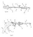
- FIG. 1is a perspective representation of an embodiment of the surgical device according to the invention wherein a disposable loading unit 40 is functionally engaged in the distal part of the casing 10 forming a housing.
- the arrow “C”illustrates the actuation stroke of the movable handle 13 .
- FIG. 2 ais a perspective view of the cross-section of the handle assembly 30 of the surgical device.
- FIG. 2 bis a side cross-section view of the handle assembly 30 of the surface device according to the invention.
- FIG. 3 ais a perspective representation of the actuation mechanism supported in the housing 10 of the handle assembly 30 .
- FIG. 3 bis an exploded view representation of the actuation mechanism in FIG. 3 a.
- FIG. 4 ais a perspective view of a disposable loading unit 40 suitable for being functionally engaged with the handle assembly 30 of the surgical device according to the invention.
- FIG. 4 bis an exploded view representation of the disposable loading unit 40 in FIG. 4 a.
- FIG. 5is a perspective representation of the engagement mechanism of a disposable loading unit 40 on the handle assembly 30 of the surgical device according to the invention.
- the arrow “A”shows a longitudinal translational movement in the proximal direction of the disposable loading unit 40 ; the arrow “B” shows a rotational movement of the disposable loading unit 40 .
- proximalrefers to the end of the device (or apparatus) closest to the operator; the term “distal” refers to the end of the device (or apparatus) furthest from the operator.
- the handle assembly 30comprises a stationary handle element 11 and a movable handle element 13 , and also comprises a casing 10 forming a housing which preferably consists of molded casing half-sections 10 a and 10 b , which form the stationary handle element 11 and a shaft portion 12 of the handle assembly 30 .
- the handle assembly 30comprises an opening 31 suitable for receiving a portion of a disposable loading unit 40 , as will be described in more detail hereinafter.
- the movable handle element 13is supported in a pivoting manner between the casing half-sections 10 a and 10 b around the pivot 15 ( FIG. 2 a ).
- a stress element(not shown in the figures), which is preferably a torsion spring, stresses the movable handle 13 away from the stationary handle 11 .
- a transmission element 17( FIG. 2 b ) engages with each of the two racks 160 a , 160 b of the drive shafts 16 a , 16 b and is pivotally mounted about a pivot 17 c .
- the transmission element 17consists of a notched wheel portion 17 a suitable for engaging with the rack 160 a of the first drive shaft, and a second notched wheel portion 17 b suitable for engaging with the rack 160 b of the second drive shaft 16 b .
- the rotational axis of both notched wheel portions 17 a , 17 bis situated at the pivot 17 c.
- the movable handle 13can pivot to move the first actuation shaft 16 a forward linearly in the distal direction and actuate the transmission element 17 in contact with the toothed rack 160 a of said first actuation shaft 16 a .
- the rotation of the transmission element 17enables the movement of the second actuation shaft 16 b linearly in the proximal direction.
- the retraction mechanismwhich comprises a retraction element 18 may be advantageously connected to the proximal end of the first actuation shaft 16 a by a traction spring 18 .
- the traction spring 18is connected to a fixed support element 19 , such that said spring 18 is configured to make a longitudinal translational movement in the distal or proximal direction.
- the first drive shaft 16 ais connected to a main actuation sled 20 a comprising at the distal end an opening 201 a engaging with the proximal part of the disposable loading unit 40 as described in detail further in the description.
- the second drive shaft 16 bis in turn connected to the secondary actuation sled 20 b by means of a guiding element 25 .
- the actuation sled 20 bcomprises at the distal end thereof an opening 201 b engaging with the proximal part of the disposable loading unit 40 .
- the opening 201 b of the secondary actuation sled 20 bis smaller in diameter than that of the main actuation sled 20 a.
- the secondary actuation sled 20 bis contained in the actuation sled 20 a , and is suitable for moving longitudinally by means of a guide rail 25 suitable for moving in a sliding manner the guiding part 26 on the guide rail 25 .
- the drive shafts 16 a , 16 b and the actuation sleds 20 b , 20 aeach respectively form a single preformed part by molding ( FIG. 3 b ).
- a fastening mechanism of the disposable loading unit 40extends into the casing 10 of the handle assembly 30 .
- the fastening mechanismcomprises a first actuation sled 20 a having a rectangular cross-section which is supported in a sliding manner with the first drive shaft 16 a , and a secondary actuation sled 20 b having a rectangular cross-section supported in a sliding manner at the second drive shaft 16 b .
- the two distal openings 201 a , 201 b of the actuation sleds 20 a , 20 bhaving a substantially circular shape, and further comprise two additional recesses situated on either side of the opening enabling the passage of the proximal end of the disposable loading unit 40 at the proximal part 45 thereof.
- the casing 10contains, inter alia, the first drive shaft 16 a , the first actuation sled 20 a , the second drive shaft 16 b and the secondary actuation sled 20 b , and the transmission element 17 and the traction element 18 ; this represents an advantageous embodiment.
- the disposable loading unit 40comprises a proximal portion 45 suitable for engaging releasably with the distal end of the handle assembly 30 ( FIG. 1 ).
- An actuation mechanism(not shown in the figure) comprised in the body 41 of the disposable loading unit 40 is configured to actuate the tool assembly 44 .
- the proximal portion 45 of the loading unitincludes a first pair of hooks 450 and a second pair of hooks 451 suitable for fastening the disposable loading unit 40 on the handle assembly 30 , at the distal end of the shaft portion 12 of the casing 10 , as will be described in more detail hereinafter.
- the disposable loading unit 40further comprises a locking element 46 consisting preferably of molded half-sections 46 a and 46 b suitable for locking and aligning the mounting assembly comprised in the body of the loading unit.
- the proximal end of the locking element 46comprises an edge 46 c suitable for engaging with the unlocking element 14 by locking.
- the unlocking elementcomprises a portion in the form of a projection 14 a situated in the recess 10 of the device engaging with the edge 46 c of the locking element.
- the disposable loading unit 40comprises a fastening element 42 engaging at least partially with the proximal part of the body 41 of the disposable loading unit, and “surrounding” at least partially the locking element 46 .
- the fastening elementmakes it possible to retain the alignment of the assembly of constituent parts of the body 41 , and more particularly the assembly of the actuation mechanism comprised in said body 41 . Indeed, in order to function correctly, the assembly of constituent parts of the loading unit 40 must be perfectly aligned with respect to one another, with tolerances of only a few tenths of millimeter, in order to actuate the overall device.
- a disposable loading unit 40is first fastened to the distal end of the handle assembly 30 .
- the proximal portion 45 of the loading unitis inserted into the opening 30 a of the handle assembly 30
- the first pair of hooks 450is made slide longitudinally in the distal end of the casing 10 in the direct shown by the arrow “A” in FIG.
- the first pair of hoods 450is engaged in a first phase through the first actuation sled 20 a via to the distal opening 201 a , then in a second phase through the second actuation sled 20 b via the distal opening 201 b .
- the second pair of hooks 451is engaged through the actuation sled 20 a via the distal opening 201 a .
- the proximal end of the locking element 46engages with the unlocking elements 14 by locking.
- the disposable loading unit 40is made rotate in the direction shown by the arrow “B” in FIG. 5 to engage the pairs of hooks 450 , 451 with the inner shoulders of the distal ends of the actuation sleds 20 a , 20 b . It should be noted that, when the disposable loading unit is made rotate, an audible click sound is produced indicating that the disposable loading unit 40 is fastened correctly to the housing 10 .
- the tool 45can be used and positioned to dispense a plurality of clips.
- the movable handle 13is moved in the direction shown by the arrow “C” in FIG. 1 against the stress of the torsion spring to make the first actuation shaft 16 a move forward linearly in the distal direction and to move the second actuation shaft 16 b forward linearly in the proximal direction by means of the transmission element 17 .
- the movement of the actuation shafts 16 a , 16 binduces the movement of the respective actuation sleds 20 a , 20 b thereof.
- the disposable loading unit 40being fastened to the handle 30 , the movement of the actuation sled 20 b induces therewith the movement in the proximal direction of the first pair of hooks 450 which is rigidly connected to a first plate (not shown in the figures).
- the first platethus moves longitudinally in the proximal direction until it engages with a clip “n ⁇ 1” stored in the body 43 of the movable loading unit 40 .
- the movement of the actuation sled 20 ainduces therewith the movement in the distal direction of the second pair of hooks 451 which is in turn rigidly connected to a second plate (not shown in the figures) suitable for moving a clip “n” in the distal direction, i.e. toward the tool assembly 44 .
- a third plate(not shown in the figures) is actuated in the distal direction toward the tool assembly 44 enabling the actuation thereof, notably making it possible in the case of a clip applicator to close the jaws of the tool assembly around the clip “n”.
- the disposable loading unit 40further comprises a securing element 43 situated at least partially on the body 41 of the loading unit to retain the alignment of the clips comprised in the body 41 before the use of the device, notably when the device is transported or stored. During the use of the device 1 , the securing element 43 must be removed to activate the various clip dispensing mechanisms.
- the invalidated or locked disposable loading unit 40can be removed from the casing 10 by applying a pressure to the unlocking element 14 , then by rotating the disposable loading unit 40 in the opposite direction of the direct shown by the arrow “B” in FIG. 5 to disengage the pairs of hooks 450 , 451 on the inner shoulders of the actuation sleds 20 a , 20 b .
- the disposable loading unit 40can be made slide in the opposite direction to that shown by the arrow “A” in order to detach the casing 10 from the disposable loading unit 40 .
- additional disposable loading unitscan be fastened to the distal end of the casing 10 , as described above, to perform the same operation, i.e. dispensing clips, or to perform further tasks, for example stapling tissue, an incision, a section operation.
- the device according to the inventionthus comprises a simplified mechanism reducing tooling and assembly requirements considerably, while offering very good operational reliability, at least cost.
- the device according to the inventionrequires small general tolerances.
- the general tolerances relating to the sizing of the clipsare as follows: ⁇ 0.30 mm on all the plane faces of the clip, ⁇ 0.4 mm for the height, ⁇ 0.40 mm width of the clip between the jaws of a tool assembly.
- the disposable loading unit 40may comprise at least one linear row of at most thirty clips, preferably at most twenty clips. These clips are used to ligate blood vessels, notably arteries, or before sectioning same or assembling organic or synthetic tissue.
- the clipsmay be absorbable or non-absorbable, in the latter case, the clips are preferably made of titanium and substantially U-shaped. Furthermore, the length of the linear row of surgical clips or staples may be modified to meet the needs of a specific surgical procedure.
- the device according to the inventiondoes not necessarily apply only surgical clips (or surgical fasteners) but may also apply staples, for example for the ablation of all or part of an organ and/or to make it possible to carry out anastomosis.
- the devicemay be used with disposable loading units designed to apply linear rows of staples and may be used to activate disposable loading units containing individual staples.
- the device according to the inventionmay also support in the housing thereof a disposable loading unit wherein the distal end part supports a blade configured to make incisions, for example an incision in stapled body tissue.
Landscapes
- Health & Medical Sciences (AREA)
- Surgery (AREA)
- Life Sciences & Earth Sciences (AREA)
- Heart & Thoracic Surgery (AREA)
- Nuclear Medicine, Radiotherapy & Molecular Imaging (AREA)
- Engineering & Computer Science (AREA)
- Biomedical Technology (AREA)
- Medical Informatics (AREA)
- Molecular Biology (AREA)
- Animal Behavior & Ethology (AREA)
- General Health & Medical Sciences (AREA)
- Public Health (AREA)
- Veterinary Medicine (AREA)
- Vascular Medicine (AREA)
- Reproductive Health (AREA)
- Surgical Instruments (AREA)
Abstract
Description
- a handle assembly comprising a casing forming a housing, a stationary handle element, and a movable handle element that can be moved by means of an actuating movement;
- at least one disposable loading unit suitable for being mounted at least partially in a reversible manner inside said casing forming a housing, said disposable loading unit comprising an actuation mechanism;
- a first actuation shaft mounted to make a longitudinal movement inside the housing in response to the movement of the movable handle element;
- a transmission element mounted to actuate a longitudinal movement of a second actuation shaft mounted inside said casing forming a housing in response to the longitudinal movement of the first actuation shaft;
- a main actuation sled and a secondary actuation sled mounted to at least partially receive said at least one disposable loading unit, said actuation sleds being secured respectively to the actuation shafts in order to activate the actuation mechanism of the disposable loading unit in response to the longitudinal movements thereof.
- surgical clip applicators;
- staplers;
- incision tools, notably incision blades.
| 1 | ||||
| 10 | ||||
| 11 | ||||
| 12 | ||||
| 13 | ||||
| 14 | Unlocking | |||
| 15 | ||||
| 16a | ||||
| 16b | ||||
| 17 | ||||
| 18 | ||||
| 19 | ||||
| 20a | ||||
| 20b | ||||
| 25 | ||||
| 26 | ||||
| 30 | ||||
| 31 | ||||
| 40 | ||||
| 41 | ||||
| 42 | ||||
| 43 | Securing | |||
| 44 | ||||
| 45 | Proximal portion | |||
| 46 (46a, 46b) | ||||
| 46c | Peripheral edge of locking | |||
| 160a, | Toothed racks | |||
| 201a, 201b | ||||
| 450 | Lower | |||
| 451 | Horizontal partition | |||
Claims (15)
Applications Claiming Priority (3)
| Application Number | Priority Date | Filing Date | Title |
|---|---|---|---|
| FR1361249AFR3013206B1 (en) | 2013-11-18 | 2013-11-18 | MULTIFUNCTIONAL RECHARGEABLE AND DISPOSABLE SURGICAL DEVICE |
| FR1361249 | 2013-11-18 | ||
| PCT/FR2014/052926WO2015071614A1 (en) | 2013-11-18 | 2014-11-17 | Reloadable and disposable multifunctional surgical device |
Publications (2)
| Publication Number | Publication Date |
|---|---|
| US20160296232A1 US20160296232A1 (en) | 2016-10-13 |
| US10314581B2true US10314581B2 (en) | 2019-06-11 |
Family
ID=49876916
Family Applications (1)
| Application Number | Title | Priority Date | Filing Date |
|---|---|---|---|
| US15/037,384Active2036-01-09US10314581B2 (en) | 2013-11-18 | 2014-11-17 | Reloadable and disposable multifunctional surgical device |
Country Status (4)
| Country | Link |
|---|---|
| US (1) | US10314581B2 (en) |
| EP (1) | EP3071120B1 (en) |
| FR (1) | FR3013206B1 (en) |
| WO (1) | WO2015071614A1 (en) |
Cited By (1)
| Publication number | Priority date | Publication date | Assignee | Title |
|---|---|---|---|---|
| US12167851B2 (en)* | 2020-06-01 | 2024-12-17 | Olympus Corporation | Treatment instrument |
Families Citing this family (19)
| Publication number | Priority date | Publication date | Assignee | Title |
|---|---|---|---|---|
| US8465502B2 (en) | 2008-08-25 | 2013-06-18 | Covidien Lp | Surgical clip applier and method of assembly |
| US9358015B2 (en) | 2008-08-29 | 2016-06-07 | Covidien Lp | Endoscopic surgical clip applier with wedge plate |
| US8403945B2 (en) | 2010-02-25 | 2013-03-26 | Covidien Lp | Articulating endoscopic surgical clip applier |
| US8968337B2 (en) | 2010-07-28 | 2015-03-03 | Covidien Lp | Articulating clip applier |
| EP3091909B1 (en)* | 2014-01-10 | 2019-11-27 | Endodynamix, Inc. | Devices for applying surgical clips |
| US10285698B2 (en)* | 2015-02-26 | 2019-05-14 | Covidien Lp | Surgical apparatus |
| AU2016388454A1 (en)* | 2016-01-18 | 2018-07-19 | Covidien Lp | Endoscopic surgical clip applier |
| CA2958160A1 (en) | 2016-02-24 | 2017-08-24 | Covidien Lp | Endoscopic reposable surgical clip applier |
| WO2017184964A1 (en)* | 2016-04-21 | 2017-10-26 | Applied Medical Resources Corporation | Laparoscopic clip applier |
| US10492795B2 (en) | 2016-11-01 | 2019-12-03 | Covidien Lp | Endoscopic surgical clip applier |
| US11583291B2 (en) | 2017-02-23 | 2023-02-21 | Covidien Lp | Endoscopic surgical clip applier |
| US10675043B2 (en) | 2017-05-04 | 2020-06-09 | Covidien Lp | Reposable multi-fire surgical clip applier |
| US10786262B2 (en)* | 2017-08-09 | 2020-09-29 | Covidien Lp | Endoscopic reposable surgical clip applier |
| US11376015B2 (en) | 2017-11-03 | 2022-07-05 | Covidien Lp | Endoscopic surgical clip applier and handle assemblies for use therewith |
| CN110547855B (en)* | 2018-06-01 | 2021-02-26 | 江苏风和医疗器材股份有限公司 | Percussion handle and cutting anastomat thereof |
| CN111281455B (en)* | 2018-12-07 | 2025-03-11 | 上海逸思医疗科技股份有限公司 | Reusable stapler with detachable adapter |
| US11192227B2 (en)* | 2019-07-16 | 2021-12-07 | Covidien Lp | Reload assembly for circular stapling devices |
| US11779340B2 (en) | 2020-01-02 | 2023-10-10 | Covidien Lp | Ligation clip loading device |
| US12114866B2 (en) | 2020-03-26 | 2024-10-15 | Covidien Lp | Interoperative clip loading device |
Citations (30)
| Publication number | Priority date | Publication date | Assignee | Title |
|---|---|---|---|---|
| US4508253A (en)* | 1983-10-04 | 1985-04-02 | United States Surgical Corporation | Surgical fastener applying apparatus |
| US5336229A (en)* | 1993-02-09 | 1994-08-09 | Laparomed Corporation | Dual ligating and dividing apparatus |
| US5389098A (en)* | 1992-05-19 | 1995-02-14 | Olympus Optical Co., Ltd. | Surgical device for stapling and/or fastening body tissues |
| US5417361A (en)* | 1993-05-05 | 1995-05-23 | Ethicon Endo-Surgery, Inc. | Staple cartridge for a surgical stapler |
| US5529235A (en)* | 1994-04-28 | 1996-06-25 | Ethicon Endo-Surgery, Inc. | Identification device for surgical instrument |
| US5743436A (en)* | 1995-12-08 | 1998-04-28 | Minnesota Mining & Manufacturing Co. | Applicator for dispensing material from a dual chamber cartridge |
| US20020198537A1 (en) | 2001-06-25 | 2002-12-26 | Smith Kevin W. | Method of applying surgical clips to tissue |
| US20030040759A1 (en) | 2001-08-21 | 2003-02-27 | De Guillebon Henri | Medical clip applying device |
| US20050006432A1 (en)* | 2003-06-17 | 2005-01-13 | Racenet David C. | Surgical stapling device |
| US20060079913A1 (en) | 2004-10-08 | 2006-04-13 | Whitfield Kenneth H | Endoscopic surgical clip applier |
| US20060097026A1 (en) | 2003-09-29 | 2006-05-11 | Ethicon Endo-Surgery, Inc. | Surgical stapling instrument incorporating a multi-stroke firing mechanism with a flexible rack |
| US20080210738A1 (en) | 2005-08-31 | 2008-09-04 | Ethicon Endo-Surgery, Inc. | Staple cartridges for forming staples having differing formed staple heights |
| US20090090763A1 (en)* | 2007-10-05 | 2009-04-09 | Tyco Healthcare Group Lp | Powered surgical stapling device |
| US20100170931A1 (en)* | 2003-03-26 | 2010-07-08 | Tyco Healthcare Group Lp | Energy Stored In Spring with Controlled Release |
| US20100292712A1 (en) | 2009-05-12 | 2010-11-18 | Ethicon, Inc. | Surgical fasteners, applicator instruments, and methods for deploying surgical fasteners |
| US20110174099A1 (en)* | 2009-12-02 | 2011-07-21 | Ross Adam J | Adapters for use between surgical handle assembly and surgical end effector |
| US20120089131A1 (en)* | 2007-09-21 | 2012-04-12 | Tyco Healthcare Group Lp | Hand held surgical handle assembly, surgical adapters for use between surgical handle assembly and surgical end effectors, and methods of use |
| EP2537471A1 (en) | 2011-06-21 | 2012-12-26 | Ethicon Endo-Surgery, Inc. | A surgical fastener having a safety feature |
| US8464925B2 (en)* | 2010-05-11 | 2013-06-18 | Ethicon Endo-Surgery, Inc. | Methods and apparatus for delivering tissue treatment compositions to stapled tissue |
| US20130200131A1 (en)* | 2012-02-03 | 2013-08-08 | Tyco Healthcare Group Lp | Circular Stapling Instrument |
| US20140305992A1 (en)* | 2013-04-16 | 2014-10-16 | Ethicon Endo-Surgery, Inc. | Modular motor driven surgical instruments with status indication arrangements |
| US20150209040A1 (en)* | 2011-01-14 | 2015-07-30 | New Hope Ventures, Lp | Surgical stapling device and method |
| US20160058444A1 (en)* | 2014-09-02 | 2016-03-03 | Ethicon Endo-Surgery, Inc. | Devices and Methods for Manually Retracting a Drive Shaft, Drive Beam, and Associated Components of a Surgical Fastening Device |
| US20160058441A1 (en)* | 2014-09-02 | 2016-03-03 | Ethicon Endo-Surgery, Inc. | Devices and Methods for Facilitating Ejection of Surgical Fasteners from Cartridges |
| US20160249929A1 (en)* | 2015-02-26 | 2016-09-01 | Covidien Lp | Surgical apparatus |
| US20170079640A1 (en)* | 2015-09-23 | 2017-03-23 | Ethicon Endo Surgery Llc | Surgical stapler having motor control based on a drive system component |
| US20170224337A1 (en)* | 2016-02-10 | 2017-08-10 | Covidien Lp | Surgical stapler with articulation locking mechanism |
| US9757130B2 (en)* | 2007-02-28 | 2017-09-12 | Ethicon Llc | Stapling assembly for forming different formed staple heights |
| US20170281187A1 (en)* | 2016-04-01 | 2017-10-05 | Ethicon Endo-Surgery, Llc | Surgical stapling system comprising a tissue compression lockout |
| US20190000467A1 (en)* | 2017-06-28 | 2019-01-03 | Ethicon Llc | Surgical instrument comprising an articulation system ratio |
Family Cites Families (2)
| Publication number | Priority date | Publication date | Assignee | Title |
|---|---|---|---|---|
| US5782396A (en) | 1995-08-28 | 1998-07-21 | United States Surgical Corporation | Surgical stapler |
| US6869435B2 (en) | 2002-01-17 | 2005-03-22 | Blake, Iii John W | Repeating multi-clip applier |
- 2013
- 2013-11-18FRFR1361249Apatent/FR3013206B1/enactiveActive
- 2014
- 2014-11-17EPEP14827464.0Apatent/EP3071120B1/enactiveActive
- 2014-11-17WOPCT/FR2014/052926patent/WO2015071614A1/enactiveApplication Filing
- 2014-11-17USUS15/037,384patent/US10314581B2/enactiveActive
Patent Citations (32)
| Publication number | Priority date | Publication date | Assignee | Title |
|---|---|---|---|---|
| US4508253A (en)* | 1983-10-04 | 1985-04-02 | United States Surgical Corporation | Surgical fastener applying apparatus |
| US5389098A (en)* | 1992-05-19 | 1995-02-14 | Olympus Optical Co., Ltd. | Surgical device for stapling and/or fastening body tissues |
| US5336229A (en)* | 1993-02-09 | 1994-08-09 | Laparomed Corporation | Dual ligating and dividing apparatus |
| US5417361A (en)* | 1993-05-05 | 1995-05-23 | Ethicon Endo-Surgery, Inc. | Staple cartridge for a surgical stapler |
| US5529235A (en)* | 1994-04-28 | 1996-06-25 | Ethicon Endo-Surgery, Inc. | Identification device for surgical instrument |
| US5743436A (en)* | 1995-12-08 | 1998-04-28 | Minnesota Mining & Manufacturing Co. | Applicator for dispensing material from a dual chamber cartridge |
| US20020198537A1 (en) | 2001-06-25 | 2002-12-26 | Smith Kevin W. | Method of applying surgical clips to tissue |
| US20030040759A1 (en) | 2001-08-21 | 2003-02-27 | De Guillebon Henri | Medical clip applying device |
| US20100170931A1 (en)* | 2003-03-26 | 2010-07-08 | Tyco Healthcare Group Lp | Energy Stored In Spring with Controlled Release |
| US20050006432A1 (en)* | 2003-06-17 | 2005-01-13 | Racenet David C. | Surgical stapling device |
| US20060097026A1 (en) | 2003-09-29 | 2006-05-11 | Ethicon Endo-Surgery, Inc. | Surgical stapling instrument incorporating a multi-stroke firing mechanism with a flexible rack |
| US20060079913A1 (en) | 2004-10-08 | 2006-04-13 | Whitfield Kenneth H | Endoscopic surgical clip applier |
| US20080210738A1 (en) | 2005-08-31 | 2008-09-04 | Ethicon Endo-Surgery, Inc. | Staple cartridges for forming staples having differing formed staple heights |
| US9757130B2 (en)* | 2007-02-28 | 2017-09-12 | Ethicon Llc | Stapling assembly for forming different formed staple heights |
| US20120089131A1 (en)* | 2007-09-21 | 2012-04-12 | Tyco Healthcare Group Lp | Hand held surgical handle assembly, surgical adapters for use between surgical handle assembly and surgical end effectors, and methods of use |
| US20090090763A1 (en)* | 2007-10-05 | 2009-04-09 | Tyco Healthcare Group Lp | Powered surgical stapling device |
| US20100292712A1 (en) | 2009-05-12 | 2010-11-18 | Ethicon, Inc. | Surgical fasteners, applicator instruments, and methods for deploying surgical fasteners |
| US20110174099A1 (en)* | 2009-12-02 | 2011-07-21 | Ross Adam J | Adapters for use between surgical handle assembly and surgical end effector |
| US8464925B2 (en)* | 2010-05-11 | 2013-06-18 | Ethicon Endo-Surgery, Inc. | Methods and apparatus for delivering tissue treatment compositions to stapled tissue |
| US20150209040A1 (en)* | 2011-01-14 | 2015-07-30 | New Hope Ventures, Lp | Surgical stapling device and method |
| EP2537471A1 (en) | 2011-06-21 | 2012-12-26 | Ethicon Endo-Surgery, Inc. | A surgical fastener having a safety feature |
| US20130200131A1 (en)* | 2012-02-03 | 2013-08-08 | Tyco Healthcare Group Lp | Circular Stapling Instrument |
| US20140305992A1 (en)* | 2013-04-16 | 2014-10-16 | Ethicon Endo-Surgery, Inc. | Modular motor driven surgical instruments with status indication arrangements |
| US20160058444A1 (en)* | 2014-09-02 | 2016-03-03 | Ethicon Endo-Surgery, Inc. | Devices and Methods for Manually Retracting a Drive Shaft, Drive Beam, and Associated Components of a Surgical Fastening Device |
| US20160058441A1 (en)* | 2014-09-02 | 2016-03-03 | Ethicon Endo-Surgery, Inc. | Devices and Methods for Facilitating Ejection of Surgical Fasteners from Cartridges |
| US20160249929A1 (en)* | 2015-02-26 | 2016-09-01 | Covidien Lp | Surgical apparatus |
| US20170079640A1 (en)* | 2015-09-23 | 2017-03-23 | Ethicon Endo Surgery Llc | Surgical stapler having motor control based on a drive system component |
| US20170224337A1 (en)* | 2016-02-10 | 2017-08-10 | Covidien Lp | Surgical stapler with articulation locking mechanism |
| US20170281187A1 (en)* | 2016-04-01 | 2017-10-05 | Ethicon Endo-Surgery, Llc | Surgical stapling system comprising a tissue compression lockout |
| US20170281185A1 (en)* | 2016-04-01 | 2017-10-05 | Ethicon Endo-Surgery, Llc | Surgical stapling system comprising a spent cartridge lockout |
| US20190000467A1 (en)* | 2017-06-28 | 2019-01-03 | Ethicon Llc | Surgical instrument comprising an articulation system ratio |
| US20190000477A1 (en)* | 2017-06-28 | 2019-01-03 | Ethicon Llc | Surgical instrument comprising a shaft including a housing arrangement |
Cited By (1)
| Publication number | Priority date | Publication date | Assignee | Title |
|---|---|---|---|---|
| US12167851B2 (en)* | 2020-06-01 | 2024-12-17 | Olympus Corporation | Treatment instrument |
Also Published As
| Publication number | Publication date |
|---|---|
| EP3071120B1 (en) | 2019-03-20 |
| US20160296232A1 (en) | 2016-10-13 |
| WO2015071614A1 (en) | 2015-05-21 |
| FR3013206A1 (en) | 2015-05-22 |
| EP3071120A1 (en) | 2016-09-28 |
| FR3013206B1 (en) | 2015-12-11 |
Similar Documents
| Publication | Publication Date | Title |
|---|---|---|
| US10314581B2 (en) | Reloadable and disposable multifunctional surgical device | |
| JP7367000B2 (en) | Clamp assembly for linear surgical stapler | |
| CN112888376B (en) | Disengagement mechanism for linear surgical stapler | |
| CN111295142B (en) | Positive axis rotation lock actuated by jaw closure | |
| RU2640947C2 (en) | Surgical stapler with locking system to prevent activation in absence of installed staple cartridge | |
| JP7021907B2 (en) | Surgical tool assembly with compact launch assembly | |
| CN109661201B (en) | Surgical suture device | |
| JP5503446B2 (en) | Crimping and releasing suture holding buttress material | |
| JP4704028B2 (en) | Surgical instruments adapted to apply multiple surgical fasteners to body tissue | |
| US9782164B2 (en) | Suturing instrument with multi-mode cartridges | |
| JP6891179B2 (en) | Surgical stapler with curved outer surface on the anvil | |
| JP5596304B2 (en) | Mountable clamp for surgical stapler | |
| EP2996579B1 (en) | Surgical stapling and cutting apparatus | |
| EP2992835B1 (en) | Devices for facilitating closing and clamping of an end effector of a surgical device | |
| JP4731904B2 (en) | Surgical instruments adapted to staple and dissect tissue in a highly controlled form | |
| US7780055B2 (en) | Loading unit having drive assembly locking mechanism | |
| JP4749681B2 (en) | Surgical stapler with lockout for used cartridge | |
| JP5697974B2 (en) | Indicator for surgical stapler | |
| EP2090234B1 (en) | Surgical stapling instrument with improved firing trigger arrangement | |
| JP5268184B2 (en) | Grasping jaw mechanism | |
| EP2952141B1 (en) | Surgical device | |
| US7431190B2 (en) | Linear stapler with improved firing mechanism | |
| JP2018122086A (en) | Endoscopic surgical clip applier | |
| EP3251613A1 (en) | Articulatable surgical instruments with separate and distinct closing and firing systems | |
| JP2004344659A (en) | Surgical stapler having single lockout mechanism for erroneous firing prevention |
Legal Events
| Date | Code | Title | Description |
|---|---|---|---|
| AS | Assignment | Owner name:CAMPBELL, PHILLIP, CHINA Free format text:ASSIGNMENT OF ASSIGNORS INTEREST;ASSIGNOR:CAMPBELL, PHILLIP;REEL/FRAME:038632/0029 Effective date:20160503 Owner name:ISMAIL, YOUSSEF, FRANCE Free format text:ASSIGNMENT OF ASSIGNORS INTEREST;ASSIGNOR:CAMPBELL, PHILLIP;REEL/FRAME:038632/0029 Effective date:20160503 Owner name:GALIANA, JEAN-MARC, FRANCE Free format text:ASSIGNMENT OF ASSIGNORS INTEREST;ASSIGNOR:CAMPBELL, PHILLIP;REEL/FRAME:038632/0029 Effective date:20160503 | |
| STPP | Information on status: patent application and granting procedure in general | Free format text:NOTICE OF ALLOWANCE MAILED -- APPLICATION RECEIVED IN OFFICE OF PUBLICATIONS | |
| STPP | Information on status: patent application and granting procedure in general | Free format text:PUBLICATIONS -- ISSUE FEE PAYMENT RECEIVED | |
| STPP | Information on status: patent application and granting procedure in general | Free format text:PUBLICATIONS -- ISSUE FEE PAYMENT VERIFIED | |
| STCF | Information on status: patent grant | Free format text:PATENTED CASE | |
| MAFP | Maintenance fee payment | Free format text:PAYMENT OF MAINTENANCE FEE, 4TH YR, SMALL ENTITY (ORIGINAL EVENT CODE: M2551); ENTITY STATUS OF PATENT OWNER: SMALL ENTITY Year of fee payment:4 |