US10314578B2 - Battery drain circuit for surgical instrument - Google Patents
Battery drain circuit for surgical instrumentDownload PDFInfo
- Publication number
- US10314578B2 US10314578B2US14/868,747US201514868747AUS10314578B2US 10314578 B2US10314578 B2US 10314578B2US 201514868747 AUS201514868747 AUS 201514868747AUS 10314578 B2US10314578 B2US 10314578B2
- Authority
- US
- United States
- Prior art keywords
- battery
- battery unit
- surgical instrument
- dock
- discharge
- Prior art date
- Legal status (The legal status is an assumption and is not a legal conclusion. Google has not performed a legal analysis and makes no representation as to the accuracy of the status listed.)
- Active, expires
Links
- 238000004891communicationMethods0.000claimsabstractdescription23
- 239000012636effectorSubstances0.000claimsdescription45
- 238000000034methodMethods0.000claimsdescription24
- 230000005355Hall effectEffects0.000claimsdescription18
- 238000001356surgical procedureMethods0.000claimsdescription17
- 230000004044responseEffects0.000claimsdescription11
- 230000008878couplingEffects0.000claimsdescription5
- 238000010168coupling processMethods0.000claimsdescription5
- 238000005859coupling reactionMethods0.000claimsdescription5
- 238000007599dischargingMethods0.000claimsdescription4
- 230000009467reductionEffects0.000claimsdescription3
- 238000012546transferMethods0.000claimsdescription2
- 238000010304firingMethods0.000description16
- 230000000712assemblyEffects0.000description12
- 238000000429assemblyMethods0.000description12
- 238000005516engineering processMethods0.000description11
- 239000000463materialSubstances0.000description9
- 238000010586diagramMethods0.000description8
- 230000033001locomotionEffects0.000description7
- 238000009434installationMethods0.000description6
- 230000007246mechanismEffects0.000description6
- 238000003780insertionMethods0.000description5
- 230000037431insertionEffects0.000description5
- 230000003111delayed effectEffects0.000description4
- 230000000977initiatory effectEffects0.000description4
- 230000005855radiationEffects0.000description4
- 238000011282treatmentMethods0.000description4
- 238000004140cleaningMethods0.000description3
- 230000001934delayEffects0.000description3
- 230000005669field effectEffects0.000description3
- 230000014509gene expressionEffects0.000description3
- 229910044991metal oxideInorganic materials0.000description3
- 150000004706metal oxidesChemical class0.000description3
- 238000012986modificationMethods0.000description3
- 230000004048modificationEffects0.000description3
- 210000000056organAnatomy0.000description3
- 239000004065semiconductorSubstances0.000description3
- WHXSMMKQMYFTQS-UHFFFAOYSA-NLithiumChemical compound[Li]WHXSMMKQMYFTQS-UHFFFAOYSA-N0.000description2
- 235000014676Phragmites communisNutrition0.000description2
- 239000000853adhesiveSubstances0.000description2
- 230000001070adhesive effectEffects0.000description2
- 229910052744lithiumInorganic materials0.000description2
- 239000010852non-hazardous wasteSubstances0.000description2
- 210000000115thoracic cavityAnatomy0.000description2
- 230000007704transitionEffects0.000description2
- 241000894006BacteriaSpecies0.000description1
- IAYPIBMASNFSPL-UHFFFAOYSA-NEthylene oxideChemical compoundC1CO1IAYPIBMASNFSPL-UHFFFAOYSA-N0.000description1
- HBBGRARXTFLTSG-UHFFFAOYSA-NLithium ionChemical compound[Li+]HBBGRARXTFLTSG-UHFFFAOYSA-N0.000description1
- 239000004775TyvekSubstances0.000description1
- 229920000690TyvekPolymers0.000description1
- 230000006978adaptationEffects0.000description1
- 230000004888barrier functionEffects0.000description1
- 230000005540biological transmissionEffects0.000description1
- 230000015572biosynthetic processEffects0.000description1
- 230000009189divingEffects0.000description1
- 230000000694effectsEffects0.000description1
- 239000002920hazardous wasteSubstances0.000description1
- 238000002955isolationMethods0.000description1
- 229910001416lithium ionInorganic materials0.000description1
- 210000004072lungAnatomy0.000description1
- 230000013011matingEffects0.000description1
- 230000002265preventionEffects0.000description1
- 230000001954sterilising effectEffects0.000description1
- 238000004659sterilization and disinfectionMethods0.000description1
- 230000001360synchronised effectEffects0.000description1
- 230000002123temporal effectEffects0.000description1
- 238000002604ultrasonographyMethods0.000description1
- 210000001835visceraAnatomy0.000description1
Images


Classifications
- A—HUMAN NECESSITIES
- A61—MEDICAL OR VETERINARY SCIENCE; HYGIENE
- A61B—DIAGNOSIS; SURGERY; IDENTIFICATION
- A61B17/00—Surgical instruments, devices or methods
- A61B17/068—Surgical staplers, e.g. containing multiple staples or clamps
- A61B17/072—Surgical staplers, e.g. containing multiple staples or clamps for applying a row of staples in a single action, e.g. the staples being applied simultaneously
- A61B17/07207—Surgical staplers, e.g. containing multiple staples or clamps for applying a row of staples in a single action, e.g. the staples being applied simultaneously the staples being applied sequentially
- A—HUMAN NECESSITIES
- A61—MEDICAL OR VETERINARY SCIENCE; HYGIENE
- A61B—DIAGNOSIS; SURGERY; IDENTIFICATION
- A61B17/00—Surgical instruments, devices or methods
- A61B17/068—Surgical staplers, e.g. containing multiple staples or clamps
- A61B17/072—Surgical staplers, e.g. containing multiple staples or clamps for applying a row of staples in a single action, e.g. the staples being applied simultaneously
- H—ELECTRICITY
- H01—ELECTRIC ELEMENTS
- H01M—PROCESSES OR MEANS, e.g. BATTERIES, FOR THE DIRECT CONVERSION OF CHEMICAL ENERGY INTO ELECTRICAL ENERGY
- H01M10/00—Secondary cells; Manufacture thereof
- H01M10/42—Methods or arrangements for servicing or maintenance of secondary cells or secondary half-cells
- H01M10/425—Structural combination with electronic components, e.g. electronic circuits integrated to the outside of the casing
- H01M10/4257—Smart batteries, e.g. electronic circuits inside the housing of the cells or batteries
- H—ELECTRICITY
- H01—ELECTRIC ELEMENTS
- H01M—PROCESSES OR MEANS, e.g. BATTERIES, FOR THE DIRECT CONVERSION OF CHEMICAL ENERGY INTO ELECTRICAL ENERGY
- H01M10/00—Secondary cells; Manufacture thereof
- H01M10/42—Methods or arrangements for servicing or maintenance of secondary cells or secondary half-cells
- H01M10/44—Methods for charging or discharging
- H01M2/1022—
- H—ELECTRICITY
- H01—ELECTRIC ELEMENTS
- H01M—PROCESSES OR MEANS, e.g. BATTERIES, FOR THE DIRECT CONVERSION OF CHEMICAL ENERGY INTO ELECTRICAL ENERGY
- H01M50/00—Constructional details or processes of manufacture of the non-active parts of electrochemical cells other than fuel cells, e.g. hybrid cells
- H01M50/20—Mountings; Secondary casings or frames; Racks, modules or packs; Suspension devices; Shock absorbers; Transport or carrying devices; Holders
- H01M50/204—Racks, modules or packs for multiple batteries or multiple cells
- H01M50/207—Racks, modules or packs for multiple batteries or multiple cells characterised by their shape
- H01M50/213—Racks, modules or packs for multiple batteries or multiple cells characterised by their shape adapted for cells having curved cross-section, e.g. round or elliptic
- H—ELECTRICITY
- H01—ELECTRIC ELEMENTS
- H01M—PROCESSES OR MEANS, e.g. BATTERIES, FOR THE DIRECT CONVERSION OF CHEMICAL ENERGY INTO ELECTRICAL ENERGY
- H01M50/00—Constructional details or processes of manufacture of the non-active parts of electrochemical cells other than fuel cells, e.g. hybrid cells
- H01M50/20—Mountings; Secondary casings or frames; Racks, modules or packs; Suspension devices; Shock absorbers; Transport or carrying devices; Holders
- H01M50/247—Mountings; Secondary casings or frames; Racks, modules or packs; Suspension devices; Shock absorbers; Transport or carrying devices; Holders specially adapted for portable devices, e.g. mobile phones, computers, hand tools or pacemakers
- H—ELECTRICITY
- H02—GENERATION; CONVERSION OR DISTRIBUTION OF ELECTRIC POWER
- H02J—CIRCUIT ARRANGEMENTS OR SYSTEMS FOR SUPPLYING OR DISTRIBUTING ELECTRIC POWER; SYSTEMS FOR STORING ELECTRIC ENERGY
- H02J7/00—Circuit arrangements for charging or depolarising batteries or for supplying loads from batteries
- H02J7/0068—Battery or charger load switching, e.g. concurrent charging and load supply
- H—ELECTRICITY
- H02—GENERATION; CONVERSION OR DISTRIBUTION OF ELECTRIC POWER
- H02J—CIRCUIT ARRANGEMENTS OR SYSTEMS FOR SUPPLYING OR DISTRIBUTING ELECTRIC POWER; SYSTEMS FOR STORING ELECTRIC ENERGY
- H02J7/00—Circuit arrangements for charging or depolarising batteries or for supplying loads from batteries
- H02J7/007—Regulation of charging or discharging current or voltage
- H02J7/00712—Regulation of charging or discharging current or voltage the cycle being controlled or terminated in response to electric parameters
- A—HUMAN NECESSITIES
- A61—MEDICAL OR VETERINARY SCIENCE; HYGIENE
- A61B—DIAGNOSIS; SURGERY; IDENTIFICATION
- A61B17/00—Surgical instruments, devices or methods
- A61B2017/00017—Electrical control of surgical instruments
- A—HUMAN NECESSITIES
- A61—MEDICAL OR VETERINARY SCIENCE; HYGIENE
- A61B—DIAGNOSIS; SURGERY; IDENTIFICATION
- A61B17/00—Surgical instruments, devices or methods
- A61B2017/00017—Electrical control of surgical instruments
- A61B2017/00022—Sensing or detecting at the treatment site
- A61B2017/00039—Electric or electromagnetic phenomena other than conductivity, e.g. capacity, inductivity, Hall effect
- A—HUMAN NECESSITIES
- A61—MEDICAL OR VETERINARY SCIENCE; HYGIENE
- A61B—DIAGNOSIS; SURGERY; IDENTIFICATION
- A61B17/00—Surgical instruments, devices or methods
- A61B2017/00367—Details of actuation of instruments, e.g. relations between pushing buttons, or the like, and activation of the tool, working tip, or the like
- A61B2017/00398—Details of actuation of instruments, e.g. relations between pushing buttons, or the like, and activation of the tool, working tip, or the like using powered actuators, e.g. stepper motors, solenoids
- A—HUMAN NECESSITIES
- A61—MEDICAL OR VETERINARY SCIENCE; HYGIENE
- A61B—DIAGNOSIS; SURGERY; IDENTIFICATION
- A61B17/00—Surgical instruments, devices or methods
- A61B2017/0046—Surgical instruments, devices or methods with a releasable handle; with handle and operating part separable
- A—HUMAN NECESSITIES
- A61—MEDICAL OR VETERINARY SCIENCE; HYGIENE
- A61B—DIAGNOSIS; SURGERY; IDENTIFICATION
- A61B17/00—Surgical instruments, devices or methods
- A61B2017/0046—Surgical instruments, devices or methods with a releasable handle; with handle and operating part separable
- A61B2017/00473—Distal part, e.g. tip or head
- A—HUMAN NECESSITIES
- A61—MEDICAL OR VETERINARY SCIENCE; HYGIENE
- A61B—DIAGNOSIS; SURGERY; IDENTIFICATION
- A61B17/00—Surgical instruments, devices or methods
- A61B2017/00681—Aspects not otherwise provided for
- A61B2017/00734—Aspects not otherwise provided for battery operated
- A—HUMAN NECESSITIES
- A61—MEDICAL OR VETERINARY SCIENCE; HYGIENE
- A61B—DIAGNOSIS; SURGERY; IDENTIFICATION
- A61B17/00—Surgical instruments, devices or methods
- A61B17/068—Surgical staplers, e.g. containing multiple staples or clamps
- A61B17/072—Surgical staplers, e.g. containing multiple staples or clamps for applying a row of staples in a single action, e.g. the staples being applied simultaneously
- A61B2017/07214—Stapler heads
- A61B2017/07285—Stapler heads characterised by its cutter
- A—HUMAN NECESSITIES
- A61—MEDICAL OR VETERINARY SCIENCE; HYGIENE
- A61B—DIAGNOSIS; SURGERY; IDENTIFICATION
- A61B2560/00—Constructional details of operational features of apparatus; Accessories for medical measuring apparatus
- A61B2560/02—Operational features
- A61B2560/0204—Operational features of power management
- H—ELECTRICITY
- H01—ELECTRIC ELEMENTS
- H01M—PROCESSES OR MEANS, e.g. BATTERIES, FOR THE DIRECT CONVERSION OF CHEMICAL ENERGY INTO ELECTRICAL ENERGY
- H01M2220/00—Batteries for particular applications
- H01M2220/30—Batteries in portable systems, e.g. mobile phone, laptop
- H02J2007/0067—
- H—ELECTRICITY
- H02—GENERATION; CONVERSION OR DISTRIBUTION OF ELECTRIC POWER
- H02J—CIRCUIT ARRANGEMENTS OR SYSTEMS FOR SUPPLYING OR DISTRIBUTING ELECTRIC POWER; SYSTEMS FOR STORING ELECTRIC ENERGY
- H02J2310/00—The network for supplying or distributing electric power characterised by its spatial reach or by the load
- H02J2310/10—The network having a local or delimited stationary reach
- H02J2310/20—The network being internal to a load
- H02J2310/23—The load being a medical device, a medical implant, or a life supporting device
- H—ELECTRICITY
- H02—GENERATION; CONVERSION OR DISTRIBUTION OF ELECTRIC POWER
- H02J—CIRCUIT ARRANGEMENTS OR SYSTEMS FOR SUPPLYING OR DISTRIBUTING ELECTRIC POWER; SYSTEMS FOR STORING ELECTRIC ENERGY
- H02J7/00—Circuit arrangements for charging or depolarising batteries or for supplying loads from batteries
- H02J7/0029—Circuit arrangements for charging or depolarising batteries or for supplying loads from batteries with safety or protection devices or circuits
- H02J7/0036—Circuit arrangements for charging or depolarising batteries or for supplying loads from batteries with safety or protection devices or circuits using connection detecting circuits
- H—ELECTRICITY
- H02—GENERATION; CONVERSION OR DISTRIBUTION OF ELECTRIC POWER
- H02J—CIRCUIT ARRANGEMENTS OR SYSTEMS FOR SUPPLYING OR DISTRIBUTING ELECTRIC POWER; SYSTEMS FOR STORING ELECTRIC ENERGY
- H02J7/00—Circuit arrangements for charging or depolarising batteries or for supplying loads from batteries
- H02J7/0042—Circuit arrangements for charging or depolarising batteries or for supplying loads from batteries characterised by the mechanical construction
- H02J7/0045—Circuit arrangements for charging or depolarising batteries or for supplying loads from batteries characterised by the mechanical construction concerning the insertion or the connection of the batteries
- Y—GENERAL TAGGING OF NEW TECHNOLOGICAL DEVELOPMENTS; GENERAL TAGGING OF CROSS-SECTIONAL TECHNOLOGIES SPANNING OVER SEVERAL SECTIONS OF THE IPC; TECHNICAL SUBJECTS COVERED BY FORMER USPC CROSS-REFERENCE ART COLLECTIONS [XRACs] AND DIGESTS
- Y02—TECHNOLOGIES OR APPLICATIONS FOR MITIGATION OR ADAPTATION AGAINST CLIMATE CHANGE
- Y02E—REDUCTION OF GREENHOUSE GAS [GHG] EMISSIONS, RELATED TO ENERGY GENERATION, TRANSMISSION OR DISTRIBUTION
- Y02E60/00—Enabling technologies; Technologies with a potential or indirect contribution to GHG emissions mitigation
- Y02E60/10—Energy storage using batteries
Definitions
- Various kinds of surgical instrumentsmay be powered by one or more battery cells. Such instruments may be used in a variety of surgical environments including, for example, endoscopic environments, laparoscopic environments, and open environments.
- Battery-powered surgical instrumentsmay include motor-driven implements, such as cutters, graspers, and/or staplers, for example.
- Battery-powered surgical instrumentsmay also include non-motor driven implements, such as RF cutter/coagulators, ultrasonic cutter/coagulators, and/or laser cutter/coagulators, for example.
- Battery-powered surgical instrumentsmay utilize primary cells, which are pre-charged and intended for a single discharge (e.g., one use). Using single discharge cells avoids the difficulties that may be associated with re-sterilizing and recharging cells. Primary cells, however, may present challenges related to shipping, storage, and disposal. For example, some charged cells can result in hazardous waste if not properly discharged since they may be only used once and may still have significant amount of charge left. To mitigate the risks, some jurisdictions have regulations governing the conditions under which cells may be shipped and disposed. Cells and batteries with higher amounts of stored energy may be required to be shipped, stored, and disposed of with safety measures that are more stringent and often more expensive.
- Examples of battery-powered surgical instrumentsinclude surgical staplers. Some such staplers are operable to clamp down on layers of tissue, cut through the clamped layers of tissue, and drive staples through the layers of tissue to substantially seal the severed layers of tissue together near the severed ends of the tissue layers.
- Some such staplersare operable to clamp down on layers of tissue, cut through the clamped layers of tissue, and drive staples through the layers of tissue to substantially seal the severed layers of tissue together near the severed ends of the tissue layers.
- Merely exemplary surgical staplersare disclosed in U.S. Pat. No. 4,805,823, entitled “Pocket Configuration for Internal Organ Staplers,” issued Feb. 21, 1989; U.S. Pat. No. 5,415,334, entitled “Surgical Stapler and Staple Cartridge,” issued May 16, 1995; U.S. Pat. No. 5,465,895, entitled “Surgical Stapler Instrument,” issued Nov. 14, 1995; U.S. Pat. No.
- surgical staplers referred to aboveare described as being used in endoscopic procedures, it should be understood that such surgical staplers may also be used in open procedures and/or other non-endoscopic procedures.
- a surgical staplermay be inserted through a thoracotomy, and thereby between a patient's ribs, to reach one or more organs in a thoracic surgical procedure that does not use a trocar as a conduit for the stapler.
- Such proceduresmay include the use of the stapler to sever and close a vessel leading to a lung. For instance, the vessels leading to an organ may be severed and closed by a stapler before removal of the organ from the thoracic cavity.
- surgical staplersmay be used in various other settings and procedures.
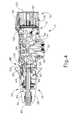
- FIG. 1depicts a perspective view of an exemplary surgical stapling instrument including an interchangeable shaft assembly, a handle assembly, and a removable battery assembly;
- FIG. 2depicts an perspective view of the instrument of FIG. 1 , showing the shaft assembly and battery assembly disassembled from the handle assembly of the instrument;
- FIG. 3depicts an exploded view of the handle assembly and battery assembly of the instrument of FIG. 1 ;
- FIG. 4depicts a cross-sectional side view of the instrument of FIG. 1 , taken along line 4 - 4 of FIG. 1 , with the shaft assembly operatively coupled to the handle assembly;
- FIG. 5depicts a side view of another exemplary surgical stapling instrument having a handle assembly and a power source
- FIG. 6Adepicts a schematic diagram of the power source detached from the handle assembly of FIG. 5 before attachment with the handle assembly;
- FIG. 6Bdepicts a schematic diagram of the power source attached with the handle assembly of FIG. 5 ;
- FIG. 6Cdepicts a schematic diagram of the power source detached from the handle assembly of FIG. 5 after attachment with the handle assembly;
- FIG. 7depicts a graph of a voltage level of the power source of FIG. 5 , as measured from a time of attachment with the handle assembly;
- FIG. 8depicts a simplified circuit diagram of the surgical instrument of FIG. 5 including an exemplary power drain
- FIG. 9depicts a perspective view of the power source of FIG. 5 in the form of an exemplary battery unit
- FIG. 10depicts another perspective view of the battery unit of FIG. 9 , with a cap removed from the battery unit;
- FIG. 11depicts yet another perspective view of the battery unit of FIG. 9 , with the cap and a casing removed from the battery unit;
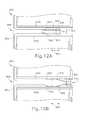
- FIG. 12Adepicts a cross-sectional side view of another exemplary power drain in an open position
- FIG. 12Bdepicts a cross-sectional side view the power drain of FIG. 12A in a closed position
- FIG. 13depicts a perspective view of the power drain of FIG. 12A ;
- FIG. 14depicts another exemplary battery unit attached to an exemplary dock of a handle assembly with various components omitted for clarity;
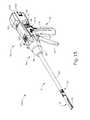
- FIG. 15depicts a perspective view of yet another exemplary surgical stapling instrument having a shaft assembly and a handle assembly;
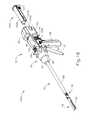
- FIG. 16depicts a partially exploded perspective view of the instrument of FIG. 15 , showing a power source detached from the handle assembly;
- FIG. 17depicts an enlarged partially exploded perspective view of the instrument and power source of FIG. 16 with various components omitted for clarity;
- FIG. 18depicts a perspective view of a battery dock of the instrument of FIG. 15 ;
- FIG. 19depicts an exploded left perspective view of the power source of FIG. 16 ;
- FIG. 20depicts an exploded right perspective view of the power source of FIG. 16 ;
- FIG. 21depicts a rear perspective sectional view of the instrument of FIG. 15 with various components omitted for clarity;
- FIG. 22depicts an enlarged rear perspective sectional view of the instrument of FIG. 15 with various components omitted for clarity;
- FIG. 23Adepicts an enlarged cross-sectional plan view of the instrument of FIG. 15 taken generally along a centerline of the power source, with an exemplary power drain in an open position;
- FIG. 23Bdepicts an enlarged cross-sectional plan view of the instrument of FIG. 15 taken generally along a centerline of the power source, with the power drain of FIG. 23A in a closed position;
- FIG. 24Adepicts an enlarged cross-sectional plan view of the instrument of FIG. 15 taken generally along a centerline of the power source, with certain components omitted for clarity, and with the power drain of FIG. 23A in the open position;
- FIG. 24Bdepicts an enlarged cross-sectional plan view of the instrument of FIG. 15 taken generally along a centerline of the power source, with certain components omitted for clarity, and with the power drain of FIG. 23A in the closed position;
- FIG. 25depicts a schematic circuit diagram of an exemplary power drain circuit
- FIG. 26depicts a flow chart showing an exemplary use of the power drain circuit of FIG. 25 with a surgical instrument
- FIG. 27depicts a schematic circuit diagram of an exemplary alternative power drain circuit
- FIG. 28depicts a flow chart showing an exemplary use of the power drain circuit of FIG. 27 with a surgical instrument
- FIG. 29depicts a schematic circuit diagram of another exemplary alternative power drain circuit.
- FIG. 30depicts a flow chart showing an exemplary use of the power drain circuit of FIG. 29 with a surgical instrument.
- proximal and distalare defined herein relative to an operator or other operator grasping a surgical instrument having a distal surgical end effector.
- proximalrefers the position of an element closer to the operator or other operator and the term “distal” refers to the position of an element closer to the surgical end effector of the surgical instrument and further away from the operator or other operator.
- distalrefers to the position of an element closer to the surgical end effector of the surgical instrument and further away from the operator or other operator.
- left and rightare define herein relative to the operator or other operators grasping the surgical instrument.
- surgical instruments described hereincomprise motorized implements for cutting and stapling
- battery configurations described hereinmay be used with any suitable type of electrical surgical instrument such as cutters, claspers, staplers, RF cutter/coagulators, ultrasonic cutter/coagulators, and laser cutter/coagulators, for example.
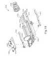
- FIG. 1depicts a motor-driven surgical cutting and fastening instrument ( 10 ) that may or may not be reused.
- surgical instrument ( 10 )includes a handle assembly ( 11 ) having a housing ( 12 ). At least a portion of the housing ( 12 ) forms a handle ( 14 ) configured to be grasped, manipulated and actuated by the clinician.
- Housing ( 12 )is configured for operative attachment to an interchangeable shaft assembly ( 16 ) that has a surgical end effector ( 18 ) operatively coupled thereto that is configured to perform one or more surgical tasks or procedures.
- interchangeable shaft assembly16
- surgical end effector ( 18 )operatively coupled thereto that is configured to perform one or more surgical tasks or procedures.
- housingmay also encompass a housing or similar portion of a robotic system that houses or otherwise operatively supports at least one drive system that is configured to generate and apply at least one control motion which could be used to actuate the interchangeable shaft assemblies disclosed herein and their respective equivalents.
- the term “frame”may refer to a portion of a handheld surgical instrument.
- the term “frame”may also represent a portion of a robotically controlled surgical instrument and/or a portion of the robotic system that may be used to operatively control a surgical instrument.
- the interchangeable shaft assemblies disclosed hereinmay be employed with various robotic systems, instruments, components and methods disclosed in U.S. Pat. No. 9,072,535, entitled “Surgical Stapling Instruments with Rotatable Staple Deployment Arrangements,” issued Jul. 7, 2015, the disclosure of which is incorporated by reference herein.
- Handle assembly ( 11 )is shown in connection with the interchangeable shaft assembly ( 16 ) that includes end effector ( 18 ), which is operable to sever tissue and apply staples to tissue as described in various references cited herein.
- Housing ( 12 )may be configured for use in connection with interchangeable shaft assemblies that include end effectors that are adapted to support different sizes and types of staple cartridges, have different shaft lengths, sizes, and types, etc.
- handle assembly ( 11 )may also be effectively employed with a variety of other interchangeable shaft assemblies including those assemblies that are configured to apply other motions and fauns of energy such as, for example, radio frequency (RF) energy, ultrasonic energy and/or motion to end effector arrangements adapted for use in connection with various surgical applications and procedures.
- RFradio frequency
- end effectors, shaft assemblies, handles, surgical instruments, and/or surgical instrument systemscan utilize any suitable fastener, or fasteners, to fasten tissue.
- a fastener cartridgecomprising a plurality of fasteners removably stored therein can be removably inserted into and/or attached to the end effector of a shaft assembly.
- Various examples of such cartridgesare disclosed in various references that are cited herein.
- FIG. 1illustrates surgical instrument ( 10 ) with interchangeable shaft assembly ( 16 ) operatively coupled to handle assembly ( 11 ).
- FIGS. 2-3illustrate attachment of interchangeable shaft assembly ( 16 ) to housing ( 12 ) of handle ( 14 ).
- Handle ( 14 )includes a pair of interconnectable handle housing segments ( 22 , 24 ) that may be interconnected by screws, snap features, adhesive, etc. In the illustrated arrangement, handle housing segments ( 22 , 24 ) cooperate to form a pistol grip portion ( 26 ) that can be gripped and manipulated by the clinician.
- handle ( 14 )operatively supports a plurality of drive systems therein that are configured to generate and apply various control motions to corresponding portions of interchangeable shaft assembly ( 16 ) that is operatively attached thereto.
- Handle ( 14 )further includes a frame ( 28 ) that operatively supports a plurality of drive systems.
- frame ( 28 )can operatively support a “first” or closure drive system, generally designated as ( 30 ), which may be employed to apply closing and opening motions to interchangeable shaft assembly ( 16 ) that is operatively attached or coupled thereto.
- closure drive system ( 30 )includes an actuator in the form of a closure trigger ( 32 ) that is pivotally supported by frame ( 28 ). More specifically, closure trigger ( 32 ) is pivotally coupled to housing ( 14 ) by a pin ( 34 ) (see FIG. 4A ).
- closure trigger ( 32 )to be manipulated by a clinician such that when the clinician grips pistol grip portion ( 26 ) of handle ( 14 ), closure trigger ( 32 ) may be easily pivoted from a starting or “unactuated” position toward pistol grip portion ( 26 ) to an “actuated” position and more particularly to a fully compressed or fully actuated position.
- Closure trigger ( 32 )may be biased into the unactuated position by spring or other biasing arrangement (not shown).
- closure drive system ( 30 )further includes a closure linkage assembly ( 36 ) pivotally coupled to closure trigger ( 32 ).
- the closure linkage assembly ( 36 )may include a first closure link (not shown) and a second closure link ( 38 ) that are pivotally coupled to closure trigger ( 32 ) by a pin (not shown).
- Second closure link ( 38 )may also be referred to herein as an “attachment member” and include a transverse attachment pin ( 37 ).
- first closure link(not shown) is configured to cooperate with a closure release assembly ( 44 ) that is pivotally coupled to frame ( 28 ).
- closure release assembly ( 44 )has a release button assembly ( 46 ) with a distally protruding locking pawl (not shown) formed thereon. Release button assembly ( 46 ) may be pivoted in a counterclockwise direction by a release spring (not shown).
- closure release assembly ( 44 )serves to lock closure trigger ( 32 ) in the fully actuated position.
- closure release button assembly ( 46 )When the clinician desires to unlock closure trigger ( 32 ) from the actuated position to return to the unactuated position, the clinician simply pivots closure release button assembly ( 46 ) such that locking pawl (not shown) is moved out of engagement with the first closure link (not shown). When the locking pawl (not shown) has been moved out of engagement with first closure link (not shown), closure trigger ( 32 ) may pivot back to the unactuated position.
- Other closure trigger locking and release arrangementsmay also be employed.
- Interchangeable shaft assembly ( 16 )includes surgical end effector ( 18 ) that comprises an elongated lower jaw ( 48 ) that is configured to operatively support staple cartridge ( 20 ) therein. End effector ( 18 ) of the present example further includes an anvil ( 50 ) that is pivotally supported relative to elongated channel ( 48 ). Interchangeable shaft assembly ( 16 ) further includes an articulation joint ( 52 ) and an articulation lock (not shown) that can be configured to releasably hold end effector ( 18 ) in a desired position relative to a longitudinal axis of shaft assembly ( 16 ).
- end effector ( 18 ), articulation joint ( 52 ), and articulation lockmay be configured and operable in accordance with at least some of the teachings of U.S. Pub. No. 2014/0263541, entitled “Articulatable Surgical Instrument Comprising an Articulation Lock,” published Sep. 18, 2014, now abandoned.
- end effector ( 18 ), articulation joint ( 52 ), and articulation lockmay be configured and operable in accordance with at least some of the teachings of any other reference(s) cited herein; or may be configured and operable in any other suitable fashion.
- Interchangeable shaft assembly ( 16 )further includes a proximal housing or nozzle ( 54 ) comprised of nozzle portions ( 56 , 58 ). Interchangeable shaft assembly ( 16 ) further includes a closure tube ( 60 ) which can be utilized to close and/or open anvil ( 50 ) of end effector ( 18 ). Shaft assembly ( 16 ) also includes a closure shuttle ( 62 ) that is slidably supported within a chassis ( 64 ) such that it may be axially moved relative thereto. Closure shuttle ( 62 ) includes a pair of proximally-protruding hooks ( 66 ) that are configured for attachment to attachment pin ( 42 ) that is attached to second closure link ( 38 ).
- a proximal end ( 68 ) (see FIG. 5A ) of closure tube ( 60 )is coupled to closure shuttle ( 62 ) for relative rotation thereto.
- a closure spring(not shown) is journaled on closure tube ( 60 ) and serves to bias closure tube ( 60 ) in the proximal direction (PD), which can serve to pivot closure trigger ( 32 ) into the unactuated position when shaft assembly ( 16 ) is operatively coupled to handle ( 14 ). Additional details regarding one or more features of alternative shaft assemblies will be provided below in greater detail.
- Interchangeable shaft assembly ( 16 )further includes articulation joint ( 52 ).
- articulation joint ( 52 )includes a double pivot closure sleeve assembly ( 70 ).
- the double pivot closure sleeve assembly ( 70 )includes an end effector closure sleeve assembly ( 72 ) for engaging an opening tab on anvil ( 50 ) in the various manners described in U.S. Pub. No. 2014/0263541, the disclosure of which is incorporated by reference herein, now abandoned.
- shaft assembly ( 16 ) of the present exampleincludes articulation joint ( 52 ), other interchangeable shaft assemblies may lack articulation capabilities.
- chassis ( 64 )includes at least one, and preferably two, tapered attachment portions (not shown) formed thereon that are adapted to be received within corresponding dovetail slots ( 76 ) formed within a distal attachment flange portion ( 78 ) of frame ( 28 ).
- Each dovetail slot ( 76 )may be tapered or, stated another way, be somewhat V-shaped to seatingly receive attachment portions (not shown) therein.
- a shaft attachment lug (not shown)is formed on the proximal end of an intermediate firing shaft ( 82 ). As such, when interchangeable shaft assembly ( 16 ) is coupled to handle ( 14 ), shaft attachment lug (not shown) is received in a firing shaft attachment cradle ( 84 ) formed in a distal end of a longitudinal drive member ( 86 ).
- shaft assembly ( 16 )includes a latch system ( 88 ) for removably coupling shaft assembly ( 16 ) to handle assembly ( 11 ) and, more specifically, to frame ( 28 ).
- latch system ( 88 )includes a lock member or lock yoke ( 90 ) that is movably coupled to chassis ( 64 ).
- lock yoke ( 90 )has a U-shape with two spaced downwardly extending legs (not shown). Legs (not shown) each have a pivot lug (not shown) formed thereon that are adapted to be received in corresponding holes (not shown) formed in chassis ( 64 ). Such arrangement facilitates pivotal attachment of lock yoke ( 90 ) to chassis ( 64 ).
- Lock yoke ( 90 )includes two proximally protruding lock lugs (not shown) that are configured for releasable engagement with corresponding lock detents or grooves ( 98 ) in distal attachment flange portion ( 78 ) of frame ( 28 ).
- lock yoke ( 90 )is biased in the proximal direction by spring or biasing member (not shown). Actuation of lock yoke ( 90 ) may be accomplished by a latch button ( 100 ) that is slidably mounted on a latch actuator assembly ( 102 ) that is mounted to chassis ( 64 ). Latch button ( 100 ) may be biased in a proximal direction relative to lock yoke ( 90 ).
- lock yoke ( 90 )may be moved to an unlocked position by biasing latch button ( 100 ) the in distal direction, which also causes lock yoke ( 90 ) to pivot out of retaining engagement with distal attachment flange portion ( 78 ) of frame ( 28 ).
- lock lugs(not shown) are retainingly seated within the corresponding lock detents or grooves ( 98 ) in distal attachment flange portion ( 78 ).
- an interchangeable shaft assemblythat includes an end effector of the type described herein that is adapted to cut and fasten tissue, as well as other types of end effectors
- the clinicianmay actuate the closure trigger ( 32 ) to grasp and manipulate the target tissue into a desired position. Once the target tissue is positioned within end effector ( 18 ) in a desired orientation, the clinician may then fully actuate closure trigger ( 32 ) to close anvil ( 50 ) and clamp the target tissue in position for cutting and stapling.
- closure drive system ( 30 )has been fully actuated. After the target tissue has been clamped in the end effector ( 18 ), it may be desirable to prevent the inadvertent detachment of shaft assembly ( 16 ) from handle assembly ( 11 ).
- lock yoke ( 90 )includes at least one and preferably two lock hooks (not shown) that are adapted to contact corresponding lock lugs (not shown) that are formed on closure shuttle ( 62 ).
- closure shuttle ( 62 )When closure shuttle ( 62 ) is in an unactuated position (i.e., the first drive system ( 30 ) is unactuated and anvil ( 50 ) is open), lock yoke ( 90 ) may be pivoted in a distal direction to unlock interchangeable shaft assembly ( 16 ) from handle assembly ( 11 ). When in that position, lock hooks (not shown) do not contact the lock lugs (not shown) on closure shuttle ( 62 ).
- closure shuttle ( 62 )is moved to an actuated position (i.e., the first drive system ( 30 ) is actuated and the anvil ( 50 ) is in the closed position)
- lock yoke ( 90 )is prevented from being pivoted to an unlocked position.
- lock hooks (not shown) on lock yoke ( 90 )will contact lock lugs (not shown) on closure shuttle ( 62 ) and prevent movement of lock yoke ( 90 ) to an unlocked position.
- Firing drive system ( 110 )operatively connects a firing trigger ( 112 ) of handle ( 14 ) with the intermediate firing shaft ( 82 ) of shaft assembly ( 16 ).
- Firing drive system ( 110 ) of the present exampleemploys an electric motor ( 114 ), located in pistol grip portion ( 26 ) of handle assembly ( 11 ).
- motor ( 114 )may be a DC brushed driving motor having a maximum rotation of, approximately, 25,000 RPM, for example.
- motor ( 114 )may include a brushless motor, a cordless motor, a synchronous motor, a stepper motor, or any other suitable electric motor.
- Motor ( 114 )is powered by a power source ( 116 ) that in one the present example comprises a removable battery unit ( 118 ).
- battery unit ( 118 ) of the present examplecomprises a proximal housing portion ( 120 ) that is configured for attachment to a distal housing portion ( 122 ).
- Proximal housing portion ( 120 ) and distal housing portion ( 122 )are configured to operatively support a plurality of batteries ( 124 ) therein.
- Batteries ( 124 )may each comprise, for example, a Lithium Ion (“LI”) battery or other suitable battery. Distal housing portion ( 122 ) is configured for removable operable attachment to control circuit board assembly ( 109 ), which is also operatively coupled to motor ( 114 ). A number of batteries ( 124 ) may be connected in series to be used as power source ( 116 ) for surgical instrument ( 10 ). In addition, power source ( 116 ) may be replaceable and/or rechargeable.
- LILithium Ion
- a first systemcomprises a frame system that couples and/or aligns the frame or spine of shaft assembly ( 16 ) with frame ( 28 ) of the handle ( 14 ).
- a second systemis closure drive system ( 30 ) that may operatively connect closure trigger ( 32 ) of handle ( 14 ) and closure tube ( 60 ) and anvil ( 50 ) of shaft assembly ( 16 ).
- closure shuttle ( 62 ) of shaft assembly ( 16 )engages with pin ( 42 ) on second closure link ( 38 ).
- a third systemis a firing drive system operatively connecting a firing trigger the handle ( 14 ) with the intermediate firing shaft ( 82 ) of the shaft assembly ( 16 ).
- the shaft attachment lug ( 80 )operatively connects with the cradle ( 84 ) of the longitudinal drive member ( 86 ).
- a fourth systemis an electrical system that can signal to a controller in the handle ( 14 ), such as microcontroller, that the shaft assembly ( 16 ) has been operatively engaged with the handle ( 14 ) to conduct power and/or communicate signals between the shaft assembly ( 16 ) and the handle ( 14 ).
- the shaft assembly ( 16 )includes an electrical connector ( 106 ) that is operatively mounted to a shaft circuit board (not shown).
- Electrical connector ( 106 )is configured for mating engagement with a corresponding electrical connector ( 108 ) on a handle control board (not shown). Further details regarding the circuitry and control systems may be found in U.S. Pub. No. 2014/0263541, the disclosure of which is incorporated by reference herein.
- the fifth systemis latch system ( 88 ) for releasably locking the shaft assembly ( 16 ) to the handle ( 14 ).
- the various shaft assemblies ( 16 ) disclosed hereinmay employ sensors and various other components that require electrical communication with the controller in the housing ( 12 ). These shaft assemblies ( 16 ) generally are configured to be able to rotate relative to the housing necessitating a connection that facilitates such electrical communication between two or more components that may rotate relative to each other.
- the connector arrangementsmust be relatively robust in nature while also being somewhat compact to fit into the shaft assembly connector portion.
- instrument ( 10 )may be constructed and operable in accordance with at least some of the teachings of U.S. patent application Ser. No. 14/226,142, entitled “Surgical Instrument Comprising a Sensor System,” filed Mar. 26, 2014, issued as U.S. Pat. No.
- instrument ( 10 )may be constructed and operable in accordance with at least some of the teachings of any of the various other references that are cited herein.
- FIG. 5illustrates another exemplary instrument ( 500 ), which is substantially identical to instrument ( 10 ), except for the differences as described below.
- Surgical instrument ( 500 )comprises a pistol grip ( 501 ), a handle ( 502 ), a trigger ( 504 ) and an end effector ( 505 ).
- Handle ( 502 ), trigger ( 504 ) and end effector ( 505 )may operate in a manner similar to that described with respect to shaft assembly ( 16 ) having end effector ( 18 ) and handle assembly ( 11 ) described above.
- Handle ( 502 ) of surgical instrument ( 500 )houses at least one battery unit ( 506 ).
- Battery unit ( 506 )may comprise a single battery or a plurality of batteries arranged in a series and/or parallel configuration.
- Handle ( 502 )includes a battery dock ( 508 ) to which battery unit ( 506 ) may be attached.
- Battery dock ( 508 )may comprise any suitable structure for coupling battery unit ( 506 ) to surgical instrument ( 500 ).
- battery dock ( 508 )may comprise a cavity in handle ( 502 ) that is configured to receive at least a portion of battery unit ( 506 ), as illustrated.
- battery dock ( 508 )may be implemented using a variety of other structures.
- some versions of battery dock ( 508 )may comprise a post that is received by battery unit ( 506 ).
- pistol grip ( 501 )may comprise battery dock ( 508 ).
- battery dock ( 508 ) of the present examplecomprises a protruding portion that is configured to interact with battery unit ( 506 ) upon attachment of battery unit ( 506 ) to handle ( 502 ). Once attached, battery unit ( 506 ) will be electrically connected to and provide power to a circuit ( 514 ) of surgical instrument ( 500 ). Circuit ( 514 ) may be located in handle ( 502 ) as shown, in end effector ( 505 ), or in any combination of locations within surgical instrument ( 500 ). In use, circuit ( 514 ) may power the operation of at least one surgical implement at end effector ( 505 ).
- circuit ( 514 )may comprise an electric motor for operating an electrically powered cutter, stapler, clasper, or other mechanical device.
- circuit ( 514 )may comprise suitable circuit components for implementing an RF, ultrasonic, or other type of non-motor-powered surgical implement.
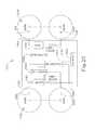
- FIGS. 6A-6Cschematically illustrate battery unit ( 506 ) and a portion of instrument ( 500 ).
- Battery unit ( 506 )may comprise a power drain ( 512 ) that automatically completes a circuit within battery unit ( 506 ) upon attachment to surgical instrument ( 500 ).
- Power drain ( 512 )serves to slowly reduce the charge of battery unit ( 506 ) over time. Once battery unit ( 506 ) has been sufficiently drained, it may be disposed as non-hazardous waste, for example.
- Battery unit ( 506 )includes an integral voltage source ( 510 ).
- voltage source ( 510 )comprises a lithium battery and comprises at least one cell selected from the group consisting of a CR123 cell and a CR2 cell.
- Battery unit ( 506 )further includes drain ( 512 ) that is electrically coupled to voltage source ( 510 ) when a switch ( 516 ) is closed.
- Battery unit ( 506 ) and surgical instrument ( 500 )each comprise electrically conductive contacts ( 518 , 520 ), respectively, that are placed into contact upon attachment of battery unit ( 506 ) to surgical instrument ( 500 ).
- FIG. 6Aillustrates battery in a non-attached position.
- Switch ( 516 )is in an open state and voltage source ( 510 ) is in a fully charged condition.
- FIG. 6Billustrates battery unit ( 506 ) in an attached position.
- Conductive contacts ( 518 ) of battery unit ( 506 )are in electrical communication with contacts ( 520 ) of surgical instrument ( 500 ), thereby allowing battery unit ( 506 ) to supply energy to circuit ( 514 ) (see FIG. 5 ).
- switch ( 516 )transitions to the closed state to electrically couple voltage source ( 510 ) to power drain ( 512 ). Energy will flow from voltage source ( 510 ) through power drain ( 512 ) during operation of surgical instrument ( 500 ).
- power drain ( 512 )will be draining the charge from voltage source ( 510 ) concurrently as battery unit ( 506 ) is supplying operational power to surgical instrument ( 500 ).
- a portion of surgical instrument ( 500 )may physically interact with power drain ( 512 ) during attachment of battery unit ( 506 ) to surgical instrument ( 500 ) to transition switch ( 516 ) from the open state to the closed state.
- FIG. 6Cillustrates battery unit ( 506 ) in a non-attached position.
- switch ( 516 )remains in the closed state to continue to drain the voltage source ( 510 ) even after battery unit ( 506 ) has been detached from surgical instrument ( 500 ).
- FIG. 7is a graph ( 600 ) of the voltage level of battery unit ( 506 ) over time, as measured from the time of attachment to surgical instrument ( 500 ), in accordance with one non-limiting example.
- Graph ( 600 )illustrates the voltage levels of a 6V cell of battery unit ( 506 ).
- Graph ( 600 )is merely representative of one example of battery unit ( 506 ).
- battery unit ( 506 )may supply any suitable voltage, such as 9 VDC, 12 VDC or 18 VDC, for example.
- battery unit ( 506 )may comprise multiple cells arranged in a parallel and/or series configuration.
- Graph ( 600 )includes three example discharge curves ( 602 , 604 , 606 ). As illustrated by first discharge curve ( 602 ), the voltage of power source ( 510 ) drops below 2.0 volts after around 28 hours. As illustrated by second discharge curve ( 604 ), the voltage of power source ( 510 ) drops below 2.0 volts after around 30 hours. As illustrated by third discharge curve ( 606 ), the voltage of power source ( 510 ) drops below 2.0 volts after around 33 hours.
- the overall shape of a discharge curvemay depend upon, for example, the level of activity of surgical instrument ( 500 ) during the surgical procedure. For example, surgical instrument ( 500 ) associated with first discharge curve ( 602 ) was more heavily used during the surgical procedure than surgical instrument ( 500 ) associated with third discharge curve ( 606 ).
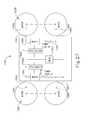
- FIG. 8is a simplified circuit diagram of a battery unit ( 616 ) comprising a power drain ( 612 ).
- Battery unit ( 616 )may be attached to surgical instrument ( 500 ), for example, via its contacts ( 618 ).
- battery unit ( 616 )comprises a first grouping of cells ( 610 ) and a second grouping of cells ( 611 ).
- groupings of cells ( 610 , 611 )may comprise lithium batteries.
- Groupings of cells ( 610 , 611 )may each have a plurality of separate cells ( 610 a , 610 b , 611 a , 611 b ) arranged in a parallel formation.
- groupings of cells ( 610 , 611 )may each be 6 VDC and arranged in a series configuration to produce 12 VDC at contacts ( 618 ) of battery unit ( 616 ) when fully charged.
- Cells ( 610 a , 610 b , 611 a , 611 b )may be electrically connected to one another in series or parallel or any other combination thereof.
- power drain ( 612 )comprises a first resistive element ( 622 ) and a second resistive element ( 624 ).
- battery unit ( 616 )comprises multiple power drains ( 612 ), each having more or less than two resistive elements or other circuitry.
- resistive element ( 622 )is coupled across an anode ( 626 ) and a cathode ( 628 ) of grouping of cells ( 610 ) through a switch ( 630 ).
- Resistive element ( 624 )is also coupled across an anode ( 632 ) and a cathode ( 634 ) of grouping of cells ( 611 ) through a switch ( 636 ).
- Switches ( 630 , 636 )are configured to be closed upon attachment of battery unit ( 616 ) to surgical instrument ( 500 ) in order to initiate the draining of groupings of cells ( 610 , 611 ).
- resistive element ( 622 )has a resistance in the range of about 90 ohms to about 110 ohms, or more particularly, in the range of about 97 ohms to about 104 ohms, or even more particularly at a value of 102.9 ohms with a power rating of 1 watt.
- the determination of the necessary resistancemay be based at least partially on the capacity of the voltage source, the voltage level of the voltage source, and the desired temporal length of the drainage curve.
- the battery capacity of grouping of cells ( 610 )is 1400 mAh
- the voltage levelis 6 VDC
- the target drain timeis 24 hours. Diving 1400 mAh by 24 hours yields a current of 0.0582 A.
- 6 V divided by 0.582 Ayields a resistance of 102.9 ohms.
- the power dissipated by the resistoris 0.350 W.
- different voltage levels, battery capacities, and desired time of dischargewill result in different resistance values.
- FIGS. 9-11are perspective views of a battery unit ( 800 ) implementing the circuitry of battery unit ( 616 ) shown in FIG. 8 .
- Battery unit ( 800 )comprises a casing ( 802 ) defining an interior cavity ( 810 ). While interior cavity ( 810 ) is illustrated in a central portion of casing ( 802 ), it is to be appreciated that internal cavity ( 810 ) may be positioned in any suitable location.
- Casing ( 802 )is covered by a cap ( 804 ) that is secured to casing ( 802 ) utilizing one or more mechanical latches ( 806 , 808 ).
- FIG. 10illustrates battery unit ( 800 ) with cap ( 804 ) removed to show a plurality of cells ( 812 ) within.
- FIG. 11illustrates battery unit ( 800 ) with a portion of casing ( 802 ) removed to reveal cells ( 812 ).
- FIGS. 12A and 12Billustrate cross-sectional views of an exemplary battery unit ( 800 ) including a translatable power drain ( 812 ).
- Power drain ( 812 )may be positioned within interior cavity ( 810 ) and may be translatable within interior cavity ( 810 ) in the directions of arrow ( 815 ).
- FIG. 12Ashows power drain ( 812 ) in an open position and
- FIG. 12Bshows power drain ( 812 ) in a closed state.
- Power drain ( 812 )may comprise at least two contacts ( 816 , 818 ).
- contacts ( 816 , 818 )may touch a non-conductive portion of casing ( 802 ), such as fingers ( 820 , 822 ).
- contacts ( 816 , 818 )are resiliently biased to exert a force against fingers ( 820 , 822 ) in order to resist movement of drain ( 812 ) in the direction of arrows ( 815 ).
- fingers ( 820 , 822 )may define one or more protrusions or stepped down portions, as shown in FIGS. 12A and 12B .
- Battery unit ( 800 ) of the present examplealso comprises electrodes ( 824 , 826 ).
- Electrodes ( 824 , 826 )may each be electrically coupled to a cathode or an anode of cells contained within battery unit ( 800 ).
- contacts ( 816 , 818 )are in electrical connection with electrodes ( 824 , 826 ), thereby allowing the voltage source to discharge through power drain ( 812 ).
- power drain ( 812 )may be transitioned from the open position to the closed position upon attachment of battery unit ( 800 ) to surgical instrument ( 500 ).
- FIG. 13is a perspective view of power drain ( 812 ) in accordance with one non-limiting example.
- Contacts ( 816 , 818 ) of drain ( 812 )are coupled to a base portion ( 830 ) of drain ( 812 ).
- contacts ( 836 , 838 ) of drain ( 812 )are coupled to base portion ( 830 ) of drain ( 812 ).
- contacts ( 816 , 818 )may be electrically connected to one another via a resistive element (not shown) mounted to a circuit board ( 832 ).
- contacts ( 836 , 838 )may be electrically connected to one another via a resistive element mounted to circuit board ( 832 ).
- contacts ( 816 , 818 , 836 , 838 )may have a bend or curvature to resiliently bias contacts ( 816 , 818 , 836 , 838 ) toward an outward position when inwardly compressed. Additionally, in the present example, distal end of each of contacts ( 816 , 818 , 836 , 838 ) has an inwardly turned section.
- Base portion ( 830 )comprises a contacting surface ( 840 ) that engages surgical instrument ( 500 ) when battery unit ( 800 ) is attached to surgical instrument ( 500 ). Through this engagement, battery drain ( 812 ) may be translated relative to casing ( 800 ).
- FIG. 14illustrates battery unit ( 800 ) attached to a battery dock ( 850 ).
- battery dock ( 850 )comprises a protruding member ( 858 ) that is sized to be received by cavity ( 810 ) (see FIG. 9 ) of battery unit ( 800 ).
- power drain ( 812 )Prior to attachment, power drain ( 812 ) is in the open position ( FIG. 12A ).
- protruding member ( 858 )is inserted into the cavity ( 810 ) and battery unit ( 800 ) is moved relative to battery dock ( 850 ) in the direction indicated by arrow ( 862 ).
- power drain ( 812 )translates relative to casing ( 802 ) in the direction indicated by arrow ( 864 ) and moves to the closed position (see FIG. 12B ). In this closed position, battery unit ( 800 ) commences to slowly drain. When the battery unit ( 800 ) is removed from battery dock ( 850 ), power drain ( 812 ) may remain in the position shown in FIG. 12B . In this way, the cells (not shown) of battery unit ( 800 ) may drain any remaining charge across a resistive element either before or during disposal.
- surgical instruments ( 10 , 500 )provide for power sources ( 116 , 510 ) having battery units ( 118 , 506 , 616 , 800 ) that include power drains ( 512 , 612 , 812 ), it will be appreciated that present and future improvements to surgical instruments ( 10 , 500 ) and related surgical procedures may place additional demand on battery units ( 118 , 506 , 616 , 800 ). Such surgical instruments ( 10 , 500 ) may not retain sufficient electrical power charge during these surgical procedures, particularly in combination with power drains ( 512 , 612 , 812 ) simultaneously in use.
- a surgical instrument ( 1000 )with a battery unit ( 1010 ) having a power drain ( 1012 ) that is configured to delay draining of battery unit ( 1010 ) until after the surgical procedure is complete.
- surgical instrument ( 1000 )will more likely have sufficient electrical power to perform the surgical procedure and later drain for disposing battery unit ( 1010 ) as non-hazardous waste.
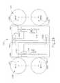
- FIGS. 15-17show exemplary surgical instrument ( 1000 ) having shaft assembly ( 16 ) and a handle assembly ( 1014 ).
- handle assembly ( 1014 )is configured to operatively couple with shaft assembly ( 16 ) and operate end effector ( 18 ) via closure system ( 30 ).
- Handle assembly ( 1014 )further includes a handle ( 1016 ) having a battery dock ( 1018 ) that is configured to receive a power source, such as battery unit ( 1010 ).
- battery unit ( 1010 )mechanically connects with handle ( 1016 ) and electrically connects with handle assembly ( 1014 ) and shaft assembly ( 16 ) in order to provide electrical power to closure system ( 30 ) and end effector ( 18 ) for use during the surgical procedure.
- Battery unit ( 1010 )is separable relative to handle assembly ( 1014 ), which may be reusable.
- FIGS. 16-17show battery unit ( 1010 ) being inserted into battery dock ( 1018 ) for installation, causing clips ( 1022 ) to engage with cooperating dock detents (not shown), which both secure battery unit ( 1010 ) within battery dock ( 1018 ) and provide feedback to the operator that battery unit ( 1010 ) is properly installed within battery dock ( 1018 ).
- FIGS. 16-17show battery unit ( 1010 ) being inserted into battery dock ( 1018 ) for installation, causing clips ( 1022 ) to engage with cooperating dock detents (not shown), which both secure battery unit ( 1010 ) within battery dock ( 1018 ) and provide feedback to the operator that battery unit ( 1010 ) is properly installed within battery dock ( 1018 ).
- alternative structures for securing battery unit ( 1010 ) within battery dock ( 1018 )may be similarly used in alternative versions.
- FIG. 17shows additional details of battery unit ( 1010 ) and battery dock ( 1018 ) mounted on a dock frame ( 1020 ) of handle assembly ( 1014 ) prior to installation.
- Battery unit ( 1010 )includes a battery cover ( 1024 ) attached to a battery base ( 1026 ), which collectively contain a plurality of batteries ( 1028 ) (see FIG. 19 ) therein.
- Battery base ( 1026 )also includes a pair of opposing, elongated guide slots ( 1030 ) longitudinally extending along a bottom of battery base ( 1026 ).
- Battery dock ( 1018 )includes a left elongated guide member ( 1032 a ) parallel with and offset from a right elongated guide member ( 1032 b ).
- Guide members ( 1032 a , 1032 b )are configured to be received within guide slots ( 1030 ). As such, guide slots ( 1030 ) and guide members ( 1032 a , 1032 b ) cooperatively guide battery unit ( 1010 ) longitudinally as battery unit ( 1010 ) slides in and out of guide dock ( 1018 ) during insertion and removal of battery unit ( 1010 ).
- battery dock ( 1018 )further includes a ramp ( 1033 ) that is configured to guide battery unit transversely upward onto a saddle ( 1034 ), which is configured to support battery unit ( 1010 ) during use of surgical instrument ( 1000 ).
- Battery dock ( 1018 )further includes a battery bulkhead ( 1035 ) positioned at a distal end of guide members ( 1032 a , 1032 b ).
- Battery bulkhead ( 1035 )has a spring ( 1036 ) extending proximally therefrom in order to bias battery unit ( 1010 ) thereagainst and urge the battery unit ( 1010 ) proximally for removal.
- Battery dock ( 1018 )also includes a dock circuit board ( 1038 ) that is powered by battery unit ( 1010 ) during use.
- dock circuit board ( 1038 )has a plurality of indicators in the form of LED lights ( 1040 ) connected thereto and configured to indicate to the operator an operational status of surgical instrument ( 1000 ), such as a remaining amount of electrical power in battery unit ( 1010 ), operative connection of battery unit ( 1010 ) with handle assembly ( 1014 ), and/or operative connection of shaft assembly ( 16 ) with handle assembly ( 1014 ).
- an operational status of surgical instrument ( 1000 )such as a remaining amount of electrical power in battery unit ( 1010 ), operative connection of battery unit ( 1010 ) with handle assembly ( 1014 ), and/or operative connection of shaft assembly ( 16 ) with handle assembly ( 1014 ).
- dock circuit board ( 1038 ) and LED lights ( 1040 )may be alternatively configured to indicate other forms of status information regarding surgical instrument ( 1000 ) to the user.
- dock circuit board ( 1038 )may include additional electronics that are configured to provide clinical function to surgical instrument ( 1000 ).
- LED lights ( 1040 )are merely illustrative examples, such that any other suitable form(s) of indicator(s) may be used in addition to or in lieu of LED lights ( 1040 ).
- FIG. 18shows battery dock ( 1018 ) in greater detail having a dock chassis ( 1042 ) supporting guide members ( 1032 a , 1032 b ), ramp ( 1033 ), saddle ( 1034 ), battery bulkhead, and circuit board ( 1038 ) as described above.
- battery dock ( 1018 )has a pair of opposing, elongated board contacts ( 1044 ) extending respectively along guide members ( 1032 a , 1032 b ).
- a distal end of each board contact ( 1044 )electrically connects to dock circuit board ( 1038 ), whereas a proximal end of each board connect ( 1044 ) is configured to engage battery unit ( 1010 ) for communicating electrical power from battery unit ( 1010 ) to dock circuit board ( 1038 ).
- battery dock ( 1018 )has an elongated protruding member, such as a switch arm ( 1046 ), extending upwardly from saddle ( 1034 ) and proximally from left guide member ( 1032 a ).
- Switch arm ( 1046 )is configured to engage a portion of drain ( 1012 ) for operating drain ( 1012 ) as will be discussed below in additional detail.
- battery unit ( 1010 )includes battery cover ( 1024 ), battery base ( 1026 ), and three batteries ( 1028 ) aligned in series within battery cover and base ( 1024 , 1026 ).
- Battery unit ( 1010 )further includes a battery circuit ( 1048 ) having a power circuit ( 1050 ) and a power drain circuit ( 1052 ).
- Battery circuitincludes ( 1048 ) a distal conductive member ( 1054 ) and a proximal conductive member ( 1056 ).
- Distal conductive member ( 1054 )includes a power cathode contact ( 1058 ) and a discharge cathode contact ( 1060 ), while proximal conductive member ( 1054 ) similarly includes a power anode contact ( 1062 ) and a discharge anode contact ( 1064 ).
- power cathode and anode contacts ( 1058 , 1062 )are part of power circuit ( 1050 )
- discharge cathode and anode contacts ( 1060 , 1064 )are part of power drain circuit ( 1052 ).
- Power cathode and discharge cathode contacts ( 1058 , 1060 ) and power anode and discharge anode contacts ( 1062 , 1064 )are configured to electrically connect to a cathode ( 1066 ) and an anode ( 1068 ) of a collection of batteries ( 1028 ).
- Power circuit ( 1050 )provides electrical power to dock circuit board ( 1038 ) when battery unit ( 1010 ) operatively connects with battery dock ( 1018 ).
- power drain circuit ( 1052 )is configured to selectively close to drain batteries ( 1028 ).
- power drain ( 1012 )includes a discharge switch ( 1070 ) and power drain circuit ( 1052 ) having a discharge circuit board ( 1072 ) to, first, selectively connect batteries ( 1028 ) to power drain circuit ( 1052 ); second, delay drain of batteries ( 1028 ); and, third, initiate and complete drain of batteries ( 1028 ).
- discharge switch ( 1070 )is translatably mounted within battery base ( 1026 ) to slide proximally from a blocker position to a released position.
- discharge switch ( 1070 )covers discharge cathode contact ( 1060 ) prior to installation with handle assembly ( 1014 ) in order to provide a physical barrier to electrically connecting batteries ( 1028 ) to drain circuit ( 1052 ).
- Discharge cathode contact ( 1060 )is thus held in an open position, but biased against discharge switch ( 1070 ) toward a closed position.
- inserting battery unit ( 1010 ) into battery dock ( 1018 )causes switch arm ( 1046 ) to engage discharge switch ( 1070 ) and slide discharge switch ( 1070 ) to the released position, thereby releasing discharge cathode contact ( 1060 ) and connecting batteries ( 1028 ) to power drain circuit ( 1052 ).
- FIGS. 23A and 24Ashow discharge cathode contact ( 1060 ) held away from connection with power drain circuit ( 1052 ) in the open position, with discharge switch in the blocker position, prior to installation.
- FIGS. 23B and 24Bshow discharge cathode contact ( 1060 ) biased against power drain circuit ( 1052 ) in the closed position, with discharge switch in the released position, after installation.
- FIG. 25schematically shows the exemplary power drain circuit ( 1052 ) with discharge circuit board ( 1072 ) for delaying and initiating drain of batteries ( 1028 ).
- Drain circuit ( 1052 )further includes a resistor element, such as a resistor ( 1078 ); a switch element, such as a metal-oxide semiconductor field-effect (“MOSFET”) transistor ( 1080 ); and a controller, such as the collection of a microprocessor ( 1082 a ), Hall effect sensor ( 1082 b ), and opto-isolator ( 1082 c ).
- drain circuit ( 1052 )is configured to delay draining electrical power across resistor ( 1078 ) until battery unit ( 1010 ) is removed from battery dock ( 1018 ).
- Hall effect sensor ( 1082 b )is configured to sense when battery unit ( 1010 ) is removed from the battery dock ( 1018 ) and communicate the sensed removal to microprocessor ( 1082 a ). It will be appreciated that various structures, mechanical, electrical, and magnetic, may be used to communicate removal to microprocessor ( 1082 a ).
- battery dock ( 1018 )may include a magnet (not shown) in proximity to Hall effect sensor ( 1082 b ) such that a reduction in magnetic field upon removal of Hall effect sensor ( 1082 b ) from battery dock ( 1018 ) causes Hall effect sensor ( 1082 b ) to communicate this removal to microprocessor ( 1082 a ).
- the Hall effect sensor ( 1082 b )may alternatively be any form of proximity sensor, such as a reed switch microswitch, configured to sense removal thereof.
- Microprocessor ( 1082 a )is connected to MOSFET transistor ( 1080 ) via opto-isolator ( 1082 c ).
- Opto-isolator ( 1082 c )is configured to pass a discharge signal from microprocessor ( 1082 a ) to MOSFET transistor ( 1080 ) while electrically isolating MOSFET transistor ( 1080 ) and resistor ( 1078 ) from microprocessor ( 1082 a ).
- MOSFET transistor ( 1080 )acts as a switch that is configured to selectively electrically connect cathode ( 1066 ) to anode ( 1068 ) across resistor ( 1078 ).
- MOSFET transistor ( 1080 )Prior to receiving the discharge signal, MOSFET transistor ( 1080 ) maintains an open circuit across resistor ( 1078 ) to prevent electrical power from cathode ( 1066 ) from flowing through resistor ( 1078 ). After receiving the discharge signal, MOSFET transistor ( 1080 ) closes the circuit across resistor ( 1078 ) to direct electrical power from cathode ( 1066 ) through resistor ( 1078 ) and effectively drain batteries ( 1028 ) across resistor ( 1078 ). Thereby, draining of batteries ( 1028 ) by power drain circuit ( 1052 ) is delayed until removal of battery unit ( 1010 ) from battery dock ( 1018 ). FIG. 25 shows two such drain circuits ( 1052 ) for two sets of batteries ( 1028 ). However, it will be appreciated that more or less drain circuits ( 1052 ) may be so used for draining the batteries ( 1028 ).
- FIG. 26shows a flow chart of an exemplary use of surgical instrument ( 1000 ) having power drain circuit ( 1052 ) in relation to FIGS. 16-17, 21, and 25-26 .
- the userinserts battery unit ( 1010 ) into battery dock ( 1018 ) to operatively connect battery unit ( 1010 ) to handle assembly ( 1014 ) and shaft assembly ( 16 ), as shown in block ( 2000 ).
- switch arm ( 1046 )directs discharge switch ( 1070 ) from the blocker position to the released position, and discharge cathode contact ( 1060 ) moves from the open position to the closed position to connect batteries ( 1028 ) to drain circuit ( 1052 ).
- the insertion of battery unit ( 1010 ) in battery dock ( 1018 )is thus detected, as shown in block ( 2002 ).
- Hall effect sensor ( 1082 b )communicates the insertion to microprocessor ( 1082 a ), as shown in block ( 2004 ).
- Microprocessor ( 1082 a )prevents MOSFET transistor ( 1080 ) from connecting resistor ( 1078 ) across cathode ( 1066 ) and anode ( 1068 ) while the user performs the surgical procedure on the patient with surgical instrument ( 1000 ), as shown in block ( 2006 ).
- the userAfter treatment, the user removes battery unit ( 1010 ) from battery dock ( 1018 ), as shown in block ( 2008 ).
- Hall effector sensor ( 1082 b )detects removal of battery unit ( 1010 ) from battery dock ( 1018 ), as shown in block ( 2010 ); and communicates removal to microprocessor ( 1082 a ), as shown in block ( 2012 ).
- Microprocessor ( 1082 a )then sends a discharge signal to MOSFET transistor ( 1080 ) via opto-isolator ( 1082 c ) in order to close power drain circuit ( 1052 ) with resistor ( 1078 ) between cathode and anode ( 1066 , 1068 ), as shown in block ( 2014 ).
- Closing drain circuit ( 1052 )directs electrical power through resistor ( 1078 ), as shown in block ( 2016 ); and thereby effectively drains a remaining portion of electrical power from batteries ( 1028 ), as shown in block ( 2018 ).
- drain ( 1012 )delays draining electrical power from battery unit ( 1010 ) until battery unit ( 1010 ) is removed from battery dock ( 1018 ). Drained battery unit ( 1010 ) may then be properly disposed of, as shown in block ( 2020 ).
- FIG. 27shows an exemplary alternative power drain circuit ( 1152 ) that may be readily incorporated into instrument ( 1000 ) in place of power drain circuit ( 1052 ) described above.
- FIG. 27schematically shows power drain circuit ( 1152 ) of drain ( 1112 ) with a discharge circuit board ( 1172 ) for delaying and initiating drain of batteries ( 1028 ).
- Power drain circuit ( 1152 ) of this examplefurther includes a resistor element, such as resistor ( 1078 ); a switch element, such as a metal-oxide semiconductor field-effect (“MOSFET”) transistor ( 1080 ); and a controller, such as the collection of a timer ( 1182 a ) and an opto-isolator ( 1182 b ).
- power drain circuit ( 1152 )is configured to delay draining electrical power across resistor ( 1078 ) until a predetermined amount of time has passed since electrical power was initially discharged from batteries ( 1028 ).
- timer ( 1182 a )is configured to sense when batteries ( 1028 ) initially discharge electrical power after insertion of battery unit ( 1010 ) in battery dock ( 1018 ); and timer ( 1182 a ) begins computing passage of time from the initial discharge.
- timer ( 1182 a )alternative examples may further include the timer in the form of an analog timer circuit, a digital timer, a microprocessor with a timer program, or other timing device. Given alternative methods for computing the passage of time, alternative timers may be so used.
- the predetermined amount of timemay be any desirable amount of time
- one example of a desirable amount of timeis an amount of time as long as the predicted time for completing the surgical procedure.
- other desirable timesmay be programmed into timer ( 1182 a ).
- timer ( 1182 a )communicates the discharge signal toward MOSFET transistor ( 1080 ) after the passage of the predetermined amount of time.
- Timer ( 1182 a )is connected to MOSFET transistor ( 1080 ) via opto-isolator ( 1182 b ).
- Opto-isolator ( 1182 b )is configured to pass the discharge signal from timer ( 1182 a ) to MOSFET transistor ( 1080 ) while electrically isolating MOSFET transistor ( 1080 ) and resistor ( 1078 ) from timer ( 1182 a ).
- MOSFET transistor ( 1080 )Prior to receiving the discharge signal, MOSFET transistor ( 1080 ) maintains an open circuit across resistor ( 1078 ) to prevent electrical power from cathode ( 1066 ) from flowing through resistor ( 1078 ).
- MOSFET transistor ( 1080 )After receiving the discharge signal from timer ( 1182 a ), MOSFET transistor ( 1080 ) closes the circuit across resistor ( 1078 ) to direct electrical power from cathode ( 1066 ) through resistor ( 1078 ) and effectively drain batteries ( 1028 ) across resistor ( 1078 ). Thereby, draining of batteries ( 1028 ) by power drain circuit ( 1152 ) is delayed until the predetermined amount of time has passed from initial discharge of electrical power.
- FIG. 27shows two such power drain circuits ( 1152 ) for two sets of batteries ( 1028 ); however, it will be appreciated that more or less power drain circuits ( 1152 ) may be so used for draining the batteries ( 1028 ).
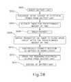
- FIG. 28shows a flow chart of an exemplary use of surgical instrument ( 1000 ) having drain circuit ( 1152 ) in relation to FIGS. 16-17, 21, and 27-28 .
- the userinserts battery unit ( 1010 ) into battery dock ( 1018 ) to operatively connect battery unit ( 1010 ) to handle assembly ( 1014 ) and shaft assembly ( 16 ), as shown in block ( 3000 ).
- switch arm ( 1046 )directs discharge switch ( 1070 ) from the blocker position to the released position, and discharge cathode contact ( 1060 ) moves from the open position to the closed position to connect batteries ( 1028 ) to drain circuit ( 1152 ).
- surgical instrument ( 1000 )may rest or be generally handled by the user without initiating timer ( 1182 a ). However, once the user directs batteries ( 1028 ) to initially discharge electrical power, as shown in block ( 3002 ), timer ( 1128 a ) begins computing the passage of time, as shown in block ( 3004 ) until reaching the predetermined amount of time from initial discharge of electrical power. This counting continues as the operator uses instrument ( 1000 ) to treat the patient, as shown in block ( 3006 ).
- timer ( 1182 a )sends a discharge signal to MOSFET transistor ( 1080 ) via opto-isolator ( 1182 b ) in order to close drain circuit ( 1152 ) with resistor ( 1078 ) between cathode and anode ( 1066 , 1068 ), as shown in block ( 3008 ).
- Closing drain circuit ( 1152 )directs electrical power through resistor ( 1078 ), as shown in block ( 3010 ), and effectively drains a remaining portion of electrical power from batteries ( 1028 ), as shown in block ( 3012 ).
- drain ( 1112 )delays draining electrical power from battery unit ( 1010 ) until the predetermined amount of time has passed. Drained battery unit ( 1010 ) may then be properly disposed of, as shown in block ( 3014 ).
- timer ( 1182 a )begins to count time (i.e., to determine whether the predetermined duration has passed) after the first time electrical power is discharged from batteries ( 1028 ) (e.g., during use of instrument ( 1000 ) in a surgical procedure). In some other versions, timer ( 1182 a ) begins to count time (i.e., to determine whether the predetermined duration has passed) after battery unit ( 1010 ) is inserted into battery dock ( 1018 ), regardless of when power is first discharged from batteries ( 1028 ) (e.g., during use of instrument ( 1000 ) in a surgical procedure). Other events that may be relied on to trigger the counting of time by timer ( 1182 a ) will be apparent to those of ordinary skill in the art in view of the teachings herein.
- FIG. 29shows another exemplary alternative power drain circuit ( 1252 ) that may be readily incorporated into instrument ( 1000 ) in place of power drain circuit ( 1052 ) described above.
- FIG. 29schematically shows power drain circuit ( 1252 ) of drain ( 1212 ) with discharge circuit board ( 1272 ) for delaying and initiating drain of batteries ( 1028 ).
- Power drain circuit ( 1252 )further includes a resistor element, such as a resistor ( 1078 ); a switch element, such as a metal-oxide semiconductor field-effect (“MOSFET”) transistor ( 1080 ); and a controller, such as the Hall effect sensor ( 1282 ).
- power drain circuit ( 1252 )is configured to delay draining electrical power across resistor ( 1078 ) until battery unit ( 1010 ) is removed from battery dock ( 1018 ).
- Hall effect sensor ( 1282 )is configured to sense when battery unit ( 1010 ) is removed from battery dock ( 1018 ) and communicate the sensed removal directly to MOSFET transistor ( 1080 ). It will be appreciated that various structures, mechanical, electrical, and magnetic, may be used to communicate removal to microprocessor ( 1082 a ).
- battery dock ( 1018 )may include a pair of magnets (not shown) in proximity to each Hall effect sensor ( 1282 ) such that a reduction in magnetic field upon removal of Hall effect sensor ( 1282 ) from battery dock ( 1018 ) causes Hall effect sensor ( 1282 ) to communicate this removal to MOSFET transistor ( 1080 ).
- the Hall effect sensor ( 1082 b )may alternatively be any form of proximity sensor, such as a reed switch microswitch, configured to sense removal thereof.
- Hall effect sensor ( 1282 )is directly connected to MOSFET transistor ( 1080 ), which acts as a switch that is configured to selectively electrically connect cathode ( 1066 ) to anode ( 1068 ) across resistor ( 1078 ).
- MOSFET transistor ( 1080 )Prior to receiving the discharge signal, MOSFET transistor ( 1080 ) maintains an open circuit across resistor ( 1078 ) to prevent electrical power from cathode ( 1066 ) from flowing through resistor ( 1078 ).
- MOSFET transistor ( 1080 )closes the circuit across resistor ( 1078 ) to direct electrical power from cathode ( 1066 ) through resistor ( 1078 ) and effectively drain batteries ( 1028 ) across resistor ( 1078 ).
- FIG. 29shows two such power drain circuits ( 1252 ) for two sets of batteries ( 1028 ). However, it will be appreciated that more or less power drain circuits ( 1252 ) may be so used for draining the batteries ( 1028 ).
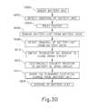
- FIG. 30shows a flow chart of an exemplary use of surgical instrument ( 1000 ) having drain circuit ( 1252 ) in relation to FIGS. 16-17, 21, and 29-30 .
- the userinserts battery unit ( 1010 ) into battery dock ( 1018 ) to operatively connect battery unit ( 1010 ) to handle assembly ( 1014 ) and shaft assembly ( 16 ), as shown in block ( 4000 ).
- switch arm ( 1046 )directs discharge switch ( 1070 ) from the blocker position to the released position, and discharge cathode contact ( 1060 ) moves from the open position to the closed position to connect batteries ( 1028 ) to power drain circuit ( 1252 ).
- Power drain circuit ( 1252 )thus detects insertion of battery unit ( 1010 ) into battery dock ( 1018 ), as shown in block ( 4002 ). The operator then uses instrument ( 1000 ) to treat the patient, as shown in block ( 4004 ). In this example, power drain circuit ( 1252 ) does not drain batteries ( 1028 ) during the surgical procedure, even if the surgical procedure extends over a significant period of time, so long as battery unit ( 1010 ) remains disposed in battery dock ( 1018 ).
- Hall effector sensor ( 1282 )detects removal of battery unit ( 1010 ) from battery dock ( 1018 ), as shown in block ( 4008 ); and sends the discharge signal directly to MOSFET transistor ( 1080 ), as shown in block ( 4010 ), in order to close drain circuit ( 1252 ) with resistor ( 1078 ) between cathode and anode ( 1066 , 1068 ), as shown in block ( 4012 ).
- Closing drain circuit ( 1252 )directs electrical power through resistor ( 1078 ) and effectively drains a remaining portion of electrical power from batteries ( 1028 ), as shown in block ( 4014 ).
- drain ( 1212 )delays draining electrical power from battery unit ( 1010 ) until battery unit ( 1010 ) is removed from battery dock ( 1018 ). Drained battery unit ( 1010 ) may then be properly disposed of, as shown in block ( 4016 ).
- a surgical instrumentcomprising: (a) a shaft assembly having a distal end portion and a proximal end portion, the distal end portion including an end effector projecting distally therefrom; (b) a handle assembly configured to receive the proximal end portion of the shaft assembly, wherein the handle assembly includes a battery dock; and (c) a battery unit configured to be received by the battery dock such that the battery unit is in electrical communication with at least one of the shaft assembly or the handle assembly, the battery unit including: (i) a battery, wherein the battery comprises: (A) an anode contact, and (B) a cathode contact, and (ii) a discharge drain including: (A) a controller, and (B) a battery power draining element, wherein the controller is configured to selectively place the battery power draining element in communication with the anode and cathode contacts to thereby drain power from the battery in response to either coupling of the battery unit with the battery dock or removal of the battery unit from the battery dock.
- Example 1The surgical instrument of Example 1, wherein the controller is configured to sense detachment of the battery unit from the battery dock such that the controller element is configured to selectively place the battery power draining element in communication with the anode and cathode contacts to thereby drain power from the battery in response to removal of the battery unit from the battery dock.
- Example 2The surgical instrument of Example 2, wherein the controller includes a microprocessor configured to receive a signal indicating that the battery unit has been detached from the battery dock.
- Example 3The surgical instrument of Example 3, wherein the controller includes a Hall effect sensor configured to sense when the battery unit has been detached from the battery dock, wherein the hall effect sensor is further configured to send the signal to the microprocessor.
- the controllerincludes a Hall effect sensor configured to sense when the battery unit has been detached from the battery dock, wherein the hall effect sensor is further configured to send the signal to the microprocessor.
- the discharge drainfurther comprises a switch element in communication with the controller and the battery power draining element, wherein the switch element is operable to selectively close to thereby place the battery power draining element in communication with the anode and cathode contacts to thereby drain power from the battery.
- Example 5The surgical instrument of Example 5, wherein the switch element comprises a MOSFET transistor.
- Example 6The surgical instrument of Example 6, wherein the controller includes a microprocessor and an opto-isolator in electrical communication between the MOSFET transistor and the microprocessor, wherein the opto-isolator is configured to transfer the signal from the microprocessor to the MOSFET transistor.
- the controllerincludes a timer, wherein the timer is configured to sense attachment of the battery unit to the battery dock and responsively begin tracking, wherein the timer is further configured to selectively place the battery power draining element in communication with the anode and cathode contacts to thereby drain power from the battery after a predetermined amount of time has elapsed since the attachment of the battery unit to the battery dock.
- Example 9The surgical instrument of Example 9, wherein the timer is configured to continue tracking time during and after use of the end effector in a surgical procedure.
- the discharge drainfurther includes a discharge contact configured to selectively move from an open position to a closed position in response to attachment of the battery unit to the battery dock, wherein at least one of the anode contact and the cathode contact is electrically disconnected from the discharge drain in the open position, and wherein each of the anode contact and the cathode contact is electrically connected to the discharge drain in the closed position.
- Example 11wherein the discharge contact is biased toward the closed position and the battery power draining element includes a discharge switch configured to selectively move from a blocker position to a released position, wherein the discharge switch is configured to hold the discharge contact in the open position before the battery unit is attached to the battery dock, and wherein the discharge switch is configured to release the discharge contact to the closed position in response to attachment of the battery unit to the battery dock.
- the discharge switchconfigured to selectively move from a blocker position to a released position, wherein the discharge switch is configured to hold the discharge contact in the open position before the battery unit is attached to the battery dock, and wherein the discharge switch is configured to release the discharge contact to the closed position in response to attachment of the battery unit to the battery dock.
- Example 12The surgical instrument of Example 12, wherein the battery unit has a base detent and the discharge switch has a corresponding switch detent, wherein the base and switch detents are configured to cooperatively secure the discharge switch in the released position.
- Example 13The surgical instrument of Example 13, wherein the battery dock includes a protruding member extending therein, wherein the protruding member is configured to engage the discharge switch and move the discharge switch from the blocker position to the released position upon attaching the battery unit to the battery dock.
- a surgical instrumentcomprising: (a) a shaft assembly having a distal end portion and a proximal end portion, the distal end portion including an end effector projecting distally therefrom; (b) a handle assembly configured to receive the proximal end portion of the shaft assembly, wherein the handle assembly includes a battery dock; and (c) a battery unit configured to be received by the battery dock such that the battery unit is in electrical communication with at least one of the shaft assembly or the handle assembly, the battery unit including: (i) a casing; (ii) an anode contact and a cathode contact positioned within the casing and configured to electrically connect to at least one battery; and (iii) a discharge drain including a discharge contact and a controller configured to sense a predetermined input, wherein the discharge contact is configured to selectively move from an open position to a closed position in response to attachment of the battery unit to the battery dock, wherein at least one of the anode contact and the cathode contact is electrically disconnected from the discharge drain
- the controllerincludes a timer configured to compute a predetermined amount of time, wherein the controller configured to sense discharge of an electrical power from the at least one battery such that the timer will initiate computation of the predetermined amount of time from the discharge of the electrical power, wherein the passage of the predetermined amount of time is the predetermined input.
- a method of discharging a remaining electrical power from at least one battery of a surgical instrumentincluding a handle assembly, a shaft assembly extending distally from the handle assembly, an end effector located at a distal end of the shaft assembly, and a battery unit, wherein the battery unit includes at least one battery and a discharge drain, wherein the handle assembly includes a battery dock configured to receive the battery unit such that the battery unit is in electrical communication with at least one of the shaft assembly or the handle assembly, the method comprising: (a) discharging an electrical power from the at least one battery to at least one of the handle assembly or the shaft assembly; (b) detaching the battery unit from the battery dock; (c) sensing the act of detaching the battery unit from the battery dock; (d) coupling the at least one battery with the discharge drain in response to sensing the act of detaching the battery unit from the battery dock; and (e) draining a remaining power from the at least one battery via the discharge drain while the battery unit remains detached from the battery dock.
- any of the versions of instruments described hereinmay include various other features in addition to or in lieu of those described above.
- any of the instruments described hereinmay also include one or more of the various features disclosed in any of the various references that are incorporated by reference herein.
- teachings hereinmay be readily applied to any of the instruments described in any of the other references cited herein, such that the teachings herein may be readily combined with the teachings of any of the references cited herein in numerous ways.
- Other types of instruments into which the teachings herein may be incorporatedwill be apparent to those of ordinary skill in the art.
- any ranges of values referred to hereinshould be read to include the upper and lower boundaries of such ranges. For instance, a range expressed as ranging “between approximately 1.0 inches and approximately 1.5 inches” should be read to include approximately 1.0 inches and approximately 1.5 inches, in addition to including the values between those upper and lower boundaries.
- Versions of the devices described abovemay have application in conventional medical treatments and procedures conducted by a medical professional, as well as application in robotic-assisted medical treatments and procedures.
- various teachings hereinmay be readily incorporated into a robotic surgical system such as the DAVINCITM system by Intuitive Surgical, Inc., of Sunnyvale, Calif.
- DAVINCITM systemby Intuitive Surgical, Inc., of Sunnyvale, Calif.
- teachings hereinmay be readily combined with various teachings of U.S. Pat. No. 6,783,524, entitled “Robotic Surgical Tool with Ultrasound Cauterizing and Cutting Instrument,” published Aug. 31, 2004, the disclosure of which is incorporated by reference herein.
- Versions described abovemay be designed to be disposed of after a single use, or they can be designed to be used multiple times. Versions may, in either or both cases, be reconditioned for reuse after at least one use. Reconditioning may include any combination of the steps of disassembly of the device, followed by cleaning or replacement of particular pieces, and subsequent reassembly. In particular, some versions of the device may be disassembled, and any number of the particular pieces or parts of the device may be selectively replaced or removed in any combination. Upon cleaning and/or replacement of particular parts, some versions of the device may be reassembled for subsequent use either at a reconditioning facility, or by an operator immediately prior to a procedure.
- reconditioning of a devicemay utilize a variety of techniques for disassembly, cleaning/replacement, and reassembly. Use of such techniques, and the resulting reconditioned device, are all within the scope of the present application.
- versions described hereinmay be sterilized before and/or after a procedure.
- the deviceis placed in a closed and sealed container, such as a plastic or TYVEK bag.
- the container and devicemay then be placed in a field of radiation that can penetrate the container, such as gamma radiation, x-rays, or high-energy electrons.
- the radiationmay kill bacteria on the device and in the container.
- the sterilized devicemay then be stored in the sterile container for later use.
- a devicemay also be sterilized using any other technique known in the art, including but not limited to beta or gamma radiation, ethylene oxide, or steam.
Landscapes
- Engineering & Computer Science (AREA)
- Health & Medical Sciences (AREA)
- Chemical & Material Sciences (AREA)
- Chemical Kinetics & Catalysis (AREA)
- Electrochemistry (AREA)
- General Chemical & Material Sciences (AREA)
- Life Sciences & Earth Sciences (AREA)
- Surgery (AREA)
- Manufacturing & Machinery (AREA)
- Power Engineering (AREA)
- Heart & Thoracic Surgery (AREA)
- Public Health (AREA)
- Nuclear Medicine, Radiotherapy & Molecular Imaging (AREA)
- Medical Informatics (AREA)
- Molecular Biology (AREA)
- Animal Behavior & Ethology (AREA)
- General Health & Medical Sciences (AREA)
- Biomedical Technology (AREA)
- Veterinary Medicine (AREA)
- Microelectronics & Electronic Packaging (AREA)
- Biophysics (AREA)
- Computer Hardware Design (AREA)
- Surgical Instruments (AREA)
- Battery Mounting, Suspending (AREA)
- Secondary Cells (AREA)
Abstract
Description
Claims (20)
Priority Applications (8)
| Application Number | Priority Date | Filing Date | Title |
|---|---|---|---|
| US14/868,747US10314578B2 (en) | 2015-09-29 | 2015-09-29 | Battery drain circuit for surgical instrument |
| PCT/US2016/052770WO2017058591A1 (en) | 2015-09-29 | 2016-09-21 | Battery drain circuit for surgical instrument |
| JP2018535817AJP6976952B2 (en) | 2015-09-29 | 2016-09-21 | Battery drain circuit for surgical instruments |
| BR112018006132-8ABR112018006132B1 (en) | 2015-09-29 | 2016-09-21 | SURGICAL INSTRUMENT AND METHOD FOR DISCHARGING REMAINING ELECTRICAL ENERGY FROM AT LEAST ONE BATTERY OF A SURGICAL INSTRUMENT |
| RU2018115975ARU2714684C1 (en) | 2015-09-29 | 2016-09-21 | Electric circuit for discharge of accumulator battery for surgical instrument |
| MX2018003958AMX381885B (en) | 2015-09-29 | 2016-09-21 | BATTERY DRAIN CIRCUIT FOR SURGICAL INSTRUMENT. |
| CN201680063851.8ACN108292719B (en) | 2015-09-29 | 2016-09-21 | Battery Drain Circuits for Surgical Instruments |
| EP16191192.0AEP3151308B8 (en) | 2015-09-29 | 2016-09-28 | Battery drain circuit for surgical instrument |
Applications Claiming Priority (1)
| Application Number | Priority Date | Filing Date | Title |
|---|---|---|---|
| US14/868,747US10314578B2 (en) | 2015-09-29 | 2015-09-29 | Battery drain circuit for surgical instrument |
Publications (2)
| Publication Number | Publication Date |
|---|---|
| US20170086826A1 US20170086826A1 (en) | 2017-03-30 |
| US10314578B2true US10314578B2 (en) | 2019-06-11 |
Family
ID=57018096
Family Applications (1)
| Application Number | Title | Priority Date | Filing Date |
|---|---|---|---|
| US14/868,747Active2037-06-19US10314578B2 (en) | 2015-09-29 | 2015-09-29 | Battery drain circuit for surgical instrument |
Country Status (7)
| Country | Link |
|---|---|
| US (1) | US10314578B2 (en) |
| EP (1) | EP3151308B8 (en) |
| JP (1) | JP6976952B2 (en) |
| CN (1) | CN108292719B (en) |
| MX (1) | MX381885B (en) |
| RU (1) | RU2714684C1 (en) |
| WO (1) | WO2017058591A1 (en) |
Cited By (288)
| Publication number | Priority date | Publication date | Assignee | Title |
|---|---|---|---|---|
| US10492787B2 (en) | 2010-09-17 | 2019-12-03 | Ethicon Llc | Orientable battery for a surgical instrument |
| US11253254B2 (en) | 2019-04-30 | 2022-02-22 | Cilag Gmbh International | Shaft rotation actuator on a surgical instrument |
| US11266410B2 (en) | 2011-05-27 | 2022-03-08 | Cilag Gmbh International | Surgical device for use with a robotic system |
| US11266409B2 (en) | 2014-04-16 | 2022-03-08 | Cilag Gmbh International | Fastener cartridge comprising a sled including longitudinally-staggered ramps |
| US11266406B2 (en) | 2013-03-14 | 2022-03-08 | Cilag Gmbh International | Control systems for surgical instruments |
| US11272928B2 (en) | 2005-08-31 | 2022-03-15 | Cilag GmbH Intemational | Staple cartridges for forming staples having differing formed staple heights |
| US11284953B2 (en) | 2017-12-19 | 2022-03-29 | Cilag Gmbh International | Method for determining the position of a rotatable jaw of a surgical instrument attachment assembly |
| US11291451B2 (en) | 2019-06-28 | 2022-04-05 | Cilag Gmbh International | Surgical instrument with battery compatibility verification functionality |
| US11291447B2 (en) | 2019-12-19 | 2022-04-05 | Cilag Gmbh International | Stapling instrument comprising independent jaw closing and staple firing systems |
| US11291441B2 (en) | 2007-01-10 | 2022-04-05 | Cilag Gmbh International | Surgical instrument with wireless communication between control unit and remote sensor |
| US11298132B2 (en) | 2019-06-28 | 2022-04-12 | Cilag GmbH Inlernational | Staple cartridge including a honeycomb extension |
| US11298127B2 (en) | 2019-06-28 | 2022-04-12 | Cilag GmbH Interational | Surgical stapling system having a lockout mechanism for an incompatible cartridge |
| US11298125B2 (en) | 2010-09-30 | 2022-04-12 | Cilag Gmbh International | Tissue stapler having a thickness compensator |
| US11304696B2 (en) | 2019-12-19 | 2022-04-19 | Cilag Gmbh International | Surgical instrument comprising a powered articulation system |
| US11304695B2 (en) | 2017-08-03 | 2022-04-19 | Cilag Gmbh International | Surgical system shaft interconnection |
| US11311290B2 (en) | 2017-12-21 | 2022-04-26 | Cilag Gmbh International | Surgical instrument comprising an end effector dampener |
| US11311292B2 (en) | 2016-04-15 | 2022-04-26 | Cilag Gmbh International | Surgical instrument with detection sensors |
| US11311294B2 (en) | 2014-09-05 | 2022-04-26 | Cilag Gmbh International | Powered medical device including measurement of closure state of jaws |
| US11317917B2 (en) | 2016-04-18 | 2022-05-03 | Cilag Gmbh International | Surgical stapling system comprising a lockable firing assembly |
| US11317913B2 (en) | 2016-12-21 | 2022-05-03 | Cilag Gmbh International | Lockout arrangements for surgical end effectors and replaceable tool assemblies |
| US11324506B2 (en) | 2015-02-27 | 2022-05-10 | Cilag Gmbh International | Modular stapling assembly |
| US11324501B2 (en) | 2018-08-20 | 2022-05-10 | Cilag Gmbh International | Surgical stapling devices with improved closure members |
| US11324503B2 (en) | 2017-06-27 | 2022-05-10 | Cilag Gmbh International | Surgical firing member arrangements |
| US11337691B2 (en) | 2017-12-21 | 2022-05-24 | Cilag Gmbh International | Surgical instrument configured to determine firing path |
| US11337698B2 (en) | 2014-11-06 | 2022-05-24 | Cilag Gmbh International | Staple cartridge comprising a releasable adjunct material |
| US11337693B2 (en) | 2007-03-15 | 2022-05-24 | Cilag Gmbh International | Surgical stapling instrument having a releasable buttress material |
| US11344299B2 (en) | 2015-09-23 | 2022-05-31 | Cilag Gmbh International | Surgical stapler having downstream current-based motor control |
| US11344303B2 (en) | 2016-02-12 | 2022-05-31 | Cilag Gmbh International | Mechanisms for compensating for drivetrain failure in powered surgical instruments |
| US11350916B2 (en) | 2006-01-31 | 2022-06-07 | Cilag Gmbh International | Endoscopic surgical instrument with a handle that can articulate with respect to the shaft |
| US11350928B2 (en) | 2016-04-18 | 2022-06-07 | Cilag Gmbh International | Surgical instrument comprising a tissue thickness lockout and speed control system |
| US11350932B2 (en) | 2016-04-15 | 2022-06-07 | Cilag Gmbh International | Surgical instrument with improved stop/start control during a firing motion |
| US11350934B2 (en) | 2016-12-21 | 2022-06-07 | Cilag Gmbh International | Staple forming pocket arrangement to accommodate different types of staples |
| US11350938B2 (en) | 2019-06-28 | 2022-06-07 | Cilag Gmbh International | Surgical instrument comprising an aligned rfid sensor |
| US11350935B2 (en) | 2016-12-21 | 2022-06-07 | Cilag Gmbh International | Surgical tool assemblies with closure stroke reduction features |
| US11350843B2 (en) | 2015-03-06 | 2022-06-07 | Cilag Gmbh International | Time dependent evaluation of sensor data to determine stability, creep, and viscoelastic elements of measures |
| US11361176B2 (en) | 2019-06-28 | 2022-06-14 | Cilag Gmbh International | Surgical RFID assemblies for compatibility detection |
| US11373755B2 (en) | 2012-08-23 | 2022-06-28 | Cilag Gmbh International | Surgical device drive system including a ratchet mechanism |
| US11369376B2 (en) | 2016-12-21 | 2022-06-28 | Cilag Gmbh International | Surgical stapling systems |
| US11376098B2 (en) | 2019-06-28 | 2022-07-05 | Cilag Gmbh International | Surgical instrument system comprising an RFID system |
| US11376001B2 (en) | 2013-08-23 | 2022-07-05 | Cilag Gmbh International | Surgical stapling device with rotary multi-turn retraction mechanism |
| US11382638B2 (en) | 2017-06-20 | 2022-07-12 | Cilag Gmbh International | Closed loop feedback control of motor velocity of a surgical stapling and cutting instrument based on measured time over a specified displacement distance |
| US11382628B2 (en) | 2014-12-10 | 2022-07-12 | Cilag Gmbh International | Articulatable surgical instrument system |
| US11382627B2 (en) | 2014-04-16 | 2022-07-12 | Cilag Gmbh International | Surgical stapling assembly comprising a firing member including a lateral extension |
| US11382626B2 (en) | 2006-10-03 | 2022-07-12 | Cilag Gmbh International | Surgical system including a knife bar supported for rotational and axial travel |
| US11389162B2 (en) | 2014-09-05 | 2022-07-19 | Cilag Gmbh International | Smart cartridge wake up operation and data retention |
| US11395652B2 (en) | 2013-04-16 | 2022-07-26 | Cilag Gmbh International | Powered surgical stapler |
| US11395651B2 (en) | 2010-09-30 | 2022-07-26 | Cilag Gmbh International | Adhesive film laminate |
| US11399837B2 (en) | 2019-06-28 | 2022-08-02 | Cilag Gmbh International | Mechanisms for motor control adjustments of a motorized surgical instrument |
| US11399831B2 (en) | 2014-12-18 | 2022-08-02 | Cilag Gmbh International | Drive arrangements for articulatable surgical instruments |
| US11406378B2 (en) | 2012-03-28 | 2022-08-09 | Cilag Gmbh International | Staple cartridge comprising a compressible tissue thickness compensator |
| US11406380B2 (en) | 2008-09-23 | 2022-08-09 | Cilag Gmbh International | Motorized surgical instrument |
| US11419606B2 (en) | 2016-12-21 | 2022-08-23 | Cilag Gmbh International | Shaft assembly comprising a clutch configured to adapt the output of a rotary firing member to two different systems |
| US11426160B2 (en) | 2015-03-06 | 2022-08-30 | Cilag Gmbh International | Smart sensors with local signal processing |
| US11426167B2 (en) | 2019-06-28 | 2022-08-30 | Cilag Gmbh International | Mechanisms for proper anvil attachment surgical stapling head assembly |
| US11426251B2 (en) | 2019-04-30 | 2022-08-30 | Cilag Gmbh International | Articulation directional lights on a surgical instrument |
| US11432816B2 (en) | 2019-04-30 | 2022-09-06 | Cilag Gmbh International | Articulation pin for a surgical instrument |
| US11439470B2 (en) | 2011-05-27 | 2022-09-13 | Cilag Gmbh International | Robotically-controlled surgical instrument with selectively articulatable end effector |
| US11446029B2 (en) | 2019-12-19 | 2022-09-20 | Cilag Gmbh International | Staple cartridge comprising projections extending from a curved deck surface |
| US11446034B2 (en) | 2008-02-14 | 2022-09-20 | Cilag Gmbh International | Surgical stapling assembly comprising first and second actuation systems configured to perform different functions |
| US11452526B2 (en) | 2020-10-29 | 2022-09-27 | Cilag Gmbh International | Surgical instrument comprising a staged voltage regulation start-up system |
| US11452528B2 (en) | 2019-04-30 | 2022-09-27 | Cilag Gmbh International | Articulation actuators for a surgical instrument |
| US11457918B2 (en) | 2014-10-29 | 2022-10-04 | Cilag Gmbh International | Cartridge assemblies for surgical staplers |
| US11464513B2 (en) | 2012-06-28 | 2022-10-11 | Cilag Gmbh International | Surgical instrument system including replaceable end effectors |
| US11464512B2 (en) | 2019-12-19 | 2022-10-11 | Cilag Gmbh International | Staple cartridge comprising a curved deck surface |
| US11464514B2 (en) | 2008-02-14 | 2022-10-11 | Cilag Gmbh International | Motorized surgical stapling system including a sensing array |
| US11464601B2 (en) | 2019-06-28 | 2022-10-11 | Cilag Gmbh International | Surgical instrument comprising an RFID system for tracking a movable component |
| USD966512S1 (en) | 2020-06-02 | 2022-10-11 | Cilag Gmbh International | Staple cartridge |
| US11471155B2 (en) | 2017-08-03 | 2022-10-18 | Cilag Gmbh International | Surgical system bailout |
| US11471157B2 (en) | 2019-04-30 | 2022-10-18 | Cilag Gmbh International | Articulation control mapping for a surgical instrument |
| US11471138B2 (en) | 2010-09-17 | 2022-10-18 | Cilag Gmbh International | Power control arrangements for surgical instruments and batteries |
| USD967421S1 (en) | 2020-06-02 | 2022-10-18 | Cilag Gmbh International | Staple cartridge |
| US11478244B2 (en) | 2017-10-31 | 2022-10-25 | Cilag Gmbh International | Cartridge body design with force reduction based on firing completion |
| US11478241B2 (en) | 2019-06-28 | 2022-10-25 | Cilag Gmbh International | Staple cartridge including projections |
| US11484307B2 (en) | 2008-02-14 | 2022-11-01 | Cilag Gmbh International | Loading unit coupleable to a surgical stapling system |
| US11484309B2 (en) | 2015-12-30 | 2022-11-01 | Cilag Gmbh International | Surgical stapling system comprising a controller configured to cause a motor to reset a firing sequence |
| US11484312B2 (en) | 2005-08-31 | 2022-11-01 | Cilag Gmbh International | Staple cartridge comprising a staple driver arrangement |
| US11484310B2 (en) | 2017-06-28 | 2022-11-01 | Cilag Gmbh International | Surgical instrument comprising a shaft including a closure tube profile |
| US11484311B2 (en) | 2005-08-31 | 2022-11-01 | Cilag Gmbh International | Staple cartridge comprising a staple driver arrangement |
| US11490889B2 (en) | 2015-09-23 | 2022-11-08 | Cilag Gmbh International | Surgical stapler having motor control based on an electrical parameter related to a motor current |
| US11497492B2 (en) | 2019-06-28 | 2022-11-15 | Cilag Gmbh International | Surgical instrument including an articulation lock |
| US11497488B2 (en) | 2014-03-26 | 2022-11-15 | Cilag Gmbh International | Systems and methods for controlling a segmented circuit |
| US11497499B2 (en) | 2016-12-21 | 2022-11-15 | Cilag Gmbh International | Articulatable surgical stapling instruments |
| US11504122B2 (en) | 2019-12-19 | 2022-11-22 | Cilag Gmbh International | Surgical instrument comprising a nested firing member |
| US11504116B2 (en) | 2011-04-29 | 2022-11-22 | Cilag Gmbh International | Layer of material for a surgical end effector |
| US11517325B2 (en) | 2017-06-20 | 2022-12-06 | Cilag Gmbh International | Closed loop feedback control of motor velocity of a surgical stapling and cutting instrument based on measured displacement distance traveled over a specified time interval |
| US11517390B2 (en) | 2020-10-29 | 2022-12-06 | Cilag Gmbh International | Surgical instrument comprising a limited travel switch |
| US11517304B2 (en) | 2008-09-23 | 2022-12-06 | Cilag Gmbh International | Motor-driven surgical cutting instrument |
| US11517311B2 (en) | 2014-12-18 | 2022-12-06 | Cilag Gmbh International | Surgical instrument systems comprising an articulatable end effector and means for adjusting the firing stroke of a firing member |
| US11523823B2 (en) | 2016-02-09 | 2022-12-13 | Cilag Gmbh International | Surgical instruments with non-symmetrical articulation arrangements |
| US11523821B2 (en) | 2014-09-26 | 2022-12-13 | Cilag Gmbh International | Method for creating a flexible staple line |
| US11523822B2 (en) | 2019-06-28 | 2022-12-13 | Cilag Gmbh International | Battery pack including a circuit interrupter |
| US11529140B2 (en) | 2017-06-28 | 2022-12-20 | Cilag Gmbh International | Surgical instrument lockout arrangement |
| US11529142B2 (en) | 2010-10-01 | 2022-12-20 | Cilag Gmbh International | Surgical instrument having a power control circuit |
| US11529137B2 (en) | 2019-12-19 | 2022-12-20 | Cilag Gmbh International | Staple cartridge comprising driver retention members |
| US11529139B2 (en) | 2019-12-19 | 2022-12-20 | Cilag Gmbh International | Motor driven surgical instrument |
| US11529138B2 (en) | 2013-03-01 | 2022-12-20 | Cilag Gmbh International | Powered surgical instrument including a rotary drive screw |
| US11534259B2 (en) | 2020-10-29 | 2022-12-27 | Cilag Gmbh International | Surgical instrument comprising an articulation indicator |
| US11534162B2 (en) | 2012-06-28 | 2022-12-27 | Cilag GmbH Inlernational | Robotically powered surgical device with manually-actuatable reversing system |
| USD974560S1 (en) | 2020-06-02 | 2023-01-03 | Cilag Gmbh International | Staple cartridge |
| USD975278S1 (en) | 2020-06-02 | 2023-01-10 | Cilag Gmbh International | Staple cartridge |
| US11547404B2 (en) | 2014-12-18 | 2023-01-10 | Cilag Gmbh International | Surgical instrument assembly comprising a flexible articulation system |
| US11547403B2 (en) | 2014-12-18 | 2023-01-10 | Cilag Gmbh International | Surgical instrument having a laminate firing actuator and lateral buckling supports |
| USD975851S1 (en) | 2020-06-02 | 2023-01-17 | Cilag Gmbh International | Staple cartridge |
| US11553971B2 (en) | 2019-06-28 | 2023-01-17 | Cilag Gmbh International | Surgical RFID assemblies for display and communication |
| US11553916B2 (en) | 2015-09-30 | 2023-01-17 | Cilag Gmbh International | Compressible adjunct with crossing spacer fibers |
| USD975850S1 (en) | 2020-06-02 | 2023-01-17 | Cilag Gmbh International | Staple cartridge |
| US11559303B2 (en) | 2016-04-18 | 2023-01-24 | Cilag Gmbh International | Cartridge lockout arrangements for rotary powered surgical cutting and stapling instruments |
| US11559304B2 (en) | 2019-12-19 | 2023-01-24 | Cilag Gmbh International | Surgical instrument comprising a rapid closure mechanism |
| USD976401S1 (en) | 2020-06-02 | 2023-01-24 | Cilag Gmbh International | Staple cartridge |
| US11559302B2 (en) | 2007-06-04 | 2023-01-24 | Cilag Gmbh International | Surgical instrument including a firing member movable at different speeds |
| US11559496B2 (en) | 2010-09-30 | 2023-01-24 | Cilag Gmbh International | Tissue thickness compensator configured to redistribute compressive forces |
| US11564688B2 (en) | 2016-12-21 | 2023-01-31 | Cilag Gmbh International | Robotic surgical tool having a retraction mechanism |
| US11564682B2 (en) | 2007-06-04 | 2023-01-31 | Cilag Gmbh International | Surgical stapler device |
| US11564686B2 (en) | 2017-06-28 | 2023-01-31 | Cilag Gmbh International | Surgical shaft assemblies with flexible interfaces |
| US11571231B2 (en) | 2006-09-29 | 2023-02-07 | Cilag Gmbh International | Staple cartridge having a driver for driving multiple staples |
| US11571215B2 (en) | 2010-09-30 | 2023-02-07 | Cilag Gmbh International | Layer of material for a surgical end effector |
| US11571212B2 (en) | 2008-02-14 | 2023-02-07 | Cilag Gmbh International | Surgical stapling system including an impedance sensor |
| US11576672B2 (en) | 2019-12-19 | 2023-02-14 | Cilag Gmbh International | Surgical instrument comprising a closure system including a closure member and an opening member driven by a drive screw |
| US11576673B2 (en) | 2005-08-31 | 2023-02-14 | Cilag Gmbh International | Stapling assembly for forming staples to different heights |
| US11583279B2 (en) | 2008-10-10 | 2023-02-21 | Cilag Gmbh International | Powered surgical cutting and stapling apparatus with manually retractable firing system |
| USD980425S1 (en) | 2020-10-29 | 2023-03-07 | Cilag Gmbh International | Surgical instrument assembly |
| US11607219B2 (en) | 2019-12-19 | 2023-03-21 | Cilag Gmbh International | Staple cartridge comprising a detachable tissue cutting knife |
| US11607239B2 (en) | 2016-04-15 | 2023-03-21 | Cilag Gmbh International | Systems and methods for controlling a surgical stapling and cutting instrument |
| US11612393B2 (en) | 2006-01-31 | 2023-03-28 | Cilag Gmbh International | Robotically-controlled end effector |
| US11612394B2 (en) | 2011-05-27 | 2023-03-28 | Cilag Gmbh International | Automated end effector component reloading system for use with a robotic system |
| US11617577B2 (en) | 2020-10-29 | 2023-04-04 | Cilag Gmbh International | Surgical instrument comprising a sensor configured to sense whether an articulation drive of the surgical instrument is actuatable |
| US11622763B2 (en) | 2013-04-16 | 2023-04-11 | Cilag Gmbh International | Stapling assembly comprising a shiftable drive |
| US11622766B2 (en) | 2012-06-28 | 2023-04-11 | Cilag Gmbh International | Empty clip cartridge lockout |
| US11627960B2 (en) | 2020-12-02 | 2023-04-18 | Cilag Gmbh International | Powered surgical instruments with smart reload with separately attachable exteriorly mounted wiring connections |
| US11627959B2 (en) | 2019-06-28 | 2023-04-18 | Cilag Gmbh International | Surgical instruments including manual and powered system lockouts |
| US11638582B2 (en) | 2020-07-28 | 2023-05-02 | Cilag Gmbh International | Surgical instruments with torsion spine drive arrangements |
| US11638587B2 (en) | 2019-06-28 | 2023-05-02 | Cilag Gmbh International | RFID identification systems for surgical instruments |
| US11642125B2 (en) | 2016-04-15 | 2023-05-09 | Cilag Gmbh International | Robotic surgical system including a user interface and a control circuit |
| US11642128B2 (en) | 2017-06-28 | 2023-05-09 | Cilag Gmbh International | Method for articulating a surgical instrument |
| US11648024B2 (en) | 2006-01-31 | 2023-05-16 | Cilag Gmbh International | Motor-driven surgical cutting and fastening instrument with position feedback |
| US11648005B2 (en) | 2008-09-23 | 2023-05-16 | Cilag Gmbh International | Robotically-controlled motorized surgical instrument with an end effector |
| US11648008B2 (en) | 2006-01-31 | 2023-05-16 | Cilag Gmbh International | Surgical instrument having force feedback capabilities |
| US11648009B2 (en) | 2019-04-30 | 2023-05-16 | Cilag Gmbh International | Rotatable jaw tip for a surgical instrument |
| US11653914B2 (en) | 2017-06-20 | 2023-05-23 | Cilag Gmbh International | Systems and methods for controlling motor velocity of a surgical stapling and cutting instrument according to articulation angle of end effector |
| US11653915B2 (en) | 2020-12-02 | 2023-05-23 | Cilag Gmbh International | Surgical instruments with sled location detection and adjustment features |
| US11653918B2 (en) | 2014-09-05 | 2023-05-23 | Cilag Gmbh International | Local display of tissue parameter stabilization |
| US11653920B2 (en) | 2020-12-02 | 2023-05-23 | Cilag Gmbh International | Powered surgical instruments with communication interfaces through sterile barrier |
| US11660163B2 (en) | 2019-06-28 | 2023-05-30 | Cilag Gmbh International | Surgical system with RFID tags for updating motor assembly parameters |
| US11666332B2 (en) | 2007-01-10 | 2023-06-06 | Cilag Gmbh International | Surgical instrument comprising a control circuit configured to adjust the operation of a motor |
| US11672532B2 (en) | 2017-06-20 | 2023-06-13 | Cilag Gmbh International | Techniques for adaptive control of motor velocity of a surgical stapling and cutting instrument |
| US11678882B2 (en) | 2020-12-02 | 2023-06-20 | Cilag Gmbh International | Surgical instruments with interactive features to remedy incidental sled movements |
| US11678877B2 (en) | 2014-12-18 | 2023-06-20 | Cilag Gmbh International | Surgical instrument including a flexible support configured to support a flexible firing member |
| US11684434B2 (en) | 2019-06-28 | 2023-06-27 | Cilag Gmbh International | Surgical RFID assemblies for instrument operational setting control |
| US11684365B2 (en) | 2004-07-28 | 2023-06-27 | Cilag Gmbh International | Replaceable staple cartridges for surgical instruments |
| US11684360B2 (en) | 2010-09-30 | 2023-06-27 | Cilag Gmbh International | Staple cartridge comprising a variable thickness compressible portion |
| US11696757B2 (en) | 2021-02-26 | 2023-07-11 | Cilag Gmbh International | Monitoring of internal systems to detect and track cartridge motion status |
| US11696761B2 (en) | 2019-03-25 | 2023-07-11 | Cilag Gmbh International | Firing drive arrangements for surgical systems |
| US11701114B2 (en) | 2014-10-16 | 2023-07-18 | Cilag Gmbh International | Staple cartridge |
| US11701113B2 (en) | 2021-02-26 | 2023-07-18 | Cilag Gmbh International | Stapling instrument comprising a separate power antenna and a data transfer antenna |
| US11701111B2 (en) | 2019-12-19 | 2023-07-18 | Cilag Gmbh International | Method for operating a surgical stapling instrument |
| US11707273B2 (en) | 2012-06-15 | 2023-07-25 | Cilag Gmbh International | Articulatable surgical instrument comprising a firing drive |
| US11717289B2 (en) | 2020-10-29 | 2023-08-08 | Cilag Gmbh International | Surgical instrument comprising an indicator which indicates that an articulation drive is actuatable |
| US11717291B2 (en) | 2021-03-22 | 2023-08-08 | Cilag Gmbh International | Staple cartridge comprising staples configured to apply different tissue compression |
| US11717294B2 (en) | 2014-04-16 | 2023-08-08 | Cilag Gmbh International | End effector arrangements comprising indicators |
| US11717285B2 (en) | 2008-02-14 | 2023-08-08 | Cilag Gmbh International | Surgical cutting and fastening instrument having RF electrodes |
| US11723658B2 (en) | 2021-03-22 | 2023-08-15 | Cilag Gmbh International | Staple cartridge comprising a firing lockout |
| US11723662B2 (en) | 2021-05-28 | 2023-08-15 | Cilag Gmbh International | Stapling instrument comprising an articulation control display |
| US11723657B2 (en) | 2021-02-26 | 2023-08-15 | Cilag Gmbh International | Adjustable communication based on available bandwidth and power capacity |
| US11730471B2 (en) | 2016-02-09 | 2023-08-22 | Cilag Gmbh International | Articulatable surgical instruments with single articulation link arrangements |
| US11730473B2 (en) | 2021-02-26 | 2023-08-22 | Cilag Gmbh International | Monitoring of manufacturing life-cycle |
| US11737751B2 (en) | 2020-12-02 | 2023-08-29 | Cilag Gmbh International | Devices and methods of managing energy dissipated within sterile barriers of surgical instrument housings |
| US11737754B2 (en) | 2010-09-30 | 2023-08-29 | Cilag Gmbh International | Surgical stapler with floating anvil |
| US11737749B2 (en) | 2021-03-22 | 2023-08-29 | Cilag Gmbh International | Surgical stapling instrument comprising a retraction system |
| US11744603B2 (en) | 2021-03-24 | 2023-09-05 | Cilag Gmbh International | Multi-axis pivot joints for surgical instruments and methods for manufacturing same |
| US11749877B2 (en) | 2021-02-26 | 2023-09-05 | Cilag Gmbh International | Stapling instrument comprising a signal antenna |
| US11744581B2 (en) | 2020-12-02 | 2023-09-05 | Cilag Gmbh International | Powered surgical instruments with multi-phase tissue treatment |
| US11744583B2 (en) | 2021-02-26 | 2023-09-05 | Cilag Gmbh International | Distal communication array to tune frequency of RF systems |
| US11751869B2 (en) | 2021-02-26 | 2023-09-12 | Cilag Gmbh International | Monitoring of multiple sensors over time to detect moving characteristics of tissue |
| US11759202B2 (en) | 2021-03-22 | 2023-09-19 | Cilag Gmbh International | Staple cartridge comprising an implantable layer |
| US11766260B2 (en) | 2016-12-21 | 2023-09-26 | Cilag Gmbh International | Methods of stapling tissue |
| US11766258B2 (en) | 2017-06-27 | 2023-09-26 | Cilag Gmbh International | Surgical anvil arrangements |
| US11766259B2 (en) | 2016-12-21 | 2023-09-26 | Cilag Gmbh International | Method of deforming staples from two different types of staple cartridges with the same surgical stapling instrument |
| US11771419B2 (en) | 2019-06-28 | 2023-10-03 | Cilag Gmbh International | Packaging for a replaceable component of a surgical stapling system |
| US11779330B2 (en) | 2020-10-29 | 2023-10-10 | Cilag Gmbh International | Surgical instrument comprising a jaw alignment system |
| US11779420B2 (en) | 2012-06-28 | 2023-10-10 | Cilag Gmbh International | Robotic surgical attachments having manually-actuated retraction assemblies |
| US11786243B2 (en) | 2021-03-24 | 2023-10-17 | Cilag Gmbh International | Firing members having flexible portions for adapting to a load during a surgical firing stroke |
| US11786239B2 (en) | 2021-03-24 | 2023-10-17 | Cilag Gmbh International | Surgical instrument articulation joint arrangements comprising multiple moving linkage features |
| US11793511B2 (en) | 2005-11-09 | 2023-10-24 | Cilag Gmbh International | Surgical instruments |
| US11793514B2 (en) | 2021-02-26 | 2023-10-24 | Cilag Gmbh International | Staple cartridge comprising sensor array which may be embedded in cartridge body |
| US11793522B2 (en) | 2015-09-30 | 2023-10-24 | Cilag Gmbh International | Staple cartridge assembly including a compressible adjunct |
| US11793518B2 (en) | 2006-01-31 | 2023-10-24 | Cilag Gmbh International | Powered surgical instruments with firing system lockout arrangements |
| US11793516B2 (en) | 2021-03-24 | 2023-10-24 | Cilag Gmbh International | Surgical staple cartridge comprising longitudinal support beam |
| US11793513B2 (en) | 2017-06-20 | 2023-10-24 | Cilag Gmbh International | Systems and methods for controlling motor speed according to user input for a surgical instrument |
| US11801051B2 (en) | 2006-01-31 | 2023-10-31 | Cilag Gmbh International | Accessing data stored in a memory of a surgical instrument |
| US11806011B2 (en) | 2021-03-22 | 2023-11-07 | Cilag Gmbh International | Stapling instrument comprising tissue compression systems |
| US11806013B2 (en) | 2012-06-28 | 2023-11-07 | Cilag Gmbh International | Firing system arrangements for surgical instruments |
| US11812958B2 (en) | 2014-12-18 | 2023-11-14 | Cilag Gmbh International | Locking arrangements for detachable shaft assemblies with articulatable surgical end effectors |
| US11812954B2 (en) | 2008-09-23 | 2023-11-14 | Cilag Gmbh International | Robotically-controlled motorized surgical instrument with an end effector |
| US11812964B2 (en) | 2021-02-26 | 2023-11-14 | Cilag Gmbh International | Staple cartridge comprising a power management circuit |
| US11826045B2 (en) | 2016-02-12 | 2023-11-28 | Cilag Gmbh International | Mechanisms for compensating for drivetrain failure in powered surgical instruments |
| US11826132B2 (en) | 2015-03-06 | 2023-11-28 | Cilag Gmbh International | Time dependent evaluation of sensor data to determine stability, creep, and viscoelastic elements of measures |
| US11826042B2 (en) | 2021-03-22 | 2023-11-28 | Cilag Gmbh International | Surgical instrument comprising a firing drive including a selectable leverage mechanism |
| US11826012B2 (en) | 2021-03-22 | 2023-11-28 | Cilag Gmbh International | Stapling instrument comprising a pulsed motor-driven firing rack |
| US11826048B2 (en) | 2017-06-28 | 2023-11-28 | Cilag Gmbh International | Surgical instrument comprising selectively actuatable rotatable couplers |
| US11832816B2 (en) | 2021-03-24 | 2023-12-05 | Cilag Gmbh International | Surgical stapling assembly comprising nonplanar staples and planar staples |
| US11839352B2 (en) | 2007-01-11 | 2023-12-12 | Cilag Gmbh International | Surgical stapling device with an end effector |
| US11839375B2 (en) | 2005-08-31 | 2023-12-12 | Cilag Gmbh International | Fastener cartridge assembly comprising an anvil and different staple heights |
| US11844520B2 (en) | 2019-12-19 | 2023-12-19 | Cilag Gmbh International | Staple cartridge comprising driver retention members |
| US11844518B2 (en) | 2020-10-29 | 2023-12-19 | Cilag Gmbh International | Method for operating a surgical instrument |
| US11853835B2 (en) | 2019-06-28 | 2023-12-26 | Cilag Gmbh International | RFID identification systems for surgical instruments |
| US11849945B2 (en) | 2021-03-24 | 2023-12-26 | Cilag Gmbh International | Rotary-driven surgical stapling assembly comprising eccentrically driven firing member |
| US11849943B2 (en) | 2020-12-02 | 2023-12-26 | Cilag Gmbh International | Surgical instrument with cartridge release mechanisms |
| US11849952B2 (en) | 2010-09-30 | 2023-12-26 | Cilag Gmbh International | Staple cartridge comprising staples positioned within a compressible portion thereof |
| US11849941B2 (en) | 2007-06-29 | 2023-12-26 | Cilag Gmbh International | Staple cartridge having staple cavities extending at a transverse angle relative to a longitudinal cartridge axis |
| US11849944B2 (en) | 2021-03-24 | 2023-12-26 | Cilag Gmbh International | Drivers for fastener cartridge assemblies having rotary drive screws |
| US11857183B2 (en) | 2021-03-24 | 2024-01-02 | Cilag Gmbh International | Stapling assembly components having metal substrates and plastic bodies |
| US11857187B2 (en) | 2010-09-30 | 2024-01-02 | Cilag Gmbh International | Tissue thickness compensator comprising controlled release and expansion |
| US11864760B2 (en) | 2014-10-29 | 2024-01-09 | Cilag Gmbh International | Staple cartridges comprising driver arrangements |
| US11871939B2 (en) | 2017-06-20 | 2024-01-16 | Cilag Gmbh International | Method for closed loop control of motor velocity of a surgical stapling and cutting instrument |
| US11877745B2 (en) | 2021-10-18 | 2024-01-23 | Cilag Gmbh International | Surgical stapling assembly having longitudinally-repeating staple leg clusters |
| US11883020B2 (en) | 2006-01-31 | 2024-01-30 | Cilag Gmbh International | Surgical instrument having a feedback system |
| US11883026B2 (en) | 2014-04-16 | 2024-01-30 | Cilag Gmbh International | Fastener cartridge assemblies and staple retainer cover arrangements |
| USD1013170S1 (en) | 2020-10-29 | 2024-01-30 | Cilag Gmbh International | Surgical instrument assembly |
| US11883025B2 (en) | 2010-09-30 | 2024-01-30 | Cilag Gmbh International | Tissue thickness compensator comprising a plurality of layers |
| US11890010B2 (en) | 2020-12-02 | 2024-02-06 | Cllag GmbH International | Dual-sided reinforced reload for surgical instruments |
| US11890005B2 (en) | 2017-06-29 | 2024-02-06 | Cilag Gmbh International | Methods for closed loop velocity control for robotic surgical instrument |
| US11890012B2 (en) | 2004-07-28 | 2024-02-06 | Cilag Gmbh International | Staple cartridge comprising cartridge body and attached support |
| US11896219B2 (en) | 2021-03-24 | 2024-02-13 | Cilag Gmbh International | Mating features between drivers and underside of a cartridge deck |
| US11896218B2 (en) | 2021-03-24 | 2024-02-13 | Cilag Gmbh International | Method of using a powered stapling device |
| US11896222B2 (en) | 2017-12-15 | 2024-02-13 | Cilag Gmbh International | Methods of operating surgical end effectors |
| US11896217B2 (en) | 2020-10-29 | 2024-02-13 | Cilag Gmbh International | Surgical instrument comprising an articulation lock |
| US11903581B2 (en) | 2019-04-30 | 2024-02-20 | Cilag Gmbh International | Methods for stapling tissue using a surgical instrument |
| US11903582B2 (en) | 2021-03-24 | 2024-02-20 | Cilag Gmbh International | Leveraging surfaces for cartridge installation |
| US11911032B2 (en) | 2019-12-19 | 2024-02-27 | Cilag Gmbh International | Staple cartridge comprising a seating cam |
| US11918212B2 (en) | 2015-03-31 | 2024-03-05 | Cilag Gmbh International | Surgical instrument with selectively disengageable drive systems |
| US11918220B2 (en) | 2012-03-28 | 2024-03-05 | Cilag Gmbh International | Tissue thickness compensator comprising tissue ingrowth features |
| US11925349B2 (en) | 2021-02-26 | 2024-03-12 | Cilag Gmbh International | Adjustment to transfer parameters to improve available power |
| US11931025B2 (en) | 2020-10-29 | 2024-03-19 | Cilag Gmbh International | Surgical instrument comprising a releasable closure drive lock |
| USD1018577S1 (en) | 2017-06-28 | 2024-03-19 | Cilag Gmbh International | Display screen or portion thereof with a graphical user interface for a surgical instrument |
| US11931034B2 (en) | 2016-12-21 | 2024-03-19 | Cilag Gmbh International | Surgical stapling instruments with smart staple cartridges |
| US11931028B2 (en) | 2016-04-15 | 2024-03-19 | Cilag Gmbh International | Surgical instrument with multiple program responses during a firing motion |
| US11937816B2 (en) | 2021-10-28 | 2024-03-26 | Cilag Gmbh International | Electrical lead arrangements for surgical instruments |
| US11944300B2 (en) | 2017-08-03 | 2024-04-02 | Cilag Gmbh International | Method for operating a surgical system bailout |
| US11944338B2 (en) | 2015-03-06 | 2024-04-02 | Cilag Gmbh International | Multiple level thresholds to modify operation of powered surgical instruments |
| US11944296B2 (en) | 2020-12-02 | 2024-04-02 | Cilag Gmbh International | Powered surgical instruments with external connectors |
| US11944336B2 (en) | 2021-03-24 | 2024-04-02 | Cilag Gmbh International | Joint arrangements for multi-planar alignment and support of operational drive shafts in articulatable surgical instruments |
| US11950779B2 (en) | 2021-02-26 | 2024-04-09 | Cilag Gmbh International | Method of powering and communicating with a staple cartridge |
| US11950777B2 (en) | 2021-02-26 | 2024-04-09 | Cilag Gmbh International | Staple cartridge comprising an information access control system |
| US11957339B2 (en) | 2018-08-20 | 2024-04-16 | Cilag Gmbh International | Method for fabricating surgical stapler anvils |
| US11957337B2 (en) | 2021-10-18 | 2024-04-16 | Cilag Gmbh International | Surgical stapling assembly with offset ramped drive surfaces |
| US11974742B2 (en) | 2017-08-03 | 2024-05-07 | Cilag Gmbh International | Surgical system comprising an articulation bailout |
| US11980362B2 (en) | 2021-02-26 | 2024-05-14 | Cilag Gmbh International | Surgical instrument system comprising a power transfer coil |
| US11980366B2 (en) | 2006-10-03 | 2024-05-14 | Cilag Gmbh International | Surgical instrument |
| US11980363B2 (en) | 2021-10-18 | 2024-05-14 | Cilag Gmbh International | Row-to-row staple array variations |
| US11986183B2 (en) | 2008-02-14 | 2024-05-21 | Cilag Gmbh International | Surgical cutting and fastening instrument comprising a plurality of sensors to measure an electrical parameter |
| US11998200B2 (en) | 2007-06-22 | 2024-06-04 | Cilag Gmbh International | Surgical stapling instrument with an articulatable end effector |
| US11998206B2 (en) | 2008-02-14 | 2024-06-04 | Cilag Gmbh International | Detachable motor powered surgical instrument |
| US11998199B2 (en) | 2017-09-29 | 2024-06-04 | Cllag GmbH International | System and methods for controlling a display of a surgical instrument |
| US11998194B2 (en) | 2008-02-15 | 2024-06-04 | Cilag Gmbh International | Surgical stapling assembly comprising an adjunct applicator |
| US12004745B2 (en) | 2016-12-21 | 2024-06-11 | Cilag Gmbh International | Surgical instrument system comprising an end effector lockout and a firing assembly lockout |
| US12004740B2 (en) | 2019-06-28 | 2024-06-11 | Cilag Gmbh International | Surgical stapling system having an information decryption protocol |
| US12016564B2 (en) | 2014-09-26 | 2024-06-25 | Cilag Gmbh International | Circular fastener cartridges for applying radially expandable fastener lines |
| US12023023B2 (en) | 2014-03-26 | 2024-07-02 | Cilag Gmbh International | Interface systems for use with surgical instruments |
| US12035913B2 (en) | 2019-12-19 | 2024-07-16 | Cilag Gmbh International | Staple cartridge comprising a deployable knife |
| US12053175B2 (en) | 2020-10-29 | 2024-08-06 | Cilag Gmbh International | Surgical instrument comprising a stowed closure actuator stop |
| US12076011B2 (en) | 2017-10-30 | 2024-09-03 | Cilag Gmbh International | Surgical stapler knife motion controls |
| US12076017B2 (en) | 2014-09-18 | 2024-09-03 | Cilag Gmbh International | Surgical instrument including a deployable knife |
| US12076008B2 (en) | 2018-08-20 | 2024-09-03 | Cilag Gmbh International | Method for operating a powered articulatable surgical instrument |
| US12082806B2 (en) | 2007-01-10 | 2024-09-10 | Cilag Gmbh International | Surgical instrument with wireless communication between control unit and sensor transponders |
| US12089841B2 (en) | 2021-10-28 | 2024-09-17 | Cilag CmbH International | Staple cartridge identification systems |
| US12102323B2 (en) | 2021-03-24 | 2024-10-01 | Cilag Gmbh International | Rotary-driven surgical stapling assembly comprising a floatable component |
| US12102372B2 (en) | 2018-07-31 | 2024-10-01 | Prana Thoracic, Inc. | Tissue resection apparatus |
| US12108951B2 (en) | 2021-02-26 | 2024-10-08 | Cilag Gmbh International | Staple cartridge comprising a sensing array and a temperature control system |
| US12137912B2 (en) | 2015-09-30 | 2024-11-12 | Cilag Gmbh International | Compressible adjunct with attachment regions |
| US12156653B2 (en) | 2015-12-30 | 2024-12-03 | Cilag Gmbh International | Surgical instruments with motor control circuits |
| US12161326B2 (en) | 2017-06-27 | 2024-12-10 | Cilag Gmbh International | Surgical anvil manufacturing methods |
| US12171507B2 (en) | 2016-08-16 | 2024-12-24 | Cilag Gmbh International | Surgical tool with manual control of end effector jaws |
| US12207835B2 (en) | 2009-12-24 | 2025-01-28 | Cilag Gmbh International | Motor-driven surgical cutting instrument with electric actuator directional control assembly |
| US12213666B2 (en) | 2010-09-30 | 2025-02-04 | Cilag Gmbh International | Tissue thickness compensator comprising layers |
| US12232723B2 (en) | 2014-03-26 | 2025-02-25 | Cilag Gmbh International | Systems and methods for controlling a segmented circuit |
| US12239316B2 (en) | 2011-05-27 | 2025-03-04 | Cilag Gmbh International | Automated end effector component reloading system for use with a robotic system |
| US12239317B2 (en) | 2021-10-18 | 2025-03-04 | Cilag Gmbh International | Anvil comprising an arrangement of forming pockets proximal to tissue stop |
| US12245764B2 (en) | 2016-12-21 | 2025-03-11 | Cilag Gmbh International | Shaft assembly comprising a lockout |
| US12245901B2 (en) | 2015-09-25 | 2025-03-11 | Cilag Gmbh International | Implantable layer comprising boundary indicators |
| US12262888B2 (en) | 2018-08-20 | 2025-04-01 | Cilag Gmbh International | Surgical instruments with progressive jaw closure arrangements |
| US12274442B2 (en) | 2016-12-21 | 2025-04-15 | Cilag Gmbh International | Surgical staple cartridge alignment features |
| US12285166B2 (en) | 2014-03-26 | 2025-04-29 | Cilag Gmbh International | Feedback algorithms for manual bailout systems for surgical instruments |
| US12324580B2 (en) | 2021-02-26 | 2025-06-10 | Cilag Gmbh International | Method of powering and communicating with a staple cartridge |
| US12336705B2 (en) | 2017-12-21 | 2025-06-24 | Cilag Gmbh International | Continuous use self-propelled stapling instrument |
| US12383267B2 (en) | 2012-06-28 | 2025-08-12 | Cilag Gmbh International | Robotically powered surgical device with manually-actuatable reversing system |
| US12432790B2 (en) | 2021-10-28 | 2025-09-30 | Cilag Gmbh International | Method and device for transmitting UART communications over a security short range wireless communication |
| US12433627B2 (en) | 2013-03-01 | 2025-10-07 | Cilag Gmbh International | Surgical instrument soft stop |
| US12440208B2 (en) | 2023-08-23 | 2025-10-14 | Cilag Gmbh International | Powered surgical instrument |
Families Citing this family (14)
| Publication number | Priority date | Publication date | Assignee | Title |
|---|---|---|---|---|
| US11251635B2 (en)* | 2017-12-19 | 2022-02-15 | Welch Allyn, Inc. | Vital signs monitor with a removable and dischargable battery |
| JP7073904B2 (en)* | 2018-05-21 | 2022-05-24 | 株式会社Gsユアサ | A power storage device, an external discharge device, and a discharge method using an external discharge device for the power storage device. |
| WO2020026095A1 (en)* | 2018-07-31 | 2020-02-06 | 3M Innovative Properties Company | Handheld device with a battery and a battery chassis |
| US20200375596A1 (en)* | 2019-05-28 | 2020-12-03 | Ethicon Llc | Nozzle Fluid Ingress Prevention Features for Surgical Stapler |
| US20200405292A1 (en)* | 2019-06-28 | 2020-12-31 | Ethicon Llc | Surgical instrument including a battery unit |
| CN110974329A (en)* | 2019-11-13 | 2020-04-10 | 北京派尔特医疗科技股份有限公司 | Anastomat and timing discharge method thereof |
| US11937794B2 (en)* | 2020-05-11 | 2024-03-26 | Covidien Lp | Powered handle assembly for surgical devices |
| CN114052809B (en)* | 2020-08-04 | 2022-12-23 | 苏州英途康医疗科技有限公司 | Electric anastomat, handle low-power-consumption control method and device thereof, and storage medium |
| CN112236090B (en) | 2020-09-16 | 2023-03-31 | 天津瑞奇外科器械股份有限公司 | Surgical instrument and battery pack thereof |
| CN112914645B (en)* | 2021-03-09 | 2022-06-21 | 常州安康医疗器械有限公司 | Disposable endoscope linear cutting anastomat |
| CN116073056A (en)* | 2021-10-29 | 2023-05-05 | 宁波海泰科迈医疗器械有限公司 | Battery assembly for electric medical instrument and electric medical instrument |
| WO2023217114A1 (en)* | 2022-05-12 | 2023-11-16 | Covidien Lp | Battery discharge mechanism for surgical instruments |
| CN115603426A (en)* | 2022-11-01 | 2023-01-13 | 苏州英途康医疗科技有限公司(Cn) | Battery discharge device and method, computer storage medium, and surgical operation apparatus |
| CN116269582B (en)* | 2023-05-19 | 2023-11-07 | 上海逸思医疗科技股份有限公司 | Surgical instrument and assembly method thereof |
Citations (40)
| Publication number | Priority date | Publication date | Assignee | Title |
|---|---|---|---|---|
| US4805823A (en) | 1988-03-18 | 1989-02-21 | Ethicon, Inc. | Pocket configuration for internal organ staplers |
| US5415334A (en) | 1993-05-05 | 1995-05-16 | Ethicon Endo-Surgery | Surgical stapler and staple cartridge |
| US5465895A (en) | 1994-02-03 | 1995-11-14 | Ethicon Endo-Surgery, Inc. | Surgical stapler instrument |
| US5597107A (en) | 1994-02-03 | 1997-01-28 | Ethicon Endo-Surgery, Inc. | Surgical stapler instrument |
| US5632432A (en) | 1994-12-19 | 1997-05-27 | Ethicon Endo-Surgery, Inc. | Surgical instrument |
| US5704534A (en) | 1994-12-19 | 1998-01-06 | Ethicon Endo-Surgery, Inc. | Articulation assembly for surgical instruments |
| US5814055A (en) | 1995-09-19 | 1998-09-29 | Ethicon Endo-Surgery, Inc. | Surgical clamping mechanism |
| US6783524B2 (en) | 2001-04-19 | 2004-08-31 | Intuitive Surgical, Inc. | Robotic surgical tool with ultrasound cauterizing and cutting instrument |
| US6978921B2 (en) | 2003-05-20 | 2005-12-27 | Ethicon Endo-Surgery, Inc. | Surgical stapling instrument incorporating an E-beam firing mechanism |
| US7007762B2 (en)* | 2001-12-26 | 2006-03-07 | Makita Corporation | Power tool |
| US7143923B2 (en) | 2003-05-20 | 2006-12-05 | Ethicon Endo-Surgery, Inc. | Surgical stapling instrument having a firing lockout for an unclosed anvil |
| US7303108B2 (en) | 2003-09-29 | 2007-12-04 | Ethicon Endo-Surgery, Inc. | Surgical stapling instrument incorporating a multi-stroke firing mechanism with a flexible rack |
| US7367485B2 (en) | 2004-06-30 | 2008-05-06 | Ethicon Endo-Surgery, Inc. | Surgical stapling instrument incorporating a multistroke firing mechanism having a rotary transmission |
| US7380696B2 (en) | 2003-05-20 | 2008-06-03 | Ethicon Endo-Surgery, Inc. | Articulating surgical stapling instrument incorporating a two-piece E-beam firing mechanism |
| US7380695B2 (en) | 2003-05-20 | 2008-06-03 | Ethicon Endo-Surgery, Inc. | Surgical stapling instrument having a single lockout mechanism for prevention of firing |
| US7404508B2 (en) | 2005-07-26 | 2008-07-29 | Ethicon Endo-Surgery, Inc. | Surgical stapling and cutting device |
| US7434715B2 (en) | 2003-09-29 | 2008-10-14 | Ethicon Endo-Surgery, Inc. | Surgical stapling instrument having multistroke firing with opening lockout |
| US7721930B2 (en) | 2006-11-10 | 2010-05-25 | Thicon Endo-Surgery, Inc. | Disposable cartridge with adhesive for use with a stapling device |
| US20110017801A1 (en)* | 2007-10-05 | 2011-01-27 | Tyco Healthcare Group Lp | Internal backbone structural chassis for a surgical device |
| US20120071866A1 (en)* | 2010-09-17 | 2012-03-22 | Ethicon Endo-Surgery, Inc. | Power control arrangements for surgical instruments and batteries |
| US20120080477A1 (en)* | 2010-10-01 | 2012-04-05 | Ethicon Endo-Surgery, Inc. | Surgical instrument having a power control circuit |
| US8408439B2 (en) | 2007-06-22 | 2013-04-02 | Ethicon Endo-Surgery, Inc. | Surgical stapling instrument with an articulatable end effector |
| US20130103023A1 (en)* | 2011-10-24 | 2013-04-25 | Ethicon Endo-Surgery, Inc. | Litz wire battery powered device |
| US8453914B2 (en) | 2009-12-24 | 2013-06-04 | Ethicon Endo-Surgery, Inc. | Motor-driven surgical cutting instrument with electric actuator directional control assembly |
| US20140239041A1 (en) | 2013-02-28 | 2014-08-28 | Ethicon Endo-Surgery, Inc. | Lockout feature for movable cutting member of surgical instrument |
| US20140239043A1 (en) | 2013-02-28 | 2014-08-28 | Ethicon Endo-Surgery, Inc. | Distal tip features for end effector of surgical instrument |
| US20140239040A1 (en) | 2013-02-28 | 2014-08-28 | Ethicon Endo-Surgery, Inc. | Surgical instrument with articulation lock having a detenting binary spring |
| US20140239044A1 (en) | 2013-02-28 | 2014-08-28 | Ethicon Endo-Surgery, Inc. | Installation features for surgical instrument end effector cartridge |
| US20140239036A1 (en) | 2013-02-28 | 2014-08-28 | Ethicon Endo-Surgery, Inc. | Jaw closure feature for end effector of surgical instrument |
| US20140239038A1 (en) | 2013-02-28 | 2014-08-28 | Ethicon Endo-Surgery, Inc. | Surgical instrument with multi-diameter shaft |
| US20140239037A1 (en) | 2013-02-28 | 2014-08-28 | Ethicon Endo-Surgery, Inc. | Staple forming features for surgical stapling instrument |
| US20140263541A1 (en) | 2013-03-14 | 2014-09-18 | Ethicon Endo-Surgery, Inc. | Articulatable surgical instrument comprising an articulation lock |
| US9072535B2 (en) | 2011-05-27 | 2015-07-07 | Ethicon Endo-Surgery, Inc. | Surgical stapling instruments with rotatable staple deployment arrangements |
| US9112248B2 (en)* | 2002-11-22 | 2015-08-18 | Milwaukee Electric Tool Corporation | Method and system for battery protection |
| US20150272575A1 (en) | 2014-03-26 | 2015-10-01 | Ethicon Endo-Surgery, Inc. | Surgical instrument comprising a sensor system |
| US9186142B2 (en) | 2013-02-28 | 2015-11-17 | Ethicon Endo-Surgery, Inc. | Surgical instrument end effector articulation drive with pinion and opposing racks |
| US9289212B2 (en) | 2010-09-17 | 2016-03-22 | Ethicon Endo-Surgery, Inc. | Surgical instruments and batteries for surgical instruments |
| US20160106425A1 (en)* | 2014-10-15 | 2016-04-21 | Ethicon Endo-Surgery, Inc. | Surgical instrument battery pack with power profile emulation |
| US9517065B2 (en) | 2013-02-28 | 2016-12-13 | Ethicon Endo-Surgery, Llc | Integrated tissue positioning and jaw alignment features for surgical stapler |
| US20160374673A1 (en)* | 2015-06-26 | 2016-12-29 | Ethicon Endo-Surgery, Llc | Firing circuit for surgical stapler |
Family Cites Families (6)
| Publication number | Priority date | Publication date | Assignee | Title |
|---|---|---|---|---|
| JP2003243040A (en)* | 2002-02-18 | 2003-08-29 | Sony Corp | Discharging method and device, and manufacturing method for battery pack |
| US20090090763A1 (en)* | 2007-10-05 | 2009-04-09 | Tyco Healthcare Group Lp | Powered surgical stapling device |
| US9050083B2 (en)* | 2008-09-23 | 2015-06-09 | Ethicon Endo-Surgery, Inc. | Motorized surgical instrument |
| US8508907B2 (en)* | 2010-11-01 | 2013-08-13 | eFluxor LLC | Method and device for collecting electrostatic charge from the atmosphere |
| WO2013119545A1 (en)* | 2012-02-10 | 2013-08-15 | Ethicon-Endo Surgery, Inc. | Robotically controlled surgical instrument |
| US20140367445A1 (en)* | 2013-06-18 | 2014-12-18 | Covidien Lp | Emergency retraction for electro-mechanical surgical devices and systems |
- 2015
- 2015-09-29USUS14/868,747patent/US10314578B2/enactiveActive
- 2016
- 2016-09-21CNCN201680063851.8Apatent/CN108292719B/enactiveActive
- 2016-09-21MXMX2018003958Apatent/MX381885B/enunknown
- 2016-09-21WOPCT/US2016/052770patent/WO2017058591A1/ennot_activeCeased
- 2016-09-21RURU2018115975Apatent/RU2714684C1/enactive
- 2016-09-21JPJP2018535817Apatent/JP6976952B2/enactiveActive
- 2016-09-28EPEP16191192.0Apatent/EP3151308B8/enactiveActive
Patent Citations (44)
| Publication number | Priority date | Publication date | Assignee | Title |
|---|---|---|---|---|
| US4805823A (en) | 1988-03-18 | 1989-02-21 | Ethicon, Inc. | Pocket configuration for internal organ staplers |
| US5415334A (en) | 1993-05-05 | 1995-05-16 | Ethicon Endo-Surgery | Surgical stapler and staple cartridge |
| US5465895A (en) | 1994-02-03 | 1995-11-14 | Ethicon Endo-Surgery, Inc. | Surgical stapler instrument |
| US5597107A (en) | 1994-02-03 | 1997-01-28 | Ethicon Endo-Surgery, Inc. | Surgical stapler instrument |
| US5632432A (en) | 1994-12-19 | 1997-05-27 | Ethicon Endo-Surgery, Inc. | Surgical instrument |
| US5673840A (en) | 1994-12-19 | 1997-10-07 | Ethicon Endo-Surgery, Inc. | Surgical instrument |
| US5704534A (en) | 1994-12-19 | 1998-01-06 | Ethicon Endo-Surgery, Inc. | Articulation assembly for surgical instruments |
| US5814055A (en) | 1995-09-19 | 1998-09-29 | Ethicon Endo-Surgery, Inc. | Surgical clamping mechanism |
| US6783524B2 (en) | 2001-04-19 | 2004-08-31 | Intuitive Surgical, Inc. | Robotic surgical tool with ultrasound cauterizing and cutting instrument |
| US7007762B2 (en)* | 2001-12-26 | 2006-03-07 | Makita Corporation | Power tool |
| US9112248B2 (en)* | 2002-11-22 | 2015-08-18 | Milwaukee Electric Tool Corporation | Method and system for battery protection |
| US7143923B2 (en) | 2003-05-20 | 2006-12-05 | Ethicon Endo-Surgery, Inc. | Surgical stapling instrument having a firing lockout for an unclosed anvil |
| US7380695B2 (en) | 2003-05-20 | 2008-06-03 | Ethicon Endo-Surgery, Inc. | Surgical stapling instrument having a single lockout mechanism for prevention of firing |
| US6978921B2 (en) | 2003-05-20 | 2005-12-27 | Ethicon Endo-Surgery, Inc. | Surgical stapling instrument incorporating an E-beam firing mechanism |
| US7000818B2 (en) | 2003-05-20 | 2006-02-21 | Ethicon, Endo-Surger, Inc. | Surgical stapling instrument having separate distinct closing and firing systems |
| US7380696B2 (en) | 2003-05-20 | 2008-06-03 | Ethicon Endo-Surgery, Inc. | Articulating surgical stapling instrument incorporating a two-piece E-beam firing mechanism |
| US7434715B2 (en) | 2003-09-29 | 2008-10-14 | Ethicon Endo-Surgery, Inc. | Surgical stapling instrument having multistroke firing with opening lockout |
| US7303108B2 (en) | 2003-09-29 | 2007-12-04 | Ethicon Endo-Surgery, Inc. | Surgical stapling instrument incorporating a multi-stroke firing mechanism with a flexible rack |
| US7367485B2 (en) | 2004-06-30 | 2008-05-06 | Ethicon Endo-Surgery, Inc. | Surgical stapling instrument incorporating a multistroke firing mechanism having a rotary transmission |
| US7404508B2 (en) | 2005-07-26 | 2008-07-29 | Ethicon Endo-Surgery, Inc. | Surgical stapling and cutting device |
| US7721930B2 (en) | 2006-11-10 | 2010-05-25 | Thicon Endo-Surgery, Inc. | Disposable cartridge with adhesive for use with a stapling device |
| US8408439B2 (en) | 2007-06-22 | 2013-04-02 | Ethicon Endo-Surgery, Inc. | Surgical stapling instrument with an articulatable end effector |
| US20110017801A1 (en)* | 2007-10-05 | 2011-01-27 | Tyco Healthcare Group Lp | Internal backbone structural chassis for a surgical device |
| US8453914B2 (en) | 2009-12-24 | 2013-06-04 | Ethicon Endo-Surgery, Inc. | Motor-driven surgical cutting instrument with electric actuator directional control assembly |
| US20120071866A1 (en)* | 2010-09-17 | 2012-03-22 | Ethicon Endo-Surgery, Inc. | Power control arrangements for surgical instruments and batteries |
| US9289212B2 (en) | 2010-09-17 | 2016-03-22 | Ethicon Endo-Surgery, Inc. | Surgical instruments and batteries for surgical instruments |
| US8632525B2 (en) | 2010-09-17 | 2014-01-21 | Ethicon Endo-Surgery, Inc. | Power control arrangements for surgical instruments and batteries |
| US20120080477A1 (en)* | 2010-10-01 | 2012-04-05 | Ethicon Endo-Surgery, Inc. | Surgical instrument having a power control circuit |
| US8695866B2 (en) | 2010-10-01 | 2014-04-15 | Ethicon Endo-Surgery, Inc. | Surgical instrument having a power control circuit |
| US9072535B2 (en) | 2011-05-27 | 2015-07-07 | Ethicon Endo-Surgery, Inc. | Surgical stapling instruments with rotatable staple deployment arrangements |
| US20130103023A1 (en)* | 2011-10-24 | 2013-04-25 | Ethicon Endo-Surgery, Inc. | Litz wire battery powered device |
| US20140239043A1 (en) | 2013-02-28 | 2014-08-28 | Ethicon Endo-Surgery, Inc. | Distal tip features for end effector of surgical instrument |
| US20140239036A1 (en) | 2013-02-28 | 2014-08-28 | Ethicon Endo-Surgery, Inc. | Jaw closure feature for end effector of surgical instrument |
| US20140239038A1 (en) | 2013-02-28 | 2014-08-28 | Ethicon Endo-Surgery, Inc. | Surgical instrument with multi-diameter shaft |
| US20140239037A1 (en) | 2013-02-28 | 2014-08-28 | Ethicon Endo-Surgery, Inc. | Staple forming features for surgical stapling instrument |
| US20140239040A1 (en) | 2013-02-28 | 2014-08-28 | Ethicon Endo-Surgery, Inc. | Surgical instrument with articulation lock having a detenting binary spring |
| US20140239044A1 (en) | 2013-02-28 | 2014-08-28 | Ethicon Endo-Surgery, Inc. | Installation features for surgical instrument end effector cartridge |
| US9186142B2 (en) | 2013-02-28 | 2015-11-17 | Ethicon Endo-Surgery, Inc. | Surgical instrument end effector articulation drive with pinion and opposing racks |
| US20140239041A1 (en) | 2013-02-28 | 2014-08-28 | Ethicon Endo-Surgery, Inc. | Lockout feature for movable cutting member of surgical instrument |
| US9517065B2 (en) | 2013-02-28 | 2016-12-13 | Ethicon Endo-Surgery, Llc | Integrated tissue positioning and jaw alignment features for surgical stapler |
| US20140263541A1 (en) | 2013-03-14 | 2014-09-18 | Ethicon Endo-Surgery, Inc. | Articulatable surgical instrument comprising an articulation lock |
| US20150272575A1 (en) | 2014-03-26 | 2015-10-01 | Ethicon Endo-Surgery, Inc. | Surgical instrument comprising a sensor system |
| US20160106425A1 (en)* | 2014-10-15 | 2016-04-21 | Ethicon Endo-Surgery, Inc. | Surgical instrument battery pack with power profile emulation |
| US20160374673A1 (en)* | 2015-06-26 | 2016-12-29 | Ethicon Endo-Surgery, Llc | Firing circuit for surgical stapler |
Non-Patent Citations (3)
| Title |
|---|
| European Examination Report dated Sep. 7, 2018 for Application No. EP 16191192.0, 6 pgs. |
| Extended European Search Report dated Feb. 8, 2017 for Application No. 16191192.0, 9 pages. |
| International Search Report and Written Opinion dated Dec. 16, 2016 for Application No. PCT/US2016/052770, 12 pgs. |
Cited By (475)
| Publication number | Priority date | Publication date | Assignee | Title |
|---|---|---|---|---|
| US12029423B2 (en) | 2004-07-28 | 2024-07-09 | Cilag Gmbh International | Surgical stapling instrument comprising a staple cartridge |
| US11896225B2 (en) | 2004-07-28 | 2024-02-13 | Cilag Gmbh International | Staple cartridge comprising a pan |
| US11890012B2 (en) | 2004-07-28 | 2024-02-06 | Cilag Gmbh International | Staple cartridge comprising cartridge body and attached support |
| US11812960B2 (en) | 2004-07-28 | 2023-11-14 | Cilag Gmbh International | Method of segmenting the operation of a surgical stapling instrument |
| US11882987B2 (en) | 2004-07-28 | 2024-01-30 | Cilag Gmbh International | Articulating surgical stapling instrument incorporating a two-piece E-beam firing mechanism |
| US11684365B2 (en) | 2004-07-28 | 2023-06-27 | Cilag Gmbh International | Replaceable staple cartridges for surgical instruments |
| US11963679B2 (en) | 2004-07-28 | 2024-04-23 | Cilag Gmbh International | Articulating surgical stapling instrument incorporating a two-piece E-beam firing mechanism |
| US12011165B2 (en) | 2004-07-28 | 2024-06-18 | Cilag Gmbh International | Surgical stapling instrument comprising replaceable staple cartridge |
| US11484312B2 (en) | 2005-08-31 | 2022-11-01 | Cilag Gmbh International | Staple cartridge comprising a staple driver arrangement |
| US11771425B2 (en) | 2005-08-31 | 2023-10-03 | Cilag Gmbh International | Stapling assembly for forming staples to different formed heights |
| US11272928B2 (en) | 2005-08-31 | 2022-03-15 | Cilag GmbH Intemational | Staple cartridges for forming staples having differing formed staple heights |
| US11793512B2 (en) | 2005-08-31 | 2023-10-24 | Cilag Gmbh International | Staple cartridges for forming staples having differing formed staple heights |
| US11484311B2 (en) | 2005-08-31 | 2022-11-01 | Cilag Gmbh International | Staple cartridge comprising a staple driver arrangement |
| US11576673B2 (en) | 2005-08-31 | 2023-02-14 | Cilag Gmbh International | Stapling assembly for forming staples to different heights |
| US11730474B2 (en) | 2005-08-31 | 2023-08-22 | Cilag Gmbh International | Fastener cartridge assembly comprising a movable cartridge and a staple driver arrangement |
| US11839375B2 (en) | 2005-08-31 | 2023-12-12 | Cilag Gmbh International | Fastener cartridge assembly comprising an anvil and different staple heights |
| US11793511B2 (en) | 2005-11-09 | 2023-10-24 | Cilag Gmbh International | Surgical instruments |
| US11648008B2 (en) | 2006-01-31 | 2023-05-16 | Cilag Gmbh International | Surgical instrument having force feedback capabilities |
| US11648024B2 (en) | 2006-01-31 | 2023-05-16 | Cilag Gmbh International | Motor-driven surgical cutting and fastening instrument with position feedback |
| US11793518B2 (en) | 2006-01-31 | 2023-10-24 | Cilag Gmbh International | Powered surgical instruments with firing system lockout arrangements |
| US11801051B2 (en) | 2006-01-31 | 2023-10-31 | Cilag Gmbh International | Accessing data stored in a memory of a surgical instrument |
| US12161329B2 (en) | 2006-01-31 | 2024-12-10 | Cilag Gmbh International | Surgical systems comprising a control circuit including a timer |
| US12433584B2 (en) | 2006-01-31 | 2025-10-07 | Cilag Gmbh International | Robotically-controlled end effector |
| US11612393B2 (en) | 2006-01-31 | 2023-03-28 | Cilag Gmbh International | Robotically-controlled end effector |
| US11350916B2 (en) | 2006-01-31 | 2022-06-07 | Cilag Gmbh International | Endoscopic surgical instrument with a handle that can articulate with respect to the shaft |
| US11944299B2 (en) | 2006-01-31 | 2024-04-02 | Cilag Gmbh International | Surgical instrument having force feedback capabilities |
| US11890029B2 (en) | 2006-01-31 | 2024-02-06 | Cilag Gmbh International | Motor-driven surgical cutting and fastening instrument |
| US11890008B2 (en) | 2006-01-31 | 2024-02-06 | Cilag Gmbh International | Surgical instrument with firing lockout |
| US11883020B2 (en) | 2006-01-31 | 2024-01-30 | Cilag Gmbh International | Surgical instrument having a feedback system |
| US11660110B2 (en) | 2006-01-31 | 2023-05-30 | Cilag Gmbh International | Motor-driven surgical cutting and fastening instrument with tactile position feedback |
| US12171508B2 (en) | 2006-03-23 | 2024-12-24 | Cilag Gmbh International | Robotically-controlled surgical instrument with selectively articulatable end effector |
| US11622785B2 (en) | 2006-09-29 | 2023-04-11 | Cilag Gmbh International | Surgical staples having attached drivers and stapling instruments for deploying the same |
| US11571231B2 (en) | 2006-09-29 | 2023-02-07 | Cilag Gmbh International | Staple cartridge having a driver for driving multiple staples |
| US11980366B2 (en) | 2006-10-03 | 2024-05-14 | Cilag Gmbh International | Surgical instrument |
| US11382626B2 (en) | 2006-10-03 | 2022-07-12 | Cilag Gmbh International | Surgical system including a knife bar supported for rotational and axial travel |
| US11877748B2 (en) | 2006-10-03 | 2024-01-23 | Cilag Gmbh International | Robotically-driven surgical instrument with E-beam driver |
| US12178434B2 (en) | 2006-10-03 | 2024-12-31 | Cilag Gmbh International | Surgical stapling system including control circuit to monitor clamping pressure |
| US12004743B2 (en) | 2007-01-10 | 2024-06-11 | Cilag Gmbh International | Staple cartridge comprising a sloped wall |
| US11844521B2 (en) | 2007-01-10 | 2023-12-19 | Cilag Gmbh International | Surgical instrument for use with a robotic system |
| US11812961B2 (en) | 2007-01-10 | 2023-11-14 | Cilag Gmbh International | Surgical instrument including a motor control system |
| US11937814B2 (en) | 2007-01-10 | 2024-03-26 | Cilag Gmbh International | Surgical instrument for use with a robotic system |
| US11849947B2 (en) | 2007-01-10 | 2023-12-26 | Cilag Gmbh International | Surgical system including a control circuit and a passively-powered transponder |
| US11931032B2 (en) | 2007-01-10 | 2024-03-19 | Cilag Gmbh International | Surgical instrument with wireless communication between a control unit of a robotic system and remote sensor |
| US11291441B2 (en) | 2007-01-10 | 2022-04-05 | Cilag Gmbh International | Surgical instrument with wireless communication between control unit and remote sensor |
| US11771426B2 (en) | 2007-01-10 | 2023-10-03 | Cilag Gmbh International | Surgical instrument with wireless communication |
| US11918211B2 (en) | 2007-01-10 | 2024-03-05 | Cilag Gmbh International | Surgical stapling instrument for use with a robotic system |
| US12082806B2 (en) | 2007-01-10 | 2024-09-10 | Cilag Gmbh International | Surgical instrument with wireless communication between control unit and sensor transponders |
| US11666332B2 (en) | 2007-01-10 | 2023-06-06 | Cilag Gmbh International | Surgical instrument comprising a control circuit configured to adjust the operation of a motor |
| US11839352B2 (en) | 2007-01-11 | 2023-12-12 | Cilag Gmbh International | Surgical stapling device with an end effector |
| US11337693B2 (en) | 2007-03-15 | 2022-05-24 | Cilag Gmbh International | Surgical stapling instrument having a releasable buttress material |
| US11648006B2 (en) | 2007-06-04 | 2023-05-16 | Cilag Gmbh International | Robotically-controlled shaft based rotary drive systems for surgical instruments |
| US11911028B2 (en) | 2007-06-04 | 2024-02-27 | Cilag Gmbh International | Surgical instruments for use with a robotic surgical system |
| US12023024B2 (en) | 2007-06-04 | 2024-07-02 | Cilag Gmbh International | Robotically-controlled shaft based rotary drive systems for surgical instruments |
| US11992208B2 (en) | 2007-06-04 | 2024-05-28 | Cilag Gmbh International | Rotary drive systems for surgical instruments |
| US11672531B2 (en) | 2007-06-04 | 2023-06-13 | Cilag Gmbh International | Rotary drive systems for surgical instruments |
| US11559302B2 (en) | 2007-06-04 | 2023-01-24 | Cilag Gmbh International | Surgical instrument including a firing member movable at different speeds |
| US11564682B2 (en) | 2007-06-04 | 2023-01-31 | Cilag Gmbh International | Surgical stapler device |
| US11857181B2 (en) | 2007-06-04 | 2024-01-02 | Cilag Gmbh International | Robotically-controlled shaft based rotary drive systems for surgical instruments |
| US12035906B2 (en) | 2007-06-04 | 2024-07-16 | Cilag Gmbh International | Surgical instrument including a handle system for advancing a cutting member |
| US11998200B2 (en) | 2007-06-22 | 2024-06-04 | Cilag Gmbh International | Surgical stapling instrument with an articulatable end effector |
| US11849941B2 (en) | 2007-06-29 | 2023-12-26 | Cilag Gmbh International | Staple cartridge having staple cavities extending at a transverse angle relative to a longitudinal cartridge axis |
| US11925346B2 (en) | 2007-06-29 | 2024-03-12 | Cilag Gmbh International | Surgical staple cartridge including tissue supporting surfaces |
| US12023025B2 (en) | 2007-06-29 | 2024-07-02 | Cilag Gmbh International | Surgical stapling instrument having a releasable buttress material |
| US11717285B2 (en) | 2008-02-14 | 2023-08-08 | Cilag Gmbh International | Surgical cutting and fastening instrument having RF electrodes |
| US11986183B2 (en) | 2008-02-14 | 2024-05-21 | Cilag Gmbh International | Surgical cutting and fastening instrument comprising a plurality of sensors to measure an electrical parameter |
| US11612395B2 (en) | 2008-02-14 | 2023-03-28 | Cilag Gmbh International | Surgical system including a control system having an RFID tag reader |
| US11446034B2 (en) | 2008-02-14 | 2022-09-20 | Cilag Gmbh International | Surgical stapling assembly comprising first and second actuation systems configured to perform different functions |
| US12213671B2 (en) | 2008-02-14 | 2025-02-04 | Cilag Gmbh International | Motorized system having a plurality of power sources |
| US11571212B2 (en) | 2008-02-14 | 2023-02-07 | Cilag Gmbh International | Surgical stapling system including an impedance sensor |
| US11998206B2 (en) | 2008-02-14 | 2024-06-04 | Cilag Gmbh International | Detachable motor powered surgical instrument |
| US11801047B2 (en) | 2008-02-14 | 2023-10-31 | Cilag Gmbh International | Surgical stapling system comprising a control circuit configured to selectively monitor tissue impedance and adjust control of a motor |
| US11464514B2 (en) | 2008-02-14 | 2022-10-11 | Cilag Gmbh International | Motorized surgical stapling system including a sensing array |
| US11638583B2 (en) | 2008-02-14 | 2023-05-02 | Cilag Gmbh International | Motorized surgical system having a plurality of power sources |
| US11484307B2 (en) | 2008-02-14 | 2022-11-01 | Cilag Gmbh International | Loading unit coupleable to a surgical stapling system |
| US11998194B2 (en) | 2008-02-15 | 2024-06-04 | Cilag Gmbh International | Surgical stapling assembly comprising an adjunct applicator |
| US11871923B2 (en) | 2008-09-23 | 2024-01-16 | Cilag Gmbh International | Motorized surgical instrument |
| US12029415B2 (en) | 2008-09-23 | 2024-07-09 | Cilag Gmbh International | Motor-driven surgical cutting instrument |
| US11684361B2 (en) | 2008-09-23 | 2023-06-27 | Cilag Gmbh International | Motor-driven surgical cutting instrument |
| US11617576B2 (en) | 2008-09-23 | 2023-04-04 | Cilag Gmbh International | Motor-driven surgical cutting instrument |
| US11617575B2 (en) | 2008-09-23 | 2023-04-04 | Cilag Gmbh International | Motor-driven surgical cutting instrument |
| US11406380B2 (en) | 2008-09-23 | 2022-08-09 | Cilag Gmbh International | Motorized surgical instrument |
| US11812954B2 (en) | 2008-09-23 | 2023-11-14 | Cilag Gmbh International | Robotically-controlled motorized surgical instrument with an end effector |
| US11517304B2 (en) | 2008-09-23 | 2022-12-06 | Cilag Gmbh International | Motor-driven surgical cutting instrument |
| US11648005B2 (en) | 2008-09-23 | 2023-05-16 | Cilag Gmbh International | Robotically-controlled motorized surgical instrument with an end effector |
| US11793521B2 (en) | 2008-10-10 | 2023-10-24 | Cilag Gmbh International | Powered surgical cutting and stapling apparatus with manually retractable firing system |
| US11730477B2 (en) | 2008-10-10 | 2023-08-22 | Cilag Gmbh International | Powered surgical system with manually retractable firing system |
| US11583279B2 (en) | 2008-10-10 | 2023-02-21 | Cilag Gmbh International | Powered surgical cutting and stapling apparatus with manually retractable firing system |
| US12207835B2 (en) | 2009-12-24 | 2025-01-28 | Cilag Gmbh International | Motor-driven surgical cutting instrument with electric actuator directional control assembly |
| US10492787B2 (en) | 2010-09-17 | 2019-12-03 | Ethicon Llc | Orientable battery for a surgical instrument |
| US12016563B2 (en) | 2010-09-17 | 2024-06-25 | Cilag Gmbh International | Surgical instrument battery comprising a plurality of cells |
| US11471138B2 (en) | 2010-09-17 | 2022-10-18 | Cilag Gmbh International | Power control arrangements for surgical instruments and batteries |
| US11559496B2 (en) | 2010-09-30 | 2023-01-24 | Cilag Gmbh International | Tissue thickness compensator configured to redistribute compressive forces |
| US11672536B2 (en) | 2010-09-30 | 2023-06-13 | Cilag Gmbh International | Layer of material for a surgical end effector |
| US11850310B2 (en) | 2010-09-30 | 2023-12-26 | Cilag Gmbh International | Staple cartridge including an adjunct |
| US11883025B2 (en) | 2010-09-30 | 2024-01-30 | Cilag Gmbh International | Tissue thickness compensator comprising a plurality of layers |
| US11684360B2 (en) | 2010-09-30 | 2023-06-27 | Cilag Gmbh International | Staple cartridge comprising a variable thickness compressible portion |
| US11298125B2 (en) | 2010-09-30 | 2022-04-12 | Cilag Gmbh International | Tissue stapler having a thickness compensator |
| US11944292B2 (en) | 2010-09-30 | 2024-04-02 | Cilag Gmbh International | Anvil layer attached to a proximal end of an end effector |
| US11571215B2 (en) | 2010-09-30 | 2023-02-07 | Cilag Gmbh International | Layer of material for a surgical end effector |
| US11812965B2 (en) | 2010-09-30 | 2023-11-14 | Cilag Gmbh International | Layer of material for a surgical end effector |
| US12213666B2 (en) | 2010-09-30 | 2025-02-04 | Cilag Gmbh International | Tissue thickness compensator comprising layers |
| US11911027B2 (en) | 2010-09-30 | 2024-02-27 | Cilag Gmbh International | Adhesive film laminate |
| US11395651B2 (en) | 2010-09-30 | 2022-07-26 | Cilag Gmbh International | Adhesive film laminate |
| US11957795B2 (en) | 2010-09-30 | 2024-04-16 | Cilag Gmbh International | Tissue thickness compensator configured to redistribute compressive forces |
| US11583277B2 (en) | 2010-09-30 | 2023-02-21 | Cilag Gmbh International | Layer of material for a surgical end effector |
| US11737754B2 (en) | 2010-09-30 | 2023-08-29 | Cilag Gmbh International | Surgical stapler with floating anvil |
| US11406377B2 (en) | 2010-09-30 | 2022-08-09 | Cilag Gmbh International | Adhesive film laminate |
| US11849952B2 (en) | 2010-09-30 | 2023-12-26 | Cilag Gmbh International | Staple cartridge comprising staples positioned within a compressible portion thereof |
| US11925354B2 (en) | 2010-09-30 | 2024-03-12 | Cilag Gmbh International | Staple cartridge comprising staples positioned within a compressible portion thereof |
| US11602340B2 (en) | 2010-09-30 | 2023-03-14 | Cilag Gmbh International | Adhesive film laminate |
| US12178432B2 (en) | 2010-09-30 | 2024-12-31 | Cilag Gmbh International | Tissue thickness compensator comprising laterally offset layers |
| US11857187B2 (en) | 2010-09-30 | 2024-01-02 | Cilag Gmbh International | Tissue thickness compensator comprising controlled release and expansion |
| US11529142B2 (en) | 2010-10-01 | 2022-12-20 | Cilag Gmbh International | Surgical instrument having a power control circuit |
| US11504116B2 (en) | 2011-04-29 | 2022-11-22 | Cilag Gmbh International | Layer of material for a surgical end effector |
| US11439470B2 (en) | 2011-05-27 | 2022-09-13 | Cilag Gmbh International | Robotically-controlled surgical instrument with selectively articulatable end effector |
| US11583278B2 (en) | 2011-05-27 | 2023-02-21 | Cilag Gmbh International | Surgical stapling system having multi-direction articulation |
| US11974747B2 (en) | 2011-05-27 | 2024-05-07 | Cilag Gmbh International | Surgical stapling instruments with rotatable staple deployment arrangements |
| US11266410B2 (en) | 2011-05-27 | 2022-03-08 | Cilag Gmbh International | Surgical device for use with a robotic system |
| US11612394B2 (en) | 2011-05-27 | 2023-03-28 | Cilag Gmbh International | Automated end effector component reloading system for use with a robotic system |
| US11918208B2 (en) | 2011-05-27 | 2024-03-05 | Cilag Gmbh International | Robotically-controlled shaft based rotary drive systems for surgical instruments |
| US12059154B2 (en) | 2011-05-27 | 2024-08-13 | Cilag Gmbh International | Surgical instrument with detachable motor control unit |
| US12256930B2 (en) | 2011-05-27 | 2025-03-25 | Cilag Gmbh International | Robotically-driven surgical instrument with E-beam driver |
| US12239316B2 (en) | 2011-05-27 | 2025-03-04 | Cilag Gmbh International | Automated end effector component reloading system for use with a robotic system |
| US12290261B2 (en) | 2011-05-27 | 2025-05-06 | Cilag Gmbh International | Robotically-driven surgical instrument with E-beam driver |
| US11406378B2 (en) | 2012-03-28 | 2022-08-09 | Cilag Gmbh International | Staple cartridge comprising a compressible tissue thickness compensator |
| US11793509B2 (en) | 2012-03-28 | 2023-10-24 | Cilag Gmbh International | Staple cartridge including an implantable layer |
| US11918220B2 (en) | 2012-03-28 | 2024-03-05 | Cilag Gmbh International | Tissue thickness compensator comprising tissue ingrowth features |
| US12121234B2 (en) | 2012-03-28 | 2024-10-22 | Cilag Gmbh International | Staple cartridge assembly comprising a compensator |
| US11707273B2 (en) | 2012-06-15 | 2023-07-25 | Cilag Gmbh International | Articulatable surgical instrument comprising a firing drive |
| US11464513B2 (en) | 2012-06-28 | 2022-10-11 | Cilag Gmbh International | Surgical instrument system including replaceable end effectors |
| US12383267B2 (en) | 2012-06-28 | 2025-08-12 | Cilag Gmbh International | Robotically powered surgical device with manually-actuatable reversing system |
| US11857189B2 (en) | 2012-06-28 | 2024-01-02 | Cilag Gmbh International | Surgical instrument including first and second articulation joints |
| US12369911B2 (en) | 2012-06-28 | 2025-07-29 | Cilag Gmbh International | Firing system lockout arrangements for surgical instruments |
| US11918213B2 (en) | 2012-06-28 | 2024-03-05 | Cilag Gmbh International | Surgical stapler including couplers for attaching a shaft to an end effector |
| US11779420B2 (en) | 2012-06-28 | 2023-10-10 | Cilag Gmbh International | Robotic surgical attachments having manually-actuated retraction assemblies |
| US12343013B2 (en) | 2012-06-28 | 2025-07-01 | Cilag Gmbh International | Interconnected joint segments forming drive tube for stapling assembly |
| US11622766B2 (en) | 2012-06-28 | 2023-04-11 | Cilag Gmbh International | Empty clip cartridge lockout |
| US11534162B2 (en) | 2012-06-28 | 2022-12-27 | Cilag GmbH Inlernational | Robotically powered surgical device with manually-actuatable reversing system |
| US11540829B2 (en) | 2012-06-28 | 2023-01-03 | Cilag Gmbh International | Surgical instrument system including replaceable end effectors |
| US11806013B2 (en) | 2012-06-28 | 2023-11-07 | Cilag Gmbh International | Firing system arrangements for surgical instruments |
| US11602346B2 (en) | 2012-06-28 | 2023-03-14 | Cilag Gmbh International | Robotically powered surgical device with manually-actuatable reversing system |
| US11373755B2 (en) | 2012-08-23 | 2022-06-28 | Cilag Gmbh International | Surgical device drive system including a ratchet mechanism |
| US11957345B2 (en) | 2013-03-01 | 2024-04-16 | Cilag Gmbh International | Articulatable surgical instruments with conductive pathways for signal communication |
| US12433627B2 (en) | 2013-03-01 | 2025-10-07 | Cilag Gmbh International | Surgical instrument soft stop |
| US11529138B2 (en) | 2013-03-01 | 2022-12-20 | Cilag Gmbh International | Powered surgical instrument including a rotary drive screw |
| US11992214B2 (en) | 2013-03-14 | 2024-05-28 | Cilag Gmbh International | Control systems for surgical instruments |
| US11266406B2 (en) | 2013-03-14 | 2022-03-08 | Cilag Gmbh International | Control systems for surgical instruments |
| US11406381B2 (en) | 2013-04-16 | 2022-08-09 | Cilag Gmbh International | Powered surgical stapler |
| US12178429B2 (en) | 2013-04-16 | 2024-12-31 | Cilag Gmbh International | Surgical instruments having modular end effector selectively coupleable to housing assembly |
| US11395652B2 (en) | 2013-04-16 | 2022-07-26 | Cilag Gmbh International | Powered surgical stapler |
| US12161320B2 (en) | 2013-04-16 | 2024-12-10 | Cilag Gmbh International | Powered surgical stapler |
| US11690615B2 (en) | 2013-04-16 | 2023-07-04 | Cilag Gmbh International | Surgical system including an electric motor and a surgical instrument |
| US11622763B2 (en) | 2013-04-16 | 2023-04-11 | Cilag Gmbh International | Stapling assembly comprising a shiftable drive |
| US11638581B2 (en) | 2013-04-16 | 2023-05-02 | Cilag Gmbh International | Powered surgical stapler |
| US11633183B2 (en) | 2013-04-16 | 2023-04-25 | Cilag International GmbH | Stapling assembly comprising a retraction drive |
| US11564679B2 (en) | 2013-04-16 | 2023-01-31 | Cilag Gmbh International | Powered surgical stapler |
| US11504119B2 (en) | 2013-08-23 | 2022-11-22 | Cilag Gmbh International | Surgical instrument including an electronic firing lockout |
| US11389160B2 (en) | 2013-08-23 | 2022-07-19 | Cilag Gmbh International | Surgical system comprising a display |
| US11376001B2 (en) | 2013-08-23 | 2022-07-05 | Cilag Gmbh International | Surgical stapling device with rotary multi-turn retraction mechanism |
| US12053176B2 (en) | 2013-08-23 | 2024-08-06 | Cilag Gmbh International | End effector detention systems for surgical instruments |
| US11918209B2 (en) | 2013-08-23 | 2024-03-05 | Cilag Gmbh International | Torque optimization for surgical instruments |
| US11701110B2 (en) | 2013-08-23 | 2023-07-18 | Cilag Gmbh International | Surgical instrument including a drive assembly movable in a non-motorized mode of operation |
| US12023022B2 (en) | 2014-03-26 | 2024-07-02 | Cilag Gmbh International | Systems and methods for controlling a segmented circuit |
| US12232723B2 (en) | 2014-03-26 | 2025-02-25 | Cilag Gmbh International | Systems and methods for controlling a segmented circuit |
| US12023023B2 (en) | 2014-03-26 | 2024-07-02 | Cilag Gmbh International | Interface systems for use with surgical instruments |
| US11497488B2 (en) | 2014-03-26 | 2022-11-15 | Cilag Gmbh International | Systems and methods for controlling a segmented circuit |
| US12285166B2 (en) | 2014-03-26 | 2025-04-29 | Cilag Gmbh International | Feedback algorithms for manual bailout systems for surgical instruments |
| US11925353B2 (en) | 2014-04-16 | 2024-03-12 | Cilag Gmbh International | Surgical stapling instrument comprising internal passage between stapling cartridge and elongate channel |
| US11963678B2 (en) | 2014-04-16 | 2024-04-23 | Cilag Gmbh International | Fastener cartridges including extensions having different configurations |
| US12274445B2 (en) | 2014-04-16 | 2025-04-15 | Cilag Gmbh International | Fastener cartridges including extensions having different configurations |
| US12256931B2 (en) | 2014-04-16 | 2025-03-25 | Cilag Gmbh International | Fastener cartridges including extensions having different configurations |
| US11918222B2 (en) | 2014-04-16 | 2024-03-05 | Cilag Gmbh International | Stapling assembly having firing member viewing windows |
| US12285171B2 (en) | 2014-04-16 | 2025-04-29 | Cilag Gmbh International | Fastener cartridges including extensions having different configurations |
| US11717294B2 (en) | 2014-04-16 | 2023-08-08 | Cilag Gmbh International | End effector arrangements comprising indicators |
| US11382627B2 (en) | 2014-04-16 | 2022-07-12 | Cilag Gmbh International | Surgical stapling assembly comprising a firing member including a lateral extension |
| US11944307B2 (en) | 2014-04-16 | 2024-04-02 | Cilag Gmbh International | Surgical stapling system including jaw windows |
| US11596406B2 (en) | 2014-04-16 | 2023-03-07 | Cilag Gmbh International | Fastener cartridges including extensions having different configurations |
| US12324585B2 (en) | 2014-04-16 | 2025-06-10 | Cilag Gmbh International | Fastener cartridges including extensions having different configurations |
| US11298134B2 (en) | 2014-04-16 | 2022-04-12 | Cilag Gmbh International | Fastener cartridge comprising non-uniform fasteners |
| US11974746B2 (en) | 2014-04-16 | 2024-05-07 | Cilag Gmbh International | Anvil for use with a surgical stapling assembly |
| US11382625B2 (en) | 2014-04-16 | 2022-07-12 | Cilag Gmbh International | Fastener cartridge comprising non-uniform fasteners |
| US12089849B2 (en) | 2014-04-16 | 2024-09-17 | Cilag Gmbh International | Staple cartridges including a projection |
| US11883026B2 (en) | 2014-04-16 | 2024-01-30 | Cilag Gmbh International | Fastener cartridge assemblies and staple retainer cover arrangements |
| US11266409B2 (en) | 2014-04-16 | 2022-03-08 | Cilag Gmbh International | Fastener cartridge comprising a sled including longitudinally-staggered ramps |
| US12414768B2 (en) | 2014-09-05 | 2025-09-16 | Cilag Gmbh International | Staple cartridge electrical contacts |
| US11389162B2 (en) | 2014-09-05 | 2022-07-19 | Cilag Gmbh International | Smart cartridge wake up operation and data retention |
| US12336709B2 (en) | 2014-09-05 | 2025-06-24 | Cilag Gmbh International | Smart cartridge wake up operation and data retention |
| US11406386B2 (en) | 2014-09-05 | 2022-08-09 | Cilag Gmbh International | End effector including magnetic and impedance sensors |
| US11311294B2 (en) | 2014-09-05 | 2022-04-26 | Cilag Gmbh International | Powered medical device including measurement of closure state of jaws |
| US11717297B2 (en) | 2014-09-05 | 2023-08-08 | Cilag Gmbh International | Smart cartridge wake up operation and data retention |
| US12042147B2 (en) | 2014-09-05 | 2024-07-23 | Cllag GmbH International | Smart cartridge wake up operation and data retention |
| US11653918B2 (en) | 2014-09-05 | 2023-05-23 | Cilag Gmbh International | Local display of tissue parameter stabilization |
| US12076017B2 (en) | 2014-09-18 | 2024-09-03 | Cilag Gmbh International | Surgical instrument including a deployable knife |
| US11523821B2 (en) | 2014-09-26 | 2022-12-13 | Cilag Gmbh International | Method for creating a flexible staple line |
| US12383259B2 (en) | 2014-09-26 | 2025-08-12 | Cilag Gmbh International | Method for creating a flexible staple line |
| US12016564B2 (en) | 2014-09-26 | 2024-06-25 | Cilag Gmbh International | Circular fastener cartridges for applying radially expandable fastener lines |
| US11918210B2 (en) | 2014-10-16 | 2024-03-05 | Cilag Gmbh International | Staple cartridge comprising a cartridge body including a plurality of wells |
| US12004741B2 (en) | 2014-10-16 | 2024-06-11 | Cilag Gmbh International | Staple cartridge comprising a tissue thickness compensator |
| US11701114B2 (en) | 2014-10-16 | 2023-07-18 | Cilag Gmbh International | Staple cartridge |
| US11931031B2 (en) | 2014-10-16 | 2024-03-19 | Cilag Gmbh International | Staple cartridge comprising a deck including an upper surface and a lower surface |
| US11931038B2 (en) | 2014-10-29 | 2024-03-19 | Cilag Gmbh International | Cartridge assemblies for surgical staplers |
| US11864760B2 (en) | 2014-10-29 | 2024-01-09 | Cilag Gmbh International | Staple cartridges comprising driver arrangements |
| US11457918B2 (en) | 2014-10-29 | 2022-10-04 | Cilag Gmbh International | Cartridge assemblies for surgical staplers |
| US11337698B2 (en) | 2014-11-06 | 2022-05-24 | Cilag Gmbh International | Staple cartridge comprising a releasable adjunct material |
| US11382628B2 (en) | 2014-12-10 | 2022-07-12 | Cilag Gmbh International | Articulatable surgical instrument system |
| US12114859B2 (en) | 2014-12-10 | 2024-10-15 | Cilag Gmbh International | Articulatable surgical instrument system |
| US11547404B2 (en) | 2014-12-18 | 2023-01-10 | Cilag Gmbh International | Surgical instrument assembly comprising a flexible articulation system |
| US12029419B2 (en) | 2014-12-18 | 2024-07-09 | Cilag Gmbh International | Surgical instrument including a flexible support configured to support a flexible firing member |
| US12108950B2 (en) | 2014-12-18 | 2024-10-08 | Cilag Gmbh International | Surgical instrument assembly comprising a flexible articulation system |
| US11571207B2 (en) | 2014-12-18 | 2023-02-07 | Cilag Gmbh International | Surgical system including lateral supports for a flexible drive member |
| US11678877B2 (en) | 2014-12-18 | 2023-06-20 | Cilag Gmbh International | Surgical instrument including a flexible support configured to support a flexible firing member |
| US11547403B2 (en) | 2014-12-18 | 2023-01-10 | Cilag Gmbh International | Surgical instrument having a laminate firing actuator and lateral buckling supports |
| US11553911B2 (en) | 2014-12-18 | 2023-01-17 | Cilag Gmbh International | Surgical instrument assembly comprising a flexible articulation system |
| US11399831B2 (en) | 2014-12-18 | 2022-08-02 | Cilag Gmbh International | Drive arrangements for articulatable surgical instruments |
| US11517311B2 (en) | 2014-12-18 | 2022-12-06 | Cilag Gmbh International | Surgical instrument systems comprising an articulatable end effector and means for adjusting the firing stroke of a firing member |
| US11812958B2 (en) | 2014-12-18 | 2023-11-14 | Cilag Gmbh International | Locking arrangements for detachable shaft assemblies with articulatable surgical end effectors |
| US11324506B2 (en) | 2015-02-27 | 2022-05-10 | Cilag Gmbh International | Modular stapling assembly |
| US11744588B2 (en) | 2015-02-27 | 2023-09-05 | Cilag Gmbh International | Surgical stapling instrument including a removably attachable battery pack |
| US12076018B2 (en) | 2015-02-27 | 2024-09-03 | Cilag Gmbh International | Modular stapling assembly |
| US11426160B2 (en) | 2015-03-06 | 2022-08-30 | Cilag Gmbh International | Smart sensors with local signal processing |
| US11826132B2 (en) | 2015-03-06 | 2023-11-28 | Cilag Gmbh International | Time dependent evaluation of sensor data to determine stability, creep, and viscoelastic elements of measures |
| US11944338B2 (en) | 2015-03-06 | 2024-04-02 | Cilag Gmbh International | Multiple level thresholds to modify operation of powered surgical instruments |
| US11350843B2 (en) | 2015-03-06 | 2022-06-07 | Cilag Gmbh International | Time dependent evaluation of sensor data to determine stability, creep, and viscoelastic elements of measures |
| US11918212B2 (en) | 2015-03-31 | 2024-03-05 | Cilag Gmbh International | Surgical instrument with selectively disengageable drive systems |
| US11490889B2 (en) | 2015-09-23 | 2022-11-08 | Cilag Gmbh International | Surgical stapler having motor control based on an electrical parameter related to a motor current |
| US11344299B2 (en) | 2015-09-23 | 2022-05-31 | Cilag Gmbh International | Surgical stapler having downstream current-based motor control |
| US11849946B2 (en) | 2015-09-23 | 2023-12-26 | Cilag Gmbh International | Surgical stapler having downstream current-based motor control |
| US12245901B2 (en) | 2015-09-25 | 2025-03-11 | Cilag Gmbh International | Implantable layer comprising boundary indicators |
| US11890015B2 (en) | 2015-09-30 | 2024-02-06 | Cilag Gmbh International | Compressible adjunct with crossing spacer fibers |
| US11553916B2 (en) | 2015-09-30 | 2023-01-17 | Cilag Gmbh International | Compressible adjunct with crossing spacer fibers |
| US11903586B2 (en) | 2015-09-30 | 2024-02-20 | Cilag Gmbh International | Compressible adjunct with crossing spacer fibers |
| US11944308B2 (en) | 2015-09-30 | 2024-04-02 | Cilag Gmbh International | Compressible adjunct with crossing spacer fibers |
| US12137912B2 (en) | 2015-09-30 | 2024-11-12 | Cilag Gmbh International | Compressible adjunct with attachment regions |
| US11712244B2 (en) | 2015-09-30 | 2023-08-01 | Cilag Gmbh International | Implantable layer with spacer fibers |
| US11793522B2 (en) | 2015-09-30 | 2023-10-24 | Cilag Gmbh International | Staple cartridge assembly including a compressible adjunct |
| US11484309B2 (en) | 2015-12-30 | 2022-11-01 | Cilag Gmbh International | Surgical stapling system comprising a controller configured to cause a motor to reset a firing sequence |
| US11759208B2 (en) | 2015-12-30 | 2023-09-19 | Cilag Gmbh International | Mechanisms for compensating for battery pack failure in powered surgical instruments |
| US12156653B2 (en) | 2015-12-30 | 2024-12-03 | Cilag Gmbh International | Surgical instruments with motor control circuits |
| US12324579B2 (en) | 2015-12-30 | 2025-06-10 | Cilag Gmbh International | Mechanisms for compensating for battery pack failure in powered surgical instruments |
| US11730471B2 (en) | 2016-02-09 | 2023-08-22 | Cilag Gmbh International | Articulatable surgical instruments with single articulation link arrangements |
| US11523823B2 (en) | 2016-02-09 | 2022-12-13 | Cilag Gmbh International | Surgical instruments with non-symmetrical articulation arrangements |
| US11779336B2 (en) | 2016-02-12 | 2023-10-10 | Cilag Gmbh International | Mechanisms for compensating for drivetrain failure in powered surgical instruments |
| US11826045B2 (en) | 2016-02-12 | 2023-11-28 | Cilag Gmbh International | Mechanisms for compensating for drivetrain failure in powered surgical instruments |
| US11344303B2 (en) | 2016-02-12 | 2022-05-31 | Cilag Gmbh International | Mechanisms for compensating for drivetrain failure in powered surgical instruments |
| US11350932B2 (en) | 2016-04-15 | 2022-06-07 | Cilag Gmbh International | Surgical instrument with improved stop/start control during a firing motion |
| US11517306B2 (en) | 2016-04-15 | 2022-12-06 | Cilag Gmbh International | Surgical instrument with detection sensors |
| US11607239B2 (en) | 2016-04-15 | 2023-03-21 | Cilag Gmbh International | Systems and methods for controlling a surgical stapling and cutting instrument |
| US12144500B2 (en) | 2016-04-15 | 2024-11-19 | Cilag Gmbh International | Surgical instrument with multiple program responses during a firing motion |
| US11311292B2 (en) | 2016-04-15 | 2022-04-26 | Cilag Gmbh International | Surgical instrument with detection sensors |
| US11931028B2 (en) | 2016-04-15 | 2024-03-19 | Cilag Gmbh International | Surgical instrument with multiple program responses during a firing motion |
| US11642125B2 (en) | 2016-04-15 | 2023-05-09 | Cilag Gmbh International | Robotic surgical system including a user interface and a control circuit |
| US11317910B2 (en) | 2016-04-15 | 2022-05-03 | Cilag Gmbh International | Surgical instrument with detection sensors |
| US11559303B2 (en) | 2016-04-18 | 2023-01-24 | Cilag Gmbh International | Cartridge lockout arrangements for rotary powered surgical cutting and stapling instruments |
| US11317917B2 (en) | 2016-04-18 | 2022-05-03 | Cilag Gmbh International | Surgical stapling system comprising a lockable firing assembly |
| US11350928B2 (en) | 2016-04-18 | 2022-06-07 | Cilag Gmbh International | Surgical instrument comprising a tissue thickness lockout and speed control system |
| US11811253B2 (en) | 2016-04-18 | 2023-11-07 | Cilag Gmbh International | Surgical robotic system with fault state detection configurations based on motor current draw |
| US12261471B2 (en) | 2016-04-18 | 2025-03-25 | Cilag Gmbh International | Technologies for detection of drive train failures in a surgical instrument |
| US12171507B2 (en) | 2016-08-16 | 2024-12-24 | Cilag Gmbh International | Surgical tool with manual control of end effector jaws |
| US11918215B2 (en) | 2016-12-21 | 2024-03-05 | Cilag Gmbh International | Staple cartridge with array of staple pockets |
| US11766259B2 (en) | 2016-12-21 | 2023-09-26 | Cilag Gmbh International | Method of deforming staples from two different types of staple cartridges with the same surgical stapling instrument |
| US12004745B2 (en) | 2016-12-21 | 2024-06-11 | Cilag Gmbh International | Surgical instrument system comprising an end effector lockout and a firing assembly lockout |
| US11350934B2 (en) | 2016-12-21 | 2022-06-07 | Cilag Gmbh International | Staple forming pocket arrangement to accommodate different types of staples |
| US11369376B2 (en) | 2016-12-21 | 2022-06-28 | Cilag Gmbh International | Surgical stapling systems |
| US12185946B2 (en) | 2016-12-21 | 2025-01-07 | Cilag Gmbh International | Articulatable surgical stapling instruments |
| US11931034B2 (en) | 2016-12-21 | 2024-03-19 | Cilag Gmbh International | Surgical stapling instruments with smart staple cartridges |
| US11992213B2 (en) | 2016-12-21 | 2024-05-28 | Cilag Gmbh International | Surgical stapling instruments with replaceable staple cartridges |
| US11564688B2 (en) | 2016-12-21 | 2023-01-31 | Cilag Gmbh International | Robotic surgical tool having a retraction mechanism |
| US11653917B2 (en) | 2016-12-21 | 2023-05-23 | Cilag Gmbh International | Surgical stapling systems |
| US11497499B2 (en) | 2016-12-21 | 2022-11-15 | Cilag Gmbh International | Articulatable surgical stapling instruments |
| US12226100B2 (en) | 2016-12-21 | 2025-02-18 | Cilag Gmbh International | Method of deforming staples from two different types of staple cartridges with the same surgical stapling instrument |
| US12274442B2 (en) | 2016-12-21 | 2025-04-15 | Cilag Gmbh International | Surgical staple cartridge alignment features |
| US11317913B2 (en) | 2016-12-21 | 2022-05-03 | Cilag Gmbh International | Lockout arrangements for surgical end effectors and replaceable tool assemblies |
| US11419606B2 (en) | 2016-12-21 | 2022-08-23 | Cilag Gmbh International | Shaft assembly comprising a clutch configured to adapt the output of a rotary firing member to two different systems |
| US11701115B2 (en) | 2016-12-21 | 2023-07-18 | Cilag Gmbh International | Methods of stapling tissue |
| US11957344B2 (en) | 2016-12-21 | 2024-04-16 | Cilag Gmbh International | Surgical stapler having rows of obliquely oriented staples |
| US12011166B2 (en) | 2016-12-21 | 2024-06-18 | Cilag Gmbh International | Articulatable surgical stapling instruments |
| US11350935B2 (en) | 2016-12-21 | 2022-06-07 | Cilag Gmbh International | Surgical tool assemblies with closure stroke reduction features |
| US11766260B2 (en) | 2016-12-21 | 2023-09-26 | Cilag Gmbh International | Methods of stapling tissue |
| US12245764B2 (en) | 2016-12-21 | 2025-03-11 | Cilag Gmbh International | Shaft assembly comprising a lockout |
| US11793513B2 (en) | 2017-06-20 | 2023-10-24 | Cilag Gmbh International | Systems and methods for controlling motor speed according to user input for a surgical instrument |
| US12274438B2 (en) | 2017-06-20 | 2025-04-15 | Cilag Gmbh International | Systems and methods for controlling motor velocity of a surgical stapling and cutting instrument according to articulation angle of end effector |
| US11653914B2 (en) | 2017-06-20 | 2023-05-23 | Cilag Gmbh International | Systems and methods for controlling motor velocity of a surgical stapling and cutting instrument according to articulation angle of end effector |
| US11382638B2 (en) | 2017-06-20 | 2022-07-12 | Cilag Gmbh International | Closed loop feedback control of motor velocity of a surgical stapling and cutting instrument based on measured time over a specified displacement distance |
| US11871939B2 (en) | 2017-06-20 | 2024-01-16 | Cilag Gmbh International | Method for closed loop control of motor velocity of a surgical stapling and cutting instrument |
| US11672532B2 (en) | 2017-06-20 | 2023-06-13 | Cilag Gmbh International | Techniques for adaptive control of motor velocity of a surgical stapling and cutting instrument |
| US11517325B2 (en) | 2017-06-20 | 2022-12-06 | Cilag Gmbh International | Closed loop feedback control of motor velocity of a surgical stapling and cutting instrument based on measured displacement distance traveled over a specified time interval |
| US11324503B2 (en) | 2017-06-27 | 2022-05-10 | Cilag Gmbh International | Surgical firing member arrangements |
| US11766258B2 (en) | 2017-06-27 | 2023-09-26 | Cilag Gmbh International | Surgical anvil arrangements |
| US12161326B2 (en) | 2017-06-27 | 2024-12-10 | Cilag Gmbh International | Surgical anvil manufacturing methods |
| US12207820B2 (en) | 2017-06-27 | 2025-01-28 | Cilag Gmbh International | Surgical anvil arrangements |
| US11529140B2 (en) | 2017-06-28 | 2022-12-20 | Cilag Gmbh International | Surgical instrument lockout arrangement |
| US11826048B2 (en) | 2017-06-28 | 2023-11-28 | Cilag Gmbh International | Surgical instrument comprising selectively actuatable rotatable couplers |
| US11678880B2 (en) | 2017-06-28 | 2023-06-20 | Cilag Gmbh International | Surgical instrument comprising a shaft including a housing arrangement |
| USD1018577S1 (en) | 2017-06-28 | 2024-03-19 | Cilag Gmbh International | Display screen or portion thereof with a graphical user interface for a surgical instrument |
| US12324581B2 (en) | 2017-06-28 | 2025-06-10 | Cilag Gmbh International | Surgical instrument comprising selectively actuatable rotatable couplers |
| US11696759B2 (en) | 2017-06-28 | 2023-07-11 | Cilag Gmbh International | Surgical stapling instruments comprising shortened staple cartridge noses |
| US11564686B2 (en) | 2017-06-28 | 2023-01-31 | Cilag Gmbh International | Surgical shaft assemblies with flexible interfaces |
| US11484310B2 (en) | 2017-06-28 | 2022-11-01 | Cilag Gmbh International | Surgical instrument comprising a shaft including a closure tube profile |
| US11642128B2 (en) | 2017-06-28 | 2023-05-09 | Cilag Gmbh International | Method for articulating a surgical instrument |
| US11890005B2 (en) | 2017-06-29 | 2024-02-06 | Cilag Gmbh International | Methods for closed loop velocity control for robotic surgical instrument |
| US11944300B2 (en) | 2017-08-03 | 2024-04-02 | Cilag Gmbh International | Method for operating a surgical system bailout |
| US11974742B2 (en) | 2017-08-03 | 2024-05-07 | Cilag Gmbh International | Surgical system comprising an articulation bailout |
| US11304695B2 (en) | 2017-08-03 | 2022-04-19 | Cilag Gmbh International | Surgical system shaft interconnection |
| US11471155B2 (en) | 2017-08-03 | 2022-10-18 | Cilag Gmbh International | Surgical system bailout |
| US11998199B2 (en) | 2017-09-29 | 2024-06-04 | Cllag GmbH International | System and methods for controlling a display of a surgical instrument |
| US12076011B2 (en) | 2017-10-30 | 2024-09-03 | Cilag Gmbh International | Surgical stapler knife motion controls |
| US11963680B2 (en) | 2017-10-31 | 2024-04-23 | Cilag Gmbh International | Cartridge body design with force reduction based on firing completion |
| US11478244B2 (en) | 2017-10-31 | 2022-10-25 | Cilag Gmbh International | Cartridge body design with force reduction based on firing completion |
| US11896222B2 (en) | 2017-12-15 | 2024-02-13 | Cilag Gmbh International | Methods of operating surgical end effectors |
| US11284953B2 (en) | 2017-12-19 | 2022-03-29 | Cilag Gmbh International | Method for determining the position of a rotatable jaw of a surgical instrument attachment assembly |
| US12076096B2 (en) | 2017-12-19 | 2024-09-03 | Cilag Gmbh International | Method for determining the position of a rotatable jaw of a surgical instrument attachment assembly |
| US11849939B2 (en) | 2017-12-21 | 2023-12-26 | Cilag Gmbh International | Continuous use self-propelled stapling instrument |
| US11883019B2 (en) | 2017-12-21 | 2024-01-30 | Cilag Gmbh International | Stapling instrument comprising a staple feeding system |
| US11369368B2 (en) | 2017-12-21 | 2022-06-28 | Cilag Gmbh International | Surgical instrument comprising synchronized drive systems |
| US11576668B2 (en) | 2017-12-21 | 2023-02-14 | Cilag Gmbh International | Staple instrument comprising a firing path display |
| US11583274B2 (en) | 2017-12-21 | 2023-02-21 | Cilag Gmbh International | Self-guiding stapling instrument |
| US12336705B2 (en) | 2017-12-21 | 2025-06-24 | Cilag Gmbh International | Continuous use self-propelled stapling instrument |
| US11751867B2 (en) | 2017-12-21 | 2023-09-12 | Cilag Gmbh International | Surgical instrument comprising sequenced systems |
| US11337691B2 (en) | 2017-12-21 | 2022-05-24 | Cilag Gmbh International | Surgical instrument configured to determine firing path |
| US11311290B2 (en) | 2017-12-21 | 2022-04-26 | Cilag Gmbh International | Surgical instrument comprising an end effector dampener |
| US12102372B2 (en) | 2018-07-31 | 2024-10-01 | Prana Thoracic, Inc. | Tissue resection apparatus |
| US11324501B2 (en) | 2018-08-20 | 2022-05-10 | Cilag Gmbh International | Surgical stapling devices with improved closure members |
| US12262888B2 (en) | 2018-08-20 | 2025-04-01 | Cilag Gmbh International | Surgical instruments with progressive jaw closure arrangements |
| US11957339B2 (en) | 2018-08-20 | 2024-04-16 | Cilag Gmbh International | Method for fabricating surgical stapler anvils |
| US12076008B2 (en) | 2018-08-20 | 2024-09-03 | Cilag Gmbh International | Method for operating a powered articulatable surgical instrument |
| US11696761B2 (en) | 2019-03-25 | 2023-07-11 | Cilag Gmbh International | Firing drive arrangements for surgical systems |
| US12290259B2 (en) | 2019-03-25 | 2025-05-06 | Cilag Gmbh International | Firing drive arrangements for surgical systems |
| US11432816B2 (en) | 2019-04-30 | 2022-09-06 | Cilag Gmbh International | Articulation pin for a surgical instrument |
| US11452528B2 (en) | 2019-04-30 | 2022-09-27 | Cilag Gmbh International | Articulation actuators for a surgical instrument |
| US11253254B2 (en) | 2019-04-30 | 2022-02-22 | Cilag Gmbh International | Shaft rotation actuator on a surgical instrument |
| US11903581B2 (en) | 2019-04-30 | 2024-02-20 | Cilag Gmbh International | Methods for stapling tissue using a surgical instrument |
| US11471157B2 (en) | 2019-04-30 | 2022-10-18 | Cilag Gmbh International | Articulation control mapping for a surgical instrument |
| US11648009B2 (en) | 2019-04-30 | 2023-05-16 | Cilag Gmbh International | Rotatable jaw tip for a surgical instrument |
| US11426251B2 (en) | 2019-04-30 | 2022-08-30 | Cilag Gmbh International | Articulation directional lights on a surgical instrument |
| US11478241B2 (en) | 2019-06-28 | 2022-10-25 | Cilag Gmbh International | Staple cartridge including projections |
| US11464601B2 (en) | 2019-06-28 | 2022-10-11 | Cilag Gmbh International | Surgical instrument comprising an RFID system for tracking a movable component |
| US11291451B2 (en) | 2019-06-28 | 2022-04-05 | Cilag Gmbh International | Surgical instrument with battery compatibility verification functionality |
| US11376098B2 (en) | 2019-06-28 | 2022-07-05 | Cilag Gmbh International | Surgical instrument system comprising an RFID system |
| US11684434B2 (en) | 2019-06-28 | 2023-06-27 | Cilag Gmbh International | Surgical RFID assemblies for instrument operational setting control |
| US11744593B2 (en) | 2019-06-28 | 2023-09-05 | Cilag Gmbh International | Method for authenticating the compatibility of a staple cartridge with a surgical instrument |
| US11684369B2 (en) | 2019-06-28 | 2023-06-27 | Cilag Gmbh International | Method of using multiple RFID chips with a surgical assembly |
| US11638587B2 (en) | 2019-06-28 | 2023-05-02 | Cilag Gmbh International | RFID identification systems for surgical instruments |
| US11361176B2 (en) | 2019-06-28 | 2022-06-14 | Cilag Gmbh International | Surgical RFID assemblies for compatibility detection |
| US11298132B2 (en) | 2019-06-28 | 2022-04-12 | Cilag GmbH Inlernational | Staple cartridge including a honeycomb extension |
| US11627959B2 (en) | 2019-06-28 | 2023-04-18 | Cilag Gmbh International | Surgical instruments including manual and powered system lockouts |
| US11523822B2 (en) | 2019-06-28 | 2022-12-13 | Cilag Gmbh International | Battery pack including a circuit interrupter |
| US12004740B2 (en) | 2019-06-28 | 2024-06-11 | Cilag Gmbh International | Surgical stapling system having an information decryption protocol |
| US11553971B2 (en) | 2019-06-28 | 2023-01-17 | Cilag Gmbh International | Surgical RFID assemblies for display and communication |
| US11350938B2 (en) | 2019-06-28 | 2022-06-07 | Cilag Gmbh International | Surgical instrument comprising an aligned rfid sensor |
| US11553919B2 (en) | 2019-06-28 | 2023-01-17 | Cilag Gmbh International | Method for authenticating the compatibility of a staple cartridge with a surgical instrument |
| US11771419B2 (en) | 2019-06-28 | 2023-10-03 | Cilag Gmbh International | Packaging for a replaceable component of a surgical stapling system |
| US11497492B2 (en) | 2019-06-28 | 2022-11-15 | Cilag Gmbh International | Surgical instrument including an articulation lock |
| US11298127B2 (en) | 2019-06-28 | 2022-04-12 | Cilag GmbH Interational | Surgical stapling system having a lockout mechanism for an incompatible cartridge |
| US11660163B2 (en) | 2019-06-28 | 2023-05-30 | Cilag Gmbh International | Surgical system with RFID tags for updating motor assembly parameters |
| US11399837B2 (en) | 2019-06-28 | 2022-08-02 | Cilag Gmbh International | Mechanisms for motor control adjustments of a motorized surgical instrument |
| US11426167B2 (en) | 2019-06-28 | 2022-08-30 | Cilag Gmbh International | Mechanisms for proper anvil attachment surgical stapling head assembly |
| US11853835B2 (en) | 2019-06-28 | 2023-12-26 | Cilag Gmbh International | RFID identification systems for surgical instruments |
| US11464512B2 (en) | 2019-12-19 | 2022-10-11 | Cilag Gmbh International | Staple cartridge comprising a curved deck surface |
| US11529137B2 (en) | 2019-12-19 | 2022-12-20 | Cilag Gmbh International | Staple cartridge comprising driver retention members |
| US11701111B2 (en) | 2019-12-19 | 2023-07-18 | Cilag Gmbh International | Method for operating a surgical stapling instrument |
| US11911032B2 (en) | 2019-12-19 | 2024-02-27 | Cilag Gmbh International | Staple cartridge comprising a seating cam |
| US11576672B2 (en) | 2019-12-19 | 2023-02-14 | Cilag Gmbh International | Surgical instrument comprising a closure system including a closure member and an opening member driven by a drive screw |
| US12035913B2 (en) | 2019-12-19 | 2024-07-16 | Cilag Gmbh International | Staple cartridge comprising a deployable knife |
| US11504122B2 (en) | 2019-12-19 | 2022-11-22 | Cilag Gmbh International | Surgical instrument comprising a nested firing member |
| US11844520B2 (en) | 2019-12-19 | 2023-12-19 | Cilag Gmbh International | Staple cartridge comprising driver retention members |
| US11446029B2 (en) | 2019-12-19 | 2022-09-20 | Cilag Gmbh International | Staple cartridge comprising projections extending from a curved deck surface |
| US11607219B2 (en) | 2019-12-19 | 2023-03-21 | Cilag Gmbh International | Staple cartridge comprising a detachable tissue cutting knife |
| US11559304B2 (en) | 2019-12-19 | 2023-01-24 | Cilag Gmbh International | Surgical instrument comprising a rapid closure mechanism |
| US11291447B2 (en) | 2019-12-19 | 2022-04-05 | Cilag Gmbh International | Stapling instrument comprising independent jaw closing and staple firing systems |
| US11304696B2 (en) | 2019-12-19 | 2022-04-19 | Cilag Gmbh International | Surgical instrument comprising a powered articulation system |
| US11529139B2 (en) | 2019-12-19 | 2022-12-20 | Cilag Gmbh International | Motor driven surgical instrument |
| USD975850S1 (en) | 2020-06-02 | 2023-01-17 | Cilag Gmbh International | Staple cartridge |
| USD967421S1 (en) | 2020-06-02 | 2022-10-18 | Cilag Gmbh International | Staple cartridge |
| USD976401S1 (en) | 2020-06-02 | 2023-01-24 | Cilag Gmbh International | Staple cartridge |
| USD966512S1 (en) | 2020-06-02 | 2022-10-11 | Cilag Gmbh International | Staple cartridge |
| USD975851S1 (en) | 2020-06-02 | 2023-01-17 | Cilag Gmbh International | Staple cartridge |
| USD975278S1 (en) | 2020-06-02 | 2023-01-10 | Cilag Gmbh International | Staple cartridge |
| USD974560S1 (en) | 2020-06-02 | 2023-01-03 | Cilag Gmbh International | Staple cartridge |
| US11660090B2 (en) | 2020-07-28 | 2023-05-30 | Cllag GmbH International | Surgical instruments with segmented flexible drive arrangements |
| US11826013B2 (en) | 2020-07-28 | 2023-11-28 | Cilag Gmbh International | Surgical instruments with firing member closure features |
| US12064107B2 (en) | 2020-07-28 | 2024-08-20 | Cilag Gmbh International | Articulatable surgical instruments with articulation joints comprising flexible exoskeleton arrangements |
| US11638582B2 (en) | 2020-07-28 | 2023-05-02 | Cilag Gmbh International | Surgical instruments with torsion spine drive arrangements |
| US11974741B2 (en) | 2020-07-28 | 2024-05-07 | Cilag Gmbh International | Surgical instruments with differential articulation joint arrangements for accommodating flexible actuators |
| US11737748B2 (en) | 2020-07-28 | 2023-08-29 | Cilag Gmbh International | Surgical instruments with double spherical articulation joints with pivotable links |
| US11883024B2 (en) | 2020-07-28 | 2024-01-30 | Cilag Gmbh International | Method of operating a surgical instrument |
| US11857182B2 (en) | 2020-07-28 | 2024-01-02 | Cilag Gmbh International | Surgical instruments with combination function articulation joint arrangements |
| US11864756B2 (en) | 2020-07-28 | 2024-01-09 | Cilag Gmbh International | Surgical instruments with flexible ball chain drive arrangements |
| US12220126B2 (en) | 2020-07-28 | 2025-02-11 | Cilag Gmbh International | Surgical instruments with double pivot articulation joint arrangements |
| US11871925B2 (en) | 2020-07-28 | 2024-01-16 | Cilag Gmbh International | Surgical instruments with dual spherical articulation joint arrangements |
| US12161323B2 (en) | 2020-07-28 | 2024-12-10 | Cilag Gmbh International | Surgical instruments with torsion spine drive arrangements |
| US11896217B2 (en) | 2020-10-29 | 2024-02-13 | Cilag Gmbh International | Surgical instrument comprising an articulation lock |
| US12226099B2 (en) | 2020-10-29 | 2025-02-18 | Cilag Gmbh International | Surgical stapler with pulse width modulated driven adjustable speed staple firing stroke |
| US11931025B2 (en) | 2020-10-29 | 2024-03-19 | Cilag Gmbh International | Surgical instrument comprising a releasable closure drive lock |
| US11844518B2 (en) | 2020-10-29 | 2023-12-19 | Cilag Gmbh International | Method for operating a surgical instrument |
| US12029421B2 (en) | 2020-10-29 | 2024-07-09 | Cilag Gmbh International | Surgical instrument comprising a staged voltage regulation start-up system |
| US11779330B2 (en) | 2020-10-29 | 2023-10-10 | Cilag Gmbh International | Surgical instrument comprising a jaw alignment system |
| US11517390B2 (en) | 2020-10-29 | 2022-12-06 | Cilag Gmbh International | Surgical instrument comprising a limited travel switch |
| US12053175B2 (en) | 2020-10-29 | 2024-08-06 | Cilag Gmbh International | Surgical instrument comprising a stowed closure actuator stop |
| US11717289B2 (en) | 2020-10-29 | 2023-08-08 | Cilag Gmbh International | Surgical instrument comprising an indicator which indicates that an articulation drive is actuatable |
| US11534259B2 (en) | 2020-10-29 | 2022-12-27 | Cilag Gmbh International | Surgical instrument comprising an articulation indicator |
| US11452526B2 (en) | 2020-10-29 | 2022-09-27 | Cilag Gmbh International | Surgical instrument comprising a staged voltage regulation start-up system |
| US12076194B2 (en) | 2020-10-29 | 2024-09-03 | Cilag Gmbh International | Surgical instrument comprising an articulation indicator |
| USD1013170S1 (en) | 2020-10-29 | 2024-01-30 | Cilag Gmbh International | Surgical instrument assembly |
| US11617577B2 (en) | 2020-10-29 | 2023-04-04 | Cilag Gmbh International | Surgical instrument comprising a sensor configured to sense whether an articulation drive of the surgical instrument is actuatable |
| USD980425S1 (en) | 2020-10-29 | 2023-03-07 | Cilag Gmbh International | Surgical instrument assembly |
| US11890010B2 (en) | 2020-12-02 | 2024-02-06 | Cllag GmbH International | Dual-sided reinforced reload for surgical instruments |
| US11627960B2 (en) | 2020-12-02 | 2023-04-18 | Cilag Gmbh International | Powered surgical instruments with smart reload with separately attachable exteriorly mounted wiring connections |
| US12232724B2 (en) | 2020-12-02 | 2025-02-25 | Cilag Gmbh International | Surgical instruments with sled location detection and adjustment features |
| US11737751B2 (en) | 2020-12-02 | 2023-08-29 | Cilag Gmbh International | Devices and methods of managing energy dissipated within sterile barriers of surgical instrument housings |
| US11744581B2 (en) | 2020-12-02 | 2023-09-05 | Cilag Gmbh International | Powered surgical instruments with multi-phase tissue treatment |
| US11849943B2 (en) | 2020-12-02 | 2023-12-26 | Cilag Gmbh International | Surgical instrument with cartridge release mechanisms |
| US12171427B2 (en) | 2020-12-02 | 2024-12-24 | Cilag Gmbh International | Powered surgical instruments with smart reload with separately attachable exteriorly mounted wiring connections |
| US11678882B2 (en) | 2020-12-02 | 2023-06-20 | Cilag Gmbh International | Surgical instruments with interactive features to remedy incidental sled movements |
| US12369912B2 (en) | 2020-12-02 | 2025-07-29 | Cilag Gmbh International | Surgical instruments with interactive features to remedy incidental sled movements |
| US11944296B2 (en) | 2020-12-02 | 2024-04-02 | Cilag Gmbh International | Powered surgical instruments with external connectors |
| US12133648B2 (en) | 2020-12-02 | 2024-11-05 | Cilag Gmbh International | Surgical instrument with cartridge release mechanisms |
| US11653920B2 (en) | 2020-12-02 | 2023-05-23 | Cilag Gmbh International | Powered surgical instruments with communication interfaces through sterile barrier |
| US11653915B2 (en) | 2020-12-02 | 2023-05-23 | Cilag Gmbh International | Surgical instruments with sled location detection and adjustment features |
| US11950779B2 (en) | 2021-02-26 | 2024-04-09 | Cilag Gmbh International | Method of powering and communicating with a staple cartridge |
| US12144501B2 (en) | 2021-02-26 | 2024-11-19 | Cilag Gmbh International | Monitoring of manufacturing life-cycle |
| US11751869B2 (en) | 2021-02-26 | 2023-09-12 | Cilag Gmbh International | Monitoring of multiple sensors over time to detect moving characteristics of tissue |
| US11812964B2 (en) | 2021-02-26 | 2023-11-14 | Cilag Gmbh International | Staple cartridge comprising a power management circuit |
| US11925349B2 (en) | 2021-02-26 | 2024-03-12 | Cilag Gmbh International | Adjustment to transfer parameters to improve available power |
| US12035910B2 (en) | 2021-02-26 | 2024-07-16 | Cllag GmbH International | Monitoring of internal systems to detect and track cartridge motion status |
| US11696757B2 (en) | 2021-02-26 | 2023-07-11 | Cilag Gmbh International | Monitoring of internal systems to detect and track cartridge motion status |
| US11701113B2 (en) | 2021-02-26 | 2023-07-18 | Cilag Gmbh International | Stapling instrument comprising a separate power antenna and a data transfer antenna |
| US12108951B2 (en) | 2021-02-26 | 2024-10-08 | Cilag Gmbh International | Staple cartridge comprising a sensing array and a temperature control system |
| US11749877B2 (en) | 2021-02-26 | 2023-09-05 | Cilag Gmbh International | Stapling instrument comprising a signal antenna |
| US11950777B2 (en) | 2021-02-26 | 2024-04-09 | Cilag Gmbh International | Staple cartridge comprising an information access control system |
| US12324580B2 (en) | 2021-02-26 | 2025-06-10 | Cilag Gmbh International | Method of powering and communicating with a staple cartridge |
| US11980362B2 (en) | 2021-02-26 | 2024-05-14 | Cilag Gmbh International | Surgical instrument system comprising a power transfer coil |
| US12035911B2 (en) | 2021-02-26 | 2024-07-16 | Cilag Gmbh International | Stapling instrument comprising a separate power antenna and a data transfer antenna |
| US12369909B2 (en) | 2021-02-26 | 2025-07-29 | Cilag Gmbh International | Monitoring of multiple sensors over time to detect moving characteristics of tissue |
| US11744583B2 (en) | 2021-02-26 | 2023-09-05 | Cilag Gmbh International | Distal communication array to tune frequency of RF systems |
| US12035912B2 (en) | 2021-02-26 | 2024-07-16 | Cilag Gmbh International | Adjustable communication based on available bandwidth and power capacity |
| US11723657B2 (en) | 2021-02-26 | 2023-08-15 | Cilag Gmbh International | Adjustable communication based on available bandwidth and power capacity |
| US12357309B2 (en) | 2021-02-26 | 2025-07-15 | Cilag Gmbh International | Staple cartridge comprising a power management circuit |
| US11730473B2 (en) | 2021-02-26 | 2023-08-22 | Cilag Gmbh International | Monitoring of manufacturing life-cycle |
| US11793514B2 (en) | 2021-02-26 | 2023-10-24 | Cilag Gmbh International | Staple cartridge comprising sensor array which may be embedded in cartridge body |
| US11723658B2 (en) | 2021-03-22 | 2023-08-15 | Cilag Gmbh International | Staple cartridge comprising a firing lockout |
| US11717291B2 (en) | 2021-03-22 | 2023-08-08 | Cilag Gmbh International | Staple cartridge comprising staples configured to apply different tissue compression |
| US11826012B2 (en) | 2021-03-22 | 2023-11-28 | Cilag Gmbh International | Stapling instrument comprising a pulsed motor-driven firing rack |
| US11737749B2 (en) | 2021-03-22 | 2023-08-29 | Cilag Gmbh International | Surgical stapling instrument comprising a retraction system |
| US12042146B2 (en) | 2021-03-22 | 2024-07-23 | Cilag Gmbh International | Surgical stapling instrument comprising a retraction system |
| US12023026B2 (en) | 2021-03-22 | 2024-07-02 | Cilag Gmbh International | Staple cartridge comprising a firing lockout |
| US11826042B2 (en) | 2021-03-22 | 2023-11-28 | Cilag Gmbh International | Surgical instrument comprising a firing drive including a selectable leverage mechanism |
| US11759202B2 (en) | 2021-03-22 | 2023-09-19 | Cilag Gmbh International | Staple cartridge comprising an implantable layer |
| US11806011B2 (en) | 2021-03-22 | 2023-11-07 | Cilag Gmbh International | Stapling instrument comprising tissue compression systems |
| US11896219B2 (en) | 2021-03-24 | 2024-02-13 | Cilag Gmbh International | Mating features between drivers and underside of a cartridge deck |
| US11793516B2 (en) | 2021-03-24 | 2023-10-24 | Cilag Gmbh International | Surgical staple cartridge comprising longitudinal support beam |
| US11944336B2 (en) | 2021-03-24 | 2024-04-02 | Cilag Gmbh International | Joint arrangements for multi-planar alignment and support of operational drive shafts in articulatable surgical instruments |
| US11857183B2 (en) | 2021-03-24 | 2024-01-02 | Cilag Gmbh International | Stapling assembly components having metal substrates and plastic bodies |
| US11849944B2 (en) | 2021-03-24 | 2023-12-26 | Cilag Gmbh International | Drivers for fastener cartridge assemblies having rotary drive screws |
| US11744603B2 (en) | 2021-03-24 | 2023-09-05 | Cilag Gmbh International | Multi-axis pivot joints for surgical instruments and methods for manufacturing same |
| US11903582B2 (en) | 2021-03-24 | 2024-02-20 | Cilag Gmbh International | Leveraging surfaces for cartridge installation |
| US11896218B2 (en) | 2021-03-24 | 2024-02-13 | Cilag Gmbh International | Method of using a powered stapling device |
| US11849945B2 (en) | 2021-03-24 | 2023-12-26 | Cilag Gmbh International | Rotary-driven surgical stapling assembly comprising eccentrically driven firing member |
| US11786243B2 (en) | 2021-03-24 | 2023-10-17 | Cilag Gmbh International | Firing members having flexible portions for adapting to a load during a surgical firing stroke |
| US12102323B2 (en) | 2021-03-24 | 2024-10-01 | Cilag Gmbh International | Rotary-driven surgical stapling assembly comprising a floatable component |
| US11786239B2 (en) | 2021-03-24 | 2023-10-17 | Cilag Gmbh International | Surgical instrument articulation joint arrangements comprising multiple moving linkage features |
| US11832816B2 (en) | 2021-03-24 | 2023-12-05 | Cilag Gmbh International | Surgical stapling assembly comprising nonplanar staples and planar staples |
| US11918217B2 (en) | 2021-05-28 | 2024-03-05 | Cilag Gmbh International | Stapling instrument comprising a staple cartridge insertion stop |
| US11826047B2 (en) | 2021-05-28 | 2023-11-28 | Cilag Gmbh International | Stapling instrument comprising jaw mounts |
| US11723662B2 (en) | 2021-05-28 | 2023-08-15 | Cilag Gmbh International | Stapling instrument comprising an articulation control display |
| US11998201B2 (en) | 2021-05-28 | 2024-06-04 | Cilag CmbH International | Stapling instrument comprising a firing lockout |
| US12239317B2 (en) | 2021-10-18 | 2025-03-04 | Cilag Gmbh International | Anvil comprising an arrangement of forming pockets proximal to tissue stop |
| US11980363B2 (en) | 2021-10-18 | 2024-05-14 | Cilag Gmbh International | Row-to-row staple array variations |
| US11957337B2 (en) | 2021-10-18 | 2024-04-16 | Cilag Gmbh International | Surgical stapling assembly with offset ramped drive surfaces |
| US11877745B2 (en) | 2021-10-18 | 2024-01-23 | Cilag Gmbh International | Surgical stapling assembly having longitudinally-repeating staple leg clusters |
| US12089841B2 (en) | 2021-10-28 | 2024-09-17 | Cilag CmbH International | Staple cartridge identification systems |
| US12432790B2 (en) | 2021-10-28 | 2025-09-30 | Cilag Gmbh International | Method and device for transmitting UART communications over a security short range wireless communication |
| US11937816B2 (en) | 2021-10-28 | 2024-03-26 | Cilag Gmbh International | Electrical lead arrangements for surgical instruments |
| US12440213B2 (en) | 2022-12-05 | 2025-10-14 | Cilag Gmbh International | Surgical instrument having a power control circuit |
| US12440209B2 (en) | 2023-05-09 | 2025-10-14 | Cilag Gmbh International | Surgical instrument with multiple program responses during a firing motion |
| US12440208B2 (en) | 2023-08-23 | 2025-10-14 | Cilag Gmbh International | Powered surgical instrument |
Also Published As
| Publication number | Publication date |
|---|---|
| EP3151308A1 (en) | 2017-04-05 |
| WO2017058591A1 (en) | 2017-04-06 |
| MX2018003958A (en) | 2018-11-09 |
| JP2018531127A (en) | 2018-10-25 |
| RU2714684C1 (en) | 2020-02-19 |
| US20170086826A1 (en) | 2017-03-30 |
| CN108292719B (en) | 2021-08-13 |
| JP6976952B2 (en) | 2021-12-08 |
| CN108292719A (en) | 2018-07-17 |
| EP3151308B1 (en) | 2020-08-26 |
| MX381885B (en) | 2025-03-13 |
| EP3151308B8 (en) | 2020-11-04 |
| BR112018006132A2 (en) | 2018-10-23 |
Similar Documents
| Publication | Publication Date | Title |
|---|---|---|
| US10314578B2 (en) | Battery drain circuit for surgical instrument | |
| JP2018531127A6 (en) | Battery drain circuit for surgical instruments | |
| EP3542731B1 (en) | Surgical instrument with electrical contact under membrane | |
| EP3420965B1 (en) | Battery powered surgical instrument with dual power utilization circuits for dual modes | |
| EP3009081B1 (en) | Surgical instrument battery pack with power profile emulation | |
| KR102211264B1 (en) | Surgical instrument with selectable integral or external power source | |
| US7900805B2 (en) | Surgical instrument with enhanced battery performance | |
| US9011471B2 (en) | Surgical instrument with pivoting coupling to modular shaft and end effector | |
| US9649150B2 (en) | Selective activation of electronic components in medical device | |
| CN103096818B (en) | Power Controls for Surgical Instruments and Batteries | |
| US20180368822A1 (en) | Battery pack with integrated circuit providing sleep mode to battery pack and associated surgical instrument | |
| JP7184822B2 (en) | Powered surgical instrument with latching mechanism to prevent battery pack removal | |
| US12193672B2 (en) | Surgical instrument battery pack with voltage polling | |
| US20250143705A1 (en) | Powered firing platform for linear surgical stapler | |
| BR112018006132B1 (en) | SURGICAL INSTRUMENT AND METHOD FOR DISCHARGING REMAINING ELECTRICAL ENERGY FROM AT LEAST ONE BATTERY OF A SURGICAL INSTRUMENT |
Legal Events
| Date | Code | Title | Description |
|---|---|---|---|
| AS | Assignment | Owner name:ETHICON ENDO-SURGERY, LLC, PUERTO RICO Free format text:ASSIGNMENT OF ASSIGNORS INTEREST;ASSIGNORS:LEIMBACH, RICHARD L.;ADAMS, SHANE;REEL/FRAME:037644/0623 Effective date:20151014 | |
| AS | Assignment | Owner name:ETHICON LLC, PUERTO RICO Free format text:CHANGE OF NAME;ASSIGNOR:ETHICON ENDO-SURGERY, LLC;REEL/FRAME:045603/0712 Effective date:20161230 | |
| STPP | Information on status: patent application and granting procedure in general | Free format text:NOTICE OF ALLOWANCE MAILED -- APPLICATION RECEIVED IN OFFICE OF PUBLICATIONS | |
| STPP | Information on status: patent application and granting procedure in general | Free format text:AWAITING TC RESP., ISSUE FEE NOT PAID | |
| STPP | Information on status: patent application and granting procedure in general | Free format text:PUBLICATIONS -- ISSUE FEE PAYMENT VERIFIED | |
| STCF | Information on status: patent grant | Free format text:PATENTED CASE | |
| AS | Assignment | Owner name:CILAG GMBH INTERNATIONAL, SWITZERLAND Free format text:ASSIGNMENT OF ASSIGNORS INTEREST;ASSIGNOR:ETHICON LLC;REEL/FRAME:056983/0569 Effective date:20210405 | |
| MAFP | Maintenance fee payment | Free format text:PAYMENT OF MAINTENANCE FEE, 4TH YEAR, LARGE ENTITY (ORIGINAL EVENT CODE: M1551); ENTITY STATUS OF PATENT OWNER: LARGE ENTITY Year of fee payment:4 |