US10310704B2 - System and method to have location based personalized UI updates on mobile app for connected users in security, video and home automation applications - Google Patents
System and method to have location based personalized UI updates on mobile app for connected users in security, video and home automation applicationsDownload PDFInfo
- Publication number
- US10310704B2 US10310704B2US14/489,748US201414489748AUS10310704B2US 10310704 B2US10310704 B2US 10310704B2US 201414489748 AUS201414489748 AUS 201414489748AUS 10310704 B2US10310704 B2US 10310704B2
- Authority
- US
- United States
- Prior art keywords
- user
- user controlled
- controlled devices
- location indicator
- portable
- Prior art date
- Legal status (The legal status is an assumption and is not a legal conclusion. Google has not performed a legal analysis and makes no representation as to the accuracy of the status listed.)
- Active, expires
Links
Images


Classifications
- G—PHYSICS
- G05—CONTROLLING; REGULATING
- G05B—CONTROL OR REGULATING SYSTEMS IN GENERAL; FUNCTIONAL ELEMENTS OF SUCH SYSTEMS; MONITORING OR TESTING ARRANGEMENTS FOR SUCH SYSTEMS OR ELEMENTS
- G05B15/00—Systems controlled by a computer
- G05B15/02—Systems controlled by a computer electric
- G—PHYSICS
- G06—COMPUTING OR CALCULATING; COUNTING
- G06F—ELECTRIC DIGITAL DATA PROCESSING
- G06F3/00—Input arrangements for transferring data to be processed into a form capable of being handled by the computer; Output arrangements for transferring data from processing unit to output unit, e.g. interface arrangements
- G06F3/01—Input arrangements or combined input and output arrangements for interaction between user and computer
- G06F3/048—Interaction techniques based on graphical user interfaces [GUI]
- G06F3/0481—Interaction techniques based on graphical user interfaces [GUI] based on specific properties of the displayed interaction object or a metaphor-based environment, e.g. interaction with desktop elements like windows or icons, or assisted by a cursor's changing behaviour or appearance
- G06F3/04817—Interaction techniques based on graphical user interfaces [GUI] based on specific properties of the displayed interaction object or a metaphor-based environment, e.g. interaction with desktop elements like windows or icons, or assisted by a cursor's changing behaviour or appearance using icons
- G—PHYSICS
- G05—CONTROLLING; REGULATING
- G05B—CONTROL OR REGULATING SYSTEMS IN GENERAL; FUNCTIONAL ELEMENTS OF SUCH SYSTEMS; MONITORING OR TESTING ARRANGEMENTS FOR SUCH SYSTEMS OR ELEMENTS
- G05B19/00—Programme-control systems
- G05B19/02—Programme-control systems electric
- G05B19/418—Total factory control, i.e. centrally controlling a plurality of machines, e.g. direct or distributed numerical control [DNC], flexible manufacturing systems [FMS], integrated manufacturing systems [IMS] or computer integrated manufacturing [CIM]
- G—PHYSICS
- G06—COMPUTING OR CALCULATING; COUNTING
- G06F—ELECTRIC DIGITAL DATA PROCESSING
- G06F16/00—Information retrieval; Database structures therefor; File system structures therefor
- G06F16/20—Information retrieval; Database structures therefor; File system structures therefor of structured data, e.g. relational data
- G06F16/29—Geographical information databases
- G—PHYSICS
- G06—COMPUTING OR CALCULATING; COUNTING
- G06F—ELECTRIC DIGITAL DATA PROCESSING
- G06F3/00—Input arrangements for transferring data to be processed into a form capable of being handled by the computer; Output arrangements for transferring data from processing unit to output unit, e.g. interface arrangements
- G06F3/01—Input arrangements or combined input and output arrangements for interaction between user and computer
- G06F3/048—Interaction techniques based on graphical user interfaces [GUI]
- G06F3/0481—Interaction techniques based on graphical user interfaces [GUI] based on specific properties of the displayed interaction object or a metaphor-based environment, e.g. interaction with desktop elements like windows or icons, or assisted by a cursor's changing behaviour or appearance
- G06F3/0482—Interaction with lists of selectable items, e.g. menus
- G—PHYSICS
- G08—SIGNALLING
- G08C—TRANSMISSION SYSTEMS FOR MEASURED VALUES, CONTROL OR SIMILAR SIGNALS
- G08C17/00—Arrangements for transmitting signals characterised by the use of a wireless electrical link
- H04L67/18—
- H—ELECTRICITY
- H04—ELECTRIC COMMUNICATION TECHNIQUE
- H04L—TRANSMISSION OF DIGITAL INFORMATION, e.g. TELEGRAPHIC COMMUNICATION
- H04L67/00—Network arrangements or protocols for supporting network services or applications
- H04L67/50—Network services
- H04L67/52—Network services specially adapted for the location of the user terminal
- H—ELECTRICITY
- H04—ELECTRIC COMMUNICATION TECHNIQUE
- H04W—WIRELESS COMMUNICATION NETWORKS
- H04W4/00—Services specially adapted for wireless communication networks; Facilities therefor
- H04W4/02—Services making use of location information
- H—ELECTRICITY
- H04—ELECTRIC COMMUNICATION TECHNIQUE
- H04W—WIRELESS COMMUNICATION NETWORKS
- H04W4/00—Services specially adapted for wireless communication networks; Facilities therefor
- H04W4/02—Services making use of location information
- H04W4/029—Location-based management or tracking services
- G—PHYSICS
- G05—CONTROLLING; REGULATING
- G05B—CONTROL OR REGULATING SYSTEMS IN GENERAL; FUNCTIONAL ELEMENTS OF SUCH SYSTEMS; MONITORING OR TESTING ARRANGEMENTS FOR SUCH SYSTEMS OR ELEMENTS
- G05B2219/00—Program-control systems
- G05B2219/20—Pc systems
- G05B2219/26—Pc applications
- G05B2219/2642—Domotique, domestic, home control, automation, smart house
- G—PHYSICS
- G08—SIGNALLING
- G08C—TRANSMISSION SYSTEMS FOR MEASURED VALUES, CONTROL OR SIMILAR SIGNALS
- G08C2201/00—Transmission systems of control signals via wireless link
- G08C2201/30—User interface
- G—PHYSICS
- G08—SIGNALLING
- G08C—TRANSMISSION SYSTEMS FOR MEASURED VALUES, CONTROL OR SIMILAR SIGNALS
- G08C2201/00—Transmission systems of control signals via wireless link
- G08C2201/90—Additional features
- G08C2201/91—Remote control based on location and proximity
- G—PHYSICS
- G08—SIGNALLING
- G08C—TRANSMISSION SYSTEMS FOR MEASURED VALUES, CONTROL OR SIMILAR SIGNALS
- G08C2201/00—Transmission systems of control signals via wireless link
- G08C2201/90—Additional features
- G08C2201/93—Remote control using other portable devices, e.g. mobile phone, PDA, laptop
Definitions
- This applicationrelates to home automation and to security systems and more particular to the control of such systems.
- Systemsare known to automate the homes and/or businesses of people.
- security systemsare known to automate the protection of people and assets within secured areas.
- Such systemsmay include a number of sensors placed throughout the area to detect and automatically report breaches in security.
- one or more timers and/or sensorsmay be provided to automate and control illumination.
- a timermay activate lighting at sunset and deactivate the lighting at sunrise.
- a timermay be coupled to an environmental control system to lower heating and/or cooling costs during periods when the area is unoccupied.
- PIRpassive infrared
- a number of sensorsmay be placed throughout a space and coupled to a central processor.
- the processormay operate to learn a schedule of normal occupancy of the space. Towards this end, the processor may collect data on use of the space over a number of 24 hour, 7 day a week periods to learn a schedule of normal occupancy by authorized persons. Once the normal schedule of occupancy has been learned, the processor may control heating, cooling and lighting systems appropriately.
- control of home or business automationmay require any of a number of different control devices.
- a security systemmay be controlled via one interface while temperature may be controlled via a separate wall-mounted interface.
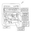
- FIG. 1illustrates a block diagram of a home automation system in accordance herewith
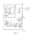
- FIG. 2depicts the portable user device of FIG. 1 during a set of configuration steps
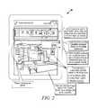
- FIG. 3depicts the portable device of FIG. 1 showing data from a thermostat
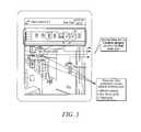
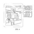
- FIG. 4depicts the updating of the user interface of the portable device of FIG. 1 as a user enters a living room;
- FIG. 5depicts the updating of the portable device as the user enters a bedroom
- FIG. 6depicts the path of a user of the portable device of FIG. 1 .
- FIG. 1is a block diagram of a home or business automation system 10 shown generally in accordance with an illustrated embodiment. Included within the system may be a security system 12 and a number of stand-alone home automation devices 14 , 16 . As used herein, home or business automation systems or devices will be referred to herein generically using the terms “home automation systems” or “home automation devices.”
- the security systemmay include a number of sensors 20 , 22 used to detect threats within a secured area 24 .
- the secured areamay be limited to the area within the walls of a home or business or may also include surrounding areas that are controlled by a human owner or user of the secured area.
- the home automation systemmay also include a portable wireless device (e.g., an iPhone, Android device, etc.) 26 that provides a user interface with the home automation system.
- the portable user devicemay be used to control any of a number of parameters or other features of the secured area. For example, the user device may be used to activate/deactivate the lighting in one or more rooms, control the blinds on the windows, lock or unlock doors, control a garage door opener, or adjust the temperature, etc.
- control panel and portable wireless devicemay be one or more processor apparatus (processors) 28 , 30 that each operate under control of one or more computer programs 32 , 34 loaded from non-transient computer readable medium (memory) 36 .
- processor apparatusprocessors
- computer programs32 , 34 loaded from non-transient computer readable medium (memory) 36 .
- reference to a step of a computer programis also reference to the processor the executed that step.
- the interface to the home automation system presented on a display 50 of the portable user deviceis dynamically adjusted based upon the location of the portable device within the secured area. This is important because in some cases (e.g., opening and closing blinds on a window, etc.), it is not necessary to display control features (e.g., buttons) when the user is out of visual range of the controlled device. More importantly, however, is that the continuous display of control features that are appropriate for the physical location of the user only obfuscates other control features that could otherwise be useful to the user.
- control featurese.g., buttons
- each of the home automation deviceshas a wireless location indicator 44 .
- the location indicatorsimply indicates the presence and identity of a nearby home automation device.
- Each location indicatorincludes a short range wireless transceiver that transmits an identification signal.
- the respective transceivers used in this regardmay be Bluetooth Low-energy Devices or equivalent (e.g., as defined in the Bluetooth Core Specification Version 4.0).
- an automation system monitoring processor operating within the portable wireless devicemay monitor an environment around the portable wireless device for home automation devices.
- the portable wireless devicedetects home automation devices via the wireless signal transmitted by a corresponding location indicator.
- each location indicatortransmits a unique system identifier 46 .
- a cross-reference file 48included within the portable wireless device.
- the cross-reference fileincludes the unique identifier of each of the location indicators and a respective identifier of one or more home automation devices that correspond to the location indicator.
- the home automation control system of a homemay include a lighting control device of a living room of the home. Located within the living room is a location indicator. During set up of the system, the user associates the location indicator in the living room with the lighting control device for the living room and saves the association in the cross-reference file. Each time that the portable user device enters the living room, the portable device detects the unique identifier of the location indicator and automatically loads the control application of the light control device.
- the portable user devicecontinuously scans for location indicators.
- the monitoring processorUpon detecting the location indicator of a home automation device, the monitoring processor automatically loads a corresponding driver (control application) for interfacing with and controlling the associated home automation device.
- the monitoring processoralso displays an icon 52 for activating that driver (and home automation device) shown on the display of the portable wireless device.
- the location indicatormay be a separate transceiver that is used to indicate the proximity of one or more home automation devices.
- the corresponding home automation device(s)may have their own wireless transceivers, but the portable device does not load the programs for directly communicating with the home automation device(s) until receiving a signal from the associated location indicator.
- the home automation device(s)may have dual purpose transceiver 38 , 40 , 42 that incorporates the functionality of the location indicator 44 .
- the display of the portable wireless devicedoes not display any control features of a home automation device until the portable wireless device detects the unique identifier from an associated location indicator. Upon detecting the location indicator, the display of the portable device displays the control features of the corresponding home automation device.
- the controlled devicesmay be from any of a number of different categories (e.g., security, video, home automation, etc.). Examples may include lighting, blinds (window curtains), locks, thermostats, switches (e.g., coffee pot), door or interior cameras, door sensors, motion sensors, glass break sensors, etc.
- buttons/icons to turn on/off the lightsbuttons/icons to control the blinds
- buttons/icons to lock/unlock the doorbuttons/icons to arm/disarm the security system
- buttons/icons to control a garage doorbuttons/icons to adjust the temperature (thermostat), etc.
- the claimed inventionsolves these problems using a number of novel approaches.
- the solutionworks based on the concept of automatic updating the user interface (UI) of mobile applications based on the location of the mobile device inside the home or business in order to control the device and sensors of the connected home systems (e.g., security, video and home automation).
- UIuser interface
- Low cost wireless location sensors or location indicatorscan be placed anywhere inside the house.
- the location sensorsregisters its position (proximity) with the mobile app or the existing connected automation devices/sensors itself can be used as a location sensing sensor or location indicator in the case of a dual mode transceiver.
- Each location sensor or location indicatorhas its own unique system identifier. These location sensors or location indicators are placed close to each connected home devices/sensors. Additional location sensors or indicators can be placed where necessary based upon need. Within the mobile app, the user can pair each location sensor or indicator with one or more connected home devices/sensors installed at that particular location. Once the mobile device receives a signal from a wireless sensor or location indicator, then the mobile app checks for an associated connected home device/sensor and loads the UI accordingly in order to control the devices available at that location.
- the UI controls(shown on the display of the portable device) get updated automatically once the mobile device (user) moves from location 1 to location 2 .
- the app on the mobile devicewill show the UI options to control the living room automation devices (e.g., lights and window). Now assume that the user with the mobile device moves from the living room to the bedroom. In this case, the app updates the UI options to control the automation devices in the bedroom (e.g., lights, thermostat, etc.).
- the UI controlscan be operative and updated even while the mobile device has a locked screen. There is no need to unlock the mobile device (e.g., a phone, a tablet, etc.) to control the devices.
- the mobile appcan request a personal identification number (PIN) to activate or otherwise control the security system devices (e.g., disarming a security panel, unlocking a door, etc.).
- PINpersonal identification number
- each UI updatecan have a customized background image as shown in FIGS. 2-5 .
- the mobile devicemay show an image of the living room on the display with icons of the controlled automation devices shown superimposed over the image at the appropriate locations.
- FIG. 2shows a screen that may be displayed on the portable device.
- a menu of icons of user devicescan be displayed along a top of the screen.
- the icons from the menumay be dragged to an appropriate location of the room.
- the association between the icon and location indicatormay be created by dragging and dropping the user device icon on top of the icon of the location indicator.
- FIG. 3depicts an icon of a thermostat.
- the iconincludes up and down buttons for the thermostat.
- the iconfurther includes a window with an indicated temperature in the room.
- FIG. 4depicts another view of a living room.
- the control featureincludes lighting as well as a window curtain control.
- FIG. 5shows an updated window as the user enters the bedroom.
- the windowincludes two lighting controls and a thermostat control.
- the mobile devicemay include a control options app executing on a control options processor.
- the control options appcan also show status information of the devices (e.g., the temperature in a room) as the user moves through an area (as shown in FIG. 6 ) or any other information that is available for the automation device.
- the systemincludes a plurality of user controlled devices, each located at a respective predetermined location within a geographic area of a user, a respective location indicator associated with each of the plurality of user controlled devices and a portable user device.
- the portable user devicefurther includes a respective controlling application of each of the plurality of user controlled devices embodied in a memory of the portable user device, a monitoring processor of the portable user device that detects a location of the portable user device within the geographic area based upon a wireless signal from one of the respective location indicators and an interface processor of the portable device that loads the controlling application of one of the plurality of user controlled devices based upon the detected location of the portable user device.
- the systemincludes a user controlled device located at a predetermined location within a geographic area of a user, a location indicator associated with the user controlled device that transmits a low power wireless signal including a unique system identifier associated with the user controlled device and a portable user device.
- the portable user devicefurther includes a controlling application of the user controlled device embodied in a memory of the portable user device, a monitoring processor of the portable user device that detects the user controlled device within the geographic area based upon the wireless signal from the location indicator; and an interface processor of the portable device that loads the controlling application of the user controlled device based upon the detected signal from the location indicator.
- the systemincludes a plurality of user controlled devices located at respective predetermined locations within a geographic area of a user, a respective location indicator associated with each of the plurality of user controlled devices that each transmit a low power wireless signal including a unique system identifier associated with the user controlled device and a wireless portable user device.
- the portable user devicefurther includes a respective controlling application of each of the plurality of user controlled devices embodied in a memory of the portable user device, a monitoring processor of the portable user device that detects a location indicator within the geographic area based upon the wireless signal from the location indicator and an interface processor of the portable device that loads the controlling application of one of the plurality of user controlled devices based upon the unique identifier of the detected wireless signal from the location indicator.
Landscapes
- Engineering & Computer Science (AREA)
- Theoretical Computer Science (AREA)
- General Engineering & Computer Science (AREA)
- Physics & Mathematics (AREA)
- General Physics & Mathematics (AREA)
- Computer Networks & Wireless Communication (AREA)
- Signal Processing (AREA)
- Databases & Information Systems (AREA)
- Human Computer Interaction (AREA)
- Remote Sensing (AREA)
- Data Mining & Analysis (AREA)
- Automation & Control Theory (AREA)
- Manufacturing & Machinery (AREA)
- Quality & Reliability (AREA)
- Selective Calling Equipment (AREA)
Abstract
Description
Claims (16)
Priority Applications (5)
| Application Number | Priority Date | Filing Date | Title |
|---|---|---|---|
| US14/489,748US10310704B2 (en) | 2014-09-18 | 2014-09-18 | System and method to have location based personalized UI updates on mobile app for connected users in security, video and home automation applications |
| CA2903924ACA2903924A1 (en) | 2014-09-18 | 2015-09-11 | System and method to have location based personalized ui updates on mobile app for connected users in security, video and home automation applications |
| EP15185567.3AEP2998946B1 (en) | 2014-09-18 | 2015-09-16 | System and method to have location based personalized ui updates on mobile app for connected users in security, video and home automation applications |
| ES15185567TES2837126T3 (en) | 2014-09-18 | 2015-09-16 | System and method to have location-based custom UI updates in mobile apps for connected users in security, video, and home automation apps |
| CN201510715662.1ACN105446144A (en) | 2014-09-18 | 2015-09-17 | System and method to have personalized ui updates on mobile app for home automation |
Applications Claiming Priority (1)
| Application Number | Priority Date | Filing Date | Title |
|---|---|---|---|
| US14/489,748US10310704B2 (en) | 2014-09-18 | 2014-09-18 | System and method to have location based personalized UI updates on mobile app for connected users in security, video and home automation applications |
Publications (2)
| Publication Number | Publication Date |
|---|---|
| US20160085412A1 US20160085412A1 (en) | 2016-03-24 |
| US10310704B2true US10310704B2 (en) | 2019-06-04 |
Family
ID=54148404
Family Applications (1)
| Application Number | Title | Priority Date | Filing Date |
|---|---|---|---|
| US14/489,748Active2035-11-21US10310704B2 (en) | 2014-09-18 | 2014-09-18 | System and method to have location based personalized UI updates on mobile app for connected users in security, video and home automation applications |
Country Status (5)
| Country | Link |
|---|---|
| US (1) | US10310704B2 (en) |
| EP (1) | EP2998946B1 (en) |
| CN (1) | CN105446144A (en) |
| CA (1) | CA2903924A1 (en) |
| ES (1) | ES2837126T3 (en) |
Cited By (1)
| Publication number | Priority date | Publication date | Assignee | Title |
|---|---|---|---|---|
| US20230154060A1 (en)* | 2021-11-17 | 2023-05-18 | Samsung Electronics Co., Ltd. | Electronic device and method for anchoring of augmented reality object |
Families Citing this family (26)
| Publication number | Priority date | Publication date | Assignee | Title |
|---|---|---|---|---|
| US10454783B2 (en)* | 2014-02-05 | 2019-10-22 | Apple Inc. | Accessory management system using environment model |
| EP3313050B1 (en) | 2014-02-05 | 2019-01-23 | Apple Inc. | Uniform communication protocols for communication between controllers and accessories |
| KR102338899B1 (en)* | 2015-01-02 | 2021-12-13 | 삼성전자주식회사 | Method and device for controlling home device |
| CN105159523A (en)* | 2015-07-31 | 2015-12-16 | 小米科技有限责任公司 | Target function enabling method, apparatus and system |
| DK179494B1 (en) | 2016-06-12 | 2019-01-11 | Apple Inc. | User interface for managing controllable external devices |
| US10608834B2 (en) | 2016-08-03 | 2020-03-31 | Honeywell International Inc. | Approach and system for avoiding ambiguous action via mobile apps through context based notification |
| CN106371329B (en)* | 2016-11-21 | 2019-12-03 | 北京小米移动软件有限公司 | Smart home appliance association method and device |
| EP3564802B1 (en)* | 2017-01-26 | 2023-08-02 | Huawei Technologies Co., Ltd. | Method and device for displaying application, and electronic terminal |
| USD844593S1 (en) | 2017-02-06 | 2019-04-02 | Hunter Douglas, Inc. | Automation gateway |
| ES2972208T3 (en)* | 2017-09-06 | 2024-06-11 | Savant Systems Inc | User interface based on a small screen virtual space |
| US11372530B2 (en)* | 2017-09-21 | 2022-06-28 | Ademco Inc. | Using a wireless mobile device and photographic image of a building space to commission and operate devices servicing the building space |
| AU2019100523A4 (en)* | 2018-05-07 | 2019-06-13 | Apple Inc. | User interfaces for viewing live video feeds and recorded video |
| EP4113989A1 (en) | 2018-05-07 | 2023-01-04 | Apple Inc. | User interfaces for viewing live video feeds and recorded video |
| US12165495B2 (en)* | 2019-02-28 | 2024-12-10 | Nice North America Llc | Virtual partition of a security system |
| US11626010B2 (en)* | 2019-02-28 | 2023-04-11 | Nortek Security & Control Llc | Dynamic partition of a security system |
| US10904029B2 (en) | 2019-05-31 | 2021-01-26 | Apple Inc. | User interfaces for managing controllable external devices |
| US11363071B2 (en) | 2019-05-31 | 2022-06-14 | Apple Inc. | User interfaces for managing a local network |
| CN110471298B (en)* | 2019-08-12 | 2020-10-23 | 珠海格力电器股份有限公司 | Intelligent household appliance control method, equipment and computer readable medium |
| CA3153935A1 (en) | 2019-09-11 | 2021-03-18 | Savant Systems, Inc. | Three dimensional virtual room-based user interface for a home automation system |
| US11513667B2 (en) | 2020-05-11 | 2022-11-29 | Apple Inc. | User interface for audio message |
| US20210358294A1 (en)* | 2020-05-15 | 2021-11-18 | Microsoft Technology Licensing, Llc | Holographic device control |
| US11657614B2 (en) | 2020-06-03 | 2023-05-23 | Apple Inc. | Camera and visitor user interfaces |
| US11589010B2 (en) | 2020-06-03 | 2023-02-21 | Apple Inc. | Camera and visitor user interfaces |
| CN116195261A (en) | 2020-09-05 | 2023-05-30 | 苹果公司 | User interface for managing audio of media items |
| US20220365667A1 (en) | 2021-05-15 | 2022-11-17 | Apple Inc. | User interfaces for managing accessories |
| US12379827B2 (en) | 2022-06-03 | 2025-08-05 | Apple Inc. | User interfaces for managing accessories |
Citations (18)
| Publication number | Priority date | Publication date | Assignee | Title |
|---|---|---|---|---|
| US20030011467A1 (en)* | 2001-07-12 | 2003-01-16 | Riku Suomela | System and method for accessing ubiquitous resources in an intelligent environment |
| US20100145479A1 (en)* | 2008-10-09 | 2010-06-10 | G2 Software Systems, Inc. | Wireless Portable Sensor Monitoring System |
| US20100217837A1 (en)* | 2006-12-29 | 2010-08-26 | Prodea Systems , Inc. | Multi-services application gateway and system employing the same |
| US20100312366A1 (en)* | 2009-06-03 | 2010-12-09 | Savant Systems Llc | Virtual room-based light fixture and device control |
| US20120154108A1 (en) | 2010-12-16 | 2012-06-21 | Optim Corporation | Portable terminal, method, and program of changing user interface |
| US20120280802A1 (en) | 2011-03-29 | 2012-11-08 | Panasonic Corporation | Remote operation system and remote controller |
| US8380226B2 (en) | 2006-04-05 | 2013-02-19 | Hewlett-Packard Development Company, L.P. | Location based reminders |
| US20130282280A1 (en)* | 2010-06-29 | 2013-10-24 | Lightstep Technologies Limited | Control module for a route guidance system |
| US20130331087A1 (en) | 2012-06-11 | 2013-12-12 | Apple Inc. | Location-Based Device Automation |
| US20130335203A1 (en)* | 2012-06-19 | 2013-12-19 | Yan Long Sun | Portable electronic device for remotely controlling smart home electronic devices and method thereof |
| US20140005809A1 (en)* | 2012-06-27 | 2014-01-02 | Ubiquiti Networks, Inc. | Method and apparatus for configuring and controlling interfacing devices |
| US20140235265A1 (en) | 2013-02-19 | 2014-08-21 | Homersoft Sp. Zo.O. | Dynamic proximity control system |
| WO2014203358A1 (en) | 2013-06-19 | 2014-12-24 | 株式会社東芝 | Method, electronic device, and program |
| US20150074259A1 (en)* | 2006-12-29 | 2015-03-12 | Prodea Systems, Inc. | Multi-services application gateway and system employing the same |
| US20150347683A1 (en)* | 2006-12-29 | 2015-12-03 | Prodea Systems, Inc. | Multi-services application gateway and system employing the same |
| US20160029155A1 (en)* | 2001-02-06 | 2016-01-28 | Nexrf, Corp. | Context aware relevance engine with client-driven narrative |
| US20160037332A1 (en)* | 2014-07-29 | 2016-02-04 | Cellco Partnership D/B/A Verizon Wireless | Method and apparatus for controlling home appliances over lte |
| US9374874B1 (en)* | 2012-02-24 | 2016-06-21 | Synapse Wireless, Inc. | Lighting control systems and methods |
Family Cites Families (5)
| Publication number | Priority date | Publication date | Assignee | Title |
|---|---|---|---|---|
| US8683317B2 (en)* | 2009-09-23 | 2014-03-25 | Fisher-Rosemount Systems, Inc. | Dynamically linked graphical messages for process control systems |
| CN102520681B (en)* | 2011-11-21 | 2016-08-03 | 康佳集团股份有限公司 | Internet-of-things terminal intelligent configuration method based on appearance information identification and system |
| EP2602677B1 (en)* | 2011-12-05 | 2018-02-21 | Nxp B.V. | Localization method, computer program product and localization device |
| KR101315452B1 (en)* | 2013-01-21 | 2013-10-14 | (주)브라이니클 | Method for providing shopping information using a mobile terminal and user interface for providing shopping information usint the mobile terminal |
| CN103426270A (en)* | 2013-06-07 | 2013-12-04 | 中山菲柯特电子电器有限公司 | Household intelligent fire-fighting early warning and escape system |
- 2014
- 2014-09-18USUS14/489,748patent/US10310704B2/enactiveActive
- 2015
- 2015-09-11CACA2903924Apatent/CA2903924A1/ennot_activeAbandoned
- 2015-09-16EPEP15185567.3Apatent/EP2998946B1/enactiveActive
- 2015-09-16ESES15185567Tpatent/ES2837126T3/enactiveActive
- 2015-09-17CNCN201510715662.1Apatent/CN105446144A/enactivePending
Patent Citations (18)
| Publication number | Priority date | Publication date | Assignee | Title |
|---|---|---|---|---|
| US20160029155A1 (en)* | 2001-02-06 | 2016-01-28 | Nexrf, Corp. | Context aware relevance engine with client-driven narrative |
| US20030011467A1 (en)* | 2001-07-12 | 2003-01-16 | Riku Suomela | System and method for accessing ubiquitous resources in an intelligent environment |
| US8380226B2 (en) | 2006-04-05 | 2013-02-19 | Hewlett-Packard Development Company, L.P. | Location based reminders |
| US20150074259A1 (en)* | 2006-12-29 | 2015-03-12 | Prodea Systems, Inc. | Multi-services application gateway and system employing the same |
| US20100217837A1 (en)* | 2006-12-29 | 2010-08-26 | Prodea Systems , Inc. | Multi-services application gateway and system employing the same |
| US20150347683A1 (en)* | 2006-12-29 | 2015-12-03 | Prodea Systems, Inc. | Multi-services application gateway and system employing the same |
| US20100145479A1 (en)* | 2008-10-09 | 2010-06-10 | G2 Software Systems, Inc. | Wireless Portable Sensor Monitoring System |
| US20100312366A1 (en)* | 2009-06-03 | 2010-12-09 | Savant Systems Llc | Virtual room-based light fixture and device control |
| US20130282280A1 (en)* | 2010-06-29 | 2013-10-24 | Lightstep Technologies Limited | Control module for a route guidance system |
| US20120154108A1 (en) | 2010-12-16 | 2012-06-21 | Optim Corporation | Portable terminal, method, and program of changing user interface |
| US20120280802A1 (en) | 2011-03-29 | 2012-11-08 | Panasonic Corporation | Remote operation system and remote controller |
| US9374874B1 (en)* | 2012-02-24 | 2016-06-21 | Synapse Wireless, Inc. | Lighting control systems and methods |
| US20130331087A1 (en) | 2012-06-11 | 2013-12-12 | Apple Inc. | Location-Based Device Automation |
| US20130335203A1 (en)* | 2012-06-19 | 2013-12-19 | Yan Long Sun | Portable electronic device for remotely controlling smart home electronic devices and method thereof |
| US20140005809A1 (en)* | 2012-06-27 | 2014-01-02 | Ubiquiti Networks, Inc. | Method and apparatus for configuring and controlling interfacing devices |
| US20140235265A1 (en) | 2013-02-19 | 2014-08-21 | Homersoft Sp. Zo.O. | Dynamic proximity control system |
| WO2014203358A1 (en) | 2013-06-19 | 2014-12-24 | 株式会社東芝 | Method, electronic device, and program |
| US20160037332A1 (en)* | 2014-07-29 | 2016-02-04 | Cellco Partnership D/B/A Verizon Wireless | Method and apparatus for controlling home appliances over lte |
Non-Patent Citations (6)
| Title |
|---|
| Examination report from corresponding EP patent application 15185567.3, dated Mar. 20, 2018. |
| Extended European search report from corresponding EP Patent Application 15185567.3, dated Feb. 9, 2016. |
| K. Scott, R. Benlamri, "Context-Aware Services for Smart Learning Spaces", Jul.-Sep. 2010, IEEE Transactions on Learning Technologies vol. 3 No. 3, retrieved on Sep. 28, 2018 from web at https://www.computer.org/csdl/trans/lt/2010/03/tlt2010030214.pdf (Year: 2010).* |
| Kathi Vian, Mike Liebhold, Anthony Townsend, "The Many Faces of Context Awareness: A Spectrum of Technologies, Applications, and Impacts", Sep. 2006, Technology Horizons Program, retrieved on Sep. 28, 2018 from web at http://www.iftf.org/uploads/media/SR-1014_ Many_Faces_Context_Awareness (Year: 2006).* |
| Luca Reggiani, Jocelyn Fiorina, Sinan Gezici, Simone Morosi, Montse Najar, "Radio Context Awareness and Applications", 2013, Hindawi Publishing Corporation, Journal of Sensors, vol. 2013 Article ID 491092, retrieved on Sep. 28, 2018 from web at https://www.hindawi.com/journals/js/2013/491092 (Year:2013).* |
| Miguel S. Familiar, Jose F. Martinez, Lourdes Lopez, "Pervasive Smart Spaces and Environments: A Service-Oriented Middleware Architecture for Wireless Ad Hoc and Sensor Networks", 2012, retrieved on Sep. 28, 2018 from web at http://journals.sagepub.com/doi/pdf/10.1155/2012/725190.* |
Cited By (2)
| Publication number | Priority date | Publication date | Assignee | Title |
|---|---|---|---|---|
| US20230154060A1 (en)* | 2021-11-17 | 2023-05-18 | Samsung Electronics Co., Ltd. | Electronic device and method for anchoring of augmented reality object |
| US12423879B2 (en)* | 2021-11-17 | 2025-09-23 | Samsung Electronics Co., Ltd. | Electronic device and method for anchoring of augmented reality object |
Also Published As
| Publication number | Publication date |
|---|---|
| CA2903924A1 (en) | 2016-03-18 |
| CN105446144A (en) | 2016-03-30 |
| EP2998946A1 (en) | 2016-03-23 |
| US20160085412A1 (en) | 2016-03-24 |
| ES2837126T3 (en) | 2021-06-29 |
| EP2998946B1 (en) | 2020-11-11 |
Similar Documents
| Publication | Publication Date | Title |
|---|---|---|
| US10310704B2 (en) | System and method to have location based personalized UI updates on mobile app for connected users in security, video and home automation applications | |
| EP3241195B1 (en) | Systems and methods of intrusion detection | |
| US10083596B2 (en) | Systems and methods of automated arming and disarming of a security system | |
| US10467887B2 (en) | Systems and methods of integrating sensor output of a mobile device with a security system | |
| US11062590B2 (en) | Systems and methods of providing allowances for a security system | |
| US10192426B2 (en) | Systems and methods of privacy within a security system | |
| US10332383B1 (en) | Connected door hinge | |
| US9834984B2 (en) | Roller shutter controller | |
| US9826352B2 (en) | Adjusting security in response to alert communications | |
| EP3241196B1 (en) | Guided installation for a magnetic door opening sensor | |
| US10223878B2 (en) | Automatic illuminating user interface device | |
| US10241647B2 (en) | Method and system of interacting with building security systems | |
| US20140313117A1 (en) | Camouflaged connected home controller | |
| US10303137B2 (en) | Structure modes for controlling various systems in closed environments | |
| WO2016109335A1 (en) | Systems and methods of intrusion detection |
Legal Events
| Date | Code | Title | Description |
|---|---|---|---|
| AS | Assignment | Owner name:HONEYWELL INTERNATIONAL INC., NEW JERSEY Free format text:ASSIGNMENT OF ASSIGNORS INTEREST;ASSIGNORS:MEGANATHAN, DEEPAK SUNDAR;ASWATH, RAVIKUMAR VEMAGAL;SIGNING DATES FROM 20140811 TO 20140813;REEL/FRAME:033767/0021 | |
| AS | Assignment | Owner name:JPMORGAN CHASE BANK, N.A., AS ADMINISTRATIVE AGENT, NEW YORK Free format text:SECURITY INTEREST;ASSIGNOR:ADEMCO INC.;REEL/FRAME:047337/0577 Effective date:20181025 Owner name:JPMORGAN CHASE BANK, N.A., AS ADMINISTRATIVE AGENT Free format text:SECURITY INTEREST;ASSIGNOR:ADEMCO INC.;REEL/FRAME:047337/0577 Effective date:20181025 | |
| AS | Assignment | Owner name:ADEMCO INC., MINNESOTA Free format text:ASSIGNMENT OF ASSIGNORS INTEREST;ASSIGNOR:HONEYWELL INTERNATIONAL INC.;REEL/FRAME:047909/0425 Effective date:20181029 | |
| STPP | Information on status: patent application and granting procedure in general | Free format text:NOTICE OF ALLOWANCE MAILED -- APPLICATION RECEIVED IN OFFICE OF PUBLICATIONS | |
| STCF | Information on status: patent grant | Free format text:PATENTED CASE | |
| AS | Assignment | Owner name:ADEMCO INC., MINNESOTA Free format text:CORRECTIVE ASSIGNMENT TO CORRECT THE PREVIOUS RECORDING BY NULLIFICATION. THE INCORRECTLY RECORDED PATENT NUMBERS 8545483, 8612538 AND 6402691 PREVIOUSLY RECORDED AT REEL: 047909 FRAME: 0425. ASSIGNOR(S) HEREBY CONFIRMS THE ASSIGNMENT;ASSIGNOR:HONEYWELL INTERNATIONAL INC.;REEL/FRAME:050431/0053 Effective date:20190215 | |
| MAFP | Maintenance fee payment | Free format text:PAYMENT OF MAINTENANCE FEE, 4TH YEAR, LARGE ENTITY (ORIGINAL EVENT CODE: M1551); ENTITY STATUS OF PATENT OWNER: LARGE ENTITY Year of fee payment:4 | |
| AS | Assignment | Owner name:RESIDEO LLC, DELAWARE Free format text:CHANGE OF NAME;ASSIGNOR:ADEMCO INC.;REEL/FRAME:071546/0001 Effective date:20241227 |