US10310554B2 - Folding display panels for large-format displays - Google Patents
Folding display panels for large-format displaysDownload PDFInfo
- Publication number
- US10310554B2 US10310554B2US14/972,962US201514972962AUS10310554B2US 10310554 B2US10310554 B2US 10310554B2US 201514972962 AUS201514972962 AUS 201514972962AUS 10310554 B2US10310554 B2US 10310554B2
- Authority
- US
- United States
- Prior art keywords
- display panels
- movable member
- panels
- cable
- folding
- Prior art date
- Legal status (The legal status is an assumption and is not a legal conclusion. Google has not performed a legal analysis and makes no representation as to the accuracy of the status listed.)
- Active, expires
Links
Images


Classifications
- G—PHYSICS
- G06—COMPUTING OR CALCULATING; COUNTING
- G06F—ELECTRIC DIGITAL DATA PROCESSING
- G06F1/00—Details not covered by groups G06F3/00 - G06F13/00 and G06F21/00
- G06F1/16—Constructional details or arrangements
- G06F1/1601—Constructional details related to the housing of computer displays, e.g. of CRT monitors, of flat displays
- G06F1/1607—Arrangements to support accessories mechanically attached to the display housing
- G—PHYSICS
- G09—EDUCATION; CRYPTOGRAPHY; DISPLAY; ADVERTISING; SEALS
- G09F—DISPLAYING; ADVERTISING; SIGNS; LABELS OR NAME-PLATES; SEALS
- G09F9/00—Indicating arrangements for variable information in which the information is built-up on a support by selection or combination of individual elements
- G09F9/30—Indicating arrangements for variable information in which the information is built-up on a support by selection or combination of individual elements in which the desired character or characters are formed by combining individual elements
- G09F9/33—Indicating arrangements for variable information in which the information is built-up on a support by selection or combination of individual elements in which the desired character or characters are formed by combining individual elements being semiconductor devices, e.g. diodes
- G—PHYSICS
- G09—EDUCATION; CRYPTOGRAPHY; DISPLAY; ADVERTISING; SEALS
- G09F—DISPLAYING; ADVERTISING; SIGNS; LABELS OR NAME-PLATES; SEALS
- G09F9/00—Indicating arrangements for variable information in which the information is built-up on a support by selection or combination of individual elements
- G09F9/30—Indicating arrangements for variable information in which the information is built-up on a support by selection or combination of individual elements in which the desired character or characters are formed by combining individual elements
- G09F9/301—Indicating arrangements for variable information in which the information is built-up on a support by selection or combination of individual elements in which the desired character or characters are formed by combining individual elements flexible foldable or roll-able electronic displays, e.g. thin LCD, OLED
- G—PHYSICS
- G09—EDUCATION; CRYPTOGRAPHY; DISPLAY; ADVERTISING; SEALS
- G09F—DISPLAYING; ADVERTISING; SIGNS; LABELS OR NAME-PLATES; SEALS
- G09F9/00—Indicating arrangements for variable information in which the information is built-up on a support by selection or combination of individual elements
- G09F9/30—Indicating arrangements for variable information in which the information is built-up on a support by selection or combination of individual elements in which the desired character or characters are formed by combining individual elements
- G09F9/302—Indicating arrangements for variable information in which the information is built-up on a support by selection or combination of individual elements in which the desired character or characters are formed by combining individual elements characterised by the form or geometrical disposition of the individual elements
- G09F9/3026—Video wall, i.e. stackable semiconductor matrix display modules
Definitions
- the present disclosurerelates to display panels used for large-format displays, and in particular relates to folding display panels for large-format displays.
- Large-format displaysare becoming increasingly popular for use in a wide variety of applications and venues. In certain instances, such as for concerts, performances, etc., the large-format displays need to be moved to the event, quickly set up before the event, dismantled after the event, and then moved into storage or to another event. Consequently, such large-format displays are typically made with modular components.
- modular large-format displayscan still be time-consuming to set up, especially for displays with dimensions measured in tens of feet.
- Such large-format displayscan comprise hundreds of modular display panels. These display panels require power and data cabling, which must be individually and manually connected to each display panel.
- pre-attaching the display modules with a hinge mechanismcan allow a screen to fan-fold up and down while keeping the panels connected mechanically.
- the power and data cablescan remain attached.
- mechanical accuracy and alignment of the modulesbecomes much more critical while the space between the pixels becomes so small that there may not even be room for cables.
- an aspect of the disclosureis a folding display panel apparatus for a large-format display, comprising: first and second display panels that each include a front side having an array of light-emitting pixels, a back side having a movable member, a top edge, opposite side edges and a bottom edge, with the first and second display panels arranged edge-to-edge; and at least one electrical cable that electrically connects the first and second panels, the at least one electrical cable including at least one data wire and at least one power wire, the at least one electrical cable having a fixed-length cable section that runs between the first and second display panels, wherein one end of the fixed-length section is attached to the movable member, and wherein the data and power wires each have an amount of slack that resides outside of the fixed-length cable section adjacent the movable member, wherein the movable member is configured so that when the first and second display panels are folded front-side to front-side, the movable member moves toward an edge of the one of the first and second display panels to accommodate
- Another aspect of the disclosureis a method of making folding display panels for a large-format display, comprising: electrically connecting with at least one electrical cable first and second display panels each having a body with a front face, a back side, a bottom edge and a top edge, the display panels arranged top-edge to bottom-edge and being foldable with respect to one another proximate the bottom edge, with the at least one electrical cable arranged adjacent the respective back sides of the first and second display panels; and attaching a fixed-length cable section of the at least one electrical cable to the first and second display panels, with one end of the fixed-length cable section being attached to a movable member, the movable member being designed and configured to retain substantially uniform tension in the fixed-length cable section during folding of the first and second display panels.
- a folding display panel apparatusthat includes: first and second display panels arranged edge-to-edge and having respective first and second front faces and respective first and second back sides; a data cable that includes at least one data wire and a power cable that includes at least one power wire, wherein the data cable and power cable are supported adjacent the respective first and second back sides; a movable member operably arranged on the first back side of the first display panel; wherein the data cable and power cable each include fixed-length sections attached to the movable member to define a portion of a flexible hinge; and wherein the movable member of the first display panel is configured to move toward the second display panel when the first and second display panels are folded face-to-face.
- Another aspect of the disclosureis a method of unfolding and folding a plurality of display panels for a large-format display, wherein adjacent panels in the plurality of display panels are arranged to fold around a hinge and each of the adjacent panels has a front face that defines a plane, wherein at least one of a power cable and a data cable is connected to each of the plurality of display panels and further wherein the at least one of a power cable and a data cable extend between adjacent panels, the method comprising: unfolding the plurality of display panels about their respective hinges so the panels extend in a linear direction and their front face planes are substantially coplanar; retaining substantially uniform tension in the at least one of a data cable and a power cable extending between adjacent panels during the unfolding step; and folding the plurality of display panels about their respective hinges to cause the panels to move toward one another so the front face planes are positioned in spaced, mutually parallel relationship when fully folded; and retaining substantially uniform tension in the at least one of a data cable and a power cable during the folding step.
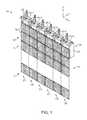
- FIG. 1is a front-elevated view of a large-format display (LFD) system according to the disclosure
- FIG. 2Ais a close-up front-elevated view and FIG. 2B is a close-up back-elevated view, which illustrate two example foldable display panels used in the LFD system of FIG. 1 and that form a display panel assembly;
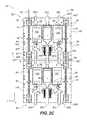
- FIG. 2Cis similar to FIG. 2B , but with the back cover removed to show the spring-loaded slide assembly and the electrical cable configuration that allow for movement of the spring-loaded slide assembly;
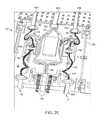
- FIG. 2Dis a close-up view of the spring-loaded slide assembly
- FIG. 2Eis a close-up view of the back side of the display panel showing more detail of the example slide assembly, the data and power wires, and the printed circuit boards supported at the back side of the display panel;
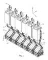
- FIG. 3is a back elevated view of the LFD system, showing how the display panels in each column of display panels can be z-folded;
- FIGS. 4A through 4Cshow three views of the display panel assembly of FIG. 2 being z-folded in a back-to-back configuration
- FIGS. 5A through 5Cshow three views of the display panel assembly of FIG. 2 being z-folded in a front-to-front configuration.
- FIG. 1is a front-elevated view of a large-format display (LFD) system 10 according to an aspect of the disclosure.
- the LFD system 10includes a front side 14 and a back side 16 .
- the LFD system 10includes an array 20 of electrical power and data units 22 (denoted, 22 - 1 , 22 - 2 , . . . 22 - 6 ) that operably support an array or assembly 50 of foldable display panels (“panels”) 52 .
- the panels 52are also referred to in the art as a “modules” or “waffles.”
- the array or assembly 50 of panels 52defines a LFD, so that array or assembly 50 is also referred to herein as LFD 50 .
- the panels 52 of array or assembly 50are arranged in columns C, e.g., C 1 , C 2 , . . . Cn, with column Cj downwardly depending from corresponding electrical power and data unit 22 - j .
- n6.
- the electrical power and data units 22are shown as each including a mounting bracket 24 that can attach to an elevated horizontal mounting bar (not shown) so that the foldable panels 52 can hang downward from their respective power units to form LFD 50 .
- FIG. 2Ais a close-up front-elevated view and FIG. 2B is a close-up back-elevated view of two example foldable panels 52 , denoted 52 T and 52 B for “top” and “bottom.”
- Two or more connected panels 52define a panel assembly.
- Each panel 52has a front side or front face 54 and a back side 56 , a top edge 58 T a bottom edge 58 B, and opposite side edges 60 .
- the front side 54 of each panel 52defines a plane and includes light-emitting pixels 72 operably disposed therein to form an array 70 of pixels.
- the plane defined by the front face 54 of panel 52may be substantially flat or may comprise one or more curvatures.
- the back side 56optionally includes a protective cover 57 as best seen in FIG. 2B .
- FIG. 2Cis similar to FIG. 2B , except that cover 57 is removed to show the various components supported on the back side 56 , as explained below.
- the side edges 60include slots 62 that can accommodate fixed or removable clips (not shown) that connect to adjacent panels 52 in adjacent columns C.
- electrical connectionsmay be established via slots 62 such that only one assembly 50 of panels 52 in an LFD system 10 needs to include certain cabling or connections (e.g., one or more electrical cables 80 ) while any adjacent, connected panels and, optionally, any panels joined similarly to those adjacent, connected panels, and any panels joined with those, etc., may receive power and/or data in a “daisy chained” sequential fashion.
- Each panel 52includes a body 51 that supports on the back side 56 and/or in an interior (not shown) various components, such as wiring, cabling, and other electrical mechanical parts, such as printed circuit boards (PCBs), wire guides, etc.
- FIGS. 2D and 2Eare close-up views similar to FIG. 2C that illustrates in more detail the aforementioned various components supported on the back side 56 of panel 52 .
- Each panel 52may include one or more electrical cables 80 , e.g., three electrical cables 80 L, 80 C, and 80 R on the left, center and right of the panel, respectively (when viewed from the front side 54 ), which run between the bottom edge 58 B and the adjacent top edge 58 T of adjacent panels 52 , as described in greater detail below.
- the electrical cables 80carry data and power. In an example, data and power are carried separately, e.g., data is carried in electrical cables 80 L and 80 R and power is carried in electrical cable 80 C, although other implementations may be used.
- power and/or data communication mediums other than cablesmay be used, e.g., via wireless energy transmission or other suitable techniques, in place of or alongside other cables (for data and/or for power).
- Two flexible support cables 90run in grooves 91 that run down the back side 56 of the panels 52 from top edge 58 T to bottom edge 58 B in a given column C to support the columnar arrangement of the panels in their deployed state (although a single, central support cable or other configuration may be used).
- support cables 90are made of steel; in various embodiments, the support cables may be either continuously flexible or flexible in a piecewise fashion (e.g., inflexible segments joined by flexible segments or portions). Cable guides 92 on back side 56 of each panel 52 are used to maintain the support cables substantially parallel to side edges 60 .
- the support cables 90serve to keep the panels in a given column C flexibly connected.
- support cables 90may include a stopper (not shown) at their lower end (e.g., the end associated with the lowest panel 52 in an assembly 50 ) such that the stopper prevents a lowest panel in an assembly, and thus the other panels in the assembly, from sliding off the end of the cables.
- support cables 90may be attached to a horizontal rotating drum (or winch; not shown) disposed in or otherwise attached or disposed in association with an electrical power and data unit 22 , which may be turned by a crank or automatedly by motor or other power source.
- only a single winchmay be used such that, referring to FIG. 1 for example, only one electrical power and data unit 22 - 1 (or other portion of assembly 50 in column C 1 ) includes a winch, which, through the panels' connections to one another between adjacent columns, is operable to fold and unfold each assembly 50 in LFD system 10 .
- the support cables 90are flexible and (together with fixed-length cable sections 80 F, discussed below) define a folding mechanism or flexible hinge mechanism H that facilitates a z-folding capability of each column C (or assembly 50 ) of panels 52 .
- hinge Hmay not necessarily comprise features commonly associated with a traditional door hinge.
- hinge Hmay comprise cables and/or wires that mechanically connect panels 52 without necessarily limiting the degrees of freedom of movement possible between the panels; however, in some embodiments, the hinge may be designed and configured to act more like a traditional door hinge, thus limiting one or more degrees of freedom of movement possible between panels 52 .
- the back side 56 of panel 52may include a slide assembly 100 , as shown in the close-up views of FIGS. 2D and 2E .
- slide assembly 100is located adjacent bottom edge 58 B on each panel 52 .
- the slide assembly 100may include a movable member 110 that in an example is in the form of a plate.
- movable member 110has a centerline 112 , a bottom edge 114 , a top edge 116 , opposite side edges 118 , a top surface 120 and bottom surface 122 ; however, other orientations may be used.
- the configuration of slide assembly 100is substantially symmetric about centerline 112 .
- the movable member 110includes, in one implementation, a pair of elongate guide slots 130 that each run in the y-direction (see axes in FIG. 2D ) on opposite sides of centerline 112 .
- the guide slots 130accommodate respective guide members 132 fixed to back side 56 .
- a pair of resilient members 150e.g., springs
- Each resilient member 150includes a front end 152 and a back end 154 .
- Each resilient member 150is operably arranged between a front-end wall 162 and a back-end wall 164 .
- the back-end wall 164is attached to the top surface 120 of movable member 110 .
- the front-end wall 162is either fixed to back side 56 or is incorporated into cover 57 and engages the front end 152 of resilient member 150 when the cover is properly positioned on back side 56 .
- slide assembly 100is spring loaded.
- the slide assembly 100also includes securing members 182 M that serve to secure end portions of each electrical cable 80 to movable member 110 , and securing members 182 B that serve to secure the opposite end portions of each electrical cable 80 to the back side 56 of the adjacent panel 52 , although in some implementations another slide assembly may be used per panel such that each panel may include two slide assemblies and each electrical cable may extend between securing members like securing members 182 M on opposing ends of adjacent panels in an assembly 50 .
- the securing members 182 M and 182 Bdefine respective fixed-length sections 80 F for electrical cables 80 .
- the fixed-length sections 80 Frun between and electrically and mechanically connect adjacent panels 52 .
- the fix-length cable sections 80 Ftherefore comprise the aforementioned hinge H, which can bend forwards or backwards, thereby providing the z-folding capability for the panel assembly 50 .
- the electrical cables 80each include one or more wires 84 .
- the wires 84 for electrical cables 80 L and 80 Rmay be loosely connected to respective PCBs 190 supported on back side 56 of the same panel 52 as the movable member 110 .
- wires 84 in electrical cables 80 L and 80 Rare used to supply data and so are referred to as “data wires.”
- the wires 84 for electrical cable 180 Care shown as “power wires” that carry power.
- the power wires 84may loosely travel over back side 56 (e.g., through open channels defined by structures on back side 56 ), with some of the power wires running to the adjacent panel 52 and at least one of the power wires may be electrically connected to one of the local PCB's 190 or otherwise supply power to the panel. In this manner, power can be conveyed from the given electrical power and data unit 22 down to each of the panels 52 in assembly 50 for a given column C.
- the data wires 84can include a service loop or portion that includes an amount of slack. The amount of slack is used to accommodate the movement of movable member 110 , as described below.
- electrical cables 80 R, 80 C, and 80 Lserve to electrically connect adjacent panels 52 in a given column C while also mechanically connecting the adjacent panels by defining the aforementioned bi-folding hinge H.
- the support cables 90also form a portion of hinge H and serve to mechanically connect adjacent panels 50 in a given column C.
- the z-folding capability of hinge His illustrated in FIGS. 3, 4A through 4C , and FIGS. 5A through 5 C.
- the z-folding capabilitymeans that the panels 52 can be z-folded (i.e., in the z direction) back-to-back (as shown in FIGS. 4A through 4C ) or face-to-face (as shown in FIGS. 5A through 5C ), thereby allowing for efficient stacking of the panels for storage.
- FIGS. 5A through 5Care different views of two adjacent panels 52 illustrating the face-to-face z-folding operation.
- the face-to-face folding operationif one of the ends of the fixed-length sections 80 F of electrical cables were not movable, they would need to “stretch” to become longer because of the bending radius required or would require slack to accommodate the folding operation.
- the movable member 110moves toward the bottom edge 58 B of the panel 52 on which it resides as the two adjacent panels are folded front-to-front (see arrow AR in FIG. 5B ).
- movable member 110The movement of movable member 110 is guided over back side 56 by guide members 132 within guide slots 130 (see FIG. 2D ). This movement allows for the fixed-length sections 80 F of cables 80 to retain a substantially uniform tension during the folding and unfolding process, thereby preventing binding of the electrical cables, while also making the panels easier to fold and unfold.
- movable member 110may be positioned adjacent top edge 58 T, excluding perhaps the top-most panel 52 in the column C, with the result that as adjacent panels 52 are folded face-to-face, the movable member will move toward top edge 58 T.
- the resilient members 150are compressed between front-end wall 162 and back-end wall 164 as these two walls move closer to one another (see FIG. 2D ). Meanwhile, the fixed-length sections 80 F of electrical cables 80 flex or bend to accommodate the folding operation at hinge H (see FIG. 5B ).
- the slack portion of wires 84(see FIGS. 2D and 2E ) accommodates the movement of movable member 110 by giving up and receiving an amount of slack during the folding and unfolding process.
- the resilient members 150store energy so that the slide assembly 100 becomes spring loaded.
- the conjunctive phrases in the foregoing examples in which the conjunctive list consists of X, Y, and Zshall each encompass: one or more of X; one or more of Y; one or more of Z; one or more of X and one or more of Y; one or more of Y and one or more of Z; one or more of X and one or more of Z; and one or more of X, one or more of Y and one or more of Z.
Landscapes
- Engineering & Computer Science (AREA)
- Theoretical Computer Science (AREA)
- Physics & Mathematics (AREA)
- General Physics & Mathematics (AREA)
- General Engineering & Computer Science (AREA)
- Multimedia (AREA)
- Computer Hardware Design (AREA)
- Human Computer Interaction (AREA)
- Devices For Indicating Variable Information By Combining Individual Elements (AREA)
- Electric Cable Arrangement Between Relatively Moving Parts (AREA)
Abstract
Description
Claims (7)
Priority Applications (1)
| Application Number | Priority Date | Filing Date | Title |
|---|---|---|---|
| US14/972,962US10310554B2 (en) | 2014-12-20 | 2015-12-17 | Folding display panels for large-format displays |
Applications Claiming Priority (2)
| Application Number | Priority Date | Filing Date | Title |
|---|---|---|---|
| US201462094960P | 2014-12-20 | 2014-12-20 | |
| US14/972,962US10310554B2 (en) | 2014-12-20 | 2015-12-17 | Folding display panels for large-format displays |
Publications (2)
| Publication Number | Publication Date |
|---|---|
| US20160179133A1 US20160179133A1 (en) | 2016-06-23 |
| US10310554B2true US10310554B2 (en) | 2019-06-04 |
Family
ID=55070709
Family Applications (1)
| Application Number | Title | Priority Date | Filing Date |
|---|---|---|---|
| US14/972,962Active2036-10-28US10310554B2 (en) | 2014-12-20 | 2015-12-17 | Folding display panels for large-format displays |
Country Status (3)
| Country | Link |
|---|---|
| US (1) | US10310554B2 (en) |
| EP (1) | EP3035320B1 (en) |
| CN (1) | CN105719575B (en) |
Families Citing this family (9)
| Publication number | Priority date | Publication date | Assignee | Title |
|---|---|---|---|---|
| US9395070B2 (en)* | 2013-07-19 | 2016-07-19 | Semiconductor Energy Laboratory Co., Ltd. | Support of flexible component and light-emitting device |
| ES2971609T3 (en)* | 2017-03-02 | 2024-06-06 | Media Graph Depot Inc | Individually controllable light-emitting diode modules to display defined patterns |
| KR102754838B1 (en) | 2019-10-29 | 2025-01-14 | 삼성전자주식회사 | Display apparatus and method of controlling the same |
| CN111613147B (en)* | 2020-06-29 | 2022-03-29 | 武汉天马微电子有限公司 | Foldable electronic device |
| CN111824603B (en)* | 2020-08-05 | 2025-08-01 | 深圳市维世科技有限公司 | Portable display device |
| CN112435595A (en)* | 2020-12-25 | 2021-03-02 | 深圳市维世科技有限公司 | Combined screen mounting structure |
| CN112530297B (en)* | 2021-01-15 | 2025-08-01 | 深圳市维世科技有限公司 | Tension resistance structure for improving stability of folding screen and display device |
| WO2022151373A1 (en)* | 2021-01-15 | 2022-07-21 | 深圳市维世科技有限公司 | Stretching-resistant structure for improving stability of folding screen and display apparatus |
| CN113241013B (en)* | 2021-06-18 | 2022-08-19 | 合肥维信诺科技有限公司 | Foldable display device and control method of foldable display device |
Citations (22)
| Publication number | Priority date | Publication date | Assignee | Title |
|---|---|---|---|---|
| US5877936A (en) | 1996-09-04 | 1999-03-02 | Yazaki Corporation | Expansion structure for door mounted circuit bodies |
| US20010054986A1 (en)* | 1999-05-18 | 2001-12-27 | Michael V. Leman | Pen-based split computer display |
| US20040233125A1 (en) | 2003-05-23 | 2004-11-25 | Gino Tanghe | Method for displaying images on a large-screen organic light-emitting diode display, and display used therefore |
| WO2005077096A2 (en) | 2004-02-09 | 2005-08-25 | Intuitive Control System, Llc | Foldable electronic display |
| US6944383B1 (en) | 2004-04-12 | 2005-09-13 | Adc Telecommunications, Inc. | Cable management panel with sliding drawer and methods |
| US20050201087A1 (en) | 2004-03-11 | 2005-09-15 | Element Labs, Inc. | System for creating a tensioned wall composed of individual LED tiles |
| US20060039142A1 (en)* | 2004-08-23 | 2006-02-23 | Temple John W | Led net display |
| US7063449B2 (en) | 2002-11-21 | 2006-06-20 | Element Labs, Inc. | Light emitting diode (LED) picture element |
| US20070001927A1 (en) | 2005-07-01 | 2007-01-04 | Eastman Kodak Company | Tiled display for electronic signage |
| US20070000849A1 (en) | 2005-01-25 | 2007-01-04 | Daktronics, Inc. | Modular display system |
| US7161623B2 (en) | 1996-10-25 | 2007-01-09 | Canon Kabushiki Kaisha | Camera control system, camera server, camera client, control method, and storage medium |
| US20070068055A1 (en)* | 2003-10-08 | 2007-03-29 | Segan Marc H | Fordable modular light array |
| US20070176854A1 (en) | 2006-01-25 | 2007-08-02 | Element Labs, Inc. | Irregular screen format for led and oled systems |
| US20070218751A1 (en)* | 2004-03-11 | 2007-09-20 | Element Labs, Inc. | Mounting system for light tiles attached to tensioned cables |
| WO2008112152A1 (en) | 2007-03-08 | 2008-09-18 | Element Labs, Inc. | Ladder display system |
| WO2010054380A2 (en) | 2008-11-10 | 2010-05-14 | Displaire Corporation | Large screen portable led display |
| US8007121B2 (en) | 2008-04-15 | 2011-08-30 | Barco, Inc. | Support structure for an LED display system |
| US20110291536A1 (en)* | 2010-06-01 | 2011-12-01 | Kno, Inc. | Hinged Dual Panel Electronic Device |
| US8172097B2 (en) | 2005-11-10 | 2012-05-08 | Daktronics, Inc. | LED display module |
| US20120120033A1 (en) | 2004-10-14 | 2012-05-17 | Daktronics, Inc. | Flexible pixel hardware and method |
| EP2755195A1 (en) | 2013-01-15 | 2014-07-16 | Huasun Technology Co., Ltd. | Flexible LED display screen |
| US8840284B1 (en)* | 2013-05-01 | 2014-09-23 | Revolution Display, Inc. | Modular light emitting displays and arrays of same |
Family Cites Families (2)
| Publication number | Priority date | Publication date | Assignee | Title |
|---|---|---|---|---|
| WO2008089092A1 (en)* | 2007-01-12 | 2008-07-24 | Element Labs, Inc. | Rod assembly connector for mounting light emitting display apparatuses |
| CN102637391B (en)* | 2012-04-01 | 2014-11-26 | 深圳市威斯泰克光电技术有限公司 | Flexible LED (Light-Emitting Diode) display screen |
- 2015
- 2015-12-17USUS14/972,962patent/US10310554B2/enactiveActive
- 2015-12-17EPEP15200780.3Apatent/EP3035320B1/enactiveActive
- 2015-12-21CNCN201510964724.2Apatent/CN105719575B/ennot_activeExpired - Fee Related
Patent Citations (22)
| Publication number | Priority date | Publication date | Assignee | Title |
|---|---|---|---|---|
| US5877936A (en) | 1996-09-04 | 1999-03-02 | Yazaki Corporation | Expansion structure for door mounted circuit bodies |
| US7161623B2 (en) | 1996-10-25 | 2007-01-09 | Canon Kabushiki Kaisha | Camera control system, camera server, camera client, control method, and storage medium |
| US20010054986A1 (en)* | 1999-05-18 | 2001-12-27 | Michael V. Leman | Pen-based split computer display |
| US7063449B2 (en) | 2002-11-21 | 2006-06-20 | Element Labs, Inc. | Light emitting diode (LED) picture element |
| US20040233125A1 (en) | 2003-05-23 | 2004-11-25 | Gino Tanghe | Method for displaying images on a large-screen organic light-emitting diode display, and display used therefore |
| US20070068055A1 (en)* | 2003-10-08 | 2007-03-29 | Segan Marc H | Fordable modular light array |
| WO2005077096A2 (en) | 2004-02-09 | 2005-08-25 | Intuitive Control System, Llc | Foldable electronic display |
| US20050201087A1 (en) | 2004-03-11 | 2005-09-15 | Element Labs, Inc. | System for creating a tensioned wall composed of individual LED tiles |
| US20070218751A1 (en)* | 2004-03-11 | 2007-09-20 | Element Labs, Inc. | Mounting system for light tiles attached to tensioned cables |
| US6944383B1 (en) | 2004-04-12 | 2005-09-13 | Adc Telecommunications, Inc. | Cable management panel with sliding drawer and methods |
| US20060039142A1 (en)* | 2004-08-23 | 2006-02-23 | Temple John W | Led net display |
| US20120120033A1 (en) | 2004-10-14 | 2012-05-17 | Daktronics, Inc. | Flexible pixel hardware and method |
| US20070000849A1 (en) | 2005-01-25 | 2007-01-04 | Daktronics, Inc. | Modular display system |
| US20070001927A1 (en) | 2005-07-01 | 2007-01-04 | Eastman Kodak Company | Tiled display for electronic signage |
| US8172097B2 (en) | 2005-11-10 | 2012-05-08 | Daktronics, Inc. | LED display module |
| US20070176854A1 (en) | 2006-01-25 | 2007-08-02 | Element Labs, Inc. | Irregular screen format for led and oled systems |
| WO2008112152A1 (en) | 2007-03-08 | 2008-09-18 | Element Labs, Inc. | Ladder display system |
| US8007121B2 (en) | 2008-04-15 | 2011-08-30 | Barco, Inc. | Support structure for an LED display system |
| WO2010054380A2 (en) | 2008-11-10 | 2010-05-14 | Displaire Corporation | Large screen portable led display |
| US20110291536A1 (en)* | 2010-06-01 | 2011-12-01 | Kno, Inc. | Hinged Dual Panel Electronic Device |
| EP2755195A1 (en) | 2013-01-15 | 2014-07-16 | Huasun Technology Co., Ltd. | Flexible LED display screen |
| US8840284B1 (en)* | 2013-05-01 | 2014-09-23 | Revolution Display, Inc. | Modular light emitting displays and arrays of same |
Non-Patent Citations (2)
| Title |
|---|
| European Search Report dated Mar. 18, 2016, in corresponding European Patent Application No. 15200780.3. |
| https://www.youtube.com/watch?v=-eXVpuUDRmU (Last viewed Dec. 7, 2015). |
Also Published As
| Publication number | Publication date |
|---|---|
| EP3035320B1 (en) | 2018-07-11 |
| US20160179133A1 (en) | 2016-06-23 |
| EP3035320A1 (en) | 2016-06-22 |
| CN105719575B (en) | 2019-12-17 |
| CN105719575A (en) | 2016-06-29 |
Similar Documents
| Publication | Publication Date | Title |
|---|---|---|
| US10310554B2 (en) | Folding display panels for large-format displays | |
| EP3769180B1 (en) | Retractable display device | |
| KR102306540B1 (en) | Electronic apparatus having rollable display device | |
| US11357117B2 (en) | Display device | |
| CN106257569B (en) | Flexible display device | |
| US9668372B2 (en) | Cable management device | |
| CN108538207B (en) | Flexible display support device | |
| US20200137902A1 (en) | Display device | |
| CN102957110A (en) | Cable sorting device and cable module | |
| US10117346B2 (en) | Supporting structure having variable form and electronic device having supporting structure | |
| CN106652798B (en) | A kind of display device and its bearing assembly | |
| KR101527815B1 (en) | Folding examination apparatus for foldable display and folding examination method using this | |
| CN104464529B (en) | Flexible display device having guide member | |
| CN109654353B (en) | Splicing device of LED display screen | |
| KR101519561B1 (en) | Bending test apparatus using linkage driving method for flat component | |
| KR101988965B1 (en) | Link Type folderble hinge Structure | |
| US20070171383A1 (en) | Portable battlewall display stand | |
| US20170031386A1 (en) | Multi-Screen Display System, Devices and Methods | |
| CN110390892A (en) | Cabinet, display panel module unit and display screen module | |
| KR101735470B1 (en) | Bending and rolling demonstration device for flexible display | |
| KR102104187B1 (en) | Mounting parts for antennas, brackets, mounting assemblies, and mounting methods | |
| KR102505007B1 (en) | Folding Test Apparatus For Foldable display | |
| CN107707691A (en) | Mobile phone and its rear board that may be deformed to scalable self-shooting bar | |
| CN220186451U (en) | Transversely folding LED screen | |
| CN214228676U (en) | Electronic equipment cabinet |
Legal Events
| Date | Code | Title | Description |
|---|---|---|---|
| AS | Assignment | Owner name:REVOLUTION DISPLAY, LLC, CALIFORNIA Free format text:ASSIGNMENT OF ASSIGNORS INTEREST;ASSIGNORS:HOCHMAN, JEREMY;LATOMBE, ARNAUD;REEL/FRAME:037319/0385 Effective date:20151216 | |
| AS | Assignment | Owner name:BANK OF AMERICA, N.A., CONNECTICUT Free format text:SECURITY INTEREST;ASSIGNOR:REVOLUTION DISPLAY, LLC;REEL/FRAME:043187/0222 Effective date:20170713 | |
| AS | Assignment | Owner name:WILMINGTON TRUST, NATIONAL ASSOCIATION, AS COLLATE Free format text:GRANT OF SECURITY INTEREST IN UNITED STATES PATENTS;ASSIGNOR:REVOLUTION DISPLAY, LLC;REEL/FRAME:043273/0665 Effective date:20170718 | |
| AS | Assignment | Owner name:WILMINGTON TRUST, NATIONAL ASSOCIATION, AS COLLATERAL AGENT, DELAWARE Free format text:GRANT OF SECURITY INTEREST IN PATENTS;ASSIGNOR:REVOLUTION DISPLAY, LLC;REEL/FRAME:045913/0001 Effective date:20180409 Owner name:WILMINGTON TRUST, NATIONAL ASSOCIATION, AS COLLATE Free format text:GRANT OF SECURITY INTEREST IN PATENTS;ASSIGNOR:REVOLUTION DISPLAY, LLC;REEL/FRAME:045913/0001 Effective date:20180409 | |
| AS | Assignment | Owner name:BANK OF AMERICA, N.A., CONNECTICUT Free format text:SECURITY INTEREST;ASSIGNORS:REVOLUTION DISPLAY, LLC;FULL THROTTLE FILMS, LLC;REEL/FRAME:045786/0433 Effective date:20180417 | |
| AS | Assignment | Owner name:REVOLUTION DISPLAY, LLC, CALIFORNIA Free format text:RELEASE OF SECURITY INTEREST IN PATENTS RECORDED AT REEL/FRAME NO.: 043273/0665;ASSIGNOR:WILMINGTON TRUST, NATIONAL ASSOCIATION, AS COLLATERAL AGENT;REEL/FRAME:046956/0385 Effective date:20180821 Owner name:REVOLUTION DISPLAY, LLC, CALIFORNIA Free format text:RELEASE OF SECURITY INTEREST IN PATENTS RECORDED AT REEL/FRAME NO.: 045913/0001;ASSIGNOR:WILMINGTON TRUST, NATIONAL ASSOCIATION, AS COLLATERAL AGENT;REEL/FRAME:046956/0585 Effective date:20180821 | |
| AS | Assignment | Owner name:FULL THROTTLE FILMS, LLC, CALIFORNIA Free format text:RELEASE BY SECURED PARTY;ASSIGNOR:BANK OF AMERICA, N.A.;REEL/FRAME:047036/0166 Effective date:20180821 Owner name:REVOLUTION DISPLAY, LLC, CALIFORNIA Free format text:RELEASE BY SECURED PARTY;ASSIGNOR:BANK OF AMERICA, N.A.;REEL/FRAME:047036/0166 Effective date:20180821 | |
| STPP | Information on status: patent application and granting procedure in general | Free format text:NOTICE OF ALLOWANCE MAILED -- APPLICATION RECEIVED IN OFFICE OF PUBLICATIONS | |
| AS | Assignment | Owner name:PRODUCTION RESOURCE GROUP, L.L.C., NEW YORK Free format text:MERGER;ASSIGNOR:REVOLUTION DISPLAY, LLC;REEL/FRAME:048512/0884 Effective date:20181127 | |
| STPP | Information on status: patent application and granting procedure in general | Free format text:PUBLICATIONS -- ISSUE FEE PAYMENT VERIFIED | |
| STCF | Information on status: patent grant | Free format text:PATENTED CASE | |
| AS | Assignment | Owner name:ALLY BANK, AS ADMINISTRATIVE AGENT, NEW YORK Free format text:SECURITY AGREEMENT;ASSIGNOR:PRODUCTION RESOURCE GROUP, L.L.C., AS A GRANTOR;REEL/FRAME:053994/0038 Effective date:20201006 | |
| MAFP | Maintenance fee payment | Free format text:PAYMENT OF MAINTENANCE FEE, 4TH YEAR, LARGE ENTITY (ORIGINAL EVENT CODE: M1551); ENTITY STATUS OF PATENT OWNER: LARGE ENTITY Year of fee payment:4 | |
| AS | Assignment | Owner name:PRODUCTION RESOURCE GROUP, L.L.C., NEW YORK Free format text:RELEASE BY SECURED PARTY;ASSIGNOR:BANK OF AMERICA, N.A.;REEL/FRAME:067298/0043 Effective date:20240430 | |
| AS | Assignment | Owner name:WELLS FARGO BANK, NATIONAL ASSOCIATION, NEW YORK Free format text:SECURITY INTEREST;ASSIGNORS:PRODUCTION RESOURCE GROUP, L.L.C.;MAGIC TO DO 2020 INC.;REEL/FRAME:067381/0294 Effective date:20240510 | |
| AS | Assignment | Owner name:KKR LOAN ADMINISTRATION SERVICES LLC, CALIFORNIA Free format text:SECURITY INTEREST;ASSIGNORS:PRODUCTION RESOURCE GROUP, L.L.C.;MAGIC TO DO 2020 INC.;REEL/FRAME:067397/0146 Effective date:20240510 | |
| AS | Assignment | Owner name:KKR LOAN ADMINISTRATION SERVICES LLC, NORTH CAROLINA Free format text:SECURITY INTEREST;ASSIGNOR:ALLY BANK;REEL/FRAME:067404/0695 Effective date:20240510 |