US10309166B2 - Genset for top drive unit - Google Patents
Genset for top drive unitDownload PDFInfo
- Publication number
- US10309166B2 US10309166B2US15/258,752US201615258752AUS10309166B2US 10309166 B2US10309166 B2US 10309166B2US 201615258752 AUS201615258752 AUS 201615258752AUS 10309166 B2US10309166 B2US 10309166B2
- Authority
- US
- United States
- Prior art keywords
- unit
- cementing
- fluid
- casing
- motor
- Prior art date
- Legal status (The legal status is an assumption and is not a legal conclusion. Google has not performed a legal analysis and makes no representation as to the accuracy of the status listed.)
- Expired - Fee Related
Links
- 239000012530fluidSubstances0.000claimsabstractdescription151
- 238000004891communicationMethods0.000claimsabstractdescription78
- 238000005553drillingMethods0.000claimsabstractdescription77
- 230000008878couplingEffects0.000claimsdescription55
- 238000010168coupling processMethods0.000claimsdescription55
- 238000005859coupling reactionMethods0.000claimsdescription55
- 239000004568cementSubstances0.000claimsdescription39
- 230000013011matingEffects0.000claimsdescription15
- 238000012544monitoring processMethods0.000claimsdescription9
- 210000000245forearmAnatomy0.000claimsdescription8
- 230000000717retained effectEffects0.000claimsdescription3
- 239000002002slurrySubstances0.000description11
- 230000015572biosynthetic processEffects0.000description10
- 238000005755formation reactionMethods0.000description10
- 238000005086pumpingMethods0.000description8
- 230000000712assemblyEffects0.000description7
- 238000000429assemblyMethods0.000description7
- 210000002445nippleAnatomy0.000description7
- 239000000314lubricantSubstances0.000description6
- 239000000463materialSubstances0.000description6
- 230000002093peripheral effectEffects0.000description6
- 239000000523sampleSubstances0.000description6
- 230000005611electricityEffects0.000description5
- 229920000642polymerPolymers0.000description5
- 230000001012protectorEffects0.000description5
- 230000002829reductive effectEffects0.000description5
- 229910045601alloyInorganic materials0.000description4
- 239000000956alloySubstances0.000description4
- 238000005520cutting processMethods0.000description4
- 238000002955isolationMethods0.000description4
- 229910052751metalInorganic materials0.000description4
- 239000002184metalSubstances0.000description4
- 241000239290AraneaeSpecies0.000description3
- 239000000919ceramicSubstances0.000description3
- 230000006835compressionEffects0.000description3
- 238000007906compressionMethods0.000description3
- 229920001971elastomerPolymers0.000description3
- 239000000806elastomerSubstances0.000description3
- 229920001198elastomeric copolymerPolymers0.000description3
- 229930195733hydrocarbonNatural products0.000description3
- 150000002430hydrocarbonsChemical group0.000description3
- 239000007788liquidSubstances0.000description3
- 238000000034methodMethods0.000description3
- 239000003921oilSubstances0.000description3
- 230000008569processEffects0.000description3
- 238000003466weldingMethods0.000description3
- 238000004804windingMethods0.000description3
- 239000004215Carbon black (E152)Substances0.000description2
- 230000004913activationEffects0.000description2
- 239000003990capacitorSubstances0.000description2
- 239000011195cermetSubstances0.000description2
- 230000000295complement effectEffects0.000description2
- 239000004020conductorSubstances0.000description2
- 239000013078crystalSubstances0.000description2
- 238000010586diagramMethods0.000description2
- 238000006073displacement reactionMethods0.000description2
- 238000004146energy storageMethods0.000description2
- 238000007373indentationMethods0.000description2
- VNWKTOKETHGBQD-UHFFFAOYSA-NmethaneChemical compoundCVNWKTOKETHGBQD-UHFFFAOYSA-N0.000description2
- 230000007935neutral effectEffects0.000description2
- 230000002265preventionEffects0.000description2
- 230000009467reductionEffects0.000description2
- 230000004044responseEffects0.000description2
- 230000002441reversible effectEffects0.000description2
- 238000007789sealingMethods0.000description2
- 239000007787solidSubstances0.000description2
- 125000006850spacer groupChemical group0.000description2
- XLYOFNOQVPJJNP-UHFFFAOYSA-NwaterSubstancesOXLYOFNOQVPJJNP-UHFFFAOYSA-N0.000description2
- RYGMFSIKBFXOCR-UHFFFAOYSA-NCopperChemical compound[Cu]RYGMFSIKBFXOCR-UHFFFAOYSA-N0.000description1
- 239000004593EpoxySubstances0.000description1
- 239000002033PVDF binderSubstances0.000description1
- BQCADISMDOOEFD-UHFFFAOYSA-NSilverChemical compound[Ag]BQCADISMDOOEFD-UHFFFAOYSA-N0.000description1
- 229910000831SteelInorganic materials0.000description1
- 229910001315Tool steelInorganic materials0.000description1
- 230000002745absorbentEffects0.000description1
- 239000002250absorbentSubstances0.000description1
- 229910052782aluminiumInorganic materials0.000description1
- XAGFODPZIPBFFR-UHFFFAOYSA-NaluminiumChemical compound[Al]XAGFODPZIPBFFR-UHFFFAOYSA-N0.000description1
- 238000004873anchoringMethods0.000description1
- 239000010426asphaltSubstances0.000description1
- 230000009286beneficial effectEffects0.000description1
- 230000005540biological transmissionEffects0.000description1
- 239000012267brineSubstances0.000description1
- 239000004927claySubstances0.000description1
- 239000000356contaminantSubstances0.000description1
- 229910052802copperInorganic materials0.000description1
- 239000010949copperSubstances0.000description1
- 239000010779crude oilSubstances0.000description1
- 230000003247decreasing effectEffects0.000description1
- 239000000839emulsionSubstances0.000description1
- 239000002360explosiveSubstances0.000description1
- 239000006260foamSubstances0.000description1
- PCHJSUWPFVWCPO-UHFFFAOYSA-NgoldChemical compound[Au]PCHJSUWPFVWCPO-UHFFFAOYSA-N0.000description1
- 229910052737goldInorganic materials0.000description1
- 239000010931goldSubstances0.000description1
- 238000002347injectionMethods0.000description1
- 239000007924injectionSubstances0.000description1
- 238000003475laminationMethods0.000description1
- 239000003077ligniteSubstances0.000description1
- 230000000670limiting effectEffects0.000description1
- 238000004519manufacturing processMethods0.000description1
- 238000005259measurementMethods0.000description1
- 239000002086nanomaterialSubstances0.000description1
- 239000003345natural gasSubstances0.000description1
- 230000000149penetrating effectEffects0.000description1
- 229920002981polyvinylidene fluoridePolymers0.000description1
- 238000010248power generationMethods0.000description1
- 230000036316preloadEffects0.000description1
- 238000010926purgeMethods0.000description1
- 230000000452restraining effectEffects0.000description1
- 239000004576sandSubstances0.000description1
- 230000035939shockEffects0.000description1
- 229910052709silverInorganic materials0.000description1
- 239000004332silverSubstances0.000description1
- HPALAKNZSZLMCH-UHFFFAOYSA-Msodium;chloride;hydrateChemical compoundO.[Na+].[Cl-]HPALAKNZSZLMCH-UHFFFAOYSA-M0.000description1
- 239000010935stainless steelSubstances0.000description1
- 229910001220stainless steelInorganic materials0.000description1
- 239000010959steelSubstances0.000description1
- 230000000007visual effectEffects0.000description1
Images


Classifications
- E—FIXED CONSTRUCTIONS
- E21—EARTH OR ROCK DRILLING; MINING
- E21B—EARTH OR ROCK DRILLING; OBTAINING OIL, GAS, WATER, SOLUBLE OR MELTABLE MATERIALS OR A SLURRY OF MINERALS FROM WELLS
- E21B19/00—Handling rods, casings, tubes or the like outside the borehole, e.g. in the derrick; Apparatus for feeding the rods or cables
- E21B19/02—Rod or cable suspensions
- E21B19/06—Elevators, i.e. rod- or tube-gripping devices
- E—FIXED CONSTRUCTIONS
- E21—EARTH OR ROCK DRILLING; MINING
- E21B—EARTH OR ROCK DRILLING; OBTAINING OIL, GAS, WATER, SOLUBLE OR MELTABLE MATERIALS OR A SLURRY OF MINERALS FROM WELLS
- E21B19/00—Handling rods, casings, tubes or the like outside the borehole, e.g. in the derrick; Apparatus for feeding the rods or cables
- E21B19/14—Racks, ramps, troughs or bins, for holding the lengths of rod singly or connected; Handling between storage place and borehole
- E—FIXED CONSTRUCTIONS
- E21—EARTH OR ROCK DRILLING; MINING
- E21B—EARTH OR ROCK DRILLING; OBTAINING OIL, GAS, WATER, SOLUBLE OR MELTABLE MATERIALS OR A SLURRY OF MINERALS FROM WELLS
- E21B19/00—Handling rods, casings, tubes or the like outside the borehole, e.g. in the derrick; Apparatus for feeding the rods or cables
- E21B19/16—Connecting or disconnecting pipe couplings or joints
- E—FIXED CONSTRUCTIONS
- E21—EARTH OR ROCK DRILLING; MINING
- E21B—EARTH OR ROCK DRILLING; OBTAINING OIL, GAS, WATER, SOLUBLE OR MELTABLE MATERIALS OR A SLURRY OF MINERALS FROM WELLS
- E21B3/00—Rotary drilling
- E21B3/02—Surface drives for rotary drilling
- E—FIXED CONSTRUCTIONS
- E21—EARTH OR ROCK DRILLING; MINING
- E21B—EARTH OR ROCK DRILLING; OBTAINING OIL, GAS, WATER, SOLUBLE OR MELTABLE MATERIALS OR A SLURRY OF MINERALS FROM WELLS
- E21B3/00—Rotary drilling
- E21B3/02—Surface drives for rotary drilling
- E21B3/022—Top drives
- E—FIXED CONSTRUCTIONS
- E21—EARTH OR ROCK DRILLING; MINING
- E21B—EARTH OR ROCK DRILLING; OBTAINING OIL, GAS, WATER, SOLUBLE OR MELTABLE MATERIALS OR A SLURRY OF MINERALS FROM WELLS
- E21B33/00—Sealing or packing boreholes or wells
- E21B33/02—Surface sealing or packing
- E21B33/03—Well heads; Setting-up thereof
- E21B33/04—Casing heads; Suspending casings or tubings in well heads
- E21B33/05—Cementing-heads, e.g. having provision for introducing cementing plugs
- E—FIXED CONSTRUCTIONS
- E21—EARTH OR ROCK DRILLING; MINING
- E21B—EARTH OR ROCK DRILLING; OBTAINING OIL, GAS, WATER, SOLUBLE OR MELTABLE MATERIALS OR A SLURRY OF MINERALS FROM WELLS
- E21B33/00—Sealing or packing boreholes or wells
- E21B33/02—Surface sealing or packing
- E21B33/03—Well heads; Setting-up thereof
- E21B33/068—Well heads; Setting-up thereof having provision for introducing objects or fluids into, or removing objects from, wells
- E—FIXED CONSTRUCTIONS
- E21—EARTH OR ROCK DRILLING; MINING
- E21B—EARTH OR ROCK DRILLING; OBTAINING OIL, GAS, WATER, SOLUBLE OR MELTABLE MATERIALS OR A SLURRY OF MINERALS FROM WELLS
- E21B33/00—Sealing or packing boreholes or wells
- E21B33/10—Sealing or packing boreholes or wells in the borehole
- E21B33/13—Methods or devices for cementing, for plugging holes, crevices or the like
- E21B33/14—Methods or devices for cementing, for plugging holes, crevices or the like for cementing casings into boreholes
- F—MECHANICAL ENGINEERING; LIGHTING; HEATING; WEAPONS; BLASTING
- F01—MACHINES OR ENGINES IN GENERAL; ENGINE PLANTS IN GENERAL; STEAM ENGINES
- F01C—ROTARY-PISTON OR OSCILLATING-PISTON MACHINES OR ENGINES
- F01C1/00—Rotary-piston machines or engines
- F01C1/08—Rotary-piston machines or engines of intermeshing engagement type, i.e. with engagement of co- operating members similar to that of toothed gearing
- F01C1/10—Rotary-piston machines or engines of intermeshing engagement type, i.e. with engagement of co- operating members similar to that of toothed gearing of internal-axis type with the outer member having more teeth or tooth-equivalents, e.g. rollers, than the inner member
- F01C1/103—Rotary-piston machines or engines of intermeshing engagement type, i.e. with engagement of co- operating members similar to that of toothed gearing of internal-axis type with the outer member having more teeth or tooth-equivalents, e.g. rollers, than the inner member the two members rotating simultaneously around their respective axes
- F—MECHANICAL ENGINEERING; LIGHTING; HEATING; WEAPONS; BLASTING
- F01—MACHINES OR ENGINES IN GENERAL; ENGINE PLANTS IN GENERAL; STEAM ENGINES
- F01C—ROTARY-PISTON OR OSCILLATING-PISTON MACHINES OR ENGINES
- F01C13/00—Adaptations of machines or engines for special use; Combinations of engines with devices driven thereby
- F—MECHANICAL ENGINEERING; LIGHTING; HEATING; WEAPONS; BLASTING
- F01—MACHINES OR ENGINES IN GENERAL; ENGINE PLANTS IN GENERAL; STEAM ENGINES
- F01C—ROTARY-PISTON OR OSCILLATING-PISTON MACHINES OR ENGINES
- F01C21/00—Component parts, details or accessories not provided for in groups F01C1/00 - F01C20/00
- F01C21/008—Driving elements, brakes, couplings, transmissions specially adapted for rotary or oscillating-piston machines or engines
- F—MECHANICAL ENGINEERING; LIGHTING; HEATING; WEAPONS; BLASTING
- F01—MACHINES OR ENGINES IN GENERAL; ENGINE PLANTS IN GENERAL; STEAM ENGINES
- F01C—ROTARY-PISTON OR OSCILLATING-PISTON MACHINES OR ENGINES
- F01C21/00—Component parts, details or accessories not provided for in groups F01C1/00 - F01C20/00
- F01C21/18—Arrangements for admission or discharge of the working fluid, e.g. constructional features of the inlet or outlet
Definitions
- the present disclosuregenerally relates to a genset for a top drive unit.
- a wellboreis formed to access hydrocarbon-bearing formations (e.g., crude oil and/or natural gas) or for geothermal power generation by the use of drilling. Drilling is accomplished by utilizing a drill bit that is mounted on the end of a drill string. To drill within the wellbore to a predetermined depth, the drill string is often rotated by a top drive on a surface rig. After drilling to a predetermined depth, the drill string and drill bit are removed and a section of casing is lowered into the wellbore. An annulus is thus formed between the string of casing and the formation. The casing string is hung from the wellhead. A cementing operation is then conducted in order to fill the annulus with cement.
- hydrocarbon-bearing formationse.g., crude oil and/or natural gas
- the casing stringis cemented into the wellbore by circulating cement into the annulus defined between the outer wall of the casing and the borehole.
- the combination of cement and casingstrengthens the wellbore and facilitates the isolation of certain areas of the formation behind the casing for the production of hydrocarbons.
- Top drivesare equipped with a motor for rotating the drill string.
- the quill of the top driveis typically threaded for connection to an upper end of the drill pipe in order to transmit torque to the drill string.
- the top drivemay also have various accessories to facilitate drilling.
- the drilling accessoriesare removed from the top drive and a casing running tool is added to the top drive.
- the casing running toolhas a threaded adapter for connection to the quill and grippers for engaging an upper end of the casing string. It would be useful to have sensors on the casing running tool to monitor operation thereof. Transmitting electricity from a stationary power source to the rotating casing running tool is problematic. Electrical slip rings are not practical because the top drive operates in a harsh environment where components are exposed to shock and vibration.
- slip ringscan spark during operation, they require complex measures, such as flameproof housings or purging with air for use in the explosive atmospheres that sometime occur during casing running operations. Slip rings also utilize brushes requiring frequent replacement. It would be beneficial to provide a local source of electrical power for the various accessories that facilitate drilling.
- a systemincludes an accessory tool selected from a group consisting of a casing unit, a cementing unit, and a drilling unit; and a genset mounted to the accessory tool and comprising: a fluid driven motor having an inlet and an outlet for connection to a control swivel of the system; an electric generator connected to the fluid driven motor; a manifold having an inlet for connection to the control swivel and an outlet connected an accessory tool actuator; and a control unit in communication with the electric generator and the manifold and comprising a wireless data link.
- FIG. 1illustrates a top drive system, according to one embodiment of the present disclosure.
- FIG. 2Aillustrates a motor unit of the top drive system.
- FIG. 2Billustrates a drilling unit of the top drive system.
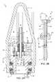
- FIGS. 3A and 3Billustrate a casing unit of the top drive system.
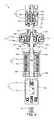
- FIG. 4illustrates a genset of the casing unit.
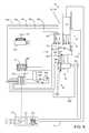
- FIG. 5is a control diagram of the top drive system in a drilling mode.
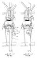
- FIGS. 6, 7A, 7B, 8A, and 8Billustrate shifting of the top drive to the drilling mode.
- FIG. 9illustrates the top drive system in the drilling mode.
- FIG. 10illustrates shifting of the top drive system from the drilling mode to the casing mode.
- FIGS. 11 and 12Aillustrate extension of a casing string using the top drive system in the casing mode.
- FIG. 12Billustrates running of the extended casing string into the wellbore using the top drive system.
- FIGS. 13A and 13Billustrate a cementing unit of the top drive system.
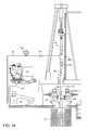
- FIG. 14illustrates cementing of the casing string using the top drive system in a cementing mode.
- FIG. 15illustrates cementing of the casing string using an alternative cementing unit, according to another embodiment of the present disclosure.
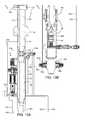
- FIG. 1illustrates a top drive system 1 , according to one embodiment of the present disclosure.
- the top drive system 1may be a modular top drive system and may include a linear actuator 1 a ( FIG. 8A ), several accessory tools (e.g., casing unit 1 c , a drilling unit 1 d , and a cementing unit 1 s ) a pipe handler 1 p , a unit rack 1 k , a motor unit 1 m , a rail 1 r , and a unit handler 1 u .
- the unit handler 1 umay include a post 2 , a slide hinge 3 , an arm 4 , a holder 5 , a base 6 , and one or more actuators (not shown).
- One or more of the accessory toolsmay include a genset 51 (sometimes referred to as an engine-generator set, and typically including an electric generator and an engine or motor mounted together to form a single piece of equipment).
- the top drive system 1may be assembled as part of a drilling rig 7 by connecting a lower end of the rail 1 r to a floor 7 f or derrick 7 d of the rig and an upper end of the rail to the derrick 7 d such that a front of the rail is adjacent to a drill string opening in the rig floor.
- the rail 1 rmay have a length sufficient for the top drive system 1 to handle stands 8 s of two to four joints of drill pipe 8 p .
- the rail lengthmay be greater than or equal to twenty-five meters and less than or equal to one hundred meters.
- the rail 1 rmay be a monorail (shown) or the top drive system may include twin rails instead of the monorail 1 r.
- the base 6may mount the post 2 on or adjacent to a structure of the drilling rig 7 , such as a subfloor structure, such as a catwalk (not shown) or pad.
- the unit rack 1 kmay also be located on or adjacent to the rig structure.
- the post 2may extend vertically from the base 6 to a height above the rig floor 7 f such that the unit handler 1 p may retrieve any of the units 1 c,d,s from the rack 1 k and deliver the retrieved unit to the motor unit 1 m.
- the arm 4may be connected to the slide hinge 3 , such as by fastening.
- the slide hinge 3may be transversely connected to the post 2 , such as by a slide joint, while being free to move longitudinally along the post.
- the slide hinge 3may also be pivotally connected to a linear actuator (not shown), such as by fastening.
- the slide hinge 3may longitudinally support the arm 4 from the linear actuator while allowing pivoting of the arm relative to the post 2 .
- the unit handler 1 umay further include an electric or hydraulic slew motor (not shown) for pivoting the arm 4 about the slide hinge 3 .
- the linear actuatormay have a lower end pivotally connected to the base 6 and an upper end pivotally connected to the slide hinge 3 .
- the linear actuatormay include a cylinder and a piston disposed in a bore of the cylinder.
- the pistonmay divide the cylinder bore into a raising chamber and a lowering chamber and the cylinder may have ports formed through a wall thereof and each port may be in fluid communication with a respective chamber.
- Each portmay be in fluid communication with a manifold 60 m of a hydraulic power unit (HPU) 60 (both in FIG. 5 ) via a control line (not shown).
- Supply of hydraulic fluid to the raising portmay move the slide hinge 3 and arm 4 upward to the rig floor 7 f .
- Supply of hydraulic fluid to the lowering portmay move the slide hinge 3 and arm 4 downward toward the base 6 .
- the linear actuatormay include an electro-mechanical linear actuator, such as a motor and lead screw or pinion and gear rod, instead of the piston and cylinder assembly.
- an electro-mechanical linear actuatorsuch as a motor and lead screw or pinion and gear rod, instead of the piston and cylinder assembly.
- the arm 4may include a forearm segment, an aft-arm segment, and an actuated joint, such as an elbow, connecting the arm segments.
- the holder 5may be releasably connected to the forearm segment, such as by fastening.
- the arm 4may further include an actuator (not shown) for selectively curling and extending the forearm segment and relative to the aft-arm segment.
- the arm actuatormay have an end pivotally connected to the forearm segment and another end pivotally connected to the aft-arm segment.
- the arm actuatormay include a cylinder and a piston disposed in a bore of the cylinder.
- the pistonmay divide the cylinder bore into an extension chamber and a curling chamber and the cylinder may have ports formed through a wall thereof and each port may be in fluid communication with a respective chamber. Each port may be in fluid communication with the HPU manifold 60 m via a control line (not shown). Supply of hydraulic fluid to the respective ports may articulate the forearm segment and holder 5 relative to the aft-arm segment toward the respective positions.
- the arm actuatormay include an electro-mechanical linear actuator, such as a motor and lead screw or pinion and gear rod, instead of the piston and cylinder assembly.
- the actuated jointmay be a telescopic joint instead of an elbow.
- the holder 5may include a safety latch for retaining any of the units 1 c,d,s thereto after engagement of the holder therewith to prevent unintentional release of the units during handling thereof.
- the holder 5may include a brake for torsionally connecting any of the units 1 c,d,s thereto after engagement of the holder therewith to facilitate connection to the motor unit 1 m.
- the pipe handler 1 pmay include a drill pipe elevator 9 ( FIG. 9 ), a pair of bails 10 , a link tilt 11 , and a slide hinge 12 .
- the slide hinge 12may be transversely connected to the front of the rail 1 r such as by a slide joint, while being free to move longitudinally along the rail.
- Each bail 10may have an eyelet formed at each longitudinal end thereof. An upper eyelet of each bail 10 may be received by a respective pair of knuckles of the slide hinge 12 and pivotally connected thereto, such as by fastening.
- Each bail 10may be received by a respective ear of the drill pipe elevator 9 d and pivotally connected thereto, such as by fastening.
- the link tilt 11may include a pair of piston and cylinder assemblies for swinging the elevator 9 relative to the slide hinge 12 .
- Each piston and cylinder assemblymay have a coupling, such as a hinge knuckle, formed at each longitudinal end thereof.
- An upper hinge knuckle of each piston and cylinder assemblymay be received by the respective lifting lug of the slide hinge 12 and pivotally connected thereto, such as by fastening.
- a lower hinge knuckle of each piston and cylinder assemblymay be received by a complementary hinge knuckle of the respective bail 10 and pivotally connected thereto, such as by fastening.
- a piston of each piston and cylinder assemblymay be disposed in a bore of the respective cylinder.
- the pistonmay divide the cylinder bore into a raising chamber and a lowering chamber and the cylinder may have ports formed through a wall thereof and each port may be in fluid communication with a respective chamber. Each port may be in fluid communication with the HPU manifold 60 m via a respective control line 66 b,c ( FIG. 5 ). Supply of hydraulic fluid to the raising port may lift the elevator 9 by increasing a tilt angle (measured from a longitudinal axis of the rail 1 r ). Supply of hydraulic fluid to the lowering port may drop the elevator 9 by decreasing the tilt angle.
- the drill pipe elevator 9may be manually opened and closed or the pipe handler 1 p may include an actuator (not shown) for opening and closing the elevator.
- the drill pipe elevator 9may include a bushing having a profile, such as a bottleneck, complementary to an upset formed in an outer surface of a joint of the drill pipe 8 p adjacent to the threaded coupling thereof.
- the bushingmay receive the drill pipe 8 p for hoisting one or more joints thereof, such as the stand 8 s .
- the bushingmay allow rotation of the stand 8 s relative to the pipe handler 1 p .
- the pipe handler 1 pmay deliver the stand 8 s to a drill string 8 where the stand 8 s may be assembled therewith to extend the drill string during a drilling operation.
- the pipe handler 1 pWhen connected to the motor unit 1 m , the pipe handler 1 p may be capable of supporting the weight of the drill string 8 to expedite tripping of the drill string.
- the linear actuator 1 amay raise and lower the pipe handler 1 p relative to the motor unit 1 m and may include a gear rack, one or two pinions (not shown), and one or two pinion motors (not shown).
- the gear rackmay be a bar having a geared upper portion and a plain lower portion.
- the gear rackmay have a knuckle formed at a bottom thereof for pivotal connection with a lifting lug of the slide hinge 12 , such as by fastening.
- Each pinionmay be meshed with the geared upper portion and torsionally connected to a rotor of the respective pinion motor.
- a stator of each pinion motormay be connected to the motor unit 1 m and be in electrical communication with a motor driver 61 via a cable 67 b (both shown in FIG. 5 ).
- the pinion motorsmay share a cable via a splice (not shown).
- Each pinion motormay be reversible and rotation of the respective pinion in a first direction, such as counterclockwise, may raise the slide hinge 12 relative to the motor unit 1 m and rotation of the respective pinion in a second opposite direction, such as clockwise, may lower the slide hinge relative to the motor unit.
- Each pinion motormay include a brake (not shown) for locking position of the slide hinge once the pinion motors are shut off. The brake may be disengaged by supply of electricity to the pinion motors and engaged by shut off of electricity to the pinion motors.
- the linear actuator 1 amay be capable of hoisting the stand 8 s .
- a stroke of the linear actuator 1 amay be sufficient to stab a top coupling of the stand 8 s into a quill 37 of the motor unit 1 m.
- the unit rack 1 kmay include a base, a beam, two or more (three shown) columns connecting the base to the beam, such as by welding or fastening, and a parking spot for each of the units 1 c,d,s (four spots shown).
- a length of the columnsmay correspond to a length of the longest one of the units 1 c,d,s , such as being slightly greater than the longest length.
- the columnsmay be spaced apart to form parking spots (four shown) between adjacent columns.
- the units 1 c,d,smay be hung from the beam by engagement of the parking spots with respective couplings 15 ( FIG. 2B ) of the units.
- Each parking spotmay include an opening formed through the beam, a ring gear, and a motor.
- Each ring gearmay be supported from and transversely connected to the beam by a bearing (not shown) such that the ring gear may rotate relative to the beam.
- Each bearingmay be capable supporting the weight of any of the units 1 c,d,s and placement of a particular unit in a particular parking spot may be arbitrary.
- Each motormay include a stator connected to the beam and may be in electrical communication with the motor driver 61 via a cable (not shown).
- a rotor of each motormay be meshed with the respective ring gear for rotation thereof between a disengaged position and an engaged position.
- Each ring gearmay have an internal latch profile, such as a bayonet profile
- each coupling 15may include a head 15 h having an external latch profile, such as a bayonet profile.
- the bayonet profilesmay each have one or more (three shown) prongs and prong-ways spaced around the respective ring gears and heads 15 h at regular intervals.
- the external prongs of the heads 15 hmay be engaged with the internal prongs of the respective ring gears, thereby supporting the units 1 c,d,s from the beam.
- the external prongs of the heads 15 hare aligned with the internal prong-ways of the ring gears (and vice versa), the heads may be free to pass through the respective ring gears.
- the latch profilesmay each be threads or load shoulders instead of bayonets.
- the unit rack 1 k and the motor unit 1 mmay each have slips, a cone, and a linear actuator for driving the slips along the cone (or vice versa) instead of the latch profiles.
- Each coupling 15may further include a neck 15 n extending from the head 15 h and having a reduced diameter relative to a maximum outer diameter of the head for extending through the respective beam opening and respective ring gear.
- Each coupling 15may further include a lifting shoulder 15 s connected to a lower end of the neck 15 n and having an enlarged diameter relative to the reduced diameter of the neck and a torso 15 r extending from the lifting shoulder 15 s and having a reduced diameter relative to the enlarged diameter of the lifting shoulder.
- the torso 15 rmay have a length corresponding to a length of the holder 5 for receipt thereof and a bottom of the lifting shoulder 15 s may seat on a top of the holder for transport from the unit rack 1 k to the motor unit 1 m.
- the unit rack 1 kmay further include a side bar for holding one or more accessories for connection to the forearm segment instead of the holder 5 , such as a cargo hook 16 and a pipe clamp 17 .
- the side barmay also hold the holder 5 when the unit handler 1 u is equipped with one of the accessories.
- FIG. 2Aillustrates the motor unit 1 m .
- the motor unit 1 mmay include one or more (pair shown) drive motors 18 , a becket 19 , a hose nipple 20 , a mud swivel 21 , a drive body 22 , a drive ring, such as drive gear 23 , a trolley 24 ( FIG. 5 ), a thread compensator 25 , a control, such as hydraulic, swivel 26 , a down thrust bearing 27 , an up thrust bearing 28 , a backup wrench 29 ( FIG. 8A ), a swivel frame 30 , a bearing retainer 31 , a motor gear 32 ( FIG. 5 ), and a latch 69 ( FIG. 5 ).
- a controlsuch as hydraulic, swivel 26 , a down thrust bearing 27 , an up thrust bearing 28 , a backup wrench 29 ( FIG. 8A ), a swivel frame 30 , a bearing retainer 31
- the drive body 22may be rectangular, may have thrust chambers formed therein, may have an inner rib dividing the thrust chambers, and may have a central opening formed therethrough and in fluid communication with the chambers.
- the drive gear 23may be cylindrical, may have a bore therethrough, may have an outer flange 23 f formed in an upper end thereof, may have an outer thread formed at a lower end thereof, may have an inner locking profile 23 k formed at an upper end thereof, and may have an inner latch profile, such as a bayonet profile 23 b , formed adjacently below the locking profile.
- the inner bayonet profile 23 bmay be similar to the inner bayonet profile of the ring gears except for having a substantially greater thickness for sustaining weight of either the drill string 8 or a casing string 90 ( FIG. 12A ).
- the bearing retainer 31may have an inner thread engaged with the outer thread of the drive gear 23 , thereby connecting the two members.
- the drive motors 18may be electric (shown) or hydraulic (not shown) and have a rotor and a stator.
- a stator of each drive motor 18may be connected to the trolley 24 , such as by fastening, and be in electrical communication with the motor driver 61 via a cable 67 c ( FIG. 5 ).
- the motors 18may be operable to rotate the rotor relative to the stator which may also torsionally drive respective motor gears 32 .
- the motor gears 32may be connected to the respective rotors and meshed with the drive gear 23 for torsional driving thereof.
- the motor unit 1 mmay instead be a direct drive unit having the drive motor 18 centrally located.
- Each thrust bearing 27 , 28may include a shaft washer, a housing washer, a cage, and a plurality of rollers extending through respective openings formed in the cage.
- the shaft washer of the down thrust bearing 27may be connected to the drive gear 23 adjacent to a bottom of the flange thereof.
- the housing washer of the down thrust bearing 27may be connected to the drive body 22 adjacent to a top of the rib thereof.
- the cage and rollers of the down thrust bearing 27may be trapped between the washers thereof, thereby supporting rotation of the drive gear 23 relative to the drive body 22 .
- the down thrust bearing 27may be capable of sustaining weight of a tubular string, such as either the drill string 8 or the casing string 90 , during rotation thereof.
- the shaft washer of the up thrust bearing 28may be connected to the drive gear 23 adjacent to the bearing retainer 31 .
- the housing washer of the up thrust bearing 28may be connected to the drive body 22 adjacent to a bottom of the rib thereof.
- the cage and rollers of the up thrust bearing 28may be trapped between the washers thereof.
- the trolley 24may be connected to a back of the drive body 22 , such as by fastening.
- the trolley 24may be transversely connected to a front of the rail 1 r and may ride along the rail, thereby torsionally restraining the drive body 22 while allowing vertical movement of the motor unit 1 m with a travelling block 73 t ( FIG. 9 ) of a rig hoist 73 .
- the becket 19may be connected to the drive body 22 , such as by fastening, and the becket may receive a hook of the traveling block 73 t to suspend the motor unit 1 m from the derrick 7 d.
- motor unit 1 mmay include a block-becket instead of the becket 19 and the block-becket may obviate the need for a separate traveling block 73 t.
- the hose nipple 20may be connected to the mud swivel 21 and receive an end of a mud hose (not shown).
- the mud hosemay deliver drilling fluid 87 ( FIG. 9 ) from a standpipe 79 ( FIG. 9 ) to the hose nipple 20 .
- the mud swivel 21may have an outer non-rotating barrel 210 connected to the hose nipple 20 and an inner rotating barrel 21 n .
- the mud swivel 21may have a bearing (not shown) and a dynamic seal (not shown) for accommodating rotation of the rotating barrel relative to the non-rotating barrel.
- the outer non-rotating barrel 210may be connected to a top of the swivel frame 30 , such as by fastening.
- the swivel frame 30may be connected to a top of the drive body 22 , such as by fastening.
- the inner rotating barrel 21 nmay have an upper portion disposed in the outer non-rotating barrel 210 and a stinger portion extending therefrom, through the control swivel 26 , and through the compensator 25 .
- a lower end of the stinger portionmay carry a stab seal for engagement with an inner seal receptacle 15 b of each coupling 15 when the respective unit 1 c,d,s is connected to the motor unit 1 m , thereby sealing an interface formed between the units.
- the control swivel 26may include a non-rotating inner barrel and a rotating outer barrel.
- the inner barrelmay be connected to the swivel frame 30 and the outer barrel may be supported from the inner barrel by one or more bearings.
- the outer barrelmay have hydraulic ports (six shown) formed through a wall thereof, each port in fluid communication with a respective hydraulic passage formed through the inner barrel (only two passages shown). An interface between each port and passage may be straddled by dynamic seals for isolation thereof.
- the inner barrel passagesmay be in fluid communication with the HPU manifold 60 m via a plurality of fluid connectors, such as the hydraulic conduits 64 a - e ( FIG.
- the outer barrel portsmay be in fluid communication with either the linear actuator 33 or lock ring 34 via jumpers (not shown).
- the outer barrel portsmay be disposed along the outer barrel.
- the inner barrelmay have a mandrel portion extending along the outer barrel and a head portion extending above the outer barrel. The head portion may connect to the swivel frame 30 and have the hydraulic ports extending therearound.
- the compensator 25may include a linear actuator 33 , the lock ring 34 , and one or more (such as three, but only one shown) lock pins 35 .
- the lock ring 34may have an outer flange 34 f formed at an upper end thereof, a bore formed therethrough, one or more chambers housing the lock pins 35 formed in an inner surface thereof, a locking profile 34 k formed in a lower end thereof, members, such as males 34 m , of a hydraulic junction 36 ( FIG. 7A ) formed in the lower end thereof, and hydraulic passages (two shown) formed through a wall thereof.
- the locking profile 34 kmay include a lug for each prong-way of the external bayonet profiles of the heads 15 h.
- Each lock pin 35may be a piston dividing the respective chamber into an extension portion and a retraction portion and the lock ring 34 may have passages formed through the wall thereof for the chamber portions. Each passage may be in fluid communication with the HPU manifold 60 m via a respective fluid connector, such as hydraulic conduit 64 a ( FIG. 3 , only one shown).
- the lock pins 35may share an extension control line and a retraction control line via a splitter (not shown).
- Supply of hydraulic fluid to the extension passagesmay move the lock pins 35 to an engaged position where the pins extend into respective slots 15 t formed in the prong-ways of the heads 15 h , thereby longitudinally connecting the lock ring 34 to a respective unit 1 c,d,s .
- Supply of hydraulic fluid to the retraction passagesmay move the lock pins 35 to a release position (shown) where the pins are contained in the respective chambers of the lock ring 34 .
- the linear actuator 33may include one or more, such as three, piston and cylinder assemblies 33 a,b for vertically moving the lock ring 34 relative to the drive gear 23 between a lower hoisting position ( FIG. 7A ) and an upper ready position (shown).
- a bottom of the lock ring flange 34 fmay be seated against a top of the drive gear flange 23 f in the hoisting position such that string weight carried by either the drilling unit 1 d or the casing unit 1 c may be transferred to the drive gear 23 via the flanges and not the linear actuator 33 which may be only capable of supporting stand weight or weight of a casing joint 90 j ( FIG. 12A ) of casing.
- String weightmay be one hundred (or more) times that of stand weight or joint weight.
- a piston of each assembly 33 a,bmay be seated against the respective cylinder in the ready position.
- Each cylinder of the linear actuator 33may be disposed in a respective peripheral socket formed through the lock ring flange 34 f and be connected to the lock ring 34 , such as by threaded couplings.
- Each piston of the linear actuator 33may extend into a respective indentation formed in a top of the drive gear flange 23 f and be connected to the drive gear 23 , such as by threaded couplings.
- Each socket of the lock ring flange 34 fmay be aligned with the respective lug of the locking profile 34 k and each indentation of the drive gear flange 23 f may be aligned with a receptacle of the locking profile 23 k such that connection of the linear actuator 33 to the lock ring 34 and drive gear 23 ensures alignment of the locking profiles.
- Each piston of the linear actuator 33may be disposed in a bore of the respective cylinder.
- the pistonmay divide the cylinder bore into a raising chamber and a lowering chamber and the cylinder may have ports (only one shown) formed through a wall thereof and each port may be in fluid communication with a respective chamber.
- Each portmay be in fluid communication with the HPU manifold 60 m via a respective fluid connector, such as hydraulic conduit 64 b (only one shown in FIG. 5 ).
- Supply of hydraulic fluid to the raising portmay lift the lock ring 34 toward the ready position.
- Supply of hydraulic fluid to the lowering portmay drop the lock ring 34 toward the hoisting position.
- a stroke length of the linear compensator 25 between the ready and hoisting positionsmay correspond to, such as being equal to or slightly greater than, a makeup length of the drill pipe 8 p and/or casing joint 90 j.
- Each coupling 15may further include mating members, such as females 15 f , of the junction 36 formed in a top of the prongs of the head 15 h .
- the male members 34 mmay each have a nipple for receiving a respective jumper from the control swivel 26 , a stinger, and a passage connecting the nipple and the stinger.
- Each stingermay carry a respective seal.
- the female member 15 fmay have a seal receptacle for receiving the respective stinger.
- the junction members 34 m , 15 fmay be asymmetrically arranged to ensure that the male member 34 m is stabbed into the correct female member 15 f.
- the backup wrench 29may include a hinge 29 h , a tong 29 t , a guide 29 g , an arm 29 a , a tong actuator (not shown), a tilt actuator (not shown), and a linear actuator (not shown).
- the tong 29 tmay be transversely connected to the arm 29 a while being longitudinally movable relative thereto subject to engagement with a stop shoulder thereof.
- the hinge 29 hmay pivotally connect the arm 29 a to a bottom of the drive body 22 .
- the hinge 29 hmay include a pair of knuckles fastened or welded to the drive body 22 and a pin extending through the knuckles and a hole formed through a top of the arm 29 a .
- the tilt actuatormay include a piston and cylinder assembly having an upper end pivotally connected to the bottom of the drive body 22 and a lower end pivotally connected to a back of the arm 29 a .
- the pistonmay divide the cylinder bore into an activation chamber and a stowing chamber and the cylinder may have ports (only one shown) formed through a wall thereof and each port may be in fluid communication with a respective chamber. Each port may be in fluid communication with the HPU manifold 60 m via a respective control line (not shown).
- Supply of hydraulic fluid to the activation portmay pivot the tong 29 t about the hinge 29 h toward the quill 37 .
- Supply of hydraulic fluid to the stowing portmay pivot the tong 29 t about the hinge 29 h away from the quill 37 .
- the tong 29 tmay include a housing having an opening formed therethrough and a pair of jaws (not shown) and the tong actuator may move one of the jaws radially toward or away from the other jaw.
- the guide 29 gmay be a cone connected to a lower end of the tong housing, such as by fastening, for receiving a threaded coupling, such as a box, of the drill pipe 8 p .
- the quill 37may extend into the tong opening for stabbing into the drill pipe box. Once stabbed, the tong actuator may be operated to engage the movable jaw with the drill pipe box, thereby torsionally connecting the drill pipe box to the drive body 22 .
- the tong actuatormay be hydraulic and operated by the HPU 60 via a control line 66 d ( FIG. 5 ).
- the backup wrench linear actuatormay include a gear rack (not shown) formed along a straight lower portion of the arm 29 a , one or two pinions (not shown), and one or two pinion motors (not shown).
- the arm 29 amay have a deviated upper portion engaged with the hinge 29 h .
- Each pinionmay be meshed with the gear rack of the arm 29 a and torsionally connected to a rotor of the respective pinion motor.
- a stator of each pinion motormay be connected to the housing of the tong 29 t and be in electrical communication with the motor driver 61 via a cable 67 a ( FIG. 5 ).
- the pinion motorsmay share a cable via a splice (not shown).
- Each pinion motormay be reversible and rotation of the respective pinion in a first direction, such as counterclockwise, may raise the tong 29 t along the arm 29 a and rotation of the respective pinion in a second opposite direction, such as clockwise, may lower the tong along the arm.
- Each pinion motormay include a brake (not shown) for locking position of the tong 29 t once the pinion motors are shut off. The brake may be disengaged by supply of electricity to the pinion motors and engaged by shut off of electricity to the pinion motors.
- the latch 69may include a one or more (pair shown) units disposed at sides of the drive body 22 .
- Each latch unitmay include a lug connected, such as by fastening or welding, to the drive body 22 and extending from a bottom thereof, a fastener, such as a pin, and an actuator.
- Each lugmay have a hole formed therethrough and aligned with a respective actuator.
- Each interior knuckle of the slide hinge 12may have a hole formed therethrough for receiving the respective latch pin.
- Each actuatormay include a cylinder and piston (not shown) connected to the latch pin and disposed in a bore of the cylinder.
- Each cylindermay be connected to the drive body 22 , such as by fastening, adjacent to the respective lug.
- the pistonmay divide the cylinder bore into an extension chamber and a retraction chamber and the cylinder may have ports formed through a wall thereof and each port may be in fluid communication with a respective chamber. Each port may be in fluid communication with the HPU manifold 60 m via a control line 66 a ( FIG. 3 , only one shown).
- the latch unitsmay share an extension control line and a retraction control line via a splitter (not shown). Supply of hydraulic fluid to the extension port may move the pin to an engaged position (shown) where the pin extends through the respective lug hole and the respective interior knuckle hole of the slide hinge 12 , thereby connecting the pipe handler 1 p to the drive body 22 . Supply of hydraulic fluid to the retraction port may move the pin to a release position (not shown) where the pin is clear of the interior slide hinge knuckle.
- FIG. 2Billustrates the drilling unit 1 d .
- the drilling unit 1 dmay include the coupling, the quill 37 , an internal blowout preventer (IBOP) 38 , and one or more, such as two (only one shown), hydraulic passages 39 .
- the quill 37may be a shaft, may have an upper end connected to the torso 15 r , may have a bore formed therethrough, may have a threaded coupling, such as a pin, formed at a lower end thereof.
- the IBOPcould be controlled from a separate control unit at the accessory tool.
- the separate control unitcould be powered from the genset 51 .
- the genset 51could be connected to the tool so as to avoid impacts during the drilling process, such as with springs.
- the IBOP 38may include an internal sleeve 38 v and one or more shutoff valves 38 u,b .
- the IBOPmay further include an automated actuator for one 38 u of the shutoff valves 38 u,b and the other 38 b of the shutoff valves 38 u,b may be manually actuated.
- Each shutoff valve 38 u,bmay be connected to the sleeve 38 v and the sleeve may be received in a recessed portion of the quill 37 and/or coupling 15 .
- the IBOP valve actuatormay be disposed in a socket formed through a wall of the quill 37 and/or coupling 15 and may include an opening port and/or a closing port and each port may be in fluid communication with the HPU manifold 60 m via a respective hydraulic passage 39 , respective male 34 m and female 15 f members, respective jumpers, the control swivel 26 , and respective fluid connectors, such as hydraulic conduits 64 c,d ( FIG. 5 ).
- the hydraulic conduit 64 emay connect to a drain port of the IBOP valve actuator.
- FIGS. 3A and 3Billustrate the casing unit 1 c .
- the casing unit 1 cmay include the coupling 15 , a clamp, such as a spear 40 , an adapter 48 , one or more, such as three (only one shown), hydraulic passages 49 , a fill up tool 50 , a genset 51 , and a frame 58 .
- the fill up tool 50may include a flow tube 50 t , a stab seal, such as a cup seal 50 c , a release valve 50 r , a mud saver valve 50 m , a fill up valve 50 f , and a fill up valve actuator 50 a.
- the fill up valve 50 fmay include a valve member, such as a ball, a valve seat, and a housing.
- the housingmay be tubular, may have an upper end connected to the torso 15 r and a lower end connected to the adapter 48 .
- the valve seatmay be disposed in the housing, may be made from a metal/alloy, ceramic/cermet, or polymer and may be connected to the housing, such as by fastening.
- the ballmay be disposed in a spherical recess formed by the valve seat and rotatable relative to the housing between an open position (shown) and a closed position.
- the ballmay have a bore therethrough corresponding to the housing bore and aligned therewith in the open position.
- a wall of the ballmay close the housing bore in the closed position.
- the ballmay have a stem extending into an actuation port formed through a wall of the housing.
- the stemmay mate with a shaft of the actuator 50 a and the actuator may be operable to rotate the ball between the open and the closed positions.
- the fill up valve actuator 50 amay be hydraulic and may have a position sensor Op in communication with the shaft and in communication with a microcontroller MCU of the genset 51 via a data cable 59 a .
- the position sensor Opmay also be electrically powered by the microcontroller MCU via the data cable 59 a .
- the position sensor Opmay verify that the actuator 50 a has properly functioned to open and/or close the fill up valve 50 f .
- the actuator 50 amay be operated by one or more fluid connectors, such as hydraulic conduits 59 b,c leading to a fluid, such as hydraulic, manifold 56 ( FIG. 4 ) of the genset 51 .
- the adapter 48may be tubular, may have a bore formed therethrough, and may have an upper end connected to the housing of the fill up valve 50 f , and may have an outer thread and an inner receptacle formed at a lower end thereof.
- the frame 58may mount the genset 51 to an outer surface of the adapter 48 .
- the spear 40may include a clamp actuator, such as linear actuator 41 , a bumper 42 , a collar 43 , a mandrel 44 , a set of grippers, such as slips 45 , a seal joint 46 , and a sleeve 47 .
- the collar 43may have an inner thread formed at each longitudinal end thereof.
- the collar upper threadmay be engaged with the outer thread of the adapter 48 , thereby connecting the two members.
- the collar lower threadmay be engaged with an outer thread formed at an upper end of the mandrel 44 and the mandrel may have an outer flange formed adjacent to the upper thread and engaged with a bottom of the collar 43 , thereby connecting the two members.
- the seal joint 46may include the inner barrel, an outer barrel, and a nut.
- the inner barrelmay have an outer thread engaged with a threaded portion of the adapter receptacle and an outer portion carrying a seal engaged with a seal bore portion of the adapter receptacle.
- the mandrel 44may have a bore formed therethrough and an inner receptacle formed at an upper portion thereof and in fluid communication with the bore.
- the mandrel receptaclemay have an upper conical portion, a threaded mid portion, and a recessed lower portion.
- the outer barrelmay be disposed in the recessed portion of the mandrel 44 and trapped therein by engagement of an outer thread of the nut with the threaded mid portion of the mandrel receptacle.
- the outer barrelmay have a seal bore formed therethrough and a lower portion of the inner barrel may be disposed therein and carry a stab seal engaged therewith.
- the linear actuator 41may include a housing, an upper flange, a plurality of piston and cylinder assemblies, a lower flange, and a position sensor Ret in communication with one or more of the piston and cylinder assemblies.
- the position sensor Retmay be also be in communication with the microcontroller MCU via a data cable 59 f .
- the position sensor Retmay also be electrically powered by the microcontroller MCU via the data cable 59 f .
- the position sensor Retmay verify that the piston and cylinder assemblies have properly functioned to extend and/or retract the slips 45 .
- the housingmay be cylindrical, may enclose the cylinders of the assemblies, and may be connected to the upper flange, such as by fastening.
- the collar 43may also have an outer thread formed at the upper end thereof.
- the upper flangemay have an inner thread engaged with the outer collar thread, thereby connecting the two members.
- Each flangemay have a pair of lugs for each piston and cylinder assembly connected, such as by fastening or welding, thereto and extending from opposed surfaces thereof.
- Each cylinder of the linear actuator 41may have a coupling, such as a hinge knuckle, formed at an upper end thereof.
- the upper hinge knuckle of each cylindermay be received by a respective pair of lugs of the upper flange and pivotally connected thereto, such as by fastening.
- Each piston of the linear actuator 41may have a coupling, such as a hinge knuckle, formed at a lower end thereof.
- Each piston of the linear actuator 41may be disposed in a bore of the respective cylinder.
- the pistonmay divide the cylinder bore into a raising chamber and a lowering chamber and the cylinder may have ports formed through a wall thereof and each port may be in fluid communication with a respective chamber.
- Each portmay be in fluid communication with the hydraulic manifold 56 via respective fluid connectors, such as hydraulic conduits 59 d,e .
- Supply of hydraulic fluid to the raising portmay lift the lower flange to a retracted position (shown).
- Supply of hydraulic fluid to the lowering portmay drop the lower flange toward an extended position (not shown).
- the piston and cylinder assembliesmay share an extension conduit 59 e and a retraction conduit 59 d via a splitter (not shown).
- the sleeve 47may have an outer shoulder formed in an upper end thereof trapped between upper and lower retainers.
- a washermay have an inner shoulder formed in a lower end thereof engaged with a bottom of the lower retainer.
- the washermay be connected to the lower flange, such as by fastening, thereby longitudinally connecting the sleeve 47 to the linear actuator 41 .
- the sleeve 47may also have one or more (pair shown) slots formed through a wall thereof at an upper portion thereof.
- the bumper 42include a striker and a base connected to the mandrel, such as by one or more threaded fasteners, each fastener extending through a hole thereof, through a respective slot of the sleeve 47 , and into a respective threaded socket formed in an outer surface of the mandrel 44 , thereby also torsionally connecting the sleeve to the mandrel while allowing limited longitudinal movement of the sleeve relative to the mandrel to accommodate operation of the slips 45 .
- the strikermay be linked to the base by one or more (pair shown) compression springs. A lower portion of the spear 40 may be stabbed into the casing joint 90 j until the striker engages a top of the casing joint. The springs may cushion impact with the top of the casing joint 90 j to avoid damage thereto.
- the sleeve 47may extend along the outer surface of the mandrel from the lower flange of the linear actuator 41 to the slips 45 .
- a lower end of the sleeve 47may be connected to upper portions of each of the slips 45 , such as by a flanged (i.e., T-flange and T-slot) connection.
- Each slip 46may be radially movable between an extended position and a retracted position by longitudinal movement of the sleeve 47 relative to the slips.
- a slip receptaclemay be formed in an outer surface of the mandrel 44 for receiving the slips 45 .
- the slip receptaclemay include a pocket for each slip 46 , each pocket receiving a lower portion of the respective slip.
- the mandrel 44may be connected to lower portions of the slips 45 by reception thereof in the pockets.
- Each slip pocketmay have one or more (three shown) inclined surfaces formed in the outer surface of the mandrel 44 for extension of the respective slip.
- a lower portion of each slip 46may have one or more (three shown) inclined inner surfaces corresponding to the inclined slip pocket surfaces.
- each slip 46may also have a guide profile, such as tabs, extending from sides thereof.
- Each slip pocketmay also have a mating guide profile, such as grooves, for retracting the slips 45 when the sleeve 47 moves upward away from the slips.
- Each slip 46may have teeth formed along an outer surface thereof. The teeth may be made from a hard material, such as tool steel, ceramic, or cermet for engaging and penetrating an inner surface of the casing joint 90 j , thereby anchoring the spear 40 to the casing joint.
- the cup seal 50 cmay have an outer diameter slightly greater than an inner diameter of the casing joint 90 j to engage the inner surface thereof during stabbing of the spear 40 therein.
- the cup seal 50 cmay be directional and oriented such that pressure in the casing bore energizes the seal into engagement with the casing joint inner surface.
- An upper end of the flow tube 50 tmay be connected to a lower end of the mandrel 44 , such as by threaded couplings.
- the mud saver valve 50 mmay be connected to a lower end of the flow tube 50 t , such as by threaded couplings.
- the cup seal 50 c and release valve 50 rmay be disposed along the flow tube 50 t and trapped between a bottom of the mandrel 44 and a top of the mudsaver valve 50 m.
- the spear 40may be capable of supporting weight of the casing string 90 .
- the string weightmay be transferred to the becket 19 via the slips 45 , the mandrel 44 , the collar 43 , the adapter 48 , the coupling 15 , the bayonet profile 23 b , the down thrust bearing 27 , the drive body 22 .
- Fluidmay be injected into the casing string 90 via the hose nipple 20 , the mud swivel 21 , the coupling 15 , the adapter 48 , the seal joint 46 , the mandrel 44 , the flow tube 50 t , and the mud saver valve 50 m.
- the clampmay be a torque head instead of the spear 40 .
- the torque headmay be similar to the spear except for receiving an upper portion of the casing joint 90 j therein and having the set of grippers for engaging an outer surface of the casing joint instead of the inner surface of the casing joint.
- FIG. 4illustrates the genset 51 .
- the genset 51may include a fluid driven, such as hydraulic, motor 52 , a gearbox 53 , an electric generator 54 , a control unit 55 , and the hydraulic manifold 56 .
- the gearbox 53may be a planetary gearbox.
- control swivel 26 , the fluid driven motor 52 , the fluid manifold 56 , the linear actuator 41 , and the fill up valve actuator 50 amay be pneumatic instead of hydraulic.
- the fluid driven motor 52may be a gerotor motor and include a housing 52 h , a drive shaft 52 d , a valve shaft 52 v , an output shaft 52 o , an orbital gear set having a rotor 52 r and a stator 52 s , a plurality of roller vanes 52 n , and a valve spool 52 p .
- the housing 52 hmay include two or more sections connected together, such as by one or more threaded fasteners.
- the output shaft 52 omay have a hollow upper head disposed in the housing and a lower shank extending therethrough. The head may have a torsional profile, such as splines, formed in an inner surface thereof.
- a shaft spacer and a lower portion of the drive shaft 52 dmay each have teeth meshed with the splines, thereby torsionally connecting the members.
- the shaft spacermay also have a torsional profile formed in an inner surface thereof meshed with a torsional profile formed in a lower end of the valve shaft 52 v.
- the drive shaft 52 dmay be disposed in the head with a sufficient clearance formed therebetween to accommodate articulation of the drive shaft with the orbiting of the rotor 52 r .
- the stator 52 smay be disposed between the housing sections and connected thereto by the threaded fasteners.
- the roller vanes 52 nmay be disposed in sockets formed in the stator 52 s and may be trapped between the housing sections.
- the rotor 52 rmay be disposed in the stator 52 s and have a number of lobes formed in an outer surface thereof equal to the number of roller vanes minus one.
- Selective supply of pressurized hydraulic fluid by the valve spool 52 p through pressure chambers formed between the rotor 52 r and the stator 52 smay drive the rotor in an orbital movement within the stator, thereby converting fluid energy from the hydraulic fluid into kinetic energy of the output shaft 52 o.
- the rotor 52 rmay have a torsional profile formed in an inner surface thereof meshed with a torsional profile formed of the upper portion of the drive shaft 52 d , thereby torsionally connecting the two members.
- the valve shaft 52 vmay extend through the drive shaft 52 s and have an upper portion with a torsional profile meshed with a torsional profile formed in a lower portion of the valve spool 52 p .
- An inletmay be formed through a wall of the housing 52 h to provide fluid communication between the valve spool 52 p and a fluid connector, such as hydraulic conduit 57 a leading to the hydraulic passage 49 .
- An outlet(not shown) may be formed through a wall of the housing 52 h to provide fluid communication between the valve spool 52 p and a fluid connector (not shown) leading to a second hydraulic passage of the coupling 15 .
- the valve spool 52 pmay be disposed in the housing 52 h and may rotate with the output shaft 52 o via the valve shaft 52 v .
- the valve spool 52 pmay have flow slots formed in an outer surface thereof that selectively provide fluid communication between the inlet and outlet and the appropriate pressure chambers formed between the rotor 52 r and the stator 52 s .
- a bushingmay be disposed between the housing 52 h and the output shaft 52 o for radial support of the output shaft therefrom.
- a thrust bearingmay be disposed between the housing 52 h and the output shaft 52 o for longitudinal support of the output shaft therefrom.
- One or more (pair shown) dynamic sealsmay be disposed between the housing 52 h and the output shaft 52 o to isolate the rotating interface therebetween for prevention of loss of hydraulic fluid from the fluid driven motor 52 and for prevention of contaminants from entering therein.
- the gear box 53may be planetary and include a housing 53 h and a cover 53 c connected thereto, such as by fasteners (not shown).
- the housing 53 h and cover 53 cmay enclose a lubricant chamber sealed at ends thereof by oil seals.
- the gear box 53may further include an input disk 53 k having a hub extending from an upper end of the lubricant chamber and torsionally connected to the output shaft 52 o of the fluid driven motor 52 by mating profiles (not shown), such as splines, formed at adjacent ends thereof.
- the gear box 53may further include an output shaft 53 p extending from a lower end of the lubricant chamber and torsionally connected to a shaft 54 s of the electric generator 54 by mating profiles (not shown), such as splines, formed at adjacent ends thereof.
- Each of the output shaft 53 p and input disk 53 kmay be radially supported from the respective cover 53 c and housing 53 h for rotation relative thereto by respective bearings.
- the hub of the input disk 53 kmay receive an end of the output shaft 53 p and a needle bearing may be disposed therebetween for supporting the output shaft therefrom while allowing relative rotation therebetween.
- a sun gear 53 smay be disposed in the lubricant chamber and may be mounted onto the output shaft 53 p .
- a stationary housing gear 53 gmay be disposed in the lubricant chamber and mounted to the housing 53 h .
- a plurality of planetary rollers 53 rmay also be disposed in the lubricant chamber.
- Each planetary roller 53 rmay include a planetary gear 53 e disposed between and meshed with the sun gear 53 s and the housing gear 53 g .
- the planetary gears 53 emay be linked by a carrier 53 b which may be radially supported from the output shaft 53 p by a bearing to allow relative rotation therebetween.
- Each planetary roller 53 rmay further include a support shaft 53 f which is supported at its free end by a support ring and on which the respective planetary gear 53 e may be supported by a bearing.
- Each planetary gear 53 emay include first and second sections of different diameters, the first section meshing with the housing gear 53 g and the sun gear 53 s and the second section meshing with an input gear 53 j and a support gear 53 b .
- the input gear 53 jmay be mounted to the input disk 53 k by fasteners.
- the support gear 53 bmay be radially supported from the input shaft 53 p by a bearing to allow relative rotation therebetween.
- the support shafts 53 fmay be arranged at a slight angle with respect to longitudinal axes of the output shaft 53 p and input disk 53 k .
- the planetary gears 53 e , housing gear 53 g , input gear 53 j , and support gear 53 bmay also be slightly conical so that, upon assembly of the gear box 53 , predetermined traction surface contact forces may be generated.
- the gear box 53may further include assorted thrust bearings disposed between various members thereof.
- rotation of the input disk 53 k by the fluid driven motor 52may drive the input gear 53 j .
- the input gear 53 jmay drive the planetary gears 53 e to roll along the housing gear 53 g while also driving the sun gear 53 s .
- the diameter of the second section of each planetary gear 53 emay be significantly greater than that of the first section, the circumferential speed of the second section may correspondingly be significantly greater than that of the first section, thereby providing for a speed differential which causes the output shaft 53 p to counter-rotate at a faster speed corresponding to the difference in diameter between the planetary gear sections.
- Driving torque of the output shaft 53 pis also reduced accordingly.
- the diameter of the first section of each planetary gear 53 emay be greater in diameter than that of the second section resulting in rotation of the input gear 53 j in the same direction as the input shaft 53 p again at a speed corresponding to the difference in diameter between the two sections.
- the electric generator 54may include a rotor, a stator, and a pair of bearings supporting the rotor for rotation relative to the stator.
- the electric generator 54may be a permanent magnet generator.
- the rotormay include a hub 54 b made from a magnetically permeable material, a plurality of permanent magnets 54 m torsionally connected to the hub, and a shaft 54 s .
- the rotormay include one or more pairs of permanent magnets 54 m having opposite polarities N,S.
- the permanent magnets 54 mmay also be fastened to the hub 54 b , such as by retainers.
- the hub 54 bmay be torsionally connected to the shaft 54 s and fastened thereto.
- the statormay include a housing 54 h , a core 54 c , a pair of end caps 54 p , and a plurality of windings 54 w , such as three (only two shown).
- the core 54 cmay include a stack of laminations made from a magnetically permeable material. The stack may have lobes formed therein, each lobe for receiving a respective winding.
- the core 54 cmay be longitudinally and torsionally connected to the housing 54 h , such as by an interference fit.
- the control unit 55may include a power converter 55 c , an electrical energy storage device, such as a battery 55 b , the microcontroller MCU, a wireless data link.
- the wireless data linkmay include a transmitter TX, a receiver RX, an antenna 55 a .
- the transmitter TX and receiver RXmay be separate devices (as shown) or may be integrated into a single transceiver.
- the transmitter TX and receiver RXmay share the single antenna 55 a (shown) or each have their own antenna.
- the wireless data linkmay be half-duplex or full-duplex.
- the power converter 55 cmay have an input in electrical communication with each winding 54 w of the electric generator 54 and an output in electrical communication with the battery 55 b .
- the power converter 55 cmay receive a multi-phase, such as three phase, power signal from the electric generator 54 and convert the power signal into a direct current power signal for charging the battery 55 b .
- the power converter 55 cmay also step-down a voltage of the power signal from the electric generator 54 to a voltage usable by the battery 55 b , such as three, six, nine, twelve, or twenty-four volts.
- the battery 55 bmay also be in electrical communication with the microcontroller MCU.
- the transmitter TXmay be in electrical communication with the microcontroller MCU and the antenna 55 a and may include an amplifier, a modulator, and an oscillator.
- the receiver RXmay be in electrical communication with the microcontroller MCU and the antenna 55 a and may include an amplifier, a demodulator, and a filter.
- the microcontroller MCUmay receive instruction signals, via the antenna 55 a and receiver RX, from a control console 62 ( FIG. 5 ) to operate the fill up valve actuator 50 a and/or the linear actuator 41 in response thereto.
- the instruction signalsmay be radio frequency wireless signals and may also be digital.
- the instruction signalsmay be received or transmitted with the used of the wireless data link.
- the microcontroller MCUmay receive position statuses from the position sensors Op, Ret, and may send the position statuses to the control console 62 via the antenna 55 a and transmitter TX.
- the electrical energy storage devicemay be a super-capacitor, capacitor, or inductor instead of a battery.
- the hydraulic manifold 56may include a plurality of control valves, such as directional control valves, for operating the fill up valve actuator 50 a and the linear actuator 41 . Each control valve may be operated by an electric actuator (not shown) in electrical communication with the microcontroller MCU.
- An inlet of the hydraulic manifold 56may be in fluid communication with the hydraulic passage 49 via a fluid connector, such as hydraulic conduit 57 b .
- the inlet of the hydraulic manifold 56may also be in fluid communication with the second hydraulic passage of the coupling 15 via another fluid connector, such as hydraulic conduit 57 c .
- the inlet of the hydraulic manifold 56may also be in fluid communication with a third hydraulic passage of the coupling 15 via another fluid connector, such as hydraulic conduit 57 d .
- the hydraulic conduits 57 a,bmay both be in simultaneous fluid communication with the hydraulic passage 49 via a splitter.
- the hydraulic conduit 64 cWhen the casing unit 1 c is connected to the motor unit 1 m , the hydraulic conduit 64 c may be connected to the hydraulic conduits 57 a,b via the control swivel 26 and the hydraulic passage 49 .
- the hydraulic conduit 64 dmay be connected to the hydraulic conduit 57 c and the outlet of the fluid driven motor 52 via the control swivel 26 and the second hydraulic passage of the coupling 15 .
- the hydraulic conduit 64 emay be connected to the hydraulic conduit 57 d via the control swivel 26 and the second hydraulic passage of the coupling 15 .
- the hydraulic conduit 64 cmay be a supply line.
- the hydraulic conduit 64 dmay be a return line.
- the hydraulic conduit 64 emay be a drain line.
- the microcontroller MCUmay operate the hydraulic manifold 56 to selectively provide fluid communication between the hydraulic conduits 57 b - d and the hydraulic conduits 59 b - e based on the instruction signals from the control console
- the genset 51may receive hydraulic fluid from the HPU 60 via the hydraulic conduit 57 a , hydraulic passage 49 , and hydraulic conduit 64 c and return spent hydraulic fluid to the HPU via the hydraulic conduit leading from the second hydraulic passage of the coupling 15 , the second hydraulic passage of the coupling, and the hydraulic conduit 64 d , thereby driving the fluid driven motor 52 .
- the fluid driven motor 52may in turn drive the electric generator 54 via the gearbox 53 .
- the electric generator 54may power the control unit 55 which may await instruction signals from the control console 62 to operate the spear 40 and/or the fill up valve 50 f via the hydraulic manifold 56 .
- FIG. 5is a control diagram of the top drive system 1 in the drilling mode.
- the HPU 60may include a pump 60 p , a check valve 60 k , an accumulator 60 a , a reservoir 60 r of hydraulic fluid, and the HPU manifold 60 m .
- the motor driver 61may be one or more (three shown) phase and include a rectifier 61 r and an inverter 61 i .
- the inverter 61 imay be capable of speed control of the drive motors 18 , such as being a pulse width modulator.
- Each of the HPU manifold 60 m and motor driver 61may be in data communication with the control console 62 for control of the various functions of the top drive system 1 .
- the top drive system 1may further include a video monitoring unit 63 having a video camera 63 c and a light source 63 g such that a technician (not shown) may visually monitor operation thereof from the rig floor 7 f or control room (not shown) especially during shifting of the modes.
- the video monitoring unit 63may be mounted on the motor unit 1 m.
- the pipe handler control lines 66 b,cmay flexible control lines such that the pipe handler 1 p remains connected thereto in any position thereof.
- the motor unit 1 mmay further include a proximity sensor 68 connected to the swivel frame 30 for monitoring a position of the lock ring flange 34 f .
- the proximity sensor 68may include a transmitting coil, a receiving coil, an inverter for powering the transmitting coil, and a detector circuit connected to the receiving coil.
- a magnetic field generated by the transmitting coilmay induce eddy current in the turns gear lock ring flange 34 f which may be made from an electrically conductive metal or alloy.
- the magnetic field generated by the eddy currentmay be measured by the detector circuit and supplied to the control console 62 via control line 65 .
- FIGS. 6, 7A, 7B, 8A, and 8Billustrate shifting of the top drive system 1 to the drilling mode.
- the unit handler 1 umay be operated to engage the holder 5 with the torso 15 r of the drilling unit 1 d .
- the arm 4may be raised slightly to shift weight of the drilling unit 1 d from the unit rack 1 k to the holder 5 .
- the respective motor 14 mmay then be operated to rotate the respective ring gear 14 g until the external prongs of the respective head 15 h are aligned with the internal prong-ways of the ring gear (and vice versa), thereby freeing the head for passing through the ring gear.
- the arm 4may then be lowered, thereby passing the drilling unit 1 d through the respective ring gear 14 g .
- the unit handler 1 umay be operated to move the drilling unit 1 d away from the unit rack 1 k until the drilling unit is clear of the unit rack.
- the arm 4may be raised to lift the drilling unit 1 d above the rig floor 7 f .
- the unit handler 1 umay be operated to horizontally move the drilling unit 1 d into alignment with the motor unit 1 m.
- the arm 4may then be raised to lift the drilling unit 1 d until the respective head 15 h is adjacent to the bottom of the drive gear 23 .
- the drive motors 18may then be operated to rotate the drive gear 23 until the external prongs of the respective head 15 h are aligned with the internal prong-ways of the bayonet profile 23 b and at a correct orientation so that when the drive gear is rotated to engage the bayonet profile with the respective head 15 h , the asymmetric profiles of the hydraulic junction 36 will be aligned.
- the drive gear 23may have visible alignment features (not shown) on the bottom thereof to facilitate use of the camera 63 c for obtaining the alignment and the orientation.
- the arm 4may be raised to lift the coupling 15 of the drilling unit 1 d into the drive gear 23 until the respective head 15 h is aligned with the locking profile 23 k thereof.
- the lock ring 34may be in a lower position, such as the hoisting position, such that the top of the respective head 15 h contacts the lock ring and pushes the lock ring upward.
- the proximity sensor 68may then be used to determine alignment of the respective head 15 h with the locking profile 23 k by measuring the vertical displacement of the lock ring 34 .
- the compensator actuator 33may be operated to move the lock ring 34 to the ready position.
- the drive motors 18may then be operated to rotate the drive gear 23 until sides of the external prongs of the respective head 15 h engage respective stop lugs of the locking profile 23 k , thereby aligning the external prongs of the respective head with the internal prongs of the bayonet profile 23 b and correctly orienting the profiles of the hydraulic junction 36 .
- the compensator actuator 33may then be operated to move the lock ring 34 to the hoisting position, thereby moving the lugs of the locking profile 34 k into the external prong-ways of the respective head 15 h and aligning the lock pins 35 with the respective slots 15 t .
- Movement of the lock ring 34also stabs the male members 34 m into the respective female members 15 f , thereby forming the hydraulic junction 36 .
- the proximity sensor 68may again be monitored to ensure that the bayonet profiles 23 b have properly engaged and are not jammed. Hydraulic fluid may then be supplied to the extension portions of the chambers housing the lock pins 35 via the control line 64 a , thereby moving the lock pins radially inward and into the respective slots 15 t .
- the locking profile 23 kmay have a sufficient length to maintain a torsional connection between the drilling unit 1 d and the drive gear 23 in and between the ready and hoisting positions of the compensator 25 .
- the drilling unit 1 dis now longitudinally and torsionally connected to the drive gear 23 .
- the tilt actuator of the backup wrench 29may then be operated to pivot the arm 29 a and tong 29 t about the hinge 29 h and into alignment with the drilling unit 1 d .
- the linear actuator of the backup tong 29may then be operated via the cable 67 a to move the tong 29 t upward along the arm 29 a until the tong is positioned adjacent to the quill 37 .
- the top drive system 1is now in the drilling mode.
- FIG. 9illustrates the top drive system 1 in the drilling mode.
- the drilling rig 7may be part of a drilling system.
- the drilling systemmay further include a fluid handling system 70 , a blowout preventer (BOP) 71 , a flow cross 72 and the drill string 8 .
- BOPblowout preventer
- the drilling rig 7may further include a hoist 73 , a rotary table 74 , and a spider 75 .
- the rig floor 7 fmay have the opening through which the drill string 8 extends downwardly through the flow cross 72 , BOP 71 , and a wellhead 76 h , and into a wellbore 77 .
- the hoist 73may include the drawworks 73 d , wire rope 73 w , a crown block 73 c , and the traveling block 73 t .
- the traveling block 73 tmay be supported by wire rope 73 w connected at its upper end to the crown block 73 c .
- the wire rope 73 wmay be woven through sheaves of the blocks 73 c,t and extend to the drawworks 73 d for reeling thereof, thereby raising or lowering the traveling block 73 t relative to the derrick 13 d.
- the fluid handling system 70may include a mud pump 78 , the standpipe 79 , a return line 80 , a separator, such as shale shaker 81 , a pit 82 or tank, a feed line 83 , and a pressure gauge 84 .
- a first end of the return line 80may be connected to the flow cross 72 and a second end of the return line may be connected to an inlet of the shaker 81 .
- a lower end of the standpipe 79may be connected to an outlet of the mud pump 78 and an upper end of the standpipe may be connected to the mud hose.
- a lower end of the feed line 83may be connected to an outlet of the pit 82 and an upper end of the feed line may be connected to an inlet of the mud pump 78 .
- the wellhead 76 hmay be mounted on a conductor pipe 76 c .
- the BOP 71may be connected to the wellhead 76 h and the flow cross 72 may be connected to the BOP, such as by flanged connections.
- the wellbore 77may be terrestrial (shown) or subsea (not shown). If terrestrial, the wellhead 76 h may be located at a surface 85 of the earth and the drilling rig 7 may be disposed on a pad adjacent to the wellhead. If subsea, the wellhead 76 h may be located on the seafloor or adjacent to the waterline and the drilling rig 7 may be located on an offshore drilling unit or a platform adjacent to the wellhead.
- the drill string 8may include a bottomhole assembly (BHA) 8 b and a stem.
- the stemmay include joints of the drill pipe 8 p connected together, such as by threaded couplings.
- the BHA 8 bmay be connected to the stem, such as by threaded couplings, and include a drill bit and one or more drill collars (not shown) connected thereto, such as by threaded couplings.
- the drill bitmay be rotated by the motor unit 1 m via the stem and/or the BHA 8 b may further include a drilling motor (not shown) for rotating the drill bit.
- the BHA 8 bmay further include an instrumentation sub (not shown), such as a measurement while drilling (MWD) and/or a logging while drilling (LWD) sub.
- MWDmeasurement while drilling
- LWDlogging while drilling
- the drill string 8may be used to extend the wellbore 77 through an upper formation 86 and/or lower formation (not shown).
- the upper formationmay be non-productive and the lower formation may be a hydrocarbon-bearing reservoir.
- the mud pump 78may pump the drilling fluid 87 from the pit 82 , through the standpipe 79 and mud hose to the motor unit 1 m .
- the drilling fluidmay include a base liquid.
- the base liquidmay be refined or synthetic oil, water, brine, or a water/oil emulsion.
- the drilling fluid 87may further include solids dissolved or suspended in the base liquid, such as organophilic clay, lignite, and/or asphalt, thereby forming a mud.
- the drilling fluid 87may flow from the standpipe 79 and into the drill string 8 via the motor 1 m and drilling 1 d units.
- the drilling fluid 87may be pumped down through the drill string 8 and exit the drill bit, where the fluid may circulate the cuttings away from the bit and return the cuttings up an annulus formed between an inner surface of the wellbore 77 and an outer surface of the drill string 8 .
- the drilling fluid 87 plus cuttings, collectively returns,may flow up the annulus to the wellhead 76 h and exit via the return line 80 into the shale shaker 81 .
- the shale shaker 81may process the returns to remove the cuttings and discharge the processed fluid into the mud pit 82 , thereby completing a cycle.
- the drill string 8may be rotated by the motor unit 1 m and lowered by the traveling block 73 t , thereby extending the wellbore 77 .
- FIG. 10illustrates shifting of the top drive system 1 from the drilling mode to the casing mode.
- the drill string 8may be tripped out from the wellbore 77 .
- the drilling unit 1 dmay be released from the motor unit 1 m and loaded onto the unit rack 1 k .
- the top drive system 1may then be shifted into the casing mode by repeating the steps discussed above in relation to FIGS. 6-8B for the casing unit 1 c.
- FIGS. 11 and 12Aillustrate extension of a casing string 90 using the top drive system 1 in the casing mode.
- the holder 5may be disconnected from the arm 4 and stowed on the side bar 13 r .
- the pipe clamp 17may then be connected to the arm 4 and the unit handler 1 u operated to engage the pipe clamp with the casing joint 90 j .
- the pipe clamp 17may be manually actuated between an engaged and disengaged position or include an actuator, such as a hydraulic actuator, for actuation between the positions.
- the casing joint 90 jmay initially be located on the subfloor structure and the unit handler 1 u may be operated to raise the casing joint to the rig floor 7 f and into alignment with the casing unit 1 c and the unit handler 1 h may hold the casing joint while the spear 40 and fill up tool 50 are stabbed into the casing joint.
- the compensator 25may be stroked upward and the pressure regulator of the HPU manifold 60 m may be operated to maintain the compensator actuator 33 at a sensing pressure, such as slightly less than the pressure required to support weight of the lock ring 34 and casing unit 1 c , such that the compensator 25 drifts to the hoisting position.
- the bumper 42may engage a top of the casing joint 90 j and the proximity sensor 68 may be monitored by the control console 62 to detect stroking of the compensator 25 to the ready position.
- the camera 63 cmay also observe stabbing of the spear 40 into the casing joint 90 j .
- the spear slips 45may be engaged with the casing joint 90 j by operating the linear actuator 41 .
- the compensator 25may be stroked upward and the pressure regulator of the HPU manifold 60 m may be operated to maintain the compensator actuator 33 at a second sensing pressure, such as slightly less than the pressure required to support weight of the lock ring 34 , casing unit 1 c , and casing joint 90 j , such that the compensator 25 drifts to the hoisting position.
- the motor 1 m and casing 1 c units, pipe handler 1 p , and casing joint 90 jmay be lowered by operation of the hoist 73 and a bottom coupling of the casing joint stabbed into the top coupling of the casing string 90 .
- the proximity sensor 68may be monitored by the control console 62 to detect stroking of the compensator 25 to the ready position and the hoist 73 may be locked at the ready position.
- the rotary table 74may be locked or a backup tong (not shown) may be engaged with the top coupling of the casing string 90 and the drive motors 18 may be operated to spin and tighten the threaded connection between the casing joint 90 j and the casing string 90 .
- the hydraulic pressuremay be maintained in the linear actuator 33 corresponding to the weight of the lock ring 34 , casing unit 1 c , and casing joint 90 j so that the threaded connection is maintained in a neutral condition during makeup.
- the pressure regulator of the HPU manifold 60 mmay relieve fluid pressure from the linear actuator 33 as the casing joint 90 j is being madeup to the casing string 90 to maintain the neutral condition while the compensator 25 strokes downward to accommodate the longitudinal displacement of the threaded connection.
- FIG. 12Billustrates running of the extended casing string 90 , 90 j into the wellbore 77 using the top drive system 1 .
- the HPU manifold 60 mmay be operated to pressurize the linear actuator 33 to exert the downward preload onto the lock ring 34 .
- the spider 75may then be removed from the rotary table 74 to release the extended casing string 90 , 90 j and running thereof may continue. Injection of the drilling fluid 87 into the extended casing string 90 , 90 j and rotation thereof by the drive motors 18 allows the casing string to be reamed into the wellbore 77 .
- the casing string 90may be drilled into the formation 86 , thereby simultaneously extending the wellbore 77 and deploying the casing string into the wellbore.
- FIGS. 13A and 13Billustrate the cementing unit 1 s of the top drive system 1 .
- the cementing unit 1 smay include the coupling 15 , the fill up valve 50 f and actuator 50 a (repurposed as a top drive isolation valve), an adapter 99 , the genset 51 , the frame 58 , the hydraulic passages 49 , and a cementing head 88 .
- the cementing head 88may include a cementing swivel 88 v , a launcher 88 h , a release plug, such as a dart 89 , and a dart detector.
- the adapter 99may similar to the adapter 48 except for having a lower connector, such as a threaded coupling, suitable for mating with the cementing head 88 .
- the cementing swivel 88 vmay include a housing torsionally connected to the drive body 22 or derrick 7 d , such as by an arrestor (not shown).
- the cementing swivel 88 vmay further include a mandrel and bearings for supporting the housing from the mandrel while accommodating rotation of the mandrel.
- An upper end of the mandrelmay be connected to a lower end of the adapter 99 , such as by threaded couplings.
- the cementing swivel 88 vmay further include an inlet formed through a wall of the housing and in fluid communication with a port formed through the mandrel and a seal assembly for isolating the fluid communication between the inlet and the port.
- the mandrel portmay provide fluid communication between a bore of the cementing head 88 and the housing inlet.
- the launcher 88 hmay include a body, a deflector, a canister, a gate, the actuator, and a crossover.
- the bodymay be tubular and may have a bore therethrough.
- An upper end of the bodymay be connected to a lower end of the cementing swivel 88 v , such as by threaded couplings, and a lower end of the body may be connected to the crossover, such as by threaded couplings.
- the canister and deflectormay each be disposed in the body bore.
- the deflectormay be connected to the cementing swivel mandrel, such as by threaded couplings.
- the canistermay be longitudinally movable relative to the body.
- the canistermay be tubular and have ribs formed along and around an outer surface thereof. Bypass passages (only one shown) may be formed between the ribs.
- the canistermay further have a landing shoulder formed in a lower end thereof for receipt by a landing shoulder of the adapter.
- the deflectormay be operable to divert fluid received from a cement line 92 ( FIG. 14 ) away from a bore of the canister and toward the bypass passages.
- the crossovermay have a threaded coupling, such as a threaded pin, formed at a lower end thereof for connection to a work string 91 ( FIG. 14 ).
- the dart 89may be disposed in the canister bore.
- the dart 89may be made from one or more drillable materials and include a finned seal and mandrel.
- the mandrelmay be made from a metal or alloy and may have a landing shoulder and carry a landing seal for engagement with the seat and seal bore of a wiper plug (not shown) of the work string 91 .
- the gate of the launcher 88 hmay include a housing, a plunger, and a shaft.
- the housingmay be connected to a respective lug formed in an outer surface of the launcher body, such as by threaded couplings.
- the plungermay be radially movable relative to the body between a capture position and a release position.
- the plungermay be moved between the positions by a linkage, such as a jackscrew, with the shaft.
- the shaftmay be connected to and rotatable relative to the housing.
- the actuatormay be fluid driven, such as a hydraulic, motor, operable to rotate the shaft relative to the housing.
- the actuatormay include an inlet and an outlet in fluid communication with the hydraulic manifold 56 via respective conduits 100 a,b.
- the console 62may be operated to supply hydraulic fluid to the launcher actuator via a control line 56 extending to the control swivel 26 and a control line extending from the control swivel to the HPU manifold 60 m .
- the launcher actuatormay then move the plunger to the release position.
- the canister and dart 89may then move downward relative to the launcher body until the landing shoulders engage. Engagement of the landing shoulders may close the canister bypass passages, thereby forcing chaser fluid 98 ( FIG. 14 ) to flow into the canister bore.
- the chaser fluid 98may then propel the dart 89 from the canister bore, down a bore of the crossover, and onward through the work string 91 .
- control swivel 26 and launcher actuatormay be pneumatic or electric.
- the launcher actuatormay be linear, such as a piston and cylinder.
- the launcher 88 hmay include a main body having a main bore and a parallel side bore, with both bores being machined integral to the main body.
- the dart 89may be loaded into the main bore, and a dart releaser valve may be provided below the dart to maintain it in the capture position.
- the dart releaser valvemay be side-mounted externally and extend through the main body. A port in the dart releaser valve may provide fluid communication between the main bore and the side bore. In a bypass position, the dart 89 may be maintained in the main bore with the dart releaser valve closed.
- Fluidmay flow through the side bore and into the main bore below the dart via the fluid communication port in the dart releaser valve.
- the dart releaser valvemay be turned, such as by ninety degrees, thereby closing the side bore and opening the main bore through the dart releaser valve.
- the chaser fluid 98may then enter the main bore behind the dart 89 , thereby propelling the dart into the work string 91 .
- the dart detectormay include one or more ultrasonic transducers, such as an active transducer 88 a and a passive transducer 88 p .
- Each transducer 88 a,pmay include a respective: bell, a knob, a cap, a retainer, a biasing member, such as compression spring, a linkage, such as a spring housing, and a probe.
- Each bellmay have a respective flange formed in an inner end thereof for longitudinal and torsional connection to an outer surface of the crossover, such as by one or more respective fasteners.
- the transducers 88 a,pmay be arranged on the crossover in alignment and in opposing fashion, such as being spaced around the crossover by one hundred eighty degrees.
- Each bellmay have a cavity formed in an inner portion thereof for receiving the respective probe and a smaller bore formed in an outer portion thereof for receiving the respective knob.
- Each knobmay be linked to the respective bell, such as by mating lead screws formed in opposing surfaces thereof.
- Each knobmay be tubular and may receive the respective spring housing in a bore thereof.
- Each knobmay have a first thread formed in an inner surface thereof adjacent to an outer end thereof for receiving the respective cap.
- Each knobmay also have a second thread formed in an inner surface thereof adjacent to the respective first thread for receiving the respective retainer.
- Each spring housingmay be tubular and have a bore for receiving the respective spring and a closed inner end for trapping an inner end of the spring therein. An outer end of each spring may bear against the respective retainer, thereby biasing the respective probe into engagement with the outer surface of the crossover. A compression force exerted by the spring against the respective probe may be adjusted by rotation of the knob relative to the respective bell.
- Each knobmay also have a stop shoulder formed in an inner surface and at a mid-portion thereof for engagement with a stop shoulder formed in an outer surface of the respective spring housing.
- Each probemay include a respective: shell, jacket, backing, vibratory element, and protector.
- Each shellmay be tubular and have a substantially closed outer end for receiving a coupling of the respective spring housing and a bore for receiving the respective backing, vibratory element, and protector.
- Each bellmay carry one or more seals in an inner surface thereof for sealing an interface formed between the bell and the respective shell.
- Each sealmay be made from an elastomer or elastomeric copolymer and may additionally serve to acoustically isolate the respective probe from the respective bell.
- Each bell and each shellmay be made from a metal or alloy, such as steel or stainless steel.
- Each backingmay be made from an acoustically absorbent material, such as an elastomer, elastomeric copolymer, or acoustic foam.
- the elastomer or elastomeric copolymermay be solid or have voids formed throughout.
- Each vibratory elementmay be a disk made from a piezoelectric material, such as natural crystal, synthetic crystal, electroceramic, such as perovskite ceramic, a polymer, such as polyvinylidene fluoride, or organic nanostructure.
- a peripheral electrodemay be deposited on an inner face and side of each vibratory element and may overlap a portion of an outer face thereof.
- a central electrodemay be deposited on the outer face of each vibratory element.
- a gapmay be formed between the respective electrodes and each backing may extend into the respective gap for electrical isolation thereof.
- Each electrodemay be made from an electrically conductive material, such as gold, silver, copper, or aluminum. Leads, such as wires, may be connected to the respective electrodes and combine into a cable for extension to an electrical coupling connected to the bell.
- Each pair of wires or each cablemay extend through respective conduits formed through the backing and the shell.
- Each backingmay be bonded or molded to the respective vibratory element and electrodes.
- Electric cables 100 c,dmay connect the electrical couplings of the respective transducers 88 a,p to the microcontroller MCU.
- the protectormay be bonded or molded to the respective peripheral electrode.
- Each jacketmay be made from an injectable polymer and may bond the respective backing, peripheral electrode, and protector to the respective shell while electrically isolating the peripheral electrode therefrom.
- Each protectormay be made from a polymer, such as an engineering polymer or epoxy, and also serve to electrically isolate the respective peripheral electrode from the crossover.
- FIG. 14illustrates cementing of the casing string 90 using the top drive system 1 in a cementing mode.
- a shoe (not shown) of the casing string 90nears a desired deployment depth of the casing string, such as adjacent a bottom of the lower formation, a casing hanger 90 h may be assembled with the casing string 90 .
- the spider 75may be set.
- the casing unit 1 cmay be released from the motor unit 1 m and replaced by the cementing unit 1 s using the unit handler 4 u .
- the work string 91may be connected to the casing hanger 90 h and the work string extended until the casing hanger 90 h seats in the wellhead 76 h .
- the work string 91may include a casing deployment assembly (CDA) 91 d and a stem 91 s , such as such as one or more joints of drill pipe connected together, such as by threaded couplings.
- An upper end of the CDA 91 dmay be connected a lower end of the stem 91 s , such as by threaded couplings.
- the CDA 91 dmay be connected to the casing hanger 90 h , such as by engagement of a bayonet lug (not shown) with a mating bayonet profile (not shown) formed the casing hanger.
- the CDA 91 dmay include a running tool, a plug release system (not shown), and a packoff.
- the plug release systemmay include an equalization valve and a wiper plug. The wiper plug may be releasably connected to the equalization valve, such as by a shearable fastener.
- an upper end of the cement line 92may be connected to an inlet of the cementing swivel 88 v .
- a lower end of the cement line 92may be connected to an outlet of a cement pump 93 .
- a cement shutoff valve 92 v and a cement pressure gauge 92 gmay be assembled as part of the cement line 92 .
- An upper end of a cement feed line 94may be connected to an outlet of a cement mixer 95 and a lower end of the cement feed line may be connected to an inlet of the cement pump 93 .
- the fill up valve 50 fmay be closed and the drive motors 18 may be operated to rotate the work string 91 and casing string 90 during the cementing operation.
- the cement pump 93may then be operated to inject conditioner 96 from the mixer 95 and down the casing string 90 via the feed line 94 , the cement line 92 , the cementing head 88 , and a bore of the work string 91 .
- cement slurry 97may be pumped from the mixer 95 into the cementing swivel 88 v by the cement pump 93 .
- the cement slurry 97may flow into the launcher 88 h and be diverted past the dart 89 (not shown) via the diverter and bypass passages.
- the technicianmay operate the control console 62 to send a command signal to the microcontroller MCU during pumping of cement slurry 97 .
- the command signalmay instruct the dart detector to switch to an initialization mode for establishing a baseline.
- the microcontroller MCUmay transmit input voltage pulses at an ultrasonic frequency to the active transducer 88 a and record the amplitude and time of the transmission for each input voltage pulse.
- the active transducer 88 amay then convert the voltage pulses into ultrasonic pulses.
- the ultrasonic pulsesmay travel through the adjacent crossover wall, through fluid contained in/flowing therethrough, and through the distal crossover wall to the passive transducer 88 p .
- the passive transducer 88 pmay convert the received ultrasonic pulses into raw voltage pulses and supply the raw voltage pulses to the microcontroller MCU.
- the microcontroller MCUmay refine the raw voltage pulses into output voltage pulses and calculate an amplitude ratio of each output pulse to the respective input pulse and calculate the transit time of each output pulse.
- the microcontroller MCUmay then supply the calculated data to the transmitter TX for sending to the control console 62 via the antenna 55 a .
- a programmable logic controller (PLC) of the control console 62may process the data to determine the baseline.
- PLCprogrammable logic controller
- the dart 89may be released from the launcher 88 h by operating the launcher actuator.
- the chaser fluid 98may be pumped into the cementing swivel 88 v by the cement pump 93 .
- the chaser fluid 98may flow into the launcher 88 h and be forced behind the dart 89 by closing of the bypass passages, thereby launching the dart.
- Passing of the dart 89 through the dart detectormay substantially decrease amplitudes of the baseline voltage pulses to reduced amplitude voltage pulses.
- the amplitude reductionmay be caused by a substantial difference in acoustic impedance between the dart mandrel and the cement slurry 97 reflecting a portion of the pulses back toward the active transducer 88 a .
- Passing of the dart 89 through the dart detectormay substantially decrease the baseline transit times to faster transit times.
- the transit time reductionmay be caused by increased acoustic velocity of the dart mandrel relative to the cement slurry 97 .
- the control console 62may detect passage of the dart 89 using either or both criteria and indicate successful launch of the dart by a visual indicator, such as a light or display screen.
- Pumping of the chaser fluid 98 by the cement pump 93may continue until residual cement in the cement line 92 has been purged. Pumping of the chaser fluid 98 may then be transferred to the mud pump 78 by closing the valve 92 v and opening the fill up valve 50 f .
- the dart 89 and cement slurry 97may be driven through the work string bore by the chaser fluid 98 .
- the dart 89may land onto the wiper plug and continued pumping of the chaser fluid 98 may increase pressure in the work string bore against the seated dart 89 until a release pressure is achieved, thereby fracturing the shearable fastener.
- the cement slurry 97may flow through a float collar (not shown) and the shoe of the casing string 90 , and upward into the annulus.
- Pumping of the chaser fluid 98may continue to drive the cement slurry 97 into the annulus until the wiper plug bumps the float collar. Pumping of the chaser fluid 98 may then be halted and rotation of the casing string 90 may also be halted. The float collar may close in response to halting of the pumping. The work string 91 may then be lowered to set a packer of the casing hanger 90 h . The bayonet connection may be released and the work string 91 may be retrieved to the rig 1 r.
- the drilling unit 1 dmay be used again after the casing or liner string is assembled for assembling the work string used to deploy the assembled casing or liner string into the wellbore 77 .
- the top drive system 1may be shifted back to the drilling mode for assembly of the work string.
- the work stringmay include a casing or liner deployment assembly and a string of drill pipe such that the drilling unit 1 d may be employed to assemble the pipe string.
- the motor unit 1 mmay be operated for reaming the casing or liner string into the wellbore 77 .
- FIG. 15illustrates cementing of the casing string 90 using an alternative cementing unit 101 , according to another embodiment of the present disclosure.
- the alternative cementing unit 101may include the coupling 15 , the fill up valve 50 f and actuator 50 a (repurposed as an IBOP), the adapter 99 , the genset 51 , the frame 58 , the hydraulic passages 49 , and a modified cementing head.
- the modified cementing headmay include the launcher 88 h , a release plug, such as the dart 89 , and the dart detector.
- the alternative cementing unit 101may be similar to the cementing unit 1 s except for omission of the cementing swivel 88 v.
- a flow tee and shutoff valve 102may be assembled as part of the standpipe 79 and the upper end of the cement line 92 may be connected to the flow tee.
- the shutoff valve 102may be closed and the conditioner 96 and cement slurry 97 may be pumped by the cement pump 93 and through the cement line 92 , mud hose, motor unit 1 m , alternative cementing unit 101 , work string 91 , and casing string 90 .
- the shutoff valve 92 vmay be closed and the shutoff valve 102 opened and the cementing operation may proceed as discussed above.
- cementing unit 1 s , 101may have a position sensor instead of or in addition to the dart detector and for verifying that the launcher actuator has properly moved the plunger to the release position.
- the casing unit 1 c and/or either cementing unit 1 s , 101may have its own control swivel and the hydraulic junction 36 may be omitted.
- the motor unit 1 mmay have a wireless data link for relaying communication between the control console 62 and the control unit 55 .
- the fluid driven motor 52 , gearbox 53 , electric generator 54 , and power converter 55 cmay be omitted and the battery 55 b may have sufficient energy capacity to operate the casing unit 1 c and/or either cementing unit 1 s , 101 during the respective operations.
- the genset 51may further include an air compressor driven by the fluid driven motor 52 or the genset may include an electric motor for driving the air compressor.
- the genset 51may be used with any other accessory tool, such as a drilling unit, a completion tool, a wireline tool, a fracturing tool, a pump, or a sand screen.
- accessory toolsuch as a drilling unit, a completion tool, a wireline tool, a fracturing tool, a pump, or a sand screen.
- a systemin one embodiment, includes an accessory tool selected from a group consisting of a casing unit, a cementing unit, and a drilling unit; and a genset mounted to the accessory tool and comprising: a fluid driven motor having an inlet and an outlet for connection to a control swivel of the system; an electric generator connected to the fluid driven motor; a manifold having an inlet for connection to the control swivel and an outlet connected an accessory tool actuator; and a control unit in communication with the electric generator and the manifold and comprising a wireless data link.
- the fluid driven motoris hydraulic
- the systemalso includes a fill up valve for opening and closing a bore of the accessory tool; and a fill up valve actuator for operating the fill up valve and connected to the outlet of the manifold.
- the fill up valve actuatorcomprises a position sensor in communication with the control unit for monitoring operation of the fill up valve actuator.
- the gensetfurther comprises a gearbox connecting the fluid driven motor to the electric generator.
- the fluid driven motoris a gerotor
- the gearboxis a planetary gearbox
- the electric generatoris a permanent magnet generator.
- the wireless data linkcomprises an antenna.
- control unitfurther comprises at least one of: a power converter in electrical communication with the electric generator; a battery in electrical communication with the power converter; a microcontroller in electrical communication with the battery; a transmitter in electrical communication with the microcontroller and the antenna; and a receiver in electrical communication with the microcontroller and the antenna.
- control swivelis located on a motor unit of the system, the system further comprising: a rail for connection to a drilling rig; and the motor unit, comprising: a drive body; a drive motor having a stator connected to the drive body; a trolley for connecting the drive body to the rail; a drive ring torsionally connected to a rotor of the drive motor; and a swivel frame connected to the drive body and the control swivel.
- the motor unitfurther comprises: a becket for connection to a hoist of the drilling rig; a mud swivel connected to the swivel frame; and a down thrust bearing for supporting the drive ring for rotation relative to the drive body.
- the systemalso includes a unit handler locatable on or adjacent to a structure of the drilling rig and operable to retrieve the accessory tool from a rack and deliver the accessory tool to the motor unit.
- the unit handlercomprises: an arm; and a holder releasably connected to the arm and operable to carry the accessory tool.
- the unit handlerfurther comprises a pipe clamp releasably connected to the arm and operable to carry a casing joint or liner for delivery to the accessory tool.
- the unit handlerfurther comprises: a base for mounting the unit handler to a subfloor structure of the drilling rig; a post extending from the base to a height above a floor of the drilling rig; a slide hinge transversely connected to the post; and the arm connected to the slide hinge and comprising a forearm segment, an aft-arm segment, and an actuated joint connecting the arm segments.
- the accessory toolis the casing unit;
- the casing unitcomprises a clamp comprising: a set of grippers for engaging a surface of a casing joint; and a clamp actuator for selectively engaging and disengaging the set of grippers with the casing joint;
- the gensetis mounted to the clamp; and
- the accessory tool actuatoris the clamp actuator.
- the casing unitfurther comprises a stab seal connected to the clamp for engaging an inner surface of the casing joint.
- the clampcomprises a position sensor in communication with the control unit for monitoring operation of the clamp actuator.
- control swivelis located on a motor unit of the system, and the casing unit further comprises a coupling connected to the clamp and having a head with a latch profile for mating with a latch profile of the motor unit and having a plurality of fluid connectors for mating with fluid connectors of the motor unit.
- the accessory toolcomprises the cementing unit; the cementing unit comprises a cementing head comprising a launcher; the genset is mounted to the cementing head; and the accessory tool actuator is the launcher.
- the cementing headfurther comprises a dart detector in communication with the control unit and for monitoring launching of a plug.
- the dart detectorcomprises: an active transducer mounted to an outer surface of the launcher and operable to generate ultrasonic pulses; a passive transducer mounted to the outer surface of the launcher and operable to receive the ultrasonic pulses.
- the cementing headfurther comprises a cementing swivel for allowing rotation of a tubular string during cementing.
- the cementing swivelcomprises: a housing having an inlet formed through a wall thereof for connection of a cement line; a mandrel having a port formed through a wall thereof in fluid communication with the inlet of the housing; a bearing for supporting rotation of the mandrel relative to the housing; and a seal assembly for isolating the fluid communication between the inlet of the housing and the port of the mandrel.
- the launchercomprises: a launcher body connected to the mandrel of the cementing swivel; a dart disposed in the launcher body; and a gate having a portion extending into the launcher body for capturing the dart therein and movable to a release position allowing the dart to travel past the gate.
- the launchercomprises a plunger movable between a capture position and a release position, wherein the launcher is operable to keep a plug retained therein in the capture position while allowing fluid flow therethrough, and to allow the fluid flow to propel the plug in the release position.
- control swivelis located on a motor unit of the system, and the cementing unit further comprises a coupling connected to the cementing head and having a head with a latch profile for mating with a latch profile of the motor unit and having a plurality of fluid connectors for mating with fluid connectors of the motor unit.
- the systemalso includes an internal blowout preventer controlled by a second control unit at the accessory tool and powered by the genset.
- a casing unit for a top drive systemincludes a clamp and a genset mounted to the clamp.
- the clampincludes a set of grippers for engaging a surface of a casing joint; and a clamp actuator for selectively engaging and disengaging the set of grippers with the casing joint.
- the gensetincludes a fluid driven motor having an inlet and an outlet for connection to a control swivel of the top drive system; an electric generator connected to the fluid driven motor; a manifold having an inlet for connection to the control swivel and an outlet connected to the clamp actuator; and a control unit in communication with the electric generator and the manifold and having a wireless data link.
- a casing unit for a top drive systemin another embodiment, includes a clamp and an assembly mounted to the clamp.
- the clampincludes a set of grippers for engaging a surface of a casing joint; and a clamp actuator for selectively engaging and disengaging the set of grippers with the casing joint.
- the assemblyincludes a manifold having an inlet for connection to a control swivel of the top drive system and an outlet connected to the clamp actuator; and a control unit in communication with the manifold and having a battery and a wireless data link.
- a cementing unit for a top drive systemincludes a cementing head and a genset mounted to the cementing head.
- the cementing headincludes a launcher: operable between a capture position and a release position, operable to keep a plug retained therein in the capture position while allowing fluid flow therethrough, and operable to allow the fluid flow to propel the plug in the release position.
- the gensetincludes a fluid driven motor having an inlet and an outlet for connection to a control swivel of the top drive system; an electric generator connected to the fluid driven motor; a manifold having an inlet for connection to the control swivel and an outlet connected to the launcher; and a control unit in communication with the electric generator and the manifold and having a wireless data link.
Landscapes
- Engineering & Computer Science (AREA)
- Life Sciences & Earth Sciences (AREA)
- Geology (AREA)
- Mining & Mineral Resources (AREA)
- Mechanical Engineering (AREA)
- Physics & Mathematics (AREA)
- Environmental & Geological Engineering (AREA)
- Fluid Mechanics (AREA)
- General Life Sciences & Earth Sciences (AREA)
- Geochemistry & Mineralogy (AREA)
- General Engineering & Computer Science (AREA)
- Earth Drilling (AREA)
Abstract
Description
Claims (27)
Priority Applications (1)
| Application Number | Priority Date | Filing Date | Title |
|---|---|---|---|
| US15/258,752US10309166B2 (en) | 2015-09-08 | 2016-09-07 | Genset for top drive unit |
Applications Claiming Priority (2)
| Application Number | Priority Date | Filing Date | Title |
|---|---|---|---|
| US201562215503P | 2015-09-08 | 2015-09-08 | |
| US15/258,752US10309166B2 (en) | 2015-09-08 | 2016-09-07 | Genset for top drive unit |
Publications (2)
| Publication Number | Publication Date |
|---|---|
| US20170067303A1 US20170067303A1 (en) | 2017-03-09 |
| US10309166B2true US10309166B2 (en) | 2019-06-04 |
Family
ID=56940427
Family Applications (1)
| Application Number | Title | Priority Date | Filing Date |
|---|---|---|---|
| US15/258,752Expired - Fee RelatedUS10309166B2 (en) | 2015-09-08 | 2016-09-07 | Genset for top drive unit |
Country Status (4)
| Country | Link |
|---|---|
| US (1) | US10309166B2 (en) |
| EP (1) | EP3347559B1 (en) |
| CA (1) | CA2997615A1 (en) |
| WO (1) | WO2017044482A1 (en) |
Cited By (14)
| Publication number | Priority date | Publication date | Assignee | Title |
|---|---|---|---|---|
| US10947835B2 (en)* | 2018-10-15 | 2021-03-16 | Ozzie's Enterprises LLC | Borehole mapping tool and methods of mapping boreholes |
| US11268350B2 (en) | 2020-04-03 | 2022-03-08 | Schlumberger Technology Corporation | Intelligent energy management system of a drilling rig |
| US11300934B2 (en) | 2019-05-23 | 2022-04-12 | Schlumberger Technology Corporation | Dynamic settings for genset automatic load-dependent start-stop control |
| US11322942B2 (en) | 2017-10-12 | 2022-05-03 | Schlumberger Technology Corporation | Electrical power generation and distribution system with power recovery and regeneration |
| US11473379B2 (en)* | 2018-06-28 | 2022-10-18 | Soilmec S.P.A. | Drilling machine provided with a detection system for detecting at least one locking position of a rotary head of an extension element of a drill string and method for detecting said at least one locking position |
| US11514383B2 (en) | 2019-09-13 | 2022-11-29 | Schlumberger Technology Corporation | Method and system for integrated well construction |
| US11697986B2 (en) | 2020-09-04 | 2023-07-11 | Schlumberger Technology Corporation | Power management at a wellsite |
| US11735950B2 (en) | 2017-10-27 | 2023-08-22 | Schlumberger Technology Corporation | Supplemental power unit for drilling rig |
| US11901800B1 (en) | 2022-09-06 | 2024-02-13 | Saudi Arabian Oil Company | Generating electricity with a magnetic drill pipe |
| US11920438B2 (en) | 2019-10-17 | 2024-03-05 | Schlumberger Technology Corporation | Intelligent power management system |
| US11942781B2 (en) | 2021-12-20 | 2024-03-26 | Schlumberger Technology Corporation | Power management at a wellsite |
| US12051897B2 (en) | 2021-12-20 | 2024-07-30 | Schlumberger Technology Corporation | Power management at a wellsite |
| US12312917B2 (en) | 2021-08-09 | 2025-05-27 | Nabors Drilling Technologies Usa, Inc. | Electric top drive |
| US12392225B2 (en) | 2020-03-31 | 2025-08-19 | Schlumberger Technology Corporation | Power management at a wellsite |
Families Citing this family (55)
| Publication number | Priority date | Publication date | Assignee | Title |
|---|---|---|---|---|
| US8210268B2 (en) | 2007-12-12 | 2012-07-03 | Weatherford/Lamb, Inc. | Top drive system |
| US9784549B2 (en) | 2015-03-18 | 2017-10-10 | Dynaenergetics Gmbh & Co. Kg | Bulkhead assembly having a pivotable electric contact component and integrated ground apparatus |
| US11293736B2 (en) | 2015-03-18 | 2022-04-05 | DynaEnergetics Europe GmbH | Electrical connector |
| EP3292263B1 (en) | 2015-05-04 | 2023-06-07 | GustoMSC B.V. | Drilling installation; handling system, method for independent operations |
| US10626683B2 (en) | 2015-08-11 | 2020-04-21 | Weatherford Technology Holdings, Llc | Tool identification |
| US10465457B2 (en) | 2015-08-11 | 2019-11-05 | Weatherford Technology Holdings, Llc | Tool detection and alignment for tool installation |
| MX384089B (en) | 2015-08-20 | 2025-03-14 | Weatherford Tech Holdings Llc | UPPER DRIVE TORQUE MEASURING DEVICE. |
| US10323484B2 (en) | 2015-09-04 | 2019-06-18 | Weatherford Technology Holdings, Llc | Combined multi-coupler for a top drive and a method for using the same for constructing a wellbore |
| CA2997615A1 (en) | 2015-09-08 | 2017-03-16 | Weatherford Technology Holdings, Llc | Genset for top drive unit |
| US10590744B2 (en) | 2015-09-10 | 2020-03-17 | Weatherford Technology Holdings, Llc | Modular connection system for top drive |
| US10167671B2 (en) | 2016-01-22 | 2019-01-01 | Weatherford Technology Holdings, Llc | Power supply for a top drive |
| US11162309B2 (en) | 2016-01-25 | 2021-11-02 | Weatherford Technology Holdings, Llc | Compensated top drive unit and elevator links |
| US10526844B2 (en)* | 2016-03-02 | 2020-01-07 | Mhwirth As | Top drive for a drilling rig |
| US10704364B2 (en) | 2017-02-27 | 2020-07-07 | Weatherford Technology Holdings, Llc | Coupler with threaded connection for pipe handler |
| US10954753B2 (en) | 2017-02-28 | 2021-03-23 | Weatherford Technology Holdings, Llc | Tool coupler with rotating coupling method for top drive |
| US11131151B2 (en) | 2017-03-02 | 2021-09-28 | Weatherford Technology Holdings, Llc | Tool coupler with sliding coupling members for top drive |
| US10480247B2 (en) | 2017-03-02 | 2019-11-19 | Weatherford Technology Holdings, Llc | Combined multi-coupler with rotating fixations for top drive |
| US10132118B2 (en) | 2017-03-02 | 2018-11-20 | Weatherford Technology Holdings, Llc | Dual torque transfer for top drive system |
| US10443326B2 (en) | 2017-03-09 | 2019-10-15 | Weatherford Technology Holdings, Llc | Combined multi-coupler |
| US10247246B2 (en) | 2017-03-13 | 2019-04-02 | Weatherford Technology Holdings, Llc | Tool coupler with threaded connection for top drive |
| US10711574B2 (en) | 2017-05-26 | 2020-07-14 | Weatherford Technology Holdings, Llc | Interchangeable swivel combined multicoupler |
| US20180340380A1 (en)* | 2017-05-26 | 2018-11-29 | Frank WERN | Local electric power generation for tong control system |
| US10526852B2 (en) | 2017-06-19 | 2020-01-07 | Weatherford Technology Holdings, Llc | Combined multi-coupler with locking clamp connection for top drive |
| US10544631B2 (en) | 2017-06-19 | 2020-01-28 | Weatherford Technology Holdings, Llc | Combined multi-coupler for top drive |
| US10527104B2 (en) | 2017-07-21 | 2020-01-07 | Weatherford Technology Holdings, Llc | Combined multi-coupler for top drive |
| US10355403B2 (en) | 2017-07-21 | 2019-07-16 | Weatherford Technology Holdings, Llc | Tool coupler for use with a top drive |
| US10745978B2 (en) | 2017-08-07 | 2020-08-18 | Weatherford Technology Holdings, Llc | Downhole tool coupling system |
| US11047175B2 (en) | 2017-09-29 | 2021-06-29 | Weatherford Technology Holdings, Llc | Combined multi-coupler with rotating locking method for top drive |
| US11441412B2 (en) | 2017-10-11 | 2022-09-13 | Weatherford Technology Holdings, Llc | Tool coupler with data and signal transfer methods for top drive |
| US11050377B2 (en) | 2017-10-30 | 2021-06-29 | Schlumberger Technology Corporation | Systems and methods for managing drive parameters after maintenance |
| US10920562B2 (en) | 2017-11-01 | 2021-02-16 | Schlumberger Technology Corporation | Remote control and monitoring of engine control system |
| US11264801B2 (en) | 2018-02-23 | 2022-03-01 | Schlumberger Technology Corporation | Load management algorithm for optimizing engine efficiency |
| US12031417B2 (en) | 2018-05-31 | 2024-07-09 | DynaEnergetics Europe GmbH | Untethered drone string for downhole oil and gas wellbore operations |
| US10605037B2 (en)* | 2018-05-31 | 2020-03-31 | DynaEnergetics Europe GmbH | Drone conveyance system and method |
| US11408279B2 (en) | 2018-08-21 | 2022-08-09 | DynaEnergetics Europe GmbH | System and method for navigating a wellbore and determining location in a wellbore |
| WO2019229521A1 (en) | 2018-05-31 | 2019-12-05 | Dynaenergetics Gmbh & Co. Kg | Systems and methods for marker inclusion in a wellbore |
| US11591885B2 (en) | 2018-05-31 | 2023-02-28 | DynaEnergetics Europe GmbH | Selective untethered drone string for downhole oil and gas wellbore operations |
| US11434713B2 (en)* | 2018-05-31 | 2022-09-06 | DynaEnergetics Europe GmbH | Wellhead launcher system and method |
| US11613940B2 (en) | 2018-08-03 | 2023-03-28 | National Oilwell Varco, L.P. | Devices, systems, and methods for robotic pipe handling |
| WO2020038848A1 (en) | 2018-08-20 | 2020-02-27 | DynaEnergetics Europe GmbH | System and method to deploy and control autonomous devices |
| US11319808B2 (en)* | 2018-10-12 | 2022-05-03 | Caterpillar Global Mining Equipment Llc | Hose retention system for drilling machine |
| WO2020151386A1 (en) | 2019-01-25 | 2020-07-30 | National Oilwell Varco, L.P. | Pipe handling arm |
| US11988059B2 (en)* | 2019-02-22 | 2024-05-21 | National Oilwell Varco, L.P. | Dual activity top drive |
| US11434725B2 (en) | 2019-06-18 | 2022-09-06 | DynaEnergetics Europe GmbH | Automated drone delivery system |
| CA3150841A1 (en)* | 2019-09-11 | 2021-03-18 | Mccoy Global Inc. | Modified casing running tool and method for using the same |
| US12044082B2 (en) | 2020-02-07 | 2024-07-23 | Itrec B.V. | Stabbing guide and an operating method |
| NL2024941B1 (en)* | 2020-02-07 | 2021-09-13 | Itrec Bv | A stabbing guide and an operating method |
| US11834914B2 (en) | 2020-02-10 | 2023-12-05 | National Oilwell Varco, L.P. | Quick coupling drill pipe connector |
| WO2021186004A1 (en) | 2020-03-18 | 2021-09-23 | DynaEnergetics Europe GmbH | Self-erecting launcher assembly |
| NO20230794A1 (en) | 2020-12-21 | 2023-07-17 | DynaEnergetics Europe GmbH | Encapsulated shaped charge |
| WO2022148557A1 (en) | 2021-01-08 | 2022-07-14 | DynaEnergetics Europe GmbH | Perforating gun assembly and components |
| CN113123736B (en)* | 2021-06-07 | 2023-01-20 | 山东科技大学 | Automatic conveying device for drill rods of anti-impact drilling machine and control method of automatic conveying device |
| US12000267B2 (en) | 2021-09-24 | 2024-06-04 | DynaEnergetics Europe GmbH | Communication and location system for an autonomous frack system |
| US12253339B2 (en) | 2021-10-25 | 2025-03-18 | DynaEnergetics Europe GmbH | Adapter and shaped charge apparatus for optimized perforation jet |
| US12312925B2 (en) | 2021-12-22 | 2025-05-27 | DynaEnergetics Europe GmbH | Manually oriented internal shaped charge alignment system and method of use |
Citations (271)
| Publication number | Priority date | Publication date | Assignee | Title |
|---|---|---|---|---|
| US1367156A (en) | 1920-03-16 | 1921-02-01 | Budd D Mcalvay | Interlocking casing-reducing nipple |
| US1610977A (en) | 1924-12-03 | 1926-12-14 | Henry T Scott | Coupling |
| US1822444A (en) | 1930-01-20 | 1931-09-08 | John W Macclatchie | Cementing head |
| US2370354A (en) | 1943-06-07 | 1945-02-27 | George L Hurst | Quick detachable coupling |
| US3147992A (en) | 1961-04-27 | 1964-09-08 | Shell Oil Co | Wellhead connector |
| US3354951A (en) | 1964-02-24 | 1967-11-28 | Offshore Co | Marine drilling apparatus |
| US3385370A (en) | 1966-06-29 | 1968-05-28 | Halliburton Co | Self-fill and flow control safety valve |
| US3662842A (en) | 1970-04-14 | 1972-05-16 | Automatic Drilling Mach | Automatic coupling system |
| US3698426A (en) | 1970-07-29 | 1972-10-17 | Smith International | Mud saver valve and method |
| US3747675A (en) | 1968-11-25 | 1973-07-24 | C Brown | Rotary drive connection for casing drilling string |
| US3766991A (en) | 1971-04-02 | 1973-10-23 | Brown Oil Tools | Electric power swivel and system for use in rotary well drilling |
| US3776320A (en) | 1971-12-23 | 1973-12-04 | C Brown | Rotating drive assembly |
| US3842619A (en) | 1972-08-16 | 1974-10-22 | A Bychurch | Reversible kelly system for rotary drilling |
| US3888318A (en) | 1971-09-16 | 1975-06-10 | Cicero C Brown | Well drilling apparatus |
| US3899024A (en) | 1975-01-10 | 1975-08-12 | Production Data Inc | Auxiliary oil well tubing shut-off assembly |
| US3913687A (en) | 1974-03-04 | 1975-10-21 | Ingersoll Rand Co | Pipe handling system |
| US3915244A (en) | 1974-06-06 | 1975-10-28 | Cicero C Brown | Break out elevators for rotary drive assemblies |
| US3964552A (en) | 1975-01-23 | 1976-06-22 | Brown Oil Tools, Inc. | Drive connector with load compensator |
| US4022284A (en)* | 1975-03-17 | 1977-05-10 | Dresser Industries, Inc. | Automatic alignment system for earth boring rig |
| US4051587A (en) | 1976-08-02 | 1977-10-04 | Varco International, Inc. | Pile handling apparatus and methods |
| US4100968A (en) | 1976-08-30 | 1978-07-18 | Charles George Delano | Technique for running casing |
| US4192155A (en) | 1977-07-21 | 1980-03-11 | Bralorne Resources Limited | Floating cushion sub |
| US4199847A (en) | 1979-01-29 | 1980-04-29 | Armco Inc. | Well riser support having elastomeric bearings |
| US4235469A (en) | 1979-05-11 | 1980-11-25 | Den-Con Tool Company | Pipe handling apparatus |
| GB2077812A (en) | 1980-06-16 | 1981-12-23 | Regan Offshore Int | Subsea well riser |
| US4364407A (en) | 1981-02-23 | 1982-12-21 | Hilliard David R | Mud saver valve |
| US4377179A (en) | 1980-10-28 | 1983-03-22 | Bernhardt & Frederick Co., Inc. | Pressure balanced ball valve device |
| US4402239A (en) | 1979-04-30 | 1983-09-06 | Eckel Manufacturing Company, Inc. | Back-up power tongs and method |
| US4449596A (en) | 1982-08-03 | 1984-05-22 | Varco International, Inc. | Drilling of wells with top drive unit |
| US4478244A (en) | 1983-01-05 | 1984-10-23 | Garrett William R | Mud saver valve |
| US4497224A (en) | 1983-08-11 | 1985-02-05 | Norton Christensen, Inc. | Apparatus for making and breaking screw couplings |
| US4593773A (en) | 1984-01-25 | 1986-06-10 | Maritime Hydraulics A.S. | Well drilling assembly |
| GB2180027A (en) | 1983-02-18 | 1987-03-18 | Novacorp Int Consult | Subsea oil pipeline connection |
| EP0250072A2 (en) | 1986-06-19 | 1987-12-23 | Cooper Industries, Inc. | Collet connector |
| US4762187A (en) | 1987-07-29 | 1988-08-09 | W-N Apache Corporation | Internal wrench for a top head drive assembly |
| US4776617A (en) | 1986-02-14 | 1988-10-11 | Kabushiki Kaisha Suiken Technology | Telescopic swivel pipe joint |
| US4779688A (en) | 1986-07-23 | 1988-10-25 | Baugh Benton F | Mud saver valve |
| US4791997A (en) | 1988-01-07 | 1988-12-20 | Vetco Gray Inc. | Pipe handling apparatus and method |
| US4813493A (en) | 1987-04-14 | 1989-03-21 | Triten Corporation | Hydraulic top drive for wells |
| US4815546A (en) | 1987-04-02 | 1989-03-28 | W-N Apache Corporation | Top head drive assembly with axially movable quill |
| US4821814A (en) | 1987-04-02 | 1989-04-18 | 501 W-N Apache Corporation | Top head drive assembly for earth drilling machine and components thereof |
| US4844181A (en) | 1988-08-19 | 1989-07-04 | Grey Bassinger | Floating sub |
| US4867236A (en) | 1987-10-09 | 1989-09-19 | W-N Apache Corporation | Compact casing tongs for use on top head drive earth drilling machine |
| GB2228025A (en) | 1989-02-08 | 1990-08-15 | Canadian Rig Ltd | Improved drilling rig |
| US4955949A (en) | 1989-02-01 | 1990-09-11 | Drilex Systems, Inc. | Mud saver valve with increased flow check valve |
| US4962819A (en) | 1989-02-01 | 1990-10-16 | Drilex Systems, Inc. | Mud saver valve with replaceable inner sleeve |
| US4972741A (en) | 1988-10-13 | 1990-11-27 | Franks Casing Crew And Rental Tools, Inc. | Isolated torsional-transfer combined tong apparatus |
| US4981180A (en) | 1989-07-14 | 1991-01-01 | National-Oilwell | Positive lock of a drive assembly |
| US4997042A (en) | 1990-01-03 | 1991-03-05 | Jordan Ronald A | Casing circulator and method |
| US5036927A (en) | 1989-03-10 | 1991-08-06 | W-N Apache Corporation | Apparatus for gripping a down hole tubular for rotation |
| US5099725A (en) | 1990-10-19 | 1992-03-31 | Franks Casing Crew And Rental Tools, Inc. | Torque transfer apparatus |
| US5152554A (en) | 1990-12-18 | 1992-10-06 | Lafleur Petroleum Services, Inc. | Coupling apparatus |
| US5172940A (en) | 1988-11-21 | 1992-12-22 | Usui Kokusai Sangyo Kaisha, Ltd. | Connector device for connecting small diameter pipe |
| US5191939A (en) | 1990-01-03 | 1993-03-09 | Tam International | Casing circulator and method |
| US5215153A (en) | 1991-11-08 | 1993-06-01 | Younes Joseph F | Apparatus for use in driving or withdrawing such earth entering elements as drills and casings |
| US5245877A (en) | 1991-03-12 | 1993-09-21 | Weatherford U.S., Inc. | Tong load cell assembly |
| US5297833A (en) | 1992-11-12 | 1994-03-29 | W-N Apache Corporation | Apparatus for gripping a down hole tubular for support and rotation |
| US5348351A (en) | 1990-12-18 | 1994-09-20 | Lafleur Petroleum Services, Inc. | Coupling apparatus |
| US5385514A (en) | 1993-08-11 | 1995-01-31 | Excelermalic Inc. | High ratio planetary transmission |
| US5433279A (en) | 1993-07-20 | 1995-07-18 | Tessari; Robert M. | Portable top drive assembly |
| US5441310A (en) | 1994-03-04 | 1995-08-15 | Fmc Corporation | Cement head quick connector |
| US5456320A (en) | 1993-12-06 | 1995-10-10 | Total Tool, Inc. | Casing seal and spool for use in fracturing wells |
| US5479988A (en) | 1991-11-30 | 1996-01-02 | Robert Patrick Appleton | Mud check valves in drilling apparatus (wells) |
| US5486223A (en) | 1994-01-19 | 1996-01-23 | Alyn Corporation | Metal matrix compositions and method of manufacture thereof |
| US5501280A (en) | 1994-10-27 | 1996-03-26 | Halliburton Company | Casing filling and circulating apparatus and method |
| US5509442A (en) | 1995-03-28 | 1996-04-23 | Claycomb; Jackson R. | Mud saver valve |
| US5577566A (en) | 1995-08-09 | 1996-11-26 | Weatherford U.S., Inc. | Releasing tool |
| US5584343A (en) | 1995-04-28 | 1996-12-17 | Davis-Lynch, Inc. | Method and apparatus for filling and circulating fluid in a wellbore during casing running operations |
| US5645131A (en) | 1994-06-14 | 1997-07-08 | Soilmec S.P.A. | Device for joining threaded rods and tubular casing elements forming a string of a drilling rig |
| US5664310A (en) | 1995-06-23 | 1997-09-09 | Bilco Tools, Inc. | Combination power and backup tong support and method |
| US5682952A (en) | 1996-03-27 | 1997-11-04 | Tam International | Extendable casing circulator and method |
| GB2314391A (en) | 1996-06-20 | 1997-12-24 | B D Kendle Engineering Ltd | High strength quick connector for tools |
| US5735348A (en) | 1996-10-04 | 1998-04-07 | Frank's International, Inc. | Method and multi-purpose apparatus for dispensing and circulating fluid in wellbore casing |
| US5778742A (en) | 1995-11-07 | 1998-07-14 | Eckel Manufacturing Company, Inc. | Hydraulic backup tong |
| US5839330A (en) | 1996-07-31 | 1998-11-24 | Weatherford/Lamb, Inc. | Mechanism for connecting and disconnecting tubulars |
| US5909768A (en) | 1997-01-17 | 1999-06-08 | Frank's Casing Crews And Rental Tools, Inc. | Apparatus and method for improved tubular grip assurance |
| US5918673A (en) | 1996-10-04 | 1999-07-06 | Frank's International, Inc. | Method and multi-purpose apparatus for dispensing and circulating fluid in wellbore casing |
| US5950724A (en) | 1996-09-04 | 1999-09-14 | Giebeler; James F. | Lifting top drive cement head |
| US5971079A (en) | 1997-09-05 | 1999-10-26 | Mullins; Albert Augustus | Casing filling and circulating apparatus |
| US5992520A (en) | 1997-09-15 | 1999-11-30 | Halliburton Energy Services, Inc. | Annulus pressure operated downhole choke and associated methods |
| US6003412A (en) | 1998-04-20 | 1999-12-21 | White Bear Energy Services Ltd. | Back-up tong body |
| US6053191A (en) | 1997-02-13 | 2000-04-25 | Hussey; James J. | Mud-saver valve |
| US6102116A (en) | 1997-04-22 | 2000-08-15 | Soilmec S.P.A. | Locking device to load and to screw a drill stem and casing tubes for drill rigs |
| US6142545A (en) | 1998-11-13 | 2000-11-07 | Bj Services Company | Casing pushdown and rotating tool |
| US6161617A (en) | 1996-09-13 | 2000-12-19 | Hitec Asa | Device for connecting casings |
| US6173777B1 (en) | 1999-02-09 | 2001-01-16 | Albert Augustus Mullins | Single valve for a casing filling and circulating apparatus |
| US6276450B1 (en) | 1999-05-02 | 2001-08-21 | Varco International, Inc. | Apparatus and method for rapid replacement of upper blowout preventers |
| US6279654B1 (en) | 1996-10-04 | 2001-08-28 | Donald E. Mosing | Method and multi-purpose apparatus for dispensing and circulating fluid in wellbore casing |
| US6289911B1 (en) | 1999-04-16 | 2001-09-18 | Smith International, Inc. | Mud saver kelly valve |
| US6309002B1 (en) | 1999-04-09 | 2001-10-30 | Frank's Casing Crew And Rental Tools, Inc. | Tubular running tool |
| US6311792B1 (en) | 1999-10-08 | 2001-11-06 | Tesco Corporation | Casing clamp |
| US6328343B1 (en) | 1998-08-14 | 2001-12-11 | Abb Vetco Gray, Inc. | Riser dog screw with fail safe mechanism |
| US20020043403A1 (en) | 1999-03-05 | 2002-04-18 | Varco International, Inc. | Load compensator for a pipe running tool |
| US6378630B1 (en) | 1999-10-28 | 2002-04-30 | Canadian Downhole Drill Systems Inc. | Locking swivel device |
| US6390190B2 (en) | 1998-05-11 | 2002-05-21 | Offshore Energy Services, Inc. | Tubular filling system |
| US6401811B1 (en) | 1999-04-30 | 2002-06-11 | Davis-Lynch, Inc. | Tool tie-down |
| US20020074132A1 (en) | 1999-03-05 | 2002-06-20 | Daniel Juhasz | Pipe running tool |
| US6431626B1 (en) | 1999-04-09 | 2002-08-13 | Frankis Casing Crew And Rental Tools, Inc. | Tubular running tool |
| US20020129934A1 (en) | 1998-09-25 | 2002-09-19 | Mullins Albert Augustus | Tubular filling system |
| US6460620B1 (en) | 1999-11-29 | 2002-10-08 | Weatherford/Lamb, Inc. | Mudsaver valve |
| US20020170720A1 (en) | 2001-05-17 | 2002-11-21 | Weatherford/Lamb, Inc. | Apparatus and methods for tubular makeup interlock |
| US6527047B1 (en) | 1998-08-24 | 2003-03-04 | Weatherford/Lamb, Inc. | Method and apparatus for connecting tubulars using a top drive |
| US6536520B1 (en) | 2000-04-17 | 2003-03-25 | Weatherford/Lamb, Inc. | Top drive casing system |
| US20030098150A1 (en) | 2001-11-28 | 2003-05-29 | Technicoil Corporation | Mast and trolley arrangement for mobile multi-function rig |
| US6571876B2 (en) | 2001-05-24 | 2003-06-03 | Halliburton Energy Services, Inc. | Fill up tool and mud saver for top drives |
| US20030107260A1 (en) | 2001-11-29 | 2003-06-12 | Andrew Ording | Composite bicycle rim with seamless braking surface |
| US6578632B2 (en) | 2001-08-15 | 2003-06-17 | Albert August Mullins | Swing mounted fill-up and circulating tool |
| US6622796B1 (en) | 1998-12-24 | 2003-09-23 | Weatherford/Lamb, Inc. | Apparatus and method for facilitating the connection of tubulars using a top drive |
| US6637526B2 (en) | 1999-03-05 | 2003-10-28 | Varco I/P, Inc. | Offset elevator for a pipe running tool and a method of using a pipe running tool |
| US20030221519A1 (en) | 2000-03-14 | 2003-12-04 | Haugen David M. | Methods and apparatus for connecting tubulars while drilling |
| US6666273B2 (en) | 2002-05-10 | 2003-12-23 | Weatherford/Lamb, Inc. | Valve assembly for use in a wellbore |
| US20040003490A1 (en) | 1997-09-02 | 2004-01-08 | David Shahin | Positioning and spinning device |
| US6675889B1 (en) | 1998-05-11 | 2004-01-13 | Offshore Energy Services, Inc. | Tubular filling system |
| US6679333B2 (en) | 2001-10-26 | 2004-01-20 | Canrig Drilling Technology, Ltd. | Top drive well casing system and method |
| US6705405B1 (en) | 1998-08-24 | 2004-03-16 | Weatherford/Lamb, Inc. | Apparatus and method for connecting tubulars using a top drive |
| US6719046B2 (en) | 2002-03-20 | 2004-04-13 | Albert Augustus Mullins | Apparatus for controlling the annulus of an inner string and casing string |
| US20040069497A1 (en) | 2002-07-30 | 2004-04-15 | Jones Franklin B. | Actuator control system for hydraulic devices |
| US6725938B1 (en) | 1998-12-24 | 2004-04-27 | Weatherford/Lamb, Inc. | Apparatus and method for facilitating the connection of tubulars using a top drive |
| US6732819B2 (en) | 2001-12-03 | 2004-05-11 | William Ray Wenzel | Mudsaver valve with retrievable inner sleeve |
| US6732822B2 (en) | 2000-03-22 | 2004-05-11 | Noetic Engineering Inc. | Method and apparatus for handling tubular goods |
| US6742584B1 (en) | 1998-09-25 | 2004-06-01 | Tesco Corporation | Apparatus for facilitating the connection of tubulars using a top drive |
| WO2004079153A2 (en) | 2003-03-05 | 2004-09-16 | Weatherford/Lamb Inc. | Casing running and drilling system |
| WO2004101417A2 (en) | 2003-05-15 | 2004-11-25 | Mechlift As | Internal running elevator |
| US6832656B2 (en) | 2002-06-26 | 2004-12-21 | Weartherford/Lamb, Inc. | Valve for an internal fill up tool and associated method |
| US20050000691A1 (en) | 2000-04-17 | 2005-01-06 | Weatherford/Lamb, Inc. | Methods and apparatus for handling and drilling with tubulars or casing |
| US6883605B2 (en) | 2002-11-27 | 2005-04-26 | Offshore Energy Services, Inc. | Wellbore cleanout tool and method |
| US6892835B2 (en) | 2002-07-29 | 2005-05-17 | Weatherford/Lamb, Inc. | Flush mounted spider |
| US6908121B2 (en) | 2001-10-22 | 2005-06-21 | Weatherford/Lamb, Inc. | Locking arrangement for a threaded connector |
| US20050206163A1 (en) | 2004-03-01 | 2005-09-22 | Jean Guesnon | Connector for high-pressure riser |
| US20050257933A1 (en) | 2004-05-20 | 2005-11-24 | Bernd-Georg Pietras | Casing running head |
| US20050269072A1 (en) | 2004-06-07 | 2005-12-08 | Folk Robert A | Wellbore top drive power systems & methods of use |
| US20050269105A1 (en) | 1998-07-22 | 2005-12-08 | Weatherford/Lamb, Inc. | Apparatus for facilitating the connection of tubulars using a top drive |
| US20050274508A1 (en)* | 2004-06-07 | 2005-12-15 | Folk Robert A | Wellbore top drive systems |
| US6976298B1 (en) | 1998-08-24 | 2005-12-20 | Weatherford/Lamb, Inc. | Methods and apparatus for connecting tubulars using a top drive |
| EP1619349A2 (en) | 2004-07-20 | 2006-01-25 | Weatherford/Lamb, Inc. | Top drive for connecting casing |
| US6994176B2 (en) | 2002-07-29 | 2006-02-07 | Weatherford/Lamb, Inc. | Adjustable rotating guides for spider or elevator |
| US7000503B2 (en) | 2004-04-27 | 2006-02-21 | Mccoy Bros. Inc. | Support system for power tong assembly |
| US7001065B2 (en) | 2003-05-05 | 2006-02-21 | Ray Dishaw | Oilfield thread makeup and breakout verification system and method |
| US20060037784A1 (en) | 2003-01-30 | 2006-02-23 | Walter Bruno H | Valve method for drilling with casing using pressurized drilling fluid |
| US7007753B2 (en) | 2002-09-09 | 2006-03-07 | Mako Rentals, Inc. | Top drive swivel apparatus and method |
| US7017671B2 (en) | 2004-02-27 | 2006-03-28 | Williford Gary M | Mud saver valve |
| US7025130B2 (en) | 2001-10-12 | 2006-04-11 | Weatherford/Lamb, Inc. | Methods and apparatus to control downhole tools |
| US20060124353A1 (en) | 1999-03-05 | 2006-06-15 | Daniel Juhasz | Pipe running tool having wireless telemetry |
| US20060151181A1 (en) | 2005-01-12 | 2006-07-13 | David Shahin | One-position fill-up and circulating tool |
| US20060180315A1 (en) | 2005-01-18 | 2006-08-17 | David Shahin | Top drive torque booster |
| US7114235B2 (en) | 2002-09-12 | 2006-10-03 | Weatherford/Lamb, Inc. | Automated pipe joining system and method |
| US7140443B2 (en) | 2003-11-10 | 2006-11-28 | Tesco Corporation | Pipe handling device, method and system |
| US7147254B2 (en) | 2000-10-16 | 2006-12-12 | Weatherford/Lamb, Inc. | Coupling apparatus |
| WO2007001887A2 (en) | 2005-06-24 | 2007-01-04 | Varco I/P, Inc. | Pipe running tool having a cement path |
| US7159654B2 (en) | 2004-04-15 | 2007-01-09 | Varco I/P, Inc. | Apparatus identification systems and methods |
| US7178612B2 (en) | 2003-08-29 | 2007-02-20 | National Oilwell, L.P. | Automated arm for positioning of drilling tools such as an iron roughneck |
| US20070044973A1 (en) | 2005-08-23 | 2007-03-01 | Vetco Gray Inc. | Riser joint coupling |
| US20070074874A1 (en) | 2005-04-18 | 2007-04-05 | Canrig Drilling Technology, Ltd. | Quill saver sub |
| EP1772715A2 (en) | 2005-10-05 | 2007-04-11 | HONDA MOTOR CO., Ltd. | Magnetostrictive torque sensor and electrically powered steering apparatus using same |
| US20070102992A1 (en) | 2005-11-09 | 2007-05-10 | Dt Swiss Inc. | Rim, and method for manufacturing a rim |
| US20070131416A1 (en) | 2003-03-05 | 2007-06-14 | Odell Albert C Ii | Apparatus for gripping a tubular on a drilling rig |
| WO2007070805A2 (en) | 2005-12-12 | 2007-06-21 | Weatherford/Lamb, Inc. | Apparatus for gripping a tubular on a drilling rig |
| US20070140801A1 (en) | 2005-12-20 | 2007-06-21 | Canrig Drilling Technology, Ltd. | Modular Top Drive |
| US20070158076A1 (en) | 2006-01-11 | 2007-07-12 | Hollingsworth Jimmy L Jr | Stand compensator |
| US7270189B2 (en) | 2004-11-09 | 2007-09-18 | Tesco Corporation | Top drive assembly |
| US7281451B2 (en) | 2002-02-12 | 2007-10-16 | Weatherford/Lamb, Inc. | Tong |
| US20070251701A1 (en) | 2006-04-27 | 2007-11-01 | Michael Jahn | Torque sub for use with top drive |
| US20070251699A1 (en) | 2006-04-28 | 2007-11-01 | Wells Lawrence E | Top drive systems |
| WO2007127737A2 (en) | 2006-04-25 | 2007-11-08 | Nabors Global Holdings Ltd. | Tubular running tool |
| US20070257811A1 (en) | 2006-04-21 | 2007-11-08 | Hall David R | System and Method for Wirelessly Communicating with a Downhole Drill String |
| US7303022B2 (en) | 2002-10-11 | 2007-12-04 | Weatherford/Lamb, Inc. | Wired casing |
| WO2008005767A1 (en) | 2006-07-05 | 2008-01-10 | Frank's International, Inc. | Stabbing guide adapted for use with saver sub |
| US20080099196A1 (en) | 1996-10-04 | 2008-05-01 | Latiolais Burney J | Casing make-up and running tool adapted for fluid and cement control |
| US20080125876A1 (en) | 2006-11-17 | 2008-05-29 | Boutwell Doyle F | Top drive interlock |
| US20080202812A1 (en)* | 2007-02-23 | 2008-08-28 | Atwood Oceanics, Inc. | Simultaneous tubular handling system |
| DE102007016822A1 (en) | 2007-04-05 | 2008-10-16 | Tracto-Technik Gmbh & Co. Kg | Linkage coupling with pin |
| US20080308281A1 (en) | 2007-06-15 | 2008-12-18 | Boutwell Jr Doyle Frederic | Control line running system |
| US7503397B2 (en) | 2004-07-30 | 2009-03-17 | Weatherford/Lamb, Inc. | Apparatus and methods of setting and retrieving casing with drilling latch and bottom hole assembly |
| WO2009076648A2 (en) | 2007-12-12 | 2009-06-18 | Weatherford/Lamb, Inc. | Top drive system |
| US20090159294A1 (en) | 2006-06-14 | 2009-06-25 | Abdolreza Abdollahi | Systems and methods for autonomous tripping of oil well pipes |
| EP2085566A2 (en) | 2008-01-11 | 2009-08-05 | TERRA AG fuer Tiefbautechnik | Drilling assembly |
| US20090200038A1 (en) | 2006-02-08 | 2009-08-13 | Pilot Drilling Control Limited | Hydraulic connector apparatuses and methods of use with downhole tubulars |
| US20090205820A1 (en) | 2004-04-15 | 2009-08-20 | Koederitz William L | Systems and methods for monitored drilling |
| US20090205837A1 (en) | 2006-02-08 | 2009-08-20 | Frank's International, Inc. | Hydraulic connector apparatuses and methods of use with downhole tubulars |
| US20090205827A1 (en) | 2006-02-08 | 2009-08-20 | Frank's International, Inc. | Hydraulic connector apparatuses and methods of use with downhole tubulars |
| US20090205836A1 (en) | 2006-02-08 | 2009-08-20 | Frank's International, Inc. | Hydraulic connector apparatuses and methods of use with downhole tubulars |
| US20090229837A1 (en) | 2008-03-11 | 2009-09-17 | Jimmy Duane Wiens | Flowback tool |
| US20090266532A1 (en) | 2006-03-23 | 2009-10-29 | Sven Revheim | Wellbore Tool for Filling, Circulating and Backflowing Fluids |
| US20090272537A1 (en) | 2008-05-04 | 2009-11-05 | Alikin Rudolf S | Aluminum riser assembly |
| US20090274545A1 (en) | 2008-05-02 | 2009-11-05 | Martin Liess | Tubular Handling Apparatus |
| US20090274544A1 (en) | 2008-05-02 | 2009-11-05 | Martin Liess | Apparatus and methods for wedge lock prevention |
| US20090316528A1 (en) | 2008-06-23 | 2009-12-24 | Schlumberger Technology Corporation | Job monitoring methods and apparatus for logging-while-drilling equipment |
| US20090321086A1 (en) | 2008-06-30 | 2009-12-31 | Tesco Corporation (Us) | Power Screw Actuator for Pipe Gripper |
| US7665530B2 (en) | 2006-12-12 | 2010-02-23 | National Oilwell Varco L.P. | Tubular grippers and top drive systems |
| US7665515B2 (en) | 2005-06-10 | 2010-02-23 | Albert Augustus Mullins | Casing and drill pipe filling and circulating method |
| US7690422B2 (en) | 2006-02-08 | 2010-04-06 | Pilot Drilling Control Limited | Drill-string connector |
| US7694730B2 (en) | 2004-03-19 | 2010-04-13 | Tesco Corporation | Spear type blow out preventer |
| US7699121B2 (en) | 1999-03-05 | 2010-04-20 | Varco I/P, Inc. | Pipe running tool having a primary load path |
| US20100101805A1 (en) | 2007-08-28 | 2010-04-29 | Frank's Casing Crew And Rental Tools, Inc. | External grip tubular running tool |
| US7730698B1 (en) | 2004-12-16 | 2010-06-08 | Montano Louis M | Split crimper for heat sealing packaging material |
| US20100200222A1 (en) | 2009-01-22 | 2010-08-12 | Blackhawk Specialty Tools, Llc | Method and apparatus for performing cementing operations |
| US20100206584A1 (en) | 2006-02-08 | 2010-08-19 | Pilot Drilling Control Limited | Downhole tubular connector |
| US20100206583A1 (en) | 2006-02-08 | 2010-08-19 | Pilot Drilling Control Limited | Downhole tubular connector |
| US7779922B1 (en) | 2007-05-04 | 2010-08-24 | John Allen Harris | Breakout device with support structure |
| US20100236777A1 (en) | 2009-03-19 | 2010-09-23 | Ashers Partouche | Power systems for wireline well service using wired pipe string |
| US7817062B1 (en) | 2005-08-04 | 2010-10-19 | Intelliserv, LLC. | Surface communication apparatus and method for use with drill string telemetry |
| US7841415B2 (en) | 2007-03-22 | 2010-11-30 | National Oilwell Varco, L.P. | Iron roughneck extension systems |
| US7878237B2 (en) | 2004-03-19 | 2011-02-01 | Tesco Corporation | Actuation system for an oilfield tubular handling system |
| US20110036586A1 (en) | 2009-08-17 | 2011-02-17 | Tace Parley Hart | Self Aligning Mud Saver Valve Seat |
| US20110039086A1 (en) | 2008-04-21 | 2011-02-17 | Zircotec Limited | Article and a method of making an article |
| EP2322357A1 (en) | 2010-09-10 | 2011-05-18 | Brainco Composites Inc. | Carbon fibre reinforced plastic bicycle rim with ceramic brake portion |
| US7958787B2 (en) | 2006-08-24 | 2011-06-14 | Canrig Drilling Technology Ltd. | Oilfield tubular torque wrench |
| US7971637B2 (en) | 2009-02-26 | 2011-07-05 | Devin International, Inc. | Dual mini well surface control system |
| US20110214919A1 (en) | 2010-03-05 | 2011-09-08 | Mcclung Iii Guy L | Dual top drive systems and methods |
| US20120048574A1 (en)* | 2010-08-09 | 2012-03-01 | Jimmy Duane Wiens | Fill up tool |
| AU2012201644A1 (en) | 2007-12-12 | 2012-04-12 | Weatherford Technology Holdings, Llc | Top drive system |
| US20120152530A1 (en) | 2010-12-17 | 2012-06-21 | Michael Wiedecke | Electronic control system for a tubular handling tool |
| US20120160517A1 (en) | 2010-12-23 | 2012-06-28 | Bouligny Vernon J | Wellbore tubular running devices, systems and methods |
| WO2012100019A1 (en) | 2011-01-21 | 2012-07-26 | 2M-Tek, Inc. | Tubular running device and method |
| US20120212326A1 (en) | 2011-02-17 | 2012-08-23 | National Oilwell Varco, L.P. | System and method for tracking pipe activity on a rig |
| WO2012115717A2 (en) | 2011-02-24 | 2012-08-30 | Mcclung Guy L Iii | Nanotag indentification systems and methods |
| US20120234107A1 (en) | 2010-08-26 | 2012-09-20 | Halliburton Energy Services, Inc. | Non-contact torque measurement apparatus and methd |
| US8307903B2 (en) | 2009-06-24 | 2012-11-13 | Weatherford / Lamb, Inc. | Methods and apparatus for subsea well intervention and subsea wellhead retrieval |
| US20130056977A1 (en) | 2011-09-02 | 2013-03-07 | Kris Henderson | Connection Assembly for Tubular Goods |
| US20130055858A1 (en) | 2008-02-12 | 2013-03-07 | Warrior Rig Ltd. | Top drive with slewing power transmission |
| US20130075106A1 (en) | 2011-09-28 | 2013-03-28 | Lap Tan Tran | Electrical generator for a cementing manifold |
| US20130075077A1 (en) | 2011-08-29 | 2013-03-28 | Premiere, Inc. | Modular Apparatus for Assembling Tubular Goods |
| US20130105178A1 (en) | 1998-12-24 | 2013-05-02 | Weatherford/Lamb, Inc. | Apparatus and methods for facilitating the connection of tubulars using a top drive |
| US8459361B2 (en) | 2007-04-11 | 2013-06-11 | Halliburton Energy Services, Inc. | Multipart sliding joint for floating rig |
| US20130207388A1 (en) | 2010-10-18 | 2013-08-15 | Sandvik Intellectual Property Ab | Pipe Coupling |
| US20130207382A1 (en) | 2012-02-07 | 2013-08-15 | Premiere, Inc. | Connection Assembly for Tubular Goods and Accessories |
| US20130233624A1 (en) | 2010-09-30 | 2013-09-12 | Suk Shin In | Drilling apparatus having head |
| US20130271576A1 (en) | 2012-04-16 | 2013-10-17 | Canrig Drilling Technology Ltd | Device control employing three-dimensional imaging |
| US8601910B2 (en) | 2009-08-06 | 2013-12-10 | Frank's Casing Crew And Rental Tools, Inc. | Tubular joining apparatus |
| US8636067B2 (en) | 2009-08-28 | 2014-01-28 | Blackhawk Specialty Tools, Llc | Method and apparatus for performing cementing operations on top drive rigs |
| US8651175B2 (en) | 2011-01-14 | 2014-02-18 | Tesco Corporation | Top drive output torque measurement method |
| US8668003B2 (en) | 2008-10-23 | 2014-03-11 | Seawell Oil Tools As | Cement head with integrated energy supply for operating valves |
| US20140090856A1 (en) | 2012-10-02 | 2014-04-03 | Weatherford/Lamb, Inc. | Compensating bails |
| WO2014056092A1 (en) | 2012-10-09 | 2014-04-17 | Noetic Technologies Inc. | Tool for gripping tubular items |
| US20140131052A1 (en) | 2012-10-25 | 2014-05-15 | Warrior Rig Ltd. | Integrated casing drive |
| US8783339B2 (en) | 2010-01-15 | 2014-07-22 | Frank's International, Inc. | Tubular member adaptor apparatus |
| US20140202767A1 (en) | 2013-01-23 | 2014-07-24 | Weatherford/Lamb, Inc. | Contingent continuous circulation drilling system |
| US20140233804A1 (en) | 2011-09-29 | 2014-08-21 | Voca As | Method and apparatus for finding stick-up height of a pipe or finding a joint between two pipes in a drilling environment |
| AU2014215938A1 (en) | 2007-12-12 | 2014-09-11 | Weatherford Technology Holdings, Llc | Top drive system |
| US20140262521A1 (en) | 2013-03-15 | 2014-09-18 | Cameron Rig Solutions, Inc. | Top Drive Main Shaft with Threaded Load Nut |
| US20140305662A1 (en) | 2013-04-11 | 2014-10-16 | Richard Lee Giroux | Crossover tool for reverse cementing a liner string |
| US20140352944A1 (en) | 2013-05-28 | 2014-12-04 | Weatherford/Lamb, Inc. | Packoff for liner deployment assembly |
| US20140360780A1 (en) | 2011-12-21 | 2014-12-11 | Bentec Gmbh Drilling & Oilfield Systems | Handling Device for Drill Rods and So-Called Top Drive Having Such a Handling Device |
| WO2015000023A1 (en) | 2013-07-05 | 2015-01-08 | Precision Alignment Holdings Pty Ltd | Alignment system for alignment of a drill rod during drilling |
| US20150014063A1 (en) | 2013-07-15 | 2015-01-15 | Canrig Drilling Technology Ltd. | Top Drive Module Connector and Methods |
| US20150083391A1 (en) | 2012-04-25 | 2015-03-26 | Mccoy Corporation | Casing running tool |
| US20150107385A1 (en) | 2013-10-17 | 2015-04-23 | DrawWorks LP | Top Drive Operated Casing Running Tool |
| US9068406B2 (en) | 2009-11-19 | 2015-06-30 | Weatherford Technology Holdings, Llc | Tong positioning arm |
| CA2841654A1 (en) | 2014-02-03 | 2015-08-03 | Warrior Rig Ltd. | Top drive coupling for drilling |
| WO2015119509A1 (en) | 2014-02-07 | 2015-08-13 | Kvik Con As | Connector for riser and lubricator |
| WO2015127433A1 (en) | 2014-02-24 | 2015-08-27 | Baker Hughes Incorporated | Electromagnetic directional coupler wired pipe transmission device |
| CA2944327A1 (en) | 2014-03-31 | 2015-10-08 | Wellpartner As | A coupling apparatus for connecting two drill pipe sections and a method of using same |
| US20150337648A1 (en) | 2014-05-21 | 2015-11-26 | Weatherford/Lamb, Inc. | Dart detector for wellbore tubular cementation |
| US9206851B2 (en) | 2012-08-16 | 2015-12-08 | The Charles Machine Works, Inc. | Horizontal directional drill pipe drive connection with locking feature |
| US20160024862A1 (en) | 2014-07-28 | 2016-01-28 | Tesco Corporation | System and method for establishing tubular connections |
| US20160138348A1 (en) | 2014-11-13 | 2016-05-19 | Canrig Drilling Technology Ltd. | Thread Compensation Apparatus |
| US20160145954A1 (en) | 2014-11-26 | 2016-05-26 | Weatherford Technology Holdings, Llc | Modular top drive |
| EP3032025A1 (en) | 2014-12-12 | 2016-06-15 | Services Pétroliers Schlumberger | Stabilizer assembly |
| US20160177639A1 (en) | 2011-01-21 | 2016-06-23 | 2M-Tek, Inc. | Actuator assembly for tubular running device |
| US20160215592A1 (en) | 2015-01-26 | 2016-07-28 | Weatherford Technology Holdings, Llc | Modular top drive system |
| US20160230481A1 (en) | 2013-03-20 | 2016-08-11 | Navalimpianti S.P.A. | System for handling riser pipe |
| WO2016197255A1 (en) | 2015-06-10 | 2016-12-15 | Warrior Energy Technologies Limited | High efficiency drilling and tripping system |
| US20170044854A1 (en) | 2015-08-11 | 2017-02-16 | Weatherford Technology Holdings, Llc | Tool detection and alignment for tool installation |
| US20170044875A1 (en) | 2015-08-11 | 2017-02-16 | Weatherford Technology Holdings, Llc | Tool identification |
| US20170051568A1 (en) | 2015-08-20 | 2017-02-23 | Weatherford Technology Holdings, Llc | Top drive torque measurement device |
| US20170067303A1 (en) | 2015-09-08 | 2017-03-09 | Weatherford Technology Holdings, Llc | Genset for top drive unit |
| US20170067320A1 (en) | 2015-09-04 | 2017-03-09 | Weatherford Technology Holdings, Llc | Combined multi-coupler for top drive |
| WO2017044384A1 (en) | 2015-09-10 | 2017-03-16 | Weatherford Technology Holdings, Llc | Modular connection system for top drive |
| US9631438B2 (en) | 2011-05-19 | 2017-04-25 | Subsea Technologies Group Limited | Connector |
| US20170211343A1 (en) | 2016-01-25 | 2017-07-27 | Weatherford Technology Holdings, Llc | Compensated top drive unit and elevator links |
| US20170284164A1 (en)* | 2014-09-30 | 2017-10-05 | Hydril USA Distribution LLC | Sil rated system for blowout preventer control |
Family Cites Families (1)
| Publication number | Priority date | Publication date | Assignee | Title |
|---|---|---|---|---|
| US6769231B2 (en)* | 2001-07-19 | 2004-08-03 | Baxter International, Inc. | Apparatus, method and flexible bag for use in manufacturing |
- 2016
- 2016-09-07CACA2997615Apatent/CA2997615A1/ennot_activeAbandoned
- 2016-09-07EPEP16766775.7Apatent/EP3347559B1/enactiveActive
- 2016-09-07USUS15/258,752patent/US10309166B2/ennot_activeExpired - Fee Related
- 2016-09-07WOPCT/US2016/050542patent/WO2017044482A1/ennot_activeCeased
Patent Citations (354)
| Publication number | Priority date | Publication date | Assignee | Title |
|---|---|---|---|---|
| US1367156A (en) | 1920-03-16 | 1921-02-01 | Budd D Mcalvay | Interlocking casing-reducing nipple |
| US1610977A (en) | 1924-12-03 | 1926-12-14 | Henry T Scott | Coupling |
| US1822444A (en) | 1930-01-20 | 1931-09-08 | John W Macclatchie | Cementing head |
| US2370354A (en) | 1943-06-07 | 1945-02-27 | George L Hurst | Quick detachable coupling |
| US3147992A (en) | 1961-04-27 | 1964-09-08 | Shell Oil Co | Wellhead connector |
| US3354951A (en) | 1964-02-24 | 1967-11-28 | Offshore Co | Marine drilling apparatus |
| US3385370A (en) | 1966-06-29 | 1968-05-28 | Halliburton Co | Self-fill and flow control safety valve |
| US3747675A (en) | 1968-11-25 | 1973-07-24 | C Brown | Rotary drive connection for casing drilling string |
| US3662842A (en) | 1970-04-14 | 1972-05-16 | Automatic Drilling Mach | Automatic coupling system |
| US3698426A (en) | 1970-07-29 | 1972-10-17 | Smith International | Mud saver valve and method |
| US3766991A (en) | 1971-04-02 | 1973-10-23 | Brown Oil Tools | Electric power swivel and system for use in rotary well drilling |
| US3888318A (en) | 1971-09-16 | 1975-06-10 | Cicero C Brown | Well drilling apparatus |
| US3776320A (en) | 1971-12-23 | 1973-12-04 | C Brown | Rotating drive assembly |
| US3842619A (en) | 1972-08-16 | 1974-10-22 | A Bychurch | Reversible kelly system for rotary drilling |
| US3913687A (en) | 1974-03-04 | 1975-10-21 | Ingersoll Rand Co | Pipe handling system |
| US3915244A (en) | 1974-06-06 | 1975-10-28 | Cicero C Brown | Break out elevators for rotary drive assemblies |
| US3899024A (en) | 1975-01-10 | 1975-08-12 | Production Data Inc | Auxiliary oil well tubing shut-off assembly |
| US3964552A (en) | 1975-01-23 | 1976-06-22 | Brown Oil Tools, Inc. | Drive connector with load compensator |
| US4022284A (en)* | 1975-03-17 | 1977-05-10 | Dresser Industries, Inc. | Automatic alignment system for earth boring rig |
| US4051587A (en) | 1976-08-02 | 1977-10-04 | Varco International, Inc. | Pile handling apparatus and methods |
| US4100968A (en) | 1976-08-30 | 1978-07-18 | Charles George Delano | Technique for running casing |
| US4192155A (en) | 1977-07-21 | 1980-03-11 | Bralorne Resources Limited | Floating cushion sub |
| US4199847A (en) | 1979-01-29 | 1980-04-29 | Armco Inc. | Well riser support having elastomeric bearings |
| US4402239A (en) | 1979-04-30 | 1983-09-06 | Eckel Manufacturing Company, Inc. | Back-up power tongs and method |
| US4235469A (en) | 1979-05-11 | 1980-11-25 | Den-Con Tool Company | Pipe handling apparatus |
| GB2077812A (en) | 1980-06-16 | 1981-12-23 | Regan Offshore Int | Subsea well riser |
| US4377179A (en) | 1980-10-28 | 1983-03-22 | Bernhardt & Frederick Co., Inc. | Pressure balanced ball valve device |
| US4364407A (en) | 1981-02-23 | 1982-12-21 | Hilliard David R | Mud saver valve |
| US4449596A (en) | 1982-08-03 | 1984-05-22 | Varco International, Inc. | Drilling of wells with top drive unit |
| US4478244A (en) | 1983-01-05 | 1984-10-23 | Garrett William R | Mud saver valve |
| GB2180027A (en) | 1983-02-18 | 1987-03-18 | Novacorp Int Consult | Subsea oil pipeline connection |
| US4497224A (en) | 1983-08-11 | 1985-02-05 | Norton Christensen, Inc. | Apparatus for making and breaking screw couplings |
| US4593773A (en) | 1984-01-25 | 1986-06-10 | Maritime Hydraulics A.S. | Well drilling assembly |
| US4776617A (en) | 1986-02-14 | 1988-10-11 | Kabushiki Kaisha Suiken Technology | Telescopic swivel pipe joint |
| EP0250072A2 (en) | 1986-06-19 | 1987-12-23 | Cooper Industries, Inc. | Collet connector |
| US4779688A (en) | 1986-07-23 | 1988-10-25 | Baugh Benton F | Mud saver valve |
| US4815546A (en) | 1987-04-02 | 1989-03-28 | W-N Apache Corporation | Top head drive assembly with axially movable quill |
| US4821814A (en) | 1987-04-02 | 1989-04-18 | 501 W-N Apache Corporation | Top head drive assembly for earth drilling machine and components thereof |
| US4813493A (en) | 1987-04-14 | 1989-03-21 | Triten Corporation | Hydraulic top drive for wells |
| US4762187A (en) | 1987-07-29 | 1988-08-09 | W-N Apache Corporation | Internal wrench for a top head drive assembly |
| US4867236A (en) | 1987-10-09 | 1989-09-19 | W-N Apache Corporation | Compact casing tongs for use on top head drive earth drilling machine |
| US4791997A (en) | 1988-01-07 | 1988-12-20 | Vetco Gray Inc. | Pipe handling apparatus and method |
| US4844181A (en) | 1988-08-19 | 1989-07-04 | Grey Bassinger | Floating sub |
| US4972741A (en) | 1988-10-13 | 1990-11-27 | Franks Casing Crew And Rental Tools, Inc. | Isolated torsional-transfer combined tong apparatus |
| US5172940A (en) | 1988-11-21 | 1992-12-22 | Usui Kokusai Sangyo Kaisha, Ltd. | Connector device for connecting small diameter pipe |
| US4955949A (en) | 1989-02-01 | 1990-09-11 | Drilex Systems, Inc. | Mud saver valve with increased flow check valve |
| US4962819A (en) | 1989-02-01 | 1990-10-16 | Drilex Systems, Inc. | Mud saver valve with replaceable inner sleeve |
| GB2228025A (en) | 1989-02-08 | 1990-08-15 | Canadian Rig Ltd | Improved drilling rig |
| US5036927A (en) | 1989-03-10 | 1991-08-06 | W-N Apache Corporation | Apparatus for gripping a down hole tubular for rotation |
| US4981180A (en) | 1989-07-14 | 1991-01-01 | National-Oilwell | Positive lock of a drive assembly |
| US4997042A (en) | 1990-01-03 | 1991-03-05 | Jordan Ronald A | Casing circulator and method |
| US5191939A (en) | 1990-01-03 | 1993-03-09 | Tam International | Casing circulator and method |
| US5099725A (en) | 1990-10-19 | 1992-03-31 | Franks Casing Crew And Rental Tools, Inc. | Torque transfer apparatus |
| US5152554A (en) | 1990-12-18 | 1992-10-06 | Lafleur Petroleum Services, Inc. | Coupling apparatus |
| US5282653A (en) | 1990-12-18 | 1994-02-01 | Lafleur Petroleum Services, Inc. | Coupling apparatus |
| US5348351A (en) | 1990-12-18 | 1994-09-20 | Lafleur Petroleum Services, Inc. | Coupling apparatus |
| US5245877A (en) | 1991-03-12 | 1993-09-21 | Weatherford U.S., Inc. | Tong load cell assembly |
| US5215153A (en) | 1991-11-08 | 1993-06-01 | Younes Joseph F | Apparatus for use in driving or withdrawing such earth entering elements as drills and casings |
| US5479988A (en) | 1991-11-30 | 1996-01-02 | Robert Patrick Appleton | Mud check valves in drilling apparatus (wells) |
| US5297833A (en) | 1992-11-12 | 1994-03-29 | W-N Apache Corporation | Apparatus for gripping a down hole tubular for support and rotation |
| US5433279A (en) | 1993-07-20 | 1995-07-18 | Tessari; Robert M. | Portable top drive assembly |
| US5385514A (en) | 1993-08-11 | 1995-01-31 | Excelermalic Inc. | High ratio planetary transmission |
| US5456320A (en) | 1993-12-06 | 1995-10-10 | Total Tool, Inc. | Casing seal and spool for use in fracturing wells |
| US5486223A (en) | 1994-01-19 | 1996-01-23 | Alyn Corporation | Metal matrix compositions and method of manufacture thereof |
| US5441310A (en) | 1994-03-04 | 1995-08-15 | Fmc Corporation | Cement head quick connector |
| US5645131A (en) | 1994-06-14 | 1997-07-08 | Soilmec S.P.A. | Device for joining threaded rods and tubular casing elements forming a string of a drilling rig |
| US5501280A (en) | 1994-10-27 | 1996-03-26 | Halliburton Company | Casing filling and circulating apparatus and method |
| US5509442A (en) | 1995-03-28 | 1996-04-23 | Claycomb; Jackson R. | Mud saver valve |
| US5584343A (en) | 1995-04-28 | 1996-12-17 | Davis-Lynch, Inc. | Method and apparatus for filling and circulating fluid in a wellbore during casing running operations |
| US5664310A (en) | 1995-06-23 | 1997-09-09 | Bilco Tools, Inc. | Combination power and backup tong support and method |
| US5577566A (en) | 1995-08-09 | 1996-11-26 | Weatherford U.S., Inc. | Releasing tool |
| US5778742A (en) | 1995-11-07 | 1998-07-14 | Eckel Manufacturing Company, Inc. | Hydraulic backup tong |
| US5682952A (en) | 1996-03-27 | 1997-11-04 | Tam International | Extendable casing circulator and method |
| GB2314391A (en) | 1996-06-20 | 1997-12-24 | B D Kendle Engineering Ltd | High strength quick connector for tools |
| US5839330A (en) | 1996-07-31 | 1998-11-24 | Weatherford/Lamb, Inc. | Mechanism for connecting and disconnecting tubulars |
| US5950724A (en) | 1996-09-04 | 1999-09-14 | Giebeler; James F. | Lifting top drive cement head |
| US6161617A (en) | 1996-09-13 | 2000-12-19 | Hitec Asa | Device for connecting casings |
| US5918673A (en) | 1996-10-04 | 1999-07-06 | Frank's International, Inc. | Method and multi-purpose apparatus for dispensing and circulating fluid in wellbore casing |
| US7096948B2 (en) | 1996-10-04 | 2006-08-29 | Frank's International, Inc. | Method and multi-purpose apparatus for dispensing and circulating fluid in wellbore casing |
| US20020084069A1 (en) | 1996-10-04 | 2002-07-04 | Mosing Donald E. | Method and multi-purpose apparatus for dispensing and circulating fluid in wellbore casing |
| US7866390B2 (en) | 1996-10-04 | 2011-01-11 | Frank's International, Inc. | Casing make-up and running tool adapted for fluid and cement control |
| US7874361B2 (en) | 1996-10-04 | 2011-01-25 | Frank's International, Inc. | Methods and devices for forming a wellbore with casing |
| US6595288B2 (en) | 1996-10-04 | 2003-07-22 | Frank's International, Inc. | Method and multi-purpose apparatus for dispensing and circulating fluid in wellbore casing |
| US20080099196A1 (en) | 1996-10-04 | 2008-05-01 | Latiolais Burney J | Casing make-up and running tool adapted for fluid and cement control |
| US5735348A (en) | 1996-10-04 | 1998-04-07 | Frank's International, Inc. | Method and multi-purpose apparatus for dispensing and circulating fluid in wellbore casing |
| US7635026B2 (en) | 1996-10-04 | 2009-12-22 | Frank's International, Inc. | Methods and devices for forming a wellbore with casing |
| US6279654B1 (en) | 1996-10-04 | 2001-08-28 | Donald E. Mosing | Method and multi-purpose apparatus for dispensing and circulating fluid in wellbore casing |
| US5909768A (en) | 1997-01-17 | 1999-06-08 | Frank's Casing Crews And Rental Tools, Inc. | Apparatus and method for improved tubular grip assurance |
| US6053191A (en) | 1997-02-13 | 2000-04-25 | Hussey; James J. | Mud-saver valve |
| US6102116A (en) | 1997-04-22 | 2000-08-15 | Soilmec S.P.A. | Locking device to load and to screw a drill stem and casing tubes for drill rigs |
| US20040003490A1 (en) | 1997-09-02 | 2004-01-08 | David Shahin | Positioning and spinning device |
| US7509722B2 (en) | 1997-09-02 | 2009-03-31 | Weatherford/Lamb, Inc. | Positioning and spinning device |
| US5971079A (en) | 1997-09-05 | 1999-10-26 | Mullins; Albert Augustus | Casing filling and circulating apparatus |
| US5992520A (en) | 1997-09-15 | 1999-11-30 | Halliburton Energy Services, Inc. | Annulus pressure operated downhole choke and associated methods |
| US6003412A (en) | 1998-04-20 | 1999-12-21 | White Bear Energy Services Ltd. | Back-up tong body |
| US6722425B2 (en) | 1998-05-11 | 2004-04-20 | Offshore Energy Services, Inc. | Tubular filling system |
| US6675889B1 (en) | 1998-05-11 | 2004-01-13 | Offshore Energy Services, Inc. | Tubular filling system |
| US6715542B2 (en) | 1998-05-11 | 2004-04-06 | Albert Augustus Mullins | Tubular filling system |
| US6390190B2 (en) | 1998-05-11 | 2002-05-21 | Offshore Energy Services, Inc. | Tubular filling system |
| US6415862B1 (en) | 1998-05-11 | 2002-07-09 | Albert Augustus Mullins | Tubular filling system |
| US6604578B2 (en) | 1998-05-11 | 2003-08-12 | Albert Augustus Mullins | Tubular filling system |
| US7665531B2 (en) | 1998-07-22 | 2010-02-23 | Weatherford/Lamb, Inc. | Apparatus for facilitating the connection of tubulars using a top drive |
| US7137454B2 (en) | 1998-07-22 | 2006-11-21 | Weatherford/Lamb, Inc. | Apparatus for facilitating the connection of tubulars using a top drive |
| US20050269105A1 (en) | 1998-07-22 | 2005-12-08 | Weatherford/Lamb, Inc. | Apparatus for facilitating the connection of tubulars using a top drive |
| US6328343B1 (en) | 1998-08-14 | 2001-12-11 | Abb Vetco Gray, Inc. | Riser dog screw with fail safe mechanism |
| US6976298B1 (en) | 1998-08-24 | 2005-12-20 | Weatherford/Lamb, Inc. | Methods and apparatus for connecting tubulars using a top drive |
| US6688398B2 (en) | 1998-08-24 | 2004-02-10 | Weatherford/Lamb, Inc. | Method and apparatus for connecting tubulars using a top drive |
| US7451826B2 (en) | 1998-08-24 | 2008-11-18 | Weatherford/Lamb, Inc. | Apparatus for connecting tubulars using a top drive |
| US6705405B1 (en) | 1998-08-24 | 2004-03-16 | Weatherford/Lamb, Inc. | Apparatus and method for connecting tubulars using a top drive |
| US7353880B2 (en) | 1998-08-24 | 2008-04-08 | Weatherford/Lamb, Inc. | Method and apparatus for connecting tubulars using a top drive |
| US7021374B2 (en) | 1998-08-24 | 2006-04-04 | Weatherford/Lamb, Inc. | Method and apparatus for connecting tubulars using a top drive |
| US7219744B2 (en) | 1998-08-24 | 2007-05-22 | Weatherford/Lamb, Inc. | Method and apparatus for connecting tubulars using a top drive |
| US6527047B1 (en) | 1998-08-24 | 2003-03-04 | Weatherford/Lamb, Inc. | Method and apparatus for connecting tubulars using a top drive |
| US7617866B2 (en) | 1998-08-24 | 2009-11-17 | Weatherford/Lamb, Inc. | Methods and apparatus for connecting tubulars using a top drive |
| US7090021B2 (en) | 1998-08-24 | 2006-08-15 | Bernd-Georg Pietras | Apparatus for connecting tublars using a top drive |
| US7513300B2 (en) | 1998-08-24 | 2009-04-07 | Weatherford/Lamb, Inc. | Casing running and drilling system |
| US6779599B2 (en) | 1998-09-25 | 2004-08-24 | Offshore Energy Services, Inc. | Tubular filling system |
| US6742584B1 (en) | 1998-09-25 | 2004-06-01 | Tesco Corporation | Apparatus for facilitating the connection of tubulars using a top drive |
| US20020129934A1 (en) | 1998-09-25 | 2002-09-19 | Mullins Albert Augustus | Tubular filling system |
| US6142545A (en) | 1998-11-13 | 2000-11-07 | Bj Services Company | Casing pushdown and rotating tool |
| US7128161B2 (en) | 1998-12-24 | 2006-10-31 | Weatherford/Lamb, Inc. | Apparatus and methods for facilitating the connection of tubulars using a top drive |
| US7004259B2 (en) | 1998-12-24 | 2006-02-28 | Weatherford/Lamb, Inc. | Apparatus and method for facilitating the connection of tubulars using a top drive |
| US6622796B1 (en) | 1998-12-24 | 2003-09-23 | Weatherford/Lamb, Inc. | Apparatus and method for facilitating the connection of tubulars using a top drive |
| US7213656B2 (en) | 1998-12-24 | 2007-05-08 | Weatherford/Lamb, Inc. | Apparatus and method for facilitating the connection of tubulars using a top drive |
| US20130105178A1 (en) | 1998-12-24 | 2013-05-02 | Weatherford/Lamb, Inc. | Apparatus and methods for facilitating the connection of tubulars using a top drive |
| US6725938B1 (en) | 1998-12-24 | 2004-04-27 | Weatherford/Lamb, Inc. | Apparatus and method for facilitating the connection of tubulars using a top drive |
| US6173777B1 (en) | 1999-02-09 | 2001-01-16 | Albert Augustus Mullins | Single valve for a casing filling and circulating apparatus |
| US20020074132A1 (en) | 1999-03-05 | 2002-06-20 | Daniel Juhasz | Pipe running tool |
| US6443241B1 (en) | 1999-03-05 | 2002-09-03 | Varco I/P, Inc. | Pipe running tool |
| US6691801B2 (en) | 1999-03-05 | 2004-02-17 | Varco I/P, Inc. | Load compensator for a pipe running tool |
| US20060124353A1 (en) | 1999-03-05 | 2006-06-15 | Daniel Juhasz | Pipe running tool having wireless telemetry |
| US20020043403A1 (en) | 1999-03-05 | 2002-04-18 | Varco International, Inc. | Load compensator for a pipe running tool |
| US7591304B2 (en) | 1999-03-05 | 2009-09-22 | Varco I/P, Inc. | Pipe running tool having wireless telemetry |
| US6637526B2 (en) | 1999-03-05 | 2003-10-28 | Varco I/P, Inc. | Offset elevator for a pipe running tool and a method of using a pipe running tool |
| US7699121B2 (en) | 1999-03-05 | 2010-04-20 | Varco I/P, Inc. | Pipe running tool having a primary load path |
| US6309002B1 (en) | 1999-04-09 | 2001-10-30 | Frank's Casing Crew And Rental Tools, Inc. | Tubular running tool |
| US6431626B1 (en) | 1999-04-09 | 2002-08-13 | Frankis Casing Crew And Rental Tools, Inc. | Tubular running tool |
| US6289911B1 (en) | 1999-04-16 | 2001-09-18 | Smith International, Inc. | Mud saver kelly valve |
| US6640824B2 (en) | 1999-04-16 | 2003-11-04 | Smith International, Inc. | Mud saver kelly valve |
| US6401811B1 (en) | 1999-04-30 | 2002-06-11 | Davis-Lynch, Inc. | Tool tie-down |
| US6276450B1 (en) | 1999-05-02 | 2001-08-21 | Varco International, Inc. | Apparatus and method for rapid replacement of upper blowout preventers |
| US6311792B1 (en) | 1999-10-08 | 2001-11-06 | Tesco Corporation | Casing clamp |
| US6378630B1 (en) | 1999-10-28 | 2002-04-30 | Canadian Downhole Drill Systems Inc. | Locking swivel device |
| US6460620B1 (en) | 1999-11-29 | 2002-10-08 | Weatherford/Lamb, Inc. | Mudsaver valve |
| US20030221519A1 (en) | 2000-03-14 | 2003-12-04 | Haugen David M. | Methods and apparatus for connecting tubulars while drilling |
| US6732822B2 (en) | 2000-03-22 | 2004-05-11 | Noetic Engineering Inc. | Method and apparatus for handling tubular goods |
| US6536520B1 (en) | 2000-04-17 | 2003-03-25 | Weatherford/Lamb, Inc. | Top drive casing system |
| US7918273B2 (en) | 2000-04-17 | 2011-04-05 | Weatherford/Lamb, Inc. | Top drive casing system |
| US20050000691A1 (en) | 2000-04-17 | 2005-01-06 | Weatherford/Lamb, Inc. | Methods and apparatus for handling and drilling with tubulars or casing |
| US7793719B2 (en) | 2000-04-17 | 2010-09-14 | Weatherford/Lamb, Inc. | Top drive casing system |
| US7712523B2 (en) | 2000-04-17 | 2010-05-11 | Weatherford/Lamb, Inc. | Top drive casing system |
| US7325610B2 (en) | 2000-04-17 | 2008-02-05 | Weatherford/Lamb, Inc. | Methods and apparatus for handling and drilling with tubulars or casing |
| US20080059073A1 (en) | 2000-04-17 | 2008-03-06 | Giroux Richard L | Methods and apparatus for handling and drilling with tubulars or casing |
| US7147254B2 (en) | 2000-10-16 | 2006-12-12 | Weatherford/Lamb, Inc. | Coupling apparatus |
| US7896084B2 (en) | 2001-05-17 | 2011-03-01 | Weatherford/Lamb, Inc. | Apparatus and methods for tubular makeup interlock |
| US6742596B2 (en) | 2001-05-17 | 2004-06-01 | Weatherford/Lamb, Inc. | Apparatus and methods for tubular makeup interlock |
| US7281587B2 (en) | 2001-05-17 | 2007-10-16 | Weatherford/Lamb, Inc. | Apparatus and methods for tubular makeup interlock |
| US7073598B2 (en) | 2001-05-17 | 2006-07-11 | Weatherford/Lamb, Inc. | Apparatus and methods for tubular makeup interlock |
| US6938697B2 (en) | 2001-05-17 | 2005-09-06 | Weatherford/Lamb, Inc. | Apparatus and methods for tubular makeup interlock |
| US20020170720A1 (en) | 2001-05-17 | 2002-11-21 | Weatherford/Lamb, Inc. | Apparatus and methods for tubular makeup interlock |
| US6571876B2 (en) | 2001-05-24 | 2003-06-03 | Halliburton Energy Services, Inc. | Fill up tool and mud saver for top drives |
| US6578632B2 (en) | 2001-08-15 | 2003-06-17 | Albert August Mullins | Swing mounted fill-up and circulating tool |
| US7025130B2 (en) | 2001-10-12 | 2006-04-11 | Weatherford/Lamb, Inc. | Methods and apparatus to control downhole tools |
| US6908121B2 (en) | 2001-10-22 | 2005-06-21 | Weatherford/Lamb, Inc. | Locking arrangement for a threaded connector |
| US6679333B2 (en) | 2001-10-26 | 2004-01-20 | Canrig Drilling Technology, Ltd. | Top drive well casing system and method |
| US20030098150A1 (en) | 2001-11-28 | 2003-05-29 | Technicoil Corporation | Mast and trolley arrangement for mobile multi-function rig |
| US20030107260A1 (en) | 2001-11-29 | 2003-06-12 | Andrew Ording | Composite bicycle rim with seamless braking surface |
| US6732819B2 (en) | 2001-12-03 | 2004-05-11 | William Ray Wenzel | Mudsaver valve with retrievable inner sleeve |
| US7281451B2 (en) | 2002-02-12 | 2007-10-16 | Weatherford/Lamb, Inc. | Tong |
| US6719046B2 (en) | 2002-03-20 | 2004-04-13 | Albert Augustus Mullins | Apparatus for controlling the annulus of an inner string and casing string |
| US6666273B2 (en) | 2002-05-10 | 2003-12-23 | Weatherford/Lamb, Inc. | Valve assembly for use in a wellbore |
| US6832656B2 (en) | 2002-06-26 | 2004-12-21 | Weartherford/Lamb, Inc. | Valve for an internal fill up tool and associated method |
| US6892835B2 (en) | 2002-07-29 | 2005-05-17 | Weatherford/Lamb, Inc. | Flush mounted spider |
| US6994176B2 (en) | 2002-07-29 | 2006-02-07 | Weatherford/Lamb, Inc. | Adjustable rotating guides for spider or elevator |
| US7143849B2 (en) | 2002-07-29 | 2006-12-05 | Weatherford/Lamb, Inc. | Flush mounted spider |
| US7448456B2 (en) | 2002-07-29 | 2008-11-11 | Weatherford/Lamb, Inc. | Adjustable rotating guides for spider or elevator |
| US20070144730A1 (en) | 2002-07-29 | 2007-06-28 | David Shahin | Flush mounted spider |
| US6925807B2 (en) | 2002-07-30 | 2005-08-09 | Comprehensive Power, Inc. | Actuator control system for hydraulic devices |
| US20040069497A1 (en) | 2002-07-30 | 2004-04-15 | Jones Franklin B. | Actuator control system for hydraulic devices |
| US7007753B2 (en) | 2002-09-09 | 2006-03-07 | Mako Rentals, Inc. | Top drive swivel apparatus and method |
| US7114235B2 (en) | 2002-09-12 | 2006-10-03 | Weatherford/Lamb, Inc. | Automated pipe joining system and method |
| US7303022B2 (en) | 2002-10-11 | 2007-12-04 | Weatherford/Lamb, Inc. | Wired casing |
| US6883605B2 (en) | 2002-11-27 | 2005-04-26 | Offshore Energy Services, Inc. | Wellbore cleanout tool and method |
| US20060037784A1 (en) | 2003-01-30 | 2006-02-23 | Walter Bruno H | Valve method for drilling with casing using pressurized drilling fluid |
| US7874352B2 (en) | 2003-03-05 | 2011-01-25 | Weatherford/Lamb, Inc. | Apparatus for gripping a tubular on a drilling rig |
| US8567512B2 (en) | 2003-03-05 | 2013-10-29 | Weatherford/Lamb, Inc. | Apparatus for gripping a tubular on a drilling rig |
| US20140116686A1 (en) | 2003-03-05 | 2014-05-01 | Weatherford/Lamb, Inc. | Apparatus for gripping a tubular on a drilling rig |
| US20070131416A1 (en) | 2003-03-05 | 2007-06-14 | Odell Albert C Ii | Apparatus for gripping a tubular on a drilling rig |
| WO2004079153A2 (en) | 2003-03-05 | 2004-09-16 | Weatherford/Lamb Inc. | Casing running and drilling system |
| US20040216924A1 (en) | 2003-03-05 | 2004-11-04 | Bernd-Georg Pietras | Casing running and drilling system |
| US7001065B2 (en) | 2003-05-05 | 2006-02-21 | Ray Dishaw | Oilfield thread makeup and breakout verification system and method |
| WO2004101417A2 (en) | 2003-05-15 | 2004-11-25 | Mechlift As | Internal running elevator |
| US7178612B2 (en) | 2003-08-29 | 2007-02-20 | National Oilwell, L.P. | Automated arm for positioning of drilling tools such as an iron roughneck |
| US7140443B2 (en) | 2003-11-10 | 2006-11-28 | Tesco Corporation | Pipe handling device, method and system |
| US7017671B2 (en) | 2004-02-27 | 2006-03-28 | Williford Gary M | Mud saver valve |
| US20050206163A1 (en) | 2004-03-01 | 2005-09-22 | Jean Guesnon | Connector for high-pressure riser |
| US7694730B2 (en) | 2004-03-19 | 2010-04-13 | Tesco Corporation | Spear type blow out preventer |
| US7878237B2 (en) | 2004-03-19 | 2011-02-01 | Tesco Corporation | Actuation system for an oilfield tubular handling system |
| US20090205820A1 (en) | 2004-04-15 | 2009-08-20 | Koederitz William L | Systems and methods for monitored drilling |
| US7159654B2 (en) | 2004-04-15 | 2007-01-09 | Varco I/P, Inc. | Apparatus identification systems and methods |
| US7000503B2 (en) | 2004-04-27 | 2006-02-21 | Mccoy Bros. Inc. | Support system for power tong assembly |
| US20050257933A1 (en) | 2004-05-20 | 2005-11-24 | Bernd-Georg Pietras | Casing running head |
| EP1961913A1 (en) | 2004-06-07 | 2008-08-27 | National Oilwell Varco, L.P. | Top drive |
| US20050269072A1 (en) | 2004-06-07 | 2005-12-08 | Folk Robert A | Wellbore top drive power systems & methods of use |
| US20050274508A1 (en)* | 2004-06-07 | 2005-12-15 | Folk Robert A | Wellbore top drive systems |
| EP1961912A1 (en) | 2004-06-07 | 2008-08-27 | National Oilwell Varco, L.P. | Top drive |
| US7231969B2 (en) | 2004-06-07 | 2007-06-19 | Varco I/P, Inc. | Wellbore top drive power systems and methods of use |
| US20050269104A1 (en) | 2004-06-07 | 2005-12-08 | Folk Robert A | Top drive systems |
| EP1619349A2 (en) | 2004-07-20 | 2006-01-25 | Weatherford/Lamb, Inc. | Top drive for connecting casing |
| US7503397B2 (en) | 2004-07-30 | 2009-03-17 | Weatherford/Lamb, Inc. | Apparatus and methods of setting and retrieving casing with drilling latch and bottom hole assembly |
| US7270189B2 (en) | 2004-11-09 | 2007-09-18 | Tesco Corporation | Top drive assembly |
| US7730698B1 (en) | 2004-12-16 | 2010-06-08 | Montano Louis M | Split crimper for heat sealing packaging material |
| US7694744B2 (en) | 2005-01-12 | 2010-04-13 | Weatherford/Lamb, Inc. | One-position fill-up and circulating tool and method |
| US20060151181A1 (en) | 2005-01-12 | 2006-07-13 | David Shahin | One-position fill-up and circulating tool |
| US20060180315A1 (en) | 2005-01-18 | 2006-08-17 | David Shahin | Top drive torque booster |
| US20070074874A1 (en) | 2005-04-18 | 2007-04-05 | Canrig Drilling Technology, Ltd. | Quill saver sub |
| US7665515B2 (en) | 2005-06-10 | 2010-02-23 | Albert Augustus Mullins | Casing and drill pipe filling and circulating method |
| WO2007001887A2 (en) | 2005-06-24 | 2007-01-04 | Varco I/P, Inc. | Pipe running tool having a cement path |
| US7817062B1 (en) | 2005-08-04 | 2010-10-19 | Intelliserv, LLC. | Surface communication apparatus and method for use with drill string telemetry |
| US7975768B2 (en) | 2005-08-23 | 2011-07-12 | Vetco Gray Inc. | Riser joint coupling |
| US20070044973A1 (en) | 2005-08-23 | 2007-03-01 | Vetco Gray Inc. | Riser joint coupling |
| EP1772715A2 (en) | 2005-10-05 | 2007-04-11 | HONDA MOTOR CO., Ltd. | Magnetostrictive torque sensor and electrically powered steering apparatus using same |
| US20070102992A1 (en) | 2005-11-09 | 2007-05-10 | Dt Swiss Inc. | Rim, and method for manufacturing a rim |
| WO2007070805A2 (en) | 2005-12-12 | 2007-06-21 | Weatherford/Lamb, Inc. | Apparatus for gripping a tubular on a drilling rig |
| AU2013205714A1 (en) | 2005-12-12 | 2013-05-23 | Weatherford Technology Holdings, Llc | Apparatus for gripping a tubular on a drilling rig |
| US20070140801A1 (en) | 2005-12-20 | 2007-06-21 | Canrig Drilling Technology, Ltd. | Modular Top Drive |
| US20130299247A1 (en) | 2005-12-20 | 2013-11-14 | Canrig Drilling Technology Ltd. | Direct modular top drive with pipe handler module and methods |
| US8839884B2 (en) | 2005-12-20 | 2014-09-23 | Canrig Drilling Technology Ltd. | Direct modular top drive with pipe handler module and methods |
| US7828085B2 (en) | 2005-12-20 | 2010-11-09 | Canrig Drilling Technology Ltd. | Modular top drive |
| US20070158076A1 (en) | 2006-01-11 | 2007-07-12 | Hollingsworth Jimmy L Jr | Stand compensator |
| US20090205836A1 (en) | 2006-02-08 | 2009-08-20 | Frank's International, Inc. | Hydraulic connector apparatuses and methods of use with downhole tubulars |
| US20090200038A1 (en) | 2006-02-08 | 2009-08-13 | Pilot Drilling Control Limited | Hydraulic connector apparatuses and methods of use with downhole tubulars |
| US20090205827A1 (en) | 2006-02-08 | 2009-08-20 | Frank's International, Inc. | Hydraulic connector apparatuses and methods of use with downhole tubulars |
| US20100206583A1 (en) | 2006-02-08 | 2010-08-19 | Pilot Drilling Control Limited | Downhole tubular connector |
| US20100206584A1 (en) | 2006-02-08 | 2010-08-19 | Pilot Drilling Control Limited | Downhole tubular connector |
| US20090205837A1 (en) | 2006-02-08 | 2009-08-20 | Frank's International, Inc. | Hydraulic connector apparatuses and methods of use with downhole tubulars |
| US7690422B2 (en) | 2006-02-08 | 2010-04-06 | Pilot Drilling Control Limited | Drill-string connector |
| US20090266532A1 (en) | 2006-03-23 | 2009-10-29 | Sven Revheim | Wellbore Tool for Filling, Circulating and Backflowing Fluids |
| US20070257811A1 (en) | 2006-04-21 | 2007-11-08 | Hall David R | System and Method for Wirelessly Communicating with a Downhole Drill String |
| WO2007127737A2 (en) | 2006-04-25 | 2007-11-08 | Nabors Global Holdings Ltd. | Tubular running tool |
| US7757759B2 (en) | 2006-04-27 | 2010-07-20 | Weatherford/Lamb, Inc. | Torque sub for use with top drive |
| US20070251701A1 (en) | 2006-04-27 | 2007-11-01 | Michael Jahn | Torque sub for use with top drive |
| US8281856B2 (en) | 2006-04-27 | 2012-10-09 | Weatherford/Lamb, Inc. | Torque sub for use with top drive |
| US20070251699A1 (en) | 2006-04-28 | 2007-11-01 | Wells Lawrence E | Top drive systems |
| US7878254B2 (en) | 2006-06-14 | 2011-02-01 | Nabors Canada | Systems, apparatus, and methods for autonomous tripping of well pipes |
| US20090159294A1 (en) | 2006-06-14 | 2009-06-25 | Abdolreza Abdollahi | Systems and methods for autonomous tripping of oil well pipes |
| WO2008005767A1 (en) | 2006-07-05 | 2008-01-10 | Frank's International, Inc. | Stabbing guide adapted for use with saver sub |
| US7490677B2 (en) | 2006-07-05 | 2009-02-17 | Frank's International | Stabbing guide adapted for use with saver sub |
| US7958787B2 (en) | 2006-08-24 | 2011-06-14 | Canrig Drilling Technology Ltd. | Oilfield tubular torque wrench |
| US20080125876A1 (en) | 2006-11-17 | 2008-05-29 | Boutwell Doyle F | Top drive interlock |
| US7882902B2 (en) | 2006-11-17 | 2011-02-08 | Weatherford/Lamb, Inc. | Top drive interlock |
| US7665530B2 (en) | 2006-12-12 | 2010-02-23 | National Oilwell Varco L.P. | Tubular grippers and top drive systems |
| US20080202812A1 (en)* | 2007-02-23 | 2008-08-28 | Atwood Oceanics, Inc. | Simultaneous tubular handling system |
| US7841415B2 (en) | 2007-03-22 | 2010-11-30 | National Oilwell Varco, L.P. | Iron roughneck extension systems |
| DE102007016822A1 (en) | 2007-04-05 | 2008-10-16 | Tracto-Technik Gmbh & Co. Kg | Linkage coupling with pin |
| US8459361B2 (en) | 2007-04-11 | 2013-06-11 | Halliburton Energy Services, Inc. | Multipart sliding joint for floating rig |
| US7779922B1 (en) | 2007-05-04 | 2010-08-24 | John Allen Harris | Breakout device with support structure |
| US20080308281A1 (en) | 2007-06-15 | 2008-12-18 | Boutwell Jr Doyle Frederic | Control line running system |
| US20130062074A1 (en) | 2007-08-28 | 2013-03-14 | Jeremy R. Angelle | External grip tubular running tool |
| US20100101805A1 (en) | 2007-08-28 | 2010-04-29 | Frank's Casing Crew And Rental Tools, Inc. | External grip tubular running tool |
| US20090151934A1 (en) | 2007-12-12 | 2009-06-18 | Karsten Heidecke | Top drive system |
| CA2707050A1 (en) | 2007-12-12 | 2009-06-18 | Weatherford/Lamb, Inc. | Top drive system |
| US8727021B2 (en) | 2007-12-12 | 2014-05-20 | Weatherford/Lamb, Inc. | Top drive system |
| US8210268B2 (en) | 2007-12-12 | 2012-07-03 | Weatherford/Lamb, Inc. | Top drive system |
| US20140326468A1 (en) | 2007-12-12 | 2014-11-06 | Weatherford/Lamb, Inc. | Method of using a top drive system |
| AU2014215938A1 (en) | 2007-12-12 | 2014-09-11 | Weatherford Technology Holdings, Llc | Top drive system |
| AU2012201644A1 (en) | 2007-12-12 | 2012-04-12 | Weatherford Technology Holdings, Llc | Top drive system |
| WO2009076648A2 (en) | 2007-12-12 | 2009-06-18 | Weatherford/Lamb, Inc. | Top drive system |
| EP2085566A2 (en) | 2008-01-11 | 2009-08-05 | TERRA AG fuer Tiefbautechnik | Drilling assembly |
| US20130055858A1 (en) | 2008-02-12 | 2013-03-07 | Warrior Rig Ltd. | Top drive with slewing power transmission |
| US8118106B2 (en) | 2008-03-11 | 2012-02-21 | Weatherford/Lamb, Inc. | Flowback tool |
| US20090229837A1 (en) | 2008-03-11 | 2009-09-17 | Jimmy Duane Wiens | Flowback tool |
| US20110039086A1 (en) | 2008-04-21 | 2011-02-17 | Zircotec Limited | Article and a method of making an article |
| US20100032162A1 (en) | 2008-05-02 | 2010-02-11 | Delaney Michael Olstad | Fill up and circulation tool and mudsaver valve |
| US8141642B2 (en) | 2008-05-02 | 2012-03-27 | Weatherford/Lamb, Inc. | Fill up and circulation tool and mudsaver valve |
| US8708055B2 (en) | 2008-05-02 | 2014-04-29 | Weatherford/Lamb, Inc. | Apparatus and methods for wedge lock prevention |
| US20090274545A1 (en) | 2008-05-02 | 2009-11-05 | Martin Liess | Tubular Handling Apparatus |
| US8776898B2 (en) | 2008-05-02 | 2014-07-15 | Weatherford/Lamb, Inc. | Apparatus and methods for wedge lock prevention |
| US20090274544A1 (en) | 2008-05-02 | 2009-11-05 | Martin Liess | Apparatus and methods for wedge lock prevention |
| US20130269926A1 (en) | 2008-05-02 | 2013-10-17 | Weatherford/Lamb, Inc. | Tubular handling apparatus |
| US8365834B2 (en) | 2008-05-02 | 2013-02-05 | Weatherford/Lamb, Inc. | Tubular handling apparatus |
| US20090272537A1 (en) | 2008-05-04 | 2009-11-05 | Alikin Rudolf S | Aluminum riser assembly |
| US20090316528A1 (en) | 2008-06-23 | 2009-12-24 | Schlumberger Technology Corporation | Job monitoring methods and apparatus for logging-while-drilling equipment |
| US7854265B2 (en) | 2008-06-30 | 2010-12-21 | Tesco Corporation | Pipe gripping assembly with power screw actuator and method of gripping pipe on a rig |
| US20090321086A1 (en) | 2008-06-30 | 2009-12-31 | Tesco Corporation (Us) | Power Screw Actuator for Pipe Gripper |
| US8668003B2 (en) | 2008-10-23 | 2014-03-11 | Seawell Oil Tools As | Cement head with integrated energy supply for operating valves |
| US20100200222A1 (en) | 2009-01-22 | 2010-08-12 | Blackhawk Specialty Tools, Llc | Method and apparatus for performing cementing operations |
| US7971637B2 (en) | 2009-02-26 | 2011-07-05 | Devin International, Inc. | Dual mini well surface control system |
| US20100236777A1 (en) | 2009-03-19 | 2010-09-23 | Ashers Partouche | Power systems for wireline well service using wired pipe string |
| US8307903B2 (en) | 2009-06-24 | 2012-11-13 | Weatherford / Lamb, Inc. | Methods and apparatus for subsea well intervention and subsea wellhead retrieval |
| US8601910B2 (en) | 2009-08-06 | 2013-12-10 | Frank's Casing Crew And Rental Tools, Inc. | Tubular joining apparatus |
| US20110036586A1 (en) | 2009-08-17 | 2011-02-17 | Tace Parley Hart | Self Aligning Mud Saver Valve Seat |
| US8636067B2 (en) | 2009-08-28 | 2014-01-28 | Blackhawk Specialty Tools, Llc | Method and apparatus for performing cementing operations on top drive rigs |
| US9068406B2 (en) | 2009-11-19 | 2015-06-30 | Weatherford Technology Holdings, Llc | Tong positioning arm |
| US8783339B2 (en) | 2010-01-15 | 2014-07-22 | Frank's International, Inc. | Tubular member adaptor apparatus |
| US20110280104A1 (en) | 2010-03-05 | 2011-11-17 | Mcclung Iii Guy L | Dual top drive systems and methods for wellbore operations |
| US20110214919A1 (en) | 2010-03-05 | 2011-09-08 | Mcclung Iii Guy L | Dual top drive systems and methods |
| US20150053424A1 (en) | 2010-08-09 | 2015-02-26 | Weatherford/Lamb, Inc. | Fill up tool |
| US20120048574A1 (en)* | 2010-08-09 | 2012-03-01 | Jimmy Duane Wiens | Fill up tool |
| US20120234107A1 (en) | 2010-08-26 | 2012-09-20 | Halliburton Energy Services, Inc. | Non-contact torque measurement apparatus and methd |
| EP2322357A1 (en) | 2010-09-10 | 2011-05-18 | Brainco Composites Inc. | Carbon fibre reinforced plastic bicycle rim with ceramic brake portion |
| US20130233624A1 (en) | 2010-09-30 | 2013-09-12 | Suk Shin In | Drilling apparatus having head |
| US20130207388A1 (en) | 2010-10-18 | 2013-08-15 | Sandvik Intellectual Property Ab | Pipe Coupling |
| US20120152530A1 (en) | 2010-12-17 | 2012-06-21 | Michael Wiedecke | Electronic control system for a tubular handling tool |
| US20120160517A1 (en) | 2010-12-23 | 2012-06-28 | Bouligny Vernon J | Wellbore tubular running devices, systems and methods |
| US8651175B2 (en) | 2011-01-14 | 2014-02-18 | Tesco Corporation | Top drive output torque measurement method |
| WO2012100019A1 (en) | 2011-01-21 | 2012-07-26 | 2M-Tek, Inc. | Tubular running device and method |
| US20160177639A1 (en) | 2011-01-21 | 2016-06-23 | 2M-Tek, Inc. | Actuator assembly for tubular running device |
| US20120212326A1 (en) | 2011-02-17 | 2012-08-23 | National Oilwell Varco, L.P. | System and method for tracking pipe activity on a rig |
| WO2012115717A2 (en) | 2011-02-24 | 2012-08-30 | Mcclung Guy L Iii | Nanotag indentification systems and methods |
| US9631438B2 (en) | 2011-05-19 | 2017-04-25 | Subsea Technologies Group Limited | Connector |
| US8893772B2 (en) | 2011-08-29 | 2014-11-25 | Kris Henderson | Modular apparatus for assembling tubular goods |
| US20130075077A1 (en) | 2011-08-29 | 2013-03-28 | Premiere, Inc. | Modular Apparatus for Assembling Tubular Goods |
| US20130056977A1 (en) | 2011-09-02 | 2013-03-07 | Kris Henderson | Connection Assembly for Tubular Goods |
| US8505984B2 (en) | 2011-09-02 | 2013-08-13 | Kris Henderson | Connection assembly for tubular goods |
| US20130075106A1 (en) | 2011-09-28 | 2013-03-28 | Lap Tan Tran | Electrical generator for a cementing manifold |
| US20140233804A1 (en) | 2011-09-29 | 2014-08-21 | Voca As | Method and apparatus for finding stick-up height of a pipe or finding a joint between two pipes in a drilling environment |
| US20140360780A1 (en) | 2011-12-21 | 2014-12-11 | Bentec Gmbh Drilling & Oilfield Systems | Handling Device for Drill Rods and So-Called Top Drive Having Such a Handling Device |
| US20130207382A1 (en) | 2012-02-07 | 2013-08-15 | Premiere, Inc. | Connection Assembly for Tubular Goods and Accessories |
| US20130271576A1 (en) | 2012-04-16 | 2013-10-17 | Canrig Drilling Technology Ltd | Device control employing three-dimensional imaging |
| US20130275100A1 (en) | 2012-04-16 | 2013-10-17 | Canrig Drilling Technology Ltd. | Wellsite control employing three-dimensional imaging |
| US20150083391A1 (en) | 2012-04-25 | 2015-03-26 | Mccoy Corporation | Casing running tool |
| US9206851B2 (en) | 2012-08-16 | 2015-12-08 | The Charles Machine Works, Inc. | Horizontal directional drill pipe drive connection with locking feature |
| US20140090856A1 (en) | 2012-10-02 | 2014-04-03 | Weatherford/Lamb, Inc. | Compensating bails |
| WO2014056092A1 (en) | 2012-10-09 | 2014-04-17 | Noetic Technologies Inc. | Tool for gripping tubular items |
| US20140131052A1 (en) | 2012-10-25 | 2014-05-15 | Warrior Rig Ltd. | Integrated casing drive |
| US20140202767A1 (en) | 2013-01-23 | 2014-07-24 | Weatherford/Lamb, Inc. | Contingent continuous circulation drilling system |
| US20140262521A1 (en) | 2013-03-15 | 2014-09-18 | Cameron Rig Solutions, Inc. | Top Drive Main Shaft with Threaded Load Nut |
| US20160230481A1 (en) | 2013-03-20 | 2016-08-11 | Navalimpianti S.P.A. | System for handling riser pipe |
| US20140305662A1 (en) | 2013-04-11 | 2014-10-16 | Richard Lee Giroux | Crossover tool for reverse cementing a liner string |
| US20140352944A1 (en) | 2013-05-28 | 2014-12-04 | Weatherford/Lamb, Inc. | Packoff for liner deployment assembly |
| WO2015000023A1 (en) | 2013-07-05 | 2015-01-08 | Precision Alignment Holdings Pty Ltd | Alignment system for alignment of a drill rod during drilling |
| US20150014063A1 (en) | 2013-07-15 | 2015-01-15 | Canrig Drilling Technology Ltd. | Top Drive Module Connector and Methods |
| US20150107385A1 (en) | 2013-10-17 | 2015-04-23 | DrawWorks LP | Top Drive Operated Casing Running Tool |
| CA2841654A1 (en) | 2014-02-03 | 2015-08-03 | Warrior Rig Ltd. | Top drive coupling for drilling |
| WO2015119509A1 (en) | 2014-02-07 | 2015-08-13 | Kvik Con As | Connector for riser and lubricator |
| WO2015127433A1 (en) | 2014-02-24 | 2015-08-27 | Baker Hughes Incorporated | Electromagnetic directional coupler wired pipe transmission device |
| CA2944327A1 (en) | 2014-03-31 | 2015-10-08 | Wellpartner As | A coupling apparatus for connecting two drill pipe sections and a method of using same |
| US20150337648A1 (en) | 2014-05-21 | 2015-11-26 | Weatherford/Lamb, Inc. | Dart detector for wellbore tubular cementation |
| US20160024862A1 (en) | 2014-07-28 | 2016-01-28 | Tesco Corporation | System and method for establishing tubular connections |
| US20170284164A1 (en)* | 2014-09-30 | 2017-10-05 | Hydril USA Distribution LLC | Sil rated system for blowout preventer control |
| US20160138348A1 (en) | 2014-11-13 | 2016-05-19 | Canrig Drilling Technology Ltd. | Thread Compensation Apparatus |
| US20160145954A1 (en) | 2014-11-26 | 2016-05-26 | Weatherford Technology Holdings, Llc | Modular top drive |
| EP3032025A1 (en) | 2014-12-12 | 2016-06-15 | Services Pétroliers Schlumberger | Stabilizer assembly |
| US20160215592A1 (en) | 2015-01-26 | 2016-07-28 | Weatherford Technology Holdings, Llc | Modular top drive system |
| WO2016197255A1 (en) | 2015-06-10 | 2016-12-15 | Warrior Energy Technologies Limited | High efficiency drilling and tripping system |
| US20170044875A1 (en) | 2015-08-11 | 2017-02-16 | Weatherford Technology Holdings, Llc | Tool identification |
| US20170044854A1 (en) | 2015-08-11 | 2017-02-16 | Weatherford Technology Holdings, Llc | Tool detection and alignment for tool installation |
| US20170051568A1 (en) | 2015-08-20 | 2017-02-23 | Weatherford Technology Holdings, Llc | Top drive torque measurement device |
| US20170067320A1 (en) | 2015-09-04 | 2017-03-09 | Weatherford Technology Holdings, Llc | Combined multi-coupler for top drive |
| US20170067303A1 (en) | 2015-09-08 | 2017-03-09 | Weatherford Technology Holdings, Llc | Genset for top drive unit |
| WO2017044384A1 (en) | 2015-09-10 | 2017-03-16 | Weatherford Technology Holdings, Llc | Modular connection system for top drive |
| US20170074075A1 (en) | 2015-09-10 | 2017-03-16 | Weatherford Technology Holdings, Llc | Modular connection system for top drive |
| US20170211343A1 (en) | 2016-01-25 | 2017-07-27 | Weatherford Technology Holdings, Llc | Compensated top drive unit and elevator links |
Non-Patent Citations (45)
| Title |
|---|
| "Fundamentals of Hydraulic Motors," Staff Report, Hydraulics and Pneumatics, Jun. 26, 2014, http://hydraulicspneumatics.com/hydraulic-pumps-motors/fundamentals-hydraulic-motors, accessed Aug. 12, 2015. |
| 3PS, Inc.; Enhanced Torque and Tension Sub with Integrated Turns; date unknown; 2 total pages. |
| A123 Systems, 14Ah Prismatic Pouch Cell, Product Specification, www.a123systems.com. |
| Australian Examination Report for Application No. 2008334992; dated Apr. 5, 2011; 2 total pages. |
| Australian Examination Report for Application No. 2012201644; dated May 15, 2013; 3 total pages. |
| Australian Examination Report for Application No. 2014215938; dated Feb. 4, 2016; 3 total pages. |
| Australian Examination Report for Application No. 2017200371; dated Feb. 8, 2018; 6 total pages. |
| Australian Examination Report for Application No. 2017200371; dated May 2, 2018; 4 total pages. |
| Australian Examination Report for Application No. 2017200371; dated Sep. 19, 2017; 5 total pages. |
| Canadian Office Action for Application No. 2,837,581; dated Apr. 25, 2016; 3 total pages. |
| Canadian Office Action for Application No. 2,837,581; dated Aug. 24, 2015; 3 total pages. |
| Canadian Office Action for Application No. 2,955,754; dated Mar. 28, 2018; 3 total pages. |
| Canadian Office Action for Application No. 2,974,298; dated May 16, 2018; 3 total pages. |
| Canadian Office Action in related application CA 2,955,754 dated Jul. 17, 2018. |
| Eaton Low Speed High Torque Motors E-MOLO-MC001-E6 Brochure, Sep. 2011. |
| EPO Extended European Search Report dated Nov. 6, 2018, for European Application No. 18159597.6. |
| EPO Extended European Search Report dated Oct. 5, 2018, for European Patent Application No. 18173275.1. |
| EPO Partial European Search Report dated Jul. 31, 2018, for European Application No. 18159597.6. |
| EPO Partial European Search Report dated Oct. 4, 2018, for European Patent Application No. 18159598.4. |
| European Extended Search Report for Application No. 12153779.9-2315; dated Apr. 5, 2012; 4 total pages. |
| European Extended Search Report for Application No. 15166062.8-1610; dated Nov. 23, 2015; 6 total pages. |
| European Extended Search Report for Application No. 17152458.0-1609; dated Jun. 8, 2017; 7 total pages. |
| European Extended Search Report for Application No. 17195552.9-1614; dated Dec. 4, 2017; 6 total pages. |
| European Patent Office; Extended European Search Report for Application No. 18157915.2; dated Jun. 6, 2018; 8 total pages. |
| European Search Report for Application No. 08 860 261.0-2315; dated Apr. 12, 2011; 4 total pages. |
| Extended Search Report in application EP18177312.8 dated Nov. 6, 2018. |
| International Search Report and Written Opinion in PCT/US2018/042812 dated Oct. 17, 2018. |
| Lefevre, et al.; Drilling Technology; Deeper, more deviated wells push development of smart drill stem rotary shouldered connections; dated 2008; 2 total pages. |
| National Oilwell Varco; Rotary Shoulder Handbook; dated 2010; 116 total pages. |
| PCT International Search Report and Written Opinion dated Nov. 25, 2016, for International Patent Application No. PCT/US2016/050542. |
| PCT Invitaiton to Pay Additional Fees for International Application No. PCT/US2008/086699; dated Sep. 9, 2009; 7 total pages. |
| PCT Notification of Transmittal of the International Search Report and the Written Opinion of the International Searching Authority for International Application No. PCT/US2008/086699; dated Sep. 11, 2009; 19 total pages. |
| PCT Notification of Transmittal of the International Search Report and the Written Opinion of the International Searching Authority for International Application No. PCT/US2015/061960; dated Jul. 25, 2016; 16 total pages. |
| PCT Notification of Transmittal of the International Search Report and the Written Opinion of the International Searching Authority for International Application No. PCT/US2016/046458; dated Dec. 14, 2016; 16 total pages. |
| PCT Notification of Transmittal of the International Search Report and the Written Opinion of the International Searching Authority for International Application No. PCT/US2016/047813; dated Jan. 12, 2017; 15 total pages. |
| PCT Notification of Transmittal of the International Search Report and the Written Opinion of the International Searching Authority for International Application No. PCT/US2016/049462; dated Nov. 22, 2016; 14 total pages. |
| PCT Notification of Transmittal of the International Search Report and the Written Opinion of the International Searching Authority for International Application No. PCT/US2016/050139; dated Feb. 20, 2017; 20 total pages. |
| PCT Notification of Transmittal of the International Search Report and the Written Opinion of the International Searching Authority for International Application No. PCT/US2017/014224; dated Jun. 8, 2017; 15 total pages. |
| PCT Notification of Transmittal of the International Search Report and the Written Opinion of the International Searching Authority for International Application No. PCT/US2017/014646; dated Apr. 4, 2017; 14 total pages. |
| Rexroth; Bosch Group; Motors and Gearboxes; Asynchronous high-speed motors 1 MB for high speeds; dated Apr. 13, 2016; 6 total pages. |
| Streicher Load/Torque Cell Systems; date unknown; 1 page. |
| Warrior, 250E Electric Top Drive (250-TON), 250H Hydraulic Top Drive (250-TON), Brochure, Apr. 2014, Rev. 1, www.warriorrig.com. |
| Warrior, 500E Electric Top Drive (500 ton-1000hp), Brochure, Document No. EC 009, May 2015, Rev. 3, www.warriorrig.com. |
| Warrior, 500E Electric Top Drive (500 ton—1000hp), Brochure, Document No. EC 009, May 2015, Rev. 3, www.warriorrig.com. |
| Weatherford, TorkSub™ Stand-Alone Torque Measuring System, Product Specification, Document No. 11368.00, Copyright 2011-2014, www.weatherford.com. |
Cited By (17)
| Publication number | Priority date | Publication date | Assignee | Title |
|---|---|---|---|---|
| US11322942B2 (en) | 2017-10-12 | 2022-05-03 | Schlumberger Technology Corporation | Electrical power generation and distribution system with power recovery and regeneration |
| US11735950B2 (en) | 2017-10-27 | 2023-08-22 | Schlumberger Technology Corporation | Supplemental power unit for drilling rig |
| US11473379B2 (en)* | 2018-06-28 | 2022-10-18 | Soilmec S.P.A. | Drilling machine provided with a detection system for detecting at least one locking position of a rotary head of an extension element of a drill string and method for detecting said at least one locking position |
| US10947835B2 (en)* | 2018-10-15 | 2021-03-16 | Ozzie's Enterprises LLC | Borehole mapping tool and methods of mapping boreholes |
| US11300934B2 (en) | 2019-05-23 | 2022-04-12 | Schlumberger Technology Corporation | Dynamic settings for genset automatic load-dependent start-stop control |
| US11514383B2 (en) | 2019-09-13 | 2022-11-29 | Schlumberger Technology Corporation | Method and system for integrated well construction |
| US11920438B2 (en) | 2019-10-17 | 2024-03-05 | Schlumberger Technology Corporation | Intelligent power management system |
| US12276179B2 (en) | 2019-10-17 | 2025-04-15 | Schlumberger Technology Corporation | Intelligent power management system |
| US12392225B2 (en) | 2020-03-31 | 2025-08-19 | Schlumberger Technology Corporation | Power management at a wellsite |
| US11268350B2 (en) | 2020-04-03 | 2022-03-08 | Schlumberger Technology Corporation | Intelligent energy management system of a drilling rig |
| US11697986B2 (en) | 2020-09-04 | 2023-07-11 | Schlumberger Technology Corporation | Power management at a wellsite |
| US12312917B2 (en) | 2021-08-09 | 2025-05-27 | Nabors Drilling Technologies Usa, Inc. | Electric top drive |
| US20240266868A1 (en)* | 2021-12-20 | 2024-08-08 | Schlumberger Technology Corporation | Power Management at a Wellsite |
| US12237674B2 (en)* | 2021-12-20 | 2025-02-25 | Schlumberger Technology Corporation | Power management at a wellsite |
| US12051897B2 (en) | 2021-12-20 | 2024-07-30 | Schlumberger Technology Corporation | Power management at a wellsite |
| US11942781B2 (en) | 2021-12-20 | 2024-03-26 | Schlumberger Technology Corporation | Power management at a wellsite |
| US11901800B1 (en) | 2022-09-06 | 2024-02-13 | Saudi Arabian Oil Company | Generating electricity with a magnetic drill pipe |
Also Published As
| Publication number | Publication date |
|---|---|
| EP3347559B1 (en) | 2021-06-09 |
| EP3347559A1 (en) | 2018-07-18 |
| US20170067303A1 (en) | 2017-03-09 |
| CA2997615A1 (en) | 2017-03-16 |
| WO2017044482A1 (en) | 2017-03-16 |
Similar Documents
| Publication | Publication Date | Title |
|---|---|---|
| US10309166B2 (en) | Genset for top drive unit | |
| AU2021201817B2 (en) | Modular top drive system | |
| AU2021201152B2 (en) | Modular top drive | |
| US10590744B2 (en) | Modular connection system for top drive | |
| US10323484B2 (en) | Combined multi-coupler for a top drive and a method for using the same for constructing a wellbore | |
| EP3816393A1 (en) | Heave compensation system for assembling a drill string | |
| BR112017015292B1 (en) | SURFACE MOTOR, MODULAR TOP DRIVE SYSTEM AND METHOD FOR OPERATING A MODULAR TOP DRIVE SYSTEM | |
| OA18336A (en) | Modular top drive. |
Legal Events
| Date | Code | Title | Description |
|---|---|---|---|
| AS | Assignment | Owner name:WEATHERFORD TECHNOLOGY HOLDINGS, LLC, TEXAS Free format text:ASSIGNMENT OF ASSIGNORS INTEREST;ASSIGNORS:THIEMANN, BJOERN;WERN, FRANK;OWNBY, JOHN FIELDING;AND OTHERS;SIGNING DATES FROM 20160908 TO 20160909;REEL/FRAME:039879/0878 | |
| STPP | Information on status: patent application and granting procedure in general | Free format text:NOTICE OF ALLOWANCE MAILED -- APPLICATION RECEIVED IN OFFICE OF PUBLICATIONS | |
| STPP | Information on status: patent application and granting procedure in general | Free format text:PUBLICATIONS -- ISSUE FEE PAYMENT VERIFIED | |
| STCF | Information on status: patent grant | Free format text:PATENTED CASE | |
| AS | Assignment | Owner name:WELLS FARGO BANK NATIONAL ASSOCIATION AS AGENT, TEXAS Free format text:SECURITY INTEREST;ASSIGNORS:WEATHERFORD TECHNOLOGY HOLDINGS LLC;WEATHERFORD NETHERLANDS B.V.;WEATHERFORD NORGE AS;AND OTHERS;REEL/FRAME:051891/0089 Effective date:20191213 | |
| AS | Assignment | Owner name:DEUTSCHE BANK TRUST COMPANY AMERICAS, AS ADMINISTR Free format text:SECURITY INTEREST;ASSIGNORS:WEATHERFORD TECHNOLOGY HOLDINGS, LLC;WEATHERFORD NETHERLANDS B.V.;WEATHERFORD NORGE AS;AND OTHERS;REEL/FRAME:051419/0140 Effective date:20191213 Owner name:DEUTSCHE BANK TRUST COMPANY AMERICAS, AS ADMINISTRATIVE AGENT, NEW YORK Free format text:SECURITY INTEREST;ASSIGNORS:WEATHERFORD TECHNOLOGY HOLDINGS, LLC;WEATHERFORD NETHERLANDS B.V.;WEATHERFORD NORGE AS;AND OTHERS;REEL/FRAME:051419/0140 Effective date:20191213 | |
| AS | Assignment | Owner name:WEATHERFORD CANADA LTD., TEXAS Free format text:RELEASE BY SECURED PARTY;ASSIGNOR:WELLS FARGO BANK, NATIONAL ASSOCIATION;REEL/FRAME:053838/0323 Effective date:20200828 Owner name:PRECISION ENERGY SERVICES ULC, TEXAS Free format text:RELEASE BY SECURED PARTY;ASSIGNOR:WELLS FARGO BANK, NATIONAL ASSOCIATION;REEL/FRAME:053838/0323 Effective date:20200828 Owner name:WEATHERFORD SWITZERLAND TRADING AND DEVELOPMENT GMBH, TEXAS Free format text:RELEASE BY SECURED PARTY;ASSIGNOR:WELLS FARGO BANK, NATIONAL ASSOCIATION;REEL/FRAME:053838/0323 Effective date:20200828 Owner name:HIGH PRESSURE INTEGRITY, INC., TEXAS Free format text:RELEASE BY SECURED PARTY;ASSIGNOR:WELLS FARGO BANK, NATIONAL ASSOCIATION;REEL/FRAME:053838/0323 Effective date:20200828 Owner name:PRECISION ENERGY SERVICES, INC., TEXAS Free format text:RELEASE BY SECURED PARTY;ASSIGNOR:WELLS FARGO BANK, NATIONAL ASSOCIATION;REEL/FRAME:053838/0323 Effective date:20200828 Owner name:WEATHERFORD NETHERLANDS B.V., TEXAS Free format text:RELEASE BY SECURED PARTY;ASSIGNOR:WELLS FARGO BANK, NATIONAL ASSOCIATION;REEL/FRAME:053838/0323 Effective date:20200828 Owner name:WEATHERFORD U.K. LIMITED, TEXAS Free format text:RELEASE BY SECURED PARTY;ASSIGNOR:WELLS FARGO BANK, NATIONAL ASSOCIATION;REEL/FRAME:053838/0323 Effective date:20200828 Owner name:WEATHERFORD NORGE AS, TEXAS Free format text:RELEASE BY SECURED PARTY;ASSIGNOR:WELLS FARGO BANK, NATIONAL ASSOCIATION;REEL/FRAME:053838/0323 Effective date:20200828 Owner name:WEATHERFORD TECHNOLOGY HOLDINGS, LLC, TEXAS Free format text:RELEASE BY SECURED PARTY;ASSIGNOR:WELLS FARGO BANK, NATIONAL ASSOCIATION;REEL/FRAME:053838/0323 Effective date:20200828 Owner name:WILMINGTON TRUST, NATIONAL ASSOCIATION, MINNESOTA Free format text:SECURITY INTEREST;ASSIGNORS:WEATHERFORD TECHNOLOGY HOLDINGS, LLC;WEATHERFORD NETHERLANDS B.V.;WEATHERFORD NORGE AS;AND OTHERS;REEL/FRAME:054288/0302 Effective date:20200828 | |
| FEPP | Fee payment procedure | Free format text:MAINTENANCE FEE REMINDER MAILED (ORIGINAL EVENT CODE: REM.); ENTITY STATUS OF PATENT OWNER: LARGE ENTITY | |
| AS | Assignment | Owner name:WELLS FARGO BANK, NATIONAL ASSOCIATION, NORTH CAROLINA Free format text:PATENT SECURITY INTEREST ASSIGNMENT AGREEMENT;ASSIGNOR:DEUTSCHE BANK TRUST COMPANY AMERICAS;REEL/FRAME:063470/0629 Effective date:20230131 | |
| LAPS | Lapse for failure to pay maintenance fees | Free format text:PATENT EXPIRED FOR FAILURE TO PAY MAINTENANCE FEES (ORIGINAL EVENT CODE: EXP.); ENTITY STATUS OF PATENT OWNER: LARGE ENTITY | |
| STCH | Information on status: patent discontinuation | Free format text:PATENT EXPIRED DUE TO NONPAYMENT OF MAINTENANCE FEES UNDER 37 CFR 1.362 | |
| FP | Lapsed due to failure to pay maintenance fee | Effective date:20230604 |