US10307669B2 - Electronic controller with finger sensing and an adjustable hand retainer - Google Patents
Electronic controller with finger sensing and an adjustable hand retainerDownload PDFInfo
- Publication number
- US10307669B2 US10307669B2US15/834,372US201715834372AUS10307669B2US 10307669 B2US10307669 B2US 10307669B2US 201715834372 AUS201715834372 AUS 201715834372AUS 10307669 B2US10307669 B2US 10307669B2
- Authority
- US
- United States
- Prior art keywords
- controller
- tracking
- handle
- hand
- user
- Prior art date
- Legal status (The legal status is an assumption and is not a legal conclusion. Google has not performed a legal analysis and makes no representation as to the accuracy of the status listed.)
- Active
Links
Images


Classifications
- A—HUMAN NECESSITIES
- A63—SPORTS; GAMES; AMUSEMENTS
- A63F—CARD, BOARD, OR ROULETTE GAMES; INDOOR GAMES USING SMALL MOVING PLAYING BODIES; VIDEO GAMES; GAMES NOT OTHERWISE PROVIDED FOR
- A63F13/00—Video games, i.e. games using an electronically generated display having two or more dimensions
- A63F13/20—Input arrangements for video game devices
- A63F13/21—Input arrangements for video game devices characterised by their sensors, purposes or types
- A63F13/218—Input arrangements for video game devices characterised by their sensors, purposes or types using pressure sensors, e.g. generating a signal proportional to the pressure applied by the player
- A—HUMAN NECESSITIES
- A63—SPORTS; GAMES; AMUSEMENTS
- A63F—CARD, BOARD, OR ROULETTE GAMES; INDOOR GAMES USING SMALL MOVING PLAYING BODIES; VIDEO GAMES; GAMES NOT OTHERWISE PROVIDED FOR
- A63F13/00—Video games, i.e. games using an electronically generated display having two or more dimensions
- A63F13/20—Input arrangements for video game devices
- A63F13/24—Constructional details thereof, e.g. game controllers with detachable joystick handles
- A—HUMAN NECESSITIES
- A63—SPORTS; GAMES; AMUSEMENTS
- A63F—CARD, BOARD, OR ROULETTE GAMES; INDOOR GAMES USING SMALL MOVING PLAYING BODIES; VIDEO GAMES; GAMES NOT OTHERWISE PROVIDED FOR
- A63F13/00—Video games, i.e. games using an electronically generated display having two or more dimensions
- A63F13/20—Input arrangements for video game devices
- A63F13/21—Input arrangements for video game devices characterised by their sensors, purposes or types
- A63F13/213—Input arrangements for video game devices characterised by their sensors, purposes or types comprising photodetecting means, e.g. cameras, photodiodes or infrared cells
- A—HUMAN NECESSITIES
- A63—SPORTS; GAMES; AMUSEMENTS
- A63F—CARD, BOARD, OR ROULETTE GAMES; INDOOR GAMES USING SMALL MOVING PLAYING BODIES; VIDEO GAMES; GAMES NOT OTHERWISE PROVIDED FOR
- A63F13/00—Video games, i.e. games using an electronically generated display having two or more dimensions
- A63F13/40—Processing input control signals of video game devices, e.g. signals generated by the player or derived from the environment
- A63F13/42—Processing input control signals of video game devices, e.g. signals generated by the player or derived from the environment by mapping the input signals into game commands, e.g. mapping the displacement of a stylus on a touch screen to the steering angle of a virtual vehicle
- A63F13/428—Processing input control signals of video game devices, e.g. signals generated by the player or derived from the environment by mapping the input signals into game commands, e.g. mapping the displacement of a stylus on a touch screen to the steering angle of a virtual vehicle involving motion or position input signals, e.g. signals representing the rotation of an input controller or a player's arm motions sensed by accelerometers or gyroscopes
- A—HUMAN NECESSITIES
- A63—SPORTS; GAMES; AMUSEMENTS
- A63F—CARD, BOARD, OR ROULETTE GAMES; INDOOR GAMES USING SMALL MOVING PLAYING BODIES; VIDEO GAMES; GAMES NOT OTHERWISE PROVIDED FOR
- A63F9/00—Games not otherwise provided for
- A63F9/24—Electric games; Games using electronic circuits not otherwise provided for
- A63F2009/2401—Detail of input, input devices
- A63F2009/2402—Input by manual operation
- A63F2009/2407—Joystick
- G—PHYSICS
- G06—COMPUTING OR CALCULATING; COUNTING
- G06F—ELECTRIC DIGITAL DATA PROCESSING
- G06F3/00—Input arrangements for transferring data to be processed into a form capable of being handled by the computer; Output arrangements for transferring data from processing unit to output unit, e.g. interface arrangements
- G06F3/01—Input arrangements or combined input and output arrangements for interaction between user and computer
- G06F3/011—Arrangements for interaction with the human body, e.g. for user immersion in virtual reality
- G06F3/014—Hand-worn input/output arrangements, e.g. data gloves
Definitions
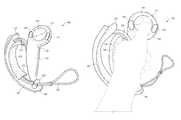
- FIG. 1depicts a controller according to an example embodiment of the present invention, with a hand retainer in an open position.
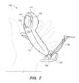
- FIG. 2depicts the controller of FIG. 1 in a user's open hand, palm up.
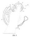
- FIG. 3depicts the controller of FIG. 1 in a user's closed hand.
- FIG. 4depicts the controller of FIG. 1 in a user's hand, palm down.
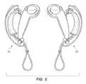
- FIG. 5depicts a pair of controllers according to an example embodiment of the present invention, with hand retainers in an open position.
- FIG. 6Adepicts a front view of right-hand controller according to another example embodiment of the present invention.
- FIG. 6Bdepicts a back view of the right-hand controller of FIG. 6A .
- FIG. 7Adepicts a window for an infrared light sensor, according to an embodiment of the present invention.
- FIG. 7Bdepicts a window for an infrared light sensor, according to another embodiment of the present invention.
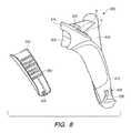
- FIG. 8shows a side view of the right-hand controller of FIG. 6A , with an outer shell that partially wraps the tubular housing of the controller's handle being exploded away to reveal instrumentation on its inner surface.
- FIG. 9Adepicts a cross section of the right-hand controller of FIG. 6A , with an outer shell that partially wraps the tubular housing of the controller's handle being exploded away.
- FIG. 9Bdepicts the cross section of FIG. 9A , except with the outer shell installed in its normal operational position.
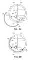
- FIG. 10Adepicts a front view of right-hand controller according to another example embodiment of the present invention, with a partially-closed hand retainer.
- FIG. 10Bdepicts a front view the controller of FIG. 10A , except with the hand retainer fully open.
- FIG. 11Adepicts a front view of head and handle components of a controller according to an example embodiment of the present invention, including a hand retainer anchor that can move peripherally about the head.
- FIG. 11Bdepicts the head and handle components of FIG. 11A except with a faceplate removed from the head to expose a lockable collar portion that may facilitate selective adjustment of the hand retainer anchor peripherally about the head.
- FIG. 12Adepicts a partially assembled controller according to an alternative embodiment of the present invention, with a hand retainer component removed.
- FIG. 12Bdepicts a closer view of a channel feature of the controller of FIG. 12A .
- FIG. 12Cis a cross-sectional view of the channel depicted in FIG. 12B .
- FIGS. 1-4depict a controller 100 for an electronic system according to an example embodiment of the present invention.
- the controller 100may be utilized by an electronic system such as a VR video gaming system, a robot, weapon, or medical device.
- the controller 100may include a controller body 110 having a handle 112 , and a hand retainer 120 to retain the controller 100 in the hand of a user (e.g. the user's left hand).
- the handle 112comprises a tubular housing that may optionally be substantially cylindrical. In this context, a substantially cylindrical shape need not have constant diameter, or a perfectly circular cross-section.
- the controller body 110may include a head (between the handle 112 and a distal end 111 ), which may optionally include one or more thumb-operated controls 114 , 115 , 116 .
- a tilting button, or any other button, knob, wheel, joystick, or trackballmay be considered as a thumb-operated control if it may be conveniently manipulated by a user's thumb during normal operation while the controller 100 is held in the hand of the user.
- the controller 100preferably includes a tracking member 130 that is fixed to the controller body 110 , and optionally includes two noses 132 , 134 , each protruding from a corresponding one of two opposing distal ends of the tracking member 130 .
- the tracking member 130is preferably but not necessarily a tracking arc having an arcuate shape.
- the tracking member 130includes a plurality of tracking transducers disposed therein, preferably with at least one tracking transducer disposed in each protruding nose 132 , 134 . Additional tracking transducers may be disposed also in the controller body 110 , with preferably at least one distal tracking transducer disposed adjacent the distal end 111 .
- the foregoing tracking transducersmay be tracking sensors that are responsive to electromagnetic radiation (e.g. infrared light) emitted by the electronic system, or they may alternatively be tracking beacons that emit electromagnetic radiation (e.g. infrared light) that is received by the electronic system.
- the electronic systemmay be a VR gaming system that widely broadcasts, i.e. paints, pulsed infrared light towards the controller 100 , with the plurality of tracking transducers of the tracking member 130 being infrared light sensors that may receive or be shadowed from the broadcast pulsed infrared light.
- the tracking transducers in each nose 132 , 134e.g.
- sensors in each nosepreferably overhang the user's hand on each distal end of the tracking member 130 , and so are better exposed (around the user's hand) to receive electromagnetic radiation emitted by the electronic system or to transmit the electromagnetic radiation to the electronic system, at more angles without an unacceptable amount of shadowing.
- the tracking member 130 and the controller body 110are made of a substantially rigid material such as hard plastic, and are firmly fixed together so that they do not appreciably translate or rotate relative to each other.
- the tracking of the translation and rotation of the constellation of tracking transducers in spaceis preferably not complicated by motion of the tracking transducers relative to each other.
- the tracking member 130may be fixed to the controller body 110 by being joined to the controller body 110 at two locations.
- the hand retainer 120may be attached to the controller 100 (either the controller body 110 or the tracking member 130 ) adjacent those two locations, to bias the user's palm against the outside surface of the handle 112 between the two locations.
- the tracking member 130 and the controller body 110may comprise an integral monolithic component having material continuity, rather than being assembled together.
- the tracking member 130 and the controller body 110may be molded together by a single injection-molding process step, resulting in one integral hard plastic component that comprises both the tracking member 130 and the controller body 110 .
- the tracking member 130 and the controller body 110may be initially fabricated separately, and then later assembled together. Either way, the tracking member 130 may be considered as fixed to the controller body 110 .
- the hand retainer 120is shown in the open position in FIG. 1 .
- the hand retainer 120may optionally be biased in the open position by a curved resilient member 122 , to facilitate the insertion of the user's left hand between the hand retainer 120 and the controller body 110 when the user is grasping for the controller with vision blocked by VR goggles.
- the curved resilient member 122may optionally be a flexible metal strip that elastically bends, or may comprise an alternative plastic material such as nylon that may bend substantially elastically.
- the curved resilient member 122may optionally be partially or completely internal to or covered by a cushion or fabric material 124 (e.g. a neoprene sheath), for the user's comfort.
- the cushion or fabric material 124may be disposed on (e.g. adhered to) only the side of the curved resilient member 122 that faces the user's hand.
- the hand retainer 120optionally may be adjustable in length, for example by including a draw cord 126 that is cinched by a spring-biased chock 128 .
- the draw cord 126may optionally have an excess length that may be used as a lanyard.
- the sheath 124optionally may be attached to the draw cord.
- the curved resilient member 122may be preloaded by the tension of the cinched draw cord 126 . In such embodiments, the tension that the curved resilient member 122 imparts to the hand retainer 120 (to bias it in the open position) causes the hand retainer to automatically open when the draw cord 126 is un-cinched.
- This disclosurealso contemplates alternative conventional ways to adjust the length of a hand retainer 120 , such as a cleat, an elastic band (that temporarily stretches when the hand is inserted, so that it applies elastic tension to press against the back of the hand), a hook & loop strap attachment that allows length adjustment, etc.
- a hand retainer 120such as a cleat, an elastic band (that temporarily stretches when the hand is inserted, so that it applies elastic tension to press against the back of the hand), a hook & loop strap attachment that allows length adjustment, etc.
- the hand retainer 120may be disposed between the handle 112 and the tracking member 130 , and be configured to contact the back of the user's hand.
- FIG. 2shows the controller 100 during operation with the user's left hand inserted therein but not grasping the controller body 110 .
- the hand retainer 120is closed and tightened over the hand, to physically bias the user's palm against the outside surface of the handle 112 .
- the hand retainer 120when closed, may retain the controller 100 to the hand even when the hand is not grasping the controller body 110 .
- FIGS. 3 and 4depict the controller 100 during operation when the hand retainer 120 is closed, and the hand is grasping the controller body 110 and the thumb is operating one or more of the thumb-operated controls (e.g. track pad 116 ).
- the handle 112 of the controller body 110preferably includes an array of proximity sensors that are spatially distributed partially or completely around its outer surface.
- the proximity sensors of the arrayare not necessarily of equal size and do not necessarily have equal spacing between them, although the array may comprise a grid.
- the array of proximity sensorsis preferably responsive to the proximity of the user's fingers to the outside surface of the handle 112 .
- the array of proximity sensorsmay be a plurality of capacitive sensors embedded under the outer surface of the handle 112 , with that outer surface comprising an electrically insulative material. The capacitance between such an array of capacitive sensors and a portion of the user's hand is inversely related to the distance there between.
- the capacitancemay be sensed by connecting an RC oscillator circuit to an element of the capacitance sensor array, and noting that the time constant of the circuit (and therefore the period and frequency of oscillation) will vary with the capacitance. In this way, the circuit may detect a release of a user's fingers from the outer surface of the handle 112 .
- the hand retainer 120may serve not only to prevent the controller 100 from falling out of hand, but also to keep fingers from excessively translating relative to the proximity sensor array of the handle 112 , to more reliably sense finger motion.
- the electronic systemmay include an algorithm embodying anatomically-possible motions of fingers, to better use the sensing from the proximity sensor array to render the opening of a controlled character's hand, finger pointing, or other motions of fingers relative to controller or relative to each other.
- the user's movement of the controller 100 and/or fingersmay help control a VR gaming system, defense system, medical system, industrial robot or machine, or another device.
- the systemmay render a throwing motion based on the movement of the tracking transducers, and may render the release of a thrown object based on the sensed release of the user's fingers from the outer surface of the handle of the controller.
- the function of the hand retainer 120may enable additional functionality of the controlled electronic system. For example, if the release and restoration of the user's grasp of the handle 112 of the controller body 110 is sensed, then such release or grasping may be incorporated into the game to display (e.g. in VR) throwing or grasping objects.
- the hand retainer 120may allow such a function to be accomplished repeatedly and safely.
- the location of the hand retainer 120 in the embodiment of FIGS. 1-4may help the tracking member 130 to protect back of user's hand from impacts in real world, for example when the user moves in response to a prompt sensed in the VR environment (e.g. while practically blinded by VR goggles).
- the controller 100may include a rechargeable battery disposed within the controller body 110 , and the hand retainer 120 (e.g. hand retention strap) may include an electrically-conductive charging wire that is electrically coupled to the rechargeable battery.
- the controller 100preferably also includes a radio frequency (RF) transmitter for communication with the rest of the electronic system.
- RF transmittermay be powered by the rechargeable battery and may be responsive to the thumb-operated controls 114 , 115 , 116 , the proximity sensors in the handle 112 of the controller body 110 , and/or tracking sensors in the tracking member 130 .
- the controller 100may be the left controller in a pair of controllers that includes a similar right controller 200 .
- the controllers 100 and 200may (together) track the motion and grip of both of a user's hands, simultaneously, for example to enhance a VR experience.
- FIG. 6Adepicts a front view of right-hand controller 600 according to another example embodiment of the present invention.
- FIG. 6Bdepicts a back view of the right-hand controller 600 .
- the controller 600has a controller body comprising a head 610 and a handle 612 .
- the head 610includes at least one thumb-operated control A, B, 608 , and may also include a control configured to be operated by the index finger (e.g. trigger 609 ).
- the handle 612comprises a tubular housing that is partially wrapped by an outer shell 640 .
- a tracking member 630is fixed to the controller body at the head 610 and at an end of the handle 612 .
- a hand retainer 620is configured to physically bias the user's palm against the outer shell 640 between the head 610 and the end of the handle 612 .
- the hand retainer 620is preferably disposed between the handle 612 and the tracking member 630 , and may comprise a hand retention strap that is adjustable in length and configured to contact the back of the user's hand.
- the hand retainer 620optionally includes a draw cord 628 , and optionally can be adjusted in length by a cord lock 626 (adjacent a distal end of the handle 612 ) that selectively prevents sliding motion by the draw cord 628 at the location of the cord lock 626 .
- tracking transducers 632 , 633are disposed on the tracking member 630 , with tracking transducers 633 being disposed on protruding noses at opposing distal ends of the tracking member 630 .
- Additional tracking transducers 634are optionally disposed on a distal region of the head 610 .
- the tracking transducers 632 , 633 , and 634may be tracking sensors that are responsive to electromagnetic radiation (e.g. infrared light) emitted by the electronic system (e.g. virtual reality gaming system), or may be tracking beacons that emit electromagnetic radiation (e.g. infrared light) that is received by the electronic system.
- the electronic systemmay be a VR gaming system that widely broadcasts, i.e. paints, pulsed infrared light towards the controller 600 , with the tracking transducers 632 , 633 , and 634 being infrared light sensors that may receive the broadcast pulsed infrared light.
- the response of such tracking sensorsmay be communicated back to the electronic system, and the system may interpret such response to effectively track the location and orientation of the controller 600 .
- FIG. 7Adepicts an exploded perspective view of an infrared light sensor 750 that is electrically connected to a flex circuit 751 , shown beneath a rectangular portion of an overlying windowed housing wall 755 that comprises an infrared-opaque plastic.
- the windowed housing wall 755includes a window 756 .
- the window 756preferably comprises an infrared-transmissive polycarbonate plastic, and may include an underside recession to accommodate the thickness of the infrared light sensor 750 .
- the windowed housing wall(e.g. the outer structure of the tracking member 630 , or the head 610 of FIG. 6A ) may be fabricated from a so-called “double shot” injection molding process, so that the majority of the housing wall is fabricated from infrared-opaque plastic, but with infrared-transmissive plastic being disposed in the window 756 above the infrared light sensor 750 .
- FIG. 7Adepicts a cross-sectional view of the infrared light sensor 750 , flex circuit 751 , and the windowed housing wall 755 as assembled.
- Infrared lightshown in FIG. 7A as three downward arrows incident upon the window 756 from above, passes through the window 756 to be received by the underlying infrared light sensor 750 .
- the housing wall 755comprises infrared-opaque plastic, the infrared light that strikes it will not pass through, and a portion may be reflected back into the window to be received by the infrared light sensor 750 .
- the window 756permits infrared light to affect the infrared light sensor 750 , despite the majority of the housing wall 755 comprising infrared-opaque plastic, so that the infrared light sensor 750 receives infrared light only from a preferred angular range.
- FIG. 7Bdepicts an exploded perspective view of the infrared light sensor 750 as electrically connected to the flex circuit 751 , shown beneath a rectangular portion of an overlying housing wall 758 that comprises an IR-transmissive plastic.
- the housing wall 758is coated with an infrared-opaque film 757 that is patterned to include a window 759 (where the infrared-opaque film 757 is absent).
- FIG. 7Bdepicts a cross-sectional view of the infrared light sensor 750 , flex circuit 751 , the housing wall 758 , and the IR-opaque film 757 , as assembled.
- Infrared lightshown in FIG. 7B as three downward arrows incident upon the housing wall 758 from above, passes through the window 759 in the infrared-opaque film 757 to pass through the housing wall 758 there to be received by the underlying infrared light sensor 750 .
- the housing wall 758comprises infrared-transmissive plastic, the infrared light that strikes it may pass into it and be lost, and perhaps unintentionally and undesirably even reach a nearby sensor via internal reflections. In this way, the window 759 in the infrared-opaque film 757 permits infrared light to primarily affect the infrared light sensor 750 .
- FIG. 8shows a side view of the right-hand controller 600 , with the outer shell 640 , which partially wraps the tubular housing of the handle 612 being exploded away to reveal instrumentation on its inner surface.
- the instrumentationmay comprise an array of proximity sensors 800 that are spatially distributed on the inner surface of the outer shell 640 , the array of proximity sensors 800 being responsive to a proximity of the user's fingers to the outer shell 640 .
- the proximity sensors 800 of the arrayare not necessarily of equal size, nor are they necessarily spaced regularly or equally from each other.
- the array of proximity sensors 800preferably may be a plurality of capacitive sensors that may be connected to a flex circuit that is bonded to the inner surface of the outer shell 640 .
- the outer shell 640includes a first electrical connector portion 805 , which may be connected to a mating second electrical connector portion of the handle 612 (as shown in more detail in FIGS. 9A-9B ).
- FIGS. 9A-Bdepicts cross sections of the right-hand controller 600 of FIG. 6A , showing that the controller's handle optionally may comprise a tubular housing 612 a, 612 b, that is split longitudinally by a seam 613 where the tubular housing portions 612 a and 612 b adjoin.
- the outer shell 640is shown exploded away from the rest of the handle.
- FIG. 9Bdepicts the cross section of FIG. 9A , except with the outer shell 640 installed in its normal operational position.
- the first electrical connector portion 805 of the outer shell 640is shown to be mating and connectable to the second electrical connector portion 905 of the controller handle.
- the outer shell 640partially wraps the tubular housing 612 a, 612 b in such a way that it preferably overlaps the longitudinal seam 613 , so that the longitudinal seam 613 may be positioned to optimize the process of manufacture rather than to accommodate the desired circumferential location of the proximity sensor array 800 .
- the outer shell 640overlaps a circumferential portion C of the tubular housing 612 a, 612 b of the handle, and the circumferential portion C angularly spans at least 100 degrees but not more than 170 degrees of the full circumference of the tubular housing 612 a, 612 b of the handle.
- Such a circumferential overlapmay, in certain embodiments, enable the proximity sensor array 800 to sense the proximity of a desired portion of the user's fingers or palm, for example the region of the hand that best indicates grasping.
- the tubular housing 612 a, 612 b of the handleneed not have a circular cross-section, and that the word “circumference” is used herein whether or not the tubular housing 612 a, 612 b of the handle has a circular cross-section.
- the term “circumference”implies the complete perimeter about the tubular housing 612 a, 612 b of the handle, which may be circular if the tubular housing 612 a, 612 b is a right circular hollow cylinder, but which may be a closed shape other than a circle if the tubular housing is shaped as a non-circular cylinder or hollow prism.
- a printed circuit board (PCB) 920may be mounted within the tubular housing 612 a, 612 b of the handle, with the second electrical connector portion 905 being electrically coupled to the PCB 920 .
- the PCB 920optionally includes a force sensing resistor (FSR) 922 , and the controller may further comprise a plunger 924 that conveys a compressive force applied via the outer shell 640 towards the outside of the tubular housing 612 a, 612 b of the handle inward to the FSR 922 .
- the FSR 922in conjunction with the proximity sensor array 800 , may facilitate sensing of both the onset of grasping by the user, and the relative strength of such grasping by the user, which may be facilitate certain gameplay features.
- the outer shell 640has a shell thickness (measured radially in FIGS. 9A-9B ) that is less than one-third of a housing wall thickness of the tubular housing portions 612 a or 612 b of the handle. In those embodiments, such a thickness inequality may improve the sensitivity of the proximity sensor array 800 relative to an alternative embodiment where the proximity sensor array 800 is disposed on or in the tubular housing 612 a, 612 b of the handle.
- FIG. 10Adepicts a front view of right-hand controller 200 according to another example embodiment of the present invention, with a partially-closed hand retainer 220 (e.g. a hand retention strap).
- FIG. 10Bdepicts a front view the controller 200 , except with the hand retainer 220 fully open.
- the controller 200includes a controller body having a head 210 and a handle 212 .
- the head 210adjoins the handle 212 at a neck region 211 of the controller 200 .
- the handle 212preferably includes an array of proximity sensors that are spatially distributed just under its outside surface, and that are preferably responsive to a proximity of the user's fingers to the outer surface of the handle 212 .
- the head 210includes thumb-operated controls A, B, and 208 .
- the controller 200also includes a tracking member 230 that is preferably fixed to the controller body at the head 210 and at a distal end of the handle 212 .
- the tracking member 230preferably includes a plurality of tracking transducers that may be sensors that are responsive to electromagnetic radiation emitted by the electronic system (e.g. pulsed infrared light emitted by a virtual reality gaming system), or tracking beacons that emit electromagnetic radiation to be received by the electronic system.
- the tracking member 230is preferably but not necessarily a tracking arc having an arcuate shape.
- the hand retainer 220is preferably disposed between the handle 212 and the tracking arc 230 .
- the controller 200includes a draw cord 228 , and a cord lock 226 adjacent a distal end of the handle 212 .
- the cord lock 226may selectively prevent sliding motion by the draw cord 228 at the cord lock 226 .
- the hand retainer 220is drawn tighter into a closed position (as shown by the motion arrow depicted in FIG. 10A ). The closed position physically biases the user's palm against an outer surface of the handle 212 .
- the hand retainer 220preferably includes a resilient member (e.g. an internal or external elastically deformable strip such as a metal strip) that biases the hand retainer 220 towards the open position shown in FIG. 10B .
- a resilient membere.g. an internal or external elastically deformable strip such as a metal strip
- the preloaded bias towards straightening of the elastically deformed resilient membercauses the hand retainer 220 to naturally open (as shown by the motion arrow depicted in FIG. 10B ).
- the open positionmay facilitate inserting or withdrawing the user's hand from the controller 200 , especially when the user's vision may be obstructed by the wearing of virtual reality goggles.
- FIG. 11Adepicts a front view of the head 210 and handle 212 components of the controller 200 , including a hand retainer anchor 302 that can be adjusted to move peripherally about the head 210 .
- FIG. 11Bdepicts the same head 210 and handle 212 components, except with a faceplate removed from the head 210 to expose a lockable collar portion 311 that may facilitate selective adjustment of the hand retainer anchor 302 peripherally about the head 210 .
- the lockable collar portion 311may translate along an arcuate path defined by an internal arcuate guide 315 .
- the lockable collar portion 311can be selectively locked by the user to prevent further movement of the anchor 302 about the periphery of the head 210 .
- the resilient member of the hand retainer 220is attached to the hand retainer anchor 302 of the head 210 , which permits the hand retainer 220 to be adjusted towards or away from the user's purlicue (between the user's thumb and fingers).
- the resilient member of the hand retainer 220is preferably attached to the hand retainer anchor 302 of the head 210 by a pivoting or rotatable attachment, so that the hand retainer 220 can pivot relative to the hand retainer anchor 302 at the location of the attachment.
- Such degree of freedomis additional to the adjustability of the position of the hand retainer anchor 302 about the periphery of the head 210 .
- FIGS. 12A, 12B, and 12Cdepict an alternative embodiment of a partially assembled controller 400 having a controller body that includes a head 410 and a handle 412 joined to the head in a neck region 411 .
- the controller bodyincludes a channel 414 that is disposed adjacent the neck region 411 .
- a hand retainerwhich is not shown in FIG. 12A so that the channel 414 will not be partially obscured, includes a resilient member 420 that terminates in a projection 425 that extends into the channel 414 .
- the projection 425includes a catch 427 that prevents longitudinal movement of the projection within the channel 414 when the hand retainer is in the closed position.
- the catch 427is a cam that increases friction with an interior surface of the channel 414 , when a relative angle of the hand retainer projection 425 corresponds to the closed position of the hand retainer—i.e., when the closed position of the hand retainer results in tension upon the resilient member 420 (e.g. in a downward direction as shown in the cross-section of FIG. 12C ).
- the hand retainer projection 425when the hand retainer projection 425 is rotated to a relative angle that corresponds to an open position of the hand retainer (e.g. in an upward direction as shown in the cross-section of FIG. 12C ), the friction between the catch 427 and the channel 414 is reduced, and the hand retainer projection 425 may be translated within the channel 414 (as indicated by the motion arrows shown in FIG. 12B ).
- the channel 414is preferably oriented so that translation of the hand retainer projection along the channel 414 preferably adjusts the relative position of the hand retainer projection 425 towards or away from the purlicue of the user's hand, for example so that the controller 400 can accommodate different hand sizes or finger lengths.
- the hand retainer projection 425may be pivotably attached to the remainder of the hand retainer by a conventional pivot joint. Such rotational degree of freedom is additional to the adjustable translation of the hand retainer projection 425 along the channel 414 .
Landscapes
- Engineering & Computer Science (AREA)
- Multimedia (AREA)
- Human Computer Interaction (AREA)
- User Interface Of Digital Computer (AREA)
- Position Input By Displaying (AREA)
Abstract
Description
Claims (22)
Priority Applications (19)
| Application Number | Priority Date | Filing Date | Title |
|---|---|---|---|
| US15/834,372US10307669B2 (en) | 2016-10-11 | 2017-12-07 | Electronic controller with finger sensing and an adjustable hand retainer |
| US15/984,231US10888773B2 (en) | 2016-10-11 | 2018-05-18 | Force sensing resistor (FSR) with polyimide substrate, systems, and methods thereof |
| US15/984,245US10691233B2 (en) | 2016-10-11 | 2018-05-18 | Sensor fusion algorithms for a handheld controller that includes a force sensing resistor (FSR) |
| US16/195,718US10987573B2 (en) | 2016-10-11 | 2018-11-19 | Virtual reality hand gesture generation |
| CN201880076032.6ACN111526925B (en) | 2017-12-07 | 2018-12-05 | Electronic controller with finger sensing and adjustable hand holder |
| EP18886397.1AEP3697509A4 (en) | 2017-12-07 | 2018-12-05 | ELECTRONIC CONTROL UNIT WITH FINGER GRIP AND ADJUSTABLE HANDHELD DEVICE |
| PCT/US2018/064116WO2019113243A1 (en) | 2017-12-07 | 2018-12-05 | Electronic controller with finger sensing and an adjustable hand retainer |
| KR1020207012389AKR102706361B1 (en) | 2017-12-07 | 2018-12-05 | Electronic controller with finger detection and adjustable hand retainer |
| JP2020529540AJP7254802B2 (en) | 2017-12-07 | 2018-12-05 | Electronic controller with finger detection and adjustable hand hold |
| US16/289,420US10649583B1 (en) | 2016-10-11 | 2019-02-28 | Sensor fusion algorithms for a handheld controller that includes a force sensing resistor (FSR) |
| US16/377,058US10898796B2 (en) | 2016-10-11 | 2019-04-05 | Electronic controller with finger sensing and an adjustable hand retainer |
| US16/389,499US11625898B2 (en) | 2016-10-11 | 2019-04-19 | Holding and releasing virtual objects |
| US16/389,629US11185763B2 (en) | 2016-10-11 | 2019-04-19 | Holding and releasing virtual objects |
| US16/392,497US10898797B2 (en) | 2016-10-11 | 2019-04-23 | Electronic controller with finger sensing and an adjustable hand retainer |
| US16/826,800US11294485B2 (en) | 2016-10-11 | 2020-03-23 | Sensor fusion algorithms for a handheld controller that includes a force sensing resistor (FSR) |
| US16/950,661US11465041B2 (en) | 2016-10-11 | 2020-11-17 | Force sensing resistor (FSR) with polyimide substrate, systems, and methods thereof |
| US17/148,362US11786809B2 (en) | 2016-10-11 | 2021-01-13 | Electronic controller with finger sensing and an adjustable hand retainer |
| US17/229,619US11992751B2 (en) | 2016-10-11 | 2021-04-13 | Virtual reality hand gesture generation |
| US17/409,357US12042718B2 (en) | 2016-10-11 | 2021-08-23 | Holding and releasing virtual objects |
Applications Claiming Priority (4)
| Application Number | Priority Date | Filing Date | Title |
|---|---|---|---|
| US29/580,635USD806173S1 (en) | 2016-10-11 | 2016-10-11 | Controller |
| US201762520958P | 2017-06-16 | 2017-06-16 | |
| US15/679,521US10391400B1 (en) | 2016-10-11 | 2017-08-17 | Electronic controller with hand retainer and finger motion sensing |
| US15/834,372US10307669B2 (en) | 2016-10-11 | 2017-12-07 | Electronic controller with finger sensing and an adjustable hand retainer |
Related Parent Applications (1)
| Application Number | Title | Priority Date | Filing Date |
|---|---|---|---|
| US15/679,521Continuation-In-PartUS10391400B1 (en) | 2016-10-11 | 2017-08-17 | Electronic controller with hand retainer and finger motion sensing |
Related Child Applications (7)
| Application Number | Title | Priority Date | Filing Date |
|---|---|---|---|
| US15/984,245Continuation-In-PartUS10691233B2 (en) | 2016-10-11 | 2018-05-18 | Sensor fusion algorithms for a handheld controller that includes a force sensing resistor (FSR) |
| US15/984,231Continuation-In-PartUS10888773B2 (en) | 2016-10-11 | 2018-05-18 | Force sensing resistor (FSR) with polyimide substrate, systems, and methods thereof |
| US16/195,718Continuation-In-PartUS10987573B2 (en) | 2016-10-11 | 2018-11-19 | Virtual reality hand gesture generation |
| US16/377,058ContinuationUS10898796B2 (en) | 2016-10-11 | 2019-04-05 | Electronic controller with finger sensing and an adjustable hand retainer |
| US16/389,499Continuation-In-PartUS11625898B2 (en) | 2016-10-11 | 2019-04-19 | Holding and releasing virtual objects |
| US16/389,629Continuation-In-PartUS11185763B2 (en) | 2016-10-11 | 2019-04-19 | Holding and releasing virtual objects |
| US16/392,497Continuation-In-PartUS10898797B2 (en) | 2016-10-11 | 2019-04-23 | Electronic controller with finger sensing and an adjustable hand retainer |
Publications (2)
| Publication Number | Publication Date |
|---|---|
| US20180099219A1 US20180099219A1 (en) | 2018-04-12 |
| US10307669B2true US10307669B2 (en) | 2019-06-04 |
Family
ID=61830463
Family Applications (3)
| Application Number | Title | Priority Date | Filing Date |
|---|---|---|---|
| US15/834,372ActiveUS10307669B2 (en) | 2016-10-11 | 2017-12-07 | Electronic controller with finger sensing and an adjustable hand retainer |
| US16/377,058Active2036-10-22US10898796B2 (en) | 2016-10-11 | 2019-04-05 | Electronic controller with finger sensing and an adjustable hand retainer |
| US17/148,362ActiveUS11786809B2 (en) | 2016-10-11 | 2021-01-13 | Electronic controller with finger sensing and an adjustable hand retainer |
Family Applications After (2)
| Application Number | Title | Priority Date | Filing Date |
|---|---|---|---|
| US16/377,058Active2036-10-22US10898796B2 (en) | 2016-10-11 | 2019-04-05 | Electronic controller with finger sensing and an adjustable hand retainer |
| US17/148,362ActiveUS11786809B2 (en) | 2016-10-11 | 2021-01-13 | Electronic controller with finger sensing and an adjustable hand retainer |
Country Status (1)
| Country | Link |
|---|---|
| US (3) | US10307669B2 (en) |
Cited By (11)
| Publication number | Priority date | Publication date | Assignee | Title |
|---|---|---|---|---|
| US20190232160A1 (en)* | 2016-10-11 | 2019-08-01 | Valve Corporation | Electronic controller with finger sensing and an adjustable hand retainer |
| US20190291000A1 (en)* | 2018-03-23 | 2019-09-26 | Valve Corporation | Handheld Controllers With Touch-Sensitive Controls |
| US20200246691A1 (en)* | 2016-10-11 | 2020-08-06 | Valve Corporation | Electronic controller with finger sensing and an adjustable hand retainer |
| US10874939B2 (en) | 2017-06-16 | 2020-12-29 | Valve Corporation | Electronic controller with finger motion sensing |
| US10888773B2 (en) | 2016-10-11 | 2021-01-12 | Valve Corporation | Force sensing resistor (FSR) with polyimide substrate, systems, and methods thereof |
| US10987573B2 (en) | 2016-10-11 | 2021-04-27 | Valve Corporation | Virtual reality hand gesture generation |
| US11167213B2 (en)* | 2016-10-11 | 2021-11-09 | Valve Corporation | Electronic controller with hand retainer and finger motion sensing |
| US11185763B2 (en) | 2016-10-11 | 2021-11-30 | Valve Corporation | Holding and releasing virtual objects |
| US11294485B2 (en) | 2016-10-11 | 2022-04-05 | Valve Corporation | Sensor fusion algorithms for a handheld controller that includes a force sensing resistor (FSR) |
| US11625898B2 (en) | 2016-10-11 | 2023-04-11 | Valve Corporation | Holding and releasing virtual objects |
| USD994778S1 (en)* | 2018-05-18 | 2023-08-08 | Valve Corporation | Game controller |
Families Citing this family (35)
| Publication number | Priority date | Publication date | Assignee | Title |
|---|---|---|---|---|
| US10549183B2 (en) | 2016-10-11 | 2020-02-04 | Valve Corporation | Electronic controller with a hand retainer, outer shell, and finger sensing |
| US10649583B1 (en) | 2016-10-11 | 2020-05-12 | Valve Corporation | Sensor fusion algorithms for a handheld controller that includes a force sensing resistor (FSR) |
| WO2018079384A1 (en)* | 2016-10-28 | 2018-05-03 | 株式会社ソニー・インタラクティブエンタテインメント | Information processing system, information processing apparatus, control method, and program |
| EP3684484A4 (en)* | 2017-12-07 | 2021-03-31 | Valve Corporation | ELECTRONIC CONTROL UNIT WITH HAND HOLDER, OUTER SHELL AND FINGER SENSOR |
| TWD197306S (en)* | 2018-05-15 | 2019-05-01 | 宏碁股份有限公司 | Motion controller |
| TWD197307S (en)* | 2018-05-15 | 2019-05-01 | 宏碁股份有限公司 | Motion controller |
| CN118939111A (en)* | 2018-05-18 | 2024-11-12 | 威尔乌集团 | Sensor fusion algorithm for handheld controllers containing force sensing resistors (FSRs) |
| US10554886B2 (en)* | 2018-05-18 | 2020-02-04 | Valve Corporation | Power management for optical position tracking devices |
| USD891429S1 (en)* | 2018-05-22 | 2020-07-28 | Disney Enterprises, Inc. | Controller |
| TWD197308S (en)* | 2018-05-31 | 2019-05-01 | 宏碁股份有限公司 | Motion controller |
| JP7337857B2 (en)* | 2018-06-20 | 2023-09-04 | バルブ コーポレーション | Virtual Reality Hand Gesture Generation |
| KR102737463B1 (en)* | 2018-06-20 | 2024-12-03 | 밸브 코포레이션 | Maintaining and releasing virtual objects |
| JP7358408B2 (en)* | 2018-06-20 | 2023-10-10 | バルブ コーポレーション | Holding and releasing virtual objects |
| GB2575820B (en)* | 2018-07-24 | 2022-11-30 | Sony Interactive Entertainment Inc | Robot interaction system and method |
| GB201816785D0 (en) | 2018-10-15 | 2018-11-28 | Tangi0 Ltd | Sensor device and method |
| TWI760654B (en)* | 2018-11-12 | 2022-04-11 | 宏達國際電子股份有限公司 | Virtual reality controller |
| US10905946B2 (en)* | 2019-02-28 | 2021-02-02 | Valve Corporation | Continuous controller calibration |
| WO2020219340A1 (en)* | 2019-04-23 | 2020-10-29 | Valve Corporation | Electronic controller with finger sensing and an adjustable hand retainer |
| US11442280B2 (en)* | 2019-04-23 | 2022-09-13 | Valve Corporation | Adjustable head-mounted display to accommodate different head and face sizes |
| US11378807B2 (en)* | 2019-08-28 | 2022-07-05 | Lg Electronics Inc. | Electronic device |
| BR112022023836A2 (en)* | 2020-05-29 | 2022-12-20 | Sony Interactive Entertainment Inc | INPUT DEVICE |
| CN114377408B (en)* | 2020-10-19 | 2025-07-29 | 宏达国际电子股份有限公司 | Handle assembly |
| US12011670B2 (en) | 2020-11-03 | 2024-06-18 | Htc Corporation | Hand controller assembly |
| US11504615B1 (en)* | 2021-05-18 | 2022-11-22 | Valve Corporation | Electronic controller with linear hand strap adjuster |
| US20240377899A1 (en)* | 2021-09-22 | 2024-11-14 | Sony Interactive Entertainment Inc. | Input device |
| USD988321S1 (en)* | 2022-02-08 | 2023-06-06 | Bigwheat Technology LLC | Joypad |
| CN118661147A (en)* | 2022-03-30 | 2024-09-17 | 索尼互动娱乐股份有限公司 | Input device, accessory component of input device, and input device assembly including input device and accessory component |
| USD975189S1 (en)* | 2022-05-08 | 2023-01-10 | Huimei Liao | Handle for game controller |
| USD976327S1 (en)* | 2022-05-29 | 2023-01-24 | Huimei Liao | Pair of handles for game controllers |
| USD999758S1 (en)* | 2022-08-15 | 2023-09-26 | Shenzhen Lingan Wireless Technology Co., Ltd | Video controller |
| USD988409S1 (en)* | 2022-09-29 | 2023-06-06 | Shenzhen Zyber Innovations Technology Co., Ltd. | VR controller grips cover set |
| USD1050123S1 (en)* | 2022-10-28 | 2024-11-05 | Xiaochuan Zhang | VR controller handle cover |
| USD1039618S1 (en)* | 2024-03-08 | 2024-08-20 | Shenzhen Bikun Technology Co., Ltd. | VR controller grips cover |
| USD1045884S1 (en)* | 2024-05-08 | 2024-10-08 | Jincheng ZHONG | Game controller cover |
| USD1075758S1 (en)* | 2024-10-27 | 2025-05-20 | Shenzhen Meike Innovation Technology Co., Ltd. | Charging controller grips |
Citations (13)
| Publication number | Priority date | Publication date | Assignee | Title |
|---|---|---|---|---|
| US20020175894A1 (en)* | 2001-03-06 | 2002-11-28 | Vince Grillo | Hand-supported mouse for computer input |
| US20040012557A1 (en)* | 2002-07-18 | 2004-01-22 | Sony Computer Entertainment Inc. | Hand-held computer interactive device |
| US20060146018A1 (en) | 2005-01-04 | 2006-07-06 | Arneson Theodore R | Joystick with tactile feedback |
| US20080136778A1 (en)* | 2006-12-05 | 2008-06-12 | Eli Hursh | Mouse device for a computer |
| US8062126B2 (en) | 2004-01-16 | 2011-11-22 | Sony Computer Entertainment Inc. | System and method for interfacing with a computer program |
| US8636199B1 (en)* | 2005-08-25 | 2014-01-28 | Hewlett-Packard Development Company, L.P. | System and method for matching a media manipulation with a media manipulation template |
| US20140098018A1 (en)* | 2012-10-04 | 2014-04-10 | Microsoft Corporation | Wearable sensor for tracking articulated body-parts |
| US20160030835A1 (en) | 2013-07-12 | 2016-02-04 | Chris Argiro | Video-game console for allied touchscreen media |
| US20160124500A1 (en)* | 2014-10-29 | 2016-05-05 | Lg Electronics Inc. | Watch type control device |
| US20160306932A1 (en)* | 2015-04-20 | 2016-10-20 | Kali Care, Inc. | Wearable system for healthcare management |
| US20160342218A1 (en)* | 2015-05-20 | 2016-11-24 | Survios, Inc. | Systems and methods for natural motion interaction with a virtual environment |
| US20170139481A1 (en)* | 2015-11-12 | 2017-05-18 | Oculus Vr, Llc | Method and apparatus for detecting hand gestures with a handheld controller |
| US20180161670A1 (en)* | 2016-12-12 | 2018-06-14 | Evgeny Boev | Single-Handed Input Controller and Method |
Family Cites Families (160)
| Publication number | Priority date | Publication date | Assignee | Title |
|---|---|---|---|---|
| US4489302A (en) | 1979-09-24 | 1984-12-18 | Eventoff Franklin Neal | Electronic pressure sensitive force transducer |
| JPS6021262A (en) | 1983-07-15 | 1985-02-02 | Matsushita Electric Ind Co Ltd | Thermal head |
| US4845457A (en) | 1987-11-25 | 1989-07-04 | Kabushiki Kaisha Cubic Engineering | Deformable type variable resistor element |
| US5184120A (en) | 1991-04-04 | 1993-02-02 | Motorola, Inc. | Menu selection using adaptive force sensing resistor |
| JPH0520135U (en) | 1991-08-28 | 1993-03-12 | 日本電子機器株式会社 | Anomaly detection device for micro computer system |
| US5302936A (en) | 1992-09-02 | 1994-04-12 | Interlink Electronics, Inc. | Conductive particulate force transducer |
| JP2682803B2 (en) | 1994-06-14 | 1997-11-26 | バンドー化学株式会社 | Auto tensioner |
| US5796387A (en) | 1994-08-16 | 1998-08-18 | Smith Engineering | Positioning system using infrared radiation |
| US5731516A (en) | 1995-06-07 | 1998-03-24 | Handfield; Michael | System and method for monitoring a pneumatic tire |
| JPH10154436A (en) | 1996-11-22 | 1998-06-09 | Hosiden Corp | Membrane switch |
| US6097374A (en) | 1997-03-06 | 2000-08-01 | Howard; Robert Bruce | Wrist-pendent wireless optical keyboard |
| DE19732888A1 (en) | 1997-07-30 | 1999-02-25 | Still & Saxby Sarl | Operating device for an industrial truck |
| US5912612A (en) | 1997-10-14 | 1999-06-15 | Devolpi; Dean R. | Multi-speed multi-direction analog pointing device |
| US6610917B2 (en) | 1998-05-15 | 2003-08-26 | Lester F. Ludwig | Activity indication, external source, and processing loop provisions for driven vibrating-element environments |
| LU90286B1 (en) | 1998-09-11 | 2000-03-13 | Iee Sarl | Force transducer |
| US6222526B1 (en) | 1998-10-29 | 2001-04-24 | Quentin J. Holmes | Hand held ergonomic computer controller |
| US6484136B1 (en) | 1999-10-21 | 2002-11-19 | International Business Machines Corporation | Language model adaptation via network of similar users |
| JP2001159569A (en) | 1999-12-02 | 2001-06-12 | Denso Corp | Pressure sensor |
| JP2001194232A (en) | 2000-01-14 | 2001-07-19 | Sony Corp | Optical sensor device and display device |
| US20020010020A1 (en) | 2000-04-26 | 2002-01-24 | Glen Johnson | Friction enhancing accessories for game controllers |
| US20010035856A1 (en) | 2000-05-08 | 2001-11-01 | Myers Christopher S. | Palm-held computer pointing devices |
| JP3980300B2 (en) | 2000-09-07 | 2007-09-26 | 株式会社フジクラ | Membrane pressure sensitive resistor and pressure sensor |
| JP2002315097A (en) | 2001-04-16 | 2002-10-25 | Mitsubishi Electric Corp | Pressure sensitive device and method of manufacturing semiconductor substrate used therein |
| US20030006962A1 (en) | 2001-07-06 | 2003-01-09 | Bajramovic Mark B. | Computer mouse on a glove |
| JP2003045262A (en) | 2001-07-27 | 2003-02-14 | Polymatech Co Ltd | Membrane type pressure-sensitive sheet and its manufacturing method |
| JP2003075271A (en) | 2001-09-04 | 2003-03-12 | Mitsumi Electric Co Ltd | Pressure-sensitive sensor |
| JP2003090773A (en) | 2001-09-19 | 2003-03-28 | Polymatech Co Ltd | Pressure-sensitive sensor and method of detecting pressing force of pressure-sensitive sensor |
| US6816151B2 (en) | 2001-11-09 | 2004-11-09 | Terry L. Dellinger | Hand-held trackball computer pointing device |
| US7092785B2 (en) | 2002-03-12 | 2006-08-15 | Gunilla Alsio | Data input device |
| JP2004028883A (en) | 2002-06-27 | 2004-01-29 | Denso Corp | Pressure-sensitive sensor |
| US20090143141A1 (en) | 2002-08-06 | 2009-06-04 | Igt | Intelligent Multiplayer Gaming System With Multi-Touch Display |
| US20080146336A1 (en) | 2002-12-04 | 2008-06-19 | Philip Feldman | Exercise Gaming Device and Method of Facilitating User Exercise During Video Game Play |
| US7050045B2 (en) | 2003-01-07 | 2006-05-23 | Interlink Electronics, Inc. | Miniature highly manufacturable mouse pointing device |
| US7112755B2 (en) | 2003-05-21 | 2006-09-26 | Nitta Corporation | Pressure-sensitive sensor |
| US8323106B2 (en) | 2008-05-30 | 2012-12-04 | Sony Computer Entertainment America Llc | Determination of controller three-dimensional location using image analysis and ultrasonic communication |
| US20050151725A1 (en) | 2003-12-30 | 2005-07-14 | Jennings Christopher P. | User interface device |
| US7362305B2 (en) | 2004-02-10 | 2008-04-22 | Senseboard Technologies Ab | Data input device |
| US7176889B2 (en) | 2004-05-21 | 2007-02-13 | Interlink Electronics, Inc. | Force sensing pointing device with click function |
| US20060111180A1 (en) | 2004-11-25 | 2006-05-25 | Zeroplus Technology Co., Ltd. | Touch-control game controller |
| US7337085B2 (en) | 2005-06-10 | 2008-02-26 | Qsi Corporation | Sensor baseline compensation in a force-based touch device |
| US7483731B2 (en) | 2005-09-30 | 2009-01-27 | Nellcor Puritan Bennett Llc | Medical sensor and technique for using the same |
| US7649522B2 (en) | 2005-10-11 | 2010-01-19 | Fish & Richardson P.C. | Human interface input acceleration system |
| US8142287B2 (en) | 2005-10-11 | 2012-03-27 | Zeemote Technology Inc. | Universal controller for toys and games |
| US7663495B2 (en) | 2005-10-12 | 2010-02-16 | The Penn State Research Foundation | Vigilance monitoring technique for vehicle operators |
| US9182837B2 (en) | 2005-11-28 | 2015-11-10 | Synaptics Incorporated | Methods and systems for implementing modal changes in a device in response to proximity and force indications |
| US7791596B2 (en) | 2005-12-27 | 2010-09-07 | Interlink Electronics, Inc. | Touch input device having interleaved scroll sensors |
| US8665213B2 (en) | 2006-02-08 | 2014-03-04 | Oblong Industries, Inc. | Spatial, multi-modal control device for use with spatial operating system |
| JP4202366B2 (en) | 2006-03-08 | 2008-12-24 | 任天堂株式会社 | Motion discrimination device and motion discrimination program |
| JP4151982B2 (en) | 2006-03-10 | 2008-09-17 | 任天堂株式会社 | Motion discrimination device and motion discrimination program |
| US7721609B2 (en) | 2006-03-31 | 2010-05-25 | Cypress Semiconductor Corporation | Method and apparatus for sensing the force with which a button is pressed |
| US20070279380A1 (en) | 2006-05-31 | 2007-12-06 | Bruno Rafael Murillo | Computer input device |
| US7886700B2 (en)* | 2006-12-14 | 2011-02-15 | Glazer Shelly K | Retractable leash assembly |
| US8932135B2 (en) | 2007-04-19 | 2015-01-13 | Adam W. Coe | Game controller |
| US7528337B2 (en) | 2007-05-15 | 2009-05-05 | Panasonic Corporation | Pressure sensitive conductive sheet and panel switch using same |
| US20080311990A1 (en) | 2007-06-13 | 2008-12-18 | Cheng Uei Precision Industry Co., Ltd. | Position system for interactive gaming device and method using the same |
| US20090205878A1 (en) | 2008-01-08 | 2009-08-20 | David Taylor | Touchpad for providing touch stick functionality in a game controller for providing relative and absolute position input |
| JP4410284B2 (en) | 2008-02-19 | 2010-02-03 | 株式会社コナミデジタルエンタテインメント | GAME DEVICE, GAME CONTROL METHOD, AND PROGRAM |
| CN102007465B (en) | 2008-02-28 | 2015-05-20 | 纽约大学 | Method and apparatus and sensor pad for providing input to a processor |
| JP4829265B2 (en) | 2008-03-24 | 2011-12-07 | 日本特殊陶業株式会社 | Manufacturing method of spark plug |
| CN101598299B (en) | 2008-06-05 | 2012-01-25 | 鸿富锦精密工业(深圳)有限公司 | Light source module and game device using same |
| US8620213B2 (en) | 2009-12-24 | 2013-12-31 | Sony Computer Entertainment Inc. | Wireless device pairing methods |
| US20100090949A1 (en) | 2008-07-22 | 2010-04-15 | Shanda Computer (Shanghai) Co., Ltd. | Method and Apparatus for Input Device |
| JP5289031B2 (en) | 2008-12-22 | 2013-09-11 | 任天堂株式会社 | GAME DEVICE AND GAME PROGRAM |
| EP2389622A1 (en) | 2009-01-26 | 2011-11-30 | Zrro Technologies (2009) Ltd. | Device and method for monitoring an object's behavior |
| US8482520B2 (en) | 2009-01-30 | 2013-07-09 | Research In Motion Limited | Method for tap detection and for interacting with and a handheld electronic device, and a handheld electronic device configured therefor |
| US20100245239A1 (en) | 2009-03-25 | 2010-09-30 | Ippasa, Llc | Pressure sensing controller |
| JP5430246B2 (en) | 2009-06-23 | 2014-02-26 | 任天堂株式会社 | GAME DEVICE AND GAME PROGRAM |
| US8777741B2 (en) | 2009-09-10 | 2014-07-15 | Nintendo Co., Ltd. | Illumination device |
| US8717291B2 (en) | 2009-10-07 | 2014-05-06 | AFA Micro Co. | Motion sensitive gesture device |
| US20110084932A1 (en) | 2009-10-13 | 2011-04-14 | Research In Motion Limited | Portable electronic device including touch-sensitive display and method of controlling same |
| US8754746B2 (en) | 2009-11-16 | 2014-06-17 | Broadcom Corporation | Hand-held gaming device that identifies user based upon input from touch sensitive panel |
| KR101154636B1 (en) | 2010-02-03 | 2012-06-08 | 닌텐도가부시키가이샤 | Display device, game system, and game method |
| US9164605B1 (en) | 2010-02-03 | 2015-10-20 | Cypress Semiconductor Corporation | Force sensor baseline calibration |
| US8368505B2 (en) | 2010-03-12 | 2013-02-05 | Almax Manufacturing Corporation | Switch using variable resistance layer to control state |
| KR20130101975A (en) | 2010-04-16 | 2013-09-16 | 니콜라스 제이 마스탄드리아 | Wearable motion sensing computing interface |
| US9529523B2 (en) | 2010-04-23 | 2016-12-27 | Handscape Inc. | Method using a finger above a touchpad for controlling a computerized system |
| US9430147B2 (en) | 2010-04-23 | 2016-08-30 | Handscape Inc. | Method for user input from alternative touchpads of a computerized system |
| JP5617552B2 (en) | 2010-06-11 | 2014-11-05 | パナソニック株式会社 | Multi-directional operation switch |
| US8274358B2 (en) | 2010-06-18 | 2012-09-25 | Shin-Etsu Polymer Co., Ltd. | Multidirectional input member and electrical device having same |
| US9950256B2 (en) | 2010-08-05 | 2018-04-24 | Nri R&D Patent Licensing, Llc | High-dimensional touchpad game controller with multiple usage and networking modalities |
| WO2012050606A2 (en) | 2010-10-12 | 2012-04-19 | New York University | Apparatus for sensing utilizing tiles, sensor having a set of plates, object identification for multi-touch surfaces, and method |
| JP2012099047A (en) | 2010-11-05 | 2012-05-24 | Tokai Rubber Ind Ltd | Input device |
| US8816964B2 (en) | 2010-11-26 | 2014-08-26 | Mckesson Financial Holdings | Sensor-augmented, gesture-enabled keyboard and associated apparatus and computer-readable storage medium |
| US8905947B2 (en) | 2010-12-02 | 2014-12-09 | Mark Annett | System and method for tongue force detection and exercise |
| US8761437B2 (en) | 2011-02-18 | 2014-06-24 | Microsoft Corporation | Motion recognition |
| JP5691020B2 (en) | 2011-03-25 | 2015-04-01 | パナソニックIpマネジメント株式会社 | Pressure sensitive switch |
| JP2012247372A (en) | 2011-05-30 | 2012-12-13 | Nippon Mektron Ltd | Pressure sensor, manufacturing method thereof, and pressure detection module |
| JP2012249978A (en) | 2011-06-06 | 2012-12-20 | Namco Bandai Games Inc | Program, information storage medium, game device and server system |
| US8929612B2 (en) | 2011-06-06 | 2015-01-06 | Microsoft Corporation | System for recognizing an open or closed hand |
| JP2013008313A (en) | 2011-06-27 | 2013-01-10 | Denso Corp | Electric apparatus |
| TWM431609U (en)* | 2011-10-12 | 2012-06-21 | Pei-Lin Huang | Anti-loose strap for protection device of tablet electronic device |
| EP2766895A4 (en) | 2011-10-14 | 2015-07-15 | Nextinput Inc | Force sensitive interface device and methods of using same |
| EP3974038A1 (en) | 2012-01-31 | 2022-03-30 | Smart Skin Technologies Inc. | Pressure mapping and orientation sensing system |
| US10209881B2 (en) | 2012-03-15 | 2019-02-19 | Ibrahim Farid Cherradi El Fadili | Extending the free fingers typing technology and introducing the finger taps language technology |
| WO2014043664A1 (en) | 2012-09-17 | 2014-03-20 | Tk Holdings Inc. | Single layer force sensor |
| WO2014100045A1 (en) | 2012-12-17 | 2014-06-26 | Qi2 ELEMENTS II, LLC | Foot-mounted sensor systems for tracking body movement |
| US9035752B2 (en) | 2013-03-11 | 2015-05-19 | Amazon Technologies, Inc. | Force sensing input device under an unbroken exterior portion of a device |
| US9389684B2 (en) | 2013-03-13 | 2016-07-12 | Visual Music Systems, Inc. | Platform for finger controls |
| US11254209B2 (en) | 2013-03-15 | 2022-02-22 | Honda Motor Co., Ltd. | System and method for controlling vehicle systems in a vehicle |
| US9001082B1 (en) | 2013-09-27 | 2015-04-07 | Sensel, Inc. | Touch sensor detector system and method |
| WO2015061689A1 (en) | 2013-10-24 | 2015-04-30 | Ramos Olivia | System and method for mining data using haptic feedback |
| JP2015088332A (en) | 2013-10-30 | 2015-05-07 | パナソニックIpマネジメント株式会社 | Pressure-sensitive switch and manufacturing method thereof, touch panel including pressure-sensitive switch and manufacturing method thereof |
| TR201904281T4 (en) | 2013-12-12 | 2019-04-22 | Koninklijke Philips Nv | Oral cavity device with variable touch selection system and method of its operation. |
| US10203762B2 (en) | 2014-03-11 | 2019-02-12 | Magic Leap, Inc. | Methods and systems for creating virtual and augmented reality |
| JP5816827B1 (en) | 2014-05-14 | 2015-11-18 | パナソニックIpマネジメント株式会社 | Grip sensor |
| JP6355978B2 (en) | 2014-06-09 | 2018-07-11 | 株式会社バンダイナムコエンターテインメント | Program and image generation apparatus |
| KR102223279B1 (en) | 2014-07-08 | 2021-03-05 | 엘지전자 주식회사 | Apparatus for measuring condition of object and wearable device |
| JP2016024707A (en) | 2014-07-23 | 2016-02-08 | 国立大学法人東京工業大学 | Tactile sense presentation device and force-tactile sense presentation system |
| CN106575164B (en) | 2014-09-10 | 2020-10-09 | 索尼公司 | Detection device, detection method, control device, and control method |
| US9864461B2 (en) | 2014-09-26 | 2018-01-09 | Sensel, Inc. | Systems and methods for manipulating a virtual environment |
| US9690408B1 (en) | 2014-09-26 | 2017-06-27 | Apple Inc. | Electronic device with an integrated touch sensing and force sensing device |
| US10048141B2 (en) | 2014-12-24 | 2018-08-14 | Nippon Mektron, Ltd. | Pressure sensing element and pressure sensor |
| WO2016110586A1 (en) | 2015-01-09 | 2016-07-14 | Ironburg Inventions Ltd | Controller for a games console |
| US9652038B2 (en) | 2015-02-20 | 2017-05-16 | Sony Interactive Entertainment Inc. | Magnetic tracking of glove fingertips |
| CN107209560A (en) | 2015-02-27 | 2017-09-26 | 惠普发展公司,有限责任合伙企业 | Detect finger movement |
| US10289192B2 (en) | 2015-03-01 | 2019-05-14 | Tactical Haptics | Embedded grasp sensing devices, systems, and methods |
| CN112764536B (en) | 2015-03-05 | 2025-04-01 | 奇跃公司 | Systems and methods for augmented reality |
| US10180734B2 (en) | 2015-03-05 | 2019-01-15 | Magic Leap, Inc. | Systems and methods for augmented reality |
| US9898091B2 (en) | 2015-06-03 | 2018-02-20 | Oculus Vr, Llc | Virtual reality system with head-mounted display, camera and hand-held controllers |
| US9909939B2 (en) | 2015-06-08 | 2018-03-06 | Adonit Co., Ltd. | Force sensing resistor with external conductive layer |
| US10514766B2 (en) | 2015-06-09 | 2019-12-24 | Dell Products L.P. | Systems and methods for determining emotions based on user gestures |
| US10427035B2 (en) | 2015-06-09 | 2019-10-01 | Microsoft Technology Licensing, Llc | Game controller with removable trigger accessory |
| US10532277B2 (en) | 2015-06-11 | 2020-01-14 | Facebook Technologies, Llc | Hand-held controllers with light-emitting diodes synchronized to an external camera |
| US10101803B2 (en) | 2015-08-26 | 2018-10-16 | Google Llc | Dynamic switching and merging of head, gesture and touch input in virtual reality |
| US10007339B2 (en) | 2015-11-05 | 2018-06-26 | Oculus Vr, Llc | Controllers with asymmetric tracking patterns |
| CN106708253A (en) | 2015-11-16 | 2017-05-24 | 广东虚拟现实科技有限公司 | Signal collecting method used for controller and controller |
| US9804693B2 (en) | 2015-12-18 | 2017-10-31 | Oculus Vr, Llc | Handheld controller with activation sensors |
| US10386922B2 (en) | 2015-12-30 | 2019-08-20 | Facebook Technologies, Llc | Handheld controller with trigger button and sensor retainer assembly |
| US9977494B2 (en) | 2015-12-30 | 2018-05-22 | Oculus Vr, Llc | Tracking constellation assembly for use in a virtual reality system |
| US11857869B2 (en) | 2015-12-31 | 2024-01-02 | Meta Platforms Technologies, Llc | Handheld controller with hand detection sensors |
| US11154772B2 (en) | 2015-12-31 | 2021-10-26 | The Bearded Bear, LLC | Handheld controller grip attachment |
| WO2017149888A1 (en) | 2016-03-04 | 2017-09-08 | 株式会社ソニー・インタラクティブエンタテインメント | Operation apparatus |
| WO2017150127A1 (en) | 2016-03-04 | 2017-09-08 | 株式会社ソニー・インタラクティブエンタテインメント | Control apparatus and control program |
| JP6877893B2 (en) | 2016-06-06 | 2021-05-26 | 任天堂株式会社 | Game device, game system, game program, and swing input judgment method |
| JP2017228031A (en) | 2016-06-21 | 2017-12-28 | 株式会社ホリ | Game machine controller |
| US10990169B2 (en) | 2016-06-28 | 2021-04-27 | Rec Room Inc. | Systems and methods for assisting virtual gestures based on viewing frustum |
| US10198855B2 (en) | 2016-07-20 | 2019-02-05 | Colopl, Inc. | Method of providing virtual space, method of providing virtual experience, system and medium for implementing the methods |
| JP6626576B2 (en) | 2016-07-21 | 2019-12-25 | 株式会社ソニー・インタラクティブエンタテインメント | Operation device and control system |
| US11269480B2 (en) | 2016-08-23 | 2022-03-08 | Reavire, Inc. | Controlling objects using virtual rays |
| US20180075657A1 (en) | 2016-09-15 | 2018-03-15 | Microsoft Technology Licensing, Llc | Attribute modification tools for mixed reality |
| US10898797B2 (en) | 2016-10-11 | 2021-01-26 | Valve Corporation | Electronic controller with finger sensing and an adjustable hand retainer |
| US11625898B2 (en) | 2016-10-11 | 2023-04-11 | Valve Corporation | Holding and releasing virtual objects |
| US10307669B2 (en) | 2016-10-11 | 2019-06-04 | Valve Corporation | Electronic controller with finger sensing and an adjustable hand retainer |
| US10888773B2 (en) | 2016-10-11 | 2021-01-12 | Valve Corporation | Force sensing resistor (FSR) with polyimide substrate, systems, and methods thereof |
| US10691233B2 (en) | 2016-10-11 | 2020-06-23 | Valve Corporation | Sensor fusion algorithms for a handheld controller that includes a force sensing resistor (FSR) |
| US10391400B1 (en) | 2016-10-11 | 2019-08-27 | Valve Corporation | Electronic controller with hand retainer and finger motion sensing |
| US10549183B2 (en) | 2016-10-11 | 2020-02-04 | Valve Corporation | Electronic controller with a hand retainer, outer shell, and finger sensing |
| US10987573B2 (en) | 2016-10-11 | 2021-04-27 | Valve Corporation | Virtual reality hand gesture generation |
| US11185763B2 (en) | 2016-10-11 | 2021-11-30 | Valve Corporation | Holding and releasing virtual objects |
| US10386224B2 (en) | 2016-10-25 | 2019-08-20 | Studio 1 Labs Inc. | Flexible conductive apparatus and systems for detecting pressure |
| WO2018110432A1 (en) | 2016-12-15 | 2018-06-21 | 株式会社ソニー・インタラクティブエンタテインメント | Information processing system, controller device, controller device control method and program |
| AU2018205044B2 (en) | 2017-01-02 | 2019-10-24 | Merge Labs, Inc. | Three-dimensional augmented reality object user interface functions |
| US10579151B2 (en)* | 2017-01-04 | 2020-03-03 | Htc Corporation | Controller for finger gesture recognition and method for recognizing finger gesture |
| WO2018179180A1 (en) | 2017-03-29 | 2018-10-04 | 株式会社ホリ | Game machine controller |
| US10459544B2 (en) | 2017-05-19 | 2019-10-29 | Htc Corporation | Electronic system and proximity sensing method |
| US10353506B2 (en) | 2017-06-16 | 2019-07-16 | Apple Inc. | Dual resistive strain and pressure sensor for force touch |
| US10444094B1 (en) | 2017-07-14 | 2019-10-15 | Flex Ltd. | Bladder system for force sensitive resistors (FSR) sensors |
| US20190076716A1 (en) | 2017-09-12 | 2019-03-14 | Intel Corporation | Activity training system |
| US10521947B2 (en) | 2017-09-29 | 2019-12-31 | Sony Interactive Entertainment Inc. | Rendering of virtual hand pose based on detected hand input |
| WO2019142329A1 (en) | 2018-01-19 | 2019-07-25 | 株式会社ソニー・インタラクティブエンタテインメント | Information processing device, information processing system, information processing method, and program |
- 2017
- 2017-12-07USUS15/834,372patent/US10307669B2/enactiveActive
- 2019
- 2019-04-05USUS16/377,058patent/US10898796B2/enactiveActive
- 2021
- 2021-01-13USUS17/148,362patent/US11786809B2/enactiveActive
Patent Citations (13)
| Publication number | Priority date | Publication date | Assignee | Title |
|---|---|---|---|---|
| US20020175894A1 (en)* | 2001-03-06 | 2002-11-28 | Vince Grillo | Hand-supported mouse for computer input |
| US20040012557A1 (en)* | 2002-07-18 | 2004-01-22 | Sony Computer Entertainment Inc. | Hand-held computer interactive device |
| US8062126B2 (en) | 2004-01-16 | 2011-11-22 | Sony Computer Entertainment Inc. | System and method for interfacing with a computer program |
| US20060146018A1 (en) | 2005-01-04 | 2006-07-06 | Arneson Theodore R | Joystick with tactile feedback |
| US8636199B1 (en)* | 2005-08-25 | 2014-01-28 | Hewlett-Packard Development Company, L.P. | System and method for matching a media manipulation with a media manipulation template |
| US20080136778A1 (en)* | 2006-12-05 | 2008-06-12 | Eli Hursh | Mouse device for a computer |
| US20140098018A1 (en)* | 2012-10-04 | 2014-04-10 | Microsoft Corporation | Wearable sensor for tracking articulated body-parts |
| US20160030835A1 (en) | 2013-07-12 | 2016-02-04 | Chris Argiro | Video-game console for allied touchscreen media |
| US20160124500A1 (en)* | 2014-10-29 | 2016-05-05 | Lg Electronics Inc. | Watch type control device |
| US20160306932A1 (en)* | 2015-04-20 | 2016-10-20 | Kali Care, Inc. | Wearable system for healthcare management |
| US20160342218A1 (en)* | 2015-05-20 | 2016-11-24 | Survios, Inc. | Systems and methods for natural motion interaction with a virtual environment |
| US20170139481A1 (en)* | 2015-11-12 | 2017-05-18 | Oculus Vr, Llc | Method and apparatus for detecting hand gestures with a handheld controller |
| US20180161670A1 (en)* | 2016-12-12 | 2018-06-14 | Evgeny Boev | Single-Handed Input Controller and Method |
Non-Patent Citations (3)
| Title |
|---|
| Brown et al, "5 improvements we're excited to see from Valve's 'Knuckles' controllers", retrieved on Jan. 20, 2019 at «https://www.vrheads.com/5-improvements-were-excited-see-valves-knuckles-controllers», VR Heads, Jul. 11, 2017 (Year: 2017).* |
| Brown et al, "5 improvements we're excited to see from Valve's 'Knuckles' controllers", retrieved on Jan. 20, 2019 at «https://www.vrheads.com/5-improvements-were-excited-see-valves-knuckles-controllers», VR Heads, Jul. 11, 2017. |
| PCT Search Report and Written Opinion dated Feb. 6, 2019 for PCT Application No. PCT/US2018/064116, 8 pages. |
Cited By (20)
| Publication number | Priority date | Publication date | Assignee | Title |
|---|---|---|---|---|
| US11185763B2 (en) | 2016-10-11 | 2021-11-30 | Valve Corporation | Holding and releasing virtual objects |
| US11625898B2 (en) | 2016-10-11 | 2023-04-11 | Valve Corporation | Holding and releasing virtual objects |
| US12042718B2 (en) | 2016-10-11 | 2024-07-23 | Valve Corporation | Holding and releasing virtual objects |
| US20200246691A1 (en)* | 2016-10-11 | 2020-08-06 | Valve Corporation | Electronic controller with finger sensing and an adjustable hand retainer |
| US11992751B2 (en) | 2016-10-11 | 2024-05-28 | Valve Corporation | Virtual reality hand gesture generation |
| US10888773B2 (en) | 2016-10-11 | 2021-01-12 | Valve Corporation | Force sensing resistor (FSR) with polyimide substrate, systems, and methods thereof |
| US10898796B2 (en)* | 2016-10-11 | 2021-01-26 | Valve Corporation | Electronic controller with finger sensing and an adjustable hand retainer |
| US10898797B2 (en)* | 2016-10-11 | 2021-01-26 | Valve Corporation | Electronic controller with finger sensing and an adjustable hand retainer |
| US11167213B2 (en)* | 2016-10-11 | 2021-11-09 | Valve Corporation | Electronic controller with hand retainer and finger motion sensing |
| US11786809B2 (en)* | 2016-10-11 | 2023-10-17 | Valve Corporation | Electronic controller with finger sensing and an adjustable hand retainer |
| US11465041B2 (en) | 2016-10-11 | 2022-10-11 | Valve Corporation | Force sensing resistor (FSR) with polyimide substrate, systems, and methods thereof |
| US11294485B2 (en) | 2016-10-11 | 2022-04-05 | Valve Corporation | Sensor fusion algorithms for a handheld controller that includes a force sensing resistor (FSR) |
| US20190232160A1 (en)* | 2016-10-11 | 2019-08-01 | Valve Corporation | Electronic controller with finger sensing and an adjustable hand retainer |
| US10987573B2 (en) | 2016-10-11 | 2021-04-27 | Valve Corporation | Virtual reality hand gesture generation |
| US10874939B2 (en) | 2017-06-16 | 2020-12-29 | Valve Corporation | Electronic controller with finger motion sensing |
| US20190291000A1 (en)* | 2018-03-23 | 2019-09-26 | Valve Corporation | Handheld Controllers With Touch-Sensitive Controls |
| US10639543B2 (en)* | 2018-03-23 | 2020-05-05 | Valve Corporation | Handheld controllers with touch-sensitive controls |
| USD994778S1 (en)* | 2018-05-18 | 2023-08-08 | Valve Corporation | Game controller |
| USD994777S1 (en)* | 2018-05-18 | 2023-08-08 | Valve Corporation | Game controller |
| USD1010007S1 (en)* | 2018-05-18 | 2024-01-02 | Valve Corporation | Game controller |
Also Published As
| Publication number | Publication date |
|---|---|
| US20210129016A1 (en) | 2021-05-06 |
| US11786809B2 (en) | 2023-10-17 |
| US20190232160A1 (en) | 2019-08-01 |
| US20180099219A1 (en) | 2018-04-12 |
| US10898796B2 (en) | 2021-01-26 |
Similar Documents
| Publication | Publication Date | Title |
|---|---|---|
| US11786809B2 (en) | Electronic controller with finger sensing and an adjustable hand retainer | |
| US10898797B2 (en) | Electronic controller with finger sensing and an adjustable hand retainer | |
| US10549183B2 (en) | Electronic controller with a hand retainer, outer shell, and finger sensing | |
| US11167213B2 (en) | Electronic controller with hand retainer and finger motion sensing | |
| EP3938062B1 (en) | Electronic controller with finger sensing and an adjustable hand retainer | |
| EP3684484A1 (en) | Electronic controller with a hand retainer, outer shell, and finger sensing | |
| US10691233B2 (en) | Sensor fusion algorithms for a handheld controller that includes a force sensing resistor (FSR) | |
| US11625898B2 (en) | Holding and releasing virtual objects | |
| US12042718B2 (en) | Holding and releasing virtual objects | |
| US20180272232A1 (en) | Force sensing resistor (fsr) with polyimide substrate, systems, and methods thereof | |
| US10649583B1 (en) | Sensor fusion algorithms for a handheld controller that includes a force sensing resistor (FSR) | |
| WO2019113243A1 (en) | Electronic controller with finger sensing and an adjustable hand retainer | |
| EP3793699B1 (en) | Sensor fusion algorithms for a handheld controller that includes a force sensing resistor (fsr) | |
| EP3794617A1 (en) | Force sensing resistor (fsr) with polyimide substrate, systems, and methods thereof |
Legal Events
| Date | Code | Title | Description |
|---|---|---|---|
| AS | Assignment | Owner name:VALVE CORPORATION, WASHINGTON Free format text:ASSIGNMENT OF ASSIGNORS INTEREST;ASSIGNOR:NIETFELD, SCOTT;REEL/FRAME:044328/0064 Effective date:20170831 Owner name:VALVE CORPORATION, WASHINGTON Free format text:ASSIGNMENT OF ASSIGNORS INTEREST;ASSIGNOR:LEINBAUGH, JEFFREY GEORGE;REEL/FRAME:044328/0163 Effective date:20170831 Owner name:VALVE CORPORATION, WASHINGTON Free format text:ASSIGNMENT OF ASSIGNORS INTEREST;ASSIGNOR:HOPE, ERIC JAMES;REEL/FRAME:044327/0983 Effective date:20170905 Owner name:VALVE CORPORATION, WASHINGTON Free format text:ASSIGNMENT OF ASSIGNORS INTEREST;ASSIGNOR:MUCHA, JEFFREY WALTER;REEL/FRAME:044328/0125 Effective date:20170818 Owner name:VALVE CORPORATION, WASHINGTON Free format text:ASSIGNMENT OF ASSIGNORS INTEREST;ASSIGNOR:SLOCUM, JEREMY;REEL/FRAME:044328/0193 Effective date:20170906 Owner name:VALVE CORPORATION, WASHINGTON Free format text:ASSIGNMENT OF ASSIGNORS INTEREST;ASSIGNOR:BRITT, SCOTT RICHARD;REEL/FRAME:044328/0119 Effective date:20170818 | |
| FEPP | Fee payment procedure | Free format text:ENTITY STATUS SET TO UNDISCOUNTED (ORIGINAL EVENT CODE: BIG.); ENTITY STATUS OF PATENT OWNER: SMALL ENTITY | |
| FEPP | Fee payment procedure | Free format text:ENTITY STATUS SET TO SMALL (ORIGINAL EVENT CODE: SMAL); ENTITY STATUS OF PATENT OWNER: SMALL ENTITY | |
| AS | Assignment | Owner name:VALVE CORPORATION, WASHINGTON Free format text:ASSIGNMENT OF ASSIGNORS INTEREST;ASSIGNOR:CONLEE, CARL;REEL/FRAME:044690/0635 Effective date:20180122 | |
| STPP | Information on status: patent application and granting procedure in general | Free format text:NOTICE OF ALLOWANCE MAILED -- APPLICATION RECEIVED IN OFFICE OF PUBLICATIONS | |
| STPP | Information on status: patent application and granting procedure in general | Free format text:PUBLICATIONS -- ISSUE FEE PAYMENT VERIFIED | |
| STCF | Information on status: patent grant | Free format text:PATENTED CASE | |
| MAFP | Maintenance fee payment | Free format text:PAYMENT OF MAINTENANCE FEE, 4TH YR, SMALL ENTITY (ORIGINAL EVENT CODE: M2551); ENTITY STATUS OF PATENT OWNER: SMALL ENTITY Year of fee payment:4 |