US10307554B2 - Mask and components thereof - Google Patents
Mask and components thereofDownload PDFInfo
- Publication number
- US10307554B2 US10307554B2US12/461,448US46144809AUS10307554B2US 10307554 B2US10307554 B2US 10307554B2US 46144809 AUS46144809 AUS 46144809AUS 10307554 B2US10307554 B2US 10307554B2
- Authority
- US
- United States
- Prior art keywords
- cushion
- mask
- layer
- frame
- assembly according
- Prior art date
- Legal status (The legal status is an assumption and is not a legal conclusion. Google has not performed a legal analysis and makes no representation as to the accuracy of the status listed.)
- Active, expires
Links
- 0C1CC*CC1Chemical compoundC1CC*CC10.000description2
Images


Classifications
- A—HUMAN NECESSITIES
- A61—MEDICAL OR VETERINARY SCIENCE; HYGIENE
- A61M—DEVICES FOR INTRODUCING MEDIA INTO, OR ONTO, THE BODY; DEVICES FOR TRANSDUCING BODY MEDIA OR FOR TAKING MEDIA FROM THE BODY; DEVICES FOR PRODUCING OR ENDING SLEEP OR STUPOR
- A61M16/00—Devices for influencing the respiratory system of patients by gas treatment, e.g. ventilators; Tracheal tubes
- A61M16/06—Respiratory or anaesthetic masks
- A61M16/0683—Holding devices therefor
- A—HUMAN NECESSITIES
- A61—MEDICAL OR VETERINARY SCIENCE; HYGIENE
- A61M—DEVICES FOR INTRODUCING MEDIA INTO, OR ONTO, THE BODY; DEVICES FOR TRANSDUCING BODY MEDIA OR FOR TAKING MEDIA FROM THE BODY; DEVICES FOR PRODUCING OR ENDING SLEEP OR STUPOR
- A61M16/00—Devices for influencing the respiratory system of patients by gas treatment, e.g. ventilators; Tracheal tubes
- A61M16/0003—Accessories therefor, e.g. sensors, vibrators, negative pressure
- A—HUMAN NECESSITIES
- A61—MEDICAL OR VETERINARY SCIENCE; HYGIENE
- A61M—DEVICES FOR INTRODUCING MEDIA INTO, OR ONTO, THE BODY; DEVICES FOR TRANSDUCING BODY MEDIA OR FOR TAKING MEDIA FROM THE BODY; DEVICES FOR PRODUCING OR ENDING SLEEP OR STUPOR
- A61M16/00—Devices for influencing the respiratory system of patients by gas treatment, e.g. ventilators; Tracheal tubes
- A61M16/0051—Devices for influencing the respiratory system of patients by gas treatment, e.g. ventilators; Tracheal tubes with alarm devices
- A—HUMAN NECESSITIES
- A61—MEDICAL OR VETERINARY SCIENCE; HYGIENE
- A61M—DEVICES FOR INTRODUCING MEDIA INTO, OR ONTO, THE BODY; DEVICES FOR TRANSDUCING BODY MEDIA OR FOR TAKING MEDIA FROM THE BODY; DEVICES FOR PRODUCING OR ENDING SLEEP OR STUPOR
- A61M16/00—Devices for influencing the respiratory system of patients by gas treatment, e.g. ventilators; Tracheal tubes
- A61M16/0057—Pumps therefor
- A—HUMAN NECESSITIES
- A61—MEDICAL OR VETERINARY SCIENCE; HYGIENE
- A61M—DEVICES FOR INTRODUCING MEDIA INTO, OR ONTO, THE BODY; DEVICES FOR TRANSDUCING BODY MEDIA OR FOR TAKING MEDIA FROM THE BODY; DEVICES FOR PRODUCING OR ENDING SLEEP OR STUPOR
- A61M16/00—Devices for influencing the respiratory system of patients by gas treatment, e.g. ventilators; Tracheal tubes
- A61M16/021—Devices for influencing the respiratory system of patients by gas treatment, e.g. ventilators; Tracheal tubes operated by electrical means
- A61M16/022—Control means therefor
- A—HUMAN NECESSITIES
- A61—MEDICAL OR VETERINARY SCIENCE; HYGIENE
- A61M—DEVICES FOR INTRODUCING MEDIA INTO, OR ONTO, THE BODY; DEVICES FOR TRANSDUCING BODY MEDIA OR FOR TAKING MEDIA FROM THE BODY; DEVICES FOR PRODUCING OR ENDING SLEEP OR STUPOR
- A61M16/00—Devices for influencing the respiratory system of patients by gas treatment, e.g. ventilators; Tracheal tubes
- A61M16/06—Respiratory or anaesthetic masks
- A61M16/0605—Means for improving the adaptation of the mask to the patient
- A61M16/0616—Means for improving the adaptation of the mask to the patient with face sealing means comprising a flap or membrane projecting inwards, such that sealing increases with increasing inhalation gas pressure
- A61M16/0622—Means for improving the adaptation of the mask to the patient with face sealing means comprising a flap or membrane projecting inwards, such that sealing increases with increasing inhalation gas pressure having an underlying cushion
- A—HUMAN NECESSITIES
- A61—MEDICAL OR VETERINARY SCIENCE; HYGIENE
- A61M—DEVICES FOR INTRODUCING MEDIA INTO, OR ONTO, THE BODY; DEVICES FOR TRANSDUCING BODY MEDIA OR FOR TAKING MEDIA FROM THE BODY; DEVICES FOR PRODUCING OR ENDING SLEEP OR STUPOR
- A61M16/00—Devices for influencing the respiratory system of patients by gas treatment, e.g. ventilators; Tracheal tubes
- A61M16/06—Respiratory or anaesthetic masks
- A61M16/0605—Means for improving the adaptation of the mask to the patient
- A61M16/0633—Means for improving the adaptation of the mask to the patient with forehead support
- A—HUMAN NECESSITIES
- A61—MEDICAL OR VETERINARY SCIENCE; HYGIENE
- A61M—DEVICES FOR INTRODUCING MEDIA INTO, OR ONTO, THE BODY; DEVICES FOR TRANSDUCING BODY MEDIA OR FOR TAKING MEDIA FROM THE BODY; DEVICES FOR PRODUCING OR ENDING SLEEP OR STUPOR
- A61M16/00—Devices for influencing the respiratory system of patients by gas treatment, e.g. ventilators; Tracheal tubes
- A61M16/08—Bellows; Connecting tubes ; Water traps; Patient circuits
- A61M16/0875—Connecting tubes
- A—HUMAN NECESSITIES
- A61—MEDICAL OR VETERINARY SCIENCE; HYGIENE
- A61M—DEVICES FOR INTRODUCING MEDIA INTO, OR ONTO, THE BODY; DEVICES FOR TRANSDUCING BODY MEDIA OR FOR TAKING MEDIA FROM THE BODY; DEVICES FOR PRODUCING OR ENDING SLEEP OR STUPOR
- A61M16/00—Devices for influencing the respiratory system of patients by gas treatment, e.g. ventilators; Tracheal tubes
- A61M16/08—Bellows; Connecting tubes ; Water traps; Patient circuits
- A61M16/0816—Joints or connectors
- A61M16/0825—Joints or connectors with ball-sockets
- A—HUMAN NECESSITIES
- A61—MEDICAL OR VETERINARY SCIENCE; HYGIENE
- A61M—DEVICES FOR INTRODUCING MEDIA INTO, OR ONTO, THE BODY; DEVICES FOR TRANSDUCING BODY MEDIA OR FOR TAKING MEDIA FROM THE BODY; DEVICES FOR PRODUCING OR ENDING SLEEP OR STUPOR
- A61M16/00—Devices for influencing the respiratory system of patients by gas treatment, e.g. ventilators; Tracheal tubes
- A61M16/20—Valves specially adapted to medical respiratory devices
- A—HUMAN NECESSITIES
- A61—MEDICAL OR VETERINARY SCIENCE; HYGIENE
- A61M—DEVICES FOR INTRODUCING MEDIA INTO, OR ONTO, THE BODY; DEVICES FOR TRANSDUCING BODY MEDIA OR FOR TAKING MEDIA FROM THE BODY; DEVICES FOR PRODUCING OR ENDING SLEEP OR STUPOR
- A61M16/00—Devices for influencing the respiratory system of patients by gas treatment, e.g. ventilators; Tracheal tubes
- A61M16/0003—Accessories therefor, e.g. sensors, vibrators, negative pressure
- A61M2016/0027—Accessories therefor, e.g. sensors, vibrators, negative pressure pressure meter
- A—HUMAN NECESSITIES
- A61—MEDICAL OR VETERINARY SCIENCE; HYGIENE
- A61M—DEVICES FOR INTRODUCING MEDIA INTO, OR ONTO, THE BODY; DEVICES FOR TRANSDUCING BODY MEDIA OR FOR TAKING MEDIA FROM THE BODY; DEVICES FOR PRODUCING OR ENDING SLEEP OR STUPOR
- A61M16/00—Devices for influencing the respiratory system of patients by gas treatment, e.g. ventilators; Tracheal tubes
- A61M16/06—Respiratory or anaesthetic masks
- A61M2016/0661—Respiratory or anaesthetic masks with customised shape
- A—HUMAN NECESSITIES
- A61—MEDICAL OR VETERINARY SCIENCE; HYGIENE
- A61M—DEVICES FOR INTRODUCING MEDIA INTO, OR ONTO, THE BODY; DEVICES FOR TRANSDUCING BODY MEDIA OR FOR TAKING MEDIA FROM THE BODY; DEVICES FOR PRODUCING OR ENDING SLEEP OR STUPOR
- A61M2205/00—General characteristics of the apparatus
- A61M2205/02—General characteristics of the apparatus characterised by a particular materials
- A61M2205/0266—Shape memory materials
- A—HUMAN NECESSITIES
- A61—MEDICAL OR VETERINARY SCIENCE; HYGIENE
- A61M—DEVICES FOR INTRODUCING MEDIA INTO, OR ONTO, THE BODY; DEVICES FOR TRANSDUCING BODY MEDIA OR FOR TAKING MEDIA FROM THE BODY; DEVICES FOR PRODUCING OR ENDING SLEEP OR STUPOR
- A61M2205/00—General characteristics of the apparatus
- A61M2205/10—General characteristics of the apparatus with powered movement mechanisms
- A—HUMAN NECESSITIES
- A61—MEDICAL OR VETERINARY SCIENCE; HYGIENE
- A61M—DEVICES FOR INTRODUCING MEDIA INTO, OR ONTO, THE BODY; DEVICES FOR TRANSDUCING BODY MEDIA OR FOR TAKING MEDIA FROM THE BODY; DEVICES FOR PRODUCING OR ENDING SLEEP OR STUPOR
- A61M2205/00—General characteristics of the apparatus
- A61M2205/15—Detection of leaks
- A—HUMAN NECESSITIES
- A61—MEDICAL OR VETERINARY SCIENCE; HYGIENE
- A61M—DEVICES FOR INTRODUCING MEDIA INTO, OR ONTO, THE BODY; DEVICES FOR TRANSDUCING BODY MEDIA OR FOR TAKING MEDIA FROM THE BODY; DEVICES FOR PRODUCING OR ENDING SLEEP OR STUPOR
- A61M2205/00—General characteristics of the apparatus
- A61M2205/33—Controlling, regulating or measuring
- A61M2205/3331—Pressure; Flow
- A61M2205/3344—Measuring or controlling pressure at the body treatment site
Definitions
- the inventionrelates to a full-face mask for use with Non-Invasive Positive Pressure Ventilation (NIPPV), Continuous Positive Airway Pressure (CPAP) and ventilators generally.
- NIPPVNon-Invasive Positive Pressure Ventilation
- CPAPContinuous Positive Airway Pressure
- ventilatorsgenerally.
- the delivery of a supply of breathable gas at positive pressure to a patient from a ventilatorrequires some sort of interface between machine and patient.
- An endo-tracheal tubeis typically used as a patient interface in invasive ventilation.
- some form of maskis used as a patient interface.
- a masktypically comprises a chamber having a nose-receiving cavity defined by a shell or frame.
- the masktypically further comprises a comfortable face-contacting portion, such as a cushion, which may be secured to an edge of the shell or frame.
- Masksare typically held in position on a patients face using an arrangement of headgear, such as a set of elastic straps. It is a continuing challenge for mask designers to improve the comfort of masks, particularly where the mask has to be worn for many hours.
- One design of maskmight be a good fit for a sub-group of patients with one shape of nose (e.g., with a high nasal bridge), but poorly fit another sub-group with a different shape of nose (e.g., with a low nasal bridge). It can be particularly difficult to design a mask which provides a good seal in the nasal bridge region because that region of the face is particularly sensitive.
- Folds and creases in the mask cushioncan become very uncomfortable on a patient's face with prolonged wear. Furthermore, in spite of the use of a cushion, the edge of a mask frame can be felt through the cushion and present an uncomfortable surface to the patient's face, particularly if the cushion is compressed.
- a maskin some cases it is appropriate for a mask to include a vent which amongst other things can allow a controlled leak flow of gas from the mask to prevent a build up of CO 2 within the mask. There may also be inadvertent or unintentional leak from the mask, for example, at a junction between the mask and the patient's skin.
- the functioning of sophisticated control algorithms in ventilators, particularly those responding to a respiratory flow signal,is improved with the use of a mask which provides low or zero unintentional leak flow.
- Prior art maskstypically include elastic headgear straps that can be shortened or stretched or otherwise rearranged on the head to return the mask to a comfortable low-leak position.
- the level of pressure support provided by the ventilatorcan vary during the course of treatment.
- Some Continuous Positive Airway Pressure (CPAP) devicesprovide an initial ramp from a low pressure up to a therapeutic pressure.
- Other CPAP devicesautomatically adjust the pressure in accordance with indications of flow limitations.
- Other devicesvary the level of pressure support within a respiratory cycle of the patient, for example, by providing a higher level during inhalation and a lower level during exhalation.
- Elastic headgear strapsmust be arranged to suit the level of pressure. If the elastic straps are arranged to suit a high pressure level, there is a risk that the straps will be too tight and uncomfortable for a low pressure level.
- a mask systemthat has one or more of the following features, each of which may assist with improving patient compliance and/or treatment: headgear including straps that are substantially inextensible and/or micro-adjustable; and/or a mask and/or cushion that includes various structures to allow enhanced/tailored sealing and/or fit at selected locations on the patient's face.
- FIGS. 1-5illustrate a first embodiment of the present invention
- FIGS. 5A and 5Billustrate an alternative embodiment of the present invention
- FIGS. 5C-5Hillustrate an alternative embodiment of the present invention with micro adjustability and quick-release capability
- FIGS. 6-15Cschematically illustrate a mechanism and principles thereof for changing strap tension in accordance with air pressure supplied to the patient
- FIGS. 16-35illustrate an alternative embodiment of the invention
- FIGS. 36-40Billustrate an embodiment of the present invention in which the sides of the patient's nose can be effectively sealed
- FIGS. 41-53illustrate alternative embodiments of the present invention showing frames/cushions enabling enhanced sealing along the sides of the patient's nose;
- FIGS. 53A-Gillustrate further embodiments of a frame in which fins are provided to support the cushion
- FIG. 53Hillustrates an additional embodiments of the present invention in which the frame includes a pad
- FIG. 53Iillustrates an exploded perspective view of yet another embodiment of the present invention.
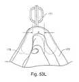
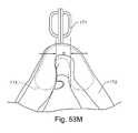
- FIGS. 53J-53Pillustrate yet another embodiment of the present invention in which the frame supports an inflatable cushion
- FIGS. 54A-54Care rear elevation, side elevation and bottom plan views, respectively, of a prior art ACLAIM cushion in exploded view;
- FIG. 54Dis a cross section of the prior art ACLAIM cushion of FIGS. 54A-54C ;
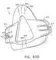
- FIGS. 55A-55Care rear elevation, bottom plan, and side elevation views, respectively, of a cushion assembly according to a first embodiment of the present invention
- FIG. 55Dis a cross section of the cushion assembly according to the first embodiment
- FIGS. 56A-56Fare rear elevation, top plan, bottom plan, side elevation, rear perspective, and front perspective views of a flexible element of the cushion assembly according to the first embodiment
- FIGS. 57A-57Care graphical illustrations of mechanical properties of the cushion assembly according to the first embodiment, a MIRAGE® cushion, and an ACLAIMTM cushion, respectively;
- FIG. 58is a cross section of a cushion assembly according to a second embodiment of the present invention.
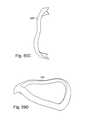
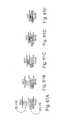
- FIGS. 59A-59Eare front elevation, rear elevation, side elevation, front perspective, and rear perspective views of a flexible element of the cushion assembly according to the second embodiment
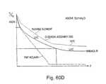
- FIGS. 60A-60Dare graphical illustrations of mechanical properties of the cushion assembly according to the second embodiment, a MIRAGE® cushion, an ACLAIMTM cushion, and a comparison of the mechanical properties of the three cushions, respectively;
- FIGS. 61A-Eare graphical representations of the operation of the cushion assemblies according to the first and second embodiments under a compressive force
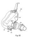
- FIG. 62is a perspective view of a cushion assembly according to a third embodiment of the present invention.
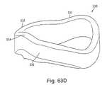
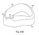
- FIGS. 63A-63Eare front elevation, rear elevation, side elevation, front perspective, and rear perspective views, respectively, of a flexible element of the cushion assembly according to the third embodiment
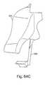
- FIGS. 64A-64Eare front elevation, rear elevation, side elevation, front perspective, and rear perspective views, respectively, of a retainer of the cushion assembly according to the third embodiment
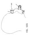
- FIG. 65is a cross section of a cushion assembly according to a fourth embodiment of the present invention.
- FIG. 66is a cross section of a cushion assembly according to a fifth embodiment of the present invention.
- FIG. 67is a cross section of a cushion assembly according to a sixth embodiment of the present invention.
- FIGS. 68 and 69illustrate an embodiment of the present invention in which the stiffness of the cushion can be selectively varied
- FIGS. 70-79illustrate further embodiments of cushions according to the present invention.
- FIG. 80illustrates a cross-sectional view of still another embodiment of the present invention.
- FIG. 81is a relaxation curve for a foam suitable for use as a flexible element according to all embodiments of the present invention.
- FIGS. 1-5show one embodiment of a mask system, including a mask assembly 15 and a headgear assembly 20 .
- the headgear assembly 20includes a plurality of straps that are configured and arranged so as to substantially surround the patient's head. These straps are connected to the mask assembly 15 to thereby retain the mask assembly 15 in relation to the patient's face.
- the mask assembly 15is shown merely as an example to demonstrate the application of the headgear assembly 20 .
- the mask assembly 15may be substituted by any suitable respiratory mask, as would be apparent to one of ordinary skill in the art.
- the headgear assembly 20utilizes a sagittal strap 25 and a horizontal strap 30 .
- the horizontal strap 30is arranged generally horizontally and is wrapped circumferentially around the patient's head. Each end 31 of each horizontal strap 30 is coupled to the mask assembly 15 . The arrangement between the horizontal strap 30 and the mask assembly 15 will be discussed in further detail below.
- the horizontal strap 30is preferably arranged to pass just inferiorly to each ear and across the insertion area of the neck muscles into the base of the skull which is generally indicated at 36 in FIG. 2 .
- a posterior end 40 of the sagittal strap 25is provided generally at a midpoint of the horizontal strap 30 so as to be positioned at an intermediate posterior area of the patient's head.
- the width of the sagittal strap 25 at the posterior area of the patient's headis relatively wide, e.g., about twice the width of the remaining portions of the sagittal strap 25 .
- This increase in surface areais advantageous as it helps to prevent the strap from sinking into a very fatty or compliant back portion of the patient's head as pressure changes, or as strap tension changes.
- the strap 25should not be so wide and/or thick that it becomes uncomfortable.
- the strapmay be made from a cool material, such as BREATHOPRENETM.
- the sagittal strap 25extends from the horizontal strap 30 , e.g., the posterior end 40 f , across the vertex of the skull generally indicated at 45 , and extends generally interiorly across a forehead of the patient's head, generally indicated at 50 (see FIG. 2 ).
- the sagittal strap 25has an anterior end 55 coupled to the mask assembly 15 , as will be discussed in further detail below.
- the headgear assembly 20may also be preferable for the headgear assembly 20 to include a pair of coronal straps 35 that interconnect the sagittal and horizontal straps 25 , 30 .
- a superior end 60 of each coronal strap 35is connected to the sagittal strap 25 proximate the vertex 45 of the patient's head
- Each coronal strap 35extends from the vertex 45 , e.g., the superior end 60 , laterally and inferiorly across the head and connects to the horizontal strap 30 just anteriorly to and just inferiorly to each ear at inferior ends 65 of the coronal straps 35 .
- Each inferior end 65 of the coronal straps 35may be connected to the horizontal strap 30 via stitching and/or an adhesive.
- the horizontal strap 30can be connected with both the coronal straps 35 and/or the sagittal strap 25 with one or more clip elements which will allow adjustability between one or more of the strap portions.
- one or more of the straps of the headgear assembly 20may be formed from a single piece of material.
- the straps of the headgear assembly 20are preferably formed to be substantially inextensible. Stated differently, the straps may be somewhat flexible, however, the straps are preferably not capable of significant elongation. The straps have sufficient stiffness or rigidity to retain their shape. Contemplative materials for the straps include polyvinylchloride (PVC), leather, polypropylene, or polyurethane. Other materials are, of course, possible. For example, another contemplated suitable material may be a relatively strong cloth tape. It is also contemplated that the straps may be lined with a felt material to add a degree of comfort to the patient. Other alterations may include perforations or holes to allow cooling through the straps.
- PVCpolyvinylchloride
- leatherleather
- polypropylenepolypropylene
- polyurethanepolyurethane
- Other materialsare, of course, possible.
- another contemplated suitable materialmay be a relatively strong cloth tape.
- the strapsmay be lined with a felt material to add
- the headgear assembly 20is coupled to the mask assembly 15 , preferably in a manner so as to allow adjustment of the position of the mask assembly 15 relative to the straps of the headgear assembly 20 .
- the mask assembly 15includes a frame assembly 70 , a cushion 75 to interface or make contact with the patient, and a cushion support 80 interposed between the frame assembly 70 and the cushion 75 .
- the cushion support 80includes an aperture (not shown) by which pressurized air is provided to a pressurized chamber of the mask assembly 70 , which is delivered to the airways of the patient.
- an elbow 85is releasably connected to the aperture of the cushion support 80 .
- the swivel elbowincludes a quick release connector 86 that is provided to an air delivery tube (not shown) which in turn is coupled to an air delivery device, e.g., a flow generator (not shown).
- the frame assembly 70includes a chassis 95 (best shown in FIG. 3 ) provided with one or more cross members 100 .
- the cross members 100support a cantilevered extension 90 which is coupled to the anterior end 55 of the sagittal strap 25 .
- the anterior end 55 of the sagittal strap 25is provided with a threaded portion 105 that is guided through a receiving aperture 91 provided on the extension 90 , as best shown in FIGS. 1 and 2 .
- a nut 110can be rotated about the threaded portion 105 to thereby adjust the distance between the extension 90 and the forehead 50 of the patient. Accordingly, the strap tension can be finely adjusted especially if the sagittal strap 25 is made of a substantially inextensible material, as described above.
- FIG. 3shows a front view of the mask assembly 10 .
- the chassis 95includes a plurality of finger portions 115 extending away from the chassis 95 .
- the lower most finger member 115 on each side of the chassis 95includes an aperture 120 configured to receive a threaded portion 105 extending from each end 31 of the horizontal strap 30 .
- a nut 110is threadedly secured to the threaded portion 105 so that the distance between the mask assembly 15 and the face of the patient can be finely tuned. Accordingly, the straps can be tightened to a high degree of accuracy so that the forces applied to the face are appropriate over a given pressure range, from about 2 to 40 cmH 2 O.
- the threaded portion 105has a substantially rectangular cross section, including two relatively flat sides and two sides having threaded sections.
- the apertures 91 and 120may have a shape that is relatively complimentary to the shape of the threaded portion 105 .
- the receiving apertures 91 , 120may have a substantially rectangular shape to thereby prevent rotation of the threaded portion 105 when adjusting the nuts 110 .
- the end of the threaded portion 105may also include an element, e.g., a member with a rectangular aperture, to help prevent rotation of the threaded portion 105 .
- FIG. 4shows a side view and more clearly shows the connection between each horizontal strap 30 and the frame assembly 70 .
- each of the finger portions 115is movably, e.g., pivotably, connected to transverse portions 96 , 97 of the chassis 95 .
- the top two finger portions 115are interconnected with a cross bar 125 while the bottom two finger members 115 are connected with a similar cross bar 130 .
- the top two finger members and the bottom two finger members, on each side of the chassis, respectivelycan move in unison, which may be advantageous from the perspective of force distribution.
- each of the finger memberscan be independently movable with respect to the transverse members 96 , 97 of the chassis 95 .
- the threaded portion 105 which extends from the end 31 of each horizontal strap 30is threaded through the receiving aperture 120 which is provided to the lower two finger portions 115 .
- any slack which is left in the horizontal strap 30will be taken up.
- any further tightening of the nut 110will cause the lower two finger portions 115 on the right hand side to rotate in a clockwise sense (as viewed from above) against the cushion support 80 .
- the lower two portions on the left hand sidewill rotate in a counter-clockwise sense, as viewed from above.
- the cushion support 80 in at least the lateral portions 82 adjacent the finger portions 115is flexible. Due to this flexibility, the lateral portions 82 impose a force on the corresponding section of the cushion 75 to thereby pinch against the sides of the nose of the patient.
- the cushion 75is integrated with the cushion support 80 is flexible or deformable, for example by the fingers 115 , in order to better fit the contours of the individual face.
- the cushion supportvery flexible to allow better fitting of the face, versus so extremely flexible that the internal volume of the mask changes excessively (e.g., >20 mL) with each breath, which would make measurement of tidal volume difficult.
- a typical silicone of 1-3 mm thicknessis suitable.
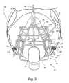
- FIG. 5shows a rear view of the mask assembly 15 in which the upper two finger portions 115 on the left side of the patient's face are manually pushed in against one of the lateral portions 82 of the cushion support 80 .
- the force which is applied from the upper two finger portions 115 to the lateral portion 82 of the cushion 80causes deformation of the cushion 75 such that it pinches against the side of the nose, thereby accommodating differently shaped noses and enhancing seal performance of the cushion 75 .
- tension in the strapsalong with flexibility of the lateral sides 82 of the support 80 , causes the fingers to rotate and pinch together thereby squeezing the sides of the nose and possibly a portion of the patient's face. Accordingly, any irregular face structures can be accommodated by the independent rotating capability. This also helps to evenly distribute the load on the face, thereby relieving areas of high contact force.
- FIG. 5shows the effect of increasing tension in the top strap (not shown), which results in pinching in the nasal bridge region of the patient. This is particularly useful for bi-level treatment so that at low pressures only low forces are applied and at high pressures high forces are applied, which is helpful for improved comfort and sealing.
- headgear made of an inelastic materialhelps prevent “pistoning” of the mask on the face, that is to say lifting off the face at high pressure, and/or digging into the face at low pressure during bi-level treatment.
- the two upper finger portions 115 provided on each transverse portion 96 , 97 of the chassis 95are not shown as being connected to any strap member of the headgear assembly 20 .
- the positioning of such upper strap portionsmay be as shown by the imaginary lines 135 , 140 in FIG. 2 .
- the imaginary line 135represents a situation where an upper strap portion would be connected to a midsection of the coronal strap 35 .
- Imaginary line 140represents a situation where an upper strap portion would be connected to the horizontal strap 30 on each side of the headgear.
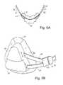
- FIGS. 5A and 5Bdepict an alternative embodiment of the present invention in which a horizontal strap 30 includes a first connector portion C 1 that is selectively coupled with a second connector portion C 2 .
- the second connector portion C 2is attached to a lower strap LS and an upper strap US.
- the upper and lower straps LS, USmay be tightened to the point where they bear against the transverse portions 82 of the frame 70 , thereby imparting an inward force on the cushion 75 to seal laterally against the sides of the patient's nose.
- the upper and lower straps LS, UScan be adjustably fixed to the frame 70 (as indicated by the arrows) to best position the area where the inward force will be applied.
- the lateral portions 82 of the support 80are made of flexible material, while the apex is more rigid.
- FIGS. 5C-5Hillustrate yet another embodiment of the present invention in which an adjustment mechanism allows coarse and fine adjustment of the head strap tension
- FIG. 5Cshows the overall mask assembly, including a mask frame 800 and which is provided with an elbow 805 including an anti-asphyxia valve 810 .
- a quick release clamp 815is provided to allow the patient to quickly remove the headgear, as described in U.S. patent application Ser. No. 10/235,846, filed Sep. 6, 2002, incorporated herein by reference in its entirety.
- FIG. 5Dshows the quick release mechanism in a partially opened position
- FIG. 5Eshows the quick release mechanism fully opened.
- a strap 820includes a pair of strap ends 820 A, 820 B provided to hold the mask assembly on the patient's head.
- One of the strap ends, e.g., 820 Bmay be releasably connected, e.g., via a slot 821 , to one end of the mask frame in a fixed position, thereby avoiding variation in length of the strap 820 which could occur with repeated removal and re-placing of the mask assembly.
- the other strap 820 Ais positioned and configured to be adjustable. Of course, both ends of the strap 820 may be adjustable.
- the strap end 820 Bmay be looped through the slot 821 by creating a loop in the strap 820 that is fixed, e.g., via a rivet 822 or other fastener.
- An adjustment assembly 825may be provided to adjust the strap 820 .
- the adjustment assembly 825may include a generally rectangular prism 830 having a strap-receiving slot 835 through its entire length.
- the slothas an opening 840 shown in the end face of the prism.
- the prismhas an upper portion 836 , a lower portion 837 and a threaded screw 845 , best shown in FIG. 5G .
- the upper and lower portions 836 , 837can assume a first position, adapted for coarse adjustment of the strap length, in which the strap end 820 A can be pulled through the length of the slot 835 .
- the upper and lower portions 836 , 837are brought together so that the threaded screw 845 engages with the strap end 820 A, preventing its movement through the slot 835 .
- the screw 845upon rotation, translates the strap end 820 A to tighten or loosen the headgear.
- the upper and lower portions 836 , 837translate via a slot and pin arrangement 841 , 842 , to enable the screw 845 to move into and out of engagement with the slot 835 .
- the threaded screw 845has one end extending beyond the length of the prism 835 having a first gear portion 850 . As shown in FIG.
- the first gear portion 850in turn engages with a second gear portion 855 at right angles thereto.
- the second gear portion 855has a cylindrical knob 860 attached to it. By rotating the cylindrical knob 860 , the second gear portion 855 rotates, driving the first gear portion 850 and therefore the screw 845 . Depending on the direction of rotation, the strap is either pulled or pushed through the slot, thus enabling fine adjustment of strap length.
- the headgear assembly 20is illustrated as including a particular form of bladder which shall be referred to as a “raviolus” 145 provided along, e.g., the sagittal strap 25 of the headgear assembly 20 .
- the raviolus 145is provided to apply a relatively constant strap force against the patient's face over an entire range of mask pressures.
- the raviolus 145is an active component that does pneumatic work to pull the mask onto the face at higher pressure.
- the raviolus 145is in communication with pressure in the mask via a small diameter silicone tube 150 attached to a port either on or in close proximity to the mask assembly 15 .
- the tube 150is provided to the elbow 85 .
- Tension in the sagittal strap 25is at least partially driven by flow generator pressure via the raviolus 145 , which causes greater strap tension/displacement at higher pressures and less strap tension/displacement at lower pressures.
- raviolus 145is shown as the preferred embodiment, variation in strap tension/displacement can be achieved by other mechanisms, including electrical and mechanical systems. As the mask pressure rises, the raviolus pressure rises, causing the raviolus to inflate to a more spherical shape, shortening it anteroposteriorly and therefore pulling posteriorly on cantilever 90 , thereby pressing the mask more firmly against the face.
- the posteriorly directed force generated by the raviolus or cantilever 90is linear on mask pressure.
- the constant of proportionalityis greater as nut 110 is tightened, causing the raviolus to be more elongated at any given mask pressure.
- the raviolus 145can be considered an automatic compensating mechanism which if set so that the mask seals at one pressure it will seal at all pressures and it will constantly balance the air pressure in the mask.
- the raviolus 145is only provided on the top strap, others could also be provided on the remaining straps, including the horizontal straps 30 .
- no raviolus 145is applied to the lower straps in this embodiment since the natural tendency of the patient's cheeks and bottom lip to billow somewhat approximates the action of the raviolus 145 to create a good seal in that area over the range of operating pressures.
- the sealing mechanism for the top of the mask and the sealing mechanism for the bottom of the maskare different.
- the mask designercan rely on the bottom lip and cheeks of the patient to inflate whereas at the top of the mask a different mechanism is used because in part, the facial structure of the nasal bridge region is very bony and rigid.
- FIGS. 6-15Adescribe more specific principles of the raviolus in detail.
- the raviolus 145may be a rectangular thin walled tube of elastomer such as silicone, pleated along two sides 147 , and then sealed at the non-pleated ends 150 .
- the non-pleated sealed ends 150are inserted into a headstrap of the mask assembly 15 , e.g., the sagittal strap 25 .
- FIGS. 6 and 7show the raviolus 145 in a relaxed state, with little or no pressure, e.g., during expiration of the patient, while FIGS. 8 and 9 show the raviolus 145 under treatment pressure, e.g., during inspiration of the patient.
- the raviolus 145is assumed to be floppy in the longitudinal direction and stiff transversely, so that it maintains the above flat topped cross section at all pressures. This could be achieved in manufacture, for example, by gluing rigid rods transversely to the top and bottom surfaces, or moulding the top and bottom surfaces to have transverse ridges, and/or by using internal tie wires between the right and left concertina walls. In practice, the basic idea and the following discussion works to a loose approximation without these refinements.
- the raviolus 145has a width W and an inflated height 2 h .
- the concertina sidesare assumed to exert negligible force and are not included in the calculations.
- the force in the strapis f.
- the raviolus 145is sliced in half transversely, and a pair of rigid plates, one of which is shown above as reference number 155 , are attached to the cut line. The two plates are connected by a rigid rod 160 .
- the force in the rigid rod 160is also f.
- the cross section of the top or bottom surfaceis an arc of a circle, radius r, and subtending an angle 2 ⁇ at the center of the circle.
- Table 1was plotted using the above equations.
- Column 2 of Table 1shows the length “x” of the raviolus (see FIG. 11 ), as a fraction of the resting length L, for various angles ⁇ .
- Column 3shows the force “f” generated (see FIG. 10 ) as a fraction of the product of pressure p, width W, and resting length L.
- FIG. 13plots the force f (as a fraction of pLW) against the length x (as a fraction of the resting length L).
- a practical raviolusmight have:
- the force generatedis proportional to the resting length and breadth of the raviolus.
- a 6 cm long by 5 cm wide raviolus connected to 20 cmH 2 Ogenerates about 0.633 KgF when it is shortened by 0.5 cm, 0.300 KaF when it is shortened by 1.0 cm, and 138 grams force when it is shortened by 1.5 cm.
- the mask assembly 15is held onto the face at three points by two straps 25 , 30 . Take the mask assembly 15 to be an isosceles triangle of base 12 cm and height 12 cm, less two small triangles in the bottom corners of height 2 cm and base 2 cm. Thus the area of the mask is 70 cm 2 .
- centroid Cis about 4.5 cm up from the bottom of the mask, or 7.5 cm down from the top; 2) the bottom strap is attached around 3.5 cm up from the bottom of the mask, or 1 cm below the centroid; and 3) the top strap attaches to a long lever arm some 15 cm above the centroid.
- the bottom strapattaches about 15 times closer to the centroid than the top strap, the bottom straps take 15/16 of the load, leaving only 100 grams to be borne by the top strap.
- the raviolus 145is in series with a stretchy headgear strap of elastance E STRAP .
- the free ends of the stretchy strap and raviolusare fixed.
- the elastance of the total systemwill be the elastance of the headgear plus the elastance of the raviolus.
- the spring constant of the raviolus under these conditionsis 0.232 KgF/cm, so its elastance is 4.3 cm/Kg. Therefore total system has a (local) elastance of 14.3 cm/Kg. The elastance of the entire system is dominated by the traditional strap.
- FIG. 15CPlotting this on the graph for force generated by the raviolus at 20 cmH 2 O and 5 cmH 2 O, we obtain FIG. 15C .
- the headgearwill shrink, causing the raviolus to lengthen from 4.35 cm to about 4.8 cm, and instead of the tension in the strap reducing from 0.1 Kg to 0.05 Kg as desired, it will decrease to only about 0.55 Kg.
- FIGS. 16-35illustrate another embodiment of the present invention.
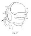
- a mask and headgear assemblyis shown in FIGS. 16-8 as installed on a model of a head.
- the mask and headgear assembly 410comprises a mask assembly 412 , headgear 414 , and an inflatable bladder which takes the form of an occipital pneumatic pillow 416 coupled to the headgear 414 to adjust the fit of the headgear 414 .
- the mask assembly 412includes a mask body assembly 418 and a mask frame 436 (which will be described in more detail below) that acts as a support or “skeleton” for the mask body assembly.
- the mask body assembly 418has a generally triangular shape when viewed from the front, as shown in FIG. 27 .
- the mask body assembly 418comprises a face-contacting portion 420 and a body portion 422 .
- the face-contacting portion 420 of the mask body assembly 418is to provide a detailed fit without causing pain, discomfort or skin damage.
- the face-contacting portion 420is designed to provide a seal around the bony parts of the nose.
- no portion of the face-contacting portion 420exerts an average pressure on the face that is greater than the average facial capillary blood pressure (typically about 25 mm Hg).
- the face-contacting portion 420is contoured to pinch the sides of the nasal bone (above the nasal cartilage) and at the level of the inner canthus.
- the face-contacting portion 420forms an inwardly-facing seal at the sides of the nasal bone.
- the face-contacting portion 420is designed not to pinch the wings of the nose, either directly by pressing on the cartilages, or indirectly by pressing on soft tissues nearby.
- it is preferable that the face-contacting portion 420not contact the eye, lashes, or tear duct mechanism at the inner canthus of the eye.
- the face-contacting portion 420 of the mask body assembly 418includes several major contoured features, which can be seen in the views of FIGS. 27-31 .
- a notch 424is provided to accommodate the bridge of the nose (nasion).
- a rise 426is provided to fit the frontal process of the maxilla bone.
- a second notch 428is provided to accommodate the cheek bone (i.e., maxillary process of the zygomatic bone).
- a second rise 430is provided to fit the jowl, and a third notch 431 is provided to accommodate the mandibular arch.
- the face-contacting portion 420is constructed of a polyurethane foam covered by a silicone “skin” or sheet. It is preferable if the silicone material is the softest (i.e., lowest durometer value) material that can be made without a tacky or peeling character. Typically, the silicone skin would be adhesively bonded to the foam to prevent wrinkling of the skin relative to the foam.
- the body portion 422 of the mask body assembly 418supports the elbow 430 , anti-asphyxia valve, and vent. It permits relatively free distortion or bending of the mask body assembly 418 relative to the frame 436 of the mask assembly 412 , and also acts as a locating and constraining mechanism to prevent the frame 436 from sliding out of place.
- the mask body assembly 418is shown in the plan view of FIG. 33A and in cross-section in FIG. 33B .
- the body portion 422is silicone, is co-molded with the face-contacting portion 420 , and is contiguous with the face-contacting portion 422 .
- the mask assembly 412includes a pressure plate or frame 436 which transmits the forces from the headgear to the cushion.
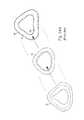
- the frame 436is generally triangular in shape and comprises a base 438 , side 440 and apex portions 442 .
- the frame 436is resiliently flexible, allowing the frame 436 to wrap around the jaw and nose of a patient.
- the base 438 and apex 442 portions of the frame 436are generally constructed so as to be more flexible than the comparatively rigid side portions 440 .
- the apex and base portions 442 , 438define a longitudinal axis L about which the frame 436 can resiliently flex, as shown in FIGS. 32 and 35 .
- the resilient flexibility of the frame 436allows the mask assembly 412 to more precisely fit a wider range of facial shapes.
- the same mask assembly 412could be used on patients with a narrow angular face (the so-called crocodile shape) as those with a wider flatter face (the so-called panda shape).
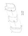
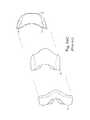
- the base portion 438 of the frame 436is generally “C” or crescent shaped.
- the apex portion 442is generally boomerang or chevron shaped.
- the flexible apex 442 and base 438 portionsmay be constructed from 1 mm polypropylene sheet approximately 2 cm wide.
- Each side portion 440can be constructed from a pair of similarly shaped pieces of aluminum 100 mm ⁇ 20 mm ⁇ 1 mm.
- the fame 436can be riveted together with 4 rivets, or joined by another known technique, such as adhesive bonding.
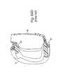
- the frame 436which is shown in isolation in the view of FIG. 32 , includes a forked bracket 444 mounted on each side portion 440 .
- Each bracket 444is constructed of aluminum or another substantially rigid material.
- There are a series of holes 446 along the length of the side portions 440which are adapted to receive a bolt to thereby secure the bracket 444 .
- the angle of the bracket 444 with respect to the side portion 440is adjustable by loosening the bolt, adjusting the angle, and tightening the bolt.
- the position of the bracket 444 along the side portioncan be adjusted by securing within a different hole.
- Both brackets 444need not be mounted in the same relative position along the side portions 440 . In this way, some allowance can be made for any asymmetry in a patient's face.
- One bracket 444is secured to each side portion.
- the bracket 444is adapted to receive and engage the nut 448 of the threaded arm 450 of the headgear 414 .
- the frame 436may include a wedge shaped spacer.
- the spaceris operatively secured between the side 440 and/or apex 442 portions and the face-contacting portion 420 of the mask body assembly 418 .
- the spaceris 1-2 cm thick at the top tapering to zero about half way down the mask.
- the wedgetapers to zero thickness from outside to inside.
- the wedgeis constructed from a generally incompressible material. The wedge provides additional force to the top of the mask body assembly 418 to assist in sealing.
- the wedgepinches the mask body assembly 418 at the sides of the nasal bones, pressing harder on the outside edge of the mask body assembly 418 than on the inside.
- the headgear 414comprises a strap assembly 452 , the occipital pneumatic pillow 416 , or other active adjustable tensioning element, and the pair of threaded arms 450 that connect with the mask assembly 412 .
- the headgear 414is constructed and arranged so that the force vector from the mask assembly 412 to headgear 414 which originates at the pneumatic center of the mask assembly 412 should pass through a point midway between the right and left external auditory meatus.
- the strap assembly 452comprises a sub-occipital strap 456 , a coronal (crown) strap 458 , and a pair of ear pieces 460 .
- the straps 456 , 458 , 460are ends of a single-piece headgear assembly, but in other embodiments of the invention, they may be unitary straps, optionally connected together at appropriate points.
- the straps 456 , 458 , 460may be constructed from a flexible but generally inextensible plastic material, such as 1 mm polypropylene sheet, optionally covered on one or both sides with layers of foam, felt, or other cushioning material to increase comfort. Because they are formed of a flexible but inextensible material, the straps 56 , 58 , 60 can conform to the shape of a patient's head, but they would not generally extend more than 1-2 mm when subject to 2 KgF tension.
- the sub-occipital strap 456passes under the occiput but above the nuchal muscles and is approximately 4 cm in width.
- the crown strap 458passes over the crown of the patient's head and is approximately 2 cm in width.
- the ear pieces 460may be constructed so as to partially or fully surround the ears.
- the ear pieces 460may be constructed from an elliptical annulus of plastic material, generally 2 cm in width, and lined with skin contact grade felt, which should slightly overlap the annulus to prevent cutting into the root of an ear.
- a pair of rigid threaded arms 450extend from the ear pieces 460 .
- Theyare constructed from 5 mm threaded nylon rod.
- the arms 450are arranged such that they are operationally proximate to the external auditory meatus and extend forwardly thereof in an approximately horizontal plane.
- Each nut or thumb-wheel 468is adapted to releasably engage with the brackets 444 mounted on the mask frame 436 , as shown in FIGS. 16, 17, 19 AND 20 .
- the arms 450are connected to the ear pieces 460 of the headgear 414 by a pivoting connector 470 , as shown in FIGS. 19, 23 and 24 .
- the inflatable occipital pneumatic pillow 416is in force-transmitting relationship with the straps 456 , 458 , 460 and is operationally positioned under the strap assembly 452 and at the rear of the head, generally in the region of the occiput.
- the occipital pneumatic pillow 416can be inflated and deflated.
- the occipital pneumatic pillow 416is connected to an air delivery conduit 462 of the mask assembly 412 via a tube 464 . In this way, the pressure in the occipital pneumatic pillow 416 is similar to the pressure in the mask assembly 412 .
- the occipital pneumatic pillow 416When mask assembly 412 pressure increases, the occipital pneumatic pillow 416 is inflated, which results in a concurrent increase in headgear 414 tension and prevents the mask assembly 412 from lifting off the face and leaking. In this way movement of the mask assembly 412 during different mask pressures is dampened.
- the occipital pneumatic pillow 416is designed to have sufficient area (A bladder ) so that in conjunction with the pressure of air in the occipital pneumatic pillow 416 (P bladder ), it will counterbalance the force on the headgear straps 456 , 458 , 460 (i.e., the force on the straps 456 , 458 , 460 caused by the pressure in the mask assembly 412 ).
- the area of the occipital pneumatic pillow 416should be sufficiently large so as to provide a force which exceeds the force caused by the mask, which is a product of the mask projected area (A mask ) and the mask pressure (P mask ).
- a bladder ⁇ P bladder⁇ Forces applied to straps
- the occipital pneumatic pillow 416is approximately 11 cm ⁇ 16 cm and has wall thicknesses in the range of about 15 mm to about 2.5 mm, with an overall deflated thickness of 3-5 mm.
- the pressure in the occipital pneumatic pillow 416increases when the mask pressure increases.
- the inflation and deflation of the occipital pneumatic pillow 416could be controlled by parameters other than mask pressure.
- a sensorcould monitor leak in the mask assembly 412 , e.g., by continuously monitoring flow in the flow generator connected to the mask assembly 412 and low-pass filtering to find the leak component of the flow. When leak is determined to be high, the occipital pneumatic pillow 416 would be caused to inflate. Conversely, when leak is determined to be low, the occipital pneumatic pillow 416 would be allowed to deflate.
- Controlling the occipital pneumatic pillow 416 pressure using a leak detection sensorwould allow the headgear 414 to be maintained at the minimum amount of tension that would allow the mask assembly 412 to remain sealed against the face, and would help to reduce the user discomfort, skin damage, and other problems inherent in over tensioning the headgear 414 .
- occipital pneumatic pillow 416it may be desirable to use more than one occipital pneumatic pillow 416 in the headgear 414 . If more than one occipital pneumatic pillow 416 is used, the occipital pneumatic pillows 416 could be placed in several locations around the headgear 414 . Moreover, each of the multiple occipital pneumatic pillows 416 could be inflated and deflated independently of the others. That type of arrangement would make it easier to compensate for asymmetries in the patient's face, because tension could be applied in the headgear 414 locally and only where needed.
- Multiple occipital pneumatic pillows 416may be caused to inflate and deflate as pressure in the mask assembly 412 increases and decreases, respectively, or they may be caused to inflate and deflate by a sensing and control system, based on measurements of leak flow.
- shape memory alloy (SMA) wiressuch as MUSCLE WIRES® (Mondo-Tronics, Inc., San Rafael, Calif., USA), which contract when electric current is applied, may be used as active tensioning elements.
- SMAshape memory alloy
- Suitable active tensioning elementsinclude servo motors and “artificial muscles” created from biomimetic materials.
- the inflating of the occipital pneumatic pillow with a pressure which is an affine function of mask pressurecomprises: measuring mask pressure with a pressure transducer, to produce a signal proportional to mask pressure; applying the signal to an amplifier with adjustable gain an offset; applying the output of the amplifier to a voltage controllable pressure source; inflating the occipital pneumatic pillow with gas from said pressure source; adjusting the offset so that the mask seals at the lowest required pressure; and adjusting the gain so that the mask seals at the highest required pressure.
- the projection in the posterior direction of the contact area of the mask with the faceis A mask
- the projection in the anterior direction of the area of contact of the straps with the posterior surface of the occipital pneumatic pillowis A bladder
- the force required to produce a seal at zero pressureis F 0
- inflating the occipital pneumatic pillow with a pressure which is an affine function of mask pressuremay comprise: connecting the mask via a first hose to a first cylinder containing a first piston, the first piston in turn being connected via a linkage to a second piston in a second cylinder, the second cylinder being connected via a second hose to the occipital pneumatic pillow; and biasing said linkage so as to inflate the occipital pneumatic pillow sufficiently to cause the mask to seal at the lowest intended usage pressure.
- biasmay be provided by a spring and/or a weight.
- An apparatus for holding a mask sealingly against a patient's facemay include a first set of extensible straps, passing from the back of the head forwards to the mask, the straps being tightened sufficiently to hold said mask sealingly against the face at the lowest intended usage pressure; a second set of inextensible straps, again passing from the back of the head forwards to the mask, and lying over the first set; and an inflatable occipital pneumatic pillow placed at the back of the head, between the first and second set of straps, said occipital pneumatic pillow being in pneumatic communication with the air in the mask.
- the first, extensible set of strapsprovides a fixed, constant force, independent of mask pressure
- the occipital pneumatic pillowacting via the second set of straps, provides a force which is a linear function of mask pressure.
- the two forcesadd together, to provide a force which is an affine function of mask pressure.
- the optimum arrangementwill be approximately when the anterior projection of the smaller of the area of contact by the occipital pneumatic pillow onto the back of the head and the area of contact of the occipital pneumatic pillow onto the second set of straps is the same as the posterior projection of the area of contact of the mask on the face.
- an apparatus for holding a mask sealingly against a patient's facemay include a set of rigid straps, passing from the back of the head forwards to the mask, a semi-rigid, springy occipital pneumatic pillow placed between said straps and the back of the head, the occipital pneumatic pillow having a non-zero internal separation between the anterior and posterior walls at atmospheric internal pressure; and a hose connecting the occipital pneumatic pillow to the mask.
- the occipital pneumatic pillowmay be conveniently constructed of an elastomeric material such as silicone, latex, or polyurethane. Its springiness may be adjusted by filling it with a springy material such as a foam of silicone, latex, polyurethane, and/or PVC, or with one or more internal or external springs.
- a comfortable internal springcan be created from a second, sealed air and/or fluid-filled elastomeric inner occipital pneumatic pillow, smaller than the outer occipital pneumatic pillow.
- the antero-posterior separation between the anterior and posterior walls of the occipital pneumatic pillow at atmospheric internal pressureshould be about 2-4 cm, for preference 3 cm, to allow a reasonable range of neck movement without overly increasing or decreasing the strap force, and to allow for a considerable compression of the structures on the back of the head (hair, skin, fat, muscle), and of the mask cushion and facial tissues, as the mask pressure increases.
- the combined stiffness of the occipital pneumatic pillow walls and any foam filling or springsshould for preference be such that it produces a force sufficient to cause the mask to seal at all intended pressures when the straps are tightened to about mid-travel, or about 1.5 centimeters below the untensioned length.
- the forcewill be of the order of 200-600 g, depending on the characteristics and fit of the mask.
- the mask cushion and the tissues at the back of the headwill be compressed. This will cause the occipital pneumatic pillow to expand. Since the occipital pneumatic pillow is preferably intentionally stiff, and has been compressed by tightening the straps below their loose length in order to provide the force F 0 required to seal at arbitrary low pressures, the springiness of the occipital pneumatic pillow will provide less and less force as the occipital pneumatic pillow expands. This loss of the initial spring recoil force should be compensated by using a occipital pneumatic pillow with an area A bladder which is suitably greater than the area of the mask A mask .
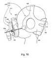
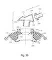
- FIG. 36represents an embodiment of the present invention including a frame 170 which is provided with a patient interface in the form of a cushion 172 .
- the frame 170is supported on the head of the patient using a plurality of straps 180 , which may be made of substantially inextensible material as described above.
- Each strap 180may include a threaded portion at an end thereof that is adapted to receive a nut 185 so that the patient can adjust the tension in the straps.
- a warping strap 175made of substantially rigid material is provided to the frame 170 .
- An adjustment mechanism 176is provided for additional adjustability of the frame 170 .
- the adjustment mechanism 176includes an adjustment screw 190 which can be rotated to effect translating movement of a wedge 195 .
- the wedge 195can be moved along an imaginary axis 196 that is aligned with the upper most head strap 180 provided at the apex of the frame 170 .
- Rotation of the adjustment screw 190causes movement of the wedge 195 against the inside surface of the warping strap 175 .
- the wedge 195may be provided to engage the outer surface of the warping strap 175 .
- the top surface 197 of the wedge 195is forced against the inside or outside surface of the warping strap 175 , which causes the frame to bend about an axis which is substantially parallel to or coincident with the imaginary axis 196 .
- This bendingcauses the lateral portions of the fame 170 to push against the sides of the cushion 172 , thereby imposing a pinching force on the sides of the patients nose.
- the provision of adjustability in the lower part of the frame 170allows the mask to more readily adapt to different types of nose features.
- the adjustabilitycould be provided along the top or middle portions of the frame as well.
- the adjustabilityallows for the patient to set the desired contacting force for a given pressure, and the frame may flex, pivot or bend to accommodate changes in pressure so that the force applied to the face is substantially constant.
- FIG. 37illustrates an embodiment similar to the embodiment of FIG. 36 , but includes additional features.
- FIG. 37discloses an aperture 200 which is surrounded by a ring shape member, e.g., a ferrous ring 210 .
- the aperture 200is adapted to receive a connector 215 which is similar to an elbow.
- the connector 215includes a first ferrous ring 220 which is adapted to magnetically couple with the ferrous ring 210 of the frame 170 .
- the connector 215includes a second ferrous ring 225 which is adapted to magnetically couple with a swivel member 230 via a magnetic ring 235 provided in the swivel 230 .
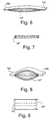
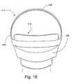
- FIG. 38shows more details on the construction of the cushion.
- the cushion 172includes a base member 240 , e.g., foam, provided to the inside of the fame 170 and a membrane 245 , e.g., silicone, that is supported by the base portion 240 .
- a base member 240e.g., foam
- a membrane 245e.g., silicone
- the distance between the top surface 197 of the wedge 195 and the inside surface of the warping strap 175is exaggerated so as to more easily view the individual components.
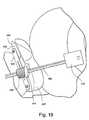
- FIG. 39shows a detailed view of the adjustment screw 190 , the wedge 195 and the frame 170 .
- the adjustment screw 190includes a threaded portion 250 and a disc portion 255 provided at the opposite end of a knob 260 of the adjustment screw 190 .
- the frame 170includes a cross slot 260 adapted to receive the disc 255 .
- the frame 170has a longitudinal slot 265 adapted to receive the threaded portion 250 of the adjustment screw 190 .
- the frame 170includes an additional frontal slot 270 to receive a lower body portion 275 of the wedge 195 .
- the frame 170includes an extension 271 having an upright member 272 that is spaced away from the bottom edge 273 of the frame 170 .
- the upright member 272includes a bearing 274 , which may be threaded.
- the wedge 195includes a groove 280 which engages with inside wall members 285 which define the longitudinal slot 265 .
- the wedge 195includes a partially threaded portion 290 .
- the partially threaded portion 290is adapted to engage with the threaded portion 250 .
- the threaded portion 250 and the disc 255are inserted into the longitudinal slot 265 and the lateral slot 260 , respectively.
- the partially threaded portion 290 of the wedge 195is then dropped on top of the threaded portion 250 , with the body portion 275 initially positioned between the upright member 272 and the end of the inside wall members 285 adjacent the bottom end 273 of the frame 170 .
- the groove 280is guided to slide along wall members 285 . Accordingly, upon rotation of knob 260 , the wedge 195 will move back and forth within the channel 295 of frame 170 .
- the extreme positions of the wedge 195are shown in FIGS. 40A and 40B , respectively.
- FIGS. 41 through 53illustrate additional embodiments which allow pinching along the lateral sides of the patient's face/nose. Similar parts have been designated with like reference numbers as compared to the embodiments of FIGS. 36 through 40B . Each of these embodiments allows for more control over adjustment and adapts more readily to variations in physiognomy between patient's with differently shaped noses.
- knob 190is operatively coupled to one and preferably a pair of racks 191 which move in opposite directions upon rotation of knob 190 .
- the distal ends 193 of the racks 191engage with lateral portions of the frame, e.g., the frame includes cammed surface which progressively increase in thickness as the distal ends 193 are moved laterally outwards, to allow bending, flexing and/or pivoting of the frame about an imaginary vertical axis, to thereby enhance pinching against the sides of the patient's face/nose.
- each knob 190is operatively connected with a portion 197 which is provided to the cushion 172 .
- the frame 170is semi-rigid while the cushion 172 is mounted to a flexible member 300 .
- the spring action of member 300 on the cushionwill help in the sealing against the sides of the patient's nose.
- frame 170may be a relatively stiff spring, compared to the stiffness of flexible member 300 . Therefore, a patient with a crocodile type face may rely on stiffness of flexible member 300 , and patients with a panda-like face may rely on the flexible member 300 lying flat against frame 170 which is flexible, but relatively stiffer than the flexible member 300 .
- This embodimentis not shown to include an adjustment knob, but could be adapted as such.
- rotation of adjustment screws 190cause a cam shaped surface 194 of the screw to engage protrusions 196 on the cushion support, thereby pinching the cushion inwardly towards the patient's nose.
- FIGS. 45, 46A and 46Billustrate yet another embodiment of the invention whereby the frame includes side wing portions 305 which can pivot with respect to the frame 170 .
- this embodimentis similar to the embodiment shown in FIG. 1 in which the finger portions 115 are provided to pivot with respect to the chassis 95 .
- FIG. 46Ais an exploded view of the embodiment of FIG. 45
- FIG. 46Bis an assembled view of the embodiment of FIG. 45 .
- This embodimentlike other embodiments, allows the sides of the cushion to more readily conform to various patient's having differently shaped noses.
- This embodimentalso automatically conforms to the face shape since the straps 180 are connected to each side wing portion 305 of the frame 170 . Lift off of the mask/cushion from the cheeks is reduced, and a more even pressure of the cushion on the face can be achieved.
- This embodimentlike many of the other embodiments described above also allows for a replaceable or disposable cushion.
- FIGS. 45A and 45Bshow yet another embodiment, similar to the embodiment of FIG. 45 , in which the side wing positions 305 can be hingedly connected in a number of predetermined positions, by clicking or detenting action.
- FIG. 45Bshows a partially exploded view including a tongue 306 provided between two hinge portions on the side wing portion 305 .
- the frame 170includes a plurality of grooves 307 adapted to receive the tongue 306 , to thereby allow adjustability in a plurality of discrete positions.
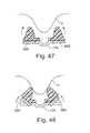
- FIGS. 47 and 48show the progressive sealing positioning of side wing portions 305 on the nose N of a patient, as the tension in the straps is increased.
- FIGS. 49 and 50illustrate yet another embodiment of an adjustment mechanism which allows the side wing portions to move, e.g., pivot, with respect to the chassis or central fame of the mask assembly.
- the adjustment mechanismincludes a plurality of holes 312 which can receive a pin provided on a flange 313 of the side wing portion 305 .
- the hinge 311could be a living hinge, a pin, an integral pin, etc.
- FIG. 51is an exploded perspective view of a mask assembly 510 according to another embodiment of the invention.
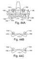
- the mask assembly 510has two major portions, a semi-rigid mask chassis 512 and a cushion/secondary frame 514 .
- the two portions 512 , 514are separable, but may be releasably or fixedly connected, as described above.
- the mask chassis 512is constructed and arranged to connect to mask headgear (not shown in FIG. 51 ), and the cushion/secondary frame 514 is constructed and adapted to make a comfortable seal with a patient's face.
- the mask chassis 512 and the cushion/secondary frame 514have structures that cooperate to cause the cushion/secondary frame 514 to move or deform relative to the mask chassis 512 so as to provide small adjustments in the fit of the mask assembly 510 to the user's face.
- the cushion/secondary frame 514comprises a cushion portion 516 and a secondary frame portion 518 .
- the two portions 516 , 518are fixedly connected.
- the cushion/secondary frame 514may be sized to act as a mouth mask, nose mask, mouth-and-nose mask, or any other type of mask that is compatible with the user's treatment protocol.
- the secondary frame portion 518is triangularly or pyramidally shaped and provides sufficient interior volume to accommodate the facial features over which the cushion/secondary frame 514 is designed to make a seal (e.g., nose, nose and mouth, etc.).
- the secondary frame portion 518is open on two sides. On the outward side of the secondary frame portion 518 , a connector 520 is provided to connect to a gas supply conduit. On the inward side, the secondary frame portion 518 is open and flares into a flange 522 , to which the cushion portion 516 is connected.
- the secondary frame portion 518may be made of a flexible or semi-flexible material, e.g., polypropylene.
- the cushion portion 516is a generally soft and conforming structure that may be, for example, a silicone membrane, foamed material (such as polyurethane foam) encapsulated within a plastic membrane, or a sealed, deformable compartment filled with air or another gas. It may be molded to (i.e., fused to) the secondary frame portion 18 , fixed using adhesives, or secured with appropriate connecting structures.
- a silicone membranefoamed material (such as polyurethane foam) encapsulated within a plastic membrane, or a sealed, deformable compartment filled with air or another gas. It may be molded to (i.e., fused to) the secondary frame portion 18 , fixed using adhesives, or secured with appropriate connecting structures.
- the secondary frame portion 518also includes structures constructed and arranged to connect the cushion/secondary frame 514 to the mask chassis 512 .
- At the top and bottom of the secondary fame portion on its patient-outward surfaceare connecting members 524 that are adapted to be inserted into corresponding receiving holes 526 in the mask chassis 512 to secure the cushion/secondary frame 514 to the mask chassis 512 .
- Connecting members 524are constructed and arranged to deflect inwardly on insertion into the receiving holes 526 to provide a snap fit between the cushion/secondary frame 514 and mask chassis 512 .
- connecting members 524are shown in FIG. 51 , the connection between the cushion/secondary frame 514 and the mask chassis 512 may be any other type of suitable connector.
- the secondary frame portion 518also includes projections 528 with surfaces that cooperate with adjustment wheels 530 in a manner that will be described below.
- the mask chassis 512is a generally triangular contoured plate of semi-rigid material, which may be co-molded with the cushion/secondary frame 514 .
- the mask chassis 512provides connecting receptacles 532 for corresponding ends of the mask headgear 534 .
- two connecting receptacles 532are provided, one at each of the left and right edges of the mask chassis 512 .
- any number of connecting receptacles 532may be provided, disposed about the mask chassis 512 as required, depending on the number and position of the headgear straps or strap ends.
- the connecting receptacles 532 and mask headgear 534are illustrated as having releasable snap-fit connections.
- the connecting receptacles 532may be any type of conventional connecting structure.
- the top edge 540 of the mask chassis 512generally includes connecting structure for connecting to a sagittal strap or strap portion of the mask headgear.
- the connecting structure at the top edge 540may be a connecting receptacle 532 or another connecting structure.
- the mask chassis 512includes a central aperture 536 that is constructed and sized to receive the raised, central portion 518 of the cushion/secondary frame 514 , such that the connector 520 may be connected to an appropriate conduit for gas delivery through the central aperture 536 of the mask chassis 512 .
- Adjacent to the central aperture 536 on the left and right sides of the mask chassis 512are adjustment wheel retaining portions 542 .
- the positions of the adjustment wheel retaining portions 542generally correspond to those of the projections 528 on the cushion/secondary frame 514 .
- Each adjustment wheel retaining portion 542is raised relative to the surrounding surface of the mask chassis 512 and includes a hole, e.g., threaded hole 544 .
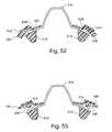
- FIGS. 52 and 53are schematic cross-sectional views of a portion of the connected mask chassis 512 and cushion/secondary frame 514 in an engaged position, showing an adjustment wheel 530 installed in an adjustment wheel retaining portion 542 and engaging a projection 528 on the secondary frame 518 .
- the adjustment wheel 530comprises a threaded rod or rivet 546 , one end of which is secured into a user-turnable head 548 to form a thumbscrew and the other end of which is coupled or provided to the bore 544 .
- the more narrow or thinner portion of the wheel 530is in contact with the protrusion 528 .
- the cushion/secondary frame 514is in a substantially undeformed state that is not influenced by the mask chassis 512 .
- the undeformed state of the cushion/secondary frame 514may or may not make a good seal against a user's skin, because of the presence of gaps or simply insufficient sealing force.
- FIG. 53illustrates the wheel 530 in a position in which it causes the cushion/secondary frame 514 to deflect towards the skin, eliminating the gaps and/or improving the fit/seal between the skin 550 and cushion portion 516 .
- certain portions of the mask chassis 512may be locally weakened in order to allow the mask chassis 512 to flex slightly to accommodate various facial shapes.
- the portions of the mask chassis 512 along lines Wmay be locally weakened to allow the mask chassis 512 to flex.
- the mask chassis 512could be made stiffer than the secondary frame, either through materials, e.g., polycarbonate, geometry, e.g., stiffening ribs, constraints, e.g., tension from headgear, or combinations thereof.
- FIG. 51illustrates an embodiment of the invention in which the mask chassis 512 and cushion/secondary frame 514 are separate pieces, and in which the movement of the cushion/secondary frame 514 relative to the mask chassis 512 is caused primarily by deflection.
- positioning structuresmay be included in the mask chassis and/or cushion/secondary frame in order to move the cushion/secondary frame relative to the mask chassis.
- the mask chassis and cushion/secondary framemay not be provided as separate or separable components, as described above in other embodiments.
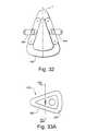
- FIGS. 53A-53Gillustrate two closely related embodiments of the present invention. Each embodiment is structured and arranged so as to help improve the lateral sealing force against the sides of the nose. These embodiments have particular use in the nasal bridge region, but could also be applied in other regions, such as the region adjacent the lower portion of the nose or the mouth.
- FIGS. 53A-53Cillustrate one embodiment in which a frame 600 has a generally triangular shape and in this example is structured to support a full face mask cushion, although it could be adapted for use as a frame for a nasal cushion.
- the frame 600may include other shapes, such as generally round, trapezoidal, or any shape that accommodates the intended area of the patient which serves as the interface.
- the frame 600includes a pair of lateral members 605 each including a connector interface 610 with at least one and preferably a plurality of apertures 615 .
- Each aperture 615is structured to receive an end of a headgear strap, preferably of the substantially inextensible type described above.
- the headgear strapcan be connected to any one of the apertures 615 .
- the aperturescan be provided to a side wall 617 of the connector interface 610 .
- a surface 616 oriented towards the patient's faceincludes a pair of fins 620 that are positioned just laterally outwards of the sides of the patient's nose in use.
- the fins 620are positioned in the nasal bridge region of the patient's nose, but the fins 620 could also extend along a greater or an entire extent of the sides of the patient's nose.
- the fins 620are structured to be received in a corresponding slot or groove formed in the facial cushion (not shown) or on the outside of the cushion
- Each fin 620may include one or more holes 625 which can help create a lock between the fin and the cushion, and may also reduce weight.
- the fins 620provide a degree of lateral support to help maintain a good seal against the sides of the patient's nose. For example, as tension in the straps is increased, a normal cushion will have a tendency to billow laterally outwards, thus increasing the chance of compromising the seal or comfort of the cushion. The provision of the fins 620 helps prevent the cushion from billowing outwardly, to thereby help maintain the seal against the sides of the patient's nose.
- the frame 600may be structured to be flexible to as to be able to pivot, bend or flex generally about an axis A. As such, when the headgear straps are tightened, the frame 600 may move about the axis A, thereby causing the fins 620 to move inwardly to pinch the sides of the patient's nose.
- a top portion 601 of the frame 600bends, pivots or flexes towards the patient's nasal bridge region, as indicated by the arrow in FIG. 53B . In the initial position, the top portion 601 is bent away from the face of the patient. Accordingly, adjustment of the side straps may cause enhanced sealing in the nasal bridge region, thereby avoiding the need for a top strap.
- the frame 600When the mask is flexed around the primary, vertical, axis A, the frame 600 tends to straighten about the secondary, horizontal axis B. This results in the top 601 of the frame 600 moving closer to the face, and the cushion being pressed into the nasal bridge.
- any desired part of the framecan be made to move in and out as desired as the frame is bent in one known plane.
- the frame 600may include one or more lines of weakness 630 , e.g. a hinge such as a living hinge, built in to top and/or bottom portions of the fame 600 .
- the lines of weakness 600will allow the frame 600 to more easily move about the axis A.
- FIGS. 53D and 53Eis very similar to the embodiment of FIGS. 53A-C .
- the main differenceis that the connector interface 610 in FIGS. 53D and 53D includes only one aperture 615 for receiving an end of a headgear strap.
- the aperture 615includes a slot 617 which is sized to allow the relatively thinner portion of the strap to slide therein, but will not allow the adjustable nut provided to the strap to pass.
- the fin 620does not include an aperture as in the embodiment of FIGS. 53A-C .
- FIG. 53Fshows the frame 600 of FIGS. 53D-E in an operative position on a model of a patient's head.
- the cushion C and elbow Ehave been attached to the frame 600 .
- FIG. 53Gis a cross-sectional view of the frame.
- FIG. 53Hshows a further embodiment of the invention in which a frame 640 is provided with a pad 645 .
- the pad 645extends along a bottom portion 650 of the frame 640 and may be provided below clip 655 and at least a portion of headgear straps 656 that are provided to each lateral side 660 of the frame 640 .
- the pad 645may therefore provide additional comfort against possible abrasion of the clip 655 and/or strap 656 against the patient's cheeks.
- the pad 645may be made of a gel and/or foam material.
- FIG. 53Iillustrates a first frame member 661 and a second frame member 662 carrying a facial interface, e.g., a cushion 663 .
- the first frame member 661includes a main opening 664 and a plurality of first holes 665 .
- the second frame member 662includes a plurality of second holes 666 that align with the holes 665 of the first frame member 662 .
- the second frame member 662includes a protrusion 667 structured to be inserted through the main opening 665 of the first frame member 661 .
- a plurality of pegs 668are provided between the first and second frame members 661 , 662 .
- Each peg 668includes a first end 669 and a second end 670 .
- the first end 669is inserted into the first holes 665 while the second end 670 is provided to the second holes 666 .
- Each peg 668may be provided with a spacer or stopper 671 .
- Each peg 668has a length “L” that is selected to adjust its depth in relation to the interior of the cushion 663 .
- the pegs 668are shown to have various lengths such that the second end 670 penetrates the second hole 666 to a depth within the cushion 663 that is tailored to the patient's facial physiognomy.
- the pegs 668may hold the frames 661 , 662 and/or the cushion 663 in place via press fit retention or the pegs 668 may include other structure to retain the cushion or frame members, e.g., barbs or undercuts.
- FIGS. 53J-53Pillustrate an embodiment of the invention where a frame 170 supports a cushion 172 made, for example of silicone and/or foam.
- the frame 170may include one or more headgear connection points 171 provided about the perimeter of the frame 170 .
- the cushion 172may include an inflatable bladder 173 provided in the nasal bridge region of the patient's nose.
- the bladder 173is shown to be a single piece which is embedded within the cushion 172 , but it could include separate pieces which are provided to discrete portions of the cushion 172 , in the desired positions.
- the bladdermay include two bladders which are provided to each side of the cushion, not including the apex of the cushion.
- the or each bladder 173may be in communication with a source of material, e.g., air or gel, etc., to adjust the volume of the bladder 173 .
- the or each bladderis provided to reduce or increase the distance between the associated cushion/frame section and the patient's face.
- FIGS. 53L-53Pshow the distance D in the nasal bridge region being progressively decreased as the frame 170 is pinched in at the sides.
- FIGS. 53L-53Pshow that the change in the shape of the sides of the cushion 172 is asymmetrical, although it may be preferable to change the shape of the cushion and/or bladder 173 in a symmetrical manner, depending on whether the patient's nasal physiognomy is symmetrical or asymmetrical.
- the cushion 172can also be structured so as to minimize billowing of the sides of the cushion upon application of increased pressure.
- the outer side walls of the cushioncan be made of a relatively thick gauge, so as to be relatively impervious to increased pressure, thereby reducing the chance that the outer wall will billow with increased pressure.
- the inner walls of the cushionadjacent the patient's nose can be made of a relatively thin gauge wall member, which will allow them to easily deflect towards the patient's nose, thereby enhancing the seal.
- the terms “rear” and “rearward”refer to the side of the cushion assembly adapted to contact the wearer's face and the terms “front” and “forward” refer to the side of the cushion assembly adapted to contact the mask shell or body.
- the term “mask”refers to nasal masks and full face masks.
- FIGS. 54A-54Care exploded rear elevation, side elevation and bottom plan views, respectively, of another known mask, the ACLAIMTM nasal mask, manufactured by Fisher & Paykel (F&P).
- the ACLAIMTM nasal maskincludes a rigid frame or shell 50 and a cushion assembly including a thin silicone seal-forming membrane 10 and a foam rim 30 .
- the shell 50includes a channel 51 defined by an inner wall 52 .
- the foam rim 30is partially positioned in the channel 51 and extends rearwardly (i.e. toward the wearer's face).
- the membrane 10is secured to the edge of the shell 50 via a tongue and groove mechanism 60 ( FIG. 54D ).
- the foam rim 30serves as a supporting structure.
- ACLAIMTM cushionrefers to the cushion assembly illustrated in FIGS. 54A-54D .
- a problem with some prior art cushions such as the ACLAIMTM cushionis that they can collapse under high pressures leading to the face being subject to the edge of the frame. This is uncomfortable for the patient and may result in marks or sores on their face.
- a cushion assembly 100 in accordance with a first embodiment of the present inventionincludes a silicone membrane 110 and an undercushion (U/C) 120 , similar to that of a MIRAGE® cushion.
- the membrane 110 and the undercushion 120are supported by an underlying cushion flange 140 .
- the membrane 110 and the undercushion 120may be formed as a one piece element with the underlying cushion flange 140 .
- the membrane 110 , the undercushion 120 and the underlying cushion flange 140may be formed of silicone and may be formed as separate elements, or as a one-piece unit.
- the cushion flange, the membrane and the undercushionare generally triangularly shaped to match the contours of a wearer's face defined by the nasal bridge region, the cheek regions, the upper lip region (in the case of a nasal mask), or the chin region (in the case of a full face mask).
- the membrane 110is generally the same shape as the undercushion 120 and surrounds the undercushion 120 .
- the cushion assembly 100includes a flexible element 130 between the membrane 110 and the undercushion 120 .
- the flexible element 130is a foam insert. Referring to FIG. 55D , the flexible element 130 is placed between the membrane 110 and the undercushion 120 . The flexible element 130 is supported by the undercushion 120 and provides initial soft compression of the cushion assembly 100 .
- a flexible element in accordance with the first embodiment of the present inventionis shown in FIGS. 56A-56F .
- the flexible element 130may be an insert constructed from a soft, compressible elastomer such as polyurethane foam.
- the flexible element 130may also be constructed from a soft silicone, for example with a hardness of Shore A 20 or less.
- the flexible element 130may further be a thermoplastic elastomer.
- the flexible element 130acts like a spring exhibiting an initial low spring constant.
- the undercushion 120exhibits the characteristic of a relatively harder, or firmer, spring constant.
- the respective roles of each layer in the first embodimentare: (i) for the membrane 110 to cause a seal to occur between its outer surface and the user's face; (ii) for the flexible element 130 to serve as a compliance layer thereby preventing premature collapse of the membrane 110 onto the undercushion 120 ; and (iii) for the cushion flange 140 of the cushion assembly 100 to serve as a support layer preventing excessive movement of the membrane 110 relative to the face thereby preventing the face from contacting a frame, body or shell of the mask or otherwise moving relative to the membrane 110 such as to compromise the seal.
- the flexible element 130is shaped to track the cavity between the membrane 110 and the undercushion 120 of the cushion assembly 100 .
- the spacing of the flexible element 130is relative to the membrane inner surface 115 such that there is still capacity for the membrane 110 to billow outwards to seal against the patient's face.
- FIGS. 57A-57Cillustrate mechanical properties of the cushion assembly 100 ( FIG. 57A ) in comparison to the mechanical properties of the MIRAGE® cushion ( FIG. 57B ) and the ACLAIMTM cushion ( FIG. 57C ).
- the y-axisrepresents relative cushion height Who. When the cushion assembly 100 is at its original height ho, the relative cushion height is 1. If the cushion assembly 100 is compressed to half its original height, the relative cushion height would be 0.5.
- the x-axisrepresents the compressive force F on the cushion assembly 100 .
- the force Fmay be the resultant force on the cushion assembly 100 being used between the mask shell and a patient's face.
- a cushion assembly 200includes a membrane 210 , a flexible undercushion 220 , a flexible element 230 , and an underlying cushion flange 240 .
- the membrane 210 and the undercushion 220may be formed as a one-piece unit with the underlying cushion flange 240 .
- the underlying cushion flange 240is attachable to a mask frame or shell 250 at a rear edge of the underlying cushion flange 240 .
- the flexible element 230is a foam insert.
- the flexible element 230may also be formed of silicone.
- FIGS. 60A-60Cillustrate mechanical properties of the cushion assembly 200 in accordance with the second embodiment of the invention, the MIRAGE® cushion and the ACLAIMTM cushion, respectively.
- FIG. 60Dillustrates a comparison of the three cushions on a single set of axes.
- the y-axisrepresents the relative cushion height h/ho and the x-axis represents the compressive force F on the cushion.
- the compressive forcesare represented as a percent of a maximum compressive force applied to the cushion assembly.
- the cushion heightis reduced to about 95% by a compressive force of about 20% of the maximum force.
- the second zonewhich corresponds to the flexible element 230 of the cushion assembly 200
- compressiongoes from 95% to 80% by a compressive force of about 60% of the maximum force.
- the third zonewhich corresponds to the undercushion 220 , increasing the force up to 100% of maximum only slightly further compresses the cushion assembly 200 .
- FIG. 60Billustrates mechanical properties of a MIRAGE® cushion. Compression of about 75% is achieved by a force of about 50% of maximum in the zone corresponding to the membrane. Further increases in the compressive force results in only slight decreases in the cushion relative height, corresponding to compression of the undercushion.
- FIG. 60Cillustrates mechanical properties of an ACLAIMTM cushion assembly.
- An initial compression to about 90%is achieved relatively easily with low force. Thereafter, further increases in the compressive force lead to large compression of the foam insert by about 30% of the maximum force. Application of a compressive force above 30% of maximum results in very slight, or almost no compression of the ACLAIMTM cushion assembly as the foam insert is completely compressed against the mask shell.
- FIG. 60Dillustrates a comparison of the three previous curves on one set of axes.
- FIGS. 61A-Eare graphical representations of the functioning of the cushion assemblies 100 , 200 according to the first and second embodiments by analogizing the flexible element 130 , 230 and the undercushion 120 , 220 , respectively, to springs.
- the spring constant of the flexible element 130 , 230is smaller than the spring constant of the undercushion 120 , 220 .
- the flexible element 130 , 230acts as a soft spring to initially take up a compressive force on the cushion assembly.
- the flexible element 130 , 230enhances the soft feel of the cushion assembly 100 , 200 and enhances conformance of the cushion assembly 100 , 200 to the wearer's face, thus improving the seal and reducing, or eliminating, leaks.
- the stiffer undercushion 120 , 220subsequently begins to compress.
- the undercushion 120 , 220reduces, or eliminates, the possibility of the wearer's face from contacting the mask shell.
- a cushion assembly 300includes a membrane 310 that extends from an underlying cushion flange 340 .
- the underlying cushion flange 340is attached at a rear end thereof to a mask shell 350 .
- a flexible element 330is disposed between the membrane 310 and the underlying cushion flange 340 .
- the flexible element 330 of this embodimentis generally taller, or deeper, than the flexible elements of the first and second embodiments.
- the flexible element 330 in this embodimentis made of one material.
- the cushion flange 340does not include an undercushion.
- the membrane 310achieves the primary seal and is supported by the flexible element 330 , which distributes the compressive forces at various locations resulting in a more comfortable mask system.
- the flexible element 330includes multiple segments 331 , 332 , 334 , 335 of different properties (force deflection characteristics).
- the segments 333 and 334may be placed in the nasal bridge region of the mask.
- the segments 333 and 334may be of different sizes and shapes and different spring constants (i.e. stiffnesses) to accommodate differences in sizes and shapes of individual wearers.
- the segments 331 , 332 , 333 , 334may be of varying sizes, shapes and spring constants to accommodate differences in the sizes and shapes of individual wearers. It should also be appreciated that any number of segments may be used.
- the flexible element 330is supported by a rigid retainer 355 .
- the retainer 355holds the flexible element 330 during assembly of the cushion assembly 300 and the mask.
- the flexible element 330 and the retainer 355may be joined together and used as a sub-assembly.
- the retainer 355may also include an extension having an elbow retainer clip 360 .
- the elbow retainer clip 360retains a rotating elbow 370 required for the supply of air from a flow generator. Further views of the retainer are shown in FIG. 64A-64E .
- a cushion assembly 400includes a two or three layer structure.
- the first layeris composed of a cushion flange 440 .
- a front side of the cushion flange 440is adapted to engage with a shell of a mask.
- the second layeris composed of flexible element 430 connected to the cushion flange 440 .
- the flexible element 430defines a cushion shape and forms a face-engaging structure.
- the flexible element 430may be provided with a third layer composed of a skin 460 .
- the first layermay be a rigid layer of polyurethane elastomer (no foam).
- the second layermay be formed of urethane foam or soft silicone.
- the third layermay be formed of silicone skin.
- the skin 460would have a thickness of 0.2 to 0.6 mm either uniform or varying according to load or the expected degree of deformation required.
- a cushion assembly 500includes a two or three layer structure.
- the first layeris composed of a cushion flange 540 .
- a front side of the cushion flange 540is adapted to engage with a shell of a mask.
- the cushion flange 540includes a supporting portion 545 that extends from the front side towards the rear side.
- the supporting portionis flexible and acts in a manner similar to the undercushion described above.
- the second layeris composed of a flexible element 530 that is attached to the cushion flange 540 and surrounds the supporting portion 545 .
- the flexible element 530defines a cushion shape and forms a face-engaging structure.
- the flexible element 530may be provided with a third layer composed of a skin 560 .
- the first layermay be a rigid polyurethane elastomer (no foam).
- the second layermay be formed of urethane foam or soft silicone.
- the third layermay be formed of silicone skin with a uniform or varying thickness as described above.
- the flexible element 530begins to compress upon contact with the wearer's face and application of a compressive force. As the compressive force increases, the flexible element 530 is further compressed until completely compressed against the supporting portion 545 . Further application of compressive force results in compression of the supporting portion 545 .
- the flexible element 530 and the supporting portionthus act as two springs in a manner similar to that illustrated in FIG. 61 .
- a cushion assembly 600includes a first layer and a second layer.
- the first layeris composed of a cushion flange 640 .
- a front side of the cushion flange 640is adapted to engage with a shell of a mask.
- the second layeris composed of flexible element 630 connected to the cushion flange 640 .
- the flexible element 430defines a cushion shape and forms a face-engaging structure.
- the first layermay be a rigid polyurethane elastomer (no foam).
- the second layeris formed of foam and includes a first portion 631 of relatively low stiffness and a second portion 632 of relatively high stiffness.
- the different stiffnessesmay be provided by forming the flexible element of foam having different densities, as indicated by the relative spacing of dots in the first and second portions 631 and 632 .
- the flexible element 630may be a single piece having varying density, or multiple pieces with different densities. Although the flexible element 630 is shown in FIG.
- the flexible element 630may be formed with more than two stiffnesses (densities).
- the second portion 6 D 2includes a region 632 a that extends beyond the cushion flange 640 to prevent the wearer's face from pressing up against the cushion flange 640 .
- the first portion 631 of the flexible element 630begins to compress upon contact with the wearer's face and application of a compressive force. As the compressive force increases, the first portion 631 may be completely compressed whereupon the second portion 632 will begin to compress. As the second portion 632 is stiffer than the first portion 631 , the decrease in the relative height of the cushion assembly 600 caused by application of the compressive force will be less in the second region 632 than in the first region 631 .
- the cushion assembly 600may be provided with a third layer, such as a skin.
- FIGS. 68 and 69illustrate another embodiment of the present invention.
- a foam cushion 700is provided to a frame 705 .
- the frameincludes an aperture 710 through which a support rod 715 is inserted.
- the aperture 710 and support rod 715may be threaded with one another such that the position of a head portion 720 of the rod 715 may be moved as indicated by the double ended arrow.
- the frame 705may be provided with a knob 725 to allow movement of the rod 715 .
- the frame 705is only shown to include one adjustment rod 715 , multiple such arrangements could of course be provided. Adjustment of the position of the rod 715 allows the cushion topography to be modified for a given pressure range.
- FIGS. 70-79illustrate cross-sectional views of additional embodiments of foam cushions according to the present invention.
- the interior of the foam cushion 729includes a spring element 730 .
- the amount of cushion material over the spring element 730can vary depending on the location of the cushion in relation to the patient's face.
- the cushioncan be modified such that the spring element 730 is embedded more deeply into the cushion, whereby a seal with the problem or sensitive area is formed by the cushion alone, substantially without much, if any, contribution of spring element
- One advantageis that the spring element 730 is fully embedded and invisible, so that there is a perceived simplicity, which can effect therapy compliance of the patient.
- FIG. 72includes a cushion 732 made of foam and a bellows 734 , preferably made of silicone, provided to an inside surface of the cushion 732 .
- the bellows 734can readily conform to the patient's face.
- FIG. 73is an arrangement which has a membrane 736 on the outside of the support 732 .
- FIG. 74is an arrangement in which a cushion 732 is provided with a channel 738 in communication with a chamber 740 arranged internally of the cushion 732 .
- the channel 738is in communication with a source of pressurized air or other medium, e.g., gel, such that the stiffness characteristics of the cushion can be changed.
- FIGS. 75A, 75B and 79illustrate various cross sections which provide at least two spring rates as the cushion is compressed.
- the cushion 732includes at least three spring rates during compression.
- the cushion 732includes three layers L 1 , L 2 and L 3 , each of which has a different spring constant.
- FIG. 78will have a first spring rate upon compressing head portion 747 into first groove 748 , a second spring rate upon compressing central portion 749 into second groove 751 , and a third spring rate upon engaging base portion 753 .
- FIG. 76illustrates a cushion 732 with a dimple 756 which may help maintain the seal, e.g., via suction, between the cushion and the patient's face.
- An advantage of a foam insert as the flexible elementis that foam is more compressible than silicone and thus a cushion assembly including a foam insert in accordance with the present invention achieves a better distribution of the load from the headgear.
- each element, membrane, flexible element, and cushion flange, in the embodiments described aboveacts as a mechanical spring.
- the embodiments described abovemay be used in combination, for example, the flexible elements of the first and second embodiments may have multiple regions of differing stiffnesses (densities) or the individual segments of the flexible element of the second embodiment may have multiple regions of differing stiffnesses (densities). Many combinations of the disclosed membrane, flexible element and cushion flange can be used to achieve the desired comfort level.
- the flexible elementcan be made from viscoelastic foam of a constant or multiple densities to provide the desirable effect.
- the flexible elementcan also be made from open or closed cell foam of constant or multiple densities.
- the flexible elementmay or may not be covered with a skin.
- a mask assembly including a cushion assembly in accordance with an embodiment of the inventioncan use a four-strap headgear similar to that of the ULTRA MIRAGETM mask system, manufactured by RESMED®.
- a mask assembly including a cushion assembly in accordance with an embodiment of the inventioncan use headgear clips in accordance with U.S. Pat. No. 6,374,826, the contents of which are hereby included by cross reference.
- An advantage of the cushion assemblies of the present invention to a mask systemis increased comfort for the user. This is possible due to uniform distribution of the forces for people who need substantial strap tension to achieve a seal.
- the flexible elementalso helps maintain the shape of the membrane and an effective seal while the user moves during the night.
- the cushion assemblies of the present inventioninclude ease of manufacturing and reduced manufacturing costs.
- the cushion assemblies of the present inventionare also less complicated than prior art cushions, for example, the ACLAIMTM cushion which is a three piece cushion requiring assembly before being affixed to the mask.
- a further advantage of the present inventionis that the flexible element results in less distortion of the membrane. This allows the physician/clinician to fit the mask in less time with a more reliable seal.
- a further advantage of the inventionis that the provision of a flexible element under the membrane achieves a more stable seal.
- the flexible elementprovides a smaller variation in the leak rate between the face and the cushion due to reduced mask movement. This enhances the therapy provided by the bi-level machines.
- the flexible elementshould have appropriate force displacement characteristics. This requirement is that the element should be soft enough to deflect initially to match the facial features but should not result in complete compression and discomfort to the user due to pressing of the rigid part of the cushion flange.
- a mask assembly 900includes a body portion 902 and a cushion 904 provided to the body portion 902 .
- the cushion 904may include a neoprene cushion 906 covered with a continuous silicon membrane 908 , for example.
- a flexible portion 910may be provided along the perimeter of the body portion 902 , for reasons described above.
- the body portion 902 and the membrane 908may be formed of a single piece in this example.
- the membrane 908includes an inner perimeter shoulder 912 and an outer perimeter shoulder 914 to engage a surface 916 of the flexible frame 910 .
- the outer perimeter shoulder 914may wrap around the edge of the flexible frame 910 .
- the outer perimeter shouldermay be said to include a groove to accommodate the outer edge of the flexible frame 910 .
- the inner peripheral shouldermay include a groove to accommodate the inner perimeter of the flexible frame 910 .
- the member 908“snaps on” to the edges of the frame 910 .
- Snapping the edge of the cushion against the fameremoves the necessity to glue the neoprene cushion to the fame, although gluing may be used between the neoprene cushion and the silicone membrane.
- This arrangementprovides superior integrity of the assembly providing a more reliable connection between all the parts and also removes any problems associated with chemical compatibility between the neoprene cushion and the nylon frame necessary for adhesion.
- the mask assemblyis robust enough to withstand forces exerted by rigorous use, thus resulting in greater reliability and patient security.
- the membrane 908provides a sealed air path which reduces air leak.
- FIG. 81A relaxation curve for a foam suitable for use in the flexible element according to the invention is shown in FIG. 81 .
- Densityis the weight per unit volume of the foam and below expressed in pounds per cubic foot (pcf.), although the above density is measured in g/cm 3 .
- the general range of polyether flexible urethane foamsis 1 to 4 pcf. This density is not a measure of firmness as is the case with latex rubber foams. For a given load bearing requirement, the higher density foam generally gives better quality and performance.
- CLDCompression load deflection
- Indentation load deflectionis one measure of load bearing and is expressed in pounds load per 50 square inches at a given percentage deflection of the foam.
- a 50 square inch circular plate (a)is pushed into the foam top surface, stopping at a given deflection and reading a load or a scale.
- a 25 percent ILD of 30means that it takes 30 pounds load to compress a 4 inch thick piece of foam to a 3 inch thickness. The higher the load, the firmer the foam.
- the foam sample sizeis larger than the circular plate, generally 15 by 15 inches for slab foams.
- ILDILD with other plate configurations and dimensions. ILD is sometimes referred to as RMA (Rubber Manufacturers Association) from the same measurement used for latex foams. Suggested practice for specifying flexible foam is: USU (Urethane Slab Uncored); USC (Urethane Slab Cored); UMU (Urethane Molded Uncored); UMC (Urethane Molded Cored). Digits following this code specify the 25 percent ILD, such as USU—30 refers to uncored slab with a 25 percent ILD of 30. Original thickness of the foam must be specified as values are affected by the original foam thickness. (See BASF Wyandotte Technical Advisory, “Effect of Foam Thickness on ILD”.)
- Sag factoris the ratio of 65 percent ILD to 25 percent ILD and gives an indication of cushioning quality. A high value indicates resistance to bottoming out Foams with low sag factors will often “bottom out” and give inferior performance. Other terms for this number are SAG factor and modulus.
- Initial hardness factoris the ratio of 25 percent ILD to the 5 percent ILD. This factor defines the surface feel. Supple or soft surface foams will have a high value while boardy or stiff surface foams will have a low value. Another term for initial hardness factor is comfort factor.
- Indentation residual gauge loadis another measure of load bearing and is expressed as inches at a given loading.
- the same 50 square inch circular plateis used as for ILD but now the plate is weighted with a given load. Normal loadings are 25, 50, or 75 pounds.
- the IRGL valueis in inches.
- the original thickness of the foammust be known to make the values meaningful. This measure is frequently used in automotive foam specifications. There is no ready correlation between ILD and IRGL values.
- Guide factoris the ratio of 25 percent ILD to density. This term is useful in determining the relative firmness of foams with different density. The closer the densities, the better the comparison. When densities are different, the foam with the highest guide factor has the cost advantage, but not necessarily the performance advantage. Another term for guide factor is normalized ILD.
- Indentation modulusis the load required to produce an indentation of 1 percent between the limits of 20 percent ILD and 40 percent ILD. The slope of this line depends on resistance of foam cell walls to buckling.
- Resilienceis a measure of elasticity or springiness of foam. In this test, a steel ball is dropped on the foam and the rebound is expressed as percent resilience. As with recovery, desirable values are dependent on application. With very soft foam, resilience can be misleading because the foam bottoms out under the load of the ball. This gives low resilience values even though the foam is very “lively” or elastic. Ball rebound is another term for this property.
- Tensile strengthis a measure of the amount of stress required to break the foam as it is pulled apart and is expresses in pounds per square inch (psi). Tensile strength can be used as a control check for quality. One common test is the determination of change of tensile strength after heat aging.
- Elongationis generally measured at the same time as tensile strength is determined. It is a measurement of the extent to which the foam can be stretched before it breaks and is expressed as a percentage of original length.
- Tear strengthis a measure of the force required to continue a tear in a foam after a split or break has been started and is expressed in pounds per lineal inch (pli or more commonly pi). This property is important in determining suitability of foam in application where the material is sewed, stapled or “hog-ringed.”
- Compression setis a measure of the deformation of a foam after it has been held compressed under controlled time and temperature conditions. The standard conditions are 22 hours at 158° F. In the test, foam is compressed to a thickness given as a percentage of its original thickness. Compression set is most commonly expressed as a percentage of original compression.
- Fatigueis a measurement of the loss in load bearing under simulated service conditions and is generally expressed as a percentage load loss. The two most common fatigue tests are static fatigue and roller shear fatigue.
- the foamIn a static fatigue test, the foam is compressed to 25 percent of its original thickness for 17 hours at room temperature. ILD losses are calculated as percentages of original values.
- roller shear fatigue testa roller, longer than the foam width, is rolled back and forth across the foam.
- the rolleris mounted in an off-set position to impart a shearing action.
- Testsvary in use of constant deflection settings or constant roller weights. Losses are calculated in ILD or IRGL as specified in the test method.
- Air flowis a measurement of the porosity or openness of foam expressed in cubic feet of air per minute (cfm). Air can be pulled through a foam by vacuum as specified in the ASTM procedure or blown through using apparatus as described in the BASF Wyandotte Technical Advisories, “BWC Portable Air Flow Apparatus” and “BWC Portable Air Flow Apparatus-Improved Model”.
Landscapes
- Health & Medical Sciences (AREA)
- Emergency Medicine (AREA)
- Pulmonology (AREA)
- Engineering & Computer Science (AREA)
- Anesthesiology (AREA)
- Biomedical Technology (AREA)
- Heart & Thoracic Surgery (AREA)
- Hematology (AREA)
- Life Sciences & Earth Sciences (AREA)
- Animal Behavior & Ethology (AREA)
- General Health & Medical Sciences (AREA)
- Public Health (AREA)
- Veterinary Medicine (AREA)
- Respiratory Apparatuses And Protective Means (AREA)
- Orthopedics, Nursing, And Contraception (AREA)
Abstract
Description
- Cephalic: In the direction of a vector running from feet to head, and beyond. The nose is cephalad to the lips and chin
- Caudal: In the direction of a vector running from head to feet, and beyond.
- Anterior: In the direction of a vector running from the back of the body to the front of the body, and beyond. The nose is anterior to the ears, and the mask is anterior to the nose.
- Posterior: In the direction of a vector running from the front of the body to the back. The ears are posterior to the nose.
- Coronal plane: A plane parallel to the plane containing the head, feet, and tips of the shoulders. A strap passing from the left ear, over the top of the head, to the right ear would be a coronal strap.
- Sagittal plane: A plane parallel to a plane passing through the head, feet, back of the spine, and tip of the nose.
- Nuchal: Pertaining to the (muscles of the) back of the neck.
- Occipital: Pertaining to the bony prominence where the muscles at the back of the neck insert into the back of the base of the skull.
- External auditory meatus: Ear hole.
- KgF: Kilograms force.
- Zygoma: The roughly half-apricot sized anterior protrusion of the cheekbone (Strictly body of zygoma).
- Inner canthus: The point where the upper and lower eyelid meet next to the bridge of the nose.
2tW=f+2pWh (eqn 1)
f=2wtcos(θ) (eqn 2)
h=r(1−cos(θ)) (eqn 3)
Finally, if the
L=2rθ (eqn 4)
f=pWLcos(θ)/θ(0<θ<π/2) (eqn 5)
x=2rsin(θ) (eqn 6)
and substituting r from
x=Lsin(θ)/θ (eqn 7)
Recall that:
f=pWLcos(θ)/θ (eqn 5)
| TABLE 1 | ||
| θ (degrees) | x/L = sin (θ)/θ | f/p WL = cos (θ)/ |
| 0 | 1.00 | infinite |
| 10 | 0.995 | 5.64 |
| 20 | 0.980 | 2.69 |
| 30 | 0.955 | 1.65 |
| 40 | 0.921 | 1.10 |
| 50 | 0.878 | 0.737 |
| 60 | 0.827 | 0.478 |
| 70 | 0.769 | 0.280 |
| 80 | 0.705 | 0.124 |
| 90 | 0.637 | 0.000 |
df/dθ=−pWL[sin(θ)/θ+cos(θ)/θ2] (eqn 5a)
dx/dθ=L[cos(θ)/θ−sin(θ)/θ2] (eqn 7a)
and dividing 5a by 7a gives (for 0<θ<=π/2):
df/dx=pW[cos(θ)/θ+sin(θ)]/[sin(θ)/θ−cos(θ)] (eqn 8a)
| TABLE 2 | |||
| Force generated | Stiffness | ||
| θ | Distance between straps | (coefficient | (coefficient |
| (degrees) | (fraction of maximum) | of pWL) | of pW) |
| 0 | 1.00 | infinite | infinite |
| 10 | 0.995 | 5.64 | 592 |
| 20 | 0.980 | 2.69 | 78 |
| 30 | 0.955 | 1.65 | 25 |
| 40 | 0.921 | 1.10 | 11 |
| 50 | 0.878 | 0.737 | 6.2 |
| 60 | 0.827 | 0.478 | 3.9 |
| 70 | 0.769 | 0.280 | 2.8 |
| 80 | 0.705 | 0.124 | 2.1 |
| 90 | 0.637 | 0.000 | 1.57 |
| W = 5 cm = | 0.05 meters | ||
| L = 6 cm = | 0.06 meters | ||
| P = 20 cm H2O = | 1960 N/m2~2,000 N/m2 | ||
fstrap=f0−Kstrap(x−x0)
Abladder×Pbladder=ΣForces applied to straps
Furthermore,
Abladder×Pbladder>Amask×Pmask
Pbladder=P0+AmaskPmask
where P0is a positive pressure sufficient to cause the mask to seal at the lowest intended usage pressure, and Amaskis the lesser of the area of contact between the occipital pneumatic pillow and the straps posteriorly, and the area of contact between the occipital pneumatic pillow and the back of the head anteriorly.
Vout=F0/Abladder+Amask/AbladderKo/KptVin.
| Property | Value | ||
| Density | 0.1752 | (g/cm3) | |
| CLD @ 25% | 1.054 | (N/cm2) | |
| CLD @ 65% | 3.375 | (N/cm2) |
| Sag Factor | 3.20 | ||
| IHF | 4.36 | ||
| Recovery % | 57 | ||
Claims (29)
Priority Applications (4)
| Application Number | Priority Date | Filing Date | Title |
|---|---|---|---|
| US12/461,448US10307554B2 (en) | 2002-11-06 | 2009-08-12 | Mask and components thereof |
| US14/471,525US10940283B2 (en) | 2002-11-06 | 2014-08-28 | Mask and components thereof |
| US17/131,973US11406784B2 (en) | 2002-11-06 | 2020-12-23 | Mask and components thereof |
| US17/873,545US11666725B2 (en) | 2002-11-06 | 2022-07-26 | Mask and components thereof |
Applications Claiming Priority (7)
| Application Number | Priority Date | Filing Date | Title |
|---|---|---|---|
| US42400502P | 2002-11-06 | 2002-11-06 | |
| US44732703P | 2003-02-14 | 2003-02-14 | |
| US48875203P | 2003-07-22 | 2003-07-22 | |
| US50389603P | 2003-09-22 | 2003-09-22 | |
| US10/533,928US8490623B2 (en) | 2002-11-06 | 2003-11-06 | Mask and components thereof |
| PCT/AU2003/001471WO2004041342A1 (en) | 2002-11-06 | 2003-11-06 | Mask and components thereof |
| US12/461,448US10307554B2 (en) | 2002-11-06 | 2009-08-12 | Mask and components thereof |
Related Parent Applications (3)
| Application Number | Title | Priority Date | Filing Date |
|---|---|---|---|
| US10/533,928ContinuationUS8490623B2 (en) | 2002-11-06 | 2003-11-06 | Mask and components thereof |
| PCT/AU2003/001471ContinuationWO2004041342A1 (en) | 2002-11-06 | 2003-11-06 | Mask and components thereof |
| US53392805AContinuation | 2002-11-06 | 2005-07-29 |
Related Child Applications (1)
| Application Number | Title | Priority Date | Filing Date |
|---|---|---|---|
| US14/471,525ContinuationUS10940283B2 (en) | 2002-11-06 | 2014-08-28 | Mask and components thereof |
Publications (2)
| Publication Number | Publication Date |
|---|---|
| US20100000543A1 US20100000543A1 (en) | 2010-01-07 |
| US10307554B2true US10307554B2 (en) | 2019-06-04 |
Family
ID=32314967
Family Applications (5)
| Application Number | Title | Priority Date | Filing Date |
|---|---|---|---|
| US10/533,928Active2030-07-21US8490623B2 (en) | 2002-11-06 | 2003-11-06 | Mask and components thereof |
| US12/461,448Active2029-05-12US10307554B2 (en) | 2002-11-06 | 2009-08-12 | Mask and components thereof |
| US14/471,525Active2027-12-22US10940283B2 (en) | 2002-11-06 | 2014-08-28 | Mask and components thereof |
| US17/131,973Expired - LifetimeUS11406784B2 (en) | 2002-11-06 | 2020-12-23 | Mask and components thereof |
| US17/873,545Expired - LifetimeUS11666725B2 (en) | 2002-11-06 | 2022-07-26 | Mask and components thereof |
Family Applications Before (1)
| Application Number | Title | Priority Date | Filing Date |
|---|---|---|---|
| US10/533,928Active2030-07-21US8490623B2 (en) | 2002-11-06 | 2003-11-06 | Mask and components thereof |
Family Applications After (3)
| Application Number | Title | Priority Date | Filing Date |
|---|---|---|---|
| US14/471,525Active2027-12-22US10940283B2 (en) | 2002-11-06 | 2014-08-28 | Mask and components thereof |
| US17/131,973Expired - LifetimeUS11406784B2 (en) | 2002-11-06 | 2020-12-23 | Mask and components thereof |
| US17/873,545Expired - LifetimeUS11666725B2 (en) | 2002-11-06 | 2022-07-26 | Mask and components thereof |
Country Status (6)
| Country | Link |
|---|---|
| US (5) | US8490623B2 (en) |
| EP (3) | EP2583713B1 (en) |
| JP (1) | JP4643442B2 (en) |
| AU (2) | AU2003275762A1 (en) |
| NZ (6) | NZ600793A (en) |
| WO (1) | WO2004041342A1 (en) |
Cited By (1)
| Publication number | Priority date | Publication date | Assignee | Title |
|---|---|---|---|---|
| US11406784B2 (en) | 2002-11-06 | 2022-08-09 | ResMed Pty Ltd | Mask and components thereof |
Families Citing this family (202)
| Publication number | Priority date | Publication date | Assignee | Title |
|---|---|---|---|---|
| DE20017940U1 (en) | 2000-10-19 | 2000-12-28 | MAP Medizintechnik für Arzt und Patient GmbH & Co KG, 82152 Planegg | Breathing mask for supplying a breathing gas to a mask user and a derivation device for deriving breathing gas |
| DE10201682A1 (en) | 2002-01-17 | 2003-07-31 | Map Medizin Technologie Gmbh | The breathing mask arrangement |
| DE10151984C5 (en) | 2001-10-22 | 2008-07-17 | Map Medizin-Technologie Gmbh | Application device for a breathing mask arrangement |
| US7320323B2 (en) | 2001-10-22 | 2008-01-22 | Map Medizin-Technologie Gmbh | Breathing mask device and application device and frontal support device thereof |
| US7743767B2 (en) | 2002-04-23 | 2010-06-29 | Resmed Limited | Ergonomic and adjustable respiratory mask assembly with frame |
| US8997742B2 (en) | 2002-04-23 | 2015-04-07 | Resmed Limited | Ergonomic and adjustable respiratory mask assembly with cushion |
| AU2003246441B2 (en)* | 2002-06-14 | 2009-01-22 | Resmed R&D Germany Gmbh | Mask cushioning and forehead pad for a respiratory mask, respiratory mask in addition to a mould and method for their production |
| JP4570966B2 (en) | 2002-09-06 | 2010-10-27 | レスメド・リミテッド | Cushion for breathing mask assembly |
| ES2443417T3 (en) | 2002-09-06 | 2014-02-19 | Resmed Limited | Forehead pad for a respiratory mask |
| NZ541912A (en)* | 2003-02-21 | 2008-05-30 | Resmed Ltd | Nasal mask assembly |
| US7318437B2 (en) | 2003-02-21 | 2008-01-15 | Resmed Limited | Nasal assembly |
| CN101987221B (en) | 2003-05-02 | 2013-09-04 | 雷斯梅德有限公司 | A mask system |
| US8714157B2 (en) | 2003-09-03 | 2014-05-06 | Fisher & Paykel Healthcare Limited | Mask |
| US9119929B2 (en)* | 2003-12-08 | 2015-09-01 | Fisher & Paykel Healthcare Limited | Breathing assistance apparatus |
| EP2510968B1 (en) | 2003-12-31 | 2017-02-08 | ResMed Limited | Compact oronasal patient interface |
| WO2005079726A1 (en) | 2004-02-23 | 2005-09-01 | Fisher & Paykel Healthcare Limited | Breathing assistance apparatus |
| EP3936180B1 (en) | 2004-04-02 | 2023-11-29 | Fisher & Paykel Healthcare Limited | Breathing assistance apparatus |
| US9072852B2 (en) | 2004-04-02 | 2015-07-07 | Fisher & Paykel Healthcare Limited | Breathing assistance apparatus |
| US20070246043A1 (en) | 2004-04-15 | 2007-10-25 | Resmed Limited | Positive-Air-Pressure Machine Conduit |
| EP2236166A2 (en)* | 2004-06-03 | 2010-10-06 | Compumedics Limited | Adaptable breathing mask |
| US8807135B2 (en) | 2004-06-03 | 2014-08-19 | Resmed Limited | Cushion for a patient interface |
| NZ608551A (en) | 2004-06-16 | 2014-10-31 | Resmed Ltd | Cushion for a respiratory mask assembly |
| US8042540B2 (en)* | 2004-10-15 | 2011-10-25 | Southmedic Incorporated | Patient oxygen delivery mask |
| WO2006050559A1 (en) | 2004-11-10 | 2006-05-18 | Resmed Limited | Method and apparatus for adjusting respiratory mask sealing force |
| EP1658873A1 (en)* | 2004-11-22 | 2006-05-24 | Gerhard Schumacher | Mask for a repiratory device for treatment of sleep apnea |
| AU2016204360B2 (en)* | 2005-01-12 | 2018-08-23 | ResMed Pty Ltd | Cushion for Patient Interface |
| EP2471566B1 (en) | 2005-01-12 | 2016-04-27 | ResMed Limited | Cushion for patient interface |
| US20060249152A1 (en)* | 2005-05-03 | 2006-11-09 | China Resource Group, Inc. | Neck positioning device for mechanical ventilator |
| NZ563608A (en) | 2005-06-06 | 2011-03-31 | Resmed Ltd | A mask with upper and lower stabilization parts contoured to the shape of a human face as part of the straps |
| US7827987B2 (en) | 2005-06-17 | 2010-11-09 | Nellcor Puritan Bennett Llc | Ball joint for providing flexibility to a gas delivery pathway |
| US7600514B2 (en) | 2005-06-17 | 2009-10-13 | Nellcor Puritan Bennett Llc | System and method for securing a gas delivery mask onto a subject's head |
| US7849855B2 (en) | 2005-06-17 | 2010-12-14 | Nellcor Puritan Bennett Llc | Gas exhaust system for a gas delivery mask |
| US7900630B2 (en) | 2005-06-17 | 2011-03-08 | Nellcor Puritan Bennett Llc | Gas delivery mask with flexible bellows |
| JP4826191B2 (en)* | 2005-09-27 | 2011-11-30 | パナソニック電工株式会社 | Activity meter |
| US8397728B2 (en) | 2005-10-14 | 2013-03-19 | Resmed Limited | Cushion to frame assembly mechanism |
| US20090126739A1 (en) | 2005-10-25 | 2009-05-21 | Resmed Limited | Interchangeable Mask Assembly |
| US8051855B2 (en)* | 2005-11-15 | 2011-11-08 | Ric Investments, Llc | Respiratory mask |
| US8371293B2 (en)* | 2005-12-16 | 2013-02-12 | Resmed Limited | Bladder cushion, forehead cushion, headgear straps, headgear cap and/or chinstrap |
| AU2007259483B2 (en)* | 2006-06-16 | 2012-11-29 | Fisher & Paykel Healthcare Limited | Breathing assistance apparatus |
| DE202007019687U1 (en) | 2006-07-14 | 2015-07-14 | Fisher & Paykel Healthcare Ltd. | Respiratory support device |
| ES2441595T3 (en) | 2006-07-18 | 2014-02-05 | Teijin Pharma Limited | Nasal respiratory mask system |
| EP2428241B1 (en) | 2006-07-28 | 2016-07-06 | ResMed Limited | Delivery of respiratory therapy |
| NZ701722A (en) | 2006-07-28 | 2016-07-29 | Resmed Ltd | Delivery of respiratory therapy |
| US8146595B2 (en)* | 2006-08-31 | 2012-04-03 | Nellcor Puritan Bennett Llc | Adjustable patient interface for a breathing assistance system |
| US8109271B2 (en)* | 2006-09-07 | 2012-02-07 | Nellcor Puritan Bennett Llc | Method and apparatus for securing a patient interface to a patient's face |
| US8490624B2 (en)* | 2006-11-13 | 2013-07-23 | Ric Investments, Llc | Patient interface with variable footprint |
| JP5214873B2 (en)* | 2006-11-13 | 2013-06-19 | 帝人ファーマ株式会社 | Nose mask |
| EP2481434B1 (en) | 2006-12-15 | 2016-04-13 | ResMed Ltd. | Delivery of respiratory therapy |
| US8517023B2 (en) | 2007-01-30 | 2013-08-27 | Resmed Limited | Mask system with interchangeable headgear connectors |
| US9981102B2 (en) | 2007-03-02 | 2018-05-29 | Resmed Limited | Respiratory mask |
| NZ578334A (en)* | 2007-04-19 | 2011-01-28 | Resmed Ltd | Mask frame connected to face cushion via intervening clip |
| EP2452716B1 (en) | 2007-07-30 | 2017-06-21 | ResMed Ltd. | Patient interface |
| WO2011014931A1 (en)* | 2009-08-07 | 2011-02-10 | Resmed Ltd | Patient interface systems |
| WO2009062010A2 (en) | 2007-11-07 | 2009-05-14 | Mergenet Solutions, Inc. | Cushion for ventilation interface |
| NZ602818A (en)* | 2008-01-31 | 2014-01-31 | Resmed Ltd | Respiratory apparatus |
| US20110000492A1 (en) | 2008-03-04 | 2011-01-06 | Resmed Ltd | Foam respiratory mask |
| US8950403B2 (en) | 2008-03-04 | 2015-02-10 | Resmed Limited | Mask system and method for constructing the same |
| NZ783425A (en) | 2008-03-04 | 2022-12-23 | ResMed Pty Ltd | Mask system |
| CN101965209A (en) | 2008-03-04 | 2011-02-02 | 雷斯梅德有限公司 | Interfaces including foam padding elements |
| US11331447B2 (en) | 2008-03-04 | 2022-05-17 | ResMed Pty Ltd | Mask system with snap-fit shroud |
| US10258757B2 (en) | 2008-05-12 | 2019-04-16 | Fisher & Paykel Healthcare Limited | Patient interface and aspects thereof |
| US10792451B2 (en) | 2008-05-12 | 2020-10-06 | Fisher & Paykel Healthcare Limited | Patient interface and aspects thereof |
| NZ589845A (en) | 2008-05-29 | 2013-05-31 | Resmed Ltd | Flexible structure for mask having a flexible gel filled structure including two gells of diferent hardness |
| US8905031B2 (en) | 2008-06-04 | 2014-12-09 | Resmed Limited | Patient interface systems |
| US8291906B2 (en) | 2008-06-04 | 2012-10-23 | Resmed Limited | Patient interface systems |
| NZ618492A (en) | 2008-06-05 | 2015-09-25 | Resmed Ltd | Treatment of respiratory conditions |
| WO2009149375A1 (en)* | 2008-06-05 | 2009-12-10 | Randall Bret F | Headgear device and methods thereto |
| US11660413B2 (en) | 2008-07-18 | 2023-05-30 | Fisher & Paykel Healthcare Limited | Breathing assistance apparatus |
| WO2010020874A2 (en)* | 2008-08-05 | 2010-02-25 | Stewart Ruth | Respiratory mask interface |
| NZ615630A (en) | 2008-09-12 | 2015-05-29 | Resmed Ltd | A foam-based interfacing structure method and apparatus |
| EP2349428B1 (en) | 2008-10-10 | 2017-09-20 | Fisher & Paykel Healthcare Limited | Nasal pillows for a patient interface |
| CN108744216B (en)* | 2008-12-10 | 2024-07-19 | 瑞思迈私人有限公司 | Headgear for a mask |
| EP2213324B1 (en) | 2009-01-30 | 2016-07-27 | ResMed R&D Germany GmbH | Patient interface structure and method/tool for manufacturing same |
| CN108310580B (en) | 2009-06-02 | 2023-06-13 | 瑞思迈私人有限公司 | Non-highlighting nasal mask |
| EP2445563A4 (en) | 2009-06-24 | 2016-03-23 | Resmed Ltd | ADJUSTABLE MASK SYSTEM AND CORRESPONDING METHODS |
| US9539403B2 (en) | 2009-08-26 | 2017-01-10 | Resmed Limited | Mask system |
| US8276588B1 (en) | 2009-10-23 | 2012-10-02 | Sleepnea | Respiratory mask with adjustable shape |
| EP2501423A4 (en) | 2009-11-18 | 2014-10-29 | Fisher & Paykel Healthcare Ltd | Nasal interface |
| WO2011060479A1 (en) | 2009-11-20 | 2011-05-26 | Resmed Ltd | Mask system |
| GB2489379B (en) | 2009-12-23 | 2016-01-13 | Fisher & Paykel Healthcare Ltd | Patient interface and headgear |
| CA2786747C (en)* | 2010-01-13 | 2017-05-16 | Thomas Julius Borody | A mask for use with a patient undergoing a sedated endoscopic procedure |
| US20110209708A1 (en)* | 2010-02-26 | 2011-09-01 | New York University | Ventilation Interface Device |
| CN102781505B (en)* | 2010-03-03 | 2015-08-12 | 皇家飞利浦电子股份有限公司 | There is the patient interface device of cam wheel adjustment mechanism |
| US8327851B2 (en) | 2010-03-15 | 2012-12-11 | Sleepnea Llc | Respiratory mask with user interface |
| JP2013523203A (en)* | 2010-03-25 | 2013-06-17 | コーニンクレッカ フィリップス エレクトロニクス エヌ ヴィ | Patient interface device with floating adjustment arm |
| NZ701943A (en) | 2010-09-01 | 2016-05-27 | Resmed Ltd | Mask system |
| EP2621573B1 (en) | 2010-09-30 | 2016-12-21 | ResMed Limited | Mask system |
| WO2012040791A1 (en) | 2010-09-30 | 2012-04-05 | Resmed Limited | Patient interface systems |
| EP2624903B1 (en) | 2010-10-08 | 2018-05-16 | Fisher & Paykel Healthcare Limited | Breathing assistance apparatus |
| EP3470102B1 (en) | 2010-10-08 | 2021-05-05 | ResMed Pty Ltd | Unobstrusive nasal mask |
| US9084859B2 (en) | 2011-03-14 | 2015-07-21 | Sleepnea Llc | Energy-harvesting respiratory method and device |
| GB2529079B (en) | 2011-04-15 | 2016-06-22 | Fisher & Paykel Healthcare Ltd | An elbow assembly for a mask |
| US10603456B2 (en) | 2011-04-15 | 2020-03-31 | Fisher & Paykel Healthcare Limited | Interface comprising a nasal sealing portion |
| EP3566736B1 (en)* | 2011-07-01 | 2020-12-09 | Fisher & Paykel Healthcare Limited | Nasal mask interface assembly |
| USD693459S1 (en) | 2011-09-16 | 2013-11-12 | Fisher & Paykel Healthcare Limited | Patient interface assembly |
| WO2013067582A1 (en) | 2011-11-08 | 2013-05-16 | Resmed Limited | Electrically stimulated respiratory assistance components |
| CN107261287B (en)* | 2011-11-15 | 2020-09-11 | 瑞思迈私人有限公司 | Nasal mask system |
| BR112014011402A2 (en)* | 2011-11-15 | 2017-06-06 | Koninklijke Philips Nv | patient interface device, and method of adjusting a patient interface device |
| US9168347B2 (en)* | 2011-11-16 | 2015-10-27 | International Business Machines Corporation | Managing an active strap system for a face mask |
| WO2013088321A1 (en)* | 2011-12-14 | 2013-06-20 | Koninklijke Philips Electronics N.V. | Patient interface device with customizable cushion |
| CN102580210A (en)* | 2012-03-07 | 2012-07-18 | 王海燕 | Equipment for alleviating children tachypnea |
| EP2863978A1 (en)* | 2012-06-22 | 2015-04-29 | Koninklijke Philips N.V. | Patient interface device |
| BR112014032623A2 (en)* | 2012-07-03 | 2017-06-27 | Koninklijke Philips Nv | patient interface system; and prevention method of formation of red marks by a patient interface on the skin of a patient |
| US20150190600A1 (en)* | 2012-07-11 | 2015-07-09 | Koninklijkie Philips N.V. | Patient interface |
| US9974915B2 (en) | 2012-07-27 | 2018-05-22 | Resmed Limited | Elastic headgear |
| CN116764059A (en) | 2012-07-27 | 2023-09-19 | 瑞思迈私人有限公司 | Patient interface and method for manufacturing the same |
| US12390612B2 (en) | 2012-07-27 | 2025-08-19 | ResMed Pty Ltd | Patient interface with elastic headgear |
| GB2553475B8 (en) | 2012-08-08 | 2019-01-02 | Fisher & Paykel Healthcare Ltd | Headgear for patient interface |
| CN104619372A (en)* | 2012-08-09 | 2015-05-13 | 皇家飞利浦有限公司 | Customization or adjustment of the patient interface |
| EP4279106A3 (en) | 2012-09-04 | 2024-01-17 | Fisher & Paykel Healthcare Limited | Valsalva mask |
| EP2897676B1 (en)* | 2012-09-21 | 2016-05-25 | Koninklijke Philips N.V. | Respiratory mask having a magnetically supported cushion |
| CN104703648B (en) | 2012-10-02 | 2017-04-26 | 皇家飞利浦有限公司 | Customizable liners using installed plug inserts |
| EP2732839B1 (en)* | 2012-11-15 | 2021-05-12 | Löwenstein Medical Technology S.A. | Device for positioning a patient interface |
| NZ728967A (en) | 2013-01-16 | 2018-08-31 | ResMed Pty Ltd | Patient interface and method for making same |
| US10004867B2 (en)* | 2013-02-04 | 2018-06-26 | Resmed Limited | Respiratory apparatus |
| US10987477B2 (en) | 2013-02-04 | 2021-04-27 | ResMed Pty Ltd | Respiratory apparatus |
| AU2014213016B2 (en) | 2013-02-04 | 2017-03-16 | ResMed Pty Ltd | Respiratory apparatus |
| USD809131S1 (en) | 2014-08-04 | 2018-01-30 | Resmed Limited | Respiratory mask assembly |
| US10413692B2 (en) | 2013-02-04 | 2019-09-17 | ResMed Pty Ltd | Cushion assembly |
| US10456540B2 (en) | 2013-03-15 | 2019-10-29 | ResMed Pty Ltd | Patient interface systems for ensuring effective seal |
| NZ623462A (en)* | 2013-04-12 | 2016-02-26 | Resmed Ltd | Neck strap, crown strap assembly and headgear for a breathing mask |
| BR112015026821A2 (en) | 2013-04-26 | 2017-07-25 | Fisher & Paykel Healthcare Ltd | breathing mask head accessory |
| KR102398717B1 (en) | 2013-06-11 | 2022-05-16 | 프리벤테크 엘티디. | Particle filter mask |
| USD743535S1 (en) | 2013-07-26 | 2015-11-17 | Resmed Limited | Headgear for patient interface |
| CA2919449C (en) | 2013-08-05 | 2022-04-12 | Fisher & Paykel Healthcare Limited | Seal for a patient interface, interface assemblies and aspects thereof |
| WO2015033263A1 (en) | 2013-09-03 | 2015-03-12 | Koninklijke Philips N.V. | Releasable elbow connector |
| EP2873434B1 (en)* | 2013-11-14 | 2021-03-17 | ResMed Pty Ltd | A patient interface |
| NZ720335A (en) | 2013-11-15 | 2021-07-30 | ResMed Pty Ltd | Patient interface and method for making same |
| US10828450B2 (en)* | 2014-05-09 | 2020-11-10 | Fisher & Paykel Healthcare Limited | Customizable respiratory mask |
| JP2017516593A (en) | 2014-06-04 | 2017-06-22 | レボリューショナリー メディカル デバイシーズ,インコーポレイテッド | Mouth and mouth ventilation mask |
| CN106413788B (en) | 2014-06-17 | 2019-12-20 | 费雪派克医疗保健有限公司 | Patient interface |
| US20170361045A1 (en) | 2014-06-27 | 2017-12-21 | Resmed Limited | Auto-fit mask |
| SG11201700351VA (en) | 2014-07-18 | 2017-02-27 | Fisher & Paykel Healthcare Ltd | Headgear clip arrangement |
| US20170173291A1 (en) | 2014-08-20 | 2017-06-22 | Revolutionary Medical Devices ,Inc. | Ventilation mask |
| WO2016032343A1 (en) | 2014-08-25 | 2016-03-03 | Fisher & Paykel Healthcare Limited | Respiratory mask and related portions, components or sub-assemblies |
| EP3185943B1 (en) | 2014-08-28 | 2019-05-15 | Koninklijke Philips N.V. | Cpap pressurized gas permeable mask cushion |
| US10397921B2 (en)* | 2014-09-10 | 2019-08-27 | Sharp Kabushiki Kaisha | Terminal, base station, and communication method |
| JP6931326B2 (en) | 2014-09-16 | 2021-09-01 | フィッシャー アンド ペイケル ヘルスケア リミテッド | Headgear assembly and interface assembly with headgear |
| US10828452B2 (en) | 2014-09-16 | 2020-11-10 | Fisher & Paykel Healthcare Limited | Intramold headgear |
| US10646680B2 (en)* | 2014-09-19 | 2020-05-12 | Fisher & Paykel Healthcare Limited | Headgear assemblies and interface assemblies with headgear |
| SG11201703928QA (en) | 2014-11-14 | 2017-06-29 | Fisher & Paykel Healthcare Ltd | Patient interface |
| EP3223894B1 (en) | 2014-11-26 | 2020-12-23 | ResMed Pty Ltd | Textile patient interface |
| CN106999691A (en)* | 2014-12-08 | 2017-08-01 | 人类设计医疗有限公司 | For the mask with inner supporting structure being used together with ventilation with air positive pressure system |
| JP2018504158A (en)* | 2014-12-09 | 2018-02-15 | コーニンクレッカ フィリップス エヌ ヴェKoninklijke Philips N.V. | Adjustable tension device for CPAP mask |
| USD825740S1 (en) | 2014-12-12 | 2018-08-14 | Revolutionary Medical Devices | Surgical mask |
| CA2977729A1 (en) | 2015-03-04 | 2016-09-09 | Fisher & Paykel Healthcare Limited | Mask system headgear |
| US10898668B2 (en) | 2015-03-04 | 2021-01-26 | ResMed Pty Ltd | Plastic to textile coupling for a patient interface and methods of manufacturing same |
| EP3274034B1 (en) | 2015-03-25 | 2021-02-24 | ResMed Pty Ltd | Patient interface with blowout prevention for seal-forming portion |
| US10639444B2 (en)* | 2015-03-31 | 2020-05-05 | Breas Medical, Inc. | Facial mask with internal intermediate maxilla support for use with ventilation and positive air pressure systems |
| EP4186548A1 (en) | 2015-04-02 | 2023-05-31 | Hill-Rom Services PTE. LTD. | Mask leakage detection for a respiratory device |
| CN104874080B (en)* | 2015-05-19 | 2016-10-05 | 湖南明康中锦医疗科技发展有限公司 | Intelligent breathing machine side cover |
| CN107635614A (en) | 2015-06-11 | 2018-01-26 | 革新医疗器械有限公司 | ventilation mask |
| US10953181B2 (en)* | 2015-06-11 | 2021-03-23 | Ventific Holdings Pty Ltd. | Respiratory mask |
| AU2016298653B2 (en) | 2015-07-24 | 2021-04-15 | Fisher & Paykel Healthcare Limited | Headgear assembly |
| EP3352825B1 (en) | 2015-09-23 | 2020-12-16 | ResMed Pty Ltd | Patient interface |
| AU2017234345B2 (en) | 2016-03-16 | 2022-03-03 | Fisher & Paykel Healthcare Limited | Intra-mould substrate |
| SG11201807699TA (en) | 2016-03-16 | 2018-10-30 | Fisher & Paykel Healthcare Ltd | Strap assembly, strap connector, headgear, headgear assembly, method of forming headgear, tubular connector, patient interface and method of joining straps |
| EP3430284B1 (en) | 2016-03-16 | 2021-07-14 | Fisher & Paykel Healthcare Limited | Directional lock for interface headgear arrangement |
| US10449325B2 (en) | 2016-03-24 | 2019-10-22 | Rainbow Vista Medical Devices, Inc. | Positive airway pressure respiration mask |
| USD882066S1 (en) | 2016-05-13 | 2020-04-21 | Fisher & Paykel Healthcare Limited | Frame for a breathing mask |
| US9629975B1 (en) | 2016-09-14 | 2017-04-25 | Revolutionary Medical Devices, Inc. | Ventilation mask |
| CN109937008B (en) | 2016-09-14 | 2022-04-15 | 革新医疗器械有限公司 | ventilation mask |
| CA3037853A1 (en)* | 2016-09-28 | 2018-04-05 | Fisher & Paykel Healthcare Limited | A yoke for headgear |
| USD848606S1 (en) | 2016-11-07 | 2019-05-14 | Revolutionary Medical Devices, Inc. | Surgical mask |
| USD823455S1 (en) | 2017-02-23 | 2018-07-17 | Fisher & Paykel Healthcare Limited | Cushion assembly for breathing mask assembly |
| USD824020S1 (en) | 2017-02-23 | 2018-07-24 | Fisher & Paykel Healthcare Limited | Cushion assembly for breathing mask assembly |
| USD823454S1 (en) | 2017-02-23 | 2018-07-17 | Fisher & Paykel Healthcare Limited | Cushion assembly for breathing mask assembly |
| US12102764B2 (en) | 2017-06-26 | 2024-10-01 | Fisher & Paykel Healthcare Limited | Respiratory mask system |
| CN107469219A (en)* | 2017-09-12 | 2017-12-15 | 宝鸡市双峰气体有限公司 | Portable oxygen respirator breathing mask |
| CA3077347A1 (en)* | 2017-09-30 | 2019-04-04 | Bedal Nv | Fixation of medical tubing with fluidum filled chamber |
| USD898188S1 (en) | 2017-11-17 | 2020-10-06 | Revolutionary Medical Devices, Inc. | Surgical mask |
| TWI678198B (en) | 2017-11-28 | 2019-12-01 | 財團法人工業技術研究院 | Adjustable respirator shell |
| WO2019123348A1 (en) | 2017-12-21 | 2019-06-27 | Fisher & Paykel Healthcare Limited | Respiratory mask system |
| EP3765135B1 (en) | 2018-03-16 | 2024-11-27 | Fisher & Paykel Healthcare Limited | Headgear with lock disengagement mechanism |
| USD884153S1 (en) | 2018-04-04 | 2020-05-12 | Fisher & Paykel Healthcare Limited | Frame for a mask assembly |
| TWI660761B (en)* | 2018-05-02 | 2019-06-01 | 陳忠勇 | Inhalation and exhalation masks |
| EP4509002A3 (en)* | 2018-10-24 | 2025-04-30 | Stryker Corporation | Surgical helmet assembly having an adjustment mechanism |
| US10974007B2 (en)* | 2019-03-07 | 2021-04-13 | Sleepnet Corporation | Facemask seal |
| CN113557048B (en)* | 2019-03-18 | 2024-10-25 | 瑞思迈私人有限公司 | Plenum insert for patient interface |
| JP7499532B2 (en)* | 2019-07-11 | 2024-06-14 | スナップ シーパップ,エルエルシー | VENTILATOR ASSEMBLY AND METHOD OF USE THEREOF |
| CN110496288B (en)* | 2019-09-29 | 2024-04-19 | 四川科弘医疗器械有限公司 | Anesthesia respirator |
| US11666724B2 (en)* | 2019-11-29 | 2023-06-06 | ResMed Pty Ltd | Adjustable headgear tubing for a patient interface |
| US12256057B2 (en) | 2019-12-31 | 2025-03-18 | ResMed Asia Pte. Ltd. | Positioning, stabilising, and interfacing structures and system incorporating same |
| JP7651196B2 (en) | 2020-03-21 | 2025-03-26 | スナップ シーパップ,エルエルシー | RESPIRATORY MASK ASSEMBLY FOR USE WITH CONTINUOUS POSITIVE AIRWAY PRESSURE (CPAP) DEVICES - Patent application |
| US11686948B2 (en) | 2020-03-27 | 2023-06-27 | ResMed Pty Ltd | Positioning, stabilising, and interfacing structures and system incorporating same |
| US12178276B2 (en) | 2020-03-27 | 2024-12-31 | ResMed Pty Ltd | Positioning and stabilising structure and system incorporating same |
| US11598967B2 (en)* | 2020-03-27 | 2023-03-07 | ResMed Pty Ltd | Positioning and stabilising structure and system incorporating same |
| JP7436018B2 (en)* | 2020-04-10 | 2024-02-21 | 山本光学株式会社 | Band binding tools for masks and masks |
| WO2021245668A1 (en)* | 2020-06-03 | 2021-12-09 | Inspir Labs Ltd. | Medical ventilation mask |
| KR102572888B1 (en)* | 2020-08-21 | 2023-09-05 | 아주대학교산학협력단 | Anesthetic mask |
| US20210145089A1 (en)* | 2020-12-14 | 2021-05-20 | Eman Mahmoud Hussien Hassan | Face mask frame with face care and blood circulation attachments |
| KR102295646B1 (en)* | 2021-02-10 | 2021-08-27 | 경일대학교산학협력단 | Oxygen supply apparatus |
| US11135459B1 (en)* | 2021-04-21 | 2021-10-05 | Robert Caldwell | Dual filtration COVID-19 mask |
| WO2022231597A1 (en)* | 2021-04-29 | 2022-11-03 | Kahrl Retti | Electrically active respirator mask |
| EP4094806A1 (en)* | 2021-05-28 | 2022-11-30 | Löwenstein Medical Technology S.A. | Patient interface with a sealing device comprising a supporting membrane and a sealing membrane |
| WO2023277708A1 (en)* | 2021-07-02 | 2023-01-05 | Fisher & Paykel Healthcare Limited | Mask assemblies for respiratory therapy |
| US20230110539A1 (en)* | 2021-10-13 | 2023-04-13 | Meta Platforms, Inc. | Methods and apparatus for fabricating curved elastic bands and articles incorporating curved elastic bands |
| WO2023249906A1 (en)* | 2022-06-21 | 2023-12-28 | The Children's Hospital Of Philadelphia | Clamping valve assembly for a ventilator |
| CN115014653B (en)* | 2022-07-08 | 2024-12-10 | 浙江创新汽车空调有限公司 | Dual-station helium gas filling recovery leak detection device for automobile air-conditioning heat exchanger and leak detection method thereof |
| CN117815504B (en)* | 2023-04-06 | 2024-10-18 | 杨红晓 | Anti-loosening anesthetic mask adapting to different faces |
| USD1018836S1 (en) | 2023-08-04 | 2024-03-19 | Dcstar Inc. | Mask frame |
| WO2025133927A1 (en)* | 2023-12-18 | 2025-06-26 | Fisher & Paykel Healthcare Limited | Mask assemblies and headgear for respiratory therapy |
Citations (411)
| Publication number | Priority date | Publication date | Assignee | Title |
|---|---|---|---|---|
| DE185017C (en) | ||||
| US443191A (en) | 1890-12-23 | Karl illing | ||
| US781516A (en) | 1904-02-03 | 1905-01-31 | George N Guthrie Jr | Respirator and inhaler. |
| US1081745A (en) | 1912-05-03 | 1913-12-16 | White S Dental Mfg Co | Nasal inhaler. |
| US1125542A (en) | 1914-03-11 | 1915-01-19 | Aubrey Humphries | Apparatus for use in administering anesthetics. |
| US1192186A (en) | 1910-09-20 | 1916-07-25 | Samuel Ward Greene | Respirator. |
| US1229050A (en) | 1917-03-29 | 1917-06-05 | Robert Donald | Respirator. |
| US1282527A (en) | 1918-04-13 | 1918-10-22 | Gratien Bidonde | Life-preserver. |
| US1362766A (en) | 1919-11-07 | 1920-12-21 | Mcgargill James Martin | Gas-mask |
| US1445010A (en) | 1920-11-15 | 1923-02-13 | William S Feinberg | Breathing apparatus for swimmers |
| US1610793A (en) | 1926-04-30 | 1926-12-14 | Kaufman Leo | Respirator |
| US1873160A (en) | 1929-02-08 | 1932-08-23 | Harold V Sturtevant | Breathing apparatus |
| GB532214A (en) | 1939-08-22 | 1941-01-20 | Hayden Thomas Cattanach | Improvements in and relating to nasal douches |
| US2353643A (en) | 1942-07-29 | 1944-07-18 | Arthur H Bulbulian | Head harness for masks |
| US2415846A (en) | 1944-10-23 | 1947-02-18 | Randall Francis Eugene | Oronasal mask |
| US2433565A (en) | 1946-06-21 | 1947-12-30 | Korman Alexander | Nose filter |
| US2625155A (en) | 1950-12-11 | 1953-01-13 | Arthur E Engelder | Face mask |
| US2706983A (en) | 1951-09-15 | 1955-04-26 | Willson Products Inc | Flexible construction in respirator mask facepiece |
| US2931356A (en) | 1958-08-25 | 1960-04-05 | Puritan Compressed Gas Corp | Oxygen mask having detachable face seal cushion |
| US3013556A (en) | 1959-08-07 | 1961-12-19 | Jr Ellis A Galleher | Head strap for respiratory masks |
| US3330273A (en) | 1964-10-15 | 1967-07-11 | Puritan Compressed Gas Corp | Oro-nasal face mask with improved sealing cuff |
| US3556097A (en)* | 1969-09-25 | 1971-01-19 | Air Reduction | Disposable anesthesia-breathing circuit unit |
| US3670726A (en) | 1969-09-23 | 1972-06-20 | Becton Dickinson Co | Breathing circuit |
| US3682171A (en) | 1971-03-31 | 1972-08-08 | Baxter Laboratories Inc | Nasal cannula |
| US3739774A (en) | 1970-05-21 | 1973-06-19 | Ml Aviation Co Ltd | Respirators |
| US3754552A (en) | 1971-06-08 | 1973-08-28 | Sandoz Ag | Flexible nasal cannula |
| US3815596A (en)* | 1973-01-26 | 1974-06-11 | Automation Ind Inc | Disposable face mask |
| US3844286A (en)* | 1973-08-10 | 1974-10-29 | Chemed Corp | Releasable medicament dental carrier and method |
| US3861385A (en) | 1972-08-25 | 1975-01-21 | Edward Carden | Anaesthetist{3 s ventilation |
| US3901228A (en)* | 1973-12-18 | 1975-08-26 | Robert J Brown | Therapeutic foot rest |
| US3902486A (en) | 1972-08-29 | 1975-09-02 | Jacquet Felicien | Portable respiratory apparatus |
| US3905361A (en) | 1974-04-24 | 1975-09-16 | Brunswick Mfg Co Inc | Apparatus for sealing the esophagus and providing artificial respiration and evacuating the stomach |
| US3938614A (en) | 1972-06-20 | 1976-02-17 | Aktiebolaget Lennartsfors Mekaniska Verkstad | Cushion member for sound-proof sealing |
| US3972321A (en) | 1975-02-20 | 1976-08-03 | Proctor John S | Upper lip mounted retaining means for medical-surgical tubes |
| US4006744A (en) | 1974-06-24 | 1977-02-08 | Abbott Laboratories | Locking cannula mount |
| US4142527A (en) | 1977-02-07 | 1979-03-06 | Garcia Nelson C | Endotracheal tube holder |
| US4153051A (en) | 1977-07-08 | 1979-05-08 | Shippert Ronald D | Compound splint and kit |
| US4156426A (en) | 1977-08-11 | 1979-05-29 | Gold Lawrence W | Head-mounted oxygen-administration device |
| DE3011900A1 (en) | 1979-04-03 | 1980-10-23 | Warne Surgical Products Ltd | UPHOLSTERY FOR A FACE MASK AND METHOD FOR THE PRODUCTION THEREOF |
| US4248218A (en) | 1978-09-22 | 1981-02-03 | Fischer Charles M | Gas administration scavenging mask |
| DD146688A1 (en) | 1979-10-19 | 1981-02-25 | Gerhard Gruner | DEVICE FOR INFLUENCING THE BREATHING SYSTEM IN NEWBORNS |
| US4264743A (en) | 1979-04-23 | 1981-04-28 | Nhk Spring Co., Ltd. | Polyurethane foam sealing material and process for producing the same |
| US4263908A (en) | 1979-07-25 | 1981-04-28 | Mizerak Vladimir S | Nasal cannula mask |
| US4267845A (en) | 1978-10-05 | 1981-05-19 | Robertson Jr Charles H | Method and apparatus for measuring pulmonary ventilation |
| US4273124A (en) | 1979-06-01 | 1981-06-16 | Zimmerman J Earl | Nasal cannula |
| US4312359A (en) | 1980-02-19 | 1982-01-26 | Life Care Systems, Inc. | Noninvasive blood pressure measuring system |
| WO1982003548A1 (en) | 1981-04-24 | 1982-10-28 | Sullivan Colin Edward | Device for treating snoring sickness |
| US4367735A (en) | 1979-12-31 | 1983-01-11 | Novametrix Medical Systems, Inc. | Nasal cannula |
| US4367816A (en) | 1981-06-10 | 1983-01-11 | Wilkes Kenneth R | Tear strip for gas sterilizable package and package |
| US4406283A (en) | 1982-02-04 | 1983-09-27 | Phillip Bir | Oxygen cannulae for continuous administration of oxygen, and its associated mounting structure and method for mounting same onto the head of a patient |
| US4414973A (en) | 1981-03-10 | 1983-11-15 | U.S.D. Corp. | Respirator face mask |
| US4422456A (en) | 1981-09-08 | 1983-12-27 | City Of Hope National Medical Center | Nasal cannula structure |
| US4449526A (en) | 1981-11-27 | 1984-05-22 | Elam James O | Mask breathing system |
| US4455675A (en) | 1982-04-28 | 1984-06-19 | Bose Corporation | Headphoning |
| US4493614A (en) | 1982-10-08 | 1985-01-15 | Lifecare Services, Inc. | Pump for a portable ventilator |
| US4548200A (en) | 1983-04-18 | 1985-10-22 | Baka Manufacturing Company, Inc. | Endotracheal tube holder |
| US4549542A (en) | 1983-07-25 | 1985-10-29 | Chien Chao Huei | Multiple-effect respirator |
| US4572323A (en) | 1983-03-28 | 1986-02-25 | Racal Safety Limited | Hearing protectors |
| US4587967A (en) | 1985-07-09 | 1986-05-13 | Lifecare Services, Inc. | Oxygen enriched reciprocating piston respirator |
| US4601465A (en) | 1984-03-22 | 1986-07-22 | Roy Jean Yves | Device for stimulating the human respiratory system |
| US4617637A (en) | 1985-07-09 | 1986-10-14 | Lifecare Services, Inc. | Servo control system for a reciprocating piston respirator |
| US4630604A (en) | 1985-04-09 | 1986-12-23 | Siebe North, Inc. | Valve assembly for a replaceable filter respirator |
| GB2176404A (en) | 1985-06-13 | 1986-12-31 | Od G Univ Im I I Mechnikova | Respirator |
| US4641647A (en) | 1985-02-08 | 1987-02-10 | Sheryl L. Taylor | Device for securing respiratory appliance during respiratory therapy |
| WO1987001950A1 (en) | 1985-09-26 | 1987-04-09 | Protector Safety Limited | Respirator |
| US4660555A (en) | 1984-09-21 | 1987-04-28 | Payton Hugh W | Oxygen delivery and administration system |
| US4671271A (en) | 1985-11-27 | 1987-06-09 | Dolores Bishop | Protective facial mask |
| US4676241A (en) | 1984-01-16 | 1987-06-30 | W.L.G. Technology | Ventilation tube swivel |
| US4699139A (en) | 1985-09-30 | 1987-10-13 | Marshall Marie F | Nasal cannula assembly with patient comfort pad |
| US4706664A (en) | 1986-04-11 | 1987-11-17 | Puritan-Bennett Corporation | Inspiration oxygen saver |
| US4711636A (en) | 1985-11-08 | 1987-12-08 | Bierman Steven F | Catheterization system |
| US4713844A (en) | 1986-07-16 | 1987-12-22 | Gentex Corporation | Protective helmet with face mask sealing means |
| USD293613S (en) | 1985-11-18 | 1988-01-05 | Anesthesia Respiratory Technology, Inc. | Anesthesia and respiratory face mask |
| US4753233A (en) | 1987-02-10 | 1988-06-28 | Advantage Medical | Nasal cannula |
| US4767411A (en) | 1987-07-14 | 1988-08-30 | Edmunds L Henry | Protective catheter sleeve |
| US4774946A (en) | 1983-11-28 | 1988-10-04 | Ackrad Laboratories, Inc. | Nasal and endotracheal tube apparatus |
| EP0288937A2 (en) | 1987-04-30 | 1988-11-02 | Cavan Corporation | Disposable breathing mask |
| US4782832A (en) | 1987-07-30 | 1988-11-08 | Puritan-Bennett Corporation | Nasal puff with adjustable sealing means |
| US4790829A (en) | 1983-08-24 | 1988-12-13 | Russell Bowden | Reusable injection catheter |
| DE3719009A1 (en) | 1987-06-06 | 1988-12-22 | Ernst Dipl Ing Hoermann | Ventilation mask with adjustable mouthpiece and nose moulding |
| US4802857A (en) | 1987-11-23 | 1989-02-07 | Laughlin Patrick E | CPR mask |
| US4803981A (en) | 1981-09-22 | 1989-02-14 | Vickery Ian M | Anaesthesia mask |
| US4811730A (en) | 1988-07-18 | 1989-03-14 | Seitz Corporation | CPR face mask and method of using same |
| US4830138A (en) | 1986-10-06 | 1989-05-16 | Finnveden Holding Ab | Pressure ring for ear cover |
| US4838878A (en) | 1985-05-03 | 1989-06-13 | Glenda G. Kalt | Universal clamp |
| US4899740A (en) | 1989-01-17 | 1990-02-13 | E. D. Bullard Company | Respirator system for use with a hood or face mask |
| US4907584A (en) | 1988-03-03 | 1990-03-13 | Mcginnis Gerald E | Respiratory mask |
| US4915105A (en) | 1988-10-28 | 1990-04-10 | Lee Tien Chu | Miniature respiratory apparatus |
| US4919128A (en) | 1988-08-26 | 1990-04-24 | University Technologies International Inc. | Nasal adaptor device and seal |
| US4919654A (en) | 1988-08-03 | 1990-04-24 | Kalt Medical Corporation | IV clamp with membrane |
| CN2056858U (en) | 1989-05-06 | 1990-05-09 | 广东省新技术进出口公司 | Once-used air-cushion mask for aneathesia and oxygen therapy |
| US4945907A (en) | 1987-04-13 | 1990-08-07 | New England Thermoplastics, Inc. | Face mask |
| US4960121A (en) | 1987-03-18 | 1990-10-02 | Figgie International, Inc. | Half-face mask assembly |
| US4966590A (en) | 1988-12-13 | 1990-10-30 | Kalt Medical Corporation | IV Clamp with membrane dressing |
| US4969880A (en) | 1989-04-03 | 1990-11-13 | Zamierowski David S | Wound dressing and treatment method |
| US4971051A (en) | 1987-07-13 | 1990-11-20 | Toffolon Norman R | Pneumatic cushion and seal |
| US4976698A (en) | 1987-10-23 | 1990-12-11 | Stokley Manuel H | Intravenous catheter and tubing stabilization device |
| US4989599A (en) | 1989-01-26 | 1991-02-05 | Puritan-Bennett Corporation | Dual lumen cannula |
| DE3927038A1 (en) | 1989-08-16 | 1991-02-21 | Juergen Hoefer | Oxygen mask measuring blood oxygen level - has sensor on lever arm for placing on forehead of wearer |
| US4996983A (en) | 1989-01-31 | 1991-03-05 | Amrhein Floyd E | Inhaler filtration device with housing supportable by spectacle temple |
| US5000173A (en) | 1987-11-19 | 1991-03-19 | Daniel Zalkin | Respiratory aid device |
| US5005571A (en) | 1988-11-25 | 1991-04-09 | Dietz Henry G | Mouth nose mask for use with an inhalation therapy and/or breathing monitoring apparatus |
| EP0427474A2 (en) | 1989-11-09 | 1991-05-15 | Smiths Industries Medical Systems Inc. | Face masks and face masks components |
| US5020163A (en) | 1989-06-29 | 1991-06-04 | Gentex Corporation | Earseal for sound-attenuating earcup assembly |
| US5022900A (en) | 1988-07-20 | 1991-06-11 | Eagle, Military Gear Overseas Ltd. | Forced ventilation filtration device |
| US5023955A (en) | 1989-04-13 | 1991-06-18 | Gentex Corporation | Impact-absorbing sound-attenuating earcup |
| US5025805A (en) | 1990-07-11 | 1991-06-25 | Betty Nutter | Nasal cannula assembly |
| US5038772A (en) | 1988-07-09 | 1991-08-13 | Dragerwerk Aktiengessellschaft | Closed-cycle breathing equipment |
| US5042478A (en) | 1988-08-26 | 1991-08-27 | University Technologies International, Inc. | Method of ventilation using nares seal |
| US5046491A (en) | 1990-03-27 | 1991-09-10 | Derrick Steven J | Apparatus and method for respired gas collection and analysis |
| US5074297A (en) | 1989-12-19 | 1991-12-24 | The General Hospital Corporation | Self-sealing mask for delivering intermittent positive pressure ventilation |
| EP0466960A1 (en) | 1987-03-10 | 1992-01-22 | Ignatius E. Theodorou | Portable breathing device |
| EP0303090B1 (en) | 1987-08-04 | 1992-04-22 | SGE SOCIETA' GENERALE ELASTOMERI S.p.A. | Seal for protective masks |
| US5113857A (en) | 1990-08-27 | 1992-05-19 | Stair Dickerman | Breathing gas delivery system and holding clip member therefor |
| US5117818A (en) | 1988-03-23 | 1992-06-02 | Palfy Christa Ursula | Nasal tube holder |
| US5121745A (en) | 1990-07-23 | 1992-06-16 | Israel Michael B | Self-inflatable rescue mask |
| US5127397A (en) | 1989-09-04 | 1992-07-07 | Ambu International A/S | Protective device kit for use in pulmonary ventilation treatment by the mouth-to-mouth or mouth-to-nose methods |
| US5137017A (en) | 1989-04-13 | 1992-08-11 | Salter Labs | Demand oxygen system |
| US5138722A (en) | 1991-07-02 | 1992-08-18 | David Clark Company Inc. | Headset ear seal |
| WO1992020395A1 (en) | 1991-05-22 | 1992-11-26 | Anne Le Mitouard | Facial breathing mask |
| WO1992020392A1 (en) | 1991-05-24 | 1992-11-26 | Calor Air Separation Limited | Nasal cannula |
| USD333015S (en) | 1991-12-02 | 1993-02-02 | Lifecare International, Inc. | Nasal mask |
| US5188101A (en) | 1991-11-15 | 1993-02-23 | Tumolo Jean S | Premature baby headband for supporting nasal cannulas and oxygen feed tubes |
| US5207665A (en) | 1990-07-06 | 1993-05-04 | Mcneil-Ppc, Inc. | Absorbent product having mechanical attachment mechanism |
| US5220699A (en) | 1992-07-27 | 1993-06-22 | Farris R David | Surgical face mask support apparatus and method |
| US5243709A (en) | 1991-09-04 | 1993-09-14 | Natus Medical, Inc. | Acoustically sealing earmuff for an infant |
| US5243971A (en) | 1990-05-21 | 1993-09-14 | The University Of Sydney | Nasal mask for CPAP having ballooning/moulding seal with wearer's nose and facial contours |
| US5245995A (en) | 1987-06-26 | 1993-09-21 | Rescare Limited | Device and method for monitoring breathing during sleep, control of CPAP treatment, and preventing of apnea |
| US5261893A (en) | 1989-04-03 | 1993-11-16 | Zamierowski David S | Fastening system and method |
| US5263939A (en) | 1992-10-09 | 1993-11-23 | Surgin Surgical Instrumentation, Inc. | Retainer for laparoscopic cannula |
| US5265595A (en) | 1989-06-19 | 1993-11-30 | Hans Rudolph, Inc. | Mask for breath analysis |
| US5265592A (en) | 1991-02-28 | 1993-11-30 | Intertechnique | Individual protective breathing equipment |
| US5267557A (en) | 1992-08-17 | 1993-12-07 | Her Mou Lin | Nose mask with a filtering device |
| US5269296A (en) | 1991-10-29 | 1993-12-14 | Landis Robert M | Nasal continuous positive airway pressure apparatus and method |
| US5271391A (en) | 1991-12-20 | 1993-12-21 | Linda Graves | Apparatus for delivering a continuous positive airway pressure to an infant |
| US5299599A (en) | 1992-09-17 | 1994-04-05 | Lifecare International, Inc. | Valving arrangement for a negative pressure ventilator |
| US5304146A (en) | 1992-10-23 | 1994-04-19 | Johnson Melissa C | Medical appliance securing device |
| US5335656A (en) | 1988-04-15 | 1994-08-09 | Salter Laboratories | Method and apparatus for inhalation of treating gas and sampling of exhaled gas for quantitative analysis |
| US5349949A (en) | 1991-10-03 | 1994-09-27 | Intertechnique | Face mask with lip, fold, and resilient spring means to improve seal |
| US5355878A (en) | 1990-06-26 | 1994-10-18 | Cam Lock (Uk) Ltd. | Breathing equipment for aircrew |
| US5355893A (en) | 1992-04-06 | 1994-10-18 | Mick Peter R | Vital signs monitor |
| US5364367A (en) | 1993-04-30 | 1994-11-15 | Minnesota Mining And Manufacturing Company | Cannula anchor |
| US5372130A (en) | 1992-02-26 | 1994-12-13 | Djs&T Limited Partnership | Face mask assembly and method having a fan and replaceable filter |
| US5372390A (en) | 1993-02-24 | 1994-12-13 | Senior Engineering Investments, B.V. | Coupling system for relatively thick-walled tubes |
| US5372388A (en) | 1993-04-30 | 1994-12-13 | American Pipe & Plastics, Inc. | Integral multi-duct conduit section |
| US5372389A (en) | 1993-06-22 | 1994-12-13 | Graco Inc. | Nozzle swivel joint |
| US5372391A (en) | 1993-02-22 | 1994-12-13 | The United States Of America As Represented By The United States Department Of Energy | Internal pipe attachment mechanism |
| US5375593A (en) | 1994-02-10 | 1994-12-27 | Press; John R. | Oxygenating pacifier |
| US5385141A (en) | 1992-04-16 | 1995-01-31 | Siebe North, Inc. | Speech diaphragm and exhalation valve |
| US5394568A (en) | 1993-01-28 | 1995-03-07 | Minnesota Mining And Manufacturing Company | Molded head harness |
| US5396885A (en) | 1992-07-31 | 1995-03-14 | Nelson; Joseph M. | Mobile air supply cart having dual tanks and connections allowing simultaneous filling of tank and delivery of air to a user |
| US5398676A (en) | 1993-09-30 | 1995-03-21 | Press; Roman J. | Portable emergency respirator |
| US5400776A (en) | 1993-07-09 | 1995-03-28 | Proprietary Technology, Inc. | Apparatus for maintaining a bend in a medical insufflation tube |
| US5419318A (en) | 1991-05-21 | 1995-05-30 | Better Breathing, Inc. | Breathing mask |
| US5425359A (en) | 1994-08-29 | 1995-06-20 | Liou; Nan-Tien | Nose plug structure with filter |
| EP0658356A2 (en) | 1993-11-19 | 1995-06-21 | Airways Ltd., Inc. | Nasal ventilation cannula |
| US5437267A (en) | 1993-08-03 | 1995-08-01 | Weinstein; Allan | Device for delivering aerosol to the nasal membranes and method of use |
| US5441046A (en) | 1993-09-29 | 1995-08-15 | Respironics, Inc. | Quick release mechanism for nasal and/or oral gas delivery mask |
| US5462528A (en) | 1988-07-01 | 1995-10-31 | Roewer; Norbert | Stomach tube |
| FR2720280A1 (en) | 1994-05-27 | 1995-12-01 | Mitouard Anne Le | Respiratory mask for assisted ventilation |
| US5488948A (en) | 1993-09-23 | 1996-02-06 | Intertechnique | Fast donning respiratory protection equipment |
| US5509409A (en) | 1994-09-12 | 1996-04-23 | The Living Trust Of Marjorie F. Weatherholt | Nasal cannula assembly |
| US5513635A (en) | 1995-02-02 | 1996-05-07 | Bedi; Shan | Nasal cannula anchoring apparatus |
| US5513634A (en) | 1994-05-06 | 1996-05-07 | Chek-Med Systems, Inc. | Combination integral bite block airway and nasal cannula |
| US5526806A (en) | 1995-04-04 | 1996-06-18 | Sansoni; Jean | Non-invasive nasal cannula |
| US5533506A (en) | 1995-01-13 | 1996-07-09 | Medlife, Inc. | Nasal tube assembly |
| US5538000A (en) | 1995-02-06 | 1996-07-23 | Hans Rudolph, Inc. | Airflow delivery system |
| US5538001A (en) | 1992-06-12 | 1996-07-23 | The Secretary Of State For Defence In Her Britannic Majesty's Government Of The United Kingdom Of Northern Ireland And Great Britain | Oxygen masks |
| WO1996028207A1 (en) | 1995-03-16 | 1996-09-19 | Assistance Publique - Hopitaux De Paris | Facial respirator mask, part and method for the manufacture thereof |
| US5560354A (en) | 1993-06-18 | 1996-10-01 | Rescare Limited | Facial masks for assisted respiration or CPAP |
| US5570684A (en) | 1995-12-29 | 1996-11-05 | Behr; R. Douglas | Heating and humidifying respiratory mask |
| US5592938A (en) | 1992-06-08 | 1997-01-14 | Respironics Inc. | Mask apparatus |
| US5623923A (en) | 1993-06-09 | 1997-04-29 | Intertechnique | Respiratory equipment with comfort adjustment |
| EP0776679A1 (en) | 1995-12-01 | 1997-06-04 | Cleantec Co., Ltd. | Mask maintaining warmth in nasal area |
| US5647357A (en) | 1995-09-08 | 1997-07-15 | Respironics, Inc. | Respiratory mask facial seal |
| US5653228A (en) | 1994-10-25 | 1997-08-05 | Byrd; Timothy N. | Medical tube holding device and associated securing strap |
| US5655527A (en) | 1994-06-03 | 1997-08-12 | Respironics Inc. | Respiratory mask with floating seal responsive to pressurized gas |
| US5660174A (en)* | 1993-07-13 | 1997-08-26 | Jacobelli; Chantal | Buccal respiration mask |
| US5662101A (en) | 1995-12-07 | 1997-09-02 | Respironics, Inc. | Respiratory facial mask |
| US5682881A (en) | 1996-10-21 | 1997-11-04 | Winthrop; Neil | Nasal CPAP/Cannula and securement apparatus |
| US5704345A (en) | 1993-11-05 | 1998-01-06 | Resmed Limited | Detection of apnea and obstruction of the airway in the respiratory system |
| US5707342A (en) | 1995-11-24 | 1998-01-13 | Fuji Photo Optical Co., Ltd. | Protector girdle for endoscopic insertion instrument |
| WO1998004310A1 (en) | 1996-07-26 | 1998-02-05 | Resmed Limited | A nasal mask and mask cushion therefor |
| US5724965A (en) | 1995-06-06 | 1998-03-10 | Respironics Inc. | Nasal mask |
| WO1998012965A1 (en) | 1996-09-23 | 1998-04-02 | Resmed Limited | Assisted ventilation to match patient respiratory need |
| US5735272A (en) | 1997-01-22 | 1998-04-07 | Dillon; Michael M. | Nasal tube holder having a nasal dilator attached thereto |
| US5740799A (en) | 1993-12-21 | 1998-04-21 | Maersk Medical A/S | Device for the supply of oxygen and/or other gases to a patient |
| US5752511A (en) | 1996-11-22 | 1998-05-19 | Simmons; Carl J. | Universal medical tube retainer and nasal wall tissue dilator |
| DE29723101U1 (en) | 1997-04-05 | 1998-05-28 | Gottlieb Weinmann Geräte für Medizin und Arbeitsschutz GmbH + Co. KG, 22525 Hamburg | Device for coupling to ventilation masks |
| WO1998023305A1 (en) | 1996-11-25 | 1998-06-04 | Kimberly-Clark Worldwide, Inc. | Adhesive composition comprising a polysiloxane |
| DE19703526A1 (en) | 1997-01-31 | 1998-08-06 | Rainer Berger | Appliance for delivery of a substance into inhaled air |
| US5794619A (en) | 1997-02-18 | 1998-08-18 | Edelman; Robert | Nasal cannula mounted solely by frictional engagement with the columella |
| US5807341A (en) | 1996-12-11 | 1998-09-15 | Team Medical Llc | Medical catheter dressing device |
| US5842469A (en) | 1997-07-03 | 1998-12-01 | Rapp; John D. | Method for extending the useful life of a nasal dilator |
| WO1999016327A1 (en) | 1997-09-29 | 1999-04-08 | Alpine Partners | Skin mounted device holder |
| US5906203A (en) | 1994-08-01 | 1999-05-25 | Safety Equipment Sweden Ab | Breathing apparatus |
| WO1999025410A1 (en) | 1997-11-14 | 1999-05-27 | Medisolve Limited | A seal for a respiratory mask, and a respiratory mask |
| US5918598A (en) | 1998-04-10 | 1999-07-06 | Belfer; William A. | Strapless respiratory facial mask for customizing to the wearer's face |
| US5921239A (en) | 1997-01-07 | 1999-07-13 | Sunrise Medical Hhg Inc. | Face mask for patient breathing |
| WO1999043375A1 (en) | 1998-02-25 | 1999-09-02 | MAP Medizintechnik für Arzt und Patient GmbH & Co. KG | Respirator mask |
| US5954049A (en) | 1991-10-15 | 1999-09-21 | Trudell Medical Limited | Equine mask with MDI adapter |
| US5975079A (en) | 1994-07-25 | 1999-11-02 | Hellings; Deborah | Anesthesia and respiratory face mask |
| WO1999061088A1 (en) | 1998-05-22 | 1999-12-02 | Resmed Limited | Ventilatory assistance for treatment of cardiac failure and cheyne-stokes breathing |
| US6019101A (en) | 1996-10-31 | 2000-02-01 | Sleepnet Corporation | Nasal air mask |
| US6026811A (en) | 1998-03-12 | 2000-02-22 | Settle; Romaine A. | Protective cover for nasal air supply hose |
| US6044844A (en) | 1996-12-02 | 2000-04-04 | Resmed Limited | Mask and harness assembly |
| WO2000020072A1 (en) | 1998-10-05 | 2000-04-13 | Respironics, Inc. | Customizable seal, mask with customizable seal and method of using such a seal |
| US6082360A (en) | 1995-05-04 | 2000-07-04 | Hans Rudolph, Inc. | Mask with gel seal |
| WO2000038772A1 (en) | 1998-12-24 | 2000-07-06 | Resmed Limited | An anti-asphyxia valve |
| US6086118A (en) | 1991-09-10 | 2000-07-11 | Bundy Corporation | Quick connect tubing connector |
| US6095996A (en) | 1997-05-30 | 2000-08-01 | Bristol-Myers Squibb Company | Adhesive composition or structure |
| US6098205A (en) | 1995-01-23 | 2000-08-08 | Schwartz; Alan N. | Goggles with pliable and resilient sealing pad |
| US6109263A (en) | 1995-08-09 | 2000-08-29 | Feuchtgruber; Gottfried | Packaged respiratory mask |
| WO2000050121A1 (en) | 1999-02-25 | 2000-08-31 | Respironics, Inc. | Adhesive nasal mask assembly, system and method of using same |
| US6119694A (en) | 1997-07-24 | 2000-09-19 | Respironics Georgia, Inc. | Nasal mask and headgear |
| US6119693A (en) | 1998-01-16 | 2000-09-19 | Resmed Limited | Forehead support for facial mask |
| US6123082A (en) | 1996-12-18 | 2000-09-26 | Resmed Limited | Device for preventing or reducing the passage of air through the mouth |
| WO2000057942A1 (en)* | 1999-03-29 | 2000-10-05 | Resmed Limited | Forehead support for a facial mask |
| US6139787A (en) | 1996-10-24 | 2000-10-31 | Ubertech Texas, Inc. | Method for applying molded silicone design elements onto substrates |
| WO2000069521A1 (en) | 1999-05-12 | 2000-11-23 | Respironics, Inc. | Low contact nasal mask and system using same |
| US6152137A (en) | 1995-01-23 | 2000-11-28 | Schwartz; Alan N. | Pliable and resilient sealing pad |
| WO2000072905A1 (en) | 1999-05-28 | 2000-12-07 | Euromedico Ltd. | Gas-supplying device |
| WO2000074758A1 (en) | 1999-06-08 | 2000-12-14 | Sleepnet Corporation | Nose mask |
| WO2000076568A1 (en) | 1999-06-16 | 2000-12-21 | Mallinckrodt Inc. | Pliable respiratory mask |
| WO2000078384A1 (en) | 1999-06-18 | 2000-12-28 | Resmed Limited | Forehead support for facial mask |
| US6193914B1 (en) | 1995-11-30 | 2001-02-27 | Ubertech Texas, Inc. | Molding thermosetting polymers onto substrates |
| US6196223B1 (en) | 1998-04-10 | 2001-03-06 | William A. Belfer | Strapless respiratory facial mask for customizing to the wearer's face |
| DE19944242A1 (en) | 1999-09-15 | 2001-03-22 | Dentallabor Negurescu Gmbh | Medical breathing mask with nose and mouth pieces joins these via orifice and flexible connector tube to breathing apparatus. |
| US6211263B1 (en) | 1996-12-23 | 2001-04-03 | The Procter & Gamble Company | Adhesive for secure topical attachment to the skin and comfortable removal |
| WO2001032250A1 (en) | 1999-11-03 | 2001-05-10 | Australian Centre For Advanced Medicine Technology Ltd | Mask |
| US6231548B1 (en) | 1999-08-26 | 2001-05-15 | Alfred Ernest Bassett | Securing device for intravenous cannula or catheter |
| EP1099452A2 (en) | 1999-11-12 | 2001-05-16 | MAP Medizintechnik für Arzt und Patient GmbH & Co. KG | Respiratory mask and method for making the same |
| US6241930B1 (en) | 1995-11-30 | 2001-06-05 | Ubertech Texas, Inc. | Method of constructing a garment with a graphical design thereon |
| US6258066B1 (en) | 1999-03-08 | 2001-07-10 | Rex W. Urich | Intravenous catheter stabilizing device |
| DE10002571A1 (en) | 2000-01-21 | 2001-07-26 | Mpv Truma Ges Fuer Medizintech | Breathing mask is of a flexible material with a spaced sealing lip at the inner support wall to give a comfortable and sealed fit at the face when in place around the nose |
| WO2001062326A1 (en) | 2000-02-25 | 2001-08-30 | MAP Medizintechnik für Arzt und Patient GmbH & Co. KG | Sealing lip device for a respiratory mask, respiratory mask and a method and a mould for producing the same |
| US20010020474A1 (en) | 2000-01-21 | 2001-09-13 | Hecker Karl Heinz | Nasal breathing mask and mask cushion for a nasal breathing mask |
| US6295366B1 (en) | 1999-03-24 | 2001-09-25 | Flightcom Corporation | Aircraft headset |
| US6328038B1 (en) | 1998-07-14 | 2001-12-11 | Fred Bruce Kessler | Nasal cannula retainer |
| WO2001095965A1 (en) | 2000-06-14 | 2001-12-20 | Fisher & Paykel Healthcare Limited | Breathing assistance apparatus |
| WO2001097893A1 (en) | 2000-06-22 | 2001-12-27 | Resmed Ltd. | Mask with gusset |
| WO2001097892A1 (en) | 2000-06-19 | 2001-12-27 | Australian Centre For Advanced Medical Technology Ltd | Mask |
| US20020005198A1 (en) | 1996-07-26 | 2002-01-17 | Philip Rodney Kwok | Full-face mask and mask cushion therefor |
| WO2002005883A1 (en) | 2000-07-17 | 2002-01-24 | Australian Centre For Advanced Medical Technology Ltd | Nasal mask with integral mouldable straps |
| US6341606B1 (en) | 1999-05-19 | 2002-01-29 | Mallinckrodt, Inc. | Disposable respiratory mask with adhesive skin interface |
| US6347631B1 (en) | 1999-11-09 | 2002-02-19 | Mallinckrodt, Inc. | Cantilever device and method for breathing devices and the like |
| US6358279B1 (en) | 1999-02-22 | 2002-03-19 | University Of Miami | Minicapsulorhexis valve |
| US6374826B1 (en) | 1999-03-18 | 2002-04-23 | Resmed Limited | Mask and headgear connector |
| GB2368533A (en) | 2000-08-12 | 2002-05-08 | Smiths Group Plc | Nose ventilation device |
| US20020053347A1 (en) | 1999-06-18 | 2002-05-09 | Saeed Ziaee | Nasal Mask |
| WO2002038221A1 (en) | 2000-11-10 | 2002-05-16 | Lee Keun Woo | Anti-fogging mask |
| WO2002045784A1 (en) | 2000-12-07 | 2002-06-13 | Resmed Ltd | Mask brace and mask assembly |
| US20020069872A1 (en) | 2000-09-22 | 2002-06-13 | Gradon Lewis George | Mouthpiece |
| US6412487B1 (en) | 1997-01-31 | 2002-07-02 | Resmed Limited | Mask cushion and frame assembly |
| US6412593B1 (en) | 1998-03-18 | 2002-07-02 | Nct Group, Inc. | Cushioned earphones |
| US6419660B1 (en) | 1998-05-29 | 2002-07-16 | Ronald D. Russo | Medical tube holder |
| US6422238B1 (en) | 1999-01-12 | 2002-07-23 | Resmed Limited | Headgear |
| US6423036B1 (en) | 1999-06-07 | 2002-07-23 | Gibbons Surgical Corporation | Cannula anchoring port |
| US20020096178A1 (en) | 1999-06-18 | 2002-07-25 | Saeed Ziaee | Nasal mask with balloon exhalation valve |
| US6431172B1 (en) | 2000-10-20 | 2002-08-13 | Mallinckrodt Inc. | Nasal cannula with inflatable plenum chamber |
| US6434796B1 (en) | 1999-10-20 | 2002-08-20 | Kathryn M. Speirs | Oxygen delivery cannula retainer, cannula with retainers assembly, and method for retaining cannulas |
| US6439234B1 (en) | 1998-04-03 | 2002-08-27 | Salter Labs | Nasal cannula |
| US6448303B1 (en) | 2000-12-29 | 2002-09-10 | National Starch And Chemical Investment Holding Corporation | Hot melt adhesives for dermal application |
| US20020124849A1 (en) | 2000-05-26 | 2002-09-12 | Taema | Nasal breathing mask with adjustable thermistor for treating respiratory disorders of sleep |
| US20020143296A1 (en) | 2001-03-29 | 2002-10-03 | Russo Ronald D. | Medical tube holder |
| DE10213905A1 (en) | 2001-03-30 | 2002-10-10 | Fred G Goebel | Breathing air flow control in a breathing apparatus for a patient, comprises determining the air pressure in a cuff, and then controlling the air flow accordingly |
| US6467483B1 (en) | 1999-07-28 | 2002-10-22 | Respironics, Inc. | Respiratory mask |
| US6467482B1 (en) | 2000-02-01 | 2002-10-22 | Georges Boussignac | Respiratory assistance apparatus |
| US6470887B1 (en) | 1998-05-12 | 2002-10-29 | Intertechnique | Protective breathing equipment with fast positioning |
| US20020157673A1 (en) | 1998-07-14 | 2002-10-31 | Kessler Fred B. | Nasal cannula retainer |
| US6478026B1 (en) | 1999-03-13 | 2002-11-12 | Thomas J. Wood | Nasal ventilation interface |
| US6482178B1 (en) | 1999-05-21 | 2002-11-19 | Cook Urological Incorporated | Localization device with anchoring barbs |
| EP1258266A1 (en) | 2001-05-18 | 2002-11-20 | Tiara Medical Systems, Inc. | Mask cushion and method of using same |
| US6491034B1 (en) | 1999-02-09 | 2002-12-10 | Resmed Limited | Gas delivery connection assembly |
| US20020185134A1 (en) | 2001-06-07 | 2002-12-12 | Bishop Giles Andrew | Face masks |
| US6530373B1 (en) | 2000-08-04 | 2003-03-11 | Mallinckrodt Inc. | Respirator mask |
| US6536435B1 (en) | 1999-02-22 | 2003-03-25 | Cabot Safety Intermediate Corporation | Respirator headpiece and release mechanism |
| US20030056795A1 (en)* | 1993-06-10 | 2003-03-27 | Gary K. Michelson | Surgical face support |
| US20030079749A1 (en) | 2001-10-25 | 2003-05-01 | Roger Strickland | Nasal cannula |
| US6561190B1 (en) | 1997-02-10 | 2003-05-13 | Resmed Limited | Mask and a vent assembly therefor |
| US6561188B1 (en) | 2000-08-21 | 2003-05-13 | Ellis Alan D | Nasal breathing apparatus and methods |
| US6561193B1 (en) | 1998-10-30 | 2003-05-13 | Linda J. Noble | Nasal gas delivery apparatus and a nasal vestibular airway |
| US6561192B2 (en) | 2000-03-03 | 2003-05-13 | The Penn State Research Foundation | Nasal oral respiratory interface |
| US20030089373A1 (en) | 2001-06-14 | 2003-05-15 | Gradon Lewis George | Breathing assistance apparatus |
| US6571798B1 (en) | 2000-04-05 | 2003-06-03 | W. Keith Thornton | Device for improving breathing and method of constructing same |
| US6579267B2 (en) | 2001-01-05 | 2003-06-17 | Applied Diabetes Research, Inc. | Pivoting joint infusion assembly |
| US20030111080A1 (en) | 2000-06-14 | 2003-06-19 | Olsen Gregory James | Breathing assistance apparatus |
| US6584975B1 (en) | 2000-08-28 | 2003-07-01 | Eldridge Taylor | Respirator mask for filtering breathed air |
| US6595215B2 (en) | 2000-03-13 | 2003-07-22 | Innomed Technologies, Inc. | Ventilation interface for sleep apnea therapy |
| US6595214B1 (en) | 2000-11-22 | 2003-07-22 | Mpv-Truma Gesellschaft Fur | Nasal respiration mask |
| US6607516B2 (en) | 1999-02-02 | 2003-08-19 | The Procter & Gamble Company | Disposable human waste management devices with improved adhesive flange to facilitate adhesion in oily conditions |
| US20030154980A1 (en) | 1991-12-20 | 2003-08-21 | Michael Berthon-Jones | Patient interface for respiratory apparatus |
| GB2385533A (en) | 2002-02-22 | 2003-08-27 | Smiths Group Plc | Face mask with seal around nose |
| US20030168063A1 (en) | 2002-03-08 | 2003-09-11 | Gambone Anthony Joseph | Pressure face mask and nasal mask |
| US6627289B1 (en) | 1988-12-20 | 2003-09-30 | Kimberly-Clark Worldwide, Inc. | Mechanical fastening tapes and method for their construction |
| US6631718B1 (en) | 1999-06-08 | 2003-10-14 | Sleepnet Corporation | Air mask with seal |
| US20030196658A1 (en) | 2002-04-23 | 2003-10-23 | Ging Anthony M. | Ergonomic and adjustable respiratory mask assembly with frame |
| US20030196656A1 (en) | 2002-04-23 | 2003-10-23 | Moore Rachael E. | Ergonomic and adjustable respiratory mask assembly with cushion |
| US6637434B2 (en) | 1998-10-30 | 2003-10-28 | Linda J. Noble | Nasal gas delivery system and method for use thereof |
| WO2003090827A1 (en) | 2002-04-23 | 2003-11-06 | Resmed Limited | Ergonomic and adjustable respiratory mask assembly |
| US6663600B2 (en) | 2000-08-03 | 2003-12-16 | Venetech International, Inc. | Dialysis catheter anchoring system |
| WO2003105921A2 (en) | 2002-06-14 | 2003-12-24 | Map Medizin-Technologie Gmbh | Mask cushioning and forehead pad for a respiratory mask, respiratory mask in addition to a mould and method for their production |
| US6669712B1 (en) | 2000-06-30 | 2003-12-30 | Norman Cardoso | Nasal oxygen cannula with supply tube management |
| US6679257B1 (en) | 1998-08-13 | 2004-01-20 | Fisher & Paykel Limited | Breathing assistance apparatus |
| USD485905S1 (en) | 2002-08-09 | 2004-01-27 | Resmed Limited | Nasal mask |
| US6684882B1 (en)* | 2002-03-15 | 2004-02-03 | Kenneth R. Morine | Respirator |
| US20040025882A1 (en) | 2000-07-21 | 2004-02-12 | Stefan Madaus | Holding device for a respiratory mask |
| US20040025885A1 (en) | 2002-08-09 | 2004-02-12 | Payne, Charles E. | Headwear for use by a sleep apnea patient |
| US20040045551A1 (en) | 2002-09-06 | 2004-03-11 | Ric Investments, Inc. | Patient interface with forehead support system |
| WO2004022146A1 (en) | 2002-09-06 | 2004-03-18 | Resmed Limited | Cushion for a respiratory mask assembly |
| US6710099B2 (en) | 1999-02-02 | 2004-03-23 | The Procter & Gamble Company | Disposable absorbent articles with improved adhesive for attachment to the skin to facilitate water adhesion stability with low pain level removal |
| WO2004041342A1 (en) | 2002-11-06 | 2004-05-21 | Resmed Limited | Mask and components thereof |
| US20040106891A1 (en) | 2002-08-30 | 2004-06-03 | Inrad, Inc. | Localizing needle with fluid delivery |
| US20040111104A1 (en) | 2002-08-23 | 2004-06-10 | Organ Recovery Systems | Cannulas, cannula mount assemblies, and clamping methods using such cannulas and cannula mount assemblies |
| US20040112384A1 (en) | 2001-09-07 | 2004-06-17 | Resmed Limited | Headgear connection assembly for a respiratory mask assembly |
| US20040127856A1 (en) | 2002-12-27 | 2004-07-01 | Carolyn Johnson | Catheter and delivery end |
| US6766800B2 (en) | 2002-08-30 | 2004-07-27 | Sensormedics Corporation | Pressure regulating valve for use in continuous positive airway pressure devices |
| US6766817B2 (en) | 2001-07-25 | 2004-07-27 | Tubarc Technologies, Llc | Fluid conduction utilizing a reversible unsaturated siphon with tubarc porosity action |
| US6776163B2 (en) | 2002-03-06 | 2004-08-17 | The Boc Group, Plc | Nasal cannulae |
| US6776162B2 (en) | 2000-03-13 | 2004-08-17 | Innomed Technologies, Inc. | Ventilation interface for sleep apnea therapy |
| WO2004073778A1 (en) | 2003-02-21 | 2004-09-02 | Resmed Limited | Nasal assembly |
| US6789543B2 (en) | 2002-07-02 | 2004-09-14 | James L. Cannon | Assisted breathing device and method of wearing same |
| WO2004078230A2 (en) | 2003-02-28 | 2004-09-16 | Sunrise Medical Hhg Inc. | Method for securing a nasal mask |
| US6805117B1 (en) | 2001-11-07 | 2004-10-19 | Ric Investments, Llc | Universal fitting headgear |
| US20040211428A1 (en) | 2003-02-28 | 2004-10-28 | Sunrise Medical Hhg Inc. | Nasal mask cushion |
| US6817362B2 (en) | 2001-08-10 | 2004-11-16 | North Safety Products Inc. | Respirator |
| US20040226564A1 (en) | 2003-05-14 | 2004-11-18 | Jan-Ove Persson | Device for holding a tracheal cannula |
| US6820617B2 (en) | 1998-08-13 | 2004-11-23 | Fisher & Paykel Limited | Breathing assistance apparatus |
| US6823869B2 (en) | 2001-09-07 | 2004-11-30 | Resmed Limited | Mask assembly |
| US6823865B2 (en) | 2000-05-15 | 2004-11-30 | Resmed Limited | Respiratory mask having gas washout vent and gas washout vent assembly for respiratory mask |
| EP1481702A2 (en) | 2003-05-30 | 2004-12-01 | Fisher & Paykel Healthcare Limited | Breathing assistance apparatus |
| US6834650B1 (en) | 1999-03-12 | 2004-12-28 | Mallinckrodt, Inc. | Face or nose mask for non-invasive ventilation of patients in general |
| US20050011523A1 (en) | 2003-07-18 | 2005-01-20 | Acoba, Llc | Method and system of Individually controlling airway pressure of a patient's nares |
| US20050033247A1 (en) | 2003-08-06 | 2005-02-10 | Thompson Paul S. | Nasal cannula assembly |
| US20050028822A1 (en) | 2003-08-08 | 2005-02-10 | Tiara Medical Systems, Inc. | Sealing nasal cannula |
| US6860270B2 (en) | 2001-08-02 | 2005-03-01 | Joseph A. Sniadach | Double barrel ventilation mask for a patient |
| US20050051171A1 (en) | 2003-09-10 | 2005-03-10 | Booth Jamie Lee | Nose breathing mask for a medical patient; and method |
| US20050051176A1 (en) | 2001-06-18 | 2005-03-10 | Riggins Michael Allen | Nasal and oral cannula apnea detection device |
| US20050056286A1 (en) | 2003-09-17 | 2005-03-17 | Huddart Brett John | Breathable respiratory mask |
| US20050061326A1 (en) | 2002-08-09 | 2005-03-24 | Payne Charles E. | Headwear for use by a sleep apnea patient |
| US6886183B2 (en)* | 2002-09-13 | 2005-05-03 | Dye Precision, Inc. | Goggle and mask system |
| US20050101933A1 (en) | 2003-11-10 | 2005-05-12 | James Marrs | Subcutaneous infusion device and method |
| WO2005053781A1 (en) | 2003-12-08 | 2005-06-16 | Fisher & Paykel Healthcare Limited | Breathing assistance apparatus |
| US20050150495A1 (en) | 2004-01-10 | 2005-07-14 | Wolfgang Rittner | Passenger oxygen mask |
| WO2005063328A1 (en) | 2003-12-31 | 2005-07-14 | Resmed Ltd | Compact oronasal patient interface |
| US20050155604A1 (en) | 2002-04-23 | 2005-07-21 | Resmed Limited | Respiratory mask assembly with magnetic coupling to headgear assembly |
| US6926004B2 (en) | 2003-08-20 | 2005-08-09 | Weinmann Geräte für Medizin GmbH & Co. KG | Breathing mask with a head fastening device |
| WO2005086943A2 (en) | 2004-03-11 | 2005-09-22 | Ric Investments, Llc | Patient interface device |
| US20050211252A1 (en) | 2002-01-17 | 2005-09-29 | Map Medizin-Technologie Gmbh | Breathing mask arrangement and a forehead support device for same |
| WO2005099801A1 (en) | 2004-04-15 | 2005-10-27 | Resmed Limited | Positive-air-pressure machine conduit |
| US20050241644A1 (en) | 2004-04-09 | 2005-11-03 | Resmed Limited | Nasal assembly |
| DE102004055433B3 (en) | 2004-11-17 | 2005-11-17 | Drägerwerk AG | Breathing mask with integrated suction area |
| WO2005110220A1 (en) | 2004-05-17 | 2005-11-24 | Resmed Limited | Position sensitive illumination system |
| AU2005100738A4 (en) | 2005-09-08 | 2005-11-24 | Respironics, Inc. | Patient interface device |
| US6968844B2 (en) | 2002-06-10 | 2005-11-29 | Laerdal Medical As | Mask cover |
| US6972003B2 (en) | 2000-03-10 | 2005-12-06 | Venetec International, Inc. | Medical anchoring system |
| WO2005118040A1 (en) | 2004-06-03 | 2005-12-15 | Resmed Limited | Cushion for a patient interface |
| US20050284481A1 (en) | 2004-06-23 | 2005-12-29 | Dragerwerk Aktiengesellschaft | Breathing mask with breathing gas supply through the strap |
| US7011090B2 (en) | 2001-09-07 | 2006-03-14 | Resmed Limited | Elbow for mask assembly |
| US20060060200A1 (en) | 2004-09-21 | 2006-03-23 | Ric Investments, Llc | Cheek-mounted patient interface |
| US20060081250A1 (en) | 2004-10-15 | 2006-04-20 | Bordewick Steven S | Nares seal |
| US20060095009A1 (en) | 2004-10-29 | 2006-05-04 | Lampropoulos Fred P | Self-suturing anchor device for a catheter |
| US20060095008A1 (en) | 2004-10-29 | 2006-05-04 | Lampropoulos Fred P | Self-suturing anchor device for a catheter |
| US7052127B2 (en) | 2002-01-23 | 2006-05-30 | Warnaco Swimwear Products Inc. | One-piece integrally-formed goggle |
| US20060124131A1 (en) | 2004-12-10 | 2006-06-15 | Respcare, Inc. | Hybrid ventilation mask with nasal interface and method for configuring such a mask |
| WO2006069415A1 (en) | 2004-12-30 | 2006-07-06 | Resmed Limited | Respiratory mask having gas washout vent and gas washout vent assembly for respiratory mask |
| US7076282B2 (en) | 1998-07-31 | 2006-07-11 | First Water Limited | Bioadhesive compositions and biomedical electrodes containing them |
| WO2006074513A1 (en) | 2005-01-12 | 2006-07-20 | Resmed Limited | Cushion for patient interface |
| WO2006074516A1 (en) | 2005-01-12 | 2006-07-20 | Resmed Limited | Respiratory mask having gas washout vent and method for making the mask |
| US7080645B2 (en) | 2001-02-06 | 2006-07-25 | Seleon Gmbh | Anti-snoring device, method for reducing snoring, and a nasal air cannula |
| US20060174887A1 (en) | 2004-12-10 | 2006-08-10 | Sanjay Chandran | Ventilation interface |
| US7101359B2 (en) | 1997-09-04 | 2006-09-05 | The Procter & Gamble Company | Absorbent article fastening device |
| US20060207597A1 (en) | 2005-03-15 | 2006-09-21 | Wright Clifford A | Adjustable bite block for respirator |
| WO2006099658A1 (en) | 2005-03-22 | 2006-09-28 | Resmed Limited | Nasal dilator |
| US7146976B2 (en) | 2002-08-06 | 2006-12-12 | Mckown Joseph R | Nasal cannula retainer |
| WO2006130903A1 (en) | 2005-06-06 | 2006-12-14 | Resmed Limited | Mask system |
| US7152599B2 (en) | 2005-05-20 | 2006-12-26 | Thomas Wendell A | Nasal mask for delivering gas |
| US7152601B2 (en) | 2000-12-18 | 2006-12-26 | Mohamed Ali Barakat | Strapless respiratory face mask |
| WO2007009182A1 (en) | 2005-07-19 | 2007-01-25 | Map Medizin-Technologie Gmbh | Respiratory mask and method for manufacturing a respiratory mask |
| US20070023044A1 (en) | 2005-07-29 | 2007-02-01 | Resmed Limited | Life style flow generator and mask system |
| US7178525B2 (en) | 2004-02-06 | 2007-02-20 | Ric Investments, Llc | Patient interface assembly supported under the mandible |
| US7191781B2 (en) | 2003-08-05 | 2007-03-20 | Innomed Technologies, Inc. | Nasal ventilation interface and system |
| WO2007041786A1 (en) | 2005-10-14 | 2007-04-19 | Resmed Ltd | Nasal assembly |
| WO2007041751A1 (en) | 2005-10-14 | 2007-04-19 | Resmed Limited | Cushion to frame assembly mechanism |
| US7207328B1 (en) | 2003-07-29 | 2007-04-24 | Armin Altemus | Emergency air delivery system for patients |
| WO2007048174A1 (en) | 2005-10-25 | 2007-05-03 | Resmed Ltd | Interchangeable mask assembly |
| WO2007053878A1 (en) | 2005-11-08 | 2007-05-18 | Resmed Ltd | Nasal assembly |
| US20070125387A1 (en) | 2005-12-02 | 2007-06-07 | Chris Zollinger | Infant nasal interface prong device |
| US7237551B2 (en) | 2004-12-22 | 2007-07-03 | Ric Investments, Llc. | Cushion for a patient interface |
| US7243723B2 (en) | 2004-06-18 | 2007-07-17 | Halliburton Energy Services, Inc. | System and method for fracturing and gravel packing a borehole |
| USD550836S1 (en) | 2005-07-06 | 2007-09-11 | Respcare, Inc. | Ventilation interface |
| USD552733S1 (en) | 2003-10-06 | 2007-10-09 | Tyco Healthcare Group Lp | Balloon anchored cannula |
| US7285255B2 (en) | 2002-12-10 | 2007-10-23 | Ecolab Inc. | Deodorizing and sanitizing employing a wicking device |
| US20070272249A1 (en) | 2006-05-10 | 2007-11-29 | Sanjay Chandran | Ventilation interface |
| US20070282272A1 (en) | 2006-05-30 | 2007-12-06 | Bannon Chad D | Device for guiding medical tubing |
| WO2007145534A1 (en) | 2006-06-16 | 2007-12-21 | Fisher & Paykel Healthcare Limited | Breathing assistance apparatus |
| WO2007143772A2 (en) | 2006-06-16 | 2007-12-21 | Johann Stadler | Holder for an indwelling venous cannula |
| US20080004573A1 (en) | 2006-05-19 | 2008-01-03 | Heiner Kaufmann | Adapter for Affixing a Medical Appliance |
| WO2008011683A1 (en) | 2006-07-28 | 2008-01-31 | Resmed Ltd | Delivery of respiratory therapy |
| WO2008011682A1 (en) | 2006-07-28 | 2008-01-31 | Resmed Ltd | Delivery of respiratory therapy |
| US20080065022A1 (en) | 2006-09-08 | 2008-03-13 | Kurt Kyvik | Catheter anchor |
| WO2008040050A1 (en) | 2006-10-02 | 2008-04-10 | Resmed Ltd | Cushion for mask system |
| US20080110469A1 (en) | 2006-11-13 | 2008-05-15 | Stanley Weinberg | Strapless flexible tribo-charged respiratory facial mask and method |
| WO2008070929A1 (en) | 2006-12-15 | 2008-06-19 | Resmed Ltd | Delivery of respiratory therapy |
| US20080200880A1 (en) | 2007-02-15 | 2008-08-21 | Kurt Kyvik | Catheter anchor |
| US20080257354A1 (en) | 2007-04-19 | 2008-10-23 | Resmed Limited | Cushion and cushion to frame assembly mechanism for patient interface |
| US20090044808A1 (en) | 2007-07-30 | 2009-02-19 | Resmed Limited | Patient interface |
| WO2009108994A1 (en) | 2008-03-04 | 2009-09-11 | Resmed Ltd | A foam respiratory mask |
| WO2009109004A1 (en) | 2008-03-04 | 2009-09-11 | Resmed Ltd | An interface including a foam cushioning element |
| US20100000534A1 (en) | 2008-06-04 | 2010-01-07 | Resmed Limited | Patient interface systems |
| WO2010028425A1 (en) | 2008-09-12 | 2010-03-18 | Resmed Ltd | A foam-based interfacing structure method and apparatus |
Family Cites Families (12)
| Publication number | Priority date | Publication date | Assignee | Title |
|---|---|---|---|---|
| DE146688C (en) | ||||
| US2970593A (en)* | 1957-05-06 | 1961-02-07 | Henry W Seeler | Mask-harness tension compensating device |
| US4739755A (en)* | 1986-10-17 | 1988-04-26 | American Cyanamid Company | Respirator |
| US4770169A (en)* | 1987-02-13 | 1988-09-13 | Mdt Diagnostic Company | Anaesthetic mask |
| US20020061692A1 (en)* | 1996-10-17 | 2002-05-23 | Helge G. Steckmann | Flat composite fabric with memory metal and its applications |
| AU755492B2 (en)* | 1998-08-12 | 2002-12-12 | Allan E. Dyer | Operation of a vertebral axial decompression table |
| AUPQ102999A0 (en)* | 1999-06-18 | 1999-07-08 | Resmed Limited | A connector for a respiratory mask and a respiratory mask |
| US6470886B1 (en)* | 1999-03-23 | 2002-10-29 | Creations By B J H, Llc | Continuous positive airway pressure headgear |
| FR2796263B1 (en)* | 1999-07-15 | 2001-09-21 | Univ Joseph Fourier | REMOTE CONTROLLED POSITIONING SYSTEM ON A PATIENT OF AN OBSERVATION / INTERVENTION DEVICE |
| US20020020416A1 (en)* | 2000-08-11 | 2002-02-21 | David Namey | Two-shot injection molded nasal/oral mask |
| US10463828B2 (en)* | 2001-10-10 | 2019-11-05 | Fisher & Paykel Healthcare Limited | Breathing assistance apparatus |
| DE10151984C5 (en)* | 2001-10-22 | 2008-07-17 | Map Medizin-Technologie Gmbh | Application device for a breathing mask arrangement |
- 2003
- 2003-11-06AUAU2003275762Apatent/AU2003275762A1/ennot_activeAbandoned
- 2003-11-06EPEP12190857.8Apatent/EP2583713B1/ennot_activeExpired - Lifetime
- 2003-11-06WOPCT/AU2003/001471patent/WO2004041342A1/enactiveApplication Filing
- 2003-11-06NZNZ600793Apatent/NZ600793A/ennot_activeIP Right Cessation
- 2003-11-06NZNZ591788Apatent/NZ591788A/ennot_activeIP Right Cessation
- 2003-11-06JPJP2005502078Apatent/JP4643442B2/ennot_activeExpired - Fee Related
- 2003-11-06NZNZ568057Apatent/NZ568057A/ennot_activeIP Right Cessation
- 2003-11-06NZNZ553302Apatent/NZ553302A/ennot_activeIP Right Cessation
- 2003-11-06EPEP03810331.3Apatent/EP1558321B1/ennot_activeExpired - Lifetime
- 2003-11-06USUS10/533,928patent/US8490623B2/enactiveActive
- 2003-11-06NZNZ583274Apatent/NZ583274A/ennot_activeIP Right Cessation
- 2003-11-06EPEP12190847.9Apatent/EP2574360B1/ennot_activeExpired - Lifetime
- 2003-11-06NZNZ539836Apatent/NZ539836A/ennot_activeIP Right Cessation
- 2009
- 2009-08-12USUS12/461,448patent/US10307554B2/enactiveActive
- 2009-11-17AUAU2009238305Apatent/AU2009238305B2/ennot_activeCeased
- 2014
- 2014-08-28USUS14/471,525patent/US10940283B2/enactiveActive
- 2020
- 2020-12-23USUS17/131,973patent/US11406784B2/ennot_activeExpired - Lifetime
- 2022
- 2022-07-26USUS17/873,545patent/US11666725B2/ennot_activeExpired - Lifetime
Patent Citations (464)
| Publication number | Priority date | Publication date | Assignee | Title |
|---|---|---|---|---|
| DE185017C (en) | ||||
| US443191A (en) | 1890-12-23 | Karl illing | ||
| US781516A (en) | 1904-02-03 | 1905-01-31 | George N Guthrie Jr | Respirator and inhaler. |
| US1192186A (en) | 1910-09-20 | 1916-07-25 | Samuel Ward Greene | Respirator. |
| US1081745A (en) | 1912-05-03 | 1913-12-16 | White S Dental Mfg Co | Nasal inhaler. |
| US1125542A (en) | 1914-03-11 | 1915-01-19 | Aubrey Humphries | Apparatus for use in administering anesthetics. |
| US1229050A (en) | 1917-03-29 | 1917-06-05 | Robert Donald | Respirator. |
| US1282527A (en) | 1918-04-13 | 1918-10-22 | Gratien Bidonde | Life-preserver. |
| US1362766A (en) | 1919-11-07 | 1920-12-21 | Mcgargill James Martin | Gas-mask |
| US1445010A (en) | 1920-11-15 | 1923-02-13 | William S Feinberg | Breathing apparatus for swimmers |
| US1610793A (en) | 1926-04-30 | 1926-12-14 | Kaufman Leo | Respirator |
| US1873160A (en) | 1929-02-08 | 1932-08-23 | Harold V Sturtevant | Breathing apparatus |
| GB532214A (en) | 1939-08-22 | 1941-01-20 | Hayden Thomas Cattanach | Improvements in and relating to nasal douches |
| US2353643A (en) | 1942-07-29 | 1944-07-18 | Arthur H Bulbulian | Head harness for masks |
| US2415846A (en) | 1944-10-23 | 1947-02-18 | Randall Francis Eugene | Oronasal mask |
| US2433565A (en) | 1946-06-21 | 1947-12-30 | Korman Alexander | Nose filter |
| US2625155A (en) | 1950-12-11 | 1953-01-13 | Arthur E Engelder | Face mask |
| US2706983A (en) | 1951-09-15 | 1955-04-26 | Willson Products Inc | Flexible construction in respirator mask facepiece |
| US2931356A (en) | 1958-08-25 | 1960-04-05 | Puritan Compressed Gas Corp | Oxygen mask having detachable face seal cushion |
| US3013556A (en) | 1959-08-07 | 1961-12-19 | Jr Ellis A Galleher | Head strap for respiratory masks |
| US3330273A (en) | 1964-10-15 | 1967-07-11 | Puritan Compressed Gas Corp | Oro-nasal face mask with improved sealing cuff |
| US3670726A (en) | 1969-09-23 | 1972-06-20 | Becton Dickinson Co | Breathing circuit |
| US3556097A (en)* | 1969-09-25 | 1971-01-19 | Air Reduction | Disposable anesthesia-breathing circuit unit |
| US3739774A (en) | 1970-05-21 | 1973-06-19 | Ml Aviation Co Ltd | Respirators |
| US3682171A (en) | 1971-03-31 | 1972-08-08 | Baxter Laboratories Inc | Nasal cannula |
| US3754552A (en) | 1971-06-08 | 1973-08-28 | Sandoz Ag | Flexible nasal cannula |
| US3938614A (en) | 1972-06-20 | 1976-02-17 | Aktiebolaget Lennartsfors Mekaniska Verkstad | Cushion member for sound-proof sealing |
| US3861385A (en) | 1972-08-25 | 1975-01-21 | Edward Carden | Anaesthetist{3 s ventilation |
| US3902486A (en) | 1972-08-29 | 1975-09-02 | Jacquet Felicien | Portable respiratory apparatus |
| US3815596A (en)* | 1973-01-26 | 1974-06-11 | Automation Ind Inc | Disposable face mask |
| US3844286A (en)* | 1973-08-10 | 1974-10-29 | Chemed Corp | Releasable medicament dental carrier and method |
| US3901228A (en)* | 1973-12-18 | 1975-08-26 | Robert J Brown | Therapeutic foot rest |
| US3905361A (en) | 1974-04-24 | 1975-09-16 | Brunswick Mfg Co Inc | Apparatus for sealing the esophagus and providing artificial respiration and evacuating the stomach |
| US4006744A (en) | 1974-06-24 | 1977-02-08 | Abbott Laboratories | Locking cannula mount |
| US3972321A (en) | 1975-02-20 | 1976-08-03 | Proctor John S | Upper lip mounted retaining means for medical-surgical tubes |
| US4142527A (en) | 1977-02-07 | 1979-03-06 | Garcia Nelson C | Endotracheal tube holder |
| US4153051A (en) | 1977-07-08 | 1979-05-08 | Shippert Ronald D | Compound splint and kit |
| US4156426A (en) | 1977-08-11 | 1979-05-29 | Gold Lawrence W | Head-mounted oxygen-administration device |
| US4248218A (en) | 1978-09-22 | 1981-02-03 | Fischer Charles M | Gas administration scavenging mask |
| US4267845A (en) | 1978-10-05 | 1981-05-19 | Robertson Jr Charles H | Method and apparatus for measuring pulmonary ventilation |
| DE3011900A1 (en) | 1979-04-03 | 1980-10-23 | Warne Surgical Products Ltd | UPHOLSTERY FOR A FACE MASK AND METHOD FOR THE PRODUCTION THEREOF |
| US4264743A (en) | 1979-04-23 | 1981-04-28 | Nhk Spring Co., Ltd. | Polyurethane foam sealing material and process for producing the same |
| US4273124A (en) | 1979-06-01 | 1981-06-16 | Zimmerman J Earl | Nasal cannula |
| US4263908A (en) | 1979-07-25 | 1981-04-28 | Mizerak Vladimir S | Nasal cannula mask |
| DD146688A1 (en) | 1979-10-19 | 1981-02-25 | Gerhard Gruner | DEVICE FOR INFLUENCING THE BREATHING SYSTEM IN NEWBORNS |
| US4367735A (en) | 1979-12-31 | 1983-01-11 | Novametrix Medical Systems, Inc. | Nasal cannula |
| US4312359A (en) | 1980-02-19 | 1982-01-26 | Life Care Systems, Inc. | Noninvasive blood pressure measuring system |
| US4414973A (en) | 1981-03-10 | 1983-11-15 | U.S.D. Corp. | Respirator face mask |
| US4944310A (en) | 1981-04-24 | 1990-07-31 | Somed Pty. Ltd. | Device for treating snoring sickness |
| WO1982003548A1 (en) | 1981-04-24 | 1982-10-28 | Sullivan Colin Edward | Device for treating snoring sickness |
| US4367816A (en) | 1981-06-10 | 1983-01-11 | Wilkes Kenneth R | Tear strip for gas sterilizable package and package |
| US4422456A (en) | 1981-09-08 | 1983-12-27 | City Of Hope National Medical Center | Nasal cannula structure |
| US4803981A (en) | 1981-09-22 | 1989-02-14 | Vickery Ian M | Anaesthesia mask |
| US4449526A (en) | 1981-11-27 | 1984-05-22 | Elam James O | Mask breathing system |
| US4406283A (en) | 1982-02-04 | 1983-09-27 | Phillip Bir | Oxygen cannulae for continuous administration of oxygen, and its associated mounting structure and method for mounting same onto the head of a patient |
| US4455675A (en) | 1982-04-28 | 1984-06-19 | Bose Corporation | Headphoning |
| US4493614A (en) | 1982-10-08 | 1985-01-15 | Lifecare Services, Inc. | Pump for a portable ventilator |
| US4572323A (en) | 1983-03-28 | 1986-02-25 | Racal Safety Limited | Hearing protectors |
| US4548200A (en) | 1983-04-18 | 1985-10-22 | Baka Manufacturing Company, Inc. | Endotracheal tube holder |
| US4549542A (en) | 1983-07-25 | 1985-10-29 | Chien Chao Huei | Multiple-effect respirator |
| US4790829A (en) | 1983-08-24 | 1988-12-13 | Russell Bowden | Reusable injection catheter |
| US4774946A (en) | 1983-11-28 | 1988-10-04 | Ackrad Laboratories, Inc. | Nasal and endotracheal tube apparatus |
| US4676241A (en) | 1984-01-16 | 1987-06-30 | W.L.G. Technology | Ventilation tube swivel |
| US4601465A (en) | 1984-03-22 | 1986-07-22 | Roy Jean Yves | Device for stimulating the human respiratory system |
| US4660555A (en) | 1984-09-21 | 1987-04-28 | Payton Hugh W | Oxygen delivery and administration system |
| US4641647A (en) | 1985-02-08 | 1987-02-10 | Sheryl L. Taylor | Device for securing respiratory appliance during respiratory therapy |
| US4630604A (en) | 1985-04-09 | 1986-12-23 | Siebe North, Inc. | Valve assembly for a replaceable filter respirator |
| US4838878A (en) | 1985-05-03 | 1989-06-13 | Glenda G. Kalt | Universal clamp |
| GB2176404A (en) | 1985-06-13 | 1986-12-31 | Od G Univ Im I I Mechnikova | Respirator |
| US4587967A (en) | 1985-07-09 | 1986-05-13 | Lifecare Services, Inc. | Oxygen enriched reciprocating piston respirator |
| US4617637A (en) | 1985-07-09 | 1986-10-14 | Lifecare Services, Inc. | Servo control system for a reciprocating piston respirator |
| WO1987001950A1 (en) | 1985-09-26 | 1987-04-09 | Protector Safety Limited | Respirator |
| US4699139A (en) | 1985-09-30 | 1987-10-13 | Marshall Marie F | Nasal cannula assembly with patient comfort pad |
| US4711636A (en) | 1985-11-08 | 1987-12-08 | Bierman Steven F | Catheterization system |
| USD293613S (en) | 1985-11-18 | 1988-01-05 | Anesthesia Respiratory Technology, Inc. | Anesthesia and respiratory face mask |
| US4671271A (en) | 1985-11-27 | 1987-06-09 | Dolores Bishop | Protective facial mask |
| US4706664A (en) | 1986-04-11 | 1987-11-17 | Puritan-Bennett Corporation | Inspiration oxygen saver |
| US4713844A (en) | 1986-07-16 | 1987-12-22 | Gentex Corporation | Protective helmet with face mask sealing means |
| US4830138A (en) | 1986-10-06 | 1989-05-16 | Finnveden Holding Ab | Pressure ring for ear cover |
| US4753233A (en) | 1987-02-10 | 1988-06-28 | Advantage Medical | Nasal cannula |
| EP0466960A1 (en) | 1987-03-10 | 1992-01-22 | Ignatius E. Theodorou | Portable breathing device |
| US4960121A (en) | 1987-03-18 | 1990-10-02 | Figgie International, Inc. | Half-face mask assembly |
| US4945907A (en) | 1987-04-13 | 1990-08-07 | New England Thermoplastics, Inc. | Face mask |
| EP0288937A2 (en) | 1987-04-30 | 1988-11-02 | Cavan Corporation | Disposable breathing mask |
| DE3719009A1 (en) | 1987-06-06 | 1988-12-22 | Ernst Dipl Ing Hoermann | Ventilation mask with adjustable mouthpiece and nose moulding |
| US5245995A (en) | 1987-06-26 | 1993-09-21 | Rescare Limited | Device and method for monitoring breathing during sleep, control of CPAP treatment, and preventing of apnea |
| US4971051A (en) | 1987-07-13 | 1990-11-20 | Toffolon Norman R | Pneumatic cushion and seal |
| US4767411A (en) | 1987-07-14 | 1988-08-30 | Edmunds L Henry | Protective catheter sleeve |
| US4782832A (en) | 1987-07-30 | 1988-11-08 | Puritan-Bennett Corporation | Nasal puff with adjustable sealing means |
| EP0303090B1 (en) | 1987-08-04 | 1992-04-22 | SGE SOCIETA' GENERALE ELASTOMERI S.p.A. | Seal for protective masks |
| US4976698A (en) | 1987-10-23 | 1990-12-11 | Stokley Manuel H | Intravenous catheter and tubing stabilization device |
| US5000173A (en) | 1987-11-19 | 1991-03-19 | Daniel Zalkin | Respiratory aid device |
| US4802857A (en) | 1987-11-23 | 1989-02-07 | Laughlin Patrick E | CPR mask |
| US4907584A (en) | 1988-03-03 | 1990-03-13 | Mcginnis Gerald E | Respiratory mask |
| US5117818A (en) | 1988-03-23 | 1992-06-02 | Palfy Christa Ursula | Nasal tube holder |
| US5335656A (en) | 1988-04-15 | 1994-08-09 | Salter Laboratories | Method and apparatus for inhalation of treating gas and sampling of exhaled gas for quantitative analysis |
| US5462528A (en) | 1988-07-01 | 1995-10-31 | Roewer; Norbert | Stomach tube |
| US5038772A (en) | 1988-07-09 | 1991-08-13 | Dragerwerk Aktiengessellschaft | Closed-cycle breathing equipment |
| US4811730A (en) | 1988-07-18 | 1989-03-14 | Seitz Corporation | CPR face mask and method of using same |
| US5022900A (en) | 1988-07-20 | 1991-06-11 | Eagle, Military Gear Overseas Ltd. | Forced ventilation filtration device |
| US4919654A (en) | 1988-08-03 | 1990-04-24 | Kalt Medical Corporation | IV clamp with membrane |
| US4919128A (en) | 1988-08-26 | 1990-04-24 | University Technologies International Inc. | Nasal adaptor device and seal |
| US5042478A (en) | 1988-08-26 | 1991-08-27 | University Technologies International, Inc. | Method of ventilation using nares seal |
| US4915105A (en) | 1988-10-28 | 1990-04-10 | Lee Tien Chu | Miniature respiratory apparatus |
| US5005571A (en) | 1988-11-25 | 1991-04-09 | Dietz Henry G | Mouth nose mask for use with an inhalation therapy and/or breathing monitoring apparatus |
| US4966590A (en) | 1988-12-13 | 1990-10-30 | Kalt Medical Corporation | IV Clamp with membrane dressing |
| US6627289B1 (en) | 1988-12-20 | 2003-09-30 | Kimberly-Clark Worldwide, Inc. | Mechanical fastening tapes and method for their construction |
| US4899740A (en) | 1989-01-17 | 1990-02-13 | E. D. Bullard Company | Respirator system for use with a hood or face mask |
| US4989599A (en) | 1989-01-26 | 1991-02-05 | Puritan-Bennett Corporation | Dual lumen cannula |
| US4996983A (en) | 1989-01-31 | 1991-03-05 | Amrhein Floyd E | Inhaler filtration device with housing supportable by spectacle temple |
| US4969880A (en) | 1989-04-03 | 1990-11-13 | Zamierowski David S | Wound dressing and treatment method |
| US5261893A (en) | 1989-04-03 | 1993-11-16 | Zamierowski David S | Fastening system and method |
| US5137017A (en) | 1989-04-13 | 1992-08-11 | Salter Labs | Demand oxygen system |
| US5023955A (en) | 1989-04-13 | 1991-06-18 | Gentex Corporation | Impact-absorbing sound-attenuating earcup |
| CN2056858U (en) | 1989-05-06 | 1990-05-09 | 广东省新技术进出口公司 | Once-used air-cushion mask for aneathesia and oxygen therapy |
| US5265595A (en) | 1989-06-19 | 1993-11-30 | Hans Rudolph, Inc. | Mask for breath analysis |
| US5020163A (en) | 1989-06-29 | 1991-06-04 | Gentex Corporation | Earseal for sound-attenuating earcup assembly |
| DE3927038A1 (en) | 1989-08-16 | 1991-02-21 | Juergen Hoefer | Oxygen mask measuring blood oxygen level - has sensor on lever arm for placing on forehead of wearer |
| US5127397A (en) | 1989-09-04 | 1992-07-07 | Ambu International A/S | Protective device kit for use in pulmonary ventilation treatment by the mouth-to-mouth or mouth-to-nose methods |
| EP0427474A2 (en) | 1989-11-09 | 1991-05-15 | Smiths Industries Medical Systems Inc. | Face masks and face masks components |
| US5074297A (en) | 1989-12-19 | 1991-12-24 | The General Hospital Corporation | Self-sealing mask for delivering intermittent positive pressure ventilation |
| US5046491A (en) | 1990-03-27 | 1991-09-10 | Derrick Steven J | Apparatus and method for respired gas collection and analysis |
| US5243971A (en) | 1990-05-21 | 1993-09-14 | The University Of Sydney | Nasal mask for CPAP having ballooning/moulding seal with wearer's nose and facial contours |
| US5355878A (en) | 1990-06-26 | 1994-10-18 | Cam Lock (Uk) Ltd. | Breathing equipment for aircrew |
| US5207665A (en) | 1990-07-06 | 1993-05-04 | Mcneil-Ppc, Inc. | Absorbent product having mechanical attachment mechanism |
| US5025805A (en) | 1990-07-11 | 1991-06-25 | Betty Nutter | Nasal cannula assembly |
| US5121745A (en) | 1990-07-23 | 1992-06-16 | Israel Michael B | Self-inflatable rescue mask |
| US5113857A (en) | 1990-08-27 | 1992-05-19 | Stair Dickerman | Breathing gas delivery system and holding clip member therefor |
| US5265592A (en) | 1991-02-28 | 1993-11-30 | Intertechnique | Individual protective breathing equipment |
| US5419318A (en) | 1991-05-21 | 1995-05-30 | Better Breathing, Inc. | Breathing mask |
| US5429683A (en) | 1991-05-22 | 1995-07-04 | Le Mitouard; Anne | Face mask for breathing |
| WO1992020395A1 (en) | 1991-05-22 | 1992-11-26 | Anne Le Mitouard | Facial breathing mask |
| WO1992020392A1 (en) | 1991-05-24 | 1992-11-26 | Calor Air Separation Limited | Nasal cannula |
| US5138722A (en) | 1991-07-02 | 1992-08-18 | David Clark Company Inc. | Headset ear seal |
| US5243709A (en) | 1991-09-04 | 1993-09-14 | Natus Medical, Inc. | Acoustically sealing earmuff for an infant |
| US6086118A (en) | 1991-09-10 | 2000-07-11 | Bundy Corporation | Quick connect tubing connector |
| US5349949A (en) | 1991-10-03 | 1994-09-27 | Intertechnique | Face mask with lip, fold, and resilient spring means to improve seal |
| US5954049A (en) | 1991-10-15 | 1999-09-21 | Trudell Medical Limited | Equine mask with MDI adapter |
| US5269296A (en) | 1991-10-29 | 1993-12-14 | Landis Robert M | Nasal continuous positive airway pressure apparatus and method |
| US5477852A (en) | 1991-10-29 | 1995-12-26 | Airways Ltd., Inc. | Nasal positive airway pressure apparatus and method |
| US5188101A (en) | 1991-11-15 | 1993-02-23 | Tumolo Jean S | Premature baby headband for supporting nasal cannulas and oxygen feed tubes |
| USD333015S (en) | 1991-12-02 | 1993-02-02 | Lifecare International, Inc. | Nasal mask |
| US20030154980A1 (en) | 1991-12-20 | 2003-08-21 | Michael Berthon-Jones | Patient interface for respiratory apparatus |
| US7302950B2 (en) | 1991-12-20 | 2007-12-04 | Resmed Limited | Patient interface for respiratory apparatus |
| US5271391A (en) | 1991-12-20 | 1993-12-21 | Linda Graves | Apparatus for delivering a continuous positive airway pressure to an infant |
| US5372130A (en) | 1992-02-26 | 1994-12-13 | Djs&T Limited Partnership | Face mask assembly and method having a fan and replaceable filter |
| US5355893A (en) | 1992-04-06 | 1994-10-18 | Mick Peter R | Vital signs monitor |
| US5385141A (en) | 1992-04-16 | 1995-01-31 | Siebe North, Inc. | Speech diaphragm and exhalation valve |
| US5592938A (en) | 1992-06-08 | 1997-01-14 | Respironics Inc. | Mask apparatus |
| US5538001A (en) | 1992-06-12 | 1996-07-23 | The Secretary Of State For Defence In Her Britannic Majesty's Government Of The United Kingdom Of Northern Ireland And Great Britain | Oxygen masks |
| US5220699A (en) | 1992-07-27 | 1993-06-22 | Farris R David | Surgical face mask support apparatus and method |
| US5396885A (en) | 1992-07-31 | 1995-03-14 | Nelson; Joseph M. | Mobile air supply cart having dual tanks and connections allowing simultaneous filling of tank and delivery of air to a user |
| US5267557A (en) | 1992-08-17 | 1993-12-07 | Her Mou Lin | Nose mask with a filtering device |
| US5299599A (en) | 1992-09-17 | 1994-04-05 | Lifecare International, Inc. | Valving arrangement for a negative pressure ventilator |
| US5263939A (en) | 1992-10-09 | 1993-11-23 | Surgin Surgical Instrumentation, Inc. | Retainer for laparoscopic cannula |
| US5304146A (en) | 1992-10-23 | 1994-04-19 | Johnson Melissa C | Medical appliance securing device |
| US5394568A (en) | 1993-01-28 | 1995-03-07 | Minnesota Mining And Manufacturing Company | Molded head harness |
| US5372391A (en) | 1993-02-22 | 1994-12-13 | The United States Of America As Represented By The United States Department Of Energy | Internal pipe attachment mechanism |
| US5372390A (en) | 1993-02-24 | 1994-12-13 | Senior Engineering Investments, B.V. | Coupling system for relatively thick-walled tubes |
| US5372388A (en) | 1993-04-30 | 1994-12-13 | American Pipe & Plastics, Inc. | Integral multi-duct conduit section |
| US5364367A (en) | 1993-04-30 | 1994-11-15 | Minnesota Mining And Manufacturing Company | Cannula anchor |
| US5623923A (en) | 1993-06-09 | 1997-04-29 | Intertechnique | Respiratory equipment with comfort adjustment |
| US20030056795A1 (en)* | 1993-06-10 | 2003-03-27 | Gary K. Michelson | Surgical face support |
| US6123071A (en) | 1993-06-18 | 2000-09-26 | Resmed Limited | Facial masks for assisted respiration or CPAP |
| US5560354A (en) | 1993-06-18 | 1996-10-01 | Rescare Limited | Facial masks for assisted respiration or CPAP |
| US5372389A (en) | 1993-06-22 | 1994-12-13 | Graco Inc. | Nozzle swivel joint |
| US5400776A (en) | 1993-07-09 | 1995-03-28 | Proprietary Technology, Inc. | Apparatus for maintaining a bend in a medical insufflation tube |
| US5660174A (en)* | 1993-07-13 | 1997-08-26 | Jacobelli; Chantal | Buccal respiration mask |
| US5437267A (en) | 1993-08-03 | 1995-08-01 | Weinstein; Allan | Device for delivering aerosol to the nasal membranes and method of use |
| US5488948A (en) | 1993-09-23 | 1996-02-06 | Intertechnique | Fast donning respiratory protection equipment |
| US5441046A (en) | 1993-09-29 | 1995-08-15 | Respironics, Inc. | Quick release mechanism for nasal and/or oral gas delivery mask |
| US5398676A (en) | 1993-09-30 | 1995-03-21 | Press; Roman J. | Portable emergency respirator |
| US5704345A (en) | 1993-11-05 | 1998-01-06 | Resmed Limited | Detection of apnea and obstruction of the airway in the respiratory system |
| EP0658356A2 (en) | 1993-11-19 | 1995-06-21 | Airways Ltd., Inc. | Nasal ventilation cannula |
| US5740799A (en) | 1993-12-21 | 1998-04-21 | Maersk Medical A/S | Device for the supply of oxygen and/or other gases to a patient |
| US5375593A (en) | 1994-02-10 | 1994-12-27 | Press; John R. | Oxygenating pacifier |
| US5513634A (en) | 1994-05-06 | 1996-05-07 | Chek-Med Systems, Inc. | Combination integral bite block airway and nasal cannula |
| FR2720280A1 (en) | 1994-05-27 | 1995-12-01 | Mitouard Anne Le | Respiratory mask for assisted ventilation |
| US5655527A (en) | 1994-06-03 | 1997-08-12 | Respironics Inc. | Respiratory mask with floating seal responsive to pressurized gas |
| US5975079A (en) | 1994-07-25 | 1999-11-02 | Hellings; Deborah | Anesthesia and respiratory face mask |
| US5906203A (en) | 1994-08-01 | 1999-05-25 | Safety Equipment Sweden Ab | Breathing apparatus |
| US5425359A (en) | 1994-08-29 | 1995-06-20 | Liou; Nan-Tien | Nose plug structure with filter |
| US5509409A (en) | 1994-09-12 | 1996-04-23 | The Living Trust Of Marjorie F. Weatherholt | Nasal cannula assembly |
| US5653228A (en) | 1994-10-25 | 1997-08-05 | Byrd; Timothy N. | Medical tube holding device and associated securing strap |
| US5533506A (en) | 1995-01-13 | 1996-07-09 | Medlife, Inc. | Nasal tube assembly |
| US6098205A (en) | 1995-01-23 | 2000-08-08 | Schwartz; Alan N. | Goggles with pliable and resilient sealing pad |
| US6152137A (en) | 1995-01-23 | 2000-11-28 | Schwartz; Alan N. | Pliable and resilient sealing pad |
| US5513635A (en) | 1995-02-02 | 1996-05-07 | Bedi; Shan | Nasal cannula anchoring apparatus |
| US5538000A (en) | 1995-02-06 | 1996-07-23 | Hans Rudolph, Inc. | Airflow delivery system |
| AU5113096A (en) | 1995-03-16 | 1996-10-02 | Assistance Publique - Hopitaux De Paris | Facial ventilation mask, and a piece and a method for its manufacture |
| WO1996028207A1 (en) | 1995-03-16 | 1996-09-19 | Assistance Publique - Hopitaux De Paris | Facial respirator mask, part and method for the manufacture thereof |
| US5526806A (en) | 1995-04-04 | 1996-06-18 | Sansoni; Jean | Non-invasive nasal cannula |
| US6082360A (en) | 1995-05-04 | 2000-07-04 | Hans Rudolph, Inc. | Mask with gel seal |
| US5724965A (en) | 1995-06-06 | 1998-03-10 | Respironics Inc. | Nasal mask |
| US6109263A (en) | 1995-08-09 | 2000-08-29 | Feuchtgruber; Gottfried | Packaged respiratory mask |
| US20020100479A1 (en)* | 1995-09-08 | 2002-08-01 | Respironics, Inc. | Customizable seal, mask with customizable seal and method of using such a seal |
| US5647357A (en) | 1995-09-08 | 1997-07-15 | Respironics, Inc. | Respiratory mask facial seal |
| US6895965B2 (en) | 1995-09-08 | 2005-05-24 | Respironics, Inc. | Customizable seal, mask with customizable seal and method of using such a seal |
| US5707342A (en) | 1995-11-24 | 1998-01-13 | Fuji Photo Optical Co., Ltd. | Protector girdle for endoscopic insertion instrument |
| US6193914B1 (en) | 1995-11-30 | 2001-02-27 | Ubertech Texas, Inc. | Molding thermosetting polymers onto substrates |
| US6241930B1 (en) | 1995-11-30 | 2001-06-05 | Ubertech Texas, Inc. | Method of constructing a garment with a graphical design thereon |
| EP0776679A1 (en) | 1995-12-01 | 1997-06-04 | Cleantec Co., Ltd. | Mask maintaining warmth in nasal area |
| US5662101A (en) | 1995-12-07 | 1997-09-02 | Respironics, Inc. | Respiratory facial mask |
| US5570684A (en) | 1995-12-29 | 1996-11-05 | Behr; R. Douglas | Heating and humidifying respiratory mask |
| US6581602B2 (en) | 1996-07-26 | 2003-06-24 | Resmed Limited | Nasal mask and mask cushion therefor |
| US6112746A (en) | 1996-07-26 | 2000-09-05 | Resmed Limited | Nasal mask and mask cushion therefor |
| US6357441B1 (en) | 1996-07-26 | 2002-03-19 | Resmed Limited | Nasal mask and mask cushion therefor |
| US20020174868A1 (en) | 1996-07-26 | 2002-11-28 | Kwok Philip Rodney | Full-face mask and mask cushion therefor |
| US6513526B2 (en) | 1996-07-26 | 2003-02-04 | Resmed Limited | Full-face mask and mask cushion therefor |
| WO1998004310A1 (en) | 1996-07-26 | 1998-02-05 | Resmed Limited | A nasal mask and mask cushion therefor |
| US6701927B2 (en) | 1996-07-26 | 2004-03-09 | Resmed Limited | Full-face mask and mask cushion therefor |
| US20020005198A1 (en) | 1996-07-26 | 2002-01-17 | Philip Rodney Kwok | Full-face mask and mask cushion therefor |
| US6634358B2 (en) | 1996-07-26 | 2003-10-21 | Resmed Limited | Nasal mask cushion assembly |
| WO1998012965A1 (en) | 1996-09-23 | 1998-04-02 | Resmed Limited | Assisted ventilation to match patient respiratory need |
| US5682881A (en) | 1996-10-21 | 1997-11-04 | Winthrop; Neil | Nasal CPAP/Cannula and securement apparatus |
| US6139787A (en) | 1996-10-24 | 2000-10-31 | Ubertech Texas, Inc. | Method for applying molded silicone design elements onto substrates |
| US6019101A (en) | 1996-10-31 | 2000-02-01 | Sleepnet Corporation | Nasal air mask |
| US5752511A (en) | 1996-11-22 | 1998-05-19 | Simmons; Carl J. | Universal medical tube retainer and nasal wall tissue dilator |
| WO1998023305A1 (en) | 1996-11-25 | 1998-06-04 | Kimberly-Clark Worldwide, Inc. | Adhesive composition comprising a polysiloxane |
| US6044844A (en) | 1996-12-02 | 2000-04-04 | Resmed Limited | Mask and harness assembly |
| US5807341A (en) | 1996-12-11 | 1998-09-15 | Team Medical Llc | Medical catheter dressing device |
| US6123082A (en) | 1996-12-18 | 2000-09-26 | Resmed Limited | Device for preventing or reducing the passage of air through the mouth |
| US6211263B1 (en) | 1996-12-23 | 2001-04-03 | The Procter & Gamble Company | Adhesive for secure topical attachment to the skin and comfortable removal |
| US5921239A (en) | 1997-01-07 | 1999-07-13 | Sunrise Medical Hhg Inc. | Face mask for patient breathing |
| US5735272A (en) | 1997-01-22 | 1998-04-07 | Dillon; Michael M. | Nasal tube holder having a nasal dilator attached thereto |
| US6412487B1 (en) | 1997-01-31 | 2002-07-02 | Resmed Limited | Mask cushion and frame assembly |
| DE19703526A1 (en) | 1997-01-31 | 1998-08-06 | Rainer Berger | Appliance for delivery of a substance into inhaled air |
| US6561190B1 (en) | 1997-02-10 | 2003-05-13 | Resmed Limited | Mask and a vent assembly therefor |
| US5794619A (en) | 1997-02-18 | 1998-08-18 | Edelman; Robert | Nasal cannula mounted solely by frictional engagement with the columella |
| DE29723101U1 (en) | 1997-04-05 | 1998-05-28 | Gottlieb Weinmann Geräte für Medizin und Arbeitsschutz GmbH + Co. KG, 22525 Hamburg | Device for coupling to ventilation masks |
| US6095996A (en) | 1997-05-30 | 2000-08-01 | Bristol-Myers Squibb Company | Adhesive composition or structure |
| US5842469A (en) | 1997-07-03 | 1998-12-01 | Rapp; John D. | Method for extending the useful life of a nasal dilator |
| US6119694A (en) | 1997-07-24 | 2000-09-19 | Respironics Georgia, Inc. | Nasal mask and headgear |
| US7101359B2 (en) | 1997-09-04 | 2006-09-05 | The Procter & Gamble Company | Absorbent article fastening device |
| WO1999016327A1 (en) | 1997-09-29 | 1999-04-08 | Alpine Partners | Skin mounted device holder |
| WO1999025410A1 (en) | 1997-11-14 | 1999-05-27 | Medisolve Limited | A seal for a respiratory mask, and a respiratory mask |
| US6119693A (en) | 1998-01-16 | 2000-09-19 | Resmed Limited | Forehead support for facial mask |
| WO1999043375A1 (en) | 1998-02-25 | 1999-09-02 | MAP Medizintechnik für Arzt und Patient GmbH & Co. KG | Respirator mask |
| US6026811A (en) | 1998-03-12 | 2000-02-22 | Settle; Romaine A. | Protective cover for nasal air supply hose |
| US6412593B1 (en) | 1998-03-18 | 2002-07-02 | Nct Group, Inc. | Cushioned earphones |
| US6439234B1 (en) | 1998-04-03 | 2002-08-27 | Salter Labs | Nasal cannula |
| US6655385B1 (en) | 1998-04-03 | 2003-12-02 | Salter Labs | Nasal cannula |
| US6196223B1 (en) | 1998-04-10 | 2001-03-06 | William A. Belfer | Strapless respiratory facial mask for customizing to the wearer's face |
| US5918598A (en) | 1998-04-10 | 1999-07-06 | Belfer; William A. | Strapless respiratory facial mask for customizing to the wearer's face |
| US6470887B1 (en) | 1998-05-12 | 2002-10-29 | Intertechnique | Protective breathing equipment with fast positioning |
| WO1999061088A1 (en) | 1998-05-22 | 1999-12-02 | Resmed Limited | Ventilatory assistance for treatment of cardiac failure and cheyne-stokes breathing |
| US6419660B1 (en) | 1998-05-29 | 2002-07-16 | Ronald D. Russo | Medical tube holder |
| US6328038B1 (en) | 1998-07-14 | 2001-12-11 | Fred Bruce Kessler | Nasal cannula retainer |
| US20020066452A1 (en) | 1998-07-14 | 2002-06-06 | Kessler Fred Bruce | Nasal cannula retainer |
| US20020157673A1 (en) | 1998-07-14 | 2002-10-31 | Kessler Fred B. | Nasal cannula retainer |
| US7076282B2 (en) | 1998-07-31 | 2006-07-11 | First Water Limited | Bioadhesive compositions and biomedical electrodes containing them |
| US6820617B2 (en) | 1998-08-13 | 2004-11-23 | Fisher & Paykel Limited | Breathing assistance apparatus |
| US6679257B1 (en) | 1998-08-13 | 2004-01-20 | Fisher & Paykel Limited | Breathing assistance apparatus |
| WO2000020072A1 (en) | 1998-10-05 | 2000-04-13 | Respironics, Inc. | Customizable seal, mask with customizable seal and method of using such a seal |
| US6637434B2 (en) | 1998-10-30 | 2003-10-28 | Linda J. Noble | Nasal gas delivery system and method for use thereof |
| US6561193B1 (en) | 1998-10-30 | 2003-05-13 | Linda J. Noble | Nasal gas delivery apparatus and a nasal vestibular airway |
| WO2000038772A1 (en) | 1998-12-24 | 2000-07-06 | Resmed Limited | An anti-asphyxia valve |
| US6422238B1 (en) | 1999-01-12 | 2002-07-23 | Resmed Limited | Headgear |
| US6710099B2 (en) | 1999-02-02 | 2004-03-23 | The Procter & Gamble Company | Disposable absorbent articles with improved adhesive for attachment to the skin to facilitate water adhesion stability with low pain level removal |
| US6607516B2 (en) | 1999-02-02 | 2003-08-19 | The Procter & Gamble Company | Disposable human waste management devices with improved adhesive flange to facilitate adhesion in oily conditions |
| US6491034B1 (en) | 1999-02-09 | 2002-12-10 | Resmed Limited | Gas delivery connection assembly |
| US6358279B1 (en) | 1999-02-22 | 2002-03-19 | University Of Miami | Minicapsulorhexis valve |
| US6536435B1 (en) | 1999-02-22 | 2003-03-25 | Cabot Safety Intermediate Corporation | Respirator headpiece and release mechanism |
| WO2000050121A1 (en) | 1999-02-25 | 2000-08-31 | Respironics, Inc. | Adhesive nasal mask assembly, system and method of using same |
| US6258066B1 (en) | 1999-03-08 | 2001-07-10 | Rex W. Urich | Intravenous catheter stabilizing device |
| US6834650B1 (en) | 1999-03-12 | 2004-12-28 | Mallinckrodt, Inc. | Face or nose mask for non-invasive ventilation of patients in general |
| US20050039757A1 (en) | 1999-03-13 | 2005-02-24 | Wood Thomas J. | Ventilation interface for sleep apnea therapy |
| US6997177B2 (en) | 1999-03-13 | 2006-02-14 | Inno Med Technologies, Inc. | Ventilation interface for sleep apnea therapy |
| US6478026B1 (en) | 1999-03-13 | 2002-11-12 | Thomas J. Wood | Nasal ventilation interface |
| US6374826B1 (en) | 1999-03-18 | 2002-04-23 | Resmed Limited | Mask and headgear connector |
| US6295366B1 (en) | 1999-03-24 | 2001-09-25 | Flightcom Corporation | Aircraft headset |
| WO2000057942A1 (en)* | 1999-03-29 | 2000-10-05 | Resmed Limited | Forehead support for a facial mask |
| US6412488B1 (en) | 1999-05-12 | 2002-07-02 | Respironics, Inc. | Low contact nasal mask and system using same |
| WO2000069521A1 (en) | 1999-05-12 | 2000-11-23 | Respironics, Inc. | Low contact nasal mask and system using same |
| US6341606B1 (en) | 1999-05-19 | 2002-01-29 | Mallinckrodt, Inc. | Disposable respiratory mask with adhesive skin interface |
| US6482178B1 (en) | 1999-05-21 | 2002-11-19 | Cook Urological Incorporated | Localization device with anchoring barbs |
| US20020046755A1 (en) | 1999-05-28 | 2002-04-25 | Torsten De Voss | Gas-supplying device |
| WO2000072905A1 (en) | 1999-05-28 | 2000-12-07 | Euromedico Ltd. | Gas-supplying device |
| US6423036B1 (en) | 1999-06-07 | 2002-07-23 | Gibbons Surgical Corporation | Cannula anchoring port |
| US7210481B1 (en) | 1999-06-08 | 2007-05-01 | Sleepnet Corporation | Nose mask |
| US6631718B1 (en) | 1999-06-08 | 2003-10-14 | Sleepnet Corporation | Air mask with seal |
| WO2000074758A1 (en) | 1999-06-08 | 2000-12-14 | Sleepnet Corporation | Nose mask |
| WO2000076568A1 (en) | 1999-06-16 | 2000-12-21 | Mallinckrodt Inc. | Pliable respiratory mask |
| US20020053347A1 (en) | 1999-06-18 | 2002-05-09 | Saeed Ziaee | Nasal Mask |
| US6532961B1 (en) | 1999-06-18 | 2003-03-18 | Resmed Limited | Forehead support for facial mask |
| US6581601B2 (en) | 1999-06-18 | 2003-06-24 | Saeed Ziaee | Nasal mask with balloon exhalation valve |
| WO2000078384A1 (en) | 1999-06-18 | 2000-12-28 | Resmed Limited | Forehead support for facial mask |
| US20020096178A1 (en) | 1999-06-18 | 2002-07-25 | Saeed Ziaee | Nasal mask with balloon exhalation valve |
| US6644315B2 (en) | 1999-06-18 | 2003-11-11 | Saeed Ziaee | Nasal mask |
| US6467483B1 (en) | 1999-07-28 | 2002-10-22 | Respironics, Inc. | Respiratory mask |
| US6231548B1 (en) | 1999-08-26 | 2001-05-15 | Alfred Ernest Bassett | Securing device for intravenous cannula or catheter |
| DE19944242A1 (en) | 1999-09-15 | 2001-03-22 | Dentallabor Negurescu Gmbh | Medical breathing mask with nose and mouth pieces joins these via orifice and flexible connector tube to breathing apparatus. |
| US6434796B1 (en) | 1999-10-20 | 2002-08-20 | Kathryn M. Speirs | Oxygen delivery cannula retainer, cannula with retainers assembly, and method for retaining cannulas |
| WO2001032250A1 (en) | 1999-11-03 | 2001-05-10 | Australian Centre For Advanced Medicine Technology Ltd | Mask |
| US6347631B1 (en) | 1999-11-09 | 2002-02-19 | Mallinckrodt, Inc. | Cantilever device and method for breathing devices and the like |
| EP1099452A2 (en) | 1999-11-12 | 2001-05-16 | MAP Medizintechnik für Arzt und Patient GmbH & Co. KG | Respiratory mask and method for making the same |
| US20010020474A1 (en) | 2000-01-21 | 2001-09-13 | Hecker Karl Heinz | Nasal breathing mask and mask cushion for a nasal breathing mask |
| DE10002571A1 (en) | 2000-01-21 | 2001-07-26 | Mpv Truma Ges Fuer Medizintech | Breathing mask is of a flexible material with a spaced sealing lip at the inner support wall to give a comfortable and sealed fit at the face when in place around the nose |
| US6467482B1 (en) | 2000-02-01 | 2002-10-22 | Georges Boussignac | Respiratory assistance apparatus |
| WO2001062326A1 (en) | 2000-02-25 | 2001-08-30 | MAP Medizintechnik für Arzt und Patient GmbH & Co. KG | Sealing lip device for a respiratory mask, respiratory mask and a method and a mould for producing the same |
| US6561192B2 (en) | 2000-03-03 | 2003-05-13 | The Penn State Research Foundation | Nasal oral respiratory interface |
| US6972003B2 (en) | 2000-03-10 | 2005-12-06 | Venetec International, Inc. | Medical anchoring system |
| US6776162B2 (en) | 2000-03-13 | 2004-08-17 | Innomed Technologies, Inc. | Ventilation interface for sleep apnea therapy |
| US6807967B2 (en) | 2000-03-13 | 2004-10-26 | Innomed Technologies, Inc. | Ventilation interface for sleep apnea therapy |
| US6595215B2 (en) | 2000-03-13 | 2003-07-22 | Innomed Technologies, Inc. | Ventilation interface for sleep apnea therapy |
| US6571798B1 (en) | 2000-04-05 | 2003-06-03 | W. Keith Thornton | Device for improving breathing and method of constructing same |
| US6823865B2 (en) | 2000-05-15 | 2004-11-30 | Resmed Limited | Respiratory mask having gas washout vent and gas washout vent assembly for respiratory mask |
| US20020124849A1 (en) | 2000-05-26 | 2002-09-12 | Taema | Nasal breathing mask with adjustable thermistor for treating respiratory disorders of sleep |
| US20030111080A1 (en) | 2000-06-14 | 2003-06-19 | Olsen Gregory James | Breathing assistance apparatus |
| WO2001095965A1 (en) | 2000-06-14 | 2001-12-20 | Fisher & Paykel Healthcare Limited | Breathing assistance apparatus |
| WO2001097892A1 (en) | 2000-06-19 | 2001-12-27 | Australian Centre For Advanced Medical Technology Ltd | Mask |
| US7107989B2 (en) | 2000-06-22 | 2006-09-19 | Resmed Limited | Mask with gusset |
| US20020029780A1 (en) | 2000-06-22 | 2002-03-14 | Frater Robert H. | Mask with gusset |
| WO2001097893A1 (en) | 2000-06-22 | 2001-12-27 | Resmed Ltd. | Mask with gusset |
| US6986352B2 (en) | 2000-06-22 | 2006-01-17 | Resmed Limited | Mask with gusset |
| US6669712B1 (en) | 2000-06-30 | 2003-12-30 | Norman Cardoso | Nasal oxygen cannula with supply tube management |
| WO2002005883A1 (en) | 2000-07-17 | 2002-01-24 | Australian Centre For Advanced Medical Technology Ltd | Nasal mask with integral mouldable straps |
| US20040025882A1 (en) | 2000-07-21 | 2004-02-12 | Stefan Madaus | Holding device for a respiratory mask |
| US6663600B2 (en) | 2000-08-03 | 2003-12-16 | Venetech International, Inc. | Dialysis catheter anchoring system |
| US7018362B2 (en) | 2000-08-03 | 2006-03-28 | Venetec International, Inc. | Dialysis catheter anchoring system |
| US6530373B1 (en) | 2000-08-04 | 2003-03-11 | Mallinckrodt Inc. | Respirator mask |
| GB2368533A (en) | 2000-08-12 | 2002-05-08 | Smiths Group Plc | Nose ventilation device |
| US6561188B1 (en) | 2000-08-21 | 2003-05-13 | Ellis Alan D | Nasal breathing apparatus and methods |
| US6584975B1 (en) | 2000-08-28 | 2003-07-01 | Eldridge Taylor | Respirator mask for filtering breathed air |
| US20020069872A1 (en) | 2000-09-22 | 2002-06-13 | Gradon Lewis George | Mouthpiece |
| US6431172B1 (en) | 2000-10-20 | 2002-08-13 | Mallinckrodt Inc. | Nasal cannula with inflatable plenum chamber |
| WO2002038221A1 (en) | 2000-11-10 | 2002-05-16 | Lee Keun Woo | Anti-fogging mask |
| US6595214B1 (en) | 2000-11-22 | 2003-07-22 | Mpv-Truma Gesellschaft Fur | Nasal respiration mask |
| WO2002045784A1 (en) | 2000-12-07 | 2002-06-13 | Resmed Ltd | Mask brace and mask assembly |
| US20040065328A1 (en) | 2000-12-07 | 2004-04-08 | Amarasinghe Amal Shirley | Mask brace and mask assembly |
| US7152601B2 (en) | 2000-12-18 | 2006-12-26 | Mohamed Ali Barakat | Strapless respiratory face mask |
| US6448303B1 (en) | 2000-12-29 | 2002-09-10 | National Starch And Chemical Investment Holding Corporation | Hot melt adhesives for dermal application |
| US6579267B2 (en) | 2001-01-05 | 2003-06-17 | Applied Diabetes Research, Inc. | Pivoting joint infusion assembly |
| US7080645B2 (en) | 2001-02-06 | 2006-07-25 | Seleon Gmbh | Anti-snoring device, method for reducing snoring, and a nasal air cannula |
| US20020143296A1 (en) | 2001-03-29 | 2002-10-03 | Russo Ronald D. | Medical tube holder |
| DE10213905A1 (en) | 2001-03-30 | 2002-10-10 | Fred G Goebel | Breathing air flow control in a breathing apparatus for a patient, comprises determining the air pressure in a cuff, and then controlling the air flow accordingly |
| US20030000526A1 (en) | 2001-03-30 | 2003-01-02 | Fred Gobel | Method for controlling a ventilator, and system therefor |
| US20030019495A1 (en) | 2001-05-18 | 2003-01-30 | Palkon David J. | Mask cushion and method of using same |
| EP1258266A1 (en) | 2001-05-18 | 2002-11-20 | Tiara Medical Systems, Inc. | Mask cushion and method of using same |
| US20020185134A1 (en) | 2001-06-07 | 2002-12-12 | Bishop Giles Andrew | Face masks |
| US20030089373A1 (en) | 2001-06-14 | 2003-05-15 | Gradon Lewis George | Breathing assistance apparatus |
| US20050051176A1 (en) | 2001-06-18 | 2005-03-10 | Riggins Michael Allen | Nasal and oral cannula apnea detection device |
| US6918404B2 (en) | 2001-07-25 | 2005-07-19 | Tubarc Technologies, Llc | Irrigation and drainage based on hydrodynamic unsaturated fluid flow |
| US7066586B2 (en) | 2001-07-25 | 2006-06-27 | Tubarc Technologies, Llc | Ink refill and recharging system |
| US6766817B2 (en) | 2001-07-25 | 2004-07-27 | Tubarc Technologies, Llc | Fluid conduction utilizing a reversible unsaturated siphon with tubarc porosity action |
| US6860270B2 (en) | 2001-08-02 | 2005-03-01 | Joseph A. Sniadach | Double barrel ventilation mask for a patient |
| US6817362B2 (en) | 2001-08-10 | 2004-11-16 | North Safety Products Inc. | Respirator |
| US7523754B2 (en) | 2001-09-07 | 2009-04-28 | Resmed Limited | Cushion for a respiratory mask assembly |
| US6823869B2 (en) | 2001-09-07 | 2004-11-30 | Resmed Limited | Mask assembly |
| US7011090B2 (en) | 2001-09-07 | 2006-03-14 | Resmed Limited | Elbow for mask assembly |
| US20040118406A1 (en) | 2001-09-07 | 2004-06-24 | Lithgow Perry David | Cushion for a respiratory mask assembly |
| US20040112384A1 (en) | 2001-09-07 | 2004-06-17 | Resmed Limited | Headgear connection assembly for a respiratory mask assembly |
| US20030079749A1 (en) | 2001-10-25 | 2003-05-01 | Roger Strickland | Nasal cannula |
| US6679265B2 (en) | 2001-10-25 | 2004-01-20 | Worldwide Medical Technologies | Nasal cannula |
| US6805117B1 (en) | 2001-11-07 | 2004-10-19 | Ric Investments, Llc | Universal fitting headgear |
| US20050211252A1 (en) | 2002-01-17 | 2005-09-29 | Map Medizin-Technologie Gmbh | Breathing mask arrangement and a forehead support device for same |
| US7052127B2 (en) | 2002-01-23 | 2006-05-30 | Warnaco Swimwear Products Inc. | One-piece integrally-formed goggle |
| GB2385533A (en) | 2002-02-22 | 2003-08-27 | Smiths Group Plc | Face mask with seal around nose |
| US6776163B2 (en) | 2002-03-06 | 2004-08-17 | The Boc Group, Plc | Nasal cannulae |
| US20030168063A1 (en) | 2002-03-08 | 2003-09-11 | Gambone Anthony Joseph | Pressure face mask and nasal mask |
| US6684882B1 (en)* | 2002-03-15 | 2004-02-03 | Kenneth R. Morine | Respirator |
| US20030196658A1 (en) | 2002-04-23 | 2003-10-23 | Ging Anthony M. | Ergonomic and adjustable respiratory mask assembly with frame |
| US20030196656A1 (en) | 2002-04-23 | 2003-10-23 | Moore Rachael E. | Ergonomic and adjustable respiratory mask assembly with cushion |
| WO2003090827A1 (en) | 2002-04-23 | 2003-11-06 | Resmed Limited | Ergonomic and adjustable respiratory mask assembly |
| US6907882B2 (en) | 2002-04-23 | 2005-06-21 | Resmed Limited | Ergonomic and adjustable respiratory mask assembly with headgear assembly |
| US20050155604A1 (en) | 2002-04-23 | 2005-07-21 | Resmed Limited | Respiratory mask assembly with magnetic coupling to headgear assembly |
| US6968844B2 (en) | 2002-06-10 | 2005-11-29 | Laerdal Medical As | Mask cover |
| WO2003105921A2 (en) | 2002-06-14 | 2003-12-24 | Map Medizin-Technologie Gmbh | Mask cushioning and forehead pad for a respiratory mask, respiratory mask in addition to a mould and method for their production |
| US6789543B2 (en) | 2002-07-02 | 2004-09-14 | James L. Cannon | Assisted breathing device and method of wearing same |
| US7146976B2 (en) | 2002-08-06 | 2006-12-12 | Mckown Joseph R | Nasal cannula retainer |
| USD485905S1 (en) | 2002-08-09 | 2004-01-27 | Resmed Limited | Nasal mask |
| US6938620B2 (en) | 2002-08-09 | 2005-09-06 | Charles E. Payne, Jr. | Headwear for use by a sleep apnea patient |
| US20050061326A1 (en) | 2002-08-09 | 2005-03-24 | Payne Charles E. | Headwear for use by a sleep apnea patient |
| US20040025885A1 (en) | 2002-08-09 | 2004-02-12 | Payne, Charles E. | Headwear for use by a sleep apnea patient |
| US20040111104A1 (en) | 2002-08-23 | 2004-06-10 | Organ Recovery Systems | Cannulas, cannula mount assemblies, and clamping methods using such cannulas and cannula mount assemblies |
| US6766800B2 (en) | 2002-08-30 | 2004-07-27 | Sensormedics Corporation | Pressure regulating valve for use in continuous positive airway pressure devices |
| US20040106891A1 (en) | 2002-08-30 | 2004-06-03 | Inrad, Inc. | Localizing needle with fluid delivery |
| US20040045551A1 (en) | 2002-09-06 | 2004-03-11 | Ric Investments, Inc. | Patient interface with forehead support system |
| WO2004022146A1 (en) | 2002-09-06 | 2004-03-18 | Resmed Limited | Cushion for a respiratory mask assembly |
| US6886183B2 (en)* | 2002-09-13 | 2005-05-03 | Dye Precision, Inc. | Goggle and mask system |
| US20060118117A1 (en) | 2002-11-06 | 2006-06-08 | Michael Berthon-Jones | Mask and components thereof |
| WO2004041342A1 (en) | 2002-11-06 | 2004-05-21 | Resmed Limited | Mask and components thereof |
| US7285255B2 (en) | 2002-12-10 | 2007-10-23 | Ecolab Inc. | Deodorizing and sanitizing employing a wicking device |
| US20040127856A1 (en) | 2002-12-27 | 2004-07-01 | Carolyn Johnson | Catheter and delivery end |
| US20040226566A1 (en) | 2003-02-21 | 2004-11-18 | Resmed Limited | Nasal assembly |
| WO2004073778A1 (en) | 2003-02-21 | 2004-09-02 | Resmed Limited | Nasal assembly |
| US7318437B2 (en) | 2003-02-21 | 2008-01-15 | Resmed Limited | Nasal assembly |
| US20060137690A1 (en) | 2003-02-21 | 2006-06-29 | Gunaratnam Michael K | Nasal assembly |
| WO2004078230A2 (en) | 2003-02-28 | 2004-09-16 | Sunrise Medical Hhg Inc. | Method for securing a nasal mask |
| US20040211428A1 (en) | 2003-02-28 | 2004-10-28 | Sunrise Medical Hhg Inc. | Nasal mask cushion |
| US20040226564A1 (en) | 2003-05-14 | 2004-11-18 | Jan-Ove Persson | Device for holding a tracheal cannula |
| EP1481702A2 (en) | 2003-05-30 | 2004-12-01 | Fisher & Paykel Healthcare Limited | Breathing assistance apparatus |
| US20050011523A1 (en) | 2003-07-18 | 2005-01-20 | Acoba, Llc | Method and system of Individually controlling airway pressure of a patient's nares |
| US7207328B1 (en) | 2003-07-29 | 2007-04-24 | Armin Altemus | Emergency air delivery system for patients |
| US7191781B2 (en) | 2003-08-05 | 2007-03-20 | Innomed Technologies, Inc. | Nasal ventilation interface and system |
| US20050033247A1 (en) | 2003-08-06 | 2005-02-10 | Thompson Paul S. | Nasal cannula assembly |
| US20050028822A1 (en) | 2003-08-08 | 2005-02-10 | Tiara Medical Systems, Inc. | Sealing nasal cannula |
| US6926004B2 (en) | 2003-08-20 | 2005-08-09 | Weinmann Geräte für Medizin GmbH & Co. KG | Breathing mask with a head fastening device |
| US20050051171A1 (en) | 2003-09-10 | 2005-03-10 | Booth Jamie Lee | Nose breathing mask for a medical patient; and method |
| US20050056286A1 (en) | 2003-09-17 | 2005-03-17 | Huddart Brett John | Breathable respiratory mask |
| USD552733S1 (en) | 2003-10-06 | 2007-10-09 | Tyco Healthcare Group Lp | Balloon anchored cannula |
| US20050101933A1 (en) | 2003-11-10 | 2005-05-12 | James Marrs | Subcutaneous infusion device and method |
| WO2005053781A1 (en) | 2003-12-08 | 2005-06-16 | Fisher & Paykel Healthcare Limited | Breathing assistance apparatus |
| US20070186930A1 (en) | 2003-12-31 | 2007-08-16 | Resmed Limited | Compact oronasal patient interface |
| US20070144525A1 (en) | 2003-12-31 | 2007-06-28 | Resmed Limited | Compact oronasal patient interface |
| US7658189B2 (en) | 2003-12-31 | 2010-02-09 | Resmed Limited | Compact oronasal patient interface |
| US20060237017A1 (en) | 2003-12-31 | 2006-10-26 | Resmed Limited | Compact oronasal patient interface |
| WO2005063328A1 (en) | 2003-12-31 | 2005-07-14 | Resmed Ltd | Compact oronasal patient interface |
| US20050150495A1 (en) | 2004-01-10 | 2005-07-14 | Wolfgang Rittner | Passenger oxygen mask |
| US7178525B2 (en) | 2004-02-06 | 2007-02-20 | Ric Investments, Llc | Patient interface assembly supported under the mandible |
| WO2005086943A2 (en) | 2004-03-11 | 2005-09-22 | Ric Investments, Llc | Patient interface device |
| US20050241644A1 (en) | 2004-04-09 | 2005-11-03 | Resmed Limited | Nasal assembly |
| WO2005099801A1 (en) | 2004-04-15 | 2005-10-27 | Resmed Limited | Positive-air-pressure machine conduit |
| WO2005110220A1 (en) | 2004-05-17 | 2005-11-24 | Resmed Limited | Position sensitive illumination system |
| US20080006277A1 (en) | 2004-06-03 | 2008-01-10 | Resmed Limited | Cushion for a Patient Interface |
| WO2005118040A1 (en) | 2004-06-03 | 2005-12-15 | Resmed Limited | Cushion for a patient interface |
| US7243723B2 (en) | 2004-06-18 | 2007-07-17 | Halliburton Energy Services, Inc. | System and method for fracturing and gravel packing a borehole |
| US20050284481A1 (en) | 2004-06-23 | 2005-12-29 | Dragerwerk Aktiengesellschaft | Breathing mask with breathing gas supply through the strap |
| US20060060200A1 (en) | 2004-09-21 | 2006-03-23 | Ric Investments, Llc | Cheek-mounted patient interface |
| US20060081250A1 (en) | 2004-10-15 | 2006-04-20 | Bordewick Steven S | Nares seal |
| US20060095008A1 (en) | 2004-10-29 | 2006-05-04 | Lampropoulos Fred P | Self-suturing anchor device for a catheter |
| US20060095009A1 (en) | 2004-10-29 | 2006-05-04 | Lampropoulos Fred P | Self-suturing anchor device for a catheter |
| DE102004055433B3 (en) | 2004-11-17 | 2005-11-17 | Drägerwerk AG | Breathing mask with integrated suction area |
| US20060174887A1 (en) | 2004-12-10 | 2006-08-10 | Sanjay Chandran | Ventilation interface |
| US20060124131A1 (en) | 2004-12-10 | 2006-06-15 | Respcare, Inc. | Hybrid ventilation mask with nasal interface and method for configuring such a mask |
| US7237551B2 (en) | 2004-12-22 | 2007-07-03 | Ric Investments, Llc. | Cushion for a patient interface |
| US20060283461A1 (en) | 2004-12-24 | 2006-12-21 | Resmed Limited | Mask system |
| WO2006069415A1 (en) | 2004-12-30 | 2006-07-06 | Resmed Limited | Respiratory mask having gas washout vent and gas washout vent assembly for respiratory mask |
| WO2006074516A1 (en) | 2005-01-12 | 2006-07-20 | Resmed Limited | Respiratory mask having gas washout vent and method for making the mask |
| WO2006074513A1 (en) | 2005-01-12 | 2006-07-20 | Resmed Limited | Cushion for patient interface |
| US20060207597A1 (en) | 2005-03-15 | 2006-09-21 | Wright Clifford A | Adjustable bite block for respirator |
| WO2006099658A1 (en) | 2005-03-22 | 2006-09-28 | Resmed Limited | Nasal dilator |
| US7152599B2 (en) | 2005-05-20 | 2006-12-26 | Thomas Wendell A | Nasal mask for delivering gas |
| WO2006130903A1 (en) | 2005-06-06 | 2006-12-14 | Resmed Limited | Mask system |
| USD550836S1 (en) | 2005-07-06 | 2007-09-11 | Respcare, Inc. | Ventilation interface |
| WO2007009182A1 (en) | 2005-07-19 | 2007-01-25 | Map Medizin-Technologie Gmbh | Respiratory mask and method for manufacturing a respiratory mask |
| US20070023044A1 (en) | 2005-07-29 | 2007-02-01 | Resmed Limited | Life style flow generator and mask system |
| AU2005100738A4 (en) | 2005-09-08 | 2005-11-24 | Respironics, Inc. | Patient interface device |
| WO2007041786A1 (en) | 2005-10-14 | 2007-04-19 | Resmed Ltd | Nasal assembly |
| WO2007041751A1 (en) | 2005-10-14 | 2007-04-19 | Resmed Limited | Cushion to frame assembly mechanism |
| WO2007048174A1 (en) | 2005-10-25 | 2007-05-03 | Resmed Ltd | Interchangeable mask assembly |
| WO2007053878A1 (en) | 2005-11-08 | 2007-05-18 | Resmed Ltd | Nasal assembly |
| US20070125387A1 (en) | 2005-12-02 | 2007-06-07 | Chris Zollinger | Infant nasal interface prong device |
| US20070272249A1 (en) | 2006-05-10 | 2007-11-29 | Sanjay Chandran | Ventilation interface |
| US20080004573A1 (en) | 2006-05-19 | 2008-01-03 | Heiner Kaufmann | Adapter for Affixing a Medical Appliance |
| US20070282272A1 (en) | 2006-05-30 | 2007-12-06 | Bannon Chad D | Device for guiding medical tubing |
| WO2007145534A1 (en) | 2006-06-16 | 2007-12-21 | Fisher & Paykel Healthcare Limited | Breathing assistance apparatus |
| WO2007143772A2 (en) | 2006-06-16 | 2007-12-21 | Johann Stadler | Holder for an indwelling venous cannula |
| US20080047560A1 (en) | 2006-07-28 | 2008-02-28 | Resmed Limited | Delivery of respiratory therapy |
| US20080060649A1 (en) | 2006-07-28 | 2008-03-13 | Resmed Limited | Delivery of respiratory therapy |
| WO2008011682A1 (en) | 2006-07-28 | 2008-01-31 | Resmed Ltd | Delivery of respiratory therapy |
| WO2008011683A1 (en) | 2006-07-28 | 2008-01-31 | Resmed Ltd | Delivery of respiratory therapy |
| US20080065022A1 (en) | 2006-09-08 | 2008-03-13 | Kurt Kyvik | Catheter anchor |
| WO2008040050A1 (en) | 2006-10-02 | 2008-04-10 | Resmed Ltd | Cushion for mask system |
| US20080110469A1 (en) | 2006-11-13 | 2008-05-15 | Stanley Weinberg | Strapless flexible tribo-charged respiratory facial mask and method |
| US20100018534A1 (en) | 2006-12-15 | 2010-01-28 | Veliss Lee James | Delivery of respiratory therapy |
| WO2008070929A1 (en) | 2006-12-15 | 2008-06-19 | Resmed Ltd | Delivery of respiratory therapy |
| US20080200880A1 (en) | 2007-02-15 | 2008-08-21 | Kurt Kyvik | Catheter anchor |
| US20080257354A1 (en) | 2007-04-19 | 2008-10-23 | Resmed Limited | Cushion and cushion to frame assembly mechanism for patient interface |
| US20090044808A1 (en) | 2007-07-30 | 2009-02-19 | Resmed Limited | Patient interface |
| WO2009109004A1 (en) | 2008-03-04 | 2009-09-11 | Resmed Ltd | An interface including a foam cushioning element |
| WO2009108994A1 (en) | 2008-03-04 | 2009-09-11 | Resmed Ltd | A foam respiratory mask |
| US20100000534A1 (en) | 2008-06-04 | 2010-01-07 | Resmed Limited | Patient interface systems |
| WO2010028425A1 (en) | 2008-09-12 | 2010-03-18 | Resmed Ltd | A foam-based interfacing structure method and apparatus |
Non-Patent Citations (95)
| Title |
|---|
| "Ear Loop Face Mask". |
| "If You Hate CPAP! You Need CPAP Pro®," www.cpappro.com. |
| Adam J. Singer MD et al. "The Cyanoacrylate Topical Skin Adhesives," American Journal of Emergency Medicine, vol. 26, 2008, pp. 490-496. |
| ComfortLite™ 2, Respironics, http://comfortlite2.respironics.com. |
| ComfortLite™, Respironics, http://comfortlite.respironics.com. |
| EP Supplementary Search Report issued in EP Application 03793493, dated Dec. 2, 2009. |
| European Search Report filed on Jul. 27, 2009 in EP Application No. 07784697.0. |
| European Search Report issued in EP 07845378.4, dated Dec. 1, 2009. |
| Examination Report dated Mar. 23, 2011 in New Zealand Application No. 591788 (2 pages). |
| Examination Report filed in New Zealand Application 539836, dated Aug. 25, 2005. |
| Examiner's Report No. 3 dated Nov. 18, 2009 in New Zealand Application No. 2003275762. |
| Extended European Search Report dated Dec. 3, 2013 in European Application No. 12190847.9 (7 pages). |
| Extended European Search Report dated Dec. 3, 2013 in European Application No. 12190857.8 (7 pages). |
| Extended European Search Report dated Mar. 19, 2009 in European Application No. EP 08161249. |
| Extended European Search Report dated Sep. 3, 2009 in corresponding EP Application No. 09161984.1. |
| Extended European Search Report. Application No. EP 08154854, dated Nov. 27, 2008. |
| Fifth Office Action dated Oct. 30, 2013 in Chinese Application No. 200910135465.7, with English Translation (4 pages). |
| First Office Action dated Aug. 12, 2011 in Chinese Patent Application No. 200910135465.7, with English translation (13 pages). |
| Fisher and Paykel Col.—Product Family—http://www.fphcare.com/osa/products.asp/. |
| Fourth Office Action dated May 28, 2013 in Chinese Application No. 200910135465.7 including May 17, 2013 Chinese Search Report, together with an English Translation (14 pages). |
| Hans Rudolph, Inc.—Mask Products—http://www.rudolphkc.com/products.php?category=Masks. |
| International Preliminary Report on Patentability for PCT/AU2004/001832, dated Jul. 3, 2006. |
| International Search Report filed in PCT/AU2006/000770, dated Aug. 3, 2006. |
| International Search Report for PCT/AU2004/001832, dated Mar. 24, 2005. |
| International Search Report for PCT/AU2005/000803, dated Jun. 30, 2005. |
| International Search Report for PCT/AU2007/001051, dated Nov. 5, 2007. |
| International Search Report for PCT/AU2007/001052, dated Oct. 9, 2007. |
| International Search Report for PCT/AU2007/001936, dated Mar. 4, 2008. |
| International Search Report PCT/AU2003/001163, dated Nov. 4, 2003. |
| International Search Report PCT/AU2003/001471, dated Feb. 12, 2004. |
| International Search Report PCT/AU2009/000240, dated May 21, 2009. |
| International Search Report PCT/AU2009/000262, dated Jun. 9, 2009. |
| International Search Report PCT/AU2009/001144, dated Dec. 18, 2009. |
| Joel W. Beam, "Tissue Adhesives for Simple Traumatic Lacerations," Journal of Athletic Training, 2008, vol. 43, No. 2, pp. 222-224. |
| Merriam-Webster Online Dictionary definition of moveable from the 14th century. |
| Office Action dated Dec. 22, 2009 in European Appln. No. 04802133.1. |
| Office Action issued in related Japanese Appln. No. 2005-502078 (dated Mar. 2, 2010) with English translation. |
| ResMed Co.—Mask Products—http://resmed.com/portal/site/ResMedUS/index.jsp?. . . |
| Respironics Co.—Mask Family—http://masksfamily.respironics.com/. |
| Second Office Action dated Jun. 11, 2012 in Chinese Application No. 200910135465.7, with English translation (9 pages). |
| SNAPP Nasal Interface, Tiara Medical Systems, Inc.—http://www.tiaramed.com/asp_shops/shopdisplayproducts.asp?id=109&cat=SNAPP%2A+Nasal+Interface. |
| Subbu Venkatraman et al., "Review Skin Adhesives and Skin Adhesion 1. Transdermal Drug Delivery Systems," Biomaterials, vol. 19, 1998, pp. 1119-1136. |
| Supplementary European Search Report dated Sep. 8, 2009 in European Appln. No. 04802133.1. |
| Supplementary Search Report issued in European Appln. 05746824.1, dated Dec. 17, 2009. |
| Supplementary Search Report issued in European Patent Appln. No. 03810331.3 (dated Dec. 18, 2009). |
| Third Office Action dated Nov. 5, 2012 in Chinese Application No. 200910135465.7, with English translation (5 pages). |
| U.S. Appl. No. 10/385,701, filed Aug. 2003, Berthon-Jones et al. |
| U.S. Appl. No. 10/584,711, filed Dec. 2004, Davidson. |
| U.S. Appl. No. 10/655,622, filed Sep. 2003, Lithgow. |
| U.S. Appl. No. 10/781,929, filed Jan. 2008, Gunaratnam et al. |
| U.S. Appl. No. 10/871,929, filed Feb. 2004, Surjaatmadja. |
| U.S. Appl. No. 11/080,446, filed Jul. 2005, Ging et al. |
| U.S. Appl. No. 11/447,295, filed Jun. 2006, Lubke et al. |
| U.S. Appl. No. 11/474,415, filed Jun. 2006, Davidson et al. |
| U.S. Appl. No. 11/491,016, filed Feb. 2007, Kwok et al. |
| U.S. Appl. No. 11/597,909, filed Jul. 2007, Worboys. |
| U.S. Appl. No. 11/703,082, filed Feb. 2007, Davidson. |
| U.S. Appl. No. 11/878,932, filed Jul. 2007, Veliss et al. |
| U.S. Appl. No. 11/878,933, filed Jul. 2007, Veliss et al. |
| U.S. Appl. No. 12/081,696, filed Apr. 2008, Davidson et al. |
| U.S. Appl. No. 12/085,191, filed May 2008, Kwok et al. |
| U.S. Appl. No. 12/219,852, filed Jul. 2008, Guney et al. |
| U.S. Appl. No. 12/309,696, filed Jan. 2009, Kwok et al. |
| U.S. Appl. No. 12/382,517, filed Mar. 2009, Lithgow. |
| U.S. Appl. No. 12/448,250, filed Jun. 2009, Veliss et al. |
| U.S. Appl. No. 12/478,537, filed Jun. 2009, Kooij et al. |
| U.S. Appl. No. 12/656,466, filed Jan. 2010, Biener et al. |
| U.S. Appl. No. 12/700,878, filed Feb. 2010, Davidson et al. |
| U.S. Appl. No. 60/006,409, filed Jan. 2008, Guney et al. |
| U.S. Appl. No. 60/064,818, filed Mar. 2008, Guney et al. |
| U.S. Appl. No. 60/424,686, filed Nov. 2002, Lithgow. |
| U.S. Appl. No. 60/533,214, filed Dec. 2003, Drew. |
| U.S. Appl. No. 60/634,802, filed Dec. 2004, Chandran. |
| U.S. Appl. No. 60/645,672, filed Jan. 2005, Chandran. |
| U.S. Appl. No. 60/795,615, filed Apr. 2006, Judson et al. |
| U.S. Appl. No. 60/833,841, filed Jul. 2006, Veliss. |
| U.S. Appl. No. 60/835,442, filed Aug. 2006, Selvarajan et al. |
| U.S. Appl. No. 60/852,649, filed Oct. 2006, Selvarajan et al. |
| U.S. Appl. No. 60/874,968, filed Dec. 2006, Kwok et al. |
| U.S. Appl. No. 60/907,856, filed Apr. 2007, Davidson et al. |
| U.S. Appl. No. 60/924,241, filed May 2007, Kwok et al. |
| U.S. Appl. No. 60/929,393, filed Jun. 2007, Kwok et al. |
| U.S. Appl. No. 60/935,179, filed Jul. 2007, Guney et al. |
| U.S. Appl. No. 60/935,336, filed Aug. 2007, Davidson et al. |
| U.S. Appl. No. 60/996,160, filed Nov. 2007, Guney et al. |
| U.S. Appl. No. 61/071,512, filed May 2008, Guney et al. |
| U.S. Appl. No. 61/213,326, filed May 2009, Dravitzki et al. |
| U.S. Appl. No. 61/222,711, filed Jul. 2009, Dravitzki et al. |
| U.S. Appl. No. 61/263,175, filed Nov. 2009, Dravitzki et al. |
| U.S. Appl. No. 61/272,162, filed Aug. 2009, Dravitzki et al. |
| U.S. Appl. No. 61/272,250, filed Sep. 2009, Dravitzki et al. |
| U.S. Appl. No. 61/483,622, filed Jul. 2003, Kwok et al. |
| Unsolicited email from Elson Silva, PhD, dated Mar. 28, 2008, "Requesting IDS of U.S. Pat. No. 6,766,817 for patents on fluids moving on porosity by Unsaturated Hydraulic Flow," (email provided in both HTML and plain text format). |
| Webster's New World Dictionary, Third College Edition 1988, definition for engaged and flexible. |
| Webster's Third New International Dictionary, 1993, Dictionary definition for adjustable, bendable, and mild steel. |
Cited By (2)
| Publication number | Priority date | Publication date | Assignee | Title |
|---|---|---|---|---|
| US11406784B2 (en) | 2002-11-06 | 2022-08-09 | ResMed Pty Ltd | Mask and components thereof |
| US11666725B2 (en) | 2002-11-06 | 2023-06-06 | ResMed Pty Ltd | Mask and components thereof |
Also Published As
| Publication number | Publication date |
|---|---|
| JP4643442B2 (en) | 2011-03-02 |
| NZ583274A (en) | 2011-06-30 |
| AU2009238305A1 (en) | 2009-12-03 |
| US10940283B2 (en) | 2021-03-09 |
| EP2574360B1 (en) | 2021-02-24 |
| EP1558321A4 (en) | 2010-01-20 |
| NZ553302A (en) | 2008-10-31 |
| NZ568057A (en) | 2010-03-26 |
| NZ591788A (en) | 2012-10-26 |
| EP1558321A1 (en) | 2005-08-03 |
| US20150007822A1 (en) | 2015-01-08 |
| US11406784B2 (en) | 2022-08-09 |
| US20210113800A1 (en) | 2021-04-22 |
| WO2004041342A1 (en) | 2004-05-21 |
| AU2003275762A1 (en) | 2004-06-07 |
| US8490623B2 (en) | 2013-07-23 |
| NZ600793A (en) | 2013-10-25 |
| US11666725B2 (en) | 2023-06-06 |
| AU2009238305B2 (en) | 2012-05-31 |
| EP2583713A2 (en) | 2013-04-24 |
| US20220355058A1 (en) | 2022-11-10 |
| NZ539836A (en) | 2007-05-31 |
| US20060118117A1 (en) | 2006-06-08 |
| US20100000543A1 (en) | 2010-01-07 |
| EP2583713A3 (en) | 2014-01-01 |
| EP2574360A2 (en) | 2013-04-03 |
| EP1558321B1 (en) | 2016-07-13 |
| EP2574360A3 (en) | 2014-01-01 |
| EP2583713B1 (en) | 2020-05-20 |
| JP2006505373A (en) | 2006-02-16 |
Similar Documents
| Publication | Publication Date | Title |
|---|---|---|
| US11406784B2 (en) | Mask and components thereof | |
| CN100502972C (en) | Face mask and components thereof | |
| US10850057B2 (en) | Cushion for a respiratory mask assembly | |
| CN103203060B (en) | Cushions for respiratory mask components | |
| US20210370005A1 (en) | Oro-nasal patient interface for treating sleep disordered breathing | |
| AU2012201085B2 (en) | Cushion for a Respiratory Mask Assembly | |
| AU2018204624A1 (en) | Cushion for a respiratory mask assembly |
Legal Events
| Date | Code | Title | Description |
|---|---|---|---|
| AS | Assignment | Owner name:RESMED LIMITED, AUSTRALIA Free format text:ASSIGNMENT OF ASSIGNORS INTEREST;ASSIGNOR:JENKINSON, PHILIP JAMES;REEL/FRAME:048495/0646 Effective date:20051020 Owner name:RESMED LIMITED, AUSTRALIA Free format text:ASSIGNMENT OF ASSIGNORS INTEREST;ASSIGNOR:SOKOLOV, RICHARD;REEL/FRAME:048495/0795 Effective date:20051025 Owner name:RESMED LIMITED, AUSTRALIA Free format text:ASSIGNMENT OF ASSIGNORS INTEREST;ASSIGNOR:RAJE, MILIND CHANDRAKANT;REEL/FRAME:048495/0776 Effective date:20051024 Owner name:RESMED LIMITED, AUSTRALIA Free format text:ASSIGNMENT OF ASSIGNORS INTEREST;ASSIGNORS:BATEMAN, PETER EDWARD;DARKIN, DONALD;HITCHCOCK, ROBIN GARTH;AND OTHERS;SIGNING DATES FROM 20051017 TO 20051103;REEL/FRAME:048495/0581 Owner name:RESMED LIMITED, AUSTRALIA Free format text:ASSIGNMENT OF ASSIGNORS INTEREST;ASSIGNOR:MCAULIFFE, PATRICK JOHN;REEL/FRAME:048495/0717 Effective date:20051023 Owner name:RESMED LIMITED, AUSTRALIA Free format text:ASSIGNMENT OF ASSIGNORS INTEREST;ASSIGNOR:BERTHON-JONES, MICHAEL;REEL/FRAME:048495/0862 Effective date:20051206 Owner name:RESMED LIMITED, AUSTRALIA Free format text:ASSIGNMENT OF ASSIGNORS INTEREST;ASSIGNOR:GUNARATNAM, MICHAEL KASSIPILLAI;REEL/FRAME:048495/0847 Effective date:20051030 | |
| STPP | Information on status: patent application and granting procedure in general | Free format text:PUBLICATIONS -- ISSUE FEE PAYMENT VERIFIED | |
| AS | Assignment | Owner name:RESMED PTY LTD, AUSTRALIA Free format text:CHANGE OF NAME;ASSIGNOR:RESMED LIMITED;REEL/FRAME:050005/0461 Effective date:20190301 | |
| STCF | Information on status: patent grant | Free format text:PATENTED CASE | |
| MAFP | Maintenance fee payment | Free format text:PAYMENT OF MAINTENANCE FEE, 4TH YEAR, LARGE ENTITY (ORIGINAL EVENT CODE: M1551); ENTITY STATUS OF PATENT OWNER: LARGE ENTITY Year of fee payment:4 |