US10307166B2 - Manual surgical ligation clip applier - Google Patents
Manual surgical ligation clip applierDownload PDFInfo
- Publication number
- US10307166B2 US10307166B2US15/283,991US201615283991AUS10307166B2US 10307166 B2US10307166 B2US 10307166B2US 201615283991 AUS201615283991 AUS 201615283991AUS 10307166 B2US10307166 B2US 10307166B2
- Authority
- US
- United States
- Prior art keywords
- clip
- jaws
- distal
- applier
- proximal
- Prior art date
- Legal status (The legal status is an assumption and is not a legal conclusion. Google has not performed a legal analysis and makes no representation as to the accuracy of the status listed.)
- Active, expires
Links
Images


Classifications
- A—HUMAN NECESSITIES
- A61—MEDICAL OR VETERINARY SCIENCE; HYGIENE
- A61B—DIAGNOSIS; SURGERY; IDENTIFICATION
- A61B17/00—Surgical instruments, devices or methods
- A61B17/12—Surgical instruments, devices or methods for ligaturing or otherwise compressing tubular parts of the body, e.g. blood vessels or umbilical cord
- A61B17/122—Clamps or clips, e.g. for the umbilical cord
- A61B17/1222—Packages or dispensers therefor
- A—HUMAN NECESSITIES
- A61—MEDICAL OR VETERINARY SCIENCE; HYGIENE
- A61B—DIAGNOSIS; SURGERY; IDENTIFICATION
- A61B17/00—Surgical instruments, devices or methods
- A61B17/12—Surgical instruments, devices or methods for ligaturing or otherwise compressing tubular parts of the body, e.g. blood vessels or umbilical cord
- A61B17/128—Surgical instruments, devices or methods for ligaturing or otherwise compressing tubular parts of the body, e.g. blood vessels or umbilical cord for applying or removing clamps or clips
- A—HUMAN NECESSITIES
- A61—MEDICAL OR VETERINARY SCIENCE; HYGIENE
- A61B—DIAGNOSIS; SURGERY; IDENTIFICATION
- A61B90/00—Instruments, implements or accessories specially adapted for surgery or diagnosis and not covered by any of the groups A61B1/00 - A61B50/00, e.g. for luxation treatment or for protecting wound edges
- A61B90/03—Automatic limiting or abutting means, e.g. for safety
- A—HUMAN NECESSITIES
- A61—MEDICAL OR VETERINARY SCIENCE; HYGIENE
- A61B—DIAGNOSIS; SURGERY; IDENTIFICATION
- A61B17/00—Surgical instruments, devices or methods
- A61B17/12—Surgical instruments, devices or methods for ligaturing or otherwise compressing tubular parts of the body, e.g. blood vessels or umbilical cord
- A61B17/122—Clamps or clips, e.g. for the umbilical cord
- A—HUMAN NECESSITIES
- A61—MEDICAL OR VETERINARY SCIENCE; HYGIENE
- A61B—DIAGNOSIS; SURGERY; IDENTIFICATION
- A61B17/00—Surgical instruments, devices or methods
- A61B17/12—Surgical instruments, devices or methods for ligaturing or otherwise compressing tubular parts of the body, e.g. blood vessels or umbilical cord
- A61B17/128—Surgical instruments, devices or methods for ligaturing or otherwise compressing tubular parts of the body, e.g. blood vessels or umbilical cord for applying or removing clamps or clips
- A61B17/1285—Surgical instruments, devices or methods for ligaturing or otherwise compressing tubular parts of the body, e.g. blood vessels or umbilical cord for applying or removing clamps or clips for minimally invasive surgery
- A—HUMAN NECESSITIES
- A61—MEDICAL OR VETERINARY SCIENCE; HYGIENE
- A61B—DIAGNOSIS; SURGERY; IDENTIFICATION
- A61B17/00—Surgical instruments, devices or methods
- A61B17/12—Surgical instruments, devices or methods for ligaturing or otherwise compressing tubular parts of the body, e.g. blood vessels or umbilical cord
- A61B2017/12004—Surgical instruments, devices or methods for ligaturing or otherwise compressing tubular parts of the body, e.g. blood vessels or umbilical cord for haemostasis, for prevention of bleeding
Definitions
- the present inventionrelates to medical devices and, in particular, a device for applying surgical clips for ligation of vessels or tissue.
- vessels or other fluid ducts or tissue conduits and structuresto be ligated during the surgical process, such as, for example, veins or arteries in the human body.
- many surgical proceduresrequire cutting blood vessels, and these blood vessels may require ligation to reduce bleeding.
- a surgeonmay wish to ligate the vessel temporarily to reduce blood flow to the surgical site during the surgical procedure.
- a surgeonmay wish to permanently ligate a vessel.
- Ligation of vessels or other tissuescan be performed by closing the vessel with a ligating clip, or by suturing the vessel with surgical thread.
- the use of surgical thread for ligationrequires complex manipulations of the needle and suture material to form the knots required to secure the vessel.
- ligating clipsare relatively easy and quick to apply. Accordingly, the use of ligating clips in endoscopic as well as open surgical procedures has grown dramatically.
- hemostatic and aneurysm clipsare used in surgery for ligating blood vessels or other tissues to stop the flow of blood. Such clips have also been used for interrupting or occluding ducts and vessels in particular surgeries such as sterilization procedures.
- a clipis applied to the vessel or other tissue by using a dedicated mechanical instrument commonly referred to as a surgical clip applier, ligating clip applier, or hemostatic clip applier.
- the clipis left in place after application to the tissue until hemostasis or occlusion occurs.
- Ligating clipscan be classified according to their geometric configuration (e.g., symmetric clips or asymmetric clips), and according to the material from which they are manufactured (e.g., metal clips or polymeric clips).
- Symmetric clipsare generally “U” or “V” shaped and thus are substantially symmetrical about a central, longitudinal axis extending between the legs of the clip.
- Symmetric clipsare usually constructed from metals such as stainless steel, titanium, tantalum, or alloys thereof.
- CASCANcomputer tomography
- MRImagnetic resonance imaging
- a clipmay also be desirable to allow for a clip to be opened again after initial closure, which is especially a problem with known surgical clips, such as metal hemostatic clips.
- prior art polymeric clipsinvolve locking the distal ends of their legs together in order to clamp down on the vessel or structure being ligated.
- Such closure of a clip having locking parts at its distal endgenerally causes or requires dissection, removal, or clearance of additional surrounding tissue, in order to allow the clip's locking features to come together, and/or due to actuation of an applier tool surrounding or applied against the distal clip ends, requiring additional time during a surgical procedure and damage to tissue.
- the usermay choose not to prepare a path for the locking features and rely on the locking features penetrating through the tissue.
- the locking featuremay have difficulty penetrating the tissue or may have difficulty locking after it has penetrated the tissue. This technique may also result in unintended penetration of tissue or vessels.
- a clip and a method and/or device for applying the clipwhich minimizes such dissection of tissue during application. It is further desirable to provide a clip which provides a proper, well-calibrated, reliable clamping force, such that the clip, when closed, is stable around the vessel ligated.
- the inventionprovides, in one or more embodiments, a surgical ligation clip and a device and/or a method of applying the clip to a vessel or tissue.
- the devicemay contain a plurality of claims and may apply a first clip to a vessel or tissue and advance a second clip contained in the applier to an applying position.
- a method of applying a surgical ligation clipincludes positioning the clip in an open position proximate an inner anatomical body vessel, the clip having first and second legs each extending along a longitudinal axis of the clip and having proximal and distal end portions with respect to said longitudinal axis, a clip hinge means joining the first and second legs at a point on their respective proximal end portions, the first and second legs each having inner clamping surface means between the clip hinge and the distal end portions of said first and second legs, the clamping surface means being apposed when the clip is in a fully closed position, and a locking means for biasing the legs closed extending proximal to the clip hinge means.
- An external forceis applied substantially along the longitudinal axis to a proximal end portion of one of the legs which forms a portion of the locking means, to move a body formed as a first part of said locking means from a first position to a second position to provide an abutment force between a curved planar segment abutment portion of said body and a curved surface formed on a second part of said locking means disposed on the first leg to bias the clip in a closed position.
- the methodmay further include moving the clip through an instrument prior to positioning the clip proximate the vessel, and may also further include that a portion of the instrument opens the clip from a closed position to an open position.
- a ligation clip applierincludes: a pair of jaws; a distal clevis tube to which the jaws are pivotally mounted; a proximal clevis tube located behind the distal clevis tube, wherein the distal clevis tube and the proximal clevis tubes move axially with respect to each other; a clip lock actuator fixed to one of the proximal and distal clevis tubes; and a distal pushrod extending through the distal and proximal clevis tubes and forming a camming connection with the jaws configured to close and move the jaws toward a proximal direction toward the clip lock actuator when the distal pushrod is moved in the proximal direction.
- a method of applying a clip on a vesselmay include: retaining a clip in a pair of jaws by inclined surfaces on a distal portion on each leg of the clip with a corresponding inclined surfaces on the jaws; moving a distal pushrod in a proximal direction; sliding projections along a slot in at least one jaw to rotate the at least one jaw to a closed position; and moving the legs of the clip by closing the jaws.
- a ligation clip appliermay include: means for pinching; a distal clevis tube to which the means for pinching are pivotally mounted; a proximal clevis tube located behind the distal clevis tube, wherein the distal clevis tube and the proximal clevis tubes move axially with respect to each other; means for locking a clip fixed to one of the proximal and distal clevis tubes; and means for moving the means for pinching extending through the distal and proximal clevis tubes and forming a camming connection with the means for pinching configured to close and move the means for pinching toward a proximal direction toward the means for locking a clip when the means for moving the means for pinching is moved in the proximal direction.
- the applieris a manually loaded instrument used to deploy proximal locking polymeric ligation clips.
- the manual applierwill load/apply a single clip at a time.
- the applieris an endoscopic instrument suitable for use in laparoscopic surgery applications.
- the polymeric clipswill be positioned in clip cartridges.
- the clipswill then be loaded into the applier manually by pressing the distal end of the applier down on the end of the clip.
- Thewill be guided by features on the cartridge and will grab the clip in the clip catch mechanism internal to the applier.
- a clip indicator internal to the applierwill indicate that a clip is present at the proximal end of the applier shaft. This will allow the user to know a clip is present prior to and during insertion/manipulation of the applier.
- the jawswill be able to actuate without disturbing the loaded clip. This allows the jaws to be used in the dissection and grasping of tissue around the vessel being ligated if necessary.
- the jaws of the applierwill clamp over the vessel to flatten the section to be ligated.
- the clipis opened internally in the applier by a set of wedges during clip load.
- the clipis then positioned over the vessel and subsequently closed with actuation of the wedges and catch mechanism. Once closed, a punch mechanism will engage the locking feature to maintain the clamping pressure of the clip.
- the jawsthen will open allowing the ligated vessel and clip to clear the applier jaws.
- the clipis positioned over the vessel with actuation of the wedge and catch mechanism and is subsequently closed when a punch mechanism is engaged with the locking feature on the clip.
- the features of the clip lockcause the legs of the clip to close and once fully locked the clip maintains the clamping pressure on the vessel.
- Each of the distal end actuationsare accomplished through the use of a proximal handle.
- the handleis made of a housing and rotation knob, which allow for a 360° continuous rotation of the distal end, separate triggers for jaw actuation and clip functions, and a multi stage transmission that allows the distal end to be actuated in the proper sequence for effective clip delivery.
- FIG. 1shows a view of a first embodiment of a surgical ligation clip of the present invention.
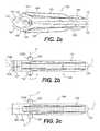
- FIGS. 2 a , 2 b , and 2 cshow side, top, and bottom views respectively, of the clip shown in FIG. 1 .
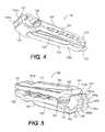
- FIGS. 3 and 4show perspective views of the clip shown in FIG. 1 from a first side.
- FIG. 5shows a perspective view of the clip shown in FIG. 1 from the side opposite to that shown in FIGS. 3 and 4 .
- FIG. 6is another side view of the clip shown in FIG. 1 .
- FIG. 6 ais a close-up detail view of the portion of the clip shown in FIG. 6 in region “ 6 a ” therein.
- FIG. 6 bis a sectional view of the clip shown in FIG. 6 taken along section B-B in the direction shown in FIG. 6 .
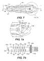
- FIG. 7is another side view of the clip shown in FIG. 1 from the opposite side to that shown in FIG. 6 .
- FIG. 7 ais a close-up detail view of the portion of the clip shown in FIG. 7 in region “ 7 A” therein.
- FIG. 7 bis a sectional view of the clip shown in FIG. 7 taken along section C-C in the direction shown in FIG. 7 .
- FIGS. 8 a , 8 b , and 8 care side, top, and bottom views, respectively, of the clip shown in FIG. 1 in an open position.
- FIG. 9is a perspective view from the bottom of the clip shown in FIG. 8 a in the open position.
- FIG. 10is a perspective side view from the top of the clip shown in FIG. 8 a in the open position.
- FIGS. 11 a , 11 b , and 11 cshow side, top, and bottom views respectively, of the clip shown in FIG. 1 , with the proximal locking components in locked position.
- FIG. 12is a perspective view from the top of the clip shown in FIG. 11 a.
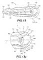
- FIG. 13is a side view of the clip shown in FIG. 11 a.
- FIG. 13 ais a close-up detail view of the portion of the clip shown in FIG. 13 in region “ 13 a ” therein.
- FIG. 14is a side view of the clip shown in FIG. 11 a from the side opposite to that shown in FIG. 13 .
- FIG. 14 ais a close-up detail view of the portion of the clip shown in FIG. 14 in region “ 14 a ” therein.
- FIG. 15is a view of the clip shown in FIG. 1 .
- FIG. 15 ais a close-up detail view of the portion of the clip shown in FIG. 15 in region “ 15 a ” therein.
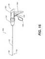
- FIG. 16shows a side view of an applier.
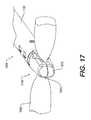
- FIG. 17shows an applier clamped on vessel.
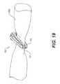
- FIG. 18shows an isometric view of clip latched on vessel.
- FIG. 19shows a clip latched on vessel.
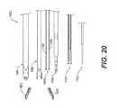
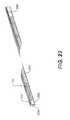
- FIG. 20shows an exploded view of applier parts.
- FIG. 21shows a wedge
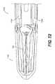
- FIG. 22shows a catch
- FIG. 23shows a punch
- FIG. 24shows a clip indicator
- FIG. 25shows an inner tube
- FIG. 26shows a jaw/inner tube camming
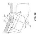
- FIG. 27shows a jaw/inner tube cam points.
- FIGS. 28 a , 28 b and 28 cshows jaws.
- FIG. 29shows an outer tube
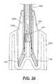
- FIG. 30shows an applier shaft distal end.
- FIG. 31shows an applier shaft proximal end.
- FIG. 32shows loaded clips in cartridge.
- FIG. 33shows a cross section view of loaded clip.
- FIG. 34shows clip legs held by detents in cartridge.
- FIGS. 35 and 36shows a clip cartridge
- FIG. 37shows an approach to cartridge for clip load.
- FIG. 38shows a clip load
- FIG. 39shows an approach to clip cartridge (cartridge and clip not shown).
- FIG. 40shows a clip load (cartridge not shown).
- FIG. 41shows a clip loaded
- FIG. 42shows jaws closed.
- FIG. 43shows a clip advance into jaw over vessel.
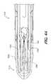
- FIG. 44shows a clip advanced over vessel wedges begin to advance.
- FIG. 45shows wedges advance to close clip.
- FIG. 46shows a punch latches clip on vessel.
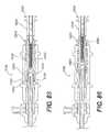
- FIG. 47shows a punch moves up to buttress.
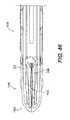
- FIG. 48shows a buttress rotating as the punch moves forward.
- FIG. 49shows a clip just before latch.
- FIG. 50shows a clip locked
- FIG. 51shows wedges retract.
- FIG. 52shows wedges fully retracted.
- FIG. 53shows a punch retracting
- FIG. 54shows a clip free/jaws open.
- FIG. 55shows a punch fully retracted.
- FIG. 56shows an internal end view of an applier shaft.
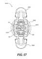
- FIG. 57shows an end view of applier with jaws open and clip loaded.
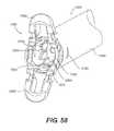
- FIG. 58shows a isometric view of distal end of applier.
- FIG. 59shows a isometric view of distal end of applier shaft with clip loaded.
- FIG. 60shows a clip viewport
- FIG. 61shows a second embodiment of the applier.
- FIG. 62shows a second embodiment—catch tube with wedges and catches.
- FIG. 63shows a second embodiment—catches and wedges.
- FIG. 64shows an applier handle
- FIG. 65shows a handle configuration (outer shell hidden).
- FIG. 66shows trigger components
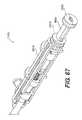
- FIG. 67shows a handle configuration (upper trigger hidden).
- FIG. 68shows internal handle components.
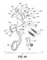
- FIG. 69shows multistage transmission components.
- FIG. 70shows an assembled multistage transmission.
- FIG. 71shows a transmission outer shell and with the Leur port removed.
- FIG. 72shows a transmission with the jaw actuator links removed.
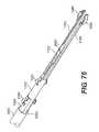
- FIG. 73shows a transmission with the catch pusher latches and dowels removed.
- FIG. 74shows a transmission with the punch latch interlock and dowel removed.
- FIG. 75shows a transmission with the center spindle and dowel removed.
- FIG. 76shows a transmission with the punch return spring removed (distal shaft connection points shown).
- FIG. 77shows a cross-section of the transmission where the jaws are open (clip loaded).
- FIG. 78shows a cross-section of the transmission where the jaws are closed (clip loaded).
- FIG. 79shows a cross-section of the transmission where the clip is advanced.
- FIG. 80shows a cross-section of the transmission where the clip is closed.
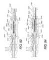
- FIG. 81shows a cross-section of the transmission where the clip is latched.
- FIG. 82shows a cross-section of the transmission where the wedges return.
- FIG. 83shows a cross-section of the transmission where the connection pins are no longer in the pocket.
- FIG. 84shows a cross-section of the transmission where the punch is unlatched.
- FIG. 85shows a cross-section of the transmission where the clip is free from the device.
- FIG. 86shows a cross-section of the transmission where the punch spring has returned.
- FIG. 87shows an isometric view of a transmission in an embodiment that does not have a punch latch interlock.
- FIG. 88shows an exploded isometric view of another embodiment showing multistage transmission components
- FIG. 89shows a cross-section of the transmission where the jaws are open (clip loaded).
- FIG. 90shows a cross-section of the transmission where the jaws are closed (clip loaded).
- FIG. 91shows a cross-section of the transmission where the clip is advanced (wedges and catch move together).
- FIG. 92shows a cross-section of the transmission where the clip is latched.
- FIGS. 93-97show side views of an applier in some FIGS. internal components are exposed and illustrated.
- FIG. 98is a side view of another clip used in accordance with an embodiment of the invention.
- FIG. 99is a top view of a clip illustrated in FIG. 98 .
- FIG. 100is a isometric view of the clip illustrated in FIG. 98 .
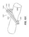
- FIG. 101is an isometric view of a clip applied onto tissue or a blood vessel.
- FIG. 102is a side view of a clip locked onto a tissue or blood vessel.
- FIG. 103is a isometric view of a distal end of applier.
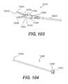
- FIG. 104is a isometric view of a shaft assembly.
- FIG. 105is a isometric view of a handle assembly.
- FIG. 106is an isometric view of a clip cartridge.
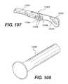
- FIG. 107is an isometric view of a jaw.
- FIG. 108is an isometric view of a pivot rivet.
- FIG. 109is an isometric view of a distal locking clevis tube.
- FIG. 110is an isometric view of a proximal locking clevis tube.
- FIG. 111is an isometric view of an actuation shaft.
- FIG. 112is an isometric view of a spring.
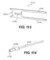
- FIG. 113is an isometric view of a clip lock actuator.
- FIG. 114is an isometric view of a distal pushrod.
- FIG. 115is a partial isometric view of applier jaws.
- FIG. 116is a partial isometric view of a distal portion of an applier.
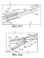
- FIG. 117is an isometric, cross-sectional, partial view of a portion of an applier.
- FIGS. 118-120are partial cutaway views of the distal portion of an applier.
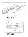
- FIG. 121is a partial distal view of a midsection of an applier.
- FIG. 122is a partial cutaway view of the jaws of applier.
- FIG. 123is a side view of another clip that may be used in accordance with invention.
- FIG. 124is a side view of the clip shown FIG. 123 and a closed position.
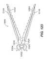
- FIG. 125is a isometric view of the clip illustrated in FIG. 123 .
- FIG. 1shows a view of a first embodiment of a surgical ligation clip 100 in accordance with present invention.
- the clip 100defines a longitudinal axis “L” along its longest dimension and includes a first leg 101 and a second leg 102 each extending along the longitudinal axis L and having proximal 111 , 112 and distal 121 , 122 end portions with respect to said longitudinal axis.
- proximalshall refer to the portion of the clip referenced herein which is away from the tips of the clip which open
- distalshall refer to the portion of the clip at the tips which open, in accordance with the convention that the clip is inserted distal tip first through an instrument towards an anatomical body to be ligated, such that distal generally refers to the direction away from the user or applier of the surgical clip and proximal refers to the direction opposite to distal.
- a clip hinge 130joins the first and second legs 101 , 102 at a point on their respective proximal end portions 111 , 112 , the first and second legs each having respective inner clamping surfaces 131 , 132 between the clip hinge 130 and the distal ends 123 , 124 of said first and second legs, the clamping surfaces being apposed when the clip is in a fully closed position.
- the term “apposed” when used with regard to the inner clamping surfaces 131 , 132shall mean close to, or nearly in contact with each other, allowing for some small spacing therebetween or a concave radius of curvature for the clamping surfaces, such to allow for a clipped vessel to reside between such apposed surfaces, as is more fully illustrated herein and with respect to the drawing figures.
- the clip hinge 130can include a bar or cylindrically shaped body or tube which defines a lateral pivot axis “P” (shown in FIGS. 2 b and 2 c ) about which the legs 101 and 102 pivot as the clip moves from open to closed position and vice versa.
- a first jaw structure 141 on the first leg 101extends proximal to a transverse axis “T” which is perpendicular to both the longitudinal axis L and lateral pivot axis P, all intersecting at a point “X” centered on the clip hinge 130 , as shown in FIG. 1 .
- the term “lateral”shall directionally mean orthogonal to both the directions of the longitudinal axis L and transverse axis T, and parallel to pivot axis P as shown in the figures.
- the first jaw structure 141includes a first curved inner surface 143 extending from the clip hinge 130 , the first curved inner surface 143 having a complex surface which is oriented at changing angles with respect to, but is generally facing towards, the longitudinal axis L, as shown in FIG. 1 .
- the curved inner surface 143is therefore substantially concave when viewed from the longitudinal axis (or plane spanning the longitudinal axis and pivot axis).
- substantially concaveshall mean a surface which is concave in overall curvature, but which may include one or more component areas which may have convex segments or protrusions, such as a notch surface or recess for mating thereto.
- a second jaw structure 142is on the second leg 102 extending proximal to the transverse axis T and has a second curved inner surface 144 extending from the clip hinge 130 .
- the “curved inner surface”can include either a single smoothly curved surface segment, or a series of connected curved or straight planar segments, which, taken together, form an overall generally curving surface.
- the surgical clip of the present inventionprovides that the jaws 141 and 142 are each substantially proximal to a transverse plane extending through transverse axis T and lateral pivot axis P, thus behind the clip hinge 130 , thereby providing a means for actuating the clip legs 101 and 102 and biasing or locking the clip and its mating faces 131 , 132 in a closed position, which biasing or locking means can be actuated and/or applied by acting only on the proximal end portions of the clip 100 , without having to lock the distal ends 123 , 124 to each other or use a clip applier tool which acts on said distal ends 123 , 124 , thereby obviating the need to dissect tissue around the distal end of the clip as in previously known surgical ligation clips.
- the means for biasing or locking the clip closedincludes a wedge or buttress body 150 which extends from and is connected to the second jaw structure 142 by a first living hinge 160 at a proximal end of said second jaw structure 142 , the buttress body 150 having an outer surface 151 at a proximal first end portion thereof, which is also disposed approximately as the proximal end of the clip 100 overall.
- the first and second jaw structures 141 , 142are spaced on opposite sides of the longitudinal axis L and define a locking space 170 therebetween.
- the wedge or buttress body 150is pivotable about the living hinge 160 to move into the locking space 170 such that the outer surface 151 of the proximal first end portion of the buttress body 150 abuts against a proximal portion 145 of the curved inner surface 143 of the first jaw structure 141 to bias the clip in a closed position (as best shown in FIGS. 11 a , and 12 - 14 ).
- the clip 100is shown in FIG. 1 in a closed position, this is with the locking means of the first and second jaws 141 , 142 and buttress body 150 being in the “unlocked” position as shown in FIGS. 1, 2 a , and 3 - 7 .
- the buttress bodyis in the “locked” position as shown in FIGS.
- the first and second jaws 141 , 142are urged or spread apart (shown, as an example, by arrows “J 1 ” and “J 2 ” in FIGS. 13 a and 14 a ) by action of surfaces of the wedge/buttress body 150 acting on portions of curved inner surfaces 143 , 144 , which act as moments about the clip hinge 130 and lateral pivot axis P to urge the legs 101 , 102 and its inner clamping surfaces 131 , 132 to become more closely apposed to each other, thereby providing additional clamping and closing force over a vessel around which the clip is applied.
- a variety of meansmay be used to actuate the wedge or buttress body 150 from the unlocked position in FIG. 1 to the locked position shown in FIGS. 11 a , 12 - 14 .
- an external forceshown, for example, as arrow “F” in FIG. 1
- the external force appliedmay be at a small angle to the longitudinal axis L, such as, for example, a force shown by arrow “F*” shown in FIG. 1 .
- the applied external forcewill create a moment about living hinge 160 to pivot the buttress body 150 into the locking space 170 .
- the external forcemay be applied by an actuating rod or other structural means in an applier instrument, or may be another clip as fed through a multi-clip applier.
- the clip 100may be inserted through an instrument having a bore or channel for receiving the clip 100 , through which the clip 100 may travel distally for positioning near a vessel during a surgical procedure.
- the clipmay be inserted in a legs closed position, but with the proximal locking means including buttress body 150 in open, unlocked position.
- the clip 100can be inserted in such fashion in closed form, the clip forms a narrow profile and can fit in smaller sized surgical instruments, thereby allowing for smaller incisions and tissue dissection or damage during surgery.
- a rod or other actuating mechanism translating or moveable on the instrument inserting the clip, or a second instrument or second clip used in conjunction with the instrument used for inserting and positioning the clip in place,maybe used to lock the clip by application of an external force on the proximal end portion of the clip as discussed above.
- a method of applying a surgical ligation clip on a vesselincludes positioning a clip, such as, for example, clip 100 , in an open position proximate a vessel, the clip having first and second legs each extending along a longitudinal axis of the clip and having proximal and distal end portions with respect to said longitudinal axis, a clip hinge means joining the first and second legs at a point on their respective proximal end portions, the first and second legs each having inner clamping surface means between the clip hinge and the distal end portions of said first and second legs, the clamping surface means being apposed when the clip is in a fully closed position.
- a clipsuch as, for example, clip 100
- a locking means for biasing the legs closedmay extend proximal to a transverse axis perpendicular to the longitudinal axis intersecting at a point centered on the clip hinge.
- the methodincludes applying an external force to a proximal end portion of the clip or of one of the legs which forms a portion of the locking means, to move a body formed as a first part of said locking means from a first position to a second position to provide an abutment force between said body and a surface formed on a second part of said locking means to bias the clip in a closed position.
- an instrumentin the method, may be used, wherein, in moving the clip through the instrument prior to positioning the clip proximate a vessel, a portion of the instrument opens the clip from a closed position to an open position, such that the legs of the clip open for placement of the clip around a vessel.
- the locking meansmay then be applied to the proximal end portion of the clip to move and bias the legs closed and clamp the clip more fully over the vessel.
- the clamping surfacesappear substantially parallel to each other, oriented, in the clip closed position, substantially or very close to parallel to a plane extending through the longitudinal axis L and lateral pivot axis P.
- the inner clamping surfaces 131 , 132may be slightly curved concave when facing said surfaces, such that the surfaces bow away from the longitudinal axis L and straighten slightly when clamping force is applied by action of the locking mechanism of the buttress body 150 acting against jaws 141 , 142 . This allows for enhanced grasping and occlusion of vessels around which the clip 100 is applied, wherein the clamping force is spread more evenly across the clamping surface.
- the living hinge 160 connecting the wedge or buttress body 150 to the second jaw 142can be integral to the second jaw 142 such that the clip body of second leg 102 proximal to transverse axis T extends as a single unitary structure including the second jaw 142 and entire wedge or buttress body 150 .
- a lateral beam or curved body 152connects the living hinge 160 to the rest of the buttress body 150 , which beam 152 curves from the living hinge 160 (which is separated by a distance from the longitudinal axis L) towards the longitudinal axis L.
- portions of wedge of buttress body 150can be oriented on both sides of longitudinal axis L.
- the pivot axis of living hinge 160extends in a lateral direction parallel the lateral pivot axis P of the main clip hinge 130 .
- the present inventionprovides, in various embodiments, a locking mechanism cooperating between the buttress body 150 and another portion of the clip.
- the proximal end portion 145 of the curved inner surface 143 of the first jaw structure 141defines a notch 147 recessed from said curved inner surface 143
- the buttress body 150defines a detent 157 formed on the outer surface thereof, the detent 157 mating with the notch 147 when the buttress body 150 is pivoted into the locking space 170 to bias the clip in the closed position, as best shown in FIGS. 11 a , 12 , and 14 .
- FIGS. 2 a , 2 b , and 2 cshow side, top, and bottom views respectively, of the clip shown in FIG. 1 .
- the wedge or buttress body 150can be divided into two lateral sections or portions 150 a and 150 b , each on opposite sides of the longitudinal axis L as shown, and can form approximate lateral halves of the buttress body 150 , with a possible space or small channel in-between.
- Lateral portion 150 b of the buttress body 150can have a width in a plane spanning the transverse and longitudinal axes sufficient to exceed a complementary width formed by the locking space 170 to create an interference fit between the proximal end portion 145 of the curved inner surface 143 of the first jaw structure 141 and the outer surfaces 151 a , 151 b on the proximal first end portion outer surface 151 of the buttress body 150 , to bias the clip in a closed position.
- An example of the transverse width of said lateral portion 150 bis shown as distance “TW 1 ” in FIG.
- the buttress body 150once locked into place as shown in FIG. 12 , is prevented from moving laterally from side to side since the notch 147 and detent 157 interlock only extends laterally partially across the clip, the detent 157 being limited in lateral movement by a shoulder 187 formed by a termination of the notch 147 laterally into the first jaw structure 141 , as shown in FIG. 9 .
- the lateral slice of buttress body 150only extends for a lateral width LW 1 which includes detent 157 , which the lateral slice LW 2 of buttress body 150 on the other side of the clip does not include the detent 157 .
- the proximal locking mechanism of the clip 100is more stable in lateral directions, which is also useful for keeping all parts of the clip together in the event the living hinge 160 may break.
- the outer surface 151 on proximal first end portion of buttress body 150 on a proximal end of the clip 100defines one or more surfaces which form a curved planar segment abutment portion, which in the embodiment as shown includes curved planar segment abutment portions 151 a and 151 b .
- the “curved planar segment abutment portion” formed by a surfacemay include a single curved surface segment or a series of curved or straight planar surface segments connected to one another which form an overall generally curved surface, each of the surface segments extending as a surface at least laterally. In the embodiment shown in FIG.
- curved planar segment abutment portion 151 aincluded planar and curved surface segments formed by the notch 157 and extends laterally for about one-half of the lateral width of clip 100
- curved planar segment abutment portion 151 bincludes planar and curved surface segments which also extend laterally for about one-half of the lateral width of clip 100 .
- Each of the curved planar segment abutment portions 151 a and 151 b on outer surface 151forms a substantial abutment surface that pushes against complementary curved inner surfaces of jaw 141 to provide a stronger and more stable locking mechanism for clip 100 .
- the second curved inner surface 144 on the second jaw structure 142forms a first laterally spanning recessed groove 146 separated from the clip hinge 130 and a first laterally spanning ball-shaped or rounded protruding surface 148 proximal to said recessed groove 146
- a distal second end portion of the buttress body 150forms a second laterally spanning recessed groove 158 and a second laterally spanning ball-shaped or rounded protruding surface 156 distal to said second recessed groove which are shaped complementary to the first rounded surface 148 and first recessed groove 146 , respectively, so as to mate in abutment when the buttress body 150 is pivoted into the locking space 170 to further stabilize and bias the clip in a closed position.
- the first recessed groove 146 , first rounded surface 148 , second recessed groove 158 , and second rounded surface 156may extend laterally all the way across the lateral width of the buttress body 150 , such that the first rounded surface 148 and second rounded surface 156 are not spherically shaped but rather form an extended, laterally-spanning, rounded, semi-cylindrical surface which can mate in corresponding semi-cylindrical shaped grooves formed by first recessed groove 146 and second recessed groove 158 .
- the buttress body 150can further define a second living hinge 162 extending laterally between the proximal first end portion 150 c of buttress body 150 and a distal second end portion 150 d , wherein the proximal first end portion 150 c including outer surface 151 further pivots about said second living hinge 162 when the buttress body 150 moves into the locking space 170 , allowing the outer surface 151 of the proximal first end portion 150 c of the buttress body to flex towards the longitudinal axis L prior to abutment against the curved inner surface 143 of the first jaw structure 141 .
- the outer surface of the proximal end of the buttress body 150 , or clip 100 itself,defines a V- or L-shaped laterally spanning notch 150 x on the proximal end of the clip 100 and further defines a laterally spanning flange 150 y extending from said notch 150 x adjacent to the curved planar segment abutment portions 151 a and 151 b .
- Each of notch 150 x and flange 150 ymay be divided into two lateral sections or components divided by a small space or channel there between as they are disposed on the lateral sectional halves 150 a and 150 b of the buttress body 150 .
- the notch 150 xprovides a receiving space for the tip of an instrument, pushing or actuating rod, or another clip, so as to enable a more stable actuation of the buttress body 150 into locking space 170 to lock the clip 100 .
- the flange 150 ymay act to limit the movement of buttress body 150 once fully inserted into locked position inside space 170 , and also further stabilizes the locking mechanism for the clip 100 .
- the buttress bodymay occupy a majority of a volume defined by locking space 170 when it is moved into clip locked position so as to bias the legs 101 , 102 in a closed position.
- the volume defined by the locking spaceis limited by the lateral width of the clip legs 101 , 102 near the hinge 130 and the jaws 141 and 142 .
- the remaining locking space 170 ′ between jaws 141 and 142once the clip is locked by movement of the buttress body 150 into space 170 , is less than half the volume of the locking space 170 as shown in FIG. 6 a .
- the presence of a bulky body like buttress body 150which occupies the majority of the volume or space between proximal extending jaws 141 and 142 when the clip 100 is in the locked position further provides a greater strength and stability to the locking of said clip.
- the buttress body 150can be characterized in one way as having a core mass which has, in a transverse plane spanning the longitudinal and transverse axes, a cross-section which approximately spans a trapezoidal shape, having rounded curved sides extending from the sides TP 1 , TP 2 , TP 3 , TP 4 of the trapezoid.
- Side TP 1defines the longest side and one of the parallel sides of the trapezoid, while side TP 2 defines the shorter parallel side.
- Side TP 3defines the longer and more distal of the non-parallel sides, while side TP 4 defines the shorter and more proximal non-parallel side.
- Side TP 1is therefore connected to sides TP 3 and TP 4 .
- the vertex TPX 1 of sides TP 1 and TP 4lies approximately on or near the longitudinal axis L, and side TP 1 makes an angle ⁇ below the longitudinal axis, towards proximal jaw 142 , such angle ⁇ being, in one embodiment, approximately 30 degrees.
- the rounded laterally-spanning protuberance 156extends substantially from side TP 3 .
- the clip hinge 130can also be a resilient hinge providing additional biasing force to maintain the inner clamping surfaces 131 , 132 of the legs towards a closed position.
- a span of each leg extending from the clip hinge 130 to its respective distal tip 123 , 124can be, in one embodiment of the present invention, at least 75% to 80% of an overall length of the clip.
- the clip hinge 130can define lateral bosses which extend laterally from the side surfaces of the clip legs, defining a bossed width or span which is greater than the clip width.
- the clip hinge 130is formed as a laterally extending bar 130 x integrally formed with the first and second legs 101 , 102 , each leg being resiliently coupled to first and second transverse sides of said bar, the bar 130 x further defining laterally spanning grooves 130 a and 130 b on longitudinally distal and proximal sides of the bar, respectively.
- These grooves 130 a and 130 bfurther enable the clip 100 to flex as pivoting about the lateral axis of hinge 130 , and further provide a resilient pivoting moment or force about said hinge.
- flanges 191 and 192extend longitudinally across respective outer surfaces of each of the first and second legs 101 , 102 which are on opposite sides to the inner clamping surfaces 131 , 132 of each respective leg, the flange 191 of the first leg 101 extending from the first jaw structure 141 to the distal end portion 121 of the first leg 101 , the flange 192 of the second leg 102 extending from the second jaw structure 142 to the distal end portion 122 of the second leg 102 .
- Each of the flanges 191 , 192defines a transverse indentation 191 a , 192 a proximate the distal end portions 121 , 122 of the legs 101 , 102 .
- the flanges 191 and 192provide a rigidity to legs 101 and 102 , respectively, such that said legs do not easily bend.
- Transverse indentations 191 a and 192 aprovide a means for a clip applier to better actuate or grip the legs 101 , 102 .
- the clip 100further includes serrations, ridges, or teeth 181 , 182 on the inner clamping surfaces 131 and 132 , respectively, as shown in FIGS. 6 b and 7 b , and 9 , 10 , and 15 a .
- the teeth or ridges 181 , 182provide additional grasping means to better attach and clamp the clip 100 onto a vessel when closed.
- the teeth or ridges 181 , 182are disposed to fit into complementarily arranged grooves 183 and 184 on the clamping surfaces 131 and 132 , respectively.
- the teeth 181 , 182may have a slanted orientation, extending proximally, so as to better grip tissue. As best shown in FIGS.
- a pair of distal hook elements 194 and 195may be disposed on the absolute distal tips of legs 101 and 102 , respectively, each hook 194 and 195 offset laterally with respect to each other to form a scissor-like configuration, such that each hook 194 and 195 fit into corresponding recesses 195 a and 194 a , respectively, on the distal tips of legs 102 and 101 , respectively.
- This mechanismprovides means to further grip and contain tissue with the space between the clamping surfaces 131 , 132 when the clip 100 is applied to body vessel, as illustrated in FIGS. 19 and 20 .
- the clip 100may be in a range of sizes. As shown in FIG. 15 , an overall length “S 1 ” of the clip 100 may be approximately 0.50 inches; the length “S 2 ”, between the intersection of transverse axis T and longitudinal axis L centered at clip hinge 130 and the distal tip of the clip, may be approximately 0.40 inches, and the radius of curvature of the inner mating or clamping surfaces 131 , 132 of the legs 101 , 102 may be approximately 3.0 inches. Such sizes and dimensions are given as an example, and it is understood that the clip may, in one or more embodiments of the invention, vary in size ranging from approximately 0.15 to 0.80 inches in overall longitudinal length, and from approximately 0.03 to 0.15 inches in lateral width. As one embodiment of the invention, the illustration of clip 100 in FIG. 15 is shown as a scaled magnification of actual size, and shows all the parts of the clip 100 in actual proportion to each other.
- the instrumentation used to deploy the clips discussed hereinmay include a manually loaded device that can apply a single clip at a time, or an automatically fed, multiclip applier.
- Both applierscan be endoscopic instruments suitable for use in laparoscopic surgery applications. In both cases the applier will clamp over the vessel to flatten the section to be ligated. The clip will then be opened, positioned over the vessel and closed. Once closed, a mechanism will engage the locking feature on the proximal end of the clips disclosed herein, to maintain the clamping pressure of the clip.
- a manual applierwill load/apply a single clip at a time.
- An automatic applierwill be able to load/apply multiple clips before the instrument has to be removed from the surgical site.
- the sequence of clip applicationis as follows:
- the various embodiments of the clips disclosed hereintherefore can start in an as-molded state; can be opened further to better encapsulate the vessel; and can then be closed further (into a third state). This process of opening and closing the clip can be repeated as needed, prior to locking.
- the clipWhen closed and locked, the clip provides an active clamping force which can also squeeze the vessel, which is beneficial if the vessel necroses and/or shrinks over time.
- the various embodiments of the surgical clips of the present inventionare preferably made of one or more polymer materials, such as, by example, acetyl homopolymer, but could also be made of a variety of other materials, including one or more metals, or a combination of metal and polymer or plastic.
- the radiopacity of the clipcan be “tuned” to a desirable level, or can be tuned to be radiopaque.
- the various embodiments of surgical clips of the present inventionare an improvement over the known polymeric surgical ligation clips, as well as standard metal clips.
- the resulting advantages of the surgical clip of the invention as disclosed hereinare: the ability to deliver a larger clip through a smaller endoscopic instrument; the ability to place a clip on a vessel just like a prior art malleable and deformable metal clip, with no need for added dissection or cleaning around the vessel, but with greater retention force than metal clips, which results in a reduced risk of clips slipping off the vessels.
- the greater clip locking stability and clip retention forceis accomplished by the locking feature applying an active biasing or clamping force as discussed above, versus the passive clamping action created by plastic deformation of malleable metal clips.
- the distal portion of the applierwould be attached to a proximal handle with components that achieve the proper sequence to successfully apply a ligation clip.
- FIG. 20One particular embodiment, of the distal portion of the invention, consists of nine parts which make up the distal end, or shaft of the applier, parts are shown and labeled in FIG. 20 .
- Each of these partsare put together to form the applier shaft.
- FIG. 30shows the distal end of the shaft assembly
- FIG. 31shows the proximal end of the shaft assembly.
- There is a varied length between the distal and proximal portions of the shaftwhich is a function of standard endoscopic instrumentation suitable for use in laparoscopic surgery applications.
- the manual applierhas a clip loaded into the applier before it can apply a clip.
- the clipsmay be loaded into the applier with, but are not limited to, the use of a clip cartridge where clips are presented to the applier in a particular orientation.
- a version of a clip cartridge, for illustration purposes only,is shown in FIG. 32-36 .
- FIG. 37shows the distal end of the applier on approach to the cartridge and FIG. 38 shows the distal end of the shaft in the clip load position. Following images will exclude the Clip cartridge so that the specific actuation of the individual parts can be seen.
- FIG. 39shows the applier in a free state which is the same state the applier will be in on approach to the clip cartridge. Note the location of the parts in the assembly as this will be used as a reference location of the parts during actuation of the applier (images not to scale).
- the outer tuberemains stationary and is the base for the shaft components. On the distal end of the outer tube there are spring fingers that force the wedges together as they move within the assembly. The end of the outer tube has two tabs with holes that the jaws mount into.
- the inner tubeis inserted into the outer tube and controls the actuation of the jaws, which are assembled to the distal end of the outer tube in the tabs on the end; see FIG. 29 for tab location.
- the jawsuse the hole in the tab of the outer tube as a bearing surface in which they rotate.
- the actuation of the inner tube and jawsare independent of all other parts in the applier shaft. This allows the jaws to be used in grasping and dissecting with or without a clip in the load position. During the loading of the clip the jaws are fully open.
- the clipis loaded into the distal end of the applier shaft by pressing the clip bosses into the clip catch.
- the catchis inserted into the outer and inner tubes. There are two sets of legs cut into the distal end of the catch, see FIG. 22 . The legs on each side of the catch spread apart when the clip bosses are pressed into them. Once the clip bosses reach the circular cutout, on the distal end of the catch, the legs spring back together and capture the clip bosses.
- the catchalso has tabs that orient the wedges.
- the clipis forced open by the fingers on the distal ends of the wedges, see FIG. 21 .
- the wedgesare inserted into the catch and orientated by the tabs on the catch to capture the upper and lower halves of the clip.
- the distal ends of the wedgesare forced together by the spring fingers on the outer tube; this is where the force to open the clip comes from.
- the wedgescapture and orient the punch, which in turn biases the wedges into the tabs of the catch, see FIG. 56 .
- FIG. 57 and FIG. 59show different views of a loaded clip in the applier with the jaws open.
- the view portis located to view the boss of a clip from either side of the applier and is position so the boss can only be viewed in the loaded position, see FIG. 60 .
- the clip indicatoris spring loaded so that the distal end is always biased toward the distal end of the applier until it is pushed against by the clip.
- a flag on the proximal end of the clip indicatorsignals the operator visually that the clip is present.
- the jawsare then used to grab the vessel intended to be ligated.
- the jawsflatten out and hold the vessel so that the loaded clip can be advanced over the vessel, closed, and locked.
- the compression of the vesselallows for a thinner cross-section for the clip to advance over and holds the vessel in place while the clip is being closed to ensure that the clip is fully seated on the vessel before it is locked.
- the jawshave half circle cutouts to allow fluid to flow out of the vessel when the clip is closed. This keeps the vessel from forming a “bubble” in the jaw cavity.
- the clipis advanced into the jaws from the load location.
- the catch, wedges, and punchmove toward the distal end of the shaft in unison, see FIG. 43 .
- the legs of the clipare stopped by the inner end surface of the jaws.
- the catchthen remains stationary as the wedges advance over the clip legs forcing the clip to close.
- the wedgesare advancing the punch is advancing up to the buttress of the clip, see FIG. 47 .
- the punchcontinues forward forcing the locking mechanism on the clip to rotate into the clip's locked position, see FIG. 48-50 .
- the punchbegins to retract toward the proximal end of the applier shaft, see FIG. 53 .
- the jawscan be opened and the clip is now free from the applier, see FIG. 54 .
- the punchis quickly returned to its start position.
- the punchmay be, but is not limited to being, spring loaded for the quick return. At this point, the punch is fully retracted and all parts are returned to their start positions, see FIG. 55 .
- the wedges and catchesare separate pieces attached to a catch tube, see FIGS. 60-63 , and have the same forward actuation sequence as the first embodiment to lock the clip but does not require a dwell on the punch when the punch returns to the start position.
- the wedge and catch assemblystop just short of the clip stopping on the inner end surface of the jaws.
- the punchis then pushed forward to engage with the locking feature of the clip.
- the clipis first pushed out of the catch and wedges until the legs of the clip stop on the inner end surface of the jaws.
- the punchcontinues forward forcing the locking mechanism on the clip to rotate into the clip's locked position. During the rotation of the locking mechanism of the clip the legs are clamped together with the locking mechanism instead of the wedges as previously described.
- This embodimentalso has internal leaf springs attached to the inner tube that bias the ends of the wedges together to open the clip during advance.
- the proximal end of the applier, or applier handleis made up of many parts that provide a user interface portion of the applier. Each of the distal end actuations are accomplished through the use of the proximal handle.
- the handlehas a two piece outer shell which stages the internal actuating components and provides a bearing surface for a multi stage transmission to allow 360° continuous rotation of the distal end.
- both triggersrotate around the same centroid, see FIGS. 65-67 .
- the lower triggeractuates the jaws and the upper trigger actuates the clip delivery sequence.
- the lower triggeris attached to the multistage transmission through two mirrored linkages which have features that allow the trigger to lock down when the jaws are closed. This feature is an over center cam.
- the linkagesalso have an inner profile which allows them to drive the section of the multistage transmission that actuates the jaws while allowing the 360° continuous rotation.
- the return stroke of the lower triggeris accomplished through a return spring attached to a cable that wraps around the front of the trigger and based on a pin at the proximal side of the handle.
- the upper triggeris attached to the multistage transmission through a linkage which has and inner profile that drives the section of the multistage transmission that actuates the clip delivery mechanisms and also allows the 360° continuous rotation.
- the return stoke of the upper triggeris accomplished through a return spring attached to the back side of the trigger and based on a pin at the proximal side of the handle. For both the actuation and return strokes there is a one way pawl that limits the direction of the upper trigger until a full stroke is completed, see FIGS. 65-68 for trigger and actuating components.
- the trigger functionsare reversed so that the upper trigger actuates the jaws and the lower trigger actuates the clip delivery mechanisms.
- the distal portion of the applieris connected to the handle through the multi stage transmission, see FIGS. 65-68 .
- One embodiment of the transmissionis made up of a two piece outer shell which acts as the bearing to allow the rotation of the distal end. Internal to the shell are features that guide the internal components during the actuation sequences of the applier.
- the jaw linkssnap together and ride on the internal surface of the transmission shell.
- the area between the jaw linksis open to allow for additional transmission parts.
- center spindlesthat snap together and attach to the wedges
- the interior surface of the center spindlesprovide a guide for the spring loaded punch
- the outer surfacesprovide a guide for the catch pusher latch and the punch interlock.
- the catch pusher latch and the punch interlockmove over the center spindles and are guided in slots on the outer shell of the transmission. Small pins move in and out of groves in the two pieces and the outer shell to achieve the appropriate timing for the clip delivery mechanisms in the shaft, see FIGS. 69-76 for the transmission assembly and FIGS. 77-86 for actuation sequence.
- FIGS. 87-88for a view of the second embodiment of the transmission
- FIGS. 89-92for the actuation sequence.
- FIG. 16is a side view of an applier 1000 in accordance with an embodiment of the invention.
- the applier 1000has a clam shell housing 1020 , a handle 1040 , a jaw trigger 1060 , and a ligate trigger 1080 .
- a jaw trigger 1060 and ligate trigger 1080are actuated by pulling the triggers 1060 and 1080 toward the handle 1040 .
- Applier 1000also includes a shaft 1120 which carries the jaws 1140 on the distal end 1160 , which is opposite from the proximal end 1180 .
- FIG. 17is a partial isometric view of the applier 1000 clamped onto a blood vessel 1580 or other tissue 1580 .
- the jaws 1140have clamped onto and deformed the vessel 1580 .
- the portion of the shaft 1120is also shown carrying the top jaw 1600 and the lower jaw 1620 which together comprise the jaws 1140 .
- FIG. 18is an isometric view of a clip 100 clamped onto a blood vessel 1580 or tissue 1580 .
- the clip 100is in a clamping position and is attached to the vessel/tissue 1580 .
- the top leg or first leg 101is shown above the second or bottom leg 102 .
- FIG. 19is a side view of a clip 100 clamped onto a vessel 1580 or tissue 1580 .
- the clamp 100includes a top first leg 101 above the bottom or second leg 102 .
- the lockedlocks the first leg 101 and the second 102 is accomplished by locking the buttress body 150 .
- the buttress body 150has moved to a position where the first rounded surface 148 is fit into a first recess groove 158 . Further, the protruding surface 156 is fit within the second recessed groove 146 .
- the first living hinge 1400is deformed to allow a first rounded surface 148 and second protruding surface 156 to fit into the first recess groove 158 and second recess groove 146 respectively.
- the second living hinge 162is deflected to permit the detent 157 to fit within the notch 147 as shown in a locking manner, thereby keeping the first leg 101 clamped and nearly in contact with the second leg 102 .
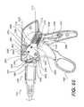
- FIG. 20is a side view of several of the parts used in the clamp applier 1000 . These parts are for the most part only partially shown and shown in a disassembled state. A top jaw 1600 and the bottom jaw 1620 are shown. The outer tube 1640 and the inner tube 1660 are also shown. The wedges 1680 including the top the wedge 1760 and bottom wedge 1780 are also shown. The catch 1700 is shown as well as the punch 1720 . At the bottom of FIG. 20 , the clip indicator 1740 is shown.
- FIG. 21is a partial isometric view of the wedges 1680 , specifically the top wedge 1760 .
- the top wedge 1760is a mirror image of the bottom wedge 1780 and that the bottom wedge 1780 may be similar to the top wedge 1760 only placed in an in inverted position as shown in FIG. 20 .
- the top wedge 1760includes a thicker portion 1820 , thicker portion 1820 may include a slanted surface 1840 which provides a transition between a thicker portion 1820 and the standard portion of the top wedge 1760 .
- the wedges 1680may have a U-shaped cross-section resulting in a channel 1850 .
- a bracket 1860may be attached. The purpose of the bracket 1860 will be discussed in more detail later below.
- FIG. 22is a partial isometric view of catch 1700 in accordance with some embodiments of the invention.
- the catch 1700may include a shaft portion 1900 .
- the fork end 1960may include a slot 2020 .
- the slot 2020may start with a rounded cut out portion 2000 and terminate with a second cut out portion 2040 .
- the forked work end 1960may start with slanted surfaces 1980 , but the proximal end 1940 of the catch 1700 there may be an attached bracket 1950 which will be shown in additional figures and discussed in more detail later below.
- the catch 1700may also include guides 1970 .
- FIG. 23is a partial isometric view of the punch 1720 .
- the punch 1720may include projections 2060 which project up from the punch 1720 at the top and bottom. As shown in FIG. 23 , the punch 1720 may also have a longitudinal hole 2090 at the end as shown.
- the punch 1720may also include a slot 2070 and a hole 2080 located at the opposite end of the punch 1720 and the longitudinal hole 2090 .
- FIG. 24is a partial isometric view of a clip indicator 1740 .
- the clip indicator 1740may include a rectangular portion 2100 and a distal cylindrical portion 2140 and a proximal cylindrical portion 2120 located on the opposite side of the rectangular portion 2100 .
- FIG. 25is a partial isometric view of an inner tube 1660 in accordance with some of the embodiments of the invention.
- the inner tube 1660may include a viewing port or a pair of viewing ports 2180 .
- the inner tube 1660 at the front end as oriented in FIG. 25may include a T-shaped structure 2200 located on both the top and the bottom as oriented in FIG. 25 of the inner tube 1660 and U-shaped grooves 2220 on both the right and left side is oriented in FIG. 25 of the inner tube 1660 .
- the inner tube 1660may also include a longitudinal running slit 2230 .
- On the opposite end of the inner tube 1660 and the T-shape structures 2200may be a bracket 2160 located on the approximate end of the inner tubes 1660 .
- the bracket 2160may be shown in later figures and discussed in additional details later below.
- FIG. 26is a side view of the jaws 1140 .
- Atop jaw 1600is located above the bottom jaw 1620 as shown in FIG. 26 .
- Both the top 1600 and bottom 1620 jawsmay include grooves 2240 .
- the jaws 1140may include T-shape structure holes 2250 configured to accommodate and have T-shaped structure 2200 as shown and described in FIG. 25 , as shown also in FIG. 26 .
- FIG. 26also shows the first portion of the inner tube 1660 in the U-shaped groves 2220 as described with respect to the inner tube 1660 in FIG. 25 .
- FIG. 27is a partial close up view of a portion of FIG. 26 .
- the top jaw 1600is shown with the T-shape structure 2200 of the inner tube 1660 .
- the T-shape structure 2200is shown in the T-shape structure hole 2250 .
- the T-shape structure hole 2250has a geometry that allows the jaws 1140 to open and close while the T-shape structure 2200 remains within the T-shape structure holes 2250 .
- the top jaw 1600also has a caming surface 2280 that cams against a caming surface 2260 of the inner tubes 1660 as the jaws 1140 opens and closes.
- top jaw 1600While only a partial close-up view of the top jaw 1600 is shown, one of ordinary skill in the art will understand that the bottom jaw 1520 is similarly configured in a mirror type image fashion.
- the top jaw 1600also engages a bottom jaw 1620 at a push point 2300 when the jaws 1140 open and close.
- FIGS. 28 a , 28 b and 28 care isometric top and bottom views of the top jaw 1600 .
- the top jaw 1600includes the T-shape structure hole 2250 , hinge pin 2620 and hinge pin cap 2630 as shown in the various views. In some instances, in the FIGS. the hinge pin cap 2630 has been removed to expose the hinge pin 2620 .
- FIG. 29is a partial isometric view of the outer tube 1640 .
- the outer tube 1640may include a viewing port 2320 , spring legs 2420 which in some embodiments bias the wedges 1680 to a radially inward position.
- the outer tube 1640may also include eye brackets 2340 having holes 2400 .
- the eye brackets 2340 and holes 2400may be used for attaching the jaws 1140 .
- Inner tube 1640also includes a shaft portion 2360 and a rim 2380 located at the end of the shaft 2360 .
- FIG. 30is a partial isometric view of the applier 1000 in a partially assembled state.
- an outer tube 1640 with the jaws 1140comprising of the top jaw 1600 , the lower jaw 1620 .
- the jaws 1140contain the clip 100 .
- the catch 1700is located behind the clip 100 .
- the punch 1720is shown along with the hole 2090 in the end of the punch 1720 .
- the distal cylindrical portion 2140 of the clip indicator 1740is shown, located in the slot 2070 .
- FIG. 31is a partial isometric view of the applier 1000 where some of the outer portions removed so the inner portions can be shown.
- the applier 1000includes the outer tubes 1640 , the wedges 1680 are shown inside the outer tubes 1640 .
- the punch 1720is shown, the slot 2070 is shown with the rectangular portion 2100 fit into the slot 2070 from the punch 1720 .
- a spring 2440is located forward of the rectangular portion 2100 .
- a hole 2080 in the punch 1720is shown with a pin 2460 located in the hole 2080 .
- the top wedge 1760 and bottom wedge 1780are also shown along the brackets 1860 attached to the top wedge 1760 and bottom wedge 1780 .
- the manual applier 1000attains the clip 100 from a cartridge 2480 as shown in FIG. 32 .
- the clips 100are removed from the cartridge ports 2500 and the cartridge 2480 and placed into the applier 1000 .
- the loading processwill be illustrated in FIGS. 33-38 .
- FIG. 33a cross-sectional view of the cartridge 2480 is shown.
- the cartridge ports 2500is shown having a clip 100 inside the cartridge port 2500 .
- a detent 2520holds the cartridge 100 within the cartridge port 2500 .
- FIG. 34is a cross-sectional view of the cartridge 2480 showing the detent 2520 securing the cartridge 100 within the cartridge port 2500 .
- FIG. 35is an end view of the cartridge 2480 .
- FIG. 36is a side view of the cartridge 2480 showing the cartridges 100 located in the cartridge port 2500 . Protrusions 2540 are also shown on the cartridge 2480 .
- FIG. 37is a partial cross-sectional view of cartridge 2480 , showing the applier 1000 approaching the cartridge 2480 in order to obtain clip 100 from the cartridge 2480 .
- the jaws 1140 of the applier 1000are open and approaches the cartridge port 2500 in order to obtain a cartridge 100 .
- FIG. 38is a cross-sectional view of a cartridge 2480 where the applier 1000 as entered the cartridge port 2500 in order to obtain a clip 100 .
- the applier 1000has moved into the cartridge port 2500 .
- the jaws 1140have entered the jaw channels 2560 and the clip 100 is now inside the applier 1000 .
- FIG. 39is a partial cross-sectional view of the applier 1000 as it approaches the clip cartridge 2480 .
- the jaws 1140are in an open position.
- the inner tube 1660has moved to a forward position causing jaws 1140 to open.
- the catch 1700is in a position ready to receive the clip 100 (not shown in FIG. 39 ).
- FIG. 40is a partial cross-sectional view of the applier 1000 as it loads the clip 100 .
- the cartridgehas not been shown for clarity.
- the jaws 1140are in an open position. While the clip 100 is shown in a closed position, in reality the standard position for some clip in accordance with the invention and as should be shown in FIG. 40 is in a slightly open position, not fully opened and not fully closed. In other embodiments of the invention, the clip 100 may be in other positions.
- FIG. 41is a partial cross-sectional view of the applier 1000 with a clip 100 lowered inside.
- the distal cylindrical portion 2140 of the clip indicator 1740is in contact with the buttress body 150 of the clip 100 .
- FIG. 42is a partial cross-sectional side view of the applier 1000 , showing the clip inside the applier 1000 and the jaws 1140 closed.
- FIG. 43is a close up view of the jaws 1140 of the applier 1000 , showing that the jaws 1140 have closed over a vessel or tissue 1580 .
- the clip 100is starting to advance into the jaws 1140 .
- FIG. 44is a close up cross-sectional partial view of the applier 1000 showing the jaws 1140 clamped or a vessel or tissue 1580 .
- the clip 100has advanced into the jaws 1140 and the wedges 1760 and 1780 have started to move into the jaws 1140 .
- FIG. 45is a partial cross-sectional view of the jaws 1140 of the applier 1000 showing the clip 100 has advanced into jaws 1140 .
- the vessel or tissue 1580is currently being clamped by the jaws 1140 but not the clip 100 .
- the upper leg 101 of the jaw 100is contacting the inner slanted surface 2580 and the lower leg 102 is contacting the inner slanted surface 2600 of the jaws 1140 .
- the wedges 1760 and 1780continue to advance to close the clip 100 , the thick portions 1820 have moved into the jaws 1140 sufficient so that as the punch continues to urge on the clip 100 , the thick portions 1820 will not be in the way of the legs 101 and 102 of the clip 100 from shutting.
- FIG. 46is a partial cut away of the applier 1000 and the jaws 1140 , where the leg 101 , the lower leg 102 have closed to clamp onto the vessel or tissue 1580 .
- the punch 1720pushes the clip 100 forward and continues to push against the buttress body 150 to cause the clip 100 to lock in a clamping position.
- the wedges 1760 and 1780have advanced far enough to not prevent the clip 100 from locking.
- FIG. 48illustrates punch 1720 continuing to move the buttress body 150 toward a latching position on the clip 100 .
- FIG. 49shows the punch 1720 continuing to move the buttress body 150 so that the detent 157 moves towards the notch 147 and the clip.
- FIG. 50shows the punch 1720 moving the buttress body 150 sufficiently forward such that the detent 157 is locked into the notch 147 , thereby locking the clip 100 in a closed position.
- FIG. 51shows the wedges 1760 and 1780 retracting into the applier 1000 leaving the clip 100 in place.
- FIG. 52shows the wedges 1760 and 1780 in a fully retracted position within the applier 1000 and the clip 100 in place in the jaws 1140 .
- FIG. 53shows the punch 1720 retreating away from the clip 100 into the applier 1000 .
- FIG. 54illustrates the jaws 1140 on the applier 1000 opening exposing the clip 100 . Removal of the applier 1000 to the right as shown in FIG. 54 will leave the clip 100 in place and it will be able to exit the applier 1000 .
- FIG. 55shows the jaws 1140 in an open position, the punch 1720 is fully retreated into the applier 1000 .
- FIG. 56is a front view of the applier 1000 showing various portions of the applier 1000 , for example the outer tube 1640 is shown.
- the catch 1700is also shown as well as the spring legs 2420 of the outer tube 1640 .
- the punch 1720can also be seen.
- Projections 2060are shown to be riding in the wedges 1760 and 1780 .
- the wedge guides 1970can also be shown as part of the wedges 1680 .
- Inner tube 1660is also illustrated.
- FIG. 57is an end-view of the applier 1000 , the jaws 1600 and 1620 are open and the clip 100 is within the applier 1000 .
- the top jaw 1600 and bottom jaw 1620are in an open position.
- the outer tube 1640is shown.
- the hinge pin 2620 of the jaws 1600 and 1620are shown.
- the hinge pin 2620connects the upper jaw 1600 and the lower jaw 1620 to the eye brackets 2340 on the outer tube 1640 .
- the clip 100as shown the upper leg 101 and the lower 102 in the spread part, open position.
- FIG. 58is an isometric view of the distal end 1160 of the applier 1000 .
- the viewing port 2180can be seen in the outer tube 1640 .
- the viewing port 2180allows the user to see if there is a clip 100 in the applier 1000 or whether, as shown in FIG. 58 , there is no clip in the applier 1000 .
- the punch 1720can be seen along with the projections 2060 of the punch 1720 , the projections are riding in the wedge 1680 .
- the slot 2020can be seen in the catch 1700 .
- FIG. 59is similar to FIG. 58 with the exception that a clip 100 is shown within the applier 1000 .
- the distal end 1180 of the applier 1000is shown.
- the first leg 101 and the second leg 102 of the clip 100in the open position.
- the jaws 1140 of the applier 1000are also shown in the open position.
- FIG. 60is a side-view of a portion of the applier 1000 .
- the viewing port 2180 in the outer housing 1640allows a user to see that a clip 100 is loaded into the applier 1000 .
- the eye brackets 2340 of the outer tube 1640are also seen, the jaws 1140 are in the open position.
- FIG. 61illustrates another embodiment of the applier 1000 where the wedges 1760 and 1780 and catch 1700 are visible in a cutaway.
- applier 1000has an outer tube 1640 .
- the top wedge 1760 and bottom wedge 1780are both located in the applier 1000 .
- Spring legs 2420are located on the outer tube 1640 and configured compress wedges 1760 and 1780 as the wedges 1760 and 1780 pass by.
- the spring legs 2420push the wedges 1760 and 1780 inward towards each other.
- Catch 1700is also shown.
- the thicker portion 1820 of the wedges 1760 and 1780are also shown.
- the thicker portions 1820will actuate part of the clip 100 (as shown in FIG. 61 ) as the wedges pass by the spring legs 2420 .
- the punch 1720can be seen as well as the catch 1700 .
- a spring loaded tab 2640connects the catch 1700 to the outer tube 1640 .
- FIG. 62illustrates another view of the embodiment shown in FIG. 61 of the applier 1000 .
- the catch 1700is connected to the wedges 1680 .
- the forked end 1960 of the catch 1700can be shown as well as the slot 2020 .
- the spring loaded button or tab 2640is shown or tabbed and shown connecting the catch wedge combination 1700 to the outer tube 1640 .
- FIG. 63the outer tube 1640 has been removed to better show the catch wedge combination 2700 .
- the upper wedge 1760 and lower wedge 1780are shown and they are integrated with the catch 1700 .
- the spring loaded tab 2640is shown as well as the flex spring 2680 which connects the spring loaded tab 2640 to the catch wedge combination 2700 .
- FIG. 64is a side-view illustrating a proximal end 1180 of a portion of the applier 1000 .
- the applier 1000includes a housing 1020 which in some embodiments may be a clam shell type housing.
- a handle 1040is also included along with a jaw actuating trigger 1060 and a ligate trigger 1080 .
- a transmission housing 1100houses a transmission to be discussed later and provides a transition between the housing 1020 and the shaft 1120 .
- FIG. 65illustrates a portion of the applier 1000 as shown in FIG. 64 , however, part of the housing 1020 is removed in order to illustrate interior components.
- FIG. 66is an exploded view of the interior components.
- FIG. 67is similar to FIG. 65 in that the housing 1020 has been removed.
- FIG. 68illustrates interior components where the housing 1020 is removed.
- Both the jaw triggers 1060 and the ligate trigger 1080pivot about the trigger pivot shaft 2940 .
- the usermay pull either ligate trigger 1080 or the jaw trigger 1160 toward the handle 1040 .
- Both of these triggersare spring loaded.
- the triggersdo not always remain in an outward position, even when a user has let go of the triggers 1080 and 1060 due to the ratchet plates 2800 .
- Ratchet plates 2800are similar but have slightly different ratcheting systems that will be described herein.
- Ratchet plates 2800contain ratchet teeth 2860 .
- the ratchet plates 2800are connected to a spring bias first pawl 2880 and second pawl 2890 .
- the first pawl 2880 and the second pawl 2890are connected by a pawl pivot pin 2900 .
- the first and second pawls 2880 and 2890are spring loaded by a pawl spring 2910 which urges against a pawl spring anchor 2930 which is attached to the back of the housing 2720 .
- the first pawl 2880engages the ratchet teeth 2860 until a pawl lift projection 2920 lifts either the first pawl 2880 or the second pawl 2890 .
- the first pawlwas disengaged by the pawl lift projection 2920 then the second pawl 2890 is engaged with the ratchet teeth 2860 . If it is the second pawl 2890 that is disengaged with the ratchet teeth 2860 by the pawl lift projection 2920 , than the first pawl 2880 becomes engaged with the ratchet teeth 2860 . In this manner, the first pawl 2880 prevents undesired trigger movement in one direction and the second pawl 2890 prevents undesired trigger movement in the second direction.
- Ratchet plates 2800are connected to the ligate lever pivot shaft 2980 via pivot pins 2820 .
- the pivot pins 2820have locking clamps 2840 to prevent the pivot pins 2820 from disengaging or coming off the ratchet plates 2800 .
- ligate lever pivot shaft 2980includes a ligate lever slot 3140 and allows the pivot pins 2820 to slide through ligate lever slot 3140 , the dimensions of the ligate lever slot 3140 may be selected to achieve desired inputs into the transmission which will be described in further detail below.
- the ligate trigger 2800also has a trigger interlock projection 3120 just configured to interacting lock with the trigger lock 3080 .
- the trigger lock 3080is biased by a spring 2780 to a forward position.
- the trigger lock 3080includes a trigger interlock hook 3100 which interacts with the trigger interlock projection 3100 to lock the ligate trigger 1080 with a ligate trigger 1080 is at a specific position.
- the specific dimensions of the ligate trigger interlock projection 3120 and the trigger interlockmay be selected in order to provide a desired input into transmission 3180 one of ordinary skill in the art.
- a jaw trigger 1060is connected to a grasper lever 3000 .
- the grasper lever 3000includes a grasper lever pivot shaft 3020 and a curve slot 3040 .
- a curved slot pin 3060may travel through the curved slot 3040 and is acted upon by spring extension 3160 which is controlled by the grasper lever spring 2770 . Actuation of the jaw trigger 1060 will cause the grasper lever 3000 and the grasper lever pivot shaft 3020 to act upon the transmission 3180 to provide input to the transmission 3180 which will be discussed further detail below.
- FIGS. 65-68are designed to provide inputs into the transmission 3180 .
- Various connecting mechanismsmay be used to connect various inputs such as the ligate trigger 1080 and the jaw trigger 1060 provide inputs to a transmission 3180 to actuate the applier 1000 in a manner desired by a user.
- the ligate lever spring 2760 and grasper lever spring 2770may be anchored to the housing by the spring anchors 2740 .
- the size and dimension of the curve slot 3040can be selected by one of ordinary skill in the art in order to provide the desired input into the transmission 3180 at a desired trigger 1060 position.
- a grasper lever pivot shaft 3020engages the jaw actuator link 3200 of the transmission 3180 .
- the center actuator link 3220engages the ligate lever 2960 via the pivot pins 2820 .
- the pawls 2880 and 2890 and the ratchet teeth 2860 along with the pawl lift projection 2920are configured so that once the ligate trigger 1080 starts to move in a direction, it cannot reverse course until it is completed movement in that direction and, at that point, it may reverse course.
- the trigger 1060 , 1080may not move forward until the trigger 1060 , 1080 has first become all the way back. Once the trigger 1060 , 1080 has come all the way back, then it may move forward, but once a trigger 1060 , 1080 starts a forward position it cannot move back until it first moves all the way forward.
- FIG. 69is an exploded view of the transmission 3180 according to an embodiment of the invention.
- the transmission 3180includes an outer clam shell housing 3240 and 3260 .
- the Leur port 3320connects to a hole 3340 in the clam shell housing 3240 .
- the Leur port 3320is used to connect the transmission 3180 to a cleaning fluid for flushing and cleaning not only the transmission 3180 but the entire applier 1000 between uses. Cleaning of surgical tools as well known in the art and will not be described further here.
- Inside the outer clam shells 3240 and 3260are jaw actuator links 3280 and 3300 , they are also in a clam shell configuration.
- the jaw actuator links 3300 and 3280include attaching structure 3360 at the front for attaching to various components which will be described later.
- the jaw actuator links 3300 and 3280also define a jaw actuator input 3200 .
- the jaw actuator input 3200defines an engaging groove 3380 which allows the jaw actuator input 3200 to attach to pin 3020 as shown in FIG. 68 .
- In the jaw actuating links 3280 and 3300between the jaw actuator links 3280 and 3300 and the catch pusher latches 3400 and 3420 are connecting pins 3460 .
- Connecting pins 3460reside in slots 3440 in the catch pusher latches 3400 and 3420 .
- the catch pusher latches 3400 and 3420also include attaching structure 3430 for attaching components which will be described later below.
- the catch pusher latches 3400 and 3420contain the center spindle 3600 .
- the center spindle 3600is attached to the center actuator link 3220 .
- Center actuator link 3220is connected to pivot pins 2820 (shown in FIG. 66 ) which allows the center actuator link 3220 to be actuated by a user.
- the center spindle 3600also houses and is attached to punch return spring 3580 .
- a punch latch interlock 3480attaches to the center spindle 3600 and provides slots 3520 for pins 3500 to reside.
- the punch latch interlock 3480also defines a pin slot 3540 for pin 2460 . The purpose for these pins and slots will be described in more detail later blow.
- FIG. 70is a perspective view of transmission 3180 .
- the outer clam shell housing 3240 and 3260are shown as well as the Leur port 3320 .
- the jaw actuator input 3200 , the center spindle 3600 and the center actuator link 3220are also shown.
- FIG. 71the outer clam shell housing 3240 and 3260 have been removed in order to better show the interior components.
- the jaw actuator links 3280 and 3300are shown as well as the catch punch latches 3420 , the pin grooves 3520 and punch latch interlock pins 3500 are set therein.
- the slot 3440is also shown with the connecting pin 3460 shown therein.
- the jaw actuator link 3200 , the center spindle 3600 and the center actuator link 3220are also shown.
- the jaw actuator linkis removed to better show various aspects of the transmission 3180 .
- Other featuresare also shown in showing connections to the transmission.
- the outer tubes 1640is shown with the rim 2380 .
- the brackets 2160 on the proximate end of the inner tube 1660are also shown as well as the catch 1700 connected to the transmission 3180 .
- the catch puncher latches 3400 and 3420are also shown as well as the center actuator link 3220 .
- FIG. 73the catch pusher latches are removed.
- the outer tube 1640is shown as well as the inner tube 1660 and the attaching brackets 2160 are attached to the inner tube 1660 .
- the catch 1700is shown having its attaching brackets 1950 also shown.
- the punch latch interlock 3480is shown as well as the punch latch interlock pins 3500 .
- the punch latch interlock 3480is attached to and carried on the center spindle 3600 .
- FIG. 74the punch latch interlock and pins are removed thus showing the center spindle 3600 , the pin 2460 residing in a pin slot 3540 .
- the wedges 1680can also be seen in part.
- FIG. 75the center spindle 3600 has been removed.
- the top 1760 and bottom 1780 wedgesare shown and the punch 1720 is shown in between the top 1760 and bottom wedge 1780 .
- the hole 2080 in the punch 1720is the same hole 2080 in which the pin 2460 shown in FIG. 74 resides.
- the punch return spring 3580is also shown urging against the punch 1720 and fit between the wedges 1760 and 1780 .
- Connecting brackets 1860 on the wedges 1760 and 1780are also shown. Connecting brackets 1860 connect the wedges 1760 and 1780 to the center spindle 3600 found in FIG. 74 .
- FIG. 76is similar to FIG. 75 but it shows the punch return spring 3580 removed.
- the outer tube 1640is shown along with the rim 2380 .
- the inner tube 1660is shown with the brackets 2160 on the approximate end of the inner tube 1660 .
- the catch 1700is shown along with the attaching bracket 1950 .
- the punch 1720is also shown riding along in between the top wedge 1760 and bottom wedge 1780 .
- the hole 2080 and the punch 1720is also shown.
- the connecting bracket 1860 on the wedges 1760 and 1780are also shown.
- the transmissionis, for the most part, absent from the drawing shown in FIG. 76 , but rather the only components left are those the transmission connects to and provides movement to.
- FIG. 77is a cross-sectional view of the transmission 3180 and various elements that the transmission connects to.
- the outer clam shell housing 3240 and 3260are shown as well as the jaw actuator link clam shell 3380 and the jaw actuator input 3200 .
- the jaw actuator link or input 3200is not contacting the outer clam shell housing 3240 and 3260 .
- the actuator link or input 3380is in a position to allow the jaws (not shown in FIG. 77 ) being open in order to load a clip 100 (not shown) into the applier 1000 .
- FIG. 78is a cross-sectional view of the transmission 3180 where the jaws 1140 (not shown in FIG. 77 ) are closed.
- the jaw actuator link or input 3200has moved forward and is contacting the outer clam shell housing 3240 and 3260 .
- the center actuator link 3220 riding on the center spindle 3600is about the same distance from the jaw link or input 3380 as shown in FIG. 77 .
- the center actuator link 3220moved forward about the same distance as the jaw actuator link or input 3380 when it moved up against the outer clam shell housing 3240 and 3260 .
- FIG. 79is a cross-sectional view of a transmission 3180 where the center spindle 3600 has advanced.
- the jaw actuator link or input 3200is still pressed against the outer clams shell housing 3240 and 3260 .
- the connecting pin 3460resides within the pocket 3680 in the outer shell 3240 and 3260 .
- punch latch interlock pins 3500have cam surfaces 3700 and will urge against the fingers 3720 on the outer shell 3240 and 3260 .
- the catch pusher latch 3420 and the punch latch interlock 3480move forward. Tension begins to build in the punch return spring 3580 .
- the pins 3460 and 3500are pins that act as connection points to allow everything to advance together and thus the clip 100 (not shown in FIG. 79 ) is advanced.
- FIG. 80the transmission 3180 is shown where the clip 100 (not shown in FIG. 80 ) is closed.
- the center spindle 3600continues to advance by actuation of the center, actuator link 3220 .
- the catch pusher latch 3420disengages as the pins 3460 come out of the pocket 3780 of the outer shell 3240 and 3260 .
- the catch pusher latch 3420stops.
- the punch latch interlock 3480moves forward and the cam surface 3700 causes the FIG. 3720 of the outer shell 3240 and 3260 to move aside and allow a punch latch interlock 3480 to move forward.
- the fingers 3720 in the outer shell 3240 and 3260are not shown in a more spread apart position in FIG. 80 , they should be as they have moved regularly outward slightly by way of the caming surface 3700 acting upon the fingers 3720 .
- FIG. 81illustrates a position of the transmission 3180 where the clip 100 (not shown) is latched.
- the center spindle 3600is fully advanced by means of the center actuator link 3220 being pressed forward into the transmission 3180 .
- the punch latch interlock 3480moves forward and the punch latch interlock pins 3500 moves forward and drop into pockets 3740 behind the outer shell fingers 3720 .
- FIG. 82illustrates the transmission 3180 when the wedges 1680 return.
- the center spindle 3600moves outward by the input placed on the center link 3220 .
- the jaw actuator link or input 3200remains in a position but up against the outer clam shell housing 3240 and 3260 .
- the punch latch interlock 3480stays in position.
- the catch pusher latch 3420began to return allowing the connecting pins 3460 to return to the pin connecting groove 3780 .
- FIG. 83illustrates the transmission 3180 .
- the center spindle 3600continues to return via an input on the center actuator link 3220 .
- a jaw actuator or link 3200is still butted against the outer clam shell housing 3240 and 3260 .
- the punch latch interlock 3480continues to pull back and the catch pusher latch 3420 continues to return.
- the punch latch interlock pins 3500cause the fingers 3720 on the outer shell 3240 and 3260 to spread apart.
- the connecting pins 3460are no longer in the pocket 3680 of the outer shell 3240 or 3260 .
- FIG. 84shows the position of the transmission 3180 where the punch 1720 is unlatched.
- the center spindle 3600continues to return to an extended position.
- the punch latch interlock 3480continues to pull back.
- the catch pusher latch 3400continues to return.
- the pins 3500force the fingers 3720 apart.
- FIG. 85illustrates a transmission 3180 in a position to free the clip 100 (not shown).
- the center spindle 3600reaches a fully extended end position by input placed on the center spindle 3220 .
- a punch latch interlock 3480continues to pull back.
- the catch pusher latch 3400reaches an end position.
- the punch latch interlock pins 3500are passed the fingers 3720 and the outer shell 3240 and 3260 and the punch latch interlock 3480 is therefore free to return.
- FIG. 86illustrates the transmission 3180 in a position for the punch return spring 3580 to be relieved.
- a center spindle 3600is at the end position.
- the punch latch interlock 3480pulls back to an end position under force from the extension spring of punch return spring 3580 .
- FIG. 87illustrates a second embodiment of the transmission 3180 wherein the second embodiment there is no punch latch interlock. As shown in FIG. 87 , part of the clam shell housing 3260 is removed to expose interior elements. The outer clam shell housing 3240 is shown along with various elements such as but not limited to a jaw actuator input link 3200 , the center spindle 3600 and the center actuator link 3220 .
- FIG. 88is an exploded view of a transmission 3180 in accordance within a second embodiment.
- FIG. 88shows outer clam shell housing 3260 and 3240 .
- the outer clam shell housing 3240has a hole 3340 for connecting to a Leur port 3320 which is used to connect a cleaning device with cleaning solution to clean a transmission and a 3180 and the rest of the tool. Cleaning of surgical tools will not be discussed in detail here.
- the jaw actuator links 3280 and 3300include attaching structure 3360 at one end and jaw actuator input link 3200 at another end.
- the jaw actuator input or link 3200includes an engaging groove 3380 .
- a connecting pin 3460for connecting the jaw actuator links 3280 and 3300 with catch puncher latches 3400 and 3420 .
- the catch puncher latches 3400 and 3420include attaching structure 3430 at one end.
- the catch puncher latches 3400 and 3420also include slots 3440 for the pin 3460 .
- the catch puncher latches 3420 and 3400house the center spindles 3640 and 3660 .
- the center spindles 3640 and 3660may be in a clam shell configuration as shown and may entrap a pin 3460 .
- FIG. 89is a side cross-sectional view of the transmission 3180 according to the second embodiment.
- the jaw actuator link or input 3200is shown spaced away from the outer clam shell 3240 .
- the center spindle clam shell 3640 and 3660as shown as well as the center actuator link 3220 .
- the jaws 1140are open when the transmission 3180 is in the position as shown in FIG. 89 .
- the clip 100(not shown) may be loaded when the jaws 1140 are open in the transmission 3180 is in the position shown in FIG. 89 .
- FIG. 90shows a transmission 3180 in an position where the jaws 1140 are closed and the clip 100 may be loaded inside the jaws 1140 .
- the jaw actuator link 3200is pressed against the clam shell housing 3240 and 3260 .
- the center spindle clam shell 3640 and 3660are shown and carry the center actuator link 3220 .
- Center actuator link 3220 and the jaw actuator link or input 3200are located about the same distance from each other in FIG. 90 as they are shown in FIG. 89 .
- FIG. 91shows a side view of the transmission 3180 where the clip 100 advances into the jaws 1140 .
- the wedges 1680 and catch 1700(not shown in FIG. 91 ) can move together.
- the center spindle 3640 and 3660began to advance by an input placed on the center actuator link 3220 .
- the jaw actuator link or input 3200remains in position.
- Connecting pins 3460are in the pocket 3680 in the outer shell 3240 and 3260 .
- the locking pin grooves 3760moved away from the connecting pin 3460 .
- the punch 1720 and catch puncher latch 3420 and 3400work together.
- FIG. 92is a side sectional view of transmission 3180 and the clip 100 (not shown) is closed or latched.
- the center spindle 3640 and 3660continues to advance. Connecting pins 3460 are located in the pockets 3680 in the outer shell 3240 and 3260 .
- the catch puncher latch 3400stops. The punch 1720 continues forward with the center spindle 3640 and 3660 until the clip 100 (not shown) is latched, everything returns in reverse order after latching.
- FIG. 93is a side view with part of the housing removed of the applier 1000 .
- the jaws 1140are shown on the shaft 1120 .
- the shaft 1120extends from the transmission housing 1100 .
- Part of the housing 1020is open to show interior elements.
- the ligate trigger 1080is shown as well as the jaw trigger 1060 .
- the applier 1000 as shown in FIG. 93shows the applier 1000 ready to receive a clip 100 as shown.
- FIG. 94is a side view of an applier 1000 with part of the transmission housing 1100 and clam shell housing 1120 removed to show interior elements.
- Applier 1000is retrieving a clip 100 (not shown) from a cartridge 2480 into the jaws 1140 of the applier 1000 .
- the ligate trigger 1080is shown as well as the jaw trigger 1160 . Position of the jaw trigger 1160 and the ligate trigger 1080 are shown when the applier 1000 is in a cartridge loading position.
- FIG. 95is a side view of the applier 1000 .
- the transmission housing 1100is cut away and the clam shell housing 1020 is cut away to show positions of interior elements. Part of the jaws 1140 and the top part of the shaft 1120 are missing to better show interior elements.
- the positions of the ligate trigger 1080 and the jaw trigger 1060are shown where the applier 1000 is ready to have the clip 100 to move forward into the jaws 1140 .
- FIG. 96illustrates an applier 1000 where part of the transmission housing 1100 , clam shell housing 1020 , the shaft 1120 and the jaws 1140 are missing.
- the ligate trigger 1080 and the jaw trigger 1060are in a position for allowing the clip 100 to move forward.
- the applier 1000 shown in FIG. 97shows an applier where the ligate trigger 1080 and the jaw actuator 1060 are in a position where the clip 100 (not shown) is to be latched. Transmission housing 1100 and the clam shell housing 1020 are shown intact.
- FIG. 98shows a side view of the clip 12000 .
- the clip 12000includes an upper leg 12002 and a lower leg 12004 . Both legs 12002 and 12004 include teeth 12006 and grooves 12007 .
- the upper leg 12002includes an upper front end and 12008 in the lower leg 12004 includes a lower front and 12010 .
- the upper front end 12008includes an upper slanted edge 12012 and the lower front end 12010 includes a lower slanted edge 12014 .
- the upper leg 12002 and the lower leg 12004pivot about a hinge portion 12016 which is part of a body portion 12018 .
- the body portion 12018includes a locking void 12020 .
- the clip 12000is locked by moving a buttress 12022 into the locking void 12020 .
- the buttress 12022includes a buttress void 12024 .
- the body portion 12018includes locking wings 12026 .
- the locking wings 12026help retain the buttress 12022 into the locking void 12020 when the clip 12000 is in a locking position.
- the buttress void 12024includes locking interior surfaces 12030 .
- the buttress 12022includes locking exterior surfaces 12032 . When the buttress 12022 is in the buttress void 12024 the locking interior surfaces 12030 and the locking exterior surfaces 12032 will be in contact with each other.
- the buttress 12022is attached to the body portion 12018 the connectors 12034 .
- the connectors 12034are resilient and will flex to permit the movement of the buttress 12022 with respect to the body portion 12018 .
- the connectors 12034are equipped with projections 12036 .
- the projections 12036are useful when the clips 12000 are arranged in an automatic applier in a nose to tail fashion. In such an instance, the upper front end 12008 and lower front end 12010 of a clip 12000 behind a first clip 12000 will engage the projections 12036 of the clip 12000 in front.
- FIG. 99illustrates a top view of the clip 12000 .
- the upper leg 12002 and the upper front end 12008are visible.
- the connector 12034 connecting the buttress 12022 and having the projection 12036is also shown in FIG. 99 .
- FIG. 100illustrates an isometric view of the clip 12000 .
- the upper leg 12002 , the lower leg 12004 , the grooves 12007 , and teeth 12006are visible.
- the lower slanted edge 12014can also be seen.
- the hinge portion 12016 , the buttress void 12024 , and the buttress 12022are also visible in the isometric view shown in FIG. 100 .
- FIGS. 101 and 102illustrate the clip 12000 clamping onto a vessel 12038 .
- the grooves and teethare not shown and are removed for clarity in FIGS. 101 and 102 .
- the vessel 12038is clamped between the upper leg 12002 and the lower leg 12004 .
- the buttress 12022has been moved into the buttress avoid 12024 causing the locking interior surfaces 12030 and a locking exterior surfaces 12032 to be in contact with each other. Movement of the buttress 12022 into the buttress avoid 12024 has caused the upper leg 12002 and the lower leg 12004 to be locked in a closed position.
- a manual applier 12040may be used with the clip 12000 shown and described in FIGS. 98 through 102 .
- a partial isometric view of a manual applier 12040 that may be used with the clip 12000is shown in FIG. 103 .
- the manual applier 12040includes a pair of jaws 12042 .
- the jaws 12042may include an upper jaw 12044 and a lower jaw 12046 .
- the jaws 12042may be pivotally attached to a distal locking clevis tube 12048 .
- the distal locking clevis tube 12048may include a boss 12050 having a hole 12052 .
- the distal locking clevis tube 12048may also include a slot 12054 through which part of the jaws 12042 extend.
- the jaws 12042may attached to the distal locking clevis tube 12048 via a pivot rivet 12056 extending through the hole 12052 in the distal locking clevis tube 12048 and the jaws 12042 .
- Behind distal locking clevis tube 12048is a proximal locking clevis tube 12058 and an actuation shaft 12108 (See FIG. 117 ).
- FIG. 104illustrates a shaft tube assembly 12060 .
- the shaft tube assembly 12060includes a handle interface 12062 located at the proximal end 12064 of the shaft tube assembly 12060 .
- the shaft tube assembly 12060also includes a distal end 12066 .
- the shaft tube assembly 12060fits over the actuation shaft 12108 (hidden in FIG. 117 ) and part of the proximal locking clevis tube 12058 .
- the shaft tube assembly 12060provides a housing for the actuation shaft 12108 .
- the shaft tube assembly 12060is removed in the other figures to show the internal comport parts of the manual applier 2040 .
- FIG. 105is an isometric view of a handle assembly 12068 .
- the handle assembly to 12068may be standard off-the-shelf feature.
- the handle 12068sold as the Hem-o-loc® handle identified as number 544965 P may be used.
- the handle 12068may include a pivoting lever 12070 attached to the handle 12072 .
- a rotator 12074is configured to allow an operator to rotate the rotator 12074 and thereby rotate also the shaft tube assembly 12060 (See FIG. 103 ) and jaws 12042 along with the components located at the distal end of the applier 12040 . This rotation capability allows a user to orient the jaws 12042 to a desired angular rotation.
- the handle 12068also includes an actuation shaft interface 12076 . It is the actuation shaft interface 12076 that communicates with the handle interface 12062 on the shaft tube assembly 12060 to cause the rotation of the shaft tube assembly 12060 , its internal components, the jaws 12042 , and other complements located at the distal end of the applier 12040 when the rotator 12074 is rotated by a user.
- the lever 12070is biased away from the handle 12072 by the leaf spring assembly 12078 .
- the applier 12040is capable of applying only a single clip 12000 at a time.
- a clip cartridge 12080as shown in FIG. 106 may be used.
- the clip cartridge 12080may include several clips 12000 located in clip retainers 12082 within the clip cartridge 12080 .
- the jaws 12042are placed over a clip 12000 and then the jaws 12042 are removed from the clip cartridge 12080 thereby causing the clip 12000 to be removed from the clip retainer 12082 and stay in the jaws 12042 .
- FIGS. 107 through 114illustrate single components of the manual applier 12040 .
- FIGS. 115 through 122illustrate how these components are assembled together. Each will be discussed in turn.
- FIG. 107illustrates an upper jaw 12044 .
- the jaw 12044includes a slot 12084 .
- the jaw 12044also includes bosses 12086 which define holes 12088 .
- the rear of the jaw 12044includes an actuation body 12090 which defines an actuation slot 12092 . It is by moving a part through the actuation slot 12092 , which will be discussed in further detail below that the jaw 12044 will pivot about a pivot rivet 12056 that extends through the holes 12088 in the bosses 12086 .
- FIG. 108is an isometric view of the pivot rivet 12056 which, as shown in FIG. 103 extends through the hole 12052 in the boss 12050 of the distal locking clevis tube 12048 .
- the pivot rivet 12056also extends through the holes 12088 in the bosses 12086 in the jaw 12044 to pivotally connect the jaw 12044 to the distal locking clevis tube 12048 .
- the pivot rivet 12056will attach both the upper jaw 12044 and the lower jaw 12046 to the distal locking clevis tube 12048 .
- FIG. 109is an isometric view of the distal locking clevis tube 12048 .
- the distal locking clevis tube 12048includes bosses 12050 defining holes 12052 a guiding slot 12096 and a narrow diameter portion 12094 .
- the narrow diameter portion 12094defines a hole 12095 , or is another words, is hollow.
- FIG. 110is an isometric view of the proximal locking clevis tube 12058 .
- the proximal locking clevis tube 12058includes a large diameter housing 12098 which has slits 12100 the large diameter housing 12098 also defines a guiding slot 12102 .
- the large diameter housing 12098is dimensioned to fit over and ride on the narrow diameter portion 12094 of the distal locking clevis tube 12048 as illustrated in FIG. 109 .
- An illustration of the proximal locking clevis tube 12058 fit over the narrow diameter portion 12094 of the distal locking clevis tube 12048will be described and illustrated in later figures described further below.
- the guiding slot 12102 on the proximal locking clevis tube 12058will align with the guiding slot 12096 in the distal locking clevis tube 12048 when the proximal locking clevis tube 12058 is mounted onto the narrow diameter portion 12094 of the distal locking clevis tube 12048 .
- the proximal locking clevis tube 12058also includes a narrow diameter portion 12104 which defines a hole 12105 , or in other words, is hollow.
- the narrow diameter portion 12104 of the proximal locking clevis tube 12058includes trunnions 12106 .
- the trunnions 12106are useful for attaching or locking the proximal locking clevis tube 12058 to the shaft tube assembly 12060 when the shaft tube assembly 12060 is fit over the narrow diameter portion 12104 of the distal locking clevis tube 12048 .
- the trunnions 12106fit into corresponding internal slots with in the shaft tube assembly 12060 to lock the shaft tube assembly 12060 to the proximal locking clevis tube 12058 .
- FIG. 111illustrates the actuation shaft 12108 .
- the actuation shaft 12108includes ends 12110 and 12112 .
- the end 12110interacts with the handle 12068 so the actuation of the lever 12070 on the handle 12068 causes the actuation shaft 12108 to move.
- FIG. 112illustrates a spring 12114 .
- the spring 12114is used to bias the jaws 12042 in a distal position. This will be discussed further below.
- FIG. 113illustrates a clip lock actuator 12116 .
- the clip lock actuator 12116includes legs 12118 and a locking projection 12120 .
- the clip lock actuator 12116also includes a slot 12122 .
- FIG. 114is a isometric view of a distal pushrod 12124 .
- the distal pushrod 12124includes a flat portion 12126 having projections 12128 located at one end. The projections 12128 are what ride with in the slot 12092 illustrated in the jaws 12044 of FIG. 107 . By moving axially, the distal pushrod 12124 causes the jaws 12044 to open and close.
- FIGS. 115 through 122are partial, isometric, assembly views of the parts described in FIGS. 104 through 114 .
- FIG. 115illustrates the clip 12000 contained within the jaws 12042 .
- the distal locking clevis tube 12048has the boss 12050 defining the hole 12052 through which the pivot rivet 12056 extends to provide a pivot shaft for the jaws 12042 .
- the pivot rivet 12056extends through the hole 12052 in the boss 12050 , the holes 12088 in the jaws 12042 (as shown in FIG. 107 ) and through the slot 12122 in the clip lock actuator 12116 (shown in FIG. 113 ).
- FIG. 116shows the jaws 12042 and a generally open position.
- Legs 12118 of the clip lock actuator 12116are shown extending through the guiding slot 12096 on the distal locking clevis to 12048 and the guiding slot 12102 in the housing 12098 of the proximal locking clevis tube 12058 .
- the legs 12118 of the clip lock actuator 12116are welded into the guiding slot 12102 of the proximal locking clevis tube 12058 .
- the actuation bodies 12090 of the jaws 12042extend through the distal locking clevis tube 12048 .
- the spring 12114is shown through the slits 12100 in the housing 12098 of the proximal locking clevis tube 12058 .
- a relief 12130is shown between the distal locking clevis tube 12048 and the housing 12098 of the proximal locking clevis tube 12058 .
- the housing 12098rides on the narrow diameter portion 12094 of the distal locking clevis tube 12048 .
- the jaws 12042are in the open position and are therefore in a distal position making the relief 12130 to be relatively large.
- FIG. 117is a partial cross-sectional view illustrating the actuation shaft 12108 attached to the end 12112 of the distal pushrod 12124 .
- the end 12112 of the distal pushrod 12124is placed into the hole 12132 in the actuation shaft 12108 .
- the end 12112 of the distal pushrod 12124is welded into the hole 12132 in the actuation shaft 12108 .
- the distal pushrod 12124extends through the spring 12114 , proximal locking clevis tube 12058 , the narrow diameter portion 12094 of the distal locking clevis tube 12048 , and the legs 12118 of the clip lock actuator 12116 .
- the spring 12114urges the narrow diameter portion 12094 of the distal locking clevis tube 12048 to bias the distal locking clevis tube 12048 to a distal position.
- FIG. 118shows the clip 12000 located in the jaws 12042 and an upper slanted edge 12012 is butted against an angled surface 12134 in the upper jaw 12044 . Likewise a lower slanted edge 12014 of the clip 12000 is butted against an angled surface 12136 in the lower jaw 12046 . In this manner, the clip 12000 is retained within the jaws 12042 .
- a locking projection 12120 on the clip lock actuator 12116is located near the buttress 12022 .
- the pivot rivet 12056is shown to be located in the slot 12122 within the clip lock actuator 12116 .
- FIG. 119illustrates a partial cross-sectional view with some of the parts removed for clarity.
- the jaws 12042are in an open position.
- the pivot rivet 12056is located in the slot 12122 within the clip lock actuator 12116 .
- the distal pushrod 12124is shown in cross-section so the front portion is removed. However, the back projection 12128 of the distal pushrod 12124 is located in the actuation slot 12092 in the actuation body 12090 of the jaw 12044 . It will be appreciated that rearward or proximal movement of the distal pushrod 12124 will cause the projection 12128 to slide through the slot 12092 causing the jaw 12044 to move to a closed position. Once the projection 12128 reaches the end of the slot 12092 and the distal pushrod 12124 still continues to move rearward or in a distal direction, the jaws 12042 will then be moved also in the distal direction.
- FIG. 120shows the jaws 12042 in a closed position.
- the projection 12128 on the distal pushrod 12124has moved to the end of the slot 12092 .
- the pivot rivet 12056is shown residing in the slot 12122 of the clip lock actuator 12116 .
- FIG. 121illustrates additional features where the jaws 12042 are in the closed position as shown in FIG. 120 .
- the clip lock actuator 12116 and its legs 12118are shown in the distal locking clevis tube 12048 .
- the spring 12114has become compressed within the proximal locking clevis tube 12058 .
- the compression of the spring 12114was caused by movement of the jaws 12042 and the distal locking clevis tube 12048 to the rearward or proximal position.
- the relief 12130 between the distal locking clevis tube 12048 and the proximal locking clevis tube 12058has shrunk drastically. In some embodiments, the relief 12130 may disappear completely.
- FIG. 122has some of the parts removed for clarity.
- the jaws 12042 and clip 12000are in the closed position.
- the jaws 12042have moved to a distal position causing the buttress 12022 to contact the locking projection 12120 on the clip lock actuator 12116 .
- Actuation of the jaws 12042is accomplished by the proximal movement or pulling on the actuation shaft 12108 (see FIG. 117 ).
- Proximal movement of the actuation shaft 12108can be accomplished by actuating a handle assembly 12068 (see FIG. 105 ) or by any other means.
- the actuation shaft 12108may be attached to a robot or any other suitable instrument. Because the actuation shaft 12108 is positively connected to the distal pushrod 12124 (see FIG. 119 ), proximally pulling on the actuation shaft 12108 will cause proximal movement of the distal pushrod 12124 . Distal movement of the distal pushrod 12124 will cause the projections 12128 (see FIG. 119 ) to slide through the actuation slot 12092 in the jaws 12042 .
- Proximal movement of the projections 12128will cause the jaws 12042 to close. Once the jaws 12042 are closed, continued proximal movement of the distal pushrod 12124 will cause the jaws 12042 to move distally. Proximal movement of the distal pushrod 12124 will cause the jaws 12042 to move proximally and continued proximal movement of the distal pushrod 12124 will cause the jaws to open. In some embodiments of the invention, the proximal movement of the distal pushrod 12124 is provided by the spring 12114 .
- FIGS. 123-123illustrate another clip 12000 that may be used in some embodiments of the invention.
- the clip 12000 shown in FIGS. 123-125is similar to the clip illustrated in FIGS. 98-102 . Differences between the clip 2000 shown in FIGS. 123-125 include the buttress 12022 having a different exterior geometry.
- the buttress 12022is attached the connectors 12034 which, in turn, are connected to the locking wings 12026 of the clip 12000 .
- the locking wings 12026have a slightly different geometry as the clips 12000 shown earlier figures, but are shaped to correspond to the exterior geometry of the buttress 12022 .
- the different exterior geometry of the buttress 12022provides desired locking and unlocking characteristics for facilitating insertion or removal of the buttress 12022 from the locking void 12020 .
- the clip 12000also has bulges 12138 mounted on the upper leg 12002 and the rear bottom leg 12004 .
- the bulges 12138assist in the retention and removal of the clip 12000 in the jaws 12042 of the applier 12040 .
- appliers 1000can be used with various shaped clips and are not limited to the various clips described herein.
- other clipsare shown and described in the application titled “Narrow Profile Surgical Ligation Clip” filed Sep. 14, 2012 and identified as U.S. patent application Ser. No. 13/616,120 which is incorporated by reference in its entirety herein.
Landscapes
- Health & Medical Sciences (AREA)
- Surgery (AREA)
- Life Sciences & Earth Sciences (AREA)
- Heart & Thoracic Surgery (AREA)
- Molecular Biology (AREA)
- Veterinary Medicine (AREA)
- Engineering & Computer Science (AREA)
- Biomedical Technology (AREA)
- Public Health (AREA)
- Medical Informatics (AREA)
- Nuclear Medicine, Radiotherapy & Molecular Imaging (AREA)
- Animal Behavior & Ethology (AREA)
- General Health & Medical Sciences (AREA)
- Reproductive Health (AREA)
- Vascular Medicine (AREA)
- Oral & Maxillofacial Surgery (AREA)
- Pathology (AREA)
- Surgical Instruments (AREA)
Abstract
Description
- 1. The clip is presented in the partially closed condition.
- 2. A device, such as a set of applier jaws clamps down on the vessel or tissue to be ligated or clamped. The applier jaws have a channel down the center that is just large enough to allow the clip to fit in the channel.
- 3. The clip is opened by pressing the proximal legs together lightly.
- 4. The clip is advanced over the vessel or tissue that is clamped within the jaws of the applier (the clip traveling in the channel area of the applier jaws).
- 5. Once fully advanced, the proximal legs are released and the clip springs back to the partially closed condition.
- 6. The proximal locking mechanisms discussed for the clip embodiments disclosed herein are actuated or pressed, causing the legs or ‘clamping section’ of the clips to close tightly on the vessel or tissue.
Claims (14)
Priority Applications (1)
| Application Number | Priority Date | Filing Date | Title |
|---|---|---|---|
| US15/283,991US10307166B2 (en) | 2011-09-15 | 2016-10-03 | Manual surgical ligation clip applier |
Applications Claiming Priority (3)
| Application Number | Priority Date | Filing Date | Title |
|---|---|---|---|
| US201161535190P | 2011-09-15 | 2011-09-15 | |
| US13/618,858US9456824B2 (en) | 2011-09-15 | 2012-09-14 | Manual surgical ligation clip applier |
| US15/283,991US10307166B2 (en) | 2011-09-15 | 2016-10-03 | Manual surgical ligation clip applier |
Related Parent Applications (1)
| Application Number | Title | Priority Date | Filing Date |
|---|---|---|---|
| US13/618,858DivisionUS9456824B2 (en) | 2011-09-15 | 2012-09-14 | Manual surgical ligation clip applier |
Publications (2)
| Publication Number | Publication Date |
|---|---|
| US20170020530A1 US20170020530A1 (en) | 2017-01-26 |
| US10307166B2true US10307166B2 (en) | 2019-06-04 |
Family
ID=46968384
Family Applications (2)
| Application Number | Title | Priority Date | Filing Date |
|---|---|---|---|
| US13/618,858Active2034-06-01US9456824B2 (en) | 2011-09-15 | 2012-09-14 | Manual surgical ligation clip applier |
| US15/283,991Active2033-04-01US10307166B2 (en) | 2011-09-15 | 2016-10-03 | Manual surgical ligation clip applier |
Family Applications Before (1)
| Application Number | Title | Priority Date | Filing Date |
|---|---|---|---|
| US13/618,858Active2034-06-01US9456824B2 (en) | 2011-09-15 | 2012-09-14 | Manual surgical ligation clip applier |
Country Status (5)
| Country | Link |
|---|---|
| US (2) | US9456824B2 (en) |
| EP (1) | EP2755578A2 (en) |
| JP (1) | JP5848827B2 (en) |
| CN (1) | CN104039248A (en) |
| WO (1) | WO2013040467A2 (en) |
Cited By (13)
| Publication number | Priority date | Publication date | Assignee | Title |
|---|---|---|---|---|
| US11534177B2 (en) | 2017-03-21 | 2022-12-27 | Teleflex Medical Incorporated | Flexible stabilizing member for a clip applier |
| US11607227B2 (en) | 2017-03-21 | 2023-03-21 | Teleflex Medical Incorporated | Surgical clip and clip applier |
| US11648014B2 (en) | 2017-11-14 | 2023-05-16 | Teleflex Medical Incorporated | Surgical clip |
| US11911043B2 (en) | 2017-06-22 | 2024-02-27 | Teleflex Medical Incorporated | Surgical clip |
| US11992222B2 (en) | 2019-12-19 | 2024-05-28 | Teleflex Medical Incorporated | Surgical clip |
| US12023041B2 (en) | 2017-03-21 | 2024-07-02 | Teleflex Medical Incorporated | Clip applier |
| US12029433B2 (en) | 2018-11-30 | 2024-07-09 | Intocare Medical Technology (Suzhou) Co., Ltd | Medical apparatus |
| US12064115B2 (en) | 2017-03-21 | 2024-08-20 | Teleflex Medical Incorporated | Clip applier having stabilizing member |
| US12096943B2 (en) | 2018-11-30 | 2024-09-24 | Intocare Medical Technology (Suzhou) Co., Ltd | Medical apparatus |
| US12102334B2 (en) | 2017-03-21 | 2024-10-01 | Teleflex Medical Incorporated | Clip applier with stabilizing member |
| US12171438B2 (en) | 2019-05-03 | 2024-12-24 | Medtronic, Inc. | Recapturable left atrial appendage clipping device and methods for recapturing a left atrial appendage clip |
| US12279774B2 (en) | 2018-09-26 | 2025-04-22 | Teleflex Medical Incorporated | Clip applier with stabilizing member |
| US12318094B2 (en) | 2019-09-26 | 2025-06-03 | Teleflex Medical Incorporated | Clip applier |
Families Citing this family (87)
| Publication number | Priority date | Publication date | Assignee | Title |
|---|---|---|---|---|
| US8465502B2 (en) | 2008-08-25 | 2013-06-18 | Covidien Lp | Surgical clip applier and method of assembly |
| US8403945B2 (en) | 2010-02-25 | 2013-03-26 | Covidien Lp | Articulating endoscopic surgical clip applier |
| US20130131697A1 (en) | 2011-11-21 | 2013-05-23 | Covidien Lp | Surgical clip applier |
| US9364216B2 (en) | 2011-12-29 | 2016-06-14 | Covidien Lp | Surgical clip applier with integrated clip counter |
| US9532787B2 (en) | 2012-05-31 | 2017-01-03 | Covidien Lp | Endoscopic clip applier |
| US20140277105A1 (en)* | 2013-03-15 | 2014-09-18 | Vanderbilt University | Material manipulation method and apparatus |
| USD796308S1 (en)* | 2014-08-12 | 2017-09-05 | Servi-Sure, LLC | Clip for a rack |
| CN107205747B (en) | 2015-01-15 | 2020-09-08 | 柯惠有限合伙公司 | Reusable endoscopic surgical clip applier |
| US10159491B2 (en) | 2015-03-10 | 2018-12-25 | Covidien Lp | Endoscopic reposable surgical clip applier |
| CN108348259B (en) | 2015-11-03 | 2020-12-11 | 柯惠有限合伙公司 | Endoscopic Surgical Fixture Applicator |
| US10702280B2 (en) | 2015-11-10 | 2020-07-07 | Covidien Lp | Endoscopic reposable surgical clip applier |
| US10905425B2 (en) | 2015-11-10 | 2021-02-02 | Covidien Lp | Endoscopic reposable surgical clip applier |
| CN108472044B (en) | 2016-01-11 | 2021-04-16 | 柯惠有限合伙公司 | endoscope-reserved surgical clip applier |
| AU2016388454A1 (en) | 2016-01-18 | 2018-07-19 | Covidien Lp | Endoscopic surgical clip applier |
| US10265079B2 (en)* | 2016-04-28 | 2019-04-23 | Grena Usa Llc | Polymeric ligating clip |
| US10548609B2 (en) | 2016-08-03 | 2020-02-04 | Teleflex Medical Incorporated | Surgical ligation clip |
| WO2018027788A1 (en) | 2016-08-11 | 2018-02-15 | Covidien Lp | Endoscopic surgical clip applier and clip applying systems |
| CN109640844B (en) | 2016-08-25 | 2021-08-06 | 柯惠Lp公司 | Endoscopic Surgical Clip Appliers and Applicator Systems |
| US10660651B2 (en) | 2016-10-31 | 2020-05-26 | Covidien Lp | Endoscopic reposable surgical clip applier |
| US10201353B2 (en) | 2017-02-03 | 2019-02-12 | Pavel Menn | Ligation clip |
| US11116514B2 (en) | 2017-02-06 | 2021-09-14 | Covidien Lp | Surgical clip applier with user feedback feature |
| CN110740694B (en) | 2017-03-21 | 2023-03-28 | 泰利福医疗公司 | Clip applier with replaceable tip |
| US10675043B2 (en) | 2017-05-04 | 2020-06-09 | Covidien Lp | Reposable multi-fire surgical clip applier |
| US10722235B2 (en) | 2017-05-11 | 2020-07-28 | Covidien Lp | Spring-release surgical clip |
| US10660723B2 (en) | 2017-06-30 | 2020-05-26 | Covidien Lp | Endoscopic reposable surgical clip applier |
| US10639032B2 (en) | 2017-06-30 | 2020-05-05 | Covidien Lp | Endoscopic surgical clip applier including counter assembly |
| US10675112B2 (en) | 2017-08-07 | 2020-06-09 | Covidien Lp | Endoscopic surgical clip applier including counter assembly |
| US10932790B2 (en) | 2017-08-08 | 2021-03-02 | Covidien Lp | Geared actuation mechanism and surgical clip applier including the same |
| US10786262B2 (en) | 2017-08-09 | 2020-09-29 | Covidien Lp | Endoscopic reposable surgical clip applier |
| US10786263B2 (en) | 2017-08-15 | 2020-09-29 | Covidien Lp | Endoscopic reposable surgical clip applier |
| US10835341B2 (en) | 2017-09-12 | 2020-11-17 | Covidien Lp | Endoscopic surgical clip applier and handle assemblies for use therewith |
| US10758245B2 (en) | 2017-09-13 | 2020-09-01 | Covidien Lp | Clip counting mechanism for surgical clip applier |
| US10653429B2 (en) | 2017-09-13 | 2020-05-19 | Covidien Lp | Endoscopic surgical clip applier |
| US10835260B2 (en) | 2017-09-13 | 2020-11-17 | Covidien Lp | Endoscopic surgical clip applier and handle assemblies for use therewith |
| US11116513B2 (en) | 2017-11-03 | 2021-09-14 | Covidien Lp | Modular surgical clip cartridge |
| US11376015B2 (en) | 2017-11-03 | 2022-07-05 | Covidien Lp | Endoscopic surgical clip applier and handle assemblies for use therewith |
| US10945734B2 (en) | 2017-11-03 | 2021-03-16 | Covidien Lp | Rotation knob assemblies and surgical instruments including the same |
| US10828036B2 (en) | 2017-11-03 | 2020-11-10 | Covidien Lp | Endoscopic surgical clip applier and handle assemblies for use therewith |
| US10932791B2 (en) | 2017-11-03 | 2021-03-02 | Covidien Lp | Reposable multi-fire surgical clip applier |
| US20190133590A1 (en) | 2017-11-03 | 2019-05-09 | Covidien Lp | Ligation clip with controlled tissue compression |
| US10722236B2 (en) | 2017-12-12 | 2020-07-28 | Covidien Lp | Endoscopic reposable surgical clip applier |
| US10849630B2 (en) | 2017-12-13 | 2020-12-01 | Covidien Lp | Reposable multi-fire surgical clip applier |
| US10959737B2 (en) | 2017-12-13 | 2021-03-30 | Covidien Lp | Reposable multi-fire surgical clip applier |
| US10743887B2 (en) | 2017-12-13 | 2020-08-18 | Covidien Lp | Reposable multi-fire surgical clip applier |
| US11051827B2 (en) | 2018-01-16 | 2021-07-06 | Covidien Lp | Endoscopic surgical instrument and handle assemblies for use therewith |
| US10932789B2 (en) | 2018-04-11 | 2021-03-02 | Covidien Lp | Ligation clip with latching and retention features |
| US10932788B2 (en) | 2018-04-11 | 2021-03-02 | Covidien Lp | Ligation clip with latching and retention features |
| US11033279B2 (en) | 2018-04-24 | 2021-06-15 | Covidien Lp | Ligation clip with retention features |
| US10993721B2 (en) | 2018-04-25 | 2021-05-04 | Covidien Lp | Surgical clip applier |
| US11304703B2 (en) | 2018-05-25 | 2022-04-19 | Covidien Lp | Ligation clip removal device |
| US10786273B2 (en) | 2018-07-13 | 2020-09-29 | Covidien Lp | Rotation knob assemblies for handle assemblies |
| US11344316B2 (en) | 2018-08-13 | 2022-05-31 | Covidien Lp | Elongated assemblies for surgical clip appliers and surgical clip appliers incorporating the same |
| US11219463B2 (en) | 2018-08-13 | 2022-01-11 | Covidien Lp | Bilateral spring for surgical instruments and surgical instruments including the same |
| US11317923B2 (en) | 2018-08-13 | 2022-05-03 | Covidien Lp | Ligation clip with improved hinge |
| US11246601B2 (en) | 2018-08-13 | 2022-02-15 | Covidien Lp | Elongated assemblies for surgical clip appliers and surgical clip appliers incorporating the same |
| US11278267B2 (en) | 2018-08-13 | 2022-03-22 | Covidien Lp | Latch assemblies and surgical instruments including the same |
| US11051828B2 (en) | 2018-08-13 | 2021-07-06 | Covidien Lp | Rotation knob assemblies and surgical instruments including same |
| US11304704B2 (en) | 2018-08-22 | 2022-04-19 | Covidien Lp | Surgical clip applier and ligation clips |
| US11147566B2 (en) | 2018-10-01 | 2021-10-19 | Covidien Lp | Endoscopic surgical clip applier |
| CA3120184A1 (en)* | 2018-11-15 | 2020-05-22 | Applied Medical Resources Corporation | Laparoscopic grasper with force-limiting grasping mechanism |
| KR102852635B1 (en)* | 2018-11-16 | 2025-08-29 | 텔리플렉스 메디컬 인코포레이티드 | Surgical clip |
| CN109480951B (en)* | 2018-12-29 | 2024-01-12 | 杭州圣石科技股份有限公司 | Disassembly-free flushable clip applier |
| CN113613567A (en)* | 2019-03-18 | 2021-11-05 | 国立大学法人熊本大学 | Fixing clamp for residual end of organ excision part |
| US11524398B2 (en) | 2019-03-19 | 2022-12-13 | Covidien Lp | Gear drive mechanisms for surgical instruments |
| US11471165B2 (en) | 2019-05-08 | 2022-10-18 | Covidien Lp | Ligation clip cartridge |
| US11707282B2 (en) | 2019-07-02 | 2023-07-25 | Covidien Lp | Multi-piece ligation clip |
| USD907204S1 (en) | 2019-08-02 | 2021-01-05 | Covidien Lp | Ligation clip |
| USD907203S1 (en) | 2019-08-02 | 2021-01-05 | Covidien Lp | Ligation clip |
| US11395660B2 (en) | 2019-08-05 | 2022-07-26 | Covidien Lp | Stackable ligation clip |
| USD907200S1 (en) | 2019-08-05 | 2021-01-05 | Covidien Lp | Ligation clip |
| DE102019130223A1 (en)* | 2019-11-08 | 2021-05-12 | Aesculap Ag | Medical sliding shaft instrument |
| EP3818950B1 (en) | 2019-11-11 | 2025-08-06 | Beijing Donglin Fushi Medical Devices Co., Ltd. | Hemostatic clamp |
| US11779340B2 (en) | 2020-01-02 | 2023-10-10 | Covidien Lp | Ligation clip loading device |
| US11723669B2 (en) | 2020-01-08 | 2023-08-15 | Covidien Lp | Clip applier with clip cartridge interface |
| US11696764B2 (en) | 2020-01-31 | 2023-07-11 | Covidien Lp | Ligation clip with controlled tissue compression |
| CN113456162A (en)* | 2020-03-15 | 2021-10-01 | 李美英 | Hemostatic clamp applicator |
| US12114866B2 (en) | 2020-03-26 | 2024-10-15 | Covidien Lp | Interoperative clip loading device |
| CN115768362A (en) | 2020-05-11 | 2023-03-07 | 格雷美国责任公司 | polymer ligation clip |
| WO2021254151A1 (en)* | 2020-06-17 | 2021-12-23 | 苏州英途康医疗科技有限公司 | Tissue clamp and hemostasis device |
| CN113796914B (en)* | 2020-06-17 | 2024-12-31 | 苏州英途康医疗科技有限公司 | Tissue clip and hemostasis device |
| US20220104868A1 (en)* | 2020-10-02 | 2022-04-07 | Covidien Lp | Fine dissection end effector assembly |
| CN114948062A (en)* | 2021-02-25 | 2022-08-30 | 江苏安特尔医疗科技有限公司 | hemostatic clip |
| CN115349911A (en)* | 2022-07-12 | 2022-11-18 | 宁波海泰科迈医疗器械有限公司 | Clip applier |
| US12419648B2 (en) | 2022-09-26 | 2025-09-23 | Covidien Lp | Two-part fasteners for surgical clip appliers and surgical clip appliers for deploying the same |
| WO2024229210A1 (en)* | 2023-05-03 | 2024-11-07 | Edwards Lifesciences Corporation | Systems, apparatuses, and methods for clips for left atrial appendage closure |
| WO2024253589A1 (en)* | 2023-06-08 | 2024-12-12 | National University Of Singapore | Vascular clamp |
| TWI853723B (en)* | 2023-10-02 | 2024-08-21 | 台灣先進手術醫療器材股份有限公司 | A surgical clip applier with locking structure |
Citations (231)
| Publication number | Priority date | Publication date | Assignee | Title |
|---|---|---|---|---|
| US125311A (en) | 1872-04-02 | Improvement in clothes-pins | ||
| US717367A (en) | 1902-09-08 | 1902-12-30 | Stanley T Ellis | Clamp applicable as clothes-peg. |
| US2277139A (en) | 1939-12-15 | 1942-03-24 | Frederick G Niemand | Surgical instrument |
| FR1212165A (en) | 1958-11-10 | 1960-03-22 | pin for attaching hanging items, especially laundry to dry | |
| US2931086A (en) | 1955-11-03 | 1960-04-05 | Rose Martin | Synthetic resin clothes pin |
| US2968041A (en) | 1958-09-25 | 1961-01-17 | John F Skold | Applicator for surgical clamps |
| FR1356257A (en) | 1964-06-26 | Tongs, in particular clothespins | ||
| US3234636A (en) | 1962-03-19 | 1966-02-15 | Ernest C Wood | Clip applicator |
| US3274658A (en) | 1963-12-05 | 1966-09-27 | Down Bros And Mayer & Phelps L | Clamping devices |
| US3279479A (en) | 1963-06-24 | 1966-10-18 | Nathan L Solomon | One piece hair clip biased closed by a flexible spring finger |
| US3326216A (en) | 1964-03-30 | 1967-06-20 | Peter B Samuels | Hemostatic clip constructions |
| US3463156A (en) | 1965-05-27 | 1969-08-26 | Edward B Mcdermott | Hemostatic clip and applicator |
| US3616497A (en) | 1970-06-24 | 1971-11-02 | Vincent J Esposito Jr | Integral clamping instruments for medical and surgical applications |
| US3733656A (en) | 1971-04-08 | 1973-05-22 | F Stadler | Clothes-peg |
| US3827438A (en) | 1972-07-10 | 1974-08-06 | G Kees | Aneurysm clip |
| US4038987A (en) | 1974-02-08 | 1977-08-02 | Olympus Optical Co., Ltd. | Forceps device for endoscope |
| US4140125A (en) | 1976-02-25 | 1979-02-20 | Med-Pro, Ltd. | Surgical tape device |
| US4296751A (en) | 1979-08-02 | 1981-10-27 | Blake Joseph W Iii | Surgical device |
| US4337774A (en) | 1978-06-14 | 1982-07-06 | Metatech Corporation | Micro surgical clip |
| US4372316A (en) | 1979-08-02 | 1983-02-08 | Blake Joseph W Iii | Surgical device |
| US4408603A (en) | 1980-10-24 | 1983-10-11 | Blake Joseph W Iii | Surgical device |
| US4414721A (en) | 1980-11-07 | 1983-11-15 | Hufnagel Charles A | Occlusive clip and applicator for constricting flexible tubular members |
| EP0105414A1 (en) | 1982-09-28 | 1984-04-18 | S & T Marketing AG | Clip for a blood vessel, especially for use in microsurgery |
| US4458682A (en) | 1982-08-02 | 1984-07-10 | Ethicon, Inc. | Non-metallic, bio-compatible hemostatic clips (ring lock clips) |
| EP0122046A1 (en) | 1983-03-11 | 1984-10-17 | Ethicon, Inc. | Absorbable fastening device with internal locking means |
| US4487205A (en) | 1982-04-26 | 1984-12-11 | Ethicon, Inc. | Non-metallic, bio-compatible hemostatic clips |
| US4493495A (en) | 1982-03-25 | 1985-01-15 | Linn Maynard W | Binding unit |
| US4514885A (en) | 1983-02-14 | 1985-05-07 | Delahousse R | Clip with two stable positions of the clothes pin type |
| US4550729A (en) | 1981-08-27 | 1985-11-05 | Ethicon, Inc. | Non-metallic, bio-compatible hemostatic clips with interlocking latch means |
| US4579118A (en) | 1983-06-01 | 1986-04-01 | Ethicon, Inc. | Hemostatic clip with penetration means |
| US4586501A (en) | 1982-10-21 | 1986-05-06 | Michel Claracq | Device for partly occluding a vessel in particular the inferior vena cava and inherent component of this device |
| US4590937A (en) | 1985-01-07 | 1986-05-27 | American Cyanamid Company | Nonmetallic surgical clip |
| US4638804A (en) | 1980-02-25 | 1987-01-27 | Ethicon, Inc. | Double-latched non-metallic, bio-compatible hemostatic clip |
| US4658822A (en) | 1985-12-31 | 1987-04-21 | Kees Jr George | Aneurysm clip |
| US4660558A (en) | 1985-12-31 | 1987-04-28 | Kees Jr George | Aneurysm clip and method of manufacture |
| US4671281A (en) | 1982-09-13 | 1987-06-09 | Ethicon, Inc. | Non-metallic, bio-compatible hemostatic clips (one piece wedge clip) |
| US4722466A (en) | 1987-05-14 | 1988-02-02 | Walter Hsu | Tack puncher for an assembly of tacks |
| US4763390A (en) | 1987-05-11 | 1988-08-16 | Rooz William B | One piece plastic garment clamp having live hinge toggle joint |
| US4765335A (en) | 1987-03-16 | 1988-08-23 | Intermar, Inc. | Aneurysm clip |
| US4777949A (en) | 1987-05-08 | 1988-10-18 | Metatech Corporation | Surgical clip for clamping small blood vessels in brain surgery and the like |
| US4777950A (en) | 1986-04-11 | 1988-10-18 | Kees Surgical Specialty Co. | Vascular clip |
| US4796625A (en) | 1982-11-15 | 1989-01-10 | Codman & Shurtleff, Inc. | Aneurysm clip |
| US4834096A (en) | 1987-10-26 | 1989-05-30 | Edward Weck Incorporated | Plastic ligating clips |
| US4835824A (en) | 1988-04-13 | 1989-06-06 | Durham Vaughn L | Medical clamp |
| US4932955A (en) | 1984-06-29 | 1990-06-12 | Baxter International Inc. | Clip |
| US4942886A (en) | 1989-02-22 | 1990-07-24 | Timmons John W | External incontinency device |
| US4966603A (en) | 1989-07-24 | 1990-10-30 | Rms Company | Aneurysm clip |
| US5015249A (en) | 1989-12-26 | 1991-05-14 | Nakao Naomi L | Endoscopic stapling device and method |
| US5030226A (en) | 1988-01-15 | 1991-07-09 | United States Surgical Corporation | Surgical clip applicator |
| WO1991009569A1 (en) | 1989-12-26 | 1991-07-11 | Naomi Nakao | Endoscopic stapling device and method |
| US5046611A (en) | 1990-10-22 | 1991-09-10 | Edward Weck Incorporated | Hemostatic clip cartridge |
| US5053045A (en) | 1988-09-16 | 1991-10-01 | Schmidt Ferenc J | Surgical clip |
| US5062846A (en) | 1989-03-28 | 1991-11-05 | Edward Weck Incorporated | Penetrating plastic ligating clip |
| US5067958A (en) | 1986-07-11 | 1991-11-26 | The Population Counsil, Inc. | Apparatus for effecting occlusion of target vessels or tissue |
| US5074870A (en) | 1989-10-06 | 1991-12-24 | Zeppelin Dieter Von | Clamp for clamping blood vessels or aneurysms |
| US5078731A (en) | 1990-06-05 | 1992-01-07 | Hayhurst John O | Suture clip |
| US5084057A (en) | 1989-07-18 | 1992-01-28 | United States Surgical Corporation | Apparatus and method for applying surgical clips in laparoscopic or endoscopic procedures |
| US5100416A (en) | 1989-10-17 | 1992-03-31 | Edward Weck Incorporated | Ligating clip applying instrument |
| US5100420A (en) | 1989-07-18 | 1992-03-31 | United States Surgical Corporation | Apparatus and method for applying surgical clips in laparoscopic or endoscopic procedures |
| US5100418A (en) | 1987-05-14 | 1992-03-31 | Inbae Yoon | Suture tie device system and applicator therefor |
| US5125915A (en) | 1990-03-02 | 1992-06-30 | Cardiopulmonics, Inc. | Locking y-connector for selective attachment to exterior of medical tubing |
| US5129885A (en) | 1990-02-13 | 1992-07-14 | United States Surgical Corporation | Safety device for trocars and surgical instruments therefor |
| US5156609A (en) | 1989-12-26 | 1992-10-20 | Nakao Naomi L | Endoscopic stapling device and method |
| US5171247A (en) | 1991-04-04 | 1992-12-15 | Ethicon, Inc. | Endoscopic multiple ligating clip applier with rotating shaft |
| US5171249A (en) | 1991-04-04 | 1992-12-15 | Ethicon, Inc. | Endoscopic multiple ligating clip applier |
| US5171250A (en) | 1987-05-14 | 1992-12-15 | Inbae Yoon | Surgical clips and surgical clip applicator and cutting and transection device |
| US5197970A (en) | 1988-01-15 | 1993-03-30 | United States Surgical Corporation | Surgical clip applicator |
| US5201416A (en) | 1990-10-22 | 1993-04-13 | Edward Weck Incorporated | Hemostatic clip cartridge |
| US5219353A (en) | 1992-02-28 | 1993-06-15 | Garvey Iii Thomas Q | Surgical endoclip |
| US5222961A (en) | 1989-12-26 | 1993-06-29 | Naomi Nakao | Endoscopic stapling device and related staple |
| US5232450A (en) | 1990-02-13 | 1993-08-03 | United States Surgical Corporation | Safety device for trocars and surgical instruments thereof |
| US5285556A (en) | 1992-12-14 | 1994-02-15 | Shorin Joseph E | Integral polymeric clamp |
| US5289963A (en) | 1991-10-18 | 1994-03-01 | United States Surgical Corporation | Apparatus and method for applying surgical staples to attach an object to body tissue |
| US5292326A (en) | 1990-09-13 | 1994-03-08 | United States Surgical Corporation | Apparatus and method for subcuticular stapling of body tissue |
| US5300081A (en) | 1992-10-09 | 1994-04-05 | United States Surgical Corporation | Surgical clip applier having clip advancement control |
| US5306283A (en) | 1992-06-30 | 1994-04-26 | American Cyanamid Company | Two-part surgical ligation clip |
| US5308337A (en) | 1993-03-16 | 1994-05-03 | Bingisser Timothy A | Medical tube clip device |
| US5356064A (en) | 1991-10-18 | 1994-10-18 | United States Surgical Corporation | Apparatus and method for applying surgical staples to attach an object to body tissue |
| US5366459A (en) | 1987-05-14 | 1994-11-22 | Inbae Yoon | Surgical clip and clip application procedures |
| US5366458A (en) | 1990-12-13 | 1994-11-22 | United States Surgical Corporation | Latchless surgical clip |
| US5378928A (en) | 1993-04-27 | 1995-01-03 | Motorola, Inc. | Plastic encapsulated microelectronic device and method |
| US5382254A (en) | 1989-07-18 | 1995-01-17 | United States Surgical Corporation | Actuating handle for surgical instruments |
| US5383881A (en) | 1989-07-18 | 1995-01-24 | United States Surgical Corporation | Safety device for use with endoscopic instrumentation |
| US5389102A (en) | 1990-09-13 | 1995-02-14 | United States Surgical Corporation | Apparatus and method for subcuticular stapling of body tissue |
| WO1995011620A2 (en) | 1993-10-20 | 1995-05-04 | Applied Medical Resources Corporation | Laparoscopic surgical clamp |
| US5423856A (en) | 1990-09-13 | 1995-06-13 | United States Surgical Corporation | Apparatus and method for subcuticular stapling of body tissue |
| US5423831A (en) | 1991-01-24 | 1995-06-13 | Nates; Colin | Clamp |
| US5431668A (en) | 1993-04-29 | 1995-07-11 | Ethicon, Inc. | Ligating clip applier |
| US5437680A (en) | 1987-05-14 | 1995-08-01 | Yoon; Inbae | Suturing method, apparatus and system for use in endoscopic procedures |
| US5447513A (en) | 1992-05-06 | 1995-09-05 | Ethicon, Inc. | Endoscopic ligation and division instrument |
| US5456401A (en) | 1991-10-18 | 1995-10-10 | United States Surgical Corporation | Surgical apparatus having articulation mechanism |
| US5462558A (en) | 1994-08-29 | 1995-10-31 | United States Surgical Corporation | Suture clip applier |
| US5464413A (en) | 1993-11-15 | 1995-11-07 | Siska, Jr.; William | Nose clip |
| US5464416A (en) | 1992-11-10 | 1995-11-07 | Ethicon, Inc. | Ligating clip |
| US5474572A (en) | 1993-01-07 | 1995-12-12 | Hayhurst; John O. | Clip for suture |
| US5474567A (en) | 1992-09-14 | 1995-12-12 | Ethicon, Inc. | Sterile clips and instrument for their placement |
| US5474569A (en) | 1992-03-18 | 1995-12-12 | Izi Corporation | Post-surgical gross pathology specimen marker |
| US5478353A (en) | 1987-05-14 | 1995-12-26 | Yoon; Inbae | Suture tie device system and method for suturing anatomical tissue proximate an opening |
| US5478003A (en) | 1991-10-18 | 1995-12-26 | United States Surgical Corporation | Surgical apparatus |
| US5509920A (en) | 1993-04-16 | 1996-04-23 | United States Surgical Corporation | Surgical hemostatic clip |
| US5527319A (en) | 1992-02-13 | 1996-06-18 | United States Surgical Corporation | Surgical fastener applying instrument for ligating and dividing tissue |
| US5542949A (en) | 1987-05-14 | 1996-08-06 | Yoon; Inbae | Multifunctional clip applier instrument |
| US5545167A (en) | 1995-04-11 | 1996-08-13 | Lin; Chih-I | Retaining mechanism of vertebral fixation rod |
| US5575802A (en) | 1994-01-15 | 1996-11-19 | Femcare (Cyprus) Limited | Medical clip |
| US5591178A (en) | 1992-10-09 | 1997-01-07 | United States Surgical Corporation | Surgical clip applier |
| US5593414A (en) | 1993-08-25 | 1997-01-14 | Apollo Camera, L.L.C. | Method of applying a surgical ligation clip |
| US5601573A (en) | 1994-03-02 | 1997-02-11 | Ethicon Endo-Surgery, Inc. | Sterile occlusion fasteners and instruments and method for their placement |
| US5607436A (en) | 1993-10-08 | 1997-03-04 | United States Surgical Corporation | Apparatus for applying surgical clips |
| US5632753A (en) | 1992-12-31 | 1997-05-27 | Loeser; Edward A. | Surgical procedures |
| US5643291A (en) | 1994-09-29 | 1997-07-01 | United States Surgical Corporation | Surgical clip applicator |
| US5676676A (en) | 1995-08-30 | 1997-10-14 | Porter; Wayne | Ligating clip having ramp-shaped vessel-clamping members |
| US5681330A (en) | 1994-03-02 | 1997-10-28 | Ethicon Endo-Surgery, Inc. | Sterile occlusion fasteners and instrument and method for their placement |
| US5683405A (en) | 1995-08-25 | 1997-11-04 | Research Medical Inc. | Vascular occluder |
| US5700270A (en)* | 1995-10-20 | 1997-12-23 | United States Surgical Corporation | Surgical clip applier |
| US5700271A (en) | 1995-10-20 | 1997-12-23 | United States Surgical Corporation | Apparatus for applying surgical clips |
| WO1998000066A1 (en) | 1996-07-03 | 1998-01-08 | Applied Medical Resources Corporation | Laparoscopic surgical clamp |
| US5709706A (en) | 1994-06-28 | 1998-01-20 | Aesculap Ag | Surgical instrument |
| US5713912A (en) | 1995-08-30 | 1998-02-03 | Stress Management, Inc. | Ligating clip having ramp-shaped vessel clamping members and tool for applying same |
| US5720756A (en) | 1992-10-09 | 1998-02-24 | United States Surgical Corporation | Surgical clip applier |
| US5725538A (en) | 1992-10-09 | 1998-03-10 | United States Surgical Corporation | Surgical clip applier |
| US5732921A (en) | 1996-06-17 | 1998-03-31 | Allen Field Company, Inc. | Clip with serrated locking means |
| US5769857A (en) | 1996-06-11 | 1998-06-23 | Mgf Group Inc. | Ligating clip applier |
| US5772673A (en) | 1996-03-07 | 1998-06-30 | United States Surgical Corporation | Apparatus for applying surgical clips |
| US5776147A (en) | 1993-10-20 | 1998-07-07 | Applied Medical Resources Corporation | Laparoscopic surgical clamp |
| US5810853A (en) | 1996-01-16 | 1998-09-22 | Yoon; Inbae | Knotting element for use in suturing anatomical tissue and methods therefor |
| US5833696A (en) | 1996-10-03 | 1998-11-10 | United States Surgical Corporation | Apparatus for applying surgical clips |
| US5833700A (en) | 1995-03-15 | 1998-11-10 | Ethicon Endo-Surgery, Inc. | Sterile occlusion fasteners and instrument and method for their placement |
| US5843097A (en) | 1996-02-03 | 1998-12-01 | Aesculap Ag | Surgical applicator |
| US5843101A (en) | 1997-05-02 | 1998-12-01 | Fry; William R. | Disposable clip for temporary vessel occulsion |
| WO1999000059A1 (en) | 1997-06-27 | 1999-01-07 | The Trustees Of Columbia University In The City Of New York | Method and apparatus for circulatory valve repair |
| US5858018A (en) | 1993-08-25 | 1999-01-12 | Apollo Camera, Llc | Low profile tool for applying spring action ligation clips |
| US5908430A (en) | 1995-06-07 | 1999-06-01 | Appleby; Timothy | Easy loading hemostatic clip and cartridge |
| US5913862A (en) | 1997-04-25 | 1999-06-22 | James Ramsey | Umbilical cord cutting and clamping device |
| US5921991A (en) | 1997-10-23 | 1999-07-13 | Biomax Technologies Inc. | Multi-colored umbilical cord clamp |
| US5941890A (en) | 1998-06-26 | 1999-08-24 | Ethicon Endo-Surgery, Inc. | Implantable surgical marker |
| US5951574A (en) | 1998-10-23 | 1999-09-14 | Ethicon Endo-Surgery, Inc. | Multiple clip applier having a split feeding mechanism |
| US5984934A (en) | 1997-10-10 | 1999-11-16 | Applied Medical Resources Corporation | Low-profile surgical clip |
| USRE36720E (en) | 1990-12-13 | 2000-05-30 | United States Surgical Corporation | Apparatus and method for applying latchless surgical clips |
| US6088889A (en) | 1997-09-03 | 2000-07-18 | Edward Elson | Clamp operable as a hemostasis valve |
| US6139555A (en) | 1996-04-19 | 2000-10-31 | Applied Medical Resources Corporation | Grasping clip applier |
| US6179850B1 (en) | 1999-01-07 | 2001-01-30 | Tushar Madhu Goradia | Method and apparatus for modulating flow in biological conduits |
| US6206897B1 (en) | 1994-12-02 | 2001-03-27 | Ethicon, Inc. | Enhanced visualization of the latching mechanism of latching surgical devices |
| US6210419B1 (en) | 1998-12-18 | 2001-04-03 | Aesculap Ag & Co. Kg | Surgical clip |
| US6258105B1 (en) | 1996-04-18 | 2001-07-10 | Charles C. Hart | Malleable clip applier and method |
| US6261303B1 (en) | 1998-12-18 | 2001-07-17 | Aesculap Ag & Co. Kg | Surgical clip |
| US6273253B1 (en) | 2000-07-07 | 2001-08-14 | Vitalitec International, Inc. | Cartridge and system for holding and applying clips |
| US6273898B1 (en) | 1997-11-26 | 2001-08-14 | Aesculap Ag & Co. Kg | Clip applicator |
| US6277131B1 (en) | 2000-02-15 | 2001-08-21 | Microline, Inc | Ladder-type medical clip feeding mechanism |
| US6290575B1 (en) | 1999-03-01 | 2001-09-18 | John I. Shipp | Surgical ligation clip with increased ligating force |
| US6293956B1 (en) | 2000-01-26 | 2001-09-25 | Designs Standards Corporation | Ligating clips |
| US6350269B1 (en) | 1999-03-01 | 2002-02-26 | Apollo Camera, L.L.C. | Ligation clip and clip applier |
| US6391035B1 (en) | 2000-03-24 | 2002-05-21 | Timothy Appleby | Hemostatic clip removal instrument |
| US6397439B1 (en) | 1997-07-30 | 2002-06-04 | Ivor Barrie Langford | Holding device |
| US20020068946A1 (en) | 2000-12-06 | 2002-06-06 | Kortenbach Juergen A. | Apparatus for the endoluminal treatment of gastroesophageal reflux disease (GERD) |
| US20020068945A1 (en) | 2000-12-06 | 2002-06-06 | Robert Sixto | Surgical clips particularly useful in the endoluminal treatment of gastroesophageal reflux disease (GERD) |
| US6421920B1 (en) | 1997-04-09 | 2002-07-23 | Price Invena Aps | Clamping and cutting devices |
| US20020111643A1 (en) | 1999-07-28 | 2002-08-15 | Aesculap Ag & Co. Kg | Surgical clip |
| WO2002067789A1 (en) | 2001-02-28 | 2002-09-06 | Microline, Inc. | Release mechanism for a grasping device |
| US6464710B1 (en) | 1995-03-06 | 2002-10-15 | Cook Urological Incorporated | Releasable, surgical clamp |
| US20020198539A1 (en) | 2001-06-25 | 2002-12-26 | Robert Sixto | Surgical clip applier having jaws adapted to guide and deform a clip |
| US20030014060A1 (en) | 2001-07-13 | 2003-01-16 | Don Wilson | Endoscopic clip applier and method |
| WO2003017827A2 (en) | 2001-08-21 | 2003-03-06 | Microline, Inc. | Safety locking mechanism for a medical clip device |
| US6599298B1 (en) | 2000-10-23 | 2003-07-29 | Vitalitec International, S.A. | Automatic surgical clip applier |
| WO2003071959A1 (en) | 2002-02-28 | 2003-09-04 | Microline, Inc. | Medical clip applier safety arrangement |
| US6638282B2 (en) | 2001-10-16 | 2003-10-28 | Cetus, Lc | Umbilical cord cutting and clamping device |
| JP2004500190A (en) | 2000-02-04 | 2004-01-08 | コンメド コーポレイション | Surgical clip application device |
| US6699258B1 (en) | 1999-11-17 | 2004-03-02 | Femcare (Cyprus) Limited | Sterilization and ligation clips |
| US20040097971A1 (en) | 2002-11-19 | 2004-05-20 | Hughett J. David | Automated-feed surgical clip applier and related methods |
| US6746461B2 (en) | 2000-08-15 | 2004-06-08 | William R. Fry | Low-profile, shape-memory surgical occluder |
| US6776783B1 (en) | 1999-01-08 | 2004-08-17 | Cardiothoracic Systems, Inc. | Surgical clips and apparatus and method for clip placement |
| US6780195B2 (en) | 1999-11-14 | 2004-08-24 | Starburst Technologies Limited | Device for clamping and cutting a flexible deformable tube |
| US20040193185A1 (en) | 2003-03-25 | 2004-09-30 | Inscope Development, Llc | Surgical jaw assembly with increased mechanical advantage |
| US20040193186A1 (en) | 2003-03-25 | 2004-09-30 | Kortenbach Juergen A. | Flexible housing element for a surgical tool |
| JP2005021587A (en) | 2003-07-02 | 2005-01-27 | Olympus Corp | Ligation apparatus |
| US20050049616A1 (en) | 2001-12-06 | 2005-03-03 | Carlos Rivera | Clip ejector for endoscopic clip applier |
| US6863675B2 (en) | 2002-09-20 | 2005-03-08 | Pilling Weck Incorporated | Ligating clip with integral penetrating hook |
| US6880699B2 (en) | 2002-08-27 | 2005-04-19 | Pilling Weck Incorporated | Cartridge for holding asymmetric surgical clips |
| US6911033B2 (en) | 2001-08-21 | 2005-06-28 | Microline Pentax Inc. | Medical clip applying device |
| US20050277954A1 (en) | 2004-06-14 | 2005-12-15 | Smith Kevin W | Endoscopic clip applier actuator |
| US7001412B2 (en) | 2004-01-28 | 2006-02-21 | Pilling Weck Incorporated | Surgical clip with integral suture-securing mechanism |
| US20060064117A1 (en) | 2004-09-23 | 2006-03-23 | Ernest Aranyi | Clip applying apparatus and ligation clip |
| US7022126B2 (en) | 2000-12-26 | 2006-04-04 | Cardio Life Research S.A. | Clamping device for anatomical structure |
| WO2006042076A2 (en) | 2004-10-08 | 2006-04-20 | Tyco Healthcare Group Lp | An endoscopic surgical clip applier |
| US7056330B2 (en) | 2002-05-31 | 2006-06-06 | Ethicon Endo-Surgery, Inc. | Method for applying tissue fastener |
| US7090685B2 (en) | 2001-06-25 | 2006-08-15 | Ethicon Endo-Surgery, Inc. | Surgical tool having a distal ratchet mechanism |
| US20060235444A1 (en) | 2005-04-14 | 2006-10-19 | Ethicon Endo-Surgery, Inc. | Clip advancer mechanism with alignment features |
| US7131977B2 (en) | 2002-08-27 | 2006-11-07 | Pilling Weck Incorporated | Apparatus and method for removing a clip |
| US7141056B2 (en) | 2000-02-15 | 2006-11-28 | Microline Pentax Inc. | Multiplier extension arrangement |
| US7144402B2 (en) | 2003-06-16 | 2006-12-05 | Synovis Life Technologies, Inc. | Vascular clamp |
| US7175648B2 (en) | 2003-11-18 | 2007-02-13 | Granit Medical Innovations, Llc | Deep endoscopic staple and stapler |
| US7179265B2 (en) | 2001-08-21 | 2007-02-20 | Microline Pentax, Inc. | Reduced diameter clip applying arrangement |
| US7182775B2 (en) | 2003-02-27 | 2007-02-27 | Microline Pentax, Inc. | Super atraumatic grasper apparatus |
| US20070049951A1 (en) | 2005-08-25 | 2007-03-01 | Microline Pentax Inc. | Apparatus alignment device |
| US7288098B2 (en) | 2005-04-14 | 2007-10-30 | Ethicon Endo-Surgery, Inc. | Force limiting mechanism for medical instrument |
| US7297149B2 (en) | 2005-04-14 | 2007-11-20 | Ethicon Endo-Surgery, Inc. | Surgical clip applier methods |
| US20080004637A1 (en) | 2006-04-29 | 2008-01-03 | Klassen James B | Surgical clip, applicator and applicator methods |
| US7326223B2 (en) | 2004-01-22 | 2008-02-05 | Teleflex Medical Incorporated | Ligating clip with integral cutting guide |
| JP2008100071A (en) | 2006-10-17 | 2008-05-01 | Tyco Healthcare Group Lp | Device for applying surgical operation clip |
| US20080207995A1 (en) | 2000-12-06 | 2008-08-28 | Ethicon Endo-Surgery, Inc. | Surgical clip application assembly |
| US20080234703A1 (en) | 2007-03-23 | 2008-09-25 | Ethicon Endo-Surgery, Inc. | Tissue approximation system |
| US20080243145A1 (en) | 2007-03-26 | 2008-10-02 | Whitfield Kenneth H | Endoscopic surgical clip applier |
| US7572266B2 (en) | 2003-10-21 | 2009-08-11 | Young Wayne P | Clip applier tool having a discharge configuration |
| US7585304B2 (en) | 2004-02-02 | 2009-09-08 | Teleflex Medical Incorporated | Endoscopic clip applying apparatus with improved aperture for clip release and related method |
| US20090240266A1 (en) | 2008-03-21 | 2009-09-24 | Dennis William G | Vessel Occlusion Clip and Application Thereof |
| WO2009136397A2 (en) | 2008-05-05 | 2009-11-12 | Niti Surgical Solutions Ltd | Endoscopic compression clip and system and method for use thereof |
| US7648514B1 (en) | 2006-03-08 | 2010-01-19 | Granit Medical Innovation, Llc | Deep endoscopic staple and stapler |
| US20100057104A1 (en) | 2008-08-29 | 2010-03-04 | Tyco Healthcare Group Lp | Endoscopic surgical clip applier with lock out |
| US20100057106A1 (en) | 2008-08-29 | 2010-03-04 | Gregory Sorrentino | Endoscopic surgical clip applier with connector plate |
| US7678125B2 (en) | 2002-11-12 | 2010-03-16 | Apollo Camera, L.L.C. | Surgical ligation clip |
| US7686820B2 (en) | 2005-04-14 | 2010-03-30 | Ethicon Endo-Surgery, Inc. | Surgical clip applier ratchet mechanism |
| US7713276B2 (en) | 2003-07-25 | 2010-05-11 | Microline Surgical, Inc. | Occlusion clip |
| US7727247B2 (en) | 2002-08-21 | 2010-06-01 | Olympus Corporation | Living tissue ligation device |
| US7731724B2 (en) | 2005-04-14 | 2010-06-08 | Ethicon Endo-Surgery, Inc. | Surgical clip advancement and alignment mechanism |
| US7740641B2 (en) | 2005-04-14 | 2010-06-22 | Ethicon Endo-Surgery, Inc. | Clip applier with migrational resistance features |
| JP2010172663A (en) | 2009-02-02 | 2010-08-12 | Fujifilm Corp | Successive clipping system |
| US7819886B2 (en) | 2004-10-08 | 2010-10-26 | Tyco Healthcare Group Lp | Endoscopic surgical clip applier |
| DE202010008714U1 (en) | 2010-10-04 | 2010-12-02 | Aesculap Ag | Surgical clip |
| WO2011044039A1 (en) | 2009-10-09 | 2011-04-14 | Ethicon Endo-Surgery, Inc. | Clip advancer with lockout mechanism |
| EP2361560A2 (en) | 2010-02-19 | 2011-08-31 | Tyco Healthcare Group LP | Surgical clip applier |
| US20110224700A1 (en) | 2010-03-09 | 2011-09-15 | Teleflex Medical Incorporated | Narrow Profile Surgical Ligation Clip |
| US8038686B2 (en) | 2005-04-14 | 2011-10-18 | Ethicon Endo-Surgery, Inc. | Clip applier configured to prevent clip fallout |
| US20110288571A1 (en) | 2010-05-24 | 2011-11-24 | Aesculap Ag | Surgical clip and surgical method for treating an aneurysm |
| US20110295291A1 (en) | 2010-05-28 | 2011-12-01 | Dean Trivisani | Novel Vascular Clamp |
| US8097004B2 (en) | 2004-09-14 | 2012-01-17 | Teresa Kathleen Wild | Apparatus for dispensing surgical clips |
| US8114098B2 (en) | 2004-12-07 | 2012-02-14 | Olympus Corporation | Insertion apparatus for endoscope |
| SE1000848A1 (en) | 2010-08-20 | 2012-02-21 | Jonas Ahnme | Self-locking clip |
| US8172870B2 (en) | 2003-06-09 | 2012-05-08 | Microline Surgical, Inc. | Ligation clip applier |
| US8236012B2 (en) | 2005-04-14 | 2012-08-07 | Ethicon Endo-Surgery, Inc. | Surgical clip advancement mechanism |
| US8262679B2 (en) | 2009-10-09 | 2012-09-11 | Ethicon Endo-Surgery, Inc. | Clip advancer |
| US8403945B2 (en) | 2010-02-25 | 2013-03-26 | Covidien Lp | Articulating endoscopic surgical clip applier |
| US8409222B2 (en) | 2004-10-08 | 2013-04-02 | Covidien Lp | Endoscopic surgical clip applier |
Family Cites Families (6)
| Publication number | Priority date | Publication date | Assignee | Title |
|---|---|---|---|---|
| US4416266A (en)* | 1981-05-15 | 1983-11-22 | The United States Of America As Represented By The Administrator Of The National Aeronautics And Space Administration | Medical clip |
| JP3390041B2 (en)* | 1993-04-05 | 2003-03-24 | オリンパス光学工業株式会社 | Forceps |
| US7144409B2 (en)* | 2001-03-05 | 2006-12-05 | Tyco Healthcare Group Lp | Surgical grasping instrument |
| JP4109069B2 (en)* | 2002-10-01 | 2008-06-25 | オリンパス株式会社 | Biological tissue ligation device |
| JP4311953B2 (en)* | 2003-02-20 | 2009-08-12 | Hoya株式会社 | Endoscopic clip device |
| JP4758173B2 (en)* | 2004-12-24 | 2011-08-24 | オリンパス株式会社 | Ligation device |
- 2012
- 2012-09-14EPEP12767172.5Apatent/EP2755578A2/ennot_activeWithdrawn
- 2012-09-14WOPCT/US2012/055592patent/WO2013040467A2/enactiveApplication Filing
- 2012-09-14CNCN201280056291.5Apatent/CN104039248A/enactivePending
- 2012-09-14USUS13/618,858patent/US9456824B2/enactiveActive
- 2012-09-14JPJP2014530896Apatent/JP5848827B2/ennot_activeExpired - Fee Related
- 2016
- 2016-10-03USUS15/283,991patent/US10307166B2/enactiveActive
Patent Citations (325)
| Publication number | Priority date | Publication date | Assignee | Title |
|---|---|---|---|---|
| US125311A (en) | 1872-04-02 | Improvement in clothes-pins | ||
| FR1356257A (en) | 1964-06-26 | Tongs, in particular clothespins | ||
| US717367A (en) | 1902-09-08 | 1902-12-30 | Stanley T Ellis | Clamp applicable as clothes-peg. |
| US2277139A (en) | 1939-12-15 | 1942-03-24 | Frederick G Niemand | Surgical instrument |
| US2931086A (en) | 1955-11-03 | 1960-04-05 | Rose Martin | Synthetic resin clothes pin |
| US2968041A (en) | 1958-09-25 | 1961-01-17 | John F Skold | Applicator for surgical clamps |
| FR1212165A (en) | 1958-11-10 | 1960-03-22 | pin for attaching hanging items, especially laundry to dry | |
| US3234636A (en) | 1962-03-19 | 1966-02-15 | Ernest C Wood | Clip applicator |
| US3279479A (en) | 1963-06-24 | 1966-10-18 | Nathan L Solomon | One piece hair clip biased closed by a flexible spring finger |
| US3274658A (en) | 1963-12-05 | 1966-09-27 | Down Bros And Mayer & Phelps L | Clamping devices |
| US3326216A (en) | 1964-03-30 | 1967-06-20 | Peter B Samuels | Hemostatic clip constructions |
| US3463156A (en) | 1965-05-27 | 1969-08-26 | Edward B Mcdermott | Hemostatic clip and applicator |
| US3616497A (en) | 1970-06-24 | 1971-11-02 | Vincent J Esposito Jr | Integral clamping instruments for medical and surgical applications |
| US3733656A (en) | 1971-04-08 | 1973-05-22 | F Stadler | Clothes-peg |
| US3827438A (en) | 1972-07-10 | 1974-08-06 | G Kees | Aneurysm clip |
| US4038987A (en) | 1974-02-08 | 1977-08-02 | Olympus Optical Co., Ltd. | Forceps device for endoscope |
| US4140125A (en) | 1976-02-25 | 1979-02-20 | Med-Pro, Ltd. | Surgical tape device |
| US4337774A (en) | 1978-06-14 | 1982-07-06 | Metatech Corporation | Micro surgical clip |
| US4296751A (en) | 1979-08-02 | 1981-10-27 | Blake Joseph W Iii | Surgical device |
| US4372316A (en) | 1979-08-02 | 1983-02-08 | Blake Joseph W Iii | Surgical device |
| US4638804A (en) | 1980-02-25 | 1987-01-27 | Ethicon, Inc. | Double-latched non-metallic, bio-compatible hemostatic clip |
| US4408603A (en) | 1980-10-24 | 1983-10-11 | Blake Joseph W Iii | Surgical device |
| US4414721A (en) | 1980-11-07 | 1983-11-15 | Hufnagel Charles A | Occlusive clip and applicator for constricting flexible tubular members |
| US4550729A (en) | 1981-08-27 | 1985-11-05 | Ethicon, Inc. | Non-metallic, bio-compatible hemostatic clips with interlocking latch means |
| US4493495A (en) | 1982-03-25 | 1985-01-15 | Linn Maynard W | Binding unit |
| US4487205A (en) | 1982-04-26 | 1984-12-11 | Ethicon, Inc. | Non-metallic, bio-compatible hemostatic clips |
| US4458682A (en) | 1982-08-02 | 1984-07-10 | Ethicon, Inc. | Non-metallic, bio-compatible hemostatic clips (ring lock clips) |
| US4671281A (en) | 1982-09-13 | 1987-06-09 | Ethicon, Inc. | Non-metallic, bio-compatible hemostatic clips (one piece wedge clip) |
| EP0105414A1 (en) | 1982-09-28 | 1984-04-18 | S & T Marketing AG | Clip for a blood vessel, especially for use in microsurgery |
| US4586501A (en) | 1982-10-21 | 1986-05-06 | Michel Claracq | Device for partly occluding a vessel in particular the inferior vena cava and inherent component of this device |
| US4796625A (en) | 1982-11-15 | 1989-01-10 | Codman & Shurtleff, Inc. | Aneurysm clip |
| US4514885A (en) | 1983-02-14 | 1985-05-07 | Delahousse R | Clip with two stable positions of the clothes pin type |
| EP0122046A1 (en) | 1983-03-11 | 1984-10-17 | Ethicon, Inc. | Absorbable fastening device with internal locking means |
| US4579118A (en) | 1983-06-01 | 1986-04-01 | Ethicon, Inc. | Hemostatic clip with penetration means |
| US4932955A (en) | 1984-06-29 | 1990-06-12 | Baxter International Inc. | Clip |
| US4590937A (en) | 1985-01-07 | 1986-05-27 | American Cyanamid Company | Nonmetallic surgical clip |
| US4658822A (en) | 1985-12-31 | 1987-04-21 | Kees Jr George | Aneurysm clip |
| US4660558A (en) | 1985-12-31 | 1987-04-28 | Kees Jr George | Aneurysm clip and method of manufacture |
| US4777950A (en) | 1986-04-11 | 1988-10-18 | Kees Surgical Specialty Co. | Vascular clip |
| US5067958A (en) | 1986-07-11 | 1991-11-26 | The Population Counsil, Inc. | Apparatus for effecting occlusion of target vessels or tissue |
| US4765335A (en) | 1987-03-16 | 1988-08-23 | Intermar, Inc. | Aneurysm clip |
| US4777949A (en) | 1987-05-08 | 1988-10-18 | Metatech Corporation | Surgical clip for clamping small blood vessels in brain surgery and the like |
| US4763390A (en) | 1987-05-11 | 1988-08-16 | Rooz William B | One piece plastic garment clamp having live hinge toggle joint |
| US4722466A (en) | 1987-05-14 | 1988-02-02 | Walter Hsu | Tack puncher for an assembly of tacks |
| US5437680A (en) | 1987-05-14 | 1995-08-01 | Yoon; Inbae | Suturing method, apparatus and system for use in endoscopic procedures |
| US5366459A (en) | 1987-05-14 | 1994-11-22 | Inbae Yoon | Surgical clip and clip application procedures |
| US5478353A (en) | 1987-05-14 | 1995-12-26 | Yoon; Inbae | Suture tie device system and method for suturing anatomical tissue proximate an opening |
| US5480405A (en) | 1987-05-14 | 1996-01-02 | Yoon; Inbae | Anchor applier instrument for use in suturing tissue |
| US5171250A (en) | 1987-05-14 | 1992-12-15 | Inbae Yoon | Surgical clips and surgical clip applicator and cutting and transection device |
| US5542949A (en) | 1987-05-14 | 1996-08-06 | Yoon; Inbae | Multifunctional clip applier instrument |
| US5100418A (en) | 1987-05-14 | 1992-03-31 | Inbae Yoon | Suture tie device system and applicator therefor |
| US4834096A (en) | 1987-10-26 | 1989-05-30 | Edward Weck Incorporated | Plastic ligating clips |
| US5514149A (en) | 1988-01-15 | 1996-05-07 | United States Surgical Corporation | Surgical clip applicator |
| US5527318A (en) | 1988-01-15 | 1996-06-18 | United States Surgical Corportion | Surgical clip advancing system |
| US5197970A (en) | 1988-01-15 | 1993-03-30 | United States Surgical Corporation | Surgical clip applicator |
| US5030226A (en) | 1988-01-15 | 1991-07-09 | United States Surgical Corporation | Surgical clip applicator |
| US4835824A (en) | 1988-04-13 | 1989-06-06 | Durham Vaughn L | Medical clamp |
| US5053045A (en) | 1988-09-16 | 1991-10-01 | Schmidt Ferenc J | Surgical clip |
| US4942886A (en) | 1989-02-22 | 1990-07-24 | Timmons John W | External incontinency device |
| US5062846A (en) | 1989-03-28 | 1991-11-05 | Edward Weck Incorporated | Penetrating plastic ligating clip |
| US5084057A (en) | 1989-07-18 | 1992-01-28 | United States Surgical Corporation | Apparatus and method for applying surgical clips in laparoscopic or endoscopic procedures |
| US5423835A (en) | 1989-07-18 | 1995-06-13 | United States Surgical Corp | Apparatus and method for applying surgical clips in laparosopic or endoscopic procedures |
| US5383881A (en) | 1989-07-18 | 1995-01-24 | United States Surgical Corporation | Safety device for use with endoscopic instrumentation |
| US5100420A (en) | 1989-07-18 | 1992-03-31 | United States Surgical Corporation | Apparatus and method for applying surgical clips in laparoscopic or endoscopic procedures |
| US5645551A (en) | 1989-07-18 | 1997-07-08 | United States Surgical Corporation | Apparatus and method for applying surgical clips |
| US5382254A (en) | 1989-07-18 | 1995-01-17 | United States Surgical Corporation | Actuating handle for surgical instruments |
| US4966603A (en) | 1989-07-24 | 1990-10-30 | Rms Company | Aneurysm clip |
| US5074870A (en) | 1989-10-06 | 1991-12-24 | Zeppelin Dieter Von | Clamp for clamping blood vessels or aneurysms |
| US5100416A (en) | 1989-10-17 | 1992-03-31 | Edward Weck Incorporated | Ligating clip applying instrument |
| WO1991009569A1 (en) | 1989-12-26 | 1991-07-11 | Naomi Nakao | Endoscopic stapling device and method |
| US5222961A (en) | 1989-12-26 | 1993-06-29 | Naomi Nakao | Endoscopic stapling device and related staple |
| US5015249A (en) | 1989-12-26 | 1991-05-14 | Nakao Naomi L | Endoscopic stapling device and method |
| US5156609A (en) | 1989-12-26 | 1992-10-20 | Nakao Naomi L | Endoscopic stapling device and method |
| US5049153A (en) | 1989-12-26 | 1991-09-17 | Nakao Naomi L | Endoscopic stapling device and method |
| US5232450A (en) | 1990-02-13 | 1993-08-03 | United States Surgical Corporation | Safety device for trocars and surgical instruments thereof |
| US5129885A (en) | 1990-02-13 | 1992-07-14 | United States Surgical Corporation | Safety device for trocars and surgical instruments therefor |
| US5125915A (en) | 1990-03-02 | 1992-06-30 | Cardiopulmonics, Inc. | Locking y-connector for selective attachment to exterior of medical tubing |
| US5078731A (en) | 1990-06-05 | 1992-01-07 | Hayhurst John O | Suture clip |
| US5423856A (en) | 1990-09-13 | 1995-06-13 | United States Surgical Corporation | Apparatus and method for subcuticular stapling of body tissue |
| US5389102A (en) | 1990-09-13 | 1995-02-14 | United States Surgical Corporation | Apparatus and method for subcuticular stapling of body tissue |
| US5292326A (en) | 1990-09-13 | 1994-03-08 | United States Surgical Corporation | Apparatus and method for subcuticular stapling of body tissue |
| US5489287A (en) | 1990-09-13 | 1996-02-06 | United States Surgical Corporation | Apparatus and method for subcuticular stapling of body tissue |
| US5573541A (en) | 1990-09-13 | 1996-11-12 | United States Surgical Corporation | Apparatus and method for subcuticular stapling of body tissue |
| US5201416A (en) | 1990-10-22 | 1993-04-13 | Edward Weck Incorporated | Hemostatic clip cartridge |
| US5046611A (en) | 1990-10-22 | 1991-09-10 | Edward Weck Incorporated | Hemostatic clip cartridge |
| US5366458A (en) | 1990-12-13 | 1994-11-22 | United States Surgical Corporation | Latchless surgical clip |
| US5395381A (en) | 1990-12-13 | 1995-03-07 | United States Surgical Corporation | Apparatus and method for applying latchless surgical clips |
| US5474732A (en) | 1990-12-13 | 1995-12-12 | United States Surgical Corporation | Forming latchless surgical clip and fixture for use therein |
| USRE36720E (en) | 1990-12-13 | 2000-05-30 | United States Surgical Corporation | Apparatus and method for applying latchless surgical clips |
| US5423831A (en) | 1991-01-24 | 1995-06-13 | Nates; Colin | Clamp |
| US5171249A (en) | 1991-04-04 | 1992-12-15 | Ethicon, Inc. | Endoscopic multiple ligating clip applier |
| USRE35525E (en) | 1991-04-04 | 1997-06-03 | Ethicon Endo-Surgery, Inc. | Endoscopic multiple ligating clip applier |
| US5171247A (en) | 1991-04-04 | 1992-12-15 | Ethicon, Inc. | Endoscopic multiple ligating clip applier with rotating shaft |
| US5289963A (en) | 1991-10-18 | 1994-03-01 | United States Surgical Corporation | Apparatus and method for applying surgical staples to attach an object to body tissue |
| US5456401A (en) | 1991-10-18 | 1995-10-10 | United States Surgical Corporation | Surgical apparatus having articulation mechanism |
| US5356064A (en) | 1991-10-18 | 1994-10-18 | United States Surgical Corporation | Apparatus and method for applying surgical staples to attach an object to body tissue |
| US5478003A (en) | 1991-10-18 | 1995-12-26 | United States Surgical Corporation | Surgical apparatus |
| US5527319A (en) | 1992-02-13 | 1996-06-18 | United States Surgical Corporation | Surgical fastener applying instrument for ligating and dividing tissue |
| US5354306A (en) | 1992-02-28 | 1994-10-11 | Garvey Iii Thomas Q | Surgical clip |
| US5219353A (en) | 1992-02-28 | 1993-06-15 | Garvey Iii Thomas Q | Surgical endoclip |
| US5474569A (en) | 1992-03-18 | 1995-12-12 | Izi Corporation | Post-surgical gross pathology specimen marker |
| US5447513A (en) | 1992-05-06 | 1995-09-05 | Ethicon, Inc. | Endoscopic ligation and division instrument |
| US5306283A (en) | 1992-06-30 | 1994-04-26 | American Cyanamid Company | Two-part surgical ligation clip |
| US5474567A (en) | 1992-09-14 | 1995-12-12 | Ethicon, Inc. | Sterile clips and instrument for their placement |
| US5601574A (en) | 1992-09-14 | 1997-02-11 | Ethicon, Inc. | Sterile clips and instrument for their placement |
| US5725537A (en) | 1992-10-09 | 1998-03-10 | United States Surgical Corporation | Method of performing a vessel anastomosis using a surgical clip applier |
| US5720756A (en) | 1992-10-09 | 1998-02-24 | United States Surgical Corporation | Surgical clip applier |
| US5591178A (en) | 1992-10-09 | 1997-01-07 | United States Surgical Corporation | Surgical clip applier |
| US5779718A (en) | 1992-10-09 | 1998-07-14 | United States Surgical Corporation | Method of anastomosing a vessel using a surgical clip applier |
| US5725538A (en) | 1992-10-09 | 1998-03-10 | United States Surgical Corporation | Surgical clip applier |
| US5300081A (en) | 1992-10-09 | 1994-04-05 | United States Surgical Corporation | Surgical clip applier having clip advancement control |
| US5464416A (en) | 1992-11-10 | 1995-11-07 | Ethicon, Inc. | Ligating clip |
| US5285556A (en) | 1992-12-14 | 1994-02-15 | Shorin Joseph E | Integral polymeric clamp |
| US5632753A (en) | 1992-12-31 | 1997-05-27 | Loeser; Edward A. | Surgical procedures |
| US5474572A (en) | 1993-01-07 | 1995-12-12 | Hayhurst; John O. | Clip for suture |
| US5308337A (en) | 1993-03-16 | 1994-05-03 | Bingisser Timothy A | Medical tube clip device |
| US5509920A (en) | 1993-04-16 | 1996-04-23 | United States Surgical Corporation | Surgical hemostatic clip |
| US5626592A (en) | 1993-04-16 | 1997-05-06 | United States Surgical Corporation | Surgical hemostatic clip |
| US5378928A (en) | 1993-04-27 | 1995-01-03 | Motorola, Inc. | Plastic encapsulated microelectronic device and method |
| US5535510A (en) | 1993-04-27 | 1996-07-16 | Motorola Inc. | Plastic encapsulated microelectronic device and method |
| US5523629A (en) | 1993-04-27 | 1996-06-04 | Motorola, Inc. | Plastic encapsulated microelectronic device |
| US5431668A (en) | 1993-04-29 | 1995-07-11 | Ethicon, Inc. | Ligating clip applier |
| US5593414A (en) | 1993-08-25 | 1997-01-14 | Apollo Camera, L.L.C. | Method of applying a surgical ligation clip |
| US5858018A (en) | 1993-08-25 | 1999-01-12 | Apollo Camera, Llc | Low profile tool for applying spring action ligation clips |
| US5993465A (en) | 1993-08-25 | 1999-11-30 | Apollo Camera, Llc | Method of ligating a vessel or duct |
| US7582095B2 (en) | 1993-08-25 | 2009-09-01 | Apollo Camera, L.L.C. | Surgical ligation clip and method for use thereof |
| US5607436A (en) | 1993-10-08 | 1997-03-04 | United States Surgical Corporation | Apparatus for applying surgical clips |
| US5755726A (en) | 1993-10-08 | 1998-05-26 | United States Surgical Corporation | Apparatus for applying surgical clips |
| US5792150A (en) | 1993-10-08 | 1998-08-11 | United States Surgical Corporation | Apparatus for applying surgical clips with improved jaw and closure mechanisms |
| US5496333A (en) | 1993-10-20 | 1996-03-05 | Applied Medical Resources Corporation | Laparoscopic surgical clamp |
| WO1995011620A3 (en) | 1993-10-20 | 1995-05-26 | Applied Med Resources | Laparoscopic surgical clamp |
| US5776147A (en) | 1993-10-20 | 1998-07-07 | Applied Medical Resources Corporation | Laparoscopic surgical clamp |
| US5776146A (en) | 1993-10-20 | 1998-07-07 | Applied Medical Resources | Laparoscopic surgical clamp |
| US5749881A (en) | 1993-10-20 | 1998-05-12 | Applied Medical Resources | Laparoscopic surgical clamp |
| WO1995011620A2 (en) | 1993-10-20 | 1995-05-04 | Applied Medical Resources Corporation | Laparoscopic surgical clamp |
| US5464413A (en) | 1993-11-15 | 1995-11-07 | Siska, Jr.; William | Nose clip |
| US5575802A (en) | 1994-01-15 | 1996-11-19 | Femcare (Cyprus) Limited | Medical clip |
| US5681330A (en) | 1994-03-02 | 1997-10-28 | Ethicon Endo-Surgery, Inc. | Sterile occlusion fasteners and instrument and method for their placement |
| US5921997A (en) | 1994-03-02 | 1999-07-13 | Ethicon Endo-Surgery, Inc. | Sterile occlusion fasteners and instrument and method for their placement |
| US5601573A (en) | 1994-03-02 | 1997-02-11 | Ethicon Endo-Surgery, Inc. | Sterile occlusion fasteners and instruments and method for their placement |
| US5709706A (en) | 1994-06-28 | 1998-01-20 | Aesculap Ag | Surgical instrument |
| US5645553A (en) | 1994-08-29 | 1997-07-08 | United States Surgical Corporation | Suture clip applier |
| US5462558A (en) | 1994-08-29 | 1995-10-31 | United States Surgical Corporation | Suture clip applier |
| US5643291A (en) | 1994-09-29 | 1997-07-01 | United States Surgical Corporation | Surgical clip applicator |
| US5695502A (en) | 1994-09-29 | 1997-12-09 | United States Surgical Corporation | Surgical clip applicator |
| US6206897B1 (en) | 1994-12-02 | 2001-03-27 | Ethicon, Inc. | Enhanced visualization of the latching mechanism of latching surgical devices |
| US6464710B1 (en) | 1995-03-06 | 2002-10-15 | Cook Urological Incorporated | Releasable, surgical clamp |
| US5833700A (en) | 1995-03-15 | 1998-11-10 | Ethicon Endo-Surgery, Inc. | Sterile occlusion fasteners and instrument and method for their placement |
| US5545167A (en) | 1995-04-11 | 1996-08-13 | Lin; Chih-I | Retaining mechanism of vertebral fixation rod |
| US5908430A (en) | 1995-06-07 | 1999-06-01 | Appleby; Timothy | Easy loading hemostatic clip and cartridge |
| US5683405A (en) | 1995-08-25 | 1997-11-04 | Research Medical Inc. | Vascular occluder |
| US5713912A (en) | 1995-08-30 | 1998-02-03 | Stress Management, Inc. | Ligating clip having ramp-shaped vessel clamping members and tool for applying same |
| US5676676A (en) | 1995-08-30 | 1997-10-14 | Porter; Wayne | Ligating clip having ramp-shaped vessel-clamping members |
| US5700270A (en)* | 1995-10-20 | 1997-12-23 | United States Surgical Corporation | Surgical clip applier |
| US5938667A (en) | 1995-10-20 | 1999-08-17 | United States Surgical Corporation | Surgical clip applier |
| US5700271A (en) | 1995-10-20 | 1997-12-23 | United States Surgical Corporation | Apparatus for applying surgical clips |
| US5810853A (en) | 1996-01-16 | 1998-09-22 | Yoon; Inbae | Knotting element for use in suturing anatomical tissue and methods therefor |
| US5843097A (en) | 1996-02-03 | 1998-12-01 | Aesculap Ag | Surgical applicator |
| US5772673A (en) | 1996-03-07 | 1998-06-30 | United States Surgical Corporation | Apparatus for applying surgical clips |
| US6258105B1 (en) | 1996-04-18 | 2001-07-10 | Charles C. Hart | Malleable clip applier and method |
| US6139555A (en) | 1996-04-19 | 2000-10-31 | Applied Medical Resources Corporation | Grasping clip applier |
| US5769857A (en) | 1996-06-11 | 1998-06-23 | Mgf Group Inc. | Ligating clip applier |
| US5732921A (en) | 1996-06-17 | 1998-03-31 | Allen Field Company, Inc. | Clip with serrated locking means |
| WO1998000066A1 (en) | 1996-07-03 | 1998-01-08 | Applied Medical Resources Corporation | Laparoscopic surgical clamp |
| US5833696A (en) | 1996-10-03 | 1998-11-10 | United States Surgical Corporation | Apparatus for applying surgical clips |
| US6421920B1 (en) | 1997-04-09 | 2002-07-23 | Price Invena Aps | Clamping and cutting devices |
| US5913862A (en) | 1997-04-25 | 1999-06-22 | James Ramsey | Umbilical cord cutting and clamping device |
| US5843101A (en) | 1997-05-02 | 1998-12-01 | Fry; William R. | Disposable clip for temporary vessel occulsion |
| US8133239B2 (en) | 1997-06-27 | 2012-03-13 | The Trustees Of Columbia University In The City Of New York | Method and apparatus for circulatory valve repair |
| US7758596B2 (en) | 1997-06-27 | 2010-07-20 | The Trustees Of Columbia University In The City Of New York | Method and apparatus for circulatory valve repair |
| US20010005787A1 (en) | 1997-06-27 | 2001-06-28 | Oz Mehmet C. | Method and apparatus for circulatory valve repair |
| US20120143217A1 (en) | 1997-06-27 | 2012-06-07 | The Trustees Of Columbia University In The City Of New York | Method and apparatus for circulatory valve repair |
| US6269819B1 (en) | 1997-06-27 | 2001-08-07 | The Trustees Of Columbia University In The City Of New York | Method and apparatus for circulatory valve repair |
| US7509959B2 (en) | 1997-06-27 | 2009-03-31 | The Trustees Of Columbia University In The City Of New York | Method and apparatus for circulatory valve repair |
| US7464712B2 (en) | 1997-06-27 | 2008-12-16 | The Trustees Of Columbia University In The City Of New York | Method and apparatus for circulatory valve repair |
| WO1999000059A1 (en) | 1997-06-27 | 1999-01-07 | The Trustees Of Columbia University In The City Of New York | Method and apparatus for circulatory valve repair |
| US6397439B1 (en) | 1997-07-30 | 2002-06-04 | Ivor Barrie Langford | Holding device |
| US6088889A (en) | 1997-09-03 | 2000-07-18 | Edward Elson | Clamp operable as a hemostasis valve |
| US5984934A (en) | 1997-10-10 | 1999-11-16 | Applied Medical Resources Corporation | Low-profile surgical clip |
| US5921991A (en) | 1997-10-23 | 1999-07-13 | Biomax Technologies Inc. | Multi-colored umbilical cord clamp |
| US6273898B1 (en) | 1997-11-26 | 2001-08-14 | Aesculap Ag & Co. Kg | Clip applicator |
| US5941890A (en) | 1998-06-26 | 1999-08-24 | Ethicon Endo-Surgery, Inc. | Implantable surgical marker |
| US5951574A (en) | 1998-10-23 | 1999-09-14 | Ethicon Endo-Surgery, Inc. | Multiple clip applier having a split feeding mechanism |
| US6210419B1 (en) | 1998-12-18 | 2001-04-03 | Aesculap Ag & Co. Kg | Surgical clip |
| US6261303B1 (en) | 1998-12-18 | 2001-07-17 | Aesculap Ag & Co. Kg | Surgical clip |
| US6179850B1 (en) | 1999-01-07 | 2001-01-30 | Tushar Madhu Goradia | Method and apparatus for modulating flow in biological conduits |
| US6776783B1 (en) | 1999-01-08 | 2004-08-17 | Cardiothoracic Systems, Inc. | Surgical clips and apparatus and method for clip placement |
| US7207997B2 (en) | 1999-03-01 | 2007-04-24 | Shipp John I | Ligation clip and clip applier |
| US6652539B2 (en) | 1999-03-01 | 2003-11-25 | Surgicon, Inc. | Method for applying a ligation clip |
| US6290575B1 (en) | 1999-03-01 | 2001-09-18 | John I. Shipp | Surgical ligation clip with increased ligating force |
| US6350269B1 (en) | 1999-03-01 | 2002-02-26 | Apollo Camera, L.L.C. | Ligation clip and clip applier |
| US6652545B2 (en) | 1999-03-01 | 2003-11-25 | Surgicon, Inc. | Ligation clip and clip applier |
| US20020111643A1 (en) | 1999-07-28 | 2002-08-15 | Aesculap Ag & Co. Kg | Surgical clip |
| US6780195B2 (en) | 1999-11-14 | 2004-08-24 | Starburst Technologies Limited | Device for clamping and cutting a flexible deformable tube |
| US6699258B1 (en) | 1999-11-17 | 2004-03-02 | Femcare (Cyprus) Limited | Sterilization and ligation clips |
| US6293956B1 (en) | 2000-01-26 | 2001-09-25 | Designs Standards Corporation | Ligating clips |
| JP2004500190A (en) | 2000-02-04 | 2004-01-08 | コンメド コーポレイション | Surgical clip application device |
| US7141056B2 (en) | 2000-02-15 | 2006-11-28 | Microline Pentax Inc. | Multiplier extension arrangement |
| US6277131B1 (en) | 2000-02-15 | 2001-08-21 | Microline, Inc | Ladder-type medical clip feeding mechanism |
| US6391035B1 (en) | 2000-03-24 | 2002-05-21 | Timothy Appleby | Hemostatic clip removal instrument |
| US6273253B1 (en) | 2000-07-07 | 2001-08-14 | Vitalitec International, Inc. | Cartridge and system for holding and applying clips |
| US6746461B2 (en) | 2000-08-15 | 2004-06-08 | William R. Fry | Low-profile, shape-memory surgical occluder |
| US6599298B1 (en) | 2000-10-23 | 2003-07-29 | Vitalitec International, S.A. | Automatic surgical clip applier |
| US20080207995A1 (en) | 2000-12-06 | 2008-08-28 | Ethicon Endo-Surgery, Inc. | Surgical clip application assembly |
| US20020068945A1 (en) | 2000-12-06 | 2002-06-06 | Robert Sixto | Surgical clips particularly useful in the endoluminal treatment of gastroesophageal reflux disease (GERD) |
| US20020068946A1 (en) | 2000-12-06 | 2002-06-06 | Kortenbach Juergen A. | Apparatus for the endoluminal treatment of gastroesophageal reflux disease (GERD) |
| US7022126B2 (en) | 2000-12-26 | 2006-04-04 | Cardio Life Research S.A. | Clamping device for anatomical structure |
| US6569171B2 (en) | 2001-02-28 | 2003-05-27 | Microline, Inc. | Safety locking mechanism for a medical clip device |
| US6840945B2 (en) | 2001-02-28 | 2005-01-11 | Microline, Inc. | Medical clip applier safety arrangement |
| US7431724B2 (en) | 2001-02-28 | 2008-10-07 | Microline Pentax Inc. | Medical clip applier safety arrangement |
| US6620184B2 (en) | 2001-02-28 | 2003-09-16 | Microline Inc. | Release mechanism for grasping device |
| WO2002067789A1 (en) | 2001-02-28 | 2002-09-06 | Microline, Inc. | Release mechanism for a grasping device |
| US7070602B2 (en) | 2001-06-25 | 2006-07-04 | Ethicon Endo-Surgery, Inc. | Method of applying surgical clips to tissue |
| US6824548B2 (en) | 2001-06-25 | 2004-11-30 | Ethicon Endo-Surgery, Inc. | Flexible surgical clip applier |
| US6743240B2 (en) | 2001-06-25 | 2004-06-01 | Ethicon Endo-Surgery, Inc. | Flexible surgical device having a rotatable end effector assembly |
| US6843794B2 (en) | 2001-06-25 | 2005-01-18 | Ethicon Endo-Surgery, Inc. | Surgical clip applier having jaws adapted to guide and deform a clip |
| US7615058B2 (en) | 2001-06-25 | 2009-11-10 | Ethicon Endo-Surgery, Inc | Surgical clip applier having jaws adapted to guide and deform a clip |
| US6716226B2 (en) | 2001-06-25 | 2004-04-06 | Inscope Development, Llc | Surgical clip |
| US7090685B2 (en) | 2001-06-25 | 2006-08-15 | Ethicon Endo-Surgery, Inc. | Surgical tool having a distal ratchet mechanism |
| US20020198537A1 (en) | 2001-06-25 | 2002-12-26 | Smith Kevin W. | Method of applying surgical clips to tissue |
| US20050125010A1 (en) | 2001-06-25 | 2005-06-09 | Smith Kevin W. | Flexible surgical clip applier |
| US20020198539A1 (en) | 2001-06-25 | 2002-12-26 | Robert Sixto | Surgical clip applier having jaws adapted to guide and deform a clip |
| US6824547B2 (en) | 2001-07-13 | 2004-11-30 | Pilling Weck Incorporated | Endoscopic clip applier and method |
| US20030014060A1 (en) | 2001-07-13 | 2003-01-16 | Don Wilson | Endoscopic clip applier and method |
| WO2003017827A3 (en) | 2001-08-21 | 2004-02-12 | Microline Inc | Safety locking mechanism for a medical clip device |
| US6911033B2 (en) | 2001-08-21 | 2005-06-28 | Microline Pentax Inc. | Medical clip applying device |
| WO2003017827A2 (en) | 2001-08-21 | 2003-03-06 | Microline, Inc. | Safety locking mechanism for a medical clip device |
| US7179265B2 (en) | 2001-08-21 | 2007-02-20 | Microline Pentax, Inc. | Reduced diameter clip applying arrangement |
| US6638282B2 (en) | 2001-10-16 | 2003-10-28 | Cetus, Lc | Umbilical cord cutting and clamping device |
| US20050049616A1 (en) | 2001-12-06 | 2005-03-03 | Carlos Rivera | Clip ejector for endoscopic clip applier |
| WO2003071959A1 (en) | 2002-02-28 | 2003-09-04 | Microline, Inc. | Medical clip applier safety arrangement |
| US7056330B2 (en) | 2002-05-31 | 2006-06-06 | Ethicon Endo-Surgery, Inc. | Method for applying tissue fastener |
| US7727247B2 (en) | 2002-08-21 | 2010-06-01 | Olympus Corporation | Living tissue ligation device |
| US7131977B2 (en) | 2002-08-27 | 2006-11-07 | Pilling Weck Incorporated | Apparatus and method for removing a clip |
| US6880699B2 (en) | 2002-08-27 | 2005-04-19 | Pilling Weck Incorporated | Cartridge for holding asymmetric surgical clips |
| US6863675B2 (en) | 2002-09-20 | 2005-03-08 | Pilling Weck Incorporated | Ligating clip with integral penetrating hook |
| US7678125B2 (en) | 2002-11-12 | 2010-03-16 | Apollo Camera, L.L.C. | Surgical ligation clip |
| US20040097971A1 (en) | 2002-11-19 | 2004-05-20 | Hughett J. David | Automated-feed surgical clip applier and related methods |
| US7211092B2 (en) | 2002-11-19 | 2007-05-01 | Pilling Weck Incorporated | Automated-feed surgical clip applier and related methods |
| US7182775B2 (en) | 2003-02-27 | 2007-02-27 | Microline Pentax, Inc. | Super atraumatic grasper apparatus |
| US20040193185A1 (en) | 2003-03-25 | 2004-09-30 | Inscope Development, Llc | Surgical jaw assembly with increased mechanical advantage |
| US20040193186A1 (en) | 2003-03-25 | 2004-09-30 | Kortenbach Juergen A. | Flexible housing element for a surgical tool |
| US8172870B2 (en) | 2003-06-09 | 2012-05-08 | Microline Surgical, Inc. | Ligation clip applier |
| US7144402B2 (en) | 2003-06-16 | 2006-12-05 | Synovis Life Technologies, Inc. | Vascular clamp |
| JP2005021587A (en) | 2003-07-02 | 2005-01-27 | Olympus Corp | Ligation apparatus |
| US7713276B2 (en) | 2003-07-25 | 2010-05-11 | Microline Surgical, Inc. | Occlusion clip |
| US7862571B2 (en) | 2003-07-25 | 2011-01-04 | Microline Surgical, Inc. | Occlusion clip and method of applying same |
| US7572266B2 (en) | 2003-10-21 | 2009-08-11 | Young Wayne P | Clip applier tool having a discharge configuration |
| US7175648B2 (en) | 2003-11-18 | 2007-02-13 | Granit Medical Innovations, Llc | Deep endoscopic staple and stapler |
| US7326223B2 (en) | 2004-01-22 | 2008-02-05 | Teleflex Medical Incorporated | Ligating clip with integral cutting guide |
| US7001412B2 (en) | 2004-01-28 | 2006-02-21 | Pilling Weck Incorporated | Surgical clip with integral suture-securing mechanism |
| US7585304B2 (en) | 2004-02-02 | 2009-09-08 | Teleflex Medical Incorporated | Endoscopic clip applying apparatus with improved aperture for clip release and related method |
| US20050277955A1 (en) | 2004-06-14 | 2005-12-15 | Palmer Matthew A | Endoscopic surgical instrument having a rotational actuator with an energy storage element |
| US7223272B2 (en) | 2004-06-14 | 2007-05-29 | Ethicon Endo-Surgery, Inc. | Endoscopic clip applier with hermaphroditic jaws mounted on non-collinear axes |
| US20050277953A1 (en) | 2004-06-14 | 2005-12-15 | Francese Jose L | Endoscopic clip applier with hermaphroditic jaws mounted on non-collinear axes |
| US20050277954A1 (en) | 2004-06-14 | 2005-12-15 | Smith Kevin W | Endoscopic clip applier actuator |
| US20050277952A1 (en) | 2004-06-14 | 2005-12-15 | Scott Arp | Endoscopic clip applier with threaded clip |
| US20050277956A1 (en) | 2004-06-14 | 2005-12-15 | Francese Jose L | Clip storage for endoscopic clip applier |
| US20050277951A1 (en) | 2004-06-14 | 2005-12-15 | Smith Kevin W | Rotational, translational and torqueing control members for an endoscopic instrument |
| US8097004B2 (en) | 2004-09-14 | 2012-01-17 | Teresa Kathleen Wild | Apparatus for dispensing surgical clips |
| US20060064117A1 (en) | 2004-09-23 | 2006-03-23 | Ernest Aranyi | Clip applying apparatus and ligation clip |
| WO2006042141A2 (en) | 2004-10-08 | 2006-04-20 | Tyco Healthcare Group, Lp | Endoscopic surgical clip applier |
| WO2006042076A2 (en) | 2004-10-08 | 2006-04-20 | Tyco Healthcare Group Lp | An endoscopic surgical clip applier |
| US7905890B2 (en) | 2004-10-08 | 2011-03-15 | Tyco Healthcare Group Lp | Endoscopic surgical clip applier |
| US8357171B2 (en) | 2004-10-08 | 2013-01-22 | Covidien Lp | Endoscopic surgical clip applier |
| WO2006042076A3 (en) | 2004-10-08 | 2009-01-29 | Tyco Healthcare | An endoscopic surgical clip applier |
| WO2006042141A3 (en) | 2004-10-08 | 2007-12-13 | Tyco Healthcare | Endoscopic surgical clip applier |
| WO2006042084A3 (en) | 2004-10-08 | 2009-04-16 | Tyco Healthcare | Endoscopic surgical clip applier |
| US7819886B2 (en) | 2004-10-08 | 2010-10-26 | Tyco Healthcare Group Lp | Endoscopic surgical clip applier |
| WO2006042084A2 (en) | 2004-10-08 | 2006-04-20 | Tyco Healthcare Group, Lp | Endoscopic surgical clip applier |
| US8409222B2 (en) | 2004-10-08 | 2013-04-02 | Covidien Lp | Endoscopic surgical clip applier |
| US8267946B2 (en) | 2004-10-08 | 2012-09-18 | Tyco Healthcare Group Lp | Endoscopic surgical clip applier |
| US8282655B2 (en) | 2004-10-08 | 2012-10-09 | Tyco Healthcare Group Lp | Endoscopic surgical clip applier |
| US7717926B2 (en) | 2004-10-08 | 2010-05-18 | Tyco Healthcare Group Lp | Endoscopic surgical clip applier |
| US7637917B2 (en) | 2004-10-08 | 2009-12-29 | Tyco Healthcare Group Lp | Endoscopic surgical clip applier |
| US8114098B2 (en) | 2004-12-07 | 2012-02-14 | Olympus Corporation | Insertion apparatus for endoscope |
| US7297149B2 (en) | 2005-04-14 | 2007-11-20 | Ethicon Endo-Surgery, Inc. | Surgical clip applier methods |
| US7740641B2 (en) | 2005-04-14 | 2010-06-22 | Ethicon Endo-Surgery, Inc. | Clip applier with migrational resistance features |
| US20060235444A1 (en) | 2005-04-14 | 2006-10-19 | Ethicon Endo-Surgery, Inc. | Clip advancer mechanism with alignment features |
| US8038686B2 (en) | 2005-04-14 | 2011-10-18 | Ethicon Endo-Surgery, Inc. | Clip applier configured to prevent clip fallout |
| US7686820B2 (en) | 2005-04-14 | 2010-03-30 | Ethicon Endo-Surgery, Inc. | Surgical clip applier ratchet mechanism |
| US20080004639A1 (en) | 2005-04-14 | 2008-01-03 | Ethicon Endo-Surgery, Inc. | Force limiting mechanism for medical instrument |
| US8328822B2 (en) | 2005-04-14 | 2012-12-11 | Ethicon Endo-Surgery, Inc. | Surgical clip applier ratchet mechanism |
| US8075571B2 (en) | 2005-04-14 | 2011-12-13 | Ethicon Endo-Surgery, Inc. | Surgical clip applier methods |
| US7731724B2 (en) | 2005-04-14 | 2010-06-08 | Ethicon Endo-Surgery, Inc. | Surgical clip advancement and alignment mechanism |
| US8216257B2 (en) | 2005-04-14 | 2012-07-10 | Ethicon Endo-Surgery, Inc. | Clip applier configured to prevent clip fallout |
| US7288098B2 (en) | 2005-04-14 | 2007-10-30 | Ethicon Endo-Surgery, Inc. | Force limiting mechanism for medical instrument |
| US8246635B2 (en) | 2005-04-14 | 2012-08-21 | Ethicon Endo-Surgery, Inc. | Clip applier with migrational resistance features |
| US20100249804A1 (en) | 2005-04-14 | 2010-09-30 | Ethicon Endo-Surgery, Inc. | Clip applier with migrational resistance features |
| US8246634B2 (en) | 2005-04-14 | 2012-08-21 | Ethicon Endo-Surgery, Inc. | Surgical clip applier ratchet mechanism |
| US8236012B2 (en) | 2005-04-14 | 2012-08-07 | Ethicon Endo-Surgery, Inc. | Surgical clip advancement mechanism |
| US20110218555A1 (en) | 2005-04-14 | 2011-09-08 | Ethicon Endo-Surgery, Inc. | Clip applier with migrational resistance features |
| US20080027465A1 (en) | 2005-04-14 | 2008-01-31 | Ethicon Endo-Surgery, Inc. | Surgical clip applier methods |
| US20070049949A1 (en) | 2005-08-25 | 2007-03-01 | Microline Pentax Inc | Clip feeder mechanism for clip applying device |
| US20070049950A1 (en) | 2005-08-25 | 2007-03-01 | Microline Pentax Inc. | Medical clip applying device |
| US20070191868A1 (en) | 2005-08-25 | 2007-08-16 | Microline Pentax Inc. | Indicating system for clip applying device |
| US20070049948A1 (en) | 2005-08-25 | 2007-03-01 | Microline Pentax Inc, | Trigger lockout device for clip applying instrument |
| US20070049951A1 (en) | 2005-08-25 | 2007-03-01 | Microline Pentax Inc. | Apparatus alignment device |
| US7648514B1 (en) | 2006-03-08 | 2010-01-19 | Granit Medical Innovation, Llc | Deep endoscopic staple and stapler |
| US20080004637A1 (en) | 2006-04-29 | 2008-01-03 | Klassen James B | Surgical clip, applicator and applicator methods |
| JP2008100071A (en) | 2006-10-17 | 2008-05-01 | Tyco Healthcare Group Lp | Device for applying surgical operation clip |
| US20080234703A1 (en) | 2007-03-23 | 2008-09-25 | Ethicon Endo-Surgery, Inc. | Tissue approximation system |
| US20080243145A1 (en) | 2007-03-26 | 2008-10-02 | Whitfield Kenneth H | Endoscopic surgical clip applier |
| US20090240266A1 (en) | 2008-03-21 | 2009-09-24 | Dennis William G | Vessel Occlusion Clip and Application Thereof |
| WO2009136397A3 (en) | 2008-05-05 | 2010-03-11 | Niti Surgical Solutions Ltd | Endoscopic compression clip and system and method for use thereof |
| WO2009136397A2 (en) | 2008-05-05 | 2009-11-12 | Niti Surgical Solutions Ltd | Endoscopic compression clip and system and method for use thereof |
| US20100057106A1 (en) | 2008-08-29 | 2010-03-04 | Gregory Sorrentino | Endoscopic surgical clip applier with connector plate |
| US20100057104A1 (en) | 2008-08-29 | 2010-03-04 | Tyco Healthcare Group Lp | Endoscopic surgical clip applier with lock out |
| US8267944B2 (en) | 2008-08-29 | 2012-09-18 | Tyco Healthcare Group Lp | Endoscopic surgical clip applier with lock out |
| US20120116420A1 (en) | 2008-08-29 | 2012-05-10 | Tyco Healthcare Group Lp | Endoscopic surgical clip applier with connector plate |
| JP2010172663A (en) | 2009-02-02 | 2010-08-12 | Fujifilm Corp | Successive clipping system |
| WO2011044039A1 (en) | 2009-10-09 | 2011-04-14 | Ethicon Endo-Surgery, Inc. | Clip advancer with lockout mechanism |
| US8267945B2 (en) | 2009-10-09 | 2012-09-18 | Ethicon Endo-Surgery, Inc. | Clip advancer with lockout mechanism |
| US20110087243A1 (en) | 2009-10-09 | 2011-04-14 | Ethicon Endo-Surgery, Inc. | Clip advancer with lockout mechanism |
| US8262679B2 (en) | 2009-10-09 | 2012-09-11 | Ethicon Endo-Surgery, Inc. | Clip advancer |
| US20110218556A1 (en) | 2009-10-09 | 2011-09-08 | Ethicon Endo-Surgery, Inc. | Clip advancer with lockout mechanism |
| EP2361560A2 (en) | 2010-02-19 | 2011-08-31 | Tyco Healthcare Group LP | Surgical clip applier |
| US8403945B2 (en) | 2010-02-25 | 2013-03-26 | Covidien Lp | Articulating endoscopic surgical clip applier |
| US20110224700A1 (en) | 2010-03-09 | 2011-09-15 | Teleflex Medical Incorporated | Narrow Profile Surgical Ligation Clip |
| WO2011112577A1 (en) | 2010-03-09 | 2011-09-15 | Teleflex Medical Incorporated | Narrow profile surgical ligation clip |
| US20110288571A1 (en) | 2010-05-24 | 2011-11-24 | Aesculap Ag | Surgical clip and surgical method for treating an aneurysm |
| US20110295291A1 (en) | 2010-05-28 | 2011-12-01 | Dean Trivisani | Novel Vascular Clamp |
| WO2012023890A1 (en) | 2010-08-20 | 2012-02-23 | Gepro Ab | Self-locking clamp |
| SE1000848A1 (en) | 2010-08-20 | 2012-02-21 | Jonas Ahnme | Self-locking clip |
| DE202010008714U1 (en) | 2010-10-04 | 2010-12-02 | Aesculap Ag | Surgical clip |
Non-Patent Citations (1)
| Title |
|---|
| Chris H. Luebkeman and Donald Peting; Architectronics the Science of Architecture "What is a Moment",1995; printed from; http://web.mit.edu/4.441/1_lectures/1_lecture5/1_lecture5.html. |
Cited By (16)
| Publication number | Priority date | Publication date | Assignee | Title |
|---|---|---|---|---|
| US12102334B2 (en) | 2017-03-21 | 2024-10-01 | Teleflex Medical Incorporated | Clip applier with stabilizing member |
| US11607227B2 (en) | 2017-03-21 | 2023-03-21 | Teleflex Medical Incorporated | Surgical clip and clip applier |
| US12433603B2 (en) | 2017-03-21 | 2025-10-07 | Teleflex Medical Incorporated | Flexible stabilizing member for a clip applier |
| US12023041B2 (en) | 2017-03-21 | 2024-07-02 | Teleflex Medical Incorporated | Clip applier |
| US12064115B2 (en) | 2017-03-21 | 2024-08-20 | Teleflex Medical Incorporated | Clip applier having stabilizing member |
| US11534177B2 (en) | 2017-03-21 | 2022-12-27 | Teleflex Medical Incorporated | Flexible stabilizing member for a clip applier |
| US11911043B2 (en) | 2017-06-22 | 2024-02-27 | Teleflex Medical Incorporated | Surgical clip |
| US11648014B2 (en) | 2017-11-14 | 2023-05-16 | Teleflex Medical Incorporated | Surgical clip |
| US11998215B2 (en) | 2017-11-14 | 2024-06-04 | Teleflex Medical Incorporated | Surgical clip |
| US12426889B2 (en) | 2017-11-14 | 2025-09-30 | Teleflex Medical Incorporated | Surgical clip |
| US12279774B2 (en) | 2018-09-26 | 2025-04-22 | Teleflex Medical Incorporated | Clip applier with stabilizing member |
| US12096943B2 (en) | 2018-11-30 | 2024-09-24 | Intocare Medical Technology (Suzhou) Co., Ltd | Medical apparatus |
| US12029433B2 (en) | 2018-11-30 | 2024-07-09 | Intocare Medical Technology (Suzhou) Co., Ltd | Medical apparatus |
| US12171438B2 (en) | 2019-05-03 | 2024-12-24 | Medtronic, Inc. | Recapturable left atrial appendage clipping device and methods for recapturing a left atrial appendage clip |
| US12318094B2 (en) | 2019-09-26 | 2025-06-03 | Teleflex Medical Incorporated | Clip applier |
| US11992222B2 (en) | 2019-12-19 | 2024-05-28 | Teleflex Medical Incorporated | Surgical clip |
Also Published As
| Publication number | Publication date |
|---|---|
| EP2755578A2 (en) | 2014-07-23 |
| WO2013040467A2 (en) | 2013-03-21 |
| US20170020530A1 (en) | 2017-01-26 |
| CN104039248A (en) | 2014-09-10 |
| JP5848827B2 (en) | 2016-01-27 |
| US9456824B2 (en) | 2016-10-04 |
| US20130261642A1 (en) | 2013-10-03 |
| JP2014531250A (en) | 2014-11-27 |
Similar Documents
| Publication | Publication Date | Title |
|---|---|---|
| US10307166B2 (en) | Manual surgical ligation clip applier | |
| US10130373B2 (en) | Automatic surgical ligation clip applier | |
| US6824547B2 (en) | Endoscopic clip applier and method | |
| JP5628348B2 (en) | Narrow contour surgical ligation clip | |
| US7585304B2 (en) | Endoscopic clip applying apparatus with improved aperture for clip release and related method | |
| US7131977B2 (en) | Apparatus and method for removing a clip | |
| CA2554265C (en) | Ligating clip with integral cutting guide | |
| US10136898B2 (en) | Narrow profile surgical ligation clip | |
| US6776783B1 (en) | Surgical clips and apparatus and method for clip placement | |
| US20060217749A1 (en) | Reduced closure force ligating clip | |
| WO2006102578A1 (en) | Reduced closure force ligating clip | |
| EP2755575B1 (en) | Narrow profile surgical ligation clip | |
| JP2005505338A (en) | Tube pinch fasteners and appliers | |
| HK1094934B (en) | Ligating clip with integral cutting guide | |
| HK1177671A (en) | Endoscopic clip applier |
Legal Events
| Date | Code | Title | Description |
|---|---|---|---|
| AS | Assignment | Owner name:TELEFLEX MEDICAL INCORPORATED, NORTH CAROLINA Free format text:ASSIGNMENT OF ASSIGNORS INTEREST;ASSIGNORS:WILLETT, LYNN;SCHMIDT, PHILIP;MONAHAN, DAN;AND OTHERS;SIGNING DATES FROM 20130102 TO 20130301;REEL/FRAME:041191/0024 | |
| AS | Assignment | Owner name:JPMORGAN CHASE BANK, N.A., AS ADMINISTRATIVE AGENT, ILLINOIS Free format text:SECURITY INTEREST;ASSIGNOR:TELEFLEX MEDICAL INCORPORATED;REEL/FRAME:041761/0470 Effective date:20170217 Owner name:JPMORGAN CHASE BANK, N.A., AS ADMINISTRATIVE AGENT Free format text:SECURITY INTEREST;ASSIGNOR:TELEFLEX MEDICAL INCORPORATED;REEL/FRAME:041761/0470 Effective date:20170217 | |
| STPP | Information on status: patent application and granting procedure in general | Free format text:NOTICE OF ALLOWANCE MAILED -- APPLICATION RECEIVED IN OFFICE OF PUBLICATIONS | |
| STPP | Information on status: patent application and granting procedure in general | Free format text:PUBLICATIONS -- ISSUE FEE PAYMENT VERIFIED | |
| STCF | Information on status: patent grant | Free format text:PATENTED CASE | |
| AS | Assignment | Owner name:JPMORGAN CHASE BANK, N.A., AS ADMINISTRATIVE AGENT Free format text:SECURITY INTEREST;ASSIGNOR:TELEFLEX MEDICAL INCORPORATED;REEL/FRAME:050620/0904 Effective date:20190925 Owner name:JPMORGAN CHASE BANK, N.A., AS ADMINISTRATIVE AGENT, ILLINOIS Free format text:SECURITY INTEREST;ASSIGNOR:TELEFLEX MEDICAL INCORPORATED;REEL/FRAME:050620/0904 Effective date:20190925 | |
| MAFP | Maintenance fee payment | Free format text:PAYMENT OF MAINTENANCE FEE, 4TH YEAR, LARGE ENTITY (ORIGINAL EVENT CODE: M1551); ENTITY STATUS OF PATENT OWNER: LARGE ENTITY Year of fee payment:4 |