US10305176B2 - Conformal antennas for unmanned and piloted vehicles and method of antenna operation - Google Patents
Conformal antennas for unmanned and piloted vehicles and method of antenna operationDownload PDFInfo
- Publication number
- US10305176B2 US10305176B2US14/716,288US201514716288AUS10305176B2US 10305176 B2US10305176 B2US 10305176B2US 201514716288 AUS201514716288 AUS 201514716288AUS 10305176 B2US10305176 B2US 10305176B2
- Authority
- US
- United States
- Prior art keywords
- antenna
- antennas
- bands
- vehicle
- patch antenna
- Prior art date
- Legal status (The legal status is an assumption and is not a legal conclusion. Google has not performed a legal analysis and makes no representation as to the accuracy of the status listed.)
- Expired - Fee Related, expires
Links
- 238000000034methodMethods0.000titledescription18
- 239000002131composite materialSubstances0.000claimsdescription9
- 230000008878couplingEffects0.000claimsdescription8
- 238000010168coupling processMethods0.000claimsdescription8
- 238000005859coupling reactionMethods0.000claimsdescription8
- 239000003989dielectric materialSubstances0.000claimsdescription6
- 239000010410layerSubstances0.000claims3
- 239000012777electrically insulating materialSubstances0.000claims2
- 239000002356single layerSubstances0.000claims2
- 239000000463materialSubstances0.000description17
- 238000004891communicationMethods0.000description16
- 238000003491arrayMethods0.000description9
- 230000007246mechanismEffects0.000description7
- 238000010276constructionMethods0.000description5
- 230000005540biological transmissionEffects0.000description4
- 230000005684electric fieldEffects0.000description4
- 238000004519manufacturing processMethods0.000description4
- 238000003756stirringMethods0.000description4
- 239000000758substrateSubstances0.000description4
- 230000008901benefitEffects0.000description3
- 230000005672electromagnetic fieldEffects0.000description3
- 238000005516engineering processMethods0.000description3
- 239000000203mixtureSubstances0.000description3
- 239000004020conductorSubstances0.000description2
- 230000001419dependent effectEffects0.000description2
- 238000013461designMethods0.000description2
- 230000002708enhancing effectEffects0.000description2
- 239000011888foilSubstances0.000description2
- 239000000446fuelSubstances0.000description2
- 239000012212insulatorSubstances0.000description2
- 244000144972livestockSpecies0.000description2
- 238000012986modificationMethods0.000description2
- 230000004048modificationEffects0.000description2
- 230000003071parasitic effectEffects0.000description2
- 239000000047productSubstances0.000description2
- 230000005855radiationEffects0.000description2
- 238000012546transferMethods0.000description2
- 241000283153CetaceaSpecies0.000description1
- RYGMFSIKBFXOCR-UHFFFAOYSA-NCopperChemical compound[Cu]RYGMFSIKBFXOCR-UHFFFAOYSA-N0.000description1
- 230000004913activationEffects0.000description1
- 239000000956alloySubstances0.000description1
- 229910045601alloyInorganic materials0.000description1
- 230000000712assemblyEffects0.000description1
- 238000000429assemblyMethods0.000description1
- 239000003990capacitorSubstances0.000description1
- 239000004035construction materialSubstances0.000description1
- 230000001276controlling effectEffects0.000description1
- 229910052802copperInorganic materials0.000description1
- 239000010949copperSubstances0.000description1
- 230000002596correlated effectEffects0.000description1
- 230000000875corresponding effectEffects0.000description1
- 230000009849deactivationEffects0.000description1
- 238000009826distributionMethods0.000description1
- 230000007613environmental effectEffects0.000description1
- 238000005530etchingMethods0.000description1
- 239000007770graphite materialSubstances0.000description1
- 238000010348incorporationMethods0.000description1
- 230000003993interactionEffects0.000description1
- 239000002105nanoparticleSubstances0.000description1
- 238000005457optimizationMethods0.000description1
- 238000009304pastoral farmingMethods0.000description1
- 230000010287polarizationEffects0.000description1
- 230000009467reductionEffects0.000description1
- 230000000284resting effectEffects0.000description1
- 238000000926separation methodMethods0.000description1
- 238000004904shorteningMethods0.000description1
- 239000013589supplementSubstances0.000description1
- 230000001052transient effectEffects0.000description1
- XLYOFNOQVPJJNP-UHFFFAOYSA-NwaterSubstancesOXLYOFNOQVPJJNP-UHFFFAOYSA-N0.000description1
Images


Classifications
- H—ELECTRICITY
- H01—ELECTRIC ELEMENTS
- H01Q—ANTENNAS, i.e. RADIO AERIALS
- H01Q1/00—Details of, or arrangements associated with, antennas
- H01Q1/27—Adaptation for use in or on movable bodies
- H01Q1/28—Adaptation for use in or on aircraft, missiles, satellites, or balloons
- H01Q1/286—Adaptation for use in or on aircraft, missiles, satellites, or balloons substantially flush mounted with the skin of the craft
- B—PERFORMING OPERATIONS; TRANSPORTING
- B64—AIRCRAFT; AVIATION; COSMONAUTICS
- B64C—AEROPLANES; HELICOPTERS
- B64C1/00—Fuselages; Constructional features common to fuselages, wings, stabilising surfaces or the like
- B64C1/36—Fuselages; Constructional features common to fuselages, wings, stabilising surfaces or the like adapted to receive antennas or radomes
- B—PERFORMING OPERATIONS; TRANSPORTING
- B64—AIRCRAFT; AVIATION; COSMONAUTICS
- B64D—EQUIPMENT FOR FITTING IN OR TO AIRCRAFT; FLIGHT SUITS; PARACHUTES; ARRANGEMENT OR MOUNTING OF POWER PLANTS OR PROPULSION TRANSMISSIONS IN AIRCRAFT
- B64D43/00—Arrangements or adaptations of instruments
- H—ELECTRICITY
- H01—ELECTRIC ELEMENTS
- H01Q—ANTENNAS, i.e. RADIO AERIALS
- H01Q1/00—Details of, or arrangements associated with, antennas
- H01Q1/27—Adaptation for use in or on movable bodies
- H—ELECTRICITY
- H01—ELECTRIC ELEMENTS
- H01Q—ANTENNAS, i.e. RADIO AERIALS
- H01Q3/00—Arrangements for changing or varying the orientation or the shape of the directional pattern of the waves radiated from an antenna or antenna system
- H01Q3/26—Arrangements for changing or varying the orientation or the shape of the directional pattern of the waves radiated from an antenna or antenna system varying the relative phase or relative amplitude of energisation between two or more active radiating elements; varying the distribution of energy across a radiating aperture
- H—ELECTRICITY
- H04—ELECTRIC COMMUNICATION TECHNIQUE
- H04B—TRANSMISSION
- H04B7/00—Radio transmission systems, i.e. using radiation field
- H04B7/02—Diversity systems; Multi-antenna system, i.e. transmission or reception using multiple antennas
- H04B7/04—Diversity systems; Multi-antenna system, i.e. transmission or reception using multiple antennas using two or more spaced independent antennas
- H04B7/06—Diversity systems; Multi-antenna system, i.e. transmission or reception using multiple antennas using two or more spaced independent antennas at the transmitting station
- H04B7/0613—Diversity systems; Multi-antenna system, i.e. transmission or reception using multiple antennas using two or more spaced independent antennas at the transmitting station using simultaneous transmission
- H04B7/0615—Diversity systems; Multi-antenna system, i.e. transmission or reception using multiple antennas using two or more spaced independent antennas at the transmitting station using simultaneous transmission of weighted versions of same signal
- H04B7/0617—Diversity systems; Multi-antenna system, i.e. transmission or reception using multiple antennas using two or more spaced independent antennas at the transmitting station using simultaneous transmission of weighted versions of same signal for beam forming
- H—ELECTRICITY
- H04—ELECTRIC COMMUNICATION TECHNIQUE
- H04B—TRANSMISSION
- H04B7/00—Radio transmission systems, i.e. using radiation field
- H04B7/14—Relay systems
- H04B7/15—Active relay systems
- H04B7/185—Space-based or airborne stations; Stations for satellite systems
- H04B7/18502—Airborne stations
- H04B7/18504—Aircraft used as relay or high altitude atmospheric platform
Definitions
- the present inventionrelates generally to antennas, and more specifically to antennas for use on air-, land- or marine-based vehicles that are constructed in physical form-factors that allow functionality of the antennas as the vehicular body, or a part thereof, including structural members, rotating members, and lifting surfaces.
- An Unmanned Aircraft System(UAS), interchangeably referred to as an Unmanned Aircraft Vehicle (UAV) or a Remotely Piloted Vehicle (RPV), has a fuselage that primarily serves as the structural and lift-producing airframe component and that enables controlled flight of the UAS within specified operational envelopes and flight conditions appropriate for the category of UAS.
- UASUnmanned Aircraft System
- UAVUnmanned Aircraft Vehicle
- RSVRemotely Piloted Vehicle
- Existing vehicular body compositionsare designed to provide a structural frame to house electronics, support lifting surfaces (wings, motors, rotors), and carry various types of payload (such as batteries, fuel and avionics).
- UAS airframescan provide the necessary enclosure(s) for remote sensing payloads and otherwise critical UAS avionics systems that enable capabilities such as precision navigation, radio communication, environmental systems, and UAS sensor functionality via radio frequency (RF) communications to various ground control stations.
- RFradio frequency
- the ground control stations and controlling pilotare located either within Line of Site (LOS) or Beyond Line of Site (BLOS) of the air vehicle, often at great distances from each other.
- the various fuselage compartments of the UASmay house equipment such as power sources, engines or electric power plants, electronics and antennas that communicate with ground control systems or other airborne aeronautical assets.
- the range of a given UASis constrained by the maximum effective distance of the UAS command links, communications links and onboard fuel/power limitations.
- An apparatus and methodfor enhancing the communications range and data rate of a system such as an Unmanned Aircraft System (UAS) or other vehicle system by utilizing a body or rotating component of the vehicle as an antenna, and a system for interfacing with the antenna system to produce a phased array, beam steering, or high directionality antenna capability.
- UASUnmanned Aircraft System
- a whole-body antennaallowing for the viable use of RF-dependent technology when using low-power sensors, greater range, longer endurance and enhanced reliability by reducing overall power consumption, parasitic drag and mean-time-before component failure.
- a method of generating a directional antenna beam using selected antennas from a larger set of antennasare examples of selected antennas from a larger set of antennas.
- FIG. 1is a schematic illustration of a phased array antenna and circuit system of the present disclosure.
- FIG. 2is an exploded perspective view of an embodiment of an antenna array of the present disclosure.
- FIG. 3is a perspective view of an embodiment of a patch antenna assembly of the present disclosure.
- FIG. 4is a partial cutaway view of an embodiment of a vehicle of the present disclosure.
- FIGS. 5A and 5Bare exploded side views of embodiments of structural panel assemblies of the present disclosure.
- FIG. 6is a schematic drawing of an alternate embodiment of a phased array antenna and circuit system of the present disclosure.
- FIGS. 7A-7Care schematic illustrations of an antenna array assembly shown in different use scenarios according to the present disclosure.
- FIG. 8is a flow chart of a method of operating an antenna array system according to the present disclosure.
- an apparatus and method for enhancing the communications range and data rate of a systemsuch as an Unmanned Aircraft System (UAS) or other vehicle system by utilizing the body or a component, such as a rotating component, of the vehicle as an antenna, along with a system for interfacing with the antenna system to produce a phased array, beam steering, or high directionality antenna capability.
- UASUnmanned Aircraft System
- Adjusting the construct of the vehicle body to a whole-body antennaallows for the viable use of radio frequency (RF)-dependent technology when using low-power sensors, further allowing for greater range, longer endurance and enhanced reliability by reducing overall power consumption, parasitic drag and mean-time-before component failure.
- RFradio frequency
- RFIDradio frequency identification
- the systemcombines conformal sections of fixed vehicle components to produce a single equivalent antenna.
- the separate antenna sectionsare driven with a phased array circuit to enable beam steering, or to produce a highly directional electromagnetic (EM) pattern.
- the rotating or moving sections of the vehiclesuch as propellers, wheel rims, ailerons, elevators, and/or rudders allow for the physical movement of antenna beam patterns to augment or supplement the capabilities of electronic beam steering. Physically moving an antenna beam spreads peaks and nulls in the radiated pattern to improve communications reliability through the coverage area. For example, when communicating with backscatter RFID tags, such as those on grazing or resting livestock, it is helpful to physically move around the antenna to improve the reliability of power transfer and reflection. For example, an aircraft on the ground may flap its rudders to stir the EM field and improve readability nearby sensors.
- each antenna sectioncan be an aggregate of antenna tiles, where individual antennas of the array are shaped as conformal bands and/or tiles positioned on or within the inner surface of a vehicle's body or fuselage (e.g., aircraft fuselage), or an otherwise appropriate segment of the body or fuselage.
- Rotary sections of the vehiclecan be similarly constructed. Utilizing the vehicle body or fuselage as antennas helps reduce the overall vehicle weight while increasing the available antenna surface area.
- One aspect of the present inventionis to replace the conventional fuselage of the aircraft with equivalently shaped antenna arrays constructed and assembled in a manner that provides both structural and electrical requirements for the aircraft.
- These antenna arrayscan be placed into the body (i.e., fuselage), lifting surfaces (e.g., wings), and/or rotating components (e.g. tire rims, propellers) of the aircraft in order to maximize the EM surface area available.
- the additional surface areabecomes available to increase the radiated power and receiving power of the antenna when communicating to distant sensors, such as backscatter RFID tags on livestock or ground sensors in the fields of a farm.
- the same or similar conformal body antenna design suitable for an aircraft applicationcan be utilized for ground-based vehicles, surface-based marine vehicles (water-surface) and sub-surface marine vehicles with substantially equal benefit, adjusting for inherent differences in the structural requirements unique to different modes of transportation.
- the larger antenna surface area and its dielectric propertiesmay be adjusted to improve EM communications with tags on sea creatures such as whales.
- a practical antennagenerally includes a radiating surface and a low impedance source of electrons.
- An electronic circuitcreates electromotive forces that move charges (electric current) in a conductor to produce electric fields (hence magnetic fields) that radiate away from the conductive surface.
- Efficient radiatorshave a complex conjugate match with the power amplifier that produces the electric current waveform.
- the complex conjugate matchis provided by adjusting the antenna impedance within the frequency range (bandwidth) of the desired EM transceiver signal. This can be accomplished by adding reactance such as capacitors and inductors, which may themselves be constructed from conformal material that is part of the vehicle surface (see, e.g., U.S. Provisional patent application Ser. No. 61/868,214 by Bridgelall et al., filed Aug. 21, 2013).
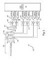
- EM fields 102 of adjacent antennae 104 , 106interact.
- a resultant radiated pattern 108may be amplified in one direction (e.g., for directional beam 109 ) resulting in a gain and canceled in other directions to result in a null 110 .
- the purposeful interaction of multiple adjacent antennas 104 , 106can control the predominant direction (i.e., the directional beam 109 ) of the radiated signal 108 either statically or dynamically, depending on algorithms used in a radio frequency control circuit.
- the RF transceiver 116controls a magnitude and phase of antenna current waveforms with phase-shifting elements 118 , 120 , 122 , 124 (governed by waveform and control signal lines) such that the composite radiated pattern 108 is steerable or highly directional, that is, at least directional beam 109 component of pattern 108 is steerable or highly directional.
- the differential power amplifiers 112 , 114can be generally commercially available radio frequency power amplifier chips, available from numerous manufacturers, or can alternatively be printed electronic circuits or flexible electronic circuits that are layered (e.g., layered onto each tile, as discussed below), for example.
- the system 100can further include one or more additional antennas 126 controlled by the transceiver 116 .
- Each additional antenna 126can have a differential power amplifier 128 , and phase-shifting elements 130 , 132 .
- the additional antennas 126can be positioned in different spatial locations relative to the antennas 104 and 106 .
- the additional antenna(s) 126can be selectively activated, deactivated, and reactivated, such that an variety of different interacting fields 102 can be generated through control of the selection of active antenna sub-sets (e.g., pairs) to generate radiated signals 108 and directional beams 109 , using any of the available antennas 104 , 106 , 126 .
- the one or more additional antennas 126 and the associated amplifiers 128 and phase-shifting elements 130 , 132can be omitted in alternate embodiments.
- An effective aperture A e of an antennais a measure of its effectiveness in receiving radiated power, and by reciprocity, its effectiveness in radiating power.
- the effective aperture A eis defined as:
- a e⁇ 2 4 ⁇ ⁇ ⁇ ⁇ G a ( Equation ⁇ ⁇ 1 )
- ⁇is a carrier wavelength
- G ais antenna gain.
- the latter(G a ) is a measure of the antenna's directionality or sharpness of the predominantly radiated direction.
- the effective aperture A eis measured in square-meters. Although not generally related to its physical size, the effective aperture A e is proportional to the radiating surface area for many antenna types, including dipoles.
- a signal power P r received from a transmitting source located at D meters from the receiving antennais:
- G t and G rare the gains of transmitting and receiving antennas, respectively
- P tis a signal power for a signal from the transmitting source.
- a carrier frequencyis f c in units of hertz
- cis the speed of light in meters per second.
- Equation 3indicates that the received signal power P r is directly proportional to the product of the effective apertures of the transmitting and receiving antennas A et and A er respectively, with all else remaining unchanged.
- An effective length l e of an antennahas a direct relationship with a physical size of that antenna.
- the effective length l eis defined as:
- V ran open-circuit voltage induced across terminals of the receiving antenna and E r is an electric field strength intercepted by the receiving antenna aperture, measured in volts per meter.
- k cis a Coulomb's law constant that depends on the medium of propagation.
- Equation 7demonstrates the direct proportionality between the effective length l e (size) of the antenna and the communications distance D, with all other factors remaining the same.
- the effective length l eis directly proportional to a physical length of the antenna, where a proportionality constant is a function of the antenna type, construction, and material properties of the antenna.
- Equation 6Equation 6 demonstrates that for a fixed distance and source electric field strength, increasing the effective antenna length l e will increase the induced voltage V r received across the receiving antenna terminals such that:
- V rk c ⁇ Q t ⁇ 1 D 2 ⁇ l e ( Equation ⁇ ⁇ 8 )
- SNRsignal-to-noise ratio
- S rnthe required SNR
- e nis the root-mean-square (RMS) value of the noise voltage
- k Bis Boltzmann's constant in units of joules per Kelvin
- Tis the receiver temperature in degrees Kelvin
- Bis the receiver bandwidth (i.e., data rate) in hertz.
- the data rateis directly proportional to the bandwidth and is a function of the bit encoding scheme used, for example, phased-shin-keying (PSK), frequency-shift-keying (FSK), amplitude-shift-keying (ASK), and quadrature amplitude modulation (QAM).
- PSKphased-shin-keying
- FSKfrequency-shift-keying
- ASKamplitude-shift-keying
- QAMquadrature amplitude modulation
- Equations 7 and 10demonstrate that antenna size (effective length l e ) is directly proportional to the communications distance D and to the square root of the data rate B respectively, keeping all other factors unchanged.
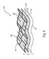
- collinear antenna arrays 200are tiles of patch antennas 202 separated by dielectric material 204 and insulator material 206 as shown in FIG. 2 .
- a separate layer, etchings, or overlay materialwill form the micro-strip transmission lines 208 that feed the antenna 200 with an electric current.
- the array of antenna patch tiles 202 and their separationcan be of different values respectively to implement multi-frequency antenna transceivers or a composite phase array antenna that is capable of spatially steering an EM beam (see, e.g., beam 109 in FIG. 1 ) from one direction to another direction.
- a ground plane 210can be integrated as a layer into composite body conformal material of a vehicle, as explained further below.
- the material choices for each layerare numerous and will depend on their cost and mass production capability. They can range from simple commodity elements such as copper to more complex composite constructions that integrate nano-particles and graphite material.
- the patch antenna tiles 202can each have the same configuration, or have different configurations.
- the provision of patch antenna tiles 202 of different configurationshelps promote flexibility for frequency-agile and spatially agile implementations.
- embodiments of the arrays 200can provide flexibility in selecting the dielectric material 204 , conductive materials of the ground plane 210 and/or the transmission lines 208 , and/or the insulator material 206 to suit desired application(s), such as marine-based, aerospace and other types of vehicles.
- Different tiles 202can have different material makeups so that portions of a vehicle with which the tiles 202 are used can operate optimally in different environments.
- an amphibious aerospace vehiclecan have tiles 202 of different makeup and can use one or more types of tiles 202 to operate in the water and other one or more types of tiles 202 to operate in the air.
- the mix of materials of the tiles 202can accompany an appropriate mix of matching circuits for each amplifier 112 , 114 , 128 associated with a given tile 202 .
- Patch antenna 302 sizesdepends on the carrier frequency f c and permittivity ⁇ r of a substrate 311 such that:
- the patch antenna 302 , ground plane 306 , and micro-strip lines 308should each be constructed with high conductivity material.
- the patch antenna 302produces an EM field pattern (see, e.g., pattern 108 in FIG. 1 ) that is perpendicular to a surface of the patch 302 and radiates away from the ground plane 306 .
- the generally rectangular patch antenna 302has a length L a and a width W a
- the substrate 311 in which the patch antenna 302 is formedhas a height H a .
- the antennas 202 , 302can be implemented as aircraft body (fuselage) integrated antennas as shown in FIG. 4 .
- Manufacturerscan construct antenna substrates using flexible composite materials or alloys that are consistent with existing technology and manufacturing methods.
- materialssuch as metallic foil or other suitable conducive materials can be used that also provide suitable ground and radiating substrates.
- These conductive foilscan sandwich composite dielectric material to provide the impedance properties needed for the desired antenna effective aperture.
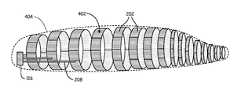
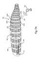
- FIG. 4illustrates one example of the concept of layering flexible material as antenna bands 402 containing tiled patch antennas 202 that can conform to the shape of different parts of a vehicle body perimeter 404 (e.g., aircraft fuselage).
- a vehicle body perimeter 404e.g., aircraft fuselage.
- Existing manufacturing toolsare available to shape and cut flexible plates into appropriately dimensioned bands that will fit as layers within other construction materials (not shown) that can help protect the antenna and provide a suitable exterior and strength for the fuselage, wings, and/or other major components of the aircraft body, as illustrated in the embodiment of an aircraft body construction.
- Existing techniquescan be adopted to create several patch antennas as collinear arrays, with graduated dimensions that conform to the fuselage and wing shapes. These patch arrays will implement multi-frequency, high gain, and beam steerable antennas.
- the shaped plateswill become bands 402 of antenna material of different dimensions to fit within assembled sections of the vehicle body 404 .
- bandas used herein incorporates nearly any suitable shape, such a full bands (i.e., full rings) or partial bands (i.e., band segments or arcs).
- All of the antennas 202can form collinear arrays of antennas to provide greater effective aperture or higher gain composite antennas.
- the Antennascan alternatively take the form of the patch antenna 302 described above, or have other suitable configurations.
- Each of the antenna tiles 202can have associated transmission lines 208 operatively connected to the driver 116 (though for simplicity not all transmission lines 208 are shown).
- Each of the antenna tiles 202can be located at a different location or area along the body perimeter 404 .
- FIGS. 5A and 5Bare exploded side views of embodiments of structural panel tiles 450 arranged in bands 402 A and 402 B, respectively, which can each incorporate one or more patch antennas 202 or 302 .
- the tiles 450each have coupling mechanisms to interconnect and interlock those tiles.
- the tiles 450 in band 402 Ahave a socket 452 A at one edge and a ball 454 A at another edge, such that adjacent tiles 450 can be interlocked together.
- the coupling mechanismcan be integrally formed with the tile 450 .
- FIG. 5Athe tiles 450 in band 402 A have a socket 452 A at one edge and a ball 454 A at another edge, such that adjacent tiles 450 can be interlocked together.
- the coupling mechanismcan be integrally formed with the tile 450 .
- the tiles 450 in band 402 Bhave a socket 452 B at one edge and a dovetail 454 B at another edge, such that adjacent tiles 450 can be interlocked together.
- FIGS. 5A and 5Bare provided merely by way of example and not limitation. Various other shapes and configurations are possible, such as fir-tree, rounded dovetail, mortise-and-tenon, jigsaw puzzle shape, and other suitable coupling mechanisms can be utilized in further embodiments.
- the illustrated embodiments of FIGS. 5A and 5Billustrate essentially two-dimensional coupling mechanisms.
- Two-dimensional coupling mechanismscan have similar shapes but be arranged in other orientations relative to the tiles 450 , such as by modifying the illustrated coupling mechanisms from side to top engaging orientations.
- three-dimensional variations of the illustrated coupling mechanisms having more complex shapes for accomplishing interlockingcan also be utilized in alternate embodiments.
- rotating structures about a vehiclecan incorporate antenna materials in layers without impeding their functionality, such as in providing lift and controllability for an aircraft application.
- FIG. 6shows one such embodiment.
- a primary antenna coil 502 in a stationary portion around a rotating axle 504carries an oscillating electric current that induces a magnetic field 506 , which in turn induces an electric current in a secondary antenna coil 508 that is conformal (i.e., integrated with) with the rotating structure.
- the induced currentdrives an antenna element 510 located on the rotating structure 512 , such as a wheel hub or a propeller of a vehicle.
- a differential power amplifier electronic driver 514is shown as the means of generating an electric current in the primary coil 502 , and can in turn be controlled by a radio frequency transceiver 516 .
- the secondary coilcan also be controlled by the transceiver 516 through appropriate slip ring, brushes or other rotational electrical connections (not shown).
- any desired number of individual antenna bands each of any desired shape and sizecan be used in a particular application.
- nearly any number of antenna bands and/or band segmentscan be electrically associated as a composite antenna and driven together with a radio frequency transceiver.
- one or more antenna bands or band segmentscan be utilized individually or in aggregate to provide a variety of antenna functionality requiring different directionality, polarization, bandwidth, reflection coefficient, impedance, and radiation pattern.
- each antenna band or patch element in a bandcan have any suitable configuration, allowing each individual band to have the same or different constructions (e.g., using the same or different materials, etc.).
- particular groups of antenna bandscan be fixed for particular functions. For instance, a given application could essentially “hard wire” a particular function for a particular aggregate group of antenna bands.
- a power distribution panelcan be used to flexibly (i.e., dynamically) select one or more antenna bands for service to a particular function at different times during service life (e.g., during flight, or while taxiing).
- wing and rudder elementscan be flapped to “stir” the EM fields while reading nearby ground sensors.
- FIGS. 7A-7Care schematic illustrations of an antenna array assembly 700 shown in different use scenarios.
- antenna tiles 202are carried by an airborne vehicle (which can be configured like that described above with respect to FIG. 4 ) that is airborne above a ground-based transceiver device 702 .
- antenna tiles 202 A and 202 B from a pair of adjacent bands 402 A and 402 Care selected to generate a directional beam 109 ′ that is spatially oriented toward the ground-based transceiver device 702 (for simplicity, the interacting fields 102 are not shown).
- the antenna tiles 202 A and 202 Bare located adjacent one another, along the same side of the body perimeter 404 .
- the airborne vehicleis in a different position relative to the ground-based transceiver device 702 . Accordingly, a different pair of antenna tiles 202 C and 202 D are selected to generate a directional beam 109 ′′ that is spatially oriented toward the ground-based transceiver device 702 (for simplicity, the interacting fields 102 are not shown in FIG. 7B ).
- Other tilescan be unused, or used to generate other beams (not shown).
- the tiles 202 C and 202 Dare located opposite one another across the body perimeter 404 (and an internal cavity thereof) on a single band 402 C. In FIG.
- the airborne vehiclecommunicates with an airborne transceiver device 704 .
- another pair of antenna tiles 202 E and 202 F on adjacent bands 402 E and 402 Fare selected to generate a directional beam 109 ′′′ (for simplicity, the interacting fields 102 are not shown).
- the antenna tiles 202 E and 202 Fare located at opposite sides of the body perimeter 404 (and across an internal cavity thereof) in the illustrated embodiment. Other tiles can be unused, or used to generate other beams (not shown). It will understood by those of ordinary skill in that art that the illustrated use case embodiments of FIGS. 7A-7C are provided merely by way of example and not limitation.
- a variety of different antenna tile pairscan be selected as desired to create spatially agile antenna beams that are arranged at nearly any possible orientation relative to the body perimeter 404 .
- Such antenna tile pairscan be selected from a single band, adjacent bands, or bands spaced apart from each other.
- FIG. 8is a flow chart of a method of operating an antenna array system.
- an antenna spatial profilecan be determined (Step 800 ).
- a desired antenna spatial profilecan be determined based on available data, such as knowing an approximate location of the antenna array system and a remote transceiver device with which it is desired to communicate. Use of a lookup table or other database can be used to facilitate such profile selection.
- a desired antenna spatial profilemay need to be determined, such as through an iterative protocol that involves making a number of preliminary selections and assessing performance feedback to make a final selection that yields optimal antenna performance, in which case the initial antenna spatial profile can be merely a temporary, nominal selection made as part of the larger protocol.
- a first antenna pair(or other sub-set of multiple antennas) is selected from a set of available antennas as a function of the antenna spatial profile (Step 802 ).
- the set of available antennascan include at least three antennas.
- the selected antennascan be located adjacent one another on a single band, on adjacent bands, on bands spaced from one another, on opposite sides of a vehicle body (or fuselage), etc.
- the antenna spatial profilecan be correlated to the spatial relationship between the antenna locations.
- other unselected antennas in the setcan remain unused, or can be used for other purposes (e.g., to generate other directional antenna beams).
- a first directional beamis then provided by the first pair of antennas, which can be generated in accordance with the antenna spatial profile and associated interacting EM fields generated by the selected antennas (Step 804 ).
- the selection of a pair of antennasdoes not preclude the active use of additional antennas (i.e., more than two antennas) as part of a common antenna assembly to generate the first directional beam. That is, the example given with respect to a pair (i.e., two) antennas is provided merely by way of example and not limitation.
- the disclosed methodis also applicable to embodiments in which sub-sets of more than two antennas are used to generate interacting fields and a given directional antenna beam.
- a second pair of antennascan be selected from the set as a function of the new antenna spatial profile (Step 808 ).
- the second pair of antennascan be entirely different antennas, or can include one of the antennas from the first pair.
- a second directional beamcan be provided by the second pair of antennas, which can be generated in accordance with the new antenna spatial profile (Step 810 ).
- Any number of additional antenna spatial profilescan be selected with the method as desired, though only two such profiles are depicted in FIG. 8 for simplicity.
- an additional algorithmcan optionally be performed to select an optimal antenna spatial profile (Step 812 ).
- the algorithm of Step 812can involve comparing a performance characteristic, such as signal strength and/or quality, between at least the first and second directional beams, and the higher performing spatial profile can be selected for further use.
- the algorithmcan apply a threshold such that once a spatial profile that meets a given threshold is identified, further feedback from other antenna pairs is not needed, thereby potentially shortening the time and resources consumed in identifying a suitable antenna spatial profile and corresponding antenna pair.
- Step 812can be omitted.
- the method illustrated in FIG. 8can further include antenna frequency selection.
- Different antennascan have different EM frequency-generating characteristics, and selection of antennas can include generating different resultant frequencies of the directional beam through selection of sub-sets of antennas with desired frequency-generating characteristics.
- Antenna frequency selectionis well understood, and therefore not explained further here and not explicitly illustrated in FIG. 8 .
- frequency agile selectioncan be combined with the spatially-agile antenna selection described above in a novel manner.
- the method illustrated in FIG. 8can further include spatial beam steering for any given directional antenna beam, as previously discussed. For instance, modulation of induced currents in selected sub-sets of available antennas governed by a transceiver can adjust characteristics of interacting EM fields and the resultant radiated EM pattern to help accomplish beam steering. Moreover, the selective activation (or deactivation) of one or more additional nearby antennas can be used to modify the interacting fields and the resultant radiated EM pattern, which can help accomplish beam steering. Beam steering can be used in addition or in the alternative to selection of different antenna groupings to achieve a desired directional beam spatial profile in various embodiments. In some applications, an algorithm can be implemented to compare beam steering performance to antenna selection performance based on temporary uses and performance feedback from an associated selection protocol in order to help optimize the directional beam spatial profile for further use under given conditions (in a manner similar to the algorithm of Step 812 ).
- any relative terms or terms of degree used hereinshould be interpreted in accordance with and subject to any applicable definitions or limits expressly stated herein. In all instances, any relative terms or terms of degree used herein should be interpreted to broadly encompass any relevant disclosed embodiments as well as such ranges or variations as would be understood by a person of ordinary skill in the art in view of the entirety of the present disclosure, such as to encompass ordinary manufacturing tolerance variations, incidental alignment variations, alignment or shape variations induced by operational conditions, incidental current fluctuations, transient signal fluctuations caused by noise, and the like.
Landscapes
- Engineering & Computer Science (AREA)
- Aviation & Aerospace Engineering (AREA)
- Physics & Mathematics (AREA)
- Astronomy & Astrophysics (AREA)
- General Physics & Mathematics (AREA)
- Computer Networks & Wireless Communication (AREA)
- Signal Processing (AREA)
- Remote Sensing (AREA)
- Mechanical Engineering (AREA)
- Variable-Direction Aerials And Aerial Arrays (AREA)
- Details Of Aerials (AREA)
Abstract
Description
where λ, is a carrier wavelength and Gais antenna gain. (Albert A. Smith, Jr.Radio Frequency Principles and Applications. New York: The Institute of Electrical and Electronic Engineers, 1998.) The latter (Ga) is a measure of the antenna's directionality or sharpness of the predominantly radiated direction. The effective aperture Aeis measured in square-meters. Although not generally related to its physical size, the effective aperture Aeis proportional to the radiating surface area for many antenna types, including dipoles.
where Gtand Grare the gains of transmitting and receiving antennas, respectively, and Ptis a signal power for a signal from the transmitting source. A carrier frequency is fcin units of hertz, and c is the speed of light in meters per second. Substituting Equation 1 into Equation 2 yields:
where Vris an open-circuit voltage induced across terminals of the receiving antenna and Eris an electric field strength intercepted by the receiving antenna aperture, measured in volts per meter. An induced voltage is equivalent to the square root of the product of the received power Prand an effective antenna resistance Rarwhere:
Vr=√{square root over (PTRar)} (Equation 5)
where kcis a Coulomb's law constant that depends on the medium of propagation. (Young, Hugh D., et al.University Physics with Modern Physics.13thEd. Addison-Wesley, 2011.) A value of kcin air is approximately 9.0×10⁹N·m2·C−2. Substituting Equation 3 into Equation 5 yields the following expression:
where enis the root-mean-square (RMS) value of the noise voltage, kBis Boltzmann's constant in units of joules per Kelvin, T is the receiver temperature in degrees Kelvin, and B is the receiver bandwidth (i.e., data rate) in hertz. The data rate is directly proportional to the bandwidth and is a function of the bit encoding scheme used, for example, phased-shin-keying (PSK), frequency-shift-keying (FSK), amplitude-shift-keying (ASK), and quadrature amplitude modulation (QAM). Solving Equation 9 for the bandwidth and substituting Equation 8 gives:
Claims (6)
Priority Applications (1)
| Application Number | Priority Date | Filing Date | Title |
|---|---|---|---|
| US14/716,288US10305176B2 (en) | 2014-05-20 | 2015-05-19 | Conformal antennas for unmanned and piloted vehicles and method of antenna operation |
Applications Claiming Priority (2)
| Application Number | Priority Date | Filing Date | Title |
|---|---|---|---|
| US201462000753P | 2014-05-20 | 2014-05-20 | |
| US14/716,288US10305176B2 (en) | 2014-05-20 | 2015-05-19 | Conformal antennas for unmanned and piloted vehicles and method of antenna operation |
Publications (2)
| Publication Number | Publication Date |
|---|---|
| US20150340759A1 US20150340759A1 (en) | 2015-11-26 |
| US10305176B2true US10305176B2 (en) | 2019-05-28 |
Family
ID=54556730
Family Applications (1)
| Application Number | Title | Priority Date | Filing Date |
|---|---|---|---|
| US14/716,288Expired - Fee RelatedUS10305176B2 (en) | 2014-05-20 | 2015-05-19 | Conformal antennas for unmanned and piloted vehicles and method of antenna operation |
Country Status (1)
| Country | Link |
|---|---|
| US (1) | US10305176B2 (en) |
Families Citing this family (199)
| Publication number | Priority date | Publication date | Assignee | Title |
|---|---|---|---|---|
| US9954374B1 (en) | 2014-05-23 | 2018-04-24 | Energous Corporation | System and method for self-system analysis for detecting a fault in a wireless power transmission Network |
| US9923386B1 (en) | 2012-07-06 | 2018-03-20 | Energous Corporation | Systems and methods for wireless power transmission by modifying a number of antenna elements used to transmit power waves to a receiver |
| US10218227B2 (en) | 2014-05-07 | 2019-02-26 | Energous Corporation | Compact PIFA antenna |
| US20140008993A1 (en) | 2012-07-06 | 2014-01-09 | DvineWave Inc. | Methodology for pocket-forming |
| US9941754B2 (en) | 2012-07-06 | 2018-04-10 | Energous Corporation | Wireless power transmission with selective range |
| US9887739B2 (en) | 2012-07-06 | 2018-02-06 | Energous Corporation | Systems and methods for wireless power transmission by comparing voltage levels associated with power waves transmitted by antennas of a plurality of antennas of a transmitter to determine appropriate phase adjustments for the power waves |
| US20150326070A1 (en) | 2014-05-07 | 2015-11-12 | Energous Corporation | Methods and Systems for Maximum Power Point Transfer in Receivers |
| US9876394B1 (en) | 2014-05-07 | 2018-01-23 | Energous Corporation | Boost-charger-boost system for enhanced power delivery |
| US9438045B1 (en) | 2013-05-10 | 2016-09-06 | Energous Corporation | Methods and systems for maximum power point transfer in receivers |
| US9891669B2 (en) | 2014-08-21 | 2018-02-13 | Energous Corporation | Systems and methods for a configuration web service to provide configuration of a wireless power transmitter within a wireless power transmission system |
| US10211680B2 (en) | 2013-07-19 | 2019-02-19 | Energous Corporation | Method for 3 dimensional pocket-forming |
| US10199835B2 (en) | 2015-12-29 | 2019-02-05 | Energous Corporation | Radar motion detection using stepped frequency in wireless power transmission system |
| US11502551B2 (en) | 2012-07-06 | 2022-11-15 | Energous Corporation | Wirelessly charging multiple wireless-power receivers using different subsets of an antenna array to focus energy at different locations |
| US10063105B2 (en) | 2013-07-11 | 2018-08-28 | Energous Corporation | Proximity transmitters for wireless power charging systems |
| US9831718B2 (en) | 2013-07-25 | 2017-11-28 | Energous Corporation | TV with integrated wireless power transmitter |
| US9893768B2 (en) | 2012-07-06 | 2018-02-13 | Energous Corporation | Methodology for multiple pocket-forming |
| US9368020B1 (en) | 2013-05-10 | 2016-06-14 | Energous Corporation | Off-premises alert system and method for wireless power receivers in a wireless power network |
| US9948135B2 (en) | 2015-09-22 | 2018-04-17 | Energous Corporation | Systems and methods for identifying sensitive objects in a wireless charging transmission field |
| US9843213B2 (en) | 2013-08-06 | 2017-12-12 | Energous Corporation | Social power sharing for mobile devices based on pocket-forming |
| US9853692B1 (en) | 2014-05-23 | 2017-12-26 | Energous Corporation | Systems and methods for wireless power transmission |
| US9991741B1 (en) | 2014-07-14 | 2018-06-05 | Energous Corporation | System for tracking and reporting status and usage information in a wireless power management system |
| US10256657B2 (en) | 2015-12-24 | 2019-04-09 | Energous Corporation | Antenna having coaxial structure for near field wireless power charging |
| US9143000B2 (en) | 2012-07-06 | 2015-09-22 | Energous Corporation | Portable wireless charging pad |
| US10992187B2 (en) | 2012-07-06 | 2021-04-27 | Energous Corporation | System and methods of using electromagnetic waves to wirelessly deliver power to electronic devices |
| US9887584B1 (en) | 2014-08-21 | 2018-02-06 | Energous Corporation | Systems and methods for a configuration web service to provide configuration of a wireless power transmitter within a wireless power transmission system |
| US9825674B1 (en) | 2014-05-23 | 2017-11-21 | Energous Corporation | Enhanced transmitter that selects configurations of antenna elements for performing wireless power transmission and receiving functions |
| US10263432B1 (en) | 2013-06-25 | 2019-04-16 | Energous Corporation | Multi-mode transmitter with an antenna array for delivering wireless power and providing Wi-Fi access |
| US10211674B1 (en) | 2013-06-12 | 2019-02-19 | Energous Corporation | Wireless charging using selected reflectors |
| US10230266B1 (en) | 2014-02-06 | 2019-03-12 | Energous Corporation | Wireless power receivers that communicate status data indicating wireless power transmission effectiveness with a transmitter using a built-in communications component of a mobile device, and methods of use thereof |
| US9882427B2 (en) | 2013-05-10 | 2018-01-30 | Energous Corporation | Wireless power delivery using a base station to control operations of a plurality of wireless power transmitters |
| US9847677B1 (en) | 2013-10-10 | 2017-12-19 | Energous Corporation | Wireless charging and powering of healthcare gadgets and sensors |
| US9787103B1 (en) | 2013-08-06 | 2017-10-10 | Energous Corporation | Systems and methods for wirelessly delivering power to electronic devices that are unable to communicate with a transmitter |
| US9824815B2 (en) | 2013-05-10 | 2017-11-21 | Energous Corporation | Wireless charging and powering of healthcare gadgets and sensors |
| US9941747B2 (en) | 2014-07-14 | 2018-04-10 | Energous Corporation | System and method for manually selecting and deselecting devices to charge in a wireless power network |
| US10038337B1 (en) | 2013-09-16 | 2018-07-31 | Energous Corporation | Wireless power supply for rescue devices |
| US9812890B1 (en) | 2013-07-11 | 2017-11-07 | Energous Corporation | Portable wireless charging pad |
| US9838083B2 (en) | 2014-07-21 | 2017-12-05 | Energous Corporation | Systems and methods for communication with remote management systems |
| US9847679B2 (en) | 2014-05-07 | 2017-12-19 | Energous Corporation | System and method for controlling communication between wireless power transmitter managers |
| US9859756B2 (en) | 2012-07-06 | 2018-01-02 | Energous Corporation | Transmittersand methods for adjusting wireless power transmission based on information from receivers |
| US10141768B2 (en) | 2013-06-03 | 2018-11-27 | Energous Corporation | Systems and methods for maximizing wireless power transfer efficiency by instructing a user to change a receiver device's position |
| US9882430B1 (en) | 2014-05-07 | 2018-01-30 | Energous Corporation | Cluster management of transmitters in a wireless power transmission system |
| US10148097B1 (en) | 2013-11-08 | 2018-12-04 | Energous Corporation | Systems and methods for using a predetermined number of communication channels of a wireless power transmitter to communicate with different wireless power receivers |
| US9871398B1 (en) | 2013-07-01 | 2018-01-16 | Energous Corporation | Hybrid charging method for wireless power transmission based on pocket-forming |
| US9941707B1 (en) | 2013-07-19 | 2018-04-10 | Energous Corporation | Home base station for multiple room coverage with multiple transmitters |
| US9876379B1 (en) | 2013-07-11 | 2018-01-23 | Energous Corporation | Wireless charging and powering of electronic devices in a vehicle |
| US10992185B2 (en) | 2012-07-06 | 2021-04-27 | Energous Corporation | Systems and methods of using electromagnetic waves to wirelessly deliver power to game controllers |
| US10206185B2 (en) | 2013-05-10 | 2019-02-12 | Energous Corporation | System and methods for wireless power transmission to an electronic device in accordance with user-defined restrictions |
| US10291066B1 (en) | 2014-05-07 | 2019-05-14 | Energous Corporation | Power transmission control systems and methods |
| US9252628B2 (en) | 2013-05-10 | 2016-02-02 | Energous Corporation | Laptop computer as a transmitter for wireless charging |
| US9859757B1 (en) | 2013-07-25 | 2018-01-02 | Energous Corporation | Antenna tile arrangements in electronic device enclosures |
| US9876648B2 (en) | 2014-08-21 | 2018-01-23 | Energous Corporation | System and method to control a wireless power transmission system by configuration of wireless power transmission control parameters |
| US9859797B1 (en) | 2014-05-07 | 2018-01-02 | Energous Corporation | Synchronous rectifier design for wireless power receiver |
| US10211682B2 (en) | 2014-05-07 | 2019-02-19 | Energous Corporation | Systems and methods for controlling operation of a transmitter of a wireless power network based on user instructions received from an authenticated computing device powered or charged by a receiver of the wireless power network |
| US10439448B2 (en) | 2014-08-21 | 2019-10-08 | Energous Corporation | Systems and methods for automatically testing the communication between wireless power transmitter and wireless power receiver |
| US10075008B1 (en) | 2014-07-14 | 2018-09-11 | Energous Corporation | Systems and methods for manually adjusting when receiving electronic devices are scheduled to receive wirelessly delivered power from a wireless power transmitter in a wireless power network |
| US10128699B2 (en) | 2014-07-14 | 2018-11-13 | Energous Corporation | Systems and methods of providing wireless power using receiver device sensor inputs |
| US10090886B1 (en) | 2014-07-14 | 2018-10-02 | Energous Corporation | System and method for enabling automatic charging schedules in a wireless power network to one or more devices |
| US9793758B2 (en) | 2014-05-23 | 2017-10-17 | Energous Corporation | Enhanced transmitter using frequency control for wireless power transmission |
| US10381880B2 (en) | 2014-07-21 | 2019-08-13 | Energous Corporation | Integrated antenna structure arrays for wireless power transmission |
| US10224758B2 (en) | 2013-05-10 | 2019-03-05 | Energous Corporation | Wireless powering of electronic devices with selective delivery range |
| US10124754B1 (en) | 2013-07-19 | 2018-11-13 | Energous Corporation | Wireless charging and powering of electronic sensors in a vehicle |
| US9124125B2 (en) | 2013-05-10 | 2015-09-01 | Energous Corporation | Wireless power transmission with selective range |
| US9899861B1 (en) | 2013-10-10 | 2018-02-20 | Energous Corporation | Wireless charging methods and systems for game controllers, based on pocket-forming |
| US10141791B2 (en) | 2014-05-07 | 2018-11-27 | Energous Corporation | Systems and methods for controlling communications during wireless transmission of power using application programming interfaces |
| US9806564B2 (en) | 2014-05-07 | 2017-10-31 | Energous Corporation | Integrated rectifier and boost converter for wireless power transmission |
| US12057715B2 (en) | 2012-07-06 | 2024-08-06 | Energous Corporation | Systems and methods of wirelessly delivering power to a wireless-power receiver device in response to a change of orientation of the wireless-power receiver device |
| US9893554B2 (en) | 2014-07-14 | 2018-02-13 | Energous Corporation | System and method for providing health safety in a wireless power transmission system |
| US9912199B2 (en) | 2012-07-06 | 2018-03-06 | Energous Corporation | Receivers for wireless power transmission |
| US10063106B2 (en) | 2014-05-23 | 2018-08-28 | Energous Corporation | System and method for a self-system analysis in a wireless power transmission network |
| US10050462B1 (en) | 2013-08-06 | 2018-08-14 | Energous Corporation | Social power sharing for mobile devices based on pocket-forming |
| US9966765B1 (en) | 2013-06-25 | 2018-05-08 | Energous Corporation | Multi-mode transmitter |
| US9900057B2 (en) | 2012-07-06 | 2018-02-20 | Energous Corporation | Systems and methods for assigning groups of antenas of a wireless power transmitter to different wireless power receivers, and determining effective phases to use for wirelessly transmitting power using the assigned groups of antennas |
| US9843201B1 (en) | 2012-07-06 | 2017-12-12 | Energous Corporation | Wireless power transmitter that selects antenna sets for transmitting wireless power to a receiver based on location of the receiver, and methods of use thereof |
| US10063064B1 (en) | 2014-05-23 | 2018-08-28 | Energous Corporation | System and method for generating a power receiver identifier in a wireless power network |
| US9867062B1 (en) | 2014-07-21 | 2018-01-09 | Energous Corporation | System and methods for using a remote server to authorize a receiving device that has requested wireless power and to determine whether another receiving device should request wireless power in a wireless power transmission system |
| US10243414B1 (en) | 2014-05-07 | 2019-03-26 | Energous Corporation | Wearable device with wireless power and payload receiver |
| US10128693B2 (en) | 2014-07-14 | 2018-11-13 | Energous Corporation | System and method for providing health safety in a wireless power transmission system |
| US10965164B2 (en) | 2012-07-06 | 2021-03-30 | Energous Corporation | Systems and methods of wirelessly delivering power to a receiver device |
| US10186913B2 (en) | 2012-07-06 | 2019-01-22 | Energous Corporation | System and methods for pocket-forming based on constructive and destructive interferences to power one or more wireless power receivers using a wireless power transmitter including a plurality of antennas |
| US9939864B1 (en) | 2014-08-21 | 2018-04-10 | Energous Corporation | System and method to control a wireless power transmission system by configuration of wireless power transmission control parameters |
| US9906065B2 (en) | 2012-07-06 | 2018-02-27 | Energous Corporation | Systems and methods of transmitting power transmission waves based on signals received at first and second subsets of a transmitter's antenna array |
| US9899873B2 (en) | 2014-05-23 | 2018-02-20 | Energous Corporation | System and method for generating a power receiver identifier in a wireless power network |
| US10224982B1 (en) | 2013-07-11 | 2019-03-05 | Energous Corporation | Wireless power transmitters for transmitting wireless power and tracking whether wireless power receivers are within authorized locations |
| US10103582B2 (en) | 2012-07-06 | 2018-10-16 | Energous Corporation | Transmitters for wireless power transmission |
| US9973021B2 (en) | 2012-07-06 | 2018-05-15 | Energous Corporation | Receivers for wireless power transmission |
| US10270261B2 (en) | 2015-09-16 | 2019-04-23 | Energous Corporation | Systems and methods of object detection in wireless power charging systems |
| US10291055B1 (en) | 2014-12-29 | 2019-05-14 | Energous Corporation | Systems and methods for controlling far-field wireless power transmission based on battery power levels of a receiving device |
| US10312715B2 (en) | 2015-09-16 | 2019-06-04 | Energous Corporation | Systems and methods for wireless power charging |
| US10090699B1 (en) | 2013-11-01 | 2018-10-02 | Energous Corporation | Wireless powered house |
| US9853458B1 (en) | 2014-05-07 | 2017-12-26 | Energous Corporation | Systems and methods for device and power receiver pairing |
| US10193396B1 (en) | 2014-05-07 | 2019-01-29 | Energous Corporation | Cluster management of transmitters in a wireless power transmission system |
| US10008889B2 (en) | 2014-08-21 | 2018-06-26 | Energous Corporation | Method for automatically testing the operational status of a wireless power receiver in a wireless power transmission system |
| US10223717B1 (en) | 2014-05-23 | 2019-03-05 | Energous Corporation | Systems and methods for payment-based authorization of wireless power transmission service |
| US9893555B1 (en) | 2013-10-10 | 2018-02-13 | Energous Corporation | Wireless charging of tools using a toolbox transmitter |
| US10205239B1 (en) | 2014-05-07 | 2019-02-12 | Energous Corporation | Compact PIFA antenna |
| US10199849B1 (en) | 2014-08-21 | 2019-02-05 | Energous Corporation | Method for automatically testing the operational status of a wireless power receiver in a wireless power transmission system |
| US9537357B2 (en) | 2013-05-10 | 2017-01-03 | Energous Corporation | Wireless sound charging methods and systems for game controllers, based on pocket-forming |
| US9419443B2 (en) | 2013-05-10 | 2016-08-16 | Energous Corporation | Transducer sound arrangement for pocket-forming |
| US9819230B2 (en) | 2014-05-07 | 2017-11-14 | Energous Corporation | Enhanced receiver for wireless power transmission |
| US9866279B2 (en) | 2013-05-10 | 2018-01-09 | Energous Corporation | Systems and methods for selecting which power transmitter should deliver wireless power to a receiving device in a wireless power delivery network |
| US9538382B2 (en) | 2013-05-10 | 2017-01-03 | Energous Corporation | System and method for smart registration of wireless power receivers in a wireless power network |
| US10103552B1 (en) | 2013-06-03 | 2018-10-16 | Energous Corporation | Protocols for authenticated wireless power transmission |
| US10003211B1 (en) | 2013-06-17 | 2018-06-19 | Energous Corporation | Battery life of portable electronic devices |
| US10021523B2 (en) | 2013-07-11 | 2018-07-10 | Energous Corporation | Proximity transmitters for wireless power charging systems |
| US9979440B1 (en) | 2013-07-25 | 2018-05-22 | Energous Corporation | Antenna tile arrangements configured to operate as one functional unit |
| US9935482B1 (en) | 2014-02-06 | 2018-04-03 | Energous Corporation | Wireless power transmitters that transmit at determined times based on power availability and consumption at a receiving mobile device |
| US10075017B2 (en) | 2014-02-06 | 2018-09-11 | Energous Corporation | External or internal wireless power receiver with spaced-apart antenna elements for charging or powering mobile devices using wirelessly delivered power |
| US10158257B2 (en) | 2014-05-01 | 2018-12-18 | Energous Corporation | System and methods for using sound waves to wirelessly deliver power to electronic devices |
| US9966784B2 (en) | 2014-06-03 | 2018-05-08 | Energous Corporation | Systems and methods for extending battery life of portable electronic devices charged by sound |
| US10153645B1 (en) | 2014-05-07 | 2018-12-11 | Energous Corporation | Systems and methods for designating a master power transmitter in a cluster of wireless power transmitters |
| US9800172B1 (en) | 2014-05-07 | 2017-10-24 | Energous Corporation | Integrated rectifier and boost converter for boosting voltage received from wireless power transmission waves |
| US10153653B1 (en) | 2014-05-07 | 2018-12-11 | Energous Corporation | Systems and methods for using application programming interfaces to control communications between a transmitter and a receiver |
| US9973008B1 (en) | 2014-05-07 | 2018-05-15 | Energous Corporation | Wireless power receiver with boost converters directly coupled to a storage element |
| US10170917B1 (en) | 2014-05-07 | 2019-01-01 | Energous Corporation | Systems and methods for managing and controlling a wireless power network by establishing time intervals during which receivers communicate with a transmitter |
| US9876536B1 (en) | 2014-05-23 | 2018-01-23 | Energous Corporation | Systems and methods for assigning groups of antennas to transmit wireless power to different wireless power receivers |
| US9871301B2 (en) | 2014-07-21 | 2018-01-16 | Energous Corporation | Integrated miniature PIFA with artificial magnetic conductor metamaterials |
| US10068703B1 (en) | 2014-07-21 | 2018-09-04 | Energous Corporation | Integrated miniature PIFA with artificial magnetic conductor metamaterials |
| US10116143B1 (en) | 2014-07-21 | 2018-10-30 | Energous Corporation | Integrated antenna arrays for wireless power transmission |
| US9965009B1 (en) | 2014-08-21 | 2018-05-08 | Energous Corporation | Systems and methods for assigning a power receiver to individual power transmitters based on location of the power receiver |
| US9917477B1 (en) | 2014-08-21 | 2018-03-13 | Energous Corporation | Systems and methods for automatically testing the communication between power transmitter and wireless receiver |
| US10122415B2 (en) | 2014-12-27 | 2018-11-06 | Energous Corporation | Systems and methods for assigning a set of antennas of a wireless power transmitter to a wireless power receiver based on a location of the wireless power receiver |
| US12079006B2 (en) | 2015-02-13 | 2024-09-03 | Position Imaging, Inc. | Spatial diversity for relative position tracking |
| US11132004B2 (en)* | 2015-02-13 | 2021-09-28 | Position Imaging, Inc. | Spatial diveristy for relative position tracking |
| US9893535B2 (en) | 2015-02-13 | 2018-02-13 | Energous Corporation | Systems and methods for determining optimal charging positions to maximize efficiency of power received from wirelessly delivered sound wave energy |
| IL241025B (en) | 2015-09-01 | 2021-10-31 | Uvision Air Ltd | Patch antennas configuration for an unmanned aerial vehicle |
| US10523033B2 (en) | 2015-09-15 | 2019-12-31 | Energous Corporation | Receiver devices configured to determine location within a transmission field |
| US12283828B2 (en) | 2015-09-15 | 2025-04-22 | Energous Corporation | Receiver devices configured to determine location within a transmission field |
| US9906275B2 (en)* | 2015-09-15 | 2018-02-27 | Energous Corporation | Identifying receivers in a wireless charging transmission field |
| US10158259B1 (en) | 2015-09-16 | 2018-12-18 | Energous Corporation | Systems and methods for identifying receivers in a transmission field by transmitting exploratory power waves towards different segments of a transmission field |
| US9893538B1 (en) | 2015-09-16 | 2018-02-13 | Energous Corporation | Systems and methods of object detection in wireless power charging systems |
| US10211685B2 (en) | 2015-09-16 | 2019-02-19 | Energous Corporation | Systems and methods for real or near real time wireless communications between a wireless power transmitter and a wireless power receiver |
| US9941752B2 (en) | 2015-09-16 | 2018-04-10 | Energous Corporation | Systems and methods of object detection in wireless power charging systems |
| US10186893B2 (en) | 2015-09-16 | 2019-01-22 | Energous Corporation | Systems and methods for real time or near real time wireless communications between a wireless power transmitter and a wireless power receiver |
| US11710321B2 (en) | 2015-09-16 | 2023-07-25 | Energous Corporation | Systems and methods of object detection in wireless power charging systems |
| US10199850B2 (en) | 2015-09-16 | 2019-02-05 | Energous Corporation | Systems and methods for wirelessly transmitting power from a transmitter to a receiver by determining refined locations of the receiver in a segmented transmission field associated with the transmitter |
| US10778041B2 (en) | 2015-09-16 | 2020-09-15 | Energous Corporation | Systems and methods for generating power waves in a wireless power transmission system |
| US9871387B1 (en) | 2015-09-16 | 2018-01-16 | Energous Corporation | Systems and methods of object detection using one or more video cameras in wireless power charging systems |
| US10008875B1 (en) | 2015-09-16 | 2018-06-26 | Energous Corporation | Wireless power transmitter configured to transmit power waves to a predicted location of a moving wireless power receiver |
| US10153660B1 (en) | 2015-09-22 | 2018-12-11 | Energous Corporation | Systems and methods for preconfiguring sensor data for wireless charging systems |
| US10135295B2 (en) | 2015-09-22 | 2018-11-20 | Energous Corporation | Systems and methods for nullifying energy levels for wireless power transmission waves |
| US10033222B1 (en) | 2015-09-22 | 2018-07-24 | Energous Corporation | Systems and methods for determining and generating a waveform for wireless power transmission waves |
| US10027168B2 (en) | 2015-09-22 | 2018-07-17 | Energous Corporation | Systems and methods for generating and transmitting wireless power transmission waves using antennas having a spacing that is selected by the transmitter |
| US10020678B1 (en) | 2015-09-22 | 2018-07-10 | Energous Corporation | Systems and methods for selecting antennas to generate and transmit power transmission waves |
| US10050470B1 (en) | 2015-09-22 | 2018-08-14 | Energous Corporation | Wireless power transmission device having antennas oriented in three dimensions |
| US10135294B1 (en) | 2015-09-22 | 2018-11-20 | Energous Corporation | Systems and methods for preconfiguring transmission devices for power wave transmissions based on location data of one or more receivers |
| US10128686B1 (en) | 2015-09-22 | 2018-11-13 | Energous Corporation | Systems and methods for identifying receiver locations using sensor technologies |
| US10734717B2 (en) | 2015-10-13 | 2020-08-04 | Energous Corporation | 3D ceramic mold antenna |
| US10333332B1 (en) | 2015-10-13 | 2019-06-25 | Energous Corporation | Cross-polarized dipole antenna |
| US9853485B2 (en) | 2015-10-28 | 2017-12-26 | Energous Corporation | Antenna for wireless charging systems |
| US9899744B1 (en) | 2015-10-28 | 2018-02-20 | Energous Corporation | Antenna for wireless charging systems |
| US10063108B1 (en) | 2015-11-02 | 2018-08-28 | Energous Corporation | Stamped three-dimensional antenna |
| US10135112B1 (en) | 2015-11-02 | 2018-11-20 | Energous Corporation | 3D antenna mount |
| US10027180B1 (en) | 2015-11-02 | 2018-07-17 | Energous Corporation | 3D triple linear antenna that acts as heat sink |
| US10079515B2 (en) | 2016-12-12 | 2018-09-18 | Energous Corporation | Near-field RF charging pad with multi-band antenna element with adaptive loading to efficiently charge an electronic device at any position on the pad |
| US10320446B2 (en) | 2015-12-24 | 2019-06-11 | Energous Corporation | Miniaturized highly-efficient designs for near-field power transfer system |
| US10038332B1 (en) | 2015-12-24 | 2018-07-31 | Energous Corporation | Systems and methods of wireless power charging through multiple receiving devices |
| US10027159B2 (en) | 2015-12-24 | 2018-07-17 | Energous Corporation | Antenna for transmitting wireless power signals |
| US11863001B2 (en) | 2015-12-24 | 2024-01-02 | Energous Corporation | Near-field antenna for wireless power transmission with antenna elements that follow meandering patterns |
| US10256677B2 (en) | 2016-12-12 | 2019-04-09 | Energous Corporation | Near-field RF charging pad with adaptive loading to efficiently charge an electronic device at any position on the pad |
| US10186892B2 (en) | 2015-12-24 | 2019-01-22 | Energous Corporation | Receiver device with antennas positioned in gaps |
| US10164478B2 (en) | 2015-12-29 | 2018-12-25 | Energous Corporation | Modular antenna boards in wireless power transmission systems |
| US10923954B2 (en) | 2016-11-03 | 2021-02-16 | Energous Corporation | Wireless power receiver with a synchronous rectifier |
| CN116455101A (en) | 2016-12-12 | 2023-07-18 | 艾诺格思公司 | Transmitter integrated circuit |
| FR3061028B1 (en)* | 2016-12-27 | 2019-05-31 | Parrot Drones | DRONE A DYNAMIC DIVERSITY OF ANTENNAS |
| US10439442B2 (en) | 2017-01-24 | 2019-10-08 | Energous Corporation | Microstrip antennas for wireless power transmitters |
| US10389161B2 (en) | 2017-03-15 | 2019-08-20 | Energous Corporation | Surface mount dielectric antennas for wireless power transmitters |
| US10680319B2 (en) | 2017-01-06 | 2020-06-09 | Energous Corporation | Devices and methods for reducing mutual coupling effects in wireless power transmission systems |
| FR3062524B1 (en) | 2017-02-01 | 2021-04-09 | Thales Sa | ELEMENTARY ANTENNA WITH PLANAR RADIANT DEVICE |
| US11011942B2 (en) | 2017-03-30 | 2021-05-18 | Energous Corporation | Flat antennas having two or more resonant frequencies for use in wireless power transmission systems |
| US10511097B2 (en) | 2017-05-12 | 2019-12-17 | Energous Corporation | Near-field antennas for accumulating energy at a near-field distance with minimal far-field gain |
| US12074460B2 (en) | 2017-05-16 | 2024-08-27 | Wireless Electrical Grid Lan, Wigl Inc. | Rechargeable wireless power bank and method of using |
| US12074452B2 (en) | 2017-05-16 | 2024-08-27 | Wireless Electrical Grid Lan, Wigl Inc. | Networked wireless charging system |
| US11462949B2 (en) | 2017-05-16 | 2022-10-04 | Wireless electrical Grid LAN, WiGL Inc | Wireless charging method and system |
| US10848853B2 (en) | 2017-06-23 | 2020-11-24 | Energous Corporation | Systems, methods, and devices for utilizing a wire of a sound-producing device as an antenna for receipt of wirelessly delivered power |
| WO2019041110A1 (en) | 2017-08-28 | 2019-03-07 | 北京小米移动软件有限公司 | Flight control method, device and system |
| US20190097328A1 (en)* | 2017-09-25 | 2019-03-28 | Apple Inc. | Systems and Methods for Mitigating Polarization Loss |
| US10122219B1 (en) | 2017-10-10 | 2018-11-06 | Energous Corporation | Systems, methods, and devices for using a battery as a antenna for receiving wirelessly delivered power from radio frequency power waves |
| US11342798B2 (en) | 2017-10-30 | 2022-05-24 | Energous Corporation | Systems and methods for managing coexistence of wireless-power signals and data signals operating in a same frequency band |
| DE112018006756T5 (en)* | 2018-01-03 | 2020-09-24 | Intel Corporation | DUAL-POLARIZED RETRODIRECTIVE ARRAY AND MULTI-FREQUENCY ANTENNA ELEMENT |
| US10615647B2 (en) | 2018-02-02 | 2020-04-07 | Energous Corporation | Systems and methods for detecting wireless power receivers and other objects at a near-field charging pad |
| US11159057B2 (en) | 2018-03-14 | 2021-10-26 | Energous Corporation | Loop antennas with selectively-activated feeds to control propagation patterns of wireless power signals |
| US11515732B2 (en) | 2018-06-25 | 2022-11-29 | Energous Corporation | Power wave transmission techniques to focus wirelessly delivered power at a receiving device |
| US11437735B2 (en) | 2018-11-14 | 2022-09-06 | Energous Corporation | Systems for receiving electromagnetic energy using antennas that are minimally affected by the presence of the human body |
| EP3918691A1 (en) | 2019-01-28 | 2021-12-08 | Energous Corporation | Systems and methods for miniaturized antenna for wireless power transmissions |
| US11018779B2 (en) | 2019-02-06 | 2021-05-25 | Energous Corporation | Systems and methods of estimating optimal phases to use for individual antennas in an antenna array |
| US12155231B2 (en) | 2019-04-09 | 2024-11-26 | Energous Corporation | Asymmetric spiral antennas for wireless power transmission and reception |
| US11381118B2 (en) | 2019-09-20 | 2022-07-05 | Energous Corporation | Systems and methods for machine learning based foreign object detection for wireless power transmission |
| WO2021055898A1 (en) | 2019-09-20 | 2021-03-25 | Energous Corporation | Systems and methods for machine learning based foreign object detection for wireless power transmission |
| US11139699B2 (en) | 2019-09-20 | 2021-10-05 | Energous Corporation | Classifying and detecting foreign objects using a power amplifier controller integrated circuit in wireless power transmission systems |
| EP4032166A4 (en) | 2019-09-20 | 2023-10-18 | Energous Corporation | SYSTEMS AND METHODS FOR PROTECTING WIRELESS POWER RECEIVER USING MULTIPLE RECTIFIERS AND PRODUCING IN-BAND COMMUNICATION USING MULTIPLE RECTIFIERS |
| WO2021055901A1 (en) | 2019-09-20 | 2021-03-25 | Energous Corporation | Asymmetric spiral antennas with parasitic elements for wireless power transmission |
| EP4073905A4 (en) | 2019-12-13 | 2024-01-03 | Energous Corporation | CHARGING STATION HAVING GUIDANCE CONTOURS FOR ALIGNING AN ELECTRONIC DEVICE TO THE CHARGING STATION AND EFFECTIVELY TRANSFERRING NEAR-FIELD RADIO FREQUENCY ENERGY TO THE ELECTRONIC DEVICE |
| US10985617B1 (en) | 2019-12-31 | 2021-04-20 | Energous Corporation | System for wirelessly transmitting energy at a near-field distance without using beam-forming control |
| US11799324B2 (en) | 2020-04-13 | 2023-10-24 | Energous Corporation | Wireless-power transmitting device for creating a uniform near-field charging area |
| US11469629B2 (en) | 2020-08-12 | 2022-10-11 | Energous Corporation | Systems and methods for secure wireless transmission of power using unidirectional communication signals from a wireless-power-receiving device |
| US12306285B2 (en) | 2020-12-01 | 2025-05-20 | Energous Corporation | Systems and methods for using one or more sensors to detect and classify objects in a keep-out zone of a wireless-power transmission field, and antennas with integrated sensor arrangements |
| US11916398B2 (en) | 2021-12-29 | 2024-02-27 | Energous Corporation | Small form-factor devices with integrated and modular harvesting receivers, and shelving-mounted wireless-power transmitters for use therewith |
| US12142939B2 (en) | 2022-05-13 | 2024-11-12 | Energous Corporation | Integrated wireless-power-transmission platform designed to operate in multiple bands, and multi-band antennas for use therewith |
| US20250079702A1 (en)* | 2023-09-05 | 2025-03-06 | Harris Global Communications, Inc. | Radio frequency device for a vehicle and associated methods |
Citations (43)
| Publication number | Priority date | Publication date | Assignee | Title |
|---|---|---|---|---|
| US3673044A (en) | 1969-09-10 | 1972-06-27 | Libbey Owens Ford Co | Producing interlayers for antenna type windshields |
| US5471220A (en)* | 1994-02-17 | 1995-11-28 | Itt Corporation | Integrated adaptive array antenna |
| US6377216B1 (en) | 2000-04-13 | 2002-04-23 | The United States Of America As Represented By The Secretary Of The Navy | Integral antenna conformable in three dimensions |
| US20020118137A1 (en)* | 2000-12-06 | 2002-08-29 | Harris Corporation, Corporation Of The State Of Delaware | Phased array communication system providing airborne crosslink and satellite communication receive capability |
| US6888502B2 (en)* | 2002-03-05 | 2005-05-03 | Precision Dynamics Corporation | Microstrip antenna for an identification appliance |
| US20060082516A1 (en)* | 2004-06-01 | 2006-04-20 | Strickland Peter C | Dielectric-resonator array antenna system |
| US7046209B1 (en) | 2004-10-21 | 2006-05-16 | The Boeing Company | Design and fabrication methodology for a phased array antenna with shielded/integrated feed structure |
| US7109943B2 (en) | 2004-10-21 | 2006-09-19 | The Boeing Company | Structurally integrated antenna aperture and fabrication method |
| US20080030404A1 (en)* | 2005-09-20 | 2008-02-07 | Irwin L Newberg | Antenna transceiver system |
| US20080169988A1 (en) | 2007-01-16 | 2008-07-17 | Deaett Michael A | Lightweight, conformal, wideband airframe antenna |
| US20080218416A1 (en) | 2007-02-01 | 2008-09-11 | Handy Erik S | Arbitrarily-shaped multifunctional structures and method of making |
| US20090008507A1 (en) | 2007-03-28 | 2009-01-08 | Jerome Pearson | Aircraft wing |
| WO2009036305A1 (en)* | 2007-09-13 | 2009-03-19 | Aerosat Corporation | Communication system with broadband antenna |
| US7548205B2 (en)* | 2003-07-15 | 2009-06-16 | Farrokh Mohamadi | Wafer scale antenna module with a backside connectivity |
| US20100177011A1 (en) | 2009-01-12 | 2010-07-15 | Sego Daniel J | Flexible phased array antennas |
| US20100188304A1 (en)* | 2007-09-13 | 2010-07-29 | Richard Clymer | Communication system with broadband antenna |
| US20100328169A1 (en) | 2008-11-07 | 2010-12-30 | Honeywell International Inc. | Ducted Fan Unmanned Aerial Vehicle Conformal Antenna |
| US7889142B1 (en) | 2008-08-27 | 2011-02-15 | Lockheed Martin Corporation | Aerodynamic wingtip device with integral ground plane |
| US20110122029A1 (en) | 2009-11-23 | 2011-05-26 | Aerovironment , Inc. | Integrated antenna and display shade |
| US8022307B2 (en) | 2006-07-10 | 2011-09-20 | The United States Of America As Represented By The Administrator Of The National Aeronautics And Space Administration | Fabric circuits and method of manufacturing fabric circuits |
| US8116762B2 (en)* | 2005-03-01 | 2012-02-14 | Qualcomm Incorporated | Method and system for providing aeronautical communication services |
| US8230581B1 (en) | 2009-06-25 | 2012-07-31 | Rockwell Collins, Inc. | Method for producing a multi-band concentric ring antenna |
| WO2012106021A1 (en) | 2011-01-31 | 2012-08-09 | Ball Aerospace & Technologies Corp. | Continuous horn circular array antenna system |
| US8332053B1 (en) | 2009-04-28 | 2012-12-11 | Hrl Laboratories, Llc | Method for fabrication of a stretchable electronic skin |
| US8352105B2 (en) | 2009-02-13 | 2013-01-08 | The Boeing Company | Unmanned underwater vehicle integrated radiation detection system |
| US20130016019A1 (en) | 2011-07-15 | 2013-01-17 | The Boeing Company | Integrated Antenna System |
| US8418642B2 (en) | 2008-05-09 | 2013-04-16 | Irobot Corporation | Unmanned submersible vehicles and methods for operating the same in a body of liquid |
| US8422951B2 (en)* | 2010-01-28 | 2013-04-16 | Raytheon Company | Wireless communication system and method for wireless signal communication in flight vehicles |
| US20130176176A1 (en) | 2012-01-09 | 2013-07-11 | Lockheed Martin Corporation | Dimensionally tolerant multiband conformal antenna arrays |
| US8525729B1 (en)* | 2009-01-09 | 2013-09-03 | Lockheed Martin Corporation | Antenna tiles with ground cavities integrated into support structure |
| US20130249748A1 (en) | 2010-11-19 | 2013-09-26 | Fujikura Ltd. | Antenna device, and moving body equipped with antenna device |
| CN103493289A (en)* | 2011-01-28 | 2014-01-01 | 凯瑟雷恩工厂两合公司 | Antenna array and method for synthesizing antenna patterns |
| US20140022139A1 (en)* | 2012-07-19 | 2014-01-23 | The Mitre Corporation | Conformal Electro-Textile Antenna and Electronic Band Gap Ground Plane for Suppression of Back Radiation From GPS Antennas Mounted on Aircraft |
| US20140049879A1 (en) | 2005-11-09 | 2014-02-20 | The United States Government As Represented By The Secretary Of The Army | Structural electrochemical capacitor |
| US8676192B2 (en)* | 2011-02-09 | 2014-03-18 | Qualcomm Incorporated | High data rate aircraft to ground communication antenna system |
| US20140268607A1 (en) | 2012-01-04 | 2014-09-18 | Board Of Regents, The University Of Texas System | Methods and Systems For Connecting Inter-Layer Conductors and Components in 3D Structures, Structural Components, and Structural Electronic, Electromagnetic and Electromechanical Components/Devices |
| US20140306851A1 (en) | 2013-04-11 | 2014-10-16 | Raytheon Company | Integrated antenna and antenna component |
| US20140327577A1 (en)* | 2013-05-02 | 2014-11-06 | Qualcomm Incorporated | Low cost high performance aircraft antenna for advanced ground to air internet system |
| US8922436B2 (en) | 2013-05-13 | 2014-12-30 | Smartsky Networks LLC | Plasma aviation antenna |
| WO2015001425A2 (en)* | 2013-07-01 | 2015-01-08 | Powerwave Technologies S.A.R.I. | Airborne antenna system with controllable null pattern |
| US8963789B2 (en) | 2010-08-13 | 2015-02-24 | Raytheon Company | Conformal hybrid EO/RF aperture |
| US8983455B1 (en) | 2014-08-18 | 2015-03-17 | Sunlight Photonics Inc. | Apparatus for distributed airborne wireless communications |
| US20150249362A1 (en) | 2013-08-21 | 2015-09-03 | Ndsu Research Foundation | Conformal body capacitors suitable for vehicles |
- 2015
- 2015-05-19USUS14/716,288patent/US10305176B2/ennot_activeExpired - Fee Related
Patent Citations (49)
| Publication number | Priority date | Publication date | Assignee | Title |
|---|---|---|---|---|
| US3673044A (en) | 1969-09-10 | 1972-06-27 | Libbey Owens Ford Co | Producing interlayers for antenna type windshields |
| US5471220A (en)* | 1994-02-17 | 1995-11-28 | Itt Corporation | Integrated adaptive array antenna |
| US6377216B1 (en) | 2000-04-13 | 2002-04-23 | The United States Of America As Represented By The Secretary Of The Navy | Integral antenna conformable in three dimensions |
| US20020118137A1 (en)* | 2000-12-06 | 2002-08-29 | Harris Corporation, Corporation Of The State Of Delaware | Phased array communication system providing airborne crosslink and satellite communication receive capability |
| US6606055B2 (en)* | 2000-12-06 | 2003-08-12 | Harris Corporation | Phased array communication system providing airborne crosslink and satellite communication receive capability |
| US6888502B2 (en)* | 2002-03-05 | 2005-05-03 | Precision Dynamics Corporation | Microstrip antenna for an identification appliance |
| US7548205B2 (en)* | 2003-07-15 | 2009-06-16 | Farrokh Mohamadi | Wafer scale antenna module with a backside connectivity |
| US20060082516A1 (en)* | 2004-06-01 | 2006-04-20 | Strickland Peter C | Dielectric-resonator array antenna system |
| US7109943B2 (en) | 2004-10-21 | 2006-09-19 | The Boeing Company | Structurally integrated antenna aperture and fabrication method |
| US7046209B1 (en) | 2004-10-21 | 2006-05-16 | The Boeing Company | Design and fabrication methodology for a phased array antenna with shielded/integrated feed structure |
| US8116762B2 (en)* | 2005-03-01 | 2012-02-14 | Qualcomm Incorporated | Method and system for providing aeronautical communication services |
| US20080030404A1 (en)* | 2005-09-20 | 2008-02-07 | Irwin L Newberg | Antenna transceiver system |
| US7545322B2 (en)* | 2005-09-20 | 2009-06-09 | Raytheon Company | Antenna transceiver system |
| US20140049879A1 (en) | 2005-11-09 | 2014-02-20 | The United States Government As Represented By The Secretary Of The Army | Structural electrochemical capacitor |
| US8022307B2 (en) | 2006-07-10 | 2011-09-20 | The United States Of America As Represented By The Administrator Of The National Aeronautics And Space Administration | Fabric circuits and method of manufacturing fabric circuits |
| US20080169988A1 (en) | 2007-01-16 | 2008-07-17 | Deaett Michael A | Lightweight, conformal, wideband airframe antenna |
| US20080218416A1 (en) | 2007-02-01 | 2008-09-11 | Handy Erik S | Arbitrarily-shaped multifunctional structures and method of making |
| US8405561B2 (en) | 2007-02-01 | 2013-03-26 | Si2 Technologies, Inc. | Arbitrarily-shaped multifunctional structures and method of making |
| US20090008507A1 (en) | 2007-03-28 | 2009-01-08 | Jerome Pearson | Aircraft wing |
| WO2009036305A1 (en)* | 2007-09-13 | 2009-03-19 | Aerosat Corporation | Communication system with broadband antenna |
| US20130285864A1 (en)* | 2007-09-13 | 2013-10-31 | Aerosat Corporation | Communication system with broadband antenna |
| US20100188304A1 (en)* | 2007-09-13 | 2010-07-29 | Richard Clymer | Communication system with broadband antenna |
| US8418642B2 (en) | 2008-05-09 | 2013-04-16 | Irobot Corporation | Unmanned submersible vehicles and methods for operating the same in a body of liquid |
| US7889142B1 (en) | 2008-08-27 | 2011-02-15 | Lockheed Martin Corporation | Aerodynamic wingtip device with integral ground plane |
| US20100328169A1 (en) | 2008-11-07 | 2010-12-30 | Honeywell International Inc. | Ducted Fan Unmanned Aerial Vehicle Conformal Antenna |
| US8525729B1 (en)* | 2009-01-09 | 2013-09-03 | Lockheed Martin Corporation | Antenna tiles with ground cavities integrated into support structure |
| US20100177011A1 (en) | 2009-01-12 | 2010-07-15 | Sego Daniel J | Flexible phased array antennas |
| US8352105B2 (en) | 2009-02-13 | 2013-01-08 | The Boeing Company | Unmanned underwater vehicle integrated radiation detection system |
| US9014885B2 (en) | 2009-02-13 | 2015-04-21 | The Boeing Company | Unmanned underwater vehicle integrated radiation detection system |
| US8332053B1 (en) | 2009-04-28 | 2012-12-11 | Hrl Laboratories, Llc | Method for fabrication of a stretchable electronic skin |
| US8230581B1 (en) | 2009-06-25 | 2012-07-31 | Rockwell Collins, Inc. | Method for producing a multi-band concentric ring antenna |
| US20110122029A1 (en) | 2009-11-23 | 2011-05-26 | Aerovironment , Inc. | Integrated antenna and display shade |
| US8422951B2 (en)* | 2010-01-28 | 2013-04-16 | Raytheon Company | Wireless communication system and method for wireless signal communication in flight vehicles |
| US8963789B2 (en) | 2010-08-13 | 2015-02-24 | Raytheon Company | Conformal hybrid EO/RF aperture |
| US20130249748A1 (en) | 2010-11-19 | 2013-09-26 | Fujikura Ltd. | Antenna device, and moving body equipped with antenna device |
| CN103493289A (en)* | 2011-01-28 | 2014-01-01 | 凯瑟雷恩工厂两合公司 | Antenna array and method for synthesizing antenna patterns |
| WO2012106021A1 (en) | 2011-01-31 | 2012-08-09 | Ball Aerospace & Technologies Corp. | Continuous horn circular array antenna system |
| US8676192B2 (en)* | 2011-02-09 | 2014-03-18 | Qualcomm Incorporated | High data rate aircraft to ground communication antenna system |
| US20130016019A1 (en) | 2011-07-15 | 2013-01-17 | The Boeing Company | Integrated Antenna System |
| US20140268607A1 (en) | 2012-01-04 | 2014-09-18 | Board Of Regents, The University Of Texas System | Methods and Systems For Connecting Inter-Layer Conductors and Components in 3D Structures, Structural Components, and Structural Electronic, Electromagnetic and Electromechanical Components/Devices |
| US8847823B2 (en) | 2012-01-09 | 2014-09-30 | Lockheed Martin Corporation | Dimensionally tolerant multiband conformal antenna arrays |
| US20130176176A1 (en) | 2012-01-09 | 2013-07-11 | Lockheed Martin Corporation | Dimensionally tolerant multiband conformal antenna arrays |
| US20140022139A1 (en)* | 2012-07-19 | 2014-01-23 | The Mitre Corporation | Conformal Electro-Textile Antenna and Electronic Band Gap Ground Plane for Suppression of Back Radiation From GPS Antennas Mounted on Aircraft |
| US20140306851A1 (en) | 2013-04-11 | 2014-10-16 | Raytheon Company | Integrated antenna and antenna component |
| US20140327577A1 (en)* | 2013-05-02 | 2014-11-06 | Qualcomm Incorporated | Low cost high performance aircraft antenna for advanced ground to air internet system |
| US8922436B2 (en) | 2013-05-13 | 2014-12-30 | Smartsky Networks LLC | Plasma aviation antenna |
| WO2015001425A2 (en)* | 2013-07-01 | 2015-01-08 | Powerwave Technologies S.A.R.I. | Airborne antenna system with controllable null pattern |
| US20150249362A1 (en) | 2013-08-21 | 2015-09-03 | Ndsu Research Foundation | Conformal body capacitors suitable for vehicles |
| US8983455B1 (en) | 2014-08-18 | 2015-03-17 | Sunlight Photonics Inc. | Apparatus for distributed airborne wireless communications |
Also Published As
| Publication number | Publication date |
|---|---|
| US20150340759A1 (en) | 2015-11-26 |
Similar Documents
| Publication | Publication Date | Title |
|---|---|---|
| US10305176B2 (en) | Conformal antennas for unmanned and piloted vehicles and method of antenna operation | |
| US11101557B2 (en) | Mechanically steered and horizontally polarized antenna for aerial vehicles, and associated systems and methods | |
| US7071879B2 (en) | Dielectric-resonator array antenna system | |
| KR20180066826A (en) | Phased array antennas for high altitude platforms | |
| EP2109184B1 (en) | Antenna system for a micro air vehicle | |
| Jun et al. | Investigation of antennas integrated into disposable unmanned aerial vehicles | |
| Mahfuz et al. | Review of patch antennas used in drone applications | |
| AU2010258222A1 (en) | Air vehicle | |
| US20050052330A1 (en) | Phase controlled antennae for data transmission between mobile devices | |
| US10254396B2 (en) | Due regard radar system | |
| US8358967B1 (en) | Towed network communications subsystem for in flight use by towing aircraft | |
| CN117099260A (en) | Antenna module ground for phased array antennas | |
| US10747217B1 (en) | Distributed directional antenna | |
| Nako et al. | Wireless power transfer to a microaerial vehicle with a microwave active phased array | |
| EP3896786A1 (en) | Antenna array | |
| Dweik et al. | A planar antenna array with integrated feed network for UAV applications | |
| Romeu et al. | Small UAV radiocommunication channel characterization | |
| CN107732441A (en) | Wave beam is faced upward high-gain omni-directional antenna | |
| Costa et al. | Design of UAV and ground station antennas for communications link budget improvement | |
| US11588238B2 (en) | Sidelobe-controlled antenna assembly | |
| Pyattaev et al. | 3D folded loop UAV antenna design | |
| US11870149B2 (en) | Directive beamforming antenna | |
| US11695212B2 (en) | Electrically coupled bowtie antenna | |
| Jeong et al. | Printed dipole antenna array with reconfigurable feeding network for wide elevation angle of U2X communications | |
| Zhu et al. | An unmanned aerial vehicle conformal antenna array of dual polarization and wide coverage range |
Legal Events
| Date | Code | Title | Description |
|---|---|---|---|
| AS | Assignment | Owner name:UNIVERSITY OF NORTH DAKOTA, NORTH DAKOTA Free format text:ASSIGNMENT OF ASSIGNORS INTEREST;ASSIGNOR:CORCORAN, MICHAEL;REEL/FRAME:035757/0916 Effective date:20150518 Owner name:NDSU RESEARCH FOUNDATION, NORTH DAKOTA Free format text:ASSIGNMENT OF ASSIGNORS INTEREST;ASSIGNOR:CORCORAN, MICHAEL;REEL/FRAME:035757/0916 Effective date:20150518 | |
| AS | Assignment | Owner name:NDSU RESEARCH FOUNDATION, NORTH DAKOTA Free format text:ASSIGNMENT OF ASSIGNORS INTEREST;ASSIGNOR:NORTH DAKOTA STATE UNIVERSITY;REEL/FRAME:035761/0591 Effective date:20150529 Owner name:NORTH DAKOTA STATE UNIVERSITY, NORTH DAKOTA Free format text:ASSIGNMENT OF ASSIGNORS INTEREST;ASSIGNOR:BRIDGELALL, RAJ;REEL/FRAME:035805/0918 Effective date:20140521 | |
| STPP | Information on status: patent application and granting procedure in general | Free format text:NOTICE OF ALLOWANCE MAILED -- APPLICATION RECEIVED IN OFFICE OF PUBLICATIONS | |
| FEPP | Fee payment procedure | Free format text:ENTITY STATUS SET TO MICRO (ORIGINAL EVENT CODE: MICR); ENTITY STATUS OF PATENT OWNER: MICROENTITY | |
| STPP | Information on status: patent application and granting procedure in general | Free format text:PUBLICATIONS -- ISSUE FEE PAYMENT VERIFIED | |
| STCF | Information on status: patent grant | Free format text:PATENTED CASE | |
| FEPP | Fee payment procedure | Free format text:MAINTENANCE FEE REMINDER MAILED (ORIGINAL EVENT CODE: REM.); ENTITY STATUS OF PATENT OWNER: MICROENTITY | |
| LAPS | Lapse for failure to pay maintenance fees | Free format text:PATENT EXPIRED FOR FAILURE TO PAY MAINTENANCE FEES (ORIGINAL EVENT CODE: EXP.); ENTITY STATUS OF PATENT OWNER: MICROENTITY | |
| STCH | Information on status: patent discontinuation | Free format text:PATENT EXPIRED DUE TO NONPAYMENT OF MAINTENANCE FEES UNDER 37 CFR 1.362 | |
| FP | Lapsed due to failure to pay maintenance fee | Effective date:20230528 |