US10303852B2 - Decision support tool for use with a medical monitor-defibrillator - Google Patents
Decision support tool for use with a medical monitor-defibrillatorDownload PDFInfo
- Publication number
- US10303852B2 US10303852B2US13/836,769US201313836769AUS10303852B2US 10303852 B2US10303852 B2US 10303852B2US 201313836769 AUS201313836769 AUS 201313836769AUS 10303852 B2US10303852 B2US 10303852B2
- Authority
- US
- United States
- Prior art keywords
- module
- decision support
- event
- protocol
- events
- Prior art date
- Legal status (The legal status is an assumption and is not a legal conclusion. Google has not performed a legal analysis and makes no representation as to the accuracy of the status listed.)
- Active, expires
Links
Images


Classifications
- G—PHYSICS
- G16—INFORMATION AND COMMUNICATION TECHNOLOGY [ICT] SPECIALLY ADAPTED FOR SPECIFIC APPLICATION FIELDS
- G16H—HEALTHCARE INFORMATICS, i.e. INFORMATION AND COMMUNICATION TECHNOLOGY [ICT] SPECIALLY ADAPTED FOR THE HANDLING OR PROCESSING OF MEDICAL OR HEALTHCARE DATA
- G16H50/00—ICT specially adapted for medical diagnosis, medical simulation or medical data mining; ICT specially adapted for detecting, monitoring or modelling epidemics or pandemics
- G16H50/20—ICT specially adapted for medical diagnosis, medical simulation or medical data mining; ICT specially adapted for detecting, monitoring or modelling epidemics or pandemics for computer-aided diagnosis, e.g. based on medical expert systems
- G06F19/345—
- A—HUMAN NECESSITIES
- A61—MEDICAL OR VETERINARY SCIENCE; HYGIENE
- A61B—DIAGNOSIS; SURGERY; IDENTIFICATION
- A61B5/00—Measuring for diagnostic purposes; Identification of persons
- A61B5/0002—Remote monitoring of patients using telemetry, e.g. transmission of vital signals via a communication network
- A61B5/0015—Remote monitoring of patients using telemetry, e.g. transmission of vital signals via a communication network characterised by features of the telemetry system
- A61B5/002—Monitoring the patient using a local or closed circuit, e.g. in a room or building
- A—HUMAN NECESSITIES
- A61—MEDICAL OR VETERINARY SCIENCE; HYGIENE
- A61B—DIAGNOSIS; SURGERY; IDENTIFICATION
- A61B5/00—Measuring for diagnostic purposes; Identification of persons
- A61B5/02—Detecting, measuring or recording for evaluating the cardiovascular system, e.g. pulse, heart rate, blood pressure or blood flow
- A61B5/0205—Simultaneously evaluating both cardiovascular conditions and different types of body conditions, e.g. heart and respiratory condition
- A61B5/02055—Simultaneously evaluating both cardiovascular condition and temperature
- A61B5/0402—
- A—HUMAN NECESSITIES
- A61—MEDICAL OR VETERINARY SCIENCE; HYGIENE
- A61B—DIAGNOSIS; SURGERY; IDENTIFICATION
- A61B5/00—Measuring for diagnostic purposes; Identification of persons
- A61B5/24—Detecting, measuring or recording bioelectric or biomagnetic signals of the body or parts thereof
- A61B5/316—Modalities, i.e. specific diagnostic methods
- A61B5/318—Heart-related electrical modalities, e.g. electrocardiography [ECG]
- A61B5/33—Heart-related electrical modalities, e.g. electrocardiography [ECG] specially adapted for cooperation with other devices
- A—HUMAN NECESSITIES
- A61—MEDICAL OR VETERINARY SCIENCE; HYGIENE
- A61B—DIAGNOSIS; SURGERY; IDENTIFICATION
- A61B5/00—Measuring for diagnostic purposes; Identification of persons
- A61B5/48—Other medical applications
- A61B5/4836—Diagnosis combined with treatment in closed-loop systems or methods
- A—HUMAN NECESSITIES
- A61—MEDICAL OR VETERINARY SCIENCE; HYGIENE
- A61N—ELECTROTHERAPY; MAGNETOTHERAPY; RADIATION THERAPY; ULTRASOUND THERAPY
- A61N1/00—Electrotherapy; Circuits therefor
- A61N1/18—Applying electric currents by contact electrodes
- A61N1/32—Applying electric currents by contact electrodes alternating or intermittent currents
- A61N1/38—Applying electric currents by contact electrodes alternating or intermittent currents for producing shock effects
- A61N1/39—Heart defibrillators
- A61N1/3993—User interfaces for automatic external defibrillators
- A—HUMAN NECESSITIES
- A61—MEDICAL OR VETERINARY SCIENCE; HYGIENE
- A61B—DIAGNOSIS; SURGERY; IDENTIFICATION
- A61B5/00—Measuring for diagnostic purposes; Identification of persons
- A61B5/02—Detecting, measuring or recording for evaluating the cardiovascular system, e.g. pulse, heart rate, blood pressure or blood flow
- A61B5/021—Measuring pressure in heart or blood vessels
- A—HUMAN NECESSITIES
- A61—MEDICAL OR VETERINARY SCIENCE; HYGIENE
- A61B—DIAGNOSIS; SURGERY; IDENTIFICATION
- A61B5/00—Measuring for diagnostic purposes; Identification of persons
- A61B5/08—Measuring devices for evaluating the respiratory organs
- A61B5/083—Measuring rate of metabolism by using breath test, e.g. measuring rate of oxygen consumption
- A61B5/0836—Measuring rate of CO2 production
- A—HUMAN NECESSITIES
- A61—MEDICAL OR VETERINARY SCIENCE; HYGIENE
- A61B—DIAGNOSIS; SURGERY; IDENTIFICATION
- A61B5/00—Measuring for diagnostic purposes; Identification of persons
- A61B5/145—Measuring characteristics of blood in vivo, e.g. gas concentration or pH-value ; Measuring characteristics of body fluids or tissues, e.g. interstitial fluid or cerebral tissue
- A61B5/1455—Measuring characteristics of blood in vivo, e.g. gas concentration or pH-value ; Measuring characteristics of body fluids or tissues, e.g. interstitial fluid or cerebral tissue using optical sensors, e.g. spectral photometrical oximeters
- A61B5/14551—Measuring characteristics of blood in vivo, e.g. gas concentration or pH-value ; Measuring characteristics of body fluids or tissues, e.g. interstitial fluid or cerebral tissue using optical sensors, e.g. spectral photometrical oximeters for measuring blood gases
- A—HUMAN NECESSITIES
- A61—MEDICAL OR VETERINARY SCIENCE; HYGIENE
- A61B—DIAGNOSIS; SURGERY; IDENTIFICATION
- A61B5/00—Measuring for diagnostic purposes; Identification of persons
- A61B5/72—Signal processing specially adapted for physiological signals or for diagnostic purposes
- A61B5/7271—Specific aspects of physiological measurement analysis
- A61B5/7282—Event detection, e.g. detecting unique waveforms indicative of a medical condition
Definitions
- the heart chamberspump because of the heart's electrical control system. More particularly, the sinoatrial (SA) node generates an electrical impulse, which generates further electrical signals. These further signals cause the above-described contractions of the various chambers in the heart to occur in the correct sequence.
- the electrical pattern created by the sinoatrial (SA) nodeis called a sinus rhythm.
- an arrhythmiamay be caused by electrical activity from locations in the heart other than the SA node. Some types of arrhythmia may result in inadequate blood flow, thus reducing the amount of blood pumped to the various parts of the body. Some arrhythmias may even result in a Sudden Cardiac Arrest (SCA).
- SCASudden Cardiac Arrest
- the heartfails to pump blood effectively, and, if not corrected, can result in death. It is estimated that SCA results in more than 250,000 deaths per year in the United States alone. Further, an SCA may result from a condition other than an arrhythmia.
- VFVentricular Fibrillation
- a challenge with defibrillationis that the electrical shock must be administered very soon after the onset of VF. There is not much time to do this since the survival rate of persons suffering from VF decreases by about 10% for each minute the administration of a defibrillation shock is delayed. After about 10 minutes the rate of survival for SCA victims averages less than 2%.
- an Implantable Cardioverter Defibrillatorcan be implanted surgically.
- An ICDcan monitor the person's heart, and administer an electrical shock as needed. As such, an ICD reduces the need to have the higher-risk person be monitored constantly by medical personnel.
- VFcan occur unpredictably, even to a person who is not considered at risk. As such, VF can be experienced by many people who lack the benefit of ICD therapy. When VF occurs to a person who does not have an ICD, they collapse, because the blood flow has stopped. They should receive therapy quickly after the onset of VF or they will die.
- an external defibrillatorFor a VF victim without an ICD, a different type of defibrillator can be used, which is called an external defibrillator. External defibrillators have been made portable, so they can be brought to a potential VF victim quickly enough to revive them.
- VFVF
- the person's conditiondeteriorates because the blood is not flowing to the brain, heart, lungs, and other organs.
- the blood flowmust be restored, if resuscitation attempts are to be successful.
- Cardiopulmonary Resuscitationis one method of forcing blood to again flow in a person experiencing cardiac arrest.
- CPRis the primary recommended treatment for some patients with some kinds of non-VF cardiac arrest, such as asystole and pulseless electrical activity (PEA).
- PDApulseless electrical activity
- CPRis a combination of techniques that include chest compressions to force blood circulation, and rescue breathing to force respiration.
- CPRProperly administered CPR provides oxygenated blood to critical organs of a person in cardiac arrest, thereby minimizing the deterioration that would otherwise occur. As such, CPR can be beneficial for persons experiencing VF, because it slows down the deterioration that would otherwise occur while a defibrillator is being retrieved. For patients with an extended down-time, survival rates are higher if CPR is administered prior to defibrillation.
- Advanced medical devicesmay be used to assist the CPR process by coaching a rescuer who performs CPR.
- a medical devicecan issue instructions, and even prompts, for the rescuer to perform CPR more effectively.
- work flowsare modeled as a graph of interdependent tasks to be performed.
- the tasks to be performedare set by a task file module configured to enable interactions between tasks and including modules for event viewing, protocol assistance, smart messaging, smart indices, reference material lookup.
- a decision support manager moduleis configured to construct data and model profiles for storage in a data and model profile bank, events for storage in a decision support events bank, and protocols for storage in a decision support protocol bank.
- Configuration filesare provided to specify a configuration for execution of one of the tasks.
- Data entered through a user interface or from a network via a wireless or wired communication modulemay define task files in the task files module, configuration files in the configuration files module, as well as data, events, and protocols to be used for a defibrillation procedure.
- a decision support manager moduleis configured to construct a dependency graph of tasks as specified in at least one of the configuration files and to execute the dependency graph.
- FIG. 1is an illustrative diagram of a scene showing the use of an external defibrillator to save the life of a person according to this disclosure.
- FIG. 2is a table listing two illustrative types of the external defibrillator shown in FIG. 1 , and who they might be used by.
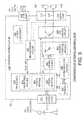
- FIG. 3is a diagram showing components of an external defibrillator, such as the one shown in FIG. 1 , configured in an illustrative embodiment according to this disclosure.
- FIG. 4shows a functional diagram of an illustrative system for providing decision support to a caregiver according to this disclosure.
- FIG. 5is an enlarged view of the task file module included in the defibrillator of the defibrillator system in FIG. 4 .
- FIG. 6is a flowchart for the modeling of a graph of interdependent tasks to be performed for a medical procedure.
- FIG. 8is a flow chart for distributing a workflow according to this disclosure.
- FIG. 9is a flow chart for the execution of a workflow according to this disclosure.
- FIGS. 10-18show a defibrillator of the defibrillator system of FIG. 4 displaying illustrative screen shots according to this disclosure.
- FIGS. 19-21show an architecture and display generated by the dashboard generator shown in FIG. 4 .
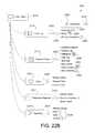
- FIGS. 22A , Bshow an illustrative flow for configuring a decision support module in accordance with this disclosure.
- FIG. 1is a diagram of a defibrillation scene showing the use of an external defibrillator to save the life of a person according to this disclosure.
- a person 82is lying on his back. Person 82 could be a patient in a hospital, or someone found unconscious, and then turned over onto his back. Person 82 is experiencing a condition in their heart 85 , which could be Ventricular Fibrillation (VF).
- VFVentricular Fibrillation
- a portable external defibrillator 100has been brought close to person 82 .
- At least two defibrillation electrodes 104 , 108are typically provided with external defibrillator 100 , and are sometimes called electrodes 104 , 108 .
- Electrodes 104 , 108are coupled together with external defibrillator 100 via respective electrode leads 105 , 109 .
- a rescuer(not shown) has attached electrodes 104 , 108 to the skin of person 82 .
- Defibrillator 100is administering, via electrodes 104 , 108 , a brief, strong electric pulse 111 through the body of person 82 .
- Pulse 111also known as a defibrillation shock, also goes through heart 85 , in an attempt to restart it, for saving the life of person 82 .
- Defibrillator 100can be one of different types, each with different sets of features and capabilities.
- the set of capabilities of defibrillator 100is determined based upon who would use it and what training they would be likely to have. Examples are now described.
- FIG. 2is a table listing two typical types of external defibrillators, and who they are primarily intended to be used by.
- a first type of defibrillator 100is generally called a defibrillator-monitor, because the defibrillator part is typically formed as a single unit with a patient monitor part.
- a defibrillator-monitoris sometimes called monitor-defibrillator.
- a defibrillator-monitoris intended to be used by persons in the medical profession, such as doctors, nurses, paramedics, emergency medical technicians, etc. who may be trained to provide medical treatment to the patient during a defibrillation process based upon information provided by the monitor. Such a defibrillator-monitor is intended to be used in a pre-hospital or hospital scenario.
- the defibrillator partmay be dedicated to a particular mode of operation. Alternatively, the defibrillator part may be configured to operate in more than one modes of operation.
- One mode of operation of the defibrillator partmay be that of an automated defibrillator, which can determine whether a shock is needed and, if so, charge to a predetermined energy level and instruct the user to administer the shock.
- Another mode of operationmay be that of a manual defibrillator, where the user determines the need and controls administering the shock.
- one illustrative defibrillatoris configured to enable both automated defibrillation and manual defibrillation modes of operation depending upon the selection of the user.
- the devicehas features additional to what is minimally needed for mere operation as a defibrillator. These features can be for monitoring physiological indicators of a person in an emergency scenario. These physiological indicators are typically monitored as signals. For example, these signals can include a person's full ECG (electrocardiogram) signals, or impedance between two electrodes. Additionally, these signals can be about the person's temperature, non-invasive blood pressure (NIBP), arterial oxygen saturation/pulse oximetry (SpO2), the concentration or partial pressure of carbon dioxide in the respiratory gases, which is also known as capnography, and so on. These signals can be further stored and/or transmitted as patient data.
- NIBPnon-invasive blood pressure
- SpO2arterial oxygen saturation/pulse oximetry
- capnographycapnography
- a second type of external defibrillator 100is generally called an AED, which stands for “Automated External Defibrillator”.
- An AEDtypically makes the shock/no shock determination by itself, automatically. Indeed, it can sense enough physiological conditions of the person 82 via only the shown defibrillation electrodes 104 , 108 of FIG. 1 . In its present embodiments, an AED can either administer the shock automatically, or instruct the user to do so, e.g. by pushing a button. Being of a much simpler construction, an AED typically costs much less than a defibrillator-monitor. As such, it makes sense for a hospital, for example, to deploy AEDs at its various floors, in case the more expensive defibrillator-monitor is more critically being deployed at an Intensive Care Unit, and so on.
- AEDscan also be used by people who are not trained in the medical profession. More particularly, an AED can be used by many professional first responders, such as policemen, firemen, etc. Even a person with only first-aid training can use one. And AEDs increasingly can supply instructions to whoever is using them.
- AEDsare thus particularly useful, because it is so critical to respond quickly, when a person suffers from VF. Often, the people who will first reach the VF sufferer may not be in the medical profession.
- a hybrid defibrillatorcan have aspects of an AED, and also of a defibrillator-monitor.
- An illustrative examplemay be an AED provided with an ECG monitoring capability.
- FIG. 3is a diagram showing components of an external defibrillator 300 configured in an illustrative embodiment according to this disclosure. These components can be configured, for example, in external defibrillator 100 of FIG. 1 . Plus, these components of FIG. 3 can be provided in a housing 301 , which is also known as casing 301 .
- External defibrillator 300is intended for use by a user 380 , who would be the rescuer.
- Defibrillator 300typically includes a defibrillation port 310 , which may be configured as a socket (not shown) in housing 301 .
- Defibrillation port 310includes nodes 314 , 318 .
- Defibrillation electrodes 304 , 308which can be similar to electrodes 104 , 108 in FIG. 1 , can be plugged into defibrillation port 310 , so as to make electrical contact with nodes 314 , 318 , respectively. It is also possible that electrodes can be hard-wired to defibrillation port 310 , etc. Either way, defibrillation port 310 can be used for guiding to person 82 via electrodes an electrical charge that has been stored in defibrillator 300 , as discussed below.
- defibrillator 300is actually a defibrillator-monitor, as was described with reference to FIG. 2 , then it will typically also have an ECG port 319 in housing 301 , for plugging in ECG leads 309 .
- ECG leads 309can help sense an ECG signal, e.g. a 12-lead signal, or a signal taken from a different number of leads.
- a defibrillator-monitorcould have additional ports (not shown), and another component 325 for the above described additional features, such as for receipt of patient signals.
- Defibrillator 300also includes a measurement circuit 320 .
- Measurement circuit 320receives physiological signals from ECG port 319 , and also from other ports, if provided. These physiological signals are sensed, and information about them is rendered by circuit 320 as data, or other signals, etc.
- defibrillator 300may lack ECG port 319 .
- Measurement circuit 320can obtain physiological signals in this case through nodes 314 , 318 instead, when defibrillation electrodes 304 , 308 are attached to person 82 .
- a person's ECG signalcan be sensed as a voltage difference between electrodes 304 , 308 .
- impedance between electrodes 304 , 308can be sensed for detecting, among other things, whether these electrodes 304 , 308 have been inadvertently disconnected from the person.
- Defibrillator 300also includes a processor 330 .
- Processor 330may be implemented in any number of ways. Such ways include, by way of example and not of limitation, digital and/or analog processors such as microprocessors and digital-signal processors (DSPs); controllers such as microcontrollers; software running in a machine; programmable circuits such as Field Programmable Gate Arrays (FPGAs), Field-Programmable Analog Arrays (FPAAs), Programmable Logic Devices (PLDs), Application Specific Integrated Circuits (ASICs), any combination of one or more of these, and so on.
- DSPsdigital-signal processors
- controllerssuch as microcontrollers
- software running in a machineprogrammable circuits such as Field Programmable Gate Arrays (FPGAs), Field-Programmable Analog Arrays (FPAAs), Programmable Logic Devices (PLDs), Application Specific Integrated Circuits (ASICs), any combination of one or more of these, and so on.
- Processor 330may include a number of modules.
- One such modulecan be a detection module 332 , which senses outputs of measurement circuit 320 .
- Detection module 332can include a VF detector.
- the person's sensed ECGcan be used to determine whether the person is experiencing VF.
- Advice module 334can be an advice module 334 , which arrives at a piece of instructional advice based on outputs of detection module 332 .
- Advice module 334can include a Shock Advisory Algorithm residing in a memory unit (not shown) in the advice module for instructing the processor to implement decision rules, etc.
- the Shock Advisory Algorithmmay reside in part or in whole on a memory 338 of the defibrillator.
- the instruction to the processorcan be to shock, to not shock, to administer other forms of therapy, and so on. If the instruction to the processor is to shock, in some external defibrillator embodiments, the processor is configured to report that instruction to the user via user interface 370 , and to prompt the user to do it. In other embodiments, the processor may be configured to execute the instructional advice, by administering the shock. If the instructional advice is to administer CPR, the processor may be configured to enable defibrillator 300 to issue prompts to administer CPR, etc.
- Processor 330can include additional modules, such as module 336 , for other functions. In addition, if other component 325 is provided, it may be operated in part by processor 330 or by another processor.
- Defibrillator 300optionally further includes the memory 338 , which can work together with processor 330 .
- Memory 338may be implemented in any number of ways. Such ways include, by way of example and not of limitation, nonvolatile memories (NVM), read-only memories (ROM), random access memories (RAM), any combination of these, etc.
- Memory 338if provided, may include programs containing instructions for execution by processor 330 or other processors that may be included in the external defibrillator. The programs provide instructions for execution by the processor 330 , and can also include instructions regarding protocols and decision making analytics, etc. that can be used by advice module 334 .
- memory 338can store prompts for user 380 , etc.
- memory 338can store patient data.
- Defibrillator 300may also include a power source 340 .
- power source 340typically includes a battery. Such a battery is typically implemented as a battery pack, which can be rechargeable or not. Sometimes, a combination is used, of rechargeable and non-rechargeable battery packs.
- Other embodiments of power source 340can include an AC power override, whereby AC power, instead of power from power source 340 is delivered to an energy storage module 350 when AC power is available.
- power source 340is controlled by processor 330 .
- Defibrillator 300additionally includes the energy storage module 350 .
- Module 350is where electrical energy is stored in preparation for a sudden discharge to administer a shock. The charge to module 350 from power source 340 to the right amount of energy can be controlled by processor 330 .
- module 350includes one or more capacitors 352 , and may include other circuitry.
- Defibrillator 300moreover includes a discharge circuit 355 .
- Circuit 355can be controlled to permit the energy stored in module 350 to be discharged to nodes 314 , 318 , and thus also to defibrillation electrodes 304 , 308 .
- Circuit 355can include one or more switches 357 . Those can be made in a number of ways, such as by an H-bridge, and in other ways well known in the art.
- Defibrillator 300further includes the user interface 370 for user 380 .
- User interface 370can be made in any number of ways.
- interface 370may include a screen, to display a parameter of a patient that is detected and measured, provide visual feedback to the rescuer for their resuscitation attempts, and so on.
- Interface 370may also include a speaker, to issue voice prompts, etc.
- Interface 370may additionally include various controls, such as pushbuttons, keyboards, and so on.
- discharge circuit 355can be controlled by processor 330 , or directly by user 380 via user interface 370 , and so on.
- Defibrillator 300can optionally include other components.
- a communication module 390may be provided for communicating with other devices. Such communication can be performed wirelessly, or via wire, or by infrared communication, and so on. In this way, data can be communicated from the defibrillator 300 to external devices, such as patient data, incident information, therapy attempted, CPR performance, and so on.
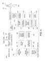
- FIG. 4shows a functional diagram of an illustrative system for providing decision support to a caregiver according to this disclosure.
- the defibrillator systemcomprises a defibrillator 410 , a defibrillation site 405 , and an external utility 415 .
- the defibrillation site 405is a subject being administered a defibrillator charge through contact electrode pair 406 by a caregiver.
- the electrode pair(electrodes 104 , 108 in FIG. 1 ) is attached to the skin of a person on one end.
- the electrode pairis tethered by hard-wiring to the defibrillator for the defibrillator to administer, via the electrodes a brief, strong electric pulse through the body of the person.
- the pulsealso known as a defibrillation shock also goes through the heart, in an attempt to restart it, for saving the life of the person.
- the defibrillation sitemay also be provided with an electrocardiogram (ECG) or other medical tool that is interfaced to the defibrillator processor module for providing the defibrillator processor module with patient parameter data for use by the defibrillator in controlling the defibrillation shock.
- ECGelectrocardiogram
- the ECGtypically includes a set of electrodes adapted for monitoring the ECG of a patient.
- the ECG leadsare divided into limb leads, called—I, II, III, aVR, aVL and aVF—and precordial (chest) leads called—V1, V2, V3, V4, V5, V6.
- the ECG voltage potential between pairs of electrodescan be measured and recorded.
- the graphical display of these currentsis known as an electrocardiogram, which is often referred to as an ECG.
- the ECG datamay provide the defibrillator processor with valuable information for use in managing the defibrillation charge.
- the ECG datamay be displayed by the defibrillator processor on a display and is useful in revealing the condition of the heart and to diagnosis heart ailments or disease.
- the defibrillator 410comprises a defibrillator processor module 420 , an energy storage device 442 , a defibrillation port 414 , a display 424 , a user interface 440 , and advantageously a decision support module 450 of this disclosure.
- the defibrillator processor 422controls when an electrical charge is applied to a patient.
- the defibrillator processor 422also controls other hardware and software residing in the defibrillator.
- the defibrillator processormay be implemented in any number of ways. Such ways include, by way of example and not of limitation, digital and/or analog processors such as microprocessors and digital-signal processors (DSPs); controllers such as microcontrollers; software running in a machine; programmable circuits such as Field Programmable Gate Arrays (FPGAs), Field-Programmable Analog Arrays (FPAAs), Programmable Logic Devices (PLDs), Application Specific Integrated Circuits (ASICs), any combination of one or more of these, and so on.
- DSPsdigital-signal processors
- controllerssuch as microcontrollers
- software running in a machineprogrammable circuits such as Field Programmable Gate Arrays (FPGAs), Field-Programmable Analog Arrays (FPAA
- the memory unit 422can be any form of data storage device. It may be at least one of random access memory (RAM) and/or read only memory (ROM). Information can be stored permanently until overwritten and/or stored temporarily for use while the unit is active.
- RAMrandom access memory
- ROMread only memory
- the display 424may be a visual display capable of displaying data transmitted from defibrillator processor 435 .
- Displays for use with this disclosuremay include an LCD screen, an e-paper display, or other bi-stable display, a CRT display or any other type of visual display.
- the parameter module 442may be any monitor configured to detect a parameter of a patient.
- the patient parametermay include one or more of the following measurements: a measurement of CO 2 exhaled by a patient; an electrical activity of the heart of a patient; an exchange of air between the lungs of a patient and the atmosphere; a pressure of the blood in a patient; a temperature of a patient; an oxygen saturation in the blood of a patient; a chest compression of a patient; an image of the internal structure of a patient; an oxygen saturation in the blood in the brain of a patient; the acidity or alkalinity of fluids in a patient; or other patient parameter.
- the patient parameter of the CO 2 exhaled by a patientmay be measured using capnography techniques.
- the patient parameter of the electrical activity of the heart of a patientmay be measured using ECG techniques.
- the patient parameter of the exchange of air between the lungs of a patient and the atmospheremay be measured using ventilation techniques.
- the patient parameter of the measurement of the pressure of the blood in a patientmay be measured using non-invasive blood pressure measurement techniques or invasive blood pressure measurement techniques.
- the patient parameter of the temperature of a patientmay be measured using temperature measurement techniques.
- the patient parameter of the oxygen saturation in the blood of a patientmay be measured using pulse oximeter techniques or tissue oximetry techniques.
- the patient parameter of the chest compression of a patientmay be measured using chest compression detection and feedback techniques.
- the patient parameter of the image of the internal structure of a patientmay be measured using ultrasound measurement techniques.
- the patient parameter of the oxygen saturation in the blood in the brain of a patientmay be measured using cerebral oximetry techniques.
- the patient parameter of the acidity or alkalinity of fluids in a patientmay be measured using non-invasive pH measurement techniques.
- the ECG data feed module 443is a module configured to manage the feed of ECG data from an electrocardiogram (ECG) that may be tethered to the defibrillator.
- ECGelectrocardiogram
- the other data feeds module 444is configured to manage the feed of other data from within or from outside the defibrillator.
- the loudspeaker 445is a device for converting electrical signals representative of coaching information into audible information for use by a caregiver.
- the microphone 446is a device for converting audible coaching information into electrical signals for use by the defibrillator.
- Communication module 430is hardware and software configured to transmit data to and from the defibrillator 410 .
- the communication module 630is configured to transmit data from the defibrillator to the external utility 415 .
- the external utility 415may be a computer, a laptop, a server, a mobile computing device, or other computing device.
- the external utilitymay also include a display screen for use as a display to monitor a patient.
- the defibrillator processor 420may receive data from the external utility through the communication module 430 to the defibrillator 410 .
- communication module 430provides for the bidirectional transmission of data between the defibrillator 410 and the external utility 415 .
- the external utilityis likewise provided with a communication module (not shown) that is compatible with the communication module 430 as required to establish the communication link with the communication module 430 of the defibrillator.
- the communication module of the defibrillator and the external utility 415respectively, enable a communication link 416 to be established between the defibrillator processor 420 and the external utility 415 for enabling the bidirectional flow of data between the defibrillator and external utility devices.
- the communication module 430may include a wireless module 432 and/or a network data connect module 434 as shown in FIG. 4 .
- the wireless modulemay illustratively be a Wi-Fi module.
- the wireless module 684may be a blue tooth module, a CDMA module, or any other communication module that enables a wireless communication link for the bidirectional flow of data between devices wirelessly.
- the network data connect module 434may be a hardware and software based data connector configured to connect with a data outlet of the external utility 416 .
- the network data connect module 434may be one or more ports and associated circuitry and software that allow bidirectional flow of data between the defibrillator processor 420 and the external utility 415 .
- the network data connect moduleis an Ethernet connector configured for connection to the external utility 414 in a wired connection.
- the network data connect modulemay be an RS232 connector, a USB or other wire connector.
- Other connectors and hardware and software configurable for providing a wired connection between the communication module 430 and the external utility 415may be used for network data connect module 434 as are well known in the art.
- the external utility 415is one or more programmed computers that may be connected to the defibrillator 410 wirelessly or by wired connection in order to allow for the exchange of information between the defibrillator and the external utility.
- the external utility of this disclosuremay be a server.
- a servermay be any computer configured to serve the requests of client programs running on the same or other computers on a network.
- the computer of the external utilitymay be a host computer configured to serve the requests of one or more client programs residing in the defibrillator 410 .
- the computer of the external utilitymay serve a client residing on the external utility or on some other computer to which the external utility may be connected.
- the external computing devicemay be a personal computer, a laptop computer, a tablet, a mobile computing device, or a server.
- the external utilitiesmay include an adjunct medical device which may be a programmed computer that provides tools for monitoring the technique of a rescuer during the defibrillation process, such as applying CPR or proper positioning of the electrodes for application of a defibrillation charge on the patient.
- the devicemay monitor CPR chest compressions provided before or after defibrillation shock.
- the devicemay measure the depth of a CPR chest compression, compare it to what it should be, and provide feedback to the user by way of instructions to go faster, deeper, etc.
- the adjunct medical devicemay be any other device that monitors defibrillation techniques and provides feedback to a rescuer at the site of the defibrillation.
- Utility applicationsmay also include existing applications that may be one or more software applications running on one or more computing devices external to the data processor module for performing a dedicated function. Examples of such functions include: performing specific services or tests.
- the defibrillator of FIG. 4is provided with the decision support module 450 of this disclosure.
- the decision support modelmay be provided to any medical device.
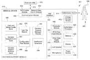
- the decision support module 450comprises a task file module 470 , a configuration files module 480 , a data and model profile bank 462 , a decision support event bank 464 , a decision support protocol bank 466 , a decision support manager module 490 , and a dashboard generator 494 .
- the decision support module 450is hardware and software configured to advantageously enable work flows to be modeled as a graph of interdependent tasks to be performed.
- the decision support moduleillustratively comprises a task file module 470 , a configuration files module 480 , data and mode profile bank 462 , decisions support event bank 464 , decision support protocol bank 466 , decision support manager module 490 , and dashboard generator.
- the task file module 470is hardware and software configured to define the tasks to be performed by the decision support module 450 and to define and enable interactions between the tasks. As shown in FIG. 5 , the task file module illustratively includes an event viewer module 472 , a protocol assistant module 473 , a smart messaging module 474 , a smart indices module 475 , and a reference material lookup module 476 for the purpose of defining the tasks and their independencies into a work flow. These modules and the functionality and the overall architecture of the decision support module is provided later in this description below.
- the configuration files module 480is hardware and software configured to specify a configuration for execution of one of the tasks residing in the task file module.
- the configuration files module 480illustratively provides the configurations for the data and data flow for each task that is available to the task file module 470 for generating graphical interdependencies between the task files into one coherent work flow While the configuration files module 480 is illustrated in FIG. 4 as a module that is separate and apart from task file module 470 , it will be appreciated to one skilled in the art to which this disclosure pertains that the configuration files module 480 may be integrated into the task file module 470 so that the task file module 470 defines both the configurations for the individual tasks as well as defining the interpedencies between those tasks into one coherent work flow.
- the data and model profile bank 462is hardware and software configured to store data and model profile constructs.
- the decision support event bankis hardware and software configured to provide events for the performance of tasks.
- the decision support protocol bankis hardware and software configured to provide protocols for the performance of tasks.
- the data and model profile bank, the decision support event bank, and the decision support protocol bankmay be fed by a data feed from the parameter module 442 , an ECG data feed from the ECG data feed module 443 , a data feed from another data feeds module 444 , a data feed entered through the user interface 440 , a data feed from the external utility 415 by wire or wirelessly over the communication link 416 , or a data feed provided by other sources.
- the data and model profile bank, the decision support event bank, and the decision support protocol bankmay be fed in these and other ways from these data feed sources directly or indirectly through one or more of the other elements that make up the decision support module that have been directly feed data from these data feed sources.
- each elementmay illustratively provide a node for receiving data generated internally or externally of the defibrillator directly from a feed source or indirectly from any one or more elements that make up the decision support module that receives a data feed directly from a feed source, in a specific manner defined by the configuration of the decision support module.
- the data and model profile bank, the decision support event bank, and the decision support protocol banksare shown in FIG. 4 separate and apart from each other, it will be appreciated to one skilled in the art to which this disclosure pertains that these banks may be integrated into one bank that is configured to provide data and model profiles, events, and protocols to the decision support module.
- the data, events, and protocolsmay be used by the configuration module in configuring the tasks, by the task file module in defining interdependencies between tasks, and by the decision manager module and the dashboard generator in a manner described below.
- the data, events, and protocols in the data and model profile bank 462 , the decision support event bank 464 , and the decision support protocol bank 466may be used by the decision support module to perform a current operation.
- the data, events, and protocolsmay also be used for operations designed for generating historic information or operation or for use for prospective purposes.
- the data, events, and protocolsmay generally be used for the purpose of enhancing the coaching of a user with respect to a medical procedure. Additionally, the data, events, and protocols may be used for other purposes, such as validating data in the data and model profile bank 462 , the decision support event bank 464 , and/or the decision support protocol bank 466 .
- the decision support manager moduleis hardware and software configured to to construct a dependency graph of the work flow of interdependent tasks defined by the task file module 470 using task configurations for each task provided by the configuration files module 480 .
- the decision support manager moduleis further configured to execute the dependency graph.
- the decision support manager modulemay further be configured as an engine for collecting, aggregating, and/or managing the data and model profile, the events, and the protocols from the data and model profile bank 462 , the decision support event bank 464 , and the decision support protocol bank 466 , respectively, for use by the configuration files module 480 in configuring the task and by the task file module 470 in creating interdependencies between the tasks.
- this collection, aggregation, managing enginemay be performed by the task file module 470 or the configuration files module 480 or distributed across one or more of the modules of the decision support module
- the dashboard generatoris hardware and software configured to provide a display of the dependency graphs of the various workflow tasks of the work flow of interdependent tasks defined by the task file module 470 using task configurations for each task provided by the configuration files module 480 .
- the dashboardmay further configured to display other information such as decision points, decision reminders, possible etiologies, checklists, caregiver input, physiological data, trend line, timeline, time stamping, location, previous patient encounters, categories of data, timers that are set by data entry, etc.
- the dashboardmay be further configured to display other information like check-off completions, predefined selections, care givers available, currently attending, or available, parameter or other information, coordination of data feeds from one or more inputs, defibrillator therapy activities, activities of partner systems, video procedures.
- a video laryngoscopemay provide tasks like apply the ventilator, check the heart rate, preview patient data.
- Configuration settingsmay be displayed such as user level, patient condition, the condition of the patient.
- the condition of the patientmay be presented by display of patient data such as EMR, ePERS, and EMS.
- the tasksmay display historic patient parameter profiles for the patient for comparison with current patient parameter profile.
- the tasksmay display patient parameter profiles for a health patient for comparison with the parameter profile of the current patient.
- the operation of the decision support module 410 of FIG. 4is illustratively shown in FIG. 6 as a flowchart for the modeling of a graph of interdependent tasks to be performed for a medical procedure.
- the operationbegins by selecting 610 one or more tasks to be performed for a medical procedure.
- the selectionmay be made through the user interface 440 by user activation of a manual key.
- the selectionmay be made from a remote location by the external utility 415 .
- the selectionmay be triggered by instructions residing in one or more of the elements residing in the decision support module.
- the decision support moduleselects 620 a configuration for execution of the selected one or more task.
- Data and/or model profile feed 630 , events feed 640 , and/or protocols feed 650is collected and aggregated by the decision support manager module for correlations performed by the configuration files in correlating the configurations for the one or more tasks and for correlations performed by the task file module in correlating interdependencies between the one or more tasks by the task file module and by the decision support manger module in correlating the graphing of the workflow of interdependencies between the one or more tasks defined by the task file module using the configurations for the one or more tasks defined by the configuration files module.
- the decision support moduleconstructs 660 the dependency graph of tasks based upon the selected configuration for coaching the caregiver.
- the dashboard generator 494provides the display of the dependency graphs of the various workflow tasks of the work flow of interdependent tasks defined by the task file module 470 using task configurations for each task provided by the configuration files module 480 .
- FIG. 7illustrates a workflow creation module 701 of hardware and software configured for the creation of a workflow according to this disclosure.
- the moduleresides on a computer which illustratively is a computer that is an external utility.
- the workflow creation module 701 of this disclosureserves as an editor advantageously for the creation of the workflow for the medical devices, such as defibrillators.
- the workflow creation modulemay provide the editor for configuring the configuration of the decision support module of the medical device; illustratively providing configurations for the configuration files in the configuration file module of the decision support module on the medical device.
- the workflow creation modulemay define the protocols that the decision support module is to follow in managing the clinical display on the medical device.
- the workflow creation modulemay further configure clinical data residing on servers that may be accessed by the medical device with protocols, rules, etc. for delivery and display to the decision support module according to this disclosure.
- the editing by the external utilitythus provides one decision support logic that may be shared with a medical device, such as a defibrillator.
- the external utilitymay provide other decision support logic and decision support information to the medical device.
- the external utility of this disclosuremay be a server configured to serve the requests of client programs running on the medical device.
- the external utilitymay include files, data, references, data and other decision support information that the external utility may share with the defibrillator or other medical device.
- the computer that includes a workflow creation module 701is an ITablet although any computer may be used. Alternatively, the module may reside on the defibrillator itself.
- the location of the workflow creation module 701 in an external utilityenables the workflow created by the workflow creation module to be distributed to one or more defibrillators in the network over communication link 415 .
- any one defibrillatorprovides a network terminal on the network and so may be used for the creation and source of distribution of workflow to defibrillators throughout the network.
- the workflow creationbegins at start 710 .
- An option 720 to create or edit an existing protocolallows a user to edit 724 an existing protocol or create 722 a new protocol.
- An edit 724 of an existing protocolallows the user to view a library 725 of custom protocol workflows and to view versions 726 of protocol workflows for selection 730 for loading as the workflow to use in the instant workflow process being defined by the workflow creation module 730 .
- the create 722 new protocolallows a user to either create a protocol by either a view 728 of a default protocol library or create 732 of a protocol.
- the selection 730 of either view 728 or create 732 optionsloads the selected protocol as the workflow to use in the instant workflow process being defined by the workflow creation module 730 .
- An editor 740allows a user to add or remove an initiating event 742 , a discrete stepwise confirmation primitive 744 , a Boolean flow control primitive 746 , and/or a nested protocol primitive 748 .
- the initiating event 742is an event that may be used to trigger the deployment of an interdependent task on the occurrence of the event.
- the discrete stepwise confirmation primitiveis the smallest ‘unit of processing’ available to a programmer of the particular machine used to impalement the workflow or an atomic element of an expression in a language for confirming the occurrence of an event.
- the Boolean flow control primitiveis a primitive of Boolean operations that define the flow of the protocol.
- the nested protocol primitiveis a primitive used to nest one or more protocols within one or more protocols.
- the protocol configured by the editor 740is verified 750 , simulated 752 , and the publication profile is edited 754 .
- the protocol so configuredis saved 756 and the creation of the workflow is ended 760 .
- FIG. 8illustrates a workflow distribution module 801 of hardware and software configured for the distribution of a workflow according to this disclosure.
- the moduleresides on a computer which illustratively is a computer that is an external utility; but as previously described in connection with the workflow creation module, the workflow distribution module may reside on the defibrillator itself.
- the workflow distributionbegins at start 810 .
- An option 820allows a user to view 822 available for distribution and/or to view 824 an installed protocol library version for each asset, which is each terminal on the network that is to receive the created workflow.
- the terminalis illustratively a defibrillator but may be any medical device for providing coaching of a user during a medical procedure.
- An option 830allows a user to select 832 assets to receive latest protocol library version and/or to select assets to remove protocol library with no replacement of the protocol and the workflow is published to the asset.
- the published workflowincludes a manual or auto update feature 842 . If the setting is manual, the asset is enabled to update the protocol library upon manual activation of a button or other active link on the asset.
- the assetis enabled to perform the update automatically by the network.
- the workflow distribution enablement of an assetis thus completed at end 850 .
- Actual configuration of the asset with the distributed workflowoccurs on the automatic update of the configuration settings of the workflow of the asset by the network or upon the manual activation of a button on the asset by a user.
- FIG. 9illustrates a workflow execution module 901 of hardware and software configured for the execution of a workflow according to this disclosure.
- the moduleresides. in a computer which illustratively is a computer that is the asset making use of the module, such as a defibrillator.
- the modulemay reside on an external utility with the output of the data feed generated by the workflow execution module fed to the defibrillator over communication line 416 .
- the workflow executionbegins at start 910 .
- a detector 920 of an eventallows detection by the workflow execution monitor of an event.
- An invocation 930allows the workflow execution monitor to invoke the event manually 932 or upon automatic detection 934 .
- the opt out 950allows the workflow execution monitor to opt out of invoking the protocol.
- the workflow executionends 970 .
- a completion module 960allows the workflow execution monitor to complete a stepwise confirmation on the invoked event 962 , completion of a set of Boolean flow control operations 964 that define the flow of the protocol, and completion of a nested protocol 966 to that nests one or more protocols within one or more protocols.
- the workflow module 960then ends 970 .
- the workflow execution module 901advances to a protocol module 940 to find an applicable protocol 942 and launch the protocol 944 .
- the workflow execution moduleadvances to the completion module 960 where the workflow execution monitor is allowed to complete a stepwise confirmation on the invoked event 962 , completion of a set of Boolean flow control operations 964 that define the flow of the protocol, and completion of a nested protocol 966 to that nests one or more protocols within one or more protocols.
- the workflow module 960then ends 970 .
- the task file moduleillustratively includes the event viewer module 472 , the protocol assistant module 473 , the smart messaging module 474 , the smart indices module 475 , and the reference material lookup module 476 for the purpose of defining the tasks and their independencies into a work flow.
- the decision support manager moduleallows the user to create pre-defined messaging that will be available. Each message will have some form of an input to trigger the message. The input may be an initiating event or it may be a timed based Boolean equation using a combination of Vital Sign data and events. Each message will also have some form of output.
- the outputmay be no output displayed because the normal output may no longer be necessary, such as for example, because other events have occurred that have preempted the need to display that message.
- the outputmay be tied to a standard set of events or a user pre-defined hierarchy of manually enterable events described above.
- the event viewer module 472is a software and hardware configuration of a construct for generating a series of timed stamp events so that the user can see what has happened with this patient.
- An eventmay be any individual data point or groupings of data points.
- an eventis a grouping of data points which may be displayed on the display of the defibrillator.
- FIG. 10shows a defibrillator 1010 of a defibrillator system 1001 displaying illustrative screen shot 1020 according to this disclosure.
- screen shot 1020depicts a workflow 1030 in this example as a non-indexed view of the major vitals signs as they vary over time.
- the event in this examplemay be referred to as the “Sparkline” view.
- Sparklinescan be defaulted to show up on the screen at startup, such as to provide a waveform along a bottom region of the display.
- the spark linecan be selected to be displayed in any of the regions of the display at any time.
- a usermay select when to display a sparkline.
- an event buttonmay be provided for the user to activate to display the “pre-defined hierarchy of manually enterable events. The user may activate the event button to bring up the Sparkline view at predetermined or any period of time.
- the Sparkline viewillustratively includes one or more event markers 1040 shown on the Sparkline by the inverted triangle appearing at the bottom of each spike depicted in the Sparkline.
- the Sparklineincludes a series of event markers running along the bottom of the Sparkline with each event marker associated with a spike depicted by in the Sparkline.
- the dashboard generator modulegenerates the Sparkline non-indexed view of the major vital sign as it varies over time.
- the event viewer moduleprovides the event marker at a point in time along the non-indexed view of the major vital sign.
- the event markerprovides a record of one or more predetermined events associated with the major sign at that point in time. In other words, the event marker shows where the defibrillator has captured events at that point in time.
- the event markermay be used by the user to do a variety of tasks.
- the event markerallows a user to zoom in on a specific vital sign, that is to say, to an indexed view.
- the event markermay allow a user to zoom in on a specific time period. In other words, the user may use the event marker to narrow the period and widen the view of the Sparkline.
- the event markermay allow a user to zoom in on a specific event; in other words, to view the event details including captured waveforms.
- the event markermay allow a user to add an event, such as by pulling up a “user pre-defined hierarchy of manually enterable events to add to the event record.
- the event markermay be used to change the view to a list view of time stamped events.
- the event markermay be used to expand the view to cover two waveform regions instead of one.
- the event markermay allow the user to navigate back to the Sparkline view.
- the vital signmay include time changing data on heart beat, SpO2, CO2, temperature, an oxygen saturation in the blood of a patient; a chest compression of a patient; an image of the internal structure of a patient; an oxygen saturation in the blood in the brain of a patient; the acidity or alkalinity of fluids in a patient; or other patient parameter.
- the events in the record that is represented by the event markermay be one or more predetermined events including an indexed view of the vital sign, a view of the vital sign over a specific period of time, a specific event, details of a specific event, a time stamped event, a listing of time stamped events, a view of one or more different vital signs at that point in time, a protocol, and so on.
- the eventsmay also be a combination of one or more of the foregoing and other predetermined events.
- the usermay configure the event viewer module with the one or more events to be contained in the records that the event viewer module may associate with an event.
- the event viewer modulemay provide a user with a hierarchy of manually programmable events.
- the hierarchy of manually programmable eventsmay enable the user to define the one or more new events for configuring the record of the event marker.
- the event viewer moduleprovides an active forward link of the event marker to the records such that on user activation of the event marker, the forward link takes the user to the records that are associated with the event marker.
- the event viewer moduleprovides an active reverse link of the event marker to the records such that on user activation of the active reverse link, the active reverse link takes the user from the records that are associated with the event marker back to the event marker.
- the decision support manager moduleallows the user to create their custom set of user pre-defined hierarchy of manually enterable events.
- the names of these eventsmay be defined by the user in their native language; thereby obviating the need for translations.
- the usermay have the ability to determine what type of waveform storage goes with any event. For example, a user may define a waveform to be displayed for 8 seconds before occurrence of a subsequent event, 8 seconds after activation of an event marker, 4 seconds after activation of an event marker and before occurrence of a subsequent event. Alternatively, the user may configure the event marker to display no waveforms on the activation of an event marker.
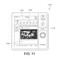
- FIG. 11shows a defibrillator 1110 of a defibrillator system 1101 displaying illustrative screen shot 1120 illustrating a workflow 1130 depicting an event 1140 .
- the event 1140was triggered by user activation of the event marker appearing as an inverted triangle at the bottom of the highlighted spiked signal in the workflow which contains an active forward link to the event 1040 in this example in accordance with this disclosure.
- the event 1140is a picture of a vehicular accident along with a record appearing underneath the picture of some data that may be useful to a caregiver such as a description of the accident (e.g., frontal collision), description of the patients, description of the injuries, etc.
- FIG. 12shows a defibrillator 1210 of a defibrillator system 1201 displaying illustrative screen shot 1220 illustrating a workflow 1230 depicting an event 1240 .
- the event displayedis a series of vital signs on one of the subjects involved in the vehicular accident shown in FIG. 11 .
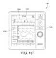
- FIG. 13shows a defibrillator 1310 of a defibrillator system 1301 displaying illustrative screen shot 1320 illustrating a workflow 1330 depicting an event 1340 .
- the event displayedis a series of vital signs shown with additional patient parameter or other data on one of the subjects involved in the vehicular accident shown in FIG. 11
- the event viewer module 472 of FIG. 5may generate a time stamping on one or more of the events that the event viewer module may include in a record to be associated with an event marker.
- each of the events illustrated in FIGS. 10-13may be provided with a time stamp to indicate the time that the data in the record displayed on activation of the event marker occurred.
- the listing of data in the record associated with an event markermay be an active listing to which additional data may be added in real or batch time. Any one or more of the original or additional data may be time stamped to indicate to a caregiver the time at which the data is captured.
- the series of time stamped events generated by the event viewer moduleenables a caregiver to track what has happened with the patient.
- the protocol assist module 473 shown in FIG. 4is a software and hardware configuration of a construct for generating a pre-defined protocol of one or more activities that can be displayed with each activity of the one or more activities being checked off by a user when the each activity is completed.
- the protocol assistant moduleallows a user to display and acknowledge a series of user pre-defined actions,
- the protocol assistant modulemay be selected by manual activation of a protocol coach button 1410 appearing in a toolbar appearing at the top of the display shot.
- the protocol assistant module selectionmay also occur automatically on a display when certain events occur. For example, if data on a patient indicates chest pain, that data event may trigger the display of the protocol for the caregiver to follow in treating the patient.
- FIG. 14shows a defibrillator 1410 of a defibrillator system 1401 displaying illustrative screen shot 1420 illustrating a listing of protocols that may be generated by the protocol assist module 473 .
- the protocols generated by the protocol module in this illustrative exampleincludes a protocol for treatment procedures for arising from an airway, a trauma, an advanced cardiac life support (ACLS), a medical emergency, and poisons.
- ACLSadvanced cardiac life support
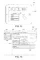
- FIG. 15shows a display of a chest pain protocol generated by the protocol assist module. More particularly, defibrillator 1510 of a defibrillator system 1501 displaying illustrative screen shot 1520 illustrating a workflow 1530 depicting an event 1540 .
- the event displayedis a chest pain protocol.
- the usermay select this protocol if a patient being treated is exhibiting chest pains.
- the screen shot 1520displays this protocol as a series of steps 1522 for the caregiver to follow in order to treat the chest pains.
- the stepsinclude acquiring a 15-lead ECG, consulting a cardiologist, administering certain medications, drawing blood, and obtaining a chest X-ray.
- the screen shot in this examplemay be a touch screen and each action may be associated with an active touch screen link.
- Thisallows a user to indicate completion of each task by touching the displayed task on the touch screen which causes a check-mark 1540 to be displayed next to each task showing which tasks have been completed.
- This featureallows a caregiver to monitor the tasks being completed by the caregiver as the caregiver performs each task in order to ensure that all of the tasks recommended by the selected procedure are completed and that they are performed in their recommended sequence.
- the step in the protocol of requesting a consultation with a particular cardiologistallows the caregiver to interact on the spot with a medical specialist, in this case a Dr. Ray.
- the caregivermay accept the consultation by touching the consult response link 1550 on the screen shot. Once accepted, the caregiver will be brought into communication with the caregiver for the purpose of participating with the caregiver in the treatment of the patient.
- the communication link established between Dr. Ray and the caregivermay be by way of instant messaging, audio link, audio-video link, or in other ways.
- the time stamping feature of this disclosureis shown in FIG. 15 in screen shot 1530 which shows events that are being tracked and displayed by the defibrillator 1510 .
- the screen shot 1530displays the events that make-up the chest pain protocol displayed in screen shot 1520 .
- screen shot 1520shows each event as an active link for the caregiver to interact with for various purposes, such as check-marking the completion of a task, establishing a communication link with a consultant, etc.
- Screen shot 1530shows these events in a running listing in which each event is added to the list once the caregiver has completed the event.
- the running listingalso generates a time stamp 1532 for each event added to the running list so that the result is a running listing of a series of time stamped events for use in tracking what has happened with the patient.
- the protocol assistant modulemay include a user defined hierarchy of manually programmable protocols, the hierarchy of manually programmable protocols providing one or more protocols selectable by the user for configuring the protocol generated by the decision support module.
- the protocol assistant modulemay include a system defined hierarchy of manually programmable protocols, the hierarchy of manually programmable protocols providing one or more protocols selectable by the user for configuring the protocol generated by the decision support module.
- the protocol assistant modulethus provides a set of user pre-defined activities, that is to say, protocol, that can be displayed on the screen and have the user check off when they complete the activity. Each check-off would be timed stamped, and if the user pre-defined the activity to be associated with an event, an event would be automatically generated at the time of check-off.
- the protocolmay appear in a primary work area of the screen such as along the bottom of a waveform region. When the protocol comes up, the information that was displayed in the primary work area may illustratively be moved to the background, unless it's currently displaying clinically critical information (e.g. AED Mode). From the protocol assistant module, a user can also pull up the Sparkline view as a part of the window to see events and checklist items in the same view area
- Protocolscan be manually selected via a protocol key, or can appear on the screen automatically when certain events occur. Protocols may be created and organized (hierarchy for manual selection) by the user. The user may define whether the protocol is manually initiated, automatically initiated, or both. Automatic initiation may be connected to an event, so that when the event occurs, the protocol appears. Events can be the standard pre-defined events provided by the decision support module or by user specified events, such as from the pre-defined hierarchy of manually enterable events previously described. For each activity in the Protocol, the user can determine if a timed stamp Event is created at the time of selection or not.
- the decision support management modulewill allow the user to create the protocols, and connect the protocol initiation events and to outputs.
- the output from the protocolmay be no output if, for example, a protocol output is preempted because, for example, the decision support module may have determined that the protocol is no longer needed.
- the outputmay be tied to a standard set of events or to the user pre-defined hierarchy of manually enterable events described above.
- FIG. 16shows a display of a smart message generated by the smart messaging module 474 shown in FIG. 4 .
- the smart message moduleis a software and hardware configuration of a construct for generating smart messaging.
- defibrillator 1610 of a defibrillator system 1601displaying illustrative screen shot 1620 illustrating a pre-defined message.
- the pre-defined messagemay be displayed when an event has occurred and may continue being displayed until another event has occurred.
- the messageis an instruction to the caregiver to administer a specified dosage of epinephrine.
- the display of the messagemay be triggered by an event such as an action in a protocol generated by the protocol assistant module.
- the displaymay be triggered by a parametric condition detected by the defibrillator such as data generated by the patient parameter module indicating a condition of the patient requiring the administration of this medication.
- the messagecould be in the in the form of an immediate action, a reminder to give more medication, an instruction to provide this medication within a specified period of time, a suggestion to consider calling a specialist such as a member of a rapid response team (RRT team), etc.
- the messagesmay appear as pop-ups on the screen, overriding a portion of the general work area of the screen, such as along a bottom of a region of a waveform such as the sparkline.
- the caregiverillustratively has the ability to acknowledge or cancel the message, and the decision support module illustratively records that action.
- the acknowledgementsis associated with an event that is automatically generated at the time of the acknowledgement.
- the caregivermay pre-define whether the acknowledgement of the message creates an event or not.
- the action informed by the user messagemay be taken from the group of action consisting of a reminder, a reminder to take a medication, and a suggestion to contact one or more persons.
- the smart messaging modulemay include an input to the predefined message including an initiating event or a time based Boolean Equation using a combination of vital sign data and events.
- the output of a predefined messageis a no output or an output tied to a standard set of events or an output based on a user predefined hierarchy of manually enterable events.
- FIG. 17shows a display of smart indices generated by the smart indices module 475 shown in FIG. 4 .
- the smart indices moduleis a software and hardware configuration of a construct for generating a predefined indice value associated with the overall health of the patient.
- defibrillator 1710 of a defibrillator system 1701displaying illustrative screen shot 1720 of the smart indices.
- the smart indicesappears above a display of one or more vital waveforms. However, it will be appreciated that the smart indices window may appear anywhere on the display of the defibrillator.
- the indice valueappears as a vital sign information on a display and may be determined by a predefined indices algorithm.
- the indice valuerepresents a health score for a patient and various indice values may be generated depending upon what set of patient parameters a caregiver may want included in the indice value.
- an indice value that is configured to provide a health score on blood pressuremay be configured to display an indice value for the blood pressure of the patient illustratively based upon the height and weight and other physical properties of the patient.
- an indice valuemay combine blood pressure and respiratory rate readings into a combined health score of the patient in which case each reading would be weighted in the health score rating according to the algorithm. Once selected the indice value may appear throughout a patient episode.
- the indice valuemay be programmed to appear at the beginning of each patient episode, manually selectable via a indices menu, or automatically displayed by initiating an event.
- the decision support manager moduleallows the user to decide which preprogrammed indices are going to be used (OBS, IPI, etc.) and which customer defined ones will be available. For each selected indices, the user can define whether its configured to be there all of the time, manually selectable, or automatically initiated (via an Initiating Event)
- FIG. 18shows a display of the reference material lookup display generated by the reference material lookup module 476 shown in FIG. 4 .
- the reference material lookup moduleis a software and hardware configuration of a construct for generating a user pre-defined set of text and graphical information in some standard form (.pdf, .doc. html5).
- defibrillator 1810 of a defibrillator system 1801displaying illustrative screen shot 1820 .
- the screen shotmay illustratively display protocols 1830 , checklists 1840 , guidelines 1850 , standards 1860 .
- the screen shotmay also display news, video, photos, tweets, other reference material, etc.
- the screen shotmay display other modules of data and information such as a library module (not shown) of reference material of text and graphical information in some standard form (.pdf, .doc. html5).
- the reference material lookup modulemay be accessed manually via a user defined hierarchical menu of reference material. Alternatively, the reference material lookup module may be requested manually or automatically when reference material is associated with a protocol task of a smart message delivered by the decision support manager module.
- the preprogrammed informationmay be shown on the screen in a general work area such as below a region of a displayed waveform. The user may scroll up and down the information and close the menu when completed.
- the decision support manager moduleallows the user to create their custom set of “user pre-defined hierarchy of referenced material.”
- the names of this materialmay be defined by the user in their native language, obviating the need for a translation.
- the usermay attach a pre-prepared file (text and graphics) to the name created by the user for a reference material in a format chosen by the user.
- the usermay have the ability to link this material to an already defined protocol task provided by the protocol assistant module or a smart message provided by the smart messaging module to allow the user easier access during use.
- the dashboard generator 494is hardware and software configured to provide a display of the dependency graphs of the various workflow tasks of the work flow of interdependent tasks defined by the task file module 470 using task configurations for each task provided by the configuration files module 480 .
- FIGS. 19-21show an illustrative architecture and display generated by the dashboard generator 494 shown in FIG. 4 . More particularly, FIG. 19 shows a defibrillator 1910 of a defibrillator system 1901 displaying illustrative screen shot 1920 illustrating a partitioning of the display into a vital sign viewer 1920 , a data entry tool 1930 , an event list 1940 , and a care path tool 1950 .
- the vital sign viewermay illustratively display vital signs of a patient such as a spark line.
- FIG. 20shows the vital sign viewer 1920 which displays an instruction from the protocol assistant module advising to apply a shock and displays an active button for the caregiver to press to apply an electrical shock from the defibrillator to the patient.
- the data entry tool 1930includes a checklist of tasks for an illustrative care path that a user may take.
- the tasks generated by the protocol assistant moduleare for the cardiac arrest protocol previously selected by the user.
- the event list 1940includes a listing of events generated by the event viewer module that have occurred during the cardiac arrest protocol each shown stamped with the time at which the event occurred.
- the care path tool 1950includes an illustrative checklist of tasks generated by the protocol assistant module for the cardiac arrest protocol previously selected by the user.
- the care path toolshows that the VF/Pulseless VT condition has been checked by the user which navigates the protocol through appropriate follow-on screen shots of tasks applicable to the VF/Pulseless VT condition.
- the care path toolalso provides a reminder generated by the smart messaging module reminding the user to provide EPIn on the 01:42 hour.
- the care path toolalso provides a follow-on task to determine whether a return of spontaneous circulation (RPSC) has been achieved after application of a shock.
- RPSCreturn of spontaneous circulation
- FIG. 21shows in the event list 1940 that the user delivered the shock recommended in vital sign viewer 1920 of FIG. 20 at the hour of 12:36.12.
- the vital sign viewer 1920is now displaying the next task in the protocol generated by the protocol assistant module which is “Check Patient—Of not Pulse, Start CPR” and indicating a 02:00 minute window to start CPR.
- the usermay then refer to the vital sign viewer 1920 , the data entry tool 1930 , the event list 1940 , and the care path tool 1950 to make the next set of informed decisions that a caregiver is being required to make in the treatment of this patient.
- the vital sign viewer and general purpose data areas of a displaymay grow or shrink as requested/necessary. Both areas may have information that is required, and optional. Typically, the required information may be shown when shrunk.
- a keyboardmay be shown at the bottom of the general purpose data Area when a data entry field is selected; thereby enabling touch screen entry of data for configuring the data support module.
- the displaymay always display a clock. The current time may be shown at the top of the general purpose area. An elapsed time may be shown in the event list.
- a vital sign viewermay be displayed for all modes, typically except for patient selection, and reporting. The user may configure which general purpose area selection they want to start in.
- the defibrillatormay be provided with a wireless bar code reader to read patient name, ID, and alerts from bracelet review/edit. Final report types may be based on the protocols selected (Code/RRT, others). Pop-ups may be used by some general purpose modes if some type of alarm, alert, overdue reminder, etc. is detected and would be masked in the current view.
- the vital sign viewermay be maximized or minimized, the vital sign values may be provided with alarm indicators, A regions of the display may display an alert.
- the general purpose data area of the patient selectormay display multiple patients, provide top level status of patient, vital signs, alerts, alarms, allow for addition or removal of patients, allow selection of a particular patient and opening up of a patient status/trends report, enable pop-ups during the other modes, such as if a patient alarm, alert, or reminder goes off.
- Patient information and demographicsmay allow a user to enter patient information or capture form EMR such as name, ID, age, sex, weight, chief complaint, pain status, patient alerts (e.g., allergies, previous codes, DNR orders, etc.), medical authority, such as who has patient's treatment approval rights.
- Patient status/trends datamay include an event list which could have the same capability wherever it is called out, elapsed time clock, such as at the top of the display, running list of events, scrollable, up and down, ability to select event and pop up event summary, simplified version of waveform event in code summary.
- Patient trendsmay include a sparkline view of some or all vital signs collected since power on, patient summary information (such as manually entered by the User).
- Free form data entry of eventsmay include event list, adding event button, event selection hierarchy, data entry forms (if applicable for selected event.
- Protocol selections/protocolsmay include a protocol selection hierarchy (with button to bring up).
- Current protocol stepmay include name of activity, help text, activity selections, reminder section, automatic reminders from protocols, with ability to select/reject, button to create a manual reminder, reminder name, time period to reminder, repeat yes/no.
- General reference materialmay include button to bring up reference material selector, ability to select for a list or set of icons, view selected .pdf material, allow zoom in, or out, page up.down.
- Patient EMR datamay include ability to select to view current patient status information from electronic medical record, view selected patients report (.pdf material). It may also include admittance date, admittance complaint, treatment orders/results, current diagnosis/treatment narrative, patient record review and save, ability to review final report (Code or RRT), ability to edit any fields, add, delete events, change text values, capture digital signature for report, save report to the system (LIFENET and EMRs).
- the tasks to be performedare set by a task file module configured to enable interactions between tasks and including modules for event viewing, protocol assistance, smart messaging, smart indices, reference material lookup.
- a decision support manager moduleis configured to construct data and model profiles for storage in a data and model profile bank, events for storage in a decision support events bank, and protocols for storage in a decision support protocol bank.
- Configuration filesare provided to specify a configuration for execution of one of the tasks.
- Data entered through a user interface or from a network via a wireless or wired communication modulemay define task files in the task files module, configuration files in the configuration files module, as well as data, events, and protocols to be used for a defibrillation procedure.
- a decision support manager moduleis configured to construct a dependency graph of tasks as specified in at least one of the configuration files and to execute the dependency graph.
- a workflow creation module of this disclosureserves as an editor advantageously for the creation of the workflow for the medical devices, such as defibrillators.
- the workflow creation modulemay provide the editor for configuring the configuration of the decision support module of the medical device; illustratively providing configurations for the configuration files in the configuration file module of the decision support module on the medical device.
- the workflow creation modulemay define the protocols that the decision support module is to follow in managing the clinical display on the medical device.
- the workflow creation modulemay further configure clinical data residing on servers that may be accessed by the medical device with protocols, rules, etc. for delivery and display to the decision support module according to this disclosure.
- the module, system, and method of this disclosurehelps avoid missed steps that can lead to errors by helping users to follow steps of a checklist, algorithm, mnemonic, protocol, guideline, etc.
- the disclosurehelps align a caregiver and supporting team on the current or upcoming activity and the time critical elements of the intervention.
- the disclosurefacilitates real-time documentation during emergencies, with simpler interfaces, prompted selection and automated time stamping.
- the disclosureenables QA review of how well the team responded or managed the emergency, in relation to the information used above.
Landscapes
- Health & Medical Sciences (AREA)
- Life Sciences & Earth Sciences (AREA)
- Engineering & Computer Science (AREA)
- Public Health (AREA)
- Biomedical Technology (AREA)
- General Health & Medical Sciences (AREA)
- Medical Informatics (AREA)
- Animal Behavior & Ethology (AREA)
- Veterinary Medicine (AREA)
- Heart & Thoracic Surgery (AREA)
- Pathology (AREA)
- Cardiology (AREA)
- Surgery (AREA)
- Molecular Biology (AREA)
- Biophysics (AREA)
- Physics & Mathematics (AREA)
- Physiology (AREA)
- Computer Networks & Wireless Communication (AREA)
- Human Computer Interaction (AREA)
- Pulmonology (AREA)
- Nuclear Medicine, Radiotherapy & Molecular Imaging (AREA)
- Radiology & Medical Imaging (AREA)
- Data Mining & Analysis (AREA)
- Databases & Information Systems (AREA)
- Epidemiology (AREA)
- Primary Health Care (AREA)
- Electrotherapy Devices (AREA)
Abstract
Description
Claims (52)
Priority Applications (1)
| Application Number | Priority Date | Filing Date | Title |
|---|---|---|---|
| US13/836,769US10303852B2 (en) | 2012-07-02 | 2013-03-15 | Decision support tool for use with a medical monitor-defibrillator |
Applications Claiming Priority (2)
| Application Number | Priority Date | Filing Date | Title |
|---|---|---|---|
| US201261667142P | 2012-07-02 | 2012-07-02 | |
| US13/836,769US10303852B2 (en) | 2012-07-02 | 2013-03-15 | Decision support tool for use with a medical monitor-defibrillator |
Publications (3)
| Publication Number | Publication Date |
|---|---|
| US20140272860A1 US20140272860A1 (en) | 2014-09-18 |
| US20160180037A9 US20160180037A9 (en) | 2016-06-23 |
| US10303852B2true US10303852B2 (en) | 2019-05-28 |
Family
ID=51528637
Family Applications (1)
| Application Number | Title | Priority Date | Filing Date |
|---|---|---|---|
| US13/836,769Active2033-10-23US10303852B2 (en) | 2012-07-02 | 2013-03-15 | Decision support tool for use with a medical monitor-defibrillator |
Country Status (1)
| Country | Link |
|---|---|
| US (1) | US10303852B2 (en) |
Cited By (4)
| Publication number | Priority date | Publication date | Assignee | Title |
|---|---|---|---|---|
| US11439837B2 (en) | 2020-07-24 | 2022-09-13 | Defibrio AS | Mobile defibrillator |
| US11759152B2 (en) | 2010-11-11 | 2023-09-19 | Zoll Medical Corporation | Acute care treatment systems dashboard |
| US12102590B2 (en) | 2020-03-30 | 2024-10-01 | Zoll Medical Corporation | Medical device system and hardware for sensor data acquisition |
| US12214211B2 (en) | 2020-09-04 | 2025-02-04 | Zoll Medical Corporation | Medical treatment system with companion device |
Families Citing this family (25)
| Publication number | Priority date | Publication date | Assignee | Title |
|---|---|---|---|---|
| US10299668B2 (en) | 2005-10-21 | 2019-05-28 | Physio-Control, Inc. | Laryngoscope with handle-grip activated recording |
| US9289621B2 (en) | 2012-05-08 | 2016-03-22 | Physio-Control, Inc. | Defibrillator network system |
| WO2014110280A2 (en)* | 2013-01-11 | 2014-07-17 | Zoll Medical Corporation | Ems decision support interface, event history, and related tools |
| US20150044653A1 (en)* | 2013-08-06 | 2015-02-12 | ArchieMD, Inc. | Systems and methods of training and testing medical procedures on mobile devices |
| US9684549B1 (en)* | 2013-12-30 | 2017-06-20 | Resources Connection, Inc. | Event management architecture |
| US20170255755A1 (en)* | 2014-10-14 | 2017-09-07 | Physio-Control, Inc. | Decision support definition editor |
| US10376441B2 (en)* | 2015-12-28 | 2019-08-13 | Ximio Health Inc. | Electronic devices for assisting performance of medical procedures |
| US11166628B2 (en) | 2016-02-02 | 2021-11-09 | Physio-Control, Inc. | Laryngoscope with handle-grip activated recording |
| US10667723B2 (en) | 2016-02-19 | 2020-06-02 | Covidien Lp | Systems and methods for video-based monitoring of vital signs |
| US10939824B2 (en) | 2017-11-13 | 2021-03-09 | Covidien Lp | Systems and methods for video-based monitoring of a patient |
| US11712176B2 (en) | 2018-01-08 | 2023-08-01 | Covidien, LP | Systems and methods for video-based non-contact tidal volume monitoring |
| US11510584B2 (en) | 2018-06-15 | 2022-11-29 | Covidien Lp | Systems and methods for video-based patient monitoring during surgery |
| US12383714B2 (en) | 2018-08-08 | 2025-08-12 | Minnetronix Neuro, Inc. | Systems, catheters, and methods for treating along the central nervous system |
| WO2020033613A1 (en) | 2018-08-09 | 2020-02-13 | Covidien Lp | Video-based patient monitoring systems and associated methods for detecting and monitoring breathing |
| US11617520B2 (en) | 2018-12-14 | 2023-04-04 | Covidien Lp | Depth sensing visualization modes for non-contact monitoring |
| US11315275B2 (en) | 2019-01-28 | 2022-04-26 | Covidien Lp | Edge handling methods for associated depth sensing camera devices, systems, and methods |
| US11490855B2 (en) | 2019-12-27 | 2022-11-08 | Physio-Control, LLC | Methods and systems for monitoring and delivering therapy to a patient including a detachable adaptor for a monitor module |
| US11484208B2 (en) | 2020-01-31 | 2022-11-01 | Covidien Lp | Attached sensor activation of additionally-streamed physiological parameters from non-contact monitoring systems and associated devices, systems, and methods |
| US12357194B2 (en) | 2020-07-09 | 2025-07-15 | Covidien Lp | Informative display for non-contact patient monitoring |
| EP4221826A4 (en) | 2020-09-30 | 2024-10-30 | Zoll Medical Corporation | REMOTE MONITORING DEVICES AND RELATED METHODS AND SYSTEMS FOR LISTENING TO AUDIBLE AED SIGNALS |
| US20220139545A1 (en)* | 2020-10-30 | 2022-05-05 | Physio-Control, Inc. | Systems and Methods for On-Device Real-Time Access and Review of Events during a Patient Treatment Episode |
| US12390124B2 (en) | 2021-01-27 | 2025-08-19 | Covidien Lp | Systems and methods for non-contact respiratory monitoring |
| US20220293262A1 (en)* | 2021-03-11 | 2022-09-15 | Zoll Medical Corporation | Resuscitative care system for context sensitive guidance |
| EP4405962A4 (en)* | 2021-09-22 | 2025-07-16 | Cochlear Ltd | PRIORITIZING CLINICAL TASKS |
| US12374128B2 (en) | 2021-12-21 | 2025-07-29 | Covidien Lp | Non-contact depth sensing monitoring in vehicles |
Citations (136)
| Publication number | Priority date | Publication date | Assignee | Title |
|---|---|---|---|---|
| US3724455A (en) | 1970-06-02 | 1973-04-03 | P Unger | Cardiac warning device |
| US3865101A (en) | 1974-05-01 | 1975-02-11 | Datascope Corp | Portable and separable heart monitor and heart defibrillator apparatus |
| US4096856A (en) | 1976-09-03 | 1978-06-27 | Physio-Control Corporation | Portable electronic physiological instrument having separable first and second components, and improved mechanical connector therefor |
| US4635639A (en) | 1985-01-08 | 1987-01-13 | Physio-Control Corporation | Modular physiological instrument |
| US4916439A (en) | 1987-01-05 | 1990-04-10 | Eac Technologies Corp. | Remote display arrangement for appliances |
| US5012411A (en) | 1985-07-23 | 1991-04-30 | Charles J. Policastro | Apparatus for monitoring, storing and transmitting detected physiological information |
| US5078134A (en) | 1988-04-25 | 1992-01-07 | Lifecor, Inc. | Portable device for sensing cardiac function and automatically delivering electrical therapy |
| US5105821A (en) | 1989-07-18 | 1992-04-21 | Reyes Rey S | Interface cable for connecting bedside electrocardiograph monitor to portable defibrillator/electrocardiograph machine |
| US5311449A (en) | 1991-03-25 | 1994-05-10 | Angeion Corporation | Sterilizable hand-held programmer/interrogator |
| US5321837A (en)* | 1991-10-11 | 1994-06-14 | International Business Machines Corporation | Event handling mechanism having a process and an action association process |
| US5419336A (en) | 1990-05-10 | 1995-05-30 | Margison; Stephen | Heart beat monitoring |
| US5470343A (en) | 1994-06-10 | 1995-11-28 | Zmd Corporation | Detachable power supply for supplying external power to a portable defibrillator |
| US5549659A (en) | 1994-11-04 | 1996-08-27 | Physio-Control Corporation | Communication interface for transmitting and receiving serial data between medical instruments |
| US5549115A (en) | 1994-09-28 | 1996-08-27 | Heartstream, Inc. | Method and apparatus for gathering event data using a removable data storage medium and clock |
| US5565759A (en) | 1994-12-15 | 1996-10-15 | Intel Corporation | Smart battery providing battery life and recharge time prediction |
| US5593426A (en) | 1994-12-07 | 1997-01-14 | Heartstream, Inc. | Defibrillator system using multiple external defibrillators and a communications network |
| EP0801959A2 (en) | 1996-04-15 | 1997-10-22 | Physio-Control Corporation | Common therapy/data port for a portable defibrillator |
| US5680863A (en) | 1996-05-30 | 1997-10-28 | Acuson Corporation | Flexible ultrasonic transducers and related systems |
| US5683423A (en) | 1996-03-14 | 1997-11-04 | Hewlett-Packard Company | Defibrillator and method for storing selected segments of audio data |
| US5685314A (en) | 1992-12-11 | 1997-11-11 | Siemens Medical Systems, Inc. | Auxiliary docking station for a patient monitoring system |
| US5715823A (en) | 1996-02-27 | 1998-02-10 | Atlantis Diagnostics International, L.L.C. | Ultrasonic diagnostic imaging system with universal access to diagnostic information and images |
| US5724985A (en) | 1995-08-02 | 1998-03-10 | Pacesetter, Inc. | User interface for an implantable medical device using an integrated digitizer display screen |
| US5749902A (en) | 1996-05-22 | 1998-05-12 | Survivalink Corporation | Recorded data correction method and apparatus for isolated clock systems |
| US5787155A (en) | 1994-11-04 | 1998-07-28 | Physio-Control Corporation | Priority line switching system |
| US5814089A (en) | 1996-12-18 | 1998-09-29 | Medtronic, Inc. | Leadless multisite implantable stimulus and diagnostic system |
| US5836993A (en) | 1996-05-16 | 1998-11-17 | Heartstream, Inc. | Electrotherapy device control system and method |
| US5857967A (en) | 1997-07-09 | 1999-01-12 | Hewlett-Packard Company | Universally accessible healthcare devices with on the fly generation of HTML files |
| US5879374A (en) | 1993-05-18 | 1999-03-09 | Heartstream, Inc. | External defibrillator with automatic self-testing prior to use |
| EP0923961A1 (en) | 1997-12-22 | 1999-06-23 | Lifecor, Inc. | Battery management apparatus for portable electronic devices |
| US5921938A (en) | 1997-10-09 | 1999-07-13 | Physio-Control Manufacturing Corporation | System and method for adjusting time associated with medical event data |
| US5950632A (en) | 1997-03-03 | 1999-09-14 | Motorola, Inc. | Medical communication apparatus, system, and method |
| USD414869S (en) | 1998-06-03 | 1999-10-05 | Medtronic Physio-Control Manufacturing Corp. | Defibrillator with retractable hooks |
| US5999493A (en) | 1996-05-13 | 1999-12-07 | Survivalink Corporation | Synchronization method and apparatus for isolated clock system |
| US6024699A (en) | 1998-03-13 | 2000-02-15 | Healthware Corporation | Systems, methods and computer program products for monitoring, diagnosing and treating medical conditions of remotely located patients |
| US6041257A (en) | 1994-09-28 | 2000-03-21 | Heartstream | Method of using a measuring instrument and data gathering system |
| US6057758A (en) | 1998-05-20 | 2000-05-02 | Hewlett-Packard Company | Handheld clinical terminal |
| US6102856A (en)* | 1997-02-12 | 2000-08-15 | Groff; Clarence P | Wearable vital sign monitoring system |
| US6111505A (en) | 1996-07-03 | 2000-08-29 | Fred N. Gratzon | Security system |
| US6134468A (en) | 1996-12-31 | 2000-10-17 | Agilent Technologies, Inc. | Method and apparatus for reducing defibrillation energy |
| US6141584A (en) | 1998-09-30 | 2000-10-31 | Agilent Technologies, Inc. | Defibrillator with wireless communications |
| US6144922A (en) | 1997-10-31 | 2000-11-07 | Mercury Diagnostics, Incorporated | Analyte concentration information collection and communication system |
| US6150951A (en) | 1997-12-22 | 2000-11-21 | Hewlett-Packard | Medical telemetry system with wireless and physical communication channels |
| WO2000070889A1 (en) | 1999-05-14 | 2000-11-23 | Medtronic Physio-Control Manufacturing Corp. | Method and apparatus for remote wireless communication with a medical device |
| US6157313A (en) | 1998-02-19 | 2000-12-05 | Motorola | Method and apparatus utilizing a multifunction remote appliance sensor |
| US6183417B1 (en) | 1992-12-11 | 2001-02-06 | Siemens Medical Systems, Inc. | Docking station for a patient monitoring system |
| US6188407B1 (en) | 1998-03-04 | 2001-02-13 | Critikon Company, Llc | Reconfigurable user interface for modular patient monitor |
| US6201992B1 (en) | 1999-04-01 | 2001-03-13 | Agilent Technologies, Inc. | Defibrillator interface capable of generating video images |
| US6223077B1 (en) | 1998-01-26 | 2001-04-24 | Physio-Control Manufacturing Corporation | Automatic power switching in a defibrillator |
| US6275737B1 (en) | 1998-10-14 | 2001-08-14 | Advanced Bionics Corporation | Transcutaneous transmission pouch |
| WO2001066182A1 (en) | 2000-03-09 | 2001-09-13 | Cardiac Science, Inc. | An automatic defibrillator module for integration with standard patient monitoring equipment |
| US6301501B1 (en) | 1999-06-17 | 2001-10-09 | Robert D. Kolder | Protective defibrillator storage device with alarm signal |
| US6301502B1 (en) | 1997-03-07 | 2001-10-09 | Cardiac Science Inc. | Defibrillation system |
| US20010041920A1 (en) | 2000-01-21 | 2001-11-15 | Starkweather Timothy J. | Ambulatory medical apparatus and method having telemetry modifiable control software |
| US6321113B1 (en) | 1998-03-31 | 2001-11-20 | Survivalink Corporation | Automatic external defibrillator first responder and clinical data outcome management system |
| US6323782B1 (en) | 1999-06-21 | 2001-11-27 | Freight Locker, Inc. | Unattended item delivery system |
| US6334070B1 (en) | 1998-11-20 | 2001-12-25 | Medtronic Physio-Control Manufacturing Corp. | Visual and aural user interface for an automated external defibrillator |
| US6336900B1 (en) | 1999-04-12 | 2002-01-08 | Agilent Technologies, Inc. | Home hub for reporting patient health parameters |
| US6370428B1 (en) | 1999-08-11 | 2002-04-09 | David E. Snyder | Method for configuring a defibrillator |
| USD455492S1 (en) | 2001-05-02 | 2002-04-09 | Medtronic Physio-Control Manufacturing Corp. | Portable external defibrillator |
| US6377223B1 (en) | 1999-11-11 | 2002-04-23 | Ge Medical Systems Information Technologies, Inc. | Portable patient monitor with antenna integrated into handle |
| US6402691B1 (en) | 1999-09-21 | 2002-06-11 | Herschel Q. Peddicord | In-home patient monitoring system |
| US6422669B1 (en) | 1998-11-09 | 2002-07-23 | Koninklijke Philips Electronics N.V. | Carrying case for defibrillator |
| US20020103508A1 (en) | 2001-01-29 | 2002-08-01 | Prabodh Mathur | Remotely operated defibrillator |
| EP1228782A1 (en) | 2001-01-31 | 2002-08-07 | St. Jude Medical AB | Medical communication system |
| US6434429B1 (en) | 1999-06-25 | 2002-08-13 | Biotronik Mess- Und Therapiegeraete Gmbh & Co. Ingenieurbuero Berlin | Implant with close and long-range telemetry |
| US20020116034A1 (en) | 2001-02-20 | 2002-08-22 | Victor Miller | Controllable, wearable MRI-compatible pacemaker with power carrying photonic catheter and VOO functionality |
| US20020116033A1 (en) | 2001-02-20 | 2002-08-22 | Wilson Greatbatch | Controllable, wearable MRI-compatible cardiac pacemaker with pulse carrying photonic catheter and VOO functionality |
| US20020116028A1 (en) | 2001-02-20 | 2002-08-22 | Wilson Greatbatch | MRI-compatible pacemaker with pulse carrying photonic catheter providing VOO functionality |
| US6441747B1 (en) | 2000-04-18 | 2002-08-27 | Motorola, Inc. | Wireless system protocol for telemetry monitoring |
| US20020123673A1 (en) | 1999-12-17 | 2002-09-05 | Webb James D. | Method and apparatus for remotely programming implantable medical devices |
| US20020138103A1 (en) | 2001-03-20 | 2002-09-26 | Mulhauser Daniel F. | Defibrillator using low impedance high capacitance double layer capacitor |
| EP1250944A2 (en) | 2001-04-16 | 2002-10-23 | GE Medical Systems Information Technologies, Inc. | Portable patient monitor with defibrillator/pacemaker interface and battery power management |
| US20020177793A1 (en) | 2001-05-25 | 2002-11-28 | Sherman Darren R. | CPR assist device with pressure bladder feedback |
| US6493581B2 (en) | 2000-12-28 | 2002-12-10 | Koninklijke Philips Electronics N.V. | System and method for rapid recruitment of widely distributed easily operated automatic external defibrillators |
| WO2003009895A1 (en) | 2001-07-20 | 2003-02-06 | Koninklijke Philips Electronics N.V. | Modular medical device and automated external defibrillator |
| US20030025602A1 (en) | 2001-07-31 | 2003-02-06 | Medtronic Physio-Control Manufacturing Corp | Method and system for locating a portable medical device |
| US6524241B2 (en) | 2000-02-14 | 2003-02-25 | First Opinion Corporation | Automated diagnostic system and method including multiple diagnostic modes |
| US20030045905A1 (en) | 2001-08-31 | 2003-03-06 | Daynes John C. | Hard paddle for an external defibrillator |
| US20030050538A1 (en) | 2001-05-29 | 2003-03-13 | Morteza Naghavi | System and method for medical observation system located away from a hospital |
| US20030058097A1 (en) | 2001-09-24 | 2003-03-27 | Medtronic Physio-Control Manufacturing Corp. | System, method and apparatus for sensing and communicating status information from a portable medical device |
| US20030097160A1 (en) | 2001-11-19 | 2003-05-22 | Caby Glen D. | Internal medical device communication bus |
| US20030109904A1 (en) | 2001-12-10 | 2003-06-12 | Medtronic Physio-Control Manufacturing Corp. | Enhanced interface for a medical device and a terminal |
| US6594634B1 (en) | 1998-09-14 | 2003-07-15 | Medtronic Physio-Control Corp. | Method and apparatus for reporting emergency incidents |
| US20030167074A1 (en) | 2002-03-04 | 2003-09-04 | Rodney Merry | Docking station for defibrillator |
| US20030212311A1 (en) | 2002-05-07 | 2003-11-13 | Medtronic Physio-Control Manufacturing Corp. | Therapy-delivering portable medical device capable of triggering and communicating with an alarm system |
| US6668192B1 (en) | 1997-04-08 | 2003-12-23 | Cardiac Science, Inc. | Automated external defibrilator with the ability to store rescue information |
| US20040049233A1 (en) | 2002-09-11 | 2004-03-11 | Edwards D. Craig | Medical device status information system |
| US20040096808A1 (en) | 2002-11-20 | 2004-05-20 | Price Amy J. | Communication assist device |
| US20040102167A1 (en) | 2002-11-26 | 2004-05-27 | Samsung Electronics Co., Ltd. | Method for displaying received signal strength bars in wireless terminal device |
| US20040111122A1 (en) | 2000-11-13 | 2004-06-10 | Medtronic Physio-Control Manufacturing Corp. | Defibrillator with a multiple-mode interface |
| US20040122476A1 (en) | 2002-12-24 | 2004-06-24 | Peter Wung | Emergency medical devices with multiple displays |
| US6771172B1 (en) | 1999-11-11 | 2004-08-03 | General Electric Company | Portable patient monitor with alarm light integrated into handle |
| US20040162586A1 (en) | 2003-02-18 | 2004-08-19 | Covey Kevin K. | Defibrillator electrodes with identification tags |
| US20040204743A1 (en) | 2003-01-14 | 2004-10-14 | Mcgrath Thomas J. | Remotely operating external medical devices |
| WO2004093979A1 (en) | 2003-04-22 | 2004-11-04 | Medtronic Physio-Control Corp. | Defibrillator/monitor system having a pod with leads capable of wirelessly communicating |
| US20050075671A1 (en) | 2003-10-02 | 2005-04-07 | Vaisnys Gintaras A. | External defibrillator enclosure with accessory storage slot |
| US20050124866A1 (en) | 2003-11-12 | 2005-06-09 | Joseph Elaz | Healthcare processing device and display system |
| WO2005058413A2 (en) | 2003-12-17 | 2005-06-30 | Medtronic Physio-Control Corp. | Defibrillator patient monitoring pod |
| US6978181B1 (en) | 2002-05-24 | 2005-12-20 | Pacesetter, Inc. | Inter-programmer communication among programmers of implantable medical devices |
| US20050288571A1 (en)* | 2002-08-20 | 2005-12-29 | Welch Allyn, Inc. | Mobile medical workstation |
| US20060069326A1 (en) | 2004-09-24 | 2006-03-30 | Roger Lee Heath | Resuscitation and life support system, method and apparatus |
| US20060142808A1 (en) | 2003-04-22 | 2006-06-29 | Christopher Pearce | Defibrillator/monitor system having a pod with leads capable of wirelessly communicating |
| US20060149323A1 (en) | 2004-12-30 | 2006-07-06 | Merry Randy L | Medical device information system |
| US20060149321A1 (en) | 2004-12-30 | 2006-07-06 | Merry Randy L | Medical device information system |
| US20060173498A1 (en) | 2005-01-31 | 2006-08-03 | Isabelle Banville | Communication between an external defibrillator and an implantable medical device |
| US7110825B2 (en) | 2003-03-03 | 2006-09-19 | Lumenis Ltd. | Method, a system, and a device for detecting and for reducing energy leakage from an energy treatment devices |
| US20070213775A1 (en) | 2005-07-19 | 2007-09-13 | Koninklijke Philips Electronics N.V. | External Defibrillator With Pre-Cpr-Ecg Based Defibrillating Shock |
| US20080077185A1 (en) | 2003-12-17 | 2008-03-27 | Christopher Pearce | Defibrillator/Monitor System Having a Pod with Leads Capable of Wirelessly Communicating |
| US20080221397A1 (en) | 2003-12-17 | 2008-09-11 | Mcmahon Michael D | Defibrillator Patient Monitoring Pod |
| US20080221930A1 (en) | 2007-03-09 | 2008-09-11 | Spacelabs Medical, Inc. | Health data collection tool |
| US20090089078A1 (en)* | 2007-09-28 | 2009-04-02 | Great-Circle Technologies, Inc. | Bundling of automated work flow |
| US7570994B2 (en) | 2003-04-25 | 2009-08-04 | Medtronic Physio-Control Corp. | Apparatus and method for maintaining a defibrillator battery charge and optionally communicating |
| US20090274384A1 (en)* | 2007-10-31 | 2009-11-05 | Mckesson Information Solutions Llc | Methods, computer program products, apparatuses, and systems to accommodate decision support and reference case management for diagnostic imaging |
| US20090295326A1 (en) | 2008-06-02 | 2009-12-03 | Physio-Control, Inc. | Defibrillator Battery Authentication System |
| US20100114236A1 (en) | 2008-10-31 | 2010-05-06 | Pacesetter Inc. | Hybrid battery system with bioelectric cell for implantable cardiac therapy device |
| US20100131482A1 (en)* | 2008-11-26 | 2010-05-27 | General Electric Company | Adaptive user interface systems and methods for healthcare applications |
| US20100185547A1 (en)* | 2009-01-16 | 2010-07-22 | Scholar David A | Project planning system |
| US20110153343A1 (en)* | 2009-12-22 | 2011-06-23 | Carefusion 303, Inc. | Adaptable medical workflow system |
| US20110172550A1 (en) | 2009-07-21 | 2011-07-14 | Michael Scott Martin | Uspa: systems and methods for ems device communication interface |
| US8040246B2 (en) | 2007-12-04 | 2011-10-18 | Avaya Inc. | Systems and methods for facilitating a first response mission at an incident scene |
| USD649644S1 (en) | 2010-07-01 | 2011-11-29 | Shenzhen Mindray Bio-Medical Electronics Co., Ltd. | Defibrillator |
| US20110295078A1 (en) | 2009-07-21 | 2011-12-01 | Reid C Shane | Systems and methods for collection, organization and display of ems information |
| US8154246B1 (en) | 2009-01-30 | 2012-04-10 | Comverge, Inc. | Method and system for charging of electric vehicles according to user defined prices and price off-sets |
| USD658296S1 (en) | 2009-12-28 | 2012-04-24 | Koninklijke Philips Electronics N.V. | Defibrillator |
| US20120123223A1 (en)* | 2010-11-11 | 2012-05-17 | Freeman Gary A | Acute care treatment systems dashboard |
| US20120172700A1 (en)* | 2010-05-21 | 2012-07-05 | Siemens Medical Solutions Usa, Inc. | Systems and Methods for Viewing and Analyzing Anatomical Structures |
| US20120239428A1 (en)* | 2011-02-21 | 2012-09-20 | Alan Ferris James | Architecture for a content driven clinical information system |
| US20120239420A1 (en)* | 2011-03-18 | 2012-09-20 | Stapelfeldt Wolf H | Clinical decision support system |
| US20130093829A1 (en)* | 2011-09-27 | 2013-04-18 | Allied Minds Devices Llc | Instruct-or |
| WO2013056194A1 (en) | 2011-10-14 | 2013-04-18 | Zoll Medical Corporation | Automated delivery of medical device support software |
| US20130096649A1 (en) | 2010-04-09 | 2013-04-18 | Zoll Medical Corporation | Systems and methods for ems device communication interface |
| US20130231947A1 (en) | 2000-05-30 | 2013-09-05 | Vladimir Shusterman | Mobile System with Network-Distributed Data Processing for Biomedical Applications |
| USD693006S1 (en) | 2010-11-15 | 2013-11-05 | Nihon Kohden Corporation | Defibrillator |
| US8594784B2 (en) | 2009-02-20 | 2013-11-26 | Babric Life Science Innovations, Llc. | Kits and methods for retrofitting and adapting common notebooks, laptop computers, and tablets, to enable each to be used as an automated external defibrillator (AED), and as a manual defibrillator |
| US9168386B2 (en) | 2009-02-20 | 2015-10-27 | Comptolife, Llc | Adaptation of the common notebook, laptop computer, netbook and tablet PC computer to enable each to be used as an automated external defibrillator (AED) to treat victims of sudden cardiac arrest |
| US9289621B2 (en) | 2012-05-08 | 2016-03-22 | Physio-Control, Inc. | Defibrillator network system |
- 2013
- 2013-03-15USUS13/836,769patent/US10303852B2/enactiveActive
Patent Citations (187)
| Publication number | Priority date | Publication date | Assignee | Title |
|---|---|---|---|---|
| US3724455A (en) | 1970-06-02 | 1973-04-03 | P Unger | Cardiac warning device |
| US3865101A (en) | 1974-05-01 | 1975-02-11 | Datascope Corp | Portable and separable heart monitor and heart defibrillator apparatus |
| US4096856A (en) | 1976-09-03 | 1978-06-27 | Physio-Control Corporation | Portable electronic physiological instrument having separable first and second components, and improved mechanical connector therefor |
| US4635639A (en) | 1985-01-08 | 1987-01-13 | Physio-Control Corporation | Modular physiological instrument |
| US5012411A (en) | 1985-07-23 | 1991-04-30 | Charles J. Policastro | Apparatus for monitoring, storing and transmitting detected physiological information |
| US4916439A (en) | 1987-01-05 | 1990-04-10 | Eac Technologies Corp. | Remote display arrangement for appliances |
| US5078134A (en) | 1988-04-25 | 1992-01-07 | Lifecor, Inc. | Portable device for sensing cardiac function and automatically delivering electrical therapy |
| US5105821A (en) | 1989-07-18 | 1992-04-21 | Reyes Rey S | Interface cable for connecting bedside electrocardiograph monitor to portable defibrillator/electrocardiograph machine |
| US5419336A (en) | 1990-05-10 | 1995-05-30 | Margison; Stephen | Heart beat monitoring |
| US5311449A (en) | 1991-03-25 | 1994-05-10 | Angeion Corporation | Sterilizable hand-held programmer/interrogator |
| US5321837A (en)* | 1991-10-11 | 1994-06-14 | International Business Machines Corporation | Event handling mechanism having a process and an action association process |
| US6183417B1 (en) | 1992-12-11 | 2001-02-06 | Siemens Medical Systems, Inc. | Docking station for a patient monitoring system |
| US5685314A (en) | 1992-12-11 | 1997-11-11 | Siemens Medical Systems, Inc. | Auxiliary docking station for a patient monitoring system |
| US5879374A (en) | 1993-05-18 | 1999-03-09 | Heartstream, Inc. | External defibrillator with automatic self-testing prior to use |
| US5470343A (en) | 1994-06-10 | 1995-11-28 | Zmd Corporation | Detachable power supply for supplying external power to a portable defibrillator |
| US5951485A (en) | 1994-09-28 | 1999-09-14 | Heartstream, Inc. | Method and apparatus for recording and replaying time-correlated medical event data |
| US5749913A (en) | 1994-09-28 | 1998-05-12 | Heartstream, Inc. | System and method for collecting and storing electrotherapy data on a detachable memory device |
| US6047207A (en) | 1994-09-28 | 2000-04-04 | Heartstream, Inc. | Method of using a measuring instrument and data gathering system |
| US6041257A (en) | 1994-09-28 | 2000-03-21 | Heartstream | Method of using a measuring instrument and data gathering system |
| US5899866A (en) | 1994-09-28 | 1999-05-04 | Heartstream, Inc. | Method and apparatus for recording and replaying time-correlated medical event data |
| US5891046A (en) | 1994-09-28 | 1999-04-06 | Heartstream, Inc. | Method of assembling a time-correlated medical event database |
| US5891049A (en) | 1994-09-28 | 1999-04-06 | Heartstream, Inc | Time and data correlated medical display system |
| US5549115A (en) | 1994-09-28 | 1996-08-27 | Heartstream, Inc. | Method and apparatus for gathering event data using a removable data storage medium and clock |
| US5674252A (en) | 1994-09-28 | 1997-10-07 | Heartstream, Inc. | Quality assurance method for a care delivery system |
| US5787155A (en) | 1994-11-04 | 1998-07-28 | Physio-Control Corporation | Priority line switching system |
| US5549659A (en) | 1994-11-04 | 1996-08-27 | Physio-Control Corporation | Communication interface for transmitting and receiving serial data between medical instruments |
| US5782878A (en) | 1994-12-07 | 1998-07-21 | Heartstream, Inc. | External defibrillator with communications network link |
| US5593426A (en) | 1994-12-07 | 1997-01-14 | Heartstream, Inc. | Defibrillator system using multiple external defibrillators and a communications network |
| US5565759A (en) | 1994-12-15 | 1996-10-15 | Intel Corporation | Smart battery providing battery life and recharge time prediction |
| US5724985A (en) | 1995-08-02 | 1998-03-10 | Pacesetter, Inc. | User interface for an implantable medical device using an integrated digitizer display screen |
| US5715823A (en) | 1996-02-27 | 1998-02-10 | Atlantis Diagnostics International, L.L.C. | Ultrasonic diagnostic imaging system with universal access to diagnostic information and images |
| US5683423A (en) | 1996-03-14 | 1997-11-04 | Hewlett-Packard Company | Defibrillator and method for storing selected segments of audio data |
| EP0801959A2 (en) | 1996-04-15 | 1997-10-22 | Physio-Control Corporation | Common therapy/data port for a portable defibrillator |
| US5999493A (en) | 1996-05-13 | 1999-12-07 | Survivalink Corporation | Synchronization method and apparatus for isolated clock system |
| US5836993A (en) | 1996-05-16 | 1998-11-17 | Heartstream, Inc. | Electrotherapy device control system and method |
| US5749902A (en) | 1996-05-22 | 1998-05-12 | Survivalink Corporation | Recorded data correction method and apparatus for isolated clock systems |
| US5680863A (en) | 1996-05-30 | 1997-10-28 | Acuson Corporation | Flexible ultrasonic transducers and related systems |
| US6111505A (en) | 1996-07-03 | 2000-08-29 | Fred N. Gratzon | Security system |
| US5814089A (en) | 1996-12-18 | 1998-09-29 | Medtronic, Inc. | Leadless multisite implantable stimulus and diagnostic system |
| US6134468A (en) | 1996-12-31 | 2000-10-17 | Agilent Technologies, Inc. | Method and apparatus for reducing defibrillation energy |
| US6102856A (en)* | 1997-02-12 | 2000-08-15 | Groff; Clarence P | Wearable vital sign monitoring system |
| US5950632A (en) | 1997-03-03 | 1999-09-14 | Motorola, Inc. | Medical communication apparatus, system, and method |
| US6374138B1 (en) | 1997-03-07 | 2002-04-16 | Cardiac Science Inc. | Defibrillation system |
| US6427083B1 (en) | 1997-03-07 | 2002-07-30 | Cardiac Science, Inc. | Defibrillation system |
| US6304780B1 (en) | 1997-03-07 | 2001-10-16 | Cardiac Science Inc. | External defibrillator system with diagnostic module |
| US6301502B1 (en) | 1997-03-07 | 2001-10-09 | Cardiac Science Inc. | Defibrillation system |
| US6668192B1 (en) | 1997-04-08 | 2003-12-23 | Cardiac Science, Inc. | Automated external defibrilator with the ability to store rescue information |
| US5857967A (en) | 1997-07-09 | 1999-01-12 | Hewlett-Packard Company | Universally accessible healthcare devices with on the fly generation of HTML files |
| US5921938A (en) | 1997-10-09 | 1999-07-13 | Physio-Control Manufacturing Corporation | System and method for adjusting time associated with medical event data |
| US6144922A (en) | 1997-10-31 | 2000-11-07 | Mercury Diagnostics, Incorporated | Analyte concentration information collection and communication system |
| EP0923961A1 (en) | 1997-12-22 | 1999-06-23 | Lifecor, Inc. | Battery management apparatus for portable electronic devices |
| US6150951A (en) | 1997-12-22 | 2000-11-21 | Hewlett-Packard | Medical telemetry system with wireless and physical communication channels |
| US5929601A (en) | 1997-12-22 | 1999-07-27 | Lifecor, Inc. | Battery management apparatus for portable electronic devices |
| US6223077B1 (en) | 1998-01-26 | 2001-04-24 | Physio-Control Manufacturing Corporation | Automatic power switching in a defibrillator |
| US6157313A (en) | 1998-02-19 | 2000-12-05 | Motorola | Method and apparatus utilizing a multifunction remote appliance sensor |
| US6188407B1 (en) | 1998-03-04 | 2001-02-13 | Critikon Company, Llc | Reconfigurable user interface for modular patient monitor |
| US6024699A (en) | 1998-03-13 | 2000-02-15 | Healthware Corporation | Systems, methods and computer program products for monitoring, diagnosing and treating medical conditions of remotely located patients |
| US6321113B1 (en) | 1998-03-31 | 2001-11-20 | Survivalink Corporation | Automatic external defibrillator first responder and clinical data outcome management system |
| US6057758A (en) | 1998-05-20 | 2000-05-02 | Hewlett-Packard Company | Handheld clinical terminal |
| USD414869S (en) | 1998-06-03 | 1999-10-05 | Medtronic Physio-Control Manufacturing Corp. | Defibrillator with retractable hooks |
| US6594634B1 (en) | 1998-09-14 | 2003-07-15 | Medtronic Physio-Control Corp. | Method and apparatus for reporting emergency incidents |
| US6141584A (en) | 1998-09-30 | 2000-10-31 | Agilent Technologies, Inc. | Defibrillator with wireless communications |
| US6438417B1 (en) | 1998-09-30 | 2002-08-20 | Koninklijke Philips Electronics N.V. | Defibrillator test system with wireless communications |
| US6381492B1 (en) | 1998-09-30 | 2002-04-30 | Martin G. Rockwell | Defibrillator with mode changing infrared communications |
| US6597948B1 (en) | 1998-09-30 | 2003-07-22 | Koninklijke Philips Electronics N.V. | Defibrillator with wireless communications |
| US6405083B1 (en) | 1998-09-30 | 2002-06-11 | Koninklijke Philips Electronics N.V. | Defibrillator with wireless communication of ECG signals |
| US6275737B1 (en) | 1998-10-14 | 2001-08-14 | Advanced Bionics Corporation | Transcutaneous transmission pouch |
| US6422669B1 (en) | 1998-11-09 | 2002-07-23 | Koninklijke Philips Electronics N.V. | Carrying case for defibrillator |
| US6334070B1 (en) | 1998-11-20 | 2001-12-25 | Medtronic Physio-Control Manufacturing Corp. | Visual and aural user interface for an automated external defibrillator |
| US6201992B1 (en) | 1999-04-01 | 2001-03-13 | Agilent Technologies, Inc. | Defibrillator interface capable of generating video images |
| US6336900B1 (en) | 1999-04-12 | 2002-01-08 | Agilent Technologies, Inc. | Home hub for reporting patient health parameters |
| WO2000070889A1 (en) | 1999-05-14 | 2000-11-23 | Medtronic Physio-Control Manufacturing Corp. | Method and apparatus for remote wireless communication with a medical device |
| US6301501B1 (en) | 1999-06-17 | 2001-10-09 | Robert D. Kolder | Protective defibrillator storage device with alarm signal |
| US6323782B1 (en) | 1999-06-21 | 2001-11-27 | Freight Locker, Inc. | Unattended item delivery system |
| US6434429B1 (en) | 1999-06-25 | 2002-08-13 | Biotronik Mess- Und Therapiegeraete Gmbh & Co. Ingenieurbuero Berlin | Implant with close and long-range telemetry |
| US6370428B1 (en) | 1999-08-11 | 2002-04-09 | David E. Snyder | Method for configuring a defibrillator |
| US6402691B1 (en) | 1999-09-21 | 2002-06-11 | Herschel Q. Peddicord | In-home patient monitoring system |
| US6377223B1 (en) | 1999-11-11 | 2002-04-23 | Ge Medical Systems Information Technologies, Inc. | Portable patient monitor with antenna integrated into handle |
| US6771172B1 (en) | 1999-11-11 | 2004-08-03 | General Electric Company | Portable patient monitor with alarm light integrated into handle |
| US20020123673A1 (en) | 1999-12-17 | 2002-09-05 | Webb James D. | Method and apparatus for remotely programming implantable medical devices |
| US6571128B2 (en) | 2000-01-21 | 2003-05-27 | Medtronic Minimed, Inc. | Microprocessor controlled ambulatory medical apparatus with hand held communication device |
| US20010041920A1 (en) | 2000-01-21 | 2001-11-15 | Starkweather Timothy J. | Ambulatory medical apparatus and method having telemetry modifiable control software |
| US6524241B2 (en) | 2000-02-14 | 2003-02-25 | First Opinion Corporation | Automated diagnostic system and method including multiple diagnostic modes |
| US7006865B1 (en) | 2000-03-09 | 2006-02-28 | Cardiac Science Inc. | Automatic defibrillator module for integration with standard patient monitoring equipment |
| WO2001066182A1 (en) | 2000-03-09 | 2001-09-13 | Cardiac Science, Inc. | An automatic defibrillator module for integration with standard patient monitoring equipment |
| US6441747B1 (en) | 2000-04-18 | 2002-08-27 | Motorola, Inc. | Wireless system protocol for telemetry monitoring |
| US20130231947A1 (en) | 2000-05-30 | 2013-09-05 | Vladimir Shusterman | Mobile System with Network-Distributed Data Processing for Biomedical Applications |
| US20040111122A1 (en) | 2000-11-13 | 2004-06-10 | Medtronic Physio-Control Manufacturing Corp. | Defibrillator with a multiple-mode interface |
| US6493581B2 (en) | 2000-12-28 | 2002-12-10 | Koninklijke Philips Electronics N.V. | System and method for rapid recruitment of widely distributed easily operated automatic external defibrillators |
| WO2002060529A2 (en) | 2001-01-29 | 2002-08-08 | Cardiac Science Inc. | A remotely operated defibrillator |
| US20020103508A1 (en) | 2001-01-29 | 2002-08-01 | Prabodh Mathur | Remotely operated defibrillator |
| EP1228782A1 (en) | 2001-01-31 | 2002-08-07 | St. Jude Medical AB | Medical communication system |
| US20020133202A1 (en) | 2001-02-20 | 2002-09-19 | Connelly Patrick R. | Electromagnetic interference immune tissue invasive system |
| US20020183796A1 (en) | 2001-02-20 | 2002-12-05 | Connelly Patrick R. | Electromagnetic interference immune tissue invasive system |
| US20020133216A1 (en) | 2001-02-20 | 2002-09-19 | Connelly Patrick R. | Electromagnetic interference immune tissue invasive system |
| US20020133200A1 (en) | 2001-02-20 | 2002-09-19 | Weiner Michael L. | Electromagnetic interference immune tissue invasive system |
| US20020133199A1 (en) | 2001-02-20 | 2002-09-19 | Macdonald Stuart G. | Electromagnetic interference immune tissue invasive system |
| US20020138108A1 (en) | 2001-02-20 | 2002-09-26 | Weiner Michael L. | Electromagnetic interference immune tissue invasive system |
| US20020138112A1 (en) | 2001-02-20 | 2002-09-26 | Connelly Patrick R. | Electromagnetic interference immune tissue invasive system |
| US20020116028A1 (en) | 2001-02-20 | 2002-08-22 | Wilson Greatbatch | MRI-compatible pacemaker with pulse carrying photonic catheter providing VOO functionality |
| US20020138102A1 (en) | 2001-02-20 | 2002-09-26 | Weiner Michael L. | Electromagnetic interference immune tissue invasive system |
| US20020138124A1 (en) | 2001-02-20 | 2002-09-26 | Helfer Jeffrey L. | Electromagnetic interference immune tissue invasive system |
| US20020138110A1 (en) | 2001-02-20 | 2002-09-26 | Connelly Patrick R. | Electromagnetic interference immune tissue invasive system |
| US20020138113A1 (en) | 2001-02-20 | 2002-09-26 | Connelly Patrick R. | Electromagnetic interference immune tissue invasive system |
| US20020138107A1 (en) | 2001-02-20 | 2002-09-26 | Weiner Michael L. | Electromagnetic interference immune tissue invasive system |
| US20020143258A1 (en) | 2001-02-20 | 2002-10-03 | Weiner Michael L. | Electromagnetic interference immune tissue invasive system |
| US20020147470A1 (en) | 2001-02-20 | 2002-10-10 | Weiner Michael L. | Electromagnetic interference immune tissue invasive system |
| US20020116033A1 (en) | 2001-02-20 | 2002-08-22 | Wilson Greatbatch | Controllable, wearable MRI-compatible cardiac pacemaker with pulse carrying photonic catheter and VOO functionality |
| US20020128689A1 (en) | 2001-02-20 | 2002-09-12 | Connelly Patrick R. | Electromagnetic interference immune tissue invasive system |
| US20020116029A1 (en) | 2001-02-20 | 2002-08-22 | Victor Miller | MRI-compatible pacemaker with power carrying photonic catheter and isolated pulse generating electronics providing VOO functionality |
| US20020133201A1 (en) | 2001-02-20 | 2002-09-19 | Connelly Patrick R. | Electromagnetic interference immune tissue invasive system |
| US20020198569A1 (en) | 2001-02-20 | 2002-12-26 | Foster Thomas H. | Electromagnetic interference immune tissue invasive system |
| US20020128691A1 (en) | 2001-02-20 | 2002-09-12 | Connelly Patrick R. | Electromagnetic interference immune tissue invasive system |
| US20020133211A1 (en) | 2001-02-20 | 2002-09-19 | Weiner Michael L. | Electromagnetic interference immune tissue invasive system |
| US20020133208A1 (en) | 2001-02-20 | 2002-09-19 | Connelly Patrick R. | Electromagnetic interference immune tissue invasive system |
| US20020133086A1 (en) | 2001-02-20 | 2002-09-19 | Connelly Patrick R. | Electromagnetic interference immune tissue invasive system |
| US20020116034A1 (en) | 2001-02-20 | 2002-08-22 | Victor Miller | Controllable, wearable MRI-compatible pacemaker with power carrying photonic catheter and VOO functionality |
| US20020138103A1 (en) | 2001-03-20 | 2002-09-26 | Mulhauser Daniel F. | Defibrillator using low impedance high capacitance double layer capacitor |
| US20030088275A1 (en) | 2001-04-16 | 2003-05-08 | Palmer Michael J. | Portable patient monitor with defibrillator/pacemaker interface and battery power management |
| US6591135B2 (en) | 2001-04-16 | 2003-07-08 | Ge Medical Systems Information Technologies, Inc. | Portable patient monitor with defibrillator/pacemaker interface and battery power management |
| EP1250944A2 (en) | 2001-04-16 | 2002-10-23 | GE Medical Systems Information Technologies, Inc. | Portable patient monitor with defibrillator/pacemaker interface and battery power management |
| USD455492S1 (en) | 2001-05-02 | 2002-04-09 | Medtronic Physio-Control Manufacturing Corp. | Portable external defibrillator |
| US20020177793A1 (en) | 2001-05-25 | 2002-11-28 | Sherman Darren R. | CPR assist device with pressure bladder feedback |
| US20030050538A1 (en) | 2001-05-29 | 2003-03-13 | Morteza Naghavi | System and method for medical observation system located away from a hospital |
| US20030028219A1 (en) | 2001-07-20 | 2003-02-06 | Powers Daniel J. | Modular medical device, base unit and module thereof, and automated external defibrillator (AED), methods for assembling and using the AED |
| WO2003009895A1 (en) | 2001-07-20 | 2003-02-06 | Koninklijke Philips Electronics N.V. | Modular medical device and automated external defibrillator |
| US20030025602A1 (en) | 2001-07-31 | 2003-02-06 | Medtronic Physio-Control Manufacturing Corp | Method and system for locating a portable medical device |
| US20030045905A1 (en) | 2001-08-31 | 2003-03-06 | Daynes John C. | Hard paddle for an external defibrillator |
| US20030058097A1 (en) | 2001-09-24 | 2003-03-27 | Medtronic Physio-Control Manufacturing Corp. | System, method and apparatus for sensing and communicating status information from a portable medical device |
| US20030097160A1 (en) | 2001-11-19 | 2003-05-22 | Caby Glen D. | Internal medical device communication bus |
| US6957102B2 (en) | 2001-12-10 | 2005-10-18 | Medtronic Emergency Response Systems, Inc. | Enhanced interface for a medical device and a terminal |
| US20030109904A1 (en) | 2001-12-10 | 2003-06-12 | Medtronic Physio-Control Manufacturing Corp. | Enhanced interface for a medical device and a terminal |
| US20030167074A1 (en) | 2002-03-04 | 2003-09-04 | Rodney Merry | Docking station for defibrillator |
| US20030212311A1 (en) | 2002-05-07 | 2003-11-13 | Medtronic Physio-Control Manufacturing Corp. | Therapy-delivering portable medical device capable of triggering and communicating with an alarm system |
| US6978181B1 (en) | 2002-05-24 | 2005-12-20 | Pacesetter, Inc. | Inter-programmer communication among programmers of implantable medical devices |
| US20050288571A1 (en)* | 2002-08-20 | 2005-12-29 | Welch Allyn, Inc. | Mobile medical workstation |
| US20040049233A1 (en) | 2002-09-11 | 2004-03-11 | Edwards D. Craig | Medical device status information system |
| US20040096808A1 (en) | 2002-11-20 | 2004-05-20 | Price Amy J. | Communication assist device |
| US20040102167A1 (en) | 2002-11-26 | 2004-05-27 | Samsung Electronics Co., Ltd. | Method for displaying received signal strength bars in wireless terminal device |
| US20040122476A1 (en) | 2002-12-24 | 2004-06-24 | Peter Wung | Emergency medical devices with multiple displays |
| US20040204743A1 (en) | 2003-01-14 | 2004-10-14 | Mcgrath Thomas J. | Remotely operating external medical devices |
| US20040162586A1 (en) | 2003-02-18 | 2004-08-19 | Covey Kevin K. | Defibrillator electrodes with identification tags |
| US7110825B2 (en) | 2003-03-03 | 2006-09-19 | Lumenis Ltd. | Method, a system, and a device for detecting and for reducing energy leakage from an energy treatment devices |
| WO2004093979A1 (en) | 2003-04-22 | 2004-11-04 | Medtronic Physio-Control Corp. | Defibrillator/monitor system having a pod with leads capable of wirelessly communicating |
| US20060142808A1 (en) | 2003-04-22 | 2006-06-29 | Christopher Pearce | Defibrillator/monitor system having a pod with leads capable of wirelessly communicating |
| US20090264948A1 (en) | 2003-04-25 | 2009-10-22 | Medtronic Physio-Control Corp. | Apparatus and method for maintaining a defibrillator battery charge and optionally communicating |
| US7570994B2 (en) | 2003-04-25 | 2009-08-04 | Medtronic Physio-Control Corp. | Apparatus and method for maintaining a defibrillator battery charge and optionally communicating |
| US20050075671A1 (en) | 2003-10-02 | 2005-04-07 | Vaisnys Gintaras A. | External defibrillator enclosure with accessory storage slot |
| US20050124866A1 (en) | 2003-11-12 | 2005-06-09 | Joseph Elaz | Healthcare processing device and display system |
| US20080221397A1 (en) | 2003-12-17 | 2008-09-11 | Mcmahon Michael D | Defibrillator Patient Monitoring Pod |
| WO2005058413A2 (en) | 2003-12-17 | 2005-06-30 | Medtronic Physio-Control Corp. | Defibrillator patient monitoring pod |
| US20110208259A1 (en) | 2003-12-17 | 2011-08-25 | Physio-Control, Inc. | Defibrillator/monitor system having a pod with leads capable of wirelessly communicating |
| WO2005058416A1 (en) | 2003-12-17 | 2005-06-30 | Medtronic Physio-Control Corp. | An external defibrillator with power and battery sharing capabilities with a pod |
| US20080077185A1 (en) | 2003-12-17 | 2008-03-27 | Christopher Pearce | Defibrillator/Monitor System Having a Pod with Leads Capable of Wirelessly Communicating |
| US20080183229A1 (en) | 2003-12-17 | 2008-07-31 | Neumiller James S | External Defibrillator With Power and Battery Sharing Capabilities With a Pod |
| US20060069326A1 (en) | 2004-09-24 | 2006-03-30 | Roger Lee Heath | Resuscitation and life support system, method and apparatus |
| US20060149321A1 (en) | 2004-12-30 | 2006-07-06 | Merry Randy L | Medical device information system |
| US20060149323A1 (en) | 2004-12-30 | 2006-07-06 | Merry Randy L | Medical device information system |
| US20060173498A1 (en) | 2005-01-31 | 2006-08-03 | Isabelle Banville | Communication between an external defibrillator and an implantable medical device |
| US20070213775A1 (en) | 2005-07-19 | 2007-09-13 | Koninklijke Philips Electronics N.V. | External Defibrillator With Pre-Cpr-Ecg Based Defibrillating Shock |
| US20080221930A1 (en) | 2007-03-09 | 2008-09-11 | Spacelabs Medical, Inc. | Health data collection tool |
| US20090089078A1 (en)* | 2007-09-28 | 2009-04-02 | Great-Circle Technologies, Inc. | Bundling of automated work flow |
| US20090274384A1 (en)* | 2007-10-31 | 2009-11-05 | Mckesson Information Solutions Llc | Methods, computer program products, apparatuses, and systems to accommodate decision support and reference case management for diagnostic imaging |
| US8040246B2 (en) | 2007-12-04 | 2011-10-18 | Avaya Inc. | Systems and methods for facilitating a first response mission at an incident scene |
| US8054177B2 (en) | 2007-12-04 | 2011-11-08 | Avaya Inc. | Systems and methods for facilitating a first response mission at an incident scene using patient monitoring |
| US20090295326A1 (en) | 2008-06-02 | 2009-12-03 | Physio-Control, Inc. | Defibrillator Battery Authentication System |
| US20100114236A1 (en) | 2008-10-31 | 2010-05-06 | Pacesetter Inc. | Hybrid battery system with bioelectric cell for implantable cardiac therapy device |
| US20100131482A1 (en)* | 2008-11-26 | 2010-05-27 | General Electric Company | Adaptive user interface systems and methods for healthcare applications |
| US20100185547A1 (en)* | 2009-01-16 | 2010-07-22 | Scholar David A | Project planning system |
| US8154246B1 (en) | 2009-01-30 | 2012-04-10 | Comverge, Inc. | Method and system for charging of electric vehicles according to user defined prices and price off-sets |
| US8594784B2 (en) | 2009-02-20 | 2013-11-26 | Babric Life Science Innovations, Llc. | Kits and methods for retrofitting and adapting common notebooks, laptop computers, and tablets, to enable each to be used as an automated external defibrillator (AED), and as a manual defibrillator |
| US9168386B2 (en) | 2009-02-20 | 2015-10-27 | Comptolife, Llc | Adaptation of the common notebook, laptop computer, netbook and tablet PC computer to enable each to be used as an automated external defibrillator (AED) to treat victims of sudden cardiac arrest |
| US9155902B2 (en) | 2009-02-20 | 2015-10-13 | Comptolife, Llc | Pocket kits and methods for retrofitting and adapting common notebook computers, laptop computers, and tablet computers, to enable each to be used as an automated external defibrillator (AED), and as a manual defibrillator |
| US20110172550A1 (en) | 2009-07-21 | 2011-07-14 | Michael Scott Martin | Uspa: systems and methods for ems device communication interface |
| US20110295078A1 (en) | 2009-07-21 | 2011-12-01 | Reid C Shane | Systems and methods for collection, organization and display of ems information |
| US20110153343A1 (en)* | 2009-12-22 | 2011-06-23 | Carefusion 303, Inc. | Adaptable medical workflow system |
| USD658296S1 (en) | 2009-12-28 | 2012-04-24 | Koninklijke Philips Electronics N.V. | Defibrillator |
| US20130096649A1 (en) | 2010-04-09 | 2013-04-18 | Zoll Medical Corporation | Systems and methods for ems device communication interface |
| US20120172700A1 (en)* | 2010-05-21 | 2012-07-05 | Siemens Medical Solutions Usa, Inc. | Systems and Methods for Viewing and Analyzing Anatomical Structures |
| USD649644S1 (en) | 2010-07-01 | 2011-11-29 | Shenzhen Mindray Bio-Medical Electronics Co., Ltd. | Defibrillator |
| US20120123223A1 (en)* | 2010-11-11 | 2012-05-17 | Freeman Gary A | Acute care treatment systems dashboard |
| USD693006S1 (en) | 2010-11-15 | 2013-11-05 | Nihon Kohden Corporation | Defibrillator |
| US20120239428A1 (en)* | 2011-02-21 | 2012-09-20 | Alan Ferris James | Architecture for a content driven clinical information system |
| US20120239420A1 (en)* | 2011-03-18 | 2012-09-20 | Stapelfeldt Wolf H | Clinical decision support system |
| US20130093829A1 (en)* | 2011-09-27 | 2013-04-18 | Allied Minds Devices Llc | Instruct-or |
| WO2013056194A1 (en) | 2011-10-14 | 2013-04-18 | Zoll Medical Corporation | Automated delivery of medical device support software |
| US9289621B2 (en) | 2012-05-08 | 2016-03-22 | Physio-Control, Inc. | Defibrillator network system |
Non-Patent Citations (223)
| Title |
|---|
| Advisory Action dated Mar. 31, 2017 , U.S. Appl. No. 12/139,359, filed Jun. 13, 2008. |
| Advisory Action, dated May 12, 2015, U.S. Appl. No. 13/690,094, filed Nov. 30, 2012. |
| Advisory Action, dated Oct. 10, 2013, U.S. Appl. No. 10/583,175, dated Nov. 1, 2007. |
| Amendment After Final dated Mar. 31, 2017, U.S. Appl. No. 12/139,359, filed Jun. 13, 2008. |
| Amendment After Notice of Allowance, dated Mar. 16, 2017, U.S. Appl. No. 13/690,075, filed Nov. 30, 2012. |
| Amendment dated Apr. 11, 2018, U.S. Appl. No. 12/139,359, filed Jun. 13, 2008. |
| Amendment dated Apr. 19, 2017, U.S. Appl. No. 12/139,359, filed Jun. 13, 2008. |
| Amendment dated Dec. 14, 2017, U.S. Appl. No. 12/139,359, filed Jun. 13, 2008. |
| Amendment dated Dec. 21, 2017, U.S. Appl. No. 13/690,075, filed Nov. 30, 2012. |
| Amendment dated Jan. 5, 2011, U.S. Appl. No. 12/139,359, filed Jun. 13, 2008. |
| Amendment dated Mar. 15, 2016, U.S. Appl. No. 12/139,359, filed Jun. 13, 2008. |
| Amendment dated May 26, 2015, U.S. Appl. No. 12/139,359, filed Jun. 13, 2008. |
| Amendment dated May 30, 2006, U.S. Appl. No. 10/378,001, filed Feb. 28, 2003. |
| Amendment dated Sep. 14, 2016, U.S. Appl. No. 12/139,359, filed Jun. 13, 2008. |
| Amendment dated Sep. 29, 2015, U.S. Appl. No. 12/139,359, filed Jun. 13, 2008. |
| Amendment filed Mar. 13, 2018, U.S. Appl. No. 15/245,450, filed Aug. 24, 2016. |
| Amendment filed Mar. 19, 2018, U.S. Appl. No. 13/836,769, filed Mar. 15, 2013. |
| Amendment filed Sep. 14, 2018, U.S. Appl. No. 14/069,021, filed Oct. 31, 2013. |
| Amendment, dated Apr. 20, 2010, U.S. Appl. No. 11/256,275, filed Oct. 21, 2005. |
| Amendment, dated Apr. 3, 2009, U.S. Appl. No. 11/256,275, filed Oct. 21, 2005. |
| Amendment, dated Apr. 5, 2012, U.S. Appl. No. 10/583,176, filed Mar. 5, 2008. |
| Amendment, dated Aug. 22, 2011, U.S. Appl. No. 10/583,176, filed Mar. 5, 2008. |
| Amendment, dated Aug. 23, 2016, U.S. Appl. No. 13/690,031, filed Nov. 30, 2012. |
| Amendment, dated Aug. 25, 2016, U.S. Appl. No. 13/690,031, filed Nov. 30, 2012. |
| Amendment, dated Dec. 18, 2013, U.S. Appl. No. 13/690,094, filed Nov. 30, 2012. |
| Amendment, dated Dec. 20, 2010, U.S. Appl. No. 10/583,209, filed Oct. 18, 2007. |
| Amendment, dated Dec. 31, 2015, U.S. Appl. No. 14/498,735, filed Sep. 26, 2014. |
| Amendment, dated Feb. 11, 2014, U.S. Appl. No. 10/583,175, filed Nov. 1, 2007. |
| Amendment, dated Feb. 18, 2016, U.S. Appl. No. 13/690,094, filed Nov. 30, 2012. |
| Amendment, dated Feb. 28, 2012, U.S. Appl. No. 13/103,783, filed May 9, 2011. |
| Amendment, dated Feb. 5, 2014, U.S. Appl. No. 13/965,667, filed Aug. 13, 2013. |
| Amendment, dated Feb. 5, 2016, U.S. Appl. No. 13/690,094, filed Nov. 30, 2012. |
| Amendment, dated Jan. 13, 2017, U.S. Appl. No. 15/057,468, filed Mar. 1, 2016. |
| Amendment, dated Jan. 19, 2015, U.S. Appl. No. 13/690,094, filed Nov. 30, 2012. |
| Amendment, dated Jan. 21, 2015, U.S. Appl. No. 14/069,021, filed Oct. 31, 2013. |
| Amendment, dated Jan. 26, 2011, U.S. Appl. No. 10/583,209, filed Oct. 18, 2007. |
| Amendment, dated Jan. 27, 2017, U.S. Appl. No. 13/690,075, filed Nov. 30, 2012. |
| Amendment, dated Jan. 4, 2010, U.S. Appl. No. 10/583,175, filed Nov. 1, 2007. |
| Amendment, dated Jan. 6, 2017, U.S. Appl. No. 15/057,468, filed Mar. 1, 2016. |
| Amendment, dated Jul. 11, 2013, U.S. Appl. No. 10/583,176, filed Mar. 5, 2008. |
| Amendment, dated Jul. 13, 2017, U.S. Appl. No. 15/057,468 filed Mar. 1, 2016. |
| Amendment, dated Jul. 29, 2010, U.S. Appl. No. 10/583,175, filed Nov. 1, 2007. |
| Amendment, dated Jul. 8, 2016, U.S. Appl. No. 15/057,468, filed Mar. 1, 2016. |
| Amendment, dated Jun. 14, 2013, U.S. Appl. No. 10/583,175, filed Nov. 1, 2007. |
| Amendment, dated Jun. 15, 2016, U.S. Appl. No. 13/836,769, filed Mar. 15, 2013. |
| Amendment, dated Jun. 16, 2010, U.S. Appl. No. 10/583,209, filed Oct. 18, 2007. |
| Amendment, dated Jun. 2, 2015, U.S. Appl. No. 13/690,094, filed Nov. 30, 2012. |
| Amendment, dated Jun. 26, 2014, U.S. Appl. No. 13/965,667, filed Aug. 13, 2013. |
| Amendment, dated Jun. 6, 2016, U.S. Appl. No. 13/690,056, filed Nov. 30, 2012. |
| Amendment, dated Mar. 15, 2017, U.S. Appl. No. 13/690,056, filed Nov. 30, 2012. |
| Amendment, dated Mar. 23, 2017, U.S. Appl. No. 15/152,248, filed May 11, 2016. |
| Amendment, dated May 11, 2016, U.S. Appl. No. 13/690,031, filed Nov. 30, 2012. |
| Amendment, dated May 12, 2015, U.S. Appl. No. 13/690,094, filed Nov. 30, 2012. |
| Amendment, dated May 17, 2017, U.S. Appl. No. 14/069,021, filed Oct. 31, 2013. |
| Amendment, dated May 25, 2016, U.S. Appl. No. 14/310,841, filed Jun. 20, 2014. |
| Amendment, dated May 9, 2013, U.S. Appl. No. 13/103,783, May 9, 2011. |
| Amendment, dated Nov. 21, 2016, U.S. Appl. No. 15/057,468, filed Mar. 1, 2016. |
| Amendment, dated Nov. 28, 2016, U.S. Appl. No. 13/690,056, filed Nov. 30, 2012. |
| Amendment, dated Nov. 3, 2014, U.S. Appl. No. 29/440,594, filed Dec. 21, 2012. |
| Amendment, dated Nov. 3, 2014, U.S. Appl. No. 29/452,640, filed Apr. 19, 2013. |
| Amendment, dated Oct. 1, 2012, U.S. Appl. No. 10/583,176, filed Mar. 5, 2008. |
| Amendment, dated Oct. 1, 2014, U.S. Appl. No. 29/440,594, filed Dec. 21, 2012. |
| Amendment, dated Oct. 1, 2014, U.S. Appl. No. 29/452,640, filed Apr. 19, 2013. |
| Amendment, dated Oct. 14, 2015, U.S. Appl. No. 13/690,094, filed Nov. 30, 2012. |
| Amendment, dated Oct. 28, 2016, U.S. Appl. No. 13/690,056, filed Nov. 30, 2012. |
| Amendment, dated Oct. 31, 2016, U.S. Appl. No. 15/057,468, filed Mar. 1, 2016. |
| Amendment, dated Oct. 5, 2015, U.S. Appl. No. 13/690,031, filed Nov. 30, 2012. |
| Amendment, dated Oct. 5, 2015, U.S. Appl. No. 13/690,056, filed Nov. 30, 2012. |
| Amendment, dated Oct. 5, 2015, U.S. Appl. No. 13/690,075, filed Nov. 30, 2012. |
| Amendment, dated Oct. 8, 2008, U.S. Appl. No. 11/256,275, dated Oct. 21, 2005. |
| Amendment, dated Sep. 23, 2015, U.S. Appl. No. 14/069,021, filed Oct. 31, 2013. |
| Amendment, dated Sep. 27, 2013, U.S. Appl. No. 10/583,175, filed Nov. 1, 2007. |
| Amendment, dated Sep. 27, 2016, U.S. Appl. No. 14/310,841, filed Jun. 20, 2014. |
| Amendment, dated Sep. 9, 2009, U.S. Appl. No. 11/256,275, filed Oct. 21, 2005. |
| Claims of U.S. Appl. No. 15/057,468 dated Jul. 8, 2016. |
| Communication from the Examining Division dated Aug. 18, 2008, Application No. EP1617896. |
| Communication from the Examining Division dated Jun. 29, 2017, Application No. EP12816583.4. |
| Decision to Grant dated Aug. 6, 2009, Application No. EP1617896. |
| Final Office Action dated Jan. 13, 2016, U.S. Appl. No. 13/690,075, filed Nov. 30, 2012. |
| Final Office Action dated Jan. 14, 2016, U.S. Appl. No. 13/690,056, filed Nov. 30, 2012. |
| Final Office Action dated Jan. 8, 2016, U.S. Appl. No. 13/690,031, filed Nov. 30, 2012. |
| Final Office Action dated Jul. 13, 2018, U.S. Appl. No. 15/245,450, filed Aug. 24, 2016. |
| Final Office Action dated Mar. 19, 2018, U.S. Appl. No. 13/690,075, filed Nov. 30, 2012. |
| Final Office Action dated Mar. 24, 2014, U.S. Appl. No. 13/690,094, filed Nov. 30, 2012. |
| Final Office Action dated Mar. 3, 2015, U.S. Appl. No. 13/690,094, filed Nov. 30, 2012. |
| Final Office Action dated May 12, 2017, U.S. Appl. No. 15/152,248, filed May 11, 2016. |
| Final Office Action dated Oct. 18, 2016, U.S. Appl. No. 13/690,075, filed Nov. 30, 2012. |
| Final Rejection dated Aug. 2, 2006, U.S. Appl. No. 10/378,001, filed Feb. 28, 2003. |
| Final Rejection dated Dec. 15, 2015, U.S. Appl. No. 12/139,359, filed Jun. 13, 2008. |
| Final Rejection dated Jan. 11, 2018, U.S. Appl. No. 12/139,359, filed Jun. 13, 2008. |
| Final Rejection dated Mar. 22, 2011, U.S. Appl. No. 12/139,359, filed Jun. 13, 2008. |
| Final Rejection dated Nov. 16, 2017, U.S. Appl. No. 14/069,021, filed Oct. 31, 2013. |
| Final Rejection dated Nov. 23, 2016, U.S. Appl. No. 12/139,359, filed Jun. 13, 2008. |
| Final Rejection, dated Apr. 29, 2010, U.S. Appl. No. 10/583,175, filed Nov. 1, 2007. |
| Final Rejection, dated Dec. 2, 2015, U.S. Appl. No. 14/069,021, filed Oct. 31, 2013. |
| Final Rejection, dated Feb. 1, 2013, U.S. Appl. No. 13/103,783, filed May 9, 2011. |
| Final Rejection, dated Feb. 28, 2014, U.S. Appl. No. 13/965,667, filed Aug. 13, 2013. |
| Final Rejection, dated Feb. 3, 2010, U.S. Appl. No. 11/256,275, filed Oct. 21, 2005. |
| Final Rejection, dated Jan. 6, 2009, U.S. Appl. No. 11/256,275, filed Oct. 21, 2005. |
| Final Rejection, dated Jul. 29, 2013, U.S. Appl. No. 10/583,175, filed Nov. 1, 2007. |
| Final Rejection, dated Jul. 7, 2016, U.S. Appl. No. 14/310,841, filed Jun. 20, 2014. |
| Final Rejection, dated Nov. 17, 2011, U.S. Appl. No. 10/583,176, filed Mar. 5, 2008. |
| Final Rejection, dated Oct. 19, 2010, U.S. Appl. No. 10/583,209, filed Oct. 18, 2007. |
| International Preliminary Examination Report, dated Nov. 12, 2004, International Application No. PCT/US03/28463, International Filing Date Sep. 9, 2003. |
| International Preliminary Report of Patentability dated Jun. 20, 2006, from International Application No. PCT/US2004/042377, dated Jun. 20, 2006. |
| International Preliminary Report on Patentability dated Apr. 18, 2016, International Application No. PCT/US15/055095, international filing date Oct. 12, 2015. |
| International Preliminary Report on Patentability dated Nov. 11, 2014, PCT/US2012/071436, dated Apr. 10, 2013. |
| International Preliminary Report on Patentability dated Nov. 11, 2014, PCT/US2012/071448, dated Feb. 8, 2013, 11 pages. |
| International Preliminary Report on Patentability dated Nov. 11, 2014, PCT/US2012/071461, dated Apr. 10, 2013, 14 pages. |
| International Preliminary Report on Patentability dated Nov. 11, 2014, PCT/US2012071450, dated May 24, 2013. |
| International Preliminary Report on Patentability from International Application No. PCT/US2004/042376, dated Jun. 20, 2006. |
| International Preliminary Report on Patentability from International Appliction No. PCT/US2004/012421, dated Oct. 28, 2005. |
| International Preliminary Report on Patentability from International Appliction No. PCT/US2004/042792, dated Jun. 20, 2006. |
| International Search Report & Written Opinion dated Jan. 25, 2016, International Application No. PCT/US15/055095, international filing date Oct. 12, 2015. |
| International Search Report and Written Opinion from International Application No. PCT/US2004/042376, dated Mar. 24, 2005. |
| International Search Report and Written Opinion from International Application No. PCT/US2004/042792, dated Jul. 20, 2005. |
| International Search Report and Written Opinion from International Appliction No. PCT/US2004/012421, dated Sep. 13, 2004. |
| International Search Report and Written Opinion from International Appliction No. PCT/US2004/042377, dated Jun. 20, 2006. |
| International Search Report and Written Opinion, PCT/US2012/071448, dated Feb. 8, 2013, 11 pages. |
| Int'l Search Report and Written Opinion, PCT/US2012/071436, mailed Apr. 10, 2013, 13 pages. |
| Int'l Search Report and Written Opinion, PCT/US2012/071461, mailed Apr. 10, 2013, 14 pages. |
| Int'l Search Report and Written Opinion, PCT/US2012/071488, mailed Feb. 8, 2013, 11 pages. |
| ISR and Written Opinion, PCT/US12/71450, issued May 24, 2013 (10 pages). |
| Non-Final Action, dated Apr. 14, 2016, U.S. Appl. No. 15/057,468, filed Mar. 1, 2016. |
| Non-Final Action, dated Mar. 13, 2017, U.S. Appl. No. 15/057,468, filed Mar. 1, 2016. |
| Non-Final Action, dated Mar. 23, 2015, U.S. Appl. No. 14/069,021, filed Oct. 31, 2013. |
| Non-Final Office Action dated Dec. 15, 2017, U.S. Appl. No. 15/245,450, filed Aug. 24, 2016. |
| NonFinal Office Action dated Sep. 20, 2018, U.S. Appl. No. 12/139,359, filed Jun. 13, 2008. |
| Non-Final Rejection dated Dec. 27, 2005, U.S. Appl. No. 10/378,001, filed Feb. 28, 2003. |
| Non-Final Rejection dated Jun. 14, 2017, U.S. Appl. No. 12/139,359, filed Jun. 13, 2008. |
| Non-Final Rejection dated Jun. 15, 2016, U.S. Appl. No. 12/139,359, filed Jun. 13, 2008. |
| Non-Final Rejection dated Jun. 29, 2015, U.S. Appl. No. 12/139,359, filed Jun. 13, 2008. |
| Non-Final Rejection dated Oct. 5, 2011, U.S. Appl. No. 12/139,359, filed Jun. 13, 2008. |
| Non-Final Rejection, dated Aug. 18, 2014, U.S. Appl. No. 29/452,640, filed Apr. 19, 2013. |
| Non-Final Rejection, dated Feb. 28, 2013, U.S. Appl. No. 10/583,175, filed Nov. 1, 2007. |
| Non-Final Rejection, dated Feb. 3, 2011, U.S. Appl. No. 11/256,275, filed Oct. 21, 2005. |
| Non-Final Rejection, dated Feb. 8, 2016, U.S. Appl. No. 14/310,841, filed Jun. 20, 2014. |
| Non-Final Rejection, dated Jan. 16, 2013, U.S. Appl. No. 10/583,176, filed Mar. 5, 2008. |
| Non-Final Rejection, dated Jun. 9, 2008, U.S. Appl. No. 11/256,275, filed Oct. 21, 2005. |
| Non-Final Rejection, dated Jun. 9, 2009, U.S. Appl. No. 11/256,275, filed Oct. 21, 2005. |
| Non-Final Rejection, dated Mar. 16, 2010, U.S. Appl. No. 10/583,209, filed Oct. 18, 2007. |
| Non-Final Rejection, dated Mar. 9, 2017, U.S. Appl. No. 14/069,021, filed Oct. 31, 2013. |
| Non-Final Rejection, dated May 1, 2012, U.S. Appl. No. 10/583,176, dated Mar. 5, 2008. |
| Non-Final Rejection, dated May 20, 2011, U.S. Appl. No. 10/583,176, filed Mar. 5, 2008. |
| Non-Final Rejection, dated Nov. 1, 2016, U.S. Appl. No. 14/310,841, filed Jun. 20, 2014. |
| Non-Final Rejection, dated Nov. 22, 2013, U.S. Appl. No. 10/583,175, filed Nov. 1, 2007. |
| Non-Final Rejection, dated Nov. 28, 2011, U.S. Appl. No. 13/103,783, filed May 9, 2011. |
| Non-Final Rejection, dated Nov. 5, 2013, U.S. Appl. No. 13/965,667, filed Aug. 13, 2013. |
| Non-Final Rejection, dated Oct. 2, 2009, U.S. Appl. No. 10/583,175, filed Nov. 1, 2007. |
| Non-Final Rejection, dated Oct. 21, 2014, U.S. Appl. No. 14/069,021, filed Oct. 31, 2013. |
| Non-Final Rejection, dated Sep. 15, 2015, U.S. Appl. No. 14/498,735, filed Sep. 26, 2014. |
| Notice of Allowance dated Aug. 15, 2018, U.S. Appl. No. 15/245,450, filed Aug. 24, 2016. |
| Notice of Allowance dated Jan. 19, 2018, U.S. Appl. No. 13/690,056, filed Nov. 30, 2012. |
| Notice of Allowance dated Jan. 31, 2018, U.S. Appl. No. 15/152,248, filed May 11, 2016. |
| Notice of Allowance dated Jul. 13, 2018, U.S. Appl. No. 13/690,075, filed Nov. 30, 2012. |
| Notice of Allowance dated Jul. 13, 2018, U.S. Appl. No. 15/152,248 filed May 11, 2016. |
| Notice of Allowance dated Jun. 14, 2017, U.S. Appl. No. 13/690,056, filed Nov. 30, 2012. |
| Notice of Allowance dated Jun. 21, 2018, U.S. Appl. No. 15/283,966, filed Oct. 3, 2016. |
| Notice of Allowance dated May 9, 2013, U.S. Appl. No. 13/103,783, filed May 9, 2011. |
| Notice of Allowance, dated Aug. 31, 2016, U.S. Appl. No. 15/057,468, filed Mar. 1, 2016. |
| Notice of Allowance, dated Feb. 18, 2016, U.S. Appl. No. 13/690,094, filed Nov. 30, 2012. |
| Notice of Allowance, dated Feb. 8, 2017, U.S. Appl. No. 13/690,075, filed Nov. 30, 2012. |
| Notice of Allowance, dated Jan. 13, 2017, U.S. Appl. No. 15/057,468, filed Mar. 1, 2016. |
| Notice of Allowance, dated Jan. 26, 2011, U.S. Appl. No. 10/583,209, filed Oct. 18, 2007. |
| Notice of Allowance, dated Jun. 26, 2014, U.S. Appl. No. 13/965,667, filed Aug. 13, 2013. |
| Notice of Allowance, dated Jun. 7, 2016, U.S. Appl. No. 13/690.031, filed Nov. 30, 2012. |
| Notice of Allowance, dated Mar. 14, 2014, U.S. Appl. No. 10/583,175, filed Nov. 1, 2007. |
| Notice of Allowance, dated Mar. 21, 2016, U.S. Appl. No. 13/690,031, filed Nov. 30, 2012. |
| Notice of Allowance, dated May 11, 2016, U.S. Appl. No. 14/498,735, filed Sep. 26, 2014. |
| Notice of Allowance, dated May 5, 2017, U.S. Appl. No. 13/690,075, filed Nov. 30, 2012. |
| Notice of Allowance, dated Nov. 19, 2014, U.S. Appl. No. 29/452,640, filed Apr. 19, 2013. |
| Notice of Allowance, dated Nov. 21, 2016, U.S. Appl. No. 15/057,468, filed Mar. 1, 2016. |
| Notice of Allowance, dated Nov. 28, 2014, U.S. Appl. No. 29/440,594, filed Dec. 21, 2012. |
| Notice of Allowance, dated Nov. 9, 2015, U.S. Appl. No. 13/690,094, filed Nov. 30, 2012. |
| Notice of Allowance, dated Sep. 3, 2013, U.S. Appl. No. 10/583,176, filed Mar. 5, 2008. |
| Office Action dated Aug. 10, 2015, U.S. Appl. No. 13/690,056, filed Nov. 30, 2012. |
| Office Action dated Aug. 18, 2014, U.S. Appl. No. 29/440,594, filed Dec. 21, 2012. |
| Office Action dated Aug. 18, 2014, U.S. Appl. No. 29/452,640, filed Apr. 19, 2013. |
| Office Action dated Aug. 21, 2017, U.S. Appl. No. 13/690,075, filed Nov. 30, 2012. |
| Office Action dated Jul. 14, 2015, U.S. Appl. No. 13/690,094, filed Nov. 30, 2012. |
| Office Action dated Jul. 15, 2015, U.S. Appl. No. 13/690,031, filed Nov. 30, 2012. |
| Office Action dated Jul. 15, 2015, U.S. Appl. No. 13/690,075, filed Nov. 30, 2012. |
| Office Action dated Jun. 14, 2018, U.S. Appl. No. 14/069,021, dated Oct. 31, 2013. |
| Office Action dated Mar. 4, 2016, U.S. Appl. No. 13/690,075, filed Nov. 30, 2012. |
| Office Action dated Mar. 7, 2016, U.S. Appl. No. 13/690,056, filed Nov. 30, 2012. |
| Office Action dated Mar. 7, 2017, U.S. Appl. No. 13/690,056, filed Nov. 30, 2012. |
| Office Action dated Nov. 15, 2016, U.S. Appl. No. 13/690,056, filed Nov. 30, 2012. |
| Office Action dated Nov. 23, 2016, U.S. Appl. No. 15/152,248, filed May 11, 2016. |
| Office Action dated Oct. 19, 2017, U.S. Appl. No. 13/836,769, filed Mar. 15, 2013. |
| Office Action dated Sep. 1, 2016, U.S. Appl. No. 13/690,056, filed Nov. 30, 2012. |
| Office Action dated Sep. 24, 2014, U.S. Appl. No. 13/690,094, filed Nov. 30, 2012. |
| Office Action dated Sep. 26, 2013, U.S. Appl. No. 13/690,094, filed Nov. 30, 2012. |
| Prelimianry Amendment, dated Aug. 14, 2013, U.S. Appl. No. 13/690,031, filed Nov. 30, 2012. |
| Preliminary Amendment, dated Aug. 14, 2013, U.S. Appl. No. 13/690,031, Nov. 30, 2012. |
| Preliminary Amendment, dated Aug. 14, 2013, U.S. Appl. No. 13/690,056, filed Nov. 30, 2012. |
| Preliminary Amendment, dated Aug. 14, 2013, U.S. Appl. No. 13/690,075, filed Nov. 30, 2012. |
| Preliminary Amendment, dated Aug. 14, 2013, U.S. Appl. No. 13/690,094, filed Nov. 30, 2012. |
| Preliminary Amendment, dated Jan. 9, 2017, U.S. Appl. No. 15/152,248, filed May 11, 2016. |
| Preliminary Amendment, dated Jan. 9, 2017, U.S. Appl. No. 15/283,966, filed Oct. 3, 2016. |
| Preliminary Amendment, dated Jun. 8, 2011, U.S. Appl. No. 13/103,783, filed May 9, 2011. |
| Preliminary Amendment, dated Nov. 18, 2016, U.S. Appl. No. 13/690,075, filed Nov. 30, 2012. |
| Preliminary Amendment, dated Oct. 28, 2016, U.S. Appl. No. 15/152,248, filed May 11, 2016. |
| Preliminary Amendment, dated Oct. 28, 2016, U.S. Appl. No. 15/283,966, filed Oct. 3, 2016. |
| Preliminary Amendment, dated Sep. 26, 2014, U.S. Appl. No. 14/498,735, filed Sep. 26, 2014. |
| RCE_Amendment dated, dated Apr. 12, 2017, U.S. Appl. No. 13/690,075, filed Nov. 30, 2012. |
| Reply to Communication from the Examining Division dated Dec. 16, 2008, Application No. EP1617896. |
| Requirement for Restriction dated Oct. 21, 2005, U.S. Appl. No. 10/378,001, filed Feb. 28, 2003. |
| Requirement for Restriction/Election dated Nov. 9, 2015, U.S. Appl. No. 14/310,841, dated Jun. 20, 2014. |
| Response After Final Action dated Mar. 23, 2017, U.S. Appl. No. 12/139,359, filed Jun. 13, 2008. |
| Response dated Oct. 12, 2017, U.S. Appl. No. 15/152,248, filed May 11, 2016. |
| Response to Final Office Action dated Jul. 27, 2018, U.S. Appl. No. 15/245,450, filed Aug. 24, 2016. |
| Response to Rejection dated Nov. 21, 2005, U.S. Appl. No. 10/378,001, filed Feb. 28, 2003. |
| Response to Restriction, dated May 14, 2008, U.S. Appl. No. 11/256,275, filed Oct. 21, 2005. |
| Response to Restriction, dated Oct. 28, 2014, U.S. Appl. No. 13/690,075, filed Nov. 30, 2012. |
| Response, dated Apr. 29, 2015, U.S. Appl. No. 13/690,094, filed Nov. 30, 2012. |
| Response, dated Aug. 7, 2014, U.S. Appl. No. 29/440,594, filed Dec. 21, 2012. |
| Response, dated Jan. 11, 2016, U.S. Appl. No. 14/310,841, filed Jun. 20, 2014. |
| Response, dated May 2, 2013, U.S. Appl. No. 13/103,783, filed May 9, 2011. |
| Response, dated May 28, 2014, U.S. Appl. No. 13/965,667, filed Aug. 13, 2013. |
| Restriction Requirement, dated Feb. 5, 2008, U.S. Appl. No. 11/256,275, filed Oct. 21, 2005. |
| Restriction Requirement, dated Oct. 20, 2014, U.S. Appl. No. 13/690,075, filed Nov. 30, 2012. |
| U.S. Appl. No. 60/464,860, filed Apr. 22, 2003, Christopher Pearce et al., 7 pages. |
| U.S. Appl. No. 60/530,151, filed Dec. 17, 2003, Christopher Pearce et al., 125 pages. |
Cited By (7)
| Publication number | Priority date | Publication date | Assignee | Title |
|---|---|---|---|---|
| US11759152B2 (en) | 2010-11-11 | 2023-09-19 | Zoll Medical Corporation | Acute care treatment systems dashboard |
| US11826181B2 (en) | 2010-11-11 | 2023-11-28 | Zoll Medical Corporation | Acute care treatment systems dashboard |
| US12207953B2 (en) | 2010-11-11 | 2025-01-28 | Zoll Medical Corporation | Acute care treatment systems dashboard |
| US12102590B2 (en) | 2020-03-30 | 2024-10-01 | Zoll Medical Corporation | Medical device system and hardware for sensor data acquisition |
| US11439837B2 (en) | 2020-07-24 | 2022-09-13 | Defibrio AS | Mobile defibrillator |
| US12285622B2 (en) | 2020-07-24 | 2025-04-29 | Defibrio AS | Mobile defibrillator |
| US12214211B2 (en) | 2020-09-04 | 2025-02-04 | Zoll Medical Corporation | Medical treatment system with companion device |
Also Published As
| Publication number | Publication date |
|---|---|
| US20160180037A9 (en) | 2016-06-23 |
| US20140272860A1 (en) | 2014-09-18 |
Similar Documents
| Publication | Publication Date | Title |
|---|---|---|
| US10303852B2 (en) | Decision support tool for use with a medical monitor-defibrillator | |
| US20200135309A1 (en) | Clinical dashboard for medical device | |
| US10559384B2 (en) | Decision support system using intelligent agents | |
| US10099063B2 (en) | Medical monitor-defibrillator with defibrillator and data operations processors | |
| JP7677580B2 (en) | System and method for generating patient encounter records - Patents.com | |
| US7623915B2 (en) | Interactive first aid information system | |
| US12070292B2 (en) | Systems and methods of integrating ambulatory medical devices | |
| US8666488B2 (en) | Post-download patient data protection in a medical device | |
| US9808636B2 (en) | Electrocardiogram identification | |
| AU2003273605A1 (en) | System for cardiac resuscitation | |
| US20210304860A1 (en) | Systems and methods of integrating medical device case files with corresponding patient care records | |
| US20250025112A1 (en) | Wearable device network system | |
| CN107427686A (en) | Adaptive clinical application configuration file for advanced defibrillator | |
| EP3142736A1 (en) | Directing treatment of cardiovascular events by non-specialty caregivers | |
| JPWO2021202490A5 (en) | ||
| Sichrovsky et al. | I need a pacemaker—what are my options? | |
| US20170255755A1 (en) | Decision support definition editor | |
| WO2025184460A1 (en) | Systems and methods for customized clinical scoring | |
| WO2024086646A1 (en) | Systems and methods for clinical guidance protocol generation | |
| Mayfield et al. | Alternating QRS Complex Morphology in a Man Presenting With Stroke | |
| US20160162644A1 (en) | Standard of care process system | |
| CN116407770A (en) | Medical device |
Legal Events
| Date | Code | Title | Description |
|---|---|---|---|
| AS | Assignment | Owner name:PHYSIO-CONTROL, INC., WASHINGTON Free format text:ASSIGNMENT OF ASSIGNORS INTEREST;ASSIGNORS:PETERSON, KEN;SMITH, MITCHELL A;EDWARDS, DENNY CRAIG;AND OTHERS;SIGNING DATES FROM 20130311 TO 20130429;REEL/FRAME:030646/0717 | |
| AS | Assignment | Owner name:CITIBANK, N.A., AS COLLATERAL AGENT, NEW YORK Free format text:FIRST LIEN SECURITY AGREEMENT;ASSIGNORS:PHYSIO-CONTROL, INC.;PHYSIO-CONTROL INTERNATIONAL, INC.;REEL/FRAME:037532/0828 Effective date:20150605 | |
| AS | Assignment | Owner name:CITIBANK, N.A., AS COLLATERAL AGENT, NEW YORK Free format text:SECOND LIEN SECURITY AGREEMENT;ASSIGNORS:PHYSIO-CONTROL, INC.;PHYSIO-CONTROL INTERNATIONAL, INC.;REEL/FRAME:037559/0601 Effective date:20150605 | |
| AS | Assignment | Owner name:CITIBANK, N.A., AS COLLATERAL AGENT, NEW YORK Free format text:ABL SECURITY AGREEMENT;ASSIGNORS:PHYSIO-CONTROL, INC.;PHYSIO-CONTROL INTERNATIONAL, INC.;REEL/FRAME:037564/0902 Effective date:20150605 | |
| AS | Assignment | Owner name:PHYSIO-CONTROL, INC., WASHINGTON Free format text:RELEASE BY SECURED PARTY;ASSIGNOR:CITIBANK, N.A.;REEL/FRAME:038378/0028 Effective date:20160405 Owner name:PHYSIO-CONTROL, INC., WASHINGTON Free format text:RELEASE BY SECURED PARTY;ASSIGNOR:CITIBANK, N.A.;REEL/FRAME:038378/0001 Effective date:20160405 Owner name:PHYSIO-CONTROL, INC., WASHINGTON Free format text:RELEASE BY SECURED PARTY;ASSIGNOR:CITIBANK, N.A.;REEL/FRAME:038379/0001 Effective date:20160405 Owner name:PHYSIO-CONTROL INTERNATIONAL, INC., WASHINGTON Free format text:RELEASE BY SECURED PARTY;ASSIGNOR:CITIBANK, N.A.;REEL/FRAME:038379/0001 Effective date:20160405 Owner name:PHYSIO-CONTROL INTERNATIONAL, INC., WASHINGTON Free format text:RELEASE BY SECURED PARTY;ASSIGNOR:CITIBANK, N.A.;REEL/FRAME:038378/0001 Effective date:20160405 Owner name:PHYSIO-CONTROL INTERNATIONAL, INC., WASHINGTON Free format text:RELEASE BY SECURED PARTY;ASSIGNOR:CITIBANK, N.A.;REEL/FRAME:038378/0028 Effective date:20160405 | |
| STPP | Information on status: patent application and granting procedure in general | Free format text:NOTICE OF ALLOWANCE MAILED -- APPLICATION RECEIVED IN OFFICE OF PUBLICATIONS | |
| STPP | Information on status: patent application and granting procedure in general | Free format text:PUBLICATIONS -- ISSUE FEE PAYMENT VERIFIED | |
| STCF | Information on status: patent grant | Free format text:PATENTED CASE | |
| CC | Certificate of correction | ||
| MAFP | Maintenance fee payment | Free format text:PAYMENT OF MAINTENANCE FEE, 4TH YEAR, LARGE ENTITY (ORIGINAL EVENT CODE: M1551); ENTITY STATUS OF PATENT OWNER: LARGE ENTITY Year of fee payment:4 |