US10303040B2 - Integrated wavelength conversion and laser source - Google Patents
Integrated wavelength conversion and laser sourceDownload PDFInfo
- Publication number
- US10303040B2 US10303040B2US15/892,307US201815892307AUS10303040B2US 10303040 B2US10303040 B2US 10303040B2US 201815892307 AUS201815892307 AUS 201815892307AUS 10303040 B2US10303040 B2US 10303040B2
- Authority
- US
- United States
- Prior art keywords
- laser
- integrated device
- wavelength converter
- enclosure
- connection point
- Prior art date
- Legal status (The legal status is an assumption and is not a legal conclusion. Google has not performed a legal analysis and makes no representation as to the accuracy of the status listed.)
- Active
Links
Images


Classifications
- G—PHYSICS
- G02—OPTICS
- G02F—OPTICAL DEVICES OR ARRANGEMENTS FOR THE CONTROL OF LIGHT BY MODIFICATION OF THE OPTICAL PROPERTIES OF THE MEDIA OF THE ELEMENTS INVOLVED THEREIN; NON-LINEAR OPTICS; FREQUENCY-CHANGING OF LIGHT; OPTICAL LOGIC ELEMENTS; OPTICAL ANALOGUE/DIGITAL CONVERTERS
- G02F1/00—Devices or arrangements for the control of the intensity, colour, phase, polarisation or direction of light arriving from an independent light source, e.g. switching, gating or modulating; Non-linear optics
- G02F1/35—Non-linear optics
- G02F1/353—Frequency conversion, i.e. wherein a light beam is generated with frequency components different from those of the incident light beams
- G—PHYSICS
- G02—OPTICS
- G02B—OPTICAL ELEMENTS, SYSTEMS OR APPARATUS
- G02B6/00—Light guides; Structural details of arrangements comprising light guides and other optical elements, e.g. couplings
- G02B6/24—Coupling light guides
- G02B6/42—Coupling light guides with opto-electronic elements
- G—PHYSICS
- G02—OPTICS
- G02F—OPTICAL DEVICES OR ARRANGEMENTS FOR THE CONTROL OF LIGHT BY MODIFICATION OF THE OPTICAL PROPERTIES OF THE MEDIA OF THE ELEMENTS INVOLVED THEREIN; NON-LINEAR OPTICS; FREQUENCY-CHANGING OF LIGHT; OPTICAL LOGIC ELEMENTS; OPTICAL ANALOGUE/DIGITAL CONVERTERS
- G02F1/00—Devices or arrangements for the control of the intensity, colour, phase, polarisation or direction of light arriving from an independent light source, e.g. switching, gating or modulating; Non-linear optics
- G02F1/35—Non-linear optics
- G02F1/39—Non-linear optics for parametric generation or amplification of light, infrared or ultraviolet waves
- H—ELECTRICITY
- H01—ELECTRIC ELEMENTS
- H01S—DEVICES USING THE PROCESS OF LIGHT AMPLIFICATION BY STIMULATED EMISSION OF RADIATION [LASER] TO AMPLIFY OR GENERATE LIGHT; DEVICES USING STIMULATED EMISSION OF ELECTROMAGNETIC RADIATION IN WAVE RANGES OTHER THAN OPTICAL
- H01S3/00—Lasers, i.e. devices using stimulated emission of electromagnetic radiation in the infrared, visible or ultraviolet wave range
- H01S3/005—Optical devices external to the laser cavity, specially adapted for lasers, e.g. for homogenisation of the beam or for manipulating laser pulses, e.g. pulse shaping
- H01S3/0085—Modulating the output, i.e. the laser beam is modulated outside the laser cavity
- G—PHYSICS
- G02—OPTICS
- G02F—OPTICAL DEVICES OR ARRANGEMENTS FOR THE CONTROL OF LIGHT BY MODIFICATION OF THE OPTICAL PROPERTIES OF THE MEDIA OF THE ELEMENTS INVOLVED THEREIN; NON-LINEAR OPTICS; FREQUENCY-CHANGING OF LIGHT; OPTICAL LOGIC ELEMENTS; OPTICAL ANALOGUE/DIGITAL CONVERTERS
- G02F1/00—Devices or arrangements for the control of the intensity, colour, phase, polarisation or direction of light arriving from an independent light source, e.g. switching, gating or modulating; Non-linear optics
- G02F1/35—Non-linear optics
- G02F1/3501—Constructional details or arrangements of non-linear optical devices, e.g. shape of non-linear crystals
- G02F1/3503—Structural association of optical elements, e.g. lenses, with the non-linear optical device
- G—PHYSICS
- G02—OPTICS
- G02F—OPTICAL DEVICES OR ARRANGEMENTS FOR THE CONTROL OF LIGHT BY MODIFICATION OF THE OPTICAL PROPERTIES OF THE MEDIA OF THE ELEMENTS INVOLVED THEREIN; NON-LINEAR OPTICS; FREQUENCY-CHANGING OF LIGHT; OPTICAL LOGIC ELEMENTS; OPTICAL ANALOGUE/DIGITAL CONVERTERS
- G02F1/00—Devices or arrangements for the control of the intensity, colour, phase, polarisation or direction of light arriving from an independent light source, e.g. switching, gating or modulating; Non-linear optics
- G02F1/35—Non-linear optics
- G02F1/3501—Constructional details or arrangements of non-linear optical devices, e.g. shape of non-linear crystals
- G02F1/3505—Coatings; Housings; Supports
- G—PHYSICS
- G02—OPTICS
- G02F—OPTICAL DEVICES OR ARRANGEMENTS FOR THE CONTROL OF LIGHT BY MODIFICATION OF THE OPTICAL PROPERTIES OF THE MEDIA OF THE ELEMENTS INVOLVED THEREIN; NON-LINEAR OPTICS; FREQUENCY-CHANGING OF LIGHT; OPTICAL LOGIC ELEMENTS; OPTICAL ANALOGUE/DIGITAL CONVERTERS
- G02F1/00—Devices or arrangements for the control of the intensity, colour, phase, polarisation or direction of light arriving from an independent light source, e.g. switching, gating or modulating; Non-linear optics
- G02F1/35—Non-linear optics
- G02F1/39—Non-linear optics for parametric generation or amplification of light, infrared or ultraviolet waves
- G02F1/392—Parametric amplification
- G02F2001/392—
- H—ELECTRICITY
- H01—ELECTRIC ELEMENTS
- H01S—DEVICES USING THE PROCESS OF LIGHT AMPLIFICATION BY STIMULATED EMISSION OF RADIATION [LASER] TO AMPLIFY OR GENERATE LIGHT; DEVICES USING STIMULATED EMISSION OF ELECTROMAGNETIC RADIATION IN WAVE RANGES OTHER THAN OPTICAL
- H01S3/00—Lasers, i.e. devices using stimulated emission of electromagnetic radiation in the infrared, visible or ultraviolet wave range
- H01S3/005—Optical devices external to the laser cavity, specially adapted for lasers, e.g. for homogenisation of the beam or for manipulating laser pulses, e.g. pulse shaping
- H01S3/0071—Beam steering, e.g. whereby a mirror outside the cavity is present to change the beam direction
- H—ELECTRICITY
- H01—ELECTRIC ELEMENTS
- H01S—DEVICES USING THE PROCESS OF LIGHT AMPLIFICATION BY STIMULATED EMISSION OF RADIATION [LASER] TO AMPLIFY OR GENERATE LIGHT; DEVICES USING STIMULATED EMISSION OF ELECTROMAGNETIC RADIATION IN WAVE RANGES OTHER THAN OPTICAL
- H01S3/00—Lasers, i.e. devices using stimulated emission of electromagnetic radiation in the infrared, visible or ultraviolet wave range
- H01S3/005—Optical devices external to the laser cavity, specially adapted for lasers, e.g. for homogenisation of the beam or for manipulating laser pulses, e.g. pulse shaping
- H01S3/0092—Nonlinear frequency conversion, e.g. second harmonic generation [SHG] or sum- or difference-frequency generation outside the laser cavity
- H—ELECTRICITY
- H01—ELECTRIC ELEMENTS
- H01S—DEVICES USING THE PROCESS OF LIGHT AMPLIFICATION BY STIMULATED EMISSION OF RADIATION [LASER] TO AMPLIFY OR GENERATE LIGHT; DEVICES USING STIMULATED EMISSION OF ELECTROMAGNETIC RADIATION IN WAVE RANGES OTHER THAN OPTICAL
- H01S3/00—Lasers, i.e. devices using stimulated emission of electromagnetic radiation in the infrared, visible or ultraviolet wave range
- H01S3/02—Constructional details
Definitions
- a laseris placed on an optical breadboard or platform along with wavelength conversion setup. The light is transmitted to the wavelength conversion setup through free space or in beam tubes.
- a laseris placed on an optical breadboard along with a wavelength conversion setup in a common exterior enclosure. This enclosure surrounds both the original laser system and the wavelength conversion setup elements.
- the laser system and wavelength conversionare integrated into a common laser platform and enclosure at the factory. While this is the most stable arrangement, purchasing the laser and wavelength conversion separately or in phases is difficult since the sources are built in the same box.
- a need remains in the art for an integrated, vertically stacked deviceincluding a laser, a wavelength converter, a mechanical interface for maintaining the laser and wavelength converter in the same plane, and apparatus for directing light from the laser to the wavelength converter within the footprint of the integrated device.
- Such wavelength conversion devicesare highly important in a variety of scientific, medical, and industrial fields because they allow the conversion of one wavelength of light, such as approximately 1.03 ⁇ m that is efficiently generated by Yb-doped gain medium, to other more application-relevant wavelengths (using nonlinear conversion techniques) that are not readily accessible via tradition laser electronic transitions.
- Such wavelength convertersallow access to light from the soft X-ray to far infrared starting with a fixed-wavelength drive laser.
- the present inventorsare focusing on producing highly reliable and reconfigurable laser products for a wide range of scientific, medical, and industrial applications.
- the present inventionprovides an approach where a highly stable laser is produced with mechanical features that enable rigid or kinematic mounting of a secondary enclosure or multiple enclosures containing a wavelength conversion setup or combinations of such for generating different wavelength light from the original laser.
- This inventionmakes it easy for the laser user to upgrade to different wavelength light sources after having purchased the initial laser, while maintaining the robustness, stability, and footprint of the original laser platform.
- this inventioncan make it easy for a user to change between different wavelengths by changing the upper wavelength conversion setup.
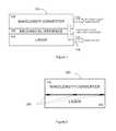
- FIG. 2is a side schematic block diagram of an example of the vertically stacked, integrated wavelength conversion and laser source of FIG. 1 .
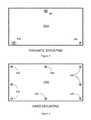
- FIG. 3is a top cutaway view of the present invention showing an embodiment of kinematic mounting.
- FIG. 4is a top cutaway view of the present invention showing an embodiment of hard mounting.
- FIG. 5Is a side schematic diagram of another embodiment of the vertically stacked, integrated wavelength conversion and laser source of FIGS. 1 and 2 using an internal beam periscope.
- the present inventionenables the addition of wavelength converting element 102 to laser element 104 while maintaining the optical head footprint and maximizing stability between the two elements by forming an integrated device 100 , 200 , 300 (see FIGS. 1, 2, and 5 ).
- a preferred embodiment of the inventionconsists of a commercial femtosecond laser 104 with attachment features 106 enabling the attachment of wavelength converting element 102 , either before or after shipment of laser 104 to a consumer.
- the factory-installed top lid(not shown) is removed and replaced with wavelength converting element 102 , with an interface such as those shown in FIGS. 3 and 4 .
- the factory-installed lid attachment featurescan be reused to attach wavelength conversion element 102 to laser 104 , hidden internal features can be used, or some combination of these can be used.
- Alignment pins(not shown) can be utilized to enable repeatable placement of the wavelength converting element with respect to the laser, or the structure of the mounting itself can be kinematic to ensure repeatable mounting, as shown in FIG. 3 .
- a periscope 514(see FIG. 5 ) attached to wavelength converting element 102 is placed in the original laser beam output path, directing the laser light 114 up to wavelength converting element 102 , within the footprint of integrated device 100 , 200 , 300 .
- frequency conversion elementssuch as harmonic generation elements (to include one or more of second harmonic generation, third harmonic generation, fourth harmonic generation, among others), a nonlinear pulse compression setup (consisting of spectral broadening and recompression), a nonlinear broadening setup (consisting of bulk or fiber broadening for generation of a broader output spectrum), a four-wave mixing (FWM) setup, a high harmonic generation (HHG) setup, an optical parametric oscillator, or an optical parametric amplifier convert the incident laser light into different wavelength region(s).
- harmonic generation elementsto include one or more of second harmonic generation, third harmonic generation, fourth harmonic generation, among others
- a nonlinear pulse compression setupconsististing of spectral broadening and recompression
- a nonlinear broadening setupconsististing of bulk or fiber broadening for generation of a broader output spectrum
- FWMfour-wave mixing
- HHGhigh harmonic generation
- an optical parametric oscillatoror an optical parametric amplifier convert the incident laser light into different wavelength region(
- FIG. 1is a side schematic block diagram of an embodiment 100 of the present invention.
- Laser 104 with initial output 112is connected to wavelength converter element 102 via mechanical interface 106 .
- Wavelength converter 102is stacked vertically on top of laser 104 and fixed with respect to laser 104 by mechanical interface 106 , which may be a kinematic mount (see FIG. 3 ) or a hard mount (see FIG. 4 ).
- Laser 104contains optical elements (not shown) which redirect laser light 114 from laser 104 to wavelength converter 102 within the footprint of vertically stacked, integrated wavelength conversion and laser source 100 for conversion to new wavelengths.
- Converted light 116is output for use by a laser operator.
- FIG. 2 , FIG. 3 , and FIG. 4show embodiments of the mechanical attachment methods for stable and robust mounting of the wavelength converting element to the laser.
- a series of three or more attachment pointsare made between the elements.
- FIG. 2shows mechanical interface 206 consisting of three or more kinematic or hard attachment points between the laser and wavelength converter.
- FIG. 3is a top view of an embodiment of kinematic mounting 206 A where wavelength converter 102 and laser 104 are attached to each other (as shown in FIGS. 1 and 2 ) via one fixed hole 306 , one slot 308 , and one loose fit hole 307 to constrain top wavelength converter 102 to be in the plane of bottom laser 104 , regardless of deflections due to temperature changes.
- Alternate kinematic mounting schemesinclude rigid spherical surfaces interfacing with a cone or triangle in the first mounting position, a slot in the second mounting position, and a plane in the third mounting position, or other so-called “kinematic” mounting arrangements.
- FIG. 3shows a top down view of one kinematic mounting method, where the attachment points are constrained based on the location.
- the location nearest the output of the laser (and closest to the beam transfer position between the top and bottom housings)is a fixed point 306 , constrained in all three dimensions (X, Y, Z) via firm attachment to the laser with a bolt or similar hardware.
- the location parallel to this attachment pointis constrained in a groove 308 in two dimensions (X, Z), where the slot allows the housings to move relative to each other in one dimension (Y).
- the third attachment pointis constrained only in the Z dimension by a loose-fitting hole 307 .
- Z-registrationis ensured via firm but compliant mounting attachment using devices such as springs, wave washers, compliant washers, or the like.
- An alternate configuration to slotted and relieved bolt holesuses spherical contacts such as tooling balls in one of the housings, and a cone or triangle contact (fixed in X, Y, Z), a slot or rail contact (fixed in X and Z), and a flat plate or plane contact (fixed in Z). See FIG. 5, 206C .
- forceis applied via a compliant mounting method to keep the tooling balls registered in the cone, slot, and plane. This mounting arrangement minimizes stresses that occur due to change in temperature or operational parameters in the laser or wavelength converter.
- This mounting methodwill reduce the variability of input pointing of the laser light into the wavelength conversion element and will ensure stable operation of the wavelength conversion at a variety of temperatures and operational conditions.
- the kinematic mounting arrangementalso puts a minimum amount of stress on both mechanical housings so that they are not deformed.
- FIG. 4is a top view of an embodiment of hard mounting 406 where eight firm attachment points are used to constrain top wavelength converter 102 to be in the plane of bottom laser 104 .
- FIG. 4is an example of a hard mounting configuration where the wavelength converter element is firmly attached to the laser in three or more places. This configuration can rigidly constrain the two elements to move in concert, enhancing stability in some configurations. Generally the kinematic attachment methods are preferred because of the reduced mechanical and thermal stress generally leads to more stable laser and wavelength converter performance.
- FIG. 5shows an embodiment of vertically stacked, integrated wavelength conversion and laser source 300 including internal beam periscope 514 for intercepting the output from laser 104 and directing it into wavelength converter 102 within the footprint of integrated device 300 using an internal beam periscope 514 .
- FIG. 5shows a method for transferring laser light 520 from the inside of the laser 104 enclosure to the inside of the wavelength converter 102 enclosure (as light 522 ). It utilizes a periscope 514 that is mounted to either the laser 104 or wavelength converter 102 mechanical housing.
- periscope 514is monolithic and contains no adjustable mirrors and is attached firmly to the wavelength converter 102 enclosure. This arrangement maximizes the stability of the light transfer from laser 104 to wavelength converter 102 and allows for the wavelength converter to be removed easily, enabling laser 104 to function as it did before wavelength conversion element 102 was attached.
- This approachalso allows for multiple types of wavelength conversion elements to be configured for use with the same laser 104 , enabling fast swapping of the output capabilities of the system.
- An alternate approachinvolves using a mirror (not shown) fixed to the laser 104 enclosure to direct the light up to a mirror (not shown) mounted on the wavelength convertor 102 enclosure.
- a plurality of optical elementsconverts the light to different wavelength regions. These elements are typically beamsplitters, waveplates, polarizers, lenses, dichroic separators and combiners, optical mirrors, crystals or optical glasses for nonlinear broadening and supercontinuum generation, and nonlinear crystals. Apertures or irises (not shown) can be used to check the alignment of the laser light within the wavelength conversion enclosure.
- the converted light 116is output from the wavelength converter element 102 through an aperture (not shown), or back into the laser 104 enclosure and out the original laser output aperture (not shown).
- the final amplifier elementis a fiber with a large minimum bend diameter, which generally defines the minimum size of the laser system along at least one dimension and forms the horizontal plane of the laser enclosure.
- the wavelength converter 102such as a parametric amplifier, shares roughly the same footprint as the laser in this invention, and is configured such that the plane of the parametric amplifier is substantially parallel to the plane of the laser defined by the fiber amplifier fiber bend geometry.
Landscapes
- Physics & Mathematics (AREA)
- Nonlinear Science (AREA)
- Optics & Photonics (AREA)
- General Physics & Mathematics (AREA)
- Electromagnetism (AREA)
- Engineering & Computer Science (AREA)
- Plasma & Fusion (AREA)
- Optical Modulation, Optical Deflection, Nonlinear Optics, Optical Demodulation, Optical Logic Elements (AREA)
Abstract
Description
- 1.
Interchangeable wavelength conversion 102 enclosures of different configurations such that the laser can be equipped with any one or more of these wavelength conversion configurations. - 2.
Mechanical attachments 106 enable rapid swapping between different configurations with accurate mechanical references enabling repeatable optical alignment for the wavelength conversion elements. - 3. Size and form factor: An integrated housing approach gives the smallest possible optical head footprint while only increasing the height of the optical arrangement. Generally, footprint is the limiting factor in optical applications, and the smaller the footprint, the better.
- 4. Retrofittability/reconfigurability: This invention enables a laser to be retrofitted after manufacture to change the wavelength to a different region and/or the pulse duration to a different value according to the customer desires.
- 5. Manufacturability: A common laser platform can be used for multiple purposes and applications, meaning the common laser can be manufactured in higher volume, enabling cost savings.
- 1.
Claims (22)
Priority Applications (1)
| Application Number | Priority Date | Filing Date | Title |
|---|---|---|---|
| US15/892,307US10303040B2 (en) | 2017-02-08 | 2018-02-08 | Integrated wavelength conversion and laser source |
Applications Claiming Priority (2)
| Application Number | Priority Date | Filing Date | Title |
|---|---|---|---|
| US201762456248P | 2017-02-08 | 2017-02-08 | |
| US15/892,307US10303040B2 (en) | 2017-02-08 | 2018-02-08 | Integrated wavelength conversion and laser source |
Publications (2)
| Publication Number | Publication Date |
|---|---|
| US20180224710A1 US20180224710A1 (en) | 2018-08-09 |
| US10303040B2true US10303040B2 (en) | 2019-05-28 |
Family
ID=63037137
Family Applications (1)
| Application Number | Title | Priority Date | Filing Date |
|---|---|---|---|
| US15/892,307ActiveUS10303040B2 (en) | 2017-02-08 | 2018-02-08 | Integrated wavelength conversion and laser source |
Country Status (1)
| Country | Link |
|---|---|
| US (1) | US10303040B2 (en) |
Families Citing this family (1)
| Publication number | Priority date | Publication date | Assignee | Title |
|---|---|---|---|---|
| US10303040B2 (en)* | 2017-02-08 | 2019-05-28 | Kapteyn Murnane Laboratories, Inc. | Integrated wavelength conversion and laser source |
Citations (15)
| Publication number | Priority date | Publication date | Assignee | Title |
|---|---|---|---|---|
| US5754333A (en)* | 1995-05-12 | 1998-05-19 | Commissariat A L'energie Atomique | Microlaser-pumped monolithic optical parametric oscillator |
| US6680956B2 (en)* | 2001-02-15 | 2004-01-20 | Aculight Corporation | External frequency conversion of surface-emitting diode lasers |
| US7039087B2 (en)* | 2004-05-13 | 2006-05-02 | The United States Of America As Represented By The Department Of The Army | End pumped slab laser cavity |
| US20070195538A1 (en)* | 2005-12-12 | 2007-08-23 | Nichia Corporation | Optical component, light converting member, and light emitting device |
| US20070237191A1 (en)* | 2006-01-30 | 2007-10-11 | Kafka James D | Devices for high power, high-repetition rate, broadly tunable coherent radiation, and its applications |
| US7394841B1 (en)* | 2007-01-18 | 2008-07-01 | Epicrystals Oy | Light emitting device for visual applications |
| US8144311B2 (en)* | 2008-10-01 | 2012-03-27 | Kabushiki Kaisha Topcon | Laser apparatus and distance measurement apparatus |
| US8410507B2 (en)* | 2008-10-07 | 2013-04-02 | Osram Opto Semiconductors Gmbh | Thermal light source having a high color rendering quality |
| US20130279170A1 (en)* | 2011-01-17 | 2013-10-24 | Mitsubishi Electric Corporation | Laser light source module |
| US9076952B2 (en)* | 2013-01-16 | 2015-07-07 | Stanley Electric Co., Ltd. | Semiconductor light-emitting device |
| US20150372200A1 (en)* | 2014-06-23 | 2015-12-24 | Stanley Electric Co., Ltd. | Semiconductor light-emitting apparatus and vehicle headlight |
| US20160131314A1 (en)* | 2014-11-11 | 2016-05-12 | Stanley Electric Co., Ltd. | Semiconductor light-emitting apparatus and vehicle headlight |
| US20160268770A1 (en)* | 2015-03-09 | 2016-09-15 | Stanley Electric Co., Ltd. | Laser light-emitting apparatus |
| US9608402B2 (en)* | 2014-08-28 | 2017-03-28 | Hisense Broadband Multimedia Technologies Co., Ltd. | Packaging structure and method of packaging tunable laser device, and tunable laser device |
| US20180224710A1 (en)* | 2017-02-08 | 2018-08-09 | KM Labs Inc. | Integrated Wavelength Conversion and Laser Source |
- 2018
- 2018-02-08USUS15/892,307patent/US10303040B2/enactiveActive
Patent Citations (16)
| Publication number | Priority date | Publication date | Assignee | Title |
|---|---|---|---|---|
| US5754333A (en)* | 1995-05-12 | 1998-05-19 | Commissariat A L'energie Atomique | Microlaser-pumped monolithic optical parametric oscillator |
| US6680956B2 (en)* | 2001-02-15 | 2004-01-20 | Aculight Corporation | External frequency conversion of surface-emitting diode lasers |
| US7039087B2 (en)* | 2004-05-13 | 2006-05-02 | The United States Of America As Represented By The Department Of The Army | End pumped slab laser cavity |
| US20070195538A1 (en)* | 2005-12-12 | 2007-08-23 | Nichia Corporation | Optical component, light converting member, and light emitting device |
| US20070237191A1 (en)* | 2006-01-30 | 2007-10-11 | Kafka James D | Devices for high power, high-repetition rate, broadly tunable coherent radiation, and its applications |
| US7394841B1 (en)* | 2007-01-18 | 2008-07-01 | Epicrystals Oy | Light emitting device for visual applications |
| US8144311B2 (en)* | 2008-10-01 | 2012-03-27 | Kabushiki Kaisha Topcon | Laser apparatus and distance measurement apparatus |
| US8410507B2 (en)* | 2008-10-07 | 2013-04-02 | Osram Opto Semiconductors Gmbh | Thermal light source having a high color rendering quality |
| US20130279170A1 (en)* | 2011-01-17 | 2013-10-24 | Mitsubishi Electric Corporation | Laser light source module |
| US9076952B2 (en)* | 2013-01-16 | 2015-07-07 | Stanley Electric Co., Ltd. | Semiconductor light-emitting device |
| US20150372200A1 (en)* | 2014-06-23 | 2015-12-24 | Stanley Electric Co., Ltd. | Semiconductor light-emitting apparatus and vehicle headlight |
| US9726340B2 (en)* | 2014-06-23 | 2017-08-08 | Stanley Electric Co., Ltd. | Semiconductor light-emitting apparatus and vehicle headlight |
| US9608402B2 (en)* | 2014-08-28 | 2017-03-28 | Hisense Broadband Multimedia Technologies Co., Ltd. | Packaging structure and method of packaging tunable laser device, and tunable laser device |
| US20160131314A1 (en)* | 2014-11-11 | 2016-05-12 | Stanley Electric Co., Ltd. | Semiconductor light-emitting apparatus and vehicle headlight |
| US20160268770A1 (en)* | 2015-03-09 | 2016-09-15 | Stanley Electric Co., Ltd. | Laser light-emitting apparatus |
| US20180224710A1 (en)* | 2017-02-08 | 2018-08-09 | KM Labs Inc. | Integrated Wavelength Conversion and Laser Source |
Also Published As
| Publication number | Publication date |
|---|---|
| US20180224710A1 (en) | 2018-08-09 |
Similar Documents
| Publication | Publication Date | Title |
|---|---|---|
| EP2179481B1 (en) | Alignment method in wavelength-converted, wavelength-modulated semiconductor lasers | |
| Liebel et al. | Sub-10-fs pulses tunable from 480 to 980 nm from a NOPA pumped by an Yb: KGW source | |
| Furch et al. | CEP-stable few-cycle pulses with more than 190 μJ of energy at 100 kHz from a noncollinear optical parametric amplifier | |
| US10931077B2 (en) | Optical reference cavity | |
| Çankaya et al. | 40-µJ passively CEP-stable seed source for ytterbium-based high-energy optical waveform synthesizers | |
| US20160240996A1 (en) | Femtosecond ultraviolet laser | |
| US10303040B2 (en) | Integrated wavelength conversion and laser source | |
| Löhring et al. | INNOSLAB-based single-frequency MOPA for airborne lidar detection of CO2 and methane | |
| Löhring et al. | Key optical components for spaceborne lasers | |
| US20230105608A1 (en) | Light source system and laser projection display device | |
| Tamer et al. | Few-cycle fs-pumped NOPA with passive ultrabroadband spectral shaping | |
| KR101573748B1 (en) | Laser wavelength conversion apparatus | |
| CN219123662U (en) | Picosecond ultraviolet laser | |
| Schiemangk et al. | Ultra-narrow linewidth diode laser based on resonant optical feedback | |
| CN214409529U (en) | Optical fiber coupling frequency converter packaging structure based on PPLN crystal | |
| US20180356706A1 (en) | Frequency-tunable laser source and method for emitting a frequency-tunable laser beam | |
| Cheng et al. | Efficient two-stage dual-beam noncollinear optical parametric amplifier | |
| Unger et al. | Beam shaping concepts for kW-class CW and QCW diode lasers | |
| Vidal et al. | High power continuous laser at 461 nm based on a frequency-doubling linear cavity | |
| Mueller et al. | 3.5 kW coherently combined ultrafast fiber laser | |
| Rothenberg et al. | High-power coherent diode arrays | |
| US20250163612A1 (en) | Ovens for nonlinear optical crystals and method of use | |
| Hadmack | An optical storage cavity-based, Compton-backscatter x-ray source using the MKV free electron laser | |
| Slivken et al. | New design strategies for multifunctional and inexpensive quantum cascade lasers | |
| Ebert et al. | Advances in the power, brightness, weight and efficiency of fiber-coupled diode lasers for pumping and direct diode applications |
Legal Events
| Date | Code | Title | Description |
|---|---|---|---|
| FEPP | Fee payment procedure | Free format text:ENTITY STATUS SET TO UNDISCOUNTED (ORIGINAL EVENT CODE: BIG.); ENTITY STATUS OF PATENT OWNER: LARGE ENTITY Free format text:ENTITY STATUS SET TO UNDISCOUNTED (ORIGINAL EVENT CODE: BIG.); ENTITY STATUS OF PATENT OWNER: SMALL ENTITY | |
| FEPP | Fee payment procedure | Free format text:ENTITY STATUS SET TO SMALL (ORIGINAL EVENT CODE: SMAL); ENTITY STATUS OF PATENT OWNER: LARGE ENTITY Free format text:ENTITY STATUS SET TO SMALL (ORIGINAL EVENT CODE: SMAL); ENTITY STATUS OF PATENT OWNER: SMALL ENTITY | |
| STPP | Information on status: patent application and granting procedure in general | Free format text:NOTICE OF ALLOWANCE MAILED -- APPLICATION RECEIVED IN OFFICE OF PUBLICATIONS | |
| STPP | Information on status: patent application and granting procedure in general | Free format text:PUBLICATIONS -- ISSUE FEE PAYMENT VERIFIED | |
| STCF | Information on status: patent grant | Free format text:PATENTED CASE | |
| AS | Assignment | Owner name:KM LABS INC., COLORADO Free format text:ASSIGNMENT OF ASSIGNORS INTEREST;ASSIGNORS:BACKUS, STERLING J;DOMINGUE, SCOTT R;KIRCHNER, MATTHEW S;AND OTHERS;REEL/FRAME:049320/0628 Effective date:20190321 | |
| AS | Assignment | Owner name:KAPTEYN-MURNANE LABORATORIES, INC., COLORADO Free format text:CORRECTIVE ASSIGNMENT TO CORRECT THE NAME OF RECEIVING PARTY PREVIOUSLY RECORDED ON REEL 049320 FRAME 0628. ASSIGNOR(S) HEREBY CONFIRMS THE ASSIGNMENT;ASSIGNORS:BACKUS, STERLING J;DOMINGUE, SCOTT R;KIRCHNER, METTHEW S;AND OTHERS;REEL/FRAME:052720/0156 Effective date:20190321 | |
| AS | Assignment | Owner name:THORLABS, INC., NEW JERSEY Free format text:ASSIGNMENT OF ASSIGNORS INTEREST;ASSIGNOR:KAPTEYN-MURNANE LABORATORIES, INC.;REEL/FRAME:053462/0107 Effective date:20191028 | |
| FEPP | Fee payment procedure | Free format text:ENTITY STATUS SET TO UNDISCOUNTED (ORIGINAL EVENT CODE: BIG.); ENTITY STATUS OF PATENT OWNER: LARGE ENTITY | |
| MAFP | Maintenance fee payment | Free format text:PAYMENT OF MAINTENANCE FEE, 4TH YEAR, LARGE ENTITY (ORIGINAL EVENT CODE: M1551); ENTITY STATUS OF PATENT OWNER: LARGE ENTITY Year of fee payment:4 |